Miniaturized Dual-Band Dielectric Resonator Antenna for IEEE 802.16d Fixed WiMAX Applications Runa Kumari, Santanu Kumar Behera Department of Electronics and Communication Engineering, National Institute of Technology, Rourkela, India Received 1 September 2011; accepted 10 January 2012 ABSTRACT: A miniaturized dual-band C-shaped dielectric resonator antenna (DRA) with partial ground plane is presented for IEEE 802.16d fixed WiMAX applications at 3.5 and 5.8 GHz. The design starts with dimensioning a single band cylindrical DRA, which has been transferred to get a dual-band ring-shaped DRA. One portion of the ring-shaped DRA is removed for forming a C-shaped DRA to get a more compact antenna. For easy fabrica- tion, the compact DRA dimensioned as 60 50 6.6 mm 3 is excited by a microstrip line feeding. The design parameters are inner and outer radii of the C-shaped antenna and air gap (between DR and ground) to control both the resonating frequency and the quality factor. The result shows peak gain around 3.26 and 5.55 dBi at 3.5 and 5.8 GHz, respec- tively. The obtained results indicate very good agreement between the simulated and meas- ured results. V C 2012 Wiley Periodicals, Inc. Int J RF and Microwave CAE 22:682–689, 2012. Keywords: dielectric resonator antenna; dual band; WiMAX; microstrip line feed I. INTRODUCTION Nowadays, the IEEE 802.16 WiMAX standard allows data transmission using multiple broadband frequency ranges. The original 802.16a standard specified transmis- sions in the range 10–66 GHz, but 802.16d allowed lower frequencies in the range 2–11 GHz. For WiMAX applica- tions, different bands are available in different parts of the world, but the frequencies commonly used for 802.16d fixed WiMAX applications are 3.5 and 5.8 GHz [1]. The lower frequencies used in this specification means that the signals suffer less from attenuation, and therefore, they provide improved range and better coverage. For low fre- quency WiMAX applications, the important requirement is the antenna miniaturization. The dielectric resonator antenna (DRA) offers advan- tages like low cost, ease of manufacture, wider impedance bandwidth, and high radiation efficiency [2, 3]. DRAs can be designed with different shapes to accommodate various design requirements [4–8]. DRAs can also be excited with different feeding methods, such as probes, microstrip lines, slots, and coplanar lines. As compared to microstrip antenna, DRA has much wider impedance bandwidth due to their many advantageous features. These include their compact size, light weight, simple structure, and versatil- ity in their shape and feeding mechanism. Among the different shapes of DRA, the cylindrical-shaped DRA offers greater design flexibility, where the ratio of radius to height (R/h R ) controls the resonant frequency and the Q-factor [5]. Fabrication of cylindrical-shaped DRA is also simpler than other shaped DRA [9–11]. Various modes can be easily excited within the cylindrical-shaped DRA, which results in either broadside or omnidirectional radiation patterns [12, 13]. Analytical studies carried out on cylindrical dielectric resonators (DRs) have demon- strated that the Q-factor could be reduced by removing a central portion of the dielectric material to form a ring. By applying perturbation theory [2], the removal of dielectric material would result in lowering the Q-factor and an increase in the resonant frequency. The impedance bandwidth can be enhanced using low-dielectric-constant materials for the resonator, but the size of the DR will be increased slightly [14]. Further, the bandwidth and reso- nant frequency of the ring-shaped DRA can be improved by proper choice of antenna parameters [15]. It has been discussed that there is generally an increase in the reso- nant frequency and a decrease in the Q-factor, when an air gap is introduced, which can provide a good imped- ance matching significantly [16–19]. This article mainly demonstrates the design of a micro- strip line fed, dual-frequency C-shaped compact DRA, Correspondence to: R. Kumari; e-mail: [email protected] V C 2012 Wiley Periodicals, Inc. DOI 10.1002/mmce.20627 Published online 27 March 2012 in Wiley Online Library (wileyonlinelibrary.com). 682

Welcome message from author
This document is posted to help you gain knowledge. Please leave a comment to let me know what you think about it! Share it to your friends and learn new things together.
Transcript
Miniaturized Dual-Band Dielectric Resonator Antennafor IEEE 802.16d Fixed WiMAX Applications
Runa Kumari, Santanu Kumar Behera
Department of Electronics and Communication Engineering, National Institute of Technology,Rourkela, India
Received 1 September 2011; accepted 10 January 2012
ABSTRACT: A miniaturized dual-band C-shaped dielectric resonator antenna (DRA) with
partial ground plane is presented for IEEE 802.16d fixed WiMAX applications at 3.5 and
5.8 GHz. The design starts with dimensioning a single band cylindrical DRA, which has
been transferred to get a dual-band ring-shaped DRA. One portion of the ring-shaped DRA
is removed for forming a C-shaped DRA to get a more compact antenna. For easy fabrica-
tion, the compact DRA dimensioned as 60 � 50 � 6.6 mm3is excited by a microstrip
line feeding. The design parameters are inner and outer radii of the C-shaped antenna and
air gap (between DR and ground) to control both the resonating frequency and the quality
factor. The result shows peak gain around 3.26 and 5.55 dBi at 3.5 and 5.8 GHz, respec-
tively. The obtained results indicate very good agreement between the simulated and meas-
ured results. VC 2012 Wiley Periodicals, Inc. Int J RF and Microwave CAE 22:682–689, 2012.
Keywords: dielectric resonator antenna; dual band; WiMAX; microstrip line feed
I. INTRODUCTION
Nowadays, the IEEE 802.16 WiMAX standard allows
data transmission using multiple broadband frequency
ranges. The original 802.16a standard specified transmis-
sions in the range 10–66 GHz, but 802.16d allowed lower
frequencies in the range 2–11 GHz. For WiMAX applica-
tions, different bands are available in different parts of the
world, but the frequencies commonly used for 802.16d
fixed WiMAX applications are 3.5 and 5.8 GHz [1]. The
lower frequencies used in this specification means that the
signals suffer less from attenuation, and therefore, they
provide improved range and better coverage. For low fre-
quency WiMAX applications, the important requirement
is the antenna miniaturization.
The dielectric resonator antenna (DRA) offers advan-
tages like low cost, ease of manufacture, wider impedance
bandwidth, and high radiation efficiency [2, 3]. DRAs can
be designed with different shapes to accommodate various
design requirements [4–8]. DRAs can also be excited with
different feeding methods, such as probes, microstrip
lines, slots, and coplanar lines. As compared to microstrip
antenna, DRA has much wider impedance bandwidth due
to their many advantageous features. These include their
compact size, light weight, simple structure, and versatil-
ity in their shape and feeding mechanism. Among the
different shapes of DRA, the cylindrical-shaped DRA
offers greater design flexibility, where the ratio of radius
to height (R/hR) controls the resonant frequency and the
Q-factor [5]. Fabrication of cylindrical-shaped DRA is
also simpler than other shaped DRA [9–11]. Various
modes can be easily excited within the cylindrical-shaped
DRA, which results in either broadside or omnidirectional
radiation patterns [12, 13]. Analytical studies carried out
on cylindrical dielectric resonators (DRs) have demon-
strated that the Q-factor could be reduced by removing a
central portion of the dielectric material to form a ring.
By applying perturbation theory [2], the removal of
dielectric material would result in lowering the Q-factor
and an increase in the resonant frequency. The impedance
bandwidth can be enhanced using low-dielectric-constant
materials for the resonator, but the size of the DR will be
increased slightly [14]. Further, the bandwidth and reso-
nant frequency of the ring-shaped DRA can be improved
by proper choice of antenna parameters [15]. It has been
discussed that there is generally an increase in the reso-
nant frequency and a decrease in the Q-factor, when an
air gap is introduced, which can provide a good imped-
ance matching significantly [16–19].
This article mainly demonstrates the design of a micro-
strip line fed, dual-frequency C-shaped compact DRA,
Correspondence to: R. Kumari; e-mail: [email protected]
VC 2012 Wiley Periodicals, Inc.
DOI 10.1002/mmce.20627Published online 27 March 2012 in Wiley Online Library
(wileyonlinelibrary.com).
682
made up of C-shaped DR supported by a substrate and
partial ground plane for IEEE 802.16d fixed WiMAX
applications. In this article, DRA volume miniaturization
for compact antenna design is also discussed. The initial
design of the proposed antenna is considered as a simple
cylindrical-shaped DRA. The desired operating frequency
of cylindrical-shaped DRA is chosen as 5.8 GHz. The
shape of the antenna has been modified by taking partial
ground plane for WiMAX and WLAN applications. The
modified C-shaped DRA is then approximated for facili-
tating its fabrication. The design procedure of the pro-
posed DRA is presented. Some parametric studies have
been performed to investigate the characteristics of DRAs
with different shapes (cylindrical- and C-shaped DRA)
and different values of inner radius (6, 9, and 2 mm) and
air gap between ground and DR. Measured S-parameter
values are also compared with the simulated results.
Finally, the extensive simulations have been carried out to
investigate the different characteristics (gain, directivity,
and radiation features) of the proposed antenna, and the
obtained results are presented in the following sections.
II. NUMERICAL ANALYSIS ON C-SHAPED DRA
The cylindrical-shaped DRA is characterized by height
(hR), radius (R), and a dielectric constant eR. The cylindri-
cal shape offers one degree of freedom more than the
hemispherical shape because of the aspect ratio RhR
. The
impedance band width and quality factor (Q) of cylindri-
cal DRA are given by Drossos et al. [20].
An analytical study has been carried out on cylindrical
DRs, which demonstrated that the Q-factor could be
reduced by removing a central portion of the cylindrical-
shaped dielectric material [21, 22]. By applying perturba-
tion theory, the removal of dielectric material would result
in reduction of the Q-factor and rise in the resonant
frequency.
The resonant frequency of the ring-shaped DRA having
outer radius R and inner radius r can be resolved using eq. (1):
fR ¼c
2pffiffiffiffiffieRp
ffiffiffiffiffiffiffiffiffiffiffiffiffiffiffiffiffiffiffiffiffiffiffiffiffiffiffiffiffiffiffiffiffiffip
2hR
� �2
þ X0
R
� �2s
(1)
where c is the speed of light in free space, and X0 is the
solution to:
J1 X0ð ÞY1 X0ð Þ
¼J1
rR X0
� �Y1
rR X0
� � (2)
where J1(X) and Y1(X) are the first-order Bessel functions
of the first and second kind, respectively (Ref. 2; Table I).
For rR � 0:7
X0 ¼ 3:56þ 5:13r
R
� �� 13:07
r
R
� �2
þ28:2r
R
� �3
(3)
The ring-shaped DRA is made up of cylindrical DRA,
where a central cylindrical section of radius r has been
detached. The effect of increasing the ratio of inner to outer
radius rR
� �of the ring-shaped resonator on resonant fre-
quency and Q-factor can be seen by applying eqs. (1)–(3).
Increasing rR
� �ratio results in intensification in Q-factor.
However, to maintain the same resonant frequency, the
outer radius R must be increased.
If the volume to surface ratio is minimized, then the
quality factor is reduced. Thus, by removing a portion of
ring-shaped DRA, a C-shaped DRA is designed to get
minimum quality factor. The volume of cylindrical- or ring-
shaped DRAs can be reduced by removing sectors of mate-
rial [23–25]. For the sectored ring-shaped DRA, the resonant
frequency fvpm of the TMvpmþd mode is given by [26]
fvpm ¼c
2pRffiffiffiffiffieRp
ffiffiffiffiffiffiffiffiffiffiffiffiffiffiffiffiffiffiffiffiffiffiffiffiffiffiffiffiffiffiffiffiffiffiffiffiffiffiffiffiffiffiffiffiffiffiffiffiX2
vp þpR
2hR
2mþ 1ð Þ� �2
s(4)
where Xvp is the solution for
J0v Xvp
� �¼ 0 (5)
It is clear that the annular ring-shaped DRA has higher
resonant frequency than a simple cylindrical-shaped DRA of
equal outer radius.
III. ANTENNA GEOMETRY AND DESIGN
In this article, the design of DRA is initiated with the res-
onant frequency assortment for the desired fixed WiMAX
applications. The dielectric materials and dimensions for
the resonator and substrate are carefully chosen. The nu-
merical analysis (described in previous section) has been
used to normalize the ratio of inner to outer radius (r/R)
for DR. The air gap (g) and inner radius are presumed.
The resonant frequency for the DRA is extracted from the
S-parameter versus frequency plot. If the resulted values
are suitable for desired applications, then only the other
parameters (namely, gain, directivity, and radiation pat-
terns) are extracted. This methodology gives an easy and
simple procedure to realize the design of proposed DRA.
The configuration of the C-shaped DRA is shown in
Figure 1. Among the different shapes of DRA, the cylin-
drical-shaped DRA offers greater design flexibility. Thus,
the design of proposed antenna is initialized by a simple
cylindrical-shaped DR, where the ratio of radius to height
controls the resonant frequency and Q-factor.
The proposed DRA design starts with a cylindrical-
shaped DR made from Teflon with dielectric constant
eR ¼ 2.1, having radius R ¼ 19 mm and height hR ¼ 5 mm.
Microstrip line feeding offers the advantages of easy,
simplest, and cost-effective fabrication of DRA. So, the
TABLE I Values of X0 for Various Ratios of rR
rR 0 0.1 0.2 0.3 0.4 0.5 0.6 0.7 0.8 0.9
X0 3.8317 3.9409 4.2358 4.7058 5.3912 6.3932 7.9301 10.522 15.7376 31.4292
Miniaturized Dual-Band DRA 683
International Journal of RF and Microwave Computer-Aided Engineering DOI 10.1002/mmce
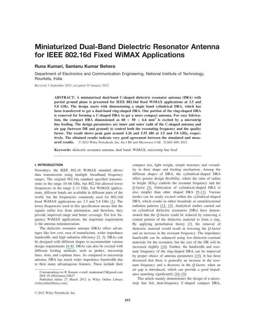
DRA is excited by a 50 X microstrip line feeding, which
has dimensions Lf ¼ 57.75 mm and Wf ¼ 2 mm. The DR
along with the feed line is mounted on the top side of FR4
substrate measuring �60-mm long by 50-mm wide with a
thickness hs of 1.6 mm, a relative dielectric constant (es) of
4.4, and a loss tangent (tan d) of 0.001 (shown in Fig. 1c).
A partially printed ground plane with dimensions 50 � 13.5
mm2 (Lg � W) was present on the bottom side of the sub-
strate as shown in Figure 1d. The air gap (g) between DR
and ground is 5.5 mm. As the cylindrical-shaped DRA (Fig.
1a) is resonanting (with VSWR < 2) at only 5.8 GHz fre-
quency, the shape of the DRA is modified to achieve the
desired dual-band resonant frequency.
A circular core of dielectric material with radius r ¼ 6
mm is detached from cylindrical-shaped DRA to get a
ring-shaped DRA as shown in Figure 1b, which resonates
at 3.5 GHz as well as at 5.8 GHz. The ring-shaped DRA
is reformed to miniaturize the size of antenna by remov-
ing one portion of ring-shaped dielectric material. Finally,
the proposed antenna consists of a well-designed C-shaped
DR having outer radius R ¼ 19 mm, inner radius r ¼ 6
mm, thickness hR ¼ 5 mm and Rr ¼ 23 mm as shown in
Figure 1c. Figures 1e and 1f show the front view and rear
view photographs of fabricated prototype C-shaped DRA
on FR4 substrate with partial ground plane.
IV. RESULTS AND DISCUSSION
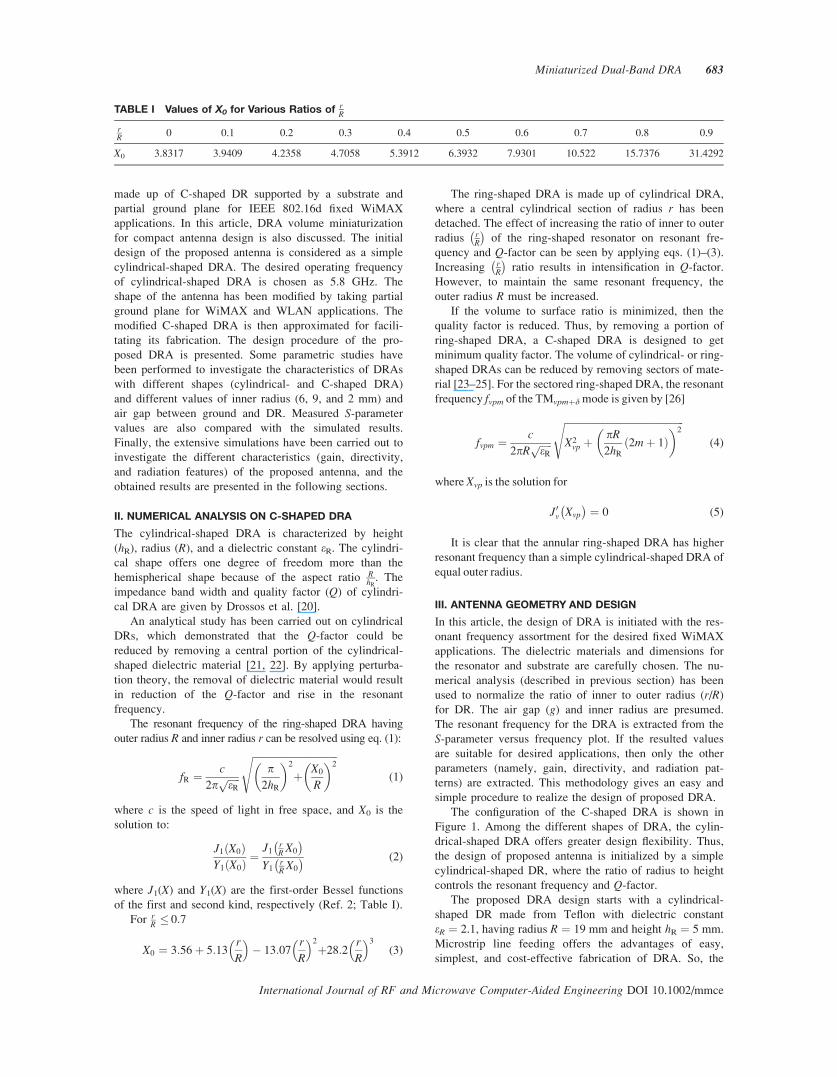
A. S-Parameter CharacteristicsThe simulation studies of S-parameter versus frequency
characteristics for the proposed C-shaped DRA have been
carried out using CST Microwave Studio software. The
simulated S-parameter versus frequency curves of the pro-
posed antenna have been presented in Figure 2. The reso-
nant frequencies are found to be 3.5 and 5.8 GHz, which
are the desired frequencies for IEEE 802.16d fixed
WiMAX applications. The parametric studies of the DRA
with respect to different shapes, its inner radius r and air
Figure 1 (a) Cylindrical-shaped DRA, (b) ring-shaped DRA,
(c) C-shaped DRA front-view, (d) C-shaped DRA rear-view, (e)
front view of fabricated C-shaped DRA, and (f) rear view of fab-
ricated DRA. [Color figure can be viewed in the online issue,
which is available at wileyonlinelibrary.com.]
Figure 2 Simulated S-parameter plot of different shaped
DRAs. [Color figure can be viewed in the online issue, which is
available at wileyonlinelibrary.com.]
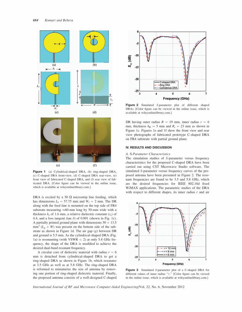
Figure 3 Simulated S-parameter plot of a C-shaped DRA for
different values of inner radius ‘‘r.’’ [Color figure can be viewed
in the online issue, which is available at wileyonlinelibrary.com.]
684 Kumari and Behera
International Journal of RF and Microwave Computer-Aided Engineering/Vol. 22, No. 6, November 2012
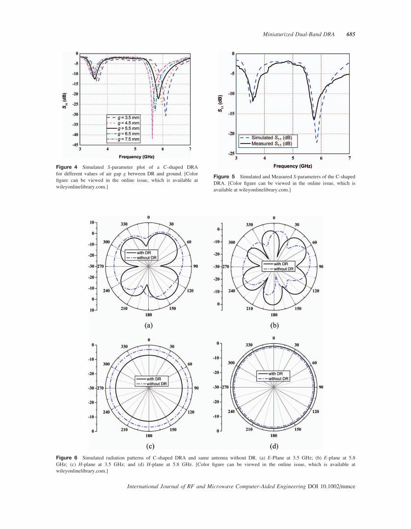
Figure 4 Simulated S-parameter plot of a C-shaped DRA
for different values of air gap g between DR and ground. [Color
figure can be viewed in the online issue, which is available at
wileyonlinelibrary.com.]
Figure 5 Simulated and Measured S-parameters of the C-shaped
DRA. [Color figure can be viewed in the online issue, which is
available at wileyonlinelibrary.com.]
Figure 6 Simulated radiation patterns of C-shaped DRA and same antenna without DR. (a) E-Plane at 3.5 GHz; (b) E-plane at 5.8
GHz; (c) H-plane at 3.5 GHz; and (d) H-plane at 5.8 GHz. [Color figure can be viewed in the online issue, which is available at
wileyonlinelibrary.com.]
Miniaturized Dual-Band DRA 685
International Journal of RF and Microwave Computer-Aided Engineering DOI 10.1002/mmce
gap g (between DR and ground) are performed and pre-
sented in Figures 2–4.
The radius of the basic cylindrical-shaped DRA is taken
as 19 mm. By drilling out a cylindrical region of radius r(which is nearly equal to 1/3 of the cylinder’s radius R)
from the center and then by removing a portion of the ring-
shaped resonator, a C-shaped DRA has been devised.
Figure 2 shows the variation of S-parameter (S11) with
different shapes of DR. It can be perceived from the fig-
ure that S11 decreases as the shape diverges from simple
cylindrical to modified ring-shaped DRA, whereas the res-
onant frequencies as well as the S11 is almost identical for
both the ring-shaped and C-shaped DRA. In comparison
to general cylindrical DRA, the S-parameter (S11) of the
proposed C-shaped DRA is less than �10 dB and exactly
at our desired resonant frequencies (3.5 and 5.8 GHz).
The variation of resonance frequency with inner radius
‘‘r’’ is shown in Figure 3. It has been observed from the
figure that the resonant frequency shifts toward right
from the desired frequency as the inner radius varies from
6 to 12 mm.
Similarly in the next design step, to improve the posi-
tion of resonant frequency, an air gap has been introduced
in between DR and ground. Thus, a parametric study has
been accomplished by varying the air gap to achieve
an optimum antenna performance. Figure 4 shows the
simulated S11 with different values of air gap g. For the
case g ¼ 5.5 mm, the desired resonant frequency with
S11 (dB) below �10 dB is perceived. From Figure 4,
it can be concluded that the resonant frequency of the
C-shaped DRA varies linearly with air gap (g).
The measurement of the fabricated C-shaped DRA is
performed using an E8363B network analyzer. Figure 5
shows the simulated and measured S-parameter (dB) as
the function of frequency. From Figure 5, it has been per-
ceived that the proposed antenna operates in 3.46–3.61
and 5.66–6.14 GHz bands, where the center frequencies
are at 3.5 and 5.8 GHz.
B. Radiation PatternsIn this proposed DRA, we have used an electrically quite
long microstrip line feeding to excite the C-shaped DRA.
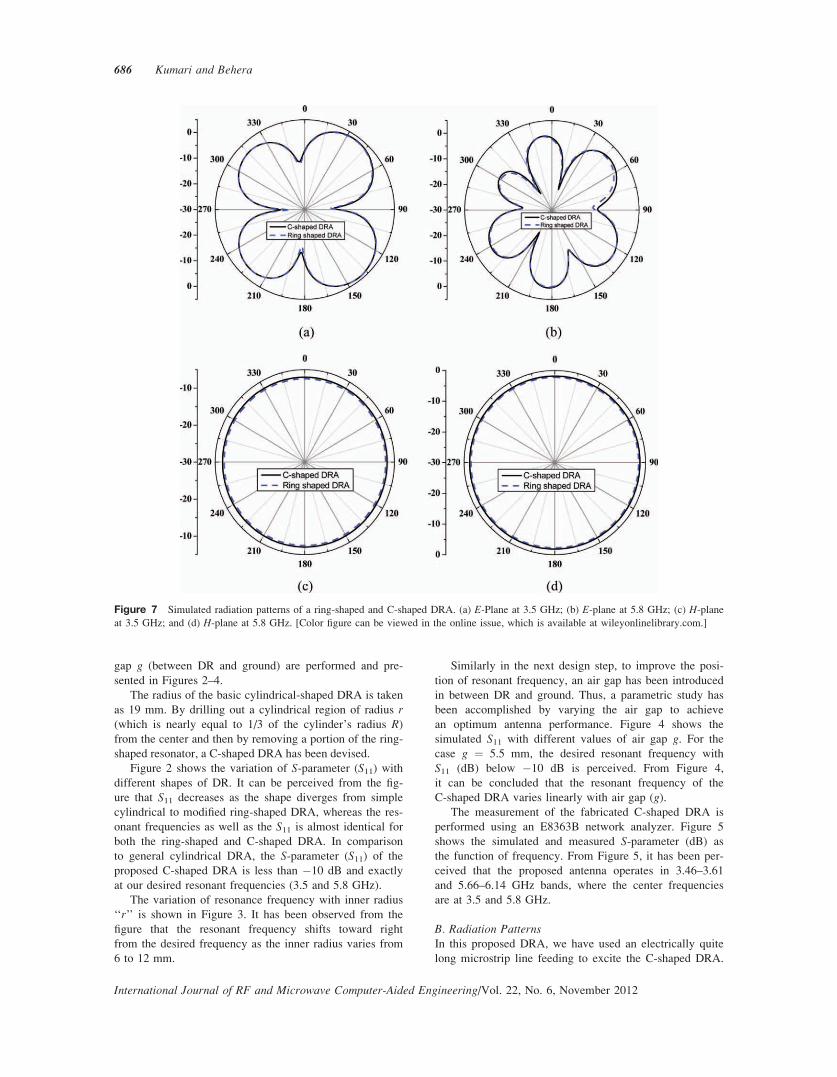
Figure 7 Simulated radiation patterns of a ring-shaped and C-shaped DRA. (a) E-Plane at 3.5 GHz; (b) E-plane at 5.8 GHz; (c) H-plane
at 3.5 GHz; and (d) H-plane at 5.8 GHz. [Color figure can be viewed in the online issue, which is available at wileyonlinelibrary.com.]
686 Kumari and Behera
International Journal of RF and Microwave Computer-Aided Engineering/Vol. 22, No. 6, November 2012
The radiation patterns of C-shaped DRA and same antenna
without DR at different resonant frequencies are shown in
Figure 6 to illustrate the contribution of feed line.
Figure 7 shows the simulated far field radiation pat-
terns of the proposed ring-shaped DRA and C-shaped
DRA for both E-plane and H-plane, at resonant frequen-
cies 3.5 and 5.8 GHz.
It can be observed from these figures that radiation
patterns for ring- and C-shaped DRA are almost same.
The proposed DRAs have same polarization plane and
almost identical radiation patterns at the two operating
frequencies, whereas the H-plane radiation patterns are
omnidirectional over the entire frequency range.
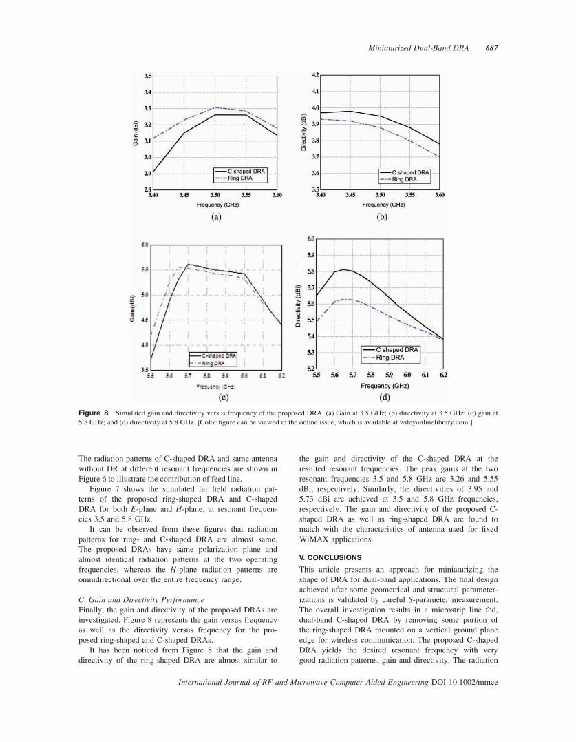
C. Gain and Directivity PerformanceFinally, the gain and directivity of the proposed DRAs are
investigated. Figure 8 represents the gain versus frequency
as well as the directivity versus frequency for the pro-
posed ring-shaped and C-shaped DRAs.
It has been noticed from Figure 8 that the gain and
directivity of the ring-shaped DRA are almost similar to
the gain and directivity of the C-shaped DRA at the
resulted resonant frequencies. The peak gains at the two
resonant frequencies 3.5 and 5.8 GHz are 3.26 and 5.55
dBi, respectively. Similarly, the directivities of 3.95 and
5.73 dBi are achieved at 3.5 and 5.8 GHz frequencies,
respectively. The gain and directivity of the proposed C-
shaped DRA as well as ring-shaped DRA are found to
match with the characteristics of antenna used for fixed
WiMAX applications.
V. CONCLUSIONS
This article presents an approach for miniaturizing the
shape of DRA for dual-band applications. The final design
achieved after some geometrical and structural parameter-
izations is validated by careful S-parameter measurement.
The overall investigation results in a microstrip line fed,
dual-band C-shaped DRA by removing some portion of
the ring-shaped DRA mounted on a vertical ground plane
edge for wireless communication. The proposed C-shaped
DRA yields the desired resonant frequency with very
good radiation patterns, gain and directivity. The radiation
Figure 8 Simulated gain and directivity versus frequency of the proposed DRA. (a) Gain at 3.5 GHz; (b) directivity at 3.5 GHz; (c) gain at
5.8 GHz; and (d) directivity at 5.8 GHz. [Color figure can be viewed in the online issue, which is available at wileyonlinelibrary.com.]
Miniaturized Dual-Band DRA 687
International Journal of RF and Microwave Computer-Aided Engineering DOI 10.1002/mmce
characteristics of the proposed antenna are also evaluated.
Within the frequency range from 3.46 to 3.61 GHz and
5.66 to 6.14 GHz, the proposed DRA exhibits S11 less
than �10 dB. The peak gains of 3.26 and 5.55 dBi are
found at 3.5 and 5.8 GHz, respectively. The simulated and
measured results present a good agreement. The proposed
C-shaped DRA design is practically suitable for IEEE
802.16d fixed WiMAX applications.
ACKNOWLEDGMENTS
The authors thank Mr. Rajeev Jyoti, Group Head Antenna
Systems Group, Space Applications Center (SAC) ISRO,
Ahmedabad, India for providing simulation and measure-
ment facilities in his Antenna Design Laboratory. They also
thank Prof. R.K. Mishra, Department of Electronic Science,
Berhampur University, India for his valuable suggestions
during preparation of the article.
REFERENCES
1. Z. Abate, WiMAX RF systems engineering, Artech House
Publishers, Boston, London, 2009.
2. A. Petosa, Dielectric resonator antenna handbook, Artech
House Publishers, Norwood, USA, 2007.
3. K.M. Luk and K.W. Leung, Dielectric resonator antennas,
Research Studies Press Ltd., Hertfordshire, UK, 2002.
4. R.K. Mongia and P. Bhartia, Dielectric resonator antennas—
A review and general design relations for resonant frequency
and bandwidth, Int J Microwave Millimeter-Wave Eng 4
(1994), 230–247.
5. A. Petosa, A. Ittipiboon, Y.M.M. Antar, D. Roscoe, and M.
Cuhaci, Recent advances in dielectric resonator antenna tech-
nology, IEEE Antennas Propag Mag 40 (1998), 35–48.
6. R. Kumari and S.K. Behera, Ring dielectric resonator antenna for
broadband applications, Proceedings of the IEEE International
Conference on Computational Intelligence and Communication
Systems, Bhopal, India, CICN, November 2010, pp. 7–10.
7. H. Khalil, S. Bila, M. Aubourg, D. Baillargeat, S. Verdeyme,
F. Jouve, C. Delage, and T. Chartier, Shape optimized design
of microwave dielectric resonators by level-set and topology
gradient methods, Int J RF Microwave Comput Aided Eng 20
(2010), 33–41.
8. H. Khalil, S. Bila, M. Aubourg, D. Baillargeat, S. Verdeyme,
F. Jouve and T. Chartier, Shape optimization of a dielectric
resonator for improving its unloaded quality factor, Int J RF
Microwave Comput Aided Eng 21 (2011), 120–126.
9. A.A. Kishk, M.R. Zunoubi, and D. Kajfez, A numerical study
of a dielectric disk antenna above grounded dielectric sub-
strate, IEEE Trans Antennas Propag 41 (1993), 813–821.
10. R Chair, A.A. Kishk and K.F. Lee, Wideband simple cylin-
drical dielectric resonator antenna, IEEE Microwave Wireless
Compon Lett 15 (2005), 241–243.
11. C.S. De Young and S.A. Long, Wideband cylindrical and
rectangular dielectric resonator antennas, IEEE Antennas
Wireless Propag Lett 53 (2006), 126–129.
12. S.A. Long, M.W. McAllister, and L.C. Shen, The resonant
cylindrical dielectric cavity antenna, IEEE Trans Antenna
Propag 31 (1983), 406–412.
13. A.A. Kishk, H.A. Auda, and B. Ahn, Radiation characteristics of
cylindrical dielectric resonator antenna with new applications,
IEEE Trans Antennas Propag Soc Newsl 31 (1989), 7–16.
14. T.A. Denidni and Q. Rao, Design, analysis and measurement
of a new dual-band compact hybrid resonator antenna, Int J
RF Microwave Comput Aided Eng 16 (2006), 629–634.
15. S.H. Ong, A.A. Kishk, and A.W. Glisson, Rod-ring dielectric
resonator antenna, Int J RF Microwave Comput Aided Eng
14 (2004), 441–446.
16. T.-H. Chang and J.-F. Kiang, Sectorial-beam dielectric reso-
nator antenna for WiMAX with bent ground plane, IEEE
Trans Antennas Propag 57 (2009), 563–567.
17. K.S. Ryu and A.A. Kishk, Ultra wideband dielectric resonator
antenna wth broadside patterns mounted on a vertical ground
plane edge, IEEE Trans Antennas Propag 58 (2010),
1047–1053.
18. A.K. Bhattacharyya, Effects of finite ground plane on the
radiation characteristics of a circular patch antenna, IEEE
Trans Antennas Propag 38 (1990), 152–159.
19. J. Huang, The finite ground plane effect on the microstrip
antenna radiation patterns, IEEE Trans Antennas Propag 31
(1983), 649–653.
20. G. Drossos, Z. Wu, and L.E. Davis, Modelling of probe-fed
cylindrical dielectric resonator antennas, Int J RF Microwave
Comput Aided Eng 9 (1999), 2–13.
21. M. Verplanken and J. Van Bladel, The electric dipole resonan-
ces of ring resonators of very high permittivity, IEEE Trans
Microwave Theory Tech 24 (1976), 108–112.
22. R.K. Mongia, A. Ittipiboon, P. Bhartia, and M. Cuchaci,
Electric monopole antenna using a dielectric ring resonator,
IEEE Electron Lett 29 (1993), 1530–1531.
23. M.T.K. Tam and R.D. Murch, Half volume dielectric resona-
tor antenna, IEEE Electron Lett 33 (1997), 1914–1916.
24. M.T.K. Tam and R.D. Murch, Compact circular sector and
annular sector dielectric resonator antennas, IEEE Trans
Antennas Propag 47 (1999), 837–842.
25. M.T.K. Tam, Compact circular sector dielectric resonator
antennas, IEEE Antennas and Propagation Symposium Digest
AP-S 1998, pp. 1958–1961.
26. S.A. Long, M.W. McAllister, and L.C. Shen, The resonant
cylindrical dielectric cavity antenna, IEEE Trans Antennas
Propag 31 (1983), 406–412.
International Journal of RF and Microwave Computer-Aided Engineering/Vol. 22, No. 6, November 2012
688 Kumari and Behera
BIOGRAPHIES
Runa Kumari is born in Odisha,
India. She received the B.E. and
M.Tech. (Engg.) degrees in Electron-
ics and Communication Engineering
from Biju Pattnaik University of
Technology, Orissa, India in the year
2003 and 2008, respectively. She is
currently working toward the Ph.D.
degree in Microwave Laboratory, Department of Electron-
ics and Communication Engineering, National Institute of
Technology Rourkela, India. Her current research area is
in Dielectric Resonator Antennas, compact antenna design
and antenna arrays. She is a Student Member of IEEE
(USA).
Santanu Kumar Behera received
the B.Sc. (Engg.) degree from UCE
Burla, Sambalpur University in the
year 1990, M.E. and Ph.D. (Engg.)
from Jadavpur University in the year
2001 and 2008, respectively. He is
presently working as an Associate
Professor in the Department of Elec-
tronics and Communication Engineering, National Institute
of Technology Rourkela, India. His current research interest
includes Planar Antenna; Dielectric Resonator Antenna and
Metamaterials. Dr. Behera is a Life Member of IETE
(India), Computer Society of India, Society of EMC Engi-
neers (India), ISTE (India), and Member of IEEE.
International Journal of RF and Microwave Computer-Aided Engineering DOI 10.1002/mmce
Miniaturized Dual-Band DRA 689
Related Documents


![A MINIATURIZED OPEN-LOOP RESONATOR FILTER … · loop resonator ends [7]. A circuit adopts the structure of the °oating plate overlays to efiectively increase the capacitive coupling](https://static.cupdf.com/doc/110x72/5cd83eaa88c9938f428b45b1/a-miniaturized-open-loop-resonator-filter-loop-resonator-ends-7-a-circuit.jpg)