EE120A Logic Design Department of Electrical Engineering University of California – Riverside Mini-Term Project PROJECT IDEAS and REQUIREMENTS EE/CS 120 A Fall 2016 Mini-Term Project Project Ideas and Requirements Objectives............................................................................................................................ 2 Equipment........................................................................................................................2 Software........................................................................................................................... 2 Parts..................................................................................................................................2 Presentation Requirements...................................................................................................3 Report Format...................................................................................................................... 4 Grading................................................................................................................................ 4 Project 1. STOPWATCH......................................................................................................5 Challenge......................................................................................................................... 5 Background and Specification......................................................................................... 5 Demonstration..................................................................................................................6 Project 2. AUTOMOBILE TURN LIGHTS CONTROL.................................................... 7 Challenge......................................................................................................................... 7 Background and Specification......................................................................................... 7 Demonstration..................................................................................................................9 Project 3. ARITHMETIC LOGIC UNIT (ALU)............................................................... 11 Challenge....................................................................................................................... 11 Background and Specification....................................................................................... 11 Demonstration................................................................................................................12

Welcome message from author
This document is posted to help you gain knowledge. Please leave a comment to let me know what you think about it! Share it to your friends and learn new things together.
Transcript
EE120A Logic DesignDepartment of Electrical EngineeringUniversity of California – Riverside
Mini-Term ProjectPROJECT IDEAS and REQUIREMENTS
EE/CS 120 AFall 2016
Mini-Term ProjectProject Ideas and Requirements
Objectives............................................................................................................................2Equipment........................................................................................................................2Software...........................................................................................................................2Parts..................................................................................................................................2
Presentation Requirements...................................................................................................3Report Format......................................................................................................................4Grading................................................................................................................................4Project 1. STOPWATCH......................................................................................................5
Challenge.........................................................................................................................5Background and Specification.........................................................................................5Demonstration..................................................................................................................6
Project 2. AUTOMOBILE TURN LIGHTS CONTROL....................................................7Challenge.........................................................................................................................7Background and Specification.........................................................................................7Demonstration..................................................................................................................9
Project 3. ARITHMETIC LOGIC UNIT (ALU)...............................................................11Challenge.......................................................................................................................11Background and Specification.......................................................................................11Demonstration................................................................................................................12
Objectives
1. Demonstration of creativity and ingenuity in applying obtained knowledgefor the solution of practical, “real-life” problems;
2. Independent research on design of logic systems;
3. Preparation of Project Documentation and Reports (that is, “Blueprints” or “Proofs”);
4. Demonstration of ability to design a digital logic system, synthesize and implement it in hardware;
5. Knowledge of how to validate a behavioral system performance with simulation software (ModelSim or Xilinx ISE);
6. Demonstration of project performance on Digilent’s Basys Spartan-3E FPGA Board. Clever emulation of external input signals, control signals and/or disturbances is a plus but not required.
Equipment
PC or compatible Digilent’s Basys Spartan-3E FPGA Evaluation Board Signal Generators, Oscilloscopes and Digital Multimeters (if needed)
Software
Xilinx ISE Design Software ModelSim XE III modeling software Digilent’s Adept ExPort Software
Parts
Any part and components required to implement the project
MiniTerm ProjectPROJECT IDEAS and REQUIREMENTS
EE120A Logic DesignUniversity of California Riverside
2
Presentation Requirements
Project Presentation will be composed of two parts:
1. Project Demonstration1 (group, in front of the class)
2. Project Defense (individual, in front of the instructor and the TA)
NOTE 1:
1. Note from the outset that the final write-up is not required for the Presentation2 per se. However, the following items MUST be shown if requested:
2. Description of the System (that is, Specification) similar to the Lab Manual Specifications;
3. Logic Circuit Schematic (and electronic if needed) with parts used (to identify the hardware interfacing issues);
4. The Verilog HDL implementation.
Expected Questions (during Project Defense)
- Design Choices both Hardware and Software (why this was picked over that,etc);
- Problems encountered and how they were resolved (this is also design related);
- How can your system be improved and/or substantially modified.
NOTE 2:
1. Project Demonstrations must be short and clear: the project’s verbal description and a demo;
2. Project Defenses are individual, 5-10 min (not in groups);
3. Presentation quality will be critical in determining the final grade for the class.
1 Project Demonstrations must show only success. Translating: encountered problems and/or gross misfortunes are to be saved for the Project Defense and Final Report Conclusions.2 The final report is required and is due by the date that will be announced later
MiniTerm ProjectPROJECT IDEAS and REQUIREMENTS
EE120A Logic DesignUniversity of California Riverside
3
Report Format
The following information must be included to receive the highest grade
1. Detailed specification of the project3
Purpose Flowchart if needed
2. System Design and Architecture4
Circuit schematic State Diagrams Timing diagrams Flow-charts etc., whatever is needed5
3. Detailed description of the problems and technical issues encountered especially the ones that resulted in system re-design and/or modifications
4. Conclusions6
whether the system works according to provided specifications, exceptions (or special care) ways to improve the system
Grading
For these projects, you will be graded on:
your creativity in developing the project; (20%)
circuit’s behavioral functionality (testbenching); (20%)
application functionality in the board; (20%)
code cleanliness ( spaghetti HDL ); (20%)
report writeup (20%)
3 Assume this is a system-product order from a customer with a very little idea of electronics other than to Press this or that button (START/STOP?)4 This is a BLUEPRINT (or PROOF) of the technical system for your records, a guide during the R&D stage5 So that an independent reviewer can understand the structure and implementation procedures6 This is viewed by the customer before the final approval (or testing stage when spec’s are modified)
MiniTerm ProjectPROJECT IDEAS and REQUIREMENTS
EE120A Logic DesignUniversity of California Riverside
4

Project 1. STOPWATCH___________________________________________________
Challenge
Given a high-level state machine, implement the state machine as a datapath anda controller.
Background and Specification
The watch displays the time in four decimal digits, and counts from 00.00to 99.99 ( d3d2.d1d0 ) seconds and wraps around. It contains a synchronousclear signal, RESET, which re-sets the count to 00.00, and an enable/disablesignal, START/STOP, which enables (starts) and suspends (stops) thecounting. There is a switch control that turns the display ON/OFF such that inthe OFF state the counting must be on-going and the count must be properlydisplayed once the switch is turned back ON.
This design is basically a BCD (binary-coded decimal) counter, whichcounts in decimal. The project will involve the development of a timer thatgenerates a tick every 10 ms. Very time the timer ticks, the digits d3d2.d1d0have to be updated. For example, when the user resets the system the circuitwill display 00.00. Next, when the timer ticks digit d0 will be increment byone. When digit d0 reaches the value 9, at the next timer tick, digit d1 has tobe increased by one while digit d0 has to go to zero. As time progress, digitsd1 and d2 have to be increased as well. When the digits reach the value 99.99,the system has to to start timing over.
In addition, a second timer is required in order to update the display. Inorder to avoid flickering, each BCD digit has to be updated every 4 msapproximately (As result the entire display is updated every 16 ms ; in onesecond the system is updated about 60 times (60*16ms = 960 ms) ). Here amultiplexing scheme has to be implemented. At first, digit d0 will be updated,next digit d1 and so on.
MiniTerm ProjectPROJECT IDEAS and REQUIREMENTS
EE120A Logic DesignUniversity of California Riverside
5

Figure P1-1. Stopwatch project Basys Board implementation
Observe that all system registers must be controlled by the same Basysboard clock signal. No asynchronous design is allowed. Notice you are free tochoose the source clock ( 25, 50 or 100 Mhz ) although we recommend to use the 50
MHz clock source. In all the scenarios, once you set the clock source, you haveto make calculations in order to make sure each timer ticks at the desiredintervals (10 ms and 4 ms).
Finally, in order to debounce the inputs, the TA will provide you with adebouncer.
Demonstration
Demostrate that the application performs according to specs.
MiniTerm ProjectPROJECT IDEAS and REQUIREMENTS
EE120A Logic DesignUniversity of California Riverside
Basys Board Clock Jumper
ON/OFF RESET START / STOP
LED display
6
Project 2. AUTOMOBILE TURN LIGHTS CONTROL
Challenge
Given a high-level state machine, implement the state machine as a datapath anda controller.
Background and Specification
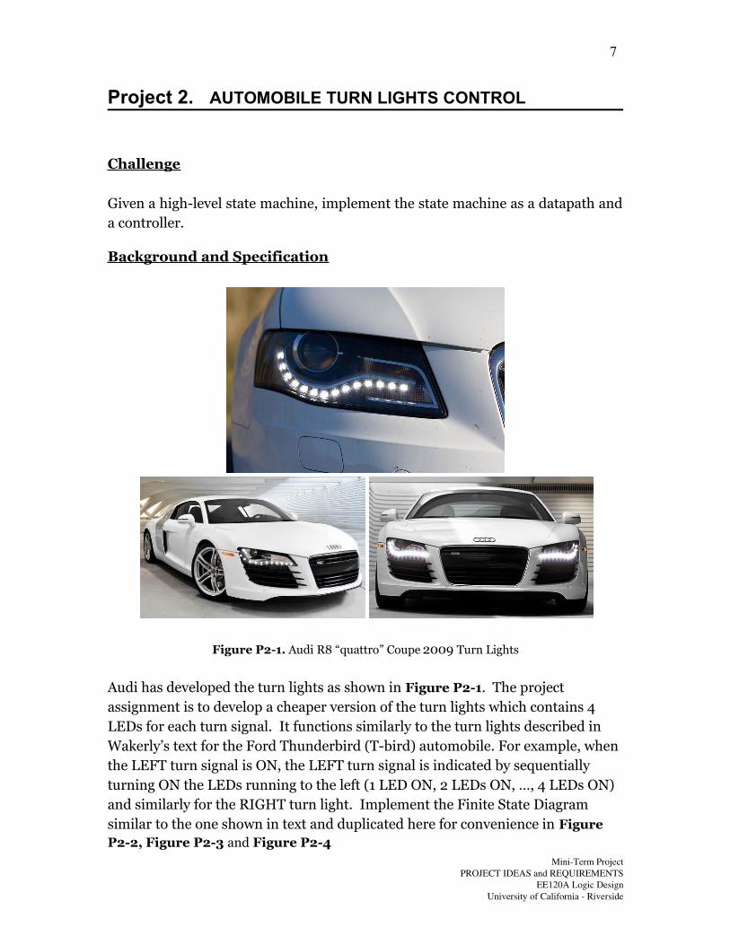
Figure P2-1. Audi R8 “quattro” Coupe 2009 Turn Lights
Audi has developed the turn lights as shown in Figure P2-1. The project assignment is to develop a cheaper version of the turn lights which contains 4 LEDs for each turn signal. It functions similarly to the turn lights described in Wakerly’s text for the Ford Thunderbird (T-bird) automobile. For example, when the LEFT turn signal is ON, the LEFT turn signal is indicated by sequentially turning ON the LEDs running to the left (1 LED ON, 2 LEDs ON, …, 4 LEDs ON) and similarly for the RIGHT turn light. Implement the Finite State Diagram similar to the one shown in text and duplicated here for convenience in Figure P2-2, Figure P2-3 and Figure P2-4
MiniTerm ProjectPROJECT IDEAS and REQUIREMENTS
EE120A Logic DesignUniversity of California Riverside
7

Figure P2-2. T-bird light naming
Figure P2-3. T-bird light turn sequence
MiniTerm ProjectPROJECT IDEAS and REQUIREMENTS
EE120A Logic DesignUniversity of California Riverside
8
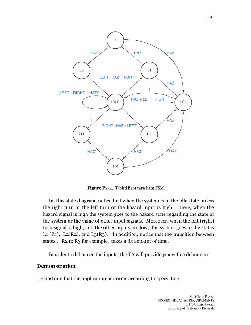
Figure P2-4. T-bird light turn light FSM
In this state diagram, notice that when the system is in the idle state unlessthe right turn or the left turn or the hazard input is high. Here, when thehazard signal is high the system goes to the hazard state regarding the state ofthe system or the value of other input signals. Moreover, when the left (right)turn signal is high, and the other inputs are low, the system goes to the statesL1 (R1), L2(R2), and L3(R3). In addition, notice that the transition betweenstates , R2 to R3 for example, takes a fix amount of time.
In order to debounce the inputs, the TA will provide you with a debouncer.
Demonstration
Demostrate that the application performs according to specs. Use
MiniTerm ProjectPROJECT IDEAS and REQUIREMENTS
EE120A Logic DesignUniversity of California Riverside
9

LEDs on the Digilent’s Basys board to emulate traffic lights (4 LEDs for
LEFT, 4 LEDs for RIGHT, etc), and
Switches (or Buttons) to emulate turn signal switching
MiniTerm ProjectPROJECT IDEAS and REQUIREMENTS
EE120A Logic DesignUniversity of California Riverside
10
Project 3. ARITHMETIC LOGIC UNIT (ALU)
Challenge
Implement the ALU datapath.
Background and Specification
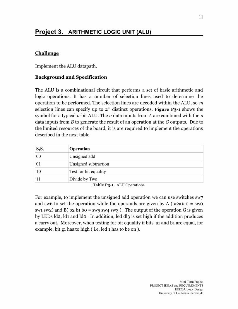
The ALU is a combinational circuit that performs a set of basic arithmetic andlogic operations. It has a number of selection lines used to determine theoperation to be performed. The selection lines are decoded within the ALU, so mselection lines can specify up to 2m distinct operations. Figure P3-1 shows thesymbol for a typical n-bit ALU. The n data inputs from A are combined with the ndata inputs from B to generate the result of an operation at the G outputs. Due tothe limited resources of the board, it is are required to implement the operationsdescribed in the next table.
S1S0 Operation
00 Unsigned add
01 Unsigned subtraction
10 Test for bit equality
11 Divide by Two Table P3-1. ALU Operations
For example, to implement the unsigned add operation we can use switches sw7and sw6 to set the operation while the operands are given by A ( a2a1a0 = sw0sw1 sw2) and B( b2 b1 b0 = sw5 sw4 sw3 ). The output of the operation G is givenby LEDs ld2, ld1 and ld0. In addition, led dl3 is set high if the addition producesa carry out. Moreover, when testing for bit equality if bits a1 and b1 are equal, forexample, bit g1 has to high ( i.e. led 1 has to be on ).
MiniTerm ProjectPROJECT IDEAS and REQUIREMENTS
EE120A Logic DesignUniversity of California Riverside
11

Figure P3-1. ALU schematic symbol
Demonstration
Design an ALU performing operations required and demonstrate theperformance on the Digilent’s Basys board. Use the buttons and switches arerequired for inputs, and the LEDs as data outputs.
MiniTerm ProjectPROJECT IDEAS and REQUIREMENTS
EE120A Logic DesignUniversity of California Riverside
12
Related Documents