Mini-Phantom & In-Air Comparison Jig REF 72194, 72195 & 72193 DOC #80396-00 R STANDARD IMAGING INC. 7601 Murphy Drive Middleton, WI 53562 TEL 800.261.4446 TEL 608.831.0025 FAX 608.831.2202 Apr / 2003 ©2003 Standard Imaging Inc. www.standardimaging.com

Welcome message from author
This document is posted to help you gain knowledge. Please leave a comment to let me know what you think about it! Share it to your friends and learn new things together.
Transcript

Mini-Phantom &In-Air Comparison JigREF 72194, 72195 & 72193
DOC #80396-00
R
STANDARD IMAGING INC.7601 Murphy DriveMiddleton, WI 53562
TEL 800.261.4446TEL 608.831.0025FAX 608.831.2202
Apr / 2003 ©2003 Standard Imaging Inc. www.standardimaging.com
cwalters
Distributed by SeeDOS Ltd Please contact Colin Walters at [email protected]
General Precautions
Warnings and Cautions alert usersto dangerous conditions that canoccur if instructions in the manualare not obeyed. Warnings areconditions that can cause injury tothe operator, while Cautions cancause damage to the equipment.
2
!
!
!
WARNING:Follow manufacturer’srecommended safety proce-dures for radioactive sources.
CAUTION:Do not drop or mishandleunit.
CAUTION:Proper use of this devicedepends on careful reading ofall instructions and labels.

Table of Contents
3
General PrecautionsOverview of the Mini-PhantomUsing the Mini-PhantomIn-Air Comparison Jig OverviewBibliographyMaintenanceServiceParts and Accessories ListCustomer ResponsibilityFeatures and SpecificationsWarranty
R7601 MURPHY DRIVEMIDDLETON, WI 53562
235678888912
Overview of the Mini-Phantom
PAGE
All of the common dosimetry systems, TAR1,TMR2, TPR3 require that dose to a point in aphantom be separated into a primarycomponent arising from the photon andelectron fluence from the head of theaccelerator and a secondary componentarising from scatter in the phantom. Morecurrent dose calculation algorithms4-7 modelenergy fluence from different parts of theaccelerator head and also require input datathat describes the change in acceleratoroutput with collimator settings.
The basic method for separating thesecomponents of dose involves the measure-ment of total scatter correction factor in a fullphantom, Sh,p, and the head scatter correc-tion factor, Sh
2,8. The phantom scattercorrection factor can be calculated as follows:Sp = Sh,p/Sh.
The measurement of Sh is usually done withan ion chamber covered with a cylindricalbuild-up cap, which is irradiated perpendicu-lar to its cylindrical axis (see Figure 1). Thebuild-up cap serves two functions: it providesenough charged particles to give a largesignal (provides build-up) and it reduces thenumber of contaminating electrons that reach
the detector.Commonly, thewall thickness ofthe build-up cap isdmax, the depth ofmaximum dose ina water phantom.This type of build-up cap has thedisadvantage ofbecoming verylarge for highenergy x-rays,which have largedmax.
The large buildup cap prevents themeasurement of Sh for small field sizessince the build-up cap must fully irradiatedat all field sizes8. It is also known thatcontamination electrons can penetrate todepths beyond dmax
9-13 and this can effectthe measurement of Sh.
Another type of build-up cap, the columnarmini-phantom, is in the shape of asquare14,15 or cylindrical13,16-19 column,which is irradiated parallel to its long axis(see Figure 2). Generally the ion chamber
Figure 1
cwalters
SeeDOS Ltd
4
Overview of the Mini-Phantom Continued
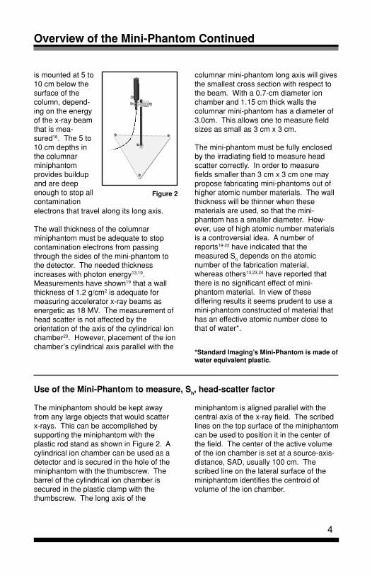
is mounted at 5 to10 cm below thesurface of thecolumn, depend-ing on the energyof the x-ray beamthat is mea-sured16. The 5 to10 cm depths inthe columnarminiphantomprovides buildupand are deepenough to stop allcontamination
columnar mini-phantom long axis will givesthe smallest cross section with respect tothe beam. With a 0.7-cm diameter ionchamber and 1.15 cm thick walls thecolumnar mini-phantom has a diameter of3.0cm. This allows one to measure fieldsizes as small as 3 cm x 3 cm.
The mini-phantom must be fully enclosedby the irradiating field to measure headscatter correctly. In order to measurefields smaller than 3 cm x 3 cm one maypropose fabricating mini-phantoms out ofhigher atomic number materials. The wallthickness will be thinner when thesematerials are used, so that the mini-phantom has a smaller diameter. How-ever, use of high atomic number materialsis a controversial idea. A number ofreports19-22 have indicated that themeasured Sh depends on the atomicnumber of the fabrication material,whereas others13,23,24 have reported thatthere is no significant effect of mini-phantom material. In view of thesediffering results it seems prudent to use amini-phantom constructed of material thathas an effective atomic number close tothat of water*.
Figure 2
electrons that travel along its long axis.
The wall thickness of the columnarminiphantom must be adequate to stopcontamination electrons from passingthrough the sides of the mini-phantom tothe detector. The needed thicknessincreases with photon energy13,19.Measurements have shown19 that a wallthickness of 1.2 g/cm2 is adequate formeasuring accelerator x-ray beams asenergetic as 18 MV. The measurement ofhead scatter is not affected by theorientation of the axis of the cylindrical ionchamber20. However, placement of the ionchamber’s cylindrical axis parallel with the
*Standard Imaging’s Mini-Phantom is made ofwater equivalent plastic.
The miniphantom should be kept awayfrom any large objects that would scatterx-rays. This can be accomplished bysupporting the miniphantom with theplastic rod stand as shown in Figure 2. Acylindrical ion chamber can be used as adetector and is secured in the hole of theminiphantom with the thumbscrew. Thebarrel of the cylindrical ion chamber issecured in the plastic clamp with thethumbscrew. The long axis of the
Use of the Mini-Phantom to measure, Sh, head-scatter factor
miniphantom is aligned parallel with thecentral axis of the x-ray field. The scribedlines on the top surface of the miniphantomcan be used to position it in the center ofthe field. The center of the active volumeof the ion chamber is set at a source-axis-distance, SAD, usually 100 cm. Thescribed line on the lateral surface of theminiphantom identifies the centroid ofvolume of the ion chamber.

5
Using the Mini-Phantom - Calculations
Measurements:
The cumulative charge is measured for100 MU irradiation’s for various field sizes.
Sh(w) = ML / M10 , where ML is the mea-sured signal for a square field of sidelength L cm, and M10 is the measuredsignal for a square field of a side length of10 cm. Figure 3 shows Sh(w), , for a6 MV beam of a Siemens MD2 linearaccelerator.
Care must be taken so that the crosssection of the miniphantom is fullyirradiated by the smallest field measured.For the setup geometry described abovethe center of the ion chamber is at SAD =100 cm but the top of the miniphantom is adistance of 90 cm from the source. Sincethe miniphantom has a diameter of 3 cmthe smallest field that can be measured is3 cm x 3 cm at 90 cm from the source.This field side length is 3 x 100/90 = 3.3cm at SAD 100 cm. So, the smallest fieldsize that can be measured is 3.3 cm x 3.3cm with the 3.3 cm collimator size beingdefined at SAD = 100 cm.
Measurements of Sh,p(w), , for a 6 MVbeam of a Siemens MD2 linear accelerator
are shown in Figure 3. These data weremeasured in a Wellhofer water scanning-tank with the detector at 10 cm depth andSAD = 100 cm.
Sp(w) = Sh,p(w)/Sh(w), , was calculatedand is also plotted in Figure 3.
These data are measured at 10-cm depthand do not hold for any other depth.These data a typical of what one maymeasure and every clinic should measuredata for its own equipment.
0.80
0.85
0.90
0.95
1.00
1.05
1.10
1.15
1.20
0 5 10 15 20 25 30 35 40 45
Side length of square field at isocenter, cm
Sh(w)
Sh,p(w)
Sp(w)
Figure 3
Sh(w)
Sh,p
(w)S
p(w)

In-Air Comparison Jig Overview
The In air Comparison Jig shown in Figure 4is designed to hold one or two chambers fora comparison of calibration factors or for aquality assurance check of radiation output,using the appropriate build-up caps. Figure4 shows the setup for two chambers. Thequality assurance measurement would bedone with only one of the two chambersmounted on the in-air comparison jig.
Using the In-Air Comparison Jig
A. Simultaneous Comparison of IonizationChambers
The In air Comparison jig is used for simul-taneous comparison of ionization chambersresponse by the following steps:
1. Set the radiation source, Co-60 or accel-erator for a 10 cm x 10 cm field.
2. Set the center of this field to the center ofthe two ionization chambers by aligning thecross hairs with the center of the marker onthe jig rod.
3. Mount the ionization chambers as shownin Figure 4 with the centers of the longitudi-nal axis of the thimble or ionization cavitiesaligned. The centers of the active length ofthe cylindrical axis must be at the same SSD.
4. Add the appropriate buildup cap for theenergy to be tested to each chamber.
5. Make sure the chambers are connectedto the appropriate electrometers using theappropriate scales and are at the tempera-ture of the radiation vault.
6. Take 3 or 4 readings for each chamber.
7. The average of the ratio of the responsesof the chambers for each setup should beequal to the calibration ratio of the two cham-bers, assuming the radiation field is flat orthe same on each side of the center line.The following equation can be used.
Figure 4
F = (FR/XR) * X
Where:F = CalculatedCalibration FactorFR = ReferencedCalibration FactorX = UncalibratedChamber CollectedChargeXR = ReferencedChamber CollectedCharge
B. Quality Assurance of In air output of ra-diation
1. Mount a single ionization chamber, in thejig (See Figure 4), so the center of the activevolume of the chamber is in the center of thefield and at the appropriate SSD or SAD fordmax.
2. Measure the temperature and pressure.
3. Follow steps A4 through A6.
4. Correcting for temperature and pressureand using other correction factors as neces-sary, determine the output in air.
5. Use as a Quality Assurance means of uni-formity of output.
6

1H.E. Johns and J.R. Cunningham, ThePhysiology of Radiology, 4th ed. (Charles C.Thomas, Springfield, 1983), pp. 336-381.
2J.G. Holt, J.S. Laughlin, and J.P. Moroney, “Theextension of the concept of tissue-air ratios(TAR) to high energy x-ray beams,” Radiology96, 437-446 (1970).
3C.J. Karzmark, A. deubert, and R. Loevinger,“Tissue-phantom ratios – An aid to treatmentplanning,” Brit. J. Radiol. 38, 158-159 (1965).
4T.R. Mackie, J.W. Scrimger, and J.J. Battista, “Aconvolution method of calculating dose for 15-MV x-rays,” Med. Phys. 12, 188-196 (1985).
5A. Boyer and E. Mok, “A photon dosedistribution model employing convolutioncalculations,” Med. Phys. 12, 169-177 (1985).
6R. Mohan, C. Chui, and L. Lidofsky, “Differentialpencil beam dose computation model forphotons,” Med. Phys. 13, 64-73 (1986).
7 A. Ahnesjö, P. Andreo, and A. Brahme,“Calculation and application of point spreadfunction for treatment planning with high energyphoton beams,” Acta. Oncol. 26, 49-56 (1987).
8F.M. Khan, W. Sewchand, J. Lee, and J.F.Williamson, “Revision of tissue-maximum ratioand scatter-maximum ratio concepts for cobalt60 and higher energy x-ray beams,” Med. Phys.7, 230-237 (1980).
9T.N. Padikal and J.A. Deye, “Electroncontamination of a high-energy x-ray beam,”Phys. Med. Biol. 23, 1086-1092 (1978).
10P.J.Biggs and C.C. Ling, “Electrons as thecause of the observed dmax shift with field size inhigh energy photon beams,” Med. Phys. 6, 291-295 (1979).
11B.R. Thomadsen, S. Kubsad, B.R. Paliwal, S.Shahabi, and T.R. Mackie, “On the cause of thevariation in tissue-maximum ratio values withsource-to-detector distance,” Med. Phys. 20,723-727 (1993).
12D.M. Frye, B.R. Paliwal, B.R. Thomadsen, andP. Jursinic, “Intercomparison of normalized head-scatter factor measurement techniques,” Med.Phys. 22, 249-253 (1995).13X.A. Li, M. Soubra, and L.H. Gerig,“Lateralelectron equilibrium and electron contaminationin measurements of head-scatter factors usingminiphantoms and brass caps,” Med. Phys. 22,
Bibliography
1167-1170 (1995).
14G. Krithivas and S.N. Rao, “Dosimetry of 24-MVx-rays from a linear accelerator,” Med. Phys. 14,274-281 (1987).
15M. Tatcher and B.E. Bjärngard, “Head-scatterfactors in rectangular photon fields,” Med. Phys.20, 205-206 (1993).
16J.J.M. van Gasteren, S. Heukelom, H.J. vanKleffens, R. van der Laarse, J.L.M. Venselaar,and C.F. Westermann, “The determination ofphantom and collimator scatter components ofthe output of megavoltage photon beams:measurements of the collimator scatter part witha beam-coaxial narrow cylindrical phantom,”Radiotherapy and Oncol. 20, 250-257 (1991).
17A.L. McKenzie and P.H. Stevens, “Twenty-fiveyears of MTRP - a theoretical and experimentalanalysis,” Phys. Med. Biol. 40, 17-29 (1995).
18A. Dutreix, B.E. Bjärngard, A. Bridier, B.Mijnheer, J.E. Shaw, and H. Svensson, MonitorUnit Calculation for High Energy Photon Beams,(ESTRO and Garant Publishers, N.V., TheNetherlands, 1997).
19P.A. Jursinic and B.R. Thomadsen, “Measure-ments of head-scatter factors with cylindricalbuild-up caps and columnar miniphantoms,”Med. Phys. 26, 512-517 (1999).
20L. Weber, P. Nilsson, and A. Ahnesjö, “Build-upcap materials for measurements of photon head-scatter factors,” Phys. Med. Biol. 42, 1875-1886(1997).
21J. Spicka, D. Herron, and C. Orton,“Separationg output factor into collimator factorand phantom scatter factor for megavoltagephoton calculations,” Med. Dos. 13, 23-24(1984).
22S. Heukelom, J.H. Lanson, and B.J. Mijnheer,“Differences in wedge factor determination in airusing a PMMA mini-phantom or a brass build-upcap,” Med. Phys. 24, 1986-1991 (1994).
23T.C. Zhu and B.E. Bjärngard, “The head-scatterfactor for small field sizes,” Med. Phys. 21, 65-68(1994).
24A.R., Hounsell and J.M. Wilkinson, “Headscatter modelling for irregular field shaping andbeam intensity modulation,” Phys. Med. Biol. 42,1737-1749 (1997).
7

8
Federal law in the U.S.A. andCanada restricts the sale, distributionor use of this device to, by or on theorder of a licensed medical practitio-ner. The use of this device should berestricted to the supervision of aqualified medical physicist. Handlingof radioactive sources is potentiallyhazardous and should be performedby qualified personnel. Should repairor replacement of this device becomenecessary after the warranty period,the customer should seek advicefrom Standard Imaging Inc. prior to
! such repair or replacement. If this deviceis in need of repair, it should not be useduntil all repairs have been made and theproduct is functioning properly and readyfor use. The owner of this device has soleresponsibility for any malfunction resultingfrom abuse, improper use or maintenance,or repair by anyone other than StandardImaging Inc. The information in this manualis subject to change without notice. Nopart of this manual may be copied orreproduced in any form, or by any means,without prior written consent of StandardImaging Inc.
REF
80396721937219472195
Description
Instruction ManualIn-Air Comparison Jig / Mini Phantom StandMini-Phantom for Exradin A12Mini-Phantom for Exradin A12 w/stand (REF 72194 + REF 72193)
Maintenance Service
Exterior cleaning of the device can bedone with a soft brush and a cloth. Gentlybrush all surfaces to remove dirt and dust.Remove any remaining dirt with a clothslightly dampened with a solution of milddetergent and water or a liquid disinfectingagent.
If assistance is desired in the properdisposal of this product (includingaccessories and components), after itsuseful life, please return to StandardImaging.
There are no serviceable parts on the Mini-Phantom or In-Air Comparison Jig.
Parts and Accessories List
Customer Responsibility
WARNING:

9
Features and Specifications
DimensionsDiameterLength
Centroid of chamber volume
Material
Fiducial marks denote chamber centroidof volume
3 cm (1.18 in)20 cm (7.87 in)
10 cm from end of phantom
Water equivalent plastic
Mini-Phantom
In-Air Comparison Jig
Chamber clamp size accomodations
DimensionsCenter Rod HeightChamber Holder
HeightLengthWidth
Base
MaterialsCenter RodChamber HolderBaseScrews
Fiducial marks on clamp assist in laseralignment
From 1/4” to 1/2” diameter for In-AirComparisons
40 cm (15.75 in)
2.22 cm (1 in)2.22 cm (1 in)6.35 cm (2.50 in)33.02 cm (13 in) equilateral triangle
Carbon fiberPolycarbonateAcrylicNylon

10
Notes

11
Notes

Warranty
12
Standard Imaging, Inc. sells this product under the warranty herein set forth. The warranty isextended only to the buyer purchasing the product directly from Standard Imaging, Inc. or asa new product from an authorized dealer or distributor of Standard Imaging, Inc.
For a period of twenty-four (24) months for well chambers and twelve (12) months for all otherStandard Imaging, Inc. products from the date of original delivery to the purchaser or a dis-tributor, this product is warranted against functional defects in materials and workmanship,provided it is properly operated under conditions of normal use, and that repairs and replace-ments are made in accordance herewith. The foregoing warranty shall not apply if the prod-uct has been disassembled, altered or repaired other than by Standard Imaging, Inc. or if theproduct has been subject to abuse, misuse, negligence or accident.
Standard Imaging’s sole and exclusive obligation and the purchaser’s sole and exclusiveremedy under the above warranties are limited to repairing or replacing free of charge, atStandard Imaging’s option, a product: (1) which contains a defect covered by the above war-ranties; (2) which are reported to Standard Imaging, Inc. not later than seven (7) days afterthe expiration date of the 12 or 24 month warranty period; (3) which are returned to StandardImaging promptly after discovery of the defect; and (4) which are found to be defective uponStandard Imaging’s examination. Transportation charges are the buyer’s responsibility. Thiswarranty extends to every part of the product except fuses, batteries, or glass breakage.Standard Imaging, Inc. shall not be otherwise liable for any damages, including but not limitedto, incidental damages, consequential damages, or special damages. Repaired or replacedproducts are warranted for the balance of the original warranty period, or at least 90 days.
This warranty is in lieu of all other warranties, express or implied, whether statutory or other-wise, including any implied warranty of fitness for a particular purpose. In no event shallStandard Imaging, Inc. be liable for any incidental or consequential damages resulting fromthe use, misuse or abuse of the product or caused by any defect, failure or malfunction of theproduct, whether a claim of such damages is based upon the warranty, contract, negligence,or otherwise.
cwalters
Distributed by SeeDOS Ltd Contact:[email protected] Web:www.seedos.com
Related Documents