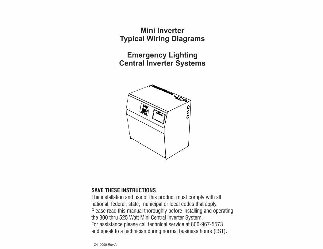
Mini Inverter Typical Wiring Diagrams Emergency Lighting Central Inverter Systems SAVE THESE INSTRUCTIONS The installation and use of this product must comply with all national, federal, state, municipal or local codes that apply. Please read this manual thoroughly before installing and operating the 300 thru 525 Watt Mini Central Inverter System. For assistance please call technical service at 800-967-5573 and speak to a technician during normal business hours (EST). Z410090 Rev A

Welcome message from author
This document is posted to help you gain knowledge. Please leave a comment to let me know what you think about it! Share it to your friends and learn new things together.
Transcript
Mini InverterTypical Wiring Diagrams
Emergency LightingCentral Inverter Systems
SAVE THESE INSTRUCTIONSThe installation and use of this product must comply with all national, federal, state, municipal or local codes that apply. Please read this manual thoroughly before installing and operating the 300 thru 525 Watt Mini Central Inverter System. For assistance please call technical service at 800-967-5573and speak to a technician during normal business hours (EST).
Z410090 Rev A
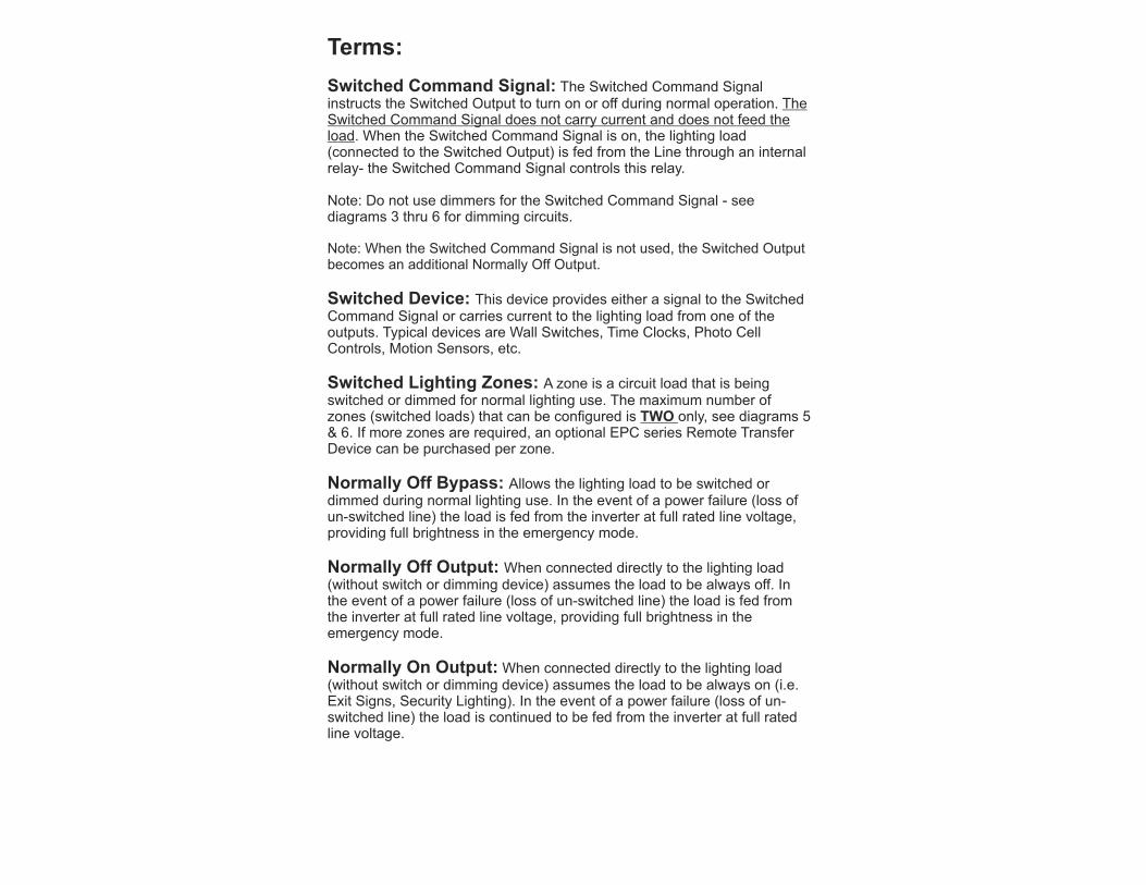
Terms:
Switched Command Signal: The Switched Command Signal instructs the Switched Output to turn on or off during normal operation. The Switched Command Signal does not carry current and does not feed the load. When the Switched Command Signal is on, the lighting load (connected to the Switched Output) is fed from the Line through an internal relay- the Switched Command Signal controls this relay.
Note: Do not use dimmers for the Switched Command Signal - see diagrams 3 thru 6 for dimming circuits.
Note: When the Switched Command Signal is not used, the Switched Output becomes an additional Normally Off Output.
Switched Device: This device provides either a signal to the Switched Command Signal or carries current to the lighting load from one of the outputs. Typical devices are Wall Switches, Time Clocks, Photo Cell Controls, Motion Sensors, etc.
Switched Lighting Zones: A zone is a circuit load that is being switched or dimmed for normal lighting use. The maximum number of zones (switched loads) that can be configured is TWO only, see diagrams 5 & 6. If more zones are required, an optional EPC series Remote Transfer Device can be purchased per zone.
Normally Off Bypass: Allows the lighting load to be switched or dimmed during normal lighting use. In the event of a power failure (loss of un-switched line) the load is fed from the inverter at full rated line voltage, providing full brightness in the emergency mode.
Normally Off Output: When connected directly to the lighting load (without switch or dimming device) assumes the load to be always off. In the event of a power failure (loss of un-switched line) the load is fed from the inverter at full rated line voltage, providing full brightness in the emergency mode.
Normally On Output: When connected directly to the lighting load (without switch or dimming device) assumes the load to be always on (i.e. Exit Signs, Security Lighting). In the event of a power failure (loss of un-switched line) the load is continued to be fed from the inverter at full rated line voltage.
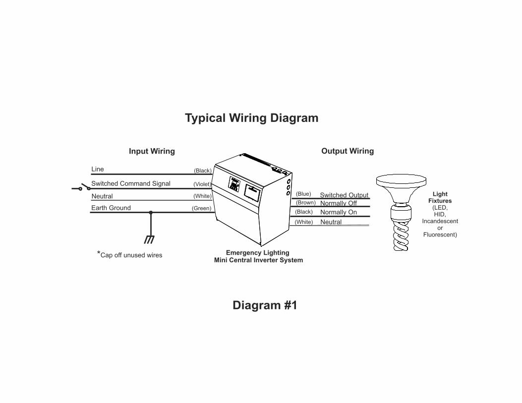
Typical Wiring Diagram
Emergency Lighting Mini Central Inverter System
(Black)
(White) (Blue)
(White)
(Brown)
(Black)
Switched Command Signal (Violet)
Earth Ground (Green)
Input Wiring
Line
Switched Output
Neutral
Normally On
Normally Off
Output Wiring
Neutral LightFixtures
(LED,HID,
Incandescentor
Fluorescent)
*Cap off unused wires
Diagram #1
Switched Output
Neutral
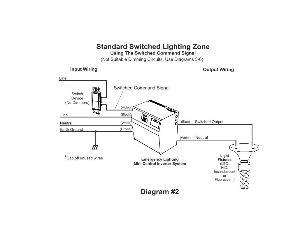
Standard Switched Lighting ZoneUsing The Switched Command Signal
Emergency LightingMini Central Inverter System
(Black)
(Blue)
(White)
(Violet)
Switched Command Signal
(Not Suitable Dimming Circuits. Use Diagrams 3-6)
(White)
Earth Ground (Green)
Input Wiring
Neutral
Line
Line
Output Wiring
SwitchDevice
(No Dimmers)
LightFixtures
(LED,HID,
Incandescentor
Fluorescent)
*Cap off unused wires
Diagram #2

Normally On
Normally Off
SwitchDevice
orDimmer
(Brown)
(White)
(Black)
Neutral
Dimming or Switched Lighting ZoneUsing Normally Off as a Bypass
Emergency LightingMini Central Inverter System
(Black)
(White)
(Green)
Input Wiring Output Wiring
Earth Ground
Neutral
Line
LightFixtures
(LED,HID,
Incandescentor
Fluorescent)
*Cap off unused wires
Diagram #3
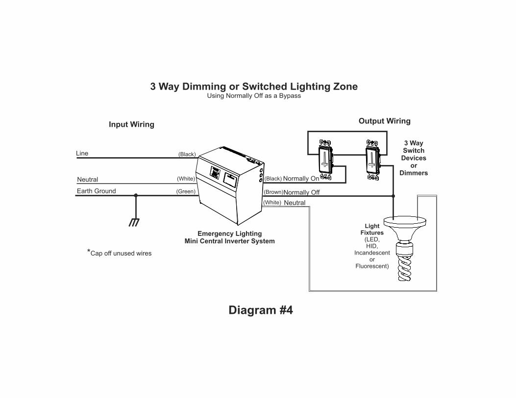
Normally On
Normally Off
3 WaySwitch
Devicesor
Dimmers
(Brown)
(White)
(Black)
Neutral
3 Way Dimming or Switched Lighting ZoneUsing Normally Off as a Bypass
Emergency LightingMini Central Inverter System
(Black)
(White)
Earth Ground (Green)
Input Wiring
Line
Neutral
Output Wiring
LightFixtures
(LED,HID,
Incandescentor
Fluorescent)
*Cap off unused wires
Diagram #4
Normally On
Normally Off
Switch or DimmerDevice
#2
(Brown)
(Blue)
(White)
(Black)
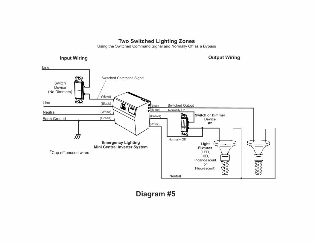
Switched Output
Neutral
Two Switched Lighting ZonesUsing the Switched Command Signal and Normally Off as a Bypass
Emergency LightingMini Central Inverter System
Switched Command Signal
(Black)
(Violet)
(White)
Earth Ground (Green)
Input Wiring
Neutral
Line
Line
SwitchDevice
(No Dimmers)
Output Wiring
LightFixtures
(LED,HID,
Incandescentor
Fluorescent)
*Cap off unused wires
Diagram #5
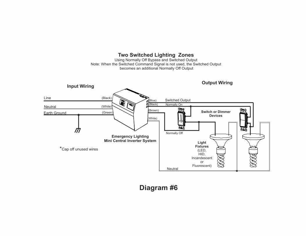
Normally On
Normally Off
Switch or DimmerDevices
(Brown)
(Blue)
(White)
(Black)
Switched Output
LightFixtures
(LED,HID,
Incandescentor
Fluorescent)Neutral
Two Switched Lighting ZonesUsing Normally Off Bypass and Switched Output
Note: When the Switched Command Signal is not used, the Switched Output becomes an additional Normally Off Output
Emergency LightingMini Central Inverter System
(Black)
(White)
Earth Ground (Green)
Input Wiring
Neutral
Line
Output Wiring
*Cap off unused wires
Diagram #6
Related Documents