ESMAP TECHNICAL PAPER 007 Mini-Grid Design Manual 21364 4' Energy Sector Management FILE C11OPY Assistance Programme September 2000 Papers in the ESMAP Technical Series are discussion documents, not final project reports. They are subject to the same copyrights as other ESMAP publications.

Welcome message from author
This document is posted to help you gain knowledge. Please leave a comment to let me know what you think about it! Share it to your friends and learn new things together.
Transcript

ESMAP TECHNICAL PAPER007
Mini-Grid Design Manual
21364
4'
Energy
Sector
Management FILE C11OPYAssistance
Programme September 2000
Papers in the ESMAP Technical Series are discussiondocuments, not final project reports. They are subject to the
same copyrights as other ESMAP publications.

JOINT UNDP I WORLD BANKENERGY SECTOR MANAGEMENT ASSISTANCE PROGRAMME (ESMAP)
PURPOSE
The Joint UNDP/World Bank Energy Sector Management Assistance Programme(ESMAP) is a special global technical assistance program run as part of the World Bank'sEnergy, Mining and Telecommunications Department. ESMAP provides advice togovernments on sustainable energy development. Established with the support of UNDPand bilateral official donors in 1983, it focuses on the role of energy in the developmentprocess with the objective of contributing to poverty alleviation, improving living conditionsand preserving the environment in developing countries and transition economies.ESMAP centers its interventions on three priority areas: sector reform and restructuring;access to modern energy for the poorest; and promotion of sustainable energy practices.
GOVERNANCE AND OPERATIONS
ESMAP is governed by a Consultative Group (ESMAP CG) composed of representativesof the UNDP and World Bank, other donors, and development experts from regionsbenefiting from ESMAP's assistance. The ESMAP CG is chaired by a World Bank VicePresident, and advised by a Technical Advisory Group (TAG) of four independent energyexperts that reviews the Programme's strategic agenda, its work plan, and itsachievements. ESMAP relies on a cadre of engineers, energy planners, and economistsfrom the World Bank to conduct its activities under the guidance of the Manager ofESMAP, responsible for administering the Programme.
FUNDING
ESMAP is a cooperative effort supported over the years by the World Bank, the UNDPand other United Nations agencies, the European Union, the Organization of AmericanStates (OAS), the Latin American Energy Organization (OLADE), and public and privatedonors from countries including Australia, Belgium, Canada, Denmark, Germany, Finland,France, Iceland, Ireland, Italy, Japan, the Netherlands, New Zealand, Norway, Portugal,Sweden, Switzerland, the United Kingdom, and the United States of America.
FURTHER INFORMATION
An up-to-date listing of completed ESMAP projects is appended to this report. For furtherinformat on, a copy of the ESMAP Annual Report, or copies of project reports, contact:
ESMAPc/o Energy, Mining and Telecommunications Department
The World Bank1818 H Street, NW
Washington, DC 20433U.S.A.
Mini-GridDesign Manual
April 2000
Joint UNDP/World Bank Energy Sector Management Assistance Program(ESMAP)

Copyright C 1999The Intemational Bank for Reconstructionand Development/THE WORLD BANK1818 H Street, N.W.Washington, D.C. 20433, U.S.A.
All rights reservedManufactured in the United States of AmericaFirst printing September 2000
ESMAP Reports are published to communicate the results of theESMAP's work to the development community with the least possibledelay. The typescript of the paper therefore has not been prepared inaccordance with the procedures appropriate to formal documents.Some sources cited in this paper may be informal documents that arenot readily available.
The findings, interpretations, and conclusions expressed in thispaper are entirely those of the author(s) and should not be attributed inany manner to the World Bank, or its affiliated organizations, or tomembers of its Board of Executive Directors or the countries theyrepresent. The World Bank does not guarantee the accuracy of the dataincluded in this publication and accepts no responsibility whatsoeverfor any consequence of their use. The Boundaries, colors,denominations, other information shown on any map in this volume donot imply on the part of the World Bank Group any judgement on thelegal status of any territory or the endorsement or acceptance of suchboundaries.
The material in this publication is copyrighted. Requests forpermission to reproduce portions of it should be sent to the ESMAPManager at the address shown in the copyright notice above. ESMAPencourages dissemination of its work and will normally givepermission promptly and, when the reproduction is for noncommercialpurposes, without asking a fee.

I.%rr
r^; . :_~~~~~~~~~~~~~~~~~~~~~~~~~~~~~~~~~~~~~~~~~~~~~~~~~~.i
- . d ' - . , t )~~
. H- ,8. ' . -' e's,. ..s, ':7
- > ; f ' . . ev ~~~~~~~~~~~~~~~~~~~~~~~~~~ , ~~~~~i
a .Mini-Grid ~>
Deig Manual t* -W


Table of contents
I. Introduction ...................................... 1
II. Setting the context for low-cost mini-grids ............... ....................... 5Ivory Coast ............................................ 6Laos ............................................ 8Irian Jaya ............................................ 9Dominican Republic ............................................ 9Conclusion ............................................ 10
III. Preconditions and action plan ...................................... 12Willingness and ability to pay ............................................ 12Identification of a responsible individual/organization ............................................ 15Adequacy of electricity supply ............................................ 16
Grid extension ............................................ 16Diesel/gasoline genset ............................................ 17Hydropower plant ............................................ 18Wind turbine ............................................ 21Solar PV station ............................................ 22
Plan of action ............................................ 23
IV. Electricity uses and demand assessment .............. ........................ 26Types of uses ............................................ 26
Lighting ............................................ 26Entertainment ............................................ 36Motor-based applications ............................................ 37Heat-generating appliances ............................................ 43
Demand assessment ............................................ 44Demand-side management ............................................ 47
V. Mapping and system layout ...................................... 49Mapping ............................................ 49System layout ............................................ 50
Powerhouse location ............................................ 50Placing the lines ............................................ 51Locating poles ............................................ 53
VI. Line configuration ...................................... 54Options for line configuration ............................................ 54
Single-phase supply ............................................ 54Three-phase supply ............................................ 59
System grounding ............................................ 61
VII. Conductor ...................................... 64Types of conductor ............................................ 64Overhead vs. Underground ............................................ 69Conductor sizing ............................................ 70
i

Rough estimate of voltage drop ..................................... 72A more accurate estimate ..................................... 72Spreadsheet estimate ..................................... 73Effect of conductor size on power loss ..................................... 75Generalized equations ..................................... 76
Stringing and sagging the conductor ..................................... 77Sag ..................................... 80Handling and inspecting the conductor ..................................... 81Preparation for stringing ..................................... 81Pulling the conductor ..................................... 81Sagging the conductor ..................................... 83
V1II. Poles .................................. 86Pole options ..................................... 86
Wood ..................................... 87Concrete ..................................... 94Steel ..................................... 96
Sizing ..................................... : 97Length ..................................... 97Girth ..................................... 99
Setting poles ..................................... 103
IX. Poletop hardware and connectors ................................. 105Joining conductors: Connectors ..................................... 105
Twisted connections ..................................... 106Split-bolt connectors ..................................... 107Parallel-groove connectors ..................................... 107Compression connectors ..................................... 108
Securing the conductors: Deadend hardware ..................................... 108Parallel-groove clamps ..................................... 108Preformed deadends ..................................... 109Automatic deadends ..................................... 109U-bolt-type clamps ..................................... 109Wedge clamps ..................................... 110
Supporting the conductor ..................................... 110Racks ...................................... 11.1Upset bolts ...................................... 111Support clevises ..................................... 112Swinging clevises ..................................... 112Wireholders ..................................... 113Other approaches ..................................... 113
Lengthening conductor: splices ..................................... 114Wrapped/twisted splices. ..................................... 115Compression splice ..................................... 115Preformed splice ..................................... 115Automatic splice ..................................... 116Knotting ..................................... 116
ii

X. Guys and anchors ......................................... 117Strength of cable ............................................... 117
Guy on a deadend pole ............................................... 117Guy at a deviation ............................................... 118
Securing the guy to a pole ............................................... 118Types of anchor ............................................... 119Sizing an anchor ............................................... 120
XI. Safety and protection ......................................... 122Introduction ............................................... 122Grounding ............................................... 123
Theory ............................................... 123Types of grounding ............................................... 124Ensuring a good ground ............................................... 124
Protection devices ............................................... 126Fuses ............................................... 126Miniature circuit breakers (MCBs) ............................................... 127Residual current devices (RCDs) ............................................... 128
Protecting the system ............................................... 130Protecting against overload currents ............................................... 130Protecting against fault currents ............................................... 131Protecting against corrosion/oxidation ............................................... 132
Protecting people ............................................... 133Nature of the hazard ............................................... 133Origin of body currents ............................................... 134Lightning protection ............................................... 141Consumer and operator education ............................................... 142
Summary ............................................... 142
XII. Service connection and housewiring ......................................... 145Service connection ............................................... 145
Service drop ............................................... 146Service entrance ............................................... 153
Metering ............................................... 154Conventional metering ............................................... 155Alternative "metering": load limiters ............................................... 156
Housewiring ............................................... 163Standardized housewiring packages ............................................... 166
XIII. Operation, maintenance, and consumer services .................................. 172Operator selection and training ............................................... 172Regular operation and maintenance ............................................... 173Consumer education ............................................... 174
Financial obligations ............................................... 174Disconnection policy ............................................... 174Theft of power ............................................... 174Awareness of options for electrical end-uses ............................................... 174Safety ............................................... 175
iii

Consumer agreement ................................................. 175Consumer services ................................................. 177
End-use promotion ................................................. 177Sales outlet for electrical components ................................................. 178Battery charging ................................................. 178
XIV. Tariffs ........................................... 179Introduction ................................................. 179Project costs to be covered ................................................. 179Options for covering project costs ................................................. 180Calculating monthly costs .................................................. 181Basic tariff types ................................................. 184
Energy-based tariff ................................................. 184Power-based tariff ................................................. 187
Designing a tariff schedule ................................................. 189
NXV. Appendices .. ........................................ 192Appendix 1. Case study: Ivory Coast ................................................. 193Appendix 2. Case study: Ban Nam Thung, Laos ................................................. 199Appendix 3. Case study: Youngsu, Irian Jaya ................................................. 205Appendix 4. Case study: El Lim6n, Dominican Republic ........................................... 212Appendix 5. Calculating required pole diameter ................................................. 221Appendix 6. Some basic electrical concepts and equations .......................................... 223
Resistance and reactance ................................................. 223Power and power factor ................................................. 227Voltage drop/power loss along a line ................................................. 228
Appendix 7: Computational examples ................................................. 233(1) Impact of power factor on system cost ................................................. 233(2) Impact of configuration on distribution system cost .......................................... 235(3) Sizing a distribution line for motor starting ................................................. 238(4) Impact of approach to conductor sizing on accuracy ......................................... 239
Appendix 8. Sag tables for multiplex conductor ................................................. 245Appendix 9. Areas for further inquiry ................................................. 250
iv
Acronyms, abbreviations, and definitions
A Ampere, a measure of electrical current
ABC Aerial bundled cable
ACSR Aluminum-conductor, steel-reinforced (a conductor made of aluminum, current-
carrying strands wrapped around a steel core which provides the mechanicalstrength)
ac Altemating current
CCA Copper chromium arsenate, a popular waterbome preservative that fixes itself tothe wood fibers once it has been impregnated into the wood
CFL Compact fluorescent light
coincident load The sum of the loads actually on at any instant of time (see p. 44)
conductor Wire or cable
consumer A customer (either a household or a commercial establishment) receiving electricpower
consumer ground A grounding electrode located on the consumer's premises, which is bonded(connected) to the frame or chassis of all electrical equipment found there. Theconsumer ground is not bonded to the system neutral unless explicitly stated. Seep. 137.
creep The elongation of conductor under tension. As tension is applied to theconductor, it stretches and will continue to stretch until a balance betweentension and the materials strength is reached, usually after several years. Seep. 80.
daN Deca-newton or 10 newtons, a metric measure of force nearly equal to the weightof I kilogram
dc Direct current
DCS Development & Consulting Services, a non-profit research and developmentorganization in Nepal that has been involved for several decades in micro-hydropower and rural electrification efforts
deadend The mechanical termination of a conductor against a support
distribution board A board or box on or in which are included the necessary items (which mightinclude MCBs, fuses, knife and light switches, and outlets) to control andmanage the distribution of electricity within the home. This is located after theconsumer's service entrance. Also referred to as a service panel.
dual phase Three-wire, single-phase configuration obtained by grounding the center tap ofthe generator or transformer supplying the mini-grid. Also known as split phase.
v
GECO Groupe electrogene-&onomie d'energie, an approach to electrification focusingon isolated generation, low-demand uses, and broad-based access to electricity,seep. 193.
genset Generating set, a generator coupled to a prime mover (typically a diesel engine)
guy wire A wire to restrain unbalanced forces on a pole, also knows as a "stay"
HDPE High-density polyethylene (in this case, used as conductor insulation)
hp Horsepower, a measure of power, equivalent to about 750 W
kWh Kilowatt-hour, a measure of electrical energy, obtained by multiplying the powerconsumed (kilowatts) by the length that this power level is consumed (hours)
low voltage Voltage used to distribute electricity around the village or other load center. It isusually based on a nominal consumer voltage of 120 V or 230 V, depending onthe country and is also referred to as a "secondary voltage".
LV Low voltage
MCB Miniature circuit breaker, a magnetic or thermal device that opens a switch whencurrent exceeds a preset amount
medium voltage A more efficient voltage to transmit electricity in bulk from source to load centerand usually not found in a mini-grid serving a single village. This voltage isusually in the range of 1 to 35 kV and is also referred to as a "primary voltage".
micro-hydropower Related to hydropower plants generating up to about 100 kW
mini-grid A distribution network, usually operating only at a low voltage and providingelectricity supply to a community. It is supplied by either its own powergenerator, such as diesel genset or a micro-hydropower plant, or by a connectionto a local distribution transformer connected to an extension of the regional ornational grid.
MOV Metal-oxide varistor, one type of lightning arrester
MV Medium voltage
N Newton, a measure of force equivalent to kg m/s2 and equal in value to theweight of about 0.1 kg. To convert from a force measured in kg to one measuredin newtons, multiply by 9.8.
NESC National Electrical Safety Code (U.S-A.)
NGO Non-governmental organization
Ohm's law R = E I (see Symbols, p. viii)
Pa Pascal, a metric unit of pressure, equal to a N/m2
peak watts The output of a solar module under peak outdoor lighting conditions
pico-hydropower Related to hydropower plants generating no more than a couple of kilowatts
powerpoint A light fixture or power outlet
vi
PV Photovoltaic, generating electricity from light, usually sunlight
PVC Polyvinyl chloride, most popular insulating and sheathing material for low-voltage conductors
RCD Residual-current device (a device to protect people from potentially dangerouselectric shock, also known as a "ground-fault circuit interrupter" or GFCI)
service drop The conductor bringing power to a home from the nearest power pole
SHS Solar home system (a solar-PV-based system to provide basic lighting andentertainment needs to an individual home, with a capacity typically in the rangeof 10 to 100 peak watts)
split phase Three-wire, single-phase configuration obtained by grounding the center tap ofthe generator or transformer supplying the mini-grid.
unit One kilowatt-hour
US$ U.S. dollars (1999) are used in this manual
UV Ultraviolet (light which is just outside the visible spectrum but which can bedestructive to certain man-made materials such as insulation)
V Volts
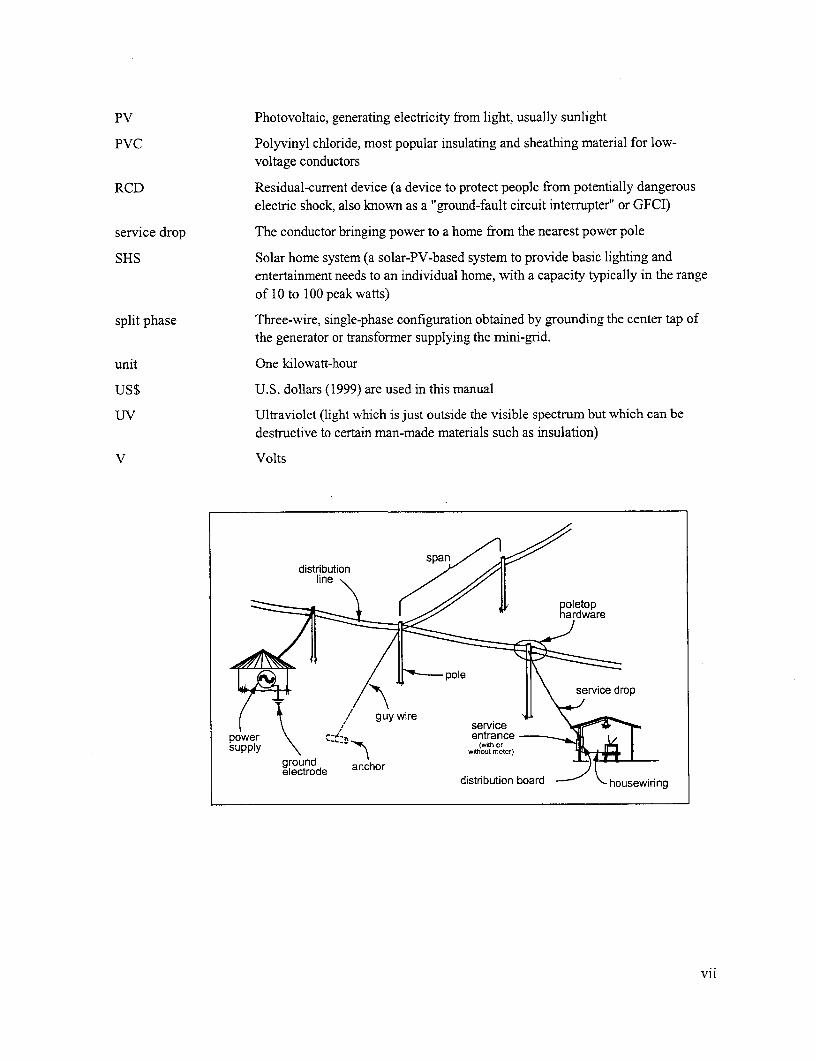
ground \ x -T entranch or
gelecutrodde aco distrbuton board housewiring
vii

Symbols
A Conductor area (mm2)
C Capacitance (farad)
Cos 4 Power factor
d Conductor diameter (meters, m)
E Voltage (volts, V)
f Frequency of power supply (hertz, Hz, or, equivalently, cycle per second)
H Horizontal force on pole due to tension in the conductor (newtons, N)
I Current (amperes, A)
L Length (meters, m)
P Power (kilowatts, kW, or kilovolt-amperes, kVA, unless otherwise indicated)
R Resistance (ohms)
r Unit resistance of a conductor (ohms/km)
s Equivalent spacing of conductors of a distribution line (meters, m), see Eqn. (3) andaccompanying text on p. 226
S Sag in a conductor (meters, m), see p. 80
WvC Unit weight of a conductor (newtons per meter, N/rn)
x Unit reactance of a conductor (ohm/km)
%VD Voltage drop expressed in percent, e.g., for a voltage drop of 23 V when the supplyvoltage is 230 V, %VD = 10 (and not 10 %/o)
Ti Efficiency
viii

Acknowledgements
The author wishes to extend his appreciation to a number of individuals who have directly contributed tothis manual. These efforts have been especially valued because, while these individuals have often beenpreoccupied with other demanding matters, they have taken the time to share some of their experiencesgained over the years.
With over 25 years of experience with the National Rural Electric Cooperative Association (NRECA)supervising and managing rural electrification assignments in Latin America and in Asia, MykManon hasbrought a dose of practical experience and a useful perspective. Recognizing the obstacles to cost-effective electrification in the more remote rural areas and the need to be flexible in designs, he hascontributed of his experience in several sections of this manual. He was a useful and responsive source ofinformation on a variety of issues that arose during the preparation of this document.
Dr. Adam Harvey has been involved for a number of years in designing and implementing rural energysystems, focusing on micro-hydropower technology, as well as being involved in a range of overseasdevelopment efforts. He made initial contributions to several chapters of this manual before recognizingthe time and efforts which would be necessary in Laos where he is presently facing the challenge ofimplementing an off-grid electrification project under the auspices of the local utility, Electricite du Laos.
Dr. Nigel Smith, presently Managing Director of Sustainable Control Systems and Principal ResearchFellow at Nottingham Trent University, has 14 years of experience in R&D, technology transfer andconsultancy for small hydro systems and low-cost electrification around the world. He contributed to thechapter on service connection and housewiring, which also includes a description of a load limitingdevice he recently developed to make access to electricity less costly for low-income households.
As a Research Associate for the Micro Hydro Group at Nottingham Trent University, Phil Maher isresponsible for a technology transfer project involving village electrification in Sub-Saharan Africa. Heis also working towards a PhD focusing on the optimization of stand-alone electrification systems usingpico-hydropower. He has experience in the design of mini-grids from Nepal and Ethiopia. In between hisactivities, he has found the time to contribute text for several chapters in this manual and has continued tocontribute by promptly responding to miscellaneous inquiries as they arose.
While numerous individuals and organizations throughout the world have constructed mini-grids to bringthe benefits of electrification to rural consumers, few of these experiences have been documented.Interested individuals have therefore not been able to build on these lessons learned. In light of thisdearth of documentation, the author is appreciative of the efforts of several individuals to take time toshare some of their experiences.
Jon Katz, working with Ecopartners, a program of the Center for Religion, Ethics, and Social Policyaffiliated with Cornell University, has been involved in an innovative pico-hydropower grid project asone component of a multi-faceted development effort in El Lim6n in the western mountains of theDominican Republic over the past several years. Jon contributed a case study of this effort for thismanual and continued to provide details and photographs of that effort as his work proceeded.
Mike Johnson founded Hydro-Technology Systems, and his work with the manufacture of micro-hydropower equipment in the U.S. eventually led to his involvement in the construction of a 170 kWmini-hydropower mini-grid on the island of Kalimantan. He continued work in that part of the world byinitiating a technology transfer program in Lrian Jaya, Indonesia, where he spent the subsequent 10 years
ix

training local staff and implementing over two dozen hydropower-supplied mini-grids in the course ofthose activities. The project at Youngsu documented in this manual is his contribution.
For the preparation of the case study from Laos, the village headman, Mai Kaen Sengmala, and villagersfrom Ban Nam Thung, welcomed and hosted the author on several separate occasions and shared detailson the origin, construction, and operation of a self-help village electrification project they had themselvesinitiated from a shared desire to bring a valued urban amenity to their community.
Safety is an important issue in the design of mini-grids servicing rural communities still unfamiliar withelectricity. Frequently, this subject is either given low-priority in an effort to reduce the cost ofelectrification or used as justification for blindly adhering to standards prepared for much larger systems,leading to greater costs than necessary. To ensure a safe system at minimum cost, it is necessary to returnto basics to question what is actually necessary, when it is, and why. With a firm knowledge ofconventional electrification system design, NRECA's Jim VanCoevering was able to clearly address myinquiries and concems on the type and extent of grounding required for low-power mini-grids as well ason a number of other topics as they arose. The thoroughness and the clarity of his responses were ofconsiderable assistance in working through these issues.
The author also appreciates the efforts of Jim Carter, wood preservation specialist with NRECA's WoodQuality Control program, and a number of other individuals who have promptly volunteered informationto fill in gaps encountered in the preparation of this document. The author's appreciation and respect alsogoes to all those individuals around the world who have set examples through their own small efforts atelectrification and who have illustrated that such efforts can begin satisfying the demand for basicelectrification among those deprived of this amenity simply by virtue of where they were born.
This manual is an expanded update of an earlier document prepared under contract with Electricite duLaos, with the financial support of the Japanese Policy and Human Resources Development (PHDR)Fund. The project idea and TOR were developed by ESMAP as part of its design of the GEF-financeddecentralized rural electrification component of the IDA-financed Southern Provinces Grid IntegrationProject.
Allen R. InversinIntemational ProgramsNational Rural Electric Cooperative AssociationEmail: [email protected]
x

1. Introduction
The benefits of electrification are well known and demand for electricity service is widespread. But,because established utilities have often been preoccupied with meeting the needs of the vocal andeconomically attractive urban areas and with maintaining existing systems, many have been unable toaddress needs of rural villages. Consequently, around the world, in rural areas beyond reach of thenational grid, numerous individuals and communities have taken it upon themselves to construct theirown rudimentary electricity distribution systems supplied by isolated power sources, such as hydropowerplants or diesel gensets. These mini-grids hold out the promise of being the lowest-cost means ofproviding electricity to neighbors or entire communities. However, they are often improvised, inefficient,unsafe, and short-lived (Fig. 1). Both national electric utilities and development organizations aretherefore reluctant to encourage and support such indigenous efforts in spite of their potential benefits.Furthermore, no guidelines exist for those interested in constructing mini-grids to a higher standard ofservice and safety.
This manual has been prepared to encourage andsupport the design of improved village electrificationschemes. It presents the theory as well as actual fieldexperiences. It is anticipated that it will be useful to .rural development agencies and to national andprovincial energy companies and authorities. It isalso hoped that, perhaps through intermediaries whohave some command of basic technical skills, it willbe useful to village entrepreneurs and villagedevelopment committees.
In this publication, a mini-grid refers to a low-voltage(LV) network within a village or neighborhoodsupplied at a single point by, for example, a dieselgenset or micro-hydropower plant (Fig. 2). Itincludes the service connections and housewiring. Itdoes not refer to the interconnection of two or moreseparate village grids into a more extensive area-widenetwork. The designs covered in this manual rangefrom low-cost designs to serve basic lighting needs to - -
more conventional designs that may become M
interconnected to the grid within the near future.This manual assumes the existence of a power supply Fig. 1. The two thin vertical conductors justand does not deal with details of this supply. It rather to the left of the pole bring power up from afocuses on the design of the system to distribute the 350 W hydropower plant at its base in a
village in Colombia. From this pole, it ispower genratdtthcosumdistributed using bare conductors to several
Mini-grids as discussed in this manual do not involve homes in three directions. Twistedthe use of any medium voltage (MV). However, it conductors are used for all connections.should be recognized that it may occasionally be Two guy cables at the bottom encircle thenecessary to use MV to reduce overall cost. This pole. (Photo credit: Phillip Maher)
Chapter L. Introduction
may occur when serving two or more discreteload centers separated by some distance or whentransmitting power from a generation sourceplant located at some distance from the loadcenter. In this case, transformers would berequired. Medium-voltage lines are is outsidethe scope of this manual.
This manual includes the following:
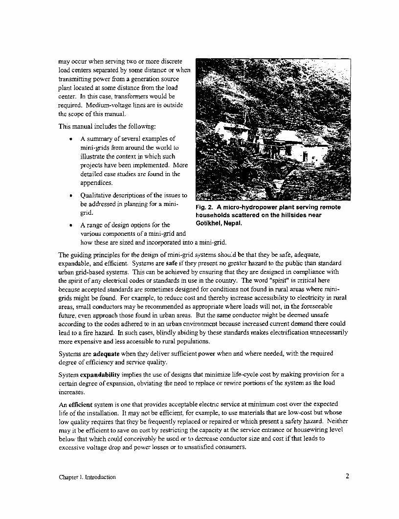
* A summary of several examples ofmini-grids from around the world toillustrate the context in which suchprojects have been implemented. Moredetailed case studies are found in theappendices.
* Qualitative descriptions of the issues tobe addressed in planning for a mini- Fig. 2. A micro-hydropower plant serving remotegrid. households scaftered on the hillsides near
* A range of design options for the Gotikhel, Nepal.various components of a mini-grid andhow these are sized and incorporated into a mini-grid.
The guiding principles for the design of mini-grid systems should be that they be safe, adequate,expandable, and efficient. Systems are safe if they present no greater hazard to the public than standardurban grid-based systems. This can be achieved by ensuring that they are designed in compliance withthe spirit of any electrical codes or standards in use in the country. The word "spirit" is critical herebecause accepted standards are sometimes designed for conditions not found in rural areas where mini-grids might be found. For example, to reduce cost and thereby increase accessibility to electricity in ruralareas, small conductors may be recommended as appropriate where loads will not, in the foreseeablefuture, even approach those found in urban areas. But the same conductor might be deemed unsafeaccording to the codes adhered to in an urban environment because increased current demand there couldlead to a fire hazard. In such cases, blindly abiding by these standards makes electrification unnecessarilymore expensive and less accessible to rural populations.
Systems are adequate when they deliver sufficient power when and where needed, with the requireddegree of efficiency and service quality.
System expandability implies the use of designs that minimize life-cycle cost by making provision for acertain degree of expansion, obviating the need to replace or rewire portions of the system as the loadincreases.
An efficient system is one that provides acceptable electric service at minimum cost over the expectedlife of the installation. It may not be efficient, for example, to use materials that are low-cost but whoselow quality requires that they be frequently replaced or repaired or which present a safety hazard. Neithermay it be efficient to save on cost by restricting the capacity at the service entrance or housewiring levelbelow that which could conceivably be used or to decrease conductor size and cost if that leads toexcessive voltage drop and power losses or to unsatisfied consumers.
Chapter I. Introduction 2

If village power systems relying on mini-grids are to be sustainable and therefore widely replicable,designs specific to the conditions found in villages must be prepared. There is a need to break out fromthe standard mold, to review specific needs in a community, to go back to basic principals, and to develop
designs that most cost-effectively address those needs. Without this approach, complexity and high costs
can quickly place mini-grids beyond the reach of the typical village. The manual therefore not only
reviews a range of technical designs but also covers in depth some of the other issues that must beaddressed for successful, affordable electrification programs.
From the four case studies presented in the appendices and summarized in the next chapter, the range ofoptions available is clear. These projects, most serving somewhat more than 100 households, werespecifically designed for bringing electricity to isolated villages. However, even under thesecircumstances, one finds a wide range of costs and sophistication, from a village mini-grid system costingabout $3,000 in Laos to a number averaging more than $90,000 in the Ivory Coast. In addition, agenerating plant is required to supply the mini-grid with electricity. This adds from $1,000 to $9,000 fordiesel gensets in Laos and the Ivory Coast, respectively, to from $4,000 to $20,000 for a micro-hydropower plants in the Dominican Republic and Irian Jaya, respectively.
Any one of these designs is not necessarily better or more appropriate that any other. Each was simplydesigned to meet a particular set of conditions under a specific set of constraints. But they do illustratethat numerous variables must be considered in the design of mini-grid and that it is not simply a case of
using the same design in different locations, as is generally done by national electric utilities around theworld. In addition to describing technical designs, an important objective of this manual is to increaseawareness of the range of issues that must be addressed in bringing the benefits of electricity to rural
people around the world.
This publication presents graphs, equations, and other quantitative and qualitative details to provideguidance for the selection and sizing of the various components that could be incorporated in an electricalmini-grid. But for such projects, sizing is relatively straightforward. Of greater importance inimplementing affordable and sustainable mini-grids is an awareness and understanding of the numerousother issues that must be addressed and resolved. The basic issues encountered in the design andimplementation of "standard" electrification were resolved long ago, and designs adopted by nationalelectric utilities vary slightly from country to country around the world. However, if these same designswere to be adopted for mini-grids, costs would be high, and rural populations would never have a chanceto access the benefits of electrification. Alternatively, such projects would require govemment subsidies,but this is an option to which few countries seem able or willing to commit.
The range of design options is much more varied with mini-grids, driven primarily by the fact thatsystems must remain affordable, yet adequate, if electrification is to be more widespread. Only designsthat achieve this will prove sustainable and replicable. But this requires that numerous issues be resolved.Examples of such issues include the following:
* Most mini-grids are not grounded. What level of grounding is warranted? And how, after goingthrough the expense and effort of grounding, can the effectiveness of grounds in providing a safeenvironment be ensured in a rural setting?
* To ensure safety yet minimize the cost of electrification, what minimum components must beincluded in the consumer's residence?
* What approaches are there to reduce the cost of meters, meter reading, billing and collecting,because these can often cost more than the cost of the electricity consumed?
Chapter I. Introduction 3

What types of conductor are most appropriate and available in the small sizes required for mini-grids?
* Should single- or three-phase distribution be used?
* How can adequate service quality be maintained such that user appliances are not damaged?
* While service to urban consumers must make provision for supplying at least 1,000 watts andoften considerably more, how can mini-grids be redesigned to cater to a maximum domesticdemand of perhaps 20 to 100 watts per household?
* How can conductors be joined when the appropriate connectors are not available for the sizescommonly needed for mini-grids?
* Adopting conventional designs would result in excess system capacity at a cost that thecommunity could never afford. How does one assess the actual needs of a community to ensurethat the system is not overbuilt and priced out of range for the community?
These are some of the issues that must be addressed before even embarking on the design and sizing of amini-grid. Consequently, while equations and graphs have been included, much of the manual focuses onincreasing awareness of these and related issues and on providing insights gained to date by those whohave already designed and constructed such systems.
Furthermore, while an objective in mini-grid design is to minimize the cost of electrification for ruralconsumers so that they may access, and benefit from, this resource, several guiding principles must bekept in mind:
* Making electrification more affordable does not simply require minimizing the total cost ofcomponents at the time of construction. Rather, the implications of system design on life-cyclecost and system performance must be kept in mind.
For example, while the use of small, locally harvested, untreated wooden poles may appear aneffective means of reducing the cost of one of the most expensive components of a mini-grid, thelabor and materials cost for their subsequent frequent replacement may not only quicklyoverwhelm any initial cost savings, but it can put the sustainability of entire system in jeopardy.
As another example, if the potential exists for increased user demand in the future, life-cyclecosts may actually be decreased by initially oversizing the distribution line. If costs areminimized by keeping conductor size to the minimum required to meet initial demand, then it willlater have to be replaced with larger conductor. The additional labor to replace the conductor aswell as the additional materials will unnecessarily increase project cost.
* Minimizing system cost may not necessarily be achieved by simply minimizing the cost of eachcomponent making up that system. The system designer must realize that the design of onecomponent can have implications on the design and cost of others. For example, as will bedescribed later, increasing project cost somewhat by incorporating capacitors in the design offluorescent lighting units to correct their power factor can result in net savings by allowing for theuse of smaller and less costly conductor and generator.
Chapter I. Introduction 4

11. Setting the context for low-cost mini-grids
Electrification first began in the urban centers in the industrialized nations and evolved in the followingcontext:
* A geographically compact service area, facilitating the supply of electric power.
* A variety of end-uses (from powering lights and radios to heavy industry) leading to a wide rangeof per-consumer demands.
* A consumer base with ready employment and access to financial resources to cover the costs ofinstalling electrical service (the connection cost), purchasing end-use appliances, and covering thecosts for electric energy (the monthly kWh bill).
Over time, standard technical and institutional designs evolved to most efficiently serve these centers.
When electricity was later introduced by these nations into cities in areas they had colonized around theworld, the natural approach was to utilize these same standard designs. But in this new context, thesedesigns were still largely appropriate, because comparable conditions were found in urban areas in thedeveloping as well as in the industrialized nations.
But as the demand for electricity spread beyond the urban areas, first into the less wealthy but stilldensely populated periurban areas and later into the rural areas with poorer, more dispersed populationswith more basic needs, electric utilities simply expanded the systems using designs with which they weremost familiar. But gradually, as the electrical network expanded, utilities found this work to bedetrimental to their economic well-being: costs of supplying electricity increased and per-consumerconsumption, and associated revenues returning to the utilities, decreased. The utility response was eitherto avoid serving these areas or, if the central governmental directive to serve the rural populations wasstrong, to request the necessary financial resources to subsidize these efforts in areas beyond the townsand cities.
But the demand for electricity continued unabated and the more enterprising, unserved areas undertooktheir own electrification, relying on locally generated power. They also recognized that standard designswhich had been used could not always affordably meet their needs. As a consequence, a range of new,less costly designs evolved. These new designs recognized the new context in which electrification wasto evolve:
* Isolated service areas, often requiring local generation to avoid the high costs of bringing powerto these areas.
* A range of more rudimentary needs, often focusing on meeting small energy needs-such as forlighting, entertainment, and, to a limited extent, the operation of simple handtools andappliances-but at the same time, occasionally considering the limited use of some moreelectricity-intensive uses such as agro-processing or cooking.
* A broad range of affordability on the part on individual consumers, but with most consumershaving more limited access to financial resources.
* Because of their eagemess to get access to electricity, the increased willingness of potentialconsumers to be actively involved in the supply of their own electricity rather than being merelythe recipients of services from an outside company.
Chapter II. Setting the context for low-cost mrini-grids 5

* The possibility that mini-grids would be interim measures and would not have to be designed tolast the 30 or more years that is (or at least should be) the case with conventional systems.
In conventional electrification around the world, designs that are fairly standard from country to countryhave been developed. But even in these cases, costs can vary broadly. In striving to develop new, lesscostly designs to serve individual comrnunities, it is clear that, because of the broad nature of the contextin which electrification is to be undertaken, no single standard design could be developed as was the casewith urban electrification.
Designs developed or adopted for mini-grids depend heavily on such factors as the size and nature of loadthat is to be imposed; on the design life that is expected of the system; on the availability and cost ofmaterials, most notably poles; on the metering system which is to be incorporated; and on the level ofsafety felt necessary.
To provide the reader with an idea of how designs evolved in different contexts to bring electricity toisolated communities, four case studies from around the world have been summarized below and includedin more detail in the appendices in this manual. These projects have common characteristics:
* Reliance on an autonomous electricity supply, which is either a diesel or gasoline genset or,where hydropower resources exist, a micro-hydropower plant.
* Meeting basic, low-power needs which are most efficiently provided by electricity, primarilyhigh-efficiency fluorescent lighting and entertaimnent (radio and TV).
* In cases where fossil fuel is used, restricting the hours of generation to early evening hours toensure an efficient loading of the powerplant.
* Dependence on the local community to provide sweat equity and local materials and to manageand operate the schemes.
* Reliance on fixed tariffs based on connected load (watts) and not on actual consumption (watt-hours), obviating the need for energy meters and associated administrative costs.
But in spite of this cornmonality, these case studies illustrate the broad range of designs that have evolvedand the wide range of costs that are possible-from about $3,000 to $90,000 for the mini-grid andhousewiring alone, to serve roughly the same number of consumers.
And while one objective is to adopt designs that can reduce the cost of electrification, another should beto maximize the benefits which can be derived from electrification. If the cost of fuel is relatively high,such as with diesel generation, an effort must be made to use available energy efficiently, by reducinglosses to the extent possible and to displace even costlier sources of energy, such as dry cells. If the costof fuel is low, such as with hydropower generation where the "fuel" is free, then as many productive usesas possible should be considered (Fig. 3).
Ivory CoastA design developed by a French organization for several westem African nations, including the IvoryCoast, is one that might be expected from individuals who have been schooled in conventional designsbut who, at the same time, recognize the new context in which off-grid rural electrification is to beimplemented.
As might be assumed from the relative high project cost, which approaches $650/consumer, each systemincorporates conventional designs and components, although these have been down-sized to cater to the
Chapter II. Setting the context for low-cost mini-grids 6

new, reduced demand levels. But with the stillhigh costs of this project come additionalbenefits which are not generally associatedwith the other case studies presented:
* To ensure consumer safety, residualcurrent devices (RCDs, see p. 127) andmore expensive undergrounddistribution in the vicinity of the _
consumers have been used.
* While the designs adopted areconsiderably costlier than those of theother projects described in the Fig. 3. This micro-hydropower plant owner inappendices, they should also have a Nepal is sharpening scissors using an electric-considerably longer life and require motor-driven planer, jointer, grindstone, and circu-less ongoing maintenance and lar saw combination. In addition to generatingreplacement. electricity for lighting and to power handtools, he
* By using conventional designs and uses mechanical power directly for oil expelling,components, the objective is to have a flour grindings, and rice hulling. The penstocksystem that, at minimum cost, can be pipe to the turbine is located in the center
connected directly to the national grid, background.when it arrives in the village at sometime in the future, and be in accordance with established national standards. At the time of grid-interconnection, a distribution transformer would simply replace the powerplant.
* Fluorescent lighting is power-factor corrected. This reduces line losses that are encountered inthe other cases presented, losses that detract somewhat from the efficiency normally associatedwith fluorescent lighting.
What is not clear from the information available on this project is whether, in an attempt to reduce cost,the conductor has been sized to meet only the average load the project designers expect (30 to 60 W perconsumer). If this is the case, then reconductoring of the distribution system would be required if, whenthe grid arrives, consumers are ready to increase their consumption. This would increase the life-cyclecost of the system.
While numerous advantages enumerated above are associated with this project design, the question thatremains is whether such a design makes the system too expensive and therefore too heavily reliant onextemal funding to be replicable in a environment with increasing competition for limited public funds.On the other hand, the observation was also made that consumers presently spend more for electricitythan they previously spent on altemative fuels displaced by electricity. Their motivation for doing soshould be probed to determine consumer willingness to pay and to assess under what circumstances, ifany, they can cover actual system cost.
Further details about this project are found in Appendix 1.
Chapter II. Setting the context for low-cost rnini-grids 7
Laos
Unlike the design prepared for the Ivory Coast, the design used in the village of Ban Nam Thung innorthwestem Laos was prepared by a young man who had recently completed agricultural training butwho had no formal electrical training. It probably represents the most basic, minimum-cost, mini-griddesign, requiring only several sizes of conductors and a few components in each housewiring circuit.Poles are usually one of the more costly components of conventional electrification projects. For thisproject, live trees were used if they were in a suitable location; at other times, villagers contributedhardwood and bamboo posts, but these were untreated and had to be periodically replaced.
For the type of mini-grid and housewiring design used, capital costs average about $20 per consumer. Alow-cost Chinese 230-V genset was also used. Project cost was low, and the factor most affecting theviability of this project at present is the cost of diesel fuel which has been rapidly increasing as the Laocurrency devalues.
A visit to the project site revealed several problems, which arose from a lack of knowledge of propersystem design rather than due to an attempt to cut costs. Incorporating design changes to resolve theseproblems may double the capital cost for the system, but this would still have been a very low-costsystem. Problem areas include the following:
* Lack of control over consumption. The tariffs were based on total connected load, generally one20-W fluorescent lamp per consumer. However, there was no enforcement, and including one tothree power receptacles in each home invited the use of appliances. Over-consumption by one ormore consumers may have been one reason for the 10-kW generator running hot and eventuallybuming out.
Each home has fuses, but at a rating of about 10 amps (the smallest size fuse wire available on thelocal market), these are more to protect conventional housewiring than to limit consumption. Ifoutlets are to be included in each home, provision should also have been made to include aproperly sized fuse, circuit breaker, or other form of load limiter (see p. 155).
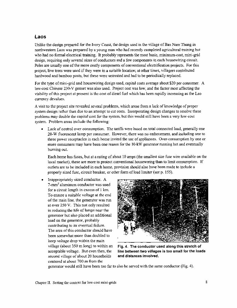
* Inappropriately sized conductor. A7-mm2 aluminum conductor was used '-C.
for a circuit length in excess of 1 km.To ensure a suitable voltage at the endof the main line, the generator was runat over 250 V. This not only resultedin reducing the life of lamps near thegenerator but also placed an additionalload on the generator, probablycontributing to its eventual failure. havThe area of this conductor should have
been somewhat more than doubled to -keep voltage drop within the mainvillage (about 350 m long) to within an Fig. 4. The conductor used along this stretch ofacceptable voltage. But even then, the line between two villages is too small for the loadssecond village of about 20 households and distances involved.centered at about 700 m from thegenerator would still have been too far to also be served with the same conductor (Fig. 4).
Chapter II. Setting the context for low-cost mini-grids 8

* Lack of power-factor correction for the 20-W fluorescent lamps which were the principal load onthe system. The generator was rated at 3.3 kW per phase at a power factor of 0.8. This meansthat while the generator could have produced 4.0 kW per phase if the ballasts had been correctedto a power factor of 1.0, it only had the capacity to produce 2.0 kW with the uncorrectedfluorescent lamps in place (with power factor of 0.5). It is conceivable that the lack of capacity-correction contributed to overloading the generator.
* Poor phase balance. Only two of the three phases at the generator output were used, permittingfull use of only two-thirds of the generator's 10 kW. Furthermore, a considerably greater numberof consumers were served by one phase than by the other. Consequently, unbalancing of thegenerator output as well as excessive loading of one of the phases may also have contributed toeventual generator failure.
While numerous design problems were encountered at this site, this project illustrated a basic design thatshowed the promise of being very low-cost. Even if the conductor size had been increased to reducevoltage drop within the main village and breakers had been used in the home to avoid the problem withthe use of incorrectly sized fuse wire, project costs would probably have been roughly $30 to $40 perhousehold.
Further details about this project are found in Appendix 2.
Irian JayaIrian Jaya, which forms part of the nation of Indonesia, is a rugged island with isolated population centers.This, coupled with high precipitation, makes it an area with significant micro-hydropower potential. Inthis case, the hydropower plant provides 24-hour power to the community.
As with the project in Laos, this is also a fairly rudimentary system. The major difference in cost isattributable to the significantly increased conductor size used for the main line. It is instructive to notethat this project had a very similar configuration to the Lao project. They both had a generator of aboutthe same capacity, generating at the same voltage, and serving roughly the same number of consumersover about the same geographical area. However, rather than using the equivalent of about 2.0 km of7 mm2 aluminum conductor, the project in Irian Jaya used more than 3.5 km of at least 35 mm2 aluminumconductor.
Even with its more than adequately sized conductor, per consumer cost for the mini-grid and housewiringaveraged $60 per household. The powerplant averaged another $130 per consumer. However, becausethe provincial govemment covered the capital cost of the mini-grid, villagers were only responsible forthe housewiring at about $22, plus somewhat more than $2 monthly to cover operating costs.
Further details about this project are found in Appendix 3.
Dominican RepublicThe Dominican Republic is a country having one of the broadest experiences worldwide with hanressingsolar photovoltaic (PV) power and making efficient use of the small amount of low-voltage (12 V) directcurrent (dc) energy generated by such systems. It also makes wide use of the small streamflows found inits numerous streams, by transporting water long distances in polyvinyl chloride (PVC) pipe for pressure(gravity) irrigation.
Chapter II. Setting the context for low-cost mini-grids 9
While solar home systems were available, their capital cost and recurring cost (largely for the batterieswhich needed periodic replacement) would have placed an unacceptable burden on the villagers. Whenthe idea of using a turbine to convert the energy of the water in the irrigation pipe into electricity wasproposed, this seemed an attractive option. It was clear that only small amounts of power could begenerated per family (roughly 30 to 40 W) because of the size of the available pipe flows. However,because of cost, the villagers were eager to devote their efforts to building a pico-hydropower plant andmini-grid and using the PVC pressure pipe for two purposes simultaneously: irrigation and powergeneration.
In the Dominican Republic, several advantages were associated with the use of low-voltage direct current(dc). Fluorescent lamps run off dc were readily available, and use of dc reduced potential safety and firehazards in village households with little prior experience with electricity. The brightness of the dc lampsappeared very insensitive to voltage. The availability of dc in the home held out the promise of battery-charging, permitting significantly more power demand per household. And finally, use of dc powerdiscourages the purchase and use of high-power appliances and devices, uses which put small systems atrisk. The reduced availability of dc appliances and devices on the local market also reduced this risk.
It was decided that each household would have access to dc power in the home but that the mini-gridwould transmit at 240 V alternating current (ac) to reduce the size and cost of conductor used in the mini-grid for transmitting power from the powerhouse to the village. At the top of the pole nearest each home,at the beginning of each service drop, a transforrner/rectifier unit with circuit breakers was installed toprovide dc power to each home.
In reality, the transformer/rectifier unit had two disadvantages: it increased the cost and complexity of theconnection and it resulted in the loss of power. While this loss was estimated at 10 W per household, thisis a fairly significant portion of the overall power available. There was the advantage that this unitlimited the power that could be used and ensured equitable distribution of power to all villagers but, intheory at least, a current limiter could also have been used with an ac system. Time will tell whetherconversion to dc was an effective approach to take.
The rnini-grid system, with dc conversion and housewiring, cost on the order of $500 per consumer, withvillager-produced concrete poles and international transportation of materials accounting for about 40 %of this cost. The powerplant added the equivalent of another $70 per household and a further $200 perconsumer would have been added if the cost of the pressure pipe had not been assumed by the irrigationproject.
Further details about this project are found in Appendix 4.
ConclusionThe project summaries highlight the wide range of capital costs per consumer possible for mini-grid-supplied electricity. If one were to restrict project designs to those described for the Ivory Coast and theDominican Republic, their high cost would probably preclude the electrification of most villages aroundthe world. Significant grants and subsidies would be required and the question is whether these could bejustified to the donor's satisfaction in light of the benefits derived.
The other two projects presented-those in Laos and Irian Jaya-seem more attractive because theypromise considerably reduced capital costs. On the other hand, higher recurring costs would be expectedfor maintaining and repairing these lower-cost and consequently less robust systems. One question that
Chapter II. Setting the context for low-cost mini-grids 10

remains is how much the cost incurred in these ongoing repairs and replacements adds to project cost?Would projects with lower capital cost also have lower life-cycle cost?
Another question to ask is whether it is more effective to design and implement a high-cost, well-designed system at the outset, when all the expertise is on-site, than to build a lower-cost system by usingless durable materials and designs and hoping that proper repairs will be made in subsequent years as theyare required. An engineer implementing projects in Indonesia writes:
I've come to the conclusion that "distribution" must be planned with a long termperspective-it's a nice idea to say we build and use bamboo posts temporarily andwill gradually replace them with steel or concrete as they rot but how many peopleever get around to doing it?'
The challenge facing those charged with implementing sustainable and affordable mini-grids is tosynthesize safe designs that meet villager needs while having the lowest life-cycle costs. In the process,they must keep in mind that, without properly trained local staff and possibly a mechanism for providingtechnical backstopping, most repairs may not be properly made. Temporary fixes will probably beundertaken-poles will be temporarily braced if not left to dangle, fuses will be bypassed and no longerserve their intended purpose, and hooked wire ends will replace broken switches. This will furtherincrease life-cycle costs or decrease system life over what was planned. Consumers are put at risk and theinitial investment may not yield the expected benefits.
Once the most appropriate, lowest life-cycle-cost design has been achieved, the questions that still remainare whether final project costs will be affordable to the community and whether the design is.sustainable.And if the project is a pilot project to be adopted elsewhere, another question is whether the final design isreplicable. If not, the potential impact from the effort expended on this pilot project will have beenconsiderably reduced.
Chapter II. Setting the context for low-cost mini-grids 11


111. Preconditions and action plan
In the enthusiasm to get access to electricity in areas far from the grid, there is often an eagerness toimmediately get down to the job-gathering and setting poles; stringing conductor; buying fuses,housewiring, and lighting fixtures; etc. However, before purchasing the necessary materials and settingup a system, the proper design must be established. But even before this, it is critical that the necessaryelements for a successful project are in place. While ensuring this may not guarantee success, omitting toconsider them is a sure recipe for failure. These elements include the following:
* Widespread interest in accessing electricity and the ability of a sufficiently large portion of thepopulation to cover, at the very least, the recurring cost of the project, if not a significant portionof its capital cost.
* Identification of a well-established, suitably qualified local entrepreneur, organization, etc., that isinitiating the request for electrification and that will have prime responsibility for managing andoperating the project on an ongoing basis.
* A potential source of electricity in the vicinity of the community in the quantities and at the timesneeded.
Because each of these three elements is critical to project success, a careful assessment of each in aspecific situation must be made before undertaking any work on the installation of a mini-grid. Failure toaddress them would put the entire project at risk.
It should be noted that a precondition that is assumed to be met before initiating a project is that nationallaws permit the generation and sale of electricity by private individuals or by organizations other than thenational utilities. If this is not the case, exceptions to the law must be sought; otherwise thoseimplementing such projects could be placing themselves, their investment, and their consumers atfinancial risk.
Willingness and ability to payPeople in all walks of life are eager to get access to electricity; however, this is clearly not a sufficientcondition for embarking on the implementation of a mini-grid project. Coupled with this must be boththe willingness and ability to pay for this service.
The cost of service includes the following components:
* Capital cost incurred in the implementation of the mini-grid project, with powerplant
* Recurring fuel cost (unless solar, micro-hydropower, or windpower is hamessed)
* Recurring operations, maintenance, and overhauling costs, both labor and materials
* Equipment replacement costs
These costs can be covered by several means:
* Grants and subsidies from the government, bilateral aid organizations, or non-governmentalorganizations
* Villager up-front contribution (such as through a connection fee)
Chapter III. Preconditions and action plan 12

* Loans
A portion of the capital costs may be covered by grants and subsidies. Villagers themselves may alsocover part of these costs up front. But while aid donors or governments might cover at least a portion ofthe capital costs, they are rarely, if ever, willing to take on the responsibility of assuming the ongoingcosts incurred in the operation and maintenance of such projects. These ongoing costs, as well as thebalance of the capital cost, must be covered by the consumers themselves through their electricity bill.Any tariff schedule used to set consumer bills should therefore be properly designed to generate thenecessary revenues to cover these costs. If the villagers are not willing or able to cover these costs, theadvisability of proceeding further with the project should be reconsidered.
Precisely establishing the cost of electrification is difficult before a project has been designed and costed.However, the case studies presented in the appendices and summarized in Chapter II provide an idea ofthe broad limits within which the costs will likely be found, depending on the sophistication of the actualdesign adopted.
The most basic mini-grid/housewiring system is one requiring a conductor down the main streets, servicedrops on either side of the conductor, housewiring, and a basic distribution board and fluorescent light ineach home. The cost may average $30 to $60 per household. It would rely on locally available polesdonated to the project by the community. (See the case studies for Laos and Irian Jaya as two examplesof such projects.)
On the other hand, by using more permanent concrete or treated wood poles or some undergroundconstruction, greater consumer and system protection, and higher-quality distribution boards andcomponents, distribution system cost may average closer to $500 per consumer, approaching the cost of amore conventional distribution system. (See the case studies for the Ivory Coast and the DominicanRepublic for two examples of such projects.)
Note that along with the above, the capital cost of the power supply itself must be added. This cost ishighly variable, especially for small powerplants, and depends on factors such as size, the type of powerbeing hamessed (e.g., hydropower or thermal power through a diesel plant), site conditions, themanufacturer and quality of the equipment, and powerhouse design. In addition, while the initial cost of agasoline or diesel genset may be low, the cost of repair, overhaul, or replacement could add considerablyto the life-cycle cost of the plant. This cost, in turn, would have to be recouped by the project ownerthrough the tariff imposed on the consumers. In addition, the recurring cost of the fuel must beconsidered. The initial cost of a small hydropower plant may be high but recurring costs for repair,maintenance, and "fuel" should be considerably lower. This cost would generally have to be borne by theconsumers through their electricity bill.
Therefore, while electrification is not inexpensive, costs incurred in the construction of mini-grids canvary widely. The same is true of the monthly payments expected of the consumers. To assist in assessingwhether a community can afford to cover these costs, it is useful to obtain a rough estimate of how agiven project cost is reflected in these consumer payments. This will give those proposing a mini-gridproject an indication of whether, or under what circumstances, such a project could reasonably beexpected to succeed financially.
As a frame of reference, assume that a proposed, very low-cost, low-power village mini-grid, including ofa small diesel genset, costs $10,000 and is to serve 100 consumers. Assume further that all costs are to becovered by the community and that loans are available on reasonable terms (here assumed to be 10 %annually over 5 years). Using Table 19 (see p. 182) and interpolating, monthly payments to repay a loan
Chapter III. Preconditions and action plan 13

for the full amount can be calculated as ($10,000)(0.023) = $230 per month or an average of $2.30 perconsumer. This payment is proportional to project cost and inversely proportional to the consumer base.For example, if the project were to cost $50,000, the average cost per consumer would by 5 x $2.30 or$11.50/month. Or if the consumer base for the original $10,000 project were only 50 or half theconsumer base originally assumed, then the cost per consumer would be 2 x $2.30 or $4.60/month. If theproject costs $50,000 and serves only 50 consumers, then the average monthly bill would reach$23 .00/consumer.
Since the mini-grid is supplied by a diesel engine, the price of fuel would have to be added to the figuresabove. To serve small fluorescent lighting and entertainment loads during the evening, this might cost anadditional $1 to $5 per consumer each month, depending on the cost of diesel fuel and actualconsumption. In addition, the cost of operation, maintenance, and repair for the plant and mini-grid eachcontribute to the total cost that must be covered, whatever the source of electricity.
A more detailed derivation of an average tariff can be found in Box 16 near the end of this manual(p. 191). By assuming a certain project "sophistication" and its associated cost as noted above, assessingwhat portion of these costs are to be bome by the consumers themselves as opposed to being covered bygrants, and then establishing the terms under which the consumers are to cover these costs, it is possibleto estimate the amount each consumer will be required to pay monthly to cover project costs. The nexttask is to assess whether the rough cost of electricity supplied by a mini-grid project of the scale and typeassumed, derived through this process, is affordable to the local community.
One approach to assessing the villagers' ability to pay is to assess how much they currently spend onenergy that would be offset by electricity, such as kerosene and candles for lighting and dry cells andautomotive batteries for use with radios and TVs. The term "offset" is important because, even ifelectricity is introduced, most villagers will still have to continue to purchase kerosene for times when theelectricity is not being generated or to purchase batteries for flashlights which will continue to be neededoutside the home.
Another approach would be to assess what level of electric service those in other comparable villages-but with some access to electricity-currently receive and how much they pay for it. In areas where mosthouseholds do not have access to a steady income, understanding how this affects their ability to affordmini-grid connection and to regularly pay their bills would also be instructive. This would help in notonly establishing the level of the tariff but also its structure (i.e., possibility of prepayment, periodicity ofpayments, bulk payments, etc.).
Note that in the discussions above, it has been assumed that the loads are primarily residential. In reality,this is typically the situation. In this case, reducing the cost of electrification to residential consumersrequires adopting lower-cost designs. However, another complementary approach that should also beconsidered where possible is to actively incorporate income-generating end-uses among the residentialloads. These can include the use of refrigeration or the manufacture of ice to increase the life of fish,fruit, or other foodstuffs; wood- or metal-working equipment; battery-charging; agro-processing such asmilling grain or hulling rice; irrigation; etc. These not only generate revenues-which can contribute tocovering an important portion of the cost of the energy generated-but they also create or broadenemployment and income-eaming opportunities both for consumers gathering raw materials to beprocessed or stored as well as for those directly employed in operating the equipment.
It should also be noted that, with certain end-uses, it may be possible for villagers to more efficientlyprocess crops than with existing traditional methods. In such cases, they may actually be generating more
Chapter III. Preconditions and action plan 14
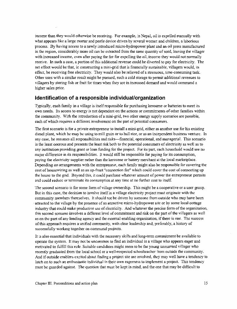
income than they would otherwise be receiving. For example, in Nepal, oil is expelled manually withwhat appears like a large mortar and pestle device driven by several women and children, a laboriousprocess. By having access to a newly introduced micro-hydropower plant and an oil press manufacturedin the region, considerably more oil can be extracted from the same quantity of seed, leaving the villagerwith increased income, even after paying the fee for expelling the oil, income they would not normallyreceive. In such a case, a portion of this additional revenue could be diverted to pay for electricity. Thenet effect would be that, in constructing a mini-grid that is financially sustainable, villagers would, ineffect, be receiving free electricity. They would also be relieved of a strenuous, time-consuming task.Other uses with a similar result might be pursued, such a cold storage to permit additional revenues tovillagers by storing fish or fruit for times when they are in increased demand and would command ahigher sales price.
Identification of a responsible individual/organizationTypically, each family in a village is itself responsible for purchasing kerosene or batteries to meet itsown needs. Its access to energy is not dependent on the actions or commitments of other families withinthe community. With the introduction of a mini-grid, two other energy supply scenarios are possible,each of which requires a different involvement on the part of potential consumers.
The first scenario is for a private entrepreneur to install a mini-grid, either as another use for his existingdiesel plant, which he may be using to mill grain or to hull rice, or as an independent business venture. Inany case, he assumes all responsibilities and risks-financial, operational, and managerial. This scenariois the least onerous and presents the least risk both to the potential consumers of electricity as well as toany institution providing grant or loan funding for the project. For its part, each household would see nomajor difference in its responsibilities. It would still be responsible for paying for its consumption,paying the electricity supplier rather than the kerosene or battery merchant at the local marketplace.Depending on arrangements with the entrepreneur, each family might also be responsible for covering thecost of housewiring as well as an up-front "connection fee" which could cover the cost of connecting upthe house to the grid. Beyond this, it could purchase whatever amount of power the entrepreneur permitsand could reduce or terminate its consumption at any time at no further cost to itself.
The second scenario is for some form of village ownership. This might be a cooperative or a user group.But in this case, the decision to involve itself in a village electricity project must originate with thecommunity members themselves. It should not be driven by someone from outside who may have beenattracted to the village by the presence of an attractive micro-hydropower site or by some local cottageindustry that could make productive use of electricity. And whatever the precise form of the organization,this second scenario involves a different level of commitment and risk on the part of the villagers as wellas on the part of any lending agency and the extemal enabling organization. if there is one. The successof this approach requires a unified community, with clear leadership and, preferably, a history ofsuccessfully working together on communal projects.
It is also essential that individuals with the necessary skills and long-term commitment be available tooperate the system. It may not be uncommon to find an individual in a village who appears eager andmotivated to fulfill this role. Suitable candidates might seem to be the young unmarried villager whorecently graduated from the local school or a well-respected schoolteacher from outside the community.And if outside enablers excited about finding a project site are involved, they may well have a tendency tolatch on to such an enthusiastic individual in their own eagerness to implement a project. This tendencymust be guarded against. The question that must be kept in mind, and the one that may be difficult to
Chapter III. Preconditions and action plan 15
answer definitively, is whether such an arrangement is likely to endure. A young person might easily belured away by the amenities and opportunities in the city and the place of assignment of a teacher mayeasily change from one school year to the next. On the other hand, using a villager who is tied to thevillage through family bonds, who has a secure means of making a steady, adequate income within thevillage, who may already play an important pivotal role in village activities, and who has some initiativeand motivation would probably more likely remain in the village and be committed to the long-termsuccess of a mini-grid project.
The second scenario is the more difficult of the two because it requires the active involvement andcommitment of most of the individuals within a community rather than of a single individual. It must beclear that some mechanism for organizational continuity exists and that the elements are there for a long-term commitment to the project. In the absence of a reliable and capable individual and communityorganization, it may be best to forego a project; otherwise, this effort will likely be costly, time-consuming, and frustrating and in the end stagnate and collapse after the outside promoter has departedthe scene.
Any mini-grid project should be expected to last for a number of years and will likely require a long-termfinancial commitment. Therefore, whatever mechanism is to be used for the implementation of a mini-grid project, it is essential that a committed organization be in place to ensure its continued operation.
Adequacy of electricity supplyThe electricity for supplying a mini-grid can come from a number of sources, ranging from theconventional (diesel and gasoline engine or a distribution transformer supplied by the national or regionalgrid) to the non-conventional (wind, solar, or micro-hydropower). Before constructing a mini-grid, it isessential that whatever supply of electricity is proposed be available in the quantities and at the times it isneeded. If not, this will not only reduce the end-uses to which electricity can be put but it may alsocomplicate the generation of adequate revenues to cover the costs incurred in electrification. And thepower supply should be located sufficiently near the load center to minimize costs in transmitting powerto the village loads.
Several electricity supply options might be considered. In probable order of popularity, these are adistribution transformers fed by a national or regional grid, a diesel/gasoline generating set (genset), amicro-hydropower plant, a wind turbine, and a solar PV (photovoltaic) station. While the purpose of thisguide is not to provide details about these various technological options, brief descriptions of issues thatshould be considered with each option are reviewed.
Grid extension
In cases where a MV line serving a number of larger load centers passes near a community, this isgenerally the cheapest approach to rural electrification. Electrification involves the local utility installinga distribution transformer of appropriate size near or in the village and making power available to thevillage. Presumably the utility is not interested in managing a small system within the community;otherwise, there would be no need for the villagers to consider implementing their own system. In thiscase, the utility may only be willing to install an energy meter at the transformer location and provide aconnection from which the villagers can extend the line into their community under appropriatesupervision and implement their own distribution system. The community would then be responsible forcollecting the necessary tariff to pay the utility, based on the consumption that has been metered at thetransformer.
Chapter III. Preconditions and action plan 16

Several advantages are associated with this option:
* Unless the electricity supply in a country is power-limited, much more power could be madeavailable at the village level than would be the case with the other options. Electrification couldtherefore have a much broader impact on the community, far beyond lighting and entertainment.With grid extension, employment generation and a much broader range of productive uses ofelectricity and social amenities are possible on a 24-hour basis.
* In implementing a project, the community has one less burden to address-the power supply. Inthis case, the national utility would usually ensure a functioning supply of electricity.
* Because of economies of scale in centralized generation, the cost of energy is relatively low.(However, the community may also have to include the cost of bringing the power to the villagein the overall project cost.)
The disadvantages associated with this options are the following:
* Some countries do not have a reliable supply. In this case, rural areas are usually the first to becut off when the load on the entire system exceeds available generation capacity. An unreliablesupply may then frustrate consumers who subsequently refuse to pay because of the poor servicethey receive. The system may then fall apart because of the lack of adequate revenues.
* If more conventional, urban-based, higher-cost design standards to which the utility subscribesmust be adhered to, the distribution design adopted in this case may be more costly than wouldotherwise be the case.
In considering this option, several questions must be asked:
* Is the existing MV line sufficiently close to the community or must it be extended. Is the utilityamenable to extending the line and what would be the cost for line extension and transformerplacement?
* Are there provisions whereby the utility could enter into some agreement with communitieswilling to be responsible for their own distribution system?
* Based on experience to date, how reliable can the power supply be expected to be and is thatadequate to meet the needs of the community?
In the Philippines, such an approach is routine. Within remote communities, utilities actually install theentire distribution system, with service connections and, through a memorandum of understanding,delegate the responsibility for the metering, billing, and collection to formally formed conimunity groups.The utility merely reads the meters at the transforrners it installed in the various community and thecommunity is responsible for collecting the fees and paying its bill.
Diesel/gasoline genset
Next to connecting to a grid-connected transformer, the use of gensets is the easiest approach toimplement. Advantages of this technology are significant: gensets are readily available is all countriesand they are low-cost and easy to transport and install (Fig. 5). But several disadvantages must be takeninto consideration:
Chapter III. Preconditions and action plan 17

* Fuel must be delivered to the community on ayear-around basis (unless it is stockpiled inthe community). Can availability of fuel inthe community be guaranteed in light of thereliability of transportation, accessibility by -
road during the rainyseasons, and political _uncertainties?
* While the cost of fuel continues to berelatively low, are there any indications that -
cost will rise significantly or that supply willdiminish sufficiently to discourage future useof this fuel? Fig. 5. A low-speed 6 kVA diesel genset in
* Gensets require expertise for regular engine southern Belize.maintenance and, occasionally, major overhauls. A local source of expertise must be available inor to the community before this option is considered. Without this intervention, the life of theequipment may be short and may lead to frequent and costly replacement of equipment.
* Can environmental pollution commonly associated with internal combustion engines-noise,disposal of spent oil, and exhaust emissions-be adequately addressed?
While the availability of fuel and its cost may be of concern, it is interesting to note that diesel fuel orkerosene is already burned in wick lamps as a principal source of lighting in rural homes in manycountries. Therefore, in these countries, fuel is already being purchased and imported into communitiesfor lighting. Because burning fuel in a wick lamp for lighting is very inefficient, reliance on a dieselgenset for electric lighting means that less fuel would need to be imported into a community to generatethe same amount of lighting as the wick lamps currently use.
Another concem might be that diesel gensets generate carbon dioxide, a gas which is generally thought tocontribute to global warming and its adverse impacts on the world environment. First, it should berecognized that the quantity of carbon dioxide generated by isolated grids for village electrification isinsignificant in comparison to that generated by a country's industrial or transportation sector or by itslarge powerplants supplying the urban areas. If the reduction of carbon dioxide emissions is truly ofconcem, it is in these areas that efforts can be cost-effectively focused, not in off-grid electrification.However, at the same time, it should be noted that the introduction of diesel gensets for lighting in areaswhere wick lamps are being used can actually reduce carbon dioxide emissions.
Hydropower plant
All power systems harnessing renewable energy resources (wind, solar, and waterpower) have theadvantage of low energy costs. However, the renewable resource with the lowest capital cost (cost perkilowatt installed) and possibly the only resource that can generate significant amounts of electricity on a
For example, a typical wick lamp with glass mantel burns fuel at the rate of about 0.04 liters/hour and producesabout 50 lumens. On the other hand, even relying on a very inefficient diesel genset (generating electricity atI kWh/liter rather than the 2 kWh/liter that is more typical for a small genset), a fluorescent unit (lamp and ballast)rated at about 10 W would consume only 0.01 liters/hour and produce about 400 lumens. So in this comparison,buming fuel in a genset produces 8 times the light, consumes fuel at the rate of one-quarter that consumed by a wicklamp (therefore emitting only one quarter the carbon dioxide), and keeps the emissions from combustion outside thehome, reducing any respiratory problems that might be caused by one's proximity to wick lanterns in the home.
Chapter III. Preconditions and action plan 18

24-hour basis to feed into a mini-grid is waterpower. But having said this, the capital or up-front cost isstill high. While the cost of a diesel genset might run several hundred dollars per kilowatt, the cost of amicro-hydropower plant (the equipment, powerhouse, and civil works) is usually five to ten times greater($2,000 to $4,000 per kilowatt). Consequently, for such a plant to be viable, it is necessary to ensure thata significant portion of the available power is used for income-generating purposes (i.e., resulting in ahigh load factor). Otherwise, the plant will not generate the revenue required to cover this increased cost(Fig. 6).
One design option to reduce the cost of the micro-hydropower option is to share the cost of the civilworks and the penstock (pressure pipe) with other uses for the water, such as irrigation or, occasionally,water supply. As noted in the case study of the project in the Dominican Republic, for example, thelengthy pipeline was initially purchased to bring water to the village for irrigation. It was this irrigationproject that bore the cost of the pipe, resulting in an insignificant additional cost for the hydropower plant(p. 219). This was not possible in the plant in Youngsu, and in this case, the cost of the hydropower plantwas a major contributor to total project costs (p. 209).
However, it should be noted that if several types of water projects are to be integrated to save costs, thismust be known at the design stage. For example, the diameter of a pipeline designed only to supply apotable water system would normally be much smaller in diameter than one designed for a micro-hydropower plant. This results because a potable-water-supply pipeline usually handles a much lowerflow and/or because excess water pressure is not needed to operate the system and can be dissipated in asmall pipe. A micro-hydropower plant requires a large diameter to minimize energy loss through friction.If a pipeline is to be used for both purposes, a large diameter pipeline would be required at the outset; it is
Fig. 6. This locally manufactured 14 kW micro-hydropower plant in Gotikhel generates power forabout 110 households during the nighttime hours for a fee of $0.40 /month for a 25 W bulb.During the day, it can run a range of electrical equipment, including a bandsaw and planer, as wellas a mechanically-driven oil expeller. While electricity is an attractive product, it is themechanically-driven oil expeller which generates most of the plant's income.
Chapter III. Preconditions and action plan 19

0 0 0
circular saw CARPENTRY
8Planer 1 lPAPE
P.1p beate, ~~~~~~~~MAKING0 Paper press tailrace
Generator
QGrain millr
(j)Turbine GO /ats MLLING G 0
(OWood store .--- l
O 1 2 3 m
||penstock (Z50 mm)
Fig. 7. Electricity generation is only one of many end-uses for this 13 kW micro-hydropower plantat Phaplu, Nepal. Most of the uses are directly driven by belts coupled to the turbine.
not typically possible to incorporate a micro-hydropower plant in a pipeline for a project that originallywas specifically designed to only supply domestic water.
Micro-hydropower also has a significant advantage in a village setting in that it first generates mechanicalpower that can easily and very efficiently be directly used to drive agro-processing, sawmilling,refrigeration, and other productive-use equipment, in addition to driving a generator. In cases where thegeneration equipment encounters problems or the grid is not functional, it is still possible for the plant toserve the community and generate revenues by directly driving belt-driven equipment (Fig. 7).
In addition, with the little disposable income in many rural areas and the relatively high cost ofelectrification, the sale of electricity for household use usually does not generate adequate income tocover costs. Frequently, it is the other equipment that is directly driven by the turbine that generates thebulk of the revenues from the operation of a micro-hydropower plant.
In addition to the relatively high capital cost of micro-hydropower, several other factors must beconsidered:
* The mere availability of water or even a fall is no guarantee that sufficient resource exists. Inaddition to needing an adequate combination of flow and fall (head) to generate the requiredpower, the terrain must be conducive to a cost-effective development of the hydropower scheme.Are all these conditions met at the site?
* Actual projects costs are very site-specific, and someone with considerably experiencedeveloping micro-hydropower sites should be involved in estimating cost. Furthermore, to ensurethat the investment will yield expected returns, it is generally necessary to gather streamflow datafor a period of at least one typical year prior to committing to the project, if a significant portionof the streamflow is to be used.
Chapter III. Preconditions and action plan 20

* The location of the resource determines the placement of the powerplant and, with hydropower,the distance between this location and the load may be considerable. Additional costs would beincurred in transmitting power over this distance, adding to the cost of the project. Thepowerhouse must also be easily accessible at all times to ensure proper operation.
* The availability of the water resource-the streamflow-is subject to the vagaries of the weather.In countries with monsoons or pronounced rainy seasons, it is quite possible to have insufficientwater for power generation for nearly half the year. The question that will then have to be askedis whether half a year of guaranteed power is sufficient to justify the project. If the plant can onlybe used for half the year, then the cost of energy to cover costs must be roughly twice as high.
Storing water originating during the rainy season for use is the dry season is only an option withlarge hydropower plants. However, small but sufficient streamflow might be available during thedry season for daily storage, such as for storing water during the late evening and daytime hoursfor use during several hours in the early evening. But this is only an option with higher-head siteswith low energy demand. Furthermore, constructing storage capacity can increase costconsiderably and create additional operations and maintenance problems.
Wind turbine
Like hydropower plants, wind turbines must be located where the resource is found. In the case of wind,this may mean on ridges and hilltops, while cornmunities are usually found lower down the slopes or inthe valleys. At other times, it may be on the coast, even within a community. But before such an optionis adopted, it is necessary to ensure that the wind regime is adequate, both in terms of wind speed and interms of its availability over the day and over the year. The turbine, tower, battery bank, and electronicsare costlier yet than the previous options, on the order of $6,000/kW for units in the 5 to 10 kW range.
Because of the variability of the energy typically associated with wind turbine, other costs are imposed onthis option:
* Possibly the most significant problem with relying on the wind resource is that, since adequatewind speeds are not always present, energy generated when little use is made of the electricity hasto be stored in a battery until it is needed. This battery bank needed to store energy addsconsiderably cost to the initial as well as recurring cost of such a system. Also required areelectronics for battery charging and an inverter to convert the stored dc power into ac power asneeded, so that it can then be distributed over the mini-grid to the consumers.
* Because of the limited availability of energy, a special electrical meter is required in the home tolimit the energy (kWh) which each household can consume daily. If this were not included, itwould be possible for a few households to consume the entire day's allotment of stored energybefore the others can access their share. These meters are not commonly available and introducea further cost to this option. Current limiters, such as a simple fuse, cannot be used for thispurpose, because these limit current or power (kW) to the consumers but do not adequately limitthe energy (kWh) that they consume over the day.
And, as in the case with hydropower, a knowledgeable individual is needed, but this time to ensure propermeasurement of the wind resource. This usually requires the collection of data for at least one year beforemaking a decision. Data already gathered in the immediate vicinity should give some indication of thisresource but care must be exercised in extrapolating the results because windpower is sensitive to thelocal topography.
Chapter III. Preconditions and action plan 21
Solar PVstation
A solar-PV-based system supplying a mini-grid would generate electricity and store it in a battery bank ina central location and then automatically invert it to alternating current (ac) when it is needed by the gridto supply consumers.
Solar energy has an advantage over the other renewable options in that this resource is more evenlydistributed throughout the world. Furthermore, the amount of solar energy reaching a specific point onthe earth over the year-the insolation-is known with a greater certainty than are wind or hydropowerresources. Therefore, a year of data collection is not required to assess the extent of the resource beforecommitting to a solar system. However, in areas such as those where buming rice stubble in the field orslash-and-burn agriculture creates a heavy haze for a month or two each year or in the mountains wherefog typically persists until late morning, one has to be cautious about predictions on insolation based onother areas in the country that may not encounter these conditions.
The principal drawback to solar power for mini-grid application is that this option relies on considerablycostlier hardware to harness this energy and make it usable. A complete power supply, with batteries,electronic controls, inverters, etc., costs at least $10,000 per peak kilowatt. This is equivalent to roughly$60,000 per "real" kilowatt, i.e., a kilowatt that generates 24 kWh daily.'
Another significant drawback is the fact that solar-PV generated electricity is direct current (dc) and, likewindpower, must be stored in this forn in a costly battery bank until it is needed. In addition to the capitalcosts, these battery banks need to be replaced periodically. For example, a 3-kWp solar array that mightgenerate 10 kWh daily would require a 3040 kWh bank of deep-discharge batteries costing at least$4,000 and having to be replaced every 5 to 10 years. As with windpower, an inverter is also required toconvert dc power to usable ac power when needed by the grid, adding further to cost and complexity.
And as with a wind system, where a limited quantity of energy is generated daily, an electronic meteringdevice would also be required with a solar-based system to ensure that this energy is equitably availableto all consumers. Some research and development work on such a device has been undertaken. Thisdevice is designed to be located in individual homes and measure energy (kWh or Wh) consumed in thehousehold. In this sense, it is similar to a prepayment meter (see p. 186). However, unlike prepaymentmeters used on national-grid-supplied systems that can supply an essentially unlimited amount of powerand energy, photovoltaic systems have a limit on the energy that can be generated and used each day.Consequently, this device allows only a preset amount of energy to be used daily. It shuts off electricityto the home for the remainder of the day once the limit has been reached. This device automaticallyresets at the beginning of every evening.
Because of these added costs, solar energy is usually not generated for distribution over a mini-grid.Rather individual solar home systems (SHSs: panel, battery, and electronics) are sold for use in individualhomes where electricity is generated, stored, and consumed as dc power, doing away with the need for agrid, inverter, and any kWh-limiting devices. The only advantage of a solar-PV-based mini-grid over aproject relying on solar home systems would be that use of a mini-grid permits energy not used by onehousehold to be used by others. But this is rarely, if ever, sufficient rationale for such a system, becausethis benefit does not justify the added expense of a grid.
A PV solar system rated at I kW (peak) would yield roughly 4 kWh daily. However, a hydropower plant or dieselgenset rated at 1 kW could yield 24 kWh daily. For a commnunity to get access to the equivalent amount of energy(i.e., 24 kWh), the PV option would have about six times the capacity noted above or 6 kW. Consequently, in termsof "real" energy generated, the solar option would cost six times its cost per kW (peak).
Chapter III. Preconditions and action plan 22

Plan of actionOnly after all three conditions noted in the first part of this chapter-villager ability to pay, presence of acommitted organization and motivated leadership, and availability of a power supply-have beendetermined not to pose any obstacles to the implementation of a mini-grid should design work beinitiated.
At the beginning of all real-world projects, there is a myriad of unanswered questions. Therefore,assumptions must initially be made. For example, the community power demand must be known beforethe capacity of the powerplant can be selected and the conductor sizes established. However, thecommunity demand depends in part on the cost of the electricity, and this is not precisely known untilafter the powerplant and conductor have been sized and costs calculated. Therefore, to begin, a cost mustbe assumed based as much as possible on past experience. Then the project can be sized according to thisestimated demand, and a project price then calculated. With this information in hand, one can thenestablish a tariff and go back to the consumers to determnine how this better cost estimate of cost willaffect their consumption. Such an iterative process will occur numerous times throughout a project. Asmore experience is gained, the better will be the assumptions made.
The two lists below itemize the steps required to design and construct a rmini-grid after the threepreconditions described above have been satisfied. It describes in summary fashion each task to beaddressed and refers to appropriate sections in the text that provide additional design and constructiondetails. However, as explained above, some tasks listed in the table cannot be completed until later in thedesign process. In these cases, approximate values must be assumed and will have to be revised as thedesign process proceeds.
Mini-Grid Design Tasks Reference Sections
I . A community-wide meeting should be held to clearly and See "Demand assessment" (p. 44).carefully present the electricity use options and constraints Those assessing demand must have aimposed on end-uses by the supply and estimated cost of understanding of the various end-useselectricity. This should be followed by a survey of and their implications for projectpotential consumers about their initial level of expected design.demand, a realistic projection of growth, and the type ofservice (i.e., whether and where three-phase distribution isnecessary). Type of power supply and voltage levelshould be identified.
2. Estimate an initial tariff structure based on an estimate of "Metering" (p. 154) describes variousproject-specific costs and proposed consumption pattems. metering options which rnay affectIf this leads to a tariff which is not affordable, the how the tariff is set and "Tariffs"implication on this project feasibility should be considered (p. 179) describes how a tariff isand alternative design options considered. established.
3. Prepare map of area to be served, locate powerhouse, lay See "Mapping and system layout"out distribution system, determine locations of loads, and (p. 49)include tentative pole locations.
Chapter III. Preconditions and action plan 23

Mini-Grid Design Tasks (cont.) Reference Sections
4. Determine the line configuration-single-phase, split- See "Line configuration" (p. 54)phase, or three-phase-required to serve the expectedload.
5. Calculate size and cost of the main conductor to serve See "Conductor" (p. 64)design demand for the different configurations. Finalizeselection of configuration and conductor size. Modifylayout (Item 3 above) if necessary to minimize requiredsize of conductor if possible.
6. Establish minimum line-to-ground clearance. See "Clearance requirements" (p. 98)
7. Assess pole options that are available and which satisfy See "Poles " (p. 86)clearance and strength requirements.
8. Select poletop hardware to be used. See "Poletop hardware andconnectors" (p. 105)
9. Design pole guys and anchors where required. See "Guys and anchors" (p. 117)
10. Based on level of services to be used by each consumer, See "Protecting people" (p. 133) anddetermine level of protection and housewiring "Housewiring" (p. 163)configuration to be adopted.
11. Determine what metering is consistent with encouraging See "Metening" (p. 154)the desired load profile.
12. Select conductor type and size for the service drop. See "Service drop" (p. 146)
Mini-Grid Construction Tasks Reference Sections
1. Procure local and purchased materials.
2. Stake pole positions. See "Locating poles" (p. 53)
3. Frame poles (i.e., prepare poletop and install poletop See "Setting poles" (p. 103)hardware) and set them.
4. Prepare anchors and guy poles as needed. See "Guys and anchors" (p. 117)
5. Install grounding electrodes, as required. See "Grounding" (p. 123)
6. String, sag, and tie line conductors and add lightning See "Stringing and sagging thearresters where necessary. conductor" (p. 77) and then
"Lightning protection" (p. 141)
7. String, sag, deadend, and connect service drops. Install See "Service drop", p. 146.poles or other line supports as required to maintainadequate clearance.
Chapter III. Preconditions and action plan 24

Mini-Grid Construction Tasks (cont.) Reference Sections
8. Install distribution board, housewiring, light points, power See "Housewiring", p. 163 andpoints, ground electrode, breakers, GFCI, etc. as required. "Grounding", p. 123.
9. Inspect and check house circuits.
10. Connect service entrance conductor to distribution board.
Chapter III. Preconditions and action plan 25

IV. Electricity uses and demand assessment
This chapter will first review typical end-uses to which electricity can be put and the constraints that amini-grid might place on the type and size of these uses. How does the fact that the generation capacityof isolated mini-grids is limited affect the types of end-uses that can be used? What impact does thevoltage variation commonly found on isolated mini-grids have on end-uses? Is three-phase powernecessary for some end-uses or is single-phase power adequate?
After this chapter reviews the end-uses that a mini-grid might supply in a specific community, it willcontinue by providing guidelines for assessing potential consumer demand so that a mini-grid can beappropriately sized for the expected loads. This step is critical to the success of a mini-grid projectbecause the mini-grid design adopted has a significant impact on project cost. Unnecessarily oversizing amini-grid increases the cost that the community must cover. Undersizing it will lead to consumerfrustration and dissatisfaction with service quality, a dissatisfaction that can easily lead to the loss ofconsumers and the inability of the remaining consumers to cover costs.
Types of uses
Lighting
Two basic types of lighting are commonly used: incandescent and fluorescent lighting. Incandescentlighting relies on passing so much electric current through a resistive filament that it heats and glows,emitting visible light in the process. Fluorescent lighting relies on the passage of electric current througha conducting gas, exciting that gas and forcing it to releases light in the process. The light is largelyinvisible, ultraviolet light, which is absorbed by the white coating on the inside of the tube (phosphors),causing it to glow and emit visible light. Each of these two types of lighting has significantly differentcharacteristics.2
Incandescent lighting
Incandescent bulbs typically used in the home range up to about 100 W and are popular with most ruralconsumers with limited means because both the fixtures and the bulbs are low-cost. The working life ofbulbs manufactured in industrialized nations with quality control typically range from 700 to 1,000 hourswhen used at their rated voltage. Their luminous efficacy is in the range of 8 to 18 lumens/W.
In comparison to fluorescent lamps, incandescent bulbs produce light inefficiently, converting roughly10 % of the energy to light and radiating the remainder as heat into the environment. To produce thesame light output, an incandescent bulb consumes about four times the power consumed by a fluorescentunit (i.e., lamp and ballast), at four times the cost. Furthermore, while individual incandescent bulbs areless expensive than fluorescent lamps, their shorter life means a higher life-cycle cost. As can be seen inTable 1, the life-cycle cost of incandescent lighting is considerably greater than that of the alternatives.As is covered in the next section, if there is a need to provide electricity at least cost to a community,promoting the use of fluorescent tubes would be advantageous.
The life of the incandescent bulb in Table 1 assumes it is operated at nominal voltage, because the life ofa bulb is heavily dependent on its operating voltage (Fig. 8). The lamp cost/hour noted would differsomewhat at other voltages. For example, operating the bulb below its nominal voltage can significantlyincrease its life, reducing its cost on a per-hour basis. But with an overvoltage of only 8 %, bulb life is
Chapter IV. Electricity uses and demand assessment 26

Table 1. A comparative life-cycle costing of lighting. The light output from the different options isroughly the same. A cost of energy of $0.10/kWh is assumed.
Incandescent bulb Fluorescent lamp Compact Fluorescent Lamp
Life (hours) 750 6000 9000
Demand (W) 100 20 20
Cost of lamp $0.40 $2.00 $20.00
Lamp cost/hour $0.0005 $0.0003 $0.0022
Cost of energy usedover its life $7.50 $12.00 $18.00
Total cost/hour $0.0105 $0.0023 $0.0042
reduced by half, doubling this cost. However, because the cost of incandescent bulbs is low($0.0005/hour), its reduced life has little affect on the total cost of using that light ($0.0105/hour). Rather,the largest drawback of operating at an overvoltage is the hassle of frequently purchasing and replacingthe bulb.
Another drawback of incandescent bulbs is that their 200%
light output is also strongly influenced by their operatingvoltage. Excessive voltage drops along a distribution 150% Life
line can result in significantly reduced lighting levels,giving rise to consumer dissatisfaction. A 10 % drop in n 0
voltage can result in a 30 % reduction in the light output. 3
Fluorescent lighting 50% Lumen/p\
Fluorescent lighting is available in two forms: theconventional straight tube and the compact fluorescent 0%
light (CFL). The principal attractive feature of this type 40% 60% 80% 100% 120% 140%
of lighting is its high efficiency, generating considerably Nominal voltage (%/6)more light (40 to 80 lumens/W) than incandescent bulbs(8 to 18 lumens/W). This type of lighting has been incandescent bulbs with variation inespecially popular this past decade for solar photovoltaic voltage.systems because it permits about a four- to five-foldincrease in the light output for the same energy consumption. Efficient use of solar electricity is essentialif maximum use is to be made of the costly energy generated by this method.
On the other hand, when more and lower-cost power is available, such as with national or mini-gridsystems, fluorescent lighting has been less popular because of higher up-front costs and, in some cases,the limited availability of tubes. But especially in the case of mini-grids, it might be in the interest ofboth the consumers and the supplier to encourage the use of fluorescent lighting. By so doing, a greaternumber of consumers can be served by the same investment in the power supply and mini-grid and for thesame fuel consumption. This can generate additional revenues for the owner and/or reduce the cost to theconsumers. Or each consumer can benefit from more lighting at the same cost.
Because of these advantages associated with the use of more efficient fluorescent lighting, consumersshould be encouraged to use this form of lighting. However, there are circumstances when the
Chapter IV. Electricity uses and demand assessment 27

consumers' disposable income is low and the difference in the initial cost between an incandescent bulband fluorescent lamp is significant enough for consumers to purchase the less expensive incandescentbulb with its lower up-front cost. Or they may not realize that the fluorescent lamp is a less expensiveoption over time. As can be seen in Table 1, the unit cost of fluorescent lighting on a life-cycle basis($0.0023/hour) is only 20 % of the cost of incandescent lighting ($0.0 1 05/hour).
In addition to the lower cost of fluorescent lighting, the cost of the lamp itself over its long life isnegligible. The same table shows that the relatively high cost of the fluorescent lamp ($2.00) contributeslittle to the cost of lighting ($0.0003/hour) when compared to the cost of the energy consumed($0.0020/hour) by that same lamp. Because the capital cost of the lamp is so small in comparison to thecosts of operating the lamp over its life, it might be advantageous for the electricity system owner toencourage the use of fluorescent lamps by covering the capital cost for providing fluorescent lamps (andpossibly even fixtures) to all consumers. This small additional cost could even be recouped over timethrough a slightly increased tariff.
By being responsible for supplying the lighting hardware, the owner could also ensure the installation ofquality lighting components, including the use of fluorescent lamps with power-factor correction (p. 32).This would broaden the benefits that the mini-grid could provide to both the consumers and plant owner.
It might be argued that a larger consumer base would probably result if up-front connection costs (costs ofthe service connection, housewiring, and lights) to the consumer are minimized by amortizing all thesecosts in the tariff. However, a more useful indication of real consumer interest in electrification wouldprobably be obtained by requiring them to pay a portion of the cost that is large enough to indicate theircommitment to electrification and their ability to find the necessary financial resources. Being forced tocover a portion of the connection cost up front will also more likely ensure that consumers haveconsidered the implications of their proposed consumption level with greater care. The larger theirconsumption level, the greater would be the connection cost they would have to cover (because largerconductor, a higher level of protection, and more extensive housewiring would be required). Covering atleast a portion of system cost up front also gives the villagers a sense of ownership and is more likely toincrease the care they take of the system.
One factor increasing the life-cycle cost of fluorescent lamps is the reduction in life caused by utilizingthem frequently for short periods of time. This arises because lamp ignition is the part of the lightingcycle of the lamps that places the largest stress on the lamp (in particular, its filament). If lamps are onlyused for short periods of time (e.g., in bathrooms or cupboards), an incandescent bulb may be most cost-effective. Also, as with any light, if the glass bulb or tube is not occasionally cleaned for dust, carbonblack from cooking fires in the home, and insects that may accumulate, light output will decrease. Thebulb should be wiped with a damp cloth and dried, but make sure that the bulb is off and cold before it isremoved.
Standard tubes
Fluorescent tubes typically used in the home range from 4 to 20 W and are available at costs ranging fromabout $4 to $8 each, including fittings. The working life of tubes manufactured in industrialized nationswith quality control typically ranges from 5,000 to 8,000 hours. Reducing tube diameter can significantlyincrease light output, and this is the direction in which designs have been heading.
Commonly used fluorescent lamps rely on a glow-type starter and a magnetic choke (a wire coil wrappedon a iron core) that serves as the ballast. The operation of such a design is explained in Box 1. Use of a
Chapter IV. Electricity uses and demand assessment 28

Box 1. Operation of a fluorescent lamp.
A comparison of the operation of incandescent and fluorescent lighting is shown in Fig. 9. In both cases,
an on-off switch is used to place the operating voltage across the light. During the operation of an
incandescent light, this voltage appears across a filament, pushing current through it and causing it toglow because of the heat generated. The resistance of the filament restricts the amount of current used.
on-off (rush) switch (a) (norma ly closed) (b) on-off switch
fluorescent tubewith filament ateach end
ignition (push) icnecnswitch incandescent(normally open) light
choke (ballast)
Fig. 9. Comparison of circuits with (a) fluorescent lighting (with manual start)and (b) incandescent lighting.
During the operation of a fluorescent light, current passes through the conducting gas within the lampfrom the electrode at one end to that at the other. The current passing through this gas emits light. Buttwo other components are required for its operation:
1. First, the gas in the lamp initially does not conduct electricity. To get it to do so requires thetemporary closure of the ignition switch. This completes the circuit, permitting current to flowthrough both filaments that are connected in series. This heats the filaments as in the case of anincandescent light and causes the gas in the vicinity of the filaments to become conducting.However, the resistance of this gas is not yet sufficiently low to conduct electricity and generatelight.
2. A ballast-a coil of wire wrapped around an iron core-is also required. When the ignition switchis briefly turned on, current flows through the ballast that is in series with the filaments, building upa magnetic field around it. A moment later, after sufficient time has passed for the gas in the vicinityof the filaments to have been heated sufficiently to be conducting, the switch is opened. The suddenstoppage of current through the ballast causes the magnetic field that has built up around the core tocollapse, inducing a high voltage peak in the windings. This voltage peak is sufficiently high toforce a "spark" to jump across the lamp from the conducting gas in the vicinity of one filament to theother, initiating the flow of current through the lamp.
(Continued on next page)
Chapter IV. Electricity uses and demand assessment 29

(Continued)
As soon as electricity starts flowing across the lamp, this current further ionizes the gas, causing it toconduct readily and to emit light in the process. But it also causes the resistance across the lamp tosuddenly drop. The ballast must now fulfill its second role, limiting the current flowing through thelamp. It provides "resistance" to the flow of current,without the losses of energy associated with the use ofa resistor. Without a ballast, the fluorescent lamp Fixed 0 Bimetallicwould provide little resistance and would cause a short contact--- C contcccircuit. The only losses of energy in a choke are those (electrode) (electrode)caused by (i) heating of the wire in the ballast because N Movablecontactof the flow of current and (ii) heating of the iron corecaused from flow of eddy currents created by thegrowing and collapsing magnetic field. This is thesource of the wattage losses associated with the use of Lampa ballast and may be several watts.)
With the typical lamp, the ignition switch is not manual but Ballastautomatic. A bimetallic strip within a small tube replaces Linethe switch (Fig. 10).iV When the on-off switch is turned on Fig. 10. "Glow' type starter for ato light the lamp (Fig. 9a), the voltage appearing between fluorescent tube.the electrode and a bimetallic strip within this small startertube causes a gas to glow and get warm, heating thebimetallic strip and causing it to bend and touch the electrode. This turns "on" the switch permittingcurrent to flow through the filaments of the fluorescent lamp. As soon as these touch, there is no morecurrent through the gas within the starter tube. The glowing stops and the bimetallic strip then coolsdown, disconnecting and turning "off' the switch. This causes the magnetic field in the ballast tocollapse, triggering flow of current through the main fluorescent tube as was described previously. Thisstarter switch then stays off because, as soon as the fluorescent lamp starts operating, there is almost notvoltage across the lamp and, therefore, no voltage across the glow tube to reheat the gas; it all appearsacross the ballast.
choke introduces power (watt) losses in the ballast itself. It also causes the lamp to draw more currentfrom the electricity supply than is really required, making inefficient use of available current anddistribution line capacity. This situation can be remedied by adding a capacitor in the circuit for power-factor correction. This is discussed later (p. 4).
More recently, electronic ballasts using solid-state devices have been developed. These supply a highfrequency current to the lamp (typically 30,000 Hz rather than 50 or 60 Hz). While costlier and moresusceptible to voltage fluctuations, this makes the lamp start quicker; brings the power factor close tounity; eliminates any flickering of the light; reduces noise, reduces ballast losses, and weight; andimproves lamp efficiency and life. A 30 % saving in energy for light output comparable to that from aconventional fluorescent lighting is possible. This technology is rapidly becoming standard in fluorescentlighting. Furthermore, if the lamp does not ignite, electrode current ceases to flow. With a magneticballast, if the lamp fails to ignite, the glow tube continues to retry igniting the lamp until the lamp ismanually switched off. This can damage the starter and ballast.
Chapter IV. Electricity uses and demand assessment 30

Low voltage affects the operation of fluorescent lamps. However, unlike incandescent bulbs, the lightoutput from fluorescent lamps is much less sensitive to voltage drops. A 10 % decrease in voltage thatwill reduce light output from an incandescent bulb by 30 % will reduce the light output from a fluorescentlamp by less than 5 %. But while a fluorescent lamp will continue to operate at 10 to 15 % belownominal rated voltage with no major change in intensity, it will become increasingly difficult to ignite(start). Below this voltage, the lamp will not light. If the lamp is already operating, flickering will bemore noticeable as voltage decreases. But if voltage drops more than roughly 25 %, the lamp may wellgo out. With lamps using magnetic ballasts, any low voltage causes the lamp to lose its gas dischargecurrent. This causes the starter switch to start triggering repeatedly in an attempt to re-ignite the lamp.Repeated restarting damages the filament electrodes at each end, reducing their light and visiblydarkening the phosphor coating at the end of the lamp. In designing a distribution system, the designshould strive to prevent the maximum drop at the end of each line from exceeding 10 %, even thoughsome lamps might continue working at somewhat lower voltages.
Higher operating voltage or reduced power-line frequency tends to shorten ballast life because of theincreased heating associated with the increased currents that these cause.
Compactfluorescent lamps (CFLs)
Somewhat more than a decade ago, CFLs spearheaded the movement toward wider use of energy efficientlighting. While operating in the same manner as fluorescent lamps and with about the same luminousefficacy, they have the advantage that they can be inserted into a socket for an ordinary incandescent bulband do not rely on the larger fittings commonly associated with fluorescent lamps. The ballast andelectronics are either built into the base of the lamp or are separate and mounted between the bulb socketand the detachable folded-tube assembly of a CFL. A possible disadvantage of lamps with integralelectronics in the lamp's base is that they can be costly, in the range of $10 to $15. However, exceptionsexist. For example, CFLs from China are commonly available in Southeast Asia for as low as $1.30.Since ballasts have roughly five times (i.e., 50,000 hours) the life of a CFL, it may be more cost-effectiveto use the modular design with a separate ballast so that an old tube can be replaced without having toalso replace the still functional ballast.
Line losses caused by using fluorescent lamps
Especially for isolated mini-grids where most efficient use must be made of limited generation capacity,the increased efficiency of fluorescent tubes over incandescent bulbs in terms of their light output for agiven power rating is attractive. However, the full potential of the advantage cannot be tapped withoutalso ensuring that the power factor associated with the operation of fluorescent tubes has been broughtnear unity.
The power factor, cos 4, associated with an electric device is a measure of how much the current passingthrough that device is in phase with the voltage. More practically, it can be regarded as a measure of theefficiency with which the current in a circuit it used. For a purely resistive load, the power factor is unity,i.e., the altemating current is in phase with the voltage driving it. The relationship between the power Pconsumed by a device, the current I through the device, and the voltage V driving that current is
P(W) = E(V) I I(A) -cos 0
For example, an incandescent lamp is a resistive load and has a unity power factor. If a 40 Wincandescent lamp is plugged into a 240 V supply, the current that the line must carry to properly operatethe lamp is simply
Chapter IV. Electricity uses and demand assessment 31

I1= P = 40 W =0. l 7 amperesE cos C(230 V) (l.0)
The situation may be different with afluorescent larnp. If the fluorescent unitcontains a magnetic ballast that is uncorrected(i.e., has no capacitor included in the circuit), it 4 X4
has certain characteristics which causes it to J - F 22gj\ |
make inefficient use of the current it draws. r T X .For fluorescent lamps with uncorrectedmagnetic ballasts, cos 4 is usually in the range .of 0.5 to 0.6 (Fig. 1 1). For example, if afluorescent unit has a power factor of 0.5 andwere to consume the same "real" power of 40W, it would require Fig. 11. View of the name plate of a ballast. Thisname plate indicates the need for a 3.8 giF capaci-
tor to raise the power factor from 0.54 to 1.0.
I 40W -0.34A(230 V) (0.5)
or twice the current to operate. Requiring this extra current to flow through the distribution line (1)increases voltage drops and losses along that line and (2) limits further the load that can be served by agiven generator. The following example illustrates these two drawbacks and how they can be resolved.
For this example, assume that a single-phase distribution line stretches 1000 m from the power supply tothe last house and that 50 households are evenly distributed along that line, with each consumer using 40W. This loading represents a total demand of 2.0 kW along the line, which, for the purpose of calculatingthe voltage drop at the end of the line, is equivalent to a single load of 1.0 kW at the end of the line. Let italso be assumed that the maximum voltage drop should not exceed 6 %. The following operatingcharacteristics for this section of the ACSR mini-grid can be calculated using the equations on p. 75.
For this example, the first row of Table 2 indicates that a 21-mm2 ACSR single-phase line can supplypower to light fifty 40-W incandescent lamps distributed along the section of line with an acceptable5.3 % voltage drop. However, if to get more lighting these are replaced by typical fluorescent lamps with
Table 2. Impact of capacitor correction on cost of line losses.
Total Conductor size Voltage Line ConductorScenario current drop loss cost
Fifty 40-W incandescent lamps 8.5 A #4 AWG (21 mm2) 5.3 % 50 W $560
Fifty 40-W fluorescent lamps* without capacitor correction 17 A #4 AWG (21 mm2) 8.3 % 210 W $560* without capacitor correction 17 A #1 AWG (42 mm2) 5.5 % 100 W $1000. with capacitor correction 8.5 A #4 AWG (21 mm2) 5.3 % 50 W $560
Chapter IV. Electricity uses and demand assessment 32
no power-factor correction, the current demand of each light would increase from 0.17 to 0.34 A per lightas previous calculated. This would lead to an increased voltage drop of 8.3 % (second row of data). Thiswould also result in increased energy losses along the line. Because the voltage drop is now outside theacceptable limit, the conductor size could be increased to 42 mm 2 to reduce the voltage drop to anacceptable value (third row). However, this roughly doubles the cost of the conductor for that line.
Alternatively, it is possible to modify the fluorescent units so that they use the current more efficiently.This is referred to a power-factor correction and involves placing a capacitor in parallel with each ballast.By choosing the proper value of the capacitor, it is possible to raise the power factor and thereby reducethe current needed to equal that used by the incandescent lamp. With an increased power factor, theprevious equation now becomes
40WI _ ~= 0.17 A(230 V) (1.0)
In this case, the distribution line with the original conductor size of 21 mm2 could again be used (fourthrow). Now, although the 40-W incandescent bulb and the 40-W fluorescent lamp both consume 40 Wand the same current, the advantage of converting to the fluorescent lamps is that roughly four times thelight is now available without the need for a distribution line with increased capacity.
The reduced size and cost of a distribution line is not the only benefit that should be considered. Thelower voltage drop is an additional benefit. High voltage drops can give rise to operational problems andfrustrations-incandescent lamps which glow too dimly, fluorescent lamps which cannot ignite, or motorswhich blow fuses or trip the breaker repeatedly because the voltage is inadequate to properly start them.Power-factor correction therefore also reduces consumer frustration and operational problems andincreases consumer satisfaction with the electricity service.
The previous paragraphs have illustrated how power-factor correction can reduce the size and cost of adistribution line and voltage drop and power losses along that line. This is illustrated in Appendix 7(p. 232). But there are additional benefits.
If fluorescent lighting is the principal load on a mini-grid, power-factor correction will permit a greaternumber of households to be served with the same generator. The current output of a generator is limitedby the capacity of the wire that makes up the windings to handle that current. A current in excess of thegenerator's design capacity causes the windings to overheat, damaging the windings or otherwisereducing its life. Therefore, because of this limit, it is necessary to make most efficient use of the currentgenerated. This is illustrated in Box 2 and again in Appendix 7 (p. 232).
Power-factor correction
The power factor can be increased by adding the correct amount of capacitance directly at the source ofthe problem, in this case, across the leads to the fluorescent unit. The value of the capacitor that must beused with each unit to achieve unity power factor is determined by the following equation:
C I x sin 46.3xEx f
where
Chapter IV. Electricity uses and demand assessment 33

Box 2. Impact of power-factor correction on the usable output of a genset.
The problem: A small gasoline genset that generates single-phase power at 230 V is rated at 3.0 kVA ata power factor (cos ¢ ) of 0.8.
(1) Can the genset furnish the current necessary to operate fifty 40-W fluorescent units (only 2.0 kWof load) with an uncorrected power factor of 0.5?
(2) What impact does increasing power factor to 1.0 have on the number of fluorescent units the samegenset can supply?
The solution: From the generator specifications and the fact that P(VA) = E(volts) x I(amperes), thegenset can supply a maximum current of
P 3000 VA1=-~ = V =-13 A
E 230 V
(1) This limit is set by the size of the wire used in the windings. No matter what the load or howefficiently the current is used, the maximum current generated should not exceed 13 A. Since thedemand from each uncorrected fluorescent lamps is 0.34 A (Fig. 12) for a total of 17 A (Table 2),this genset has inadequate capacity to satisfy the demand.
(2) By increasing the power factor and making more efficient use of the current, only 0.17 A isrequires of each lamp for a total of 8.5 A to satisfy the demand. The genset is now not only ableto satisfy the demand but it can also increase the load it can serve by 50 %.
I=0.34A I=0.17A
230V - 230V
(a) without power-factor (b) with capacitorcorrection
Fig. 12. With the addition of a capacitor in the circuit toincrease the power factor to 1.0, this 40-W fluorescent unitcan give the same light for half the current consumption.
C = value of capacitor required (farads)E = nominal operating voltagef = power frequency, usually 50 or 60 hertz (cycles per second)0 = power-factor angle = cos-'(power factor)
The value of I, the current in amperes drawn by each unit may be indicated on the nameplate on thefluorescent unit. Altematively, it is possible to connect up one unit and measure its current consumption.
The calculation for the value of capacitance needed to increase the power factor from 0.5 to 1.0 for thefluorescent unit used in the previous example, is as follows:
Chapter IV. Electricity uses and demand assessment 34

power factor = cos 4 0.504, = 60°
sin 4 = 0.87
so that
c = (6.34)(0.87) = 0 000004 = 4106= 4 microfarads = 4 pf(6.3) (230)(0
In this case, including a capacitance of 4 1if would increase the power factor from 0.5 to 1.0 and reducecurrent consumption from 0.34 to 0.17 A. Even a capacitance of half this value, 2 p.f, would increase thepower factor from 0.5 to 0.75 and reduce current consumption 0.34 to 0.22 A.' The first 2 pf ofcapacitance is therefore more effective in reducing current draw than the second.
In this example, the capacitor would have to be connected between the input leads of the fluorescent unit.It should be placed on the lamp side of the switch so that the capacitor does not remain in the live circuitwhen the light is switched off. It should be rated at least at the working voltage (in this case, 230 V,although a higher voltage rating would usually increase its life). Metalized film capacitors for acapplications should be used.
Is power-factor correction worth it?
While the inclusion of capacitors to increase the power factor has a number of benefits, the cost of thecapacitors themselves would then be incurred. How does the added cost for the capacitors compare withthe cost savings?
As an example, assume the previous case in which uncorrected fluorescent lamps are to be used becausethey benefit the consumers by providing several times the lighting capacity of incandescent bulbs.Furthermore, a single-phase distribution line using a #1 AWG conductor is initially considered to satisfythe requirement of keeping the voltage drop to within 6 %. The alternative being considered ispurchasing and installing capacitors which will permit the use of smaller, #4 conductor.
What is the cost of this intervention? In the above case, including fifty 4-pf capacitors would cost about$200 for materials and some for the labor required for their installation (if the fluorescent units are notpurchased already corrected).
The benefits from this interventions are the following:
* Reduced conductor size for the distribution lines. From Table 2, the cost savings obtained bybeing able to use a smaller conductor is about $440 up front.
* Reduced energy losses along the line. Table 2 also shows that lines losses would be reduced by50 W by using capacitors even though the conductor is smaller. What is the cost of generatingthis energy which is lost through resistive heating of the conductor?
If we assume that the mini-grid and all lights operate a total of 5 hours each day, the additionalenergy losses in the line each year would equal about 90 kWh. If the fuel costs $0.50 per liter andthe genset generates 2 kWh/liter, the cost of the energy is roughly $0.25/kWh. Consequently, thecost of lost energy would amount to about $20 every year.
Note these latter figures cannot be obtained directly from the previous equations but require more involvedcalculations, which are beyond the scope of this publication.
Chapter IV. Electricity uses and demand assessment 35

* Reduced generator cost. As seen in Box 2, by using power-factor correction, a generator withhalf the kVA capacity would be required. This is an additional savings that depends on the costof locally available generators.
All these financial benefits are in addition to increased lighting and improved quality of service from asystem which requires no additional fuel consumption.
Planning to only use power-factor-corrected ballasts from the outset permits the construction of a moreefficient and therefore less costly supply and mini-grid. If, on the other hand, the system is presentlyoperating with too many fluorescent lamps, the voltage at the end of the line may already appear too lowor the capacity of the generator may be inadequate. In this case, fluorescent fixtures in homes alreadycorrected to the grid can be retrofitted with capacitors. This will reduce current demand and subsequentoperational problems due to too low a voltage at the end of the line. It may also permit some additionallamps to be connected, without having to replace the conductors or generator with ones of greatercapacity.
In summary, power-factor correction can reduce energy losses in the mini-grid, improve operationalcharacteristics of the grid, and permit increased use to be made of existing generating capacity. Thesebenefits should probably convince most that power-factor correction is a worthwhile undertaking whenlow power-factor uses are prevalent.
So why are fluorescent units frequently sold without the necessary capacitors? By omitting the capacitor,manufacturers are able to noticeably reduce the cost of the unit without affecting the brightness of thelamp. The consumer thereby appears to benefit from the lower cost of the unit because of this omission.However, it is the owner of the mini-grid, which may be the community itself, that loses. Without power-factor correction, the energy losses in the distribution system would increase, the quality of the voltagewould decrease, and/or fewer households could be served by the same powerplant.
Entertainment
Next to lighting, the most popular end-uses for electricity in a village are typically televisions (TVs),radios, and cassette players/recorders. In rural areas off the national or regional grid, these are generallypowered by batteries. While the cost of batteries may appear low, this is not the case. Compared to thecost of energy from the national grid (about $0.1 0/kWh) or from a diesel-powered mini-grid (at perhaps$0.40 to $0.80/kWh but dependent on a large number of factors), electric energy from dry cells costsroughly $50.00/kWh (but is strongly dependent on the source and age of the batteries). Because of theirsomewhat larger power demand, TVs are often powered by automobile batteries that are regularly carriedto the nearest town for charging. Energy from automotive batteries is also relatively expensive, costingabout $2 to $3/kWh for battery-charging, transportation costs, and the amortized cost of the battery.
Replacing batteries with ac power from a mini-grid can present a major economic benefit to thoseconsumers who use batteries. This can be achieved in either of two ways. The first is to purchaseequipment that can be powered by both batteries as well as ac. Using ac is usually accomplished by usinga separate ac/dc converter-an "adapter"-which often comes with the radio or other dc electronicequipment and plugs into a power outlet in the home. Then batteries would only be used when the radiois used away from the outlet.
The second approach is to continue using batteries but to use special rechargeable batteries and a batterycharger. This has the additional advantage that it would be possible to power the radio, flashlights, andother devices outside the home or at times the mini-grid is shut down.
Chapter IV. Electricity uses and demand assessment 36
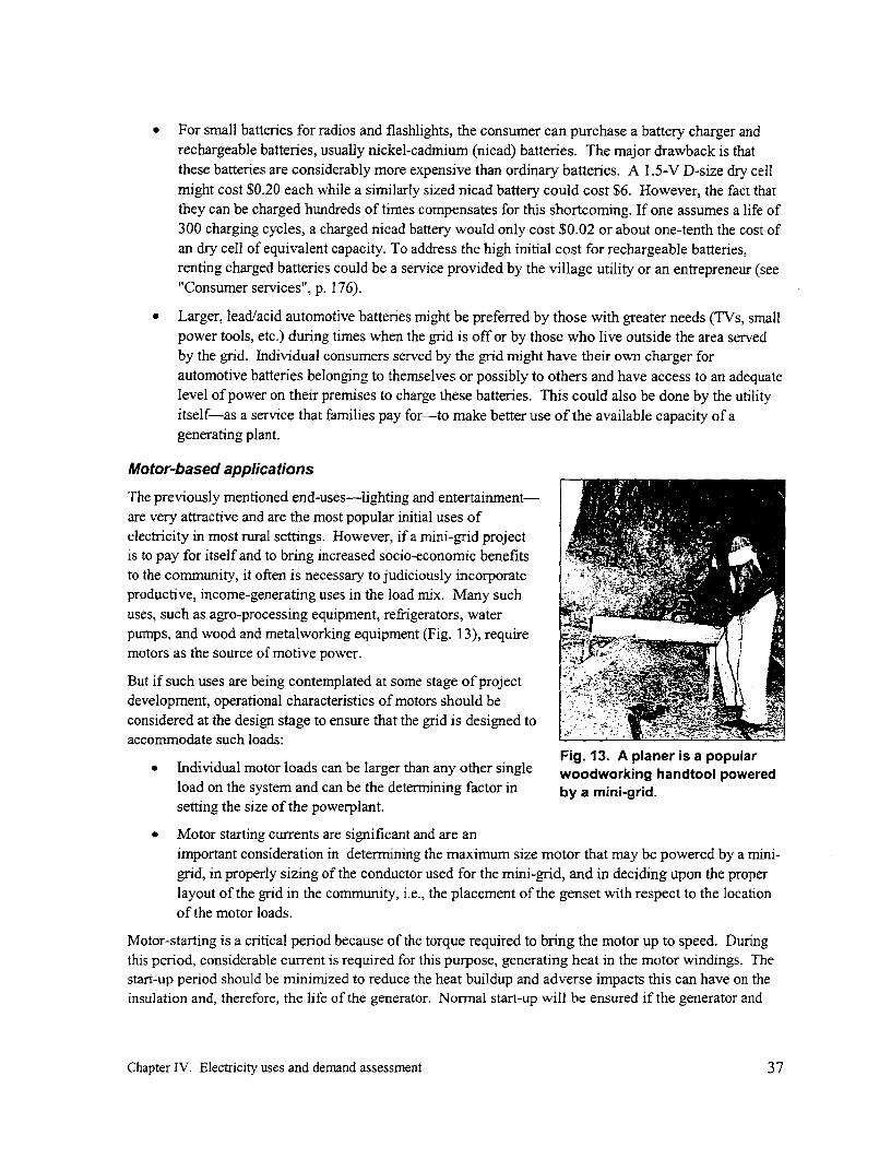
* For small batteries for radios and flashlights, the consumer can purchase a battery charger andrechargeable batteries, usually nickel-cadmium (nicad) batteries. The major drawback is thatthese batteries are considerably more expensive than ordinary batteries. A 1.5-V D-size dry cellmight cost $0.20 each while a similarly sized nicad battery could cost $6. However, the fact thatthey can be charged hundreds of times compensates for this shortcoming. If one assumes a life of300 charging cycles, a charged nicad battery would only cost $0.02 or about one-tenth the cost ofan dry cell of equivalent capacity. To address the high initial cost for rechargeable batteries,renting charged batteries could be a service provided by the village utility or an entrepreneur (see"Consumer services", p. 176).
* Larger, lead/acid automotive batteries might be preferred by those with greater needs (TVs, smallpower tools, etc.) during times when the grid is off or by those who live outside the area servedby the grid. Individual consumers served by the grid might have their own charger forautomotive batteries belonging to themselves or possibly to others and have access to an adequatelevel of power on their premises to charge these batteries. This could also be done by the utilityitself-as a service that families pay for-to make better use of the available capacity of agenerating plant.
Motor-based applications
The previously mentioned end-uses-lighting and entertainment-are very attractive and are the most popular initial uses ofelectricity in most rural settings. However, if a mini-grid projectis to pay for itself and to bring increased socio-economic benefitsto the community, it often is necessary to judiciously incorporateproductive, income-generating uses in the load mix. Many suchuses, such as agro-processing equipment, refrigerators, waterpumps, and wood and metalworking equipment (Fig. 13), requiremotors as the source of motive power.
But if such uses are being contemplated at some stage of projectdevelopment, operational characteristics of motors should beconsidered at the design stage to ensure that the grid is designed toaccommodate such loads:
Fig. 13. A planer is a popular* Individual motor loads can be larger than any other single woodworking handtool powered
load on the system and can be the determining factor in by a mini-grid.setting the size of the powerplant.
* Motor starting currents are significant and are animportant consideration in determining the maximum size motor that may be powered by a mini-grid, in properly sizing of the conductor used for the mini-grid, and in deciding upon the properlayout of the grid in the community, i.e., the placement of the genset with respect to the locationof the motor loads.
Motor-starting is a critical period because of the torque required to bring the motor up to speed. Duringthis period, considerable current is required for this purpose, generating heat in the motor windings. Thestart-up period should be minimized to reduce the heat buildup and adverse impacts this can have on theinsulation and, therefore, the life of the generator. Normnal start-up will be ensured if the generator and
Chapter IV. Electricity uses and demand assessment 37

the distribution line to the motor have adequate capacity to supply this extra current to the motor whilerestricting the voltage drop to no more than about 20 % of nominal. If this is not possible, the motor maystall and will likely be damaged. The capability of a generator to start a given motor depends on manyfactors, including the design and characteristics of the motor, as well as the type of voltage regulator andexciter used by the generator and the characteristics of the line connecting the motor to the generator.
The following pages will first identify the types of loads that a motor may experience. This will befollowed by a review of the types of motors that might be used for mini-grid applications to supply thoseloads. And finally, the calculation of the nominal current drawn by a running motor will be illustratedand the implications of the size of a motor's starting current on the maximum size motor that might beused with a particular generator will be explained.
Types of loads
Once operating under a constant load, motors have current requirements that are approximatelyproportional to the load they are driving and that are straightforward to calculate (see below). But whilea generator might provide more than adequate power to run a motor, it is possible that the same generatorand the distribution line between the generator and the motor do not have sufficient capacity to start themotor. The size of the demand placed on the generator during start-up depends on both the nature of theload to be driven and the type of motor used. For this reason, it is useful to categorize end-uses formotors by the type of load they impose on the motor upon starting. Starting loads can be divided intothree categories:
1. Applications with low starting torque, such as floor drills and portable tools, food mixers andblenders, and sewing machines. Fans and centrifugal pumps also fit into this category becausethe load each imposes on the system is small at low starting speeds and only increase as the speedincreases.
2. Applications with constant torque, such as air compressors for running tools or filling tires,refrigerators and freezers, conveyor belts, and positive displacement pumps such as gear pumps.
3. Applications with high inertial starting torque, where the large mass attached to the shaft makesit difficult to start it turning. These include some grindstones, grain mills, and woodworkingequipment such as bandsaws.
The last two categories represent more difficult loads to serve because of their starting requirements.
Types of motors
The principal types of motors that might be found in a small community are brush type or "universal"motors and induction motors. Universal motors are small-typically 1/20 hp or less-and are used in alltypes of handheld appliances, such as drills, mixers, blenders, saws, and sewing machines. They areinefficient, noisy, and require maintenance as their brushes wear. However, they are insensitive to thequality of power provided and can operate successfully under extremely adverse conditions of low orfluctuating voltage or variable frequency. They are usually high speed, with the speed dropping rapidlyas load increases.
Induction motors are sold as free-standing units to power pumps, air compressors, fans, conveyors, andother machines or are incorporated into larger appliances such as refrigerators. Their speed remainsrelatively constant as load changes. Induction motors are mechanically rugged, but are sensitive to powerquality and may be damaged by prolonged operation at low voltage. They also impose significantburdens on the grid due to their need for extra current during the starting process.
Chapter IV. Electricity uses and demnand assessment 38

Induction motors are available as single-phase and three-phase motors. Whether a single- or three-phasemotor is used to drive a specific piece of equipment is determined by the size of the demand, the cost ofthe motor, and the type of electric service available. Single-phase motors are available in sizes fromfractional horsepower ratings up to approximately 10 hp. Three-phase motors are also available infractional horsepower ratings, but in sizes below I hp are more expensive than single-phase motors. Userequipment with a power demand of less than 1 hp is therefore almost always driven by a single-phasemotor. Single-phase motors are used to drive smaller appliances, such as hand-held power tools, mixersand blenders, as well as larger equipment, such as water pumps, air compressors, fans, grain mills, andtable saws. Single-phase motors larger than 1/3 hp should be capacitor-start types to reduce startingcurrents and the voltage flicker they cause (see below). Three-phase motors, because of their lower costand ruggedness, are preferred for all applications over 10 hp and are often used in smaller sizes if three-phase power is available. The cost of extending three-phase service sometimes outweighs the savings inthe cost of the motor for applications between 1 and 10 hp.
For typical motor loads that might be found in a small comnmunity, single-phase induction motors areusually favored. Table 3 illustrates typical operating characteristics for the three common types ofinduction motors:
1. Capacitor-run: The limited starting performance of this type of motor makes it most suited to lowstarting-torque applications which limits its starting current demand. It operates with a highpower factor and efficiency. The capacitor is continuously rated and remains in the circuitpermanently.
2. Capacitor-start: This motor has a capacitor that is only included in the circuit to improve thepower factor, and therefore reduce current demand, during the start-up period. It has a goodstarting performance. As the motor comes up to speed, a centrifugal switch switches out thecapacitor. During its running, the power factor and efficiency are lower because the capacitanceis no longer in the circuit.
Table 3. Sample operating characteristics for a four-pole (about 1400 rpm) single-phase inductionmotors running on 240 V, 50 Hz.
Y~~~~ ~ ~~~~ 0 ^ o o ° 0
E ) sJ 0 JQ< 0 X run 1.1 6.5 7 -0 . 3.
Capacitor- 0.12 - 2.2 .75 6.5 67 % 0.72 5~~~.5- o.5 oe 13 L
L. " M C~L. 4-..
o2- 0 0 xU) w IL )j _ Tu T
Capacitor- 0.12 - 1.5 .25 1.7 65 % 0.95 3.5 3.5 12 1if none
run ~~~1.1 6.5 72 % 0.98 3.5 3.5 40 gf none
Capacitor- 0. 12 -2.2 .75 6.5 67 % 0.72 5.5 5.5 none 130 gfstart 2.2 16.5 77 % 0.75 4.5 4.5 none 160 1tf
Capacitor- 0.75 -3.0 1.5 9.0 79 % 0.87 2.0 5.6 30 Rf 160/200 pLfstart/run 3.0 16.4 80 % 0.93 2.9 5.2 40 pf 200/250 ,f
Chapter IV. Electricity uses and demand assessment 39
3. Capacitor-start/capacitor-run: This type of motor has a good starting performance and thereforeis suitable for high starting-torque applications. It is the most efficient of all single-phaseinduction motors and is generally used with higher-horsepower single-phase motors. It includesboth a temporarily connected start capacitor and a permanently connected run-capacitor.
In the table, the term "locked rotor" used by motor manufacturers refers to the starting condition wheninitial currents are similar to those one would encounter if the rotor were locked. Note that these currentsare from four to six times the nominal running currents. During start-up, the power factor of the motor isusually much lower than it is while running. The inefficient use of current that is implied in a low powerfactor is one reason for the high currents required. For example, while six times the running current maybe drawn on start-up, the starting power may actually only be twice the running power.
It is important that available voltage on the mini-grid be maintained at near its nominal value during start-up. A low voltage reduces the starting ability of a motor. Appliances requiring a high starting torque,such as a refrigerator compressor, are in danger of overheating and not starting under these conditions.With a high current demand, the voltage available at the motor is decreased through voltage drops alongthe line which supplies the motor if its capacity is inadequate (because it is too long or uses too small aconductor). Ideally, voltage drop during motor starting should be limited to no more than about 5 %.However, if starts are infrequent and thus not likely to cause complaints from other users, voltage dropsas high as 20 % at the motor terminals during starting can be tolerated. For these reasons, motors of anysignificance should preferably be sited near the powerplant and, if possible, supplied by a separate circuit.This will provide maximum voltage to the motor and will also reduce voltage drop witnessed by theconsumers along the remainder of the line. Since there will still be a voltage dip when the motor starts,the frequency of this starting and the annoyance it may cause other consumers (usually throughfluctuating light intensity) should be kept in mind when laying out the distribution system.
Motor and line sizing
Running current
A motor is normally rated and labeled by the maximum continuous shaft or mechanical output power ithas available to drive the equipment to which it is connected. This is measured in horsepower (hp). Theactual power it delivers will depend upon the load imposed by the equipment it drives and is equal to orless than the rated power. The relationship between the output power of a motor and the power itconsumes (input power) is given by the following relationships:
Pi(W) Po(W) Po(hp)x750cos r x cos ij x cosS
where
cos 4 power factor
l = efficiency of the motor
Pi = input power
PO = output power available for driving equipment (expressed in either watts orhorsepower, with the conversion factor, 1.0 hp = 750 W)
Chapter IV. Electricity uses and demand assessment 40

For example, assume that a flour mill requires a motor with 3 hp (2.3 kW) of shaft power to run atcapacity. A 4-hp motor is found and the motor manufacturer indicates its efficiency as 70 %, with apower factor of 0.75 when running. The motor's electricity demand while driving the flour mill would be
P (VA) = = 4300 VA = 4.3 kVA0.70 x 0.75
If a single-phase motor running off a 230-V supply were used, the steady-state current drawn from themini-grid would be
P,(VA) 4300VA
E 230V
where E is the voltage imposed across the motor.
If a three-phase motor running off a 230/400 V supply were used, the steady-state current drawn from themini-grid would be
Pi P(VA) 4300 VAI (E -= =6.2A
3E 690 Vwhere E represents the phase-to-neutral voltage (see Fig. 1 Sc).
By knowing the nominal running current associated with a motor and the factor by which this is increasedduring start-up, as noted in Table 3, it is possible to size the line conductors between the generator and themotor to keep voltage drop during start-up to within acceptable limits (such as no more than the 20 %noted on the previous page). An example can be found in Appendix 7 (see p. 237).
Maximum limit on motor size
For a system supplied by a synchronous generator, which is typically the case with a mini-grid, motor-starting capability will depend on the size of the generator and its design, particularly on the design of thevoltage regulation and excitation system. A good quality synchronous generator will be fitted with anautomatic voltage regulator (AVR) that will maintain the output voltage under motor starting conditionsby circuitry that can boost the field current for several seconds. This can help supply the high startingcurrent requirements (up to six times nominal running current) of motors used for high starting-torqueloads. Because of the greater starting torque possible, synchronous generators should be selected wheremotor loads are likely.
For direct motor starting, the maximum limit on motor capacity (measured in hp) typically is numericallyequal to 15 % of the capacity of the generator (measured in kW). If a high quality motor is used, currentshould be no more than about four times nominal and the maximum motor capacity may be up to twicethis value.
To reduce the cost of the generator, lower-cost induction motors connected to some capacitors with thenecessary electronics occasionally serve as induction generators for use in isolated locations. These havebecome increasingly popular with micro-hydropower plants that capitalize on the lower cost andincreased robustness associated with the simpler construction of induction motors.
For systems supplied by such induction generators, motor-starting capability is less than systems suppliedby synchronous generators because the design on induction generation precludes the possibility ofincreasing the field current as is possible with synchronous generators. For a motor starting on a linesupplied by an induction generator, the maximum limit on motor capacity (measured in hp) typically is
Chapter IV. Electricity uses and demand assessment 41

numerically equal to 5-10 % of the capacity of the generator (measured in kW). In practice, higher-capacity motors than this can often be started, provided that the required starting torque is low. Butsignificant voltage dips can occur.
The limits on the size of motors above are valid for both single-phase motors driven by single-phasegenerators and three-phase motors driven by three-phase generators. Another case is where single-phasemotors are driven off three-phase generators. In this case, if the generator and distribution line are delta(three-wire) connected, the maximum limit on motor capacity (measured in hp) is again numerically equalto about 15 % the capacity of the generator (measured in kW). If the generator and distribution line arewye (four-wire) connected, the maximum limit on motors capacity is about half this value.
While the primary concern above is maintaining a sufficiently high voltage at the motor to ensure itsproper operation, too high a voltage (over 10 % above nominal) can also damage motors because of thehigher currents associated with the higher voltage. High frequencies can cause problems with motorsrequiring a high starting torque. If the supply frequency is as much as 10 % above the nominal frequency,the steady-state motor speed would be correspondingly higher and the additional torque requirements toget up to this higher speed can be sufficient for the motor to fail to start altogether. Any voltage drop inthe line from the power supply to the load further exacerbates this problem. This reinforces the argumentfor placing motors as close to the generator as possible.
Over-frequency can also affect some motors in the running mode. When driving certain loads, such ascentrifugal pumps and fans, the higher frequency implies a high motor speed that in turn implies anincreased load (since load is proportional to the square or cube of the speed). This results in an excessivecurrent, which can lead to overheating and possible burn-out. The frequency rise should not exceed 10 %.
Mechanical-drive alternative for large motors
As explained earlier, a mini-grid that relies on its own small power supply may have a difficult timesupplying large motors. For example, a 7 kW village genset that serves the lighting needs of 50 familiesin the evening cannot be used to drive a 4-hp rice mill even during the day because the generator hasinsufficient power to start the motor. For this reason, end-uses which depend on motors can beconsidered to be in either of two broad categories: those which require fractional horsepower motorswhich easily can be be run by a small powerplant (hand drill and saws, blenders, fans, sewing machines,some pumps, refrigerators, etc.) and motors (for grain mills, rice hullers, table saws, etc.) which are toolarge to be powered by a small powerplant.
For motors driving the first set of end-uses, a mini-grid can power them, provided that the supply hassufficient capacity, as noted earlier. For motors driving the second set of end-uses, this may not be thecase. But even in this case, an alternative solution may exist. This would be to select a prime mover(e.g., a diesel engine or hydropower plant) to directly drive this equipment, usually by means of flat orvee belts. Actually, this is often how electricity is introduced into a community. An entrepreneur firstpurchases a diesel engine to drive his rice or grain mill. Then, perhaps as an afterthought, he or sheconsiders the possibility of also generating electricity as an additional source of income and providing aservice to the commnunity as well.
Even when a generator is already installed to provide electricity to community households, using theprime mover (the engine) to directly (i.e., mechanically) drive the end-use equipment would still haveseveral important advantages.
* No electric motor need be purchased.
Chapter IV. Electricity uses and demand assessment 42

* As mentioned above, a smaller prime mover would be needed because its capacity could be moreclosely matched to the steady-state load to be driven; it could be significantly smaller than wouldotherwise be required if it were to also start a motor.
* The capacity of the line supplying the motor need not be oversized simply to meet the occasionalsupply requirements of that motor. E
* Consumers are not frustrated with poor quality service caused by voltage variations associatedwith the operation of the motor.
* It is more efficient. A portion of the energy available is lost in using electricity to drivemotorized equipment. If a motor is electricity-driven, the prime mover must generate electricity,losing energy in the conversion from mechanical to electrical power (80 % efficiency). Furtherenergy is lost in transmitting the electricity to the motor, although this should not be significant ifthe mini-grid has been properly sized (possibly at an additional cost). And finally more energy islost in the motor as it reconverts the electrical energy back to mechanical energy (at an efficiencyof perhaps 80 % for small motors being considered). Therefore, the overall efficiency of thisconversion would be about (0.80) x (0.80) or 60 - 70 %. In other words, more than 30 % of theenergy available from the prime mover would be lost if, rather than directly driving theequipment, electricity is first generated to then drive a motor that in turn powers the equipment.Still additional losses would be incurred if the generator were belt-driven by the prime moverrather than being directly coupled. These energy losses represent increased fuel consumptionand, therefore, increased running costs.
The principal advantage of using electricity for motor loads is that it is not always possible to locate theseloads close enough to the prime mover for direct drive. This may be because they cannot be located onthe same property (possibly because they have different owners); because the powerplant, such as ahydropower plant, is not located in a convenient location for the end-users; or because more than onelarge, motor-driven end-use is required at different locations in the village. Electricity may be moreconvenient but unless the capacity of the power supply is sufficiently large and can accommodate electricmotors of adequate capacity to operate all the end-uses, another means will have to be found of drivingthem.
Heat-generating appliances
Another category of end-uses are those which rely on electricity to generate heat. These include suchappliances and equipment as irons, hot plates, cookers, soldering irons, hair dryers, and space heaters.The unique feature of these end-uses is that they consume considerable power and therefore have a majorimpact on the design of a mini-grid. In a village setting, while individual fluorescent lamps mighttypically consume up to 20 W, incandescent bulbs up to 100 W, and small motors for power tools up toseveral hundred watts, heat-generating appliances can each easily consume 1,000 W.
If the capacity of the power supply for a mini-grid is small, as it usually is, the use of these appliancesshould not be allowed, especially during times of peak village demand, i.e., in the early evening hours.Small mini-grids simply do not have the required capacity to permit the widespread use of theseappliances.
If cooking needs were to be met, a more costly power supply and mini-grid would be required. Typically,the peak coincident demand for electricity in many villages in developing countries around the worldwhich have been grid-connected for a number of years is about 250 W. To accommodate the use of a
Chapter IV. Electricity uses and demand assessment 43

1 kW hotplate by each consumer without increasing the voltage drop, the generator capacity and the areaof the conductor (and its cost) for both the distribution system and the service drops may have to beincreased by up to 400 %. Since the cost of the conductor represents a major component of the cost for amini-grid project, such an increase in the investment could significantly decrease the attractiveness of aproject, even if adequate power were available.
The argument is commonly heard that the availability of electricity for cooking would displace fuelwoodextracted from forests and reduce the rate of deforestation. While an appealing argument for includingthis end-use, this is rarely if ever the case unless the cost of electricity is heavily subsidized. One reasonfor the high cost of electricity is the increased capital cost of the project due to the increased size of theconductor and associated components required, as was just explained. This cost must eventually be bomeby the consumer. Another reason is simply the recurring cost of electricity. While energy needs forcooking depends on numerous factors, it can easily amount to several kilowatt-hours daily per householdand cost $10 to $20 or more each month. For many rural households, this could add considerably to thefinancial burden they would have to shoulder.
Use of electricity is occasionally promoted as a source of heat energy when the supply comes from amicro-hydropower plant. In this case, the marginal cost of energy (the extra cost incurred by generatingmore energy each day) is minimal because the fuel is free. This is not the case with a diesel-suppliedmini-grid where each 2 to 3 kWh generated requires the consumption of another liter of diesel fuel. Buteven in the case of a mini-hydropower plant, the capacity limit is still a problem. Consequently, whilethis approach has been promoted in micro-hydropower projects in Nepal, several types of locallymanufactured cookers that reduce each family's power demand have also been developed and promoted(Figs. 14). Each of these designs places a maximum demand of about 250 W on the system. Somedesigns slowly cook with this low power input (i.e., similar to the operation of a rice cooker) while othersuse various approaches to store the heat they generate when excess power is available during the day andthen extract the heat during the much shorter cooking times.5
Another circumstance under which a micro-hydropower plant is used to generate heat is when this is usedas a method for goveming or controlling the speed of the turbine/generator unit. To generate at a constant50 or 60 Hz, a constant load must be imposed on the turbine/generator unit. To achieve this, any excesspower not used by the consumers is diverted into a water heater to heat water that in turn can be used forproductive purposes (clothes washing facilities, hot water supply for cooking, etc.).
Heat energy is generated by passing electricity through a resistive element. Consequently, voltagevariations do not affect the operation of these appliances. The major impact is on the heat generated thatvaries as the square of the applied voltage. A 10 % increase (or decrease) in the voltage will result isroughly a 20 % increase (or decrease) in heat output. Frequency has no impact on this end use.
Demand assessmentA critical step in the initial planning process is to estimate the maximum initial coincident load that theprospective consumers are to impose on the system and how this load is expected to grow over time. Thisis necessary in order to size both the generating plant (or transformer) and the conductor used in the
The coincident load is the sum of the loads actually on at any instant of time. This is generally different from thesum of all the individual community loads (called "connected load") because all these loads are not generally on atthe same time, i.e., they do not coincide. For example, if two 1-kW motors may be used at the same time for somedaytime hours and sixty 50-W bulbs are all lighted during the early evening hours, the connected load is 5 kW butthe maximum coincident load that the powerplant must supply is 3 kW.
Chapter IV. Electricity uses and demnand assessment 44

Fig. 14. At the left, a locallymanufactured low-wattage cooker inuse in a restaurant in Nepal. Aboveare visible the two sections of thecooker just before their lips arewelded together. Four heatingelements are installed beneath theinner pot. The socket and pilot lightare near the bottom of the outer pot.(Photo credit, below: Lionel Mackay)
distribution system (Chapter VII). Investments in each of these components are significant, andimproperly sizing either of these would make it more difficult to cover the capital and/or recurring costsof the system and therefore to ensure system viability:
* Too small a capacity could lead to consumer dissatisfaction with the service, leading tofrustration on the part of the consumers and their possible hesitancy to pay the electricity bill. Itcould also interfere with serving additional consumers or additional load growth which wouldotherwise increase the consumer base and thereby reduce cost.
* Too large a capacity would mean additional investment costs for the construction and possibly theoperation of the system that could be difficult to recoup without raising the tariff to a pointbeyond the consumers' ability to pay.
Making load projections that reflect reality is frequently a difficult task to accomplish, especially forperspective consumers who have little experience with electrification. Simply asking households whatuses they would make of electricity in the home and how many 40-W bulbs they would like to use willnot lead to reliable conclusions. Prospective users generally have little knowledge of, for example, theamount of illumination would come from a 40-W bulb in a dark room, what the difference is between the
Chapter IV. Electricity uses and demand assessment 45

light emitted from a 40-W incandescent bulb and a 40-W fluorescent lamp, or what monthly costs theywould actually incur for each.
Another factor affecting the demand of potential consumers is the unit cost of electricity ($/kWh). Projectimplementers should have done sufficient planning to at least have estimated this cost on the basis ofapproximate costs that the project will incur. (For an idea of the range of costs that might be incurred, seep. 13.) If a tariff to cover all outstanding and ongoing costs is to be set, the project implementer shouldgo through the exercise explained in the Chapter XIV and illustrated in Boxes 15 and 16 (p. 184 and 190).This should provide a more realistic costing of electricity service and give potential consumers a betterfeel for how much they would have to pay for a certain level of service and whether this will beaffordable. Of course, it will also be necessary to gage the ability of prospective consumers to purchasethe required appliances and make use of the electricity.
An indication of the power demand that would satisfy rural consumers might be obtained from aknowledge of how rural households make use of their disposable income and what end-uses are presentlyfound in a typical home, end-uses that could realistically be supplied by grid power.
Probably a more reliable approach for assessing future demand than simply asking potential consumerswould be to survey households in adjoining, already-electrified areas or in a region with similar economicactivities, disposable income, demographics characteristics, etc. This would determine the average initialloads per household in these areas as well as their historical load growth.
The already-electrified regions that would be surveyed should preferably have a similar type of service asthat being proposed in the new community, such as 24-hour power or electricity for 4 hours each evening.Furtherrnore, it should also be clear that the demand served by these electricity supplies has not been sup-pressed because of limited generation capacity during hours of operation. Projections of loads in areas tobe electrified made on the basis of loads in regions with suppressed demand would understate the actualdemand to be met in the new areas. Consumers in the already electrified regions used as the basis fordemand projections should also be paying a similar tariff as the one projected in the new areas to beelectrified.
Any projections of load and load growth in an area to be electrified using infornation gathered fromalready-electrified regions should also consider such factors as the difference in the level of disposableincome in the two areas, the presence of raw materials or industry, the potential for tourism, and access tooutside markets for goods which might be grown or produced locally. In surveying already-electrifiedcommunities, it is also important to determine to what extent three-phase service is required to servetypical loads, such as motors for agro-processing.
The load projection must not simply be that expected the day electricity is switched on. Rather, it must besufficiently high to provide adequate capacity into the future. How far into the future depends on thespecific situation and the size of the required mini-grid investment. For example:
* If a low-cost grid is envisioned simply for lighting in a community where there is littleopportunity of increasing disposable income, the load might not be expected to increasesignificantly. In this case the demand when the project begins may be expected to remain largelyunchanged over the life of the mini-grid.
* If a village is located in a fertile region, with road access but with no hope of receiving powerfrom the extension of the national grid, the load projected at the end of the expected life of thedistribution system should be used.
Chapter IV. Electricity uses and demand assessment 46

* If a village is interested in building an isolated mini-grid to be used only until it is replaced aftersome period of time by a more conventional distribution system to be installed by the nationalutility, the load expected over this period of time should be used.
* If a village is interested in building an isolated mini-grid in anticipation of eventually connectingto the approaching national grid, and if they feel that having a mini-grid that can be directlyinterconnected to the grid once it has arrived, at no additional cost to the utility, provides addedincentive for the utility to connect them, a 20- or 30-year planning horizon as is used by theelectric utility might be used.
Demand-side managementAfter projecting the peak coincident demand that is expected at a new project site, it may still be possibleto reduce project cost by either reducing the generation or distribution capacity required to meet this peakdemand or permitting increased consumer load with the same generating and distribution capacity. Thisis achieved through demand-side management, i.e., managing electrical demand on the system in order toachieve more efficient use of the investment. For example, original plans might call for a 2 kW grain millto work during the early evening hours when domestic needs require 8 kW. This would require a gensetwith a capacity of at least 10 kW. Demand-side management would attempt to restrict milling to hourswhere it does not coincide with lighting, thereby reducing the required maximum generating capacity toonly 8 kW. Box 3 presents other examples of demand-side management.
Chapter IV. Electricity uses and demand assessment 47

Box 3. Demand-side management in Nepal.
In the villages around Aserdi in central Nepal, an isolated system supplied by a 1.0 kV line and small
transformers serves three types of loads: residential lighting mostly in the evening, hulling of rice and
milling of grain generally during the day, and water pumping located at the end of the distribution
system. If the pump were to adversely affect the quality of electricity (causing brownouts) by
imposing too much demand through the existing distribution line, the demand could be managed by
operating the pump during late evening hours when excess line capacity is available. Furthermore, the
water system would not be adversely affected by this scheduling because water is stored in a reservoir
supplying a gravity-fed water-distribution system.
Another effort at demand management was to implement a capacity-based tariff for the small domestic
consumers in the area. This is less costly to administer, because no meter, meter reading, or billing is
required. But another reason was to encourage off-peak uses of electricity-encouraging 25-W and
50-W consumers to run radios during the daytime to save on battery purchases or encouraging 250-W
consumers to use off-peak electricity to assist in cooking.
This latter approach to demand management requires that appropriate electrical end-use equipment be
readily available. For example, to encourage the displacement of increasingly difficult-to-find
fuelwood with electricity without the peaks usually associated with electric cooking, various designs
for low-wattage heat storage cookers have been developed and were promoted. These were designed
to be plugged in most of the day when excess capacity is available in the home, storing heat that can
later be used for cooking or heating when needed. In the Aserdi region, the 250-W limit was
specifically set with this use in mind; it permitted the simultaneous use of the cooker and one light.
With a capacity- or demand-based tariff, the consumer pays for using up to a pre-selected level of power (e.g.,25, 50, or 250 watts) but can use this power for whatever period of time. Rather than paying a tariff based on theactual energy (kWh) consumed that is measured by an energy meter that periodically must be read and billed bythe utility, the consumer pays a fixed monthly tariff. To ensure that the household consumption does not exceed
its pre-selected level of power, any of several forms of current limiter is used to restrict demand.
Chapter IV. Electricity uses and demand assessment 48


V. Mapping and system layout
After it has been established that potential consumers appear willing and able to cover the costs that willbe incurred according to an agreed-upon tariff schedule, that an acceptable electricity supply is available,and that a well-founded and sustainable organizational mechanism exists to undertake such a project,planning can proceed. This chapter will begin by briefly reviewing steps required in preparing a map ofthe area to be electrified, a map that will assist with the planning and design process and provide aframework within which to collect the necessary data. This chapter will then review factors affecting theplacement of the powerhouse and the physical layout of the mini-grid on the map that has been prepared.
MappingThe mapping effort should begin with a sketch of the community, starting with the general features foundin the village and ending with the placement of specific homes, shops, schools, and other potential villageloads.
The map can begin with a sketch that includes the placement of the larger features, including a roughlayout of the roads, trails, paths, and streams going through the community. Other landmarks such asvillage wells, market areas, meeting halls, schools, paddy land, and large trees can then be added. Andfinally, individual homes should be included.
It will be useful to draw this map somewhat to scale, because distances later will be used to calculateconductor size, pole locations, etc. Although the use of a long surveying tape (30 to 100 m) should givemore accurate results, a good first cut should be achieved by simply pacing distances between all thevillage landmarks and individuals homes. Modem technology such as global positioning system (GPS)receivers can also be used but this requires that another set of skills be developed. Furthermore, theaccuracy over small distance such as are found within a community may be less than can be obtained bysimply pacing distances.
If distances are to be paced, all individuals involved in gathering data to prepare the map should firstcalibrate their standard pace. They should decide what feels like their "standard" pace over the actualtype of terrain they will be crossing. They should each walk a fixed number of standard paces (e.g., 20)and measure the distance with a tape. From this, they can each estimate the average length of a singlepace (e.g., 0.65 m). By doing this several times in different places, they should also be able to get an ideaof the accuracy of their pacing. As the village survey proceeds, it would be a good idea to occasionallyuse a tape to verify the length of these average paces. From this, they can get a feeling for the variation inthis average length from place to place and day to day.
Once paces have been calibrated, measurement should start from a specific landmark. Although thefinished map should be the same independent of where pacing begins, it would be preferable to start at thelocation of the proposed powerhouse (see the following section for guidelines in placing the powerhouse).Then pacing can proceed along what might be the eventual alignment of the distribution system.
Once all measurements have been made on the first sketched map, the map can be redrawn closer to scale.This map should be adequate for design purposes. Alternatively, once a map has been redrawn based onpaces and the initial distribution system laid out, another iteration can be made using a surveyor's tape,but distances can be rounded to the nearest meter. Greater accuracy is not necessary.
Chapter V. Mapping and system layout 49
System layoutThe principal use for the map will be to provide a base on which to lay out the distribution lines for themini-grid so that detailed design work can be initiated (sizing of the power system, conductor, and poles).For this purpose, the next step will be to visit each potential consumer, to assess what design load is to beused during the system peak (the daily coincident peak demand) for that consumer (p. 43), and to indicatethis at the proper location on the map. If a motor or other load with atypical characteristics is to be usedby any consumer, this should also be indicated.
In addition to assessing initial consumer load, the growth in this load into the future must be estimated asrealistically as possible. Also to be included is the expected growth in demand from new consumers,either from existing villagers who are yet unwilling to commit to being electrified or from newhouseholds that have yet to establish themselves. And finally, some thought may already have been givento the establishment of new shops and commercial loads in the near future or new institutional loads like aclinic, school, or government office that are under consideration. The size and location of these newloads must also be considered in planning for a mini-grid if it is expected that this grid will serve them.
Once all the design loads to be served have been estimated, the distribution system can be laid out. Thisrequires finalizing the location of the powerhouse, the placement of the lines, and the pole locations. Inlarge part, these are determined by the layout of the village and the general nature of the loads to beserved. Factors affecting this aspect of project design are explained in the following sections.
Once the nature of the power demand and the layout of the distribution system are known, the next stepswill be to determine the line configuration (Chapter VI), the conductor type and sizes to adequatelysupply that demand (Chapter VII), and available pole options and size to ensure adequate line clearanceand a safe system (Chapter VIII). While a few comments are made below on the placement of poles, thisonly serves as initial guidance. Final pole placement can be determined after the steps just mentionedhave been completed.
Powerhouse location
The location of the powerhouse will be affected by several factors, but this task is simplified by the factthat there are usually a very limited number of optons. These factors include the following:
* Voltage drop. As with much of the design planning for a mini-grid, the location of thepowerhouse is determined, to the extent possible, by the need to ensure that voltage drop at theend of each line remains within acceptable limits at minimum cost. To achieve this, the optimumgenerator location is in the center of the load it is to serve.
* Location of the energy source to be harnessed. If the powerplant relies on hydropower, it mustbe located at the most efficient location for power-generation purposes. A very limited number ofoptions usually exist. Power must be transmitted from that point to the mini-grid. While this willincrease the cost of the distribution system somewhat, this is offset by the other advantagesimplicit in relying on low-cost hydropower-generated electricity. If the power source is wind-based, the powerplant must usually be located on a ridge or other high point to tap the largestwind resource, even though this may also be outside the load center. If the source of energy isdiesel, the powerplant could be located in the center of the load. However, even in this case, ifthe village is on the flank of a hill on one side of a valley, with the main road below, it might bemore advantageous to generate power just off the road, where fuel drums can be more easilydelivered, even though it may be on the outskirts of the village.
Chapter V. Mapping and system layout 50

It is often the case that a mini-grid is privately owned, as a small business. In such cases, the
location of the powerplant owner's property may determine the powerplant location.
* Size and nature of the end-use. Irrespective of who owns the mini-grid, if a large load such as a
grain mill is to be supplied, it may be most efficient to place the powerplant near that mill to
reduce the costs of the heavier line that would otherwise be required to serve that load.
* Noise. Diesel-based electricity generation can be a noisy undertaking. If effective silencing of
the exhaust is not possible, this might also force the genset to be located at a more isolated part of
the village.
Placing the lines
Once the powerhouse has been located, the distribution line is required to bring the electricity to the
vicinity of the consumers. The best layout for the distribution system will be one that meets the criteria
for voltage drop while minimizing cost and keeping safety and reliability in mind. In general, the shortest
line will minimize cost, because this will reduce the cost of both the conductor and poles. Poles are often
the most expensive component of a distribution system, and an important part of the design process is to
be economical in their use.
Depending on the layout of the consumers relative to the location of the powerhouse, the best layout may
be to extend lines in several directions from the powerhouse. Several factors must be taken into
consideration in deciding where these lines are to be placed. The relative importance of each must be
decided in each situation. These factors include the following:
* Location of roads, trails, and paths. The principal reason for locating lines along such arteries
is that most present and future consumers typically build their homes along road or trails and
these permit easy access for line construction and maintenance. Should street lighting also be a
priority, this is facilitated by locating poles along the principal arteries.
Care should be taken if roads carry vehicular traffic. Sufficient clearance under the conductor is
required whenever the possibility exists that vehicles will pass undemeath. Road crossing should
be avoided or minimized whenever possible. The alternative is to use higher, more robust, and
therefore costlier poles on either side of the road at each crossing to provide this greater
clearance.
In some countries, crossing property lines also causes problems, as many are not eager to have
power poles, especially with guys, in the "middle" of their yards, rice paddy, or coconutplantation. Following well-established paths and trails known to be open to the general public
minimizes this problem. At other times, in some communities, there is sufficient esprit de corps
and interest in electrification for all to join together and accept such inconveniences as one of the
costs of electrification.
* Presence of trees. When conventional lines are built, trees are often the first casualties. The
right-of-way along lines is generally cleared of trees to prevent them from interfering with the
operation of the line: to prevent branches from falling and breaking conductors or from shorting
the lines. In some areas, trees represent a source of income for the villagers (from the sale of fruit
and nuts) who are loath to destroy them for this reason.
On the other hand, depending of the strength, flexibility, amount of foliage, and age of a tree, they
are sometimes used as living power poles that have already withstood the test of time. These
Chapter V. Mapping and system layout 51

"poles" have the advantage of requiring no treatment to prevent decay, especially of the buriedportion at and just below the ground line that is the most susceptible. Lines are sometimes drapedover branches, while at other times, they are properly fixed to spool insulators mounted on themain trunk.
* Religious buildings/areas. Buildings or areas of religious or cultural significance must beidentified and a clear understanding of what constraints these impose on line routing should beestablished.
* Topography. Certain areas should be avoided if they will complicate the construction orongoing upkeep and maintenance of a line. These includes steep slopes, areas susceptible toerosion, swampy areas, and areas prone to flooding.
* Line length. Because poles and conductor are the most costly component of a mini-grid project,the alignment of the line should be selected to minimize their number and length, respectively.
* Minimizing changes in alignment. Whenever there is a bend in the line, the conductor undertension imposes a lateral force on the pole tending to tip it. Depending on the change inalignment at a pole and the tension of the conductor, this lateral force might have to becounteracted by a guy and anchor.' This adds to the cost and effort required in installing themini-grid. They also pose a safety hazard, as they may be difficult to see, especially in theevening, or simply get in the way. For this reason, where conductor tension is sufficiently large,an effort should be made to minimize deviations of adjacent spans for as long a distance aspossible, "concentrating" bends at as few points as possible..
* Loading. If several lines radiate from the powerhouse, the aim should be to equalize the kW-kmloading on each line during peak demand times, to the extent possible. This will permit the use ofthe same size conductor, reducing its cost through quantity discounts and possibly reducing theselection of connection hardware required. This will also make most efficient use of the lines.
However, with three-phase power, another more critical requirement for the proper operation ofthe generator is that loads on all three phases be as balanced as possible. This requirementbecomes more critical as generator capacity is approached and should receive high priority.
* Planning horizon. In laying out and designing a mini-grid, an adequate planning horizon shouldbe used and, to the extent possible, the mini-grid should be designed to pernit it to be efficientlyused over this period. Both new areas into which the grid might expand or existing customerswho might expand their use of electricity should be considered.
The focus of the present effort is to lay out the lines that are part of the distribution system itself and willbring electricity to points relatively close to each consumer. Separate from the distribution line are theservice drops that are used to bring the power the remainder of the way from the nearest pole to theconsumer. Details for the design of the service drops will be discussed separately in Chapter XII.
Depending on the layout of the village, one question that may need to be answered at this stage is howclose the main distribution line must approach each consumer. This answer depends on the peak demandor current required by the consumer(s) served by a service drop, the sizes of the conductor that can beused for the service drop, and the maximum allowable voltage drop. At this point, Fig. 101 (p. 148) can
When electric utilities build distribution lines, guys are typically used on poles whenever the change in directionof the line exceeds 5 '.
Chapter V. Mapping and system layout 52

be used to derive the maximum distance for any given values for these parameters. If too many home areoff in one direction from the distribution line, then one branch of the distribution line may have to beextended in that direction to bring power closer to those consumers and permit shorter service drops.
Once an initial layout for the distribution line has been established, selecting line configuration (ChapterVI) and the size of the conductor for the distribution system (Chapter VII) can proceed.
Locating poles
Once the general layout for the distribution line has been prepared, poles must be placed along that line tosupport the conductors with adequate clearance to ensure a line that does not pose any hazard to people orvehicular traffic passing beneath it. Factors affecting pole location include the following:
* At bends in the line. As noted in the discussion of line placement, guying may be needed ateach bend in the line. Therefore, to minimize the need for guys and anchors and associated costs,hassles, and safety issues, any significant bends along the line should be concentrated at as fewpoints as possible. Poles must then be located at each of these bends.
* Location of load clusters. As is explained later (p. 149), it is recommended that each servicedrop supplying a consumer takes off from a pole rather than from mid-span. For this reason, atleast one pole will have to be located near each cluster of homes within a certain radius of thepole. In this case, the location of home clusters determines pole location.
- Adequate ground clearance. In areas where homes are less densely located, the type and size ofconductor used, the length of available poles, and the required ground clearance will determinethe maximum span that is possible. For this reason, pole locations can only be finalized oncethese parameters have been established.
- Pole strength. Mechanical loading caused by wind on the conductor is transferred to the poles(as is described in Chapter VIII). The poles have to be strong enough to support this load, and thestrength of the poles available for the project may limit the maximum spans achievable.
Chapter V. Mapping and system layout 53


VI. Line configuration
To distribute power around a load center, four basic distribution line configurations are possible: twosingle-phase configurations and two three-phase configurations. These are illustrated in Fig. 15. Allconfigurations use similar materials and construction techniques. On some occasions, a combination ofthese configurations can be used to achieve a more cost-effective distribution system design.
For a particular village situation, the attributes of each configurations and a rough sizing and costing ofthe conductor and poletop hardware for each configuration should be assessed to determine which lineconfiguration is the most cost-effective. The sizing of the conductor for each configuration can be foundusing Table 8 or Box 5 after an acceptable voltage drop has been established. An example of conductorsizing for a sample line and the impact on line configuration on conductor size are illustrated in ChapterVII and in Appendix 7 (beginning on p. 234).
Options for line configuration
Single-phase supply
Single-phase, two-wire
For this configuration, two conductors from the powerhouse serve the entire commnunity at a voltage thatis usually nominally set at 120 or 230 V. To ensure a system that can easily be maintained and for whichconstruction materials and consumer appliances can readily be found locally, this voltage should coincidewith the standard in use in the country.
If the powerhouse is located in the middle of the load center, single-phase lines might take off from thepowerhouse in several directions. Consumer connections to this system are straightforward: the mini-gridis comprised of a pair of conductors that pass by each consumer and the service drop simply taps both ofthese lines (Fig. 1 5a). From this point of view, this is the simplest option to design and is therefore themost conmmonly used for mini-grids. But it is not the most efficient option. System design for the otheroptions is somewhat less straightforward because the distribution lines include at least three conductors,and the system designer is faced with a choice of which pair of these conductors each consumer shouldtap so that the loads are balanced. Balancing loads along a distribution means that, as one proceeds alongthat line, loads are connected to each phase conductor in a such way that the currents in these conductorsare as close to equal as possible.
A pair of single-phase lines can also be used with a single-phase, three-wire configuration as well as withboth three-phase configurations, when a small load off in some direction does not warrant stringing asplit-phase or three-phase line in that direction (Fig. 15b, 15c, and 15d). It should be noted that evenunder circumstances where three-phase power is generated, three-phase power may not be used or neededby any one consumer. Rather, pairs of single-phase lines leave the three-phase generator in variousdirections to serve the different portions of the comrnunity.
It is possible to ground one of the conductors of a single-phase system (as shown by the dotted ground inFig. 15a). This is discussed at the end of this chapter.
While mini-grids frequently use this basic configuration because it lends itself to being easily understood,this is the most costly configuration (as is illustrated in Table 4 below). However, two comments aboutsingle-phase distribution should be made at this point:
Chapter VI. Line configuration 54

(a) Single-phaseNo E 2Z0v = domestic consumer
E ~~~~~~~~~~230 VE ~~~~~~~~~~~(120 V)
JJ4 d ; b (1 210eY) UN= commercial consumer
230 V(120 V) 230v 1V
(120V) 120 V
(b) Split-phase (primarily used with 120/240 V systems)
E (neutral) _ 120/240 V
120 v 11
(c) Three-phase, wye
EX E _ _ 1 1 ~~~~~~~~~~~~~~400/230 V
1E I t 1t o (208/120 V)-~~- ~30
(neutral) ____= .__
230 V 230 v(120 V) K (120V)
2v230 V230 V V
(120 V) 400 v(208 V)
30
(d) Three-phase, delta
E 3 2(120 V)30
230 (120V) 2 30V
230 V2 20 V) 230 V
(120V) V 1
Fig. 15. The four basic distribution line configurations that may have application for a villagemini-grid. The supply (on the left) can be either a generator or transformer. E represents thecommonly used voltage in the country (generally 120 V or 230 V).
Chapter VI. Line configuration 55

* In theory, the three other configurations described in this chapter are all cheaper for serving a
specific load than the basic single-phase, two-wire configuration in terms of conductor cost.
However, for lightly loaded lines, minimum conductor size is set by mechanical constraints, i.e.,
the need for strength in tension. Therefore, the capacity of the smallest acceptable conductor
selected on the basis of strength may, when used in a simple, single-phase two-wire
configuration, still be more than adequate to serve the load, within acceptable voltage drop limits.
In this case, reverting to the use of a more efficient, split-phase or three-phase configuration
would unnecessarily increase cost, because the added value of the increased current-carryingcapacity associated with the other configurations would not be needed. The precise point where
split- or three-phase configurations are more economic is site-specific; it depends on the size and
locations of the loads along the line and the size of the smallest usable conductor.
* In those countries where the nominal consumer voltage is 120 V, this configuration has another
advantage. If a three-phase line serves a community which, after some time, begins to place
excessive demand on the line (based on voltage-drop criteria), the line would have to be
reconductored. This means that the existing conductor would have to be removed and replaced
with a larger one, incurring increased material and labor costs. However, if a single-phase, two-
wire, 120 V configuration supplied by a single-phase generator had been used, it would have been
possible to capitalize on the higher initial investment by simply adding a single conductor. If theloads were perfectly balanced along the line, adding this conductor would increase line capacity
by four. Even if there were a 50 % load unbalance, adding this single conductor would still more
than double line capacity. (The meaning of the load unbalance is discussed in the following
section).
The following interventions to a single-phase, two-wire line would have to be made to transformit into the more efficient split-phase three-wire configuration discussed in the following section:
- Add a third conductor to the existing line.
- Reconnect the powerplant so that its full output voltage is split, e.g., 120-0-120 V rather than
120 V.
- Move the existing service drop connections to the new conductor as necessary to ensure
balanced loading on both phase conductors.
If this configuration seems advantageous, the adequacy of line-to-ground clearance after addingthe third conductor must be verified.
Single-phase, three-wire (split-phase)
This single-phase configuration, which requires the use of three rather than two conductors, is primarily
used with systems operated at a nominal consumer voltage of 120 V (Fig. 15b). In this case, the
Three-phase distribution is generally more efficient than single-phase distribution and is commonly used aroundthe world. In North America, a significant portion of Latin America, and a few other countries influenced by theU.S. (such as the Philippines, Japan, and Liberia) where consumers use electricity at 120 V, three-phase power isavailable primarily in the more heavily populated areas. When faced with the task of serving sparsely populatedrural areas in the U.S. in the first half of the twentieth century, engineers decided that single-phase distribution at themedium-voltage level was fully adequate and less expensive. But at the low-voltage level, distributing single-phasepower to individual consumers at 120 V is not efficient. The altemative that was developed was to rely on a single-phase, three-wire system (120-0-120 V), which permitted the distribution of single-phase power almost as efficientlyas three-phase power (Table 4). On the other hand, in Europe and in parts of the world influenced by Europeancountries, systems supplying the consumer with 230 V have traditionally been three-phase everywhere, in both rural
Chapter VI. Line configuration 56

generator is connected to generate twice the nominal voltage (at 240 V rather than at 120 V). The twophase-conductors are connected at the ends of the generator winding. The neutral conductor, which maybe grounded as is explained at the end of this chapter, is connected to the center-tap of that winding. Thisconfiguration is also referred to as a split-phase or, in some countries, a dual-phase configuration.
In countries where the nominal consumer voltage is 230 V, a single-phase, two-wire system that hasoutgrown its capacity can also be converted to the more advantageous single-phase, three-wire system.However, because generators to generate 230-0-230 V are not commonly available, converting to a three-wire system to make use of its increased capacity would require connecting the 230 V generator output toa 230/460 V transformer, with a center-tapped secondary. This secondary would be connected to thethree-wire line as described in the previous paragraph.
As is shown in Fig. 15b, one of the two conductors serving each of the typical residential consumersalways taps the neutral conductor of the distribution line. The other always taps one of the two phase-conductors. In selecting which phase conductor to tap, it is important-both to minimize voltage drop aswell as to ensure proper operation of the generator-that the maximum coincident loading on each of thetwo phase-conductors be balanced.
If the consumer loads located off in some direction are too small to justify stringing all three conductors, asingle-phase, two-wire line can be drawn to serve those loads. As before, the phase-conductor to betapped by the line extending in that direction should be selected with the objective always in mind ofbalancing the loads on the main (three-wire) line(s).
The split-phase configuration provides a couple of advantages over the previous configuration:
* Reduced cost: This configuration can result in savings in the cost of the conductor because asmaller conductor can serve the same load. Alternatively, with the same size conductor, either agreater load can be served or the same load can be served with a smaller voltage drop and lineloss.
If loads are properly balanced along the line, the neutral conductor would carry much less currentthan the phase conductors (zero current if the line were perfectly balanced) and negligible voltagedrop would appear along the return or neutral line. This approach is more effective because eachof the smaller single-phase loads is therefore only affected by the voltage drop along oneconductor instead of two. Also, by operating a balanced line at twice the voltage, half the currentis required to serve the same total load. The percentage voltage drop and the power loss aretherefore both reduced to a quarter of those in the single-phase, two-wire configuration describedabove for the same size conductor. Alternatively, with a properly balanced load, thisconfiguration can use a conductor with one quarter the area (i.e., four times the resistance) andstill have the same voltage drop and power loss as in the first case. While it does require threelengths of conductor rather than two, these conductors are smaller and less costly.
Table 4 indicates the relative cost for the four possible configurations discussed in this chapter. Acost of 4.0 has been assigned as the cost for the single-phase, two-wire system. In preparing thistable, the following are assumed:
and urban areas. Therefore, under these circumstances, adopting a single-phase, three-wire variant (230-0-230 V)would have no advantage over three-phase power that was already commonly available. As a result, 230-V single-phase generators are typically available only with a maximum output of 230 V, while 120-V generators can beconnected to have a maximum output of 240 V in a I20-0-120 V configuration.
Chapter VI. Line configuration 57

Table 4. Relative conductor costs for distribution systems servingboth balanced and unbalanced loads with the same percentagevoltage drop. Note that the cost of labor and poletop hardware,which can be significant, has not been included in this comparison.
Relative conductor cost
Line configuration Balanced loads 50 % unbalance
Single-phase, two-wire 4.0 4.0
Single-phase, three-wire 1.5 2.0
Three-phase, four wire 1.3 2.0
Three-phase, three-wire 3.0 3.2
Note assumptions in accompanying text.
- The conductor size for each configuration in the table is selected to result in the same lineperformance for all cases, i.e., the same percent voltage drop along the line while serving thesame size load.
- The neutral conductor (in those cases where there is one, see Fig. 1 5bc) has the same size asthe phase conductors, as is often the case (even in the case where, with a properly balancedsystem, the neutral would handle a much smaller current and the conductor could becorrespondingly smaller).
- Conductor cost is proportional to its cross-sectional area, which is approximately the case.
- Conductors are available in a continuous range of sizes. In reality, conductors come in a fewdiscrete sizes.
If loads are properly balanced, the relative cost for the two single-phase configurations describedabove can be seen in the first two rows in Table 4. The split-phase configuration requires one-quarter the conductor size (and cost) of the single-phase, two-wire configuration but 50 % mustbe added to that because three rather than two conductors are now required (assuming conductorsof equivalent size).
If loads are not perfectly balanced, which is typically the case, cost savings still exist but aresomewhat reduced, depending on the degree of unbalance. Table 4 also indicates the relative costfor circuits designed to serve an assumed unbalanced load of 50 % with the same voltage drop.
While the cost of the conductor associated with the split-phase configuration would be reduced,this saving might be slightly offset by the increased cost of the poletop hardware associated with
Given the situation with a single-phase (three-wire) or a three-phase system where one load is less than the otherone or other two equal loads, respectively. The percentage unbalance of these loads served by these lines is definedas 100 times the different in the magnitude of these two different size loadings divided by the average of all two (orthree) loads. For example, for a single-phase (three-wire) system with loads of 3 kW and 5 kW, the unbalance is50 % (a difference of 2 kW divided by an average load of 4 kW). Similarly, for a three-phase system where theloads are 7 kW, 7 kW, and 4 kW, the unbalance is again 50 % (a difference of 3 kW divided by an average load of6 kW).
Chapter VI. Line configuration 58

stringing the third conductor. However, if aerial bundled cable (ABC) or multiplex were used forthe distribution line, the poletop hardware would remain unchanged (see Box 4, p. 65).
It should also be noted that, while three-phase, four-wire distribution is the most efficient meansof transmitting power, the difference in cost between this configuration and the simpler split-phase configuration, when only conductor costs are considered, is small. The inclusion of laborand poletop hardware costs can change the relative costing.
A case study in Appendix 7 calculates the cost of using a variety of configurations to serve agiven load. It also illustrates that, while considerably smaller and less costly conductor might bepossible with some configurations as noted above, increased labor and poletop hardware costsmay be incurred. (p. 234).
* Increased efficiency for running larger motors (this advantage is generally restricted tosystems which are nominally 120 V): If a larger motor load is to be run in the village, it can beserved more efficiently by tapping the two phase-conductors to take advantage of the highervoltage of 240 V.
Three-phase supply
In addition to being able to provide single-phase service (e.g., at 120 or 230 V) as with the two previousoptions, this supply option also provides three-phase service (i.e., 208/120 V wye or 120 V delta and400/230 V wye or 230 V delta, respectively) for consumers who need larger quantities of power to runlarger motors or other industrial processes. However, while three-phase power has some advantages oversingle-phase power, the reality is that even in areas where three-phase power is distributed, use istypically only made of "simpler" single-phase power, which adequately supplies all appliances and end-uses commonly found in a rural home.
However, the layout of the community, the location of the powerhouse in relation to the village center,and/or the need for three-phase power along the main road for commercial purposes in the vicinity of thepowerhouse may suggest that an initial length of line from the powerhouse use a three-phaseconfiguration. It would then divide into individual single-phase lines to supply the remainder of thevillage. If this is the case, when tapping the three-phase line, loads on each of the three phase-conductorsshould be as balanced as possible to minimize voltage drop and ensure proper operation of the generator.
Several disadvantages are associated with three-phase, and even split-phase, distribution over the single-phase, two-wire configuration:
* Using three or four conductors rather than two means that a higher pole may be required tomaintain the same ground clearance, and more poletop hardware would be required (unless someform of bundled insulated cable is used).
* Making most efficient use of these two options requires that some additional care be taken tobalance peak-time loads on the different phase conductors.
* If the load served by a mini-grid expands to exceed its design value, the only way of increasingits capacity is by reconductoring, i.e., replacing all the conductors with ones of larger size, acostly and time-consuming undertaking.
* For systems with low electricity demand, mechanical strength determines the minimum size ofthe conductor. Consequently, it is possible that the excess capacity available from the three phase
Chapter VI. Line configuration 59

configuration with this smallest usable conductor is not necessary and that a single-phase linewould suffice.
Three-phase generators can be connected in two different configurations, either as four-wire delta or asthree-wire wye (or star). One point in common with both configurations is that generator manufacturersgenerally require the user to derate the generator in cases where the outputs are not balanced. If this is notdone, load unbalance can result in excessive generator heating and eventual failure of the unit. This maywell have been one of the contributing factors to the generator burning out in the case of the mini-grid inLaos, presented in the Appendix 2 (p. 198).
Three-phase, four-wire (wye)
This is the configuration commonly used for low-voltage three-phase distribution networks designed bynational electric utilities and can be the least expensive. As illustrated in Fig. 15c, this configuration cansupply both single-phase consumers as well as larger end-uses requiring three-phase power. As noted inTable 4, this configuration is generally more efficient than the infrequently used three-phase, three-wire(delta) alternative. The increased efficiency of the wye configuration arises because current is transmittedat about 1.7 times the voltage associated with the delta configuration. This means less current is required,which reduces percentage voltage drop and power losses in the distribution line by factor of three for abalanced system.
The neutral conductor may be grounded but this is not essential, especially in the case of mini-grids, aswill be discussed below.
Three-phase, three-wire (delta)
This configuration is less frequently used for electricity distribution. While Table 4 indicates that this is acostlier option than the three-phase wyeconfiguration, it also indicates that unbalancedloading on a delta-connected distribution (a)system has a smaller impact on voltage dropwith this configuration than with the split- A
phase or three-phase, four-wire configuration. B
This is explained in the following paragraphs. _ _ _ _ _ _
For the sake of simplicity assume that only onephase is loaded (Fig. 16). In the case of a wyeconfiguration (a), the entire current is supplied (b)by a single generator winding (A). Thewindings supplying the other two phaseconductors (B and C) supply nothing to thisload because those circuits are open.Consequently, if a 6 kW generator is used, the 4 4maximum load that could be served without generator windings loadsexceeding the rating of the generator underthese circumstances would be 2 kW. In thecase of the delta configuration (b), winding A Fig. 16. While the wye-connected load is onlysupplies two-thirds of the necessary current, supplied by one winding, all three windingswith the remaining two windings each contribute to supplying each delta-connected
load.
Chapter VI. Line configuration 60

supplying one-third of the required current.Consequently, the maximum load that can be (a)imposed on any one of the three output circuitsof a delta-connected generator can exceed themaximum load associated with the wye systemby 50 % before reaching the maximum current ___
rating of one of the three generator windings.Therefore, for example, the 6 kW generatorconnected in a delta configuration could now (b)serve a maximum single load of 3 kW.However, if one of the output circuits isoverloaded, the other outputs must accordinglybe loaded below capacity.
In actual operation, loads would be placed on g wall phase conductors, but each phase conductor generator windings loadswould share in serving two loads in the case ofa delta configuration (Fig. 17b) rather than inonly serving one (Fig. 17a). Altematively, this Fig. 17. Each phase conductor supplies one wye-can be seen as each winding sharing in the connected load while each delta-connectedsupply of each load. It is therefore possible for phase supplies two.one or two loads to each exceed the rating ofone winding as long as the remaining loads areless.
In summary, while the delta configuration is not the cheapest option in terms of conductor cost for theline it supplies, it does have the advantage that unbalanced kW loading increases voltage drop by asmaller amount. Furthermnore, because loading is shared by the generator coils, a delta-connectedgenerator can accept about twice the load imbalance than can a wye-connected generator. These facts canprove to be advantageous in cases were balancing the kW loading on the various circuits leaving thepowerhouse cannot be achieved because of the layout of the village loads.
System groundingOne more issue to consider at this point is whether or not to ground the neutral conductor for those threeconfigurations marked with dashed grounding symbols in Fig. 15. At medium voltages, systemgrounding is typically used to protect the electrical system and ensure safe and reliable service. With oneconductor firmly bonded to the ground, it permits economies in the construction and use of various lineequipment-such as transformers and insulators-by permitting a reduction in the required insulationlevels. It increases the effectiveness of lightning arresters by providing a low-resistance path to groundand also somewhat reduces voltage drop along a line by allowing some of the return currents to flowthrough the earth. It increases worker and public safety, in part by facilitating the detection andsubsequent isolation of any fault to ground that might occur. An example of a fault to ground would beone caused by a phase conductor breaking and falling down to earth. The system ground(s) wouldprovide a return path for the fault current, completing the circuit. If ground resistance is sufficiently low,
These seem to add to more than the required current. This is not the case because the windings do not supply allthe currents at the same time (i.e., the currents are out of phase).
Chapter VI. Line configuration 61

current through the ground loop would trip a breaker. Multi-grounded neutrals attempt to minimize
ground resistance and thereby maximize fault currents by providing multiple low-resistance return paths.
However, detecting a fault current even on a medium-voltage system may still be difficult because of the
relatively high resistance commonly found between the conductor that has fallen on the ground and the
ground itself, even though a fallen conductor can still prove lethal to the touch. It is even more difficult
on a secondary system because, from Ohm's law, the considerably lower voltage implies a considerably
lower fault current. Two additional factors reduce the effectiveness of grounding for small systems
commonly associated with mini-grids:
* The fault current that can be supplied by a small generator is limited.
* Those installing mini-grids often do not put in the effort required to ensure reliable low-resistance
grounds.
For these reasons, fault currents associated with low-voltage mini-grids can be too small to trigger
miniature circuit breakers (MCBs) or blow fuses. Therefore, the neutral conductor should not
automatically be grounded in the hope that this affords added protection. Grounded mini-grids may
actually prove more dangerous. For example, when a person touches an appliance with an intemal short
to its metal housing, a ground provides a direct path for any fault current through the body to return to the
generator. This current may be too small to trigger an MCB or blow a fuse but can be more than
sufficient to place the person at risk. This is discussed in detail in Chapter XI on safety.
Generally, little justification can be found to ground the neutral conductor of an isolated low-voltagemini-grid. More detailed descriptions of grounding and safety are found in Chapter XI. In the case of a
mini-grid supplied by a transformer connected to a regional or national grid, the approach to groundingwill probably be determined by the national standards in force in the country. And in these cases, the
neutral conductor may well be grounded.
The following approaches are suggested for an isolated mini-grid:
* For low-cost, unsophisticated systems, with primarily lighting and entertainment loads that
present the user with little chance for touching an energized portion of the circuit, a floating (i.e.,
ungrounded) system can simply be used. This is safer and less costly than grounding both the
system neutral and consumer grounds and bonding the latter to the neutral conductor. And a
system ground, even with a properly installed consumer ground, will not give a person
accidentally touching the live conductor any protection. Under this latter condition, a floating
system at least reduces the magnitude of the current that might flow through someone touching a
live component.
* For the occasional consumer who is using other equipment with a metal housing or frame, fault
currents through the body can be reduced through the use of a consumer ground. Or for an
additional financial outlay, a properly installed and operating RCD will immediately open the
consumer circuit when it senses a fault current. But in these cases, the system neutral should
nowhere be grounded.
Depending on whether or not the system is grounded, the following actions must be taken:
* If the system (i.e., the neutral conductor used in the system) is not grounded, then all conductors
should be treated as live phase conductors. While a neutral conductor might be no more than a
few volts above ground, an accidental grounding of any of the phase conductors would raise the
voltage of the neutral conductor to the system voltage. Therefore for a floating system, all
Chapter VI. Line configuration 62

conductors should be treated as phase conductors and be adequately insulated. In addition, multi-pole MCBs, which automatically open all conductors when a fault occurs on any one phase,should be used. Fuses might also be used. In this case, these must be used in conjunction with amulti-pole (e.g., a knife) switch mounted on the supply side of the fuse to permit the consumer'scircuit, including the fuse, to be isolated manually. This removes the threat from any voltage thatmight otherwise be present on the line(s) with any fuse still intact and permits the householdcircuit to be repaired and fuse replaced without fear of shock.
* If a grounded system neutral is used, then multiple grounds should be used along the system. It isalso important that all metal surfaces associated with the generating and electrical system in thepowerhouse also be bonded to the system ground. Consumers who utilize equipment orappliances with metal housings should also ground equipment on their premises by bonding it tothe grounded neutral conductor on the supply side of the distribution board. Placing a ground rodat the consumer's service entrance would provide an additional margin of safety.
Chapter VI. Line configuration 63

VIl. Conductor
Once the nature of the loading has been determined, the selection of a conductor to most effectively serveconsumer load and load growth at minimum cost can be assured by following the standard approach forproperly sizing the conductor. In this process, both the voltage drop at the end of the line as well asenergy (kWh) losses along the line-both of which depend on conductor size-must be kept withinacceptable bounds. This chapter will first briefly review the types of conductor that might be used for thedistribution of electricity around a load center and some of their attributes. It will then describe howconductors are sized and installed.
Types of conductorFor electricity distribution, two materials are generally used: copper and aluminum.
Copper is available in several forms. Hard-drawn copper is used as a conductor because of its higherstrength. Annealed copper is used as a ground wire and for other applications where it is necessary tobend and shape the conductor. Annealing copper-heating it to a red heat after drawing it through thedrawing die-softens it and reduces its strength from about 390 MPa for hard-drawn copper to about240 MPa. For this reason, it is also not good practice to use soldered splices with hard-drawn copperwhen its full strength must be utilized. Soldering anneals the wire near the joint, reducing its strength.Splicing sleeves should be used for joining lengths of conductors.
Aluminum is presently widely used but it only has two-thirds the conductivity of copper. Comparing twoconductors with the same resistance per unit length, an aluminum conductor requires 1.6 times the area ofa copper conductor. Such an aluminum conductor would have 75 % the tensile strength but only 55 % ofthe weights of the equivalent copper conductor. Aluminum is preferred in many cases because its smallerweight-to-strength ratio permits longer spans and potentially fewer poles. But pure aluminum conductorstretches easily in high winds or if objects fall on it. Therefore, to increase its strength, aluminum strandscan be wrapped around a steel core to obtain steel-reinforced, aluminum conductor (ACSR). ACSR is themost widely used conductor for lines constructed by conventional utilities.
Steel conductor has also been used, because its low cost can, under certain circumstances, compensate forits relatively high resistance. An example of using steel conductor for making low-capacity service dropsis described in Box 8 (p. 147).
Below are described the basic conductor types that might be used in mini-grids and some of theircharacteristics:
1. Bare conductor. This is one of the most common types of conductor used with conventionallow-voltage distribution systems around the world. Conmmonly, ACSR is used.
* Because this conductor is bare, it provides an increased safety hazard either to peopleworking on the line or to villagers who may come into contact with a conductor, either bytouching a fallen line or by touching an installed line either directly, with a tool or long polesthey may be carrying, or by riding in a vehicle that is too high. Maintaining sufficientclearance is essential, as is abiding by strict construction standards; otherwise, bare conductorshould not be used.
Chapter VII. Conductor 64

* ACSR is only commonly available in sizes down to about 13 mm2 (AWG #6). Smalleruninsulated aluminum or copper conductor can more easily break and present a safety hazardto villagers.
* Because no insulation is used, these conductors must be individually strung on separate spoolinsulators. This requires the used of additional hardware and time to install.
2. Single insulated conductor (Fig. 18). This type of conductor consists of copper or aluminumover which a layer of plastic insulation, most commonly polyvinyl chloride (PVC), is laid. Theconductor may be stranded or solid, with solid conductor predominately in the smaller sizes(under 13 mm2.) This type of conductor is manufactured almost everywhere and is commonlyused for housewiring.
* The installation of this type of conductor isusually done in areas far from anyregulatory body, and installers tend to beuntrained. It is therefore difficult tomaintain acceptable safety standards.
* This conductor is convenient in that it can Fig. 18. Single-core, insulated conductors.be deadended by simple wrapping.
* Least expensive as an initial investment and readily available.
- UV protection may be a problem with certain types of insulation.
3. Non-metallic-sheathed multi-conductor. Two or more insulated conductors overlaid with anouter sheath or jacket (Fig. 19).
i Deadending is done by wrapping or knottingsince no specific hardware has adapted for 7
exterior deadending. .
- Because of availability, ease of installation,and safety, this conductor is commonly used a iI4oK cABLe 304 70C
for informal minigrids.
* Because of the weight to strength ratio of this Fig. 19. Non-metallic, sheathed multi-conductor, spans are generally limited to less conductors.than about 10 meters.
* UV protection may be a problem with certain types of insulation.
4. Multiplex and aerial bundled cable (ABC). This cable is composed of one or more insulatedstranded conductors, which are commonly aluminum, wrapped around a messenger conductor.The messenger, which serves as a conductor as well as the member which supports the weight ofthe entire bundle of conductors, can be either insulated or bare. ABC is designed specifically foruse with distribution lines, whereas multiplex has been specifically manufactured for use as aconductor for secondary drops. However, as explained in Box 4, multiplex can also be used fordistribution lines.
Chapter VII. Conductor 65

Box 4. Use of multiplex for distribution lines
For conventional low-voltage distribution lines, two, three, or four separate bare ACSR conductors aretypically used for the distribution line, and duplex, triplex, or quadruplex is used as the conductor for theservice drop, for which it is specifically manufactured. This box describes an alternative approach thatuses multiplex conductor for the main line, exploiting the advantages of using insulated conductor for thispurpose, as is detailed earlier. Multiplex could then also be used as the service drop, althoughconsiderably smaller and less expensive conductorwould likely be used with mini-grids.
This approach basically involves raising the multiplexand then sagging it span by span. But only themessenger cable is supported at each pole; the otherconductors are wrapped around the messenger, which -;is deadended on a spool insulator at the end of eachspan or up to once every 5-6 spans.
If deadended at each spool insulator, the multiplex and U-other conductor form loops (between the two deadendson opposing spans) (Fig. 20). It is from this loop that Fig. 20. A loop between two adjacentall household connections for the individual service deadended spans of triplex. (Photo credit:drops are made (Fig. 21). These connections are most Myk Manon)
effectively made by removing the insulation at the loopand using ordinary split-bolt or compression connectors. While there are special connectors to tap multi-plex line by piercing the insulation, these are more costly than ordinary connectors and may be difficult toprocure after the initial line has been strung and additional consumers would like to be connected.
Since the other conductors do not need to be supported at the pole, hardware and labor savings arerealized through the elimination of this additional hardware and the time required for their installation.The use of multiplex in this manner is similar to the use of ABC, which, unlike multiplex, has beendesigned specifically for this application. However, ABC is somewhat more expensive and uses special,more costly connectors. For installation of the multiplex, the same standard hardware (upset bolts,clevises, spool insulators, and brackets) is used as is used with the installation of the more conventionalmultiple uninsulated conductors. Noexpensive separators or covered con- preformed deadendnectors are required. (one on each side) pole
To take full advantage of long spans conductorswhere ground clearance permits, ACSR together ,. spool insulatorshould be used as the messengerconductor.
distribution neutral messengerline cnnector (insulated
(Continued on next page) or taped)
-service drop (duplex)
Fig. 21. A duplex service connection to a triplexdistribution line, similar to that shown in Fig. 22.
Chapter VII. Conductor 66
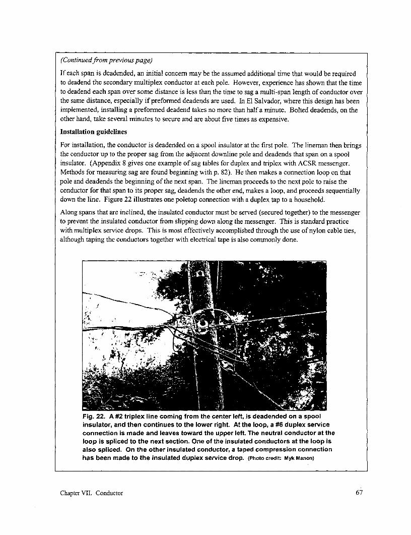
(Continuedfrom previous page)
If each span is deadended, an initial concern may be the assumed additional time that would be requiredto deadend the secondary multiplex conductor at each pole. However, experience has shown that the timeto deadend each span over some distance is less than the time to sag a multi-span length of conductor overthe same distance, especially if preformed deadends are used. In El Salvador, where this design has beenimplemented, installing a preformed deadend takes no more than half a minute. Bolted deadends, on theother hand, take several minutes to secure and are about five times as expensive.
Installation guidelines
For installation, the conductor is deadended on a spool insulator at the first pole. The lineman then bringsthe conductor up to the proper sag from the adjacent downline pole and deadends that span on a spoolinsulator. (Appendix 8 gives one example of sag tables for duplex and triplex with ACSR messenger.Methods for measuring sag are found beginning with p. 82). He then makes a connection loop on thatpole and deadends the beginning of the next span. The lineman proceeds to the next pole to raise theconductor for that span to its proper sag, deadends the other end, makes a loop, and proceeds sequentiallydown the line. Figure 22 illustrates one poletop connection with a duplex tap to a household.
Along spans that are inclined, the insulated conductor must be served (secured together) to the messengerto prevent the insulated conductor from slipping down along the messenger. This is standard practicewith multiplex service drops. This is most effectively accomplished through the use of nylon cable ties,although taping the conductors together with electrical tape is also commonly done.
Fig. 22. A #2 triplex line coming from the center left, is deadended on a spoolinsulator, and then continues to the lower right. At the loop, a #6 duplex serviceconnection is made and leaves toward the upper left. The neutral conductor at theloop is spliced to the next section. One of the insulated conductors at the loop isalso spliced. On the other insulated conductor, a taped compression connectionhas been made to the insulated duplex service drop. (Photo credit: Myk Manon)
Chapter VII' Conductor 67

Multiplex with one, two, or three conductors wrapped around the messenger conductor is calledduplex, triplex, and quadruplex, respectively. The messenger is commonly ACSR to provide thenecessary strength.
* Maintenance costs associated with these types of cable are reduced because clearing treebranches from the lines need not be as frequent. In addition, the size of the cleared areaaround the conductors may be reduced, lessening the adverse visual and environmentalimpact associated with overhead conductors.
* These types of conductors are safer than uninsulated conductor. Branches falling onuninsulated lines present a hazard. This hazard is more to persons coming into contact withthe branches when they try to remove them (especially if the system neutral is grounded) thanto the system itself. Even though resistance to current flow through the branches issufficiently high that breakers or fuse protection will often not trip, the system will not bedamaged. However, if a person forms a parallel path to earth, sufficient current may passthrough that person to present a hazard. Insulated conductors do not pose this hazard.
* The danger to individuals who might come into contact with the lines (caused by individualscarrying sticks or other long objects, children flying kites, or linesmen working on the line) isreduced because of the insulation. Furthermore, when new buildings are constructed, ownersrarely consult the electric utility about necessary clearances between the lines and thestructure. In these cases, this type of conductor is more forgiving.
* Linemen working on the lines prefer the added insulation. While electrical shocks at 120 or230 V are not always fatal, they are a nuisance. Furthermore, adequate protective equipmentand training is often not given to those working on energized lines.
* A problem common to many countries is the theft of electricity by individuals tapping thesecondary conductors, especially in more densely populated areas where narrow streetscompel the lines to run close to buildings. With ABC, it is difficult to tap the line withoutspecial piercing connectors because of the insulation and the fact that the conductors arebundled. With multiplex conductor used as the main distribution line, taps can only easily bemade at the loops at each pole, reducing the length over which the line can be illegallytapped.
* Only a single conductor rather than multiple conductors has to be strung, reducing time andlabor costs.
* Because of the greater weight per unit length of the bundled cable, total sag of a singlemultiplex or ABC will be greater than that for a single conductor. However, except for longspans, the total sag associated with multiplex or ABC will usually be less than the sagassociated either the two (for single-phase service) to four (for three-phase service)conductors that would otherwise be used, affixed to the pole in a vertical configuration (i.e.,not on cross-arms). The added ground clearance gives the advantage of longer spans on thesame size poles and can provide an increased line-to-ground safety margin.
* Stranded conductors are preferred over solid aluminum. Stranded conductor is more flexibleto work with when making connections.
* Phase and neutral conductors can be clearly identified.
Chapter VII. Conductor 68
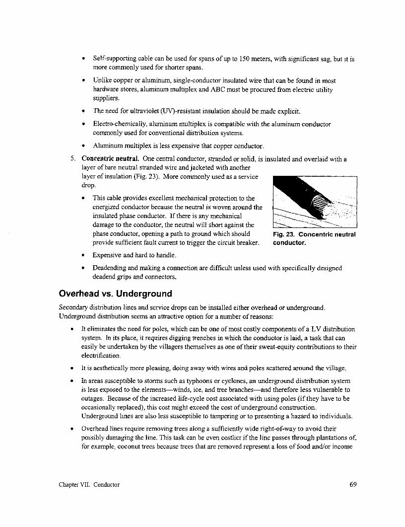
* Self-supporting cable can be used for spans of up to 150 meters, with significant sag, but it ismore commonly used for shorter spans.
* Unlike copper or aluminum, single-conductor insulated wire that can be found in mosthardware stores, aluminum multiplex and ABC must be procured from electric utilitysuppliers.
* The need for ultraviolet (UV)-resistant insulation should be made explicit.
* Electro-chemically, aluminum multiplex is compatible with the aluminum conductorcommonly used for conventional distribution systems.
* Aluminum multiplex is less expensive that copper conductor.
5. Concentric neutral. One central conductor, stranded or solid, is insulated and overlaid with alayer of bare neutral stranded wire and jacketed with anotherlayer of insulation (Fig. 23). More commonly used as a servicedrop.
* This cable provides excellent mechanical protection to theenergized conductor because the neutral is woven around theinsulated phase conductor. If there is any mechanicaldamage to the conductor, the neutral will short against the _ _ __ __ _
phase conductor, opening a path to ground which should Fig. 23. Concentric neutralprovide sufficient fault current to trigger the circuit breaker. conductor.
Expensive and hard to handle.
* Deadending and making a connection are difficult unless used with specifically designeddeadend grips and connectors.
Overhead vs. UndergroundSecondary distribution lines and service drops can be installed either overhead or underground.Underground distribution seems an attractive option for a number of reasons:
* It eliminates the need for poles, which can be one of most costly components of a LV distributionsystem. In its place, it requires digging trenches in which the conductor is laid, a task that caneasily be undertaken by the villagers themselves as one of their sweat-equity contributions to theirelectrification.
* It is aesthetically more pleasing, doing away with wires and poles scattered around the village.
* In areas susceptible to storms such as typhoons or cyclones, an underground distribution systemis less exposed to the elements-winds, ice, and tree branches-and therefore less vulnerable tooutages. Because of the increased life-cycle cost associated with using poles (if they have to beoccasionally replaced), this cost might exceed the cost of underground construction.Underground lines are also less susceptible to tampering or to presenting a hazard to individuals.
* Overhead lines require removing trees along a sufficiently wide right-of-way to avoid theirpossibly damaging the line. This task can be even costlier if the line passes through plantations of,for example, coconut trees because trees that are removed represent a loss of food and/or income
Chapter VII. Conductor 69

to their owners. In addition, vegetation growing in the vicinity of the lines must periodically be
trimmed. Use of underground line eliminates these problems.
But there are also disadvantages associated with the use of underground construction:
* Locating and repairing underground faults, should they occur, requires specialized equipment and
training.
* If additional capacity will be required to meet increased consumer loads in the future, the capacity
of underground lines cannot easily be increased either by adding another phase conductor to a
single-phase line or by upgrading the conductor size.
* When new homes are built along an existing line, making joints along this line to serve these new
consumers is considerably more difficult and requires specialized training.
* Because underground conductors are exposed to moisture, rodents and insects, damage from
construction of other underground facilities such as water lines, it is essential that only high
quality materials, specifically designed for underground electrical distribution be used. This
increases cost and can slow project construction.
* If the village is located in rocky terrain, digging trenches will be difficult and slow.
But in the end, it is usually the cost argument that holds sway: under most circumstances, underground is
still considerably costlier than overhead distribution because of the need for reliable insulation. And
because as high a connection rate as possible is needed to maximize the potential impacts of
electrification and ensure the maximum number of connections to reduce unit costs, reducing cost of
electrification assumes a high priority. It is for this reason that overhead lines are still the mostcommonly used option for rural electrification.
Conductor sizingFor consumers to benefit from electrification, electricity must be transmitted over distribution lines from
the power supply to these consumers. And because the conductor used for these lines is one of the more
expensive components of a mini-grid, there is an incentive to make electrification more affordable by
using a smaller, cheaper conductor. However, in the process of transmitting electricity, resistance in the
conductor leads to a drop in voltage along the line and to an associated loss of power. Reducing
conductor size can result in (1) poor quality of power at the consumer end of the line (low voltage and
more pronounced voltage fluctuations) and (2) loss of power (due to resistive losses in the conductor). As
is discussed in Chapter IV, low voltage can result in poor service (e.g., decreasing the light output of
incandescent bulbs, making it difficult to ignite fluorescent tubes, or buming out electric motors). Loss of
power along the line means extra power must be generated and paid for, if there is sufficient excess
generating capacity in the first place; otherwise, fewer consumers could be served by that supply.
Assuming that the power supply is operating to specification, the size and type of conductor used for the
mini-grid and, to a lesser extent, the power factor are the sole factors that determine whether an
acceptable voltage can be maintained. The purpose for this section is to show how to calculate the
required conductor size. But before this issue can be addressed, the following data is required:
* The first requirement for ensuring properly sized conductor is to establish the expected load themini-grid is to serve. This is described in the section on demand assessment (p. 43) in Chapter
IV. The proper performance of this task is important. Underestimating load will mean that the
Chapter VII. Conductor 70

number refersto both pole
200 and span F2E]0- [
powerhouse 200 600 6
service drop 400consumer (with coincidentpeak load in watts)
Fig. 24. A portion of a village mini-grid for which the maximum voltage drop is to be calculated.
grid is undersized, leading to problems mentioned above. Overestimating the expected load willunnecessarily increase the cost of the system. An estimate should also be made for the powerfactor, ranging from 1.0 for only resistive loading like incandescent lighting to roughly 0.6 forcases where the principal load is uncorrected fluorescent lighting.
* The second requirement is to have mapped the conmmunity to be served and, on the map, to havelaid out the distribution lines and indicated the locations and expected peak coincident demand ofall the envisioned loads, as explained in Chapter V.
- The third requirement is that the desired option for line configuration explained in Chapter VI hasbeen identified or the options at least reduced.
To introduce the various ways of calculating voltage drop along a conductor, the case shown in Fig. 24will be used. A 2-wire single-phase ACSR line is envisioned, with a 0.30 m spacing between conductorsand twelve 25-m spans. It is to be supplied by a 230-V, 50-Hz generator. A major use of the electricityin this example is a mixture of incandescent and fluorescent lighting with an average power factor of 0.9.The peak coincident demand, which occurs during the early evening hours, expected over the life of theproject, is indicated in watts in the figure. (Note that the assumed values for loads are higher than mightbe the case in a typical mini-grid. They were only selected for the purpose of illustrating the proceduresdescribed.)
For this example, it is assumed that the maximumacceptable voltage drop is 6 %. A 13 mm2 aluminumconductor has been tentatively selected and the first Table 5. Resistance and reactance fortask is to determine whether this conductor is suitable. ACSR conductor.The basic equations that will be used are reviewed in Conductor Resistance Reactance*Appendix 6. The properties of available ACSR area (ohm/km) (ohm/km)conductors under the conditions spacing noted 13 mm2 2.26 0.32previously are shown in Table 5. 2
21 rmm 1.41 0.32Several approaches to determnining voltage drop will 34 m 2 0.87be illustrated, beginning with what is usually the 0.31roughest estimate but the easiest to make and ending * At 0.30 m conductor spacing served by 50 Hz.
Chapter VII. Conductor 71
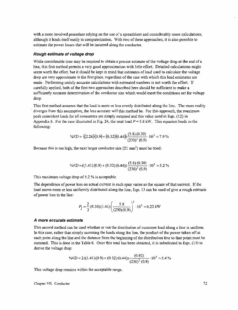
with a more involved procedure relying on the use of a spreadsheet and considerably more calculations,although it lends itself easily to computerization. With two of these approaches, it is also possible toestimate the power losses that will be incurred along the conductor.
Rough estimate of voltage drop
While considerable time may be required to obtain a precise estimate of the voltage drop at the end of aline, this first method permits a very good approximation with little effort. Detailed calculations mightseem worth the effort, but it should be kept in mind that estimates of load used to calculate the voltagedrop are very approximate in the first place, regardless of the care with which this load estimates aremade. Performing unduly accurate calculations with estimated numbers is not worth the effort. Ifcarefully applied, both of the first two approaches described here should be sufficient to make asufficiently accurate determination of the conductor size which would meet the conditions set for voltagedrop.
This first method assumes that the load is more or less evenly distributed along the line. The more realitydiverges from this assumption, the less accurate will this method be. For this approach, the maximumpeak coincident loads for all consumers are simply summed and this value used in Eqn. (12) inAppendix 6. For the case illustrated in Fig. 24, the total load P = 5.8 kW. This equation leads to thefollowing:
%VD = ((2.26)(0.9) + (0.32)(0.44)) (5.8) (0730) ' 9% =(23 0)2 (0.9)
Because this is too high, the next larger conductor size (21 mm2) must be tried:
%VD = ((1.41) (0.9) + (0.32) (0.44)) ( ) ( ) 105 2%(230)2 (0.9)
This maximum voltage drop of 5.2 % is acceptable.
The dependence of power loss on actual current in each span varies as the square of that current. If theload seems more or less uniformly distributed along the line, Eqn. 13 can be used of give a rough estimateof power loss in the line:
PI =-2(0.30)(1.41) ( - . 103 =0.22kWl3 ((230)(0.9)
A more accurate estimate
This second method can be used whether or not the distribution of customer load along a line is uniform.In this case, rather than simply summing the loads along the line, the product of the power taken off ateach point along the line and the distance from the beginning of the distribution line to that point must besummed. This is done in the Table 6. Once this total has been obtained, it is substituted in Eqn. (15) toderive the voltage drop:
%VD=2((1.41)(0.9)+ (0.32)(0.44)) (0.2) 10 =5.4%(230)2 (0.9)
This voltage drop remains within the acceptable range.
Chapter VII. Conductor 72
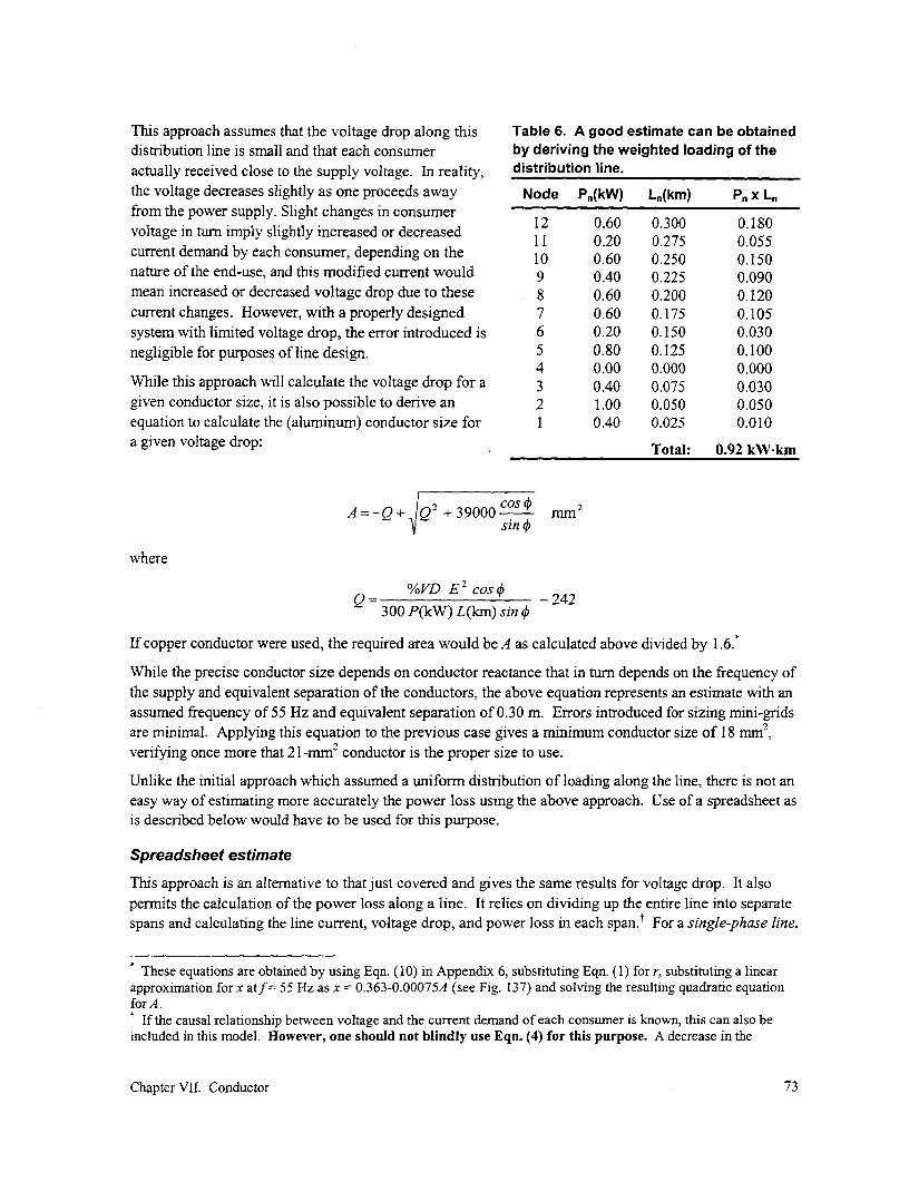
This approach assumes that the voltage drop along this Table 6. A good estimate can be obtaineddistribution line is small and that each consumer by deriving the weighted loading of theactually received close to the supply voltage. In reality, distribution line.the voltage decreases slightly as one proceeds away Node Pn(kW) Ln(km) Pn x L,from the power supply. Slight changes in consumer 12 0.60 0.300 0 180voltage in turn imply slightly increased or decreased 11 0.20 0.275 0.055current demand by each consumer, depending on the 10 0.60 0.250 0.150nature of the end-use, and this modified current would 9 0.40 0.225 0.090mean increased or decreased voltage drop due to these 8 0.60 0.200 0.120current changes. However, with a properly designed 7 0.60 0.175 0.105system with limited voltage drop, the error introduced is 6 0.20 0.150 0.030negligible for purposes of line design. 5 0.80 0.125 0.100
4 0.00 0.000 0.000While this approach will calculate the voltage drop for a 3 0.40 0.075 0.030given conductor size, it is also possible to derive an 2 1.00 0.050 0.050equation to calculate the (aluminum) conductor size for 1 0.40 0.025 0.010a given voltage drop: Total: 0.92 kW-km
A= -Q + Q2 + 39000 COS rn2sin +
where
Q %VD E2 cos4 -242300 P(kW) L(lan) sin +
If copper conductor were used, the required area would be A as calculated above divided by 1.6.
While the precise conductor size depends on conductor reactance that in turn depends on the frequency ofthe supply and equivalent separation of the conductors, the above equation represents an estimate with anassumed frequency of 55 Hz and equivalent separation of 0.30 m. Errors introduced for sizing mini-gridsare minimal. Applying this equation to the previous case gives a minimum conductor size of 18 mm2,verifying once more that 2 1 -mM2 conductor is the proper size to use.
Unlike the initial approach which assumed a uniform distribution of loading along the line, there is not aneasy way of estimating more accurately the power loss using the above approach. Use of a spreadsheet asis described below would have to be used for this purpose.
Spreadsheet estimate
This approach is an alternative to that just covered and gives the same results for voltage drop. It alsopermits the calculation of the power loss along a line. It relies on dividing up the entire line into separatespans and calculating the line current, voltage drop, and power loss in each span.t For a single-phase line,
These equations are obtained by using Eqn. (10) in Appendix 6, substituting Eqn. (1) for r, substituting a linearapproximnation for x atf = 55 Hz as x = 0.363-0.00075A (see Fig. 137) and solving the resulting quadratic equationfor A.t If the causal relationship between voltage and the current demand of each consumer is known, this can also beincluded in this model. However, one should not blindly use Eqn. (4) for this purpose. A decrease in the
Chapter VII. Conductor 73
Eqns. (4), (9), and (1 1) in Appendix 6 would be used, respectively. (For other configurations, theequations in Table 8 would be used.) Then the total voltage drop and loss would be obtained by summingthe individual drops and losses. While basically a simple technique, it requires the use of a spreadsheeteither completed manually or, preferably, by computer. However, while reliance on a computer cangreatly facilitate determination of the voltage drop and power loss at any point in the system under anumber of different scenarios, extreme care must be taken to ensure that all embedded equations in thespreadsheet are correct. Results obtained by the computer should always be checked against the estimatesobtained using the very simple methods noted above, as there should always be close agreement if allequations have been properly applied.
The contents of each column included in the spreadsheet in Table 7 are explained below:
* Column (1): The number of each span, starting with the remotest pole, in this case span #12 thatends on pole #12. Spans are numbered consecutively outward from the supply, but with thefurthest pole listed first.
* Column (2): The power taken off by spurs (i.e., service connections) originating from the pole atthe end of that span.
* Column (3): The total load served by that span. This is the sum of the total load served by thespur(s) shown in the previous column plus the total load served by the next span(s) in the outwarddirection (the value found in the position located immediately above it, or "O" in the case of thefirst row).
* Column (4): The voltage at the end of that span. As an approximation, this is always set to thegeneration voltage.
* Colurn (5): The current flowing in that span equals the current in the next span(s) in the outwarddirection (found in the previous row) plus the current needed to serve the load in the spurs at theend of that span as calculated using Eqn. (4) in Appendix 6.
* Column (6): The length of that span.
* Column (7): The voltage drop in that span, calculated using the first part of Eqn. (9) inAppendix 6. The values inserted into that equation are those found in the same row, columns (5)and (6), along with the average power factor for the loads on that line and the values of r and x forthe conductor being used along that span (which are shown at the end of Table 7).
* Colurnn (8): The power loss in that span, calculated using the first part of Eqn. (1 1) inAppendix 6. The values inserted into that equation are the same as those used in column (7),except for reactance that does not affect power loss.
consumer voltage (due to voltage drop in the line from the supply) can cause either an increased or decreaseddemand for current, depending on the nature of the end-use. For example, at a lower voltage, a light bulb woulddraw less current while a motor might draw more current. Furthermore, the size and direction of the current changemay not be as straightforward to calculate as may first appear. If the voltage supplied to a light bulb decreases1O %, Eqn. (4) implies the current would increase 1O %. However, in real life, because a bulb is considered aresistive load, the current demand would be proportional to the voltage, e.g., a 10 O/ lower voltage would imply acurrent decrease of 10 %. To complicate matters further, at a lower voltage, the filament temperature is lower andits resistance increases, further decreasing the current. As a bottom line, no general approach exists that can be usedto calculate actual current drawn by the consumer based on the nominal power drawn by the consumer.Fortunately, all these variation in current with changes in voltage are minimal, and assuming a constantvoltage in the analysis does not introduce significant errors in conclusions drawn when sizing mini-grids.
Chapter VII. Conductor 74

Table 7. This spreadsheet layout is another approach for calculating voltage dropand power loss along a length of distribution line. The span is identified by thesame number as the pole at the end of that span.
(1) (2) (3) (4) (5) (6) (7) (8)Pole (or Demand (kW) Voltage Current Length Volt drop Power loss
span) no. Spurs Main (V) (A) (km) (V) (kW)
12 0.600 0.600 230 2.9 0.025 0.2 0.00111 0.200 0.800 230 3.9 0.025 0.3 0.00110 0.600 1.400 230 6.8 0.025 0.5 0.0039 0.400 1.800 230 8.7 0.025 0.6 0.0058 0.600 2.400 230 11.6 0.025 0.8 0.0097 0.600 3.000 230 14.5 0.025 1.0 0.0156 0.200 3.200 230 15.5 0.025 1.1 0.0175 0.800 4.000 230 19.3 0.025 1.4 0.0264 0.000 4.000 230 19.3 0.025 1.4 0.0263 0.400 4.400 230 21.3 0.025 1.5 0.0322 1.000 5.400 230 26.1 0.025 1.8 0.0481 0.400 5.800 230 28.0 0.025 2.0 0.055
TOTALS: 5.80 28.0 0.300 12.5 0.239Assumptions:
Power factor= 0.9Resistance = 1.41 ohm/kmReactance 0.32 ohm/km
Each row is completed down to the first span. This is very quickly done using a computerizedspreadsheet after the equations have been inputted. This spreadsheet indicates a voltage drop along theentire line of 12.5 V or 5.4 %, confirming the results of the previous approaches. The power loss duringtimes of peak demand is more precisely calculated to be 240 W, confirming that the estimate made earlierwas fairly close.
Effect of conductor size on power loss
While limiting the voltage drop is important in order for electrical appliances to operate as they areintended to, power losses can be important because they represent lost revenues to the system owner. Inthe example above, energy loss at peak times is about 250 W. If the system operates for only four hourseach night and the load remains constant, this will, for example, consume 1.0 kWh nightly or about360 kWh annually. If the system is supplied by a small diesel genset, this will mean that about 180 litersof fuel costing perhaps $50 is wasted annually.
If one is trying to minimize cost, the question that must next be asked is whether spending more for alarge conductor with fewer losses generates savings that are more than the cost of the larger conductorrequired to achieve this. For example, what would be the effect of selecting the next larger conductor size(34 mm2)?
Placing the new values for resistance and reactance for this new conductor into the spreadsheet in Table 7will show a power loss of 150 W and a reduction in the voltage drop to 4 %. Supplying this power losswould require about 220 kWh, a reduction of about 100 W or 140 kWh annually. This would cost about
Chapter VII. Conductor 75
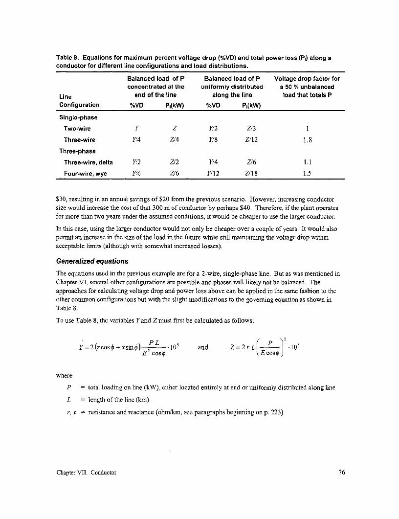
Table 8. Equations for maximum percent voltage drop (%VD) and total power loss (PI) along aconductor for different line configurations and load distributions.
Balanced load of P Balanced load of P Voltage drop factor forconcentrated at the uniformly distributed a 50 % unbalanced
Line end of the line along the line load that totals PConfiguration %VD P,(kW) %VD P,(kW)
Single-phase
Two-wire Y Z Y/2 Z/3 1
Three-wire Y/4 Z/4 Y/8 Z/12 1.8
Three-phase
Three-wire, delta Y12 Z/2 Y14 Z/6 1.1
Four-wire, wye Y16 Z/6 Y/12 Z/18 1.5
$30, resulting in an annual savings of $20 from the previous scenario. However, increasing conductorsize would increase the cost of that 300 m of conductor by perhaps $40. Therefore, if the plant operatesfor more than two years under the assumed conditions, it would be cheaper to use the larger conductor.
In this case, using the larger conductor would not only be cheaper over a couple of years. It would alsopermit an increase in the size of the load in the future while still maintaining the voltage drop withinacceptable limits (although with somewhat increased losses).
Generalized equations
The equations used in the previous example are for a 2-wire, single-phase line. But as was mentioned inChapter VI, several other configurations are possible and phases will likely not be balanced. Theapproaches for calculating voltage drop and power loss above can be applied in the same fashion to theother common configurations but with the slight modifications to the goveming equation as shown inTable 8.
To use Table 8, the variables Y and Z must first be calculated as follows:
Y=2(rcos¢>+xsin ) .1 05 and Z=2rLi ) .13oE 2 cost Z= Ercos J
where
P = total loading on line (kW), either located entirely at end or unifornly distributed along line
L = length of the line (km)
r, x = resistance and reactance (ohm/kn, see paragraphs beginning on p. 223)
Chapter VII. Conductor 76

E = nominal consumer voltage, i.e., 120 or 230 V(for single-phase, three-wire: phase-neutral voltage)(for delta configuration: phase-phase voltage)(for wye configuration: phase-neutral voltage)
The percentage voltage drop and power loss in the first four column of data in Table 8 are for a balanced3-wire, single-phase configuration and for balanced three-phase configurations. As an example of howvoltage drop changes if loads are not balanced, the last column in Table 8 includes factors that mustmultiply the voltage drops for balanced loads (the first or third column of data) to obtain the maximumvoltage drop for a 50 % unbalance in loading (for the meaning of a 50 % unbalance, see the footnote onp. 57).'
Using these equations, Box 5 provides a graphical solution for conductor size under the conditions noted.
Stringing and sagging the conductorAfter the most appropriate type and size of conductor, pole, and poletop hardware have been selected fora specific application and the poles, poletop hardware, and any necessary guys have been properlyinstalled, the conductor must bestrung. This involves placing theconductor in position, tensioning the H Hconductor so that the tension does not sexceed a certain percentage of itsultimate strength, and then fixing the WCconductor at each pole. Tensioningthe conductor is referred to a "sagging"because tension and sag are directly Lrelated to each other; the properhorizontal tension "H" is generally Fig. 25. Basic terms associated with sagging adetermined by measuring sag "S" :conductor.(Fig. 25).
Before any work on stringing and sagging the conductor can commence, the appropriate sag tables mustbe obtained. For the more conventional types of conductor (ACSR, multiplex or ABC, etc.), theconductor manufacturer should be able to provide these. Examples are found in Appendix 8. If otherconductor is used, it is necessary to establish the maximum tension that should not be exceeded and tocalculate the sag associated with that tension (see next section). For example, in the U.S., the NESClimits the tension on ACSR conductor to 35 % of ultimate strength at 16 °C when it is initially strung andcarrying no ice or wind loading.
Placing the conductor in place can be fairly straightforward with small conductor. However, as larger andheavier conductor is used, more care must be exercised. This section deals primarily with suchconductor, although some points are common for all conductors.
Trying to balance loads along a distribution line means that, as one proceeds along that line, loads are connected toeach phase conductor in such a way that the currents in these conductors at each point along the line are as close toequal as possible. This leads to negligible current in the neutral conductor (in cases when there is such a conductor,see Fig. 14b and 14c) and mninimizes voltage drop along the line.
Chapter VII. Conductor 77

Box 5. Estimating conductor size.
In the initial planning process, it is often necessary to obtain an initial estimate of conductor size for aspecific project. The graphs below provide a quick way for using equations found in Table 8 todetermine the conductor size required to keep the maximum voltage drop to within a desired range.
To estimate conductor size for a stretch of distribution line operating at a nominal consumer voltage of230 V (see p. 76 for definition) with loads balanced along the line, a conductor equivalent spacingof 0.30 m, and a frequency of 50 Hz , either of the following three numbers will be required, dependingon the actual situation:
4. If the load is concentrated at the end of the line, multiply the peak load (kW) by the length of theline (kim) to get the kW-km loading, k'.
5. If the load is relatively evenly distributed over the entire length of the line, sum all the peakcoincident loads (kW) and multiply this by half the length of line to get the kW-km loading, k'.
6. If the load is unevenly spread, sum the products of each load (kW) and its distance (km) from thebeginning of the line to get the kW-km loading, k'.
To determnine conductor size for a single-phase, two-wire system under the conditions mentioned above,look up the value k = k' on the appropriate graph (determined by the average power factor of the loadsserved), move vertically until the desired voltage drop is reached, and then move horizontally left (for alu-minum conductor) or right (for copper conductor) to determine the value.
For perfectly balanced systems:
For a single-phase, three-wire system, use the value k = k'/4 and follow the steps noted in theprevious paragraph. For a three-phase, delta system, use the value k = k'/2 and follow the samesteps. For a three-phase, wye system, use the value k = k'/6 and follow the same steps.
For systems with a 50 % load unbalance:
For a single-phase, three-wire system, use the value k = k'/2.3 and follow the steps noted in theprevious paragraph. For a three-phase, delta system, use the value k =k '1.8 and follow the samesteps. For a three-phase, wye system, use the value k = k'/4 and follow the same steps.
In preparing the graphs below, a distribution voltage of 230 V was assumed. To determine conductor sizefor another operating voltage, first determine the value of k as described above. Take this value of k andmultiply it by (230/E)2, where E is the nominal voltage being used by a single-phase consumer (definedon p. 76). Use this modified value of k and proceed to use the appropriate graph to determine necessaryconductor size. Note that, for a given conductor, if the distribution voltage were reduced by half to1 15 V, the load that could be served by this same line would be reduced to one quarter of the original loadserved at 230 V.
In preparing the graphs below, an equivalent spacing of distribution conductors of 0.30 and a frequency of50 Hz were assumed. If either of these parameters are different for a specific situation, the impedance ofthe line x changes somewhat, but this will generally change the graphs only slightly. If a more precisevalue is desired, the equations in Table 8 can be used. The resistance and reactance for a specificconductor can be obtained for the graphs and equations found in Appendix 6 (beginning with p. 223).
Chapter VII. Conductor 78

? | ~~~~~~~Power factor=1.|100. - 63
E 80 50E
60 < 3 8
10 %~~~~~~~~.
0 4 -220 °13= ~ 2 5 2
0~~~~~~~~~~~~~~~~~~~~~~~
0.0 1.0 2.0 3.0 4.0 5.0k (kW km)i
l { Po~~~~~~~~~wer factor=0.
E 80 -. % 2% 3.
E60 - 3 E
L.40 L.25
.2 .25
00 .0
0.0 1.0 2.0 3.0 4.0 5.0k (kW km)
Chapter~ ~ ~ ~ ~~~~Poe facto Coduto67
E 8 - ~4 % __ __EE 80-___ ____E
- E~~~~~~~~~~
60 - --- 38
40 -~ 25
X20 I -- 13
0 - . 100.0 1.0 2.0 3.0 4.0 5.0
k (kW kmn)
Chapter VII. Conductor 79

In planning for the stringing and sagging of larger conductor, it is necessary that sagging be done withinseveral hours of pulling the conductor. This is because the conductor will begin creeping as soon as it isoff the ground and the required sag will start to change. Creeping is the elongation of conductor undertension. As tension is applied to the conductor, it stretches and will continue to stretch until a balancebetween tension and the materials strength is reached. This process may take several years. With newconductor, if sagging is not completed within the reconimended time period, it becomes impossible toaccurately calculate the sag from sag charts, which only indicate "initial" sag and "final" sag. Forexample, it can be seen from Appendix 8 that, while the proper sag for a 70-m span of #2 ACSR triplex at25 °C is 0.53 meters for new conductor, it increases to 0.75 m after creeping has completed. If there istoo much time between pulling the conductor and tensioning or sagging this conductor, the required sagwill be at some unknown value somewhere between these two sag values.
Sag
The sag in a conductor is determined by the weight and tension of the conductor and its span. Therelation between these three parameters for a given conductor is illustrated in Fig. 26. If one assumes thatunder a given tension, a conductor with a span of "L" has a sag of "S" (Fig. 26a), then keeping the samesag (and therefore ground clearance) while increasing the span will require placing the conductor underincreased tension (Fig. 26b). If the tension then exceeds the allowable value, it can be decreased for thisincreased span by increasing the sag (Fig. 26c). If this reduces clearance to too low a value and the longerspan is necessary, then a longer pole would be required.
For a given conductor type and size, the sag depends on the span according to the following relationship:
H H 2H 2H
(a) (b)
L Lsame sag same spandoubling span doubling tension
4H 7 4H
(c) I- s , I -
2L
Fig. 26. For the same span, the sag is inversely proportional to the tension, see(a) and (b). To maintain the same sag, the tension in a conductor is proportionalto the square of the span, see (a) and (c).
Chapter VII. Conductor 80

8.0H
where
S = sag (m)
w,C = weight of the conductor per unit length (kg/m or N/m)
L, = span (m)
H= horizontal force at pole (either kg or N but must be the same as used in weight of conductorabove). This is approximately equal to the tension in the conductor.
Handling and inspecting the conductor
When receiving conductor to be used on a project, the reel and any protective covering on the conductorshould be inspected for damage. A broken reel or damaged covering may indicate improper handling andpossible damage to the conductor. When handling larger reels manually, they should be kept in anupright position and rolled. If necessary, ramps should be used to facilitate loading and unloading.During warehousing and transport, reels should be kept in an upright position at all times; otherwise, thelays of the conductor may overlap, causing possible damage to the conductor or delays in the stringingprocess.
Preparation for stringing
Prior to stringing the conductor, the route of the line shouldbe inspected to ensure all is ready for the pull. The right of .
way should be inspected for obstacles that may damage theconductor or complicate the stringing. If any obstaclescannot be removed, rigging may be required to ensure thatthe conductor is not damaged during the pulling process.
For larger conductor that is heavier and bulkier and involveshandling greater forces in the stringing and sagging process, . /pulleys should be temporarily installed on each pole andinspected to ensure that surfaces are smooth and roll freely.-The reel should be properly located with a stable base andpositioned on the reel stand so that the conductor will unwindfrom the bottom. A leader line (rope) several dozen meterslong is attached to the beginning of the conductor, usually by Fig. 27. These flexible grips aremeans of a wire mesh grip (Fig. 27), and threaded through the comprised of a tubular steel meshfirst pulley. This provides added safety to the pulling team, that is fit over the end of the cable.facilitates threading the conductor through the pulleys, and Under tension, the mesh tightens onhelps protect the conductor during the installation process. the cable, increasing its grip as ten-All guys should be installed and checked and poles inspected sion is increased. But it is easilyfor proper positioning before pulling the conductor. removed once the tension is relieved.
Pulling the conductor
The conductor should not be payed out (removed) from a reel or coil that is not free to rotate; otherwise,each turn removed will leave one complete twist in the conductor that could eventually cause kinks. In all
Chapter VII. Conductor 81

cases, the reel should be mounted so that it is free to rotate. But it should not be allowed to spin freely,because this can cause the conductor to tangle on the reel, possibly damaging the conductor and delayingthe process. It is also important to make sure the insulation is not damaged by dragging the multiplexover the ground or sharp objects, to avoid having vehicles cross or animals walk over the conductor, andto avoid kinks while paying out the conductor.
A couple of approaches for paying out the conductor from a reel are possible:
* The conductor can be paid out along the ground from a rotating reel that is moved down along theline, carried either by a vehicle or by a group a individuals, depending on access to thedistribution line and the weight of the reel. Alternatively, the reel can be placed in the mostaccessible point nearest the section being constructed and the conductor pulled along the line. Toavoid any damage to the insulator or conductor by dragging it across the countryside, villagerscan hold on to the conductor at appropriate intervals, each carrying his or her section until it canbe place under its final resting place along the line. The conductor would then be carefully raisedonto the insulators for final tensioning.
* With conventional distribution lines, pulleys are hung from the location on each pole where theconductor is to be mounted. A rope would then be passed through the pulleys and the end tied tothe conductor on a fixed but rotating reel located at the end of the section being worked on. Thisrope would then be pulled over consecutive pulleys toward the beginning of the section, pullingthe conductor along with it.
Once the conductor has been pulled, it should be deadended at one end so that sagging can begin withminimum delay. To minimize delay, the specific span to be sagged within the entire section being pulledshould have been selected before pulling the conductor and measuring the temperature. In this way, thesag is known and work on getting the proper sag can proceed inmmediately.
To facilitate temporarily holding the conductor along its length, any of a variety of grips can be used.These hold the conductor while tension isapplied, but they are easily removed once thetension is released (Figs. 28 and 29).
Before the conductor is tensioned, any pole thatwould be subjected to an unbalanced force mustbe suitably guyed to counteract the tension in theconductor that may cause the pole to otherwise N
bend over and break. This may be accomplished A-"k
Fig. 29. A grip is being used to tension aFig. 28. Grips of a wide variety of designs conductor passing through a pulley in a system inare used to temporarily hold a conductor. rural Nepal.
Chapter VII. Conductor 82

deadend
pulley ; 7itiming cable reel.pulley l i_9rope
span being sagged
Fig. 30. Once a section of line has been pulled over pulley, properly sagging one span properlysags the entire section. Timed sagging is one method for sagging longer spans. In stringing theconductor in this case, the rightmost pole should be temporarily guyed toward the right becausethe conductor under tension tends to force that pole to the left.
by placing permanent guy wires and anchors in cases where this unbalanced force remains after the linehas been fully strung. In cases where unbalanced conductor forces on a pole will disappear once theentire length of the line has been completed, a temporary guy wire firmly fixed to the bottom of a trees, afence post, etc., can be used.
Sagging the conductor
The correct tensioning or sagging of the conductor is one of the most important phases of distribution lineconstruction, especially for larger conductor sizes, and effects its reliability and longevity. If a conductoris sagged too tightly, it will cause the structure and conductor to fatigue. If all the conductors along aspan do not have the same sag, the wind can cause them to slap together, causing outages and damage tothe conductors. If it is sagged too loosely, it can become a hazard to the public because of the reducedclearance.
To determine the proper sag for a given span, it will be necessary to measure both the span and thetemperature of the conductor at the time of sagging. To measure the temperature of the conductor, athermometer should be placed directly against a piece of the conductor raised to poletop level. It shouldnot be placed in direct sunlight as this will give a false reading. The temperature should be noted after thereadings no longer change significantly.
As can be seen by referring to typical sag tables in Appendix 8, the temperature is important. Sag canchange considerably with changes in temperature because the conductor expands and contracts as thetemperature increase or decreases. For example, at an early moming temperature of 16 °C, a 70-m spanof #2 ACSR triplex should have a sag of 0.48 m. But should conductor temperature rise to 32 °C in themiddle of the day, this sag will increase about 20 % to 0.58 m. Close attention must be paid to theconductor temperature at the time of sagging.
For a given span and temperature, reference to sagging tables such as the ones in Appendix 8 will give therequired sag under these conditions. The initial sag chart should only be used with new conductor thathas never crept. (The final sag chart is to be used on conductor that has been removed from other linesand reinstalled. This chart is also used to check sag on existing line.)
After one span of a section of conductor has been sagged, it is not necessary to sag every span. Assumethat the conductor has been pulled over freely rotating pulleys. Then, if the conductor is one span is
Chapter VII. Conductor 83
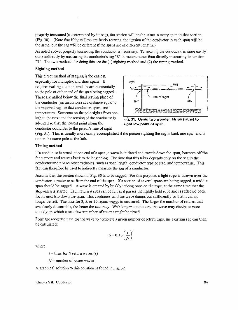
properly tensioned (as determined by its sag), the tension will be the same in every span in that section(Fig. 30). (Note that if the pulleys are freely rotating, the tension of the conductor in each span will bethe same, but the sag will be different if the spans are of different lengths.)
As noted above, properly tensioning the conductor is necessary. Tensioning the conductor is more easilydone indirectly by measuring the conductor's sag "S" in meters rather than directly measuring its tension"T". The two methods for doing this are the (1) sighting method and (2) the timing method.
Sighting method
This direct method of sagging is the easiest,especially for multiplex and short spans. Itrequires nailing a lath or small board horizontally Ls sagto the pole at either end of the span being sagged.These are nailed below the final resting place of line of sightthe conductor (on insulators) at a distance equal to lath laththe required sag for that conductor, span, andtemperature. Someone on the pole sights from one m
lath to the next and the tension of the conductor is Fig. 31. Using two wooden strips (laths) toadjusted so that the lowest point along the sight low point of span.conductor coincides to the person's line of sight(Fig. 31). This is usually more easily accomplished if the person sighting the sag is back one span and isnot on the same pole as the lath.
Timing method
If a conductor is struck at one end of a span, a wave is initiated and travels down the span, bounces off thefar support and retums back to the beginning. The time that this takes depends only on the sag in theconductor and not on other variables, such as span length, conductor type or size, and temperature. Thisfact can therefore be used to indirectly measure the sag of a conductor.
Assume that the section shown in Fig. 30 is to be sagged. For this purpose, a light rope is thrown over theconductor, a meter or so from the end of the span. If a section of several spans are being sagged, a middlespan should be sagged. A wave is created by briskly jerking once on the rope, at the same time that thestopwatch is started. Each return waves can be felt as it passes the lightly held rope and is reflected backfor its next trip down the span. This continues until the wave damps out sufficiently so that it can nolonger be felt. The time for 3, 5, or 10 return waves is measured. The larger the number of retums thatare clearly discemible, the better the accuracy. With longer conductors, the wave may dissipate morequickly, in which case a fewer number of returns might be timed.
From the recorded time for the wave to complete a given number of return trips, the existing sag can thenbe calculated:
S=0. 31jIi-N)
where
t = time for N return waves (s)
N= number of return waves
A graphical solution to this equation is found in Fig. 32.
Chapter VII. Conductor 84
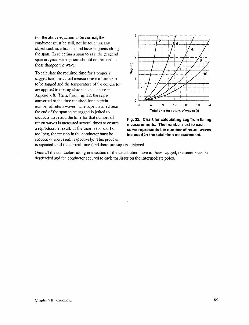
For the above equation to be correct, the 32conductor must be still, not be touching any I _ - 4
object such as a branch, and have no joints along I I 6the span. In selecting a span to sag, the deadend l/
these dampen the wave. 2E ziiTo calculate the required time for a properly Xn ___|_ 4, 10sagged line, the actual measurement of the span 1 1/ ,to be sagged and the temperature of the conductorare applied to the sag charts such as those inAppendix 8. Then, from Fig. 32, the sag isconverted to the time required for a certain 0
number of return waves. The rope installed near 0 4 8 12 16 20 24
the end of the span to be sagged is jerked to Total time for return of waves (s)
induce a wave and the time for that number of Fig. 32. Chart for calculating sag from timingreturn waves is measured several times to ensure measurements. The number next to eacha reproducible result. If the time is too short or curve represents the number of return wavestoo long, the tension in the conductor must be included in the total time measurement.reduced or increased, respectively. This processis repeated until the correct time (and therefore sag) is achieved.
Once all the conductors along one section of the distribution have all been sagged, the section can bedeadended and the conductor secured to each insulator on the intermediate poles.
Chapter VII. Conductor 85

Vill. Poles
If the distribution line and service drops are not placed underground (see p. 68), they must be supportedsufficiently high off the ground to keep them out of the way of vehicular traffic and out of reach ofpedestrians. This is necessary both to maintain the integrity of the line as well as to prevent the risk ofshock to individuals who might otherwise accidentally come into contact with the conductors. These arethe principal reasons for using poles and are the main factors determining their length.
In satisfying this purpose, it is necessary that these poles be strong enough to resist forces-such as thosedue to wind or the tension in the conductor-that would tend to bring them down, again affecting theintegrity of the line and presenting a safety risk to villagers. Some of these forces, such as thoseassociated with the tension in the conductors at a bend in the line, are permanent forces and arecounterbalanced through the use of guys. The design and installation of guys is described in Chapter X.Other forces, primarily those arising from wind acting on the pole itself and on the conductors supportedby the poles, change in direction and magnitude and are typically resisted by the strength of the poleitself.
To minimize project costs and safety hazards, poles must also be durable. While quality poles are likelyto be costlier, their use will reduce the necessity of purchasing additional replacement poles and ofreinstalling these and transferring the line from the old to the new poles. In short, more durable poles thatwill reduce life-cycle costs should be selected. Another reality to face is that, while considerable effortwill be placed by the community in constructing a new mini-grid project, there will usually be lesscommitment to regular upkeep; the attitude will be that, unless it is really broken, there is no need to fixit. Meanwhile, safety may be compromised as poles degrade.
Poles of wood, concrete, and steel are commonly used to support the conductors, although other structuressuch as trees or supports constructed of angle iron and bars are occasionally used.
This chapter will cover the following topics:
* Types and attributes of poles commonly used to support distribution lines
* A review of clearance requirements, as this determines the required length of these poles
A review of the forces that these structures should resist, as this determines the required strengthof these poles
* Methods for setting poles
Pole optionsPoles are made from a variety of materials, with the most frequently used being of wood, concrete, andsteel. None of these has a clear advantage in all situations; rather, the selection process should include theconsideration of several criteria under site-specific conditions. These include availability, cost, weightand ease of handling, strength, and durability. Note also that in a single project, it might be advisable touse several types of poles. At the end of a span that has to be raised to provide sufficient access tovehicular traffic or that has to extend across a wide river or ravine, taller and stronger poles of concrete orsteel construction might be more suitable. On the other hand, poles to support shorter service drops mightbe shorter wood or bamboo poles. At other places, if suitable live trees are found, these can be used.
Chapter VIII. Poles 86

Before proceeding with a review of pole options, one word of caution about poles in general should benoted. Because they can be the most expensive component of a distribution system, there is an incentiveto minimize project costs by selecting the least expensive pole option. However, a less costly poleusually implies reduced strength and/or quality. This has several implications:
* Weaker, poorer quality poles and the conductors they support are more likely to fall under stress,resulting in a greater safety hazard to the population.
* Shorter life implies the need for additional investments when poles later will need to be replaced.In addition to the cost of new replacement poles, the community will incur the additional cost ofremoving the old poles, resetting the new ones, and reconnecting the conductors, guys, etc., all ofwhich contribute to additional cost and hassle. It is also likely that the manpower and expertisewill no longer be on-site when poles need to be replaced.
Wood
Wood poles are widely used for electrification worldwide because they exhibit a variety of advantages:
* These are lighter than the equivalent concrete pole, the common altemative, and easier to handlein the field.
* Wood poles are not as susceptible to breakage during transport and handling.
* Wood poles can usually be field-drilled, permitting greater flexibility in the placement ofmounting bolts and facilitating later modification.
* Wood poles are not adversely affected by airborne salt in coastal zones that can cause corrosionof the reinforcing steel in concrete poles.
* Local plantations permit self-sufficiency in the production of one of the costliest components ofan RE program, creating employment, reducing the need for foreign exchange, and lowering thecost of RE.
* Larger, conventional wooden poles are easier to climb directly (with gaffs, sharp metal spursaffixed to the inside edge of a boot).
* Properly managed, wood is a renewable resource, requiring much less energy in the manufactureof poles and contributing no net carbon dioxide or other greenhouse gases, unlike thoseassociated with the production of cement or steel for poles.
* Numerous environmental benefits are associated with increasing forest cover for pole productionin marginal areas-reduced erosion of land and sedimentation that leads to the destruction ofriverine habitats, improved ground water quality and quantity, more abundant and diversewildlife, and opportunities for increased employment opportunities from processing a range offorest products. Forests also serves as a sink for carbon dioxide, a gas increasingly recognized ascontributing to global warming and its adverse implications.
* In a number of countries, rural households have little disposable income and the problem facingan RE program is the inability of these households to cover the cost of connection as well as thecost of energy. Growing trees for poles may be one option requiring few financial and laborinputs that can reduce the cost of electrification. Although growing suitable trees requiresperhaps a dozen years, it can eventually provide a regular income to rural households that, in part,can be used to cover the cost of their electric service.
Chapter VIII. Poles 87

Offsetting these advantages is the fact that untreated wood poles are susceptible to decay and insectdamage. Tree species that are decay and insect resistant do exist but are not common. Local inhabitantsshould be able to identify resistant local species, but it needs to be verified whether this apparentresistance is for wood under ground-contact conditions and exposed to the weather. The inspection offence posts or building timbers of the allegedly resistant species should be able to verify this.
In Bolivia, for example, a tropical species called cuchi (Austronium Urundera) is stripped of its sapwoodand widely used for posts, poles, and building timbers. The heartwood of this species is extremelyresistant to decay and insect attack but is, unfortunately, crooked. Some old-timers see this as anadvantage and call them "balcony poles" because they can be located beneath a balcony since the crookwill still place the conductors at a safe distance from the front of the balcony. A certain species of palmswith a very hard outer shell has also been used as poles on the Altiplano.
The altemative to finding resistant trees is to chemically treat wood poles. This is discussed below.
In countries where the electric utility uses wood poles, criteria have usually been developed to provideguidance as to what specific characteristics to look for when selecting suitable poles. Generally, poleswith the following characteristics are preferred:
* straight poles with little twist or spiral grain
* poles without large and/or numerous knots, as these weaken the pole
* adequate wood density as indicated by tree ring count (The width of the tree rings is an indicationof the rate of growth of the tree, with wider spacing indicative of lower strength. In the U.S., withpine which is treated, rings spacing in the outer growth which average greater than about 4 mmindicates wood which has grown too quickly.)
In addition to the above, it is clear that poles should have sufficient girth to give them the requiredstrength. This is further explained later in this chapter (p. 98).
Wood pole production
An obstacle facing the widespread use of wood poles is that, in a growing number of countries, forests aredisappearing or do not have suitable trees. It is possible to plant trees specifically for pole production, butadequate lead-time is required until newly planted trees can be harvested for this purpose. Tropical pinescan produce a 9-m pole in about 15 years but have limited strength. Faster growing soft wood speciesexist but these tend to be weaker. More commonly found hardwood species such as eucalyptus, areanother option, but these do not get very good preservative penetration and retention. However, becausewood poles will continue to be in demand for expanding rural electrification as well as for replacingexisting damaged poles, the need for poles will continue decades into the future, well after any treeplantation starts yielding trees of adequate dimensions.
On the national level, the advantages of wood poles and their production should be sufficient incentive fora national commitment to the creation of local tree plantations, possibly in collaboration with other gov-ernment departments, non-govemmental organizations, or private entrepreneurs.
An example of pole specifications are those utilized by the rural cooperatives in the United States. These can befound in the section "Electric program regulations and bulletins" located on the Web at<http://www.usda.gov/rus/regs.shtml>. This is the document "Specification for Wood Poles, Stubs and AnchorLogs" referred to as Bulletin 1728F-700 (formerly Bulletin 50-24).
Chapter VIII. Poles 88

For example, in the Philippines, the National Electrification Administration (NEA) recognized thenumerous advantages of using wood poles in rural areas. It also realized the dwindling source of forestresources in its own country and the high cost in importing poles from overseas. Consequently, thePower Use Development Division of the Cooperative Services Department of the NEA initiated a tree-planting program in 1993. Nearly half of the 1 19 rural electric cooperatives in the country are nowinvolved in this program.
These rural electric cooperatives raise seedlings that they donate to their consumers (either individuals orusers groups) or sell under contract to large landowners. A condition for membership in some coopera-tives is planting a couple of trees on the member's own land. The largest single area under cultivationpresently is 400 ha. Upon maturity, the co-op agrees to purchase these trees for their eventual chemicaltreatment and use as wood poles.
Specifically for the Philippines, the NEA recommends planting Gmelina Arborea, Eucalyptus Deglupta,and Acacia Mangium which all can adapt to the varied climatic regimes in the country.6 It is expectedthat a 35-foot (10.5 m) pole with a diameter of 8 inches (0.20 m) would be available after about 8 yearsfollowing the planting of the seedling. The planting density is at least 500 trees per hectare. It isexpected that the co-op will save roughly 50 % over the current price of imported poles. At an estimateddevelopment cost of roughly $1,000 per hectare, NEA projects a 50-fold return on investment after 10years.
Wood pole treatment
One of the most characteristic features of wood species used for poles is the presence of two distinctlydifferent types of wood within each stem: sapwood and heartwood. Sapwood, normally much lighter incolor than heartwood, forms the outer periphery of poles, a layer which can range from a couple ofcentimeters to more than 10 cm in thickness, depending on the species. In living trees, the outer sapwoodzone is where nutrient transport and storage occurs. Heartwood is found in the center of the stem. It iscomposed of wood cells that have ceased any active function and have gradually been filled with organicsubstances known as extractives. These extractives tend to darken the wood in this portion of the stem.
Heartwood is generally more durable than sapwood due to the presence of these extractives, many ofwhich are toxic, to some degree, to the organisms which cause wood to deteriorate. Sapwood, in theabsence of these extractives, is readily degraded by any number of wood deteriorating organisms,including fungi, molds, stains, and insects such as termites and certain beetle species. For this reason, it isessential to the longevity of wood poles that the outer, susceptible sapwood layer is protected from theseorganisms by the addition of preservative chemicals that make the sapwood unavailable as a food source.Proper application of these chemicals in the sapwood will enable the treated pole to last for an extendedtime in service.
Before poles can be treated, they must be properly dried. Green trees have a very high moisture content,often well above 100%. After felling and peeling, they gradually dry until their moisture content comesinto equilibrium with the environment (at which time their moisture content is usually down to less than30 %). This drying process is called seasoning. As the pole dries during seasoning, the wood shrinks anddevelops longitudinal "checks" on its surface. Depending on the character of the species, such checkingcan be very limited or quite extensive.
Although they are of useful size, what is left unclear is the strength of these poles after only 8 years of growth.
Chapter VIII. Poles 89

It is very important that drving be done properly, so that normal checking takes place before treatment.During treatment, all wood surfaces exposed in open checks are well treated. Subsequent drying of thetreated pole in storage may open the original checks, but will not expose untreated wood. In a dryclimate, poles can be adequately seasoned by natural air circulation, but care must be taken to avoid theonset of incipient decay or insect attack during the air drying process. Significant strength loss can occurwith little visible outward sign of decay in such material. Poles can also be seasoned by artificial means,including kiln drying or steam conditioning, both of which, when done properly, sterilize the wood andkill any decay fungi present.
Three basic groups of wood preservatives are used to treat wood poles: oil-borne preservatives, andwater-bome preservatives, and creosote. The major oil-borne preservative is pentachlorophenol,commonly referred to as "penta". The major water-bome preservatives are chromated copper arsenate,commonly referred to as CCA-C, and ammoniacal copper zinc arsenate, also known as ACZA.'
Creosote, a constituent of coal tar and a by-product of producing coke from the destructive distillation ofcoal for the steel-making industry, is normally used to treat poles through a controlled pressure/vacuumprocess. However, depending on the species being treated and the amount of sapwood present, somepoles can be creosote-treated with an extended hot/cold soak.
Penta, a man-made chemical, is dissolved in a mixture of petroleum solvents and then impregnated in thepole by either a pressure treating process or in some cases, an extended hot/cold soak.
CCA-C and ACZA are comprised of several different water-soluble chemicals that are combined and thenforced into the sapwood layer of poles during a pressure-treating process. The preservative is thenchemically bound to the wood fibers, and once fixed, it cannot leach out into the ground. Due to thechemical nature of the water-borne preservatives, pressure treating is the only method than can be usedwith these chemicals to properly treat poles.
Without chemical treatment, many poles may not last beyond one year, especially in the warmer, moistclimates. Their frequent replacement is costly and places an additional burden on those operating andmaintaining a mini-grid. Furthermore, system reliability is reduced. However, with the proper chemicaltreatment and with careful quality control, poles can last for decades, even in wet environments. With aground-line treatment procedure incorporated in a line inspection and maintenance program, this can beincreased considerably.
The following paragraphs described the most common methods for treating poles.
Pressure cylinders
Conventionally, wood poles are treated in large, centrally located treatment plants. They are first properlydried and then, when the moisture content has decreased sufficiently, they are treated in a pressurecylinder. Several procedures are possible:
Empty cell method: In the pressure method, the flooded cylinder is placed under considerablepressure to force the preservative into the wood. This provides deeper and more uniformpenetration of the preservative, higher absorption of the preservative, and more effectiveprotection than obtained with other methods. After penetration, a vacuum can also be drawn to
These variants of the arsenate preservative are preferred because they exhibit less conductivity when the pole getswet.
Chapter VIII. Poles 90

recover some of the preservative. This still leaves the cell walls coated, but the cells onlypartially filled.
* Full cell method: In the double-vacuum method, the timber to be treated is placed in a sealedcylinder and a vacuum is drawn. The cylinder is then flooded. As the vacuum is released andthe pressure within the cylinder increases, usually to atmospheric, preservation is sucked up in thewood. After a period of soaking, the preservative is withdrawn, and a final vacuum is drawn torecover some of the preservative that had been absorbed by the timber.
Although typically large, small units have also been built.7 Being smaller in size, they might be built atscattered points in the country where rural electrification projects are being implemented. Forelectrification in more remote areas, the advantage of growing trees locally is largely defeated if thesethen have to be transported long distances to these centrally located plants. Other options are required.
Hot/cold soak
One method that is probably themore readily available in less- fdeveloped countries is the hot/coldsoak approach (Fig. 33).' Rather .sriIthan applying pressure to force oil drums bars lodgedpreservative into the poles or 50-mm welded under ledgdrawing a vacuum to draw the an
preservative into the wood, it relieson a partial vacuum within the woodinduced by varying the temperatureof the preservative in an open tank.However, this method must be used supporting blockwork
with caution as one is dealing withhot, toxic preservatives and subject fire
to exposure to large volumes ofvapor from these heatedpreservatives. Pollution of the local Fig. 33. The hoticold soak method for treating poles.environment is also possible if careis not taken in handling the preservative, the treatment process, and the treated poles. Because of thenature of the process and the inability to carefully monitor all the variables, the results are inconsistent.
Seasoned wood contains minute air spaces that usually amount to slightly more than half the volume ofthe wood. When wood is placed in a preservative that is then heated, the expansion of the air thataccompanies its increased temperature forces some of it to be expelled. Then on cooling, the remainingair contracts and the preservative is drawn into the wood. Typically, the preservative is heated to 85 0 to95 °C, maintained for about an hour and then let to cool before the poles are withdrawn.
The amount of preservative absorbed depends on the species and size of wood being treated and iscontrolled by the difference in these temperatures used for the treatment. As with the other methodsdescribed above, after penetration, excessive preservative can be recovered by removing the poles beforethe preservative has completed cooled. Or heat can be applied a second time and then removing the polesI to 3 hours after it has been in the hot preservative.
Chapter VIII. Poles 91

This process can be used with any preservative that will remain stable when heated, with creosote-typepreservatives being the most commonly used. The arsenate water-borne preservatives cannot be usedwith this method because the salts precipitate out under high temperatures. For other preservatives whichcontain inflammable solvents or are liable to decompose on heating, a variation of this method is usedwhereby the heating of the wood and the absorption of the preservative are performed separately. Firstthe wood is heated for I to 2 hours using hot air, steam, or water. The wood is then quickly transferred toa tank of cold preservative where it is absorbed while cooling. Arsenate preservatives would again notwork in this situation, because the salts would precipitate on touching the hot exterior of the wood,preventing the absorption of the preservative.
The plant required for this treatment can be easily made locally. Oil drums are cut longitudinally andwelded to form a long trough as shown in the figure. These tanks must be suitably stiffened andsupported to prevent bulging under the weight of the preservative and poles and the action of the heat.Some bars must also be used to ensure that the poles remain submerged during the entire process. Twodisadvantages of this process are that it can consume considerable fuelwood and that contamination of thetreatment area can occur if care is not exercised.
High pressure sap displacement
In the Philippines where rural electric cooperatives are growing their own poles, the Forest ProductsResearch and Development Institute in Laguna has developed another device for the in situ treatment ofwood poles through high-pressure sap displacement.
A cylindrical pressure cap is fitted over the base of anewly felled tree (Fig. 34). A water-borne preservativesolution is then introduced into this cap and forced upthrough the bottom of the tree. This forces the sap out,leaving the preservative behind. Up to two poles can betreated simultaneously, with treatment times of up to
_ te several hours, depending on a range of variables. Thetreating equipment cost $5,500 with a 1/3-hp electricmotor and $8,200 with a 2-hp diesel engine.9
Presently, several dozen rural electric cooperatives andentrepreneurs are using this treatment plant in the
Fig. 34. Adjustable steel fingers mounted Philippines, each plant having a production capacity ofon the pressure cap restrain the rubber a~bout 10 poles daily. Gmelina arborea, a light, rapidlyseal when the preservative within the cap is growing hardwood, is commonly used and harvestedpressurized.
after seven years. By this time, poles have attained aheight of about 10 m length and a diameter of 220 mm.
Treatment is with CCA, with a retention of 12 to 17 kg per cubic meter and full penetration of thesapwood. To minimize environmental problems and ensure quality treatment, the operation should becarefully managed.
A small version of this device that is hand-powered has been developed which is used to specifically treatbamboo. It is still not too labor-intensive, as two or three people are sufficient to do the treatment.Treating time is I to 2 hours, depending on the moisture content of the bamboo.
Chapter VIII. Poles 92

Other approaches
As opposed to sap displacement described in the previous paragraphs, asap-replacement option is also possible. This treatment has been appliedto freshly-felled bamboo. The butt end of the pole is soaked in a polecontainer of preservative, allowing the preservative to diffuse from thebase of the bamboo to the tip of the leaves via transpiration. This strapstreatment takes about 4 to 5 days, depending on the sunlight that willhelp in the transpiration.
It is also possible to immerse dried bamboo in the preservative solutionand let the preservative soak in over a certain period of time.
A common approach to increasing the life of buried poles is to paint thebase with bitumen. Another approach is to soak in sump oil the portionof the pole to be buried. However, it is not clear how effective theseapproaches are, if at all.
Because the principal problem of insect damage and decay occurs aroundthe ground line of the pole, where moisture and oxygen provide optimal Fig. 35. A concrete postconditions, another solution sometimes used is to prepare concrete supporting a wood polefoundations poured on-site or carried in. Poles are then clamped to this eliminates the problem ofbase (Fig. 35). decay and insect damage
at and below the groundPoles first decay at the ground line, while the above portion it is usually line.much less affected by decay. Therefore, at several sites, once polesstarted decaying around the ground line, the solution was to simply cutoff the decayed portion and rebury the remainder. The disadvantage of this stop-gap approach is that,unless poles were previously oversized, line-to-ground clearance may be reduced to below what is neededto provide for adequate safety to pedestrians.
Use of trees
To properly support lines, wood poles must be adequately treated to prevent decay and insect damage;properly guyed to counteract permanent forces acting on the line; and adequately sized and properly set inthe ground to offset temporal forces acting on the poles, arising primarily from the wind. Living poles-trees-can be an option that transfers on to nature the cost and effort of guying, setting, and protectingagainst decay.
It is necessary to use healthy trees, with no dead branches, for this purpose. Since trees with abundantfoliage can easily catch the wind, the trees should have sufficient rigidity to prevent large displacementswhen the wind is blowing. Line insulators can be mounted on the main trunk and branches and foliagearound the line cleared. The tree's lower branches should be trimnmed to discourage children fromclimbing and playing on the tree.
Around the world, various trees are used as "living fence posts". Cuttings are placed in a row and growinto fence posts that can periodically be trimmed. This raises the questions of why "living power poles"cannot also be planted. In Laos, for example, teak trees are being grown throughout the country (Fig. 36).It would appear that, while poles can be installed for a mini-grid project, it may also be possible to plantsuitable trees at strategic locations under the lines. When these trees have grown to a suitable size, the
Chapter VIII. Poles 93

lines could be transferred to these trees. If mini-grid is superceded,the poles can then be used as a source of timber.
Concrete
Where wood poles are not an option because suitable poles are notgrown or available locally, steel-reinforced concrete is an alternative.This permits local manufacture with relatively inexpensive, readily -Lavailable materials-cement and reinforcing steel. However, the X
manufacture of concrete poles is subject to the need for good design,quality materials, and competent execution. And a major dis- @ iVadvantage of concrete poles is their weight and the subsequentdifficulty in handling, moving, and installing them, especially in areaswith no vehicular access. They are more susceptible to cracking orbreaking than wood poles.
Because concrete has little strength in tension, steel is embedded inthe concrete to provide this strength. Forces imposed by externalloads are transferred from the concrete to the steel through a bondbetween the two. This bond is formed by the chemical adhesionwhich develops at the concrete-steel interface, by the natural Fig. 36. Straight, well-formedroughness of the surface of hot-rolled reinforcing bars, and by the teak trees seem to clearlyclosely spaced, rib-shaped surface deformations on the bars which suggest their suitability asprovide a high degree of interlocking of the two power poles.materials.
If poles are cast in the village, simple reinforced concretepoles are the most commonly made. Prestressed concretepoles are preferred because they are lighter and arealmost always used commercially. However, becausetheir manufacture requires prestressing the reinforcingsteel, this is more difficult to do in a rural setting wherethe appropriate equipment and quality control are notavailable.
* Cast reinforced concrete: This is the easiestand least costly design but one that yields thepoorest strength characteristics. Reinforcingsteel or "rebar" is simply placed in the formsprior to pouring the concrete (Fig. 37).Reinforcing steel has no initial stresses; thesestresses only develop as the structure is placedunder load. As the structure begins to deflect, a ^portion of the concrete is placed under tension : '
and can begin to develop hairline cracks before Fig. 37. Steel reinforcement placed in athe steel begins to provide the necessary tension mold ready for casting at an isolated siteto counteract the imposed load. This design may in Indonesia. Completed poles at thealso be subject to voids or variations in density, left are curing. (Photo credit: Mark Hayton)
Chapter VIII. Poles 94

depending on the actual manufacturing process used.
* Cast prestressed concrete: In this design, the reinforcing steel is prestressed and is undertension even before the structure is placed in use. However, special prestressing steel-in theform of either wire, cable, or bars-with several times the tensile strength of reinforcing steelmust be used.
Pre-tensioning and post-tensioning represent two altematives for prestressing the steel. However,only pre-tensioning reinforcement is used in the production of poles. In this case, the prestressingstrands are tensioned between well-anchored abutments in the casting yard prior to placingconcrete in the beam forms. The concrete is then poured around the tensioned strands. After theconcrete has attained sufficient strength, the strands are cut. As they try to collapse back to theiroriginal length, the prestressing forces are transferred to the concrete through the bond andfriction along the strands, chiefly at the outer ends.
Development & Consulting Services (DCS) in Butwal, Nepal, has researched and developed utility polesmade both of reinforced and prestressed concrete for manufacture in remote locations. Because timber isincreasingly difficult to find in the country, concrete seems an attractive substitute.
Trheir reinforced concrete poles are 7 m long, with a 200-mm squarecross -section at the base, tapering to a 130-mm section at the top.They weigh about 540 daN (a deca-newton is approximately equalto 1.0 kilogram-force) and are designed to accommodate theequivalent of about 200 daN applied near the top.'° On-sitemanufacture of these poles was attempted in at least two locationswith mixed results because of quality of the poles. In one case, fieldresults seemed satisfactory; in the other, on-site manufacture wasabandoned (Fig. 38).
DCS also developed a mechanism to manufacture prestressed polesin the field. The poles made in a lab setting with this device were8.0 m long, with a 100 mm x 260 rmm cross-section at the base,tapering to a 100 mm x 120 mm section at the top. They weighedabout 340 daN and were designed to accommodate the equivalent toa force of 140 daN applied near the top of the pole. The prestressed Fig. 38. In additional to weight,poles had some weight and cost reductions in comparison to similar weak poles due to the lack ofreinforced concrete poles of about 30 % and 15 %, respectively. properly graded aggregate and
While every effort was made to design prestressing equipment that poor compaction of theconcrete were other reasonswas as light as possible, the estimated mass of the mould and that discouraged their use intensioning frame was still 750 kg. This is due to the fact that the Gotikhel, Nepal.frame must be sufficiently rigid to withstand the force associatedwith prestressing or stretching 36 reinforcing wires running thelength of the mould or a total force of about 50 tons. The equipment could be partially dismantled, butthis still represented a considerable weight to carry to remote villages. Maintaining good control over theaggregate type and size distribution, water content, curing rate, degree of vibration, and grade of concreteto make full use of the prestressing are also expected to be difficult under village conditions. Prestressingthe wire itself is not difficult but would also require personnel who are adequately trained, able to followtechnical instruction, and capable of making accurate measurements. Because each device only permitted
Chapter VIII. Poles 95

the construction of one pole at a time and agood part of a week was required for thepole to cure before detensioning the wires,considerable time and staff would be tiedup in the field making poles for a project.
In short, while concrete poles are anoption, they are clearly not an easy option.One of the biggest problems even afterpoles have been manufactured is that theyare difficult to carry in areas off the road.Furthermore, raising poles is also difficultand can represent a real risk to thoseinvolved in this process (Fig. 39). Few =; -= V who have been through the process wouldlike to repeat it. However, in cases where Fig. 39. A gin pole being used to raise a concrete pole.no clear altemative exists, those who have (Photo credit: Jon Katz)
to make and use concrete poles eventually find a way of managing the tasks of transporting and raisingthe poles.
Steel
When the grid has to be constructed in an area without vehicular access, where suitable trees pannot foundand where concrete poles cannot easily be made or transported, an altemative has been to use steel poles.Their construction permits a pole to be fabricated of smaller sections that can be easily transported, byporter if necessary, and assembled on-site. Strength ofsteel is predictable and steel poles can be designed andmanufactured to more exacting tolerance. It is suscep-tible to corrosion (rusting) and appropriate precautions NOmust be taken, including galvanizing or painting.
One design for such poles originated from the work ofNepal Hydro & electric Pvt. Ltd. of Butwal (Fig. 40):.Slightly tapered tubular poles are made up of sectionsfabricated of 1.5- and 2-mm plate, each with a lengthof 1.25 or 2.5 m, and galvanized with a zinc coating ofabout 600 g/m2. For transport and storage, sections are i
placed inside each other. Each section weighs from 4to 60 kg, permitting one or more pole sections to becarried by a single individual. Assembled, thesebecome poles with lengths of 5 through 17 m. Cost areabout $1.30/kg. For example, a lighter-weight (i.e.,1.5 mm construction except for the base section) 10 mpole costing $130 can handle a maximum permissibletransverse poletop load of 130 kg without guys. Aheavier-weight and slightly longer, 10.6-m pole costing Fig. 40. Poles fabricated in Nepal can be$310 can handle a maximum load of 540 kg. easily carried by porters in sections to
isolated villages. (Photo credit: Dale Nafziger)
Chapter VIII. Poles 96

Another approach to design is utilized for 11 kV andLV lines in India. Poles with a length of 7.5 or 8.0 m PVCcapare assembled from two rectangular steel sections ofdifferent cross-section inserted about 0.2 m into eachother. They are joined by bolts as shown in Fig. 41.The larger section weighs no more than 60 kg. These guide cap weld
poles are designed for a maximum working poletop ----------load of up to 200 kg and are painted with red oxide _
12primer coating to prevent rusting. m bots
A simple variant of this that has been adopted in severalprojects is to use 6-m lengths of standard galvanized ularpipe at least 50 mm in diameter. In areas with difficult secgon
access, 6-m lengths are cut in half to facilitatetransportation. On-site, a standard pipe bushing orcoupling is then used to join the threaded end of each ofthe two sections together. The portion of the pole to be NOTE: A suitable baseplate of steel shall beburied is painted in bituminous paint. To prevent welded at bottom. (Drawing not to scale.)rainwater from entering through the top of the pipe and Fig. 41. A steel pole design prepared byleading to corrosion inside at the base of the pole, a pipe the Rural Electrification Corporation ofcap can be screwed at the top end of the pipe (but this India.requires that end to be threaded). An easier option is toinvert an aluminum soft drink can over the top of thepole.
SizingThe two basic parameters needed to specify a woodpole are its length (deternined primarily by clearancerequirements) and its girth (determined by its strength erall conductor spacingrequirements).
Length
As illustrated in Fig. 42, the minimum length of a poleis determined as the sum of the following lengths,ordered by their relative contribution to the overall saglength:
* Ground clearance requirements to protect both pole ground clearancethe line and people. ]en th
* Depth that the pole is set in the ground toensure a stable structure. m C _
J r S S ~~ pole setting (depth* Sag required to keep the tension within the of embedment)
conductor within acceptable limits within thetypical temperature range encountered in thearea. Fig. 42. Factors entering into the determi-
nation of pole length.
Chapter VIII. Poles 97

Table 9. Minimum vertical Insulated Bareclearances for low-voltage Neutral phase phasedistribution lines, set by the Clearance category conductor Conductor conductorNESC in the U.S.A.
Areas traversed by 4.7 m 4.8 m 5.0 mvehicular traffic
Areas accessible on to 2.9 m 3.6 m 3.8 mpedestrians
* Top insulator to bottom insulator spacing at the pole (equivalent to the upper conductor to lowerconductor spacing).
* Upper insulator to peak of pole.
The first three. factors above, which generally figure predominantly in setting the length of the pole, aredescribed in greater detail below.
Clearance requirements
To ensure that the integrity of power lines is not compromised and that the lines do not present a hazard topeople nearby, minimum clearances under various conditions are established. For example, as a point ofreference, Table 9 indicated the minimum vertical clearances for low-voltage lines in the U.S.
In the case of a mini-grid, three categories might be suggested:
* The greatest clearances and therefore the longest poles are required where the line is located overroad or trails where large vehicles are expected to pass. Such vehicles can have significantheight. These include trucks that can be heavily loaded with produce from the field or bussescarrying people and cargo on the roof. There are presumably national regulations concemingclearances under these circumstances and mini-grid designs should comply with these.
* Most poles used for the distribution line fall in the medium-height category. These often followthe roads, main trails, and paths within the community.
* The shortest poles or those requiring the least strength are those along the service drops,supporting small conductors where the lateral force on the pole is small. The selection andinstallation of these poles can be the responsibility of the consumers themselves, subject tocertain safety requirements and verification before connection.
Setting depth
As is discussed in more detail toward the end of this chapter (p. 102), a rule a thumb that is widely usedfor the depth a pole should be set into the ground is that this equal 0.6 m plus 10 % of the length of thepole.
Sag
The amount of sag associated with a given conductor depends on the length of the specific span underconsideration, the temperature of the conductor, the mechanical loading (i.e., wind and ice) on the line,and the factor of safety that has been adopted. This is described in Chapter VII (p. 79).
For a given conductor, the minimum sag that leads to minimum pole length can be obtained by increasingconductor tension as much as possible. But each conductor has an ultimate strength that cannot be
Chapter VIII. Poles 98

exceeded. In reality, to ensure that the capability of the conductor is not exceeded, the tension in theconductor is limited to some percentage (a safety factor) of its ultimate strength that is set by the electricutility (or a national electricity code if such exists).
For example, in the rural U.S., the NESC guidelines specify this percentage as 35 % of ultimate strengthfor ACSR conductor under "normal" conditions (at 16 °C with no wind). While this might seem like alarge safety factor, it has been selected because actual maximum expected loading on the conductor andlow temperatures would increase the tension to which the conductor is subjected. For example, undermaximum loading conditions in areas without ice (i.e., with a conductor temperature of -1 °C, subject to awind pressure of 440 N/M2, equivalent to a windspeed approaching 80 kph), the tension of the conductorshould not exceed 60 % of its ultimate strength (equivalent to a safety factor of 1.7). Values for sag (andcorresponding tensions) for a specific conductor for a given span should be obtained from the conductormanufacturer. Examples, specifically for multiplex, are those values given in Appendix 8. The values inthis appendix are dependent on safety factors, mechanical loading, type of materials, weight of conductor,etc. Values of sag for the specific conductor and safety factors being assumed should be obtained fromthe manufacturer of that conductor.
Poles are one of the costliest components of a distribution system. This cost can be reduced by reducingthe number of poles required; this would require increasing the spans. However, increased spans result inincreased sag that reduces line-to-ground clearance. Therefore, longer poles may then be required toensure adequate clearance. Therefore, there is a trade-off between pole length and number in order to getthe least expensive line. But in densely populated areas in a village, pole spacing is typically determinedby the location of the individual homes that are served from each pole (since mid-span taps for servicedrops are not recommended). These given spans would, in turn, set the minimum sags.
Girth
There are three forces that may typically act on a power pole:
* The longitudinal (i.e., in the direction of the line) forces resulting from the unbalanced pull of theconductors.
* The lateral (i.e., sideways) forces due to two factors: the pull of the conductor on those poleswhere there is a change in the direction of the line and the force of the wind that, from time totime, acts on both the pole and adjacent conductors.
* Vertical forces resulting from the weight of the pole itself, the weight of the conductors, and thedownward pull of any guy wires.
Longitudinal forces are best handled by balancing the tension in the conductors of either side of the polewhen sagging (tensioning) the lines. Where conductors end on a deadend structure, guys are used tocounteract this unbalanced force.
One component of the lateral force is caused by the tension in the conductor acting on the pole at thosepoints where the line changes direction. This force component is permanent and, if it is more than thepole can handle, is counteracted by the use of a guy wire (Chapter X). The other principal component oflateral force is caused by the wind and is usually temporary in nature. The strength of the pole itself mustbe relied upon to counteract this force. This sets the required strength of the poles. If the pole were notsufficiently strong, two guys would be required, even along straight stretches of line, because the windcould blow in any direction. Because the strength of the pole alone is used to counteract this last forcedue to wind, this is the component that has to be calculated so that a pole of adequate strength is selected.
Chapter VIII. Poles 99

If poles are sufficiently strong to counter the lateral Table 10. Design wind speeds (kmlhr) usedforces they will encounter, they are usually strong in a couple of countries for deriving theenough with regards to the vertical forces. design forces acting on conductors and
poles.The forces arising from the pressure of the wind Lh i Hv n
Light wind Heavy windagainst the conductors and poles depends on the speed Country regime regimeof the wind. For objects of cylindrical cross-section, a -wind with the speed of V (km/h) results in a force per Tunisia 82 95unit intercepted area of the following:' United States 52 77
Bangladesh 100
- = 0.05 V2 N/M2 = 0.0010 V2 lbs/ft2A
The maximum design wind speed for several countries is shown in Table 10. Note that these maximumwind speeds are commonly found in flat, open areas. As applied to mini-grid distribution within avillage, poles are often sheltered by homes and trees and generally experience reduced wind speeds.
Figure 43 shows both the forces from the wind pushing against the pole as well as the forces acting on aportion of the conductor, forces that are inturn transmitted to the pole through itsconnection at the poletop. d f
The simplified equation below can be ctorused to estimate the maximum averagespan which can be obtained when using awooden pole of given type and h winu on poledimensions. The complete equation as L2
well as the derivation of the equationbelow are found in Appendix 5. The =nt due to force
more complete equation in the appendix oM oindon conductors)
forrns the basis for the design ofconventional medium-voltage lines. - (moment due to force
Pof wind on pole)
Mini-grids usually make use of shorterand smaller diameter poles, and the Mr (resisting moment from ground on pole)
conductors are relatively more closelyspaced on the pole than for medium-voltage lines. The moment due to thewind forces on the pole are smaller than Fig. 43. Forces on a pole due to the wind acting on boththose arising from forces on the conductor the pole and the conductors. For simplicity, only oneand can be overlooked. This permits a conductor is shown.simplification of the final equation that is,in most cases, accurate enough todetermine the maximum allowable span for a given pole:
This assumes a drag coefficient of CD = 1.2.
Chapter VIII. Poles 100

L (L;L +2 = 0.06f cg3
2 )SFnd, hV2
where
L = average span (in) as defined in the Table 11. Ultimate fiber stresses (NIm2
equation above or Pa) for typical wood species
LI, L2 = spans lengths (m) of either side of pole Species Fiber stressas showni Fig. 43 Southern yellow pine 50.106
f = ultimate fiber stress of wood poles (see Eucalyptus 70. 106
Table I11) Teak 70.106
cg = circumference (m) of the pole at the Mangrove 90106
ground line
SF = safety factor (usually 2 to 2.5)
n = number of conductors (or, when used as subscript, represents the number of theconductor)
dc = diameter of the conductor (m), with insulation
h = exposed height (m) of pole
V = design wind speed (knm/hr)
If ABC or multiplex conductor is used, let n = 1 in the equation above and let d, equal the cross-sectionaldiameter of the bundled conductor.
In a typical village situation, homes are relatively densely placed and spans will be fairly short if theservice drop to each consumer is to take off from a pole. This coupled with the small size conductorwhich is needed to serve a typical load imply that, based on this equation alone, a fairly small diameterpole would be required. This is illustrated in Box 6.
While the application of the commonly used equation implies that a small pole will frequently seemsufficient, several words of caution are warranted, with two of these illustrated in Box 6:
* Any decay or insect infestation that attacks the outer portion of the pole will have much moreimpact on the strength of small poles. Poles should be somewhat oversized to make allowancefor this.
* A more important factor is sizing small poles under these circumstances may well be the need foradequate strength if the pole is to support the lateral force on it due to both the ladder and thetechnician fixing the secondary conductors to the poletop and then connecting the service drops.
* And finally, as is suggested in Appendix 9, it is not clear to what extent the strength of polesnoted in Table 11 remains valid for small diameter poles.
Consequently, care must be exercised in using both the equation above as well as its more completeversion in Appendix 5.
Chapter VIII. Poles 101

Box 6. Calculating required pole diameter.
Assuming that 50-m single-phase, two-wire spans of single insulated 25-mm2 conductor with an overalldiameter of 8 mm are to be supported on a southem yellow pine pole 6 m above the ground and that amaximum wind speed is set at 60 krm/hr. A safety factor of 2.0 is selected. The equation relating averagespan to pole dimensions can be solved for the pole circumference and from there pole diameter at theground line dg can be determined:
3 L SF n d h V2 (50)(2)(2)(0.008)(6)(60)2 0 011g 0.06f (0.06)(50 106)
cg = 0.22 m = r dg
dg = 0.070 m
One concem with such small poles is that any decay or deterioration of the outer portion of the pole has asignificant affect on strength. For example, if the outer 1 cm of this pole loses strength from decay orinsect damage, the 7-cm pole would effectively be reduced to 5 cm of useful wood. With a reduction inits diameter to 70 % (i.e., 5/7) of its original value, the pole retains only (0.70)3 or one-third of its originalstrength. (As is shown in Appendix 5, the strength of a pole varies as the cube of its diameter orcircumference.)
Another concem is that the pole may not be sufficiently strong to handle the force of a technician workingat the poletop. For example, if a technician working on the line has a weight of 80 kg and a light-weightladder is installed as shown below, the lateral force F acting on the pole would be at least
F =1(g)3(m) =13kg = 130 N6.0 m
FThis implies that the resisting moment of the pole must be(130 N)(6.0 m) or 780 N m. Reverting to the originalequation for a pole's resisting moment in Appendix 5, thepole's resisting moment is expressed as:
M, 0.0031 f Cg3
SF 6.0 m
and the required dimensions would be80 kg \\ ladder
3 Mr SF (780)(2) -0 010l\\(0.0031)f (0.0031)(50-106)
cg = 0.22 m
dg = 0.070m m -
1 .o m
This happens to be the same diameter as that required torestrain maximum wind forces on the conductor. If the pole had been sized for a smaller conductor, thecalculated pole diameter would be even less than that required to support the technician on the ladder.This situation would have posed a safety hazard for the technician.
Chapter VIII. Poles 102

Setting polesBecause it can be a costly component of a mini-grid and because it affects the operation and safety of adistribution system, the proper installation of poles is important. Two factors influencing the integrity ofpole installation are the setting depth and the technique used for setting the pole.
The pole must be properly set in the ground to counteract two basic forces acting on the pole:
* Permanent but small lateral forces caused by conductor tension at small deviations in thedirection of the main line (usually less than 50) or by service drops off to either side. Permanentbut large lateral forces caused by conductor tension at large deviations are countered by guys (seeChapter X).
* Temporary but potentially large lateral forces caused by the wind
The purpose for setting the pole is to distribute these forces over a sufficient area of soil to keep pressurewithin the soil to within what is allowable for the soil encountered. If this condition is not met, the polewill "kick out" of the ground. Greater resistance to overturning can be obtained by increasing settingdepth. However, for a given line-to-ground clearance, this also requires a longer, more costly or moredifficult-to-find pole. Altematively, as is described below, cribbing or pole keys might be used.
The size of each pole is determined by the maximum forces it is designed to withstand. And each polehas an optimum setting depth. If the setting is too shallow, the pole would tip over and fall under theseforces and the design girth (and strength) of the pole itself would not be used to full advantage, i.e., asmaller-diameter pole could have been used. If the setting is too great, this provides no additionalstrength; the pole will break before it can tip over and fall. Setting the pole too deep is therefore alsocounterproductive. Excavating the hole would require an additional effort, and the extra depth reducesline-to-ground clearance for a pole of given length.
Unfortunately, the precise depth for setting a pole is difficult to predict and is often determined byexperience. Many uncertainties are associated with the effect of the soil on the pole and the widevariations in the capacity of a given soil.
A rule a thumb that is widely used for setting depth is that it should be 0.6 m (2.0 feet), plus 10 % of thelength of the pole. A six-meter pole would therefore require a depth of 1.2 m. This depth may beincreased somewhat in soft soil or if the poles are set on a slope. Research conducted at the beginning ofthe rural electrification period in the U.S. indicated that the diameter of the pole had negligible, if any,effect on the stability of the pole. This is because overturning of the pole is caused by the failure of thesoil in shear and the areas of the shearing surfaces are largely independent of pole diameter.'3 (This wasfound to be true for the sizes of poles used on conventional systems. To what extent this is true forconsiderably smaller diameter poles is unclear. See Appendix 9.)
The diameter of the hole should be such that there is sufficient clearance all around the pole and all theway down to permit unfettered tamping of the backfill. If the hole is too narrow, backfilling cannot beproperly done, leaving voids around the pole which will reduced its ability to withstand lateral forces.The diameter of the hole should be fairly uniform from top to bottom. Once the pole has been placed inposition, small amounts of soil are placed back into the hole in layers and thoroughly tamped. Anystanding water in the hole should be removed. Dry fill should be used and should not include any grasses,roots, pieces of wood, or other organic matter. It is important to stress that proper tamping is essential, asa poorly tamped pole will not stay in alignment. As a rule of thumb, if the tamping has been properly
Chapter VIII. Poles 103

done, little of the excavated soil should be left over.This ensures that a highly compacted volume of soil direction of strainis located around the base of the pole.
In sandy or swampy ground, the pole should either beset deeper or supported by guys, braces, or cribbing.One form of cribbing uses a empty oil drum intowhich the pole is set. The drum is then filled with |concrete or small stones to secure the pole. Another about 0m
simple method of crib bracing is shown in Fig. 44.
In those few cases where greater stability may berequired, concrete can be placed around the pole. Inthis case, the hole should be somewhat larger and the 2-rn log abou about 0.6 mconcrete should extend a little above ground level, diameterwith the surface beveled to encourage any rainwaterto run away from the pole. Proportions for a good larqe stones, well tamped
mix would be roughly 1:2.5:5 by volume(cement:sand:gravel) and this should be just fluidenough not to require tamping. To ensure proper Fig. 44. An simple form of cribbing.setting, the pole should be well braced and nottouched for up to a week after the pour.
If poles are subjected to slightly lateraf forces as noted at thebeginning of this section, pole keys can be used (Fig. 45). direction of strainIn hard soil, only the upper key may be needed; in soft soil,both keys would be used.
aboutOS . m
pole keyzs
Fig. 45. An example of the use of polekeys to counteract small lateral forcesacting on a pole.
Chapter VIII. Poles 104


IX. Poletop hardware and connectors
Poles and conductors are typically the costliest elements for most mini-grids. However, miscellaneoushardware, while costing relatively little, plays a critical role in ensuring the integrity of the entire system.This includes the hardware necessary to ensure proper electrical continuity between the variousconductors used in the system and the clamps or other hardware for securing the conductors to the polesor to other structures, such as to the homes being electrified. Poor use of this hardware can place theentire system in jeopardy. This chapter describes this various hardware as well as the proper proceduresfor using it.
Before proceeding further, one component that can generally beeliminated from consideration is the crossarm, often seen as anintrinsic part of a power line. These are commonly used withmedium-voltage lines to provide the necessary spacing betweenconductors to prevent clashing or shorting between conductors.While it is not rare to see crossarms being used for low-voltagemini-grids (Fig. 46), this is generally done more as a reflexaction-power poles are simply expected to have crossarms.
With mini-grids, not only is a voltage of 120 V or 230 V ratherthan 11,000 V or 20,000 V much less dangerous, but insulatedconductors are generally used. Furthermore, because crossarmsassociated with mini-grids are often poorly constructed, theirinclusion merely decreases system reliability, as poorly designed , j _.crossarms and braces fail. Therefore, instead of using crossarms ifor low-voltage distribution systems, a vertical conductor Nconfiguration is typically used, with the conductors secured to . Ithe pole using spool insulators. !
Joining conductors: ConnectorsConnectors are necessary to ensure a good electrical bond Fig. 46. Pole with crossarm for abetween the conductors being joined. These conductors are distribution system in San Felipe,usually either of aluminum or copper. Before embarking on a Belize.discussion of connectors, it is necessary to briefly describe thecharacteristics of these two metals that affect the quality ofconnections made.
The surfaces of both copper and aluminum oxidize. This oxidized layer acts as an insulator and must bebroken to achieve adequate metal-to-metal contact for a good electrical connection. Copper oxide isgenerally broken down by applying relatively low contact pressure. Unless copper is badly oxidized,good contact can be obtained with very little or no cleaning. However, aluminum oxide is a hard,tenacious, resistive film that forms rapidly on the surface of aluminum exposed to air. This is one reasonfor aluminum's good resistance to corrosion in a normal environmnent. The oxide film that forms after nomore than a few hours is too thick and tough to permit a low resistance contact without cleaning. Even abright and clean appearance of an aluminum connector is no assurance that low contact resistance can beobtained without cleaning.
Chapter IX. Poletop hardware and connectors 105
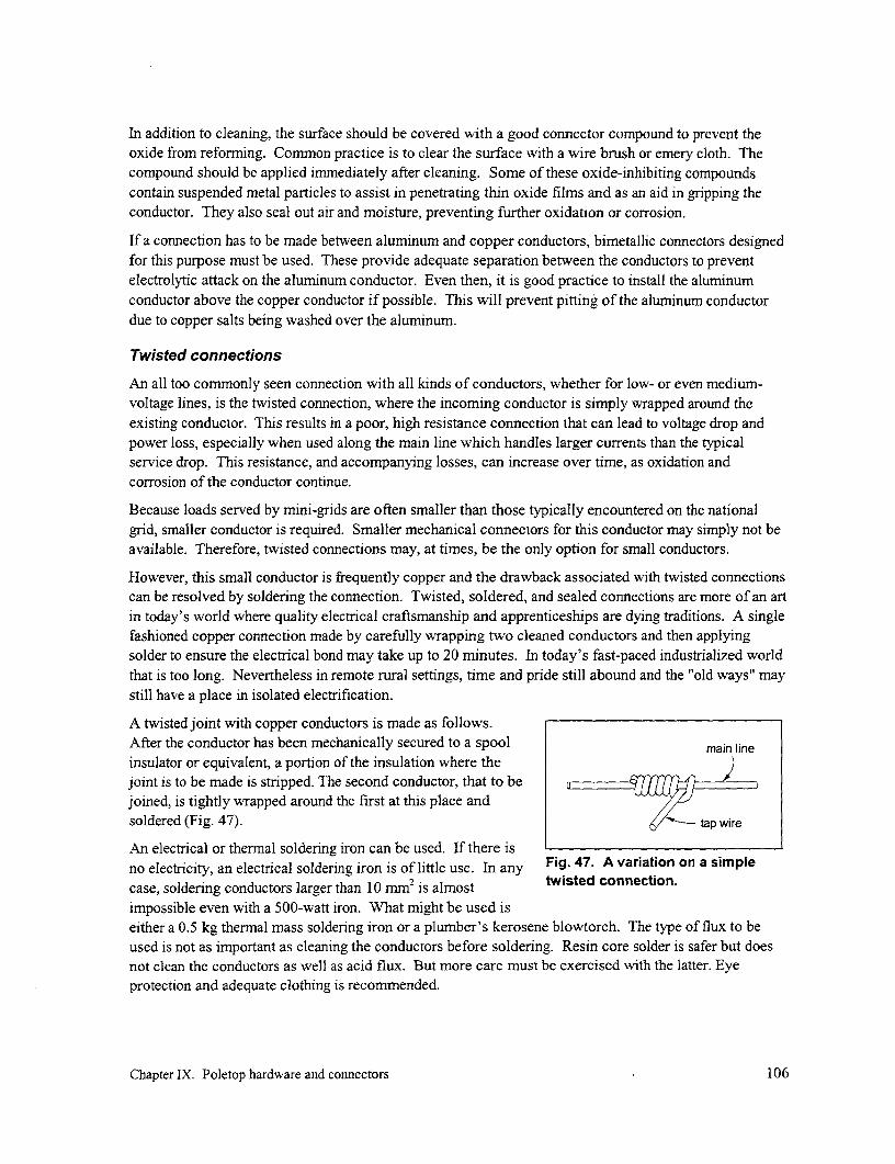
In addition to cleaning, the surface should be covered with a good connector compound to prevent theoxide from reforming. Common practice is to clear the surface with a wire brush or emery cloth. Thecompound should be applied immediately after cleaning. Some of these oxide-inhibiting compoundscontain suspended metal particles to assist in penetrating thin oxide films and as an aid in gripping theconductor. They also seal out air and moisture, preventing further oxidation or corrosion.
If a connection has to be made between aluminum and copper conductors, bimetallic connectors designedfor this purpose must be used. These provide adequate separation between the conductors to preventelectrolytic attack on the aluminum conductor. Even then, it is good practice to install the aluminumconductor above the copper conductor if possible. This will prevent pitting of the aluminum conductordue to copper salts being washed over the aluminum.
Twisted connections
An all too commonly seen connection with all kinds of conductors, whether for low- or even medium-voltage lines, is the twisted connection, where the incoming conductor is simply wrapped around theexisting conductor. This results in a poor, high resistance connection that can lead to voltage drop andpower loss, especially when used along the main line which handles larger currents than the typicalservice drop. This resistance, and accompanying losses, can increase over time, as oxidation andcorrosion of the conductor continue.
Because loads served by mini-grids are often smaller than those typically encountered on the nationalgrid, smaller conductor is required. Smaller mechanical connectors for this conductor may simply not beavailable. Therefore, twisted connections may, at times, be the only option for small conductors.
However, this small conductor is frequently copper and the drawback associated with twisted connectionscan be resolved by soldering the connection. Twisted, soldered, and sealed connections are more of an artin today's world where quality electrical craftsmanship and apprenticeships are dying traditions. A singlefashioned copper connection made by carefully wrapping two cleaned conductors and then applyingsolder to ensure the electrical bond may take up to 20 minutes. In today's fast-paced industrialized worldthat is too long. Nevertheless in remote rural settings, time and pride still abound and the "old ways" maystill have a place in isolated electrification.
A twisted joint with copper conductors is made as follows.After the conductor has been mechanically secured to a spool main lineinsulator or equivalent, a portion of the insulation where the )joint is to be made is stripped. The second conductor, that to bejoined, is tightly wrapped around the first at this place andsoldered (Fig. 47). 6/ tap wire
An electrical or thermal soldering iron can be used. If there isno electricity, an electrical soldering iron is of little use. In any Fig. 47. A variation on a simplecase, soldering conductors larger than 10 mm2 is almost twisted connection.impossible even with a 500-watt iron. What might be used iseither a 0.5 kg thermal mass soldering iron or a plumber's kerosene blowtorch. The type of flux to beused is not as important as cleaning the conductors before soldering. Resin core solder is safer but doesnot clean the conductors as well as acid flux. But more care must be exercised with the latter. Eyeprotection and adequate clothing is recommended.
Chapter IX. Poletop hardware and connectors 106

Once completed, the joint and uninsulated portion of the conductor should be tightly wrapped withelectrical tape to protect anyone who might be working in the vicinity of the connection as well as toprotect against possible shorts.
Split-bolt connectors
This split bolt was one of the earliest developed connectors specifically formaking electrical connections between two conductors. Its design haschanged little over the past century. The connector, as its name implies, isa split-shank bolt where the conductors to be connected are placed in theopen groove of the connector (Fig. 48). Some split-bolt connectors willhave a separating spacer that is intended to be placed between the -
connecting conductors. This spacer performs two primary functions:
* It provides more surface contact between the conductors.
* If tin-plated, it will serve as a bimetallic inert separator for Fig. 48. A split-boltdissimilar conductors such as aluminum and copper. connector, with
The advantages of this connector are that it is widely available in the local spacer. (Source: BurndyCorp., Manchester, New
marketplace and may be installed with simple wrenches. Insulated split- Hampshiae)
bolt covers are available, but this type of connector is usually insulatedusing electrical tape. Problems associated with the split-bolt connectors aredue to their misapplication or improper installation. Two wrenches or spanners are required wheninstalling this connector, one to hold the head of the connector and the other to tighten the compressionnut. Because this is a two-handed operation, the installer can find it uncomfortable to make a properconnection.
A word of caution: Although somewhat similar in appearance, U-bolt clamps should not be interchangedwith split-bolt connectors because tightening a U-bolt can damage the conductor.
Split-bolt connectors are not available for conductors smaller than about 3 mm2 or AWG #12.
Parallel-groove connectors
Parallel-groove connectors may be used for all-aluminum and all-copper or for bimetallic connections(Fig. 49). They can be used to provide electrical continuity from one conductor to the next; they are notto be used to mechanically connect two conductors under opposing tension. Some parallel-grooveconnectors may be provided with square-neck carriage bolts which will allow single-wrench installation.However, with small conductors, a second wrench may be used to avoid kinking of the conductor whentightening the connector. The advantage of this connector is its simple installation; only a wrench isrequired. Problems associated with this connector are also due to misapplication or improper installation
Fig. 49. Parallel- Yr
groove connector.(Source: Burndy Corp., ____
Manchester, New
Hampshire)
Chapter IX. Poletop hardware and connectors 107

of the connector. It is also difficult to insulate this type of connector due to its size and the exposed boltthreads. For small conductor, this type of connector is more expensive that other types that cover thesame range of conductor sizes.
This type of connector is typically available for conductor no smaller than about 8 mm2 (AWG #8).
Compression connectors
Compression connectors provide excellent electric and mechanicalconnecting properties. The compression connector, with its wide range ofapplications, has become the most widely used and least problematicconnector available in the market today. Compression tap connectors canaccept a wide range of conductors sizes and can accommodate copper,aluminum, and ACSR (Fig. 50).
This type of connector requires a special compression tool, which frequentlyuses custom dies that are placed in the jaw of the tool and match thecompression connector being used. However, some standardized dies can Fig. 50. A compressioncover a range of conductor sizes. A drawback associated with using this larger distribution linetype of connector is that nothing can be done without the proper tool and to a smaller serviceproper die. If this tool has been misplaced or damaged, then the use of drop. (Source: Burndy
generic tools like pliers or vise grips might be attempted. But these will Crop., Manchester, New
normally result in an improper connection. Another drawback to these Hampshire)
connectors is that they can only be used once; they cannot be opened andreused elsewhere.
These connectors are typically available to handle conductor begirming at about 3 mm2 (AWG #12). Theconnector shown in Fig. 50 can handle a range of conductor sizes. Before the connector is crimped, theupper portion is hung over the main conductor and the end of the smaller service drop is passed throughthe opening at the bottom.
Securing the conductors: Deadend hardware
Parallel-groove clamps
The parallel-groove clamp can appear similar to the parallel-groove connector described previously but ismore robust and usually has more bolts to clamp down on the conductor (Fig. 51). Designs are availablethat can be used to clamp either bare or insulated conductor. These operate by crushing somewhat thecable and slightly deforming it. As a deadend clamp, the conductor is passed around an insulator and thetail is folded back on itself and clamped. The same procedure is also commonly used for deadending guywires. As with all bolted hardware, if the bolts and nuts are not tightened according to the manufacturer's
Fig. 51. Parallel- a bgroove clamp.(Source: Burndy Corp.,
Manchester, New
Chapter IX. Poletop hardware and connectors 108

specifications, the deadend may fail. Another drawback iscost, and as a deadending solution, parallel-groove clamps arenot the most cost-effective solution.
A parallel-groove clamp can also be used to secure a pair ofinsulated conductors to a wire loop (a bail) that is in turnhooked to the pole or other support as is shown in Fig. 52.The clamp used in this figure was fabricated locally in Nepal.But a common problem was that, because considerable forceis required to tighten the clamp, it would eventually cut intothe insulated conductors and create a short.
Preformed deadends
The most popular and cost-effective deadending hardware forthe conmmon sizes of conductor used by electric utilities (#6 .A t uto 4/0 or from 13 to 110 mm2) is the preformed deadend pole and the t wo-conductor ABC is(Fig. 53). The preformed deadend requires no special tools deadended on both sides of theand, for small conductors, no tool whatsoever for installation. tree.The preformed deadend isinserted around the insulator ordeadend clevis and thenwrapped around the conductor LV
(which can be either insulated or -bare). The few drawbacks tothis deadending device are thatthe preformed grip must bespecifically matched to the Fig. 53. Preformed deadends installed over the end of a lengthspcnductry siz heand its reuse is of conductor. (Source: Preformed Line Products, Cleveland, Ohio)conductor size and its reuse IS
not recommended. However, in the real world, this is oflittle concern, because deadends are rarely replaced.
Automatic deadends
Automatic deadends are available for copper, aluminum, -4,and ACSR conductors. A machined jaw inside of atapered cylinder adjusts and holds the conductor in place(Fig. 54). This type of deadend is the easiest of all ;deadends to install and some manufacturers will allow /the deadend to be reused. The main drawback is the cost.For small conductor sizes, the automatic deadend gsolution may not be the most economical option. Thisdeadend is available for conductors beginning at 8 mm2
(AWG #8).
U-bolt-type clamps g
Specialty clamps which utilize a U-bolt along with a cap Fig. 54. An automatic deadend can beand a spacer to confine the conductor are available used at each end of a guy wire.
Chapter IX. Poletop hardware and connectors 109

(Fig. 55). These should not be confusedwith standard U-bolts that are commonlyavailable. These latter are to be used onlywith steel cable. If a U-bolt is tightened oncopper or alurminum, it will compress intothe softer metal, damage the conductor, andpossibly cause premature failure.
Fig. 55. U-bolt-type clamp. (Source: Burndy Crop.,Wedge clamps Manchester, New Hampshire)
Wedge clamps can be used for deadendingself-supporting service drop wire. A wedge clampcommercially available for this purpose is shown inFig. 56. In its operation, the conductor is slippedbetween the wedge and the sleeve (Fig. 57). Placing theconductor under tension forces the wedge into thesleeve, compressing the conductor against the sleeve. Fig. 56. Wedge claMp. (Source: Thomas &The clamping force increases as tension on the
conductor is increased. ~~~~~Betts, Memphis, Tennessee)conductor IS increased.
The wedge clamp grips both ACSR and aluminum conductor and is available with a rigid or flexible bail(the loops at the end of the clamp from which it is supported). Single clamps may accommodate a rangeof conductor sizes. The wedge clamp has a large surface area that grips the conductor with or withoutinsulation and minimizes crushing damage to the conductor and/or insulation. An advantage is that nospecial tools are required for installation and the wedge clamp may be reused.
This clamp is not readily available in most local markets and is a more expensive type of deadendingdevice. Sizes are available for conductors beginning at 13 Mm2 (AWG #6).
Wedge clamps are also available for deadending insulated conductor such as ABC (Fig. 58).
Supporting the conductorRacks, upset bolts, and clevises are used to support spool insulators that are in turn used to supportconductors on the pole. For all these options, the conductor should be tied to the spool as shown inFig. 59. If there is a deviation in the direction of the line at the pole, the conductor should be placed onthe side of the spool insulator so that the conductor pushes againstit (the first two illustrations in Fig. 60). If the angle of deviation ofthe line is greater than 600, then the conductor should be deadendedin each line direction (Fig. 60, last illustration); otherwise,
conductor
Fig. 58. This wedge clamp forinsulated ABC conductor is
Fig. 57. Basic configuration of a wedge clamp. fabricated of plastic.
Chapter IX. Poletop hardware and connectors 110

excessive force is placed on the rack or clevis support.
Racks
For multiple-wire low-voltage installations, spoolinsulators are typically fitted to racks that are fastened to -the pole with two or more machine bolts (Fig. 61). Theracks can be fitted with multiple insulators at fixedspacings, thus providing flexibility in different Fig. 59. Tying a conductor to a spoolconfigurations of low voltage-lines. The advantage is insulator
Fig. 60. Properplacement of theconductor on aspool insulator.
that a single standardized rack can accommodate almost all the open low-voltage applications, therebysimplifying warehousing and purchasing. This approach can also lead to the main disadvantages of theracks. The full use of the multiple spools may not be necessary and the rack becomes an expensive pieceof hardware where a single upset bolt or support clevis would suffice. There is also a tendency tooverstress the rack when it is used in deadend applications with larger conductor (i.e., because of thegreater tension involved). The bolt pattem of the rack may not conform to the deadend spacing of theconductors and the rack will bend and eventually fail. Another disadvantage is that if a bare conductor isnot correctly tied to the vertically installed spool insulator, it can move down onto the metallic support
and cause a short to ground.
Upset bolts
Single and double upset bolts are used for single conductorinstallation (Fig. 62). The upset bolt is a modified machine boltwith an extension for installing a single spool insulator. The single
r r
Fig. 61. Spool insulators ________
and used here to deadend aline. In this case, the boltpattern coincides with the Fig. 62. Spool bolts (single- and double-upset).spool positions. (Source: Joslyn Manufacturing Co., Franklin Park, Illinois)
Chapter IX. Poletop hardware and connectors ill

upset bolt is for mounting the neutral and the spool is mountednext to the pole. The double upset bolt is used for energizedconductors and provides spacing between the pole and the spool | ' l
insulator. The upset bolts are used in tangent applications (i.e.,no lateral angular change in the direction of the conductor as itpasses the pole) and for angles up to 50 (Fig. 63). Theadvantage of the upset bolt is that it is an inexpensive supportfor a spool insulator and spacing between conductors is notfixed as with the fixed spacing of the rack.
Support clevises I . I
Support clevises are fixed, single-insulator supports that are 4==Kfastened directly to the pole with a machine bolt. These looklike single-spool insulator racks (Fig. 64). The advantage of a K 49support clevis is that a single hardware item can be used for allapplications. However, a support clevis with a machine bolt iscostlier than an upset bolt. Also, an improperly tied bare Fig. 63. Comparison of theconductor can drop down onto the metal support can and cause a installation of a single upset boltshort to ground, depending on the type of pole. Clevis supports and a clevis. The former is onlyare used for line angles from 50 to 30°. used for angles less than about 50.
Swinging clevises
Spool-insulator swinging clevises (Fig. 65) are used to provide a flexible swinging support for theconductor. Swinging clevises are use in deadending applications and angles from 300 to 60° where acertain amount of freedom of movement is desired for attaching the conductor to the pole. This freedomof movement is desirable at angle structures and deadends to absorb mechanical stresses caused by windand span length variations. The advantage to the swinging clevis is that it provides a shock absorbingpoint for the conductor and provides a greater distance between the pole and the conductor. Thedisadvantage is that this unit is relatively expensive compared to the fixed clevis support and requires anincreased inventory of hardware.
it, -WE4
I~~~~~~~~~~~~~~~~~~~~B ,
Fig. 64. Support clevis. (Source: Joslyn Fig. 65. Swinging clevis. (Source: Joslyn
Manufacturing Co., Franklin Park, Illinois) Manufacturing Co., Franklin Park, Illinois)
Chapter IX. Poletop hardware and connectors 112

Wireholders
A wireholder is a porcelain insulator fitted with aheavy wood screw or clamping device in order tosecure it to a wooden beam or pipe conduit,respectively (Fig. 66). Wireholders are designedfor service drop (Fig. 67) applications but havefound use in small conductor applications for mainlines. The advantages are ease of installation andlow cost. Their disadvantage is their relatively low .'-'mechanical strength to support the conductor. Overtime, the wireholder may loosen and fall from thepole as the pole deteriorates.
Other approaches Fig. 66. Wireholders. (Source: Joslyn Manufacturing
Other approaches have been adopted to support Co., Franklin Park, Illinois)
conductor. One such approach is the use ofsuspension clamps that are available to support bare or insulated conductor (Fig. 68). Locally-made J-
shaped clamps have also been used. However, in this case, care must be taken when used to support
insulated conductor or bare aluminum conductor because, over time, the support can pierce the insulation
or cut into the conductor. Commercially, clamps are available which are coated with heat- and WV-
resistant plastic. Nepal fabricated its own clamps with a flexible insert to protect the insulation (Fig. 69).
Other less conventional approaches to supporting conductor are found in low-cost schemes that use
insulated conductor (Fig. 70). This can be either multiple lengths of single-core insulated conductor or
non-metallic sheathed multi-conductor. In these cases, the conductor is either looped once around the
pole (Fig. 71) and held in place with a staple or is supported by a loop of insulated wire also held in place
_ qNW
Fig. 68. A commercially madesuspension clamp for baremessenger conductor. To
Fig. 67. A wireholder used to deadend a service support insulated conductor,drop must be secured to a solid part of the the same clamp is available withhome. a plastic coating.
Chapter IX. Poletop hardware and connectors 113
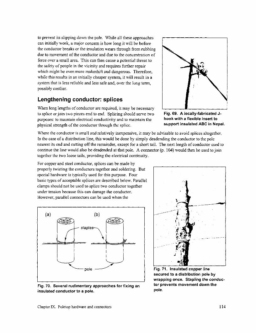
to prevent its slipping down the pole. While all these approachescan initially work, a major concern is how long it will be beforethe conductor breaks or the insulation wears through from rubbingdue to movement of the conductor and due to the concentration offorce over a small area. This can then cause a potential threat tothe safety of people in the vicinity and requires further repairwhich might be even more makeshift and dangerous. Therefore,while this results in an initially cheaper system, it will result in asystem that is less reliable and less safe and, over the long term,possibly costlier.
Lengthening conductor: splicesWhen long lengths of conductor are required, it may be necessaryto splice or join two pieces end to end. Splicing should serve two Fig. 69. A locally-fabricated J-purposes: to maintain electrical conductivity and to maintain the hook with a flexible insert tophysical strength of the conductor through the splice, support insulated ABC in Nepal.
Where the conductor is small and relatively inexpensive, it may be advisable to avoid splices altogether.In the case of a distribution line, this would be done by simply deadending the conductor to the polenearest its end and cutting off the remainder, except for a short tail. The next length of conductor used tocontinue the line would also be deadended at that pole. A connector (p. 104) would then be used to jointogether the two loose tails, providing the electrical continuity.
For copper and steel conductor, splices can be made byproperly twisting the conductors together and soldering. Butspecial hardware is typically used for this purpose. Fourbasic types of acceptable splices are described below. Parallelclamps should not be used to splice two conductor togetherunder tension because this can damage the conductor.However, parallel connectors can be used when the
(a) (b) .4.
staples
pole Fig. 71. Insulated copper linesecured to a distribution pole bywrapping once. Stapling the conduc-
Fig. 70. Several rudimentary approaches for fixing an tor prevents movement down theinsulated conductor to a pole. pole.
Chapter IX. Poletop hardware and connectors 114

conductors are not under tension, such as between the loose ends of two deadended conductors on the
same pole.
Wrapped/twisted splices.
This splice is used on small solidconductors made of copper or steel.The two wires are laid parallel andone conductor is wrapped over theother in reverse turns. Such a splice Fig. 72. A twisted splice before soldering.is shown in Fig. 72. To improve theconductivity and strength the spliceis soldered. This type of splice requires discipline and an appreciation for quality workmanship if it is tobe used successfully.
Twisted splices should not be used with ACSR, AAAC, and other aluminum multiple-wire conductorbecause these do not provide any mechanical strength and would introduce line loss due to poorconductivity across the splice.
Compression splice
This type of splice is very reliable and now commonplace. For small size conductors, the cost of thissplice is very attractive. A compressible splice is a metal tube that slides over the ends of the conductorsto be spliced and is squeezed or crimped onto the conductor by a compression tool. The compressionsleeve should only be used for the size of conductor for which it has been specified. Furthermore, thecompression tool must be fitted with the dies for that particular sleeve. If properly installed, the sleeveshould be able to support the full tension of the conductor. A disadvantage of this splice is that is cannotor should not be made without the proper compression tool and die.
For multi-layered ACSR transmission conductors, a couple of sleeves are installed over each other. Theinner steel sleeve is used to secure the two ends of the steel core and the outer sleeve is used over theouter aluminum strands and the inner sleeve. However, for the ACSR commonly used for distributionline, this type of splice is increasingly being replaced by a single sleeve placed over the entire conductor.Sizes range from solid #8 AWG (8 mm2 ) copper conductor and #4 AWG (21 mm2 ) ACSR on up.
For small solid-core conductors, a compression splice would be the best recommendation. This splicewill offer both good mechanical strength and optimum electrical conductive properties. Hand operatedmechanical presses are reasonably priced and can provide years of service if cleaned and maintainedperiodically.
Preformed splice
This splice is made up of preformed tempered wire that is installed by hand over the conductor as in thecase of preformed deadends. The splice principal is based on the "Chinese finger puzzle". As tension isapplied to the splice the covered preformned wires will grip the spliced conductor firmer. As in the case ofpreformed deadends, preformed splices should not be reused. These types of splices do not requirespecial tools like the press for the compression splices. Splices for small sizes are not readily availablebelow #6 AWG and the splices may not accept full tension.
Chapter IX. Poletop hardware and connectors 115

Automatic splice
This splice is based on griping wedgesinside of a tapered tube (Fig. 73). The - --
bared end of each conductor to be ' -
spliced is inserted into the tube with thegripping jaws. When the ends are fully Fig. 73. An exploded view of an automatic splice. (Source:inserted and then placed under tension, Fargo Mfg. Co., Poughkeepsie, NY.)
the gripping wedges are pulled towardeach end, further tightening their grip on the conductor. The advantage of this splice is that its applicationrequires no special tools. It is the easiest and most trouble-free method of splicing conductor. On theother hand, this type of splice is usually the most expensive of all the mechanical splices available,although prices have been going down as they have gained in popularity. These splices cannot be reused.Automatics splices are commonly available for solid copper conductor down to AWG #8 (8 mm2) and forACSR down to AWG #4 (21 mm2).
Knotting
An unconventional but fairly common practice for some low-cost schemes that use smaller insulatedconductor is to join the conductors by knotting together their ends. In this manner, it is the knot thatprovides the strength in tension. The insulation on the free ends of the knot is partially removed and theends should then be connected using one of the techniques described earlier (p. 104). This is not aconventionally accepted splice and it is not clear how durable it is, what type of knot least compromiseson the strength of the line, etc.
Chapter IX. Poletop hardware and connectors 116

X. Guys and anchors
When a line deadends on a pole or when there is a deviation in the direction of the conductor at a pole, itplaces a permanent force on the pole. If significant, this force must be counteracted by a guy wire thattransfers the force to an anchor in the ground. Guy wires are usually made of stranded steel that isheavily galvanized. However, where guys are near chemical plants or in mining districts, galvanized wirewill not stand up, and copper-clad cable may be used under such conditions.
While guy wires are commonly used with conventional medium- and low-voltage lines, mini-grids mayuse considerably smaller conductor. When this is the case, these smaller conductors can be placed underless tension, and forces which are in turn transferred to the poles at bends or at dead ends arecorrespondingly smaller and may not require guys to counteract. Furthermore, if ground clearance ismore than adequate, lines can have considerable sag, further reducing the tension (see sag-tensionrelationship, p. 80).
In some countries, guy wire can be useful and tends to "disappear", placing the system at risk. Therefore,if a guy is essential to ensure the proper operation of the system, all member of the community must beaware of this to avoid tampering or theft. The guy must also be protected vehicles and pedestrians fromaccidentally running across it.
Strength of cable
Guy on a deadend pole
Fig. 74 illustrates two cases in which guys are used. In the case of a simple deadend at the end of a line(a), the tension in each of the conductors exerts an unbalanced force on the pole. H represents the sum ofthe horizontal forces on the pole due to the tensions in the two or more conductors. In most cases, this isapproximately the same as the sum of the tensions in the conductor. A guy is required to counterbalancethis force. However, because theguy is anchored in the ground andmakes an angle 0 to the horizontal, (a) fbIthe tension in the guy is greater (b)than H. It is also increased by a --------- H 2Hsin/
factor SF, a safety factor ofperhaps 2. With a total force of H H
imposed by all the conductors, theguy must be able to resist the force 2H sing/2)
Tg of the following value:
T H -SF T
cost)
The tension in each conductor canbe obtained once the sag andweight of that conductor has beenestablished (p. 79). Fig. 74. Calculating guy tensions (a) at a deadend structure
and (b) at a deviation along a line.
Chapter X. Guys and anchors 117

Guy at a deviation
If there is a deviation in the line equalto an angle of a, the conductors exert (a) (b)an unbalanced force i n the direction
that bisects the angles between the twonconductors of a value shown inFig. 74. Here, His the sum of thehorizontal forces of all the conductors pformed
in any one direction and is again eadend J-clamp 9 1 approximately equal to the sum of the === 1tensions in all the conductors in thatdirection. All the forces originatingwith the conductors must again be parallel-groovecdampresisted by the guy, resulting in atension in the guy of the followingvalue:
2H. SF sinS-I _
g cos= Fig. 75. Options for securing a guy wire to a pole.
Securing the guy to a poleFig. 75 illustrates two conventional ways of securing a guy wire to a pole. The first (a) requires a guyhook of any one of numerous designs (Fig. 76) mounted with a through bolt. With a wrapped type design(b), the guy wire encircles the pole over curved sheet metal plates to prevent the guy from biting into thegrain of the wood. A J-clamp (Fig. 77) on each side of the pole prevents the guy wire from travelingdown the pole. The guy wire is deadended by using either preformed deadends (p. 108), parallel grooveclamps (p. 107), automatic deadends (p. 108) or U-bolts (Fig. 78).
_.~~~~~~~~~~~~~~~~~~~~~~~~~~*
Fig. 76. Guy hookattachment. (Source: Fig. 77. J-hook. (Source: Fig. 78. U-bolt clamp. (Source:Joslyn Manufacturing Co., Joslyn Manufacturing Co., Joslyn Manufacturing Co., FranklinFranklin Park, Illinois) Franklin Park, Illinois) Park, Illinois)
Chapter X. Guys and anchors 118

Types of anchorSeveral approaches to anchoring can be applied in A excavated Aless accessible areas. The least expensive anchor is --- 1 trenchprobably the deadman anchor. It has the advantage i
that its holding power can surpass that of other K _E-_types of anchors because this can be changed by Plan Viewchanging its size, in addition to its depth. Anchorsof this type are commonly made of a section of a anchorrolog. Even untreated logs can last a long time ifadequately buried. At times, sections of concrete un sturbedthat have broken in transport have been used as go /anchors. This type of anchor is installed as shownin Fig. 79. The anchor rod is laid in an area which loghas been trenched out. As with all buried anchors,it is preferable to tie into them using threaded Section View AA
anchor rods that connects to the guy wire aboveground because they are less susceptible to Fig. 79. Installation of a deadman anchor.corrosion damage. A hole should be drilled throughthe log and a washer of adequate size used underthe nut. As a less costly although possibly less durable alternative to using an anchor rod, the guy wire issometimes painted with bitumen, placed around the anchor, and tied together with a guy (parallel groove)clamp.
A second type of anchor is the plate anchor.Its installation is illustrated in Fig. 80.Because this anchor bears completelyagainst undisturbed earth, it develops a large undisturbed
holding power in most soil. Where the cost roundof labor is high, the disadvantage with both plateof these types of anchors is that considerable anchor rodlabor could be required to dig a hole of driven in groundadequate size and depth. In areas withvehicular access, this can sometimes beavoided through the use of screw anchors Fig. 80. Installation of a plate anchor.that are screwed into the ground. Powerequipment is generally used for this purpose because considerable torque is required.
Each of these anchors should be installed so that it rests beneath undisturbed earth as much as possible.The entire length of the anchor rod and the guy cable should be set in a straight line between theattachment on the pole and the point where the rod attaches to the anchor. If the rod is out of alignment, itwill eventually pull into alignment, causing a lengthening of the guy-anchor assembly and permitting thepole to lean in the opposite direction.
A third alternative is an anchor rod cast into a circular block of concrete (Fig. 81). But this type of anchormost effectively works with a mechanized pole auger slightly larger than the diameter of the concreteblock.
Chapter X. Guys and anchors 119
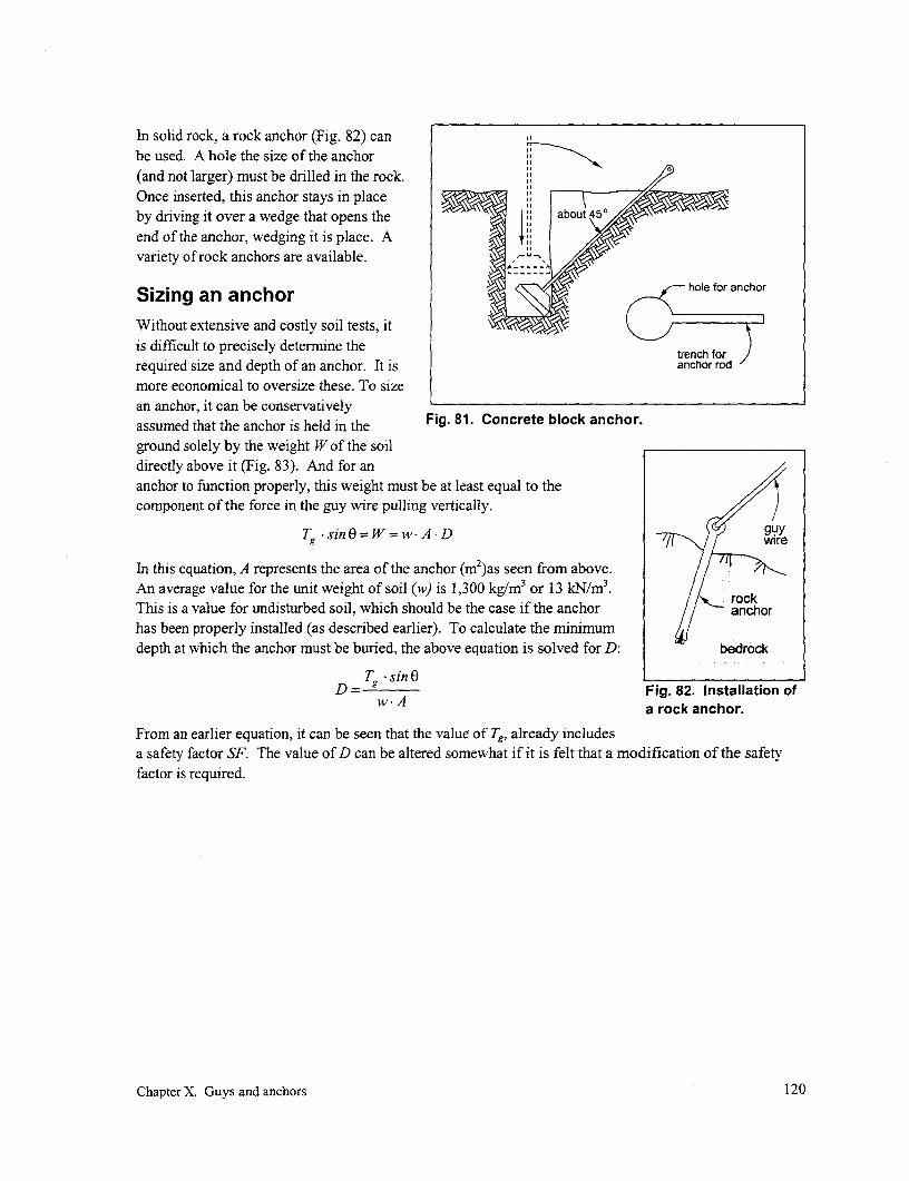
In solid rock, a rock anchor (Fig. 82) canbe used. A hole the size of the anchor(and not larger) must be drilled in the rock. NOnce inserted, this anchor stays in placeby driving it over a wedge that opens theend of the anchor, wedging it is place. Avariety of rock anchors are available.
Sizing an anchor h f anho
Without extensive and costly soil tests, itis difficult to precisely determine the trenrequired size and depth of an anchor. It is anchor rod
more economical to oversize these. To sizean anchor, it can be conservatively Fig. 81. Concrete block anchor.assumed that the anchor is held in theground solely by the weight W of the soildirectly above it (Fig. 83). And for ananchor to function properly, this weight must be at least equal to thecomponent of the force in the guy wire pulling vertically.
Tg sin8O=W=wwA.D gyre
In this equation, A represents the area of the anchor (m2)as seen from above.An average value for the unit weight of soil (w) is 1,300 kg/m3 or 13 kN/m3. rackThis is a value for undisturbed soil, which should be the case if the anchor anchorhas been properly installed (as described earlier). To calculate the minimumdepth at which the anchor must be buried, the above equation is solved for D: bedrock
T sin0ED = g Fig. 82. Installation of
w A a rock anchor.
From an earlier equation, it can be seen that the value of Tg, already includesa safety factor SF. The value of D can be altered somewhat if it is felt that a modification of the safetyfactor is required.
Chapter X. Guys and anchors 120

,_ ~~~~~~~~~~~~~~~~guy tension/ 0 anchor rod g
A
' -' i T 'Tg sin E ,'.I >' anchor Sj
Fig. 83. An anchor is assumed to be restrained by the weight of the soil above it.
Chapter X. Guys and anchors 121


XI. Safety and protection
IntroductionThis chapter is concerned with the reliability and the safety of the distribution and housewiring systems.One concern is to ensure protection of appliances and end-use equipment. These can be damaged byincorrect installation and poor-quality electricity supply. These factors in turn can lead to safety risks aswell as to needless expenses. This concem extends to the protection of distribution cables, housewiring,and devices from degradation and damage; otherwise, these present similar risks.
Risks to appliances and equipment that should be protected against can be caused by the following:
* Incorrectly installed or sized components causing internal heating (such as poor electricalconnections, undersized conductor, or motors that are not properly matched to the speed of theload they are driving)
* Excessive currents, caused either by overloading the circuit or by contact between two or moreconductors (generating heat and/or sparks which could lead to fire)
e Undervoltage and overvoltage (which can prevent motors from properly starting, in turn leadingto excessive currents; prematurely age fluorescent lamps and ballasts; or burn out light bulbs)
* Underfrequency and overfrequency (both factors which can cause some appliances to run hotter)
* Mechanical stress (for instance, dropping a heavy or sharp object on a cable, a tight bend forcedon an inflexible cable, or a conductor connection failing due to fatigue caused by repetitiousflexing)
* Temperature stress (external overheating caused by, for example, placing a cable too close to afire, cookstove, or lamp)
* Chemical stress (such as corrosion caused by joining of two dissimilar metals such as aluminumand copper or the degradation of insulation material causing embrittlement and cracking)
* Lightning
* Ingress of dust and liquids (such as rains and condensation)
Another closely related concern is human safety. Electricity can be dangerous, particularly for villagersto whom it is largely unfamiliar. Every effort should be made to minimize the risk to those usingelectricity. In addition to threats to safety caused by the factors mentioned above, other risks to humansinclude the following:
* Shocks due to direct contact with live conductors.
* Shocks due to indirect contact with live conductors, by touching liquids or exposed metallic partswhich have inadvertently become electrically live (or by touching other people who areinadvertently live)
* Fires started by sparking or overheating of damaged or degraded or wrongly installed electricalcomponents
* Shocks due to lightning conducted to exposed parts or liquids.
Chapter XI. Safety and protection 122
The need to ensure a safe and reliable system should be a concern at each step of the project as itprogresses, from design stage through to construction. This concern for safety should continue through tothe operation and maintenance of the system. Each time any action has to be taken-whether repairing afallen conductor, extending the distribution system, or adding outlets in a home-the normal reflex actionshould to be to ponder the safety implications of each design or procedure being considered.
In designing and constructing a mini-grid, the objective should be to strive to address all these potentialrisks. This can be done through a variety of actions:
* Incorporating and correctly installing the following:
- Overcurrent circuit devices
- Residual-current devices (ground-fault circuit interrupters)
- Grounding electrodes
- Lightning arresters
- Voltage and frequency limiters (these are considered as part of the design of the electricitysupply rather than of the distribution system and not considered herein)
* Properly maintaining the installation
* Periodically testing installed safety devices and replacing them as necessary
* Taking precautions against mechanical, thermal, and chemical stress
* Consumer and operator education
Because the concept of grounding (or earthing) of an electrical system is commonly referred to indiscussions about protection and safety,, this chapter will begin by reviewing this topic. It will thendescribe the various devices used to protect both equipment and people from electrical shock. This willbe followed by explanations of various electrical faults that must be protected against and how propergrounding and the use of these devices can be used to guard against hazards posed by these faults.
Grounding
Theory
While the resistance of soil is generally high, it is frequently a fairly good conductor from one point onthe earth to another simply by virtue of the large cross-sectional area of this "conductor". An example ofhow the earth can be used as a conductor is the method of transmitting electricity over long distances,called single-wire earth-retum (SWER). Early telegraphy systems also used the ground as a returnconductor. In these cases, instead of using two conductors to transmit electricity as is conventionallydone, the electricity is transmitted to the load in one conductor and returns back to the source throughearth or the ground (Fig. 84). The electricity enters and leave the earth through grounding electrodes thatcan be in the form of a long metal rod, a sheet or ribbon of metal, or a matrix of reinforcing bar embeddedin the concrete floor of a building.
While it was previously noted that most of the ground "conductor" has a low resistance because of itslarge cross-sectional area, this may not be true in the immediate vicinity of the grounding electrodes. Inthis area, the current must pass through the soil that has a relatively small cross-sectional area. Thisincreases resistance to the flow of current. If grounding electrodes are used as protective measures withmini-grids, it is necessary to ensure that the resistance in the vicinity of these electrodes is sufficiently
Chapter XI. Safety and protection 123

low. This is requisite for the proper operation ofsome electrical components such as lightning outgoing current
arresters and, depending on system design, circuitbreakers, and for the protection of individuals power _ _ _ _ _ _ _ load
using the system. Several approaches for reducing supply
resistance in the vicinity of a grounding electrode w:j;are discussed below (p. 123). - g
Z~~~~/// g~~~~~~lectroden
Types of grounding
Rod: Grounding rods are the most economical returningcu rretmeans of grounding, require no excavation, andcan be more easily driven deeper into the ground, Fig. 84. Using the earth as a conductor.where resistivity is less because of increasedmoisture. Deep ground rods are much less sensitive to seasonal variations than grounding systemsinstalled near the surface that dries out during the dry season. Driving the rod into the ground alsoensures a close, definite contact with the soil.
There are several types of ground rods. Solid copper gives excellent conductivity and is highly resistantto corrosion. But it is expensive and, being a soft metal, it is not ideally suited for driving deep in heavysoils. Steel rods, galvanized to reduce the chance of corrosion, are inexpensive and strong but the life ofthe galvanizing can be short in acidic soil. The best choice is a steel core with a copper cladding. Thesteel gives it strength while the copper exterior offers good conductivity and resistance to corrosion. Careshould be taken to ensure that the copper exterior is more than a thin copper plating which mnight give theappearance of being a quality product but may be scrape off as the rod is driven, exposing the steel tocorrosion.
When installing a ground rod, if it is too long and cannot be driven further, the top should not be bentover. Bending the rod can break the protective layer and encourage corrosion. This will in turn reducethe cross-sectional area at the bend, increase the resistance at that point, and eventually cause the rod torust through.
However, contrary to what might appear intuitively, the diameter of the rod has little impact on theground resistance. Larger-diameter rod should only be considered when it has to be driven in hardterrain.
Plate: Plate electrodes are normally of cast-iron or copper buried vertically, with the center about a meterbelow the surface. These provide a large surface area and are used mainly where the ground is shallow.Disadvantages include the need for considerable excavation and susceptibility of variations in groundresistance as the water content of the soil changes over the year. With this type of electrode, theconnection between the grounding lead and the electrode is located underground and is therefore subjectto corrosion through cathodic action. Painting the connection with bitumen can protect this fromhappening.
Ensuring a good ground
Going through the motions of installing ground electrodes does not ensure that these serve their intendedpurpose. This may actually be dangerous if it gives the false impression of safety where there is none. Ifa ground is made by inserting a short rod in dry soil, for example, it is possible for a "grounded" object to
Chapter XI. Safety and protection 124

still be energized with 240 V, which could be fatal if touched. It is therefore important that a good groundis assured when it is installed and that it be maintained over its life.
To ensure proper operation of the ground rod, ground resistance should be low. One way of doing this isto extend the rod deeper into the ground. Research undertaken by the U.S. National Bureau of Standardsconcluded that doubling the length of the ground rod reduces resistance by 40 %.
Another option is to simply increase the surface area of the grounding electrode. While it would appearthat this can be done by increasing the diameter of an individual electrode, research with grounding rodshas shown that this only has a marginal effect. For example, increasing rod diameter (and its surfacearea) by a factor of 300 % only decreases resistance by about 20 %. (The only reason for consideringincreased rod diameter is when strength is required to penetrate hard terrain.)
While increasing rod diameter has little effect, increasing area by using a number of interconnected, butadequately spaced, electrodes seems more effective. However, resistance does not vary in inverseproportion as the number used, as might be expected. In addition, multiple grounds rods should bespaced apart further than their depth of penetration to be effective. 14 In this case, increasing effectivesurface area by 300 % by using three adequately spaced grounding rods of the original size decreasesresistance by about 60 %.
In areas served by a municipal water system, another way of increasing the surface of the groundingelectrode is to use an existing cold water pipe on the consumer's premises. This is effective in caseswhere the entire water system is metallic. However, with the increasing usage of PVC pipe for watersystems, the continuity is broken and this grounding may not be as effective as assumed.
A second approach is to reduce the resistance of the soil in the vicinity of the electrode. One way is toincrease the moisture content of the soil in the vicinity of the electrode. Since the moisture of the soilusually increases with depth, this can be accomplished by driving the electrode deeper into the soil.
Another way is to chemically treat the soil in the vicinity of the electrodes (Fig. 85). This is also a usefulapproach when ground resistance is too high and ground rods cannot be driven deeper into the groundbecause of hard underlying rock that has moreresistance than soil. Care must be taken to ensurethat the treatment does not corrode the electrode. SOIL TREA71NG MATERIAL IS
PLACED IN CIRCULAR TRENCHMagnesium sulfate, copper sulfate, and ordinary AND COVERED WITH EARTH
rock salt are suitable non-corrosive materials.Magnesium sulfate is the least corrosive, but rock -; i , ...
salt is cheap and does the job if applied in a .. .*. .trench dug around the electrode. This method isnot permanent as the chemicals are gradually o \ . APPROX
leached away by rainfall. Depending on several 0 o M.
factors, it may be several years before anothertreatrnent will be required. Chemical treatmentalso reduces the seasonal variation of resistance EARTH ELECTRODE
of the soil. .
In areas of bedrock, with little soil cover, makinggood grounds is difficult. Drilling a hole intobedrock is necessary and generally requiresaccess to a pneumatic drill. In this case, to Fig. 85. Trench method of soil treatment.'4
Chapter XI. Safety and protection 125

reduce ground resistance, an oversized hole is drilled, a grounding rod inserted, and the hole backfilledwith concrete mortar or a sodium bentonite slurry. Bentonite is a clay mineral of volcanic origin mined in
most continents and ground to various sizes. Like concrete, it is hygroscopic, i.e., it attracts moisture by
chemically bonding with water. For this reason, these materials form a good conducting medium between
the grounding electrode and the sides of the hole and a good bond to these two surfaces. It also increases
the effective area of contact between the electrode and the surrounding rock. Sodium bentonite absorbs
roughly five times its weight of water and expands to occupy more than 10 times its dry volume. It is
applied in granular form so that it can be poured in place before swelling begins. In a borehole, the
bentonite/water mixture should swell in less than a day. This material continues to draw moisture fromthe soil and air around it, thus maintaining its volume and low resistivity. However, in a very dry, desert-
like environment, it will dry and shrink, drawing away form the embedded rod and increasing resistancerather than reducing it.
As noted earlier, a grounding electrode is usually more effective if it is installed in depth than if the same
electrode is laid horizontally closer to the surface. However, under the latter circumstances, grounding
can be improved by embedding somewhat more than 5 m of 5-mm diameter, bare copper conductor or the
equivalent length of 12-mm diameter reinforcing bar (or properly bonded lengths of rebar) within or near
the bottom of a concrete slab or footing in direct contact with earth. In this case, a conductor would haveto be bonded to the steel or copper and brought out for connection. Concrete is not as conductive as
bentonite, but it does improve electrical conductivity between the small diameter electrode and the earth.
Protection devices
Fuses
A fuse is a device for opening a circuit by means of a conductordesigned to melt when an excessive current flows through it.Two types are commonly used: the rewirable fuse (Fig. 86) andthe cartridge fuse.
The principal feature of a rewirable fuse is that, once the fusehas blown, the fusing element or wire can be easily replaced at iminimum cost. While these fuses may be convenient, low-cost,and popular, a principal disadvantage is that any inexperienced s _ _ J
person can replace the blown fuse wire with one of incorrectsize or one made of ordinary wire. Such an action completely Fig. 86. A rewirable fuse is screwednegates the purpose of the fuse to open the circuit when current to the ceramic cover that is then
reaches an unsafe level and places the system in jeopardy. In snapped over the ceramic base,one site visited, the continually blowing fuse was replaced by completing the circuit.progressively larger fuse wire. In the end, the generatoroverheated and burned from the overload (p. 201).
Another disadvantage is that this type of fuse does not discriminate between a momentary high currentthat is acceptable (e.g., due to a motor starting) and a continuous overload current that must beinterrupted. It also is not precise, because the actual fusing current depends on the ambient temperature
and the length of the fusing element. Furthermore, the minimum current for the fuse to blow might be
considerably (e.g,, two times) higher than its current rating, making it possible for the line being protected
Chapter XI. Safety and protection 126

to operate at a considerably higher current than it was designed for. The fuse can also deteriorate overtime, causing nuisance interruptions of the circuit.
To address some of these drawbacks, the cartridge fuse was developed. In this design, the fusing elementor wire is enclosed within a cartridge made of ceramic or glass and is less susceptible to deterioration inservice. By being manufactured under controlled conditions, its current rating is more precisely known.
Miniature circuit breakers (MCBs)
A circuit breaker is an electro-mechanical device that isdesigned primarily to automatically open a circuit whencurrents in excess of its design rating pass through (Fig. 87).Under normal conditions, a mechanism within the breakerholds the contacts in the closed position. The contacts areautomatically separated when the release mechanism in thebreaker is operated by magnetic and/or thermal means.
A magnetic breaker is tripped when excess current activates asolenoid. This pulls an iron slug into the solenoid's coil andcollapses the attached tripping linkage to open the contacts.Such breakers have a very quick reaction time. A therTnal -i
breaker is tripped with excess current heats a bimetallic strip.The resultant deflection trips the release mechanism. Because 4 W :Fof the time required to heat the bimetallic strip, reaction timestend to be slower. This might be more appropriate on a circuitwith a motor, because a brief initial peak current demand in Fig. 87. A selection of circuitexcess of the breaker's rated current is part of the normal breakers. (Source: Airpax Protector Group,
operating cycle of a motor. A magnetic breaker used under Cambridge, MD)
these circumstances might trip each time an attempt is made tostart the motor. Some breakers can contain both types of activation.
An ordinary switch is designed to make or break a current not greatly in excess to its normal rated current.A breaker can also be used to open a circuit manually, such as when work is undertaken on the circuit itcontrols (e.g., the housewiring). However, a breaker is capable of disconnecting a much larger faultcurrent. Ordinary switches would spark excessively under similar conditions, possibly damaging theswitch or even starting a fire.
While it is costlier than a fuse, a circuit breaker provides numerous advantages:
* It is easy to use and considerably more precise and more sensitive than a fuse.
* It can also be quicker acting; when small overload currents occur, the circuit breaker is likely tooperate before the fuse blows.
* It can be tripped by a small sustained overload current but not by a harmless transient overcurrentsuch as due to the switching surge which accompanies the ignition of a fluorescent lamp.
* The breaker on a faulty circuit is easy to detect, because this is indicated by the position of theswitch, and the breaker cannot be switched on as long as the fault condition remains.
* It can more conveniently be used as a switch when repairs have to be done to the circuit. It canbe reset manually after a fault has been corrected, and no stock of fuses is necessary.
Chapter XI. Safety and protection 127

* It is factory-calibrated and cannot readily be changed.
* Under fault conditions, breakers positively disconnect all poles of the circuit it controls
The required capacity of the circuit breaker (or fuse) depends on its function. An overcurrent device at
the powerhouse (or transformer, if the mini-grid is connected to a larger network) would be used. to
protect the generator or transformer from being overloaded. The capacity of an overcurrent device placed
on the consumer's premises would depend on its function. If it is to ensure that the current does not
exceed the capacity of the housewiring, then the size of the device would be set by this capacity. If it is to
limit consumer-drawn power to a specific limit that determines his tariff, then the device would be sized
according to this limit. For example, a household that has subscribed to a 50 W service would have a
breaker that would trip if the demand goes significantly beyond this limit.
Residual current devices (RCDs)
As is discussed below (p. 132), even very small currents can prove fatal. These currents are much smaller
than those that can be detected by the standard fuses and MCBs discussed above. The RCD is a
specialized form of circuit breaker developed to detect small fault currents that can pose a threat to
humans.
An RCD, also called a ground-fault protected
circuit interrupter (GFCI), is a device circuitthat is inserted in the circuit andlocated between the power supply andthe circuit along which protection is RCD
sought, usually on the premises of theconsumer (Fig. 88). This device is anautomatic switch that senses the supplycurrent into the circuit to be protected(Ij) and compares it with the currentout of this circuit (I). Under normal
operating conditions, these two Icurrents should be equal, and the _ _ _ _ _I_B_ J
switch maintains the supply.However, under fault conditions, such Fig. 88. Potentially dangerous currents leaking through aas when a person touches the live person (IB) will cause the current in (I;) and current out (la)conductor, a portion of the current of the circuit to be unequal, forcing the RCD to open thepassing through the RCD into the circuit,protected circuit would then passthrough that person (I,), leak into the ground, circumvent the RCD, and return through the ground back to
the supply either through a system ground if there is one, through any fault, or simply through capacitive
coupling between the circuit and the ground (p. 134). As soon as the RCD senses a difference (A)
between the incoming and outgoing currents, it trips and isolates the protected circuit.
An RCD operates by detecting the difference in current flowing into and out of the protected circuit,
independently of how well the generator is grounded or whether it is grounded at all. But incorrectly
grounding the consumer circuit can prevent an RCD from detecting fault currents.
Chapter XI. Safety and protection 128
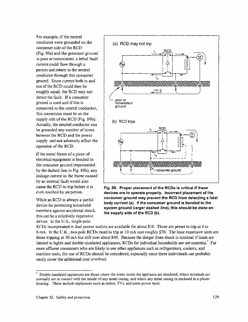
For example, if the neutralconductor were grounded on the (a) RCD may not tripconsumer side of the RCD(Fig. 89a) and the generator ground RCDis poor or nonexistent, a lethal faultcurrent could flow through a 4Eperson and return to the neutralconductor through this consumerground. Since current both in andout of the RCD could then beroughly equal, the RCD may not I 0detect the fault. If a consumer
por orground is used and if this is nonexistentconnected to the neutral conductor, groundthis connection must be on thesupply side of the RCD (Fig. 89b). (b) RCD tripsActually, the neutral conductor canbe grounded any number of times RCDbetween the RCD and the powersupply and not adversely affect theoperation of the RCD.
If the metal frame of a piece ofelectrical equipment is bonded tothe consumer ground (representedby the dashed line in Fig. 89b), any T Iconsumerground
leakage current to the frame causedby an internal fault would alsocause the RCD to trip before it is Fig. 89. Proper placement of the RCDs is critical if theseeven touched by an person. devices are to operate properly. Incorrect placement of the
While an RCD is always a useful consumer ground may prevent the RCD from detecting a fataldevice for protecting household body current (a). If the consumer ground is bonded to the
system ground (larger dashed line), this should be done onmembers against accidental shock, h upysd fteRD()this can be a relatively expensivedevice. In the U.S., single-poleRCDs incorporated in dual power outlets are available for about $10. These are preset to trip at 4 to6 mA. In the U.K., two-pole RCDs rated to trip at 10 mA cost roughly $70. The least expensive units arethose tripping at 30 mA but still cost about $40. Because the danger from shock is minimal if loads arelimited to lights and double-insulated appliances, RCDs for individual households are not essential. Formore affluent consumers who are likely to use other appliances such as refrigerators, cookers, andmachine tools, the use of RCDs should be considered, especially since these individuals can probablyeasily cover the additional cost involved.
Double-insulated appliances are those where the wires inside the appliance are insulated, where terminals arenormally not in contact with the inside of any metal casing, and where any metal casing in enclosed in a plastichousing. These include appliances such as radios, TVs, and some power tools.
Chapter XI. Safety and protection 129
Tripping of an RCD indicates a fault condition that must be corrected in order to remove the hazard that it
will likely continue to present to equipment or people.
If the RCD resets and the person in the household knows what caused the tripping, the mini-grid operator
can then be infonned, isolate the supply for that premise only, and repair or remove the faulty appliance.
If the cause for the tripping is unknown, this must be investigated further by the system operator:
* If an RCD can be reset, this implies a fault that is temporary in nature, possibly caused by
someone touching a faulty appliance. If the consumer does not know which appliance is causing
that tripping, the system operator must investigate further. One way to accomplish this is to
install a (temporary) consumer ground electrode if one is not already installed. All appliances
should be disconnected from the protected circuit being checked. Each appliance is then
connected, one at a time, to the circuit, the chassis is grounded through the consumer ground
electrode, and then the appliance is switched on. If the RCD trips either when the appliance is
connected or when it is switched on, the culprit load has been found.
* If the RCD still does not reset, the fault is probably permanent in nature and located in the
equipment or cabling. The technician would first disconnect both output leads from the RCD. If
the device can be reset, the problem is probably not a faulty device. He would then reconnect the
RCD and progressively isolate further sections of the circuit, by temporarily disconnecting both
conductors to those sections being checked until disconnecting one section or appliance allows
the RCD to be reset. This indicates that the fault is located in the last disconnected section.
In both cases above, once the culprit has been found, it is necessary to find the source of the problem so
that it can be repaired. A close inspection of the wiring and insulation may locate the cause of the fault.
An ohmmeter might also be of some use.
Protecting the system
Protecting against overload currents
Overload currents occur when too much load is placed on the circuit or generator. This type of
overcurrent can be caused by connecting too many lights or appliances to the supply or by connecting up
appliances, such as hot plates or irons, that draw too much current. Overload currents can be caused
when switching on a motor, until it comes up to speed, especially if it starts under a load. During this
period, additional current is required until the motor comes up to speed. If the motor is starting up with
no load, e.g., the motor is connected to a rice mill but no rice has yet been placed in the hopper, the motor
will start fairly quickly and the period of overload and the overcurrent will be minimal. If, on the other
hand, the motor starts under load, e.g., a motor is connected to a pump at the bottom of a well, then the
motor is pushing against the pressure of a full pipe of water as soon as it starts. It will take it longer to
come up to speed, and the duration of the period of overcurrent will increase. Overload currents also can
be caused by placing too much load on a motor after it has come up to speed, causing it to slow down or
stall, such as a saw binding and stalling because the wood being cut is too wet and/or thick or the blade is
too dull.
Impact
Overload currents can be inconvenient and merely affect the performance of lights or appliances. For
example, if in the evening too many lights have been turned on, the excess current causes an increased
voltage drop in the distribution system, reducing the voltage that is available in the home or workplace.
Chapter XI. Safety and protection 130

As a consequence, light bulbs will dim and this lower voltage may make it impossible to even start afluorescent lamp until the total load on the system has been reduced.
Overload currents can be dangerous as well, especially if they are sustained for long periods. Theincreased voltage drop that results can prevent a motor from getting the power it needs to start. It thencomes up to speed slowly, drawing excess current in the process and exposing the wires to hightemperatures due to this excess current. Overheating can cause an accelerated deterioration of thehousewiring, generator, or motor insulation and its eventual breakdown, or even generate sufficient heatto cause a fire. It can cause sparks in a switch when the appliance drawing the excess current is switchedoff, damaging the switch. Without any protection, it can also damage the generator, inverter, ortransformer providing power to the mini-grid.
Protection
To protect the system against overload currents, either of two devices are commonly used: fuses orMCBs. These should be placed at the beginning of the mini-grid, i.e., in the powerhouse or at thetransformner, to protect the supply from being forced to supply more power than it has been designed togenerate and to protect the consumers from the effects of low voltage. These should also be placed on thepremises of the customers themselves, primarily to protect them from drawing too much current andputting themselves at risk of fire or electrical shock that may result. This protection also protects theother consumers by isolating the offending consumer from the remainder of the mini-grid, permitting it tooperate normally once the offending load has been automatically removed. Depending on the size of themini-grid, additional breakers might be located at the beginning of each long branch of the grid. In caseof an overcurrent on one branch, the MCB would open, isolating that branch until the problem is resolvedbut maintaining power to the remainder of the community.
Overload currents are not as large as short-circuit currents. Because the rating of fuses is not preciselyknown, it is possible for fuses not to blow even if overload currents exceed the fuse rating. For thisreason, MCBs are often preferred to protect against overcurrents.
Protecting against fault currents
Fault currents between two conductors are caused under abnornal conditions when the close proximity oraccidental contact of one conductor to another causes current to flow between the two. Fault currentswhich could prove hazardous to the system include the following:
* Short circuits between conductors. These could be transient, high-level currents such as would becaused by shorts within the system, when bare portions of the conductors supplying a load comedirectly into contact with each other. This could be caused by a falling branch or tree pullingdown the distribution lines, causing uninsulated portions of the conductor to touch each other; awire from a loose connection within an appliance touching the other wire; or a heavy objectfalling across a wire, cutting through its insulation.
* Leakages through insulation. These are sustained, lower-level currents caused by the leakage ofcurrent through degraded insulation. These currents can occur due to the breakdown of theinsulation used with conductors, such as housewiring, or with insulation within an appliance, suchas in the winding of a motor.
Chapter XI. Safety and protection 131

Impact
Short-circuit faults can damage both line and equipment because of the potentially large currents involved
and the heat that is generated. It may also cause fires. On the other hand, smaller leakage currents inthemselves are not an immediate hazard. But even small currents can heat the insulation, further
aggravating the situation over time, until a short circuit may eventually develop.
Protection
Fuses and MCBs, installed in the powerhouse as well as on the premises of the consumers, are generallyused to provide protection against short-circuit currents. These devices should already have beenincluded in the system and sized to protect against overload currents (see previous section). Becauseshort-circuit currents are considerably greater than overload currents, these devices will also serve to
protect against the former. However, because of the large currents that short circuits can create, thesedevices must be designed to be able to safely accommodate these high currents as they open, without
damage to themselves.
'Leakage faults involving small currents flowingthrough degrading insulation along a conductor 1 RCDcannot readily be detected unless the problem is ---
sufficiently advanced to generate the additionalcurrents needed to trigger a fuse or MCB. The bestprotection is to use good quality insulated conductorof adequate size, taking precautions in the use ofelectrical equipment, and installing the housewiringin areas where it is not exposed to conditions that Fig. 90. With a short circuit or leakagecould initiate the deterioration of the insulation. It is across wiring insulation, the current in and
important to note that short-circuit and leakage faults out of the RCD remain equal and the RCD
cannot be detected by RCDs. This is because, in this will not trigger.case, the incoming and outgoing currents throughthe RCD are equal (Fig. 90).
Leakage faults involving currents flowing through the insulation to the frame of a piece of equipmentcould worsen over time if that equipment has been grounded through a consumer ground (as shown inFig. 94). In this case, fault currents can flow back to the power supply through the ground, generatingheat and causing the insulation to deteriorate further. Depending on the resistance of the ground, fault
currents might be sufficient to trip a breaker on the consumer's premises. Chances for detecting such afault would be considerably improved if an RCD were included on the consumer's distribution board (see
Fig. 98b) and even better if the consumer ground were bonded to a multi-grounded system neutral (see
Fig. 98c).
On the other hand, if that equipment is not grounded, the leakage problem may not worsen and cause theequipment to bum or otherwise fail. But in this case, it could prove a safety hazard to persons touching it.This is covered later in this chapter.
Protecting against corrosion/oxidation
Whenever different metals are in contact, especially in a damp environment, corrosion can occur, the rate
of corrosions being dependent on the type of metal, the dampness present, and the any contamination(such as salt spray from the ocean or contaminants in industrial emissions). This problem occurs
Chapter XI. Safety and protection 132

primarily at any connections between )aluminum and copper conductors, such as (a)between an aluminum distribution line and A Y
a copper service drop. 1)
When exposed to air, the surface ofaluminum rapidly oxidizes. The thinresistive film of aluminum oxide which (b)results can prevent a good contact between A
1,it and another conductor, decreasing qualityof service. B
Impact
If conductors of different materials are (c)connected together, any corrosion which Aappears at their points of contact will lead ___
to the gradual deterioration of the surface, B
increasing resistance and leading to anincreased voltage drop at the interface. It isfor this reason that special care must beexercised with working with connectionsbetween alurninum and copper. (d)
Oxidation is mostly a problem at A - , )aluminum-aluminum connections where itforms a layer on the surface of a conductor lthat increases the resistance at the - 5 RC
connection. Copper also oxidizes forminga resistive layer, but this is easily cleaned orsimply broken down under the pressure of a - - - - I - -connector.
Protection Fig. 91. A person can complete a circuit just like anyother electrical component.When making aluminum-aluminum or
aluminum-copper connections, special caremust be exercised, because the resistive oxide layer that forms on the surfaces of the conductor can resultin poor connections. The section on joining conductors (p. 104) explains the techniques involved inmaking such connections and the precautions that must be taken into account.
Protecting people
Nature of the hazard
The generator in Fig. 91 a generates 23 0 V and supplies a two-wire circuit that goes around the village.For any appliance such as a TV to work, electric current must flow through the TV from one side of thepower supply (A) to the other side (B), thereby completing a circuit. The bulb is not lighted because theswitch is open, preventing electric current from flowing around the circuit from point A through the bulbback to point B. As soon as the switch is closed, the circuit is completed, permitting the light to glow.
Chapter XI. Safety and protection 133
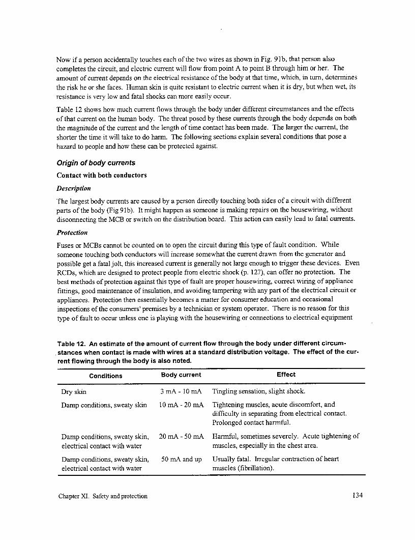
Now if a person accidentally touches each of the two wires as shown in Fig. 91b, that person alsocompletes the circuit, and electric current will flow from point A to point B through him or her. Theamount of current depends on the electrical resistance of the body at that time, which, in turn, determinesthe risk he or she faces. Human skin is quite resistant to electric current when it is dry, but when wet, itsresistance is very low and fatal shocks can more easily occur.
Table 12 shows how much current flows through the body under different circumstances and the effectsof that current on the human body. The threat posed by these currents through the body depends on boththe magnitude of the current and the length of time contact has been made. The larger the current, theshorter the time it will take to do harm. The following sections explain several conditions that pose ahazard to people and how these can be protected against.
Origin of body currents
Contact with both conductors
Description
The largest body currents are caused by a person directly touching both sides of a circuit with differentparts of the body (Fig 91b). It might happen as someone is making repairs on the housewiring, withoutdisconnecting the MCB or switch on the distribution board. This action can easily lead to fatal currents.
Protection
Fuses or MCBs cannot be counted on to open the circuit during this type of fault condition. Whilesomeone touching both conductors will increase somewhat the current drawn from the generator andpossible get a fatal jolt, this increased current is generally not large enough to trigger these devices. EvenRCDs, which are designed to protect people from electric shock (p. 127), can offer no protection. Thebest methods of protection against this type of fault are proper housewiring, correct wiring of appliancefittings, good maintenance of insulation, and avoiding tampering with any part of the electrical circuit orappliances. Protection then essentially becomes a matter for consumer education and occasionalinspections of the consumers' premises by a technician or system operator. There is no reason for thistype of fault to occur unless one is playing with the housewiring or connections to electrical equipment
Table 12. An estimate of the amount of current flow through the body under different circum-stances when contact is made with wires at a standard distribution voltage. The effect of the cur-rent flowing through the body is also noted.
Conditions Body current Effect
Dry skin 3 mA - 10 mA Tingling sensation, slight shock.
Damp conditions, sweaty skin 10 mA - 20 mA Tightening muscles, acute discomfort, anddifficulty in separating from electrical contact.Prolonged contact harmful.
Damp conditions, sweaty skin, 20 mA - 50 mA Harmful, sometimes severely. Acute tightening ofelectrical contact with water muscles, especially in the chest area.
Damp conditions, sweaty skin, 50 mA and up Usually fatal. Irregular contraction of heartelectrical contact with water muscles (fibrillation).
Chapter XI. Safety and protection 134
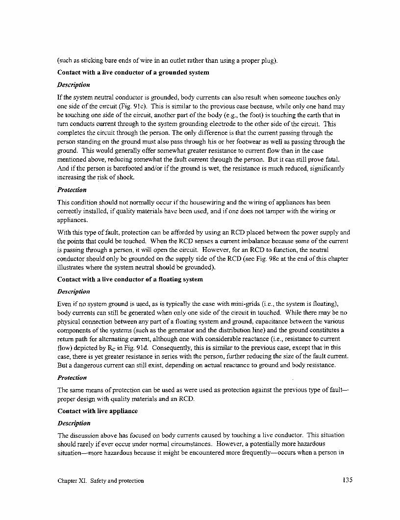
(such as sticking bare ends of wire in an outlet rather than using a proper plug).
Contact with a live conductor of a grounded system
Description
If the system neutral conductor is grounded, body currents can also result when someone touches onlyone side of the circuit (Fig. 91 c). This is similar to the previous case because, while only one hand maybe touching one side of the circuit, another part of the body (e.g., the foot) is touching the earth that intum conducts current through to the system grounding electrode to the other side of the circuit. Thiscompletes the circuit through the person. The only difference is that the current passing through theperson standing on the ground must also pass through his or her footwear as well as passing through theground. This would generally offer somewhat greater resistance to current flow than in the casementioned above, reducing somewhat the fault current through the person. But it can still prove fatal.And if the person is barefooted and/or if the ground is wet, the resistance is much reduced, significantlyincreasing the risk of shock.
Protection
This condition should not normally occur if the housewiring and the wiring of appliances has beencorrectly installed, if quality materials have been used, and if one does not tamper with the wiring orappliances.
With this type of fault, protection can be afforded by using an RCD placed between the power supply andthe points that could be touched. When the RCD senses a current imbalance because some of the currentis passing through a person, it will open the circuit. However, for an RCD to function, the neutralconductor should only be grounded on the supply side of the RCD (see Fig. 98c at the end of this chapterillustrates where the system neutral should be grounded).
Contact with a live conductor of a floating system
Description
Even if no system ground is used, as is typically the case with mini-grids (i.e., the system is floating),body currents can still be generated when only one side of the circuit in touched. While there may be nophysical connection between any part of a floating system and ground, capacitance between the variouscomponents of the systems (such as the generator and the distribution line) and the ground constitutes areturn path for alternating current, although one with considerable reactance (i.e., resistance to currentflow) depicted by Rc in Fig. 91d. Consequently, this is similar to the previous case, except that in thiscase, there is yet greater resistance in series with the person, further reducing the size of the fault current.But a dangerous current can still exist, depending on actual reactance to ground and body resistance.
Protection
The same means of protection can be used as were used as protection against the previous type of fault-proper design with quality materials and an RCD.
Contact with live appliance
Description
The discussion above has focused on body currents caused by touching a live conductor. This situationshould rarely if ever occur under normal circumstances. However, a potentially more hazardoussituation-more hazardous because it might be encountered more frequently-occurs when a person in
Chapter XI. Safety and protection 135
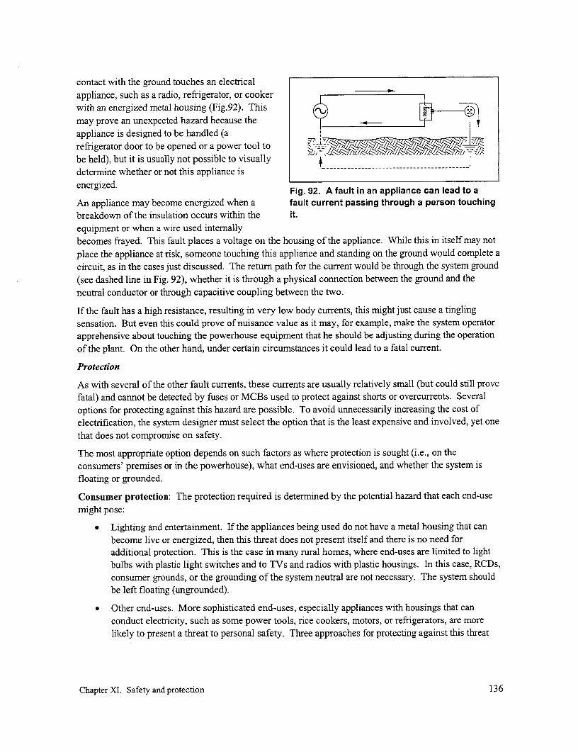
contact with the ground touches an electricalappliance, such as a radio, refrigerator, or cookerwith an energized metal housing (Fig.92). This
may prove an unexpected hazard because the -
appliance is designed to be handled (arefrigerator door to be opened or a power tool tobe held), but it is usually not possible to visuallydetermine whether or not this appliance is -- - - - -
energized. Fig. 92. A fault in an appliance can lead to a
An appliance may become energized when a fault current passing through a person touchingbreakdown of the insulation occurs within the it.equipment or when a wire used internallybecomes frayed. This fault places a voltage on the housing of the appliance. While this in itself may notplace the appliance at risk, someone touching this appliance and standing on the ground would complete acircuit, as in the cases just discussed. The return path for the current would be through the system ground(see dashed line in Fig. 92), whether it is through a physical connection between the ground and theneutral conductor or through capacitive coupling between the two.
If the fault has a high resistance, resulting in very low body currents, this might just cause a tinglingsensation. But even this could prove of nuisance value as it may, for example, make the system operatorapprehensive about touching the powerhouse equipment that he should be adjusting during the operationof the plant. On the other hand, under certain circumstances it could lead to a fatal current.
Protection
As with several of the other fault currents, these currents are usually relatively small (but could still provefatal) and cannot be detected by fuses or MCBs used to protect against shorts or overcurrents. Severaloptions for protecting against this hazard are possible. To avoid unnecessarily increasing the cost ofelectrification, the system designer must select the option that is the least expensive and involved, yet onethat does not compromise on safety.
The most appropriate option depends on such factors as where protection is sought (i.e., on theconsumers' premises or in the powerhouse), what end-uses are envisioned, and whether the system isfloating or grounded.
Consumer protection: The protection required is determined by the potential hazard that each end-usemight pose:
* Lighting and entertainment. If the appliances being used do not have a metal housing that canbecome live or energized, then this threat does not present itself and there is no need foradditional protection. This is the case in many rural homes, where end-uses are limited to lightbulbs with plastic light switches and to TVs and radios with plastic housings. In this case, RCDs,consumer grounds, or the grounding of the system neutral are not necessary. The system shouldbe left floating (ungrounded).
* Other end-uses. More sophisticated end-uses, especially appliances with housings that canconduct electricity, such as some power tools, rice cookers, motors, or refrigerators, are morelikely to present a threat to personal safety. Three approaches for protecting against this threat
Chapter XI. Safety and protection 136

are described below. Each ofthese approaches can be used person touchingalone; together they provide an consumer circuit housin standing on ground
increase safety factor (at a to circuitfinancial cost).
- Using double-insulatedappliances. A fault current capacitivethrough the housing cannot bcouping consumeoccur if it is entirely circuit and oounsumeground R ronmanufactured of an WI R
insulating material, such as T 'plastic. Double-insulated -- -----appliances should bepurchased when available;these use properly insulated Fig. 93. The resistances and reactance encounteredinternal wiring and have a when an individual comes into contact with a faulty
appliance. This circuit is floating but includes anon-conducting extenor. cnue rud- s~~~onsumer ground.
- Using a consumer ground. Ifthe svstem is floating as is shown in Fig. 92, no physical connection exists between theconductors and ground; the only connection is through capacitive coupling (shown by thedashed grounding symbol). If a person comes into contact with the housing of a piece ofequipment in which a fault has occurred, the entire fault current would pass through the body.What happens in this case is illustrated in Fig. 93 (leaving out the consumer ground for thetime being). The magnitude of this fault current I1 is calculated by dividing the impedance ofthis portion of the circuit (equal to the vector sum of body resistance, RB; ground resistance,RGI; and capacitive "resistance", Rc) into the total voltage that appears across this impedance.These variables are defined in Fig. 93 which is a representation of what is happening inFig. 92, except for the addition of a consumer ground. (Fig. 95a in Box 7 presents aquantitative example). Because the capacitive "resistance" (properly referred to as reactance)is relatively high for a small system, the amount of fault current flowing through this circuitand, therefore, through the person is largely limited by this reactance.
Now, adding a consumer ground provides a parallel path for this current; however, it does notsignificantly decrease the total impedance and therefore does not noticeably increase the totalfault current, IF (compare the first equation in Fig. 95a and 95b). But what is important is thatthe consumer ground provides a lower resistance path to ground, diverting most of the faultcurrent that would otherwise pass through the person and reducing the current through thebody (IB) to a safer level, depending on the effectiveness of this consumer ground (comparethe second equations in Figs. 95a and 95b).
If the neutral conductor were grounded, then the entire fault voltage would appear across theperson and the ground, independent of whether or not a consumer ground were used(Fig. 94a). Unlike the previous case, the low-resistance connection(s) between the neutralconductor and the ground would lead to a high fault current, and the consumer groundgenerally would not reduce body currents to acceptable levels as in the previous casedescribed above. It might only succeed in doing this if the consumer ground has a very lowground resistance, something frequently difficult to achieve in practice.
Chapter XI. Safety and protection 137

The required protection in thiscase would be to bond the housingto the system (neutral) ground (a)(Fig. 94b). This would place thehousing at the same voltage as theneutral conductor that is alreadygrounded and reduce any bodycurrents. Furthermore, if any shortshould occur within the housing,the ensuing high currents throughthis bonded ground (because of thelow resistance) will more likely besufficient to trip the MCB or blowa fuse on the distribution board, (b)isolating the faulty circuit andremoving the threat to a person. bond to ground rBut even if the fault current wereinadequate to accomplish this, thebonded circuit would place thehousing at ground potential,removing any voltage differenceacross the person and, therefore,-_- -
reducing any body current to zero.Therefore, to ensure a safe system Fig. 94. For a system with a grounded neutral,when the system neutral is well- also bonding the consumer ground on his or herground, a consumer ground should premises to the grounded neutral conductorbe included on the premises and ensures a safe environment.
also bonded to the neutral.
In this case, this consumer ground is redundant if the system neutral remains correctlygrounded. However, if for some reason the system grounds fail or the neutral conductorbreaks, the consumer ground will again resume its role of diverting a portion of any faultcurrents from the equipment frame to ground, thereby reducing potential fault currentsthrough the person touching the equipment. But depending on actual grounding resistances,adequately lowering fault currents to completely eliminate the threat of shock cannot beguaranteed.
- Using an RCD. While each of the options described above would reduce the threat ofelectrical shock to individuals on the premises due to faulty appliances, a properly installedand functioning RCD can always ensure a safe environment. The only drawback is cost. Ifan RCD is included in the household circuit served by a grounded system, with metalsurfaces of electrical appliances bonded to the system neutral, it is essential that such bondingis only located between the supply and the RCD (see Fig. 98c). Otherwise, the RCD may notfunction because any fault current may return to the supply by first going back through theRCD rather than through the system ground.
If consumer grounds are used, it is also possible to use a single RCD to provide someprotection from equipment faults to a number of consumers who are located between the
Chapter XI. Safety and protection 138

Box 7. Operation of a consumer ground
For this example, it is assumed that Fig. 93 represents a simple single-phase circuit supplied by a floating,three-phase 240 V power supply (i.e., the neutral conductor is not grounded). It supplies electricity to anappliance whose wiring is shorted to its metal frame near the live end of the appliance.
Fig. 95a describes what is happening in Fig. 93 without a consumer ground. If an individual touches thisframe, current will flow through his or her body, encountering body resistance (RB, perhaps 1500 ohm), aresistance into the ground in the vicinity of his or her feet (RG0 , perhaps 500 ohms), and a capacitivereactance (Rc, perhaps 6000 ohm). Then, if the voltage across this total resistance is 240 V, the total faultcurrent that would all pass through the person will be about 240/6300 = 38 mA, which could proveharmful.* Note that the fault current through the person's body (IB) is most prominently affected by thehigh capacitive reactance and is not significantly affected by resistance through the person. For example,if the person were standing on wet groundwith zero resistance (RGI = 0), the currentwould then increase only marginally to total fault240/6200 = 39 mA (a) current, IF
If a consumer ground is installed, with a / I RB
ground resistance of perhaps 300 ohms, 240 V useful load b 1500 ohms
this would, as before, have little effect on current the total fault current (Fig. 95b). This \ _ _______(_ 5 ohms
would now increase slightly to 240/6000 = 6000 ohms
40 mA. But more important is the factthat this current now has two paths to IF = V = 38 mAfollow to ground (through the consumer 6300 Qground and through the person). Because IB = IF= 38 mAof the lower resistant path through theconsumer ground, most of this current consumer(35 mA) will pass through that path, (b) total fault ground
leaving only 5 mA to flow through the l grunperson. This significantly decreases the / load IIj 1500 ohms
threat to the person. This threat can be 240 V useful III 7 RG2
reduced further if, for example, the person Rcut 300 ohms 500 ohms
is wearing shoes with rubber soles. .Because rubber is an insulator, this would 6000 ohms
further increase grounding resistancebetween the body and ground and further 1 240 V 40 mAdecrease the portion of the current passing 6000 Qthrough the body. I 2 = 6000 n (40 mA) = 5 mA
2000 (4m) m
* Note that total resistance is the vector sum of Fig. 95. Calculation of currents lI passing through anresistance and reactance, that is, individual (a) without and (b) with a consumer ground.
RT= V(1500 + 500) 2 + 60002 = 6300 ohm
Chapter XI. Safety and protection 139

RCD
tosupply i i neutral
Fig. 96. Using an RCD to protect against leakage currents caused by faults within equipmentwhich is grounded through a consumer ground.
RCD and the end of the line (Fig. 96). For this approach to work, the neutral on theconsumer side of the RCD should neither be bonded to the consumer ground nor begrounded. When used in this manner, the current difference sensed by the RCD will ariseboth from equipment faults being considered here as well as from miscellaneous leakagecurrents elsewhere on this protected part of the system. Therefore, the rating of the RCD hasto be sufficiently high to avoid nuisance tripping yet low enough to sense the fault currentsbeing protected against. While an RCD used in this manner could detect the larger currentsarising from faults within the various equipment, it should not be relied upon to detect thesmaller fault currents that might pass through an individual. In using this design, individualsare protected only insofar as the RCD trips due to a housing-to-ground fault sensed before anindividual touches the faulty equipment.
Powerhouse operator protection: While, in many cases, no ground may be necessary on the consumers'premises because no uses beyond lighting and entertainment are contemplated, the powerhouse clearlydoes contain several points that might accidentally become energized and prove hazardous to operatingstaff. These include the housing for the generator, the diesel engine, and the breaker box and/ordistribution board (if constructed of metal). An RCD cannot be used to protect from faults or strayvoltages in the generating equipment.
* If the system is floating, a powerhouse ground to the generating equipment can be used to reducefault currents in the same manner as was achieved with the independent consumer grounddescribed previously. This provides an altemative, lower resistance path for a fault currentaround the person touching the equipment.
Since concrete conducts electricity as does earth, the concrete foundation on which a generator ismounted might serve as part of this grounding system for a village power station (if the generatoris firmly bolted to this foundation). Its effectiveness can be increased by welding the anchors ofthe generator to the rebar before the foundation block is cast. The effectiveness and area ofinfluence of this "mat" to provide protection to the operating staff can be supplemented byplacing a 5 to 10 mm2 bare copper conductor in a firmly packed trench perhaps 0.10 m deep. (Alarger conductor is not necessary because a conductor that is used solely to provide protection tothe operating staff need not be designed to handle a large current.) This conductor could be in the
Chapter XI. Safety and protection 140

form of a loop perhaps 0.30 m beyond the base of the genset, immediately below the area wherethe powerhouse operator might be standing. This loop should also be firmly connected to thegenerator housing, perhaps at the generator mounting bolts and the other end can be connected toa grounding electrode. This electrode should be installed in a protected (i.e., little traveled) areajust beyond the perimeter of the powerhouse to reduce possible tampering as well as increase thechance that it is in more moist, and therefore more conductive, ground. It is important that theintegrity of this grounding system be maintained and that it is not possible, for example, forsomeone to trip over the grounding wire and pull it out of the ground, breaking the connection.Any other metal surface or junction boxes that are associated with the electrical system in thepowerhouse should also be well interconnected to this grounding mat.
If the system is well grounded, then as in the case of the consumer circuit, the equipment groundand system ground should be securely bonded together.
Lightning protection
When lightning discharges in the vicinity of a distribution line, a high voltage is induced in the line whichcan break down the insulation on the windings of transformers or generators connected to the line ordamage electronic equipment in the home or powerhouse. The associated high currents may also generatelarge amounts of heat and release considerable mechanical force. The purpose of a protective system is todivert these very high transient voltages and currents into the earth where they can be safely dissipated orto shunt these around rather than through devices that need protection.
Commercially available lightning arresters come with aweatherproof enclosure, connection leads, and a mountingstud or bracket. They should be connected to the distribution , Y
line, close to the equipment or accessory requiring protection,such as just outside the powerhouse or the service entrance(Fig. 97). At each of these locations, an arrester should beconnected between each of the phase conductors and acommon ground electrode, whether or not the system neutral , -i
is grounded. When the lightning-induced high-voltage peakon the distribution line reaches the arrester, it acts as a switch lpermitting the passage of the current and voltage peaks down -i into the ground through a ground rod. The voltage a
differentials between the phase conductors are therebyreduced to safer levels. Once the voltage peak has passed, thearrester automatically shuts off any further current flow. v -
Furthermore, the leads to and from a lightning arrester must '$2
be as short as possible and not coiled as shown in Fig. 97, 97 Tre tngae robecause these factors increase impedance (opposition to Fig. 97. Three lightning arresters oncurrent flow) to ground. With a large, rapid, lightning- a three-phase, four-wire line just
outside the powerhouse.induced current surge through arrester and the leads, anyvoltage drop due to current flow through this impedance addsfurther to the line-to-ground voltage and the net voltage could remain at troublesome levels.
For application on a distribution line, two types of arrester are commonly used: metal-oxide varistors(MOVs) and spark-gap type surge arresters. The first is made of a metal which temporarily loses most of
Chapter XI. Safety and protection 141

its resistance when a large voltage is imposed across it and then shuts off when the voltage peak haspassed. The second is comprised of an air gap across which a current surge jumps when sufficientvoltage is applied, with the spark extinguishing itself after the voltage peak passes.
Lightning is usually of less concem with low-voltage lines than with medium-voltage lines because theformer tend to be lower to the ground and located among dwellings and trees where exposure to lightingis reduced. However, in areas where lightning is a frequent occurrence, low-voltage arresters can beinstalled at the service entrance.
Because solid-state electronics are sensitive to voltage surges, further protection is recommended forradios, TVs, or other electronic equipment is used in the home where lighting is a problem.. Unlessgrounding resistances are very low, i.e., less than an ohm, higher than normal voltages may still appearbetween the phase conductors in the home. To address this problem, surge suppressors are used andshould be installed either just before the leads enter the equipment or in the equipment itself.
Consumer and operator education
One of the best ways of preventing people from receiving electrical shock is to ensure that systemoperators, and the consumers themselves, have a good understanding of how shocks occur. They willthen be in a better position to avoid this type of danger. A program of consumer education on the safe useof electricity is essential at the time of system commissioning and at periodic intervals aftercommissioning (p. 173). A well-illustrated maintenance and safety manual for system operators shouldaccompany every distribution system. And periodic visits should be made to individual consumers toobserve how they are using the system and to observe any dangerous situations, e.g., hooking clotheshangers on wiring, unauthorized connections, faulty plugs, wire insulation damaged by proximity to thecooking fire, etc.
SummaryFuses, MCBs, and RCDs are generally used for protecting the system from excess currents that candamage the system or provide a safety hazard to people. Grounding can also play an important role.However, because incorrectly installed grounding can pose an increased hazard, it is important thatgrounding not be installed as an afterthought, in the hope that it will automatically make the system safer;it could have the opposite effect.
The final section in Chapter VI provides guidance as to when a mini-grid can be floating and when itshould be grounded (p. 60). The following summarizes options for protection under these two scenarios:
1. Powerhouse: In all cases, a groand should be included in the powerhouse as protection foroperators within the powerhouse (Fig. 98abc). This is in part accomplished by bolting thegenerating equipment to a concrete foundation block, if one is included. A grounding loop alsoconnected to this equipment should be buried a short distance below ground level around thisequipment and firmly bonded to a grounding rod. In addition, all metal housings within thepowerhouse that contain electrical equipment should be tied into this ground. If the system isfloating and a fault arises in the generator, this ground will provide a low-resistance path for mostof the fault current to follow, reducing current through anyone touching the equipment(paralleling the operation of a consumer ground, p. 136). If the neutral conductor is alsogrounded, then the powerhouse ground should be bonded to the neutral conductor. This will
Chapter XI. Safety and protection 142
reduce the voltage across people touching thegenerating and control equipment and largely RCD (optaonaI)Eeliminate any fault currents through that (a)rperson. H
2. Consumer: The consumer protection required idepends on the sophistication of the users.Note that in all cases summarized below, aRCD can be used to protect the user, whether (b)the system neutral is grounded (Fig. 98c) or not r
(Figs. 98a and 98b). However, because therelatively cost of an RCD can makeelectrification less accessible in cases wheredisposable income is limited, it should be usedwhere necessary and no cheaper alternative (c)exists.
- For a basic system commonly found, whichmostly serves lighting and entertainmentend-uses, no special protection is necessary /-in the home because the threat of touching * e consumerany energized conductor or metal surface yrstend groundwhich may be live is minimal. Radios andtelevisions are generally housed in plasticand double-insulated. A floating system is Fig. 98. Grounding options for a mini-grid.adequate.
If one or more power outlets are included in the home, there is increased danger from eitherchildren playing with these outlets or adults trying to energize appliances without the properplugs (e.g., slipping bare ends of wires into the outlet). RCD could provide some protection(Fig. 98a), unless the person places himself across both openings of the outlet, effectivelyshorting the conductors. Placing outlets out of reach of smaller children is another action thatcould be taken.
For the occasional consumers who might have more sophisticated end-uses (refrigeration,power tools, pumps, cookers, etc.), a fault within the equipment can energize the equipmenthousing or frame, creating a fault current through anyone touching this equipment. (Even ifthe system is floating and no part of the system is physically connected to a ground electrode,the system is grounded through capacitance between the generator and conductor and theground.) As illustrated in Box 7, a consumer ground on those premises will reduce any faultcurrents through a person that might arise due to his or her touching faulty equipment(Fig. 98b). Altematively, an RCD can be included on the premises to isolate the consumercircuit if a fault occurs within the equipment. Then, if resistance to ground through thiscapacitance is sufficiently low to provide a current that can be of danger to people touchingthe housing, the fault current within the equipment should then be sufficient to trigger theRCD and insolate the offending circuit until the fault is found.
- For a system that is supplied by a medium-voltage grid extension through a distributiontransformer, a grounded neutral system may be used if this is accepted practice. A conductor
Chapter XI. Safety and protection 143

should be used to connect all metallic housings on the premises and this should be bonded tothe system neutral conductor. Multiple grounds along that neutral will ensure a safer systemby providing redundancy and reducing system resistance to ground. Currents originatingfrom a fault in the equipment housing would go directly to the system neutral and encounterminimum resistance. This encourages high fault currents that may trip the MCB or fuses onthe distribution board and isolate the circuit. Even if this does not happen, the low resistancepath from housing to ground would remove any voltage across a person touching the faultyequipment, removing the threat of a fault current. An RCD could provide added securityprovided it is properly positioned (Fig. 98c)
Chapter XI. Safety and protection 144


Xii. Service connection and housewiring
Service connectionThe service connection consists of two components:
* The service drop. This includes usually two, but occasionally three or four, conductors between
the consumer and the distribution line; their connections to the distribution lines; and their
connections to the entrance of the consumer's residence or business (Fig. 99).
In most cases, the service drop is comprised of overhead conductors. This implies easier and
lower-cost construction and permits more flexibility if that is needed after construction of the
mini-grid, such as to accommodate a change in the location of the residence on the property or a
replacement of a temporary structure located on one part of the property with a more permanent
one elsewhere on that property. For these reasons, an overhead service drop is what is assumed
in this section. Occasionally, an underground service connection is used, as in the case of theGECO projects implemented by the French in several countries in Africa (see p. 192).
* The service entrance. The service entrance is comprised of the elements necessary to take the
electricity from the service drop to inside the customer's premises. Conventionally, the service
entrance includes the conductors and associated hardware from the service drop to the meter, the
meter, and in some places a disconnecting device. For mini-grids, the meter may be omitted and
the service entrance may lead directly indoors to the customer's distribution board or junction
f~~~~~~~
service drop serviceentrance:
distribution line service connection housewiring
Fig. 99. The basic components to deliver power from the distribution line to theuser.
Chapter XII. Service connection and housewiring 145

box, which might then include a current-limiting
device as an alternative mechanism to a meterfor controlling/monitoring electricity use (see"Metering", p. 153). Or the meter and thecustomer's distribution board may both bereplaced by a single device, such as theprepayment meters being widely promoted inthe Republic of South Africa.
In some countries, the meters or current-limiting -*
devices are placed on the power pole itself,
before rather than after the service drop(Figs.l00 and 132). Access to these for meterreading or repair may even require the use of a ichair or even a ladder. While such a placementminimizes the chances of tampering, this optionis not recommended because it makes accuratemeter-reading difficult. If current limitingdevices are affixed to the pole, this makesreplacing or resetting the fuse element or breakerdifficult. Furthermore, a consumer might be - 1, -$;
tempted to climb up the pole to reset the current- Fig. 100. In Thailand, meters arelimiting device to turn on his power and thereby commonly mounted at all heights on theputs himself at risk by coming into contact with nearest pole.energized lines.
Service drop
Conductor type
While bare conductor can be used for a properly designed main distribution grid, it should not be used forservice drops for mini-grid systems. Bare energized conductors connected directly to a consumer'sdwelling pose a high risk to electrical hazards to the general public.
Of the conductors described in Chapter VII, multiplex conductor is specifically designed for service dropinstallation, and hardware exists for deadending, splicing, and connections. When available, it should beused in cases with the level of consumption found in industrialized nations, i.e., hundreds of kWh permonth.
However, such high usage is unusual on mini-grids. Therefore, smaller insulated, single-core copperconductor is the most commonly used for service drops. This is especially so in unregulated installationsbecause the installation is inexpensive and literally can be done by anyone who can connect wires.Unfortunately, these individuals may also have little concern for, or knowledge of, the safety hazards orelectrical or mechanical limitations involved.
This type of service drop has the highest failure rate. Because of the conductivity of copper, a fairly smallconductor is required to serve the purpose if it is selected on the basis of limiting the voltage drop alongthe service drop to a specific value. This is even more the case for mini-grids, where consumer demand istypically very low, further reducing the required conductor size. For example, if the voltage drop along a230-V single-phase service drop were restricted to only 1 % and if several inefficient incandescent lights
Chapter XII. Service connection and housewiring 146

and a TV were the only end-uses, then 1-ampere service would provide 230 W which would be more than
adequate. A copper conductor as small as 0.5 mm2 in area would transmit this power a distance of about
30 m and still satisfy these conditions. Alternatively, if each home had only one capacitor-corrected
fluorescent lamp which each consumed a total of 30 W (i.e., with losses), a 0.5 mm2 service drop could
serve 4 homes evenly distributed along 100 m length of service drop strung from house to house. For this
reason, the minimum size conductor is restricted more by physical strength requirements than by its
current-carrying capacity. Due to the small size of conductors involved (usually less than about 3 MM2),
the installations overstress the cable for what it was intended. Long spans will break at the fastening
point due to fatigue of the copper as a result of movement caused by wind and mechanical stress.
When compared with copper, aluminum conductor is less expensive but has 60 % more resistance than a
copper conductor of comparable size. Furthermore, when used for service drops to meet small power
demands, small aluminum conductor faces the same problems noted previously for copper.
In summary, for the typical mini-grid project, individual consumer loads are often very small.
Furthermore, costs must be minimized in order to make electricity more accessible to households in the
community. Based on the good conductivity of copper, small conductor could be used but, as mentioned
above, the conductor is susceptible to breaking through fatigue. Larger copper conductor might be used
simply because of the increased strength that it offers, at an additional cost. One approach for making use
of the large current-carrying capacity of copper conductor while avoiding the need to purchase large
conductor simply to satisfy strength requirements is to use a homemade duplex option described in Box 8.
This capitalizes on the use of good conductivity of copper conductor and the strength of steel conductor to
come up with a cost-effective hybrid. But because the steel wire would be bare, use of this option should
be restricted to systems where the neutral conductor is properly grounded. Altematively, PVC-coated
steel fencing wire might be used.
Conductor Sizing
In various countries, national electrical codes have been established to serve as guidelines to be adhered
to in order to ensure the design of a safe electrical system. But one has to apply such codes judiciously
because they have generally been designed to address conventional needs found in urban areas where
constraints are often different from those found in rural areas. For example, minimum conductor sizes
have been established by the need to ensure that adequate capacity is available to meet the load that might
be expected in urban areas. This is often well in excess of what is found in rural areas and, in these cases,
abiding by these guidelines unnecessarily increases the cost of electrification, making it less accessible to
rural communities.
As with the sizing of conductors used for the main distribution line, one important factor affecting the
size of the conductor used for the service drop is the acceptable voltage drop along this section of line.
This is usually set at no more than I to 3 % under maximum consumer load. The acceptable value is
somewhat affected by the actual size of the voltage drop already incurred through the distribution line
from the powerhouse up to that point.
The size of the service drop conductor required so that the voltage drop at the end of the line does not
exceed the desired value (see above) is calculated with the same equations used to calculate the size of the
It might be noted here that, even in rural homes connected to the national grid, a peak coincident power demand ofabout 250 W per household is common in many parts of the world (unless the electricity is so heavily subsidizedthat it encourages unnecessary over-consumption and waste).
Chapter XII. Service connection and housewiring 147
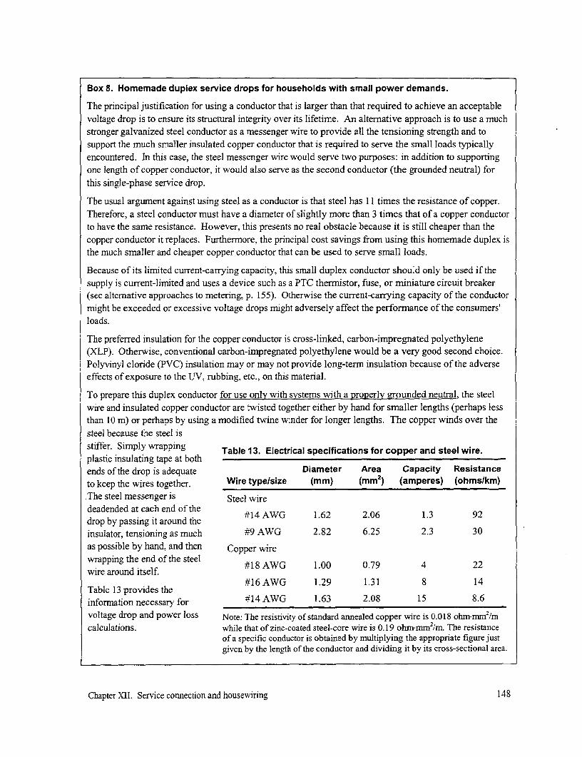
Box 8. Homemade duplex service drops for households with small power demands.
The principal justification for using a conductor that is larger than that required to achieve an acceptable
voltage drop is to ensure its structural integrity over its lifetime. An alternative approach is to use a muchstronger galvanized steel conductor as a messenger wire to provide all the tensioning strength and tosupport the much smaller insulated copper conductor that is required to serve the small loads typicallyencountered. In this case, the steel messenger wire would serve two purposes: in addition to supportingone length of copper conductor, it would also serve as the second conductor (the grounded neutral) forthis single-phase service drop.
The usual argument against using steel as a conductor is that steel has 11 times the resistance of copper.
Therefore, a steel conductor must have a diameter of slightly more than 3 times that of a copper conductorto have the same resistance. However, this presents no real obstacle because it is still cheaper than thecopper conductor it replaces. Furthermore, the principal cost savings from using this homemade duplex isthe much smaller and cheaper copper conductor that can be used to serve small loads.
Because of its limited current-carrying capacity, this small duplex conductor should only be used if thesupply is current-limited and uses a device such as a PTC thermistor, fuse, or miniature circuit breaker(see alternative approaches to metering, p. 155). Otherwise the current-carrying capacity of the conductormight be exceeded or excessive voltage drops might adversely affect the performnance of the consumers'loads.
The preferred insulation for the copper conductor is cross-linked, carbon-impregnated polyethylene(XLP). Otherwise, conventional carbon-impregnated polyethylene would be a very good second choice.Polyvinyl cloride (PVC) insulation may or may not provide long-term insulation because of the adverseeffects of exposure to the UV, rubbing, etc., on this material.
To prepare this duplex conductor for use only with systems with a properly grounded neutral, the steelwire and insulated copper conductor are twisted together either by hand for smaller lengths (perhaps lessthan 10 m) or perhaps by using a modified twine winder for longer lengths. The copper winds over thesteel because the steel is
stiffer. Simply wrapping Table 13. Electrical specifications for copper and steel wire.plastic insulating tape at bothends of the drop is adequate Diameter Area Capacity Resistanceto keep the wires together. Wire type/size (mm) (mm2) (amperes) (ohmslkm)The steel messenger is Steel wire
deadended at each end of thedrop by passing it around theinsulator, tensioning as much #9 AWG 2.82 6.25 2.3 30
as possible by hand, and then Copper wirewrapping the end of the steel #18 AWG 1.00 0.79 4 22
wire around itself.#16AWG 1.29 1.31 8 14
Table 13 provides theinformation necessary for #14 AWG 1.63 2.08 15 8.6voltage drop and power loss Note: The resistivity of standard annealed copper wire is 0.018 ohrn-mm2/mcalculations. while that of zinc-coated steel-core wire is 0.19 ohminmm2/m. The resistance
of a specific conductor is obtained by multiplying the appropriate figure justgiven by the length of the conductor and dividing it by its cross-sectional area.
Chapter XII. Service connection and housewiring 148

0.5 mm2 1.0 mm2
I 2.5mm2
0I-t for copperCD 2 conductor - _ 4.0 mm2
0
0 I 6.0 ml(3)
U0~~~~~~~~~~~~~~~~~0m
00.001 0.010 0.100
P(kW) x L(km)
Fig. 101. A graph to calculate the voltage drop at the end of a copper 230-Vsingle-phase service drop serving one or more homes. The area of the conductorassociated with each curve is indicated at the top and right of the graph.
main distribution conductor (see Table 8, p. 75). However, if small conductors are used (i.e., less thanabout 10 mm2 ), the value of inductance x for the conductor is much smaller than its resistance r and theterms "x sin 4" can therefore be neglected. The equation for voltage drop for a single-phase service, thensimplifies to the following:
P(kW) L(kmn) Percent voltage drop = %VD _ 2 r 2 o10
Note that, for these small conductor sizes, the solution to the simplified equation is independent of thepower factor. To facilitate solving this equation for a service voltage of 230 V, the graph in Fig. 101 wasprepared. To use this graph to size a specific service drop, sum the products of the peak coincident loadin each home (in watts) along that drop and its distance from the beginning of that service drop (inmeters). Look for this value on the horizontal axis and then move up to the point where the line for thedesired percentage voltage drop is reached. The required size for a copper conductor is determined by thecurve closest to that point. Multiply the area by 1.6 if an aluminum conductor is to be used.
As an example, assume that a home with a peak coincident demand of 200 W is located at 40 m from thebeginning of the service drop and a second home with a peak demand of 400 W is located at the end ofthis 70 m service drop. The value of P x L is (0.20)(0.040) + (0.40)(0.070) is 0.036 kW-km. Referring tothe table or equation, a copper service drop of 2.5 mm2 (or aluminum service drop of about 4.0 mm2)would be required for the voltage drop not to exceed about 1 %.
As can be seen from the equations for power loss (p. 75 and Table 8), power loss is dependent on the power factor.The power loss along service drops is inversely proportional to the square of the power factor. For example,doubling the power factor from 0.5 to 1.0 through power-factor correction reduces power loss in the line by a factorof four.
Chapter XI1. Service connection and housewiring 149

Table 14. Minimum allowable size for various materials for service drops.
Length of run Length of runLoad Voltage drop (120 V service) (230 V service)
Size for overhead in air* (A) (%) (meters) (meters)
Aluminum (5 mm2) 5 1 22 42
5 2 43 83
5 3 65 125
Copper (5 mm2 ) 5 1 35 67
5 2 71 133
5 3 104 200
Copper (0.8 mm2 ) plus steel 1 1 10 20
neutral messenger (2.0 MM2 ) 1 2 21 40
1 3 31 59
Service drops for most mini-grids tend to be limited to less than a 5-ampere demand per user. As notedearlier, because the current along a service drop is so small, it becomes the mechanical strength of theconductor rather than voltage drop that becomes the more important factor affecting conductor size, aswas mentioned earlier. In addition to withstanding the tension in the conductor, the service dropconductor must have sufficient strength to prevent physical damage from falling tree limbs, the occasionalabandoned set of shoes thrown over the line, or even people carrying long sections of bamboo poles.Over time, the action of the wind swaying the conductor back and forth can also work-harden theconductor, making it more brittle and susceptible to fatigue and breaking at the point it is fastened. Forthese reasons, while smaller conductor might be adequate electrically, some recommend a minimumdiameter, such as 5 mm2 , for a self-supporting copper conductor. Assuming the recommendation,Table 14 provides guidance for the maximum permissible length of service drops for different voltagedrops using this diameter conductor. For comparative purpose, the characteristics of the hybrid conductorproposed in Box 8 have also been included.
Connections
Service drop connections with the main low-voltage distribution line should preferably be made at thepole rather than along the span, because mid-span taps have only been used with limited success. Theyare the principal source of service drop failure where these are used without expensive attachmenthardware, because the service drop is subject to wind-initiated motion and metal fatigue at theunsupported joint. Once the conductor has been strung, it also becomes more difficult to make a mid-span connection or disconnection.
When consumers are densely grouped, several configurations are possible. One is to connect eachconsumer to the main line in a maypole arrangement (Fig. 102). This requires more conductor butminimizes the voltage drop along the service drop and makes each consumer independent of the others.Another option is to run the service drop from consumer to consumer (Fig. 103). This requires lessconductor but increases the voltage drop along the line and possibly reduces the quality of power for the
Chapter XII. Service connection and housewiring 150

remoter consumers. If anintermediate consumer isdisconnected for whatever reason, itmakes it easier for that consumer tosteal power since the line still runs"though" his premises.
Both ends of a service drop whichdoes not use multiplex should usually P. _
be deadended on smooth-facedinsulators or other hardware '7 -
specifically provided to insure a solid support (Fig. 104). However, if amultiplex conductor is used, then n -only the messenger conductor needs l"
to be deadended, because the other
conductors, which are wrapped Fig. 102. Maypole arrangement for service drops supplyingaround the messenger, are supported a dense grouping of homes in Davao in the Philippines.by the messenger conductor. In bothof these cases, the conductors aremechanically secured. These approaches remove any strain that might otherwise be placed on theelectrical connection by the tension in the conductor and minimize any adverse effect the movement ofthe conductor caused by wind might have on the connection. In short, it reduces the possibility that theintegrity of the electrical circuit is placed in jeopardy. This practice is more critical for village griddesigns because the conductor size is usually small and of limited strength.
For solid insulated conductors less than 25 mm2 (or #4 AWG), wrapped deadends as illustrated inFig. 105 are common practice for service drop installations. The conductor is tensioned to hand strength
by the installer without the use of mechanical tensioning devices. The conductor is deadended at one endand then drawn up and deadended at the other end and simply wrapped several times, leaving enough of a
Fig. 103. An arrangement used in Bangladesh to serve a row of stores in a bazaar. Feeding thecenter of each section of service drop reduces the voltage drop along this line.
Chapter XII. Service connection and housewiring 151
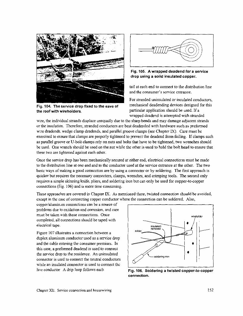
Fig. 105. A wrapped deadend for a servicedrop using a solid insulated copper.
tail at each end to connect to the distribution lineand the consumer's service entrance.
For stranded uninsulated or insulated conductors,Fig. 104. The service drop fixed to the eave of mechanical deadending devices designed for thisthe roof with wireholders. particular application should be used. If a
wrapped deadend is attempted with strandedwire, the individual strands displace unequally due to the sharp bends and may damage adjacent strandsor the insulation. Therefore, stranded conductors are best deadended with hardware such as preformedwire deadends, wedge clamp deadends, and parallel groove clamps (see Chapter IX). Care must beexercised to ensure that clamps are properly tightened to prevent the deadend from failing. If clamps suchas parallel groove or U-bolt clamps rely on nuts and bolts that have to be tightened, two wrenches shouldbe used. One wrench should be used on the nut while the other is used to hold the bolt head to ensure thatthese two are tightened against each other.
Once the service drop has been mechanically secured at either end, electrical connections must be madeto the distribution line at one end and to the conductor used at the service entrance at the other. The twobasic ways of making a good connection are by using a connector or by soldering. The first approach isquicker but requires the necessary connectors, clamps, wrenches, and crimping tools. The second onlyrequires a simple skinning knife, pliers, and soldering iron but can only be used for copper-to-copperconnections (Fig. 106) and is more time consuming.
These approaches are covered in Chapter IX. As mentioned there, twisted connection should be avoided,except in the case of connecting copper conductor where the connection can be soldered. Also,copper/aluminum connections can be a source ofproblems due to oxidation and corrosion, and caremust be taken with these connections. Once |wreholder
completed, all connections should be taped withelectrical tape. _n|to
Figure 107 illustrates a connection between aduplex aluminum conductor used as a service dropand the cable entering the consumer premises. Inthis case, a preformed deadend is used to connectthe service drop to the residence. An uninsulated oe e
connector is used to connect the neutral conductors soldenng iron
while an insulated connector is used to connect thelive conductor. A drip loop follows each Fig. 106. Soldering a twisted copper-to-copper
connection.
Chapter XII. Service connection and housewiring 152

connection to lead any water away from the bare neutral wire wireholder
connectors. preformedinsulatecd wire- -. deadend I
If ABC conductor is used for the servicedrop, Fig. 108 illustrates how this cable isusually deadended on a distribution pole. In connector
this case, a single-phase line passes from the Iasticlower left to the upper right and theinsulated neutral conductor is supported by asuspension clamp. One compression clamp insulated
on the distribution line (lower left) connects connector
the phase conductor to each of the three drip loops
service drops, while the clamp next to itconnects the neutral to the drops. The Fig. 107. A connection between a duplex
. ~~service conductor and the residence.compression clamp on the upper nrght isused to connect the distribution line neutralto the grounded steel distribution pole.Figure 109 illustrates how a wedge clamp is used to deadend the other end of a service drop to a home
build of concrete. The cable passes through conduit to prevent damage to its insulation that might occur
by rubbing against the concrete.
Service entrance
The service entrance serves the function of connecting the consumer (the housewiring) to the electric
utility (the service drop) and, usually, includes a mechanism for monitoring and/or controlling the power
(kW) or energy (kWh) used.
In all cases where an overhead service drop is used, the service entrance brings the electricity from theservice drop which is normally at an elevation unreachable by a person down to a height that can be
Fig. 108. Wedge clamps deadending Fig. 109. A wedge clamp deadending a serviceservice drops on a fabricated metal drop found in a concrete home in the Tunisia.distribution Dole in Tunisia.
Chapter XII. Service connection and housewiring 153

touched by an adult. Therefore, it is important that the service entrance provide adequate protectionagainst electrical shocks for the general population. The service entrance should provide sufficientmechanical protection for the conductor so that an object rubbing or striking the service entrance will notdamage the conductors or cause a short circuit. At times, a metal service mast, possibly extending abovethe roof, leads the conductor down the outside of the home. At other times, a heavy shielded cable is usedand fastened to the dwelling with large staples. And in simple mini-grids, the service entrance may be nomore than simply a pair of insulated single wires passing through the wall of the customer's premises to ajunction box or distribution board located inside the residence.
More typically, the conductor coming down from the service drop leads to an enclosure that houses eitheran energy meter (the conventional approach, see "Conventional metering", p. 154) or an power- orcurrent-limiting device (more typically used by smaller mini-grids, see p. 155). An energy meter shouldgenerally be located 1.7 to 2.0 meters above ground level so that it can be easily read and high enough tokeep it beyond the reach of small children. And it should preferably be mounted on the outside of thehouse before bringing the line indoors. If a current-limiting device is used, it might be located somewhathigher as there is no need to read it.
The enclosure should be locked or sealed to deter tampering. Provision should be made for access to theswitch on the MCB to allow resetting, if such is used. The enclosure must be fully water-proof and fixedto a structurally sound, permanent part of the building or a purpose-built support. Cable entries should befrom the bottom only, with a drip loop to prevent water entering the unit from these openings.
Ideally, the enclosure should be outside the house or business premises. In a number of countries, metersare mounted inside the home. The rationale is that the consumer often purchases the meter and keeps inindoors to protect it from vandalism. However, the reality is that the indoor location often frustrates thoseresponsible for reading the meter when the consumers are habitually "not home". It also makes it easierto tamper with the meter to make it understate the actualenergy used. If meters are used with a mini-grid and ifthat system is to be effectively managed to the benefitof all the consumers, they should be mounted outdoors.
In some countries, families may be living in temporaryquarters on their property until they earn sufficient -
money to build a more permanent home elsewhere onthe property. In these cases, the service entrance maybe located with a brick masonry structure, usually nearthe front of the property, that includes the meter orcurrent-limiting device (Fig. 1 10). Other conductorsthen lead from there to the temporary structure.
MeteringAn electricity distribution system supplies a service toconsumers, and for this reason, some means must beincorporated within the system to assess what theconsumers owe to cover the costs incurred in providingthis service. This is one function of metering. Fig. 110. Service drop to a masonryConventionally, this is done by using an energy or structure in the yard is commonly seen inkilowatt-hour meter, which measures the electrical Bolivia.
Chapter XII. Service connection and housewiring 154

energy used by the consumer and is included as part of the service entrance. A meter reader then
periodically records meter readings and the energy consumed each month is calculated. The utility then
uses this to prepare the consumers' bills. These should be based on a tariff schedule designed to generate
the necessary revenue to cover all costs incurred in delivering this service (see p. 178).
But mini-grids serving rural areas face additional constraints:
* The mini-grid is supplied by a powerplant of limited capacity. Consequently, the metering
function may also have to provide some control over the power consumption by each consumer to
ensure the equitable availability of electricity to all consumers. Energy meters alone cannotaddress this issue.
* While electricity is seen as an important commodity, the amount that many households can spend
on electricity is limited. If energy meters were used, simply the cost of the meter, meter reading,
bill preparation, and collection for each household would exceed the cost of supplying theelectricity consumed. It also would involve more sophisticated bookkeeping.
Rather than billing on the basis of energy consumed, a less costly and more equitable form of "metering"
involves setting a tariff based on the power consumed by each household. A consumer's bill might then
be calculated either on the basis of connected load (e.g., a household is permitted up to the use of two
fluorescent lamps and one TV) or on the basis of a subscribed maximum power input (e.g., a household
can use up to 40 W).
In summary, the option for metering in a specific situation depends on a number of factors, including the
capacity of the power plant, the number of consumers, the cost of energy, the ability and willingness of
consumers to pay, the desire to benefit as many of the households as reasonably possible, and the
institutional mechanism to operate and manage the system. Below, the technical options for "metering"are reviewed. The section "Options for tariff schedules" in Chapter XIV describes the advantages and
disadvantages associated with each of these options and should be reviewed before adopting any of thetechnical options described below.
Conventional metering
If a mini-grid uses the conventional approach-relying on energy meters-for metering, this is usually
because no other alternatives are either known or considered. While this approach has advantages for
national-grid-connected systems, it presents a variety of drawbacks when used with mini-grids, the most
significant being cost and the inability to ensure equitable use of the capacity of small power systems.
The typical energy meter is an electro-mechanical or electronic device that is part of the service entrance,
preferably placed outside the home to facilitate meter reading but occasionally found inside. Two options
exist for the connection of energy meters: the bottom-connected meters and the socket-connected meters.
If a bottom-connected meter (Fig. 111) is to be installed, the entrance cable should have extra sheathing to
protect the conductors leading to the distribution board and be sealed at the meter's entrance. Open-base
meters should not be used because the exposed terminals present a high level of danger to people,
especially to curious prying little fingers, and encourages tampering. Some bottom-connected meters do
not have bi-metallic connections required for copper conductors. Before installing the service entrance,
verify the type of wire that is compatible with the meter.
If a socket-connected meter is to be installed, suitable conduit is provided to protect the conductors from
the service drop to the meter. This installation provides for the most security for both the utility and the
Chapter XII. Service connection and housewiring 155

consumer, but its initial cost is higher. There are manyoperational advantages to a socket meter installation,but unless the country is already using socket meters,they most likely will not be introduced for mini-gridapplications.
Alternative "metering": load limiters
The second basic approach to "metering" is to limit thecurrent to a predetermined and agreed upon level andto pay on the basis of this level. In it simplest sense,this limit can be based on a verbal agreement. Ahousehold would simply notify the system managerthat it will limit its consumption to, for example, two40-W bulbs and pay $1 per month for that service. Theonly factors ensuring that these terms are abided by areeither the family's honesty or its fear that it will bepenalized when someone somehow finds out that it isusing a couple of 60 W bulbs. While this is thecheapest approach, it will probably only work for some * .
small systems where there is a good understandingbetween all members of a community. It will also Fig. 111. View of a bottom-connectedwork when there is plenty of excess capacity in both meter.the supply and distribution system, but additional costswill be incurred by the system owner for the extra energy generated and consumed.
In larger communities, suspicions that one or more households are exceeding their entitlement can easilyarise, and a natural reaction is for some of the other households to start exceeding their quota rather thanto confront the possible offender(s). This will lead to overloading the system and to a subsequentreduction in consumer voltage. This can then lead to the use of higher wattage light bulbs to try to offsetthe reduction in light due to the lower voltage. By the time the situation becomes so bad that thecommunity meets to try to solve the problem, the culture of suspicion and over-consumption will oftenhave become too endemic for consumption level to be effectively regulated by verbal agreement.
But to avoid problems that may well arise, several technical solutions are available. These all rely on loadlimiters, which are simply overcurrent cutout devices. If the consumer draws a current higher than that towhich he or she has subscribed, the cutout will operate and disconnect the supply. Some load limitershave to be reset manually while others reset automatically. The consumer pays a fixed monthly feeaccording to the rating of his load limiter, irrespective of the kilowatt-hour consumption (Fig. 112).
Table 15 reviews the characteristics of five possible current cut-out devices.
Fuses
Using fuses may be the most obvious and cheapest approach to limiting a current into a consumer's homeand they are widely available. However, they are not a good option for several reasons. They are notaccurate. They age when operated at close to their rated current and will fail in time, even if the ratedcurrent is not exceeded. More annoying to the consumer is the fact that they cannot be reset; a fuse needsto be replaced each time it blows. It must be accessible for replacement because this may happen
Chapter XII. Service connection and housewiring 156
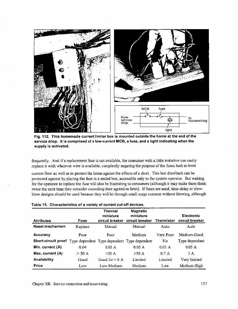
MCB fuse
from ~~~~~~~~~~~to| housewserviceirindrophoswrg
light
Fig. 112. This homemade current limiter box is mounted outside the home at the end of theservice drop. It is comprised of a low-current MCB, a fuse, and a light indicating when thesupply is activated.
frequently. And if a replacement fuse is not available, the consumer with a little initiative can easilyreplace it with whatever wire is available, completely negating the purpose of the fuses both to limit
current flow as well as to protect the home against the effects of a short. This last drawback can beprotected against by placing the fuse in a sealed box, accessible only to the system operator. But waitingfor the operator to replace the fuse will also be frustrating to consumers (although it may make them thinktwice the next time they consider exceeding their agreed-to limit). If fuses are used, time-delay or slow-blow designs should be used because they will let through small surge currents without blowing, although
Table 15. Characteristics of a variety of current cut-off devices.
Thermal Magneticminiature miniature Electronic
Attributes Fuse circuit breaker circuit breaker Thermistor circuit breaker
Reset mechanism Replace Manual Manual Auto Auto
Accuracy Poor Poor Medium Very Poor Medium-Good
Short-circuit proof Type dependent Type dependant Type dependant No Type dependant
Min. current (A) 0.04 0.05 A 0.05 A 0.01 A 0.05 A
Max. current (A) >50A >50 A >50 A 0.7 A 5 A
Availability Good Good for > 6 A Limited Limited Very limited
Price Low Low-Medium Medium Low Medium-High
Chapter XII. Service connection and housewiring 157
they too may age with time.
Miniature circuit breakers (MCBs)
While somewhat more expensive, circuit breakers are more accurate than fuses and have the advantagethat they can be reset without replacement. As with any device used to monitor or control electricityconsumption, it is open to tampering by the owner of the residence. Placing the device indoors encouragetampering as this can be done in privacy. A partial solution to this is to always locate the device in alocation outside the home, suitably protected from the elements. The device should be enclosed in a boxwith restricted access. Box 9 describes MCBs used as "metering" devices by a national utility in a moreconventional setting in urban areas of Zimbabwe.
PTC thermistors
While miniature circuit breakers are available down to 0.01 A, they are relatively costly. Positivetemperature coefficient (PTC) thermistors have been used as low-cost alternatives. This solid-statedevice, resembling a coin soldered between two conductors, is placed in series with the incoming current.If current exceeds its rated value, the device heats up and, at a certain temperature, suddenly presents ahigh resistance, effectively stopping the flow of any further current. The devices "resets" automaticallywhen the overload is disconnected and the thermistor is permitted to cool down. Waiting several minutesuntil the thermistor cools down, permitting current to flow once more, could again be frustrating to theconsumer who has to wait in the dark.
Thermistors must be protected from larger currents associated with a short that might occur within theresidence. To protect the thermistor, a fuse rated above the rating of the thermistor must be placed inseries.
To prevent tampering, the thermistor and fuse should be located in a sealed box. However, should thefuse blow because of significantly excessive current draw, the consumer would encounter the same levelof frustration as found with using a fuse alone in a sealed box, that is, waiting for the operator to comereplace the fuse. To address this issue, two fuses are sometimes used, one with a lower rating outside thesealed box which can be replaced by the consumer and one inside that is larger but still adequate toprotect the thermistor. In this manner, failure of the consumer to correctly replace the fuse will mean thatthe next time excessive current is drawn, the fuse inside the sealed box will blow, revealing hisimproprieties.
PTC thermistors are only available in sizes up to about 0.7 A (equivalent to a power demand of 160 W at230 V). It should be noted that thermistors are triggered by current (A) and not power consumption (W).As was noted earlier (p. 32), uncorrected fluorescent lamps make inefficient use of current. For example,a capacitor-corrected fluorescent lamp operating at 23 W would draw a current of 0.10 A at 230 V.However, a fluorescent lamp operating at 23 W without capacitor correction and with a power factor of0.5 would draw 0.20 A. This is twice the current draw for the same amount of lighting. Therefore, if twoconsumers pay the same tariff and both have thermistors set to cut off at 0.4 A, the consumer withuncorrected fluorescents could operate about 2 lamps while his or her next door neighbor with correctedfluorescents could operate about 4 lamps.
Both PTC thermistors as well as thermal MCBs have been used in projects in Nepal. Box 10 describesbriefly experiences in that country.
Chapter XII. Service connection and housewiring 158

Box 9. Load-limited supplies in urban Zimbabwe.
Load-limited domestic supplies have even been used by more conventional electric utilities. In Zim-babwe, for example, MCB-type load limiters have been extensively used since the 1960s. In 1996,129,000 consumers had load-limited supplies, compared to 210,000 consumers with metered supplies.The vast majority of these consumers were in urban areas. There are eight categories of supply, rangingfrom 1 to 30 amperes. However, the categories above 7.5 amps are no longer provided to new customers,as it is considered that these consumers can afford a metered connection and that their higher consump-tion makes metering worthwhile.
The typical cost to the supply authority, ZESA, for providing a load-limited service connection is US$ 50compared to US$ 100 for a metered supply. The load-limited households save on housewiring costs,because some components, as an additional enclosure for fuses or circuit breakers, are not mandatory.
Table 16 presents tariff and customer data for thedifferent load-limited supply categories. The tariff Table 16. Approximate consumerfor metered customers consists of a fixed monthly distribution by to tariff category (1996).
charge of $1.90 and energy charges of $0.019/kWh Limiter Monthly cost Number offor the first 300 kWh and $0.045 for the balance. (amps) (US$) customers*Since the fixed monthly charge for a metered supplyis the same as the total monthly charge for a 1 amp 1.0 1.90 2,400load limit, it is clear to the consumer that the load 2.5 2.90 5,700limiter is the cheaper option for this consumption 5.0 4.50 27,000level. 7.5 7.50 49,900
While one might suspect that load-limited consumers 10.0 13.60 1,800might squander energy available to them, 15.0 19.10 13,900measurements have shown that, for load-limited sup- 22.5 22.60 1,100plies in the range 1 to 7.5 amperes, load factors arewithin the range 24 to 29%. These are not excessive. 30.0 32.60 122The consumers are provided with leaflets on how to *Information based on data from most but not all area
use the load-limited supply. offices.
Load-limited customers pay for their electricity inadvance, each month, at the local electricity board office. No bills are sent to the customers. If the tariffis not paid, then the supply is disconnected within two weeks. Metered consumers have their meter readevery month and are presented with a bill a few days after the reading date.
The main problem that ZESA has faced with its load-limited supplies is the theft of electricity. A recentfraud was the replacement of 5-amp load limiters with 15-amp load limiters, with the consumer erasingthe number 1 in the front! Utility staff have also been found to be involved in this fraudulent activity.They have been known to make arrangements with consumers for uprating load limiters. The consumersthen pay the original tariff plus a secret payment to the staff member. These frauds are detected byregular checks at the consumer installation, using staff from other districts. Incorrect load-limiter ratingsare detected by connecting a 3 kW load after each load limiter and checking that the load limiter operates.However, this is very time consuming.
Damage to MCBs is quite common and is often done by the consumer repeatedly attempting to reset thedevice without first clearing the overload. An annual failure rate of 9% was found in Chitungwiza town-ship, compared to less than 0.2% for electricity meters.
Chapter XII. Service connection and housewiring 159

Box 10. Load-limited supplies in rural Nepal.
In Nepal, load limiters have been used on rural electrification projects since the 1980s. They were firstused on stand-alone micro-hydropower projects. Load limiters are particularly appropriate for theseprojects because marginal operating costs are minimal; the cost of operating the plant is largelyindependent of how much of its capacity is used. PTC thermistors and thermal MCBs are used and havegenerally been found to be reliable. Most connections are of 100 W (0.5 amps) or less.
In 1989, load limiters were installed at the Andhi Khola electrification project, a 5-MW scheme thatsupplies electricity to the local area and sells excess power to the grid. Rural and semi-urban consumersare supplied and more than 95% of households have a connection. Initially there were three load limiteroptions: 25 W, 50 W and 250 W, with the 250 W option being designed to enable consumers to use a lowwattage cooker that was promoted by the project. A 100 W option has been recently introduced.
It is clear from Table 17 that, before the 100 W option was available, rural consumers generallysubscribed to the 50-W load-limited supply, whereas the semi-urban consumers tended to have a 250-Wload limiter or meter. The monthly cost for the load-limited supplies are $0.34 for 25 W, $0.70 for 50 W,and $1.90 for 250 W. The average monthly consumption of the metered consumers is 87 kWh at a cost of$3.70 (1994).'5
Table 17. Distribution of consumers according to type and tariff category.
Classification of Load limited consumer Metered Totalconsumer 25W 50W 250W consumer consumers
Rural 19 127 40 0 186
Semi-urban 2 59 171 83 315
Each rural community served by a load-limited supply is organized in a users' group, and one memberfrom each group is employed as a service person to collect the tariff and carry out basic repair andmaintenance work. Because every household has a load limiter rather than a meter, the monthly fees arefixed. This is advantageous for the electricity company and the service person, since both know theamounts of money due from each consumer. The service person is then responsible for collectingmonthly fees and for periodically depositing a predetermined sum into the local bank account of theelectric utility.
Electronic circuit breakers (ECBs)
Electronic circuit breakers use a semiconductor device, such as a triac or transistor, to disconnect thesupply in the event of excessive current. The current is often measured in terms of a voltage drop across alow resistance. Additional circuitry is used to provide time delays that prevent disconnection due to surgecurrents and to automatically reconnect the supply. ECBs have been designed specifically as load limitersand are available from specialist suppliers. Their typical cost is $15, which is higher than for most othertypes of load limiters but can often be justified as a result of better accuracy and their auto-reset facility(as illustrated in Box 1 1).
Electronic circuit breakers are a fairly recent development, and it is important to check that the productsare reliable, either by obtaining samples for evaluation or through recommendation from other users.
Chapter XII. Service connection and housewiring 160

Box 11. Cost vs. accuracy for alternative load-limiter options.
For this example, consider the case of a micro-hydropower scheme for a village with one hundredhouseholds, where each household is to be supplied with a 1-amp load-limited supply with a rated voltage
of 230 V, enough for four light bulbs or three light bulbs and a small black and white TV. The ambient
temperature extremes at this village varies between 10 °C in the evening of the cooler season and a 40 °C
peak during the day in the warm season.
Two types of load limiters are available for this comparison, a thermal miniature circuit breaker and an
electronic circuit breaker. The price of the MCB is $5 and the ECB $15. The cost of the micro-hydropower scheme is $2,000 per kilowatt.
The characteristics of the MCB are such that at 45 °C the tripping current is between 1.00 and 1.35 A.However, when ambient temperatures decrease to 15 °C, this range increases to between 1.15 and 1.55 A,
as more heating is required from the current to compensate for the lower ambient temperature. In thislatter case, a greater power output will be required from the micro-hydropower plant. To preventoverloading and a consequent reduction in supply voltage, the scheme must be designed to supply thishigher current.
The characteristics of the ECB are such that the tripping current is between 1 and 1.2 A, irrespective ofthe ambient temperature.
Since 100 load limiters will be used, it is acceptable to assume average values from the tripping current
range, i.e., 1.35 A for the MCB and 1.1 A for the ECB.
The maximum apparent power consumption P(VA) in the village when either only PTCs and only ECBsare used, respectively, would be the following:
PMCB =lOOx230Vx1.35A=31,000VA=31.0kVA
PECB =lOOx 230Vx1.1OA=25,300VA=25.3kVA
The actual power requirement must take into account the power factor of the load and the fact that theconsumers will not all be using their maximum entitlement at the same time. The reduction will dependon usage patterns in the community and types of load and should be determined by a pre-installation
(Continued next page)
Two organizations involved with electronic circuit breakers are Development Consulting Services inNepal and Sustainable Control Systems Ltd. in the UK."6
In deciding what type of load limiter might be used, the following factors should be considered:
* Likelihood of fraud and theft: Where the likelihood of the consumer trying to obtain freeelectricity by bypassing the load limiter is low, manually reset circuit breakers are an acceptablechoice. These must be accessible to the consumer for resetting. If protection against bypassing isrequired, the load limiter must be auto-resetting and fully sealed against the ingress of moisture sothat it can be mounted on a distribution or service connection pole. This makes it harder for theconsumer to bypass the load limiter and easier for detection, because any bypassing should beclearly visible.
Chapter XIL Service connection and housewiring 161

(Continued)
survey and comparisons with existing projects. In this case, it is assumed that most households will beusing close to their rated power in the evenings for lighting and TVs. The estimate for the maximumactual power consumption is taken to be 0.8 times the maximum theoretical power consumption. An
additional factor, for power loss in the distribution system must also be included, amd is assumed to be1.1 in this case.
Hence the power required from the micro-hydropower plant under each scenario is:
PMCB =0.8xl.lx31.0kVA=27.3kW
PECB = 0.8 x 1.1 x 25.3 kVA =22.3 kW
The cost of the scheme with the MCBs is:
Micro-hydropower scheme 27.3kW @ $2,000 per kW $54,600MCBs 100 units @ $5 $ 500
Total $55,100
The cost of the scheme with the ECBs is:
Micro-hydropower scheme 22.3kW @ $2,000 per kW $44,600ECBs 100 units @ $15 $ 1,500
Total $46,100
It is clear that, in this case, use of the more costly ECBs would be justified because the savings in the costof the micro-hydropower scheme would be ten times greater than the extra cost of the load limiters.
In the case of a diesel powered system, the initial savings are likely to be less due to lower equipmentcosts. However, with diesel generation, there will be additional savings in fuel costs as less power wouldneed to be generated. A similar analysis can be done in this case.
The financial argument for using accurate load limiters will be greater for higher-current connections asfewer load lirmiters would be required for the same generating capacity.
* Cost against accuracy: It is tempting for service providers to install cheap load limiters in orderto reduce costs. However, if the cheap limiters have poor accuracy, the overall cost may behigher because a greater power capacity will be required and energy usage will be greater. This isillustrated in Box 11. The minimum and maximum tripping currents for load limiters must bestudied in order to ensure that the consumers will always receive the current for which they havesubscribed and to deternine the most cost-effective option. Variations in tripping current withtemperature must be taken into account, for the full temperature range that can occur where thelimiter is located. In addition to the cost disadvantages of load limiters with poor accuracy,customer complaints are likely to be higher, because some customers may be unable to run asmany appliances from a load limiter of the same current rating as their neighbors.
Chapter XII. Service connection and housewiring 162

HousewiringLand tenure practices in a specific country can have a considerable impact on the price households arewilling to pay for accessing electric service. If a home is part of a squatter settlement where families donot own the land, they probably have limited financial resources and, in any case, are probably not willingto spend much for electrifying their home if, from one day to the next, they may have to move. Or if it isclear that the mini-grid is a stop-gap measure until the national grid arrives in several years and thedistribution system will then have to be rebuilt, they may also not be willing to sink too much into atemporary scheme even if their homes are permanent. In these cases, there may be an argument to uselow-quality and therefore less costly materials, as long as they are safe.
Minimum building standards, such as a requirement for a water-tight roof, are often imposed on thegrounds of safety. In some countries, traditional dwellings with thatched roofs are not allowed to havegrid-supplied electricity. However, it is also important to recognize that, if households do not haveelectricity, they would use kerosene and candles that could also result in considerable safety risks. This istherefore a strong argument that electricity should even be available to traditional dwellings.
On the other hand, if potential consumers have ownership of their land, they are usually more willing tomake a larger financial commitment. In this case, the question of the quality of the materials andworkmanship used for housewiring and, inevitably, its cost are often a point of discussion. Low-cost (andlower quality) materials clearly make electrification more affordable at the outset. However, one has tobe cautious because these families are apt to remain in a home for a long time. If low-quality materialsare used, switches and outlets are bound to eventually fail. Most will then resort to makeshift solutions-sticking wires into outlets or making switches by hooking bare wires together. Therefore, from the pointof view of the life-cycle cost of the installation, personal safety, and consumer satisfaction, one shouldlean toward the higher-quality solution, even at the expense of somewhat additional cost.
Housewiring originates at the service entrance, conveys power to the distribution board usually located ona wall in the house, and then distributes it to the various lighting fixtures and power outlets in and aroundthe home. In a village setting, a distribution board might look like that shown in Fig. 113. In this case, itis a plywood base with a frame I to 2 cm high around the back that raises this base above the mountingsurface and leaves space for the wiring. In industrialized countries, a distribution board would generallytake the form of a steel box, with door.
Rather than selecting from a range of electrical components that might be mounted on such a board, it iswiser to decide what protection and control features should be part ofthe consumer's supply and then to select those components which } ,
permit accessing these features.
For the most basic system, a distribution board may not even be needed. In this case, power would be delivered to a light in each home. Withthe arrival of nightfall, the genset is started, lighting the lights. Severalhours later, the system is shut down. No light switches, fuses, breakers, Yknife switches, MCBs, etc., would be required.
However, most consumers are somewhat more demanding and require
Fig. 113. One design for a distribution board, which includes aknife switch, a fuse and a switch for each of two lighting circuits, .and a fuse with the power outlet.
Chapter XII. Service connection and housewiring 163

features that give them more flexibility. Below are explained the various components which might beincluded as part of the distribution board and circumstances under which each would be included:
* Light switches. These are required if the consumer wishes some control over which lights are tobe lit and when. This is usually the case. In more sophisticated systems, these light switches areplaced at the entrance to the room in which the light is found. However, in more rural settings,the home is small and the switches are centrally located, often on the distribution board itself
* Power outlets. If the generator can supply adequate power and if the mini-grid has adequatecapacity to distribute this power without increasing the voltage drop beyond an acceptable value,consumers may wish to make use of other electrical devices or appliances. These can range froma TV and/or radio to motor-driven equipment to a wide range of other equipment usuallyavailable on local markets. But power outlets should not be included if generating or distributioncapacity is inadequate, because the mere presence of outlets will tempt the consumer to go out topurchase these appliances.
Furthermore, if power outlets are included, an MCB or fuse must be included to have somecontrol over the maximum additional power that the consumer may use.
- MCBs. This can serve several functions:
- It would also serve to protect the housewiring from overcurrents and shorts.
- It can be used as an occasional on-off switch, to isolate the home from the supply when, forexample, modifications or repairs have to be made to the existing housewiring. With systemsthat are only on for several hours in the evening, this is not critical because repairs ormodifications can be made when the system is off.
- It can be used as a current limiter (see below) in situations where the consumer is billedaccording to his or her maximum powerdemandsetbytheMCB. -_
MCBs have the advantage over fuses in that theyare resettable, more precise, and less open totampering. They are, however, more expensive. - .
The MCBs should be located immediately at theentrance to the distribution board, before anyother components, irrespective of what othercomponents are included on this board.
* Current limiter. If the tariff schedule requiresthe use of a current limiter, a MCB (above) mightserve that purpose, in addition to several otherpurposes already mentioned above. Other lower- 4cost or more readily available altematives arepossible (p. 155). These could also be mounted i
as part of the distribution board (Fig. 114). Fig. 114. The distribution board for a* Knife switch. If fuses are used to protect the rural home in Nepal. The service drop to
circuit for overcurrent, a knife switch would be the home enters from the right andused to isolate the household circuit from the passes through a Norwegian currentsupply in an emergency situation or if repairs are limiter and the main breaker with fuses.
Chapter XII. Service connection and housewiring 164
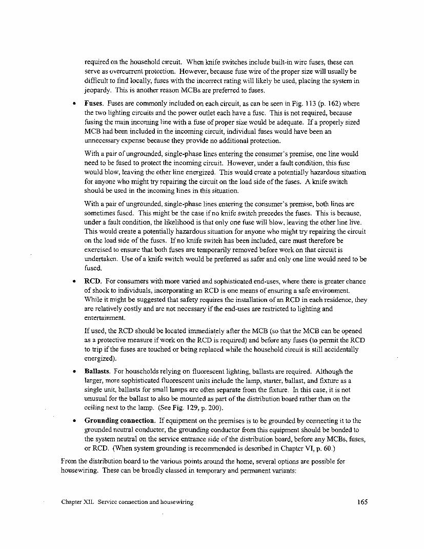
required on the household circuit. When knife switches include built-in wire fuses, these can
serve as overcurrent protection. However, because fuse wire of the proper size will usually be
difficult to find locally, fuses with the incorrect rating will likely be used, placing the system in
jeopardy. This is another reason MCBs are preferred to fuses.
* Fuses. Fuses are commonly included on each circuit, as can be seen in Fig. 113 (p. 162) where
the two lighting circuits and the power outlet each have a fuse. This is not required, because
fusing the main incoming line with a fuse of proper size would be adequate. If a properly sized
MCB had been included in the incoming circuit, individual fuses would have been an
unnecessary expense because they provide no additional protection.
With a pair of ungrounded, single-phase lines entering the consumer's premise, one line would
need to be fused to protect the incoming circuit. However, under a fault condition, this fuse
would blow, leaving the other line energized. This would create a potentially hazardous situation
for anyone who might try repairing the circuit on the load side of the fuses. A knife switch
should be used in the incoming lines in this situation.
With a pair of ungrounded, single-phase lines entering the consumer's premise, both lines are
sometimes fused. This might be the case if no knife switch precedes the fuses. This is because,
under a fault condition, the likelihood is that only one fuse will blow, leaving the other line live.
This would create a potentially hazardous situation for anyone who might try repairing the circuit
on the load side of the fuses. If no knife switch has been included, care must therefore be
exercised to ensure that both fuses are temporarily removed before work on that circuit is
undertaken. Use of a knife switch would be preferred as safer and only one line would need to be
fused.
* RCD. For consumers with more varied and sophisticated end-uses, where there is greater chance
of shock to individuals, incorporating an RCD is one means of ensuring a safe environment.While it might be suggested that safety requires the installation of an RCD in each residence, they
are relatively costly and are not necessary if the end-uses are restricted to lighting and
entertainment.
If used, the RCD should be located immediately after the MCB (so that the MCB can be opened
as a protective measure if work on the RCD is required) and before any fuses (to permit the RCD
to trip if the fuses are touched or being replaced while the household circuit is still accidentally
energized).
* Ballasts. For households relying on fluorescent lighting, ballasts are required. Although the
larger, more sophisticated fluorescent units include the lamp, starter, ballast, and fixture as a
single unit, ballasts for small lamps are often separate from the fixture. In this case, it is not
unusual for the ballast to also be mounted as part of the distribution board rather than on theceiling next to the lamp. (See Fig. 129, p. 200).
* Grounding connection. If equipment on the premises is to be grounded by connecting it to the
grounded neutral conductor, the grounding conductor from this equipment should be bonded to
the system neutral on the service entrance side of the distribution board, before any MCBs, fuses,
or RCD. (When system grounding is recommended is described in Chapter VI, p. 60.)
From the distribution board to the various points around the home, several options are possible for
housewiring. These can be broadly classed in temporary and permanent variants:
Chapter XII. Service connection and housewiring 165

housewinwire duct
Fig. 115. Housewiring neatly stapled to beams in a home in Fig. 116. CommerciallyGotikhel, Nepal. A wooden junction box is visible in the upper available plasticleft. housewiring ducts.
Temporary wiring. This kind of housewiring is associated with some wiring harnesses and isused in homes built of "temporary" materials. In this case, the housewiring is simply tied tobeams and posts as required. This design options is popular because the location of thehousewiring and the lights to which it is connected can be easily modified to suit the occasion.
* Permnanent wiring. In this case, the housewiring can be stapled to beams and posts within thehome (Fig. 1 15). Alternatively, where the wall is of earth or cement, wooden strips are placedwhere the housewiring is to go and the housewiring stapled along these strips. A more recentvariant is to use plastic ducts designed for this purpose (Fig. 116). The base of the duct is nailedor screwed to the wall, the housewiring is laid in the duct, and then the other half is mated to thebase and snaps into place. This approach both secures and protects the housewiring.
Standardized housewiring packages
The purpose of standardizing housewiring is to facilitate this task and to reduce cost of materials andinstallation so as to permit r-ural households to be able to afford to connect. Two examples ofstandardized packages are discussed below:
* Pre-packaged components: In this case, standard packages of all the components needed toelectrifyr a home are collected, packaged, and delivered to the home to be electrified. An exampleof a project utilizing pre-packaged components is found in Box 12.
* Wiring harnesses: These are pre-fabricated housewiring systems, produced in a range of standardsizes complete with in-line switches and light fittings. The harness is comprised of several leadstaking off from a commnon point, a junction box within the home. The installation is simply amatter of securing the double-insulated conductors to beamns or exposed building supports,usually by tying. The wiring harnesses used in Nepal are explained in Box 13.
Chapter XII. Service connection and housewiring 166

Box 12. Case study, El Salvador, 1989
Program overview
In almost 30 years of rural electrification in El Salvador, housewiring has been largely ignored. Lineswere extended into the rural areas under the assumption that, if electricity were available, potential userswould flock to the electric utility requesting service. In an interview of 3,000 electrified and non-electrified residences in 1989, only 60 % of the dwellings within 25 meters from the lines were electrifiedover a period of 20 years. The principal reason for non-connection was the unavailability of cash up frontto cover the cost of a service connection ($90, which included the service drop wire and the meterinstallation) and housewiring ($250, roughly a quarter of which was labor).
As part of a subsequent rural electrification program to make electrification more affordable to ruralhouseholds, NRECA created a pilot credit program within the national utility CEL to offer both theservice connection as well as the housewiring under a two-year credit program. Standardizedhousewiring packages were also a part of this program.
Four options were initially available (options that included from one to three 20-A breakers) but becauseof the increased complexity, these were narrowed down to two. Even though low initial loads wereexpected, housewiring and breakers were sized to accommodate maximum loads expected in any typicalresidence in the country, i.e., 15 or 20 A.
Each option included a fixed quantity of all the required, UL-listed* materials needed for the job:appropriately sized conductor, staples for fastening it to the wall, ground rod, connectors, junction boxes,outlets, nails and screws, tape, and light bulbs to complete the job. The materials for each job were putinto a cardboard box for delivery, along with an inventory. The packages were then delivered to eachparticipating household. A local electrician was then contracted to undertake the wiring.
Although including a standard length of conductor limited somewhat the options for locating thereceptacles, this was important to ensure the consumer saw that they were all treated equally.Furthermore, it was determined that customizing the conductor length added considerably to the cost oflabor: increased administrative costs, additional visits to the homes to measure the conductor whichwould have been required, and the need to enter into a different contract between each household and theelectrician. However, the consumers were notified that, if they wish, they could always make their ownarrangements with the electrician to have more housewiring at an additional cost.
Standardization provided several cost advantages to potential consumers. It permitted bulk purchasing ofhousewiring materials that reduced cost of materials. It further reduced the cost by having theinstallations competitively bid and by organizing the housewiring program so that the winning electriciancould wire a group of 10 or more houses at the same time. Costs were reduced in spite of the fact that allUL-listed materials were used (unlike those used by the utility) and the work was guaranteed.
In addition to reducing cost, housewiring was made even more affordable by replacing the previouslyrequired up-front payment of about $340 with a token down payment and small monthly payments fortwo years.
(Continued next page)
* Underwriters Lab is a widely recognized, private, not-for-profit safety testing and certification organization in theU.S. Safety requirement are based on its Standards for Safety. Additional informnation can be found on the Internetat <http://www.ul.com>.
Chapter XII. Service connection and housewiring 167
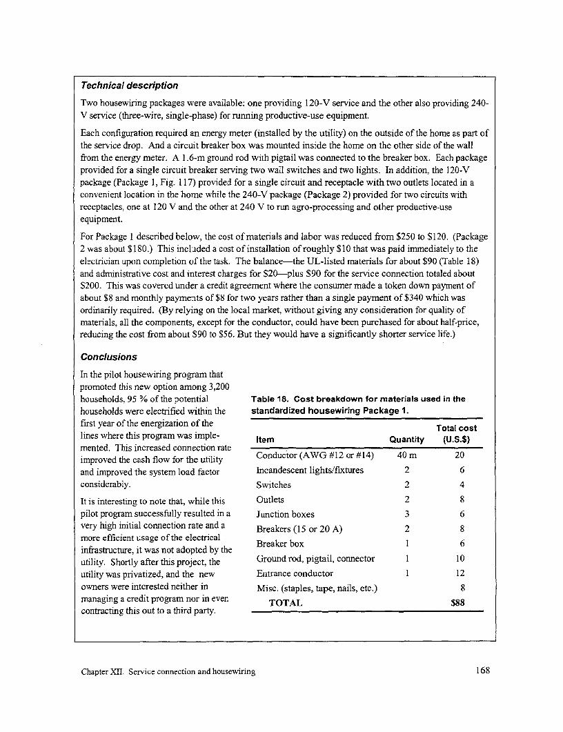
Technical description
Two housewiring packages were available: one providing 120-V service and the other also providing 240-V service (three-wire, single-phase) for running productive-use equipment.
Each configuration required an energy meter (installed by the utility) on the outside of the home as part ofthe service drop. And a circuit breaker box was mounted inside the home on the other side of the wallfrom the energy meter. A 1.6-m ground rod with pigtail was connected to the breaker box. Each packageprovided for a single circuit breaker serving two wall switches and two lights. In addition, the 120-Vpackage (Package 1, Fig. 1 17) provided for a single circuit and receptacle with two outlets located in aconvenient location in the home while the 240-V package (Package 2) provided for two circuits withreceptacles, one at 120 V and the other at 240 V to run agro-processing and other productive-useequipment.
For Package I described below, the cost of materials and labor was reduced from $250 to $120. (Package2 was about $180.) This included a cost of installation of roughly $10 that was paid immediately to theelectrician upon completion of the task. The balance-the UL-listed materials for about $90 (Table 18)and administrative cost and interest charges for $20-plus $90 for the service connection totaled about$200. This was covered under a credit agreement where the consumer made a token down payment ofabout $8 and monthly payments of $8 for two years rather than a single payment of $340 which wasordinarily required. (By relying on the local market, without giving any consideration for quality ofmaterials, all the components, except for the conductor, could have been purchased for about half-price,reducing the cost from about $90 to $56. But they would have a significantly shorter service life.)
Conclusions
In the pilot housewiring program thatpromoted this new option among 3,200households, 95 % of the potential Table 18. Cost breakdown for materials used in thehouseholds were electrified within the standardized housewiring Package 1.first year of the energization of the Total costlines where this program was imple- Item Quantity (U.S.$)mented. This increased connection rateimproved the cash flow for the utility Conductor (AWG #12 or #14) 40 m 20and improved the system load factor Incandescent lights/fixtures 2 6considerably. Switches 2 4
It is interesting to note that, while this Outlets 2 8pilot program successfully resulted in a Junction boxes 3 6very high initial conmection rate and a Breakers (15 or 20 A) 2 8more efficient usage of the electricalinfrastructure, it was not adopted by the Breaker box 1 6utility. Shortly after this project, the Ground rod, pigtail, connector 1 10utility was privatized, and the new Entrance conductor 1 12owners were interested neither in Misc. (staples, tape, nails, etc.) 8managing a credit program nor in even TOTAL $88contracting this out to a third party.
Chapter XII. Service connection and housewiring 168

PROYECTO DE ELECTRIFICACION RURAL
Fig. 117. A home wired with one of the standard housewiringpackage used in El Salvador (see Box 12).
Readyboards: An alternative to a pre-fabricated wiringharness is a pre-manufactured distribution board. InSouth Africa where much of its development has takenplace, this is aptly named a "'readyboard" (Fig. 1 1 8).These readyboards are connected directly after the"metering" device. Even in the basic unit, the consumerprotection includes a RCD. Also included are MCBs forlighting and plug circuits. The unit may have a numberof breakouts for cables/conduits and the option ofincreasing the number of circuit breakers. Some unitsalso come with a top-mounted light, and in the lowerincome households, this may be the principal use. Theuse of double- insulated wiring provides additionalprotection to the consumer. A readyboard is a part of thestandard installation package used for township *,
electrification projects in South Africa, and there are a - --v 1 ,
number of companies that manufacture them LW
commercially. The readyboards cost the utility - *> .approximately $40 each. e, l
The distribution boards used in Nepal as part of their Fig. 118. Readyboard. (Source:
wiring harnesses are essentially low-tech readyboards. Circuit Breaker Industries, South Africa)
Chapter XII. Service connection and housewiring 169

Box 13. Wiring harnesses in Nepal
In the Andhi Khola Rural Electrification Project in Nepal, both conventional wiring and wiring harnessesare offered to the householders. The conventional wiring installations are approximately six times thecost of wiring harnesses. The most basic wiring hamess, which is made for two lights or one light andone two-pin socket costs roughly $5 (Fig. 119). The wiring harnesses are installed by trained villagers,under supervision of the electricity supply company, and the lights are placed in positions decided by the
service entrance conductor
) _wooden junction box
current cut-off Efs
ligh bulb /
\<> ~~double-insulated \ oe ultin-fine switc
Fig. 119. Components of a typical Nepali wiring harness.
householder (Fig. 120). The cables are always of ample length. The excess length is neatly strapped andtied and can be undone if the lights are moved. This reduces the problem of the householder extendingthe wiring by twisting bits of wire together.
The wiring harness was developed to provide a safe,low-cost means of wiring the traditional thatchedroofed houses. However, because of the flexibilityit offers, it has also proved popular for the moresolidly built houses with corrugated iron roofs.Conventional wiring installations are permanent,making it difficult to change the location of lights ina room.
The wiring harnesses are used in conjunction withload limiters. If a consumer pays the tariffassociated with a larger current limiter, the wiring Fig. 120. Lightbulb and inline switch asharness can be upgraded to allow for extra loads to part of a wiring harness.be connected.
Chapter XII. Service connection and housewiring 170

They are standardized units assembledunder controlled conditions (Fig. 121).Installation simply requires mounting iton a secure surface in the home andconnecting it to the service entrance.
Standardization presents a number ofadvantages:
* Bulk purchase of materials and laborpermits a reduction in cost.
* The consumers can easily understandthe price they have to pay for wiring Fig. 121. Nepali readyboard with Norwegiantheir home. Standardization of two or current limiter, fuse, and two outlets.three sizes and a fixed price for eachremoves any hidden charges and any consumer uncertainty about the cost for electrifying theirhomes.Typically, housewiring is undertaken by local contractors who generally have no vestedinterest in minimizing the cost of housewiring to the consumer. The cost they charge may bebased on the number of components installed and the labor required for their installation. In thesecases, they therefore have no incentive to minimize the number of components they install.
* The packages are prepared in a central location, permitting close control over what is includedand the quality of materials and workmanship.
- The inclusion of the appropriate protection equipment, e.g., grounding, breakers, fuses, etc., canbe ensured.
One minor disadvantage associated with this approach might be that it may limit the housewiringconfigurations. For example, in cases where the standardization of the available packages implies that apredetermined length of conductor for wiring the home is available, this restricts somewhat the wiringoptions within a home. However, standardization does not necessarily preclude wealthier householdsfrom wiring their home as they see fit by going to an established electrician.
Chapter XII. Service connection and housewiring 171


XiII. Operation, maintenance, and consumer services
Operator selection and trainingThe system personnel responsible for the operation, maintenance, and management of the powerplant andmini-grid play a critical role in ensuring a reliable and sustainable system. Even a costly, well-designedsystem with quality components may not continue operating reliably if these tasks are not properlyhandled. It is essential that the individuals selected to perform these tasks have a suitable attitude,aptitude, integrity, and rapport with the community.
If a private entrepreneur is responsible for the system, then he or she will likely select the operators oreven serve in that capacity. This is the entrepreneur's prerogative. On the other hand, if an outsideorganization is assisting the village in project development and implementation, it may be its role to guidethe selection of system personnel. To increase the chance that suitable candidates are selected, it might beadvantageous to delay the identification of these individuals. In this case, as many community membersas are interested should be involved in the project development and implementation from the start. Thenbased on an assessment of the capabilities of each of these individuals as the project evolves, how theyinteract with the others, their natural leadership capacity, etc., several would then be selected and trainedin the actual operation and maintenance of the plant.
In this manner, while one or two individuals would eventually be selected from this set and given initialresponsibility for project operation, the community would have a pool of individuals from which to drawin case the principal operators are not available, because they may have an obligation away from thevillage, may be ill, or may have to attend to more pressing matters. Identifying and training only one ortwo individuals from the outset puts the project at risk should they become unavailable for whateverreason.
The operator plays an important role in ensuring continued operation of the plant. To minimize trainingand backup needs and to ensure continuity, it is desirable that there be little staff turnover with thisposition. While it might appear appropriate to assign this responsibility to a younger member of thecommunity who is looking for work, possibly one who has recently completed his schooling, a moresuitable candidate for system operator might be an older person who is well established in the community,with his or her own home, land, and sustainable occupation. Younger individuals tend to be moretransient and likely to take off to the more attractive urban areas in search of employment or otheropportunities. Continuity is lost and a new operator would then have to be trained.
In addition to receiving training during project development and construction, training must extend overthe long term to be effective and be on-the-job in nature. It cannot be done in an hour or two in alecturing atmosphere. As part of this training, the implementing organization must periodically return tothe community and monitor the status of the project, evaluate the quality and nature of the repairs ormodifications to system design that have been implemented after the project was commissioned, reviewthe maintenance records, and audit the books. Optimally, the operator should also feel that he or she cancontact, and has access to, a suitably trained individual with the required expertise in a nearby town whenneeded.
Chapter XIII. Operation, maintenance, and consumer services 172

Regular operation and maintenanceA principal responsibility of the plant operator is to start and shut down the plant on a pre-establishedschedule and to ensure its proper and reliable operation. In performing this work, the operator mustmaintain up-to-date records in a logbook at the powerhouse. The date (and time, where relevant) of eachobservation must also be recorded. This record of plant operation can be used for a variety of purposes,such as:
* To determine when periodic maintenance must be undertaken.
* To contribute to the database which can be used to revise the tariff schedule.
* To assist with trouble-shooting any problems that may arise with the operation of the plant andmini-grid.
Items such as the following should be recorded:
* Daily hours of operation (when started and when shut-down). One purpose of these numbers isthat they are an indication of when certain tasks must be undertaken (such as changing the oil,greasing the bearings, or undertaking minor and major overhauls).
* The energy (kWh) meter reading at the beginning or end of each day (if an energy meter islocated at the powerhouse). This may highlight unusual day-to-day variations that could beindicative of some problem with the system.
* Output voltage and current readings from a voltmeter and ammeter with a switch (or an ammeterfor each phase) which should be installed in the powerhouse. These are important indicators ofpotential problems that could lead to system failure, problems such as unbalanced phases,overloaded phases, unexpected loading, and abnormal voltage setting on the generator,
* The volume of fuel, oil, and/or grease added, with date. This is useful to calculate actual fuelexpenses incurred in running the powerplant, expenses that must be taken into considerationwhen setting or revising the tariff. It can also be used to determine fuel consumption (liters perkWh), which can be an indication on the state of the powerplant, whether fuel is being siphonedoff for unofficial reasons, etc.
* Any unusual observations (noises, unusually high fuel consumption, occasional high currentdemands that may be indications of faults or theft of power, details of low-voltage complaints byconsumers, frequent breaker trips, etc.). Being aware of these factors is crucial if consumers areto continue getting reliable power and permit locating potential problems before they have anadverse impact on system operation.
* Date and explanation of any maintenance or repairs made.
The operator should also be responsible for making regular inspections of the mini-grid, ensuringadequate right-of-way clearance in the vicinity of the line and trimming any branches that could threatenthe integrity of the lines; looking for signs of irregularities along the lines (such as unofficial taps to theline); and foreseeing potentially hazardous conditions along the line (such as caused by a broken guy ordamaged pole, a new home being erected in proximity to the line or a service drop, or a severed groundconnection).
Another task of the operator might be to collect payments for electric service from each consumer onsome regular basis. A methodology for doing this must be established, and clear records must be
Chapter XIII. Operation, maintenance, and consumer services 173
maintained and be available to be reviewed when necessary. Collection may, at times, prove difficultbecause some consumers wanting special favors (such as a delay or waiver in paying their bill) may placepressure on the operator. To facilitate his task, all consumers must be aware of the fact that the operatoris responsible to others to ensure that all bills are collected and that he or she would be held personallyresponsible for any shortfall in the collection.
The village electricity organization should preferably establish an account with a local bank to ensure thatrevenues generated from the operation of the mini-grid are properly accounted for and accessible for theintended purposes (for paying staff and for covering costs of tools, supplies, and materials). A policy ofmultiple signatories might be established to ensure, to the degree possible, that one individual does notabscond with the savings.
Consumer education
Financial obligations
Consumers must be made aware that they must pay for the service they agree to receive and that this isrequired for the ongoing operation of the plant. Any failure of the consumers to pay their bills puts theplant in jeopardy for the entire community. Furthermore, it must be made clear that if the consumer nolonger has the wherewithal to pay, that household will be disconnected (unless the others are willing tocover the increased financial obligations).
Disconnection policy
To encourage payment of bills, a written policy concerning the disconnection of individual consumersfrom the mini-grid in case of non-payment must be clearly defined, readily available to all at the outset,and well publicized. Reference to such a policy should be included in an agreement into which eachconsumer enters with the village utility when applying for service (see p. 174). And it should bepromptly enforced, without exception, and implemented in a transparent manner. Failure to forcefullyimplement a disconnection policy will contribute to growing problems, as one consumer sees that othersare benefiting by circumventing established regulations and starts to follow in their footsteps. Graduallyrevenues will decrease to such a point that the system cannot cover costs incurred and will stop operating.
Theft of power
Consumers must also be made aware that any theft of power will not be tolerated because this will alsothreaten the operation of the entire system. A course of action should be clearly and explicitly defined ifany consumer is found to be attempting to circumvent the normal operating procedures (e.g., bypassingthe meters or current limiter or temporarily tapping the main line each evening upon cover of darkness).
Awareness of options for electrical end-uses
Many in rural villages are unaccustomed with the range of uses to which electricity can be put. This canlimit the benefits that consumers can derive from electricity service if excess capacity exists. Apromotion or awareness-raising effort should be implemented by the utility to address this issue. Forexample, with battery-powered radios and cassette players commonly found in rural homes, one electricaldevice that could have significant economic impact is an ac/dc converter to run these items from acvoltage or to use rechargeable batteries charged by the mini-grid. However, while this can have asignificant economic impact on households-because batteries are such an expensive source ofelectricity-it is rarely promoted.
Chapter XIII. Operation, maintenance, and consumer services 174

At the same time, it would be wise for those involved not to start promoting end-uses-such as hot platesor electric kettles-which should not be used if system capacity is inadequate. Their use would onlycreate problems in the future.
Safety
Especially because electricity is a new commodity in a rural community, all households, whetherconsumer or non-consumers, should be made aware that playing with or touching electrical lines can leadto death. This should also be emphasized by teachers in the schools. Some of the cautions ideas thatmust be shared with the community include the following:
* Stay away from any downed conductors and immediately notify the plant operator to shut downthe plant so that repairs can be made. Although low-voltage lines will generally appear harmless,they can still present a potentially lethal shock.
* Water is usually a good conductor of electricity and persons should never be standing in water oron a wet surface while touching an electrical switch or appliance or plugging in an appliance.These may be designed to be safe but can occasionally fail. Washing babies or clothes should bedone away from electrical circuits or appliances.
* Before replacing light bulbs, ensure that electricity to that fixture has been tumed off.
* Any extensions of housewiring, except through the use of properly made extension cords, shouldbe done by a qualified individual or at least inspected by one.
* No one should climb poles for whatever purpose, because this can pose a risk to both the climberas well as others in the vicinity.
For a larger electrification prograr, well-illustrated electrical safety brochure can be prepared anddistributed to each household in the community. (Because of cost, printing such brochures may be out ofthe question for a single village project.) This brochure should highlight the various dangerous situationsassociated with electricity. In addition to text, presenting a graphical presentation of the information isoften more attractive and more meaningful to all. Text should be kept to a minimum.
In some countries, posters are popular and are stuck on the walls inside the home as decoration.Attractive educational posters with clear illustrations can be distributed to all households and schools.
Consumer agreementTo minimize problems that may frustrate the continued successful operation of a project, it is wise toensure that consumers are aware of their obligations and of the repercussions for failing to live up to theseobligations. One mechanism for achieving this is to have each consumer sign an agreement or contractwhen he or she applies for service. This agreement should describe the obligations of consumers wishingelectric service. Box 14 shows a variation of an agreement that is widely used between consumers andtheir neighborhood mini-grids in the Philippines. In this case, each mini-grid is supplied by a meteredtransformer located along a line extension from a distant, much larger, rural electric cooperative. Thisagreement shown is only meant to serve as an example. The actual agreement should be designed to be asshort and as clear as possible and to include those issues that are appropriate to the specific system underconsideration.
Chapter XIII. Operation, maintenance, and consumer services 175

Box 14. Example of agreement between a consumer and the electricity supplier, based on anapplication for service from a Barangay (neighborhood) Power Association in the Philippines.
[NAME OF COMMUNITY ELECTRICITY SUPPLIER]
I, the undersigned, agree to purchase electricity from [name of community electricity supplier] under thefollowing terms and conditions:
1. The undersigned shall comply with the policies, regulations, and tariffs established by the [nameof community electricity supplier].
2. The undersigned shall have his premises wired in accordance with the wiring specificationsapproved by [name of community electricity supplier]. The undersigned shall allow employeesof [name of community electricity supplier] to enter his or her premises if there is valid reason tosuspect the illegal use of electricity or dangerous modification of the housewiring.
3. The undersigned shall not be party to the vandalism, theft, or destruction of electric facilitieswhich could jeopardize continued safe electric service to the community.
4. The undersigned shall support and cooperate with staff of the [name of conmnunity electricitysupplier] to curtail pilferage of electricity and tampering of electric meters, clear the right-of-way,and remove constructions that may hamper delivery of electricity or pose a danger to life andproperty.
5. The undersigned shall not, in any manner whatsoever, pilfer electricity either directly orindirectly, install illegal and/or unauthorized connections, or tamper with his or her electricmeter. It is in the interest of the undersigned to discourage other consumers from engaging inillegal activities or to report such occurrences.
6. Out of respect for, and in recognition of, the rights of other consumers and to avoid disconnectionby the [name of community electricity supplier], the undersigned agrees to pay his power bill tothe [name of community electricity supplier] in the prescribed period and not to engage in theaforementioned illegal activities.
7. The acceptance of this application shall constitute an agreement between the undersigned and the[name of community electricity supplier].
Date Applicant's printed name
Consumer no. Signature
Approval:
Chairman[name of comrnmunity electricity supplier]
Chapter XIII. Operation, maintenance, and consumer services 176

SASTRES Y COSTURERAS prodx*cnCon cnetgla eMWnca puedes toner una TIENDA 0 OIO)re mYs r4edo con mgquinas eI6cbicas
Z7COMEDORpara pana d_ EnemT 2P
Fig. 122. Part of a cartoon strip illustrating uses to which electricity can be put. (Source:NRECA/Guatemala)
Under some circumstances, utilities require a security deposit from consumers before providing electricservice, an amount that is returned to the consumer if he or she should terminate service. Such depositsare more widely used in urban areas where the comrnmunity is less cohesive and where households canpack and leave from one day to the next. In these cases, agreements could also specify the size of a safetydeposit that may be required from each consumer. The electric utility draws on these deposits only ifconsumers incur costs that they fail to pay before they are disconnected.
Consumer servicesIn addition to providing consumers guidance on the safe use of electricity, the village electric utility canalso provide other services to the consumer.
End-use promotion
If sufficient generation capacity exists, one service would be to make consumers aware of uses to whichelectricity can be put, productive or otherwise, such as grain grinding, refrigeration, fans, television,battery-charging (nickel-cadmium or automotive), blenders, soldering, and a village cellular-telephonepost (Fig. 122). The uses promoted should only be those which contribute to the objective of operating asefficient a system as possible. For example, ironing clothes should not be promoted for small dieselsystems while it might be promoted during the daytime for micro-hydropower systems (as long as theirnumbers can somehow be regulated, such as by the use of limiters). A diesel system with excess capacitymight promote battery-charging with families outside the village when it is operational or this could be anovernight end-use promoted to make use of excess hydropower capacity beginning later in the evening.
In situations where generator capacity is limited but where incandescent lighting is the norm, the wideruse of more efficient, although more expensive, fluorescent lights can be promoted. Along these lines, aservice to consumers would be to provide credit to encourage the use of such lighting. This could be paidback over time by a slight increase in the tariff. As was illustrated earlier in Table I (p. 25), the cost ofthe lamp is insignificant compared to the cost of energy over the life of the lamp or bulb, so there is littlerisk to the utility in providing credit and a significant advantage for all. Depending on the size of theplant in comparison to the expected load, it might be advantageous to offer perspective consumers the
Chapter XIII. Operation, maintenance, and consumer services 177

choice of fluorescent lighting units at the same price as incandescent units, with the balance paid backthrough the tariff.
Sales outlet for electrical components
An associated service which the village utility can perform itself or through a local entrepreneur is tomake available for sale items such as bulbs, fluorescent tubes, fixtures, conductor for housewiring, smallac/dc radios, and other hardware and equipment which would be in demand by the villagers. The utilityinvolvement in this service would have several advantages:
* It could save villagers time and money by making supplies that it can purchase in bulk availablelocally.
* It could ensure that a standardized set of materials and equipment of appropriate quality andcapacity are used: conductor, fluorescent fixtures with power-factor correction, appropriatelysized light bulbs and fuses, etc.
Battery charging
Because of the cost of battery chargers and rechargeable batteries (see p. 35), another service that thevillage utility could provide is to either charge batteries or to rent charged batteries. For nicad batteries,the utility would cover the initial high cost of these batteries and rent them out for a fraction the cost ofthe usual dry-cell batteries. The only risk facing the utility would be that villagers might not return thedischarged batteries. But this issue should be fairly easy to address within a typical community. Such anapproach could also facilitate the proper disposal of spent batteries, as this could be done by the utilityitself. At present, batteries are simply discarded outdoors but as they corrode, they may leave behindtraces of toxic metals.
Chapter XIII. Operation, maintenance, and consumer services 178


XIV. Tariffs
IntroductionFor any mini-grid project, covering the cost that has been incurred in the construction of the powerplantand the distribution system as well as the cost of the electric power that is generated is critical to its on-going success. For this purpose, a properly designed tariff schedule defining what each consumer mustpay for continuing to be supplied with electricity has to be established. To achieve this objective, thetariff should not be arbitrarily set by simply adopting the tariff that is used by the national utility, on thegrounds of being "equitable". It should not be set equal to the current expenses incurred by householdsfor those uses for which electricity will substitute (i.e., costs of batteries for radios and TVs, candles andkerosene for lighting, etc.), under the assumption that this is what consumers can afford. And neithershould it be set based on political considerations, because these generally have little correlation withpivotal financial considerations. If the tariff were to be set by any of these methods, there is no guaranteethat sufficient revenues would be gathered. In this case, the system would then not be able to bemaintained, it would falter, and the investment in the project in terms of time, energy, and financingwould probably have been wasted.
To achieve its objective, a tariff must be designed to generate revenues to cover all the construction andoperating costs of a generating/distribution system, plus a profit or margin if that is required by the ownerof the system. These cost components must first be calculated, the revenues that must be raised to coverthese costs are then determined, and a tariff schedule to raise that revenue must finally be established.
This chapter first identifies the costs that are incurred in implementing and then operating a mini-gridproject. It then briefly reviews the options for covering these costs and follows by describing how coststo be raised each month are calculated. This chapter concludes by describing different types of tariff andillustrating how tariff schedules for mini-grids might be established.
It is the role of the project implementer, who should be aware of the economic realities in the community,to assess project costs, to identify what portion can be covered up-front, and to configure a tariff structurethat covers the balance of these costs and ensures equitable access to electricity by all consumers.
Project costs to be coveredThe following costs are typically incurred in constructing and operating a mini-grid:
1. Capital cost of the project, which includes items such as the following:
* Planning and design
* Land acquisition
* Powerhouse
* Generating plant with controls (genset; hydropower turbine/generator with govemor and/orload controller; PV array or wind turbine, batteries, electronic controller, and inverter; etc.)
. Poles
* Conductor for the main distribution line and service drops
Chapter XIV. Tariffs 179

* Poletop hardware (insulators, connectors, clamps, lightning arresters, etc.)
* Other hardware (grounding rods; guy wires, attachment hardware, and anchors; etc.)
* Housewiring materials, if costs are covered by the project (housewiring, staples, insulatingtape, distribution board or junction box, breakers, fuses, current-limiters, lighting fixtures,outlet receptacles, etc.)
* Tools
* Labor (construction, wiring, inspection, project commissioning, etc.)
* Transport and handling
2. Recurring operation and maintenance (O&M) costs, which include the following items. For eachof these items, both the cost and the period over which this cost would be incurred must bespecified.
* Fuel costs (e.g., diesel fuel and lubricating oil). This is the major recurring cost for a mini-grid supplied by an internal combustion engine. For renewables systems, this cost isminimal.
* System operator
* Materials (grease, belts, replacement lights, administrative supplies, etc.)
* Equipment repair and overhaul.
3. Interest payments, if loans are necessary to cover a portion of project cost.
Options for covering project costsThese costs can be covered in several ways:
* Grants. This type of funding may be available from the local or national government, bilateralaid organizations, private businesses, or non-govemmental organizations (NGOs) to cover a
portion of a project's capital cost. A common rationale for grants is that project beneficiaries-families residing in rural areas-are at a disadvantage. An initial infusion of capital is then seenas assisting them to be in a better position to maintain the developmental momentum that isexpected or hoped will result for the project, While a range of benefits is associated withelectrification, some may be difficult to quantify, and they may not necessarily result inimmediate cash returns to the beneficiaries themselves. These benefits may include reducedurban migration and attendant problems, a more agriculturally productive nation, reduced adverseenvironmental impacts, or a better educated and healthier citizenry. In making subsidies or grantsavailable, national governments or other entities like the Global Environmental Facility (GEF)can be seen as placing a monetary value for these benefits.
Contributing grants or subsidies to cover a portion of the capital cost of a project can be justified.However, these should never be expected to cover ongoing recurring costs or equipmentreplacement costs, because this can never be guaranteed by the donor. If the on-going
The GEF is an independent international financial entity implemented by the U.N. Development Programme(UNDP), the U.N. Environmental Programme (UNEP), and the World Bank which defrays the costs of rnakingplanned projects environmentally friendly, with the aim of sustainable economic development.
Chapter XIV. Tariffs 180

sustainability of a project were to depend on such funding, the project would stop functioningonce this funding is no longer available. Nowadays, most donors are aware of this. If acommunity itself cannot fully cover at least all recurring project costs, then the advisability ofproceeding with the project should seriously be questioned.
* Up-front villager contributions. To reduce the monies that must be raised externally orborrowed, the villagers themselves may raise some monies at the outset of a project. Thesecontributions, when made by families with little disposable income, are also seen by extemalproject funders as an indication of villager commitment to the project.
Several avenues are open for making such contributions. For many projects, individualhousehold can cover all housewiring costs, and this can be considered as an up-front villagercontribution. Villagers might reduce project cost by providing a portion of the labor required toimplement the project (sweat equity) or by providing suitable poles or other required materials.And finally, each household in the village may decide, or be asked, to make an up-frontcontribution to defray a portion of the remaining costs. For grid-connected homes, this is oftenreferred to as a connection fee.
While up-front villager contributions might appear an attractive manner of buying down projectcost, little disposable income among some households may prevent them from getting electricityservice, depending on the magnitude of this contribution. This may introduce a feeling ofresentment or inequity among those households left out. Therefore, if it appears that this could bea problem, it might be best to avoid an up-front contribution (except for possibly the cost ofhousewiring) and rather to include this as part of the tariff, to be paid over time. This willgenerally make electrification more affordable, will increase the numbers of households served,and, by increasing the consumer base, should decrease the amount which each must contributetoward total project cost.
* Loans. These would be required to cover the balance of the capital costs (i.e., those not coveredby the above two mechanisms). The usual source of loans for this purpose is from NGOs. Theymay maintain a revolving fund for such development projects or may channel funds through adevelopment bank in the country and guarantee these loans. These loans might also be availableat subsidized rates, under the implicit acknowledgment that it is difficult for such projects tocover their costs with loans available at commercial interest rates. In theory, loans would also beavailable from commercial banks but, unless it is a loan to an individual, banks are likely to behesitant to loan to community organizations for such unconventional projects. Whatever thesource of the loan, it eventually would have to be repaid by the villagers by including the sum forloan repayment as one component in the regular tariff payments.
Calculating monthly costsEither grants or up-front villager contributions are used to cover at least a portion of a project's cost. Anyremaining balance would have to be covered by a loan of some form. Loan repayments would then bemade using revenue generated through monthly consumer billing. The size of the revenue that must beraised to cover loan repayment and other recurring costs are calculated as described below.
In this discussion, it is assumed that a loan has been taken out and that the monthly tariff must generateadequate revenue to repay the loan over the period of that loan. If, for example, the loan is to be repaidover a 5-year period, the tariff would be set to cover this sum over the first five years of the project. After
Chapter XIV. Tariffs 181

that period, the loan would have been repaid, and the tariff could be recalculated because it would nolonger need to include a loan repayment component. Other assumptions may have to be made and othercost components may have to be included in the tariff, as necessary, to reflect the actual project situation.
This exercise is useful as it will illustrate what consumers must pay every month in order to cover theactual capital and recurring cost of a project. It will illustrate that, unless a grid can be built at a low life-cycle cost and be well managed, consumers will have to pay considerably for electricity supply. This isthe reason that rural electrification around the world often has to be subsidized. However, if a project iswell implemented and yields benefits to the nation (reduced urban migration, better health, employmentopportunities, value added to rural raw materials, etc.) as well as to the consumers themselves, subsidiesmay simply be seen as the cost for obtaining these benefits.
The following steps illustrate how to calculate the revenue that must be raised each month to coverproject cost. An example is found in Box 15.
1. Calculate loan repayment. If a loan is necessary to cover a portion of project cost, tariff payments* will have to generate adequate revenue with which to make regular loan repayments. The loan
amount L would equal the capital cost of the project, minus any grants or up-front villagercontributions. Based on the terms of the loan (annual interest of i over a period of N years), themonthly payment PMT to repay the loan in equal installments would be the following:
PMT =- 12 r( )NJ
Rather than using the above equation, the monthly payment can also be obtained by multiplyingthe loan amount L by the appropriate factor from Table 19.
2. Calculate fuel costs (if a diesel genset or other form of intemal combustion engine is used).Based on the envisioned uses to which electricity will be put, the monthly consumption of thecommunity (kWh) can be estimated by summing the product of (i) the average power eachhousehold is expected to use, (ii) the average length of time each day it is to be used, and (iii) afactor of about 30 (days per month). Then knowing the specific energy output of the genset(kilowatt-hours generated per liter of fuel consumed) from literature, the supplier, or historicaldata from units operating elsewhere, it is possible to estimate the volume of fuel (liters) requiredeach month. The cost of that fuel delivered to the site CF ($ per month) can then be calculated.Once the plant is operational, one of the tasks of the plant operator will be to regularly record the
Table 19. Factor by which to multiply loan amount to calculatemonthly payments, based on the interest and term of the loan.
Term Annual interest(years) 4% 8% 12% 16% 20%
2 0.044 0.047 0.049 0.052 0.055
4 0.023 0.025 0.027 0.030 0.032
6 0.016 0.018 0.020 0.023 0.0258 0.012 0.015 0.017 0.019 0.02210 0.010 0.012 0.015 0.017 0.020
12 0.009 0.011 0.013 0.016 0.019
Chapter XIV. Tariffs 182

actual fuel use by the plant to determine whether the tariff must be modified in light of actual fuelconsumption figures.
3. Depending on the ownership/management structure, the plant operator(s) may also receive amonthly fee Co as remuneration for services rendered.
4. Certain interventions will be necessary at regular intervals to ensure that the powerplant continuesto operate satisfactorily. These might include the replacement of drive belts, air or oil filters, andbearings; refurbishing the powerplant; and minor and major overhauls. Many of these tasks aredone after so many hours of operation (e.g., replacing the oil every 500 hours of operation orundertaking a major overhaul every 3,000 hours). These time intervals must be obtained from theequipment manufacturer or supplier, from those with experience with operating similar plants inthe country, or possibly from technical school instructors. In addition to determining theseintervals, it will be necessary to obtain an estimate of the cost of each intervention, both labor andmaterials.
For each of these tasks, determine the cost and period between interventions. From this periodand a knowledge of how many hours each month the plant will be operating, estimate how manymonths pass between interventions. Then divide the cost of each intervention by this interval toobtain an estimate of the cost on a monthly basis. Add the costs for all the major interventions toget the total cost Cm ($ per month) for maintenance, repairs, and overhauls.
5. For some projects, funds are generated to cover the cost of a replacement powerplant CR. If thecost of the original powerplant is being bome by the community, paid for either by a loan or byup-front villager contributions, it may be assumed that the same process would be used topurchase the replacement unit(s). In this case, adding this cost component to arrive at themonthly cost is not necessary. However, if the cost of the original powerplant was covered by adonor and if the project is designed to be sustainable without additional inputs from a donor, thenthis cost component must be included to ensure sufficient cash will be raised to cover the cost ofreplacement units by the time the original unit fails. To determine how much must be set asideeach month, assuming that these funds are placed in an interest-bearing savings account, multiplythe expected cost of the powerplant when it is to be purchased by the suitable factor in Table 20.
6. Determine what other costs must be covered by revenues generated from the sale of electricity forthat specific project, Cx ($ per month). This could include such items as profit, otheradministrative costs, taxes, etc.
Table 20. Factor by which to multiply the expected futureprice of a powerplant to calculate monthly payments whichmust be invested each month for the time indicated.
Time Annual interest(years) 0% 2% 4% 8% 12%
1 0.083 0.083 0.082 0.080 0.0792 0.042 0.041 0.040 0.039 0.0373 0.028 0.027 0.026 0.025 0.0234 0.021 0.020 0.019 0.018 0.0165 0.017 0.016 0.015 0.014 0.0126 0.014 0.013 0.012 0.011 0.010
Chapter XIV. Tariffs 183

After the values have been calculated, the total monthly cost Cr for operating the system and for payingback the initial investment is simply the sum of individual costs described above:
CT =PMT+CF +CO +CM +CR +CX
Box 15 illustrates how these basic equations are applied in a specific situation. Note that if the loan is tobe repaid over 6 years, the tariff must raise an average of $7.30/month/consumer. But if the term for theloan is doubled to 12 years, PMT will be somewhat reduced, and an average of $5.90/month/consumerwould have to be raised monthly. With a 6-year loan, if the cost for the entire project is covered by agrant and no loan were necessary, the tariff would fall to $3.50/month/consumer to only cover O&Mcosts. On the other hand, if the community were to cover all project costs with its own resources,including the cost of a replacement engine, project cost would average $9.20 monthly for each consumer.
Basic tariff typesThe previous section briefly described how the revenues required to support project costs are established.The purpose of a tariff schedule is to define the structure by which the various consumers will thencontribute to these revenues. While there are numerous options, they basically fall into two categories:energy-based and power-based.
Energy-based tariff
The bill paid by a consumer under this type of tariff is determined by the actual quantity of energy isactually used by the consumer. This is measured through the use of an energy or kilowatt-hour meter.This may be regarded as a more equitable approach, because a consumer is charged according to theenergy actually consumed. Those who use less electricity pay less.
Energy meters are commonly used for large-grid-connect systems, where they present several advantages:
* They provide an accurate record of power consumption for both billing and planning purposes.
* Meters encourage energy conservation because the customer's consumption directly determineshis or her bill. The consumers save if they reduce electricity use.
* Meter readings can help with the detection of fraud or meter failures because unusual trends inconsumption can be used as a signal to initiate an investigation.
* Time-of-day meters (i.e., meters which measure consumption during different portions of theday) can be used that discourage consumption at peak times and encourage the use of off-peakpower (although these are more expensive than standard meters).
However, meters also have a number of drawbacks:
* Good-quality meters add to the consumers' cost for accessing electricity. In an attempt to reducethis cost, low-quality energy meters may be used and these may have the problem of unreliablyrecording the low demand levels (e.g., 10 W to run a fluorescent light or less to power a smallradio). More importantly, the costs associated with meter reading, accounting, billing, andrevenue collection are significant, especially if the consumers are widely dispersed or remotelylocated. With low consumption levels commonly found in rural areas, these costs can addconsiderably to the overall costs of service.
Chapter XIV. Tariffs 184

Box 15. Example of deriving the monthly revenue required to cover project costs.
A village with 40 families has undertaken a mini-grid project powered by a 3 kW diesel genset dedicatedto electricity generation for residential use. All families have indicated an interest in receiving electricityand it is estimated that they would use an average of 60 W for the four hours that the plant will beoperating every evening.
The capital cost of a mini-grid project, including a powerplant and housewiring is $12,000. To cover thiscost, a grant for $4,000, which also covered the cost of the diesel genset, was obtained. The balance wasloaned to the community by an NGO under the agreement by which loan repayments would be depositedinto a revolving fund that would then provide a source of funding for future projects. The agreementstipulates that the loan has to be paid back in equal installments over 6 years at an interest rate of 10%.
The plant operator will be paid a sum of $20/month to operate the plant, to undertake routinemaintenance, and to collect the monthly payments from the consumers.
The supplier of the diesel genset notes the following:
* Fuel consumption: 2 kWh per liter when the plant is running above half-load and the cost ofdiesel fuel in the village is $0.40/liter.
* Oil change every 300 hours at a cost of $5.
* Overhaul every 4,000 hours at a cost of $1,100.
Determine the monthly costs to be raised by revenue from the sale of electricity to cover all costs incurredand estimate what the average tariff should be levied on each consumer to generate this revenue.
Solution:
1. Covering a loan of $8,000 at 10% for 6 years would require a payment of PMT= ($8000)(.019)= $152/month.
2. The monthly energy requirement will be
(40 consumers) ( 60W 4 h 3 a =290,000 W hours = 290 kWhconsumer) day month9
This will require about 150 liters of diesel at $0.40/liter, costing CF = $60/month.
The operator's remuneration Co = $20/month.
Each month, the mini-grid will be operating 120 hours. Maintenance is restricted to an oil change and anoverhaul. On a monthly basis, the cost for these will be
$5 $1,100CM $ + =$35/month
2.5 months 33 months
The diesel engine has to be replaced in about 6 years for a future cost estimated at $2,300. Revenues ofCR = $26 must be invested monthly in the village's savings account at 8 % interest.
The total revenues which must be generated is CT = $290.
The tariff schedule must next be set in order to generate $290 monthly to cover the cost of generating290 kWh during this period. Several examples of tariff schedules are found in Box 16.
Chapter XIV. Tariffs 185
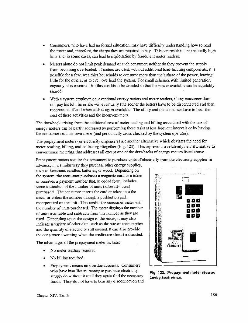
* Consumers, who have had no formnal education, may have difficulty understanding how to readthe meter and, therefore, the charge they are required to pay. This can result in unexpectedly highbills and, in some cases, can lead to exploitation by fraudulent meter readers.
* Meters alone do not limit peak demand of each consumer; neither do they prevent the supplyfrom becoming overloaded. If meters are used, without additional load-limiting components, it ispossible for a few, wealthier households to consume more than their share of the power, leavinglittle for the others, or to even overload the system. For small schemes with limited generationcapacity, it is essential that this condition be avoided so that the power available can be equitablyshared.
* With a system employing conventional energy meters and meter readers, if any consumer doesnot pay his bill, he or she will eventually (the sooner the better) have to be disconnected and thenreconnected if and when cash is again available. The utility and the consumer have to bear thecost of these activities and the inconveniences.
The drawback arising from the additional cost of meter reading and billing associated with the use ofenergy meters can be partly addressed by performing these tasks at less frequent intervals or by havingthe consumer read his own meter (and periodically cross-checked by the system operator).
The prepayment meters (or electricity dispensers) are another alternative which obviates the need formeter reading, billing, and collecting altogether (Fig. 123). This represents a relatively new alternative toconventional metering that addresses all except one of the drawbacks of energy meters listed above.
Prepayment meters require the consumers to purchase units of electricity from the electricity supplier inadvance, in a similar way they purchase other energy supplies,such as kerosene, candles, batteries, or wood. Depending onthe system, the consumer purchases a magnetic card or a token - -
or receives a payment number that, in coded form, includes .
some indication of the number of units (kilowatt-hours)purchased. The consumer inserts the card or token into themeter or enters the number through a pushbutton pad. I -incorporated on the unit. This credits the consumer meter with - *Othe number of units purchased. The meter displays the number i 00
of units available and subtracts from this number as they are ' O 01used. Depending upon the design of the meter, it may alsoindicate a variety of other data, such as the rate of consumptionand the quantity of electricity still unused. It can also providethe consumer a warning when the credits are almost exhausted.
The advantages of the prepayment meter include:
* No meter reading required.
* No billing required.
Prepayment means no overdue accounts. Consumerswho have insufficient money to purchase electricity Fig. 123. Prepayment meter (Source:
simply do without it until they again find the necessary Conlog South Africa).
funds. They do not have to bear any disconnection and
Chapter XIV. Tariffs 186

reconnection costs.
* Easy budgeting by the consumer and the ability to pay for small amounts in the same way thatother energy resources are purchased.
* No consumer inquiries and complaints regarding bills.
* No problems associated with bad or non-existent postal systems or customers having no formaladdress at which to receive bills.
* It facilitates energy conservation as the consumer can easily relate expense to appliance usage.
* Time-of-day tariffs can be programmed into the meter and easily modified.
* It automatically disconnects the consumer if he or she is unable to pay the bill, avoiding badfeelings that may arise if the system operator disconnects the consumer.
The main disadvantages that remain or have been introduced by this new technology are the following:
* The cost of the meter and card/token/number dispenser is high.
* A well-organized sales and support service is required.
* The burden is on the consumer to go to the electricity supplier's office or shop that has been fittedwith the necessary equipment to purchase electricity. The customers must therefore be withineasy reach of this service as they may wish to buy cards several times each month.
* Although not a major disadvantage, customers need some training on how to use prepaymentmeters.
Despite the numerous attractive features of prepayment meters, the high cost of the equipment and thesophisticated support services required preclude this from being a viable altemative for mini-gridapplications. By their nature, mini-grids have too few consumers to provide an economic justification forthis option.
Power-based tariff
In this case, the tariff is based on the maximum amount of power used by the consumer. The poweravailable to the consumer is predetermined and payment is made on the basis of this power level. Thesimplest variation of this approach is to base the level of consumption on a written or oral agreement withthe consumer (e.g., limiting consumption to no more than two 10-W bulbs and a small B&W television orpaying 50 rupees (US$ 1) monthly for each light bulb installed). This approach has the cleardisadvantage that there is no way of enforcing this limit and it is therefore open to abuse.
Another variation is to electrically limit the power consumer by limiting the current into the home(p. 155). Load limiters have a number of advantages over metered connections:
* They limit peak demand and therefore prevent overloading of generators (or transformers) andthe distribution lines. Consumers cannot, on their own, decide to increase their consumption.
* By preventing excess consumption by a few individuals who might consume whatever level ofpower they wish to use because they can afford it, use of limiters can ensure that all consumerscan get access to some electricity.
* Costs associated with meter reading are removed.
Chapter XIV. Tariffs 187

* Payment is simpler for both the collector and the consumer, as the amount to be paid on a regularbasis is known.
* Fraud and confusion relating to the payment process are greatly reduced.
* The payment can be required in advance to ease cash flow for the electricity supplier.
* Reliable load limiters are less expensive than reliable electric energy meters.
* Loads with low power factors (such as uncompensated fluorescent lamps) make inefficient use ofavailable current. Excessive currents in the system lead to energy losses or the need for increasedinvestment for additional generating and distributing capacity to more efficiently handle theseincreased currents. Standard electricity meters do not record usage of these excess currents. Thismight be seen to benefit the consumer but places extra burden on those responsible for the viableoperation of the mini-grid. However, in measuring current, load limiters sense the total currentused and tend to place the burden on individual consumers to improve their power factor(provided that they are made aware of how this is done). This benefits both the consumers whocan effectively increase the power available to themselves at no increase in energy cost and to theutility which incurs fewer losses in the distribution line and generator.
* Load limiters encourage off-peak consumption of electricity, which is especially desirable whenthe "fuel" to produce the electricity is free and no storage is involved, as is the case of mostmicro-hydropower schemes. This encourages the more efficient use of the energy resource.
The main disadvantages are:
* Restricted electricity availability for the consumer. To encourage this option, load limiters musthave a clear financial advantage over a metered supply for consumers, especially if they realizethis is not the way electricity is conventionally "metered" in urban areas.
* Increased opportunities for fraud and theft by consumers tampering with the load limiters. Suchtampering is difficult to detect because, unlike with a metered supply, there is no record of thequantity of electricity consumed. Automatically-resetting load limiters are an exception, sincethey can be mounted high on a distribution or service connection pole to deter bypassing or othertypes of tampering.
* Uneconomical use of electricity. Load limiters do not encourage economical use of electricitybecause the consumers bill takes no account of the energy consumed. They could, for example,leave lights on all the time. But these consumers using limiters generally have little disposableincome and would quickly realize that leaving lights on forces them to purchase light bulbs morefrequently, adding unnecessarily to their domestic expenses. Measurements in Zimbabwe(Box 9) confirm that load factors are not excessive. Furthermore, a capacity-based tariff shouldnot be used with larger consumers, as they can easily cover the cost of the meter.
* Poor reliability. Reliability can be a problem if load limiters that cannot withstand short-circuitcurrents are not sufficiently protected or if the accessibility required for manual resetting leads toabuse of the load limiter.
* Poor accuracy with certain limiters. Thermal devices such as standard miniature circuit breakersand thermistors have poor accuracy, especially where there are wide variations in ambienttemperature. Magnetic miniature circuit breakers and ECBs are considerably more accurate.
Chapter XIV. Tariffs 188

* Consumer education is required to minimize customer dissatisfaction by making them aware thatrepeated tripping of the load limiter can be due to low power-factor appliances or to the use ofappliances that have too high a current consumption for the load limiter.
* As with the conventional energy meters, non-payment requires disconnection of the consumer(and possible later reconnection) and the costs and inconveniences that these entail.
Designing a tariff scheduleA wide variety of tariff schedules is possible. In designing such a schedule for a specific project, any oneor more of the following characteristics can be incorporated. But whichever design is adopted, it mustgenerate the revenues required to cover project costs. Characteristics include the following:
* Based on one or more fixed levels of demand. For example, consumers can subscribe to either a25- or 50 W, load-limited service for $0.50 or $1.00 per month, respectively. Altematively, theymight pay $0.02/installed watt, although this is more difficult to maintain and enforce.
* Based on actual energy (kWh) consumed. Based on kWh readings periodically taken from aconsumer's meter (e.g., every month or two months), the household pays either a fixed price perunit (e.g., $0.70/kWh) or any of several unit prices based on the total energy consumed (e.g.,$0.40/kWh for the first 10 kWh and $0.70/kWh thereafter).
* Based on the type of consumer (with residential, commercial, industrial, and govemmentconsumers possibly having different rates).
* Based on time-of-day, a tariff generally available for consumers with larger commercial orindustrial loads. Rates vary, depending on the time of the day that electricity is used. To avoidinterference with lighting loads, lower rates may be offered during the daytime, for agro-processing, or during the late evening hours, such as for pumping potable water into a storagetank, when lights and other domestic loads are not being used. Electric utilities use time-of-daymeters, which are more expensive, to ensure that special rates are only applied to electricityconsumed during designated times. However, special time-of-day rates can also be applied forthe few larger loads on a rural mini-grid even without time-of-day meters, through a writtenagreement. Any failure of the larger consumers to abide by such an agreement would benoticeable to other consumers on the grid. If the load is large, it would cause significantvariations in the intensity of incandescent bulbs supplied by the mini-grid.
* Regressive (where larger consumers pay a smaller unit cost).
* Progressive tariffs (where the smaller consumers pay a smaller unit cost)
A progressive or regressive tariff is used to discourage or encourage increased energy usage, respectively,depending on factors such as cost and availability of fuel or the size of the generator in comparison to theload. The tariff schedule adopted may include several of these characteristics.
In addition to generating the desired revenues to cover project cost, the tariff schedule should alsocontribute to making electricity more affordable. Toward this end, the tariff schedule should bestructured to strive to achieve these other objectives:
* To minimize the additional costs and complications incurred in generating and accounting for thisrevenue (i.e., the costs of metering billing, collection, and administration), especially if
Chapter XIV. Tariffs 189

affordability is an issue. For example, using a tariff based on a subscribed, maximum power leveleliminates the need for meter reading, billing, and more involved accounting (see p. 186).
* To give even poor members of the community access to some basic electricity. This usuallyinvolves a low tariff, commonly referred to as a "lifeline" tariff, for the first several kilowatt-hours consumed, sufficient for basic needs (e.g. lighting and radio).
* To maximize the number of consumers, so that the capital cost as well as the cost for running thesystem are spread out over as large a consumer base as possible.
* To incorporate flexibility in the consumer payment schedule, a feature which is even moreimportant when consumers do not have a regular income stream. This might be done bypermitting advance payments or else bulk payments several times a year (e.g., when the harvestcomes in).
* To encourage the productive (income-generating) uses of the power generated by the primemover (e.g., by a diesel engine or a micro-hydropower plant)-through either a direct mechanicaldrive or an electric motor or other appliance-so as to generate additional income and thereby toreduce the costs that residential consumers would have to cover.
- To encourage demand-side management, such as encouraging other uses of electricity at timesoutside peak lighting hours in the early evening.
Examples of sample tariff schedules for the case described in Box 15 are found in Box 16.
Chapter XIV. Tariffs 190

Box 16. Sample tariff schedules
Box 15 illustrated how the magnitude of the revenue that has to be raised each month to cover bothcapital and recurring costs of the project is calculated. Below, a variety of tariff schedules for generatingthis revenue is illustrated. Recall that in that example, $290/month had to be raised to cover the cost ofgenerating an estimated 290 kWh each month.
Energy-based tariff: This approach requires a meter to be read for the number of units consumed andbills to be prepared on this basis. Examples include the following:
* A basic tariff schedule is simply to bill each consumer based on a fixed rate. In this case,charging $1.00 for each kWh consumed would raise the $290 required monthly.
* A more complicated schedule would be to include a fixed charge. Consumers would have to paythis charge to cover sunk costs that have already been incurred (capital cost and cost of operator),irrespective of how much electricity they consume. In addition, a variable charge would berequired to cover the other costs would depend on how much energy is consumed. For example,the tariff schedule could be $4.30/month plus $0.40/kWh. With 40 consumers using 290 kWheach month, this schedule would again raise the (40)($4.30) + (290)($0.40) or $290 required. Inthis manner, if a consumer has financial constraints, he can consume less energy and reduce hismonthly bill without jeopardizing the project's need to keep generating revenues to cover thecapital cost.
Power-based tariff: This approach is based on paying a fixed amount depending on the amount ofpower (watts) to which each consumer subscribed. Examples include the following:
* Each consumer agrees not to exceed 60 W demand. Since $290 must be raised from 40consumers, each consumer must pay $7.30 each month.
* A village includes 9 commercial consumers (restaurants and shops) who have 200-W current-limited service, with the remaining load composed of residential consumers who have a current-limited service of 20 W (for one or two CFLs and a radio). A tariff is set proportional to theirdemand: residential consumers are charged $2.40/month while the commercial consumers arecharged $24/month. This tariff schedule has again been designed to generate $290 each month.
Chapter XIV. Tariffs 191

XV. Appendices
Appendix 1. Case study: Ivory Coast
Appendix 2. Case study: Laos
Appendix 3. Case study: Irian Jaya
Appendix 4. Case study: Dominican Republic
Appendix 5. Calculating required pole diameter
Appendix 6. Derivation of basic voltage drop/power loss equations
Appendix 7. Computational examples
Appendix 8. Sag tables for multiplex conductor
Appendix 9. Areas for further inquiry
Chapter XV: Appendices 192


Appendix 1. Case study: Ivory Coast
Project initiation
To address the problem of urban migration by increasing the attractiveness of rural areas, the availabilityof modem services-including access to electricity and the benefits associated with it-is generally felt tobe a necessary element. At least in theory, solar photovoltaic systems are seen as an electricity supplyaltemative well-suited for meeting the most common domestic demands-electricity for lighting andaudiovisual equipment-and for specialized end-uses such as vaccine refrigeration or water pumping.But before this technology can find widespread application, the life of the components will have to beincreased, their cost decreased, and mechanisms put in place for the financing of small systems and fortheir dissemination and ongoing maintenance. Today, such projects are still limited to programs heavilydependent on international aid.
APAVE, a French association of electricity producers, has been involved in a variety of developmentprograms in French-speaking countries over the past 15 years, programs associated with conventionalelectrification as well as with solar photovoltaic applications. It felt that to meet the demand for smallquantities of electricity, at least over the medium term, solutions more in harmony with the socio-economic character of rural areas were needed. On the basis of experiences gained, APAVE felt that, iftechnical and institutional designs could be developed that would pennit the implementation of lower-costsystems that could be managed by other than the national utility, then this would open up the possibilitiesfor broad rural electrification. These designs would have to maximize the involvement of localbeneficiaries, to give them a stake in the project rather than leaving them on the sidelines as merespectators. Relying on the local beneficiaries to contribute sweat-equity to the implementation of theproject and to then manage and operate it would provide a more viable and realistic alternative to projectimplementation by the national utility and could further reduce costs.
APAVE consequently proposed an integrated approached to rural electrification referred to as "groupeelectrogene-economie d'energie" (GECO), which includes the generation, distribution, and use ofelectricity. It was designed to address the obstacles encountered by conventional approaches to ruralelectrification: high cost, overly conservative system design for the end-uses envisioned, and the limitednumber of consumers that could afford to connect.*
Design concept
The GECO concept includes the following basic features:
* The use of a small autonomous powerplant, generally a diesel or gasoline genset (although pico-hydropower plants' are also planned).
* A mini-grid supplying consumers with low levels of "basic" power.
* Electric service for only a portion of the day.
This case study is included because it illustrated one of several interesting options for off-grid electrification.However, the documentation used in its preparation left a number of issues unclear. An attempt was made to resolvethese issues by contacting individuals connected with these projects; however, no responses were obtained.t "Pico-hydropower plants" refers to plants harnessing small waterpower resources and generating no more thanseveral kilowatts.
Chapter XV: Appendices 193

This approach focuses primarily on comnmunities that generally have from 40 to 400 consumers (homes),where households are grouped together rather than scattered and are constructed of at least semi-permanent materials. To be able to spread the cost of the mini-grid over as broad a base as possible, alarge majority of the households in each perspective community must be willing to become consumers;
otherwise, the system is not built.
The genset supplies power for 3 to 4 hours every evening, primarily for internal and external high-efficiency lighting, public lighting, audiovisual equipment, and fans. Consumers each have 3 to 4 power
points (i.e., each power point represents either a light fixture or power outlet). The average design powerdemand per household is generally in the range of 30 to 60 VA. Depending on the social and economicrealities in each village, operating times and capacities of the power supply can be increased. Publiclighting can be included if desired and if the conmmunity is willing and able to cover those costs.
The GECO concept imposes no specific management option. In the Ivory Coast, households within thecommunity become members of a consumer cooperative and, in the process, each agrees to amemorandum of understanding between the two parties. This cooperative than undertakes the technicaland financial management of the installation. It is also possible for the cooperative to contract part or allof the management to a private operator. This rnight be more appropriate in larger, more urbanizedcenters where the sense of solidarity is not as strong as in a rural setting.
While the system is designed to provide very small amounts of electricity, the objective is to design thesystem so that it will be completely compatible with grid-interconnection when it is available. At thattime, the genset would simply be replaced by a distribution transformer and metering/protectionequipment. Bringing conventional power to a village then becomes much more attractive for the nationalor regional utility because it would simply need to install a transformer, it would inherit a well-establishedload, and it would essentially serve one customer. It could therefore forego the complications involved inhaving to deal with numerous individual small consumers, where the costs it would incur in meterreading, billing, and collection could easily exceed any fee collected. The responsibility for ensuringprompt payment of the conmmunity's electricity bill to the utility would be transferred to the communityitself through the cooperative originally set up.
At the time of interconnection with the grid, it is always be possible for certain consumers (such asbusinessmen or craftsmen), with potentially larger demand, to opt for the conventional individualsubscription contract that may meet their needs more effectively.
A part-time employee paid by the cooperative is in charge of the technical operations to the system. Thisindividual is responsible for tuming on and off the genset each day, for refueling and lubricating thegenset, and for undertaking simple maintenance tasks. Most villages have local mechanics capable ofmaintaining and doing minor repairs on the genset.
The tariff level is set to cover the investment in the mini-grid, the operating costs, and the cost of thegenerating equipment. Each consumer pays a fee on the basis of the number of power points installed in
This concept is widely used by rural electric cooperatives in the Philippines to serve more remote neighborhoodsor barangay. The utility supplies electricity through a metered transformer into a mnini-grid that it is responsible forconstructing. Legally established Barangay Power Associations accept responsibility for meter reading, billing, andcollecting within their membership and for paying the utility, on a monthly basis, a lump sum based on single meterreadings made each month by the utility at the transformer(s) serving the area. Enforcing prompt payment anddealing with theft of power within the comnmunity is no longer the burden of the utility but falls on the communityitself which is generally better qualified to handle this issue.
Chapter XV: Appendices 194

his or her house and a sliding regressive scale (decreasing cost of additional points). A volunteer from thecooperative is responsible for collecting the monthly tariff.
Financing of these projects are covered in part by initial contributions from the villagers. Subsidies orgrants also cover part of project costs, while the balance is covered by a medium-term, soft loan grantedby a local credit institution to the village cooperative. In some cases, these loans may be guaranteed byan international aid organization or other non-government organization.
Project technical details
After a local community has expressed an interest in getting access to electricity, a study is undertaken todetermine the technical and economic feasibility of a project. Potential demand is assessed at this time.
The type of generator used dependson the expected demand of thecommunity. If demand does not principalexceed about 10 kVA, the linecommunity is broken down into powerblocks of unit demand that do not supplyexceed 5 kVA. Each block is secondary distribution linesupplied by a single-phase gensetfeeding a 2-wire, single-phasenetwork (Fig. 124). If demand s -
switchboard ~~~~~~terminalexceeds 10 kVA, a three-phase '\,- -distributiongenerator is used, supplying the (underground)main lines of either three single- ---phase networks or a 4-wire, three- Fig. 124. Basic configuration of a GECO system.
phase, main distribution backbone,which in turn supplies a series of single-phase networks.
In most cases, these main lines are overhead. These may then branch out into secondary lines that areusually buried and supply switchboards. Because the homes are low, single-story structures, buriedarmored cable is then used from each switchboard to supply a group of homes.
The genset is considered a "consumable": it easily can be transported elsewhere or exchanged whennecessary. A 3,000 rpm single-phase genset is assumed to have a life of 4,000 hours while a 1500 rpm,usually three-phase, genset is assumed to have a life of 10,000 hours. Gensets are usually fueled withgasoline or diesel.
In addition to the genset, the powerhouse contains a power meter and a run-time meter. On occasion, therun-time meter is coupled to a cut-out that trips after a pre-determined number of hours. This is designedto ensure that the community does not fail to remember to pay its obligations, i.e., loan repayments, inaddition to those connected with the day-to-day operation of the genset.
Switchboards supply electricity and provide individual protection to groups of homes. They are installedat the geographical center of this group and either placed at the bottom of a distribution pole or in a smallmasonry structure. Each includes a 300 mA RCD, a capacitor for power-factor correction for thedomestic fluorescent lighting loads, a two-pole 1 0-ampere circuit breaker for each household, and aground rod connection.
Chapter XV: Appendices 195

A typical domestic installation includes an outside lighting point, an internal lighting point, and anelectric power outlet, although the numbers of power points can be increased. Housewiring is wall-mounted and the outside equipment and the junction box are sealed. Lamps are miniature, uncorrectedfluorescent tubes or CFLs, selected because of their long life and low power demand. Power-factorcorrection is achieved within the switchboards rather than at individual lamps. This reduces voltage dropand power losses in the main portion of the distribution system and reduces the demand for current placed
on the generator.
If public lighting is provided along the main village streets, an additional conductor may be provided forthis purpose. Pole-mounted, power-factor-corrected, watertight 1 8-W lights in fiberglass-reinforcedpolyester housings are used. In village squares, where concessions are built of flimsy temporarymaterials, fluorescent lighting strips are installed on 3-m high, surface-treated wooden poles.
The grounding system includes copper wires running through the foundation of the generator housing andby 2-m ground rods installed at each switchboard. To ensure proper operation of the RCDs, grounding ofthe neutral in the switchboards is done doNvnstream of the RCD and no grounding is used in individualhomes. Protection from electric shock in each home relies on a shared RCD in the switchboard servingthat group of homes.
Lightning is a major risk and lighting arresters are installed at the generator and at each down-conductorto the switchboards.
Prior to commissioning the plant, the installation is verified. This involves a visual examination to checkthat the material complies with the safety standard prescribed, is correctly chosen and installed, and is free
from visible damage that could affect safety. The tests cover continuity measurements on the neutralconductor, measurements of line insulation and ground connection, tests of RCDs, operating tests on
lights, and voltage measurements at the source and at each switchboard.
Two levels of genset maintenance are envisioned: standard maintenance operations carried out byoperations staff and specialized maintenance operations that require specific interventions. The formerrequires that an operator be trained in routine maintenance and provided with an appropriate stock of
consumables (lubricants and filters). At half-year intervals, a visit by a specialist is scheduled, and atleast once every year, a complete service is perforrned in the specialist's workshop.
Project costing and tariff
To prepare a cost breakdown for the GECO approach, ten villages in the Ivory Coast were studied. Theaverage project serves about 130 households with 3 to 4 power points each, along with public lighting.The cost breakdown (excluding the cost of the genset, which averages $9,400 per site) is shown inTable 21. This amounts to about $630 per consurmer (household). This cost excludes any taxes andassumes that materials are supplied locally. Procuring materials overseas (exclusive of tax and import
A capacitor for power-factor correction is usually located as close as possible to the source of the inductive load-the magnetic ballasts in the case of fluorescent lighting. This is to minimize the impact of increased currents onvoltage drop and power losses along that segment of the conductor between the inductive load and the capacitor. Inthe case presented in the GECO project, rather than using a smaller capacitor in each fluorescent unit, a single,larger capacitor is located in the switchboard. However, as is explained on p. 148, when small conductors are used,reactance of the conductor is much smaller than its resistance, and power factor has a negligible impact on percentvoltage drop. Therefore in this case, there is no need to mninimize distance between capacitor and the ballasts ineach fluorescent unit to reduce voltage drop. However, increased power losses are incurred due to the highercurrents over this distance; however, this is still low because of the low demand in each home.
Chapter XV: Appendices 196

duties) results in a saving of more than 20 %. Table 21. Cost breakdown for an "average" projectIncluding taxes would add an additional 20 % with locally purchased materials, exclusive of taxes.
to the costs shown. Costs (US$)
The still substantial project costs are in part Description Sub-totals Totalsdue to the use of quality materials to minimize Main line $13,600future costs that would otherwise be incurredfor repair and maintenance and to an emphasis Secondary lines $12,200on a safe design, with adequate consumerprotection. It is expected that future costs Secondary panels $4,100will be reduced by 20 to 30 % as projects Buried cable junctionbecome more routine, as multiple projects are boxes $2,400implemented at the same time, and with the Grounding andbulk purchase of materials. accessories $1,200
In the Ivory Coast, the average operating cost, Service connection $22,000including fuel, maintenance, and minor Domestic installation $18,800manpower requirements (for refueling, Public lighting $3,600generator start-up and shut-down, minor Lightning protection $2,100maintenance on the generator set andnetwork) works out to about $0.50 per month Study and supervision $9,800per power point. The cost of fuel, which TOTAL $82,100accounts for about 70 % of this cost, has beencalculated on the basis of the delivered cost of In-kind local contributionsdiesel at about $0.50/liter. Cable trenches $8,900
The following items are considered in the Holes for poleformulation of the tariff: installations $1,300
* The investment in the mini-grid Powerhouse $1,700
* The cost of the generating set TOTAL $11,900
* The operating costs (materials andlabor for the day-to-day running ofthe project)
The precise values of the first two components depend on the Table 22. An approximate cal-size of any grant assistance, the amount of subsidy received, and culation for the monthly tariff perthe interest rate and duration of the loan taken out to cover the power point needed to cover allbalance. If there were no government grant or subsidy and if project costs, with breakdown.long-term, low-interest loans were available, an approximate Item Amount (US$)breakdown of the monthly tariff per power point would be asillustrated in Table 22. With each consumer averaging 3 to 4 Min-grd loan 1.50power points, the tariff per household would amount to roughly Generator$9 per month. These figures do not include any tax, which replacement 0.50would add another 20 %. Operating cost 0.50
In the actual situation, monthly payments are made on the basis TOTAL $2.50of the number of power points in a home, with the rate per point
Chapter XV: Appendices 197

decreasing with this number of points.
After the introduction of electricity, the use of batteries, candles, and fuel for lamps continued. Suchlighting is still required for occasional use in areas beyond the reach of electric lighting or as a night lightin the home after the power is shut off. Batteries are still required for such uses as hunting during thenight and for listening to radio during the day. It is interesting to note that the cost of electricity supplygenerally exceeds the cost of lamp fuel, candles, and batteries that are displaced. Depending on the actualtariff in a particular village, the overall operating cost of electrification varies between 1.0 and 1.3 timesthe cost of energy supply options previously used.
To cover loan repayments, it is necessary for regular income to be generated from electricity sales toconsumers. However, since villagers often do not have regular jobs as is generally the case in urbansettings, monetary income to villagers tends to be come sporadically, such as when crops are harvestedand sold. This could pose a problem to the plant operator who must ensure that adequate cash is availableto meet the loan repayment schedule.
Conclusions
Potential advantages associated with the GECO approach include the following:
* By keeping cost lower than conventional mini-grids, it encourages the maximum number ofconnections, spreading the base over which to recover costs and thereby reducing unit cost.
* Standardizing the design facilitates its replication in other interested villages and reduces its cost.It allows communities to access the benefits of electrification without being at the mercy ofnational utilities or beholden to national electrification priorities. (However, these projects arestill dependent on the whims of outside institutions for access to grants and subsidies.)
* In focusing on meeting lighting and entertainment (radio and TV) needs during early eveninghours, it meets the most popular uses of electricity while minimizing fuel consumption and cost.
* By involving the local community, it reduces project cost. At the same time, it frees the electricutility from involvement in small troublesome projects that it cannot effectively implement andpermits it to focus on the more profitable efforts in urban and peri-urban areas.
* Implementing a well-designed mini-grid permits easy interconnection onto the grid in the future,permitting the national utility to maximize its return at minimum cost.
But several conditions affecting the viability of this approach must also be kept in mind:
* It requires some level of village cohesiveness and initiative and the presence of one or moreindividuals who can easily and effectively assume leadership roles. With the conventionalapproach, the utility is in charge of all aspects of electrification; the consumers' only obligation isto pay their bills.
* An adequate disposable income within the community is requisite. Availability of only seasonalincome or inadequate income among some can force the entire mini-grid serving a largelydomestic load to shut down. This is a less important factor for a utility serving the national gridbecause the broader consumer base permits cross-subsidies. Furthermore, the industrial andcommercial demand on the national system is more reliable and significant.
* Costs of this approach are nonetheless very high, in fact higher than the cost of the candles, lampfuel, and batteries previously used, while service capacity and availability is severely limited.
Chapter XV: Appendices 198

Appendix 2. Case study: Ban Nam Thung, Laos
Project initiation
In 1991, northern Laos faced a drought that significantly reduced rice yields. To address this shortfall,international aid provided emergency assistance in the form of rice. The village of Ban Nam Thung,located several kilometers to the east of Luang Nam Tha in northwestem Laos, was provided 27 tons ofrice to tide it over until the next growing season. A small portion of the rice was donated as a gift to thevillagers, while most was placed in a rice bank from which the villagers could borrow as needed. Thiswas done with the understanding that farmers had to eventually return to the bank any rice they borrowedas they produced surpluses. The rice that was returned was eventually sold, generating funds for thevillage that could be used for a community project. They opted to use these funds to undertake theelectrification of their village. An agricultural student temporarily living in the village as part of his fieldtraining offered to assist in planning and implementing the project. In 1997, the sum of $1,700 obtainedfrom the sale of the rice was earnarked for the electrification of the village.
Design concept
Because of the cost of running a diesel genset, it was decided that the plant would generate power forthree hours every night to serve basic lighting and entertainment purposes. Power was supplied to nearlythe entire village of approximately 140 households. A few decided not to get electricity because of eitherthe inability to pay or the lack of awareness of the technology and the hesitancy to make the commitment.Households were to be charged on the basis of the number and type of end-uses to which electricitywould be put.
Project technical details
The powerhouse is comprised of a grass-roofed, bamboo structure near the center of the village(Fig. 125). There, a 18-hp Chinese diesel engine drives a 10-kW three-phase generator. From thislocation, two main lines stretch in both directions, each connected to one of the two phases. Presently, thethird phase is not used and the system is notgrounded. The longer line is comprised of twoinsulated 7-mm2 stranded aluminum conductorsextending a total of 800 m, serving most of themain village and a separate village a shortdistance to the south. The shorter, 300-m lineloops around the more heavily loaded, northern mend of the village on or near the main east-westroad between Luang Nam Tha and Oudomsai(Fig. 126). This is a 2 x 4.0 mm2, PVC insulatedand sheathed copper conductor. Service drops of2 x 0.5 mm2, PVC insulated and sheathed copperconductor extend in opposing easterly andwesterly directions from the main lines, passingfrom house to house, usually through each home.
Along the main lines, wooden or bamboo poles Fig. 125. Ban Nam Thung powerhouse andset in the ground are used. At times, smaller operators.
Chapter XV: Appendices 199

Fig. 126. Aerial view of Ban Narn Thung showing the main Fig. 127. The two main conductorsdistribution lines extending in two opposing directions are supported by wrapping each
from the powerhouse (black dot). once around the pole. Also visibleis a service drop deadended by
wrapping it once around the pole.
bamboo poles are used to raise the line to provide adequate ground
clearance, poles that are simply tied to an post or fence.
Because of the cost that would have been incurred in fixing insulators
to each pole, thcse were not used. Rather, each main conductor was 1
initially simply wrapped around the top of each pole (see Fig. 127). z^!
This seemed to work well except in the case where live trees were used ; s:
as poles. In this case, the growing trees caused the conductor to stretch,JX
breaking the insulation, and giving rise to shorts especially during ! l
rains. t i4 ^ X
At one point when the fuse link tended to blow too frequently (see below), villagers were given the advice that wrapping the an Faconductoraround the top of each pole was (inexplicably) causing the probley and b that the more conventional, although more involved, crossa design should be used (Fig. 128). Needless to say, the plant operators found { 1 i , h1
that this intervention did not resolve the problem of fuses blowing and s d d bythat the first design would have sufficed.pole.
Two approaches were used to connect the service drops to the mainline. W hen the drop consi sted of a longer span, the conductor was .
Fig. 128. More r ecently, crossarms were included to support thesmain lines that were tied to the crossarm using lengths of string or wire. These proved more complicated to prepare and provided -.
no advantage over simply wrapping the lines around the top of e poe se Fg.12)each pole.
Chapter XV: Appendices 200
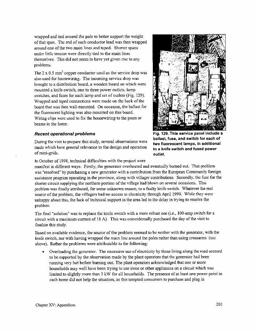
wrapped and tied around the pole to better support the weightof that span. The end of each conductor lead was then wrappedaround one of the two main lines and taped. Shorter spansunder little tension were directly tied to the main linesthemselves. This did not seem to have yet given rise to any i -problems.
The 2 x 0.5 mm2 copper conductor used as the service drop wasalso used for housewiring. The incoming service drop wasbrought to a distribution board, a wooden board on which were |mounted a knife-switch, one to three power outlets, lamp i
switches, and fuses for each lamp and set of outlets (Fig. 129).Wrapped and taped connections were made on the back of theboard that was then wall-mounted. On occasion, the ballast for .' Q J
the fluorescent lighting was also mounted on this board.Wiring clips were used to fix the housewiring to the posts orbeams in the home.
Recent operational problems Fig. 129. This service panel include ab3allast, fuse, and switch for each of
During the visit to prepare this study, several observations were tw fusent lamps fo addtonmade which have general relevance to the design and operation to a knife switch and fused powerof mini-grids. outlet.
In October of 1998, technical difficulties with the project weremanifest in different ways. Firstly, the generator overheated and eventually bumed out. That problemwas "resolved" by purchasing a new generator with a contribution from the European Community foreignassistance program operating in the province, along with villager contributions. Secondly, the fuse for theshorter circuit supplying the northem portion of the village had blown on several occasions. Thisproblem was finally attributed, for some unknown reason, to a faulty knife switch. Whatever the realsource of the problem, the villagers had no access to electricity through April 1999. While they wereunhappy about this, the lack of technical support in the area led to the delay in trying to resolve theproblem.
The final "solution" was to replace the knife switch with a more robust one (i.e., 100-amp switch for acircuit with a maximum current of 18 A). This was coincidentally purchased the day of the visit tofinalize this study.
Based on available evidence, the source of the problem seemed to be neither with the generator, with theknife switch, nor with having wrapped the main line around the poles rather than using crossarms (seeabove). Rather the problems were attributable to the following:
Overloading the generator. The excessive use of electricity by those living along the road seemedto be supported by the observation made by the plant operators that the generator had beenrunning very hot before buming out. The plant operators acknowledged that one or morehouseholds may well have been trying to use irons or other appliances on a circuit which waslimited to slightly more than 3 kW for all households. The presence of at least one power point ineach home did not help the situation, as this tempted consumers to purchase and plug in
Chapter XV: Appendices 201
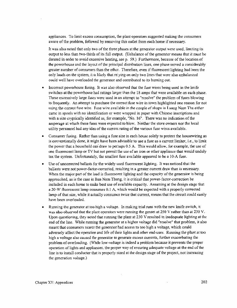
appliances. To limit excess consumption, the plant operators suggested making the consumersaware of the problem, followed by removing this outlet from each home if necessary.
It was also noted that only two of the three phases at the generator output were used, limiting itsoutput to less than two-thirds of its full output. (Unbalance of the generator means that it must bederated in order to avoid excessive heating, see p. 59.) Furthernore, because of the location ofthe powerhouse and the layout of the principal distribution lines, one phase served a considerablygreater number of consumers than the other. Therefore, even if fluorescent lighting had been theonly loads on the system, it is likely that relying on only two lines that were also unbalancedcould well have overloaded the generator and contributed to its burning out.
Incorrect powerhouse fusing. It was also observed that the fuse wires being used in the knifeswitches at the powerhouse had ratings larger than the 18 amps that were available on each phase.These excessively large fuses were used in an attempt to "resolve" the problem of fuses blowingto frequently. An attempt to purchase the correct fuse wire in town highlighted one reason for notusing the correct fuse wire. Fuse wire available in the couple of shops in Luang Nam Tha eithercame in spools with no identification or were wrapped in paper with Chinese inscriptions andwith a size cryptically identified as, for example, "No. 16". There was no indication of theamperage at which these fuses were expected to blow. Neither the store owners nor the localutility personnel had any idea of the current rating of the various fuse wires available.
* Consumer fusing. Rather than using a fuse size in each house solely to protect the housewiring asis conventionally done, it might have been advisable to use a fuse as a current limiter, i.e., to limitthe power that a household can draw to perhaps 0.5 A. This would allow, for example, the use ofone fluorescent lamp or TV but not permit the use of an iron or other appliance that would undulytax the system. Unfortunately, the smallest fuse available appeared to be a 10-A fuse.
* Use of uncorrected ballasts for the widely used fluorescent lighting. It was noticed that theballasts were not power-factor-corrected, resulting in a greater current draw than is necessary.When the major part of the load is fluorescent lighting and the capacity of the generator is beingapproached, as is the case in Ban Nam Thung, it is critical that power-factor-correction beincluded in each home to make best use of available capacity. Assuming at the design stage thata 20-W fluorescent lamp consumes 0.1 A, which would be expected with a properly correctedlamp of that size, while it actually consumes twice that current, means that the circuit could easilyhave been overloaded.
* Running the generator at too high a voltage. In making trial runs with the new knife switch, itwas also observed that the plant operators were running the genset at 250 V rather than at 230 V.Upon questioning, they noted that running the plant at 230 V resulted in inadequate lighting at theend of the line. While running the generator at a higher voltage did "resolve" that problem, it alsomeant that consumers nearer the generator had access to too high a voltage, which couldadversely affect the operation and life of their lights and other end-uses. Running the plant at toohigh a voltage also caused the generator to generate excess currents, further exacerbating theproblem of overloading. (While low-voltage is indeed a problem because it prevents the properoperation of lights and appliances, the proper way of ensuring adequate voltage at the end of theline is to install conductor that is properly sized at the design stage of the project, not increasingthe generation voltage.)
Chapter XV: Appendices 202

If the necessary interventions noted above are Table 23. Cost breakdown for componentsadopted, the generator should no longer burn out. used for basic housewiring (including aThen, the only remaining problem would be single 20-W fluorescent lamp).purchasing diesel fuel that, due to the rapidly falling Component
- Component ~~~~~~Costvalue of the local currency, is becomingincreasingly difficult for the villagers to cover. Knife switch 1.25
Project costing and tariff Fuse holder (2) 1.40
Initial cost was $1,500 for the diesel genset Single outlet .45purchased in China and $200 for the conductor for Light switch .30the main lines. The cost of the service drop as wellas the housewiring was the responsibility of each Fluorescent lampconsumer. The cost of the latter for each household Fixture .40was approximately $7 for components and $3 for Ballast 2.10labor. Although a precise cost breakdown for theoriginal home installation was not available, Starter .30Table 23 presents cost for similar components, had Lamp (20 W) 1.20they been purchased at the time of this study. Notethat these are retail costs and that almost all Wiring (20 m, 2 x 0.5 mm2 copper) 2.00materials come from China. Higher quality TOTAL $9.40materials would be costlier on a capital-cost basisbut might prove advantageous if the system is tolast.
The monthly bill is based on the number and type of appliances in use in the home. Initially, for the mostpopular end-use-fluorescent lighting-the tariff was set at $0.50 for each of one or two 20 Wfluorescent lamps. Based on operational experience, this was raised to $0.80 to cover costs. Morerecently, this was raised to $1.00 to cover the increasing cost of fuel due to the loss of value of the localcurrency. In addition to a per-lamp cost, separate tariffs are set for other uses, such as video cassetteplayers and televisions. Each household pays the powerplant operator on a monthly basis and receives areceipt.
Revenues gathered are set aside to meet the follows needs:
* Expenditures to cover the 210 liters of diesel fuel typically used each month.
* Two plant operators at a monthly cost of $5 each.
* A fund to cover the cost of spare parts and repairs, a fund that is topped up by additional villagercontributions if sufficient funds are not available to cover costs that have to be incurred.
Conclusions
This project highlighted the importance for technical backstopping. While the plant operators had basicelectrical skills learned on the job, all those involved in one way or another with the project seemed tohave difficulty in critically diagnosing problems that occurred. Consequently, measures were taken thatcorrected nothing but resulted in increased costs and hassle (such as adding crossarms to the poles orbuying new and larger knife switches) or that may have exacerbated the problem (such as running thegenerator at a higher voltage than normal or replacing fuses with ones of higher capacity).
Chapter XV: Appendices 203

It also pointed to the need for proper planning and designs. In this case, while each household waspermitted to use at least one 20-W fluorescent lamp powered by a genset of limited capacity, there was noupper limit on per-consumer usage and no way of enforcing an upper limited had there been one. Also,conductors were not properly sized, with the resulting excessive voltage drop that created consumerdissatisfaction with the service.
And finally, it was clear that project operators must be wary of "answers" given them by those notproperly trained. Heeding incorrect advice results in a waste of time, money, and energy.
On the other hand, project implementers have developed a project design that, with few changes, couldserve as an example of a basic, low-cost system. Beside the power supply, all that the system involvedwas wiring for the main distribution lines and service drops-with no other special hardware-andhousewiring materials.
Chapter XV: Appendices 204

Appendix 3. Case study: Youngsu, Irian Jaya
Project initiation
Youngsu is a coastal village located in the eastem Indonesian province of Irian Jaya, isolated from thenational power grid, and only accessible by boat or trail. This village consists of 150 homes, a clinic,school, church, and a govemment office building. The villagers are principally subsistence farmers andfishermen. Sources of income for the village include the sale of fish, coconuts, mangos, and variousvegetable crops. Typically, a household would spend up to $4.50 monthly on kerosene and candles forlighting. The average household wage was estimated to be $300 annually. In an isolated location withfew amenities, the village found it difficult to retain full-time govemment teachers and clinic workers.
Several other coastal villages near Youngsu had already been electrified using micro-hydropowersystems. As a result, the village leaders in Youngsu had a basic understanding of the technology andexpressed a high level of interest to implement their own village micro-hydropower project. Theinstallation of a diesel plant was first considered but ruled out due to the high cost of fuel, transportation,and maintenance. Village representatives submitted a formal request for funding to the DevelopmentBoard of the Provincial Govemment (BAPPEDA) early in 1993. At this point, Yayasan Usaha SejhatraIndonesia (YUSI), a local non-governmental organization (NGO) experienced in designing and installingmicro-hydropower systems, was contracted by BAPPEDA to survey the site and submit a designrecommendation with a budget for the project. In 1994, the village received funding assistance from theprovincial govemment for the purpose of implementing a village micro-hydropower system. YUSI wasthen contracted to undertake development of the micro-hydropower system with the understanding thatthe village of Youngsu would agree to provide the required labor, local materials, and land for the project.
YUSI was established in Irian Jaya in 1987 by the World Relief Corporation, with funding from USAID.The facility it operates is fully equipped to manufacture small water turbines and implement villagemicro-hydropower systems. To date, over 30 small-scale hydropower systems have been installed inEastern Indonesia by YUSI, resulting in over 40,000 direct beneficiaries. YUSI provides training anddirect support of the installed micro-hydropower systems with spare parts and repair, an importantelement in insuring sustainability of the village micro-hydropower systems.
The village of Youngsu had previously undertaken govemment-funded projects, which includedconstruction of a suspension footbridge, a medical clinic building, and improvement of village roads.Like all govenmment-funded projects within the village, the village govemment authority known as thekepala desa formally initiated the micro-hydropower project while a representative from BAPPEDAsupervised actual implementation of the project.
Design concept
With a drop of 30 m in elevation along a local stream within a few hundred meters from the village,tapping this resource for the generation of power appeared a appropriate source of power for the village.A 12 kW micro-hydropower scheme, using a crossflow turbine fabricated in-country, was constructed tosupply the mini-grid and provides three-phase power that was generated, transmitted, and distributed at380/220 V.
This case study was prepared by Mike Johnson ([email protected]).
Chapter XV: Appendices 205

The valve to the turbine is set to generate any level of power up to its design limit. An electronic loadcontroller disposes of any power in excess of that used by the community by converting it to heat that isdissipated in the water leaving the powerhouse. In this way, a constant load is placed on the turbine,permitting it to operate at a constant speed and frequency (50 Hz). This is the conventional approach to
governing a micro-hydropower plant because it is considerably less costly and problematical than usingelectro-mechanical governors. The only difference with micro-hydropower projects elsewhere is that, inthose cases, excess power is generally used to heat water then used by the villagers, such as for washing,rather than thrown away.
Because the village had no experience with electricity prior to the micro-hydropower project, nearly all of
the installed consumer loads were for lighting. The typical home in Youngsu is arranged with a porch,living area, cooking space, and sleeping quarters. Because a home normally has no ceiling above theconnecting walls, a 40-watt fluorescent fixture mounted high in the rafters will cast light into all rooms.
The village clinic, church, and government office used a more conventional approach with severalfluorescent fixtures installed as needed. To provide lighting for the village road network, 1 0-wattfluorescent fixtures were mounted on the distribution poles. The fixtures were mounted on angled woodsupports that were covered with galvanized sheet metal to protect the fixtures from rain. Switches, near
the base of the pole, but high enough so that children could not reach them, were used to turn the lights onand off.
The plant was generally operated only during the evening hours. It was only run during the daytime ifthere was a need for power, such as to run a saw, planer, or some other tool.
Project technical details
After the powerplant, one of the most expensive components of a mini-grid would normally be the poles.Because of the remoteness of Youngsu, transportation adds further to the cost of anything imported intothe community. The materials must first be trucked a distance over 100 krn from the city of Jayapura tothe nearest dock. From the dock, a 3-hour boat trip is required to the village. In addition to the cost oflocal transportation, costs for materials shipped to the remote province of Irian Jaya are generally higher
that the price at their source in Java. These factors were considered in selecting the type and material forthe distribution poles to be used.
Three types of poles that had been used previously in other village systems in the country wereconsidered:
* Indonesian-manufactured, galvanized, 80 mm x 6 m, lightweight, steel water-pipe, the upperthreaded end closed off with an 80-mm steel pipe cap.
* Steel-reinforced concrete poles, poured upright in place using a wooden form. The square cross-section of 150 mm on a side at the base tapered to 100 mm at the top.
* Locally available ironwood poles.
This first option-using galvanized water pipe for distribution poles in a village system-has certainadvantages. With its 6-m length, setting the pole 1 m into the ground still allows sufficient clearancebetween the conductors and the ground. If the tops of the galvanized pipes have been capped (to preventthe entrance of rainwater that would speed up corrosion of the pole from the inside at ground level) andthe buried sections have been coated with bitumen, they have provided years of service in other projects.In projects located in the interior of the country, where materials are typically flown in, galvanized poles
are transported in 3--m segments and joined by pipe couplings.
Chapter XV: Appendices 206

If a pole is located in soil that does not provide good compaction, a concrete support is poured around itsbase. If a pole requires guying, a single section of ABC is used for the guy, secured through a hole nearthe top of the pole and attached to a rock anchor buried in the ground. The strength of the pipe is notcompromised by drilling 1 0-mm holes near the top for attachment of cable hangers, streetlights, or otherfixtures. Use of galvanized pipes for distribution poles provides a uniform, professional appearance. Thechief disadvantage of the galvanized pipe, which is manufactured in another part of the country andshipped across the Indonesian archipelago, is its cost. The cost per pole including the threaded cap,delivered to the village, would have been US$ 37.
The second option-using poured-in-place concrete poles-requires the construction of suitable forms.Because forns must be left in place for several days for the concrete to cure, multiple forms must beprepared; otherwise, pouring poles would take too much time. For each pole, approximately 0.8 m3 ofgood quality, high-strength concrete is required, in addition to a matrix of reinforcing rod around whichthe concrete is poured. Attachment holes for bolts and anchor wires are provided by inserting pieces ofslightly tapered bamboo sections through the forms near the top. When the pole has sufficiently cured,the bamboo can be knocked out, leaving the necessary holes. If the installation crew is experienced andthe concrete is mixed properly with good quality aggregate, the results can be good. Conversely,improperly mixed concrete and poor aggregate can result in failure. In addition, an adequate curing timeis required for the completed pole. If the conductors are attached and tensioned too soon, the pole willcrack. Unit cost of the concrete pole was calculated to be US$ 34. In this application, there would havebeen no cost advantage with using concrete as opposed to galvanized steel pole. In addition, cost for theforms and well as for labor and the risk of pole failure ruled out the use of concrete poles.
The third option-using ironwood poles-was chosen for a number of reasons. Youngsu is a coastalvillage that lies at the foot of a heavily forested mountain range. Ironwood suitable for distribution polesis in abundance and can be used under government regulations that allow trees to be harvested for use inlocal infrastructure and community development projects. Although ironwood is a term used to describea number of tree species, the particular type of ironwood commonly used in the area is a dark, dense,naturally preserved material known as kayu besi. It is used for supporting piers for village homes and forother applications where the wood is buried. Posts installed by the Japanese during World War II are stillstanding. The ironwood tree itself can be up to 1 m in diameter. These poles may be drilled in the topsection for attachments and can be directly buried, although a coating of bitumen below grade will furtherpreserve the pole. Normally, the pole is buried about 1 m and well tamped for stabilization. No costswere associated with the ironwood poles for the Youngsu project, since the village had agreed to provideall local materials. The 1,100 meters of single- and three-phase distribution cable required 55 poles,which were set at an approximate spacing of 20 m.
Although some low-voltage village distribution systems use bare conductors, secured to insulators on thepole, it was decided that both single- and three-phase conductors for the distribution cable would bealuminum ABC that is commonly used by the national electric utility, PLN. This type of cable ismanufactured in Indonesia and is ordered from Jakarta or Surabaya on large spools. In the case of theYoungsu installation, as with other village electrification projects, the insulated conductors provide anadded measure of safety for villagers who are as yet unfamiliar with electricity and associated hazards.Secondly, stringing ABC on the poles requires only a simple hanger per pole rather than several insulatorsand mounting hardware used with open conductors. The cost of ABC is somewhat more than that foropen conductor, although this difference is somewhat reduced because of the lower labor costs forinstallation and the elimination of insulators and most poletop hardware.
Chapter XV: Appendices 207

Both 2-conductor (2 x 35 mm2) single-phase and 4-conductor (3 x 50 mm2 + 1 x 35 mm2) three-phaseABC were used. To support this cable, a 10-nrm hole was drilled 100 mm from the top of each of theironwood poles. Through this hole, a 10 mm x 120 mm bolt was inserted, and this was used to attach asimple "J" hanger fashioned from a length of 3 mm x 30 mm iron strap (Fig. 130). In the case of thethree-phase cable, only the ground conductor was hung in the hanger while for the single-phase cable, oneconductor was hung in the hanger. A short piece of insulated copper wire was used at times to secure theconductor to the hanger in order to prevent movement of thecable and the resulting wear of the insulation. It is not knownwhether, over time, any damage has occurred to the insulationor conductor being supported by a hanger of this design.
Where a single-phase cable branched off the three-phasecable, the single-phase cable was deadended on the polecarrying the three-phase ABC. A wedge clamp was used todeadend the neutral conductor of the single-phase line. Thisdevice, which has a tapering groove and wedge, is attached tothe pole with an eyebolt. The cable is inserted into thegroove and is held in by the wedge when tensioned. To makethe connection, the conductors were bared and joined with a 4single galvanized steel U-bolt cable clamp of appropriate I, X .
size. Prior to joining, the cables were given a good coating ofa anti-oxidation compound. Fig. 130. Homemade "J" hangers are
used to support the insulated ABC.The same method was used to join lengths of conductor. The (Photo credit: Mike Johnson)two lengths of conductor to be joined were overlapped about100 mm and the insulation removed from this overlapping section. These were joined together with twoU-bolt clamps after cleaning and the application of the anti-oxidation compound. On stretches withmultiple conductors such as along three-phase lines, the connection on each line was staggered about300 mm to avoid shorting between conductors.
These methods for making connections and splices use a low-cost, readily available piece of hardware-aU-bolt clamp. While they seem to have provided a good electrical connection and have stood the test oftime in the case of the Youngsu project, use of this hardware is not generally recommended for thesepurposes.
Where a service drop was provided from the ABC to the building or home, an insulated 2 x 10 mrn2
copper conductor was used. This smaller cable was attached to the aluminum distribution cable using U-bolts as previously described. Typically, the cable was then attached to the building by securing it to theoutside wall or a convenient surface with one or more heavy staples. While it is not proper practice tojoin conductors of dissimilar metals (copper and aluminum), a generous coating of de-oxidationcompound was used with good results. Because the service drops were relatively short and lightweight,they were attached directly to, and supported directly by, the ABC conductor and no attachment was usedto deadend the service drops to the pole. It is unknown whether the use of staples or the direct attachmentof the service drop to the ABC cable has led to fatigue of the metal due to swinging of the conductor andeventual breaking of the joint as might be envisioned.
The Youngsu system does not use individual kilowatt-hour meters; rather, each residential customer isbilled a monthly flat rate and allowed a maximum total connected load of 40 W. Nearly all of the homeshave installed florescent lamps rather than incandescent light bulbs. Although incandescent light fixtures
Chapter XV: Appendices 208

and bulbs are less expensive, their use was discouraged because of inefficiency and the necessity of
frequently replacing bulbs.
Each home was supplied with an Indonesian-manufactured single-pole circuit breaker. The smallest sizethat could be procured in quantity was 0.5 amp. Although this allowed the consumption of more current
than that permitted by the 40-W limit, the breakers at least provide protection against short circuits and
the use of high-current loads such as electric irons. At another village installation where breakers of a
higher value were used, a govemment schoolteacher ironing his trousers in the evening regularly browned
out the village. The Indonesian breakers were supplied with a mounting plate and plastic cover. Thebreaker was mounted close to the incoming conductor, usually on the home's porch, with a drip loop
provided to keep water from running into the breaker. Because the electrical system is floating, no
grounding electrodes are used. From the breaker, 2-wire indoor-type insulated wire connects the lamp,
switch, and a single outlet.
The honor system was expected to prevent individual consumers from drawing more than 40 watts of
power from the distribution system. In practice, however, many homes exceeded this limit and eventually
the cumulative effect resulted in the turbine shutting when the frequency dropped below 45 Hz. This
would normally occur during the dry season when the turbine was running at part load due to lack ofwater. At this point, the kepala desa would police the consumers and attempt to enforce the 40-watt rule.Villages in Indonesia are prone to operate by consensus, where pressure to conform corrects behavior
which is contrary to the community interest. In time, after a period of trial and error, the village adaptedits energy usage to availability of power.
Apart from residential use and lighting for the few community buildings, some of the more enterprisingvillagers discovered income-generating opportunities made possible by the micro-hydropower system.The use of a few incandescent lamps permitted small poultry businesses to provide warmth for raising
chicks, leading to considerable success in an otherwise damp environment. Some woodworking tools,particularly electric hand-held wood planers are being used to work rough cut boards into finished
lumber. The government clinic also installed a small refrigerator, which is used to preserve medical
supplies.
Because the operation of the electronic load controller was sensitive to lightning, lightning arresters wereincluded at the powerhouse.
Project costing and tariff
Table 24 provides the cost breakdown for the mini-grid portion of the project. One factor that reduced
project cost was reliance on local materials (ironwood poles, sand, gravel, and rock). Labor provided bythe villages on an in-kind basis reduced cost. Electric service was provided up to and including the
breaker. The consumer was responsible for purchasing and installing the housewiring, the 40-watt
fixture, and an outlet, if desired. YUSI provided electricians to supervise consumer installations.
In addition to this cost, the cost of the micro-hydropower systems totaled about $19,000.
Individual households were responsible for covering the cost of all materials used for housewiring listed
in the Table 25 (except the breakers) and labor. This amounted to about $22.
This approach was adopted to be consistent with what seems to be the approach typically used by PLN, thenational utility, for low-voltage distribution.
Chapter XV: Appendices 209

Table 24. Cost breakdown for the Youngsu mini-grid serving 150 homes, a clinic, school,church, and government office building.
Items Quantity Unit cost Total
Three-phase ABC 600 m 4.40 2,640
Single-phase ABC 500 m 2.40 1,200
Service wire 1,000 m 1.60 1,600
Housewiring (see below) 150 19.70 2,950
Village lighting and switches 24 12.00 290
Circuit breakers 5 5.50 30
U-bolt clamps 180 .60 110
J hangers 60 .40 20
Bolts, nuts, washers 80 1.60 130
Friction clamps 15 2.70 40
Concrete 35 40-kg bags 6.80 240
TOTAL US$ 9,250
The provincial government funded the capital cost for the Table 25. Breakdown of housewiringproject. Consequently, revenues to repay this cost were not costs.required. However, to cover the cost of the operator as well Costas to have a reserve to procure materials for the Component (US$)maintenance of the system, a monthly tariff per consumerwas set at Rp. 5,000, which was equal to $2.30 when the Circuit breaker $5.50
project was commissioned in 1994. Given that the cost of Fluorescent unit, 2 x 20 W 6.80kerosene typically used for lighting was nearly double this Outlet 1.10figure, electrification with its many additional uses andbenefits was a bargain for the villagers. Furthermore, Switch 1.40recurring costs should be minimal, at least in the first years Wire (20 m) 4.50of the project, and if monthly fees continually to actually be Staples .40collected and accounted for, adequate funds should be TOTAL $19.70available to cover these plus the operator's wages.However, it is clear that this project, as with mostinfrastructure projects, is dependent on extemal fundingand it is not clear whether such a project could be implemented with costs solely covered with fundsgenerated by the local beneficiaries, even if credit on reasonable terms were available.
In addition, the kepala desa was responsible for collecting the monthly user fees. This type of accountingis not transparent and often results in funds disappearing or being used for some other purposes. Yet in
Chapter XV: Appendices 210

the case of Youngsu, there was no alternative other than financial management by the local government
authority.
Chapter XV: Appendices 211


Appendix 4. Case study: El Lim6n, Dominican Republic
Project initiation
The village of El Lim6n is located in the arid southwest mountains of the Dominican Republic (DR), two
hours west of Santo Domingo. Nearly seventy households eke out a marginal living growing onions,
eggplant, and other low-value cash crops. Like most Dominican villages off the infrastructure corridors,
El Lim6n has little prospect of being connected to the national electrical grid in the foreseeable future.
But unlike the typical Dominican village, El Lim6n is a highly organized community with a strong history
of participation in self-help projects. For the past 25 years ADESJO, a regional community development
organization in the nearby city of San Juan de Ocoa, has been providing technical and financial support
for such projects as the construction of the road, school, irrigation system, water system, and agricultural
improvement. In each case, the community has assimilated new skills and moved rapidly toward self-
reliance. The result has been a community with an atypically high degree of self-confidence and project
management skills.
El Lim6n's experience in building and operating its irrigation system provided the base for the
electrification project. When construction of the irrigation system began in 1991, the community could
only provide manual labor. Within a few years the villagers had acquired the technical and management
skills necessary to maintain (and extend) the elaborate gravity-fed PVC pipe irrigation system. A very
effective system of work brigades evolved, headed by a five person committee; each member wasresponsible for one day of the workweek. This approach is now being used to extend the irrigation
system, as well as for other community projects, including the electrification effort and the fairly
extensive repairs needed after Hurricane George.
The Irrigation Committee is the village's most sophisticated management operation. It allocates water,
schedules water use (which involves moving sprinklers every two hours around the clock), and makes
sure that all members of the irrigation project make their payments to cover the original $75,000
construction loan. The actual handling of money and the record keeping is done in the nearby city of
Ocoa by ADESJO, which managed the loan and the initial construction. Fifty-nine families participate in
the irrigation project and each is responsible for making quarterly payments timed with their quarterly
harvests. Most own from 1.0 to 1.5 ha and pay $170 to $250 quarterly. Most people have been able to
keep up with their payments.
The electrification of El Lim6n grew out of a 1996 regional workshop on very small hydropower systems
presented by the EcoPartners Project (a Cornell University affiliate), in cooperation with ADESJO. The
workshop visited El Lim6n as a field exercise in system design and demonstrated a 12-volt
turbine/generator unit to the community. Response was enthusiastic, and a turbine was eventually
installed at the village school, with extensive community participation. Residents expressed a very strong
interest in villagewide electrification powered by the irrigation system. The system described here was
designed to address the limited water resource available. Technical support has been provided by
EcoPartners, logistic support by ADESJO, and labor by the community.
The implementation approach was unusual, in that the electrification was integrated into a much broader
village development project. The expatriate project implementer resided in the village on a half-time
basis over the two years of the project, with much time spent on other activities. A major project priority
This case study was prepared by Jon Katz ([email protected]).
Chapter XV: Appendices 212
has been transferring technical skills into the community, and residents learned construction, wiring,electronic assembly, and computer/video documentation skills.
The project was officially inaugurated the beginning of April 1999 although portions of the village hadbegun receiving power earlier. A total of 56 households now receive electricity and a few more will beadded later. All have one light and a second will be installed shortly.
Design concept
As the source of power, a 2.5 kW micro-hydropower plant was built along an irrigation pipeline tohamess the excess energy in the water as it descends the final kilometer of a 6 km PVC pipeline. A low-cost, 240-V induction motor, with an appropriate electronic load controller, is used as a generator tosupply single-phase power to the mini-grid.
The distribution system transmits the power about 600 m to the village and distributes it around thevillage, supplying homes as far as about I km from the village center (Fig. 131). Because of the limitedhydropower potential of the irrigation pipeline and the need to serve 60 households and to provideroughly 200 W of power to the school for lighting and the computer center, the power available to eachhousehold is initially limited to no more than 35 W. This might be altered somewhat as actual operationalexperience is gained. Potentialconsumers were made aware that thiswas only adequate for a couple ofcompact fluorescent lights and a radio 3 \or tape recorder; that a small 12-V 18 Villatelevision could be used if lights were 10 Additionl Village of El Limon
turned off; and that refrigerators, irons, Mapn ' Dominican Republic
and hair dryers could not be used atall. While many residents would have i School
preferred more electricity, explaining - House~~ ~ - Storethat the energy available 24 hours a - Barnday would equal the output of three -Power Line
photovoltaic panels quieted all further 500 ft
objections. Only one family in El -. To Turbine
Limon has been able to afford a 1800 ftprivate single-panel system, and athree-panel system is considered a Ea
great luxury
After passing through the turbine,water is fed back into a network ofpipes to irrigate the land at lowerelevations. Because the irrigationsystem runs around the clock,electricity will be available at alltimes. The energy calculation of 2.5kW was based on the 6 I/s(liters/second) flow observed over atypical year. However, 1998 was a
Fig. 131. Layout of the el Lim6n mini-grid.
Chapter XV: Appendices 213

drought year and the water flow dropped to about 2 1/s. This was inadequate for irrigation as well aselectricity generation, and the community recently obtained the pipe necessary to extend the system to thenext stream, whose flow was measured at 12 1/s during the drought. The irrigation extension shouldassure a minimum of 2.5 kW at all times and may allow for some expansion.
A conventional distribution system in the DR distributes electricity to and around the village at a mediumvoltage and then steps it down to 120 V, the nominal residential voltage in the country. In this project,the decision was made to generate and distribute power at 240 V for the following reasons:
* This voltage is sufficiently high to permit the use of reasonably priced conductor for transmittingpower from the powerhouse to and around the community while restricting the maximum voltagedrop to 5 %.
* It somewhat reduces the danger of shock and makes the system easier and safer for villageresidents to maintain.
* Power can be generated at the "transmission voltage" of 240 V, eliminating the losses and theexpense associated with a step-up transformer that would otherwise have been needed at thepowerhouse.
* The absence of 240-V lamps and appliances on the local market makes it difficult for end-users toillegally tap the power line, a common practice in the DR.
While 240 V is available around the village, consumers only have access to low-voltage direct current(dc). To convert the distribution voltage to 12-V dc for domestic use, a converter-a small transformer,rectifier, and filter capacitor-that is usually pole-mounted outside each home is used. The design ofsystem components within the home parallels that used for solar home systems (SHSs)-dc wiring,fluorescent lighting, and a connection for radio or TV. Also like SHSs, for those who wish to make theadditional investment in a battery, it would appear that power could be stored, if the available voltage isadequate to properly charge lead-acid batteries. This has yet to be attempted. But unlike the solar option,the power of 35 W per household will be available 24 hours per day, making the battery only necessary tooperate larger loads. In fact, only a few batteries are likely to be installed, reducing both system life-cyclecosts and toxic pollution associated with the uncontrolled dumping of lead-acid batteries. Twelve-voltappliances are increasingly readily available in the DR because of the popularity of SHSs.
This approach has the following advantages:
* Availability of only 12 V dc in the home reduces the potential for shock and fire hazard andfacilitates maintenance by local residents who have little prior experience with electricity.
* The use of a converter (necessary to convert electricity available at 240 V ac outside the home to12 V dc within the home) and breakers in a steel box for each consumer sets an absolute limit onthe current than can be drawn, even if the limiting device in the home is bypassed. This mightalso be possible with an ac system but finding a low-cost, low-current (i.e., about 0.07 A) circuitbreaker may be difficult.
* Should battery-charging prove practical at the voltage available from the transformer/rectifier,this would permit significantly more energy to be available to the consumer.
* No noticeable change in brightness is apparent in the compact fluorescent lamps over aconsiderable voltage range (8 to 15 V).
Disadvantages of this approach included the following:
Chapter XV: Appendices 214

* Increased costs, complexity, and chance of failure are associated with the converters.
* Incurring losses estimated at 10 W per household is also a significant disadvantage whenavailable ac power is limited to no more than 35 W per household. These losses are typical of thegeneral-purpose transformers donated to the project. The use of high-efficiency transformerscould decrease these losses.
Project technical details
The 135 poles required for the project were fabricated on-site of steel-reinforced concrete. The 20-foot(6-m) poles have a square cross-section of 6 inches (150 mm) at their base, tapering to 4 inches (100 mm)at the tip. Although at first reluctant to transfer his skills, the mason who designed the poles dideventually teach the local residents how to form and wire the reinforcing steel, and production of thepoles continued without his involvement. Reinforcement consists of four 3/8-inch (10 mm) rods runningthe length of the pole, tied by square rings of 3/16-inch (5 mm) every 6 inches. Forms consisted ofwooden walls nailed to a wood platform. Four poles were made at a time, at the rate of 8 per week. As iscustomarily the case, concrete was mixed on the ground. The use of ungraded aggregate produced a low-strength concrete, but there was little problem with breakage of the cured poles. To facilitate themounting of insulators, two (later four, at right angles) pieces of 1/2-inch (13 mm) plastic water pipe wereincluded in the pole to provide through-holes. The material costs for the poles (cement, reinforcing steel,and aggregate) averaged about $40 per pole.
Moving the poles, which each weigh over 500 pounds, proved to be a major problem. To facilitate thistask, a handcart was built of steel box tubing and automobile wheels. Despite the cart, moving the polesto locations away from the roads proved difficult. In some locations, it was necessary to carry the poleswith teams of 12 workers. One conclusion drawn from this experience was that it would have been wiserto choose longer, less direct transmission runs that followed roads wherever possible.
Holes were dug using basic hand tools. The poles were raised using a variety of pulleys, poles, and ginpoles. Differing conditions required a constant reinvention of approaches and techniques. While nevereasy, and often hazardous, the process became less formidable with practice.
Where necessary, poles were guyed with the usual 3/8-inch (10 mm2) high-tensile cable. This cable wastied around an anchor made of meter-long lengths of concrete pole castoffs buried a meter underground.
Because of cost-savings resulting from quantity discounts, only two sizes of conductor were incorporatedin the system, one for the multiplex and one for the copper. This meant that the longer, more heavilyloaded "transmission" runs used #2 (34 mm2) aluminum secondary cable in duplex, triplex, andquadruplex combinations (one, two, or three insulated aluminum conductors, respectively, wrappedaround the neutral ACSR conductor) to keep voltage drop within acceptable limits. For example, theinitial run was comprised of two lengths of triplex or a total of six conductors. As the line approached thevillage and split off into two directions, a transition was made to one quadruplex and one duplex cable.
Where the multiplex ended, hard-drawn solid #12 (3.3 mm2) copper conductor with ultraviolet-resistanthigh-density polyethylene (HDPE) insulation, rather than off-the-shelf indoor wiring, was used to extendfurther within the village,. This wire is mechanically much stronger than indoor wiring, and theinsulation is more durable and tougher for outdoor service. This conductor was specially fabricated at acost only slightly higher than indoor wiring. The sizes of the conductors used were calculated using aspreadsheet developed to calculate voltage drops and costs of conductor made of differing materials andwith different sizes.
Chapter XV: Appendices 215
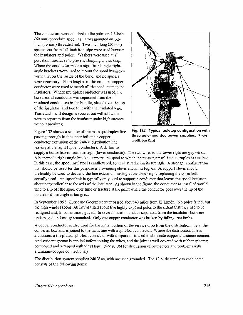
The conductors were attached to the poles on 2.5-inch(60 mm) porcelain spool insulators mounted on 1/2-inch (13 mm) threaded rod. Two-inch-long (50 mm)spacers cut from 1/2-inch iron pipe were used betweenthe insulators and poles. Washers were used at allporcelain interfaces to prevent chipping or cracking.Where the conductor made a significant angle, right-angle brackets were used to mount the spool insulatorsvertically, on the inside of the bend, and no spacers
were necessary. Short lengths of the insulated copperconductor were used to attach all the conductors to theinsulators. Where multiplex conductor was used, the
bare neutral conductor was separated from the
insulated conductors in the bundle, placed over the topof the insulator, and tied to it with the insulated wire.This attachment design is secure, but will allow thewire to separate from the insulator under high stresseswithout breaking.
Figure 132 shows a section of the main quadruplex line Fig. 132. Typical poletop configuration withpassing through in the upper left and a copper three pole-mounted power supplies. (Photo
conductor extension of the 240-V distribution line credit: Jon Katz)
leaving at the right (upper conductor). A dc line tosupply a home leaves from the right (lower conductor). The two wires to the lower right are guy wires.A homemade right-angle bracket supports the spool to which the messenger of the quadruplex is attached.In this case, the spool insulator is cantilevered, somewhat reducing its strength. A stronger configurationthat should be used for this purpose is a swinging clevis shown in Fig. 65. A support clevis shouldpreferably be used to deadend the line extension leaving at the upper right, replacing the upset bolt
actually used. An upset bolt is typically only used to support a conductor that leaves the spool insulatorabout perpendicular to the axis of the insulator. As shown in the figure, the conductor as installed would
tend to slip off the spool over time or fracture at the point where the conductor goes over the lip of theinsulator if the angle is too great.
In September 1998, Hurricane George's center passed about 40 miles from El Lim6n. No poles failed, butthe high winds (about 160 km/h) tilted about five highly exposed poles to the extent that they had to berealigned and, in some cases, guyed. In several locations, wires separated from the insulators but wereundamaged and easily reattached. Only one copper conductor was broken by falling tree limbs.
A copper conductor is also used for the initial portion of the service drop from the distribution line to theconverter box and is joined to the main line with a split-bolt connector. Where the distribution line isaluminum, a tin-plated split-bolt connector with a separator is used to eliminate copper-aluminum contact.
Anti-oxidant grease is applied before joining the wires, and the joint is well covered with rubber splicingcompound and wrapped with vinyl tape. (See p. 104 for discussion of connectors and problems withaluminum-copper connections.)
The distribution system supplies 240 V ac, with one side grounded. The 12 V dc supply to each homeconsists of the following items:
Chapter XV: Appendices 216

* A 0.63-ampere MCB on the 240 V side toprotect the system in case of diode ortransformer failure.
* A converter (consisting of a transformer, anencapsulated rectifier bridge, and computer-grade filter capacitors rated at 20,000microfarad, 40 V dc).
* A 6-ampere, dc self-resetting MCB on the dcside transformer in case the manual breaker inthe house is bypassed.
For both of the above MCBs, thermal units wereselected to keep costs down. All the components foreach home are mounted in one ventilated, waterproofsteel box, generally strapped to the pole nearest the Ihome (Fig. 133). In the case of sturdier homes, the box imay be mounted on the outside of the home. Given thesocial structure in the village, tampering is not expectedto be a problem; otherwise, these boxes could be sealed. Within the home, the principal power-limiting device is * m i _I_a wall-mounted, 3-ampere manual (3 A x 12 V = 36 W) Fig. 133. Each home is supplied by dcreset circuit breaker. The box can be sealed to prevent power from a pole-mounted power supply.the consumer from bypassing the breaker if that should (Photo credit Jon Katz)prove a problem.
If the homes are further than about 10 m from the pole, two lengths of the insulated #12 copper conductorserve as the service drop from the pole to the home; otherwise, #16 (1.3 rmm2) flexible duplex (lamp) cordis used.
This flexible cord is also used for internal housewiring. Two 10-W compact fluorescent lamps with high-quality wall switches are provided for each house, as is a connector to power a radio or small TV. Forradios requiring other than 12 volts, converters designed for use in automobiles are widely available. Afew households will probably decide to incorporate a battery for the occasional use of higher wattageappliances. To prevent tripping the 3-A breaker in the house due to the high current draw of dischargedbatteries, a current-limiting device will be supplied to these households. This will probably be a power-transistor-based series current limiter.
Lightning is not expected to be a major problem, since most of the distribution system is in relatively lowareas. However, as a precaution, each converter has a MOV (metal-oxide varistor) spike protectionarrester between the phase and neutral conductors, and the neutral conductor at about 20 poles withconverters is grounded using with 8-foot (2.5 m) galvanized-steel ground rods. The few poles in exposedlocations are fitted with lightning rods. The powerhouse end of the transmission line is also protected bya lightning arrester.
Back at the powerhouse, the turbine is protected by a 1 0-ampere magnetic circuit breaker. Each of thethree branches of the system is provided with a 5-ampere thermal circuit breaker at the powerhouse,which also allows powering up the system in stages. If startup outrush currents prove to be a problem,
Chapter XV: Appendices 217

several solid-state time-delay relays will be installed in various system branches to provide a moregradual startup. This has not yet been a problem.
For safety purposes, the use of RCDs in the powerhouse was considered, but it was decided that multiplegrounding of the system, which is not compatible with use of RCDs at that location, provides a higherdegree of safety. Also, nuisance tripping of any RCD used, because of leakages along the long runs,
might also be a problem.
Management and human resources
Before work started, the project was brought tothe village's governing town meeting. Afterextensive discussion, the village formallyreached consensus on making theelectrification a community project. Each ofthe 65 households was required to contributeone day of work per week. Some individualsworked much more, and several households multimately failed to contribute significantlabor. Two key individuals took on personal, l _long-term responsibility for completion of theproject. One concentrated on the poles and i distribution wiring and the other on theelectronic assembly of the fluorescent lampsand converter units. The project was Fig. 134. Despite the use of a cart expressly built
completed in about 18 months. The largest for this purpose, difficult terrain still made the taskpart of the work, by far, was transporting the of transporting concrete poles difficult. (Photo credit:
aggregate, fabricating the pole, transportingthem, and then setting the 135 reinforcedconcrete poles (Fig. 134). While at times the idea of a lighter, more easily made pole seemed veryattractive, the reinforced cement poles proved their strength during the hurricane.
Both the community and the project implementer found the process of electrification more difficult andtime-consuming than expected. The single largest problem was the unanticipated difficulty of workingwith the concrete poles. There were also changes from the original plan that added substantial work. Just
before construction began, the powerhouse site had to be moved from the village about 600 meters up thevalley because of a new area which was to be irrigated. Also, residents were very involved in day-to-daydesign issues and opted for a more durable system. Fewer trees, and therefore more poles, were used thanoriginally anticipated, and a concrete powerhouse much more elaborate than the simple shed originallyenvisioned was constructed. Other delays were unavoidable. Funds for the distribution wire andmaterials arrived almost a year later than expected, and Hurricane George, while doing little physicaldamage to the system, diverted labor to repairs and replanting.
In this project, the organizational strength and motivation of the villagers of El Lim6n were critical tomeeting the challenges they faced. Many residents felt that, at least until a less labor-intensive altemativeto concrete poles is found, many communities would have difficulty carrying this type of project tocompletion with their own resources.
Chapter XV: Appendices 218

Outside resources were also critical to Table 26. Cost breakdown of the mini-grid.project success. The EcoPartners Projectcoordinator spent half of the two-yearproject period in El Lim6n, although Description US$ %much of his time was dedicated to otherprojects in the community. Institutional Tasmission wire 3,500 1connections were very important too, with Distribution wire (#12 copper) 2,400 8Rotary International providing about one Distribution materials 1,500 5third of the materials, as well as a skilled Poles (135 6-m concrete) 5,400 19volunteer for two months. Lighting 3,500 12
Misc. electrical supplies 1,500 5Project costing and tariffCovreunt1,0 5Converter units 1,400 5The cost incurred in the construction of Transformers for above (donated) 1,000 3the mini-grid portion of this project isbroken down in Table 26. In addition, a Miscellaneous material 1,000 3additional $4,200 was more or less evenly Tools 500 2split between the powerhouse and theturbine and controls. Most of the cost ofthe penstock (the pressure pipe) was Shipping 1,000 3covered by the irrigation project. Intemational transportation 4,800 17Otherwise, the cost of the unusually long Local transport 300 1(6 kin) PVC pipe would have added Telecommunications 500 2$10,000 to the cost ofthe project. In Administration 600 2addition, there were contributions of food, TOTAL $28,900 100 %community labor (estimated at 7,500hours), and technical assistance(estimated at 1,500 hours).
For several reasons, it was initially decided to seek donations for the capital costs of this project:
- The system design was very innovative, and it felt inappropriate to ask the community to pay foran experiment that might not yield expected results.
* Loans were unlikely to be available for an unproven design.
* The comrnunity had minimal cash resources.
* The community had committed to contributing a significant amount of labor.
* Donation of capital funding was available from the United Nations Development Programme-Global Environmental Fund and from Rotary International.
In addition, the community will be responsible for operation and maintenance of the system. TheElectricity Committee will set a monthly fee to cover regular maintenance: cleaning filters, periodicturbine bearing replacement, lamp replacements (1 0,000-hour life), and repairs. Residents were involvedin every phase of construction and are already prepared to perform most of the maintenance and repairsthemselves.
The tariff is expected to be minimal, about $2 per month, approximately the same as that typically spentfor kerosene for lamps. Because project costs were covered from various external sources, the monthly
Chapter XV: Appendices 219

tariffs are expected to cover the cost of materials such as bulb replacement and turbine bearings and the
cost of the plant operator. To ensure payment, the Electricity Committee has decided to require a written
agreement with each household before installing the housewiring. At present, nearly 60 households (all
in the village except for the four houses located outside the present service area) have access to electricity.
Conclusions
Response from the community has been enthusiastic, both verbally and in terms of labor provided, and
this forebodes well for the continuation of the project after it has been coTmmissioned. But it is too early
to know how diligent the consumers will be about monthly electricity payments. Electricity, even in
limited quantities, is extremely important to most residents, both practically and as a symbol of
development.
In the process of implementing this project, lessons were learned:
* Everything takes longer than one expects.
* Seek out individual residents who will commit to the project as a personal responsibility.
* Use packaged subsystems wherever possible (particularly the turbine and controls).
* Place as much emphasis on teaching skills as on getting the work done.
* Bring in skilled volunteers when possible.
* With a project of this complexity and this degree of community participation, extensive technical
support is needed. Having someone who understands the technology available to initiate eachphase of the work and to be on-call at other times is essential.
But questions still remain:
e Will the system operate reliably and satisfactorily under actual loading? Will reliance on the useof dc at the consumer level prove its worth or will unexpected problems arise?
- Given the fixed and limited power available, how will the community deal with load growth in
the village?
* Will all villagers regularly pay the agreed-upon tariff on a continuing basis and will this tariff
generate the necessary revenues?
* Will the work of operating the system be distributed equitably, or will the burden fall on the
village activists, to the point that over-reliance on a few puts the system in jeopardy over the long
term?
* What level of technical and financial assistance would be required to implement this projectelsewhere and what implications does this have for project replicability?
Chapter XV: Appendices 220


Appendix 5. Calculating required pole diameterChapter VIII includes a simplifiedequation establishing the relationshipbetween the span supported by poles tothe circumference of the pole at the F on conductor
ground line to ensure sufficient strength tocounter maximum expected wind forces. LiA more complete form of the equation is hl ..- win 'r on pole
derived below. Simplifying assumptions 2
made which permit the use of thesimplified equation are also noted.
ofmdon firstThe total force of the wind acting on the o nf wque due to force F1
nth conductor F, is transmitted to the poleat a distance hn (m) to the pole's ground -M (tforwque due to force
line and creates a moment M, (N-m)which is equal to Mr (resisting moment from ground on pole)
Mn, = Fn hn, = 0.05 v2 L IL2 )Id hn,2 Fig. 43 (repeated from Chapter Vill). Forces on a pole
where due to the wind acting on both the pole and theconductor. For simplicity, only the first of several
Fn = force (N) on pole due to nth conductors is shown.
conductor
V = design wind speed (km/hr)
LI, L2 = spans lengths (m) of either side of pole as shown in Fig. 43 (see above)
d, = diameter of conductor (m), with insulation
h, = height (m) of the insulator (supporting the nt' conductor) above the pole's ground line
The total force of the wind blowing on the pole itself also creates a moment Mp (N m) which is obtained
by integrating the pressure along the pole (i.e., to make up for the fact that the pressure acting on the poleat the tip has a greater effect on the bending moment on the pole than the pressure acting near the
ground). This moment is approximately equal to
y(dg +2d, h 2MP= 0.05 V2 fj+2 jp 2
3 2
where
hp = height of pole (m)
dg = pole diameter (m) at its ground line
d, = pole diameter (m) at its tip
Chapter XV: Appendices 221

The resisting moment Mr (N m) created by the strength of the wood at the base is equal to
0.0031 fCg3M, SF
where
f = ultimate fiber stress of wood poles (see Table 11, p. 100)
cg pole circumference at the ground line (m)
SF = safety factor (usually 2 to 2.5)
Finally, for a pole to resist fracture, the resisting moments must equal the sum of all the other momentsacting on the pole.
M, =MP + M + M2 +. (etc., for third and fourth conductor is they are used)
0.00 31lfcg3 (d_+2d 2 L (L (L +L>=o.sv 05V 9 th~+00 2 2d hi + 0.05K 2 2 id, h2 ....
SF 3 ) 2 ( 2 ( 2 )
To simplify the calculations, it is assumed below that all the "n" conductors used are located near the topof the pole (i.e., hp = hn = h) and have the same diameter. This is usually the case for secondarydistribution lines. Any small discrepancies caused by these assumptions err on the side of safety. It isalso assumed that forces due to small deviations in the line are not significant. (If they are, they should becountered by guys.)
0.003l fg 3 = 0 0 5 2(dg +2d, )h (n,L +L d)SF 3 2 )j
Furthermore, for small, short poles, the contribution of the first termn in the bracket is considerably smaller
than that of the second term and can be disregarded. The maximum span for a pole of given
circumference at the ground line is the following:
Li(L + L, 0.06 f cL2 ;L hnd, SF
Note that this is the maximum average span under design maximum wind speeds that the pole can resist.
This does not indicate whether or not the conductor strength is adequate. The maximum span that the
conductor can support it determined by its strength and allowable sag (see Chapter VII, p.79).
Or equivalently, the pole diameter (m) required to support a given average span is the following:
dg =0.80L3Y h n d, SF
Chapter XV: Appendices 222

Appendix 6. Some basic electrical concepts and equationsVoltage drop along a line affects the quality and usability of
the electricity delivered to the consumer. Power losses in that
line result in an extra cost that must be borne by the consumer. line
These two parameters are affected by the conductor and line
configuration selected. To ensure the most cost-effective i) Em'1'
service to consumers, it is therefore important to understand the
relationships between each of these two parameters and supply load
conductor size and configuration. I
To calculate the voltage drop and power loss requires knowing Fig. 135. A basic distribution line.
the size of the load supplied by the line and its power factor,
along with the conductor's resistance and reactance. The
conductor's resistance is determined by its type (usually either copper or aluminum) and size (cross-
sectional area). The conductor's reactance is determined by its size and its physical proximity to other
conductors.
This appendix will first review the basic terms and equations related to voltage drop and power loss. It
will then calculate these for a simple single-phase, two-wire system, first for the case where the entire
load is located at the end of the line (Fig. 135) and then for the case where the load is distributed along the
line. And finally, it will present the equations needed to calculate these two parameters for all commonly
used single- and three-phase line configurations, equations that have been summarized in Table 8.
Resistance and reactance
In the simple single-phase line illustrated in Fig. 136, a generator forces or "pressurizes" the current I into
a conductor and on its way to the load. At the load, the current transfers its power P to perform some
magnetic field around conductordue to the flow of current
- .1- F,
Loa J 111_ Dower (heat,E fi iLght; motion,
_ / ~~~~~~~~~~~~~~~sound)
generator conductor
Fig. 136. Impedance originates from the forces on electrons as they pass through a changing
magnetic field.
Chapter XV: Appendices 223
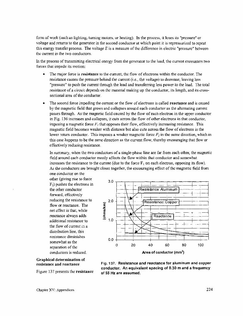
form of work (such as lighting, turning motors, or heating). In the process, it loses its "pressure" orvoltage and returns to the generator in the second conductor at which point it is repressurized to repeatthis energy transfer process. The voltage E is a measure of the difference in electric "pressure" betweenthe current in the two conductors.
In the process of transmitting electrical energy from the generator to the load, the current encounters twoforces that impede its motion:
* The major force is resistance to the current, the flow of electrons within the conductor. Theresistance causes the pressure behind the current (i.e., the voltage) to decrease, leaving less"pressure" to push the current through the load and transferring less power to the load. The totalresistance of a circuit depends on the material making up the conductor, its length, and its cross-sectional area of the conductor.
* The second force impeding the current or the flow of electrons is called reactance and is causedby the magnetic field that grows and collapses around each conductor as the alternating currentpasses through. As the magnetic field caused by the flow of each electron in the upper conductorin Fig. 136 increases and collapses, it cuts across the flow of other electrons in that conductor,imposing a magnetic force F, that opposes their flow, effectively increasing resistance. Thismagnetic field becomes weaker with distance but also cuts across the flow of electrons in thelower return conductor. This imposes a weaker magnetic force F2 in the same direction, which inthis case happens to be the same direction as the current flow, thereby encouraging that flow oreffectively reducing resistance.
In surnmary, when the two conductors of a single-phase line are far from each other, the magneticfield around each conductor mostly affects the flow within that conductor and somewhatincreases the resistance to the current (due to the force F, on each electron, opposing its flow).As the conductors are brought closer together, the encouraging effect of the magnetic field fromone conductor on theother (giving rise to force 3.0F2 ) pushes the electrons inthe other conductor Resistance: Alum inumforward, effectively 7 1 _reducing the resistance to 2.0 Resistance: Copperflow or reactance. The E = _
net effect is that, whilereactance always adds Reactan - l _
additional resistance to 1.0 _the flow of current in a ___ __I
distribution line, this ==re resistance diminishes 0.0 - T lsomewhat as the
separation of the 0 20 40 60 80 100separation of theconductors is reduced. Area of conductor (mm2)
Graphical determination ofresistance and reactance Fig. 137. Resistance and reactance for aluminum and copper
conductor. An equivalent spacing of 0.30 m and a frequencyFigure 137 presents the resistance of 55 Hz are assumed.
Chapter XV: Appendices 224

and reactance of conductor commonly used ondistribution lines as a function of its cross-sectional E 0.10 l
area. Note that reactance is a function of the geometry E
of the conductor and not of the material of which is it , 0
constructed. '0 oo
A conductor's reactance is one factor used in*m -0.05 ____
determining its voltage drop in a given situation. But -_for conductor sizes commonly used as distributionlines within a mini-grid, reactance usually plays a 0.10 0.30 0.50 0.70 0.90
minimal role because, as can be observed fromFig. 137, resistance is usually considerably larger.
Therefore, while the precise value of reactance Fig. 138. This indicates the additional
depends on both system frequency and equivalent reactance to that listed in Fig. 137
spacing, any figures more precise than those resulting from changes in the equivalent
obtainable from the graph are unnecessary for small spacing of the conductors.conductor because this factor contributes little tovoltage drop.
However, if large conductor is necessary, a more precise value for reactance may be necessary and can be
obtained as follows:
* To determine the reactance for another conductor spacing, the value for the "equivalent spacing"
must first be determined. For a single-phase line, the equivalent spacing is simply equal to the
physical spacing between the two conductors. The equivalent spacing for a three-phase line isexplained later in Eqn. (3). The corresponding reactance that must be added to or subtracted from
the reactance found in the graph in Fig. 137 can be determined from Fig. 138.
* To determine the reactance for another frequency, take the value of reactance obtain above and
add or subtract 10 % depending on whether the supply frequency is 60 or 50 Hz, respectively.
For example, assume that the reactance of a single-phase line of 80-mm2 copper or aluminum conductor,
a spacing of 0.20 m, and operating at 50 Hz is required. To take into consideration the smaller equivalent
spacing, begin with the 0.30 ohms/km associated with this size conductor with a spacing of 0.30 m (from
Fig. 137) and add a negative 0.04 (from Fig. 138) associated with the smaller equivalent spacing. This
leads to a reactance to 0.26 ohm for each kilometer of conductor. To take into account the reduced
frequency of 50 Hz, 10 % of this value or about 0.03 ohms/km is then subtracted from the value just
obtained, which leads of a final reactance of 0.23 ohms/km.
The graphs and example illustrate how placing the two conductors closer together than 0.30 m effectivelyreduces the reactance (as previously explained) by adding a negative number to the value found in
Fig. 137 for a spacing less than 0.30 m. Aerial bundled cable, where insulated conductors are closelywrapped around each other, presents less reactance because the size of the magnetic forces from the first
conductor encouraging the flow in the second approaches the size of the magnetic forces opposing the
flow of current in the first conductor.
Calculation of resistance and reactance by equations
The unit resistance (ohm/km) of a conductor depends on (1) the material used and (2) its cross-sectional
area.
Chapter XV: Appendices 225

The usual materials used are either copper or aluminum. Occasionally, steel conductors are used. Ofthese, copper has the least resistance. The resistance of aluminum is 1.6 times that of copper and steel is10 times that of copper.
The equation for the resistance of a conductor is the following:
r 18 ohm/km (1)
where
A = cross-sectional area of the conductor (mm2 )
k = 1.0 for copper1.6 for aluminum10. for steel
For ACSR, the cross-sectional area of the conductor is the total cross-sectional area of the aluminumwires making up the ACSR. When calculating resistance, the steel core is assumed not to conduct.
Line reactance does not depend on the material used for the conductor. Rather, it depends on
geometrical considerations-the size of the conductor and the equivalent spacing between conductors-aswell as the frequency of the supply. The equation for the reactance of a conductor is
x=27tf 19+461og,o( )]10 5 ohm/km (2)
where
f = line frequency, usually 50 or 60 Hzs = equivalent spacing of conductors in meters (see below)
d = overall physical diameter of the conductor (meters) = 4A 10-3
Note that if stranded conductor or cable is used, the overall physical diameter of the conductor is largerthan the diameter associated with the actual cross-sectional area A of the metal making up the aconductor. The overall physical diameter of the cable also includes voids between the strands making upthe conductor.
For a single-phase configuration, the equivalent spacing is equal to the distance between phaseconductors. For a three-phase configuration, the equivalent spacing is
s = 3 sI *S 3 m (3)
where SI, s2, and S3 are the distances (in meters) between the first and second, second and third, and thirdand first conductors.
Example for calculating r and x
A single-phase line of AWG #4 (21 MM2) copper conductor supplied by a 60 Hz generator is being
considered. This seven-strand conductor has an overall diameter of 0.0060 m, the conductor spacing is0.30 m, and the area of the conductor is A = 21 mm2. Therefore, from Eqn. (1):
Chapter XV: Appendices 226

__ (18.4)(1.O)=0.88ohm/km
21
and from Eqn. (2):
x=2-3.14.601 19+46 0.gl, 030 lo-
*L +41g 0 C0.00609]=380(19+ 77) 10-5
= 0.37 ohm/km
Note that if the overall physical diameter of the conductor isunknown, it can also be estimated if the number of strandsand area of the conductor are known. For example, because fthe area of the conductor in this case is about 21 mm2, each 3m 2
of the seven strands has an area of 3.0 mm2. Because A = 3 m7id2/4, each strand must therefore have a diameter of about d
2.0 mm or 0.0020 m. As can be seen from Fig. 139 for thecase of a cable with 7 strands, the overall diameter of theconductor is equal to three times the diameter of a singlestrand or about 0.0060 m.
Power and power factor Fig. 139. Cross-sectional view of aseven-strand conductor.
In addition to depending on the resistance and reactance ofthe conductor used, voltage drop and power loss also dependon the magnitude of the current transmitted by the conductor. This latter is determined by the power Pconsumed by the load, its power factor (cos 0), and the operating voltage. (The power factor can be
interpreted as a measure of the efficiency with which the current is used by the load. It is a characteristic
of the load itself.)
The relationship between these two parameters and both the current I through the load and the voltage E
across the load is given by the following:
P(kW) = cos F x P(kVA) = cos f x E(V) x I(A) x I0-3 (4)
For example, if 230 V is placed across a fluorescent lamp with a nameplate rating of 0.17 A and a power
factor of 0.6, then the power it consumes is
P(kW)=cos4 xE(V)xI(A)x10- 3 =0.6x230Vx0.17Ax10- 3 =0.023kW=23W
Or if the same voltage is placed across a resistive load (i.e., with a power factor = 1.0), such as a light
bulb, which consumes the same power, the current required by the bulb will be
Chapter XV: Appendices 227

P(kW)x103 0.023kWx103 =0.10Acos xE(V) 1.0 x230V
Voltage drop/power loss along a line
This section presents equations forvoltage drop and power loss along a calculated dropdistribution line. For the sake ofsimplicity, these equations are initially I r L cos x I x L sin 0derived for the case of a single-phase, actualtwo-wire line. It first calculates the error dropvoltage drop and power loss for a singleload located at the end of the line andthen for the case where the load is evenly Edistributed along a line. This section I Ix Lconcludes with slightly modified IrLversions of these equations which can beapplieds to these bquala n slitphas cand Fig. 140. Vector relationship between voltage, voltage
idrops, and current in a single line. (Es = supply voltage,three-phase configurations. The results E = voltage across load)are summarized in Table 8, p. 75).
For a general case, it is assumed that,because of the nature of the load, the current in a section of line is out of phase with the supply voltage byan angle of 4 (Fig. 140). While no simple forn of an equation for the precise value of the actual voltagedrop (VD,, volts) along this single line is possible, it can be estimated as the value of the "calculateddrop" in Fig. 140:
VD1 I (rcos4)+xsin4)L (5)
where
I = current in the line (amperes)r = line resistance (ohms/kin)x = line reactance (ohms/kmn)L = length of the line (km)
cos 0 = power factor at the beginning of the line power factor at the load
The percent voltage drop at the load is
VD VzD%VDz100 VD 100 V (6)
Es E
because, for the typical situation where the voltage drop must be low, Es5 Z E.'The power loss is more straightforward to calculate. The loss along a single line is simply
P1(fkW) = 12 r L 10-3 (7)
The factor of 1 00 is included to convert the ratio to a percent. Note that if a computerized spreadsheet program isused, it can be set to automatically display the voltage drop ratio as a percent; in this case, no additional factor of100 is required.
Chapter XV: Appendices 228

Single-phase, two-wire configuration
Calculations for load concentrated at end of line
Once the supply voltage E (in volts), conductor resistance r and reactance x (both in ohms/km), line
length L (in kilometers), and power consumption P and power factor cos 4 of a single load located at the
end of a single-line have been determined, the line current can be calculated from Eqn. (4) as follows:
I= P(kVA) 103 = P(kW) *103 (8)E E cos4
Substituting this into Eqn. (5), the voltage drop VD along two lengths of line (i.e., to the load and back)becomes
VD,2L(rcos +xsin ¢)I=2L(rcos +xsin)x P(kW) 13 volts (9)E cos
The percent voltage drop becomes
~~~~~~ ~~~~~P(W) ~(0%VD z200 L(r cos0+ x sin E2 L (r cos~+ x sin+) x lo,10 % (1 0)E E 2 COS
The power loss along the two length of line becomes
I(kW)=2Lr12 10-3 =2LrP(kW)) 2 1 3 (10)PI (M)= 2 L =2Lr E cos (l1
For example, if a 21 mm2 single-phase, 240-V ACSR line with a spacing of 0.50 m is used to bring power
500 m from the power house to a load of 3 kW with a power factor of 0.95, what is the percent voltagedrop and power loss along that line?
cos= 0.95
= 180
sin 4=0.31
r = 1.39 ohm/km
x = 0.44 + 0.05 = 0.49 ohm/km
3,000W W 137A(230 V) (0.95)
VD =(2)(0.50km)[(1.39)(0.95)+ (0.49)(0.31)]ohm/km (13.7 A)= 20 V
P, =(2)(0.50km)(1.39ohm/km)(13.7 A)2 =260W
Chapter XV: Appendices 229
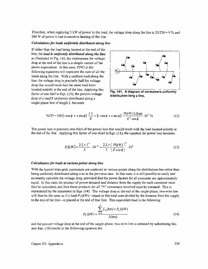
Therefore, when supplying 3 kW of power to the load, the voltage drop along the line is 20/230 = 9 % and
260 W of power is lost in resistive heating of the line.
Calculations for loads uniformly distributed along line
If rather than the load being located at the end of theline, the load is uniformly distributed along the lineas illustrated in Fig. 141, the expressions for voltage
drop at the end of the line is a simple variant of theabove expressions. In this case, P(W) in thefollowing equations will represent the sum of all the /\J
loads along the line. With a uniform load along theline, the voltage drop is precisely half the voltagedrop that would result had the same load been n
located entirely at the end of the line. Applying this Fig. 141. A diagram of consumers uniformly
factor of one-half to Eqn. (10), the percent voltage distribution long a line.drop of a load P uniformly distributed along a
single-phase line of length L becomes
~~~~~ ~~ILP(kW) L(km). 0 %(2%VD = 10(r cos0+ x sin0) -= (r cos + x sin 0) (lo ) )10% (12)E E 2 COS
The power loss is precisely one-third of the power loss that would result with the load located entirely atthe end of the line. Applying this factor of one-third to Eqn. (1 1), the equation for power loss becomes
2Lr I 2 2 2Lr P(kW) 2(3
PI (kW) o10 3= .03 (13)3 3 Eo)
Calculations for loads at various points along line
With the typical mini-grid, consumers are scattered at various points along the distribution line rather than
being uniformly distributed along it as in the previous case. In this case, it is still possible to easily and
accurately calculate the voltage drop, provided that the power factors for all consumer are approxirnately
equal. In this case, the product of power demand and distance from the supply for each consumer must
first be calculated, and then these products for all "N" consumers involved must be summed. This is
represented by the numerator in Eqn. (14). The voltage drop at the end of the single-phase, two-wire line
will then be the same as if a load Pr(kW)-equal to this total sum divided by the distance from the supply
to the end of the line-is placed at the end of that line. This equivalent load is the following:
N
EL.n(km) x Pn (kW)
PT (kW) L= n=) (14)
and the percent voltage drop at the end of the single-phase, two-wire line is obtained by substituting this
into Eqn. (10) results in the following equation for:
Chapter XV: Appendices 230

N
I Ln (km) x Pn (kW)%VD z 2(rcosO+xsinO) " E 2 cos o % (15)
An example of the application of these equations is found in Chapter VII (p. 71).
General solution
Since the power consumed by any load is equal to the product of the voltage across that load, the currentthrough the load, and its power factor, the current for each of the basic line configurations is as shown inFig. 142. It is obtained by solving the first equation for each configuration for the current, I. The percentvoltage drop affecting each load is also indicated in Fig. 142 as a function of the voltage drop along asingle length of line, VD,. The value of the latter is found in Eqn. (5). Note that the actual voltage dropexperienced by the load in the single-phase, two-wire configuration is twice the value of VD, because thevoltage drop occurs along two lengths of line. For a split-phase configuration, the voltage drop occursonly in one conductor, as the currents cancel out in the return conductor is the loads are balanced. Thevoltage drop experienced by the load on each phase of the three-phase, delta configuration is J timesthe value of VD because the voltage drop occurs along two lengths of line but these drops are out ofphase. And the voltage drop experienced by each load in the wye configuration occurs in only oneconductor, for the same reason as for the split-phase configuration. Substituting the values of all thevariables will lead to the equations for percent voltage drop found in Table 8.
The total loss of power along the circuit is obtained by substituting the value for current for theconfiguration under consideration (Fig. 142) and multiplying the resultant by the number of phaseconductors carrying the current (2 for either single-phase configuration or 3 for either three-phaseconfiguration). This leads to the power loss equations found in Table 8. Note that for a balanced circuit,which is assumed here, the current in the neutral is zero and therefore contributes nothing to the total loss.
Chapter XV: Appendices 231

(a) (b)
E -- E I= O
P I 4---I--p~~~~~~~~
P12
Power consumed by p 3each single-phase load: P = E I cos -10- 2
Current in phase line: = P 3 PEcos ) 2Ecos4
Percent voltagedrop at each load: 2 VD, 100/E YD, 100/E
(c) (d) r P/3
E E
P/3~ ~~ 1=0
Power consumed by P= E-I COS_10-3 - = E I cos4) 10-each single-phase load: 3 S1 3
Current in phase line: P 103 I = E c 103
T= E cos 43E cos
Percent voltage O VD, 100/Edrop at each load: VD, IOOIE
Fig. 142. Line current for different configurations, each serving a total load of P (kW). Balancedloads are assumed in all cases. The value of VD, is found in Eqn. (5).
Chapter XV: Appendices 232

Appendix 7: Computational examplesBy means of examples, this appendix illustrates how conductor size is determined in several situations.At the same time, these examples will also illustrate (1) the impact of power factor on the size and cost ofthe conductor, (2) the impact of system configuration and conductor options on the cost of lineconstruction, and (3) the relative accuracy of several approaches to estimating conductor size,respectively.
(1) Impact of power factor on system cost
In the first phase of electrification, lighting is the most popular end-use. And while incandescent bulbsare still popular in many parts of the world because of their low cost, many are now aware that fluorescentlighting is more efficient, that is, that it produces considerably more lighting than can be achieved withincandescent lamps for the same amount of power consumed. But even with the use of fluorescentlighting, not all are aware that fluorescent units commonly available in many countries are not power-factor corrected; neither are they aware of the implication this has on system cost. While lack of power-factor correction does not directly affect the amount of light available, this does have two implicationswhich lead to increased cost:
T The conductor needed to serve the load may be larger than would otherwise be necessary.
* Increased generation capacity will also be required (even though the same power is consumed).
For this example, assume that a three-phase generatorsupplying 230 V at 50 Hz is located in the middle of thevillage and that a single-phase, 1.0 km-long, single-phase, two-wire aluminum line serves similar lighting 1.0 km >
needs of each of three sectors in the village (Fig. 143).Assume that each sector has a load of 60 homes with theequivalent of 40 watts of fluorescent lighting in each,that this load is evenly distributed alone the line, andthat the voltage drop should not to exceed 6 % at the endof the line. main distribution line
with loading of 9.0 kW kmIn each home, this same amount of lighting can be metby either of the following: Fig 143. One of three portions of a village
* Two 75 W bulbs for which conductor and generator sizeare to be calculated.
* Two 20-W fluorescent lamps without power-factor correction (with a power factor of 0.6), with each consumer requiring 45 W (whichincludes 5 W to account for losses in the ballast)
* Two 20-W fluorescent lamps with the power-factor corrected to 1.0, also requiring 45 W.
For each of these cases, the conductor size that will be required to ensure that the percent voltage dropdoes not exceed 6 % and the generator capacity required to serve this load will be derived below.
Chapter XV: Appendices 233

Incandescent lighting
Conductor requirements
In this case, each main ACSR distribution line will need to be sized to serve a total load of 60 x 150W or9.0 kW uniformly distributed along the line. Using the appropriate graph in Box 5, with k = 4.5 kW-km,an aluminum conductor of 80 mm2 would be required to keep the voltage drop to within about 6 %.
Generator requirements
Each phase of the three-phase generator must serve a 9 kW resistive load. A total generating capacity of27 kW (at a power factor of 1.0) or 27 kVA would be required.
Fluorescent lighting without power-factor correction
Conductor requirements
In this case, each distribution line will need to be sized to serve a total load of 60 x 45 W or 2.7 kWuniformly distributed along the line. Using the appropriate graph in Box 5, with k = 1.4 kW-km and apower factor of 0.6, an aluminum conductor of 40 mm2 would be required to keep the voltage drop towithin 6 %.
Generator requirements
Each phase of the three-phase generator must serve a 2.7 kW load with a power factor of 0.6. A totalgenerating capacity of P(kVA) = P(kW)/cos 4 = 8.1/0.6 or 14 kVA will be required. Fluorescent lightingmakes more efficient use of the current generated and, therefore, less current and reduced generatingcapacity are required.
Fluorescent lighting with power-factor correction
Conductor requirements
In this case, each line will again need to be sized to serve a total load of 60 x 45 W or 2.7 kW uniformlydistributed along the line. Using the appropriate graph in Box 5, with k = 1.4 kW-km and a power factorwhich has been corrected to 1.0, an aluminum conductor of 25 mn2 would be required to keep the voltagedrop to within 6 %.
Generator requirements
Each phase of the three-phase generator must again serve a load of 2.7 kW but with a power factor of 1.0.A total generating capacity of P(kVA) = P(kW)lcos 0 = 8.1/1.0 or about 8.0 kVA will now be required.This further decrease in the capacity of the generator is due to the fact that, by adding power-factorcorrection, still more efficient use is being made of the current and, therefore, even less current is requiredof the generator. Therefore, the wire in the generator windings can be reduced in size, resulting in a lessexpensive generator.
Conclusions
The conclusions of the previous calculations are summarized in Table 27. As can be seen, replacingincandescent lighting with fluorescent lighting results in cost savings in both conductor and generatorcapacity but the full extent of the savings is not evident until power-factor correction is incorporated inthe fluorescent lighting units. In using fluorescent lighting with power-factor correction, conductorrequired is only about one-third the size (and cost) of the conductor that would have been used to supplyincandescent lighting.
Chapter XV: Appendices 234
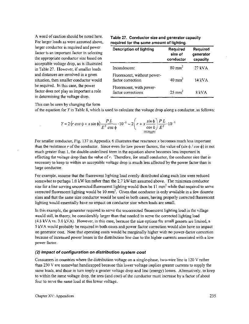
A word of caution should be noted here. Table 27. Conductor size and generator capacityFor larger loads as were assumed above, required for the same amount of lighting.larger conductor is required and power Description of lighting Required Requiredfactor is an important factor in selecting size of generatorthe appropriate conductor size based on conductor capacityacceptable voltage drop, as is illustratedin Table 27. However, if smaller loads Incandescent 80 mm2 27 kVAand distances are involved in a given Fluorescent, without power-situation, then smaller conductor would factor correction 40 mm2 14 kVAbe required. In this case, the power Fluorescent, with power-factor does not play as important a role factor corrections 25 mm2 8 kVAin determining the voltage drop.
This can be seen by changing the formof the equation for Y in Table 8, which is used to calculate the voltage drop along a conductor, as follows:
Y=2(rcos4)+xsind?) P 10-5 =2r+x sin) P L0-E2 COS Q COS f E 2
For smaller conductor, Fig. 137 in Appendix 6 illustrates that reactance x becomes much less importantthan the resistance r of the conductor. Since even for low power factors, the value of (sin 4 1 cos )) is notmuch greater than 1, the double-underlined term in the equation above becomes less important inaffecting the voltage drop than the value of r. Therefore, for small conductor, the conductor size that isnecessary to keep to within an acceptable voltage drop is much less affected by the power factor than islarge conductor.
For example, assume that the fluorescent lighting load evenly distributed along each line were reducedsomewhat to perhaps 1.0 kW km rather than the 2.7 kW km assumed above. The minimum conductorsize for a line serving uncorrected fluorescent lighting would then be 11 mm2 while that required to servecorrected fluorescent lighting would be 10 mm2. Given that conductor is only available in a few discretesizes and that the same size conductor would be used in both cases, having properly corrected fluorescentlighting would essentially have no impact on conductor size when loads are small.
In this example, the generator required to serve the uncorrected fluorescent lighting load in the villagewould still, in theory, be considerably larger than that needed to serve the corrected lighting load(4.8 kVA vs. 3.0 kVA). However, in this case, because the size options for small gensets are limited, a5 kVA would probably be required in both cases and power factor correction would also have no impacton generator cost. Note that operating costs would be marginally higher with no power-factor correctionbecause of increased power losses in the distribution line due to the higher currents associated with a lowpower factor.
(2) Impact of configuration on distribution system cost
Consumers in countries where the distribution voltage on a single-phase, two-wire line is 120 V ratherthan 230 V are somewhat handicapped because this lower voltage implies greater currents to supply thesame loads, and these in turn imply a greater voltage drop and line (energy) losses. Altematively, to keepto within the same voltage drop, the area (and cost) of the conductor must increase by a factor of aboutfour to serve the same load at this lower voltage.
Chapter XV: Appendices 235
However, by reverting to a different configuration, it may be possible to reduce costs. The followingexample first calculates the installed line cost for supplying a specific load with a single-phase, two-wireconfiguration. It then illustrates the impact on cost of using a single-phase, three-wire configuration toserve the same load and then of using a three-phase, four-wire configuration.
For this example, it is assumed that a single-phase generator is available in the village and that, by properconnections to the generator terminals, either 120 V, 120-0-120 V, or 208/120 V at 60 Hz can begenerated. The generator is at the end of a 1.4 km ACSR distribution line which serves 40 consumersevenly distributed along that line. Each consumer has a 20-W fluorescent lamp, with the power factorcorrected to 1.0, that consumes a total of 25 W.
To determine the approximate conductor size that will be required so that the voltage drop does notexceed the desired maximum set at 6 %, the graphs in Box 5 (p. 77) will again be used. However, sincethe nominal voltage used by the consumer is other than 230 V, the value of k described in that box mustbe modified as explained therein. Alternatively, the equations in Table 8 can be used.
Note that Box 5 assumes an operating frequency of 50 Hz while, in this case, the frequency is 60 Hz. Intheory, the graphs in Box 5 have not been prepared for this frequency and one should rely on the forrnulasin Table 8 since the reactance of the conductor depends on the frequency of the supply (see Eqn. (2) inAppendix 6). However, because in this case the power factor, cos 4, is 1.0, then sin 4 = 0 and it can beseen from the equations in Table 8 that the value of Y (and therefore the percent voltage drop) does notdepend of the reactance of the conductor. For the same reason, equivalent spacing of the conductor,which also affects reactance, has no impact in this case. Therefore, the graphs in Box 5 can be used. Fornon-unity power factors, the original equations in Table 8 would have to be used if more accurate resultsare required.
Two-wire configuration
For this example, a total load of 1.0 kW (with cos 4 = 1.0) uniformly distributed over a line 1.4 km longis to be supplied. As explained in Box 5, the value of k, modified for a voltage of 120 V, is as follows:
k=(1.0 kW)(1. 4 km) (230) =2.6kWkm2 120
From the first graph, the distribution line would require two lengths of 48 mm2 aluminum conductor orAWG 1/0 to handle the expected current without exceeding a 6 % voltage drop.
Three-wire configuration
As explained in Box 5, for this case, the value of k for a perfectly balanced system, modified for a voltageof 120 V, is as follows:
k (1.0 kW)(1.4 km) ( 1)(230 )2 065 kWI
2 4 120
In this case, an aluminum conductor of about 12 mm2 or AWG #6 would be necessary. Therefore,although this distribution line would now require three lengths of conductor, a considerably smallerconductor would be required. Note that this value is only correct if the loads along the line are perfectlybalanced. In reality, this is difficult to ensure. If we assume a 50 % load unbalance, the above value of kmust be multiplied by a factor of 1.8 as indicated in the last column in Table 8. For the new value of k =1.2, the distribution line would require a 23 mm2, which is close to a larger, AWG #4 conductor.
Chapter XV: Appendices 236

Three-phase, four wire configuration
Assuming the realistic case where the circuit has a 50 % load unbalanced, Box 5 indicates that the valueof k is as follows:
k = (I-0 W)1.4km (1 ( 230) = 0.65 kW km2 4 120
In this case, AWG #6 would be necessary. Compared to the unbalanced single-phase, three-wireconfiguration above, this configuration requires four length of smaller conductor.
Costs
A comparative costing of these four configurations will be calculated using costs from El Salvador. Toillustrate the impact of conductor type on cost, two conductor options will also be considered. The first isthe use of uninsulated ACSR conductor and the second is the use of multiplex as explained in Box 4. Thecosts assumed for this costing are indicated in Table 28.
Table 28. Recent small-quantity costs for quality materials and labor in El Salvador, includingduties, taxes, warehousing, and delivery. Costs are in U.S. dollars and totals are expressed totwo significant figures.
Conductor costlm Poletop hardware cost/pole
Conductor Materials Labor Total Materials Labor Total
#1/0 ACSR (2-wire) 1.84 .56 2.40 22.84 20.64 43
#4 ACSR (3-wire) 1.05 .72 1.80 31.26 30.96 62
#6 ACSR (3-wire) .90 .33 1.20 31.26 30.96 62
#6 ACSR (4-wire) 1.20 .44 1.60 41.68 41.28 83
#1/0 duplex 2.24 .30 2.50 10.60 10. 32 21
#4 triplex 2.30 .15 2.40 10.20 9.50 20
#6 triplex 1.21 .12 1.30 9.80 9.30 19
#6 quadruplex 1.70 .12 1.80 9.80 9.30 19
Table 29 summarizes the component costs for a single 30-m span (conductor plus poletop hardware at thepole at the end of that span) for the four configurations being considered in the example.
Conclusions
Several conclusions can be drawn from Table 29:
* Labor costs can be a significant portion of line construction cost, especially for bare ACSR lineswhich are much more labor intensive then multiplex lines (bare ACSR requires that each line tobe strung separately whereas one conductor is strung if bundled cable is used). The costs inTable 28 are for electric-utility-implemented installations. In cases where labor costs of lower or
Chapter XV: Appendices 237

Table 29. Breakdown of the costing per 30-m span for all the options being considered forsupplying the village load. For two cases indicated, a 50 % load unbalance is assumed.
Bare ACSR Multiplex
Configuration Materials Labor Total Materials Labor Total
Two-wi re (#1/0) $78 $37 $115 $78 $19 $97
Three-wire (#4)(unbalanced) $62 $53 $115 $79 $14 $93
Three-wire (#6)(balanced) $58 $41 $99 $46 $13 $59
Four-wire (#6)(unbalanced) $78 $54 $132 $61 $13 $74
where a more rudimentary village design which require less labor are utilized, labor cost can bereduced significantly.
* Independent of the configuration, the multiplex (or ABC) option can be considerably cheaper,primarily because of the fact that less labor is required for its installation.
* The single-phase, three-wire configuration is the least costly if balanced loads are considered.However, as noted, this is difficult to ensure. With a more realistic unbalance of 50 %, the least-cost configuration depends on the conductor option. The three-phase, four-wire configuration isthe least costly (at $74 per span) when multiplex conductor is used while either of the single-phase configurations is the least costly (at $1 15 per span) when bare ACSR is used.
* Three-phase distribution is, in theory, more efficient than single-phase distribution. However,this example illustrates that, in this case, the cost for a three-phase line is greater than even asingle-phase, two-wire line.
(3) Sizing a distribution line for motor starting
It is assumed that a 15 kW diesel genset is located on one side of a village and that one load beingsupplied is a 2 hp motor to run a rice huller that must be located 1400 m away. To facilitate motorstarting and minimize conductor size, a 220/380 V, three-phase, four-wire line will be used to supply themotor. The motor efficiency is 80 %, its power factor is 85 % during normal operation and 60 % duringstart-up, and the current draw is 6 times the normal operating current during start-up. Is the generator ofadequate capacity to start the motor? And if it is, is a 10 mm2 copper conductor of adequate size to ensurethat the voltage drop along the line to the motor during its start-up does not exceed about 20 %?
The maximum horsepower capacity of a three-phase motor driven by a three-phase synchronousgenerator is about 15 % of the generator's kilowatt rating. This generator should be able to start a motorwith a capacity of up to about 2.2 hp and should therefore be adequate to start the proposed motor.
To determine whether the proposed conductor is of adequate size, the voltage drop must be calculated.But this requires that the current needed by the motor first be calculated. From the equation on p. 39), thepower input to the motor necessary to drive the rice huller during normal operation is as follows:
Chapter XV: Appendices 238

(2.0 hp) 750-)jp= ~~hp)=.2V
p (0.80)(0.85) 2.2 kVA
and then, from Fig. 142d, the line current during this time would be
2200 VA3 (220 V)
The start-up current will attain six times this value or 20 A at the power factor of 0.60 noted earlier.
To determine the percent voltage drop under these conditions, the values of resistance and reactance of
the conductor must first be found. From Fig. 137, for a 10 mm2 copper conductor, this can be found to be
r = 1.8 ohms/km and x = 0.4 ohms/km. Inserting these values into the equation for voltage drop in
Fig. 142d and Eqn. (5) referred to in that figure, the percent voltage drop is the following:
100 100%VD= VD,-= I (r cosb + x sin c;)E
E E
m20 [(1.8)(1.4)(0.6)+ (0.4)(1.4)(0.8)] 1 2° = 18220
The resulting voltage drop of 18 % during motor start-up falls within the acceptable range. Note that this
assumes that the only load on the distribution line is the motor. If the possibility exists that lighting or
other loads may be connected to that line during motor start-up, either before or after the location of themotor along the distribution line, these currents must also be included in the above calculations because
they also would contribute to the voltage drop along the line.
After start-up, when the power factor increases to 0.85 and the current demand reduces to 3.3 A, the
percent voltage drop due to the normal operation of the motor will reduce to the following expression:
10010%VD= VD, E = I (r cos; + x sin4) E
E E
=3.3 [(1.8)(1 .4)(.85)+ (0.4)(1 .4)(0.50)] 2°0 = 3.6220
A 3.6 % voltage drop is acceptable at the motor location. However, as noted above, other loads along the
distribution line will increase voltage drop along that line and calculations for the voltage drop at the
motor location (or at the end of the line) must also consider and include other loads that may be on at the
same time.
(4) Impact of approach to conductor sizing on accuracy
The conductor size for a single-phase line serving a total load of 4.4 kW distributed as shown in Fig. 144
is to be determined. Assume an average power factor of 0.9, a supply voltage of 230 V, and a maximum
acceptable voltage drop of about 6 %. It is assumed that ACSR conductor is available in the followingsizes: 10, 25, 35, 50, 70, and 100 mm2. The graphs in Box 5 will be used for the initial sizing of the
conductor. Longer computational methods will then be used to illustrate that these more time-consumingapproaches may yield more precise results but that quick estimates are often more than sufficient for the
purpose of selecting conductor size.
Chapter XV: Appendices 239

distribution linewith 25-m span
226t service drop27\- ~~~~~~~Key:
o 50W
* 100W
/ *~~~~~~ 200 Wbranch circuit n a W
Fig. 144. A map showing the location of consumer loads along the distribution line to be sized,together with their maximum coincident demand.
To reduce project cost, the same size conductor is typically used for the entire network. The use of asingle size usually permits a lower unit cost through quantity purchases and minimizes the range of sizes,and costs, for items such as connectors, preformed deadends, and tooling dies (for crimping connectors)required for line installation. For the initial costing, it is assumed that a single-size conductor is used. Ifit is felt that conductor of this size is too large for use in branch circuits, it is always possible to determinethe size of these circuits separately and then to cost them to decide if branch circuits of smaller size aremore cost-effective.
Since the maximum voltage drop occurs at the end of the line with the largest combination of loading andlength, the line stretching from the supply all the way to the right in Fig. 144 will be the main line that isto be sized. For this sizing, the peak coincident load of 0.90 kW served by the branch circuit headingdownward will simply be considered as an additional load to the 50 W consumer load which is also.connected to the pole (no. 1 0) where the lines join.
The easiest cases to analyze are those where the entire load is either concentrated at the end of the line oruniformly distributed along the line. While either of these cases rarely reflects reality, the results obtainedstill give a rough estimate of conductor size.
* If the entire load were concentrated at the end of the line, this would result in the maximumvoltage drop. While this is not the case here, it does set the upper limit on the size of theconductor. In this case, k (as defined in Box 5) would equal (4.4)(.60) or 2.6 kW-km. From thefirst two graphs in Box 5, a 50 rmm2 aluminum conductor would be required if the power factorwere 1.0 and 75 mm2 if it were 0.8. For a power factor of 0.9, an estimate for the conductorwhich would be required would be 60 mm2 . Given available sizes noted previously, a 70 mm2
aluminum conductor would be required.
Chapter XV: Appendices 240
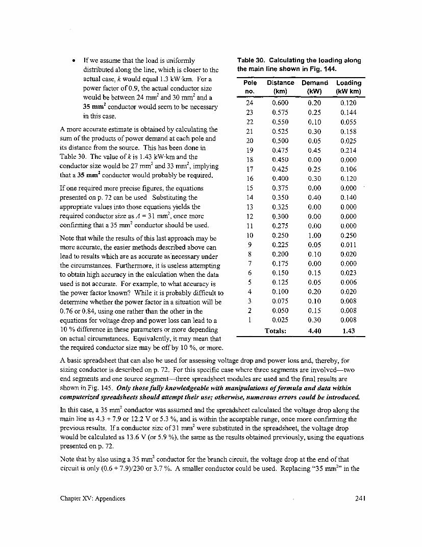
* If we assume that the load is uniformly Table 30. Calculating the loading along
distributed along the line, which is closer to the the main line shown in Fig. 144.
actual case, k would equal 1.3 kW-km. For a Pole Distance Demand Loading
power factor of 0.9, the actual conductor size no. (km) (kW) (kW km)
would be between 24 mm and 30 mm2 and a35 mm' conductor would seem to be necessary 23 0.675 0.20 0.144
in this case. ~~23 0.575 0.25 0.144in this case.
22 0.550 0.10 0.055A more accurate estimate is obtained by calculating the 21 0.525 0.30 0.158
sum of the products of power demand at each pole and 20 0.500 0.05 0.025
its distance from the source. This has been done in 19 0.475 0.45 0.214
Table 30. The value of k is 1.43 kW-km and the 18 0.450 0.00 0.000
conductor size would be 27 mm2 and 33 nim2, implying 17 0.425 0.25 0.106
that a 35 mm' conductor would probably be required. 16 0.400 0.30 0.120
If one required more precise figures, the equations 15 0.375 0.00 0.000
presented on p. 72 can be used Substituting the 14 0.350 0.40 0.140
appropriate values into those equations yields the 13 0.325 0.00 0.000
required conductor size as A = 31 mm2, once more 12 0.300 0.00 0.000
confirming that a 35 mm2 conductor should be used. 11 0.275 0.00 0.000
Note that while the results of this last approach may be 10 0.250 1.00 0.250
more accurate, the easier methods described above can 9 0.225 0.05 0.011
lead to results which are as accurate as necessary under 8 0.200 0.10 0.020
the circumstances. Furthermore, it is useless attempting 7 0.175 0.00 0.000
to obtain high accuracy in the calculation when the data 6 0.150 0.15 0.023
used is not accurate. For example, to what accuracy is 5 0.125 0.05 0.006
the power factor known? While it is probably difficult to 4 0.100 0.20 0.020
determine whether the power factor in a situation will be 3 0.075 0.10 0.008
0.76 or 0.84, using one rather than the other in the 2 0.050 0.15 0.008
equations for voltage drop and power loss can lead to a 1 0.025 0.30 0.008
10 % difference in these parameters or more depending Totals: 4.40 1.43
on actual circumstances. Equivalently, it may mean thatthe required conductor size may be off by 10 %, or more.
A basic spreadsheet that can also be used for assessing voltage drop and power loss and, thereby, for
sizing conductor is described on p. 72. For this specific case where three segments are involved-two
end segments and one source segment-three spreadsheet modules are used and the final results are
shown in Fig. 145. Only those fully knowledgeable with manipulations offormula and data within
computerized spreadsheets should attempt their use; otherwise, numerous errors could be introduced.
In this case, a 35 mm2 conductor was assumed and the spreadsheet calculated the voltage drop along the
main line as 4.3 + 7.9 or 12.2 V or 5.3 %, and is within the acceptable range, once more confirming the
previous results. If a conductor size of 31 mm2 were substituted in the spreadsheet, the voltage drop
would be calculated as 13.6 V (or 5.9 %), the same as the results obtained previously, using the equations
presented on p. 72.
Note that by also using a 35 mm2 conductor for the branch circuit, the voltage drop at the end of that
circuit is only (0.6 + 7.9)/230 or 3.7 %. A smaller conductor could be used. Replacing "35 mm2'" in the
Chapter XV: Appendices 241

module for the branch circuit with smaller values, one could go down to using a 4 mm2 aluminumconductor for that circuit before the voltage drop between the source and end of the branch circuit attainsthe 6 % limit. Therefore, rather than using 35 mm2 conductor for this branch, a long service drop ofperhaps 5 mm2 aluminum conductor could be used.
Notes on the use of spreadsheet for more involved circuits:
Note that two very similar spreadsheet modules are used in Fig. 145: one for end segments and one forsource segments. Any distribution circuit can be divided into segments and one of the two modules canbe used to analyze each, depending on the type of segment. Here, a segment can either be a length of linebetween the power supply and the first junction, a length of line between any two consecutive junctions,or a length between any end of the line and the preceding junction. For calculating purposes, twodifferent types of segments are used: source or intermediate segments (including the first two types ofsegments defined above) and end segments (including the last type of segment defined above).
Any radial circuit can be analyzed using these two modules. For example, for the line presented in thelower right of Fig. 146, the five modules for the end segments and the three modules for the intermediateand source segments would be interrelated as shown in this figure.
Note that the differences between the two modules are only in two cells:
* The first entry in the "Main demand" column is zero in the source or intermediate module.
* The sum of the currents leaving any source or intermediate segments (i.e., the sum of thecurrents calculated at the beginning of the follow-on segment or segments) is placed at thetop of the "Current" column (see the Source segment module in Fig. 145 as an example).
For the proper use of spreadsheets, all cells must be properly interrelated. Otherwise errors are easilyintroduced. In preparing spreadsheets, results should always be checkedfor reasonableness againstresults obtained using other methods.
A "junction" here is defined as a point where line conditions change, usually a point where the line splits up,although a point where the conductor size changes would also qualify.
Chapter XV: Appendices 242

Fig. 145. A detailed analysis of the line shown in Fig. 144 verifies that a 35 mm2 conductor is
suitable to keep voltage drop to within 6 %.
Basic specifications:Voltage at end = 230 V
Frequency= 50 Hz
Power factor 0.9
Ending segment
Main line, pole 10 - 24 (1) (2) | (3) (4) (5) (6) 1 (7) | (8)
Span Denand (kW) Voltge Current Length Volt drop Power loss
no. Spurs Main (V) (A) (km) (V) -(kW)
Line specifications: 24 0.200 0.200 230.0 1.0 0.025 0.0 0.000
Conductor size = 35 mm2 23 0.250 0.450 230.0 2.2 0.025 0.1 0.000
Equiv. separation= 0.3 m 22 0.100 0.550 230.0 2.7 0.025 0.1 0.000
Resistance= 0.84 ohm/km 21 0.300 0.850 230.0 4.1 0.025 0.2 0.001
Reactance 0.30 ohm/km 20 0.050 0.900 230.0 4.3 0.025 0.2 0.001
19 0.450 1.350 230.0 6.5 0.025 0.3 0.002
18 0.000 1.350 230.0 6.5 0.025 0.3 0.002
17 0.250 1.600 230.0 7.7 0.025 0.3 0.003
16 0.300 1.900 230.0 9.2 0.025 0.4 0.004
15 0.000 1.900 230.0 9.2 0.025 0.4 0.004
14 0.400 2.300 230.0 11.1 0.025 0.5 0.005
13 0.000 2.300 230.0 11.1 0.025 0.5 0.005
12 0.000 2.300 230.0 11.1 0.025 0.5 0.005
11 0.000 2.300 230.0 11.1 0.025 0.5 0.005
TOTALS: 2.30 230.0 11.1 0.350 4.3 0.036
End segment
Branch line, pole 10,25-30 Span. Demand (kW) Voltage Current Length Volt drop Power loss
no. Spurs I Main (V) (A) (km) (V) (kW)
Line specifications: 30 0.150 0.150 230.0 0.7 0.025 0.0 0.000
Conductorsize= 35 mm2 29 0.200 0.350 230.0 1.7 0.025 0.1 0.000
Equiv. separation= 0.3 m 28 0.050 0.400 230.0 1.9 0.025 0.1 0.000
Resistance 0.84 ohm/km 27 0.100 0.500 230.0 2.4 0.025 0.1 0.000
Reactance= 0.30 ohm/km 26 0.100 0.600 230.0 2.9 0.025 0.1 0.000
25 0.300 0.900 230.0 4.3 0.025 0.2 0.001
TOTALS: 0.90 230.0 4.3 0.150 0.6 0.002
Source segment
Main line, pole 1-10 Span Denund (kW) Voltage Current Length Volt drop Power loss
no. Spurs Main (V) (A) (km) (V) (kW)
15.5
Line specifications: 10 0.100 230.0 15.9 0.025 0.7 0.011
Conductor size = 35 mn? 9 0.050 0.050 230.0 16.2 0.025 0.7 0.011
Equiv. separation= 0.3 m 8 0.100 0.150 230.0 16.7 0.025 0.7 0.012
Resistance= 0.84 ohnh/km 7 0.000 0.150 230.0 16.7 0.025 0.7 0.012
Reactance= 0.30 ohm/km 6 0.100 0.250 230.0 17.1 0.025 0.8 0.012
5 0.050 0.300 230.0 17.4 0.025 0.8 0.013
4 0.200 0.500 230.0 18.4 0.025 0.8 0.014
3 0.100 0.600 230.0 18.8 0.025 0.8 0.015
2 0.150 0.750 230.0 19.6 0.025 0.9 0.016
1 0.300 1.050 230.0 21.0 0.025 0.9 0.019
TOTALS: 1.05 230.0 21.0 0.250 7.9 0.134
Chapter XV: Appendices 243

Fig. 146. Illustration of how a series of spreadsheet modules can be used to analyze a moreinvolved distribution system.
I (line current) in this column
End segment A End segment B
-_ __- --- T
spreadsheet moodule _for internediate andsource segment
\ , . ~~~~~~~~~~~~spreadsheetIntennediate seg nt C End segment D module for
end segment
current at end of one segment (e.g , E) _is equal to sum of currents intosubsequent segrents (e.g., C and D)
End segment F Intemneiate seg nt E End segment G
-( C \ BSounce segment
F~~~~~
_ _ ;___ 43~ distribution lineGenerator G ~being analyzed
Generator
Chapter XV: Appendices 244

Appendix 8. Sag tables for multiplex conductorBelow are sag tables prepared for duplex and triplex aluminum conductor with a bare (neutral) ACSRmessenger used in a "light loading district" in the U.S. as defined by the NESC (wind loading of440 N/M2). The safety factor is defined as follows:
* Initial unloaded condition (initial sag): When the conductor is initially strung and is carryingno load, the tension shall not exceed 35 % of the ultimate strength of the conductor at 16 'C.
* Final unloaded condition (final sag): When the conductor has been subjected to assumed windloading over a period of time, it receives a permanent stretch. When this condition is reached, thetension in the conductor without loading shall not exceed 25 % of ultimate strength of theconductor at 16 'C.
Furthermore, when the conductor is loaded to its assumed wind loading, the tension shall not exceed 60 %of the ultimate strength of the conductor at -1 'C (loaded condition).
Note the following trends:
- For the short and long spans of a specific duplex (or triplex) conductor, the tensions are roughlythe same. This means that a greater sag is associated with the longer span (as determined by theequation for sag).
X For a specific span and specific size conductor, the tension for both duplex and triplex is the samebecause the same size messenger is used. However, the associated sags are greater for triplexbecause the weight of that bundle of conductors is greater for the the equivalent size duplex.
* For a specific span of duplex (or triplex) conductor, the sag is the same independent of the size ofthe duplex (or triplex) conductors used. This is because the weight of the conductor bundle and itsultimate tension are both proportional to conductor area. As the weight of the conductor bundleincreases, the ultimate tension increases proportionately and their ratio (wdI), which appears inthe sag equation, remains unchanged.
For sagging new cable, the shaded sections of the tables below are the ones of immediate importance.
These tables have been provided by a conductor manufacture specifically for the conductor and operatingconditions described above. Conductor manufacturers would be able to provide charts for other size andtype conductors that are to be used in a particular situation.
Chapter XV: Appendices 245

DUPLEX#6 (13 mm2) ACSR Duplex (113 kglkm)
Sag at initial Tension atsag (m) initial sag
(kg)
Span Conductor temperature Conductor temperature(m) I-1°C | 1°C 16°C I25C 32°C 40°C |-1C 10°C 16C 25C 3C 40C40 | 0.14 0.16 0.16 0.18 0.20 0.23 165 145 140 123 110 jo10070 0.42 .47 0.50 0.53 0.57 0.60 163 148 139 130 121 116
Sag at final Tension atsag (m) final sag
(kg)Span Conductor temperature Conductor temperature-Im) -1°C 10°C 16C 25°C 32°C 400C -1°C 10°C 16°C 250C 32°C 40°C
40 0.16 0.20 0.23 | 0.27 0.31 0.38 137 115 100 83 72 | 6070 0.49 ! 0.58 0.63 0.73 0.80 0.88 140 1190 110 95 86 78
#4 (21 mm2) ACSR Duplex (172 kg/km)
Sag at initial Tension atsag (m) initial sag
(kg)
|| Span || || Conductor temperature Conductor temperature(m) |-1C 100C 16°C 2 5C | 40°C -1°C 1O°C 1160C 2C 32°C I 40°Cr 40 0.15 0.17 0.17 | 0.19 | 0.20 | 0.23 236 207 1 203 | 179 169 | 148|r 70 | 4 0.49 _0.52 j 0.56 | 0.60 |0.62 237 216 | 201 1 189 176 J 169
Sag at final Tension atsag (m) final sag
(kg)* || Span || || Conductor temperature Conductor temperature
II (m) || || -10C |10C 16°C | 25°C 32 0C 40°C -10C I 10C 116°C I 25°C I 32°C I 40°C Ir0 0.17| 0.21 0.23 | 0.28 0.33 0.39 198 | 165 | 148 1 121 1 105 1 88W70 |05 0.61 0.66 | 0.76 0.84 0.92 204 173 | 159 | 138 | 125 | 114|
Chapter XV: Appendices 246

#2 (34 mm2) ACSR Duplex (265 kg/km)
Sag at initial Tension atsag (m) initial sag
(kg)Span Conductor temperature Conductor temperature
_ (m) | -1CC |10C 16°C |25°C | 32C 40°C -1°C I| C 116°C I 25°C I 32°C |40°C40 0.14 0.15 0.16 0.18 0.20 0.22 392 351 330 293 265 23670 0.41 0.45 0.48 0.53 0.58 0.63 1 395 357 338 306 282 257
Sag at final Tension atsag (m) final sag
(kg)Span Conductor temperature I Conductor temperatureI(m) |-1G 10°C | 16°C 25°C I 32°C 40°C -1°C |10C W16C 25°C 32-C 40°C
[4 0.16 10.20 | 0.22 | 0.27 | 0.32 0.38 323 264 237 194 165 1401 70 |0.50 0.59 | 0.64 1 0.74 1 0.82 0.91 323 1 274 252 219 198 179
#1/0 (53 mm2) ACSR Duplex (424 kg/km)
Sag at initial Tension atsag (m) initial sag
(kg)Span Conductor temperature 1] Conductor temperatureLM) -1°C | 10°C 16°C 25°C 32°C 400C || -1C I| C 116°C I 25°C I 32°C |40°C
40 0.14 1 0.16 1 0.17 0.19 0.21 0.24 I 602 536 502 1 440 1 400 35470 0.43 0.48 1 0.50 0.56 0.61 10.67 606 548 516 1 465 14428 390
Sag at final Tension atsag (m) final sag
(kg)||Spani| Conductor temperature Conductor temperature
(m) |-1C 10°C I 16°C 25°C |32C 40°C -1°C 10°C 116°C I 25°C I 32°C |40°C|40| 0.17 0.21 | 0.23 0.29 0.34 0.39 | 497 404 361| 295 | 253 | 2151 J70 0.521 0.62 1 0.67 0.77 0.85 0.94 1 497 4421 388 1 338 1 306 1 277
Chapter XV: Appendices 247

TRIPLEX#6 (13 mm2) ACSR Triplex (172 kg/km)
Sag at initial Tension atsag (m) initial sag
(kg)Span Conductor temperature Conductor temperature(m) -1°C 10°C 16°C 25°C 32°C 40°C -1°C 10°C 16°C 25°C 32°C 40°C40 0.21 0.24 0.25 0.28 0.31 0.34 165 145 140 123 110 10070 0.65 0.71 0.76 0.81 0.87 0.91 163 148 139 130 121 116
Sag at final Tension atsag (m) final sag
(kg)
Span Conductor temperature Conductor temperature(m) -1°C 10°C 16°C |25C 32°C 400C I 10°C |160C 1 25°C I 32°C I 40°C40 0.25 0.30 0.34 0.41 0.48 0.57 137 | 115 100 1 83 | 72 |6070 0.75 |0.89 0.96 1.11 1.23 |1.35 140 | 119 |110 | 95 | 86 |78
#4 (21 mm2) ACSR Triplex (252 kg/km)
Sag at initial Tension atsag (m) initial sag
(kg)Span Conductor temperature Conductor temperature(m) -L1C 100C 16°C 25°C 32°C 40° 'C| I 1O°C 16°C 25C 32C 40°C40 0.21 0.24 0.25 0.28 0.30 0.34 236 207 203 179 169 114870 0.65 0.71 0.76 0.81 0.87 0.91 | 237 216 201 189 176 j 169
Sag at final Tension atsag (m) final sag
(kg)Span Conductor temperature B Conductor temperature(m) -1°C 10°C 16°C 25°C 32°C 400C -1°C 10°C 160C 25°C 32°C I 40°C40 0.25 0.30 0.34 0.41 0.48 | 0.57 |198 165 148 121 | 105 188170 0.75 0.89 0.97 1.11 1.23 1.35 1 204 173 159 138 | 125 | 114
Chapter XV: Appendices 248
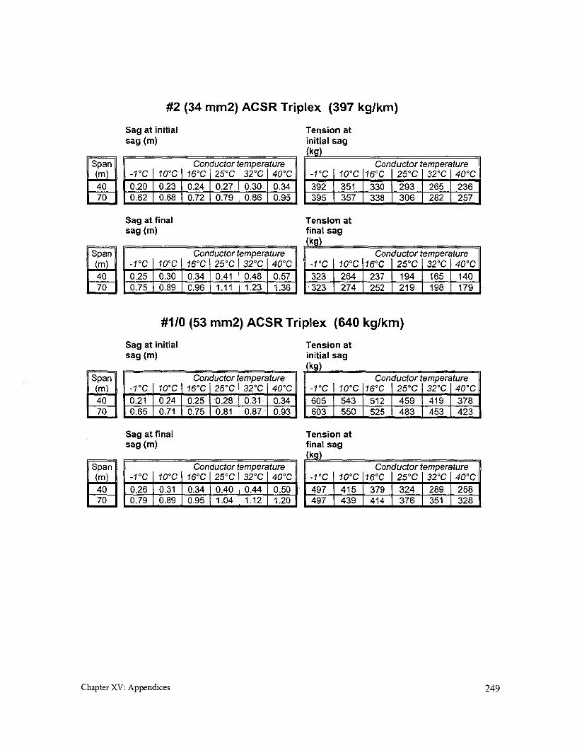
#2 (34 mm2) ACSR Triplex (397 kg/km)
Sag at initial Tension atsag (m) initial sag
(kg)
Span Conductor temperature F Conductor temperature(m) -10C | 10C 16°C 250C 320C | 40°C -1°C | 10'C 1 16'C I 25°C 32°C I 40°C40 0.20 0.230.240.27 0.30 0.34 392 351 330 293 1265 23670 0.62 0.68 0.72 0.79 0.86 0.95 395 1 357 1338 1306 J282 257
Sag at final Tension atsag (m) final sag
(kg)Span Conductor temperature - Conductor temperature(m) -1°C 10°C 16°C 25°C 32°C I 40°C | -1°C | 10°C | 16°C I 25°C I 320C| 40°C40 0.25 0.30 0.34 0.41 0.48 0.57 | 323 7 264 | 237 1 194 J 165 14070 0.75 0.89 0.96 1.11 1.23 1.36 i 323 274 252 219 1 198 | 179
#1/0 (53 mm2) ACSR Triplex (640 kg/km)
Sag at initial Tension atsag (m) initial sag
(kg)Span Conductor temperature Conductor temperature
|| (in) ID -1°C o10oC 16°C I 25°C 320C I 40°C -1°C |10C 1160C I 250C I 32°C | 40°C[j40 0.21 0.24 0.25 0.28 0.31 10.34 605 543 512 1 459 419 1 378
70 0.65 0.71 | 0.75 | 0.81 0.87 | 0.93 603 550 525 | 483 453 | 423
Sag at final Tension atsag (m) final sag
(kg)Span Conductor temperature || Conductor temperature
|m) -1°C I 10°C I 16°C | 25°C 32°C | 40C ||| -1°C | 10°C 116°C | 25°C I 32°C 40°C40 0.26 0.31 0.34 0.40 0.44 | 0.5011 497 | 415 | 379 | 324 1 289 25870 0.79 0.89 0.95 1.04 1.12 1.20 497 | 439 414 | 376 | 351 328
Chapter XV: Appendices 249


Appendix 9. Areas for further inquiryIn the process of preparing this manual, questions were raised to which there seemed no clear response.Some of these questions have been listed below. It is hoped that this annotated listing might serve todraw information from others with experience in these areas. Altematively, it might serve as topics forfurther research. If readers have information that addresses any of these points, we would appreciate it ifit could be forwarded to the address below so that this information can be shared with others:
Allen R. InversinNRECA - International Programs4301 Wilson BoulevardArlington, VA 22203-1860
Fax: 703-907-5532Email: [email protected]
Pole treatment
Poles can be the most costly component of a mini-grid. Wood poles rely on a renewable resource, can belocally produced, and have numerous useful characteristics. The principal drawback is short life due todecay and insect damage. What can be done to increase its life and the attractiveness of this option? Whatuseful techniques can be developed that could increase the their life? In some areas, pole butts arepainted with bituminous paints to offer protection when poles are set in earth in an area open to theelements,. How effective is this "treatment" (i.e., a comparison of with and without)? Against what doesit protect (decay, insect damage, etc.)? What about soaking the butts of poles in used automotive sumpoil? Is this an effective treatment against something? Under what circumstances is it effective? Can itseffectiveness be proved? What other simple treatment options have been documented?
Metal Poles
Poles are generally the costliest single components of a mini-grid and even costlier when life-cycle costsare considered. Local wooden poles are inexpensive or free, if available, but without treatment, which isdifficult to effectively achieve on a small scale, they must usually be frequently replaced. Concrete polescan be locally produced but require suitable quality control of both materials and production and aredifficult to transport and set. The most appropriate alternative could be fabricated sectionalized steelpoles, which are easy to handle and set and have a long life if galvanized or properly painted. ChapterVIII provides a couple of ideas for such poles. An intervention that could prove of great advantage tothose implementing mini-grids would be one or more simple yet durable metal pole designs, including adescription of construction techniques. Such a design should also include information on the properdepth for setting different size poles, maximum lateral poletop force that can be handled before a polebuckles and collapses, and typical cost and manufacturing requirements. Designs for locally fabricatedpoletop hardware suitable for metal poles would also be useful.
Strength of smaller diameter poles
Poles are sized by using the ultimate fiber stress of the species under consideration and calculating thestrength required at the ground line to withstand a given bending moment due primarily to the lateralforce of the wind and to line tension when there is a deviation in the direction of the line. For poles usedwith mini-grids, poles with reduced girth are necessary. Are the values of ultimate fiber stress over the
Chapter XV: Appendices 250
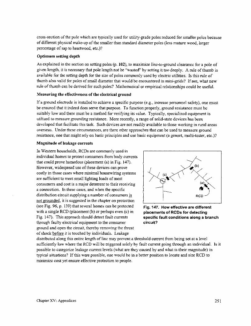
cross-section of the pole which are typically used for utility-grade poles reduced for smaller poles becauseof different physical make-up of the smaller than standard diameter poles (less mature wood, largerpercentage of sap to heartwood, etc.)?
Optimum setting depth
As explained in the section on setting poles (p. 102), to maximize line-to-ground clearance for a pole ofgiven length, it is necessary that pole length not be "wasted" by setting it too deeply. A rule of thumb isavailable for the setting depth for the size of poles conmnonly used by electric utilities. Is this rule ofthumb also valid for poles of small diameter that would be encountered in mini-grids? If not, what newrule of thumb can be derived for such poles? Mathematical or empirical relationships could be useful.
Measuring the effectiveness of the electrical ground
If a ground electrode is installed to achieve a specific purpose (e.g., increase personnel safety), one mustbe ensured that it indeed does serve that purpose. To function properly, ground resistance must besuitably low and there must be a method for verifying its value. Typically, specialized equipment isutilized to measure grounding resistance. More recently, a range of solid-state devices has beendeveloped that facilitate this task. Such devices are not readily available to those working in rural areasoverseas. Under these circumstances, are there other approaches that can be used to measure groundresistance, one that might rely on basic principles and use basic equipment (a genset, multi-tester, etc.)?
Magnitude of leakage currents
In Western households, RCDs are commonly used inindividual homes to protect consumers from body currentsthat could prove hazardous (placement (a) in Fig. 147).However, widespread use of these devices can provecostly in those cases where minimal housewiring systems Care sufficient to meet small lighting loads of mostconsumers and cost is a major deterrent to their receiving aa connection. In these cases, and when the specificdistribution circuit supplying a number of consumers is RCDnot grounded, it is suggested in the chapter on protection(see Fig. 96, p. 139) that several homes can be protected Fig. 147. How effective are differentwith a single RCD (placement (b) or perhaps even (c) in placements of RCDs for detectingFig. 147). This approach should detect fault currents specific fault conditions along a branchthrough faulty electrical equipment to the consumer circuit?ground and open the circuit, thereby removing the threatof shock before it is touched by individuals. Leakagedistributed along this entire length of line may prevent a threshold current from being set at a levelsufficiently low where the RCD will be triggered solely by fault current going through an individual. Is itpossible to categorize leakage current levels (what are they caused by and what is their magnitude) intypical situations? If this were possible, one would be in a better position to locate and size RCD tominimize cost yet ensure effective protection to people.
Chapter XV: Appendices 251

Mark Hayton, personal correspondence, Bandung, Indonesia, 23 April 1993.
2 Louineau, Dicko, Fraenkel, Barlow, and Bokalders, "Rural lighting, A guide for development workers",Intermediate Technology Publications Ltd. (103-105 Southampton Row, London WC1B 4HH, U.K.), 1994.
3 D.C. Pritchard, "Lighting", Fifth edition, Longman, 1995 (ISBN 0-582-23422-0).
4 Theodore Baumeister (ed), "Standard Handbook for Mechanical Engineers", Seventh Edition, McGraw-Hill BookCompany, New York, 1967.
5 Allen Inversin, "New designs for rural electrification, Private-sector experiences in Nepal", NRECA, Arlington,VA, 1994.
6 "Primer on woodpole production program", Power Use Development Division, Cooperative Services Department,NEA, Philippines.
7 A.K. Lahiry, "Manual of a mini treating plant for waterbome preservative treatment of timber and bamboo", RuralElectrification Board (Dhaka, Bangladesh), Paper No. IRGAWP 99-40130 published in 1999 by The InternationalResearch Group on Wood Preservation (SE-100 44 Stockholm, Sweden)
' "Building in hot climates. A selection of overseas building notes", issued by the Building Research Establishment,Distribution Unit (Garston, Watford, WD2 7JR, England).
9 "Series 4, High pressure sap displacement treatment", Second Revision, Forest Products Research andDevelopment Institute, Laguna, Philippines, December 1997.
10 "Report on design, construction and testing of RCC electric poles", DCS (prepared for ITDG/Nepal), Butwal,Nepal. June 1995.
" "Final report on development of a portable device for manufacturing pre-stressed concrete power poles formicrohydro schemes", prepared by DCS for the UTNDP's Rural Energy Development Programme, Butwal, Nepal.November 1998.
12 "REC specifications and construction standards", Rural Electrification Corporation, Ltd., New Delhi, 1994.
13 J.F. Seiler, "Effect of depth of embedment on pole stability", Wood Preserving News (American Wood-Preservers' Association), November 1932 (available at the USDA Library in Beltsville, MD).
14 "Getting down to earth", Biddle Instruments (510 Township Line Road, Blue Bell, PA 19422, Phone: 215-646-9200), 1990.
'5 Dale L. Nafziger, "A synopsis of domestic sector impacts at the Andhi Khola hydel and rural electrificationproject and their implications for future Butwal Power Company rural electrification planning", Butwal PowerCompany (P.O. Box 126, Kathmandu, Nepal), 1994.
16 Development and Consulting Services can be reached through P.O. Box 126, Kathmandu and Sustainable ControlSystems, which been field testing its unit in Peru, can be reached through 4 Charleston House, Peel Street,Nottingham NGI 4GN, England (or, on the Internet, at http//:www.scs-www.com).
Chapter XV: Appendices 252


The World Bank
1818 H Street, NW
Washington, DC 20433 USA
Tel.: 1.202.458.2321 Fax.: 1.202.522.3018
Internet: www.esmap.org
Email: [email protected]
AR\ joint UNDP/Wor Bank Programme
A joint UNDP/WorLd Bank Programme
Related Documents