Document Number: 9.4.6_MIN_DPI_28-01-05 CONFIDENTIAL REPORT FOR MINE SAFETY DIVISION, DEPARTMENT OF PRIMARY INDUSTRIES P.O. B OX 674, WOLLONGONG EAST NSW 2520 REVIEW OF F AILURES OF BOLTHOLE REPAIRS TO FLAMEPROOF MOTORS Report Compiled by: - Glen Allan Technology Manager, Regional NSW Welding Technology Institute of Australia Unit 3, Suite 2, 9 Parramatta Road, Lidcombe, 2141. PO Box 6165, Silverwater, NSW 1811 Phone: (02) 9748 4443 Fax: (02) 9748 2858 E-mail [email protected] URL http://www.wtia.com.au C:\Documents and Settings\allang\My Documents\Consultancy\Consultancy Reports\Mine Safety Division, NSW Department of Primary Industries\Bolt hole repair\9.4.6_MIN_DPI_28-01-05.doc Page 1 of 22 CONFIDENTIAL

Welcome message from author
This document is posted to help you gain knowledge. Please leave a comment to let me know what you think about it! Share it to your friends and learn new things together.
Transcript

Document Number: 9.4.6_MIN_DPI_28-01-05
CONFIDENTIAL REPORT
FOR
MINE SAFETY DIVISION, DEPARTMENT OF PRIMARY INDUSTRIES
P.O. BOX 674, WOLLONGONG EAST NSW 2520
REVIEW OF FAILURES OF BOLTHOLE REPAIRS
TO FLAMEPROOF MOTORS
Report Compiled by:
Glen Allan
Technology Manager, Regional NSW
Welding Technology Institute of Australia
Unit 3, Suite 2, 9 Parramatta Road, Lidcombe, 2141. PO Box 6165, Silverwater, NSW 1811
Phone: (02) 9748 4443 Fax: (02) 9748 2858
E-mail [email protected] URL http://www.wtia.com.au
C:\Documents and Settings\allang\My Documents\Consultancy\Consultancy Reports\Mine Safety Division, NSW Department of Primary Industries\Bolt hole repair\9.4.6_MIN_DPI_28-01-05.doc Page 1 of 22
CONFIDENTIAL

ABN 69 003 696 526 Unit 3, Suite 2, 9 Parramatta Road, Lidcombe PO Box 6165, Silverwater, NSW, 1811
Phone: + 61 (0)2 9748 4443 Fax: + 61 (0)2 9748 2858 Email: [email protected] URL: http://www.wtia.com.au
ON BEHALF OF:
Mine Safety Division, Department of Primary Industries
Review of failures of bolthole repairs to flameproof motors
DOCUMENT NO:
9.4.6_MIN_DPI_28/01/05
REVISION NO: 3 PAGES: 22 DATE: 28th January 2005
COMPILED BY: RECOMMENDED BY: AUTHORISED BY:
G. ALLAN C. SMALLBONE C. SMALLBONE
CONTENTS Executive Summary..........................................................................................................................3 1 Scope........................................................................................................................................4 2 Site inspection...........................................................................................................................4
2.1 Visual examination of Motor A..............................................................................................4 3 Specimens provided for analysis..............................................................................................4
3.1 Specimens provided by Mr Paul de Gruchy (Motor A) .........................................................4 3.2 Specimen provided by Mr John Chapman (Motor B)...........................................................5
4 Investigation of bolt hole failures ..............................................................................................5 4.1 Metallographic examination..................................................................................................5
5 Discussion.................................................................................................................................6 5.1 Method of repair ....................................................................................................................6 5.2 Alternative methods of repair................................................................................................7 5.3 Qualification of repair methods .............................................................................................7 5.4 Test methods to evaluate repaired bolt holes ......................................................................8 5.5 Considerations for welded repair ..........................................................................................8 5.6 Determining the initial failure mode ......................................................................................9
6 Recommendations....................................................................................................................9 6.1 Quality assurance systems...................................................................................................9 6.2 Qualification and approval of welding...................................................................................9
Appendix A – Figures .....................................................................................................................10
The WTIA has joined forces with industry and Governments and created a multi million dollar Technology Support Centres Network. This Network assists industry to identify and exploit world’s best technology and manufacturing methods to establish a vibrant Australian industry beyond 2006. Together we are implementing a step-by-step process that will lead to ongoing viability and greater profitability for all concerned:
(1) Determine your technological and manufacturing needs; (2) Identify world’s best practice; (3) Draw upon the Network to implement world’s best practice at your site.
C:\Documents and Settings\allang\My Documents\Consultancy\Consultancy Reports\Mine Safety Division, NSW Department of Primary Industries\Bolt hole repair\9.4.6_MIN_DPI_28-01-05.doc Page 2 of 22
CONFIDENTIAL

Executive Summary
At the request of Mr Bob Kennedy, Inspector of Electrical Engineering, Mine Safety Division, NSW Department of Primary Industries, the WTIA was engaged to assist with investigation of failures in bolthole repairs on flameproof enclosures.
A site visit was made to the premises of MinePro Electrical Services at 4a/415 West Botany Street Rockdale on Tuesday 18th January 2004, to inspect failed bolt hole weld repairs on a Joy Mining 250 Volt d.c. traction motor being overhauled. The failed welds had originated at another third party workshop and were discovered during the overhaul process. The inspection was carried out in the company of Mr Sean McNamara of MinePro, Mr John Waudby, Mr Paul de Gruchy and Mr Wally Koppe of Mine Safety Division, NSW Department of Primary Industries, Mr John Chapman of Joy and Mr Glen Allan of WTIA.
Bolthole repairs had been carried out on the end faces and the hand access hole of the stator frame. The holes appeared to have been filled with weld metal that had been drilled and tapped. A number of the weld deposit inserts used to repair the boltholes had failed. The force required to remove the inserts was in some cases very low. There is concern that the repair method used was unsuitable to maintain the structural integrity of the flameproof enclosure.
WTIA was asked to determine the method that had been used to carry out the repair. WTIA was also asked to provide information to assist with welded repairs of boltholes. It is not clear why the boltholes were repaired in the first place.
Visual examination of a motor being overhauled by MinePro Electrical Services showed that the failure of bolthole inserts on that particular motor was extensive.
Mr Paul de Gruchy provided specimens from the motor inspected at MinePro Electrical Services to WTIA for metallurgical analysis. Mr John Chapman provided a further specimen from another motor that had similar bolthole failures.
Metallographic analysis showed that insert materials were weld deposits. The welding method was probably the gas metal arc welding (GMAW, MIG) process. The welding technique used had not resulted in any fusion of the weld deposits to the parent metal on any of the failed inserts examined. There was evidence that the maximum temperatures reached in the parent metal were at least 700°C below the minimum temperatures necessary for fusion.
It is clear from the failed inserts that the welding practice used was unsatisfactory. It is not known if any of the repairers currently using this down hole welding approach have qualified their welding procedures. It is recommended that further work be carried out to establish whether satisfactory down-hole welds can be made using the GMAW process. If a satisfactory technique can be developed, all repairers should be made aware of the actions required to produce satisfactory welds.
The companies carrying out welding during the manufacture, overhaul, and repair on flame proof enclosures should have a welding quality management system in accordance with AS/NZS ISO 3834. Repairers should be required to qualify their welding procedures, ensure that welds should only be made in accordance with a qualified welding procedure specification, and ensure that only suitably trained and experienced welders are used.
Technical work instructions should be developed that provide details of the method of preparation for welding, drilling out of damaged threads, cleaning out the hole before welding, specific details of the set up of the welding equipment and any other details necessary for the correct application of a qualified welding procedure.
It may be necessary to limit the application of welded repairs if repairers cannot demonstrate an ability to produce satisfactory welds.
C:\Documents and Settings\allang\My Documents\Consultancy\Consultancy Reports\Mine Safety Division, NSW Department of Primary Industries\Bolt hole repair\9.4.6_MIN_DPI_28-01-05.doc Page 3 of 22
CONFIDENTIAL

1 Scope
At the request of Mr Bob Kennedy, Inspector of Electrical Engineering, Mine Safety Division, NSW Department of Primary Industries, the WTIA was engaged to assist with investigation of failures in bolthole repairs on flameproof enclosures. A site visit was made to the premises of MinePro Electrical Services, 4a/415 West Botany Street Rockdale on Tuesday 18th January 2004, to inspect failed bolthole repair welds on a Joy Mining 250 Volt d.c. traction motor being overhauled. The failed welds had originated at another third party workshop and were discovered during the overhaul process.
WTIA was asked to determine the method that had been used to carry out the repair. WTIA was also asked to provide information to assist with welded repairs of boltholes. WTIA was not asked to determine why the boltholes had been repaired.
2 Site inspection
WTIA visited the premises of MinePro Electrical Services, 4a/415 West Botany Street Rockdale on Tuesday 18th January 2004, where a meeting to discuss repairs and inspection of a motor with failed bolthole inserts was carried out.
Present at the meeting were:
Mr Sean McNamara MinePro Electrical Services (Australasia)
Mr John Waudby Mine Safety Division, Department of Primary Industries
Mr Paul de Gruchy Mine Safety Division, Department of Primary Industries
Mr Wally Koppe Mine Safety Division, Department of Primary Industries
Mr John Chapman Joy Manufacturing Company Pty Ltd
Mr Glen Allan WTIA
Information gained and comments are contained in the following report.
2.1 Visual examination of Motor A
On the motor examined at the MinePro workshop, boltholes had been repaired on the frame ends and on the hand access hole on the stator frame. See Figures 1 & 2.
All six bolthole inserts had failed at the hand access hole. At least 13 of the 16 boltholes on the stator frame end faces had been repaired with inserts. There was evidence of insert failure on a number of those repaired holes. See Figure 3.
Very little force was required to remove the inserts in some cases. Some inserts could be dislodged with hand force only. See Figure 4.
Insert material that had been removed from failed repairs was examined. The specimens were approximately 14mm diameter an up to 45mm in length. See Figure 5. The boltholes for the hand access hole were blanked on the inside with a cover that was welded in place.
All failed insert specimens were oxidised and had a rough outside surface appearance. There were features on the outside surface of the inserts that were consistent with GMAW wire and weld spatter. See Figure 6.
There was no evidence of fusion to the stator frame parent metal on the specimens examined.
3 Specimens provided for analysis
3.1 Specimens provided by Mr Paul de Gruchy (Motor A)
Specimens were provided from boltholes on the stator frame end face and hand access hole.
The motor identification details provided were:
C:\Documents and Settings\allang\My Documents\Consultancy\Consultancy Reports\Mine Safety Division, NSW Department of Primary Industries\Bolt hole repair\9.4.6_MIN_DPI_28-01-05.doc Page 4 of 22
CONFIDENTIAL

Joy Mining 250 Volt d.c. traction motor, 35 Hp
Part number: 600505-80
Frame size: 41J9
Serial number: MV583-67-UX
Manufacturer: Reliance
DMR approval number: MDA Ex d 0188
Certification number: AUS Ex 3147X
3.2 Specimen provided by Mr John Chapman (Motor B)
A specimen was provided from the stator frame end face.
The motor identification details provided were:
Joy Mining 950 Volt a.c. motor, 50/50 Hp
Part number: 600199-87
Frame size: 16DB400J1
Serial number: A25141
Manufacturer: Reliance
DMR approval number: MDA Ex d 1168
Certification number: Not known
4 Investigation of bolt hole failures
4.1 Metallographic examination
Specimens were provided for metallurgical investigation from two motors. Details of the motors are provided above. For the purpose of this report the motors were identified as Motor A and Motor B.
Sections were removed from inserts for metallographic examination.
4.1.1. Micro-section 1 from Motor A
A section was taken through the point indicated by the arrow on the failed insert shown in Figure 6.
The specimen was examined in the polished condition. There was a circular form with half of the circle protruding from the body of metal. See Figure 7. The diameter of the circle was measured at approximately 1mm. The form was consistent with a GMAW solid wire consumable.
The specimen was etched and the microstructures were examined. There was partial fusion of the wire to the body of weld metal. There was a network of fine oxide inclusions and porosity around the circumference of the wire. See Figure 8. This is consistent with molten metal coming in contact with the wire but with insufficient temperature at the boundary for complete fusion.
The microstructure of the material in the insert material was consistent with a low carbon steel weld deposit. The grain size and microstructures were consistent with a weld deposit in the as welded condition.
4.1.2. Micro-section 2 from Motor A
A longitudinal section was taken through a failed insert from Motor A. The microstructure was consistent with low carbon steel weld metal. See Figure 9.
C:\Documents and Settings\allang\My Documents\Consultancy\Consultancy Reports\Mine Safety Division, NSW Department of Primary Industries\Bolt hole repair\9.4.6_MIN_DPI_28-01-05.doc Page 5 of 22
CONFIDENTIAL

4.1.3. Micro-section 3 from Motor B
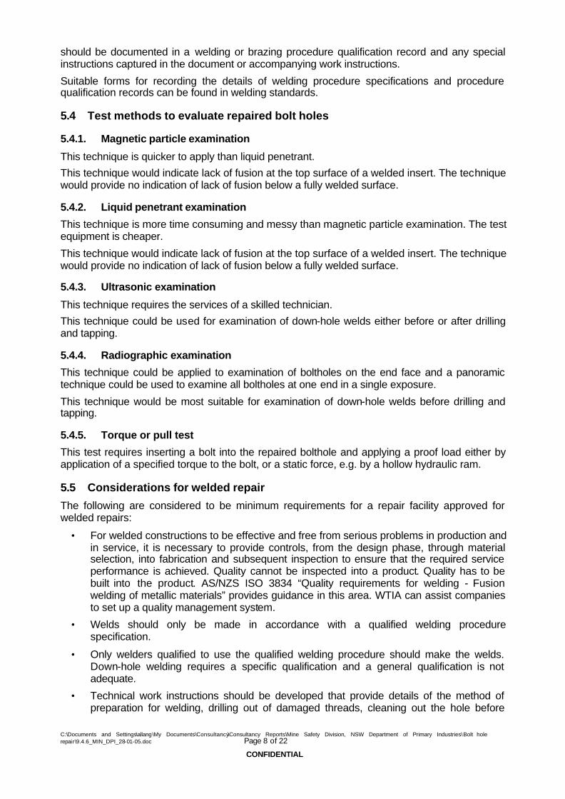
A section was taken through the point indicated by the arrow in Figure 10. The section contained parent metal and insert material.
The polished specimen was examined in the polished condition. There was a gap between the parent metal and insert material. There was no evidence of fusion of the insert material with the parent metal.
The parent metal had a significant number of elongated manganese sulphide inclusions. See Figure 11. This feature is consistent with hot rolled steel produced by the ingot route.
The specimen was etched and the microstructures examined. The parent metal was a relatively coarse-grained low carbon steel in the normalised condition. See Figure 12.
The microstructures in the parent metal were examined in the region adjacent to the insert material. See Figure 13. The micrograph shows parent metal on the lower left of the frame, location A, and insert material in the upper right region at location B.
The parent metal microstructure at location C had been partially modified. The microstructure was consistent with a peak temperature not exceeding 850°C.
The parent metal microstructure at location D was not modified by the welding operation. This indicates that the parent metal temperature did not reach 720°C as the weld metal was deposited.
The melting temperature of steel is in the vicinity of 1500°C. It is clear from the evidence in the parent metal microstructures that temperatures generated in the parent metal were more than 700°C below the threshold minimum temperature required for fusion to the weld metal.
The variation in microstructure between locations C and D is an indicator that there was a higher heat sink in the parent metal in the circumferential direction and a lower heat sink in the radial direction.
There was no evidence of slag in any of the specimens examined. This is consistent with the GMAW process.
5 Discussion
5.1 Method of repair
The insert material in Motor A and Motor B were similar and consistent with weld metal deposited by the GMAW (MIG) process. The welding consumable was a 1.0mm or 1.2mm diameter solid wire. The welds appear to have been made by directing the welding arc down the holes and continuously welding until the hole was filled.
It is generally considered very difficult to achieve sidewall fusion when welding into a hole with a depth exceeding the diameter. The structural steel welding code, AS/NZS 1554.1:2004 “Structural steel welding Part 1: Welding of steel structures”, requires that for access to weld into plug weld preparations the diameter of the hole must be not less than 8mm plus the thickness of the part containing the hole. Under these guidelines a hole of 14mm in diameter can only be 6mm deep.
5.1.1. Welding considerations for deep holes
Achieving sound welding at the base of 45mm deep holes that are 14mm diameter may be possible with conventional GMAW, however the correct set-up of the equipment and welding parameters would need to be determined. Using conventional GMAW equipment with settings suitable for welding a fillet weld or butt weld onto a flat surface would not be adequate.
With a welding machine set up for spray transfer with 1.0mm wire the contact tip to work distance (CTWD) would normally be in the range of 16mm to 22mm. An increase in CTWD to over 45mm would result in an increase in deposition rate and less penetration. As a minimum,
C:\Documents and Settings\allang\My Documents\Consultancy\Consultancy Reports\Mine Safety Division, NSW Department of Primary Industries\Bolt hole repair\9.4.6_MIN_DPI_28-01-05.doc Page 6 of 22
CONFIDENTIAL

significantly higher wire feed rates (welding current) and higher voltages would be required to get penetration at the bottom of a 45mm deep hole.
There would remain the problem that the arc energy would not be applied directly to the parent metal. Preheating the parent metal would improve the chances of getting fusion to the bore of the hole. The minimum extent and acceptability of preheating would have to be determined.
It is clear from the failed inserts that the welding practice used was unsatisfactory. It is not known if any of the repairers currently using this down-hole welding approach have qualified welding procedures.
5.2 Alternative methods of repair
5.2.1. Groove welded repair
It is understood that an alternative weld repair method is to make a weld groove preparation by excavation from the outside diameter of the flange. This method requires more extensive preparation and there is a significantly higher volume of weld metal. The greater weld metal volume results in greater distortion around the weld zone due to thermal strains and may lead to a requirement for remachining.
On the positive side, this method is capable of producing a sound homogenous weld deposit with complete fusion to the parent metal.
5.2.2. Threaded inserts
Threaded inserts are an option where there is enough metal between the bolthole and the outside and inside surfaces of the parent metal. The method of securing the threaded insert in place should be considered. If welding is used then an approved method that provides a minimum throat thickness should be used. Reduction of weld throat thickness by subsequent machining should be considered.
5.2.3. Brazed inserts
Plugs made from bar stock or similar weldable steel could be brazed into position. The bolthole would be drilled out to remove all thread form and provide a parallel side cylindrical hole. A suitable sized steel plug would then be inserted and brazed in position.
This method would be easier to control in a workshop than the currently unproven down-hole welding technique.
5.2.4. Friction welding
Friction hydro-pillar welding is a method developed by TWI in the UK that may be suitable for these bolthole repairs. The technique uses mechanical energy to produce heat by friction and a solid phase weld is produced. The welding machine is “programmable” for a particular activity so once the settings were established repeatable results would be expected.
Further investigation is recommended to establish whether friction hydro-pillar welding is a suitable alternative.
5.3 Qualification of repair methods
For any repair method that involves welding or brazing, qualification testing should be carried out to prove the process and procedure. In many areas of industry there is a belief that so long as repair work is carried out by a welder or boilermaker having appropriate trade papers, the outcomes are guaranteed. Unfortunately this leads to unsatisfactory outcomes when technically challenging repairs are attempted.
It is a relatively simple exercise to produce a test weld using the proposed repair method and carry out appropriate testing to prove that a satisfactory outcome was achieved, thereby qualifying the method. The method used, including all details of the welding or brazing process
C:\Documents and Settings\allang\My Documents\Consultancy\Consultancy Reports\Mine Safety Division, NSW Department of Primary Industries\Bolt hole repair\9.4.6_MIN_DPI_28-01-05.doc Page 7 of 22
CONFIDENTIAL
should be documented in a welding or brazing procedure qualification record and any special instructions captured in the document or accompanying work instructions.
Suitable forms for recording the details of welding procedure specifications and procedure qualification records can be found in welding standards.
5.4 Test methods to evaluate repaired bolt holes
5.4.1. Magnetic particle examination
This technique is quicker to apply than liquid penetrant.
This technique would indicate lack of fusion at the top surface of a welded insert. The technique would provide no indication of lack of fusion below a fully welded surface.
5.4.2. Liquid penetrant examination
This technique is more time consuming and messy than magnetic particle examination. The test equipment is cheaper.
This technique would indicate lack of fusion at the top surface of a welded insert. The technique would provide no indication of lack of fusion below a fully welded surface.
5.4.3. Ultrasonic examination
This technique requires the services of a skilled technician.
This technique could be used for examination of down-hole welds either before or after drilling and tapping.
5.4.4. Radiographic examination
This technique could be applied to examination of boltholes on the end face and a panoramic technique could be used to examine all boltholes at one end in a single exposure.
This technique would be most suitable for examination of down-hole welds before drilling and tapping.
5.4.5. Torque or pull test
This test requires inserting a bolt into the repaired bolthole and applying a proof load either by application of a specified torque to the bolt, or a static force, e.g. by a hollow hydraulic ram.
5.5 Considerations for welded repair
The following are considered to be minimum requirements for a repair facility approved for welded repairs:
• For welded constructions to be effective and free from serious problems in production and in service, it is necessary to provide controls, from the design phase, through material selection, into fabrication and subsequent inspection to ensure that the required service performance is achieved. Quality cannot be inspected into a product. Quality has to be built into the product. AS/NZS ISO 3834 “Quality requirements for welding - Fusion welding of metallic materials” provides guidance in this area. WTIA can assist companies to set up a quality management system.
• Welds should only be made in accordance with a qualified welding procedure specification.
• Only welders qualified to use the qualified welding procedure should make the welds. Down-hole welding requires a specific qualification and a general qualification is not adequate.
• Technical work instructions should be developed that provide details of the method of preparation for welding, drilling out of damaged threads, cleaning out the hole before
C:\Documents and Settings\allang\My Documents\Consultancy\Consultancy Reports\Mine Safety Division, NSW Department of Primary Industries\Bolt hole repair\9.4.6_MIN_DPI_28-01-05.doc Page 8 of 22
CONFIDENTIAL

welding, specific details of the set up of the welding equipment and any other details necessary for the correct application of the qualified welding procedure.
5.6 Determining the initial failure mode
WTIA has not had an opportunity to examine boltholes before repair. With the best of welding practice the insert material will have similar mechanical properties to the original stator frame parent metal. The failure mode that led to such extensive repairs has not been determined, therefore WTIA cannot comment on the likely success of welded repairs.
6 Recommendations
It is recommended that further work be carried out to establish whether satisfactory down-hole welds can be made using the GMAW process. If a satisfactory technique can be developed, all repairers should be made aware of the actions required to produce satisfactory welds.
It may be necessary to limit the application of welded repairs if repairers cannot demonstrate an ability to produce satisfactory welds.
6.1 Quality assurance systems
The companies carrying out welding during the manufacture, overhaul and repair on flame proof enclosures should have a welding quality management system that addresses the minimum requirements of AS/NZS ISO 3834.
6.2 Qualification and approval of welding
6.2.1. Qualification of welding procedures
Welds should only be made in accordance with a qualified welding procedure specification. Welding quality should be qualified in accordance with AS/NZS 3992. In this case a special test piece would be required that simulates the diameter, hole depth and heat sink of the job to be carried out.
6.2.2. Qualification of welders
Only welders qualified to use the qualified welding procedure should make the welds. Welder qualification on the qualified procedure is necessary. A general qualification in the welding process used is not sufficient in this case.
Basis of Review
This review has been prepared in good faith. It is based largely on verbal, written and other information provided by the parties as mentioned in this review, uses the latest information, experience and expertise readily available to the WTIA, and applies only to the conditions and circumstances considered in this review.
It is recommended the review be used together with other data (contractual, service etc.) to resolve any pertinent matters, and is issued on the basis that parties mentioned herein are responsible for the proper supply/fabrication/operation of this equipment/component. The WTIA agrees to maintain the confidentiality of this review.
WTIA has not retained any copies of or originals of any documentation furnished by the client that is referred to herein and forms the basis of this review.
C:\Documents and Settings\allang\My Documents\Consultancy\Consultancy Reports\Mine Safety Division, NSW Department of Primary Industries\Bolt hole repair\9.4.6_MIN_DPI_28-01-05.doc Page 9 of 22
CONFIDENTIAL

Appendix A – Figures
Figure 1. General view of the stator frame end face of Motor A. An insert has been partially removed.
C:\Documents and Settings\allang\My Documents\Consultancy\Consultancy Reports\Mine Safety Division, NSW Department of Primary Industries\Bolt hole repair\9.4.6_MIN_DPI_28-01-05.doc Page 10 of 22
CONFIDENTIAL

Figure 2. General view of side cover of Motor A showing partially removed inserts.
C:\Documents and Settings\allang\My Documents\Consultancy\Consultancy Reports\Mine Safety Division, NSW Department of Primary Industries\Bolt hole repair\9.4.6_MIN_DPI_28-01-05.doc Page 11 of 22
CONFIDENTIAL

Figure 3. Detail of the partially extracted insert from Motor A.
C:\Documents and Settings\allang\My Documents\Consultancy\Consultancy Reports\Mine Safety Division, NSW Department of Primary Industries\Bolt hole repair\9.4.6_MIN_DPI_28-01-05.doc Page 12 of 22
CONFIDENTIAL

Figure 4. Insert easily removed by hand.
C:\Documents and Settings\allang\My Documents\Consultancy\Consultancy Reports\Mine Safety Division, NSW Department of Primary Industries\Bolt hole repair\9.4.6_MIN_DPI_28-01-05.doc Page 13 of 22
CONFIDENTIAL

Figure 5. Inserts after extraction from Motor A.
C:\Documents and Settings\allang\My Documents\Consultancy\Consultancy Reports\Mine Safety Division, NSW Department of Primary Industries\Bolt hole repair\9.4.6_MIN_DPI_28-01-05.doc Page 14 of 22
CONFIDENTIAL

Figure 6. Closer view of insert material after removal from the bolthole (Motor A). Partially melted welding wire is evident.
C:\Documents and Settings\allang\My Documents\Consultancy\Consultancy Reports\Mine Safety Division, NSW Department of Primary Industries\Bolt hole repair\9.4.6_MIN_DPI_28-01-05.doc Page 15 of 22
CONFIDENTIAL

Figure 7. X 100 - Unetched
The photomicrograph was sectioned at the position indicated by the arrow in Figure 6. There is a semi-circular form in the upper part of the field.
The circle was measured at 1.0mm diameter.
C:\Documents and Settings\allang\My Documents\Consultancy\Consultancy Reports\Mine Safety Division, NSW Department of Primary Industries\Bolt hole repair\9.4.6_MIN_DPI_28-01-05.doc Page 16 of 22
CONFIDENTIAL

Figure 8. X 100 – 2% Nital etch
The same photomicrograph as shown in Figure 7, sectioned at the position indicated by the arrow in Figure 6. A partially unfused boundary can be seen.
C:\Documents and Settings\allang\My Documents\Consultancy\Consultancy Reports\Mine Safety Division, NSW Department of Primary Industries\Bolt hole repair\9.4.6_MIN_DPI_28-01-05.doc Page 17 of 22
CONFIDENTIAL

Figure 9. X 200 – 2% Nital etch
Insert material from Motor A. the microstructure is consistent with a low carbon steel weld deposit.
C:\Documents and Settings\allang\My Documents\Consultancy\Consultancy Reports\Mine Safety Division, NSW Department of Primary Industries\Bolt hole repair\9.4.6_MIN_DPI_28-01-05.doc Page 18 of 22
CONFIDENTIAL
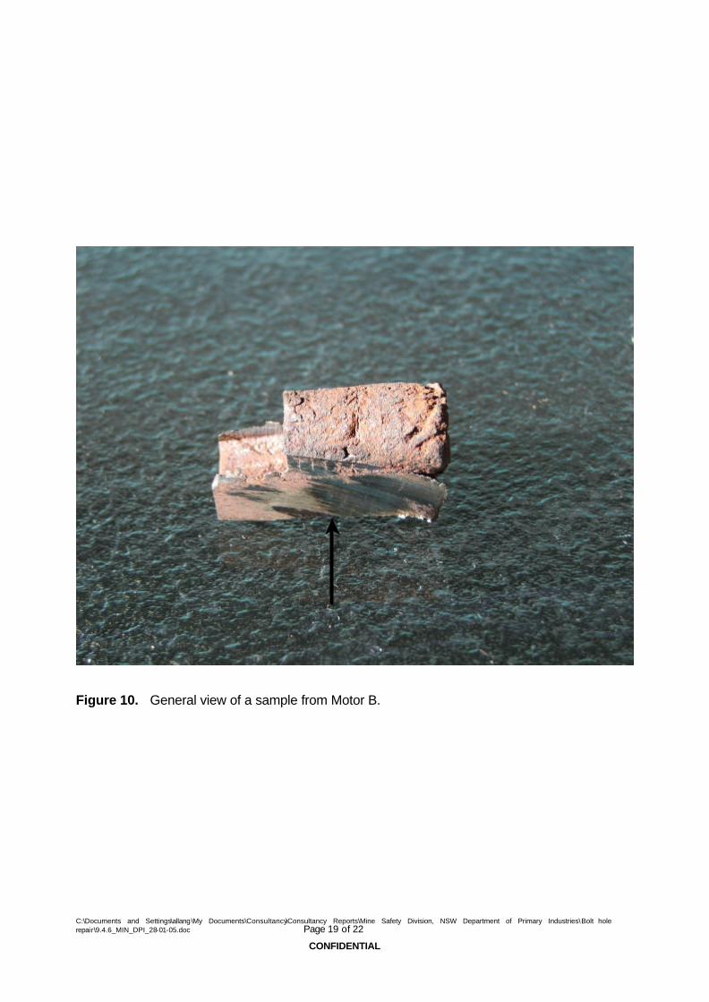
Figure 10. General view of a sample from Motor B.
C:\Documents and Settings\allang\My Documents\Consultancy\Consultancy Reports\Mine Safety Division, NSW Department of Primary Industries\Bolt hole repair\9.4.6_MIN_DPI_28-01-05.doc Page 19 of 22
CONFIDENTIAL

Figure 11. X 200 Unetched.
Stator frame parent metal sectioned adjacent to a repaired hole from Motor B. Elongated manganese sulphide (MnS) inclusions are evident. The inclusion morphology is typical of wrought steel made by ingot route.
C:\Documents and Settings\allang\My Documents\Consultancy\Consultancy Reports\Mine Safety Division, NSW Department of Primary Industries\Bolt hole repair\9.4.6_MIN_DPI_28-01-05.doc Page 20 of 22
CONFIDENTIAL

Figure 12. Magnification X 200, Etched in 2% Nital.
Stator frame parent metal sectioned adjacent to a repaired hole from Motor B. The microstructure is consistent with wrought steel produced by conventional hot rolling.
C:\Documents and Settings\allang\My Documents\Consultancy\Consultancy Reports\Mine Safety Division, NSW Department of Primary Industries\Bolt hole repair\9.4.6_MIN_DPI_28-01-05.doc Page 21 of 22
CONFIDENTIAL

D
A
B
C
Figure 13. Motor A stator frame parent metal (A) and weld deposit (B). The parent metal is partially heat affected (C). There is a region that is not heat-affected zone (D). There is no evidence that the parent metal has approached melting temperatures during the welding operation.
C:\Documents and Settings\allang\My Documents\Consultancy\Consultancy Reports\Mine Safety Division, NSW Department of Primary Industries\Bolt hole repair\9.4.6_MIN_DPI_28-01-05.doc Page 22 of 22
CONFIDENTIAL
Related Documents