
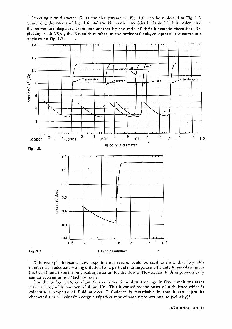
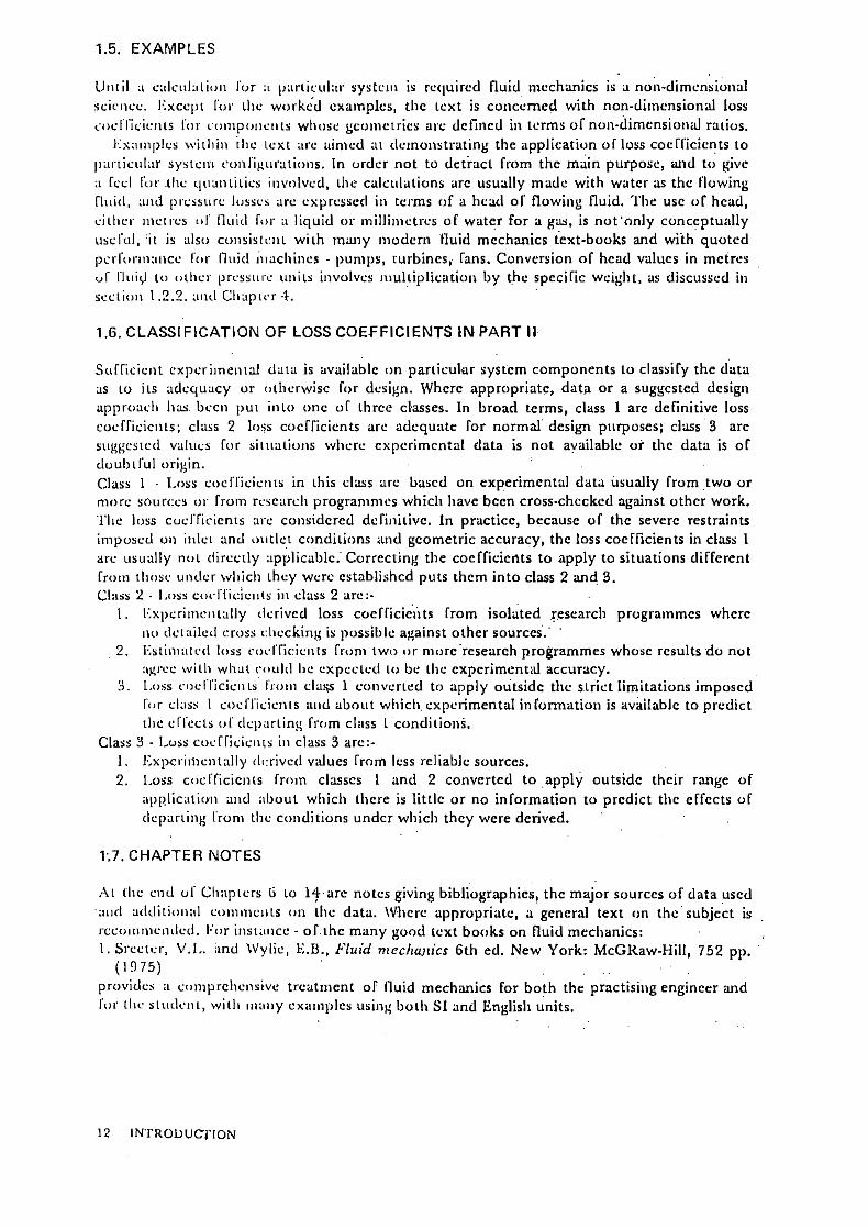
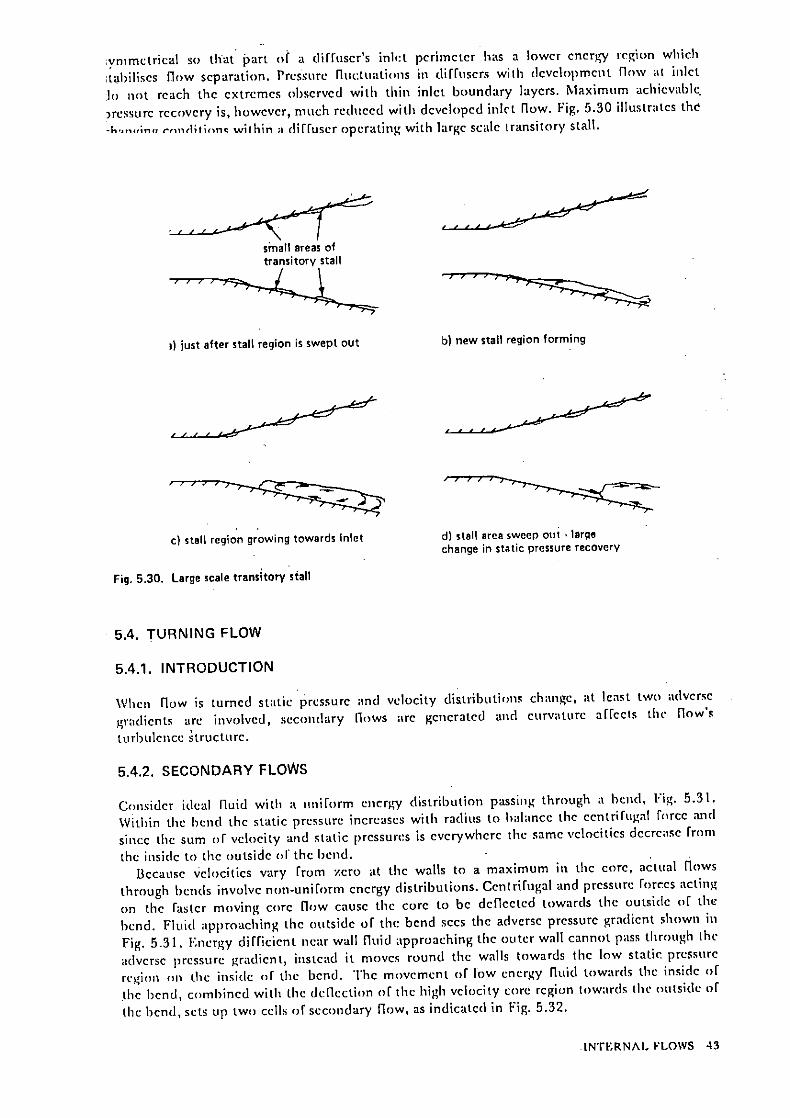
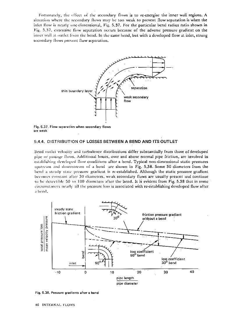
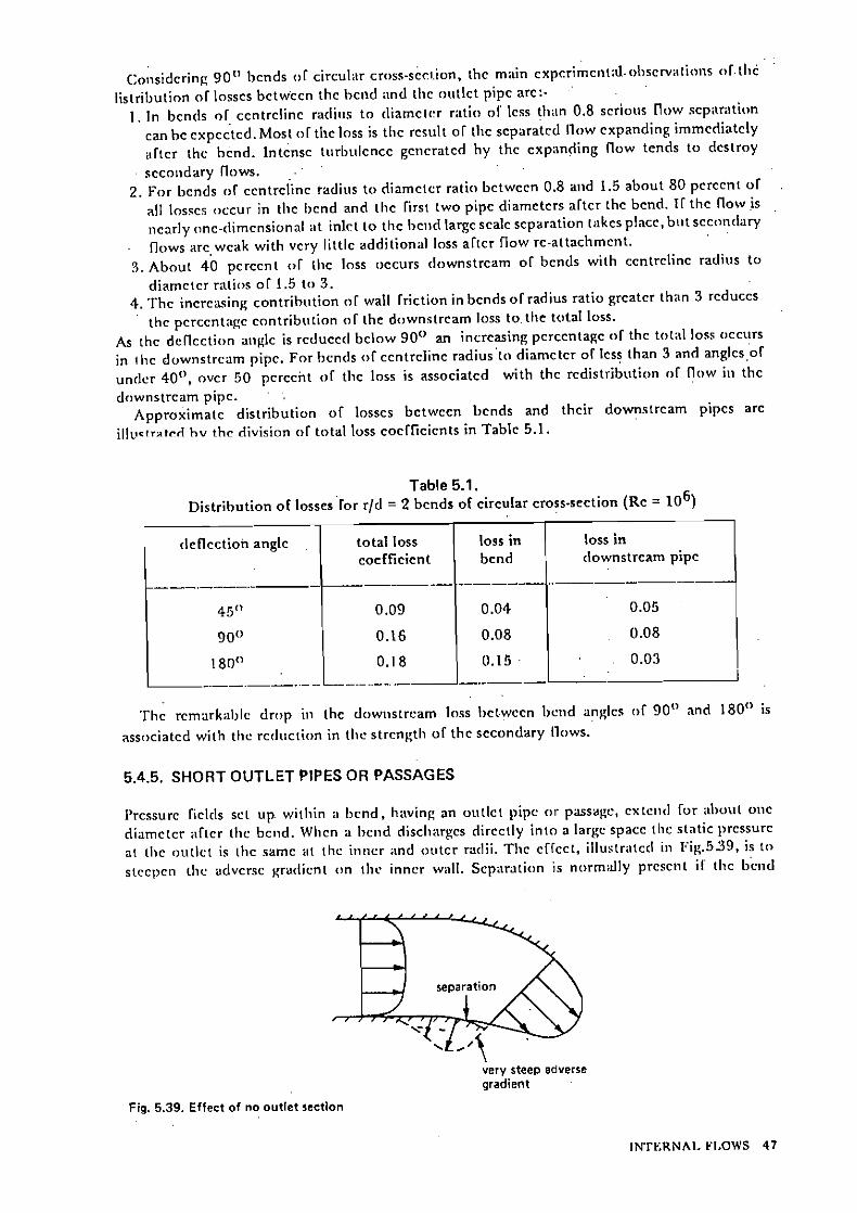
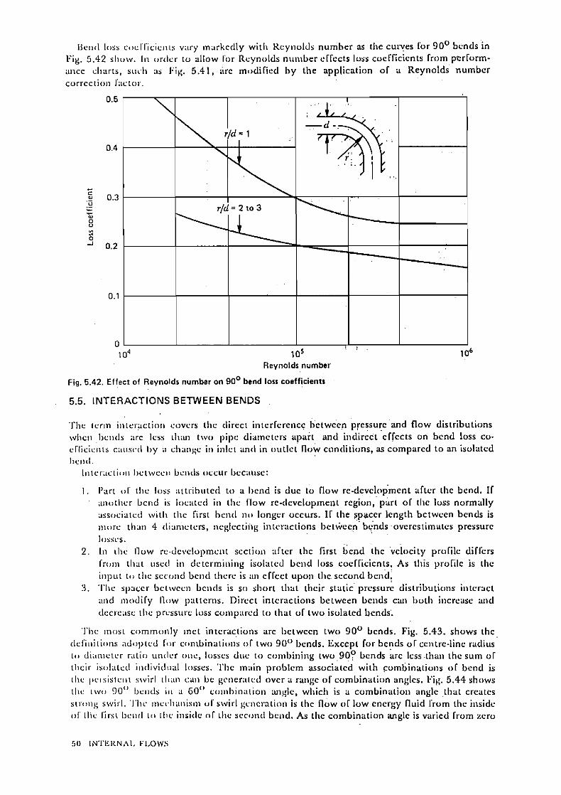
Miller - Internal Flow System (1)
Dec 10, 2015
Perdidas de carga en tuberias
Welcome message from author
This document is posted to help you gain knowledge. Please leave a comment to let me know what you think about it! Share it to your friends and learn new things together.
Transcript


11.1. Introduction 165
11.2. Inlct conditions and Rcynolds numbcrs 165
11.3. Conica! diffuscrs 167 11.3.1. Frcc dischargc - Rcynolds numbcr lo6 and thick inlct boundary laycr (clars 1) 169 11.3.2. Frcc dirchargc - Rcynolds numbcr o f l o 6 and thin inlct boundary laycr (claas 1) 169 11.3.3. Long outlct pipc - Rcynolds numhcr o f l o6 a n d a thick inlct boundary layer (clirs 1) 169 11.3.4. Long outlct pipc - thin inlct boundary laycr (clars 2) 170 11.3.5. Short outlct pipc - O t o 4 diamctcrs (claas 2) 170 11.3.6. Examplc 171
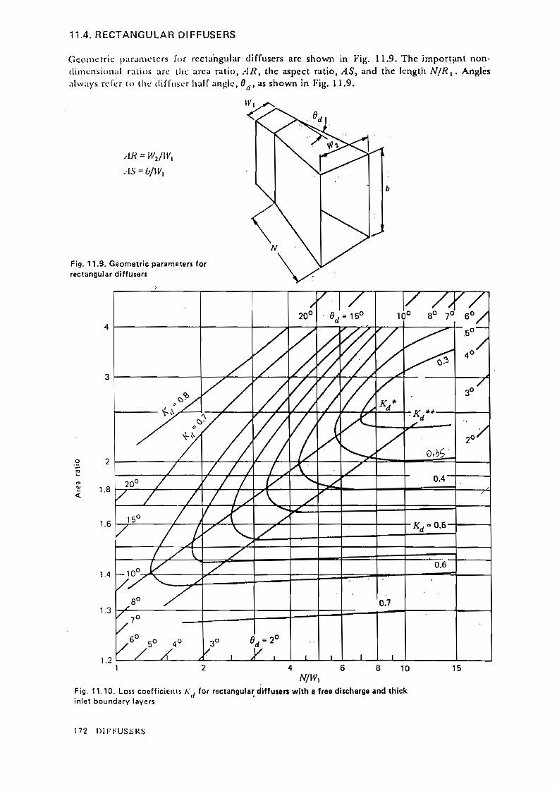
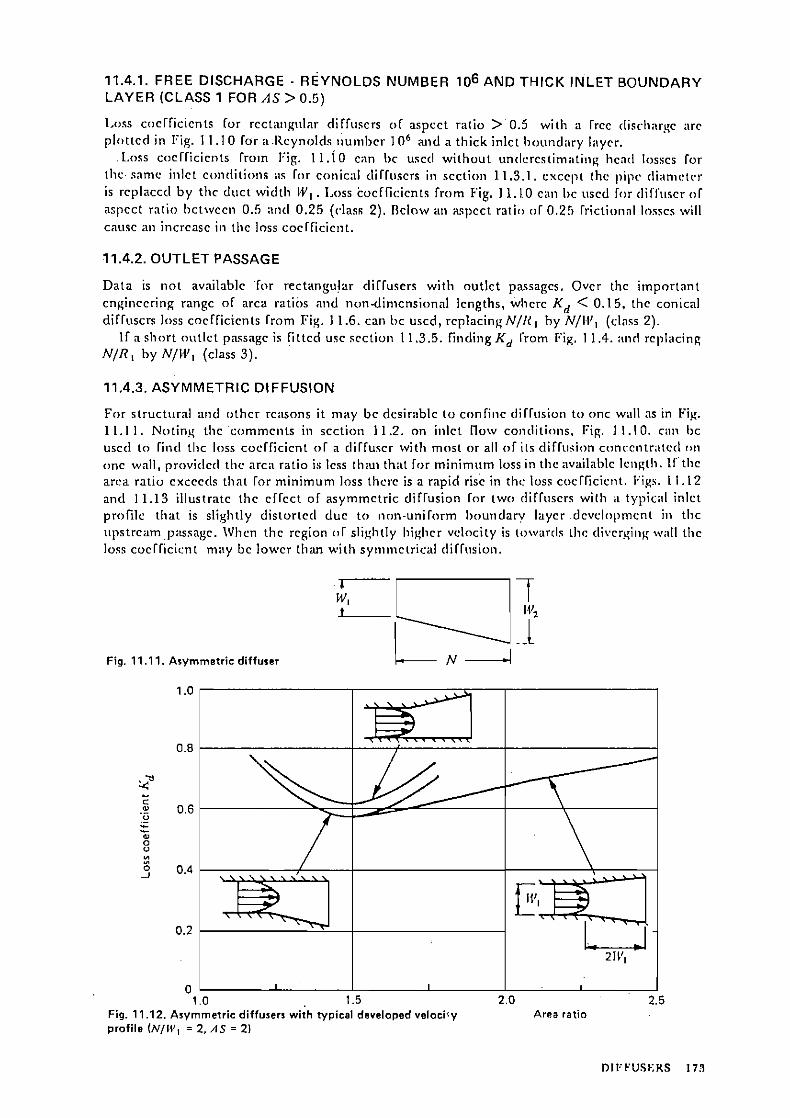
1 1.4. Rectangular diffitscrs 172 11.4.1. Frcc dischargc - Rcynolds numbcr l o6 and thick inlet boundary laycr
(clars 1 for A S >0.5) 173 11.4.2. Outlct passagc 173 11.4.3. Asymmctric diffusion 173
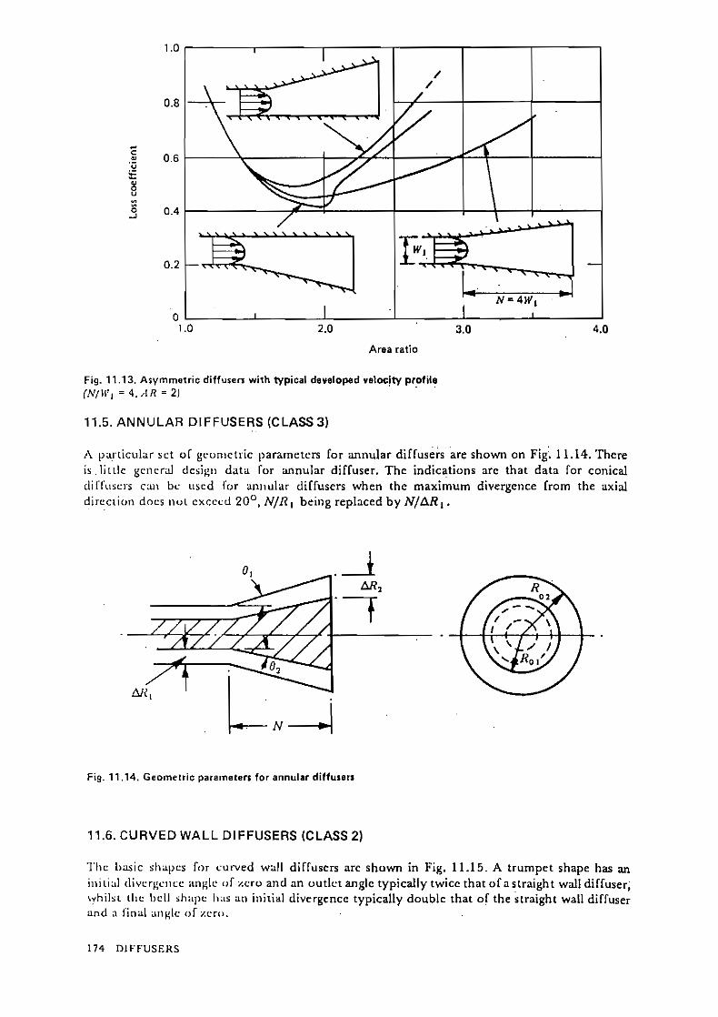
11.5. Annular diffuscrs (class 3) 174
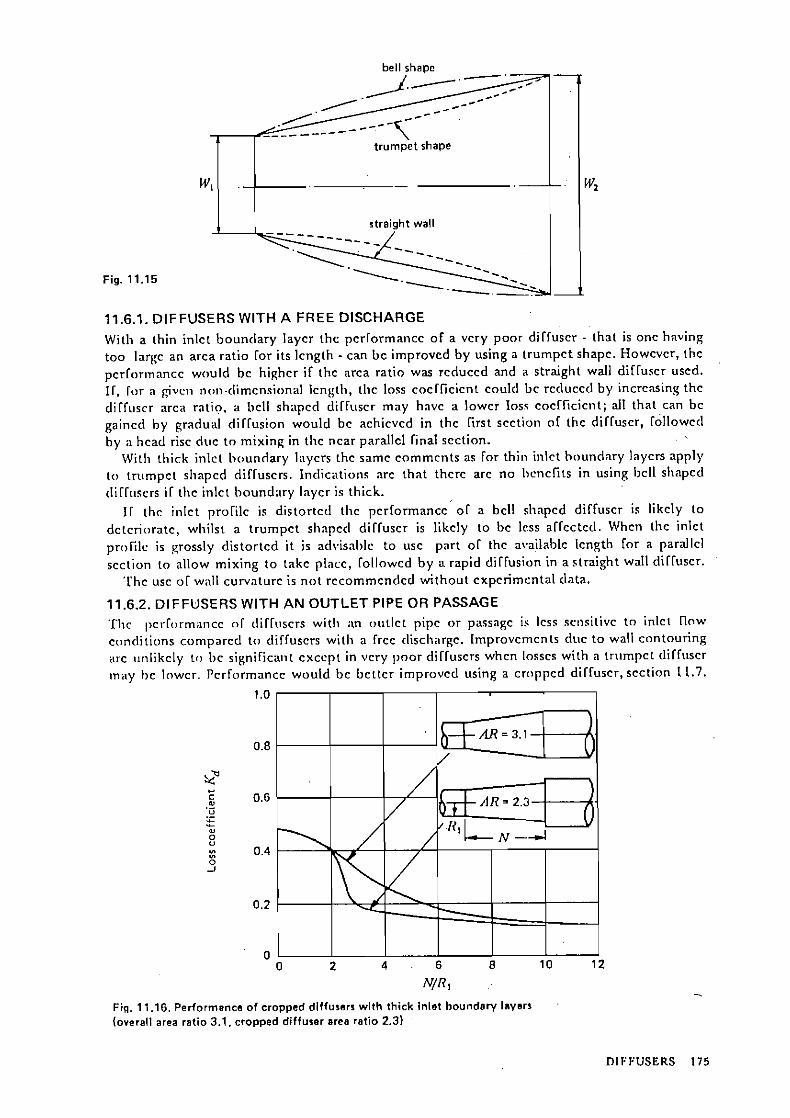
11.6. Curvcd wall diffuscrs (class 2) 174 11.6.1. Diffuscrs witli a frcc dirchargc'175 11.6.2. Diffuscrs with an outlct pipc or parsagc 175
11.7. Croppcd diffusers 176 11.7.1. Examplc 176
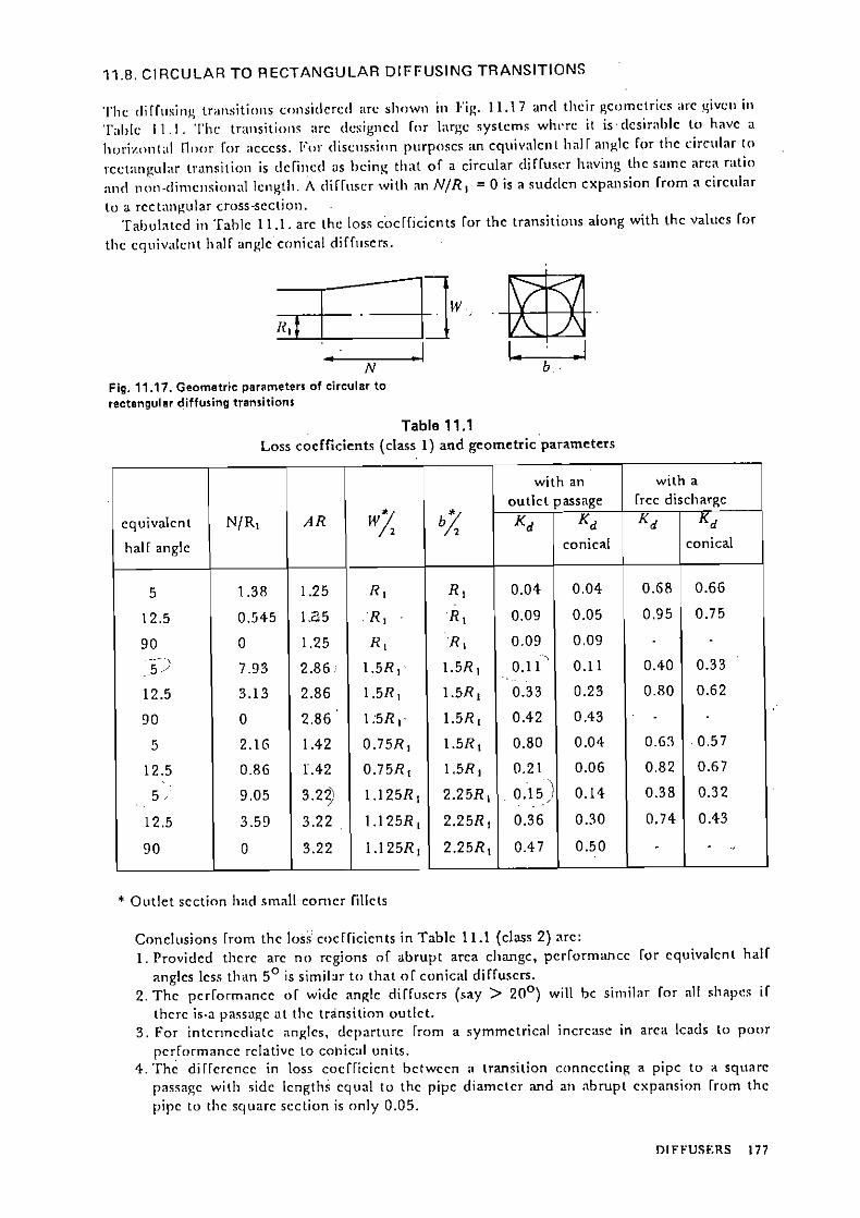
11.8. Circular t o rectangular diffusing transitions 177
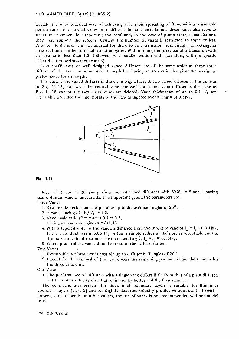
11.9. Vancd Diffuscrs (class 2) 178 11.9.2. Examplc 180 €S1 U@ ,CQS.
*,0n~UL 12. Cornbined Turning and Diffusing Flow 183
12.1. Introcluctioti 183 12.1.1. Rcynolds numbcr (clars 3) 184
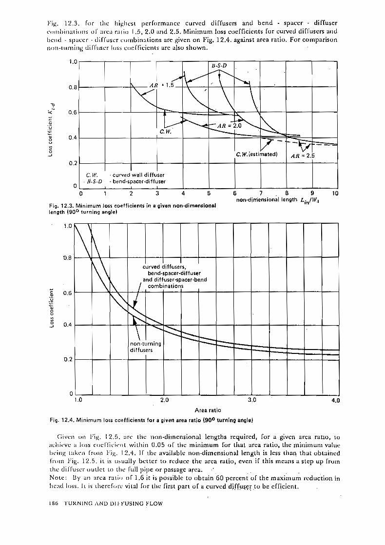
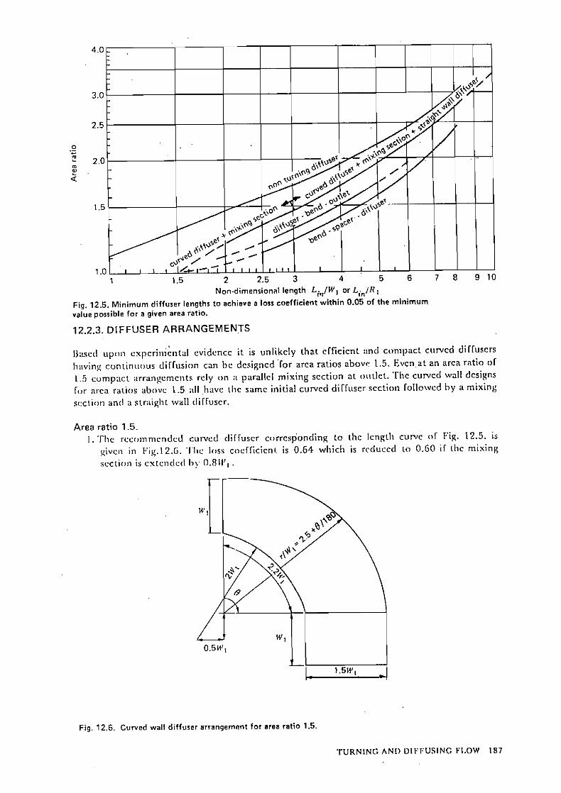
12.2. Dcsign rccommcndations for curvcd diffuscrs 185 12.2.1 Baris for dcsigns 185 12.2.2. Minimum Icngths and loss cocfficicnts (clara 2) 185 12.2.3. Diffuscr arrangcmcnts 187
12.3. 9O0 bcnd-spaccr-diffuscr combinations (class 1) 189
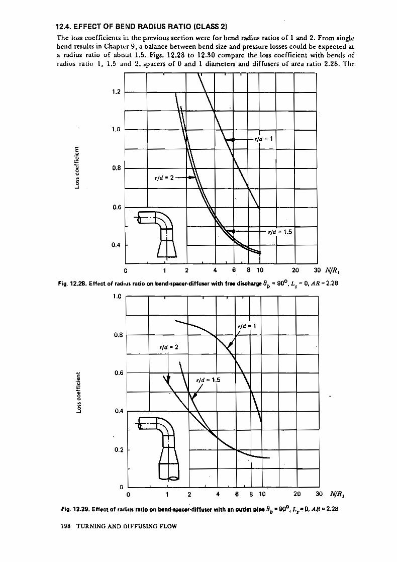
12.4. Effcct o i hend radius ratio (class 2) 198
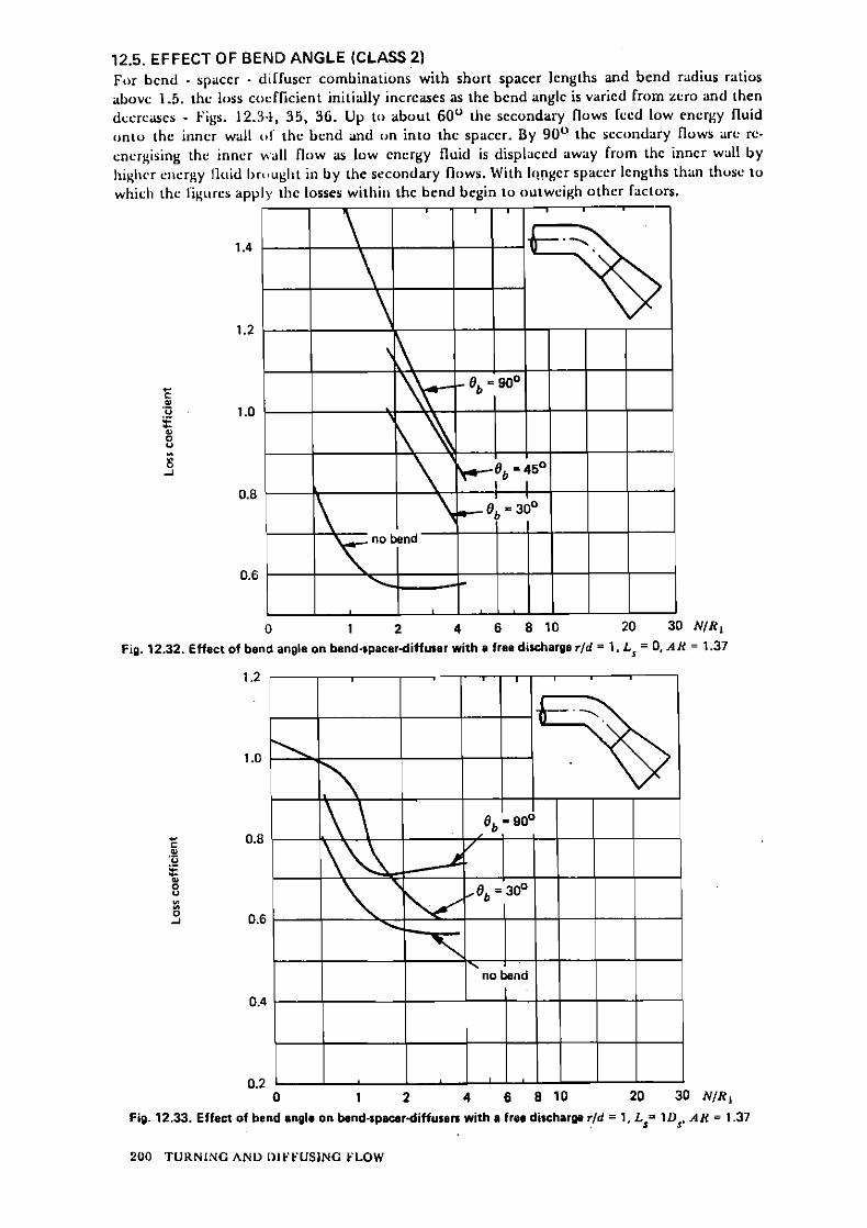
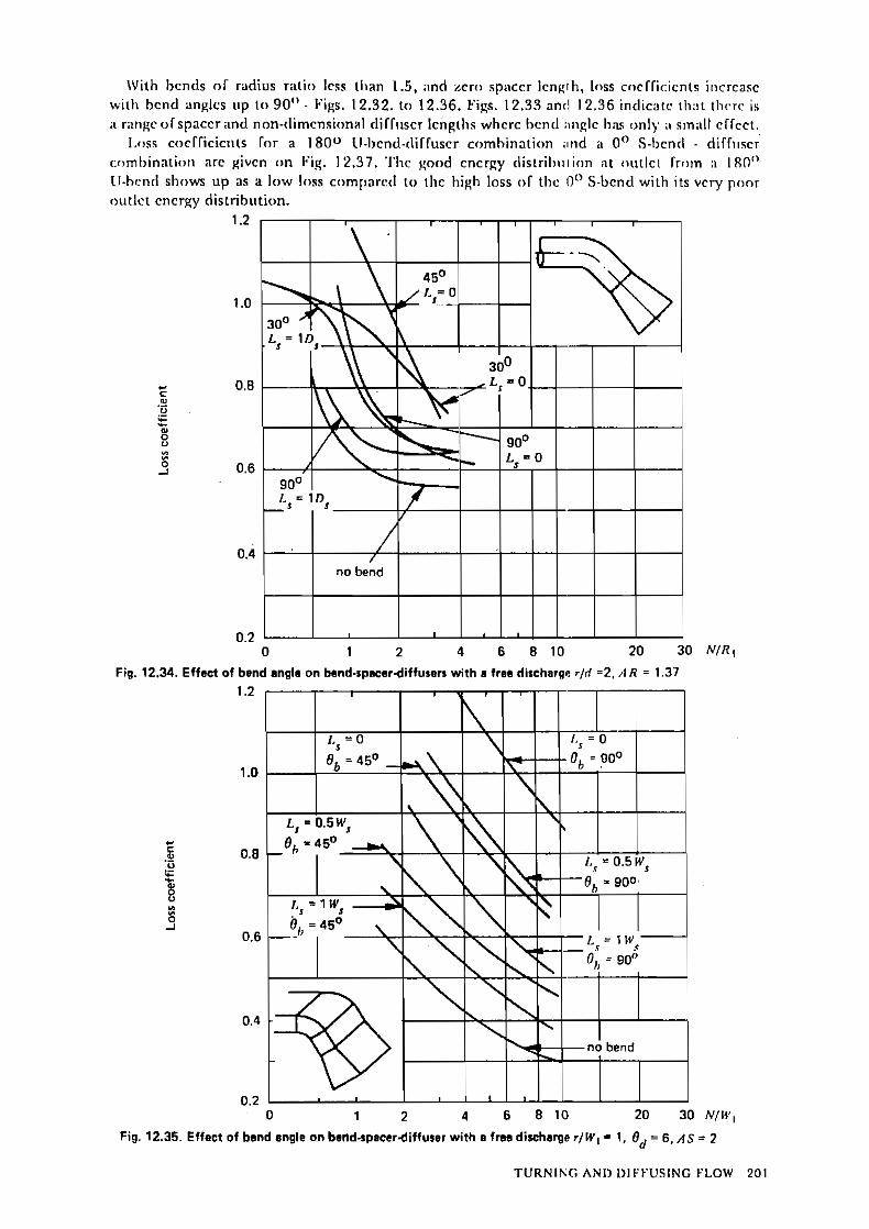
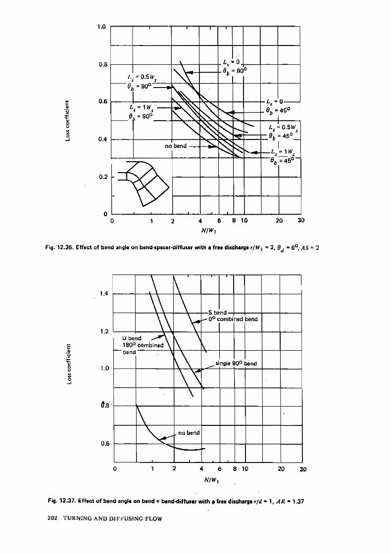
12.5. Eficct o í bcnd anglc (class 2) 200
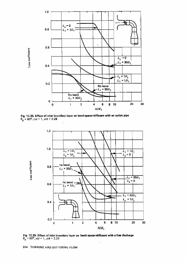
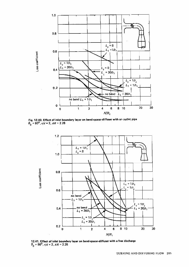
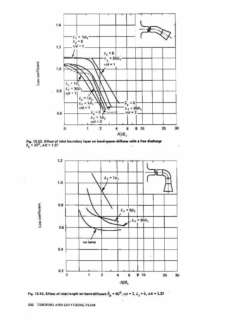
12.6. Effcct o i inlct boundary Iaycr thickncss (class 2) 203
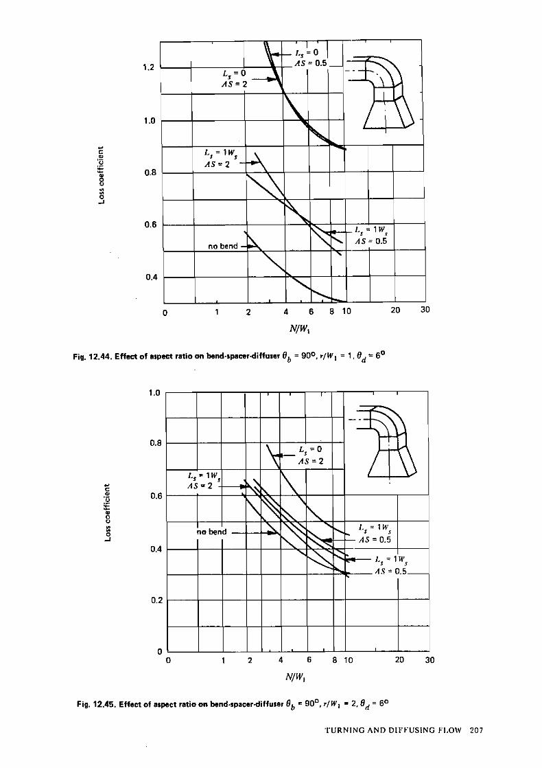
12.7. Effcct of aspcct ratio (class 3) 203
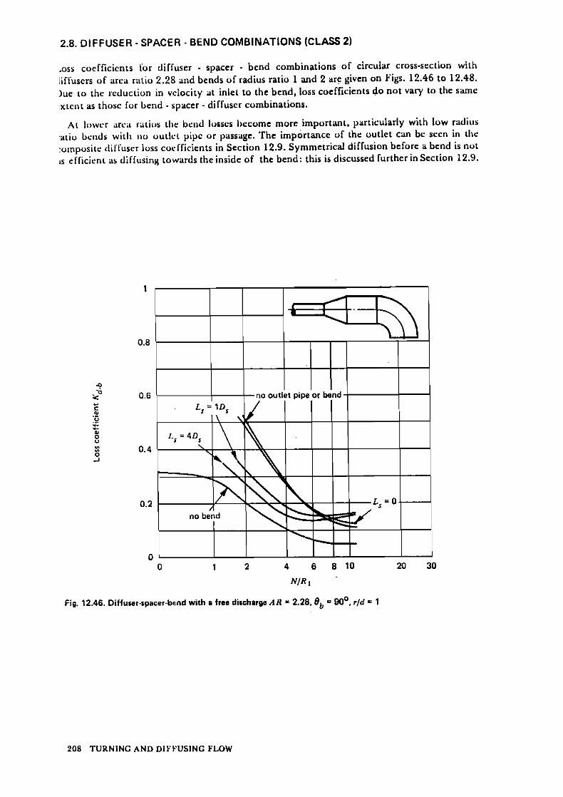
12.8. Diffuscr-spaccr-hcnd combinations (class 2) 208
12.9. Compositc turning diffuscrs (class 2) 210
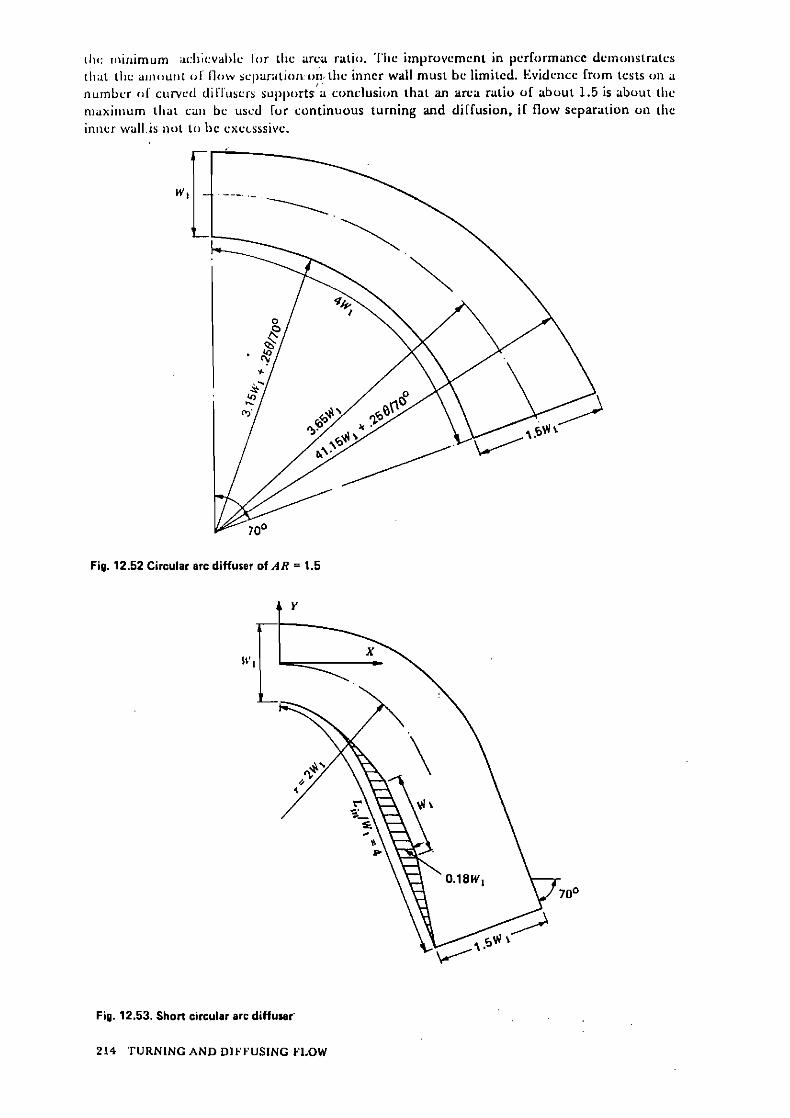
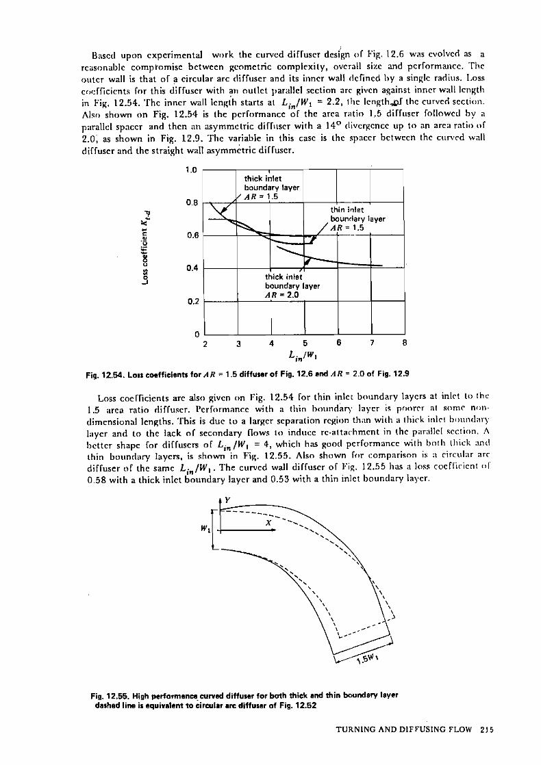
12.10. Curvcd wall diffuscrs 212
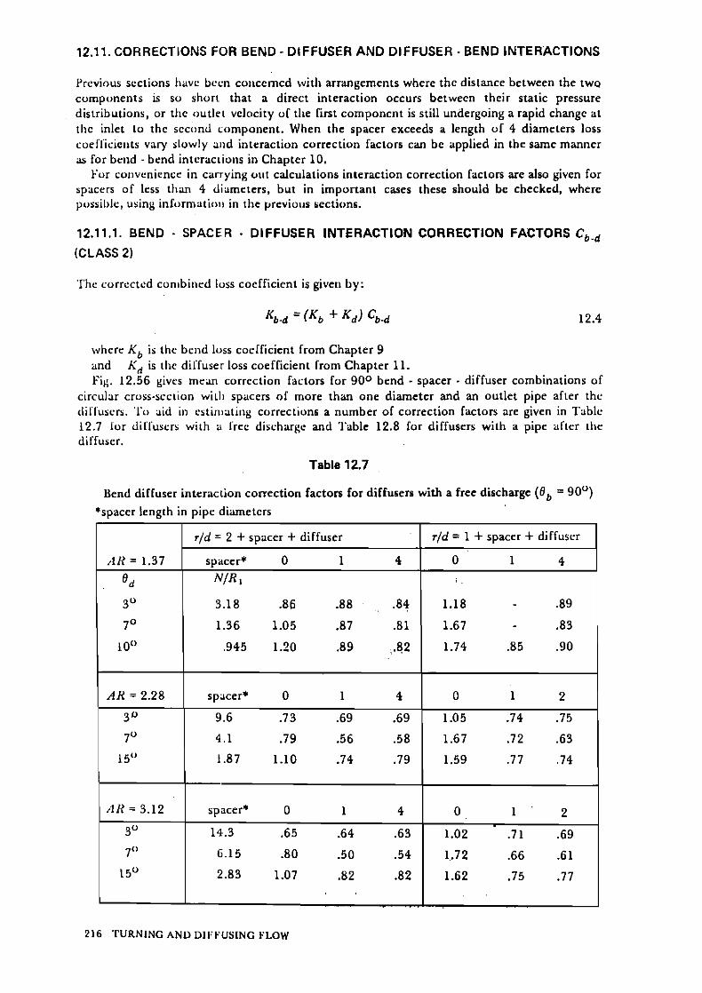
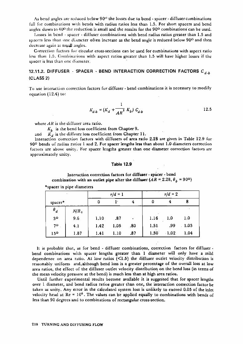
12.1'1. Corrcctions for bciid-difluscr and diffuscr-bend'intcractions 216' 12.11.1. Dcnd-,pacer-dlffurcr lntcraction corrcctlon f a c t o ~ r Cb.d (class 2) 216 12.1 1.2. Diffuscr-spaccr-bcnd intcraction corrcction factors Cd.b (class 2) 218
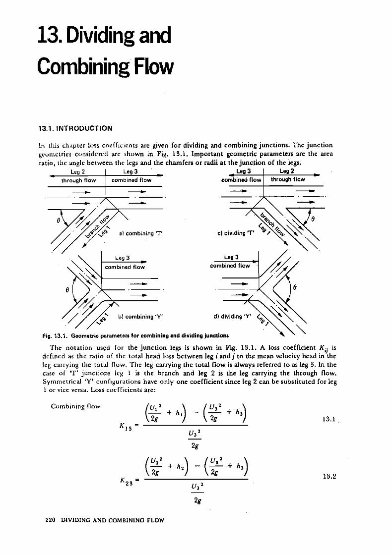
13. Dividing and Cornbining Flow 220 13.1. lntroduction 220
13.1.1. Rcynolds numbcr (class 3) 221 13.1.2. Cross-scctional rhapc (clars 2) 221
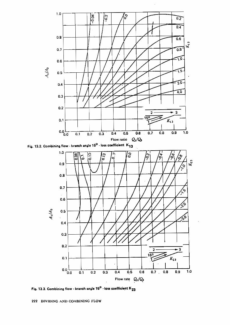
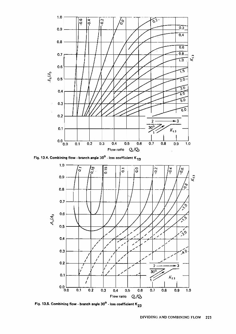
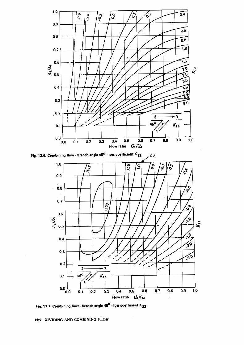
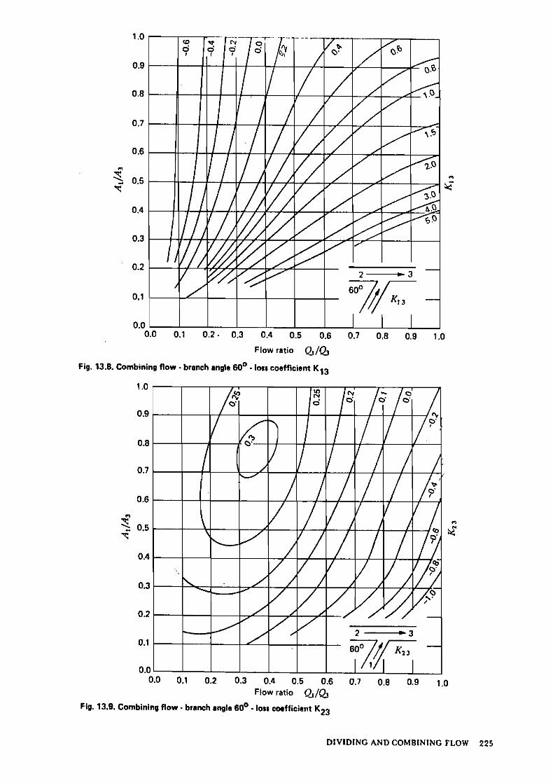
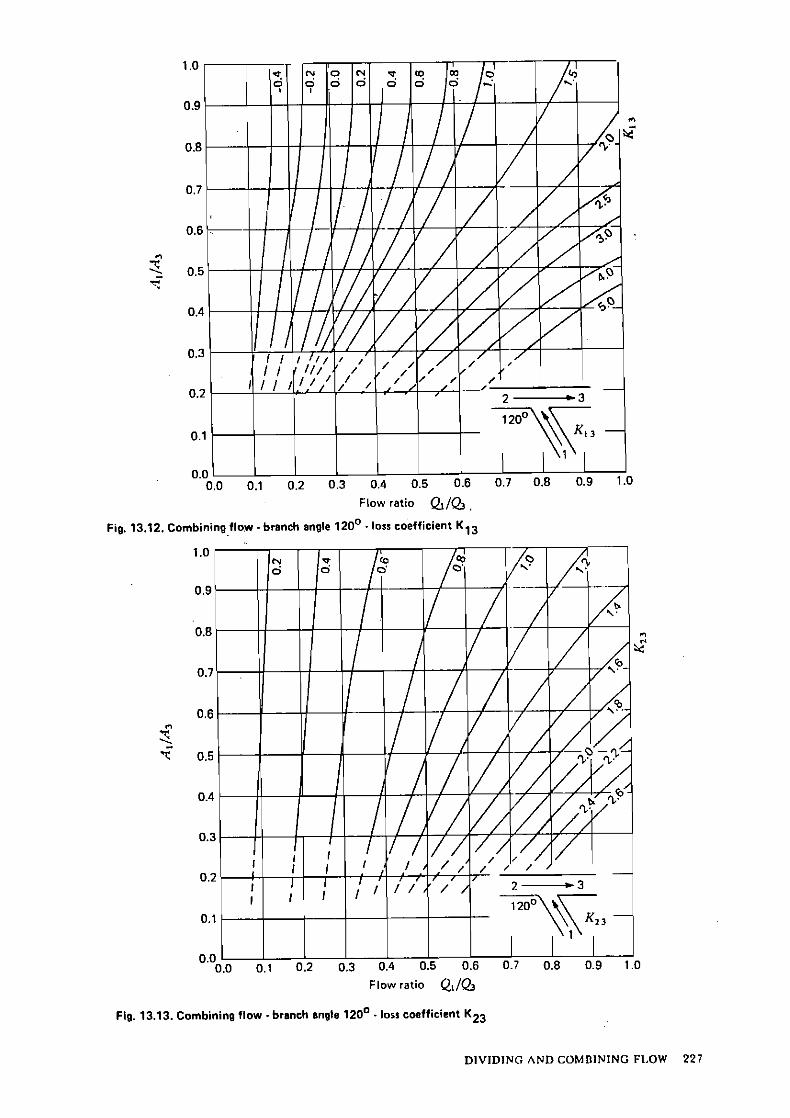
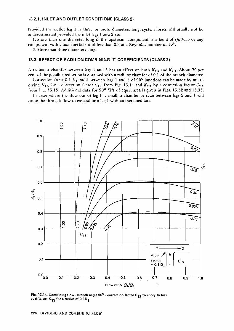
13.2. Sliarp-cdged combining 'T's (class 1) 221 13.2.1. lnlct and outlct condiiions (clasr 2) 228
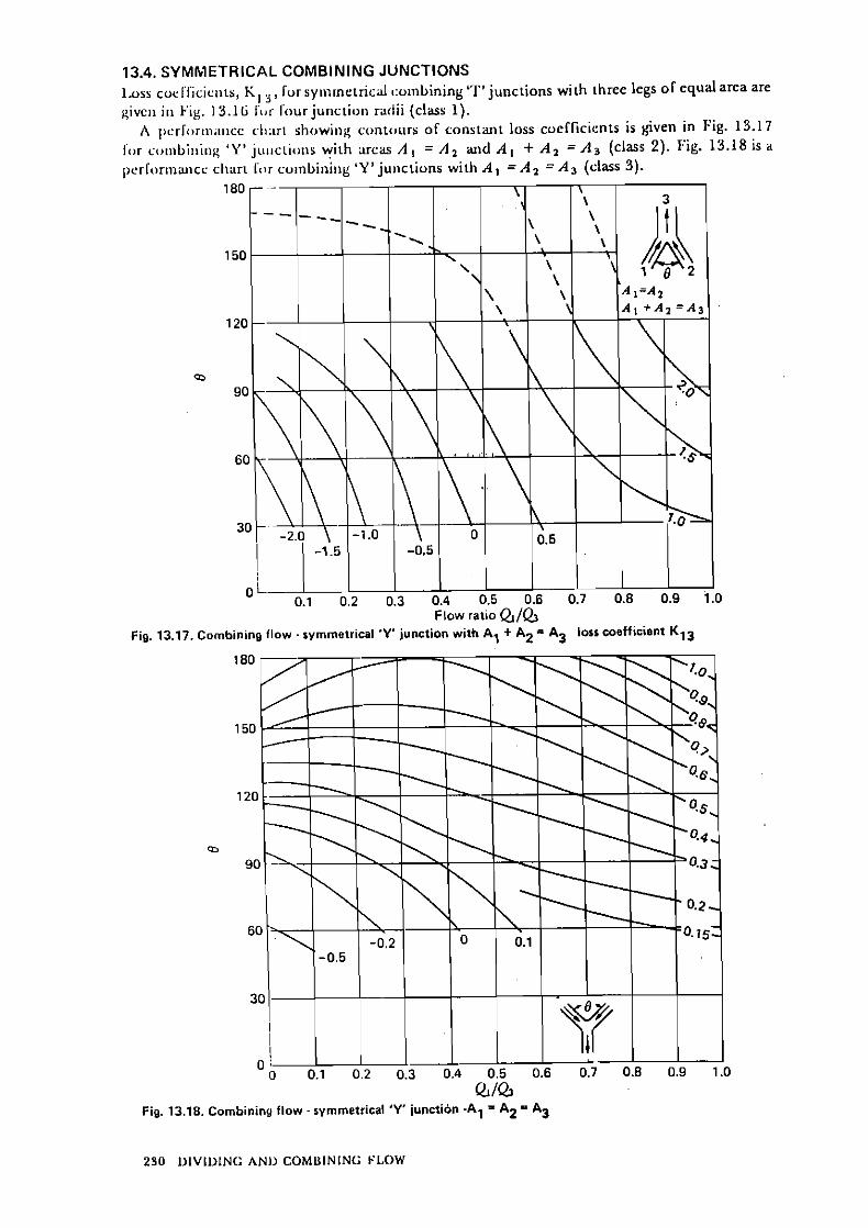
13.3. Effcct of radii on combining 'T' cocfficients (class 2) 228 13.4. Symmctrical combining junctioris 230 13.5. Sharp-cdgcd dividing "i"s (class 2) 233
13.5.1. lnlct and outlct conditions (clasa 2) 233 13.5.2. Examplc 234

13.6. I.:I'I'cci oI' raclii oii ilividiiip "1" c i icf l ic ie i i~s 237
13.7. l inp r t~vcd pcrlr>riiiaiicc dividiiig "r's (class 2) 237 . .
13.8. Syniinciric:il diuidiiig juiict ions 237 . . , ., , .
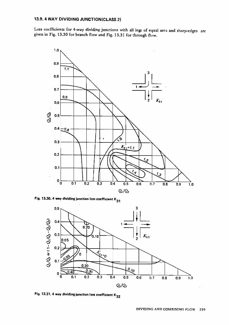
. . 13.3. 4-\v;iy dividiiig juiiciioii (class 2) 239
13.10. C:Ticct ol crt>ss-scctiotinl shiipe (i:lass 2) 240 ' :
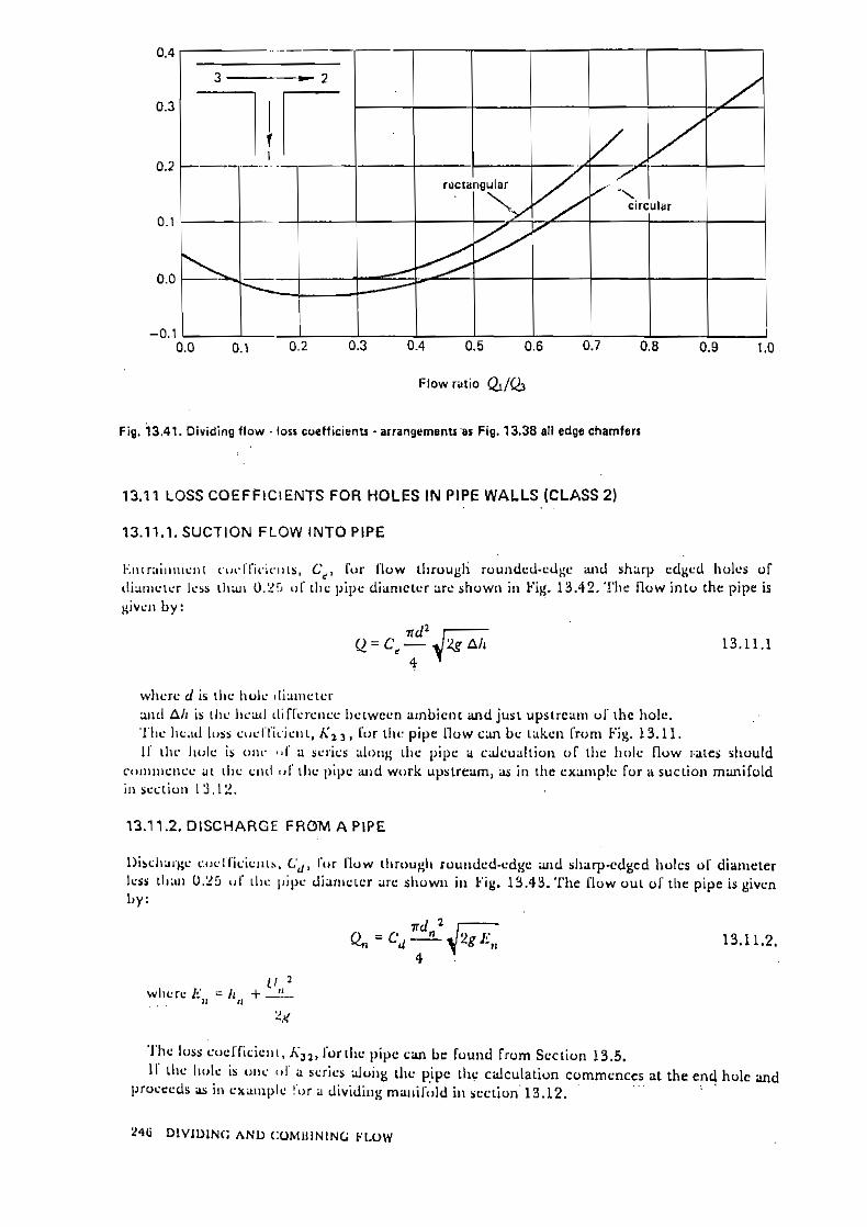
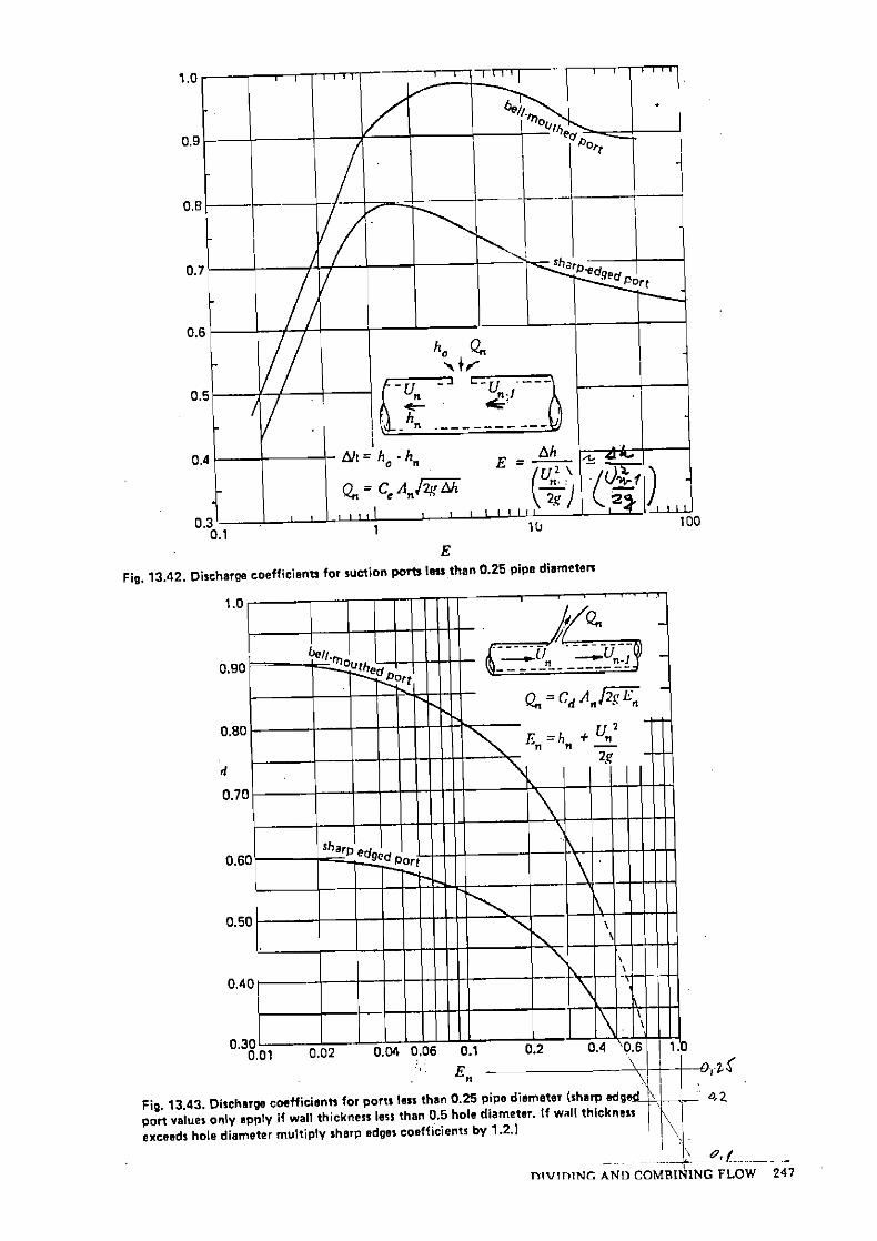
13.1 1. Loss cocrficieiiis for Iiolcs iii pipe wails (class 2) 246 . . . . . . 13.1 1.1. Suriioii flow inio pipc 246
j . . . . 13.1 1.2. Dirchiir~c from a pipr 246 . .
13. I Y . hI;iiiiI'oI<ls 2 4 8 19.1?.1. Soluiioii iiiciliud 248 8 ' . :
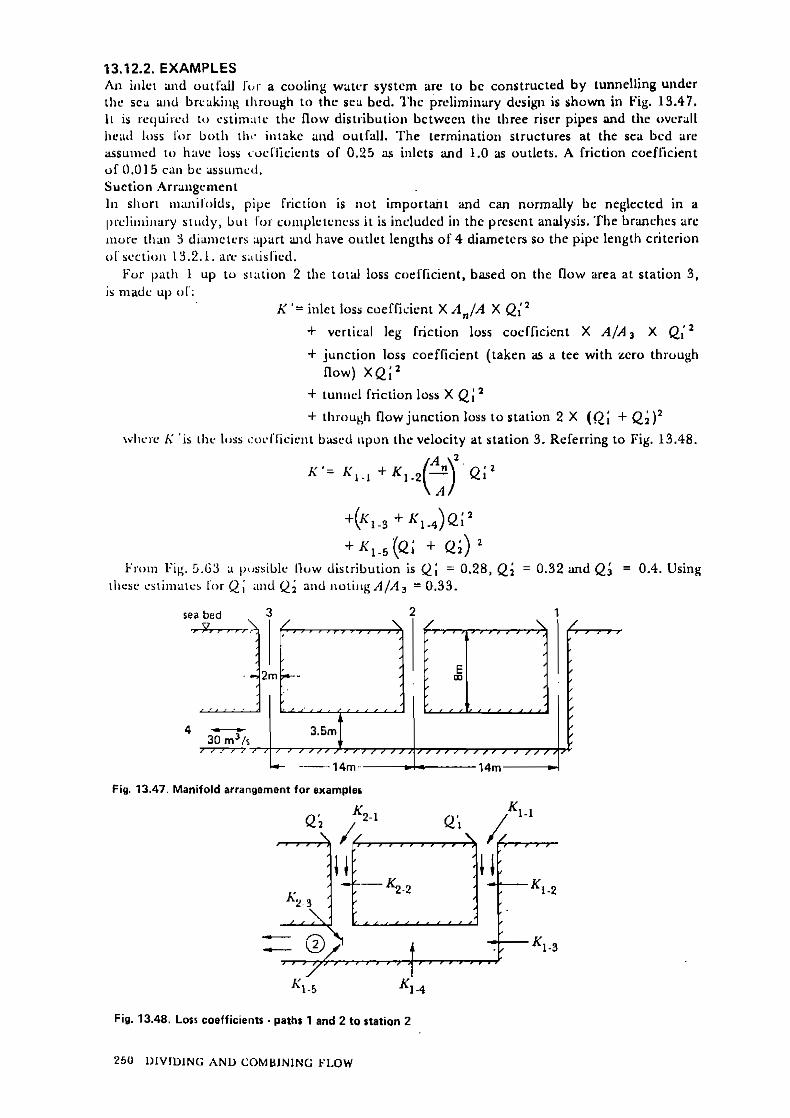
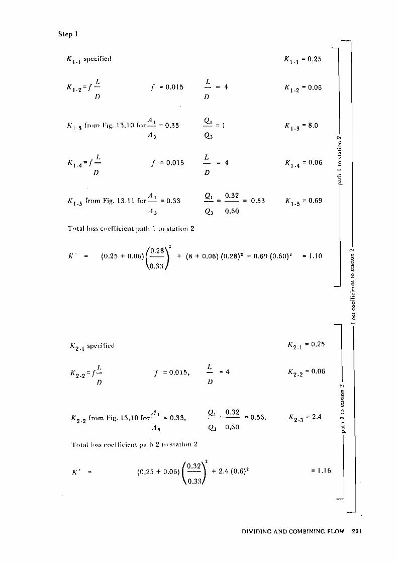
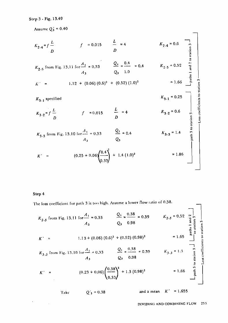
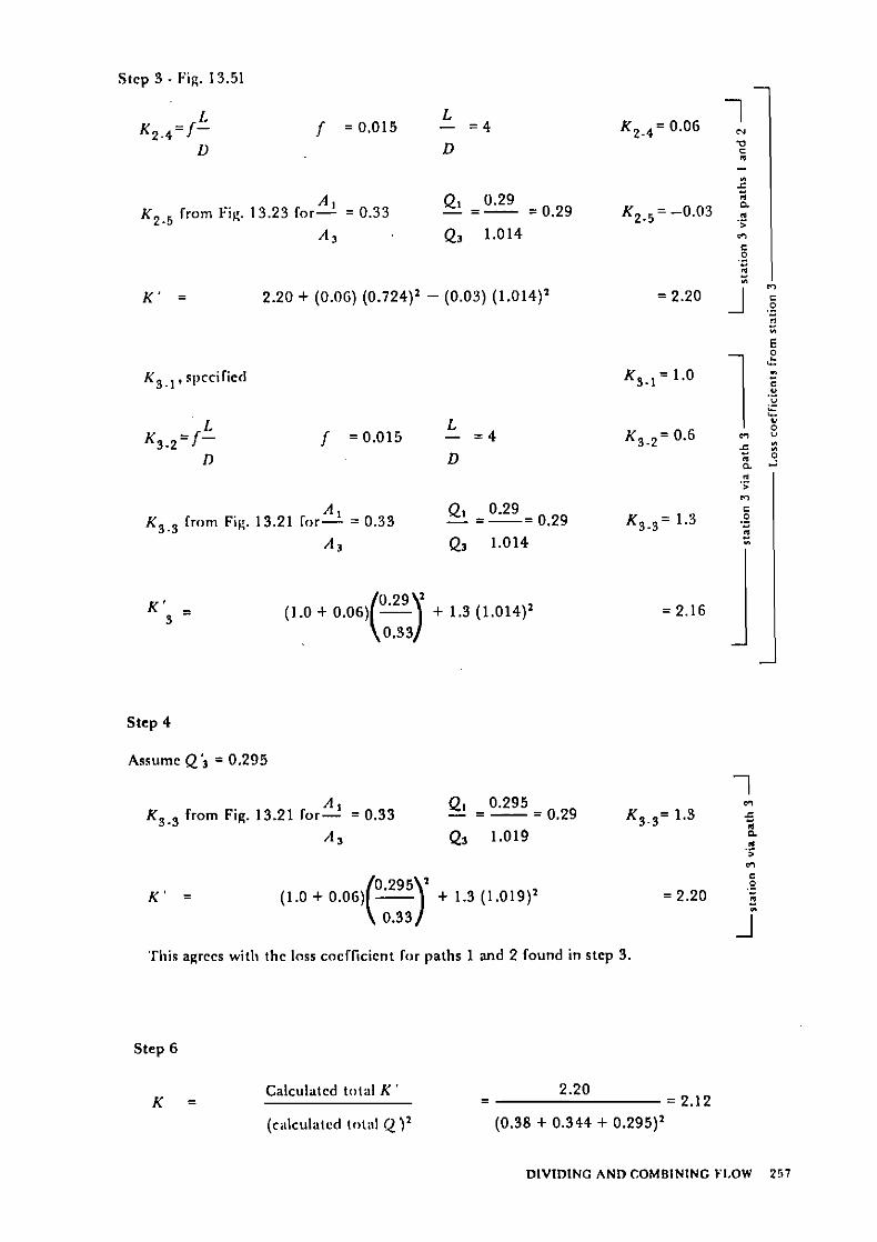
19.1 2.2. Bxunplcs 250 . . ,. . . . . i
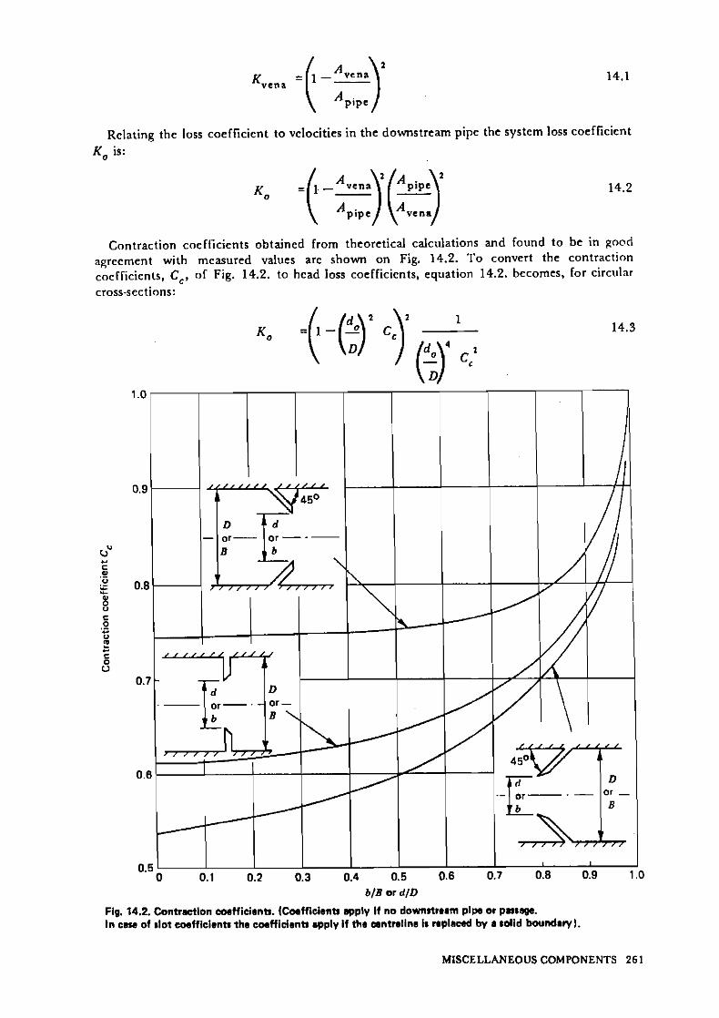
14 . Misccllnncous Systeni C o m p o n r n t s 260 . ,
. . . . . . . . . . . . . . . 14.1. Iiirr<idiiclion 2 6 0 ' . . . , , , 1 4 . 2 Oril ices, scrcciis 2 n d perrora tcd platcs 262
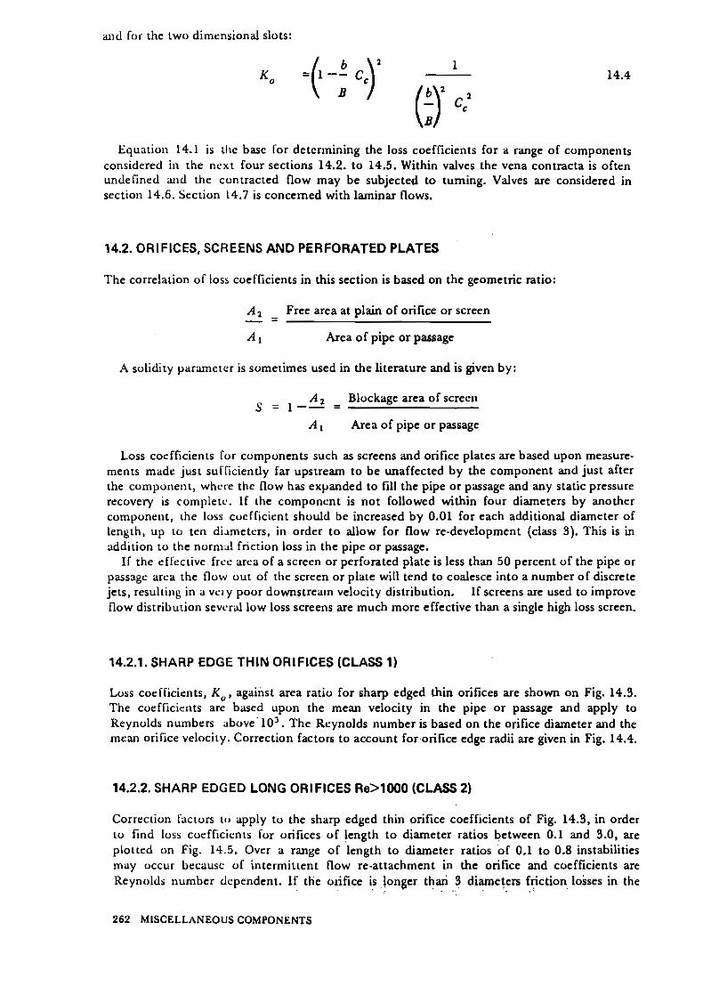
14.2.1. Sharp cdgc iliin orificcr (chrs 1) 262 . . 14.2.2, Shorp r<lgci.l long orificcs RiA000 (clasr 2) 262 . ,
14.2.3. SIinrp<dge<l pcrforarcd platsr (c1a.s 2) 265 : . , ,
I.I.Z:l. ICuund wire scrernr and nc1iin.q (clasr 2) 265 : ! , . . 14.2.5. 'i'r:asIiracks (class 2) 265 1.1.2.6. Ir.>lnioil i>l~iiruciioiis iii pipes aiid parragcs.(clasi 9) 268 l4.2.7. Iloiicycuiiibs (clrsr 2) 268
. , .
14.3. 1)iffcrenii:il I l i ~ w ineicrs (class 2 ) 268 . . , , . . , . . . . , . .". . . .
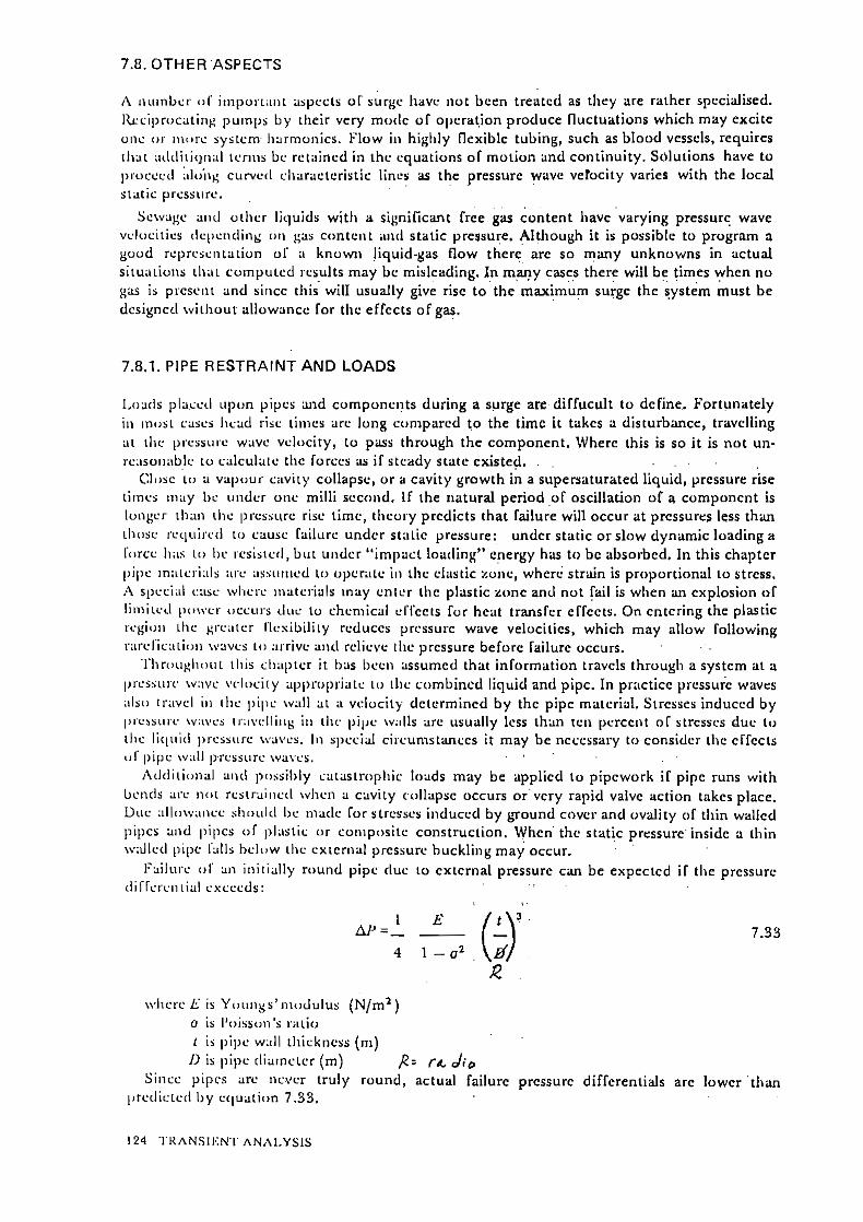
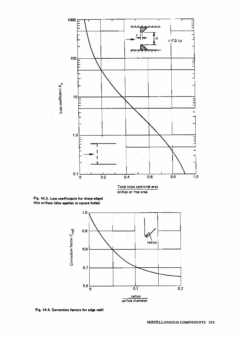
14.4. I i i l e~s ;iliJ coii1i;iciioiis 268 . . . . . . .J.,,
. . 14.4.1. lnlcis (clasr 2) 268 ' . . , ,:,,e ;.:: , . . . . . . _ . . . . . "':,r# 1K.4.2. Cuiiirnciiuns 270 ._. . / :,. . .
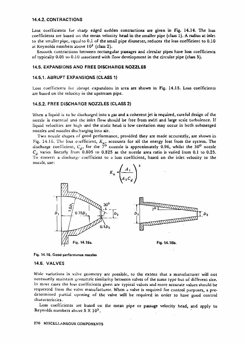
14.5. I,:xp;msions ;iiid I'rrc discliarge iiozzles 270 . . .
. ,. . .
. 14:5.1: Alirupt cxpansions (clars 1) 270 ' '
i4~5.2. ]:res dircliargc noimlcr (class 2) 270 ' . ,. .,:.. ' , , , . . l . Valves 2 7 0 . . . . . . . . . . . .
. . . . . , . ~ : . . . _ . , , .. ::., . . . . . . . . . . . .:. .
14.6.1. nallvaivcs (class 2) 271 , . : : . ! ' . l i ~ j.: . . . . : :
14.6.2. nuitcrfly valvcs (class 2) 277 . . . .
, . 14.6.3. Uia~hrapm valvcs (clars 31 271 A . . . . . 1 ! t . . . . , , . - 14.6.4. Caie znd rluicc valvcs (clarr 2) 273 . , . .
. . . . . 1 . 5 . Clobc, 'Y'and angl! valvcs (clasr 3) 274 , , , . ' ' I : : .
14.6.6. Yoppci valiicr (cl=rr 3) 275 . . : . : . ', . : : ' ,
Pl.G.7.. Plug valvcr(class 3) 275 . . . s . . ., .> : ! ,< , ; ! . . , . . . . , . . l.l.G:8. Ili:flux nnd chcck valvcs 275 : ' , : : )
,,, . !:, , : ,:., '
. . , . . ' . i . . I . , , . . I ' . > . . , id. -;
.l4:7.- ' ,I.amiiiai. Ilow 276 , .
. . . . ... . . . '14.7.1. Sniooth inlets (class 2) 276 , : . : :
I ' :~ . .i 14.7.2. Sl~arprdgcd oriíiccs (claís 3) 279 . , , . , , , : . : . . . .
,: 14.7.3. I.ong orificcs (clnrr 3) 279 , . ,
. . J.
' fik.7!.). Iliiund iv i rc rcrcciis (clasr 3) 279 . . . . . . . . . . . , , , . . 1 . . , .
7 5 Valvcs (clair 3) 279 . . . . . . . . . . . . . . . : . : , : . : 8 . .
15. Sources of In fo rmat ion on Kelated Subjects 282 : , ; . . . . . . . . . . . .
15.1. Introdiicrioii 282 ..: . ; , , / . . . . : . . , . 8
. . . . ~ . , . . . . . . . . . . . . . . . . . .., 15.2. Cencral sourcc- o1 d a t a 282 . , . .: .- : 15.3. Coniprissiblc fl"w 282 . . . . . , . 4: 15.4. Two-pli.:sc l l o w , Iioiling arid non-Newtonian flows 283 . . t .
15.5. P i p c ~ ~ i c i \ v o r k s 283 . : . , ~ ,~ . . . . . . .
15.6. Fluicl in;iclii~ic-sysiciii iiiicracrioiis 284 , . . ,, . ' J, ,.
15.7. I.al>yriiiiIi sciils 2 8 5 : . . . : . i . : . . . ; . . . . .
15.8. ' F l o ~ i i i ~ ~ u r c i i i c i i i 285 . . . . . . . . . 15.9. "Fhw ilirougli tube 1)undles 285 . . 1 . . . t . ~. i.
15.10. Ad<l i t ivcs 285 , . i . . . . i /
15.1 1. 1:loiv i i i I ~ i o l o ~ i c a l sysieins 285 , , .
15.12. ~ o k c :iiid vil>rdiioii 2 8 5 J ' x;;
i 1 - .. ,
. , .., . .... 1 , , . . , . . ,
Symbols, Non -dimensional Ratios and Pressure Definitions
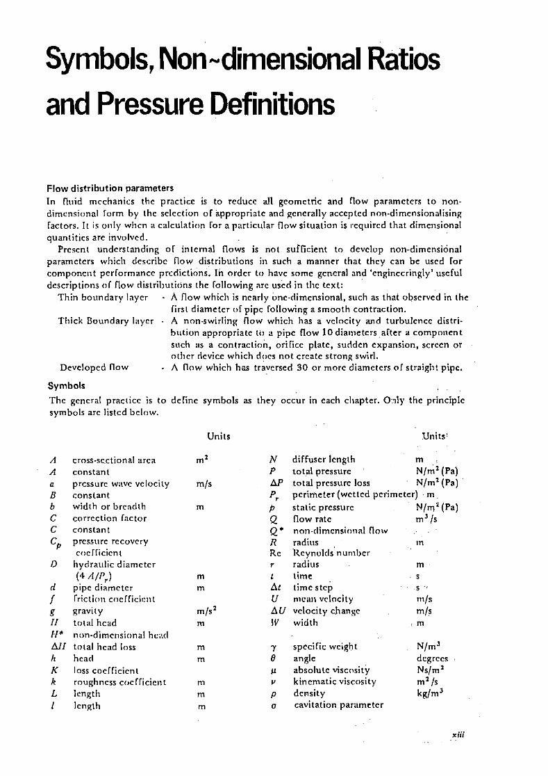
Flow distribution parameters In fliiid mcchanics thc practicc is to reduce al1 gcomctric and llow paramctcrs t o non- dimensional lorm by thc sclcction of appropriatc and gcncrally acccptcd non-dimcnsionalising lactors. I r is oiily wlicn a calculation lor a p:irticiilar flow situation is rcqiiircd that dimensional quantitics are involvcd.
Prcscnt undcrstanding o l intcrnal flows is not sufficient to dcvclop non-dimensional paramctcrs wliicli describe flow distributions iii such a manner tha t thcy can be uscd lor componciit pcrlormancc prcdictions. ln ordcr t o havc somc gcncral and 'cnginccringly' uscful dcscriptions o l flow distril~utiOns thc lollo\ving nrc uscd in tlic tcxt:
Tliin boiindary laycr - A flow which is ncarly Lnc-dimensional. such as thai obscrvcd in the lirst diametcr r ~ l pipc lollowing a smooth contraction.
Tliick Boundary 1;iycr - A non-swirling flow which has a vclocity and turbulcncc distri- b i~ t ion appropriatc to a pipc flow 10diatiietcrs alter a component siich as a contraction, orilicc platc, suridcn cxpansion, scrccn or otlicr ricvicc which dcics no t crcatc strong swirl.
Devclopcd flow . A flow wliich h a trivcrscd 3 0 or morc diamctcrs o l straigli! pipc.
Symbols
Thc gcncral practicc is t o define symbols as they occur in cach cliaptcr. 0:afy thc principlc symbols are listcd bclow.
A cross-scctional arca A constant a prcssurc w;ivc vclocity B constant b width or brcadih C corrcction factor C constant Cp prcssiirc rccovcry
c~>cll icicnt D hydraiilic diamctcr
(4 AlJ'J rl pipc diamctcr / I'rictioii coclliciciit g gravity II total hcad II* non-dimcrisional hc:i<l AII total hcad loss h hcad K loss cocllicicnt k roughncss coclliciciit L lcngtli I lcngih
Units . - Units'
N diffuscr lcngih m P total pressurc N/ml (Pa) AP total prcssurc loss N/ml (Pa) P, pcrimcter (wcttcd pcrimeter) m p static prcssurc N/m2(Pa) Q flow ratc m' /S
Q* non-dimcnsi~inal floiv . . R radios in Re Hcynolds nunibcr r radius m ' t timc , S
At time stcp S ' <
U nic;iii vclocity in/s AU vclocity cJianRc 4 s IV width , m
7 spccilic wcight N/m3 0 anglc dcgrccs , p absoluic viscosity , Nslm' v kincmatic viscosity . m2/s p dcnsity k d m 3 o cavitation paramctcr
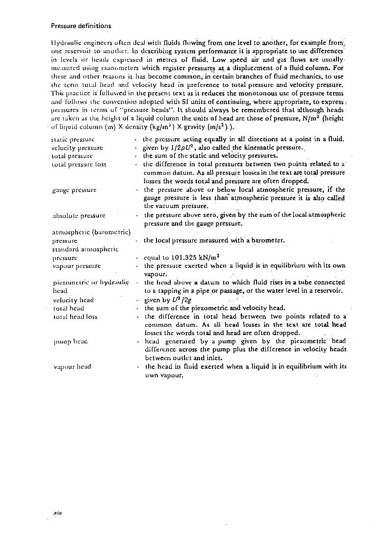
Pressure definitions . . . . . .
Ilydi-aulic cnginccrs oftcn ded witli fluids flowing from one level to another, for eiainplefrom; oiie rescrvoir i o uioilirr. In dcscribing systcin performance i t is appropriate to use differcnces' in lcvcls iir Iiciiils cxpi-csscd iii meires of fluid. Low speed i r aiid gas ílows are usually. I I I L . : L S L I ~ C ~ usiiig !iiaiii~iriciers which register pressures e. a displaccment of a fluid column. For ilirsr illid titlier reuoiis it Iias become common, in'certain branches of íluid mechanics, t o use ~ I i c reriii toi:il 1ic:icl :ind vclocity Iiead in preferente to total prcssurc w d velocity prcssure. 'Cliis p rx i i ce is followed i r i tlic presciit text as it reduces the monotonous use of pressure terms :uid folli)ws ilie coiivciitioii adopted witli SI units of continuiiig, whcrc appropriate, t o rxpress . prcssurcs i i i lcriiis o í " ~ T C S S U I < : hcads". l t sliould always bc remeinbcred that although heads. are iakcii as ilic Iiciglii o l a licluid colunin tlie units of head are those of pressure, N/m2 (Iieight
liquid c~luii i i i (in) X density (kgjin3) X gravity (in/s".): . . .
siaiic prcssui-c - thr prcssure acting equaily in ail directions a t a point in a fluid. velocity prcssurc - givrri by 1 / 2 p U , d s o called !he kinetnatic pressure., total prcssiire - tlie sum o í the sedtic .and velocity pressures. ioral pi-cssurc loss - tlic differeiice in total prrssures betwccn two points related to a '
commoii daturn. As al1 prcssurc lossrsin ihe text are total prcssure losscs the words t o t d 2nd presk"'re are often dropped.
~ : i ~ i g ~ p r c s u ~ - ilie pressurr above or below local atinoipheric pressure, if the gauge pressure is lcss than-a~mos~her ic prcssure it is aisp cailed tlir vacuum pressure.
:il)solulc pressurc . ilie pressurr above zero. given b y the sum of the locd atmospheric prrssure md tlle gaugc pressure. , .
atmosphcl-ic (baronictric) ~>rcssurc - tlie local pressure measuredwi tha . . . . barometer. siaiidard aiiiiosplicric ; , , . I . . . . . . prcssurc - cqiiiil to 101.325 k~ / i i i " vapour ~ i ~ e s s i ~ r e - ihe pressure cxertrd whcii a liquid is in cquilibriuni with its own
vapour. piezi>inciric o r Iiydr.iulic - tlie Iicad &ovc a daturn t o which fluid rises in a tube connccted Iicad to a tapping in a pipe p r passage, or the water level in a reservoir.
velocity Iieacl - givcn by U / 2 g !I ' i towl heiid - the sum of the piezometric and velocity hcad.
ioial 1ic;id loss - ihe diffrrence in total head betwecn two points related t o a coninion daturn. As al1 hcad losses in the t rx t are total head
j/ losscs the words total w d head are often dropprd.
!! lnnnp Iicad - Iicad ycneraird by a yump given b y thc picromrtric head diffrrencc across tlie pump plus the diffcrence in velocity heads ,
betwecii outlct and inlct. !! ' v i ~ ~ > ~ i u r l i c x l - tlir hcad iri íluid exerrcd when a liquid is in equilibrium with its
own vapour.


1. lntroduction
'E: g E...
1.1. TYPES O F FLOW CONSIDERED
Intcrnal flow is conccrned with fluids flowing in pipcs, passagcs, ducts, conduits, ciilvcrts. tuiincls and components such ;L$ bcnds, diffiisers and hcat cxchangcrs. In tlic tcxt, "pipc" is iiscd for flow through circularcross-scctions and "passage" if the cross-scction is non-circular. Conlincd in pipcs m d passagcs most liquids and gasses bchave in a similar manncr so thc gcncral term fluid is appropriate and uscd throiighout thc text.
Exccpt for Chaptcrs G and 7, o n cavitation and transielit ilow, tlie prcscnt work is rcstrictcd to steady flow of a single phasc near Ncwtonian fluid. A Newtbnian fluid is charactcrised b y shc;ir stress bcing proportional t o strain with the constant of proportionality being the absolutc viscosity. Gencrally fully turbulcnt flows arc assumcd except in discussion o n important aspccts o l low Rcynolds numbcr flows. Tiirbulent single phase intcrnal flows are o f coiisidcrablc cnginccring intcrcst but are thc cxception in naturc. For instancc tlic most common forin of pump, thc hcart, opcratcs cyclically in thc laminar to tiirl>ulcnt tr;insition rcgion, pumping a complcx fliiid with living cclls and solids i i i sus\>cnsion, whilst tlic flow of niitricnts ir1 pl;ints occurs wliolly in thc 1;iminar rcgion.
In practicc thc flow of blo<id and othcr mixturcs is so complcx that singlc phasc ítow pnramctcrs havc to bc uscrl, with corrcctions applicd t o account for dcpartiircs from singlc phasc .conditiuns. Many o f thc flow plicnomena of single phasc flow iipply to mixturcs, providcd scparation or re-distribution of phascs does n o t occur due t o accelcration forces.
Thc tcrm steady flow is uscd in rclation to overall systcm ilows. Violcntly unstcady flow may bc prcscnt in onc or morc componcnts, bu t providcd unstcady flow in componcnts docs not aitcr tlic ovcrall systcm prcssurc and flow by morc than a pcrccnt o r so, stcady flow can bc said io cxist. Enginccring flows arc usually turbulent, with local velocities and pressurcs varying continually. Conccptually, thc flow can bc visualised as having mean valucs of vclocity and prcssurcs with fluctuating componcnts supcrimposcd.
Virtiially n o iniormation is availablc o n flow structurc duriiig transients and the assumption has to bc madc tliat stcady flow loss coefficicnts can be used. In practicc, using steady flow cocfficicnts a l o n ~ with thc transient dynamic cquations, it is found that for a singlc flow wiriation, c:ilciilatcd temporal and spatial prcssures and flows agrcc rcasoiiably wcll with mcasurcd valucs. Thc turbulcnt cddics rcsponsiblc for major cncrgy dissipation in interna1 flow Iiavc diamctcrs that can bc of tlic ordcr of one thousandth of the pipc diamctcr and thcy occiir in closc proximity to the boundarics. I t might bc cxpccted that, providcd a change in flow of onc pcrccnt occurs in the time for ten near wall cddies to pass a particular location, the flow could be considcrcd slowly varying and as an approximation, steady statc cocfficicnts would apply. Carrying this to thc cxtrcme, slowly varying conditions could bc assumcd, i f calculatcd in stcps, for any changc that occurrcd in a time longer than it t akes thc flow to travcl on.c pipc diamctcr. Achicving ncar stcady flow conditions in components may takc longcr than in pipcs. for :ilthriugh c n c r ~ y dissip:ition is iiltimatcly via thc samc sizc cddics as in pipcs, thcsr cddics arisc from vcry much Iiirgcr cdclics cauacd b y scparation and sccondarv flows. l'akiiig a typical largc cddy sizc as twcnty pcrccnt o f thc pipe o r componcnt tliamctcr, and assuming ten largc cddics havc to bc shcd to cstahlish a stcady flow ficld. c h a n ~ c s taking twicc thc timc for flow to travcl a pipc diamctcr could bc considercd slowly varying: Although prcssure losscs may approach thc stcady stñtc valucs in the time it takcs thc flow to travcl two pipc diamctcrs, th r vclocity and turbiilcnt structurc of tlic flow will not approach dcvelopcd conditions until tlic
INTRODUCTION 3

Ilow II:IS ira\~ersctI iliii-ty 01. 1111>re pipc diaiiiricrs. Loss c í i i i i s :uirl c;~Icu1aiio11~ o í pressurc losses in thc tcxt are for incompressible
Ilow. 'i'liis is i i c i rcs~i-iciion as rcgards liq~iids which havc prcssure wdve velocitics (vclocity oT souiid) oí ~ I i c ordrr u l 1000 m/s cornpared t o typical flow velocities of undcr 10 m/s - ecli~ivalciii io hlacli ii~iniber oT 0.0 l . For gasscs the pcrlormancc data can bc uscd directly for Ilo\vs al h.l~cli iiuiiihcr lcss ilim 0.2 . rquivslciit to 70 m/s for air at no rmd temperaiurc and prcssure. I T tlciisicy cliaiigcs arc signiíicaiit in loiig systcms, incomprcssiblc cdculations can be inildc by dividiiig up ihc systcin iind using inean densitics and pressures in diffcrent parts of ilic sysiciii. I'riividc<l correctioiis are applied to account Tor compressibility, loss coefficicnts ciiii L J C llbcd L I ~ 1 0 hl:~cIi iiunibcrs IJT 0.8. In tliis case ii is the local Mach nuinber ihai is iiiipi,rtaiii railicr i1i;ui a I\lacli nuiiibcr b a c d oii thc mcan íiow.
, . . , . . . . , . ., , . .,
1.2. SYSTEM O F UNITS AND FLUID PROPERTIES . .
. . . . . . . . : . . . . . . . . . . . . 1.2.1. SI UNITS . . . . . . . .
111 SI iiiiiis niass is iiic;isurcd in kilogr&ns, kg; lcngth in m i t i n , m; and forcc is measurcd in Ncwioiis, N . A I\'cwi»ii is elie íorce requircd to acccleratc 1 kg a t a [ate of 1 m/s2.
, . .: , , .
1N = l kg X 1 m/s2 ,
. . .. . i :; . . . . . . . . . . . . . ,:. , . ! ;,, .,' ., . , . . . . . . . . . . .
. . . 1.2.2. PRESSURE . . . . . . , . .
. . . . . .,, : . :
l'lic b x i c pressurc uiiit is ihe Newton per square me&, N/ml, which is given the namc. . . . . . . . . . . . . .
Pascal, Pa. . . . . , : , . . :.,. , . .: .,: . .
\Vlicn ilic oiily xseleration is ihai duc t o gravity;of 9.81 m/s2, holding an apple o r a s m d glass oT wntcr iiivolves cxcriing a íorce ol roughly one Newton. If the glass of water is poured ovcr il ~ I C L ~ C S C I L I ~ ~ C Lray it would f o m a layer approximately 0.0001 m decp. he basic unit o í prcssure is. ihcrcíorc, a rclatively smdl unit and in enginecring the kilo Pascal, kPa, c q u d t o 10' N/ni1, is ol'tcii usetl. Anotlicr prcssure unit is t heba r , which is equal to las Pa; As the l>;iscal Iios iioc Touiiil gcricrd accepiance N/ml is gcnerally used in the text.
. , . . : :
, I ;
1.2.3. DENSITY . . . . . , . , .
! ...
Tlic iiiass pci- uiiit volunle is reícrred lo as the fluid d e n s i t y , ~ . Units o l density are:.
. . AL iioriiinl tciiipcr;ilurcs 2nd pressures ihe dei;sity of water'is approximately 1000 kg/m3
. : . , . . : . aiid elic dciisicy ol 'a ir is approxirnatcly 1.2 kg/m3.
. . : , 8 . . , . ..
1.2.4. SPECIFIC WEIGHT . . . . , . . . . . ..: ..>.
. . . . . . . . . . . < . . t . :
'I'lic-sliecilic wciglit 7 (=pg) is tlie weighi of fluid per unit volume and has dimcnsions of force ~pcr unic volurnc wliicli are: . . . . . . . . . . ,


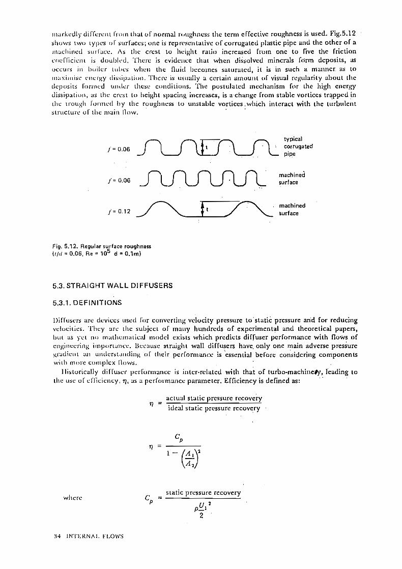


Related Documents


