
Welcome message from author
This document is posted to help you gain knowledge. Please leave a comment to let me know what you think about it! Share it to your friends and learn new things together.
Transcript

www.kennametal.com P1
Shoulder Mills
Mill 1-10 Platform . . . . . . . . . . . . . . . . . . . . . . . . . . . . . . . . . . . . . . . . . . . . . . . . . . . . . . . . . . . . . . . . . . .P2–P20
Mill 1-10, 90° Shoulder Milling Cutters . . . . . . . . . . . . . . . . . . . . . . . . . . . . . . . . . . . . . . . . . . . . . .P2–P13
Mill 1-10, 90° Helical Shoulder Milling Cutters . . . . . . . . . . . . . . . . . . . . . . . . . . . . . . . . . . . . . . .P14–P20
Mill 1-14 Platform . . . . . . . . . . . . . . . . . . . . . . . . . . . . . . . . . . . . . . . . . . . . . . . . . . . . . . . . . . . . . . . . . .P22–P42
Mill 1-14, 90° Indexable Shoulder Milling, Single Inserts Row. . . . . . . . . . . . . . . . . . . . . . . . . . . . .P22–P31
Mill 1-14, 90° Helical Shoulder Milling Cutters . . . . . . . . . . . . . . . . . . . . . . . . . . . . . . . . . . . . . . . .P32–P42
Mill 1-18 Platform . . . . . . . . . . . . . . . . . . . . . . . . . . . . . . . . . . . . . . . . . . . . . . . . . . . . . . . . . . . . . . . . . .P44–P55
Mill 1-18, 90° Shoulder Milling Cutters, Increased Axial Depth of Cut . . . . . . . . . . . . . . . . . . . . . .P44–P55
Mill 1-25 Platform . . . . . . . . . . . . . . . . . . . . . . . . . . . . . . . . . . . . . . . . . . . . . . . . . . . . . . . . . . . . . . . . . .P56–P62
Mill 1-25, 90° Machining Non-Ferrous Material . . . . . . . . . . . . . . . . . . . . . . . . . . . . . . . . . . . . . . .P56–P62
KSSM . . . . . . . . . . . . . . . . . . . . . . . . . . . . . . . . . . . . . . . . . . . . . . . . . . . . . . . . . . . . . . . . . . . . . . . . . . . .P64–P73
KSSM10, 90° Shoulder Milling Cutter, Small Depth of Cut . . . . . . . . . . . . . . . . . . . . . . . . . . . . . .P64–P68
KSSM12, 90° Shoulder Milling Cutter, Medium Depth of Cut . . . . . . . . . . . . . . . . . . . . . . . . . . . .P70–P73
KSSM-KSSP, Helical Cutters . . . . . . . . . . . . . . . . . . . . . . . . . . . . . . . . . . . . . . . . . . . . . . . . . . . . . . . .P74–P78
KSSP, 90° Helical Cutters, End Milling, Shell Mills, Integral Shank . . . . . . . . . . . . . . . . . . . . . . . . .P74–P78
KFSR Helical Platform . . . . . . . . . . . . . . . . . . . . . . . . . . . . . . . . . . . . . . . . . . . . . . . . . . . . . . . . . . . . . .P80–P87
KFSR, 90° Helical Cutters, Serrated Inserts . . . . . . . . . . . . . . . . . . . . . . . . . . . . . . . . . . . . . . . . . .P80–P87

www.kennametal.comP2
Mill 1-10™ • High-Performance Shoulder Milling Platform
Primary ApplicationThe multifunctional Mill 1-10 platform works with all tool materials in shoulder, ramp, slot, plunge, and helical milling with one insert style to improve productivity and reduce inventory and machining costs. The super positive cutting rake, soft cutting action, and low cutting forces enable higher feed rates and spindle protection. Innovative insert and cutter body designs offer improved ramping capabilities.
Features and Benefits
Versatility
• Works with all tool materials.
• Capable of shoulder, ramp, plunge, and helical milling.
• Internal coolant and air supply.
Advantages
• Optimised soft cutting edge.
• Elliptical edge generates 90° wall.
• Increased ramping capability due to state of the art insert and cutter body design.
• Innovative chip gash design for excellent chip evacuation and perfect cutter body stability.
• All pockets are machined into heat-treated materials, guaranteeing best-in-class runout and pocket strength.
• Inserts feature innovative margin along the main cutting edge, corner nose radius, and wiper facet for perfect edge stability.
To learn more, scan here.
For instructions on how to scan, please see page xxix.
www.kennametal.com P3
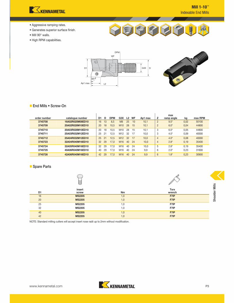
Mill 1-10™
Indexable End Mills
• Aggressive ramping rates.
• Generates superior surface finish.
• Mill 90° walls.
• High RPM capabilities.
� End Mills • Screw-On
order number catalogue number D1 D DPM G3X L2 WF Ap1 max Zmax
ramp angle kg max RPM
3745708 16A02R025M08ED10 16 13 8,5 M8 25 10 10,1 2 9.5° 0,02 50100
3745709 20A02R028M10ED10 20 18 10,5 M10 28 15 10,1 2 6.0° 0,04 44800
3745710 20A03R028M10ED10 20 18 10,5 M10 28 15 10,1 3 6.0° 0,05 44800
3745711 25A03R032M12ED10 25 21 12,5 M12 32 17 10,0 3 4.0° 0,09 40000
3745712 25A04R032M12ED10 25 21 12,5 M12 32 17 10,0 4 4.0° 0,08 40000
3745723 32A04R040M16ED10 32 29 17,0 M16 40 24 10,0 4 2.8° 0,19 35400
3745724 32A05R040M16ED10 32 29 17,0 M16 40 24 10,0 5 2.8° 0,19 35400
3745725 40A06R040M16ED10 40 29 17,0 M16 40 24 9,9 6 2.0° 0,23 31600
3745726 42A06R040M16ED10 42 29 17,0 M16 40 24 9,9 6 1.8° 0,23 30900
� Spare Parts
D1insert screw Nm
Torx wrench
16 MS2205 1,0 F7IP
20 MS2205 1,0 F7IP
25 MS2205 1,0 F7IP
32 MS2205 1,0 F7IP
40 MS2205 1,0 F7IP
42 MS2205 1,0 F7IP
NOTE: Standard milling cutters will accept insert nose radii up to 2mm without modification.
Shoulder Mills
www.kennametal.comP4
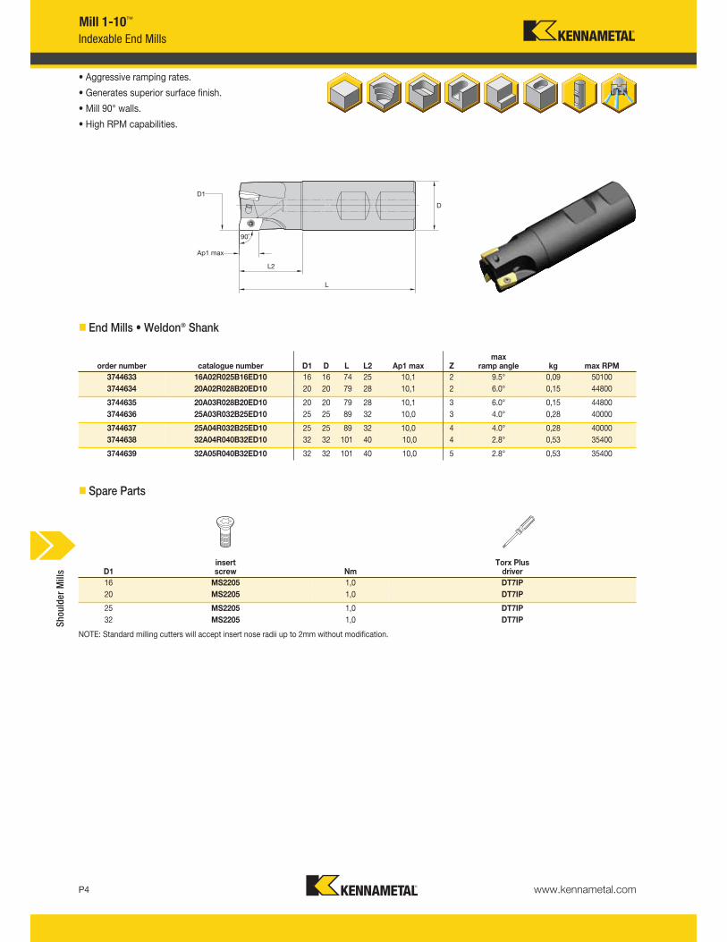
Mill 1-10™
Indexable End Mills
• Aggressive ramping rates.
• Generates superior surface finish.
• Mill 90° walls.
• High RPM capabilities.
� End Mills • Weldon® Shank
order number catalogue number D1 D L L2 Ap1 max Zmax
ramp angle kg max RPM
3744633 16A02R025B16ED10 16 16 74 25 10,1 2 9.5° 0,09 50100
3744634 20A02R028B20ED10 20 20 79 28 10,1 2 6.0° 0,15 44800
3744635 20A03R028B20ED10 20 20 79 28 10,1 3 6.0° 0,15 44800
3744636 25A03R032B25ED10 25 25 89 32 10,0 3 4.0° 0,28 40000
3744637 25A04R032B25ED10 25 25 89 32 10,0 4 4.0° 0,28 40000
3744638 32A04R040B32ED10 32 32 101 40 10,0 4 2.8° 0,53 35400
3744639 32A05R040B32ED10 32 32 101 40 10,0 5 2.8° 0,53 35400
� Spare Parts
D1insert screw Nm
Torx Plus driver
16 MS2205 1,0 DT7IP
20 MS2205 1,0 DT7IP
25 MS2205 1,0 DT7IP
32 MS2205 1,0 DT7IP
NOTE: Standard milling cutters will accept insert nose radii up to 2mm without modification.
Shoulder Mills
www.kennametal.com P5
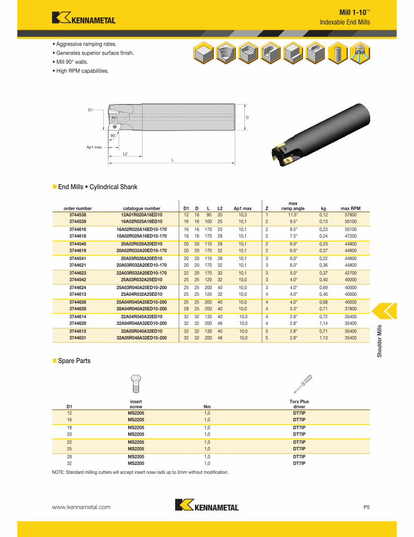
Mill 1-10™
Indexable End Mills
• Aggressive ramping rates.
• Generates superior surface finish.
• Mill 90° walls.
• High RPM capabilities.
� End Mills • Cylindrical Shank
order number catalogue number D1 D L L2 Ap1 max Zmax
ramp angle kg max RPM
3744538 12A01R020A16ED10 12 16 90 20 10,3 1 11.5° 0,12 57800
3744539 16A02R025A16ED10 16 16 100 25 10,1 2 9.5° 0,13 50100
3744616 16A02R025A16ED10-170 16 16 170 25 10,1 2 9.5° 0,23 50100
3744618 18A02R028A16ED10-170 18 16 170 28 10,1 2 7.5° 0,24 47200
3744540 20A02R028A20ED10 20 20 110 28 10,1 2 6.0° 0,23 44800
3744619 20A02R032A20ED10-170 20 20 170 32 10,1 2 6.0° 0,37 44800
3744541 20A03R028A20ED10 20 20 110 28 10,1 3 6.0° 0,22 44800
3744621 20A03R032A20ED10-170 20 20 170 32 10,1 3 6.0° 0,36 44800
3744623 22A03R032A20ED10-170 22 20 170 32 10,1 3 5.0° 0,37 42700
3744542 25A03R032A25ED10 25 25 120 32 10,0 3 4.0° 0,40 40000
3744624 25A03R040A25ED10-200 25 25 200 40 10,0 3 4.0° 0,69 40000
3744613 25A04R032A25ED10 25 25 120 32 10,0 4 4.0° 0,40 40000
3744626 25A04R040A25ED10-200 25 25 200 40 10,0 4 4.0° 0,68 40000
3744628 28A04R040A25ED10-200 28 25 200 40 10,0 4 3.3° 0,71 37800
3744614 32A04R040A32ED10 32 32 130 40 10,0 4 2.8° 0,72 35400
3744629 32A04R048A32ED10-200 32 32 200 48 10,0 4 2.8° 1,14 35400
3744615 32A05R040A32ED10 32 32 130 40 10,0 5 2.8° 0,71 35400
3744631 32A05R048A32ED10-200 32 32 200 48 10,0 5 2.8° 1,13 35400
� Spare Parts
D1insert screw Nm
Torx Plus driver
12 MS2205 1,0 DT7IP
16 MS2205 1,0 DT7IP
18 MS2205 1,0 DT7IP
20 MS2205 1,0 DT7IP
22 MS2205 1,0 DT7IP
25 MS2205 1,0 DT7IP
28 MS2205 1,0 DT7IP
32 MS2205 1,0 DT7IP
NOTE: Standard milling cutters will accept insert nose radii up to 2mm without modification.
Shoulder Mills

www.kennametal.comP6
Mill 1-10™
Indexable End Mills
• Aggressive ramping rates.
• Generates superior surface finish.
• Mill 90° walls.
• High RPM capabilities.
� End Mills • Cylindrical Shank • Long Length
order number catalogue number D1 D L L2 Ap1 max Zmax
ramp angle kg max RPM
3744617 16A02R025A16ED10R31-170 16 16 170 25 9,7 2 8.0° 0,23 50100
3744620 20A02R032A20ED10R31-170 20 20 170 32 9,8 2 4.5° 0,37 44800
3744622 20A03R032A20ED10R31-170 20 20 170 32 9,8 3 4.5° 0,36 44800
3744625 25A03R040A25ED10R31-200 25 25 200 40 9,8 3 3.0° 0,69 40000
3744627 25A04R040A25ED10R31-200 25 25 200 40 9,8 4 3.0° 0,68 40000
3744630 32A04R048A32ED10R31-200 32 32 200 48 9,7 4 2.0° 1,13 35400
3744632 32A05R048A32ED10R31-200 32 32 200 48 9,7 5 2.0° 1,13 35400
NOTE: For inserts with corner nose radii 2,4 and 3,1.
� Spare Parts
D1insert screw Nm
Torx Plus driver
16 MS2205 1,0 DT7IP
20 MS2205 1,0 DT7IP
25 MS2205 1,0 DT7IP
32 MS2205 1,0 DT7IPShoulder Mills
www.kennametal.com P7
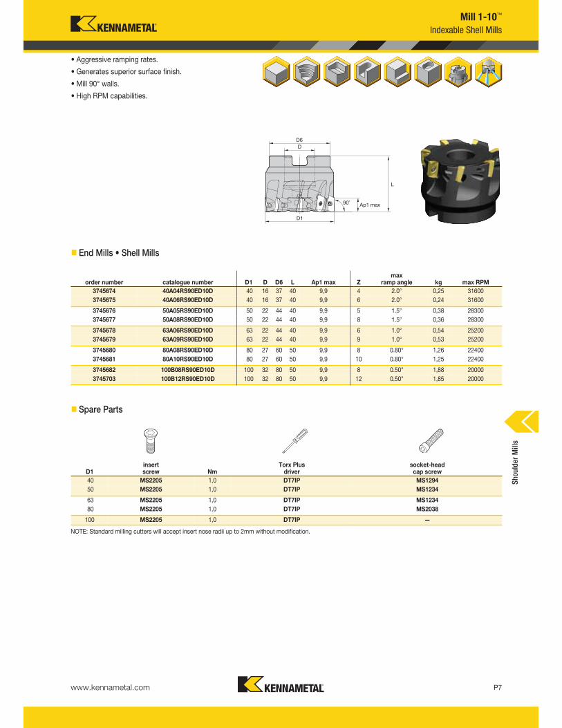
Mill 1-10™
Indexable Shell Mills
• Aggressive ramping rates.
• Generates superior surface finish.
• Mill 90° walls.
• High RPM capabilities.
� End Mills • Shell Mills
order number catalogue number D1 D D6 L Ap1 max Zmax
ramp angle kg max RPM
3745674 40A04RS90ED10D 40 16 37 40 9,9 4 2.0° 0,25 31600
3745675 40A06RS90ED10D 40 16 37 40 9,9 6 2.0° 0,24 31600
3745676 50A05RS90ED10D 50 22 44 40 9,9 5 1.5° 0,38 28300
3745677 50A08RS90ED10D 50 22 44 40 9,9 8 1.5° 0,36 28300
3745678 63A06RS90ED10D 63 22 44 40 9,9 6 1.0° 0,54 25200
3745679 63A09RS90ED10D 63 22 44 40 9,9 9 1.0° 0,53 25200
3745680 80A08RS90ED10D 80 27 60 50 9,9 8 0.80° 1,26 22400
3745681 80A10RS90ED10D 80 27 60 50 9,9 10 0.80° 1,25 22400
3745682 100B08RS90ED10D 100 32 80 50 9,9 8 0.50° 1,88 20000
3745703 100B12RS90ED10D 100 32 80 50 9,9 12 0.50° 1,85 20000
� Spare Parts
D1insert screw Nm
Torx Plus driver
socket-headcap screw
40 MS2205 1,0 DT7IP MS1294
50 MS2205 1,0 DT7IP MS1234
63 MS2205 1,0 DT7IP MS1234
80 MS2205 1,0 DT7IP MS2038
100 MS2205 1,0 DT7IP —
NOTE: Standard milling cutters will accept insert nose radii up to 2mm without modification.
Shoulder Mills
www.kennametal.comP8
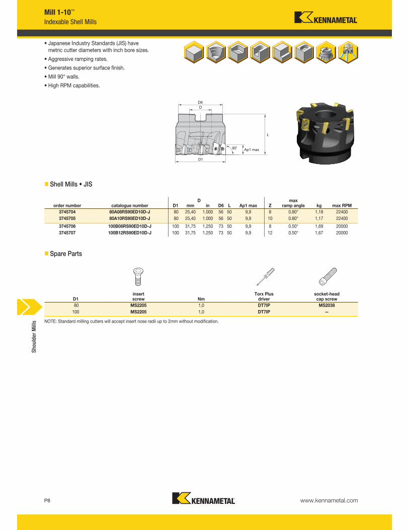
Dorder number catalogue number D1 mm in D6 L Ap1 max Z
max ramp angle kg max RPM
3745704 80A08RS90ED10D-J 80 25,40 1.000 56 50 9,9 8 0.80° 1,18 22400
3745705 80A10RS90ED10D-J 80 25,40 1.000 56 50 9,9 10 0.80° 1,17 22400
3745706 100B08RS90ED10D-J 100 31,75 1.250 73 50 9,9 8 0.50° 1,69 20000
3745707 100B12RS90ED10D-J 100 31,75 1.250 73 50 9,9 12 0.50° 1,67 20000
D1insert screw Nm
Torx Plus driver
socket-headcap screw
80 MS2205 1,0 DT7IP MS2038
100 MS2205 1,0 DT7IP —
Mill 1-10™
Indexable Shell Mills
• Japanese Industry Standards (JIS) have metric cutter diameters with inch bore sizes.
• Aggressive ramping rates.
• Generates superior surface finish.
• Mill 90° walls.
• High RPM capabilities.
� Shell Mills • JIS
� Spare Parts
NOTE: Standard milling cutters will accept insert nose radii up to 2mm without modification.
Shoulder Mills
www.kennametal.com P9
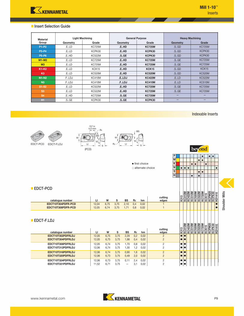
Mill 1-10™
Inserts
� Insert Selection Guide
Indexable Inserts
EDCT-PCD EDCT-F.LDJ
(PCD)
P v v v
M v v
K v v v
N v v v v
S v v
H v v
v first choice
alternate choice
catalogue number LI W S BS Rε hmcutting edges K
313
KC410M
KC422M
KC510M
KC520M
KC522M
KC725M
KCK15
KCPM20
KCPK30
KD1410
EDCT10T304PDFR-PCD 12,04 6,75 3,75 2,10 0,4 0,02 1 v
EDCT10T308PDFR-PCD 12,05 6,74 3,75 1,71 0,8 0,02 1 v
catalogue number LI W S BS Rε hmcutting edges K
313
KC410M
KC422M
KC510M
KC520M
KC522M
KC725M
KCK15
KCPM20
KCPK30
KD1410
EDCT10T302PDFRLDJ 12,05 6,75 3,75 2,29 0,2 0,02 2 v v
EDCT10T304PDFRLDJ 12,05 6,75 3,75 1,98 0,4 0,02 2 v v
EDCT10T308PDFRLDJ 12,05 6,74 3,75 1,70 0,8 0,02 2 v v
EDCT10T312PDFRLDJ 12,06 6,74 3,75 1,30 1,2 0,02 2 v v
EDCT10T316PDFRLDJ 12,06 6,74 3,75 0,90 1,6 0,02 2 v v
EDCT10T320PDFRLDJ 12,06 6,73 3,75 0,49 2,0 0,02 2 v v
EDCT10T324PDFRLDJ 12,06 6,73 3,75 0,11 2,4 0,02 2 v v
EDCT10T331PDFRLDJ 11,52 6,71 3,75 — 3,1 0,02 2 v v
� EDCT-PCD
� EDCT-F.LDJ
MaterialGroup
Light Machining General Purpose Heavy Machining
Geometry Grade Geometry Grade Geometry Grade
P1–P2 .E..LD KC725M .E..HD KC725M .S..GD KC725M
P3–P4 .E..LD KCPK30 .E..HD KCPK30 .S..GD KCPK30
P5–P6 .E..HD KC522M .S..GE KCPK30 .S..GD KCPK30
M1–M2 .E..LD KC725M .E..HD KC725M .S..GE KC725M
M3 .E..LD KC725M .E..HD KC725M .S..GE KC725M
K1–K2 .E..LD KCK15 .E..HD KCK15 .S..GD KCK15
K3 .E..LD KC520M .E..HD KC520M .S..GD KC520M
N1–N2 .F..LDJ KC410M .E..LDJ KC422M .E..LD KC522M
N3 .F..LDJ KC410M .F..LDJ KC410M .E..LD KC510M
S1–S2 .E..LD KC522M .E..HD KC725M .S..GE KC725M
S3 .E..LD KC522M .E..HD KC725M .S..GE KC725M
S4 .E..HD KC725M .S..GE KC725M — —
H1 .S..GE KCPK30 .S..GE KCPK30 — —
Shoulder Mills
www.kennametal.comP10
P v v v
M v v
K v v v
N v v v v
S v v
H v v
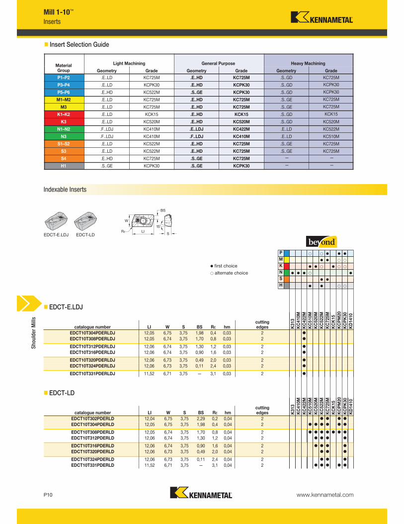
v first choice
alternate choice
catalogue number LI W S BS Rε hmcutting edges K
313
KC410M
KC422M
KC510M
KC520M
KC522M
KC725M
KCK15
KCPM20
KCPK30
KD1410
EDCT10T304PDERLDJ 12,05 6,75 3,75 1,98 0,4 0,03 2 v
EDCT10T308PDERLDJ 12,05 6,74 3,75 1,70 0,8 0,03 2 v
EDCT10T312PDERLDJ 12,06 6,74 3,75 1,30 1,2 0,03 2 v
EDCT10T316PDERLDJ 12,06 6,74 3,75 0,90 1,6 0,03 2 v
EDCT10T320PDERLDJ 12,06 6,73 3,75 0,49 2,0 0,03 2 v
EDCT10T324PDERLDJ 12,06 6,73 3,75 0,11 2,4 0,03 2 v
EDCT10T331PDERLDJ 11,52 6,71 3,75 — 3,1 0,03 2 v
catalogue number LI W S BS Rε hmcutting edges K
313
KC410M
KC422M
KC510M
KC520M
KC522M
KC725M
KCK15
KCPM20
KCPK30
KD1410
EDCT10T302PDERLD 12,04 6,75 3,75 2,29 0,2 0,04 2 v v v v
EDCT10T304PDERLD 12,05 6,75 3,75 1,98 0,4 0,04 2 v v v v v v
EDCT10T308PDERLD 12,05 6,74 3,75 1,70 0,8 0,04 2 v v v v v v v
EDCT10T312PDERLD 12,06 6,74 3,75 1,30 1,2 0,04 2 v v v v
EDCT10T316PDERLD 12,06 6,74 3,75 0,90 1,6 0,04 2 v v v v
EDCT10T320PDERLD 12,06 6,73 3,75 0,49 2,0 0,04 2 v v v
EDCT10T324PDERLD 12,06 6,73 3,75 0,11 2,4 0,04 2 v v v
EDCT10T331PDERLD 11,52 6,71 3,75 — 3,1 0,04 2 v v v v v
� EDCT-E.LDJ
� EDCT-LD
Mill 1-10™
Inserts
EDCT-E.LDJ EDCT-LD
� Insert Selection Guide
MaterialGroup
Light Machining General Purpose Heavy Machining
Geometry Grade Geometry Grade Geometry Grade
P1–P2 .E..LD KC725M .E..HD KC725M .S..GD KC725M
P3–P4 .E..LD KCPK30 .E..HD KCPK30 .S..GD KCPK30
P5–P6 .E..HD KC522M .S..GE KCPK30 .S..GD KCPK30
M1–M2 .E..LD KC725M .E..HD KC725M .S..GE KC725M
M3 .E..LD KC725M .E..HD KC725M .S..GE KC725M
K1–K2 .E..LD KCK15 .E..HD KCK15 .S..GD KCK15
K3 .E..LD KC520M .E..HD KC520M .S..GD KC520M
N1–N2 .F..LDJ KC410M .E..LDJ KC422M .E..LD KC522M
N3 .F..LDJ KC410M .F..LDJ KC410M .E..LD KC510M
S1–S2 .E..LD KC522M .E..HD KC725M .S..GE KC725M
S3 .E..LD KC522M .E..HD KC725M .S..GE KC725M
S4 .E..HD KC725M .S..GE KC725M — —
H1 .S..GE KCPK30 .S..GE KCPK30 — —
Shoulder Mills
Indexable Inserts
www.kennametal.com P11
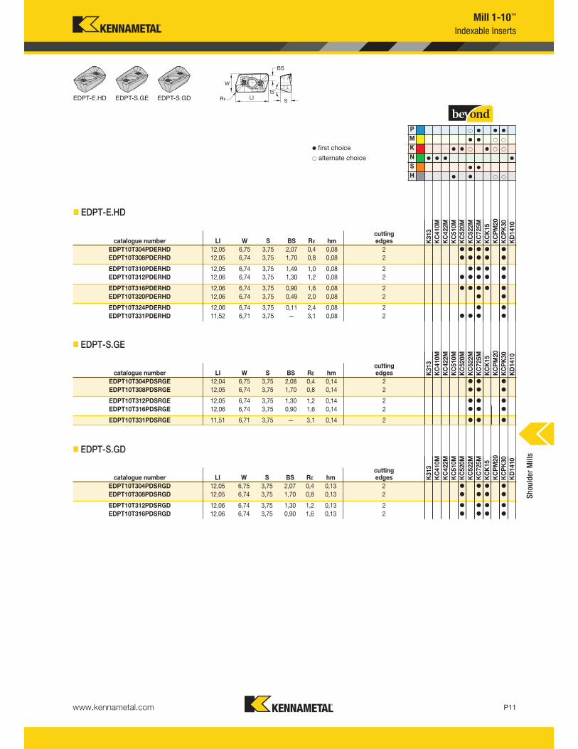
Mill 1-10™
Indexable Inserts
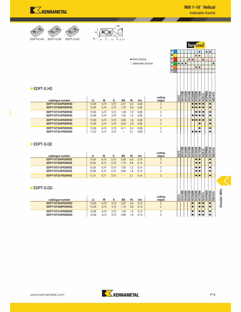
EDPT-E.HD EDPT-S.GE EDPT-S.GD
H
S
N
K
M
P v v v
v v
v v v
v v v v
v v
v v
v first choice
alternate choice
� EDPT-E.HD
catalogue number LI W S BS Rε hmcutting edges K
313
KC410M
KC422M
KC510M
KC520M
KC522M
KC725M
KCK15
KCPM20
KCPK30
KD1410
EDPT10T304PDERHD 12,05 6,75 3,75 2,07 0,4 0,08 2 v v v v v
EDPT10T308PDERHD 12,05 6,74 3,75 1,70 0,8 0,08 2 v v v v v
EDPT10T310PDERHD 12,05 6,74 3,75 1,49 1,0 0,08 2 v v v v
EDPT10T312PDERHD 12,06 6,74 3,75 1,30 1,2 0,08 2 v v v v v
EDPT10T316PDERHD 12,06 6,74 3,75 0,90 1,6 0,08 2 v v v v v
EDPT10T320PDERHD 12,06 6,74 3,75 0,49 2,0 0,08 2 v v
EDPT10T324PDERHD 12,06 6,74 3,75 0,11 2,4 0,08 2 v v
EDPT10T331PDERHD 11,52 6,71 3,75 — 3,1 0,08 2 v v v v
� EDPT-S.GE
catalogue number LI W S BS Rε hmcutting edges K313
KC410M
KC422M
KC510M
KC520M
KC522M
KC725M
KCK15
KCPM20
KCPK30
KD1410
EDPT10T304PDSRGE 12,04 6,75 3,75 2,08 0,4 0,14 2 v v v
EDPT10T308PDSRGE 12,05 6,74 3,75 1,70 0,8 0,14 2 v v v
EDPT10T312PDSRGE 12,05 6,74 3,75 1,30 1,2 0,14 2 v v v
EDPT10T316PDSRGE 12,06 6,74 3,75 0,90 1,6 0,14 2 v v v
EDPT10T331PDSRGE 11,51 6,71 3,75 — 3,1 0,14 2 v v v
� EDPT-S.GD
catalogue number LI W S BS Rε hmcutting edges K
313
KC410M
KC422M
KC510M
KC520M
KC522M
KC725M
KCK15
KCPM20
KCPK30
KD1410
EDPT10T304PDSRGD 12,05 6,75 3,75 2,07 0,4 0,13 2 v v v v
EDPT10T308PDSRGD 12,05 6,74 3,75 1,70 0,8 0,13 2 v v v v
EDPT10T312PDSRGD 12,06 6,74 3,75 1,30 1,2 0,13 2 v v v v
EDPT10T316PDSRGD 12,06 6,74 3,75 0,90 1,6 0,13 2 v v v v
Shoulder Mills
www.kennametal.comP12
Mill 1-10™
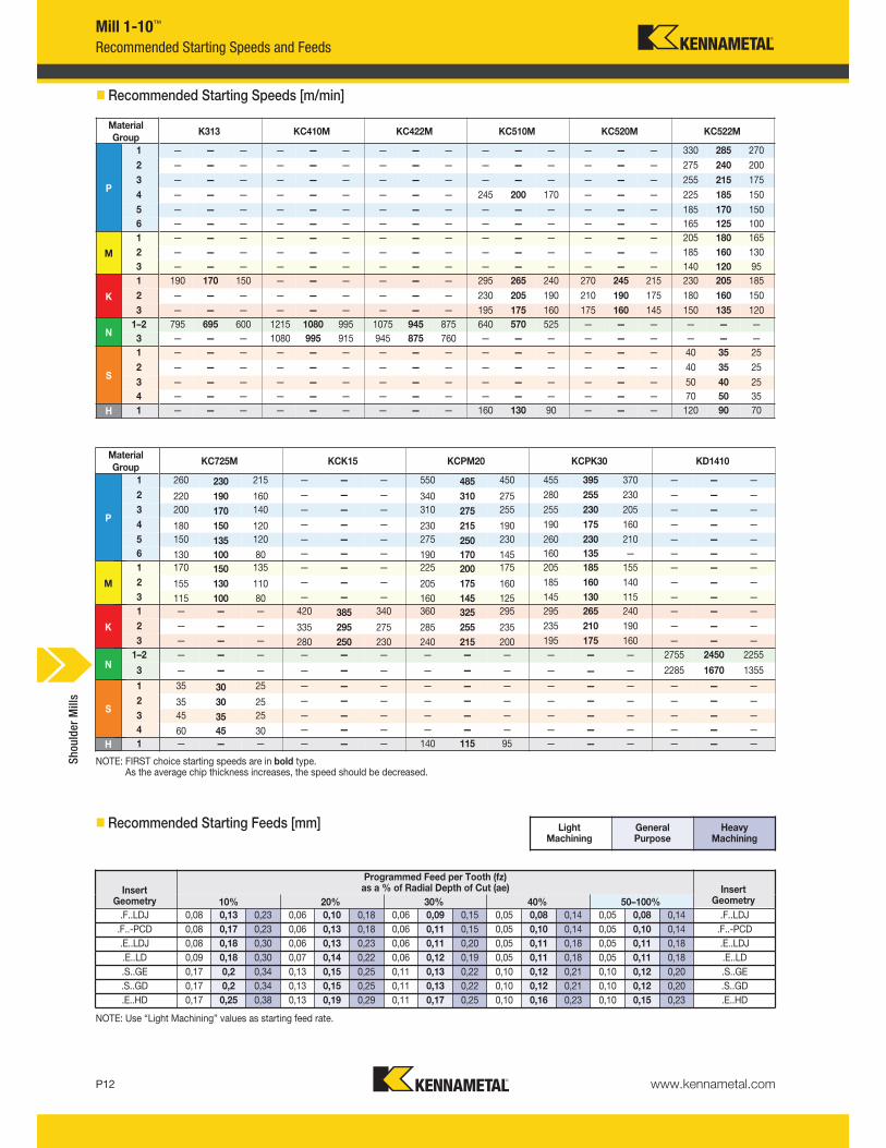
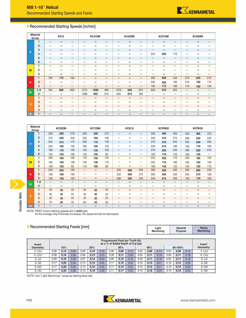
NOTE: FIRST choice starting speeds are in bold type.As the average chip thickness increases, the speed should be decreased.
Material
GroupK313 KC410M KC422M KC510M KC520M KC522M
P
1 — — — — — — — — — — — — — — — 330 285 270
2 — — — — — — — — — — — — — — — 275 240 200
3 — — — — — — — — — — — — — — — 255 215 175
4 — — — — — — — — — 245 200 170 — — — 225 185 150
5 — — — — — — — — — — — — — — — 185 170 150
6 — — — — — — — — — — — — — — — 165 125 100
M
1 — — — — — — — — — — — — — — — 205 180 165
2 — — — — — — — — — — — — — — — 185 160 130
3 — — — — — — — — — — — — — — — 140 120 95
K
1 190 170 150 — — — — — — 295 265 240 270 245 215 230 205 185
2 — — — — — — — — — 230 205 190 210 190 175 180 160 150
3 — — — — — — — — — 195 175 160 175 160 145 150 135 120
N1–2 795 695 600 1215 1080 995 1075 945 875 640 570 525 — — — — — —
3 — — — 1080 995 915 945 875 760 — — — — — — — — —
S
1 — — — — — — — — — — — — — — — 40 35 25
2 — — — — — — — — — — — — — — — 40 35 25
3 — — — — — — — — — — — — — — — 50 40 25
4 — — — — — — — — — — — — — — — 70 50 35
H 1 — — — — — — — — — 160 130 90 — — — 120 90 70
Material
GroupKC725M KCK15 KCPM20 KCPK30 KD1410
P
1 260 230 215 — — — 550 485 450 455 395 370 — — —
2 220 190 160 — — — 340 310 275 280 255 230 — — —
3 200 170 140 — — — 310 275 255 255 230 205 — — —
4 180 150 120 — — — 230 215 190 190 175 160 — — —
5 150 135 120 — — — 275 250 230 260 230 210 — — —
6 130 100 80 — — — 190 170 145 160 135 — — — —
M
1 170 150 135 — — — 225 200 175 205 185 155 — — —
2 155 130 110 — — — 205 175 160 185 160 140 — — —
3 115 100 80 — — — 160 145 125 145 130 115 — — —
K
1 — — — 420 385 340 360 325 295 295 265 240 — — —
2 — — — 335 295 275 285 255 235 235 210 190 — — —
3 — — — 280 250 230 240 215 200 195 175 160 — — —
N1–2 — — — — — — — — — — — — 2755 2450 2255
3 — — — — — — — — — — — — 2285 1670 1355
S
1 35 30 25 — — — — — — — — — — — —
2 35 30 25 — — — — — — — — — — — —
3 45 35 25 — — — — — — — — — — — —
4 60 45 30 — — — — — — — — — — — —
H 1 — — — — — — 140 115 95 — — — — — —
� Recommended Starting Speeds [m/min]
NOTE: Use “Light Machining” values as starting feed rate.
Light Machining
General Purpose
Heavy Machining
Recommended Starting Speeds and Feeds
� Recommended Starting Feeds [mm]
InsertGeometry
Programmed Feed per Tooth (fz)as a % of Radial Depth of Cut (ae) Insert
Geometry10% 20% 30% 40% 50–100%
.F..LDJ 0,08 0,13 0,23 0,06 0,10 0,18 0,06 0,09 0,15 0,05 0,08 0,14 0,05 0,08 0,14 .F..LDJ
.F..-PCD 0,08 0,17 0,23 0,06 0,13 0,18 0,06 0,11 0,15 0,05 0,10 0,14 0,05 0,10 0,14 .F..-PCD
.E..LDJ 0,08 0,18 0,30 0,06 0,13 0,23 0,06 0,11 0,20 0,05 0,11 0,18 0,05 0,11 0,18 .E..LDJ
.E..LD 0,09 0,18 0,30 0,07 0,14 0,22 0,06 0,12 0,19 0,05 0,11 0,18 0,05 0,11 0,18 .E..LD
.S..GE 0,17 0,2 0,34 0,13 0,15 0,25 0,11 0,13 0,22 0,10 0,12 0,21 0,10 0,12 0,20 .S..GE
.S..GD 0,17 0,2 0,34 0,13 0,15 0,25 0,11 0,13 0,22 0,10 0,12 0,21 0,10 0,12 0,20 .S..GD
.E..HD 0,17 0,25 0,38 0,13 0,19 0,29 0,11 0,17 0,25 0,10 0,16 0,23 0,10 0,15 0,23 .E..HD
Shoulder Mills
www.kennametal.com P13
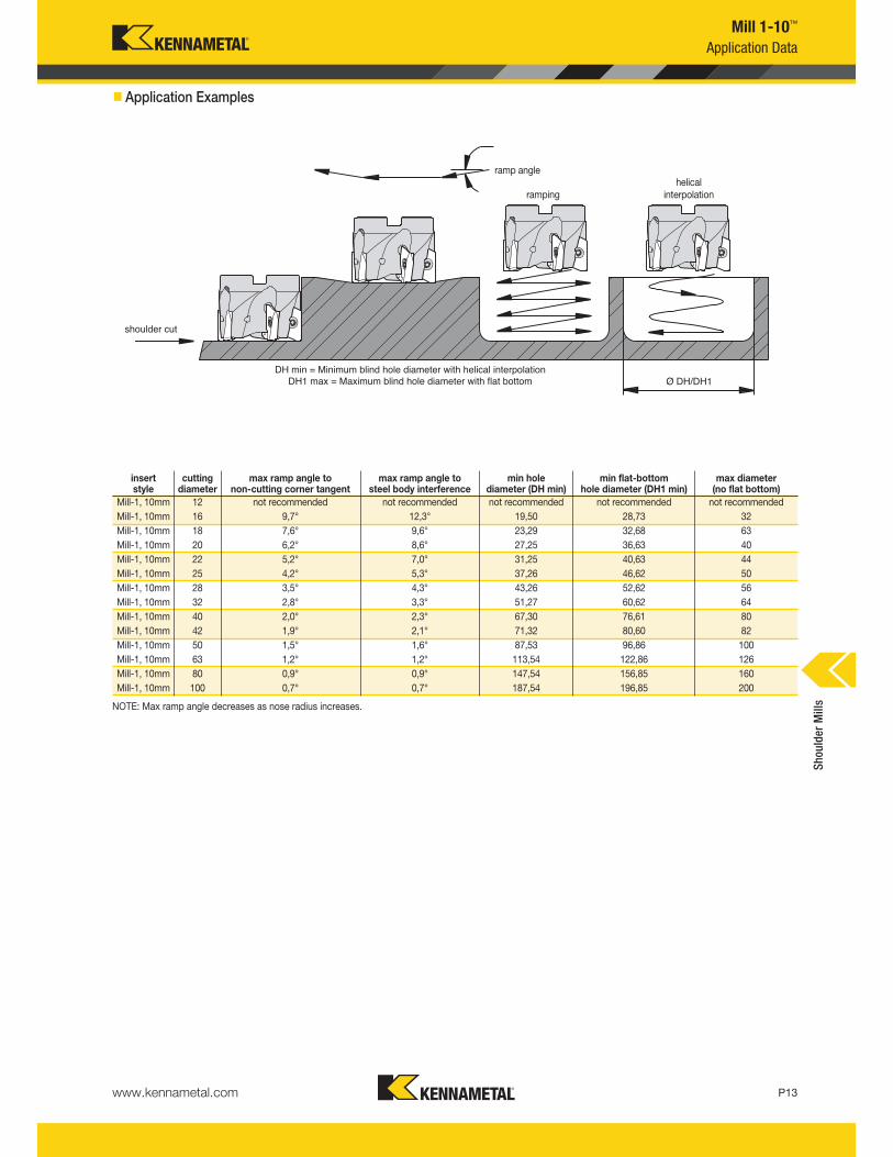
Mill 1-10™
Application Data
shoulder cut
Ø DH/DH1
DH min = Minimum blind hole diameter with helical interpolation
DH1 max = Maximum blind hole diameter with flat bottom
helicalinterpolationramping
ramp angle
NOTE: Max ramp angle decreases as nose radius increases.
insert style
cuttingdiameter
max ramp angle to non-cutting corner tangent
max ramp angle tosteel body interference
min holediameter (DH min)
min flat-bottomhole diameter (DH1 min)
max diameter (no flat bottom)
Mill-1, 10mm 12 not recommended not recommended not recommended not recommended not recommended
Mill-1, 10mm 16 9,7° 12,3° 19,50 28,73 32
Mill-1, 10mm 18 7,6° 9,6° 23,29 32,68 63
Mill-1, 10mm 20 6,2° 8,6° 27,25 36,63 40
Mill-1, 10mm 22 5,2° 7,0° 31,25 40,63 44
Mill-1, 10mm 25 4,2° 5,3° 37,26 46,62 50
Mill-1, 10mm 28 3,5° 4,3° 43,26 52,62 56
Mill-1, 10mm 32 2,8° 3,3° 51,27 60,62 64
Mill-1, 10mm 40 2,0° 2,3° 67,30 76,61 80
Mill-1, 10mm 42 1,9° 2,1° 71,32 80,60 82
Mill-1, 10mm 50 1,5° 1,6° 87,53 96,86 100
Mill-1, 10mm 63 1,2° 1,2° 113,54 122,86 126
Mill-1, 10mm 80 0,9° 0,9° 147,54 156,85 160
Mill-1, 10mm 100 0,7° 0,7° 187,54 196,85 200
� Application Examples
Shoulder Mills
www.kennametal.comP14
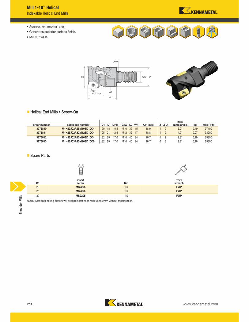
Mill 1-10™ Helical
Indexable Helical End Mills
• Aggressive ramping rates.
• Generates superior surface finish.
• Mill 90° walls.
� Helical End Mills • Screw-On
� Spare Parts
NOTE: Standard milling cutters will accept insert nose radii up to 2mm without modification.
order number catalogue number D1 D DPM G3X L2 WF Ap1 max Z Z Umax
ramp angle kg max RPM
3773810 M1H20J02R28M10ED10C4 20 18 10,5 M10 32 15 18,9 4 2 6.0° 0,49 37100
3773811 M1H25J02R32M12ED10C4 25 21 12,5 M12 32 17 18,8 4 2 4.0° 0,07 33200
3773812 M1H32J02R40M16ED10C4 32 29 17,0 M16 40 24 18,7 4 2 2.8° 0,19 29300
3773813 M1H32J03R40M16ED10C6 32 29 17,0 M16 40 24 18,7 6 3 2.8° 0,18 29300
D1insert screw Nm
Torx wrench
20 MS2205 1,0 F7IP
25 MS2205 1,0 F7IP
32 MS2205 1,0 F7IP
Shoulder Mills
www.kennametal.com P15
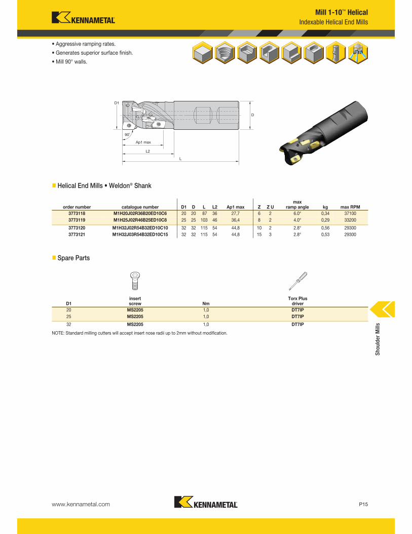
Mill 1-10™ Helical
Indexable Helical End Mills
• Aggressive ramping rates.
• Generates superior surface finish.
• Mill 90° walls.
� Helical End Mills • Weldon® Shank
� Spare Parts
order number catalogue number D1 D L L2 Ap1 max Z Z Umax
ramp angle kg max RPM
3773118 M1H20J02R36B20ED10C6 20 20 87 36 27,7 6 2 6.0° 0,34 37100
3773119 M1H25J02R46B25ED10C8 25 25 103 46 36,4 8 2 4.0° 0,29 33200
3773120 M1H32J02R54B32ED10C10 32 32 115 54 44,8 10 2 2.8° 0,56 29300
3773121 M1H32J03R54B32ED10C15 32 32 115 54 44,8 15 3 2.8° 0,53 29300
D1insert screw Nm
Torx Plus driver
20 MS2205 1,0 DT7IP
25 MS2205 1,0 DT7IP
32 MS2205 1,0 DT7IP
NOTE: Standard milling cutters will accept insert nose radii up to 2mm without modification.
Shoulder Mills
www.kennametal.comP16
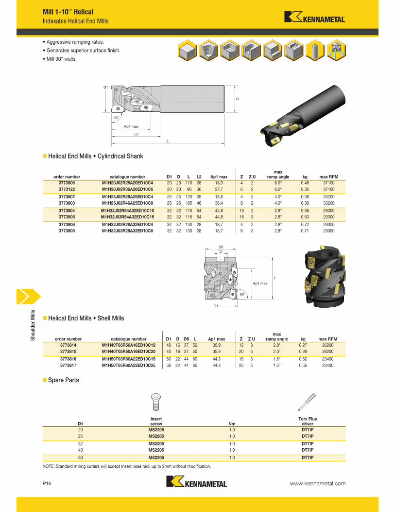
Mill 1-10™ Helical
Indexable Helical End Mills
• Aggressive ramping rates.
• Generates superior surface finish.
• Mill 90° walls.
� Helical End Mills • Cylindrical Shank
� Spare Parts
NOTE: Standard milling cutters will accept insert nose radii up to 2mm without modification.
� Helical End Mills • Shell Mills
order number catalogue number D1 D L L2 Ap1 max Z Z Umax
ramp angle kg max RPM
3773806 M1H20J02R28A20ED10C4 20 20 110 28 18,9 4 2 6.0° 0,48 37100
3773122 M1H20J02R36A20ED10C6 20 20 90 36 27,7 6 2 6.0° 0,36 37100
3773807 M1H25J02R28A25ED10C4 25 25 120 28 18,8 4 2 4.0° 0,38 33200
3773803 M1H25J02R46A25ED10C8 25 25 105 46 36,4 8 2 4.0° 0,30 33200
3773804 M1H32J02R54A32ED10C10 32 32 115 54 44,8 10 2 2.8° 0,56 29300
3773805 M1H32J03R54A32ED10C15 32 32 115 54 44,8 15 3 2.8° 0,53 29300
3773808 M1H32J02R28A32ED10C4 32 32 130 28 18,7 4 2 2.8° 0,72 29300
3773809 M1H32J03R28A32ED10C6 32 32 130 28 18,7 6 3 2.8° 0,71 29300
order number catalogue number D1 D D6 L Ap1 max Z Z Umax
ramp angle kg max RPM
3773814 M1H40T03R50A16ED10C12 40 16 37 50 35,9 12 3 2.0° 0,27 26200
3773815 M1H40T05R50A16ED10C20 40 16 37 50 35,9 20 5 2.0° 0,26 26200
3773816 M1H50T03R60A22ED10C15 50 22 44 60 44,3 15 3 1.5° 0,62 23400
3773817 M1H50T05R60A22ED10C25 50 22 44 60 44,3 25 5 1.5° 0,55 23400
D1insert screw Nm
Torx Plus driver
20 MS2205 1,0 DT7IP
25 MS2205 1,0 DT7IP
32 MS2205 1,0 DT7IP
40 MS2205 1,0 DT7IP
50 MS2205 1,0 DT7IP
Shoulder Mills
www.kennametal.com P17
Indexable Inserts
EDCT-F.LDJ
v first choice
alternate choice
� EDCT-F.LDJ
P v v v
M v v
K v v v
N v v v v
S v v
H
catalogue number LI W S BS Rε hmcutting edges K
313
KC410M
KC422M
KC510M
KC520M
KC522M
KC725M
KCK15
KCPM20
KCPK30
KD1410
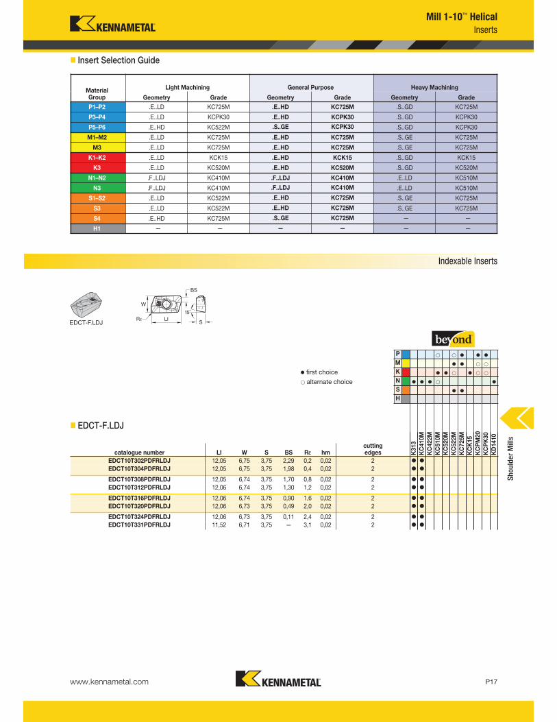
EDCT10T302PDFRLDJ 12,05 6,75 3,75 2,29 0,2 0,02 2 v v
EDCT10T304PDFRLDJ 12,05 6,75 3,75 1,98 0,4 0,02 2 v v
EDCT10T308PDFRLDJ 12,05 6,74 3,75 1,70 0,8 0,02 2 v v
EDCT10T312PDFRLDJ 12,06 6,74 3,75 1,30 1,2 0,02 2 v v
EDCT10T316PDFRLDJ 12,06 6,74 3,75 0,90 1,6 0,02 2 v v
EDCT10T320PDFRLDJ 12,06 6,73 3,75 0,49 2,0 0,02 2 v v
EDCT10T324PDFRLDJ 12,06 6,73 3,75 0,11 2,4 0,02 2 v v
EDCT10T331PDFRLDJ 11,52 6,71 3,75 — 3,1 0,02 2 v v
Mill 1-10™ Helical
Inserts
� Insert Selection Guide
MaterialGroup
Light Machining General Purpose Heavy Machining
Geometry Grade Geometry Grade Geometry Grade
P1–P2 .E..LD KC725M .E..HD KC725M .S..GD KC725M
P3–P4 .E..LD KCPK30 .E..HD KCPK30 .S..GD KCPK30
P5–P6 .E..HD KC522M .S..GE KCPK30 .S..GD KCPK30
M1–M2 .E..LD KC725M .E..HD KC725M .S..GE KC725M
M3 .E..LD KC725M .E..HD KC725M .S..GE KC725M
K1–K2 .E..LD KCK15 .E..HD KCK15 .S..GD KCK15
K3 .E..LD KC520M .E..HD KC520M .S..GD KC520M
N1–N2 .F..LDJ KC410M .F..LDJ KC410M .E..LD KC510M
N3 .F..LDJ KC410M .F..LDJ KC410M .E..LD KC510M
S1–S2 .E..LD KC522M .E..HD KC725M .S..GE KC725M
S3 .E..LD KC522M .E..HD KC725M .S..GE KC725M
S4 .E..HD KC725M .S..GE KC725M — —
H1 — — — — — —
Shoulder Mills
www.kennametal.comP18
v first choice
alternate choice
P v v v
M v v
K v v v
N v v v v
S v v
H
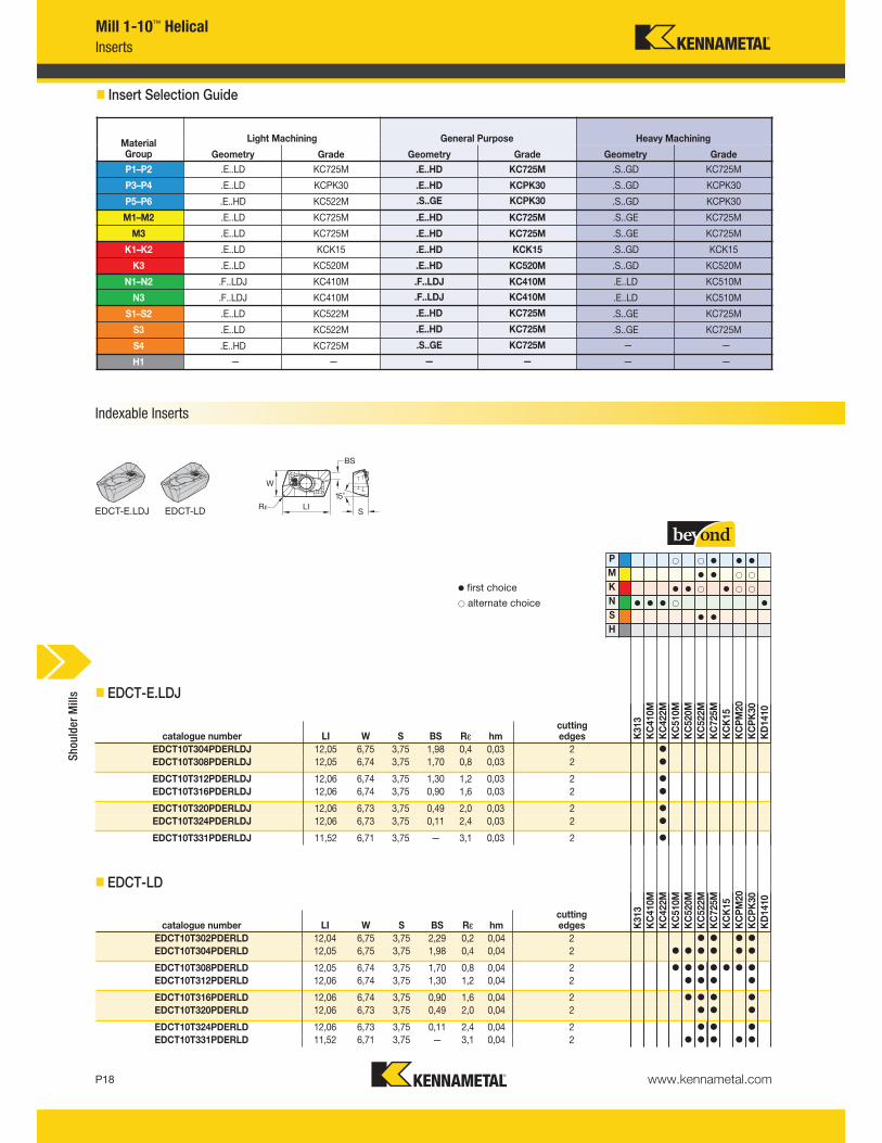
Mill 1-10™ Helical
Inserts
� EDCT-E.LDJ
catalogue number LI W S BS Rε hmcuttingedges K
313
KC410M
KC422M
KC510M
KC520M
KC522M
KC725M
KCK15
KCPM20
KCPK30
KD1410
EDCT10T304PDERLDJ 12,05 6,75 3,75 1,98 0,4 0,03 2 v
EDCT10T308PDERLDJ 12,05 6,74 3,75 1,70 0,8 0,03 2 v
EDCT10T312PDERLDJ 12,06 6,74 3,75 1,30 1,2 0,03 2 v
EDCT10T316PDERLDJ 12,06 6,74 3,75 0,90 1,6 0,03 2 v
EDCT10T320PDERLDJ 12,06 6,73 3,75 0,49 2,0 0,03 2 v
EDCT10T324PDERLDJ 12,06 6,73 3,75 0,11 2,4 0,03 2 v
EDCT10T331PDERLDJ 11,52 6,71 3,75 — 3,1 0,03 2 v
catalogue number LI W S BS Rε hmcuttingedges K
313
KC410M
KC422M
KC510M
KC520M
KC522M
KC725M
KCK15
KCPM20
KCPK30
KD1410
EDCT10T302PDERLD 12,04 6,75 3,75 2,29 0,2 0,04 2 v v v v
EDCT10T304PDERLD 12,05 6,75 3,75 1,98 0,4 0,04 2 v v v v v v
EDCT10T308PDERLD 12,05 6,74 3,75 1,70 0,8 0,04 2 v v v v v v v
EDCT10T312PDERLD 12,06 6,74 3,75 1,30 1,2 0,04 2 v v v v
EDCT10T316PDERLD 12,06 6,74 3,75 0,90 1,6 0,04 2 v v v v
EDCT10T320PDERLD 12,06 6,73 3,75 0,49 2,0 0,04 2 v v v
EDCT10T324PDERLD 12,06 6,73 3,75 0,11 2,4 0,04 2 v v v
EDCT10T331PDERLD 11,52 6,71 3,75 — 3,1 0,04 2 v v v v v
� EDCT-LD
EDCT-E.LDJ EDCT-LD
Indexable Inserts
� Insert Selection Guide
MaterialGroup
Light Machining General Purpose Heavy Machining
Geometry Grade Geometry Grade Geometry Grade
P1–P2 .E..LD KC725M .E..HD KC725M .S..GD KC725M
P3–P4 .E..LD KCPK30 .E..HD KCPK30 .S..GD KCPK30
P5–P6 .E..HD KC522M .S..GE KCPK30 .S..GD KCPK30
M1–M2 .E..LD KC725M .E..HD KC725M .S..GE KC725M
M3 .E..LD KC725M .E..HD KC725M .S..GE KC725M
K1–K2 .E..LD KCK15 .E..HD KCK15 .S..GD KCK15
K3 .E..LD KC520M .E..HD KC520M .S..GD KC520M
N1–N2 .F..LDJ KC410M .F..LDJ KC410M .E..LD KC510M
N3 .F..LDJ KC410M .F..LDJ KC410M .E..LD KC510M
S1–S2 .E..LD KC522M .E..HD KC725M .S..GE KC725M
S3 .E..LD KC522M .E..HD KC725M .S..GE KC725M
S4 .E..HD KC725M .S..GE KC725M — —
H1 — — — — — —
Shoulder Mills
www.kennametal.com P19
v v v
v v
v v v
v v v v
v v
P
M
K
N
S
H
Mill 1-10™ Helical
Indexable Inserts
EDPT-E.HD EDPT-S.GE EDPT-S.GD
v first choice
alternate choice
� EDPT-E.HD
� EDPT-S.GE
� EDPT-S.GD
catalogue number LI W S BS Rε hmcuttingedges K
313
KC410M
KC422M
KC510M
KC520M
KC522M
KC725M
KCK15
KCPM20
KCPK30
KD1410
EDPT10T304PDERHD 12,05 6,75 3,75 2,07 0,4 0,08 2 v v v v v
EDPT10T308PDERHD 12,05 6,74 3,75 1,70 0,8 0,08 2 v v v v v
EDPT10T310PDERHD 12,05 6,74 3,75 1,49 1,0 0,08 2 v v v v
EDPT10T312PDERHD 12,06 6,74 3,75 1,30 1,2 0,08 2 v v v v v
EDPT10T316PDERHD 12,06 6,74 3,75 0,90 1,6 0,08 2 v v v v v
EDPT10T320PDERHD 12,06 6,74 3,75 0,49 2,0 0,08 2 v v
EDPT10T324PDERHD 12,06 6,74 3,75 0,11 2,4 0,08 2 v v
EDPT10T331PDERHD 11,52 6,71 3,75 — 3,1 0,08 2 v v v v
catalogue number LI W S BS Rε hmcuttingedges K313
KC410M
KC422M
KC510M
KC520M
KC522M
KC725M
KCK15
KCPM20
KCPK30
KD1410
EDPT10T304PDSRGE 12,04 6,75 3,75 2,08 0,4 0,14 2 v v v
EDPT10T308PDSRGE 12,05 6,74 3,75 1,70 0,8 0,14 2 v v v
EDPT10T312PDSRGE 12,05 6,74 3,75 1,30 1,2 0,14 2 v v v
EDPT10T316PDSRGE 12,06 6,74 3,75 0,90 1,6 0,14 2 v v v
EDPT10T331PDSRGE 11,51 6,71 3,75 — 3,1 0,14 2 v v v
catalogue number LI W S BS Rε hmcuttingedges K
313
KC410M
KC422M
KC510M
KC520M
KC522M
KC725M
KCK15
KCPM20
KCPK30
KD1410
EDPT10T304PDSRGD 12,05 6,75 3,75 2,07 0,4 0,13 2 v v v v
EDPT10T308PDSRGD 12,05 6,74 3,75 1,70 0,8 0,13 2 v v v v
EDPT10T312PDSRGD 12,06 6,74 3,75 1,30 1,2 0,13 2 v v v v
EDPT10T316PDSRGD 12,06 6,74 3,75 0,90 1,6 0,13 2 v v v v
Shoulder Mills
www.kennametal.comP20
Mill 1-10™ Helical
Recommended Starting Speeds and Feeds
� Recommended Starting Speeds [m/min]
455 395 370
280 255 230
255 230 205
190 175 160
260 230 210
160 135 —
205 185 155
185 160 140
145 130 115
295 265 240
235 210 190
195 175 160
— — —
— — —
— — —
— — —
— — —
— — —
— — —
550 485 450
340 310 275
310 275 255
230 215 190
275 250 230
190 170 145
— — — 225 200 175
— — — 205 175 160
— — — 160 145 125
420 385 340 360 325 295
335 295 275 285 255 235
280 250 230 240 215 200
— — — — — —
— — — — — —
— — — — — —
— — — — — —
— — — — — —
— — — — — —
— — — — — —
KCK15
— — —
— — —
— — —
— — —
— — —
— — —
KC725M
260 230 215
220 190 160
200 170 140
180 150 120
150 135 120
130 100 80
170 150 135
155 130 110
115 100 80
— — —
— — —
— — —
— — —
— — —
35 30 25
35 30 25
45 35 25
60 45 30
— — —
Material
Group
P
1
2
3
4
5
6
M
1
2
3
K
1
2
3
N1–2
3
S
1
2
3
4
H 1
— — —
70 50 35
— — —
— — —
— — —
— — —
— — —
330 285 270
275 240 200
255 215 175
— — —
225 185 150
— — —
185 170 150
— — —
165 125 100
— — —
205 180 165
— — —
185 160 130
— — —
140 120 95
270 245 215
230 205 185
210 190 175
180 160 150
175 160 145
150 135 120
— — —
— — —
— — —
— — —
— — —
40 35 25
— — —
40 35 25
— — —
50 40 25
— — —
— — —
— — —
— — —
— — —
245 200 170
— — —
— — —
— — —
— — —
— — —
295 265 240
230 205 190
195 175 160
640 570 525
— — —
— — —
— — —
— — —
— — — — — —
— — — — — —
— — — — — —
— — — — — —
— — — — — —
— — — — — —
— — — — — —
— — — — — —
— — — — — —
— — — — — —
— — — — — —
— — — — — —
— — — — — —
— — — — — —
1215 1080 995 1075 945 875
1080 995 915 945 875 760
— — — — — —
— — — — — —
— — — — — —
4
1
— — —
— — —
— — —
1 — — —
2
3
4
5
6
1
2
3
1
2
3
1–2
3
1
2
3
— — —
— — —
— — —
— — —
— — —
— — —
190 170 150
— — —
— — —
795 695 600
— — —
— — —
— — —
— — —
— — —
P
Material
GroupK313 KC410M KC422M KC510M KC520M
KC522M
M
K
N
S
H
NOTE: FIRST choice starting speeds are in bold type.As the average chip thickness increases, the speed should be decreased.
KCPM20 KCPK30
Heavy Machining
General Purpose
Light Machining
NOTE: Use “Light Machining” values as starting feed rate.
� Recommended Starting Feeds [mm]
InsertGeometry
Programmed Feed per Tooth (fz)as a % of Radial Depth of Cut (ae) Insert
Geometry10% 20% 30% 40% 50–100%
.F..LDJ 0,08 0,13 0,23 0,06 0,10 0,18 0,06 0,09 0,15 0,05 0,08 0,14 0,05 0,08 0,14 .F..LDJ
.E..LDJ 0,08 0,18 0,30 0,06 0,13 0,23 0,06 0,11 0,20 0,05 0,11 0,18 0,05 0,11 0,18 .E..LDJ
.E..LD 0,09 0,18 0,30 0,07 0,14 0,22 0,06 0,12 0,19 0,05 0,11 0,18 0,05 0,11 0,18 .E..LD
.S..GE 0,17 0,20 0,34 0,13 0,15 0,25 0,11 0,13 0,22 0,10 0,12 0,21 0,10 0,12 0,20 .S..GE
.S..GD 0,17 0,20 0,34 0,13 0,15 0,25 0,11 0,13 0,22 0,10 0,12 0,21 0,10 0,12 0,20 .S..GD
.E..HD 0,17 0,25 0,38 0,13 0,19 0,29 0,11 0,17 0,25 0,10 0,16 0,23 0,10 0,15 0,23 .E..HD
Shoulder Mills
www.kennametal.com
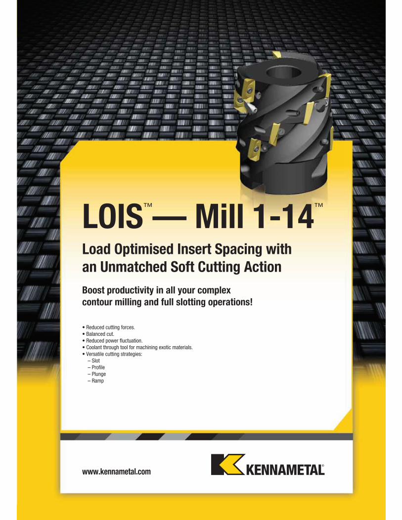
LOIS™
—Mill 1-14™
Load Optimised Insert Spacing with
an Unmatched Soft Cutting Action
• Reduced cutting forces.
• Balanced cut.
• Reduced power fluctuation.
• Coolant through tool for machining exotic materials.
• Versatile cutting strategies:
– Slot
– Profile
– Plunge
– Ramp
Boost productivity in all your complex
contour milling and full slotting operations!

P22
Mill 1-14™
Primary ApplicationMill 1-14 is a versatile, functional cutter system for a range of cutting tasks. Mill 1-14 cutters can be used for profiling, slotting, ramping, helical interpolation, circular interpolation, and other milling applications. It’s a single tool with multi-functional benefits. The Mill 1-14 inserts also are specially designed to add cutting versatility. Innovative micro-geometry features contribute greatly to enhanced performance, various rake angles, negative T-land, and small hone. Results include significantly reduced cycle times and lower cutting forces. Test results in producing 90º walls have proven excellent as well; try GD2 geometry.
Features and Benefits
Features
• Insert geometries and grades for most workpiece materials.
• Insert radii from 0,15mm (.016") up to 4mm (.157").
• Axial depth of cut up to 14mm (.551").
• Beyond™ grade technology.
Benefits
• Easy cutting action, kind on entry and also exiting the workpiece.
• Polished geometry for aluminium machining.
• Slotting, profiling, ramping, helical interpolation, and plunging.
www.kennametal.com P23
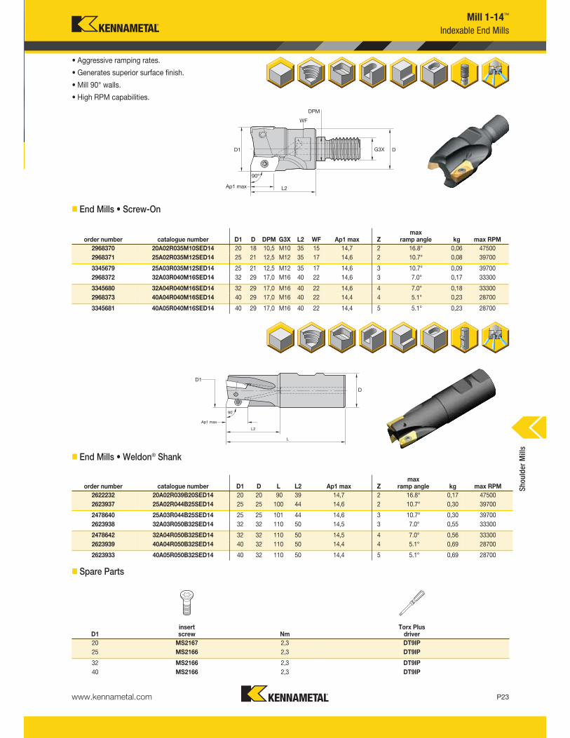
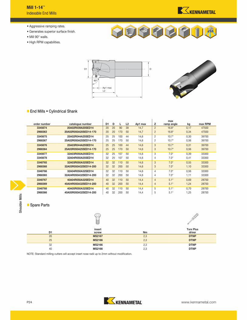
Indexable End Mills
Mill 1-14™
• Aggressive ramping rates.
• Generates superior surface finish.
• Mill 90° walls.
• High RPM capabilities.
� End Mills • Screw-On
� End Mills • Weldon® Shank
order number catalogue number D1 D DPM G3X L2 WF Ap1 max Zmax
ramp angle kg max RPM
2968370 20A02R035M10SED14 20 18 10,5 M10 35 15 14,7 2 16.8° 0,06 47500
2968371 25A02R035M12SED14 25 21 12,5 M12 35 17 14,6 2 10.7° 0,08 39700
3345679 25A03R035M12SED14 25 21 12,5 M12 35 17 14,6 3 10.7° 0,09 39700
2968372 32A03R040M16SED14 32 29 17,0 M16 40 22 14,6 3 7.0° 0,17 33300
3345680 32A04R040M16SED14 32 29 17,0 M16 40 22 14,6 4 7.0° 0,18 33300
2968373 40A04R040M16SED14 40 29 17,0 M16 40 22 14,4 4 5.1° 0,23 28700
3345681 40A05R040M16SED14 40 29 17,0 M16 40 22 14,4 5 5.1° 0,23 28700
order number catalogue number D1 D L L2 Ap1 max Zmax
ramp angle kg max RPM
2622232 20A02R039B20SED14 20 20 90 39 14,7 2 16.8° 0,17 47500
2623937 25A02R044B25SED14 25 25 100 44 14,6 2 10.7° 0,30 39700
2478640 25A03R044B25SED14 25 25 101 44 14,6 3 10.7° 0,30 39700
2623938 32A03R050B32SED14 32 32 110 50 14,5 3 7.0° 0,55 33300
2478642 32A04R050B32SED14 32 32 110 50 14,5 4 7.0° 0,56 33300
2623939 40A04R050B32SED14 40 32 110 50 14,4 4 5.1° 0,69 28700
2623933 40A05R050B32SED14 40 32 110 50 14,4 5 5.1° 0,69 28700
� Spare Parts
D1insert screw Nm
Torx Plus driver
20 MS2167 2,3 DT9IP
25 MS2166 2,3 DT9IP
32 MS2166 2,3 DT9IP
40 MS2166 2,3 DT9IP
Shoulder Mills
www.kennametal.comP24
Mill 1-14™
Indexable End Mills
• Aggressive ramping rates.
• Generates superior surface finish.
• Mill 90° walls.
• High RPM capabilities.
� End Mills • Cylindrical Shank
� Spare Parts
order number catalogue number D1 D L L2 Ap1 max Zmax
ramp angle kg max RPM
3345674 20A02R039A20SED14 20 20 90 39 14,7 2 16.8° 0,17 47500
2968363 20A02R050A20SED14-170 20 20 170 50 14,7 2 16.8° 0,34 47500
3345675 25A02R044A25SED14 25 25 100 44 14,6 2 10.7° 0,30 39700
2968367 25A02R050A25SED14-170 25 25 170 50 14,6 2 10.7° 0,56 39700
3345676 25A03R044A25SED14 25 25 100 44 14,6 3 10.7° 0,31 39700
2968364 25A03R050A25SED14-170 25 25 170 50 14,6 3 10.7° 0,56 39700
3345677 32A03R050A25SED14 32 25 107 50 14,6 3 7.0° 0,39 33300
3345678 32A04R050A25SED14 32 25 107 50 14,6 4 7.0° 0,41 33300
3348765 32A03R050A32SED14 32 32 110 50 14,6 3 7.0° 0,55 33300
2968368 32A03R050A32SED14-200 32 32 200 50 14,6 3 7.0° 1,10 33300
3348766 32A04R050A32SED14 32 32 110 50 14,6 4 7.0° 0,56 33300
2968365 32A04R050A32SED14-200 32 32 200 50 14,6 4 7.0° 1,11 33300
3348767 40A04R050A32SED14 40 32 110 50 14,4 4 5.1° 0,69 28700
2968369 40A04R050A32SED14-200 40 32 200 50 14,4 4 5.1° 1,24 28700
3348768 40A05R050A32SED14 40 32 110 50 14,4 5 5.1° 0,70 28700
2968366 40A05R050A32SED14-200 40 32 200 50 14,4 5 5.1° 1,25 28700
D1insert screw Nm
Torx Plus driver
20 MS2167 2,3 DT9IP
25 MS2166 2,3 DT9IP
32 MS2166 2,3 DT9IP
40 MS2166 2,3 DT9IP
NOTE: Standard milling cutters will accept insert nose radii up to 2mm without modification.
Shoulder Mills
www.kennametal.com P25
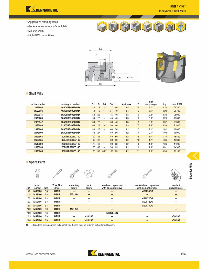
Mill 1-14™
Indexable Shell Mills
• Aggressive ramping rates.
• Generates superior surface finish.
• Mill 90° walls.
• High RPM capabilities.
� Shell Mills
� Spare Parts
NOTE: Standard milling cutters will accept insert nose radii up to 2mm without modification.
order number catalogue number D1 D D4 D6 L Ap1 max Zmax
ramp angle kg max RPM
2623940 40A04RS90ED14D 40 16 — 37 40 14,4 4 5.1° 0,20 28700
2623934 40A05RS90ED14D 40 16 — 37 40 14,4 5 5.1° 0,20 28700
2623941 50A05RS90ED14D 50 22 — 45 40 14,3 5 3.8° 0,30 25000
2478686 50A06RS90ED14D 50 22 — 45 40 14,3 6 3.8° 0,29 25000
2623942 63A06RS90ED14D 63 22 — 50 40 14,3 6 2.8° 0,52 21800
2478689 63A07RS90ED14D 63 22 — 50 40 14,3 7 2.8° 0,53 21800
2623963 80A07RS90ED14D 80 27 — 60 50 14,2 7 2.1° 1,02 19000
2478690 80A09RS90ED14D 80 27 — 60 50 14,2 9 2.1° 1,08 19000
2623964 100A08RS90ED14D 100 32 — 80 50 14,2 8 1.7° 1,75 16800
2623935 100A10RS90ED14D 100 32 — 80 50 14,2 10 1.7° 1,86 16800
2510390 125B09RS90ED14D 125 40 — 90 63 14,2 9 1.3° 2,86 14900
2623936 125B12RS90ED14D 125 40 — 90 63 14,2 12 1.3° 3,01 14900
2623965 160C11RS90ED14D 160 40 66,7 100 63 14,2 11 1.0° 3,95 13100
D1insert screw Nm
Torx Plus driver
mountingscrew
lockscrew
low-head cap screwwith coolant groove
socket-head cap screwwith coolant groove
coolant shower plate
40 MS2166 2,3 DT9IP — — — MS1294CG —
40 MS2166 2,3 DT9IP MS1294 — — — —
50 MS2166 2,3 DT9IP — — — MS2072CG —
63 MS2166 2,3 DT9IP — — — MS2072CG —
80 MS2166 2,3 DT9IP — — — MS2038CG —
100 MS2166 2,3 DT9IP MS1254 — — — —
100 MS2166 2,3 DT9IP — — MS1254CG — —
125 MS2166 2,3 DT9IP — 420.200 — — 470.232
160 MS2166 2,3 DT9IP — 420.200 — — 470.233
Shoulder Mills
www.kennametal.comP26
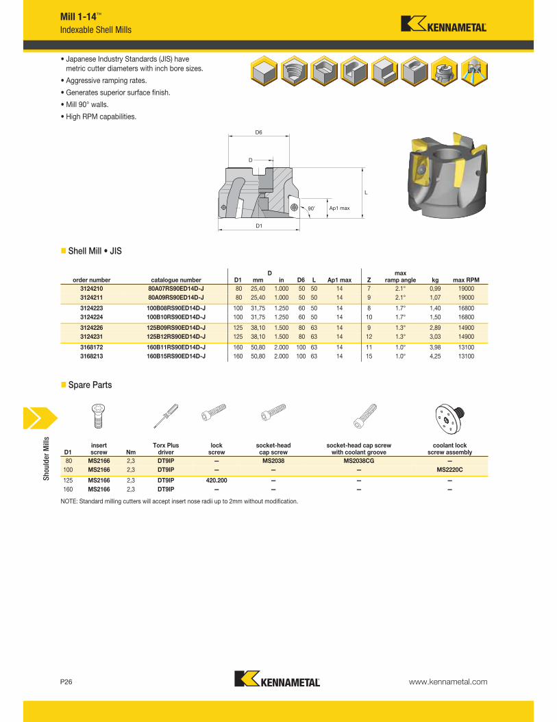
Mill 1-14™
Indexable Shell Mills
• Japanese Industry Standards (JIS) have metric cutter diameters with inch bore sizes.
• Aggressive ramping rates.
• Generates superior surface finish.
• Mill 90° walls.
• High RPM capabilities.
� Shell Mill • JIS
� Spare Parts
Dorder number catalogue number D1 mm in D6 L Ap1 max Z
max ramp angle kg max RPM
3124210 80A07RS90ED14D-J 80 25,40 1.000 50 50 14 7 2.1° 0,99 19000
3124211 80A09RS90ED14D-J 80 25,40 1.000 50 50 14 9 2.1° 1,07 19000
3124223 100B08RS90ED14D-J 100 31,75 1.250 60 50 14 8 1.7° 1,40 16800
3124224 100B10RS90ED14D-J 100 31,75 1.250 60 50 14 10 1.7° 1,50 16800
3124226 125B09RS90ED14D-J 125 38,10 1.500 80 63 14 9 1.3° 2,89 14900
3124231 125B12RS90ED14D-J 125 38,10 1.500 80 63 14 12 1.3° 3,03 14900
3168172 160B11RS90ED14D-J 160 50,80 2.000 100 63 14 11 1.0° 3,98 13100
3168213 160B15RS90ED14D-J 160 50,80 2.000 100 63 14 15 1.0° 4,25 13100
NOTE: Standard milling cutters will accept insert nose radii up to 2mm without modification.
D1insert screw Nm
Torx Plus driver
lockscrew
socket-headcap screw
socket-head cap screwwith coolant groove
coolant lock screw assembly
80 MS2166 2,3 DT9IP — MS2038 MS2038CG —
100 MS2166 2,3 DT9IP — — — MS2220C
125 MS2166 2,3 DT9IP 420.200 — — —
160 MS2166 2,3 DT9IP — — — —
Shoulder Mills
www.kennametal.com P27
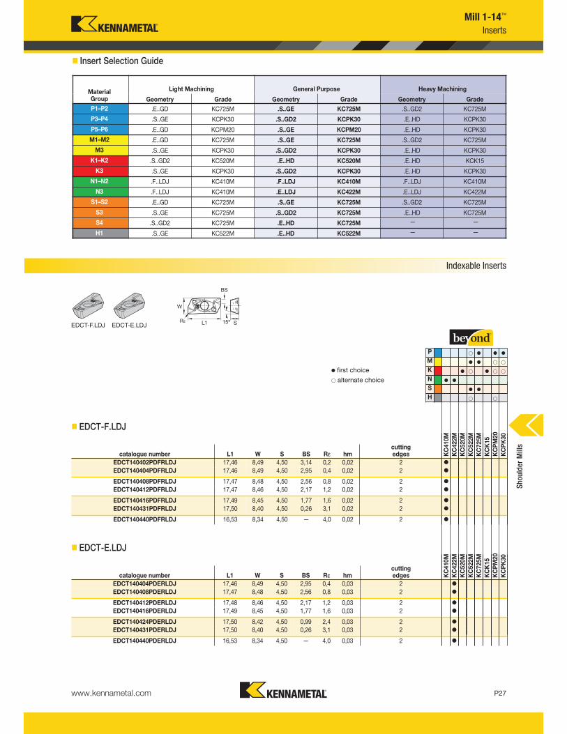
Mill 1-14™
Inserts
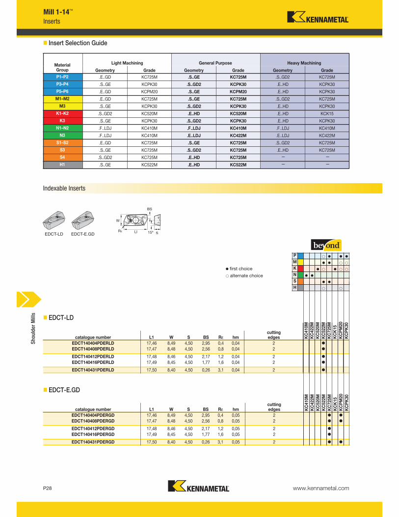
� Insert Selection Guide
Indexable Inserts
EDCT-F.LDJ
� EDCT-F.LDJ
� EDCT-E.LDJ
P v v v
M v v
K v v
N v v
S v v
H
catalogue number L1 W S BS Rε hmcuttingedges K
C410M
KC422M
KC520M
KC522M
KC725M
KCK15
KCPM20
KCPK30
EDCT140402PDFRLDJ 17,46 8,49 4,50 3,14 0,2 0,02 2 v
EDCT140404PDFRLDJ 17,46 8,49 4,50 2,95 0,4 0,02 2 v
EDCT140408PDFRLDJ 17,47 8,48 4,50 2,56 0,8 0,02 2 v
EDCT140412PDFRLDJ 17,47 8,46 4,50 2,17 1,2 0,02 2 v
EDCT140416PDFRLDJ 17,49 8,45 4,50 1,77 1,6 0,02 2 v
EDCT140431PDFRLDJ 17,50 8,40 4,50 0,26 3,1 0,02 2 v
EDCT140440PDFRLDJ 16,53 8,34 4,50 — 4,0 0,02 2 v
catalogue number L1 W S BS Rε hmcuttingedges K
C410M
KC422M
KC520M
KC522M
KC725M
KCK15
KCPM20
KCPK30
EDCT140404PDERLDJ 17,46 8,49 4,50 2,95 0,4 0,03 2 v
EDCT140408PDERLDJ 17,47 8,48 4,50 2,56 0,8 0,03 2 v
EDCT140412PDERLDJ 17,48 8,46 4,50 2,17 1,2 0,03 2 v
EDCT140416PDERLDJ 17,49 8,45 4,50 1,77 1,6 0,03 2 v
EDCT140424PDERLDJ 17,50 8,42 4,50 0,99 2,4 0,03 2 v
EDCT140431PDERLDJ 17,50 8,40 4,50 0,26 3,1 0,03 2 v
EDCT140440PDERLDJ 16,53 8,34 4,50 — 4,0 0,03 2 v
MaterialGroup
Light Machining General Purpose Heavy Machining
Geometry Grade Geometry Grade Geometry Grade
P1–P2 .E..GD KC725M .S..GE KC725M .S..GD2 KC725M
P3–P4 .S..GE KCPK30 .S..GD2 KCPK30 .E..HD KCPK30
P5–P6 .E..GD KCPM20 .S..GE KCPM20 .E..HD KCPK30
M1–M2 .E..GD KC725M .S..GE KC725M .S..GD2 KC725M
M3 .S..GE KCPK30 .S..GD2 KCPK30 .E..HD KCPK30
K1–K2 .S..GD2 KC520M .E..HD KC520M .E..HD KCK15
K3 .S..GE KCPK30 .S..GD2 KCPK30 .E..HD KCPK30
N1–N2 .F..LDJ KC410M .F..LDJ KC410M .F..LDJ KC410M
N3 .F..LDJ KC410M .E..LDJ KC422M .E..LDJ KC422M
S1–S2 .E..GD KC725M .S..GE KC725M .S..GD2 KC725M
S3 .S..GE KC725M .S..GD2 KC725M .E..HD KC725M
S4 .S..GD2 KC725M .E..HD KC725M — —
H1 .S..GE KC522M .E..HD KC522M — —
v first choice
alternate choice
EDCT-E.LDJ
Shoulder Mills
www.kennametal.comP28
� EDCT-LD
� EDCT-E.GD
catalogue number L1 W S BS Rε hmcutting edges K
C410M
KC422M
KC520M
KC522M
KC725M
KCK15
KCPM20
KCPK30
EDCT140404PDERLD 17,46 8,49 4,50 2,95 0,4 0,04 2 v
EDCT140408PDERLD 17,47 8,48 4,50 2,56 0,8 0,04 2 v
EDCT140412PDERLD 17,48 8,46 4,50 2,17 1,2 0,04 2 v
EDCT140416PDERLD 17,49 8,45 4,50 1,77 1,6 0,04 2 v
EDCT140431PDERLD 17,50 8,40 4,50 0,26 3,1 0,04 2 v
catalogue number L1 W S BS Rε hmcutting edges K
C410M
KC422M
KC520M
KC522M
KC725M
KCK15
KCPM20
KCPK30
EDCT140404PDERGD 17,46 8,49 4,50 2,95 0,4 0,05 2 v v
EDCT140408PDERGD 17,47 8,48 4,50 2,56 0,8 0,05 2 v v
EDCT140412PDERGD 17,48 8,46 4,50 2,17 1,2 0,05 2 v
EDCT140416PDERGD 17,49 8,45 4,50 1,77 1,6 0,05 2 v
EDCT140431PDERGD 17,50 8,40 4,50 0,26 3,1 0,05 2 v v
Mill 1-14™
Inserts
P v v v
M v v
K v v
N v v
S v v
H
v first choice
alternate choice
EDCT-LD EDCT-E.GD
� Insert Selection Guide
MaterialGroup
Light Machining General Purpose Heavy Machining
Geometry Grade Geometry Grade Geometry Grade
P1–P2 .E..GD KC725M .S..GE KC725M .S..GD2 KC725M
P3–P4 .S..GE KCPK30 .S..GD2 KCPK30 .E..HD KCPK30
P5–P6 .E..GD KCPM20 .S..GE KCPM20 .E..HD KCPK30
M1–M2 .E..GD KC725M .S..GE KC725M .S..GD2 KC725M
M3 .S..GE KCPK30 .S..GD2 KCPK30 .E..HD KCPK30
K1–K2 .S..GD2 KC520M .E..HD KC520M .E..HD KCK15
K3 .S..GE KCPK30 .S..GD2 KCPK30 .E..HD KCPK30
N1–N2 .F..LDJ KC410M .F..LDJ KC410M .F..LDJ KC410M
N3 .F..LDJ KC410M .E..LDJ KC422M .E..LDJ KC422M
S1–S2 .E..GD KC725M .S..GE KC725M .S..GD2 KC725M
S3 .S..GE KC725M .S..GD2 KC725M .E..HD KC725M
S4 .S..GD2 KC725M .E..HD KC725M — —
H1 .S..GE KC522M .E..HD KC522M — —
Shoulder Mills
Indexable Inserts
www.kennametal.com P29
Mill 1-14™
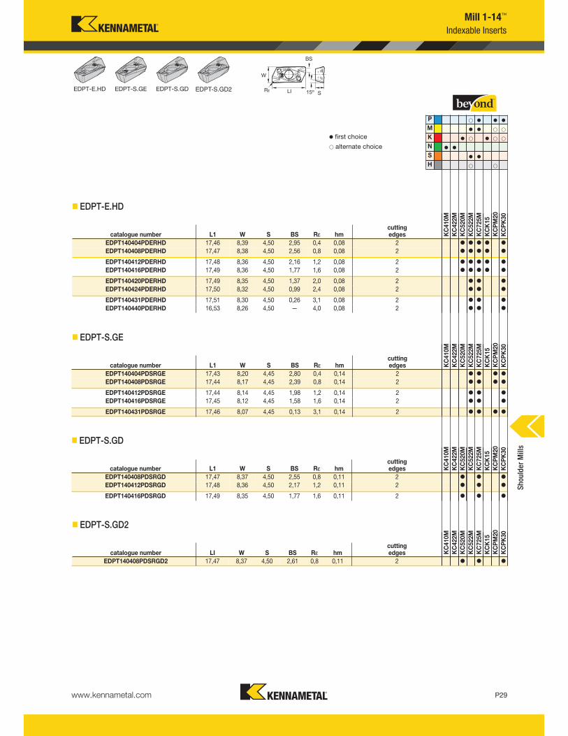
Indexable Inserts
v first choice
alternate choice
P v v v
M v v
K v v
N v v
S v v
H
� EDPT-E.HD
catalogue number L1 W S BS Rε hmcutting edges K
C410M
KC422M
KC520M
KC522M
KC725M
KCK15
KCPM20
KCPK30
EDPT140404PDERHD 17,46 8,39 4,50 2,95 0,4 0,08 2 v v v v v
EDPT140408PDERHD 17,47 8,38 4,50 2,56 0,8 0,08 2 v v v v v
EDPT140412PDERHD 17,48 8,36 4,50 2,16 1,2 0,08 2 v v v v v
EDPT140416PDERHD 17,49 8,36 4,50 1,77 1,6 0,08 2 v v v v v
EDPT140420PDERHD 17,49 8,35 4,50 1,37 2,0 0,08 2 v v v
EDPT140424PDERHD 17,50 8,32 4,50 0,99 2,4 0,08 2 v v v
EDPT140431PDERHD 17,51 8,30 4,50 0,26 3,1 0,08 2 v v v
EDPT140440PDERHD 16,53 8,26 4,50 — 4,0 0,08 2 v v v
� EDPT-S.GE
catalogue number L1 W S BS Rε hmcutting edges K
C410M
KC422M
KC520M
KC522M
KC725M
KCK15
KCPM20
KCPK30
EDPT140404PDSRGE 17,43 8,20 4,45 2,80 0,4 0,14 2 v v v v
EDPT140408PDSRGE 17,44 8,17 4,45 2,39 0,8 0,14 2 v v v v
EDPT140412PDSRGE 17,44 8,14 4,45 1,98 1,2 0,14 2 v v v
EDPT140416PDSRGE 17,45 8,12 4,45 1,58 1,6 0,14 2 v v v
EDPT140431PDSRGE 17,46 8,07 4,45 0,13 3,1 0,14 2 v v v v
� EDPT-S.GD
catalogue number L1 W S BS Rε hmcutting edges K
C410M
KC422M
KC520M
KC522M
KC725M
KCK15
KCPM20
KCPK30
EDPT140408PDSRGD 17,47 8,37 4,50 2,55 0,8 0,11 2 v v v
EDPT140412PDSRGD 17,48 8,36 4,50 2,17 1,2 0,11 2 v v v
EDPT140416PDSRGD 17,49 8,35 4,50 1,77 1,6 0,11 2 v v v
� EDPT-S.GD2
catalogue number LI W S BS Rε hmcutting edges K
C410M
KC422M
KC520M
KC522M
KC725M
KCK15
KCPM20
KCPK30
EDPT140408PDSRGD2 17,47 8,37 4,50 2,61 0,8 0,11 2 v v v
Shoulder Mills
EDPT-E.HD EDPT-S.GE EDPT-S.GD EDPT-S.GD2
www.kennametal.comP30
Heavy Machining
General Purpose
Light Machining
— — — — — — 175 160 145 150 135 120
— — — 280 250 230 240 215 200 195 175 160
—
Mill 1-14™
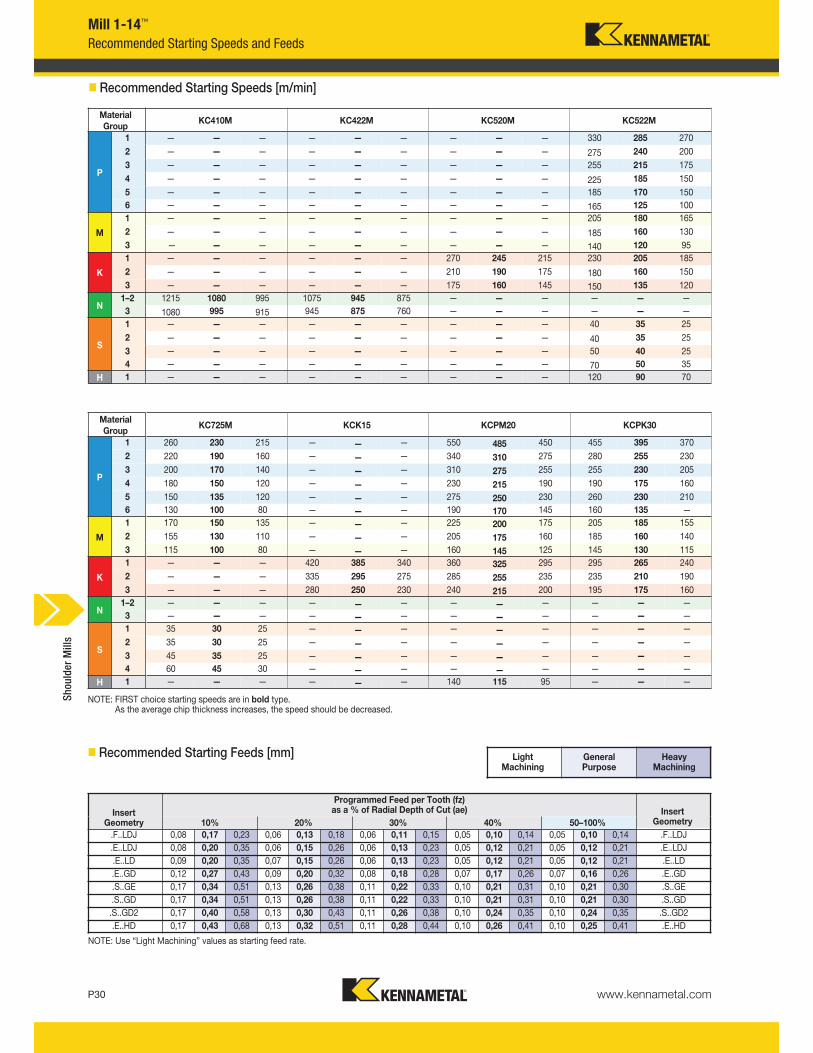
NOTE: FIRST choice starting speeds are in bold type.As the average chip thickness increases, the speed should be decreased.
Recommended Starting Speeds and Feeds
NOTE: Use “Light Machining” values as starting feed rate.
Material
GroupKC410M KC422M KC520M KC522M
KC725M KCK15 KCPM20 KCPK30
P
1 — — — — — — — — — 330 285 270
260 230 215 — — — 550 485 450 455 395 370
2 — — — — — — — — — 275 240 200
220 190 160 — — — 340 310 275 280 255 230
3 — — — — — — — — — 255 215 175
200 170 140 — — — 310 275 255 255 230 205
4 — — — — — — — — — 225 185 150
180 150 120 — — — 230 215 190 190 175 160
5 — — — — — — — — — 185 170 150
150 135 120 — — — 275 250 230 260 230 210
6 — — — — — — — — — 165 125 100
130 100 80 — — — 190 170 145 160 135 —
M
1 — — — — — — — — — 205 180 165
170 150 135 — — — 225 200 175 205 185 155
2 — — — — — — — — — 185 160 130
155 130 110 — — — 205 175 160 185 160 140
3 — — — — — — — — 140 120 95
115 100 80 — — — 160 145 125 145 130 115
K
1 — — — — — — 270 245 215 230 205 185
— — — 420 385 340 360 325 295 295 265 240
2 — — — — — — 210 190 175 180 160 150
— — — 335 295 275 285 255 235 235 210 190
3
N1–2 1215 1080 995 1075 945 875 — — — — — —
— — — — — — — — — — — —
3 1080 995 915 945 875 760 — — — — — —
— — — — — — — — — — — —
S
1 — — — — — — — — — 40 35 25
35 30 25 — — — — — — — — —
2 — — — — — — — — — 40 35 25
35 30 25 — — — — — — — — —
3 — — — — — — — — — 50 40 25
45 35 25 — — — — — — — — —
4 — — — — — — — — — 70 50 35
60 45 30 — — — — — — — — —
H 1 — — — — — — — — — 120 90 70
— — — — — — 140 115 95 — — —
� Recommended Starting Speeds [m/min]
� Recommended Starting Feeds [mm]
InsertGeometry
Programmed Feed per Tooth (fz)as a % of Radial Depth of Cut (ae) Insert
Geometry10% 20% 30% 40% 50–100%
.F..LDJ 0,08 0,17 0,23 0,06 0,13 0,18 0,06 0,11 0,15 0,05 0,10 0,14 0,05 0,10 0,14 .F..LDJ
.E..LDJ 0,08 0,20 0,35 0,06 0,15 0,26 0,06 0,13 0,23 0,05 0,12 0,21 0,05 0,12 0,21 .E..LDJ
.E..LD 0,09 0,20 0,35 0,07 0,15 0,26 0,06 0,13 0,23 0,05 0,12 0,21 0,05 0,12 0,21 .E..LD
.E..GD 0,12 0,27 0,43 0,09 0,20 0,32 0,08 0,18 0,28 0,07 0,17 0,26 0,07 0,16 0,26 .E..GD
.S..GE 0,17 0,34 0,51 0,13 0,26 0,38 0,11 0,22 0,33 0,10 0,21 0,31 0,10 0,21 0,30 .S..GE
.S..GD 0,17 0,34 0,51 0,13 0,26 0,38 0,11 0,22 0,33 0,10 0,21 0,31 0,10 0,21 0,30 .S..GD
.S..GD2 0,17 0,40 0,58 0,13 0,30 0,43 0,11 0,26 0,38 0,10 0,24 0,35 0,10 0,24 0,35 .S..GD2
.E..HD 0,17 0,43 0,68 0,13 0,32 0,51 0,11 0,28 0,44 0,10 0,26 0,41 0,10 0,25 0,41 .E..HD
Material
Group
P
1
2
3
4
5
6
M
1
2
3
K
1
2
3
N1–2
3
S
1
2
3
4
H 1
Shoulder Mills
www.kennametal.com P31
Mill 1-14™
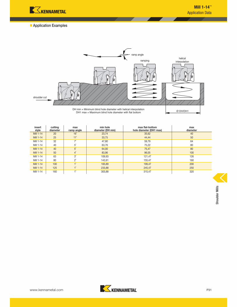
Application Data
shoulder cut
Ø DH/DH1DH min = Minimum blind hole diameter with helical interpolation
DH1 max = Maximum blind hole diameter with flat bottom
ramp angle
helicalinterpolationramping
Mill 1-14 100 1˚ 183,89 199,47 200
Mill 1-14 125 1˚ 233,88 245,47 250
Mill 1-14 40 5˚ 64,00 75,47 80
Mill 1-14 50 4˚ 83,96 96,05 100
Mill 1-14
Mill 1-14
20 16˚ 23,74 35,62 40
25 11˚ 33,75 44,44 50
insertstyle
cuttingdiameter
maxramp angle
min holediameter (DH min)
max flat-bottomhole diameter (DH1 max)
maxdiameter
Mill 1-14 32 7˚ 47,80 59,79 64
Mill 1-14 40 5˚ 63,76 75,22 80
Mill 1-14 63 3˚ 109,93 121,47 126
Mill 1-14 80 2˚ 143,91 155,47 160
Mill 1-14 160 1˚ 303,88 315,47 320
� Application Examples
Shoulder Mills

P32
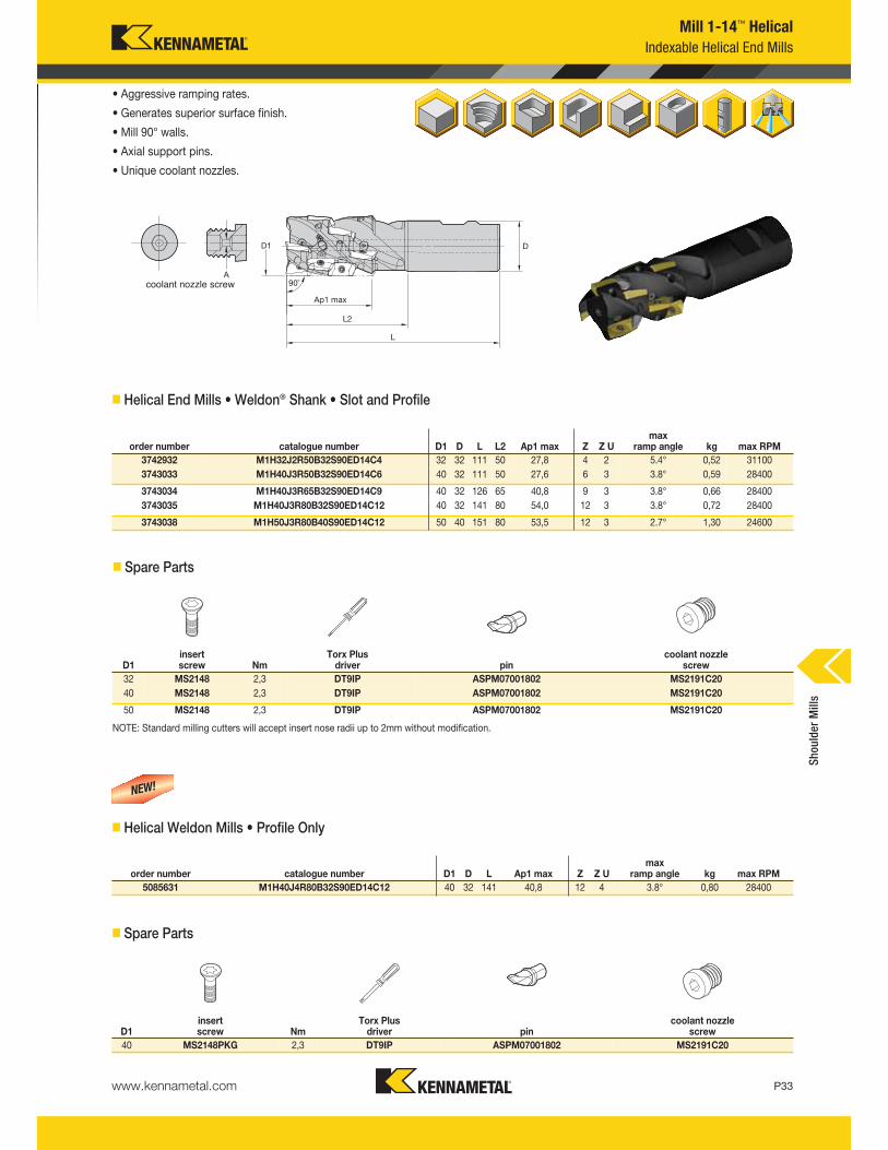
Mill 1-14™ Helical Cutters
Primary ApplicationThe Mill 1-14 helical cutters will increase your axial depth of cut. Designed with axial support pins for added stability, the Mill 1-14 features our essential Load-Optimised Insert Spacing™ (LOIS) technology. LOIS dramatically minimises unwanted vibrations and fluctuations in power requirements, resulting in a much smoother-sounding cut. Up to nine different coolant nozzle diameters enable tailoring to suit each machine tool, providing remarkably consistent, focused coolant flow.
Features and Benefits
Functions
• Improves axial depth of cut better than standard end mills due to the positioning of inserts in helical configuration.
• Up to nine different coolant nozzle diameters tailored to suit each machine tool.
• One tool that offers features common to end mills, but rarely seen on a helical cutter: Helical ramping from solid, slotting, contouring, ramping, and plunging.
Benefits
• Increases depth of cut.
• Consistent, focused coolant flow.
• Built for performance, accuracy, and versatility.
www.kennametal.com P33
Mill 1-14™ Helical
Indexable Helical End Mills
• Aggressive ramping rates.
• Generates superior surface finish.
• Mill 90° walls.
• Axial support pins.
• Unique coolant nozzles.
� Helical End Mills • Weldon® Shank • Slot and Profile
� Spare Parts
NOTE: Standard milling cutters will accept insert nose radii up to 2mm without modification.
order number catalogue number D1 D L L2 Ap1 max Z Z Umax
ramp angle kg max RPM
3742932 M1H32J2R50B32S90ED14C4 32 32 111 50 27,8 4 2 5.4° 0,52 31100
3743033 M1H40J3R50B32S90ED14C6 40 32 111 50 27,6 6 3 3.8° 0,59 28400
3743034 M1H40J3R65B32S90ED14C9 40 32 126 65 40,8 9 3 3.8° 0,66 28400
3743035 M1H40J3R80B32S90ED14C12 40 32 141 80 54,0 12 3 3.8° 0,72 28400
3743038 M1H50J3R80B40S90ED14C12 50 40 151 80 53,5 12 3 2.7° 1,30 24600
D1insert screw Nm
Torx Plus driver pin
coolant nozzle screw
32 MS2148 2,3 DT9IP ASPM07001802 MS2191C20
40 MS2148 2,3 DT9IP ASPM07001802 MS2191C20
50 MS2148 2,3 DT9IP ASPM07001802 MS2191C20
� Helical Weldon Mills • Profile Only
order number catalogue number D1 D L Ap1 max Z Z Umax
ramp angle kg max RPM
5085631 M1H40J4R80B32S90ED14C12 40 32 141 40,8 12 4 3.8° 0,80 28400
� Spare Parts
D1insert screw Nm
Torx Plus driver pin
coolant nozzle screw
40 MS2148PKG 2,3 DT9IP ASPM07001802 MS2191C20
Shoulder Mills
coolant nozzle screw
NEW!
www.kennametal.comP34
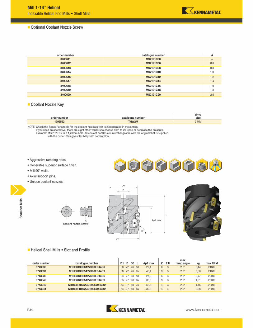
Mill 1-14™ Helical
Indexable Helical End Mills • Shell Mills
• Aggressive ramping rates.
• Generates superior surface finish.
• Mill 90° walls.
• Axial support pins.
• Unique coolant nozzles.
� Helical Shell Mills • Slot and Profile
order number catalogue number D1 D D6 L Ap1 max Z Z Umax
ramp angle kg max RPM
3743036 M1H50T3R50A22S90ED14C6 50 22 46 50 27,4 6 3 2.7° 0,44 24600
3743037 M1H50T3R65A22S90ED14C9 50 22 46 65 40,4 9 3 2.7° 0,58 24600
3743039 M1H63T3R50A27S90ED14C6 63 27 60 50 27,0 6 3 2.0° 0,77 22000
3743040 M1H63T3R65A27S90ED14C9 63 27 60 65 39,9 9 3 2.0° 1,01 22000
3743042 M1H63T3R75A27S90ED14C12 63 27 60 75 52,8 12 3 2.0° 1,16 22000
3743041 M1H63T4R65A27S90ED14C12 63 27 60 65 39,9 12 4 2.0° 0,98 22000
order number catalogue numberdrive size
1993552 THW2M 2 MM
3400611
3400612
3400613
3400614
3400616 MS2191C12 1,2
3400617 MS2191C14 1,4
3400618 MS2191C16 1,6
3400619 MS2191C18 1,8
3400620 MS2191C20 2,0
MS2191C00 —
MS2191C06 0,6
�Optional Coolant Nozzle Screw
� Coolant Nozzle Key
NOTE: Check the Spare Parts table for the coolant hole size that is incorporated in the cutters.If you need an alternative, there are eight other variants to choose from to increase or decrease the pressure.Example: MS2191C12 is a 1,20mm hole. All coolant nozzles are interchangeable with the original that is supplied
with the cutter. This gives flexibility with coolant flow.
order number catalogue number A
MS2191C08 0,8
MS2191C10 1,0
Shoulder Mills
coolant nozzle screw
www.kennametal.com P35
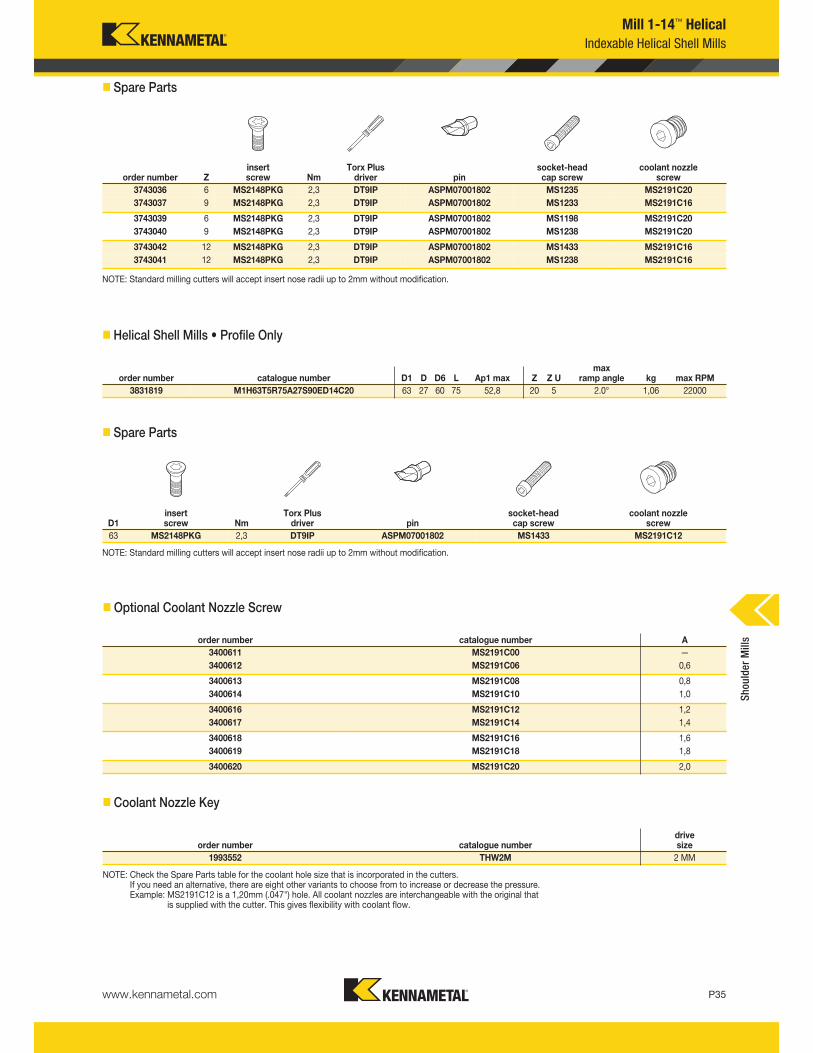
� Spare Parts
NOTE: Standard milling cutters will accept insert nose radii up to 2mm without modification.
� Helical Shell Mills • Profile Only
order number catalogue number D1 D D6 L Ap1 max Z Z Umax
ramp angle kg max RPM
3831819 M1H63T5R75A27S90ED14C20 63 27 60 75 52,8 20 5 2.0° 1,06 22000
� Spare Parts
NOTE: Standard milling cutters will accept insert nose radii up to 2mm without modification.
�Optional Coolant Nozzle Screw
� Coolant Nozzle Key
D1insert screw Nm
Torx Plus driver pin
socket-headcap screw
coolant nozzle screw
63 MS2148PKG 2,3 DT9IP ASPM07001802 MS1433 MS2191C12
order number catalogue number A
3400611 MS2191C00 —
3400612 MS2191C06 0,6
3400613 MS2191C08 0,8
3400614 MS2191C10 1,0
3400616 MS2191C12 1,2
3400617 MS2191C14 1,4
3400618 MS2191C16 1,6
3400619 MS2191C18 1,8
3400620 MS2191C20 2,0
order number catalogue numberdrive size
1993552 THW2M 2 MM
NOTE: Check the Spare Parts table for the coolant hole size that is incorporated in the cutters.If you need an alternative, there are eight other variants to choose from to increase or decrease the pressure.Example: MS2191C12 is a 1,20mm (.047") hole. All coolant nozzles are interchangeable with the original that
is supplied with the cutter. This gives flexibility with coolant flow.
Mill 1-14™ Helical
Indexable Helical Shell Mills
order number Zinsert screw Nm
Torx Plus driver pin
socket-headcap screw
coolant nozzle screw
3743036 6 MS2148PKG 2,3 DT9IP ASPM07001802 MS1235 MS2191C20
3743037 9 MS2148PKG 2,3 DT9IP ASPM07001802 MS1233 MS2191C16
3743039 6 MS2148PKG 2,3 DT9IP ASPM07001802 MS1198 MS2191C20
3743040 9 MS2148PKG 2,3 DT9IP ASPM07001802 MS1238 MS2191C20
3743042 12 MS2148PKG 2,3 DT9IP ASPM07001802 MS1433 MS2191C16
3743041 12 MS2148PKG 2,3 DT9IP ASPM07001802 MS1238 MS2191C16
Shoulder Mills
www.kennametal.comP36
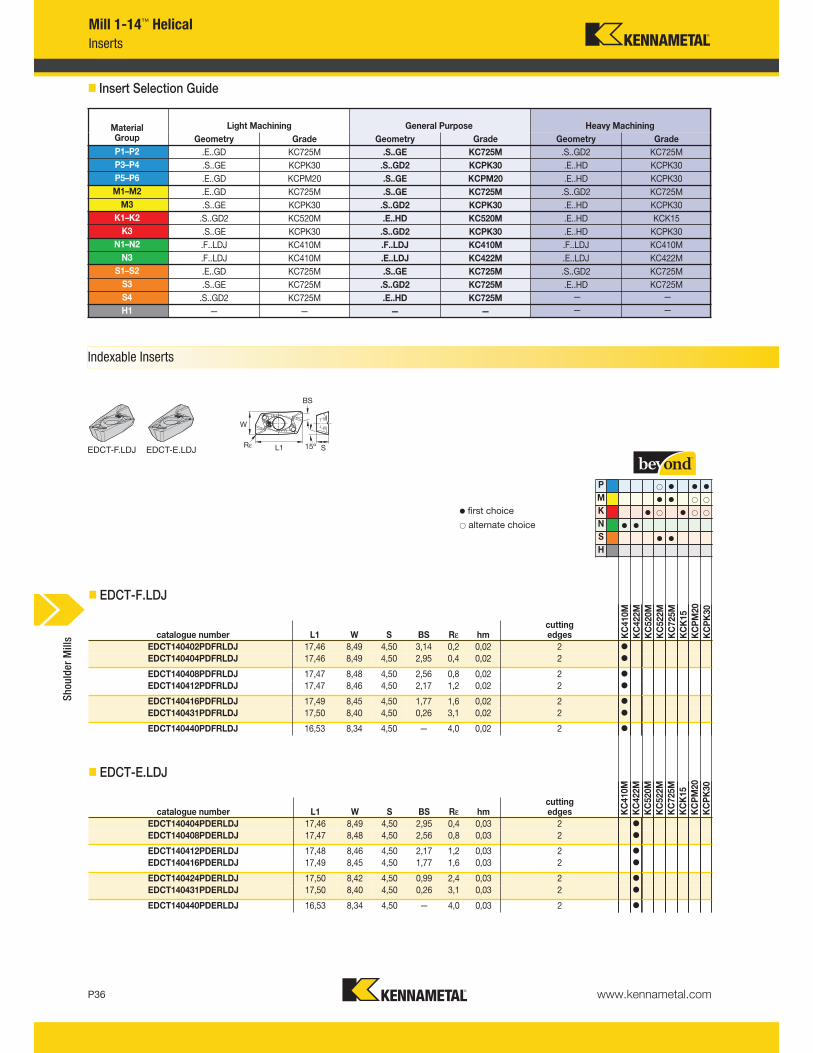
Mill 1-14™ Helical
Inserts
� Insert Selection Guide
Indexable Inserts
EDCT-F.LDJ
� EDCT-F.LDJ
� EDCT-E.LDJ
P v v v
M v v
K v v
N v v
S v v
H
catalogue number L1 W S BS Rε hmcutting edges K
C410M
KC422M
KC520M
KC522M
KC725M
KCK15
KCPM20
KCPK30
EDCT140402PDFRLDJ 17,46 8,49 4,50 3,14 0,2 0,02 2 v
EDCT140404PDFRLDJ 17,46 8,49 4,50 2,95 0,4 0,02 2 v
EDCT140408PDFRLDJ 17,47 8,48 4,50 2,56 0,8 0,02 2 v
EDCT140412PDFRLDJ 17,47 8,46 4,50 2,17 1,2 0,02 2 v
EDCT140416PDFRLDJ 17,49 8,45 4,50 1,77 1,6 0,02 2 v
EDCT140431PDFRLDJ 17,50 8,40 4,50 0,26 3,1 0,02 2 v
EDCT140440PDFRLDJ 16,53 8,34 4,50 — 4,0 0,02 2 v
catalogue number L1 W S BS Rε hmcutting edges K
C410M
KC422M
KC520M
KC522M
KC725M
KCK15
KCPM20
KCPK30
EDCT140404PDERLDJ 17,46 8,49 4,50 2,95 0,4 0,03 2 v
EDCT140408PDERLDJ 17,47 8,48 4,50 2,56 0,8 0,03 2 v
EDCT140412PDERLDJ 17,48 8,46 4,50 2,17 1,2 0,03 2 v
EDCT140416PDERLDJ 17,49 8,45 4,50 1,77 1,6 0,03 2 v
EDCT140424PDERLDJ 17,50 8,42 4,50 0,99 2,4 0,03 2 v
EDCT140431PDERLDJ 17,50 8,40 4,50 0,26 3,1 0,03 2 v
EDCT140440PDERLDJ 16,53 8,34 4,50 — 4,0 0,03 2 v
MaterialGroup
Light Machining General Purpose Heavy Machining
Geometry Grade Geometry Grade Geometry Grade
P1–P2 .E..GD KC725M .S..GE KC725M .S..GD2 KC725M
P3–P4 .S..GE KCPK30 .S..GD2 KCPK30 .E..HD KCPK30
P5–P6 .E..GD KCPM20 .S..GE KCPM20 .E..HD KCPK30
M1–M2 .E..GD KC725M .S..GE KC725M .S..GD2 KC725M
M3 .S..GE KCPK30 .S..GD2 KCPK30 .E..HD KCPK30
K1–K2 .S..GD2 KC520M .E..HD KC520M .E..HD KCK15
K3 .S..GE KCPK30 .S..GD2 KCPK30 .E..HD KCPK30
N1–N2 .F..LDJ KC410M .F..LDJ KC410M .F..LDJ KC410M
N3 .F..LDJ KC410M .E..LDJ KC422M .E..LDJ KC422M
S1–S2 .E..GD KC725M .S..GE KC725M .S..GD2 KC725M
S3 .S..GE KC725M .S..GD2 KC725M .E..HD KC725M
S4 .S..GD2 KC725M .E..HD KC725M — —
H1 — — — — — —
v first choice
alternate choice
EDCT-E.LDJ
Shoulder Mills
P v v v
M v v
K v v
N v v
S v v
H
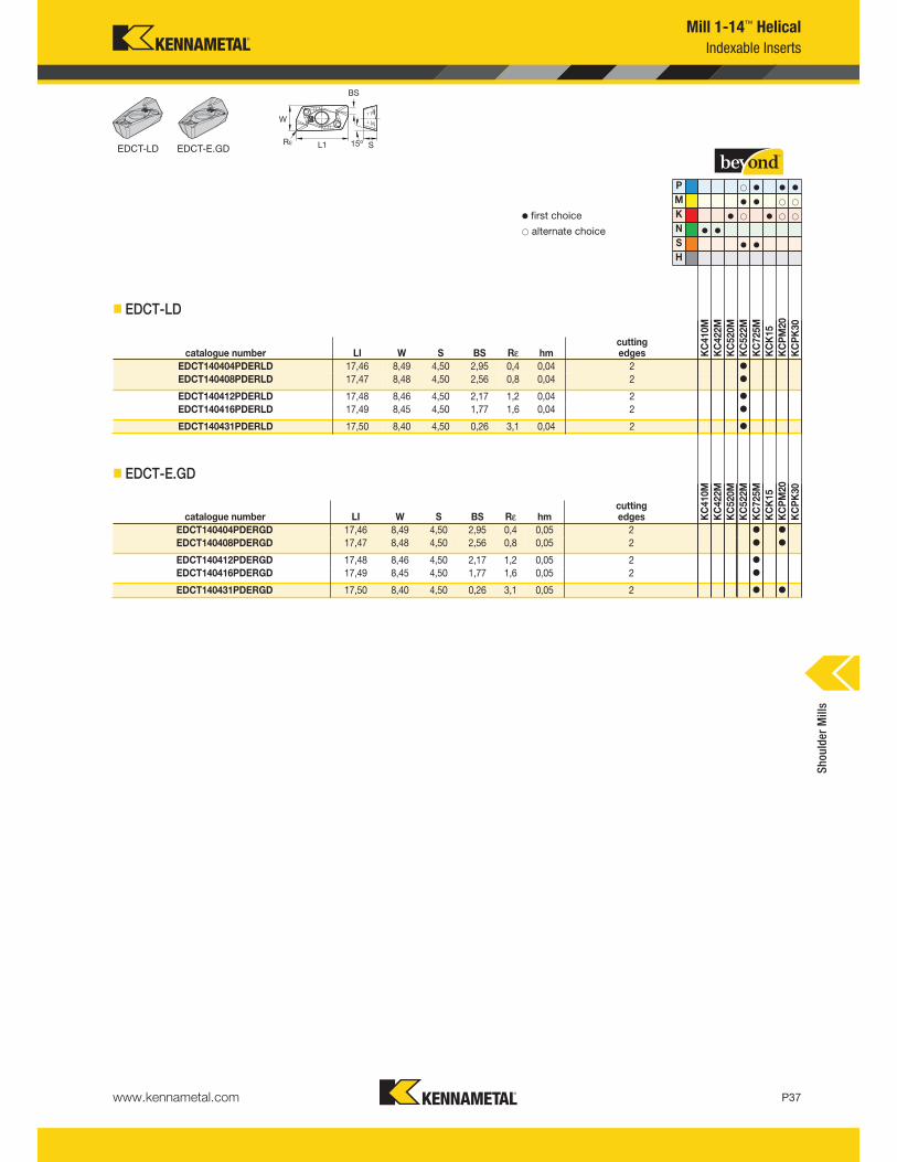
� EDCT-LD
� EDCT-E.GD
catalogue number LI W S BS Rε hmcutting edges K
C410M
KC422M
KC520M
KC522M
KC725M
KCK15
KCPM20
KCPK30
EDCT140404PDERLD 17,46 8,49 4,50 2,95 0,4 0,04 2 v
EDCT140408PDERLD 17,47 8,48 4,50 2,56 0,8 0,04 2 v
EDCT140412PDERLD 17,48 8,46 4,50 2,17 1,2 0,04 2 v
EDCT140416PDERLD 17,49 8,45 4,50 1,77 1,6 0,04 2 v
EDCT140431PDERLD 17,50 8,40 4,50 0,26 3,1 0,04 2 v
catalogue number LI W S BS Rε hmcutting edges K
C410M
KC422M
KC520M
KC522M
KC725M
KCK15
KCPM20
KCPK30
EDCT140404PDERGD 17,46 8,49 4,50 2,95 0,4 0,05 2 v v
EDCT140408PDERGD 17,47 8,48 4,50 2,56 0,8 0,05 2 v v
EDCT140412PDERGD 17,48 8,46 4,50 2,17 1,2 0,05 2 v
EDCT140416PDERGD 17,49 8,45 4,50 1,77 1,6 0,05 2 v
EDCT140431PDERGD 17,50 8,40 4,50 0,26 3,1 0,05 2 v v
Mill 1-14™ Helical
Indexable Inserts
v first choice
alternate choice
Shoulder Mills
EDCT-LD EDCT-E.GD
www.kennametal.com P37
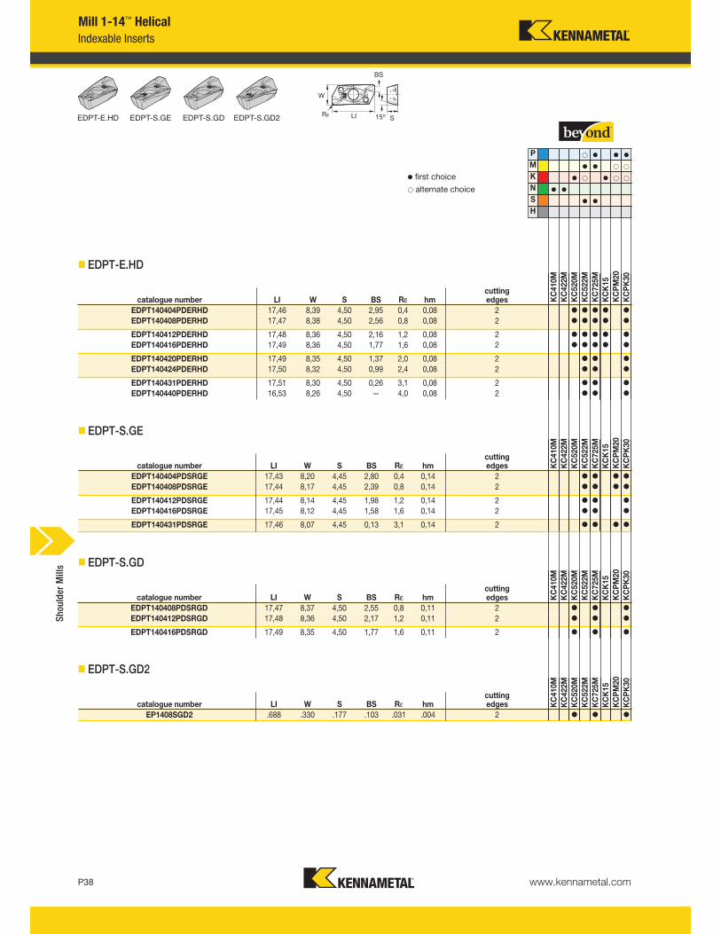
www.kennametal.comP38
EDPT-E.HD EDPT-S.GE EDPT-S.GD
Mill 1-14™ Helical
Indexable Inserts
� EDPT-E.HD
� EDPT-S.GE
� EDPT-S.GD
P v v v
M v v
K v v
N v v
S v v
H
catalogue number LI W S BS Rε hmcutting edges K
C410M
KC422M
KC520M
KC522M
KC725M
KCK15
KCPM20
KCPK30
EDPT140404PDERHD 17,46 8,39 4,50 2,95 0,4 0,08 2 v v v v v
EDPT140408PDERHD 17,47 8,38 4,50 2,56 0,8 0,08 2 v v v v v
EDPT140412PDERHD 17,48 8,36 4,50 2,16 1,2 0,08 2 v v v v v
EDPT140416PDERHD 17,49 8,36 4,50 1,77 1,6 0,08 2 v v v v v
EDPT140420PDERHD 17,49 8,35 4,50 1,37 2,0 0,08 2 v v v
EDPT140424PDERHD 17,50 8,32 4,50 0,99 2,4 0,08 2 v v v
EDPT140431PDERHD 17,51 8,30 4,50 0,26 3,1 0,08 2 v v v
EDPT140440PDERHD 16,53 8,26 4,50 — 4,0 0,08 2 v v v
catalogue number LI W S BS Rε hmcutting edges K
C410M
KC422M
KC520M
KC522M
KC725M
KCK15
KCPM20
KCPK30
EDPT140404PDSRGE 17,43 8,20 4,45 2,80 0,4 0,14 2 v v v v
EDPT140408PDSRGE 17,44 8,17 4,45 2,39 0,8 0,14 2 v v v v
EDPT140412PDSRGE 17,44 8,14 4,45 1,98 1,2 0,14 2 v v v
EDPT140416PDSRGE 17,45 8,12 4,45 1,58 1,6 0,14 2 v v v
EDPT140431PDSRGE 17,46 8,07 4,45 0,13 3,1 0,14 2 v v v v
catalogue number LI W S BS Rε hmcutting edges K
C410M
KC422M
KC520M
KC522M
KC725M
KCK15
KCPM20
KCPK30
EDPT140408PDSRGD 17,47 8,37 4,50 2,55 0,8 0,11 2 v v v
EDPT140412PDSRGD 17,48 8,36 4,50 2,17 1,2 0,11 2 v v v
EDPT140416PDSRGD 17,49 8,35 4,50 1,77 1,6 0,11 2 v v v
v first choice
alternate choice
� EDPT-S.GD2
catalogue number LI W S BS Rε hmcutting edges K
C410M
KC422M
KC520M
KC522M
KC725M
KCK15
KCPM20
KCPK30
EP1408SGD2 .688 .330 .177 .103 .031 .004 2 v v v
Shoulder Mills
EDPT-S.GD2
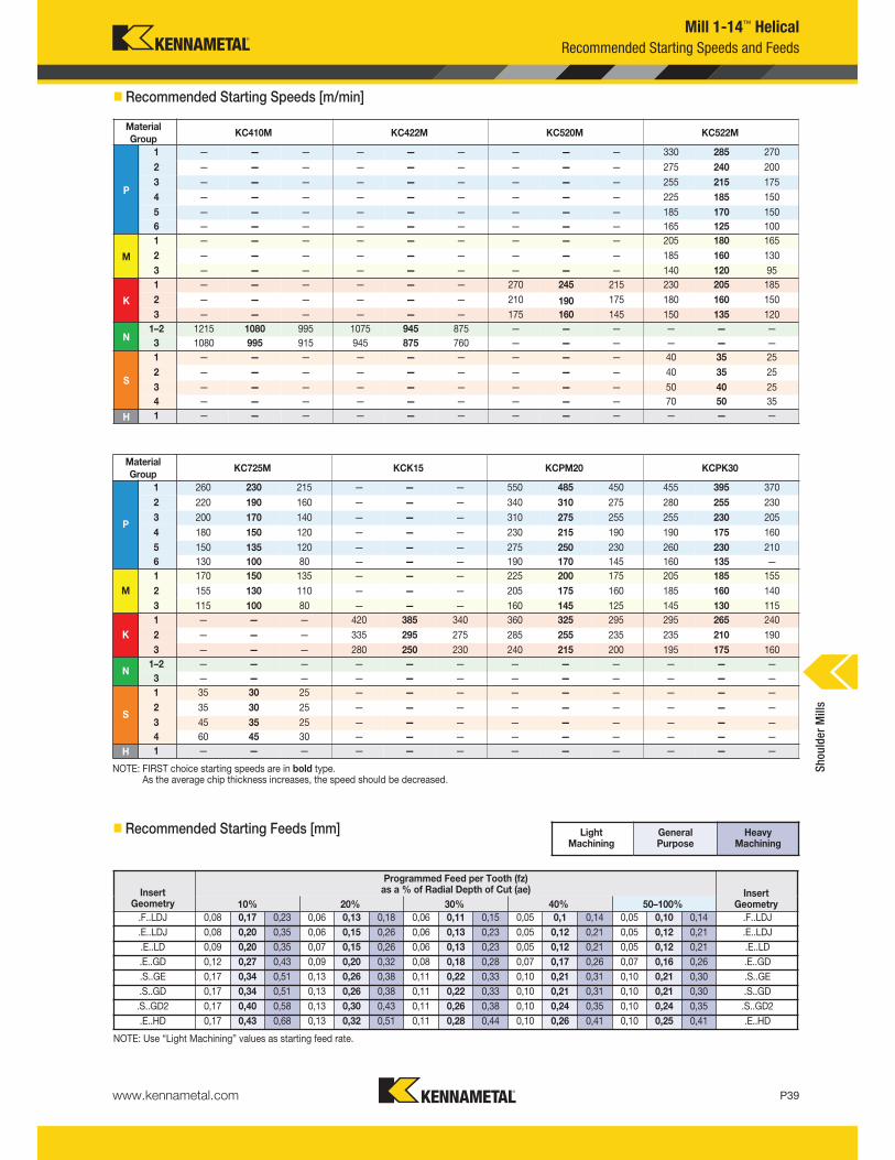
www.kennametal.com P39
Light Machining
General Purpose
Heavy Machining
Mill 1-14™ Helical
NOTE: FIRST choice starting speeds are in bold type.As the average chip thickness increases, the speed should be decreased.
NOTE: Use “Light Machining” values as starting feed rate.
Material
GroupKC410M KC422M KC520M KC522M
KC725M KCK15 KCPM20 KCPK30
P
1 — — — — — — — — — 330 285 270
260 230 215 — — — 550 485 450 455 395 370
2 — — — — — — — — — 275 240 200
220 190 160 — — — 340 310 275 280 255 230
3 — — — — — — — — — 255 215 175
200 170 140 — — — 310 275 255 255 230 205
4 — — — — — — — — — 225 185 150
180 150 120 — — — 230 215 190 190 175 160
5 — — — — — — — — — 185 170 150
150 135 120 — — — 275 250 230 260 230 210
6 — — — — — — — — — 165 125 100
130 100 80 — — — 190 170 145 160 135 —
M
1 — — — — — — — — — 205 180 165
170 150 135 — — — 225 200 175 205 185 155
2 — — — — — — — — — 185 160 130
155 130 110 — — — 205 175 160 185 160 140
3 — — — — — — — — — 140 120 95
115 100 80 — — — 160 145 125 145 130 115
K
1 — — — — — — 270 245 215 230 205 185
— — — 420 385 340 360 325 295 295 265 240
2 — — — — — — 210 190 175 180 160 150
— — — 335 295 275 285 255 235 235 210 190
3 — — — — — — 175 160 145 150 135 120
— — — 280 250 230 240 215 200 195 175 160
N1–2 1215 1080 995 1075 945 875 — — — — — —
— — — — — — — — — — — —
3 1080 995 915 945 875 760 — — — — — —
— — — — — — — — — — — —
S
1 — — — — — — — — — 40 35 25
35 30 25 — — — — — — — — —
2 — — — — — — — — — 40 35 25
35 30 25 — — — — — — — — —
3 — — — — — — — — — 50 40 25
45 35 25 — — — — — — — — —
4 — — — — — — — — — 70 50 35
60 45 30 — — — — — — — — —
H 1 — — — — — — — — — — — —
— — — — — — — — — — — —
Recommended Starting Speeds and Feeds
� Recommended Starting Speeds [m/min]
� Recommended Starting Feeds [mm]
InsertGeometry
Programmed Feed per Tooth (fz)as a % of Radial Depth of Cut (ae) Insert
Geometry10% 20% 30% 40% 50–100%
.F..LDJ 0,08 0,17 0,23 0,06 0,13 0,18 0,06 0,11 0,15 0,05 0,1 0,14 0,05 0,10 0,14 .F..LDJ
.E..LDJ 0,08 0,20 0,35 0,06 0,15 0,26 0,06 0,13 0,23 0,05 0,12 0,21 0,05 0,12 0,21 .E..LDJ
.E..LD 0,09 0,20 0,35 0,07 0,15 0,26 0,06 0,13 0,23 0,05 0,12 0,21 0,05 0,12 0,21 .E..LD
.E..GD 0,12 0,27 0,43 0,09 0,20 0,32 0,08 0,18 0,28 0,07 0,17 0,26 0,07 0,16 0,26 .E..GD
.S..GE 0,17 0,34 0,51 0,13 0,26 0,38 0,11 0,22 0,33 0,10 0,21 0,31 0,10 0,21 0,30 .S..GE
.S..GD 0,17 0,34 0,51 0,13 0,26 0,38 0,11 0,22 0,33 0,10 0,21 0,31 0,10 0,21 0,30 .S..GD
.S..GD2 0,17 0,40 0,58 0,13 0,30 0,43 0,11 0,26 0,38 0,10 0,24 0,35 0,10 0,24 0,35 .S..GD2
.E..HD 0,17 0,43 0,68 0,13 0,32 0,51 0,11 0,28 0,44 0,10 0,26 0,41 0,10 0,25 0,41 .E..HD
Material
Group
P
1
2
3
4
5
6
M
1
2
3
K
1
2
3
N1–2
3
S
1
2
3
4
H 1
Shoulder Mills
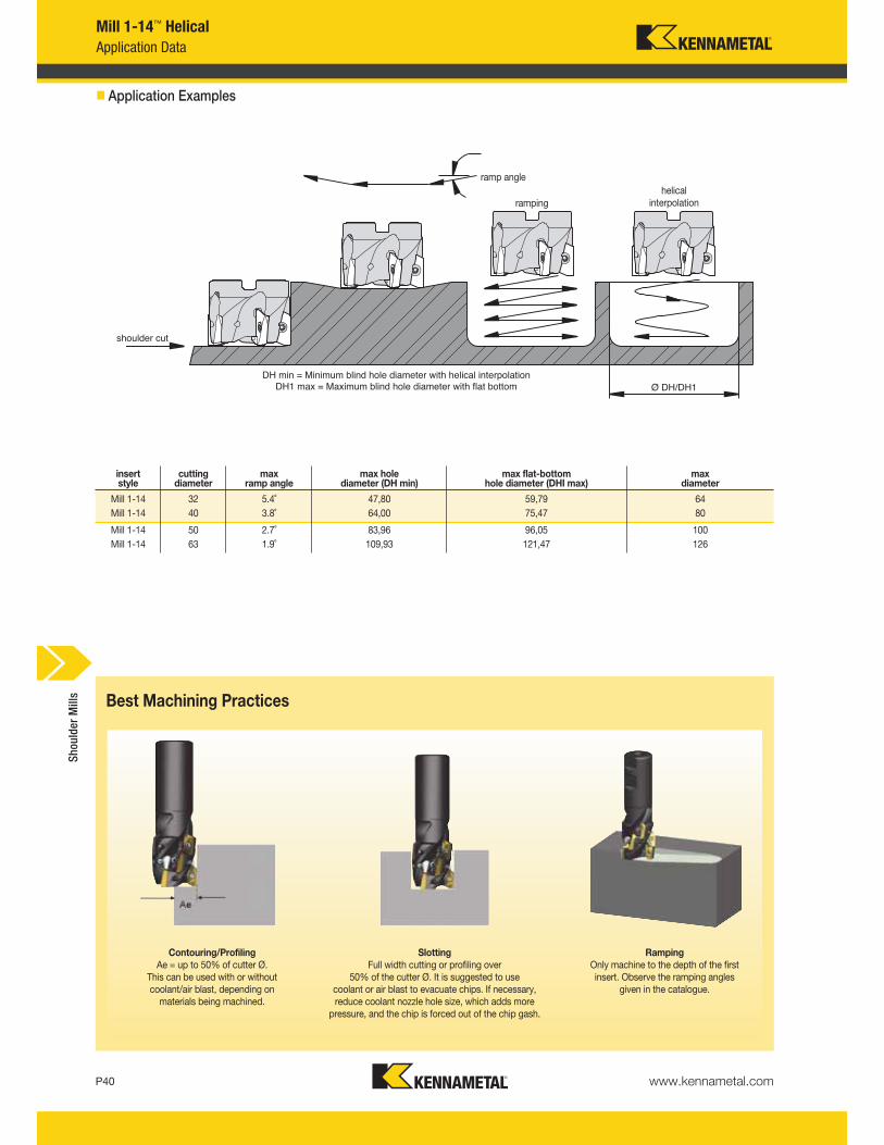
www.kennametal.comP40
Mill 1-14™ Helical
Application Data
shoulder cut
Ø DH/DH1
helicalinterpolationramping
ramp angle
DH min = Minimum blind hole diameter with helical interpolation
DH1 max = Maximum blind hole diameter with flat bottom
� Application Examples
insertstyle
cuttingdiameter
maxramp angle
max holediameter (DH min)
max flat-bottom hole diameter (DHI max)
max diameter
Mill 1-14 32 5.4˚ 47,80 59,79 64
Mill 1-14 40 3.8˚ 64,00 75,47 80
Mill 1-14 50 2.7˚ 83,96 96,05 100
Mill 1-14 63 1.9˚ 109,93 121,47 126
Best Machining Practices
Contouring/Profiling
Ae = up to 50% of cutter Ø. This can be used with or withoutcoolant/air blast, depending onmaterials being machined.
Slotting
Full width cutting or profiling over 50% of the cutter Ø. It is suggested to use
coolant or air blast to evacuate chips. If necessary,reduce coolant nozzle hole size, which adds morepressure, and the chip is forced out of the chip gash.
Ramping
Only machine to the depth of the firstinsert. Observe the ramping angles
given in the catalogue.
Shoulder Mills
www.kennametal.com P41
Mill 1-14™ Helical
Application Data
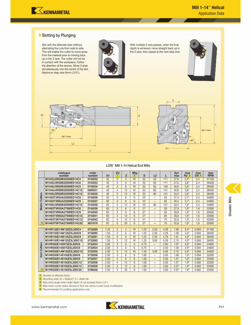
Slot with the alternate side method, alternating the cuts from side to side. This will enable the cutter to move away from the material prior to moving back up in the Z-axis. The cutter will not be in contact with the workpiece. Follow the direction of the arrows. Move 3 axessimultaneously into the centre of the slot. Maximum step over 8mm (.315").
With multiple Z-axis passes, when the finaldepth is achieved, move straight back up inthe Z-axis, then repeat at the next step over.
LOIS™ Mill 1-14 Helical End Mills
Number of effective flutes.
Mounting style: W = Weldon®; S = Shell mill.
Max ramp angle when radial depth of cut exceeds 8mm (.31").
Max insert corner radius allowed in first row without cutter body modification.
Recommended for profiling applications only.
1
2
3
4
5
catalogue number
order number D1
ZUZ
Mtg.D L2 L
Ap1 max
maxRa
maxCR
max RPM
Metric Cutters
M1H32J2R50B32S90ED14C4 3742932 32 2 4 W 32 50 111 27,8 5,4º 2,4 31100
M1H40J3R50B32S90ED14C6 3743033 40 3 6 W 32 50 111 27,6 3,8° 2,4 28400
M1H40J3R65B32S90ED14C9 3743034 40 3 9 W 32 65 126 40,8 3,8° 2,4 28400
M1H40J4R80B32S90ED14C12 5085631 40 4 12 W 32 80 141 40,8 3,8° 2,5 28400
M1H40J3R80B32S90ED14C12 3743035 40 3 12 W 32 80 141 54,0 3,8° 2,4 28400
M1H50T3R50A22S90ED14C6 3743036 50 3 6 S 22 — 50 27,3 2,7° 2,4 24600
M1H50T3R65A22S90ED14C9 3743037 50 3 9 S 22 — 65 40,4 2,7° 2,4 24600
M1H50J3R80B40S90ED14C12 3743038 63 3 12 W 40 80 151 53,5 1,9° 2,4 24600
M1H63T3R50A27S90ED14C6 3743039 63 3 6 S 27 — 50 27,0 1,9° 1,6 22000
M1H63T3R65A27S90ED14C9 3743040 63 3 9 S 27 — 65 39,9 1,9° 1,6 22000
M1H63T4R65A27S90ED14C12 3743041 63 4 12 S 27 — 65 39,9 1,9° 1,6 22000
M1H63T3R75A27S90ED14C12 3743042 63 3 12 S 27 — 75 52,8 1,9° 1,6 22000
M1H63T5R75A27S90ED14C20 3831819 63 5 20 S 27 — 75 52,8 1,9° 1,6 22000
Inch Cutters
M1HR125E14W125Z2L200C4 3732889 1.25 2 4 W 1.25 2.00 4.28 1.09 5.4º 0.094 31100
M1HR150E14W125Z3L200C6 3732890 1.50 3 6 W 1.25 2.00 4.28 1.09 4.0º 0.094 28400
M1HR150E14W125Z3L250C9 3732891 1.50 3 9 W 1.25 2.50 4.78 1.61 4.0º 0.094 28400
M1HR150E14W125Z3L300C12 3732892 1.50 3 12 W 1.25 3.00 5.28 2.13 4.0º 0.094 28400
M1HR200E14S075Z3L200C6 3732933 2.00 3 6 S 0.75 — 2.00 1.07 2.6º 0.094 24600
M1HR200E14S075Z3L250C9 3732934 2.00 3 9 S 0.75 — 2.50 1.59 2.6º 0.094 24600
M1HR200E14W150Z3L300C12 3732935 2.00 3 12 W 1.50 3.00 5.69 2.10 2.6º 0.094 24600
M1HR250E14S100Z3L200C6 3732936 2.50 3 6 S 1.00 — 2.00 1.06 1.9º 0.094 22000
M1HR250E14S100Z3L250C9 3732937 2.50 3 9 S 1.00 — 2.50 1.57 1.9º 0.062 22000
M1HR250E14S100Z4L250C12 3732938 2.50 4 12 S 1.00 — 2.50 1.57 1.9º 0.062 22000
M1HR250E14S100Z3L300C12 3732939 2.50 3 12 S 1.00 — 3.00 2.07 1.9º 0.062 22000
M1HR250E14S100Z5L300C20 3786638 2.50 5 20 S 1.00 — 3.00 2.07 1.9º 0.062 22000
� Slotting by Plunging
1
5
5
2 3 4
Shoulder Mills
www.kennametal.comP42
Mill 1-14™ Helical
Application Data
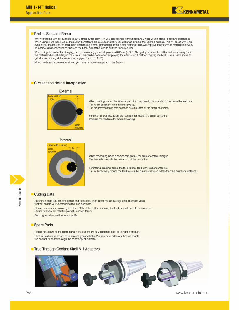
� Profile, Slot, and RampWhen taking a cut that equals up to 50% of the cutter diameter, you can operate without coolant, unless your material is coolant-dependent. When using more than 50% of the cutter diameter, there is a need to have coolant or an air blast through the nozzles. This will assist with chipevacuation. Please use the feed table when taking a small percentage of the cutter diameter. This will improve the volume of material removed. To achieve a superior surface finish on the base, adjust the feed to suit the finish required.
When using this cutter for plunging, the maximum suggested step over is 3,30mm (.130"). Always try to move the cutter and insert away from the material when retracting in the Z-axis. This can be done when employing the alternate cut method (zig zag method). Use a 3-axis move to get all axes moving at the same time, suggest 0,25mm (.010").
When machining a conventional slot, you have to move straight up in the Z-axis.
� Circular and Helical Interpolation
External
When profiling around the external part of a component, it is important to increase the feed rate.This will maintain the chip thickness value.The programmed feed rate needs to be calculated at the cutter centerline.
For external profiling, adjust the feed rate for feed at the cutter centerline.Increase the feed rate for external profiling.
� Cutting Data
Reference page P39 for both speed and feed data. Each insert has an average chip thickness valuethat will enable you to determine the feed per tooth.
Please remember when using less than 50% of the cutter diameter, the feed rate will need to be increased. Failure to do so will result in premature insert failure.
Running too slowly will reduce tool life.
� Spare Parts
Please make sure all the spare parts in the cutters are fully tightened prior to using the product.
Shell mill cutters no longer have coolant grooved bolts. We now have adaptors that will enable the coolant to be fed through the adaptor pilot diameter.
� True Through Coolant Shell Mill Adaptors
Internal
When machining inside a component profile, the area of contact is larger.The feed rate needs to be slower and at the centerline.
For internal profiling, adjust the feed rate for feed at the cutter centerline.This will effectively reduce the feed rate as the distance traveled is less than the peripheral distance.
Radial width of
cut (Ae)Ae
Cutter
centerline
Radial width of cut (Ae)
AeCutter
centerline
Shoulder Mills
Visit www.kennametal.com or contact your local Authorised Kennametal Distributor.
www.kennametal.com
ERICKSON™
Superior Gripping
• Heavy- and fine-milling applications.
• Great accuracy ≤5µm (.0002") at 3 x D and best gripping system.
• Pre-balanced to high specifications.
• Versatile as a collet chuck with the use of reduction sleeves.
For bearing milling chucks when grip counts.
ERICKSON — the industry name you can trust.
www.kennametal.comP44
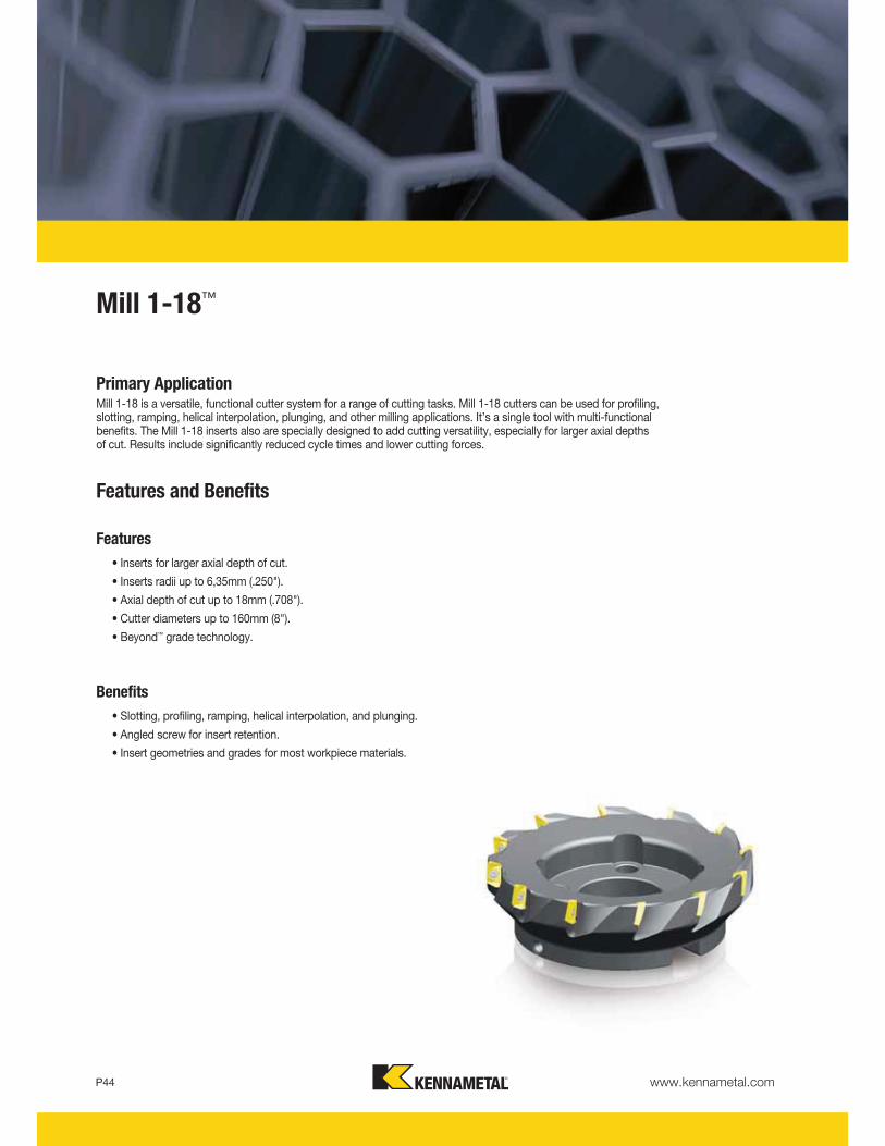
Mill 1-18™
Primary ApplicationMill 1-18 is a versatile, functional cutter system for a range of cutting tasks. Mill 1-18 cutters can be used for profiling, slotting, ramping, helical interpolation, plunging, and other milling applications. It’s a single tool with multi-functional benefits. The Mill 1-18 inserts also are specially designed to add cutting versatility, especially for larger axial depths of cut. Results include significantly reduced cycle times and lower cutting forces.
Features and Benefits
Features
• Inserts for larger axial depth of cut.
• Inserts radii up to 6,35mm (.250").
• Axial depth of cut up to 18mm (.708").
• Cutter diameters up to 160mm (8").
• Beyond™ grade technology.
Benefits
• Slotting, profiling, ramping, helical interpolation, and plunging.
• Angled screw for insert retention.
• Insert geometries and grades for most workpiece materials.
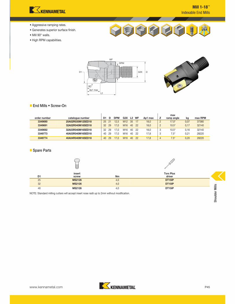
www.kennametal.com P45
Mill 1-18™
Indexable End Mills
• Aggressive ramping rates.
• Generates superior surface finish.
• Mill 90° walls.
• High RPM capabilities.
� End Mills • Screw-On
� Spare Parts
NOTE: Standard milling cutters will accept insert nose radii up to 2mm without modification.
order number catalogue number D1 D DPM G3X L2 WF Ap1 max Zmax
ramp angle kg max RPM
3349690 25A02R035M12SED18 25 21 12,5 M12 35 17 18,0 2 17.0° 0,07 37380
3349691 32A02R040M16SED18 32 29 17,0 M16 40 22 18,0 2 10.5° 0,17 32140
3349692 32A03R040M16SED18 32 29 17,0 M16 40 22 18,0 3 10.5° 0,16 32140
3349773 40A03R040M16SED18 40 29 17,0 M16 40 22 17,8 3 7.5° 0,21 28220
3349774 40A04R040M16SED18 40 29 17,0 M16 40 22 17,8 4 7.5° 0,20 28220
D1insert screw Nm
Torx Plus driver
25 MS2126 4,0 DT15IP
32 MS2126 4,0 DT15IP
40 MS2126 4,0 DT15IP
Shoulder Mills
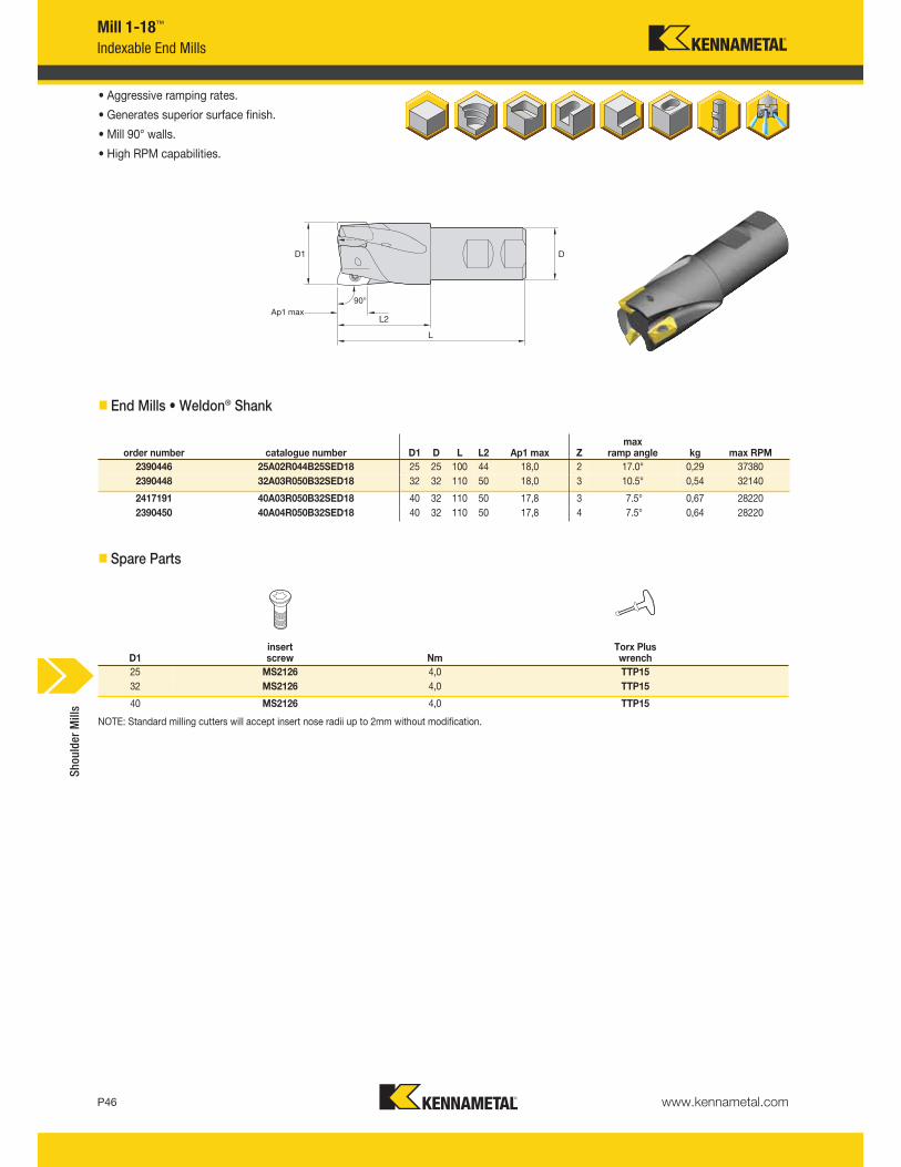
www.kennametal.comP46
Mill 1-18™
Indexable End Mills
• Aggressive ramping rates.
• Generates superior surface finish.
• Mill 90° walls.
• High RPM capabilities.
� End Mills • Weldon® Shank
� Spare Parts
order number catalogue number D1 D L L2 Ap1 max Zmax
ramp angle kg max RPM
2390446 25A02R044B25SED18 25 25 100 44 18,0 2 17.0° 0,29 37380
2390448 32A03R050B32SED18 32 32 110 50 18,0 3 10.5° 0,54 32140
2417191 40A03R050B32SED18 40 32 110 50 17,8 3 7.5° 0,67 28220
2390450 40A04R050B32SED18 40 32 110 50 17,8 4 7.5° 0,64 28220
D1insert screw Nm
Torx Plus wrench
25 MS2126 4,0 TTP15
32 MS2126 4,0 TTP15
40 MS2126 4,0 TTP15
NOTE: Standard milling cutters will accept insert nose radii up to 2mm without modification.
Shoulder Mills
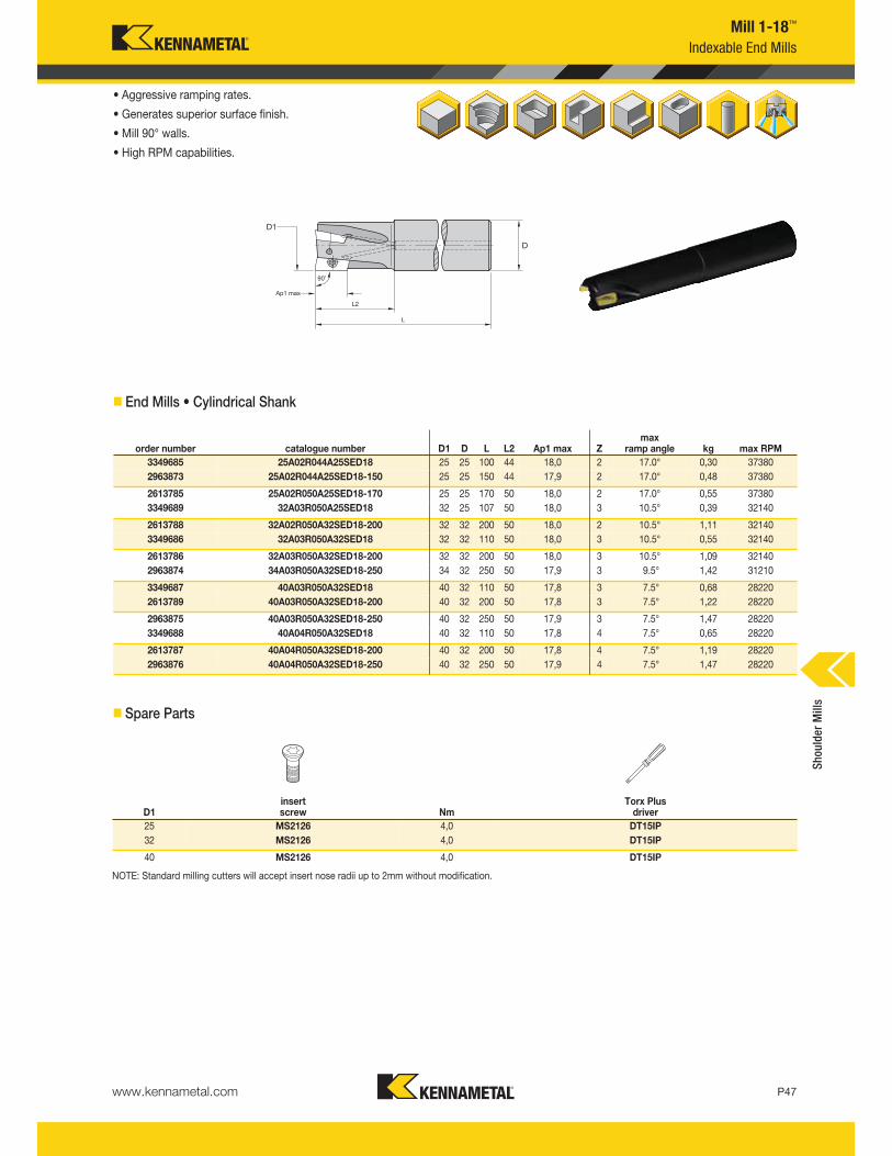
www.kennametal.com P47
Mill 1-18™
Indexable End Mills
• Aggressive ramping rates.
• Generates superior surface finish.
• Mill 90° walls.
• High RPM capabilities.
� End Mills • Cylindrical Shank
� Spare Parts
order number catalogue number D1 D L L2 Ap1 max Zmax
ramp angle kg max RPM
3349685 25A02R044A25SED18 25 25 100 44 18,0 2 17.0° 0,30 37380
2963873 25A02R044A25SED18-150 25 25 150 44 17,9 2 17.0° 0,48 37380
2613785 25A02R050A25SED18-170 25 25 170 50 18,0 2 17.0° 0,55 37380
3349689 32A03R050A25SED18 32 25 107 50 18,0 3 10.5° 0,39 32140
2613788 32A02R050A32SED18-200 32 32 200 50 18,0 2 10.5° 1,11 32140
3349686 32A03R050A32SED18 32 32 110 50 18,0 3 10.5° 0,55 32140
2613786 32A03R050A32SED18-200 32 32 200 50 18,0 3 10.5° 1,09 32140
2963874 34A03R050A32SED18-250 34 32 250 50 17,9 3 9.5° 1,42 31210
3349687 40A03R050A32SED18 40 32 110 50 17,8 3 7.5° 0,68 28220
2613789 40A03R050A32SED18-200 40 32 200 50 17,8 3 7.5° 1,22 28220
2963875 40A03R050A32SED18-250 40 32 250 50 17,9 3 7.5° 1,47 28220
3349688 40A04R050A32SED18 40 32 110 50 17,8 4 7.5° 0,65 28220
2613787 40A04R050A32SED18-200 40 32 200 50 17,8 4 7.5° 1,19 28220
2963876 40A04R050A32SED18-250 40 32 250 50 17,9 4 7.5° 1,47 28220
D1insert screw Nm
Torx Plus driver
25 MS2126 4,0 DT15IP
32 MS2126 4,0 DT15IP
40 MS2126 4,0 DT15IP
NOTE: Standard milling cutters will accept insert nose radii up to 2mm without modification.
Shoulder Mills
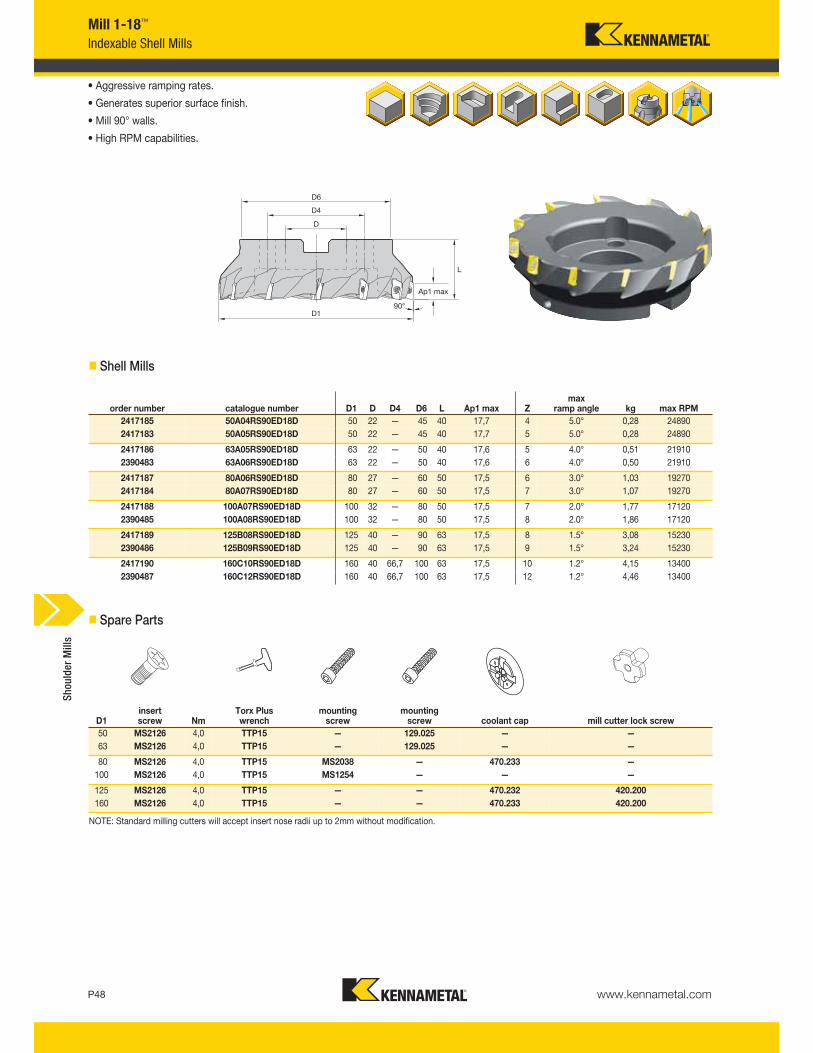
www.kennametal.comP48
Mill 1-18™
Indexable Shell Mills
• Aggressive ramping rates.
• Generates superior surface finish.
• Mill 90° walls.
• High RPM capabilities.
� Shell Mills
� Spare Parts
order number catalogue number D1 D D4 D6 L Ap1 max Zmax
ramp angle kg max RPM
2417185 50A04RS90ED18D 50 22 — 45 40 17,7 4 5.0° 0,28 24890
2417183 50A05RS90ED18D 50 22 — 45 40 17,7 5 5.0° 0,28 24890
2417186 63A05RS90ED18D 63 22 — 50 40 17,6 5 4.0° 0,51 21910
2390483 63A06RS90ED18D 63 22 — 50 40 17,6 6 4.0° 0,50 21910
2417187 80A06RS90ED18D 80 27 — 60 50 17,5 6 3.0° 1,03 19270
2417184 80A07RS90ED18D 80 27 — 60 50 17,5 7 3.0° 1,07 19270
2417188 100A07RS90ED18D 100 32 — 80 50 17,5 7 2.0° 1,77 17120
2390485 100A08RS90ED18D 100 32 — 80 50 17,5 8 2.0° 1,86 17120
2417189 125B08RS90ED18D 125 40 — 90 63 17,5 8 1.5° 3,08 15230
2390486 125B09RS90ED18D 125 40 — 90 63 17,5 9 1.5° 3,24 15230
2417190 160C10RS90ED18D 160 40 66,7 100 63 17,5 10 1.2° 4,15 13400
2390487 160C12RS90ED18D 160 40 66,7 100 63 17,5 12 1.2° 4,46 13400
NOTE: Standard milling cutters will accept insert nose radii up to 2mm without modification.
Shoulder Mills
D1insert screw Nm
Torx Plus wrench
mountingscrew
mountingscrew coolant cap mill cutter lock screw
50 MS2126 4,0 TTP15 — 129.025 — —
63 MS2126 4,0 TTP15 — 129.025 — —
80 MS2126 4,0 TTP15 MS2038 — 470.233 —
100 MS2126 4,0 TTP15 MS1254 — — —
125 MS2126 4,0 TTP15 — — 470.232 420.200
160 MS2126 4,0 TTP15 — — 470.233 420.200

Indexable Milling
Check the Kennametal website!
Visit http://www.kennametal.com/milling/ to browse our electronic catalogue any time you’re looking for Kennametal’s best tooling solutions.
It’s fast, free, and always available. The online e-catalogue is updated weekly with products and solutions for milling, turning, holemaking,
and tooling systems applications.
P49
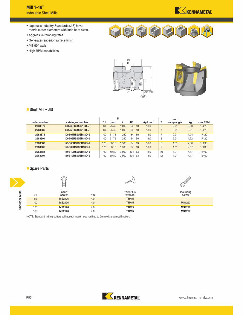
www.kennametal.comP50
Mill 1-18™
Indexable Shell Mills
• Japanese Industry Standards (JIS) have metric cutter diameters with inch bore sizes.
• Aggressive ramping rates.
• Generates superior surface finish.
• Mill 90° walls.
• High RPM capabilities.
� Shell Mill • JIS
� Spare Parts
NOTE: Standard milling cutters will accept insert nose radii up to 2mm without modification.
D
order number catalogue number D1 mm in D6 L Ap1 max Zmax
ramp angle kg max RPM
2963877 80A06RS90ED18D-J 80 25,40 1.000 54 50 18,0 6 3.0° 0,93 19270
2963882 80A07RS90ED18D-J 80 25,40 1.000 54 50 18,0 7 3.0° 0,91 19270
2963878 100B07RS90ED18D-J 100 31,75 1.250 64 50 18,0 7 2.0° 1,24 17120
2963904 100B08RS90ED18D-J 100 31,75 1.250 64 50 18,0 8 2.0° 1,22 17120
2963880 125B08RS90ED18D-J 125 38,10 1.500 84 63 18,0 8 1.5° 2,56 15230
2963906 125B09RS90ED18D-J 125 38,10 1.500 84 63 18,0 9 1.5° 2,57 15230
2963881 160B10RS90ED18D-J 160 50,80 2.000 104 63 18,0 10 1.2° 4,17 13400
2963907 160B12RS90ED18D-J 160 50,80 2.000 104 63 18,0 12 1.2° 4,17 13400
D1insert screw Nm
Torx Plus wrench
mountingscrew
80 MS2126 4,0 TTP15 —
100 MS2126 4,0 TTP15 MS1297
125 MS2126 4,0 TTP15 MS1297
160 MS2126 4,0 TTP15 MS1297
Shoulder Mills
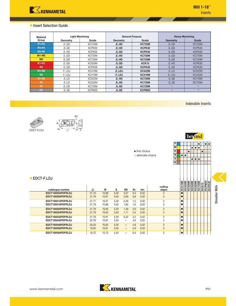
www.kennametal.com P51
Mill 1-18™
Inserts
� Insert Selection Guide
Indexable Inserts
EDCT-F.LDJ
v first choice
alternate choice
� EDCT-F.LDJ
P v v v
M v v v
K v v
N v v
S v v v
H
catalogue number LI W S BS Rε hmcutting edges K
C410M
KC422M
KC520M
KC522M
KC525M
KC725M
KCK15
KCPM20
KCPK30
EDCT180504PDFRLDJ 21,75 10,98 5,50 3,07 0,4 0,02 2 v
EDCT180508PDFRLDJ 21,76 10,97 5,50 2,69 0,8 0,02 2 v
EDCT180512PDFRLDJ 21,77 10,97 5,50 2,29 1,2 0,02 2 v
EDCT180516PDFRLDJ 21,78 10,96 5,50 1,90 1,6 0,02 2 v
EDCT180520PDFRLDJ 21,79 10,95 5,50 1,49 2,0 0,02 2 v
EDCT180524PDFRLDJ 21,79 10,93 5,50 1,11 2,4 0,02 2 v
EDCT180532PDFRLDJ 21,79 10,91 5,50 0,32 3,2 0,02 2 v
EDCT180540PDFRLDJ 20,78 10,87 5,50 — 4,0 0,02 2 v
EDCT180548PDFRLDJ 20,20 10,83 5,50 — 4,8 0,02 2 v
EDCT180550PDFRLDJ 19,95 10,81 5,50 — 5,0 0,02 2 v
EDCT180564PDFRLDJ 18,72 10,73 5,50 — 6,4 0,02 2 v
MaterialGroup
Light Machining General Purpose Heavy Machining
Geometry Grade Geometry Grade Geometry Grade
P1–P2 .E..GD KC725M .E..HD KC725M .S..GD KC725M
P3–P4 .S..GE KCPK30 .E..HD KCPK30 .S..GD KCPK30
P5–P6 .E..HD KCPK30 .S..GD KCPK30 .S..GD KCPK30
M1–M2 .E..GD KC725M .E..HD KC725M .S..GD KC725M
M3 .E..GD KC725M .E..HD KC725M .S..GE KC725M
K1–K2 .E..GD KC520M .S..GD KCK15 .E..HD KCPK30
K3 .E..GD KCPK30 .S..GD KCPK30 .E..HD KCPK30
N1–N2 .F..LDJ KC410M .E..LDJ KC422M .E..LD KC522M
N3 .F..LDJ KC410M .F..LDJ KC410M .E..LDJ KC422M
S1–S2 .E..LD KC522M .E..HD KC725M .S..GE KC725M
S3 .E..LD KC522M .E..HD KC725M .S..GE KC725M
S4 .E..HD KC725M .S..GE KC725M — —
H1 .S..GE KCPM20 .S..GE KCPM20 — —
Shoulder Mills
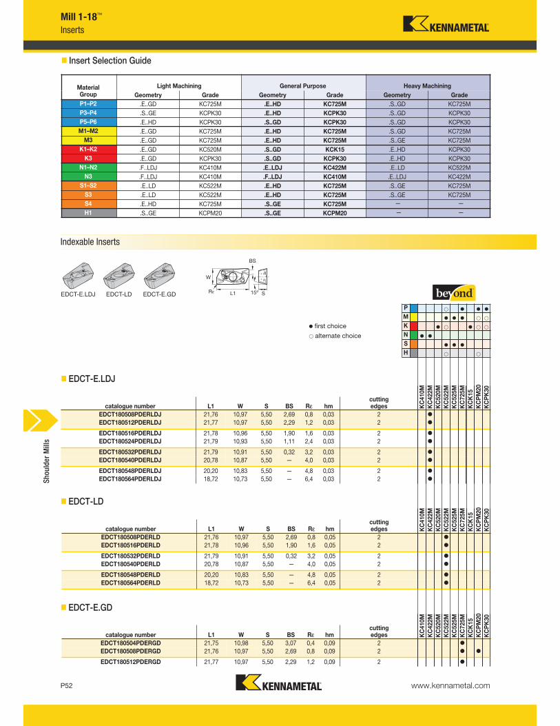
www.kennametal.comP52
� EDCT-E.LDJ
� EDCT-LD
catalogue number L1 W S BS Rε hmcutting edges K
C410M
KC422M
KC520M
KC522M
KC525M
KC725M
KCK15
KCPM20
KCPK30
EDCT180508PDERLDJ 21,76 10,97 5,50 2,69 0,8 0,03 2 v
EDCT180512PDERLDJ 21,77 10,97 5,50 2,29 1,2 0,03 2 v
EDCT180516PDERLDJ 21,78 10,96 5,50 1,90 1,6 0,03 2 v
EDCT180524PDERLDJ 21,79 10,93 5,50 1,11 2,4 0,03 2 v
EDCT180532PDERLDJ 21,79 10,91 5,50 0,32 3,2 0,03 2 v
EDCT180540PDERLDJ 20,78 10,87 5,50 — 4,0 0,03 2 v
EDCT180548PDERLDJ 20,20 10,83 5,50 — 4,8 0,03 2 v
EDCT180564PDERLDJ 18,72 10,73 5,50 — 6,4 0,03 2 v
catalogue number L1 W S BS Rε hmcuttingedges K
C410M
KC422M
KC520M
KC522M
KC525M
KC725M
KCK15
KCPM20
KCPK30
EDCT180508PDERLD 21,76 10,97 5,50 2,69 0,8 0,05 2 v
EDCT180516PDERLD 21,78 10,96 5,50 1,90 1,6 0,05 2 v
EDCT180532PDERLD 21,79 10,91 5,50 0,32 3,2 0,05 2 v
EDCT180540PDERLD 20,78 10,87 5,50 — 4,0 0,05 2 v
EDCT180548PDERLD 20,20 10,83 5,50 — 4,8 0,05 2 v
EDCT180564PDERLD 18,72 10,73 5,50 — 6,4 0,05 2 v
catalogue number L1 W S BS Rε hmcutting edges K
C410M
KC422M
KC520M
KC522M
KC525M
KC725M
KCK15
KCPM20
KCPK30
EDCT180504PDERGD 21,75 10,98 5,50 3,07 0,4 0,09 2 v
EDCT180508PDERGD 21,76 10,97 5,50 2,69 0,8 0,09 2 v v
EDCT180512PDERGD 21,77 10,97 5,50 2,29 1,2 0,09 2 v
� EDCT-E.GD
Mill 1-18™
Inserts
EDCT-E.LDJ EDCT-LD EDCT-E.GD
v first choice
alternate choice
P v v v
M v v v
K v v
N v v
S v v v
H
� Insert Selection Guide
MaterialGroup
Light Machining General Purpose Heavy Machining
Geometry Grade Geometry Grade Geometry Grade
P1–P2 .E..GD KC725M .E..HD KC725M .S..GD KC725M
P3–P4 .S..GE KCPK30 .E..HD KCPK30 .S..GD KCPK30
P5–P6 .E..HD KCPK30 .S..GD KCPK30 .S..GD KCPK30
M1–M2 .E..GD KC725M .E..HD KC725M .S..GD KC725M
M3 .E..GD KC725M .E..HD KC725M .S..GE KC725M
K1–K2 .E..GD KC520M .S..GD KCK15 .E..HD KCPK30
K3 .E..GD KCPK30 .S..GD KCPK30 .E..HD KCPK30
N1–N2 .F..LDJ KC410M .E..LDJ KC422M .E..LD KC522M
N3 .F..LDJ KC410M .F..LDJ KC410M .E..LDJ KC422M
S1–S2 .E..LD KC522M .E..HD KC725M .S..GE KC725M
S3 .E..LD KC522M .E..HD KC725M .S..GE KC725M
S4 .E..HD KC725M .S..GE KC725M — —
H1 .S..GE KCPM20 .S..GE KCPM20 — —
Shoulder Mills
Indexable Inserts
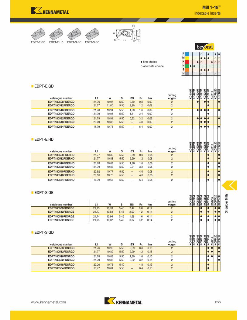
www.kennametal.com P53
Mill 1-18™
Indexable Inserts
EDPT-E.GD EDPT-E.HD EDPT-S.GE EDPT-S.GD
v first choice
alternate choice
� EDPT-E.GD
� EDPT-E.HD
� EDPT-S.GE
� EDPT-S.GD
P v v v
M v v v
K v v
N v v
S v v v
H
catalogue number L1 W S BS Rε hmcutting edges K
C410M
KC422M
KC520M
KC522M
KC525M
KC725M
KCK15
KCPM20
KCPK30
EDPT180508PDERGD 21,76 10,97 5,50 2,69 0,8 0,09 2 v v v v
EDPT180512PDERGD 21,77 11,00 5,50 2,29 1,2 0,09 2 v
EDPT180516PDERGD 21,78 10,94 5,50 1,90 1,6 0,09 2 v v v v v
EDPT180524PDERGD 21,79 10,93 5,50 1,11 2,4 0,09 2 v
EDPT180532PDERGD 21,79 10,91 5,50 0,32 3,2 0,09 2 v v v v v
EDPT180548PDERGD 20,20 10,83 5,50 — 4,8 0,09 2 v v v
EDPT180564PDERGD 18,79 10,73 5,50 — 6,4 0,09 2 v v v v
catalogue number L1 W S BS Rε hmcutting edges KC410M
KC422M
KC520M
KC522M
KC525M
KC725M
KCK15
KCPM20
KCPK30
EDPT180508PDERHD 21,77 10,89 5,50 2,69 0,8 0,08 2 v v
EDPT180512PDERHD 21,77 10,88 5,50 2,29 1,2 0,08 2 v v
EDPT180516PDERHD 21,78 10,87 5,50 1,90 1,6 0,08 2 v v
EDPT180532PDERHD 21,79 10,83 5,50 0,31 3,2 0,08 2 v v
EDPT180540PDERHD 20,92 10,77 5,50 — 4,0 0,08 2 v v
EDPT180548PDERHD 20,16 10,75 5,50 — 4,8 0,08 2 v v
EDPT180564PDERHD 18,79 10,66 5,50 — 6,4 0,08 2 v v
catalogue number L1 W S BS Rε hmcutting edges K
C410M
KC422M
KC520M
KC522M
KC525M
KC725M
KCK15
KCPM20
KCPK30
EDPT180508PDSRGE 21,73 10,70 5,45 2,42 0,8 0,14 2 v v v v
EDPT180512PDSRGE 21,77 10,68 5,45 2,00 1,2 0,14 2 v v v v
EDPT180516PDSRGE 21,74 10,66 5,45 1,59 1,6 0,14 2 v v v v
EDPT180532PDSRGE 21,75 10,62 5,45 0,07 3,2 0,14 2 v v v v
catalogue number L1 W S BS Rε hmcutting edges K
C410M
KC422M
KC520M
KC522M
KC525M
KC725M
KCK15
KCPM20
KCPK30
EDPT180508PDSRGD 21,76 10,90 5,50 2,69 0,8 0,15 2 v v v
EDPT180512PDSRGD 21,77 10,89 5,50 2,29 1,2 0,15 2 v v v
EDPT180516PDSRGD 21,78 10,88 5,50 1,90 1,6 0,15 2 v v v
EDPT180532PDSRGD 21,79 10,83 5,50 0,32 3,2 0,15 2 v v
EDPT180548PDSRGD 20,20 10,75 5,49 — 4,8 0,13 2 v
EDPT180564PDSRGD 18,77 10,64 5,50 — 6,4 0,13 2 v
Shoulder Mills
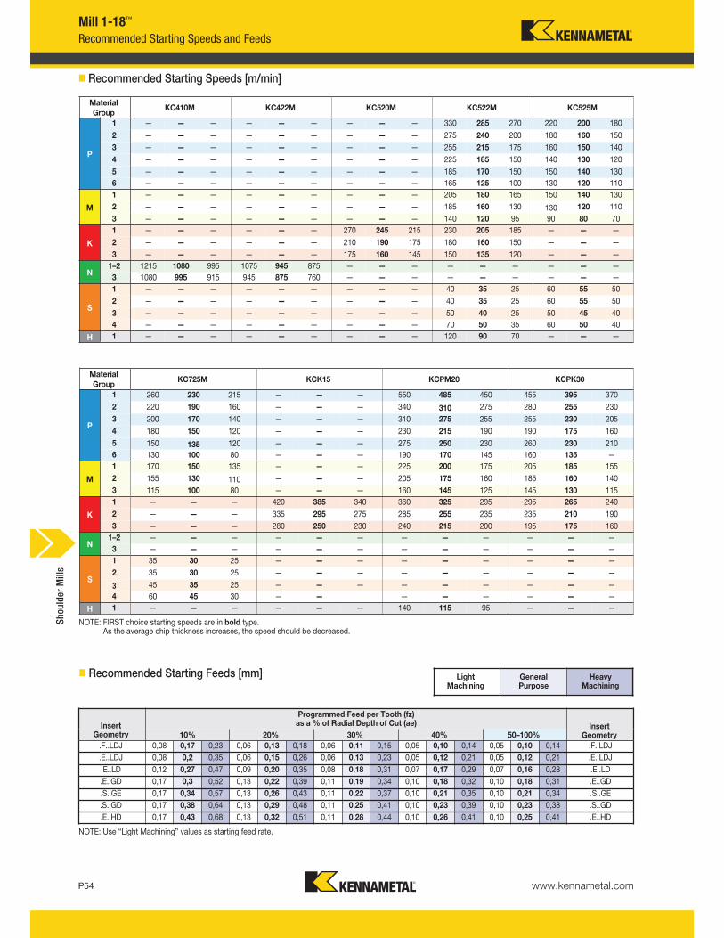
0,21
0,05 0,10 0,14
0,05 0,12 0,21
0,07 0,16 0,28
0,10 0,18 0,31
0,10 0,21 0,34
0,10 0,23 0,38
0,10 0,25 0,41
0,05 0,10 0,14
0,05 0,12 0,21
0,07 0,17 0,29
0,10 0,18 0,32
0,10 0,35
0,10 0,23 0,39
0,10 0,26 0,41
0,06 0,11 0,15
0,06 0,13 0,23
0,08 0,18 0,31
0,11 0,19 0,34
0,11 0,22 0,37
0,11 0,25 0,41
0,11 0,28 0,44
0,06 0,13 0,18
0,06 0,15 0,26
0,09 0,20 0,35
0,13 0,22 0,39
0,13 0,26 0,43
0,13 0,29 0,48
0,13 0,32 0,51
0,17 0,23
0,2 0,35
0,27 0,47
0,3 0,52
0,34 0,57
0,38 0,64
0,43 0,68
0,08
0,08
0,12
0,17
0,17
0,17
0,17
10% 20% 30% 40% 50–100%Insert
Geometry
Programmed Feed per Tooth (fz)as a % of Radial Depth of Cut (ae)Insert
Geometry
www.kennametal.comP54
Heavy Machining
General Purpose
Light Machining
NOTE: FIRST choice starting speeds are in bold type.As the average chip thickness increases, the speed should be decreased.
NOTE: Use “Light Machining” values as starting feed rate.
Material
GroupKC410M KC422M KC520M KC522M KC525M
P
1 — — — — — — — — — 330 285 270 220 200 180
2 — — — — — — — — — 275 240 200 180 160 150
3 — — — — — — — — — 255 215 175 160 150 140
4 — — — — — — — — — 225 185 150 140 130 120
5 — — — — — — — — — 185 170 150 150 140 130
6 — — — — — — — — — 165 125 100 130 120 110
M
1 — — — — — — — — — 205 180 165 150 140 130
2 — — — — — — — — — 185 160 130 130 120 110
3 — — — — — — — — — 140 120 95 90 80 70
K
1 — — — — — — 270 245 215 230 205 185 — — —
2 — — — — — — 210 190 175 180 160 150 — — —
3 — — — — — — 175 160 145 150 135 120 — — —
N1–2 1215 1080 995 1075 945 875 — — — — — — — — —
3 1080 995 915 945 875 760 — — — — — — — — —
S
1 — — — — — — — — — 40 35 25 60 55 50
2 — — — — — — — — — 40 35 25 60 55 50
3 — — — — — — — — — 50 40 25 50 45 40
4 — — — — — — — — — 70 50 35 60 50 40
H 1 — — — — — — — — — 120 90 70 — — —
KC725M KCK15 KCPM20 KCPK30
260 230 215 — — — 550 485 450 455 395 370
220 190 160 — — — 340 310 275 280 255 230
200 170 140 — — — 310 275 255 255 230 205
180 150 120 — — — 230 215 190 190 175 160
150 135 120 — — — 275 250 230 260 230 210
130 100 80 — — — 190 170 145 160 135 —
170 150 135 — — — 225 200 175 205 185 155
155 130 110 — — — 205 175 160 185 160 140
115 100 80 — — — 160 145 125 145 130 115
— — — 420 385 340 360 325 295 295 265 240
— — — 335 295 275 285 255 235 235 210 190
— — — 280 250 230 240 215 200 195 175 160
— — — — — — — — — — — —
— — — — — — — — — — — —
35 30 25 — — — — — — — — —
35 30 25 — — — — — — — — —
45 35 25 — — — — — — — — —
60 45 30 — — — — — — — —
— — — — — — 140 115 95 — — —
� Recommended Starting Speeds [m/min]
� Recommended Starting Feeds [mm]
Mill 1-18™
Recommended Starting Speeds and Feeds
.F..LDJ .F..LDJ
.E..LDJ .E..LDJ
.E..LD .E..LD
.E..GD .E..GD
.S..GE .S..GE
.S..GD .S..GD
.E..HD .E..HD
Material
Group
P
1
2
3
4
5
6
M
1
2
3
K
1
2
3
N1–2
3
S
1
2
3
4
H 1
Shoulder Mills
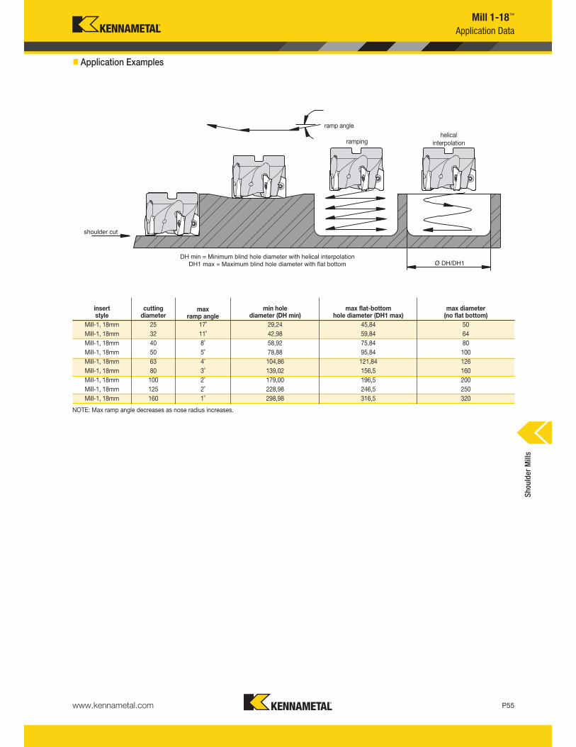
www.kennametal.com P55
Mill 1-18™
Application Data
shoulder cut
Ø DH/DH1DH min = Minimum blind hole diameter with helical interpolation
DH1 max = Maximum blind hole diameter with flat bottom
helicalinterpolationramping
ramp angle
insertstyle
cuttingdiameter
max ramp angle
min holediameter (DH min)
max flat-bottom hole diameter (DH1 max)
max diameter(no flat bottom)
Mill-1, 18mm 25 17˚ 29,24 45,84 50
Mill-1, 18mm 32 11˚ 42,98 59,84 64
Mill-1, 18mm 40 8˚ 58,92 75,84 80
Mill-1, 18mm 50 5˚ 78,88 95,84 100
Mill-1, 18mm 63 4˚ 104,86 121,84 126
Mill-1, 18mm 80 3˚ 139,02 156,5 160
Mill-1, 18mm 100 2˚ 179,00 196,5 200
Mill-1, 18mm 125 2˚ 228,98 246,5 250
Mill-1, 18mm 160 1˚ 298,98 316,5 320
NOTE: Max ramp angle decreases as nose radius increases.
� Application Examples
Shoulder Mills
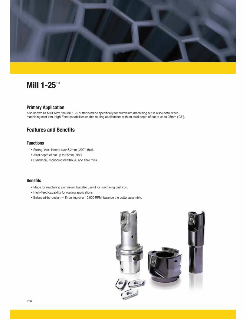
Mill 1-25™
Primary ApplicationAlso known as Mill1 Max, the Mill 1-25 cutter is made specifically for aluminium machining but is also useful when machining cast iron. High-Feed capabilities enable routing applications with an axial depth of cut of up to 25mm (.98").
Features and Benefits
Functions
• Strong, thick inserts over 5,2mm (.200") thick.
• Axial depth of cut up to 25mm (.98").
• Cylindrical, monoblock/HSK63A, and shell mills.
Benefits
• Made for machining aluminium, but also useful for machining cast iron.
• High-Feed capability for routing applications.
• Balanced-by-design — if running over 10,000 RPM, balance the cutter assembly.
P56
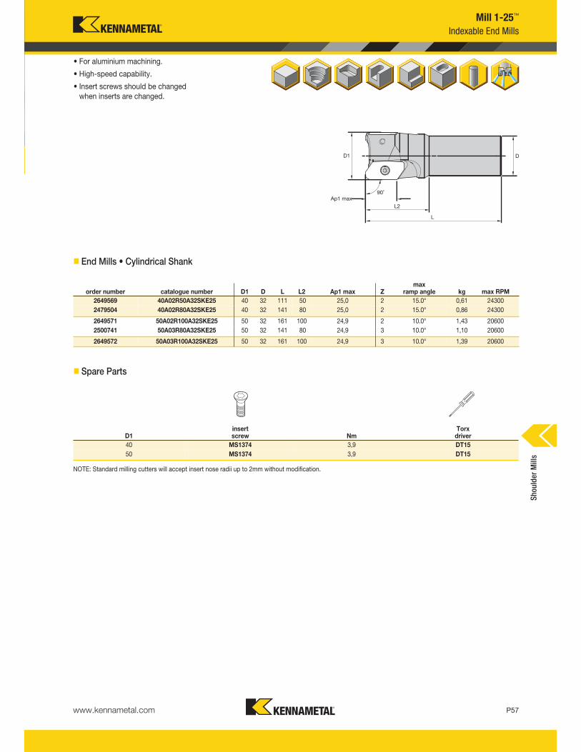
www.kennametal.com P57
Mill 1-25™
Indexable End Mills
• For aluminium machining.
• High-speed capability.
• Insert screws should be changedwhen inserts are changed.
� End Mills • Cylindrical Shank
� Spare Parts
NOTE: Standard milling cutters will accept insert nose radii up to 2mm without modification.
order number catalogue number D1 D L L2 Ap1 max Zmax
ramp angle kg max RPM
2649569 40A02R50A32SKE25 40 32 111 50 25,0 2 15.0° 0,61 24300
2479504 40A02R80A32SKE25 40 32 141 80 25,0 2 15.0° 0,86 24300
2649571 50A02R100A32SKE25 50 32 161 100 24,9 2 10.0° 1,43 20600
2500741 50A03R80A32SKE25 50 32 141 80 24,9 3 10.0° 1,10 20600
2649572 50A03R100A32SKE25 50 32 161 100 24,9 3 10.0° 1,39 20600
D1insert screw Nm
Torx driver
40 MS1374 3,9 DT15
50 MS1374 3,9 DT15
Shoulder Mills
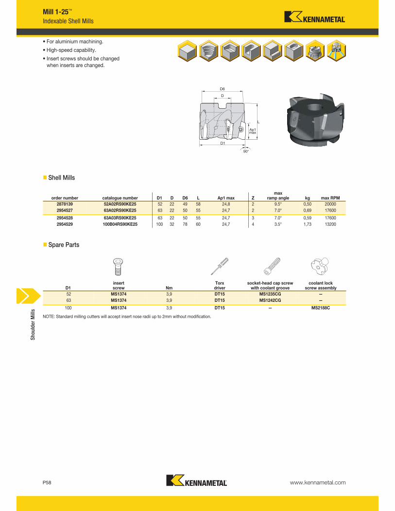
www.kennametal.comP58
Mill 1-25™
Indexable Shell Mills
• For aluminium machining.
• High-speed capability.
• Insert screws should be changedwhen inserts are changed.
� Shell Mills
� Spare Parts
order number catalogue number D1 D D6 L Ap1 max Zmax
ramp angle kg max RPM
2878139 52A02RS90KE25 52 22 49 58 24,8 2 9.5° 0,50 20000
2954527 63A02RS90KE25 63 22 50 55 24,7 2 7.0° 0,69 17600
2954528 63A03RS90KE25 63 22 50 55 24,7 3 7.0° 0,59 17600
2954529 100B04RS90KE25 100 32 78 60 24,7 4 3.5° 1,73 13200
D1insert screw Nm
Torx driver
socket-head cap screwwith coolant groove
coolant lock screw assembly
52 MS1374 3,9 DT15 MS1235CG —
63 MS1374 3,9 DT15 MS1242CG —
100 MS1374 3,9 DT15 — MS2188C
NOTE: Standard milling cutters will accept insert nose radii up to 2mm without modification.
Shoulder Mills

It’s easy for your company to be environmentally conscious with the Kennametal Carbide Recycling Program.
By sending us your used carbide tools, you help preserve and protect the environment and ensure that theseproducts are recycled responsibly. Kennametal accepts any coated or non-coated carbide items, includinginserts, drills, reamers, and taps.
Carbide Recycling
Help preserve and protect our planet!
By using the Kennametal Carbide Recycling Program, you will receive:
• A partner who cares about a sustainable environment.
• Easy-to-use web portal to value your used carbide.
• Access to our popular Green Box™ options for carbide collection.
• Systematic and efficient disposal of carbide materials.
• Improved profitability.
Program is not currently available in all geographical areas.
For more information, please visit www.kennametal.com/carbiderecycling.
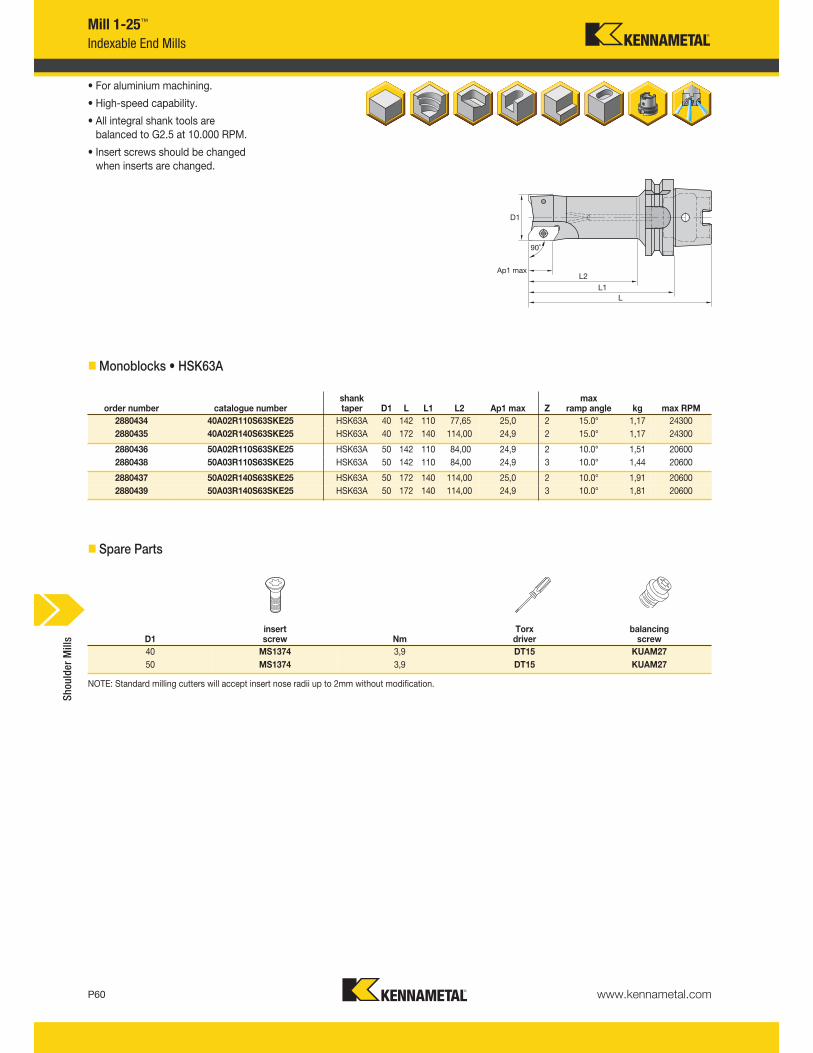
www.kennametal.comP60
Mill 1-25™
Indexable End Mills
• For aluminium machining.
• High-speed capability.
• All integral shank tools are balanced to G2.5 at 10.000 RPM.
• Insert screws should be changed when inserts are changed.
�Monoblocks • HSK63A
� Spare Parts
D1insert screw Nm
Torx driver
balancingscrew
40 MS1374 3,9 DT15 KUAM27
50 MS1374 3,9 DT15 KUAM27
NOTE: Standard milling cutters will accept insert nose radii up to 2mm without modification.
order number catalogue numbershank taper D1 L L1 L2 Ap1 max Z
max ramp angle kg max RPM
2880434 40A02R110S63SKE25 HSK63A 40 142 110 77,65 25,0 2 15.0° 1,17 24300
2880435 40A02R140S63SKE25 HSK63A 40 172 140 114,00 24,9 2 15.0° 1,17 24300
2880436 50A02R110S63SKE25 HSK63A 50 142 110 84,00 24,9 2 10.0° 1,51 20600
2880438 50A03R110S63SKE25 HSK63A 50 142 110 84,00 24,9 3 10.0° 1,44 20600
2880437 50A02R140S63SKE25 HSK63A 50 172 140 114,00 25,0 2 10.0° 1,91 20600
2880439 50A03R140S63SKE25 HSK63A 50 172 140 114,00 24,9 3 10.0° 1,81 20600
Shoulder Mills
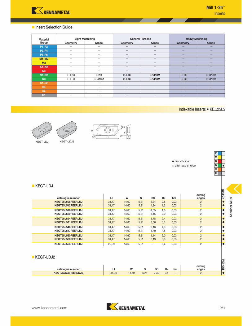
www.kennametal.com P61
Mill 1-25™
Inserts
� Insert Selection Guide
Indexable Inserts • KE...25L5
KEGT-LDJ
v first choice
alternate choice
� KEGT-LDJ
P
M
K
N v
S
H
catalogue number LI W S BS Rε hmcutting edges K
C410M
KEGT25L508PEERLDJ 31,47 14,60 5,21 5,34 0,8 0,03 2 v
KEGT25L512PEERLDJ 31,47 14,60 5,21 4,94 1,2 0,03 2 v
KEGT25L516PEERLDJ 31,47 14,60 5,21 4,55 1,6 0,03 2 v
KEGT25L520PEERLDJ 31,47 14,60 5,21 4,15 2,0 0,03 2 v
KEGT25L524PEERLDJ 31,47 14,60 5,21 3,78 2,4 0,03 2 v
KEGT25L531PEERLDJ 31,47 14,60 5,21 3,06 3,1 0,03 2 v
KEGT25L540PEERLDJ 31,47 14,60 5,21 2,16 4,0 0,03 2 v
KEGT25L547PEERLDJ 31,47 14,60 5,21 1,40 4,8 0,03 2 v
KEGT25L550PEERLDJ 31,47 14,60 5,21 1,14 5,0 0,03 2 v
KEGT25L560PEERLDJ 31,47 14,60 5,21 0,13 6,0 0,03 2 v
KEGT25L564PEERLDJ 29,99 14,60 5,21 — 6,4 0,03 2 v
MaterialGroup
Light Machining General Purpose Heavy Machining
Geometry Grade Geometry Grade Geometry Grade
P1–P2 — — — — — —
P3–P4 — — — — — —
P5–P6 — — — — — —
M1–M2 — — — — — —
M3 — — — — — —
K1–K2 — — — — — —
K3 — — — — — —
N1–N2 .F..LNJ K313 .E..LDJ KC410M .E..LDJ KC410M
N3 .E..LDJ KC410M .E..LDJ KC410M .E..LDJ KC410M
S1–S2 — — — — — —
S3 — — — — — —
S4 — — — — — —
H1 — — — — — —
Shoulder Mills
� KEGT-LDJ2
catalogue number LI W S BS Rε hmcutting edges K
C410M
KEGT25L508PEERLDJ2 31,39 14,59 5,21 7,30 0,8 — 2 v
KEGT-LDJ2
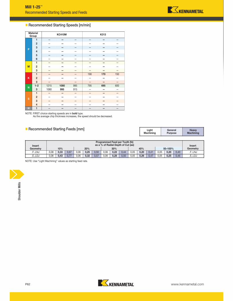
www.kennametal.comP62
Heavy Machining
General Purpose
Light Machining
InsertGeometry
Programmed Feed per Tooth (fz)as a % of Radial Depth of Cut (ae) Insert
Geometry10% 20% 30% 40% 50–100%
.F..LNJ 0,08 0,33 0,67 0,06 0,25 0,50 0,06 0,22 0,44 0,05 0,20 0,41 0,05 0,20 0,40 .F..LNJ
.E..LDJ 0,08 0,43 0,77 0,06 0,32 0,57 0,06 0,28 0,50 0,05 0,26 0,47 0,05 0,25 0,46 .E..LDJ
Mill 1-25™
NOTE: FIRST choice starting speeds are in bold type.As the average chip thickness increases, the speed should be decreased.
NOTE: Use “Light Machining” values as starting feed rate.
� Recommended Starting Speeds [m/min]
Recommended Starting Speeds and Feeds
� Recommended Starting Feeds [mm]
MaterialGroup
KC410M K313
P
1 — — — — — —
2 — — — — — —
3 — — — — — —
4 — — — — — —
5 — — — — — —
6 — — — — — —
M
1 — — — — — —
2 — — — — — —
3 — — — — — —
K
1 — — — 190 170 150
2 — — — — — —
3 — — — — —
N1–2 1215 1080 995 795 695 600
3 1080 995 915 — — —
S
1 — — — — — —
2 — — — — — —
3 — — — — — —
4 — — — — — —
H 1 — — — — — —
Shoulder Mills
Related Documents


![Mill Operation Manual-En[1]](https://static.cupdf.com/doc/110x72/553ca2064a79593e2c8b4a66/mill-operation-manual-en1.jpg)


![Fanuc 21 Mill Sp[1]](https://static.cupdf.com/doc/110x72/54861998b4af9f780d8b4fee/fanuc-21-mill-sp1.jpg)

![Animal Feed Mill[1]](https://static.cupdf.com/doc/110x72/553da3444a7959632d8b46e3/animal-feed-mill1.jpg)
