MIL-STD-461 EMI INPUT FILTER FGDS-20A-50V : up to 20A CURRENT Gaia Converter FC05-050.07/13 Revision D © REDEFINING THE SOURCE OF POWER For locations, phone, fax, E-Mail see back cover 6 20A EMI Filter Module 9 to 50 VDC Input Range MIL-STD-461D/E/F & DO-160C/D/E/F/G Compliant 1-General The GAIA Converter filter module FGDS-20A-50V provides a state-of-the-art product to fulfill Electromagnetic Interferences (EMI) requirements for Aerospace and Defence applications. The FGDS-20A-50V is a very compact and low loss solution for applications requiring up to 20A input current. The FGDS-20A-50V complies with major standards including : • the US MIL-STD-461 rev D, E and rev F • the international DO-160 rev C, D, E, F & rev G In particular, the filter module is compliant with the following requirements of MIL-STD-461D/E and DO-160-C/D/E standards : • MIL-STD-461D/E/F Part 2. & 3. requirements : • Conducted Emission (CE) • CE102, power leads, emission over 10KHz to 10MHz, basic curve • Conducted Susceptibility (CS) • CS101, power leads, frequency 30Hz to 150KHz, curve #1 • CS114, bulk cable injection, frequency 10KHz to 400MHz, • CS115, spikes, bulk cable injection calibrated spike • CS116, damped sinusoidal transient • DO-160-C/D/E/F/G requirements : • Conducted Emission (CE) • Section 21 power lines, emission over 15KHz to 152MHz, category B, AZ & LMH • Conducted Susceptibility (CS) • Section 20 power lines, frequency 10KHz to 400MHz In addition, this filter withstands in a transparent state without dammage the transient and spike requirements of : • MIL-STD-704A/D/E/F with up to 80V/100ms • MIL-STD-1275A/B/C/D with up to 100V/50ms The FGDS-20A-50V is suitable for all GAIA Converter DC/DC converters and DC architecture • from 50W up to 300W output power • up to 20A output current • up to 50V permanent input voltage. Hi-Rel Grade Hi-Rel Grade • To comply with MIL-STD-461D/E/F power leads : • CE 102 : Emission requirement over 10 KHz to 10MHz • CS 101 : Susceptibility requirement over 30Hz to 150KHz • CS 114 : Susceptibility requirement over 10KHz to 400MHz • CS 115 : Susceptibility requirement for spikes • To comply with DO-160C/D/E/F/G power lines : • Conducted emission requirement over 15 KHz to 152MHz • Conducted susceptibility requirement over 10Hz to 400MHz • Temperature range : • operating temperature : -40°C/+105°C case • storage temperature : -55°C/+125°C • RoHS process 2-Product Selection Options : /T : option for -55°C start up operating temperature /S : option for screening and serialization FGDS-20A-50V option /

Welcome message from author
This document is posted to help you gain knowledge. Please leave a comment to let me know what you think about it! Share it to your friends and learn new things together.
Transcript

MIL-STD-461 EMI INPUT FILTERFGDS-20A-50V : up to 20A CURRENT
Gaia Converter FC05-050.07/13 Revision D©
REDEFINING THE SOURCE OF POWER
For locations, phone, fax, E-Mail see back cover
6
20A EMI Filter Module9 to 50 VDC Input Range
MIL-STD-461D/E/F & DO-160C/D/E/F/G Compliant
1-General
The GAIA Converter filter module FGDS-20A-50Vprovides a state-of-the-art product to fulfillElectromagnetic Interferences (EMI) requirements forAerospace and Defence applications.The FGDS-20A-50V is a very compact and low losssolution for applications requiring up to 20A inputcurrent.The FGDS-20A-50V complies with major standardsincluding :• the US MIL-STD-461 rev D, E and rev F• the international DO-160 rev C, D, E, F & rev G
In particular, the filter module is compliant withthe following requirements of MIL-STD-461D/Eand DO-160-C/D/E standards :• MIL-STD-461D/E/F Part 2. & 3. requirements :
• Conducted Emission (CE) • CE102, power leads, emission over 10KHz to 10MHz, basic curve• Conducted Susceptibility (CS) • CS101, power leads, frequency 30Hz to 150KHz, curve #1 • CS114, bulk cable injection, frequency 10KHz to 400MHz,
• CS115, spikes, bulk cable injection calibrated spike • CS116, damped sinusoidal transient
• DO-160-C/D/E/F/G requirements :• Conducted Emission (CE) • Section 21 power lines, emission over 15KHz to 152MHz, category B, AZ & LMH• Conducted Susceptibility (CS) • Section 20 power lines, frequency 10KHz to 400MHz
In addition, this filter withstands in a transparentstate without dammage the transient and spikerequirements of :
• MIL-STD-704A/D/E/F with up to 80V/100ms• MIL-STD-1275A/B/C/D with up to 100V/50ms
The FGDS-20A-50V is suitable for all GAIA ConverterDC/DC converters and DC architecture
• from 50W up to 300W output power• up to 20A output current• up to 50V permanent input voltage.
Hi-RelGradeHi-RelGrade
• To comply with MIL-STD-461D/E/F power leads :
• CE 102 : Emission requirement over 10 KHz to 10MHz
• CS 101 : Susceptibility requirement over 30Hz to 150KHz
• CS 114 : Susceptibility requirement over 10KHz to 400MHz
• CS 115 : Susceptibility requirement for spikes
• To comply with DO-160C/D/E/F/G power lines :
• Conducted emission requirement over 15 KHz to 152MHz
• Conducted susceptibility requirement over 10Hz to 400MHz
• Temperature range :
• operating temperature : -40°C/+105°C case
• storage temperature : -55°C/+125°C
• RoHS process
2-Product Selection
Options :
/T : option for -55°C start up operating temperature /S : option for screening and serialization
FGDS-20A-50V option/

For locations, phone, fax, E-Mail see back cover
2
EMI Filter FGDS-20A-50V
Gaia Converter FC05-050.07/13 Revision D©
6
Hi-RelGrade
3- Electrical SpecificationsData are valid at +25°C, unless otherwise specified.
Parameter ConditionsLimit ortypical
UnitsFGDS-20A-50V
Input
Nominal input voltage Full temperature range Nominal VDC 28
Permanent inputvoltage range (Ui)
Full temperature range Min. - Max. VDC 9 - 50
Transient input voltage Full loadMaximumMaximum
VDC/msVDC/ms
80/100100/50
Output
Permanent output currentFull temperature rangeup to 100°C caseUi min. to max.
Maximum A 20
Permanent output powerFull temperature rangeup to 100°C caseUi min. to max.
Maximum W 300
Power dissipationCurrent 20A @ 25°CCurrent 20A @ 85°C
MaximumMaximum
WW
22,6
Thermal resistanceCase to ambientin free air cooling
Nominal °C/W 15
General
Electrical strengh testvoltage
Case to any pinGnd pin to any other pin
MinimumMinimum
VDCVDC
500500
Reliability data MTBFaccording MIL-HDBK-217F
Conditions Gf
Conditions AIC
@40°C@85°C@40°C@85°C
HoursHoursHoursHours
27 000 0007 000 00013 000 0003 500 000
EMI compliance
Conducted emissionPower leadsPower linesPower lines
MIL-STD-461D/E/FDO-160C cat B & AZDO-160D/E/F/G cat B & LMH
CE102Section 21Section 21
See section 6See section 6See section 6
Conducted susceptibility50 Ohm impedance10A10KHz to 400MHz
MIL-STD-461D/E/FMIL-STD-461D/E/FDO-160C/D/E/F/G
CS115CS116Section 20
CompliantCompliantCompliant
For locations, phone, fax, E-Mail see back cover
3
EMI Filter FGDS-20A-50V
Gaia Converter FC05-050.07/13 Revision D©
6
Hi-RelGrade
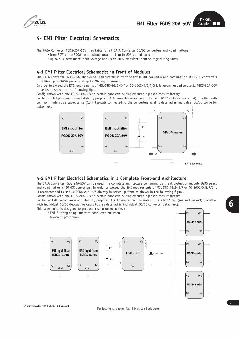
4- EMI Filter Electrical Schematics
The GAIA Converter FGDS-20A-50V is suitable for all GAIA Converter DC/DC converters and combinations :• from 50W up to 300W total output power and up to 20A output current• up to 50V permanent input voltage and up to 100V transient input voltage during 50ms.
4-1 EMI Filter Electrical Schematics in Front of ModulesThe GAIA Converter FGDS-20A-50V can be used directly in front of any DC/DC converter and combination of DC/DC convertersfrom 50W up to 300W power and up to 20A input current.In order to exceed the EMI requirements of MIL-STD-461D/E/F or DO-160C/D/E/F/G it is recommended to use 2x FGDS-20A-50Vin series as shown in the following figure.Configuration with one FGDS-10A-50V in certain case can be implemented : please consult factory.For better EMI performance and stability purpose GAIA Converter recommends to use a R*C* cell (see section 4) together withcommon mode noise capacitance (10nF typical) connected to the converters as it is detailed in individual DC/DC converterdatasheet.
4-2 EMI Filter Electrical Schematics in a Complete Front-end ArchitectureThe GAIA Converter FGDS-20A-50V can be used in a complete architecture combining transient protection module LGDS seriesand combination of DC/DC converters. In order to exceed the EMI requirements of MIL-STD-461D/E/F or DO-160C/D/E/F/G itis recommended to use 2x FGDS-20A-50V directly in series up front as shown in the following figure.Configuration with one FGDS-20A-50V in certain case can be implemented : please consult factory.For better EMI performance and stability purpose GAIA Converter recommends to use a R*C* cell (see section 4-3) (togetherwith individual DC/DC decoupling capacitors as detailed in individual DC/DC converter datasheet).This schematics is designed to propose a solution to achieve :
• EMI filtering compliant with conducted emission• transient protection
C*
R*
Go
Vo
GI
VI
Gnd
EMI input filter
FGDS-20A-50V
Go
Vo
GI
VI
Gnd
EMI input filter
FGDS-20A-50V
Cc
Cc
Cc
Cc
BP
BP
BP: Base Plate
MGDM-series
Gin
Vin Vo
Go
EMI input filterFGDS-20A-50V
Go
+Vo
GI
VI
MGDM-series
Go
+Vo
GI
VI
MGDM-series
Go
+Vo
GI
VI
MGDM-series
EMI input filterFGDS-20A-50V
LGDS-300
VoVo Vi
Gi
123
789
5
Vi
Gi GoGndGnd
220µF/50V
Vi
Gi
Vo
Go
C*
R*

For locations, phone, fax, E-Mail see back cover
4
EMI Filter FGDS-20A-50V
Gaia Converter FC05-050.07/13 Revision D©
6
Hi-RelGrade
4- EMI Filter Electrical Schematics (continued)
4-3 R*C* Network Discussion
The RC damping network is used for stability purposes in negative input impedance systems such as DC/DC converters.
DC/DC converters are negative input impedance systems whereas, filters are composed of passive elements and display apositive output impedance to the converter.
To ensure the stability of the whole system “LISN + input Filter + DC/DC converters”, the filter output impedance must bekept below the converter’s input impedance, which is given by the following formula :
Vin2 Vin2 x ηZin = ____ = _________
Pin Powhere :Vin is the converter input voltage,Pin is the converter input power,
Po is the converter output power
η is the efficiency of the converter.
As it can be seen from the preceding equation, the worst case for system’s stability is at Vinmin, so this is the conditionwhich should be considered for the filter design.
As the filter is made of low ESR inductors and ceramic capacitors, it has an important quality factor Q which causes a sharpincrease of the filter’s output impedance at the resonant frequency and leads to a violation of the stability criteria, causingthe system to break into oscillations.
Consequently, the values of RC network has to be adjusted to dampen sufficiently the filter’s resonance and make itsoutput impedance lower than the converter’s input impedance.
The value of the RC network strongly depends on the application’s conditions (input voltage range and total power drawnfrom the source as well as the standards that the equipment has to meet MIL-STD-461 or DO-160 ... ) this becausemeasurements method (LISN) differs from one standard to another affecting the C value.
In most applications a low ESR aluminium electrolytic capacitor can be used for damping the network and it’s internalESR value will be enough to dampen the input voltage without adding external resistor.
The table hereafter summarizes the recommended capacitor value at 100% output load for various power according toDO160 and to MIL-STD-461 standards. The capacitor value can be linearly reduced depending on output power; forexample, it can divided by 2 at 50 % load...
Total Power 75W 100W 150W 200W 300W
Capacitor Value forMIL-STD-461 standards
330 µF 470 µF 470 µF 680 µF 1 000 µF
Capacitor Value forDO-160 standards
100 µF 100 µF 220 µF 220 µF 330 µF

For locations, phone, fax, E-Mail see back cover
5
EMI Filter FGDS-20A-50V
Gaia Converter FC05-050.07/13 Revision D©
6
Hi-RelGrade
5- MIL-STD-461D/E/F Conducted Emission Tests Set-Up
5-1 MIL-STD-461D/E/F Measurement Method
The conducted noise emission measurementmethod is described in the MIL-STD-461D/E/Fstandards.The «DUT» (Device Under Test) is powered thrua 2 meters length parallel wire.
One end is terminated with the DUT and the otherend is terminated with LISN networks.The measurements are made with a measurementreceiver, the unit being dBµV
To 50 ohmsinput receiver
+28V out+28V in
Return outReturn in
2m
DUT
LISN
LISN
To 50 ohmstermination

For locations, phone, fax, E-Mail see back cover
6
EMI Filter FGDS-20A-50V
Gaia Converter FC05-050.07/13 Revision D©
6
Hi-RelGrade
6- MIL-STD-461E Conducted Emission Level Results
MIL-STD-461E : MGDS-75-H-J with FGDS-20A-50V MIL-STD-461E : MGDS-100-M-26 with FGDS-20A-50V
MIL-STD-461E : MGDS-150-H-J with FGDS-20A-50V MIL-STD-461E : 2 x MGDS-75-H-J with FGDS-20A-50V
For locations, phone, fax, E-Mail see back cover
7
EMI Filter FGDS-20A-50V
Gaia Converter FC05-050.07/13 Revision D©
6
Hi-RelGrade
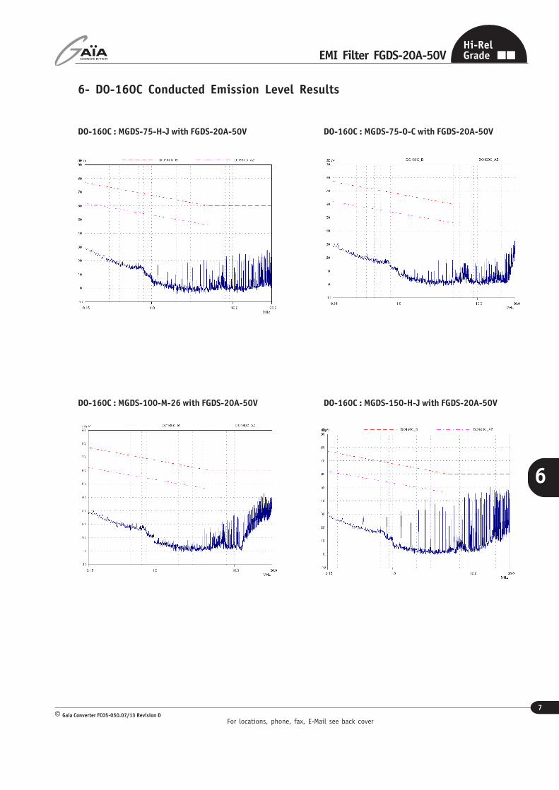
6- D0-160C Conducted Emission Level Results
DO-160C : MGDS-75-H-J with FGDS-20A-50V DO-160C : MGDS-75-O-C with FGDS-20A-50V
DO-160C : MGDS-100-M-26 with FGDS-20A-50V DO-160C : MGDS-150-H-J with FGDS-20A-50V

For locations, phone, fax, E-Mail see back cover
8
EMI Filter FGDS-20A-50V
Gaia Converter FC05-050.07/13 Revision D©
6
Hi-RelGrade
6- D0-160E Conducted Emission Level Results
DO-160E : MGDS-75-H-J with FGDS-20A-50V DO-160E : MGDS-75-O-C with FGDS-20A-50V
DO-160E : MGDS-100-M-26 with FGDS-20A-50V DO-160E : MGDS-150-H-J with FGDS-20A-50V

For locations, phone, fax, E-Mail see back cover
9
EMI Filter FGDS-20A-50V
Gaia Converter FC05-050.07/13 Revision D©
6
Hi-RelGrade
6- D0-160G Conducted Emission Level Results
DO-160G : MGDS-75-H-F with FGDS-20A-50V DO-160G : MGDS-75-O-J with FGDS-20A-50V
DO-160G : MGDS-150-H-C with FGDS-20A-50V DO-160G : MGDS-150-H-J with FGDS-20A-50V

For locations, phone, fax, E-Mail see back cover
10
EMI Filter FGDS-20A-50V
Gaia Converter FC05-050.07/13 Revision D©
6
Hi-RelGrade
7- Environmental QualificationsThe modules have been subjected to the following environmental qualifications.
Characteristics Conditions Severity Test procedure
Climatic Qualifications
Life at hightemperature
DurationTemperature / status of unit
Test D : 1 000 Hrs@ 105°C case, unit operating@ 125°C ambient, unit not operating
MIL-STD-202GMethod 108A
Altitude
Altitude level CDurationClimb upStabilizationStatus of unit
40.000 ft@-55°C30 min.1 000 ft/min to 70 000 ft@-55°C,30 min.unit operating
MIL-STD-810EMethod 500.3
Humidity cyclic
Number of cycleCycle durationRelative humidity variationTemperature variationStatus of unit
10Cycle I : 24 Hrs60 % to 88 %31°C to 41°Cunit not operating
MIL-STD-810EMethod 507.3
Humidity steady
Damp heatTemperatureDurationStatus of unit
93 % relative humidity40°C56 daysunit not operating
MIL-STD-202GMethod 103B
Salt atmosphere
TemperatureConcentration NaClDurationStatus of unit
35°C5 %48 Hrsunit not operating
MIL-STD-810EMethod 509.3
Temperaturecycling
Number of cyclesTemperature changeTransfert timeSteady state timeStatus of unit
200-40°C / +85°C40 min.20 min.unit operating
MIL-STD-202AMethod 102A
Temperatureshock
Number of shocksTemperature changeTransfert timeSteady state timeStatus of unit
100-55°C / +105°C10 sec.20 min.unit not operating
MIL-STD-202GMethod 107G
Mechanical Qualifications
Vibration(Sinusoidal)
Number of cyclesFrequency / amplitudeFrequency / accelerationDurationStatus of unit
10 cycles in each axis10 to 60 Hz / 0.7 mm60 to 2 000 Hz / 10 g2h 30 min. per axisunit not operating
MIL-STD-810DMethod 514.3
Shock(Half sinus)
Number of shocksPeak accelerationDurationShock formStatus of unit
3 shocks in each axis100 g6 ms1/2 sinusoidalunit not operating
MIL-STD-810DMethod 516.3
Bump(Half sinus)
Number of bumpsPeak accelerationDurationStatus of unit
2 000 bumps in each axis40 g6 msunit not operating
MIL-STD-810DMethod 516.3

For locations, phone, fax, E-Mail see back cover
11
EMI Filter FGDS-20A-50V
Gaia Converter FC05-050.07/13 Revision D©
6
Hi-RelGrade
8- Dimensions
11- Connections
Dimension are given in mm (inches). Tolerance : +/- 0,2 mm (+/- 0.01 “) unless otherwise indicated.Weight : 35 grams (1.22 Ozs) max.
Pin Single
1 + Input (Vi)
2 - Input (Gi)
3 - Output (Go)
4 + Output (Vo)
5 Ground (Gnd)
6 Ground (Gnd)
4
3
1
2
5
6
Bottom view
9- Materials
Case : Metallic case black anodized coating.Pins : Plated with pure matte tin over nickel underplate.
10- Product Marking
Upper face : Company logo, location of manufacturing.Side face : Module reference, option, date code : year and week of manufacturing.
Pin dimensions :
Pins 5, 6 : Ø 0,73 mm (0.029’’)
Pins 1, 2, 3, 4 : Ø 1,29 mm (0.051’’)
Information given in this datasheet is believed to be accurate and reliable. However, no responsibility is assumed for the consequence of its use nor for any infringement of patents or other rights of third parties which may result from its use.These products are sold only according to GAIA Converter general conditions of sale, unless otherwise confirmed by writing. Specifications subject to change without notice.
Prin
ted
in F
ranc
e by
GAIA
Con
vert
er G
aia
Conv
erte
r FC
05-5
0.07
/13
Revi
sion
D.
Grap
hism
e :
Phili
ppe
Clic
q
Represented by :
For more detailed specifications and applications information, contact :
International HeadquartersMarketing and Sales department
GAÏA Converter - FranceAddress : B.P. 26 - 33186 LE HAILLAN - FRANCE
Tel. : + (33)-5-57-92-12-80Fax : + (33)-5-57-92-12-89
North American HeadquartersGAÏA Converter Canada, IncAddress : 6611 ThimensST-LAURENT, QUEBEC - CANADA H4S 1W2Tel. : (514)-333-3169Fax : (514)-333-4519
6
Related Documents