..- ,, /’ ,, ., ,- . ,/-” D!m!d MI L-STD-454N 30 June 1992 SUPERSEDING MI L-ST D-454M 15 December 1989 MILITARY STANDARD STANDARD GENERAL REQUIREMENTS FOR ELECTRONIC EQUIPMENT L:- - ---..- --A j ‘-”” ‘“” ; ;,!, . .. . . AMSC t4/A /-’-’~ FSC QDRQ DISTRIBUTION STATEMENT A. Approved for public releauq dldributlon 18 unllmited. ‘“/ .,. /. /

Welcome message from author
This document is posted to help you gain knowledge. Please leave a comment to let me know what you think about it! Share it to your friends and learn new things together.
Transcript

..-
,,
/’,,.,
,-. ,/-”
D!m!dMI L-STD-454N30 June 1992
SUPERSEDINGMI L-ST D-454M15 December 1989
MILITARY STANDARD
STANDARD GENERAL REQUIREMENTS FOR
ELECTRONIC EQUIPMENTL:- - ---..---A
j ‘-””‘“” ;
;,!,
. . . .
.
AMSC t4/A /-’-’~FSC QDRQ
DISTRIBUTION STATEMENT A. Approved for public releauq dldributlon 18 unllmited.
‘“/
.,.
/.
/

MIL-STD-454N30 June 199!2
DEPARTMENT OF DEFENSE
Washington DC 20360
Standard General Requirements for Electronic Equipment
MIL-STD-454N
1. This Mi1itary Standard is approved for use by all Departments andAgencies of the Department of Defense.
*2. Beneficial comments (recommendation, additions, deletions) and anypertinent data which may be of use in improving this document should beaddressed to Defense Electronics Supply Center, ATTN: DESC-EPE, Dayton, OH45444-5270, by using the Standardization Document Improvement Proposal(DD Form 1426) appearing at the end of this document or by letter.
ii

MIL-STD-454N30 June 1992
*FOREWORD
This standard is the technical baseline for the design and construction ofelectronic equipment for the Department of Defense. It captures in onedocument, under suitable subject headings, fundamental design requirementfor eleven general electronic specifications. The opportunity to focus on asingle document, afforded to contractors, results in substantial savings tothe Government. This standard was prepared and is semiannually updatedthrough the cooperative efforts of Government and industry. The followingGovernment documents are intimately associated with tbia standard:
MIL-I-983
MIL-E-4158
MIL-E-5400
MIL-E-8189
DOD-E-8983
MIL-P-1126B
MIL-E-119Q1
MIL-F-18870
MIL-T-21200
MIL-T-28800
Interior Communication Equipment, Naval Shipboard, BasicDesign Requirements for (Not for New Design)
Electronic Equipment, Gnound, General Specification for
Electronic Equipment, Aerogpace, General Specification for
Electronic Equipment, Mis8iles, Boo8ters and Allied Vehicles,General Specification for (Not for New Design)
Electronic Equipment, Aero8pace, Extended Space Environment,General Specification for
Parts, Materials, and Processes Used in Electronic Equipment
Electronic, Electrical and Electromechanical Equipment,Guided Missile and Associated Weapon 8ystenw, QeneralSpecification for
Fire Control Equipment, Naval Shipboard, QeneralSpecification for
Test Equipment for Use with Ele@t~oni@ and ElectricalEquipment, (feneml Specification for (Not fop New Design)
Test Equipment for Use with Electrical and ElectronicEquipment, General Specification for
iii

MIL-STD-454N15 December 1989
CONTENTSParagraph
1.1.11.21.31.4‘?,.3.4.4.14.25.6.
SCOPERequirements applicable to electronic equipmentRevision of requirementsMethod of referenceInterrelationshipof requirementsAPPLICABLE DOCUMENTSDEFINITIONSGENERAL REQUIREMENTSApplicationUse of #election and application standardsDETAIL REQUIREMENTSNOTES
Individual Requirements
Requirement 1 - Safety Design Criteria - Personnel HazardsRequirement 2 - CapacitorsRequirement 3 - Flammabi1ityRequirement 4 - Fungus-Inert MatemialsRequirement 5 - SolderingRequirement 6 - BearingsRequirement 7 - InterchangeabilityRequirement 8 - Electrical Overload ProtectionRequirement S - WorkmanshipRequirement 10 - Electrical ConnectorsRequirement 11 - Insulating Materials, ElectricalRequirement 12 - Fastener HardwareRequirement 13 - Structural WeldingRequirement 14 - Transformers, Inductors, and Coi1sRequirement 15 - Metals, Corrosion ResistanceRequirement 16 - Dissimilar Meta18Requirement 17 - Printed WiringRequirement 18 - Derating of Electronic Parts and MaterialsRequirement 19 - TerminationsRequi~ement 20 - Wire, Hookup, InternalRequirement 21 - CastingsRequirement 22 - Pa~ts Selection and ControlRequirement 23 - AdhesivesRequirement 24 - Welds, Resistance, Electrical IntevconnectionaRequirement 25 - Ele@t~ical PowerRequirement 26 - Arc-Resistant MaterialsRequirement 27 - Batte~ies
iv

MIL-STD-4S4N15 May 1990
CONTENTS - Continued
Requirement 28 - ControlsRequirement 29 - Electron TubesRequirement 30 - Semiconductor DevicesRequirement 31 - Moisture PocketsRequirement’32 - Test ProvisionsRequirement 33 - ResistorsRequirement 34 - NomenclatureRequirement 35 - ReliabilityRequirement 36 - AccessibilityRequirement 37 - Circuit BreakersRequirement 38 - Quartz Cnystals and Oscillator UnitsRequirement 39 - Fuses and Fuse HoldersRequirement 40 - ShuntsRequirement 41 - SpringsRequirement 42 - Tuning Dial MechanismsRequirement 43 - LubpicantaRequirement 44 - Fibrous Materials, OrganicRequirement 45 - Corona and Electrical Breakdown PreventionRequirement 46 - Motors and Rotary Power ConvertersRequirement 47 - Encapsulation and Embedment (Potting)Requirement 48 - GearsRequirement 49 - HydraulicsRequirement 50 - Indicator LightsRequirement 51 - Meters, Electrical IndicatingRequirement 52 - Thermal DesignRequirement 53 - Waveguides and Related DevicesRequirement 54 - MaintainabilityRequirement 55 - EnclosuresRequirement S6 - Rotary Servo DevicesRequirement 57 - RelaysRequirement 68 - SwitchesRequi~ement 59 - BrazingRequirement 60 - Sockets and Aace#80riesRequirement 61 - Elect~omagnetic Inte~ference ControlRequirement 62 - Human EngineeringRequirement 63 - Special ToolsRequirement 64 - Microelectronic DevicesRequirement 65 - Cable, Coaxial (RF)Requirement 66 - Cable, MulticonductorRequirement 67 - Ma~kingRequirement 68 - Readouts and DisplaysRequirement 69 - Internal Wiping Praati@e#Requirement 70 - Electrical FiltensRequirement ’71- Cable and Wine, InterconnectionRequirement 72 - Substitutability
v

MIL-STD-454N15 December 1989
Requirement 73 - Standard Electronic ModulesRequirement 74 - Grounding, Bonding, and ShieldingRequirement 75 - Electrostatic Discharge ControlRequirement 76 - Fiber Optics
CONTENTS - Continued
Tables
Table 1-1Table l-IITable 4-ITable 10-1Table 20-1Table ‘21-ITable 26-ITable 41-1Table 41-11Table 41-111Table 50-1Table 53-ITable 64-ITable 64-IITable 66-ITable 69-ITable 71-1Table 71-11
IndexesIndex 1-1Index I-2
Probable effects of shockSuitable protective measuresFungi-susceptibilityof materialsAbbreviations for thermocouple materialsWire, electricalQeneral comparison of metallic casting proceseegArc-resistant materialsMaterials fop electrical spring applicationCorrosion resisting steel for springsCarbon steel for springsIndicator lights and associated itemsWaveguides and related devicesDigital technology progression predictionPerfomnanae chanactenistics-digital mio~oelectr.onicsCable, multiconductorElectrical clearance and leakage (areepage)distancesWire, electrical, interconnectionCable, mtilticonductor,inte~connection Indexes
Index of Applicable DocumentsSubject Index
vi

MIL-STD-454N30 June 1992
STANDARD GENERAL REC!UIREMSNTSFOR ELECTRONIC EQUIPMENT
1.1 Requirements awl icable to electronic eauiument. This standard coversthe common requirements to be used in military specifications for electronicequipment.
1.2 Revision of requirements. Revisions of individual requirements apeindicated by a date below the requirement number located at the bottom ofthe page. A note, *Supersedes Requirement (no.) (date)“, is placed in thelower corner of each revised page, opposite the requirement number and date.When the basic document ia revised, those requirements not affected bychange retain their existing date.
●1.2.1 Redating. Although individual requirements are reviewed and updatedor validated at least once every twelve months, r@qUinementS are not redatedunless technical changes are mede.
*1.3. Method of refemence. This standard shall not be invoked on a blanketbasis. Rather each requirement contained herein shall be referenced in theindividual specification by specifying this standard and the requirementnumber.
1.4 lnterrelationshiD of Feauirements. Each requirement is intended tocover some discipline in the design of equipment, such as a procedure, aprocess or the selection and application of parts and materials. Many ofthese disciplines, howaver, cannot retain a clear-cut separation onisolation from others so that when requirements of MIL-STD-454 arereferenced in a specification some requirements will undoubtedly have adirect interrelationshipwith other requirements. This interrelationshipshould be taken into consideration when invoking or using theserequirements.
2. APPLICABLE DOCUMSNTS
2.1 Individual Requirements. See paragraph 2 of each individualrequirement for a listing of applicable documents contained therein,including those for guidance only. Doauments referenced in the individualrequirements apply to the extent speaified thenein.
2.1.1 ADDli@abl@ igsues. Unless otherwise specified, the applicable issuesshall be those listed in that issue of the Department of Defense Index ofSpecifications and Standards (DODISS) specified in the solicitation. Theapplicable issue of nongovennment documents shall be the issue specified.
1

MIL-STD-454N30 June 1992
2.1.2 Copies. Copies of specifications, standards, drawings, andpublications required by contractors in connection with specific procurementfunctions should be obtained from the procuring activity or as directed bythe contracting officer.
*2.1.3 Industry addresses. Addreasea for obtaining documents referencedherein but not obtainable from the Government are as follows!
AQhfA
AMS
ANSI
ASM
ASTM
AWS
EIA
IEEE
IPC
American Qear Manufacturers AaBo@iation1500 King StreetSuite 201Arlington VA 22314
Society of Automotive Engineer8 (SAE)400 Commonwealth DriveWarrendale PA 15096
American National Standards Institute11 West 42nd StreetNew York NY 10036
American Society for MetalsMetals Park OE 44073
American Society for Testing and Materials1916 Race StreetPhiladelphia PA 19103
Ame~ican Welding Society550 N W LeJeune RoadPo Box 351040Miami FL 33135
Electronic Industries Association2001 Pennsylvania Ave, NWWashington DC 20006
Institute of Electrical and Electronics EngineersIEEE Service Center445 Hoes Lane PO Box 1331Piscataway, NJ 08S55-1331
In8titute for Interconnectingand Paakaging Electronic Circuits73S0 Nonth Lincoln AvenueLincolnwood IL 60646-1776
2

MIL-STD-454N30 June 1992
NAS National Standards Association1200 Quinae Onchand BoulevardQaithersburg MD 20878
NFPA National Fire Protection AssociationBattery March ParkQuincy MA 02269
UL Underwriter Laboratories, Incorporated333 PfingstenRoad Northbrook IL 60062-2096
3. DEFINITIONS
3.1 As used in this standard, the word “airborne” denotes thoseaPPliCatiOnE PeCUliar to aircraft and missile or other systems designed foroperation primarily within the earth’s atmosphere; “space” denotesapplication peculiar to spacecraft and systems designed for operation nearor beyond the upper reaches of the earth’s atmosphere; and -aerospace”includes both airborne and spa.seapplications.
3.2 Other terms are defined in the individual Requirements.
4. GENERAL REQUIREMENTS
4.1 Application. The Requirements contained herein are intended to provideuniform requirements applicable to electronic equipment, unless otherwisespecified in the Requirement, and shal1 be incorporated by reference ingenanal equipment specifications. Other doaumants may referenceRequirements when applicable.
4.!2 Use of selection and application standards. When a selection andapplication standard is invoked in a Requirement, the devices or partsselected shall conform to the applicable military specifications refe~encedin the standard.
5. DETAIL REQUIREMENTS
5.1 Individual Requirements for electronic equipment follow
6.1 The margins of this standard are marked with asteriskg to indiaatewhere changes (additions, modifications, corrections, deletions) from theprevious issue were made. This is done as a convenience only and theGovernment assumes no 1iabi1ity whatsoever for any inaccuracies in these
3

MIL-STD-494N30 June 1992
notations. Bidders and contractors are cautioned to evaluate therequirements of this document based on the entire content irrespective ofthe marginal notations and relationship to the last previous issue.
6.2 Subject term (key word) listinE.
Cable selectionCorona protectionEncapsulationFastenersFlammabilityFungus protectionInterchangeabi1ity of partsMarkingMateriala selectionMicroelectronics
Custodians:Army - ERNavy - ASAir Force - 11
Review activities:Army - AR, AV, CR, ME, MI, PT, TENavy - EC, SH, OSAir Force - 17, 19, 85, 99
Other:DLA - ESFAA
NomenclatureParts selectionPrinted wiringsafetySolderingSubstitutability of partsThermal designWaveguidesWire selectionWorkmanship
Preparing activity:Air Force - 10
Agent:DLA - ES
Project QDRQ-0119
4

MIL-STD-454N
REQUIREMENT 1
SAFETY DESIGN CRITERIA - PERSONNEL HAZARDS
1. Purpose. This requirement establishes safety design criteria and providesguidelines for personnel protection.
2, Documents aDDlicable to Requirement 1:
MIL-B-5087 Bonding, Electrical, and Lightning Protection, forAerospace Systems
MIL-STD-131O Shipboard Bonding, Grounding, and Other Techniques forElectromagnetic Compatibility and Safety Shielding
MIL-STD-1472 Human Engineering Design Criteria for Military Systems,Equipment and Facilities
MIL-HDBK-600 Guidelines for Identification, Markings, Labeling, Storage,and Transportation of Radioactive Commodities
ANSI C95.1-1Q82 Safety Levels with Respect to Human Exposure to RadioFrequency Electromagnetic Fields, 300 KHz to 100 GHz
ANSI C95.‘2-1982 Radio Fnequency Radiation Hazard Warning SymbolANSI N2.1-1969 Radiation SymbolANSI 235.1-1972 Accident Prevention Signs, Specification forANSI 235.2-1968 Accident Prevention Tags, Specification forANSI 235.4-1973 Specification for Informational Signs Complementary to
ANSI 235.1, Aacident Prevention SignsANSI 253.1-1979 Marking Physical Hazards, Safety Color Code forNFPA 70-1990 National Electrical Code10 CFR 20 Code of Federal Regulations, Title 10, Chapter 1, Part 2021 CFR 1000-1050 Code of Federal Regulations, Title 21, Chapter 1, Parts
1000-105029 CFR 1910 Code of Federal Regulations, Title 29, Chapter KVII, Part
1910
3. Definitions
3.1 Chassis. electrical eauiDment. The chassis is a structural itemfabricated in such manner as to facilitate assemblage and interconnectionofelectrical or electronic items for the specific purpose of providing a basisfor electrical or electronic circuits. It normally has drilled or stampedholes to accommodate the items but may include only the items necessary forits own mounting and support.
3.2 -. The frame is any construction eyetem fitted and united together,designed for mounting or supporting electrical OP electronic parts or units.
3.3 Fail-safe. The design feature of a part, unit or equipment which allowsthe item to fail only into a non-hazardous mode.
1-1
REQUIREMENT 13 May 1991

MIL-STD-454N
3.4 Interlock. An interlock is an automatic switch which eliminates allpower from the equipment when an access door, cover or plate is removed.
3.4.1 BvDassable interlock. A bypassable interlock is an automatic switchwith a manually operated electrical bypass device to allow equipmentmaintenance operations on energized equipnwnt.
3.5 Battleshort. A switch used to bypass normal interlocks in missioncritical equipment (i.e., equipment which must not be shut down or themission function will fail) during battle conditions.
4. Requirements
4.1 Fail-8afe. The design and development of all military electronicequipment shall provide fail-safe features for safety of personnel duringthe installation, operation, maintenance, and repair or interchanging of acomplete equipment assembly or component parts thereof.
4.2 Bondin.ein hazardous areas. Electronic equipment to be installed inareas where explosive or fire hazards exist shal1 be bonded in accordancewith MIL-B-5087 for aerospace systems, MIL-STD-131O for shipboand systems,and NFPA 70, Chapter !3,for gnound systems, or as otherwise specified in thedetail equipment specification.
4.3 Temperature. At an ambient temperature of 25°C, the operatingtemperature of control panels and operating controls shall not exceed 49-C.Other exposed parts subjeat to oontaat by operating personnel shall notexceed 60°C.
4.4 Electrical. The design shall incorporate methods to protect personnelfrom inadvertent contact with voltages capable of producing shock hazards.
4.4.1 -. Means shall be provided so that power may be cut off whileinstalling, replacing, or interchanging a complete equipm+nt, assembly, orpart thereof. Interface with electrical power #our@es shall be inaccordance with the applicable regulations or requirements. If a main power8witch is provided, it shall be clearly labeled as such and shall cut offall power to the complete equipment.
4.4.2 Ground. The design and construction of equipment, excludingself-powered equipment, shall insure that all external parts, surfaces, andshieldg, exclusive of antenna and t~angmission line terminals, ape at groundpotential at all times duning normal operation. The design shall includeconsideration o! ground cur~enta and voltage limits (possible ancing)established on a basis of hazardous location. Antenna and transmission lineterminals shall be at ground potential, except for madio frequency (Pi)energy on their external surfaces
1-2

MIL-STD-454N
4.4.2.1 Self-uowered eauipment. Self-powered equipment shal1 have al1external surfaces at the same potential
4.4.2.2 Grounding methods. Plugs for use with metal cased portable toolsand equipment shall have provisions for automatically grounding the metalframe or case of tools and equipment when the plug is mated with receptacle,and the gnounding pin shall make first, break last. Q~ound connections toshields, hinges, and other mechanical partg shall not be used to completeelectrical circuits. Any external or interconnectingcable, where a groundis part of the cimuit, shall carry a ground wire in the cable terminated atboth ends in the same manner as the other conductors. In no case, exceptwith coaxial cables, shall the shield be depended upon for acurrent-carrying ground connection. Static and safety grounds shall not beused to complete electrical circuits. A point on the electrically conductivechassis or equipment frame shall serve as the common tie point for staticand safety grounding. The path from the tie point to ground shall:
a. Be centinuous and permanent,
b. Have ample carrying capacity to conduct safely any fault currents that~Y be imposed upon it,
c. Have impedance sufficient1y low to limit the potential above ground andto facilitate the operation of the over current devices in the circuits, and
d. Have mfficient mechanical strength of the material to minimizepossibility of ground disconnection.
4.4.2.3 Hinged or slide-mounted Danels and doors. Hinge8 or slides shallnot be used fo~ grounding paths. Panels and doo~s containing metere,#witaheg, test points, etc, shal1 be attached or hinged in such a manner asto insure that they are at the same ground potential as the equipment inwhich they are mounted, whether in a closed or open position. A groundshall be aonside~ed satisfactory if the electrical connation between thedoor on panel and the system tie point exhibits a resistance of O.1 ohm OFless and has sufficient ampacity to insure the reliable and immediatetripping of equipment over-current protection devices.
4.4.2.4 Shieldinl. Except where a conflict with single-point shieldgrounding requirements would be created, shielding on wire or cable #hall begrounded to the chassis or frame. The shielding shall be secured to preventit from contacting exposed current-carryingparts or grounding to thechassis or frame at any point other than the gnound termination. Theshielding shall end at a sufficient distance from exposed conductors toprevent shorting or arcing between the conducto~ and the shielding.
1-3
MIL-STD-454N
4.4.3 Accidental contact. The design shall incorporate methods to protectpersonnel from accidental contact with voltages in excess of 30 volts rma ordc during normal operation of a complete equipment.
4.4.3.1 Guards and barriers. Al1 contaats, terminals and like deviceshaving voltages between 70 and 500 volts ma or dc with respect to groundshal1 be guarded from accidental contact by personnel if such points areexposed to contact during direct support or operator maintenance. Quarda orbarriers may be provided with test probe holes where maintenance testing isrequired.
4.4.3.2 High voltage guardin6. Assemblies operating at potentials inexcess of 500 volts 8hall be completely enclosed from the remainder of theassembly and equipped with nonbypassable interlocks.
4.4.3.3 VoltaEe measurement. When the operation or maintenance ofequipment employing potentials in excess of 300 volts peak could requirethat these voltages be measured, the equipment shall be provided with testpoints so that these voltage8 can be measured at a relatively low potentiallevel. In no case shall the potential exceed 300 volts peak relative toground Test points with voltages above 30 volts shall have the conductingmaterial recessed a distance no less than the diameter of the probe hole anda minimum of 1.5 mm. If a voltage divider is used, the voltage dividerresistance between the test point and ground shall consist of at least tworesistors of equal value in parallel.
4.4.3.4 Quardinfiof r! voltafes. Transmitter output terminals, antennas andother devices that carry sufficient r! voltage to burn or injure personnelshall be protected from accidental contact in the same manner as for acvoltages in the ’70to 500 volt range.
4.4.3.5 Main power switch. The power input side of the main powen switchand the incoming power line aonneotions shall be given physical protectionagainst accidental contact.
4.4.4 Protective devices
4.4.4.1 Interlocks. Wlen a unit is provided with access doors, covers orplates, these accesg points shall be interlocked as follows:
a. MO interlock= are required when all potentials in excess o! 70 volts arecompletely protected with guards or barrier= to prevent accidental contactunder all conditions of ope~ation or any level of maintenance.
1-4

MIL-STD-454M
b. Bypassable interlocks are required when voltages between ‘/Oand 500 voltsare exposed as the result of an access door, cover, or plate being opened.Uote that these internal voltage8 are allowed to be unguarded only if theyare not exposed during direct support or operator maintenance. The bypassdevice shall be of such design that closing the associated door, cover orplate wi11 automatical1y open the bypass device and leave the interloak inposition to function normally. Visual means shall be provided to indicatewhen the interlock is bypassed.
c. Nonbypa8sable interlocks are required when any voltage in exces8 of 500volts is expoged as a result of an access door, coven OF plate being opened.
4.4.4.2 Battle short indicator. When a battle short switch Is required bythe individual equipment specification, a readily visible indicator lightshall be provided to indicate when the battle short switch is ON.
4.4.4.3 Safety switches. Safety switchee which will.deactivate a= Ociatedmechanical drive units shall be provided for the purpose of disconnectingthese units without disconnecting othen parts of the equipment. Suchremotely located units and assemblies shall have provision fornonoverrideable safety switches to allow independent disconnection in theassociated equipment.
4.4.5 Discharfiini?devices
4.4.5.1 Automatic discbarie devices. High voltage circuits and capacitorsshall be provided with discharging devises unless they discharge to 30 voltsor less within two seconds after power removal The particular dischargingdevice that is chosen shall insure that the capacitor or high voltagecircuit is discharged to 30 volts or less within two seconds. Theseprotective devices shall be positive acting, highly reliable, and shallactuate automatically either by mechanical release on by electrical solenoidwhen the door or cover is opened. When resistive bleeder networks are usedto discharge capacitors, the bleeder network shall consist of at least twoequal valued resistons in parallel.
4.4.5.2 Shorting rods. Shorting rods shall be provided with alltransmitting equipment where voltages are in excess of 70 volts rnw on dc.Where size permits, shorting rods shall be stored within the transmittingequipment, permanently attached, and readily accessible to maintenancepersonnel. The permanent y attached rod shal1 be connected through aflexible stranded copper wire (covered with a transparent sleeving] to thestud provided at the transmitter main frame. Where size doee not permitinternal storage of the shorting rod, a grounding stud shall be provided topermit attachment of a portable shomting rod. Tbe connection to the studshall be such that accidental loosening on high resistance to tbe ground isprevented.
1-5

MIL-STD-4S4N
4.4.6 Connectors. Connectors used in multiple electric circuits shall beselected to preclude mismating. Where design considerations require plug andreceptacles of similar configuration in close proximity, the mating plugsand receptacles shal1 be suitably coded or marked to clearly indicate themating connectors. Plugs and receptacles shall not be of #imilarconfiguration if the major unit contains explosive items The design of theconnector shal1 be such that the operator is not exposed to electrical shockor burns when normal disconnect methods are used. Exposed pin contacts shal1not be energized (hot) after being disconnected from the socket contacts.
4.5 Radiation. The design of all equipment for which a federal standardexists under 21 CFR 1000 - 1050, on the Radiation Control for Health andSafety Act of 1968, shall conform to the appropriate federal standard.
4.5.1 Microwave and rf radiation. All electronic equipment or electricaldevice8 capable of emitting microwave or n! radiation between 300 KHz and100 QHz shall be so designed, fabricated, shielded and operated as to avoidoverexposure of personnel In areas where unintended radiation levels exist,equipment design and installation in any unrestricted area accessible topersonnel shall meet the requirements of ANSI C95.1. Shields, covers, doons,etc, which when opened or removed will allow microwave and rf radiation toexceed the above, shal1 be provided with nonbypassable interlocks.
4.5.2 X ~adiation. All electronic or elect~ical devices capable ofproducing X radiation shall be so degigned, fabricated, shielded andoperated as to keep personnel exposure as low as reasonably achievable. Forequipment and installation design, shielding requirements shall bemaintained at all times which limit radiation levels to not greater than ‘2milliroentgens (mr) in any one hour and 100 mr in any 7 consecutive days atthe operator position or within 5cm from the equipment (whichever is closer)in any ,unrestrictedarea accessible to personnel In addition, these levelsshal1 be reduced whenever necessary to ensure that exposed personnel neve~receive an absorbed dose to the whole body or any critical organ in excesEof 125 millirem per calendar quarter or 500 millirem per year. Otherexposure Ehall be based on application criteria and limits as required byNuclear Regulatory Commission Rules and Regulations, 10 CFR 20: OSHARegulations, 29 CFR 1910.96: and FDA Regulation, 2.1CFR, Chapter 1,Subchapter J, Radiological Health. Equipment which, when shields, covers,doors, etc. are removed, will allow X radiation to exceed 2.0 mr per hourshal1 be provided with nonbypassable interlocks.
4.5.3 Laser radiation. Laser equipment and system design, installation,andoperational and maintenance procedures shall conform to 21 CFR 1040. IfTitle 21 cannot be met because of operational ~equirementH, an exemptionshall be requested from the procuring activity and applicable military laser#afety regulations shall be used as a design requirement.
1-6

MIL-STD-454M
4.6 Mechanical. The design of the equipment shall provide personnel maximumaccess and safety while installing, operating, and maintaining theequipment. Equipment design shall include provisions to prevent accidentalpulling out of drawers or rack mounted equipment components. Suitableprotection shall be provided to prevent contact with moving mechanical pantssuch as gears, fans, and belts when the equipment is complete and operating.Sharp projections on cabinets, doors, and similar parts shall be avoided.Doors or hinged covers shal1 be rounded at the corners and provided withstops to hold them open.
4.6.1 Mechanical interconnection.The design shall provide positive meansto prevent the inadvertent revemsing or mismating of fittings; COUP1ings;fuel, oil, hydraulic, and pneumatic lines; and mechanical 1inkage. Whenprevention of mismating by design consideration is not feasible, coding ormarking shall be employed when approved by the procuring activity. Codingand msrking wi11 not be approved as a substitute for proper design or iternsinvolving explosive, emergency, or safety critical systems.
4.6.2 Power switch location. Equipment power switches shall be so selectedand located that accidental contact by personnel wi11 not place equipment inoperation.
4.6.3 Cathode ray tubes. Provision shall be incorporated to protectpersonnel from injury due to implosion of cathode ray tubes.
4.7 Eauipment safety markings. Danger, caution, etc, signs, labels andmmkings shall be used to warn of specific hazards such as voltage, current,thermal, or physical The signs, labels, and markings shal1 be as permanentas the normal 1ife expectancy of the equipment on which they are affixed.Quards, barriens, and access doors, cove~a or plates shal1 be mmked toindicate the hazard which may be be present upon removal of such devices.When possible, msrking sbal1 be located such that it is not removed when thebarrier or access door is removed. Additionally, hazards internal to a unitshall be marked adjacent to hazards if they ane significantly different fromthose of surrounding items. Such a case would be a high voltage terminal ina group of low voltage devices.
a. Physical hazards shal1 be mmked with color codes in accordance with ANSIZ53.1 where applicable to electronic equipment.
b. For potentials between 70 and 500 volts, warning signs or labels shall bein accordance with ANSI Z35.1, Class II, and ANSI Z35.4, and shall read, asa minimum, “Caution - (Insert maximum voltage applicable) Volts.“
1-7

MIL-STD-454N
c. For potentials in excess of 500 volts, warning signs or labels shall bein accordance with ANSI 235.1, Class I and ANSI 235.4, and shall read, as aminimum, “Danger - High Voltage - (Insert maximum voltage applicable)Volta.“
d. Microwave or rf radiation warning signs shall be in accordance with ANSI235.1 and ANSI C95.2. Labels shall be provided on all radiation shields towarn personnel of the radiation hazards involved upon removal thereof. Anyitem which can emit radiation levels in excess of those specified inparagraph 4.5.1 shall be labeled. Minimum safe clearance distances shall beclearly marked. Warning signs shall,be posted in all aneas having electronicequipment designed to operate between 300 KHz and 100 QHz with intendedelectromagnetic radiation levels exceeding those in paragmaph 4.5.1.
e. (1) Laser labels shall be in acaondance with 21 (!FR1040.
(2) Military exempt laser labels: A permanent label shall be affixed onall military laser systems that have been certified exempt from 21 CFR 1040(PerformanceStandards for Light-Emitting Products), which reads:
CAVTION
This electronic pvoduct ha8 been exempted f~om FDA radiation safetyperformance ntandards, prenfribed in the Code of Federal Regulations,Title 21, Chapter 1, Subcbapte~ J, pur8uant to Ixemption No. 76 ,PL-01DOD i88ued on 26 July 1976. This product should not be used withoutadequate protective devices OP p~ocedure#.
f. Shields which protect personnel from X radiation shall be labeled inaccordance with 10 CFR 20.
g. Coding for accident prevention tags .vhal1 be in accordance with ANSI235.2.
h. The marking or labeling of commodities containing radioactive mate~ialsshal1 be in accordance wi~h 10 CFR 20.
i. Ionizing radiation hazard symbols shall be in accordance with ANSI N2
4.8 Hazardous and restricted mateniala
4.8.1 Gases or fumes. The materials, as installed in tbe equipment andunder serviae conditions specified in the equipment #pacification, shallliberate gases which combine with the atmosphere to form an aoid OFaonnosive alkali, nor shall they liberate toxic or corrosive fumes which
1.
not
1-s

MIL-STD-454M
would be detrimental to the performance of the equipment or health ofpersonnel. The materials also shall not liberate gases which will produce anexplosive atmosphere.
4.8.2 Mercury. Materials and parts containing mercury shall not be usedunless use of mercury is specifically required or approved by the procuringactivity.
4.8.3 Radioactive materials. Use of radioactive materials shall conform toNuclear Regulatory Commission regulations and shal1 require approval of theprocuring activity. Radium shall not be used to achieve self-luminosity.
4.8.4 Glass fibers. Glass fiber materials shall not be used as the outersurface or covering on cables, wire or other items where they may cause skinimitation to operating pensonnel. This does not pmeclude the use ofmilitary specification wire and cable. When maintenance procedures requireaccess to glass fibers, such as insulation, a proper caution note shall beprovided.
5. Information for guidance only
5.1 Human engineering?.Human engineering factors affecting safety should beconsidered when establishing general or detailed design criteria. Rigorousdetailed operational or maintenance proaedur.eaare not acceptablesubstitutes for an inherently safe design. Hazard and safety requirements ofMIL-STD-14’Y2should be used as a guide.
5.2 Electrical. Proper instructions in accident prevention and first-aidprocedures should be given to all persons engaged in electrical work tofully inform them of the hazards involved.
5.2.1 Shock hazarda Current rather than voltage is the most importantvamiable in establishing the criterion for shock intensity. Three factorsthat detenmine the severity of electrical shock are: (1) quantity ofcurrent flowing through the body; (2) path of current thnough tbe body: and(3) duration of time that the current flows through the body. The voltagenecessary to produce the fatal current is dependent upon the resistance ofthe body, contact aonditions, and the path through the body. See table l-I.Sufficient current passing through any part of the body will cause severeburns and hemorrhages. However, relatively small currents can be lethal ifthe path includes a vital part of the body, such as the heart or lungs.Electrical burns are usually of two types, those produced by heat of the arcwhich occurs when the body touches a high-voltage circuit, and those causedby passage of electrical current thnough the skin and tissue. While current
1-9

MIL-sTD-45414
is the primary factor which determines shock severity, protectionrequirements are based upon the voltage involved to simplify theiramlication. In cases where the maximum current which can flow from a uoint. .is less than the values shown in table 1-1 for reflex action, protectionrequirements may be relaxed.
TABLE l-I. Probable effects of shock.
Current Values (Mi1liamperes)Effects
AC DC25 Hz to 400 Hz
o-1 0-4 Perception1-4 4-15 Surprise4-21 15-80 Reflex action21-40 80-160 Muscular inhibition40-100 160-300 Respiratory blockOver 100 Over 300 Usually fatal
5.2.2 Insulation of controls. All control shafts and bushings thereofshould be grounded wheneven practicable. Alternatively, the control knobs orlevers and all attachment screws that can be contacted duping use should beelectrically insulated from the shaft.
5.2.3 Qroundinj?to chassis. Ground connection to an electrically conductivechassis or frame should be mechanically secured by soldering to a spotweldedterminal lug or to a portion of the chassis or frame that has been formedinto a soldering lug, or by use of a terminal on the ground wire and thensecuring the terminal by a screw, nut, and lockwasher. The screw should fitin a tapped hole in the chassis or frame or it should be held in athrough-hole by a nut. When the chassis or frame is made of steel, the metalaround the screw hole 8hould be plated or tinned to provide a corrosionresistant connection. When aluminum alloya are used, the metal around thegrounding screw or bolt hole may be oovered with a corrosion resietantsurface film only if the resistance through the film is not more than 0.002ohm. Hardware used for mounting of meters, switahes, test points, etc,should be grounded, whenever possible.
1-1o

MIL-STD-454N
5.2.4 Accidental contact. Suitable protective measures are defined in tablel-II.
5.2.4.1 High current protection. Power sources capable of supplying highcurrent can be hazardous regardless of the voltage at which they operatebecause of the arcing and heat generated if an accidental short circuitoccurs. Al1 power buses supplying 25 amperes or over should be proteotedagainst accidental short circuiting by tools, jewelry or removable conductiveassemblies. This may be accomplished by one or more of the following:
a.
b.
c.
Use of guards and barriers,
Sufficient space separation to prevent short cincuits,
Caution - warning signs.
5.2.4.2 Interlocks. Various equipment designs require different approachesto the use of interlocks. Intemlock use does not modify any otherrequirements of this standard and must be consistent with equipment or systemspecifications. Equipment sub-assemblies operating in excesg of 500 voltsshould be considered guamded from accidental contact only if they arecompletely enalosed from the remainder of the equipment and are separatelyprotected by nonbypassable interlocks. (An example of an equipment where“suchcompartmentalization is desirable is a display unit which utilizes a highvoltage power supply for a cathode ray tube.) Modularized or sealed highvoltage assemblies whiah are opened only at depot level ame exempt frominterlocking requirements when approved by the procuring activity.
5.2.4.3 Permanent terminations. Terminations such as soldered connectionsto transformer, connectors, spliceg, etc, which are normal1y permanent andnot used during routine maintenance testing, may be protected by permanentinsulation such as shrink sleeving, tubing, insulating shields, etc, providedthe material is rated for the potential exposed voltage.
5.3 Mechanical. Design of rack-mounted equipment should maintain the centerof gravity as low as possible to minimize tipping over.
5.4 Markinf. MIL-HDBK-600 references known electronic iterm which requiremmking and may be used as a guide.
5.5 Materials. Certain chemicals have been identified in the Oa@upationalSafety and Health Act (OSHA) ag aancer.-p~oducingsubstances (carcinogens)Before using any matenials which might contain these chemicals, they shouldbe evaluated in accordance with 29 CFR 1910.
1-11

mL-sm-454N
,
D8mm
.
84
.
.
.. 1-12

MIL-STD-454N
REQUIREMENT 2
CAPACITORS
1. PuruoSei This requirement establishes criteria for the 9election andapplication of capacitors.
2. Do@ument8 auplioable to Requirement 2!
MIL-C-39006/22
MIL-C-39006/25
MIL-STD-198
Capacitors, Fixed, Electrolytic (Nonsolid lllect~olyte),Tantalum, (Polarized,Sintered Slug), 85 C (Voltage Deratedto 125 C), Established Reliability, Style CLR79
Capacitors, Fixed, Electrolytic (Nonsolid Electrolyte),Tantalum, (Polarized,Sintered Slug) (Extended Range), 85 C(Voltage Derated to 125 C), Established Reliability, StyleCLRS1
Capacitors, Selection and Use of
3. Definitions. Not applicable.
4. Requirements
4.1 Selection. Capacito~# shall be 8elected and applied in accordance withMILSTD-19S
4.2 Fixed, tantalum electrolytic. Fop Naval Air Systems Commsnd, the useof wet slug tantalum capacitors (except tantalum cased units in accordancewith MIL-C39006122 and MIL-C-39006125) requires the approval of theprocuring activity, and silver cased tantalum capacitors shal1 not be used.
5. Information for guidance only. Not applicable.
2-1
REQUIREMENT 220 September 19SS

MIL-STD-454N
REQUIREMENT 3
FLAMMABILITY
1. Purpose. This requirement establishes criteria for the selection andapplication of materials with respect to flammability.
2. Documents aDDliCable to Requirement 3:
MIL-STD-202 Test Methods for Electronic and Electrical Component PartsASTM D568-77 Rate of Burning andlor Extent and Time of Burning of
Flexible Plastics in a Ve~tical Position, Test Method forASTM D635-61 Rate of Burning andlor Extent and Time of Burning of
Self-Supporting Plastics in a Horizontal Position, TestMethod for
ASTM D1OOO-B2 Pressure-Sensitive Adhesive Coated Tapes Used forElectrical Insulation, Methods of Testing
UL 94-80 Standard for Tests for Flammability of Plastic Materialsfor Parts in Devices and Appliances
3. Definition. Flammability is a complex characteristic which combines easeof ignition, surface flammability, heat contribution, smoke production, firegasses, and fire endurance. Flammability is a function of chemicalcomposition, physical configuration, temperature, availability of oxygen,and ~etardants or additivee.
4. Requirements. Materials used in military equipment shall, in the end itemconfiguration, be noncombustible or fire retardant in the most hazardousconditions of atmosphe~e, pressure, and temperature to be expected in theapplication. Fire retardant additives may be used provided they do notadversely affect the specified performance requirements of the basicmaterials. Fire retardance 8hal1 not be achieved by use of nonpermanentadditives to the basic material
5. Information fop guidance only. The test used to determine theflammability of material should be the test specified in the materialspecification. Since some materials may change state on characteristicsrelative to flammability during application, tests may be performed on theend item materials mixedlblendedlsatumtedlimpregnatedllayered and processedto simulate the final configuration in the end equipment usage.
5.1 If the specification does not have such a test, testing should be inaccondanae with ASTM D568, ASTM D635, ASTM D1OOO, or MIL-STD-202, Method111, as applicable.
3-1
REQUIREMENT 310 September 1987
MIL-STD-454N
5.2 Materia18 not covered by the above test8 should be tested in accordancewith a procedure approved by the pnocu~ing activity. UL 94 is a usefulguide to develop teat methods and offers a comparative scale to definedegree of flammability.
3-2

MIL-STD-454N
REQUIREMENT 4
FUNGUS-INERT MATERIALS
1. Purpose. This requirement identifies those materials which areacceptable nonnutrients of fungus and establishes conditions under whichfungus nutrient materials are aaaeptable.
2. Documents auulicable to Requirement 4:
MIL-T-152 Treatment, Moistu~e and Fungus Resistant, ofCommunications, Electronic, and Associated ElectricalEquipment
MIL-V-173 Varnish, Moisture and Fungus Resistant (For Treatment ofCommunications, Electronic, and Associated Equipment)
MIL-STD-S1O Environmental Test Methods and Engineering Guidelines29 CFR 1910 Code of Federal Regulations, Title 29, Chapter XVII, Part
1910
3. Definitions
3.1 Fungus-inert material. A material which, in all modified states andgrades, is not a nutrient to fungi.
3.2 Fungicide. A subgtance that destroys or inhibits the growth of fungi
4. Requirements
4.1 Preferred materials. Fungus-inert materials listed in Qroup I of table4-I are preferred for use. These materials need not be tested for fungusresistance prior to use. The appearance of a particular material in table4-I does not constitute approval for its use except from the viewpoint ofthe resistance of the material to fungi
4.2 Acceptable materials. Those materials listed in Group II of table 4-IWY be used, provided it has been demonstrated that they meet therequirements of paragraph 4.4. When materials are compounded with apemw.nently effective fungicide in order to meet the fungus testrequirement, there shall be no loss of the original electronic or physicalproperties required by the basic material specification. Fungicidescontaining mercury shall not be used.
4.3 Hermeticallv sealed aDDlications. Fungus nutnient materials may beused untreated within hermetically sealed enclosures.
4.4 Fungus testinE. Group II materials shall be subjected to the fungustest specified in MIL-STD-81O, Method 508, for a period of 2S days.Certification by a qualified laboratory or by the material producer, based
REQUIREMENT 44-1 30 June 19S9

MIL-STD-454N
on test data on record that the material meets Grade O or Grade 1requirements of table 508-1, Method 508, MIL-STD-81O, is sufficientevidence of acceptability.
TABLE 4-I. Funj?isusceptibility of materials.
Group I - Fun.@s-inert materials
(Funflus-inertin all modified states and frades)
Acrylics ~1Acrylonitrile-styreneAcrylonitrile-vinyl-chloridecopolymer
AsbestosCeramicsChlorinated polyesterFluorinated ethylenepropylene copolymer
(FEP)GlassMetalsMicaPlastic laminates:Silicone-glass fiberPhenolic-nylon fiber
Diallyl phthalatePolyacrylonitrile
PolyamidePolycarbonatePolyester-glass fiber laminatesPolyethylene, high density
(above 0.940)Polyethylene terephthalatePolyimidePolymonochlorotrifluoroethylenePolypropylenePolystyrenePolysulfonePolytetrafluoroethylenePolyvinylidene chlorideSilicone resinSiloxane-polyolefinpolymerSiIoxane polystyrene
Grouu II - Furulusnutrient materials
(May require treatment to attain fungus resistance)
ABS (acrylonitrile-butadiene-styrene) Polyethylene, low and mediumAcetal resins density (0.940 and below)Cellulose acetate Polymethyl methacrylateCellulose acetate butyrate Polyurethane (the ester typesEpoxy-glass fiber laminates are particularly susceptible)Epoxy-resin PolyrioinoleatesLubricants Polyvinyl chlorideMelamine-formaldehyde Polyvinyl chloride-acetateOrganic polysulphides Polyvinyl fluoridePhenol-formaldehyde Rubbers, natural and syntheticPolydichlorostyrene Urea-formaldehyda
4-2

MIL-STD-4S4N
~/ Literature shows that unden certain aonditiong polyamides may beattacked by selective micro-organisms. However, for military applications,they are considered Group 1.
5. Information for Euidance only
5.1 Process-related materials. Processing materials to be tested forfungus resistance in accordance with paragraph 4.4, such as paint, ink,coatings, adhesives, lubricants, viscous damping fluids, silicone grease,et@, #hould be prepaned in the form of 50 mm squares or circles no morethan 1.6 mm thick for testing. Liquid or paste materials should beprepared by impregnating to saturation a sterile sample of glass fabric.
5.2 Parts treatment. When treatment of parts is required to formfungus-resistantmaterials, a moisture and fungus proofing (tAFP)varnishconforming to MIL-V-173 may be applied in accordance with MIL-T-152 afterthe part is cleaned. The MPP varnish should not be applied to any partwhere the treatment will interfere with performance.
5.3 Carcinof!ens.Certain chemicals have been identified in theOcaupational Safety and Health Act (OSHA) as cancer-producing substances(carcinogens). Before using any materials which might contain thesechemicals, they should be evaluated in accordance with 29 CFR 1910.Consideration of the toxicity of a substance should be given prior tomaterial selection.
4-3

MIL-STD-454N
REQUIREMENT 5
SOLDERINCi
1. Purpose. This requirement establishes the basis for soldering ofelectrical and electronic equipment.
2. Document applicable to Requirement 5!
MIL-STD-2000 Standard Requirements for Soldered Electrical andElectronic Asaemblie6
DOD-STD-1866 Soldering Process, General (Non-Electrical) (Metric)
3. Definitions. Not applicable.
4. Requirements
4.1 Qeneral. Electrical and Electronic equipment shall be assembled,soldered, and cleaned in accordance with the requirements of MIL-STD-2000.
4.2 Structural SolderinE. Non-Electrical soldered connecting shall be inaccordance with the requirements of DOD-STD-1866.
4.3 Workmanship. Workmanship of soldered assemblies shall be in accordancewith MIL-STD-2000 or DOD-STD-1866 as appropriate.
Information for guidance only.
5.1 Application. MIL-STD-2000 expresses the minimum requirements
appropriate tO the ~nufa@tuFe Of electrical and electronic equipment. Itmay be necessary to supplement the requirements of MIL-STD-2000 in order toachieve higher reliability requirements associated with critical equipmentapplications (space, nuclear ordnance, command/control, etc.).
5-1
REQUIREMENT 530 Octoben 1991

MIL-STD-454N
REQUIREMENT 6
BEARIMQS
1. PurDOse This requirement establishes criteria for the selection andapplication of bearings.
2. Documents aDDliCable to Requirement 6:
FF-B-171FF-B-185
FF-B-187FF-B-195MIL-B-3990MIL-B-5687
MIL-B-8942MIL-B-8943MIL-B-8948MIL-B-13506MIL-B-17380MIL-B-81744MIL-B-81793
MIL-B-81934MIL-B-61936MIL-STD-1334
Bearings, Bal1, Annular (General Purpose)Bearings, Roller, Cylindrical; and Bearings, Roller, Self-Aligning
Bearing, Roller, TaperedBearings, Sleeve, (Bronze,Plain or Flanged)Bearing, Roller, Needle, Airframe, Anti-Fni@tion, InchBearing, Sleeve, Washers, Thrust, Sintered, Metal PowderOil Impregnated, General Specification forBearings, Plain, TFE Lined, Self-AligningBearings, Journal-Plain and Flanged, TFE LinedBearing, Plain Rod End, TFE Lined, Self-AligningBearing, Sleeve (Steel Backed)Bearing, Roller, ThrustBarrier Coating Solution, Lubnicant Migration DeterringBearing, Ball, Annular, for Instruments and PrecisionRotating Components
Bearing, Sleeve, Plain and Flanged, Self-LubricatingBearing, Plain, Self-Aligning (BeCu, CRES Race)Process for Barrier Coating cf Anti-Friction Bearings
3. Definitions. Not applicable.
4. Reaui~ements
4.1 Selection and application. Bearings best suited to meet the physical,functional, environmental and service life requirements of the applicationshall be selected from those conforming to one or mope cf tbe specificationslisted below. Replacement of the bearing shall be possible without uge ofspecial tools unless such provisions would adversely affect the properfunctioning on service life of the bearing.
FF-B-l’fl MIL-B-56S7 MIL-B-17380FF-B-1S5 MIL-B-8E142 MIL-B-B17Q3FF-B-1S7 MIL-B-S943 MIL-B-81E134FF-B-195 MIL-B-S948 MIL-B-B1936MIL-B-3990 MIL-B-13506
6-1
REQUIREMENT 630 June 1989

MIL-STD-454N
4.2 Lubricant. Adequate lubricant shall be provided either within thebearing or externally in the form of oil reservoirs or g~ease FelUbFiCatiOnfacilities except as noted in 4.3. Where lubricant replenishment isrequired, precaution shall be taken to prevent purged or lost lubricant fromentering and adversely affecting the operation of the electronic equipment.Where bearings coated with preservative are installed in closed housings,the preservatives shall be compatible with the lubricant used in theassembly.
4.3 Unlubricated bearings. Unlubricated bearings or bushings may be usedonly in applications where the presence of a lubricant would be undesirableor detrimental and the functional, environmental and se~vice liferequirements can be met in this condition.
4.4 Barrier coating. Bearings requiring a barrier coating shall be coatedin accordance with MIL-STD-1334. Barrier coating material shall conform toMIL-B-81744.
4.5 Seals and shields. All rolling element bearings shall be adequatelyprotectad by seals or shields on the bearing or installed in housings whichprovide adequate shielding to prevent foreign matter from entering thebearing.
4.6 Electrical grounding. Ball and noller bearings used for rotating anelectrically anergized equipment shall be electrically shunted to avoidcurrent flow through the bearings.
4.7. Alifinment.Bearings shall be located to ensure proper shaft alignmentand support.
5. Information for guidance only
6.1 Self-lubricatingbearings. Permanently lubricated bearings onbushings of plastic, metallic-plastic combinations, or all metallicmateriala with or without d~y film lubricant may be used pnovided wearproducts produced during operation will not cause or contribute to failuxwof the elec!t~onicequipment or bearings.
5.2 Unlubricated bearings. For selection of low f~iction, long life,unlubricated bearings refer to MIL-B-BQ42, MIL-B-S943, and MIL-B-6948.
6-2

“’MIL-STD-454N
REQUIREMENT 7
INTERCHANQEABILITY
1. Purpose. This requirement establishes design criteria to aesure theinterchangeabilityof parts, subassemblies, and assemblies.
2. Documents aml icable to Requirement 7:
MIL-STD-!280 Definitions of Items Levels, Item Exchangeability, Models,and Related Terms
MIL-STD-154’Y Electronic Parts, Materials, and Processes for Space andLaunch Vehicles
3. Definitions.
3.1 Assembly, interchangeable item. part. subassembly and substitute item.The terms assembly, interchangeable item, part, subassembly and substituteitem are defined in MIL-STD-280.
3.2 Standard Darts. For Air Force space and launch vehicles, standandparts are as described in MIL-STD-1547. For al1 other equipments, standardparts are defined in the applicable general specification or contract.
4. Requirements
4.1 Design tolerances. Design tolerances shall permit parts, sub-assemblies and assemblies to be used in thein parent assemblies withoutregard to the source of supply or manufacturer. Parts, subassemblies andand assemblies having the full range of dimensions and characteristicspermitted by the specification governing the part, subassembly or assemblyshall be usable as replacement items without selection and without from tbespecified performance requirements of the parent items.
4.2 Parts and materialg. When permission is granted to use a nonstandardpant or matenial because the existing standard part or material is notavailable, the equipment shal1 be so designed that the nonstandard part ormaterial and the standard part or material are interchangeable. When thespecification for the part or material contains substitutability orsupersession information, the design shall permit the #ubstitute or super-seding parts or materials to be used interchangeably.
5. Information for guidance only. Not applicable
REQUIREMENT 715 December 1989
7-1

MIL-STD-454N
REQUIREA4SMT8
ELECTRICAL OVERLOAD PROTECTION
1. PurDOae. This requirement establishes the criteria and philosophy forelectrical overload protection.
2. Documents aDDliCable to Requirement 8:
MIL-STD-280 Definitions of Item Levels, Item Exchangeability, Models,and Related Terms
MIL-STD-1539 Electrical Power, Direct Current, Space Vehicle DesignRequirements
NFPA 70-1990 National Electrical Code
3. Definitions
3.1 Class 1 eauipment: Ground and shipboard, including test and checkoutg~ound equipment
3.2 Class 2 eauiument: Manned aerospace equipment
3.3 Clas8 3 eauipment: Unmanned aeroapace equipment
4. Requirements. The requirements specified herein shall apply only toequipment and systems as defined in MIL-STD-2S0 for class 1 and class 2equipment and MIL-STD-1539 for class 3 equipment.
4.) Protection for class 1 eauiDment
4.1.1 Current overload Protection. Current ovenload protection shall beprovided for primary circuits. Devices such as fuses, circuit breakers, timedelays, cutouts, or solid-state current-interruptiondevices shall be used toopen a circuit whenever an overload condition OCCUIIS. No overcurrentprotective device shall be connected in series with any conductor which isgrounded at the power sounce unlees the device simultaneously opens all loadconductors in the cimcuit and no pole operates independent y, or as otherwiseallowed by the National Ele@t~ical Code, NFPA 70. Protective devices forwired-in equipment #hal1 be connected to the load side of the equipment power#witch (main circuit powem disconnect] For portable equipment a separableconnector or the attachment plug and receptacle shall serve ag the maincircuit power disconnect and the protective device may be on either the lineBide or the load side of the equipment on-off switch.
s-1
REQUIREMENT S30 April 1991

MIL-STD-454N
4.1.2 Fuses. Where fuses are used, at least one extra fuse of each typeand rating used shall be supplied and attached to the applicable units of theequipment. Panel-mounted fuse posts shall be such as to permit renewal offuses without use of tools.
4.1.3 Ci~@uit breakers. Circuit breakers shall give a visual indicationwhen tripped. Holding the switching device closed on an overload shall notprevent tripping of the breaker. Multi-pole circuit breakers shall be used
for three-phase equipment and shall disconnect all phases if an overloadoccurs in any one phase. Circuit breakers shal1 not be used as switchesunless such breakers have been specifically designed and tested for that type8ervice.
4.2 Protection for class 2 eauipment
4.!2.1 Current overload protection. Current overload protection for theequipment shall be provided by fuses or circuit breakers. Circuit breakersshall not be used as switches unless such breakers have been specificallydesigned and tested for that type service.
4.2.2 SDar@ fU13eS When fuses are used, a minimum of one spare fuse foreach size and rating but a quantity of not less than 10 percent of the totalshal1 be inco~porated in the equipment and shall be contained in the samecompartment.
4.3 PPOtectiOn for class 3 eauimnent. Electrical overload protection shallnot be provided in individual boxeg or systems receiving power.
5.1 Location. Overload protection for the equipment should be providedtherein. For class 1 and claas 2 equipment, all protective devices employedin the equipment should be in a readily accessible, safe location.
5.2 Resettable circuit !motectors. Circuit breakers or othen resettabledevices should be used to protect critical circuits, or where predictableoverloadn 011surges occur because of peculiar equipment functions or operatoreffects which are unavoidable.
8-2

MIL-STD-454N
REQUIREMENT 9
WORKMANSHIP
1. Puruose. This requirement establishes the acceptable workmanship criteriafor electronic equipment. This requirement will define those workmanshiprequirements not normslly covered in subsidiary specifications OF drawinge.
2. Documents applicable to Requirement Q: Not applicable.
3. Definitions. Not applicable
4. Reauiremente
4.1 Cleaning. After fabrication, parts and assembled equipment shall becleaned of emudgen: loose, spattered, or exaenn solde~; weld metal; metalchips and mold release agents; or any other foreign msterial which mightdetract from the intended operation, function, or appearance of theequipment.
4.2 Threaded Da~ts or devices. Screws, nuts and bolts shall show noevidence of cross threading, mutilation, or detrimental or hazardous burrs,and shall be firmly secured.
4.3 Rearing assemblies. Bearing assemblies shall be fnee of ~ust,discoloration, and imperfections of ground, honed, or lapped surfaces.Contacting surfaces shall be free of tool msrks, gouge msrks, nicks, or othersurface-type defects. There shall be no detrimental interference, binding,or galling.
4.4 Wirinj?. Wires and cables shall be positioned or protected to avoidcontact with rough on ir~egular surfaces and sharp edges and to avoid damsgeto conductors or adjacent parts.
4.5 Shielding. Shielding on wires and cables shall be secured in a mannerthat will pnevent it fnom contacting or shorting exposed current-carryingparts. The ends of the shielding or braid shall be secured to preventfraying.
5. Information for guidance only
5.1 Containment. The harness and cable form containment means should beneat in appearance, uniformly applied, and positioned to retain critical formfactors and breakout locations. The containment means (lacing, ties, tiedownstraps, etc) should not cause the wire or cable insulation to deform so thatpe~fomnsnce characteristics are adver.salyaffected.
REQUIREMENT 912 February 198B
Q-1

MIL-STD-454N
5.2 Insulation. There should be no evidence of burns, abrading, or pinchmarks in the insulation that could cause short circuits or leakage.
5.3 Clearance. The clearance between wires or cables and heat generatingparts should be .eufficientto minimize deterioration of the wires or cables
9-2
MIL-STD-454N
REQUIREMENT 10
ELECTRICAL CONNECTORS
1. PurDo8e. This requirement establishes criteria fon the selection andapplication of electrical connectors.
*2.. Documents aDDliCable to Requirement 10 :
MIL-J-641MIL-P-642
MIL-C-10544
MIL-C-12520
MIL-C-29600
MIL-C-38999
MIL-C-55116MIL-C-551S1
MIL-A-5S339
MIL-C-83503
MIL-STD-1353
MIL-STD-1646
MIL-STD-2120ContactEIA-2QV-A
Jack, Telephone, General Specification forPlug, Telephone, and Acce8aory ScFewE, General SpecificationforConnector, Plug and Receptacle (Electrical, Audio,Waterproof, Ten Contact, Polarized)Connector, Plug and Receptacle (Electrical,Waterproof), andAcceasorieB, Qeneral Specification forConnector, Electrical, Circular, Miniature, Composite, HighDensity, Quick Coupling, Environment Resistant, RemovableCrimp ContactsConnectors, Electrical, Circular, Miniature, High Density,Quick Disconnect (Bayonet,Threaded, and Breech Coupling)Environment Resistant, Removable Crimp and Hermetic Soldercontacts, General Specifications forConnectors, Miniature, Audio, Five-Pin and Six-PinConnectors, Plug and Receptacle, Intermediate Power(Electrical) (Waterproof)Type Mw, Qeneral Spe@ificatiOn fOrAdapters, Connector, Coaxial, Radio Frequency (BetweenSeries and Within Series)Connectors, Electrical, Flat Cable, and/on Printed WiningBoard, Nonenvironmental, General Specification forElectrical Connectors, Plug-In Sockets and AssociatedHardware, Selection and Use ofSe~vicing Tool= fop Electric Contacta and Connecticrm,Selection and Use ofConnectors, Electromagnetic Interference (EMI) Filter
Cable Connectors for Audio Facilities fom Radio Broadcasting
3. Definitions. Not applicable.
4. Requirements
4.1 Selection. Selection and use of electrical connectors shall be inaccordance with MIL-STD-1353 and as specified herein. Intended useinformation contained in the individual connector specifications shall beconsidered prior to making connector selections. Contact crimp, installing
REQUIREMENT 1030 June 1992
1o-1

MIL-STD-454N
and removal tools shall be in accordance with MIL-STD-1646 or as specifiedin the individual connector specifications. However, contractors may usetooling as recommended by the contact or tooling manufacturer provided thatthe finished crimp meets all of the performance requirements of the contactand connector specification. The variety of these tools required within aEygtem shall be kept to a minimum. Maintenance instructions and other datasupplied by the contractor shall list the military standard tools andcontacta.
4.2 Audio freauency and communication connectors, special puruose.Connectors conforming to MIL-C-10544 or MIL-C-55116 shall be used in audiofrequency applications, such as head sets and chest sets, excluding pilots’helmets. For low level, three wire and audio input circuits in fixed plantnontactical sound equipment, connectors conforming to EIA-297-A shall beused.
4.3 Connectors with th@rmOdOUDle contacts. All connectors used inconjunction with thermocouples shall have theim contact materials identifiedby one of the following methods:
a. Nameplate securely attached to each connector half or mounted on thepanel-mounted receptacles.
b. InmJlation sleeving or other markers designed for attachment around wirebundles. Markers shall be attached adjacent to the plug. Contact materialsshall be identified with abbreviations in accordance with table 10-1.
TABLE 10-1. Abbreviations for thermocouple materials.
ChromelAlumelIronConstantanCopperPlatinumPlatinumRhodium
Rhenium
CRALFECNCuPT
PT RHRE
CobaltTungstenRhenium
TungstenIridiumRhodiumIridiumRhodium
Mo1ybdenumGold
co
W REwIRRH
IR RI+MOAU
4.4 Heavy dut.vconnectors
10-2

MIL-STD-454N
4.4.1 Power connectors (40-200 amDeres). Al1 powe~ connectors for anyground application shall confcrm tc Section 102 of MIL-STD-1353 and shall beused with heavy duty jacketed @able as specified on the insert standards.
*4.4.2 General Durpose and shipboard. Connectors for general purpcse heavyduty applications and shipboard power applications shall conform to Section102 of MIL-STD-1353. Connectors used for external applications shall bepressurized and waterproof in the mated and unmated condition in accordancewith the mqui~ements of Classes C or L. Connectors used internally (withina protective enclcsure such as a shelter) may be in accordance with Class Rpnovided watemprocfing OF pressurization is not a requirement for theapplication.
4.4.3 Right angle power and control (Army only). In application whereright angle bend is required, center lock screw multicontact connector#shall conform to MIL-C-12520 or MIL-C-55181, as applicable.
4.5 Qeneral utility connectors. Polanized connectors me the preferredEtylee.and shall be used where automatic grcunding must be provided toinsure safety to equipment and personnel. Connectors fan genenal utilitypower applications shall aonform to Section 106 of MIL-STD-1353.
4.6 Plugs and jacks (teleDhOne t.vDe). Telephone type jacks and plugs shal1conform to MIL-J-641 and MIL-P-642.
4.7 Test jacks. Test jacks shall conform to Section 10S of MIL-STD-1353.Jacks or receptacles for use as rf test points shall be selected inaccordance with paragraph 4.8.
4.8 Rf connectors. Rf connectors shall conform to Section 200 ofMIL-STD-1353. Adapters used with rf connectors shall conform toMIL-A-55339.
4.9 Connectors for Drinted WirinE. Printed circuit connectors shallconform to Section 104 of MIL-STD-1353.
4.10 Connecter wiring. Multiple conductors may terminate in a contactp~ovided the sum of the cross 8ectional areas of the conductors does notexceed the maximum cross sectional mea for which the contact is rated. Notmore than one wire shall be routed through any hole in the grommet of anenvironmentally sealed connector.
4.11 Extra contacts. The following requirements are applicable to allarticles of equipment, except those in which it is unlikely that additionalcircuits will be required.
10-3

MIL-STD-4S4N
4.11.1 Quantity and location. Unused connector contacte or contactpositions for external circuits shall be provided for future use, and shallbe located on the periphery (outer contacts) of the connector. The minimumquantity shall be as specified below:
Total number of used Unused contacts or contactcontacta in connecto~ positions reauired [rein)
1 thru 3 1 (optional)4 thru 25 a26 thru 100 4101 or over 6
4.11.2 An extra connector shall not be used to meet this requirementwithout the approval of the procuring activity.
4.11.3 Size and nating of extna contacts. The size and rating of extracontacts shall be compatible with other contacts within the connectors.
4.11.4 CnimD contact connector.e. When crimp contaat environmentally sealedconnectors are used, all contact positions shall be filled with contacts.
4.11.5 SealinE DIUfi#. Sealing plugs shall be inserted in the grommet holesof unused contacts in environmentally sealed connector.
4.11.6 Potted connectors. For potted connecto~a, each unused contact shal1have a maximum gauge wire of 150 mm minimum length attached and identified
with the contact designation for future use. For connectors external to theunit, the wire end shall be suitably capped to prevent moisture fromentering the connector.
4.12 Protective measures. All unmated connectors shall be protected withmetal or plastic caps or otherwise suitably protected during maintenance,etorage and shipment. Protective caps 6pecified by military specificationsor militamy standards and designed fon mating with specific connectors shallbe used. Unmated connectors which may contain electrically “hot” circuitswhile in environmentally hazardous areas shall be aovered with moistureproofand vapo~proof caps. Conne@ton# on enclosed cabinet mounted equipment neednot be provided with protective caps unless an environmental hazard exists.
4.13 Connecto~a fov pound conductor flat cable. Connectors for use withflexible nound conductor flat cable shall conform to bfIL-C-B3503.
10-4

MIL-STD-454N
4.14 Fireproof connectors. Fireproof and firewall connector shall beclass K and shall conform to Section 101 of MIL-STD-1353. Where it isnece88amy to maintain electrical continuity for a limited time undercontinuous flame, both the receptacle and mating plug shall be class K.If flame integrity only is necessary without the need for electricalcontinuity, a class K neaeptacle shall be used, but the mating plug maybe of any type and class. In all cases, the plug and receptacle shall beenvironment resisting.
4.15 Filter pin connectors. Electrical connecters incorporating filterpins shall be considered for use only when conventional electrical filtensare not acceptable. When used, filter pin ccnnectore shall conform toMIL-STD-2120.
*4.16 Comnosite Connectcra. Miniatu~e aomposite environment resistingconnectors shall conform to MIL-C-29600 or MIL-C-3S999.
5. Information for guidance only. Not applicable.
10-5

MIL-STD-454N
REQUIREMENT 11
INSULATING MATERIALS, ELECTRICAL
1. Purpose. This requirement establishes criteria for the selection andapplication of electrical insulating materials. Insulating materials usedfor encapsulation and embedment (potting)and for conformal coating areexcluded from this requirement.
2. Documentg armlicable to Requirement 11:
L-P-516HH-I-553MIL-I-1OMIL-M-14MIL-P-79MIL-I-631
MIL-P-Q97
MIL-I-3158
MIL-I-3190
MIL-I-3S25
MIL-I-7444MIL-T-13020
MIL-P-15037
MIL-P-15047
MIL-I-15126
MIL-I-17205
MIL-P-18177
MIL-I-18746
MIL-P-19161
MIL-I-19166
Plagtic Sheet and Plastic Rod, Thermosetting, CastInsulation Tape, Electrical (Rubber, Natural and Synthetic)Insulating Compound, Electrical, Ceramic, Class LMolding Plastica and Molded Plastic Parts, ThermosettingPlastic Rods and Tubes, Thermosetting, LaminatedInsulation, Electrical, Synthetic-Resin Composition,NonrigidPlastia Material, Laminated, Thermosetting, ElectricalInsulation, Sheets, Glass Cloth, Silicone ResinInsulation Tape, Electrical, Glass-Fiber (Re8in-Filled),and Cord, Fibrous-GlassInsulation Sleeving, Electrical, Flexible, Coated, GeneralSpecification forInsulation Tape, Electrical, Self-Fusing: For Use inElectroniaa, Communications, and Al1ied EquipmentInsulation Sleeving, Electrical, FlexibleTape, Rubber, Unvulcanized, Splicing and Molding (TapesTL-317/U and TL-318/U)Plastic Sheet, Laminated, Thermosetting, Qlass-Cloth,Melamine-ResinPla8ti@ Sheets, Laminated, Thermosetting, Nylon Fabric Base,Phenolic-resinInsulation Tape, Electrical, Pressure Sensitive Adhesiveand Pressure Seneitlve Thermosetting AdheniveInsulation Cloth and Tape, Electrical, Glass Fiber,VarnishedPlastic Sheet, Laminated, Thermosetting, Glass Fiber Base,Epoxy-ResinInsulation Tape, Nonadhering, Glass Fabric,Polytetrafluoroethylene CoatedPlastic Sheet, Laminated, Glass ClothPolytetrafluoroethylene ResinInsulation Tape, Electrical, High-Temperature, Glass Fiber,Pressure Sensitive
BEQUIREMSNT 1115 December 1989
11-1

MIL-STD-454N
MIL-I-22076
MIL-I-22129
MIL-I-23053
MIL-I-23264
MIL-I-23594
MIL-I-24092
MIL-I-24204
MIL-I-24391MIL-I-46852
MIL-I-49456
MIL-I-81765
MIL-I-8S080
AMB 3638E
AMS 3653D
AMB 3654B
AMS 3635A
ASTM D32Q5-8129 CFR 1910
Insulation Tubing, Electrical, Nonrigid, Vinyl, Very LowTemperature GradeInsulation Tubing, Electrical, PolytetrafluoroethyleneResin, NonrigidInsulation Sleeving, Electrical, Heat-Shrinkable,GeneralSpecification forInsulator, Ceramic, Electrical and Electronic, GeneralSpecification forInsulation Tape, Electrical; High Temperature Polytetra-fluoroethylene,Pressure-SensitiveInsulating Varmish, Electrical, Impregnating, SolventContainingInsulation, Electrical, High Temperature, Bonded, SyntheticFiben PaperInsulation Tape, Electrical, Plastic, Pressure SensitiveInsulation Tape, Electrical, Self-Adhering, UnsupportedSi1icone RubberInsulation 8heet, Electrical, Silicone Rubber, ThermallyConductive, Fiberglass ReinforcedInsulating Components, Molded, Electrical, Heat Shrinkable,General Specification forInsulation Sleeving, Electrical, Shrinkable Without Heat,General Specification forPlastic tubing, Electrical Insulation, IrradiatedPolyolefin, Pigmented, Semi-rigid, Heat-Shrinkable 2 to 1Shrink RatioTubing, Electrical Insulation, Standard Wall, ExtrudedPolytetrafluoroethylene (PTFE)Tubing, Electrical Insulation, Light Wall, ExtrudedPolytetrafluoroethylene (PTFE)Tubing, Eleatmical Insulation, Thin Wall, ExtrudedPolytetnafluonoethylene (PTFE)PTFE Tubing, Specification forCode of Federal Regulations, Title 29, Chapter XVII, Part1910
3. Definitions. Not applicable.
4. Requirements
4.1 Ceramics. Ceramic compounds shal1 confarm to MIL-I-10. Ceramicinsulators shall conform to MIL-I-23264.
4.2 Electrical taDe. Tape shall be selected from the types included inMIL-I-3158, MIL-I-3825, MIL-T-13020, MIL-I-15126, MIL-I-17205, MIL-I-18746,MIL-I-19166, MIL-I-23594, MIL-I-24391, and MIL-I-46852.
11-2

MIL-STD-454N
4.3 Sleevinfiand tubin.4. Sleeving and tubing shall aonform to MIL-I-631,MIL-I-3190, MIL-I-7444, MIL-I-22076, MIL-I-2212!3,MIL-I-23053, MIL-I-85080,AMS 3638, Ahf33653, Ahf23654, Ahf3365S, otIASTM D3295. MIL-I-631 shall alsoapply to film, film tape, sheet and sheet tape forma of insulation.
4,4 Plastic, thermo$etting, cast. When used for electrical insulation,parts fabricated from cast tbermosetting plastic materials shall be inaccordance with L-P-516.
4.5 Plastic, thermosettinr?.laminated. Materials selected shall conformto MIL-P-79, MIL-P-997, MIL-P-15037, MIL-P-15047, MIL-P-18177, MIL-P-19161,or MIL-I-24204. The preferred base is glass cloth. Electrical in#ulator8fabricated from laminated thermosetting-plastic sheets, plates, rods andtubeg (except transparent plastics) shall be treated after all mecbining andpunching operations with a suitable moisture barrier unless the plastic hasa moisture absorption of 1.0 percent or less or is used in a hermeticallysealed container.
4.6 Plaetic. thermoaettin~, molded. Materials used to mold electricalinsulators shall conform to MIL-M-14. Molded parts which undergo subsequentmachining shall be vacuum impregnated with a suitable moistune barriermaterial and dried after all sunface-br.cakingoperations have beencompleted. Cotton and linen shall not be used as filler material in anyelectrical insulator. kfete~ialshaving moisture absorption of 1.0 percentor less, and those ueed in hermetically sealed containers, need not beimpregnated.
4.7 Varnish, insulating?. Insulating varnieh shall confonm to MIL-I-24092.
4.8 Heat shrinkable insulations.For applications requiring heat shrinkableinsulators other than sleeving, such as strain relief boots or enclosurefeed throughs, the material shall conform to MIL-I-81765.
4.9 Thermally conductive insulators. Applicatione which require athermal1y conductive insulator between heat generating parts and their heatsinks shall use a material in accordance withis not suitable.
*4.10 Polyvinyl ahloride. Polyvinyl chloridebe used in aerospace applications. Their useprocuring activity appmoval.
5. Information for Euidance only
MIL-I-49456 if silicone grease
insulating materials shall notin other applications requires
11-3

MIL-STD-4.54M
*5.1 Selection criteria. Insulating materials should be #elected based uponmeeting or exceeding application requirements, such as:
a.
b.
c.
d.
e.
Temperature endurance f.
Moigture absorption and penetration g.
Fungus resistance b.
Dielectric strength i.
Dielectric constant
Mechanical strength
Dissipation factor
Ozone resistance
Flammability
5.2 Carcinogens. Certain chemicals have been identified in theOccupational Safety and Health A@t (OSHA) as aancer.-producing substances(carcinogens). Before using any materials which might contain thesechemicals, they should be evaluated in accordance with 29 CFR 1910.Consideration of the toxicity of a substance should be given prior tomaterial selection.
11-4

MIL-STD-454N
REQUIREMENT 12
FASTENER HARDWARE
1. Purpose. This requirement establishes criteria for the selection andapplication of fastener hardware.
2. Documents aDDlicable to Requirement 12:
FF-B-575FF-N-836
FF-R-556
FF-S-85FF-S-86FF-S-92FF-S-200FF-S-21OFF-W-84FF-W-92FF-W-1OOTT-S-1732
FED-sTD-H2aMIL-S-1222MIL-F-5591MIL-R-5674
MIL-B-6812MIL-S-7742
MIL-B-’Y838MIL-R-7885MIL-R-8a14MIL-B-8831
MIL-S-8879
MIL-F-18240
MIL-T-22361MIL-S-22473MIL-R-22978MIL-R-24243
Bolts, Hexagon and SquareNut, Square, Hexagon, Cap, Slotted, Castle Knurled, Weldingand Single Ball SeatRivet, Solid, Small; Rivet, Split, Small; Rivet Tubular,Small; Flat Washer (Burr); and Cap, Rivet, General PurposeScrew, Cap, Slotted and Hexagon-HeadScrew, Cap, Socket-HeadScrew, Machine; Slotted, Cross Recessed or Hexagon HeadSetscrews; Hexagon Socket and Spline Socket, HeadlessSetscrews, Square Head and Slotted HeadlessWashers, Lock (Spring)Washer, Metal, Flat (Plain)Washer, Lock (Tooth)Sealing Compound, Pipe Joint and Thread, Lead Free, GeneralPurposeScrew-Thread Standards for Federal ServicesStuds, Bolts, Hex Cap Screws, Socket Head Cap Screws and NutsFasteners, Panel: NonstructuralRivets, Structural, Aluminum Alloy, Titanium Columbium Alloy,General Specification forBolts, AircraftScrew Threads, Standard, Optimum Selected Series; GeneralSpecification forBolt, Internal Wenching, 160 KSI FTURivets; Blind, Structural, Pull-Stem and Chemically ExpandedRivet=, B1ind, Nonstructural TypeBolt, Tensile, Steel, 180 KSI FTU, 450”F, External Wrenching,Flanged HeadScrew Threads, Controlled Radius Root with Increased MinorDiameter, General Specification forFastener, Externally Threaded 250”F, Self-Locking, ElementforThread Compound, Antiseize, Zinc Dust-petrolatumSealing, Locking and Retaining Compounds! (Single-Component)Fastener, Rotary, Quick-Operating, High StrengthRivet, Blind, Nonstructural, Retained Mandrel, Open-end,Domed Head, Aluminum Alloy, Carbon Steel
REQUIREMENT 1216 February 1989
12-1

MIL-STD-454N
MIL-N-25027MIL-R-2’1384MIL-S-46163
MS33522
MS33540MS33557
NAS498NAS547NAS16S6
NAS16S7
Nut, Self-Locking 2500F, 450°F, and 800°FRivet, Blind, Drive TypeSealing, Lubricating, and Wicking Compounds: Thread Locking,Anaerobic, Single ComponentRivets, Blind, Structural, Mechanically Locked and FrictionRetainer Spindle, (Reliabilityand Maintainability,Design and Construction Requirements for)Safety Wiring, and Cotter Pinning, General Practices forNonstructural Rivets for B1ind Attachment, Limitationsfor Design and UsageRolts, Shear, 95 KSI FSUFa8tener, Rotary, Quick-Operating, High StrengthRivet, Blind, Aluminum Sleeve, Mechanically Locked, Spindle,BulbedRivet. Blind. Monel and Inconel Sleeve. Mechanically LockedSpindie, Bulbed
3. Definitions. Not applicable.
4. Reauirementa
4.1 Threaded fasteners and related Darts
4.1.1 S@~ew tb~eads. Screw thread selection shall be based on the usingapplications in accordance with the following.
a. Screw threads shal1 be in accordance with FED-STD-H28 in applieationswhere the thmeaded fasteners are required to mate with or mount threadedcommercial equipment or devices.
b. Screw threads shall be in accordance with MIL-S-S879 for applicationsrequiring high strength or high fatigue life. (Caution shall be exercisedwhere a MIL-S-SS79 UNJ external thread fastener i8 used due to itsincompatibi1ity with the commonly used UNC, UNF or UNEF threaded nut ortapped hcle.).
c. Screw thread sizes and series for general usage shall be selected inaccordance with MIL-S-7742.
4.1.2 screws. Screws shall confcrm to the specifications listed below.
a. Machine screws shall confcrm to FF-S-92.
b. Cap screws shall conform to FF-S-8S cr FF-S-86.
12-2

MIL-STD-454N
c. Setscrews shall conform to FF-S-200 or FF-S-21O.
d. Self-locking screws shall conform to MIL-F-18240. Fiber inserts shallnot be used as the locking device.
4.1.3 Bolts. Bolts .ehallconfo~m to the specifications listed below.
a. Hex bolts shall conform to FF-B-575.
b. Bolt studs shall conform to MIL-S-1222.
c. Aircraft bolts shall conform to MIL-S-6812.
d. Internal wrenching bolts shall conform to MIL-B-7838
e. High tensile strength bolts shall conform to MIL-B-8831.
f. Shear bolts shall confonm to NAS498.
4.1.4 N= Nuts shall conform to the specifications listed below
a. General purpose nuts shall confonm to FF-N-836.
b. High temperature nuts shall conform to MIL-S-1222.
c. Self-locking nuts shall conform to MIL-N-25027.
4.1.4.1 Sheet sr.rin~nuts. Sheet spring nuts shall not be used withoutspecific approval of the procuring agency.
4.1.5 Safety wi~ing and cotter pins. Application of #afety wiring andcotter pins shall conform to MS33540.
4.1.6 Quarter turn fastenens. Quarter turn fasteners shal1 conform toMIL-F-6591.
4.1.1 Rotary auick oDeratini4hi~h strength fasteners. Rotary quickoperating high strength fasteners shall conform to MIL-F-229’YBor NAS547.
4.1.8. Lockwashers. Lockwashers shall conform to the specifications listedbelow.
a. Spring lockwashers shall conform to FF-W-84.
b. Tooth lockwashers shall confonm to FF-W-1OO.
12-3

MIL-STD-454N
4.1.9 Flat washers. Flat washers shall conform to FF-W-9’2.
4.1.10 Thread-1ocking and retaining comuounds. Thread-locking and retainingcompounds shall conform to MIL-S-22473 or MIL-S-46163.
4.1.11 Antiseize compounds. Antiseize compounds shall conform toMIL-T-22361 Or TT-S-1732.
4.2 RivetE
4.2.1 Nonstructural nivets. Nonstructuralfollowing.
a, Small solid, split, tubular and generalFF-R-556.
rivets shall conform to the
purpose ~ivets shall conform to
b. Nonstructural blind rivets shall conform to MIL-R-SS14
Blind, nonstructural, retained mandrel type rivets shall confonm to;IL-R-24243.
4.2.2 Structural rivets. Stmmtural rivets shall conform to the following!
a. Aluminum and aluminum alloy rivets shall conform to MIL-R-5674.
b. Structural, blind, pull-stem rivets shall conform to MIL-R-7885,or NAS 1687.
NAS1686
c.
5.
5.1
Blind, drive type rivets shall conform to MIL-R-27384
Information for guidance only
Threaded fasteners
5.1.1 FasteninE of soft materials to soft materials. The mounting orassembly of parts made of soft materials to soft materials should beaccomplished by one
a. A through-screwlockwasher.
b. A through-screwcompound applied to
c. A screw or bolt=taked, clinched OF
of the following methods:
or bolt secured by a self-locking nut or plain nut with a
or bolt secured by a plain nut with a thread lockingthe threads of the screw or bolt and nut.
in a threaded device such as a threaded bushing: apressed-in nut; or a threaded insert. The bushing, nut,
12-4

MIL-STD-454N
or insert shall be secured to, or should be ingtalled in, the parentstructure in accordance with the applicable procedures. The engaged lengthof threaded inserts in the parent material should be at least 1.5 times thenominal diameter of the internal thread. Where the matenial thickness isinsufficient to accommodate a 1.5 times thread diameter insert, a shorterinsert may be used in application where maximum st~ength is not of primaryimportance; or a solid threaded bushing (which provides equal strength withleas length because of the greater outside diameter of the bushing) should beused. When the screw or bolt is to be installed in an aluminum alloy part,the aluminum al10Y part should be p~ovided with threaded inserts of corrosionresistant steel or othe~ suitable materials. When the sorew or bolt is to beinstalled in a plastic material part, the plastic part should be providedwith threaded inserts. If lockwashers or self-locking threaded inserts arenot used, a thread-locking compound in accordance with 4.1.10 should be
applied tO the threads of the screw or bolt.
d. A screw or bolt in a tapped hole, with a thnead-locking compound inaccordance with 4.1.10 applied to the threads of the screw or bolt.
e. A stud in a tapped hole. Self-locking nuts should be avoided onstud-mounted components, unless the stud material is compatible with thestrength and material of tbe nut used.
5.1.2 Fastening of hard materiala to soft materials. In addition to themethods outlined in 5.1.1, a screw or bolt with a lockwasher may be used in athreaded bushing, staked, clinched or pressed-in nut, threaded insert ortapped hole.
5.1.3 FasteninE of soft materials to hard materials. In addition to themethods outlined in 5.1.1, a self-locking screw or bolt may be used in a holetapped into the hard material Self-locking screws or bolts with nonmetallic
locking devices should not be used where the specified service conditions orp~oceesing, such as baking of paints or soldering, might deteriorate thelocking device.
5.1.4 Fastening of hard materials to hard materials. Any of the methodsoutlined in 5.1.1 through 5.1.3 may be used.
5.1.5 Fastening of brittle materials. Bnittle castinga on parts made ofceramic or othen brittle materials should be properly cushioned whennecessary to prevent breakaga. Washers or gaskets of suitable material andcompressibility should be used betwean the facing surfaces of the brittlepart and other brittle or metal parts, when practicable, to prevent breakageOF damage to the protected parts during assembly or f~om 6evere shock,vibration or temperature changes encounte~ed under the specified service
12-5

MIL-STD-454N
conditions. Lead washers should not be used. Parts that are secured withthreaded devices and pliable washers should not use lockwashers as thelocking device, and other approp~iate locking devices should be considered.
!i.1.6 FasteninE with aluminum alloy or magnesium fastenera. The use ofthreaded fasteners made of aluminum al10Y or magnesium to mate with threadedparts of aluminum alloy or magnesium should be avoided wherever possible.Where such i8 required, an antiseize compound in acco~dance with 4.1.11should be used to prevent seizing of the thneadg.
5.1.7 Flat washers. Flat washers should be used for the followingapplications:
a. Between screw heads and soft materials, unless a washer head gcrew, orsimilar type that provides a bearing surface equivalent to the bearingsurface of the appropriate flat washer, is being used.
b. Between a nut or lockwasher and a soft material
c. Where lockwashers are used for securing a soft material, a flat washershould be provided to prevent marring or chipping of the material or theapplied protective coating, except in areas where an electrical ground iarequired.
d. Except where it conflicts with electromagnetic interferenceconsiderations, a flat washe~ should be used between an organically finishedmaterial and lock-washers, bolt and screw heads, or nuts.
*5.1.8. Thread engagement. The length of the screws and bolts installed withnuts should be such that the exposed portion is a minimum lenght equivalentto 1.5 thread pitches plus the chamber. Maximum length should be 1imited bythe nea~est la~ge~ #tandar.dBcFew length. For highly stressed applications,screws OP bolts should have a minimum thread engagement of 1.5 timee theirnominal diameter in tapped parts other than nuts. In normal applications,screws 011bolts should have a minimum engagement length equal to theirnominal diameter in tapped parts other than nuts. When the assembly is notfrequently disassembled and where maximum strength is not required, lessthread engagement may be used.
S.2 Rivets. Rivets should be used in preference to other hardware forsecuring parts not requi~ing nemoval. Wherever the thickness of metal whichaccepts the heads of flush rivets is lese than the height of the mivet heads,the material should be dimpled rather than countersunk. The distance fromthe center of rivet holes to the edges of the material in which the rivetsare placed shall not be legs than 1.5 times the rivet diameter. Design andlimitations of rivets should be in accordance with MR33522 and MB335S7.
12-6

MIL-STD-454N
Rivets for joining magnesium parts should be composition 5056 anodizedaluminum alloy or an aluminum alloy having equal galvanic compatibility withthe magnesium being used.
5.3 Other fastening methods
5.3.1 Set screws. One set screw may be used on a flatted shaft. Two setscrews at 90- to 120° displacement should be used when the shaft is notflatted. Cone-point set screws should not be used, except when the opposingmetal has been properly countersunk to receive the cone-point.
5.3.2 Accens devices. Fasteners for uEe with access devices should bereadi1y removable for replacement purposes without damaging the attachedpanel or access door.
5.3.2.1 Nonstructural aDolicati0n8. Quarter-turn fastenars should be usedonly to retain nonstructural access to devices where quick access isrequired.
3.3.2.2 Structural aDDlications. Rotary, quick-operating, high strengthpanel fasteners should be used to retain structural aacess deviceg wherequick acceas is required.
5.3.2.3 Thneaded fasteners. Threaded fasteners used with acceas devicesshould be self-aligning, captive type handwane.
5.3.3 Sanew threaded device armliaations
5.3.3.1 Screws or bolte without nuts. Applications requiring the use ofscrews or bolts without nuts should use one of the following screw lockingmethods:
a. Lockwashers under the heads of the screws or bolts
b. Self-locking screws
0. Self-locking threaded inserts
d. A locking or retaining compound in accordance with 4.1.10 applied tothe threads
e. Safety wire through drilled heads in accordance with 4.1.5.
5.3.3.2 Countersunk head screws. Countersunk head screws, when not securedby other locking means, should be secured by the application of a thread-
12-7

bfIL-sTD-454N
locking compound in accordance with 4.1.10. Staking by means of upsettingmetal is acceptable for permanent assemblies when other means areimpracticable or unsatisfactory for de8ign reasons.
5.3.3.3 Thread-forminfi,thread-cutting,and drive screws. Thread forming,thread-cutting, and drive screws should not be used except for attachingidentification plates.
5.3.3.4 Safety wiring and cotter Dins. Safety wiring and cotter pins shouldnot be used on termina18 such as screws and threaded studs that are requiredto function as electrical terminals.
!3.3.3.5 Thread-locking?and retaining COMDOUndS. Thread-locking andretaining compounds should not be used where required electrical conductivityis impaired or failure of the compound would endange~ personnel or damage theequipment.
12-8

MIL-STD-454N
REQUIREMENT 13
STRUCTURAL WELDING
1. PurDose. This requirement establishes criteria for structural welds.Welded electrical connections are excluded from this requirement.
2. Documentn applicable to Requirement 13:
MIL-W-6858 Welding, Resistance, Spot and SeamMIL-W-46132 Welding, Fusion, Electron Beam, Process fonMIL-STD-22 Welded Joint DesignMIL-STD-248 Welding and Brazing Procedure and Performance QualificationMIL-STD-1261 Arc Welding Procedures for Constructional SteelsMIL-STD-1S95 Qualification of Aincraft, Missile, and Aerospace Fusion
Welde~sMIL-STD-2219 Fusion Welding for Aerospace ApplicationsMIL-HDBK-5 Metallic Materials and Elements fcn Aerospace Vehicle
StructuresMIL-HDBK-730 Materials JoiningANSI/AWS A2.4-86 Standard Symbols for Welding, Brazing and Nondestructive
ExaminationANSI/AWS A3.O-85 Standard Welding Terms and Definitions, Including Terms for
Brazing, Soldering, Thermal Spraying and Thermal Cutting
3. Definitions. Not applicable.
4. Reauirementn
4.1 Arc and gas welding. Welding by arc and gas methcds ahal1 be performedby operators who have passed the applicable certification tests and have acertificate of proficiency in accordance with MIL-STD-248 or MIL-STD-1595.Welding of aluminum, magnesium, and steel alloys shall conform toMIL-STD-2219.
4.2 Resistance welding. Resistance welding of joints shall conform toMIL-W-685FI
5. Information for guidance onlv
-S.1 Qeneral. The joint aneas of all parts to be welded should be @leaned ofcontaminants and materiale which may be detrimental to obtaining satisfactorywelds. Degnadatio of material properties in the heat affected zone cauged bywelding should be considered. Weldments should be stress relieved wheninduced stress resulting from welding, design ccnfigu~ation, or materialswelded may be harmful. See ANSI/AWS 2.4 fop welding symbols, ANSI/AWS
REQUIREMENT9 May 1991
13-1
A3.O
13

MIL-STD-454N
for welding terms and definitions, andMIL-HDBK-730 provides guidance in thisrelated processes.
MIL-STD-22 for welded joint designs.field of materials joining and its
5.2 Resistance welding. MIL-HDBK-5 may be used as a guide for spot-to-sheetedge distances and allowable strengths.
5.3 Noncritical applications. In ground equipment applications, weldingprocedures in accordance with MIL-STD-1261 may be used where, if the weldshould fail, it will not compromise personnel or equipment safety or preventcompletion of the mission.
5.4 Other methods. Other welding methods, such aa the electron beam processof MIL-W-46132, may be used provided approval is obtained from the procuringactivity.
13-2

MIL-STD-454N
REQUIREMENT 14
TRANSFORMERS, INDUCTORS, AND COILS
1. PuPDose. This requirement establisbeg criteria for the selection andapplication of transformers, inductors, and coils.
2. Documents aDDliCable to Requirement 14:
MIL-T-55631 Transformers, Intermediate Frequency, Radio Frequency andDiscriminator, General Specification for
MIL-T-83721 Transformer, Variable, Power, General Specification forMIL-STD-9S1 DesiAn, ManufacturinE and Quality Standards for Custom
Elec~romagnetic Devi~es for Spac~ ApplicationsMIL-STD-12S6 Transformers, Inductors, and Coils, Selection
3. Definitions. Not applicable
4. Requirements
4.1 Selection. Selection of transformers, inductors, and coiaccordance with MIL-STD-1286 and the following paragraphs.
nd Use of
s shall be in
4.1.1 Intermediate,radio freauency and digcriminatov transformers.Inte~meadiate,radio frequency and discriminator transformers shal1 conformto Grade 1, 2, or 4 of MIL-T-55631. The use of Grade 3 transformers shall belimited to hermetically sealed or encapsulated assemblies.
4.1.2 Variable transformers. Variable transformers shall conform toMIL-T-a3’r21.
4.1.3 Custom electromagnetic devices for sDa@e aDDlications. Customelectromagnetic devices for space applications shall confo~m to MIL-STD-981
5. Information fon guidance only. Not applicable
REQUIREMSIIT1420 September 19SS
14-1

MIL-STD-454N
REQUIREMENT 15
METALS, CORROSION RESISTANCE
1. PurDose. This requirement establishes cniteria for tbe seleotion andtreatment of metals as related to their ability to resist corrosion.
2. Documents armlicable to Requirement 15:
MIL-STD-889 Dissimilar MetalsMIL-STD-1516 Unified Code for Coatings and Finishes for DOD Materiel
3. Definitions. Not applicable
4. Requirements. Metals shall be corrosion resistant or shall beaoated or metallurgically processed to resist corrosion. Materials andprocesses for metallic parts shall conform to applicable requirements inMIL-STD-889 and MIL-STD-1516. Coatings shall be eelected from MIL-STD-1516.
5. Information for guidance only. The environmental severity to which theequipment will be exposed should be considered in selection of metals. Theuse of non-corrosion resistant steel alloys, except whene specificallyrequired for electronic purposes, should be kept to a minimum.
15-1
REQUIREMENT 1510 September 1987

MIL-STD-454N
REQUIREMENT 16
DISSIMILAR MSTALS
1. PurDose. This requirement establishes criteria for the selection andprotection of dissimilar metal combinations and other significant corrosionbehavior factors.
2. Document applicable to Requirement 16:
MIL-STD-889 Dissimilar hfetalg
3. Definitions. Not applicable
4. Reauirement6. Selection of meta18 for use in electronic equipment shallbe made in accordance with the requirements of MIL-STD-889.
5. Information for i?uidanceonly. Where electronic design requirementspreclude the insulation of incompatible metal combinations as identified inMIL-STD-889 from one another, specific!attention should be paid to isolatingthe combination from exte~ior.environments.
16-1
REQUIREMENT 1610 September 1967

MIL-STD-454N
REQUIREMENT 17
PRINTED WIRING
1. Puruose. This requirement established criteria for the design andtreatment of printed wiring assemblies.
‘2.Documents aDDlicable to Reauinement 17:
MIL-P-46843 Printed Wiring AssembliesMIL-STD-1861 Electrical and Electronic Assemblies, Boards, Cards,
and Associated Eandware, Selection and Use ofANSI/IPC-D-322 Guidelines for Selecting Printed Wiring Beard
Sizes Using Standard Panel Sizes
3. Definitions. Not applicable
4. Requirements
4.1 Rigid Drinted wirinj?and DFinted wiring boards. Rigid printed wiringand printed wiring boards for single-sided, double-sided, and multilayerprinted wiring shall conform to MIL-STD-1861. The materials uged forsingle-sided, double-sided, and multilayer printed wiring boards shallconform to MIL-STD-1S61.
4.2 Rii?idminted wiring assemblies. Rigid printed wiring assembliesconsisting of rigid printed wiring boards on which separately manufacturedparts have been added shall conform to MIL-STD-1S61. For Army missileweapon systemz, MIL-P-46S43 shall apply only for replacement purposes
4.3 Conformal coatinfi.When conformal coating is required, rigid printingwiring assemblies shall be confonmally coated with a coating material whichconforms to MIL-STD-1S61.
4.4 Flexible and rij?id-flexwiring. Flexible and rigid-flex printed wiringshall conform to MIL-STD-1S61 and shall be designed in accordance withMIL-STD-1S61.
*4.5 Discrete wiring bcamds. Digcrete wiring boardg with plated-throughholes shall be in accordance with MIL-STD-1861.
4.6 Baakulane asgemblieg. Drinted wiring. Electrical baakplane printedwiring assemblies shall conform to MIL-STD-1861 and shall be designed inaccordance with MIL-STD-1S61.
REQUIREMENT 1730 June 1992
17-1

MIL-STD-454N
5. Information for guidance only
5.1 Printed wiring board size. Guidelines for the selection of printedwiring board eizeg are delineated in ANSI/IPC-D-322.
17-2
MIL-STD-434N
REQUIREMENT 18
DERATING OF ELECTRONIC PARTS AND MATERIALS
1. Purpose. This requirement establishes criteria for derating of electronicparts and materials.
2. Document auDlicable to Requirement 18:
MIL-STD-1547 Parts, Materials, and Processes for Space and LaunchVehicles, Technical Requirements for
3. Definitions. Not applicable
4. Requirements
4.1 Derating. In the application of electronic parts and materials, theparts and materials selected shall be used within their electrical ratingsand environmental capabilities (e.g., any ambient or hot spot temperatures,voltage, current, or power dissipation). Derating shall be accomplished asnecessary to a8sure the required equipment reliability within the specifiedoperating conditions.
4.2 Derating for launch vehicles and space systems Electronic parts andmaterials used in launch vehicles or space systems shall be derated inaccordance with the requirements of MIL-STD-154’Y.
5. Information for guidance only. Not applicable.
REQUIREMENT 1812 February 1988
18-1

MIL-STD-454N
REQUIREMENT 19
TERMINATIONS
1. Purpose. This requirement established criteria for the selection andapplication of terminati0n8.
2. Documents aDDlicable to Requirement 19:
MIL-T-7928 Terminals, Lug and Splice, Crimp-Style, CopperMIL-T-15659 Terminal, Lug, Solder, Copper and Phosphor BronzeMIL-T-55156 Terminals, Lug, Splices, Conductor; Screw Type, General
Specification forMIL-T-55164 Terminal Boards, Molded, Barrier, Screw Type, and
Associated Terminal Board Lugs, General Specification forMIL-STD-1277 Splices, Terminals, Terminal Boards, Binding Posts, Terminal
Junction Systems, Wire Caps; ElectricalMS 27212 Terminal Boards, Assembly, Molded-in Stud, Electric
3. Definitions. Not applicable.
4. Requirements
4.1 Termina18
4.1.1 Lug terminals. Lug tenminals shall conform to one of the followingspecificationg, and wherever possible shall be selected from MIL-STD-1277.
MIL-T-792S Crimp, Insulated and NoninsulatedMIL-T-15659 SolderMIL-T-55156 Screw
4.1.2 Stud terminals. feed-through terminals. and binding rmste Studterminals, feed-through terminals and binding posts shall be selected fromMIL-STD-1277.
4.1.3 Number of wires per terminal or lug. The number of wireg terminated inan individual tenminal or lug shall not be greater than three. Multisectionturret, bifurcated, or multi-hole lug terminals shall have not more thanthree wires per section, tong, or hole. In no case shall the total cro8ssectional area of the terminated wires exceed the cross sectional areacapacity of the terminal or lug. If a greater number of wires is requiredthan those specified berein, approval of the procuring activity shall beobtained.
4.2 Terminal boards. Terminal boards shall be gelected from MIL-STD-1277
REQUIREMENT 1930 June 1989
19-1

MIL-STD-454N
4.2.1 Number of lUAS uer terminal The maximum number of lugs to beconnected to any one terminal on a terminal board shal1 be two for screw-typeterminal boards covered by MIL-T-55164 and as specified in the detailspecification sheets for stud-type terminal boards. Not more than four lugsshall be connected to any one terminal of a board covered by M22’7212.Aacesso~Ien such an stud connectors, 8traddle plates, jumpers and terminalboard lugs shall be counted as lugs for this purpose.
4.3 Terminal junction systems. Terminal junction systems shall be selectedfrom MIL-STD-1277.
5. Information for i?uidanceonly. Crimping of terminal lugs should he soaccomplished that the connections will meet the resistance (voltage drop) andtensile strength requirements and tests of MIL-T-7Q28.
19-2

MIL-STD-454N
REQUIREMENT 20
WIRE, HOOKUP, INTERNAL
1. Purpose. This requirement establishes criteria for the selection andapplication Of electrical internal hookup wire.
2. Documents aDDliCable to Requirement 20:
QQ-W-343MIL-W-76MIL-w-5oa6
hlIL-W-6845MIL-W-5E46MIL-W-5908MIL-W-16878MIL-W-19150MIL-W-22759
MIL-W-81044
MIL-W-81381MIL-W-81822
MIL-STD-681
Wire, Electrical, Coppen (Uninsulated)Wire and Cable, Hookup, Elect~ical, InsulatedWire, Electric, Polyvinyl Chloride Insulated, Copper orCopper Al10YWire, Electrical, Iron and Constantan, ThermocoupleWire, Electrical, Chromel and/or Alumel, ThermocoupleWire, Electrical, Copper and Constantan, ThermocoupleWine, Electrical, Insulated, General Spe@ification forWire, Insulated, Hard Drawn CopperWire, Electric, Fluonopolymer-Insulated,Copper or CopperAlloyWine, Electric, Crosslinked Polyalkene, Cros81inkedAlkane-Imide Polymer, or Polyarylene Insulated, Copper orCopper Al10YWire, Elect~i@, Polyimide Insulated, Copper or Copper AlloyWire, Electrical, Solderless Wrap, Insulated andUninsulated, General Specification forIdentificationCoding and Application of Hook-Up and Leadwire
3. Definitions. Not applicable,
4. Reauirementa
4.1 Selection. Internal hookup wire shall be selected from the types andclasses specified by the documents listed in table 20-1. For solderless mapapplications, wires shall be selected which are in accordance withMIL-w-sla22.
4.1.1 MIL-W-76 shall be used for Army applications only
4.1.2 MIL-W-16878 shall not be used for Air Force or Navy aerospaceapplications.
20-1
REQUIREMENT 2030 June 1992

MILrsTc-454N
—
IMA.u_L
.
20-2

MIJrSTC-454N
—
—
—
.
—
—
—
4AI=14=I=IIll

r’arrsw454N
20-4

MIL-STD-454N
20-5

MIL-STD-454N
9g -.,
20-6
MIL-sTD-45411
4.1.3 MIL-W-22759 wire with only single polytetrafluoroethylene insulationused in Air Force space and missile applications shall require the approvalof the procuring activity.
4.1.4 Wires with polyvinyl chloride insulation shall not be used inaerospace applications. Use of these wires in any other application requiresprior approval of the procuring activity.
4.1.5 Silver plated copper wire shall not be used in applications involvingAPmy missile ayatenw.
4.2 Identification.Hookup wires in the equipment shall be, insofar aspracticable, distinctly coded in color or numbered. Short hookup wire, 150mm or less between termination points, need not be marked if the path of theshort wine can be cagily and visually traaed. The unmsrked wire must bespecified on the drawing. Codes, when used, shal1 be in accordance withMIL-STD-681 or ag otherwise agreed upon with the procuring activity. Numbersshall not be used where they would be difficult to read on trace, such as inaompact aesemblie=.
*4.3 Bare wire. Bare hookup wire shall be type H class S, soft or drawn andannealed, and coated, and shall conform to QQ-W-343. Bare hookup wire shallnot be used unless insulated wire is impractical because of circuitcharacteristics or shortness of wire run.
5. Information for F,uidanceonly
S.1 Solid or stranded. Stranded wire should be used for conductors andcables which are normslly flexed in use and servicing of the equipment, suchas cables attached to the movable half of detachable connectors and hangingcables attached to removable or movable doors and shields Leads 150 mm orless in length may be run as solid wires unless they form interconnectionsbetween shock isolation mounted parts and nonshock isolation mounted parts.There are come other inatancee, such as wire wrapping, where a solidconductor msy be required regardless of length.
5.2 Cold flow. Certain insulating materials exhibit a cold flowcharacteristic. Caution should be used in the selection of these materialsin applications requining restrictive clamping or tying, eta, whe~e thisfeature may result in exposed or shorted conductors.
5.3 Thermocouple wipe. Selection of thermocouple wire shall be inaccordance with MIL-W-5845, MIL-W-5846, or MIL-W-5908.
20-7

MIL-STD-454N
REQUIREMENT 21
CASTINGS
1. PurDose. This requirement establi8he8 criteria for the design,classification, inspection, and repair of castings.
2. Documents aDDliCable to Requirement 21:
MIL-STD-2’Y6 Impregnation of Porous Nonferrous Metal CastingsMIL-STD-2175 Castings, Classification and Inspection of
3. Definitions. Not applicable.
4. Requirements
4.1 Die castings. Die castings shall not be used where the casting might besubject to impact. Zinc alloy die castings shall not be used wheredimensional changes of the casting could affect use of equipment.
4.2 Porous castings’.When required, castings shall be impregnated inaccordance with MIL-STD-276.
4.3 Classification and inspection. Castings shall be classified andinspected in accordance with MIL-STD-2175.
4.4 Inserts. Inserts which are intended to be cast in place shall beknu~led, grooved, or otberwiae prepared to secure satisfactory keying of theinsert to the casting. Inserts shall be fabricated from a material which isnot adversely affected by exposure to the molten casting alloy. When insertsare located near a casting edge, sufficient edge distance shall be allowed inorder to develop the required resistance to insert pull-out, and to avoidcracking of the casting. Casting defects resulting from use of inserts, suchas partial alloying, peon bonds, porosity, and cracks shall not be present.
5. Information for i?uidanceonly
5.1 Selection and aDDlication. In any design utilizing metallic castings,consideration should be given to intended application, the availability ofmolding and ca6ting alleys, the choice of a suitable cagting process (seetable 21-1), and the use of ribs and fins.
21-1
REQUIREMENT 2110 September 1987

MIL-STD-454N
TABLE 21-1. General comparison of metallic castin~ processes.
‘ypeof:astings
SandDieInve#tmenShellmoldPermanentmoldPlastermold
limen-Iionalmcuracy
311
2
2
2
Lbilityto,eproduceninedetail
311
2
2
1
.
’001!Ost—
133
3
3
1
citabilityor volumereduction
312
1
1
3
urfacemooth-ess
311
2
2
2
;uitabilitj:or largeIized:aatinga
133
3
2
3
Legend! 1 = Very gooa; 2 = good; 3 = fair
5.2 Repair of unmachined castings. Repair of minor discontinuities ordefects in unmachined or raw castings should be permitted only when specificaPP~OVal has been granted by the cO~tFactOp ~te~ial Review Board (m) , Or18 specified on the engineering documentation. Weld repair should be limitedto clasa 3 and class 4 castings .(class1 and class 2 repair should requireprocuring activity approval) and to areas where no severe stress will beencountered. Heat treatable alloys must be ful1y reheat treated afte~ weldingto meet drawing requirements.
5.3 Reuair of machined castings. Repair of defects in machined castingsshould be permitted for class 3 and class 4 castings based on thecontractor’s MRB decision. Class 1 and class 2 casting repain should requireprocuring activity approval Reheat treatment should be required unlessengineering analysis during bfBBaction can demonstrate it is unnecessary.
21-2

MIL-STD-454N
REQUIREMENT 22
PARTS SELECTION AND CONTROL
1. PurDose. This requirement offers guidance as to parts seleation andcontrol which must be considered when preparing contractual documents. ITDOES NOT ESTABLISH REQUIREMENTS AND MUST NOT BE REFERENCED IN CONTRACTUALDOCUMENTS. Parts selection and control must be directly specified in thecontract or the system/equipment specification, as appropriate.
2. Documents aDD1iCable to Requirement 22:
MIL-STD-965 Parts Control Program
MIL-STD-1546 Parts, Materials, and Processes Standardization Controland Management Pnognam for Spacecraft and Launch Vehicles
3. Definitions. Not applicable
4. Requirements. Not applicable
5. Information for guidance only
5.1 Parts control rmog~am. MIL-STD-Q65 establishes two pnocedumes coveningthe submission, review, and approval of Prognam Parts Selection List8 andchanges thereto. The objective is to achieve life cycle cost savings and costavoidance8 by: (1) assisting equipment or system managers and theircontractors in the selection of parts commensurate with contractual require-ments, (2) minimizing the variety of parts used in new design, (31 enhancingnterchangeability, reliability, and maintainability of military equipmentand supplies, and (4) conserving re80urce8 and (5) assuring long termavailability of parts. MIL-STD-965 mu8t be tailored when applied;application guidance i8 offered in the document.
5.2 Part8 control DroEram for 8Dacecraft and launc!hVehi@le8. (Notapplicable to NASA program8) MIL-STD-1546 establishes the criteria andrequirement for the preparation and implementationof a Parts, Materials,and Proce88e8 Standardization Control and Management Program for u8e duringthe design, development, fabrication, and te8t of spacecraft and launchvehicles. The implementation of thi8 8tandard i8 intended to: (1) assuretotal, integrated, and coordinated management of the selection, application,procurement, control and standardization of part8, materials and pmocesses(PMP), (2) reduce program C08t8, (3) improve the standardization andreliability of program parts, materials, and proce88e8 and (4) a88ure longterm availability of parts.
22-1
REQUIREfdSNT2212 February 198S

MIL-STD-454N
REQUIREMENT ’23
ADHESIVES
1. Purpose. This requirement establishes guidance for the selection andapplication of adhesives.
2.Documents aDDliCable to Requirement 23:
MMM-A-121W-A- 130MMM-A-132W-A- 134W-A-138W-A-181MMM-A-189MMM-A-1617MMM-A-1931MIL-A-3E120MIL-A-5540MIL-A-8576MIL-A-22397
MIL-A-24179MIL-A-2S463
MIL-A-46050
MIL-A-46146
MIL-A-47089MIL-A-47315MIL-A-47317MIL-A-47318MIL-A-48611MIL-A-52194MIL-A-81236MIL-A-81253MIL-A-83377
MIL-A-87135MIL-HDBK-69129 CFR 1910
Adhesive, Bonding, Vulcanized Synthetic Rubber to SteelAdhesive, ContactAdhesive, Heat Resistant, Airframe Structural, Metal to MetalAdhesive, Epoxy Resin, Metal to Metal Structural BondingAdhesive, Metal to Wood, StructuralAdhesive, Phenol, Reaomcinol, or Melamine BaseAdhesive, Synthetic-Rubber, Thermoplastic, General PurposeAdhe#ive, Rubber Base, (lene~alPurposeAdhesive, Epoxy, Silver Filled, ConductiveAdhesive, Optical, ThermosettingAdhe6ive, PolychloropreneAdhesive, Acrylic Base, for Acrylic PlasticAdhesive, Phenol and Resorcinol Resin Base (for MarineSexwice Use)Adhesive, Flexible Unicellular-PlasticThermal InsulationAdhesive, Film Form, Metallic Structural SandwichConstructionAdhesive, Cyanoacrylate, Rapid Room-Temperature Curing,Solventles8Adhesive-Sealants, Silicone, RTV, Non-Corrosive (for UseWith Sensitive Metals and Equipment)Adhesive, Metal Filled, Conductive, Electrical and ThermalAdhesive, PolyurethaneAdhesive, Air Drying, Silicone RubberAdhesive, Copolymer PolyurethaneAdhesive System, Epoxy-Elastomeric, for Glass-To-MetalAdhesive, Epoxy (for Bonding Glass Reinforced Polyester)Adhesive, Epoxy Resin With Polyamide Curing AgentAdhesive, Modified Epoxy Resin With Polyamine Curing AgentAdhesive Bonding (Structural) for Aerospace and OtherSyetema, Requi~ementa fopAdhesives, Non-Conductive, for Electronics ApplicationAdhesive BondingCode of Federal Regulations, Title 29, Chapter XVII, Part1910
23-1
REQUIREMENT 2315 December 1989

MIL-STD-454N
3. Definitions
3.1 Adhesives. Adhesives are substances capable of holding materialstogether by surface attachment. Adhesive is a general term and includes,among otherg, cement, glue, mucilage and paste. All of these terms apeloosely used interchangeably.
4. Requirements. Not applicable.
5. Information fOIIguidance onlX
5.1 Design of joint. The joint should be designed to minimize concentrationsof stress. The basic stress should be in shear. The weakest design is wherethe basic stress is in cleavage or peel and non-axial loading in tensionproduces cleavage.
5.!2 Deleterious effects. The user should ascertain that the formulation ofthe adhesive selected will have no deleterious effects on the bonded assemblyor nearby items when the bonded assembly is in storage, transit or use underthe environmental conditions for which it was designed. Deleterious effectsmay be caused by the slow release of trapped solvents which can damage manytypes of rubber and plastic, or cause other harmful results degradingoperation of the equipment.
5.3 &mlication. Cane ghould be taken to avoid starved joints which are theresult of either absorption of adhesive by a porous material, poorapplication, inadequate coverage, or exceaaive pre#nure. Where one or both ofthe adherends are porous, successive thin coats of adhesive should be appliedto completely seal the surface, and each coat should be dry before the next@oat is applied. This procedure should be used instead of the application ofone thick adhesive coat to the porous surface, except in the caee of siliconeadhesives. In general, the thicker the adhesive layer, the lower the shea~resistance, but the higher the strength to impact and peeling.
5.4 Structural Compatibility. Adhesives which are not compatiblestructurally should be avoided. FOP example, a brittle adheaive should not beused ton glass bonding because excessive shrinkage during setting or cumingwill load the glass in tension. For assemblies which may be flexed orsubject to impact, a bnittle adhesive should not be used.
5.5 Carcinogens. Certain chemicals have been identified in the OccupationalSafety and Health Act (OSHA) as cancer producing substances (carcinogens)Befo~e using any materials which might contain carcinogens, they should beevaluated in accordance with 29 CFR 1910. Consideration of the toxicity of asubstance should be given pnior to matenial selection.
23-2

MIL-STD-454N
5.6 Thermoplastic. All thermoplastic adhesives have a tendency to creepunder load, especial1y at elevated temperature, and should not be used incritical structural applications. Many thermoplastic adhee.ives have limitedor poop Penintance to certain solvents.
5.7 Materials to be bonded. The materials to be bonded assume criticalimportance as there are some materials, such as fluorocarbon, polyethylene,and nylon that cannot be bonded satisfactorily without prior treatment,special adhesives, or both.
5.8 Quide for selection and application. The following, although not acomplete list, may be used as a guide in selecting adhesives and bondingprocedures to meet design requirements in electronic equipment.
MMM-A-121 MMM-A-1617 MIL-A-2S463 MIL-A-48611MMM-A-130 W-A-1931 MIL-A-46050 MIL-A-52194MMM-A-132 MIL-A-3920 MIL-A-46146 MIL-A-81236MMfd-A-134 MIL-A-5540 MIL-A-47089 MIL-A-81253MMM-A-138 MIL-A-8576 MIL-A-47315 MIL-A-83377W-A-181 MIL-A-22397 MIL-A-47317 MIL-A-87135W-A-189 MIL-A-24179 MIL-A-47316 MIL-HDBK-691
Many of these specifications have no requirements pertaining to electricalproperties. Where electrical properties are important, the suitability of thematerial for the application should be established.
23-3

MIL-STD-454N
REQUIREMENT 24
WELDS, RESISTANCE, ELECTRICAL INTERCONNECTIONS
1. Purpose. This requirement establishes criteria for resistance welds ofelectrical and electronic interconnectionsand part leads. This requirementdoes not include structural welds.
!2.Documents applicable to Requirement 24:
MIL-W-8939 Welding, Resistance, Electronic Circuit Modules
3. Definitions. Not applicable.
4. Requirements. Weld8 and welding processes shall be in accordance withMIL-W-8939
5. Information fon Euidanae onl~
5.1 Contaminants. All surfaces of leads or parts to be welded should befree of contaminants which would adversely affect fo~ming of the weldedjoint.
5.2 Electrical connections. Except where needed to meet electromagneticinterference or system compatibility requirements, welded electricalconnections should not be used where it may be neceeaa~y to diaaonnect,IIepla@e,or ~econnect a part or module during se~vicing.
5.3 Excess conductor wire. Excess conductor wipe should be trimmedsufficiently close to provide adequate clearance to prevent possibleelect~ical shorting but not so close as to cause damage to the welded joint.
5.4 Strain relief Each pant lead terminating at a connection point shouldhave allowance for strain relief to minimize tensile or shear st~ess.
24-1
REQUIREMENT 2412 February 1988

MIL-STD-454N
REQUIREMENT 25
ELECTRICAL POWRR
1. PurDose. This requirement establishes criteria for electrical power.
2. Documents aDDlicable to Requirement 25:
MIL-STD-205 Frequencies for Electric PowerMIL-STD-255 Electric Voltages, Alternating and Direct CurrentMIL-STD-704 Aircnaft Electric Power CharacteristicsMIL-STD-1275 Characteristics of 28 Volt DC Electrical Systems in
Military VehiolesMIL-STD-13QQ Interface Standard for Shipboard SystemsMIL-STD-1539 Electrical Power, Direct Current, Space Vehicle Design
Requirements
3. Definitions. Not applicable
4. Requirements
4.1 General. Except as specified below, the electrical power sourcerequired for electronic equipment and associated equipment and fop portionsof systems employing electronic equipment shall be in accordance withMIL-STD-205 and MIL-STD-255.
4.2 Airborne. The electrical power requirements for airborne and associatedequipment shall be in accordance with MIL-STD-704.
4.3 ShiDboard. The electrical power requirements for shipboard andassociated equipment ahal1 be in accordance with Type I or Type II ofSection 300 of MIL-STD-1399.
4.4 SDace. The electrical power requirements for space equipment shall bein accordance with MIL-STD-1539.
4.5 Ground vehicles. The electrical power requirements for military groundvehicles shall be in acco~dance with MIL-STD-1275.
5. Information for Euidance onlv. Not applicable.
25-1
REQUIREMENT 2515 December 1989

MIL-STD-454N
REQUIREMENT 26
ARC-RSSISTANT MATERIALS
1. Purpose. This requirement establishes criteria for the selection andapplication of arc-resistant materials used for insulation of electricalpower circuits.
2. Documents aDDliCable to Requirement 26:
L-P-51622-R-765MIL-I-1OMIL-M-14MIL-P-79MIL-P-997
MIL-P-15037
MIL-P-1Q161
MIL-M-24325MIL-P-2551B
MIL-P-46112FED-STD-406ASTM D495-73
29 CFR 1Q1O
Plastic Sheet and Plastic Rod, Thermosetting, CastRubber, Si1iconeInsulating Compound, Electrical, Ce~amic, Class LMolding Plastics and Molded Plastic Parte, ThermosettingPlastic Rod and Tube, Thermoeetting, LaminatedPlastic Material, Laminated, Thermosetting, ElectricalInsulation, Sheets, Glass Cloth, Silicone ResinPlastic Sheet, Laminated, Thermosetting, Glass-Cloth,Melamine-ResinPlastia Sheet, Laminated, Glass Cloth, Polytetra-fluoroethylene ResinMolding Material, Plastic, Epoxy Compounds, ThermosettingPlastic Material, Silicone Resin, Glass Fiber Base,Low-Pressure LaminatedPlastic Sheet and Strip, PolyimidePlastics: Methods of TestingStandard Method of Test for High-Voltage, Low-Current DryArc Resistance of Solid Electrical Insulation MaterialsCode of Federal Regulations, Title 29, Chapter XVII, Part1910
3. Definitions. Not applicable.
4. Reauiremente. Materials shall conform to table 26-I. The materialslisted have passed the minimum requirements of 115 Becondn when subjectedto the arc-resistance test of ASTM D495 or Method 4011 of FED-STD-406, andare listed in approximate order of arc resistance.
5. Information for $!uidanceonly
5.1 ADDliCati0n8. Materials may be masked, if necessary, during anytreatment of the equipment in which they are used which might result indegradation of the arc-resistant properties of the material. Fop parts whichmay be exposed to other than high-voltage, low-current arcing, the materialsshould be evaluated fon overall thermal and electrical characteristics.Suitability fon the specific application and the potential for satisfactory
REQUIREMENT 2630 June 1989
26-1

MIL-STD-454N
performance in elevated humidity, as defined in the detail equipmentspecification, Ehould also be considered.
5.2 Carcinogens. Certain chemicals have been identified in the OccupationalSafety and Health A@t (OSHA) as cancer-pnoducingsubstance (carcinogens).Before using any materials which might contain these chemicals, they shouldbe evaluated in accordance with ’29CFR 1910. Consideration of the toxicityof a substance should be given prior to material selection.
TABLE 26-I. Arc-resistant materials.
Materials .%ecification m
Ceramic MIL-I-1O Al1
Pla#tic(s), thermosetting, MIL-M-14 CMI-5, GDI-30, GDI-30F,Molding MAG, MAI-30, MAI-60,
MAI-1OO, MAT-30, MDG,MME, MMI-5, MMI-30, fASGMSI-30, SDG, SDG-F, SDI-30
Molding, epoxy compounds MIL-M-24325 MEE
Laminated rods and tubes MIL-P-79 GMG
Laminated sheets
Glass cloth, melamine MIL-P-15037 GMSresin
Glass cloth, polytetra- MIL-P-19161 GTEfluoroethyleneresin
Glass cloth, silicone MIL-P-997 GSGresin
Low pressure laminate, MIL-P-25518 Allsilicone resin, glassfiber base
Sheet and rod, cast L-P-516 E-2
Sheet and strip, polyimide MIL-P-46112 Al1
Silicone rubber ZZ-R-765 All
26-2

MIL-STD-454N
REQUIREMENT 27
BATTERIES
1. Purpose. This requirement establishes the criteria for the selection and
aPPli@atiOn of batteries, including installation and marking criteria.
!t2.Documents applicable to Requirement 27:
MIL-B-18 Batteries, Non-Rechargeable, DryMIL-B-10154 Batteries, Prima~y, Waten-Activated (Dunk Type)MIL-B-11188 Batteries, Storage, Lead-AcidDOD-B-15072 Batteries, Storage, Lead-Acid, Portable, General
Specification for (Metric)MIL-B-49030MIL-B-49430MIL-B-49436MIL-B-49458MIL-B-49461MIL-B-55118MIL-B-55130MIL-B-55252
Batteries,Batteries,Battenies,Batteries,Batterie8,Batteries,Batteries,Battenies.
Dry (Alkaline)Non-Rechargeable, Lithium Sulfun DioxideRechargeable, Nickel-Cadmium, SealedNon-Rechargeable, Lithium Manganese DioxideNon-Rechargeable, Lithium Thionyl ChlorideStorage, (Cells), Vented, Nickel-CadmiumRechargeable, Nickel-Cadmium, Sealedlda~nesium.Drv
MIL-B-817E7 Batteries‘and-Cells,“Sto~age,Mickel-Cadmium, Aircraft,General Specification for
MIL-B-B3769 Batteries, Stonage, Lead-Acid, Qeneml Specifiaation forDOD-STD-1578 Nickel-Cadmium Battery Usage Practices for Space VehiclesRegulation 700-83, Army Materiel Command
3. Definitions. Not applicable
4. Reauir.ement8
4.1 ~ Batteries shall not be used unless approved by the procuringactivity.
4.1.1 ArmY applications. Battery power fon Amy equipment (developmentandnon-development type) and other-service-developedequipment adopted by theArmy shal1 be selected in accordance with Army Materiel Command Regulation700-83.
4.1.2 Suace applications. Batteries for space applications shall beselected and applied in accordance with DOD-STD-1578.
4.1.3 Lithium batteries. When lithium batteries are to be used in anequipment, direction on their use, transportation, storage, and disposal
REQUIREMENT 2730 June 1892
27-1

MIL-STD-454N
should be requested through the procuring activity from the followingsources:
FOP Army:
For ?Javy:
For Air Force:
US Army Laboratory CommandElectronics Technology and Devices LaboratoryATTN: SLCET-PFt Monmouth NJ 0’7703-5302
Department of the NavyNaval Sea Systems CommandATTN: NAVSEA 652Washington DC 20362
Sacramento Air Logistics CenterATTN: MMIEC -McClellan AFB CA 95652
4.2 Rechargeable batteries. Rechargeable batteries shall conform toMIL-B-11188, DOD-B-15072, MIL-B-49436, MIL-B-55118, MIL-B-55130, MIL-B-81757,MIL-B-83’f69,or DOD-STD-1578.
4.3 NonrecharEeable batteries. Nonrechargeable batteries shall conform toMIL-B-18, MIL-B-10154, MIL-B-49030, MIL-B-49430, MIL-B-494SS, MIL-B-49461, orMIL-B-55252
4.4 Installation marking. Connections, polarity, minimum acceptablevoltage for equipmant operation, nominal voltage, and type(s) of batteriesrequired shall be mmked as applicable in a prominent place on or adjaaent tothe battery compartment.
4.5 Warninfilabel. Battery-powened equipment, with the exception ofequipment requiring permanent battery installation, shall be labeledexternally as follows:
WASNIUQRS~VS BATTERIES BEFOES
SEIPMSIiTOR IIIACTIVSSi’03AQKOF 30 DAYS OR M3BB
Examples of equipment requiming permanent battery installation are soncbuoys,mi88ilea, and fuses.
5. Information for Euidance cnly. The battery compartment should be providedwith devicee to firmly secure the batteries. Adequate room should be provided
27-2

MIL-STD-454N
for battery installation, maintenance, testing, and removal withoutdisassembly of the equipment. The battery compartment should prevent pressurebuild-up from heat, gases, liquids, or chemicals released during batteryoperation, charging, deterioration, or rupture, and should also preventsuch materials from entering the electronic compartment. When magnesium drybatteries are uged, extra precautions should be obsenved e.indethesebatteries give off heat at high rates of discharge (less than 10 hours) andevolve hydrogen.
27-3

MIL-STD-4S4N
REQUIREMENT 28
CONTROLS
1. Purpose. This requirement establishes criteria for the selection andapplication of controls.
2. Documents applicable to Requirement 28:
MIL-K-3926 Knobs, Control (For Use with Electronic, Communications,and Al1ied Equipment)
MIL-K-25049 Knob, Cont~ol, Equipment, AircraftMIL-D-2.S728 Dial, Control, Multitum Counters, QenePal SpeCifi@atiOn for
3. Definitions
3.1 Ouenatinf control. Operating controls are controls that may be requiredfor use during the normal operation of the equipment.
3.2 Adjustment controls. Adjustment controls are controls that are used fonalignment and calibration of the equipment and are not used during normaloperation of the equipment.
4. Reauiremente
4.1 Qeneral. All controls shall be marked, indexed, sized, and located 80that the control position can be readily identified. Controls shall havefixed guide ma~ks if pre-setting of the controls is required. Contnolslocated adjacent to their associated displays shall be so positioned thatoperation of the control will not obscure the display. Controls shall be soconnected in the circuit that tbe controlled characteristics (e.g.,sensitivity, volume, or voltage) increase with clockwise rotation of thecontrol as seen from the operating position. In general, movement of acontrol forwand, clockwise, to the right, or up, shal1 turn the equipment on,cause the quantity to increase or cause the equipment to move forward,clockwise, to the right or up.
4.2 Accessibility
4.2,1 ODeratinflcontrols. Controls necessary for the operation of theequipment shall be neadily accessible, and unless otherwise specified shallbe located on the front panel of the unit.
4.2.2 Adjustment controls. Adjustment controls that are required forperiodic alignment or calibration shall be mounted bebind covered openings,
REQUIREMENT 2810 September 1EJ87
28-1

MIL-STD-454N
such as access doors, on the surfaces of the equipment accessible wheninstalled. When not adjustable by hand, controls shall be designed to accepta common screwdriver blade tip. Controls which infrequently requireadjustment need not be accessible from the operating panel, but shall bereadily accessible for servicing when the equipment is opened for maintenancepu~poaes.
4.3 Mechanical characteristics
4.3.1 w Mechanical stops shall be pmovided for all adjustablecontrols, except controls designed for unlimited rotation. Where flexiblecontrol shafts are employed, or where stops integral to the adjustablecontrol on the mechanism could be damaged by excessive torque, stops shall beprovided on the driving end of the ehaft.
4.3.2 Locking devices. Control locking devices shall be capable ofretaining the controls in any given setting within the range of control Thelocking and unlocking action shall be easily and quickly accomplished, andshall not affect the getting of the control. When in the unlocked position,the locking devices shall not interfere with the normal operation of thecontrol Wheve vernier controls are used, the locking devices shall openateon both main and vernier controls if necessary to prevent damage.
4.3.3 Nonturn devices. All nonturning cont~ols and bodies or cases ofturning controls shall be equipped with a positive device to prevent theirturning in the panel or assembly on which they are mounted.
4.3.4 Shafts and couplinfis. Coupling between or to #hafts shall beaccomplished by means of metallic or insulated couplings rigidly secuned.
4.3.5 Control knobs and handles. Control knobs conforming to MIL-K-3926 orMIL-K-’25O49shall be uged wherever suitable. For knobs not covered by amilitary specification, color, tactile information, and flammabilityrequirements shall be in accordance with MIL-K-3926. Control knobs andhandles shall have high impact stnength and shall be firmly gecu~ed to thecontrol shafts by use of setscrews wherever that type of fastener isapplicable. Plasti@ knobe and handles shall have metal inserts for setscrewsand Bhall not warp or crack.
4.3.6 Multitu~n counte~s control dials. Manual1y operated multiturncounters control dials shall conform to MIL-D-28728.
4.3.7 Stabilit.v. All controls shall be so designed that the setting,pogition, or adjustment of any control shall not be altered when theequipment is subjected to the service conditions #pe@ified in the detailequipment 6pecificati0n.
28-2

MIL-STD-454N
4.3.8 Factory adjustment controls. The design of equipment shall notinclude “factory- or sealed adjustment controls, unless specifically approvedby the detail equipment specification.
5. Information for guidance only
5.1 Arrangement and location. Controls should be anranged to facilitatesmooth and rapid operation. All controls which have sequential relations,which are related to a particular function or operation, or which areoperated togethen should be grouped together along with their associateddisplays. Controls should be conveniently located with respect to associatedvisual displays. Controls should be of such size and so spaced that themanipulation ofa given control does not interfere with the setting of anadjacent control. Adjustment controls with required test points should begrouped and so marked as to pnovide for simplicity and ease of maintenance.
5.2 Mechanical operation. Infrequently required controls should bescrewdriver adjusted. Play and backlash in controls should be held to aminimum commensurate with intended operational functions and should not causepoor contact or inaccurate Betting. Controls should operate freely andsmoothly without binding, scraping, or cutting. Controls msy be lubricatedwhen lubrication does not interfere with operation and is specified in thedetail equipment specification.
5.3 Shafts and couDlings. Shafts subject to removal may have theircouplings seauned by two set screws 90 to 120 degnees apart. Flexiblecouplings msy be used for controls where the use of rigid couplings wouldinterfere with the satisfactory operation OXImounting of such aontrols.
2.9-3

MIL-STD-454N
REQUIREMENT 29
ELECTRON TUBES
1. PUPDOSR. This requirement establishes criteria for the selection andapplication of electron tubes.
2. Document aDDlicable to Requirement 29:
MIL-STD-200 Electron Tubes, Selection and Use of
3. Definitions. Not applicable.
4. Requirements. Electron tubes shall be selected and applied in accordancewith MIL-STD-200.
5. Information for fiuidanceonly. Not applicable.
REQUIREMENT 2920 Septemben 1988
29-1

MIL-STD-454N
REQUIREMENT 30
SEMICONDUCTOR DEVICES
1. PuPDOBe. This requirement establishes criteria for the selection andapplication of semiconductor devices.
2. Documents ADP1icable to Requirement 30.
MIL-S-19500 Semiconductor Devices, General Specification forMIL-STD-701 Lists of Standand Semiconductor DevicesMIL-STD-750 Test Methods “forSemiconducto~ DevicesMIL-STD-134’Y Parts, Materials, and Proceeaee for Space and Launch
Vehicles, Technical Requirements for
3. Definitions. Not applicable.
4. Requirements.
4.1 Selection and application. Semiconductor devices shall be selected and
applied in accordance with MIL-STD-701 and, for Space Division, AFSC (SD),MIL-STD-1S47.
4.1.1 Reliability. Discrete semiconductor devices in military systemsduring full scale development and production shall, as a minimum, conform toMIL-S-19S00, product assurance JANTX level JANS level shal1 be used forspace applications.
4.1.2 Order of Precedence. Unless otherwise specified, the order ofprecedence shall be as follows:
4.1.2.1 For Packaged Devices:
a. MIL-S-19500 - Qualified semiconductors listed in MIL-STD-701
b. Other MIL-S-19500 - Other qualified semiconductors subject toprocuring activity approvals.
c. Active DESC drawings subject to procuring activity approval
d. Other semiconductor documents (see 4.1.3) subject to procu~ingactivity approval All devices shall be screened and tested in accordancewith 4.1.3.4.
4.1.2.2 For Dice:
REQUIREMENT 306 May 1991
30-1

a.and detailed
b.approval.
MIL-STD-45N
MIL-S-19500 JAN C program (See paragraph 1.2.1.2, Appendix H,specifications).
Other semiconductor documents subject to procuring activity
4.1.3 Qualified Devices. When the contract fom a design specifies the useof TX equivalent quality level or higher on DESC drawings, and there is aJANTX, JANTXV, or JANS device available, the qualified JANTX, JANTXV, or JANS.eemiconducto~shall be the only device authorized for use.
4.1.3.1 JANS Level. JANS level devices shall be used in space flight, andaritical applications for Spaae Division, AFSC (SD). When JANS level parts,in accordance with MIL-S-19500, are not available on cannot be qualified bythe manufacturer, the requirements of MIL-STD-1547 shall apply in accordancewith p~ocuring activity direction.
4.1.3.2 JANTX. JANTXV. and JANS Levels. JANTX, JANTXV, or JANS leveldevices shall be used in Amy Missile Command, Amy Laboratory Command, NavalAir Systeme Command and Air Force applications other than SD space, launch,and reentry equipment. When a qualified JANTX, JANTXV device does not existand an active DESC drawing device of the required generic chip and packagetype or case outline does exist, the DESC drawing device ahal1 be thepreferred device authorized for that degign.
4.1.3.3 JAN Level. JAN level is no longer authorized for new designs. WhenJAN level does not exist or is not available (for old design), theaPPrOPpiate substitutions shall be JAMTX, JANTXV, or JANS when available.When JANTX, JANTXV, or JANS level devices are not available, JAN level may beused subject to the procuring activity approval provided the devices aregcreened per JANTX requirements of table II and be tested in accordance withrequirements of table III (group A) and table IV (group B) of MIL-S-19500.
4.1.3.4 Other Semiconductors. When MIL-S-19500 qualified devices are notavailable, other semiconductors may be used subject to procuring activityapproval. All devices shall be screened and tested as in 4.1.3.3 above.
4.2 Sealinj?-.All semiconductor devices used in equipment shal1 behermetically sealed in glass, metal, metal oxide, ceramic, OP a combinationof these. Use of plastic (organic or polymeric) encapsulated or sealeddevices nequires the approval of the proauring activity.
5. Information for fuidance only. Semiconductor devices are susceptible toelectrostatic dfscha~ge damage. Appropriate discharge procedures should beobserved prio~ to handling these parts, and deeign selection of deeireddevices should include a consideration of the effectiveness of the input orother protective elements included in the device deeign.
30-2
MIL-STD-454M
REQUIREMENT 31
MOISTURE POCKETS
1. PurDose. This requirement establishes criteria for the treatment anddrainage of moisture pockets.
2. Documents aDDli@abl@ to Requirement 31. Mot applicable.
3. Definitions. Mot applicable.
4. Requirements. Where moistune pockets are unavoidable in unsealedequipment, provision shall be made for drainage of such pockets Desiccantsor moisture-absorbent materials shall not be used within moisture pockets.
5. Information for guidance only
5.1 Pockets, wells, and traDs. Pocket#, wells, traps, and the like in whichwater or condensate could collect when the equipment i8 in normal positionshould be avoided.
5.2 Sealed eauiDment. In sealed equipment or assemblies such as waveguides,the use of desiccants or other methods, such as ga# purging, is permitted.
REQUIREMENT 3110 September 1987
31-1

MIL-STD-454N
REQUIREMENT 32
TEST PROVISIONS
1. Purpose. This requirement establishes criteria for test provisions.
2. Documents anDlicable to Requirement 32:
MIL-STD-415 Test Provisions for Electronic Systems and AssociatedEquipment, Design Critenia for
MIL-STD-2165 Testability Program for Electronic Systems and Equipment
3. Definitions. Not applicable.
4. Requirements
4.1 Built-in test devices. Built-in test deviceg shall maintain theiraccuracy under all operating conditions requined by the equipment under test.These devices shall be provided with connections OF access for theiroperational checkout on calibration.
4.2 External test Doints. Protection shall be provided in the test pointcircuitry to prevent equipment damage caused by the external grounding oftest points.
4.3 Failure effect. Unless otherwise specified, provisions for testing shallbe so designed that any failure of built-in test devices will not degradeequipment operation or cause equipment shut down.
4.4 Test Drovieion8 Test provisions to provide means for monitoringperformance, calibration, and fault isolation shall be in accordance withMIL-STD-41S.
5. Information fop guidance onlv
5.1 Testability program. When specified by the procuring activity, atestability program should be implemented in accordance with MIL-STD-2165
REQUIREMENT 3212 Februany 1988
32-1

MIL-STD-454N
REQUIREMENT 33
RESISTORS
1. PurDose. This requirement establishes criteria for the selection andapplication of resistors.
2. Documents aDKtlica.bleto Requirement 33:
MIL-T-23648 Thermistor (The~mallySensitive Reai8tor), Insulated,General Specification for
MIL-STD-199 Resistors, Selection and Use of
3. Definitions. Not applicable.
4. Requirements
4.1 Selection. Rasistors shall be #elected and applied in accordance withMIL-STD-199.
4.2 Thermistors. Thermistors shall conform to MIL-T-23648.
5. Information for fuidance only. Not applicable.
REQUIREMENT 3320 September 1988
33-1

MIL-STD-454N
REQUIREMENT 34
NOMENCLATURE
1. PurDose. This requirement establishes criteria for nomenclature (item nameand type designation).
2. Document apDlicable to Requirement 34:
MIL-STD-196 Joint Electronics Type Designation System
3. Definition. Not applicable.
4. Requirements. Item names and type designations for electronic equipmentshall be established in accordance with MIL-STD-196.
5. Information for guidance only. The assignment of type designations doesnot constitute approval of equipment or the uge of a particular item in aspecific set and does not waive any requirements of the contract involved,nor does the app~oval of the equipment constitute approval of the typedesignation assignment.
REQUIREMENT3412 February 1988
34-1

MIL-STD-454N
REQUIREMENT 35
RELIABILITY
1. Purpose. This requirement offers guidance as to meltability requirementswhich must be considered when preparing contractual documents. IT DOES NOTESTABLISH REQUIREMENTS, AND MUST NOT BE REFERENCED IN CONTRACTUAL DOCUMSNTSReliability program tasks, quantitative requirements, and verification ordemonstration requirements must be dinectly specified in the contract or the8yatem/equipment specification, as appropriate.
~. D0CUitIent8aDDliCable to Requirement 35.
MIL-STD-721 Definitions of Terms for Reliability and MaintainabilityMIL-STD-756 Reliability Modeling and PredictionMIL-STD-761 Reliability Design Qualification and Produat Acceptance
Te8tS: Exponential DistributionMIL-STD-785 Reliabi1ity Program for Sy8tems and Equipment Development and
ProductionMIL-STD-1629 Procedures for Performing a Failure Mode, Effects and
Criticality AnalysisMIL-HDBK-217 Reliability Prediction of Electronic Equipment
3. Definitions. Not applicable
4. Requirement. Not applicable
5. Information for fuidance only.
5.1 Reliability r.mogram. Reliability engineering and accounting tasks aimedat preventing, detecting, and connecting reliability design deficiencies,weak parts, and workmanship defects and providing reliability relatedinformation e88ential to acquisition, operation, and support managementshould be included in contract requirements with the objective ofestablishing and maintaining an efficient reliability prognam according tolife CyCle pha8e. MIL-STD-785 ie the overal1 p!wgram document fo~ the area.It is sectionalized into individual task 8tatements and require8 exten8ivetailoring when it i8 applied. Detailed application guidance a8 to the natureof the ta8k8 and when they 8hould be imposed is provided. Other reliabilitydocuments which may be invoked through MIL-STD-785 on which may be citeddirectly as a baSi8 for contract requirement include MIL-STD-721,MIL-STD-756, MIL-STD-7E1, MIL-STD-1629, and MIL-HDBK-217.
5.2 Quantitative ~eauirements. Quantitative ~eliability requirements andverification or demonstrateion requirements should be established appropriateto p~ogram phase.
REQUIREMENT 353 May 1991
35-1

MIL-STD-454N
REQUIREMENT 36
ACCESSIBILITY
1. Purpose. This requirement establishes criteria for accessibility.
2. Documents aDDliCable to Requirement 36:
hfIL-sTD-280 Definition of Item Levels, Item Exchangeability,Mcdels,and Related Terms
MIL-STD-721 Definitions of Terms for Reliability and MaintainabilityMIL-STD-1472 Human Engineering Design Criteria for Military Systems,
Equipment and Faci1ities
3. Definitions
3.1 Accessibility. Accessibility is as defined in MIL-STD-721
3.2 Part, subassembly, and assembly. Part, subassembly, and agsembly are asdefined in MIL-STD-280.
4. Reauinements
4.1 Access. Each article of equipment and each major subassembly forming apa~t thereof shall provide for tbe necesRa~y access to its interior parts,terminals, and wiring for adju=tmentm, required circuit checking, and theremoval and replacement of maintenance parte. Accessibility for testing andreplacement does not apply to parts located in nonrepair.ablesubassemblies orassemblies. For routine serviaing and maintenance, unsoldering of wires, wireharnesses, parts or subassemblies shall not be required in order to gainaccesa to terminala, solde~ed connections, mounting screws and the like.Inspection windows shall be provided whe~e necessany. Sizes of openings,maximum reach requirements, and allowable sizes and weights of replaceableassemblies shall confcrm to limits established in MIL-STD-1472.
4.2 Connections. Connections to parts inside a removable container shall bearranged to permit removal of the container without threading connectionleads through the container.
4.3 ~ Parts which are identified as replaceable parts shall not be❑ounted hy means or rivets, spot welding, or hard curing compounds. Nounsoldering or soldering of connections shall be necessary when the fnontpanel or any subchassis is ~emoved for maintenance purposes. Design shall besuch that where plug-in modules or assemblies are used, they can be eaailyinserted in the proper location when correctly oriented without damage toequipment CYIparta being engaged.
REQUIREMENT 3612 February 1988
36-1

MIL-STD-454N
4.4 Enclosures. Accessibility to chassis, assemblies, or parts containedwithin cabinets, consoles or other enclomnes shall be provided from outsidethe basic equipment through the use of access doors, by mounting such itemson withdrawal slides, swinging doors, through cable extenders and cableretractors, provisions for circuit card extenders which will allow part onmodule operation in the open position, or other arrangements to permitadequate access for properly servicing the equipment. Automatic or manual1yoperated locks shall be provided to lock the chassis in the servicingposition. When withdrawal slides are used they shall be of guided sectionalconstruction with tracks and rolle~s Complete removal and access forservicing of electronic equipment contained within cabinets, consoles orother enclosures shall be pnovided from either the front or near of theequipment. Guide pins or locating pins, or the equivalent, shall be providedfon mechanical alignment during mounting. Shipboard equipment shal1 havecomplete access for maintenance and servicing from the front of theequipment.
4.5 Bolt-together racks and enclosures. For Navy ship and shoreapplications, when bolt-together racks are nequired, fastening shall beprovided to bolt adjacent racks together at the top with external bracketsand through the bottom of the rack to a base or foundation. Bottom mountingshall be accessible fnom the front with minimum disassembly of internal pa~tsor subassemblies.
5. Information for guidance only
5.1 COmDatibillt.V.Equipment should be designed for optimum accessibilitycompatible with openating, maintenance, electromagnetic compatibility, andenclonu~e ~equirements.
5.2 Parts. If, in order to check or remove a part, it is necessary todisplace some other part, the latter part should be so wired and mounted thatit can be moved without being disconnected and without causing circuitdetuning on instability.
36-2

MIL-STD-454N
REQUIREMENT 37
CIRCUIT BREAKERS
1. PurDose. This requirement establishes criteria for tbe selection andapplication of circuit breakers.
2. Do@umenta armlioable to Requirement 37:
MIL-STD-149S Circuit Breakers, Selection and Use of
3. Definitions. Not applicable
4. Requirements
4.1 Selection and aDDli@ation. Circuit breakers shall be selected fromhfIL-STD-1498.Trip-free circuit breakens shall be used. Nontrip-free circuitbreakers shall be used only when the application requires ovemiding of thetripping mechanism for emergency use.
4.2 Manual operation. Circuit breakers shall be capable of being manuallyoperated to the ON and OFF positions. Circuit bneakers shall not be used asON-OFF switches unless such b~eakers have been specifically designed andtested for that type of service.
4.3 Position identification. Circuit breakers shall have easily identifiedON, OFF and TRIPPED positions except that the TRIPPED position may be thesame as the OFF position with no differentiation between OFF and TRIPPEDbeing required.
4.4 Orientation. Cin@uit breakens shal1 opemate when pe~manent1y inclinedin any direction up to 30 degrees from the normal vertical or normalhorizontal position. The trip point of an inclined unit shall not vary monethan + 5 percent of the current specified for nommal position mounting.Circuit breakers used on flight equipment and portable test equipment shalloperate within the limits of the detail specification when the equipment isin any position or ~otation about its th~ee principal axes.
5. Information fcr guidance only. Not applicable.
37-1
REQUIREMENT 3720 September 1988

MIL-STD-454N
REQUIREMENT 38
QUARTZ CRYSTALS AND OSCILLATOR UNITS
1. Purpose. This requirement establishes criteria for the selection ofquartz crystal units and crystal oscillators.
2. Documents aDDlicable to Requirement 38:
MIL-O-5531O 08ci1lators, CrystalMIL-STD-683 Crystal Units, Quartz; and Holders, Crystal
3. Definitions. Mot applicable.
4. Requirements
4.1 Quartz cr.vstals.Quartz @rystal units shall be selected in accordancewith MIL-STD-683.
4.2 Crystal oscillator units. Crystal oscillator units shall conform toMIL-O-S331O.
5. Information fop duidance only. Mot applicable
30-1
REQUIREMENT 3820 September 1988

MIL-STD-454M
REQUIREMENT 39
FUSES AND FUSE HOLDERS
1. Purpose. This requirement establishes criteria for the selection andapplication Of fUSeS, fuseholders, and associated hardware.
2. Document aDDlicable to Requirement 39:
MIL-STD-1360 Fuses, Fu8eholders, and Associated Hardware, Selectionand Use of
3. Definitions. Not applicable.
4. Reauirementa
4.1 Selection and aDnli@ation. Fuses, fuseho~ders, and associated hardwareshall be selected fnom MIL-STD-1360.
4.2 Extractor post type fuseholders. The load shal1 be connected to thefuseholder terminal that terminates in the removable cap assembly.
5. Information for guidance only
5.1 Branch circuits. Fusing should be so applied that fuses in branchcircuits will open before the fuses in the main circuit.
5.2 Thermal considerations. Fuses are thermally activated devices. Ingeneral, time delay fuses are most susceptible to ambient temperatureextremes; current limiter.8the least.
5.3 Load current considerations. Fuse ratings are in temns of RMS, notaverage, 1ine currents measured using true RMB neading instruments. Directcurrent lines having a pulRating component should be measuned using a trueRMS reading instrument.
39-1
REQUIREMIWT 3920 September 1988

MIL-STD-454N
REQUIREMENT 40
SHUNTS
1. PurDose. This requirement establishes criteria for the selection ofexternal meter shunts.
2. Documents applicable to Requirement 40:
MIL-S-61 Shunt, Instmwnent, External, 50 millivolt (LightweightType)MIL-I-1361 Instrument Auxiliaries, Electrical Measuring; Shunts,
Re8iators, and Transformers
3. Definitions. Not applicable.
4. Requirements. External meter shunts shall aonfomn to MIL-S-61 orMIL-I-1361, as applicable.
5. Information for fiuidanoeonly. Not applicable.
40-1
REQUIREMENT 4020 September 19S8

MIL-STD-454N
REQUIREMENT 41
SPRINGS
1. Purpose. This requirement establishes criteria for the design,selection, and application of springs.
*2. Documents aDDlicable to Requirement 41:
QQ-S-766
QQ-W-321
MIL-S-7947
MIL-S-13!282
MIL-S-13572
MIL-C-19311
MIL-S-46049
MIL-C-81021
ASTM A29/A29M-88
ASTM A22Q/A22SM-83
ASTM A313-8’Y
ASTM A682-79
ASTM A6841A684M-86
ASTM B122-86
Steel, Stainless and Heat Re8isting, Alloys, Plate, Sheet,and Strip
Wire, Copper Alloy
Steel, Sheet and Strip (1095) Aircraft Quality
Silver and Silver Alloy
Spring, Helical, Compression and Extension
Copper-Chromium Al10Y Forgings, Wrought Rod, Bar and Strip(Copper Alloy Numbers 182, 184 and 185)
Strip, Metal, Carbon Steel, Cold rolled, Hardened andTempe~ed, Spring Ouality
Copper-Beryllium Alloy (Copper Alloy Numbers C17500 andC1751O), strip
Steel Bars, Carbon and Alloy, Hot Wrought and ColdFinished, General Requirements for
Steel Wire, bfu8icSpming Quality
Chromium-Nickel Stainless and Heat Resisting Steel Springwipe
Steel, Strip, High Carbon, Cold Rolled, Spring Quality,General Requirements for
Steel, Strip, High Carbon, Cold Rolled
Plate, Sheet, Strip and Roller Bar, Copper Nickel Tin Alloy,Copper Nickezinc (Nickel Silver), and Coppen Nickel Alloy
REQUIREMENT 4130 June 1992
41-1

ASTM B139/B139M-90
ASTM B151/B151-11.89
ASTM B194-8B
ASTM B196/B196M-88
ASTM B197/B197M-89
ASTM B206-B6A
ASTM B206M-87
ASTM B522-BO
MIL-STD-454N
Bronze, Rod, Bar
Alloy (Nickel Silver) Copper Nickel Zink and Copper NickelRod and Bar
Copper-Bemyllium Alloy Plate, Sheet, Strip, and Balled Ban
Copper-BerylliumAlloy Rod and Bar
Copper-Beryllium Alloy Wire
Copper Nickel Zinc Alloy Wire and Copper Nickel Alloy Wire
Copper Nickel Zinc Alloy Wire and Copper Nickel Alloy WireMetric
Gold-Silver-PlatinumElectrical Contact Alloy, Specificationfor
Metals Handbook, Vol I (1978), American Society for Metals
3. Definitions. Not applicable.
4. Requirements
4.1 Helical sDrinEs. Helical springs shall conform to MIL-S-13572.
4.2 Electrical contact sDring#. Electrical contact springs shall usematerials selected from table 41-1.
4.3 Carbon steel springs Carbon steel springs shall be suitably plated orfinished to resist corrosion.
5. Information for guidance only
5.1 Corrosion resistinf steel. Corrosion reeiating steel 8pring6 arepreferred where electrical conductivity is not a consideration and wheretheyare adequate for the purpose intended.
5.2 Fatii?uelimits. Fatigue limits of the springs 8hould not be advemselyaffected by corvosion, ope~ating temperature, and other environmental
41-2

MIL-STD-454N
conditions in service. Fatigue limits should be consistent with the maximumspecified operating cycles fan the respective part or equipment or, if suchis not specified, with the maximum duty cycle to be expected during theequipment service life.
5.3 Electrical conductivit!f. Electrical conductivity of contact #pningeshould not be adversely affected by corrosion, operating temperature andother environmental conditions in service.
5.4 Enclosure. Where practicable, springs should be enclosed in housings orotherwise captivated in order to prevent broken pieces from entering andadvereely atfecting the equipment.
5.5 Heat treatment. Springs made of materials that achieve their desiredproperties by heat treatment, such as copper-beryllium alloys, annealedcarbon steels, CRES steels, or heat nesisting alloys, ghould be heat treatedto the specified temper after forming.
5.6 Grain orientation. Flexure and forming of springs should be designed toOCCUP perpendicular to the grain of tbe material. Deviation fnom theperpendicular should not exceed 45 degrees.
5.7 Documents for specifying materials. When the materials listed in tables41-1, 41-11, and 41-111 me used, they Bhould aonform to the specificationslisted for each material.
41-3

MIL-STD-454N
*TABLE 41-1. Materials for electrical spring application.
fdaterialMaterial Form Specification
Copper-nickel-zinc alloy Plate, sheet, strip and ASTM B122rolled bar
Rod, shapes and flat products CIQ-C-586with finished edges (flat ASTM B122wire, strip and bar) ASTM B151
ASTM B206
Copper-beryl1ium alloy Bars and rod ASTM B196
Wire ASTM B197
Strip ASTM B194
Copper al10Y Wire, spring QQ-W-321
Copper-cobalt-beryllium Strip MIL-C-81021alloy
Oopper-chromiumal10Y Bar, rod, and strip MIL-C-19311
Phosphor bronze Bar, rod, plate, sheet, strip, ASTM B139and flat wire
Platinum-iridiumalloy Strip ASTM B522
Silver-copperalloy Bar, rod, plate, sheet, strip, MIL-S-13282and wire
?alladium-copper al10Y MetalsHandbook, Vol I
41-4

MIL-STD-454
TABLE 41-11. Corrosion resisting steel for sDrings.
Material
7Steel, CRES
Material
Form
WireStrip
MaterialSpecification
ASTM A313QQ-S-766
TABLE 41-111. Carbon steel fan sD~ings.
Steel, high carbon
Steel, carbon and al10Y(for springs)
Steel, carbon and alloy(for springs)
Steal, carbon, strip
Steel, carbon (1095)
Form
Wire, spring, music
Strip, cold rolleduntempered spring
Bars, round, squareand flat
Cold rolled, hardenedand tempered spring
Sheet and strip A-annealed(condition 1) II-hardtemper(condition 3) cold finished
MaterialSpecification
ASTM A228
ASTM A6S2ASTM A684
ASTM A29
MIL-S-46049
MIL-S-7947
41-5

MIL-STD-454N
REQUIREMENT 42
TUNING DIAL MECHANISMS
1. Purpose. This requirement establishes criteria for the design of tuningdial mechanism.
2. Documents e.DPliCableto Requirement 42:
MIL-S-3644 Shaft Assembly, FlexibleMS33558 Numerals and Letters, Aircraft Instrument Dial, Standard
Form of
3. Definitions. Not applicable.
4. Requirements
4.1 DA The division marking and lettering on tuning dials shall besuitably etched or printed with characters of style MS33558. Dial markingsshall be legible at a distance of 0.6 meter fnom any point within a solidangle of 60 degrees defined by a surface of revolution about a line throughthe center of the dial and perpendicular to the panel. Minimum space betweencharacters shall be one stroke width. The width of the lubber line or pointertip shall not exceed the width of the graduation marks. Except for digitaltuning indicators, for which only one calibration number will be seen, dialsshal1 be marked so that at least two ml ibration numbers on each band can beseen at any dial setting.
4.2 Ralance and friction. Weighted tuning knobs shall be counterbalanced.Friction in tuning dial mechanism shall allow smooth and easy adjustment ofthe operating knob over the enti~e operating range of the mechaninm, but#hall have sufficient resistance or shall incorporate a positive lockingdevice to maintain the setting under all specified service conditions.Friction shall be achieved through dry or elastic resistance nather than byfluid resistance.
4.3 Flexible control shafts. Flexible #haft assemblies conforming toMIL-S-3644 shall be used when a flexible mechanical connection is nequimdbetween the tuning knob and the tuned device.
5. Information for guidance only
5.1 Tuning ratio. The tuning ratio used should be the optimum which willpermit both rapid and precise setting.
42-1
REQUIREMENT 4230 June 1989

MIL-STD-4541J
REQUIREMENT 43
LUBRICANTS
1. PurP0se8. This requirement establishes criteria for the selection andapplication of lubricants.
2. Documents aDDlicable to ReaUi~@M@nt 43!
VV-L-800
VV-P-236
MIL-L-2105
MIL-L-3150
MIL-L-3918
MIL-L-6085
MIL-L-60S6
MIL-L-15719and
MIL-L-17331
MIL-H-17672
MIL-L-23398
MIL-G-23827
MIL-Q-24139
DOD-Q-24508
MIL-L-4601O
MIL-G-81322
Lubricating Oil, General Purpose, Preservative (Water-Displacing, Low-Temperature)
Petrolatum, Technical
Lubricating Oil, Gear, Multi-Purpose
Lubricating Oil, Preservative, Medium
Lub~icating Oil, Instrument, Jewel Beaning
Lubricating Oil, In8tmment, Aincmaft, Low Volatility
Lubricating Oil, Gear, Petroleum Base
Lubricating Qrea’8e(High-Temperature,Ele@tric Motor, Ball
Rollen Bea~ings)
Lubricating Oil, Steam Turbine (N0nC0rr08iV@)
Hydraulia Fluid, Petroleum, Inhibited
Lubricant, Solid Film, Air Cuned, Corrosion Inhibiting, NATOCode Number S-749
Qrease, Airc~aft and In8t~ument, Qear and Actuator Screw
Gnea6e, Multi-Purpose, Quiet Service
Grease, High Performance, MUlti-PUrp08e (Metric)
Lubricant, Cleaner, and Preservative
Orease, Aircraft, General Purpose, Wide Temperature Range
43-1
REQUIREMENT 431’5August 1990

MIL-STD-454N
MIL-L-8132Q Lubricant, Solid Film, Extreme Environment, NATO Code Numbers-1737
29 CFR 1910 Code of Federal Regulations, Title 29, Chapter XVII, Part1910
3. Definitions. Not applicable.
4. Requirements
4.1 ~eneral. Lubricants shall aonform to one of the following:
VV-L-800 MIL-L-6086 MIL-G-24139VV-P-236 MIL-L-15719 DOD-Q-24508MIL-L-2105 MIL-L-17331 MIL-L-4601OMIL-L-3150 MIL-H-17672 MIL-G-81322MIL-L-3918 MIL-L-233Q8 MIL-L-S1329MIL-L-6085 MIL-Q-23a2’r
4.2 Silicones. Silicone compounds shall not be used as lubricants.
4.3 QraDhite base lubricants. Qrapbite base lubricants shall not be used.
5. Information fon guidance onlv.
5.1 Variety. The number of different lubricants should be held to aminimum.
5.2 Volatility. Low volatility lubricants should be used where practical
5.3 Compatibility. Tbe lubricant Ehould be chemically inert with regard tothe materials it contacts.
5.4 Carcin0tien8. Certain chemicals have been identified in tbe occupationalSafety and Health Aat (OSHA) as cancer-producing substances (carcinogens)Before using any materials which might contain these chemicals, they shouldbe evaluated in accordance with 29 CFR 1910. Consideration of the toxicityof a substance should be given p~io~ to material selection.
43-2

MIL-STD-454N
REQUIREMENT 44
FIBROUS MATERIALS, ORGANIC
1. PurDo8e. This requirement establishes criteria for tbe selection andapplication of organic fibrous materials.
2. Documents aDDliCabie tO ReqUi~@ment 44:
V-T-276V-T-285V-T-291V-T-295CCC-C-428
MIL-W-530
MIL-C-572MIL-T-3530
MIL-W-4088MIL-C-9074MIL-W-2726529 CFR 1910
Thread, CottonThread, PolyesterThread, LinenThread, NylonCloth, Duck, Cotton: Fire, Water, Weather, and MildewResistantWebbing, Textile, Cotton, General Purpose, Natural or inCO1OP8Cords, Yarns, and Monofilament, Organic Synthetic FiberThread and Twine, Mildew Resistant or Water RepellantTreatedWebbings, Textile, Woven NylonCloth, Laminated, Sateen, RubberizedWebbing, Textile, Woven Nylon, ImpregnatedCode of Federal Regulations, Title 29, Chapter XVII, Part1910
3. Definitions. Not applicable.
4. Reauirement8
4.1 Webbin~
4.1.1 Cotton. Cotton webbing shall conform to MIL-W-530, class 4 or 7. Class‘ishall be used when webbing will come in contact with natural or syntheticrubber or class 4 when prolonged contact with the skin may occur.
4.1.2 N- Nylon webbing shall conform to MIL-W-4088 or class R ofMIL-W-2’?265.
4.2 Cotton duck. Cotton duck used fon protective enclosures shall confo~m totype I or type II of CCC-C-428. Medium texture number 4 shall be used forheavy duty service and hard textune number 12 shall be used for servicesrequiring light weight.
4.3 Thread. Thread shall conform to V-T-276, V-T-285, V-T-291, or V-T-295
44-1
REQUIREMENT 448 May 1991

MIL-STD-454N
4.3.I Treatment. Cotton and linen thread shall be treated in accordance withMIL-T-3530. Type 1, class 2 mildew inhibiting agent shall be used when threadwill come in contact with natural or synthetic ~ubben on type 1, class 1 whenprolong contact with the skin may oocur.
4.4 Sateen. Laminated, two-ply rubberized cotton sateen shall conform toMIL-C-QO’Y4.This sateen shall not be used when prolonged contact with theskin may occur.
4.5 Cords. yarn, and monofilaments. Cords, yarns, and monofilaments shallconform to MIL-C-572. Types PVCA, AR, VCR, and CTA shall not be used wherethey may be exposed to fungus attack.
5. Information fOIIguidance only
5.1 Shrinkage. Fabric and thread should be preshrunk or allowanae should bemade for shrinkage in orde~ to provide fon satisfactory fit of finished itemsboth before and aften they are immersed in water and then dried.
5.2 Carcinogens. Certain chemicals have been identified in the OccupationalSafety and Health Act (OSHA) as cancer producing substances (carcinogens)Before using any materials which might contain these chemicals, they shouldbe evaluated in accordance with 29 CFR 1L!1O.Consideration of the toxicity ofa substance should be given prior to material selection.
44-2

MIL-STD-454N
REQUIREMENT 45
CORONA AND ELECTRICAL BREAKDOWN PREVENTION
1. Puruose. This requirement establishes criteria for the prevention ofcorona and electrical breakdown.
2. Documents auulicable to Requirement 45:
ASTM D149-87 Dielectric Breakdown Voltage and Dielectric Strength ofSolid Electrical Insulating Materials at Commercial PowerFrequencies
ASTM D1868-81 Detection and Measurement of Partial Discharge (Corona)Pulses in Evaluation of Insulation Systems
3. Definitions
3.1 Corona (air). A luminous discharge due to ionization of the airsurrounding a conductor caused by a voltage gradient exceeding a certaincritical value, called the partial discharge (corona) inception voltage(CIV).
3.2 Partial discharge (corona) inceution voltage (CIV). The lowest rmavoltage at which continuous partial discharges above Some stated magnitude(which may define the limit of permissible background noise) occur as theapplied voltage is gradual1y increased.
3.3 Partial discharfie(corona) extinction voltaie (CEV). The highest rmsvoltage at which partial discharges above some stated magnitude no longeroccur a~ the applied voltage i8 gradually decreased from above the inceptionvoltage.
3,4 Breakdown. A disruptive discharge through insulatiori,involving a suddenand large increase in current through the insulation because of oompletefailure under electrostatic stress. Also called punctu~e.
4. Requirements
4.1 Corona cmevention. The CEV shall be at least 150 pencent of the peakcircuit voltage, co~nesponding to the maximum specified steady-state rnmsupply voltage. This requirement applies:
a. When the equipment iE terminated with the cabling or other accessoryequipment with which it is intended to be used and
45-1
REQUIREMENT 4515 December 1989

MIL-STD-454M
b.’When the equipment is operated under the specified environmental serviceconditions and
c. When the equipment is supplied with the specified power source frequenciesand voltages including commonly recurring transients.
4.2 Electrical breakdown Prevention. The equipment shal1 be designed andmanufactured with electrical clearance spacing, leakage (creepage) distances,and insulation characteristics adequate to prevent electrical breakdown. Thisrequirement applies under all specified environmental service conditions
including service life and using the specified operating voltages (includingtransients). Liquid dielectnicn, gages other than air, or pressurization toprevent electrical breakdown shall not be used unless approved by theprocuring activity.
5. Information for guidance only
5.1 Effects of corona. Corona occurring at the interface of an insulator anda metal can damage or reduce the life of an insulating system. In general,inorganic insulating materials ape more nesistant to the damaging effect= ofcorona than organic insulating materials. Comona also generateselectromagnetic interference and liberates ozone, a toxic, oxidant gas.
5.2 Insulation system. Corona can occur within cavities between aninsulating material and a metal surface which are in contact. Therefore, careshould be exe~cised to avoid cavities at such interfaces whe~e high voltagesam encounte~ed.
5.3 Metal parts. Sharp edges and pointg should be avoided on metal partswhich are included in high intensity electric fields.
5.4 Corona testin.e.There are many factors which determine whether or notoorona will occur, including temperature, humidity, ambient pressure, testspecimen shape, rate of voltage change and the previoue hiBtory of theapplied voltage. Test methods such as ASTM D1868 may be used but the testresults lack accuracy and repeatahi1ity and require g~eat care due to thepersonnel hazards involved.
5.5 Electrical breakdown testinfi. The breakdown voltage of a giveninsulating material is dependent upon electrode size and shape, insulatorthickness, temperature, humidity, rate of voltage application, voltagewaveform and voltage frequency. When testing, care must be exercised toassure that the insulating material is evaluated under the actualenvironmental conditions which apply to the equipment and that the occurrenceof corona or localized heating does not mask the true breakdown voltage. Atest usable at power frequencies (25 to 800 Hz) is ASTM D149.
45-2

MIL-STD-454N
REQUIREMENT 46
MOTORS AND ROTARY POWSR CONVERTERS
1. Purpose. This requirement establishes criteria for the selection andapplication of motors and rotary power converters.
*2. Documents applicable to Requirement 46:
MIL-D-24MIL-Q-3111MIL-G-3124
MIL-M-4820
MIL-M-7969
MIL-M-8609
MIL-F-Q397MIL-M-17059
MIL-M-17060
MIL-M-17413MIL-M-17556
MIL-M-19097MIL-M-19160
MIL-M-19633
MIL-B-23071
Dynamotors, General Specification forGenerator, Electric, Direct Current (Naval Shipboard Use)Generator, Alternating Current, 60 Cycle (Naval ShipboardUse)Motor-Generator, Skid Mounted, Type MD-4
Motor, Alternating Current, 400 Cycle, 115/200-Volt System,Aircraft, General Specification forMotors, Direct Current, 28 Volt System, Aincnaft, GeneralSpecification forFrequency Converter, Mobile, Type MC-1AMotor, 60 Cycle, Alternating Cur~ent, Fractional Horsepower(ShipboardUse)Moto~s, 60 Hertz, Alternating Current, Integral Horsepower(ShipboardUse)Motors, Direct Current, Integral Horsepower, Naval ShipboardMoton, Direct Current, Fractional Ho~sepowem, (Shipboardu8elMotor-Generators, DC to AC, Shipboard ServiceMotor-Generator, 60 Hertz AC to 400 He~tz AC, Shipboa~dServiceMotor-Generator, 60 Cycle AC to 400 Cycle AC (VoltageandFrequency Regulated) Shipboard ServiceBlowers, Miniature, for Cooling Electronic Equipment,General Specification for
3. Definitions. Not applicable.
4. Requirements
*4.1 Motors - alternating cument. Alternating current motors shall confo~mto MIL-M-7969, MIL-M-17059 or MIL-M-17060, except that any motor used with aminiature blower for cooling electronic equipment shall be in accordancewith MIL-B-23071
46-1
REQUIREMENT 4630 June 1992

MIL-STD-454N
*4.2 Motors - direct current. Direct current motors shall conform toMIL-M-8609, MIL-M-17413 or MIL-M-17556.
●4.3 Motor-Generators. Motor-generatorsshall conform to one of thefollowing:
MIL-M-4S20 kfIL-M-19160MIL-M-EJ397 MIL-M-19633MIL-M-19097
4.4 Generators - alternating current. Alternating current generators shallconfomm to MIL-Q-3124.
4.5 Generators - direct current. Direct current generators shall conform toMIL-Q-3111.
4.6 Dvnamotors. Dynamotors shall conform to MIL-D-24.
5. Information for guidance only. Not applicable
46-2

MIL-STD-454N
REQUIREMENT 47
ENCAPSULATION AND EMBEDMENT (POTTING)
1. Purpose. This requirement establishes criteria for encapsulating andembedding (potting) a part or an assembly of discrete Parts. COnfOr~lcoating of printed circuit assemblies is excluded from this requirement.
2..Documents aDDlicable to Requirement 47:
MIL-S-8516 Sealing Compound, Polysulfide Rubber, Electric Connectors andElectric Systems, Chemically Cured
MIL-I-16923 Insulating Compound, Electrical, EmbeddingMIL-S-23586 Sealing Compound, Electrical, Silicone Rubber, Accelerator
RequiredMIL-M-24041 Molding and Potting Compound, Chemically Cured, Polyurethane
(Polyether Based)MIL-I-S1550 Insulating Compound, Electrical, Embedding, Reversion
Resistant Silicone29 CFR 1910 Code of Federal Regulations, Title 29, Chapter XVII, Part
1910
3. Definitions
3.1 Encapsulation. A process for encasing a part or an assembly of discreteparts within a protective material which is generally not over 2.5 mm thickand does not require a mold or container.
3.2 Embedment (D otting) A process for encasing a part or an assembly ofdiscrete parts within a protective material whiah is generally over 2.5 mmthick, varies in thickness, fills the connecting areas within an assembly,and nequi~es a mold or container to confine the material while it ishardening. Potting is an embedding process wbene the protective materialbonds to the mold or container so that it becomes integral with tbe item.
4. Requirements. Encapsulation and embedment materials shall be of anonrever8ion type and shall be #elected from the following specifications:MIL-S-8516, MIL-I-16923, MIL-S-23586, MIL-M-24041, and MIL-I-81550. Thematerials selected shall be capable of filling all voids and air spaces inand around the items being encased. For Air Force applications, approval foruEe of any material other than t~anspanent silicone in accordance withMIL-I-81S50 shall be requested through the procuring activity from the WrightResearch and Development Center, ATTN: MLSE, Wright-Patterson AFB OH45433-6S23.
5. Information for guidance only
47-1
REQUIREMENT 4715 December 1988

MIL-STD-454N
5.1 Selection. The following points should be considered when selecting anencapsulation or embedment material:
a. Need for precautions due to hazardous characteristics of the material
b. Electrical, mechanical and thermal properties, including tear resistance,resistance to flame, chemicals, moisture, water, humidity, fungus, andtemperature extremes
c. Color or transparency
d. Dissipation factor
e. Specific gravity
f. Shrinkage
g. Heat distortion parameters
h. Stresses on parts
i. Durometer hardnesa
j. Adhesion to substrates (and priming]
k. Temperatures of application and curing
1. Repairability
m. Dielectric constant
n. Volume resiativity
o. Reversion resistance, including hydrolytic stability
p. Vincosity
q. Solvent affects
r. Compatibility with parts or assemblies to which applied.
5.2 Application. The encapsulation or embedment of microelectronic modulesand equipment modules should be avoided, except whe~e specifically indicatedby the requirements of a particular application. In such instances, themodule degign should be completely verified fon the particular encapsulation
47-2

MIL-STD-454N
or embedment materials and processes to be employed. Any changes in moduledesign, materials, and processes may require re-evaluation of the modules. Inparticular, extreme temperature aging and temperature cycling tests should beperformed to verify adequacy of the design. Wherever economically feasible,the module to be encapsulated or embedded should be designed as a throw-awayunit.
5.3 Carcinogens. Certain chemicals have been identified in the OccupationalSafety and Health Act (OSHA) as cancer-producingsubstances (carcinogens).Before using any materials which might contain these chemicals, they shouldbe evaluated in accordance with 29 CFR 1910. Consideration of the toxicityof a substance should be given prior to material selection.
47-3

MIL-STD-454N
REQUIREMENT 48
GEARS
1. PurDose. This requirement establishes criteria for the selection andapplication of gears.
2..Documents applicable to Requirement 48:
Index American Qear Manufacturers Association (AGMA)
3. Definitions. Not applicable.
4. Requirement. Gears not operating in a lubricant bath shall be made ofcorrosion resistant materials. Gears operating in a lubricant bath containinga corrosion inhibiting additive may be made of noncorrosion resistantmaterials.
5. Information for guidance only
5.1 Designation. Gears should be designated, dimensioned, toleranceand inspected in accordance with the applicable AQMA specifications.
5.2 Planetary or epicvclic gearing. Planetary or epicyclic gearing ispreferred to worm gearing.
5.3 Nonmetallic ~ears. Nonmetallic geans may be used when they meetload, life, and environmental requirements of the applicablespecification.
48-1
REQUIRRMRNT 4810 September 1987

MIL-STD-454N
REQUIREMENT 49
HYDRAULICS
1. PurDose. This requirement establishes criteria for the design andinstallation of a bydnaulic system when it functions as an integral part ofan electronic system.
‘2.Documents aDDlicable to Requirement 49:
MIL-H-5440
MIL-H-8B91
MIL-H-25475
ANSI B93.1-1964
ANSI B93.2-1971ANSI B93.3-1968
ANSI B93.4M-1981
ANSI B93.5-1979
ANSI B93.6-19’72
ANSI B93.7-1968
ANSI B93.8-1968
ANSI B93.9M-1969
ANSI B93.10-1969
ANSI B93.llM-1981ANSI SAE JS14fANSI SAE J518@
Hydraulic Systems, Aircraft, Types I and II, Design,Installation, and Data Requirements forHydraulic Systems, Manned Flight Vehicles, Type III,Design, Installation, and Data Requirements forHydraulic Systems, Missile, Design, Installation,Tests, and Data Requirements, General RequirementsforFluid Power Cylinders, Dimension IdentificationCodeforFluid Power, Glossary cf Terms forCylinder Bore and Piston Rod Sizes for Fluid PowerCylindersElectric Resistance Welded Mandrel Drawn HydraulicLine TubingUse of Fine-Resistant Fluids fcr Fluid Powen Systems,Practices fon tbeMounting Flanges and Shafts fon Positive DisplacementFluid Power Pumps and Motors, Dimensions andIdentificationCode forMounting Surfaces of Sub-Plate Type Hydraulic FluidPower Valvee, Dimensions fcrBore and Rod Size Combinations and Rod EndConfigurations for Cataloged Square Head IndustrialFluid Power CylindersSymbols for Marking Electrical Leada and Ports cnFluid Power ValvesStatic Pressure Rating Methods of Squa~e Head FluidPcwer Cyclinder8Seamless Low Carbon Steel Hydraulic Line TubingHydnaulic Tube FittingsHydraulic Flanged Tube and Hose Connections, 4 Bolt,Split Flanged Type
3. Definitions. Not applicable.
4. Reaui~ement8
49-1
REQUIREMENT 4910 September 1987

MIL-STD-454N
4.1 Aircraft or manned flight vehicles. The design and installation ofhydraulic systems for aircraft or manned flight vehicles shall conform to theapplicable type and class or system described in MIL-H-544o or MIL-H-88Q1.
4.2 Missiles. The design and installation of hydraulic systems for missilesshall conform to the applicable type and class of system shown inMIL-H-25475.
5. Information for Euidance only. The following documents contain additionalinformation on hydraulic design:
AW31 B93.1 ANSI B93.8ANSI B93.2 ANSI B93 QMANSI B93.3 ANSI B93.10ANSI B93.4M ANSI B93.llMANSI B93.5 ANSI SAE J514ANSI B93.6 ANSI SAE J51SANSI B93.’Y
49-2

MIL-STD-434!J
REQUIREMENT 50
INDICATOR LIGHTS
1. Puruose. This requirement establishes criteria for selection andapplication of indicator lights and associated items.
2. Documents applicable to Requirement 50:
MIL-L-3661 Lampholders, Indicator Lights, Indicator-LightHousings, andIndicator-LightLenses, General Specification for
MIL-L-6363 Lamps, Incandescent, Aircraft Senvice, General Requirementsfor
MIL-L-7806 Light, Panel, Plastic Plate LightingMIL-L-7961 Lights, Indicators, Press to TestMIL-L-15096 Lamp, Glow, Qeneral Specification forMIL-S-19500 Semiconductor Devices, General Specification forMIL-STD-1472 Human Engineering Design Criteria for Military Systems,
Equipment and Facilities
3. Definitions. Not applicable.
4. Requirements
4.1 Lights and accessories. Indicator lights, indicator light housings,lampholders, lenses, and lamps shall be selected in accordance with table50-1.
4.’2 Visual displav and legend lights. Visual display and legend lights shallcomply with the requi~ements in hfIL-STD-1472.
4.3 Light emittinE diodes (LED’s) LED’E when used as indicator lights shallconform to the applicable detail specifications of MIL-S-19500.
5. Information for guidance only. Not applicable.
so-1
REQUIREMENT 501 May 1991

MIZ-ST13-454N
rIndicatorlightsrIndicator1ighthousings
Lampholders
Ihvnses
Incandescentlamps,generalpurpose
FIncandescentlamps,severeenvironment
UeonlarKIa
Fluorementlamps
TABLESO-I.IndicatorIighteandaesoclateditems.
MXL-L-MXL-L- MIL-L-$S61 7806 1961
x x
x
x x
x
MXL-L- MIL-L- ML-S- M-L- W-L-6363 15098 19500 00111 00116
x
x x
x
x x
x
50-2

MIL-STD-454N
REQUIREMENT 51
METERS, ELECTRICAL INDICATING
1. Purpose. This requirement establishes criteria for the selection andapplication of electrical meters.
2. Document# aDDliCable to Requirement 51:
MIL-M-7793 Meter, Time TotalizingMIL-M-16034 Meter, Electrical Indication (Switahboa~dand Portable Types)MIL-M-1612S Meters, Electrical, FrequencyMIL-I-81219 Indicator, Elapsed Tima, ElectrochemicalMIL-STD-127Q Metensr Electrical Indicating, Selection and Use of
3. Definitions. Not applicable.
4. Requirements. Meters shall be selected and applied in accordance withMIL-STD-1279. Meters required other than those listed in MIL-STD-1279 shallconfo~m to one of the following epecification8: MIL-M-7793, MIL-M-16034,MIL-M-16125, MIL-I-81219.
5. Information for guidance only. For analog meters, the normal operatingvalue of the quantity to be indicated should be between 1/3 and 3/4 of fullscale deflection, whereve~ practicable.
51-1
REQUIREMENT 5120 September 19S8

MIL-STD-4S4N
REQUIREMENT 52
THERMAL DESIGN
1. PurDose. This requirement establishes criteria for thermal design.
2. Documents applicable to Requirement 52:
F-F-300 Filter, Air Conditioning, Viscous-impingementand Dry TypesCleanable
MIL-F-16S52 Filter, Air Environmental Control System, Cleanable,Impingement (High Velocity Type)
MIL-B-23071 BlowerB, Miniature, for Cooling Electronic Equipment,General Specification for
MIL-HDBK-251 Reliability/De8ign, Themaal Applications
3. Definitions
3.1 Auxiliary heating or cooling. External heating or cooling devices notnormally part of the equipment configuration.
3.2 Cold Dlate. A heat transfer surface cooled by forced air or other heattransfer fluid to which heat dissipating parts are mounted.
3.3 Contaminant. Any foreign substance contained in air or other heattransfer fluid which adversely affects cooling performance, such as dustparticles, lint, oil, sludge, etc.
3.4 Direct impingement. Passing cooling air over parts without the use ofcold plates or heat exchangers.
3.5 Entrained water. Water condensed from the cooling air and carried alongwith the cooling air.
3.6 External source 6UDDlied cooling air. Forced air supplied fPOM aconditioning source such as an air conditioner OF aircraft environmentalcontrol system which is not normally a part of the electronic equipment.
3.7 Forced air cooling. The dissipation of heat to cooling air, includingram air, supplied by a sourae with sufficient p~essure to flow through theunit.
3.8 Heat exchanger. An air-to-air or liquid-to-air finned duct arrangementwhich is used to transfer dissipated heat from a hot neciraulating fluid tothe cooling fluid by conduction through the finned surfaces.
52-1
REQUIREMENT 5230 June 19S9

MIL-STD-454N
3.9 Natural coolinf. The dissipation of heat to surroundings by conduction,convection, radiation, or any combination thereof without the benefit ofextennal cooling deviceg.
3.10 & An element or component used in tbe production of an electronicequipment or subsystem, such as a microcircuit, diode, transistor, capacito~,resistor, relay switch, or tnansfommen.
3.11 Pressure drOD (differentialmessupe). Resistance to flow usuallymeasured as the static pressure difference across the electronic equipmentfrom inlet to coolant outlet.
4. Reauir.ementa
4.1 Forced air cooling. Forced air cooling shall be used only when naturalcooling is not adequate. Exhaust and recirculating fans and blowers shall bedriven by ac brushless motors or by pnope~ly shielded dc moto~s. Miniatureblowers shall conform to MIL-B-!23071.Air filters shall be provided for airintakes for fan and blower cooled unitg when required to protect internalparts. Filters, when used, shall conform to F-F-300 or MIL-F-16552, and shallbe removable for cleaning without disassembly of the equipment. Allventilation openings shall be designed and located to comply withelectromagnetic interference, undesired radiation and enolosure requirements.Air exhaust shall be directed away from operating personnel.
4.1.1 External source. For equipment designed for use with external souncesupplied cooling air, which may contain entrained water or other contaminantsdetrimental to the equipment, precautionary measures shall be taken to avoiddirect impingement on internal parts and circuitry by channeling or use ofheat exchangers.
4.1.2 Aircraft amlicatlon. Equipment that is intended for use in aircraftand requires forced air cooling shall be designed using cold plates or heatexchangers so that none of the cooling air will come into contact withinternal parts, circuitry, or connectors.
4.2 Other cooling methods. Prior approval of the procuring activity shall beobtained when heat densities or other design requirements make the uae of airfor cooling impractical and altennate methods, such as liquid, evaporative,change of phase material, or heat pipes, are ~equired.
5. Information for Euidance onl!f.The design factors which should beconsidered in dete~mining the required fan or blower characteristics include#uch factors as amount of heat to be dissipated, the quantity of air to bedelivewd at the pressune drop of the enclosed equipment, tbe allowable noise
52-2

MIL-STD-454N
level, the permissible level of heat that may be exhausted into thesurrounding environment, and other pertinent factors affecting the coolingrequirement of the equipment. Induced drafts and ventilation by means ofbaffles and internal vents should be used to the greatest practicable extent.When practicable, ventilation and air exhaust openings should not be locatedin the top of enclosures or in front panels. When it is impractical to avoiddirect impingement on internal parts and circuitry by channeling or use ofheat exchangers, the waten and contaminants should be removed from thecooling air by suitable water and contaminant removal devices.
5.1 External source. For equipment designed for use with external sourcesupplied cooling air, minimum differential pressure (pressure drOp) Of thecooling air through the equipment heat exchanger or cold plate should bemaintained, consistent with adequate cooling.
5.2 DesiEn fuidance. MIL-SDBK-251 may be ueed as a guide for detailinformation on thermal degign of electronic equipment.
52-3

MIL-STD-454N
REQUIREMENT 53
WAVEGUIDES AND RELATED DEVICES
1. Purpose. This requirement establishes criteria for the selection andaPPliOatiOn of waveguides and related devices.
2. Documents &DDliCable to ReCJUiFeIDent53:
MIL-Q-24211MIL-S-55041MIL-STD-1327
MIL-STD-1328
MIL-STD-1329MIL-STD-1352MIL-STD-1358MIL-STD-1636MIL-STD-163’7
MIL-STD-1638MIL-STD-1639
MIL-STD-1640MIL-STD-2113MIL-STD-2162
MIL-HDBK-216MIL-HDBK-660
Gaskets, Waveguide Flange, General Specification forSwitches, Waveguide, General Specification forFlanges, Coaxial and Waveguide; and Coupling Assemblies,Selection ofCouplers, Directional (Coaxial Line, Waveguide, and Printedcircuit), Selection ofSwitches, RF Coaxial, Selection ofAttenuations,Fixed and Variable, Selection ofWaveguides, Rectangular, Ridge and Circular, Selection ofAdapters, Coaxial tc Waveguide, Selection ofDummy Loads, Electrical, Waveguide, Coaxial, and Stripline,Selection ofWaveguide Assemblies, Rigid and Flexible, Selection ofPower Dividers, Power Combiners, and Power Divider/Combiners, Selection ofMixer Stages, Radio Frequency, Selection ofRadio Frequency Circulators and Isolators, Selection ofAmplifiers, Radio Frequency and Microwave, Solid State,Selection ofRF Transmission Lines and FittingsFabrication of Rigid Waveguide As8embliea (Sweep Bends andTwists)
3. Definitions. Not applicable.
4. Reauirementa. Waveguides and related devices shall be selected inaccordance with the standards appearing in table 53-I and shall conform to aspecification listed in the table or to a specification imposed by thelisted standard.
5. Information for guidance only
5.1 RF transmission lines and fittings. MIL-HDSK-216 should be used as atechnical information guide for RF transmission lines and fittings.
5.2 Rigid waveguide assemblies. MIL-HDBK-660 should be used as a guide tothe fabrication of rigid waveguide assemblies wbene bends and twists arerequired to satisfy a particular application.
REQUIREMENT 5353-1 20 Septemben 19S8

MIL-STD-454N
TABLE 53-I. Waveguides and related devices.
ApplicableItemDescription Documnt
lAda,teFs \Coa.xialtoWaveguideI MIL.-STD-U336
CirculatOr# SF-SMAandWaveguide MIL-S7D-2113
Couplers DirectionalCoaaial MIL-3Y0-1328IhveguideandPrtdCkt
Coupling.Wemblies Quick-Disconnectfor ML-ND-1327SubminiatureWaveguideFlanges
DwqvLoads Waveguide,Coaxial MIL-S9D-1637andStripIine
Imnges lWareg”ideandCoaxialI MIL-STO-1327
MixerStageo SF-DIP,Flatpack, I MIL-S7D-1640WIandConnector
I SFCoaxial
MIL-.WD-1E39
EIL-S-55041
MIL-STD-1329
WaveguideAcsembliea FlexibleandRigid MIL-STO-1638
Waveguides RigidRectangular MIL-2TD-1358EigidCircular,SingleandDoubleRidge
53-2

MIL-STD-454N
REQUIREMENT 54
MAINTAINABILITY
1. PurDose. This requirement offers guidance as to maintainabilityrequirements which must be considered when preparing contractual documents.IT DOES NOT ESTABLISH REQUIREMENTS, AND MUST NOT BE REFERENCED INCONTRACTUAL DOCUMENTS. Maintainability program tasks, quantitativerequirement, and verification OP demonstration requirements must bedirectly specified in the contract or the system/equipment specification, asappropriate.
2. Documents applicable to Requirement 54:
MIL-STD-470MIL-STD-471MIL-STD-721MIL-HDBK-472
3. Definitions.
Maintainability Program for Systems and EquipmentMaintainability Verification/Demonstration/EvaluationDefinitions of Temna fon Reliability and MaintainabilityMaintainability Prediction
Not applicable.
4. Requirements. Not applicable.
5. Information for guidance onl~
5.1 Maintainability Droj?ram.Maintainability engineering and accountingtasks aimed at preventing, detecting, and correcting maintainability designdeficiencies and providing maintainability related information essential toacquisition, operation, and support management should be included incontract requirements with the objective of establishing and maintaining anefficient maintainability program according to life cycle phase. MIL-STD-470is the overall program document for the area. Other maintainabilitydocuments which may be invoked through MIL-STD-470 or which may be citeddi~ectly as a basis for contract msquirements include MIL-STD-471,MIL-STD-721, and MIL-HDBK-472.
5.2 Quantitative requirements. Quantitative maintainability requirementsand verification on demonstration requirements should be established asappropriate to program phase.
54-1
REQUIREMENT 5412 February 1988

MIL-STD-454N
REQUIREMENT 55
ENCLOSURES
1. PurDose. This requirement establishes criteria fon the design andconstruction of enclosures.
2. Documents aDRlicable to Reauir.ement5S!
MIL-C-1’Y2 Cases, Bases, Mounting, and Mount8, Vibration (For UseWith Electronic Equipment in Aircraft)
MIL-M-81288 Mounting Bases, Flexible Plastic FoamMIL-STD-10S Definitions of and Basic Requirements for Enclosures for
Electnic and Electronic EquipmentEIA RS-31O-C-77 Racks, Panels, and Associated Equipment
3. Definitions
3.1 Enclosures. Enclosures are hcusings such as consoles, cabinets, andcases, which are designed to provide protection and support to mechanism,parts, and assemblies.
4. Requirements
4.1 Cases and mcuntin.dbases for airborne equivment. Materials, bonding,shielding and performance requirements of MIL-C-172 shall apply to allcases. Mounting bases shall conform to MIL-C-l’f2or MIL-M-81288, asapplicable.
4.2 De@ee of enclosure. Enclosures shall be designed in accordance withMIL-STD-1OS, table I for the degree of enclosu~e best suited to tbeapplication. Moisture absorbent materials such as open-celled foam shallnet be used to fill moisture pockets.
4.3 Materials. Materials used shall be corrcsion and deteriorationnesistant or aoated to resist corrosicn and deterioration.
4.4 Racks and panels. The internal clearance and the equipment mountinghcles of racks and panels shall be in accordance with EIA RS-31O-C.
4.5 Test requirements. Enclosures shall be tested as specified inMIL-STD-1OS.
5. Information for guidance cnly
55-1
REQUIREMENT 5510 Septemben 1987

MIL-STD-454N
5.1 Cases for aerospace ground support equipment. The detailed equipmentspecification or contract for the particular equipment will specify the typeof case to be supplied by the contractor. T~ansit cases and combination typecases may not be required for ship, depot, or field shops wherever the areaof use is protected or controlled for human occupancy.
5.2 Desiccants. Where moisture build up in sealed equipment cannot betolerated, the use of desiccants or dehydrating agents #hould be considered.
5.3 Materials. Materials for the enclosure should be the lightest pra@ticalconsistent with the strength required for sturdiness, serviceability and.safety.
55-2

MIL-STD-454N
REQUIREMENT 56
ROTARY SERVO DEVICES
1. PurDose. This requirement establishes criteria for the selection andapplication of rotary servo devices such as sexwomotor8, Synchros,electrical Penolvere, tachometer generato~s, encodere, and tranaolvers.
*2. Documents applicable to Reffuirement56:
MIL-S-22432MIL-S-22820
MIL-T-22821MIL-R-50781MIL-E-81512
MIL-S-81746MIL-S-81963
MIL-T-83727MIL-E-85082MIL-STD-71OMIL-STD-1451MIL-HDBK-218MIL-HDBX-225MIL-HDBK-231
Servomotors, General SpecificationServomoton-Tachometer Genenator AC, General SpecificationforTachometer Generator AC, Qeneral Specification forResolven, Electrical, Linean, GeneraI Specification forEncoder, Shaft Position to Digital, Contact Type, AltitudeRepo~ting, Qenenal Specification fop
Servtorqs, General Specification forServo Components, Pnecision Instrument, Rotating, CommonRequirements and Tests, General Specification forTransolvens, General Specification for
Encoder8, Shaft Angle to Digital, General Specification forSynchros, 60 and 400 CycleResolvers, Electrical, Selection ofApplication of Electrical ResolversSynchros, Description and OperationEncoder, Shaft Angle to Digital
3. Definitions. Not applicable.
4. Requirements
4.1 Rotary servo devices. Rotary servo devices shall conform to MIL-S-81963aa applicable.
4.2 Servomotors. Servomotors shall conform to MIL-S-22432.
4.3 Synchro8. Synchros shall be selected and applied in accordance withMIL-STD-71O.
4.4 Electrical resolvers. Electrical resolve~e shall be eelected andapplied in accordance with MIL-STD-1451.
4.5 Electrical linear resolvers. Electrical linear resolvers shall conformto MIL-R-50781.
REQUIREMENT 5630 June 1992
56-1

MIL-STD-454N
4.6 Tachometer j?enerators.Tachometer generators shall conform toMIL-T-22821.
4.7 Tranaolvers. Transolvers shall conform to MIL-T-83727.
4.8 Encoden8. Encoders shall conform to MIL-E-85082 for generalapplication. For altitude reporting applications, encoderB shall conform toMIL-E-a1512.
4.9 Servomotor-tachometer feneratorg. Servomotor-tachometer generatorsshall conform to MIL-S-22B20.
4.10 Servtoras. Servtorqs shall conform to MIL-S-81746.
*5. Information for iuidance only. The following documents containadditional information for application:
MIL-HDBK-218 (Resolvers)
MIL-HDBK-225 (Synchros)
MIL-HDBX-231 (Encoders)
56-2

MIL-STD-454N
REQUIREMENT 57
RELAYS
1. PurDose. This requirement establishes criteria for the selectionand application of relays.
2. Documents aDDliCable to Reauinement 57:
MIL-R-83S16 Relays, Reed, Dry, General Specification forMIL-STD-1346 Relays, Selection and Application
3. Definitions. Not applicable
4. Requirements
4.1 Selection. UnlesE otherwise specified, the order of precedence forrelay selection shall be as follows:
a. Relays ligted in MIL-STD-1346. Reed relays shall conform to MIL-R-83316
b. DESC selected item drawing relays, subject to procuring activity approval.
c. Other relays, subject to procuring activity approval. Sufficient detailmust be presented (e.g., contact loads, coil voltages of requested relay vsthe standard part) to justify the uge of the nonstandard part.
4.2 Application. Relays shall be applied in accordance with MIL-STD-1346.The use of reed relays in airborne applications requires procuring activityapproval.
5. Information for fiuidanceonly. Not applicable.
57-1
REQUIREMENT 5’720 September 1988

MIL-STD-454N
REQUIREMENT 58
SWITCHES
1. PurDo8e. This requirement establishes criteria for tbe selection andapplication of switches and associated hardware. This requirement is notapplicable to RF coaxial switches.
2. Documents applicable to Requirement 58:
MIL-S-12285 Switch, Thermostat@MIL-S-15743 Switches, Rotary, EnclosedMIL-S-1S396 Switches, Meter and Control, Naval ShipboardMIL-S-83731 Switch, Toggle, Unsealed and Sealed Toggle, General
Specification forMIL-STD-1132 Switche# and Associated Hardware, Selection and Use of
3. Definitions. Mot applicable.
4. Reauirementa
4.1 Selection and application. Switches and associated hardware shall beselected and applied in accordance with MIL-STD-1132. Switches required otherthan those listed in MIL-STD-1132 shall conform to one of the followingspecifications: MIL-S-122S5, MIL-S-15743, MIL-S-183Q6, and MIL-S-83731.
5. Information for Euidance only. Not applicable.
58-1
REQUIREMENT 5S20 September 19SS

MIL-STD-454N
REQUIREMENT 59
BRAZING
1. PurDose. This requirement establishes cmiteria for brazing.
2. Document aDDliQable to Requirement 59:
MIL-B-7883 Brazing of Steels, Copper, Copper Alloys, Nickel Alloys,Aluminum and Aluminum Alloys
3. Definitions. Not applicable.
4. Requirements. Brazing of steel, copper, copper alloys, nickel alloys,aluminum, and aluminum alloys shall be in accordance with MIL-B-7883.
5. Information for i?uidanceonly. Electrical connections of stranded orinsulated wire or those having construction which may entr,apfluxes shouldnot be brazed.
59-1
REQUIREMENT 5912 Febmuar.y1988

MIL-STD-454N
REQUIREMENT 60
SOCKETS AND ACCESSORIES
1. PuPDOse. This requirement established criteria for tbe selection andapplication of sockets and accessories for plug-in parts.
2. Documents aDDliCable to Requirement 60:
MIL-S-12883 Socket and Accessories for Plug-In Electronic Components,General Specification for
MIL-S-24251 Shield, Retainer (Bases), and Adapters, Electron Tube, HeatDissipating, General Specification for
MIL-M-3B527 Mounting Pads, Electrical-ElectronicComponent, GeneralSpecification for
MIL-S-S3502 Sockets, Plug-In Electronic Components, Round Style,QeneFal Specification for
MIL-S-83734 Sockets, Plug-in Electronic Components, Dual-in-line (DIPs)and Single-in-line packages (SIPS), General Specification fop
3. Definitions. Not applicable.
4. Reauinements
4.1 Soaketa. Sockets for plug-in electronic parts shall be of tbe singleunit type and shall conform to MIL-S-12883, MIL-S-83502 or MIL-S-83734. Theuse of sockets for microcircuits nequireg approval of the procuring activity.
4.2 Shields. Heat dissipating tube shields shall confarm to MIL-S-24251
4.3 Mountinfipads. Where mounting pads are required for use with smallelectrical or electronic devices, they shall conform to MIL-M-38527.
5. Information fop guidance only
5.1 Use of sockets. The use of sockets in mission related and groundsupport equipment should be kept to a minimum, due to the possibility ofintermittent connections during shock, vibration, and temperature cycling
5.2 Shield bases. Shield bases, for use with heat dissipating shields,should be mounted on clean, smooth, metallic mating surfaces, to minimize thecontact resistance (themal and electrical) between the base and thesupporting chassis.
60-1
REQUIREMENT 6020 September 1988

MIL-STD-454N
REQUIREMENT 61
ELECTROMAGNETIC INTERFERENCE CONTROL
1. PuPDOse. This requirement establishes criteria for electromagneticinterference control.
2. Documents aDQliCable to Reauir.ement61:
MIL-STD-461 Electromagnetic Emission and Susceptibility Requirementsfor the Control of Electromagnetic Interfe~en@e
MIL-STD-462 Electromagnetic Interference Chanacteniatics, Measurement ofMIL-STD-469 Radar Engineering Design Requirements, Elect~omagnetic
CompatibilityMIL-HDBK-253 Guidance fop the Design and Test of Systems Protected Against
the Effects of Electromagnetic EnergyNTIA Manual National Telecommunications and Information Administration
Manual of Regulations and Procedure8 for Radio FrequencyManagement
3. Definitions. Not applicable
4. Heauirements
4.1 General. Electromagnetic interference requirements shall be asspecified in MIL-STD-461.
*4.2 Radar eauipment. Radar systems and equipment shall also conform tothe provisions of section 5.3 of the NTIA Manual as specified in the contmactand to MIL-STD-469 except that MIL-STD-469 shall not be used fon Air Forceapplications. In the event of conflict, the following descending order ofprecedence shall prevail! NTIA Manual, MIL-STD-469, MIL-STD-461.
4.3 Tests. Tests and test methods shall be as specified in MIL-STD-462. Forother than Air Fence applications, MIL-STD-469 shall also apply fan radarequipment and sy#tema.
5. Information for .4uidanceonly. MIL-HDBK-253 provides guidance for thedesign and test of electronic systems which are to be immune to thedetrimental effects of electromagnetic energy.
6)-1
REQUIREfdSNT6130 Octoben 1991

MIL-STD-454N
REQUIREMENT 62
HUMAN ENGINEERING
1. PurDOse. This requirement offers guidance as to human engineeringrequirements which must be considered when preparing contractual documents.IT DOES NOT ESTABLISH REQUIREMENTS, AND MUST NOT BE REFERENCED IN CONTRACTUALDOCUMRNTS. Human engineering requirements and related test and evaluationrequirements must be directly specified in the contract or thesystem/equipment specification, as appropriate.
2. Documents amlicable to Requirement 62:
MIL-H-46855 Humsn Engineering Requirements for Military Systems,Equipment and Facilities
MIL-STD-14’Y2 Human Engineering Design Criteria fon Military Systems,Equipment and Facilities
3. Definitions. Not applicable.
4. Requirements. Not applicable.
5. Information for guidance only. Human engineering applied duringdevelopment and acquisition of military eyatems, equipment, and facilitiesserves to achieve the effective integration of personnel into the design ofthe system. The objective of a humsn engineering effort is to develop orimprove the crew/equipment/softwareinterfaae and to achieve requiredeffectiveness of humsn performance during system operation, maintenance andcontrol and to make economical demands upon personnel re=ouvcen, skills,training, and coBts. MIL-H-46855 is the overall requirements document forthe area. It must be tailored when applied: application guidance is offeredin the document. MIL-STD-1472 provides design criteria which msy beselectively applied as requirements or guidance.
62-1
REQUIREMENT 6212 February 198S
MIL-STD-454N
REQUIREMENT 63
SPECIAL TOOLS
1. Purpose. This requirement establishes criteria for the selection andapplication of special tools.
2. documents aDDlicable to Requirement 63. Not applicable
3. Definitions.
3.1 Special tools. Tools, including jigs, fixtures, stands, and templates,not listed in the Federal Supply Catalog.
4. Requirements.
4.1 APDPOUal. The use of any special tool shall be subject to the approvalof the procuring activity.
4.2 Furnishing and stowint. Special tools needed for operation andorganization level maintenance shall be furnished by tbe contmacton and 8hallbe mounted securely in each equipment in a convenient and accessible place,or in a centnal accessible location for an equipment array requiring suchtools.
5. Information for j?uidanceonly. The design of equipment should be suchthat the need for special tools for tuning, adjustment, maintenance,replacement, and installation is kept to a minimum. Only when the requiredfunction cannot be provided by an existing standand tool should special toolsbe considered. Necessary tools should be identified as eanly as possible.
63-1
REQUIREMENT 6310 September 1987
MIL-STD-454N
REQUIREMENT 64
MICROELECTRONIC DEVICES
1. PurDose. This requirement establishes criteria for the selection andapplication Of microelectronic devices. These criteria are based on theobjectives of achieving technological superiority, quality, reliability, andmaintainability in military systems.
‘2.Documents aDDiiCable to Requirement 64:
MIL-M-3851O Microcircuits, General Specification forMIL-H-38534 Hybrid Microcircuits, General Specification forMIL-I-38535 Integrated Circuits (Microcircuits)Manufacturing, General
Specification forMIL-STD-785 Reliability Program for Systems and Equipment Development
and ProductionMIL-STD-883 Test Methods and Procedures for MicroelectronicsMIL-STD-975 NASA Standard Electrical, Electronic and Electro-
mechanical Parts ListMIL-STD-1547 Parts, Materials and Processes for Space and Launch Vehicles,
Technical Requirements forMIL-STD-156’2 Lists of Standamd MicrocircuitsMIL-STD-1686 Electrostatic Discharge Control Program for Protection of
Electrical and Electronic Parts, Assemblies and Equipment(Excluding Electrically Initiated Explosive Devices)
MIL-BUL-103 List of Standardized Military Drawings (SfdDs)MIL-HDBK-217 Reliability Prediction of Electronic EquipmentANSI/IEEE 10’76-1987 VfISICHa~dware Description Language (VHDL)VHSIC Interoperability Standards. Includes specifications for the TM-bus, ETM
bus, Pi bus, and VHSIC Electrical Specification. (Copiesavailable from Naval Research Laboratory, Code 530S,Washington, DC 20375-5000).
Tester Independent Support Software System (TISSS) Specifications (Copiesavailable from TISSS Program Office, RL/ERD, Griffiss AirFence Base, NY 13441-5700).
3. Definitions
3.1 Microelectronic devices. Monolithic, hybrid, rf and microwave(hybrid/integrated)circuits, multichip microcircuits, and microcircuitmodules.
3.2 Verv hiEh 8Deed integ~ated circuits (VHSIC). A technology developmentprogram (1980-1989) for the design and manufacture Of high speed digitalintegrated circuits with 1.25 and 0.5 micrometer feature sizes for military
REQUIREMENT 6430 October 1991
64-1

MIL-STD-454N
applications. Many VHSIC’S incorporate Built-In-Test and later VHSIC’S willincorporate interoperability features. Table 64-II describes VHSICcharacteristics.
3.3 Microwave/millimeterwave monolithic intej?ratedcircuits (MIMIC).Program to establish the capabilities to design, develop, manufacture andtest analog microwave/ millimeter wave integrated cimcuits for use inmilitary systems.
3.4 Advanced microcircuit technolog.v. Microcircuit fabrication and designtechnology which is newly available for prototype designs and will beavailable for production in the near future (2-5 years). VHSIC and MIMIC areexamples. For digital microcircuits, the performance capability can beapproximately characterized by the minimum feature size, the clockingfrequency, and the functional throughput rate. (See S.1)
3.5 VHSIC hardware description lanfuage (VHDL). A high level computerlanguage developed under the VHSIC program for describing the signalstructure of elect~onic hardware (chips, modules, and sub#ystema). Thelanguage describes the signal flow and the structure of the device in terwwof the basic circuit models, fundamental logic blocks, and higher levelfunctional assemblies of logic blocks.
3.6 Qualified Device (Microcircuit). Any device or microcircuit which basmet the requirements of MIL-M-3551O, MIL-H-38543, or MIL-I-38535 and islisted on the associated QPL/QML listings.
3.7 Waveform and Vector Exchange Specification (WAVES). A high levelcomputer language developed under the VHSIC and Advanced Tactical Fighten(ATF) prog~ama for describing test vector and wavefOm Stimuli fOr elect~Onichardware (chips, modules, and subsystems) The WAVES is compatible with theVHDL simulation language and simulation environments.
3.8 Application SDecific IntefiratedCircuit (ASIC). Any microcircuit thatis custom designed or any programmable microcircuit (e.g. EPROM, EEPROM,UVEPROM, PLA, PLD, gate array, sea of gates, standard cell library, etc.)that is programmed or personalized to perfo~m a specific equipment or austomfunction.
4. Requirements
4.1 Selection
4.1.1i.e.,
Technoloj?v. At each stage in new and re-engineered system designs,concept studies, demonstration and validation, and full scale
64-2

MIL-STD-454N
development, the advanced microcircuit technologies which meet reliability,performance, and cost requirements of the application shall be evaluated foruse in the production phase.
4.1.2 Reliability. Microelectronic devices in military systemc in fullscale development and production shall, as a minimum, conform to theapplicable pnoduct assurance level of MIL-M-3851o, MIL-H-38s34, orMIL-I-38535.
4.1.3 Order of precedence. Unless otherwise specified, the order ofprecedence shall be as follows:
a. Microcircuits listed in table I of MIL-STD-1562.
b. Other MIL-M-3851O, MIL-H-38534, OF MIL-I-38535 microcircuits not listedin tables III, IV and V of MIL-STD-1562.
c. Other microcircuits listed in table II of MIL-STD-1562 as preferred fornew design, Eubject to pnocuring activity approval.
d. A@tive Standa~dized Military Drawing (SMD) or DESC drawing microcircuitnot listed in tables III, IV and V of MIL-STD-1562, subject to procuringactivity approval.
e. Other microcircuits (see 4.1.5), subject to procuring activity approval
4.1.4 Qualified devices. When the contract or purchase order for newdesign, redesign, or part level upgrade of military ha~dware specifie= tbeuse of MIL-STD-883 class B or S microcircuits, and there is a qualifieddevice of tbe required generic chip and package type or case outline, thequalified class device shall be the only device authorized in that design.
4.1.4.1 Suace Applications. When qualified devices are not available orcannot be qualified by tbe manufacturer, the requirements of MIL-STD-875 orMIL-STD-1547 shall apply.
4.1.4.2 Other ADPliCati0n8. When a qualified device does not exist and aSMD device of the nequired generic chip and package type or case outline doesexist, the SMD device shall be the preferred device authorized for thatdesign.
4.1.5 Other miaroci~cuits. For other than qualified devices, the followinginformation #hall be inaluded in the nonstandard part approval request(except where identificationof a military detail specification, or SMDnumber satisfies this requirement or other dinection iE given):
64-3

MIL-STD-454N
a. Device nomenclature, marking, configuration, functional requirements,parameters and limits sufficient to insure the required form, functions andinterchangeability.
b. Required environmental, endurance (life) and other design capabilitytests.
c. Quality assurance requirements, including screening and lot qualityconformance (acceptance)tests. As a minimum, devices shall be procured toall the requi~ements of MIL-STD-883 paragraph 1.’2.1.Rybnid or integratedmicrocircuits shall be procured to the requirements of MIL-H-38534 orMIL-I-38535. The applicable detail specification, SMD or vendor/contractordocument shall be specified for electrical performance, mechanical, and finalelectrical test requirements.
d. An evaluation of the projected availability and product assurance statusfor the time of production and through the projected life of the system.
e. Device design and test documentation in the VSDL and WAVES format (see4.5.3 and 4.5.4).
4.1.6 Electrostatic sensitive uarts. Microcircuits are susceptible toelectrostatic discharge (ESD) damage. Microcircuit susceptibility isclaazitied in MIL-STD-1686 and Test Method 30i5 of MIL-STD-883. When devicesusceptibility is not available, it can be determined using Test Method 3015or Appendix B of MIL-STD-1686. Microcircuits from the ESDS Class necessaryto meet system ESD requirements shall be selected. ESD susceptibility ofmicrocircuits are listed in the associated QPL/QML listings of MIL-M-3851Ofor JAN devices and MIL-H-38534 or MIL-I-38535 for the individual device.
4.2 Programmable devices. Use of programmable devices, regardless of type,requires approval of the procuring activity.
4.3 Fu8ible link devices. When fusible link devices (PROMS, PALs, PLDs,eta) are programmed by the user, parametric and functional electrical testsin accordance with MIL-STD-883, Method 5005, (+roupA, Subgroups 7 and 9 as aminimum, shall be performed aften programming to verify the specific programconfiguration and effectiveness of link fusing. This testing shall be doneon a 100Z basis when performing board or 8ubsystem/systemsimulations.
4.4 PackaEes. Microcircuit device= used in equipment shall be hermeticallysealed in glass, metal or ceramic (or combinations of thege) packages. Noorganic or polymeric materials such as lacquers, varnishes, coatings,adheeives, or greages shall be used inside the microcircuit package, unlessotherwise specified. No det!iccantsshall be contained in the microcircuitpackage, unless otherwise specified.
64-4

MIL-STD-454N
4.5 Device design and test documentation
4.5.1 ASIC documentation in VHDL. Digital Application-Specific IntegratedCircuits (ASICS) designed after 30 Septemben 1988 shall be documented bymeans of structural and behavioral VHSIC Hardware Description Language (VHDL)descriptions in accordance with IEEE 1076. (See paragraph 5.’7)BehavioralVHDL descriptions shall include function and timing at the ports accurateenough to enable the performance of test generation and determination offault detection/fault isolation levels at the integrated circuits pins whenperforming board OP subsystem simulations.
4.5.2 Fault coveraee. For all digital microcircuits developed or modifiedafter 31 December 1991, fault coverage shall be documented in accordance withMIL-STD-S83 Test Method 5012 for all manufactu~ing-level logic tests.
4.5.3 Qualified Device Documentation in VHDL. Digital qualified devices foruse in board level designs after 31 December 1991 shall be documented bymeans of behavioral VHDL descriptions in accordance with ANSI/IEEE 10’76.(See paragraph 5.7) Behavioral VHDL descriptions shall include function andtiming at the port accurate enough to perform test generation and determinefault detection/fault isolation levels at the integrated circuit pins.
4.5.4 ASIC test stimuli documentation in WAVES. Digital ASICS designedafter 31 December 1991 shall have all test vectors and test waveformsdocumented and delivered to the Government in tbe WAVES format.
4.6 Cost considerations. Microelectronic devices =hall be selected on tbebasis of overall life cyale cost.
5. Information for guidance only
5.1 Technology prog~ession. The u6e of advanced micno@ircuit technologyshould be considered and evaluated in the design of all #ystema/equipment.For critical weapon systems applications, and fo~ system developmentschedules projected to be longer than four yea~a’,tbe performance advantageprovided by advanced technologies, such as VHSIC and MIMIC, should beevaluated early in the system development phasea fan use in the procu~ementstage.
5.1.1 P~ojected availability. The pvojected availability of advanceddigital (VHSIC) technologies for use in progressive stages of systemdevelopment is’provided in table 64-I to aid in performing this evaluation.
64-5

Year
1987
1988
1989
1990
1991
1992
1993
1994
MIL-STD-454N
TABLE 64-I. Digital technology pv0gPe88i0n prediction.
Concept I D&V II FSD III P&D
.5 - 1.0
.5 - .8
.5 - .7
.4 - .6
.4 - .5
.3 - .4
.25 - .3
.25 - .3
1.0 - 1,25
.8 - 1.0
.7 - 1.0
.5 - .8
.5 - .6
.4 - .6
.3 - .5
.4
1.0 - 1.25
1.0 - 1.25
.8 - 1.0
.6 - 1.0
.6 - .8
.5 - .7
.4 - .6
.5
1.25 - 1.5
1.0 - 1.25
1.0 - 1.25
.8 - 1.0
.7 - .8
.6 - .7
.5 - .6
D&V: Demonstration and Validation
FSD: Full Scale Development
P&D: Production and Deployment
I, II, III! System Development Milestones
5.1.2 Performance characteristics. The numbers in table 64-I represent the“minimum feature size” which generally characterizes the performance andcharacteristics of digital technology. (See table 64-II.)
5.2 Reliability DPediCtiOn. When requined, microcircuit reliabilitypredictions should be prepared in accordance with MIL-HDBK-217.
5.2.1 Reliability prediction. When required. microcircuit reliabilitypredictions should be prepared in accordance
5.2.2 Reliability assurance. A plan shouldmicroelectronic devices meet the reliabilityat the time of full scale development. Thisresubmission of parts list, if so invoked bypriorito procurement of parts to be used in actual prcductio~ to assure thatall evaluations are based on the most recent standardization status.
with MIL-HDBK 217.
be in place to assure thatrequirement of paragraph 4.1.2plan should p~ovide fo~aontract, thnough DESC/MPCAG
64-6
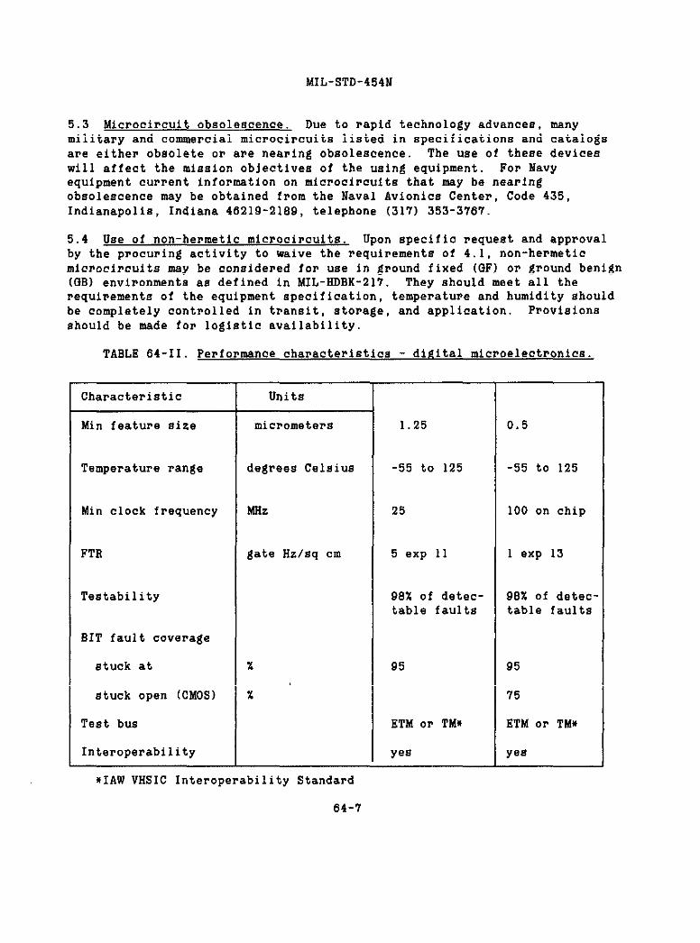
MIL-STD-454N
5.3 Microcircuit obsolescence. Due to rapid technology advances, manymilitary and commercial microcircuits listed in specifications and catalogsare either obsolete or are nearing obsolescence. ‘The use of these deviceswill affect the mission objectives of the using equipment. For Navyequipment current information on microcircuits that may be nearingobsolescence may be obtained from the Naval Avionics Center, Code 435,Indianapolis, Indiana 46219-2189, telephone (317) 3S3-3767.
5.4 Use of non-hermetic microcircuits. Upon specific request and approvalby the procuring activity to waive the requirements of 4.1, non-hermeticmicrocircuits may be considered for use in ground fixed (GF) or ground benign(GB) environments as defined in MIL-HDBK-217. They should meet all therequirements of the equipment specification, temperature and humidity shouldbe completely controlled in t~ansit, storage, and application. Provisionsshould be made for logistic availability.
TABLE 64-II. Performance characteristics - digital microelectronics.
Characteristic
Min feature size
Temperature range
Min clock frequency
FTR
Testability
BIT fault coverage
stuck at
stuck open (CMOS)
Test bus
Interoperabi1ity
Units
micrometers
degrees Celsius
MHz
gate Hz/sq cm
1.25
-55 to 125
25
5 exp 11
98% of detec-table faults
95
ETM or TM*
yes
0.5
-55 to 125
100 on chip
1 exp 13
98% of detec-table faults
95
75
ETM or TM*
yea
*IAW VHSIC InteroperabilityStandard
64-1

MIL-STD-454N
5.5 Testability. New and upgraded systems should exploit chip levelbuilt-in-test features to enhance the testability and operationalavailability of the module or system. When advanced digital modules orboards are developed, microcircuits incorporating the VHSIC ETM-BUS on VHSICTM-BUS should be used. (See VHSIC IntenoperabilityStandards.)
5.6 Life cycle cost evaluation. The following factons should be consideredin esti~ting life cycle costs associated with selection ot microcircuitdevices or technologies! a) effect of built-in-test on repain,maintainability, operational availability, and reconfigurability; and b)value of VHDL descriptions of chips, modules, and boards in resupply,multiple source development, and design upgrade.
5.7 ASIC Documentation Reference. Data Item Description, DI-EGDS-80811,provides the documentation preparation and delivery instructions for ASIC
64-S

MIL-STD-454N
REQUIREMENT 65
CABLE, COAXIAL (RF)
1. PurDose. This requirement establishes criteria for the #election andapplication of coaxial radio frequency (rf) cable.
2. Documents applicable to Requirement 65!
MIL-C-17 Cable, Radio Frequency, Flexible and Semirigid, GeneralSpecification for
MIL-L-38Q0 Lines, Radio Frequency Transmission (Coaxial, AirDielectric)
MIL-C-22931 Cable, Radio Frequency, Semirigid, Coaxial, Semi-AirDielectric, General Specification for
MIL-C-23S06 Cable, Radio Frequency, Coaxial, Semirigid, FoamDielectric, General Specification fon
MIL-HDBX-216 RF Transmission Lines and Fittings
3. Definitions. Mot applicable.
4. Requirements
4.1 Cable selection. Selection of coaxial cable shall be in accordance withMIL-C-1’?,MIL-L-3S90, MIL-C-22931 or MIL-C-23S06. Other types of cable maybe used provided they are selected from specifications acceptable for thespecific application and approved by the procuring activity.
*4.2 ADDlication restriction. Cablea with polyvinyl chloride insulationshall not be used in aerospace applications. Use of these cables in anyother application requires prior approval by the proauring activity.
5. Information for guidance only
5.1 ADDli Cati OII Euidance. MIL-HDBK-216 may be used as a technioalinformation guide to applications of transmission lines and fittings.
5.2 Critical circuits. FOIIuse above 400 MHz and in cnitical nf circuits,elements such as environmental requirements, short leads, and groundingshould be considered in design application, along with critical electricalcharacteristics such ag attenuation, capacitance, and structural return10ss
65-1
REQUIREMENT 6515 December 19S9

MIL-STD-454N
REQUIREMENT 1313
CABLE, MULTICONDUCTOR
1. Puruose. This requirement establishes criteria for selection andapplication Of eledtpicd multiconductor cable for use within electronicequipment.
*2. Documents aDDliCable to Requirement 66:
QQ-W-343MIL-C-1’Y
MIL-C-442MIL-C-3432
MIL-W-50B6
MIL-W-5845MIL-W-5846MIL-W-590BMIL-C-70’78
MIL-w-e777
MIL-C-13777
MIL-W-16878MIL-C-19547MIL-W-22759
MIL-C-23437MIL-C-24640
MIL-C-24643
MIL-W-25038
MIL-C-270’72MIL-C-2’Y500MIL-C-49035
MIL-C-55021
Wire, Electrical, Copper (Uninsulated)Cables, Radio Frequency, Flexible and Semirigid, GeneralSpecification forCable (Wire), Two Conductor, ParallelCable (Powen and Special Punpose) and Wire, Electrical (300and 600 Volts)Wire, Electric, Polyvinyl Chloride Insulated, Copper orCopper AlloyWire, Electrical, Iron and Constantan, ThermocoupleWire, Electrical, Chromel and/or Alumel, ThermocoupleWire, Electrical, Copper and Constantan, ThermocoupleCable, Electric, Aerospace Vehicle, General SpecificationforWire, Electrical, Silicone-Insulated,Copper, 600 Volt,200”CCable, Special Purpose, Electrical: General SpecificationforWire, Electrical, Insulated, General Spe@ifiaationCable, Electrical, Special Purpose, Shore UseWire, Electric, FluoPopolymer-In8ulated, Copper orAlloyCable, Electrical, Shielded PairsCable, Electrical, Lightweight, for Shipboard Use,
for
copper
QeneralSpecification for
Cable and Cond, Electrical, Low Smoke, for Shipboard Use,ffeneralSpecification forWire, Electrical, High Temperature and Fire Resistant,AircraftCable, Special Pu~pose, Electrical, MulticonductorCable, Electrical, Shielded and Unshielded, AerospaceCable, Power, Electrical (Flexible,Flat, Unshielded] (RoundConductor), General Specification forCable, Twisted Pairs and Triples, Internal Hookup, GeneralSpecification for
66-1
REQUIREMENT 6630 June 1992

MIL-STD-454N
MIL-W-81044 Wire, Electric, Crosslinked Polyalkene, CrosalinkedAlkane-imide Polymer, or Polyarylene Insulated, Copper orCoPPen Alloy
MIL-W-81381 Wire, Electric, Polyamide-Insulated, Copper OF Copper A11oYASTM A580-90 Wire, Steel, Stainless and Heat ResistingASTM B33-74 Tinned Soft or Annealed Copper Wire for Electrical Punposes
3. Definitions. Not applicable.
4. Reauirement8
4.1 Selection and application. Selection and application of multiconductorcable shall be in accordance with table 66-I.
4.’2 Solid or stranded. Either solid on stranded conductors may be used(within the restrictions of the particular wire or cable specification)except that (a) with the exception of thermocouple and flat cable wire, onlystranded wire shall be used in aerospace applications, and (b) for otherapplications stranded wire shall be used when so indiaated by the equipmentapplication. Specifically, with the exception of flat multiconductor flexiblecable, stranded wire shall be used for wires and cables which are normallyflexed in use and serviaing of the equipment, such as cables attached to themovable half of detachable connectors.
4.3 Application reStriCti0n6
4.3.1 Cable containing MIL-W-1687S wire shall not be used for Air Force orNavy aerospace applications.
4.3.2 Cables with polyvinyl chloride insulation shall not be used inaerogpace applications. Use of these cables in any other application requiresprior approval of the proauring activity.
4.3.3 MIL-W-22759 wire with only single polytetrafluoroethylene insulationused in Air Force space and missile applications shall require the approvalof the procuring activity.
4.3.4 Silver plated copper wire shall not be used in applications invalvingArmy missile systems.
5. Information for Euidance only. Not applicable.
66-2


141L-s’l’D-454N
:
. . . .
---- 66-4

MIL-STD-454N
1: I II
- j... 66-5
. . ..

MIL-STD-454N
c“,
.
-.1 ml
66-6

MIL-STD-454N
REQUIREMENT 67
MARKINQ
1. Purpose. This requirement established criteria for external and intermalmarkings on equipment, assemblies and component parts. Marking for safety,shipping and handling is not within the scope of this requirement.
2. Documents applicable to Requirement 67:
L-S-300
MIL-M-13231MIL-P-15024MIL-N-18307
MIL-S-81963
MIL-STD-12
MIL-STD-130MIL-STD-155MIL-STD-195MIL-STD-196MIL-STD-280
MIL-STD-411MIL-STD-7B3MIL-STD-1189MIL-STD-1285IEEE 200-1975
Sheeting and Tape, Refletting, Nonexposed Lens, AdhesiveSackingMarking of Electronic ItemsPlate, Tags and Sands for Identification of EquipmentNomenclature and Identification for Electronic, Aeronauticaland Aeronautical Support Equipment, Including Ground SupportEquipmentServo-Components Precision Instrument, Rotating, CommonRequirements and Tests, General Specification forAbbreviations for Use on Drawings, Specifications, Standardsand in Technical Documents.Identification Marking of U.S. Military PropertyJoint Photographic Type Designation SystemMarking of Connections for Electrical AssembliesJoint Electronics Type Designation SystemDefinitions of Item Levels, Item Exchangeability, Models, andRelated TermsAircrew Station SignalsLegends for Use in Airc~ew StationE and on Airborne EquipmentBar Code Symbology StandardMarking of Electrical and Electronic PartsElectrical and Electronic Parts and Equipments, ReferenceDesignations for
3. Definitions. Not applicable.
4. Reauiremente
4.1 Patent information. At the manufacturer’s option, patent information maybe included on equipmant, subject to the following restrictions:
a. The identification plate may contain patent information when approved bythe procuring activity.
b. The location of and method used to mark patent information shall notconflict with any specified equipment requirements, such as ma~king,enclosure integrity, control and indicator locations, etc.
REQUIREMENT 6767-1 20 September 19SS

MIL-STD-454N
c. Patent information shall not be located on or in equipment having asecurity classification of confidential or higher, with the exception thatpatented items used in security classified equipment, when marked, shall bemarked in such a manner that patent information will be visible only when theitem is removed or di8a8sembled fo~ repair or replacement.
4.’2 SymboioQ
4.2.1 Reference desi~nations. Except for external connectors and cables,reference designations shall be employed to identify the location of eachitem for its particular circuit application. The identificationand markingof reference designators for parts and equipment shall be in accordance withIEEE ‘200.On subminiatunized assemblies, such as printed or etched boards orother forms of assembly where space is at a premium, the referencedesignations need not be mmked. In lieu thereof, reference designationmarking shall be shown by means of pictorial diagrama, line drawings,photograph , or other media to provide for circuit identification (by meansof reference designations) in the appropriate handbooks fon the equipment. Itshall not be mandatory to mark the reference designations of parts innonrepairable subassemblies. Connectors may be further identified on thatside of the panel to which the mating connector attaches, by a name denotingthe function of tbe cable attached thereto. External cables shall be assignedreference designations W1, W2, etc, in accordance with IEEE 200. Thenumerical portions of the reference designations shall be consecutive, wherepracticable.
4.‘2.2 Abbreviations and legends. Abbreviations and legends shall confonm toMIL-STD-12, MIL-STD-411, or MIL-STD-783, as applicable.
4.3 Marking methods. Equipment, parta and assemblies shall be permanentlymarked or identified. Permanency and legibility shall be as required inMIL-STD-130.
4.3.1 Direct marking. Markings may be applied dinectly to a part or anassembly by die or rubber stamping, etching, eng~aving, molding, casting,forging, decalcomania transfer, stenciling, on silk sareening.
4.3.2 Plates. Information and identificationplates shall conform to andshall be marked in accordance with MIL-P-15024.
4.3.2.1 Identification (ID) Dlates. The ID plate shall be fastened in such amanner as to remain firmly affixed throughout the normal life expectancy ofthe item to which it is attached. Type G, adhesive-backed metal, ID platesshall be used on hermetically sealed items, magnesium cases, or othar itemswhere mounting of a plate by mechanical fasteners is impractical.
67’-2

MIL-STD-454N
4.3.2.2 ID plate location. Plates shall be located so that they are notobscured by other parts.
4.3.3 Markinficables, cords and wires. The following methods shall be usedto mark cables, co~ds and wires:
a. Molded on the cable or cord.
b. Stamped on the cable, cord or wire.
c. Bands in accordance with MIL-P-15024, securely attached or captivated.
d. Adhesive tag or tape that wi11 withstand the applicable environmentalrequirements.
4.4 Bar codes. Bar codes shall conform to MIL-STD-1189.
4.5 Type designated items. Each item which is type designated in accordancewith MIL-STD-196 or MIL-STD-135 shall contain an identificationmarking inaccordance with MIL-N-1B307 for Navy and AiP Force on MIL-M-13231 for Army.These items are systems (electrical-electronic), sets, groups, and some unitsand assemblies, as defined in MIL-STD-280.
4.6 Fuse holders. The current rating of fuses shall be marked adjacent tothe fuse holder. In addition, ‘SPARE- shall be marked adjacent to each sparefuse holder.
4.7 Connections. Marking adjacent to plugs, jacks and other electricalconnectors shall identify the connected circuits to preclude crossconnections. The connections to electrical pants such aa motors, generatorsand transformer shall be marked in accordance with MIL-STD-195.
4.8 Servo-component connection and mankings. Servo-component marking andconnection identification shall conform to MIL-S-81963.
4.9 Controls and indicating devices. Ma~kings shall be provided on the frontof each exterior and interior panel and panel doo~, also on control mountingsurfaces of each chassis, subpanel, etc, to clearly (though necessarilybriefly) designate the functions and operations of all controls, fuses, andindicating devices mounted thereon, protruding through, or available throughaccess holes therein. All markings shall be located on the panel on chaasisin correot relationship to the ~egpective designated items.
4.10 Sockets. The chassis shall be marked to identify both sockets andparts, modules or assemblies to be plugged into the sockets. The side of thechassis upon which items are plugged into sockets shall be marked, adjacent
67-3

MIL-STD-454N
to each socket, with the reference designation for the item. The reverse sideof the chassis shall be marked, adjacent to each socket, with the referencedesignation used in the circuit diagram and table of parts to identify thesocket itself If space does not permit marking of reference designationsfor sockets and parts, modules, or assemblies mounted in sockets, a locationdiagram shall be placed where it is visible when viewing the chassis, andshall display the mmkings described herein.
4.11 Cables, cords and wires. All cables, cords and wires which requiredisconnection to remove units for senvicing and maintenance shall be uniquelyidentified.
4.12 Printed wiring boards. Markings on printed wiring boa~da shall notinterfere with electrical opemation. When ink is used, it shall benon-conductive. Markings shall be considered when leakage (creepage]distances are determined.
4.13 Replaceable parts and assemblies. Replaceable parts and assembliesshall be marked for identification in accordance with MIL-STD-1285 orMIL-STD-130, as applicable.
4.14 Programmable itenw Equipments which are software programmable shallindicate the identifying number and revision of the software program whichhas been loaded into memory. The preferred method is to pmovide either alocal or a ~emote display which ig under the control of the software program.HoWaver, when the uae of a display is not practical, the equipment enclosuneshall be marked with the information as follows:
4.14.1 Preproduction and production equipment shal1 be marked with theidentifying number and revision of the software program. The identifyingnumber shal1 be preceded by the words “software program”
4.14.2 Development equipment shall be marked in a manner similar topreproduction and production equipment, except that means shall be providedto easily change the revision letter by the use of a matte surface for handmarking or by using selfadhesive labels. The u8e of the revision letter ornumber and a patch letter or number is permissible.
4.14.3 The marking requirement doea not apply when changes to the softwareprogram are accomplished by making a hardware change (for example, when thesoftware program resides in fusible link devices such as PRObfa) In suchcaEea, the marking requirements applicable to a handwane change shall apply.
5. Information for j?uidan@eonly
5.1 RefIective msnke~s. Where reflective msrkers are required reflectivepolyester tape in accordance with L-S-300 may be used.
67-4

MIL-STD-454!4
REQUIREMENT 68
READOUTS AND DISPLAYS
1. Purpose. This requirement establishes criteria for the selection ofneadouts and displays.
*’2.Documents applicable to Requirement 68:
MIL-D-28803 Display, Optoelectronic, Readouts, Segmented, GeneralSpecification for
MIL-D-87157 Displays, Diode, Light Emitting, Solid State, GeneralSpecification for
3. Definitions. Readouts and displays are devices which are designedpnimar.ily to convert electrical information into alphanumeric on symbolicpresentations. These devices may contain integrated circuitry to function asdecode~s or drivers.
4. Requirements
*4.1 Optoelectronic t!me readouts. Incandescent type readouts shall conformto MIL-D-28803.
4.2 Lifihtemittinfidiode displays. Visible light emitting diode displaysshall conform to MIL-D-87157, quality level A or B.
5. Information for .@idance only. Not applicable.
68-1
REQUIREMENT 6830 June 1992

MIL-STD-454N
REQUIREMENT 69
INTERNAL WIRING PRACTICES
1. Purpose. This requirement establishes criteria for internal wiringpractices.
2. Documents armlicable to Requirement 69:
MIL-T-152
MIL-V-173
MIL-I-631
MIL-T-713MIL-I-3158
MIL-I-3190
MIL-T-7926
MIL-I-22076
MIL-I-23053
MIL-S-23190
MIL-T-43435MIL-STD-108
MIL-STD-1130
Treatment, Moisture and Fungus Resistant, of Communications,Electronic and Associated Electrical EquipmentVarnish, Moisture-And-FungusResistant (For Treatment ofCommunications, Electronic, and Associated Equipment)Insulation, Electrical, Synthetic-Resin Composition,Non-RigidTwine, Fibrous: Impregnated, Lacing and TyingInsulation Tape, Electrical Qlass-Fiber (Resin Filled); andCord, Fibrous-GlassInsulation Sleeving, Electrical, Flexible, Coated, GeneralSpecification for
Terminals, Lug: Splices, Conductors: Crimp Style, Copper,General Specification forInsulation Tubing, Electrical, Non-Rigid, Vinyl, Very LowTemperature GradeInsulation Sleeving, Electrical, Heat Shrinkable, GeneralSpecification forStraps, Clamps, and Mounting Hardware, Plastic and Metal forCable Harness Tying and SupportTape, Lacing and TyingDefinition of and Basic Requirements for Enclosure forElectric and Electronic EquipmentConnations, Electrical, Solderless, Wrapped
3. Definitions. Not applicable.
4. Requirements
4.1 Clearance and leakage (c~eemge) di=tancen. Clearance between solderconnections or bare conductorB, such as on terminal stnipg, stand offs onBimilan connections, shall be such that no accidental contact can occurbetween adjacent connections when subjected to service conditions specifiedin the equipment specification. For electrical clearance and leakagedintancea, see table 69-1.
4.2 ThrouEh hole protection. Whenever wires are run through holes in metalpartitions, shields, and the like, less than 3 mm in thickness, the holes
REQUIREMENT 6916 February 1989
69-1

MIL-STD-454N
shall be equipped with suitable mechanical protection (grommet) ofinsulation. Panels 3 mm or more in thickness either shall have grommets orshall have the hole edges rounded to a minimum radius of 1.5 mm:
TABLE 69-I. Electrical clearance and leakaEe (creepafie)distances.
Voltage ao Clearance Leakage Distances (mm)(rnw) or dc Condition (mm) Enclosure I Enclosure II
To 150 A 1.5 1.5 1.5B 3 3 6c 6 9.5 19
150-300 A 1.5 1.5 1.5B 3 3 6c 6 12.5 19
300-600 A 1.5 3 3B 3 6 6c 6 12.5 19
600-1000 A 3 9.5 12.5B 6 19 25c 12.5 38 50
Condition A. For use where the effect of a short circuit is limited to theunit, and where normal operating power does not exceed 50 watts.
Condition B. For use where short circuit protection in the form of fuses,circuit breakers, etc, is provided, and where normal operating power does notexceed 2000 watts.
Condition C. For use where short circuit protection in the form of fuses,circuit breakers, etc, is provided, and where normal operating power exceeds2.000wattE.
69-2

MIL-STD-454N
Enclosure 1. Enclosure I is an equipment enclosure which has no openings, orin which the openings are so constructed that drops of liquid or solidparticles striking the enclosure at any angle frOm O_ tO 15_ frOm thedownward ventical cannot enter the enclosure either directly on by strikingand running along a horizontal or inwardly inclined surface. (*Drip-proofenclosure for other than motors, generators, and similar machines” ofMIL-STD-108 meets the description).
Enclosure II Enclosure II is any equipment enclosure which affords lessprotection than enclosure 1.
4.3 Wiring arrangement. Wiring shall be arranged to permit bundling by oneor more of the following methods or permanently mounted in cable ducts.
4.3.1 Lacing. Twine shall be in accordance with Type P of MIL-T-713. Tapeshall conform to MIL-T-43435. Cordage shall be in accordance with Type SR-4.5of MIL-I-3158.
4.3.2 Binding. Tape for binding shall be as specified in MIL-T-43435.
4.3.3 Sleevintiinsulation. Sleeving insulation shall conform to MIL-I-631,MIL-I-3190, MIL-I-22076, or MIL-I-23053.
4.3.4 WrauDinE and tvinf. Plastic devices for wrapping and tying of wipesshall conform to MIL-S-23190.
4.4 Solderless wraurmd wipe connections. Soldenless wrapped wire connectionsshall be in accordance with MIL-STD-1130. Procuring activity approval isrequired for Navy ai~borne and Army missile applications.
4.5 claIIIDed connections. In no case shall electrical oonnectiona depend uponwi~en, lug=, terminals, and the like, clamped between a metallic member andan insulating metenial of other than a ceramic on vitric nature. Suchconnections shall be clamped between metal members, preferably, such as anassembly of two nuts, two washer= and a machine screw.
4.6 Connectors, insulation sleeving. Unpotted connectors furnished asintegrml wired in parts of artioles of equipment shall have a piece ofinsulating tubing placed over each wire in the connector. The tubing shall belong enough to cover the contact and at least 12.5 mm of insulation of thewire attached to it; but in no case shall the length of the tubing exceed 50mm. The minimum length of 12.5 mm may be reduced to 4.5 mm where restrictedvolume does not permit longer tubing (such as in miniaturized electronicsubassemblies). The tubing shall fit tightly over the contact or be tied8ecunely enough so that it will not slide off. If bare wine is used, thetubing shall be long enough to extend at least 6 mm beyond the contact, metal
69-3

MIL-STD-434N
shell or clamp, whichever projects the farthest. This paragraph does notapply to connectors with body insulated crimp-on contacts, to insulationdisplacement connectors or mae8 soldered flat cable connectors, nor does itaPPIY to wire wrapped connectors in accordance with MIL-sTD-1130.
5. Information for Euidance only
5.1 Wiring arrangement. All wiring should be arranged in a neat andworkmanlike manner. The use of preformed cableg and wiring harness ispreferred to the point-to-point method of wiring. Wires should be bundled androuted to minimize electrical coupling. Unless suitably protected, wire orcable attached to sensitive circuit= should not be placed adjacent to adisturbing circuit.
5.2 Internal wirinfi.Stranded wire is preferred: however, solid wire may beused in the equipment, provided such wire is so insulated or held in placethat it does not fail or show excessive motion likely to result in failurewhen the equipment is subjected to vibration and #hock encountered under thespecified Eervice conditions. An uninterrupted wire is preferable to ajunction. The following descending order of preference exists when junctionsare used, and the choice of the listed junctions should be determined byconsideration of reliability factors, maintenance factors, and manufacturingprocedural:
a. Permanent splices.
b. Bolted connections
c. Connectors.
5.3 WirinE Protection. The wiring should be secured and protected againstchafing due to vibration or movement (such as slide out racks or drawers)For securing of wiring, polyamide clamps or wrapping and tying devices withintegral mounting facilities or adhesive bonding are preferred. Metal clamps,if used, 8hould be cushioned. Individual conductors thus secured should lieessentially parallel.
5.4 Cable ducts. Where cable ducts are employed, provisions Ehould he madefor the removal of any wire that !OEYbecome faulty. For example, covers maybe employed at intervals to aid in the removal of a faulty wire.
5.5 Bend radius. The bend radius of polyethylene cable should not be lessthan five times the @able diameter.to avoid establishing a pemanent set inthe cable
69-4

MIL-STD-454N
5.6 Sleevinfi.Flexible plastic sleeving, either nonflammable, selfextinguishing, or flame retardant, should be used on cables subject toflexing, such as panel door cables. The sleeving should be secured undercable clamps at each end, and the cable should be formed and secured so thatthe cable will not be subject to abrasion in its normal flexing motion. Incases where abrasion cannot be avoided, additional protection should beprovided
5.7 Panel door cables. Wiring to parts on a hinged door should be in asingle cable if possible, arranged to flex without being damaged when thedoor is opened and closed.
5.8 Slack. Wires and cable should be as short as practicable, except thatsufficient slack should be provided to:
a. Prevent undue stress on cable fores, wires and connections, includingconnections to resiliently supported parts,
b. Enable parts to be removed and replaced during servicing withoutdisconnecting other parts,
c. Facilitate field repair of broken or cut wires,
d. Permit units in drawers and slide out racks to be pulled out to the limitof the slide or support travel without breaking connections Units which aredifficult to connect when mounted, should be capable of movement to a moreconvenient position for connecting and disconnecting cables. When drawers onracks are fully extended and rotated, if rotatable, the @able bend radiusshould not be less than three times the cable assembly diameter. when flatmolded cable assemblies am used, the bend radius should not be less than tentimes the cable assembly thickness,
e. Permit replacement of the connected part at least twice. Exceptions tothis provision are cases where rf leads must be as short as possible forelectrical reaaons, when fixed path rotating iH apecified, on the amount ofslack is limited”by space available,
f. Ensure freedom of motion of lugs or terminals normally intended to havecome degree of movement.
5.9 SuDDor.t. Wire and cable should be properly supported and secured top~event undue st~eng on the conductors and terminals and undue change inposition of the wire or cable duning and after subjection of the equipment tospecified 8ervice conditions, or after service or nepai~ of the equipment in
69-5

MIL-STD-454N
a normal manner. When shielding on wire or cable is unprotected by an outerinsulation, adequate support is necessary to prevent the shielding fromcoming in contact with exposed terminals or conductors. Twine or tape shouldnot be used fom securing wire and cable.
5.10 Cable and harness design. Cables and separable harnesses should be ofthe two-connector type. The two connectors should be of the same number ofcontacts and all contacts should be wired point-to-point (i.e., pin 1 to pin1, pin A to pin A, or pin 1 to pin A and up in sequence) A minimum number ofconneator types and contact configurations within a type should be usedconsistent with non-crosmating requirements and circuit and spareconsiderations.
5.11 Solderiess crimp connections. Solderless crimp connections should meetthe following requirements:
a. Insulated, solderless lugs are pneferred and should conform to MIL-T-7928.
b. Where thermal or other considerations prevent the use of insulated lugs,non-insulated solderless lugs conforming to MIL-T-7Q28 should be used,provided they are covered with an insulating sleeve.
5.12 Fungus Protection. Prior to attachment of terminals to prepared lengthsof cables which contain matenials that will support fungus, the ends shouldbe pnotected against entrance of moisture and fungus by treatment with afungicidal varnish conforming to MIL-V-173 in accordance with MIL-T-152.
69-6

MIL-STD-454N
REOUIREMENT 70
ELECTRICAL FILTERS
1. Purpose. This requirement establishes criteria for the selection andapplication 0+ electrical filters.
2. Document applicable to Requirement 70:
MIL-STD-1395 Filters and Networks, Selection and Use o+
3. Definitions. Not applicable.
4. Requirements. Electrical filters shall be selected and applied inaccordance with MIL-STD-1395.
5. Information for quidance only. Not applicable.
70-1
REQUIREMENT 7020 September 1988
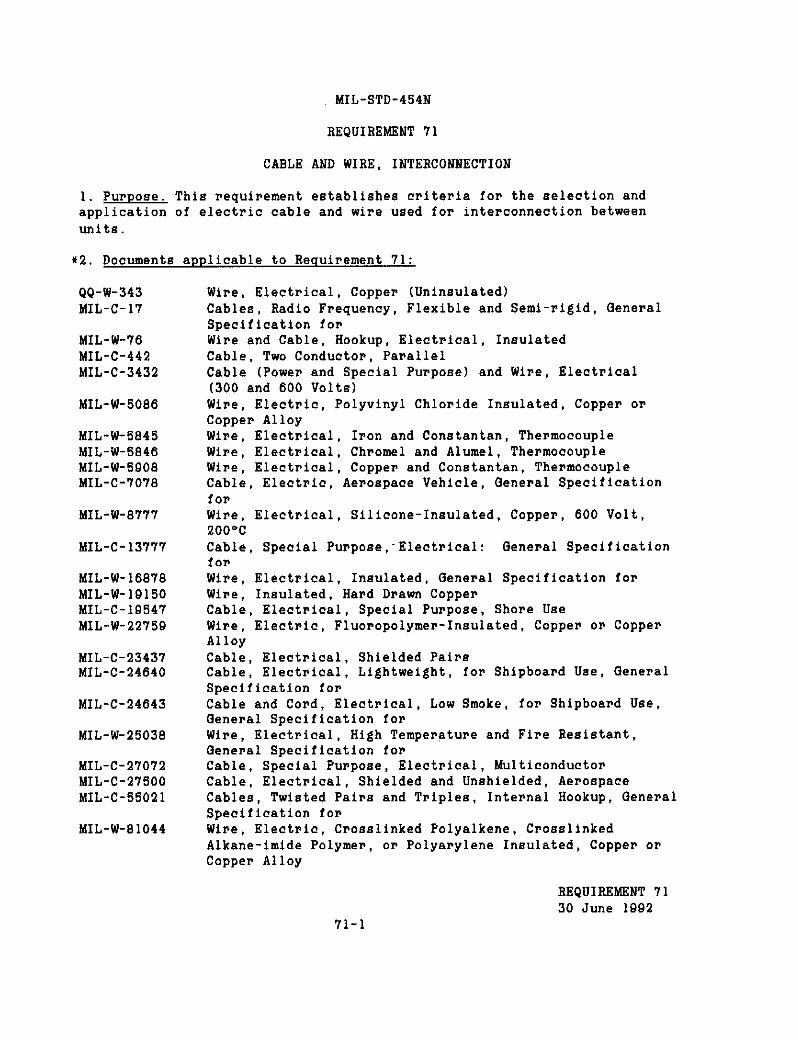
MIL-STD-454N
REQUIREMENT 71
CABLE AND WIRE, INTERCONNECTION
1. PurDose. This requirement establishes criteria for the selection andapplication of electric cable and wire used for interconnection betweenunits.
*2. Documents applicable to Requirement 71:
QQ-W-343MIL-C-17
MIL-W-76MIL-C-442MIL-C-3432
MIL-W-5086
MIL-W-5845MIL-W-5846MIL-W-5908MIL-C-’7O78
kfIL-W-8’i7’/
MIL-C-13777
MIL-W-16878MIL-W-19150MIL-C-1Q547MIL-W-22759
MIL-C-23437MIL-C-24640
MIL-C-24643
MIL-W-25038
MIL-C-27072MIL-C-27500MIL-C-55021
MIL-W-81044
Wire, Electrical, Copper (Uninsulated)Cables, Radio Frequency, Flexible and Semi-rigid, GeneralSpecification forWire and Cable, Hookup, Electrical, InsulatedCable, Two Conductor, ParallelCable (Power and Special Purpose) and Wire, Electrical(300 and 600 Volts)Wire, Electric, Polyvinyl Chloride Insulated, Copper orCopper Al10Y
Wire, Electrical, Iron and Constantan, ThermocoupleWire, Electrical, Ch~omel and Alumel, ThermocoupleWine, Electniaal, Copper and Constantan, ThermocoupleCable, Electric, Ae~ospa@e Vehicle, General Specificationfor
Wire, Electrical, Silicone-Insulated,Copper, 600 Volt,200”CCable, Special Purpose,-Ele@tnical: QenePal SpecificationfOPWire, Electrical, Insulated, General Specification forWine, Insulated, Hard Drawn CoppemCable, Electrical, Special Purpose, Shore UseWire, Electnic, Fluoropolymer-In8ulated, Copper or CopperAlloyCable, Electrical, Shielded PairsCable, Electrical, Lightweight, for Shipboard Use, GeneralSpecification forCable and Cord, Electrical, Low Smoke, for Shipboard Use,General Specification forWire, Electrical, High Temperature and Fire Resistant,QenePal SpecifIcation forCable, Special Purpose, Electrical, MulticonductorCable, Electrical, Shielded and Unshielded, AerospaceCables, Twisted Pairs and Triples, Internal Hookup, GenePalSpecification fopWire, Electric, Cmosslinked Polyalkene, CrosslinkedAlkane-imide Polyme~, or Polyarylene Insulated, Coppen OPCopper Alloy
REQUIREMENT 7130 June 1992
71-1

MIL-STD-454N
MIL-W-81381MS25471
MS2711O
ASTM A580-90ASTM B33-74
3. Definition
Wire, Electric, Polyamide-Insulated, Copper or Copper A11oYWire, Electrical, Silicone Insulated, Copper, 600 Volt,200°C, Polyester JacketWire, Electrical, Silicone Insulated, Copper, 600 Volt,200”C, FEP JacketWire, Steel, Stainless and Heat ResistantTinned Soft or Annealed Copper Wine for Electrical Purposes
3.1 Interconnectingwire. Insulated, single-conductor wire used tocarry electric current between units.
3.2 Interconnecting cable. Two or more insulated conductors contained in acommon covering on one or more insulated conductors with a gnoss metallicshield outer conducto~ used to carry electrical current between units.
4. Reauiremente
4.1 Wire selection. Selection of wire for interconnectionbetween unitsshall be in accordance with table 71-1.
4.2 Multiconductor cable selection. Selection of multiconductor cable forinterconnectionbetween units shall be in accordance with table 71-11.
4.3 ADpli Cati OII r.2StPi Cti011S
4.3.1 MIL-W-76 shall be used for Army application only (see 4.3.3)
4.3.2 MIL-W-16878 Eball not be used for Air Force or Navy aerospaceapplications.
4.3.3 Cable or wire with polyvinyl chloride insulation shall not be used inaerospace applications. Use of these wires on cables in any othenapplication requires prior approval of the procu~ing activity.
4.3.4 MIL-W-22759 wire with only single polytetrafluoroethylene insulationused in Air Force space and missile applications #hall require the approvalof the procuring activity.
4.3.5 Use of aluminum wire requireg specific approval by the procuringactivity.
4.3.6 Silver plated copper wine shall not be used in applications involvingArmy missile systems.
71-2

MIL-STD-454N
5. Information for fiuidanceonly
3.1 Pulsed or rf signals. All interconnectingcables carrying pulsed or rf#ignals should be coaxial cables or waveguides and should be terminated,when possible, in the charactenistia impedance of the t~anamitting media.
71-3

MIL-STB454N
71-4

MIL-STD-454N
71-5

MIlA71’D-454N
71-6

71-7

MIL-ST’tF454N
~.
.1
>1
71-8

MIL-STD-454N
A_LL

NIL-STD-454N
I
71-10 ‘.

71-11

iVIL-S’JD--454N
J-lL__li “ “ “71-12

MIL-STD-454N
REQUIREMENT 72
SUBSTITUTABILITY
1. Purpose. This requirement establishes criteria for the selection andapplication of substitute parts.
2. Documents armiicable to Requirement 72!
MIL-STD-4S0 COnfiguPatiOn COntFOl - Engineering Changee, Deviation6 andWaivers
MIL-sTD-9a3 Substitution List for Micnocincuits
3. Definitions. Not applicable.
4. Requirements
4.1 Militarv Darts. Substitution of parts covered by military specificationsand standands that include substitutability or supersession information isacceptable Thi6 type substitution does not require submission of engineeringchange proposals, deviation8, OF waivens in accordance with MIL-STD-480.
4.2 Commercial Darts. When the equipment design specifies a commercial part,a military specification part may be substituted when the form, fit andfunctional characteristics of the military part ame equal to on better thanthoge of the specified commercial part under equivalent environmentalconditions. Applicable microcircuits are listed in MIL-STD-9B3. Othersubstitutions are subject to applicable configu~ation cont~ol procedures ofMIL-STD-480.
4.3 Unavailable Darts. When the equipment design specifies a part that isunavailable, a substitute part which meets the form, fit and functionalcharacteristics of the specified pa~t may be substituted after approval isobtained from the applicable procuring activity. Applicable microcircuits arelisted in MIL-STD-983 Other substitutions are subject to the applicableconfiguration control pnocedunes of MIL-STD-480.
4.4 Initial aualifi@ation/reliabilitydemonstration. Substitute parts withquality/reliabilitycharacteristics superior to those specified in the partslist shall not be used in equipment to be subjected to initial qualificationor demonstration tests.
5. Information for guidance onlv. Not applicable.
REQUIREMENT 7216 December 1989
72-1

MIL-STD-454N
REQUIREMENT 73
STANDARD ELECTRONIC MODULES
1. Purnose. This requirement establishes criteria for the selection andapplication of standard electronic modules (sEM).
*2. Documents apDli@able to Requirement 73!
MIL-M-2a787 Modules, Standand Elect~oni@, General Specification forMIL-STD-1378 Requirements for Employing Standard Electronic ModulesMIL-STD-1389 Design Requirements for Standard Electronic ModulesMIL-KDBK-246 Program Managers Guide for the Standard Electronic Modules
Program
3. Definitions. Not applicable.
4. Requirements. Requirements for the design and application of standardelectronic modules shall be in accordance with MIL-STD-1389 andMIL-STD-1378. Standard electronic modules shal1 be in accordance withMIL-M-28787
*5. Information for guidance onlv. Guidance for program and acquisitionmanagers as to the applicability of SEME for specific system/equipmentacquisitions is provided in MIL-SDBK-246.
REQUIREMENT 7330 June 1992
73-1

MIL-STD-454N
REQUIREMENT 74
GROUNDING, BONDING, AND SHIELDING
1. Purpose. This requirement establishes grounding, bonding, and ehieldinginterface criteria for installation of electronic equipment.
2. Documents applicable to Requirement 74!
MIL-B-5087 Bonding, Electrical, and Lightning Protection, for AerospaceSystems
MIL-STD-18S-124 Grounding, Bonding, and Shielding for Common LongHaul/Tactical Communication Systems Including (hound BasedCommunications-ElectronicsFacilities and Equipments
MIL-STD-131O Shipboard Bonding, Grounding, and Other Techniques forElectromagnetic Compatibility and Safety Shielding
MIL-STD-1542 Electromagnetic Compatibility (EMC) and flroundingRequirements for Space System Facilities
MIL-STD-1S57 Grounding, Bonding, and Shielding Design PmactiaesMIL-HDBK-419 Ground, Bonding, and Shielding for Electronic Equipments and
Facilities
3. Definitions. Not applicable.
4. Requirements. Grounding, bonding, and shielding provisions shall beinco~porated into equipment design, as necessary, to enable installation ofequipment into the applicable platform or faaility. The g~ounding, bonding,and shielding installation and interface requirements are specified in thefollowing documents:
Aerospace ground support facilities MIL-B-5087Aircraft and space vehicles MIL-B-5087Ground telecommunicationsC-E equipment MIL-STD-18S-124Shipboard equipment MIL-STD-131OGround space systems facilities MIL-STD-1542Other Army ground equipment MIL-STD-1S57
5. Infonmation for fuidance only. Extensive guidance for grounding, bondingand shielding may be found in MIL-HDBK-419.
REQUIREMENT 7415 December 19S9
74-1

MIL-STD-454N
REQUIREMENT 75
ELECTROSTATIC DISCHARGE CONTROL
1. Purpose. This requirement offers guidance regarding the handling andcontrol of electronic parts and assemblies that are susceptible to damage ordegradation from electrostatic discharge. IT DOES NOT ESTABLISH REQUIREMENTSAND MUST NOT BE REFERENCED IN CONTRACTUAL DOCUMSNTS. Requirements for theeste.blishmentand implementation of an electrostatic discharge (ESD) controlprogram in accordance with MIL-STD-16S6 must be dinectly specified in thecontract or equipment specification.
‘2.Documents aDDlicable to Requirement 75:
MIL-M-3S51O Microcircuits, General Specification fonMIL-STD-SS3 Test Methods and Procedures for MicroelectronicsMIL-STD-16S6 Electrostatic Discharge Control Prog~am fop P~otection of
Electrical and Electronic Parts, Assemblies, and Equipment(excludingelectrically initiated explosive devices)
DOD-HDBX-263 Electrostatic Di#charge Control Handbook for Protection ofElectrical and Electronic Parts, Assemblies, and Equipment(excludingelectrically initiated explosive devices)
3. Definitions. Definitions of applicable terminology may be found inMIL-M-3S51O, MIL-STD-8S3, MIL-STD-16S6, and DOD-HDBK-263.
4. Requirements. Not applicable.
5. Information for Euidance onlv
5.1 ESD control program. MIL-STD-16S6 establishes the ~equirements for theestablishment, implementation,and monitoring of an ESD control program,including identificationof electrostatic discharge sensitive (ESDS) items,classification of ESD sensitivity levels, control program elements, extent ofprogram element applicability to each acquisition, protective meaau~en to beemployed in equipment design, handling, storage, and packaging of ESDS items,protected wonk a~eas, personnel t~aining, ESD audits and program reviews, andtailoring Appendix A of MIL-STD-16S6 establishes the cnite~ia and procedureton classifying ESDS parts by tegt. Appendix B of MIL-STD-1686 identifies andclase’ifies ESDS items DOD-HDBK-263 provides guidelines for the establishmentand implementation of an ESD control program in accordance with MIL-STD-16S6.
5.‘.2General guidelines for an ESD control p~ofram. Any program designed forthe prevention of ESD damage to ESDS parts and assemblies should be based onthe following considerations!
REQUIREMENT 7512 February 19SS
75-1

MIL-STD-454N
a. Identification of ESDS parts and assemblies and determination ofsensitivity
b. Minimization of static charge generation
c. Reduction of stored charges (grounding)
d. Isolation of ESDS parts (Faraday shielding and line transient protection)
e. Proper handling, storage, and transportation of ESDS paintsand assemblies
f. Personnel training and certification
g. Protected work areas.
75-2

MIL-STD-454N
REQUIREMENT 76
FIBER OPTICS
1. PuPPose. This requirement establishes the criteria for the selection,application and testin8 Of fiber Optic ~terial. devices and acces#Orie#.
2. Documents aDDlicable to Requirement 76:
MIL-STD-18B-111
MIL-STD-7Q0
DOD-STD-1678
DOD-STD-1863
DOD-STD-1864
MIL-STD-2163
MIL-c-22520/lo
DOD-D-24620
MIL-C-24621
DOD-S-24622
MIL-S-241323
MIL-H-24626optic
MIL-P-24627
MIL-P-24628
Subsystem Design and Engineering Standards for CommonLong Haul and Tactical Fiber Optics Communications
Product Assurance Program Requirements for Electronicand Fiber Optic Parts Specifications
Fiber Optic Test Methods and Instrumentation
Interface Designs and Dimensions for Fiber OpticInterconnectionDevices
Fiber Optic Symbols
Insert Arrangements for MIL-C-288’76(Navy)Environment Resisting Fiber Optic Connectors
Crimping Tool, Terminal, Hand
Detector, PIN, Fiber Optic (Metric)
Coupler, Passive, Fiber Optic, Qeneral Specificationfop (Met~i@)
Sourses, LED, Fiber Optic (Metric)
Splice, Fiber Optic Cable, General Specification for(Metric)
Harness Assemblies, Cable, Pressure Proof, Fiber
Penetrators,(for Inboard
Penetratora,
Bulkhead, Connectonized, Fiber OpticUse on Navy Ships and Subma~ines)
Hull, Connectorized, Connecto~a,Pressure Proof, Fiber Optic, Submarine
REQUIREMENT 7630 October 1991
76-1

MIL-STD-454N
MIL-S-24725
MIL-A-24726
MIL-R-24’i2’i
MIL-I-24728
MIL-M-24731
MIL-L-24732
MIL-C-24733
MIL-F-24’Y34
MIL-T-24735
MIL-M-24736
MIL-R-24737
MIL-C-28876
MIL-T-29504
MIL-F-49291
Switches, Fiber Optic, Shipboard, ElectricalNonlatching, Bypass, Multimode Cable, Standalone(Metric)
Attenuators, Fiber Optic, Shipboard, GeneralSpecification for
Rotary Joints, Fiber Optic, Shipboard (Metric),Qeneral Specification for
InterconnectionBox, Fiber Optic, Metric, GeneralSpecification fon
Multiplexer, Demultiplexers, Multiplexer ,Demultiplexers (Muldems), Frequency Division, FiberOptic, Interfaceable,Shipboard (Metric), GeneralSpecification for
Light Sources, Rigid and Flexible, Fiberscope, FiberOptic (Metric) , General Specification for
Controllers, Interface Unit, Fiber Optic (Metric),GenePal Specification for
Fiberscope, Fiber Optic (Metric), GeneralSpecification for
Transmitters, Light Signal, Analog, Fiben Optic(Metric), General Specification for
Multiplexer , Demultiplexers, Multiplexer,Demultiplexers (Muldeme), Time Division, Fibe~ Optic,Interfaceable, Shipboard (Metric), GeneralSpecification fop
Receivers, Light Signal, Analog, Fiber Optic,Shipboard (Metric), Qeneral Specification for
Connectors, Fiber Optic, Environment Resisting (forNavy Shipboard Applications)
Termini, Fiber Optic Connector, Removable
Fiber, Optical, General Specification for
76-2

MIL-C-49292
MIL-I-81969
MIL-C-83522
MIL-T-83523
MIL-M-83524
MIL-K-83525
MIL-C-83526
MIL-C-83532
MIL-M-83S33
DoD-c-a504!l
MIL-HDBK-277
MIL-HDBK-278
MIL-HDBK-282
MIL-HDBK-415systems
IEC-693-80
IEEE-STD-812-S4
3. Definitions.
MIL-STD-454N
Cable Assembly, Nonpressurized, General Specificationfor
Installing and Bemoval Tools, Electrical Contact,General Specification for
Connectors, Fiber Optic, Single Terminus, QeneralSpecification for
To018, Fiber Optic, General Specification for
Microscope, Optical, fcr Field Inspection of OpticalFibers
Kit, Portable Optical Microscope, Militarized, 200XMagnification for Field Inspection of Optical Fibers
Connector, Fiber Optic, Circular, EnvironmentResisting, Hermaphroditic, Qenenal Specification fop
Connectors, Fiber Optic
Maintenance Kit, Fiber Optic Components, GeneralSpecificationfor
Cable, Fiber Optic, Environment Resisting (fon NavyShipboard Application), General Specification for
Fiber Optic Checkout Procedure fon MilitaryApplications
System Design Guide for Applying Fiber OpticTechnology to Shipboard Systems
Fiber Optic Cable Installation Procedures
Design Handbook fon Fiber Optic Communications
Optical Fibers, Dimensions of
IEEE Standard Definitions of Terms Relating to Fiberoptics
3.1 Definitions of terminology used in fiber optics technology shall be ascontained in IEEE-STD-812.
‘76-3.

MIL-STD-454N
4. Requirements
4.1 SymboloEv. Graphic symbols for fiber optic parts for uae on engineeringdrawings, specifications, etc. shall be as contained in DOD-STD-1864.
4.2 Dimensions. Dimensions for optical fibers shall be as specified inIEC-693-80 and MIL-F-49291.
4.3 Interface deeitinsand dimensions. Standard interface designs,dimenniorm and termination types for use in fiber optic connecto~e andcoupler8 shall be a8 specified in DOD-STD-1863.
4.4 Sy8ten and subsystem desicn. Fiber optic system and subsystem designsshall be in accordance with the criteria specified in MIL-STD-188-111 (see5.1 also)
4.5 Test procedures. Standardized test procedures for fiber opticcomponents shall be as 8pecified in DOD-STD-16’Y8.
4.6 Light sources.
4.6.1 Light emittin.ediodes (LEDs). Fiber optic LED sources shall conformto the requirements of DOD-S-24622.
4.6.2 FiberscoDe liiht sources. Fiber optic light sources for nigid andflexibie fiberscopes shall conform to the requirements of MIL-L-24’Y32.
4.7 splices. Fiber optic splices shall confo~m to the nequinements ofMIL-S-24623.
4.8 Cables. Fiber optic cable8 shall conform to the requirements ofDOD-C-85045.
4.9 Cable assemblies. Cable assemblies shall conform to the requirements ofMIL-C-4929’2
4.10 Harness assemblies. Fiber optic harness assemblies shall conform tothe requirements of MIL-H-24626.
4.11 Connectors. Fiber optic connectors shall conform to the requirementsof MIL-C-288’Y6, MIL-C-83522, MIL-C-83526 OXIMIL-C-83532. Insert arrangementsfor MIL-C-28876 connectors shall conform to MIL-STD-2163. Removableterminale for fiber optic connectors 8hall conform to MIL-T-2Q504.
4.12 Penetr.atOPs. Fiber optic penetrators (hull on bulkhead) shall conformto the requirements of MIL-P-24627 or MIL-P-24628.
76-4

4.13 Detectors.DOD-D-24620.
4.14 cOuDlers.MIL-C-24621.
MIL-STD-454N
Fiber optic detectors shall conform to the requirements of
Fiber optic couplers shall conform to the requirements of
4.15 Rotary joints. Fiber optic rotary joints shall conform to the~equivemente of MIL-R-24727.
4.16 Interconnection boxee. Fiber optic inte~connectionboxes shall conformto the requi~ement6 of MIL-I-24728.
4.17 MultiDlexens and demultiDlexers.
4.17.1 Freauenov division. Fiber optic frequency division multiplexer anddemultiplexers shall conform to the
4.17.2 Time division. Fiber opticdemultiplexers shall conform to the
4.18 Controllers, interface unit.the nequinementg of MIL-C-24733.
~equirements of MIL-M-24731
time division multiplexer andrequirements of MIL-M-24736.
Fiber optic controller shall conform to
4.19 Fiberscoues. Fiber optic ‘fiberscopes shall conform toof MIL-F-24734.
4.20 Transmitters. analod. Fiber optic analog transmittersthe requirements of MIL-T-24735.
4.21 Receivers, analog. Fiber optic analog receivers shallrequirements of MIL-R-2473’Y.
the requirements
shall conform to
conform to the
4.22 Attenuators. Fiber optic attenuators shall conform to the requirementsof MIL-A-24726.
4.23 Switches. Fiber optic switches shall conform to the requirements ofMIL-S-2472S
4.24 TOOIE and Inmection eauirJment. Fiber optic tools, inspectionequipment, and related kits shall conform to the requirements of MIL-I-81969,MIL-T-83523, MIL-M-83524, MIL-K-83525, MIL-M-83533 and MIL-C-22520/10.
5. Information for j?uidanceonlv.
5.1 Design guides. Fiber optic system design guide information is availablein MIL-HDBK-415 and MIL-HDBK-278.
76-3

MIL-STD-454
5.’2 Installation and checkout DroceduPes. Guidance for installation andcheckout procedures is contained in MIL-HDBK-277 and MIL-HDBK-282.
5.3 Product assurance rmogram. When a requirement exists for theimplementation of a fiber optic product assurance program, refer toMIL-STD-790
76-6

MIL-STD-4S4N
*INDEX OF APPLICABLE DOCUMZNTS
Document Requirement
SPECIFICATIONS
Federal
FF-F-300..’......................52L-P-516.....................11,26L-S-300........................67V-T-276....................... .44V-T-285....................... .44V-T-291........................44V-T-295........................44W-L-00111......................50W-L-00116......................50FF-B-171........................6FF-B-185........................6FF-B-187........................6FF-B-195........................6FF-B-575.......................12FF-N-836.......................12FF-R-556.......................12FF-S-85........................12FF-S-86........................12FF-S-92........................12FF-S-200.......................12FF-S-210.......................12FF-W-84........................12FF-W-Q2........................12FF-W-lOO.......................12KH-I-553.......................11
Document Requirement
QQ-S-766........................41QQ-W-321........................41QQ-W-343..................20.66.71TT-S-1732.......................12VV-L-800........................43VV-P-236........................4322-R-765........................26CCC-C-428.......................44W-A-121 ........................23W-A-130 .......................23MMM-A-132.......................23MMM-A-134..................... ..23W-A-138 .......................23MMM-A-181.......................23W-A-189 .......................23MMM-A-1617......................23W-A-1931 ......................23
Mi1itary
MIL-I-10.....................11.26MIL-M-14.....................11,26MIL-C-17..................65.66.’Y1MIL-B-18........................27MIL-D-24........................46MIL-S-61... ....................40MIL-W-’Y6.....................2O.71MIL-P-79.....................11 ,26MIL-T-152.....................4.69MIL-C-172.......................55MIL-V-173.....................4.6!2MIL-C-442... ................66.71
INDEX 130 June 1992
11-1

MIL-STD-454M
Document Requirement
MIL-W-530......................’44MIL-C-572......................44MIL-I-631...................11,69MIL-J-641......................10MIL-P-642......................10MIL-T-713......................69MIL-P-997...................11,26MIL-S-1222.....................12MIL-I-1361.....................40MIL-L-2105.....................43MIL-Q-3111.....................46MIL-Q-3124.. ..................46MIL-L-3150.....................43MIL-I-3158..................11,69MIL-I-3190..................11,69MIL-C-3432..................66.71MIL-T-3530.....................44MIL-S-3644.....................42MIL-L-3661.....................50MIL-I-3825.....................11MIL-L-3890.....................65MIL-L-3918.....................43MIL-A-3920.....................23MIL-K-3926.....................28MIL-B-3990......................6MIL-W-4088.....................44MIL-M-4820.....................46MIL-W-5086. .............20.66.71MIL-B-5087...................1,74MIL-H-5440.....................49MIL-A-5540.....................23MIL-F-5591.....................12MIL-R-5674.....................12MIL-B-5687......................6MIL-W-51345...............2O.66.71
Document Requirement
MIL-W-5846................2O.66.71MIL-W-5908................2O.66.71MIL-L-6085......................43MIL-L-6086......................43MIL-L-6363......................50MIL-B-6812......................12MIL-W-6858......................13MIL-C-7078...................66.71MIL-I-7444......................11MIL-S-7742......................12MIL-M-7793......................51MIL-L-7806......................50MIL-B-7838.... .................12MIL-B-7883... ..................59MIL-R-7885......................12MIL-T-7928..... .............19.69MIL-S-7947......................41MIL-L-7961......................50MIL-M-7969......................46MIL-S-8516......................47MIL-A-8576......................23MIL-M-.9609......................46MIL-W-8777...................66.71MIL-R-8814......................12MIL-B-8831......................12MIL-S-8S79......................12MIL-FI-8891......................49MIL-W-8939......................24MIL-W-8942.......................6MIL-B-8943.......................6MIL-W-8948.......................6MIL-C-Q074......................44MIL-F-93Q7......................46MIL-B-10154.....................27
11-2

MIL-STD-454N
Document Requirement
MIL-C-10S44....................10MIL-B-11188....................2’7MIL-S-12285....................58MIL-C-12520....................10MIL-S-12883....................60MIL-T-13020....................11MIL-M-13231....................67MIL-S-13282....................41MIL-B-13506.....................6MIL-S-13572....................41MIL-C-13777.................66.71MIL-P-13949....................17MIL-P-15024....................67MIL-P-15037.................11,26MIL-P-15047....................11DOD-B-15072....................27MIL-L-15098....................50MIL-I-15126....................11MIL-T-15659....................19MIL-L-15719....................43MIL-S-15743....................58MIL-M-16034....................51MIL-M-16125....................51MIL-F-16552....................52MIL-W-16878..............2O.66.71MIL-I-16923....................47MIL-M-17059....................46MIL-M-17060....................46MIL-I-17205....................11MIL-L-1’7331....................43MIL-B-173S0.....................6MIL-M-17413....................46MIL-M-17556....................46MIL-H-17672....................43MIL-P-18177....................11
Document Requirement
MIL-F-18240.....................12MIL-N-18307.....................67MIL-S-18396.....................58MIL-I-1.S746.....................11MIL-M-19097.....................46MIL-W-19150..................2O.71MIL-M-19160.....................46MIL-P-19161..................I1.26MIL-8-19166.....................11MIL-C-19311.....................41MIL-S-19500..................30.50MIL-C-19547..................66.71MIL-M-19633.....................46MIL-I-22076..................11,69MIL-I-22129.....................11MIL-T-22361.....................12MIL-A-2’2397.....................23MIL-S-22432.....................56MIL-S-22473.....................12MIL-C-22520/10..................76MIL-W-22759...............2O.66.71MIL-S-22820.....................56MIL-T-22821.....................56MIL-C-22931.....................65MIL-F-22978.....................12MIL-I-23053..................11,69MIL-B-23071..................46.52MIL-S-23190.....................69MIL-I-23264.....................11MIL-L-2339S.....................43MIL-C-23437..................66,71MIL-S-23586.....................47
11-3

MIL-STD-454N
Document Requirement
MIL-I-23S94....................11MIL-T-23648....................33MIL-C-23S06....................65MIL-G-23827....................43MIL-M-24041....................47MIL-I-24092....................11MIL-G-24139....................43MIL-A-24179....................23MIL-I-24204....................11MIL-G-24211....................53MIL-R-24243....................12MIL-S-24251. ..................60MIL-M-24325....................26MIL-I-24391....................11MIL-Q-24508....................43DOD-D-24620....................76MIL-C-24621....................76DOD-S-24622....................76MIL-S-24623....................76MIL-H-24626....................76MIL-P-24627....................76MIL-P-24628....................76MIL-C-24640.................66.71MIL-C-24643.................66.71MIL-S-24725....................76MIL-A-24’126....................76MIL-B-24727....................76MIL-I-24728....................76MIL-M-24731....................76MIL-L-24732....................76MIL-C-24733....................76MIL-F-24734....................76MIL-T-24735....................76MIL-M-24736....................76MIL-R-24737....................76MIL-N-2S027....................12MIL-W-25038.................66.71MIL-K-25049....................28
Document Requirement
MIL-A-25463.....................23MIL-H-26475.....................49MIL-P-2551S.....................26MIL-C-27072..................66.71MIL-W-27265.....................44MIL-R-27384.....................12MIL-C-27500..................66.71MIL-D-2872S.....................28MIL-M-2S787.....................73MIL-D-28803.....................68MIL-C-28809.....................17MIL-A-28870.....................17MIL-C-2SS76.....................76MIL-T-29504.....................76MIL-M-38510..................64.75MIL-M-38527.....................60MIL-C-39006/22...................2MIL-C-39006/25...................2MIL-T-43436.....................69MIL-L-46010.....................43MIL-S-4604EI.....................41MIL-A-46060.....................23MIL-I-46058.....................17MIL-P-46112.....................26MIL-W-46132.....................13MIL-A-46146.....................23MIL-S-46163.....................12MIL-P-46843.....................17MIL-I-46852.....................11MIL-R-46855.....................62MIL-A-4708Q.....................23MIL-A-47315.....................23MIL-A-47317.....................23MIL-A-47318.....................23MIL-A-48611.....................23MIL-B-4E1030.....................27MIL-C-49055.....................66MIL-F-49291.....................76
11-4

MIL-STD-454N
Document Requirement
MIL-C-492E12....................76MIL-B-49430....................27MIL-B-49436....................2’7MIL-C-49055....................66MIL-I-49456....................11MIL-R-49458....................27MIL-B-49461....................27MIL-R-50781....................56MIL-P-SOB84....................17MIL-A-52194....................23MIL-C-S5021.................66.71MIL-S-55041....................53MIL-P-55110....................17MIL-C-9S116....................10MIL-B-55118....................27MIL-B-55130....................27MIL-T-55156....................19MIL-T-55164....................19MIL-C-551B1....................10MIL-B-55252....................27MIL-O-55310....................38MIL-A-5533Q....................10MIL-T-55631....................14MIL-C-B1021....................41MIL-W-81044..............2O.66.71MIL-I-81219....................!31MIL-A-81236....................23MIL-A-81253....................23MIL-M-8128B....................55MIL-Q-81322....................43MIL-L-81329....................43MIL-W-81381..............2O.66.71MIL-E-81512....................66MIL-I-81S50....................47MIL-B-81744.....................6MIL-S-81746....................56MIL-B-81757....................27
Document Requirement
MIL-I-81765.....................11MIL-B-91793......................6MIL-W-81822.....................20MIL-B-81E134......................6MIL-B-81936......................6MIL-S-81963..................56.67MIL-I-81969.....................76MIL-A-83377.....................23MIL-S-83502.....................60MIL-C-83503.....................10MIL-R-83616.....................57MIL-C-83622.....................76MIL-T-B3523.....................76MIL-M-83524.....................76MIL-K-83525.....................76MIL-C-83526.....................76MIL-C-83532.....................76MIL-M-83533.....................76MIL-T-83721.....................14MIL-T-83727.....................56MIL-S-83731.....................58MIL-S-83734.....................60MIL-B-83769.....................27MIL-C-85045.....................76MIL-I-85080.....................11MIL-E-85082.....................56MIL-A-87135.....................23MIL-D-87157.....................68
STANDARDS
Federal
FED-STD-H28.....................12FED-STD-406.....................26
11-5
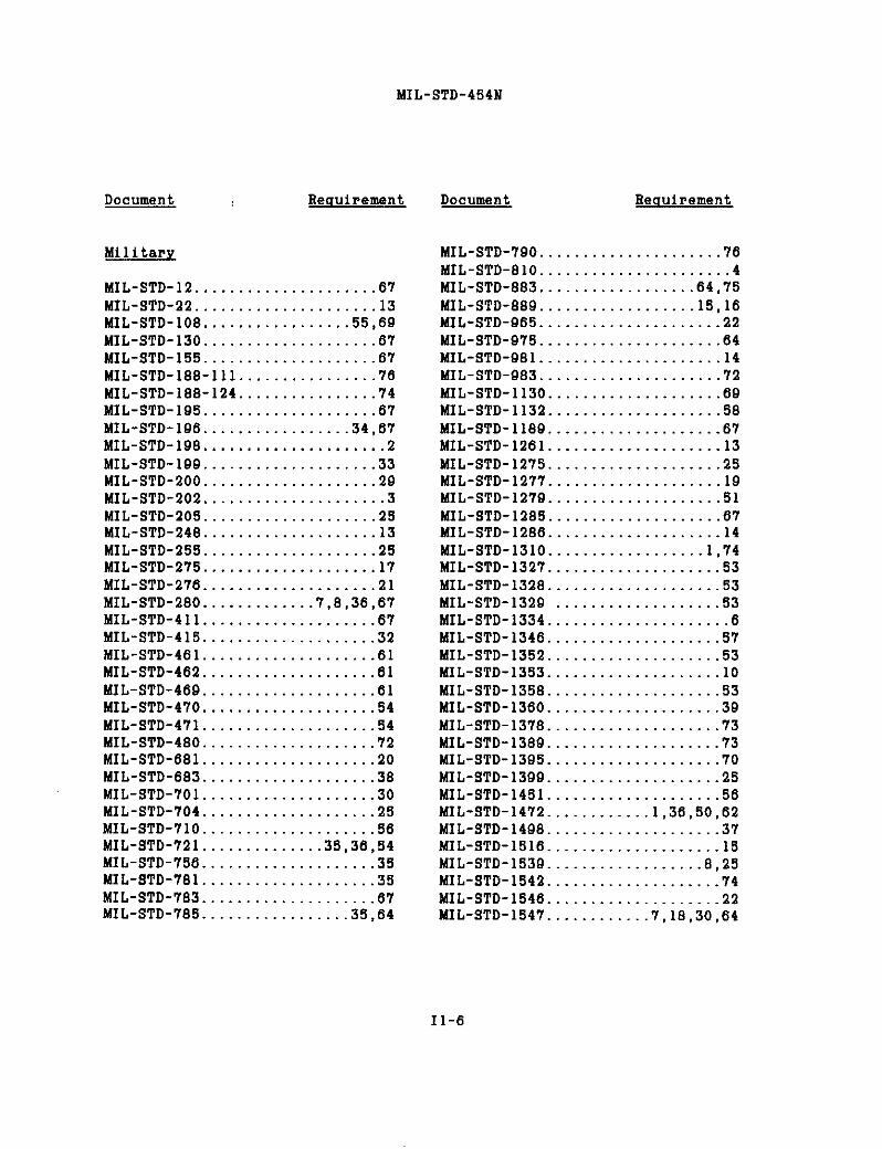
MIL-STD-454N
Document
Mi1itary
MIL-STD-12..MIL-STD-22..MIL-STD-1OS.MIL-STD-130.MIL-STD-155.
Requirement
. . . . . . . . . . . . . . 67. .. . .. . 13
...............55.69. ............. 6’?.. ...... .. .. .67
MIL-STD-lSS-111................76MIL-STD-188-124................74MIL-STD-195....................67MIL-STD-196.................34.67MIL-STD-198...C.C.C..C..........2MIL-STD-199....................33MIL-STD-200....................29MIL-STD-202.....................3MIL-STD-203....................25MIL-STD-24S....................13MIL-STD-255....................25MIL-STD-275....................17MIL-STD-276....................21MIL-STD-2S0.............7.S.36.67MIL-STD-411....................67MIL-STD-415....................32MIL-STD-461....................61MIL-STD-462....................61MIL-STD-469....................61MIL-STD-470....................54MIL-STD-471....................54MIL-STD-480....................72MIL-STD-6S1....................20MIL-STD-683....................38MIL-STD-701....................30MIL-STD-704....................25MIL-STD-710....................56MIL-STD-721..............36.36.54MIL-STD-756....................35MIL-STD-781....................35MIL-STD-7S3....................6’7MIL-STD-786.................35.64
Document Requirement
MIL-STD-790.....................76MIL-STD-810......................4MIL-STD-883..................64.75MIL-STD-889..................15.16MIL-STD-965.....................22MIL-STD-975.....................64MIL-STD-9S1.....................14MIL-STD-983.....................72MIL-STD-1130....................69MIL-STD-1132....................58MIL-STD-1189....................67MIL-STD-1261....................13MIL-STD-1275....................25MIL-STD-1277....................19MIL-STD-1279....................51MIL-STD-128S....................67MIL-STD-1286....................14MIL-STD-1310..................1,74MIL-STD-1327....................53MIL-STD-1328....................53MIL-STD-1329 ...................53MIL-STD-1334.....................6MIL-STD-1346....................57MIL-STD-1352....................53MIL-STD-1353....................10MIL-STD-135S....................53MIL-STD-1360....................39MIL-STD-137S....................73MIL-STD-1389....................73MIL-STD-1395. .................70MIL-STD-1399....................25MIL-STD-1451....................56MIL-STD-1472............1.36.5O.62MIL-STD-1498....................37MIL-STD-1516....................15MIL-STD-1539..................8.25MIL-STD-1542....................74MIL-STD-1546....................22MIL-STD-1547............7.18.3O.64
11-6

MIL-STD-454N
Document
MIL-STD-1562........DOD-STD-15’78... .MIL-STD-1595........MIL-STD-1629. ... .MIL-STD-1636... ..MIL-STD-1637...........
Requirement
. . . . . . . 64
........27
. . ..13
........35
........53
........53MIL-STD-1638...................53MIL-STD-1639...................53MIL-STD-1640...................53MIL-STD-1646...................1ODOD-STD-1678...................76MIL-STD-1686................64.75MIL-STD-1857...................74DOD-STD-1S63...................76DOD-STD-1864...................76MIL-STD-2000....................5MIL-STD-2113...................53MIL-STD-2118...................17MIL-STD-2119...................1’7MIL-STD-2120...................10MIL-STD-2162...................53MIL-STD-2163...................’76MIL-STD-216S...................32MIL-STD-2175...................21MIL-STD-2219...................13MS25471........................71MS27110........................71MS27212........................19MS33522........................12MS33540........................12MS33557’........................12MS3355S........................42
HANDBOOKS
Mi1itary
MIL-HDBK-5.....................13MIL-HDBK-216................53.65MIL-HDBK-217................35.64MIL-HDBK-218...................56MIL-HDBK-246...................73
Document Requirement
MIL-HDBK-225....................56MIL-HDBK-231....................56MIL-HDBK-251....................52MIL-HDBK-253....................61DOD-HDBK-263....................75MIL-HDBK-277....................76MIL-SDBK-278....................76MIL-HDBK-282....................76MIL-HDBK-415....................76MIL-HDBX-419....................’74MIL-HDBK-472....................54MIL-HDBK-600.....................1MIL-HDBK-660....................53MIL-HDBK-691....................23MIL-HDBK-730....................13
OTHER QOVT DOCUMENTS
MIL-BUL-103.....................6410 CFR20 ........................121 CFRIOOO - 1050...............129 CFR1910 ................... ...............1.4.11.23.26.43.44.47MTIA Manual.....................61Tester Independent SupportSoftware System (TISSS) Spec8.64
VHSIC Interoperabi1ity Standards64Army Regulation 700-B3..........27
NON-QOVT DOCUMENTS
A(JMASpecificationa.............48AMS3638E .......................11AMS3653D .......................11AMS3654B .......................11AMS365SA .......................11
11-7

MIL-STD-454U
Document Requirement
AMSIB93. 1-64..................49ANSI B93.2-71..................49ANSI B93.3-68..................49ANSI B93.4M-81.................49ANSI B93.5-79..................49ANSI B93,6-72,..,...,.,,,,,,.,.49ANSI B93.7-68..................49ANSI B93.8-68..................49ANSI B93.9M-69.................49ANSI B93.10-69.................49ANSI B93.llM-81................49ANSI C95.1-82...................1ANSI C95.2-82...................1ANSI N2.1-69....................1ANSI Z35.1-’72...................1ANSI Z35.2-6S...................1ANSI Z35.4-73...................1ANSI Z53.I-79...................1ANSI/AWS A2.4-86...............13ANsI/Aws A3.o-85...............13ANSI/IPC-D-322.................1’7ANSI/IPC-DW-425/11.............17ANsI/sAE J514f.................49ANSI/SAE J518c.................49ASM Metals Hdbk, Vol 1-1978....41ASTM A29/A29M-8S...............4lASTM A122-86...................41ASTM A139/A139m-LI0.............4lASTM A151/A151m-89.............41ASTM A206-86a/A206m-87.........41ASTM A2281A228M-83.............41
Document Requirement
ASTM A682-79....................41ASTM A6S4/A684M-86 .............41ASTM B33-74..................66.71ASTM B194-SB....................41ASTM B196/B196M-88..............4lASTM B197/B197M-S9,.............4lASTM B522-80....................41ASTM D149-87....................45ASTM D485-’Y3..................,.26ASTM D56S-77.....................3ASTM D636-S1.....................3ASTM D1000-S2....................3ASTM D1868-81...................45ASTM D3295-81...................11EIA-297-A.......................10EIA-310-C.......................55IEC-693-80......................76IEEE 812-84.....................76IEEE 200-1975...................67IEEE 1076-1987..................64NAS 498....................... ..12NAS 547.........................12NAS 1686........................12NAS 1687...................... ..12NFPA 70-1990...................1,8UL 94-80.........................3
ASTM A313-8’Y...................41ASTM A580-90................67.71
11-S

MIL-SIP3454N
2ubJecJ Ilaauirement
Abbreviations.......................67Accea.vdevi@e#.......................llAcce.e#ibility........................36Mapte?aBfConn*@toP........................loWeveguide...........................53Adbeaiven............................23Antiseize mspound. . . . . . . . . . . . . . . . . ..llArc-resiatent materials. . . . . . . . . . . . . .26Attenueto?a,?! . . . . . . . . . . . . . . . . . . . ...53kvriem, electrical . . . . . . . . . . . . . . . . ..lWte?ien. . . . . . . . . . . . . . . . . . . . . . . . . . ..rlBearingassemblies. . . . . . . . . . . . . . . . . . ..OBearingn. . . . . . . . . . . . . . . . . . . . . . . . . . . . ..flBoards
Diemete vi?ing. . . . . . . . . . . . . . . . . . ..l7hintadwiring . . . . . . . . . . . . . . . . . . . ..l7
Boltn. . . . . . . . . . . . . . . . . . . . . . . . . . . . . . ..llhnding
Mbeaive. . . . . . . . . . . . . . . . . . . . . . . . . ..!3Electrical . . . . . . . . . . . . . . . . . . . . ..l. 74
Emaing. . . . . . . . . . . . . . . . . . . . . . . . . . . ...59Cabinets. . . . . . . . . . . . . . . . . . . . . . . . . . . ..5SCable, coexjal. . . . . . . . . . . . . . . . . . . . ...65Cable,noi~iconductorInterconnection....................’llInternal...........................66
Capa.3it0~a............................2Carcinogcnsl,4,11,23,26,43,44,47Ceees................................55Castings.............................!llCi~cuitbmAern..................8. 37Cieening..............................9Cleamnce.........................9.69Coaxialcable........................65coILs................................l4Commwialparts.....................7l
3ubJecJ Beauirement
ConfomalcOating....................i7ConnectioneAccemeibilityof...................36Cle!lpad............................(lecPimp..............................oQUarkingOf. . . . . . . . . . . . . . . . . . . . . . ...67Soldered. . . . . . . . . . . . . . . . . . . . . . . . . ...5S!lded. . . . . . . . . . . . . . . . . . . . . . . . . . ...24WireAkap. . . . . . . . . . . . . . . . . . . . . . . ...69
C0nnect0F8Electrical . . . . . . . . . . . . . . . . . . . . ..l. 10Filter pin. . . . . . . . . . . . . . . . . . . . . . . ..lORf cOaxial. . . . . . . . . . . . . . . . . . . . . . . ..lO
Containment. . . . . . . . . . . . . . . . . . . . . . . . ...9contFOLv. . . . . . . . . . . . . . . . . . . . . . . . . . ...28
Insulatim of. . . . . . . . . . . . . . . . . . . . . ..iFlexible absfta fo~. . . . . . . . . ...28. 42
COnverte?a,FOteq.pOm. . . . . . . . . . ...46Cooling. . . . . . . . . . . . . . . . . . . . . . . . . . . ...52COnOnapr.mntiOn. . . . . . . . . . . . . . . . . ...45Corweionprotection. . . . . . . . . . . . . 19, 16Couplers, directional . . . . . . . . . . . . . [email protected]. . . . . . . . . . . . . . . . . . ..O9Crystal mitg . . . . . . . . . . . . . . . . . . . . . ...38Darating. . . . . . . . . . . . . . . . . . . . . . . . . . . ..l8Desiccenta. . . . . . . . . . . . . . . . . . . . . ..3i. 55Devices,aic?oelectronic. . . . . . . . . . . . .64Devices,nemiconda&m...............3ODial mecbanime,tuning. . . . . . . . . . . ...42Dials, cont~ol. . . . . . . . . . . . . . . . . . . . ...28Dincbargingdevic.w. . . . . . . . . . . . . . . . . ..lDi#playa. . . . . . . . . . . . . . . . . . . . . . . . . . . ..O8Dimimilar mtaLa. . . . . . . . . . . . . . . . . . ..l6Oynamtoms...........................46
INDEX 2
12-1

NIL-S’I’E-454N
W 3aauirement
Wot?icalBwckllown. . . . . . . . . . . . . . . . . . . . . . . . ...45tOBnWtiOI!B. . . . . . . . . . . . ..g. lCI,14, 89Filte?fl.........................lo.70Inmlating materials. . . . . . . . . . . . . . ..llMetem. . . . . . . . . . . . . . . . . . . . . . . . . . . . ..SlOve?loadprotection. . . . . . . . . . . . . . . ...8Poma?. . . . . . . . . . . . . . . . . . . . . . . . . . . . . ..l9
fflechoinegnetiainte~ter-me control. . . . . . . . . . . . . . . .01
Electronic part derating. . . . . . . . . . . . . . 18ElectrOntubas. . . . . . . . . . . . . . . . . . . . . . ..2OElectrostatic
Di#&evgecontml. . . . . . . . . . . . . . . . ...75Sensitive partn.............3O.04, 7S
3mbadment. . . . . . . . . . . . . . . . . . . . . . . . . . . ..4l3ncapsulati0n. . . . . . . . . . . . . . . . . . . . . . ...47Enclomeen. . . . . . . . . . . . . . . . . . . ..l. S6, $53ncoders. . . . . . . . . . . . . . . . . . . . . . . . . . . . ..MFab?ic. . . . . . . . . . . . . . . . . . . . . . . . . . . . . ...44i’astene~hardeme. . . . . . . . . . . . . . . . . . . ..llFaatenm, th?eaded. . . . . . . . . . . . . . . . . ..l!lFiber Optics. . . . . . . . . . . . . . . . . . . . . . . . ..7OFib?ouamate~ial, organic. . . . . . . . . . . . .44Filters, cle&?icai . . . . . . . . . . . . . ..lO. 70Fini#bcu. . . . . . . . . . . . . . . . . . . . . . . . . . . . ..1SFlmebility . . . . . . . . . . . . . . . . . . . . . . . . . ...9Flanges, vaveguide. . . . . . . . . . . . . . . . . ...53FunguaineFt mate?ia16. . . . . . . . . . . . . . ...4Fungueprotection. . . . . . . . .. . ...4. 44, 69Fueeboldcrs. . . . . . . . . . . . . . . . . . . . . . . ...39Fuae8. . . . . . . . . . . . . . . . . . . . . . . . . . . ...8. 39Fueible link devices. . . . . . . . . . . . . . . ...64Deart?ains . . . . . . . . . . . . . . . . . . . . . . . . ...486MF8. . . . . . . . . . . . . . . . . . . . . . . . . . . . . . ...48OaneratOm............................4OOmnding.. . . . . . . . . . . . . . . . . . . . ..l. 6, 74lluepda’,eiectr.ical . . . . . . . . . . . . . . . . . . . ..iEandles, control. . . . . . . . . . . . . . . . . . . . ..NIbdtame, faatener. . . . . . . . . . . . . . . . . . ..l2Eeating. . . . . . . . . . . . . . . . . . . . . . . . . . . . . ..5liiookupwire............................2O
3uiJ@ Reauireaant
Emenengineering.., . . . . . . . . . . . . . . . ...82llqdxaulic8. . . . . . . . . . . . . . . . . . . . . . . . . ...49Idanti! ication marking. . . . . . . . . . .20, 07Indicaton lights . . . . . . . . . . . . . . . . . . . . ..SOInductors. . . . . . . . . . . . . . . . . . . . . . . . . . . ..l4Insulating mate?iala,
electrical . . . . . . . . . . . . . . . . . . . . . . . . ..llInterchangeability. . . . . . . . . . . . . . . . . . ...7Interference,
eiectrOmgnetic. . . . . . . . . . . . . . . . . . . ..6iInterlocks. . . . . . . . . . . . . . . . . . . . . . . . . . . ..lInternal wt~ingpractices . . . . . . . . . . . . .69Itemnaww, nomenclature. . . . . . . . . . . ...34Jack@,teiephone/te8t. . . . . . . . . . . . . . . ..lOKnobe,control. . . . . . . . . . . . . . . . . . . ..l. !48Lacing. . . . . . . . . . . . . . . . . . . . . . . . . . ...9. 69.LampE. . . . . . . . . . . . . . . . . . . . . . . . . . . . . . . ..BOLeakagediatance. . . . . . . . . . . . . . . . . . . . ..OBLegends. . . . . . . . . . . . . . . . . . . . . . . . . . . . ...67Light emitting dioden. . . . . . . . . . . .. SO.68Lights, indicator. . . . . . . . . . . . . . . . . . . ..5OLime, rf t?anmis.cicn. . . . . . . . . . ..S3. 65Lcada,dmag, r4. . . . . . . . . . . . . . . . . . . ...33Lockingdevices. . . . . . . . . . . . . . . . . ..Kk. 28LubFicant.c. . . . . . . . . . . . . . . . . . . . . . . ..O. 43Lugte?ainals: . . . . . . . . . . . . . . . . . . . . . . ..l9Maintainability. . . . . . . . . . . . . . . . . . . . ...54tiking . . . . . . . . . . . . . . . . . . . . . . . . . . . . ...67B-stteeyinstallation . . . . . . . . . . . . . . . ..!l7Diala. . ..’. . . . . . . . . . . . . . . . . . . . . . . . . ...42Fuse. . . . . . . . . . . . . . . . . . . . . . . . . . . ..3O. 673adioa@tivemateniel. . . . . . . . . . . . . . . . ..lWarning. . . . . . . . . . . . . . . . . . . . . . . . . . . . . ..l
MaterialnArc-reai#tant. . . . . . . . . . . . . . . . . . . . . ...26Ca~cinogena. . . . . . . . . . . . . . . . .. . . . . . . . . .. . . . . . . . ...1. 4, 11, 13, ’26,43, 44, 47
8iectPical insulating. . . . . . . . . . . . . . . ..ilFabric. . . . . . . . . . . . . . . . . . . . . . . . . . . . . ...44
12-2
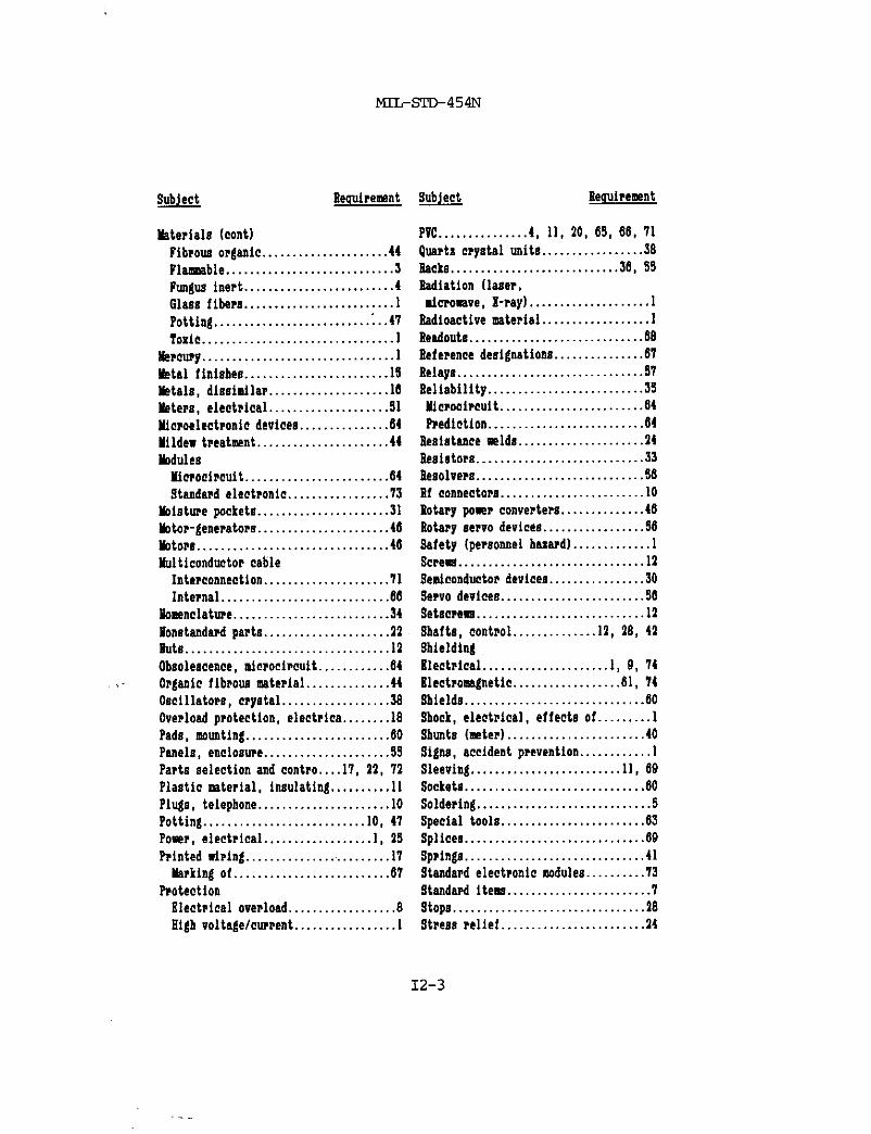
MIL+TE-454N
SubJ@ Beouirement
Materials (cent)Fib?ouaoF@ic. . . . . . . . . . . . . . . . . . ...44Fiambie . . . . . . . . . . . . . . . . . . . . . . . . . ...3Fm.guaiaert . . . . . . . . . . . . . . . . . . . . . . ...4Glans fibers . . . . . . . . . . . . . . . . . . . . . . . ..lPotting. . . . . . . . . . . . . . . . . . . . . . . . ..~..4T?Oxic. . . . . . . . . . . . . . . . . . . . . . . . . . . . . . ..l
kke?cu?g. . . . . . . . . . . . . . . . . . . . . . . . . . . . . . ..lMatai fini8bea. . . . . . . . . . . . . . . . . . . . . . ..lSBetaIs, diaaimflar. . . . . . . . . . . . . . . . . . ..l6Ueters, electrical . . . . . . . . . . . . . . . . . . ..SlMfmoelectmic devicen. . . . . . . . . . . . . . .64Mfidewt?eatwnt. . . . . . . . . . . . . . . . . . . ...44kdules
Hic?Oci?cuit. . . . . . . . . . . . . . . . . . . . . ...64Standmdelectronic . . . . . . . . . . . . . . ...73
kistwepacket8 . . . . . . . . . . . . . . . . . . . . ..3lhtor-generatOrn. . . . . . . . . . . . . . . . . . . ...46WOP8. . . . . . . . . . . . . . . . . . . . . . . . . . . . . ...46Uticonductor cable
Interconnection. . . . . . . . . . . . . . . . . . . ..7lInternal . . . . . . . . . . . . . . . . . . . . . . . . . ...66
flOmenclatwe. . . . . . . . . . . . . . . . . . . . . . . ...34flon@tandmfpart8. . . . . . . . . . . . . . . . . . . ..l2.tiuta. . . . . . . . . . . . . . . . . . . . . . . . . . . . . . . . ..i2Obmlencence,mfmociwuit. . . . . . . . . . . .64
,. OrganicfibpouamateFial. . . . . . . . . . . ...44Oacillatm, cry8tal . . . . . . . . . . . . . . . ...38Oeerioedprotection, electrica . . . . . . . .18Pads, wmntint. . . . . . . . . . . . . . . . . . . . . . ..6OPaneis, enclOmm. . . . . . . . . . . . . . . . . . ...59Parts selection and contm. . . .17, 11, 71Plastic mteriai, insulating. . . . . . . . . . 11PIugs, telephone. . . . . . . . . . . . . . . . . . . . ..lOPOtting. . . . . . . . . . . . . . . . . . . . . . . . . ..lO. 41Poser, electrical . . . . . . . . . . . . . . . . ..l. 1S??inted wiping. . . . . . . . . . . . . . ... . . . . . ..l’l
Merkingof. . . . . . . . . . . . . . . . . . . . . . . ...67P70tection
Electrical overload. . . . . . . . . . . . . . . . ..aEtgbvoltage/cwmt. . . . . . . . . . . . . . . ..l
SdJe&t Eeauireuent
Pvt.. . . . . . . . . . ...4. 11, 20,65,66,71
@e.rtzcryntaimitn . . . . . . . . . . . . . . . ..S8sackE. . . . . . . . . . . . . . . . . . . . . . . . . ...36. 55Sadiation (lacer,ticromve, X-ray). . . . . . . . . . . . . . . . . . ..l
Sadioe.ctivemterial . . . . . . . . . . . . . . . . ..lReedouta. . . . . . . . . . . . . . . . . . . . . . . . . . . ..6BSeferencedeaigrmtions. . . . . . . . . . . . . . .67Relayn. . . . . . . . . . . . . . . . . . . . . . . . . . . . . ..Y7Reliability . . . . . . . . . . . . . . . . . . . . . . . . ..3SnfcFO@iFcuit. . . . . . . . . . . . . . . . . . . . . ...64hediction . . . . . . . . . . . . . . . . . . . . . . . ...64
Resiatencemldn. . . . . . . . . . . . . . . . . . . ..l4Be8i#tora. . . . . . . . . . . . . . . . . . . . . . . . . ...33Be#olve?n. . . . . . . . . . . . . . . . . . . . . . . . . ...56M c0nnect0r8. . . . . . . . . . . . . . . . . . . . . . ..lORotarypamerconverters . . . . . . . . . . . . .46Sotaryaervo devicea. . . . . . . . . . . . . . . ..MSafety [permnneibm?dl. . . . . . . . . . . ..lScree8. . . . . . . . . . . . . . . . . . . . . . . . . . . . . ..l2Semiconductordevices. . . . . . . . . . . . . . . .30Se?vodevices. . . . . . . . . . . . . . . . . . . . . ...56Setsc?em. . . . . . . . . . . . . . . . . . . . . . . . . . ..l2Sbafta, controi. . . . . . . . . . . . ..l2. !8, 41ShieldingSlectr.icai. . . . . . . . . . . . . . . . . . . ..l. 0, 74Klect?06agnetic. . . . . . . . . . . . . . . . ..6l. 74Sbield8. . . . . . . . . . . . . . . . . . . . . . . . . . . . ..6OSbo@k,electrical, effects of. . . . . . . . . 1shunts (mteF) . . . . . . . . . . . . . . . . . . . . . ..4oSigns, accident prevention. . . . . . . . . . . . 1Sieeving. . . . . . . . . . . . . . . . . . . . . . . ..ll. 69Sockets..............................6OSoldering. . . . . . . . . . . . . . . . . . . . . . . . . . ...5Special too18. . . . . . . . . . . . . . . . . . . . . ...63Splices. . . . . . . . . . . . . . . . . . . . . . . . . . . ...69spFings. . . . . . . . . . . . . . . . . . . . . . . . . . . . ..4lStendapdelectronic modules. . . . . . . . . .73Stend~d items. . . . . . . . . . . . . . . . . . . . . ...79t0pa. . . . . . . . . . . . . . . . . . . . . . . . . . . . . . ..l8Stre8srelief . . . . . . . . . . . . . . . . . . . . . ...24
12-3

MIFSIE454N
Subject llequirement
9tmctwa1 welding. . . . . . . . . . . . . . . . . . ..l3SUbmitut.lbillty. . . . . . . . . . . . . . . . . . . . ..mSvitches. . . . . . . . . . . . . . . . . . . . . . . . . . . . ..M
Battlesho?t. . . . . . . . . . . . . . . . . . . . . . . . ..lCircuit breakers umd aa. . . . . . . . . ...37Interlock. . . . . . . . . . . . . . . . . . . . . . . . . . ..lrlf. . . . . . . . . . . . . . . . . . . . . . . . . . . . . ..l. 53$afety. . . . . . . . . . . . . . . . . . . . . . . . . . . . . ..lWaveguide. . . . . . . . . . . . . . . . . . . . . . . . ...53
!lymbOIOgy. . . . . . . . . . . . . . . . . . . . . . . . . . ...67Syncbros. . . . . . . . . . . . . . . . . . . . . . . . . . . ...56Tachomters. . . . . . . . . . . . . . . . . . . . . . . . ...56Tape
BlectPical. . . . . . . . . . . . . . . . . . . . . . . . ..llM.cing. . . . . . . . . . . . . . . . . . . . . . . . . . . ...69Reflective. . . . . . . . . . . . . . . . . . . . . . . ...67
?emtnal Anards,ntr.ips. . . . . . . . . . . . . ..l9!eminal lugs. . . . . . . . . . . . . . . . . . . . . . . ..l9feminatim. . . . . . . . . . . . . . . . . ..l. 19, 697eatpr0visi0ns . . . . . . . . . . . . . . . . . ..lO. 317herml deuifn. . . . . . . . . . . . . . . . . . . . . ...529bemist0ra. . . . . . . . . . . . . . . . . . . . . . . . ...33Tber60c0uple6. . . . . . . . . . . . . . . . . . . ..iO. 107brefid. . . . . . . . . . . . . . . . . . . . . . . . . . . . . ...44Vb?eadeddevice#. . . . . . . . . . . . . . . . . . . . ..l’JTh?eads. . . . . . . . . . . . . . . . . . . . . . . . . . . . . ..l27001s, special . . . . . . . . . . . . . . . . . . . . . . ..6SToxicmaterials. . . . . . . . . . . . . . . . . . . . . . ..l?rannformra. . . . . . . . . . . . . . . . . . . . . . . . ..l47cansist0?s. . . . . . . . . . . . . . . . . . . . . . . . . ..3o
(’ I
W!@! @!!!E!a
7mnmimi0n lines, rf . . . . . . . . . . . . . ...53Tmngolvers. . . . . . . . . . . . . . . . . . . . . . . . . ..$6Tubashielda. . . . . . . . . . . . . . . . . . . . . . . . ..6OTubes,electm. . . . . . . . . . . . . . . . . . . . . ..’l~?uningdial mechanima................42Typadasignations. . . . . . . . . . . . . . ...34. 67Va?nisb,Insulating. . . . . . . . . . . . . . . . . ..llVebicle#,@rend. . . . . . . . . . . . . . . . . . . . ..l5VUSIC. . . . . . . . . . . . . . . . . . . . . . . . . . . . . . ...64Wining le.bels.., . . . . . . . . . . . . . . . . ..l. 27k%abe?a. . . . . . . . . . . . . . . . . . . . . . . . . . . . . ..l214eveguide8. . . . . . . . . . . . . . . . . . . . . . . . . ...53Webbing. . . . . . . . . . . . . . . . . . . . . . . . . . . . ...44Ualding, stmctural . . . . . . . . . . . . . . . . . ..l3kkldn, Resistance. . . . . . . . . . . . . . . ..l3. 14WirekIookup..............................2OInte~connection. . . . . . . . . . . . . . . . . . . ..7l9olido? atranded. . . . . . . . . . . . . ..2O.66Tbemcouple . . . . . . . . . . . . . . . . . . . . . . ..2Otiirewrap. . . . . . . . . . . . . . . . . . . . . . . . . . ..2O
4ViIIeIdentification . . . . . . . . . . . . . . . . . ..2OWiring
hmngement......................~, 69Connector. . . . . . . . . . . . . . . . . . . . . . . . . ..lOInternal . . . . . . . . . . . . . . . . . . . . . . . . . ...69hinted . . . . . . . . . . . . . . . . . . . . . . . . . . . ..llBigid-flex. . . . . . . . . . . . . . . . . . . . . . . . ..l?
44a~kcmahip. . . . . . . . . . . . . . . . . . . . . . . . . . ..O
,. .. -.--,. . . . I I—
i- _-J((
12-4 LI
-.

.“. .,, ,-.-”, “s, “i, rw.mus eamons are omofere. ,. W,,
.\
Related Documents