NOT MEASUREMENT SENSITIVE MIL-STD-2045-47001D w/CHANGE 1 23 June 2008 SUPERSEDING MIL-STD-2045-47001D 29 September 2005 DEPARTMENT OF DEFENSE INTERFACE STANDARD CONNECTIONLESS DATA TRANSFER APPLICATION LAYER STANDARD AMSC N/A AREA DCPS DISTRIBUTION STATEMENT A . Approved for public release; distribution is unlimited. Downloaded from http://www.everyspec.com

Welcome message from author
This document is posted to help you gain knowledge. Please leave a comment to let me know what you think about it! Share it to your friends and learn new things together.
Transcript

NOT MEASUREMENT SENSITIVE
MIL-STD-2045-47001D w/CHANGE 1 23 June 2008 SUPERSEDING MIL-STD-2045-47001D 29 September 2005
DEPARTMENT OF DEFENSE INTERFACE STANDARD
CONNECTIONLESS DATA TRANSFER
APPLICATION LAYER STANDARD
AMSC N/A AREA DCPS DISTRIBUTION STATEMENT A. Approved for public release; distribution is unlimited.
Downloaded from http://www.everyspec.com

MIL-STD-2045-47001D w/CHANGE 1
ii
FOREWORD This military standard is approved for use by all Departments and Agencies of the Department of Defense (DoD). This military standard is produced by the Radio Information Transfer Technical Working Group (RITTWG). The MIL-STD-2045 document series was established within the Data Communication Protocol Standards (DCPS) Standardization Area to allow for the enhancement of commercial standards or the development of standards that are unique to DoD. Specific details and instructions for establishing a MIL-STD-2045 document, as well as profile development guidelines, are documented in the RITTWG Management Plan. RITTWG Working Groups (WGs) are responsible for standard development, formal service and agency coordination, and approval. This military standard does not supersede the scope of Allied Communication Publication (ACP) 123 with US SUPP-1. ACP 123 with US SUPP-1 addresses message handling communications protocol and procedures for the exchange of military messages. The Preparing Activity (PA) for this standard is USA CECOM LCMC, ATTN: AMSEL-SE-CD (Chairman, Combat Net Radio Working Group (CNRWG), Fort Monmouth, NJ 07703. The custodians for the document are identified in the Defense Standardization Program, “Standardization Directory (SD1)” under Standardization Area DCPS. Beneficial comments (recommendations, additions, deletions) and any pertinent data that may be of use in improving this military standard should be addressed to the PA at the above address by letter. Comments, suggestions, or questions on this document should be addressed to CDR, USA CECOM LCMC, ATTN: AMSEL-SE-CD Chairman, (CNRWG), Building 1209, Fort Monmouth, NJ 07703 or emailed to [email protected]. Since contact information can change, you may want to verify the currency of this address information using the ASSIST Online database at http://assist.daps.dla.mil.
Downloaded from http://www.everyspec.com

MIL-STD-2045-47001D w/CHANGE 1
iii
CONTENTS PARAGRAPH................................................................................................................................................ PAGE FOREWORD............................................................................................................................................... ii 1 SCOPE ....................................................................................................................................................... 1 1.1 Purpose. ............................................................................................................................................ 1 1.2 Scope. ............................................................................................................................................... 1 1.3 Application guidance. ....................................................................................................................... 1 2 APPLICABLE DOCUMENTS .................................................................................................................... 2 2.1 General. ............................................................................................................................................ 2 2.2 Government documents. ................................................................................................................... 2 2.3 Specifications, standards, and handbooks. ......................................................................................... 2 2.3.1 Other Government documents, drawings, and publications. .............................................................. 3 2.3.2 North Atlantic Treaty Organization (NATO) Standardization Agreements (STANAG)
documents, drawings, and publications. ............................................................................................ 3 2.4 Non-Government publications. ......................................................................................................... 3 2.5 Order of precedence. ......................................................................................................................... 4 3 DEFINITIONS ........................................................................................................................................... 5 3.1 Definitions of terms. ......................................................................................................................... 5 3.2 Abbreviations and acronyms. ............................................................................................................ 8 4 GENERAL REQUIREMENTS ................................................................................................................. 13 4.1 Application layer users. .................................................................................................................. 13 4.2 Interoperability. .............................................................................................................................. 13 4.3 Application layer services provided. ................................................................................................ 13 4.4 System standards and design. .......................................................................................................... 13 5 SPECIFIC REQUIREMENTS .................................................................................................................. 15 5.1 Application layer. ........................................................................................................................... 15 5.2 Application Protocol Data Unit (PDU). ........................................................................................... 15 5.3 Application header. ........................................................................................................................ 15 5.4 Application header formatting. ....................................................................................................... 22 5.5 Syntax. ........................................................................................................................................... 22 5.5.1 Field Presence Indicator (FPI). ........................................................................................................ 22 5.5.2 Field Recurrence Indicator (FRI). ................................................................................................... 22 5.5.3 Group Presence Indicator (GPI). ..................................................................................................... 22 5.5.4 Group Recurrence Indicator (GRI). ................................................................................................. 22 5.5.5 End-of-literal field marker. ............................................................................................................. 23 5.5.6 Data-field construction procedures. ................................................................................................. 23 5.6 Application header fields. ............................................................................................................... 26 5.6.1 Version. .......................................................................................................................................... 26 5.6.2 Data compression type. ................................................................................................................... 26 5.6.3 Originator, recipient, and information addressee fields. .................................................................. 27 5.6.4 User Message Format (UMF) field. ................................................................................................. 27 5.6.5 Functional Area Designator (FAD) field. ........................................................................................ 31 5.6.6 Message Number field. ................................................................................................................... 31 5.6.7 Message Subtype field. .................................................................................................................... 31
Downloaded from http://www.everyspec.com

MIL-STD-2045-47001D w/CHANGE 1
iv
5.6.8 File Name. ...................................................................................................................................... 31 CONTENTS
PARAGRAPH................................................................................................................................................ PAGE 5.6.9 Message Size field. ......................................................................................................................... 31 5.6.10 Operation Indicator field. ................................................................................................................ 31 5.6.11 Retransmit Indicator field. .............................................................................................................. 32 5.6.12 Message Precedence field. ............................................................................................................... 32 5.6.13 Security Classification field. ........................................................................................................... 33 5.6.14 Control and Release Marking field. ................................................................................................. 33 5.6.15 Originator Date-Time Group (DTG). .............................................................................................. 34 5.6.16 DTG Extension field. ...................................................................................................................... 35 5.6.17 Time Perishability DTG. ................................................................................................................. 35 5.6.18 Machine Acknowledge Request Indicator field. ............................................................................... 35 5.6.19 Operator Acknowledge Request Indicator field. .............................................................................. 35 5.6.20 Operator Reply Request Indicator field. .......................................................................................... 35 5.6.21 Message Acknowledgment DTG. .................................................................................................... 35 5.6.22 Receipt/Compliance (R/C) field. ..................................................................................................... 36 5.6.23 Cannot Comply (CANTCO) Reason field. ...................................................................................... 36 5.6.24 Cannot Process (CANTPRO) Reason field. ..................................................................................... 36 5.6.25 Reply Amplification field. ............................................................................................................... 36 5.6.26 Reference Message Data group. ...................................................................................................... 37 5.6.27 Header Size field. ........................................................................................................................... 37 5.6.28 Security Parameter Information (SPI). ............................................................................................ 37 5.6.29 Keying Material ID Length. ............................................................................................................ 38 5.6.30 Keying Material ID. ........................................................................................................................ 38 5.6.31 Cryptographic Initialization Length. ............................................................................................... 38 5.6.32 Cryptographic Initialization. ........................................................................................................... 38 5.6.33 Key Token Length. ......................................................................................................................... 38 5.6.34 Key Token. ..................................................................................................................................... 38 5.6.35 Authentication Data (A) Length. .................................................................................................... 38 5.6.36 Authentication Data (A). ................................................................................................................ 38 5.6.37 Authentication Data (B) Length. ..................................................................................................... 38 5.6.38 Authentication Data (B). ................................................................................................................. 39 5.6.39 Signed acknowledge request indicator. ............................................................................................ 39 5.6.40 Message Security Padding Length. .................................................................................................. 39 5.6.41 Message Security Padding. ............................................................................................................. 39 5.6.42 Group Size field. ............................................................................................................................. 39 5.7 Application header formatting rules and construction procedures. ................................................... 39 5.7.1 Case and conditionality statement syntax. ....................................................................................... 39 5.7.2 Cases and conditions for the application header. ............................................................................. 41 5.7.3 User data. ....................................................................................................................................... 52 5.7.4 Message acknowledgments. ............................................................................................................ 52 5.8 Processing factors. .......................................................................................................................... 53 5.8.1 Application process. ....................................................................................................................... 53 5.8.2 Message formats. ............................................................................................................................ 53 5.8.3 Lower layer interactions. ................................................................................................................. 53 5.8.4 Application header padding. ........................................................................................................... 55 6 NOTES ..................................................................................................................................................... 56
Downloaded from http://www.everyspec.com

MIL-STD-2045-47001D w/CHANGE 1
v
6.1 Subject term (key word) listing. ...................................................................................................... 56 6.2 Issue of the DoD index of specifications and standards (DODISS). ................................................. 56
CONTENTS PARAGRAPH................................................................................................................................................ PAGE 6.3 Management of TCP connections. ................................................................................................... 56 6.4 Application header initial settings. .................................................................................................. 57 6.5 Changes from previous issue. .......................................................................................................... 62 APPENDIX A APPLICATION HEADER FIELDS AND CODES FOR VMF .......................................... 63 A.1 General. .......................................................................................................................................... 63 A.1.1 Scope. ............................................................................................................................................. 63 A.1.2 Application. .................................................................................................................................... 63 A.2 Applicable documents. .................................................................................................................... 63 A.3 Codeword tables. ............................................................................................................................ 63 A.3.1 Unit reference number codewords. .................................................................................................. 63 A.3.2 FAD codewords. ............................................................................................................................. 63 A.3.3 Message Number codewords. .......................................................................................................... 64 A.3.4 Message Subtype codewords. .......................................................................................................... 64 A.3.4.1 MIL-STD-6017 message cases as message subtypes. ....................................................................... 64 A.3.5 CANTCO Reason codewords. ......................................................................................................... 65 A.3.6 CANTPRO Reason codewords. ....................................................................................................... 65 A.3.7 Data field construction procedures for VMF messages/user data. .................................................... 67 APPENDIX B EXAMPLE OF APPLICATION LAYER PDU AND VMF MESSAGE CONSTRUCTION 68 B.1 General. .......................................................................................................................................... 68 B.1.1 Scope. ............................................................................................................................................. 68 B.1.2 Application. .................................................................................................................................... 68 B.2 Example application layer PDU construction. ................................................................................. 68 B.2.1 Application layer data exchange. .................................................................................................... 68 B.2.2 Example. ........................................................................................................................................ 70 B.3 Example VMF message construction. ............................................................................................. 76 B.3.1 VMF message data exchange. ......................................................................................................... 76 B.3.2 Example. ........................................................................................................................................ 77 B.3.3 Example. ........................................................................................................................................ 79 APPENDIX C SEGMENTATION/REASSEMBLY PROTOCOL ............................................................. 82 C.1 General. .......................................................................................................................................... 82 C.1.1 Scope. ............................................................................................................................................. 82 C.1.2 Application. .................................................................................................................................... 82 C.1.3 Definitions. ..................................................................................................................................... 82 C.1.3.1 Definitions of terms. ....................................................................................................................... 82 C.1.3.2 Summary of S/R acronyms, terms, explanations, and applications. ................................................. 83 C.1.4 Summary of S/R procedures. ........................................................................................................... 89 C.2 Applicable documents. .................................................................................................................... 90 C.3 Overall operation. ........................................................................................................................... 90 C.3.1 Maximum segment size (MSS). ...................................................................................................... 91 C.3.1.1 MSS for IP datagram exchanges. .................................................................................................... 91 C.3.1.2 MSS for n-layer pass through exchanges. ........................................................................................ 91 C.3.1.3 MSS for Packet Mode exchanges. ................................................................................................... 92
Downloaded from http://www.everyspec.com

MIL-STD-2045-47001D w/CHANGE 1
vi
C.3.2 Interface with peer-to-peer layers. ................................................................................................... 92 C.3.2.1 UDP/IP Datagram exchanges. ......................................................................................................... 95 C.3.2.2 MIL-STD-188-220 n-layer pass through (NLP) exchanges. ............................................................ 95
CONTENTS PARAGRAPH................................................................................................................................................ PAGE C.3.3 S/R PDU format. ............................................................................................................................. 96 C.3.3.1 Common S/R header. ...................................................................................................................... 96 C.3.3.2 Data segment. ................................................................................................................................. 97 C.3.3.3 Partial Acknowledgment PDU. ....................................................................................................... 98 C.3.3.4 Complete Acknowledgment PDU. ................................................................................................... 99 C.3.3.5 Abort Request PDU. ....................................................................................................................... 99 C.3.3.6 Abort Confirm PDU. ..................................................................................................................... 100 C.3.3.7 Acknowledgment Request. ............................................................................................................ 100 C.3.4 Data segment acknowledgment schemes. ...................................................................................... 101 C.3.4.1 End of Data Transfer (EDT) Acknowledgment Required scheme. ................................................. 101 C.3.4.2 End of Data Transfer Acknowledgment Not Required scheme. ..................................................... 101 C.3.5 S/R Basic procedures. ................................................................................................................... 102 C.3.5.1 S/R Basic Overview. ..................................................................................................................... 102 C.3.5.2 S/R Basic Flow Control. ............................................................................................................... 104 C.3.5.3 S/R Basic timing parameters and variables. .................................................................................. 105 C.3.5.4 Detailed S/R Basic Procedures ...................................................................................................... 107 C.3.5.5 S/R Basic timers. .......................................................................................................................... 116 C.3.5.6 Basic Timer equations. ................................................................................................................. 118 C.3.5.7 Basic Initialization equations. ....................................................................................................... 119 C.3.6 S/R Enhanced procedures. ............................................................................................................ 120 C.3.6.1 S/R Enhanced Overview. .............................................................................................................. 120 C.3.6.2 Enhanced Flow Control. ............................................................................................................... 123 C.3.6.3 S/R Enhanced timing parameters and variables. ........................................................................... 125 C.3.6.4 Detailed S/R Enhanced Procedures ............................................................................................... 131 C.3.6.5 S/R Enhanced timers. ................................................................................................................... 137 C.3.6.6 Enhanced Timer equations. .......................................................................................................... 147 C.3.6.7 Enhanced Initialization equations. ................................................................................................ 148 C.3.7 S/R Basic / S/R Enhanced Interoperability Notes and Considerations ............................................ 150 C.3.8 Examples. ..................................................................................................................................... 150 APPENDIX D SECURITY EXTENSION PROTOCOL .......................................................................... 179 D.1 General. ........................................................................................................................................ 179 D.1.1 Scope. ........................................................................................................................................... 179 D.1.2 Application. .................................................................................................................................. 179 D.2 Applicable documents. .................................................................................................................. 179 D.3 Definitions. ................................................................................................................................... 179 D.4 General requirements. ................................................................................................................... 179 D.4.1 SPI 0 authentication using SHA-1 and DSA/no encryption. .......................................................... 179 D.4.1.1 Message Security Group. .............................................................................................................. 179 APPENDIX E DoD STANDARDIZED PROFILE IMPLEMENTATION CONFORMANCE
STATEMENTS (DSPICS) REQUIREMENTS LIST (DPRL) FOR MIL-STD-2045-47001D ........ 186 E.1 General. ........................................................................................................................................ 186 E.1.1 Scope. ........................................................................................................................................... 188
Downloaded from http://www.everyspec.com

MIL-STD-2045-47001D w/CHANGE 1
vii
E.1.2 Application. .................................................................................................................................. 188 E.2 Applicable documents. .................................................................................................................. 188 E.3 Notation. ...................................................................................................................................... 188 E.4 Implementation requirements. ...................................................................................................... 189
CONTENTS PARAGRAPH................................................................................................................................................ PAGE E.5 Detailed requirements. .................................................................................................................. 190 APPENDIX F COMBAT NET RADIO PLATFORM - SYSTEM IMPLEMENTATION ........................ 282 F.1 General. ........................................................................................................................................ 282 F.1.1 Scope. ........................................................................................................................................... 282 F.1.2 Application. .................................................................................................................................. 282 F.2 Applicable documents. .................................................................................................................. 282 F.3 Definitions. ................................................................................................................................... 282 F.4 General requirements. ................................................................................................................... 282 F.4.1 Reason for table. ........................................................................................................................... 282 F.4.1.1 Process explanation. ..................................................................................................................... 282 F.4.2 Table construction. ....................................................................................................................... 282 F.4.2.1 Platform/System and version implementation codes (column 5). ................................................... 284 F.4.3 MIL-STD-2045-47001 Platform – system implementation (example). .......................................... 303 F.4.4 CNRWG website MIL-STD-2045-47001 platform – system implementation spreadsheet example. 306 TABLE ......................................................................................................................................................... PAGE TABLE I. Application header ................................................................................................................ 15 TABLE II. Version codes ........................................................................................................................ 26 TABLE III. Data compression type codes ................................................................................................. 27 TABLE IV. UMF codes ............................................................................................................................ 28 TABLE V. Message Standard Version based on UMF codes.................................................................... 30 TABLE VI. Operation Indicator codes...................................................................................................... 31 TABLE VII. Message Precedence codes..................................................................................................... 32 TABLE VIII. Security Classification codes.................................................................................................. 34 TABLE IX. DTG codes ............................................................................................................................ 34 TABLE X. R/C codes .............................................................................................................................. 36 TABLE XI. Security Parameter Information type codes ............................................................................ 37 TABLE XII. SPI typical field sizes............................................................................................................. 37 TABLE XIII. Logical operator definitions................................................................................................... 40 TABLE XIV Case level minimum implementation..................................................................................... 51 TABLE XV Expected response minimum implementation. ....................................................................... 51 TABLE XVI Special consideration minimum implementation. .................................................................. 51 TABLE XVII. Port Numbers for PDUs related to the exchange of 47001 ALP.............................................. 54 TABLE XVIII. Application header initial settings ......................................................................................... 57 TABLE A-I. FAD codewords..................................................................................................................... 63 TABLE A-II MIL-STD-6017 message subtypes ......................................................................................... 64 TABLE A-III. CANTCO Reason codewords................................................................................................. 65 TABLE A-IV. CANTPRO Reason codes ...................................................................................................... 65 TABLE B-I. Example construction of application layer PDU..................................................................... 70
Downloaded from http://www.everyspec.com

MIL-STD-2045-47001D w/CHANGE 1
viii
TABLE B-II. Example construction of fictitious VMF message data ........................................................... 78 TABLE B-III. Example of Future Use Groups .............................................................................................. 79 TABLE C-I. Summary of S/R acronyms, terms, explanations, and applications ......................................... 84 TABLE C-II. S/R and UDP Destination/Source Port field values for S/R PDUs sent via UDP/IP ................ 95
CONTENTS TABLE ......................................................................................................................................................... PAGE TABLE C-III. S/R Destination/Source Port and MIL-STD-188-220 Intranet Message Type field values for S/R PDUs sent via MIL-STD-188-220 NLP in support of MIL-STD-2045-47001 ALP
exchanges. ............................................................................................................................. 96 TABLE C-IV. Types of S/R PDUs................................................................................................................ 97 TABLE C-V. Programmable S/R flow control parameters......................................................................... 104 TABLE C-VI. Programmable S/R parameters ............................................................................................ 105 TABLE C-VII. Programmable S/R flow control parameters......................................................................... 125 TABLE C-VIII. Programmable S/R parameters ............................................................................................ 127 TABLE C-IX. Example of construction of S/R PDU (Acknowledgment Request) ....................................... 151 TABLE D-I. Example construction of the SEP......................................................................................... 180 TABLE E-I. Pre-Application header requirements................................................................................... 190 TABLE E-II. Application header requirements ......................................................................................... 198 TABLE E-III. Post application header receipt requirements ....................................................................... 220 TABLE E-IV. Cases................................................................................................................................... 220 TABLE E-V. Conditions........................................................................................................................... 225 TABLE E-VI. Expected response requirement............................................................................................ 227 TABLE E-VII. Special considerations ......................................................................................................... 229 TABLE E-VIII. Segmentation/Reassembly Protocol requirements................................................................. 234 TABLE E-IX. Security Extension Protocol requirements. ........................................................................... 281 TABLE F-I. MIL-STD-2045-47001 PLATFORM – SYSTEM IMPLEMENTATION (TEMPLATE) ...... 285 TABLE F-II. MIL-STD-2045-47001 PLATFORM – SYSTEM IMPLEMENTATION (EXAMPLE) ........ 303 TABLE F-III. MIL-STD-2045-47001 PLATFORM – SYSTEM IMPLEMENTATION ............................. 306 FIGURE......................................................................................................................................................... PAGE FIGURE 1. Application PDU structure..................................................................................................... 15 FIGURE 2. Application protocol data field bit order (example) ................................................................ 24 FIGURE 3. System compatibility relationship examples........................................................................... 26 FIGURE B-1. Application layer interaction with other communications layers ............................................ 69 FIGURE B-2. Exchange of application layer PDU between communications layers...................................... 69 FIGURE B-3. VMF message services interaction with other communications layers.................................... 77 FIGURE B-4. Exchange of message data between communications layers ................................................... 77 FIGURE C-1. Segmentation/Reassembly header .......................................................................................... 96 FIGURE C-2. Data segment......................................................................................................................... 98 FIGURE C-3. Partial acknowledgment ........................................................................................................ 98 FIGURE C-4. Complete acknowledgment.................................................................................................... 99 FIGURE C-5. Abort Request...................................................................................................................... 100
Downloaded from http://www.everyspec.com

MIL-STD-2045-47001D w/CHANGE 1
ix
FIGURE C-6. Abort Confirm..................................................................................................................... 100 FIGURE C-7. Acknowledgment Request PDU........................................................................................... 100 FIGURE C-8. S/R Example Scenario Symbol Key ..................................................................................... 152 FIGURE C-9. S/R Example Scenario, Nominal ......................................................................................... 154 FIGURE C-10. S/R Example Scenario, Missed Segments ............................................................................ 158 FIGURE C-11. S/R Example Scenario, Multicast ........................................................................................ 166
CONTENTS FIGURE......................................................................................................................................................... PAGE FIGURE C-12, S/R Example Scenario, Temporarily Out of Range .............................................................. 168 FIGURE C-13, S/R Example Scenario, Permanently Out of Range .............................................................. 174 PARAGRAPH................................................................................................................................................ PAGE CONCLUDING MATERIAL .................................................................................................................. 310
Downloaded from http://www.everyspec.com

MIL-STD-2045-47001D w/CHANGE 1
1
1 SCOPE 1.1 Purpose. This military standard presents the minimum essential technical parameters in the form of a mandatory system standard and optional design objectives for interoperability and compatibility among digital message transfer devices (DMTDs), between DMTDs and applicable command, control, communications, computers, and intelligence (C4I) systems and among C4I systems using digital data for information transfer over limited bandwidth communication channels.
1.2 Scope. This military standard addresses part of the communications protocol and procedures for the exchange of digital data among DMTDs, between DMTDs and C4I systems, and among C4I systems participating in inter- and intra-Service tactical networks. The material is presented in the context of the Open Systems Interconnection (OSI), as documented in national and international standards.
1.3 Application guidance. This military standard applies to the design, construction, and development of new equipment and systems, and to the retrofit of existing equipment and systems.
Downloaded from http://www.everyspec.com

MIL-STD-2045-47001D w/CHANGE 1
2
2 APPLICABLE DOCUMENTS 2.1 General. The documents listed in this section are specified in sections 3, 4, and 5 of this standard. This section does not include documents cited in other sections of this standard or recommended for additional information as examples. While every effort has been made to ensure the completeness of this list, document users are cautioned that they will meet all specified requirements documents cited in sections 3, 4, and 5 of this standard, whether or not they are listed.
2.2 Government documents. 2.3 Specifications, standards, and handbooks. The following specifications, standards, and handbooks form a part of this military standard to the extent specified herein. Unless otherwise specified, the issues of these documents are those listed in the current issue of the DoD Index of Specifications and Standards (DoDISS) and supplements thereto, cited in the solicitation (see 6.2).
DEPARTMENT OF DEFENSE STANDARDS:
FEDERAL: FED-STD-1037 Glossary of Telecommunication Terms FIPS 180-1 Secure Hash Standard (SHS) FIPS 186-2 Digital Signature Standard (DSS)
FIPS 10-4 Countries, Dependencies, Areas of Special Sovereignty, and Their Principal Administrative Divisions
MILITARY:
MIL-STD-188-220 DoD Interface Standard, Digital Message Transfer Device Subsystems MIL-STD-2500 National Imagery Transmission Format (NITF) Version 2.1 For the National Imagery Transmission Format Standard (NITFS) MIL-STD-6016 DoD Interface Standard, Tactical Data Link (TDL) 16 Message
Standard MIL-STD-6017 DoD Interface Standard, Variable Message Format (VMF) MIL-STD-
6017 MIL-STD-6040 DoD Interface Standard U.S. Message Text Formatting Program
Description of U.S. Message Text Formatting Program (USMTF) Joint Pub (JP) 1-02 DoD Dictionary of Military and Associated Terms
NATIONAL SECURITY AGENCY CENTRAL SECURITY SERVICE: DOI-103 Defense Special Security Communications System (DSSCS) Operating
Instructions System - Data Procedures DOI-103 [Unless otherwise indicated, copies of federal and military standards are available from the Standardization Document Order Desk, 700 Robbins Avenue, Building 4D, Philadelphia, PA 19111-5094.] Department of Defense Standards documents are available at the ASSIST website: http://assist.daps.dla.mil. MIL-STD-6016, MIL-STD-6017, MIL-STD-6040 can be obtained from [Director, Defense Information System Agency (DISA), Center for Systems Engineering Architectures and Integration (GE3) Interoperability Standards Division (GE33), 5600 Columbia Pike, Falls Church, VA, 22041-2717.]
Downloaded from http://www.everyspec.com

MIL-STD-2045-47001D w/CHANGE 1
3
2.3.1 Other Government documents, drawings, and publications. The following other Government documents, drawings, and publications form a part of this military standard to the extent specified herein. Unless otherwise specified, the issues are those cited in the solicitation.
Standard Change Catalogs (SCCs) and Interface Change Proposals (ICPs) based on this document, approved or otherwise, shall not be implemented in or by any platform or system. Approved SCC/ICPs shall be incorporated in the next release of this document.
2.3.2 North Atlantic Treaty Organization (NATO) Standardization Agreements (STANAG) documents, drawings, and publications.
The following NATO STANAG documents, drawings, and publications form a part of this military standard to the extent specified herein. Unless otherwise specified, the issues are those cited in the solicitation.
STANAG 4545 Edition 1 – NATO Secondary Imagery Format (NSIF) Version 1.0
2.4 Non-Government publications. The following documents form a part of this military standard to the extent specified herein. Unless otherwise specified, the issues of the documents that are DoD adopted are those listed in the issue of the DoDISS cited in the solicitation. Unless otherwise specified, the issues of documents not listed in the DoDISS are the issues of the documents cited in the solicitation (see 6.2).
INTERNATIONAL ORGANIZATION for STANDARDIZATION (ISO): ISO 7498-1 Information Processing Systems -- Open Systems Interconnection -- Basic
Reference Model. [ISO standards are available from the American National Standards Institute (ANSI), Inc., 1430 Broadway, New York, NY 10018.]
OTHER: Lempel-Ziv-Welch “A technique for high performance data compression”, Terry A. Welch, IEEE
Computer, Vol. 17, No. 6, pp. 8-19, June 1984 Lempel-Ziv 1977 “A universal algorithm for sequential data compression”, J. Ziv and A.
Lempel, IEEE Transactions on Information Theory, Vol IT-23, No. 3, pp 337-343, May 1977.
RFC 1951 “DEFLATE Compressed Data Format Specification version 1.3”, L. Peter
Deutsch, May 1996. RFC 1952 “GZIP file format specification, version 4.3”, L. Peter Deutsch, May 1996.
Downloaded from http://www.everyspec.com

MIL-STD-2045-47001D w/CHANGE 1
4
2.5 Order of precedence. In the event of a conflict between the text of this military standard and the references cited herein, the text of this military standard takes precedence. Nothing in this MIL-STD, however, supersedes applicable laws and regulations unless a specific exemption has been obtained.
Downloaded from http://www.everyspec.com

MIL-STD-2045-47001D w/CHANGE 1
5
3 DEFINITIONS 3.1 Definitions of terms. This section defines the terms and definitions used in this military standard. Acknowledge The act of notifying a unit transmitting data that the data has been received as a
valid data. Are “Are” is used to introduce background information provided to enhance
understanding of requirements. “Are” is not a directive. Bit A binary digit. In the binary system of numbering, each digit can only have one of
two values (0 or 1). (Derived from ACP 167E) Compatibility The capability of two or more items or components of equipment or materiel to
exist or function in the same system or environment without mutual interference. (Joint Pub 1-02)
Data Element A basic unit (class) of information having a unique meaning and subcategories (data items) of distinct units or values. Examples of data elements are military personnel grade, sex, race, geographic location, and military unit. (Joint Pub 1-02) The VMF data element is the Data Use Identifier (DUI).
Data Field Identifier (DFI) A category of data whose specification includes one or more Data Use Identifier (DUI) specifications. Each DUI's class of data must fall within the bounds of the DFI category.
Data Item A subunit of descriptive information or value classified under a data element. For example, the data element "military personnel grade" contains data items such as sergeant, captain, and colonel. (Joint Pub 1-02).
Disused A DI value that was previously named but is no longer valid. A DISUSED value cannot be renamed without determining if coordinated implementation is required.
Illegal A term used to describe a bit code that is not a permissible entry into the tactical data system(s) supporting interface. (For example, a 9-bit DUI called HEADING that has legal values of 0-359 that represents degrees has illegal values of 360-511.)
No Statement
A data item that indicates that no information on this DUI is being transmitted. (This does not necessarily indicate that the originator does not have the information.) The procedure to transmit a no statement value is to set the presence indicator to zero. Receipt of a presence indicator set to zero shall be interpreted as no statement.
Reserved A data item that indicates it cannot be used because it is intended for a planned future use.
To Be Determined
This indicates that the data item design is incomplete. (DI names and bit codes will be specified at a later time.)
Undefined A term used to describe a bit code that has no currently assigned value but may have a value assigned in the future. (This occurs in logically coded items (DUIs) in which all the DIs in the DUI do not have assigned values.)
Unknown A data item that indicates that other values available for this DUI have not been determined by the originator.
Data Link The means of connecting one location to another for the purpose of transmitting and receiving data. (Joint Pub 1-02)
Downloaded from http://www.everyspec.com

MIL-STD-2045-47001D w/CHANGE 1
6
Data Use Identifier (DUI) A data element (class of data). The DUI specification determines the name and permitted contents of each message field to which the DUI is assigned, as explained below. A Data Field Identifier (DFI) specification includes a specification for each DUI under that DFI. Each DUI specification identifies the DUI name, and the data items and associated bit codes employed by the DUI. When a DUI is designated as the contents of a VMF message field, the DUI name is the field name, and the data items employed by the DUI are (subject to any implementation or message restrictions) the data items which may be conveyed in that field.
Default Condition The state automatically assumed by a terminal's hardware or software in the absence of an input directing otherwise.
Digital Message Transfer Device (DMTD)
A portable data terminal device with limited message generation and processing capability. DMTDs are used for remote access to automated C4I systems and to other DMTDs. The environment encompasses point-to-point, point-to-multipoint, relay and broadcast transfer of information over data communications links. (MIL-STD-188-220)
Directive (1) A military communication in which policy is established or a specific action is ordered. (Joint Pub 1-02) (2) A plan issued with a view to putting it in effect when so directed, or in the event that a stated contingency arises. (Joint Pub 1-02) (3) Broadly speaking, any communication that initiates or governs action, conduct, or procedure. (Joint Pub 1-02)
Field Presence Indicator (FPI)
A one bit field used to indicate the presence or absence of the following field.
Field Recurrence Indicator (FRI)
A one bit field used to indicate the repeatability of a field.
Global Multicast Global multicast addressing, used when broadcasting messages to all systems on a broadcast subnetwork.
Group Multicast Group multicast addressing, used when broadcasting messages to multiple (but not all) stations on a broadcast subnetwork.
Group Presence Indicator (GPI)
A one bit field used to indicate the presence or absence of the following group.
Group Recurrence Indicator (GRI)
A one bit field used to indicate the repeatability of a group.
Interoperability (1) The ability of systems, units or forces to provide services to and accept services from other systems, units or forces and to use the services so exchanged to enable them to operate effectively together. (Joint Pub 1-02) (2) The condition achieved among communications-electronics systems or items of communications-electronics equipment when information or services can be exchanged directly and satisfactorily between them and/or their users. The degree of interoperability should be defined when referring to specific cases. (Joint Pub 1-02) (3) The ability to exchange data in a prescribed manner and the processing of such data to extract intelligible information which can be used to control/coordinate operations.
Is “Is” is used to introduce background information provided to enhance understanding of requirements. “Is” is not a directive.
Joint Connotes activities, operations, organization, etc., in which elements of more than one Service of the same nation participate. (Joint Pub 1-02)
Link 16 A secure, jam-resistant, nodeless data link which utilizes the Joint Tactical Information Distribution System, and the protocols, conventions and fixed word
Downloaded from http://www.everyspec.com

MIL-STD-2045-47001D w/CHANGE 1
7
message formats defined by the MIL-STD-6016. Mandatory Field A field which shall contain data with each transmission of the message. May The word “may” in the text expresses a permissible practice or action, not a
mandatory requirement. Message Any thought or idea expressed briefly in a plain, coded, or secret language,
prepared in a form suitable for transmission by any means of communications. (Joint Pub 1-02)
Message Standard A set of protocols consisting of rules, procedures, formats, data element definitions, or other conventions for information exchange and related interactions agreed upon between cooperating systems to ensure interoperability.
Minimum Implementation The statement of minimum data exchange requirements that must be implemented by Service/Agency systems participating on a Variable Message Format (VMF) Interface to ensure the continued flow of information. This is defined in terms of requirements that must be met at four different levels: Functional, Message, Case, and Data Element.
Multicast Multicast is the delivery of information to a group of destinations simultaneously using the most efficient strategy to deliver the messages over each link of the network only once, creating copies only when the links to the destinations split.
Must The word “must” in the text is used in legislative or regulatory requirements with which both the customer and the vendor shall comply.
Nested Group Any group within a group. NET ID The IP address is divided into two parts: the network portion of the IP address
(NET ID) and the host portion of the IP address (HOST ID). The network MASK identifies the network portion of the IP address. The subnetwork mask is set to all “1”s for the portion of the IP address (e.g 255.255.255.0) that is the NET ID. For example using the previous IP mask with the following IP address IPv4 192.168.0.1, the first 3 octets would be the NETID (i.e., 192.168.0) and the last octet would be the HOSTID which is determined by the 24 bit mask.
Network In information technology, a network is a series of points or nodes interconnected by communication paths. Networks can interconnect with other networks and contain subnetworks.
Operator “Operator” is the person entering and receiving tactical information within a TDS, as appropriate to the capability to which a particular requirement applies. No attempt is made to specify the operator position or title expected to carry out specified actions or use specified capabilities, because these vary among systems and platforms.
Optional Field A field which is not designated as a mandatory field. An optional field shall be preceded by an FPI or be nested within a group which includes a GPI.
Receipt/Compliance The acknowledgment of a message and/or an indication of intent to respond to a message, either by machine acknowledgment or operator action.
Shall “Shall” is directive, indicating a mandatory capability or requirement that must be implemented, and that is testable.
Should The word “should” in the text expresses a recommendation or advice on implementing such a requirement, not a mandatory requirement.
Streaming/Undelimited Streaming/undelimited as used in this document defines a service provided by a transport layer (e.g., TCP) that does not have an end-of –packet indication, but instead it provides a stream of data bytes. When using streaming/undelimited transport layer it is for the application to define the end of the packet by breaking the transport connection on each packet or by specifying the end-of-packet in the application data (e.g., MIL-STD-2045-47001).
Downloaded from http://www.everyspec.com

MIL-STD-2045-47001D w/CHANGE 1
8
Subnetwork A subnetwork is a separately identifiable part of a larger network that typically represents a certain limited number of host computers, the hosts in a building or geographic area, or the hosts on an individual local area network.
Tactical Data Link (TDL) A JCS approved standardized communications link suitable for transmission of digital information. A TDL is characterized by its standardized message formats and transmission characteristics.
Technical Interface Design Plan (TIDP)
An engineering implementation plan that specifies the technical standards required to achieve compatibility and interoperability. The plan includes a comprehensive technical description of the operational interface, message implementation, methods, and rules for processing data between operational facilities and a final list of effective Service/Agency facilities/systems.
Testable The ability to be verified with one of the standard verification methods (i.e., Inspection, Analysis, Demonstration, or Test).
User Data This portion of the application PDU shall contain the application process messages or data. The User Data is individually encoded and zero padded before it is passed to the Application Layer to have the Application Header added.
VMF Variable Message Format (VMF) is a bit oriented digital information standard consisting of variable length messages suitable for near real time data exchange in a bandwidth constrained combat environment.
VMF Unit A system, platform, or unit communicating directly on a data link using VMF. XML-VMF Document An XML compliant representation of a given VMF message format. XML-VMF Mapping The description of how an XML-VMF Document is derived from its respective
VMF message format. Will “Will” is used to introduce background information provided to enhance
understanding of requirements. “Will” is not a directive.
3.2 Abbreviations and acronyms. Abbreviations and acronyms used in this military standard are defined below. In addition, those listed in the current edition of FED-STD-1037 that are pertinent to standards referenced by this document have been included for the convenience of the reader.
ABRRC Abort Request Retry Count ABRRL Abort Request Retry Limit ABRT Abort Request Timer ACP Allied Communication Publication ALP Application Layer Protocol ANSI American National Standards Institute ASCII American Standard Code for Information Interchange C Conditional C4I Command, Control, Communications, Computers, and Intelligence CANTCO Cannot Comply CANTPRO Cannot Process CAT Category CECOM Communications-Electronics Command CNR Combat Network Radio CNRWG Combat Net Radio Working Group DACR Destination Abort Confirm Received DARPA Defense Advanced Research Projects Agency DCPS Data Communication Protocol Standards DISA Defense Information Systems Agency
Downloaded from http://www.everyspec.com

MIL-STD-2045-47001D w/CHANGE 1
9
DMTD Digital Message Transfer Device DoD Department of Defense DoDISS Department of Defense Index of Specifications and Standards DOI DSSCS Operating Instruction DPRL DSPICS Requirements List DRFST Destination Reference Freeze State Timer DS Destination Status DSA Digital Signature Algorithm DSPICS DoD Standard Profile Implementation Conformance Statements DSS Digital Signature Standard DSSCS Defense Special Security Communications System DTG Date-Time Group EDT End of Data Transfer EISRIAI Estimated Inter-Segment Receive Interval Adjustment Increment EISRIAP Estimated Inter-Segment Interval Aging Period EISRIAS Estimated Inter-Segment Interval Aging Steps EISRIAT Estimated Inter-Segment Interval Aging Timer EISRILT Estimated Inter-Segment Receive Interval Lifetime EISRIT Estimated Inter-Segment Receive Interval Time EISRITF Expired Inter-Segment Receive Interval Timer Factor ERTD Estimated Round Trip Delay ERTDAI Estimated Round Trip Delay Adjustment Increment ERTDAP Estimated Round Trip Delay Aging Period ERTDAS Estimated Round Trip Delay Aging Steps ERTDAT Estimated Round Trip Delay Aging Timer ERTDLT Estimated Round Trip Delay Lifetime ESATF Expired Segment Acknowledgment Timer Factor FAD Functional Area Designator FED-STD Federal Standard FIPS Federal Information Processing Standard FPI Field Presence Indicator FRI Field Recurrence Indicator GPI Group Presence Indicator GRI Group Recurrence Indicator HAVCO Have Complied HLEN Header Length HNSR Highest Numbered Segment Received HNSS Highest Numbered Segment Sent HOPCNT Hop Count ICP Interface Change Proposal IEEE Institute of Electrical and Electronics Engineers, Inc. IISRIT Initial Inter-Segment Receive Interval Timer IL Internet Layer Header Size IP Internet Protocol IRTD Initial Round Trip Delay ISO International Organization for Standardization ISRIT Inter-Segment Receive Interval Timer ISRITDF Inter-Segment Receive Interval Timer Down Factor ISRITEC Inter-Segment Receive Interval Timer Expirations Count ISRITEL Inter-Segment Receive Interval Timer Expirations Limit ISRITJF Inter-Segment Receive Interval Timer Jitter Factor
Downloaded from http://www.everyspec.com

MIL-STD-2045-47001D w/CHANGE 1
10
ISRITUF Inter-Segment Receive Interval Timer Up Factor ISRT Inter-Segment Receive Timer ISST Inter-Segment Send Timer ISSTAF Inter-Segment Send Timer Adjustment Factor IXMP Information Transfer Management Panel JTF Joint Task Force LCMC Life Cycle Management Command LNUS Lowest Numbered Unacknowledged Segment JTF Joint Task Force LRA Least Recently Active LSB Least Significant Bit LSN Last Segment Number LZ Lempel-Ziv LZW Lempel-Ziv-Welch M Mandatory MESR Maximum Estimated Round Trip Delay (ERTD) to Saved Estimated Round Trip Delay (SERTD)
Ratio MESRITR Maximum Estimated Inter-Segment Interval Time (EISRIT) to Saved Estimated Inter-Segment
Receive Interval Time (SEISRIT) Ratio MIL-STD Military Standard MIN IMP Minimum Implementation MISRIT Measured Inter-Segment Receive Interval Time MR Machine Receipt MRTD Measured Round Trip Delay MSB Most Significant Bit MSS Maximum Segment Size MTU Maximum Transfer Unit NA Not Applicable NCA National Command Authority ND Not Determined NITF National Imagery Transmission Format NITFS National Imagery Transmission Format System NLPT Network Layer Pass Through NOMST Number of Missing Segment Threshold NOSNR Number of Segments Not Received NOSR Number of Segments Received NS Number of Stations NSIF NATO Secondary Imagery Format OACR Originator Abort Confirm Received OPRACK Operator Acknowledge ORFST Originator Reference Freeze State Timer ORTS Originator Status OSI Open Systems Interconnection P/F Poll/Final PAIT Partial Acknowledgment Interval Timer PAITAF Partial Acknowledgment Interval Timer Adjustment Factor PASSN Partial Acknowledgment Starting Segment Number PDU Protocol Data Unit QOS Quality of Service QSO Queue Size in Octets R/C Receipt/Compliance
Downloaded from http://www.everyspec.com

MIL-STD-2045-47001D w/CHANGE 1
11
RDM Redistributed Message REISRIT Relaxed Estimated Inter-Segment Receive Interval Time RERTD Relaxed Estimated Round Trip Delay RFAIT Request for Acknowledgment Interval Timer RFAITAF Request for Acknowledgment Interval Timer Adjustment Factor RFARC Request for Acknowledgment Retry Count RFARL Request for Acknowledgment Retry Limit RFC Request for Comments RSCT Received Segment Count Threshold RT Reassembly Timer RTD Round Trip Delay RTDJF Round Trip Delay Jitter Factor RTDDF Round Trip Delay Down Factor RTDUF Round Trip Delay Up Factor RTEC Reassembly Timer Expiration Count RTECL Reassembly Timer Expiration Count Limit S/R Segmentation/Reassembly SAT Segment Acknowledgment Time SCC Standard Change Catalog SCL Segment Credit Limit SCT Segment Credit Threshold SCU Segment Credits Used SCUMF Segment Credits Used Multiplication Factor SD1 Standardization Directory SEISRIT Saved Estimated Inter-Segment Receive Interval Time SERTD Saved Estimated Round Trip Delay SH Segmentation/Reassembly Header Size SHA-1 Secure Hash Algorithm SHS Secure Hash Standard SINCGARS Single Channel Ground and Airborne Radio System SLNUS Smallest Lowest Number Unacknowledged Segment SN Segment Number SPI Security Parameters Information SRC Segment Retry Count SRCL Segment Retry Count Limit SRL Segment Range Limit SSN Starting Segment Number SSRLPO Segment Send Rate Limit Per Originator STANAG NATO Standard Agreement T2AT Type 2 Acknowledgment Timer TAFRFTTCT Time Allowed from Request for Transfer to Complete Timer TBD To Be Determined TCP Transmission Control Protocol TDL Tactical Data Link TE Test Edition TIDP-TE Technical Interface Design Plan-Test Edition TOS Type of Service UDP User Datagram Protocol ULP Upper Layer Protocols UMF User Message Format URN Unit Reference Number
Downloaded from http://www.everyspec.com

MIL-STD-2045-47001D w/CHANGE 1
12
USMTF United States Message Text Format VMF Variable Message Format WG Working Group WILCO Will Comply XML eXtensible Markup Language XOR Exclusive OR
Downloaded from http://www.everyspec.com

MIL-STD-2045-47001D w/CHANGE 1
13
4 GENERAL REQUIREMENTS 4.1 Application layer users. In the context of this MIL-STD, the user of the application layer is the application process that requires the communications services to effect information exchange (the transfer of digital data) between end systems.
4.2 Interoperability. Interoperability of the application entity between end systems shall be achieved by implementing the application layer protocol (ALP) specified in this MIL-STD. This standard defines the minimum essential data communications parameters and protocol conventions that are necessary to support the handling and exchange of single messages or concatenated messages [a series of messages that are combined together in a single user data block for delivery to the same destination(s)] over subnetworks and point-to-point links.
4.3 Application layer services provided. The ALP provides the following services to the application process in order to facilitate the reliable exchange and distribution of messages of data between end user systems:
a. Identification of intended communications partners.
b. Identification of privacy/security mechanisms required. c. Passing of quality-of-service parameters (performance and non-performance parameters). d. Synchronization of cooperating application processes. e. Message handling (distribution, receipting, and monitoring). f. Identification of constraints on data syntax (character sets, data structure). g. Message or data transfer via connectionless operation. h. Optional security services.
4.4 System standards and design. The parameters and other requirements specified in this military standard are mandatory if the word shall is used in connection with the parameter value or requirement under consideration. Non-mandatory objectives are indicated in parentheses after a standardized parameter value or by the words should, can or may in connection with the parameter value or requirement under consideration. APPENDIX E also indicates whether specific parameters or other requirements are mandatory or optional. All users of this document will take into consideration all parts of the document before making decisions to define, procure or implement systems. In the event that there is an apparent conflict between the main volume and APPENDIX E, then one of the following actions shall be taken:
a. The “mandatory” option shall be selected over the “optional” one.
b. The matter should be referred to the Combat Network Radio Working Group (CNRWG) for adjudication.
This document contains numerous essential technical parameters in the form of mandatory and optional fields where in some situations the parent capability is optional but the value is mandatory if the optional field/group is specified present. Even though the child value is mandatory, it does not mean the parent capability is mandatory.
Downloaded from http://www.everyspec.com

MIL-STD-2045-47001D w/CHANGE 1
14
Example: The Version field is a mandatory field and valid data must be entered. In the case of the GPI for G3 (Information Address Group), it is mandatory that data must be entered in the GPI field. If GPI for G3 is specified “1” (Present), then it is mandatory that the appropriate data be specified in the GRI for R2. The fact that the GRI field is mandatory when the optional group G3 is specified present does not mean the GPI field must always be specified “1” (Present).
Downloaded from http://www.everyspec.com

MIL-STD-2045-47001D w/CHANGE 1
15
5 SPECIFIC REQUIREMENTS 5.1 Application layer. This application layer provides the simplified message-handling protocol.
5.2 Application Protocol Data Unit (PDU). The application PDU shall be composed of an application header and user data, as shown in FIGURE 1.
L MS SB B
L M S S B B
Application Header User Data
FIGURE 1. Application PDU structure
5.3 Application header. The application header shall consist of the fields shown in TABLE I. The application header may contain two categories of fields, mandatory (M) and conditional (C). A conditional field is dependent upon the presence or absence of other fields. The order of fields shall follow that shown in TABLE I. The application header shall always be a multiple of 8 bits. If an application header is not a multiple of 8 bits, it shall be zero filled so that it becomes a multiple of 8 bits.
TABLE I. Application header
Field Name CAT Group Code
Repeat Code Description/ Resolution
Maximum Field Size
(bits) VERSION M MIL-STD-2045-47001
VERSION NUMBER 4
FPI M COMPRESSION TYPE 1
DATA COMPRESSION TYPE 2
GPI M ORIGINATOR ADDRESS GROUP
1
FPI G1 1
URN G1 24
FPI G1 1
UNIT NAME G1 448
GPI M RECIPIENT ADDRESS GROUP (See 5.6.3.a)
1
GRI G2 R1(N) 0<=N<=16
1
FPI G2 R1 1
URN G2 R1 24
Downloaded from http://www.everyspec.com

MIL-STD-2045-47001D w/CHANGE 1
16
TABLE I. Application header - Continued
Field Name CAT Group
Code Repeat Code Description/
Resolution Maximum Field Size
(bits) FPI G2 R1 1
UNIT NAME G2 R1 448
GPI M INFORMATION ADDRESS GROUP (See 5.6.3.a)
1
GRI G3 R2(16 - N) 1
FPI G3 R2 1
URN G3 R2 24
FPI G3 R2 1
UNIT NAME G3 R2 448
FPI M 1
HEADER SIZE 16
GPI M FUTURE USE 1 1
GROUP SIZE G4 12
<Future information group(s) and/or field(s) will be present here>
G4 0 - 4095 (i.e., GROUP
SIZE) GPI M FUTURE USE 2 1
GROUP SIZE G5 12
<Future information group(s) and/or field(s) will be present here>
G5 0 - 4095 (i.e., GROUP
SIZE) GPI M FUTURE USE 3 1
GROUP SIZE G6 12
<Future information group(s) and/or field(s) will be present here>
G6 0 - 4095 (i.e., GROUP
SIZE) GPI M FUTURE USE 4 1
GROUP SIZE G7 12
<Future information group(s) and/or field(s) will be present here>
G7 0 - 4095 (i.e., GROUP
SIZE) GPI M FUTURE USE 5 1
GROUP SIZE G8 12
Downloaded from http://www.everyspec.com

MIL-STD-2045-47001D w/CHANGE 1
17
TABLE I. Application header - Continued
Field Name CAT Group Code
Repeat Code Description/ Resolution
Maximum Field Size
(bits) <Future information group(s) and/or field(s) will be present here>
G8 0 - 4095 (i.e., GROUP
SIZE) GRI M R3(16) MESSAGE HANDLING
GROUP 1
UMF M R3 4
FPI M R3 1
MESSAGE STANDARD VERSION R3 4
GPI M R3 VMF MESSAGE IDENTIFICATION GROUP
1
FAD G9 R3 4
MESSAGE NUMBER G9 R3 7
FPI G9 R3 1
MESSAGE SUBTYPE G9 R3 7
FPI M R3 1
FILE NAME R3 448
FPI M R3 1
MESSAGE SIZE R3 20
OPERATION INDICATOR M R3 2
RETRANSMIT INDICATOR M R3 1
MESSAGE PRECEDENCE CODE M R3 3
SECURITY CLASSIFICATION M R3 2
FPI M R3 1
FRI R3/R4(16) 1
CONTROL/RELEASE MARKING R3/R4 9
GPI M R3 ORIGINATOR DTG 1
YEAR G10 R3 7
MONTH G10 R3 4
DAY G10 R3 5
HOUR G10 R3 5
MINUTE G10 R3 6
Downloaded from http://www.everyspec.com

MIL-STD-2045-47001D w/CHANGE 1
18
TABLE I. Application header - Continued
Field Name CAT Group Code
Repeat Code Description/ Resolution
Maximum Field Size
(bits) SECOND G10 R3 6
FPI G10 R3 DTG EXTENSION 1
DTG EXTENSION G10 R3 12
GPI M R3 PERISHABILITY DTG 1
YEAR G11 R3 7
MONTH G11 R3 4
DAY G11 R3 5
HOUR G11 R3 5
MINUTE G11 R3 6
SECOND G11 R3 6
GPI M R3 ACKNOWLEDGMENT REQUEST GROUP
1
MACHINE ACKNOWLEDGE REQUEST INDICATOR
G12 R3 1
OPERATOR ACKNOWLEDGE REQUEST INDICATOR
G12 R3 1
OPERATOR REPLY REQUEST INDICATOR
G12 R3 1
GPI M R3 RESPONSE DATA GROUP 1
YEAR G13 R3 DTG OF MESSAGE BEING ACKNOWLEDGED
7
MONTH G13 R3 4
DAY G13 R3 5
HOUR G13 R3 5
MINUTE G13 R3 6
SECOND G13 R3 6
FPI G13 R3 DTG EXTENSION 1
DTG EXTENSION G13 R3 12
R/C G13 R3 RESPONSE TO ACKNOWLEDGE REQUEST
3
Downloaded from http://www.everyspec.com

MIL-STD-2045-47001D w/CHANGE 1
19
TABLE I. Application header - Continued
Field Name CAT Group Code
Repeat Code Description/ Resolution
Maximum Field Size
(bits) FPI G13 R3 1
CANTCO REASON CODE G13 R3 3
FPI G13 R3 1
CANTPRO REASON CODE G13 R3 6
FPI G13 R3 1
REPLY AMPLIFICATION G13 R3 350
GPI M R3 REFERENCE MESSAGE DATA GROUP
1
GRI G14 R3/R5(4) 1
FPI G14 R3/R5 1
URN G14 R3/R5 24
FPI G14 R3/R5 1
UNIT NAME G14 R3/R5 448
YEAR G14 R3/R5 7
MONTH G14 R3/R5 4
DAY G14 R3/R5 5
HOUR G14 R3/R5 5
MINUTE G14 R3/R5 6
SECOND G14 R3/R5 6
FPI G14 R3/R5 DTG EXTENSION 1
DTG EXTENSION G14 R3/R5 12
GPI M R3 FUTURE USE 6 1
GROUP SIZE G15 R3 12
<Future information group(s) and/or field(s) will be present here>
G15 0 - 4095 (i.e., GROUP
SIZE) GPI M R3 FUTURE USE 7 1
GROUP SIZE G16 R3 12
<Future information group(s) and/or field(s) will be present here>
G16 0 - 4095 (i.e., GROUP
SIZE) GPI M R3 FUTURE USE 8 1
Downloaded from http://www.everyspec.com

MIL-STD-2045-47001D w/CHANGE 1
20
TABLE I. Application header - Continued
Field Name CAT Group Code
Repeat Code Description/ Resolution
Maximum Field Size
(bits) GROUP SIZE G17 R3 12
<Future information group(s) and/or field(s) will be present here>
G17 0 - 4095 (i.e., GROUP
SIZE) GPI M R3 FUTURE USE 9 1
GROUP SIZE G18 R3 12
<Future information group(s) and/or field(s) will be present here>
G18 0 - 4095 (i.e., GROUP
SIZE) GPI M R3 FUTURE USE 10 1
GROUP SIZE G19 R3 12
<Future information group(s) and/or field(s) will be present here>
G19 0 - 4095 (i.e., GROUP
SIZE) GPI M R3 MESSAGE SECURITY
GROUP 1
SECURITY PARAMETERS INFORMATION
G20 R3 4
GPI G20 R3 KEYING MATERIAL GROUP
1
KEYING MATERIAL ID LENGTH G20/ G21
R3 3
KEYING MATERIAL ID G20/ G21
R3 64
GPI G20 R3 CRYPTOGRAPHIC INITIALIZATION GROUP
1
CRYPTOGRAPHIC INITIALIZATION LENGTH
G20/ G22
R3 4
CRYPTOGRAPHIC INITIALIZATION
G20/ G22
R3 1024
GPI G20 R3 KEY TOKEN GROUP 1
KEY TOKEN LENGTH G20/ G23
R3 8
FRI G20/ G23
R3/R6(17) 1
KEY TOKEN G20/ G23
R3/R6 16384
GPI G20 R3 AUTHENTICATION (A) GROUP
1
AUTHENTICATION DATA (A) LENGTH
G20/ G24
R3 7
Downloaded from http://www.everyspec.com

MIL-STD-2045-47001D w/CHANGE 1
21
TABLE I. Application header - Continued
Field Name CAT Group Code
Repeat Code Description/ Resolution
Maximum Field Size
(bits) AUTHENTICATION DATA (A) G20/
G24 R3 DIGITAL SIGNATURE 8192
GPI G20 R3 AUTHENTICATION (B) GROUP
1
AUTHENTICATION DATA (B) LENGTH
G20/ G25
R3 7
AUTHENTICATION DATA (B) G20/ G25
R3 DIGITAL SIGNATURE 8192
SIGNED ACKNOWLEDGE REQUEST INDICATOR
G20 R3 1
GPI G20 R3 MESSAGE SECURITY PADDING GROUP
1
MESSAGE SECURITY PADDING LENGTH
G20/ G26
R3 8
FPI G20/ G26
R3 1
MESSAGE SECURITY PADDING G20/ G26
R3 2040
GPI M FUTURE USE 11 1
GROUP SIZE G27 12
<Future information group(s) and/or field(s) will be present here>
G27 0 - 4095 (i.e., GROUP
SIZE) GPI M FUTURE USE 12 1
GROUP SIZE G28 12
<Future information group(s) and/or field(s) will be present here>
G28 0 - 4095 (i.e., GROUP
SIZE) GPI M FUTURE USE 13 1
GROUP SIZE G29 12
<Future information group(s) and/or field(s) will be present here>
G29 0 - 4095 (i.e., GROUP
SIZE) GPI M FUTURE USE 14 1
GROUP SIZE G30 12
<Future information group(s) and/or field(s) will be present here>
G30 0 - 4095 (i.e., GROUP
SIZE) GPI M FUTURE USE 15 1
Downloaded from http://www.everyspec.com

MIL-STD-2045-47001D w/CHANGE 1
22
TABLE I. Application header - Continued
Field Name CAT Group Code
Repeat Code Description/ Resolution
Maximum Field Size
(bits) GROUP SIZE G31 12
<Future information group(s) and/or field(s) will be present here>
G31 0 - 4095 (i.e., GROUP
SIZE)
5.4 Application header formatting. The application header shall use a variable format syntax and format structure. The syntax and formatting procedures are defined below.
5.5 Syntax. The application header consists of an ordered collection of bits (ones and zeros). A group is a combination of two or more related fields designated as a group. There are two types of groups, “G” groups and “R” groups. A “G” group is a combination of related fields. An “R” group is a repeatable combination of related fields. Presence and recurrence indicators as defined below shall be allowed in groups. The following syntax fields shall be used in the selection of fields to be transmitted:
a. Field Presence Indicators (FPIs). An FPI is a one-bit field used to indicate the presence or absence of the following field.
b. Field Recurrence Indicators (FRIs). An FRI is a one-bit field used to indicate the repeatability of a field.
c. Group Presence Indicators (GPIs). A GPI is a one-bit field used to indicate the presence or absence of the following group.
d. Group Recurrence Indicators (GRIs). A GRI is a one-bit field used to indicate the repeatability of a
group. 5.5.1 Field Presence Indicator (FPI). The FPIs are used to indicate the presence (FPI = 1) or absence (FPI = 0) of the following field and are not used for mandatory fields or single bit fields. These indicators are transparent to the user, allowing the user to send only those fields containing information when use of those fields is not mandatory.
5.5.2 Field Recurrence Indicator (FRI). Fields may be designated as repeatable through a 1-bit FRI. If a field is preceded by an FPI, FPI = 1 shall precede the first occurrence of the FRI and is not present for following repetitions. If the FPI = 0, neither the FRI nor the field is present in the application header. An FRI = 1 indicates the recurrence of the field after this iteration. An FRI = 0 indicates the field will not occur after this iteration.
5.5.3 Group Presence Indicator (GPI). A group is a combination of related fields. FPIs, FRIs, GPIs, and GRIs shall be allowed in groups. If a group is preceded by a GPI, then the GPI indicates the presence (GPI = 1) or absence (GPI = 0) of the group.
5.5.4 Group Recurrence Indicator (GRI). An “R” group is repeatable and shall be preceded by a GRI. A “G” group is not repeatable and shall not be preceded by a GRI. If an “R” group is preceded by a GPI, GPI = 1 shall precede the first occurrence of the GRI
Downloaded from http://www.everyspec.com

MIL-STD-2045-47001D w/CHANGE 1
23
and is not present for following repetitions. If the GPI = 0, neither the GRI nor the group is present in the application header. A GRI = 1 indicates the recurrence of the group after this iteration. A GRI = 0 indicates the group will not occur after this iteration.
5.5.5 End-of-literal field marker. The end-of-literal field marker, a 7-bit ANSI ASCII DELETE character (1111111), is used to indicate the end of free-text, character-oriented, literal fields only. The maximum literal field size is specified for each such field in TABLE I. Either the end-of-literal field marker or the field maximum length shall signify the end of a text field. The application header processing software shall be capable of recognizing both conditions.
5.5.6 Data-field construction procedures. The following construction procedures prescribe the sequence in which the application header fields are linearly joined before passing data to the next lower protocol layer. The header is constructed with elemental data fields ordered as specified in this standard. The data elements for the application header are as specified in this standard. There are two representations for data elements: 7-bit ANSI ASCII characters and binary numbers. All fields shall be joined least significant bit (LSB) first. The LSB of the first data field or field/group indicator shall be LSB-justified within the first byte of the message buffer. The LSB of each successive data field shall be concatenated to the most significant bit (MSB) of the preceding data field. The characters in a literal field are joined such that the LSB of the first character immediately follows the MSB of the previous field. The LSB of the second character immediately follows the MSB of the first character. This pattern is repeated until all characters of the field are joined. FIGURE 2 uses the first few fields of the application header (from TABLE I) as an example of the data field bit order. An example of a complete application header is provided in APPENDIX B. Bit No. 1 of FIGURE 2 maps to the LSB of the application header shown in FIGURE 1. FIGURE 2 is interpreted as follows:
BIT NO. FIELD NAME VALUE/CODE MEANING 1 - 4 Version 4 MIL-STD-2045-47001D
w/CHANGE 1 5 FPI for Data Compression 0 NOT PRESENT 6 GPI for Originator Address Group 0 NOT PRESENT 7 GPI for Recipient Address Group 0 NOT PRESENT 8 GPI for Information Address Group 0 NOT PRESENT 9 FPI for Header Size 0 NOT PRESENT 10 GPI for Future Use 1 0 NOT PRESENT 11 GPI for Future Use 2 0 NOT PRESENT 12 GPI for Future Use 3 0 NOT PRESENT 13 GPI for Future Use 4 0 NOT PRESENT 14 GPI for Future Use 5 0 NOT PRESENT 15 GRI for Message Handling Group 0 NOT REPEATABLE 16 - 19 UMF 2 VMF K-Series 20 FPI for Message Standard Version 0 NOT PRESENT 21 GPI for VMF Message Identification
Group 1 PRESENT
22 - 25 FAD 1 GENERAL INFORMATION
EXCHANGE … … … …
Downloaded from http://www.everyspec.com

MIL-STD-2045-47001D w/CHANGE 1
24
OCTET 1 OCTET 2 OCTET 3 20 … … … … … … 27 20 … … … … … … 27 20 … … … … … … 27 20 L
S B
M S B
L S B
M S B
L S B
M S B
Field Version FPI GPI GPI GPI FPI GPI GPI GPI GPI GPI GRI UMF FPI GPI FAD Value 1 1 0 0 0 0 0 0 0 0 0 0 0 0 0 0 1 0 0 0 1 1 0 0 0
FIGURE 2. Application protocol data field bit order (example)
5.5.6.1 ASCII data element. In a data element composed of a string of 7-bit ANSI ASCII characters, the left most character shall be stored in memory first.
5.5.6.2 Binary data element. In a data element composed of a binary code, it shall be interpreted as a single data field.
5.5.6.3 Header format notations. The header format is depicted in TABLE I; the notations used to describe the header format are as follows:
a. Category. The category shall display an “M” for those fields that are mandatory. All other fields are conditional.
b. Group Code. The group codes in TABLE I represent a logical grouping of information that is implemented as a “G” group. “G” groups within a header will be notated as GN where N indicates that numbered grouping (i.e., G1 indicates the first “G” group within the header, etc.). Nested groups are indicated by “GN/GN” notation where the left-most group is the highest level of the nesting and the right-most group is the current, lowest level.
c. Repeat codes. The repeat codes in TABLE I denote group appearance, nesting of groups, and maximum repetitions. The following notations are used: (1) R - Indicates this field is repeatable. (2) RN - Indicates this field is part of a group that can be repeated, with N
specifying the group number (that is, R1 indicates the first repeatable group in the message).
(3) (N) - Appears with the first field of a repeatable group, that is, R3(16), and
indicates the maximum number of appearances of the group in the message. The example, R3(16), indicates the third repeatable group of the message that can appear a maximum of sixteen times.
(4) RN/RN - Indicates nested repeating groups. Example R3/R4 R4 is nested in R3.
5.5.6.4 Future Use Groups. The Future Use Groups were designed to take into consideration future Application Header expansion while retaining backward compatibility between various MIL-STD-2045-47001 versions. The premise is that once all systems have implemented version D and greater, no new fields shall be added outside these Future Use Groups.
a. These groups shall be specified "0" (Not Present) for MIL-STD-2045-47001D w/CHANGE 1. Refer to paragraph 5.7.2.1.9, Case 9.
Downloaded from http://www.everyspec.com

MIL-STD-2045-47001D w/CHANGE 1
25
b. A Future Use Group structures shall contain a mandatory Group Size field as its first field. Including the Group Size field will allow implementation of versions D and D w/CHANGE 1 to count out and ignore the appropriate number of bits and then resume reading the header, i.e. system A with version D implemented, receives a version E application header from system B. The Group Size field is a mandatory 12-bit field indicating the size, in bits, of the group including all of the fields inside this group except the Group Size field.
c. As additional groups are added within a primary future “nested” use group, a nested group numbering scheme shall be used. The following is an example: G4 [Future Use 1], G4.1 [Nested Future Use group 4.1], G4.2 [Nested Future Use group 4.2].
d. Version field and Future Use Groups relationships.
(1) Version D w/CHANGE 1. If the Version field is specified "3" (MIL-STD-2045-47001D) or “4” (MIL-STD-2045-47001D w/CHANGE 1), then all the Future Use Groups are specified "0" (Not Present).
(2) Post Version D w/CHANGE 1. If the Version field is specified "5" through "14" (post version D w/CHANGE 1 versions of MIL-STD-2045-47001), then Future Use Groups may be specified "1" (Present) depending upon existence of new fields in those individual groups.
e. Examples of Future Use Groups structures are contained in APPENDIX B.
f. Originating system to receiving system relationships.
FIGURE 3 provides a graphical representation of two situations. In Situation I, a system implementing version D or later sends a message to a system implementing version C or earlier. In this case, the receiving system shall respond with a MIL-STD-2045-47001 Response with the Version field specifying “15” (Version Sent Not Implemented). In Situation II, a system implementing version D or later sends a message to the system implementing version D or later. In this case, the receiving system shall process the received message in accordance with paragraph 5.5.6.4.
Situation I – A Version E System Transmits to a Version C System
Situation II – A Version E System Transmits to a Version D System
System 1-Version E Originates.
System 2-Version C Receives.
System 2 Originates Response with Version “15”.
System 1 Receives Response with Version “15”.
System 3 – Version E Originates.
System 4 - Version D Receives and Processes IAW 5.5.6.4
Downloaded from http://www.everyspec.com

MIL-STD-2045-47001D w/CHANGE 1
26
FIGURE 3. System compatibility relationship examples 5.6 Application header fields.
5.6.1 Version. This field shall be a 4-bit binary codeword representing the version of the MIL-STD-2045-47001 header being used for the message. TABLE II lists the MIL-STD-2045-47001 revision indicated by the Version code. The version code 15 shall be used in a response to indicate that the receiving system does not implement the MIL-STD-2045-47001 version originally sent. Only the Version field, data compression type FPI, originator address group and recipient address group shall be required in this case. If a system receives a version not implemented and is not backward compatible then it shall reply with bit code “15” (Version Sent Not Implemented). If a system implementing versions “D” and above receives a bit code representing an “Undefined” value (identifying a future version of MIL-STD-2045-47001), then the system shall process in accordance with paragraph 5.5.6.4.
TABLE II. Version codes
Code
MSB - LSB MIL-STD-2045-47001
Revision 0000 (0)
MIL-STD-2045-47001
0001 (1)
MIL-STD-2045-47001B
0010 (2)
MIL-STD-2045-47001C
0011 (3)
MIL-STD-2045-47001D
0100 (4)
MIL-STD-2045-47001D w/CHANGE 1
0101-1110 (5-14)
Undefined
1111 (15)
Version Sent Not Implemented
5.6.2 Data compression type. The absence of this field signifies that data compression is not used. When present, this field shall be a 2-bit binary codeword representing whether the message or messages contained in the User Data portion of the Application PDU have been Unix compressed using compress/uncompress (LZW algorithm) or compressed using GZIP (LZ-77 algorithm). TABLE III lists the Data Compression indicated by the Data Compression Type. When any type of optional data compression is indicated and multiple messages are present in the User Data portion of the Application PDU, all messages shall be compressed and each message shall be compressed independently of the other messages.
Downloaded from http://www.everyspec.com

MIL-STD-2045-47001D w/CHANGE 1
27
TABLE III. Data compression type codes
Code MSB-LSB
Compression Reference Compression Algorithm
00 (0)
Unix compress/uncompress Lempel-Ziv-Welch Compression Algorithm, Welch 1984
01 (1)
GZIP RFC 1951 and RFC 1952 (Lempel-Ziv Compression Algorithm, Lempel-Ziv 1977)
10-11 (2-3)
Undefined
5.6.3 Originator, recipient, and information addressee fields. These fields shall contain addresses that represent the names of the originating and receiving person(s) or process(es). The receiving application layer shall use the recipient and information fields to determine how the message shall be handled or delivered after the decoding process. The value in these fields depends on the person or process receiving the message. If a person is to be designated, the fields shall uniquely identify the individual so that the message may be routed to a specific mailbox or terminal. If a process is to be designated, these fields shall uniquely identify the process. The process shall be associated with an end system to define the address uniquely. The following requirements apply to recipient and information addressee fields:
a. The recipient and information addressee fields shall be extendible to a combined total of 16 addressees.
b. When the recipient address is not present (GPI = 0) and the information address group is not present (GPI = 0), the message shall be broadcast in accordance with lower layer broadcast rules.
c. Message Concatenation. For additional information see paragraph 5.7.2.5.6.
5.6.3.1 Unit Reference Number (URN) field. This field shall be a 24-bit binary code used to uniquely identify friendly military units, broadcast networks and multicast groups. URN 16777215 identifies a broadcast and would be used to send a message to the local subnetwork without routing (e.g., radio subnetwork, data link address of 127, IP broadcast without routing, or Local Area Network subnetwork broadcast without routing). The Broadcast URN shall not be acknowledged. A URN that identifies a multicast group would represent a sometimes large group of users, typically organized by echelon. The applicable codes for this field are specified in the MIL-STD-6017. The URN field and the Unit Name field are mutually exclusive fields (one or the other, not both).
5.6.3.2 Unit Name field. This field shall be a variable size field up to a maximum of 448 bits. It shall be in a character-coded format and used to uniquely identify a friendly military individual, unit, broadcast group or multicast group. This field is divided into 64 groups of 7 bits each representing an ANSI ASCII character. Special characters are legal. ANSI ASCII Delete (1111111) shall be used as an end-of-text marker if the field is not at the maximum length. The Broadcast URN (16777215) shall have the corresponding unit name of Broadcast URN. The URN field and the Unit Name field are mutually exclusive fields (one or the other, not both).
5.6.4 User Message Format (UMF) field. This field shall be a 4-bit binary codeword representing the message formats shown in TABLE IV. This field indicates the format of the message that is contained in the user data field and has association with the other message format-dependent fields, including, Functional Area Designator (FAD) (see 5.6.5), Message Number (see 5.6.6), Message Subtype (see 5.6.7), CANTCO Reason, (see 5.6.23), and CANTPRO Reason (see 5.6.24). The
Downloaded from http://www.everyspec.com

MIL-STD-2045-47001D w/CHANGE 1
28
applicable codes for these fields are associated with the corresponding UMF in appendices to this document as shown in TABLE IV.
TABLE IV. UMF codes
Type of Message Format Code MSB - LSB
Message Format-Dependent Field/Code
Reference Link 16
(J-series message) 0000 (0)
MIL-STD-6016
Binary File 0001 (1)
5.6.4.1
Variable Message Format (VMF) (K-series message)
0010 (2)
APPENDIX A
National Imagery Transmission Format System (NITFS)
0011 (3)
5.6.4.7
Redistributed Message (RDM)
0100 (4)
5.6.4.2
United States Message Text Format (USMTF)
0101 (5)
5.6.4.3
(DOI-103) 0110 (6)
5.6.4.4
eXtensible Markup Language (XML) - Message Text Format (MTF)
0111 (7)
5.6.4.5
eXtensible Markup Language (XML) - Variable Message Format (VMF)
1000 (8)
5.6.4.6
Undefined 1001 – 1111 (9 - 15)
TBD
5.6.4.1 Binary file. The transfer of a binary file or data block is indicated by setting the UMF field to “1” (0001). The block of data being transferred is a “logical binary file” whose format and content is not dictated by the file system or specific software application resident in the interfacing host processors. The binary file data is placed in the User Data portion of the application PDU. The file name is indicated in the File Name field (see 5.6.8) and the file size is indicated in the Message Size field (see 5.6.9). Except as indicated below, all other fields in the Message Handling Repeatable Group (R3) are used as defined in APPENDIX A. For file transfers, the GPI for the VMF Message Identification Group (G9) shall be set to 0.
5.6.4.2 Redistributed message. Redistributed Messages shall be indicated by a UMF field of ‘4’ (0100). Redistributed Messages in MIL-STD-2045-47001 function similarly to forwarding an e-mail message. When a station receives a message, it may determine that the message should be forwarded to one or more other recipients. This determination could be automatic (i.e. all messages from Address X will be automatically forwarded to Address Y), or may be the result of operator action (i.e. the operator feels another unit should have the information contained in the message and manually forwards the message). Regardless, the mechanism for determining which messages should be forwarded is beyond the scope of this document, and should be determined by specific platform requirements.
Downloaded from http://www.everyspec.com

MIL-STD-2045-47001D w/CHANGE 1
29
A Redistributed Message shall consist of two components: the Original Message and the Redistribution Header. When a station forwards a message, the Original Message (the entire Application PDU, i.e. the Application Header plus the User Data) shall be placed in the User Data portion of the Redistributed Message. The Application Header and User Data of the Original Message shall not be modified. The Redistribution Header shall contain the address of the station performing the message forwarding as the Originator Address, shall set the UMF field to Redistributed Message, and can specify each destination as either a recipient or information only copy. The Redistribution Header shall use the same Operation Indicator, Security Classification, and Control/Release Marking that were contained in the Original Message Application Header.
When a station receives a message containing a UMF field indicating a Redistributed Message, it shall process the Redistribution Header accordingly and then continue to process the Original Message. The destination shall process the Original Message even though it is not specified in the destination address list of the Original Message. The destination shall respond to any actions required by the Acknowledgment Request Group (G12) indicated in the Redistribution Header. However, the destination shall not respond to any actions required by the Acknowledgment Request Group (G12) indicated in the Application Header of the Original Message.
If the optional Redistributed Message capability is implemented in a system, there shall be a mechanism for the Application Layer to process both the Redistribution Header and the Original Message Application Header, and to indicate that the received message was redistributed.
Except as indicated below, all other fields in the Message handling Repeatable Group (R3) are used as defined in APPENDIX A. For Redistributed Messages, the GPI for the VMF Message Identification Group (G9) shall be set to 0.
5.6.4.3 USMTF messages. The format of USMTF messages is defined in MIL-STD-6040. The transfer of a USMTF file or data block is indicated by setting the code field to “5” (0101). The block of data being transferred is in USMTF format whose content is not dictated by the file system or software application resident in the interfacing host processors. For UMFs of this type the GPI for the VMF Message Identification Group (G9) shall be set to 0.
5.6.4.4 DOI-103 messages. The transfer of a DOI-103 file or data block is indicated by setting the code field to “6” (0110). The block of data being transferred is in USMTF format whose content is not dictated by the file system or software application resident in the interfacing host processors. For UMFs of this type the GPI for the Message Identification Group (G9) shall be set to 0.
5.6.4.5 XML-MTF. The format of XML-MTF messages is defined in MIL-STD-6040, Annex A. The Transfer of an XML-MTF file or data block is indicated by setting the code field to binary "7" (0111). The block of data being transferred is in XML-MTF format whose content is not dictated by the file system or software application resident in the interfacing host processors. For UMF of this type the GPI for VMF Message Identification Group (G9) shall be set to 0 (Not Present).
5.6.4.6 XML-VMF. The format of XML-VMF messages is defined in MIL-STD-6017, Appendix F. The Transfer of an XML-VMF file or data block is indicated by setting the code field to binary "8" (1000). The block of data being transferred is in XML-VMF format whose content is not dictated by the file system or software application resident in the interfacing host processors. For UMF of this type the GPI for VMF Message Identification Group (G9) shall be set to 1 (Present).
Downloaded from http://www.everyspec.com

MIL-STD-2045-47001D w/CHANGE 1
30
5.6.4.7 NITFS. The format of NITFS image transfers are defined in MIL-STD-2500B, Notice 2 and STANAG 4545, Edition 1. The transfer of a NITFS image is indicated by setting the code field to binary “3” (0011). Each file transferred shall comply with the National Imagery Transmission Format Standard (NITFS) 2.1 Tactical Profile. The NITFS is a group of standards specifying the format, compression, and communication of image files and amplifying information such as text, graphics, and location. The NITF is the primary document within the standard that specifies the file format, and is designated as US DOD Interface Standard, MIL-STD-2500. The NITF establishes the requirements for the file format component of the NITFS, provides a detailed description of the standard file format structure, and specifies the valid data content and format for all fields defined within an NITF file. The NATO Secondary Imagery Format (NSIF) Version 1.0, referenced as STANAG 4545, Edition 1 is the NATO equivalent to the NITF 2.1, therefore, any reference to NITF implies NSIF.
5.6.4.8 Message Standard Version. This field shall be a 4-bit binary codeword (0 - 15) representing the message standard. This field indicates the version of the message standard that is contained in the user data field and has association with the UMF field. For those standards that do not support baseline implementation by the year, will be denoted by the Revision/Reissue. For the VMF and XML-VMF bit codes 11 through 15 are reserved for those situations outside the current numbering scheme. The message standard versions for the supported UMF codes are shown in TABLE V.
TABLE V. Message Standard Version based on UMF codes
MSG STD Ver Bit
Code
Link 16 (MIL-STD-6016)
[0]
Binary File
[1]
VMF
[2]
NITFS MIL-STD-2500
[3]
RDM
[4]
USMTF (MIL-
STD-6040)
[5]
DOI-103
[6]
XML-MTF
[7]
XML-VMF
[8] 0 6016 Illegal TIDP-TE R2 2500B
Notice 2
Illegal 1993 Undef Undef Undef
1 6016A Illegal TIDP-TE R3 Undef Illegal 1995 Undef Undef Undef 2 6016B Illegal TIDP-TE R4 Undef Illegal 1997 Undef Undef Undef 3 6016C Illegal TIDP-TE R5 Undef Illegal 1998 Undef Undef TIDP-TE R5 4 6016D Illegal TIDP-FTE R6 Undef Illegal 1999 Undef Undef TIDP-FTE
R6 5 6016E Illegal 6017 Undef Illegal 2000 Undef Undef 6017 6 6016F Illegal 6017A Undef Illegal 2001 Undef 2001 6017A 7 6016G Illegal 6017B Undef Illegal 2002 Undef 2002 6017B 8 6016H Illegal 6017C Undef Illegal 2003 Undef 2003 6017C 9 6016I Illegal 6017D Undef Illegal 2004 Undef 2004 6017D
10 6016J Illegal 6017E Undef Illegal 2005 Undef 2005 6017E 11 6016K Illegal Reserved Undef Illegal 2006 Undef 2006 Reserved 12 6016L Illegal Reserved Undef Illegal 2007 Undef 2007 Reserved 13 6016M Illegal Reserved Undef Illegal 2008 Undef 2008 Reserved 14 6016N Illegal Reserved Undef Illegal 2009 Undef 2009 Reserved 15 6016O Illegal Reserved Undef Illegal 2010 Undef 2010 Reserved
Downloaded from http://www.everyspec.com

MIL-STD-2045-47001D w/CHANGE 1
31
5.6.5 Functional Area Designator (FAD) field. This field shall contain a 4-bit binary codeword that identifies the functional area of a specific VMF message using codewords. The FAD combined with the Message Number field is used to define the applicable VMF message. The applicable codes for this field are specified in APPENDIX A as referenced TABLE A-I.
5.6.6 Message Number field. This field shall contain a 7-bit binary codeword that represents the number that identifies a specific VMF message within a functional area (see 5.6.5). The Message Number value shall range from 1 to 127, bit code 0 is illegal.
5.6.7 Message Subtype field. This field shall contain a 7-bit binary codeword that represents the number that identifies a specific case (see A.3.4) within a VMF message. The case depends on the setting of the UMF field (see 5.6.4), Functional Area Designator field (see 5.6.5) and Message Number field (see 5.6.6) as is specified in APPENDIX A as referenced in TABLE IV and TABLE A-II.
5.6.8 File Name. The File Name field shall be a character coded, variable length field of up to 64 7-bit ANSI ASCII characters (448 bits). It indicates the name of the computer file or data block contained in the User Data portion of the application PDU. The last four characters of the field may consist of a period followed by a three-character ending, indicative of the file type (e.g., .txt, .doc, .exe, .bin). Special characters are legal. ANSI ASCII Delete (1111111) shall be used as an end-of-text marker if the field is not at the maximum length.
5.6.9 Message Size field. This field shall contain a 20-bit binary number indicating the size, in bytes, of the associated message. Within the user data, a message which is not a multiple of 8 bits, shall be zero-filled so that it becomes a multiple of 8 bits. When optional message compression is used, the message size field shall reflect the size of the message after it has been compressed. This field is required when there is more than one occurrence of the Message Handling Group (R3 in TABLE I) or, when there is a single occurrence of the Message Handling Group and a streaming/undelimited transport (such as TCP) is being used, but not when a delimited transport (such as UDP and S/R) is being used. If the transport protocol is unknown, a streaming/undelimited transport should be assumed when determining whether the message size field is required.
5.6.10 Operation Indicator field. This field shall be a 2-bit binary codeword, as shown in TABLE VI, indicating the operational function of the message used in support of an operation, exercise, simulation or test.
TABLE VI. Operation Indicator codes
Downloaded from http://www.everyspec.com

MIL-STD-2045-47001D w/CHANGE 1
32
Operation Indicator Code MSB - LSB
Explanation
Operation 00 (0)
A military action or the carrying out of a strategic tactical, service, training, or administrative military mission; the process of carrying on combat, including movement, supply, attack, defense and maneuvers needed to gain the objectives of any battle or campaign. (JP 1-02)
Exercise 01 (1)
A military maneuver or simulated wartime operation involving planning preparation, and execution. It is carried out for the purpose of training and evaluation. It may be a combined, joint, or single-Service exercise, depending on participating organizations. (JP 1-02)
Simulation 10 (2)
Bogus message(s) initiated from simulated video, computer-generated or other input such as a scenario generator for training purposes.
Test 11 (3)
Message(s) inserted for the purpose of validating connectivity and interoperability of communications components and Command, Control, Communications, Computers and Intelligence (C4I) system(s).
5.6.11 Retransmit Indicator field. This shall be a one-bit field indicating whether a message is a retransmission. This field set to 1 shall affirm that the message is a retransmission. This field set to 0 shall indicate that the message is not a retransmission.
5.6.12 Message Precedence field. This field shall be a 3-bit binary codeword indicating the relative precedence of a message as shown in TABLE VII.
TABLE VII. Message Precedence codes
Precedence Code
MSB - LSB Explanation
Reserved 110-111 (6 – 7)
CRITIC/ECP 101 (5)
Used for (1)the NCA and certain designated commanders of Unified and Specified Commands, and then only for certain designated emergency action command and control messages and (2) for certain designated units that use the DOI-103 message format to communicate with National Command Level and then only for certain messages satisfying CRITIC criteria. These messages shall be processed ahead of all other application data and interrupt lower precedence traffic.
Downloaded from http://www.everyspec.com

MIL-STD-2045-47001D w/CHANGE 1
33
TABLE VII. Message Precedence codes
Precedence Code MSB - LSB
Explanation
Flash Override 100 (4)
Used for messages of higher precedence than Flash but lower than CRITIC/ECP.
Flash 011 (3)
Used for initial enemy contact messages or operational combat messages of extreme urgency.
Immediate 010 (2)
Used for messages relating to situations that gravely affect the security of national/allied forces or populace and that require immediate delivery to the addressee(s).
Priority 001 (1)
Used for messages that require expeditious action by the addressee(s) and/or furnishes essential information for the conduct of operations in progress when routine precedence will not suffice.
Routine 000 (0)
Used for all types of messages that justify transmission by rapid means unless of sufficient urgency to require a higher precedence.
5.6.13 Security Classification field. This field shall be a 2-bit codeword indicating the security classification of the message as shown in TABLE VIII.
5.6.14 Control and Release Marking field. This optional repeatable 9 bit field is intended to support the exchange of a list of up to 16 country codes (refer to MIL-STD-6017, DFI/DUI 4127/005, Nationality, Data Items) with which the message may be released. This field may be repeated up to 16 times in conjunction with its associated FRI.
Downloaded from http://www.everyspec.com

MIL-STD-2045-47001D w/CHANGE 1
34
TABLE VIII. Security Classification codes
Classification Code
MSB - LSB Unclassified 00
(0) Confidential 01
(1) Secret 10
(2) Top secret 11
(3) 5.6.15 Originator Date-Time Group (DTG). These fields shall contain date and time information indicating the time, expressed in Zulu (Universal Time Coordinate) Time, that the message was prepared. This group combination shall be 33 bits long and shall contain data fields representing the year, month, day, hour, minute, and seconds of the message. Coding for each data field shall be as shown in TABLE IX.
If the SECOND field specifies “63” (NO STATEMENT), the receiving system shall process this value as “0” seconds.
TABLE IX. DTG codes
Element # Bits Data Items Code (MSB LSB)
Year 7 2000 through 2094 1995 through 1999 Undefined
(0000000 – 1111111) 0 through 94 95 through 99 100 through 127
Month 4 Illegal January February March April May June July August September October November December Illegal
(0000 – 1111) 0 1 2 3 4 5 6 7 8 9 10 11 12 13 through 15
Downloaded from http://www.everyspec.com

MIL-STD-2045-47001D w/CHANGE 1
35
TABLE IX. DTG codes Continued
Day 5 Illegal 1 through 31
(00000 – 11111) 0 1 through 31
Hour (24 hour clock) 5 0 through 23 Illegal
(00000 – 11111) 0 through 23 24 through 31
Minute 6 0 through 59 Illegal
(000000 – 111111) 0 through 59 60 through 63
Second 6 0 through 59 Illegal No Statement
(000000 – 111111) 0 through 59 60 through 62 63
5.6.16 DTG Extension field. This field shall be a 12-bit binary field containing a value that uniquely identifies each message. This field is mandatory if more than one message is sent with the same Originator DTG.
5.6.17 Time Perishability DTG. The fields in this group provide the latest time the message is still of value. These fields shall be encoded as specified in 5.6.15.
5.6.18 Machine Acknowledge Request Indicator field. This field shall be a 1-bit binary codeword indicating whether the originator of a message requires a machine acknowledge for the message. This field set to 1 shall affirm that a machine acknowledgment is required. This field set to 0 shall indicate that a machine acknowledgment is not required.
5.6.19 Operator Acknowledge Request Indicator field. This field shall be a 1-bit binary codeword indicating whether the originator of a message requires an operator acknowledgment for the message from the recipient. This field set to 1 shall affirm that an operator acknowledgment from the recipient is required. This field set to 0 shall indicate that an operator acknowledgement is not required.
5.6.20 Operator Reply Request Indicator field. This field shall be a 1-bit binary codeword indicating whether the originator of a message requires an operator reply to the message. This field set to 1 shall affirm that an operator reply to the message is required. This field set to 0 shall indicate that an operator reply is not required.
5.6.21 Message Acknowledgment DTG. The fields in this group provide the date and time of the original message that is being acknowledged. These fields shall be encoded as specified in 5.6.15.
Downloaded from http://www.everyspec.com

MIL-STD-2045-47001D w/CHANGE 1
36
5.6.22 Receipt/Compliance (R/C) field. This field shall be a 3-bit binary codeword representing the R/C codes shown in TABLE X.
TABLE X. R/C codes
Type of R/C Code
MSB - LSB Used by Explanation
Undefined 000 (0)
Machine Receipt [MR]
001 (1)
Recipient Automatically generated in response to a machine acknowledge request from the originator to indicate that the original message can be successfully processed at the ultimate destination.
Cannot Process [CANTPRO]
010 (2)
Recipient Automatically generated to indicate that an original message cannot be successfully processed at the ultimate destination.
Operator Acknowledge [OPRACK]
011 (3)
Recipient A positive operator-generated acknowledgment to indicate receipt of a message at the ultimate destination.
Will Comply [WILCO]
100 (4)
Recipient An operator reply generated to indicate that a received message is understood and that the ultimate destination will comply.
Have Complied [HAVCO]
101 (5)
Recipient An operator reply generated to indicate that a received message is understood and that the ultimate destination has complied.
Cannot Comply [CANTCO]
110 (6)
Recipient An operator reply generated to indicate that a received message cannot or will not be carried out.
Undefined 111 (7)
5.6.23 Cannot Comply (CANTCO) Reason field. This user-defined field shall be a 3-bit binary codeword indicating the reason that a recipient cannot comply with a particular message. The applicable codes for this field depend on the setting of the UMF field and are specified in APPENDIX A as referenced in TABLE IV.
5.6.24 Cannot Process (CANTPRO) Reason field. This user-defined field shall be a 6-bit binary codeword indicating the reason that a particular message cannot be processed by a recipient or information addressee. It shall be used only in R/C messages. The applicable codes for this field depend on the setting of the UMF field and are specified in APPENDIX A as referenced in TABLE IV.
5.6.25 Reply Amplification field. This field shall be a variable size up to a maximum of 350 bits. It shall be a character-coded field to provide textual data for an amplification of the recipient’s reply to a message, if necessary. This field is divided into 50
Downloaded from http://www.everyspec.com

MIL-STD-2045-47001D w/CHANGE 1
37
groups of 7 bits each representing an ANSI ASCII character. Special characters are legal. ANSI ASCII Delete (1111111) shall be used as an end-of-text marker if the field is not at the maximum length.
5.6.26 Reference Message Data group. This group is used to reference existing messages that are related to the subject message contained in the User Data portion of the application PDU. The elements of this group are used to uniquely identify a reference message by specifying the originator address group and DTG. For example, if the subject message is a response to a previously exchanged request message, then the Reference Message Data Group may contain the originator and DTG of the request message.
5.6.27 Header Size field. This field shall be a 16-bit binary number indicating the size, in octets, of the header. All fields contained in the header, including all header fields preceding the Header Size field, the Header Size field itself, and all header fields following the Header Size field, are included in the octet count. This optional field is required when sending multiple messages over a streaming transport mechanism, e.g. persistent TCP connection.
5.6.28 Security Parameter Information (SPI). This field shall be a 4-bit binary field, as shown in TABLE XI, indicating the identities of the parameters and algorithms that enable unambiguous security processing. This provides for 16 unique security implementations. Security implementations will differ in that all implementation may not provide the same security services or use the same algorithms and parameters.
TABLE XI. Security Parameter Information type codes
Code MSB - LSB
Reference
0000 (0)
Authentication (using SHA-1 and DSA) / No Encryption
0001 – 1111 (1 – 15)
Undefined
It should be noted that the maximum field sizes are quite large in order to support newer and future cryptographic algorithms and very large key sizes. TABLE XII provides guidance on current typical sizes. In addition APPENDIX D provides the actual field sizes used when the SPI value is 0.
TABLE XII. SPI typical field sizes Field Name Size (bits)
Keying Material ID 0 - 64 Cryptographic Initialization 0 - 128 Key Token 0 - 512 Authentication Data (A) 320 - 1024 Authentication Data (B) 320 - 1024 Message Security Padding 0 - 128
Downloaded from http://www.everyspec.com

MIL-STD-2045-47001D w/CHANGE 1
38
5.6.29 Keying Material ID Length. This field shall be a 3-bit binary field that defines the size, in octets, of the Keying Material ID field. A value of zero (0) defines the length as one (1) octet and a value of seven (7) defines the length as eight (8) octets. The Keying Material ID Length value shall range from 0 to 7.
5.6.30 Keying Material ID. This field shall be a variable size up to a maximum of 64 bits. This binary field identifies the key, a unique value, which was used for encryption. The SPI shall specify the value used for this field.
5.6.31 Cryptographic Initialization Length. This field shall be a 4-bit binary field that defines the size, in 64-bit blocks, of the Cryptographic Initialization field. A value of zero (0) defines the length as one (1) 64-bit block and a value of 15 defines the length as 16 64-bit blocks. The Cryptographic Initialization Length value shall range from 0 to 15.
5.6.32 Cryptographic Initialization. This field shall be a variable size up to a maximum of 1024 bits. This binary field identifies a sequence of bits used by the originator and recipient to initialize the encryption and decryption process. The mechanism that describes how Cryptographic Initialization is achieved and the format of initialization data is determined by the value of the SPI.
5.6.33 Key Token Length. This field shall be an 8-bit binary field that defines the size, in 64-bit blocks, of the Key Token field. A value of zero (0) defines the length as one (1) 64-bit block and a value of 255 defines the length as 256 64-bit blocks. The Key Token Length value shall range from 0 to 255. A key token maybe required for each originator, recipient and information addressee. The FRI field allows for up to 17 key tokens per message.
5.6.34 Key Token. This field shall be a variable size up to a maximum of 16,384 bits. This binary field that contains information, which enables each member of each address group to decrypt the user data associated with this message header. The mechanism that describes how Key Tokens are generated, validated, and processed is specified by the value of the SPI.
5.6.35 Authentication Data (A) Length. This field shall be a 7-bit binary field that defines the size, in 64-bit blocks, of the Authentication Data (A) field. A value of zero (0) defines the length as one (1) 64-bit block and a value of 127 defines the length as 128 64-bit blocks. The Authentication Data (A) Length value shall range from 0 to 127.
5.6.36 Authentication Data (A). This field shall be a variable size up to a maximum of 8192 bits. This binary field is created by the originator of the message. It provides both connectionless integrity and data origin authentication (proof of origin). The mechanism that describes how Authentication Data (A) is generated, validated, and processed is specified by the value of the SPI.
5.6.37 Authentication Data (B) Length. This field shall be a 7-bit binary field that defines the size, in 64-bit blocks, of the Authentication Data (B) field. A value of zero (0) defines the length as one (1) 64-bit block and a value of 127 defines the length as 128 64-bit blocks. The Authentication Data (B) Length value shall range from 0 to 127.
Downloaded from http://www.everyspec.com

MIL-STD-2045-47001D w/CHANGE 1
39
5.6.38 Authentication Data (B). This field shall be a variable size up to a maximum of 8192 bits. This binary field is created by the party sending the response acknowledgment message. It consists of a digital signature (proof of receipt) of the message which is being acknowledged. The acknowledgment message itself shall also contain Authentication Data (A). The mechanism that describes how Authentication Data (B) is generated, validated, and processed is specified by the value of the SPI.
5.6.39 Signed acknowledge request indicator. This field shall be a 1-bit binary field indicating whether the originator of a message requires a signed response from the recipient. This field set to 1 shall indicate that a signed response is required from the recipient. This field set to 0 shall indicate that a signed response is not required.
5.6.40 Message Security Padding Length. This field shall be an 8-bit binary field that defines the size, in octets, of the message security padding field. A value of zero (0) defines the length as zero (0) octets and a value of 255 defines the length as 255 octets. The Message Security Padding Length value shall range from 0 to 255.
5.6.41 Message Security Padding. This field shall be a variable size up to a maximum of 2040 bits. This binary field is necessary for a block encryption algorithm so that the message content to be encrypted is a multiple of the encryption block length. The value of the SPI shall specify the message security padding rules.
5.6.42 Group Size field. This field shall be a 12-bit binary number indicating the size, in bits, of the Future Use Group in which this field is contained. A value of “0” should not be used for this field. If the parent group is specified present then this child field is mandatory.
5.7 Application header formatting rules and construction procedures. The case and condition syntax and procedures tabulated below shall be applied in the formatting and construction of the application header.
5.7.1 Case and conditionality statement syntax. The purpose of the case and conditionality statements is to rigorously and unambiguously define the construction rules for the application header so that it will be possible to achieve consistent construct implementations across multiple systems. They include cases for each use of the application header and the inter-element conditionalities within the application header for basic processing, defaults, legal entries, and special considerations.
5.7.1.1 Logical operators. Natural language does not lend itself to rigorous and unambiguous expression, therefore it is necessary to use well established logical operators to establish precise, mathematical meaning for logical relationships. The logical operators that will be used in this document are:
AND - separates two discrete values and evaluates to true if both of the discrete values are true.
OR - inclusive OR separates two discrete values and evaluates to true if at least one of the discrete conditions is true.
XOR - exclusive OR separates two discrete values and evaluates to true if and only if one, not both, of the discrete conditions is true.
NOT - a simple negation of the condition so that if A is true then NOT A would yield false.
Downloaded from http://www.everyspec.com

MIL-STD-2045-47001D w/CHANGE 1
40
The following truth table (TABLE XIII) illustrates the meaning of the logical operator definitions given above. The table shows, for example, that given both “A” and “B” as true, then “NOT A” will yield false. “A AND B” will yield true, “A OR B” will yield true, and “A XOR B” will yield false. “A AND B” in this example represents names or action designators.
TABLE XIII. Logical operator definitions
A B NOT A A AND B A OR B A XOR B TRUE TRUE FALSE TRUE TRUE FALSE TRUE FALSE FALSE FALSE TRUE TRUE FALSE TRUE TRUE FALSE TRUE TRUE FALSE FALSE TRUE FALSE FALSE FALSE
5.7.1.2 Application. Case and conditionality statements are used only to restrict the structure of the application header to a well-defined subset of the possible legal configurations that are specified by the application rules of application header construction.
5.7.1.3 Reserved words. Case statements reserved words that will be used in this document are:
CASE - Identifies the title (purpose) under which the statement is defined. END CASE - Ends the case statement. IF...THEN...ELSE - Describes conditions under which statements are valid. The statement always
starts with “IF” and shall end with “ENDIF”. An “IF” statement selects for execution, one or none of the enclosed sequence of statements depending on the (truth) value of one or more corresponding conditions.
ELSIF - This keyword is used to extend the flexibility of the “IF...THEN...ELSE” construct. It is used when multiple conditions need to be evaluated in order to determine a logic path. Multiple “ELSIF” conditions are permitted. The general form is:
IF condition THEN sequence of statements ELSIF condition THEN sequence of statements ELSE sequence of statements ENDIF ENDIF - Ends condition statement. 5.7.1.4 Cases. Case statements are a form of expressing a condition. The construct in this document indicates there shall be at least two alternatives. Case statements are used when a condition statement becomes too complex. A case statement may include an “XOR” (Exclusive OR) operator when it is possible to accomplish the same purpose in one or more ways. A case statement may also include an “OR” operator when any, or all, of several data elements can be used. Unlike cases in MIL-STD-6017, cases in MIL-STD-2045-47001 are not mutually exclusive and may be used together as required by the nature of the data being transmitted.
5.7.1.5 Conditions. Condition statements define the conditions under which a data group, data element, or value in a data element may be used. The condition statement is very structured in its use. The following is an example of the format of a conditional statement:
Downloaded from http://www.everyspec.com

MIL-STD-2045-47001D w/CHANGE 1
41
IF (condition) THEN (Sequence of Statements) ELSIF (condition) THEN (Sequence of Statements) ELSE (Sequence of Statements) ENDIF For the execution of an “IF” statement, the condition specified after “IF”, and any conditions specified after other keywords are evaluated in succession until one evaluates to “TRUE”, or all conditions are evaluated and yield “FALSE”. If one condition evaluates to “TRUE”, then the corresponding sequence of statements are executed. If all conditions evaluate to “FALSE” and an “ELSE” statement is present, the sequence of statements associated with the “ELSE” are executed; otherwise, none of the sequence statements are executed.
5.7.1.6 Defaults. Defaults will be defined only if the receiving system’s default value is of concern to the interface.
5.7.1.7 Expected response. The expected response by the system receiving an application header will depend on the content of the header fields and shall be stated as it relates to the case and conditionality statements for the header.
5.7.1.8 Special considerations. Special considerations cover those exceptions that cannot be defined under the preceding paragraphs.
5.7.1.9 Application header receipt. Upon receipt of an application header, a system shall validate the presence of all mandatory groups and fields, determine that all occurrence category conditions are satisfied, and validate the legality of all field entries to determine the legality of the header. This receipt processing is required for each header.
5.7.2 Cases and conditions for the application header. 5.7.2.1 Cases. 5.7.2.1.1 Case 1: Message is an original message. THIS CASE REQUIRES GPI for Group 13 [Response Data Group] shall be “0” (Not Present) AND User Data body shall be present END CASE 5.7.2.1.2 Case 2: Message is an acknowledgment message. THIS CASE REQUIRES GPI for Group 13 [Response Data Group] shall be “1” (Present) AND GPI for Group 11 [Perishability DTG Group] shall be “0” (Not Present) AND GPI for Group 12 [Acknowledgment Request Group] shall be “0” (Not Present) AND User Data shall not be present END CASE
Downloaded from http://www.everyspec.com

MIL-STD-2045-47001D w/CHANGE 1
42
5.7.2.1.3 Case 3: Message is not a XML or XML-VMF message. THIS CASE REQUIRES UMF shall be “0” (Link 16 (J-series message)) OR UMF shall be “1” (Binary File) OR UMF shall be “3” (National Imagery Transmission Format System (NITFS)) OR UMF shall be “4”(Redistributed Message (RDM)) OR UMF shall be “5”(United States Message Text Format (USMTF)) OR UMF shall be “6” (DOI-103) OR UMF shall be “7” (eXtensible Markup Language (XML) - Message Text Format (MTF)) AND GPI for Group 9 [VMF Message Identification Group] shall be “0” (Not Present)
AND User Data shall be present END CASE 5.7.2.1.4 Case 4: Message is a redistributed message. THIS CASE REQUIRES UMF shall be “4” (Redistributed Message) AND GPI for Group 9 [Message Identification Group] shall be “0” (Not Present) AND User Data shall be present END CASE 5.7.2.1.5 Case 5: Message was compressed. THIS CASE REQUIRES FPI for Data Compression shall be “1” (Present) AND GPI for Group 13 [Response Data Group] shall be “0” (Not Present) AND User Data shall be present END CASE
5.7.2.1.6 Case 6: Message has security services applied. THIS CASE REQUIRES GPI for Group 20 [Message Security Group] shall be “1” (Present) END CASE 5.7.2.1.7 Case 7: Message is a signed acknowledgment.
THIS CASE REQUIRES GPI for Group 13 [Response Data Group] shall be "1" (Present) AND GPI for Group 11 [Perishability DTG Group] shall be "0" (Not Present) AND GPI for Group 12 [Acknowledgment Request Group] shall be "0" (Not Present) AND GPI for Group 24 [Authentication (A) Group] shall be "1" (Present) AND GPI for Group 25 [Authentication (B) Group] shall be "1" (Present)
AND Signed Acknowledge Request Indicator shall be "0" (Signed Response Not Required) AND User Data shall not be present END CASE
Downloaded from http://www.everyspec.com
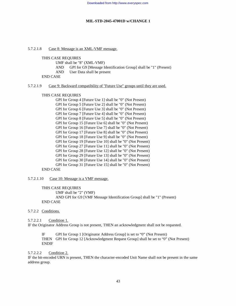
MIL-STD-2045-47001D w/CHANGE 1
43
5.7.2.1.8 Case 8: Message is an XML-VMF message. THIS CASE REQUIRES UMF shall be "8" (XML-VMF) AND GPI for G9 [Message Identification Group] shall be "1" (Present)
AND User Data shall be present END CASE 5.7.2.1.9 Case 9: Backward compatibility of "Future Use" groups until they are used. THIS CASE REQUIRES GPI for Group 4 [Future Use 1] shall be "0" (Not Present) GPI for Group 5 [Future Use 2] shall be "0" (Not Present) GPI for Group 6 [Future Use 3] shall be "0" (Not Present) GPI for Group 7 [Future Use 4] shall be "0" (Not Present) GPI for Group 8 [Future Use 5] shall be "0" (Not Present) GPI for Group 15 [Future Use 6] shall be "0" (Not Present) GPI for Group 16 [Future Use 7] shall be "0" (Not Present) GPI for Group 17 [Future Use 8] shall be "0" (Not Present) GPI for Group 18 [Future Use 9] shall be "0" (Not Present) GPI for Group 19 [Future Use 10] shall be "0" (Not Present) GPI for Group 27 [Future Use 11] shall be "0" (Not Present) GPI for Group 28 [Future Use 12] shall be "0" (Not Present) GPI for Group 29 [Future Use 13] shall be "0" (Not Present) GPI for Group 30 [Future Use 14] shall be "0" (Not Present) GPI for Group 31 [Future Use 15] shall be "0" (Not Present) END CASE 5.7.2.1.10 Case 10: Message is a VMF message. THIS CASE REQUIRES UMF shall be "2" (VMF) AND GPI for G9 [VMF Message Identification Group] shall be "1" (Present) END CASE 5.7.2.2 Conditions. 5.7.2.2.1 Condition 1. IF the Originator Address Group is not present, THEN an acknowledgment shall not be requested.
IF GPI for Group 1 [Originator Address Group] is set to “0” (Not Present) THEN GPI for Group 12 [Acknowledgment Request Group] shall be set to “0” (Not Present) ENDIF 5.7.2.2.2 Condition 2. IF the bit-encoded URN is present, THEN the character-encoded Unit Name shall not be present in the same address group.
Downloaded from http://www.everyspec.com

MIL-STD-2045-47001D w/CHANGE 1
44
IF FPI for URN is set to “1” (Present) THEN FPI for Unit Name shall be set to “0” (Not Present) ENDIF 5.7.2.2.3 Condition 3. IF the bit-encoded URN is not present, THEN the character-encoded Unit Name shall be present in the same address group.
IF FPI for URN is set to “0” (Not Present) THEN FPI for Unit Name shall be set to “1” (Present) ENDIF 5.7.2.2.4 Condition 4. IF the character-encoded Unit Name is present, THEN the bit-encoded URN shall not be present in the same address group.
IF FPI for Unit Name is set to “1” (Present) THEN FPI for URN shall be set to “0” (Not Present) ENDIF 5.7.2.2.5 Condition 5. IF the character-encoded Unit Name is not present, THEN the bit-encoded URN shall be present in the same address group.
IF FPI for Unit Name is set to “0” (Not Present) THEN FPI for URN shall be set to “1” (Present) ENDIF 5.7.2.2.6 Condition 6. This paragraph is left blank to maintain paragraph conformity.
5.7.2.2.7 Condition 7. IF Message Handling Group (R3) repeats, THEN Message Size and Header Size shall be present.
IF GRI of R3 [Message Handling Group] is set to “1” (Repeated) THEN FPI for Message Size shall be set to “1” (Present) AND FPI for Header Size shall be set to "1" (Present) ENDIF 5.7.2.2.8 Condition 8. IF the message is not a CANTCO, THEN CANTCO Reason Code shall not be present.
IF R/C is NOT set to “6” (CANTCO) THEN FPI for CANTCO Reason Code shall be set to “0” (Not Present) ENDIF 5.7.2.2.9 Condition 9. IF the message is not a CANTPRO, THEN CANTPRO Reason Code shall not be present.
IF R/C is NOT set to “2” (CANTPRO) THEN FPI for CANTPRO Reason Code shall be set to “0” (Not Present)
Downloaded from http://www.everyspec.com

MIL-STD-2045-47001D w/CHANGE 1
45
ENDIF 5.7.2.2.10 Condition 10. This paragraph is left blank to maintain paragraph conformity.
5.7.2.2.11 Condition 11. IF the Machine Acknowledge OR Operator Acknowledge OR Operator Reply Request Indicators are set to “1”, THEN the Originator DTG group shall be present.
IF Machine Acknowledge Request Indicator is set to “1” (Machine Acknowledgment Required) OR Operator Acknowledge Request Indicator is set to “1” (Operator Acknowledgment
Required) OR Operator Reply Request Indicator is set to “1” (Operator Reply Required) THEN GPI for Group 10[Originator DTG] shall be set to “1” (Present) ENDIF 5.7.2.2.12 Condition 12. This paragraph is left blank to maintain paragraph conformity.
5.7.2.2.13 Condition 13. IF the Security Parameters Information is “0” (Authentication (using SHA-1 and DSA)/ No Encryption) THEN GPI for Keying Material Group, GPI for Cryptographic Initialization Group, GPI for Key Token Group, AND GPI for Message Security Padding Group shall all be set to “0” (Not Present), AND the GPI for Authentication Data (A) Group shall be set to “1” (Present).
IF Security Parameters Information is set to “0” (Authentication (using SHA-1 and DSA)/ No Encryption)
THEN GPI for Group 21 [Keying Material Group] shall be set to “0” (Not Present) AND GPI for Group 22 [Cryptographic Initialization Group] shall be set to “0” (Not Present) AND GPI for Group 23 [Key Token Group] shall be set to “0” (Not Present) AND GPI for Group 24 [Authentication (A) Group] shall be set to “1” (Present) AND GPI for Group 26 [Message Security Padding Group] shall be set to “0” (Not Present)
ENDIF 5.7.2.2.14 Condition 14. IF the GPI for Acknowledgment Request Group is set to “0” (Not Present) THEN the Signed Acknowledge Request Indicator shall be set to “0” (Signed Acknowledgment Not Required).
IF GPI for Group 12 [Acknowledgment Request Group] is set to “0” (Not Present) THEN Signed Acknowledge Request Indicator shall be set to “0” (Signed Acknowledgment Not
Required). ENDIF 5.7.2.2.15 Condition 15. IF the Signed Acknowledge Request Indicator is set to “1” (Signed Acknowledgment Required) THEN the Acknowledgment Request Group shall be set to “1” (Present).
IF Signed Acknowledge Request Indicator is set to “1” (Signed Acknowledgment Required) THEN GPI for Group 12 [Acknowledgment Request Group] shall be set to “1” (Present). ENDIF
Downloaded from http://www.everyspec.com

MIL-STD-2045-47001D w/CHANGE 1
46
5.7.2.2.16 Condition 16. IF the User Message Format (UMF) field is set to “6” (DOI-103), THEN the Message Precedence is “5” (CRITIC/ECP).
IF UMF is set to “6” (DOI-103), THEN Message Precedence is set to “5” (CRITIC/ECP)
ENDIF 5.7.2.2.17 Condition 17.
IF Retransmit Indicator is set to “1” (Retransmitted Message) THEN GPI for G10 [Originator DTG] shall be set to “1” (Present) identifying the original
date-time-group of the original message ENDIF 5.7.2.2.18 Condition 18. If UMF is set to “2” (Variable Message Format (VMF)) THEN the FPI for Message Standard Version field is set to “1” (PRESENT). IF UMF is set to “2” (Variable Message Format (VMF))
THEN FPI for Message Standard Version shall be set to “1” (Present) ENDIF 5.7.2.3 Defaults. Default values for Message Precedence, Acknowledgments, and Message Classification shall be user defined.
5.7.2.4 Expected response. 5.7.2.4.1 Machine Acknowledge requested. IF Machine Acknowledge Requested Indicator is set to “1” (Machine Acknowledgment Required) THEN Response shall have R/C set to “1” (Machine Receipt) OR Response shall have R/C set to “2” (CANTPRO) ENDIF 5.7.2.4.2 Operator Acknowledge requested. IF Operator Acknowledge Requested Indicator is set to “1” (Operator Acknowledgment Required) THEN Response shall have R/C set to “3” (OPRACK) OR Response shall have R/C set to “2” (CANTPRO) ENDIF 5.7.2.4.3 Operator Reply Requested.
IF Operator Reply Requested Indicator is set to “1” (Operator Reply Required) THEN Response shall have R/C set to “4” (WILCO) OR Response shall have R/C set to “5” (HAVCO) OR Response shall have R/C set to “6” (CANTCO) OR Response shall have R/C set to “2” (CANTPRO) ENDIF
Downloaded from http://www.everyspec.com

MIL-STD-2045-47001D w/CHANGE 1
47
5.7.2.4.4 Signed Acknowledge Requested.
IF Signed Acknowledge Request Indicator is set to “1” (Signed Acknowledgment Required) THEN Response shall have GPI for Group 25[Authentication (B) Group] set to “1” (Present)
OR {Response shall have R/C set to “2” (CANTPRO) AND [CANTPRO Reason Code is specified “27” (Authentication Failure)
OR CANTPRO Reason Code is specified “28” (Certificate not found) OR CANTPRO Reason Code is specified “29” (Certificate invalid) OR CANTPRO Reason Code is specified “30” (Do not support this SPI
value) OR CANTPRO Reason Code is specified “31” (Can not generate a signed
acknowledgment)]} ENDIF 5.7.2.5 Special considerations. 5.7.2.5.1 Perishable data check. Discard messages that are too old. IF GPI for Group 11 [Perishability DTG Group] is set to “1” (Present) AND Group 11 [Perishability DTG Group] is earlier than current DTG THEN User Data shall be ignored AND
IF Machine Acknowledgment Request indicator is set to “1” (Machine Acknowledgment Required)
THEN Response shall have R/C set to “2” (CANTPRO) AND a CANTPRO Reason Code set to “25” (Message too Old, Based On
Perishability) ENDIF ENDIF 5.7.2.5.2 Response to version non-interoperability. Version code is set to “15” (Version Sent Not Implemented) if recipient does not implement the MIL-STD-2045-47001 version sent.
IF Recipient does not implement Version sent THEN Version shall be set to “15” (Version Sent Not Implemented) AND FPI for Data Compression Type shall be set to “0” (Not Present) AND GPI for Group 1 [Originator Address Group] shall be set to “1” (Present) AND Originator Address specified is the Original Recipient AND GPI for Group 2 [Recipient Address Group] shall be set to “1” (Present) AND Recipient Address specified is the Originator of the original message ENDIF 5.7.2.5.3 Broadcast transmission check. IF the Recipient Address Group is not present, AND the Information Address Group is not present THEN the message shall be a broadcast transmission.
IF GPI for Group 2 [Recipient Address Group] is set to “0” (Not Present) AND GPI for Group 3 [Information Address Group] is set to “0” (Not Present) THEN the message shall be broadcast in accordance with lower layer broadcast protocols ENDIF
Downloaded from http://www.everyspec.com

MIL-STD-2045-47001D w/CHANGE 1
48
5.7.2.5.4 Originator DTG check. IF the Originator DTG is ambiguous, THEN the DTG Extension shall be present.
IF Originator DTG is equal to the Originator DTG of a previously sent message THEN FPI for DTG Extension shall be set to “1” (Present) AND DTG Extension shall be unique ENDIF 5.7.2.5.5 Message sent via a streaming/undelimited transport protocol check. If Message Handling Group (R3) only occurs once and the message is being sent via a streaming/undelimited transport protocol, such as TCP, then Message Size and Header Size shall be present.
IF GRI of R3 [Message Handling Group] is set to “0” (Not Repeated) AND the message is being sent via a streaming/undelimited transport
THEN FPI for Message Size shall be set to “1” (Present) AND FPI for Header Size shall be set to "1" (Present)
ENDIF 5.7.2.5.6 Message concatenation. When concatenating messages, the Originator, Recipient and Information Address Groups shall be common for all concatenated messages and therefore will appear once in the Application Header. The Message Handling Group (R3) shall repeat to specify information about each concatenated message. Each occurrence of the Message Handling Group [R3] shall be matched to its respective message in the User Data portion. The total size of any single User Data portion (e.g. a single VMF message) within a concatenated message block shall not exceed 1 megabyte (1,048,575 bytes).
IF GPI for Group 1 [Originator Address Group] is set to “1” (Present) OR GPI for Group 2 [Recipient Address Group] is set to “1” (Present) OR GPI for Group 3 [Information Address Group] is set to “1” (Present) THEN (Group 1 [Originator Address Group], Group 2 [Recipient Address Group], and Group 3
[Information Address Group] addresses are common to all concatenated messages) AND GRI for R3 [Message Handling Group] shall be set to “1” (Repeated) AND Each iteration shall match in sequence specifying information about its respective
concatenated message AND FPI for Message Size shall be set to “1” (Present) AND FPI for Header Size shall be set to "1" (Present)
AND Message Size (any single message within the concatenated block) shall not exceed1,048,575 bytes
ENDIF 5.7.2.5.7 Message case and message subtype relationship.
IF Cases exist for transmitted VMF message THEN FPI for Message Subtype is specified “1” (Present) ENDIF
5.7.2.5.8 Sending response to a large message. If the received message size is greater than the Maximum Segment Size AND Response(s) were requested AND the message was received via a reliable transport mechanism (e.g. S/R, TCP, etc.) THEN send the response(s) via a reliable transport mechanism.
Downloaded from http://www.everyspec.com

MIL-STD-2045-47001D w/CHANGE 1
49
IF The received message size is greater than Maximum Segment Size AND GPI for G12 [Acknowledgment Request Group] is set to “1” (Present) AND the message was received via a reliable transport mechanism
THEN Response(s) to the received message shall be sent via a reliable transport mechanism ENDIF
5.7.2.5.9 DTG extension to DTG of message being acknowledged.
IF GPI for Group 13 [Response Data Group] is set to “1” (Present) THEN IF FPI for DTG Extension discriminating the Originator DTG is set to “1” (Present)
THEN Response message shall have GPI for Group 13 [Response Data Group] identifying the DTG of message being acknowledged is set to “1” (Present) AND FPI for DTG Extension discriminating the DTG of message being
acknowledged shall be set to “1” (Present) ELSE Response message shall have GPI for Group 13 [Response Data Group] identifying the
DTG of message being acknowledged is set to “1” (Present) AND FPI for DTG Extension discriminating the DTG of message being
acknowledged is set to “0” (Not Present) ENDIF ENDIF
5.7.2.5.10 Decompression of messages prior to parsing.
IF FPI for Data Compression Type field is set to “1” (Present) THEN Receiving system shall decompress the user data prior to parsing ENDIF
5.7.2.5.11 Unit Name usage in a response message.
IF FPI for Unit Name identifying the originator is set to “1” (Present) THEN Response message shall have the FPI for Unit Name identifying the recipient is set to “1”
(Present) AND FPI for URN is set to “0” (Not Present)
ENDIF 5.7.2.5.12 URN usage in a response message.
IF FPI for URN identifying the originator is set to “1” (Present) THEN Response message shall have the FPI for URN identifying the recipient set to “1” (Present) AND FPI for Unit Name shall be set to “0” (Not Present) ENDIF
5.7.2.5.13 Addressee URN uniqueness. A specified URN shall occur at most once as an addressee of a message, either as a recipient destination or as an information destination. Duplicate destination URNs in the recipient address group and the information address group of a message are not permitted.
Downloaded from http://www.everyspec.com

MIL-STD-2045-47001D w/CHANGE 1
50
5.7.2.5.14 Message that uses Segmentation/Reassembly protocol.
IF Data transfer is greater than the Maximum Segment Size (MSS) permitted AND (Data package is transported via CNR networks using UDP
OR Data package is transported via CNR networks using n-layer pass through) THEN Message Segmentation/Reassembly protocol shall be used ENDIF 5.7.2.5.15 UMF Codes in the Acknowledgment Header. If the message is an Acknowledgment Header, then UMF code shall be the same as the UMF code for the message being acknowledged. 5.7.2.5.16 VMF Message Identification Group in Acknowledgment Header. If the message is an Acknowledgment Header, then Group 9 [VMF Message Identification Group] shall be the same as the Group 9 [VMF Message Identification Group] for the message being acknowledged. 5.7.2.5.17 Messages that should use MIL-STD-188-220 N-layer pass through. The intent of this special condition is to provide guidance as to when N-layer pass through should be used to transmit messages when MIL-STD-188-220 is used as the lower level protocol. This allows for stations to automatically determine when to use N-layer pass through which reduces network overhead associated with IP headers.
IF ( (the message is broadcast according to 5.6.3b) OR (the only destination address specified is the broadcast URN) OR (all destination addresses (i.e., all recipient and information addresses) are in same IP
subnetwork as the Originator)) THEN N-layer pass-through should be used ENDIF
Note: The above assumes stations in the same MIL-STD-188-220 subnetwork have identical NETIDs (i.e., the logical combination of the IP Subnet Mask and the IP Address). Determining when a Destination URN(s) is in the same subnetwork as the Originator URN can be implemented by converting the URN(s) to IP addresses and using the IP Subnet Mask specified for the subnetwork. 5.7.2.6 Minimum implementation (MIN IMP). A platform/system shall implement those items defined in this document as being MIN IMP, i.e., they are mandatory. Unless otherwise stated, MIN IMP items shall be required for transmission and reception. Upon reception, MIN IMP items shall always be processed and understood. The term “understood” shall be taken to mean some form of post-parsing processing, i.e., display to an operator, adding to a database, etc. MINIMP items shall not be discarded prior to such action. MIN IMP occurs at several levels as follows:
a. All fields marked “M” in TABLE I application header. b. All fields within groups of TABLE I where the GPI is specified present, except for those that could be
mutually exclusive such as in the Acknowledgement Request Group (G12).
c. Cases, as defined in TABLE XIV.
Downloaded from http://www.everyspec.com

MIL-STD-2045-47001D w/CHANGE 1
51
d. Expected Responses as defined in TABLE XV.
e. Special Considerations as defined in TABLE XVI.
TABLE XIV. Case level minimum implementation. Case Title Transmit Receive
1 Message is an original message. M M 2 Message is an acknowledgment message. M M 3 Message is not a XML or XML-VMF message. M M 4 Message is a redistributed message. O M 5 Message was compressed. O M 6 Message has security services applied. O O 7 Message is a signed acknowledgment. O O 8 Message is an XML-VMF message. O O 9 Backward compatibility of “Future Use” groups until they are used. M M
10 Message is a VMF message. O O
TABLE XV. Expected response minimum implementation. Expected Response
Title Transmit Receive
1 Machine Acknowledge requested. M M 2 Operator Acknowledge requested. M M 3 Operator Reply requested. M M 4 Signed Acknowledge requested. O O
TABLE XVI. Special consideration minimum implementation.
Special
Consideration Title Transmit Receive
1 Perishable Data Check. M M 2 Response to version non-interoperability. M M 3 Broadcast Transmission Check. M M 4 Add DTG Extension when Originator DTGs are the same. M M 5 Message sent via a streaming/undelimited transport
protocol. M M
6 Message Concatenation O M 7 Message Case and Message Subtype Relationship. M M 8 Sending Response to a large message. M M 9 DTG Extension to DTG of Message Being Acknowledged. M M 10 Decompression of messages prior to parsing. M M 11 Unit Name usage in a response message. M M 12 URN usage in a response message. M M 13 Address URN uniqueness. M M 14 Message uses Segmentation/Reassembly protocol. M M 15 UMF codes in the Acknowledgment Header M M
Downloaded from http://www.everyspec.com

MIL-STD-2045-47001D w/CHANGE 1
52
TABLE XVI. Special consideration minimum implementation.
Special Consideration
Title Transmit Receive
16 VMF Message Identification Group in Acknowledgment Header
M M
17 Messages that should use MIL-STD-188-220 N-layer pass through
O O
5.7.2.7 Field level minimum implementation. When a system implements either a mandatory or an optional field, it shall implement all field values for that field and processing logic to use all field values for transmission and reception
5.7.3 User data. This portion of the application PDU contains the application process messages or data.
5.7.4 Message acknowledgments. A message acknowledgment is a report back to the originator on a receiving station’s receipt of and intentions with respect to a received message. Acknowledgment requests are directed to message recipients only; they do not apply to information addressees. Acknowledgments are implemented in the acknowledgment header format.
5.7.4.1 Acknowledgment header format. Machine and operator acknowledgment request indicators are used by the originator to request a specific response from the receiving station, or appropriate operator, for selective acknowledgment of message receipt and compliance with the message instructions. A receiving station shall respond to the originator by sending an acknowledgment header. Depending on the type of acknowledgment request from the originator or the type of system involved, the response may be machine-generated (automatic) or operator-generated (manual) or a combination thereof. The acknowledgment header consists of the following groups and fields (see also 5.7.2.1.2):
a. Acknowledgment originator address group (G1)
b. Acknowledgment recipient address group (R1)
c. Message Handling Group (R3). Within Message Handling Group, the Response Data Group (G13), shall include the DTG of message being acknowledged and the R/C field.
5.7.4.2 Message accountability. The application header shall be used for the detection of duplicate messages and to associate an acknowledgment header with the original requesting message. The received fields of originator address group, originator DTG, and DTG Extension are used to uniquely identify a message. The originator shall guarantee the uniqueness of this combination of fields by ensuring that no original message is transmitted having the same DTG and DTG Extension.
a. Duplicate message check. The originator address group, originator DTG, and DTG Extension fields of each received message are compared with the corresponding fields of previous messages. Any duplicate messages (including retransmitted messages) shall be acknowledged if required and shall otherwise be ignored (discarded).
b. Acknowledgment matching. The originator address group, DTG of message being acknowledged, and DTG Extension fields of each received acknowledgment header are compared with the recipient address group, Originator DTG, and DTG Extension fields of previously originated messages that require acknowledgment. The
Downloaded from http://www.everyspec.com

MIL-STD-2045-47001D w/CHANGE 1
53
message handling application shall maintain DTG, Originator Address, and DTG Extension information about previously received messages for a period of time long enough to exhaust the message originator’s retransmission timers. Acknowledgment headers that match original messages shall be processed; unmatched Acknowledgment headers shall be ignored (discarded).
5.7.4.3 Message retransmission. A retransmission capability shall be provided to enable the automatic retransmission of a message that has not received an acknowledgment when one was requested. Automatic Retransmissions shall only apply if a machine acknowledgment is requested. Any Application layer acknowledgment precludes message retransmission.
a. The number of automatic retransmissions shall be selectable with a range of 0 to 3. The parameter governing the number of retransmissions shall be separately selectable for each Originator DTG/DTG Extension combination.
b. A timer shall be provided to schedule the automatic retransmission. An expiration timer shall be selectable with a range of 5 to 600 seconds. Upon expiration of the timer, provided an acknowledgment has not been received, the message shall be retransmitted by the originating system. If an acknowledgment is not received prior to expiration of the timer on the final retransmission, the operator shall be notified. Messages containing perishable data and requiring acknowledgment shall have the Perishability DTG set to a time later than the retransmit timeout.
5.8 Processing factors. 5.8.1 Application process. The application process shall provide the application layer the bit-oriented or character-oriented messages that satisfy information exchange requirements.
5.8.2 Message formats. The message formats shall be user-defined. The UMF field in the application layer header specifies the message format that is being used in the application process.
5.8.3 Lower layer interactions. Several application layer fields are used to indicate a desire for special handling or quality of service (QOS) from the lower layer protocols. The lower layer protocols should use these indications as guidance for providing the requested service.
5.8.3.1 Security Classification. This application layer field as described in TABLE VIII provides the desired guidance to the lower layers for establishing security classification.
5.8.3.2 Message Precedence. This application layer field as described in TABLE VII provides the desired guidance to the lower layers for setting message transmission precedence.
5.8.3.3 Quality of Service (QOS). The QOS desired by the application layer is derived from multiple fields: Message Size, Message Precedence, Originator DTG, Time Perishability DTG, and Machine Acknowledgment Request Indicator. The following QOS parameters are mapped from these application layer fields:
a. Normal/High Throughput
Downloaded from http://www.everyspec.com

MIL-STD-2045-47001D w/CHANGE 1
54
b. Normal/Low Delay
c. Normal/High Reliability
These QOS parameters are based on the following conditions:
IF (Time Perishability DTG - Originator DTG) <= Perish AND Precedence <> Routine THEN Delay = Low ELSIF (Time Perishability DTG - Originator DTG) > Perish AND Message Acknowledgment Indicator == 1 AND Message Size >= Message Size Threshold THEN Reliability = High ELSIF Message Size >= Message Size Threshold AND Delay == Normal AND Reliability == Normal THEN Throughput = High ELSE Delay = Normal AND Throughput = Normal AND Reliability = Normal ENDIF where:
Message Size Threshold has a default value of (3*480 = 1440) bytes. Message Size Threshold shall be a parameter with a range of 1 to 1,048,575 bytes. Perish shall be a parameter with a range of 1 to 10800 seconds.
5.8.3.4 Originator address group. This application layer group as described in 5.6.3 provides guidance to the lower layers for the originator address.
5.8.3.5 Recipient address group. This application layer group as described in 5.6.3 provides guidance to the lower layers for the destination address.
5.8.3.6 Message broadcast indicators. The absence of a Recipient Address group and the absence of an Information Address group as described in 5.6.3 provides guidance to the lower layers for broadcast options.
5.8.3.7 Destination port number. The port named “mil-2045-47001” has been registered with the Internet Assigned Number Authority and has been assigned port number 1581 (decimal) to indicate the MIL-STD-2045-47001 ALP as defined by this standard. This “mil-2045-47001” port shall be passed as the destination port parameter value to the lower layer protocol (e.g., UDP, TCP, or S/R) when exchanging UMF defined in TABLE IV. TABLE XVII shows the port numbers that shall be used for IP/UDP data exchanges using the “47001” ALP. (See C.3.2.1 for a discussion on exchanging data using the S/R protocol). If n-layer pass through is invoked without S/R, the next lower layer is the intranet layer and destination port number is not required.
TABLE XVII. Port Numbers for PDUs related to the exchange of 47001 ALP
Downloaded from http://www.everyspec.com

MIL-STD-2045-47001D w/CHANGE 1
55
“47001” messages sent via UDP/IP UDP Destination Port number UDP Source Port number 1581 Any value
5.8.4 Application header padding. The application header shall always be a multiple of 8 bits. If an application header is not a multiple of 8 bits, it shall be zero-filled so that it becomes a multiple of 8 bits. This field shall be variable in size 0 - 7 bits. This padding allows the message portion to start on a byte boundary.
Downloaded from http://www.everyspec.com

MIL-STD-2045-47001D w/CHANGE 1
56
6 NOTES This section contains information of a general or explanatory nature that may be helpful, but is not mandatory.
6.1 Subject term (key word) listing. The following key words and phrases apply to this MIL-STD.
Application Header Application Layer Combat Network Radio (CNR) DOI-103 Link 16 MIL-STD-188-220 MIL-STD-2045-47001 MIL-STD-6016 MIL-STD-6017 MIL-STD-6040 NITFS Receipt/Compliance (R/C) Security Extension Protocol (SEP) Segmentation/Reassembly (S/R) TIDP-TE Unit Reference Number (URN) USMTF VMF 6.2 Issue of the DoD index of specifications and standards (DODISS). When this military standard is used in procurement, the applicable issue of the DoDISS will be cited in the solicitation.
6.3 Management of TCP connections. When TCP is used to transport the MIL-STD-2045-47001 ALP over low bit rate combat network radio (CNR) networks, the overhead for opening and closing connections can contribute substantially to the offered load presented to the CNR network. The following conventions for the management of TCP connections used to transport the ALP are offered to allow the amount of overhead generated as the result of opening and closing TCP connections to be controlled.
a. When a MIL-STD-2045-47001 message becomes available for transport, a TCP connection will be opened to the destination if a connection to the destination hasn’t already been established.
b. An established TCP connection to a given destination will be gracefully closed if no activity (transmitted or received data) occurs on the connection within some configurable time period of the most recent activity on that connection.
c. If a connection already exists to a given destination and an additional connection offer is received from the same destination, the older connection will be closed at the end of the normal completion of any pending message transports such that only one connection is maintained and utilized for each destination.
d. MIL-STD-2045-47001 messages will be offered for transport over the TCP connection to the specified destination in the order established by the Message Precedence field of the MIL-STD-2045-47001 Application Header. If a higher priority message becomes available for transport to a destination while a lower priority message is in the process of being transported to the same destination, the transport of the higher priority message
Downloaded from http://www.everyspec.com

MIL-STD-2045-47001D w/CHANGE 1
57
will begin immediately after the transport of the lower priority message is completed. Lower priority messages that have not already been offered for transport on the connection should not be offered for transport until after higher priority messages have been offered for transport on the connection.
e. The number of connections/destinations that can be utilized simultaneously by a single MIL-STD-2045-47001 application should be limited to a configurable number. Once this limit is reached there are two reasons additional connections might need to be established: either a message becomes available locally for transport to an additional destination, or a connection offer is received from a new remote source.
(1) In the case of a locally generated message to an additional destination, the Least Recently Active (LRA) connection, that is not currently being used for the transport of messages, should be closed prior to the establishment of a connection to the new destination. If all connections are actively being used, then the new message transport request should be discarded and treated as a transport failure.
(2) In the case that a connection offer is accepted from an additional remote source, the LRA connection that is not currently being used for the transport of messages should be closed. If all connections are actively being used, then the new recently accepted connection should be abruptly closed. Abruptly closing the newly accepted connection will terminate any pending transmissions from the remote source and inform the remote source that any pending messages were not transported successfully.
6.4 Application header initial settings. TABLE XVIII provides guidance to be used to describe the initial settings of the Application Header used by all systems to facilitate initial interoperability. These initial settings are proposed to support minimum requirements for message transmissions.
TABLE XVIII mimics TABLE I with the last two columns being replaced with “Prefill Value” and “Data Item” columns. The prefill column identifies the bit code associated with this field. The data item column information identifies the meaning or source of the information associated with this field.
The following symbology is used with this table:
Not part of the initial settings. Ww Provided by Mission Computer, based MIL-STD-2045-47001 Version xxxxxx
URN pre-designated/assigned and resident in the mission computer.
Yy Based on message FAD, message number and message subtype. zz Time data derived from the mission computer.
TABLE XVIII. Application header initial settings
Field Name CAT Group
Code Repeat Code
Prefill Value
Data Item
VERSION M ww Mission Computer Fill (Version D or higher)
FPI M 0 Not Present
Downloaded from http://www.everyspec.com

MIL-STD-2045-47001D w/CHANGE 1
58
TABLE XVIII. Application header initial settings - Continued
Field Name CAT Group Code
Repeat Code
Prefill Value
Data Item
DATA COMPRESSION TYPE
GPI (Originator) M 1 Present
FPI G1 1 Present
URN G1 xxxxxx Mission Computer Fill
FPI G1 0 Not Present
UNIT NAME G1
GPI (Addressee(s)) M 1 Present
GRI G2 R1(N) 0<=N<=
16
0 Not Repeated
FPI G2 R1 1 Present
URN G2 R1 xxxxxx Mission Computer/Operator Fill
FPI G2 R1 0 Not Present
UNIT NAME G2 R1
GPI (Info Addressee(s)) M 0 Not Present
GRI G3 R2(16 - N)
FPI G3 R2
URN G3 R2
FPI G3 R2
UNIT NAME G3 R2
FPI M 0 Not Present
HEADER SIZE
GPI (Future Use Group 1) M G4 0 Not Present
GPI (Future Use Group 2) M G5 0 Not Present
GPI (Future Use Group 3) M G6 0 Not Present
GPI (Future Use Group 4) M G7 0 Not Present
GPI (Future Use Group 5) M G8 0 Not Present
GRI (Message Handling Group) M R3(16) 0 Not Repeated
UMF M R3 2 Variable Message Format (VMF)
FPI M R3 1 Present
Downloaded from http://www.everyspec.com

MIL-STD-2045-47001D w/CHANGE 1
59
TABLE XVIII. Application header initial settings - Continued
Field Name CAT Group Code
Repeat Code
Prefill Value
Data Item
MESSAGE STANDARD VERSION R3 5 MIL-STD-6017
GPI (VMF Message Identification Group)
M R3 1 Present
FAD G9 R3 yy Message Dependent
MESSAGE NUMBER G9 R3 yy Message Dependent
FPI G9 R3 yy Message Dependent
MESSAGE SUBTYPE G9 R3 yy Message Dependent
FPI M R3 0 Not Present
FILE NAME R3
FPI M R3 0 Not Present
MESSAGE SIZE R3
OPERATION INDICATOR M R3 0 Operation
RETRANSMIT INDICATOR M R3 0 Not a Retransmission
MESSAGE PRECEDENCE CODE M R3 7 Routine
SECURITY CLASSIFICATION M R3 0 Unclassified
FPI M R3 0 Not Present
FRI R3/R4 (16)
CONTROL/RELEASE MARKING R3/R4
GPI (Originator DTG) M R3 1 Present
YEAR G10 R3 zz Auto Fill
MONTH G10 R3 zz Auto Fill
DAY G10 R3 zz Auto Fill
HOUR G10 R3 zz Auto Fill
MINUTE G10 R3 zz Auto Fill
SECOND G10 R3 zz Auto Fill
FPI G10 R3 0 Not Present
DTG EXTENSION G10 R3
GPI (Perishability DTG) M R3 0 Not Present
YEAR G11 R3
MONTH G11 R3
Downloaded from http://www.everyspec.com

MIL-STD-2045-47001D w/CHANGE 1
60
TABLE XVIII. Application header initial settings - Continued
Field Name CAT Group Code
Repeat Code
Prefill Value
Data Item
DAY G11 R3
HOUR G11 R3
MINUTE G11 R3
SECOND G11 R3
GPI (Acknowledgment Request Group)
M R3 1 Present
MACHINE ACKNOWLEDGE REQUEST INDICATOR
G12 R3 1 Machine Acknowledgment Required
OPERATOR ACKNOWLEDGE REQUEST INDICATOR
G12 R3 0 Operator Acknowledgment Not Required
OPERATOR REPLY REQUEST INDICATOR
G12 R3 0 Operator Reply Not Required
GPI (Response Data Group) M R3 0 Not Present
YEAR G13 R3
MONTH G13 R3
DAY G13 R3
HOUR G13 R3
MINUTE G13 R3
SECOND G13 R3
FPI G13 R3
DTG EXTENSION G13 R3
R/C G13 R3
FPI G13 R3
CANTCO REASON CODE G13 R3
FPI G13 R3
CANTPRO REASON CODE G13 R3
FPI G13 R3
REPLY AMPLIFICATION G13 R3
GPI (Reference Message DTG) M R3 0 Not Present
GRI G14 R3/R5(4)
FPI G14 R3/R5
URN G14 R3/R5
Downloaded from http://www.everyspec.com

MIL-STD-2045-47001D w/CHANGE 1
61
TABLE XVIII. Application header initial settings - Continued
Field Name CAT Group Code
Repeat Code
Prefill Value
Data Item
FPI G14 R3/R5
UNIT NAME G14 R3/R5
YEAR G14 R3/R5
MONTH G14 R3/R5
DAY G14 R3/R5
HOUR G14 R3/R5
MINUTE G14 R3/R5
SECOND G14 R3/R5
FPI G14 R3/R5
DTG EXTENSION G14 R3/R5
GPI (Future Use Group 6) M G15 R3 0 Not Present
GPI (Future Use Group 7) M G16 R3 0 Not Present
GPI (Future Use Group 8) M G17 R3 0 Not Present
GPI (Future Use Group 9) M G18 R3 0 Not Present
GPI (Future Use Group 10) M G19 R3 0 Not Present
GPI (Message Security Group) M R3 0 Not Present
SECURITY PARAMETERS INFORMATION
G20 R3
GPI (Keying Material Group) G20 R3
KEYING MATERIAL ID LENGTH G20/ G21
R3
KEYING MATERIAL ID G20/ G21
R3
GPI (Cryptographic Initialization Group)
G20 R3
CRYPTOGRAPHIC INITIALIZATION LENGTH
G20/ G22
R3
CRYPTOGRAPHIC INITIALIZATION
G20/ G22
R3
GPI (Key Token Group) G20 R3
KEY TOKEN LENGTH G20/ G23
R3
FRI G20/ G23
R3/R6 (17)
Downloaded from http://www.everyspec.com

MIL-STD-2045-47001D w/CHANGE 1
62
TABLE XVIII. Application header initial settings - Continued
Field Name CAT Group Code
Repeat Code
Prefill Value
Data Item
KEY TOKEN G20/ G23
R3/R6
GPI (Authentication (A) Group) G20 R3
AUTHENTICATION DATA (A) LENGTH
G20/ G24
R3
AUTHENTICATION DATA (A) G20/ G24
R3
GPI G20 R3
AUTHENTICATION DATA (B) LENGTH
G20/ G25
R3
AUTHENTICATION DATA (B) G20/ G25
R3
SIGNED ACKNOWLEDGE REQUEST INDICATOR
G20 R3
GPI G20 R3
MESSAGE SECURITY PADDING LENGTH
G20/ G26
R3
FPI G20/ G26
R3
MESSAGE SECURITY PADDING G20/ G26
R3
GPI M G27 0 Not Present
GPI M G28 0 Not Present
GPI M G29 0 Not Present
GPI M G30 0 Not Present
GPI M G31 0 Not Present
6.5 Changes from previous issue. Marginal notations are used in this revision to identify changes with respect to the previous issue.
Downloaded from http://www.everyspec.com

MIL-STD-2045-47001D w/CHANGE 1
63
APPENDIX A
APPLICATION HEADER FIELDS AND CODES FOR VMF A.1 General. A.1.1 Scope. This appendix contains definition of the VMF codes and values for application header fields that are dependent on the setting of the UMF field.
A.1.2 Application. This appendix is conditional based on the setting of the UMF field as indicated in 5.6.4 and TABLE IV of this standard. If the UMF field is set to “2” (VMF), this appendix is mandatory for application headers pertaining to VMF messages. For all other settings of UMF field, this appendix is optional.
A.2 Applicable documents. GOVERNMENT STANDARDS
MIL-STD-6017 DoD Interface Standard, Variable Message Format (VMF) MIL-STD-6017
A.3 Codeword tables. A.3.1 Unit reference number codewords. The VMF codes for the URN field shall be in accordance with the MIL-STD-6017.
A.3.2 FAD codewords. The VMF codes for the FAD field are defined in TABLE A-I. The FAD field is defined in 5.6.5 of this document. The combination of the FAD field and the Message Number field shall point to the message number that appears in the Message Descriptions of the MIL-STD-6017. For example, if the UMF = 2 (VMF K-Series), FAD = 1 (General Information Exchange), and Message Number = 1 (Free Text Message), then this corresponds to message number K01.1, in the ‘Message and Purpose Table’ of the MIL-STD-6017.
TABLE A-I. FAD codewords
Functional Area Code
MSB - LSB Network Control 0000
(0) General Information Exchange 0001
(1) Fire Support Operations 0010
(2) Air Operations 0011
(3)
Downloaded from http://www.everyspec.com

MIL-STD-2045-47001D w/CHANGE 1
APPENDIX A
64
TABLE A-I. FAD codewords – Continued
Functional Area Code
MSB - LSB Intelligence Operations 0100
(4) Land Combat Operations 0101
(5) Maritime Operations 0110
(6) Combat Service Support 0111
(7) Special Operations 1000
(8) Joint Task Force (JTF) Operations
Control 1001 (9)
Air Defense/Air Space Control 1010 (10)
Undefined 1011-1111 (11–15)
A.3.3 Message Number codewords. The VMF codes for the Message Number field are listed in the MIL-STD-6017. The Message Number field is defined in 5.6.6 of this document.
A.3.4 Message Subtype codewords. The VMF codes for the Message Subtype field are listed in TABLE A-II. The Message Subtype field is defined in 5.6.7 of this document. The combination of the FAD field (see 5.6.5), the Message Number field (see 5.6.6) and the Message Subtype field (see 5.6.7) identifies a specific case within a multi-purpose message.
A.3.4.1 MIL-STD-6017 message cases as message subtypes. Case statements define the rules for the preparation of each message for transmission and/or reception. These statements include the specific function of a message, its purpose(s), and the conditions for the use of data groups and data elements within that message. Cases for each VMF message variant are found in the MIL-STD-6017, K-Series Message Formats Message Processing section of the parent message.
TABLE A-II. MIL-STD-6017 message subtypes
Message Subtype Case Number
Code MSB - LSB
No Cases 0000000 (0)
Case 1.1 through Case 1.127
0000001 through 1111111
(1 through 127)
In increments of 1 case.
Downloaded from http://www.everyspec.com

MIL-STD-2045-47001D w/CHANGE 1
APPENDIX A
65
A.3.5 CANTCO Reason codewords. The VMF codes for the CANTCO Reason field are defined in TABLE A-III. The CANTCO Reason field is defined in 5.6.23 of this document.
TABLE A-III. CANTCO Reason codewords
CANTCO reason Code MSB - LSB
Communications problem 000 (0)
Ammunition problem 001 (1)
Personnel problem 010 (2)
Fuel problem 011 (3)
Terrain/Environment problem 100 (4)
Equipment problem 101 (5)
Tactical Situation problem 110 (6)
Other 111 (7)
A.3.6 CANTPRO Reason codewords. The VMF codes for the CANTPRO Reason field are defined in TABLE A-IV. The CANTPRO Reason field is defined in 5.6.24 of this document.
TABLE A-IV. CANTPRO Reason codes
CANTPRO Reason Code MSB - LSB
Undefined 000000 (0)
Field content invalid 000001 (1)
Message incorrectly routed 000010 (2)
Address inactive 000011 (3)
Reference point unknown to receiving agency
000100 (4)
Downloaded from http://www.everyspec.com

MIL-STD-2045-47001D w/CHANGE 1
APPENDIX A
66
TABLE A-IV. CANTPRO Reason codes – Continued
CANTPRO Reason Code
MSB - LSB Fire units shall be controlled by receiving agency
000101 (5)
Mission shall be controlled by receiving agency
000110 (6)
Mission number unknown by receiving agency
000111 (7)
Target number unknown by receiving agency
001000 (8)
Schedule number unknown by receiving agency
001001 (9)
Incorrect controlling address for a given track number
001010 (10)
Track number not in own track file 001011 (11)
Invalid according to given field 001100 (12)
Message cannot be converted 001101 (13)
Agency file full 001110 (14)
Agency does not recognize this message number
001111 (15)
Agency cannot correlate message to current file content
010000 (16)
Agency limit exceeded on repeated fields or groups
010001 (17)
Agency computer system inactive 010010 (18)
Addressee unknown 010011 (19)
Can’t forward (agency failure) 010100 (20)
Can’t forward (link failure) 010101 (21)
Illogical juxtaposition of header fields 010110 (22)
Cannot uncompress Unix (LZW) compressed data
010111 (23)
Cannot uncompress LZ-77 compressed data
011000 (24)
Message too old, based on Perishability 011001 (25)
Downloaded from http://www.everyspec.com

MIL-STD-2045-47001D w/CHANGE 1
APPENDIX A
67
TABLE A-IV. CANTPRO Reason codes – Continued
CANTPRO Reason Code
MSB - LSB Security level restriction 011010
(26) Authentication Failure 011011
(27) Certificate not found 011100
(28) Certificate invalid 011101
(29) Do not support this SPI value 011110
(30) Can not generate a signed acknowledgement
011111 (31)
Response not available for retransmission
100000 (32)
Undefined 100001-111111 (33 – 63)
A.3.7 Data field construction procedures for VMF messages/user data. The following construction procedures prescribe the sequence in which the message fields are linearly joined to create the user data. The message is constructed with elemental data fields ordered as specified in the message descriptions provided in the MIL-STD-6017. The data elements for the messages are also as specified in the MIL-STD-6017. There are two representations for data elements: 7-bit ANSI ASCII characters and binary numbers. All fields shall be joined LSB first. The LSB of the first data field or field/group indicator shall be LSB-justified within the first byte of the message buffer. The LSB of each successive data field or field/group indicator shall be the LSB of the user data shown in FIGURE 2 of this document. The characters in a literal field are joined such that the LSB of the first character immediately follows the MSB of the previous field. The LSB of the second character immediately follows the MSB of the first character. This pattern is repeated until all characters of the field are joined.
Downloaded from http://www.everyspec.com

MIL-STD-2045-47001D
68
APPENDIX B
EXAMPLE OF APPLICATION LAYER PDU AND VMF MESSAGE CONSTRUCTION B.1 General. B.1.1 Scope. This appendix provides examples illustrating the construction of the Application Layer PDU and VMF Message data buffers (or streams).
B.1.2 Application. This appendix is not a mandatory part of MIL-STD-2045-47001. The information contained herein is intended for guidance only.
B.2 Example application layer PDU construction. This section provides an example illustrating the construction of the Application Layer PDU data buffer (or stream).
B.2.1 Application layer data exchange. The relationship of the Application Layer to other communication layers is shown in FIGURE B-1. A layered communication model is used in this example for consistency with the principles of the ISO OSI reference model. The model discussed here is tailored to focus attention specifically on the Application Layer, and the data it produces. A user of the Application Layer exchanges user data with its peer at another node by sending and receiving the User Data via the Application Layer. The Application Layer sends and receives the User Data transparently by producing and exchanging an Application Layer PDU with its peer at another node. The Application Layer PDU consists of the Application Header concatenated with the User Data, and is sent and received via lower communication layers. The lower communication layers send and receive the User Data transparently over a variety of communications media.
The format of the Application Layer PDU is defined in terms of the actual data buffer or data stream used to exchange the PDU between the Application Layer and the lower communication layers. The rationale for using the PDU’s data buffer/stream to define the format is 1) for consistency with industry standard commercial communications hardware and software (e.g., UNIX implementations of TCP/IP), which exchange data with other software when sending or receiving as a buffer or stream of octets; 2) to provide a definition independent of the specifics of any other communication layer, consistent with the ISO OSI model principle of making communication layers independent; and 3) to avoid differences in the bit representations used to implement communications on different media. For example, on Ethernet LAN media each octet is sent LSB first, but on FDDI media each octet is sent MSB first. To achieve a universal definition of the PDU format, its representation is defined independent of the other communication layers. The relationship of the Application Layer PDU’s data buffer/stream to the Application Layer is depicted in FIGURE B-2. The Application Layer PDU is defined as a buffer or stream of octets. The rational for treating the PDU as a series of octets is for consistency with the way communications data is handled by industry standard commercial communications hardware and software and for independence from platform-dependent byte ordering issues. The Application Header and the User Data are each individually defined as a series of octets for the same reasons.
Downloaded from http://www.everyspec.com

MIL-STD-2045-47001D w/CHANGE 1
APPENDIX B
69
FIGURE B-1. Application layer interaction with other communications layers
FIGURE B-2. Exchange of application layer PDU between communications layers
Application Layer PDU
(App. Header & User Data)
User Data
User of Application
Layer Services
Application Layer
Lower Communication
Layers
Data Buffer or
Data Stream (octets)
Outgoing Frame Construction
Incoming Frame Construction
User of Application Layer Services
User Data User of Application
Layer Services
Application Layer
Application Layer
Lower Communication
Layers
User Data
Application Layer PDU
Lower Layer Headers Trailers
Lower Communication
Layers
Communications Path
App. Header
Downloaded from http://www.everyspec.com

MIL-STD-2045-47001D w/CHANGE 1
APPENDIX B
70
B.2.2 Example. The construction of an Application Layer PDU is illustrated by the example in TABLE B-I. Example construction of application layer PDU. The first four columns of the table provide a description of each field in the example, the field length in bits, and the value of the field in both decimal and binary representations. The last four columns show the physical encoding of the Application Layer PDU. In the fifth column, Field Fragments, the bits of each field are placed in octets. The bit(s) of each field are positioned in an octet such that the LSB of the field is positioned in the least significant unencoded bit of the octet, the next LSB of the field is placed in the next least significant unencoded bit of the octet, and repeated until all of the bits of the field have been encoded. When an octet is filled before all the bits of a field are encoded, the process is continued encoding the next octet with the remaining bits of the field. This field/octet encoding procedure is performed starting with the first field and octet, and repeated for each successive field and individual octet, in order, until the encoding is completed. When a field has groups, the field encoding procedure is performed starting with the first group, and repeated for each successive group and individual octet, in order, until the encoding of the field is completed. The Unit Name field illustrates the encoding of a field with groups. Note the LSB of a field or octet is defined as the bit having the weight of 20 when the field or octet is represented as a numeric value. X’s are used to identify bits that are not associated with the field being encoded. The sixth column, Octet Value - Binary, assembles the bits contributed by successive fields into complete octets, represented in binary. The seventh column, Octet Value - Hexadecimal, represents the octet value in hexadecimal. The last column, Octet Number, numbers the octets from first to last starting with 0.
When all fields have been encoded, any remaining unencoded bits in the last octet are filled with zeroes (zero padded). The Application Header is individually encoded and zero padded. The User Data is individually encoded and zero padded before it is passed to the Application Layer to have the Application Header added.
Unit Name is a variable length field. It can be terminated either with an end of text marker, or by using the maximum number of bits. In this example, the field is terminated with the Application Header end of text marker, the ANSI ASCII Delete character.
The Application Header is followed by the User Data. The User Data is shown as a single 10-octet message to complete the Application Layer PDU.
TABLE B-I. Example construction of application layer PDU
FIELD OCTET BUFFER/STREAM TITLE LENGTH
(Bits)
VALUE (Dec)
VALUE (Binary) MSB LSB 2n 20
FIELD FRAGMENTS MSB LSB 27 20
OCTET VALUE (Binary) MSB LSB 27 20
OCTET VALUE (Hex)
OCTET NO
Application Header Version 4 3 0011 XXXX0011 FPI 1 0 0 XXX0XXXX Data Compression Type 2 NA GPI for Originator Address 1 1 1 XX1XXXXX FPI for URN 1 1 1 X1XXXXXX URN 24 207 000000000000000011001111 1XXXXXXX 11100011 E3 0 01100111 01100111 67 1 00000000 00000000 00 2
Downloaded from http://www.everyspec.com

MIL-STD-2045-47001D w/CHANGE 1
APPENDIX B
71
FIELD OCTET BUFFER/STREAM TITLE LENGTH
(Bits)
VALUE (Dec)
VALUE (Binary) MSB LSB 2n 20
FIELD FRAGMENTS MSB LSB 27 20
OCTET VALUE (Binary) MSB LSB 27 20
OCTET VALUE (Hex)
OCTET NO
X0000000
TABLE B-I. Example construction of application layer PDU – Continued FIELD OCTET BUFFER/STREAM TITLE LENGTH
(Bits)
VALUE (Dec)
VALUE (Binary) MSB LSB 2n 20
FIELD FRAGMENTS MSB LSB 27 20
OCTET VALUE (Binary) MSB LSB 27 20
OCTET VALUE (Hex)
OCTET NO
FPI for Unit Name 1 1 1 1XXXXXXX 10000000 80 3 Unit Name (Note 1) 448 max UNITA 7 85 1010101 X1010101 7 78 1001110 0XXXXXXX 01010101 55 4 XX100111 7 73 1001001 01XXXXXX 01100111 67 5 XXX10010 7 84 1010100 100XXXXX 10010010 92 6 XXXX1010 7 65 1000001 0001XXXX 00011010 1A 7 XXXXX100 End of text marker (ANSI
ASCII DEL) 7 127 1111111 11111XXX 11111100 FC 8
XXXXXX11 GPI for Recipient Address
Group 1 1 1 XXXXX1XX
GRI for R1 1 0 0 XXXX0XXX FPI for URN 1 1 1 XXX1XXXX URN 24 3 000000000000000000000011 011XXXXX 01110111 77 9 00000000 00000000 00 10 00000000 00000000 00 11 XXX00000 FPI for Unit Name 1 0 0 XX0XXXXX Unit Name 448 NA GPI for Information Address
Group 1 0 0 X0XXXXXX
GRI for R2 1 NA FPI for URN 1 NA
Downloaded from http://www.everyspec.com

MIL-STD-2045-47001D w/CHANGE 1
APPENDIX B
72
TABLE B-I. Example construction of application layer PDU – Continued
FIELD OCTET BUFFER/STREAM TITLE LENGTH
(Bits)
VALUE (Dec)
VALUE (Binary) MSB LSB 2n 20
FIELD FRAGMENTS MSB LSB 27 20
OCTET VALUE (Binary) MSB LSB 27 20
OCTET VALUE (Hex)
OCTET NO
URN 24 NA FPI for Unit Name 1 NA Unit Name 448 NA FPI for Header Size 1 0 0 0XXXXXXX 00000000 00 12 Header Size 16 NA GPI for FUTURE USE 1 1 0 0 XXXXXXX0 GPI for FUTURE USE 2 1 0 0 XXXXXX0X GPI for FUTURE USE 3 1 0 0 XXXXX0XX GPI for FUTURE USE 4 1 0 0 XXXX0XXX GPI for FUTURE USE 5 1 0 0 XXX0XXXX GRI for R3 1 0 0 XX0XXXXX UMF 4 2 0010 10XXXXXX 10000000 80 13 XXXXXX00 FPI for Message Standard
Version 1 0 0 XXXXX0XX
Message Standard Version 4 NA GPI for VMF Message
Identification Group 1 1 1 XXXX1XXX
FAD 4 15 1111 1111XXXX 11111000 F8 14 Message Number 7 99 1100011 X1100011 FPI for Message Subtype 1 0 0 0XXXXXXX 01100011 63 15 Message Subtype 7 NA FPI for File Name 1 0 0 XXXXXXX0 File Name 448 NA FPI for Message Size 1 0 0 XXXXXX0X Message Size 20 NA Operation Indicator 2 1 01 XXXX01XX Retransmit Indicator 1 0 0 XXX0XXXX Message Precedence Codes 3 2 010 010XXXXX 01000100 44 16 Security Classification 2 0 00 XXXXXX00 FPI for Control/Release
Marking 1 0 0 XXXXX0XX
FRI 1 NA Control/Release Marking 9 NA GPI for Originator DTG 1 1 1 XXXX1XXX Year 7 4 0000100 0100XXXX 01001000 48 17 XXXXX000
Downloaded from http://www.everyspec.com

MIL-STD-2045-47001D w/CHANGE 1
APPENDIX B
73
TABLE B-I. Example construction of application layer PDU – Continued
FIELD OCTET BUFFER/STREAM TITLE LENGTH
(Bits)
VALUE (Dec)
VALUE (Binary) MSB LSB 2n 20
FIELD FRAGMENTS MSB LSB 27 20
OCTET VALUE (Binary) MSB LSB 27 20
OCTET VALUE (Hex)
OCTET NO
Month 4 2 0010 X0010XXX Day 5 14 01110 0XXXXXXX 00010000 10 18 XXXX1110 Hour 5 15 01111 1111XXXX 11111110 FE 19 XXXXXXX0 Minute 6 27 011011 X011011X 1XXXXXXX 10110110 B6 20 Second 6 55 110111 XXX11011 FPI for DTG Extension 1 0 0 XX0XXXXX DTG Extension 12 NA GPI for Perishability DTG 1 0 0 X0XXXXXX Year 7 NA Month 4 NA Day 5 NA Hour 5 NA Minute 6 NA Second 6 NA GPI for Acknowledgment
Request Group 1 1 1 1XXXXXXX 10011011 9B 21
Machine Acknowledge Request Indicator
1 1 1 XXXXXXX1
Operator Acknowledge Request Indicator
1 0 0 XXXXXX0X
Operator Reply Request Indicator
1 0 0 XXXX0XXX
GPI for Response Data Group
1 0 0 XXX0XXXX
Year 7 NA Month 4 NA Day 5 NA Hour 5 NA Minute 6 NA Second 6 NA FPI for DTG Extension 1 NA DTG Extension 12 NA R/C 3 NA
Downloaded from http://www.everyspec.com

MIL-STD-2045-47001D w/CHANGE 1
APPENDIX B
74
TABLE B-I. Example construction of application layer PDU – Continued
FIELD OCTET BUFFER/STREAM TITLE LENGTH
(Bits)
VALUE (Dec)
VALUE (Binary) MSB LSB 2n 20
FIELD FRAGMENTS MSB LSB 27 20
OCTET VALUE (Binary) MSB LSB 27 20
OCTET VALUE (Hex)
OCTET NO
FPI for CANTCO Reason Code
1 NA
CANTCO Reason Code 3 NA FPI for CANTPRO Reason
Code 1 NA
CANTPRO Reason Code 6 NA FPI for Reply Amplification 1 NA Reply Amplification 350 NA GPI for Reference Message
Data Group 1 0 0 XX0XXXXX
GRI 1 NA FPI for URN 1 NA URN 24 NA FPI for Unit Name 1 NA Unit Name 448 NA Year 7 NA Month 4 NA Day 5 NA Hour 6 NA Minute 6 NA Second 6 NA FPI for DTG Extension 1 NA DTG Extension 12 NA GPI for FUTURE USE 6 1 0 0 X0XXXXXX GPI for FUTURE USE 7 1 0 0 0XXXXXXX 00000001 01 22 GPI for FUTURE USE 8 1 0 0 XXXXXXX0 GPI for FUTURE USE 9 1 0 0 XXXXXX0X GPI for FUTURE USE 10 1 0 0 XXXXX0XX GPI for Message Security
Group 1 0 0 (If the GPI is zero the other
GPIs are not sent.) XXXX0XXX
Security Parameters Information
4 NA NA
GPI for Keying Material Group
1 NA
Keying Material ID Length 3 NA Keying Material ID 64 NA
Downloaded from http://www.everyspec.com

MIL-STD-2045-47001D w/CHANGE 1
APPENDIX B
75
TABLE B-I. Example construction of application layer PDU – Continued
FIELD OCTET BUFFER/STREAM TITLE LENGTH
(Bits)
VALUE (Dec)
VALUE (Binary) MSB LSB 2n 20
FIELD FRAGMENTS MSB LSB 27 20
OCTET VALUE (Binary) MSB LSB 27 20
OCTET VALUE (Hex)
OCTET NO
GPI for Cryptographic Initialization Group
1 NA
Cryptographic Initialization Length
4 NA
Cryptographic Initialization 1024 NA GPI for Key Token Group 1 NA Key Token Length 8 NA FRI 1 NA Key Token 16384 NA GPI for Authentication Data
(A) Group 1 NA
Authentication Data (A) Length
7 NA
Authentication Data (A) 8192 NA GPI for Authentication Data
(B) Group 1 NA
Authentication Data (B) Length
7 NA
Authentication Data (B) 8192 NA Signed Acknowledge
Request Indicator 1 NA
GPI for Message Security Padding Group
1 NA
Message Security Padding Length
8 NA NA
FPI for Message Security Padding
1 NA NA
Message Security Padding 2040 NA NA GPI for FUTURE USE 11 1 0 0 XXX0XXXX GPI for FUTURE USE 12 1 0 0 XX0XXXXX GPI for FUTURE USE 13 1 0 0 X0XXXXXX GPI for FUTURE USE 14 1 0 0 0XXXXXXX 00000000 00 23 GPI for FUTURE USE 15 1 0 0 XXXXXXX0 (Zero Padding) 7 0 0000000 0000000X 00000000 00 24 User Data Message 1 5*8 25-29
Downloaded from http://www.everyspec.com

MIL-STD-2045-47001D w/CHANGE 1
APPENDIX B
76
Note 1: One and only one of the fields Unit Name and URN are to be present. Unit Name is shown present only for illustrative purposes, and is incorrectly shown with the URN also present.
B.3 Example VMF message construction. This section provides an example illustrating the construction of the VMF Message data buffer (or stream).
B.3.1 VMF message data exchange. The relationship of the VMF Messaging Services to other communication layers is shown in FIGURE B-3. A layered communication model is used in this example for consistency with the principles of the ISO OSI reference model. The model discussed here is tailored to focus attention specifically on VMF Messaging Services, and the data it produces. A user of VMF Messaging Services exchanges Message Content with its peer at another node by sending and receiving the Message Content via the VMF Messaging Services. VMF Messaging Services sends and receives the Message Content by converting the Message Content to Message Data and exchanging the Message Data with its peer at another node. The VMF Message Data is sent and received via lower communication layers. The lower communication layers send and receive the VMF Message Data transparently over a variety of communications media. Note that VMF Messaging Services would ordinarily use Application Layer services from the lower communication layers to send and receive Message Data. The Message Data would then appear in the Application Layer PDU’s User Data field.
The format of the Message Data is defined in terms of the actual data buffer or data stream used to exchange the Message Data between the VMF Messaging Services and the lower communication layers. The rationale for using the Message Data’s data buffer/stream to define the format is 1) for consistency with industry standard commercial communications hardware and software (e.g., UNIX implementations of TCP/IP), which exchange data with other software when sending or receiving as a buffer or stream of octets; 2) to provide a definition independent of the specifics of any other communication layer, consistent with the ISO OSI model principle of making communication
Outgoing Frame
Construction Incoming Frame
Construction
User of VMF Messaging
Services Message Content
User of VMF Messaging
Services
VMF Messaging
Services
VMF Messaging
Services
Lower Communication
Layers
Message Data
Message Data Lower Layer
Headers Trailers
Lower Communication
Layers
Communications Path
Downloaded from http://www.everyspec.com

MIL-STD-2045-47001D w/CHANGE 1
APPENDIX B
77
FIGURE B-3. VMF message services interaction with other communications layers layers independent; and 3) to avoid differences in the bit representations used to implement communications on different media. For example, on Ethernet LAN media each octet is sent LSB first, but on FDDI media each octet is sent MSB first. To achieve a universal definition of the Message Data format, its representation is defined independent of the other communication layers. The relationship of the Message Data’s data buffer/stream to the VMF Messaging Services is depicted in FIGURE B-4. The Message Data is defined as a buffer or stream of octets. The rational for treating the Message Data as a series of octets is for consistency with the way communications data is handled by industry standard commercial communications hardware and software and for independence from platform-dependent byte ordering issues.
FIGURE B-4. Exchange of message data between communications layers
B.3.2 Example. The construction of VMF Message Data is illustrated by the example in TABLE B-II. Example construction of fictitious VMF message data. The first four columns of the table provide a description of each field in the example, the field length in bits, and the value of the field in both decimal and binary representations. The last four columns show the physical encoding of the VMF Message Data. In the fifth column, Field Fragments, the bits of each field are placed in octets. The bit(s) of each field are positioned in an octet such that the LSB of the field is positioned in the least significant unencoded bit of the octet, the next LSB of the field is placed in the next least significant unencoded bit of the octet, and repeated until all of the bits of the field have been encoded. When an octet is filled before all the bits of a field are encoded, the process is continued encoding the next octet with the remaining bits of the field. This field/octet encoding procedure is performed starting with the first field and octet, and repeated for each successive field and individual octet, in order, until the encoding is completed. When a field has groups, the field encoding procedure is performed starting with the first group, and repeated for each successive group and individual octet, in order, until the encoding of the field is completed. The Target Number field illustrates the encoding of a field with groups. Note the LSB of a field or octet is defined as the bit having the weight of 20 when
Message Data
Message Content
User of VMF Messaging
Services
VMF Messaging Services
Lower Communication
Layers
Data Buffer or
Data Stream (octets)
Downloaded from http://www.everyspec.com

MIL-STD-2045-47001D w/CHANGE 1
APPENDIX B
78
the field or octet is represented as a numeric value. X’s are used to identify bits that are not associated with the field being encoded. The sixth column, Octet Value - Binary, assembles the bits contributed by successive fields into complete octets, represented in binary. The seventh column, Octet Value - Hexadecimal, represents the octet value in hexadecimal. The last column, Octet Number, numbers the octets from first to last starting with 0.
When all fields have been encoded, any remaining unencoded bits in the last octet are filled with zeroes (zero padded). Each VMF Message is individually encoded and zero padded.
TABLE B-II. Example construction of fictitious VMF message data
FIELD OCTET BUFFER/STREAM TITLE LENGTH
(Bits)
VALUE (Dec)
VALUE (Binary) MSB LSB 2n 20
FIELD FRAGMENTS MSB LSB 27 20
OCTET VALUE (Binary) MSB LSB 27 20
OCTET VALUE (Hex)
OCTET NO
Field 1 5 0 00000 XXX00000 FPI 1 1 1 XX1XXXXX Field 2 (ASCII CHAR) 7 66(B) 1000010 10XXXXXX 10100000 A0 1 XXX10000 FPI 1 1 1 XX1XXXXX Field 3 (A1234) 21 Group 1 (ASCII CHAR) 65 (A) 1000001 01XXXXXX 01111000 78 2 XXX10000 Group 2 1234 00010011010010 010XXXXX 01010000 50 3 10011010 10011010 9A 4 XXXXX000 FPI 1 0 0 XXXX0XXX Field 4 21 NA GPI 1 0 0 XXX0XXXX Field 5 5 NA Field 6 6 NA Field 7 6 NA FPI 1 0 0 XX0XXXXX Field 8 7 NA GPI 1 0 0 X0XXXXXX Field 9 24 NA Field 10 32 NA Field 11 5 NA Field 12 5 NA Field 13 6 NA Field 14 6 NA (Zero Padding) 1 0 0 0XXXXXXX 00000000 00 5
Downloaded from http://www.everyspec.com

MIL-STD-2045-47001D w/CHANGE 1
APPENDIX B
79
B.3.3 Example. TABLE B-III. Example of Future Use Groups provides an example of the use of Future Use Groups. The Future Use Groups were designed to take into consideration future Application Header expansion but yet retain backward compatibility between various MIL-STD-2045-47001 versions. The premise is that once all systems have implemented version D and greater no new fields shall be added outside these Future Use Groups. Refer to paragraph 5.5.6.4 for further descriptions.
TABLE B-III. Example of Future Use Groups
Field Name CAT Group
Code Repeat Code Description/
Resolution Maximum Field Size
(bits) GPI M FUTURE USE 1 1 GROUP SIZE G4 12 FPI G4 1 NEW FIELD A1 G4 4 FPI G4 1 NEW FIELD A2 G4 6 GPI FOR G4.1* G4/G4.1* 1 GPI FOR G4.2* G4/G4.2* 1 GPI FOR G4.3* G4/G4.3* 1 GPI M FUTURE USE 2 1 GROUP SIZE G5 12 FPI G5 1 NEW FIELD B1 G5 2 FPI G5 1 NEW FIELD B2 G5 8 GPI FOR G5.1 G5/G5.1 1 GPI FOR G5.2 G5/G5.2 1 GPI FOR G5.3 G5/G5.3 1 GPI M FUTURE USE 3 1 GROUP SIZE G6 12 FPI G6 1 NEW FIELD C1 G6 2 FPI G6 1 NEW FIELD C2 G6 8 GPI FOR G6.1 G6/G6.1 1 GPI FOR G6.2 G6/G6.2 1 GPI FOR G6.3 G6/G6.3 1 GPI M FUTURE USE 4 1 GROUP SIZE G7 12 GPI M FUTURE USE 5 1 GROUP SIZE G8 12 GPI M R3 FUTURE USE 6 1 GROUP SIZE G15 R3 12 FPI G15 R3 1 NEW FIELD D1 G15 R3 3
Downloaded from http://www.everyspec.com

MIL-STD-2045-47001D w/CHANGE 1
APPENDIX B
80
FPI G15 R3 1 NEW FIELD D2 G15 R3 7 GPI FOR G15.1 G15/G15.1 R3 1
Downloaded from http://www.everyspec.com

MIL-STD-2045-47001D w/CHANGE 1
APPENDIX B
81
TABLE B-III. Example of Future Use Groups – Continued
Field Name CAT Group
Code Repeat Code Description/
Resolution Maximum Field Size
(bits) GPI FOR G15.2 G15/G15.2 R3 1 GPI FOR G15.3 G15/G15.3 R3 1 GPI M R3 FUTURE USE 7 1 GROUP SIZE G16 R3 12 FPI G16 R3 1 NEW FIELD E1 G16 R3 4 FPI G16 R3 1 NEW FIELD E2 G16 R3 5 GPI FOR G16.1 G16/G16.1 R3 1 GPI FOR G16.2 G16/G16.2 R3 1 GPI FOR G16.3 G16/G16.3 R3 1 GPI M R3 FUTURE USE 8 1 GROUP SIZE G17 R3 12 GPI M R3 FUTURE USE 9 1 GROUP SIZE G18 R3 12 GPI M R3 FUTURE USE 10 1 GROUP SIZE G19 R3 12 GPI M FUTURE USE 11 1 GROUP SIZE G27 12 FPI G27 1 NEW FIELD F1 G27 5 FPI G27 1 NEW FIELD F2 G27 5 GPI FOR G27.1 G27/G27.1 1 GPI FOR G27.2 G27/G27.2 1 GPI FOR G27.3 G27/G27.3 1 GPI M FUTURE USE 12 1 GROUP SIZE G28 12 GPI M FUTURE USE 13 1 GROUP SIZE G29 12 GPI M FUTURE USE 14 1 GROUP SIZE G30 12 GPI M FUTURE USE 15 1 GROUP SIZE G31 12 * Groups G4.1 – G4.3, describe future nested groups within group 4.
Downloaded from http://www.everyspec.com

MIL-STD-2045-47001D w/CHANGE 1
82
APPENDIX C
SEGMENTATION/REASSEMBLY PROTOCOL C.1 General. C.1.1 Scope. Segmentation/Reassembly (S/R) protocol has an important capability of being able to segment a large information transfer when it is transmitted over bandwidth limited communication channels. The S/R protocol has an important mechanism that tries to ensure that segments will only be re-sent if they were not previously received. This concept is referred to as Selective Retransmission, the goal of which is to avoid most unnecessary resends of large segments over bandwidth limited CNR networks. In addition to Selective Retransmission, the S/R Protocol ensures that IP Fragmentation will not occur on an IPv4 network, and can be configured such that the Data Link Layer Maximum Transmission Unit size is not violated. The S/R protocol provides reliable connectionless service on top of UDP or N-layer pass through with minimum overhead. The S/R Protocol does not address use with TCP at the Transport Layer, as the CNR WG strongly discourages the use of TCP on CNR networks. This appendix specifies the S/R protocol, the notation, the S/R parameters, and the S/R processing for interoperability among CNR networks. It is designed specifically with CNR network usage in mind. The S/R procedures are set forth in the following paragraphs.
The S/R procedure described here handles the S/R protocol transparently to the application. The S/R protocol shall be automatically applied to application layer PDUs that exceed a specified segment size. If the S/R protocol is implemented with the default parameters specified in this appendix, and used in conjunction with MIL-STD-188-220 and the default parameters specified in that document for Intranet Fragmentation/Reassembly Protocol, the Intranet Fragmentation/Reassembly Protocol specified in MIL-STD-188-220D and later versions will be precluded from invocation.
There are two S/R Protocols defined in this appendix: S/R Basic and S/R Enhanced. All platforms shall implement either S/R Basic or S/R Enhanced in order to be compliant with the specification. The S/R Basic Protocol is intended to provide minimum interoperability in order to exchange large messages between platforms. The S/R Enhanced Protocol is provided for platforms that desire greater efficiency over the air at the expense of a more complex implementation. If a platform implements the S/R Enhanced Protocol, it does not have to implement the S/R Basic Protocol, as the two protocols are designed to be fully compatible. Any station using S/R Basic should be able to send and receive messages to and from any station using S/R Enhanced, and vice versa. The variables, parameters, and timers used by the S/R Basic Protocol are a subset of the S/R Enhanced Protocol, however, in some cases the internal actions taken when timers expire differ between the two versions of the protocol, but in a way that is intended to preserve interoperability.
The S/R process shall take place at the interface between the Application Layer and the next lower level layer (e.g., Transport Layer or Intranet Layer).
C.1.2 Application. This appendix is a mandatory part of MIL-STD-2045-47001.
C.1.3 Definitions. C.1.3.1 Definitions of terms. The following terms are used in this Appendix:
Downloaded from http://www.everyspec.com

MIL-STD-2045-47001D w/CHANGE 1
APPENDIX C
83
a. Sent: For the purpose of the S/R Appendix, the term “sent” refers to the action of the S/R Layer making a data transfer request to the next lower level layer in the protocol stack (e.g., UDP or N-Layer Pass Through) to transmit data.
b. Originator: The station sending Application PDU segments.
c. Destination: The station receiving Application PDU segments.
d. Application PDU Identifier: The unique identifier used to determine the Application PDU of the current transfer. This identifier consists of the Originator Address combined with the unique Serial Number of the transfer.
e. Request for Acknowledgment: An Originator is said to have issued a Request for Acknowledgment any time it sends an Acknowledgement Request or a segment with the P-bit = 1.
f. Unsent Segment: A segment is considered an Unsent Segment only the first time it is transmitted by an Originator. If a segment is re-sent for any reason, it is no longer considered an Unsent Segment.
g. Variable: Variables are dynamic. They are tracked by either the Originator or Destination as appropriate and are reset, incremented, or calculated when certain events occur during run-time.
h. Parameter: Parameters are values used in calculations by either an Originator or Destination and are passed into the system (i.e., using a configuration message or non-volatile storage). These Parameters usually remain fixed during run-time; however systems implementing advanced algorithms may wish to adjust these variables during run-time based on measured data collected during operation. This appendix provides minimum, maximum, and default values for Parameters. The default values presented in this appendix will not be optimal for all system configurations and shall be stored in such a way that systems are able to alter the default values, e.g., load a new set of tables from a CD-ROM.
i. Rate Limited CNR: Low bandwidth radio networks that are used for tactical combat operations. Communication over these radios is characterized by frequent transmissions which are corrupted even after Forward Error Correction (FEC) has been applied at the receiver, e.g., networks using VHF SINCGARS waveform.
j. Selective Retransmission: Mechanism by which only segments that were not received by a Destination are retransmitted, as opposed to retransmitting all segments of a transaction.
k. Bit Mask: Field in the Partial Acknowledgment PDU consisting of a series of bits (i.e., set to value 1 or 0) where each bit in the field represents the acknowledgment status of a corresponding data segment.
l. OUTSTANDING Segment Number: Any segment that has been sent, but for which acknowledgments have not been received and processed from all ACTIVE Destinations.
C.1.3.2 Summary of S/R acronyms, terms, explanations, and applications. S/R acronyms, terms, explanations, and applications used in this appendix are defined in TABLE C-I. below for convenience of the reader.
Constant in the Remarks field refers to a parameter whose value is assigned during initialization and does not change unless the network configuration changes.
Downloaded from http://www.everyspec.com

MIL-STD-2045-47001D w/CHANGE 1
APPENDIX C
84
TABLE C-I. Summary of S/R acronyms, terms, explanations, and applications S/R Items Description Cross
Reference Maintained By (Originator (O) /Destination (D))
Remarks Basic / Enhanced
ABRRC Abort Request Retry Count
C.3.6.7.2 C.3.6.7.3 C.3.6.5.5
O/D Enhanced
ABRRL Abort Request Retry Limit
C.3.6.5.5 O/D Constant Enhanced
ABRT Abort Request Timer
C.3.6.5.5 O Enhanced
DACR Destination Abort Confirm Received
C.3.6.7.2 O Enhanced
DRFST Destination Reference Freeze State Timer
C.3.6.5.3 D Enhanced
DS Destination Status C.3.6.7.2 C.3.6.5.2
O Basic & Enhanced
EDT End of Data Transfer
C.1.4 C.3.3.1.3 C.3.3.2 C.3.4.1
N/A Terminology N/A
EISRIAI Estimated Inter-Segment Receive Interval Adjustment Increment
C.3.6.5.12
D Enhanced
EISRIAP Estimated Inter-Segment Interval Aging Period
C.3.6.3.1.f D Constant Enhanced
EISRIAS Estimated Inter-Segment Interval Aging Steps
C.3.6.7.1 C.3.6.5.12
D Enhanced
EISRIAT Estimated Inter-Segment Interval Aging Timer
C.3.6.5.12 D Enhanced
EISRILT Estimated Inter-Segment Receive Interval Lifetime
C.3.6.7.1 D Constant Enhanced
EISRIT Estimated Inter-Segment Receive Interval Time
C.3.6.7.1 C.3.6.6.3 C.3.6.5.11 C.3.6.5.12
D Enhanced
EISRITF Expired Inter-Segment Receive Interval Timer Factor
C.3.6.5.11 D Constant Enhanced
Downloaded from http://www.everyspec.com

MIL-STD-2045-47001D w/CHANGE 1
APPENDIX C
85
TABLE C-I. Summary of S/R acronyms, terms, explanations, and applications - Continued S/R Items Description Cross
Reference Maintained By (Originator (O) /Destination (D))
Remarks Basic / Enhanced
ERTD Estimated Round Trip Delay
C.3.6.7.1 C.3.6.5.9 C.3.6.5.4 C.3.6.5.5 C.3.6.6.1
O Enhanced
ERTDAI Estimated Round Trip Delay Adjustment Increment
C.3.6.5.9 O Enhanced
ERTDAP Estimated Round Trip Delay Aging Period
C.3.6.5.9 C.3.6.5.12
O Constant Enhanced
ERTDAS Estimated Round Trip Delay Aging Steps
C.3.6.7.1 C.3.6.5.9
O Enhanced
ERTDAT Estimated Round Trip Delay Aging Timer
C.3.6.5.9 O Enhanced
ERTDLT Estimated Round Trip Delay Lifetime
C.3.6.7.1 Constant Enhanced
ESATF Expired Segment Acknowledgment Timer Factor
C.3.6.5.4 O Constant Enhanced
HNSR Highest Numbered Segment Received
C.3.3.3.2 D Basic & Enhanced
HNSS Highest Numbered Segment Sent
C.3.6.7.2 C.3.6.5.4
O Basic & Enhanced
HOPCNT Hop Count C.3.6.7.1 O/D Basic & Enhanced
IISRIT Initial Inter-Segment Receive Interval Timer
C.3.6.7.1 C.3.6.5.1 C.3.6.5.12
D Basic & Enhanced
IRTD Initial Round Trip Delay
C.3.6.7.1 C.3.6.5.9
O Basic & Enhanced
ISRIT Inter-Segment Receive Interval Timer
C.3.6.5.11 C.3.6.6.3
D Basic & Enhanced
ISRITDF Inter-Segment Receive Interval Timer Down Factor
C.3.6.6.3 D Constant Enhanced
ISRITEC Inter-Segment Receive Interval Timer Expirations Count
C.3.6.6.3 C.3.6.7.3 C.3.6.5.11
D Enhanced
Downloaded from http://www.everyspec.com

MIL-STD-2045-47001D w/CHANGE 1
APPENDIX C
86
TABLE C-I. Summary of S/R acronyms, terms, explanations, and applications - Continued S/R Items Description Cross
Reference Maintained By (Originator (O) /Destination (D))
Remarks Basic / Enhanced
ISRITEL Inter-Segment Receive Interval Timer Expirations Limit
C.3.6.5.11 D Constant Enhanced
ISRITJF Inter-Segment Receive Interval Timer Jitter Factor
C.3.6.5.11 C.3.6.6.3
D Constant Enhanced
ISRITUF Inter-Segment Receive Interval Timer Up Factor
C.3.6.6.3 D Constant Enhanced
ISRT Inter-Segment Receive Timer
C.3.6.5.10 C.3.6.6.3
D Basic & Enhanced
ISST Inter-Segment Send Timer
C.3.6.5.7 O Enhanced
ISSTAF Inter-Segment Send Timer Adjustment Factor
C.3.6.5.7 O Constant Enhanced
LNUS Lowest Numbered Unacknowledged Segment
C.3.6.6.2 C.3.6.7.2
O Basic & Enhanced
LSN Last Segment Number
C.3.3.2.2 C.3.6.5.11
O/D Basic & Enhanced
MESR Maximum Estimated Round Trip Delay (ERTD) to Saved Estimated Round Trip Delay (SERTD) Ratio
C.3.6.5.4 O Constant Enhanced
MESRITR Maximum Estimated Inter-Segment Receive Interval Time (EISRIT) to Saved Estimated Inter-Segment Receive Interval Time (SEISRIT) Ratio
C.3.6.5.11 D Constant Enhanced
MISRIT Measured Inter-Segment Receive Interval Time
C.3.6.6.3 D Basic & Enhanced
MRTD Measured Round Trip Delay
C.3.6.6.1 O Basic & Enhanced
MSS Maximum segment size
C.3.1 O/D Constant Basic & Enhanced
Downloaded from http://www.everyspec.com

MIL-STD-2045-47001D w/CHANGE 1
APPENDIX C
87
TABLE C-I. Summary of S/R acronyms, terms, explanations, and applications - Continued S/R Items Description Cross
Reference Maintained By (Originator (O) /Destination (D))
Remarks Basic / Enhanced
NOMST Number of Missing Segment Threshold
C.3.6.2.1.f D Constant Enhanced
NOSNR Number of Segments Not Received
C.3.6.7.3 C.3.6.5.3
D Enhanced
NOSR Number of Segments Received
C.3.6.7.3 C.3.6.5.11
D Enhanced
NS Number of Stations C.3.6.3.3.y O Enhanced OACR Originator Abort
Confirm Received C.3.6.7.3 D Enhanced
ORFST Originator Reference Freeze State Timer
C.3.6.5.6 O Enhanced
PAIT Partial Acknowledgment Interval Timer
C.3.6.5.8 D Enhanced
PAITAF Partial Acknowledgment Interval Timer Adjustment Factor
C.3.6.5.8 D Constant Enhanced
PASSN Partial Acknowledgment Starting Segment Number
C.3.6.6.2 O Basic & Enhanced
QSO Queue Size in Octets
Specified in the MIL-STD-188-220 Parameter Tables
N/A Terminology N/A
REISRIT Relaxed Estimated Inter-Segment Receive Interval Time
C.3.6.7.1 C.3.6.6.3 C.3.6.5.11 C.3.6.5.3
D Enhanced
RERTD Relaxed Estimated Round Trip Delay
C.3.6.7.1 C.3.6.5.4
O Basic & Enhanced
RFAIT Request for Acknowledgment Interval Timer
C.3.6.5.2 O Basic & Enhanced
RFAITAF Request for Acknowledgment Interval Timer Adjustment Factor
C.3.6.5.2 O Constant Enhanced
RFARC Request for Acknowledgment Retry Count
C.3.6.7.2 C.3.6.5.2
O Basic & Enhanced
Downloaded from http://www.everyspec.com

MIL-STD-2045-47001D w/CHANGE 1
APPENDIX C
88
TABLE C-I. Summary of S/R acronyms, terms, explanations, and applications - Continued S/R Items Description Cross
Reference Maintained By (Originator (O) /Destination (D))
Remarks Basic / Enhanced
RFARL Request for Acknowledgment Retry Limit
C.3.6.5.3 O Constant Basic & Enhanced
RSCT Received Segment Count Threshold
C.3.6.2.1.e D Constant Enhanced
RT Reassembly Timer C.3.6.5.1 C.3.6.6.3 C.3.6.5.11
D Enhanced
RTD Round Trip Delay C.3.6.6.1 N/A Terminology N/A RTDJF Round Trip Delay
Jitter Factor C.3.6.6.1 O Constant Enhanced
RTDDF Round Trip Delay Down Factor
C.3.6.6.1 O Constant Enhanced
RTDUF Round Trip Delay Up Factor
C.3.6.6.1 O Constant Enhanced
RTEC Reassembly Timer Expiration Count
C.3.6.5.1 D Enhanced
RTECL Reassembly Timer Expiration Count Limit
C.3.6.5.1 D Constant Enhanced
SAT Segment Acknowledgment Time
C.3.6.5.4 O Enhanced
SCL Segment Credit Limit
C.3.6.5.3 O Constant Basic & Enhanced
SCT Segment Credit Threshold
C.3.6.2.1.b O Constant Enhanced
SCU Segment Credits Used
C.3.6.7.2 C.3.6.5.4 C.3.6.5.2
O Basic & Enhanced
SCUMF Segment Credits Used Multiplication Factor
C.3.6.5.2 O Constant Enhanced
SEISRIT Saved Estimated Inter-Segment Receive Interval Time
C.3.6.7.1 C.3.6.6.3 C.3.6.5.11
D Enhanced
SERTD Saved Estimated Round Trip Delay
C.3.6.7.1 C.3.6.6.1
O Basic & Enhanced
SLNUS Smallest Lowest Number Unacknowledged Segment
C.3.6.6.2 C.3.6.7.2
O Basic & Enhanced
Downloaded from http://www.everyspec.com

MIL-STD-2045-47001D w/CHANGE 1
APPENDIX C
89
TABLE C-I. Summary of S/R acronyms, terms, explanations, and applications - Continued S/R Items Description Cross
Reference Maintained By (Originator (O) /Destination (D))
Remarks Basic / Enhanced
SN Segment Number C.3.6.6.3 C.3.3.2.1
O/D Basic & Enhanced
SRC Segment Retry Count
C.3.6.5.4 O Basic & Enhanced
SRCL Segment Retry Count Limit
C.3.5.1.1.2 C.3.5.3.1.a
O Constant Basic & Enhanced
SRL Segment Range Limit
C.3.6.2.1.c O Constant Enhanced
SSN Starting Segment Number
C.3.3.3.1 O/D Basic & Enhanced
SSRLPO Segment Send Rate Limit Per Originator
C.3.6.5.7 O Enhanced
T2AT Type 2 Acknowledgment Timer
C.3.6.7.1 C.3.6.5.7
O Constant from MIL-STD-188-220 Parameter Tables
Enhanced
TAFRFTTCT Time Allowed from Request for Transfer to Complete Timer
C.3.6.5.13 O Enhanced
C.1.4 Summary of S/R procedures. The procedures described in this appendix provide a detailed explanation of the S/R Protocol. This paragraph is intended to provide a high-level overall summary of the protocol, and is not intended to provide requirements or to be used as implementation guidance. This paragraph should be considered “for information only”.
There are two primary methods of transmitting S/R data that differ on what action is taken at the End of Data Transfer (EDT). When the EDT Acknowledgment Not Required scheme is used, the Destination takes no autonomous action when it believes the data transfer is complete. The EDT Acknowledgment Required scheme requires the Destination to transmit an acknowledgment to the Originator when the Destination believes that the data transfer is complete. Additionally, in S/R Enhanced, the Destination automatically transmits Partial Acknowledgments periodically during the transaction triggered by additional timers and thresholds. The EDT acknowledgment will either be triggered when the Destination successfully receives the final S/R Data Segment, or when the Destination’s Reassembly Timer expires and it has not received the full transfer. In the former case, the Destination provides an automatic confirmation to the Originator that the transmission has successfully completed. In the latter case, the Destination provides an automatic indication to the Originator that the Destination missed some portion of the data transfer, and that missing data should be retransmitted. All Data Segments include a “Poll/Final Bit", often referred to as the “P-bit” or “P/F bit”, used to solicit a response from the recipient of the Data Segment, further explained in section C.3.3.1.5. In both acknowledgment schemes, the Originator can solicit an acknowledgment at any time by either transmitting a Acknowledgment Request PDU or by setting the P-bit equal to “1” for any given Data Segment PDU.
Downloaded from http://www.everyspec.com

MIL-STD-2045-47001D w/CHANGE 1
APPENDIX C
90
Regardless of the overall acknowledgment scheme employed, the Originator and Destination stations maintain a series of Timers, Counters, Parameters, and Variables used to facilitate the S/R procedures. These mechanisms attempt to ensure that an efficient and robust transfer of the data is conducted. The Timers and Counters are used to regulate the flow of Data Segments, automatically generate Partial Acknowledgments to the Originator, and employ a selective retransmission scheme that minimizes wasted bandwidth.
Systems are always free to perform only one-to-one transmission of Application PDUs, however, the S/R protocol described in this appendix provides for one-to-many transmissions as well. Transmission to multiple destinations is handled in much the same fashion as transmission to a single destination. The detailed explanation of the protocol indicates when an Originator keeps multiple sets of values for multiple destinations or when values can be shared when performing a one-to-many transmission.
C.2 Applicable documents.
RFC 791 Internet Protocol -- DARPA Internet Protocol Specification
RFC 768 User Datagram Protocol
RFC 1122 Requirements for Internet Hosts -- Communication Layers RFC 2460 Internet Protocol, Version 6 (IPv6) Specification MIL-STD-188-220D Digital Message Transfer Device Subsystems
C.3 Overall operation. MIL-STD-2045-47001 formatted messages, i.e., Application Layer protocol data units (PDUs), which are larger than the designated Segment Size, shall be segmented by the Originator prior to transmission, and reassembled at the Destination prior to delivery to the application. The designated Segment Size shall be less than or equal to the MSS for the applicable configuration, and greater than or equal to three octets (in order to support transferring a one megabyte payload in a maximum of 65,535 segments). Each segment shall be encapsulated in a single S/R PDU. Each S/R PDU is then transmitted in one UDP PDU, or one Intranet Layer PDU. S/R PDUs sent using UDP or n-layer pass through may be lost, and hence an acknowledgment mechanism may be employed to ensure reliable delivery of all segments in a connectionless transport environment. The retransmission strategy is defined to fulfill an acknowledgment scheme. The Destination shall not assume that segments will be received in the order that they were transmitted, however in S/R Basic, a Destination does not begin a reassembly transaction until the first segment of the transaction (i.e., a Data Segment PDU with Segment Number of “1”) is received.
The S/R procedure is designed to handle all aspects of the S/R protocol transparently to the application. If the data passed to the S/R Layer in the S/R-unitdata request from the application exceeds the specified Segment Size it shall be transmitted as multiple segments with an S/R header appended to each segment. Destinations shall be responsible for ensuring that segments are reassembled in the proper order, regardless of the order of reception. Note that S/R protocol concerns itself only with the S/R header and does not examine or modify the message itself (other than to perform segmentation).
Application Layer PDUs with an associated Precedence of Routine shall be sent as EDT Acknowledgment Not Required. Application Layer PDUs with an associated Message Precedence of Priority or higher shall be sent as EDT Acknowledgment Required, except when sending segments to Multicast addresses in the S/R Basic protocol, in which case all segments are always sent EDT Acknowledgment Not Required.
Downloaded from http://www.everyspec.com

MIL-STD-2045-47001D w/CHANGE 1
APPENDIX C
91
S/R Segments, regardless of the Precedence and/or Type of Service of the associated Application Layer PDU, when sent over a MIL-STD-188-220 CNR, should not be sent as a Data Link Layer Type 3 Packets, since the guarantee of delivery is provided via S/R Acknowledgments.
C.3.1 Maximum segment size (MSS). The MSS shall be based on the equations below.
MTU : Maximum Transfer Unit size at the Network Layer SH : S/R header size UDP : UDP header size IPHS : IP header size MSS(IP) = MTU - (SH + UDP + IPHS) for IP datagrams; and MSS(n-layer pass through) = MTU – SH for n-layer pass through MSS(Packet Mode) = MTU – SH for n-layer pass through using Packet Mode
NOTE: It is desirable that IP datagrams, which will be transmitted across multiple subnetworks, do not exceed 576 octets with IPv4 or 1280 octets with IPv6. A MSS of 496 octets for both IPv4 and IPv6 will assure that IP fragmentation will not occur at any IP router/gateway devices. The following components take on maximized constant values based on the definitions provided within this appendix:
MTU = 576 octets (IPv4) or 1280 octets (IPv6) or 3090 octets (NLP) SH = 12 octets UDP = 8 octets IPHS = 60 octets (IPv4) or 174 octets (IPv6) Thus: MSS(IPv4) = 576 – (12 + 8 + 60) = 496 or MSS(IPv6) = 1280 – (12 + 8 + 174) = 1086 or MSS(NLP) = 3090 – 12 = 3078 (theoretical); 496 (default – see section C.3.1.2)
C.3.1.1 MSS for IP datagram exchanges. The MSS value for both IPv4 and IPv6 shall be computed based on the MTU value for the network layer employed by each system based on the formulas in section C.3.1. For MIL-STD-188-220 networks, this value is specified in the MIL-STD-188-220 Parameter Table. For MIL-STD-188-220 networks, if an MTU value is not present in the MIL-STD-188-220 Parameter Table for a given network configuration, then an MTU of 576 shall be used for IPv4, and an MTU of 1280 shall be used for IPv6.
C.3.1.2 MSS for n-layer pass through exchanges. The MSS value for n-layer pass through shall be computed based on the MTU value specified in the MIL-STD-188-220 Parameter Tables using the formulas in section C.3.1. An MTU of 576 shall be used when no MTU value in the MIL-STD-188-220 Parameter Tables is applicable for the network configuration.
Since neither UDP nor IP are present with n-layer pass through, IP fragmentation is not a concern. Therefore the only theoretical limitation on size is based on maximum transmission size allowed by the intranet layer. For n-layer pass through, the following components take on the maximized constant values provided below.
Downloaded from http://www.everyspec.com

MIL-STD-2045-47001D w/CHANGE 1
APPENDIX C
92
MTU = 3090 octets (theoretical) or 576 (mandated default) SH = 12 octets Thus: MSS = 3090 – 12 = 3078 octets (theoretical) = 496 (mandated default for CNR when no value in Parameter Table)
Although the MSS for n-layer pass through is theoretically 3078 octets, the mandated MSS value for n-layer pass through is 496 octets in the absence of a MIL-STD-188-220 Parameter Table MTU value.
C.3.1.3 MSS for Packet Mode exchanges. S/R is not used for Packet Mode.
C.3.2 Interface with peer-to-peer layers. The S/R protocol interacts with both the next higher layer e.g., the MIL-STD-2045-47001 Application Layer Protocol (ALP) and the next lower layer, which is either UDP or the Intranet Layer if n-layer pass through is invoked. Several primitives are used to pass information for the sending and receiving of data across the upper layer boundary:
a. When sending to a single destination unicast IP address, requests for transfer of data should be made by the upper layer (Application layer), using the S/R-Unitdata Request primitive with the following parameters:
S/R-Unitdata Request Destination unicast IP Address - IN Parameter Source unicast IP Address - IN Parameter Source S/R Port - IN Parameter End of Data Transfer Acknowledge Required (TRUE/FALSE) - IN Parameter Time Allowed From Request For Transfer To Complete - IN Parameter IP TOS - IN Parameter (IPv4) IP Differentiated Services – IN Parameter (IPv6) Data/Data Length - IN Parameter Application PDU Identifier - OUT Parameter
b. When sending to a single destination unicast Link address via MIL-STD-188-220 n-layer pass through (NLP), requests for transfer of data should be made by the upper layer (Application layer), using the S/R-Unitdata Request primitive, with the following parameters. The value of the parameter "Source IP unicast Address on the destination net" is used to specify which 188-220 net the message is to be sent over in cases where a single station is attached to multiple 188-220 nets and has a different Source IP unicast address on each net.
S/R-Unitdata Request Source IP unicast Address on the destination net - IN Parameter Destination Data Link Address - IN Parameter Source Data Link Address - IN Parameter Source S/R Port - IN Parameter End of Data Transfer Acknowledge Required (TRUE/FALSE) - IN Parameter Time Allowed From Request For Transfer To Complete - IN Parameter IP TOS - IN Parameter IP Differentiated Services – IN Parameter (IPv6) Data/Data Length - IN Parameter
Downloaded from http://www.everyspec.com

MIL-STD-2045-47001D w/CHANGE 1
APPENDIX C
93
Application PDU Identifier - OUT Parameter
c. When sending to multiple unicast destination IP addresses that are on the same MIL-STD-188-220 net (using selective directed broadcast, reference RFC 1770), requests for transfer of data should be made by the upper layer (Application layer), using the S/R-Unitdata Request primitive with the following parameters. The use of this mechanism allows the transfer to be supported at the Data Link layer using reliable MIL-STD-188-220 services, e.g., Type 2 with multiple unicast addresses.
S/R-Unitdata Request Net-directed IP broadcast Address - IN Parameter (This must correspond to a MIL-STD-188-
220 net) Array (2-9) of Destination unicast IP Addresses - IN Parameter Source unicast IP Address - IN Parameter Source S/R Port - IN Parameter End of Data Transfer Acknowledge Required (TRUE/FALSE) - IN Parameter Time Allowed From Request For Transfer To Complete - IN Parameter IP TOS - IN Parameter IP Differentiated Services – IN Parameter (IPv6) Data/Data Length - IN Parameter Application PDU Identifier - OUT Parameter
d. When sending to a multiple destination unicast Link address via MIL-STD-188-220 NLP, requests for transfer of data should be made by the upper layer (Application layer), using the S/R-Unitdata Request primitive, with the following parameters. The use of this mechanism allows the transfer to be supported at the data link layer using reliable MIL-STD-188-220 services, e.g., Type 2 with multiple unicast addresses. In S/R Enhanced, if the global broadcast Link address, e.g., 7-bit address 127, is specified as one of the unicast destination Data Link addresses, the source Data Link unicast address of the acknowledgment for the first Segment from any Destination should be dynamically added to the list of Destination unicast Data Link Addresses (if not already present). The dynamically added Destination unicast Data Link address will be treated the same as Destination unicast Data Link addresses specified by the Application, i.e., the destination should have an opportunity to receive subsequent segments and the result of the transfer to the destination should be reported to the Application via a S/R-Status Indication. The value of the parameter "Source IP unicast Address on the destination net" is used to specify which 188-220 net the message is to be sent over in cases where a single station is attached to multiple 188-220 nets and has a different Source IP unicast address on each net.
S/R-Unitdata Request Source IP unicast Address on the destination net - IN Parameter Array (2-16) of Destination unicast Data Link Addresses - IN Parameter Destination Data Link Address - IN Parameter Source Data Link Address - IN Parameter Source S/R Port - IN Parameter End of Data Transfer Acknowledge Required (TRUE/FALSE) - IN Parameter Time Allowed From Request For Transfer To Complete - IN Parameter IP TOS - IN Parameter IP Differentiated Services – IN Parameter (IPv6) Data/Data Length - IN Parameter Application PDU Identifier - OUT Parameter
Downloaded from http://www.everyspec.com

MIL-STD-2045-47001D w/CHANGE 1
APPENDIX C
94
e. When sending to multiple unicast destination IP addresses via multicast, broadcast, or net-directed broadcast, requests for transfer of data should be made by the upper layer (Application layer), using the S/R Unitdata Request primitive with the following parameters. The use of this mechanism allows the transfer to be supported at the data link layer using unacknowledged MIL-STD-188-220 services. In S/R Enhanced, if the global broadcast IP address, i.e., 255.255.255.255, is specified a one of the unicast destination IP addresses, the source IP unicast address of the acknowledgment for the first Segment from any Destination should be dynamically added to the list Destination unicast IP Addresses. The dynamically added Destination unicast IP address will be treated the same as Destination unicast IP addresses specified by the Application, i.e., the destination should have an opportunity to receive subsequent segments and the result of the transfer to the destination should be reported to the Application via a SR -Status Indication.
S/R-Unitdata Request IP Address - IN Parameter (Must be multicast, broadcast, or net-directed broadcast) Array (2-16) of Destination unicast IP Addresses - IN Parameter Source unicast IP Address - IN Parameter Source S/R Port - IN Parameter End of Data Transfer Acknowledge Required (TRUE/FALSE) - IN Parameter Time Allowed From Request For Transfer To Complete - IN Parameter IP TOS - IN Parameter IP Differentiated Services - IN Parameter (IPv6) Data/Data Length - IN Parameter Application PDU Identifier - OUT Parameter
f. When aborting transfer, use the S/R-Unitdata Abort Request primitive, with the following parameters. This primitive should be used by both the Originator and the Destination and will cause an Abort Request PDU to be sent appropriately.
S/R-Unitdata Abort Request
Application PDU Identifier - IN Parameter
g. When requesting the status of a transfer, use the S/R-Unitdata Transfer Progress Request primitive, with the following parameters. This primitive should be used by both the Originator and the Destination.
S/R-Unitdata Transfer Progress Request
Application PDU Identifier - IN Parameter Percentage Transferred - OUT Parameter
h. Indications should be provided to the upper layer if requested, when the first Data Segment is received through the S/R-First-Segment Indication primitive, with the following parameters. This indication allows the Destination to optionally examine the contents of the first segment, e.g., MIL-STD-2045-47001 Application Header, and decide whether or not the transfer should be aborted.
S/R-First-Segment Indication Application PDU Identifier - OUT Parameter (Originator and Serial Number) Data/Data Length - OUT Parameter (Data/Data Length for the first segment only)
i. Indications should be provided to the upper layer if requested, when data is received through the S/R -Unitdata Indication primitive, with the following parameters:
Downloaded from http://www.everyspec.com

MIL-STD-2045-47001D w/CHANGE 1
APPENDIX C
95
S/R-Unitdata Indication Originator (IP Address or Link Address) - OUT Parameter Data/Data Length - OUT Parameter
j. Indications should be provided to the upper layer if requested, when data is received through the S/R - Status Indication primitive, with the following parameters. In the case of a request with multiple destinations, multiple indications may be received.
S/R-Status Indication Array (1-16) of Record Destination (IP Address or Link Address) - OUT Acknowledgment Result - OUT Parameter (SUCCESS or FAILURE) Acknowledgment Failure Reason - OUT Parameter (e.g., descriptive string) End Record Application PDU Identifier - OUT Parameter
C.3.2.1 UDP/IP Datagram exchanges. The source port parameter provided in the S/R-Unitdata Request and the destination port parameter as specified in TABLE C-II shall be placed in corresponding Source and Destination Port fields of the S/R header for exchanges via UDP/IP. The port named “udp-sr-port”, which has been registered with the Internet Assigned Number Authority and assigned port number 1624 (decimal), shall be specified as the destination UDP port in all S/R invocations of the UDP service interface for sending of S/R PDUs (e.g., Data Segment, Acknowledgment Request, Partial Acknowledgment, etc.). At the receiving station, a destination UDP port value of 1624 shall indicate the S/R protocol as defined by this standard. For example, when stations use S/R to support the exchange the MIL-STD-2045-47001 ALP via UDP/IP, the values indicated in TABLE C-II shall be used for the S/R and UDP Destination/Source Port fields.
TABLE C-II. S/R and UDP Destination/Source Port field values for S/R PDUs sent via UDP/IP in support of MIL-STD-2045-47001 ALP exchanges
Field Value S/R Destination Port 1581 (“mil-2045-47001”) S/R Source Port Any value, as specified in S/R-Unitdata Request UDP Destination Port 1624 (“udp-sr-port”) UDP Source Port Any value
C.3.2.2 MIL-STD-188-220 n-layer pass through (NLP) exchanges. The source port parameters provided in the SR-Unitdata Request and the destination port parameter as specified in TABLE C-III shall be placed in the corresponding Source and Destination Port fields of the S/R header for exchanges via MIL-STD-188-220 NLP. The MIL-STD-188-220 Intranet Message Type field value of 10, "Segmentation/Reassembly (S/R) Protocol" has been reserved for sending S/R PDUs (e.g., Acknowledgment Request, Partial Acknowledgment, etc.) via MIL-STD-188-220 NLP. At the receiving station, MIL-STD-188-220 Intranet Message Type field value of 10, shall indicate the S/R protocol as defined by this standard. For example, when stations use S/R to exchange the MIL-STD-2045-47001 ALP via MIL-STD-188-220 NLP, the values indicated in TABLE C-III shall be used for the S/R Destination/Source Port fields and MIL-STD-188-220 Intranet Message Type field.
Downloaded from http://www.everyspec.com

MIL-STD-2045-47001D w/CHANGE 1
APPENDIX C
96
TABLE C-III. S/R Destination/Source Port and MIL-STD-188-220 Intranet Message Type field values for S/R PDUs sent via MIL-STD-188-220 NLP in support of MIL-STD-2045-47001 ALP exchanges.
Field Value S/R Destination Port 1581 (“mil-2045-47001”) S/R Source Port Any value, as specified in S/R-Unitdata Request MIL-STD-188-220 Intranet Message Type
10, "Segmentation/Reassembly (S/R) Protocol"
C.3.3 S/R PDU format. PDU bit ordering for all PDUs described in section C.3.3 shall be implemented as shown in TABLE C-IX . The same S/R PDUs are used for both S/R Basic and S/R Enhanced.
C.3.3.1 Common S/R header. FIGURE C-1 depicts the S/R header that shall precede all S/R segments defined in this appendix to complete a S/R PDU.
Source Port Destination Port Type HLEN P/F Serial Number
FIGURE C-1. Segmentation/Reassembly header
Where: Source Port: 16 bits Destination Port: 16 bits Type: 3 bits HLEN: 12 bits P/F: 1 bit Serial Number: 16 bits C.3.3.1.1 Source Port. This 16-bit port number identifies the application process that is sending the Application PDU that is being transported by S/R. Its value is established by the Source Port parameter that is passed on the S/R service interface sending the request.
C.3.3.1.2 Destination Port. This 16-bit port number identifies the application process that will receive the Application PDU that is being transported by S/R. Its value is established by TABLE C-II and TABLE C-III.
C.3.3.1.3 Type. This field identifies the types of S/R PDUs in accordance with the three-bit sequences as specified in TABLE C-IV. below.
Downloaded from http://www.everyspec.com

MIL-STD-2045-47001D w/CHANGE 1
APPENDIX C
97
TABLE C-IV. Types of S/R PDUs
S/R PDU Type Decimal Value Data Segment with End of Data Transfer Acknowledgment required 0 Data Segment with End of Data Transfer Acknowledgment not required 2 Partial Acknowledgment 4 Complete Acknowledgment 6 Abort Request 1 Abort Confirm 5 Acknowledgment Request 3 Undefined 7
C.3.3.1.4 Header length (HLEN). This 12-bit field indicates the total length of the S/R header in 32-bit words. The maximum value for the Header length is 104.
C.3.3.1.5 Poll/Final (P/F). This 1-bit field is used to request a response from the recipient of the PDU.
a. When a Data Segment is received with the P/F bit set to “1”, the Destination shall respond with a Partial Acknowledgment or a Complete Acknowledgment with P/F bit set to “1”.
b. When an Abort Request is received with the P/F bit set to “1”, the receiving unit shall return an Abort Confirm with P/F bit set to “1”.
c. The P/F bit does not apply to Acknowledgment Request PDUs.
d. When sending requests, the P/F bit is referred to as the P-bit. When sending responses, the P/F bit is referred to as the F-bit.
C.3.3.1.6 Serial Number. This 16-bit number is assigned by the Originator and uniquely identifies the Application PDU to which this segment belongs. Originator(s) shall manage Serial Numbers such that they are not ambiguous, for example, increment the serial number from 0 to 65,535 before reusing values to send additional Application PDUs. Since two Originators can choose the same serial number for different Application PDUs, Destination(s) must consider both the S/R PDU Source Address and Segment Serial Number field (which combine to form the Application PDU Identifier) in order to associate the S/R PDU with the intended Application PDU.
C.3.3.2 Data segment. Application PDUs that are larger than the specified Segment Size shall be segmented and sent to the destination addressee as the data portion of the data segment. The Segment Size shall be user configurable, and shall default to MSS. No segment of a single Application PDU shall exceed MSS octets in length. The length of the data portion of each segment of a single Application PDU shall be the same (i.e., equal to the specified Segment Size) except possibly for the last segment, which may be shorter. If the last segment does not require the full segment size used for previous segments, it shall not be zero padded. Two types of data segments may be used in order to indicate whether an EDT acknowledgment is required or not required. If an EDT acknowledgment is required, the destination addressee shall respond with a Complete Acknowledgment after correctly receiving all segments of an Application PDU. If the S/R Enhanced Protocol is employed the Destination shall respond with a Partial
Downloaded from http://www.everyspec.com

MIL-STD-2045-47001D w/CHANGE 1
APPENDIX C
98
Acknowledgment if its Reassembly Timer expires and not all expected segments have been received. The format of the data segment is shown in the FIGURE C-2.
Source Port Destination Port Type HLEN P/F Serial Number Segment Number Last Segment Number
Data Portion Type = 0 or 2; HLEN = 3
FIGURE C-2. Data segment
Where: Segment Number: 16 bits Last Segment Number: 16 bits C.3.3.2.1 Segment Number. This 16-bit number identifies the segment’s position in the overall Application PDU and is assigned by the Originator. It is used in the reassembly process by the Destination. The Segment Number of the first segment in the transmission shall be 1.
C.3.3.2.2 Last Segment Number. This 16-bit number indicates the total number of segments in the Application PDU identified by the Serial Number. The Last Segment Number (LSN) shall be greater than or equal to the Segment Number assigned to the first segment in the transmission.
C.3.3.3 Partial Acknowledgment PDU. The Partial Acknowledgment is used by the recipient to inform the Originator which segments have been received. No data field shall be permitted with the Partial Acknowledgment. The format of the Partial Acknowledgment is shown in FIGURE C-3.
Source Port Destination Port Type HLEN P/F Serial Number Starting Segment Number Bit Mask/Padding
<Bit Mask/Padding (If the Bit Mask is greater than 16 bits it is extended in 32 bit increments)>
… Type = 4
FIGURE C-3. Partial acknowledgment Where: Starting Segment Number (SSN): 16 bits Bit Mask: HNSR – SSN + 1 bits Padding: 0 through 31 bits C.3.3.3.1 Starting Segment Number (SSN). This 16-bit number indicates that all segments prior to this number have been successfully received in sequence (this identifies the first sequential segment number, i.e., the lowest segment number that has not yet been received).
Downloaded from http://www.everyspec.com

MIL-STD-2045-47001D w/CHANGE 1
APPENDIX C
99
This number also indicates the segment corresponding to the first bit in the Bit Mask field. The first bit in the Bit Mask field shall always have a value of not received.
C.3.3.3.2 Acknowledgment segments bitmap. The bits in this field are used to indicate which segments of an Application PDU have or have not been successfully received at the Destination. A bit set (1) means the segment has been correctly received. A bit reset (0) indicates the segment was not received. These bits are relative to the Starting Segment Number. The first bit of this field corresponds to the Starting Segment Number and shall always be reset (0). Any additional segments that have been received with a Segment Number greater than the Starting Segment Number shall be indicated with a bit set (1). This field is extensible in 32-bit increments. Implementations shall support a maximum size of 3248 bits for this field. The actual size of the Bit Mask field in number of bits shall be:
Highest Numbered Segment Received (HNSR) – Starting Segment Number + 1 If no segments have been received, the Starting Segment Number shall equal 1 and the Highest Numbered Segment Received shall equal 1, which results in a Bit Mask field size of 1. The single bit composing the Bit Mask field shall be set to bit reset (0).
C.3.3.3.3 Padding. Padding shall be used to ensure that the PDU ends on a 32-bit boundary. Padding bits shall be set to bit reset (0).
C.3.3.4 Complete Acknowledgment PDU. The Complete Acknowledgment is used by the destination addressee to inform the Originator that all segments of an Application PDU associated with the Serial Number were received correctly. No data field shall be permitted with the Complete Acknowledgment. The format of the Complete Acknowledgment is shown in FIGURE C-4. below.
Source Port Destination Port Type HLEN P/F Serial Number
Type = 6; HLEN = 2
FIGURE C-4. Complete acknowledgment C.3.3.5 Abort Request PDU. The Abort Request shall be used to abort the transfer of an Application PDU. Either the Application PDU Originator or its Destination may initiate the abort action. No data field shall be permitted with the Abort Request. When a Destination receives an Abort Request from the Originator, any received segments associated with the Serial Number are discarded. When an Originator receives an Abort Request from the Destination, the Originator shall stop transmitting segments associated with the Serial Number to that Destination and report a failed transmission as appropriate to the Application Layer. If the sender of the Abort Request desires an Abort Confirm, the P/F bit shall be set to 1. In S/R Basic, the P/F bit shall be set to “0” (i.e., Abort Confirms are not requested). The format of the Abort Request is shown in FIGURE C-5. The Abort Request frame shall be sent to indicate that the sender is no longer willing to continue the transfer of the Application PDU..
Downloaded from http://www.everyspec.com

MIL-STD-2045-47001D w/CHANGE 1
APPENDIX C
100
Source Port Destination Port Type HLEN P/F Serial Number
Type = 1; HLEN = 2
FIGURE C-5. Abort Request C.3.3.6 Abort Confirm PDU. After receiving an Abort Request with the P/F bit set to 1, the receiving unit shall confirm its acceptance of the abort by transmitting an Abort Confirm. No data field shall be permitted with the Abort Confirm. All received segments with the same Serial Number identified in the Abort Request are discarded. The format of the Abort Confirm is shown in FIGURE C-6.
Source Port Destination Port Type HLEN P/F Serial Number
Type = 5; HLEN = 2
FIGURE C-6. Abort Confirm C.3.3.7 Acknowledgment Request. An Acknowledgment Request PDU shall be used by the Application PDU Originator to request the acknowledgment status of all previous transmitted Data Segments. Upon receiving an Acknowledgment Request PDU, the Destination shall return a Partial Acknowledgment PDU to the Originator if not all data segments have been received, a Complete Acknowledgment if all data segments have been received, or an Abort Request PDU if the receiver wishes to terminate the transfer. No data field shall be permitted with the Acknowledgment Request PDU. The format of the Acknowledgment Request PDU is shown in FIGURE C-7.
Source Port Destination Port Type HLEN P/F Serial Number Last Sent Segment Number Padding
Type = 3, P/F = 1; HLEN = 3
FIGURE C-7. Acknowledgment Request PDU Where: Last Sent Segment Number: 16 bits Padding: 16 bits C.3.3.7.1 P/F bit. The P/F bit shall always have a value of bit set to 1 for Acknowledgment Requests.
C.3.3.7.2 Last Sent Segment Number (LSSN). This 16-bit number is used in the Acknowledgment Request to indicate the highest segment number that had been sent at the time that the Acknowledgment Request was issued.
C.3.3.7.3 Padding. The size of the Padding field shall be 16 bits to ensure that the PDU ends on a 32-bit boundary. Padding bits shall be set to 0. The Destination station shall ignore this field.
Downloaded from http://www.everyspec.com

MIL-STD-2045-47001D w/CHANGE 1
APPENDIX C
101
C.3.4 Data segment acknowledgment schemes. A Selective Retransmission scheme shall be employed that allows the Destination to inform the Originator which data segments have been received. The Originator only retransmits segments after a reasonable period of time has passed and the Destination specifically indicates that the segment was not received via a Partial Acknowledgement. Several mechanisms exist by which the Originator can solicit acknowledgments from the Destination.
Acknowledgment requests and responses that are used with the S/R protocol are defined as follows:
a. Acknowledgment Request PDU: This PDU is sent by an Originator to solicit a response from a Destination. The Destination shall respond either with a Partial Acknowledgment PDU, a Complete Acknowledgment PDU, or an Abort Request PDU. This provides a mechanism for an Originator to explicitly request an acknowledgment from a Destination without having to transmit a data segment.
b. Data Segment PDU with P-bit = 1: The Originator can set the P-bit = 1 in any data segment to solicit a response from the Destination. The Destination shall respond with either a Partial Acknowledgment PDU or a Complete Acknowledgment PDU with the F-bit = 1, or an Abort Request PDU. This provides a mechanism for an Originator to explicitly request an acknowledgment from a Destination without having to send a separate Acknowledgment Request PDU.
c. Partial Acknowledgment PDU: A Partial Acknowledgment PDU is used by the Destination to inform the Originator which segments have and have not been received.
d. Complete Acknowledgment PDU: A Complete Acknowledgment PDU is used by the Destination to inform the Originator that all segments of an Application PDU were received.
e. Abort Request PDU: An Abort Request PDU can be issued to indicate that the sender is no longer willing to continue the transfer of the Application PDU.
Two data segment acknowledgment schemes are defined: EDT Acknowledgment Required and EDT Acknowledgment Not Required. All data segments associated with the same Serial Number shall use the same data segment acknowledgment scheme, i.e., all data segments with the same Serial Number shall contain the same Type field value.
C.3.4.1 End of Data Transfer (EDT) Acknowledgment Required scheme. The EDT Acknowledgment Required scheme is an acknowledgment scheme that requires the Destination to either respond to the Originator with an unsolicited Complete Acknowledgment when all data segments have been received or an unsolicited Partial Acknowledgment if not all data segments have been received and the Destination’s Reassembly Timer has expired. Additionally, for the S/R Enhanced Protocol, the Destination shall transmit unsolicited Partial Acknowledgment PDUs to the Originator periodically during the S/R transaction as dictated by the Partial Acknowledgment Interval Timer (PAIT) behavior. The Destination may also respond to Data Segment PDUs with an Abort Request PDU.
In the S/R Enhanced Protocol, the Reassembly Timer is a local timer maintained by the receiver of the data segments that assists in performing the reassembly function. This timer determines how long a receiver waits to receive all data segments of a transmission. The Reassembly Timer is started upon receipt of a Data Segment with EDT Acknowledgment Required PDU, and is updated as subsequent data segments are received. The initial value of the reassembly timer is based on the network characteristics and the number of data segments to be received, and is updated based on the rate of reception of subsequent segments. All data segments of a single Application PDU should be received before the Reassembly Timer expires. The Reassembly Timer is further described in paragraph C.3.6.5.1
C.3.4.2 End of Data Transfer Acknowledgment Not Required scheme.
Downloaded from http://www.everyspec.com

MIL-STD-2045-47001D w/CHANGE 1
APPENDIX C
102
The EDT Acknowledgment Not Required scheme is an acknowledgment scheme that requires no unsolicited actions to be taken by the Destination at any time. The Destination shall only send an acknowledgment in response to an Acknowledgment Request PDU or a Data Segment PDU with P-bit = 1. The Destination may also respond to Data Segment PDUs with an Abort Request PDU.
C.3.5 S/R Basic procedures.
C.3.5.1 S/R Basic Overview. The S/R Basic Protocol allows for efficient exchange of segmented large messages between an Originator and multiple Destinations, including the standard S/R Selective Retransmission mechanism. In the S/R Basic Protocol mixed-mode Destination Addresses shall be handled as separate S/R Transactions, one for Unicast Addresses and one for Multicast Addresses. A single S/R Basic transaction shall only contain Unicast Addresses or Multicast Addresses (including the Global address), but may not contain both. Therefore, if mixed-mode Destination Addresses are specified in the S/R-Unitdata Request, the S/R Basic Protocol shall automatically generate two separate transactions, one for the Unicast Addresses and one for the Multicast Addresses, and therefore start two transactions transparently to the Application. This is done to reduce network flooding based on receiving acknowledgments from potentially large multicast groups or the global address.
The S/R Basic Protocol provides a simplified flow control mechanism that is based upon a Segment Credit Limit (SCL). Systems implementing the S/R Basic Protocol will be able to have transmitted messages received by systems implementing either the S/R Basic Protocol or the S/R Enhanced Protocol. Systems implementing the S/R Basic Protocol will be able to receive messages transmitted by systems implementing either the S/R Basic Protocol or the S/R Enhanced Protocol.
When an Abort Request PDU is issued in the S/R Basic Protocol, the P-bit shall be set to the value “0”, as the S/R Basic Protocol does not request Abort Confirm PDUs to be issued.
C.3.5.1.1 S/R Basic Segmentation. The Originator shall map the original application PDU into an ordered sequence of segments. Each segment shall be the specified Segment Size octets in length, with the possible exception of the last segment that can be less than the specified Segment Size octets in length. If the last segment is less than the specified Segment Size octets in length, it shall not be padded. The host can configure the Segment Size to any legal value up to but not exceeding MSS. Destinations shall verify the Segment Size for each segment is the same (with the possible exception of the last segment) and abort any transaction where a segment with an incorrect segment size is received. If no Segment Size is specified, MSS shall be used for the Segment Size. The Originator shall assign a single, unique Serial Number to each application PDU and copy it into the header of each segment associated with that application PDU. Serial Numbers are managed by each Originator in accordance with paragraph C.3.3.1.6. Each data segment shall then be sequentially sent, starting with segment number equal to 1. The Originator shall track which segments have and have not been acknowledged for each Destination. Every segment specifies the Last Segment Number (the total number of segments in the Application PDU) and its Segment Number (segment sequence number of the current segment).
Multiple S/R transfers can be enacted simultaneously by an Originator, and are distinguished by their Application PDU Identifier, however, due to the complexity of S/R transactions, it is encouraged that an Originator only maintain a single S/R transaction at a time.
Downloaded from http://www.everyspec.com

MIL-STD-2045-47001D w/CHANGE 1
APPENDIX C
103
Each S/R segment shall be transmitted in one UDP Request or one Intranet Layer Request (if n-layer pass through is used) by the Originator. The Originator shall indicate in the segmentation header whether the transfer of the Application PDU requires an EDT Acknowledgment or does not require an EDT Acknowledgment. All Data Segment PDUs associated with the same serial number shall use the same Type field value (i.e., either all Data Segment PDUs will be EDT Acknowledgment Required or EDT Acknowledgment Not Required for a given transaction).
If the Originator wishes to abort the transfer of the Application PDU, it shall transmit an Abort Request PDU to the Destination and shall set the P-bit = 0.
C.3.5.1.1.1 Transmitting to Multicast Addresses. When transmitting to Multicast Addresses, which includes the Global Address, in the S/R Basic Protocol, the Originator shall only transmit each Data Segment PDU once. The Originator shall set the P-bit = 0 for all Data Segment PDUs. No flow control, acknowledgments, or retries are used when transmitting to Multicast Addresses. All Data Segment PDUs shall be sent as EDT Acknowledgment Not Required.
C.3.5.1.1.2 Transmitting to Unicast Addresses. When transmitting to Unicast Addresses in the S/R Basic Protocol, the Originator shall indicate in the S/R header that an acknowledgment is required by setting the P-bit = 1 when transmitting the first segment. Subsequent segments shall not be sent until the Originator receives an acknowledgment for the first segment from all Destination(s) or any non-responsive destinations are pruned (i.e., the Destination Status is set to INACTIVE).
The Originator shall then engage in Flow Control procedures in order to achieve efficient transmission of Data Segment PDUs. Flow Control shall be restricted by a Segment Credit Limit, representing the maximum number of unacknowledged segments allowed at any given time, and governed by a set of timers. Flow Control procedures are discussed in detail in section C.3.5.2, and the Timers used with S/R Basic are discussed in detail in section C.3.5.3. The general operation of the Flow Control procedures involves the Originator issuing a Request for Acknowledgment to the Destination(s) when the Segment Credit Limit (SCL) is reached. The Originator shall only send data segments that will not cause the number of unacknowledged segments to exceed the Segment Credit Limit.
The Originator shall retransmit only data segments that were not received by one or more Destination(s) as indicated by a Partial Acknowledgment PDU received from the Destination(s) prior to the expiration of the Request for Acknowledgment Interval Timer (RFAIT). Missing data segments are retransmitted a finite number of times until either acknowledgment(s) indicate all data segments have been received or the transfer of the Application PDU is aborted with a given Destination. The number of retry attempts for a segment shall be limited by the Segment Retry Count Limit (SRCL) parameter. In the case that multiple Data Segments are available at the same time for sending, Data Segments with lower Segment Numbers shall be resent/sent before Data Segments with higher Segment Numbers.
Each time the Originator issues a Request for Acknowledgment, it shall start a Request for Acknowledgment Interval Timer (RFAIT). If the RFAIT expires without the receipt of an acknowledgment from any Destinations, the Originator shall transmit an Acknowledgment Request PDU. If an acknowledgment is not received from a Destination after Request For Acknowledgement Retry Limit (RFARL) number of tries, that Destination is marked INACTIVE. The transfer of the Application PDU shall be aborted to the INACTIVE Destination and an error indication should be returned to the Upper Layer Protocol. The S/R Basic Protocol then continues the transaction with any remaining ACTIVE Destinations. If the RFAIT is active and another Request for Acknowledgment is issued by the Originator for any reason, the RFAIT shall be restarted. The RFAIT is further described in paragraph C.3.5.5.1.
Downloaded from http://www.everyspec.com

MIL-STD-2045-47001D w/CHANGE 1
APPENDIX C
104
When the Originator sends a Data Segment PDU with EDT Acknowledgment Required and Segment Number = Last Segment Number, then the P-bit shall be set to 1, requesting an acknowledgment.
C.3.5.1.2 S/R Basic Reassembly. The Destination shall monitor for S/R segments to arrive. The source address of the Originator (as provided by the lower level protocol) combined with the S/R header Serial Number, forms the Application PDU Identifier, which uniquely identifies the Application PDU to which each segment belongs. On n-layer pass through networks, it is the serial number and source data link address which establish each unique data stream; on IP networks, it is the serial number and source IP address which establish each unique data stream. In the S/R Basic Protocol, only a segment with a “Segment Number” field value of “1” will start an S/R receive transaction.
Each Destination shall reassemble the segments in the proper order, regardless of the order of reception. Each Destination shall track which segments have and have not been received for each Application PDU Identifier such that duplicate received segments can be detected and ignored. Once a complete Application PDU is reassembled, it shall be forwarded to the application.
When the Destination receives any Request for Acknowledgment it shall respond with either a Partial Acknowledgment PDU, Complete Acknowledgment PDU, or Abort Request PDU as appropriate. If the Destination receives a data segment with EDT Acknowledgment Required (Type field = 0), and this data segment completes the Application PDU, then it shall respond with a Complete Acknowledgment PDU.
If the Destination receives an Abort Request PDU, it shall discard any data segments already received associated with that Application PDU. If the Abort Request has the P-bit = 1, the Destination shall respond with an Abort Confirm PDU with F-bit = 1 to the Originator.
If the Destination wishes to abort the transfer of the Application PDU, it shall transmit an Abort Request PDU to the Originator with the P-bit = 0.
C.3.5.2 S/R Basic Flow Control. The purpose of the Flow Control scheme is to limit the rate at which segments are transmitted to prevent unnecessary traffic on the network for non-responsive Destinations.
C.3.5.2.1 S/R Basic Flow Control parameters and behaviors. The values of the S/R Flow Control parameters shall be initially defined based on the network characteristics and the S/R operation. The parameter for S/R Basic Flow Control is:
Segment Credit Limit (SCL): The maximum number of Data Segments that the Originator may have outstanding (i.e., sent and unacknowledged) for a single Application PDU simultaneously. Once this limit is reached, no additional segments can be sent by the Originator until some of the outstanding segments have been acknowledged. The Originator shall solicit an acknowledgment by setting the P-bit = 1 when it sends the Data Segment that causes the number of outstanding segments to reach the SCL. The maximum value for SCL is derived from the limitation of the number of bits that can be used in the Bit Mask field of a Partial Acknowledgment PDU.
C.3.5.2.2 S/R Basic Flow Control parameter values. The default values below will not be optimal for all CNR networks. Systems shall have the ability to change the parameters listed in the TABLE C-V below. The CNRWG will publish tables with recommended values for MIL-STD-188-220D networks on the CNRWG Website.
TABLE C-V. Programmable S/R flow control parameters
Downloaded from http://www.everyspec.com
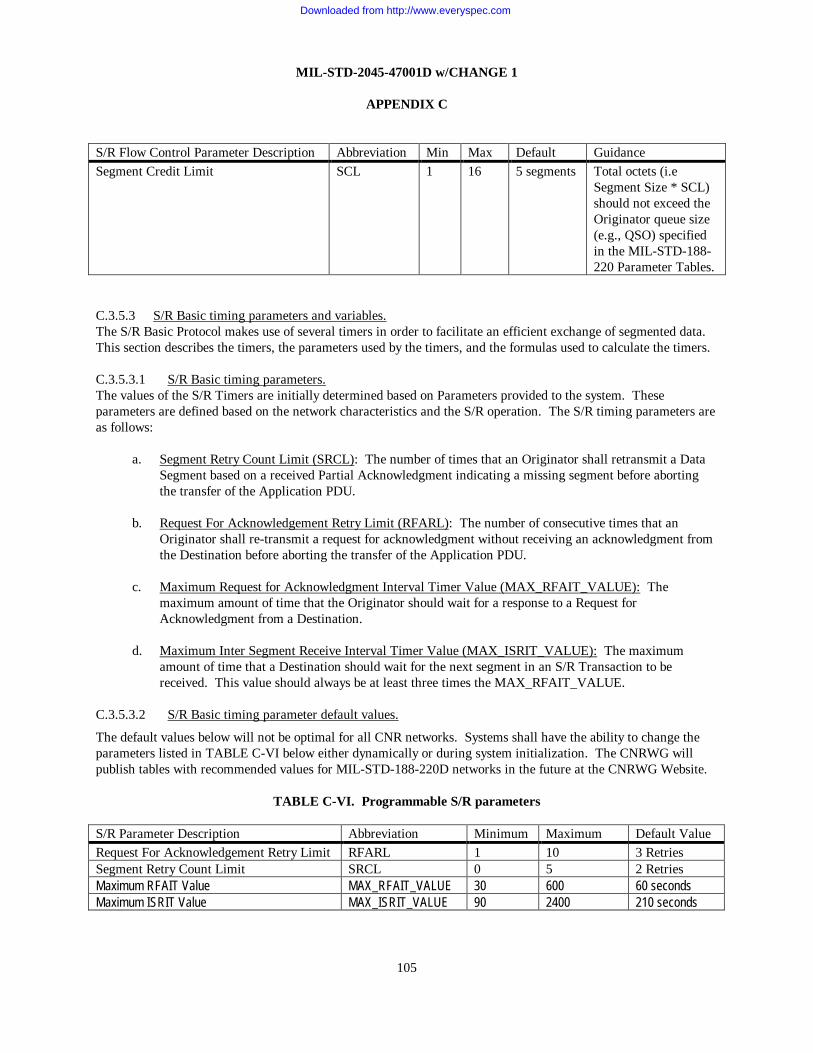
MIL-STD-2045-47001D w/CHANGE 1
APPENDIX C
105
S/R Flow Control Parameter Description Abbreviation Min Max Default Guidance Segment Credit Limit SCL 1 16 5 segments Total octets (i.e
Segment Size * SCL) should not exceed the Originator queue size (e.g., QSO) specified in the MIL-STD-188-220 Parameter Tables.
C.3.5.3 S/R Basic timing parameters and variables. The S/R Basic Protocol makes use of several timers in order to facilitate an efficient exchange of segmented data. This section describes the timers, the parameters used by the timers, and the formulas used to calculate the timers.
C.3.5.3.1 S/R Basic timing parameters. The values of the S/R Timers are initially determined based on Parameters provided to the system. These parameters are defined based on the network characteristics and the S/R operation. The S/R timing parameters are as follows:
a. Segment Retry Count Limit (SRCL): The number of times that an Originator shall retransmit a Data Segment based on a received Partial Acknowledgment indicating a missing segment before aborting the transfer of the Application PDU.
b. Request For Acknowledgement Retry Limit (RFARL): The number of consecutive times that an Originator shall re-transmit a request for acknowledgment without receiving an acknowledgment from the Destination before aborting the transfer of the Application PDU.
c. Maximum Request for Acknowledgment Interval Timer Value (MAX_RFAIT_VALUE): The maximum amount of time that the Originator should wait for a response to a Request for Acknowledgment from a Destination.
d. Maximum Inter Segment Receive Interval Timer Value (MAX_ISRIT_VALUE): The maximum amount of time that a Destination should wait for the next segment in an S/R Transaction to be received. This value should always be at least three times the MAX_RFAIT_VALUE.
C.3.5.3.2 S/R Basic timing parameter default values.
The default values below will not be optimal for all CNR networks. Systems shall have the ability to change the parameters listed in TABLE C-VI below either dynamically or during system initialization. The CNRWG will publish tables with recommended values for MIL-STD-188-220D networks in the future at the CNRWG Website.
TABLE C-VI. Programmable S/R parameters S/R Parameter Description Abbreviation Minimum Maximum Default Value Request For Acknowledgement Retry Limit RFARL 1 10 3 Retries Segment Retry Count Limit SRCL 0 5 2 Retries Maximum RFAIT Value MAX_RFAIT_VALUE 30 600 60 seconds Maximum ISRIT Value MAX_ISRIT_VALUE 90 2400 210 seconds
Downloaded from http://www.everyspec.com

MIL-STD-2045-47001D w/CHANGE 1
APPENDIX C
106
C.3.5.3.3 S/R Basic timing variables. The value of the S/R variables may be recalculated or adjusted dynamically during S/R operation. The modification of these variables is based not only on the Parameters defined above, but several S/R Variables that are tracked during operation. In general, the system must maintain one set of the following Variables for the duration of each S/R transaction (composed of an Originator, Destination, and Application PDU). The S/R timing Variables are as follows:
a. Request For Acknowledgement Retry Count (RFARC): The number of times an Originator has re-transmitted a Request for Acknowledgement without receiving an acknowledgment from the Destination. The Originator shall maintain the RFARC for each Destination.
b. Measured Round Trip Delay (MRTD): The measured value from the time a Data Segment is sent until the time the acknowledgement of that segment is received. The Originator shall measure the MRTD only for segments sent using the Unsent Segments procedure (i.e., not when segments are resent).
c. Smallest Lowest Numbered Unacknowledged Segment (SLNUS): The Segment Number of the lowest numbered segment that has been sent by the Originator but for which an acknowledgment has not yet been received from all ACTIVE Destinations. The Originator shall maintain the SLNUS for each active transfer. If there is only one Destination, then the SLNUS will equal the LNUS for that Destination.
d. Last Segment Number (LSN): The final Segment Number of the current Application PDU. The Originator shall maintain the LSN for each active transfer. The Destination shall also maintain the LSN for each active transfer.
e. Highest Numbered Segment Sent (HNSS): The Segment Number of the highest numbered segment that has been sent by the Originator. The Originator shall maintain the HNSS for each active transfer.
f. Measured Inter-Segment Receive Interval Time (MISRIT): The measured time between receiving the current segment and the previous segment. The Destination shall measure the MISRIT when a segment is received for an active transfer.
g. Relaxed Estimated Round Trip Delay (RERTD): The adjusted ERTD to account for variation in transmission times. The Originator shall maintain the RERTD for each Destination.
h. Segment Credits Used (SCU): The current number of segments that have been sent but not acknowledged by all Destinations. The Originator shall maintain the SCU for each active transfer.
i. Saved Estimated Round Trip Delay (SERTD): The currently saved value of the ERTD. Updates to this value are only made based on actual measurements. The Originator shall maintain the SERTD for each Destination.
j. Segment Retry Count (SRC): The number of times that a segment has been re-sent by the Originator to all active Destinations. The Originator shall maintain the SRC for each active transfer.
k. Partial Acknowledgment Starting Segment Number (PASSN): This refers to the value of the SSN contained in the Partial Acknowledgment currently being processed by the Originator.
Downloaded from http://www.everyspec.com

MIL-STD-2045-47001D w/CHANGE 1
APPENDIX C
107
l. Segment Number (SN): This refers to the value of the Segment Number field contained in the Data Segment of an active transfer currently being processed by the Originator
m. Hop Count (HOPCNT): Stations shall maintain the maximum HOPCNT of all other stations with which it has an active transfer. This value may not be available in all systems (e.g., systems that do not implement MIL-STD-188-220 Topology Updates to maintain an Topology Map), in which case a default value of 1 shall be used.
n. Initial Inter-Segment Receive Interval Timer (IISRIT): The initial value for the ISRIT. This value is calculated as per the equation in section C.3.5.7.3. This variable shall be calculated for each Destination.
o. Initial Round Trip Delay (IRTD): The initial value for the ERTD. This value is calculated as per the equation in section C.3.5.7.2. This variable shall be calculated for each Destination.
p. Lowest Numbered Unacknowledged Segment (LNUS): The Segment Number of the lowest numbered segment that has been sent by the Originator but for which an acknowledged has not yet been received by the Destination. The Originator shall maintain the LNUS for each Destination with which it has an active transfer.
q. Destination Status (DS): The Originator shall maintain the DS for each Destination associated with a transfer. If the Originator is still attempting to successfully complete the transfer for the Destination, the value shall be ACTIVE. If the Originator has aborted the transfer to the Destination, the value shall be INACTIVE.
r. Originator Status: The Destination shall maintain the Originator Status for each Application PDU Identifier. If the Destination is still attempting to successfully reassemble segment associated with the Application PDU Identifier, the value shall be ACTIVE. If the Destination has aborted the transfer to the Destination or sent a complete acknowledgment, the value shall be INACTIVE.
C.3.5.4 Detailed S/R Basic Procedures C.3.5.4.1 S/R Basic Procedure for sending Unsent (data) Segments to Multicast Addresses. The following is the entirety of the mandatory process for transmitting segments to Multicast Addresses, which includes the Global Address. In the S/R Basic Protocol, segments sent to Multicast Addresses should be sent as Data Segments with EDT Not Required. The P-bit should be set to “0” on all Data Segment PDUs transmitted to a Multicast Address. No S/R Timers are required by the S/R Basic Protocol at the Originator when transmitting to Multicast Addresses. Any responses received by the Originator referring to the Multicast S/R Transaction may be ignored.
The goal of the procedure herein is to send each Data Segment PDU to each Multicast Address one time. There is no mechanism for acknowledgments or retries in the S/R Basic Protocol for Multicast Addresses. In order to account for systems that may be implementing Data Link Layer concatenation, the first segment of the transaction must be transmitted over the air before additional segments are sent down the protocol stack for transmission. This is necessary to allow the timers on the receiver to be properly initialized.
The Originator of the S/R Multicast transaction shall, at a minimum, perform the following logic:
Send the first Data Segment PDU in the transfer with P-bit = 0 and EDT Acknowledgment Not Required. Wait for the transmission of the first Data Segment to complete
Downloaded from http://www.everyspec.com

MIL-STD-2045-47001D w/CHANGE 1
APPENDIX C
108
WHILE (not all data segments have been sent as Unsent Segments) LOOP
Send the next Data Segment in the transfer with P-bit = 0 and EDT Acknowledgment Not Required END WHILE LOOP This ends the mandatory procedures for sending S/R messages to Multicast Addresses. Implementers may desire to enhance the procedures for Multicast transactions by allowing for flow control, retransmission of segments, destination discovery, or other procedures described in the S/R Enhanced section for Multicast transactions. Enhancing the Multicast transaction logic is permissible as long as the station can interoperate with systems only implementing the mandatory components of S/R Basic Multicast transactions described in this section. C.3.5.4.2 S/R Basic Procedure for sending Unsent (Data) Segments to Unicast Addresses. The intent of this procedure is to send each Data Segment of an Application PDU one time. Once a Data Segment has been sent, it is no longer unsent. Retries are not handled by this procedure, only the initial transmission of each segment. Unsent Segments are only transmitted when there is space available in the “window” (i.e., the Segment Credits Used does not exceed the Segment Credit Limit) and further Acknowledgments are not expected (i.e., when the Request for Acknowledgment Interval Timer is not running). The first segment of an S/R Transaction is always sent with the P-bit set to 1, requesting an acknowledgment. Additional segments of a transfer will not be transmitted until each Destination responds to the first segment or has been eliminated as a non-responsive Destination. Subsequent segments are sent in groups up to the Segment Credit Limit in number, and the P-bit is only set in the last segment in the “window”, which prevents unnecessary acknowledgments from being requested.
When the Originator is sending the first segment of a transaction or receives a Partial Acknowledgment that causes SLNUS to increase (and therefore the SCU to decrease), or prunes a destination that causes SLNUS to increase (and therefore the SCU to decrease), it shall take the following actions:
WHILE ((there are still Unsent Segments) AND (SCU is less than the SCL, i.e., (SCU < SCL)) AND (The RFAIT is not running))
LOOP IF (HNSS == 0) THEN
Send the first Data Segment PDU in the transfer with P-bit = 1 -- (Request an Acknowledgment) Record that Segment Number 1 is OUTSTANDING Set the SCU = 1 Set the Destination Status for each Destination to Active (DS = ACTIVE) Set the RFARC for each Destination = 0 Set SLNUS = 1 Set LNUS for each Destination = 1 Start the RFAIT according to C.3.5.5.1 Start the MRTD counter.
ELSE IF (SCU == SCL - 1) -- (Next Segment sent will reach the Segment Credit Limit)
OR (HNSS == LSN - 1) -- (Next Segment is the Last Segment) THEN
Send the next Data Segment in the transfer with P-bit=1 -- (Request for Acknowledgment) Record that the Segment Number of the Data Segment just sent is OUTSTANDING Increment the SCU by 1
Downloaded from http://www.everyspec.com

MIL-STD-2045-47001D w/CHANGE 1
APPENDIX C
109
Start the RFAIT according to C.3.5.5.1 Start the MRTD counter.
ELSE Send the next Data Segment in the transfer with P-bit=0 Record that the Segment Number of the Data Segment just sent is OUTSTANDING Increment the SCU by 1
ENDIF ENDIF Set the SRC for this segment to 0 Update the HNSS
END WHILE LOOP C.3.5.4.3 S/R Basic Procedure for processing acknowledgment.
a. The intent of this procedure is two-fold. First, this procedure determines if the number of Segment Credits Used can be reduced due to the fact that all Destinations have positively acknowledged reception of a specific Data Segment. Second, this procedure records which Data Segments were missed by any Destination and therefore need to be resent. The actual retransmission of Data Segments is handled by a separate procedure. If all Destinations transmit an Acknowledgment, then the Request for Acknowledgment Interval Timer can be stopped instead of waiting for it to expire.
When an Originator receives a Partial Acknowledgment PDU, it shall take the following actions: IF the Serial Number matches an Application PDU Identifier
AND the Partial Acknowledgment source matches a Destination associated with the matching Application PDU Identifier
THEN IF the DS == ACTIVE for the Destination that sent the Partial Acknowledgment THEN
IF the MRTD counter is running Update the Round Trip Delay Timers according to C.3.5.6.1.
ENDIF Set the RFARC for this Destination to 0 Set SavedLNUS = LNUS Set SavedSLNUS = SLNUS Update LNUS for this Destination and SLNUS according to C.3.5.6.2 IF LNUS < > SavedLNUS -- (i.e., LNUS has changed)
Record that this Destination has acknowledged all segments up to LNUS FOR Each Segment Number that is OUTSTANDING
IF All Active Destinations have acknowledged the segment THEN
Decrement the SCU by 1 Record that this Segment Number is NOT OUTSTANDING
ENDIF END FOR LOOP
ENDIF IF (LNUS < HNSS + 1) -- (i.e., there is a Bit Mask field to process) THEN
Downloaded from http://www.everyspec.com

MIL-STD-2045-47001D w/CHANGE 1
APPENDIX C
110
FOR (Each bit to process in the Bit Mask field of the Partial Acknowledgment PDU, there will be HNSS+1 – LNUS bits to loop over. Bits not present in the Bit Mask from HNSR to HNSS are treated as if they exist and are set to zero (0))
LOOP IF the current bit of the Bit Mask equals 1
Record that this Destination has acknowledged this segment IF All Active Destinations have acknowledged the segment
AND the Segment Number is OUTSTANDING THEN
Decrement the SCU by 1 Record that this Segment Number is NOT OUTSTANDING
ENDIF ENDIF
END FOR LOOP ELSE -- There is no Bit Mask field to process (i.e., LNUS == HNSS +1)
Record that this destination has acknowledged all sent segments. FOR (Each segment from SLNUS to HNSS)
IF (All Destinations have acknowledged the segment) AND the Segment Number is OUTSTANDING
THEN Decrement SCU by 1 Record that this Segment Number is NOT OUTSTANDING
ENDIF END FOR LOOP
ENDIF IF The RFARC for all ACTIVE Destinations is 0 THEN
Stop the RFAIT according to C.3.5.5.1 Send any remaining Unsent Segments according to C.3.5.4.2
ENDIF ELSE -- (The Destination that sent the Partial Acknowledgment is INACTIVE)
Send an Abort Request PDU with P-bit = 0 to the Destination that generated the Partial Acknowledgment
ENDIF ELSE -- (either the serial number does not match any Application PDU Identifier, or the source
of the Partial Acknowledgment does not match any of the Destination associated with the Application PDU identifier)
Send an Abort Request PDU back to the source of the Partial Acknowledgment with P-bit = 0 using the Application PDU Identifier sent by the source of the Partial Acknowledgment
ENDIF
b. The intent of this procedure is to mark any Destination that sends a Complete Acknowledgment as INACTIVE, meaning that the transaction to that particular Destination is finished. If all Destinations are finished, processing for this transaction can end.
When an Originator receives a Complete Acknowledgment PDU, it shall take the following actions: IF the Serial Number matches an Application PDU Identifier
Downloaded from http://www.everyspec.com

MIL-STD-2045-47001D w/CHANGE 1
APPENDIX C
111
AND the Complete Acknowledgment PDU source matches a Destination associated with the matching Application PDU Identifier
THEN IF the DS == ACTIVE for the Destination that sent the Complete Acknowledgment PDU THEN
Set the DS = INACTIVE for this destination ENDIF IF the DS == INACTIVE for all Destinations THEN
Stop all timers, counters, etc. associated with this transaction. Segments associated with the Application PDU are discarded by the Originator. Issue notification to Upper Layer Protocol that transaction is complete.
ENDIF ELSE – (the serial number does not match an identifier or the Destination is not known)
Ignore the received Complete Acknowledgment PDU. ENDIF
C.3.5.4.4 S/R Basic Procedure for resending unacknowledged data segments. The intent of this procedure is to resend any Data Segment that was missed by at least one Destination. Resent Data Segments are transmitted to all active Destinations in order to prevent destinations timing out due to inactivity from the Originator (recall that duplicate segments received by a Destination are discarded). It is also the intent of this procedure to ensure that only the last sent segment in a window of segments has the P-bit set to 1.
This procedure shall be executed any time the (RFAIT Stops) or (the RFAIT Expires and at least one Partial Acknowledgment was received).
FOR Each sent segment that is not fully acknowledged -- (i.e., not all Destinations have acked the segment)
IF SRC < SRCL THEN
IF HNSS == 1 THEN -- (must retransmit first segment)
Resend the unacknowledged Segment to all active Destination(s) with P-bit = 1 Start the RFAIT according to C.3.5.5.1
ELSE IF ((SCU == SCL) OR (HNSS == LSN)) -- (only resending unacknowledged segments)
THEN IF Segment is last Segment of FOR LOOP THEN
Resend the unacknowledged Segment to all active Destination(s) with P-bit = 1 Start the RFAIT according to C.3.5.5.1
ELSE Resend the unacknowledged Segment to all active Destination(s) with P-bit = 0
ENDIF ELSE -- (resend unacknowledged segments after which new Unsent Segments will be sent)
Resend the unacknowledged Segment to all active Destination(s) with P-bit = 0 ENDIF Increment the SRC for this segment
ELSE -- (the SRC >= SRCL then)
Downloaded from http://www.everyspec.com

MIL-STD-2045-47001D w/CHANGE 1
APPENDIX C
112
Send an Abort Request PDU with P-Bit = 0 to the Unicast Address of active Destination(s) that have not acknowledged the segment.
Provide an S/R Status Indication to the Upper Layer Protocol (ULP) indicating failure for any Destination(s) that did not acknowledge the segment.
Set the Destination Status (DS) to INACTIVE for the Destination(s) that did not acknowledge the segment.
IF All Destination(s) are INACTIVE THEN
Stop all timers, counters, etc. associated with this transaction. Segments associated with the Application PDU are discarded by the Originator. Issue notification to Upper Layer Protocol that transaction is complete.
ELSE -- (at least one Destination is still ACTIVE) IF (Segment is Last Segment of FOR LOOP)
AND ((SCU == SCL) OR (HNSS == LSN)) THEN
Issue an Acknowledgment Request PDU to all Destinations with DS == ACTIVE ENDIF Set SavedSLNUS = SLNUS SLNUS = Smallest LNUS associated with any ACTIVE Destination IF SLNUS <> SavedSNLUNS THEN
FOR Each Segment Number that is OUTSTANDING IF All Active Destinations have acknowledged the segment THEN
Decrement the SCU by 1 Record that this Segment Number is NOT OUTSTANDING
ENDIF END FOR LOOP
ENDIF ENDIF
ENDIF END FOR LOOP
C.3.5.4.5 S/R Basic Procedure for processing received data segment(s). The intent of this procedure is to receive and reassemble each Data Segment in its proper place in the Application PDU that is being reassembled. When a Data Segment with a Segment Number of “1” is received and it does not match a current Application PDU Identifier, a new reassembly transaction is started. If the segment is not the first segment, and does not match an existing Application PDU Identifier, the segment is discarded and the transaction is aborted, as a processing error must have occurred.
When a Destination receives a Data Segment it shall take the following actions:
IF the Serial Number and source address does not match an Application PDU Identifier THEN
IF the Segment Number of the received segment == 1 THEN
Create a new Application PDU Identifier indicating that no segments have been received. Initialize receive variables associated with the new Application PDU identifier according to C.3.5.7.3 Set the Originator Status associated with the new Application PDU Identifier to ACTIVE.
Downloaded from http://www.everyspec.com

MIL-STD-2045-47001D w/CHANGE 1
APPENDIX C
113
Generate a S/R-First-Segment Indication to the Application. ELSE
IF P-Bit == 1 in the received segment THEN
Transmit an Abort Request PDU with P-bit = 0 to the Originator. ENDIF
ENDIF ENDIF IF the Serial Number and source address of the received segment match an Application PDU Identifier THEN
IF Originator Status == ACTIVE THEN
Stop the Inter-Segment Receive Timer (ISRT) according to C.3.5.5.2 Stop the Inter-Segment Receive Interval Timer (ISRIT) according to C.3.5.5.3 IF the segment number was not previously received THEN
Record the segment as having been received. Reassemble the data at the proper location in the Application PDU based on the Segment Number IF (P-Bit == 1 in the received segment)
OR (the received segment completes the Application PDU, i.e., all segments have now been received at least once AND the Data Segment is EDT Acknowledgment Required (Type == 0))
THEN -- (Its time to acknowledge segments) IF all segments have now been received THEN
Send a Complete Acknowledgment Set the Originator Status to INACTIVE and remember that all segments were received.
ELSE -- (some segments have not been received yet) Send a Partial Acknowledgment indicating which segment have and have not been received (i.e. those segments between HNSR and SSN that have not been received).
ENDIF ELSE -- (no acknowledgment needs to be sent yet for the non-duplicate segment)
IF all segments have now been received (but EDT Acknowledgment not Required) THEN
Set the Originator Status to INACTIVE and remember that all segments were received. ENDIF
ENDIF ELSE -- (it is a duplicate segment on an active transfer)
IF (the P-Bit == 1 in the received segment) THEN -- (Its time to acknowledge segments that have been received)
Send a Partial Acknowledgment indicating which segment have and have not been received. ENDIF Discard the duplicate segment
ENDIF IF not all segments have been received
Restart the ISRT according to C.3.5.5.2 Restart the ISRIT according to C.3.5.5.3
ENDIF ELSE -- (the Originator is INACTIVE)
IF P-Bit == 1 in the received segment
Downloaded from http://www.everyspec.com

MIL-STD-2045-47001D w/CHANGE 1
APPENDIX C
114
THEN IF all segments were received -- (i.e., the transaction was complete) THEN
Send a Complete Acknowledgment PDU ELSE -- (all segments were not received)
Transmit an Abort Request PDU with P-bit = 0 to the Originator. ENDIF
ENDIF Discard the received Segment (associated with the inactive Application PDU Identifier)
ENDIF ENDIF C.3.5.4.6 S/R Basic Procedure for processing a received Acknowledgment Request PDU. The intent of this procedure is for a Destination to respond to the Originator with either a Partial Acknowledgment PDU or Complete Acknowledgment PDU as appropriate.
When a Destination receives an Acknowledgment Request PDU it shall take the following actions:
IF the Serial Number and source address does not match an Application PDU Identifier THEN
Transmit Partial Acknowledgment to the Originator indicating that no segments have been received (i.e. the Starting Segment Number of the Partial Acknowledgment will be ‘1’)
ELSE -- (the Serial Number and source address matches an Application PDU Identifier) IF (Originator Status == ACTIVE) -- (all segments have not yet been received) THEN
Stop the Inter-Segment Receive Timer (ISRT) according to C.3.5.5.2 Stop the Inter-Segment Receive Interval Timer (ISRIT) according to C.3.5.5.3 Send a Partial Acknowledgment indicating which segment have and have not been received. Restart the ISRT according to C.3.5.5.2 Restart the ISRIT according to C.3.5.5.3
ELSE --(the matching Originator is INACTIVE) IF all segments were received THEN
Send a Complete Acknowledgment PDU ELSE -- (all segments were not received)
Send an Abort Request PDU with P-Bit = 0 to the Unicast Address of the Originator ENDIF
ENDIF ENDIF
C.3.5.4.7 S/R Basic Procedure for processing a received Abort Request PDU.
a. The intent of this procedure is for a Destination to terminate processing of a transaction when it receives an Abort Request.
When a Destination receives an Abort Request PDU it shall take the following actions:
IF the Serial Number matches an Application PDU Identifier
Downloaded from http://www.everyspec.com

MIL-STD-2045-47001D w/CHANGE 1
APPENDIX C
115
AND (Originator Status == ACTIVE) -- (all segments have not yet been received) THEN
Stop all timers, counters, etc. associated with this transaction. Segments associated with the Application PDU are discarded by the Originator. Set Originator Status = INACTIVE
ENDIF IF (P-bit == 1 in received Abort Request PDU) THEN
Send an Abort Confirm PDU with the Serial Number specified in the Abort Request PDU ENDIF
b. The intent of this procedure is to remove a Destination from the list of ACTIVE Destinations when an Originator receives an Abort Request from a Destination.
When an Originator receives an Abort Request PDU it shall take the following actions;
IF the Serial Number matches an Application PDU Identifier where this station is a Destination AND (Destination Status == ACTIVE)
THEN Set Destination Status = INACTIVE IF All Destinations are INACTIVE THEN
Stop the timers, counters, etc. associated with this transaction. Segments associated with the Application PDU are discarded by the Originator. Issue notification to Upper Layer Protocol that transaction is complete
ELSE -- (at least one Destination is still ACTIVE) Set SavedSLNUS = SLNUS SLNUS = Smallest LNUS associated with any ACTIVE Destination IF SLNUS <> SavedSNLUNS THEN
FOR Each Segment Number that is OUTSTANDING IF All Active Destinations have acknowledged the segment THEN
Decrement the SCU by 1 Record that this Segment Number is NOT OUTSTANDING
ENDIF END FOR LOOP
ENDIF IF The RFARC for all ACTIVE Destinations is 0 THEN -- (First resend any unacknowledged segments, which is triggered by stopping the
RFAIT, then send any remaining Unsent Segments if there are segment credits available)
Stop the RFAIT according to C.3.5.5.1 Send any remaining Unsent Segments according to C.3.5.4.2
ENDIF ENDIF
ENDIF IF (P-bit == 1 in received Abort Request PDU) THEN
Downloaded from http://www.everyspec.com

MIL-STD-2045-47001D w/CHANGE 1
APPENDIX C
116
Send an Abort Confirm PDU with the Serial Number specified in the Abort Request PDU ENDIF
C.3.5.5 S/R Basic timers. The S/R Protocol shall use the following Timers in order to facilitate an efficient exchange of segmented data between the Originator and the Destination.
C.3.5.5.1 Request for Acknowledgment Interval Timer (RFAIT). The RFAIT shall be run at the Originator to predict a time by which a response to a Request for Acknowledgment should be received. The Originator shall maintain one RFAIT for each active Application PDU Identifier.
a. Starts: The RFAIT shall be started (or stopped then restarted) at the Originator each time a Request for Acknowledgment is issued. If the RFAIT is already running when a Request for Acknowledgment is issued, the RFAIT shall be restarted, i.e., stopped then started again. Only one RFAIT shall be running at any given time for each Application PDU that is active at the Originator. The RFAIT value shall be calculated according to the procedure below each time it is started or restarted. The RERTD selected for use in the following equation shall be the largest of any active Destination (DS=ACTIVE).
Increment the RFARC for all ACTIVE Destinations by 1. RFAIT = Max(RERTD) IF RFAIT > MAX_RFAIT_VALUE THEN
RFAIT = MAX_RFAIT_VALUE ENDIF
b. Stops: The RFAIT shall be stopped when a Partial Acknowledgment or Complete Acknowledgment is
received from all Destinations, at this time all Unacknowledged Segments (i.e. any Data Segment that has not been acknowledged by all ACTIVE Destinations) will be resent according to C.3.5.4.4, then any Unsent Segments will be sent according to C.3.5.4.2
Note: The MRTD is not updated when the RFAIT timer is stopped because received Partial Acknowledgments are inherently ambiguous, i.e., the Originator can never know with certainty which specific S/R PDU received by the Destination caused the Partial Acknowledgment to be sent.
c. Expires: When the RFAIT expires at the Originator, meaning that at least one Destination did not
send an Acknowledgment, the following shall occur: FOR 1 to (Number of Destinations with DS == ACTIVE) -- (Loop over all ACTIVE Destinations) LOOP
IF RFARC for the Destination >= RFARL THEN
Send an Abort Request to the Destination with P-Bit = 0. Provide an S/R Status Indication to the ULP indicating failure for any Destinations that did not
acknowledge the segment. Set the DS to INACTIVE for the Destination IF All Destinations are INACTIVE THEN
Stop the timers, counters, etc. associated with this transaction. Segments associated with the Application PDU are discarded by the Originator.
Downloaded from http://www.everyspec.com

MIL-STD-2045-47001D w/CHANGE 1
APPENDIX C
117
Issue notification to Upper Layer Protocol that transaction is complete EXIT RFAIT Expires Procedure -- (S/R Transaction processing is complete)
ELSE -- (at least one Destination is still ACTIVE) Set SavedSLNUS = SLNUS SLNUS = Smallest LNUS associated with any ACTIVE Destination IF SLNUS <> SavedSNLUNS THEN
FOR Each Segment Number that is OUTSTANDING IF All Active Destinations have acknowledged the segment THEN
Decrement the SCU by 1 Record that this Segment Number is NOT OUTSTANDING
ENDIF END FOR LOOP
ENDIF ENDIF
ENDIF END FOR LOOP IF At least one Partial Acknowledgment PDU was received during the RFAIT period THEN
Resend all Unacknowledged Segments (i.e. any Data Segment that has not been acknowledged by all ACTIVE Destinations) according to C.3.5.4.4.
ELSE Issue an Acknowledgement Request PDU to all Destinations with DS ==ACTIVE Start the RFAIT according to C.3.5.5.1
ENDIF Send any remaining Unsent Segments according to C.3.5.4.2
C.3.5.5.2 Inter-Segment Receive Timer (ISRT). The ISRT shall be used to measure the time between received S/R PDUs at the Destination as required to update the estimate for the Inter-Segment Receive Interval Timer. The Destination shall maintain one ISRT for each Application PDU as described below.
a. Starts: When a Data Segment PDU or Acknowledgment Request PDU is received, the time at which the PDU was received is recorded.
b. Stops: When the next Data Segment PDU or Acknowledgment Request PDU is received, the elapsed
time since receipt of the previous segment is calculated and stored as the MISRIT, if it is greater than the currently stored MISRIT value. This time shall be used to update the ISRIT according to C.3.5.5.3. The ISRT shall only be restarted if not all of the segments associated with the Application PDU have been received.
IF (ISRT > MISRIT) THEN
MISRIT = ISRT ENDIF
c. Expires: The ISRT never expires; it is only used to measure the interval between the receipts of
segments with the same Application PDU Identifier.
Downloaded from http://www.everyspec.com

MIL-STD-2045-47001D w/CHANGE 1
APPENDIX C
118
C.3.5.5.3 Inter-Segment Receive Interval Timer (ISRIT). The ISRIT shall be used to predict a time by which the next segment should be received at the Destination. The Destination shall maintain one ISRIT for each Application PDU as described below.
a. Starts: When a segment is received, the ISRIT shall be started or restarted to predict a time by which the next segment should be received. The value of ISRIT shall be set according to C.3.5.6.3.
b. Stops: When the next segment is received, the ISRIT shall be stopped and then restarted if all
segments have not been received.
c. Expires: When the ISRIT expires, the transaction shall be aborted.
Destination shall send an Abort Request PDU with P-Bit = 0 Destination shall discard segments associated with the Application PDU
C.3.5.6 Basic Timer equations. This section contains additional equations related to timers.
C.3.5.6.1 Round Trip Delay (RTD) equations. The following sequence of equations shall be used to calculate the RERTD, and the SERTD. In S/R Basic, the worst case RTD for each Destination is kept. The RFAIT is based on RERTD. After the first segment is sent and acknowledged, the first “full credit window” of segments will be issued. For this first “full credit window” set of segments, RERTD will be given a very conservative, worst case value, based on the “window size” (i.e. Segment Credit Limit). Subsequent RERTD values will be based on actual measured MRTD values. This is done to optimize RERTD for implementations that may concatenate segments at the Data Link Layer.
Stop MRTD Counter. IF (HNSS == 1) THEN
RERTD = IRTD * 2.2 * SCL ELSE
IF MRTD > SERTD THEN
SERTD = MRTD ENDIF RERTD = SERTD * 2.2
ENDIF C.3.5.6.2 LNUS and SLNUS equations. When a Partial Acknowledgment is received, the following sequence of equations shall be used to update the LNUS associated with the Destination that sent the Partial Acknowledgment. When the LNUS is updated, the SLNUS is updated to the smallest LNUS value associated with any active Destination.
IF PASSN > LNUS THEN
LNUS = PASSN SLNUS = Smallest LNUS associated with any ACTIVE Destination associated with the same Application
PDU Identifier as specified by the serial number field of the Partial Acknowledgment.
Downloaded from http://www.everyspec.com

MIL-STD-2045-47001D w/CHANGE 1
APPENDIX C
119
ENDIF C.3.5.6.3 Segment reception equations. When a segment is received the following sequence of equations shall be used to calculate the ISRIT and start/restart the ISRT.
IF SN <= 1 AND The segment is not a duplicate THEN
ISRT = 0 Start ISRT ISRIT = IISRIT * (Max SRCL Value) * 2.2 -- (reference Table C-VI) Start ISRIT
ELSE -- i.e., ((SN == 1 AND the segment is a duplicate) OR SN>1) ISRIT = MISRIT * (Max SRCL Value) * 2.2 -- (reference Table C-VI) IF ISRIT > MAX_ISRIT_VALUE THEN
ISRIT = MAX_ISRIT_VALUE ENDIF Start ISRIT
ENDIF C.3.5.7 Basic Initialization equations.
C.3.5.7.1 Network enable initialization. Before any segments have been sent or received (e.g., upon enabling the net), the following sequence of equations shall be used to initialize parameter values.
HOPCNT = 1 (unless another value can be obtained by the system, e.g., querying the Intranet Layer in a MIL-STD-188-220 system and obtaining the value from the Topology Map, in which case use the Maximum of the Hopcounts for each of the recipients being transmitted to)
C.3.5.7.2 Application PDU transmit initialization. Each time an Originator initiates the transfer of an Application PDU, the following sequence of equations shall be used to initialize the following parameter values associated with that Application PDU.
SCU = 0 HNSS = 0 LNUS = 0 (For each Destination) SLNUS = LNUS DS = ACTIVE (For each Destination) IF Transfer occurs directly over a MIL-STD-188-220 net and T2AT is available THEN
IRTD = HOPCNT * T2AT (T2AT taken from MIL-STD-188-220 Protocol Parameter Tables. This equation calculates a default value that can be used for Destinations on the same net. This calculation is performed when the net is enabled based on the net’s configuration. The default value for the net may be modified by the operator.)
ELSE
Downloaded from http://www.everyspec.com

MIL-STD-2045-47001D w/CHANGE 1
APPENDIX C
120
IF Number of Stations on the Network is available THEN
IRTD = HOPCNT * (Number of Stations on the Network) * 2 sec ELSE
IRTD = HOPCNT * 30 sec ENDIF
ENDIF For sending the first segment, RERTD will be based on IRTD. SERTD = 0 RERTD = IRTD * 2.2
C.3.5.7.3 Application PDU receive initialization. Each time a Destination begins reception of a new Application PDU, the following sequence of equations shall be used to initialize the following parameter values associated with that Application PDU Identifier.
IF Transfer occurs directly over a MIL-STD-188-220 net and T2AT is available THEN
IISRIT = HOPCNT * T2AT (T2AT taken from MIL-STD-188-220 Protocol Parameter Tables. This equation calculates a default value that can be used for Originators on the same net. This calculation is performed when the net is enabled based on the net’s configuration. The default value for the net may be modified by the operator.)
ELSE IF Number of Stations on the Network is available THEN
IISRIT = HOPCNT * (Number of Stations on the Network) * 3 sec ELSE
IISRIT = HOPCNT * 30 sec ENDIF
ENDIF MISRIT = IISRIT
C.3.6 S/R Enhanced procedures. The S/R Enhanced protocol described below is a full, stand-alone protocol implementation and does not rely on the S/R Basic protocol above. C.3.6.1 S/R Enhanced Overview. The S/R Enhanced procedures offers improved performance over the S/R Basic procedures, enhancing both the efficiency and the capabilities of the S/R Basic Protocol. In the S/R Enhanced Protocol mixed-mode Destination Addresses shall be permitted. A single S/R Enhanced transmission may contain any mix of Unitcast Addresses and/or Multicast Addresses (including the Global address). When an Abort Request PDU is issued in the S/R Enhanced Protocol, if an Abort Confirm PDU response is desired, the P-bit shall be set (i.e., set to the value “1”). This allows for retries of Abort commands.
The S/R Enhanced Protocol provides a complex flow control mechanism that is based not only upon a Segment Credit Limit (also called a Window Size or Windowing Scheme), but an assortment of adjustment factors and aging mechanisms. The S/R Enhanced protocol also introduces the concept of the Reference Freeze State, and
Downloaded from http://www.everyspec.com

MIL-STD-2045-47001D w/CHANGE 1
APPENDIX C
121
several additional timers and counters used to trigger automated actions in an effort to prevent stalls in the transmission path. Systems implementing the S/R Enhanced Protocol will be able to have transmitted messages received by systems implementing either the S/R Basic Protocol or the S/R Enhanced Protocol. Systems implementing the S/R Enhanced Protocol will be able to receive messages transmitted by systems implementing either the S/R Basic Protocol or the S/R Enhanced Protocol.
The S/R Enhanced Protocol also adds the concept of “Destination Learning” when transmitting messages to Multicast Addresses, including the Global Address, that allows the Originator to build an address list of Unitcast Addresses that the message is being transmitted to based on the response to the first segment sent to the Multicast Address(es).
C.3.6.1.1 S/R Enhanced Segmentation. The Originator shall map the original application PDU into an ordered sequence of segments. Each segment shall be the specified Segment Size bytes in length, with the possible exception of the last segment that can be less than the specified Segment Size bytes in length. If the last segment is less than the specified Segment Size octets in length, it shall not be padded. The host can configure the Segment Size to any value up to but not exceeding MSS. If no Segment Size is specified by the host, MSS shall be used for the Segment Size. The Originator shall assign a single, unique Serial Number to each application PDU and copy it into the header of each segment associated with that application PDU. Serial Numbers are managed by each Originator in accordance with paragraph C.3.3.1.6. Each data segment shall then be sequentially sent, starting with segment number equal to 1. The Originator shall track which segments have and have not been acknowledged for each Destination.
Every segment shall specify the Last Segment Number (the total number of segments in the Application PDU) and it’s Segment Number (segment sequence number of the current segment). Multiple S/R transfers can be enacted simultaneously by an Originator, and are distinguished by their Application PDU Identifier, however, due to the complexity of S/R transactions, it is encouraged that an Originator only enact a single S/R transaction at a time.
Each S/R segment shall be transmitted in one UDP Request or one Intranet Layer Request (if n-layer pass through is used) by the Originator. The Originator shall indicate in the segmentation header whether the transfer of the Application PDU requires an EDT Acknowledgment (Type field = 0) or does not require an EDT Acknowledgment (Type field = 2). All data segments associated with the same serial number shall use the same Type field value.
For the first segment, the Originator shall indicate in the S/R header that an acknowledgment is required by setting the P-bit = 1. Subsequent segments shall not be sent until the Originator receives an acknowledgment for the first segment from all Destination(s). The Originator and Destination(s) shall then engage in Flow Control procedures in order to achieve efficient transmission of Data Segments. Flow Control shall be restricted by a Credit Limit, representing the maximum number of unacknowledged segments allowed at any given time, and governed by a series of timers. Flow Control procedures are discussed in detail in section C.3.6.2, and the Timers used with S/R Flow Control are discussed in detail in section C.3.6.3. The general operation of the Flow Control procedures involves the Originator periodically issuing a Request for Acknowledgment to the Destination(s) in order to manage the number of outstanding unacknowledged segments. The Originator shall not send any data segments that will cause the number of unacknowledged segments to exceed the Segment Credit Limit (SCL).
The Originator shall retransmit only data segments that were not received by one or more Destination(s) as indicated by a Partial Acknowledgment (Type field = 4) received from the Destination(s) subsequent to the expiration of the Segment Acknowledgment Timer (SAT). Missing data segments shall only be retransmitted a finite number of times until either acknowledgment(s) indicate all data segments have been received or the transfer of the Application PDU is aborted with a given Destination. The number of retry attempts for a segment shall be limited by the Segment Retry Count Limit (SRCL) parameter. In the case that multiple Data Segments are
Downloaded from http://www.everyspec.com

MIL-STD-2045-47001D w/CHANGE 1
APPENDIX C
122
available at the same time for sending, Data Segments with lower Segment Numbers shall be resent/sent before Data Segments with higher Segment Numbers.
Each time the Originator issues a Request for Acknowledgment, it shall start a Request for Acknowledgment Interval Timer (RFAIT). If the RFAIT expires without the receipt of an acknowledgment from all Destinations, the Originator shall transmit an Acknowledgment Request (Type field = 3). If acknowledgment(s) are not received from all Destination(s) after Request For Acknowledgement Retry Limit (RFARL) number of tries, the transfer of the Application PDU shall be aborted and an error indication shall be returned to the Upper Layer Protocol. If the RFAIT is active and another Request for Acknowledgment is issued by the Originator for any reason, the RFAIT shall be restarted. The RFAIT is further described in paragraph C.3.6.5.2.
When the Originator sends a Data Segment with EDT Acknowledgment Required (Type Field = 0) and Segment Number = Last Segment Number, then the P-bit shall be set to 1, requesting an acknowledgment. When the transfer of the Application PDU is complete, either successfully or unsuccessfully, the Originator shall place the associated Application PDU Identifier in the Reference Freeze State, see paragraph C.3.6.1.3.
If the Originator wishes to abort the transfer of the Application PDU, it shall transmit an Abort Request (Type field = 1) to the Destination. If the Originator wishes to receive confirmation of the abort, then it shall set the P-bit = 1 in the Abort Request. If the Originator receives an Abort Request or an Abort Confirm, the Originator shall set the Destination Abort Confirm Received (DACR) for that Destination to TRUE.
C.3.6.1.2 S/R Enhanced Reassembly. The Destination shall monitor for S/R segments to arrive. The source address of the Originator (as provided by the lower level protocol) combined with the S/R header Serial Number, forms the Application PDU Identifier, which uniquely identifies the Application PDU to which each segment belongs. On N-layer pass through networks, it shall be the serial number and source data link address which establish each unique data stream; on IP networks, it shall be the serial number and source IP address which establish each unique data stream. Each Destination shall reassemble the segments in the proper order, regardless of the order of reception. Each Destination shall track which segments have and have not been acknowledged for each Application PDU Identifier such that duplicate received segments can be detected and ignored. Once a complete Application PDU is reassembled, it shall be forwarded to the application. The Destination shall not forward an incomplete Application PDU to the application.
When the Destination receives any Request for Acknowledgment corresponding to an Application PDU that is not in Reference Freeze State, it shall respond with either a Partial Acknowledgment or Complete Acknowledgment as appropriate. If a Partial Acknowledgment was recently transmitted prior to receiving a Request For Acknowledgment, then the transmission of the next Partial Acknowledgment may be delayed as a means of controlling the number of Partial Acknowledgment sent by the Destination. If the Destination receives a data segment with EDT Acknowledgment Required (Type field = 0) and the P-bit = 0, and this data segment completes the Application PDU, then it shall respond with a Complete Acknowledgment (Type field = 6) and the F-bit = 0.
When the Destination receives a Data Segment (Type field = 0 or 2) or an Acknowledgment Request (Type field = 3), then it shall start a Reassembly Timer. For each different Application PDU Identifier, a different Reassembly Timer shall be used. The Reassembly Timer shall be based on interval timing between reception of segments and the number of segments not yet received. When the Application PDU is successfully reassembled, the Reassembly Timer associated with that Application PDU Identifier shall be terminated. Reassembly Timer behavior is described in paragraph C.3.6.5.1.
If the data segments associated with the Application PDU are of type EDT Acknowledgment Not Required (Type field = 2), and the Reassembly Timer expires before the Application PDU is successfully reassembled, the Destination shall discard any data segments already received associated with that Application PDU and transmit an
Downloaded from http://www.everyspec.com

MIL-STD-2045-47001D w/CHANGE 1
APPENDIX C
123
Abort Request (Type field = 1) with the P-bit = 1 to the Originator. The Destination shall then enter the Reference Freeze state for this Application PDU.
If the Data Segments associated with the Application PDU are of type EDT Acknowledgment Required (Type field = 0), and the Reassembly Timer expires before the Application PDU is successfully reassembled, then the Destination shall transmit a Partial Acknowledgment (Type field = 4) to the Originator and restart the Reassembly Timer. If no further data is received from the Originator after the Reassembly Timer Expiration Count Limit number of Partial Acknowledgments are transmitted, then the Destination shall discard any Data Segments already received associated with that Application PDU and transmit an Abort Request (Type field = 1) to the Originator with the P-bit = 1. When the transfer of the Application PDU is complete, either successfully or unsuccessfully, the Destination shall place the associated Application PDU Identifier in the Reference Freeze State, see paragraph C.3.6.1.3.
If the Destination receives an Abort Request (Type field = 1), it shall discard any data segments already received associated with that Application PDU and enter the Reference Freeze state for that Application PDU. If the Abort Request has the P-bit = 1, the Destination shall respond with an Abort Confirm (Type field = 5) with F-bit = 1 to the Originator. If the Destination receives an Abort Request, the Destination shall set the Originator Abort Confirm Received (OACR) for the Originator to TRUE.
If the Destination wishes to abort the transfer of the Application PDU, it shall transmit an Abort Request (Type field = 1) to the Originator. If the Destination wishes to receive confirmation of the abort, then it shall set the P-bit = 1 in the Abort Request. If the Destination receives an Abort Confirm, the Destination shall set the OACR for the Originator to TRUE.
When the Destination receives any Request for Acknowledgment or Data Segment corresponding to an Application PDU that is in Reference Freeze State, if the OACR is FALSE and all segments were previously received then a Complete Acknowledgment shall be sent to the Originator. If the OACR is FALSE and not all segments were previously received then an Abort Request with P-bit = 1 shall be sent to the Originator. If the OACR is TRUE then an Abort Request with P-bit = 0 shall be sent to the Originator.
C.3.6.1.3 Reference Freeze State. The Reference Freeze State is used to reduce uncertainty concerning re-used Serial Numbers. Serial Numbers form a part of the Application PDU Identifier. While Serial Numbers are defined to be unique, there comes a point in time where an Originator may need to start re-using Serial Numbers to start a new transfer. The Reference Freeze states helps Destinations determine if an Application PDU Identifier for a given Data Segment is part of a completed transfer or a new transfer. It also helps Originators determine if responses from a Destination are part of a completed transfer or a current transfer.
Once a transfer is complete, either successfully or unsuccessfully, the Originator and Destination shall place the associated Application PDU Identifier in the Reference Freeze State. If a data segment is received with an Application PDU Identifier that is currently in a Reference Freeze State, it is considered part of a previously completed transfer and shall be ignored. Once an Application PDU Identifier is removed from the Reference Freeze State, S/R PDUs with that Application PDU Identifier shall be accepted.
The timers related to the Reference Freeze State for Originators and Destinations are explained in sections C.3.6.5.6 and C.3.6.5.3 respectively.
C.3.6.2 Enhanced Flow Control. The purpose of the Flow Control scheme is to limit the rate at which segments are transmitted such that segments are not discarded by lower layer protocols.
Downloaded from http://www.everyspec.com

MIL-STD-2045-47001D w/CHANGE 1
APPENDIX C
124
C.3.6.2.1 S/R Enhanced Flow Control parameters and behaviors. The values of the S/R Flow Control parameters shall be initially defined based on the network characteristics and the S/R operation. The parameters and behaviors for S/R Flow Control are as follows:
a. Segment Credit Limit (SCL): The maximum number of Data Segments that the Originator may have outstanding (i.e., sent and unacknowledged) for a single Application PDU simultaneously. Once this limit is reached, no additional segments shall be sent by the Originator until some of the outstanding segments have been acknowledged. The Originator shall solicit an acknowledgment by setting the P-bit = 1 when it sends the Data Segment that causes the number of outstanding segments to reach the SCL. The maximum value for SCL is derived from the MTU size.
b. Segment Credit Threshold (SCT): The number of outstanding (i.e., sent and unacknowledged) S/R Data Segments per Application PDU that can be sent by an Originator before the station shall request an acknowledgment. The goal of the SCT is for the Originator to request an acknowledgment before reaching the SCL, which blocks the transmission of more segments. The Originator shall solicit an acknowledgment by setting the P-bit = 1 when it sends the Data Segment that causes the number of outstanding segments to exceed the SCT.
c. Segment Range Limit (SRL): The maximum difference between the Smallest Lowest Numbered Unacknowledged Segment (SLNUS) and the Highest Numbered Segment Sent (HNSS). Once this limit is reached, no additional segments shall be sent by the originator until the SLNUS has been acknowledged. The purpose of this parameter is to limit the size of the Bitfield field in a Partial Acknowledgment. The maximum value for SRL is derived from the MTU size.
d. Segment Send Rate Limit Per Originator (SSRLPO): The maximum rate at which an Originator can send segments over a network. The purpose of the SSRLPO is to limit the rate at which segments can be sent by each originator to something that is less than the maximum rate that the net can support. For MIL-STD-188-220 nets, the Originator shall calculate the minimum timer interval between sending segments, and use the value to set the ISST as described in C.3.6.5.7.
e. Received Segment Count Threshold (RSCT): The maximum number of S/R Data Segments received (new or duplicate) by the Destination per Application PDU since the last acknowledgement was sent. The Destination shall generate an appropriate acknowledgement PDU (Partial or Complete) and transmit it to the Originator when it receives the End of Data Transfer Acknowledgment required (Type 0) Data Segment that causes the number of received segments since the last acknowledgement was sent to reach the RSCT. The goal of the RSCT is for the Destination to acknowledge some segments before the Originator reaches the SCL, which blocks the transmission of more segments.
f. Number of Missing Segments Threshold (NOMST): The number of segments with Segment Numbers less than the Highest Numbered Segment Received (HNSR) that are missing at the Destination, i.e., Data Segments that were sent by the Origination but have not yet been received by the Destination, that triggers action by the Destination. The Destination shall send a Partial Acknowledgment to the Originator when it receives the End of Data Transfer Acknowledgment required (Type 0) Data Segment that causes this threshold to be reached. The goal of the NOMST is for the Destination to acknowledge some segments before the Originator reaches the SCL, which blocks the transmission of more segments.
Downloaded from http://www.everyspec.com

MIL-STD-2045-47001D w/CHANGE 1
APPENDIX C
125
C.3.6.2.2 S/R Enhanced Flow Control parameter values. The default values below will not be optimal for all CNR networks. Systems shall have the ability to change the parameters listed in TABLE C-VII below either dynamically or during system initialization. The CNRWG will publish tables with recommended values for MIL-STD-188-220D networks in the future on the CNRWG Website .
TABLE C-VII. Programmable S/R flow control parameters S/R Flow Control Parameter Description Abbreviation Min Max Default Guidance Segment Credit Limit SCL 1 3216 5 segments Total octets should
not exceed Originator queue size (e.g., QSO)
Segment Credit Threshold SCT 1 SCL 4 segments 75% of SCL Segment Range Limit SRL 1 3216 16 segments 300% of SCL Received Segment Count Threshold RSCT 1 SCT 2 segments 50% of SCL Number of Missing Segments Threshold NOMST 1 SCT 2 segments 50% of SCL C.3.6.3 S/R Enhanced timing parameters and variables. The S/R Protocol makes use of several timers in order to facilitate an efficient exchange of segmented data. This section describes the timers, the parameters used by the timers, and the formulas used to calculate the timers.
C.3.6.3.1 S/R Enhanced timing parameters. The values of the S/R Timers are initially determined based on Parameters provided to the system. These parameters are defined based on the network characteristics and the S/R operation. The S/R timing Parameters are as follows:
a. Abort Request Retry Limit (ABRRL): Maximum number of times an Abort Request with P-bit = 1 can be re-sent without receiving a response before abandoning the transmission.
b. Request for Acknowledgment Interval Timer Adjustment Factor (RFAITAF): Scale factor used to adjust the Saved Estimated Round Trip Delay (SERTD) for retry values of the RFAIT.
c. Expired Inter-Segment Receive Interval Timer Factor (EISRITF): The amount by which the ISRIT shall be increased when a segment is not received within the expected amount of time.
d. Estimated Round Trip Delay Aging Period (ERTDAP): The interval between adjustments to the Estimated Round Trip Delay (ERTD) due to aging during periods of inactivity. This value shall always be equal to or less than the ERTDLT.
e. Estimated Round Trip Delay Lifetime (ERTDLT): The amount of time it will take to adjust the ERDT back up to the Initial Round Trip Delay (IRTD) due to aging during periods of inactivity.
f. Estimated Inter-Segment Receive Interval Aging Period (EISRIAP): The interval between adjustments to the Estimated Inter-Segment Receive Interval Timer (EISRIT) due to aging in the absence of additional received segments. This value shall always be equal to or less than the Estimated Inter-Segment Receive Lifetime (EISRILT).
Downloaded from http://www.everyspec.com

MIL-STD-2045-47001D w/CHANGE 1
APPENDIX C
126
g. Estimated Inter-Segment Receive Interval Lifetime (EISRILT): The amount of time it will take to adjust the EISRIT back up to the Initial Inter-Segment Receive Interval Timer (IISRIT) due to aging in the absence of additional received segments.
h. Expired Segment Acknowledgment Timer Factor (ESATF): The amount by which you increase the ERTD when an acknowledgment is not received within the expected amount of time.
i. Inter-Segment Receive Interval Timer Down Factor (ISRITDF): A scaling factor applied to the difference between the most recent Measured Inter-Segment Receive Interval Time (MISRIT) and the current EISRIT to lower the EISRIT.
j. Inter-Segment Receive Interval Timer Expirations Limit (ISRITEL): The maximum number of times the ISRIT can expire without receiving additional segments before aborting the transfer of the Application PDU.
k. Inter-Segment Receive Interval Time Jitter Factor (ISRITJF): A scaling factor used to adjust the EISRIT in order to account for transmission timing variance.
l. Inter-Segment Receive Interval Timer Up Factor (ISRITUF): A scaling factor applied to the difference between the most recent MISRIT and the current EISRIT to increase the EISRIT.
m. Maximum ERTD to SERTD Ratio (MESR): Value used to limit the amount the ERTD can be increased due to an expired SAT.
n. Maximum EISRIT to SEISRIT Ratio (MESRITR): Value used to limit the amount the EISRIT can be increased due to an expired ISRIT.
o. Partial Acknowledgment Interval Timer Adjustment Factor (PAITAF): The amount by which the REISRIT is adjusted to set the PAIT.
p. Initial Round Trip Delay (IRTD): The initial estimated value of the round trip delay between the Originator and Destination.
q. Round Trip Delay Jitter Factor (RTDJF): A scaling factor used to adjust the ERTD in order to account for transmission timing variance.
r. Round Trip Delay Up Factor (RTDUF): A scaling factor applied to the difference between the most recent Measured Round Trip Delay (MRTD) and the current ERTD. Once applied, the resulting value is added to the current ERTD, resulting in a new ERTD.
s. Round Trip Delay Down Factor (RTDDF): A scaling factor applied to the difference between the most recent MRTD and the current ERTD. Once applied, the resulting value is subtracted from the current ERTD, resulting in a new Estimated Round Trip Delay.
t. Hop Count (HOPCNT): The number of separate times a segment must be transmitted (including transmission by the Originator and intermediate relay points) in order for the segment to reach its Destination. If the segment reaches the Destination on the first attempt, no Link Layer retries are necessary.
Downloaded from http://www.everyspec.com

MIL-STD-2045-47001D w/CHANGE 1
APPENDIX C
127
u. Segment Credits Used Multiplication Factor (SCUMF): The amount by which the SAT is increased per each previously sent segment that has not yet been acknowledged.
v. Segment Retry Count Limit (SRCL): The number of times that an Originator shall retransmit a Data Segment based on a received Partial Acknowledgment indicating a missing segment before aborting the transfer of the Application PDU.
w. Request For Acknowledgement Retry Limit (RFARL): The number of consecutive times that an Originator shall re-transmit a request for acknowledgment without receiving an acknowledgment from the Destination before aborting the transfer of the Application PDU.
x. Reassembly Timer Expiration Count Limit (RTECL): For an EDT Acknowledgment Required transfer, the number of times that a Destination shall transmit a Partial Acknowledgment without receiving additional Data Segments from the Originator before aborting the transfer of the Application PDU. For an EDT Acknowledgment Not Required transfer, the number of times the RT shall expire before the Destination aborts the transfer of the Application PDU.
C.3.6.3.2 S/R Enhanced timing parameter default values.
The default values below will not be optimal for all CNR networks. Systems shall have the ability to change the parameters listed in TABLE C-VIII below. The CNRWG will publish tables with recommended values for MIL-STD-188-220D networks in the future on the CNRWG Website.
TABLE C-VIII. Programmable S/R parameters S/R Parameter Description Abbreviation Minimum Maximum Default Value Abort Request Retry Limit ABRRL 1 10 2 Request For Acknowledgement Retry Limit RFARL 1 10 2 Request For Acknowledgement Interval Timer Adjustment Factor
RFAITAF 0.1 1.0 0.75
Expired Inter-Segment Receive Interval Timer Factor
EISRITF 1.0 10.0 1.15
Estimated Round Trip Delay Aging Period ERTDAP 100 ms ERTDLT ERTDLT/10 Estimated Round Trip Delay Lifetime ERTDLT 1 minute 1440 minutes 60 minutes Estimated Inter-Segment Receive Interval Aging Period
EISRIAP 100 ms EISRILT EISRILT/10
Estimated Inter-Segment Receive Interval Lifetime
EISRILT 1 minute 1440 minutes 60 minutes
Expired Segment Acknowledgment Timer Factor ESATF 1.0 10.0 1.15 Inter-Segment Receive Interval Timer Down Factor
ISRITDF 0.0 1.0 0.4
Inter-Segment Receive Interval Timer Expirations Limit
ISRITEL 1 10 5
Inter-Segment Receive Interval Time Jitter Factor ISRITJF 1.0 2.0 1.5 Inter-Segment Receive Interval Timer Up Factor ISRITUF 0.0 1.0 0.8 Inter-Segment Send Timer Adjustment Factor ISSTAF 0.0 10.0 1.0 Segment Retry Count Limit SRCL 0 5 1 Retry
Downloaded from http://www.everyspec.com

MIL-STD-2045-47001D w/CHANGE 1
APPENDIX C
128
S/R Parameter Description Abbreviation Minimum Maximum Default Value Round Trip Delay Up Factor RTDUF 0.0 1.0 0.8 Round Trip Delay Down Factor RTDDF 0.0 1.0 0.4 Maximum ERTD to SERTD Ratio MESR 1 10 4 Maximum EISRIT to SEISRIT Ratio MESRITR 1 10 4 Partial Acknowledgment Interval Timer Adjustment Factor
PAITAF 0 10 1
Reassembly Timer Expiration Count Limit RTECL 0 10 3
TABLE C-VIII. Programmable S/R parameters - Continued S/R Parameter Description Abbreviation Minimum Maximum Default Value Round Trip Delay Jitter Factor RTDJF 1.0 2.0 1.5 Segment Credit Limit SCL 1 3216 5 Segment Credits Used Multiplication Factor SCUMF 1.0 2.0 1.1 Segment Range Limit SRL 1 3216 16 C.3.6.3.3 S/R Enhanced timing variables. The value of the S/R Timers shall be capable of being recalculated or adjusted dynamically during S/R operation. The modification of these timers is based not only on the Parameters defined above, but several S/R Variables that are tracked during operation. In general, the system must maintain one set of the following Variables for each S/R transfer (composed of an Originator, Destination, and Application PDU). The S/R timing Variables are as follows:
a. Abort Request Retry Count (ABRRC): The number of times an Abort Request with P-bit = 1 has been re-sent without receiving a response. The Originator shall maintain the ABRRC for each active transfer. The Destination shall also maintain the ABRRC for each active transfer.
b. Request For Acknowledgement Retry Count (RFARC): Number of times an Originator has re-transmitted a Request for Acknowledgement without receiving an acknowledgment from the Destination. The Originator shall maintain the RFARC for each Destination.
c. Estimated Inter-Segment Receive Interval Time (EISRIT): Estimated time at which the next segment will be received at the Destination. The Destination shall maintain the EISRIT for each Originator.
d. Measured Round Trip Delay (MRTD): The measured value from the time a Data Segment is sent until the time the acknowledgement of that segment is received, or from the time an Abort Request is sent until the time the coupled Abort Confirm is received. The Originator shall measure the MRTD when an acknowledgment is received for an Unsent Segment of an active transfer.
e. Estimated Round Trip Delay (ERTD): The current estimated value of the round trip delay to a Destination. This value is calculated. The Originator shall maintain the ERTD for each Destination with which it has an active transfer.
f. Estimated Round Trip Delay Adjustment Increment (ERTDAI): The amount by which the ERTD is adjusted due to aging in the absence of activity. The Originator shall maintain the ERTDAI for each Destination with which it has an active transfer.
Downloaded from http://www.everyspec.com

MIL-STD-2045-47001D w/CHANGE 1
APPENDIX C
129
g. Estimated Round Trip Delay Aging Steps (ERTDAS): The number of times the ERTD will be increased due to aging in the absence of activity. This value shall be calculated. The Originator shall maintain the ERTDAS for each Destination with which it has an active transfer.
h. Estimated Inter-Segment Receive Interval Adjustment Increment (EISRIAI): The amount by which the EISRIT is adjusted due to aging in the absence of additional received segments. The Destination shall maintain the EISRIAI for each Originator.
i. Estimated Inter-Segment Receive Interval Aging Steps (EISRIAS): The number of times the EISRIT will be increased due to aging in the absence of additional received segments. This value shall be calculated. The Destination shall maintain the EISRIAS for each Originator.
j. Smallest Lowest Numbered Unacknowledged Segment (SLNUS): The Segment Number of the lowest numbered segment that has been sent by the Originator but for which an acknowledgment has not yet been received from all Destinations. The Originator shall maintain the SLNUS for each active transfer. If there is only one Destination, then the SLNUS will equal the LNUS for that Destination.
k. Inter-Segment Receive Interval Timer Expirations Count (ISRITEC): The number of times the ISRIT has expired without receiving additional segments. The Destination shall maintain the ISRITEC for each active transfer.
l. Last Segment Number (LSN): The final Segment Number of the current Application PDU. The Originator shall maintain the LSN for each Destination with which it has an active transfer. The Destination shall also maintain the LSN for each active transfer.
m. Highest Numbered Segment Sent (HNSS): The Segment Number of the highest numbered segment that has been sent by the Originator. The Originator shall maintain the HNSS for each active transfer.
n. Measured Inter-Segment Receive Interval Time (MISRIT): The measured time between receiving the current segment and the previous segment. The Destination shall measure the MISRIT when a segment is received for an active transfer.
o. Number Of Segments Not Received (NOSNR): The number of segments that the Destination has not yet received from the Originator. This number shall include both Data Segments that were sent by the Originator but not received by the Destination and Data Segments that have not yet been sent by the Originator. The Destination shall maintain the NOSNR for each active transfer.
p. Relaxed Estimated Inter-Segment Receive Interval Time (REISRIT): The adjusted EISRIT to account for jitter in transmission times. The Destination shall maintain the REISRIT for each Originator.
q. Relaxed Estimated Round Trip Delay (RERTD): The adjusted ERTD to account for jitter in transmission times. The Originator shall maintain the RERTD for each Destination.
r. Reassembly Timer Expiration Count (RTEC): The number of times the RT has expired without receiving all of the segments associated with an Application PDU. The Destination shall maintain the RTEC for each active transfer.
s. Segment Credits Used (SCU): The current number of segments that have been sent but not acknowledged by all Destinations. The Originator shall maintain the SCU for each active transfer.
Downloaded from http://www.everyspec.com

MIL-STD-2045-47001D w/CHANGE 1
APPENDIX C
130
t. Saved Estimated Inter-Segment Receive Interval Time (SEISRIT): The currently saved value of the estimated time at which the next segment will be received at the Destination. Updates to this value are only made based on actual measurements. The Destination shall maintain the SEISRIT for each Originator.
u. Saved Estimated Round Trip Delay (SERTD): The currently saved value of the ERTD. Updates to this value are only made based on actual measurements. The Originator shall maintain the SERTD for each Destination.
v. Number Of Segments Received (NOSR): The total number of segments received at the Destination for the given Application PDU. The Destination shall maintain the NOSR for each active transfer.
w. Segment Retry Count (SRC): The number of times that a segment has been re-sent by the Originator to all active Destinations. The Originator shall maintain the SRC for each active transfer.
x. Partial Acknowledgment Starting Segment Number (PASSN): This refers to the value of the SSN contained in the Partial Acknowledgment currently being processed by the Originator.
y. Number of Stations (NS): The number of stations on the network. The NS can be determined via several methods, including but not limited to MIL-STD-188-220 XNP Messages, Operator Interface, or pre-loaded System Configuration.
z. Segment Number (SN): This refers to the value of the Segment Number field contained in the Data Segment of an active transfer currently being processed by the Originator.
aa. Hop Count (HOPCNT): The number of hops set by the system for a given Destination. This allows the system to be modified from the initial guesses for the IRTD and IISRIT to account for the number of MIL-STD-188-220 intranet hops and/or IP internet hops to the Destination. This value shall be set as per equation in section C.3.6.7.1. The Originator shall maintain the HOPCNT for each Destination with which it has an active transfer.
bb. Initial Inter-Segment Receive Interval Timer (IISRIT): The initial value for the ISRIT. This value is calculated as per equation in section C.3.6.7.1. This variable shall be calculated for each Destination.
cc. Initial Round Trip Delay (IRTD): The initial value for the ERTD. This value is calculated as per equation in section C.3.6.7.1. This variable shall be calculated for each Destination.
dd. Inter-Segment Send Timer (ISST): This value is calculated according to C.3.6.5.7. There shall be one ISST per net at the Originator.
ee. Lowest Numbered Unacknowledged Segment (LNUS): The Segment Number of the lowest numbered segment that has been sent by the Originator but for which an acknowledged has not yet been received by the Destination. The Originator shall maintain the LNUS for each Destination with which it has an active transfer.
ff. Destination Status (DS): The Originator shall maintain the DS for each Destination associated with a transfer. If the Originator is still attempting to successfully complete the transfer for the Destination, the value shall be ACTIVE. If the Originator has aborted the transfer to the Destination, the value shall be INACTIVE.
Downloaded from http://www.everyspec.com

MIL-STD-2045-47001D w/CHANGE 1
APPENDIX C
131
gg. Destination Abort Confirm Received (DACR): The Originator shall maintain the DACR for each Destination associated with an Application PDU Identifier. Indicates whether or not the Originator has received an Abort Request for an Abort Confirm from the Destination.
hh. Originator Abort Confirm Received (OACR): The Destination shall maintain the OACR for each Application PDU Identifier. Indicates whether or not the Destination has received an Abort Request for an Abort Confirm from the Originator.
ii. Originator Status: The Destination shall maintain the Originator Status for each Application PDU Identifier. If the Destination is still attempting to successfully reassemble segment associated with the Application PDU Identifier, the value shall be ACTIVE. If the Destination has aborted the transfer to the Destination or sent a complete acknowledgment, the value shall be INACTIVE.
C.3.6.4 Detailed S/R Enhanced Procedures C.3.6.4.1 S/R Enhanced Procedure for sending Unsent (data) segments. When the Originator is sending the first segment or receives a Partial Acknowledgment that causes SLNUS to increase, it shall take the following actions:
WHILE ((not all data segments have been sent as Unsent Segments) AND (SCU is less than the SCL, i.e., (SCU < SCL)) AND (The SRL has not been reached, i.e., ((HNSS – SLNUS) < SRL)) AND (The RFAIT is not running) AND (The ISST is not running) AND ((SLNUS >=1) OR ((SLNUS <= 0) AND (HNSS<=0)))
LOOP IF ((HNSS==0) AND (SLNUS <=1)) THEN
Send the first Data Segment in the transfer with P-bit=1 -- (Request an Acknowledgment) Set the Destination Status for each Destination to Active (DS = ACTIVE) SLNUS=1 LNUS=1 Start the RFAIT according to C.3.6.5.2
ELSE IF ((HNSS > 1 -- (more than one segment has been sent)
AND ((SCU == SCT) OR (SCU == SCL - 1)) OR (SN == LSN) -- (Next Segment is the Last Segment)
THEN Send the next Data Segment in the transfer with P-bit=1 -- (Request for Acknowledgment) Start the RFAIT according to C.3.6.5.2
ELSE Send the next Data Segment in the transfer with P-bit=0
ENDIF ENDIF Start SAT according to C.3.6.5.4. Set the SRC for this segment to 0 Increment the SCU by 1 Update the HNSS
END WHILE LOOP
Downloaded from http://www.everyspec.com

MIL-STD-2045-47001D w/CHANGE 1
APPENDIX C
132
C.3.6.4.2 S/R Enhanced procedure for processing received data segment(s). When a Destination receives a Data Segment it shall take the following actions:
IF the Serial Number and source address does not match an Application PDU Identifier THEN
Create a new Application PDU Identifier indicating that no segments have been received. Initialize receive variables associated with the new Application PDU identifier according to C.3.6.7.3 IF the Segment Number of the received segment == 1 THEN
Set the Originator Status associated with the new Application PDU Identifier to ACTIVE. Generate a S/R-First-Segment Indication to the Application.
ELSE Set the Originator Status associated with the new Application PDU Identifier to INACTIVE Set the OACR associated with the new Application PDU Identifier to TRUE
ENDIF ENDIF IF the Serial Number and source address of the received segment match an Application PDU Identifier THEN
IF Originator Status == ACTIVE THEN
Stop the Inter-Segment Receive Timer (ISRT) according to C.3.6.5.10 Stop the Inter-Segment Receive Interval Timer (ISRIT) according to C.3.6.5.11 Stop Reassembly Timer (RT) according to C.3.6.5.1 Increment the segments received by 1 since the last Partial Acknowledgment was sent. IF the segment number was not previously received THEN
Mark the segment as having been received. Reassemble the data at the proper location in the Application PDU based on the Segment Number IF (PAIT is not running AND the P-Bit==1 in the received segment)
OR the received segment completes the Application PDU, i.e., all segments have now been received at least once AND the Data Segment is EDT Acknowledgment Required (Type == 0)
OR ((Type field of the received segment == 0, i.e., EDT Acknowledgment Required) AND ((segments received since the Last Partial Acknowledgment was sent == RSCT)
OR (Number of Missing Segments has changed from being < NOMST >= NOMST)))
THEN -- (Its time to acknowledge segments) IF all segments have now been received THEN
Send a Complete Acknowledgment Set the Originator Status to INACTIVE and remember that all segments were received. Start the Destination Reference Freeze State Timer (DRFST) according to C.3.6.5.3
ELSE (some segments have not been received yet) Send a Partial Acknowledgment indicating which segment have and have not been received. Set the segments received since the last Partial Acknowledgment was sent, to 0 Stop the PAIT (if it’s running) and then restart the PAIT according to C.3.6.5.8
ENDIF ELSE (no acknowledgment needs to be sent yet for the non-duplicate segment)
IF all segments have now been received (but EDT Acknowledgment not Required)
Downloaded from http://www.everyspec.com

MIL-STD-2045-47001D w/CHANGE 1
APPENDIX C
133
THEN Set the Originator Status to INACTIVE and remember that all segments were received.
ENDIF ENDIF
ELSE (it is a duplicate segment on an active transfer) IF (PAIT is not running AND the P-Bit==1 in the received segment)
OR ((Type field of the received segment == 0, i.e., EDT Acknowledgment Required) AND (segments received since the Last Partial Acknowledgment was sent == RSCT))
THEN -- (Its time to acknowledge segments that have been received) Send a Partial Acknowledgment indicating which segment have and have not been received. Set the segments received since the last Partial Acknowledgment was sent, to 0 Stop the PAIT (if it’s running) and then Restart the PAIT according to C.3.6.5.8
ELSE -- (no acknowledgment needs to be sent yet) -- No further action required
ENDIF Discard the duplicate segment ENDIF IF not all segments have been received
Restart the ISRT according to C.3.6.5.10 Restart the ISRIT according to C.3.6.5.11 Restart the Reassembly Timer (RT) according to C.3.6.5.1
ENDIF ELSE -- (the Originator is INACTIVE)
IF all segments were received THEN
IF P-Bit==1 in the received segment THEN
Send a complete acknowledgment ENDIF
ELSE -- (all segments were not received) IF the OACR associated with the new Application PDU Identifier to == FALSE THEN
IF the segment is not a duplicate THEN
Mark the Segment as having been received Increment the Number Of Segments Received (NOSR) by 1 Restart the DRFST according to C.3.6.5.3
ENDIF IF ABRT is not already running for the Application PDU Identifier
AND P-Bit==1 in the received segment THEN
Send an Abort Request with P-Bit =1 to the unicast address of the Originator Start the ABRT according to C.3.6.5.8
ENDIF ENDIF
ENDIF Discard the received Segment (associated with the inactive Application PDU Identifier)
ENDIF ENDIF
Downloaded from http://www.everyspec.com

MIL-STD-2045-47001D w/CHANGE 1
APPENDIX C
134
C.3.6.4.3 S/R Enhanced procedure for processing acknowledgment.
a. When an Originator receives a Partial Acknowledgment, it shall take the following actions:
For each Partial Acknowledgment received by the Originator:
IF the Serial Number matches an Application PDU Identifier AND the Partial Acknowledgment source does not match any of the unicast Destinations associated with the matching Application PDU identifier AND the global broadcast address was specified by the application as one of unicast Destination IP addresses AND HNSS == 1
THEN Add the unicast source IP address of the Partial Acknowledgment to the list of Destinations for the Application PDU Identifier and the new Destination's status to active (DS=ACTIVE).
ENDIF IF the Serial Number matches an Application PDU Identifier
AND the Partial Acknowledgment source matches a Destination associated with the matching Application PDU Identifier
THEN IF the DS == ACTIVE for the Destination that sent the Partial Acknowledgment THEN
Set SavedLNUS = LNUS Set SavedSLNUS = SLNUS Update LNUS for this Destination and SLNUS according to C.3.6.6.2 IF LNUS < > SavedLNUS -- (i.e., LNUS has changed)
Record that this Destination has acknowledged all segments up to LNUS Decrement SCU by (SLNUS – SavedSLNUS) -- (if SLNUS has not changed,
SCU will not change) ENDIF
IF (LNUS < HNSS + 1) -- (i.e., there is a Bit Mask field to process) THEN
FOR (Each bit to process in the Bit Mask field of the Partial Acknowledgment PDU) LOOP
IF the current bit of the bit mask equals 0 THEN Resend the unacknowledged Data Segments according to C.3.6.4.4. ELSE -- (the current bit of the bit mask equals 1)
Set the RFARC for the Destination to 0 IF All Destinations have acknowledged the segment THEN
Decrement the SCU by 1 IF The RFARC for all Destinations is 0 THEN
Stop the RFAIT according to C.3.6.5.2 ENDIF
Downloaded from http://www.everyspec.com

MIL-STD-2045-47001D w/CHANGE 1
APPENDIX C
135
ENDIF ENDIF
END FOR LOOP ELSE -- There is no Bitfield field to process (i.e., LNUS == HNSS +1)
Set the RFARC for the Destination to 0 ENDIF IF (SLNUS==HNSS + 1) -- All Destinations have all Segments THEN
SCU=0 IF The RFARC for all Destinations is 0 THEN
Stop the RFAIT according to C.3.6.5.2 ENDIF
ENDIF Send any remaining Unsent Segments according to C.3.6.4
ELSE -- (The Destination that sent the Partial Acknowledgment is INACTIVE) IF ((DACR == FALSE) AND (All segments were not acknowledged by the Destination)) THEN
Send an Abort Request with P-bit=1 to the Destination that generated the Partial Acknowledgment Start the ABRT according to C.3.6.5.8
ENDIF ENDIF
ELSE -- (either the serial number does not match any Application PDU Identifier, or the source of the Partial Acknowledgment does not match any of the Destination associated with the Application PDU identifier)
Send an Abort Request back to the source of the Partial Acknowledgment with P-bit=0 ENDIF
b. When an Originator receives a Complete Acknowledgment, it shall take the following actions:
For each Complete Acknowledgment received by the Originator:
IF the Serial Number matches an Application PDU Identifier AND the Complete Acknowledgment source matches a Destination associated with the
matching Application PDU Identifier THEN
IF the DS == ACTIVE for the Destination that sent the Complete Acknowledgment THEN
Set the DS = INACTIVE for this destination ENDIF IF the DS == INACTIVE for all Destinations THEN
Stop the RFAIT according to C.3.6.5.2 Run the ORFST according to C.3.6.5.6 --(All segments were acknowledged by all Destinations)
ENDIF ENDIF
Downloaded from http://www.everyspec.com

MIL-STD-2045-47001D w/CHANGE 1
APPENDIX C
136
C.3.6.4.4 S/R Enhanced procedure for resending unacknowledged data segments. When the Originator is processing a valid Partial Acknowledgment, for each segment corresponding to a bit in the bit mask with a value of 0 (unacknowledged), it shall take the following actions:
IF the SAT for the missing segment has expired THEN
IF SRC < SRCL THEN
IF the ISST is not running THEN
IF More than one Destination has not acknowledged the segment being resent THEN
IF SCU >= SCT OR HNSS == 1 OR SN == LSN
THEN Resend the unacknowledged Segment to all active Destination(s) with P-bit=1 Start the RFAIT according to C.3.6.5.2
ELSE Resend the unacknowledged Segment to all active Destination(s) with P-bit=0
ENDIF ELSE -- (Only one Destination has not acknowledged the segment)
IF SCU >= SCT OR All segments have been sent once OR HNSS == 1
THEN Resend the unacknowledged Segment to the Destination(s) unicast address with P-bit=1 Start the RFAIT according to C.3.6.5.2
ELSE Resend the unacknowledged Segment to the Destination(s) unicast address with P-bit=0
ENDIF ENDIF Restart the SAT for the Segment according to C.3.6.5.4
ENDIF ELSE -- (the SRC >= SRCL then)
Send an Abort Request with P-Bit =1 to the unicast address of active Destination(s) that have not acknowledged the segment.
Start the ABRT according to C.3.6.5.8 Provide an SR Status Indication to the Upper Layer Protocol (ULP) indicating failure for any
Destination(s) that did not acknowledge the segment. Set the Destination Status (DS) to INACTIVE for the Destination(s) that did not acknowledge the
segment. IF All Destination(s) are INACTIVE THEN
Stop the TAFRFTTCT and all other timers associated with this transaction.
Downloaded from http://www.everyspec.com

MIL-STD-2045-47001D w/CHANGE 1
APPENDIX C
137
Segments associated with the Application PDU are discarded by the Originator. Place the associated Application PDU Identifier in the Originator Reference Freeze State and
start the Originator Reference Freeze State Timer (ORFST). ENDIF
ENDIF ELSE -- (the SAT is still running)
No Operation (Do not resend the Segment because the SAT is still running) ENDIF
C.3.6.4.5 S/R Enhanced Procedure for processing a received Acknowledgment Request PDU. When a Destination receives an Acknowledgment Request PDU it shall take the following actions:
IF the Serial Number and source address does not match an Application PDU Identifier THEN
Create a new Application PDU Identifier indicating that no segments have been received. Initialize receive variables associated with the new Application PDU identifier according to C.3.6.7.3 Set the Originator Status associated with the new Application PDU Identifier to ACTIVE. Send a Partial Acknowledgment indicating no segments have been received. Set the segments received since the last Partial Acknowledgment was sent to 0 Start PAIT according to C.3.6.5.8
ELSE -- (the Serial Number and source address matches an Application PDU Identifier) IF Originator Status == ACTIVE -- (all segments have not yet been received) THEN
IF PAIT is not running Send a Partial Acknowledgment indicating which segment have and have not been received. Set the segments received since the last Partial Acknowledgment was sent to 0 Start PAIT according to C.3.6.5.8
END IF ELSE --(the Originator Status is INACTIVE)
IF all segments were received THEN
Send a Complete Acknowledgment ELSE (all segments were not received)
IF the OACR associated with the new Application PDU Identifier == FALSE AND ABRT is not already running for the Application PDU Identifier
THEN Send an Abort Request with P-Bit = 1 to the unicast address of the Originator Start the ABRT according to C.3.6.5.8
ENDIF ENDIF
ENDIF ENDIF
C.3.6.5 S/R Enhanced timers.
Downloaded from http://www.everyspec.com

MIL-STD-2045-47001D w/CHANGE 1
APPENDIX C
138
The S/R Protocol shall use the following Timers in order to facilitate an efficient exchange of segmented data between the Originator and the Destination.
C.3.6.5.1 Reassembly Timer (RT). The Reassembly Timer shall be run at the Destination to predict a time by which all segments should be received. If the Reassembly Timer expires more than the RTECL times, the transfer shall be terminated. The system shall be able to configure the RTECL Parameter. The Destination shall maintain one RT for each active Application PDU Identifier.
a. Starts: The RT shall be started at the Destination when the first Data Segment or Acknowledgement Request associated with an Application PDU is received. The RT shall be initialized using the value described by C.3.6.6.3 to estimate the time at which all Data Segments should have been received/reassembled. When the RT is started at the Destination the RTEC shall be set to 0. As subsequent segments are received, the RT shall be restarted using a new projected time calculated as described by C.3.6.6.3 (based on the measured time interval between received segments and the number of segments that are yet to be received). The RT shall also be restarted using this same equation if it expires before all segments are received and the Retry Counter is less than the RTECL.
b. Stops: The RT shall always be running at the Destination when a transfer is active and not all segments have been received. The RT shall only be stopped when all segments have been received. If the transfer was EDT Acknowledgement Required, then a Complete Acknowledgment shall be sent when the RT is stopped, the Application PDU Identifier shall be placed in the Destination Reference Freeze State, and the DRFST shall be started.
c. Expires: When RT expires at the Destination station the following shall occur:
IF RTEC >= RTECL
THEN Send an Abort Request with P-Bit = 0. Segments associated with the Application PDU are discarded. Place the associated Application PDU Identifier in the Destination Reference Freeze State and start
the DRFST. ELSE -- (if the RTEC < RTECL then)
The RTEC shall be incremented by 1. IF the transfer is EDT Acknowledgment Required THEN
Send a Partial Acknowledgment. ENDIF Increase the ISRIT on a non-persistent basis according to C.3.6.5.11 c to reflect the fact that none
of the missing segments were received as expected. Restart the RT timer as described above with a new projected time as described in C.3.6.6.3.
ENDIF C.3.6.5.2 Request for Acknowledgment Interval Timer (RFAIT). The RFAIT shall be run at the Originator to predict a time by which a response to a Request for Acknowledgment should be received. The Originator shall maintain one RFAIT for each active Application PDU Identifier.
Downloaded from http://www.everyspec.com

MIL-STD-2045-47001D w/CHANGE 1
APPENDIX C
139
a. Starts: The RFAIT shall be started (or stopped then restarted) at the Originator each time a Request for Acknowledgment is issued. If the RFAIT is already running when a Request for Acknowledgment is issued, the RFAIT shall be restarted, i.e., stopped then started again. Only one RFAIT shall be running at any given time for each Application PDU that is active at the Originator. The RFAIT value shall be calculated according to the procedure below each time it is started or restarted. The RERTD and SERTD selected for use in the following equation shall be the largest of any active Destination (DS=ACTIVE) with a RFARC greater than 0.
IF RFARC == 0 for all Destinations THEN
RFAIT = RERTD * SCUMF**SCU ELSE
RFAIT = SERTD * RFAITAF ENDIF
b. Stops: The RFAIT shall be stopped when a Partial Acknowledgment or Complete Acknowledgment is
received from all Destinations. If RFAIT is stopped because all segments associated with an Application PDU have been acknowledged, the Originator shall place the Application PDU Identifier in the Reference Freeze State and then start an Originator Reference Freeze State Timer (ORFST).
Note: The ERTD is not updated when the RFAIT timer is stopped because received Partial Acknowledgments are inherently ambiguous, i.e., the Originator can never know with certainty which specific S/R PDU received by the Destination caused the Partial Acknowledgment to be sent.
c. Expires: When the RFAIT expires at the Originator, meaning that at least one Destination did not send
an Acknowledgment, the following shall occur:
FOR 1 .. (Number of Destinations with DS == ACTIVE) LOOP
IF RFARC for the Destination >= RFARL THEN
Send an Abort Request to the Destination with P-Bit = 1. Provide an SR Status Indication to the ULP indicating failure for any Destinations that did not
acknowledge the segment. Set the DS to INACTIVE for the Destination IF All Destinations are INACTIVE THEN
Stop the TAFRFTTCT. Segments associated with the Application PDU are discarded. Place the associated Application PDU Identifier in the Originator Reference Freeze State
and start the ORFST. EXIT FOR LOOP -- (This causes an immediate exit from the FOR LOOP)
ELSE Check to see if SCU can be updated (i.e., the Destination just made INACTIVE was the
only destination that had not acknowledged outstanding sent segments) and update accordingly.
ENDIF ELSE -- (if the RFARC < RFARL then)
Increment the RFARC 1.
Downloaded from http://www.everyspec.com

MIL-STD-2045-47001D w/CHANGE 1
APPENDIX C
140
Issue another Acknowledgement Request (causing the RFAIT to be restarted). ENDIF
END FOR LOOP IF The number of active Destinations (DS == ACTIVE) > 0 THEN
IF RFARC > 0 for more than one active Destination (DS == ACTIVE) THEN
Issue an Acknowledgement Request to all Destinations with DS ==ACTIVE ELSE
Issue an Acknowledgement Request to one Destination ENDIF
ENDIF C.3.6.5.3 Destination Reference Freeze State Timer (DRFST). The DRFST shall be run at the Destination to predict a time from when a transfer completes, either successfully or unsuccessfully, until no additional frames associated with the given Application PDU Identifier will be received. The Destination shall maintain one DRFST for each completed Application PDU Identifier transfer. The following general behavior is observed when the DRFST is running:
a. Starts: The DRFST shall be started, using the value specified by the equations below, when a transfer is completed at the Destination. The Destination shall remember if the transfer associated with the Application PDU Identifier was successful or unsuccessful and the Application PDU Identifier associated with the transfer.
NOSNR = LSN – NOSR IF SCL < NOSNR THEN
DRFST = (SCL * REISRIT) + (RFARL * REISRIT) ELSE
DRFST = (NOSNR * REISRIT) + (RFARL * REISRIT) ENDIF
b. Stops: The DRFST shall only stop when it expires or when it gets restarted.
c. Expires: When the DRFST expires at the Destination, the associated Application PDU Identifier shall
be transitioned out of the Reference Freeze State. The Destination shall release all memory required to store information about the associated transfer. Any Data Segments or Acknowledgment Requests subsequently received by the Destination with the same Application PDU Identifier are treated as a new transfer, causing the destination to start reassembling the new transfer.
C.3.6.5.4 Segment Acknowledgment Timer (SAT). The SAT shall be run at the Originator to predict a time by which a sent or resent Data Segment should have been acknowledged by all Destination(s). The SAT shall also be used to measure the time from when an Unsent Segment was sent until it was acknowledged by any Destination. The Originator shall maintain one SAT for each Data Segment that has been sent but not yet acknowledged by all Destination(s).
a. Starts: The SAT shall be started at the Originator immediately after each segment is sent or resent to all active Destinations. The SAT value shall be calculated according to the equation below when it is started. Only one SAT timer shall be running at any given time for each segment associated with the
Downloaded from http://www.everyspec.com

MIL-STD-2045-47001D w/CHANGE 1
APPENDIX C
141
same Application PDU. The SAT shall be calculated, used for each Destination and the largest SAT shall be utilized.
SAT = RERTD * SCUMF**SCU
IF an Unsent Segment was sent THEN
--Do nothing ELSE -- (if a segment was resent)
Increment SRC for the associated segment by 1 ENDIF Start the ISST
b. Stops: The SAT shall only be stopped if all active Destinations have acknowledged the segment. The
following procedure shall be performed any time an acknowledgement is received. Note that the receipt of a single Partial Acknowledgement or Complete Acknowledgement can cause the following procedure to be performed for multiple SATs associated with any newly acknowledged segment.
IF the acknowledged segment is an Unsent Segment -- (i.e., the associated SRC == 0) THEN
Use the time from when the segment was sent until when it was acknowledged to update ERTD according to C.3.6.6.1.
Restart the Estimated Round Trip Delay Aging Timer (ERTDAT) ENDIF IF The SAT is still running
AND All active Destinations have acknowledged the segment THEN
Stop the SAT ENDIF
Note: The ERTD is not updated if a resent segment is acknowledged because the acknowledgment is ambiguous, i.e., it could have resulted from the first send of the segment or a subsequent resend of the segment. Time measurements based on when an ambiguous acknowledgment is received are assumed to be inaccurate and therefore cannot be used to update the ERTD.
c. Expires: When the SAT expires the Originator shall perform the procedure below for each of the
Destination(s) that did not acknowledge the segment.
IF (ERTD * ESATF) < (SERTD * MESR) THEN
ERTD = ERTD * ESATF ELSE
ERTD = SERTD * MESR ENDIF RERTD = ERTD * RTDJF Restart the ERTDAT.
Downloaded from http://www.everyspec.com

MIL-STD-2045-47001D w/CHANGE 1
APPENDIX C
142
C.3.6.5.5 Abort Request Timer (ABRT). The ABRT shall be run at the Originator to predict a time by which an Abort Confirm should have been received from the Destination. The Originator shall maintain one ABRT for each Application PDU. The ABRT shall be run at the Destination to predict a time by which an Abort Confirm should have been received from the Originator. The Destination shall maintain one ABRT for each Application PDU.
a. Starts: The ABRT shall be started at the Originator each time an Abort Request is sent with the P-Bit = 1. Only one ABRT shall be running per Application PDU at the Originator. The value of the ABRT shall be set according to the following equation. The first time an Abort Request is sent, the ABRRC shall be set equal to 0. The RERTD selected for use in the following equation shall be the largest of any active Destination (DS==ACTIVE) that the Abort Request is being addressed to.
IF ABRRC == 0 THEN
ABRT = RERTD * SCUMF**SCU ELSE
ABRT = RERTD ENDIF The value of the ABRT shall be set according to the following equation at the Destination. ABRT = 2 * ISRIT
b. Stops: The ABRT shall be stopped at the Originator or Destination when an Abort Confirm is received
with a matching Application PDU Identifier or when an Abort Request is received with a matching Application PDU Identifier.
IF an Abort Request has only been sent once (i.e., ABRRC == 0) when the corresponding Abort
Confirm is received THEN
The time from when the Abort Request was sent until when the corresponding Abort Confirm is received is used at the Originator to update ERTD according to C.3.6.6.1.
ENDIF
c. Expires: When the ABRT expires
IF ABRRC < ABRRL THEN
The ABRRC shall be incremented by 1. Send the Abort Request again with P-Bit = 1 Restart the ABRT
ENDIF
C.3.6.5.6 Originator Reference Freeze State Timer (ORFST). The ORSFT shall be run at the Originator to predict a time at which an Application PDU Identifier can be safely reused as part of a new transfer. The Originator shall maintain one ORFST for each Application PDU transfer that has completed. The following general behavior is observed when the ORFST is running:
Downloaded from http://www.everyspec.com

MIL-STD-2045-47001D w/CHANGE 1
APPENDIX C
143
a. Starts: The Originator shall start the ORFST when an Application PDU transfer is completed, either successfully or unsuccessfully to all Destination(s). The associated Application PDU Identifier shall not be reused until this timer expires. If the ORFST is running and an ABRT is not running when a Partial Acknowledgement is received corresponding to the Application PDU Identifier, an Abort Request shall be sent by the Originator with the P-Bit = 0. The value of the ORFST shall be set according to the equation below.
ORFST = 2 * RERTD * (LSN - HNSS)
b. Stops: The ORFST shall be stopped by the Originator if all of the Application PDU Identifiers at the
Originator are either in an active or frozen state when another message needs to be sent. In this case the Originator shall search for the ORFST with the least time remaining. This ORFST shall be stopped such that a new message can be sent reusing the associated Application PDU Identifier, without the Application PDU Identifier being ambiguous to any destination.
c. Expires: When the ORFST expires, the associated Application PDU Identifier shall be transitioned
out of the Reference Freeze State such that it can be reused as part of subsequent message exchanges without the Application PDU Identifier being ambiguous to any destination.
C.3.6.5.7 Inter-Segment Send Timer (ISST). The ISST shall be run at the Originator to help control the rate at which segments are sent or resent when communicating over Rate Limited CNR. The Originator shall maintain only one ISST per CNR net. All Application PDUs sent over the CNR net are controlled by the corresponding ISST.
a. Starts: The ISST shall be started at the Originator after a Data Segment is sent or resent over a CNR net. The timer value shall be set according to the equation below. Only one ISST shall be started for each independent Rate Limited CNR that an Originator participates on, not one per Application PDU. This timer shall be used by the Originator to manage the transmit rate of Data Segments over an individual CNR net so as to limit the CNR bandwidth utilized for the transfer of segments within a given time period. The ISST manages transmit flow control for a given network as a whole whether a single Application PDU or multiple Application PDUs are being transmitted simultaneously. The next segment of any given Application PDU shall not be sent or resent while the ISST is active, even when Segment Credit is available and SRL has currently not been exceeded for individual Application PDUs. The ISST, which manages the network as a whole, shall take precedence over the Segment Credit Limits and Segment Range Limits, which manage individual Application PDUs.
IF Transfer occurs directly over a MIL-STD-188-220 net THEN
ISST = ISSTAF * T2AT / (2 * NS) ELSE
ISST = 0 --(This is a default value that may need to be modified by the operator for each destination. The 0 default value is intended to be used over high-speed WAN/LANs.)
ENDIF Note: The ISST will help avoid frequent discards at lower layers by offering segments at a rate that is less than the net's maximum rate. It will also help improve reliability in cases where a Destination will not acknowledge any segments, i.e., the use of segment credits to perform flow control and avoid discards is not possible.
Downloaded from http://www.everyspec.com

MIL-STD-2045-47001D w/CHANGE 1
APPENDIX C
144
To avoid blocking (i.e., situations where the Originator is not sending segments to any Destination even when multiple segments are available for transfer to different Destinations) it is recommended that only one message at a time is segmented and sent to any one Destination. Also, it is recommended that the number of messages to different Destinations being sent at the same time over CNR should be limited to help avoid the situation where a number of transfers have started but they are taking too long to complete because the source rate restriction. When S/R simultaneous message transfer limits are reached for a CNR net, it is valid for the S/R Layer to report transfer failures back to the application for the most recent transfer request, even though no attempt was made to send any segments.
b. Stops: The Originator shall stop the ISST when the Originator disconnects from the CNR net.
c. Expires: When the ISST expires at the Originator, another Segment can be resent/sent over the
corresponding Rate Limited CNR. The Application PDU Identifier of the next segment to be resent/sent shall be fairly (e.g., randomly) selected from the pool of Application PDU Identifiers associated with transfers over the given CNR net that are not blocked due to the SCL and/or the SRL. Fairly selecting the Application PDU Identifier will help ensure that all simultaneous transfers progress to completion at similar rates. The segment with the lowest Segment Number shall always be resent/sent first according to C.3.6.4/C.3.6.4.4. Giving segments with the lowest Segment Number priority to be resent/sent will result in an increased likelihood that Segment Credit will be available and that the SRL will not be exceeded for any transfer over the given CNR net.
C.3.6.5.8 Partial Acknowledgment Interval Timer (PAIT). The PAIT helps the Destination avoid sending frequent Partial Acknowledgments for a small number of segments. If a Request for Acknowledgment is received by a Destination and the PAIT is running, the transmission of the associated Partial Acknowledgement shall be delayed until after the PAIT expires, until the NOMST is reached, or until the RSCT is reached. The Destination shall maintain one PAIT for each Application PDU.
a. Starts: The PAIT shall be started whenever a Partial Acknowledgment is sent by the Destination. Only one PAIT shall be running at the destination per Application PDU. The value of the PAIT shall be set according to the equation below.
IF NOSNR >= SCL THEN
PAIT = PAITAF * REISRIT ELSE
PAIT = 0 (When an Acknowledgement is requested, send the Partial Acknowledgement without delay)
ENDIF
b. Stops: The PAIT shall be stopped when the NOMST is reached, the RSCT is reached, or when all segments for the associated Application PDU have been received by the Destination. When the PAIT is stopped a Partial Acknowledgment or Complete Acknowledgment shall be sent by the Destination as appropriate. If a Partial Acknowledgment is sent, the PAIT shall be restarted.
c. Expires: When the PAIT expires at the Destination:
IF one or more requests for acknowledgment have been received since the PAIT was started THEN
Downloaded from http://www.everyspec.com

MIL-STD-2045-47001D w/CHANGE 1
APPENDIX C
145
Send a Partial Acknowledgment Restart the PAIT
ENDIF
C.3.6.5.9 Estimated Round Trip Delay Aging Timer (ERTDAT). If the last exchange with a Destination resulted in the ERTD being less than the IRTD, the ERTDAT shall be used to increase the ERTD back to the IRDT on a non-persistent basis during idle periods. The idea is that prior positive experience by an Originator during active periods with a Destination is less likely to be applicable in the future as time passes without any new activity occurring between the Originator and the Destination. The Originator maintains one ERTDAT for each Application PDU.
a. Starts: The ERTDAT shall be started, or restarted, each time the ERTD is updated when the SAT timer is stopped because an Unsent Segment is acknowledged, or when the SAT expires. The ERTDAT shall also restarted when it expires if the updated ERTD < IRDT. The value of the ERTDAT shall be set according to the equation below.
IF ERTD < IRTD THEN
ERTDAI = (IRTD – ERTD) / ERTDAS ERTDAT = ERTDAP Start ERTDAT
ENDIF
b. Stops: The ERTDAT shall be stopped each time the ERTD is updated, i.e., when the SAT timer is stopped because an Unsent Segment is acknowledged or when the SAT expires.
c. Expires: When the ERTDAT expires the ERTD is adjusted according to the equation below. If
ERTDAT < IRDT then the ERTDAT is restarted.
ERTD = ERTD + ERTDAI IF ERTD < IRTD THEN
ERTDAT = ERTDAP Start ERTDAT
ENDIF
C.3.6.5.10 Inter-Segment Receive Timer (ISRT). The ISRT shall be used to measure the time between received segments at the Destination as required to update the estimate for the reassembly time. The Destination shall maintain one ISRT for each Application PDU.
a. Starts: When a segment is received, the time at which the segment was received is recorded.
b. Stops: When the next segment is received, the elapsed time since receipt of the previous segment is calculated and stored as the MISRIT. This time shall be used to update both the ISRIT and the RT according to C.3.6.6.3. The ISRT shall be restarted if not all of the segments associated with the Application PDU have been received.
c. Expires: The ISRT never expires; it is only used to measure the interval between the receipts of
segments with the same Application PDU Identifier.
Downloaded from http://www.everyspec.com

MIL-STD-2045-47001D w/CHANGE 1
APPENDIX C
146
C.3.6.5.11 Inter-Segment Receive Interval Timer (ISRIT). The ISRIT shall be used to predict a time by which the next segment should be received at the Destination. The Destination shall maintain one ISRIT for each Application PDU.
a. Starts: When a segment is received, the ISRIT shall be started or restarted to predict a time by which the next segment should be received. The value of ISRIT shall be set according to C.3.6.6.3.
b. Stops: When the next segment is received, the ISRIT shall be stopped and then restarted if not all
segments have not been received.
c. Expires: When the ISRIT expires, the ISRIT and RT values shall be updated according to the equation below. The ISRIT and RT shall then be restarted as appropriate.
ISRITEC = ISRITEC + 1 IF ISRITEC < ISRITEL THEN
IF (EISRIT * EISRITF) < (SEISRIT * MESRITR) THEN
EISRIT = EISRIT * EISRITF REISRIT = EISRIT * ISRITJF
ENDIF ISRIT = REISRIT Start ISRIT RT = REISRIT * (LSN – NOSR) Start RT
ELSE Destination shall send an Abort Request with P-Bit = 0 Destination shall discard segments associated with the Application PDU Destination shall place the associated Application PDU Identifier in the Destination Reference
Freeze State and start the DRFST. ENDIF
C.3.6.5.12 Estimated Inter-Segment Receive Interval Aging Timer (EISRIAT). If the last segment received from an Originator resulted in the EISRIT less than the IISRIT, the EISRIAT shall be used to increase the EISRIT back to the IISRIT on a non-persistent basis during idle periods. The idea is that prior positive experience by a Destination during active periods with an Originator is less likely to be applicable in the future as time passes without any new activity occurring between the Destination and the Originator.
a. Starts: The EISRIAT shall be started, or restarted, each time the EISRIT is updated when a segment is received or the ISRIT expires. The EISRIAT shall also be restarted when it expires if the updated EISRIT < IISRIT. The value of the EISRIAT shall be set according to the equation below.
IF EISRIT < IISRIT THEN
EISRIAI = (IISRIT – EISRIT) / EISRIAS EISRIAT = EISRIAP Start EISRIAT
ENDIF
Downloaded from http://www.everyspec.com

MIL-STD-2045-47001D w/CHANGE 1
APPENDIX C
147
b. Stops: The EISRIAT shall be stopped each time the EISRIT is updated, i.e., when a segment is
received or the ISRIT expires.
c. Expires: When the EISRIAT expires the EISRIT shall be adjusted according to the equation below. If EISRIAT < IISRIT then the EISRIAT is restarted.
EISRIT = EISRIT + EISRIAI IF EISRIT < IISRIT THEN
EISRIAT = EISRIAP Start EISRIAT
ENDIF
C.3.6.5.13 Time Allowed From Request For Transfer To Complete Timer (TAFRFTTCT). The TAFRFTTCT limits the time from when the transfer request is made until it must be completed.
a. Starts: The TAFRFTTCT shall be started when the transfer request is received by the S/R Layer and shall be set according to the equation below.
TAFRFTTCT = The parameter specified in the S/R-Unitdata request sent by the application.
b. Stops: The TAFRFTTCT shall be stopped when the Destination Status for all Destinations transitions
to INACTIVE.
c. Expires: When the TAFRFTTCT expires, an Abort Request shall be sent to all active Destinations and provide an appropriate S/R-Status Indication primitive.
C.3.6.6 Enhanced Timer equations. This section contains additional equations related to timers.
C.3.6.6.1 Round Trip Delay (RTD) equations. The following sequence of equations shall be used to calculate the ERTD, RERTD, and the SERTD.
IF MRTD < SERTD THEN
ERTD = SERTD - (RTDDF * (SERTD - MRTD)) ELSE
ERTD = SERTD + (RTDUF * (MRTD - SERTD)) ENDIF SERTD = ERTD RERTD = ERTD * RTDJF
C.3.6.6.2 LNUS and SLNUS equations. When a Partial Acknowledgment is received, the following sequence of equations shall be used to update the LNUS associated with the Destination that sent the Partial Acknowledgment. When the LNUS is updated, the SLNUS is updated to the smallest LNUS value associated with any active Destination.
IF PASSN > LNUS
Downloaded from http://www.everyspec.com

MIL-STD-2045-47001D w/CHANGE 1
APPENDIX C
148
THEN LNUS = PASSN SLNUS = Smallest LNUS associated with any active Destination associated with the same Application
PDU Identifier as specified by the serial number field of the Partial Acknowledgment. ENDIF
C.3.6.6.3 Segment reception equations. When a segment is received the following sequence of equations shall be used to calculate the EISRIT and start/restart the ISRT, ISRIT, and RT.
IF SN <= 1 AND The segment is not a duplicate
THEN ISRITEC = 0 ISRT = 0 Start ISRT
ELSE ((SN <= 1 AND the segment is a duplicate) OR SN>1) IF MISRIT < SEISRIT THEN
EISRIT = SEISRIT – (ISRITDF * (SEISRIT– MISRIT)) ELSE
EISRIT = SEISRIT + (ISRITUF * (MISRIT – SEISRIT)) ENDIF IF SN > 2 THEN
SEISRIT = EISRIT ENDIF REISRIT = EISRIT * ISRITJF ISRIT = REISRIT Start ISRIT RT = REISRIT * (LSN – NOSR) Start RT
ENDIF C.3.6.7 Enhanced Initialization equations.
C.3.6.7.1 Network enable initialization. Before any segments have been sent or received (e.g., upon enabling the net), the following sequence of equations shall be used to initialize parameter values.
HOPCNT = 1 (This is a default value that may need to be modified by the operator for each destination) IF Transfer occurs directly over a MIL-STD-188-220 net THEN
IRTD = HOPCNT * T2AT (T2AT taken from MIL-STD-188-220 Protocol Parameter Tables. This equation calculates a default value that can be used for Destinations on the same net. This calculation is performed when the net is enabled based on the net’s configuration. The default value for the net may be modified by the operator.)
ELSE
Downloaded from http://www.everyspec.com

MIL-STD-2045-47001D w/CHANGE 1
APPENDIX C
149
IRTD = HOPCNT * 10 sec. (This is a default value that may need to be modified by the operator for each destination)
ENDIF ERTD = IRTD SERTD = ERTD RERTD = ERTD * RTDJF ERTDAS = ERTDLT / ERTDAP (This is initialized for each destination when the first message is sent to
that destination, after the net is enabled) IF Transfer occurs directly over a MIL-STD-188-220 net THEN
IISRIT = HOPCNT * T2AT (T2AT taken from MIL-STD-188-220 Protocol Parameter Tables. This equation calculates a default value that can be used for Originators on the same net. This calculation is performed when the net is enabled based on the net’s configuration. The default value for the net may be modified by the operator.)
ELSE IISRIT = HOPCNT * 10 sec. (This is a default value that may need to be modified by the operator for
each destination) ENDIF EISRIT = IISRIT SEISRIT = EISRIT REISRIT = EISRIT * ISRITJF EISRIAS = EISRILT / EISRIAP
C.3.6.7.2 Application PDU transmit initialization. Each time an Originator initiates the transfer of an Application PDU, the following sequence of equations shall be used to initialize the following parameter values associated with that Application PDU.
SCU = 0 HNSS = 0 LNUS = 0 (For each Destination) SLNUS = LNUS RFARC = 0 (For each Destination) ABRRC = 0 (For each Destination) DS = ACTIVE (For each Destination) DACR = FALSE (For each Destination)
C.3.6.7.3 Application PDU receive initialization. Each time a Destination begins reception of a new Application PDU, the following sequence of equations shall be used to initialize the following parameter values associated with that Application PDU Identifier.
ABRRC = 0 NOSNR = 0 NOSR = 0 ISRITEC = 0 OACR = FALSE
Downloaded from http://www.everyspec.com

MIL-STD-2045-47001D w/CHANGE 1
APPENDIX C
150
C.3.7 S/R Basic / S/R Enhanced Interoperability Notes and Considerations This section represents notes from the designers and does not contain any requirements, and is provided only for informational purposes. The S/R Basic protocol was designed with the intention that it would be fully interoperable with the S/R Enhanced protocol. An example of the considerations that were taken into account include, but are not limited to:
1. The S/R Basic protocol does not issue Abort Request PDUs with the P-Bit = 1, however, if it receives an Abort Request PDU with P-Bit = 1, it will respond with an Abort Confirm PDU.
2. The S/R Basic protocol does not attempt to optimize its timers and counters, rather it uses worst case values. While this will results in less efficient performance, it will still remain interoperable with the S/R Enhanced protocol.
3. The S/R Basic protocol does not solicit any responses from stations when using Group Multicast addressing, however, the S/R Enhanced protocol may cause unsolicited responses to be issued. In this event, the S/R Basic protocol logic should disregard these responses.
4. The S/R Basic protocol does not issue any unsolicited responses, however, any PDU received with the P-bit = 1 will be responded to by a station using the S/R Basic protocol, which will facilitate interoperability with the S/R Enhanced protocol.
5. The S/R Basic protocol does not maintain a “Reference Freeze State”, rather, it relies on the nature of the Serial Number field in the S/R header to provide robust enough separation of S/R Transactions over time.
6. There may be cases where an S/R Enhanced system expects an automatically generated response and if the destination is an S/R Basic system, this response will not be automatically generated. In this event, there is logic in the S/R Enhanced protocol to explicitly request this response, and an S/R Basic system will generate a response to the explicit request.
C.3.8 Examples. This section does not contain any requirements, and is provided for guidance and informational purposes.
TABLE C-IX illustrates the construction of the S/R PDU - Acknowledgment Request Segment (Type=3) and the bit ordering for this PDU. The first four columns of the table provide a description of each field in the example, the field length in bits, and the value of the field in both decimal and binary representations. The last four columns show the physical encoding of the S/R header. In the fifth column, Field Fragments, the bits of each field are placed in octets. The bit(s) of each field are positioned in an octet such that the MSB of the field is positioned in the most significant unencoded bit of the octet, the next MSB of the field is placed in the next most significant unencoded bit of the octet, and repeated until all of the bits of the field have been encoded. When an octet is filled before all the bits of a field are encoded, the process is continued by encoding the next octet with the remaining bits of the field. This field/octet encoding procedure is performed starting with the first field and octet, and repeated for each successive field and individual octet, in order, until the encoding is completed. X’s are used to identify bits that are not associated with the field being encoded. The sixth column, Octet Value - Binary, assembles the bits contributed by successive fields into complete octets, represented in binary. The seventh column, Octet Value - Hexadecimal, represents the octet value in hexadecimal. The last column, Octet Number, numbers the octets from first to last starting with 0.
Each S/R PDU is individually encoded. For this example, the Source Port has a value of 5000, the Destination Port has a value of 1581, the Type equals 3 for Acknowledgment Request, HLEN equals 3, P/F equals 1, Serial Number has a value of 16000, Last Sent Segment Number has a value of 260 and the Padding is zero (0).
FIGURE C-9 through FIGURE C-13 illustrate the Basic S/R process. Symbols used in these figures are described in FIGURE C-8.
Downloaded from http://www.everyspec.com

MIL-STD-2045-47001D w/CHANGE 1
APPENDIX C
151
TABLE C-IX. Example of construction of S/R PDU (Acknowledgment Request)
FIELD OCTET BUFFER/STREAM TITLE LENGTH
(Bits)
VALUE (Dec)
VALUE (Binary) MSB LSB 2n 20
FIELD FRAGMENTS MSB LSB 27 20
OCTET VALUE (Binary) MSB LSB 27 20
OCTET VALUE (Hex)
OCTET NO
Source Port 16 5000 0001001110001000 00010011 00010011 13 0 10001000 10001000 88 1 Destination Port 16 1581 0000011000101101 00000110 00000110 06 2 00101101 00101101 2D 3 Type 3 3 011 011XXXXX HLEN 12 3 000000000011 XXX00000 01100000 60 4 0000011X P/F 1 1 1 XXXXXXX1 00000111 07 5 Serial Number 16 16000 0011111010000000 00111110 00111110 3E 6 10000000 10000000 80 7 Last Sent Segment
Number 16 260 0000000100000100 00000001 00000001 01 8
00000100 00000100 04 9 Padding 16 0 0000000000000000 00000000 00000000 00 10 00000000 00000000 00 11
Downloaded from http://www.everyspec.com

MIL-STD-2045-47001D w/CHANGE 1
APPENDIX C
152
FIGURE C-8. S/R Example Scenario Symbol Key
7 56
121110
8 4
21
9 3
= DATA SEGMENT PDU w/o PBIT
= DATA SEGMENT PDU w/ PBIT SET
= ACKNOWLEDGEMENT REQUEST PDU
= PARTIAL ACKNOWLEDGEMENT PDU
= COMPLETE ACKNOWLEDGEMENT PDU
= ABORT REQUEST PDU
= ABORT CONFIRM PDU
= EVENT or CONDITION
SRC
D#
D#
D#
D#
Reason
SSN
Symbol Description
Notes: Segment Retry Count (SRC) is displayed only for the Originator, and
only if the retry count is not equal to 1. PDU transmission or reception is indicated by ‘Tx’ or ‘Rx’, respectively. SN = Segment Number SSN = Starting Segment Number D# = Destination Number
Reason
P=1SN SRC
Tx/Rx
Tx/Rx
Tx/Rx
Tx/Rx
Tx/Rx
Tx/Rx
Tx/Rx
Downloaded from http://www.everyspec.com

MIL-STD-2045-47001D w/CHANGE 1
APPENDIX C
153
Downloaded from http://www.everyspec.com

MIL-STD-2045-47001D w/CHANGE 1
APPENDIX C
154
FIGURE C-9. S/R Example Scenario, Nominal
Downloaded from http://www.everyspec.com

MIL-STD-2045-47001D w/CHANGE 1
APPENDIX C
155
Downloaded from http://www.everyspec.com

MIL-STD-2045-47001D w/CHANGE 1
APPENDIX C
156
FIGURE C-9. S/R Example Scenario, Nominal - Continued
Downloaded from http://www.everyspec.com

MIL-STD-2045-47001D w/CHANGE 1
APPENDIX C
157
Con
ditio
ns (M
isse
d Se
gmen
ts S
cena
rio):
SRC
L =
2; S
CL
= 5;
RFA
RL
= 2
Mes
sage
siz
e =
9 Se
gmen
tsEn
d-to
-End
ack
now
ledg
emen
ts m
ay o
r may
not
be
requ
ired
All p
artic
ipan
ts u
sing
Bas
ic S
/R
STE
PO
RIG
INA
TOR
DE
STI
NA
TIO
N #
1D
ES
TIN
ATI
ON
#2
DE
STI
NA
TIO
N #
3D
ES
TIN
ATI
ON
#4
1 2 3 987654
SN=1
P=11
Tx
P=11
Rx
P=11
Rx
P=11
Rx
D1
2Tx
D2
2Tx
D3
2Tx
D3
2R
xD
22
Rx
D1
2R
xSC
U=
1
1
1
SCU
=
1
D3
2R
xD
22
Rx
D1
2R
xSC
U=
1
1
1
10 11
D1
= N
o m
isse
d se
gmen
tsD
2, D
3 =
Occ
asio
nal m
isse
d se
gmen
tsD
4 =
No
rece
ptio
nIIS
RIT
= 1
5 se
c (IS
RIT
= 1
65 s
ec);
IRTD
(SC
U=1
) = 1
0 se
c (R
FAIT
= 22
sec
); IR
TD(S
CU
=5) =
50
sec
(RFA
IT =
110
sec
)
RFA
IT E
xpire
s
SN=1
P=11
Tx
SCU
=
1
2
P=11
Rx
P=11
Rx
P=11
Rx
D1
2Tx
D2
2Tx
D3
2Tx
RFA
IT E
xpire
s7
5612
1110 8
421
93
75
61211
10 842
1
93
SCU
=
0
SC
U=S
CL
P=16
Tx2
54
3
SCU
= 1
2
3
4
5
12
D4
Tx
Downloaded from http://www.everyspec.com

MIL-STD-2045-47001D w/CHANGE 1
APPENDIX C
158
FIGURE C-10. S/R Example Scenario, Missed Segments
Downloaded from http://www.everyspec.com

MIL-STD-2045-47001D w/CHANGE 1
APPENDIX C
159
STE
PO
RIG
INA
TOR
DE
STI
NA
TIO
N #
1D
ES
TIN
ATI
ON
#2
DE
STI
NA
TIO
N #
3D
ES
TIN
ATI
ON
#4
1918
D3
5R
xD
23
Rx
D1
7R
x
SCU
=
5
5
3
P=16
Rx
25
43
P=16
Rx
24
3P
=16R
x2
5
D1
7Tx
D2
3Tx
D3
5Tx
D3
5R
xD
29
Rx
D1
9R
x
SCU
=
5
5
1
1716151413
SC
U=S
CL
P=18
Tx3
75
4
SCU
= 3
3
3
4
5
22
2
P=18
Rx
37
54
D1
9Tx
P=18
Rx
37
54
D2
9Tx
P=18
Rx
37
4
D3
5Tx
23222120S
RC
Lim
it7
5612
1110 8
421
93
SCU
=
0
D3
Rx
SN
=LSN
P=19
Tx
SCU
=
1
24
D1 Tx
D2 Tx
D1
Rx
D2
Rx
SCU
=
1
0
2625
P=19
Rx
P=19
Rx
D3
Tx
Downloaded from http://www.everyspec.com

MIL-STD-2045-47001D w/CHANGE 1
APPENDIX C
160
FIGURE C-10. S/R Example Scenario, Missed Segments - Continued
Downloaded from http://www.everyspec.com

MIL-STD-2045-47001D w/CHANGE 1
APPENDIX C
161
Not
es:
Step
1 -
Orig
inat
or in
itiat
es tr
ansa
ctio
n w
ith S
egm
ent #
1 an
d se
ts th
e P
-bit.
No
furth
er s
egm
ents
are
sen
t unt
il al
l des
tinat
ions
hav
eac
know
ledg
ed re
ceip
t. S
egm
ent C
redi
ts U
sed
(SC
U) i
s in
crem
ente
d to
1.
Ref
er to
sec
tion
C.3
.5.4
.2.
Step
2 -
Des
tinat
ions
(exc
ept D
4) re
ceiv
e Se
gmen
t #1
and
initi
aliz
e S/
R ti
mer
s. R
efer
to s
ectio
n C
.3.5
.4.5
.St
ep 3
- D
estin
atio
ns tr
ansm
it a
parti
al a
ckno
wle
dgem
ent,
whi
ch c
onfir
ms
conn
ectiv
ity.
The
Star
ting
Seg
men
t Num
ber (
SSN
) is
set
to 2
, ind
icat
ing
the
next
seg
men
t whi
ch is
read
y to
be
rece
ived
.St
ep 4
- O
rigin
ator
rece
ives
par
tial a
ckno
wle
dgem
ents
as
sepa
rate
tran
smis
sion
s, n
ot n
eces
saril
y in
the
orde
r sho
wn.
SC
U is
not
decr
emen
ted
beca
use
parti
al a
ckno
wle
dgem
ent f
rom
D4
is o
utst
andi
ng.
The
Req
uest
For
Ack
now
ledg
emen
t Ret
ry C
ount
(RFA
RC
)fo
r all
dest
inat
ions
that
sen
d a
parti
al a
ckno
wle
dgem
ent i
s se
t to
0. R
efer
to s
ectio
n C
.3.5
.4.3
.a.
Step
5 -
The
Req
uest
For
Ack
now
ledg
emen
t Int
erva
l Tim
er (R
FAIT
) exp
ires,
indi
catin
g th
at a
n ac
know
ledg
emen
t was
not
rece
ived
.Th
e R
FAR
C fo
r D4
is in
crem
ente
d to
2.
Ref
er to
sec
tion
C.3
.5.5
.1.
Step
6 -
Seg
men
t #1
is re
sent
to a
ll de
stin
atio
ns w
ith th
e P-
bit s
et, a
nd th
e O
rigin
ator
rest
arts
the
RFA
IT.
Segm
ent R
etry
Cou
nt(S
RC
) is
incr
emen
ted
to 2
. SC
U is
not
incr
emen
ted,
as
this
seg
men
t is
bein
g re
sent
. R
efer
to s
ectio
n C
.3.5
.4.4
.St
ep 7
- D
estin
atio
ns (e
xcep
t D4)
rece
ive
Segm
ent #
1 ag
ain
and
stop
/rest
art a
ll tim
ers.
Step
8 -
Des
tinat
ions
tran
smit
a pa
rtial
ack
now
ledg
emen
t, ev
en th
ough
Seg
men
t #1
had
prev
ious
ly b
een
rece
ived
and
ackn
owle
dged
.St
ep 9
- S
ame
as S
tep
4.St
ep 1
0 - T
he R
FAIT
exp
ires
agai
n. T
he o
rigin
ator
not
es th
at th
e R
FAR
C fo
r D4
is e
qual
to th
e R
eque
st F
or A
ckno
wle
dgem
ent
Ret
ry L
imit
(RFA
RL)
, and
mar
ks D
4 as
Inac
tive
and
send
s st
atus
to th
e up
per l
ayer
pro
toco
l. T
he S
CU
is d
ecre
men
ted
to a
ccou
ntfo
r des
tinat
ion
prun
ing.
Ref
er to
sec
tion
C.3
.5.5
.1.
Step
11
- Orig
inat
or s
ends
an
Abo
rt R
eque
st to
D4.
Step
12
- Orig
inat
or S
/R la
yer s
ends
seg
men
ts to
low
er la
yer p
roto
cols
as
indi
vidu
al P
DU
s. T
hese
laye
rs (e
.g. D
ata
Link
laye
r) m
ayor
may
not
con
cate
nate
them
into
a s
ingl
e tra
nsm
issi
on.
SCU
is in
crem
ente
d fo
r eac
h P
DU
sen
t. T
he P
-bit
is s
et o
nly
for t
he la
stPD
U in
the
sequ
ence
whe
n th
e Se
gmen
t Cre
dit L
imit
(SC
L) is
reac
hed.
Step
13
- Des
tinat
ions
rece
ive
segm
ents
and
sto
p/re
star
t the
Inte
r-Se
gmen
t Rec
eive
Inte
rval
Tim
er (I
SR
IT),
wai
ting
for t
he n
ext P
DU
to a
rrive
. D
2 an
d D
3 do
not
rece
ive
all s
egm
ents
. R
efer
to s
ectio
n C
.3.5
.4.5
.St
ep 1
4 - D
estin
atio
ns tr
ansm
it a
parti
al a
ckno
wle
dgem
ent,
with
the
SSN
set
to th
e ne
xt s
egm
ent r
eady
to b
e re
ceiv
ed.
If on
e or
mor
e se
gmen
ts s
ince
the
last
par
tial a
ckno
wle
dgem
ent r
eque
st a
re m
issi
ng, t
he S
SN
will
be
set t
o th
e la
st re
ceiv
ed c
ontig
uous
segm
ent p
lus
1. A
dditi
onal
mis
sing
seg
men
ts (i
f any
) are
indi
cate
d in
the
parti
al a
ckno
wle
dgem
ent B
it M
ask
subf
ield
. R
efer
toFi
gure
C-3
.St
ep 1
5 - O
rigin
ator
rece
ives
all
parti
al a
ckno
wle
dgem
ents
as
sepa
rate
tran
smis
sion
s, n
ot n
eces
saril
y in
the
orde
r sho
wn.
SC
U is
decr
emen
ted
to 3
whe
n th
e fin
al p
artia
l ack
now
ledg
emen
t is
rece
ived
, ind
icat
ing
that
ther
e ar
e 3
outs
tand
ing
segm
ents
that
nee
d to
be re
trans
mitt
ed.
The
RFA
RC
for a
ll st
atio
ns is
set
to 0
. R
efer
to C
.3.5
.4.3
.a.
Downloaded from http://www.everyspec.com

MIL-STD-2045-47001D w/CHANGE 1
APPENDIX C
162
FIGURE C-10. S/R Example Scenario, Missed Segments - Continued
Downloaded from http://www.everyspec.com

MIL-STD-2045-47001D w/CHANGE 1
APPENDIX C
163
Downloaded from http://www.everyspec.com

MIL-STD-2045-47001D w/CHANGE 1
APPENDIX C
164
FIGURE C-10. S/R Example Scenario, Missed Segments - Continued
Downloaded from http://www.everyspec.com

MIL-STD-2045-47001D w/CHANGE 1
APPENDIX C
165
Downloaded from http://www.everyspec.com

MIL-STD-2045-47001D w/CHANGE 1
APPENDIX C
166
FIGURE C-11. S/R Example Scenario, Multicast
Downloaded from http://www.everyspec.com

MIL-STD-2045-47001D w/CHANGE 1
APPENDIX C
167
Downloaded from http://www.everyspec.com

MIL-STD-2045-47001D w/CHANGE 1
APPENDIX C
168
FIGURE C-12, S/R Example Scenario, Temporarily Out of Range
Downloaded from http://www.everyspec.com

MIL-STD-2045-47001D w/CHANGE 1
APPENDIX C
169
STE
PO
RIG
INA
TOR
DE
STI
NA
TIO
N #
1D
ES
TIN
ATI
ON
#2
DE
STI
NA
TIO
N #
3
14 15 16 222120191817
D1
7Tx
D2
7Tx
SN
=LS
N
P=18
Tx7
SCU
=
1
2
23
P=18
Rx
7P
=18R
x7
D1 Tx
D2 Tx
D1
Rx
D2
Rx
SCU
=
2
0D3
Rx
Rx
Rx
ISR
IT E
xpire
s7
5612
1110 8
421
93
D3
Tx
In R
ange
75
61211
10 842
1
93
D2
7R
xD
17
Rx
SCU
=
5
5
SCU
=
0
24
Not
es:
Step
1- O
rigin
ator
initi
ates
tran
sact
ion
with
Seg
men
t #1
and
sets
the
P-b
it. N
o fu
rther
seg
men
ts a
re s
ent u
ntil
all d
estin
atio
ns h
ave
ackn
owle
dged
rece
ipt.
Seg
men
t Cre
dits
Use
d (S
CU
) is
incr
emen
ted
to 1
. R
efer
to s
ectio
n C
.3.5
.4.2
.St
ep 2
- D
estin
atio
ns re
ceiv
e Se
gmen
t #1
and
initi
aliz
e S
/R ti
mer
s. R
efer
to s
ectio
n C
.3.5
.4.5
.St
ep 3
- D
estin
atio
ns tr
ansm
it a
parti
al a
ckno
wle
dgem
ent,
whi
ch c
onfir
ms
conn
ectiv
ity.
The
Star
ting
Seg
men
t Num
ber (
SSN
) is
set
to 2
, ind
icat
ing
the
next
seg
men
t whi
ch is
read
y to
be
rece
ived
.
Downloaded from http://www.everyspec.com

MIL-STD-2045-47001D w/CHANGE 1
APPENDIX C
170
FIGURE C-12, S/R Example Scenario, Temporarily Out of Range - Continued
Downloaded from http://www.everyspec.com

MIL-STD-2045-47001D w/CHANGE 1
APPENDIX C
171
Not
es (C
ontin
ued)
:St
ep 4
- O
rigin
ator
rece
ives
par
tial a
ckno
wle
dgem
ents
as
sepa
rate
tran
smis
sion
s, n
ot n
eces
saril
y in
the
orde
r sho
wn.
SC
U is
decr
emen
ted
whe
n th
e fin
al p
artia
l ack
now
ledg
emen
t is
rece
ived
. Th
e R
eque
st F
or A
ckno
wle
dgem
ent R
etry
Cou
nt (R
FAR
C) f
or a
llde
stin
atio
ns th
at s
end
a pa
rtial
ack
now
ledg
emen
t is
set t
o 0.
Ref
er to
sec
tion
C.3
.5.4
.3.a
.St
ep 5
- D
3 fa
lls o
ut o
f com
mun
icat
ions
rang
e. (N
odes
mov
ing
in a
nd o
ut o
f ran
ge a
re n
ot S
/R a
ctio
ns, b
ut a
re p
hysi
cal i
nput
s to
this
scen
ario
.)St
ep 6
- Orig
inat
or S
/R la
yer s
ends
seg
men
ts to
low
er la
yer p
roto
cols
as
indi
vidu
al P
DU
s. T
hese
laye
rs (e
.g. D
ata
Link
laye
r) m
ayor
may
not
con
cate
nate
them
into
a s
ingl
e tra
nsm
issi
on.
SCU
is in
crem
ente
d fo
r eac
h P
DU
sen
t. T
he P
-bit
is s
et o
nly
for t
he la
stPD
U in
the
sequ
ence
whe
n th
e Se
gmen
t Cre
dit L
imit
(SC
L) is
reac
hed.
Step
7 -
Des
tinat
ions
(exc
ept D
3) re
ceiv
e se
gmen
ts a
nd s
top/
rest
art t
he In
ter-S
egm
ent R
ecei
ve In
terv
al T
imer
(IS
RIT
), w
aitin
g fo
rth
e ne
xt P
DU
to a
rriv
e. R
efer
to s
ectio
n C
.3.5
.4.5
.St
ep 8
- O
rigin
ator
falls
out
of c
omm
unic
atio
ns ra
nge.
(N
odes
mov
ing
in a
nd o
ut o
f com
mun
icat
ions
are
not
S/R
act
ions
, but
are
phys
ical
inpu
ts to
this
sce
nario
.)St
ep 9
- D
estin
atio
ns tr
ansm
it a
parti
al a
ckno
wle
dgem
ent,
with
the
SSN
set
to th
e ne
xt s
egm
ent r
eady
to b
e re
ceiv
ed.
For a
llse
gmen
ts re
ceiv
ed, t
he S
SN is
set
to 7
.St
ep 1
0 - O
rigin
ator
doe
s no
t rec
eive
par
tial a
ckno
wle
dgem
ents
.St
ep 1
1 - O
rigin
ator
rega
ins
com
mun
icat
ions
with
the
othe
r nod
es.
Step
12
- The
Req
uest
For
Ack
now
ledg
emen
t Int
erva
l Tim
er (R
FAIT
) exp
ires,
with
out a
ny a
ckno
wle
dgem
ents
rece
ived
. Th
eR
FAR
C fo
r all
dest
inat
ions
is in
crem
ente
d to
2.
Ref
er to
sec
tion
C.3
.5.5
.1.
Step
13
- Orig
inat
or tr
ansm
its a
n A
ckno
wle
dgem
ent R
eque
st P
DU
to a
ll de
stin
atio
ns, a
nd re
star
ts th
e R
FAIT
.St
ep 1
4 - D
1 an
d D
2 re
ceiv
e Ac
know
ledg
emen
t Req
uest
and
upd
ate
timer
s. R
efer
to s
ectio
ns C
.3.5
.4.6
and
C.3
.5.5
.2.
Step
15
- D1
and
D2
trans
mit
parti
al a
ckno
wle
dgem
ents
, with
the
SSN
set
to th
e ne
xt s
egm
ent r
eady
to b
e re
ceiv
ed.
This
is a
repe
at o
f the
par
tial a
ckno
wle
dgem
ent s
ent e
arlie
r, as
no
addi
tiona
l seg
men
ts h
ave
been
rece
ived
.St
ep 1
6 - O
rigin
ator
rece
ives
par
tial a
ckno
wle
dgem
ents
from
D1
and
D2
as s
epar
ate
trans
mis
sion
s, n
ot n
eces
saril
y in
the
orde
rsh
own,
and
con
tinue
s to
wai
t for
an
ackn
owle
dgem
ent f
rom
D3.
SC
U is
not
dec
rem
ente
d at
this
tim
e.St
ep 1
7 - D
3 re
gain
s co
mm
unic
atio
ns w
ith th
e ot
her n
odes
.St
ep 1
8 - D
3 IS
RIT
exp
ires,
as
no s
egm
ents
sin
ce S
egm
ent #
1 ha
ve b
een
rece
ived
.St
ep 1
9 - D
3 ab
orts
the
trans
actio
n w
ithou
t any
atte
mpt
to re
cove
r, an
d se
nds
an A
bort
Req
uest
. R
efer
to s
ectio
n C
.3.5
.5.3
.c.
Step
20
- Orig
inat
or re
ceiv
es D
3 A
bort
Req
uest
and
mar
ks D
3 as
Inac
tive.
SC
U is
dec
rem
ente
d to
0, i
ndic
atin
g th
at th
ere
are
noou
tsta
ndin
g se
gmen
ts th
at n
eed
to b
e re
trans
mitt
ed, a
nd a
llow
ing
furth
er tr
ansm
issi
on o
f Uns
ent s
egm
ents
. R
efer
to s
ectio
nC
.3.5
.4.7
.St
ep 2
1 - O
rigin
ator
sen
ds re
mai
ning
Uns
ent s
egm
ents
, unt
il th
e La
st S
egm
ent N
umbe
r (LS
N) i
s re
ache
d, in
crem
entin
g S
CU
for
each
PD
U s
ent.
The
P-b
it is
set
on
the
final
seg
men
t. R
efer
to s
ectio
n C
.3.5
.4.2
.St
ep 2
2 - D
estin
atio
ns re
ceiv
e se
gmen
ts, i
nclu
ding
the
final
seg
men
t, an
d se
nd th
e re
asse
mbl
ed m
essa
ge to
the
uppe
r lay
erpr
otoc
ol.
Step
23
- Des
tinat
ions
tran
smit
a co
mpl
ete
ackn
owle
dgem
ent p
er C
.3.5
.4.5
.St
ep 2
4 - O
rigin
ator
rece
ives
all
com
plet
e ac
know
ledg
emen
ts, a
nd m
arks
all
dest
inat
ions
as
Inac
tive,
term
inat
ing
the
trans
actio
nan
d re
porti
ng s
tatu
s to
the
uppe
r lay
er p
roto
col.
Ref
er to
sec
tion
C.3
.5.4
.3.b
.
Downloaded from http://www.everyspec.com

MIL-STD-2045-47001D w/CHANGE 1
APPENDIX C
172
FIGURE C-12, S/R Example Scenario, Temporarily Out of Range - Continued
Downloaded from http://www.everyspec.com

MIL-STD-2045-47001D w/CHANGE 1
APPENDIX C
173
Downloaded from http://www.everyspec.com

MIL-STD-2045-47001D w/CHANGE 1
APPENDIX C
174
FIGURE C-13, S/R Example Scenario, Permanently Out of Range
Downloaded from http://www.everyspec.com

MIL-STD-2045-47001D w/CHANGE 1
APPENDIX C
175
Downloaded from http://www.everyspec.com

MIL-STD-2045-47001D w/CHANGE 1
APPENDIX C
176
FIGURE C-13. S/R Example Scenario, Permanently Out of Range - Continued
Downloaded from http://www.everyspec.com

MIL-STD-2045-47001D w/CHANGE 1
APPENDIX C
177
Downloaded from http://www.everyspec.com

MIL-STD-2045-47001D w/CHANGE 1
APPENDIX C
178
FIGURE C-13. S/R Example Scenario, Permanently Out of Range - Continued
Downloaded from http://www.everyspec.com

MIL-STD-2045-47001D w/CHANGE 1
179
APPENDIX D
SECURITY EXTENSION PROTOCOL
D.1 General. D.1.1 Scope. This appendix provides a description of the features and values associated with each SPI code currently defined in TABLE D-I.
D.1.2 Application. This appendix is mandatory for systems implementing SEP.
D.2 Applicable documents. GOVERNMENT STANDARDS None. D.3 Definitions. Refer to Section 3 of this standard.
D.4 General requirements. D.4.1 SPI 0 authentication using SHA-1 and DSA/no encryption. The SEP implementation, SPI field “0”, is designed to provide message authentication for the MIL-STD-2045-47001 application header and associated user data. Security services provided by this SEP implementation include: 1) Data origin authentication; 2) Connectionless integrity; 3) Non-repudiation with proof of origin (message signature); and 4) Non-repudiation with proof of delivery (signed acknowledgment). This implementation does not provide confidentiality. Confidentiality is a security service that protects information from unauthorized disclosure through the use of data encryption.
D.4.1.1 Message Security Group. The Message Security Group shall consist of the fields in TABLE D-I when Case 6, condition 13 and expected response 5.7.2.4.4 apply. This example depicts the construction of a response message to an originator who requested a signed acknowledgement. The values of the Authentication Data (A) and Authentication Data (B) are values, which are dependent upon the message content and signature keys of the sender and cannot be specified in this example. Values, which cannot be determined, are denoted with “ND”. For the sake of simplicity it was assumed that the portion of application header proceeding Group 20, was a multiple of 8 bits, so that G20 would start a new octet.
Downloaded from http://www.everyspec.com

MIL-STD-2045-47001D w/CHANGE 1
APPENDIX D
180
TABLE D-I. Example construction of the SEP
FIELD OCTET BUFFER/STREAM TITLE LENGTH
(Bits)
VALUE (Dec)
VALUE (Binary) MSB LSB 2n 20
FIELD FRAGMENTS MSB LSB 27 20
OCTET VALUE (Binary) MSB LSB 27 20
OCTET VALUE
(Hex)
OCTET NO
GPI for Message Security Group
1 1 1 XXXXXXX1
Security Parameters Information
4 0 0000 XXX0000X
GPI for Keying Material Group
1 0 0 XX0XXXXX
Keying Material ID Length 3 NA Keying Material ID 64 NA GPI for Cryptographic
Initialization Group 1 0 0 X0XXXXXX
Cryptographic Initialization Length
4 NA
Cryptographic Initialization 1024 NA GPI for Key Token Group 1 0 0 0XXXXXXX 00000001 01 1 Key Token Length 8 NA FRI 1 NA Key Token 16384 NA GPI for Authentication Data
(A) Group 1 1 1 XXXXXXX1
Authentication Data (A) Length
7 4 0000100 0000100X 00001001 09 2
Authentication Data (A) (Note 1)
320 ND 10001011 11001000 11001000 C8 3
10101100 11011000 11011000 D8 4 00011010 11011100 11011100 DC 5 10110110 10110110 10110110 B6 6 01100100 00101101 00101101 2D 7 00010000 10111010 10111010 BA 8 01000011 10110100 10110100 B4 9 01011100 01010101 01010101 55 10 10110111 11010001 11010001 D1 11 00011000 00100110 00100110 26 12 00011111 11110100 11110100 F4 13 10010101 01011000 01011000 58 14 10110001 00100100 00100100 24 15 01101010 11011111 11011111 DF 16 10111001 01010110 01010110 56 17 01111100 00011111 00011111 1F 18
Downloaded from http://www.everyspec.com

MIL-STD-2045-47001D w/CHANGE 1
APPENDIX D
181
FIELD OCTET BUFFER/STREAM TITLE LENGTH
(Bits)
VALUE (Dec)
VALUE (Binary) MSB LSB 2n 20
FIELD FRAGMENTS MSB LSB 27 20
OCTET VALUE (Binary) MSB LSB 27 20
OCTET VALUE
(Hex)
OCTET NO
10010010 01011111 01011111 5F 19
Downloaded from http://www.everyspec.com

MIL-STD-2045-47001D w/CHANGE 1
APPENDIX D
182
TABLE D-I. Example construction of the SEP – Continued
FIELD OCTET BUFFER/STREAM TITLE LENGTH
(Bits)
VALUE (Dec)
VALUE (Binary) MSB LSB 2n 20
FIELD FRAGMENTS MSB LSB 27 20
OCTET VALUE (Binary) MSB LSB 27 20
OCTET VALUE
(Hex)
OCTET NO
10110011 00110100 00110100 34 20 01000001 11100010 11100010 E2 21 11000000 01000001 01000001 41 22 01000001 11000000 11000000 C0 23 11100010 01000001 01000001 41 24 00110100 10110011 10110011 B3 25 01011111 10010010 10010010 92 26 00011111 01111100 01111100 7C 27 01010110 10111001 10111001 B9 28 11011111 01101010 01101010 6A 29 00100100 10110001 10110001 B1 30 01011000 10010101 10010101 95 31 11110100 00011111 00011111 1F 32 00100110 00011000 00011000 18 33 11010001 10110111 10110111 B7 34 01010101 01011100 01011100 5C 35 10110100 01000011 01000011 43 36 10111010 00010000 00010000 10 37 00101101 01100100 01100100 64 38 10110110 10110110 10110110 B6 39 11011100 00011010 00011010 1A 40 11011000 10101100 10101100 AC 41 11001000 10001011 10001011 8B 42 GPI for Authentication Data
(B) Group 1 1 1 XXXXXXX1
Authentication Data (B) Length
7 4 0000100 0000100X 00001001 09 43
Authentication Data (B) (Note 1)
320 ND 10001011 11001000 11001000 C8 44
10101100 11011000 11011000 D8 45 00011010 11011100 11011100 DC 46 10110110 10110110 10110110 B6 47 01100100 00101101 00101101 2D 48 00010000 10111010 10111010 BA 49 01000011 10110100 10110100 B4 50 01011100 01010101 01010101 55 51 10110111 11010001 11010001 D1 52
Downloaded from http://www.everyspec.com

MIL-STD-2045-47001D w/CHANGE 1
APPENDIX D
183
TABLE D-I. Example construction of the SEP – Continued FIELD OCTET BUFFER/STREAM TITLE LENGTH
(Bits)
VALUE (Dec)
VALUE (Binary) MSB LSB 2n 20
FIELD FRAGMENTS MSB LSB 27 20
OCTET VALUE (Binary) MSB LSB 27 20
OCTET VALUE
(Hex)
OCTET NO
00011000 00100110 00100110 26 53 00011111 11110100 11110100 F4 54 10010101 01011000 01011000 58 55 10110001 00100100 00100100 24 56 01101010 11011111 11011111 DF 57 10111001 01010110 01010110 56 58 01111100 00011111 00011111 1F 59 10010010 01011111 01011111 5F 60 10110011 00110100 00110100 34 61 01000001 11100010 11100010 E2 62 11000000 01000001 01000001 41 63 01000001 11000000 11000000 C0 64 11100010 01000001 01000001 41 65 00110100 10110011 10110011 B3 66 01011111 10010010 10010010 92 67 00011111 01111100 01111100 7C 68 01010110 10111001 10111001 B9 69 11011111 01101010 01101010 6A 70 00100100 10110001 10110001 B1 71 01011000 10010101 10010101 95 72 11110100 00011111 00011111 1F 73 00100110 00011000 00011000 18 74 11010001 10110111 10110111 B7 75 01010101 01011100 01011100 5C 76 10110100 01000011 01000011 43 77 10111010 00010000 00010000 10 78 00101101 01100100 01100100 64 79 10110110 10110110 10110110 B6 80 11011100 00011010 00011010 1A 81 11011000 10101100 10101100 AC 82 11001000 10001011 10001011 8B 83 Signed Acknowledge
Request Indicator 1 1 1 XXXXXXX1
GPI for Message Security Padding Group
1 0 0 XXXXXX0X
Message Security Padding Length
8 NA NA
Downloaded from http://www.everyspec.com

MIL-STD-2045-47001D w/CHANGE 1
APPENDIX D
184
TABLE D-I. Example construction of the SEP – Continued FIELD OCTET BUFFER/STREAM TITLE LENGTH
(Bits)
VALUE (Dec)
VALUE (Binary) MSB LSB 2n 20
FIELD FRAGMENTS MSB LSB 27 20
OCTET VALUE (Binary) MSB LSB 27 20
OCTET VALUE
(Hex)
OCTET NO
FPI for Message Security Padding
1 NA NA
Message Security Padding 2040 NA NA Note 1 - The values in these fields are based upon random numbers generated at the time the signature is created. It is not therefore possible to determine the actual values, which would be placed in these fields. For illustrative purposes, we have chosen the values (r and s) found in Appendix 5 of FIPS 186-2.
D.4.1.1.1 Security Parameters Information. The Security Parameters Information (SPI) is set to “0” to identify the SEP-0 implementation.
D.4.1.1.2 Keying Material ID Length. Confidentiality is not provided therefore Keying Material ID is not present.
D.4.1.1.3 Cryptographic Initialization Length. Confidentiality is not provided therefore Cryptographic Initialization is not present.
D.4.1.1.4 Key Token Length. Confidentiality is not provided therefore key tokens are not present.
D.4.1.1.5 Authentication Data (A). D.4.1.1.5.1 Message is an original message. The Authentication Data (A) field provides for data origin authentication, connectionless integrity and non-repudiation with proof of origin. It is generated by digitally signing the hash of both the application header and user data. The 160-bit hash is computed by the SHA-1 hashing algorithm. Note that the SHA-1 algorithm requires padding to be added to the original message to ensure it is a multiple of 512 bits, but this padding is utilized only by SHA-1 and should not be transmitted. The 320-bit signature is then computed from this 160-bit hash by the Digital Signature Algorithm (DSA). For purposes of hashing, the Authentication data (A) field shall be set to 320 zeroes; once the 320-bit signature has been generated from the 160-bit hash, the Authentication data (A) field shall be set to this 320-bit signature value. The input to the hash starts with the LSB of the first field of the application header. This corresponds with the header version field. It ends with the last byte of the uncompressed user message. When multiple user messages are present, a signature is calculated for each user message for which authentication is desired by digitally signing the hash of both the application header (with all Authentication data (A) fields zeroed out) and that particular instance of the user message.
D.4.1.1.5.2 Message is a signed acknowledgement. When the message being prepared is a signed acknowledgement, both the Authentication data (A) and Authentication data (B) fields are required (see Section 5.7.2.1.7). Verification of Authentication Data (B) fields
Downloaded from http://www.everyspec.com

MIL-STD-2045-47001D w/CHANGE 1
APPENDIX D
185
shall be performed in accordance with the DSA using the original message header and user data. In this case, non-zeroed Authentication Data (A) fields of the original message are used for the hash calculation.
D.4.1.1.6 Authentication Data (B). The Authentication Data (B) field provides for non-repudiation with proof of delivery (signed acknowledgment). It is generated by digitally signing the hash of both the entire original application header and the user data of the message being acknowledged. In this case the Authentication data (A) fields of the original message being acknowledged are included within the hash calculation. The hashing algorithm is SHA-1. The signature algorithm is the DSA. The input to the hash starts with the LSB of the first field of the original application header. This corresponds with the header version field. It ends with the last byte of the uncompressed original user data of the message being acknowledged.
D.4.1.1.7 Signed Acknowledge Request Indicator. This field is set to “1” when the message originator is requesting a signed acknowledgment from the recipient.
D.4.1.1.8 Message Security Padding. Confidentiality is not provided therefore GPI for Message Security Padding is “0” (not present).
Downloaded from http://www.everyspec.com

MIL-STD-2045-47001D w/CHANGE 1
186
APPENDIX E
DoD STANDARDIZED PROFILE IMPLEMENTATION CONFORMANCE STATEMENTS (DSPICS) REQUIREMENTS LIST (DPRL) FOR MIL-STD-2045-47001D w/CHANGE 1
E.1 General. This appendix has two functions:
1. It provides the DoD Standardized Profile Implementation Conformance Statements (DSPICS) Requirements List (DPRL) for MIL-STD-2045-47001D w/CHANGE 1 implementations. An implementation’s completed DPRL is called the DSPICS. The DSPICS states which features, capabilities and options have been implemented by any specific system built using this standard.
2. It provides a summary of which MIL-STD-2045-47001 features and capabilities are mandatory or
optional. In the event that there is an apparent conflict between this appendix and the main volume, one of the following actions shall be taken:
a. The “mandatory” option shall be selected in preference to the “optional” option. b. The matter shall be referred to the CNRWG for adjudication.
This document contains numerous essential technical parameters in the form of mandatory and optional fields where in some situations the parent capability is optional but the value is mandatory if the optional field/group is specified present. Even though the child value is mandatory, it does not mean the parent capability is mandatory. Example: The Version field is a mandatory field and valid data must be entered. In the case of the GPI for G3 (Information Address Group), it is mandatory that data must be entered in the GPI field. If GPI for G3 is specified “1” (Present) then it is mandatory that the appropriate data be specified in the GRI for R2 field. The fact that the GRI field is mandatory when the optional group G3 is specified present does not mean the GPI field must always specified “1” (Present).
The main part of this appendix is a fixed-format questionnaire divided into a number of major sub-sections; these can be divided into sub-sections, each containing a group of individual items. Answers to the questionnaire items shall be provided in the Support column by marking an answer (i.e., by check the applicable entry) to indicate a restricted choice (Yes, or No) or by entering a value or a range of values.
The DSPICS questionnaire consists of 9 main sections:
(1) Pre-Application Header Requirements (2) MIL-STD-2045-47001D w/CHANGE 1, TABLE I, Application Header (3) Post Application Header Receipt Requirements (4) Cases (5) Conditions (6) Expected Response Requirements (7) Special Considerations (8) Segmentation/Reassembly Protocol (9) Security Extension Protocol
Downloaded from http://www.everyspec.com

MIL-STD-2045-47001D w/CHANGE 1
187
An item number in the first column identifies each item. The second column contains the field name, statement of function, or the question to be answered. The third column contains the reference to the material that specifies the item in the main body of the standard. The fourth column records the status of the item – whether support is
Downloaded from http://www.everyspec.com

MIL-STD-2045-47001D w/CHANGE 1
APPENDIX E
188
mandatory, optional, prohibited or conditional and fifth column for answers. The last column is to be used to list comments by their numerical endnote designator.Implementers shall show the extent of compliance by completing the DPRL. That is, compliance to all mandatory requirements and the options that are not supported are shown. If a conditional requirement is inapplicable, the “No” choice shall be used. If a mandatory requirement is not satisfied, exception information must be supplied by entering a reference note in the Notes column, to an accompanying rationale for the noncompliance.
E.1.1 Scope. This appendix contains the minimum set of MIL-STD-2045-47001 features required for joint interoperability. It is intended to be used by a variety of personnel including system designers, procurers, implementers, developers and users. The following shall use the DSPICS:
a. The protocol implementer, as a checklist to reduce the risk of failure to conform to the standard through oversight and to inform any interested parties of the system implementation.
b. The supplier and acquirer or potential acquirer of the implementation, as a detailed indication of the
capabilities of the implementation, stated relative to the common basis for understanding provided by the standard DSPICS performa.
c. The user or potential user of the implementation, as a basis for initially checking the level of the
interoperability with another implementation. (Note that while interoperability can never be guaranteed, failure to interoperate can often be predicted from incompatible DSPICSs.)
d. A protocol tester, as the basis for selecting appropriate tests against which to assess the claim for
conformance of the implementation.
E.1.2 Application. This appendix is a mandatory part of MIL-STD-2045-47001.
E.2 Applicable documents. None.
E.3 Notation. The following notations and symbols are used in the DPRL to indicate the status of features:
STATUS SYMBOL
M Mandatory. A field which shall contain data with each transmission of the Application Header.
M.<n> Support of every item of the group labeled by the same numeral <n> required, but only one is active at a time.
O Optional. A field which is not designated as a mandatory field. An optional field shall be preceded by an FPI or be nested within a group which includes a GPI.
O.<n> Optional, <n> is the number of optional selections. P Item Number
P:O.<n> Parent item number of this option and number of options related to the parent when there is more than one.
C Conditional. Condition statements defined the conditions under which a data group, data element, or value in a data element may be used. The condition statement is very structured
Downloaded from http://www.everyspec.com

MIL-STD-2045-47001D w/CHANGE 1
APPENDIX E
189
in its use. E Mutually Exclusive. One or another field specified must occur, but not both.
NA Not applicable (i.e., logically impossible in the scope of the profile). X Excluded or prohibited. i Out of scope of profile (left as an implementation choice).
The O.<n> notation is used to show a set of selectable options (i.e., one or more of the set must be implemented) with the same identifier <n>.
NOTATIONS FOR CONDITIONAL STATUS
<predicate>:: This notation introduces a group of items, all of which are conditional on <predicate>. <predicate>: This notation introduces a single item, which is conditional on <predicate>.
<index>: This predicate symbol means that the status following it applies only when the DSPICS states that the features identified by the index are supported. In the simplest case, <index> is the identifying tag of a single DSPICS item. The symbol <index> also may be a Boolean expression composed of several indices.
<index>:: When this group predicate is true, the associated clause should be completed. In each case, the predicate may identify a profile feature, or a Boolean combination of predicates. (“^” is the symbol for logical negation.)
SUPPORT COLUMN SYMBOLS
Yes Supported by the implementation. No Not supported by the implementation. NA Not applicable
The support of every item as claimed by the implementer is stated by checking the appropriate answer (Yes or No) in the support column. E.4 Implementation requirements. This appendix categorizes requirements, identified by MIL-STD-2045-47001 paragraph numbers, as Mandatory, Conditional or Optional. Unless otherwise specified, the category assigned to a requirement applies to all subordinate subparagraphs for the requirement. Fully compliant systems shall implement all mandatory and conditional requirements. Minimally compliant systems shall implement all mandatory requirements and some conditional requirements as described in this appendix.
Downloaded from http://www.everyspec.com

MIL-STD-2045-47001D w/CHANGE 1
APPENDIX E
190
E.5 Detailed requirements.
TABLE E-I. Pre-Application header requirements
Item Number Field Name Reference Status Tx Rx
Support Tx Rx
Notes
1.1 Application Layer 5.1 NA 1.1.1 The application layer
shall provide the simplified message-handling protocol.
5.1 M M Yes ___ ___ No ___ ___
1.2 Application Protocol Data Unit (PDU)
5.2 M M Yes ___ ___ No ___ ___
1.2.1 Application PDU shall be in accordance with FIGURE 1.
5.2 M M Yes ___ ___ No ___ ___
1.3 Application Header 5.3 M M Yes ___ ___ No ___ ___
1.3.1 Application Header shall be in accordance with TABLE I.
5.3 M M Yes ___ ___ No ___ ___
1.3.2 The order of fields shall follow that shown in TABLE I.
5.3 M M Yes ___ ___ No ___ ___
1.3.3 Shall be in multiples of 8 bits. If necessary zero fill.
5.3 M M Yes ___ ___ No ___ ___
1.4 Application Header Formatting
5.4 M M Yes ___ ___ No ___ ___
1.4.1 Application Header Formatting shall be in accordance with variable format syntax and format structure.
5.4 M M Yes ___ ___ No ___ ___
1.5 Syntax 5.5 M M Yes ___ ___ No ___ ___
1.5.1 Presence and recurrence indicators as defined below shall be allowed in groups.
5.5 M M Yes ___ ___ No ___ ___
1.5.2 Syntax, the following fields shall be used:
5.5 M M Yes ___ ___ No ___ ___
1.5.2.1 Field Presence Indicator (FPI)
5.5.1 1.5.2:M Yes ___ ___ No ___ ___
1.5.2.2 Field Recurrence Indicator (FRI)
5.5.2 1.5.2:M Yes ___ ___ No ___ ___
Downloaded from http://www.everyspec.com

MIL-STD-2045-47001D w/CHANGE 1
APPENDIX E
191
TABLE E-I. Pre-Application header requirements - Continued
Item Number Field Name Reference Status
Tx Rx Support Tx Rx
Notes
1.5.2.2.1 If a field is preceded by an FPI, FPI = 1 shall precede the first occurrence of the FRI and is not present for following repetitions.
5.5.2 1.5.2.2:M Yes ___ ___ No ___ ___
1.5.2.3 Group Presence Indicator (GPI)
5.5.3 1.5.2:M Yes ___ ___ No ___ ___
1.5.2.3.1 FPIs, FRIs, GPIs, and GRIs shall be allowed in groups.
5.5.3 1.5.2.3:M Yes ___ ___ No ___ ___
1.5.2.4 Group Recurrence Indicator (GRI)
5.5.4 1.5.2:M Yes ___ ___ No ___ ___
1.5.2.4.1 An “R” group is repeatable and shall be preceded by a GRI.
5.5.4 1.5.2.4:M Yes ___ ___ No ___ ___
1.5.2.4.2 A “G” group is not repeatable and shall not be preceded by a GRI.
5.5.4 1.5.2.4:M Yes ___ ___ No ___ ___
1.5.2.4.3 If an “R” group is preceded by a GPI, GPI = 1 shall precede the first occurrence of the GRI and is not present for following repetitions.
5.5.4 1.5.2.4:M Yes ___ ___ No ___ ___
1.5.2.5 End-of-Literal Field Marker
5.5.5 M M Yes ___ ___ No ___ ___
1.5.2.5.1 Either the end-of-literal field marker or the field maximum length shall signify the end of a text field.
5.5.5 1.5.2.5:M Yes ___ ___ No ___ ___
1.5.2.5.2 The application header processing software shall be capable of recognizing both conditions.
5.5.5 1.5.2.5:M Yes ___ ___ No ___ ___
1.5.2.6 Data-Field Construction Procedures
5.5.6 M M Yes ___ ___ No ___ ___
1.5.2.6.1 All fields shall be joined LSB first.
5.5.6 1.5.2.6:M Yes ___ ___ No ___ ___
Downloaded from http://www.everyspec.com

MIL-STD-2045-47001D w/CHANGE 1
APPENDIX E
192
TABLE E-I. Pre-Application header requirements - Continued Item Number Field Name Reference Status
Tx Rx Support Tx Rx
Notes
1.5.2.6.2 The LSB of the first data field or field/group indicator shall be LSB-justified within the first byte of the message buffer.
5.5.6 1.5.2.6:M Yes ___ ___ No ___ ___
1.5.2.6.3 The LSB of each successive data field shall be concatenated to the MSB of the preceding data field.
5.5.6 1.5.2.6:M Yes ___ ___ No ___ ___
1.5.2.6.4 ASCII Data Element 5.5.6.1 1.5.2.6:M Yes ___ ___ No ___ ___
1.5.2.6.4.1 In a data element composed of a string of 7-bit ANSI ASCII characters, the left most character shall be stored in memory first.
5.5.6.1 1.5.2.6.4:M Yes ___ ___ No ___ ___
1.5.2.6.5 Binary Data Element 5.5.6.2 1.5.2.6:M Yes ___ ___ No ___ ___
1.5.2.6.5.1 In a data element composed of a binary code, it will be stored as a single data field.
5.5.6.2 1.5.2.6.5:M Yes ___ ___ No ___ ___
1.5.2.6.6 Header Format Notations
5.5.6.3 1.5.2.6:M Yes ___ ___ No ___ ___
1.5.2.6.6.1 The category shall display an “M” for those fields that are mandatory.
5.5.6.3.a 1.5.2.6.6:M Yes ___ ___ No ___ ___
1.5.2.6.7 Future Use Groups 5.5.6.4 1.5.2.6:M Yes ___ ___ No ___ ___
1.5.2.6.7.1 Systems have implemented version D and greater, no new fields shall be added outside these Future Use Groups
5.5.6.4 1.5.2.6.7:M Yes ___ ___ No ___ ___
1.5.2.6.7.2 These groups shall be specified "0" (Not Present) for MIL-STD-2045-47001D w/CHANGE 1.
5.5.6.4.a 1.5.2.6.7:M Yes ___ ___ No ___ ___
Downloaded from http://www.everyspec.com
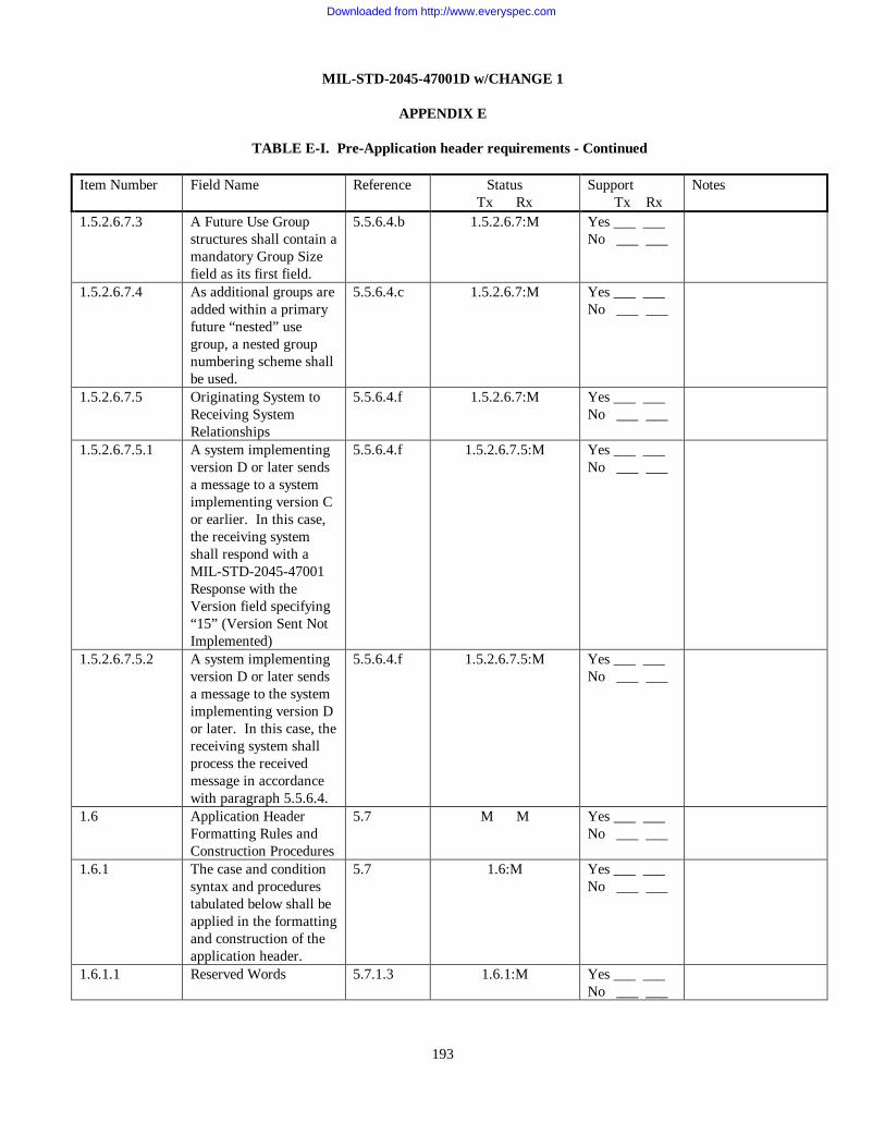
MIL-STD-2045-47001D w/CHANGE 1
APPENDIX E
193
TABLE E-I. Pre-Application header requirements - Continued Item Number Field Name Reference Status
Tx Rx Support Tx Rx
Notes
1.5.2.6.7.3 A Future Use Group structures shall contain a mandatory Group Size field as its first field.
5.5.6.4.b 1.5.2.6.7:M Yes ___ ___ No ___ ___
1.5.2.6.7.4 As additional groups are added within a primary future “nested” use group, a nested group numbering scheme shall be used.
5.5.6.4.c 1.5.2.6.7:M Yes ___ ___ No ___ ___
1.5.2.6.7.5 Originating System to Receiving System Relationships
5.5.6.4.f 1.5.2.6.7:M Yes ___ ___ No ___ ___
1.5.2.6.7.5.1 A system implementing version D or later sends a message to a system implementing version C or earlier. In this case, the receiving system shall respond with a MIL-STD-2045-47001 Response with the Version field specifying “15” (Version Sent Not Implemented)
5.5.6.4.f 1.5.2.6.7.5:M Yes ___ ___ No ___ ___
1.5.2.6.7.5.2 A system implementing version D or later sends a message to the system implementing version D or later. In this case, the receiving system shall process the received message in accordance with paragraph 5.5.6.4.
5.5.6.4.f 1.5.2.6.7.5:M Yes ___ ___ No ___ ___
1.6 Application Header Formatting Rules and Construction Procedures
5.7 M M Yes ___ ___ No ___ ___
1.6.1 The case and condition syntax and procedures tabulated below shall be applied in the formatting and construction of the application header.
5.7 1.6:M Yes ___ ___ No ___ ___
1.6.1.1 Reserved Words 5.7.1.3 1.6.1:M Yes ___ ___ No ___ ___
Downloaded from http://www.everyspec.com

MIL-STD-2045-47001D w/CHANGE 1
APPENDIX E
194
TABLE E-I. Pre-Application header requirements - Continued Item Number Field Name Reference Status
Tx Rx Support Tx Rx
Notes
1.6.1.1.1 The statement always starts with “IF” and shall end with “ENDIF”.
5.7.1.3 1.6.1.1:M Yes ___ ___ No ___ ___
1.6.1.2 Cases 5.7.1.4 1.6.1:M Yes ___ ___ No ___ ___
1.6.1.3 Conditions 5.7.1.5 1.6.1:M Yes ___ ___ No ___ ___
1.6.1.4 Defaults 5.7.1.6 1.6.1:M Yes ___ ___ No ___ ___
1.6.1.5 Expected Responses 5.7.1.7 1.6.1:M Yes ___ ___ No ___ ___
1.6.1.5.1 The expected response by the system receiving an application header will depend on the content of the header fields and shall be stated as it relates to the case and conditionality statements for the header.
5.7.1.7 1.6.1.5:M Yes ___ ___ No ___ ___
1.6.1.6 Special Considerations 5.7.1.8 1.6.1:M Yes ___ ___ No ___ ___
1.7 User Data 5.7.3 M M Yes ___ ___ No ___ ___
1.8 Message Acknowledgments
5.7.4 M M Yes ___ ___ No ___ ___
1.8.1 Acknowledgment Header Format
5.7.4.1 1.8:M Yes ___ ___ No ___ ___
1.8.1.1 A receiving station shall respond to the originator by sending an acknowledgment header.
5.7.4.1 1.8.1:M Yes ___ ___ No ___ ___
1.8.1.2 The acknowledgment header consists of the following groups and fields
5.7.4.1 1.8.1:M Yes ___ ___ No ___ ___
1.8.1.2.1 Acknowledgment originator address group (G1)
5.7.4.1.a 1.8.1:M Yes ___ ___ No ___ ___
1.8.1.2.2 Acknowledgment recipient address group (R1)
5.7.4.1.b 1.8.1:M Yes ___ ___ No ___ ___
1.8.1.2.3 Message Handling Group (R3)
5.7.4.1.c 1.8.1:M Yes ___ ___ No ___ ___
Downloaded from http://www.everyspec.com

MIL-STD-2045-47001D w/CHANGE 1
APPENDIX E
195
TABLE E-I. Pre-Application header requirements - Continued Item Number Field Name Reference Status
Tx Rx Support Tx Rx
Notes
1.8.1.2.3.1 Within Message Handling Group, the Response Data Group (G13), shall include the DTG of message being acknowledged and the R/C field.
5.7.4.1.c 1.8.1:M Yes ___ ___ No ___ ___
1.8.2 Message Accountability 5.7.4.2 1.8:M Yes ___ ___ No ___ ___
1.8.2.1 The application header shall be used for the detection of duplicate messages and to associate an acknowledgment header with the original requesting message.
5.7.4.2 1.8.2:M Yes ___ ___ No ___ ___
1.8.2.2 The originator shall guarantee the uniqueness of this combination of fields by ensuring that no original message is transmitted having the same DTG and DTG Extension.
5.7.4.2 1.8.2:M Yes ___ ___ No ___ ___
1.8.2.3 Any duplicate messages (including retransmitted messages) shall be acknowledged if required and shall otherwise be ignored (discarded).
5.7.4.2.a 1.8.2:M Yes ___ ___ No ___ ___
1.8.2.4 Acknowledgment headers that match original messages shall be processed; unmatched Acknowledgment headers shall be ignored (discarded).
5.7.4.2.b 1.8.2:M Yes ___ ___ No ___ ___
1.8.3 Message Retransmission 5.7.4.3 1.8:M Yes ___ ___ No ___ ___
Downloaded from http://www.everyspec.com

MIL-STD-2045-47001D w/CHANGE 1
APPENDIX E
196
TABLE E-I. Pre-Application header requirements - Continued Item Number Field Name Reference Status
Tx Rx Support Tx Rx
Notes
1.8.3.1 A retransmission capability shall be provided to enable the automatic retransmission of a message that has not received an acknowledgment when one was requested.
5.7.4.3 1.8.3:M Yes ___ ___ No ___ ___
1.8.3.2 Automatic Retransmissions shall only apply if a machine acknowledgment is requested.
5.7.4.3 1.8.3:M Yes ___ ___ No ___ ___
1.8.3.3 The number of automatic retransmissions shall be selectable with a range of 0 to 3.
5.7.4.3.a 1.8.3:M Yes ___ ___ No ___ ___
1.8.3.4 The parameter governing the number of retransmissions shall be separately selectable for each Originator DTG/DTG Extension combination.
5.7.4.3.a 1.8.3:M Yes ___ ___ No ___ ___
1.8.3.5 A timer shall be provided to schedule the automatic retransmission.
5.7.4.3.b 1.8.3:M Yes ___ ___ No ___ ___
1.8.3.6 An expiration timer shall be selectable with a range of 5 to 600 seconds.
5.7.4.3.b 1.8.3:M Yes ___ ___ No ___ ___
1.8.3.7 Upon expiration of the timer, provided an acknowledgment has not been received, the message shall be retransmitted by the originating system.
5.7.4.3.b 1.8.3:M Yes ___ ___ No ___ ___
Downloaded from http://www.everyspec.com

MIL-STD-2045-47001D w/CHANGE 1
APPENDIX E
197
TABLE E-I. Pre-Application header requirements - Continued Item Number Field Name Reference Status
Tx Rx Support Tx Rx
Notes
1.8.3.8 If an acknowledgment is not received prior to expiration of the timer on the final retransmission, the operator shall be notified.
5.7.4.3.b 1.8.3:M Yes ___ ___ No ___ ___
1.8.3.9 Messages containing perishable data and requiring acknowledgment shall have the Perishability DTG set to a time later than the retransmit timeout.
5.7.4.3.b 1.8.3:M Yes ___ ___ No ___ ___
1.9 Processing Factors 5.8 M M Yes ___ ___ No ___ ___
1.9.1 Application Process 5.8.1 1.9:M Yes ___ ___ No ___ ___
1.9.1.1 The application process shall provide the application layer the bit-oriented or character-oriented messages that satisfy information exchange requirements.
5.8.1 1.9.1:M Yes ___ ___ No ___ ___
1.9.2 Message Formats 5.8.2 1.9:M Yes ___ ___ No ___ ___
1.9.2.1 The message formats shall be user-defined.
5.8.2 1.9.2:M Yes ___ ___ No ___ ___
1.9.3 Quality of Service (QOS)
5.8.3.3 O O Yes ___ ___ No ___ ___
1.9.3.1 Message Size Threshold shall be a parameter with a range of 1 to 1,048,575 bytes.
5.8.3.3 1.9.3:M Yes ___ ___ No ___ ___
1.9.3.2 Perish shall be a parameter with a range of 1 to 10800 seconds.
5.8.3.3 1.9.3:M Yes ___ ___ No ___ ___
1.9.4 Destination Port Number 5.8.3.7 M M Yes ___ ___ No ___ ___
Downloaded from http://www.everyspec.com

MIL-STD-2045-47001D w/CHANGE 1
APPENDIX E
198
TABLE E-I. Pre-Application header requirements - Continued Item Number Field Name Reference Status
Tx Rx Support Tx Rx
Notes
1.9.4.1 This “mil-2045-47001” port (1581) shall be passed as the destination port parameter value to the lower layer protocol when exchanging UMF defined in TABLE IV.
5.8.3.7 1.9.4:M Yes ___ ___ No ___ ___
1.9.4.2 TABLE XVII shows the port numbers that shall be used for IP/UDP data exchanges using the “47001” ALP.
5.8.3.7 1.9.4:M Yes ___ ___ No ___ ___
1.10 Application Header Padding
5.8.4 M M Yes ___ ___ No ___ ___
1.10.1 The application header shall always be a multiple of 8 bits.
5.8.4 1.7:M Yes ___ ___ No ___ ___
1.10.2 If an application header is not a multiple of 8 bits, it shall be zero-filled so that it becomes a multiple of 8 bits.
5.8.4 1.7:M Yes ___ ___ No ___ ___
1.10.3 This field shall be variable in size 0 - 7 bits.
5.8.4 1.7:M Yes ___ ___ No ___ ___
TABLE E-II. Application header requirements
Item Number Field Name Reference Status Tx Rx
Support Tx Rx
Notes
2.1 VERSION 5.6.1 5.7.2.5.2
M M Yes ___ ___ No ___ ___
2.1.a MIL-STD-2045-47001 5.6.1 2.1:O.<6> Yes ___ ___ No ___ ___
2.1.b MIL-STD-2045-47001B 5.6.1 2.1:O.<6> Yes ___ ___ No ___ ___
2.1.c MIL-STD-2045-47001C 5.6.1 2.1:O.<6> Yes ___ ___ No ___ ___
2.1.d MIL-STD-2045-47001D 5.6.1 5.7.2.1.9
2.1:O.<6> Yes ___ ___ No ___ ___
2.1.e MIL-STD-2045-47001D w/CHANGE 1
5.6.1 5.7.2.1.9
2.1:O.<6> Yes ___ ___ No ___ ___
2.1.f VERSION SENT NOT 5.6.1 2.1:O.<6> Yes ___ ___
Downloaded from http://www.everyspec.com

MIL-STD-2045-47001D w/CHANGE 1
APPENDIX E
199
IMPLEMENTED 5.7.2.5.2 No ___ ___ 2.2 FPI 5.5.1
5.7.2.1.5 5.7.2.5.2 5.7.2.5.10
M M Yes ___ ___ No ___ ___
2.2.a NOT PRESENT 5.5.1 2.2:M.<2> Yes ___ ___ No ___ ___
2.2.b PRESENT 5.5.1 2.2:M.<2> Yes ___ ___ No ___ ___
2.2.1 DATA COMPRESSION TYPE
5.6.2
O M Yes ___ ___ No ___ ___
2.2.1.a UNIX COMPRESS/ UNCOMPRESS
5.6.2 2.2.1:O Yes ___ ___ No ___ ___
Downloaded from http://www.everyspec.com

MIL-STD-2045-47001D w/CHANGE 1
APPENDIX E
200
TABLE E-II. Application header requirements - Continued
Item Number Field Name Reference Status
Tx Rx Support Tx Rx
Notes
2.2.1.b GZIP 5.6.2 2.2.1:M Yes ___ ___ No ___ ___
2.3 GPI FOR G1 (ORIGINATOR ADDRESS GROUP)
5.5.3 5.6.3 5.7.2.1.2 5.7.2.2.1 5.7.2.5.2 5.7.2.5.6
M M Yes ___ ___ No ___ ___
2.3.a NOT PRESENT 5.5.3 2.3:M.<2> Yes ___ ___ No ___ ___
2.3.b PRESENT 5.5.3 2.3:M.<2> Yes ___ ___ No ___ ___
2.3.1 FPI 5.5.1 5.7.2.2.2 5.7.2.2.5
2.3:M Yes ___ ___ No ___ ___
2.3.1.a NOT PRESENT 5.5.1 2.3.1:M.<2> Yes ___ ___ No ___ ___
2.3.1.b PRESENT 5.5.1 2.3.1:M.<2> Yes ___ ___ No ___ ___
2.3.1.1 URN 5.6.3.1 A.3.1
2.3.1.b:M 2.3.2.b:E
Yes ___ ___ No ___ ___
2.3.2 FPI 5.5.1 5.7.2.2.3 5.7.2.2.4
2.3:M Yes ___ ___ No ___ ___
2.3.2.a NOT PRESENT 5.5.1 2.3.2:M.<2> Yes ___ ___ No ___ ___
2.3.2.b PRESENT 5.5.1 2.3.2:M.<2> Yes ___ ___ No ___ ___
2.3.2.1 UNIT NAME 5.6.3.2 2.3.2.b:M 2.3.1.b:E
Yes ___ ___ No ___ ___
2.4 GPI FOR G2 (RECIPIENT ADDRESS GROUP)
5.5.3 5.6.3 5.7.2.1.2 5.7.2.5.2 5.7.2.5.3 5.7.2.5.6
M M Yes ___ ___ No ___ ___
2.4.a NOT PRESENT 5.5.3 2.4:M.<2> Yes ___ ___ No ___ ___
2.4.b PRESENT 5.5.3 2.4:M.<2> Yes ___ ___ No ___ ___
2.4.1.1 GRI FOR R1 (0<=N<=16)
5.5.4 5.7.2.1.2
2.4.b:M Yes ___ ___ No ___ ___
2.4.1.1.a NOT REPEATED 5.5.4 2.4.1.1:M.<2> Yes ___ ___ No ___ ___
Downloaded from http://www.everyspec.com

MIL-STD-2045-47001D w/CHANGE 1
APPENDIX E
201
TABLE E-II. Application header requirements - Continued Item Number Field Name Reference Status
Tx Rx Support Tx Rx
Notes
2.4.1.1.b REPEATED 5.5.4 2.4.1.1:M.<2> Yes ___ ___ No ___ ___
2.4.1.1.1 The recipient and information addressee fields shall be extendible to a combined total of 16 addressees.
5.6.3a. 2.4.1.1:M Yes ___ ___ No ___ ___
2.4.1.2 FPI 5.5.1 5.7.2.2.2 5.7.2.2.5
O M Yes ___ ___ No ___ ___
2.4.1.2.a NOT PRESENT 5.5.1 2.4.1.2:M.<2> Yes ___ ___ No ___ ___
2.4.1.2.b PRESENT 5.5.1 2.4.1.2:M.<2> Yes ___ ___ No ___ ___
2.4.1.2.1 URN 5.6.3.1 A.3.1
2.4.1.2.b:M 2.4.1.3.1:E
Yes ___ ___ No ___ ___
2.4.1.3 FPI 5.5.1 5.7.2.2.3 5.7.2.2.4
O M Yes ___ ___ No ___ ___
2.4.1.3.a NOT PRESENT 5.5.1 2.4.1.3:M.<2> Yes ___ ___ No ___ ___
2.4.1.3.b PRESENT 5.5.1 2.4.1.3:M.<2> Yes ___ ___ No ___ ___
2.4.1.3.1 UNIT NAME 5.6.3.2 2.4.1.3.b:M 2.4.1.2.1:E
Yes ___ ___ No ___ ___
2.5 GPI FOR G3 (INFORMATION ADDRESS GROUP)
5.5.3 5.6.3 5.7.2.1.2 5.7.2.5.3 5.7.2.5.6
M M Yes ___ ___ No ___ ___
2.5.a NOT PRESENT 5.5.3 2.5:M.<2> Yes ___ ___ No ___ ___
2.5.b PRESENT 5.5.3 2.5:M.<2> Yes ___ ___ No ___ ___
2.5.1.1 GRI FOR R2 (16 – N)
5.5.4 2.5.b:M Yes ___ ___ No ___ ___
2.5.1.1.a NOT REPEATED 5.5.4 2.5.1.1:M.<2> Yes ___ ___ No ___ ___
2.5.1.1.b REPEATED 5.5.4 2.5.1.1:M.<2> Yes ___ ___ No ___ ___
2.5.1.1.1 The recipient and information addressee fields shall be extendible to a combined total of 16 addressees.
5.6.3.a. 2.5.1.1:M Yes ___ ___ No ___ ___
Downloaded from http://www.everyspec.com

MIL-STD-2045-47001D w/CHANGE 1
APPENDIX E
202
TABLE E-II. Application header requirements - Continued Item Number Field Name Reference Status
Tx Rx Support Tx Rx
Notes
2.5.1.2 FPI 5.5.1 5.7.2.2.2 5.7.2.2.5
O M Yes ___ ___ No ___ ___
2.5.1.2.a NOT PRESENT 5.5.1 2.5.1.2:M.<2> Yes ___ ___ No ___ ___
2.5.1.2.b PRESENT 5.5.1 2.5.1.2:M.<2> Yes ___ ___ No ___ ___
2.5.1.2.1 URN 5.6.3.1 A.3.1
2.5.1.2.b:M 2.5.1.3.1:E
Yes ___ ___ No ___ ___
2.5.1.3 FPI 5.5.1 5.7.2.2.3 5.7.2.2.4
O M Yes ___ ___ No ___ ___
2.5.1.3.a NOT PRESENT 5.5.1 2.5.1.3:M.<2> Yes ___ ___ No ___ ___
2.5.1.3.b PRESENT 5.5.1 2.5.1.3:M.<2> Yes ___ ___ No ___ ___
2.5.1.3.1 UNIT NAME 5.6.3.2 2.5.1.3.b:M 2.5.1.2.1:E
Yes ___ ___ No ___ ___
2.6 FPI 5.5.1 M M Yes ___ ___ No ___ ___
2.6.a NOT PRESENT 5.5.1 2.6:M.<2> Yes ___ ___ No ___ ___
2.6.b PRESENT 5.5.1 2.6:M.<2> Yes ___ ___ No ___ ___
2.6.1 HEADER SIZE 5.6.27 5.7.2.2.7 5.7.2.5.5 5.7.2.5.6
2.6.b:M 6.5:M 6.6:M
6.12:M
Yes ___ ___ No ___ ___
2.7 GPI FOR G4 (FUTURE USE 1)
5.5.3 5.5.6.4 5.7.2.1.9
O M Yes ___ ___ No ___ ___
2.7.a NOT PRESENT 5.5.3 2.7:M.<2> Yes ___ ___ No ___ ___
2.7.b PRESENT 5.5.3 2.7:E.<2>
Yes ___ ___ No ___ ___
2.7.1 GROUP SIZE 5.5.6.4 5.6.42
O M Yes ___ ___ No ___ ___
2.8 GPI FOR G5 (FUTURE USE 2)
5.5.3 5.5.6.4 5.7.2.1.9
O M Yes ___ ___ No ___ ___
2.8.a NOT PRESENT 5.5.3 2.8:M.<2> Yes ___ ___ No ___ ___
2.8.b PRESENT 5.5.3 2.8:E.<2>
Yes ___ ___ No ___ ___
Downloaded from http://www.everyspec.com

MIL-STD-2045-47001D w/CHANGE 1
APPENDIX E
203
TABLE E-II. Application header requirements - Continued Item Number Field Name Reference Status
Tx Rx Support Tx Rx
Notes
2.8.1 GROUP SIZE 5.5.6.4 5.6.42
O M Yes ___ ___ No ___ ___
2.9 GPI FOR G6 (FUTURE USE 3)
5.5.3 5.5.6.4 5.7.2.1.9
O M Yes ___ ___ No ___ ___
2.9.a NOT PRESENT 5.5.3 2.9:M.<2> Yes ___ ___ No ___ ___
2.9.b PRESENT 5.5.3 2.9:E.<2>
Yes ___ ___ No ___ ___
2.9.1 GROUP SIZE 5.5.6.4 5.6.42
O M Yes ___ ___ No ___ ___
2.10 GPI FOR G7 (FUTURE USE 4)
5.5.3 5.5.6.4 5.7.2.1.9
O M Yes ___ ___ No ___ ___
2.10.a NOT PRESENT 5.5.3 2.10:M.<2> Yes ___ ___ No ___ ___
2.10.b PRESENT 5.5.3 2.10:E.<2>
Yes ___ ___ No ___ ___
2.10.1 GROUP SIZE 5.5.6.4 5.6.42
O M Yes ___ ___ No ___ ___
2.11 GPI FOR G8 (FUTURE USE 5)
5.5.3 5.5.6.4 5.7.2.1.9
O M Yes ___ ___ No ___ ___
2.11.a NOT PRESENT 5.5.3 2.11:M.<2> Yes ___ ___ No ___ ___
2.11.b PRESENT 5.5.3 2.11:E.<2>
Yes ___ ___ No ___ ___
2.11.1 GROUP SIZE 5.5.6.4 5.6.42
O M Yes ___ ___ No ___ ___
2.12.1 GRI FOR R3 (MESSAGE HANDLING GROUP) (16)
5.5.4 5.6.9 5.7.2.1.2 5.7.2.2.7 5.7.2.5.5 5.7.2.5.6
M M Yes ___ ___ No ___ ___
2.12.1.a NOT REPEATED 5.5.4 2.12.1:M.<2> Yes ___ ___ No ___ ___
2.12.1.b REPEATED 5.5.4 2.12.1:M.<2> Yes ___ ___ No ___ ___
2.12.2 UMF 5.6.4
M M Yes ___ ___ No ___ ___
2.12.2.a LINK 16 (J-SERIES) 5.6.4
2.12.2:O.<9> Yes ___ ___ No ___ ___
2.12.2.b BINARY FILE 5.6.4.1 5.7.2.1.3
2.12.2:O.<9> Yes ___ ___ No ___ ___
Downloaded from http://www.everyspec.com

MIL-STD-2045-47001D w/CHANGE 1
APPENDIX E
204
TABLE E-II. Application header requirements - Continued Item Number Field Name Reference Status
Tx Rx Support Tx Rx
Notes
2.12.2.c VARIABLE MESSAGE FORMAT (VMF) (K-SERIES)
5.6.4
2.12.2:O.<9> Yes ___ ___ No ___ ___
2.12.2.d NATIONAL IMAGERY TRANSMISSION FORMAT SYSTEM (NITFS)
5.6.4 5.6.4.7
2.12.2:O.<9> Yes ___ ___ No ___ ___
2.12.2.e REDISTRIBUTED MESSAGE
5.6.4.2 5.7.2.1.4
2.12.2:O.<9> Yes ___ ___ No ___ ___
2.12.2.e.1 Redistributed Messages shall be indicated by a UMF field of ‘4’ (0100)
5.6.4.2 2.12.2.e:M Yes ___ ___ No ___ ___
2.12.2.e.2 A Redistributed Message shall consist of two components: the Original Message and the Redistribution Header
5.6.4.2 2.12.2.e:M Yes ___ ___ No ___ ___
2.12.2.e.3 When a station forwards a message, the Original Message (the entire Application PDU, i.e. the Application Header plus the User Data) shall be placed in the User Data portion of the Redistributed Message
5.6.4.2 2.12.2.e:M Yes ___ ___ No ___ ___
2.12.2.e.4 The Application Header and User Data of the Original Message shall not be modified
5.6.4.2 2.12.2.e:M Yes ___ ___ No ___ ___
2.12.2.e.5 The Redistribution Header shall contain the address of the station performing the message forwarding as the Originator Address
5.6.4.2 2.12.2.e:M Yes ___ ___ No ___ ___
2.12.2.e.6 The Redistribution Header shall set the UMF field to Redistributed Message
5.6.4.2 2.12.2.e:M Yes ___ ___ No ___ ___
Downloaded from http://www.everyspec.com

MIL-STD-2045-47001D w/CHANGE 1
APPENDIX E
205
TABLE E-II. Application header requirements - Continued Item Number Field Name Reference Status
Tx Rx Support Tx Rx
Notes
2.12.2.e.7 The Redistribution Header shall use the same Operation Indicator, Security Classification, and Control/Release Marking that were contained in the Original Message Application Header
5.6.4.2 2.12.2.e:M Yes ___ ___ No ___ ___
2.12.2.e.8 When a station receives a message containing a UMF field indicating a Redistributed Message, it shall process the Redistribution Header accordingly and then continue to process the Original Message
5.6.4.2 2.12.2.e:M Yes ___ ___ No ___ ___
2.12.2.e.9 The destination shall process the Original Message even though it is not specified in the destination address list of the Original Message
5.6.4.2 2.12.2.e:M Yes ___ ___ No ___ ___
2.12.2.e.10 The destination shall respond to any actions required by the Acknowledgment Request Group (G12) indicated in the Redistribution Header
5.6.4.2 2.12.2.e:M Yes ___ ___ No ___ ___
2.12.2.e.11 The destination shall not respond to any actions required by the Acknowledgment Request Group (G12) indicated in the Application Header of the Original Message
5.6.4.2 2.12.2.e:M Yes ___ ___ No ___ ___
Downloaded from http://www.everyspec.com

MIL-STD-2045-47001D w/CHANGE 1
APPENDIX E
206
TABLE E-II. Application header requirements - Continued Item Number Field Name Reference Status
Tx Rx Support Tx Rx
Notes
2.12.2.e.12 If the optional Redistributed Message capability is implemented in a system, there shall be a mechanism for the Application Layer to process both the Redistribution Header and the Original Message Application Header, and to indicate that the received message was redistributed
5.6.4.2 2.12.2.e:M Yes ___ ___ No ___ ___
2.12.2.e.13 For Redistributed Messages, the GPI for the VMF Message Identification Group (G9) shall be set to 0
5.6.4.2 2.12.2.e:M Yes ___ ___ No ___ ___
2.12.2.f UNITED STATES MESSAGE TEXT FORMAT (USMTF)
5.6.4.3 2.12.2:O.<9> Yes ___ ___ No ___ ___
2.12.2.g DOI-103 5.6.4.4 2.12.2:O.<9> Yes ___ ___ No ___ ___
2.12.2.h XML-MTF 5.6.4.5 2.12.2:O.<9> Yes ___ ___ No ___ ___
2.12.2.i XML-VMF 5.6.4.6 2.12.2:O.<9> Yes ___ ___ No ___ ___
2.12.3 FPI 5.5.1 M M Yes ___ ___ No ___ ___
2.12.3.a NOT PRESENT 5.5.1 2.12.3:M.<2> Yes ___ ___ No ___ ___
2.12.3.b PRESENT 5.5.1 2.12.3:M.<2> Yes ___ ___ No ___ ___
2.12.3.1 MESSAGE STANDARD VERSION
5.6.4.8 2.12.3.b:M Yes ___ ___ No ___ ___
2.12.4 GPI FOR G9 (VMF MESSAGE IDENTIFICATION GROUP)
5.5.3 5.7.2.1.2 5.7.2.1.3
2.12.2.c:M Yes ___ ___ No ___ ___
2.12.4.a NOT PRESENT 5.5.3 2.12.4:M.<2> Yes ___ ___ No ___ ___
2.12.4.b PRESENT 5.5.3 2.12.4:M.<2> Yes ___ ___ No ___ ___
Downloaded from http://www.everyspec.com

MIL-STD-2045-47001D w/CHANGE 1
APPENDIX E
207
TABLE E-II. Application header requirements - Continued Item Number Field Name Reference Status
Tx Rx Support Tx Rx
Notes
2.12.4.1 FAD 5.6.5 A.3.2
2.12.2.c:M 2.12.4.b:M
Yes ___ ___ No ___ ___
2.12.4.2 MESSAGE NUMBER 5.6.6 2.12.2.c:M 2.12.4.b:M
Yes ___ ___ No ___ ___
2.12.4.3 FPI 5.5.1 5.7.2.5.7
2.12.2.c:M 2.12.4.1:M 2.12.4.2:M
Yes ___ ___ No ___ ___
2.12.4.3.a NOT PRESENT 5.5.1 2.12.4.3:M.<2> Yes ___ ___ No ___ ___
2.12.4.3.b PRESENT 5.5.1 2.12.4.3:M.<2> 2.12.2.c:O 2.12.4.1:O 2.12.4.2:O
6.7:M
Yes ___ ___ No ___ ___
2.12.4.3.1 MESSAGE SUBTYPE 5.6.7 A.3.4
2.12.4.3.b:M
Yes ___ ___ No ___ ___
2.12.5 FPI 5.5.1 5.7.2.1.2
M M Yes ___ ___ No ___ ___
2.12.5.a NOT PRESENT 5.5.1 2.12.5:M.<2> Yes ___ ___ No ___ ___
2.12.5.b PRESENT 5.5.1 2.12.5:M.<2> 2. 12.2.b:O
Yes ___ ___ No ___ ___
2.12.5.1 FILE NAME 5.6.8
2.12.5.b:M 2.12.2.b:M
Yes ___ ___ No ___ ___
2.12.6 FPI 5.5.1 5.7.2.1.2 5.7.2.2.7 5.7.2.5.5 5.7.2.5.6
2.2:M 2. 12.1:M Yes ___ ___ No ___ ___
2.12.6.a NOT PRESENT 5.5.1 2.12.6:M.<2> Yes ___ ___ No ___ ___
2.12.6.b PRESENT 5.5.1 2.12.6:M.<2> Yes ___ ___ No ___ ___
2.12.6.1 MESSAGE SIZE 5.6.9 5.7.2.2.7 5.7.2.5.5 5.7.2.5.6
2.12.6.b:M 6.5:M 6.6:M
6.12:M
Yes ___ ___ No ___ ___
2.12.7 OPERATION INDICATOR
5.6.10 M M Yes ___ ___ No ___ ___
2.12.8 RETRANSMIT INDICATOR
5.6.11 5.7.2.2.17
M M Yes ___ ___ No ___ ___
2.12.8.a NOT A RETRANSMITTED MESSAGE
5.6.11 2.12.8:O.<2> Yes ___ ___ No ___ ___
Downloaded from http://www.everyspec.com

MIL-STD-2045-47001D w/CHANGE 1
APPENDIX E
208
TABLE E-II. Application header requirements - Continued Item Number Field Name Reference Status
Tx Rx Support Tx Rx
Notes
2.12.8.b RETRANSMITTED MESSAGE
5.6.11 5.7.2.2.17
2.12.8:O.<2> Yes ___ ___ No ___ ___
2.12.9 MESSAGE PRECEDENCE CODE
5.6.12 M M Yes ___ ___ No ___ ___
2.12.10 SECURITY CLASSIFICATION
5.6.13 M M Yes ___ ___ No ___ ___
2.12.11 FPI 5.5.1 5.7.2.1.2
M M Yes ___ ___ No ___ ___
2.12.11.a NOT PRESENT 5.5.1 2.12.11:M.<2> Yes ___ ___ No ___ ___
2.12.11.b PRESENT 5.5.1 2.12.11:M.<2> Yes ___ ___ No ___ ___
2.12.11.1 CONTROL/RELEASE MARKING
5.6.14 2.12.11.b:M Yes ___ ___ No ___ ___
2.12.12 GPI FOR G10 (ORIGINATOR DTG)
5.5.3 5.6.15 5.7.2.1.2 5.7.2.2.11 5.7.2.2.17
M M 2.12.8.b:M
2.12.14.1:M 2.12.14.2:M
Yes ___ ___ No ___ ___
2.12.12.a NOT PRESENT 5.5.3 2.12.12:M.<2> Yes ___ ___ No ___ ___
2.12.12.b PRESENT 5.5.3 2.12.12:M.<2> Yes ___ ___ No ___ ___
2.12.12.1 YEAR 5.6.15 2.12.12.b:M Yes ___ ___ No ___ ___
2.12.12.2 MONTH 5.6.15 2.12.12.b:M Yes ___ ___ No ___ ___
2.12.12.3 DAY 5.6.15 2.12.12.b:M Yes ___ ___ No ___ ___
2.12.12.4 HOUR 5.6.15 2.12.12.b:M Yes ___ ___ No ___ ___
2.12.12.5 MINUTE 5.6.15 2.12.12.b:M Yes ___ ___ No ___ ___
2.12.12.6 SECOND 5.6.15 2.12.12.b:M Yes ___ ___ No ___ ___
2.12.12.7 FPI 5.5.1 5.7.2.5.4
2.12.12.b:M Yes ___ ___ No ___ ___
2.12.12.7.a NOT PRESENT 5.5.1 2.12.12.7:M.<2> Yes ___ ___ No ___ ___
2.12.12.7.b PRESENT 5.5.1 2.12.12.7:M.<2> Yes ___ ___ No ___ ___
2.12.12.7.1 DTG EXTENSION 5.6.16 2.12.12.7.b:M Yes ___ ___ No ___ ___
Downloaded from http://www.everyspec.com

MIL-STD-2045-47001D w/CHANGE 1
APPENDIX E
209
TABLE E-II. Application header requirements - Continued Item Number Field Name Reference Status
Tx Rx Support Tx Rx
Notes
2.12.13 GPI FOR G11 (PERISHABILITY DTG)
5.5.3 5.6.17 5.7.2.1.2 5.7.2.5.1
O M Yes ___ ___ No ___ ___
2.12.13.a NOT PRESENT 5.5.3 2.12.13:M.<2> Yes ___ ___ No ___ ___
2.12.13.b PRESENT 5.5.3 2.12.13:M.<2> Yes ___ ___ No ___ ___
2.12.13.1 YEAR 5.6.15 2.12.13.b:M Yes ___ ___ No ___ ___
2.12.13.2 MONTH 5.6.15 2.12.13.b:M Yes ___ ___ No ___ ___
2.12.13.3 DAY 5.6.15 2.12.13.b:M Yes ___ ___ No ___ ___
2.12.13.4 HOUR 5.6.15 2.12.13.b:M Yes ___ ___ No ___ ___
2.12.13.5 MINUTE 5.6.15 2.12.13.b:M Yes ___ ___ No ___ ___
2.12.13.6 SECOND 5.6.15 2.12.13.b:M Yes ___ ___ No ___ ___
2.12.14 GPI FOR G12 (ACKNOWLEDGMENT REQUEST GROUP)
5.5.3 5.7.2.1.2 5.7.2.2.1 5.7.2.2.14 5.7.2.2.15 5.7.2.5.8
M M Yes ___ ___ No ___ ___
2.12.14.a NOT PRESENT 5.5.3 2.12.14:M.<2> Yes ___ ___ No ___ ___
2.12.14.b PRESENT 5.5.3 2.12.14:M.<2> Yes ___ ___ No ___ ___
2.12.14.1 MACHINE ACKNOWLEDGE REQUEST INDICATOR
5.6.18 5.7.2.2.11 5.7.2.2.15 5.7.2.5.1 5.7.4.1
2.12.14.b:M Yes ___ ___ No ___ ___
2.12.14.2 OPERATOR ACKNOWLEDGE REQUEST INDICATOR
5.6.19 5.7.2.2.11 5.7.2.2.15 5.7.2.5.2
2.12.14.b:M Yes ___ ___ No ___ ___
2.12.14.3 OPERATOR REPLY REQUEST INDICATOR
5.6.20 5.7.2.2.11 5.7.2.5.3
2.12.14.b:M Yes ___ ___ No ___ ___
Downloaded from http://www.everyspec.com

MIL-STD-2045-47001D w/CHANGE 1
APPENDIX E
210
TABLE E-II. Application header requirements - Continued Item Number Field Name Reference Status
Tx Rx Support Tx Rx
Notes
2.12.15 GPI FOR G13 (RESPONSE DATA GROUP)
5.5.3 5.6.21 5.7.2.1.1 5.7.2.1.2 5.7.2.1.5 5.7.2.5.9
4.1.2:M Yes ___ ___ No ___ ___
2.12.15.a NOT PRESENT 5.5.3 2.12.15:M.<2> Yes ___ ___ No ___ ___
2.12.15.b PRESENT 5.5.3 2.12.15:M.<2> Yes ___ ___ No ___ ___
2.12.15.1 YEAR (DTG OF MESSAGE BEING ACKNOWLEDGED)
5.6.15 2.12.15.b:M Yes ___ ___ No ___ ___
2.12.15.2 MONTH 5.6.15 2.12.15.b:M Yes ___ ___ No ___ ___
2.12.15.3 DAY 5.6.15 2.12.15.b:M Yes ___ ___ No ___ ___
2.12.15.4 HOUR 5.6.15 2.12.15.b:M Yes ___ ___ No ___ ___
2.12.15.5 MINUTE 5.6.15 2.12.15.b:M Yes ___ ___ No ___ ___
2.12.15.6 SECOND 5.6.15 2.12.15.b:M Yes ___ ___ No ___ ___
2.12.15.7 FPI 5.5.1 5.7.2.5.9
2.12.15.b:M Yes ___ ___ No ___ ___
2.12.15.7.a NOT PRESENT 5.5.1 2.12.15.7:M.<2> Yes ___ ___ No ___ ___
2.12.15.7.b PRESENT 5.5.1 2.12.15.7:M.<2> Yes ___ ___ No ___ ___
2.12.15.7.1 DTG EXTENSION 5.6.16 2.12.15.7.b:M 4.1.2:M 6.8:M
Yes ___ ___ No ___ ___
2.12.15.8 R/C 5.6.22 5.7.2.4.1
4.1.2:M
Yes ___ ___ No ___ ___
2.12.15.8.a MACHINE RECEIPT [MR]
5.6.22 5.7.2.2.8 5.7.2.2.9
2.12.15.8:M.<6> Yes ___ ___ No ___ ___
2.12.15.8.b CANNOT PROCESS [CANTPRO]
5.6.22 5.7.2.2.8 5.7.2.4.1 5.7.2.4.2 5.7.2.4.3 5.7.2.4.4 5.7.2.5.1
2.12.15.8:M.<6> Yes ___ ___ No ___ ___
Downloaded from http://www.everyspec.com

MIL-STD-2045-47001D w/CHANGE 1
APPENDIX E
211
TABLE E-II. Application header requirements - Continued Item Number Field Name Reference Status
Tx Rx Support Tx Rx
Notes
2.12.15.8.c OPERATOR ACKNOWLEDGE [OPRACK]
5.6.22 5.7.2.2.8 5.7.2.2.9 5.7.2.4.2
2.12.15.8:M.<6> Yes ___ ___ No ___ ___
2.12.15.8.d WILL COMPLY [WILCO]
5.6.22 5.7.2.2.8 5.7.2.2.9 5.7.2.4.3
2.12.15.8:M.<6> Yes ___ ___ No ___ ___
2.12.15.8.e HAVE COMPLIED [HAVCO]
5.6.22 5.7.2.2.8 5.7.2.2.9 5.7.2.4.3
2.12.15.8:M.<6> Yes ___ ___ No ___ ___
2.12.15.8.f CANNOT COMPLY [CANTCO]
5.6.22 5.7.2.2.9 5.7.2.4.3
2.12.15.8:M.<6> Yes ___ ___ No ___ ___
2.12.15.9 FPI 5.5.1 M M Yes ___ ___ No ___ ___
2.12.15.9.a NOT PRESENT 5.5.1 2.12.15.9:M.<2> 4.2.8:M
Yes ___ ___ No ___ ___
2.12.15.9.b PRESENT 5.5.1 2.12.15.9:M.<2> 2.12.15.8.f:O
Yes ___ ___ No ___ ___
2.12.15.9.1 CANTCO REASON CODE
5.6.23 5.7.2.2.8 A.3.5
2.12.15.9.b:M
Yes ___ ___ No ___ ___
2.12.15.9.1.a COMMUNICATIONS PROBLEM
5.6.23 A.3.5
2.12.15.9.1:O.<8> Yes ___ ___ No ___ ___
2.12.15.9.1.b AMMUNITION PROBLEM
5.6.23 A.3.5
2.12.15.9.1:O.<8> Yes ___ ___ No ___ ___
2.12.15.9.1.c PERSONNEL PROBLEM
5.6.23 A.3.5
2.12.15.9.1:O.<8> Yes ___ ___ No ___ ___
2.12.15.9.1.d FUEL PROBLEM 5.6.23 A.3.5
2.12.15.9.1:O.<8> Yes ___ ___ No ___ ___
2.12.15.9.1.e TERRAIN/ENVIRONMENT PROBLEM
5.6.23 A.3.5
2.12.15.9.1:O.<8> Yes ___ ___ No ___ ___
2.12.15.9.1.f EQUIPMENT PROBLEM
5.6.23 A.3.5
2.12.15.9.1:O.<8> Yes ___ ___ No ___ ___
2.12.15.9.1.g TACTICAL SITUATION PROBLEM
5.6.23 A.3.5
2.12.15.9.1:O.<8> Yes ___ ___ No ___ ___
2.12.15.9.1.h OTHER 5.6.23 A.3.5
2.12.15.9.1:O.<8> Yes ___ ___ No ___ ___
2.12.15.10 FPI 5.5.1 5.7.2.2.9
M M Yes ___ ___ No ___ ___
2.12.15.10.a NOT PRESENT 5.5.1 2.12.15.10:M.<2> 4.2.9:M
Yes ___ ___ No ___ ___
Downloaded from http://www.everyspec.com

MIL-STD-2045-47001D w/CHANGE 1
APPENDIX E
212
TABLE E-II. Application header requirements - Continued Item Number Field Name Reference Status
Tx Rx Support Tx Rx
Notes
2.12.15.10.b PRESENT 5.5.1 2.12.15.10:M.<2> 2. 12.15.8.b:O
Yes ___ ___ No ___ ___
2.12.15.10.1 CANTPRO REASON CODE
5.6.24 A.3.6
2.12.15.10.b:M
Yes ___ ___ No ___ ___
2.12.15.10.1.a FIELD CONTENT INVALID
5.6.24 A.3.6
2.12.15.10.1:O.<32> Yes ___ ___ No ___ ___
2.12.15.10.1.b MESSAGE INCORRECTLY ROUTED
5.6.24 A.3.6
2.12.15.10.1:O.<32> Yes ___ ___ No ___ ___
2.12.15.10.1.c ADDRESS INACTIVE 5.6.24 A.3.6
2.12.15.10.1:O.<32> Yes ___ ___ No ___ ___
2.12.15.10.1.d REFERENCE POINT UNKNOWN TO RECEIVING AGENCY
5.6.24 A.3.6
2.12.15.10.1:O.<32> Yes ___ ___ No ___ ___
2.12.15.10.1.e FIRE UNITS SHALL BE CONTROLLED BY RECEIVING AGENCY
5.6.24 A.3.6
2.12.15.10.1:O.<32>
Yes ___ ___ No ___ ___
2.12.15.10.1.f MISSION SHALL BE CONTROLLED BY RECEIVING AGENCY
5.6.24 A.3.6
2.12.15.10.1:O.<32>
Yes ___ ___ No ___ ___
2.12.15.10.1.g MISSION NUMBER UNKNOWN BY RECEIVING AGENCY
5.6.24 A.3.6
2.12.15.10.1:O.<32> Yes ___ ___ No ___ ___
2.12.15.10.1.h TARGET NUMBER UNKNOWN BY RECEIVING AGENCY
5.6.24 A.3.6
2.12.15.10.1:O.<32> Yes ___ ___ No ___ ___
2.12.15.10.1.i SCHEDULE NUMBER UNKNOWN BY RECEIVING AGENCY
5.6.24 A.3.6
2.12.15.10.1:O.<32> Yes ___ ___ No ___ ___
2.12.15.10.1.j INCORRECT CONTROLLING ADDRESS FOR A GIVEN TRACK NUMBER
5.6.24 A.3.6
2.12.15.10.1:O.<32> Yes ___ ___ No ___ ___
2.12.15.10.1.k TRACK NUMBER NOT IN OWN TRACK FILE
5.6.24 A.3.6
2.12.15.10.1:O.<32> Yes ___ ___ No ___ ___
2.12.15.10.1.l INVALID ACCORDING TO GIVEN FIELD
5.6.24 A.3.6
2.12.15.10.1:O.<32> Yes ___ ___ No ___ ___
2.12.15.10.1.m MESSAGE CANNOT BE CONVERTED
5.6.24 A.3.6
2.12.15.10.1:O.<32> Yes ___ ___ No ___ ___
2.12.15.10.1.n AGENCY FILE FULL 5.6.24 A.3.6
2.12.15.10.1:O.<32> Yes ___ ___ No ___ ___
Downloaded from http://www.everyspec.com

MIL-STD-2045-47001D w/CHANGE 1
APPENDIX E
213
TABLE E-II. Application header requirements - Continued Item Number Field Name Reference Status
Tx Rx Support Tx Rx
Notes
2.12.15.10.1.o AGENCY DOES NOT RECOGNIZE THIS MESSAGE NUMBER
5.6.24 A.3.6
2.12.15.10.1:O.<32> Yes ___ ___ No ___ ___
2.12.15.10.1.p AGENCY CANNOT CORRELATE MESSAGE TO CURRENT FILE CONTENT
5.6.24 A.3.6
2.12.15.10.1:O.<32> Yes ___ ___ No ___ ___
2.12.15.10.1.q AGENCY LIMIT EXCEEDED ON REPEATED FIELDS OR GROUPS
5.6.24 A.3.6
2.12.15.10.1:O.<32> Yes ___ ___ No ___ ___
2.12.15.10.1.r AGENCY COMPUTER SYSTEM INACTIVE
5.6.24 A.3.6
2.12.15.10.1:O.<32> Yes ___ ___ No ___ ___
2.12.15.10.1.s ADDRESSEE UNKNOWN
5.6.24 A.3.6
2.12.15.10.1:O.<32> Yes ___ ___ No ___ ___
2.12.15.10.1.t CAN’T FORWARD (AGENCY FAILURE)
5.6.24 A.3.6
2.12.15.10.1:O.<32> Yes ___ ___ No ___ ___
2.12.15.10.1.u CAN’T FORWARD (LINK FAILURE)
5.6.24 A.3.6
2.12.15.10.1:O.<32> Yes ___ ___ No ___ ___
2.12.15.10.1.v ILLOGICAL JUXTAPOSITION OF HEADER FIELDS
5.6.24 A.3.6
2.12.15.10.1:O.<32> Yes ___ ___ No ___ ___
2.12.15.10.1.w CANNOT UNCOMPRESS UNIX (LZW) COMPRESSED DATA
5.6.24 A.3.6
2.12.15.10.1:O.<32> Yes ___ ___ No ___ ___
2.12.15.10.1.x CANNOT UNCOMPRESS LZ-77 COMPRESSED DATA
5.6.24 A.3.6
2.12.15.10.1:O.<32> Yes ___ ___ No ___ ___
2.12.15.10.1.y MESSAGE TO OLD, BASED ON PERISHABILITY
5.6.24 5.7.2.5.1 A.3.6
2.12.15.10.1:O.<32> 6.1:M
Yes ___ ___ No ___ ___
2.12.15.10.1.z SECURITY LEVEL RESTRICTION
5.6.24 A.3.6
2.12.15.10.1:O.<32> Yes ___ ___ No ___ ___
2.12.15.10.1.aa AUTHENTICATION FAILURE
5.6.24 5.7.2.4.4 A.3.6
2.12.15.10.1:O.<32> Yes ___ ___ No ___ ___
2.12.15.10.1.bb CERTIFICATE NOT FOUND
5.6.24 5.7.2.4.4 A.3.6
2.12.15.10.1:O.<32> Yes ___ ___ No ___ ___
2.12.15.10.1.cc CERTIFICATE INVALID
5.6.24 5.7.2.4.4 A.3.6
2.12.15.10.1:O.<32> Yes ___ ___ No ___ ___
Downloaded from http://www.everyspec.com

MIL-STD-2045-47001D w/CHANGE 1
APPENDIX E
214
TABLE E-II. Application header requirements - Continued Item Number Field Name Reference Status
Tx Rx Support Tx Rx
Notes
2.12.15.10.1.dd DO NOT SUPPORT THIS SPI VALUE
5.6.24 5.7.2.4.4 A.3.6
2.12.15.10.1:O.<32> Yes ___ ___ No ___ ___
2.12.15.10.1.ee CAN NOT GENERATE A SIGNED ACKNOWLEDGMENT
5.6.24 5.7.2.4.4 A.3.6
2.12.15.10.1:O.<32> Yes ___ ___ No ___ ___
2.12.15.10.1.ff RESPONSE NOT AVAILABLE FOR RETRANSMISSION
5.6.24 A.3.6
2.12.15.10.1:O.<32> Yes ___ ___ No ___ ___
2.12.15.11 FPI 5.5.1 M M Yes ___ ___ No ___ ___
2.12.15.11.a NOT PRESENT 5.5.1 2.12.15.11:M.<2> Yes ___ ___ No ___ ___
2.12.15.11.b PRESENT 5.5.1 2.12.15.11:M.<2> Yes ___ ___ No ___ ___
2.12.15.11.1 REPLY AMPLIFICATION
5.6.25 2.12.15.11.b:M Yes ___ ___ No ___ ___
2.12.16 GPI FOR G14(REFERENCE MESSAGE DATA GROUP)
5.5.3 5.6.26 5.7.2.1.2
M M Yes ___ ___ No ___ ___
2.12.16.a NOT PRESENT 5.5.3 2.12.16:M.<2> Yes ___ ___ No ___ ___
2.12.16.b PRESENT 5.5.3 2.12.16:M.<2> Yes ___ ___ No ___ ___
2.12.16.1.1 GRI FOR R4 (4) 5.5.4 5.6.26
2.12.16.b:M Yes ___ ___ No ___ ___
2.12.16.1.1.a NOT REPEATED 5.5.4 2.12.16.1.1:M.<2> Yes ___ ___ No ___ ___
2.12.16.1.1.b REPEATED 5.5.4 2.12.16.1.1:M.<2> Yes ___ ___ No ___ ___
2.12.16.1.2 FPI 5.5.1 5.7.2.2.2 5.7.2.2.5 5.7.2.5.11 5.7.2.5.12
2.12.16.b:M Yes ___ ___ No ___ ___
2.12.16.1.2.a NOT PRESENT 5.5.1 2.12.16.1.2:M.<2> Yes ___ ___ No ___ ___
2.12.16.1.2.b PRESENT 5.5.1 2.12.16.1.2:M.<2> Yes ___ ___ No ___ ___
2.12.16.1.2.1 URN 5.6.3.1 2.12.16.1.2.b:M 2.12.16.1.3.1:E
Yes ___ ___ No ___ ___
Downloaded from http://www.everyspec.com

MIL-STD-2045-47001D w/CHANGE 1
APPENDIX E
215
TABLE E-II. Application header requirements - Continued Item Number Field Name Reference Status
Tx Rx Support Tx Rx
Notes
2.12.16.1.3 FPI 5.5.1 5.7.2.2.3 5.7.2.2.4 5.7.2.5.11 5.7.2.5.12
2.12.16:M Yes ___ ___ No ___ ___
2.12.16.1.3.a NOT PRESENT 5.5.1 2.12.16.1.3:M.<2> Yes ___ ___ No ___ ___
2.12.16.1.3.b PRESENT 5.5.1 2.12.16.1.3:M.<2> Yes ___ ___ No ___ ___
2.12.16.1.3.1 UNIT NAME 5.6.3.2 2.12.16.1.3.b:M 2.12.16.1.2.1:E
Yes ___ ___ No ___ ___
2.12.16.1.4 YEAR 5.6.15 2.12.16.b:M Yes ___ ___ No ___ ___
2.12.16.1.5 MONTH 5.6.15 2.12.16.b:M Yes ___ ___ No ___ ___
2.12.16.1.6 DAY 5.6.15 2.12.16.b:M Yes ___ ___ No ___ ___
2.12.16.1.7 HOUR 5.6.15 2.12.16.b:M Yes ___ ___ No ___ ___
2.12.16.1.8 MINUTE 5.6.15 2.12.16.b:M Yes ___ ___ No ___ ___
2.12.16.1.9 SECOND 5.6.15 2.12.16.b:M Yes ___ ___ No ___ ___
2.12.16.1.10 FPI 5.5.1 2. 12.16.b:M Yes ___ ___ No ___ ___
2.12.16.1.10.a NOT PRESENT 5.5.1 2.12.16.1.10:M.<2> Yes ___ ___ No ___ ___
2.12.16.1.10.b PRESENT 5.5.1 2.12.16.1.10:M.<2> Yes ___ ___ No ___ ___
2.12.16.1.10.1 DTG EXTENSION 5.6.16 2.12.16.1.10.b:M Yes ___ ___ No ___ ___
2.12.16.1.11 GPI FOR G15 (FUTURE USE 6)
5.5.3 5.5.6.4 5.7.2.1.9
O M Yes ___ ___ No ___ ___
2.12.16.1.11.a NOT PRESENT 5.5.3 2.12.16.1.11:M.<2> Yes ___ ___ No ___ ___
2.12.16.1.11.b PRESENT 5.5.3 2.12.16.1.11:E.<2>
Yes ___ ___ No ___ ___
2.12.16.1.11.1 GROUP SIZE 5.5.6.4 5.6.42
O M Yes ___ ___ No ___ ___
2.12.16.1.12 GPI FOR G16 (FUTURE USE 7)
5.5.3 5.5.6.4 5.7.2.1.9
O M Yes ___ ___ No ___ ___
Downloaded from http://www.everyspec.com

MIL-STD-2045-47001D w/CHANGE 1
APPENDIX E
216
TABLE E-II. Application header requirements - Continued Item Number Field Name Reference Status
Tx Rx Support Tx Rx
Notes
2.12.16.1.12.a NOT PRESENT 5.5.3 2.12.16.1.12:M.<2> Yes ___ ___ No ___ ___
2.12.16.1.12.b PRESENT 5.5.3 2.12.16.1.12:E.<2>
Yes ___ ___ No ___ ___
2.12.16.1.12.1 GROUP SIZE 5.5.6.4 5.6.42
O M Yes ___ ___ No ___ ___
2.12.16.1.13 GPI FOR G17 (FUTURE USE 8)
5.5.3 5.5.6.4 5.7.2.1.9
O M Yes ___ ___ No ___ ___
2.12.16.1.13.a NOT PRESENT 5.5.3 2.12.16.1.13:M.<2> Yes ___ ___ No ___ ___
2.12.16.1.13.b PRESENT 5.5.3 2.12.16.1.13:E.<2>
Yes ___ ___ No ___ ___
2.12.16.1.13.1 GROUP SIZE 5.5.6.4 5.6.4.2
O M Yes ___ ___ No ___ ___
2.12.16.1.14 GPI FOR G18 (FUTURE USE 9)
5.5.3 5.5.6.4 5.7.2.1.9
O M Yes ___ ___ No ___ ___
2.12.16.1.14.a NOT PRESENT 5.5.3 2.12.16.1.14:M.<2> Yes ___ ___ No ___ ___
2.12.16.1.14.b PRESENT 5.5.3 2.12.16.1.14:E.<2>
Yes ___ ___ No ___ ___
2.12.16.1.14.1 GROUP SIZE 5.5.6.4 5.6.42
O M Yes ___ ___ No ___ ___
2.12.16.1.15 GPI FOR G19 (FUTURE USE 10)
5.5.3 5.5.6.4 5.7.2.1.9
O M Yes ___ ___ No ___ ___
2.12.16.1.15.a NOT PRESENT 5.5.3 2.12.16.1.15:M.<2> Yes ___ ___ No ___ ___
2.12.16.1.15.b PRESENT 5.5.3 2.12.16.1.15:E.<2>
Yes ___ ___ No ___ ___
2.12.16.1.15.1 GROUP SIZE 5.5.6.4 5.6.42
O M Yes ___ ___ No ___ ___
2.12.17 GPI FOR G20 (MESSAGE SECURITY GROUP)
5.5.3 5.7.2.1.2 5.7.2.1.6 APPENDIX D
M M Yes ___ ___ No ___ ___
2.12.17.a NOT PRESENT 5.5.3 2.12.17:M.<2> Yes ___ ___ No ___ ___
2.12.17.b PRESENT 5.5.3 2.12.17:M.<2> 4.1.6:M
Yes ___ ___ No ___ ___
2.12.17.1 SECURITY PARAMETERS INFORMATION
5.6.28 5.7.2.2.13 D.4.1
2.12.17.b:M Yes ___ ___ No ___ ___
Downloaded from http://www.everyspec.com

MIL-STD-2045-47001D w/CHANGE 1
APPENDIX E
217
TABLE E-II. Application header requirements - Continued Item Number Field Name Reference Status
Tx Rx Support Tx Rx
Notes
2.12.17.1.a AUTHENTICATION (USING SHA-1 AND DSA) / NO ENCRYPTION
5.6.28 D.4.1.1.1
2.12.17.1:M Yes ___ ___ No ___ ___
2.12.17.2 GPI FOR G21 (KEYING MATERIAL GROUP)
5.5.3 5.7.2.2.13
2.12.17.b:M Yes ___ ___ No ___ ___
2.12.17.2.a NOT PRESENT 5.5.3 2.12.17.2:M.<2> 2.12.17.1.a:M
Yes ___ ___ No ___ ___
2.12.17.2.b PRESENT 5.5.3 2.12.17.2:M.<2> Yes ___ ___ No ___ ___
2.12.17.2.1 KEYING MATERIAL ID LENGTH
5.6.29 D.4.1.1.2
2.12.17.2.b:M 2. 12.17.1:C
Yes ___ ___ No ___ ___
2.12.17.2.2 KEYING MATERIAL ID
5.6.30 2.12.17.2.b:M 2. 12.17.1:C
Yes ___ ___ No ___ ___
2.12.17.3 GPI FOR G22(CRYPTOGRAPHIC INITIALIZATION GROUP)
5.5.3 5.7.2.2.13
2.12.17.b:M Yes ___ ___ No ___ ___
2.12.17.3.a NOT PRESENT 5.5.3 2.12.17.3:M.<2> 2.12.17.1.a:M
Yes ___ ___ No ___ ___
2.12.17.3.b PRESENT 5.5.3 2.12.17.3:M.<2> Yes ___ ___ No ___ ___
2.12.17.3.1 CRYPTOGRAPHIC INITIALIZATION LENGTH
5.6.31 D.4.1.1.3
2.12.17.3.b:M 2.12.17.1:C
Yes ___ ___ No ___ ___
2.12.17.3.2 CRYPTOGRAPHIC INITIALIZATION
5.6.32 2.12.17.3.b:M 2.12.17.1:C
Yes ___ ___ No ___ ___
2.12.17.4 GPI FOR G23 (KEY TOKEN GROUP)
5.5.3 5.7.2.2.13
2.12.17.b:M Yes ___ ___ No ___ ___
2.12.17.4.a NOT PRESENT 5.5.3 2.12.17.4:M.<2> 2.12.17.1.a:M
Yes ___ ___ No ___ ___
2.12.17.4.b PRESENT 5.5.3 2.12.17.4:M.<2> Yes ___ ___ No ___ ___
2.12.17.4.1 KEY TOKEN LENGTH 5.6.33 D.4.1.1.4
2.12.17.4.b:M 2.12.17.1:C
Yes ___ ___ No ___ ___
2.12.17.4.2 FRI (17) 5.5.2 2.3, 2.4, 2.5, 2. 12.17.4:C
Yes ___ ___ No ___ ___
2.12.17.4.2.a NOT REPEATED 5.5.2 2.12.17.4.2:M.<2> Yes ___ ___ No ___ ___
2.12.17.4.2.b REPEATED 5.5.2 2.12.17.4.2:M.<2> Yes ___ ___ No ___ ___
2.12.17.4.3 KEY TOKEN 5.6.34
2.12.17.4.b:M 2.12.17.1:C
Yes ___ ___ No ___ ___
Downloaded from http://www.everyspec.com

MIL-STD-2045-47001D w/CHANGE 1
APPENDIX E
218
TABLE E-II. Application header requirements - Continued Item Number Field Name Reference Status
Tx Rx Support Tx Rx
Notes
2.12.17.5 GPI FOR G24 (AUTHENTICATION GROUP (A))
5.5.3 5.7.2.2.13 D.4.1.1.5
2.12.17.b:M Yes ___ ___ No ___ ___
2.12.17.5.a NOT PRESENT 5.5.3 2.12.17.5:M.<2> Yes ___ ___ No ___ ___
2.12.17.5.b PRESENT 5.5.3 2.12.17.5:M.<2> 2.12.17.1.a:M
Yes ___ ___ No ___ ___
2.12.17.5.1 AUTHENTICATION DATA (A) LENGTH
5.6.35 2.12.17.5.b:M 2.12.17.1:C
Yes ___ ___ No ___ ___
2.12.17.5.2 AUTHENTICATION DATA (A)
5.6.36 D.4.1.1.5.1
2.12.17.5.b:M 2.12.17.1:C
Yes ___ ___ No ___ ___
2.12.17.6 GPI FOR G25(AUTHENTICATION GROUP (B))
5.5.3 5.7.2.4.4 D.4.1.1.6
2.12.17.b:M Yes ___ ___ No ___ ___
2.12.17.6.a NOT PRESENT 5.5.3 2.12.17.6:M.<2> Yes ___ ___ No ___ ___
2.12.17.6.b PRESENT 5.5.3 2.12.17.6:M.<2> 2.12.17.7:C 2.12.14.b:C
Yes ___ ___ No ___ ___
2.12.17.6.1 AUTHENTICATION DATA (B) LENGTH
5.6.37 2.12.17.6.b:M Yes ___ ___ No ___ ___
2.12.17.6.2 AUTHENTICATION DATA (B)
5.6.38 D.4.1.1.6
2.12.17.6.b:M
Yes ___ ___ No ___ ___
2.12.17.7 SIGNED ACKNOWLEDGE REQUEST INDICATOR
5.6.39 5.7.2.2.14 5.7.2.4.4 D.4.1.1.7
2.12.17.b:M Yes ___ ___ No ___ ___
2.12.17.8 GPI FOR G26 (MESSAGE SECURITY PADDING GROUP)
5.5.3 5.7.2.2.13
2.12.17.b:M Yes ___ ___ No ___ ___
2.12.17.8.a NOT PRESENT 5.5.3 2.12.17.8:M.<2> 2.12.17.1.a:M
Yes ___ ___ No ___ ___
2.12.17.8.b PRESENT 5.5.3 2.12.17.8:M.<2> Yes ___ ___ No ___ ___
2.12.17.8.1 MESSAGE SECURITY PADDING LENGTH
5.6.40 2.12.17.8.b:M Yes ___ ___ No ___ ___
2.12.17.8.2 FPI 5.5.1 2.12.17.8.b:M Yes ___ ___ No ___ ___
2.12.17.8.2.a NOT PRESENT 5.5.1 2.12.17.8.2:M.<2> Yes ___ ___ No ___ ___
2.12.17.8.2.b PRESENT 5.5.1 2.12.17.8.2:M.<2> Yes ___ ___ No ___ ___
2.12.17.8.2.1 MESSAGE SECURITY PADDING
5.6.41 D.4.1.1.8
2.12.17.8.2.b:M Yes ___ ___ No ___ ___
Downloaded from http://www.everyspec.com

MIL-STD-2045-47001D w/CHANGE 1
APPENDIX E
219
TABLE E-II. Application header requirements - Continued Item Number Field Name Reference Status
Tx Rx Support Tx Rx
Notes
2.13 GPI FOR G27 (FUTURE USE 11)
5.5.3 5.5.6.4 5.7.2.1.9
O M Yes ___ ___ No ___ ___
2.13.a NOT PRESENT 5.5.3 2.13:M.<2> Yes ___ ___ No ___ ___
2.13.b PRESENT 5.5.3 2.13:E.<2>
Yes ___ ___ No ___ ___
2.13.1 GROUP SIZE 5.5.6.4 5.6.42
O M Yes ___ ___ No ___ ___
2.14 GPI FOR G28 (FUTURE USE 12)
5.5.3 5.5.6.4 5.7.2.1.9
O M Yes ___ ___ No ___ ___
2.14.a NOT PRESENT 5.5.3 2.14:M.<2> Yes ___ ___ No ___ ___
2.14.b PRESENT 5.5.3 2.14:E.<2>
Yes ___ ___ No ___ ___
2.14.1 GROUP SIZE 5.5.6.4 5.6.42
O M Yes ___ ___ No ___ ___
2.15 GPI FOR G29 (FUTURE USE 13)
5.5.3 5.5.6.4 5.7.2.1.9
O M Yes ___ ___ No ___ ___
2.15.a NOT PRESENT 5.5.3 2.15:M.<2> Yes ___ ___ No ___ ___
2.15.b PRESENT 5.5.3 2.15:E.<2>
Yes ___ ___ No ___ ___
2.15.1 GROUP SIZE 5.5.6.4 5.6.42
O M Yes ___ ___ No ___ ___
2.16 GPI FOR G30 (FUTURE USE 14)
5.5.3 5.5.6.4 5.7.2.1.9
O M Yes ___ ___ No ___ ___
2.16.a NOT PRESENT 5.5.3 2.16:M.<2> Yes ___ ___ No ___ ___
2.16.b PRESENT 5.5.3 2.16:E.<2>
Yes ___ ___ No ___ ___
2.16.1 GROUP SIZE 5.5.6.4 5.6.42
O M Yes ___ ___ No ___ ___
2.17 GPI FOR G31 (FUTURE USE 15)
5.5.3 5.5.6.4 5.7.2.1.9
O M Yes ___ ___ No ___ ___
2.17.a NOT PRESENT 5.5.3 2.17:M.<2> Yes ___ ___ No ___ ___
2.17.b PRESENT 5.5.3 2.17:E.<2>
Yes ___ ___ No ___ ___
Downloaded from http://www.everyspec.com

MIL-STD-2045-47001D w/CHANGE 1
APPENDIX E
220
TABLE E-II. Application header requirements - Continued Item Number Field Name Reference Status
Tx Rx Support Tx Rx
Notes
2.17.1 GROUP SIZE 5.5.6.4 5.6.42
O M Yes ___ ___ No ___ ___
TABLE E-III. Post application header receipt requirements
Item Number Field Name Reference Status Tx Rx
Support Tx Rx
Notes
3.1 Application Header Receipt
5.7.1.9 M M Yes ___ ___ No ___ ___
3.1.1 Upon receipt of an application header, validate the presence of all mandatory groups and fields.
5.7.1.9 3.1:M Yes ___ ___ No ___ ___
3.1.2 Validate that all occurrence category conditions are satisfied, and validate the legality of all field entries to determine the legality for the header.
5.7.1.9 3.1:M Yes ___ ___ No ___ ___
TABLE E-IV. Cases
Item Number
Field Name Reference Status Tx Rx
Support Tx Rx
Notes
4.1.1 CASE 1: Message is an original message. THIS CASE REQUIRES GPI for G13 [Response Data Group] is specified “0” (NOT PRESENT) AND User Data shall be present END CASE
5.7.2.1.1 5.7.2.6
M M Yes ___ ___ No ___ ___
Downloaded from http://www.everyspec.com

MIL-STD-2045-47001D w/CHANGE 1
APPENDIX E
221
4.1.2 CASE 2: Message is an acknowledgment message. THIS CASE REQUIRES GPI for Group 13 [Response Data Group] is specified "1" (PRESENT) AND GPI for G11 [Perishability DTG] is specified “0” (NOT PRESENT) AND GPI for G12 [Acknowledgment Request Group] is specified “0” (NOT PRESENT) AND the User Data shall not be present END CASE
5.7.2.1.2 5.7.4.2 5.7.2.6
M M Yes ___ ___ No ___ ___
Downloaded from http://www.everyspec.com

MIL-STD-2045-47001D w/CHANGE 1
APPENDIX E
222
TABLE E-IV. Cases -Continued
Item Number
Field Name Reference Status Tx Rx
Support Tx Rx
Notes
4.1.3 CASE 3: Message is not a VMF or XML-VMF message. THIS CASE REQUIRES UMF is specified “0” (LINK 16 (J-SERIES MESSAGE)) OR UMF is specified “1” (BINARY FILE) OR UMF is specified “3” (NATIONAL IMAGERY TRANSMISSION FORMAT SYSTEM (NITFS)) OR UMF is specified “4” (REDISTRIBUTED
MESSAGE (RDM)) OR UMF is specified “5” (UNITED STATES
MESSAGE TEXT FORMAT (USMTF)) OR UMF is specified “6” (DOI-103) OR UMF is specified “7” (EXTENSIBLE MARKUP LANGUAGE (XML) - MESSAGE TEXT FORMAT (MTF)) AND GPI for G9 [VMF Message Identification Group] is specified “0” (NOT PRESENT) END CASE
5.7.2.1.3 5.7.2.6
M M Yes ___ ___ No ___ ___
4.1.4 CASE 4: Message is a Redistributed Message. THIS CASE REQUIRES UMF is specified “4” (Redistributed Message) AND GPI for G9 [VMF Message Identification Group] is specified “0” (NOT PRESENT) AND User Data shall be present END CASE
5.7.2.1.4 5.7.2.6
O M Yes ___ ___ No ___ ___
4.1.5 CASE 5: Message was compressed. THIS CASE REQUIRES FPI for Data Compression is specified “1” (PRESENT) AND GPI for G13 [Response Data Group] is specified
“0” (NOT PRESENT) AND User Data shall be present END CASE
5.7.2.1.5 5.7.2.6
O M Yes ___ ___ No ___ ___
4.1.6 CASE 6: Message has security services applied. THIS CASE REQUIRES GPI for G20 [Message Security Group] is specified “1” (PRESENT) END CASE
5.7.2.1.6 5.7.2.6
O O Yes ___ ___ No ___ ___
Downloaded from http://www.everyspec.com

MIL-STD-2045-47001D w/CHANGE 1
APPENDIX E
223
TABLE E-IV. Cases -Continued Item Number
Field Name Reference Status Tx Rx
Support Tx Rx
Notes
4.1.7 CASE 7: Message is a signed acknowledgment. THIS CASE REQUIRES GPI for G13[Response Data Group] is specified “1” (PRESENT) AND GPI for G11[Perishability DTG Group] is specified
“0” (NOT PRESENT) AND GPI for G12 [Acknowledgment Request Group] is
specified “0” (NOT PRESENT) AND GPI for G24 [Authentication (A) Group] is specified
“1” (PRESENT) AND GPI for G25 [Authentication (B) Group] is specified
“1” (PRESENT) AND Signed Acknowledge Request Indicator is specified
“0” (SIGNED RESPONSE NOT REQUIRED) AND User Data shall be present END CASE
5.7.2.1.7 5.7.2.6
O O Yes ___ ___ No ___ ___
4.1.8 CASE 8: Message is an XML-VMF message. THIS CASE REQUIRES UMF is specified "8" (XML-VMF) AND GPI for G9 [Message Identification Group] is specified "1" (Present) AND User Data shall be present END CASE
5.7.2.1.8 5.7.2.6
O O Yes ___ ___ No ___ ___
Downloaded from http://www.everyspec.com

MIL-STD-2045-47001D w/CHANGE 1
APPENDIX E
224
TABLE E-IV. Cases -Continued Item Number
Field Name Reference Status Tx Rx
Support Tx Rx
Notes
4.1.9 CASE 9: Backward Compatibility of “Future Use” groups until they are used. THIS CASE REQUIRES GPI for G4 [Future Use 1] is specified “0” (NOT PRESENT) AND GPI for G5 [Future Use 2] is specified “0” (NOT PRESENT) AND GPI for G6 [Future Use 3] is specified “0” (NOT PRESENT) AND GPI for G7 [Future Use 4] is specified “0” (NOT PRESENT) AND GPI for G8 [Future Use 5] is specified “0” (NOT PRESENT) AND GPI for G15 [Future Use 6] is specified “0” (NOT PRESENT) AND GPI for G16 [Future Use 7] is specified “0” (NOT PRESENT) AND GPI for G17 [Future Use 8] is specified “0” (NOT PRESENT) AND GPI for G18 [Future Use 9] is specified “0” (NOT PRESENT) AND GPI for G19 [Future Use 10] is specified “0” (NOT PRESENT) AND GPI for G27 [Future Use 11] is specified “0” (NOT PRESENT) AND GPI for G28 [Future Use 12] is specified “0” (NOT PRESENT) AND GPI for G29 [Future Use 13] is specified “0” (NOT PRESENT) AND GPI for G30 [Future Use 14] is specified “0” (NOT PRESENT) AND GPI for G31 [Future Use 15] is specified “0” (NOT PRESENT) END CASE
5.7.2.1.9 5.7.2.6
M M Yes ___ ___ No ___ ___
4.1.10 CASE 10: Message is a VMF message. THIS CASE REQUIRES UMF shall be “2” (VMF) AND GPI for G9 [VMF Message Identification Group] is specified “1” (Present) END CASE
5.7.2.1.10 5.7.2.6
E.5.1.1.1.1 Yes ___ ___ No ___ ___
Downloaded from http://www.everyspec.com

MIL-STD-2045-47001D w/CHANGE 1
APPENDIX E
225
TABLE E-V. Conditions
Item Number Field Name Reference Status Tx Rx
Support Tx Rx
Notes
4.2.1 CONDITION 1: IF GPI for G1 [Originator Address Group] is specified “0” (NOT PRESENT) THEN GPI for G12[Acknowledgment Request Group] is specified “0” (NOT PRESENT) ENDIF
5.7.2.2.1 M M Yes ___ ___ No ___ ___
4.2.2 CONDITION 2: IF FPI for URN is specified “1” (PRESENT) THEN FPI for Unit Name is specified “0” (NOT
PRESENT) ENDIF
5.7.2.2.2 M M Yes ___ ___ No ___ ___
4.2.3 CONDITION 3: IF FPI for URN is specified “0” (NOT PRESENT) THEN FPI for Unit Name is specified “1” (PRESENT) ENDIF
5.7.2.2.3 M M Yes ___ ___ No ___ ___
4.2.4 CONDITION 4: IF FPI for Unit Name is specified “1” (PRESENT) THEN FPI for URN is specified “0” (NOT PRESENT) ENDIF
5.7.2.2.4 M M Yes ___ ___ No ___ ___
4.2.5 CONDITION 5: IF FPI for Unit Name is specified “0” (NOT
PRESENT) THEN FPI for URN is specified “1” (PRESENT) ENDIF
5.7.2.2.5 M M Yes ___ ___ No ___ ___
4.2.6 CONDITION 6: This paragraph is left blank to maintain paragraph conformity.
5.7.2.2.6 NA
4.2.7 CONDITION 7: IF GRI for R3 is specified “1” (REPEATED) THEN FPI for Message Size is specified “1” (PRESENT)
AND FPI for Header Size is specified "1" (PRESENT)
ENDIF
5.7.2.2.7 M M Yes ___ ___ No ___ ___
4.2.8 CONDITION 8: IF R/C is NOT specified “6” (CANTCO) THEN FPI for CANTCO Reason Code is specified “0”
(NOT PRESENT) ENDIF
5.7.2.2.8 M M Yes ___ ___ No ___ ___
4.2.9 CONDITION 9: IF R/C is NOT specified “2” (CANTPRO) THEN FPI for CANTPRO Reason Code is specified “0” (NOT PRESENT) ENDIF
5.7.2.2.9 M M Yes ___ ___ No ___ ___
4.2.10 CONDITION 10: This paragraph is left blank to maintain paragraph conformity.
5.7.2.2.10 NA
Downloaded from http://www.everyspec.com

MIL-STD-2045-47001D w/CHANGE 1
APPENDIX E
226
TABLE E-V. Conditions-Continued
Item Number
Field Name Reference Status Tx Rx
Support Tx Rx
Notes
4.2.11 CONDITION 11: IF Machine Acknowledge Request Indicator is
specified “1” (MACHINE ACKNOWLEDGMENT REQUIRED) OR Operator Acknowledge Request Indicator
is specified “1” (OPERATOR ACKNOWLEDGMENT REQUIRED)
OR Operator Reply Request Indicator is specified “1” (OPERATOR REPLY REQUIRED)
THEN GPI for G10[Originator DTG] is specified “1” (PRESENT)
ENDIF
5.7.2.2.11 M M Yes ___ ___ No ___ ___
4.2.12 CONDITION 12: This paragraph is left blank to maintain paragraph conformity.
5.7.2.2.12 NA
4.2.13 CONDITION 13: IF Security Parameters Information is specified “0” (AUTHENTICATION (USING SHA-1 AND DSA)/NO ENCRYPTION)) THEN GPI for G21 [Keying Material Group] is specified
“0” (NOT PRESENT) AND GPI for G22[Cryptographic Initialization
Group] is specified “0” (NOT PRESENT) AND GPI for G23[Keying Token Group] is
specified “0” (NOT PRESENT) AND GPI for G24 [Authentication (A) Group]
is specified “1” (PRESENT) AND GPI for G26 [Message Security Padding
Group] is specified “0” (NOT PRESENT) ENDIF
5.7.2.2.13 O M Yes ___ ___ No ___ ___
4.2.14 CONDITION 14: IF GPI for G12 [Acknowledgment Request Group] is specified “0” (NOT PRESENT) THEN Signed Acknowledge Request Indicator is
specified “0” (SIGNED ACKNOWLEDGMENT NOT REQUIRED)
ENDIF
5.7.2.2.14 O M Yes ___ ___ No ___ ___
4.2.15 CONDITION 15: IF Signed Acknowledge Request Indicator is
specified “1” (SIGNED ACKNOWLEDGMENT REQUIRED)
THEN GPI for G12 [Acknowledgment Request Group] is specified “1” (PRESENT) ENDIF
5.7.2.2.15 O M Yes ___ ___ No ___ ___
Downloaded from http://www.everyspec.com

MIL-STD-2045-47001D w/CHANGE 1
APPENDIX E
227
TABLE E-V. Conditions-Continued Item Number
Field Name Reference Status Tx Rx
Support Tx Rx
Notes
4.2.16 CONDITION 16:
IF UMF is specified “6” (DOI-103), THEN Message Precedence is specified “5” (CRITIC/ECP) ENDIF
5.7.2.2.16 O M Yes ___ ___ No ___ ___
4.2.17 CONDITION 17: IF Retransmit Indicator is specified “1” (RETRANSMITTED MESSAGE) THEN GPI for G10 [Originator DTG] is specified “1” (PRESENT) identifying the original date-time- group of the original message ENDIF
5.7.2.2.17 O M Yes ___ ___ No ___ ___
4.2.18 CONDITION 18: IF UMF is set to “2” (Variable Message Format (VMF)) THEN FPI for Message Standard Version is specified “1”
(PRESENT) ENDIF
5.7.2.2.18 M M Yes ___ ___ No ___ ___
TABLE E-VI. Expected response requirement
Item Number
Field Name Reference Status Tx Rx
Support Tx Rx
Notes
5.1 Machine Acknowledge Requested: IF Machine Acknowledge Request Indicator is specified “1” (MACHINE ACKNOWLEDGMENT REQUIRED) THEN Response Message R/C is specified “1” (MACHINE RECEIPT) OR Response Message R/C is specified “2” (CANTPRO) ENDIF
5.7.2.4.1 5.7.2.6
M M Yes ___ ___ No ___ ___
5.2 Operator Acknowledge Requested: IF Operator Acknowledge Request Indicator is specified “1” (OPERATOR ACKNOWLEDGMENT REQUIRED) THEN Response Message R/C is specified “3” (OPERATOR ACKNOWLEDGE) OR Response Message R/C is specified “2” (CANTPRO)
5.7.2.4.2 5.7.2.6
M M Yes ___ ___ No ___ ___
Downloaded from http://www.everyspec.com

MIL-STD-2045-47001D w/CHANGE 1
APPENDIX E
228
Item Number
Field Name Reference Status Tx Rx
Support Tx Rx
Notes
ENDIF
TABLE E-VI. Expected response requirement -Continued Item Number
Field Name Reference Status Tx Rx
Support Tx Rx
Notes
5.3 Operator Reply Requested: IF Operator Reply Request Indicator is specified “1” (OPERATOR REPLY REQUIRED) THEN Response Message R/C is specified “4” (WILCO) OR Response Message R/C is specified “5” (HAVCO) OR Response Message R/C is specified “6” (CANTCO) OR Response Message R/C is specified “2” (CANTPRO) ENDIF
5.7.2.4.3 5.7.2.6
M M Yes ___ ___ No ___ ___
5.4 Signed Acknowledge Requested: IF Signed Acknowledge Request Indicator is specified “1” (SIGNED ACKNOWLEDGMENT REQUIRED) THEN Response shall have GPI for G25 [Authentication (B)
Group] is specified “1” (PRESENT) OR {Response shall have R/C is specified “2” (CANTPRO) AND [CANTPRO Reason Code is specified “27” (AUTHENTICATION FAILURE) OR CANTPRO Reason Code is specified “28” (CERTIFICATE NOT FOUND) OR CANTPRO Reason Code is specified “29” (CERTIFICATE INVALID)
OR CANTPRO Reason Code is specified “30” (DO NOT SUPPORT THIS SPI VALUE)
OR CANTPRO Reason Code is specified “31” (CAN NOT GENERATE A SIGNED ACKNOWLEDGMENT)]} ENDIF
5.7.2.4.4 5.7.2.6
O O Yes ___ ___ No ___ ___
5.5 In a data element composed of a binary code, it shall be interpreted as a single data field.
5.5.6.2 M Yes ___ ___ No ___ ___
Downloaded from http://www.everyspec.com

MIL-STD-2045-47001D w/CHANGE 1
APPENDIX E
229
TABLE E-VII. Special considerations
Item Number
Field Name Reference Status Tx Rx
Support Tx Rx
Notes
6.1 Perishable Data Check: IF GPI for G11 [Perishable Data DTG] is specified “1”
(PRESENT) AND G11 [Perishable Data DTG] is earlier than
current DTG THEN User Data shall be ignored
AND IF Machine Acknowledge Request Indicator is
specified “1” (MACHINE ACKNOWLEDGMENT REQUIRED)
THEN Response Message R/C is specified “2” (CANTPRO) AND CANTPRO Reason Code is specified “25” (MESSAGE TOO OLD, BASED ON PERISHABILITY) ENDIF ENDIF
5.7.4.1 5.7.2.6
M M Yes ___ ___ No ___ ___
6.2 Response to version non-interoperability. IF Recipient does not implement Version sent THEN Version is specified "15" (VERSION SENT NOT IMPLEMENTED)
AND FPI for Data Compression Type is specified "0" (NOT PRESENT)
AND GPI for Group 1 [Originator Address Group] is specified "1" (PRESENT) AND Originator specified is the Original Recipient
AND GPI for Group 2 [Recipient Address Group] is specified "1" (PRESENT)
AND Recipient specified is the Originator of the original message
ENDIF
5.7.4.2 5.7.2.6
M M Yes ___ ___ No ___ ___
6.3 Broadcast Transmission Check. IF GPI for G2 [Recipient Address Group] is specified “0”
(NOT PRESENT) AND GPI for G3 [Information Address Group] is
specified “0” (NOT PRESENT) THEN message shall be broadcast in accordance with lower
layer broadcast protocols ENDIF
5.6.3.b. 5.7.4.3 5.7.2.6
M M Yes ___ ___ No ___ ___
6.4 Add DTG Extensions when Originator DTGs are the same: IF Originator DTG is equal to the Originator DTG of a
previously sent message THEN FPI for DTG Extension is specified “1” (PRESENT)
5.7.2.5.4 5.7.2.6
M M Yes ___ ___ No ___ ___
Downloaded from http://www.everyspec.com

MIL-STD-2045-47001D w/CHANGE 1
APPENDIX E
230
Item Number
Field Name Reference Status Tx Rx
Support Tx Rx
Notes
AND DTG Extension shall be unique ENDIF
Downloaded from http://www.everyspec.com

MIL-STD-2045-47001D w/CHANGE 1
APPENDIX E
231
TABLE E-VII. Special considerations -Continued
Item Number
Field Name Reference Status Tx Rx
Support Tx Rx
Notes
6.5 Message sent via a streaming/undelimited transport protocol: IF GRI for R3 is specified “0” (NOT REPEATED)
AND the message is being set via a streaming/undelimited transport
THEN FPI for Message Size is specified “1” (PRESENT) AND FPI for Header Size is specified "1"
(PRESENT) ENDIF
5.7.2.5.5 5.7.2.6
M M Yes ___ ___ No ___ ___
6.6 Message concatenation: The total size of any single User Data portion (e.g. a single VMF message) within a concatenated message block shall not exceed 1 megabyte (1,048,575 bytes) IF GPI for G1 [Originator Address Group] is specified
“1” (PRESENT) (OR GPI for G2 [Recipient Address Group] is
specified “1” (PRESENT) OR GPI for G3 [Information Address Group] is
specified “1” (PRESENT)) THEN (Groups G1 [Originator Address Group], G2 [Recipient Address Group] and G3 [Information Address Group] addresses are common to all concatenated messages)
AND GRI for R3 [Message Handling Group] is specified “1” (REPEATED)
AND Each iteration shall match in sequence specifying information about its respective
concatenated message AND FPI for Message Size is specified “1” (PRESENT) AND FPI for Header Size is specified "1" (PRESENT)
AND Message Size (any single message within the concatenated block) shall not exceed 1,048,575 bytes
ENDIF
5.7.2.5.6 5.7.2.6
O M Yes ___ ___ No ___ ___
6.7 Message Case and Message Subtype Relationship: IF Cases exist for transmitted VMF message THEN FPI for Message Subtype is specified “1” (PRESENT) ENDIF
5.7.2.5.7 5.7.2.6
M M Yes ___ ___ No ___ ___
Downloaded from http://www.everyspec.com

MIL-STD-2045-47001D w/CHANGE 1
APPENDIX E
232
TABLE E-VII. Special considerations -Continued Item Number
Field Name Reference Status Tx Rx
Support Tx Rx
Notes
6.8 Sending Response to a large message: IF The received Message Size is greater than Maximum Segment Size
AND The received message GPI for G12 [Acknowledgment Request Group] is specified “1” (PRESENT) AND The message was received via a reliable
transport mechanism THEN Response(s), to the received message shall be sent
via a reliable transport mechanism ENDIF
5.7.2.5.8 5.7.2.6
M M Yes ___ ___ No ___ ___
6.9 DTG Extension to DTG of Message Being Acknowledged. IF GPI for G13 [Response Data Group] is specified
“1” (PRESENT) THEN IF FPI for DTG Extension discriminating the Originator DTG is specified “1” (PRESENT) THEN Response message shall have GPI for
G13[Response Data Group] identifying the DTG of Message Being Acknowledged is specified “1” (PRESENT) AND FPI for DTG Extension
discriminating the DTG of Message Being Acknowledged is specified “1” (PRESENT)
ELSE Response message shall have GPI for G13 [Response Data Group] identifying the DTG of Message Being Acknowledged is specified “1” (PRESENT) AND FPI for DTG Extension
discriminating the DTG of Message Being Acknowledged is specified “0” (NOT PRESENT)
ENDIF ENDIF
5.7.2.5.9 5.7.2.6
M M Yes ___ ___ No ___ ___
Downloaded from http://www.everyspec.com

MIL-STD-2045-47001D w/CHANGE 1
APPENDIX E
233
TABLE E-VII. Special considerations -Continued Item Number
Field Name Reference Status Tx Rx
Support Tx Rx
Notes
6.10 Decompression of messages prior to parsing. IF FPI for Data Compression Type field is specified
“1” (PRESENT) THEN Receiving system shall decompress the user data
prior to parsing ENDIF
5.7.2.5.10 5.7.2.6
M M Yes ___ ___ No ___ ___
6.11 Unit Name usage in a response message. IF FPI for Unit Name identifying the originator is specified “1” (PRESENT) THEN Response message shall have the FPI for Unit
Name identifying the recipient is specified “1” (PRESENT)
AND FPI for URN is specified “0” (NOT PRESENT) ENDIF
5.7.2.5.11 5.7.2.6
M M Yes ___ ___ No ___ ___
6.12 URN usage in a response message. IF FPI for URN identifying the originator is specified
“1” (PRESENT) THEN Response message shall have the FPI for URN
identifying the recipient specified “1” (PRESENT) AND FPI for Unit Name is specified “0” (NOT
PRESENT) ENDIF
5.7.2.5.12 5.7.2.6
M M Yes ___ ___ No ___ ___
6.13 Addressee URN uniqueness. A specified URN shall occur at most once as an addressee of a message either as a recipient destination or as an information destination. A duplicate destination URN in the recipient address group and the information address group of a message is not permitted.
5.7.2.5.13 5.7.2.6
M M Yes ___ ___ No ___ ___
6.14 Message uses Segmentation/Reassembly protocol: IF Data transfer is greater than the maximum
segment size (MSS) permitted AND (Data package is transported via CNR using UDP
OR Data package is transported via CNR using N-Layer Pass Through)
THEN Message Segmentation/Reassembly protocol shall be used
ENDIF
5.7.2.5.14 5.7.2.6 C.1.1
M M Yes ___ ___ No ___ ___
6.15 UMF codes in the Acknowledgment Header: If the message is an Acknowledgment Header then the UMF code shall be the same as the UMF code for the message being acknowledged.
5.7.2.5.15 5.7.2.6
M M Yes ___ ___ No ___ ___
Downloaded from http://www.everyspec.com

MIL-STD-2045-47001D w/CHANGE 1
APPENDIX E
234
TABLE E-VII. Special considerations -Continued Item Number
Field Name Reference Status Tx Rx
Support Tx Rx
Notes
6.16 VMF Message Identification Group in Acknowledgment Header: If the message is an Acknowledgment Header, then Group 9 [VMF Message Identification Group] shall be the same as the Group 9 [VMF Message Identification Group] for the message being acknowledged.
5.7.2.5.16 5.7.2.6
M M Yes ___ ___ No ___ ___
6.17 IF ( (the message is broadcast according to 5.6.3b) OR (the only destination address specified is the broadcast URN) OR (all destination addresses (i.e. all recipient and
information addresses) are in same IP subnetwork as the Originator))
THEN N-layer pass-through should be used ENDIF
5.7.2.5.17 O…..O Yes ___ ___ No ___ __
6.18 Message Accountability 5.7.4.2 M Yes ___ ___ No ___ __
6.18.1 The message handling application shall maintain DTG, Originator Address, and DTG Extension information about previously received messages for a period of time long enough to exhaust the message originator’s retransmission timers.
5.7.4.2.b 6.18:M Yes ___ ___ No ___ __
TABLE E-VIII. Segmentation/Reassembly Protocol requirements
Item Number
Field Name Reference Status
Support
Notes
7.1 SEGMENTATION/REASSEMBLY PROTOCOL 5.7.2.5.14 APPENDIX C C.1.2 (MIL-STD-188-220D 5.4.1.1.2.5)
6.14:M Yes ___ No ___
7.2 SCOPE C.1.1 NA 7.2.1 Definition of Terms C.1.3.1 M Yes ___
No ___
7.2.1.a Parameter values shall be stored in such a way that systems are able to alter the default values.
C.1.3.1.h 7.2.1:M Yes ___ No ___
7.2.a The S/R protocol shall be automatically applied to application layer messages that exceed the a specified segment size.
C.1.1 7.1:M Yes ___ No ___
7.2.b All platforms shall implement either S/R Basic or S/R Enhanced in order to be compliant with the specification.
C.1.1 7.1:M Yes ___ No ___
7.2.b.1 S/R Basic Protocol C.1.1 7.1:O.<2> Yes ___ No ___
Downloaded from http://www.everyspec.com

MIL-STD-2045-47001D w/CHANGE 1
APPENDIX E
235
Downloaded from http://www.everyspec.com

MIL-STD-2045-47001D w/CHANGE 1
APPENDIX E
236
TABLE E-VIII. Segmentation/Reassembly Protocol requirements – Continued Item Number
Field Name Reference Status
Support
Notes
7.2.b.2 S/R Enhanced Protocol C.1.1 7.1:O.<2> Yes ___ No ___
7.2.c The S/R process shall take place at the interface between the Application Layer and the next lower level layer (e.g., Transport Layer or Intranet Layer).
C.1.1 7.1:M Yes ___ No ___
7.3 Overall Operation. C.3 7.1:M Yes ___ No ___
7.3.a MIL-STD-2045-47001 formatted messages, i.e., Application Layer protocol data units (PDUs), which are larger than the designated Segment Size, shall be segmented by the Originator prior to transmission, and reassembled at the Destination prior to delivery to the application.
C.3 7.3:M Yes ___ No ___
7.3.b The designated Segment Size shall be less than or equal to the MSS for the applicable configuration, and greater than or equal to three octets (in order to support transferring a one megabyte payload in a maximum of 65,535 segments).
C.3 7.3:M Yes ___ No ___
7.3.c Each segment shall be encapsulated in a single S/R PDU. C.3 7.3: M Yes ___ No ___
7.3.d The Destination shall not assume that segments will be received in the order that they were transmitted, however in S/R Basic, a Destination does not begin a reassembly transaction until the first segment of the transaction (i.e., a Data Segment PDU with Segment Number of “1”) is received.
C.3 7.3:M Yes ___ No ___
7.3.e If the data passed to the S/R Layer in the S/R-unitdata request from the application exceeds the specified Segment Size it shall be transmitted as multiple segments with an S/R header appended to each segment.
C.3 7.3:M Yes ___ No ___
7.3.f Destinations shall be responsible for ensuring that segments are reassembled in the proper order, regardless of the order of reception.
C.3 7.3:M Yes ___ No ___
7.3.g Application Layer PDUs with an associated Precedence of Routine shall be sent as EDT Acknowledgment Not Required, except when sending segments to Multicast addresses in the S/R Basic protocol, in which case all segments are always sent EDT Acknowledgment Not Required.
C.3 7.3:M Yes ___ No ___
7.3.g
7.3.h Application Layer PDUs with an associated Precedence of Priority or higher shall be sent as EDT Acknowledgment Required.
C.3 7.3:M Yes ___ No ___
Downloaded from http://www.everyspec.com

MIL-STD-2045-47001D w/CHANGE 1
APPENDIX E
237
TABLE E-VIII. Segmentation/Reassembly Protocol requirements – Continued Item Number
Field Name Reference Status
Support
Notes
7.3.1 The MSS shall be based on the equations below. MTU: Maximum Transfer Unit size at the Network Layer SH: S/R header size UDP: UDP header size IPHS: IP header size MSS(IP) = MTU - (SH + UDP + IPHS) for IP datagrams; and MSS(n-layer pass through) = MTU – SH for n-layer pass through MSS(Packet Mode) = MTU – SH for n-layer pass through using Packet Mode
C.3.1 7.2 7.3:M
Yes ___ No ___
7.3.1.1 MSS for IP Datagram Exchanges. C.3.1.1 7.3.1:M Yes ___ No ___
7.3.1.1.a The MSS value for both IPv4 and IPv6 shall be computed based on the MTU value for the network layer employed by each system based on the formulas in section C.3.1. For MIL-STD-188-220 networks, this value is specified in the MIL-STD-188-220 Parameter Table.
C.3.1.1 7.3.1.1:M Yes ___ No ___
7.3. 1.1.b For MIL-STD-188-220 networks, if an MTU value is not present in the MIL-STD-188-220 Parameter Table for a given network configuration, then an MTU of 576 shall be used for IPv4.
C.3.1.1 7.3.1.1:M Yes ___ No ___
7.3. 1.1.c For MIL-STD-188-200 networks, if an MTU value is not present in the MIL-STD-188-220 Parameter Table for a given network configuration, then an MTU of 1280 shall be used for IPv6.
C.3.1.1 7.3.1.1:M Yes ___ No ___
7.3.1.2 MSS for N-layer Pass Through Exchanges. C.3.1.2 7.3.1:M Yes ___ No ___
7.3.1.2.a The MSS value for n-layer pass through shall be computed based on the MTU value specified in the MIL-STD-188-220 Parameter Tables using the formulas in section C.3.1.
C.3.1.2 7.3.1.2:M Yes ___ No ___
7.3.1.2.b An MTU of 576 shall be used when no MTU value in the MIL-STD-188-220 Parameter Tables is applicable for the network configuration.
C.3.1.2 7.3.1.2:M Yes ___ No ___
7.3.2 Interface with peer-to-peer layers. C.3.2 7.1:M Yes ___ No ___
7.3.2.1 UDP/IP Datagram Exchanges. C.3.2.1 7.3:M Yes ___ No ___
7.3.2.1.a The source port parameter provided in the S/R-Unitdata Request and the destination port parameter as specified in TABLE C-II shall be placed in corresponding Source and Destination Port fields of the S/R header.
C.3.2.1 7.3.2:M Yes ___ No ___
Downloaded from http://www.everyspec.com

MIL-STD-2045-47001D w/CHANGE 1
APPENDIX E
238
TABLE E-VIII. Segmentation/Reassembly Protocol requirements – Continued Item Number
Field Name Reference Status
Support
Notes
7.3.2.1.b The port named “udp-sr-port” has been registered with the Internet Assigned Number Authority and assigned port number 1624 (decimal), shall be specified as the destination UDP port in all S/R invocations of the UDP service interface for sending of S/R PDUs (e.g., Data Segment, Acknowledgment Request, Partial Acknowledgment, etc.).
C.3.2.1 7.3.2.1:M Yes ___ No ___
7.3.2.1.c At the receiving station, a destination UDP port value of 1624 shall indicate the S/R protocol as defined by this standard.
C.3.2.1 7.3.2.1:M Yes ___ No ___
7.3.2.1.d When stations use S/R to support the exchange the MIL-STD-2045-47001 ALP via UDP/IP, the values indicated in TABLE C-II shall be used for the S/R and UDP Destination/Source Port fields.
C.3.2.1 7.3.2.1:M Yes ___ No ___
7.3.2.2 MIL-STD-188-220 N-layer Pass Through (NLP) Exchanges. C.3.2.2 7.3:M Yes ___ No ___
7.3.2.2.a The source port parameters provided in the SR-Unitdata Request and the destination port parameter as specified in TABLE C-III shall be placed in the corresponding Source and Destination Port fields of the S/R header for exchanges via MIL-STD-188-220 NLP.
C.3.2.2 7.3.2.2:M Yes ___ No ___
7.3.2.2.b At the receiving station, MIL-STD 188-220 Intranet Message Type field value of 10 shall indicate the S/R protocol as defined by this standard.
C.3.2.2 (MIL-STD-188-220D 5.4.1.1.2.5)
7.3.2.2:M Yes ___ No ___
7.3.2.2.c When stations use S/R to exchange the MIL-STD-2045-47001 ALP via MIL-STD-188-220 NLP, the values indicated in TABLE C-III shall be used for the S/R Destination/Source Port fields and MIL-STD-188-220 Intranet Message Type field.
C.3.2.2 7.3.2.2:M Yes ___ No ___
7.3.3 S/R PDU Format C.3.3 7.1:M Yes ___ No ___
7.3.3.a PDU bit ordering for all PDUs described in section C.3.3 shall be implemented as shown in TABLE C-VIII
C.3.3 7.3.3:M Yes ___ No ___
7.3.3.1 Common S/R Header C.3.3.1 7.3.3:M Yes ___ No ___
7.3.3.1.a Figure C-1 depicts the S/R header that shall precede all S/R segments defined in this appendix to complete a S/R PDU.
C.3.3.1 7.3.3:M Yes ___ No ___
7.3.3.1.1 Source Port. C.3.3.1.1 7.3.3.1:M Yes ___ No ___
7.3.3.1.2 Destination Port. C.3.3.1.2 7.3.3.1:M Yes ___ No ___
7.3.3.1.3 Type. C.3.3.1.3 7.3.3.1:M Yes ___ No ___
7.3.3.1.3.a Data Segment with End of Data Transfer Acknowledgment required shall be Type 0.
C.3.3.1.3 7.3.3.1.3:O<7>
Yes ___ No ___
Downloaded from http://www.everyspec.com

MIL-STD-2045-47001D w/CHANGE 1
APPENDIX E
239
TABLE E-VIII. Segmentation/Reassembly Protocol requirements – Continued Item Number
Field Name Reference Status
Support
Notes
7.3.3.1.3.b Abort Request shall be Type 1. C.3.3.1.3 7.3.3.1.3: O<7>
Yes ___ No ___
7.3.3.1.3.c Data Segment with End of Data Transfer Acknowledgment not required shall be Type 2.
C.3.3.1.3 7.3.3.1.3: O<7>
Yes ___ No ___
7.3.3.1.3.d Acknowledgment Request shall be Type 3. C.3.3.1.3 7.3.3.1.3: O<7>
Yes ___ No ___
7.3.3.1.3.e Partial Acknowledgment shall be Type 4. C.3.3.1.3 7.3.3.1.3: O<7>
Yes ___ No ___
7.3.3.1.3.f Abort Confirm shall be Type 5. C.3.3.1.3 7.3.3.1.3: O<7>
Yes ___ No ___
7.3.3.1.3.g Complete Acknowledgment shall be Type 6. C.3.3.1.3 7.3.3.1: O<7>
Yes ___ No ___
7.3.3.1.4 Header Length (HLEN). C.3.3.1.4 7.3.3.1:M Yes ___ No ___
7.3.3.1.5 Poll/Final (P/F). This 1-bit field is used to request a response from the recipient of the PDU.
C.3.3.1.5 7.3.3.1:M Yes ___ No ___
7.3.3.1.5.a When a data segment is received with the P/F bit set to “1”, the Destination shall respond with a Partial Acknowledgment or a Complete Acknowledgment with P/F bit set to “1”.
C.3.3.1.5.a 7.3.3.1.5:M
Yes ___ No ___
7.3.3.1.5.b When an Abort Request is received with the P/F bit set to “1”, the receiving unit shall return an Abort Confirm with P/F bit set to “1”.
C.3.3.1.5.b 7.3.3.1.5:M
Yes ___ No ___
7.3.3.1.6 Serial Number. C.3.3.1.6 7.3.3.1:M Yes ___ No ___
7.3.3.1.6.a Originating systems (Originators) shall manage Serial Numbers such that they are not ambiguous, for example, increment the serial number from 0 to 65,535 before reusing values to send additional Application PDUs.
C.3.3.1.6 7.3.3.1.6:M
Yes ___ No ___
7.3.3.2 Data Segment PDU. C.3.3.2 7.3.3.1.3.a:M 7.3.3.1.3.c:M
Yes ___ No ___
7.3.3.2.a Application PDUs that are larger than the specified Segment Size shall be segmented and sent to the destination addressee as the data portion of the data segment.
C.3.3.2 7.3.3.2:M Yes ___ No ___
7.3.3.2.b The Segment Size shall be user configurable, and shall default to MSS.
C.3.3.2 7.3.3.2:M Yes ___ No ___
7.3.3.2.c No segment of a single Application PDU shall exceed MSS octets in length.
C.3.3.2 7.3.3.2:M Yes ___ No ___
7.3.3.2.d The length of the data portion of each segment of a single Application PDU shall be the same (i.e., equal to the specified Segment Size) except possibly for the last segment, which may be shorter.
C.3.3.2 7.3.3.2:M Yes ___ No ___
7.3.3.2.e If the last segment does not require the full segment size used for previous segments, it shall not be zero padded.
C.3.3.2 7.3.3.2:M Yes ___ No ___
Downloaded from http://www.everyspec.com

MIL-STD-2045-47001D w/CHANGE 1
APPENDIX E
240
TABLE E-VIII. Segmentation/Reassembly Protocol requirements – Continued Item Number
Field Name Reference Status
Support
Notes
7.3.3.2.f Two types of data segments may be used in order to indicate whether an EDT acknowledgment is required or not required
C.3.3.2 7.3.3.2:M Yes ___ No ___
7.3.3.2.f.1 If an EDT acknowledgment is required, the destination addressee shall respond with a Complete Acknowledgment after correctly receiving all segments of an Application PDU.
C.3.3.2 7.3.3.2.f:M Yes ___ No ___
7.3.3.2.f.2 If the S/R Enhanced Protocol is employed the Destination shall respond with a Partial Acknowledgment if its Reassembly Timer expires and not all expected segments have been received.
C.3.3.2 7.3.3.2.f:M Yes ___ No ___
7.3.3.2.1 Segment Number. C.3.3.2.1 7.3.3.2:M Yes ___ No ___
7.3.3.2.1.a The Segment Number of the first segment in the transmission shall be 1.
C.3.3.2.1 7.3.3.2.1:M
Yes ___ No ___
7.3.3.2.2 Last Segment Number. C.3.3.2.2 7.3.3.2:M Yes ___ No ___
7.3.3.2.2.a The Last Segment Number (LSN) shall be greater than or equal to the Segment Number assigned to the first segment in the transmission.
C.3.3.2.2 7.3.3.2.2:M
Yes ___ No ___
7.3.3.3 Partial Acknowledgment PDU. C.3.3.3 7.3.3.1.3.e:M
Yes ___ No ___
7.3.3.3.a No data field shall be permitted with the Partial Acknowledgment.
C.3.3.3 7.3.3.3:M Yes ___ No ___
7.3.3.3.1 Starting Segment Number (SSN). C.3.3.3.1 7.3.3.3: M
Yes ___ No ___
7.3.3.3.1.a The first bit in the Bit Mask field shall always have a value of not received.
C.3.3.3.1 7.3.3.3.1:M
Yes ___ No ___
7.3.3.3.2 Acknowledgment Segments Bit Mask. C.3.3.3.2 7.3.3.3:M Yes ___ No ___
7.3.3.3.2.1 The first bit of this field corresponds to the Starting Segment Number and shall always be reset (0).
C.3.3.3.2 7.3.3.3.2:M
Yes ___ No ___
7.3.3.3.2.2 Any additional segments that have been received with a Segment Number greater than the Starting Segment Number shall be indicated with a bit set (1).
C.3.3.3.2 7.3.3.3.2:M
Yes ___ No ___
7.3.3.3.2.3 Implementations shall support a maximum size of 3248 bits for this field.
C.3.3.3.2 7.3.3.3.2:M
Yes ___ No ___
7.3.3.3.2.4 The actual size of the Bit Mask field in number of bits shall be: Highest Numbered Segment Received (HNSR) – Starting Segment Number + 1
C.3.3.3.2 7.3.3.3.2:M
Yes ___ No ___
Downloaded from http://www.everyspec.com

MIL-STD-2045-47001D w/CHANGE 1
APPENDIX E
241
TABLE E-VIII. Segmentation/Reassembly Protocol requirements – Continued Item Number
Field Name Reference Status
Support
Notes
7.3.3.3.2.5 If no segments have been received, the Starting Segment Number shall equal 1 and the Highest Numbered Segment Received shall equal 1, which results in a Bit Mask field size of 1.
C.3.3.3.2 7.3.3.3.2:M
Yes ___ No ___
7.3.3.3.2.6 The single bit composing the Bit Mask field shall be set to bit reset (0).
C.3.3.3.2 7.3.3.3.2:M
Yes ___ No ___
7.3.3.3.3 Padding. C.3.3.3.3 7.3.3.3:M Yes ___ No ___
7.3.3.3.3.1 Padding shall be used to ensure that the PDU ends on a 32-bit boundary.
C.3.3.3.3 7.3.3.3.3:M
Yes ___ No ___
7.3.3.3.3.2 Padding bits shall be set to bit reset (0). C.3.3.3.3 7.3.3.3.3:M
Yes ___ No ___
7.3.3.4 Complete Acknowledgment PDU. C.3.3.4 7.3.3.1.3.g:M
Yes ___ No ___
7.3.3.4.1 No data field shall be permitted with the Complete Acknowledgment.
C.3.3.4 7.3.3.4:M Yes ___ No ___
7.3.3.5 Abort Request PDU. C.3.3.5 7.3.3.1.3.b:M
Yes ___ No ___
7.3.3.5.1 The Abort Request shall be used to abort the transfer of an Application PDU.
C.3.3.5 7.3.3.5:M Yes ___ No ___
7.3.3.5.2 No data field shall be permitted with the Abort Request. When a Destination receives an Abort Request from the Originator, any received segments associated with the Serial Number are discarded.
C.3.3.5 7.3.3.5:M Yes ___ No ___
7.3.3.5.3 When an Originator receives an Abort Request from the Destination, the Originator shall stop transmitting segments associated with the Serial Number to that Destination and report a failed transmission as appropriate to the Application Layer.
C.3.3.5 7.3.3.5:M Yes ___ No ___
7.3.3.5.4 If the sender of the Abort Request desires an Abort Confirm, the P/F bit shall be set to 1.
C.3.3.5 7.3.3.5:M Yes ___ No ___
7.3.3.5.5 In S/R Basic, the P/F bit shall be set to “0” (i.e., Abort Confirms are not requested).
C.3.3.5 7.3.3.5:M Yes ___ No ___
7.3.3.5.6 The Abort Request frame shall be sent to indicate that the sender is no longer willing to continue the transfer of the Application PDU.
C.3.3.5 7.3.3.5:M Yes ___ No ___
7.3.3.6 Abort Confirm PDU. C.3.3.6 7.3.3.1.3.f:M
Yes ___ No ___
7.3.3.6.1 After receiving an Abort Request with the P/F bit set to bit 1, the receiving addressee shall confirm its acceptance of the abort by transmitting an Abort Confirm.
C.3.3.6 7.3.3.6:M Yes ___ No ___
7.3.3.6.2 No data field shall be permitted with the Abort Confirm. C.3.3.6 7.3.3.6:M Yes ___ No ___
7.3.3.7 Acknowledgment Request PDU. C.3.3.7 7.3.3.1.3.d:M
Yes ___ No ___
Downloaded from http://www.everyspec.com

MIL-STD-2045-47001D w/CHANGE 1
APPENDIX E
242
TABLE E-VIII. Segmentation/Reassembly Protocol requirements – Continued Item Number
Field Name Reference Status
Support
Notes
7.3.3.7.1 An Acknowledgment Request PDU shall be used by the Application PDU Originator to request the acknowledgment status of all previous transmitted Data Segments.
C.3.3.7 7.3.3.7:M Yes ___ No ___
7.3.3.7.2 Upon receiving an Acknowledgment Request PDU, the Destination shall return a Partial Acknowledgment PDU to the Originator if not all data segments have been received, a Complete Acknowledgment if all data segments have been received, or an Abort Request PDU if the receiver wishes to terminate the transfer.
C.3.3.7 7.3.3.7:M Yes ___ No ___
7.3.3.7.3 No data field shall be permitted with the Acknowledgment Request PDU.
C.3.3.7 7.3.3.7:M Yes ___ No ___
7.3.3.7.4 P/F Bit. C.3.3.7.1 7.3.3.7:M Yes ___ No ___
7.3.3.7.4.1 The P/F bit shall always have a value of bit set (1) for Acknowledgment Requests.
C.3.3.7.1 7.3.3.7.4:M
Yes ___ No ___
7.3.3.7.5 Last Sent Segment Number (LSSN). C.3.3.7.2 7.3.3.7:M Yes ___ No ___
7.3.3.7.6 Padding Field. C.3.3.7.3 7.3.3.7:M Yes ___ No ___
7.3.3.7.6.1 The size of the Padding field shall be 16 bits to ensure that the PDU ends on a 32-bit boundary.
C.3.3.7.3 7.3.3.7.6:M
Yes ___ No ___
7.3.3.7.6.2 Padding bits shall be set to 0. C.3.3.7.3 7.3.3.7.6:M
Yes ___ No ___
7.3.3.7.6.3 The Destination station shall ignore this field. C.3.3.7.3 7.3.3.7.6:M
Yes ___ No ___
7.3.4 Data segment acknowledgment schemes. C.3.4 7.1:M Yes ___ No ___
7.3.4.a A Selective Retransmission scheme shall be employed that allows the Destination to inform the Originator which data segments have been received.
C.3.4 7.3.4:M Yes ___ No ___
7.3.4.a.1 a. Acknowledgment Request PDU: This PDU is sent by an Originator to solicit a response from a Destination. The Destination shall respond either with a Partial Acknowledgment PDU, a Complete Acknowledgment PDU, or an Abort Request PDU.
C.3.4.a 7.3.4.a:M Yes ___ No ___
7.3.4.a.2 b. Data Segment PDU with P-bit = 1: The Originator can set the P-bit = 1 in any data segment to solicit a response from the Destination. The Destination shall respond with either a Partial Acknowledgment PDU or a Complete Acknowledgment PDU with the F-bit = 1, or an Abort Request PDU.
C.3.4.b 7.3.4.a:M Yes ___ No ___
7.3.4.b All data segments associated with the same Serial Number shall use the same data segment acknowledgment scheme, i.e., all data segments with the same Serial Number shall contain the same Type field value.
C.3.4 7.3.4:M Yes ___ No ___
Downloaded from http://www.everyspec.com

MIL-STD-2045-47001D w/CHANGE 1
APPENDIX E
243
TABLE E-VIII. Segmentation/Reassembly Protocol requirements – Continued Item Number
Field Name Reference Status
Support
Notes
7.3.4.1 End of Data Transfer (EDT) Acknowledgment Required Scheme
C.3.4.1 7.3.4:M Yes ___ No ___
7.3.4.1.a The S/R Enhanced Protocol, the Destination shall transmit unsolicited Partial Acknowledgment PDUs to the Originator periodically during the S/R transaction as dictated by the Partial Acknowledgment Interval Timer (PAIT) behavior.
C.3.4.1 7.3.4:M Yes ___ No ___
7.3.4.2 End of Data Transfer (EDT) Acknowledgment Not Required Scheme
C.3.4.2 7.3.4:M Yes ___ No ___
7.3.4.2.a The Destination shall only send an acknowledgment in response to an Acknowledgment Request PDU or a Data Segment PDU with P-bit = 1.
C.3.4.2 7.3.4:M Yes ___ No ___
7.3.5 S/R Basic Procedures. C.3.5 7.2.b:M Yes ___ No ___
7.3.5.1 S/R Basic Overview C.3.5.1 7.2.b.1:M Yes ___ No ___
7.3.5.1.a In the S/R Basic Protocol mixed-mode Destination Addresses shall be handled as separate S/R Transactions, one for Unicast Addresses and one for Multicast Addresses.
C.3.5.1 7.3.5.1:M Yes ___ No ___
7.3.5.1.b A single S/R Basic transaction shall only contain Unicast Addresses or Multicast Addresses (including the Global address), but may not contain both.
C.3.5.1 7.3.5.1:M Yes ___ No ___
7.3.5.1.c When an Abort Request PDU is issued in the S/R Basic Protocol, the P-bit shall be set to the value “0”, as the S/R Basic Protocol does not request Abort Confirm PDUs to be issued.
C.3.5.1 7.3.5.1:M Yes ___ No ___
7.3.5.1.1 Basic Segmentation C.3.5.1.1 7.3.5.1:M Yes ___ No ___
7.3.5.1.1.a The Originator shall map the original application PDU into an ordered sequence of segments.
C.3.5.1.1 7.3.5.1.1:M
Yes ___ No ___
7.3.5.1.1.b Each segment shall be the specified Segment Size octets in length, with the possible exception of the last segment that can be less than the specified Segment Size octets in length.
C.3.5.1.1 7.3.5.1.1:M
Yes ___ No ___
7.3.5.1.1.c If the last segment is less than the specified Segment Size octets in length, it shall not be padded.
C.3.5.1.1 7.3.5.1.1:M
Yes ___ No ___
7.3.5.1.1d Destinations shall verify the Segment Size for each segment is the same (with the possible exception of the last segment) and abort any transaction where a segment with an incocrrect segment size is received
C.3.5.1.1 7.3.5.1.1:M
Yes ___ No ___
7.3.5.1.1.e If no Segment Size is specified, MSS shall be used for the Segment Size.
C.3.5.1.1 7.3.5.1.1:M
Yes ___ No ___
7.3.5.1.1.f The Originator shall assign a single, unique Serial Number to each application PDU and copy it into the header of each segment associated with that application PDU.
C.3.5.1.1 7.3.5.1.1:M
Yes ___ No ___
7.3.5.1.1.g Each data segment shall then be sequentially sent, starting with segment number equal to 1.
C.3.5.1.1 7.3.5.1.1:M
Yes ___ No ___
Downloaded from http://www.everyspec.com

MIL-STD-2045-47001D w/CHANGE 1
APPENDIX E
244
TABLE E-VIII. Segmentation/Reassembly Protocol requirements – Continued Item Number
Field Name Reference Status
Support
Notes
7.3.5.1.1.h The Originator shall track which segments have and have not been acknowledged for each Destination.
C.3.5.1.1 7.3.5.1.1:M
Yes ___ No ___
7.3.5.1.1.i Each S/R segment shall be transmitted in one UDP Request or one Intranet Layer Request (if n-layer pass through is used) by the Originator.
C.3.5.1.1 7.3.5.1.1:M
Yes ___ No ___
7.3.5.1.1.j The Originator shall indicate in the segmentation header whether the transfer of the Application PDU requires an EDT Acknowledgment or does not require an EDT Acknowledgment.
C.3.5.1.1 7.3.5.1.1:M
Yes ___ No ___
7.3.5.1.1.k All data segments associated with the same serial number shall use the same Type field value (i.e., either all Data Segment PDUs will be EDT Acknowledgment Required or EDT Acknowledgment Not Required for a given transaction).
C.3.5.1.1 7.3.5.1.1:M
Yes ___ No ___
7.3.5.1.1.l If the Originator wishes to abort the transfer of the Application PDU, it shall transmit an Abort Request PDU to the Destination and shall set the P-bit = 0.
C.3.5.1.1 7.3.5.1.1:M
Yes ___ No ___
7.3.5.1.1.1 Transmitting to Multicast Addresses C.3.5.1.1.1 7.3.5.1.1:M
Yes ___ No ___
7.3.5.1.1.1.a
When transmitting to Multicast Addresses, which includes the Global Address, in the S/R Basic Protocol, the Originator shall only transmit each Data Segment PDU once.
C.3.5.1.1.1 7.3.5.1.1.1:M
Yes ___ No ___
7.3.5.1.1.1.b
The Originator shall set the P-bit = 0 for all Data Segment PDUs.
C.3.5.1.1.1 7.3.5.1.1.1:M
Yes ___ No ___
7.3.5.1.1.1.c
All Data Segment PDUs shall be sent as EDT Acknowledgment Not Required.
C.3.5.1.1.1 7.3.5.1.1.1:M
Yes ___ No ___
7.3.5.1.1.2 Transmitting to Unicast Addresses C.3.5.1.1.2 7.3.5.1.1:M
Yes ___ No ___
7.3.5.1.1.2.a
When transmitting to Unicast Addresses in the S/R Basic Protocol, the Originator shall indicate in the S/R header that an acknowledgment is required by setting the P-bit = 1 when transmitting the first segment.
C.3.5.1.1.2 7.3.5.1.1.2:M
Yes ___ No ___
7.3.5.1.1.2.b
Subsequent segments shall not be sent until the Originator receives an acknowledgment for the first segment from all Destination(s) or any non-responsive destinations are pruned (i.e., the Destination Status is set to INACTIVE).
C.3.5.1.1.2 7.3.5.1.1.2:M
Yes ___ No ___
7.3.5.1.1.2.c
The Originator shall then engage in Flow Control procedures in order to achieve efficient transmission of Data Segment PDUs.
C.3.5.1.1.2 7.3.5.1.1.2:M
Yes ___ No ___
7.3.5.1.1.2.d
Flow Control shall be restricted by a Segment Credit Limit, representing the maximum number of unacknowledged segments allowed at any given time, and governed by a set of timers.
C.3.5.1.1.2 7.3.5.1.1.2:M
Yes ___ No ___
7.3.5.1.1.2.e
The Originator shall only send data segments that will not cause the number of unacknowledged segments to exceed the Segment Credit Limit.
C.3.5.1.1.2 7.3.5.1.1.2:M
Yes ___ No ___
Downloaded from http://www.everyspec.com

MIL-STD-2045-47001D w/CHANGE 1
APPENDIX E
245
TABLE E-VIII. Segmentation/Reassembly Protocol requirements – Continued Item Number
Field Name Reference Status
Support
Notes
7.3.5.1.1.2.f
The Originator shall retransmit only data segments that were not received by one or more Destination(s) as indicated by a Partial Acknowledgment PDU received from the Destination(s) prior to the expiration of the Request for Acknowledgment Interval Timer (RFAIT).
C.3.5.1.1.2 7.3.5.1.1.2:M
Yes ___ No ___
7.3.5.1.1.2.g
The number of retry attempts for a segment shall be limited by the Segment Retry Count Limit (SRCL) parameter.
C.3.5.1.1.2 7.3.5.1.1.2:M
Yes ___ No ___
7.3.5.1.1.2.h
In the case that multiple Data Segments are available at the same time for sending, Data Segments with lower Segment Numbers shall be resent/sent before Data Segments with higher Segment Numbers.
C.3.5.1.1.2 7.3.5.1.1.2:M
Yes ___ No ___
7.3.5.1.1.2.i
Each time the Originator issues a Request for Acknowledgment, it shall start a Request for Acknowledgment Interval Timer (RFAIT).
C.3.5.1.1.2 7.3.5.1.1.2:M
Yes ___ No ___
7.3.5.1.1.2.j
If the RFAIT expires without the receipt of an acknowledgment from any Destinations, the Originator shall transmit an Acknowledgment Request PDU.
C.3.5.1.1.2 7.3.5.1.1.2:M
Yes ___ No ___
7.3.5.1.1.2.k
The transfer of the Application PDU shall be aborted to the INACTIVE Destination and an error indication should be returned to the Upper Layer Protocol.
C.3.5.1.1.2 7.3.5.1.1.2:M
Yes ___ No ___
7.3.5.1.1.2.l
If the RFAIT is active and another Request for Acknowledgment is issued by the Originator for any reason, the RFAIT shall be restarted.
C.3.5.1.1.2 7.3.5.1.1.2:M
Yes ___ No ___
7.3.5.1.1.2.m
When the Originator sends a Data Segment with EDT Acknowledgment Required PDU and Segment Number = Last Segment Number, then the P-bit shall be set to 1, requesting an acknowledgment.
C.3.5.1.1.2 7.3.5.1.1.2:M
Yes ___ No ___
7.3.5.1.2 Basic Reassembly C.3.5.1.2 7.3.5.1:M Yes ___ No ___
7.3.5.1.2.a The Destination shall monitor for S/R segments to arrive. C.3.5.1.2 7.3.5.1.2:M
Yes ___ No ___
Each Destination shall reassemble the segments in the proper order, regardless of the order of reception.
C.3.5.1.2 7.3.5.1.2:M
Yes ___ No ___
7.3.5.1.2.b Each Destination shall track which segments have and have not been received for each Application PDU Identifier such that duplicate received segments can be detected and ignored.
C.3.5.1.2 7.3.5.1.2:M
Yes ___ No ___
7.3.5.1.2.c Once a complete Application PDU is reassembled, it shall be forwarded to the application.
C.3.5.1.2 7.3.5.1.2:M
Yes ___ No ___
7.3.5.1.2.d When the Destination receives any Request for Acknowledgment it shall respond with either a Partial Acknowledgment PDU, Complete Acknowledgment PDU, or Abort Request PDU as appropriate.
C.3.5.1.2 7.3.5.1.2:M
Yes ___ No ___
Downloaded from http://www.everyspec.com

MIL-STD-2045-47001D w/CHANGE 1
APPENDIX E
246
TABLE E-VIII. Segmentation/Reassembly Protocol requirements – Continued Item Number
Field Name Reference Status
Support
Notes
7.3.5.1.2.e If the Destination receives a data segment with EDT Acknowledgment Required (Type field = 0), and this data segment completes the Application PDU, then it shall respond with a Complete Acknowledgment PDU.
C.3.5.1.2 7.3.5.1.2:M
Yes ___ No ___
7.3.5.1.2.f If the Destination receives an Abort Request PDU, it shall discard any data segments already received associated with that Application PDU.
C.3.5.1.2 7.3.5.1.2:M
Yes ___ No ___
7.3.5.1.2.g If the Abort Request has the P-bit = 1, the Destination shall respond with an Abort Confirm PDU with F-bit = 1 to the Originator.
C.3.5.1.2 7.3.5.1.2:M
Yes ___ No ___
7.3.5.1.2.h If the Destination wishes to abort the transfer of the Application PDU, it shall transmit an Abort Request PDU to the Originator with the P-bit = 0.
C.3.5.1.2 7.3.5.1.2:M
Yes ___ No ___
7.3.5.2 S/R Basic Flow Control C.3.5.2 7.3.5.1.1.2:M
Yes ___ No ___
7.3.5.2.1 S/R Basic Flow Control Parameters and Behaviors C.3.5.2.1 7.3.5.2:M Yes ___ No ___
7.3.5.2.1.1 The values of the S/R Flow Control parameters shall be initially defined based on the network characteristics and the S/R operation.
C.3.5.2.1 7.3.5.2.1:M
Yes ___ No ___
7.3.5.2.1.1.a
The parameter for S/R Basic Flow Control is: Segment Credit Limit (SCL)
C.3.5.2.1 7.3.5.2.1:M
Yes ___ No ___
7.3.5.2.1.1.a.1
The Originator shall solicit an acknowledgment by setting the P-bit = 1 when it sends the Data Segment that causes the number of outstanding segments to reach the SCL.
C.3.5.2.1 7.3.5.2.1:M
Yes ___ No ___
7.3.5.2.2 S/R Basic Flow Control Parameter Values C.3.5.2.2 7.3.5.2:M Yes ___ No ___
7.3.5.2.2.1 Systems shall have the ability to change the parameters listed in the TABLE C-V.
C.3.5.2.2 7.3.5.2.2:M
Yes ___ No ___
7.3.5.3 S/R Basic Timing Parameters and Variables C.3.5.3 7.3.5.1.1.2:M
Yes ___ No ___
7.3.5.3.1 S/R Basic Timing Parameters C.3.5.3.1 7.3.5.3:M Yes ___ No ___
7.3.5.3.1.a Segment Retry Count Limit (SRCL): The number of times that an Originator shall retransmit a Data Segment based on a received Partial Acknowledgment indicating a missing segment before aborting the transfer of the Application PDU.
C.3.5.3.1.a 7.3.5.3.1:M
Yes ___ No ___
7.3.5.3.1.b Request For Acknowledgement Retry Limit (RFARL): The number of consecutive times that an Originator shall re-transmit a request for acknowledgment without receiving an acknowledgment from the Destination before aborting the transfer of the Application PDU.
C.3.5.3.1.b 7.3.5.3.1:M
Yes ___ No ___
7.3.5.3.2 S/R Basic Timing Parameter Default Values C.3.5.3.2 7.3.5.3:M Yes ___ No ___
Downloaded from http://www.everyspec.com

MIL-STD-2045-47001D w/CHANGE 1
APPENDIX E
247
TABLE E-VIII. Segmentation/Reassembly Protocol requirements – Continued Item Number
Field Name Reference Status
Support
Notes
7.3.5.3.2.a Systems shall have the ability to change the parameters listed in TABLE C-VI either dynamically or during system initialzation.
C.3.5.3.2 7.3.5.3.2:M
Yes ___ No ___
7.3.5.3.3 S/R Basic Timing Variables: In general, the system must maintain one set of the following Variables for the duration of each S/R transaction (composed of an Originator, Destination, and Application PDU)
C.3.5.3.3 7.3.5.3:M Yes ___ No ___
7.3.5.3.3.a Request For Acknowledgement Retry Count (RFARC): The number of times an Originator has re-transmitted a Request for Acknowledgement without receiving an acknowledgment from the Destination. The Originator shall maintain the RFARC for each Destination.
C.3.5.3.3.a 7.3.5.3.3:M
Yes ___ No ___
7.3.5.3.3.b Measured Round Trip Delay (MRTD): The measured value from the time a Data Segment is sent until the time the acknowledgement of that segment is received. The Originator shall measure the MRTD only for segments sent using the Unsent Segments procedure (i.e., not when segments are resent).
C.3.5.3.3.b 7.3.5.3.3:M
Yes ___ No ___
7.3.5.3.3.c Smallest Lowest Numbered Unacknowledged Segment (SLNUS): The Segment Number of the lowest numbered segment that has been sent by the Originator but for which an acknowledgment has not yet been received from all ACTIVE Destinations. The Originator shall maintain the SLNUS for each active transfer. If there is only one Destination, then the SLNUS will equal the LNUS for that Destination.
C.3.5.3.3.c 7.3.5.3.3:M
Yes ___ No ___
7.3.5.3.3.d Last Segment Number (LSN): The final Segment Number of the current Application PDU. .
C.3.5.3.3.d 7.3.5.3.3:M
Yes ___ No ___
7.3.5.3.3.d.1
The Originator shall maintain the LSN for each active transfer
C.3.5.3.3.d 7.3.5.3.3.d:M
Yes ___ No ___
7.3.5.3.3.d.2
The Destination shall also maintain the LSN for each active transfer.
C.3.5.3.3.d 7.3.5.3.3.d:M
Yes ___ No ___
7.3.5.3.3.e Highest Numbered Segment Sent (HNSS): The Segment Number of the highest numbered segment that has been sent by the Originator. The Originator shall maintain the HNSS for each active transfer.
C.3.5.3.3.e 7.3.5.3.3:M
Yes ___ No ___
7.3.5.3.3.f Measured Inter-Segment Receive Interval Time (MISRIT): The measured time between receiving the current segment and the previous segment. The Destination shall measure the MISRIT when a segment is received for an active transfer.
C.3.5.3.3.f 7.3.5.3.3:M
Yes ___ No ___
7.3.5.3.3.g Relaxed Estimated Round Trip Delay (RERTD): The adjusted ERTD to account for jitter in transmission times. The Originator shall maintain the RERTD for each Destination.
C.3.5.3.3.g 7.3.5.3.3:M
Yes ___ No ___
Downloaded from http://www.everyspec.com

MIL-STD-2045-47001D w/CHANGE 1
APPENDIX E
248
TABLE E-VIII. Segmentation/Reassembly Protocol requirements – Continued Item Number
Field Name Reference Status
Support
Notes
7.3.5.3.3.h Segment Credits Used (SCU): The current number of segments that have been sent but not acknowledged by all Destinations. The Originator shall maintain the SCU for each active transfer.
C.3.5.3.3.h 7.3.5.3.3:M
Yes ___ No ___
7.3.5.3.3.i Saved Estimated Round Trip Delay (SERTD): The currently saved value of the ERTD. Updates to this value are only made based on actual measurements. The Originator shall maintain the SERTD for each Destination.
C.3.5.3.3.i 7.3.5.3.3:M
Yes ___ No ___
7.3.5.3.3.j
Segment Retry Count (SRC): The number of times that a segment has been re-sent by the Originator to all active Destinations. The Originator shall maintain the SRC for each active transfer.
C.3.5.3.3.j 7.3.5.3.3:M
Yes ___ No ___
7.3.5.3.3.k Partial Acknowledgment Starting Segment Number (PASSN): This refers to the value of the SSN contained in the Partial Acknowledgment currently being processed by the Originator.
C.3.5.3.3.k 7.3.5.3.3:M
Yes ___ No ___
7.3.5.3.3.l Segment Number (SN): This refers to the value of the Segment Number field contained in the Data Segment of an active transfer currently being processed by the Originator
C.3.5.3.3.l 7.3.5.3.3:M
Yes ___ No ___
7.3.5.3.3.m
Hop Count (HOPCNT): C.3.5.3.3.m 7.3.5.3.3:M
Yes ___ No ___
7.3.5.3.3.m.1
Stations shall maintain the maximum HOPCNT of all other stations with which it has an active transfer.
C.3.5.3.3.m 7.3.5.3.3:M
Yes ___ No ___
7.3.5.3.3.m.2
This value may not be available in all systems, in which case a default value of 1 shall be used.
C.3.5.3.3.m 7.3.5.3.3.k:M
Yes ___ No ___
7.3.5.3.3.n Initial Inter-Segment Receive Interval Timer (IISRIT): The initial value for the ISRIT. This value is calculated as per the equation in section C.3.5.7.3. This variable shall be calculated for each Destination.
C.3.5.3.3.n 7.3.5.3.3:M
Yes ___ No ___
7.3.5.3.3.o Initial Round Trip Delay (IRTD): The initial value for the ERTD. This value is calculated as per the equation in section C.3.5.7.2. This variable shall be calculated for each Destination.
C.3.5.3.3.o 7.3.5.3.3:M
Yes ___ No ___
7.3.5.3.3.p Lowest Numbered Unacknowledged Segment (LNUS): The Segment Number of the lowest numbered segment that has been sent by the Originator but for which an acknowledged has not yet been received by the Destination. The Originator shall maintain the LNUS for each Destination with which it has an active transfer.
C.3.5.3.3.p 7.3.5.3.3:M
Yes ___ No ___
7.3.5.3.3.q Destination Status (DS): The Originator shall maintain the DS for each Destination associated with a transfer. If the Originator is still attempting to successfully complete the transfer for the Destination, the value shall be ACTIVE. If the Originator has aborted the transfer to the Destination, the value shall be INACTIVE.
C.3.5.3.3.q 7.3.5.3.3:M
Yes ___ No ___
Downloaded from http://www.everyspec.com

MIL-STD-2045-47001D w/CHANGE 1
APPENDIX E
249
TABLE E-VIII. Segmentation/Reassembly Protocol requirements – Continued Item Number
Field Name Reference Status
Support
Notes
7.3.5.3.3.r Originator Status: The Destination shall maintain the Originator Status for each Application PDU Identifier. If the Destination is still attempting to successfully reassemble segment associated with the Application PDU Identifier, the value shall be ACTIVE. If the Destination has aborted the transfer to the Destination or sent a complete acknowledgment, the value shall be INACTIVE.
C.3.5.3.3.r 7.3.5.3.3:M
Yes ___ No ___
7.3.5.4 Detailed S/R Basic Procedures C.3.5.4 7.3.5:M Yes ___ No ___
7.3.5.4.1 S/R Basic Procedure for Sending Unsent (data) Segments to Multicast Addresses
C.3.5.4.1 7.3.5.4:M Yes ___ No ___
7.3.5.4.1.a The Originator of the S/R Multicast transaction shall, at a minimum, perform the following logic:
Send the first Data Segment PDU in the transfer with P-bit = 0 and EDT Acknowledgment Not Required. Wait for the transmission of the first Data Segment to complete. WHILE (not all data segments have been sent as Unsent Segments) LOOP
Send the next Data Segment in the transfer with P-bit = 0 and EDT Acknowledgment Not Required
END WHILE LOOP
C.3.5.4.1 7.3.5.4.1:M
Yes ___ No ___
7.3.5.4.2 S/R Basic Procedure for Sending Unsent (data) Segments to Unicast Addresses
C.3.5.4.2 7.3.5.4:M Yes ___ No ___
7.3.5.4.2.a When the Originator is sending the first segment of a transaction or receives a Partial Acknowledgment that causes SLNUS to increase (and therefore the SCU to decrease), or prunes a destination that causes SLNUS to increase (and therefore the SCU to decrease), it shall take the actions as described in paragraph C.3.5.4.2.
C.3.5.4.2 7.3.5.4:M Yes ___ No ___
7.3.5.4.3 S/R Basic Procedure for Processing Acknowledgment C.3.5.4.3 7.3.5.4:M Yes ___ No ___
7.3.5.4.3.1 When an Originator receives a Partial Acknowledgment PDU, it shall take the actions as described in paragraph C.3.5.4.3.a.
C.3.5.4.3.a 7.3.5.4.3:M
Yes ___ No ___
7.3.5.4.3.2 When an Originator receives a Complete Acknowledgment PDU, it shall take the actions described in paragraph C.3.5.4.3.b.
C.3.5.4.3.b 7.3.5.4.3:M
Yes ___ No ___
7.3.5.4.4 S/R Basic Procedure for Resending Unacknowledged Data Segments
C.3.5.4.4 7.3.5.4:M Yes ___ No ___
7.3.5.4.4.1 This procedure shall be executed any time the (RFAIT Stops) or (the RFAIT Expires and at least one Partial Acknowledgment was received).
C.3.5.4.4 7.3.5.4.4:M
Yes ___ No ___
Downloaded from http://www.everyspec.com

MIL-STD-2045-47001D w/CHANGE 1
APPENDIX E
250
TABLE E-VIII. Segmentation/Reassembly Protocol requirements – Continued Item Number
Field Name Reference Status
Support
Notes
7.3.5.4.5 S/R Basic Procedure for Processing Received Data Segment(s) C.3.5.4.5 7.3.5.4:M Yes ___ No ___
7.3.5.4.5.1 When a Destination receives a Data Segment it shall take the actions described in paragraph C.3.5.4.5.
C.3.5.4.5 7.3.5.4.5:M
Yes ___ No ___
7.3.5.4.6 S/R Basic Procedure for Processing a Received Acknowledgment Request PDU
C.3.5.4.6 7.3.5.4:M Yes ___ No ___
7.3.5.4.6.1 When a Destination receives an Acknowledgment Request PDU it shall take the actions described in paragraph C.3.5.4.6.
C.3.5.4.6 7.3.5.4.6:M
Yes ___ No ___
7.3.5.4.7 S/R Basic Procedure for Processing a Received Abort Request PDU
C.3.5.4.7 7.3.5.4:M Yes ___ No ___
7.3.5.4.7.1 When a Destination receives an Abort Request PDU it shall take the actions described in paragraph C.3.5.4.7.a.
C.3.5.4.7.a 7.3.5.4.7:M
Yes ___ No ___
7.3.5.4.7.2 When an Originator receives an Abort Request PDU it shall take the actions described in paragraph C.3.5.4.7.b.
C.3.5.4.7.b 7.3.5.4.7:M
Yes ___ No ___
7.3.5.5 S/R Basic Timers C.3.5.5 7.3.5:M Yes ___ No ___
7.3.5.5.a The S/R Protocol shall use the following Timers in order to facilitate an efficient exchange of segmented data between the Originator and the Destination.
C.3.5.5 7.3.5.5:M Yes ___ No ___
7.3.5.5.1 Request for Acknowledgment Interval Timer (RFAIT). C.3.5.5.1 7.3.5.5:M Yes ___ No ___
7.3.5.5.1.a The RFAIT shall be run at the Originator to predict a time by which a response to a Request for Acknowledgment should be received.
C.3.5.5.1 7.3.5.5:M Yes ___ No ___
7.3.5.5.1.b The Originator shall maintain one RFAIT for each active Application PDU Identifier.
C.3.5.5.1 7.3.5.5:M Yes ___ No ___
7.3.5.5.1.1 The RFAIT shall be started (or stopped then restarted) at the Originator each time a Request for Acknowledgment is issued.
C.3.5.5.1.a 7.3.5.5.1:M
Yes ___ No ___
7.3.5.5.1.1.a
If the RFAIT is already running when a Request for Acknowledgment is issued, the RFAIT shall be restarted, i.e., stopped then started again.
C.3.5.5.1.a 7.3.5.5.1:M
Yes ___ No ___
7.3.5.5.1.1.b
Only one RFAIT shall be running at any given time for each Application PDU that is active at the Originator.
C.3.5.5.1.a 7.3.5.5.1:M
Yes ___ No ___
7.3.5.5.1.1.c
The RFAIT value shall be calculated according to the procedure below each time it is started or restarted. Increment the RFARC for all ACTIVE Destinations by 1. RFAIT = Max(RERTD) IF RFAIT > MAX_RFAIT_VALUE THEN
RFAIT = MAX_RFAIT_VALUE ENDIF
C.3.5.5.1.a 7.3.5.5.1:M
Yes ___ No ___
Downloaded from http://www.everyspec.com

MIL-STD-2045-47001D w/CHANGE 1
APPENDIX E
251
TABLE E-VIII. Segmentation/Reassembly Protocol requirements – Continued Item Number
Field Name Reference Status
Support
Notes
7.3.5.5.1.1.d
The RERTD selected for use in the following equation shall be the largest of any active Destination (DS=ACTIVE).
C.3.5.5.1.a 7.3.5.5.1:M
Yes ___ No ___
7.3.5.5.1.2 The RFAIT shall be stopped when a Partial Acknowledgment or Complete Acknowledgment is received from all Destinations, at this time Unacknowledged Segments will be resent according to C.3.5.4.4 then any Unsent Segments will be sent according to C.3.5.4.2.
C.3.5.5.1.b 7.3.5.5.1:M
Yes ___ No ___
7.3.5.5.1.3 When the RFAIT expires at the Originator, meaning that at least one Destination did not send an Acknowledgment, the following shall occur as described in paragraph C.3.5.5.1.c.
C.3.5.5.1.c 7.3.5.5.1:M
Yes ___ No ___
7.3.5.5.2 Inter-Segment Receive Timer (ISRT) C.3.5.5.2 7.3.5.5:M Yes ___ No ___
7.3.5.5.2.a The ISRT shall be used to measure the time between received S/R PDUs at the Destination as required to update the estimate for the Inter-Segment Receive Interval Timer.
C.3.5.5.2 7.3.5.5.2:M
Yes ___ No ___
7.3.5.5.2.b The Destination shall maintain one ISRT for each Application PDU.
C.3.5.5.2 7.3.5.5.2:M
Yes ___ No ___
7.3.5.5.2.1 This time shall be used to update the ISRIT according to C.3.5.5.3.
C.3.5.5.2.b 7.3.5.5.2:M
Yes ___ No ___
7.3.5.5.2.2 The ISRT shall only be restarted if not all of the segments associated with the Application PDU have been received.
C.3.5.5.2.b 7.3.5.5.2:M
Yes ___ No ___
7.3.5.5.3 Inter-Segment Receive Interval Timer (ISRIT) C.3.5.5.3 7.3.5.5:M Yes ___ No ___
7.3.5.5.3.a The ISRIT shall be used to predict a time by which the next segment should be received at the Destination.
C.3.5.5.3 7.3.5.5.3:M
Yes ___ No ___
7.3.5.5.3.b The Destination shall maintain one ISRIT for each Application PDU.
C.3.5.5.3 7.3.5.5.3:M
Yes ___ No ___
7.3.5.5.3.1 When a segment is received, the ISRIT shall be started or restarted to predict a time by which the next segment should be received.
C.3.5.5.3.a 7.3.5.5.3:M
Yes ___ No ___
7.3.5.5.3.2 The value of ISRIT shall be set according to C.3.5.6.3. C.3.5.5.3.a 7.3.5.5.3:M
Yes ___ No ___
7.3.5.5.3.3 When the next segment is received, the ISRIT shall be stopped and then restarted if all segments have not been received.
C.3.5.5.3.b 7.3.5.5.3:M
Yes ___ No ___
7.3.5.5.3.4 When the ISRIT expires, the transaction shall be aborted. C.3.5.5.3.c 7.3.5.5.3:M
Yes ___ No ___
7.3.5.5.3.4.1
Destination shall send an Abort Request PDU with P-Bit = 0 C.3.5.5.3.c 7.3.5.5.3.4:M
Yes ___ No ___
7.3.5.5.3.4.2
Destination shall discard segments associated with the Application PDU
C.3.5.5.3.c 7.3.5.5.3.4:M
Yes ___ No ___
7.3.5.6 Basic Timer Equations C.3.5.6 7.3.5:M Yes ___ No ___
7.3.5.6.1 Round Trip Delay (RTD) Equations C.3.5.6.1 7.3.5.6:M Yes ___ No ___
Downloaded from http://www.everyspec.com

MIL-STD-2045-47001D w/CHANGE 1
APPENDIX E
252
TABLE E-VIII. Segmentation/Reassembly Protocol requirements – Continued Item Number
Field Name Reference Status
Support
Notes
7.3.5.6.1.a The following sequence of equations shall be used to calculate the RERTD, and the SERTD, according to C.3.5.6.1.
C.3.5.6.1 7.3.5.6.1:M
Yes ___ No ___
7.3.5.6.2 LNUS and SLNUS Equations C.3.5.6.2 7.3.5.6:M Yes ___ No ___
7.3.5.6.2.a When a Partial Acknowledgment is received, the following sequence of equations shall be used to update the LNUS associated with the Destination that sent the Partial Acknowledgment, according to C.3.5.6.2.
C.3.5.6.2 7.3.5.6.2:M
Yes ___ No ___
7.3.5.6.3 Segment Reception Equations C.3.5.6 7.3.5.6:M Yes ___ No ___
7.3.5.6.3.a When a segment is received the following sequence of equations shall be used to calculate the ISRIT and start/restart the ISRT, according to C.3.5.6.3.
C.3.5.6.3 7.3.5.6.3:M
Yes ___ No ___
7.3.5.7 Basic Initialization Equations C.3.5.7 7.3.5:M Yes ___ No ___
7.3.5.7.1 Network Enable Initialization C.3.5.7.1 7.3.5.7:M Yes ___ No ___
7.3.5.7.1.a Before any segments have been sent or received (e.g., upon enabling the net), the following sequence of equations shall be used to initialize parameter values, according to C.3.5.7.1.
C.3.5.7.1 7.3.5.7:M Yes ___ No ___
7.3.5.7.2 Application PDU Transmit Initialization C.3.5.7.2 7.3.5:M Yes ___ No ___
7.3.5.7.2.a Each time an Originator initiates the transfer of an Application PDU, the following sequence of equations shall be used to initialize the following parameter values associated with that Application PDU, according to C.3.5.7.2.
C.3.5.7.2 7.3.5.7:M Yes ___ No ___
7.3.5.7.3 Application PDU Receive Initialization C.3.5.7.3 7.3.5:M Yes ___ No ___
7.3.5.7.3.a Each time a Destination begins reception of a new Application PDU, the following sequence of equations shall be used to initialize the following parameter values associated with that Application PDU Identifier, according to C.3.5.7.3.
C.3.5.7.3 7.3.5.7:M Yes ___ No ___
7.3.6 S/R Enhanced Procedures C.3.6 7.2.b.2:M
Yes ___ No ___
7.3.6.1 S/R Enhanced Overview. C.3.6.1 7.2.b:M Yes ___ No ___
7.3.6.1.a In the S/R Enhanced Protocol mixed-mode Destination Addresses shall be permitted.
C.3.6.1 7.3.6.1:M Yes ___ No ___
7.3.6.1.b When an Abort Request PDU is issued in the S/R Enhanced Protocol, if an Abort Confirm PDU response is desired, the P-bit shall be set (i.e., set to the value “1”).
C.3.6.1 7.3.6.1:M Yes ___ No ___
7.3.6.1.1 S/R Enhanced Segmentation C.3.6.1.1 7.3.6.1:M Yes ___ No ___
7.3.6.1.1.a The Originator shall map the original application PDU into an ordered sequence of segments.
C.3.6.1.1 7.3.6.1.1:M
Yes ___ No ___
Downloaded from http://www.everyspec.com

MIL-STD-2045-47001D w/CHANGE 1
APPENDIX E
253
TABLE E-VIII. Segmentation/Reassembly Protocol requirements – Continued Item Number
Field Name Reference Status
Support
Notes
7.3.6.1.1.b Each segment shall be the specified Segment Size bytes in length, with the possible exception of the last segment which can be less than the specified Segment Size bytes in length.
C.3.6.1.1 7.3.6.1.1:M
Yes ___ No ___
7.3.6.1.1.c If no Segment Size is specified by the host, MSS shall be used for the Segment Size.
C.3.6.1.1 7.3.6.1.1:M
Yes ___ No ___
7.3.6.1.1.d The Originator shall assign a single, unique Serial Number to each application PDU and copy it into the header of each segment associated with that application PDU.
C.3.6.1.1 7.3.6.1.1:M
Yes ___ No ___
7.3.6.1.1.e Each data segment shall then be sequentially sent, starting with segment number equal to 1.
C.3.6.1.1 7.3.6.1.1:M
Yes ___ No ___
7.3.6.1.1.f The Originator shall track which segments have and have not been acknowledged for each Destination.
C.3.6.1.1 7.3.6.1.1:M
Yes ___ No ___
7.3.6.1.1.g Every segment shall specify the Last Segment Number (the total number of segments in the Application PDU) and it’s Segment Number (segment sequence number of the current segment).
C.3.6.1.1 7.3.6.1.1:M
Yes ___ No ___
7.3.6.1.1.h Each S/R segment shall be transmitted in one UDP Request or one Intranet Layer Request (if n-layer pass through is used) by the Originator.
C.3.6.1.1 7.3.6.1.1:M
Yes ___ No ___
7.3.6.1.1.i The Originator shall indicate in the segmentation header whether the data transfer requires an End of Data Transfer Acknowledgment (Type field = 0) or does not require an End of Data Transfer Acknowledgment (Type field = 2).
C.3.6.1.1 7.3.6.1.1:M
Yes ___ No ___
7.3.6.1.1.j All data segments associated with the same serial number shall use the same Type field value.
C.3.6.1.1 7.3.6.1.1:M
Yes ___ No ___
7.3.6.1.1.k For the first segment, the Originator shall indicate in the S/R header that an acknowledgment is required by setting the P-bit = 1.
C.3.6.1.1 7.3.6.1.1:M
Yes ___ No ___
7.3.6.1.1.l Subsequent segments shall not be sent until the Originator receives an acknowledgment for the first segment from all Destination(s).
C.3.6.1.1 7.3.6.1.1:M
Yes ___ No ___
7.3.6.1.1.m
The Originator and Destination(s) shall then engage in Flow Control procedures in order to achieve efficient transmission of Data Segments.
C.3.6.1.1 7.3.6.1.1:M
Yes ___ No ___
7.3.6.1.1.n Flow Control shall be restricted by a Credit Limit, representing the maximum number of unacknowledged segments allowed at any given time, and governed by a series of timers.
C.3.6.1.1 7.3.6.1.1:M
Yes ___ No ___
7.3.6.1.1.o The Originator shall not send any data segments that will cause the number of unacknowledged segments to exceed the Segment Credit Limit (SCL).
C.3.6.1.1 7.3.6.1.1:M
Yes ___ No ___
7.3.6.1.1.p The Originator shall retransmit only data segments that were not received by one or more Destination(s) as indicated by a Partial Acknowledgment (Type field = 4)
C.3.6.1.1 7.3.6.1.1:M
Yes ___ No ___
Downloaded from http://www.everyspec.com

MIL-STD-2045-47001D w/CHANGE 1
APPENDIX E
254
TABLE E-VIII. Segmentation/Reassembly Protocol requirements – Continued Item Number
Field Name Reference Status
Support
Notes
7.3.6.1.1.q Missing data segments shall only be retransmitted a finite number of times until either acknowledgment(s) indicate all data segments have been received or the transfer of the Application PDU is aborted with a given Destination.
C.3.6.1.1 7.3.6.1.1:M
Yes ___ No ___
7.3.6.1.1.r The number of retry attempts for a segment shall be limited by the Segment Retry Count Limit (SRCL) parameter.
C.3.6.1.1 7.3.6.1.1:M
Yes ___ No ___
7.3.6.1.1.s In the case that multiple Data Segments are available at the same time for sending, Data Segments with lower Segment Numbers shall be resent/sent before Data Segments with higher Segment Numbers.
C.3.6.1.1 7.3.6..1:M Yes ___ No ___
7.3.6.1.1.t Each time the Originator issues a Request for Acknowledgment, it shall start a Request for Acknowledgment Interval Timer (RFAIT).
C.3.6.1.1 7.3.6.1.1:M
Yes ___ No ___
7.3.6.1.1.u If the RFAIT expires without the receipt of an acknowledgment from all Destinations, the Originator shall transmit an Acknowledgment Request (Type field = 3).
C.3.6.1.1 7.3.6.1.1:M
Yes ___ No ___
7.3.6.1.1.v If acknowledgment(s) are not received from all Destination(s) after Request For Acknowledgement Retry Limit (RFARL) number of tries, the transfer of the Application PDU shall be aborted and an error indication shall be returned to the Upper Layer Protocol.
C.3.6.1.1 7.3.6.1.1:M
Yes ___ No ___
7.3.6.1.1.w
If the RFAIT is active and another Request for Acknowledgment is issued by the Originator for any reason, the RFAIT shall be restarted.
C.3.6.1.1 7.3.6.1.1:M
Yes ___ No ___
7.3.6.1.1.x When the Originator sends a Data Segment with EDT Acknowledgment Required (Type Field = 0) and Segment Number = Last Segment Number, then the P-bit shall be set to 1, requesting an acknowledgment.
C.3.6.1.1 7.3.6.1.1:M
Yes ___ No ___
7.3.6.1.1.y When the transfer of the Application PDU is complete, either successfully or unsuccessfully, the Originator shall place the associated Application PDU Identifier in the Reference Freeze State, see paragraph C.3.6.1.3.
C.3.6.1.1 7.3.6.1.1:M
Yes ___ No ___
7.3.6.1.1.z If the Originator wishes to abort the transfer of the Application PDU, it shall transmit an Abort Request (Type field = 1) to the Destination.
C.3.6.1.1 7.3.6.1.1:M
Yes ___ No ___
7.3.6.1.1.aa
If the Originator wishes to receive confirmation of the abort, then it shall set the P-bit = 1 in the Abort Request.
C.3.6.1.1 7.3.6.1.1:M
Yes ___ No ___
7.3.6.1.1.ab
If the Originator receives an Abort Request or an Abort Confirm, the Originator shall set the DACR for that Destination to TRUE.
C.3.6.1.1 7.3.5.1:M Yes ___ No ___
7.3.6.1.1.ac
If the last segment is less than the specified Segment Size octets in length, it shall not be padded.
C.3.6.1.1 7.3.5.1:M Yes ___ No ___
7.3.6.1.2 S/R Enhanced Reassembly C.3.6.1.2 7.3.6.1:M Yes ___ No ___
Downloaded from http://www.everyspec.com

MIL-STD-2045-47001D w/CHANGE 1
APPENDIX E
255
TABLE E-VIII. Segmentation/Reassembly Protocol requirements – Continued Item Number
Field Name Reference Status
Support
Notes
7.3.6.1.2.a The Destination shall monitor port for S/R segments to arrive. The source address of the Originator (as provided by the lower level protocol) combined with the S/R header Serial Number, forms the Application PDU Identifier, which uniquely identifies the Application PDU to which each segment belongs. On N-layer pass through networks, it shall be the serial number and source data link address which establish each unique data stream; on IP networks, it shall be the serial number and source IP address which establish each unique data stream.
C.3.6.1.2 7.3.6.1.2:M
Yes ___ No ___
7.3.6.1.2.b Each Destination shall reassemble the segments in the proper order, regardless of the order of reception.
C.3.6.1.2 7.3.6.1.2:M
Yes ___ No ___
7.3.6.1.2.c Each Destination shall track which segments have and have not been acknowledged for each Application PDU Identifier such that duplicate received segments can be detected and ignored.
C.3.6.1.2 7.3.6.1.2:M
Yes ___ No ___
7.3.6.1.2.d Once a complete Application PDU is reassembled, it shall be forwarded to the application.
C.3.6.1.2 7.3.6.1.2:M
Yes ___ No ___
7.3.6.1.2.e The Destination shall not forward an incomplete Application PDU to the application.
C.3.6.1.2 7.3.6.1.2:M
Yes ___ No ___
7.3.6.1.2.f When the Destination receives any Request for Acknowledgment corresponding to an Application PDU that is not in Reference Freeze State, it shall respond with either a Partial Acknowledgment or Complete Acknowledgment as appropriate.
C.3.6.1.2 7.3.6.1.2:M
Yes ___ No ___
7.3.6.1.2.g If the Destination receives a data segment with EDT Acknowledgment Required (Type field = 0) and the P-bit = 0, and this data segment completes the Application PDU, then it shall respond with a Complete Acknowledgment (Type field = 6) and the F-bit = 0.
C.3.6.1.2 7.3.6.1.2:M
Yes ___ No ___
7.3.6.1.2.h When the Destination receives a Data Segment (Type field = 0 or 2) or an Acknowledgment Request (Type field = 3), then it shall start a Reassembly Timer.
C.3.6.1.2 7.3.6.1.2:M
Yes ___ No ___
7.3.6.1.2.i For each different Application PDU Identifier, a different Reassembly Timer shall be used.
C.3.6.1.2 7.3.6.1.2:M
Yes ___ No ___
7.3.6.1.2.j The Reassembly Timer shall be based on interval timing between reception of segments and the number of segments not yet received.
C.3.6.1.2 7.3.6.1.2:M
Yes ___ No ___
7.3.6.1.2.k When the Application PDU is successfully reassembled, the Reassembly Timer associated with that Application PDU Identifier shall be terminated. Reassembly Timer behavior is described in paragraph C.3.6.5.1.
C.3.6.1.2 7.3.6.1.2:M
Yes ___ No ___
Downloaded from http://www.everyspec.com

MIL-STD-2045-47001D w/CHANGE 1
APPENDIX E
256
TABLE E-VIII. Segmentation/Reassembly Protocol requirements – Continued Item Number
Field Name Reference Status
Support
Notes
7.3.6.1.2.l If the data segments associated with the Application PDU are of type EDT Acknowledgment Not Required (Type field = 2), and the Reassembly Timer expires before the Application PDU is successfully reassembled, the Destination shall discard any data segments already received associated with that Application PDU and transmit an Abort Request (Type field = 1) with the P-bit = 1 to the Originator.
C.3.6.1.2 7.3.6.1.2:M
Yes ___ No ___
7.3.6.1.2.m
The Destination shall then enter the Reference Freeze state for this Application PDU.
C.3.6.1.2 7.3.6.1.2.k:M
Yes ___ No ___
7.3.6.1.2.n If the Data Segments associated with the Application PDU are of type EDT Acknowledgment Required (Type field = 0), and the Reassembly Timer expires before the Application PDU is successfully reassembled, then the Destination shall transmit a Partial Acknowledgment (Type field = 4) to the Originator and restart the Reassembly Timer.
C.3.6.1.2 7.3.6.1.2:M
Yes ___ No ___
7.3.6.1.2.o If no further data is received from the Sending station after the Reassembly Timer Expiration Count Limit number of Partial Acknowledgments are transmitted, then the Receiving station shall discard any Data Segments already received associated with that Application PDU and transmit an Abort Request (Type field = 1) to the Sending station with the P-bit = 1.
C.3.6.1.2 7.3.6.1.2:M
Yes ___ No ___
7.3.6.1.2.p When the transfer of the Application PDU is complete, either successfully or unsuccessfully, the Destination shall place the associated Application PDU Identifier in the Reference Freeze State, see paragraph C.3.6.1.3.
C.3.6.1.2 7.3.6.1.2:M
Yes ___ No ___
7.3.6.1.2.q If the Destination receives an Abort Request (Type field = 1), it shall discard any data segments already received associated with that Application PDU and enter the Reference Freeze state for that Application PDU.
C.3.6.1.2 7.3.6.1.2:M
Yes ___ No ___
7.3.6.1.2.r If the Abort Request has the P-bit = 1, the Destination shall respond with an Abort Confirm (Type field = 5) with F-bit = 1 to the Originator.
C.3.6.1.2 7.3.6.1.2:M
Yes ___ No ___
7.3.6.1.2.s If the Destination receives an Abort Request, the Destination shall set the Originator Abort Confirm Received (OACR) for the Originator to TRUE.
C.3.6.1.2 7.3.6.1.2:M
Yes ___ No ___
7.3.6.1.2.t If the Destination wishes to abort the transfer of the Application PDU, it shall transmit an Abort Request (Type field = 1) to the Originator.
C.3.6.1.2 7.3.6.1.2:M
Yes ___ No ___
7.3.6.1.2.u If the Destination wishes to receive confirmation of the abort, then it shall set the P-bit = 1 in the Abort Request.
C.3.6.1.2 7.3.6.1.2:M
Yes ___ No ___
7.3.6.1.2.v If the Destination receives an Abort Confirm, the Destination shall set the OACR for the Originator to TRUE.
C.3.6.1.2 7.3.6.1.2:M
Yes ___ No ___
Downloaded from http://www.everyspec.com

MIL-STD-2045-47001D w/CHANGE 1
APPENDIX E
257
TABLE E-VIII. Segmentation/Reassembly Protocol requirements – Continued Item Number
Field Name Reference Status
Support
Notes
7.3.56.1.2.w
When the Destination receives any Request for Acknowledgment or Data Segment corresponding to an Application PDU that is in Reference Freeze State, if the OACR is FALSE and all segments were previously received then a Complete Acknowledgment shall be sent to the Originator.
C.3.6.1.2 7.3.6.1.2:M
Yes ___ No ___
7.3.6.1.2.x If the OACR is FALSE and not all segments were previously received then an Abort Request with P-bit = 1 shall be sent to the Originator.
C.3.6.1.2 7.3.6.1.2:M
Yes ___ No ___
7.3.6.1.2.y If the OACR is TRUE then an Abort Request with P-bit = 0 shall be sent to the Originator.
C.3.6.1.2 7.3.6.1.2:M
Yes ___ No ___
7.3.6.1.3 Reference Freeze State C.3.6.1.3 7.3.6.1:M Yes ___ No ___
7.3.6.1.3.a Once a transfer is complete, either successfully or unsuccessfully, the Originator and Destination shall place the associated Application PDU Identifier in the Reference Freeze State.
C.3.6.1.3 7.3.6.1.3:M
Yes ___ No ___
7.3.6.1.3.b If a data segment is received with an Application PDU Identifier that is currently in a Reference Freeze State, it is considered part of a previously completed transfer and shall be ignored.
C.3.6.1.3 7.3.6.1.3:M
Yes ___ No ___
7.3.6.1.3.c Once an Application PDU Identifier is removed from the Reference Freeze State, S/R PDUs with that Application PDU Identifier shall be accepted.
C.3.6.1.3 7.3.6.1.3:M
Yes ___ No ___
7.3.6.2 Enhanced Flow Control C.3.6.2 7.3.6:M Yes ___ No ___
7.3.6.2.1 S/R Enhanced Flow Control Parameters and Behaviors C.3.6.2.1 7.3.6.2:M Yes ___ No ___
7.3.6.2.1.a The values of the S/R Flow Control parameters shall be initially defined based on the network characteristics and the S/R operation.
C.3.6.2.1 7.3.6.2.1:M
Yes ___ No ___
7.3.6.2.1.1 Segment Credit Limit (SCL): The maximum number of Data Segments that the Originator may have outstanding (i.e., sent and unacknowledged) for a single Application PDU simultaneously. Once this limit is reached, no additional segments shall be sent by the Originator until some of the outstanding segments have been acknowledged. The Originator shall solicit an acknowledgment by setting the P-bit = 1 when it sends the Data Segment that causes the number of outstanding segments to reach the SCL. The maximum value for SCL is derived from the MTU size.
C.3.6.2.1.a 7.3.6.2.1:M
Yes ___ No ___
7.3.6.2.1.2 Segment Credit Threshold (SCT) C.3.6.2.1.b 7.3.6.2.1:M
Yes ___ No ___
Downloaded from http://www.everyspec.com

MIL-STD-2045-47001D w/CHANGE 1
APPENDIX E
258
TABLE E-VIII. Segmentation/Reassembly Protocol requirements – Continued Item Number
Field Name Reference Status
Support
Notes
7.3.6.2.1.2.a
Segment Credit Threshold (SCT): The number of outstanding (i.e., sent and unacknowledged) S/R Data Segments per Application PDU that can be sent by an Originator before the station shall request an acknowledgment.
C.3.6.2.1.b 7.3.6.2.1:M
Yes ___ No ___
7.3.6.2.1.2.b
The Originator shall solicit an acknowledgment by setting the P-bit = 1 when it sends the Data Segment that causes the number of outstanding segments to exceed the SCT.
C.3.6.2.1.b 7.3.6.2.1:M
Yes ___ No ___
7.3.6.2.1.3 Segment Range Limit (SRL): The maximum difference between the Smallest Lowest Numbered Unacknowledged Segment (SLNUS) and the Highest Numbered Segment Sent (HNSS). Once this limit is reached, no additional segments shall be sent by the originator until the SLNUS has been acknowledged. The purpose of this parameter is to limit the size of the Bitfield field in a Partial Acknowledgment. The maximum value for SRL is derived from the MTU size.
C.3.6.2.1.c 7.3.6.2.1:M
Yes ___ No ___
7.3.6.2.1.4 Segment Send Rate Limit Per Originator (SSRLPO): The maximum rate at which an Originator can send segments over a network. The purpose of the SSRLPO is to limit the rate at which segments can be sent by each originator to something that is less than the maximum rate that the net can support. For MIL-STD-188-220 nets, the Originator shall calculate the minimum timer interval between sending segments, and use the value to set the ISST as described in C.3.6.5.7.
C.3.6.2.1.d 7.3.6.2.1:M
Yes ___ No ___
7.3.6.2.1.5 Received Segment Count Threshold (RSCT): The maximum number of S/R Data Segments received (new or duplicate) by the Destination per Application PDU since the last acknowledgement was sent. The Destination shall generate an appropriate acknowledgement PDU (Partial or Complete) and transmit it to the Originator when it receives the End of Data Transfer Acknowledgment required (Type 0) Data Segment that causes the number of received segments since the last acknowledgement was sent to reach the RSCT.
C.3.6.2.1.e 7.3.6.2.1:M
Yes ___ No ___
7.3.6.2.1.6 Number of Missing Segments Threshold (NOMST): The number of segments with Segment Numbers less than the Highest Numbered Segment Received (HNSR) that are missing at the Destination, i.e., Data Segments that were sent by the Origination but have not yet been received by the Destination, that triggers action by the Destination. The Destination shall send a Partial Acknowledgment to the Originator when it receives the End of Data Transfer Acknowledgment required (Type 0) Data Segment that causes this threshold to be reached.
C.3.6.2.1.f 7.3.6.2.1:M
Yes ___ No ___
7.3.6.2.2 S/R Enhanced Flow Control Parameter Values C.3.6.2.2 7.3.6.2:M Yes ___ No ___
Downloaded from http://www.everyspec.com

MIL-STD-2045-47001D w/CHANGE 1
APPENDIX E
259
TABLE E-VIII. Segmentation/Reassembly Protocol requirements – Continued Item Number
Field Name Reference Status
Support
Notes
7.3.6.2.2.a Systems shall have the ability to change the parameters listed in TABLE C-VII either dynamically or during system intialization.
C.3.6.2.2 7.3.6.2.2:M
Yes ___ No ___
7.3.6.3 S/R Enhanced Timing Parameters and Variables C.3.6.3 7.3.6:M Yes ___ No ___
7.3.6.3.1 S/R Enhanced Timing Parameters C.3.6.3.1 7.3.6.3:M Yes ___ No ___
7.3.6.3.1.a Abort Request Retry Limit (ABRRL): Maximum number of times an Abort Request with P-bit = 1 can be re-sent without receiving a response before abandoning the transmission.
C.3.6.3.1.a 7.3.6.3.1:M
Yes ___ No ___
7.3.6.3.1.b Request for Acknowledgment Interval Timer Adjustment Factor (RFAITAF): Scale factor used to adjust the Saved Estimated Round Trip Delay (SERTD) for retry values of the RFAIT.
C.3.6.3.1.b 7.3.6.3.1:M
Yes ___ No ___
7.3.6.3.1.c Expired Inter-Segment Receive Interval Timer Factor (EISRITF): The amount by which the ISRIT shall be increased when a segment is not received within the expected amount of time.
C.3.6.3.1.c 7.3.6.3.1:M
Yes ___ No ___
7.3.6.3.1.d Estimated Round Trip Delay Aging Period (ERTDAP): The interval between adjustments to the Estimated Round Trip Delay (ERTD) due to aging during periods of inactivity. This value shall always be equal to or less than the ERTDLT.
C.3.6.3.1.d 7.3.6.3.1:M
Yes ___ No ___
7.3.6.3.1.e Estimated Round Trip Delay Lifetime (ERTDLT): The amount of time it will take to adjust the ERDT back up to the Initial Round Trip Delay (IRTD) due to aging during periods of inactivity.
C.3.6.3.1.e 7.3.6.3.1:M
Yes ___ No ___
7.3.6.3.1.f Estimated Inter-Segment Receive Interval Aging Period (EISRIAP): The interval between adjustments to the Estimated Inter-Segment Receive Interval Timer (EISRIT) due to aging in the absence of additional received segments. This value shall always be equal to or less than the Estimated Inter-Segment Receive Lifetime (EISRILT).
C.3.6.3.1.f 7.3.6.3.1:M
Yes ___ No ___
7.3.6.3.1.g Estimated Inter-Segment Receive Interval Lifetime (EISRILT): The amount of time it will take to adjust the EISRIT back up to the Initial Inter-Segment Receive Interval Timer (IISRIT) due to aging in the absence of additional received segments.
C.3.6.3.1.g 7.3.6.3.1:M
Yes ___ No ___
7.3.6.3.1.h Expired Segment Acknowledgment Timer Factor (ESATF): The amount by which you increase the ERTD when an acknowledgment is not received within the expected amount of time.
C.3.6.3.1.h 7.3.6.3.1:M
Yes ___ No ___
7.3.6.3.1.i Inter-Segment Receive Interval Timer Down Factor (ISRITDF): A scaling factor applied to the difference between the most recent Measured Inter-Segment Receive Interval Time (MISRIT) and the current EISRIT to lower the EISRIT.
C.3.6.3.1.i 7.3.6.3.1:M
Yes ___ No ___
Downloaded from http://www.everyspec.com

MIL-STD-2045-47001D w/CHANGE 1
APPENDIX E
260
TABLE E-VIII. Segmentation/Reassembly Protocol requirements – Continued Item Number
Field Name Reference Status
Support
Notes
7.3.6.3.1.j Inter-Segment Receive Interval Timer Expirations Limit (ISRITEL): The maximum number of times the ISRIT can expire without receiving additional segments before aborting the transfer of the Application PDU.
C.3.6.3.1.j 7.3.6.3.1:M
Yes ___ No ___
7.3.6.3.1.k Inter-Segment Receive Interval Time Jitter Factor (ISRITJF): A scaling factor used to adjust the EISRIT in order to account for transmission timing variance.
C.3.6.3.1.k 7.3.6.3.1:M
Yes ___ No ___
7.3.6.3.1.l Inter-Segment Receive Interval Timer Up Factor (ISRITUF): A scaling factor applied to the difference between the most recent MISRIT and the current EISRIT to increase the EISRIT.
C.3.6.3.1.l 7.3.6.3.1:M
Yes ___ No ___
7.3.6.3.1.m
Maximum ERTD to SERTD Ratio (MESR): Value used to limit the amount the ERTD can be increased due to an expired SAT.
C.3.6.3.1.m 7.3.6.3.1:M
Yes ___ No ___
7.3.6.3.1.n Maximum EISRIT to SEISRIT Ratio (MESRITR): Value used to limit the amount the EISRIT can be increased due to an expired ISRIT.
C.3.6.3.1.n 7.3.6.3.1:M
Yes ___ No ___
7.3.6.3.1.o Partial Acknowledgment Interval Timer Adjustment Factor (PAITAF): The amount by which the REISRIT is adjusted to set the PAIT.
C.3.6.3.1.o 7.3.6.3.1:M
Yes ___ No ___
7.3.6.3.1.p Initial Round Trip Delay (IRTD): The initial estimated value of the round trip delay between the Originator and Destination.
C.3.6.3.1.p 7.3.6.3.1:M
Yes ___ No ___
7.3.6.3.1.q Round Trip Delay Jitter Factor (RTDJF): A scaling factor used to adjust the ERTD in order to account for transmission timing variance.
C.3.6.3.1.q 7.3.6.3.1:M
Yes ___ No ___
7.3.6.3.1.r Round Trip Delay Up Factor (RTDUF): A scaling factor applied to the difference between the most recent Measured Round Trip Delay (MRTD) and the current ERTD. Once applied, the resulting value is added to the current ERTD, resulting in a new ERTD.
C.3.6.3.1.r 7.3.6.3.1:M
Yes ___ No ___
7.3.6.3.1.s Round Trip Delay Down Factor (RTDDF): A scaling factor applied to the difference between the most recent MRTD and the current ERTD. Once applied, the resulting value is subtracted from the current ERTD, resulting in a new Estimated Round Trip Delay.
C.3.6.3.1.s 7.3.6.3.1:M
Yes ___ No ___
7.3.6.3.1.t Hop Count (HOPCNT): The number of separate times a segment must be transmitted (including transmission by the Originator and intermediate relay points) in order for the segment to reach its Destination. If the segment reaches the Destination on the first attempt, no Link Layer retries are necessary.
C.3.6.3.1.t 7.3.6.3.1:M
Yes ___ No ___
7.3.6.3.1.u Segment Credits Used Multiplication Factor (SCUMF): The amount by which the SAT is increased per each previously sent segment that has not yet been acknowledged.
C.3.6.3.1.u 7.3.6.3.1:M
Yes ___ No ___
Downloaded from http://www.everyspec.com

MIL-STD-2045-47001D w/CHANGE 1
APPENDIX E
261
TABLE E-VIII. Segmentation/Reassembly Protocol requirements – Continued Item Number
Field Name Reference Status
Support
Notes
7.3.6.3.1.v Segment Retry Count Limit (SRCL): The number of times that an Originator shall retransmit a Data Segment based on a received Partial Acknowledgment indicating a missing segment before aborting the transfer of the Application PDU.
C.3.6.3.1.v 7.3.6.3.1:M
Yes ___ No ___
7.3.6.3.1.w
Request For Acknowledgement Retry Limit (RFARL): The number of consecutive times that an Originator shall re-transmit a request for acknowledgment without receiving an acknowledgment from the Destination before aborting the transfer of the Application PDU.
C.3.6.3.1.w 7.3.6.3.1:M
Yes ___ No ___
7.3.6.3.1.x Reassembly Timer Expiration Count Limit (RTECL): For an EDT Acknowledgment Required transfer, the number of times that a Destination shall transmit a Partial Acknowledgment without receiving additional Data Segments from the Originator before aborting the transfer of the Application PDU. For an EDT Acknowledgment Not Required transfer, the number of times the RT shall expire before the Destination aborts the transfer of the Application PDU.
C.3.6.3.1.x 7.3.6.3.1:M
Yes ___ No ___
7.3.6.3.2 S/R Enhanced Timing Parameter Default Values C.3.6.3.2 7.3.6.3:M Yes ___ No ___
7.3.6.3.2.a Systems shall have the ability to change the parameters listed in TABLE C-VIII.
C.3.6.3.2 7.3.6.3.2:M
Yes ___ No ___
7.3.6.3.3 S/R Enhanced Timing Variables C.3.6.3.3 7.3.6.3:M Yes ___ No ___
7.3.6.3.3.a The value of the S/R Timers shall be capable of being recalculated or adjusted dynamically during S/R operation.
C.3.6.3.3 7.3.6.3:M Yes ___ No ___
7.3.6.3.3.1 Abort Request Retry Count (ABRRC): C.3.6.3.3.a 7.3.6.3.3:M
Yes ___ No ___
7.3.6.3.3.1.a
The number of times an Abort Request with P-bit = 1 has been re-sent without receiving a response. The Originator shall maintain the ABRRC for each active transfer.
C.3.6.3.3.a 7.3.6.3.3.1:M
Yes ___ No ___
7.3.6.3.3.1.b
The Destination shall also maintain the ABRRC for each active transfer.
C.3.6.3.3.a 7.3.6.3.3.1:M
Yes ___ No ___
7.3.6.3.3.2 Request For Acknowledgement Retry Count (RFARC): Number of times an Originator has re-transmitted a Request for Acknowledgement without receiving an acknowledgment from the Destination. The Originator shall maintain the RFARC for each Destination.
C.3.6.3.3.b 7.3.6.3.3:M
Yes ___ No ___
7.3.6.3.3.3 Estimated Inter-Segment Receive Interval Time (EISRIT): Estimated time at which the next segment will be received at the Destination. The Destination shall maintain the EISRIT for each Originator.
C.3.6.3.3.c 7.3.6.3.3:M
Yes ___ No ___
Downloaded from http://www.everyspec.com

MIL-STD-2045-47001D w/CHANGE 1
APPENDIX E
262
TABLE E-VIII. Segmentation/Reassembly Protocol requirements – Continued Item Number
Field Name Reference Status
Support
Notes
7.3.6.3.3.4 Measured Round Trip Delay (MRTD): The measured value from the time a Data Segment is sent until the time the acknowledgement of that segment is received, or from the time an Abort Request is sent until the time the coupled Abort Confirm is received. The Originator shall measure the MRTD when an acknowledgment is received for an Unsent Segment of an active transfer.
C.3.6.3.3.d 7.3.6.3.3:M
Yes ___ No ___
7.3.6.3.3.5 Estimated Round Trip Delay (ERTD): The current estimated value of the round trip delay to a Destination. This value is calculated. The Originator shall maintain the ERTD for each Destination with which it has an active transfer.
C.3.6.3.3.e 7.3.6.3.3:M
Yes ___ No ___
7.3.6.3.3.6 Estimated Round Trip Delay Adjustment Increment (ERTDAI): The amount by which the ERTD is adjusted due to aging in the absence of activity. The Originator shall maintain the ERTDAI for each Destination with which it has an active transfer.
C.3.6.3.3.f 7.3.6.3.3:M
Yes ___ No ___
7.3.6.3.3.7 Estimated Round Trip Delay Aging Steps (ERTDAS): The number of times the ERTD will be increased due to aging in the absence of activity. This value shall be calculated. The Originator shall maintain the ERTDAS for each Destination with which it has an active transfer.
C.3.6.3.3.g 7.3.6.3.3:M
Yes ___ No ___
7.3.6.3.3.8 Estimated Inter-Segment Receive Interval Adjustment Increment (EISRIAI): The amount by which the EISRIT is adjusted due to aging in the absence of additional received segments. The Destination shall maintain the EISRIAI for each Originator.
C.3.6.3.3.h 7.3.6.3.3:M
Yes ___ No ___
7.3.6.3.3.9 Estimated Inter-Segment Receive Interval Aging Steps (EISRIAS): The number of times the EISRIT will be increased due to aging in the absence of additional received segments. This value shall be calculated. The Destination shall maintain the EISRIAS for each Originator.
C.3.6.3.3.i 7.3.6.3.3:M
Yes ___ No ___
7.3.6.3.3.10
Smallest Lowest Numbered Unacknowledged Segment (SLNUS): The Segment Number of the lowest numbered segment that has been sent by the Originator but for which an acknowledgment has not yet been received from all Destinations. The Originator shall maintain the SLNUS for each active transfer.
C.3.6.3.3.j 7.3.6.3.3:M
Yes ___ No ___
7.3.6.3.3.11
Inter-Segment Receive Interval Timer Expirations Count (ISRITEC): The number of times the ISRIT has expired without receiving additional segments. The Destination shall maintain the ISRITEC for each active transfer.
C.3.6.3.3.k 7.3.6.3.3:M
Yes ___ No ___
7.3.6.3.3.11.1
Last Segment Number (LSN): The final Segment Number of the current Application PDU.
C.3.6.3.3.l 7.3.6.3.3:M
Yes ___ No ___
7.3.6.3.3.11.a
The Originator shall maintain the LSN for each Destination with which it has an active transfer.
C.3.6.3.3.l 7.3.6.3.3.11.1:M
Yes ___ No ___
Downloaded from http://www.everyspec.com

MIL-STD-2045-47001D w/CHANGE 1
APPENDIX E
263
TABLE E-VIII. Segmentation/Reassembly Protocol requirements – Continued Item Number
Field Name Reference Status
Support
Notes
7.3.6.3.3.11.b
The Destination shall also maintain the LSN for each active transfer.
C.3.6.3.3.l 7.3.6.3.3.11.1:M
Yes ___ No ___
7.3.6.3.3.12
Highest Numbered Segment Sent (HNSS): The Segment Number of the highest numbered segment that has been sent by the Originator. The Originator shall maintain the HNSS for each active transfer.
C.3.6.3.3.m 7.3.6.3.3:M
Yes ___ No ___
7.3.6.3.3.13
Measured Inter-Segment Receive Interval Time (MISRIT): The measured time between receiving the current segment and the previous segment. The Destination shall measure the MISRIT when a segment is received for an active transfer.
C.3.6.3.3.n 7.3.6.3.3:M
Yes ___ No ___
7.3.6.3.3.14
Number Of Segments Not Received (NOSNR): The number of segments that the Destination has not yet received from the Originator. This number shall include both Data Segments that were sent by the Originator but not received by the Destination and Data Segments that have not yet been sent by the Originator. The Destination shall maintain the NOSNR for each active transfer.
C.3.6.3.3.o 7.3.6.3.3:M
Yes ___ No ___
7.3.6.3.3.15
Relaxed Estimated Inter-Segment Receive Interval Time (REISRIT): The adjusted EISRIT to account for jitter in transmission times. The Destination shall maintain the REISRIT for each Originator.
C.3.6.3.3.p 7.3.6.3.3:M
Yes ___ No ___
7.3.6.3.3.16
Relaxed Estimated Round Trip Delay (RERTD): The adjusted ERTD to account for jitter in transmission times. The Originator shall maintain the RERTD for each Destination.
C.3.6.3.3.q 7.3.6.3.3:M
Yes ___ No ___
7.3.6.3.3.17
Reassembly Timer Expiration Count (RTEC): The number of times the RT has expired without receiving all of the segments associated with an Application PDU. The Destination shall maintain the RTEC for each active transfer.
C.3.6.3.3.r 7.3.6.3.3:M
Yes ___ No ___
7.3.6.3.3.18
Segment Credits Used (SCU): The current number of segments that have been sent but not acknowledged by all Destinations. The Originator shall maintain the SCU for each active transfer.
C.3.6.3.3.s 7.3.6.3.3:M
Yes ___ No ___
7.3.6.3.3.19
Saved Estimated Inter-Segment Receive Interval Time (SEISRIT): The currently saved value of the estimated time at which the next segment will be received at the Destination. Updates to this value are only made based on actual measurements. The Destination shall maintain the SEISRIT for each Originator.
C.3.6.3.3.t 7.3.6.3.3:M
Yes ___ No ___
7.3.6.3.3.20
Saved Estimated Round Trip Delay (SERTD): The currently saved value of the ERTD. Updates to this value are only made based on actual measurements. The Originator shall maintain the SERTD for each Destination.
C.3.6.3.3.u 7.3.6.3.3:M
Yes ___ No ___
Downloaded from http://www.everyspec.com

MIL-STD-2045-47001D w/CHANGE 1
APPENDIX E
264
TABLE E-VIII. Segmentation/Reassembly Protocol requirements – Continued Item Number
Field Name Reference Status
Support
Notes
7.3.6.3.3.21
Number Of Segments Received (NOSR): The total number of segments received at the Destination for the given Application PDU. The Destination shall maintain the NOSR for each active transfer.
C.3.6.3.3.v 7.3.6.3.3:M
Yes ___ No ___
7.3.6.3.3.22
Segment Retry Count (SRC): The number of times that a segment has been re-sent by the Originator to all active Destinations. The Originator shall maintain the SRC for each active transfer.
C.3.6.3.3.w 7.3.6.3.3:M
Yes ___ No ___
7.3.6.3.3.23
Partial Acknowledgment Starting Segment Number (PASSN): This refers to the value of the SSN contained in the Partial Acknowledgment currently being processed by the Originator.
C.3.6.3.3.x 7.3.6.3.3:M
Yes ___ No ___
7.3.6.3.3.24
Number of Stations (NS): The number of stations on the network. The NS can be determined via several methods, including but not limited to MIL-STD-188-220 XNP Messages, Operator Interface, or pre-loaded System Configuration.
C.3.6.3.3.y 7.3.6.3.3:M
Yes ___ No ___
7.3.6.3.3.25
Segment Number (SN): This refers to the value of the Segment Number field contained in the Data Segment of an active transfer currently being processed by the Originator.
C.3.6.3.3.z 7.3.6.3.3:M
Yes ___ No ___
7.3.6.3.3.26
Hop Count (HOPCNT): The number of hops set by the system for a given Destination. This allows the system to be modified from the initial guesses for the IRTD and IISRIT to account for the number of MIL-STD-188-220 intranet hops and/or IP internet hops to the Destination. This value shall be set as per equation in section C.3.6.7.1. The Originator shall maintain the HOPCNT for each Destination with which it has an active transfer.
C.3.6.3.3.aa 7.3.6.3.3:M
Yes ___ No ___
7.3.6.3.3.27
Initial Inter-Segment Receive Interval Timer (IISRIT): The initial value for the ISRIT. This value is calculated as per equation in section C.3.6.7.1. This variable shall be calculated for each Destination.
C.3.6.3.3.bb 7.3.6.3.3:M
Yes ___ No ___
7.3.6.3.3.28
Initial Round Trip Delay (IRTD): The initial value for the ERTD. This value is calculated as per equation in section C.3.6.7.1. This variable shall be calculated for each Destination.
C.3.6.3.3.cc 7.3.6.3.3:M
Yes ___ No ___
7.3.6.3.3.29
Inter-Segment Send Timer (ISST): This value is calculated according to C.3.6.5.7. There shall be one ISST per net at the Originator.
C.3.6.3.3.dd 7.3.6.3.3:M
Yes ___ No ___
7.3.6.3.3.30
Lowest Numbered Unacknowledged Segment (LNUS): The Segment Number of the lowest numbered segment that has been sent by the Originator but for which an acknowledged has not yet been received by the Destination. The Originator shall maintain the LNUS for each Destination with which it has an active transfer.
C.3.6.3.3.ee 7.3.6.3.3:M
Yes ___ No ___
Downloaded from http://www.everyspec.com

MIL-STD-2045-47001D w/CHANGE 1
APPENDIX E
265
TABLE E-VIII. Segmentation/Reassembly Protocol requirements – Continued Item Number
Field Name Reference Status
Support
Notes
7.3.6.3.3.31
Destination Status (DS): The Originator shall maintain the DS for each Destination associated with a transfer. If the Originator is still attempting to successfully complete the transfer for the Destination, the value shall be ACTIVE. If the Originator has aborted the transfer to the Destination, the value shall be INACTIVE.
C.3.6.3.3.ff 7.3.6.3.3:M
Yes ___ No ___
7.3.6.3.3.32
Destination Abort Confirm Received (DACR): The Originator shall maintain the DACR for each Destination associated with an Application PDU Identifier. Indicates whether or not the Originator has received an Abort Request for an Abort Confirm from the Destination.
C.3.6.3.3.gg 7.3.6.3.3:M
Yes ___ No ___
7.3.6.3.3.33
Originator Abort Confirm Received (OACR): The Destination shall maintain the OACR for each Application PDU Identifier. Indicates whether or not the Destination has received an Abort Request for an Abort Confirm from the Originator.
C.3.6.3.3.hh 7.3.6.3.3:M
Yes ___ No ___
7.3.6.3.3.34
Originator Status: The Destination shall maintain the Originator Status for each Application PDU Identifier. If the Destination is still attempting to successfully reassemble segment associated with the Application PDU Identifier, the value is ACTIVE. If the Destination has aborted the transfer to the Destination or sent a complete acknowledgment, the value is INACTIVE.
C.3.6.3.3.ii 7.3.6.3.3:M
Yes ___ No ___
7.3.6.4 Detailed S/R Enhanced Procedures C.3.6.4 7.3.6:M Yes ___ No ___
7.3.6.4.1 S/R Enhanced Procedure for Sending Unsent (Data) Segments C.3.6.4.1 7.3.6.4:M Yes ___ No ___
7.3.6.4.1.a When the Originator is sending the first segment or receives a Partial Acknowledgment that cause SLNUS to increase, it shall take the actions as described in C.3.6.4.1.
C.3.6.4.1 7.3.6.4.1:M
Yes ___ No ___
7.3.6.4.2 S/R Procedure for Processing Received Data Segment(s) C.3.6.4.2 7.3.6.4:M Yes ___ No ___
7.3.6.4.2.a When the Destination receives a Data Segment it shall take the actions as described in C.3.6.4.2.
C.3.6.4.2 7.3.6.4.2:M
Yes ___ No ___
7.3.6.4.3 S/R Enhanced Procedure for Processing Acknowledgment C.3.6.4.3 7.3.6.4:M Yes ___ No ___
7.3.6.4.3.a When an Originator receives a Partial Acknowledgment, it shall take the actions as described in C.3.6.4.3.a.
C.3.6.4.3.a 7.3.6.4.3:M
Yes ___ No ___
7.3.6.4.3.b When an Originator receives a Complete Acknowledgment, it shall take the actions as described in C.3.6.4.3.b.
C.3.6.4.3.b 7.3.6.4.3:M
Yes ___ No ___
7.3.6.4.4 S/R Enhanced Procedure for Resending Unacknowledged Data Segments
C.3.6.4.4 7.3.6.4:M Yes ___ No ___
Downloaded from http://www.everyspec.com

MIL-STD-2045-47001D w/CHANGE 1
APPENDIX E
266
TABLE E-VIII. Segmentation/Reassembly Protocol requirements – Continued Item Number
Field Name Reference Status
Support
Notes
7.3.6.4.4.a When the Originator is processing a valid Partial Acknowledgment, for each segment corresponding to a bit in the bitmask with a value of 0 (unacknowledged), it shall take the actions as described in C.3.6.4.4.
C.3.6.4.4 7.3.6.4.4:M
Yes ___ No ___
7.3.6.4.5 S/R Enhanced Procedure for Processing a Received Acknowledgement Request PDU.
C.3.6.4.5 7.3.6.4:M Yes ___ No ___
7.3.6.4.5.a When a Destination receives an Acknowledgement Request PDU it shall take the actions as described in C.3.6.4.5.
C.3.6.4.5 7.3.6.4.5:M
Yes ___ No ___
7.3.6.5 S/R EnhancedTimers C.3.6.5 7.3.6:M Yes ___ No ___
7.3.6.5.a The S/R Protocol shall use the all Timers as described in C.3.6.5.1 through C.3.6.5.13 in order to facilitate an efficient exchange of segmented data between the Originator and the Destination.
C.3.6.5 7.3.6.5:M Yes ___ No ___
7.3.6.5.1 Reassembly Timer (RT) C.3.6.5.1 7.3.6.5:M Yes ___ No ___
7.3.6.5.1.a The Reassembly Timer shall be run at the Destination to predict a time by which all segments should be received.
C.3.6.5.1 7.3.6.5.1:M
Yes ___ No ___
7.3.6.5.1.b If the Reassembly Timer expires more than the Reassembly Timer Expiration Count Limit (RTECL) times, the transfer shall be terminated.
C.3.6.5.1 7.3.6.5.1:M
Yes ___ No ___
7.3.6.5.1.c The system shall be able to configure the RTECL Parameter. C.3.6.5.1 7.3.6.5.1:M
Yes ___ No ___
7.3.6.5.1.d The Destination shall maintain one RT for each active Application PDU Identifier.
C.3.6.5.1 7.3.6.5.1:M
Yes ___ No ___
7.3.6.5.1.1 Reassembly Timer (RT) starts: C.3.6.5.1.a 7.3.6.5.1:M
Yes ___ No ___
7.3.6.5.1.1.a
The RT shall be started at the Destination when the first Data Segment or Acknowledgement Request associated with an Application PDU is received.
C.3.6.5.1.a 7.3.6.5.1.1:M
Yes ___ No ___
7.3.6.5.1.1.b
The RT shall be initialized using the value described by C.3.6.6.3 to estimate the time at which all Data Segments should have been received/reassembled.
C.3.6.5.1.a 7.3.6.5.1.1:M
Yes ___ No ___
7.3.6.5.1.1.c
When the RT is started at the Destination the RTEC shall be set to 0.
C.3.6.5.1.a 7.3.6.5.1.1:M
Yes ___ No ___
7.3.6.5.1.1.d
As subsequent segments are received, the RT shall be restarted using a new projected time calculated as described by C.3.6.6.3 (based on the measured time interval between received segments and the number of segments that are yet to be received).
C.3.6.5.1.a 7.3.6.5.1.1:M
Yes ___ No ___
7.3.6.5.1.1.e
The RT shall also be restarted using this same equation if it expires before all segments are received and the Retry Counter is less than the RTECL.
C.3.6.5.1.a 7.3.6.5.1.1:M
Yes ___ No ___
7.3.6.5.1.2 Reassembly Timer (RT) stops: C.3.6.5.1.b 7.3.6.5.1:M
Yes ___ No ___
Downloaded from http://www.everyspec.com

MIL-STD-2045-47001D w/CHANGE 1
APPENDIX E
267
TABLE E-VIII. Segmentation/Reassembly Protocol requirements – Continued Item Number
Field Name Reference Status
Support
Notes
7.3.6.5.1.2.a
The RT shall always be running at the Destination when a transfer is active and not all segments have been received.
C.3.6.5.1.b 7.3.6.5.1.2:M
Yes ___ No ___
7.3.6.5.1.2.b
The RT shall only be stopped when all segments have been received.
C.3.6.5.1.b 7.3.6.5.1.2:M
Yes ___ No ___
7.3.6.5.1.2.c
If the transfer was EDT Acknowledgement Required, then a Complete Acknowledgment shall be sent when the RT is stopped, the Application PDU Identifier shall be placed in the Destination Reference Freeze State, and the Destination Reference Freeze State Timer (DRFST) shall be started.
C.3.6.5.1.b 7.3.6.5.1.2:M
Yes ___ No ___
7.3.6.5.1.3 Reassembly Timer (RT) expires: C.3.6.5.1.c 7.3.6.5.1:M
Yes ___ No ___
7.3.6.5.1.3.a
When RT expires at the Destination station the behaviors as specified in PDL form shall occur according to C.3.6.5.1.c.
C.3.6.5.1.c 7.3.6.5.1.3:M
Yes ___ No ___
7.3.6.5.2 Request for Acknowledgment Interval Timer (RFAIT) C.3.6.5.2 7.3.6.5:M Yes ___ No ___
7.3.6.5.2.a The RFAIT shall be run at the Originator to predict a time by which a response to a Request for Acknowledgment should be received.
C.3.6.5.2 7.3.6.5.2:M
Yes ___ No ___
7.3.6.5.2.b The Originator shall maintain one RFAIT for each active Application PDU Identifier.
C.3.6.5.2 7.3.6.5.2:M
Yes ___ No ___
7.3.6.5.2.1 Request for Acknowledgment Interval Timer (RFAIT) starts: C.3.6.5.2.a 7.3.6.5.2:M
Yes ___ No ___
7.3.6.5.2.1.a
The RFAIT shall be started (or stopped then restarted) at the Originator each time a Request for Acknowledgment is issued.
C.3.6.5.2.a 7.3.6.5.2.1:M
Yes ___ No ___
7.3.6.5.2.1.b
If the RFAIT is already running when a Request for Acknowledgment is issued, the RFAIT shall be restarted, i.e., stopped then started again.
C.3.6.5.2.a 7.3.6.5.2.1:M
Yes ___ No ___
7.3.6.5.2.1.c
Only one RFAIT shall be running at any given time for each Application PDU that is active at the Originator.
C.3.6.5.2.a 7.3.6.5.2.1:M
Yes ___ No ___
7.3.6.5.2.1.d
The RFAIT value shall be calculated according to the procedure below each time it is started or restarted.
C.3.6.5.2.a 7.3.6.5.2.1:M
Yes ___ No ___
7.3.6.5.2.1.e
The RERTD and SERTD selected for use in the following equation shall be the largest of any active Destination (DS=ACTIVE) with a RFARC greater than 0.
IF RFARC == 0 for all Destinations THEN
RFAIT = RERTD * SCUMF**SCU ELSE
RFAIT = SERTD * RFAITAF ENDIF
C.3.6.5.2.a 7.3.6.5.2.1:M
Yes ___ No ___
7.3.6.5.2.2 Request for Acknowledgment Interval Timer (RFAIT) stops: C.3.6.5.2.b 7.3.6.5.2:M
Yes ___ No ___
Downloaded from http://www.everyspec.com

MIL-STD-2045-47001D w/CHANGE 1
APPENDIX E
268
TABLE E-VIII. Segmentation/Reassembly Protocol requirements – Continued Item Number
Field Name Reference Status
Support
Notes
7.3.6.5.2.2.a
The RFAIT shall be stopped when a Partial Acknowledgment or Complete Acknowledgment is received from all Destinations.
C.3.6.5.2.b 7.3.6.5.2.2:M
Yes ___ No ___
7.3.6.5.2.2.b
If RFAIT is stopped because all segments associated with an Application PDU have been acknowledged, the Originator shall place the Application PDU Identifier in the Reference Freeze State and then start an Originator Reference Freeze State Timer (ORFST).
C.3.6.5.2.b 7.3.6.5.2.2:M
Yes ___ No ___
7.3.6.5.2.2.c
The ERTD is not updated when the RFAIT timer is stopped because received Partial Acknowledgments are inherently ambiguous, i.e., the Originator can never know with certainty which specific S/R PDU received by the Destination caused the Partial Acknowledgment to be sent.
C.3.6.5.2.b 7.3.6.5.2.2:M
Yes ___ No ___
7.3.6.5.2.3 Request for Acknowledgment Interval Timer (RFAIT) expires:
C.3.6.5.2.c 7.3.6.5.2:M
Yes ___ No ___
7.3.6.5.2.3.a
When the RFAIT expires at the Originator, meaning that at least one Destination did not send an Acknowledgment, the behaviors as specified in PDL form shall occur, according to C.3.6.5.2.c.
C.3.6.5.2.c 7.3.6.5.2.3:M
Yes ___ No ___
7.3.6.5.3 Destination Reference Freeze State Timer (DRFST)
C.3.6.5.3 7.3.6.5:M Yes ___ No ___
7.3.6.5.3.a The DRFST shall be run at the Destination to predict a time from when a transfer completes, either successfully or unsuccessfully, until no additional frames associated with the given Application PDU Identifier will be received.
C.3.6.5.3 7.3.6.5.3:M
Yes ___ No ___
7.3.6.5.3.b The Destination shall maintain one DRFST for each completed Application PDU Identifier transfer.
C.3.6.5.3 7.3.6.5.3:M
Yes ___ No ___
7.3.6.5.3.1 The DRFST starts: C.3.6.5.3.a 7.3.6.5.3:M
Yes ___ No ___
7.3.6.5.3.1.a
The DRFST shall be started, using the value specified by the equations below, when a transfer is completed at the Destination.
NOSNR = LSN – NOSR IF SCL < NOSNR THEN
DRFST = (SCL * REISRIT) + (RFARL * REISRIT)
ELSE DRFST = (NOSNR * REISRIT) + (RFARL *
REISRIT) ENDIF
C.3.6.5.3.a 7.3.6.5.3.1:M
Yes ___ No ___
7.3.6.5.3.1.b
The Destination shall remember if the transfer associated with the Application PDU Identifier was successful or unsuccessful and the Application PDU Identifier associated with the transfer.
C.3.6.5.3.a 7.3.6.5.3.1:M
Yes ___ No ___
Downloaded from http://www.everyspec.com

MIL-STD-2045-47001D w/CHANGE 1
APPENDIX E
269
TABLE E-VIII. Segmentation/Reassembly Protocol requirements – Continued Item Number
Field Name Reference Status
Support
Notes
7.3.6.5.3.2 DRFST stops: C.3.6.5.3.b 7.3.6.5.3:M
Yes ___ No ___
7.3.6.5.3.2.a
The DRFST shall only stop when it expires or when it gets restarted.
C.3.6.5.3.b 7.3.6.5.3.2:M
Yes ___ No ___
7.3.6.5.3.3 DRFST expires: C.3.6.5.3.c 7.3.6.5.3:M
Yes ___ No ___
7.3.6.5.3.3.a
When the DRFST expires at the Destination, the associated Application PDU Identifier shall be transitioned out of the Reference Freeze State.
C.3.6.5.3.c 7.3.6.5.3.3:M
Yes ___ No ___
7.3.6.5.3.3.b
The Destination shall release all memory required to store information about the associated transfer.
C.3.6.5.3.c 7.3.6.5.3.3:M
Yes ___ No ___
7.3.6.5.3.3.c
Any Data Segments or Acknowledgment Requests subsequently received by the Destination with the same Application PDU Identifier are treated as a new transfer, causing the destination to start reassembling the new transfer.
C.3.6.5.3.c 7.3.6.5.3.3:M
Yes ___ No ___
7.3.6.5.4 Segment Acknowledgment Timer (SAT) C.3.6.5.4 7.3.6.5:M Yes ___ No ___
7.3.6.5.4.a The SAT shall be run at the Originator to predict a time by which a sent or resent Data Segment should have been acknowledged by all Destination(s).
C.3.6.5.4 7.3.6.5.4:M
Yes ___ No ___
7.3.6.5.4.b The SAT shall also be used to measure the time from when an Unsent Segment was sent until it was acknowledged by any Destination.
C.3.6.5.4 7.3.6.5.4:M
Yes ___ No ___
7.3.6.5.4.c The Originator shall maintain one SAT for each Data Segment that has been sent but not yet acknowledged by all Destination(s).
C.3.6.5.4 7.3.6.5.4:M
Yes ___ No ___
7.3.6.5.4.1 SAT starts: C.3.6.5.4.a 7.3.6.5.4:M
Yes ___ No ___
7.3.6.5.4.1.a
The SAT shall be started at the Originator immediately after each segment is sent or resent to all active Destinations.
C.3.6.5.4.a 7.3.6.5.4.1:M
Yes ___ No ___
7.3.6.5.4.1.b
The SAT value shall be calculated according to the equation below when it is started.
SAT = RERTD * SCUMF**SCU
IF an Unsent Segment was sent THEN
-- Do nothing ELSE -- (if a segment was resent)
Increment SRC for the associated segment by 1 ENDIF Start the ISST
C.3.6.5.4.a 7.3.7.4.4.1:M
Yes ___ No ___
7.3.6.5.4.1.c
Only one SAT timer shall be running at any given time for each segment associated with the same Application PDU.
C.3.6.5.4.a 7.3.6.5.4.1:M
Yes ___ No ___
Downloaded from http://www.everyspec.com

MIL-STD-2045-47001D w/CHANGE 1
APPENDIX E
270
TABLE E-VIII. Segmentation/Reassembly Protocol requirements – Continued Item Number
Field Name Reference Status
Support
Notes
7.3.6.5.4.1.d
The SAT shall be calculated, used for each Destination and the largest SAT shall be utilized.
C.3.6.5.4.a 7.3.6.5.4.1:M
Yes ___ No ___
7.36.5.4.2 SAT stops: C.3.6.5.4.b 7.3.6.5.4:M
Yes ___ No ___
7.3.6.5.4.2.a
The SAT shall only be stopped if all active Destinations have acknowledged the segment.
C.3.6.5.4.b 7.3.6.5.4.2:M
Yes ___ No ___
7.3.6.5.4.2.b
The procedure as specified in PDL form shall be performed any time an acknowledgement is received. Note that the receipt of a single Partial Acknowledgement or Complete Acknowledgement can cause the procedure as specified in PDL form to be performed for multiple SATs associated with any newly acknowledged segment.
C.3.6.5.4.b 7.3.6.5.4.2:M
Yes ___ No ___
7.36.5.4.3 SAT expires: C.3.6.5.4.c 7.3.6.5.4:M
Yes ___ No ___
7.3.6.5.4.3.a
When the SAT expires the Originator shall perform the procedure below for each of the Destination(s) that did not acknowledge the segment.
IF (ERTD * ESATF) < (SERTD * MESR) THEN
ERTD = ERTD * ESATF ELSE
ERTD = SERTD * MESR ENDIF RERTD = ERTD * RTDJF Restart the ERTDAT
C.3.6.5.4.c 7.3.6.5.4.3:M
Yes ___ No ___
7.3.6.5.5 Abort Request Timer (ABRT)
C.3.6.5.5 7.3.6.5:M Yes ___ No ___
7.3.6.5.5.a The ABRT shall be run at the Originator to predict a time by which an Abort Confirm should have been received from the Destination.
C.3.6.5.5 7.3.6.5.5:M
Yes ___ No ___
7.3.6.5.5.b The Originator shall maintain one ABRT for each Application PDU.
C.3.6.5.5 7.3.6.5.5:M
Yes ___ No ___
7.3.6.5.5.c The ABRT shall be run at the Destination to predict a time by which an Abort Confirm should have been received from the Originator.
C.3.6.5.5 7.3.6.5.5:M
Yes ___ No ___
7.3.6.5.5.d The Destination shall maintain one ABRT for each Application PDU.
C.3.6.5.5 7.3.6.5.5:M
Yes ___ No ___
7.3.6.5.5.1 ABRT starts: C.3.6.5.5.a 7.3.6.5.5:M
Yes ___ No ___
7.3.6.5.5.1.a
The ABRT shall be started at the Originator each time an Abort Request is sent with the P-Bit = 1.
C.3.6.5.5.a 7.3.6.5.5.1:M
Yes ___ No ___
7.3.6.5.5.1.b
Only one ABRT shall be running per Application PDU at the Originator.
C.3.6.5.5.a 7.3.6.5.5.1:M
Yes ___ No ___
Downloaded from http://www.everyspec.com

MIL-STD-2045-47001D w/CHANGE 1
APPENDIX E
271
TABLE E-VIII. Segmentation/Reassembly Protocol requirements – Continued Item Number
Field Name Reference Status
Support
Notes
7.3.6.5.5.1.c
The value of the ABRT shall be set according to the following equation.
IF ABRRC == 0 THEN
ABRT = RERTD * SCUMF**SCU ELSE
ABRT = RERTD ENDIF
C.3.6.5.5.a 7.3.6.5.5.1:M
Yes ___ No ___
7.3.6.5.5.1.d
The first time an Abort Request is sent, the ABRRC shall be set equal to 0.
C.3.6.5.5.a 7.3.6.5.5.1:M
Yes ___ No ___
7.3.6.5.5.1.e
The RERTD selected for use in the following equation shall be the largest of any active Destination (DS==ACTIVE) that the Abort Request is being addressed to.
IF ABRRC == 0 THEN
ABRT = RERTD * SCUMF**SCU ELSE
ABRT = RERTD ENDIF
C.3.6.5.5.a 7.3.6.5.5.1:M
Yes ___ No ___
7.3.6.5.5.1.f
The value of the ABRT shall be set according to the following equation at the Destination.
ABRT = 2 * ISRIT
C.3.6.5.5.a 7.3.6.5.5.1:M
Yes ___ No ___
7.3.6.5.5.2 ABRT stops: C.3.6.5.5.b 7.3.6.5.5:M
Yes ___ No ___
7.3.6.5.5.2.a
The ABRT shall be stopped at the Originator or Destination when an Abort Confirm is received with a matching Application PDU Identifier or when an Abort Request is received with a matching Application PDU Identifier.
C.3.6.5.5.b 7.3.6.5.5.2:M
Yes ___ No ___
7.3.6.5.5.3 ABRT expires: C.3.6.5.5.c 7.3.6.5.5:M
Yes ___ No ___
7.3.6.5.5.3.a
When the ABRT expires IF ABRRC < ABRRL THEN
The ABRRC shall be incremented by 1. Send the Abort Request again with P-Bit = 1 Restart the ABRT
ENDIF
C.3.6.5.5.c 7.3.6.5.5.3:M
Yes ___ No ___
7.3.6.5.6 Originator Reference Freeze State Timer (ORFST) C.3.6.5.6 7.3.6.5:M Yes ___ No ___
7.3.6.5.6.a The ORSFT shall be run at the Originator to predict a time at which an Application PDU Identifier can be safely reused as part of a new transfer.
C.3.6.5.6 7.3.6.5.6:M
Yes ___ No ___
Downloaded from http://www.everyspec.com

MIL-STD-2045-47001D w/CHANGE 1
APPENDIX E
272
TABLE E-VIII. Segmentation/Reassembly Protocol requirements – Continued Item Number
Field Name Reference Status
Support
Notes
7.3.6.5.6.b The Originator shall maintain one ORFST for each Application PDU transfer that has completed.
C.3.6.5.6 7.3.6.5.6:M
Yes ___ No ___
7.3.6.5.6.1 ORFST starts: C.3.6.5.6.a 7.3.6.5.6:M
Yes ___ No ___
7.3.6.5.6.1.a
The Originator shall start the ORFST when an Application PDU transfer is completed, either successfully or unsuccessfully to all Destination(s).
C.3.6.5.6.a 7.3.6.5.6.1:M
Yes ___ No ___
7.3.6.5.6.1.b
The associated Application PDU Identifier shall not be reused until this timer expires.
C.3.6.5.6.a 7.3.6.5.6.1:M
Yes ___ No ___
7.3.6.5.6.1.c
If the ORFST is running and an ABRT is not running when a Partial Acknowledgement is received corresponding to the Application PDU Identifier, an Abort Request shall be sent by the Originator with the P-Bit = 0.
C.3.6.5.6.a 7.3.6.5.6.1:M
Yes ___ No ___
7.3.6.5.6.1.d
The value of the ORFST shall be set according to the equation below. ORFST = 2 * RERTD * (LSN - HNSS)
C.3.6.5.6.a 7.3.6.5.6.1:M
Yes ___ No ___
7.3.6.5.6.2 ORFST stops: C.3.6.5.6.b 7.3.6.5.6:M
Yes ___ No ___
7.3.6.5.6.2.a
The ORFST shall be stopped by the Originator if all of the Application PDU Identifiers at the Originator are either in an active or frozen state when another message needs to be sent.
C.3.6.5.6.b 7.3.6.5.6.2:M
Yes ___ No ___
7.3.6.5.6.2.b
In this case the Originator shall search for the ORFST with the least time remaining.
C.3.6.5.6.b 7.3.6.5.6.2:M
Yes ___ No ___
7.3.6.5.6.2.c
This ORFST shall be stopped such that a new message can be sent reusing the associated Application PDU Identifier, without the Application PDU Identifier being ambiguous to any destination.
C.3.6.5.6.b 7.3.6.5.6.2:M
Yes ___ No ___
7.3.6.5.6.3 ORFST expires: C.3.6.5.6.c 7.3.6.5.6:M
Yes ___ No ___
7.3.6.5.6.3.a
When the ORFST expires, the associated Application PDU Identifier shall be transitioned out of the Reference Freeze State such that it can be reused as part of subsequent message exchanges without the Application PDU Identifier being ambiguous to any destination.
C.3.6.5.6.c 7.3.6.5.6.3:M
Yes ___ No ___
7.3.6.5.7 Inter-Segment Send Timer (ISST) C.3.6.5.7 7.3.6.5:M Yes ___ No ___
7.3.6.5.7.a The ISST shall be run at the Originator to help control the rate at which segments are sent or resent when communicating over Rate Limited CNR.
C.3.6.5.7 7.3.6.5.7:M
Yes ___ No ___
7.3.6.5.7.b The Originator shall maintain only one ISST per CNR net. C.3.6.5.7 7.3.6.5.7:M
Yes ___ No ___
7.3.6.5.7.1 ISST starts: C.3.6.5.7.a 7.3.6.5.7:M
Yes ___ No ___
Downloaded from http://www.everyspec.com

MIL-STD-2045-47001D w/CHANGE 1
APPENDIX E
273
TABLE E-VIII. Segmentation/Reassembly Protocol requirements – Continued Item Number
Field Name Reference Status
Support
Notes
7.3.6.5.7.1.a
The ISST shall be started at the Originator after a Data Segment is sent or resent over a CNR net. The timer value shall be set according to the equation below.
IF Transfer occurs directly over a MIL-STD-188-220 net THEN
ISST = ISSTAF * T2AT / (2 * NS) ELSE
ISST = 0 --(This is a default value that may need to be modified by the operator for each destination. The 0 default value is intended to be used over high-speed WAN/LANs.)
ENDIF
C.3.6.5.7.a 7.3.6.5.7.1:M
Yes ___ No ___
7.3.6.5.7.1.b
Only one ISST shall be started for each independent Rate Limited CNR that an Originator participates on, not one per Application PDU.
C.3.6.5.7.a 7.3.6.5.7.1:M
Yes ___ No ___
7.3.6.5.7.1.c
This timer shall be used by the Originator to manage the transmit rate of Data Segments over an individual CNR net so as to limit the CNR bandwidth utilized for the transfer of segments within a given time period.
C.3.6.5.7.a 7.3.6.5.7.1:M
Yes ___ No ___
7.3.6.5.7.1.d
The ISST manages transmit flow control for a given network as a whole whether a single Application PDU or multiple Application PDUs are being transmitted simultaneously.
C.3.6.5.7.a 7.3.6.5.7.1:M
Yes ___ No ___
7.3.6.5.7.1.e
The next segment of any given Application PDU shall not be sent or resent while the ISST is active, even when Segment Credit is available and SRL has currently not been exceeded for individual Application PDUs.
C.3.6.5.7.a 7.3.6.5.7.1:M
Yes ___ No ___
7.3.6.5.7.1.f
The ISST, which manages the network as a whole, shall take precedence over the Segment Credit Limits and Segment Range Limits, which manage individual Application PDUs.
C.3.6.5.7.a 7.3.6.5.7.1:M
Yes ___ No ___
7.3.6.5.7.2 ISST stops: C.3.6.5.7.b 7.3.6.5.7:M
Yes ___ No ___
7.3.6.5.7.2.a
The Originator shall stop the ISST when the Originator disconnects from the CNR net.
C.3.6.5.7.b 7.3.6.5.7.2:M
Yes ___ No ___
7.3.6.5.7.3 ISST expires: C.3.6.5.7.c 7.3.6.5.7:M
Yes ___ No ___
7.3.6.5.7.3.a
When the ISST expires at the Originator, another Segment can be resent/sent over the corresponding Rate Limited CNR.
C.3.6.5.7.c 7.3.6.5.7.3:M
Yes ___ No ___
7.3.6.5.7.3.b
The Application PDU Identifier of the next segment to be resent/sent shall be fairly (e.g., randomly) selected from the pool of Application PDU Identifiers associated with transfers over the given CNR net that are not blocked due to the SCL and/or the SRL.
C.3.6.5.7.c 7.3.6.5.7.3:M
Yes ___ No ___
Downloaded from http://www.everyspec.com

MIL-STD-2045-47001D w/CHANGE 1
APPENDIX E
274
TABLE E-VIII. Segmentation/Reassembly Protocol requirements – Continued Item Number
Field Name Reference Status
Support
Notes
7.3.6.5.7.3.c
Fairly selecting the Application PDU Identifier will help ensure that all simultaneous transfers progress to completion at similar rates.
C.3.6.5.7.c 7.3.6.5.7.3:M
Yes ___ No ___
7.3.6.5.7.3.d
The segment with the lowest Segment Number shall always be resent/sent first according to C.3.6.4/C.3.6.4.4.
C.3.6.5.7.c 7.3.6.5.7.3:M
Yes ___ No ___
7.3.6.5.7.3.e
Giving segments with the lowest Segment Number priority to be resent/sent will result in an increased likelihood that Segment Credit will be available and that the SRL will not be exceeded for any transfer over the given CNR net.
C.3.6.5.7.c 7.3.6.5.7.3:M
Yes ___ No ___
7.3.6.5.8 Partial Acknowledgment Interval Timer (PAIT) C.3.6.5.8 7.3.6.5:M Yes ___ No ___
7.3.6.5.8.a If a Request For Acknowledgment is received by a Destination and the PAIT is running, the transmission of the associated Partial Acknowledgement shall be delayed until after the PAIT expires, until the NOMST is reached, or until the RSCT is reached.
C.3.6.5.8 7.3.6.5.8:M
Yes ___ No ___
7.3.6.5.8.b The Destination shall maintain one PAIT for each Application PDU.
C.3.6.5.8 7.3.6.5.8:M
Yes ___ No ___
7.3.6.5.8.1 PAIT starts: C.3.6.5.8.a 7.3.6.5.8:M
Yes ___ No ___
7.3.6.5.8.1.a
The PAIT shall be started whenever a Partial Acknowledgment is sent by the Destination.
C.3.6.5.8.a 7.3.6.5.8.1:M
Yes ___ No ___
7.3.6.5.8.1.b
Only one PAIT shall be running at the destination per Application PDU.
C.3.6.5.8.a 7.3.6.5.8.1:M
Yes ___ No ___
7.3.6.5.8.1.c
The value of the PAIT shall be set according to the equation below.
IF NOSNR >= SCL THEN
PAIT = PAITAF * REISRIT ELSE
PAIT = 0 (When an Acknowledgement is requested, send the Partial Acknowledgement without delay)
ENDIF
C.3.6.5.8.a 7.3.6.5.8.1:M
Yes ___ No ___
7.3.6.5.8.2 PAIT stops: C.3.6.5.8.b 7.3.6.5.8:M
Yes ___ No ___
7.3.6.5.8.2.a
The PAIT shall be stopped when the NOMST is reached, the RSCT is reached, or when all segments for the associated Application PDU have been received by the Destination.
C.3.6.5.8.b 7.3.6.5.8.2:M
Yes ___ No ___
7.3.6.5.8.2.b
When the PAIT is stopped a Partial Acknowledgment or Complete Acknowledgment shall be sent by the Destination as appropriate.
C.3.6.5.8.b 7.3.6.5.8.2:M
Yes ___ No ___
7.3.6.5.8.2.c
If a Partial Acknowledgment is sent, the PAIT shall be restarted.
C.3.6.5.8.b 7.3.6.5.8.2:M
Yes ___ No ___
Downloaded from http://www.everyspec.com

MIL-STD-2045-47001D w/CHANGE 1
APPENDIX E
275
TABLE E-VIII. Segmentation/Reassembly Protocol requirements – Continued Item Number
Field Name Reference Status
Support
Notes
7.3.6.5.8.3 PAIT expires: C.3.6.5.8.c 7.3.6.5.8:M
Yes ___ No ___
7.3.6.5.8.3.a
When the PAIT expires at the Destination: IF one or more requests for acknowledgment have been received since the PAIT was started THEN
Send a Partial Acknowledgment Restart the PAIT
ENDIF
C.3.6.5.8.c 7.3.6.5.8.3:M
Yes ___ No ___
7.3.6.5.9 Estimated Round Trip Delay Aging Timer (ERTDAT) C.3.6.5.9 7.3.6.5:M Yes ___ No ___
7.3.6.5.9.a If the last exchange with a Destination resulted in the ERTD being less than the Initial Round Trip Delay (IRTD), the ERTDAT shall be used to increase the ERTD back to the IRDT on a non-persistent basis during idle periods.
C.3.6.5.9 7.3.6.5.9:M
Yes ___ No ___
7.3.6.5.9.b The Originator maintains one ERTDAT for each Application PDU.
C.3.6.5.9 7.3.6.5.9:M
Yes ___ No ___
7.3.6.5.9.1 ERTDAT starts: C.3.6.5.9.a 7.3.6.5.9:M
Yes ___ No ___
7.3.6.5.9.1.a
The ERTDAT shall be started, or restarted, each time the ERTD is updated when the SAT timer is stopped because an Unsent Segment is acknowledged, or when the SAT expires.
C.3.6.5.9.a 7.3.6.5.9.1:M
Yes ___ No ___
7.3.6.5.9.1.b
The ERTDAT shall also restarted when it expires if the updated ERTD < IRDT.
C.3.6.5.9.a 7.3.6.5.9.1:M
Yes ___ No ___
7.3.6.5.9.1.c
The value of the ERTDAT shall be set according to the equation below.
IF ERTD < IRTD THEN
ERTDAI = (IRTD – ERTD) / ERTDAS ERTDAT = ERTDAP Start ERTDAT
ENDIF
C.3.6.5.9.a 7.3.6.5.9.1:M
Yes ___ No ___
7.3.6.5.9.2 ERTDAT stops: C.3.6.5.9.b 7.3.6.5.9:M
Yes ___ No ___
7.3.6.5.9.2.a
The ERTDAT shall be stopped each time the ERTD is updated, i.e., when the SAT timer is stopped because an Unsent Segment is acknowledged or when the SAT expires.
C.3.6.5.9.b 7.3.6.5.9.2:M
Yes ___ No ___
7.3.6.5.9.3 ERTDAT expires: C.3.6.5.9.b 7.3.6.5.9:M
Yes ___ No ___
Downloaded from http://www.everyspec.com

MIL-STD-2045-47001D w/CHANGE 1
APPENDIX E
276
TABLE E-VIII. Segmentation/Reassembly Protocol requirements – Continued Item Number
Field Name Reference Status
Support
Notes
7.3.6.5.9.3.a
When the ERTDAT expires the ERTD is adjusted according to the equation below.
ERTD = ERTD + ERTDAI IF ERTD < IRTD THEN
ERTDAT = ERTDAP Start ERTDAT
ENDIF
C.3.6.5.9.c 7.3.6.5.9.3:M
Yes ___ No ___
7.3.6.5.9.3.b
If ERTDAT < IRDT then the ERTDAT is restarted. C.3.6.5.9.c 7.3.6.5.9.3:M
Yes ___ No ___
7.3.6.5.10 Inter-Segment Receive Timer (ISRT) C.3.6.5.10 7.3.6.5:M Yes ___ No ___
7.3.6.5.10.a
The ISRT shall be used to measure the time between received segments at the Destination as required to update the estimate for the reassembly time.
C.3.6.5.10 7.3.6.5.10:M
Yes ___ No ___
7.3.6.5.10.b
The Destination shall maintain one ISRT for each Application PDU.
C.3.6.5.10 7.3.6.5.10:M
Yes ___ No ___
7.3.6.5.10.1
ISRT starts: C.3.6.5.10.a 7.3.6.5.10:M
Yes ___ No ___
7.3.6.5.10.1.a
When a segment is received, the time at which the segment was received is recorded.
C.3.6.5.10.a 7.3.6.5.10.1:M
Yes ___ No ___
7.3.6.5.10.2
ISRT stops: C.3.6.5.10.b 7.3.6.5.10:M
Yes ___ No ___
7.3.6.5.10.2.a
When the next segment is received, the elapsed time since receipt of the previous segment is calculated and stored as the MISRIT.
C.3.6.5.10.b 7.3.6.5.10.2:M
Yes ___ No ___
7.3.6.5.10.2.b
This time shall be used to update both the ISRIT and the RT according to C.3.6.6.3.
C.3.6.5.10.b 7.3.6.5.10.2:M
Yes ___ No ___
7.3.6.5.10.2.c
The ISRT shall be restarted if not all of the segments associated with the Application PDU have been received.
C.3.6.5.10.b 7.3.6.5.10.2:M
Yes ___ No ___
7.3.6.5.10.3
ISRT expires: C.3.6.5.10.c 7.3.6.5.10:M
Yes ___ No ___
7.3.6.5.10.3.a
The ISRT never expires; it is only used to measure the interval between the receipts of segments with the same Application PDU Identifier.
C.3.6.5.10.c 7.3.6.5.10.3:M
Yes ___ No ___
7.3.6.5.11 Inter-Segment Receive Interval Timer (ISRIT) C.3.6.5.11 7.3.6.5:M Yes ___ No ___
7.3.6.5.11.a
The ISRIT shall be used to predict a time by which the next segment should be received at the Destination.
C.3.6.5.11 7.3.6.5.11:M
Yes ___ No ___
7.3.6.5.11.b
The Destination shall maintain one ISRIT for each Application PDU.
C.3.6.5.11 7.3.6.5.11:M
Yes ___ No ___
7.3.6.5.11.1
ISRIT starts: C.3.6.5.11.a 7.3.6.5.11:M
Yes ___ No ___
Downloaded from http://www.everyspec.com

MIL-STD-2045-47001D w/CHANGE 1
APPENDIX E
277
TABLE E-VIII. Segmentation/Reassembly Protocol requirements – Continued Item Number
Field Name Reference Status
Support
Notes
7.3.6.5.11.1.a
When a segment is received, the ISRIT shall be started or restarted to predict a time by which the next segment should be received.
C.3.6.5.11.a 7.3.6.5.11.1:M
Yes ___ No ___
7.3.6.5.11.1.b
The value of ISRIT shall be set according to C.3.6.6.3. C.3.6.5.11.a 7.3.6.5.11.1:M
Yes ___ No ___
7.3.6.5.11.2
ISRIT stops: C.3.6.5.11.b 7.3.6.5.11:M
Yes ___ No ___
7.3.6.5.11.2.a
When the next segment is received, the ISRIT shall be stopped and then restarted if not all segments have not been received.
C.3.6.5.11.b 7.3.7.46.5.11.2:M
Yes ___ No ___
7.3.6.5.11.3
ISRIT expires: C.3.6.5.11.c 7.3.6.5.11:M
Yes ___ No ___
7.3.6.5.11.3.a
When the ISRIT expires, the ISRIT and RT values shall be updated according to the equation below.
ISRITEC = ISRITEC + 1 IF ISRITEC < ISRITEL THEN
IF (EISRIT * EISRITF) < (SEISRIT * MESRITR)
THEN EISRIT = EISRIT * EISRITF REISRIT = EISRIT * ISRITJF
ENDIF ISRIT = REISRIT Start ISRIT RT = REISRIT * (LSN – NOSR) Start RT
ELSE Destination shall send an Abort Request with P-
Bit = 0 Destination shall discard segments associated
with the Application PDU Destination shall place the associated
Application PDU Identifier in the Destination Reference Freeze State and start the DRFST.
ENDIF
C.3.6.5.11.c 7.3.6.5.11.3:M
Yes ___ No ___
7.3.6.5.11.3.b
The ISRIT and RT shall then be restarted as appropriate. C.3.6.5.11.c 7.3.6.5.11.3:M
Yes ___ No ___
7.3.6.5.12 Estimated Inter-Segment Receive Interval Aging Timer (EISRIAT)
C.3.6.5.12 7.3.6.5:M Yes ___ No ___
7.3.6.5.12.a
If the last segment received from an Originator resulted in the EISRIT less than the Initial Inter-Segment Receive Interval Aging Timer (IISRIT), the EISRIAT shall be used to increase the EISRIT back to the IISRIT on a non-persistent basis during idle periods.
C.3.6.5.12 7.3.6.5.12:M
Yes ___ No ___
Downloaded from http://www.everyspec.com

MIL-STD-2045-47001D w/CHANGE 1
APPENDIX E
278
TABLE E-VIII. Segmentation/Reassembly Protocol requirements – Continued Item Number
Field Name Reference Status
Support
Notes
7.3.6.5.12.b
The EISRIAT shall be started, or restarted, each time the EISRIT is updated when a segment is received or the ISRIT expires.
C.3.6.5.12 7.3.6.5.12:M
Yes ___ No ___
7.3.6.5.12.1
EISRIAT starts: C.3.6.5.12.a 7.3.6.5.12:M
Yes ___ No ___
7.3.6.5.12.1.a
The EISRIAT shall be started, or restarted, each time the EISRIT is updated when a segment is received or the ISRIT expires.
C.3.6.5.12.a 7.3.6.5.12.1:M
Yes ___ No ___
7.3.6.5.12.1.b
The EISRIAT shall also be restarted when it expires if the updated EISRIT < IISRIT.
C.3.6.5.12.a 7.3.6.5.12.1:M
Yes ___ No ___
7.3.6.5.12.1.c
The value of the EISRIAT shall be set according to the equation below.
IF EISRIT < IISRIT THEN
EISRIAI = (IISRIT – EISRIT) / EISRIAS EISRIAT = EISRIAP Start EISRIAT
ENDIF
C.3.6.5.12.a 7.3.6.5.12.1:M
Yes ___ No ___
7.3.6.5.12.2
EISRIAT stops: C.3.6.5.12.b 7.3.6.5.12:M
Yes ___ No ___
7.3.6.5.12.2.a
The EISRIAT shall be stopped each time the EISRIT is updated, i.e., when a segment is received or the ISRIT expires.
C.3.6.5.12.b 7.3.6.5.12.2:M
Yes ___ No ___
7.3.6.5.12.3
EISRIAT expires: C.3.6.5.12.c 7.3.6.5.12:M
Yes ___ No ___
7.3.6.5.12.3.a
When the EISRIAT expires the EISRIT shall be adjusted according to the equation below.
EISRIT = EISRIT + EISRIAI IF EISRIT < IISRIT THEN
EISRIAT = EISRIAP Start EISRIAT
ENDIF
C.3.6.5.12.c 7.3.6.5.12.3:M
Yes ___ No ___
7.3.6.5.12.3.b
If EISRIAT < IISRIT then the EISRIAT is restarted. C.3.6.5.12.c 7.3.6.5.12.3:M
Yes ___ No ___
7.3.6.5.13 Time Allowed From Request For Transfer To Complete Timer (TAFRFTTCT)
C.3.6.5.13 7.3.6.5:M Yes ___ No ___
7.3.6.5.13.1
TAFRFTTCT starts: C.3.6.5.13.a 7.3.6.5.13:M
Yes ___ No ___
7.3.6.5.13.1.a
The TAFRFTTCT shall be started when the transfer request is received by the S/R Layer and shall be set according to the equation below. TAFRFTTCT = The parameter specified in the S/R Unitdata request sent by the application.
C.3.6.5.13.a 7.3.6.5.13.1:M
Yes ___ No ___
Downloaded from http://www.everyspec.com

MIL-STD-2045-47001D w/CHANGE 1
APPENDIX E
279
TABLE E-VIII. Segmentation/Reassembly Protocol requirements – Continued Item Number
Field Name Reference Status
Support
Notes
7.3.6.5.13.2
TAFRFTTCT stops: C.3.6.5.13.b 7.3.6.5.13:M
Yes ___ No ___
7.3.6.5.13.2.a
The TAFRFTTCT shall be stopped when the Destination Status for all Destinations transitions to INACTIVE.
C.3.6.5.13.b 7.3.6.5.13.2:M
Yes ___ No ___
7.3.6.5.13.3
TAFRFTTCT expires: C.3.6.5.13.c 7.3.6.5.13:M
Yes ___ No ___
7.3.6.5.13.3.a
When the TAFRFTTCT expires, an Abort Request shall be sent to all active Destinations and provide an appropriate SR – Status Indication primitive.
C.3.6.5.13.c 7.3.6.5.13.3:M
Yes ___ No ___
7.3.6.6 Enhanced Timer Equations C.3.6.6 7.3.6:M Yes ___ No ___
7.3.6.6.1 Round Trip Delay (RTD) Equations C.3.6.6.1 7.3.6.6:M Yes ___ No ___
7.3.6.6.1.a The sequence of equations as described in C.3.6.6.1 shall be used to calculate the Estimated RTD (ERTD), Relaxed Estimated (RERTD), and the Saved Estimated RTD (SERTD).
C.3.6.6.1 7.3.6.6.1:M
Yes ___ No ___
7.3.6.6.2 LNUS and SLNUS Equations C.3.6.6.2 7.3.6.6:M Yes ___ No ___
7.3.6.6.2.a When a Partial Acknowledgment is received, the sequence of equations as described in C.3.6.6.2 shall be used to update the LNUS associated with the Destination that sent the Partial Acknowledgment.
C.3.6.6.2 7.3.6.6.2:M
Yes ___ No ___
7.3.6.6.3 Segment Reception Equations C.3.6.6.3 7.3.6:M Yes ___ No ___
7.3.6.6.3.a When a segment is received the sequence of equations as described in C.3.6.6.3shall be used to calculate the Estimated Inter-Segment Receive Interval Time (EISRIT) and start/restart the Inter-Segment Receive Timer (ISRT), Inter-Segment Receive Interval Timer (ISRIT), and Reassembly Timer (RT).
C.3.6.6.3 7.3.6.6.3:M
Yes ___ No ___
7.3.6.7 Enhanced Initialization Equations C.3.6.7 7.3.6:M Yes ___ No ___
7.3.6.7.1 Network Enable Initialization C.3.6.7.1 7.3.6.7:M Yes ___ No ___
7.3.6.7.1.a Before any segments have been sent or received (e.g., upon enabling the net), the sequence of equations as described in C.3.6.7.1 shall be used to initialize parameter values.
C.3.6.7.1 7.3.6.7.1:M
Yes ___ No ___
7.3.6.7.2 Application PDU Transmit Initialization C.3.6.7.2 7.3.6:M Yes ___ No ___
7.3.6.7.2.a Each time an Originator initiates the transfer of an Application PDU, the sequence of equations as described in C.3.6.7.2 shall be used to initialize the parameter values associated with that Application PDU
C.3.6.7.2 7.3.6.7.2:M
Yes ___ No ___
Downloaded from http://www.everyspec.com

MIL-STD-2045-47001D w/CHANGE 1
APPENDIX E
280
TABLE E-VIII. Segmentation/Reassembly Protocol requirements – Continued Item Number
Field Name Reference Status
Support
Notes
7.3.6.7.3 Application PDU Receive Initialization C.3.6.7.3 7.3.6:M Yes ___ No ___
7.3.6.7.3.a Each time a Destination begins reception of a new Application PDU, the sequence of equations as described in C.3.6.7.3 shall be used to initialize the parameter values associated with that Application PDU Identifier.
C.3.6.7.3 7.3.6.7.3:M
Yes ___ No ___
Downloaded from http://www.everyspec.com

MIL-STD-2045-47001D w/CHANGE 1
APPENDIX E
281
TABLE E-IX. Security Extension Protocol requirements. Item Number Field Name Reference Status
Tx Rx Support Tx Rx
Notes
8.1 Security Extension Protocol 5.7.2.1.6 5.7.2.1.7 5.7.2.2.13 5.7.2.4.4 APPENDIX D
4.1.6: M 4.1.7:M
Yes ___ ___ No ___ ___
8.1.1 This appendix is mandatory for systems implementing SEP.
D.1.2 8.1:M Yes ___ ___ No ___ ___
8.1.2 The Message Security Group shall consist of the fields in TABLE D-I when Case 6, condition 13 and expected response 5.7.2.4.4 apply.
D.4.1.1 8.1:M Yes ___ ___ No ___ ___
8.1.2.1 The Authentication data (A) field shall be set to 320 zeroes
D.4.1.1.5.1 8.1.2:M Yes ___ ___ No ___ ___
8.1.2.2 Once the 320-bit signature has been generated from the 160-bit hash, the Authentication data (A) field shall be set to this 320-bit signature value
D.4.1.1.5.1 8.1.2:M Yes ___ ___ No ___ ___
8.1.2.3 Verification of Authentication Data (B) fields shall be performed in accordance with the DSA using the original message header and user data.
D.4.1.1.5.2 8.1.2:M Yes ___ No ___
Downloaded from http://www.everyspec.com

MIL-STD-2045-47001D w/CHANGE 1
282
APPENDIX F
COMBAT NET RADIO PLATFORM - SYSTEM IMPLEMENTATION F.1 General. F.1.1 Scope. This appendix provides a template (TABLE F-I) describing MIL-STD-2045-47001 platform and system implementation of fields and protocols associated with each platform/system. The repository of data collected from all platform and system implementations shall be located on the CNRWG website: https://www.us.army.mil/suite/page/495338. F.1.2 Application. This appendix is a mandatory part of MIL-STD-2045-47001. PMOs and systems implementers shall submit updates to this table every time their respective system is updated/revised or otherwise changed. The CNRWG facilitator shall insert the data into the CNRWG website spreadsheet. F.2 Applicable documents. None. F.3 Definitions. Data Item: A subunit of descriptive information or value classified under a data element. For example, the data element "military personnel grade" contains data items such as sergeant, captain, and colonel. (Joint Pub 1-02). F.4 General requirements. F.4.1 Reason for table. MIL-STD-2045-47001 has a large number of parameters and data items (DI) that makes it difficult to achieve interoperability between operational systems. A table providing the MIL-STD-2045-47001 Application Header implementations down to the elemental level, protocols and associated ports cross referenced to each system implementation will reduce interoperability problems. The table is intended to give a realistic and truthful idea of a system's operational capabilities and limitations rather than its technical implementation which can be obtained from the Implementers Profile Statement and/or DSPICS. F.4.1.1 Process explanation. TABLE F-I is the template an individual platform/system would fill out and submit to the CNRWG facilitator for inclusion into the repository. TABLE F-II is a fictious abbreviated example of when TABLE F-I is completed. TABLE F-III is an abbreviated example of the repository of MIL-STD-2045-47001 Platform – System Implementation located on the CNRWG website spreadsheet. F.4.2 Table construction. The table is constructed as follows:
a. Column 1, MIL-STD-2045-47001D w/CHANGE 1 Fields: specifies the MIL-STD 2045-47001 Application Header field.
b. Column 2, Category (CAT): describes the field category (Mandatory or Optional).
Downloaded from http://www.everyspec.com

MIL-STD-2045-47001D w/CHANGE 1
283
c. Columns 3, Data Items and 4, Bit Codes: provides the bit code and data item respectively of each of the fields.
Downloaded from http://www.everyspec.com

MIL-STD-2045-47001D w/CHANGE 1
APPENDIX F
284
d. Column 5 Platform/System and Version Implementation Codes (Plat/Syst and Ver Imp Codes), provides a separate column for each platform/system described.
e. Column 6, Comments, is used to:
(1) Describe any differences between the platform/systems implementation and the way it is described in MIL-STD-2045-47001D w/CHANGE 1.
(2) Any other additional information that may be useful to aid operational interoperability.
F.4.2.1 Platform/System and version implementation codes (column 5). Implementation codes are broadly separated into two functions transmit (T) and receive (R). Each of these are further divided into field and DI implementations. The following subparagraphs describe the form of system implementation used within each field by each system. F.4.2.1.1 Field level transmit codes.
Code Explanation
T The system shall transmit all data from the indicated field.
NT The system shall not originate the indicated field.
RT The system shall not originate the indicated field but shall redistribute it.
Tn The system shall originate only the specified data item value "n" for the field specified.
TBD To be determined.
F.4.2.1.1.1 DI level transmit codes. Code Explanation
T The system shall originate the DI value for the field specified.
NT The system shall not originate the DI value for the field specified, but shall perform required receipt/compliance actions/responses.
RT The system shall not originate the DI value for the specified field, but shall retransmit it.
TBD To be determined.
F.4.2.1.2 Field level receive codes. Code Explanation
R The system shall process the indicated field in a positive manner, i.e., not discard it. This typically, but not always , will involve displaying or storing in a database at least some of the data for operator call down.
NP The system shall not process the indicated field but shall perform required receipt/compliance actions/responses on the associated message.
DM The system shall discard the entire message upon receipt of the indicated field, but shall perform required receipt/compliance actions/responses on the associated message.
Rn The system shall process the indicated field as if specific DI value "n" has been received.
TBD To be determined.
Downloaded from http://www.everyspec.com

MIL-STD-2045-47001D w/CHANGE 1
APPENDIX F
285
F.4.2.1.2.1 DI level receive codes. Code Explanation
R The system shall process the indicated DI in a positive manner, i.e. not discard it. This typically will involve displaying or storing in a database the data for operator call down. For example, if a system claims to be "R" for UMF field Value 3 (NITFS), then that system shall be capable of displaying the associated imagery file either immediately or by recalling it from a database. If the system discards the file then NP or DM shall be used.
NP The system shall not process the indicated DI but shall perform required receipt/compliance actions/responses the associated message.
DM The system shall discard the entire message upon receipt of the indicated DI, but shall perform required receipt/compliance actions/responses the associated message.
Rn The system shall process the indicated DI as if specific DI value "n" had been received.
TBD To be determined.
TABLE F-I. MIL-STD-2045-47001 PLATFORM – SYSTEM IMPLEMENTATION (TEMPLATE)
MIL-STD-2045-47001D w/CHANGE 1 FIELDS
CAT
DATA ITEMS
BIT CODE
Plat/Syst and Ver Imp
Codes
COMMENTS
VERSION M Original 0
B 1 C 2 D 3
D w/CHANGE 1
4
Undefined 5-14
Version Set Not Implemented
15
FPI M Not Present 0
Present 1 COMPRESSION O
Unix Compress/ Uncompress
0
GZIP 1
Undefined 2-3 GPI M GPI for G1. Originator Address
Group. Not Present 0 Present 1
FPI O Not Present 0
Present 1
Downloaded from http://www.everyspec.com

MIL-STD-2045-47001D w/CHANGE 1
APPENDIX F
286
MIL-STD-2045-47001D w/CHANGE 1 FIELDS
CAT
DATA ITEMS
BIT CODE
Plat/Syst and Ver Imp
Codes
COMMENTS
URN O Note 1 Originator.
TABLE F-I. MIL-STD-2045-47001 PLATFORM – SYSTEM IMPLEMENTATION (TEMPLATE) - Continued
MIL-STD-2045-47001D w/CHANGE 1 FIELDS
CAT
DATA ITEMS
BIT CODE
Plat/Syst and Ver Imp
Codes
COMMENTS
FPI O Not Present 0
Present 1 UNIT NAME O Note 2 Originator. GPI M GPI for G2. Recipient Address
Group. Not Present 0
Present 1 GRI O GRI FOR R1.
Not Repeated 0 Repeated 1 R1(N) 0<=N<=16.
FPI O Not Present 0
Present 1 URN O Note 1 Recipient. FPI O
Not Present 0 Present 1
UNIT NAME O Note 2 RECIPIENT. GPI M GPI for G3. Information Address
Group. Not Present 0
Present 1 GRI O
Not Repeated 0 Repeated 1 R2(16 – N).
FPI O Not Present 0
Present 1 URN O Note 1 INFORMATION RECIPIENT. FPI O
Not Present 0 Present 1
UNIT NAME O Note 2 Information Recipient. FPI M
Not Present 0 Present 1
HEADER SIZE O
Downloaded from http://www.everyspec.com

MIL-STD-2045-47001D w/CHANGE 1
APPENDIX F
287
TABLE F-I. MIL-STD-2045-47001 PLATFORM – SYSTEM IMPLEMENTATION (TEMPLATE) - Continued
MIL-STD-2045-47001D w/CHANGE 1 FIELDS
CAT
DATA ITEMS
BIT CODE
Plat/Syst and Ver Imp
Codes
COMMENTS
Illegal 0 1 – 65,535
Bytes 1 -
65535
GPI M GPI for G4. Future Use 1. Not Present 0
Present 1 GROUP SIZE O
0 – 4095 Bits 0 - 4095 Total size of G4. GPI M GPI FOR G5. FUTURE USE 2.
Not Present 0 Present 1
GROUP SIZE O 0 – 4095 Bits 0 - 4095 TOTAL SIZE OF G5. GPI M GPI FOR G6. FUTURE USE 3.
Not Present 0 Present 1
GROUP SIZE O 0 – 4095 Bits 0 - 4095 TOTAL SIZE OF G6. GPI M GPI FOR G7. FUTURE USE 4.
Not Present 0 Present 1
GROUP SIZE O 0 – 4095 Bits 0 - 4095 TOTAL SIZE OF G7. GPI M GPI FOR G8. FUTURE USE 5.
Not Present 0 Present 1
GROUP SIZE O 0 – 4095 Bits 0 - 4095 TOTAL SIZE OF G8. GRI M GRI FOR R3. MESSAGE
HANDLING GROUP. Not Repeated 0
Repeated 1 R3(16). UMF M
Link 16 0 Binary File 1
Variable Message
Format (VMF)
2
Nationality Imagery
Transmission Format System
(NITFS)
3
Downloaded from http://www.everyspec.com

MIL-STD-2045-47001D w/CHANGE 1
APPENDIX F
288
TABLE F-I. MIL-STD-2045-47001 PLATFORM – SYSTEM IMPLEMENTATION (TEMPLATE) - Continued
MIL-STD-2045-47001D w/CHANGE 1 FIELDS
CAT
DATA ITEMS
BIT CODE
Plat/Syst and Ver Imp
Codes
COMMENTS
Redistributed Message (RDM)
4
United States Message Text
Format (USMTF)
5
DOI-103 6 eXtensible
Markup Language (XML) –
Message Text Format (MTF)
7
eXtensible Markup
Language (XML) – Variable Message
Format (VMF)
8
Undefined 9 - 15 FPI M
Not Present 0 Present 1
Message Standard Version
O
Refer to TABLE V for Data Item/Bit
Code associations.
0 - 15
GPI M GPI FOR G9. VMF MESSAGE IDENTIFICATION GROUP.
Not Present 0 Present 1
FAD O Network Control
0
General Information Exchange
1
Fire Support Operations
2
Downloaded from http://www.everyspec.com

MIL-STD-2045-47001D w/CHANGE 1
APPENDIX F
289
TABLE F-I. MIL-STD-2045-47001 PLATFORM – SYSTEM IMPLEMENTATION (TEMPLATE) - Continued
MIL-STD-2045-47001D w/CHANGE 1 FIELDS
CAT
DATA ITEMS
BIT CODE
Plat/Syst and Ver Imp
Codes
COMMENTS
Air Operations 3 Intelligence Operations
4
Land Combat Operations
5
Maritime Operations
6
Combat Service Support
7
Special Operations
8
Joint Task Force (JTF) Operations
Control
9
Air Defense/Air Space Control
10
Undefined 11 - 15 MESSAGE NUMBER O
Illegal 0 1 - 127 1 - 127
FPI O Not Present 0
Present 1 MESSAGE SUBTYPE O
No Cases 0 Case 1.1 – Case
1.127 1 - 127
FPI M Not Present 0
Present 1 FILE NAME O Note 3 FPI M
Not Present 0 Present 1
MESSAGE SIZE O Illegal 0 - 7
8 – 1,048,575 Bytes
8 - 104857
5
OPERATION INDICATOR
M
Operation 0
Downloaded from http://www.everyspec.com

MIL-STD-2045-47001D w/CHANGE 1
APPENDIX F
290
TABLE F-I. MIL-STD-2045-47001 PLATFORM – SYSTEM IMPLEMENTATION (TEMPLATE) - Continued
MIL-STD-2045-47001D w/CHANGE 1 FIELDS
CAT
DATA ITEMS
BIT CODE
Plat/Syst and Ver Imp
Codes
COMMENTS
Exercise 1 Simulation 2
Test 3 RETRANSMIT INDICATOR
M
Message is not a
Retransmission
0
Message is a Retransmission
1
MESSAGE PRECEDENCE CODE
M
Routine 0 Priority 1
Immediate 2 Flash 3
Flash Override 4 Critic/ECP 5
Reserved 6 - 7 SECURITY CLASSIFICATION
M
Unclassified 0 Confidential 1
Secret 2
Top Secret 3 FPI M
Not Present 0 Present 1
FRI O Not Repeated 0
Repeated 1 R4(16) CONTROL/RELEASE MARKING
O
No Statement 0 Note 4 1 - 342
Undefined 343 - 511
GPI M GPI FOR G10. ORIGINATOR DTG.
Not Present 0 Present 1
YEAR O 2000 - 2094 0 - 94
Downloaded from http://www.everyspec.com

MIL-STD-2045-47001D w/CHANGE 1
APPENDIX F
291
TABLE F-I. MIL-STD-2045-47001 PLATFORM – SYSTEM IMPLEMENTATION (TEMPLATE) - Continued
MIL-STD-2045-47001D w/CHANGE 1 FIELDS
CAT
DATA ITEMS
BIT CODE
Plat/Syst and Ver Imp
Codes
COMMENTS
1995 - 1999 95 - 99 Undefined 100 -
127
O Illegal 0
January 1 February 2 March 3 April 4 May 5 June 6 July 7
August 8 September 9
October 10 November 11 December 12
Illegal 13 - 15 DAY O
Illegal 0 1 - 31 1 - 31
HOUR O (24 HOUR CLOCK). 0 - 23 0 - 23 Illegal 24 - 31
MINUTE O 0 - 59 0 – 59 Illegal 60 - 63
SECOND O 0 - 59 0 – 59 Illegal 60 - 62
No Statement 63 FPI O
Not Present 0 Present 1
DTG EXTENSION O 0 - 4095 0 - 4095 GPI M GPI FOR G11. PERISHABILITY
DTG. Not Present 0
Present 1 YEAR O
2000 - 2094 0 - 94 1995 - 1999 95 - 99
Downloaded from http://www.everyspec.com

MIL-STD-2045-47001D w/CHANGE 1
APPENDIX F
292
TABLE F-I. MIL-STD-2045-47001 PLATFORM – SYSTEM IMPLEMENTATION (TEMPLATE) - Continued
MIL-STD-2045-47001D w/CHANGE 1 FIELDS
CAT
DATA ITEMS
BIT CODE
Plat/Syst and Ver Imp
Codes
COMMENTS
Undefined 100 - 127
MONTH O Illegal 0
January 1 February 2 March 3 April 4 May 5 June 6 July 7
August 8 September 9
October 10 November 11 December 12
Illegal 13 - 15 DAY O
Illegal 0 1 - 31 1 - 31
HOUR O (24 HOUR CLOCK). 0 - 23 0 - 23 Illegal 24 - 31
MINUTE O 0 - 59 0 – 59 Illegal 60 - 63
SECOND O 0 - 59 0 – 59 Illegal 60 - 62
No Statement 63 GPI M GPI FOR G12.
ACKNOWLEDGMENT REQUEST GROUP.
Not Present 0 Present 1
MACHINE ACKNOWLEDGE REQUEST INDICATOR
O
Machine Acknowledgment Not Required
0
Downloaded from http://www.everyspec.com

MIL-STD-2045-47001D w/CHANGE 1
APPENDIX F
293
TABLE F-I. MIL-STD-2045-47001 PLATFORM – SYSTEM IMPLEMENTATION (TEMPLATE) - Continued
MIL-STD-2045-47001D w/CHANGE 1 FIELDS
CAT
DATA ITEMS
BIT CODE
Plat/Syst and Ver Imp
Codes
COMMENTS
Machine Acknowledgme
nt Required
1
OPERATOR ACKNOWLEDGE REQUEST INDICATOR
O
Operator Acknowledgment Not Required
0
Operator Acknowledgme
nt Required
1
OPERATOR REPLY REQUEST INDICATOR
O
Operator Reply Not Required
0
Operator Reply Required
1
GPI M GPI FOR G13. RESPONSE DATA GROUP.
Not Present 0 Present 1
YEAR O 2000 - 2094 0 - 94 1995 - 1999 95 - 99
Undefined 100 - 127
MONTH O Illegal 0
January 1 February 2 March 3 April 4 May 5 June 6 July 7
August 8 September 9
October 10 November 11 December 12
Illegal 13 - 15 DAY O
Downloaded from http://www.everyspec.com

MIL-STD-2045-47001D w/CHANGE 1
APPENDIX F
294
TABLE F-I. MIL-STD-2045-47001 PLATFORM – SYSTEM IMPLEMENTATION (TEMPLATE) - Continued
MIL-STD-2045-47001D w/CHANGE 1 FIELDS
CAT
DATA ITEMS
BIT CODE
Plat/Syst and Ver Imp
Codes
COMMENTS
Illegal 0 1 - 31 1 - 31
HOUR O (24 HOUR CLOCK). 0 - 23 0 - 23 Illegal 24 - 31
MINUTE O 0 - 59 0 – 59 Illegal 60 - 63
SECOND O 0 - 59 0 – 59 Illegal 60 - 62
No Statement 63 FPI O
Not Present 0 Present 1
DTG EXTENSION O 0 - 4095 0 - 4095 R/C O
Undefined 0 Machine
Receipt (MR) 1
Cannot Process (CANTPRO)
2
Operator Acknowledge (OPRACK)
3
Will Comply (WILCO)
4
Have Complied (HAVCO)
5
Cannot Comply (CANTCO)
6
Undefined 7 FPI O
Not Present 0 Present 1
CANTCO REASON CODE
O
Communications problem
0
Ammunition problem
1
Downloaded from http://www.everyspec.com

MIL-STD-2045-47001D w/CHANGE 1
APPENDIX F
295
TABLE F-I. MIL-STD-2045-47001 PLATFORM – SYSTEM IMPLEMENTATION (TEMPLATE) - Continued
MIL-STD-2045-47001D w/CHANGE 1 FIELDS
CAT
DATA ITEMS
BIT CODE
Plat/Syst and Ver Imp
Codes
COMMENTS
Personnel problem
2
Fuel problem 3 Terrain/Environment problem
4
Equipment problem
5
Tactical Situation problem
6
Other 7 FPI O
Not Present 0 Present 1
CANTPRO REASON CODE
O
Undefined 0 Field content
invalid 1
Message incorrectly
routed
2
Address inactive
3
Reference point unknown to
receiving agency
4
Fire units shall be controlled by
receiving agency
5
Mission shall be controlled by
receiving agency
6
Mission number
unknown by receiving agency
7
Downloaded from http://www.everyspec.com

MIL-STD-2045-47001D w/CHANGE 1
APPENDIX F
296
TABLE F-I. MIL-STD-2045-47001 PLATFORM – SYSTEM IMPLEMENTATION (TEMPLATE) - Continued
MIL-STD-2045-47001D w/CHANGE 1 FIELDS
CAT
DATA ITEMS
BIT CODE
Plat/Syst and Ver Imp
Codes
COMMENTS
Target number unknown by
receiving agency
8
Schedule number
unknown by receiving agency
9
Incorrect controlling
address for a given track
number
10
Track number not in own track file
11
Invalid according to given field
12
Message cannot be converted
13
Agency file full 14 Agency does not recognize this message
number
15
Agency cannot correlate
message to current file
content
16
Agency limit exceeded on
repeated fields or groups
17
Agency computer
system inactive
18
Addressee unknown
19
Can’t forward (agency failure)
20
Downloaded from http://www.everyspec.com

MIL-STD-2045-47001D w/CHANGE 1
APPENDIX F
297
TABLE F-I. MIL-STD-2045-47001 PLATFORM – SYSTEM IMPLEMENTATION (TEMPLATE) - Continued
MIL-STD-2045-47001D w/CHANGE 1 FIELDS
CAT
DATA ITEMS
BIT CODE
Plat/Syst and Ver Imp
Codes
COMMENTS
Can’t forward (link failure)
21
Illogical juxtaposition of
header fields
22
Cannot uncompress Unix (LZW) compressed
data
23
Cannot uncompress
LZ-77 compressed
data
24
Message too old, based on Perishability
25
Security level restriction
26
Authentication Failure
27
Certificate not found
28
Certificate invalid
29
Do not support this SPI value
30
Can not generate a
signed acknowledgeme
nt
31
Response not available for
retransmission
32
Undefined 33 - 63 FPI O
Not Present 0 Present 1
REPLY AMPLIFICATION
O
GPI M GPI FOR G14. REFERENCE MESSAGE DATA GROUP.
Downloaded from http://www.everyspec.com

MIL-STD-2045-47001D w/CHANGE 1
APPENDIX F
298
TABLE F-I. MIL-STD-2045-47001 PLATFORM – SYSTEM IMPLEMENTATION (TEMPLATE) - Continued
MIL-STD-2045-47001D w/CHANGE 1 FIELDS
CAT
DATA ITEMS
BIT CODE
Plat/Syst and Ver Imp
Codes
COMMENTS
Not Present 0 Present 1
GRI O Not Repeated 0
Repeated 1 R5(4). FPI O
Not Present 0 Present 1
URN O Note 1 FPI O
Not Present 0 Present 1
UNIT NAME O Note 2 YEAR O
2000 - 2094 0 - 94 1995 - 1999 95 - 99
Undefined 100 - 127
MONTH O Illegal 0
January 1 February 2 March 3 April 4 May 5 June 6 July 7
August 8 September 9
October 10 November 11 December 12
Illegal 13 - 15 DAY O
Illegal 0 1 - 31 1 - 31
HOUR O (24 HOUR CLOCK). 0 - 23 0 - 23 Illegal 24 - 31
MINUTE O 0 - 59 0 – 59 Illegal 60 - 63
SECOND O
Downloaded from http://www.everyspec.com

MIL-STD-2045-47001D w/CHANGE 1
APPENDIX F
299
TABLE F-I. MIL-STD-2045-47001 PLATFORM – SYSTEM IMPLEMENTATION (TEMPLATE) - Continued
MIL-STD-2045-47001D w/CHANGE 1 FIELDS
CAT
DATA ITEMS
BIT CODE
Plat/Syst and Ver Imp
Codes
COMMENTS
0 - 59 0 – 59 Illegal 60 - 62
No Statement 63 FPI O
Not Present 0 Present 1
DTG EXTENSION O 0 - 4095 0 - 4095 GPI M GPI FOR G15. FUTURE USE 6.
Not Present 0 Present 1
GROUP SIZE O 0 – 4095 Bits 0 - 4095 TOTAL SIZE OF G15. GPI M GPI FOR G16. FUTURE USE 7.
Not Present 0 Present 1
GROUP SIZE O 0 – 4095 Bits 0 - 4095 TOTAL SIZE OF G16. GPI M GPI FOR G17. FUTURE USE 8.
Not Present 0 Present 1
GROUP SIZE O 0 – 4095 Bits 0 - 4095 TOTAL SIZE OF G17. GPI M GPI FOR G18. FUTURE USE 9.
Not Present 0 Present 1
GROUP SIZE O 0 – 4095 Bits 0 - 4095 TOTAL SIZE OF G18. GPI M GPI FOR G19. FUTURE USE 10.
Not Present 0 Present 1
GROUP SIZE O 0 – 4095 Bits 0 - 4095 TOTAL SIZE OF G19. GPI M GPI FOR G20. MESSAGE
SECURITY GROUP. Not Present 0
Present 1 SECURITY PARAMETERS INFORMATION
O
Downloaded from http://www.everyspec.com

MIL-STD-2045-47001D w/CHANGE 1
APPENDIX F
300
TABLE F-I. MIL-STD-2045-47001 PLATFORM – SYSTEM IMPLEMENTATION (TEMPLATE) - Continued
MIL-STD-2045-47001D w/CHANGE 1 FIELDS
CAT
DATA ITEMS
BIT CODE
Plat/Syst and Ver Imp
Codes
COMMENTS
Authentication (using SHA-1
and DSA)/ No Encryption
0
Undefined 1 - 15 GPI M GPI FOR G21. KEYING
MATERIAL GROUP. Not Present 0
Present 1 KEYING MATERIAL ID LENGTH
O
1 – 8 Octets 0 - 7 KEYING MATERIAL ID
O
0 – (264 – 1) 0 – (264 – 1)
GPI O GPI FOR G22. CRYPTOGRAPHIC INITIALIZATION GROUP.
Not Present 0 Present 1
CRYPTOGRAPHIC INITIALIZATION LENGTH
O
1 – 15 64-Bit Blocks
0 – 7
CRYPTOGRAPHIC INITIALIZATION
O
0 – (21024 – 1) 0 – (21024 –
1)
GPI O GPI FOR G23. KEY TOKEN GROUP.
Not Present 0 Present 1
KEY TOKEN LENGTH O 1 – 256 64-Bit
Blocks 0 – 255
FRI O Not Repeated 0
Repeated 1 R6(17). KEY TOKEN O
Downloaded from http://www.everyspec.com

MIL-STD-2045-47001D w/CHANGE 1
APPENDIX F
301
TABLE F-I. MIL-STD-2045-47001 PLATFORM – SYSTEM IMPLEMENTATION (TEMPLATE) - Continued
MIL-STD-2045-47001D w/CHANGE 1 FIELDS
CAT
DATA ITEMS
BIT CODE
Plat/Syst and Ver Imp
Codes
COMMENTS
0 – (216384 – 1) 0 – (216384 –
1)
GPI O GPI FOR G24. AUTHENTICATION (A) GROUP.
Not Present 0 Present 1
AUTHENTICATION DATA (A) LENGTH
O
1 – 128 64-Bit Blocks
0 - 127
AUTHENTICATION DATA (A)
O DIGITAL SIGNATURE.
0 – (28192 – 1) 0 – (28192 –
1)
GPI O GPI FOR G25. AUTHENTICATION (B) GROUP.
Not Present 0 Present 1
AUTHENTICATION DATA (B) LENGTH
O
1 – 128 64-Bit Blocks
0 - 127
AUTHENTICATION DATA (B)
O DIGITAL SIGNATURE.
0 – (28192 – 1) 0 – (28192 –
1)
SIGNED ACKNOWLEDGE REQUEST INDICATOR
O
Signed Response is Not
Required
0
Signed Response is
Required
1
GPI O GPI FOR G26. MESSAGE SECURITY PADDING GROUP.
Not Present 0 Present 1
Downloaded from http://www.everyspec.com

MIL-STD-2045-47001D w/CHANGE 1
APPENDIX F
302
TABLE F-I. MIL-STD-2045-47001 PLATFORM – SYSTEM IMPLEMENTATION (TEMPLATE) - Continued
MIL-STD-2045-47001D w/CHANGE 1 FIELDS
CAT
DATA ITEMS
BIT CODE
Plat/Syst and Ver Imp
Codes
COMMENTS
MESSAGE SECURITY PADDING LENGTH
O
0 – 255 Octets 0 – 255 FPI O
Not Present 0 Present 1
MESSAGE SECURITY PADDING
O
0 – (22040 – 1) 0 – (22040 –
1)
GPI M GPI FOR G27. FUTURE USE 11. Not Present 0
Present 1 GROUP SIZE O 0 – 4095 Bits 0 - 4095 TOTAL SIZE OF G27. GPI M GPI FOR G28. FUTURE USE 12.
Not Present 0 Present 1
GROUP SIZE O 0 – 4095 Bits 0 - 4095 TOTAL SIZE OF G28. GPI M GPI FOR G29. FUTURE USE 13.
Not Present 0 Present 1
GROUP SIZE O 0 – 4095 Bits 0 - 4095 TOTAL SIZE OF G29. GPI M GPI FOR G30. FUTURE USE 14.
Not Present 0 Present 1
GROUP SIZE O 0 – 4095 Bits 0 - 4095 TOTAL SIZE OF G30. GPI M GPI FOR G31. FUTURE USE 15.
Not Present 0 Present 1
GROUP SIZE O 0 – 4095 Bits 0 - 4095 TOTAL SIZE OF G31. SEGMENTATION AND REASSEMBLY (S/R)
SECURITY EXTENSION PROTOCOL (SEP)
Downloaded from http://www.everyspec.com

MIL-STD-2045-47001D w/CHANGE 1
APPENDIX F
303
TABLE F-I. MIL-STD-2045-47001 PLATFORM – SYSTEM IMPLEMENTATION (TEMPLATE) - Continued
MIL-STD-2045-47001D w/CHANGE 1 FIELDS
CAT
DATA ITEMS
BIT CODE
Plat/Syst and Ver Imp
Codes
COMMENTS
LEGEND: VMF Syntax Field Categories: M = Mandatory O = Optional Note 1: System implements the full field size of 24 bits, in accordance with paragraph 5.6.3.1. Note 2: System implements ANSI ASCII characters and maximum field size in accordance with paragraph 5.6.3.2. Note 3: System implements ANSI ASCII characters and maximum field size in accordance with paragraph 5.6.8. Note 4: System implements MIL-STD-6017, DFI/DUI 4127/005, Nationality, Data Items in accordance with paragraph 5.6.14. Note 5: System implements ANSI ASCII characters and maximum field size in accordance with paragraph 5.6.25. F.4.3 MIL-STD-2045-47001 Platform – system implementation (example). TABLE F-II is an abbreviated example of the MIL-STD-2045-47001 Platform – System Implementation submission.
TABLE F-II. MIL-STD-2045-47001 PLATFORM – SYSTEM IMPLEMENTATION (EXAMPLE) MIL-STD-2045-47001D w/CHANGE 1 FIELDS
CAT
DATA ITEMS
BIT CODE
ALPHA BLOCK II
COMMENTS
VERSION M T/R Original 0 NT/NP
B 1 NT/NP C 2 NT/NP D 3 T3/R3
D w/CHANGE 1
4 T4/R4
Undefined 5-14 TBD
Version Set Not Implemented
15 T15/R15
FPI M T/R Not Present 0 T/R
Present 1 T/R COMPRESSION O T/R Unix
Compress/Uncompress
0 T/R
Downloaded from http://www.everyspec.com

MIL-STD-2045-47001D w/CHANGE 1
APPENDIX F
304
TABLE F-II. MIL-STD-2045-47001 PLATFORM – SYSTEM IMPLEMENTATION (EXAMPLE) MIL-STD-2045-47001D w/CHANGE 1 FIELDS
CAT
DATA ITEMS
BIT CODE
ALPHA BLOCK II
COMMENTS
GZIP 1 T/R Undefined 2-3 NT/DM
GPI M T/R GPI for G1. Originator Address Group.
Not Present 0 NT/NP Present 1 T1/R1
FPI O T/R Not Present 0 NT/NP
Present 1 T1/R1 URN O Note 1 T/R Originator. FPI O T/R
Not Present 0 T/R Present 1 T/R
UNIT NAME O Note 2 T/R Originator. GPI M T/R GPI for G2. Recipient Address
Group. Not Present 0 NT/NP
Present 1 T1/R1 GRI O T/R GRI for R1.
Not Repeated 0 NT/NP Repeated 1 T1/R1 R1(N) 0<=N<=16.
FPI O T/R Not Present 0 T/R
Present 1 T1/R1 URN O Note 1 T/R Recipient.
TABLE F-II. MIL-STD-2045-47001 PLATFORM – SYSTEM IMPLEMENTATION (EXAMPLE) - Contiunued
MIL-STD-2045-47001D w/CHANGE 1 FIELDS
CAT
DATA ITEMS
BIT CODE
ALPHA BLOCK II
COMMENTS
FPI O T/R Not Present 0 T/R
Present 1 T/R UNIT NAME O Note 2 T/R RECIPIENT.
.
.
.
.
.
.
.
.
.
.
.
.
.
.
.
.
.
. SEGMENTATION AND REASSEMBLY (S/R)
T/R
Downloaded from http://www.everyspec.com

MIL-STD-2045-47001D w/CHANGE 1
APPENDIX F
305
TABLE F-II. MIL-STD-2045-47001 PLATFORM – SYSTEM IMPLEMENTATION (EXAMPLE) - Contiunued
MIL-STD-2045-47001D w/CHANGE 1 FIELDS
CAT
DATA ITEMS
BIT CODE
ALPHA BLOCK II
COMMENTS
SECURITY EXTENSION PROTOCOL (SEP)
T/R
Note 1: System implements the full field size of 24 bits, in accordance with paragraph 5.6.3.1. Note 2: System implements ANSI ASCII characters and maximum field size in accordance with paragraph 5.6.3.2. Note 3: System implements ANSI ASCII characters and maximum field size in accordance with paragraph 5.6.8. Note 4: System implements MIL-STD-6017, DFI/DUI 4127/005, Nationality, Data Items in accordance with paragraph 5.6.14. Note 5: System implements ANSI ASCII characters and maximum field size in accordance with paragraph 5.6.25.
Downloaded from http://www.everyspec.com

MIL-STD-2045-47001D w/CHANGE 1
APPENDIX F
306
F.4.4 CNRWG website MIL-STD-2045-47001 platform – system implementation spreadsheet example. TABLE F-III is an abbreviated example of the MIL-STD-2045-47001 Platform – System Implementation CNRWG website spreadsheet. The data inserted is fictional and is not to be construed as actual implementation data.
TABLE F-III. MIL-STD-2045-47001 PLATFORM – SYSTEM IMPLEMENTATION MIL-STD-2045-
47001D w/CHANGE 1 FIELDS
CAT
DATA ITEMS
BIT CODE
ALPHA
BRAVO CHARLIE
DELTA
ECHO
FOX-TROT
GOLF COMMENTS
VERSION M T/R T/R T/R T/R T/R T/R T/R Original 0 NT/NP NT/NP NT/NP T0/R0 NT/NP NT/NP NT/NP B 1 NT/NP T1/R1 T1/R1 NT/NP NT/NP T1/R1 NT/NP C 2 NT/NP NT/NP NT/NP NT/NP T2/R2 NT/NP NT/NP D 3 T3/R3 NT/NP NT/NP NT/NP NT/NP NT/NP T3/R3 D w/CHANGE 1 4 T4/R4 NT/NP NT/NP NT/NP NT/NP NT/NP NT/NP Undefined 5-14 TBD NT/NP NT/NP NT/NP NT/NP NT/NP TBD
Version Set Not Implemented
15 T15/R15 T15/R15 NT/NP NT/NP T15/R15 T15/R15 T15/R15
FPI M T/R T/R T/R T/R T/R T/R T/R Not Present 0 T/R T0/R0 T/R T/R T/R T0/R0 T/R Present 1 T/R NT/NP T/R T/R T/R NT/NP T/R
COMPRESSION O T/R NT/DM T/R(1) T/R(1) T/R(1) NT/DM T/R(1) (1) Although CHARLIE, DELTA, ECHO, and GOLF implements both forms of data compression, only one shall be selected, prior to the mission and must apply to all messages sent during that mission.
Unix Compress/Uncompress
0 T/R NT/DM NT/NP NT/R0 T/R NT/DM T/R
GZIP 1 T/R NT/DM T1/R1 NT/NP T/R NT/DM T/R
Downloaded from http://www.everyspec.com

MIL-STD-2045-47001D w/CHANGE 1
APPENDIX F
307
TABLE F-III. MIL-STD-2045-47001 PLATFORM – SYSTEM IMPLEMENTATION MIL-STD-2045-
47001D w/CHANGE 1 FIELDS
CAT
DATA ITEMS
BIT CODE
ALPHA
BRAVO CHARLIE
DELTA
ECHO
FOX-TROT
GOLF COMMENTS
Undefined 2-3 NT/DM NT/DM NT/DM NT/DM NT/DM NT/DM NT/DM
Downloaded from http://www.everyspec.com

MIL-STD-2045-47001D w/CHANGE 1
APPENDIX F
308
TABLE F-III. MIL-STD-2045-47001 PLATFORM – SYSTEM IMPLEMENTATION - CONTINUED
MIL-STD-2045-47001D w/CHANGE 1
FIELDS
CAT
DATA ITEMS
BIT CODE
ALPHA
BRAVO CHARLIE
DELTA
ECHO
FOX-TROT
GOLF COMMENTS
GPI M T/R T/R T/R T/R T/R T/R T/R Not Present 0 NT/NP NT/NP NT/NP NT/NP NT/NP NT/NP NT/NP Present 1 T1/R1 T1/R1 T1/R1 T1/R1 T1/R1 T1/R1 T1/R1
FPI O T/R T/R T/R T/R T/R T/R T/R Not Present 0 NT/NP NT/NP NT/NP NT/NP NT/NP NT/NP NT/NP Present 1 T1/R1 T1/R1 T1/R1 T1/R1 T1/R1 T1/R1 T1/R1
URN O Note 1 T/R T/R T/R T/R T/R T/R T/R FPI O T/R T/R T/R T/R T/R T/R T/R
Not Present 0 T/R T0/R0 T/R T/R T/R T0/R0 T/R Present 1 T/R NT/NP T/R T/R T/R NT/NP T/R
UNIT NAME O Note 2 T/R NT/NP T/R T/R(2) T/R (2) NT/NP T/R (2) DELTA and ECHO implement VMF ANSI ASCII codes ANBS.
GPI M T/R T/R T/R T/R T/R T/R T/R Not Present 0 NT/NP NT/NP NT/NP NT/NP NT/NP NT/NP NT/NP Present 1 T1/R1 T1/R1 T1/R1 T1/R1 T1/R1 T1/R1 T1/R1
GRI O T/R T/R T/R T/R T/R T/R T/R Not Repeated 0 T/R T/R NT/NP NT/NP NT/NP T/R T/R Repeated 1 T1/R1(1
6) T1/R1(16)
T1/R1(16) T1/R1 T1/R1 T1/R1(16)
T1/R1(16)
FPI O T/R T/R T/R T/R T/R T/R T/R Not Present 0 T/R T/R T/R T/R T/R T/R T/R Present 1 T1/R1 T0/R0 T/R T/R T/R T0/R0 T1/R1
URN O Note 1 T/R T/R T/R T/R T/R T/R T/R FPI O T/R T/R T/R T/R T/R T/R T/R
Not Present 0 T/R T0/R0 T0/R0 T/R T/R T0/R0 T/R Present 1 T/R NT/DM NT/DM T/R T/R NT/DM T/R
Downloaded from http://www.everyspec.com

MIL-STD-2045-47001D w/CHANGE 1
APPENDIX F
309
TABLE F-III. MIL-STD-2045-47001 PLATFORM – SYSTEM IMPLEMENTATION - CONTINUED MIL-STD-2045-
47001D w/CHANGE 1 FIELDS
CAT
DATA ITEMS
BIT CODE
ALPHA
BRAVO CHARLIE
DELTA
ECHO
FOX-TROT
GOLF COMMENTS
UNIT NAME O Note 2 T/R NT/DM NT/DM T/R(2) T/R(2) NT/DM T/R (2) DELTA and ECHO implement VMF ANSI ASCII codes ANBS.
.
.
.
.
.
.
.
.
.
.
.
.
.
.
.
.
.
.
.
.
.
.
.
.
.
.
.
.
.
.
.
.
.
SEGMENTATION AND REASSEMBLY (S/R)
T/R NT/DM T/R T/R T/R T/R T/R
SECURITY EXTENSION PROTOCOL (SEP)
T/R NT/DM T/R T/R T/R T/R T/R
Note 1: System implements the full field size of 24 bits, in accordance with paragraph 5.6.3.1. Note 2: System implements ANSI ASCII characters and maximum field size in accordance with paragraph 5.6.3.2. Note 3: System implements ANSI ASCII characters and maximum field size in accordance with paragraph 5.6.8. Note 4: System implements MIL-STD-6017, DFI/DUI 4127/005, Nationality, Data Items in accordance with paragraph 5.6.14. Note 5: System implements ANSI ASCII characters and maximum field size in accordance with paragraph 5.6.25.
Downloaded from http://www.everyspec.com

MIL-STD-2045-47001D w/CHANGE 1
310
CONCLUDING MATERIAL
a. Preparing activity: US Army CECOM Life Cycle Management Command (USA CECOM LCMC): CR1
b. Custodians: Army: CR1 Navy: OM Air Force: 02 DISA: DC1
c. Review activities: OSD: IR, SE Army: AC, AV, CR, IE, MI, PT, TM1, TM3 Navy: CG, CH, EC, MC, ND Air Force: 11, 13, 33, 99 DCMA: CM NIMA: MP DIA: DI NSA: NS NORAD& USSPACECOM: US d. Project number: DCPS-2007-001 e. NOTE: The activities listed above were interested in this document as of the date of this document. Since organizations and responsibilities can change, you should verify the currency of the information above using the ASSIST Online database at http://assist.daps.dla.mil
Downloaded from http://www.everyspec.com
Related Documents