EEimzEl MIL-HDBK-299(sH) 3 April 1989 KILITARY HANDBOOK CABLE COMPARISON HANDBOOK DATA PERTAINING TO ELECTRIC SHIPBOARD CABLE AHSC N/A FSC 6145 DIsTRIBuTEON STATEMENT A . Approved for public release; distribution unlimited Downloaded from http://www.everyspec.com

Welcome message from author
This document is posted to help you gain knowledge. Please leave a comment to let me know what you think about it! Share it to your friends and learn new things together.
Transcript

EEimzElMIL-HDBK-299(sH)3 April 1989
KILITARY HANDBOOK
CABLE COMPARISON HANDBOOKDATA PERTAINING TO ELECTRIC SHIPBOARD CABLE
AHSC N/A FSC 6145DIsTRIBuTE ON STATEMENT A. Approved for public release; distribution unlimited
Downloaded from http://www.everyspec.com
FIIL-HDBK-299(SH)3 April 1989
DEPARTMENT OF DEPENSEWashington, DC 20362-5101
Cable Comparison Hsndbook
I 1. This specification is approved for use within the Naval Sea Systems Commsnd,Department of the Navy, snd.is available for use by all Departments and Agenciesof the Department of Defense.
2. Beneficial ,comments (recommendations, additions, deletions) and any pertinentdata which may be of use in improving this document should be addressed to:COmmsn&r, Naval Sea Systems Command, SSA 55Z3 , Department of the Navy,Washington, DC 20362-5101 by usfng the self-addressed Standardization D,ocumentImprovement Proposal (DD Porm 1426) appearing at the end of this document or byletter.
ii,,
Downloaded from http://www.everyspec.com
I .
MIL-HDBK-299(SH)3 April 1989
FOREWOSD
1. This document supplements dap”artmental manuals, directives, militarystandards, and so forth, and provides ,baslC information on shipboard cables. Itcontains listings of shipboard cables.,.dsta cables, and supersession information,and should provids valuable facts and guidance to personnel responsible for thedesign, handling, installation, and maintenance of shipboard cable.
2. The “Cable Comparison Handbook- was firat published in 1946 to facilitateutilization of electrical shipboard cable, snd to assist in the planning of cableinsta,llationa. A reprint was issued in 1948, and revised editio& were-printedin 1953, 1956, 1960, 1964, 1975,,and 1977.. T%is 1988 edition containsinformation on current cables. The information is based on currerit data, Section304 of the General Specifications for Ships of the United States Navy, andMIL-C-915, MIL-C-24640, and MIL-C-24643.
3. For many years most of the shipboard power and lighting cables for fixedinstallation used silicone -glass insulation, polyvinyl chloride jacket, aluminumarmor,. m,d watertight co~tmtion. It was.determined that cables with all ofthese features were not necessary for mamy applications, especially for
aPPlicatiO~ wifiin watertight compartments and rion-critical areas above thewatertightness level. Therefore, for applications within watertight compartmentsand non-critical areas, a new family of non-watertight lover cost cables wasdesigned. This new fanily of cables is electrically and dimensionallyinterchangeable with silicone -glasa insulated cables of equivalent size’s,and iscovered by MIL-C-915.
Additionally, cablea jacketed with polyvinyl chloride presented the dangersof toxic fumes and dense, impenetrable smoke when undergoing combustion. Thesehazards became increasingly evident when an electrical fire smoldered through the
)” Because of the overwhelming amountcable ways aboard the DDC 19 (USS ‘)11~ .of smoke and fumes, firefighters were unable to effectively control the fire, anda large amount of damage resulted. A new fsmily of low smoke, low toxic cable,constricted with a polyolef in jacket vice polyvinyl chloride jacket, conforms torigid toxic and smoks indaxes and effectively reduces the hazards associated withthe pol~inyl chloride jacketed cables. I%e new 10V smoka”cable is covered byMIL-c-24643.
A family of lightweight cables has also been introduced to aid in theelimination of excessive weight from the fleet. Considering the substantialamount of cable present on a ahip or submarine, a reduction in cable weight willhave a considerable impact on the overall load, thus improving performance andincreasing efficiency. This new fcmily of lightweight cables is constructed fromcross-linked polyalkene cnd mica polyimida insulation, and a cross-linkedpolyolef in jacket. The lightweight cable is covered by FIIL-c-24640.
4. Cables are listed in this handbook by general classification according to
application and design. Electrical shipboard cables are under control of theDefense Industrial Supply Center, and are covered in Navy Stock List of GeneralStores, FSC 6145.
iii
Downloaded from http://www.everyspec.com

1.
Paragraph 1.1.1
2.2.12.1.12.2
3.3.13.2 .’
4.4.14.1.14.1.2 ‘“4.1.34.1.44.1.56.1.6
6.1.74.1.8
5.5.1
5.2
5.3
5.45.4.15.4:25.4.2.15.4.35..4.45.4.55.4.65.4.75.h.7.l5.4.7.25.4.7.35.4.7.45.6.7.55.4.7.65.4.85.h.9
NIL-HDBK-299(SH)3 April 1989
CONTENTS
SCOPE ..............................................Scope .............................................
SEFEMNCEODOCUHENTS ...............................Government documents ..............................Specif lcati0n9 ....................................Or&r of precedence .................................
DEFINITIONS ......................’..................Ampacity ..........................................Circuit integrity ..;....... .......~...............
GENSRAL DESCRIPTION OF DATA AND CABLE TYPES ........General description of data and cable types .. ....Cable types and construction ......................Identification information ........................Csble available through ti,litsry specifications ...Commercially- available cables .....................Supersession dsta .................................Physical characteristics snd electricalratings of cables ................................
Ampacity derating factors .........................Ampacity ratings for degaussing cable .............
D.ETAIL2D KEQUIKEMENTS ..............................Cable ~“s and construction characteristics (asspecified in MIL-C-24643) list ...................
Csble q’pes and construction characteristics (asspecified in MIL-C-24640) list ...................
Csble -es and construction characteristics (asspecified in MIL-C-915) list ......................
I&ntification information ........................Stsndard idsntification code (STD) ................Telephone identification code (TEL) ...............COnductOr pairing .................................Special identification code (SPL) .................Twisted pair identification cods ..................Tvisted triad identification code .................Letter identification code (LTR) ..................Methods of applying i&ntificatiOn ................Methodl ..........................................Hethod2 ..........................................14ethod3 ..........................................llethod4 ..........................................Iiethod5 ..........................................Method6 ..........................................Manufacturer’s identification tape ................Year of manufacture ...............................
11
11‘11
1
12222
“2
233
.3
3.
9
111212151516161616161617171717171818
iv
Downloaded from http://www.everyspec.com
141L-HDBK-299(sH)3 April 1989
CONTENTS - Continued
IParagraph 5.5
5.5.15.5.25.5.3
5.5.4
5.65.7‘5.85.9
6.6.1
Table I.11.III .Iv.v.VI.VII .VIII .xx.
x.X3.XII .XIII.
XIV .
xv.
NI .
XVII .
XVIII.
Brief explanation of cable ratings andcharacteristics tables ...........................
First five columna ................................Overall dismeter ...................................Kated voltage, smpaci~, and’minimum radiusof bend ..........................................
Conductor identification. ..........................”Cable classification (MIL-C-24643) ................Ccble classification (MIL-C-24640) ................Cable classification (NIL-C-915) ..................Ampacity rating .;.................................
Noms....................... ........................!kbject term (keyword) listing ...................
TABLSS
lUi-C-24643 cable application data ..................llIL-c-2k640 cable application data .................HIL-C-915 cable application data ...................Commercial cable application data ..................Superseasion dsta ..................................141L-c-24643 cable ratinga and characteristics ......KIL-c-24640 cable ratings and characteristics ......141L-C-915 cable ratings and characteristics ........Ampaci~ &rating factors for smbienttemperatures above 50”C ........................ ..
Ampacities of dagaussing cable .....................Voltage drop equations for ac circuits .............Voltage drop equations for dc circuits .............Drop.factors for NTSGA cable, 450-volt,three-phase, 60-Hz power systerns ..................
Drop factors for LSTSGA cable, 450-volt,three-phsae, 400-Hz power ,systema .................
Drop factors for Lq6SGA cable, 450-volt,three-phase, 400-Kz power system ..................
Cable characteristics - LqTSGA cable - interiorCo-iCations , weapons control snd electronicsystems ...........................................
Drop factors for IL3TSGAcable, 120-volt,three-phase or single-phase, 60-Hr lightingsysterns (using I and Iw) ..........................
Drop factors for ISTSGA cable, 120-volt,three-phase or single-phase, 60-Hz lightingsystams (using watts snd vars) .....................
E?B.i
28”2828
282828556472
7.474
1921232324305665
72737778
79
80
81
g2
83
Wt
v
Downloaded from http://www.everyspec.com

MIL-HDBK-299(SH)3 April “1989
Paragraph 10.io.1
20.20.120.2
30.30.1
40.40.140.240.3
50.
50.150.250.3
50.4
. . 50.4.150.4.2
CONTSNTS - Continued
APPENDIX
Es@
SCOPE ..............................................Scope .............................................
KsFsRENcEDm~i ..............................,Government documants ...............................Other publications ................................
DEFINITIONS ..’................ .......................Symbols and abbreviations .........................
GENSSAL DESCRIPTION OF SQUATIONS AND CALCULATIONS ..General description of voltage drop equations .....Three -phase line currents for single -phase loads ..Lighting system calculations using wattsandvars .........................................
DETAILED DESCRIPTIONS OF SQUATIONS AND CALCULATIONS(DERIVATIONS) .......................................Power Systems - derivation of drop factors (DF) ...Lighting systems - derivation of drop factors (DF)..Lighting systems - derivation of drop factors (DF)uaingload watts andvars ........................Derivation of resistance and reactance valuesfor cables .......................................
Calculation of resistance values for cables .......Calculation of reactance values for cables ........
7575
757575
7575
767685
86
“878790
92
9696101
I,,.
vi
Downloaded from http://www.everyspec.com
.
MIL-HDBK-299(SH)3 April 1989
1. SCOPE
1.1 w. This handbook is intended to aid supply and installingactivities in utilization of electric shiuboard cable, uarcicularlv in rhe
I.
selection of alternate or substitute cables for use in lieu of specified typesand sizes which might not be immediately available. It is also intended to aidin selecting currently available items for replacement of obsolete items. Thishandbook does not cover shore-we cable, magnet wire, coaxial cables, or radiofrequency special cables used in connection with minesweeping and harbor defense.
,. 2. REFEMNCSD DOCUMSNTS
I
2.1 Government documents. .,,
2.1.1 Suecif ica;ions. Unless othe&ise specified, the followingspecifications of the issue listed in that issue of the Department of DefenseIndex of Specifications and Standards (DoDISS) specifieda part of this handbook to the extent specified herein.
SPECIMCATIONS
KILITAKYKIL-,C-915 - Cable and Cord, Electrical,
General Specification for.
ii the solicitation form
for Shipboard Usa,
MIL-C-24640 ,-.Cable, Electrical, Lightweight, for Shipboard Use,General Specification for.
KIL-C-24643 - Cable and Cord, Electrical, Low Smoke, for ShipboardUse, General Specification for.
(Copies of specifications required by contractors in connection withspecific acquisition ftictions should be obtained from the contracting activityor as directed by the contracting officer. )
2.2 Order of urecedenee. In the event of a conflict berveen the text of.this handbook arid the references cited herein, the text of this handbooktake precedence.
3. DEFINITIONS
3.1 @DaCity. Ampacity is ,an electrical property denoting currentcapacity.
shall
carrying
3.2 Circuit inte~. Circuit integrity indicates cable construction andprovides addsd protection that will allow that cable to function for a longerperiod under fire conditions.
.4. GSNEWU DESCRIPTION OF DATA AND CMLE TYPES
4.1 General descrirition of date and cable tvr.es. General informationconcerning cable types is specified in,4.1.1 through 4.1.8, below.
1
Downloaded from http://www.everyspec.com

MIL-HDSK-299(SH)3 April 1989
4.1.1 Cabl~ ction. A list of cable types and constructioncharacteristics is provided in 5.1, 5.2, and 5.3. Cables listed are inaccordance with NIL-c-24643 (for 10V smoke cable) , MIL-C-24640 (for lightweightcable) , and M3L-C-915 (for shipbosrd cables) . Cables are listed alphabeticallywithin application snd design characteristics. This listing provides a briefdescription of the number of conductors and the type of insulation and jacketingemployed in construction.
4.1.2 Jdentifi cation informatio~. A list of conductor identificationmethods smployed for various qpes of cables is provided in 5.~.
4.1.3 ~ sDecificatiOtis tables 1. 11. andn. Tables I, II, +d III provide a listing of cables, available throughmilitary specifications, according to general application. This list is intendedto aid in the selection of cables for different applications.
4.1.4 ~~. Table IV provides a listof commercially-available cables according to general application.
4.1.5 $upersession data (table V)-. Table V lists cable types’alphabetically tisiingNIL-C-915 cable designations. Cable types which werecovered by previous specifications are listed with the corresponding presenttype.
‘4.1.6 my sical character sties and electr ical ratines of cables (tables VI.v~>. Tables VI, VII, snd VIII contain information concerning physicalcharacteristics. tid electrical ratings at normal operating temperatures ~ Cablesmust not be loaded in excess of these maximum ratings.
applicable to tables VI,
Additional explamtionsVII, and VIII are as follows:
(a) Cables are listed according to.military specification sheet,functional category within that military specification sheet(such as watertight snd non-watertight, flexing, and non-flexing,power and lighting, communications and electronics ), and size andtype dasi~tion within each table.
(b) Rated voltages are not listed for cable types designed for voicecommunication, analog or digital data transmission, or sendingcircuits such as s“onsrsnd pyrometer. The applicability of thesetypes must be determined from additional circuit parameters suchss signal waveform, frequency .sndpeak amplitude, signalfidslity, pulse duration and recurrence frequency, atten~tion,and frequency bandvidth.
(c) The notation Ind/Avg denotes that individual conductors can carrythe current listed under Ind, providsd the average of allcurrents in the individual conductors does not exceed the valuelisted undsr Avg.
(d) The measurement point for minimum radius of bend should be thatsurface of the cable jacket which is on the innermost pnrtion ofthe cable bend. Dimensions listed are approximately eight timesthe overall diameter of the cable or cord. However, duringinstallation or operatinn, a dimension of approximately rwelvetimes the cable overall diameter for conduit bends, sheaves, andother tuned surfaces around which the cable or cord may bepulled under tension should be used.
2
I - –- - ~~~~ --
Downloaded from http://www.everyspec.com
141L-HDBK-299(SH)3 April 1989
(e) Unless otherwise indicated, all conductors are of the same size.Unless othervise indicated, all conductors are soft, amealedcopper. For additional dsta covering conductor stranding andconductor dimensions, see MIL-C-915, 141L-C-24640, andKIL-C-2h6h3.
k.1.7 ~aci~ deratine factors (table IX1. Table IX lists ampacityderating factors for ambient temperature above 50 degrees Gelsius (”C), (see5.9).
4.1.8 Amuacitv ratirwi for deeauss inr cable. Table X lists the ampacityratings (w.ximum amperes per conductor) for dsgaussing cables.
,, 5. DETAILSD IU?QUI~S
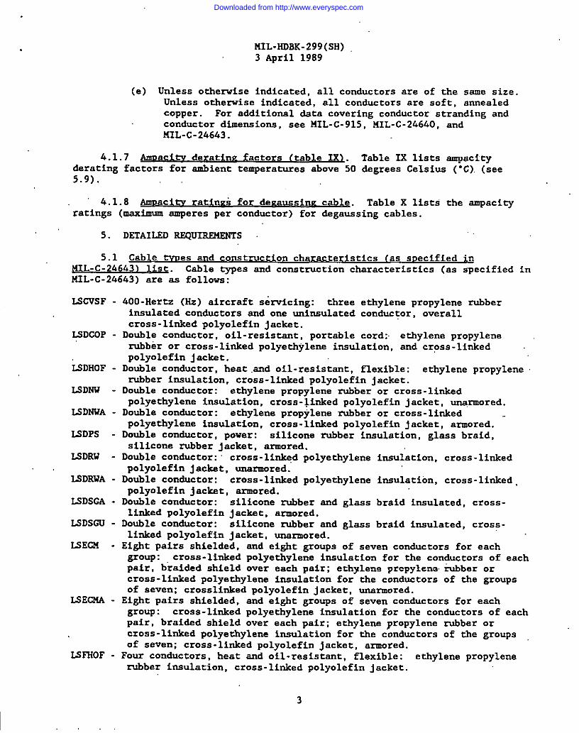
5.1 Cable -es and construction characteristics (as sDecified in
NIL -C-24643) list. Cable types and construction characteristics (as specified inIUL-C-24643) are as follows:
LSCVSF -
LSDCOP -
&DHOF -
LSDNW -
LSDWWA -
LSDPS -
Ii3DRW -
ISDRWA -
ISDSGA -
LSDSCU -
LSECM -
LSECILi -
LSFHOF -
400-Hertz (Hz) aircrsft seticing: three ethylene propylene rubberinsulated conductors snd one uninsulated conductor, overallcross -linksd polyolefin jacket.
Double conductor, oil-resistant, portable cord > ethylene propylenerubber or cross -linked polyethylene insulation, and cross -linkedpolyolefin jackst.
Double conductor, heat .s.ndoil-resistant, flexible: ethylene propylenerubber insulation, cross -linksd polyolefin jacket.
Double conductor: ethylene propylene rubber or cross -linkedpolyethylene insulation. cross -linked polyolef in jacket, [email protected] conductor: ethylene propylene rubber or cross- linkedpolyethylene insulation, cross. linked polyolef in jacket, armored.
Double condustor, power: silicone rubber insulation, glass braid,silicone rubber jacket, armored.
Double conductor: cross -li~d polyethylene insulation, cross-linkedpolyolefin jackst, unarmored.Double conductor: cross -linksd polyethylene insulation, cross-linked .polyolef in jackst, armored.
Double conductor: silicone rubber and glass braid insulated, cross-linked polyolef in jackst, armored.
Doubla conductor: silicone rubber and glass braid insulated, cross -linked polyolef in jackst, unarmored.
Eight pairs shielded, and eight groups of seven conductors for eachgroup: cross-linked polyethylene insulation for the conductors of eachpair, braided shield sver each pair; ethylsne prcpylene. rubber orcross-linked polyethylene insulation for the conductors of the groupsof seven; crosslinked polyolef in jacket, unarmored.
Eight pairs shielded, and eight groups of seven conductors for eachgroup: cross -linked polyethylene insulation for the conductors of eachpair, braidsd shield over each pair; ethylene propylene rubber orcross-li&d polyethylene insulation for the conductors Of the grOuPs
of seven; cross-linked polyr.lefin jacket, armored.Four conductors, heat and oil -resistant, flexible: ethylene propylenerubber insulation, cross-linked polyolefin jacket.
3
Downloaded from http://www.everyspec.com

MIL-HDBK-299(SH)3 April 1989
LSFNU - Four conductors: ethylene propylene rubber or cross-linked polyethyleneinsulation, cross-linked polyolef in jacket, unarmored.
ISFNWA - Four conductors: ethylene propylene rubber or cross-linked polyethyleneinsulation, cross -linked polyolef in jacket, armored.
IAWPs - Four conductors, power: silicone rubber. insulation, glass braid,silicone rubber jacket, armored.
LSFSGA - Four conductors: silicons rubber and glass insulated, cross -linkedpolyolef in jacket, armored.
LSFSGU - Four conductors: silicone rubber and glsss insulated, cross-linkedpnlynlef in jacket, unsrmored.
EMA - Multiple conductor: ethylene propylene rubber or cross-linkedpolyethylene itiulation, cross-linked polyolef in jacket, srmored.
L+MCOS - Multiple conductor, oil-resistsnt, shieldad: ethylene propylene rubber
liN.fOu -
lS1.OY -
LSMHOF -
LSI’!MOP-
ma’iw -
IShNUA -
I_SMRI -
EMS -
ISMSA -
lsLscA -
Lsnscs -
LSMSCU -
Isnu -
IsiUs -
LSPBT14 -
or cross -linked polyethylene over.pairs, or over assembly, cross:linked ‘.polyolef in jacket.Multiple conductor, degauss ing: ethylene propylene” or cross-linkedpolyethylene insulation, cross-linked polyolefin jacket, unarmored.Multiple conductor, degaussing: ethylene propylene or cross-linkedpolyethylene insulation, cross-linked polyolef in jacket, armoredbetveen double- layer jacket.Multiple conductor, heat snd oil-resistant, flexible: ethylenepropylene rubber or cross-linked polyethylene i~ulacion, cross-linkedpolyolef i? jackst.14ultiple conductor, microphone, oil-resistant, portable: ethylenepropylene rubber or,cross -linksd polyethylene insulation, cross-1 inkedpolyolefin jacket.Multiple conductor: ethylene propylene rubber or cross-linkedpolyethylene insulation, cross -linked polyolef in jackat, unsrmored.Multiple conductor: ethylene propylene rubber or cross-linkedpolyethylene insulation, cross -linkad pnlyolaf in jacket, armored.Multiple conductor: ethylene propylene rubber or cross-linkedpolyethylene insulated, without fillers, no overall jacket.
Multiple conductor, shieldsd: ethylene propylene rubber or cross -linkedpolyethylene insulation, overall braided shield, cross -linkedpolyolefin jackst, unsrmored.
Multiple conductor, shielded: ethylene propylene rubber or cross- linkedpolyethylene insulation, overall braidsd shield, cross- linkedpolyolef in jacket, armored.
Multiple conductor: silicone rubbsr insulated-glass braided conductors,cross-linked polyolefin jackst, armored.
Multiple conductor: silicone rubber insulated- glass braidsd conductors,cross-linksd polyolefin jacket, double overall shieldsd.
Multiple conductor: silicone rubber insulated- glass braidsd conductors,cross-linked polyolefin jackst, unsrmored.
Multiple conductor: ethylene propylene rubber or cross-1 inkedpolyethylene insulation, cross -linked polyolef in jacket, unarmored.
Multiple conductor: ethylene propylene rubber or cross-linkedpolyethylene insulation, cross -linked polyolef in jacket, double overallshieldsd.Pyrometer base multiple pairs: ethylene propylene rubber or cross,:linked polyethylene insulation on one copper and one constantanconductor, cross -linksd polyolefin jacket, armored.
Downloaded from http://www.everyspec.com

I
I JSTHOF -
LnNw -
lSTNWA -
lSrPNW -
ISTPWWA -
- LSTPS -
LSPB’RiU -
I.SPI .
ISSHOF -
USRW -
li?.SRWA -
ISSSP -
iSssGA -
ISSSGU -
LSTWA -
tiTCJW -
ISTC.IX -
liSTCFJi -
lSTCOP -
ISTCTA -
li3TCT0 -
IST(7TX -
MIL-HDBK-299{SH)3 April 1989
Pyrometer base multiple pairs: . ethylene propylene rubber or cross-linked polyethylene insulation on one copper and one constantanconduct6r, cross -linked polyolef in jacket, unarmored.Position indicator: silicone rubber insulation, glass braid, shieldedpairs, siiicone rubber jackst, armored.Single conductor, heat snd oil-resistsnt, flexible: ethylene propylene
rubber insulation, cross-linked polyolef in jacket.Single conductor, radio: cross -linked polyethylene insulation, cross -linked polyolef in jackst, u.ns~ored.Single conductor, radio: cross -linksd polyethylene insulation, cross-linked polyolef in jacket, armored.Single conductor: ethylene propylene rubber or cross-linkedpolyethylene insulation, cross -linked polyolef in jacket.Single.conductor: silicone rubber snd glass tape insulated, cross-linked polyolef in jacket, armored.
Single conductor: silicone rubber and glass tape insulated, cross-linked polyolef in jacket, unsrmored.
Thermocouple, type J, single pair: one iron and one constantinconductor, extrudsd silicone rubber insulated, glsss braided, cross-linksd polyolef in jackst, armared.
Thermocouple, type J, s@gle pair: one iron and one constantanconductor, extrudad silicone rubber insulated, glass braided, cross-linked polyolef in jackst, unsrmored.
Thermocouple, type J, multiple pairs: extruded silicone rubberinsulated, glass braid on one iron snd one constantan conductor foreach pair, silicone rubber jacket, armored.Thermocouple, type K, multiple pairs: extruded silicone rubberinsulated, glass braid on one Chromel and one Alumel conductor foreach pair, silicone rubber jacket, aimored.
Three conductors, oil-resistsnt, portable: ethylene propylene rubberor cross-linked polyethylene insulation, cross -linked polyolef injacket.
Thermocouple, type T, single pair: one copper snd one constantanconductor, extrudsd eilicone rubber insulated, glsss braided, cross -linked polyolef in jacket,. armored.
Thermocouple, type T, single pair: one copper snd one constantanconductor, extruded silicone rubber insulated, glass braidsd, cross -linked polyolef in jacket, unsrmored.
Thermocouple, we T, multiple pairs: extrudsd silicone rubberinxulated, glssa braid on one copper and one cons tantan conductor foreach pair, cross-linked polyolefin jacket, armored.
Three conductors, heat and oil-resistant, flexible: ethylene propylenerubber insulation, cross -linked polyolef in jacket.
Three conductors: ethylens propylene rubber or cross-linkedpolyethylene insulation, crose -linked polyolef in jackst, unsrmored.Three conductors: ethylene propylene rubber or cross-linkedPolyethylene insulation, cross -linked polyolaf in jacket, armored.Tvisted pairs: ethylene propylene or cross- lfnked polyethyleneinsulation, cross -linked polyolef in jackst, unsrmored.
Twisted pairs: ethylene propylene or cross-linked polyethyleneinsulation, cross-linksd polyolef in jacket, armored.
Three conductors, power supply: silicone rubber insulation, glassbraid, silicone rubber jackst, armored.
5,,
Downloaded from http://www.everyspec.com
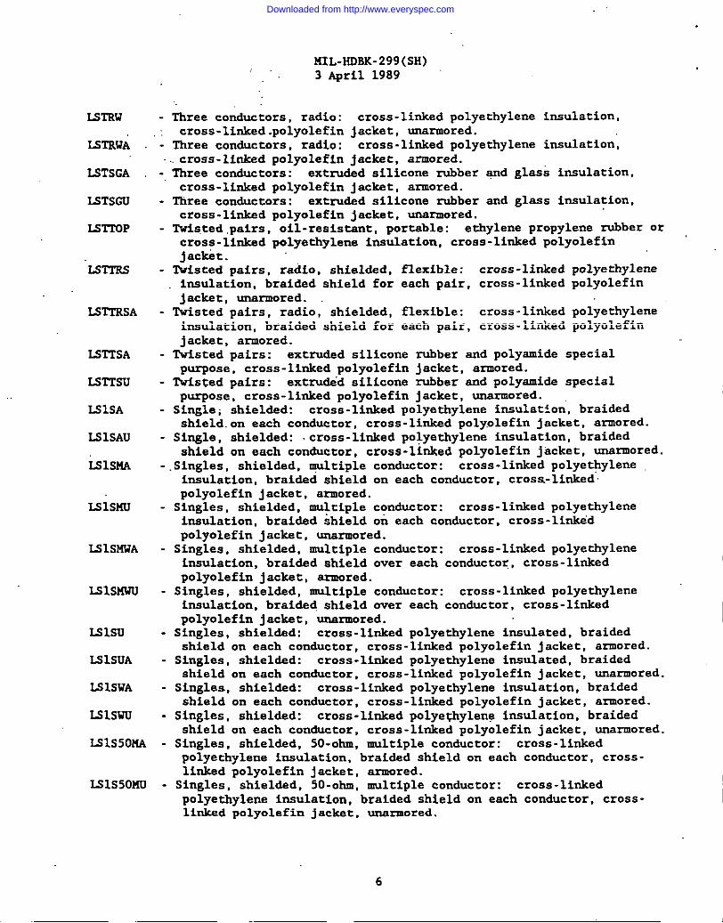
LSrRw
I ISTRWA
LSTSGA
ISTSGU
IS-TOP
LSTTRS
=TTRSA
LSTTSA
Lsmsu
LSISA
IA31SAU
tilsm
I LSISMU
MISMWA
LSISI’4WU
ISlsu
LSISUA
ISISWA
LSlswu
LS1S50MA
IS1S50MU
141L-HDsK-299(SH)3 April 1989
lhree conductors, radio: cross -linked polyethylene insulation,cross -linked .polyolefin jacket, unarmored.Three conductors, radio: cross-linked polyethylene insulation,cross- linksd polyolefin jacket, armored.Three conductors: extrudsd silicone rubber -d glass insulation,cross -linked polyolef in jackst, armored.Three conductors: extrudsd silicone rubber and glass insulation,cross -linkad polyolef in jackat, unarmored.Twisted pairs, oil-resistant, portable: ethylene propylene rubber orcross -linksd polyethylene insulation, cross-linked polyolef injackbt.Wsted pairs, radio, shiel&d, flexible: cross -linked polyethyleneinsulation, braided shield for each pair, cross -linked polyolef injacket, unarmored.Twisted pairs, radio, shielded, flexible: cross -linked polyethyleneinsulation, braided shield for each pair, cross-linked polyolef injacket, armored.
Tvisted pairs: extruded silicone rubber and polyamide special
P~Ose, cross-linked polyolef in jackst, armored.‘TwisTedpairs: extru&’d silicone rubber and polyamide special
PurPOse, cross-linked polyolefin jacket, unarmored.Single; shieldsd: cross -linked polyethylene insulation, braidedshield.on each conductor, cross -linkad poly.olefin jacket, armored.
Single, shieldsd: cross -linked polyethylene insulation, braidedshield on each conductor, cross-linked polyolef in jacket, unarmored.Singles, shielded, qultiple conductor: cross-linked polyethyleneinsulation, braided shield on each conductor, cross-linkedpolyolef in jacket, armored.Singles, shielded, multiple conductor: cross -linked polyethyleneinsulation, braided shield on each conductor, cross-linkedpolyolef in jacket, unsxmored.Singles, shielded, multiple conductor: cross -linked polyethyleneinsulation, braidsd shield over each conductor, cross-linkedpolyolef in jackat, armored.Singles, shielded, multiple conductor: cross-linked polyethyleneinsulation, braidsd shield over each conductor, cross-linkedpolyolef in jackst, unarmored.Singles, shieldsd: cross -linked polyethylene insulated, braidedshield on each conductor, cross-linked polyolef in jacket, armored.Singles, shieldsd: cross -linked polyethylene insulated, braidedshield on each conductor, cross-linked polyolefin jacket, unarmored.Singles, shieldsd: cross -linked polyethylene insulation, braidedshield on each conductor, cross -linked polyolef in jacket, armored.
Singles, shieldsd: cross -linked polye@ylene insulation, braidedshield on each conductor, cross-linked polyolefin jacket, unarmored.Singles, shieldsd, 50-ohuI,multiple conductor: cross-linkedpolyethylene insulation, braided shield on each conductor, cross-linked polyolef in jacket, armored.Singles, shieldsd, 50-ohm, multiple conductor: cross-linkedpolyethylene insulation, braided shield on each conductor, cross-linksd polyolef in jacket, unarmored.
6
Downloaded from http://www.everyspec.com

LS1S50H-US -
lsls75nA -
IS1S75MU -
Isa -
.LS2AU -
LS2AUS -
LS2CS -
IS2SA -
IS2SJ -
1.S2SJA -
lS2ilJ -
LS2SUS -
L52SWA -
IS2SWAU -
152SWL-7 -
u2swlA-7 -
IS2SW0 -
L32SWUA -
IS2U -
LS2UA -
Ii32uw-42 -
E32UWA-42 -
U2UWS-42 -
HIL-HDBK-299(SH)3 April 1989’
Singles, shielded, 51)-Ohm,multiple conductor: cross-linkedpolyethylene insulation, braided shield on each conductor, cross-linked polyolef in jacket, double overall shielded.
Singles, shielded, 75-ohm, multiple conductor: cross -linkedpolyethylene insulation, braidsd shield over each”conductor, cross -linked polyolef in jacket, armored.
Singles, shielded, 75-ohm, multiple conductor: cross-linkedpolyethylene insulation, braided shield over each conductor, cross -linked polyolef in jackst, unarmored.
Tvisted pairs, shielded: crose -linked polyethylene insulation,overall br,aidcd shield, cross -linked polyolef in jacket, arqored.
Tvisted pairs, shieldsd: cross ~linked polyethylene insulation,overall braided shield, cross -linked polyolef in jacket, unarmored.
Tvisted pairs, shielded: cross-linked polyethylene insulation,overall braided shield, cross-linked polyolefin jacket, doubleoverall shielded.Pairs, shielded: cross -linked polyethylene insulation, doublebrai&d shield overall, cross -linked polyolef in jacket.Pairs, shieldsd: cross. linked polyethylene insulation, bra~ded.
shield over each ‘pair, cross -linked.polyolef in jacket, armored.Pairs, ahieldcd: ethylene propylene rubber or cross -linkedpolyethylene insulation, overall braided shield, cross -linkedpolyolef in jacket, unarmored.Pairs, ahieldcd: ethylene propylene rubber or cross -linkedpolyethylene insulation. overall braided shield. cross -linkedpol~ole~in jackct, .irmored.Pairs, shielded: cross -linked polyethylene insulation,ehield over each pair, cross-linked polyolef in jacket,Pairs, shieldsd: cross -linked polyethylene insulation,shield over each pair, cross -linked polyolef in jacket,overill shielded.Pairs, shielded: cross-linked polyethylene insulation,shield over each pair, cross -linked polyolef in jacket,Pairs, shielded: cross- linked polyethylene insulation,
shield over each pair, cross-linked polyolefin jacket,Paira, shielded: c“ross-linked polyethylene insulation,shield over each pair, cross -linked polyolefin jacket,
Pairs, shielded: cross -linked polyethylene insulation,shield over each pair, cross-linked polyolefin jacket,
Paire, shielded: croae -linked polyethylene insulation,shield over each pair, cross -linked polyolef in jacket,Pairs. shielded: cross -linked uolvethvlene insulation.
braidedunarmored.braideddouble
braidedarmored.brai&dunarmored. .braidedunsrmored.braidedarmored.braidedunarmored.braided
shieid over each pair, cross- l~nk~d p~lyolef in jackct i armored.Pairs: cross -linked polyethylene insulation, overall braided shield,cross -linked polyolef in jacket, unarmored.Pairs: cross -linked polyethylene insulation ,’overall braided shield,cross-linked polyolefin jacket, armored.
Tvieted pairs: cross -linked polyethylene insulation, overall braidedshield, cross -linksd polyolefin jacket, unarmored.
Twisted pairs: cross -limed polyethylene. insulation, overall braided .shield, cross -linked polyolef in jacket, armored.
Tvisted pairs: cross-linked polyethylene insulation, overall braidedshield, cross-linked polyole fin jacket, double overall shielded.
7
Downloaded from http://www.everyspec.com

KIL-HDBK-299(sH)3 April 1989”
LS2WA
lS2WAlJ
LS3SA
=3SF
LS3SJ
LS3SJA
U3SU
LS3SUS
IS3SWA
U3SWU
LS3SWUS
U3U
LS3UA
LS4NW8
lStJlJA8
ISSJ
=4SJA
u15KvTsGA -
LS5KVTSGU -
IS6SGA -
LS6SGU -
LS7PS -
U7SGA -
Pairs: cross -linked polyethylene insulation, ovsrall braided shield,cross. linked polyolefin jacket, armorsd..;Pairs: cross -linked polyethylene insulation, overall braided shield,cross- linked polyoleffn jackst, uncnnored.
Triads, shieldsd: cross -linked polyethylene insulation, braidedshield over each triad, cross-linked polyolefin jacket, armored.
Triads, shielded, flexible: cross -linked polyethylene insulation,braided shield over each triad, polyester tape over the assembledtriads, cross -linked polyolef in jacket.
Triads, shielded: ethylene propylene rubber or cross- linkedpolyethylene insulation, overall braidsd shield, cross-linked
polyolef in jacket, unarmored.Triads, shieldsd: ethylene propylene rubber .or cross- linksdpolyethylene insulation, overall braided shield, cross -linkedpolyolefin jacket, armored.
Triads, shielded: cross -linked polyethyl.ine insulation, braidedshield over each triad, cross -linked polyolefin jacket, armored.
Triads, shielded: cross -linksd polyethylene insulation, braidedshield over eech triad, cross -linksd polyolef in jacket, doubleoverall shieldsd.
Triads, shieldscl: cross -linksd polyethylene i~ulation, braidedshield over each triad, cross -linksd polyolefin jacket, armored.
Triads, shielded: cross -linked polyethylene. insulation, braidedshield over each triad, cross -linksd polyolefin jacket, unsrmored.
Triads, ahieldsd: cross-linked polyethylene insulation, braidedshield over eech triad, cross -linksd polyolef in jacket, doubleoverall shielded.
Triads: cross -linked polyethylene insulation, marker braid on eachtriad, cross -Linked polyolef in jacket, unarmored.
Triads: cross-linked polyethylene insulation, marker braid on eachtriad, cross -linked polyolef in jacket, armored.
Four conductors: cross -linked polyethylene insulation or ethylene
propy~ene rubber, cross-linked polyolef in jacket, unarmored.Four conductors: cross -linked polyethylene insulation or ethylenepropylene rubber, cross-linked polyolefin jacket, armored.Four conductors, shielded: ethylene propylene rubber or cross-linkedpolyethylene insulation, overall braided shield, cross -linkedpolyolef in jacket, unarmored.Four conductors, shielded: ethylene propylene rubber or cross -linkedpolyethylene insulation, overall braidsd shield, cross-linkeduolvolef in iacket. armored.5000~v01t, tiree conductors: silicons rubber and glass tapeinsulation, cross -linksd polyolef in jacket, armored.
5000-volt, three conductors: silicone rubber and glass tapeinsulation, cross -linked polyolef in jacket, unarmored.
Six conductors: silicone and glass insulation, cross -linkedpolyolef in jacket, armored.Six conductors: silicone and glass insulation, cross -linkedpolyolef in jacket, unsrmored.
Saven conductors, power supply: silicone rubber insulation, glassbraid, silicone rubber jacket, armored.Seven conductors: silicone rubber cnd class insulation. cross-linkedpolyolef in jacket, armored.
..
8,,
.
Downloaded from http://www.everyspec.com

ES7SGU -
IS8WW6 -
IS8NWA6 -
5.2
141L-HDBK-299(SH)3 April 1989
Seven conductors: silicone rubber and glass insulation, cross-linkedpolyolef in jacket, unarmored.Eight conductors: cross -linked polyethylene or ethylene propylenerubber insulation, cross -linked polyolef in jacket, unarmored.
Eight conductors: cross -linked polyethylene or ethylene propylenerubber insulation, cross -linked polyolef in jacket, armored.
Cable -es and construction character Sties (as snecified lx!ML -C-24640) list. Cable types and construction characteristics (as specified inMIL- C-24640) are as follows:
1“ FXWA
~’. ,KxcwHxcow
MXCWA
Hxo
Uxso
.Trx
m
Trx.s
TTXSA
lmso
‘mxw
DX
DXA
DXW
DXOW
DXWA
“h
FxA
Fxw
Fxow
Double conductor, power “supply: cross -linked polyalkene insulation,crose-linked polyolefin jacket, unarmored.
Double conductor, power supply: cross-linked polyalkene insulation,cross-linked polyolefin jacket, armored.
Two conductors: mica polyimide insulation, cross-linked polyolefinjacket, unarmored.Two conductors: mica polyimide insulation, cross-linked polyolef injacbt, overall shielded.
Two conductors: mica polyf.mide insulation, cross-linked polyolef injacket, arpored.Four conductors, power supply: cross -linked polyalkene insulation,cross -linked polyolef in fluoride jacket, unarmored.Four conductors, “power supply: cross-linked polyalkene insulation,cross -linked polyolef in flucyide jac~t, armored.
Four conductors: mica polyimide, insulation, cross-linked polyolef injackst, unarmmred.Four conductors: mica polyimide insulation, cross -linked polyolef inja.ket, overall shielded.Four conductors: mica polyim@ insulation, cross-1 inked polyolef injacket, armored.Multi-conductor, control: mica polyimide insulation, cross-linked “”polyolefin jacket, —ored.
Multi -conductor, control: mica polyimide insulation, cross-linkedpolyolef in jacket, overall shielded.
Multi-conductor, control: mica polyimide insulation, cross-linkedpolyolef in jacket, armored.
Multi-conductor, power supply: cross -linked polyalkene insulation,cross -linked polyolef in jackst, overall shieldad.
Multi -conductor; cross -linksd polyalkene insulation, cross-linkedpolyolef in jacket, overall shiel&d.
Multi-pair, twisted: cross-linked polyalkene insulation, cross -linkedpolyolef in jacket, unarmored.
t’!ulti-pair, tvisted: cross -linked polyalkcns insulation, cross -linkedpolyolef in jacket, armored.
Multi-pair, tdsted, shielded: cross -linked polyalkene insulation,cross-linked polyolefin jacket, unarmored.
Multi-pair, tvisted, shielded: cross -linked polyalkene insulation,cross -linked polyolef in jacket, armored.
Multi-pair, tvisted, shieldsd: cross-linked polyalkene insulation,cross-linked polyolefin jackat, overall shielded.
Multi-pair: mica polyfmide insulation, cross -linked polyolef in jacket,unarmored.
.
9
.
Downloaded from http://www.everyspec.com

‘lTKOw
TTXWA
TK
TXA
TXW
TKow
TKWA
IXISo
Ix.sow
2XA0
2K0
2XOW
2KS
2KSA
2XS0
2XSAW
2KSAOW
2K5AWA
2XSX0
2KSW
2KSWA
3X5
3XSA
3KSW
3KSOW
KIL-HDBK-299(sH)3 April 1989
Multi-pair: mica polyi.mide insulation, cross-linked polyolef in jacket,overall shielded.
Multi -pair: mica polyimide insulation, cross-linked. polyolef in jacket,armored.
Three conductor, power supply: cross -linked polyolef in insulation,cross -linkad polyolefin jacket, unarmored.
lhree conductor, power supply: cross -linked polyolef in insulation,cross -linksd polyolef in jackat, armored.
Three conductor, power: mica polyimida insulation; cross-linkedpolyolef in jackst, unarmored.Three conductor, power: mica polyimide insulation; cross-linkedpolyolefin jackct, overall shiel~d.
Three conductor, power: mica polyimidc insulation; cross-linkedpolyolef in jacket, armored.
Multi -conductor, shieldad: cross-linked polyalkene insulation, cross-linked polyolef in j’ackst, overall shielded.
Multi-conductor, shielded: cross -linked polyalkene insulation, cross-li@ccd polyolef in jacket, overall shielded.
Multi-pair, twisted: cross -linked polyalkene insulation, cross-linkedpolyolef in jacket, overall shieldad.
Multi-pair, twisted: cross -linked polyalkene insulation, czoss -linkedpolyolef in jackat, rwerall ihieldcd.
Multi -pair, tvisted: cross -linked polyalkene insulation, cross-linkedpolyolef in jackst, overall shieldad.
Multi-pair, twisted, shielded: cross -linked polyalkene ikulation,cross -linkad polyoleffn jackst, unsrmorkd.
Multi-pair, twisted, shieldad: cross-linked polyalkene insulation,cross-linked polyolefin jacket, srmored.
Multi-pair, tiisted, shieldsd: cross -linked polyalksne insulation,cross-linked polyolefin jackat, overall shielded.
Iiulti-pair, shieldad: cross -linked polyalkene insulation, cross-linkedpolyolef in jackst, ~rmored.
Multi-pair, shieldad: cross -linked polyalkene ‘insulation, cross-linkedpolyolef in jackct, overall shielded.
Multi-pair, shielded: cross -linked polyalkene insulation, cross-1 inkedpolyolef in jacket, armored.
Multi-pair, twisted, shielded: cross -linked polyalkene insulation,cross -linkad polyolefin jacket, overall shielded.
Multi -pair, shielded: cross -linked polyalkene insulation, cross-linkedpolyolefin jackat, unarmored.
Multi-pair, shielded: cross -linkad polyalkene insulation, cross -linkedpolyolef in jackct, overall shielded.
Multi -Dair. shielded: cross -linked nolvalkene insulation. cross-linkedpolyoief ii jackct, armored.
Multi-triad, twisted, shieldsd:cross-linked polyolefin jacket,
Multi- triad, tvisted, shielded:cross -linked polyolef in jackst,
Multi -triad, tvistad, shielded:cross -linked polyolef in jackct,
Multi- triad, twisted, shieldad:cross-linked polyolefin jacket,
. .
cross -linked polyalkene insulation,unarmored.cross -linked polyalkene insulation,armored.cross -linked polyalkene insulationunarmored.cross -linked polyalkene insulation,overall Shielded.
10
Downloaded from http://www.everyspec.com
MIL-HDBK-299(SH)3 April 1989
3XSUA -
7XW -
7XWA -
5.3
Multi-triad, twisted, shielded: cross-linkedcross-linked polyolefin jacket, armored.
Seven conductors: mica polyimida insulation,jacket, unarmored.Seven conductors: mica polyimide insulation,jacket, armored.
polyalkene insulation,
cross -linked polyolef in
cross -linked polyolef in
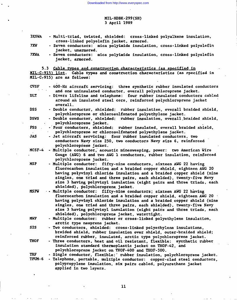
Cable tvnes and construction characteristics [as sr.ecified~
lUL -C-915) list. Cable types cnd construction characteristics (as specified in141L-C:915) sre as follows:
CVSF
DLT
DSS
DSWS
FSS
Jb
MCSF-4
MSP
MSFu
nwF
S2S
THOF
TRFTPOM-6
400 -Hr aircrsft servicing: three synthstic rubber insulated conductorsand one uninsulated conductor, overall polychloroprene jacket.
Divers lifeline and telephone: four rubber insulated conductors cabledaround ah insulated steel core, reinforced polychloroprene jacketoverall.
Double conductor, shielded: robber insulation, overall braidsd shield,polychloroprene or chloroaulfomted polyethylene jacket.Double conductor, shieldad: rubber insulation, overall ,braided shield,polychloroprene jacket.Four conductors, shielded: rubber insulated, overall braided shield,po~ychloroprene or chlorosulfotited” polyethylene jacliet.
Jet aircraft servicing: four “ru6ber insulated conductors, twoconductors Navy size 250, tvo conductors Navy size 6, reinforcedpolychloropiene jacket.
Multiple conductor ,“acoustic minesweeping, power: two American WireGauge (AWG) 6 and tvo AWG 1 conductors, rubber insulation, reinforcedpolychloroprerie jacket:
Multiple conductor: fifty-nine conductors, sixteen AWG 22 havingfluorocarbon insulation and a braided copper shield, eighteen AWG 20hsving polyvinyl chloride insulation and a braided copper shield (ninesingles, one triad and khree paizs, each shielded) , twenty-five Navysize 3 having polyvinyl insulation (eight pairs and three triads, eachshielded), polychloroprene. jadcet.
Multiple conductor: fifty-nine conductors; sf.xteenAWG 22 hivingfluorocarbon insulation and a braidsd copper shield, eighteen AWG 20having polpinyl chloride incubation and a braided. copper shield (ninesingles, one triad and three pairs, each shielded) , tventy -five Navysize 3 having polyvinyl insulation (eight pairs and three triads, eachshielded) , polychloroprena jacket, watertight.
Multiple conductor: rubber or cross-linked polyethylene insulation,arctic type neoprene jacket.
Tvo conductors, shieldsd: cross-linked polyethylene insulations,braided shield, rubber insulation over shield, outer -braided shield;reinforced rubber, insulatsd, arctic type polychloroprene jacket.
Three conductors, heat and oil resistant, flexible: synthetic rubberinsulation standard thermoplastic jacket on THOF-42, cndpolychloroprene jacket on THOF-400 and THOF -500.Single conductor, flexible: “ rubber insulation, polychloroprene jacket.Telephone, porrsble, multiple conductor: copper- clad steel conductors,polypropylene insulation, six pairs cabled, polyurethane jacketapplied in tvo layera.
11
Downloaded from http://www.everyspec.com

KIL-HDBK-299(SH)3 April 1989 -
TRXP - Single conductor: polychloropreneTSP - l%isted pairs: polyvinyl chloride
jacket, watertight, unarmored.TSPA - Twisted pairs: polyvinyl chloric@
jacket, watertight, armored.TSS - Three conductors. suecial uurr.ose.
jacket.insulated, special thermoplastic
insulated, special thermoplastic
. shielded: rubber insulation, overallbraided shield, poiychlor~pr~ne or chlorosulfoncted polyethylene jacket,
lSWF -●Singles, shielded: polyethylene insulation, braided shield on each
2SWF -
5ss -
7ss -
5.
conductor, arctic -e polychloroprene jacket.Pairs, shielded, watertight, flexible: polyethylene insulation, braidedshield over each pair, arctic -e polychloroprene .jacket.
Five conductors, shielded, sonar: rubber insulation, braided shield onone conductor only, end a braidsd shield over the assembled fiveconductors, polychloroprene jacket overall.Seven conductors, shielded: rubber, insulation, overall braided shield,polychloroprene or chlorosulfoncted polyethylene jacket.
4 ~dent ification information. Conductors and groups of conductors, suchas pairs and triads, are separately identified within a completed cable. Theidentification codss should be as specified in 5.4.1 through 5.4.9, inclusive.
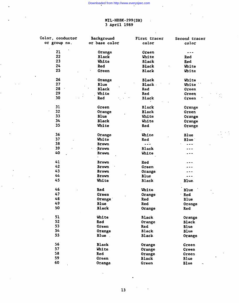
5.4.1 standa d de t~~ .code The conductor identificationcode for standsrd cables should be as follows:
Color, conductoror group no.
1.2“345
678’9
10
1112131415
1617181920
Background First traceror base color’ Color
BlackWhiteRedGreenOrsnge
BlueWhiteRedGreenOrsnge
BlueBlackRedGreenBlue
BlackWhiteOrangeBlueRed
,..
. . .
.-.
.-.
.-.
.-.
. . .
BlackBlackBlackBlack
BlackiihiteUhiteWhiteWhite
RedRedRedRedGreen
12
Second tracercolor
.-.
. . .
..--..-..
-..-..-------..
..----. . .-..-..
---. . .. . .---..-
Downloaded from http://www.everyspec.com
1’
Color, conductoror group no.
2122232425
2627282930
3132333435
3637383940
4142434445
4647484950
515253S.i55
5657585960
MIL-HDBK-299 (SH)3 April 1989
Backgroundor base color
OrangeBlackWhiteRedGreen
OrangeBlueBlackWhiteRed
GreenOrangeBlueBlackWhite
OrangeUhitaBrovn,BrovnBrown
BrownBrownBrovnBrownWhite
RedGreenOrangeBlueBlack
WhiteRedGreenOrangeBlue
BlackWhiteRedGreenOrange
First tracercolor
GreenWhite
BlackBlackBlack
BlackBlackRedRedBlack
BlackBlackWhiteWhiteRed
UMteRed.-..
BlackWhite
RedGreenOrangeBlueBlack
WhiteOrangeRedRedOrange
BlackOrangeRedBlackBlack
OrangeOrangeOrangeBlackGreen
Second tracercolor
. . .
RedRedWhitewhite
WhiteWhiteGreenGreenGreen
OrangeGreenOrangeOrangeOrange
BlueBlue.-.......
---..-. . .-..
Blue
BlueRedBluaOrangeRed
OrangeBlackBlueBlueOrange
GreenGreenGreenBlueBlue ..
13””
Downloaded from http://www.everyspec.com

Color, conductoror group no.
6162636665
6667686970
71727376“75
7677787980
8182838485
8687888990
9192939495
96979899100
MIL-HDBK-299(SH)3 April 1989
Backgroundor base color
BlueBlackWhiteRedGreen
OrangeBlueBlackWhiteRed
GreenOrangeBlueBlackRed
GreenOrangeBlueRedGreen
BlueOrangeGreenBlackWhite
BlueBlackWhiteRedGreen
BlueBlackwhiteRedGreen
orangeYellowYellowYellowYellow
First tracercolor
GreenRedOrangeBlackOrange
WhiteWhiteGreenGreen
.Green
WhiteRedRedOrangeOrange
RedWhiteWhiteWhiteWhite
BlackWhiteRedGreenGreen
Green“OrangeOrangeOrangeOrange
OrAgeBlueBlueBlueBlue
Blue..-
BlackWhiteRed
Second tracercolor
OrangeBlueBlueBlueBlua
RedRedBlueBlueBlue
RedBlackBlackBlueBl”ue
BlackGreenGreenOrangeOrange
Green..-.......-.
.-.
..-----..---
---. . .---. . .---
. . .
. . .
. . .
. . .
. . .
14
Downloaded from http://www.everyspec.com

IiIL-HDBK:299(SH)3 April 1989
Color, conductoror group no.
101102103104105
106107108109110
111112113114115.
116117118119120
121122123124125
126127
Backgroundor base color
YellowYellowYellowBlackWhite
RedGreenOrangeBlueBlack
WhiteGreenOrangeBlueBlack
RedGreenOrsngeBlueBlack
WhiteRedOr~eBlusBlack
UliiteRed
First tracercolor
GreenOrangeBlueYellowYellow
YellowYellowYellowYellowYellow
YellowYeLlOwYellowYellowYellow
YellowYellowYellowYellowYellow
YellowYellowYellowYellowYellow
YellowYellow
Second tracercolor
. . .
. . .
..-
.-.-..
. . .
.-.---. . .
Red
RedRedRedRedWhite
WhiteWhiteUhiteWhiteGreen
GreenGreenGreenGreenBlue
BlueBlue
5.4.2 ~eleuhone identification code (TSL~. The conductor identificationcods for telephone cables should be as follows:
Color orconductor no. GQk
1 Black2 White3 Rsd4 Green5 Orsnge6’ Blue
5.4.2.1 Conductor uairing. Theshould be ss follows:
Color orconductor no- GQl@i
7 Brovn8 Gray9 Yellow
10 Purple11 Tsn12 Pink
pairing of conductors for forming pairs
15
Downloaded from http://www.everyspec.com
141L-HDBK-299(sH)3 April 1989
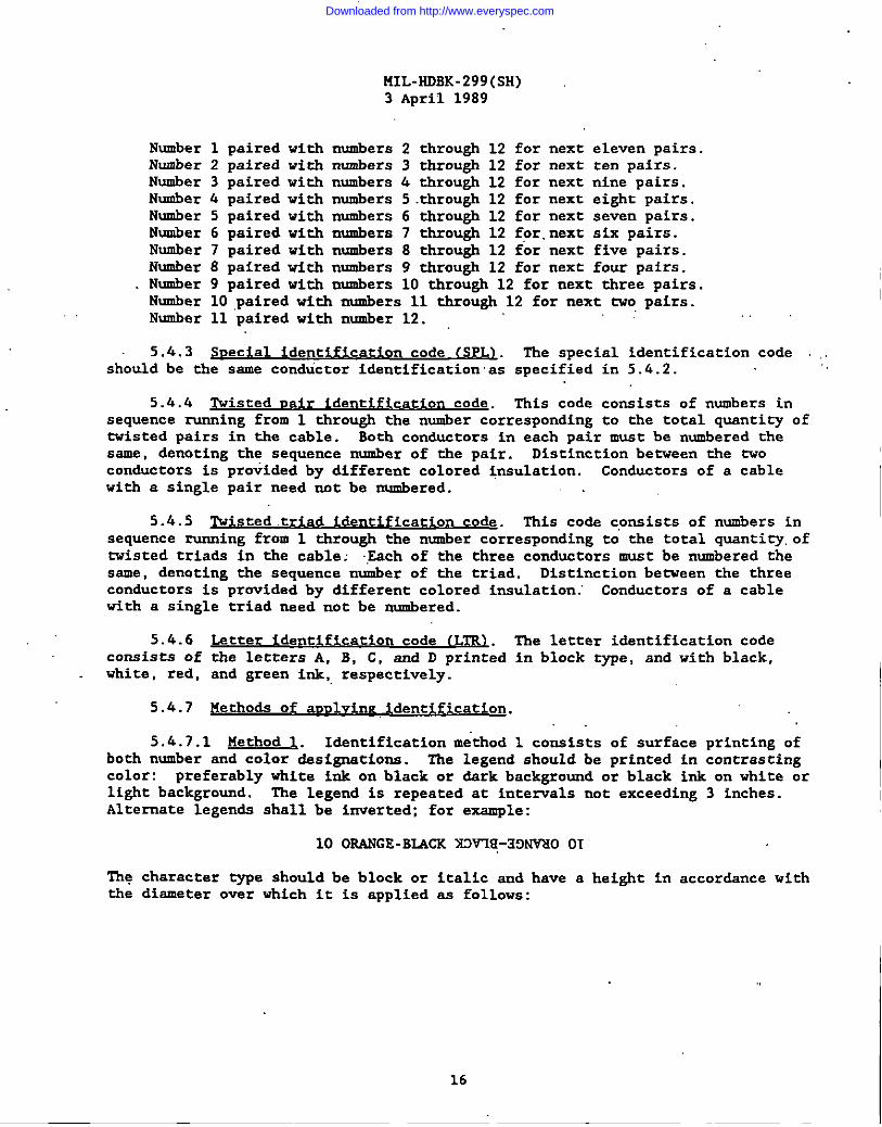
Number 1 paired with numbers 2 through 12 for next eleven pairs.Number 2 paired vi th numbers 3 through 12 for next ten pairs.Number 3 paired with numbers 4 through 12 for next nine pairs.Number 4 paired with numbers 5 through 12 for next eight pairs.Number 5 paired with numbers 6 through 12 for next seven pairs.Number 6 paired with numbers 7 through 12 for.next six pairs.Number 7 paired with numbers 8 through 12 for next five pairs.Number 8 paired with numbers 9 through 12 for next four pairs.Number 9 paired with numbers 10 through 12 for next three pairs.Number 10 paired with numbers 11 through 12 for next two pairs.Number 11 paired with number 12.
5.4.3 S ec a de t~ code (SPL~. The special identification code ..should be the same condtictor identification as specified in 5.6.2.
5.4.4 ~isted uair identif ication code. This code conxists of numbers insequence running from 1 through the number corresponding to the total quantity oftwisted pairs in the cable. Both conductors in each pair must be nwmbered thesame, ¬ing the sequence number of the pair. Distinction between the twoconductors is provided by different colored insulation. Conductors of a cablewith a single pair need not be nwmbered.
5.4.5 Nisted triad identification code. This code consists of numbers insequsnce running from 1 through the number corresponding to the total quanti~. oftwisted triads in the cable J Each of the three conductors muxt be numbered thesame, denoting the sequence number of the triad. Distinction betveen the threeconductors is provided by different colored insulation .“ Conductors of a cablewith a single triad need-not be numbered.
5.4.6 Lstter identif ication code (Lllll.consists of the letters A, B, C, and D printedwhite, red, and green ink,,respectively.
The letter identification codein block type, and with black,
5.4.7 ~ethodx of auulvin~ identif ication.
5.4.7.1 Method l,. Identification ma’thod 1 consists of surface printing ofboth number and color &signations. The legend should be printed in contrastingcolor: preferably white ink on black or dark background or black ink on white orlight background. The legend is repeated at intenals not exceeding 3 inches.Alternate legends shall be inverted; for example:
10 OWGE-BLiCK XW’Iff,-13W30 OT
The character type should be block or italic and have athe diameter over which it is applied as follows:
height in accordance with
16
Downloaded from http://www.everyspec.com
MIL-HDBK-299(SH)3 April 1989
I
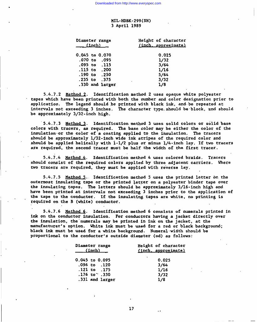
Diameter rsnge Height of character(in h)c finch. auuroximate >
o.o&5 to 0.070. 0.025.070 to .095 1/32.095 to .115 3/64.115 to .200 1/16.190 to .250 5/6k.235 to .375 3/32.330 and larger 1/8
5.4.7.2 !!ethod 2. Identification method 2 uses opaque white polyestertapes which have been printed with both the number and color designation prior toapplication. The legen’d should .be printed with black ink, and.be repeated atintervals not exceeding 3 inches. ‘I’hecharacter type.should be block, and shouldbe approximately 3/32 -inch high.
‘5.4.7.3 Nethod 3.. I&ntification method 3 uses solid colors or solid basecolors with tracers, as required. The base color may be either the color of theinsulation. or the color of”a coating applied to the insulation. The tracersshould be approximately 1/32-inch,tide ink stripes of the required COlOr and
should be applied helically with 1-1/2 plus or minus 1/4-inch lay. If tvo tracersare required, the second tracer must be half the width of the first tracer.
5.k.7.h Method h. Identification method 4 uses colored braids. Tracersshould consist of the required colors applied by three adjscent carriers. Where
two tracers are required, they must be applied with reverse lay.
5.6.7.5 Method 5.. Identification method 5 uses the printed letter on theoutermost insulating tape or the printed letter on a polyester binder tape overthe insulating tapes. The letters should be”approximately 3/16-inch high andhave been printed at intervals not exceeding 3 inches prior to the application ofthe tape to the conductor. If the insulating tapes are vhite, no printing isrequired on the B (white) conductor.
5.4.7.6 Method 6. Identification method 6 consists of numerals printed inink on the conductor insulation. For conductors having a jacket directly overthe insulation, the “numerals may be printed in ink on the jacket, at themanufacturer’s option. Uhita ink gmst be used for a red or black background;black ink must be used for a white background. Numeral width should beproportional to the conductor 1s outside diameter (od) as follows:
Diameter range Height of character(in h)c finch. auDroximate 1
17
0.045 to 0.095 0.025.096 to .120 3/64.121 to .175 1/16.176 to- .330 3/32.331 and larger 1/8
Downloaded from http://www.everyspec.com
I
IUL-HOBK-299(SH)3 APril 1989
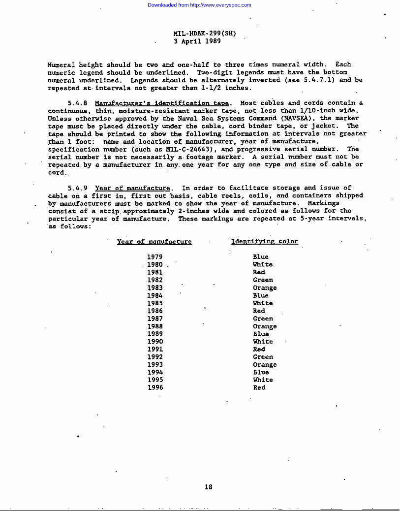
Numeral height should be two snd one-half to three times numeral width. Each
numeric legend should be underlined. Tvo -digit legends must have the bottomnumeral underlined. Legends should be alternately inverted (see 5.6.7.1) snd berepeated at.intervals not greater than 1-1/2 inches.
5.4.8 ~anufacturer rs identification taue. Host cab’les and cords contain acontinuous, thin, moisture -resistant marksr tape, not less than I/lO-inch wids.Unless orhe=ise approved by the Naval Sea Systems Comsnd (NAVSSA), the markertape must be placed ,directly under the cable, cord binder tape, Or jacket. fietape should be printed to show the following information at inten-als not greater,gha.n1 foot: nsme and location of manufacturer, year of manufacture,specification number (such as “kIL-C-24643) , snd progressive serial number. Theserial number is not necessarily a.footage msrker. A serial number must not berepeated by a msnufacrurer in eny.one year for sny one type and size of.cable orcord.,
5.&.9 Year of manufacture. In order to facilitate storage and issue ofcable on a first in, first out bssis, cable reels, COilS, ~d containers shippedby manufacturers must be msrksd to show the year of manufacture. Msrkingsconsist of a strip.approximately 2-inches tide and colored as follovs for theparticular year of manufacture. These markings are repeated at 5-year intervals,as follows :
Year of manufacture
197919801981198219831984198519861987198819891990199119921993199419951996
Identifvinr CO1OX
BlueWhiteRedGreenOrsngeBlueWhiteRedGreenOrsngeBlueWhiteRedGreenOrangeBlusWhiteRed
.
18
Downloaded from http://www.everyspec.com

MIL-HDBK-299(SH)3 April 1989
TA8LS I.’ k!IL-C-24643 cable auulication data. ~
application
eneral usage:For all portions of power, lighting, interior communicationweapons control and electronics systems, except wherecircuit parameters (such as audio or radio frequsncy, lov-level microphone, smchro. scale volta~e. and other tvuesof signals)- require-’special types of cibie. Types LSfi,LS3U, IS.DNW,LST’lik7,LSFNW, ISMNW, ESHOF, LSDHOF, LSTHOF,ISFHOF, LMHOF, MDCOP, LSTCOP, snd 13MCOS should be usedonly for runs that are either totally within one compart -ment, or tot’allywithin tvo contiguous comparuuents.However, these q-pe csbles must not -be used vhere a water-tight deck or watertight bulkhead below flooding water levelII (iWL-11) is penetrated. Type SG cable should be used fo]comections between the ship service generators and theirrespective switchboards snd betveen sections of the shipservice svitchbosrds.
High voltage - 60 ilz:.For 3000- and 5000-volt, three-phase power applications.
I Casu.sltypower.
400-Hz power:For 400-H2 service for static frequency chsnger cables, busties, and feeders where csble of lover impedsnce isrequired to reduce voltage drop.
Audio and telephona:For audio, telephone, call bell, announcing, and alarmsystems. Msy also be used for other interior communicationsnd weapons control systams, provided smpere rating of thecable snd voltage drop for the system are not exceeded.Types ISTFNW and LST’TOP should be used only for runs thatare either totally within one compartment, or totallywithin tvo contiguous compartments. However, this typecable should not be used where a watertight deck or water-tight bulkhead below FQL-11 is penetrated.
See footnotes at end of table.
Cable type 2,/
Non-flexinservic
MDNWLSTNWlJ3FNwEwNwLssscuLSDSCULSTSCULSFSCULS6SCULS7SCUExScuLSHULS3U
LS5KVTScu
LS6SCU
LSTPNUIsrl’su
Repeatedflexingservice
LSSHOFtiDHOFLSTHOFIiWHOFLSMHOFLSDCOPLSTCOPLSMCOS
LSTHOF-4:
LSTTOP
19
Downloaded from http://www.everyspec.com
I ,’
141L-HDBK-299(SH)3 April 1989
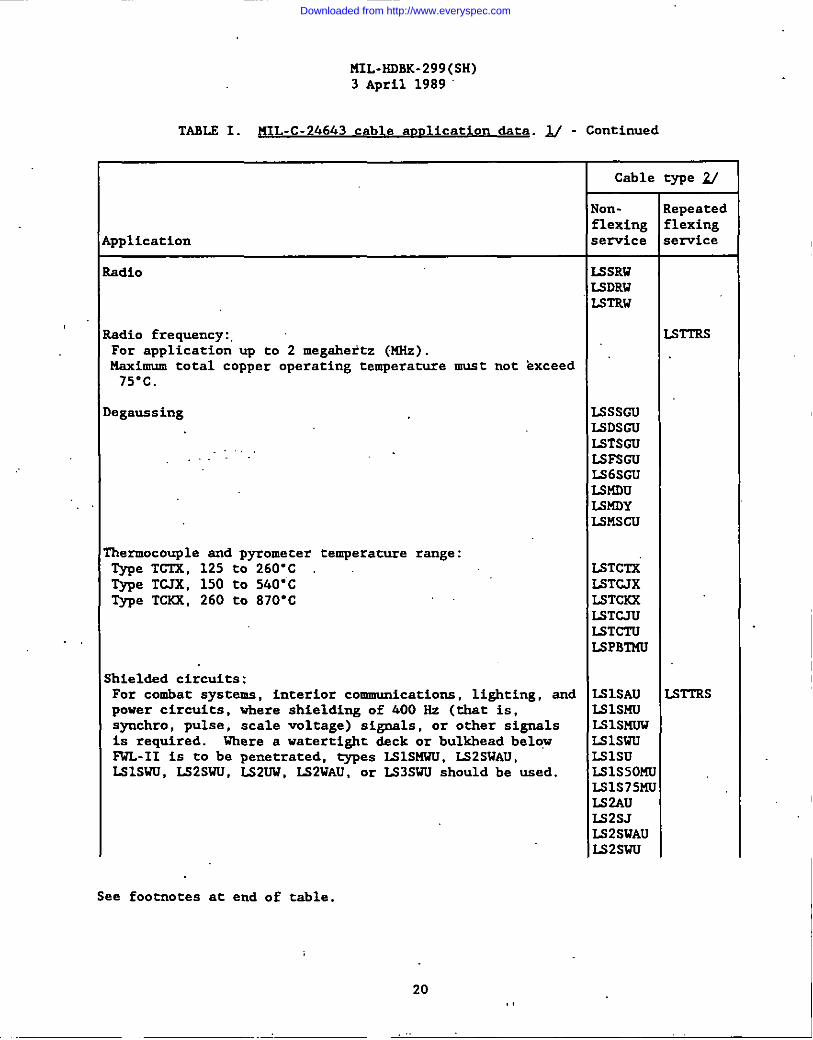
TABLS 1. 141L-C-24643 cable am lication data. ~ - Continued
pplication
adio
adio frequency:.For application up to 2 megahertz (KHz).Maximum total copper operating temperature must not exceed75*C.
,egaussing
. ..-
‘hermocouple and Dyromecer temperature range:me TC’&, 125 t~-Type TCJX, 150 toType TCXR, 260 to
260”C ‘.540” C870”C
:hielded circuits:For combat systems, interior communications, lighting, andpower circuits, vhere shielding of 400 Hz (that is,symhro, pulse, scale voltage) signals, or other signalsis required. Where a watertight clackor bulkhead belowFWL-11 is to be penetrated, types LSISMWU, LS2SWAU,LSISWU, LS2SWU, LS2UW, LS2WAU, or LS3SWU should be used.
Cable type U
Non-flexingservice
L5SRWLSDRW15TRW
lssscuMDSGUISTSGULSFSCULS6SGULS14DUI.SKDYLSMSCU
LSTC17iISTCJXLSTCKXESTCJUlSTCTULSPBTMU
I.SISAULSLSHUMISMUWL31swuLslsuLS1S50MILS1S75MIIS2AUIS2SJU2SWAUM2SWU
:epeatedIexing:ervice
SrrRs
STTRS
See footnotes at end of table.
20
Downloaded from http://www.everyspec.com
MIL-HDBK-299(SH)3 April 1989
I
I
TABL2 1. MIL-C-24643 cable auulication dsta. ~ - Continued
Cable type ~
NOn - Repeatedflexing flexing
~pplication service semrice
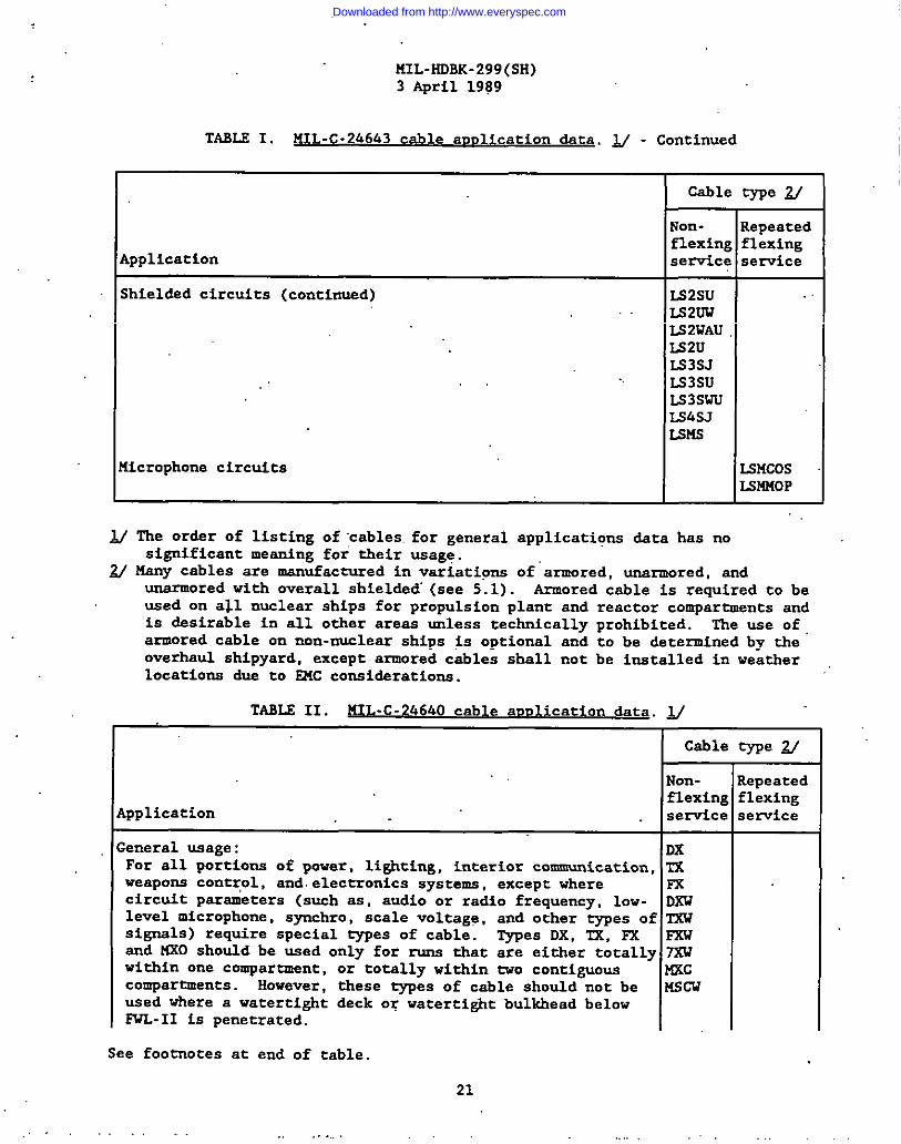
;hieldsd circuits (continusd) LS2SUIS52UULS2WAULS2UE33SJLS3SULS3SWULS4SJLSKS
[icrophone circuits LS14COSIld’lMoP
$/ The ordsr of listing of cables. for general applications dsta has nosignificant mesning for their usage.
~ Many cablea are manufactured in variations of”armored, unarmored, sndunsrmored with overall shielded” (see 5.1) . Armored cable is required to beused on all nuclear ships for propulsion plant and reactor compartments andis desirable in all other aress unless technically prohibited. The We Of
armored cable on non-nuclesr ships is optionsl and to be determined by theoverhsul shipyard, except armored cables shsll not be installed in weatherlocations d~- to EMC co~idsrations.
TABLE II. HIL -C-24640 cable auulication dsta. J/
Csbla type ~
NOrt- Repeatedflexing flexing
Application service service
:eneral usage: DxFor all portions of paver, lighting, interior communication, TXweapons control, snd electronics systems, except where Fxcircuit parameters (such ss, audio or radio frequency, low- DXW
level micrOphOne. sYchrO, scale vOltage, and other types of TKwsignsls ) require special types of cable. Types DX, Tx, FX FKWand MXO should be used only for runs that are either totally mwithin one compartment, or totally within tvo contiguous KKccOmparQnents. However, these types of cable should not be MScwused vhere a watertight deck or watertight bulkhead belowPUL-II is penetrated.
See footnotes at end of table,
. . . . . .. .. . . .
21
Downloaded from http://www.everyspec.com
MIL-HDBK-299(SH)3 APril 1989
TAILS II. JIIL-C-24640 cable aml ication data. ~ - Continued
I
Cable type ~
Non-. Repeatedflexing flexing
pplication service service
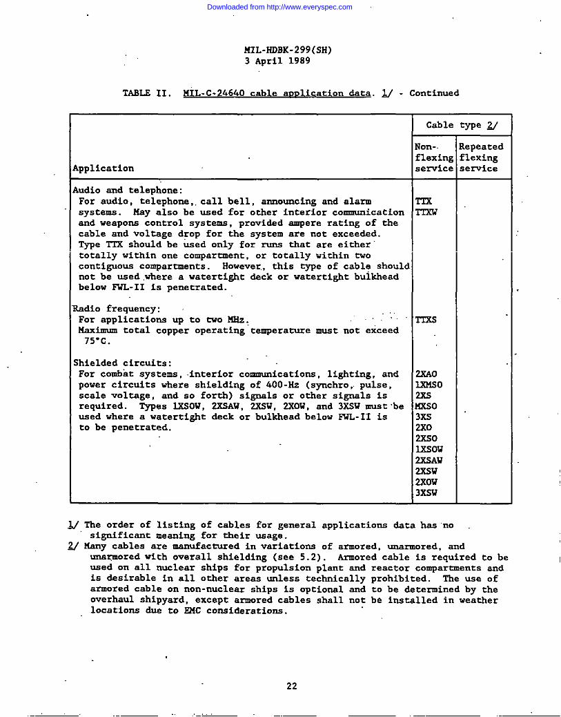
udio and telephone:For audio, telephone,, call bell, announcing snd alarm T-TXsystems. Ksy also be used for other interior communication mcnd weapons control systems, providsd smpere rating of thecable and voltage drop for the system are not exceeded.Type T1’X should be tied only for - that are eithertotally within one compartment, or totally within tvocontiguous comparunents. However,, this type of cable shouldnot be used ,where a watertight deck or watertight bulkheadbelow lWL-11 is penetrated.
adio frequency:For applications UP to ~0 ~: TTxsmaximum total copper operating temperature must not exceed
75” C.
hielded circuits:For combat systems, interior communications, lighting, and 2XA0power circuits vhere shielding of 400-Hz (synchro, pulse, IX31Soscale voltage, and so forth) signcls or other signals is 23Srequired. Types 3X.SOW, 2XSAW, 2RBW, 2XOW, and 3XSW must ‘be ~oused where a watertight deck or bulkhead below FWL-II is 3X5to be penetrated. 2X0
2XS0IXSow2XSAW2XSW2ROW3XSW
N The order of listing of cables for general applications data hcs ‘nosignificcnt mecning for their usage.
~ Many cables are manufactured in variations of armored, unarmored, andunc~ored with overall shielding (see 5.2) . Armored cable is required to beused on all nuclear ships for propulsion plant and reactor compartments andis desirable in all other areas unless technically prohibited. The use ofarmored cable on non-nuclesr ships is optional and to be determined by theoverhaul shipyard, except armored cables shall not be installed in weatherlocations due to E14Cconsiderations.
22
Downloaded from http://www.everyspec.com

141L-HDRK-299(SH)3 April 1989
TAEL.E III. MIL-C-915 cable auulication data. ~
Cable type ~
NOn- Repeatedflexing flexing
application service sewice
utboard submersible:For .hydrophones, transducers, outboard dial telephones, 14SPW 14sP
retractable sntenqae snd sfmilar.equipment. Types m, TSPA TSPlSWF, snd 2SWF are for hydrophores, transducers, and lPR-A20E 5s5telephone lines in the weather. ~es lPR-A20E, lPR.-16, lPR-16 525
7PR-16, 3PR-16, lQ-16, ITR-16,’and 7SPR-16S are only forSUbm=ine outboard use.
7PR-16 DSS2SPR-16 FSS3PR-16 TSSlQ-16 nwFITR-16 DSWS7sPR-16S MCSF
lSWF2SWFTPUM
‘elding electrode circuit TRF”TPXF
here -to-ship power THOF-4002TIOF-500
iver’s line and telephone DLT00-R2 aircraft servicing CVSF-4C aircraft servicing .,. JAS-250
~ The ordar of listing of cables for,general application data has no :ignificancmeaning for their usage.
M Many cables are manufactured in variations. of armored, unarmored, snd=rmored with overall shielding (see 5.3) .
TARLR IV. Commercial cable auolication dsta. JJ
Cable rype-Application repeated flexing
service
Cords for portable tools snd equipment: Un&rvriters approvec
IFor power supply to electric typewriters, office S, SO, ST, SJ, SJO,mschines, electric drills, sanders, portable extension SJTlights, and similar equipment. Safety ground conductorsmust be green.
~ The order of listing of cables for general application data haa no significantmeaning for their usage.
23
Downloaded from http://www.everyspec.com
I
>“
KIL-HDBK-299(SH)
3April
1989
I
dom
mu
m-1
.nao
0.dr.la”m
zzzzLsm
hzazzzzsm
cnddd+d~
-~+
~~
>>
\\\\\\\>\
\\\\\\>>
\\\\\\\\\\>
>>
..
..
..
..
..
..
..
..
..
..
..
..
....
..
..
..
..
..
..
..
..
..
..
..
..
..
..
..
..
..
..
..
..
..
..
..
..
..
..
..
..
.::
..
..
..
..
..
..
..
..
..
..
..
..
..
..
...
..
....
..
..
..
..
..
..
..
..
..
.-..::
::.
..
..
..
..
..
..
..
..
....
..
..
....
..
..
..
..
..
..
..
..
..
..
..
..
..
...:::
..
..
..
..
..
..
..
..
..
..
..
..
....
..
..
..
..
..
..
..
..
..
..
..
..
..
...:::
..
..
..
..
..
..
..
..
..
..
..
..
....
..
..
..
..
..
..
..
..
..
..
..
..
..
...:::
..
..
..
..
..
..
..
..
..
..
..
..
....
..
..
..
..
..
..
..
..
..
..
..
..
::::::::
..
..
..
..
..
..
..
..
..
..
..
..
..
..
..
..
..
..
..
..
..
..
...-.
:..:..:
..
..
..
..
..
..
..
..
..
..
..
..
::.::..
..
..
..
..
..
..
..
..
..
..
..
..
.U
.u::::::<
’i::::
::.=i-ai:::::;:::a
:;-;;~~&
.h.
~<:<
:::;
<g<
:::::
:&~
..
..
..
..
..
....sE
EE
.239~..222z2i$.::S
Z5Z
-’XO
I=O
2m
u
24
Downloaded from http://www.everyspec.com

MIL-HDSK-299(SH)
I
3April
1989
..
..
..
..
..
..
..
..
..
..
..
..
..
..
..
..
..
..
..
..
..
..
..
..
..
..
..
..
..
..
..
..
...
..
..
..
..
..
..
..
..
..
..
..
..
..
..
..
..
..
..
..
..
..
..
..
..
..
..
..
..
..
..
..
..
...
..
..
..
..
..
...
..
..
..
..
..
..
..
..
..
..
..
..
..
..
..
..
..
..
..
..
..
..
..
..
..
..
..
..
..
..
..
..
..
..
.
..
..
..
..
..
...
..
..
..
..
..
..
..
..
..
..
NN
I-.S---*
F3F
’tw.n
uu
-ldd
\\\\\\\\.
..
..
..
..
..
..
..
..
..
..
..
..
..
...
..
:::..
..
..
..
..
..
..
..
..
..
..
..
..
..
..
..
..
..
..
..
..
..
..
..
..
..
..
..
..
..
..
..
..
..
..
..
..
..
..
..
.
m-m
”::::::\\
..
..-.<at:
:-a:..
~~
G~
<L$~
gEz2zs
EE
0.
,5<..
..
..
..
..
..
..
..
..
..
..
..
..
..
..
..
..
..
mm
mm
+m
mw
U-8m
mI-d
med
em..m
.--W*
.\\\\\\\\\\\\\\
..
..
..
..
..
..
..
..
..
..
..
..
..
..
..
..
..
..
..
..
..
..
..
..
..
..
..
..
..
..
..
..
..
..
..
..
..
..
..
..
..
..
..
..
..
..
..
..
..
..
..
..
..
..
..
..
..
..
..
..
..
..
..
..
..
..
..
..
..
..
..
..
..
..
..
..
..
..
..
..
..
..
..
..
..
..
..
..
..
..
..
..
..
..
..
..
..
..
..
..
..
..
..
..
..
..
..
..
..
..
..
..
..
..
..
..
..
..
.. .?~.
..
..
..
..
..
..
..
..
..
..
..
..
..
..
.
..
..
..
..
..
..
..
..
..
..
..
..
..
..
..
..
..
..
..
..
..
..
..
..
..
..
..
..
..
..
..
..
..
..
..
..
..
..
..
..
..
..
..
..
..
..
..
..
..
..
..
..
..
..
..
..
..
..
..
.-d
..
..
.<A
...e.
Az~
$~~
;W
+ew
+!-w
25
Downloaded from http://www.everyspec.com
141L-HDBK-299(sH)
3April
1989
..
..
..
..
..
..
..
..
..
..
..
..
..
..
..
..
..
..
..
..
.
..
..
..
..
..
..
..
..
..
..
..
..
-.
..
..
..
..
..
.
26
Downloaded from http://www.everyspec.com
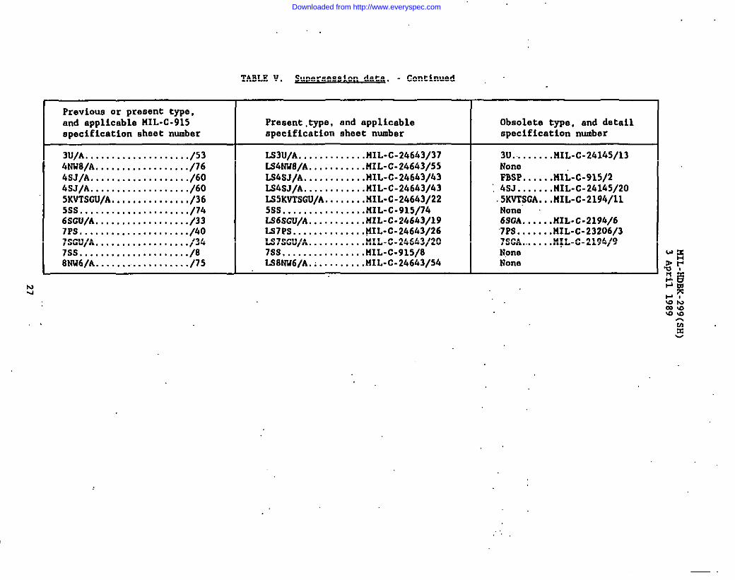
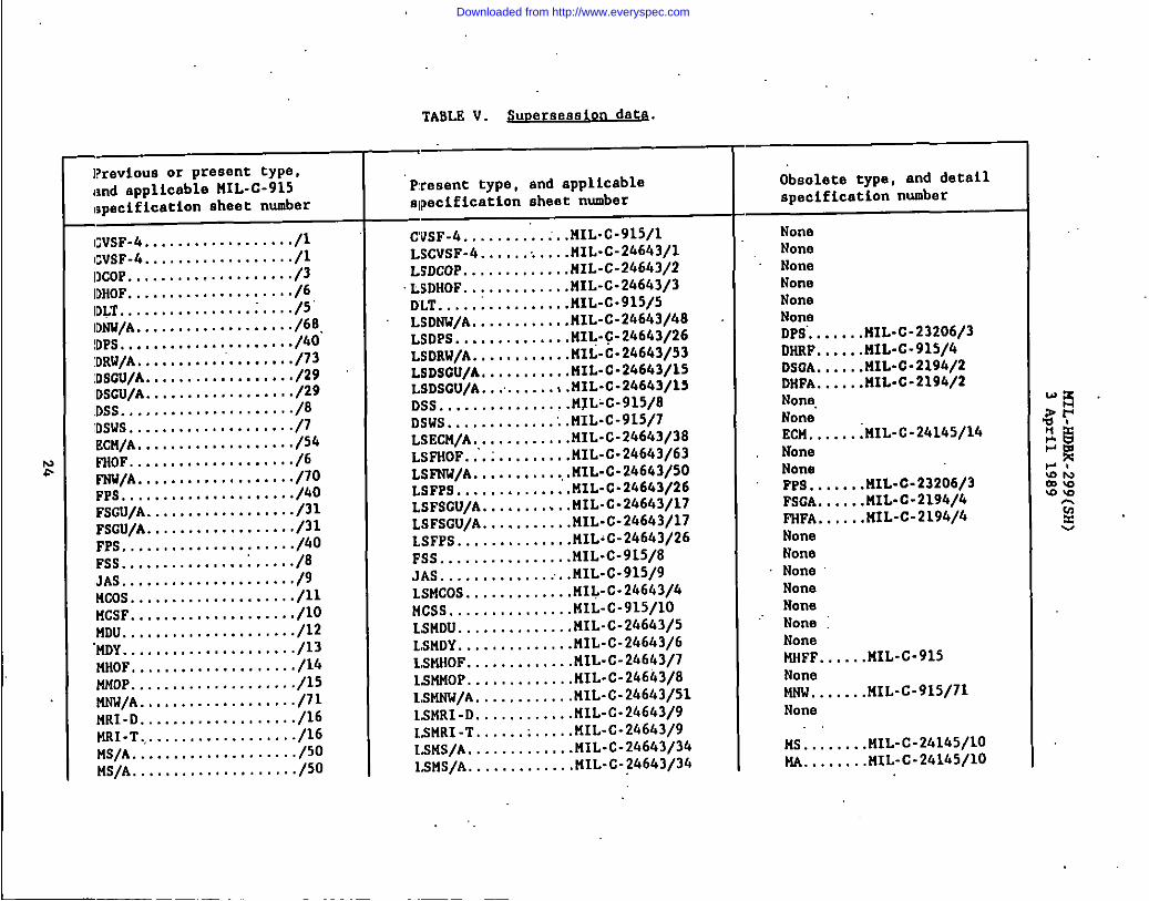
Previ0ut3or present type,and applicable HIL-C-915 Present,type, and applicable Obsolete type, and detailspecification sheet number specification sheet number specification number
3U/A..................../53 lS3U/A.............HIL-C-24643/37 3U.........UIL-C-24145/134NW8/A................../16 LS4NW8/A...........UIL-C-24643/55 None4sJ/A.................../60 LS4SJ/A............HIL-C-24643}43 FBSP......nli-c-915/24SJ/A.................../60 LS&SJ/A............HIL-C-246h3/43 ; 4SJ.......141L-C-24145/205KvTsGU/A.............../36 LS5KVTSCU/A........MIL-C-24643/22 5KVT5GA...141L-C-2194/115ss,..................../74 5ss................UIL-C-915/74 None6sGu/A................../33 LS6SCU/A,..........llIL-C-24643/19 6SOA......HIL-c-219b/67PS...................../40 LS7PS..............U1L-C-24643/267SCU/A
‘7PS.......UIL-C-23206/3................../36 LS7SCU/A...........HIL-C-2h6h3/20
7ss7SCA.......H~L-C-2194/9
...................../8 7ss................UIL-C-915/S NorIeSW6/A .................../75 W7NU6/A. ;.........k31L-C-24643/54 Norm
Nu
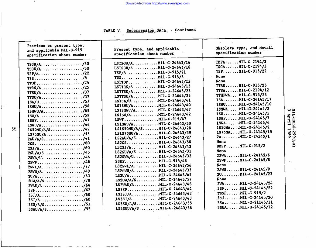
TABLE V. $uDerse@aion datq. - Continued
.,
Downloaded from http://www.everyspec.com
)41L-HDBK-299(SH)3 April 1989
5.5 prief exnlanation of cable ratines and charatter istics tables.
5.5.1 First five columns. Each cable is identified by the Militaryspecification and specification sheet number in the left hand column, followed bythe type designation, conductor size (AWG or MM) , number of conductors, andconductor cross sectional area (circular roils).
5.5.2 Overall diameter. The noverall diameter” is the overall measurementof the finished csble, and should be the determining dimension in selecting theproper dsck or bulkhead stuffing tube size, or multi-cable tram it,inserts. Thisdiameter is alao the determining dimension for stuffing ~es for equipment.
5.5.3 J&ted v ta e ac01 e . am itv. and minimum radius of bend. Electricalcharacteristics are given under columns headed “Rated voltage” .md 8Ampaci~”m .“Minimum radius of bend” , which is approximately eight times the overalldiameter, is also given. Cables must not be used in excess of these ratings.
5.5.4 Conducto~ catio . The letters in the conductoridentif ica,tioncolumn represent the identification, and the number represents themethod of a“pplying the identification. For example, STD-1 means standardidentification applied by method 1, which is printing of the number. and colordesignation on the outer surface of the insulation or jacket of each conductor.TEL-3 means telephone identification applied by method 3, vhich is coloredinsulation on each conductor. The abbreviations used are as follows:
STII - Standard identification codeTSL - Telephone identification codeSPL - Special identification codeLTK - Latter identification code
5.6 Cable classification (uIL-C-246k31. Cables specified in MIL-C-24643are listed in table VI un&r tha following general classifications:
-(a) Watertight (with circuit integri,~) , ,non-flexing senice:
(i) Power and lighting.(2) Control.(3) Electronic, cohnunication, and
(b) Watertight, non-flexing semice:
(1) Power and lighting.(2) Electronic, communication, and
instrumentation.
instrumentation.
(c) Non-watertight (vitb circuit integrity), non-flexing se~ice:
(1) Electronic, communication, and instrumentation.
28
Downloaded from http://www.everyspec.com
I
MIL-HDBK-299.(SH)3 April 1989
(d) Non-watertight, non-flexing service:
(1) Power and lighting.(2) Control.(3) Electronic, communication, and instrumentation.
(e) Non-watertight, flexing service:
(1) Power and lighting.(2) Control.(3) Electronic, communication, and instrumentation.
I
29 ,,
I
Downloaded from http://www.everyspec.com

w0
TABL@ VI (a)(l).
—
Iumk”,#cca-
&0pM41y,cad Curducon(mm mm)
m 4m,LY)R
ID
.
LIW3LTRJLIRJL-
LTRJL!2R-3L?RJL’212-S
S17J4
SlnlS3DJ
SsD-1m-l
hm6urm!k Awaw MIX
ommlmm
ommlam
Ibditud kcdml..
Luclm)
—
10.011s12.0123
10.011s12013S
43
Am dUcb
Ca16mcml(MCXS)
Iowam.lm167.S90211633
losmm3.lm167S03111L931
4s30
6C0
WCImbknl
W/G C46bIyps6w14nuim
Clbk Ciblo~titF n,qpnn(lb)
2.9193bm4AmSA13
2S303.4X74339Mm
0361
Ralcd.llt&
Ilws.(Iuds)
NW61U411WC40’C
hubknt AmMeaiWCmbknl
S&LLmo1s40LO1O2.Z93
MmL7WIwo22U!
ans
+
127 272147 299172 3mm w
n7 372147 359
z z
mm1003mmKm
mmmlM-4aml
-ml
mmmm
mmmm
2361601S8119
236,1(/3ma119
~
mo27smo240
230275
&
m3mmml-9313ml-9314a31J5L$
am-mll201-93s23m-27m
a
rnl-wm‘3SM319
WI-9316301$517
246W9
34642n9
SJS41A. 10IS690A. U!S4SOA-S6SOA- :
s6siJu- lmS4.sou. IL!S6sou- l-sosdsou- MO
SIPs 6 12 -1-p3423—14/1034n2
%’-E-24643no S7SOA- 3S7SOA- 4
1614
77
2ss04,110
23s04.110
2sao4,1106s30
103W13L’m
25m4.110
10.WOMmmmos2hm83fml
1CU60321L6C0ml.ml413.601
59564s
maw
4,04n
mnl2W4
15/11aY14 E--E34642no 57SOU- 3
SmOU- 4
SD9S. 3SOPS. 45DP!4. 6S3PS. 9SoPs. 14
1614
-
1614
‘ 12109
161410973
:mmm4m
77
2a222
i-2a‘21
:1122
S4s5%
ASS
$2.613.730
Al..4n394.730.s21.%1
1,1Z412171,632lKVI2119
.142
.19s
.121.141.194,s22533
,JC4.12s.239mlA1O.740
mmLsma4w33m4.4CE
4334.9
30302s4,04s
3n104,04,0so6,07.073
10.011s13n
,SSD4SID4sm4S2D4Ss3U
5273.1STD.1SrLMS2DJm-l Y
LIR-3L3RJLIRJLIRJL’lR-3L~J
2603(mm3
KmKu3MmmmmmKmKQ3mmmmIcEllma
:3s4134
13n4460‘m13616s1!?3w41349a
L76.%11P?WS94
nmG42.44.4372
m3-Pwl-7203-woS203-920s203-9304Mum511M243.30ws762044S7lc4-4sm30X33W
12m4133n1161331s934s319310
246WS SDSOA- 2-5S2SOA. 4SD3DA- 9SDSOA. 14XhSOA. 2SSOSDA- 2050 SOA- 73SOSOA- Im50SOA- 200
772sum:
n1142331833s4m
‘m126169lwms347227
SDSOA. XIISOSOA- 4M
Downloaded from http://www.everyspec.com

,.
TABLE VI (a)(l).~. .
.
Iumtx)f m“
Ikmni tilt
. . .
*L.C. SatedWc4tap,
nlti,(F&m)
+
1bmbkat
133344@70136169199ma247327
+
de,
4VChmbkm
able IYPCdcdglluion
Im6ucio:he AWGorMC6J
Am duch
mductm(MCM)
3SS134.110
IOJSOnom20.230SlhmS365tIoimo111.KGSoo.onInfal
nom
Mm4,410
103SOm.am33.630Slhm
Io.s,mo167SVJ111,(OI
Lsm4,110
Io.sso>ornm3L6208J6m
loiml161.SM211.(OI
51620
Csbk Rsdhndbadmin.
:imchu)
MI30404,0so607.073
10,011s13,0
-50
303.!4s536J&o23
10,0ILO
303343M65&oas
10.0ILO
u
L12RID
55734S273.1S2D.1S1’D.ls-m-uLTR.3LTR.3LIR.3LIR.2LTR.2LTRJ
S3D4
S773.1S323-1m-imuLTRJLTSML2R.3L7R.5LTR.5
FiFi-S3D.1SKS4Sra.11LTRJLTR.SLTR.5LTR.3LiR.3
NSN61W31SOT
AmbkJSOTmbiamdimlcter
(1:%1)391A17.544,670.731,911
lm41.1671s2s1s413.Q59
0.215
A97.%2Lao,%0
I.tm12s0L4G9imslam
0.447313IJOMO
I,(MO1,3401,338Lollslam
sm
lsDsGu-L5DSOU.KDSOU-LsDSDU-LsDSDU.LSDSOU.wDSOU-Basau.lsDSOU-EDSOU.LSDSOU.
—
mmmlmmmm10Q3ImoKm103IIcm1o11ma
ml
ml1030mm10II1033toolmm1o11mm
mmIfxslKGlmmKm10301o11lammm
Im
13*.
44m7s174Ma159m413491
41
lam41s!n116us1s3224?s0433
1017
3254101136160116no
101736u1011361602162m
12m4135n11615sla3M319310
10
:64101126137
z
717s6410I136157206334
3024463ZLn.nmW3.m203.2797303$79sZ33-S476202.3477m?-nsolm.%ia302.5371mM4d4
1s6a7m
m2.34mm2-34823034483201.3404302-3m9m3J4s33m.a46sml.sm$an-lsll
203.3309210.2344m2.3sio203J4?J3mJ6s9.203-693s203.6936203.6$57m2.34m
16141097110
m
H
.106
.194
.2s932,Ul
1,0181,2172W33.1134.242
0.4s1
,134204*,517
L076Lm91.4123.1s23s33
0,136.n3196.4ta
1.015Lad18303.1033.819
.316
34642/36
24642/17
34642/17
2464Y14
LSFP.$ 14
—9
1614107310
mmm
4
-i44444444
LSFSOA.LSFSGA.LWsaA.WSCA.LsFSDA-uFSDA-WSGA-K55NSA-ISFSGA.
11183969110148174auq
II18396911014s174n!271
149
IIIn39m110148
::Sn
1118Y?d9110148Im3ZA2s4
149
wmau.Ls5W3u.umau-LsFsGu-LWWu.15RU3U.ISFSGU.UESGU.umau.
16141073Io
m0m3
3
444444444
—
1
493330n10Ism
LSSGA- 34 137 30W491
Downloaded from http://www.everyspec.com

TABLE VI (a)(1), ~. .
Amadcub
mndlula(McM)
. . .. .
&awud@@ - Continued
Ammciw. ed Oxiduaa
--xl
mWi6erd
#i
WCAmbknl
-
WCmbkm
[M&
Kd42i14
464n4
E
UlalwLlraa-IUlomn ubk
—
1
;1t11I11
—
I11I1111’1I1
T333333
4ibleCn.Mdl
dhllwermu.
(Lid@
Cum.719.923
1.0311.1631.4211S3lbmUtJI31do
Cd@
-=&f~nWplu(U@
OA34S30
1M2
I@dkmdbmdmin.
[Imcbu]
C12Rm
Ihwdnils=
mu
(w
t4SN614241
3269010M2I2111Mmom413K0630JlmSmm021.M3dmomDnbm
LSOA. nLS3.WA.ISS.$OA- :lSS3l3A-L5SWA. 2LSSSOA- 63015SWA- M13L5S20A- MIXISXMA- ICUISS30A. Z3J
1
O&2m4m6$02mlullWI2COI
1o11mm1003mmmlmaIon1022mm1M2
Wi22236146737s7829U2IwlMMMm
181’214323423530
z930mm1430
181’214
-.
an-wn22MW42nw93mMw6b3w97m44.74W2-9W223.2-W$202.9m301.94%
UnlM294rn6.4697,733
Lwsau. M3ss.3au- M-u. imls2sau. mLsssau. MOL94au. 4mUi3w2u.lsmou. zWssou. 10UU320u.Ls.3au. s
123181214232430Sw
E930137214m
1371s1114
302-4293m2-0279an264720U471303a76M6.2323Z024377a343246302+.3iam3.2642m442m
31.
C&m4m
:IwoMaX03
-ii-14la1097s
16141097
W630E3ml
103.63321MI0303m3423.mldm,ad3nmxom2.cmfco,mOYl,ml
3.3m4,1106S3!3
1038013K?Nimm32,!E9
Om,S12damIml1.11813711AM
H%3.310
o.4mS33.6m,A77.7s1m.9m
0.361A14Slo.%7
1X91.1631716$2334.UI63m7m
ZF,160
2-34.0
::0-37SJ8.39-3
10012313.3
30224,04.04.3Ss6.0
S3D4S3D4SrrMS3134SID4s31MS37M
mlKmKmmamlmmIaalmoladIan1030
mldmm3C&lOxl@lodm
ICCUKmmmImomm
149’197mMI46757579.7MO10W1430mm
-ir-1733%4764~.
149197Zu
101722%47tAn
LnPs.3m 4.lSl?$6Lsr3S 9ISITS. 14IS1-FS 22IS3P4. 29
All5W.738
464Y16 LSX40A. 3LS3SGA. 4LSISGA- 9LS3SOA-lSISCiA- !!
33333
Mm4,410Io,?ao13J2mmam
A61.459.673.76a.8m
.la,1S6X8334
303.04.04s5.0
S3D.1Sm.1S3D.1m-lSlT2.1
1118 .
;69
1017364764
11M
:69
1017264764
3.0246mm24679mmsoanalm2AJfa3
Downloaded from http://www.everyspec.com

,,
,.
TABLE VI (a)(l). ~. .
bQ3vclaza AWCa Ma
-
310
MOm
%
1614109731
&mmx-a4m
AM*IY, e
Hz.AITAC4
UdCm6ucmr(MC64)
Lm16uam
k 0,
‘iwcU&m
1—
WCmlbkot
cable0.u8u
(ibbmeigblpmnw9+-(M)
a9671339Mm3338319743365BB
00)9.337MI313A43Em
lm3IAln3.4m1(s643375695
14173m734AW3s636331
UIRID WC
Ambkal.
(Imbu)1
3464Y16 lS3WlA- S3lsrsaA. 733,73saA. lmLS3SOA- 330lS3XlA. X0153WJA- 303LslsaA-4oo
S3.63063490
Imtm167EOIlllmX3moo413.ml
2.%06.110
103s013C9030s303363063bm
tmdm167.803211.moX93m411600
1O$MO167.8C0XamIW,OM413.6m
lm91.1841316MmLn93.m73233
“:M93
10s13013s
3n104B43xl4-!7-!8.09>
1031333133
11.813n143339163
m-lSm4S51M
%{S1’7blStD-1
m-lSn3.1S3D.1m-lS3u.1S3n.1mlS3D.1S3D.1m-lsn3.1S3U4
ELT3MLT7isLI14.3LXTL.5
IOJ3mmIaxlmooUmmlomm
1033KmmmimImoKmKmICcoK03ICOOmmKm
11014817423337134a43!
11183931@11014817433527i3m433
r333315391433
101LMla2163m.
:
1017%476410113sla2163303m4m
160216~:
W600
110146174334334393m
1118393169110146174334334m3m
101Ill13433m334m974
r17347uIm1%la3067363m274
—
—
lo3J3b93b334031b33aa4Io31Em2034306m7.-om7im.oq
3M69J301-94%b31.M9Jb33.34mMMW32013033ml-mm301.9303M3.93m303Q676b3346773m.93m
a714143014713ml.wmlmulo.3-3mo
3OMSS1O203+3443014$11mlala3m.6313
3s33>JJ
T33333333J33
T1333
346W36 0.41134914333073103Lm30030303
A49-$73,718.611.969
1.1341266Mu1.6691,9973.333
wu
T3464Y13 LSmA- lmLl!3W3W3A. 33oL9SKV3SOA- 393LSKV3SOA- 3!4LS$KV3SIJA. 403
mm3nm
Ym30U33mJmooXml
mma3momm
oOm330330m3
3.3x.33002Am
34t43m wcfmou- lmls.mvmau.330KnW3s13u-lx!lsnw5sou-391LiKv3Sau-4m
omom3$0403
33333
Im,axl167X0330JXQ330m3413.KO
1,7401.93023303A3nMoo
3310Mu4,3M3,4176,193
11A13n143139163
1743353U391433
10I2163503m
.4C0
Downloaded from http://www.everyspec.com
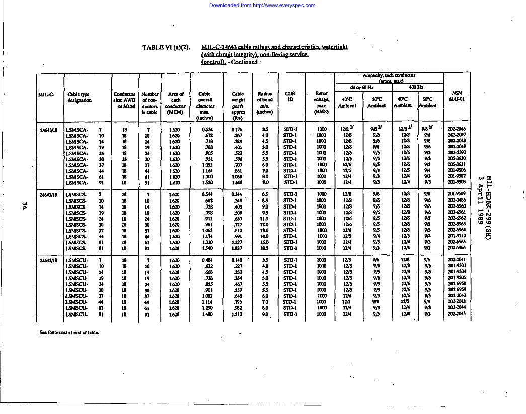
TABLE VI (a)(2). ~. .
(rxm@,-COntin.sd
AmwilY, U Cm6!xmr
[IL-C
MWIB
4643118
K64Ym
#i@mSuc
Aakc.1
—Llbk IYP lutu
*CCIkllad
—
710141924.w37u61Sr—
7101419ux!37446191
-i101419
;37u6191
Arud
Calasol(MCSS)
Cs6remmn
.fbmew*
(Imtlu)
0s4An,718.m.SIM.931
mu1.164lXO1s30
0344.663,72s.79a.9U.%1
1,06s1.174L310Isa
0,4s4.633.s6s.7$s.Wsol
1.(031,114Mm1.4s0
Cabb+tl!pun
*99-(b)
0,176X7mAmm396.anMI
ImsMO
oa4439.m33s0A91.n7.810.931
kn7lla7
0,148.237.mo..3s4A67S39.64s.793.593
L71O
IrAdultibdda
pcba)
WRID
SWC6mlrug!a,
(s%rucnbkat
614S01mblcnr
UWsCA- 7K6rscA. 10WMssa. 14L5MSCA- 19L%MSCA. 34LSMSC4- mma- 37W6SSCA. uLSMSCA- 61mssx. 91
&$ssC3. 7W64scs. 10LsM- 14L$M3cs 19ma ?.4S.rscs. sKbsscs. 37E3SS13 44SSKC% 61Ahsscs 91
*N UmmmW6
9B 11
9/4s9/49/69/39/39159149/3%3
~v
mmamaW6W61316
~6 lr
9/69/69r69s9rs
Mm1.s20167.0lAIOMm1.6301A30MmMmMm
334,04sso335s607Ll,no9B
S3Ts.1S3u.1m-lm-lm-lSI13.1m-lm-lm-l”S3D.1
mllaxtomlmoKmmoo1O-J31o11Ionmm
10IB18181818IBIsm18
1018lamIs16ls18lsIs
718lB1818IsM18lars
9rsli3W4W4
9/49i39/3
lbmMmMm1.630L6m1.6201.6301.6301.6301,620
63.SJ
9,093
Sru-1S1-r3-lm-lm-lm.1 ,
Sn3.1m-lS3D-1S3D-1m-l
lcmKmmalammoolmomllamKmml
mmmmOm1o11lamlamKmlammmIon
lzmmWaWE
9s9/69/49/69/59i39/39149r3913
9b9/69/69169r39,59/39/49/39n
mmmranW4W613/6
9/69/69/69/69/99119/s9149nW3
9/69/69169/69/59/39i39/49139/3
301.9309303.MS4Z02-5%33024561m3-6%2303-%63anwml$woX04%33US.OW
m3-m41ml$wn301.9504301.9X63034558mL69s9203.30423m.m43an-mum3-3043
11311013.014.016.0183
334.04s
W6W3IZ413/4
WEW3la
125W4W4
laml?A
%
Lm4scu- 7LsMscu- 10
MmMm
SrD.1SIIMsr73-IShKclJ. 14
mscu- 19.suScu- uS4scu. 30S6sscu. 37mscu. 44s4SCU. 615MSCU. 91
Mm1,630l,6mlAmMm16301.630Mm
S,o55536.07.0M9.0
m-lSKMSITS-ISrD-1m-lSr73-1S3n.1
maW6W6W6lWw4W4
W6W6WsW4W4
Downloaded from http://www.everyspec.com
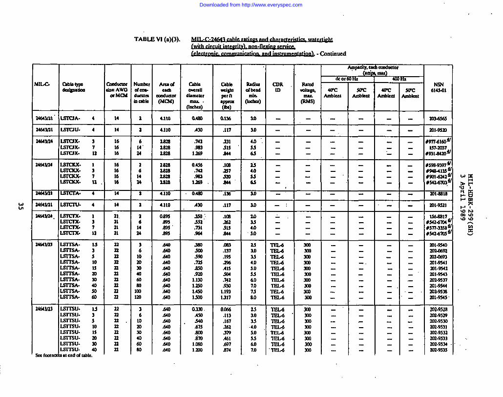
. .
TABLIZ Vl (a)(3).~. .
. . ..--: ..-
~ - Conlimmd
Rmtdwimp,
IIlu(14mS)
Appall -d! dueor‘+ I
NW614s41
cablecmxau
dhmcmmm
(Inch)
o.4m
—
Iumbc,$mn.Ikumm1CM@
AmdUcsl
Dn6wtm(MC$d)
Um
motudbd
w-)
so
=
WCmblum
du-knI&AWOa Mms
ChbkdgblprnwQ-(bs)
0.1?6
CUR[0
-
SWW’cAaknl
m%sds14 ‘1
U5wm Isswu. 4 14 a 4.110 .117 ml-mm
Nd4Y14 IsIrlx. 3LsrWx. 7IslWx. 12
161616
1616
;
14
lamlam2.s2s
2s2s2s24Zm4
4.110
.741
.Sa3lms
0,4s6.74a.Sm
1269
oAm
2s131s244
.lm
.n7so24’
.lM
madlm.zm7mam~
W9ml ~WI-4133$W14Z42!sum:
-.
‘-
r!464Y14 Isnxx.Isnxx. :
RR. LN64.Vll IS-WIXA. 4 211-W8
U6@ll I IXIC17J. 4 14 1 4.110 .117 la mh9s21-:
a4d4Y24. IsIm’x.Lmn%. :15rcsx7Lsrcrx. 11
21.mm21
a2nn.un2s2snnn
nan,nnnnn
26
;
76
10al3040m80m,m
oAmMSamm
.d40140Am.d40.640.mo.640mMO.640
~:5.s1.731.904
somlso.msMO.mo
1.130l.mo1.4s0Mm
.lm
.ms51Ja44
l-m.lm.195.ZmAUS04.~2.9m
1.19s1317
anSJ4LIm
2.!103.!4,05,053607,073&o
Tes,6‘ml.-6IEL-6‘m&6‘mLd‘17w6‘17iM‘nm,6TEIA‘17m.6
moYmYmmlmlmlmo
zm
1
ml-wZoMM9.1Zolamn
!464Ym Is-15A- 13IsrssA. 3I.m-lsA. 5
-’
.-
-.
-
-’.-
-.
IsImA- 10LsrssA- ummA. m
mwsaml.m42291$543mz-%nml-9544MO-%39mm4s
t
Isl-rsA- mLsrrsA. 40LmTsA- soLssTsA. 40
!444Ym Iss7wJ. MLsnwJ. 3LSITSU. 5Isl-swJ. 10mu- Mmu. mlssTmJ- 30mu. 40
iceImma m cudd table.
36
10mm40mw
MO.moMOMOMb.640MOA40
0.3m.Amso47s&-msm
IL-SOlam
0LE6.113.167X.1.374.461,Wm4
TELd‘17m,617m,6ml.6‘sELd7EL.6ml,6‘ml,6
mmlmamIolmomml
Downloaded from http://www.everyspec.com
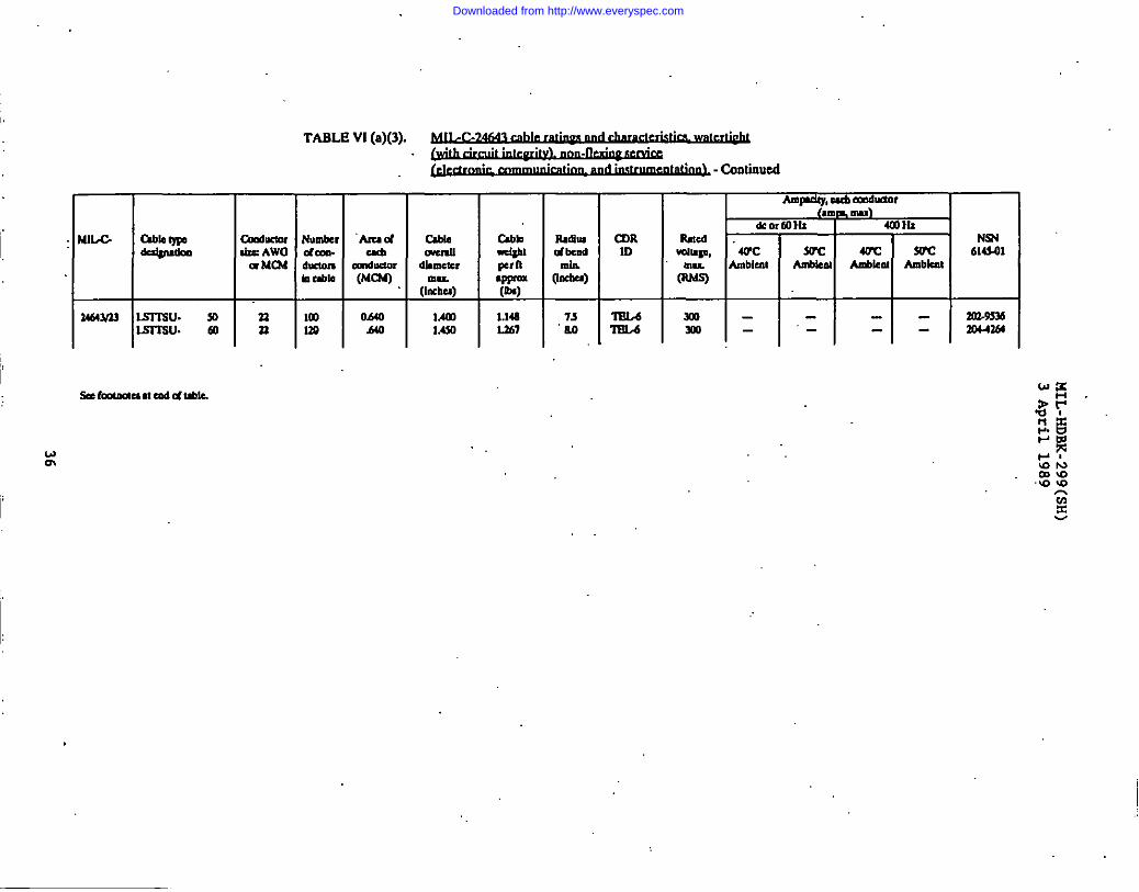
I
16Mw Isl-lw. soIsr6’su. m
- (mlrnmM cadd ubk.
wm
TABLE VI (a)(3).~. .
. . .~ -Conlinued
I n
H
0A40 Lan H 1.6$0
-rIIuuu CDRdbmd ID
MllL
W=)
T“: l’i3Mslo -xo- 1 I
----
NW614$01
lm-9s36X44X4
,,
Downloaded from http://www.everyspec.com

.--—
.
w-I
TABLE VI (b)(l). ~. .
. .. . .~ - COruinued -
mmI I I
34b4%3 3SS14WA 14 1
a=-Cdw Iml
13.CW 1393amo 1.76341.740 lmoC&%30 l.no
x6s30 1.19013,ma 1s70mm 1.9s041.140 am
+=
4.110 .7s0
4110
4.110
lam=Wpnqlpm(0s)
O.sa
.136
1.1431.7U3Zst44.191S.M3
13601041X-m4.4806471
0.333
S3
.OM
.134
ndw Cmdbd m
[Imhu)
+
so m-l
a S3D4
ao m13-19s .S3D.1
10.! Sm3.113s ml14.n S17M
T7.0 S3ul9s ml
1%0 S3D.1133 SID.133,0 S3D.1
3=4s S3u.1
4s m.1
10 m-l
10 S313.1
Amrdy, & CadulOr
mu)*orlMHl 4mns
Ruco NSNda~ WC. m 40’C WC 614s43
ma Ambient Ambbm Ambknt Ambient(w
m 36 7A - . ml$13s7
nno 36 ?A I- - ml-sm8
Sa fmtmu mad d Me.
Downloaded from http://www.everyspec.com

TABLE VI (b)(2). ~. .
. . .1“
kekmrz AWOa MIX
—
WnbcMfam.hlctonn&b
CDR10
6TD-1
Uw6Sdufi
Ulu.
mm
600
ml
MILC able I)pOd+mkm E1-i
k
614301Ambkm
ArudU&
Cce411am(MCN)
IXJ18menu
dimmer
(::%Mm 4
mdbm2& ~~d bead
~- @@-)(0s)
3M2 10.0
13m 10.0
34MY47 IS1363WA. m n m 0,702
34643U7 I ls13Mwu- ‘m n m .7(6J 1.$s$ SID-1 -130M341345W43 IL7UWA. t 23
:n
nnn
--#--nnnnnnn
:
.X9
.No
.ml
.ml
.mo
.mo
.m
+--mlm.mo.’m
:%,ml7X7.ml
Osn
930Mao12s0
0.4ssMO
l.omlam
.710Am.9s0 :
L&m1.360law1.4YIMmLm
0s20.&aan.9?a
1040111012801380lsn1.740
0.910
+
auo 3s
35.6s6 U.90 75
Sma
i%:m-a
ml
6mdmml
-1- -13m3m11
E3464W30 3S13WA. 14
LS13WA. 30ISSWA. W
1464Y30 Isuwu- 2Issw3J.IA13wW:L93WU- w
-, --. -
-.
.-
.--“ .
m
T.:m
:AIB &l
73
.s0 45An 3,0618 60.m 63
751236 no1s43 SJ1.5Q3 9,0
SID.’2Sn3itS3D.a.711M
-sml-S3D.2.5TTI.2S3Li.aS3D-aSKI-zS3D.2m-zS3D-2m-l
E.:sru.2SID-2
$:S3D.1S3T3.2S3D.2Sn3.1
aoml
r%601600Wdm
“ammMOanmo
600.
c%mlmotoo6006mMOal
1=m3-3wJ~ mm-E35n671182
-ii .maa33-7X8-3on-nf
wm
LU33.5WA- 73S19W’A- 10K33WA- 14L91.SWA- 19
=. :lS33WA. 37IS7SWA. ULQ.SWA. 61 iL!?d
m3.7634m3.3339303-ls90
Z317
a17s.337ms%.711.937
1,174Mm1-912
10.0
3s4sso&o63750.0859.0L
34643M U41SWAULQSWAU.LQ3WAU.-AU.LS33WAU.LS33WAU.MSWAU-lSSWAU-LQSWAU.LS3SWAU.
s71014193430374461
33n33
:n33331123
614allanlam14?au—
14
.7W7mlm,7C0,ml.703,7C0,mlml,ml
mrl
206-33403ca-933131n471m3.353730WMm3-333um3-3339mJo191m-naim-mm I2214 10.0
t3464356 Ilx.swb 7 16 SID-2 ml
=++
-. 3m.74M
3C6.36U
31B-3632
16 14 2300 .%0 .467 I 7.3 m-a m
m 2 Mm .3$3 .103 I 20 “SID.2
Downloaded from http://www.everyspec.com

TABLE VI (b)(2). ~. .
. . .
- Caaimmd
M12,C
2A64M32
2454%32
2464%7
2464357
2464%7
14643i44
lA642i46
Zu4ym
z4t4Ym
* IColnol
AnpLoy, Cuil Ccaduuor
#au&,
WCImblua
i
WCLmbk.nl
Arud Ix4aomau
6!mutc,mu.
(IOduI)
a710.910
In1s2!2lSUI.’ma
E
Osm.7$).Slw
MOMm1640Ialo
E
0.750
Rmcddmgc,
tluz
w)
MN614S01
m2a272m4a432M.69922CU65442m.94nan4rmYm-.7m4m4fm4
C4mrrdlldonh U6!4
WCAm6knt
(Mm)”
O.ml
I
4.0am W I%:ml43S272.2Smw22.
Lsswu.Sswu.s.4wu-Smwv.Smw22.S2.9wu.
3711
:2227
6142422
:74
122—
a6
Jm42mw
122
ii--
r
ImL6mlAm
6C0601m6m600mmlm
momo
z6002U2momoml
-.-“
,-lAZOMmMmMmMm
L6mMmlaL6m1.6mI&oMmMm1,622
A1O1J2422.256Mm2.321
awl224392.742Ml
Mm1.28913s2Z.ml
609.095
10s,13s
-
Zo4ain634.09.09.s
10s125
Sn2.aS221-2ma
S2m261— —
16mm18mm18m18
52SWUA.522WUA-S2SWUA.S26WUA-S.SW12A-SSWUA-SSW12A-SSWUA.SLSWUA-
1>7m19u203761
S2n.aSm.aSm.zS2D-2S2D.aS2D.2m-aS2D-2S2D-2
-“-’-,
m1 I
OA92 6S17ELJ
m
=H=S29 6SIEU
.2.55 10,0 ‘mu
1.OM 4DT232A7
0.741 SB lm,z
an-ml
an-mm
2CM223
mz-mzz
tan
ma
-,-
s2LrA’s421”z6 24
S2WA. 49122 40 .ml lAm
L2m
[
n
mmm18lB18M18m
mm
49 .7C12
.522WA- 3SSWA- 7-A. 10S.MWA. 14.SSWA-*A. ~.SISWA- 3.9SWA. 37S12WA- 44
9i~3241S7n%7
Ill132
Im .L6m1.6m1.6m
O.m!SW
IzmMmlSIOI,m1.9102010
Z2m
.3mmAm
1.12.7
4s6.07385
S2m2S272-26n2.2sm.1
mfalmma6cmamml
zm600
XaQ2nan.$mzowzmZ13.m232-7603a22Jm4loJ-7msml.’mxan.6m7
-“
-.
-.
-.-
MmI,moI,mo11.alMm
1.442l.m2..?I4l.ml3399
9.0WIln12.013KI
SID.2m2-2S2D.2S2D-2S2Dl
azn328
—S2D-zS2D-2
m14m220.2$011
&3vu: 3smwu.7u cd C4I,Me.
921
1,6mMm
0.6s.!.940
4s6.0
Downloaded from http://www.everyspec.com
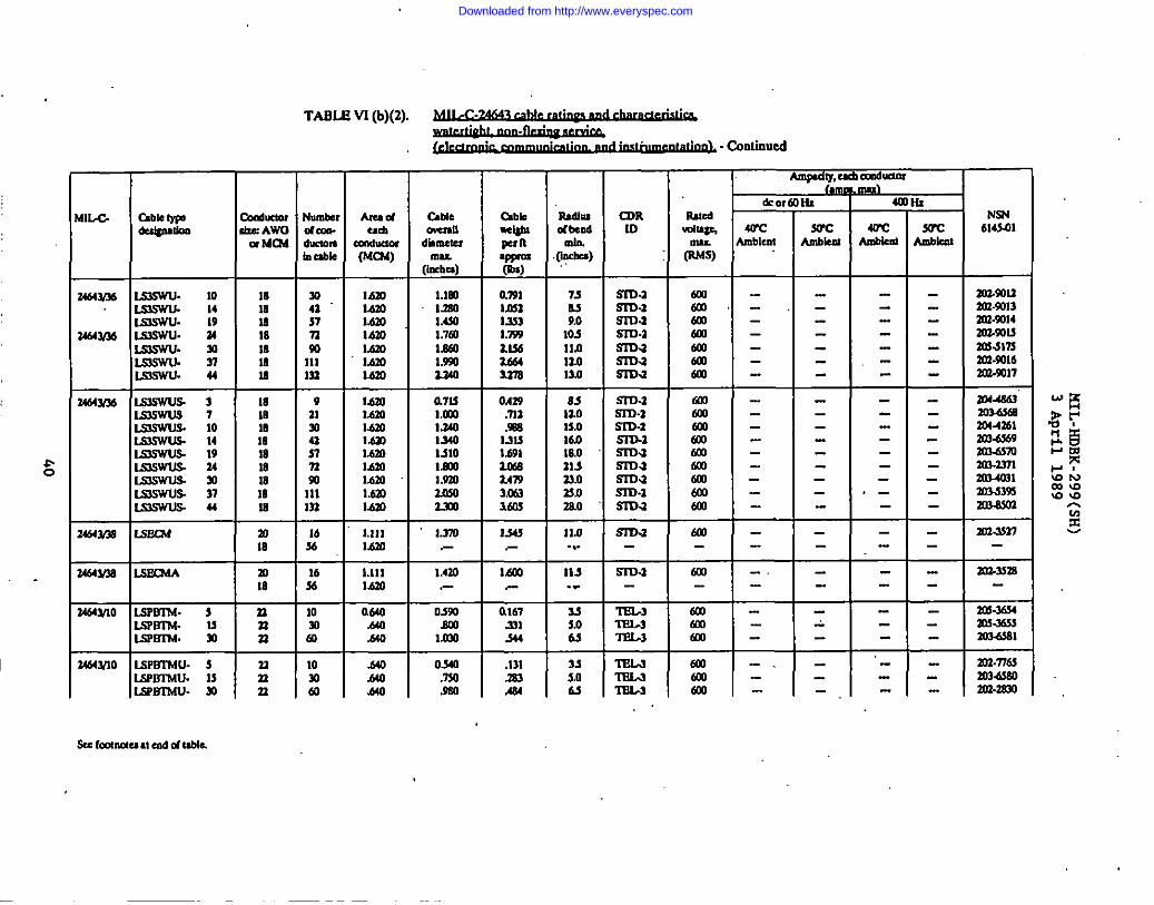
—
TABL@ VI (b)(2). ~. .
. . ..-,.. . !
~ - codilalsd
—
ArudUdl
mldueor(Mu4)
Mm1AMMmMmL6m1.620Mm
Mm1620MmMmLao14201620Mm1,670
1.111Mm
AmQdy, Ud dm
hb@mOlx AWOa Mm
mmIsmmlaIs
laIBmmmmmlBIs
alm
+
+
4!7CSUCtikd hbkm
-..-----
&0,
4WC❑blait
cablemmll
diameter
(I:rm)l.lml.mo1.4s0l.lmMm1.45U17A
a7u1.OM13401s401s10
(kbb-ww n
W&=
awl1.0521ss3l.ws14s6
Is7a
04s9mama
U4u1,691
24W3,003lan
dwi%
(kbu),.
tDR10
SMC6
~w-M41.
(lu.sS)
NSN614.7QI
mXQuml-m13SOS-SQ14202-s0sSm-slnSM-?116an-ml
mi4s6sZo3’6XaX44.612m4%9lm4s70Xua371-1m3.s395Zma5m
Zm-sn
ml-ssm
lm.sm4Sm-smslol&5m
Zol.naml-Zm.zmo
WCLuLicOl
daa.
n&k
—
so4157n92IllLu—
911.muS7n59IllIll—
1656
=liiiRTvu. 19
7-7u9.0
10s11.012.01s.0
SsD.1mamaSm.aSITJmama
6manaaSalsol6m
lsm.14643/36 153swu. m
15swu- soLS4SWWS7
t
------
---_---_------
,--
InJ-u
T2464?.56 Ismwus. 3
Kun’lJs7Lmswus 1015swus— 14Imswus. 19mwu.s. 14Lmswus-31LsswlJs’ 37BlswsJ.s. 44
s-$1%01s,01601s,021sls.oam2s.0
sm.1Ssuam-lSllham-lmaSImSSD.2SID.a
mlmoSalal601mlmmlml
1.9202nsoZml
+
--
----
1..770.-
1.4m
1s4s
MO.-
11167mm
1la. . .
113.-
SJ5.0U
ma
SsD.1
mlluA
ml
ml
tcomlml
+
----
-_----
“_-----
2464YM s.sEa.sA m18
nnn
:
rw64
1.111Mm
a640,640.640
-.
-0s50.sm
I.ml
I 246WI0 LsPm14u- sLsPLnmsu. MLslLtrb4u. so
alnn
10soal
.649
.640&o
0340.7s0.9s0
.131
.isl
.484
35so6s
Tm.JIEL-s‘mlA
.,
6mamam
-,
w rmmtm er,6duble.
Downloaded from http://www.everyspec.com
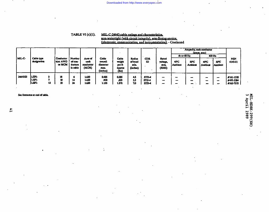
m. 1
I
laWI. 7 MI&% 12 18
TABLE VI (c)(l). ~. .
. . .~ - Cmlinued
NumbNd030.
:=
614u
AmsdCu6
Dm6mor(MU16)
1.620Mm1.620
C!blsCwel-au
dametumu.
(indlu)
O@ma
MM
%J~Fm=(It@
am$Yn
Mn
Fk6hnof bd
&L43u7.n
CDRID
Sm4SID4Sm4
Rued*mga,
0=)
Ampdly,ucb Km61nm
*
N94614S41
#161-lSmt49s-3n4#161.nn
. .
Downloaded from http://www.everyspec.com

,.
Ammdw.ad d-
TABL@ VI (d)(l). ~. .
. .~ - Cantimmd
—
qumhdam
Amdcdl
Xnduclol(MCN)
lSW4.I1O
Io.ml13Lm20s30mA3d636s0,fdfm
.25&b4.410
103WIwwl
?l63LWUmm
13604,110
Io”womsm
MIW
2464343
3464W43
3464390
34643M
34643U9
k or
arcmbknt
137.244m70136169199
133344m7613616s199
i+%-%
TWC40’CAUWUU Aubka
x
WChblcnl
‘N94614S4
(MI@ t)pLt+,.lkm
hrAncuukc Awau Mm
Cable Csbk
=W~r n●W=(0s)
oml.93.m204293M3Sm
Mm
0L40.112.m9330mI&l.939
1.136
0.104.141a
CDR03
.R’Sm.1m-lmm-lMD.1SID.1S53)-1
m-l!n73-1.73D.1S3m.1STa.1m-lS3D.ISl13-1
M33.1S313,1S173.1m-l
bcdl mu(Inch)
0.350Am
.s43AIOAm.910
Mm1.lm
ADNW. “ 3Aa3Nw- 4mhw. 9-iDhw. 14SatW’. 35
12 13m n41 4435 ‘@n 70116 334333 1643163 193
um4133n116333163
an-l$n3030376ml-3314auua3
161410973Io
a22a1aaa
—
2a211
:a
4444
mmKmWlommIwolow
3d3-3313=3316mlwll303.3493
.3DNw- 30saw. 7ssnmv. lm
mm 12m4133n116i33133
.33n44a
3?3163lW
.11m4135n11633313s
m3-3493303.3494303-3493mz.wd203.3497m3-3498203-34W303-3WI
ADNWA-SDNWA-X3NWA.S)NWA-SDhWA-SDNIVA-SDNWA.SDNWA.
.w?4w.5WUW.
34914
:73lm
16141097310
1614107
0s40.480595.6a.740.W
1.130llm
mmmmlammooKmmmmm
—34933
-0.447SllA30Sm
mmmm10J3Km
11183269
1116390
303.d3nman3034373303.AS74
T10 1117 mB 39t4 t4
3034s73m3Aw3msmol3W4W3
SFNWA- 3S970VA. 4AF7qWA. 9SW4WA. 33
1614107
4444
2SM4,110
10..Wmm
0.497%7AmAm
.136
.164mS37
Ml203s4,0
53734.Sin-lm-lS173-1
10W
ma1003
.7374w 3S174w 4S3ww- 9m- 14H7’4w- 33S3NW- 30S3Nw- 75S174TV. lmS3ww. 130
161410973
:cm
113333333
asm4,110
10,3W13moZ3B3052f?o83LWIIn,tm67SW
All.49Am,6m.7&3S@
1.1341.3631s15
L-es.107Mlml39J.?33
1.3011.4S23..?18
S313.1m-l5733.1m-lmm-tS3m-1mm-lS3m.1mm-l
mmmmOmmllam
11!8393169110148174333
1017%4764
11
#5160
1017x4764103139km216
303.3.Wmwo33mz-3w.2303.3m3m3-3wlml.mos101
136w216
110KmKmmm
146174235
Z07..3W63m3501am-wm
k fcomuu II endd ttble.
Downloaded from http://www.everyspec.com
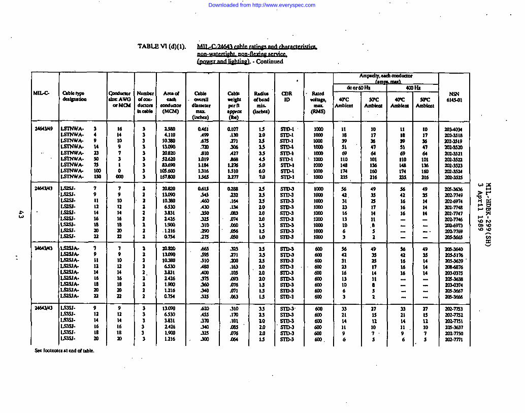
TABLE VI (d)(l). ~. .
-. .(@wdJ@@ - C&uucd
AIUC4U
um6ua0f(MC63)
uao4,1:0
10,330m.wmmamnbm43bm165M7167dm
aRID
sm.1SID.1m-lSm.im-lSru.1mlS3’D.lml
—
I“llloe,#am.km”1 &l@
—
3
:333J13
Rmnu8dbcrdmh
Wba)
M3.0u23M433.0&o7b
>h
L4
—
mImblca
—
11
:m6911014s17421S
&o
WCUbkrll
CdlKm,E AWOa Mc?4
1614109731
C&
N3N6143.01
61Dmm0,
(z)
0.46iAmAn.723B1O
1J119lJM13161S6sF
34643/49 153NWA. 32SINWA. 4IS3NWA. 9IS374WA. 143S3NWA. 23IS174WA. W
75*f mltSl?4WA- 130
24643f43 lSW- 7LQ5J. 9IS.33. 11L9m. 12lSSJ- 14lS3.31- 16
— —
1017%4764lmIllla2!6
111839Mc?)110144174233
.Im371x$.bnM
L2m13102277
1C03mlomammlCOImmmmmm
791012141618mn
7910u141618m21
a1a32z31z
—
az111.11a2
205mmm10.s063m2271Z436Lm
.2316a734
O.-m34sAmA31ml3333103s0.37s
0.2s8232.164.134.m3m4mm6Jno
S3DJSl13-3sin-3S3D.3SI’U-3.sm-.lsn3-3sin-3S3D-3
Imomm
3641,313316131063
493sn171411.8s2
3642161616
49s141414
zm-2m6203-7749
moo
mm10J3mmmmlmo
ILslm.L.QsJ.Ls324-
ls3mA.lswklSl33A-IsmlA.LS2S3A.lS36JA.L=WA-LS121A-LS3SIA.
mm23
-.
246W43 79II11141610m33
m.mommlo.3murn233124161S001.216am
M35%.310AmAm3733m340m
bmA333m340.33s300
m271.m.163ml.093m6ml.063
310.lm.101nm’m6
u2sas20ao201s13Is
33?J7.02,03.0u
sn3-3S31MS3D-3Sr3M.slm3sin-3SID-3S3D-3S7D.3
SID-3.S3D-3S373.3S3’D3srD-3.SIDJ
:mlmomomamoam602
%’ml6mm
3641313316131063
3321141196
4933n17141183a
27M111073
%41161616
n21M1196
493!141414
‘zm.woml%303-36393LWS76
3m-36m20303743m.3%7mi-30M
203.m3303.n3a033-77513m-m37ammoan-mlT
34643/43 Um3. 9Lus3. 12Lns3. 14IS333. 16ls2s3- 18IS31. n
130m65m36313.4361.9011.316
nIs131073
912141618m
333333
Downloaded from http://www.everyspec.com
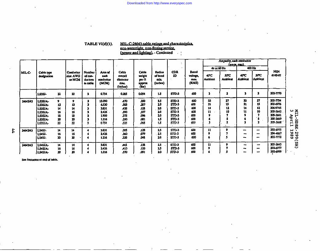
TABL@ Vlfd)(l).. . .
EMIIA
24643/6s
24643f43
3466W43
I I--uable w Cardnctor NUIIILW0a@u6m & Awa dOm-
aMm6 ducmm10&b
SLsl. 7.3 n 3
.s4s3. 14
I14 4
SSJ. 16 4S4s3. : n4
Audcd
Cm6!xinr(MIX)
a734
llM6s30333114U”Iwo1216a7n
lml247.61.116
3an24361216
. .~.calldluwd :
Amodv. ad Omdlldm I
CableCnemll
dhwwmu
(M@
am
t.mmAm35037sX033s
39sm3m
.443Alom
.3$0xl.lm.Jm.0%mlam
.Imm.c46
.1s6
.133
.031
Radb19dbd
da
0@4
L1
3Ju
.ao‘iO3.0M15
2!.2$10
u.‘3s10
slD-3
s3’a-3
sin-3Sm.1
S3D-35333-3-S3D.3S3D.3SILM
sru-3
R’:
Rud
IML
m
6W
2amtol
.falWLa
am601al
601601flu
3121 all1302.m
mF33 : s n 203.m411 21 S 3C0.W7614 11 14 11 m6@76s11 10 11 10 Znc?4429 7 9 7 31M-3M16 s “5 3QI?4493.2 : 2 m.-
,.
11 9 -- 20249759 7 -- 30448676 s -- ml=nm
I 1 1 1
11 9 - - an.35639 7 - -6 s - - 2y-6993’
Downloaded from http://www.everyspec.com
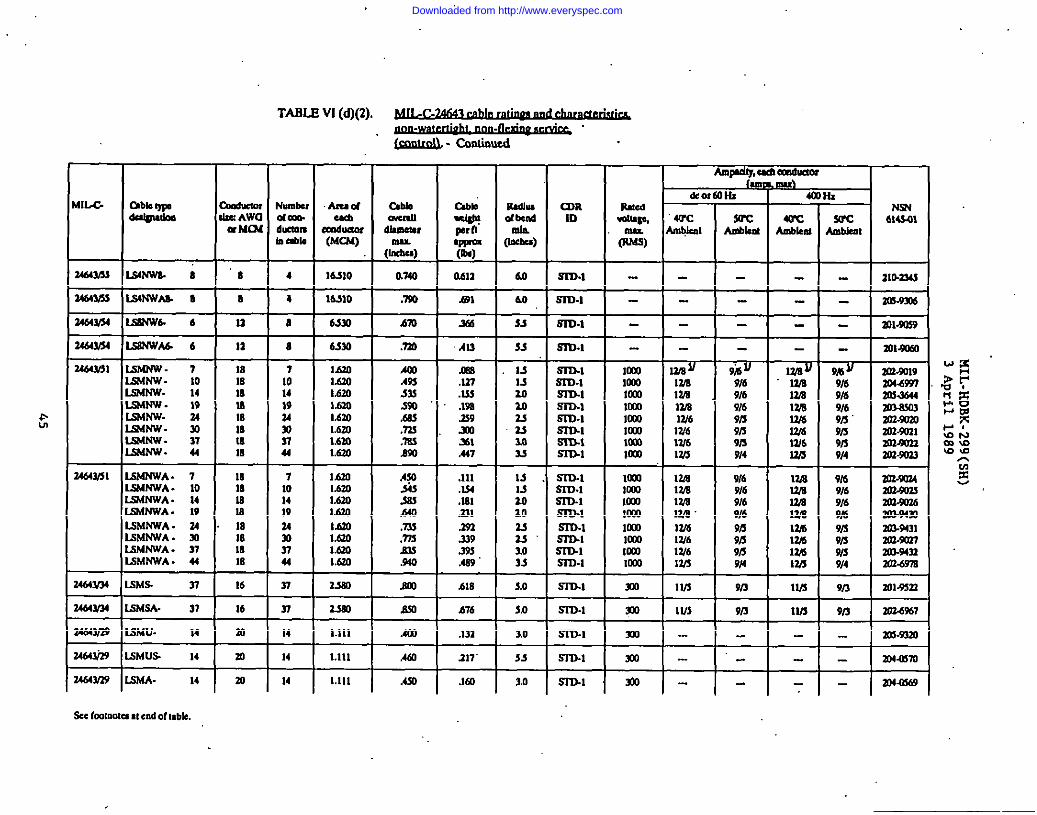
. .
E
TABLE VI (d)(2). ~. .
. . .
Ampdq,a Ca!duum&!loa-
N3N6143431
2m3343
-iG
WCmbkd
rWCbmbkn:
4
WCAubkrd
kaouclozcAWa M4X
*UU,LW04-k!mOn0CW4
Amadma
Xn6uam(MC63)
316kd0kmm9rmu.
(Incbu)
a740
.m
ml
mRm WC
Mkm
34643/53Iww 8 8
R--ii-11
4
i-
-i-
16s10
I6J1O
4.m
6S30
60
60-53
Sm.1
m-l 3QW306
mmrZ464Y34LShWb62464MS4L5BNWA6-6
24663/513SWNW. 7ISMNW . 10L564Nw- 14lsmtiw- 19LSMNW. 343.SMNW. 30LsA3tw- 373sdt4w. 44
sm.1
8 .m 53 S3D.1
~mmalmW6W613/6W3
17A17AmlZJEW6W6W612/5
~9149/69169/39/39/s9!4
@-9169169/69/39i39/39/4
7101419343031u
1J5201.6201.6301.6301.6301.6301.6301630
m.337.333.1%2$9mlml.447
.111
.M4
.Im
.331
.293’339395.46?
S3D-193D.1mlS313.1Sin-lSn3.1S3T3.1S31bl
m-lSm.1m.1Sin-lm-lSin-lS313.1Sr33.1
moolmmlKmlaoIL6mmolCCO
10Mlalo1o11lmla-o1o11IaaImo
A%mmlM3m.7R$050
L34643/3115MNWA- 7
3S64NWA. 103S4MVA . 14lSlW4WA- 19ISMNWA - 34LWhWA . 30L5MNWA - 37L9MNWA . 44
Ut4Y34 Mm. 37
mm1818m18laIn
16
16
10
710141934303744—
37
16301.6031.6301.6301J3301.630ltao167.0
2SI
9/69169169149fi9fi9B9i4
%59169169/6
;:9/3914
9/3
9n
303-WM
303.SV36303.943023U.9431an-xmm3-9433301.6W6
Em 618 3.0 .s3D4 m 1V3 913 13/3 X)1$533
37—
14
m .m h76 S3D-1 m IU3 303’6m713/3
1.111 Am 10
5s
S3-Q-l
Sn34
m
m
ms-93m
mmrn
.-
.-=3=- m
m
1.111
1,111
14—14
117’
Aso .160 3.0 Sru.1 3X b34-c669
kcL=.3tnottialcadoft,bk.
Downloaded from http://www.everyspec.com
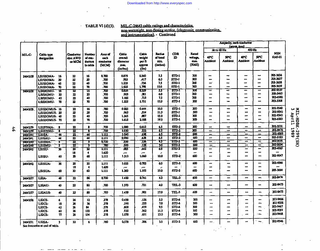
TABLE VI (d)(3). ~
~ - Ca3dnued
AwdY, txbMOduaa I
&Numb Am d abled m8. cad m.xauducmm =@uctu dhaerInnbb (MwI
g-k)
am 0s73: mm .9s440 .mo lalm .lm la
ad :X0 .m340 .mo 1.1s!m .ml 1s.$
de0,
&c❑biml
C&lb=Wpnqfrlm(IL@
0.?4uA17.7%1.%6
.391
.no1.751
0.444.314mlZma
-0612
~+
v35K-~TZii-.-30@
am
Udh,dbecdMin.
(Ircbu)
amm
Rmcd.dls*msx(N@
W---.3W7-- an-m-- m3.m39---- 3oi34d!----
SJho7s
+607510.$
10311533,0193
Js_
*
~~
m..
10,0
Sro.1mlm-lm-l?mxrSIBlS3’Dl531M-m-lSIT34Sn3-1m-l
3mInm
-%-mlm40J
WIX0mlm
+
BISOM- 16 nLsls30tAA-30 33LS1S3063A-40 33ISIS50MA.70 n
L9S30MU- m nL9S50MU. 40 nL9S30MU. m n
m mm.imlm
mm .mo 1.633
sin-2~Sm&
sm3-~S3D4
sin-3
S3D.2-
S3D-3
%iEi
aEL3
‘3-w-3
1 -- 1 mms9s--
I -- 1~
* =1=1=4 lhm .-So 1.111 1310
32 1.111 lamL6m ,-
: I.Ill 1.%0
60 am l,4m
60..
10.0
4n
4n
ml
m
ml
doo
_
LW.UA- @
ls3A- 40
I.103
0.741
.731
.501
ISA(3. u
Is3Aus. 40
Lszcs. 6L52cs 18Lmcs. 41IsKs. mLs3a. n TF
60 ml urn
80 .703 L4YI
11 1X 0,430% 550M .37s EmIm ,278 .930134 xi% lmo
I17.0 Ko m3464315S
34d4mlse nmtm
.136
.?35A19S3h31
.306
S57.09s11-7lln
33
SITMS3T34S3D4sm4sm4
537).2
-.
.-1 I 1.
- .- ‘io2Jm46lssA- 3 33Imlendd mbk,
6 .X0I
osm
Downloaded from http://www.everyspec.com

TABLE VI (d)(3). ~. .
. . .~. COndnud
Amprhy,eM6an6Lmm
1~
40CAnblml
-
.-
&0,
Wc
1
WCbnoucmrZe Awaa M04
(ml,CwUauAnew
J&)
0,710Am.5U310mMm1.W31.450I.mlI.m
urn.660m.930
Lc40:Lnol.mo13601.5301.?40
cZ3RID
RJkddip,maw)
&dUdl
Rlduacu
Ix!lomtlgbt961hw9-(Ou)
rumAX3618.m51.0321.3561s431X$3317
o.lm25s356SE.733.%31,1761.459
%
Rrnu9WxndmlnMrJ)
WCdcu,.
nCAh
m64Y31 L5mA. 7Lsa3A- 10W.sA. 14Is-s& 19Kl.9A- 34m. mLu5A. 37Li3.5A. 44
333333n3333333533
14m‘m?44am7443la
T14mn2448m74mnl
anm.mmm.ml.ml.m.ml.momm
.ml
.ml
.mo
.X33
.mo
.mo
.m
.m
.ml
.?33
435.06.0U747511s13.0145
F4s5.0606s73soS790mo
Sra-aS3D2m.2.S3D-2S5D.1,Sm41mm-aS37M ,ma
=SID-2s3m-267n.25373-2S3’73.3m-2
.xm-l
633mo600Co6L33ml
c%ml
593ammmotcamtooCaltulml
-,
TL=3A- 61
1464&31Limu. 3Is.5u- 7Isnu. 10
14a.LQmJ. flmu.K36u- Z4SSU- 44lS13U- 61
nn33
.n3333
:73n
rL53mm.LQ5us.ls33uS-LQ6usIS,SU.SEi36usLs33usIs33usIs16usLQ3us
34643,01 3710141934m374461
33nn33n33nn“n23
6
;38?a40M7485m3
.7LW
.ml
.ml
.ml
.’momml.aw.X0.mo
Osm.730ml.9ml.lm1.’3701.3401,A401.6101530
Ola..M7A9d.n3.91s1,191lAmL433
3540
7JI83110ml13Jlm16017519s
m-zS3D.2m-aS3D.3m-a6T0-1SID-3S3D.151D.2Sr33-a
am(alammo630ml693m
%’ -’
-.
!-
-,
Downloaded from http://www.everyspec.com
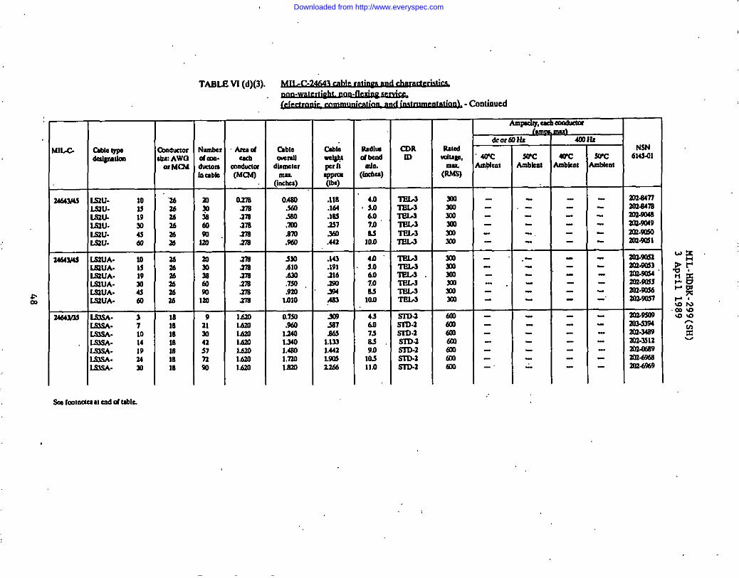
➤ ✎� ✎✎�
TABLE VS (d)(3). ~. .
I .,.~- Ccm(inucd
I I Ammdm,exba@lda—
lumblIfDm
AmadUch
Wcducla(MR4
cum.27samns276am
.27sm.27sm.27sam
14201.6011.620MmMloM.701.620
mw 2’&%Y
So’cm14eat
NSN6M3m
]
CaMi~Cppm(ox)
.118
.164la!.2S7‘WI.U1
?,143.191.316mm46,
.w3SS7.S6$ I
1.123MlLs%Um
I
Sadiudbcldda.:tiu)
mduttmw AWOm Mm
“26Z67626
:
(/3s)0.480ssomlnm.962
-00.610
,7s0.9201.010
0,7S0.9!.0124013s0L4s0Lmolmo
2034477m3a476
ma.9u4921m9aoam-ml
34643A315tu- 10153u. lslsau- 19l.s3u- W
4.!Hi 60
4,0S.o607.0ulao
4n$.0607.0u10JI
m173L-3lT31AIE183IEL3‘s’aL3
=T‘KL-3.
17U,3 F,....-Sm -m -WI -m -m -m
-iii-tJn -6o1-talKma-a600
ab643usLSIUA. 10~UA- MIS2UA. 19lSUA-IS3UA. :ISUA- 40
3m.9m
Zo2.msan-ms6
1-1-SI13.3S3D-2SID.2SSD3SID-zSIDJSns.1
43so738S9.0103114 30M%9
Downloaded from http://www.everyspec.com
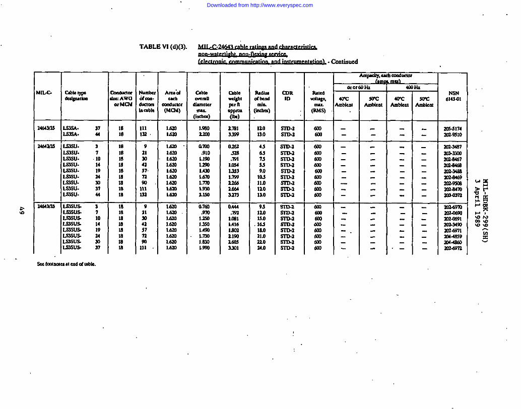
?&
. .
TABLE VI(d)(3). ~.,
. . .~- COnlinucd
CDRID
SID.1m-l
Aru”dcub
m16uc10r(MIX)
Am@y, Cu6CwAmor-
4umbci4ml.!IuKlmsabk
ildllmd bed
[I%&
de01
ambknl
&_(u
sotAuo4ml
la+
4otAmbient
7
sowUwuo
Ill.x/ tib ~du@dm
mldlKmrw:AWOorMm
Cablemmudhclwmu(I”dlu)
1.9802.2M
able+b!P n.ppm(lb)
17813399
4wed NSN614541
ms4174W2-951O
G(RMs)
6C0al
1810
Illm
IanMm
noU,o
464YM Imsu. 3Lmu. 7Imsu. 10lmsu- 14lssu- 19
1sIs18181s
:16IB
MatallMm1.620lAZO
;%l.lalMm
16201.67JIMm1.620Mm16201.6Z0Mm
am.910LISQl.lxl1AMMm1.’7M1.930l.lso
0.761.m1.2$0I.lwlAWl.mImn1.9$0
O.wm.W1mu1353i.mUbi1M4m
0A44.mlmlIA16
RZ&nw]
436-!7-$M9.010s11.9no13.0
9s120I.wlti16.0ala21024.0
m-lSID.2SIII.2maSID.aSID.1maSITMSIn.a
SID.1.SID.2S17M
aSID.2SID.2
mlalalmml
zlmKm
dmm
E6Xm6QI
ml-34mloslmzola4672@a4tamz-14s9m2-S4@a?z-%mKwM7fJall’03n
Zo’L69m
anmlan34soW2mlm14eS9an4Sm
15su. 24LSwu. -wI.SSu. 37ISSu. u
4641nJrLinusLmu.sL5suslsa.ws.LinusIslsus15susISSIJs
371014lVuw37
181818181818Nm
-.
.-
6eebmu31uum6dubk.
Downloaded from http://www.everyspec.com
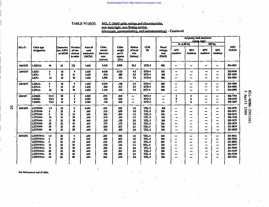
-Am. m .,,/4, /., ,,,, .- . . . . . .-14 -..,,1 . ..--.I “1...... -.:..:..
. . .~ -COnlinwl
7-—m
m.c Imsuclo. AWCxMR#
<.mlwdcor,.MmmDUbb
AIUC4ad!
am4uaw(MC?.6)
lbdiludbmd
❑hWw
cIIRID
UUC6W41q0,INLmum
mcl-alldlamcw
(l%-)Z310
ohmalo1.090
SucIIr6klll
614W
U6w3s
M66M17
S3SU3. 44 U 132 Mm
MmlaL&m
S3D.3
SID4S3D4Sriu
6m
3mmm
m.4e61
303.96s233.333sm44364-,
—sm. 3S3u. 7.9U. 12
1818Is
9al36
UCMm?
W319
&WIA. 3SUJA- 7S3UA- U
mlau
-F1616
9‘s1%
-i-13
MmLAMIAOI
%3380
odm.w1.144
ms.lm.103
.1=mm
-m-m533
6-m4
S1734
m-ss3n-3S173-3
X4486!304466
aw7164‘sceJ6smw637
-i-66
—s6au- D13suFll- D3JSMRJ. ’373
U64m
164Ysa
S19MV.S3PNW.SrPhw.sT9Nw-smw-S3?mv.S3QNW.Sm4w
S3TNWA.S3ThWA-SSQNWA.
M3s10ISmw40
333323
:nnn
n
2nnn
:
3610’30
:m80—3610303040mm
0640.640.660.640Am.660.660M
.640AM,640.660‘t-to.660AmMO
333.310.3s:AmWI373.mo.la
m.mA13Jm560.62!.mMS
m 10MM312020u10
Mlla1sMlo20u3.0
17m377W3
T8L-3T7L3nSL3ll?b3‘nil/3
TEL-3
n?l.s
‘n3b3
LU774?3
m30JIllmmm3mm
L?(CImmmlmmmm
m-xlmX62471m-m3Lt-7slBbn-33n3n3-3674ma81930148M.-
—
.IM
.13n375333.S38
033m3
mlasal2ol-9x6W1.8S?3zm.m67a31-934n2018349lm.moZIM-ml
ISIF’tWA. 10IS37NWA. 13LSIPNW’A.nLS3YNWA. W~NWA. 40
.136
.161anm3m
Downloaded from http://www.everyspec.com

u?.
TABLE VI (c)(l). ~.!
.,~ - Cmimo3d
NW6143JJI
233AMS0
#m&m
WCnbkmt
lm-.
i—
30’Cmbkat
73
CaMea.hmlldhmeter
(1::-)
1.491
a4s.460Slo3m.mdmSt411.430zlmMm
o.4a33s4.&n139313103.CCQ
O.11o.&o.K13ml.9531M3MmIblolf.m
MbUighlpcrfl.W(08)
Mm.-
alol.117Ma.173.w3393m133928114-$31
RI’M.16J2911210
E
0037.143s].769M131sm3L933X6
Smedkdtlge,.mw
@a
Nl,c- oductnre Awaa MU4
AIUC4euh WC
Ak.km
n
mMkol
m.-
Ilmr. dbmdmh
“(MU5)
9.0..
u643n
1464Y3
Nt4311
WSF. 4 J3
1614u9147s
z4m
31—az1
;a2a23
T44444
mm33SS0
asao4110S3309M14.om33910
S4.noLnmN3s03
m4.1109.004Z11O61.X4137.ml
m~m61X4tm.tmmmrn3J2.7013mco3691.COI813.703
L3DHOQ- 3M73HOF. 4L$OHOR’ Sls33HoIa 9WDHOP. 14LSOH09- 13BHOP. 3015DHOP. 83WHOP-KDHOF- %
UFHOP- 3ISF360R 4lsF160K 9l.sFlioB 41lsFno9. aISFHOB 133
Sm600fmaml@n
%mml
603mmoml
.&’armml6036006mml602ml
33”S34130.menco1693334n
73336w93163
mBS162m32339160365sm3
193s333a.Jo
21n37u34n
:27s7m
21
2
:n
:2334363
16al34nS3MO—
:L33363
1733313446
11.017naln
4n435s11.0no16~
-
:347330143
1614941to133
N6w3 WOF-KSHOBL53HOF.KSHOP-LSSHO?.L3SHORLS3HOF.lssnoP.LS3NOF.
333to3303mno3m693803
11111III1
M3Jso7JIS.o83113nfl13s
363W6363m6s4m
MM?/l1 lssw MO 330
161412914
3mmo
254fJ4,11063309.04314J3m
I.lm
0.430.mo330m,7s0
L7a7
om4.136.179ml.366
66
3.54,04.75,060
mo
mlmlmlm6m
1—33333
1733313446
303a643m-%36m3a433034m6a73&67
L931ioF- 3ls3noQ. 4K3HOP- 6l.slnoF- 9Lsr360P. 14
Sm kaleacsatcudd lb!.
Downloaded from http://www.everyspec.com

I1“
TABLE Vl(c)(l). ~. .
u-MILG ChbbwL?ulgulkn
14s4Y3 ls31ioP- nIs3nos uL9r340Kl.snioF. ELsrHoP- 4mIsr330s 3mEJHOB an
SmImmc$uuad C4ubla.LnN
Tkukmr NumtczZCAWO dcon-W MLn4 duclom
loram
1 31
: 3lm 3400 3m 3mo 3
Amsdcdl
Cmduaof(MUdl
aa.9104L11Ouxtm3321m4135m3m.mlfOmxo
abkmu’dldbmcternub
(Imhci)
am1.3301s207.240m3,100Iuo
__14_Gob RduI COR :-w ‘Wbd wparn
(hdla)‘(--
MM 7B SID-3YSW 10.0 SIDJyz4m 13s sl’03ym 18,0 STO.3Y43m ‘?ln SllX3y7313 may7.9SI % S3D.3J’
600mlalmlbm6mml
em
arcmbkm
m93197mmmlml tl
WC4LTCWCIdeal -km Ambbat
u ‘m 4434 93 06IB3 197 Imm4--36$ m.! 36$
3! 0273E... -
Ns74614SQ1
m3.06mmMhb9m3-w4mz.mmmomZm.lom
Downloaded from http://www.everyspec.com

nL.c-
L96iHoF. 7lSdHOF- 10LSM401L 14ISUK4P. 19IS.4HOR 14MMHo& wISIHOP- 37UMHOF. 44L9dHOPJ 61
.3dJmxm AWOw NW
161616161616161616
. .
TABL@ Vl (e)(2). ~.,
—
Iumbe,*con.Iklclm1&l@
—
710141924Y1374461
AmsdC&b
mdvdot(MC64)
Ma9mL760
2s0U80U49UwlMm
-- Continued
Cdie
mu(Indw)
Osm,s6$.63s.m.7)sal!.9Xmlo1.173
4Xbb=WPIn*P(It@
aM4.w.4mwAS7341.674.m1.1X
4n4s5.953
.:7s6.09s
‘mn
RSID.1Sm.1SnMSnMSlnlSnblSI’o-l
I Ampdiy,esA
T&or6
~w ~Ambiuu
WV
,@l
z lvlml lVJm 11~too Ivlal U17Km Ills
.tio 1U4C4W IV3
la
SucLuwlu
9/6 u
9169/69/69169/69149n9n
L400
WC&km
,~u
llnIlnU/lWIII/llul1114lln
k--b6141.61
1=mbkal
916uZ03-SS4
:: m-1’m9B Im.n939/6 ana’wl9/6914 201x1939n XOJ3999n 2m.m4
Downloaded from http://www.everyspec.com

TABLE W (e)(3)..~. .
. . .~ -Continued
Amsuhy,CsdCcm6uctor1#4Jn
WCAnsJklu
*—
-G
Wcmbkm
rWCmbkat-L
Number Au ddaa. eachbin” Cmduamlacabla (MC7A)
21 1AM
NsN6143.01
CableOvcmudhmdcrmu.
(incba)
LQm
abb=mpet11VP=(lb)
0.618
mlMOJ3n
RJdLud bedmhw)
C73RID
RudVdts’e,
(%’6103-?A91==t===- 10 SSD-3
srLP-3SID-sSm.s
-,
-.
p-mWIMlV-Is
Sn-6
-,
T4n2n
4%
m-
s
m’-03Y1
42s
203.93373oxrn6WMn7
14643n umcxPP. 1LSOCOP. IsL5moP- 1
al18Is
1818m30In t
a LOma Mma 1AM
1 lmo4 L&m5 1.0206 lmo7 Mm
O,noX3330
.6603103s0Ams%
$X64X4 LsMms a
lS6Pm3’ 4msm$ 5156PCIJS.6wms 7
34643M lmAbsoP. s
34643n IS3CQP. 2
a4643naLS3’SOP. 3s
E 10lssTOP. Is
Z4S4Y13Lslllt# 24
IS3’37S6Ls3T3m.8Lm’3Rs- 10IsPslm. 12LS17’RS 16
.130
.167,091.lm.337
-0s9
.s67
.11sAMm2.53
.333
.381MA74s]All.m
7m-s3a6m3xns303-34M303-7A3Eml.zm
SPL36PMSPL-3SPL-3SPL-S
ssq.3
Srs3.s
TEsA
17?3A3
S3u.1SPD.1Sm.1S3D.2SrD-1m-lSI’D.3
mlSmmmlsol
m
~
-.
4,0sos-$SJ
Lo1.1M1.7.103.03.3
maw
30M3S3
34
18
mmmm
+-+=
Jm
36s
A.30ml.701A30
.s80
.740
.sm,s93lmoI,lm1.190
‘-.
T6 1.030to mmm Lom30 Lom
434n4n4/03
-.
S14SIYSnsn
—
T4 lmo8 lam12 10.23
1.022: Lmu34 Lam32 Lom
n30m302030m
T4 l.mu8 lam12 l.om
mu: Lmo34 Lom33 Unl
lAn7PsA-LssTnM-L9sTnsA-lsr3nsA-LsrnLsA-Isn7ssA.isnlssA-
2468101216
w20mm3030m
0.730.’mlmlID60I.wl1,1s01140
397.394,4’m3213S7.s0s.764
455,0S56.S7n7,075
S3D.aS173.1sm.2SSD.1S30.2.s3n.2SID.2
34643n3 ...
-.-’ .M3.6473
LLY ~a; k sm.30rm4; nurmfmcfmi
w 6143.01
Downloaded from http://www.everyspec.com
MIL-HDBK-299.(SH)3 April 1989
5.7 Cable classification (MIL-C-246401. Cables specified in MIL-C-246L0are listed in table VII under the following general classifications:
(a)
(b)
(c)
watertight (with circuit integrity), non-flexing se-ice:
(1) power.(2) control.(3) electronic, communication, and instrumentation.
Watertight, non-flexing si~ice:
.(1) electronic, communication, and instrumentation.
Non-watertight, non-flexing service:
(1) power.(z) electronic, comqmicatiOn and instrumentation.
55 ,,
Downloaded from http://www.everyspec.com
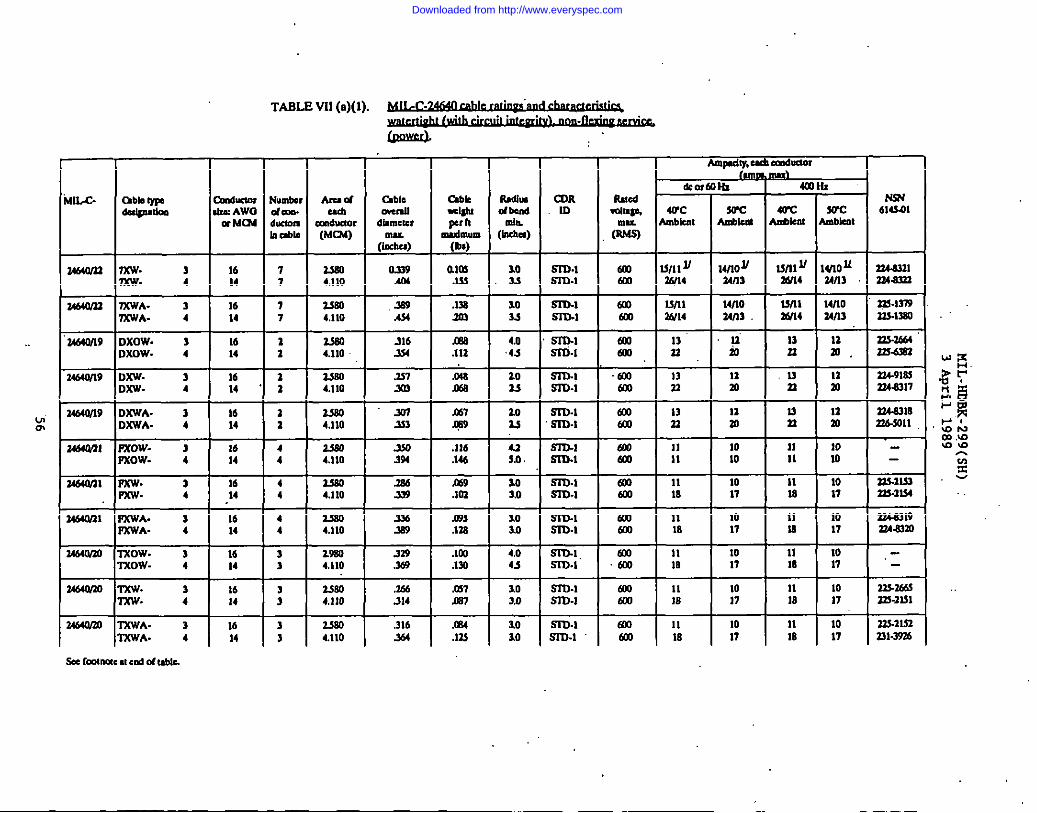
TABL@ VU (a)(l).~. . . .
. . .
L13QdAmQadty,d Ca@JdOI
Ikofmlix“MUX- Chbb133M OxMuuu Numbs
&4@mk10 ti AWO dram.m M(M @xlOll
b&b
a4640n3 7XW 3 16 773DV- 4 14 7
34640M 7XWA- 1 16 77XWA- 4 14 7
34640n9 DXOW. 1 16DXOW- 4 14 :
34t4w19 D~- 1 16 2orU- 4 14 “ a
Hz
mAmbkm
Amac4Ucb
mouctor(MC24)
Mm4,110
3s604,110
&3m4.110
3sm4.I1O &
t3bk Ra6b=MI dA&pan
yb;m (Inc6a)
alm %0.133 .33
.133 30m 33
m 4.0.112 4s
,Om 20JM9 3s
CDR10
R#cd NW614341WC 3WC WC
Allmnt An4Jkn! MkaLwwdldhmctcr
Ulu.(Lwhu)
0339.4a
mlmw,
Sm.1SlT3.1
WI: 14no~ I Unl ~wu an4
32463313243333
rn.lrn3a3-13m
6mal
.339.434
S3’O.1Sn3.1
S3D.1SITM
Sln.1m-l
cm03
mo601
M/lo34n3-12w,
33s7.m43zK3a3
>16.334
.337303
234-91=3ua317
ml6m
laa3
w“ 34640n9 D.TWA- 3 16 2m OxWA. 4 14 z
2444JM Pxow- 3 16 4Fxow- 4 14 4
34.540nlPxw J 16 4Pxw. 4 14 4
34nonl F%WA- 1 16 4F%WA- 4 14 4
14640m3mow. 3 16 3Txow- 4 14 3
3464vm Txw- 3 16Txw 4 14 :
3s04,110
m4,110
3s004,110
“.W7333
.A9J3$4
.386339 $
K67 m@9 u
.116 u
.146 so.
.t69 10
.103 10
.09S 10
.138 3,0
.tm 4,0
.lYI 4s
S3134SI134
Sin-lsm.1
Sn3.1.$333-I
mlKm
6Xa
faml
11m
1010
1017
324.8.7183343011
343.2133n3-3134
334a319334a3m
3s804.110
29604,110
S3D.1S1734
1017
1017
36-9
329.3C4
6m
.%JS173.1SID.1
Lmo4,110
?s04.110
.266314
.316
+
ml 10.m7 3,0
.m4 10
.Jl! 10
m-l ml 11 10 11 10 32723635-ID-I m M 17 18 17 3n-3LM
S3D.1 mo 11 10 11 10 327.1153m-l 603 18 17 m 17 nl-mm
I I I34640/mTXWA- 3 16 3
TXWA. 4 14 3
* fmtnaestendd mbk
Downloaded from http://www.everyspec.com
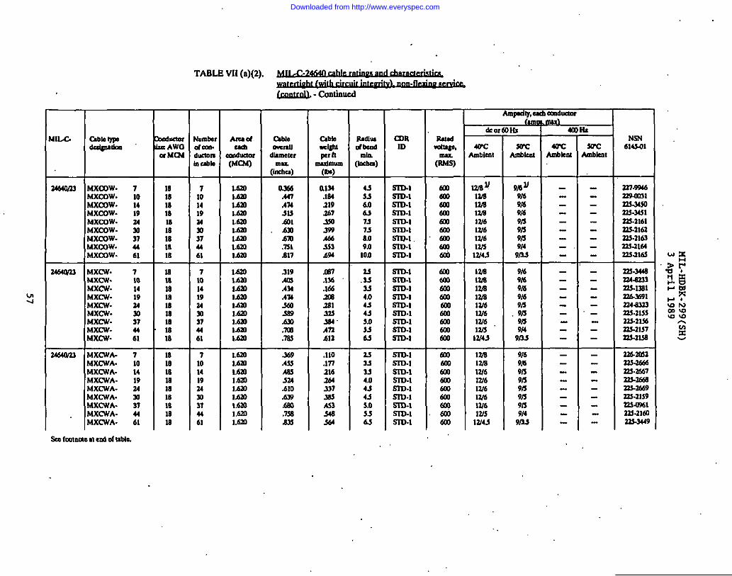
.
TABL.@W (a)(2).~.,
-- CJnlinud
—
amID
Atudad!
mtduam(MCM)
&m
4UCLmbkst
a—
3UC!mbkat
~blaIYPBOcdgmdm
‘4Uu.ba,dam.hclmlhAll@
au.Luualld!helcr
Cabb+bIp hIndmun(en)
a134.144219am
N3N614S01WC
Ambknt
(1%”)0x4A47A74513.601Ami.m.731.417
my
WEmU/a12/6W6W61W5W4S
~~U9/69/49/69A39/39i59/49/3s
uxmw. 7uxmw. 10UXCOW. 14uxmw. 19Uxww. 34Wxmw. 30uxmw- 37Mxmw. 44uxmw- 61
m181818181818la18
71014193430374461
1.630L6al1AM1.6231.620IL&aMm1.6303.6m
43S3606s73758.o9/1Ion
s3m.3m-lm-lS3m.1s3m.1S3D.1m.1m-lm-l
6006m6JI0WIa601amOqam
359A66333&w
3464M3 !4X(w. 7Uxcw. 10Wxcw. 14$3Xcw. 19Uxcw. 34UXCW- mWxcw. 37$5Xcw- 44L4XCW- 61
blXCWA- 7!4XCWA. 10WCWA- 14UXCWA- 19$4XCWA- 34t5XCWA. 30tiXCWA- 37UXCWA- 44
U1818la1818la1818
ii-101.9181818Mm18
7101419343037u61
71014193430m4461
1.630MmMmL6mlaMm1.6301.6mL6m
1,620l,mlL4mMmL1.a3IhmLao1.630l.tal
319AmAMA74-ml369Am.7X.m
364AuAmm.4.610.6mful.7s
M7.1%.165la
u.33334n4-7435.0336s
Sm.1m.1m-lm-lSID.1SnMS3D-1mm-lm.1
amammoWmoCalalm
VA13A13AmaW6W6W6Ws13/45
9169169t69/69/59/39/39/490s
U.4
mlM
S373.1S3D-1Sm.1m-lmm-lSID4m-lmud
ma600601m
%
34640n3 .110.m216144-737MA53
17AW913/6W6W613.6W6Ws13/43
9[69m9159/s9/39/39/s9149/3s
S43344 63 sm.1IMXCWA- 61
* Immue u erxl04I&Me.
Downloaded from http://www.everyspec.com
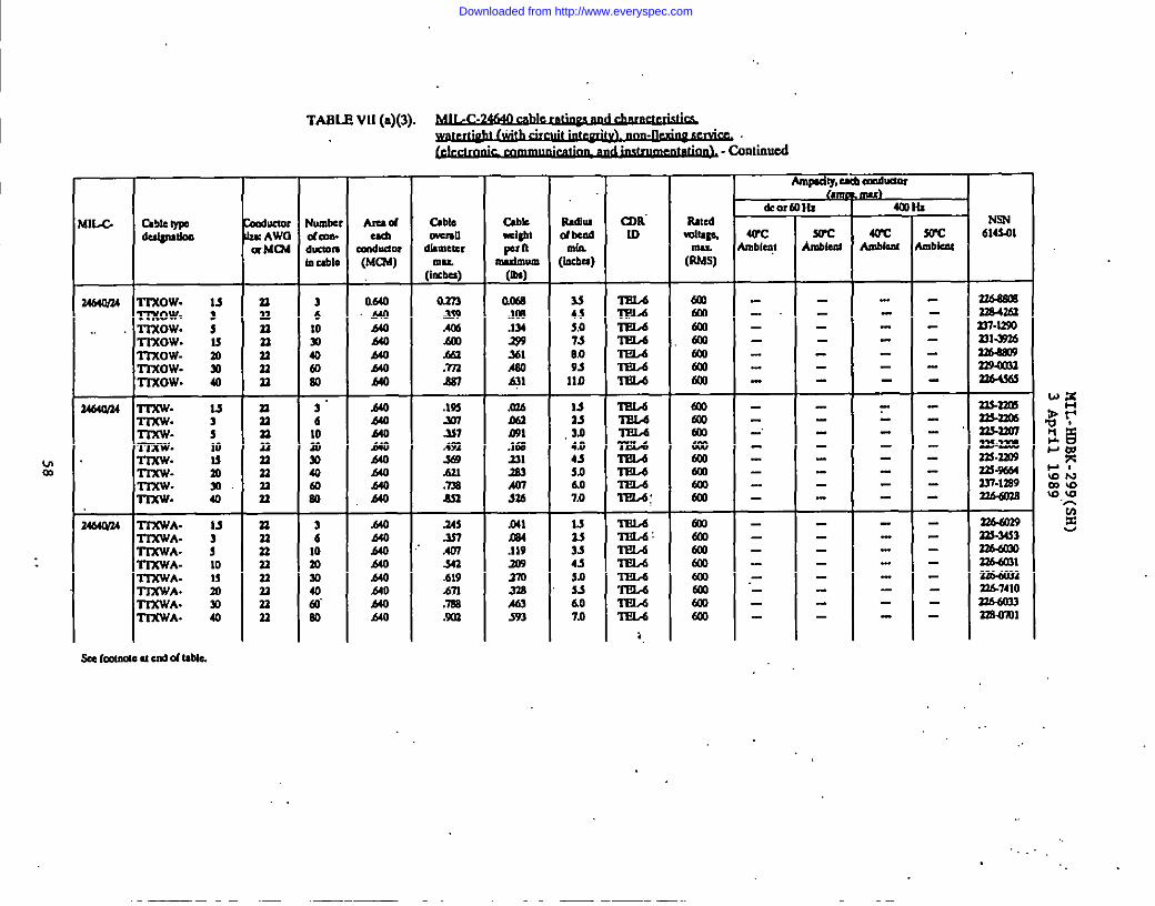
TABL@ W (a)(3).~. .
I . . .~ - continued
Amnuh.ad!cm6ne01I(km
X&la
WCb6klo
hunter Amad -bledam. Udl WtmuInclomOXWJUSOI ditmel?,,UbIo (MCM)
(i:&)
3 Q640 o.m6 A40 m10 640 AMY1 MO &a40 MO .&a@l MO .m60 ha .4s7
3“ .mo .1936 440 Y17
MO J37: MO Anw MO w40 640 .67.1
MO: ,640 z
3 .640 .24s6 MO .33710 MO “ Ao7m b40 341so Mo .61940 #o i.n~.
MO .7s3en MO .W3
MIW ableIn106u@’ukm
amUdgbtpm:n
IMdmum(0s)
ma.Im.1s6299xl.460Lql
Iumuld bmd
[I&)u4s5,07s009slln
CIIRIO
ImL.4
IEld
Il?4-A
T3fL4
RmdWluge,
CNt(Iu.5s)
NSN6143-01
dKlOlcAwaxMm
n6.49mn64zfan7-lmnl-mlln6Jmo93w#33nb4s65
246W24 TrxOw- 1sl-mow. 3-maw. s-maw. IS
n32n33nn‘n
_
-.
-.
Trxow. 30mow- 30mow. 40
1
mall
m.nol
z.=Zn-stda.%lm?7.6az6
2464W uJ510u30m40
nnnnnn
;
rnnun22aaal
X06&aml.1632s1X3Ao7X4
mlCM.119209370ml.463593
13as3.04.04.75.06.07a
1.5’333.s435ns>6.07.0
‘midmLdlm.dTEL6
TEL4w‘lTIA:
TEL417L4‘m?L6ml.6mo,dTt56Tel/6TEL-4
uco
rT37WA.T3%WA.lTXWA-TS%WA-TSXWA-TIXWA.ITXWA.Tl%WA.
M amColWIWJ@lWImm
“-
:10umm40
,,, .
.
Downloaded from http://www.everyspec.com

TABLE VII(b)(l).~. . .
—
Rioon#bend❑bbLuba)
COR10
Arudcad
ccdduacu(fAaA)
144m6~w%mu.
(14Ms)
N3N614S01
z
arc❑blau
rdubn NumbeI,AWO ofCm.rMC24 duclclll
h&b
13bleC4u811
mu(huh-)1 x
i-
3464WM lXSOW.Ixsow.Cmow.Ixsow.
3464M7 2xow-2xow-2xow-2xow-2xow-2XOW.
3212 a640MMOA40
m372mmmn3
tialw2W7XU33143s922$-3231
224aMl21492m223a932Z23a933mawZn-9w2
0314SalSM462
4,0AO?Jl6.0
-4s6,074as103Iln
(mta6U26m
S4mm6mSoomml
+
23 1432 m33 30
m 1126 24s24 43 Z-.6
18344160n
26 2426 Im26134
Tz 62333 :33 3an 2222 4223 m22 74
2XSAOW.SxsAow.2XSAOW.XiAow.axsAow.3X.9AOW.amow.3XSM3W.
3710141934w37
.640440MO440AM640A40A40
A373.!0.481.742ml.9s21.020W40
.U32s3
A42S4s.730S2.s971
53
:90io.o11s12s12.0
mSooalmlm600Kslmo
-.
-.
%m
$n 6m 14n m
23 622 1423 2s
22 6m 14m 3418 2818 m
m 118 618 14
18 1
.640640h40
.640640.640
O.sdA93691
A46.$47.741
.112
.195304
23403s
3s4/3m
.SSD.2S2W2SSS3-3
.S3U.2m-sS273-1
602aa6m
2s23032ss-22032%-IW4
2z4.9m2234m3332$-1293+-l+
------34640/U2XSAWA. 31X9AWA. 72XSAWA- 14
.1482A4A43
mo603@l
- ..
1--1-3464W162XSOW. 3
2XSOW. 72XSOW. 122XSOW. 192XSOW. 20
2A64W162XSW. 12XSW. 323LSW. 7
MmIhm1.6mMmMm
tdm1,6m1.6m
323.636.344101011’M
.327AolAmm1.2%
638,010s13313.$
sr04s173.2SK3-2S273.2m-a
@m201mlml6m
334’8211234.0212324a313224-9181323-1376
mmmaw?222.s947
.-
0.7.$8All.617
0s03.167Jla
104.03,0
.SSU2SISL2sTm3
fcoalm
mo
.-
13464LV1612XSWA- 1
seefmtnrned cd ortable.
l.dm 219’m94.s69 Lo SS7X2
Downloaded from http://www.everyspec.com
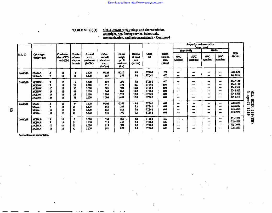
TABLE VII(b)(l).. . .
. . .~ - Conlhud
—
AIUC4Udl
mducm?(MCbS)
lb30lbal
lmMm1.630L6mMmMm
16201.6301.630M30
1.6301.629t.620Mm
Almu4tY,eachCc@Auulndimk
SwcLmbkm
3VC
&o/
m❑blmt
Nm614301
QMCCwmlldbmheamu
(IrKhti)
Osm.467
S39.nl.9Xma1.011lxm
O.XE.669.s63.941
-$33.718.913
~bb=Wp nmdmum(09)
0.31031s
.371m3.’7)3Ma1.127M69
Rsdiludbead
[la=)CURm
brdllcmlzaAWCm MUi
nubb—
b14—
92133
4n5.0
in43110l~o13.016.0
S4D-2Sm.1
72349!s33MM0
33441s3314-91m334a314aau.$?24.9316334-91S4
W933349SI2’LWW43n36B3
M18
la181018InIs
M18Is18
T10In18
—
3464MB ntsmv. 33XSOW. 73XSOW. 1033KOW. 143XSOW. 193XSOW. 34
Sm.1537).2SSD4SKD-lSn3-zml
5SD-3SID.153’s)-2Sr33.1
S1-u-lSsls.aWV-aS3D.2
mo603mSaoam
7
41
m on37.413.m
.333.As6:Wl873
4n557.07J
T537.07s
-.-
m0
3n.3ml3m.4361Z?3-M63333-M63
34MM8 3XSWA. 33XSWA. 73XWA. 103XSWA- 14
- ICLUU4Cu ad cdUble.
9alm41
Downloaded from http://www.everyspec.com

. .
mi-
TABLE VU (c)(l).~. .
- continued
TFFMlIX- (hbla~ liardudorNumberOetl$lUlkn dzeAWCl dmn.
w Ma duclomillable
14b4Wl DX. 3 16 2DX. 4 14 a
F=R--H+
mArud&
Cmdudor(MCM)
2s804.110
aso4110
Um4110
2s404.110
LwJ).4,110
2s804.110
w*
Q241 Omm7 ~
alm4 %
al .063 as?40
=++
.261 m inSlo m6 2s
311 qln% 2s
Ampdly,cd!Ccmdulor
lk0r60NI 401HZIXIR RJIUI NsNID : - 40’C sow WC WC 614Mll
Ambkal tiknl Ambkto Ambient(w
Stelcaltuimenddubk.
Downloaded from http://www.everyspec.com

TABL@ V31(c)(2).~. .
~ - CQotimd
AmmdlY,udlam6ue0r I—
Omie
#iml
WCArdm*
~
T40’C30’CAubknt Ambled
T
WCu.bkcd
AmidUc6
mduem
Cabkm“u
Pi6ilud bedmh[incba)
—
4sho11.9
mR10
SIm.1S3m.1S3n.1
IMc6Wlugr,mu.(IO@
NSN614301
nix. tibb~6u@81b0
n&k (I%a)03mSo7.9n
6m6m6m
+
------
. ..-.--------
------------
V&36$033&363133M4C$
km.owmms3m.sm7
133umfl
U-21%3m4m4n4.9nm334mm3w2191333.21s0
+
Ixhmo. 7Ixhlso.lxMso- :
lxAo- 33XA0. 73xAo- 103xAo-33L40. :
33nn
nn23n33
716m
OMO.640Am
.649 331
.340 AnMO mlMO -611.440 .83s
m.13s.lm.343A9
mm.140.m243.311393
.061m4.133.193.mo300.YmAm
4nso607s10s
4n53697su95
3n104,0soso336s7n
alall@m630Cal
-,
-,
TU64M2 2X0. 6
2X0. 18lXO. n2X0. 41lXO.3X0. .:
$.6M 331.640 S30.W.. 433.640 m.640 .637
.640 .618
MO -7s1,4m
.Mo,A40 A29.640 ,677
6mKmml
zmlCo.CJm$
Z464W Z&. 2
X9. ;1014
2s 1923(s. 24
w
U64019 ‘lXsA ax4sA- 3IXSA. 1lXSA- 10
n
:33
;3333
2272nnnn23n
1133n
4614mn3s48a
T614
;3s48m
-.
ml.102.176,329.ml.3m.443-531
.117
.124
.m3
39so4.05,0so55637n
3060&o
.sm.zs313.2S3D.25373.2s3m.2S17J.2S173.2m-l
S3D-2SI-O.2S133.2
6mmlmlmlmlmmoa
@l
%
.-
.-
.-
.--.
.-
.t40 I .7U,A40 m.640. 916m 324.9194
224.9195mm%
61430
Downloaded from http://www.everyspec.com

TABLE VU (c)(2).~ . .
. . .~ - Gantinucd
641L.C.
Ammdm UdlCwdmw* L
4a
40’Cblbklll
Audcad!
calmmmlldkmekrMu
(Iahu)
CAbbwdalpdml
mdnan, NumM. AWO dam.tM(36 duclom
laubb
bled~3G
(i%:)
NW614301
*
mblcrd Ambklll
-,--,-
----
(MCI4)
3A6W !X.90. 14olso- 19lxso- 30 -1-
’34 m‘a sn 60
36 4PN61
0A40A40A40
m l--Omd.763.937
X9 24=OYII 93 Sn34
95 S3m.aS54 11.4 Sm3-I
.101 4-4 m-l
to Sl13.1
mldolml
mo”
@o
27.4.9197w.4.9ma3mlm3
3m.9ml
32$2LW
.-Ixsxo. 434d4w13
Ixs 7 Mm I “A47
-=t=-3464M1
Z4d40i$
IOLSA. 7
dXO- 10dXO. 14
&x.90- 2dXSO- 9W60. 21U.so. 37
m. 1rrx. 13
13 177RIAO! Mmlml dm .- 3n@6d
mw43
?2%2148333.214933A.ml2M.1373
z-h mlU31
*
___-,-
----
/4rl~ 4f3A~3m6
3/4.0 anlIOA 4n3
*U
mT16 216 916 2116 37
al 3PAIR30 U PNR3
.4s~.556
Um .6W
Mi3n JmLom S91
U3m 3mlMO .641
m Laomomdm
a4d4M0
3464W4 Kmtoo
33$.1190333-1393
14d4w4
Z4d40n
r3-xA- 3TxA. u
r3’x9. 2Txs 4 +
m 3PAMm S PNR
m 3 PNRm 4PNR
+
Lom .?41mm ,434
mm AllMm .474 +--E-E
mal
daKll
WAari
9mam43344333
%
-.
._”2464M m. 2
TxsA- 4
34MO15 rrxso- 2~0- 6TX30- 8Tx.so. 10
m 2 PAIRm 6PAIR30 8PNRm 10PNR
Mm A161.030 -446I.om Allmm h7s
.l,.d 5,0 SI13-3
.316 65 S1-O.l
.284 8.0 S3W2
.311 8.0 SID-2
2244333nP.219z3mOx13?2AJ4m
damtlmam
U ln6/AvIIndimtcsthemuimumoumntforachccadueor(Ind),andIhe”midmumNrmat(Avg)fateachcondti.rduri10cmduciomInthecabkUIwed, :
Downloaded from http://www.everyspec.com
HIL-HDBK-299(SH)3 April 1989
5.8 Cable classification (MIL-C-915). Cables specified in MIL-C-915 arelisted in table VIII under the following general classifications:
(a) Watertight, flexing service:
(1) power.(2) control.(3) electronic, communication and instrumentation.
(b) Non-watertight, flexing service:
(1) power and lighting.(2) electronic, co-ication, and instrumentation.
(c) Non-watertight, non-flexing se~ice:
(1) electronic, communication, and instrumentation.
.(d) Watertight, non-flexing service:
(1) electronic, comunmication, snd instrumentation..
I
I
Downloaded from http://www.everyspec.com
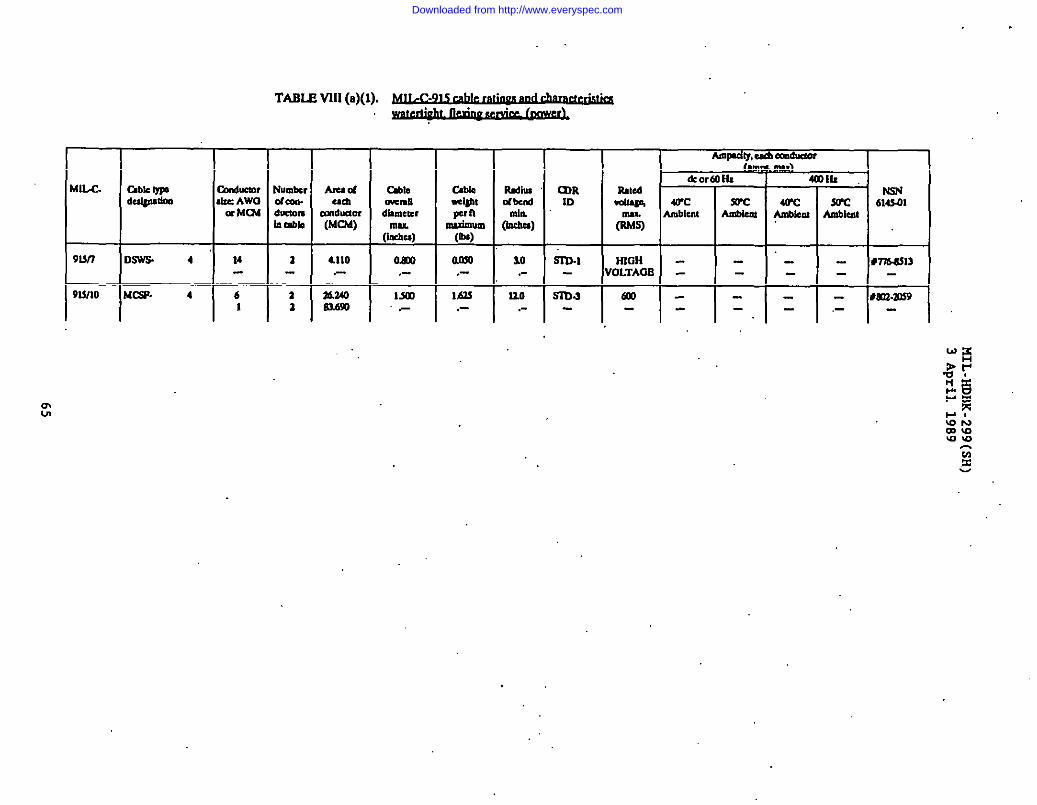
.
AmpCity,u mdmorAL
I
TABLE VIII(a)(l).~ . .
&m
Wcdiem 7:
m.
614$.01Imbkat
b—
amIniJkm
4Q’Clmbkm
W/c. Gbk wdulpmkm
Dn&cIOlccAwla Mm
IumbtlIfaa.IXQW9itsbb
ml,c4cmUdkmeter
(I&.)
O.Ko,-
Mol
C4blaW,ti@,lF nmudu.um(Ou)
nMo,-
1AM,-
UIRID
3=’9un
9ono
DSWS 4
Uw. 4
14
61
1
—2a
10.-
HIGH0LTAC19
Uo.-
6M - lm’Mos4,- 1-
mLn
. .
Downloaded from http://www.everyspec.com
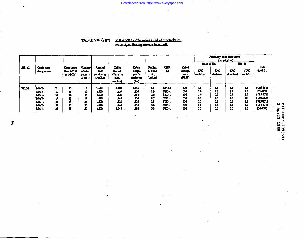
I
[lu2-
)ls/w Wm. 7$6WF- 10m. 14w. t9w- Z4UwP. YIuwF- 37
tivenlm AWOwMm
161818M181818
TABLE WI (a)(2).~.,
Iwmllnabb
71014197.43)sl
Amsdem
O16umf(MUI6)
laL&9I.t.m1.6XIL6mlf.m1.620
C4blo-ddknemrmu
(Incha)
Osul.&u.&M.74!n.%.9Uml
Cabla*Wpern
mdmum(IIS)
ala2302s03J0Amm460
RdhuCm81d
&2s)ls1020uasl.o33
CIIR10
S1-04m-lm-lm.1Sro-1m-lm-l
Um651
2!mml
Am6dw.cd Ctn6udof I
&or
WCmblult
13lo2,023253,0M
Lho6&
WCbnbhnf
4WCtiled
Downloaded from http://www.everyspec.com
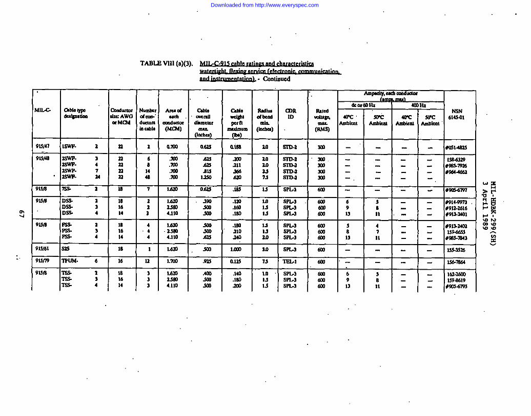
mu
:.
TABLE VU) (a)(3).
. . ..-. .
Ampdly,e mdLmOI. .
MII.4 &bletyps*W SsI 4mm
ccductofNum6c, Ammos able axtdcdpdm
liltedtiab’AWCI dom.’ ~; dWti& ID
NSNadl. C8t.mll *S% ~“ $&c 4WC S&c
- Mild614301
duaom tiuam 61Mluu W AmbkMb UbII (MUM) .
A!nbkm Anbke,lAmbkat+? (IIKba)
(Imbu)(sMS)
91S147 lSWT. a a a am 062s alss ‘Lo S3D.3 m -“
9LWS 3SWF. 3 n 6 Am .201 202.5WT-
SsD-z m -4 II 8 :% m 111 2.0
aswwS37)J
7 233m -
14 .mo AIS s. %wF u n
SrD.a4s
X4 -.m UsO Am : S17J-1 ml -.
9wa 7s.s. 2 ls 7 IJsm O&l .lss u SPL-3 Sal -
9ula DSS- 1 18 2 Ssu .Im lLl 5PM mz
6DS 3 16 X0 .Im u SPLA
:fao 9
DSS. 4 14 4.110 303 .1s0 u SF1.J 6X 13
91SIS Fs a 18 4 1.620 #3 .14a u3 16
sew 603.4 mm SCo 110
Fs- 4 14 4:
4,110 ‘.sas 140 : 13
9LV61 Sa9 18 I 1A30 ,SCo Ln31 10 SPU m -
913n9 ‘nlm4. 6 16 u l,m .91J alti 7s ‘6EL1 KD -
9UIS w 1 1s 3 L6m Am .140 1,0 SPI,3W 3
tul 616 3 33s0 501
lss- 4.1s0 Is SW m
14 39
4,110 SOI 103 u SPu alo 13
, 1 1
--- S0314S3S
*
Downloaded from http://www.everyspec.com
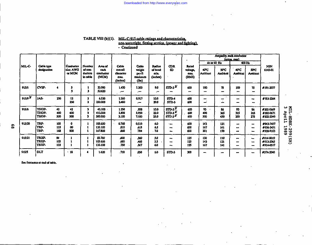
TABLE VIII(b)(l).
- Cmlinued
1N3N614340mRdllu
d bad
(*)
4#191a?Y3+n3-3364
WV, ,CVSP. 4, :
+-E-E-E90.-
laomn +
ml lm.-
me-mo -’
‘n
-“- +
m 7s--
-.--z93 a63153s0 %
------
9M16 ‘3HOF. 43T310F. 4034%lnoP- sc03m
3 4zlm l+1.3M ,9383 413sm 3.9303 mnml 3.lm 7.lm
10.0no‘uJ3
al
I
93,ml moml m
*mu@6303a671#aD.3cMo
91sno TR3L 103 0I’RF. 133 mTRP. Ma m
9un] lllxP- 84 1T3WF- 10s 1‘3RXF. 133 1 M
M6s7.0
M3360 +
mo 143a 167ml ml
133 LWlZY 143In 167
121141I’m—110111141
494%74m*936.3431
.-
e38.91m
t914.9310#913.3ofJ#91W317
------
91313 IDLT ].18 411”al”7’Olw 60 5373.3 ‘l-l-l-l-ISe CaolM4uN ad d Ubk.
Downloaded from http://www.everyspec.com

. .
TABLE Vlll(b)(2).
.-~. COntinuul
I 1’
m10
I I I‘hidU
anduacw(MIX)
Mm
C&ommudihnacrmn(imlU4) (In)
0.z4a
Rdhudtad
(t%.)’20
I I Ampdly,d Ccmdtiw.Inm mu)
&.nalHI 41mtll I%R 1.5 PC-E-Cal%I.. —.= --- --- ..-
mu. AmbIwt A@Melu Anbkm Amblmt(nMS)
ma W - . - - mum
Downloaded from http://www.everyspec.com

411A
W67 USP
I
nm16
TABLE VIIl(c)(l).~. .
. . .---- .-
~ - COntimud
Numbda+kumh &l@
16laas
maim I 1AM
L
Im1.111 .- .-lsal .-
-
Ib6knC4bdMI(L
103.-
%
Am ty,e
LkO1faHl~R RNC6ID @w% =
Ambkm Ambkti(nMS)
- -.- --- --
sealmmuu ● d C4Lbla
TIuor
6COHINSN
WC 614S01AnMr.tuAmbkat
m
. .
Downloaded from http://www.everyspec.com
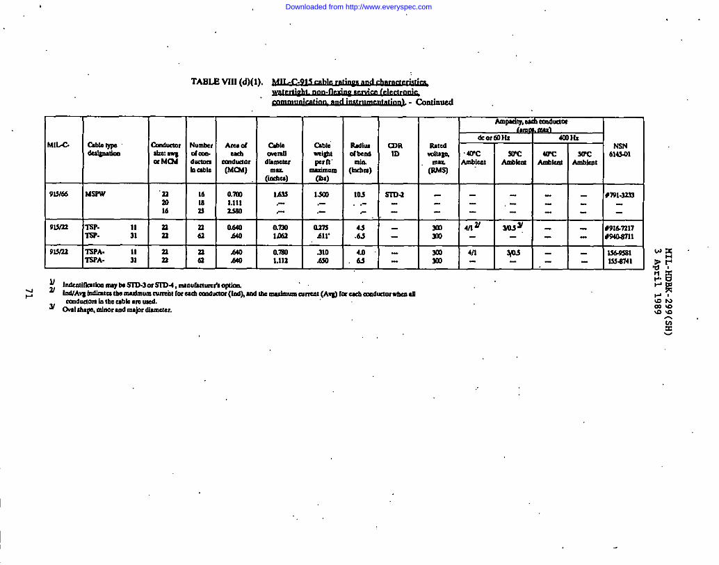
MIIX.
9WM
WmP
!3W21
,.
TABLE Vlll(d)(l),~. .
. . .. . .
~ - COdnud
R-1-%1 1
ISPA. n n~A- : n a
Arudeta
Cmduculr(MN)
O.’m1.111ls80
aaoMO
.440A40
amC?..mll
dhlwal
(Ixu)MIS.-
amIml
am1.111
abler+tFrh’mnbmlm~
1s0.-
amAlr
-J1O.650
hdlludbud
(h%)Iu
.-,-
(DRID
m-l
cmduaomIntheC,bh** d.. . ,. -
y Galtlup,minoraddmijnrdmde,.
Ampdy,h Culdnmlmad
tiorallh 40)HZRJtcd I(5NWtsm arc m WC J(PC 6145.01
Amblrat Ambbc4 AuMe@4 Ambklu(&”q
X0m
I -- - #wl.lm,--- --- -_
~z WY _ _ #91LWn7-’- - @40.sill
1 1 1 I4/! w - - ~1
- - - ls5w41
Downloaded from http://www.everyspec.com
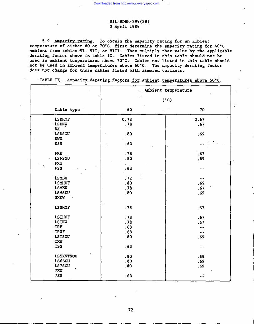
MIL-HDBK-299(SH)3 April 1989
5.9 Anmacitv rating. To obtain the ampacity rating for an ambienttemperature of either 60 or 70”c, first determine the ampacity rating for 40”cambient from tables VI, VII, or VIII. Then multiply that value by the applicablederating factor shown in table IX. Cables listed in this table should not beused in ambient temperatures above 70-C. Cables nnt listed in this table shouldnot be used in ambient temperatures above 60”c. The +mpacity derating factor&es not change for those cables listed with armored variants.
TABLS Ix. ~ deratirrzfactnrs fo bient temperatures above SO-C.
Ambient temperature
(“c)
Cable type 60 70
UDHOF 0.78 0.67LSD~ .78 .67DXLSDSCU .80 .69DWXDsS .63 ..... ..
FRw .78 ,67LSFSCU .80 .69FxwFSS . .63 ..
LW4Du .72 .-ISMHOF .80 .69LSMNW .78 .67 “U3mscu .80 .69nxcw
LSSHOF .78 .67
LSTHOF .78 .67LSWW .78 .67TsF .63 ..TSXF .63 --U3TSCU .80 .69TxwTSS .63 .-
L$5KVTSCU .80 .69LS6SCU .80 .69LS7SGU .80 .697XW7ss .63 .-.
72
Downloaded from http://www.everyspec.com
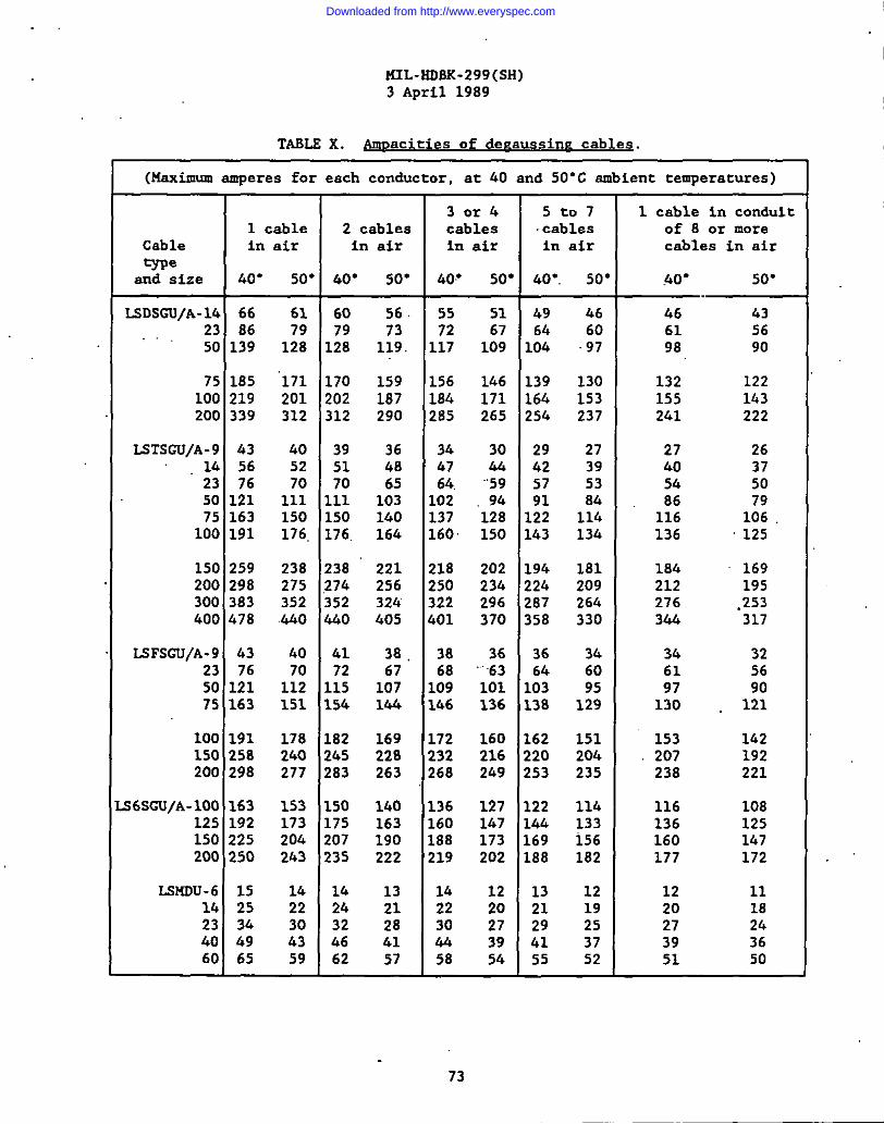
.
MIL-HDBK-299(SH)3 April 1989
TASLS X. Amnacities of deraus3inE cables.
(Maximum amperes for each conductor, at 40 and 50”C ambient temperatures)
30r4 5t07 1 cable in conduit1 cable 2 cables cables cables of 8 or more
Cable in air in air in air in air cables in airtype
and size 40” 50” 60“ 50” &o” 50” .40”. 50” .40” 50”
LSDSGU/A-16 66 61 60 56 55 51 49 b6 46 4323 86 79 79 73 72 67 64 60,.. 61 5650 139 128 128 119. 117 109 lofl 97 98 90
75 185 “171 170 159 156 146 139 130 132 122100 219 201 202 187 184 171 164 153 155 143200 339 312 312 290 285 265 254 237 241 222
LsTsGu/A-9 43 40 39 36 34 30 29 27 27 2614 56 52 51 48 47 44 42 39 40 3723 76 70 70 65 64. ““59 57 53 54 5050 121 111 111 103 102 94 91 84 8675 163
79150 150 140 137 128 122 114 116 106
100 191 176. 176, 164 160 150 143 134 136 125
150 259 238 238 221 218 202 194 181 184 169200 298 275 27’4 256 250 234 224 209 212 195300 383 352 352 32ci 322 296 287 264 276 .253400 478 4.40 440 405 401 370 358 330 344 317
LSFsGu/A-9 43 40 41 38. 38 36 36 34 34 3223 76 70 72 67 68 ‘“”’63 64 60 61 5650 121 112 115 107 109 101 103 95 9775 163
90151 154 144 146 136 138 129 130 , 121
100 191 178 182 169 172 160 162 151 153150 258
142240 245 228 232 216 220 204 207 192
200 298 277 283 263 268 249 253 235 238 221
s6sGu/A-loo 163 153 150 140 136 127 122 114 116 108125 192 173 175 163 160 147 144 133 136 125150 225 204 207 190 188 173 169 156 160 147200 250 243 235 222 219 202 188 182 177 172
LMDU-6 15 14 14 13 14 12 13 12 12 1114 25 22 24 21 22 20 21 19 20 1823 34 30 32 28 30 27 29 25 27 2440 49 43 66 41 44 39 41 37 39 3660 65 59 62 57 58 54 55 52 51 50
73
Downloaded from http://www.everyspec.com
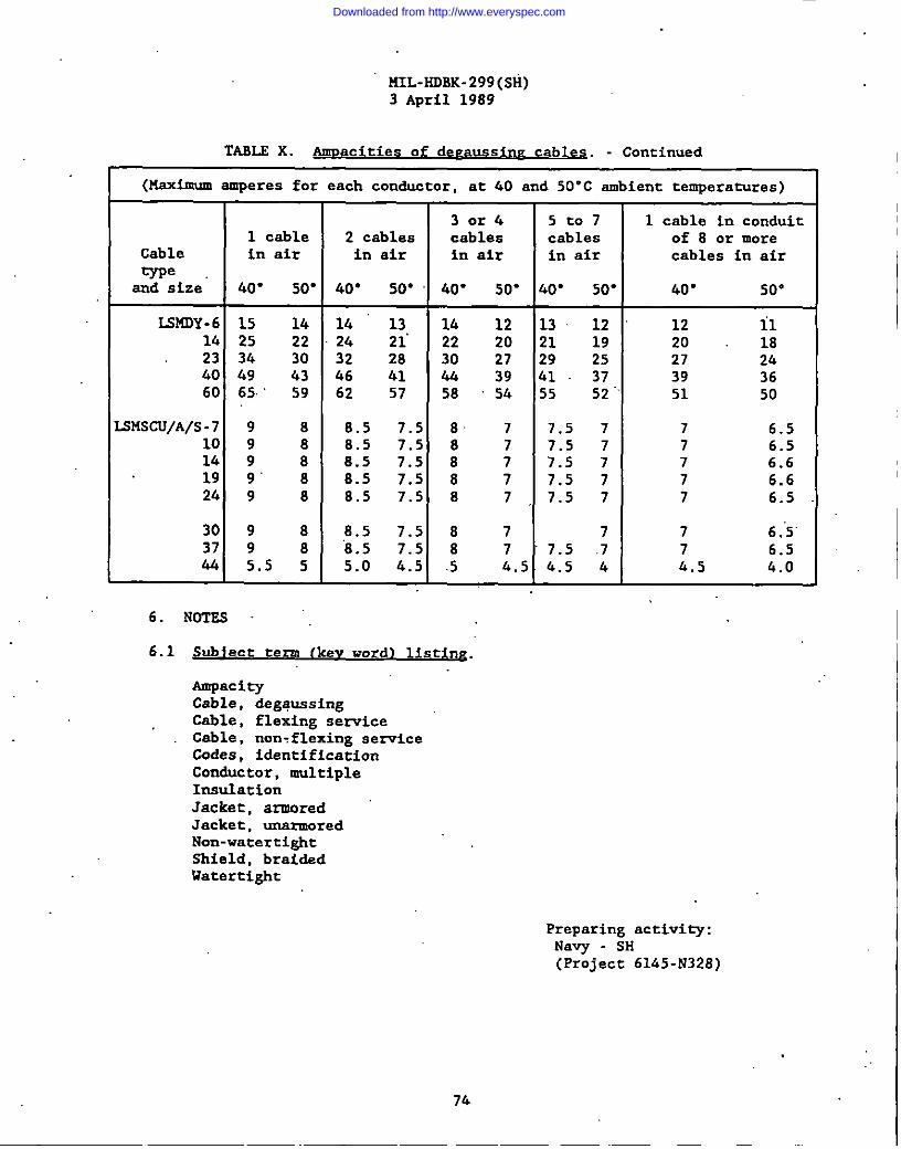
PIIL-HOBK-299(Sli)3 April 1989
TAME X. Aumac tie 0~ cables. - Continued
(Mc.ximumamperes for each conductor, at 40 and 50”C ambient temperatures)
30r4 5t07 1 cable in conduit1 cable 2 cables cables
Cablecables of 8 or more
in air in air in air in air cables in airme
snd size 40” so” 40” 50” 40” 50” &o” 50” 40” 50”
L314DY-6 15 lk 14 13 14 12 13 12 12 il14 25 22 24 21’ 22 20 21 19 20 1823 34 30 32 28 30 27 29 25 27 2640 49 43 k6 41 44 39 .41 37 3960 65 59 62 57 58
3654 55
52.51 50
SUSCU/A/S-7 98 8.5 7.5 8 7 7,5 7 7 6.510 9 8 8.5 7.5 8 7 7.5 7 7 6.516 9 8 8.5 7.5 8 7 7.5 7 7 6.619 9’ 8 8.5 7.5 87 7.5 7 7 6.624 9 8 8.5 7.5 8 7 7.5 7 7 6.5
30 98 8.5 7.5 87 7 7 6.’5’37 9 8 “8.5 7.5 8 7 7.5 .7 7 6.544 5.5 5 5.0 4.5 .5 4.5 4.5 4 .4.5 k.O i
6. NOTES
6.1 Sub ect te~ sting.
AmpacityCable, degaussingCable, flexing serviceCable, non=flexing sen-iceCO&s, identificationConductor, multipleInsulationJacket, armoredJacket, unarmoredNon-watertightShield, braidsdWatertight
Preparing activity:Navy - SH(Project 6145-N328)
Downloaded from http://www.everyspec.com

MIL-NDBK-299(SH)3 April 1989
I
I
,.I
APPENDIK
ELECTRICAL CABLE VOLTAGE DROP CALCUUTIONS FOR POWSR AND LIGHTING SYSTEMS
10. SCOPE
10.1 -. This appendix is intendsd for uxs ss a guide in determiningvoltage drops for csbles used in alternating current (at) snd direct current (dc)pover, lighting, interior communication, weapons control and electronic systems.
20. RSFSRENCED oocunsNTs
20.1 Government documents.
This paragraph is not applicable to this appendix.
20.2 Qther uublications. The following documents form a part of thishandbook to the extent specified herein. Unless othervise specified, the issuesof the documents,yhich are DoD adopted shall be those listed in the issue of theDoDISS specified in the solicitation. The issues of documents which have notbeen adopted shall be those in effect on the date of the cited DoDISS.
AMERICAN SOCIETY FOR TESTINGAND MATERIALS (ASTM)B8 - Standard Specification for Concentric-Lay-StrandedCopper
Conductors, Hard, Hedium-Hard, or Soft.B “258- Stsndard Specification for Standard Nominal Dismeters and
Cross-SectionalAreas of AWG Sizes of Solid Round WiresUsed as Electrical Conductors.
(Application for copies should be addressed to the American Society forTesting snd Materiala, 1916 Rsce Street, Philadelphia, PA 19103.)
(Nongovernment standsrds are generally available for reference fromlibraries. They are also distributed among nongovernment stan&r&’ bodies andusing Fedsral agencies.)
30. DEFINITIONS
30.1 Svmbols and”abbreviations. Selected symbols and abbreviations used inthis appendix are as follows:
E-
v-L-
cmil -
E is the symbol for sending end or bus (normally switchboard)voltage. It is li”ne-to-neutral rated voltage for thres-phase acsystems (line-to-line rated voltage divided by the squsre root of3), snd three-wire & systemx, and line-to-line rated voltage for dcsnd eingle phase alternating current systems.
V is che abbreviation for receiver or load voltage.L is the abbreviation for the length, in feet, of a single conductorin circuits hsving equsl conductor lengths in all legs of thecircuit.Cmil is th& abbreviation for thea single leg of the circuit.
75
circular mil cross-sectional area of
Downloaded from http://www.everyspec.com
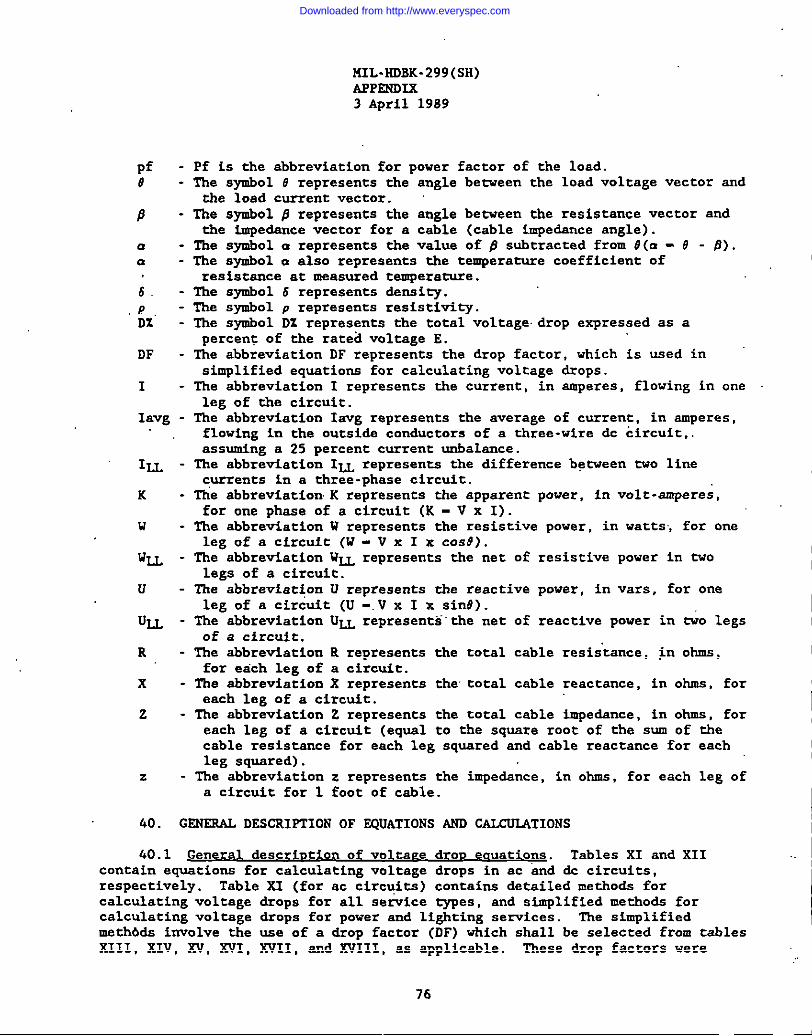
141L-HDBK-299(SH)APPSNDLX3 April 1989
pf8
9
aa
.$.PD%”
DF
I
- Pf is the abbreviation for power factor of the load.- The symbol .9represents the angle betveen the load voltage vector and
the load current vector.- The symbol @ represents the angle betveen the resistance vector and
the impedance vector for a cable (cable impedance angle).- The symbol a represents the valus of 6 subtracted from 9(a - .9- 6).- The s%bol a also represents the temperature coefficient of
Iavg -
ILL -
K-
u-
u~ -
u-
Uu -
R-
x-
z-
z-
resistance at measured temperature.The symbol 6 represents dansity.The symbol p represents resistivity.The symbol DZ represents the total voltage.drop expressed as apercent of the rated voltage E.
The abbreviation DF represents the drop factor, which is used insblified equations for calculating voltage drops.The abbreviation I represents the current, in amperes, flowing in oneleg of the circuit.The abbreviation Iavg represents the average of current, in amperes,flowing in the outsids conductors of a three-wire dc circuit,.assuming a 25 percent current unbalance.The abbreviation IU represents the difference between two linecurrents in a three-phase circuit.
The abbreviation K represents the apparent power, in volt-amperes’,for one phase of a circuit (K - V x I).
The abbreviation U represents the resistive power, in watts, for oneleg of a circuit (W - V x I x COS8).
The abbreviation WU represents the net of resistive power in twolegs of a circuit.
The abbreviation U represents the reactive povar, in vars, for oneleg of a circuit (U -.V x I x sinO).
The abbreviation U~ represents”the net of reactive power in MO legsof a circuit.
The abbreviation R rapresents the total cable resistance, @ ohms,for each leg of a circuit.
The abbreviation X represents the total cable reactance, in ohms, foreach leg of a circuit.The abbreviation Z represents the total cable impedance, in ohms, foreach leg of a circuit (equal to the square root of the sum of thecable resistance for each leg squared and cable reactance for eachleg squared).
The abbreviation z represents the impedance, in ohms, for each leg ofa circuit for 1 foot of cable.
&o. GSNSRAL DESCRIPTION OF EQUATIONS AND CALCUUTIONS
60.1 General description of voltage dron eauations. Tables XI and XIIcontain equations for calculating voltage drops in ac and dc circuits,resDectivelv. Table XI (for ac circuits) contains detailed methods forcalculating voltagecalculating voltagemethbds involve theXIII, XIV, XV, XVI,
drops for all setiici types, and simplified methods fordrops for power and lighting se=ices. ‘I%esimplifieduse of a drop factor (DF) which shall be selected from tablesXVII, and XVIII, as applicable. These drop factors were
76
Downloaded from http://www.everyspec.com

I
MIL-HDBK-299(SH)AFPSNDIX3 April 1989
calculated using the impedance characteristic of type LSTSGA and LS6SGA cableain accordance with MIL-C-246&3. Althoud calculations are baaed ,uDonfullcoverage aluminum-armored cablea (armored cables represent worst caae impedancevaluas) they may be used for equivalent size unarmored cables. The tabulateddrop factors for qpe ISTS~ cable,may be used for other cable q’pes with similarimpedance characteristics, including lightveigbt cablea in accordance withMIL-C-24660. For any nonsi.milarcables, drop factors may be calculated by usingthe impedance characteristics of the cable in the appropriate equation .containe.dherein vhich &rive from the”s.fmplifiedmethod specified in 50.1 for powersystems, 50.2 for lighting aysteme (I and IU method), and 50.3 for lightingsystems (watts and vara method).
TABLS XI. Voltage drou aauations for ac circuits.
Type ofservice Detailed method equation Simplified method equation
Lighting service only:
D% -
()
2(1OO)L ~ coaoingle pheae, E DZ - 2Lx IxDFall types of (from table XVII)service OR
DZ -4LXWXDF”(from table XVIII)
Lighting aenice only:
hree-phase,.()
~X - @OO)L & CO.SaDZ-LXIUXDF
all service (from type XVII)types except ORpower DX - LX2WLLXDF
(from table XVIII)
hree-phaae, Dx
[ ‘z a’
- 100L(cos
() ]
+&& 2& DZ - L x I x DF (frompower service EE 2 table XIII, XIV, or(see note) XV as appropriate)
NOTE: 2his equation may be used on power systems through 4160 volts.
77
Downloaded from http://www.everyspec.com

MIL-HDBK-299(SH)APPENDIK3 April 1989
I
I
TABLE XII. v~s
-e of service Equstion
vo-wire,all service types
D% -ps x IX2LX1 00
except power cmilx E
2400XIXL where RSS - 12, which iscmil x E. the resistivi~ of copper
,. at an assumed operatingtemperature of 45”C
Lo-wire,power se~ice
D%.- ‘s ‘~i; fEx 100
2600x IxL where RSS - 13, which iscmil x E the resistivity of copper
at ~ assumed operating,temperature of 65-C
hree-wire,lighting service
D% -RES x .(1avv + O.25 Iave) x Lxl 00
cmil x E
1500 x Iave x L vhere RES - 12, which is,-cmil x E the resistivi~ of copper
at an assumed operatingtemperature of 45”C .
‘hree-wire,power service DZ _ ‘s x (Iavr + O.25 Iavp) x Lxl 00
cmil x E
.1625X Iav!zx L where RSS - 13, vhich iscmilx E the resistivity of copper
at an aasumed operatingtemperature of 65”G
78
Downloaded from http://www.everyspec.com
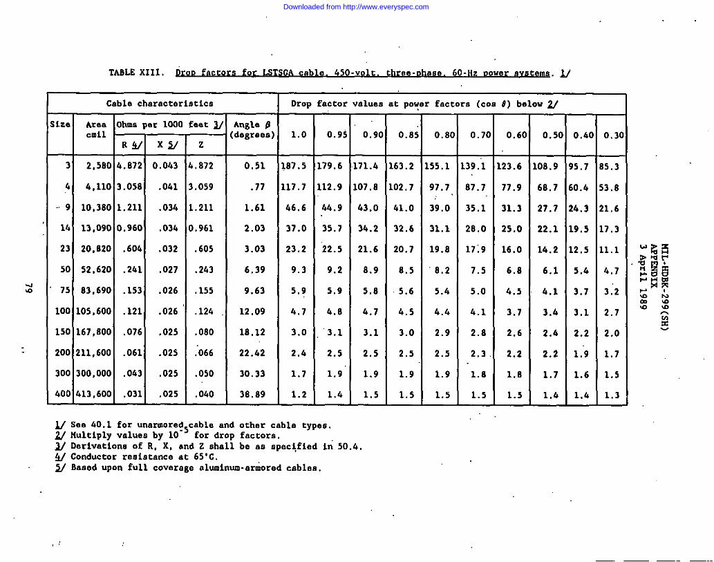
ble 450-volt.three-ghase.60-Hz vower sW&tllM.uTASL2 XIII.
Cable characteristics
ize. Area Ohms par 1000 factI/
Drop factor values at pow, factors(COS t) below 2/
0.5(
08.9
68.7
27.7
22.1
14.2
6.1
4.1
3.4
2.4
2.2
1.7
I.&
—
0.3(
—
5.3
‘3.8
:1.6
.7.3
,1.1
4.7
3:2
2,7
2.0
1.7
1.5
1.3—
0.60
-
23.6
77.9
31.3
25.0
16.0
6.8
4.5
3.7
2.6
2.2
1.8
1.5
—
0.40
—
5.7
0.4
4.3
9.5
2.5
5.4
3.7
3.1
2.2
1;9
1.6
1..4—
Ar@s LI:degreea) 1.0 0.95
79.6
12.9
b4.9
35.7
22.5
9.2
5.9
4.8
‘3.1
2.5
1.9”
1.4
I Clrdlz
0.9( 0.85 0.8[ 0.7’
T3 2,580
4 It,llo
~~9 10,380
4.872 0.043 ,.872
,.059
,.211
1.961
.605
.243
,155
.lzfl
.080
;066
.050
,Ofbo
0.51
.77
1.61
2.03
3.03
6.39
9.63
12.09
18.12
22.42
30.33
38.89
87.5
17.7
46.6
37.0
23.2
9.3
5.9
4.7
3.0
2.4
1.7
1.2
,71.4
,07.8
63.0
34.2
21.6
8.9
5.8
4.7
3.1
2,5
1.9
1.5
63.2
02,7
41.0
32.6
20.7
8.5
5.6
4.5
3.0
2.5
1.9
1.5
,55.1
97.7
39.0
31.1
19.8
8.2
5.6
4.4
2.9
2.5
1.9
1.5
39.’3
87.7
35.1
28.0
17:9
7.5
5.0
h.1
2.8
2.3
1.8
1.5
3.058 .041
1.211 .034
14 13,0900.960I
.034
.604 .032
.241 .027
.153 .026
.121 .026
,076 .025
23 20,820
50 52,620
75 83,690
100 105,600
150 167,800
200 211,600 .061 .025
I300 300,000 ,063I
,025
*.0311 .025
See IJO.1 for unarmore$5cable and other cable types.Multiply valuesby 10 for drop factrms.Derivationsof R, X, and Z shallbe as spec~fied k 50.4.Conductorresistanceat 65”C.Based upon full coveragealuminum-arioredcables.
Downloaded from http://www.everyspec.com
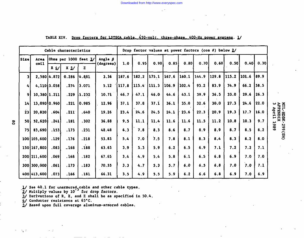
TABLEXIV. w fact~. 450-vti three-Ohaae.@JO-HZ DQMIUxMU. u
Cable characteristics Drop factorvalues at power factora (cm 0) below u
,Iza Area ohms per 1000 feet y AnfJepcmil (degrees) 1.0 0.95 0.90 0.85 O.BO 0.70 0.60 0.50 O.ko 0.30
R~ x~ z
3 2,5804.872 0.286 4.8,81 3.36 187.6 182.2 175.1 167.6 160.1 144.9 129.8 115.2 101.6 89.9
4 4,110 3.058 .274 3.071 5.12 117.8 11s.4’111.3 106.9 102.4 93.2 83.9 74.9 66.2 58.5
9 10,3801.211 .229 1.232 10.71 46.7 47,1 46.0 4fA.6 &3.1 39.9 36.5 33.0 29.6 26.3
14 13,0900.960 .221 0.985 12.96 37.1 37.8 37,i 36.1 35.0 32.6 30.0 27.3 24.6 22.0
23 20,820 ,604 .211 .640 19.26 23.4 ‘24.6 24.5 24.1 23.6 22.3 20.9 19.3 17.7 16.0
50 52,620 .241 .181 .302 36,88 9.5 11.1 11.4 11.6 11.6 11.5 11.2 10.8 10.3 9.7
75 2.3,690 .153 .173 .231 48.48 6.3 7.8 8.3 8.6 8.7 8.9 8.9 8.7 8.5 B.2
100 105,600 .129 .176 .218 53.83 5.4 7.0 1.5 7.8 8.1 8.3 8.4 8.3 8.2 B.O
150 167,800 .083 ..168 .iB8 63.63 3.9 5.3 5.9 6.2 6.5 6.9 7.1 7.2 7.2 7,1
200 211,600 .069 ,168 .182 67.65 3.6 4.9 5.4 5.8 6,1 6.5 6.8 6.9 7.0 7.0
300 300,000 .061 .173 .183 70.55 3.3 4.7 5.3 5.7 6.0 6.5 6.8 7.0 “7.0 7.1
400 413,600 .073 .166 .181 66.31 3.5 4.9 5.5 5.9 6.2 6.6 6.8 6.9 7.0 6.9
3,/Sea 40.1 for unarmored.cable and other cable types.~ f4ultiplyvaluesby 10-’ for drop factors. -‘,w Derivationsof R, X, and Z shallbe as specifiedin 50.4.~ Conductor reaLstance at 65-C.w Based upon full coveragealuminum-armoredcables.
Downloaded from http://www.everyspec.com
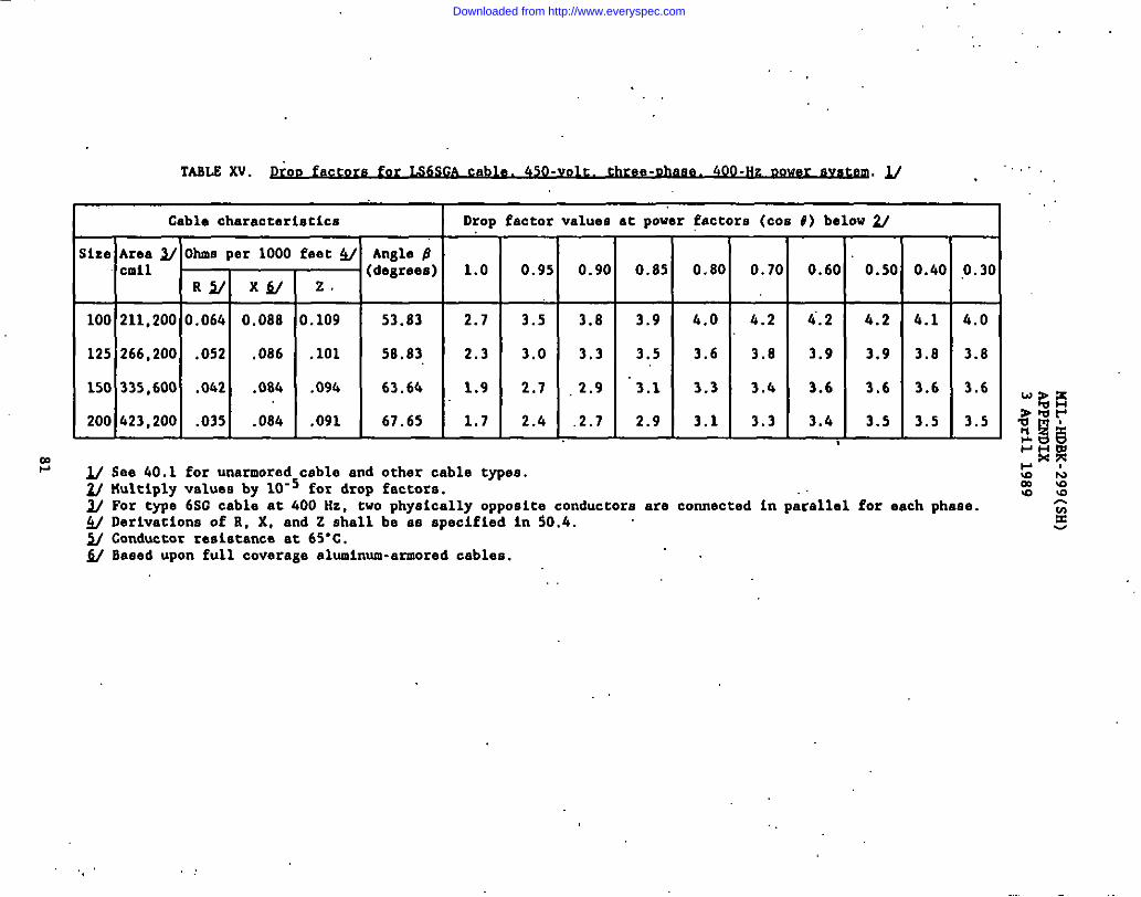
,,
.
TASLSXV. PKOD fac~e. 450-v~. 400-HZ~.u .
Cable characteristics
-H+iza Area ~ Ohms per 1000 feet~
cmilR~ X~
100 211,2000.064 0.088
125 266,200 .052 .086
150 335,600 .062 .084
200 423,200 .035 .084
z
.109
.101
.094
,091
Angle pdegrees]
53.83
58.83
63.64
67.65
Drop factor values at power Pactors(COS 4) belowU
1.0
2.7
2.3
1.9
1.7T0.95 0.90
3.5 3.8
3,0 3,3
2.7 2.9
2.4 .2.7 t
0.85 0.8(
3.9 4.0
3.5 3.6
3.1 3.3
2.9 3.1
0.70
-
4.2
3.8
3.4
3.3
0.6(
i.2
3.9
3.6
3.6
0.50
4.2
3.9
3.6
3.5
O.&(
&.1
3.8
3.6
3.5—
0.3C
—4.0
3.8
3.6
3.5—
U See 40.1 for unarmoredcable and other cable typee.~ Multiplyvaluesby 10-5 for drop factors.V For type 6SC cable at 400 Hz, two physicallyopposite conductors ace connected in parallel for eech phase..4/ Derivationsof R. X. and Z shallbe as euecifiedin $0.4.~ Conductorreeistanc~at 65”c.W Based upon full coveragealuminum-armoredcables.
Downloaded from http://www.everyspec.com

TARLS XVI. G e St c~ or communications,
I yeauons control and electronicsvstems. ~
mN
60 HZ 400.Hz
Ohms pet 1000 feet ~ Ohms per 1000 feet ~
Size Area Angle fJ ‘ Angle f3cmil R~ x~ z (degrees) R~ Xy z (degrees)
3 2,580 4.546 0.043 4.546 0.54 4.546 0.287. 4.555 3.61..
4 4,110 2.853 .041 2.853 ,82 2.853 .274 2.866 5.49
9 10,380 1.130 .034 1.131 1.72 1.130 .229 1.153 11.46
14 13,090 0.896 .034 0.897 2.17 0.896 .224 0.924 14.04
23 20,820 .562 .032 .563 3.26 .563 .211 .601 20.56
50 52,620 .,525 .027 .zzi 6.84 .225 .181 .289 38.81
75 83,690 .1.43 .026 .145 10.30 .143 ,173 .224 50.42
100 105,600 .113 .026 .116 12.96 .120 .176 .213 55.71
150 167,800 .071. ,025 ,075 19.40 .677 ;168 .185 65.38
200 211,600 .057 .025 .062 23.68 .064 .168 .180 69.15
300 300,000 .041, .026 .049 32.38 .059 .,173 .183 71.17
400 .413,600 .028 .025 .038 41.76 .068 .166 .179 67.72
~ See 40.1 for unarmored cable and other cable types.~ Derivationsof R, X, and Z as specified in 50.4.~ C.nductor resistance at 45-C,~ Eased upon full coverage aluminum-armoredcables.
,.,’
Downloaded from http://www.everyspec.com
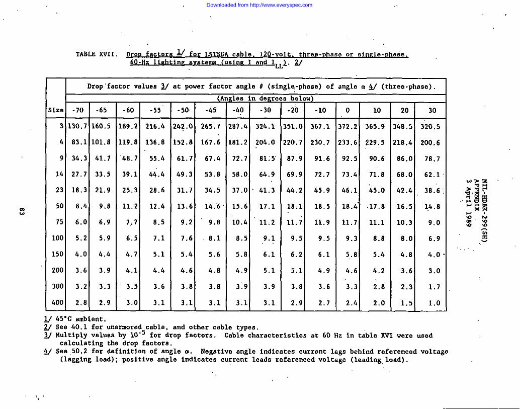
mw
TABLE XVII. Prnf accore ~ for LSTSGA cable. lzo-volt. three-vhase or sin~le-c.hatie.6;-Hz liuhtine svstems (usinE I and lLL1. 2/
Drop”factor values ~ at power factor angle O (singlq-phase)of angle u ~ (three-phase).
(Angles in degrees below)
ize -70 -65 -60 -55” -50 -45 -40 -30 -20 -10 0 10 20 30
3 130.7 160.5 109.2 216.4 242.0 265.7 287.4 32k.1 351.0 367.1 312.2 365.9 348.5 320.5
4 83.1 101.8 119.8 136.8 152.8 167.6 181.2 204.0 220.7 230.7 233.6 229.5 218.4 200.6
9 34.3 41.7 “48.7 55.4 61.7 67..i 72.7 81:5 87.9 91.6 92.5 90.6 K6.O 78.7
lb 27.7 33.5 39,1 44’.4 49.3 53.8 58.0 64.9 69.9 72.7 73.4 71,8 68.0 62.1
23 18.3 21.9 25.3 2K.6 31.7 34.5 37.0 fbl.3 44.2 45.9 46.1 i5.o 42.4 38.6
50 8.4 9.8 11.2 12.4 13.6 14.5 15.6 17.1 18.1 18.5 18.4 <17.8 16.’5 1,4.8
75 6.0 6.9 7,.7 8.5 9.2 9.8 ‘1O.4 11.2 11.7 11.9 11.7 11.1 10.3 9.0
100 5.2 5.9 6.5 7.1 7.6 8.1 g.5 9.1 9.5 9.5 9.3 8.8 8.0 6.9
150 4.0 4.4 4.7 5.1 5.4 5.6 5.8 6.1 6.2 6.1 5.8 5.4 4.8 4.0
200 3.6 3.9 4.1 4.4 4.6 4.8 4.9 5.1 5.1 4.9 4.6 4.2 3.6 3.0
300 3.2 3.3 3.5 3.6 3.8 3.8 3:9 3.9 3.8 3.6 “’3.3 2.8 2.3 1.7
400 2.8 2.9 3.0 3.1 3.1 3.1 3.1 3.1 2.9 2.7 2.4 2.0 1.5 1.0L
~ 45*C ambient.~ See 40.1 for unarmored cable, and other cable types.~ Multiply values by 10“5 for drop factors. Cable characteristicsat 60 Hz in table XVI were used
calcul~ting the drop factors.~ See ,50.2for definitionof angle a. Negative angle indicates current lags
(lagging load); positive angle indicates current leads referencedvoltagebehind referenced voltage(laading,load).
‘!
Downloaded from http://www.everyspec.com
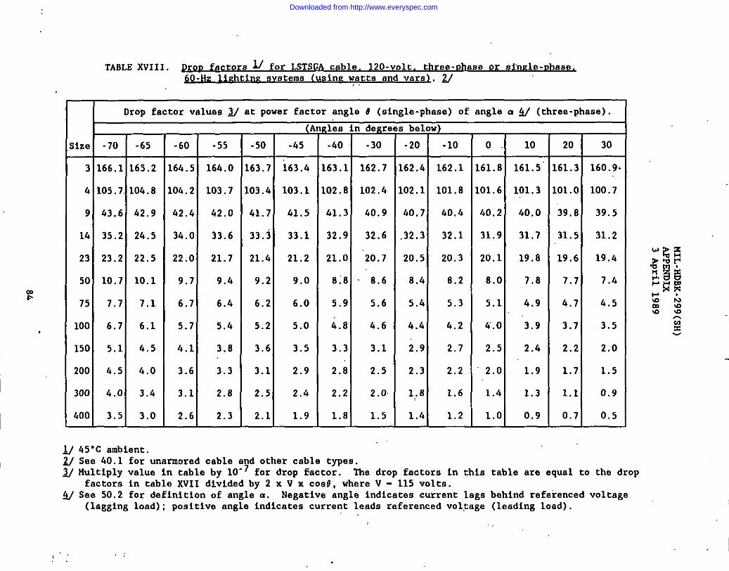
TABLE XVIII. Pr D fa tOrc s ~ for LSTSGA cable. 12O-volt. three-pha
600-Hz
se or sfnele-uhase
n~ 8Vsterns [using watts and vars1. 2/.
I Drop factor valuea ~ at power factor angle # (single-phaae) of angle o ~ (three-phase)
;ize -70 -65
3 166.1 165.2
.!!105.7 104.8
9 43.6 42.9
14 35.2 24.5
23 23.2 22.5
50 10.7 10.1
75 7.7 7.1
100 6.7 6.1
150 5.1 4.5
200 4.5 4.0
300 4.0 3,4
400 3.5 3.0
-60
.64.5
,Oh.2
42.4
34.0
22.0
9.7
6.7
5.7
4.1
3.6
3.1
2.6
.55
164.0
103.7
42.0
33.6
21.7
9.4
6.4
5.4
3.8
3.3
2.8
2.3
Q
-50 -45
63.7 i63.4
03.4 103,1
41.7 41.5
33,3 33.1
21.4 21.2
9.2 9.0
6.2 6.0
5.2 5.0
3.6 3.5
3.1 2.9
2.5 2.4
2.1 1.9
,leain degr(
-40 -30
.63.1 162.7
02.8 102.4
.41.3 40.9
32.9 32.6
21.0 20.7
8:8 8.6
5.9 5.6
4.8 4.6
3.3 3.1
2.8 2.5
2.2 2.0
1.8 1.5
below)
-20 -10
62.4 162.1
02.1 101.8
40.7 40.4
32.3 32.1
20.5 20.3
8.4 8.2
5.4 5.3
4.4 4.2
2.9 2.7
2.3 2.2
1,.8 1.6
1.4 1.2
0. 10
.61.8 161.5
.01.6 101.3
40.2 40.0
31.9 31.7
20.1 19.8
8.0 7.8
5.1 4.9
fi.o ‘3.9
2.5 2.4
2.0 1.9
1.4 1.3
1.0 0.9
20
61.3
01.0
39.8
31.5
19.6
7.7
4.7
3.7
2.2
1.7
1.1
0.7
30
160.9.
100.7
39.5
31.2
19.4
7.4
4.5
3.5
2.0
1.5
0.9
0,5
M 45°C ambient~ See 40.1 for unarmored cable and other cable types.
3/ Multic.lvvalue in table bv 10-7 for droD factor. The drOD factora in this table are eaual to the drODfact~r~ in table XVII di~i.dedby 2 x V.x coa#, where V -“115 volts.
~ See 50.2 for definition of angla a. Negativa angle indicates current lags behind referenced voltage(lagging load) ; positive angle indicatea current leada referencedvoltage (leading load).
,’ ,.
Downloaded from http://www.everyspec.com
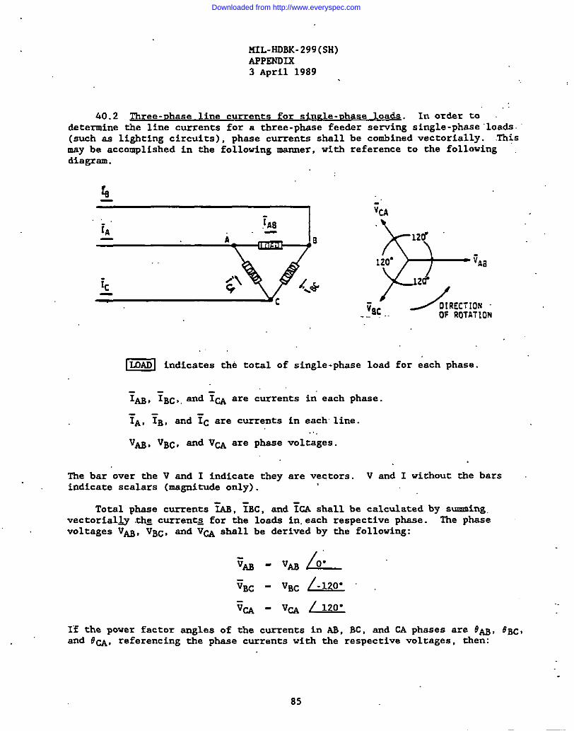
MIL-HOBK-299(SH)APPENDIX3 April 1989
,:40.2 nree-nh ase line currents for sin=le-uhase loads. IrIordsr to
determine the line currents for a three-phsse fceder serving single-phase“loads.(such as lighting circuits), phase currents shall be combined vectorially. .Thismsy be accomplished in the following msnner, with reference to the followingdiagram.
= indi.ates the total of single-phcse load for ea.h phase.
I ?n, YBC,,and ~u are currents in’each phase.
~A, ?B, and TC are currents in each line.. . .
V~, VBC, and Vw are phsse voltages.
1. Ihe bar over the V and I indicate they are vectors. V and I without tbe barsindicate scalars (msgnituds only).
Total phase currents ‘~, ~BC, and ~CA shall be calculated by summing.vectorial~ .thgcurrents for the loads in.each respective phase. The phasevoltages V-, VBC, and VW shall be derived by the following:
I
If the power factor angles of the currents in AB, BC, and CA phases are 6’AB,6BC,and OW, referencing the phase currents with the respective voltages, then:
B5
Downloaded from http://www.everyspec.com
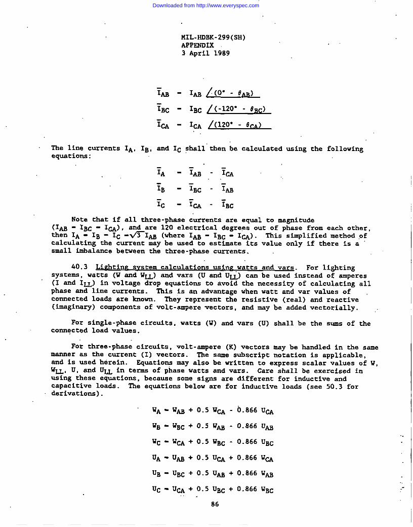
MIL-HOBK-299(SH)APPENDIK3 April 1989
The line currents IA, IB, snd IC ?hsll”then be calculated using the followingequati0n5:
:~ -7~-Y~.
;B - YBC - Yu
Tc - & - ?B~
Note thst if all three-Dhase currents are eaual to ma$cnitude(Iwthen
- IBC - 1~) , and are 1!20electrical dcgree~ out of p~ase from each other,IA- IB - IC -WI~ (where I- - IBc - 1~) . This simplified method ,of
calculating the current msv be used to estimate its value onlv if there is a,SMS1l imbalance betveen the three-phase currents.
.
40.3 L“ tin~. For lightingsystems, watts (W snd w~) and vars (U snd UU) can be used instead of amperes(I and 1~) in voltage drop equstions to avoid the necessity of calculating allphase snd line currents. This is sn advantage when watt and var values ofcannected loads are known. They represent the resistive (real) snd reactive(i.maginsry)components of volt-ampere vectors, ~d may be added vectOriallY. ..
For single-phase circuits, watts (W) cnd vars (U) shall be the sums of theconnected load valuss.
For three-phase circuits, volt-ampere (K) vectors may be handled in the samemanner ss the current (I) vectars. The same subscript notation is applicable,snd is used herein. Equations msy also be written to express scalar values af W,h’~, U, snd U~ in terms of phase watts snd vars. Care shall be exercised inusing these equations, because some signs are different for inductive andcapacitive loads. The equations below are for inductive loads (see 50.3 forderivations).
WA = WM + 0.5 W~ - 0.866 U~
WB - WBC + 0.5 WM - 0.866 Um
WC - kt~ + 0.5 WBC - 0.866 UBC
UA - U~ + 0.5 U~ + 0.866 W~
UB - UBC + 0.5 U~ + 0.866 W~
UC - Ua + 0.5 UBC + 0.866 WBC
86
_-
Downloaded from http://www.everyspec.com
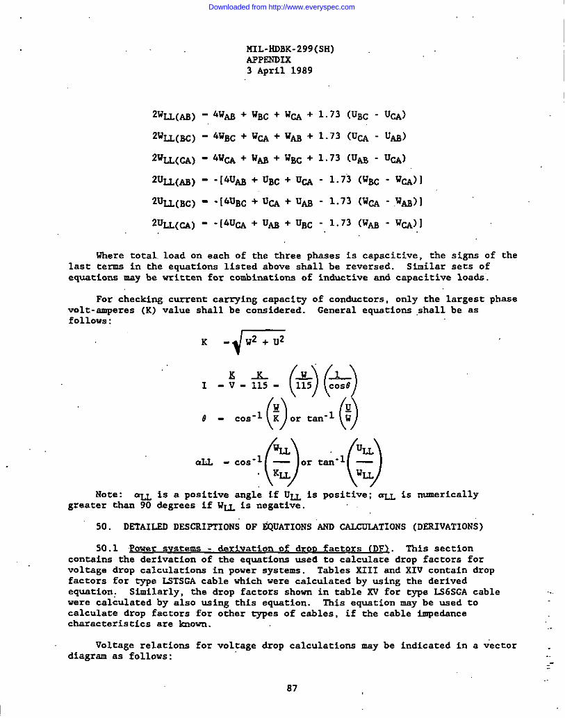
1. KIL-HDBK-299(SH)APPENDIX3 April 1989
1.’
I
Where total.load on each of the three phases is capacitive, the signs of thelast terms in the equations listed above shsll be reversed. Similar sets ofequations may be vritten for combinations of inductive and capacitive loads.
For checking current carving capacity of conductors, only the largest phasevolt-amperes (K) value shall be considered. General equations ,sballbe asfollows:
nLL-cos-lf~)ortai-l~~)
Note: ~ is a positive angle if U~ is ppsitive: aLL is numericallygreater thsn 90 degrees if W= is negative.
50. DsTAID DESmIFTIONS OF @ATIONS ‘km CALCUMTIONS (DERIVATIONS)
50.1 Power svstens - deriVatiOn of drOD factors (DF>. This sectioncontains the derivation of the equations used to calculate drop factors forvoltage drop calculations in power systems. Tables XIII and XIV contain dropfactors for type LSTSGA cable which were calculated by using the derivedequation: Similarly, the drop factors shovn in table XV for type IS6SGA cable ..were calculated by also using this equation. Ibis equation may be used tocalculate drop factors for other eypes of cables, if the cable impedancecharacters tics are known.
Voltage relations for voltage drop calculations may be indicated in a vector .diagram as follows: _-
..87
Downloaded from http://www.everyspec.com
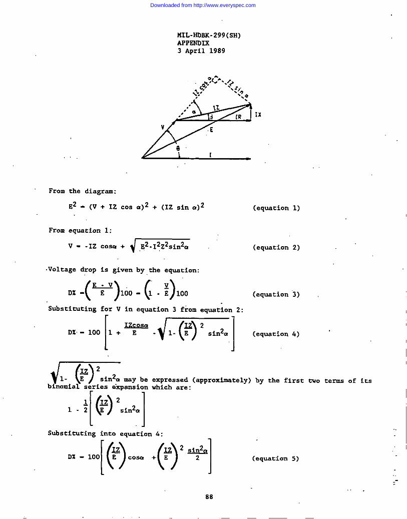
141L-HDSK-299(SH)APPENOLX3 April 1989
,?(:. . ,‘0,, .+
‘.r,.,,%.. ‘~:e,
~.
.,,” II
,.’~i [R ‘x
v E
a’1
From the diagram:
E2 - (V + 12 COS CI)2+ (IZ Sin a)2 (equation 1)
From equation 1:
v--1’-+~ ‘ (equstion 2)
Voltage drop is given by the equation:
D-(Y)lOO-(1-:)100Substituting for V in equation 3 from equation 2:
(equation 3)
-’++=-m=’] ‘eqwti0n4) ~
m sin2a may be expressed (approximately)binomial series expansion which are:
[() ]
1=21-2E sin2a
Substituting into equation 4:
by the first tvo terms of its
(equation 5)
--
88
Downloaded from http://www.everyspec.com
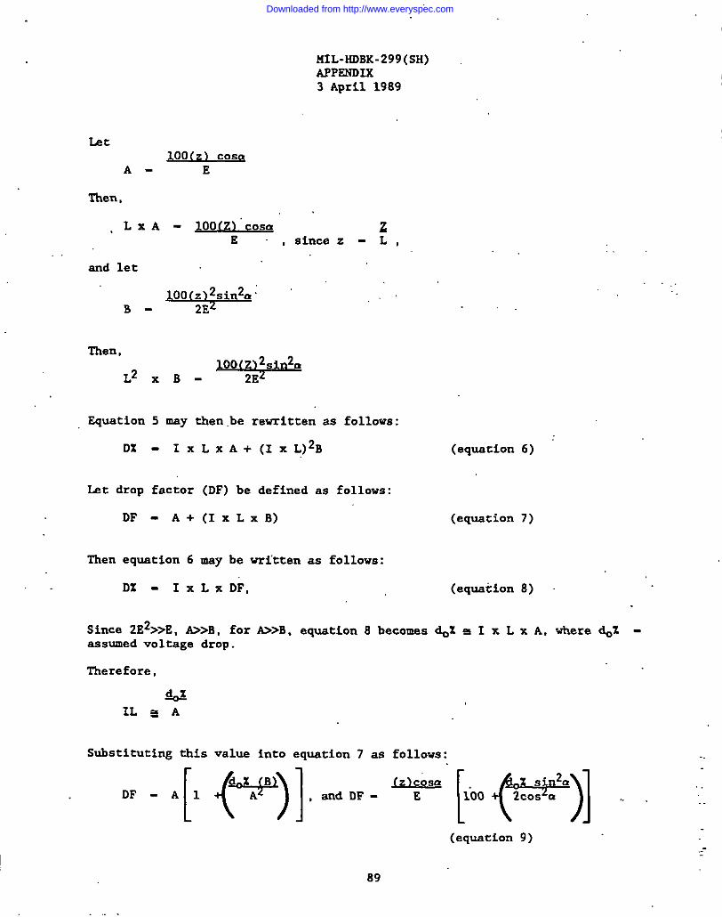
MIL-HDBK-299(SH)APPSNDIK3 April 1989
L2c100(2) Cosa
A- E
l-hen,
, L X A - IOO(Z)’COSU zE ,since z-L,
snd let
B- -’
Then,
L2XB-9
Equstion 5 msy then.be revritten as follows:
D% - IX LX A+(IXL)2B
Lst drop factor (DF) be defined as follows:
DF-A+(Ix LxB)
(equation 6)
(equstion 7)
l?henequation 6 msy be vritten as follows:
DZ -Ix LxDF, (equation 8)
Since 2E2>>E, &>B, for ti>B, equation 8 becomss d# s I x L x A, vhere d# -sssumed voltage drop.
Therefore,
Substituting this value into equstion 7 as follows:
L
12k?s!z,snd DF - E
(equation 9)
89
Downloaded from http://www.everyspec.com
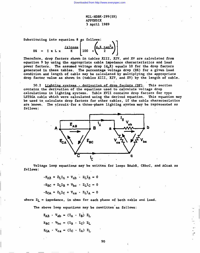
MIL-HOBK-299(SH)AFPZNDLX3 April 1989
Substituting into equation 8 as follows:
D% . I.L. w[oo +@,-’j]—
Therefore, drop factors shown in tables XIII, XIV, snd XV are calculated fromeWtiOn 9 by using the appropriate cable $.mpedencecharacteristics and loadpower factors. The assumed voltage drop (~% ) equals 10 for the drop factorsgenerated in these tables. The percentage voltage drop (D%) for a given loadcondition and length of cable may be calculated by multiplying the appropriatedrop factor value as shown in (tables XIII, XIV, and XV) by the length of cable.
50.2 Lichtine svseema - derivation of dror.factors (DFI. This sectioncontains,the derivation of the equations used to calculate voltage dropcalculations in lighting systems. Table XVII contains drop factors for typeL5TSGA cable which were calculated using the derived equation. This equation msybe used to,calculate drop factors for other cables, if the cable characteristicsare lmown. The circuit.for a three-phase lighting system may be represented asfollows:
Voltage loop equations may be vritteu for loops BAabB, CBbcC, and ACCSA asfollows:
-l?~ + ZLIA + Vab “-ZLIB - 0
-EBC + ZLIB + Vbc - ZLIC _ O
-~ + ZLIC + Vca - ZLIA _ O
where ZL - impedance, in ohms for each phase of both cable and load.
The above loop equations may be rewritten’as follows:
E~-V~- (IA - IB) ZL
EBC - Vbc - (IB - Ic) ZL
%A-vca - (Ic - IA) ZL
..
90
Downloaded from http://www.everyspec.com
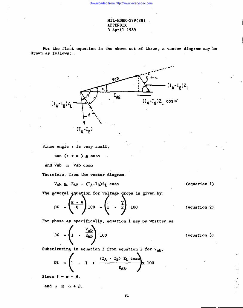
I
MIL-HOBK-299(SH)
I
I
APPSNOIX3 April 1989
For the first equation in the above set of three, a vector diagram may bedrawn as follows:
\
t
0 ‘.‘.\
(“IA-IB) ‘
Since angie e is very small,
Cos(c+a)scosa.
and Vab s Vab cosa
Therefore, from the vector diagram,
Vab ~, EN - (IA-IB)ZL COSIY (equation 1)
The general quation for voltage drops is given by:
., .~),oo .(.),OO (equation2,
For phaae AS specifically, equation 1 may be vritten aa
.( )VA
DZ-1 - Em 100
Substituting in equecion 3 from equation 1 for V*,
( )
(lA - IB) ZL cosD% -l-l+ x 100
Em
Since # - u + B.
(equation 3)
..
91
--
Downloaded from http://www.everyspec.com
I ..
.
MIL-HOBK-299(SH)APPENB7.X3 April 1989
Therefore,
“D’ -(lA-*::’”) 100,’
(equation 4)
Eq&tion 4 may be generalized by letting IL represent the difference in linecurrents (IA-IB, IB-IC or IC-IA), and E represent the line-to-line rated sourcevoltage (Em i EBC, or E&) .
Equation 4 may then be irrittenas folloys:,,.
02 -I~x
~
Since ZL - L
o% - Im
Let drop factor
SQs.tZLX E x 100
equation 5 may
mXL XZLXEX
(equation 5)
be rewritten as follows: .
100 (equation 6)
(DF),be defined as follows:
uDF - ZLX E x 100 (equation 7)
Substituting eqqation 7 into equation 6,
DZ - I~x LxDF (equation 8)
Therefore, drop factors in table XVII are calculated from equation 7 by u ingappropriate cable impe~ce characteristics and load power factora. The entriesof table XVII are prapared for a given power factor using the relationshipe - a + # from the vector diagram in 50.2.
50.3 ~L actors usi load wattsand vars. I?hissection contains the derivation of the equations used tocalculate voltage drop in lighting systems by the load watts and vars method.Table KVIII contains drop factora for type 15TSW cable vhich were calculatedusing the &rived equationa. The equations may be used to calculate drop factorsfor other cable types, if the cable characteristics are Imown. The followingvector diagram is used in derivation of the equations:
.
. .
--
92
Downloaded from http://www.everyspec.com
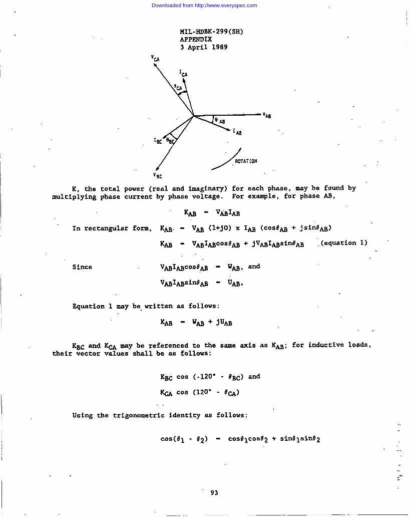
1“I
I
K. the totalmultiplying ply3se
KIL-HDBK-299(SH)APPEWDIX3 April 1989
“m
&
‘CA
%
VA8‘JAa
1.481~~~
/ >TA7[QN,.“EC
power (real and imaginary) for each phase, may becurrent by phase voltage. For example, for phase
found byAs,
In rectangular form, KAB. - VM (l+jO) x 1~ (COSOW + jsinOAg)
Since vMIMc05e0 -
V@~sinfl~ -
Equation 1 may be.vritten as follows:
W~, and
UAB,
KM . w#@ + jupJ.
KBC and ~ may be referenced to the same axis as Km; for inductive loads,their vector values shall be as follows:
KBC cos (-120” - #BC) and
@ co, (120” - o~)
Using the trigonometric identity as follows:..
c08(e1 - e2) - COS01COS62 + sin91sinfJ2.’. .
.-
93
Downloaded from http://www.everyspec.com
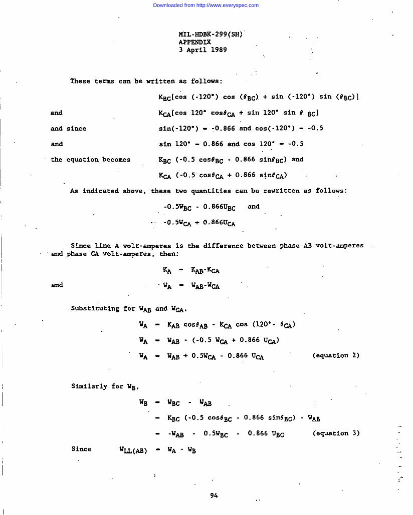
and
snd
snd
the
I
snd
PIIL-HDBK-299(SH)APPKWDXK3 April 1989
These terms can be written ss follows:
KBCICOS (-12f)”)cos (#BC).+ Sin (-120”) sin (OBC)
~[cos 120” c0sr3~ + sin 120” sin # Bc]
since sin(-120”) - ;0.866 snd COS(-120”) - -0.5
sin 120” - 0.866 snd COS 120” - -0.5
equation becomes KBC (-0.5 COSOP,C - 0.866 sin#BC) snd
KCA (’-0.5”cOs@CA + 0.866 s!nd~)
As indicated above, these tvo quantities can be rewritten as follows:
-0.5WBc - 0.866UBC and
-- -0.5VCA + 0.866UCA
Since line A vole-smperes is the difference between phase AS volt-smperesphase CA volt-smperes, then:
Substituting for l?~ and UW,
VA - KM COSt?~ - ~ COS (120”- #~)
V* -wAg- (-0.5 WCA + 0.666 UCA)
WA . w~ + 0.5WCA - 0.866 UCA (equation 2)
siMihrly fOr WB,
WB-WBC-tlU.
- KBC (-0.5 COS8BC - 0.866 Sin@BC) - w~
-ti~ - 0.5WBc - 0.866 UBC (equstion 3)
Since ‘IJ(AB) - ‘A - WB
94 ,,
--
Downloaded from http://www.everyspec.com

I
MIL-HDBK-299(SH)APPSNDIX3 April 1989
Substituting from equations 2 and 3,
%L(AB) - 2w/@ + 0.5 (WBC + Wm) + 0.866 (UBC - UW)
and 2w~(Ag) - 4w~ + wB~ + WW + 1.73 (UBC - UM)
By an analysis similar to tb”t shown above, the equation for 2 UU(AB) msybe found.
Equations for WU(BC), WLL(CA), ULL(BC) and U~(CA) “maybe fO~d byreferring the K vectors to the same sxis of VBC for WLL(BC) and ULL(BC), and VCAfor WU(W) and ULL(W) . Equs%ions for capacitive loads, or mixed inductive and
I capacitive 10a&, may also be &rived by assigning the proper sign to each phase~gle (negative for inductive and positive for capacitive) in determining valuesof cosine and sine (~ 120” ~ 0). It shouLd be noted that if these equations aredivided by load voltage, V, similar expressions involving resistive and reactive.—‘c-orients of current will result. In-some casks, use of these equations may bemore convenient than the vector rotation method when currents are used incalculations.
The general voltage.drop equ.atiorifor lighting systems as derived in 50.2 is
.Dz - Iux LxDF (equation 4)
Since W~ - Iu (V) (cosa ), subs~ituting 2W~ - 21~’ (V) (cosa ) intoequation 4 will give
LX2WLLXDFD% - (equation 5)
1.
I2(v) Cosa
I LX a new drop factor (DF’) be &fined as follows:
DFDF’ - 2(V) COSa
Therefore,
D% - LX2WLLXDF’..
The three-phase voltage drop equation (equation=gle, in accOrkCe with the following derivation:
I5) may be revritten, without
95
.-.
..-
Downloaded from http://www.everyspec.com

MIL-HDBK-299(SH)APPEWDLX3 April 1989
I
AS shovn in 50.2,
Cos (a + 81DF - Z~X E x 100,
where # - a+fl
Substituting for DF in equation 5,
I L x Wu x ZL (COSQ cosfl~ sinn sir@) x 100
IDX - E(V) COSQ
Using a trigonometric identity,
100 x L x W~ x ZL (cosa cos~ ~ sinm si@)
02 - E(V) COSa.
100 x L X Ku X (R COSU f X Sinm)
E(V)
100 x L X (RW~ ~ X’U~)
120 x 115
DZ - 725 (L) (RW~ ~ XU~) x 10-5, vhere R and X are cable co~t~ts =shown in table XIV. Plus is used in the above equation for inductive loads, andminus is used for capacitive loa&. In order to calculate the percentage voltagedrop, entries in table XVIII may be used vitb the value of power specified andlength of the cable.
50..4 ge vat 0 0 es stanceri i n f r i and reactance values for cables. Thissection contains the derivation of.valuss for cable resistance and reactance usedin tables KIII, XIV, KV, and XVI. The cables identified in this dmcument haveconductor.diameters of stamdsrd AWG, rather than Navy siZes. Navy sizes areclose to equivalent AWG sizes. However, the differences are enough to affeetcable impedsnce values.
The i,&al method of determining resistance and reactance valuas forparticular cable types is by test measurements. In the absence of.test data,however, these values may be derived mathematically.
50.4.1 Ca cu at 0 0~ or cab eS. The method used hereinfor calculating the resistance of electrical cables is based upon the onespecified.in ASTM B 258 snd ASTM B 8. This gensral method may be used tocalculate with reasonable accuracy the resistance,of sny cable with concentric-lay-strandsd conductors. lhe overall approach is as follows:
96
.-
.
,-...--
Downloaded from http://www.everyspec.com

1,
MIL-HDBK-299(SH)APPF.NDIK3 April 1989
(1) Calculate & resistance at 20”C for solid conductors usingASTM B 258.
(2) Adjwt for concentric-lay-strandedconductors using ASTM B 8.(3) Adjust for ac resistance by’multiplying by the ac/dc resistance
ratio at the &sired frsquency (60 or 400 Hz).(4) Adjust to temperature for which cable service is &signed. As
specified in ASTM B 258,“& ,resistanceat 20°C in ohms per 1000feet is given by:
()R& - % 105.35
where p (resistivity) is 875.20 ohm-pounds per mile squared, andis 6 (dsnaity) 8.89 grams per centimeter cubed. Therefore,
R& - 10.371.47d2
where d is the diameter of.the conductor in mfls. Therefore. thefolloving chart for tj@e’5G-“equivalentsolid.conductors shali begenerated.
~ (ohms per 1000 ft) atDesienation Qia. (mils~ 20”C
SG-3 50.8 4.018SG-4 64.1 2.522SG-9 101.9 0.999SG-14 114.4 “’” .792SG-23 144.3 .498SG-50 229.4 .197SG-75 289.3 .124SG-1OO 324.9 .098SG-150 409.6 .062SG-200 460.0 .049SG-300 547.7 .035SG-400 643.1 .025
This data for solid conductors must be adju.stedfor concentric.lay-strandedSG conductors. Because of the lay in stranded conductors, the resistance foreach unit length of a strandsd conductor is slightly greatsr titanthat for anequivalent diameter solid conductor. ASTM B 8 provides a precise mathematicalmethod for &riving the multiplying factor (k, in percent) that is used to modify& resistance of a solid conductor for ,- equivalent concentric-lay-stranded ..conductor. A lay factor (mind) is @termined for each wire in a concentric-lay-strandsd conductor from ‘..-
“nd - ~
.,.
,-..,_-
97
Downloaded from http://www.everyspec.com
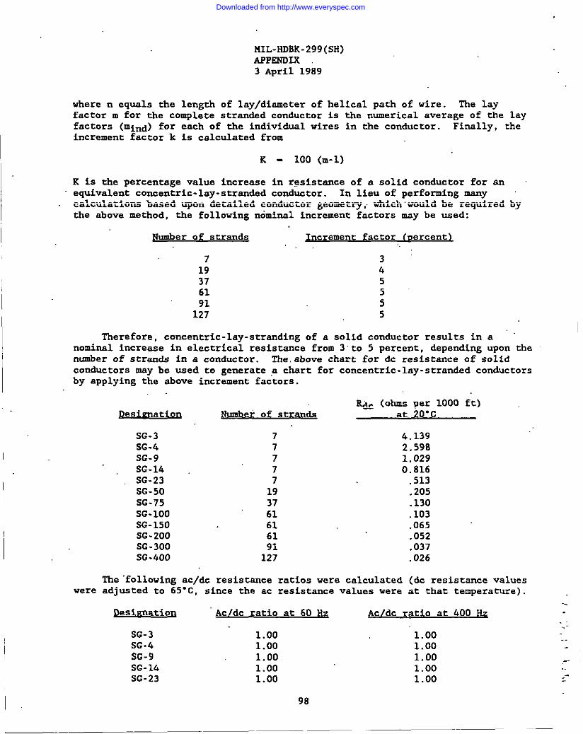
MIL-HDBK-299(SH)APPSNDLX3 April 1989
where n equals the length of lay/diameter of helical path of wire. The layfactor m for the complete strandsd conductor is the numerical average of the layfactors (mind) for each of the individual wires in the conductor. Finally, theincrement factor k is calculated from
K- 100 (m-1)
K is the percentage valus increase in resistance of a solid conductor for anequivalent concentric-lay-stranded conductor. In lieu of performing manycalculations based upon &tailed conductor geometry,.which.would be required bythe above method, the folloving n6minal increment factors may be used:
Number of strands Jncrement factor (nercent~
7 3:19 437 561 591 5
127 5
Therefore, concentric-lay-stranding of a solid conductor results in anominal increase in electrical resistance from 3‘to 5 percent, depending upon thenumber of strands in a conductor. The.above chart for dc resistance of solid
I conductors msy be used to generate ,achsrt for concentric.lay-stranded conductorsby applying the above increment factors.
~ (ohms per 1000 ft)Desienation flumberof stran& at 20”C
SG-3 7 4.139SG-.4 7 2.598SG-9 7 1.029SG-14 7 0.816
were
SG-23 7SG-50 19SG-75 37SG-1OO 61SG-150 61SG-200 61SG-300 91SG-400 127
The ‘folloving ac/dt resistsnce ratios were calculatedadjusted to 65”C, since the ac resistance values were
;513.205.130.103.065.052.037.026
(dc resistance valuesat that temperature).
..Desireation Ac/dc ratio at 60 Hz Ac/dc ratio at LOO Hz
-...SG-3 1.00 1.00SG-4 1.00
..1.00
SG-9 1.00 1.00 -.SG-14 1.00 1.00SG-23 1.00 1.00
--
98
Downloaded from http://www.everyspec.com

MIL-HOBK-299(SH)APPSNDIX3 April 1989
Desireation
SG-50SG-75SG-1OOSG-150SG-200SG-300SG-400
Ac/dc ratio at 60 Hz
1.001.001.001.001.001.001.00
Acldc ratio at 400 HZ
1.001.001.061.091.141.432.35
Therefore, the above chart for & resistance of concentric-lay-st!randadconductors msy be used to generate a chart of ac resistances, 60 and 400 w20”C, by multiplication of the appropriate ac~dc resistance ratio.
Ac resistance, 60 Hz Ac resistance, 400 HzDesisnation (ohms r.er1000 ft)- (ohms per 1000 ft)
SG-3 4.139 4.139SG-4 2.598 2.598SG-9 1.029SG-14
1.0290.816 0.816
SG-23 .513SG-50 .205.SG-75 .130SG-1OO .103SG-150 .665SG-200 .052SG-300 .037SG-400 .026
Finally, ac resistances must be adjusted for the designservice. Resistance values at a selectad temperature may bemeasured resistance values at snother temperature by
I Rt _ Rto [1 + a (t-to)]
Where:
For
ForiS 65”c.
The,.
at
.513
.205
.130
.109
.071
.059
.053
.061
temperature of cablecalculated from
Rt - required resistance.Rto - messked resistance.
t - temperature at which resistance is required.
to - temperature at which resistance was measured.a - temperature coefficient of resistance at measured temperature.
to - 20”C, a - 0.00393 per l“c, and to - 25”C, a - 0.00385 per l-C.
tables XIII (60 Hz) and XIV (400 Hz), the applicable temperature value .-l’herefore,resistances in tha above chart must be multiplied by . -.
1 + 0.00393 (65-20) - 1.177 ,. ..
following data results:
_-
99
Downloaded from http://www.everyspec.com
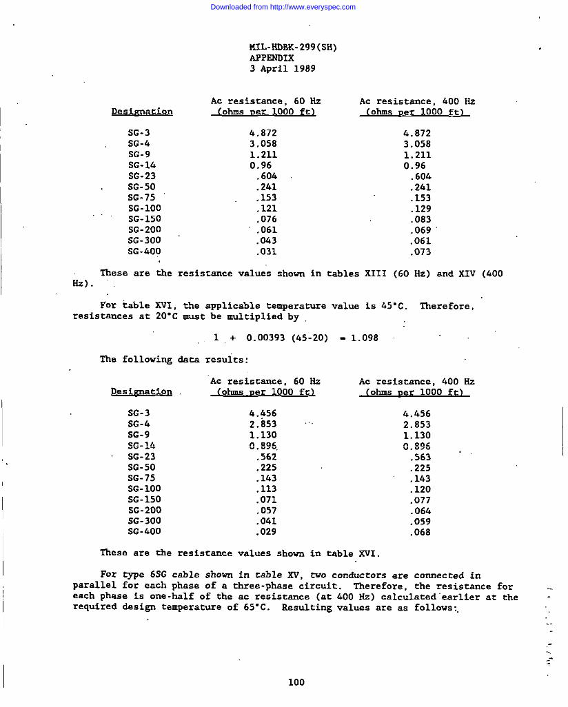
KIL-HOBK-299(SH)APPENOIX3 April 1989
Ac resistance, 60 HzDesignation (ohms Der 1000 ft1
SG-3 4.872SG-4 3.058SG-9 1.211SG-14 0.96SG-23 .604SG-50 .241SG-75 .153SG-1OO .121SG-150 .076SG-200 .061SG-300 .063SG-400 .031
Ac resistance, 400 Hz(ohms uer 1000 ft)
4.8723.0581.2110.96.606.241.153.129.083.069.061.073
These are the resistance values shown in tables XIII (60 Hz) and XIV (400L).
For table XVI, the applicable temperature value is 45”C. Therefore,resistances at 20”c must be multiplied by
1 + 0.00393 (45-20) _ 1.098
The following &ta resul’ts:
Designation
SG-3SG-4SG-9SG-14SG-23SG-50SG-75SG-1OOSG-150SG-200SG-300SG-400
‘Ac resistance, 60 Hz~1 000 ft
4.~562.853 “1.1300.896,.562.225.143.113.071.057.041.029
Ac resistance, 400 Hz(ohms uer 1000 ft)
4.4562.8531.1300.896.563 “.225.143.120.077.064.059.068
These are the resiscance values shovn in table XVI.
For type 6SG cable shown in cable xv, two conductors are connected inparallel for each phase of a three-phsse circuit. Therefore. the resistance for ..each phase is one-half of the aC resist=ce (at
required &sign temperature of 65-C. Resulting400 Hz) calculated“earlierat the -values are as follows:,
..
,-
-:
Downloaded from http://www.everyspec.com
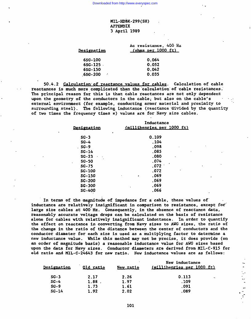
I,.
I KIL-HDBK-299(SH)APPENDIX3 April 1989
pesicnation
6sG-1OO6SG-1256sG-150.6sG-200 ~~
Ac resistance, 400 Hz~ 000 t
0.0640.0520.0420.035
50.4.2 Calculation”of reactance values for cables. Calculation of cablereactcnces is much more complicated than the “calculation”of cable resistances.’The principal rsason for this is that cable reactance are not only dependentwon the geometry of the conductors in the cable; but also on the cable.’s ..externcl environment (for exxmple, conducting armor mxterial and proximity tosurrounding steel). The folloving inductance (reactance‘dividedby the quanti~of tvo times the frequency times m) values are for Navy size cables.
I
Pe i=ns ation
SG-3SG-kSG-9SG-14SG-23 .,SG-50SG-75SG-1OOSG-150SG-200SG-300
Inducta.ncemill ihenries ner 1000 ft~
0.109.104.098.085.080.074.072.072.069.069.069
I SG-400 .066
In terms of the .magni~e of impedance for a cable, these values of’inductance are relatively in.significant in comparison to resistance, except for’large size cables at 400 Hz. Conxequsntly, in the absence of reactance data,reasonsblv accurate voltage drous can be calculated on the basis of resistance-.alone for cables with relatively insignificant inductance. In Or&r to quantifythe effect on reactxnce in converting from Navy sizes to AWG sizes, the ratio ofthe change in the ratio of the distsnce betveen the center of conductors snd theconduccor diameter.for each size is used sx a multiplying factor to determine anew inductance value. While this method may not be precise, it does provide (onan order of magnitu& bssis) a reaxonsble inductancevalue for AWG sizes basedupon the data for Navy sizes. Conductor dicmetersare derived from MIL-C-9,15forold ratio snd N3L-C-24643 for new ratio. New inductancevalues are as follows:
I New inductanceDesivnatiorl ~ New ratio Jmillihenries uer 1 )-000 ft
I
SG-3 2.17 2.26 0.113SG-4 1.88 . 1.97 .109
ISG-9 1.73 1.61 .091SG-lk 1.92 2.02 .089
101
..
.,. --.-
Downloaded from http://www.everyspec.com
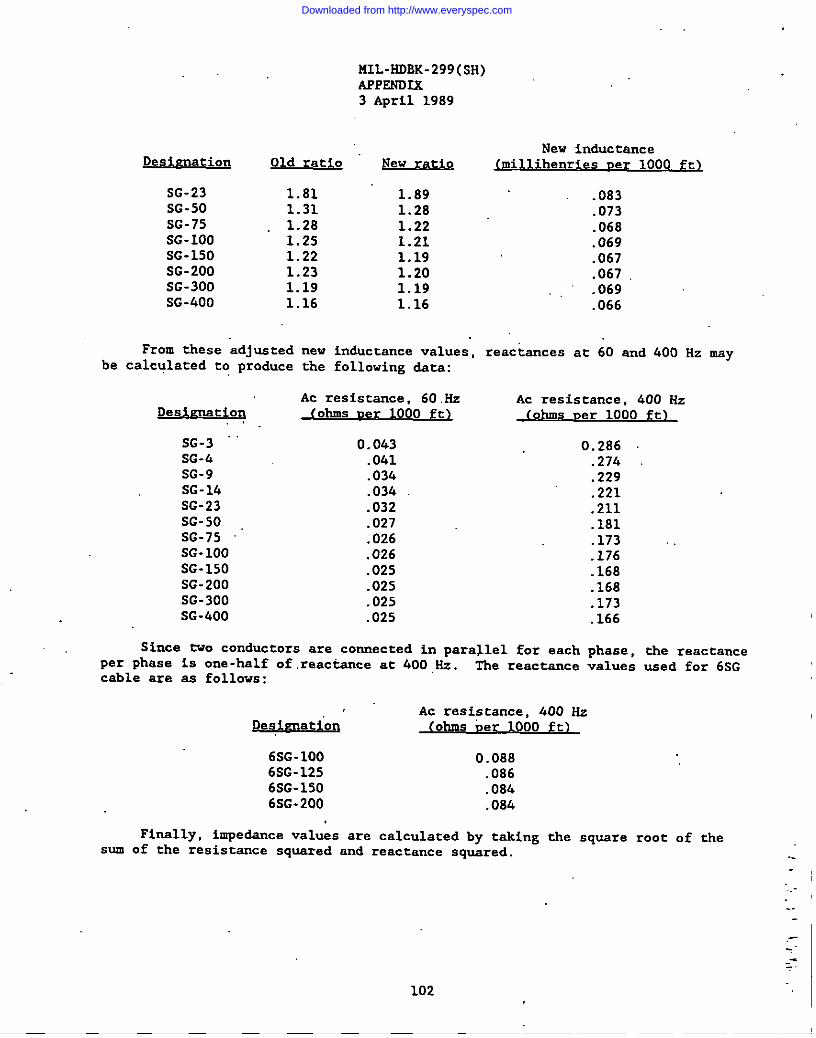
MIL-HDBK-299(SH)APPSNDIK ‘ -3 April 1989
Desienation
SG-23SG-50SG-75SG-100SG-150SG-200SG-300SG-600
Old ratio New ratio
IFrom these adjusted
I be calculated to produce
1.811.311.281.251.221.231.191.16
Desienatioq. .
SG-3SG-hSG-9SG-14SG-23SG-50SG-75SG-100SG-150SG-200SG-300SG-400
1.891.281.221.211.191.201.191.16
new inductance values,the following data:
Ac resistance, 60.Hz(ohms ner 1000 ft~
o.o&3.041.034.034.032.027.026.026.025.025.025.025
New inductance
.083
.073
.068
.069
.067
.067
.069
.066
reactance at 60 and 400 Hz may
Ac resistance, 400 Hz(ohms ner 1000 ft)
0.286.274.229.221.211.181.173 .,.176.168.168.173.166
Since tvo conductors are connected in parallel for each phase, the reactance
per phase is one-half of reactance at 400 ,Hz. The reactance values used for 6SGcable are as follows:
,“ Ac resistance, 400 Hz.g&&r@& (ohms ber 1000 ft)
6SG-1OO 0.0886SG-125 .0866SG-150 .08h6SG-200 .084
Finally, impedance values are calculated by taking the square root of thesum of the resistance squared and reactance squared.
. .
,---
-=
102
Downloaded from http://www.everyspec.com

MIL-HDBK-299(SH)3 April 1989
INDEX
Cable Information
a3!2
Cable application data ...........................’..................Cable classification ,..............................................Identification information 1.........................................Methods of applying identification .................................Ratings and characteristics ........................................Supersession data ...................................................Types and construction characteristics .............................Year of manufacture ................................................
Cable Ratings and Characteristics
CVSF . . . . . . . . . . . . . . . . . . . . .DLT ......................DX .......................DXA ......................DXOW .....................DXW ......................DXWA .....................DSS ......................DSWS .....................FSS ......................Fx .......................FxA ......................Fxow .....................
“.FKW ......................FXWA .....................JAS ......................UCVSF ...................LSDCOP ...................LSDHOF ...................L5DNW ....................NDNWA ...................LSDPS ....................lSDRW ....................ISDRWA: ..................ISDSGA .:.................ISDSGU ...................LSECM ....................LSECMA ...................LSFHOF ...................I.SFNW....................LWTilJA....................
lkls.e
6868616156.565667656761615656566a515h5142423037373031.40&o514262
LSFPS ....................ISFSCA . . . . . . .. . . . . . . . . . . .LSFSGU ....................I.SMA.....................Lsncos ...................ISIDu ....................LSKDY. ....................L5MHOF ...................LSMMOP ...................EMWW ....................ISMNWA ...................Mm ....................IS4S .....................EMSA....................LSISCA ...................IS4Scs.. .........’........LSMSCU ...................Lam .....................LSnus ....................ISPBTN ..................’..LSPBTMU ...................ISPI .....................LSSHOF .....................ISIRU ....................LSSRWA ...................USSF ....................LSSSGA ...................E&XXI..... ..............ISTUA ...................LSTCJU ...................
1928121630’26318
313131455637375354454550L545343434454540.!+0415137375131323535
--
103
Downloaded from http://www.everyspec.com
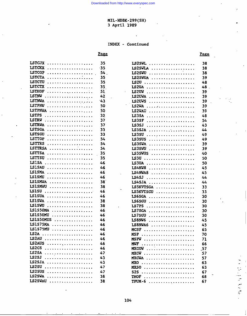
L5TC.7X...................LSTCKX ...................LSTCOP ...................LSTCTA ...................ISTCTU ...................lST~ ...................LSTHOF . . . . . . . . .. . . . . . . . . . .Ismw. . . . . . . . . . . . . . . . . . . .LSTNWA .....................LSTPNW ..............”.....LSTPNWA ..................ISTPS ....................LSTRW ....................IJY3!RWA. ..................ISTSGA ...................LSTSCU ...................L5TTOP ...................lSr-TRS...................LS2TRSA ............’......UTITSA. ..................LSTTSU ...................LSISA ....................EilSAU ...................ISISMA ...................IS1S14U...................LSISUWA ..................Lslsmwu ..................ISlsu ....................ISISUA ...................ISISWA ...................ISlswu ...................L51S50NA .................LSlssomu .................LS1S50KUS ................LS1S75MA .................IS1S75MU .................LS2A .....................IS2AU ....................LS2AUS ...................LS2CS ....................LS2SA ....................L52SJ .....................LS2SJA ...................L52SU ....................LS2SUS ...................E2SWA ...................LS2SUAU ..................
MIL-HDBK-299(SH)3 April 1989
Centinued
E=s=
3s3554,353535,5162’43505032373733335454543535466646f463838 .464638384646&64646464646&647h34347673838
L92SWL ...................IS2SWLA ..................LS2SWU ...............”.....LS2SWUA ..................IS2U .....................LS2UA ....................LS2UW ....................,IJ32UWA...................,U2UWS ...................LS2WA ....>...............LS21JAU...................LS3SA ....................IS3SF ....................LS3SJ ....................LS3SJA .....................L53SU .....................IS3SUS ...................LS3SWA ...................LS3SWU...................L$3SWUS ..................LS3U .....................IS3UA .....................LS4WW8 ...................M4NTJA8 ...................IS4SJ ....................LS4SJA ...................LS5KVTSGA ................M5KVTSCU ................LS6SGA ...................LS6SGU ...................IJ37PS....................LS7SCA ...................U7SGU ...................M8NW6 ...................LS8NWA6 ..................HCSF. ....................KSP . . . . . . . . . . . . . . . . . . . . . .MSFW . . . . . . . . . . . . . . . . . . . . .l’lws . . . . . . . . . . . . . . . . . . . . . .Hxcow . . . . . . . . . . . . . . . . . . . .mm. . . . . . . . . . . . . . . . . . . . .MXCWA ....................Mxo ......................14xs o....................S2S ......................THOF .....................TFUM-6 ...................
&Q,
383838394848.393939 ‘“.393948546344494939394050504545444433333030303030454565707166
.57575763636768 ‘“67
-:.-
.--,--
104
Downloaded from http://www.everyspec.com

MIL-HDBK-299(sH)3 April 1989
INDSK - Continued
TRF . . . . . . . . . . . . . . . . . . . . . .TRKP . . . . . . . . . . . . . . . . . . . . .TSP ......................TSPA .....................TSS ......................l-lx......................TTKA .....................TTXou ....................‘rfxs.....................TTXSA. ...................TI’X.So....................2TXW.....................TTXWA ....................Tx .......................TxA .......................IKou. ....................TKW ......................TXWA .....................lSWF .....................
“IX14So ....................mow.. ..’................2SWP .....................
EaPs
686871716763635863,63635858616156565667625967
2KA0 . . . . . . . . . . . . . . . . . . . .2K0 . . . . . . . . . . . . . . . . . . . . .2XOIJ . . . . . . . . . . . . . . . . . . . .2KS . . . . . . . . . . . . . . . . . . . . .2KSA . . . . . . . . . . . . . ...’..”..2KSAOU . . . . . . . . . . . . . . . . . .2KSAU . . . . . . . . . . . . . . . . . . .2K2AUA . . . . . . . . . . . . . .. . . .2KS0 . . . . . . . . . . . . . . . . . . . .2KSOV . . . . ... . . . . . . . . . .. . . .2KSX0 . . . . . . . . . . . . . . . . . . .2KSU . . . . . . . . . . . . . . . . . . . .2KSVA ...................3KS .....................3KSA .....................3KSOW .....................3XSV ....................3XSWA ...................5ss .....................7ss .....................7X37 ....................7XWA ....................
Appendix
Cable characteristics, LSTSGA cable ...............................Definitions’.......................................................Derivation of resistance and reactancevalues for cables ................................................Drop factors for IS6SGA cable .....................................Drop factors for Ii3TSGAcable (60-H2) .............................Drop factors for LqTSGA cable (400-Hz) .............................Drop factors for ISTSGA cable (using I and 1~ drop factorvalues) ..........................................................Drop,factors for LSTSGA cable (using watts and vars) ..............Voltage drop equations for ac circuits .......’.....................Voltage drop equations for &circuits ............................
E@
626259626259595962.59635960636360606069675656
.@&
8275
96798381
83’.847778
105 ,,
Downloaded from http://www.everyspec.com
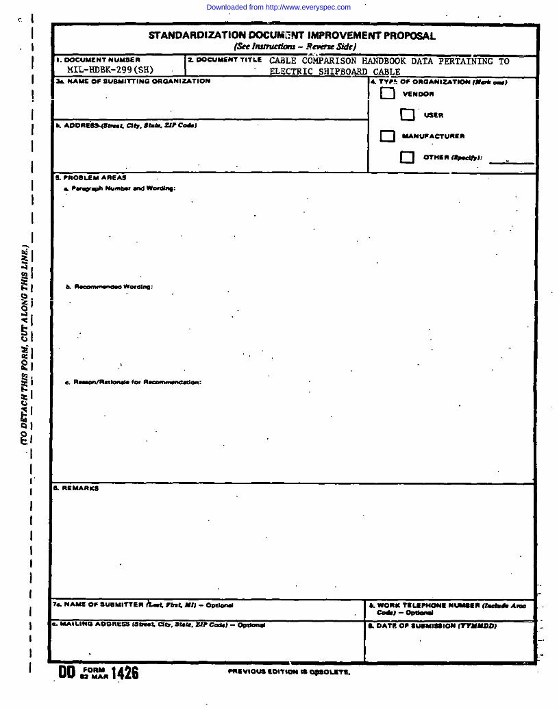
. .c I
I.1
IIII1I
III
II
iilz,
“1I,.I
IIII
:I
I II I
I
/
STANDARDIZATION DOCUMWT IMPROVEMENT PROPOSAL(sEl?Inmuuiau - Jkwsewe)
. DOCUMENT NUMSER 2 00 CUMENT TITLE MLE C<ti~N-
MIL-HDBK-299(Sli) ELECTRIC sHIPBOARD CABLE. MAME0$SWSWI-IHOORGANIZATION ~~, oFo”oA”12ATm.,”d-,
I o 07”En f8mdfy,,-
●1100LEM AREAS
.“,
. NAME OF SUBU1lTEm b L ~fmt.Ml) - O@mul b. ~,c l~WNE Nwun fkha A=
MAILINCI &09RESS (Slwd, CIti, stsm, ZIP c&) . ~ ~ DATE OP SWMMEIOM fTYMMDDJ
1’
Downloaded from http://www.everyspec.com
,
I
lNSTRUCf10N5 In & continuing ●ffon to msh our tidardkation documen?s better, tbe DoD pm?tda ti form for use in
ct!bndttiag COmraenw md wggatbm for im> owntenb. AD m of military standsrdkstkn documenb e hvitedtoprovide
ruggatkoru.lhh form IMY b 4etacbe?,folded along tbe fines indiated, taped along the Iooae edge (DO NOT STAPLE), and
mailed. Xo black 5, be at QIM@C ar Ponible ●bout Puticuhr problem smw such u wording wbii required interpretation, WSI
* tid. =~~=. 100% CII~eUO_ ~ wu i-mi=tibk ~ tiw PIupcued wrdii CIIIW= wbicb mxld tievkte tbe~blemn. Enterinblab C my renwlm not mhted to - specif~ Parsgmpb of the document. If block 7 u lwed OUt, m
Allowiedg.?memt Wu! be mailed to you rntbia .90dayttolotyou kno= Nut you! comnienb wererec6mdmdue beii
Camidemd.
NO’J93 lhis form IMY not be used to request copia of documents, nor to request wsivem, dtitiotu, or &fiition of
~=ti= IW-=1* On CW=nt -U=* @-fJ mbmitted 00 thh form do I!ot constitute or hllpfy ●Utb0ri21ti0n
to &w -y portion Et tbe referenced docuotent(s)or tosmend contmcttmlreq~nk
I
(Fold EIO,U thb UIU)
(Fold e&IU WI lINJ
.
DEPARTMENT OF THE NAW
COMMANDERNAvAL SEA SYSTEMS COMMAND (SSA 55Z3)DEPARTMENT OF TNE NAVY
111111 FI
WASHINGTON , DC 20362-5101 UN17E0 =ATCS
OFFICIAL SLISINE~●ENALTY FOR ●RIVATE USE E300 B~S~NE:SNoR~PLY MAIL
WASHINGTON D. C.
POSt_AGE WILL 8E PAID EY THE DEPARTMENT OF THE NAVY
~ “
COMMANDER~ .-
NAVMJ SEA SYSTEMS COKMAND (SEA 5523) ~ .“
DEPARTMENT OF TNE NAVY ~ “:
WASHINGTON, DC 20362-5101.:
~=
,,
Downloaded from http://www.everyspec.com

Downloaded from http://www.everyspec.com
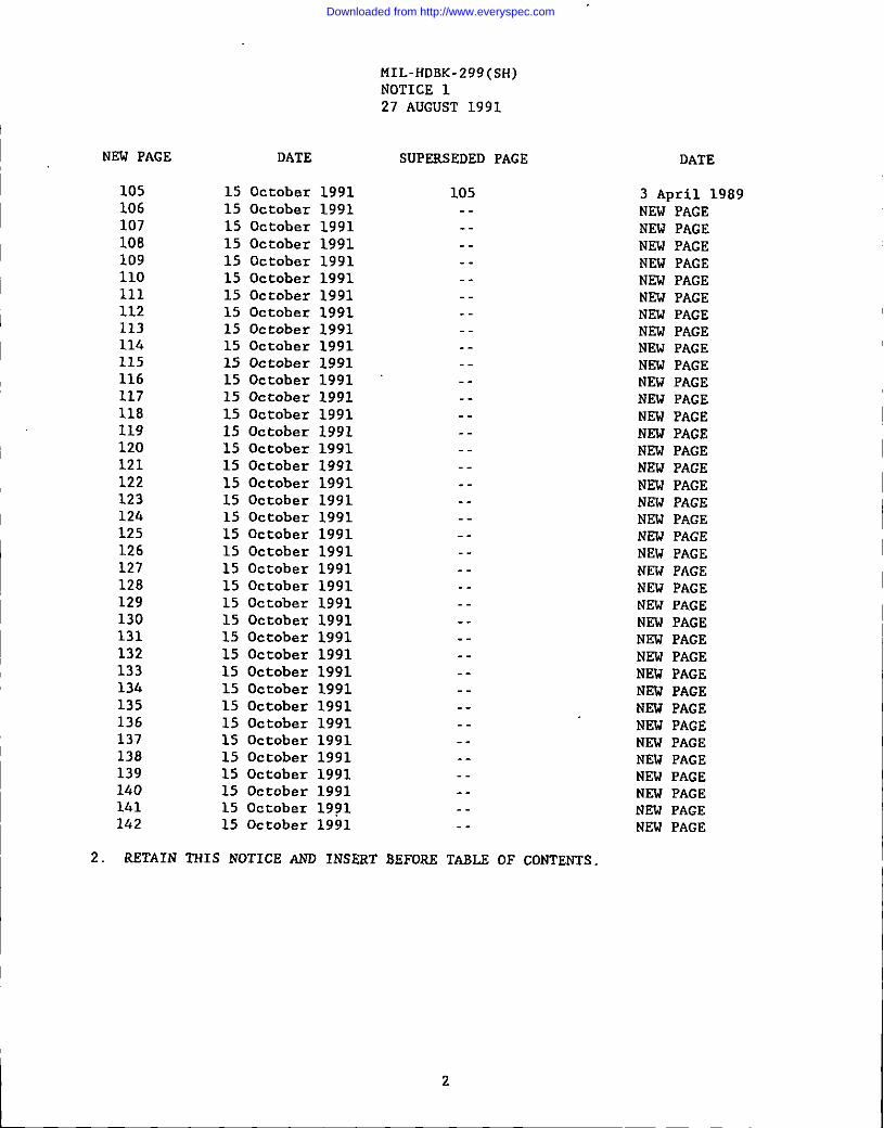
Downloaded from http://www.everyspec.com

Downloaded from http://www.everyspec.com

Downloaded from http://www.everyspec.com

Downloaded from http://www.everyspec.com
Downloaded from http://www.everyspec.com

Downloaded from http://www.everyspec.com

Downloaded from http://www.everyspec.com

Downloaded from http://www.everyspec.com
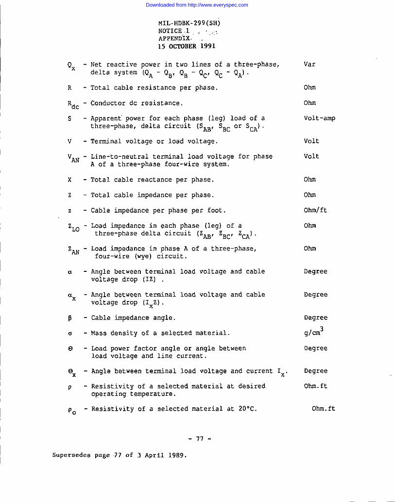
Downloaded from http://www.everyspec.com

Downloaded from http://www.everyspec.com
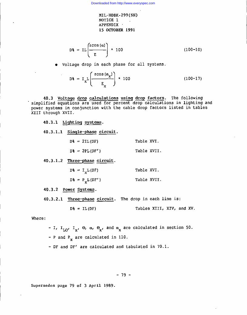
Downloaded from http://www.everyspec.com
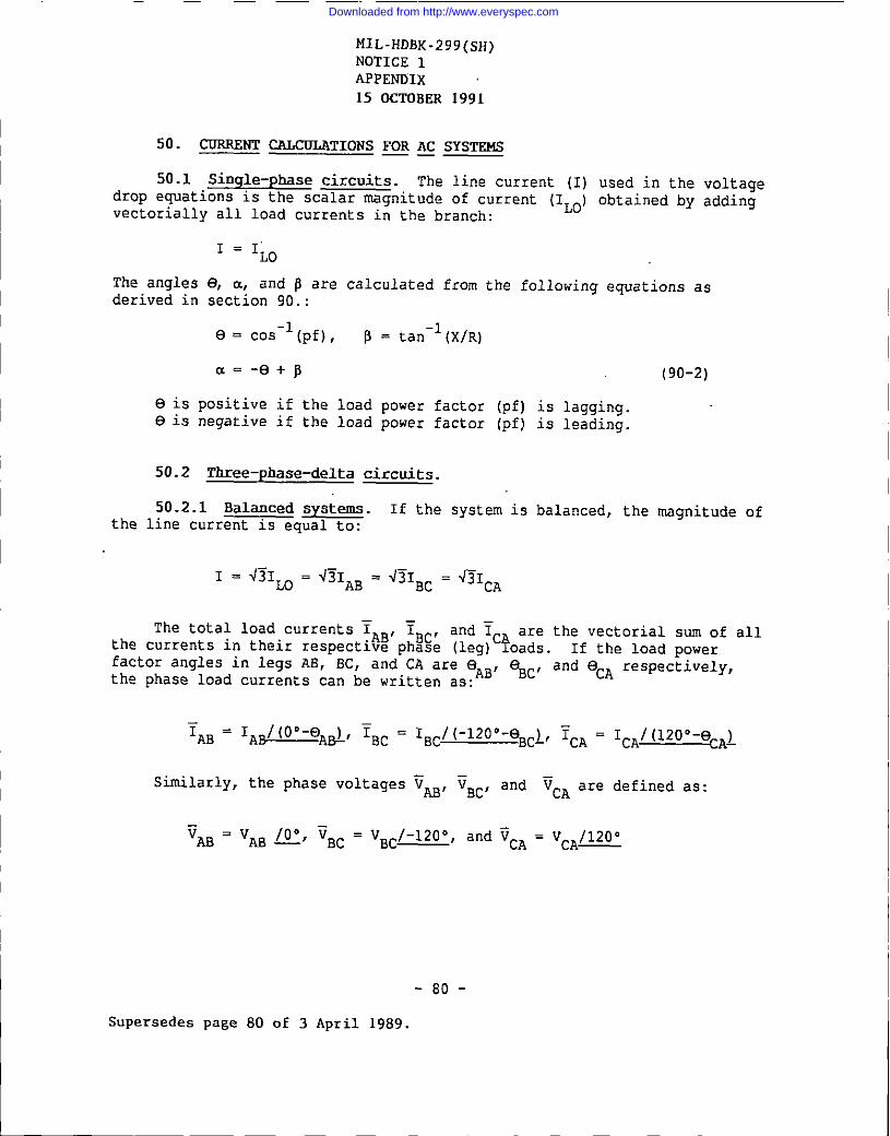
Downloaded from http://www.everyspec.com
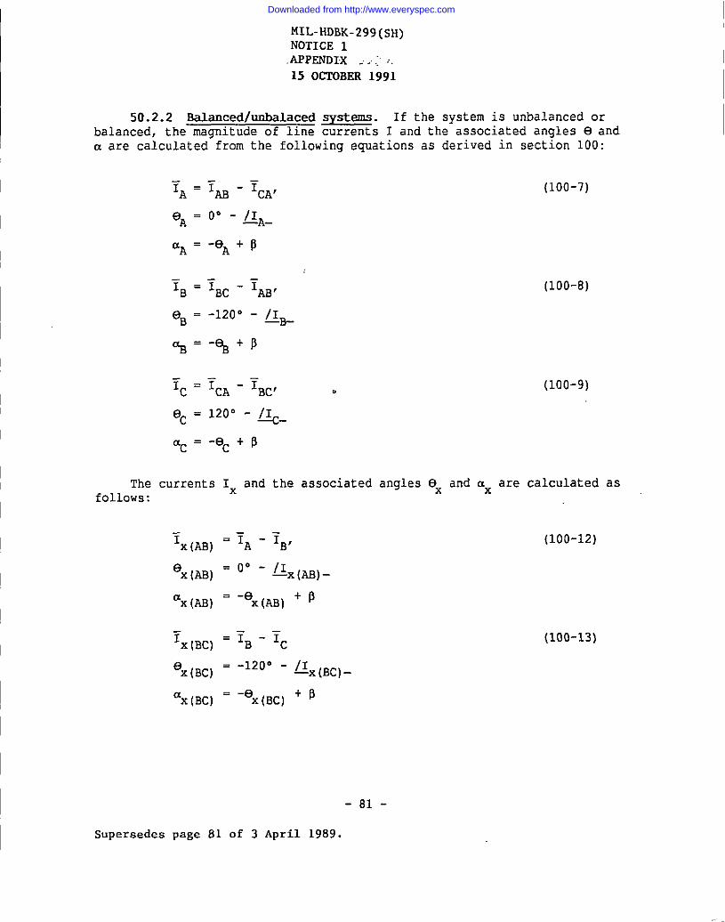
Downloaded from http://www.everyspec.com
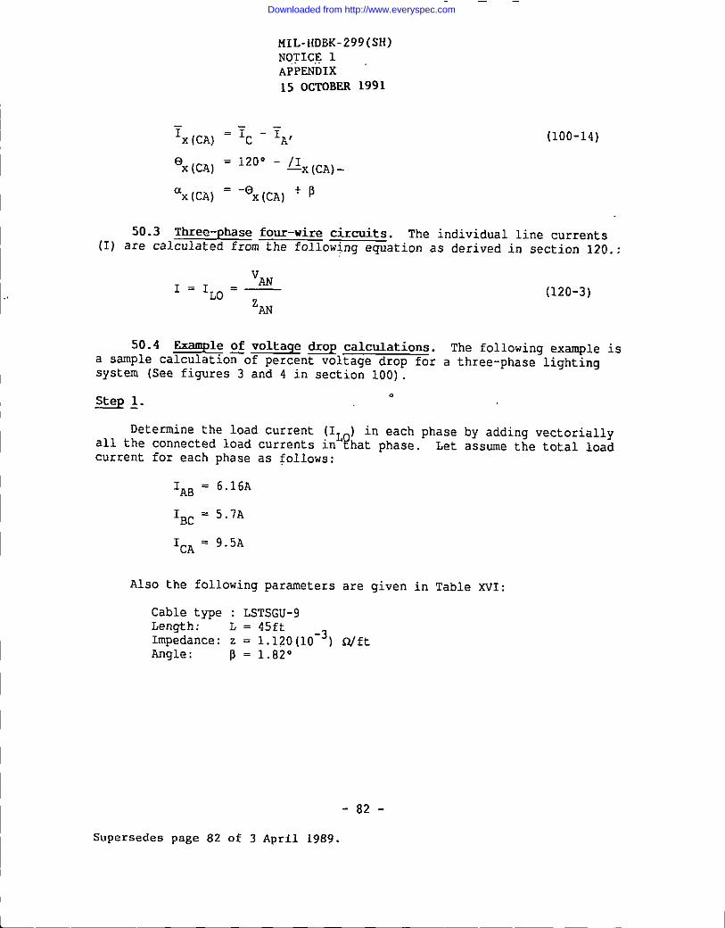
Downloaded from http://www.everyspec.com

Downloaded from http://www.everyspec.com

Downloaded from http://www.everyspec.com
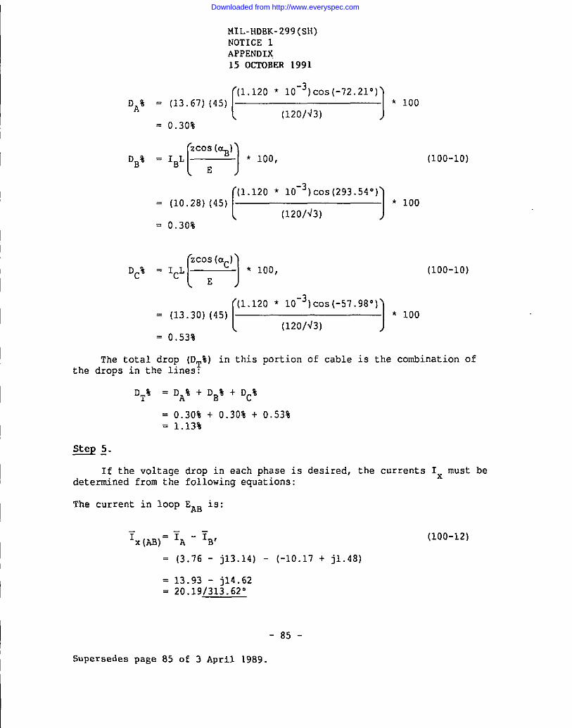
Downloaded from http://www.everyspec.com
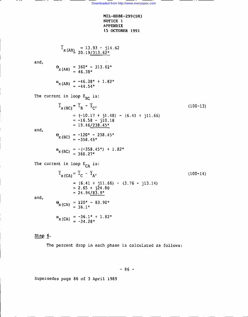
Downloaded from http://www.everyspec.com

Downloaded from http://www.everyspec.com

Downloaded from http://www.everyspec.com
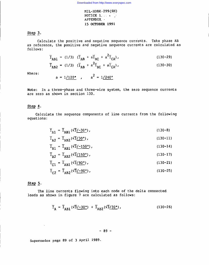
Downloaded from http://www.everyspec.com

Downloaded from http://www.everyspec.com

Downloaded from http://www.everyspec.com
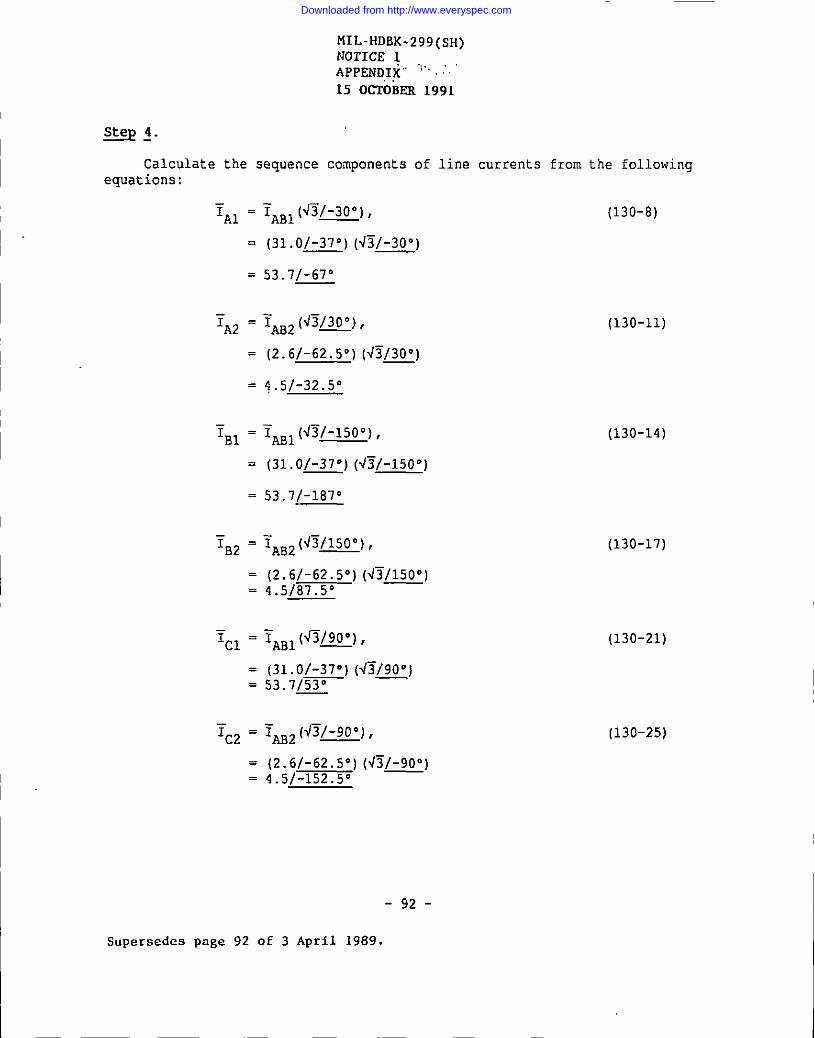
Downloaded from http://www.everyspec.com

Downloaded from http://www.everyspec.com
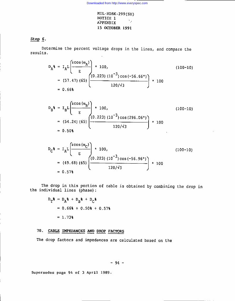
Downloaded from http://www.everyspec.com
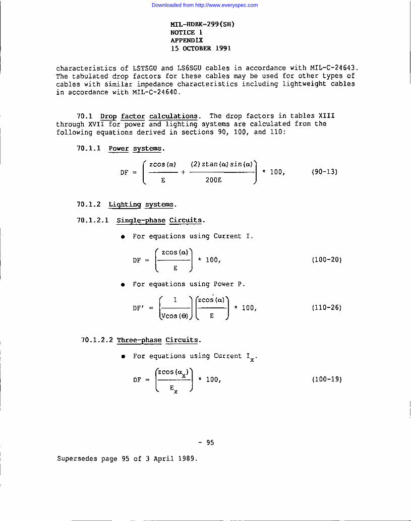
Downloaded from http://www.everyspec.com

Downloaded from http://www.everyspec.com
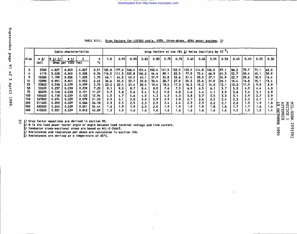
Downloaded from http://www.everyspec.com
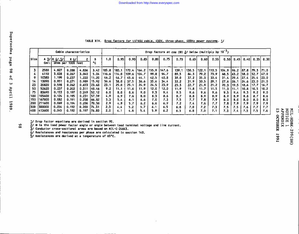
Downloaded from http://www.everyspec.com
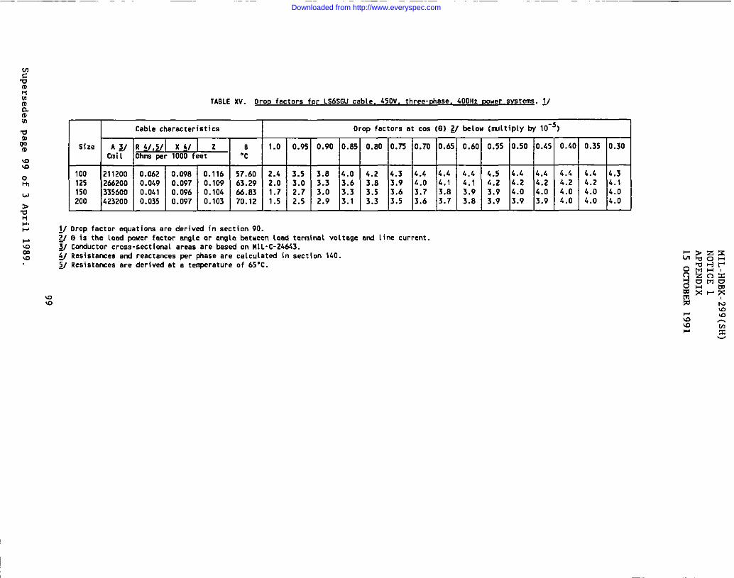
Downloaded from http://www.everyspec.com

Downloaded from http://www.everyspec.com

Downloaded from http://www.everyspec.com

Downloaded from http://www.everyspec.com
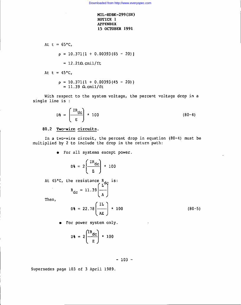
Downloaded from http://www.everyspec.com
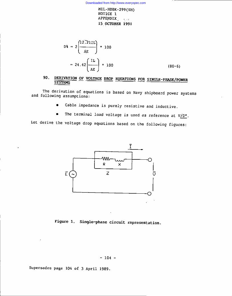
Downloaded from http://www.everyspec.com

Downloaded from http://www.everyspec.com
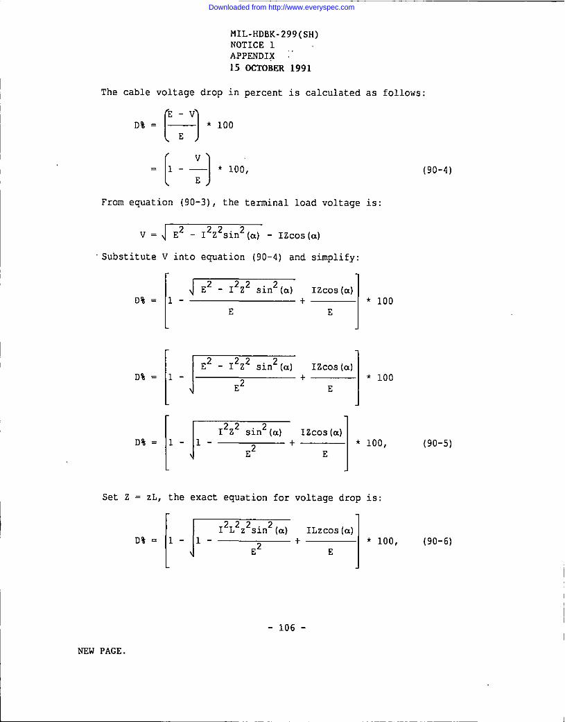
Downloaded from http://www.everyspec.com

Downloaded from http://www.everyspec.com

Downloaded from http://www.everyspec.com
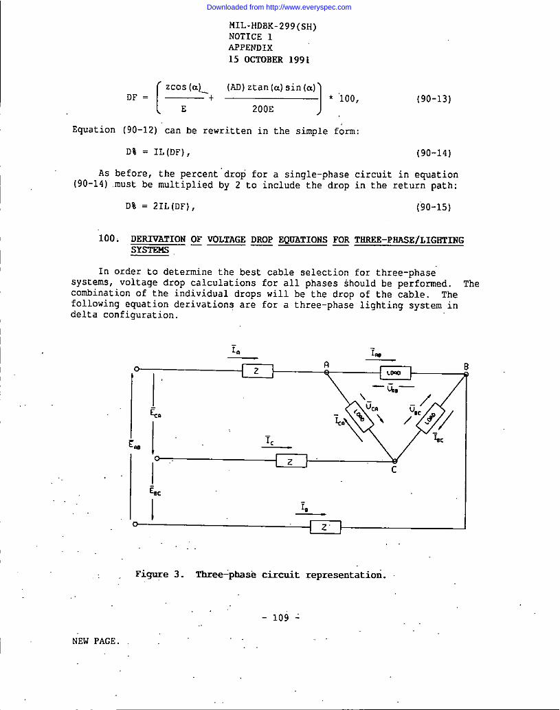
Downloaded from http://www.everyspec.com

Downloaded from http://www.everyspec.com
Downloaded from http://www.everyspec.com
Downloaded from http://www.everyspec.com

Downloaded from http://www.everyspec.com
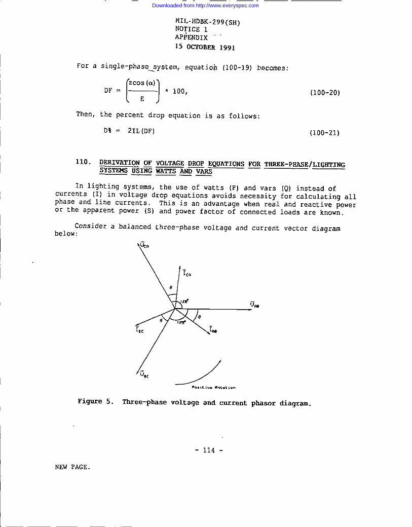
Downloaded from http://www.everyspec.com
Downloaded from http://www.everyspec.com

Downloaded from http://www.everyspec.com

Downloaded from http://www.everyspec.com
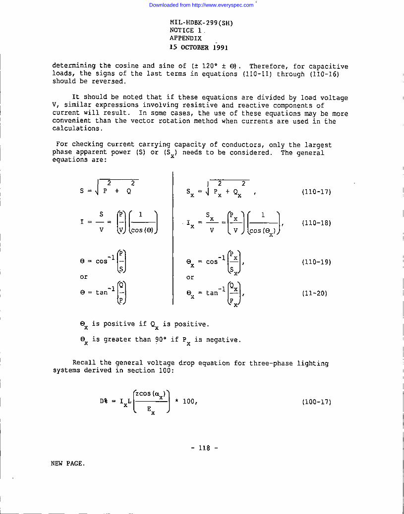
Downloaded from http://www.everyspec.com
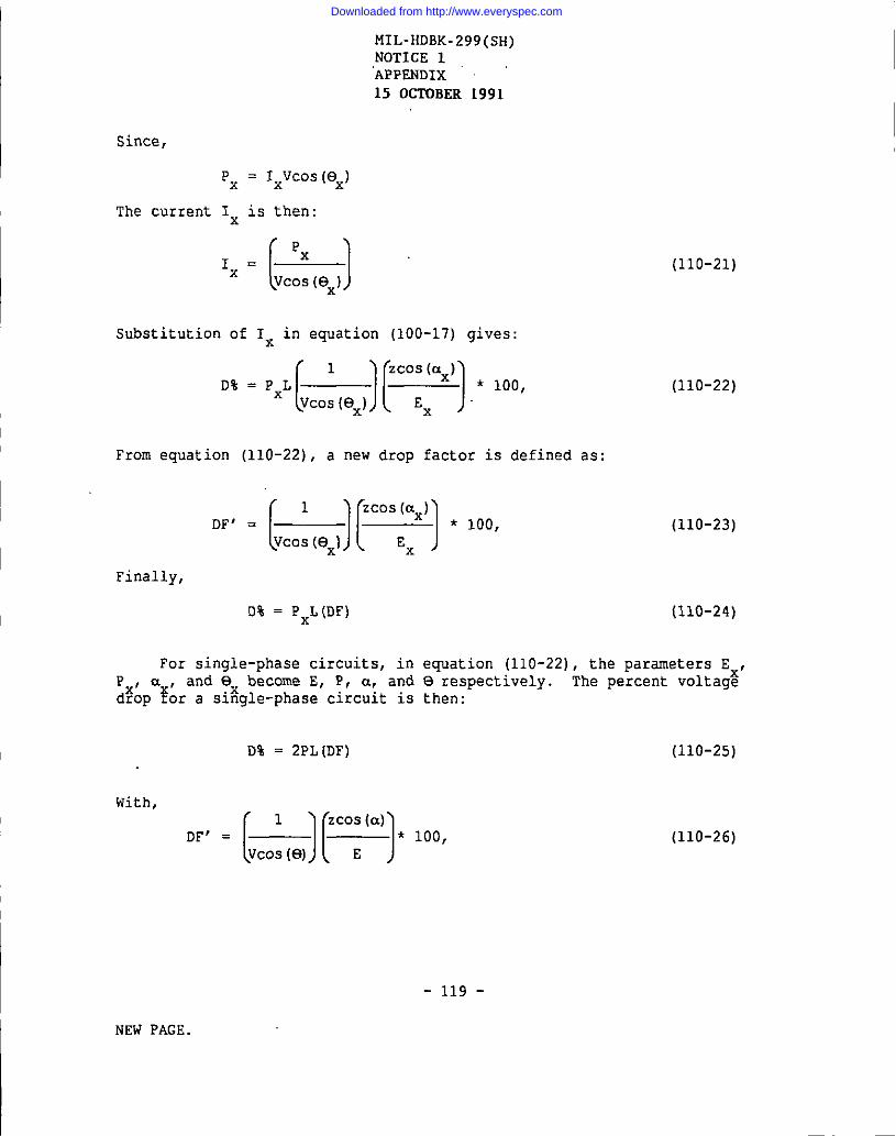
Downloaded from http://www.everyspec.com
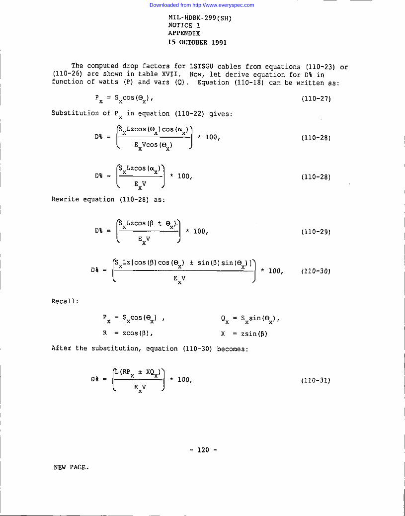
Downloaded from http://www.everyspec.com

Downloaded from http://www.everyspec.com

Downloaded from http://www.everyspec.com

Downloaded from http://www.everyspec.com

Downloaded from http://www.everyspec.com

Downloaded from http://www.everyspec.com

Downloaded from http://www.everyspec.com

Downloaded from http://www.everyspec.com

Downloaded from http://www.everyspec.com
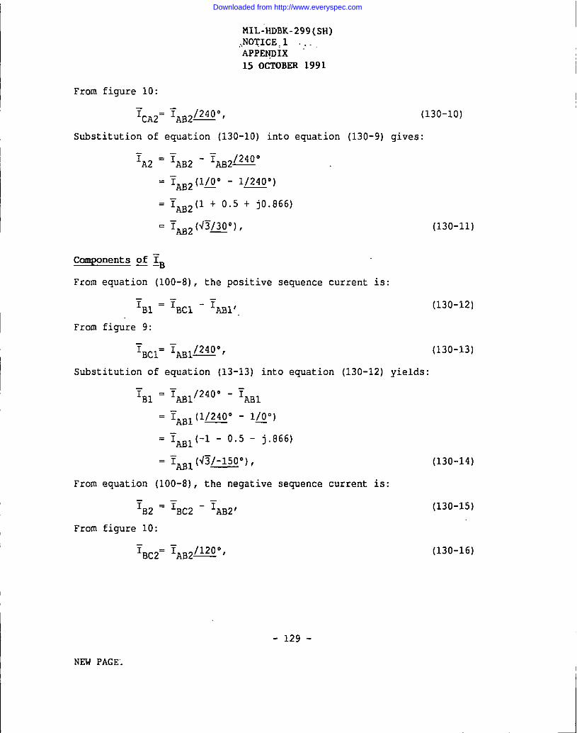
Downloaded from http://www.everyspec.com

Downloaded from http://www.everyspec.com
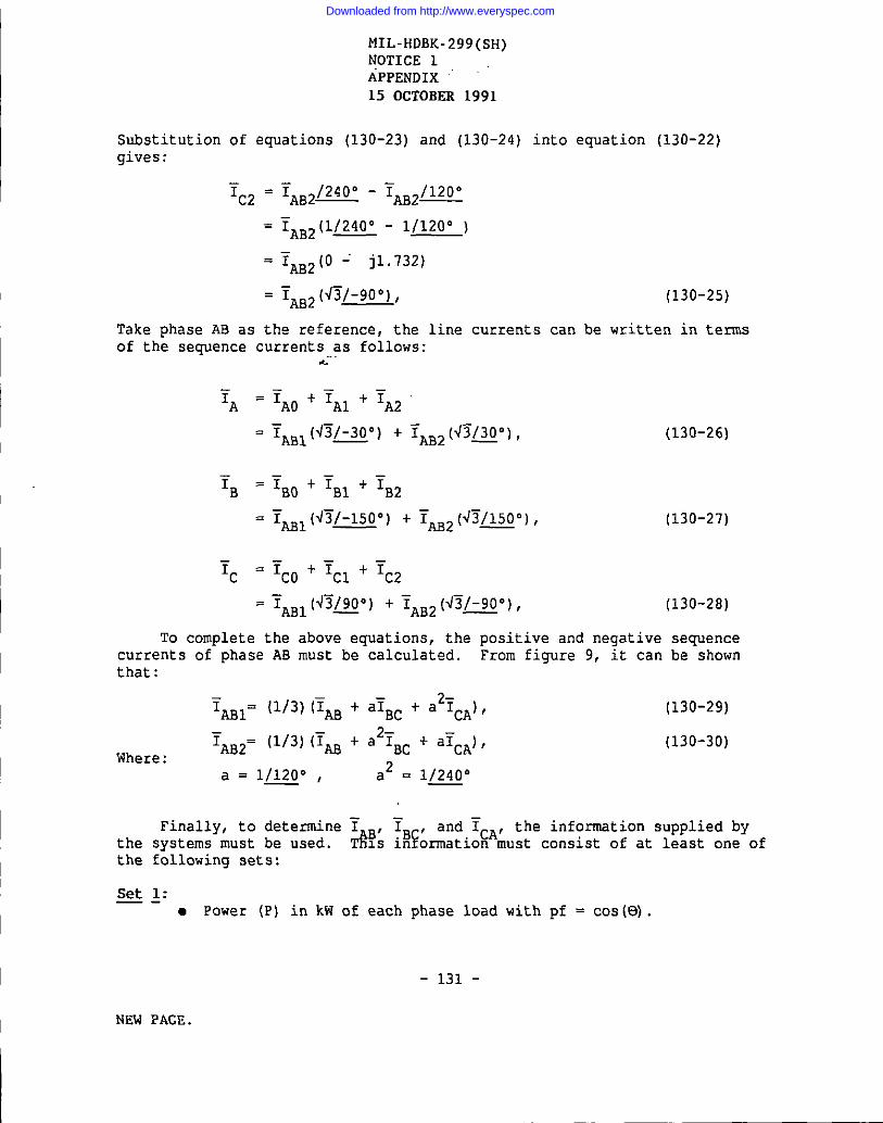
Downloaded from http://www.everyspec.com

Downloaded from http://www.everyspec.com
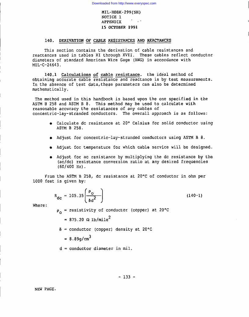
Downloaded from http://www.everyspec.com
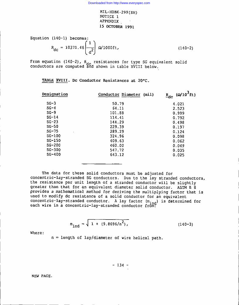
Downloaded from http://www.everyspec.com
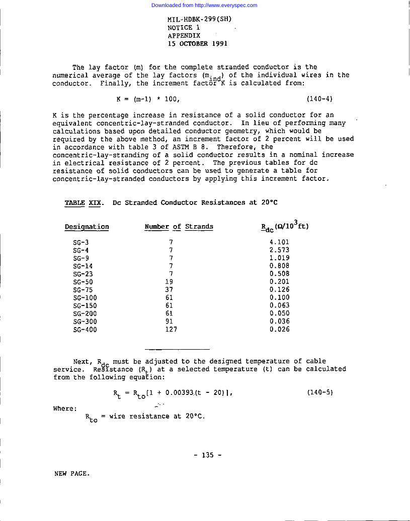
Downloaded from http://www.everyspec.com
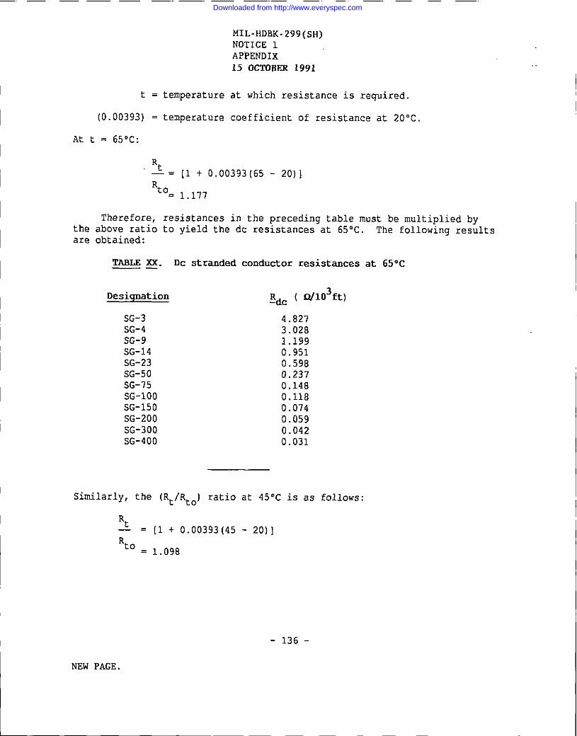
Downloaded from http://www.everyspec.com
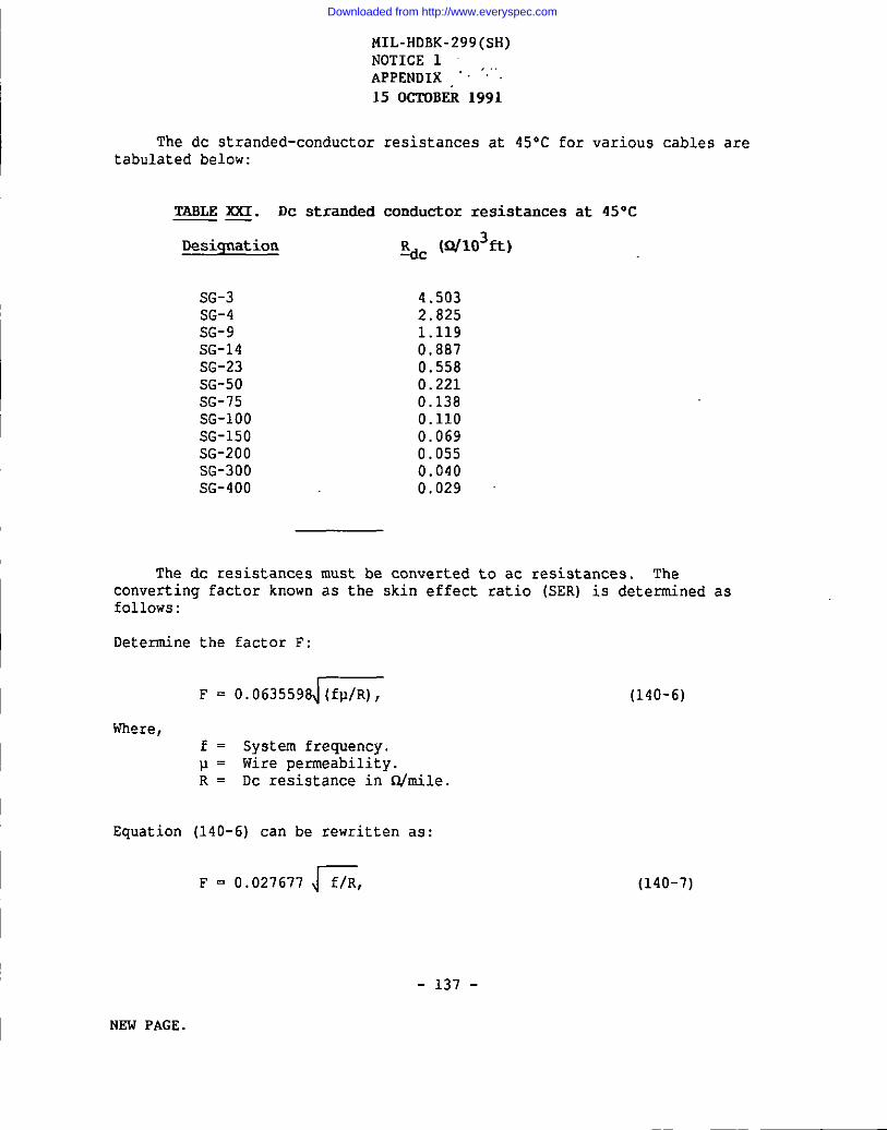
Downloaded from http://www.everyspec.com
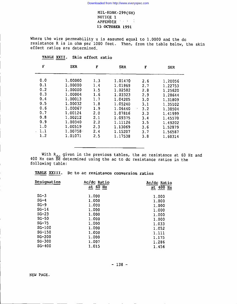
Downloaded from http://www.everyspec.com

Downloaded from http://www.everyspec.com

Downloaded from http://www.everyspec.com

Downloaded from http://www.everyspec.com
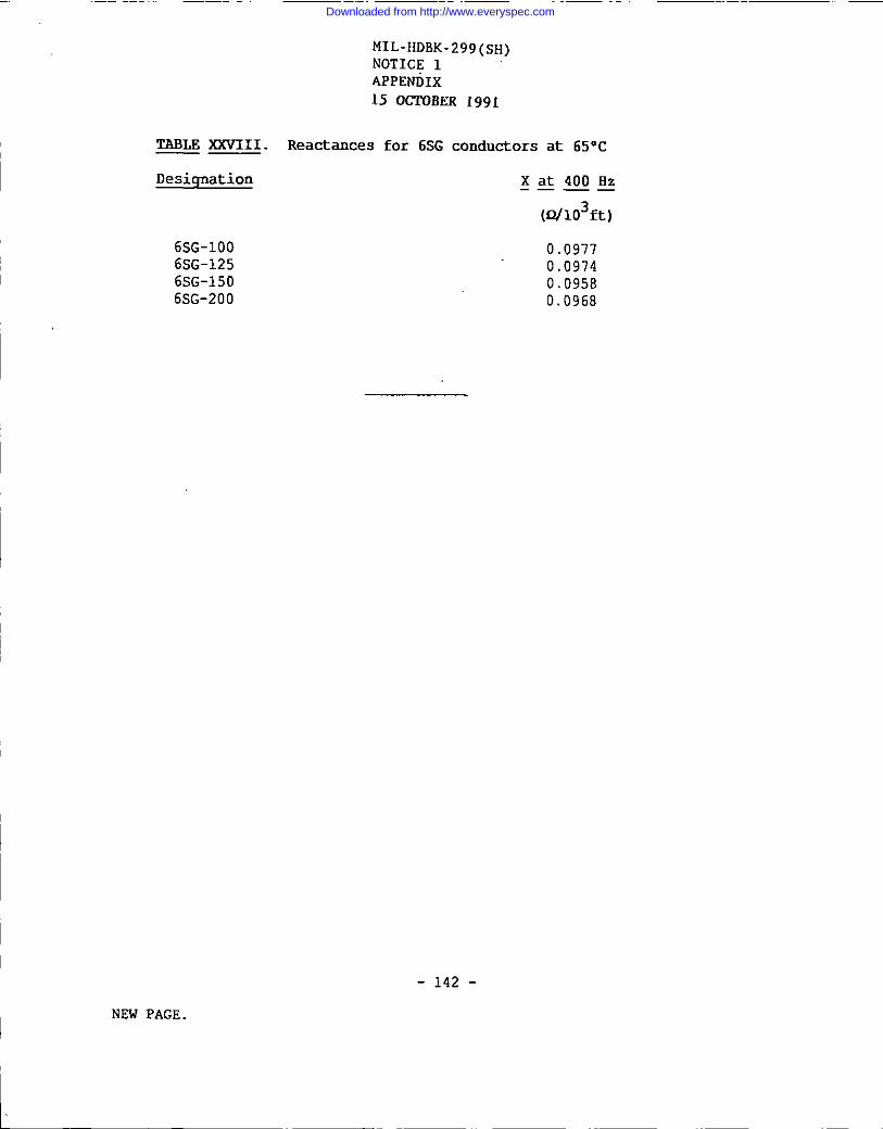
Downloaded from http://www.everyspec.com
Related Documents


