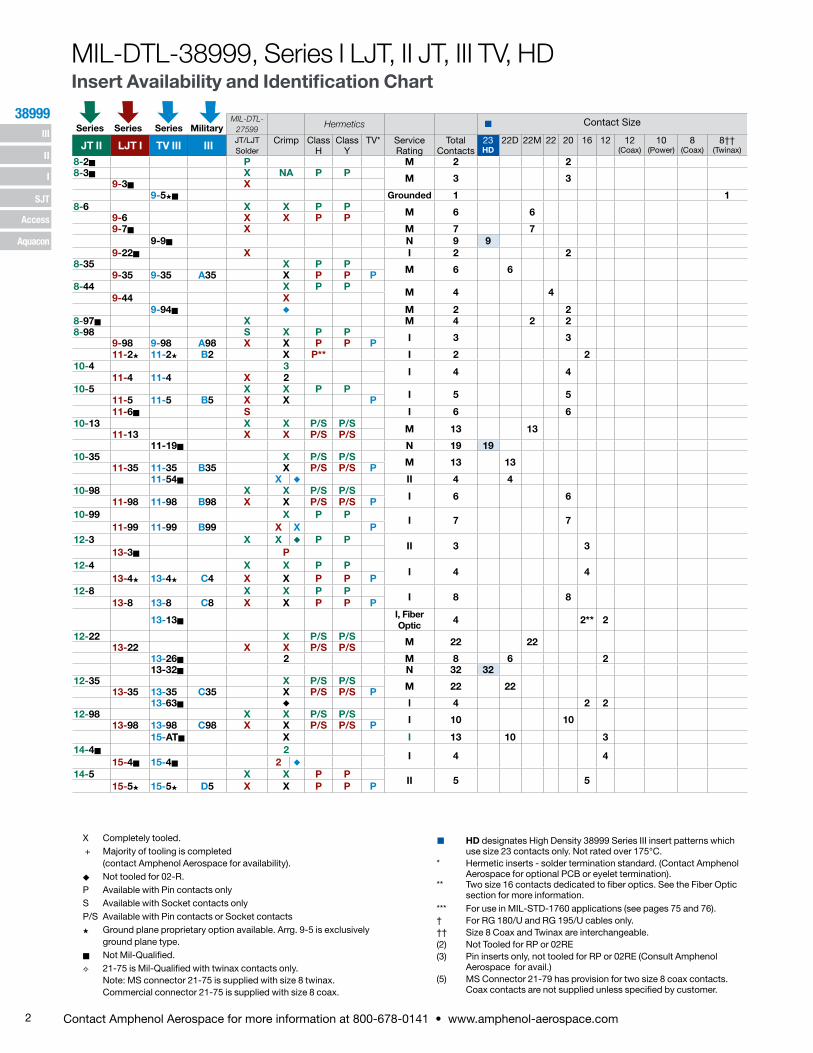
2 Contact Amphenol Aerospace for more information at 800-678-0141 • www.amphenol-aerospace.com 38999 III SJT I II Access Aquacon MIL-DTL- 27599 Hermetics Contact Size JT II LJT I TV III III JT/LJT Solder Crimp Class H Class Y TV* Service Rating Total Contacts 23 HD 22D 22M 22 20 16 12 12 (Coax) 10 (Power) 8 (Coax) 8†† (Twinax) 8-2n P M 2 2 8-3n X NA P P M 3 3 9-3n X 9-5Hn Grounded 1 1 8-6 X X P P M 6 6 9-6 X X P P 9-7n X M 7 7 9-9n N 9 9 9-22n X I 2 2 8-35 X P P M 6 6 9-35 9-35 A35 X P P P 8-44 X P P M 4 4 9-44 X 9-94n u M 2 2 8-97n X M 4 2 2 8-98 S X P P I 3 3 9-98 9-98 A98 X X P P P 11-2H 11-2H B2 X P** I 2 2 10-4 3 I 4 4 11-4 11-4 X 2 10-5 X X P P I 5 5 11-5 11-5 B5 X X P 11-6n S I 6 6 10-13 X X P/S P/S M 13 13 11-13 X X P/S P/S 11-19n N 19 19 10-35 X P/S P/S M 13 13 11-35 11-35 B35 X P/S P/S P 11-54n X u II 4 4 10-98 X X P/S P/S I 6 6 11-98 11-98 B98 X X P/S P/S P 10-99 X P P I 7 7 11-99 11-99 B99 X X P 12-3 X X u P P II 3 3 13-3n P 12-4 X X P P I 4 4 13-4H 13-4H C4 X X P P P 12-8 X X P P I 8 8 13-8 13-8 C8 X X P P P 13-13n I, Fiber Optic 4 2** 2 12-22 X P/S P/S M 22 22 13-22 X X P/S P/S 13-26n 2 M 8 6 2 13-32n N 32 32 12-35 X P/S P/S M 22 22 13-35 13-35 C35 X P/S P/S P 13-63n u l 4 2 2 12-98 X X P/S P/S I 10 10 13-98 13-98 C98 X X P/S P/S P 15-ATn X I 13 10 3 14-4n 2 I 4 4 15-4n 15-4n 2 u 14-5 X X P P II 5 5 15-5H 15-5H D5 X X P P P MIL-DTL-38999, Series I LJT, II JT, III TV, HD Insert Availability and Identification Chart Series Series Series Military X Completely tooled. + Majority of tooling is completed (contact Amphenol Aerospace for availability). u Not tooled for 02-R. P Available with Pin contacts only S Available with Socket contacts only P/S Available with Pin contacts or Socket contacts H Ground plane proprietary option available. Arrg. 9-5 is exclusively ground plane type. n Not Mil-Qualified. G 21-75 is Mil-Qualified with twinax contacts only. Note: MS connector 21-75 is supplied with size 8 twinax. Commercial connector 21-75 is supplied with size 8 coax. HD designates High Density 38999 Series III insert patterns which use size 23 contacts only. Not rated over 175°C. * Hermetic inserts - solder termination standard. (Contact Amphenol Aerospace for optional PCB or eyelet termination). ** Two size 16 contacts dedicated to fiber optics. See the Fiber Optic section for more information. *** For use in MIL-STD-1760 applications (see pages 75 and 76). † For RG 180/U and RG 195/U cables only. †† Size 8 Coax and Twinax are interchangeable. (2) Not Tooled for RP or 02RE (3) Pin inserts only, not tooled for RP or 02RE (Consult Amphenol Aerospace for avail.) (5) MS Connector 21-79 has provision for two size 8 coax contacts. Coax contacts are not supplied unless specified by customer.

Welcome message from author
This document is posted to help you gain knowledge. Please leave a comment to let me know what you think about it! Share it to your friends and learn new things together.
Transcript
2 Contact Amphenol Aerospace for more information at 800-678-0141 • www.amphenol-aerospace.com
38999 III
SJT
I
II
Access
Aquacon
MIL-DTL-27599
Hermetics Contact Size
JT II LJT I TV III III JT/LJTSolder
Crimp ClassH
ClassY
TV* Service Rating
Total Contacts
23HD
22D 22M 22 20 16 12 12(Coax)
10(Power)
8(Coax)
8††(Twinax)
8-2n P M 2 28-3n X NA P P M 3 39-3n X
9-5Hn Grounded 1 18-6 X X P P M 6 69-6 X X P P
9-7n X M 7 79-9n N 9 9
9-22n X I 2 28-35 X P P M 6 69-35 9-35 A35 X P P P8-44 X P P M 4 49-44 X
9-94n u M 2 28-97n X M 4 2 28-98 S X P P I 3 39-98 9-98 A98 X X P P P
11-2H 11-2H B2 X P** I 2 210-4 3 I 4 411-4 11-4 X 210-5 X X P P I 5 511-5 11-5 B5 X X P
11-6n S I 6 610-13 X X P/S P/S M 13 1311-13 X X P/S P/S
11-19n N 19 1910-35 X P/S P/S M 13 1311-35 11-35 B35 X P/S P/S P
11-54n X u II 4 410-98 X X P/S P/S I 6 611-98 11-98 B98 X X P/S P/S P10-99 X P P
I 7 711-99 11-99 B99 X X P
12-3 X X u P PII 3 3
13-3n P12-4 X X P P
I 4 413-4H 13-4H C4 X X P P P
12-8 X X P PI 8 813-8 13-8 C8 X X P P P
13-13nI, Fiber Optic 4 2** 2
12-22 X P/S P/S M 22 2213-22 X X P/S P/S13-26n 2 M 8 6 213-32n N 32 32
12-35 X P/S P/S M 22 2213-35 13-35 C35 X P/S P/S P13-63n u l 4 2 2
12-98 X X P/S P/S I 10 1013-98 13-98 C98 X X P/S P/S P15-ATn X I 13 10 3
14-4n 2I 4 4
15-4n 15-4n 2 u
14-5 X X P PII 5 515-5H 15-5H D5 X X P P P
MIL-DTL-38999, Series I LJT, II JT, III TV, HDInsert Availability and Identification Chart
Series Series Series Military
X Completely tooled. + Majority of tooling is completed
(contact Amphenol Aerospace for availability).u Not tooled for 02-R.P Available with Pin contacts onlyS Available with Socket contacts onlyP/S Available with Pin contacts or Socket contactsH Ground plane proprietary option available. Arrg. 9-5 is exclusively
ground plane type. n Not Mil-Qualified.G 21-75 is Mil-Qualified with twinax contacts only.
Note: MS connector 21-75 is supplied with size 8 twinax. Commercial connector 21-75 is supplied with size 8 coax.
HD designates High Density 38999 Series III insert patterns which use size 23 contacts only. Not rated over 175°C.
* Hermetic inserts - solder termination standard. (Contact Amphenol Aerospace for optional PCB or eyelet termination).
** Two size 16 contacts dedicated to fiber optics. See the Fiber Optic section for more information.
*** For use in MIL-STD-1760 applications (see pages 75 and 76).† For RG 180/U and RG 195/U cables only.†† Size 8 Coax and Twinax are interchangeable.(2) Not Tooled for RP or 02RE(3) Pin inserts only, not tooled for RP or 02RE (Consult Amphenol
Aerospace for avail.)(5) MS Connector 21-79 has provision for two size 8 coax contacts.
Coax contacts are not supplied unless specified by customer.
3Contact Amphenol Aerospace for more information at 800-678-0141 • www.amphenol-aerospace.com
38999 III
SJT
I
II
Access
Aquacon
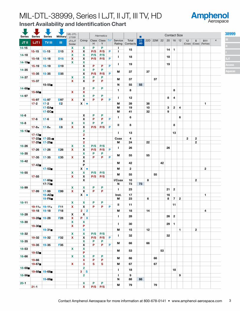
MIL-DTL-38999, Series I LJT, II JT, III TV, HDInsert Availability and Identification Chart
MIL-DTL-27599
Hermetics Contact Size
JT II LJT I TV III III JT/LJTSolder
Crimp Class H
ClassY
TV* Service Rating
Total Contacts
23HD
22D 22M 22 20 16 12 12(Coax)
8(Coax)
8††(Twinax)
4
14-15 X X P P I15 14 1
15-15 15-15 D15 X X P/S P/S P I14-18 X X P/S P/S
I 18 1815-18 15-18 D18 X X P/S P/S P
14-19n X XI 19 19
15-19 15-19 D19 X P P P14-35 X P P
M 37 3715-35 15-35 D35 X P/S P/S P
14-37 X X P PM 37 37
15-37 X X P P15-55n N 55 55
14-68n 2 P P1 8 8
15-68n X X14-97 X P P
I 12 8 415-97 15-97 D97 X X P P P17-2 17-2 E2 X u M 39 38 1
17-EAn M 19 10 3 2 417-ECn M 41 32 9
16-6 X P PI 6 6
17-6 17-6 E6 X P P P16-8 X X P P
II 8 817-8H 17-8H E8 X X P/S P/S P
16-13n 2I 13 13
17-13n 217-22n 17-22Hn u Coax 4 2 217-25n 17-25n 2 M 24 22 2
16-26 X X P/S P/SI 26 26
17-26 17-26 E26 X X P/S P/S P16-35 X P P
M 55 5517-35 17-35 E35 X X P P P
16-42 XM 42 42
17-42n P17-52n X u M 2 2
16-55 X X P/S P/SM 55 55
17-55 X X P/S P/S17-60n X I/Coax 10 8 217-73n N 73 73
16-99 X X P PI 23 21 2
17-99 17-99 E99 X X P P19-ADn X u Inst. 17 16 119-FAn M 23 6 8 7 2
18-11 X X P PII 11 11
19-11H 19-11H F11 X X P P P19-18 19-18 F18 2 2 M 18 14 4
18-28 X XI 28 26 2
19-28n 19-28 F28 X P X18-30 X X
I 30 29 119-30n X P
19-31n X M 15 12 1 218-32 X X P/S P/S
I 32 3219-32 19-32 F32 X X P/S P/S P
18-35 X P PM 66 66
19-35 19-35 F35 X P P P18-53 X X
M 53 5319-53n P
18-66 X X P PM 66 66
19-66 X P P19-67n X 3 S S M 67 67
18-68n 2I 18 18
19-68n 19-68n 3 S18-96n 2 I 9 9
19-88n N 88 8820-1 X P P
M 79 7921-1 X P/S P/S
Series Series Series Military

4 Contact Amphenol Aerospace for more information at 800-678-0141 • www.amphenol-aerospace.com
38999 III
SJT
I
II
Access
Aquacon
MIL-DTL-27599
Crimp Hermetics Service Rating
Total Contact Size
JT II LJT I TV III III JT/LJTSolder
H Y TV* 23HD
22D 22M 22 20 16 16 (Cx)
12 12(Cx)
10(Power)
8(Power)
8(Cx)
8††(Twinax)
4
20-2 X M 65 6521-2n X20-11n 3 I 11 1121-11H 21-11H G11 X20-16 X X P/S P/S
II 16 1621-16H 21-16H G16 X X P P P21-25n I 25 2521-27n X I 27 27
21-29n X I 27 19 4 420-35 X P P M 79 7921-35 21-35 G35 X P/S P/S P20-39 X X P P I 39 37 221-39 21-39 G39 X X P P P20-41 X X P P
I 41 4121-41 21-41 G41 X X P/S P/S P21-48n M 4 4
21-75H 21-75HG G75 2 X N M 4 4 (4) 21-79n 21-79n 2 X II 19 17 2 (2)
21-121n N 121 12122-1 X P/S P/S
M 100 10023-1 X P P
22-2 X X P PM 85 85
23-2 X X P P23-6Hn 23-6Hn X P M 6 6
22-14n 2 uI 14 14
23-14n 23-14n 2 u
22-21 X X P PII 21 21
23-21H 23-21H H21 X X P P P22-32 X X P P
I 32 3223-32n X P23-34n X I 34 34
22-35 X P/S P/S M 100 10023-35 23-35 H35 X P P P
22-53n P I 53 5323-53 23-53 H53 X X P/S P/S P
23-54 n X M 53 40 9 422-55 X X P P I 55 55
23-55 23-55 H55 X P23-63 n S M 57 49 4 4
23-97n X II 16 1623-99n X II 11 11
23-151 n N 151 15124-1 X P P
M 128 12825-1 X P P
24-2 XM 100 100
25-2 X24-4 X P P I 56 48 825-4 25-4 J4 X P
25-7n 25-7 J7 X M Twx 99 97 225-8H J8 u Twinax 8 825-11*** J11 2 u N 11 2 925-16n M 8 6 225-17n u M 42 36 6
24-19n X P PI 19 1925-19H 25-19H J19 X P
25-20n 25-20*** J20 2 u N 30 10 13 4 3
MIL-DTL-38999, Series I LJT, II JT, III TV, HDInsert Availability and Identification Chart
X Completely tooled.+ Majority of tooling is completed
(contact Amphenol Aerospace for availability).u Not tooled for 02-R.P Available with Pin contacts onlyS Available with Socket contacts onlyP/S Available with Pin contacts or Socket contactsH Ground plane proprietary option available. Arrg. 9-5, 26-62 is exclusively
ground plane type. n Not Mil-Qualified.G 21-75 is Mil-Qualified with twinax contacts only. * Hermetic inserts - solder termination standard. (Contact Amphenol
Aerospace for optional PCB or eyelet termination).
HD designates High Density 38999 Series III insert patterns which use size 23 contacts only. Not rated over 175°C.
** Two size 16 contacts dedicated to fiber optics. See the Fiber Optic Section for more information.
*** For use in MIL-STD-1760 applications (see pages 75 and 76).† For RG 180/U and RG 195/U cables only.†† Size 8 Coax and Twinax are interchangeable.(2) Not Tooled for RP or 02RE(3) Pin inserts only, not tooled for RP or 02RE (Consult Amphenol for avail.)(4) MS connector 21-75 is supplied with size 8 twinax.
Commercial connector 21-75 is supplied with size 8 coax.(5) MS Connector 21-79 has provision for two size 8 coax contacts.
Coax contacts are not supplied unless specified by customer.(PWR) Suffix at end of part number to replace coax, twinax, and fiber contacts
with power contacts.
Series Series Series Military
5Contact Amphenol Aerospace for more information at 800-678-0141 • www.amphenol-aerospace.com
38999 III
SJT
I
II
Access
Aquacon
(Insert arrangements requiring non-standard shells)
X Completely tooled.+ Majority of tooling is completed (contact
Amphenol Aerospace for availability).u Not tooled for 02-R.P Pin inserts only (contact Amphenol Aerospace
for socket availability).H Ground plane proprietary option available.
Arrangement 9-5, 25-62 is exclusively ground plane type.
n Not Mil-Qualified.* Hermetic inserts - solder termination standard.
(Contact Amphenol Aerospace for optional PCB or eyelet termination).
** Two size 16 contacts dedicated to fiber optics.See the Fiber Optic section for more information.
*** For use in MIL-STD-1760 applications (pgs. 75 and 76).
† For RG 180/U and RG 195/U cables only.†† Size 8 Coax and Twinax are interchangeable.Note: 25L-3 and 25L-7 use longer shells.(PWR) Suffix at end of part number to replace coax,
twinax, and fiber contacts with power contacts.
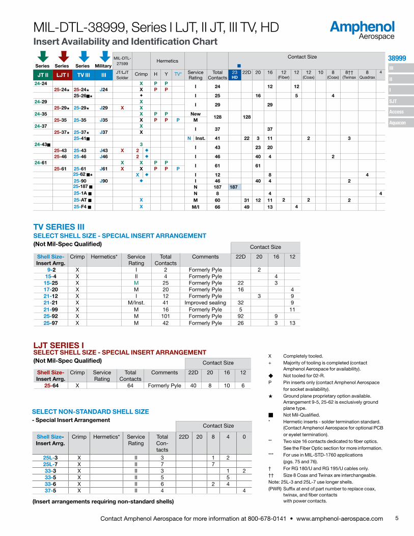
SELECT NON-STANDARD SHELL SIZE- Special Insert Arrangement
Contact Size
Shell Size-Insert Arrg.
Crimp Hermetics* Service Rating
Total Contacts
Comments 22D 20 16 12
9-2 X I 2 Formerly Pyle 215-4 X II 4 Formerly Pyle 4
15-25 X M 25 Formerly Pyle 22 317-20 X M 20 Formerly Pyle 16 421-12 X I 12 Formerly Pyle 3 921-21 X M/Inst. 41 Improved sealing 32 921-99 X M 16 Formerly Pyle 5 1125-92 X M 101 Formerly Pyle 92 925-97 X M 42 Formerly Pyle 26 3 13
Contact Size
Shell Size- Insert Arrg.
Crimp Hermetics* Service Rating
Total Con-tacts
22D 20 8 4 0
25L-3 X II 3 1 225L-7 X II 7 733-3 X II 3 1 233-5 X II 5 533-6 X II 6 2 437-5 X II 4 4
SELECT SHELL SIZE - SPECIAL INSERT ARRANGEMENT (Not Mil-Spec Qualified)
MIL-DTL-27599
HermeticsContact Size
JT II LJT I TV III III JT/LJTSolder
Crimp H Y TV* Service Rating
Total Contacts
23HD
22D 20 16 12 (Fiber)
12 12 (Coax)
10 8(Coax)
8††(Twinax
8Quadrax
4
24-24 X P PI 24 12 12
25-24H 25-24H J24 X P P25-26nH F I 25 16 5 4
24-29 XI 29 29
25-29H 25-29H J29 X X24-35 X P P New
128 12825-35 25-35 J35 X P P P M
24-37 XI 37 37
25-37H 25-37H J37 X25-41n N Inst. 41 22 3 11 2 3
24-43n 3I 43 23 20
25-43 25-43 J43 X 2 u
25-46 25-46 J46 2 u I 46 40 4 224-61 X X P P
I 61 6125-61 25-61 J61 X X P P P
25-62 nH X u I 12 8 425-90 J90 u I 46 40 4 225-187 n N 187 18725-1A n N 8 4 425-AT n X M 60 31 12 11 2 2 225-F4 n X M/I 66 49 13 4
TV SERIES III
MIL-DTL-38999, Series I LJT, II JT, III TV, HD Insert Availability and Identification Chart
Series Series Series Military
Contact Size
Shell Size-Insert Arrg.
Crimp Service Rating
Total Contacts
Comments 22D 20 16 12
25-64 X 64 Formerly Pyle 40 8 10 6
LJT SERIES ISELECT SHELL SIZE - SPECIAL INSERT ARRANGEMENT (Not Mil-Spec Qualified)

6 Contact Amphenol Aerospace for more information at 800-678-0141 • www.amphenol-aerospace.com
38999 III
SJT
I
II
Access
Aquacon
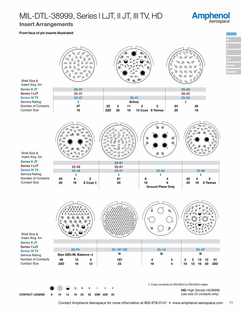
Front face of pin inserts illustrated
MIL-DTL-38999, Series I LJT, II JT, III TV, HD Insert Arrangements
CONTACT LEGEND 8 10 12 16 20 22 22M 22D 23
AB
A
B
C 12
3
45
61
2
345
67
82
197
35 4
6
A
B
51
64
3
21
23
4
B AA
BC
DC A
B
AB
8-2 8-3 8-6 8-35 8-44 8-97 8-989-3 9-6 9-7 9-22 9-35 9-44 9-98 11-2
9-5 9-9 HD 9-35 9-94 9-98 11-2M M Grounded M M N I M M M M I I2 3 1 6 7 9 2 6 4 2 2 2 3 220 20 8 Twinax 22M 22M 23 20 22D 22 20 22M 20 20 16
12
13
19
18
17
16 15
149
8
4
5
6
10
111
2
3
1413
12 11 10
2829
3015
16
25
2627
3839
414036
24
35
3433
20
32
31
17
1819
21 2223
37
98
7
6
5
4
321 1
6
11
17
30
A
B
C
D
E
F
A
B
C
DE
F
G
H
AB
C
D
EF
G
H
J
K
LN M
A
D
C
B
16-6 16-8 16-1317-2 17-6 17-8 17-13 17-22
17-EA 17-EC 17-2 17-6 17-8 17-22M I II I Coax
10 3 2 4 32 9 38 1 6 8 13 2 222D 20 16 12 22D 20 22D 8 Twinax 12 16 16 12 Coax 8 Coax
HD: High Density HD38999 (use size 23 contacts only)
AB
CD
E
FG
H 22
1
20
A
CDE
F B 1829
32
1 1
2122
AB
C
D
AB
C
DE
F
G
H
JK
A
10 76
53 4
BC
1
2
9 8
A
BC
DA
B
CD
E
12-8 12-22 12-35 12-98 14-4 14-513-8 13-22 13-35 13-98 15-4 15-513-8 13-26 13-32 HD 13-35 13-63 13-98 15-AT 15-4 15-5
I M M N M I I I I II8 22 6 2 32 22 2 2 10 10 3 4 520 22M 22D 12 23 22D 16 12 20 22D 12 12 16
A
BC
D A
BC
D
EA
B
CD
E
F1
2
3
456
7
8
910
11
1213
1 2
3
4
567
89
10 1716
1918
15
1413
1211
12
3
456
7
8
910
11
1213A
B
D
C
A
B
CD
E FA
B
CD
E
F
GA
B
C
A
B
C
D
10-4 10-5 10-13 10-35 10-98 10-99 12-3 12-411-4 11-5 11-6 11-13 11-35 11-98 11-99 13-3 13-411-4 11-5 11-19 HD 11-35 11-54 11-98 11-99 13-4
I I I M N M II I I II I4 5 6 13 19 13 4 6 7 3 420 20 20 22M 23 22D 22D 20 20 16 16
AB
C
DE
FG
H
J
KL
MN
P
R
A
B
C
D
EFG
H
J
KL
M N
P
RS
T U
AB
C
D
EFGH
J
K
LM
N P
R
ST
U V
321
13
12
11
4
5
6
78
910
1415
1617
181920
2322
21
24
25
1
2131
1
11
2131
39
16
241731253932
465247
40
5553
1041 A
B
C
DE
F
GH
AB
C
D
EFG
H
JK
L
M
14-15 14-18 14-19 14-35 14-37 14-68 14-9715-15 15-18 15-19 15-35 15-37 15-68 15-9715-15 15-18 15-19 15-25 15-35 15-55 HD 15-97
I I I M M M N I I14 1 18 19 22 3 37 37 55 8 8 420 16 20 20 22D 16 22D 22M 23 16 20 16
Shell Size & Insert Arrg. for:
Series II JTSeries I LJTSeries III TVService RatingNumber of ContactsContact Size
Shell Size & Insert Arrg. for:
Series II JTSeries I LJTSeries III TVService RatingNumber of ContactsContact Size
Shell Size & Insert Arrg. for:
Series II JTSeries I LJTSeries III TVService RatingNumber of ContactsContact Size
Shell Size & Insert Arrg. for:
Series II JTSeries I LJTSeries III TVService RatingNumber of ContactsContact Size
Shell Size & Insert Arrg. for:
Series II JTSeries I LJTSeries III TVService RatingNumber of ContactsContact Size

7Contact Amphenol Aerospace for more information at 800-678-0141 • www.amphenol-aerospace.com
38999 III
SJT
I
II
Access
Aquacon
Front face of pin inserts illustrated
MIL-DTL-38999, Series I LJT, II JT, III TV, HD Insert Arrangements
CONTACT LEGEND 8 10 12 16 20 22 22M 22D 23
HD: High Density HD38999 (use size 23 contacts only)
12
3
4
56
789
10
1112
13 14
15 16
17
1819
20
2122
23
24
AB
C
D
E
FGHJ
KL
M
N
P
RS T
U
V
WX
Y
Z
ab
c
1
3
4
9
10
16
17
24
25
31
32
39
40
47
46
52
53
55
1
21
42
41
31
11
A
B
1
3
4
9
10
16
17
2431
2532
39
40
46
47
52
53
55
1
5
28
9 310
7
6 4
16-26 16-35 16-42 16-5517-25 17-26 17-35 17-42 17-55
17-26 17-35 17-52 17-60M I M M M M I/Coax
22 2 26 55 42 2 55 8 222D 8 Coax 20 22D 22 8 Twinax 22M 22D 8 Coax
1 273
8 15
241625
33
4250
5967
72 73
7166
5849
4132
AB
C
D
E
FGHJ
KL
M
N
P
R
S TU
VWX
YZ
1
2
3
4
5
678
9
10
11
12
18
19 17
1623
15
22
20
21 14
13 A
B
C
D
E
F
G
H
J
K
L
A
B
C
DE
F
G
H
J
K
L
M
N
P
R
S
T
U
AB
C
D
E
FG
H
R
JK
LM
N
P
ST
UV
W
X
Y
Za
b
c
d
e
16-99 18-11 18-2817-99 19-11 19-18 19-28
17-73 HD 17-99 19-FA 19-11 19-18 19-28N I M II M M73 21 2 6 8 7 2 11 14 4 26 223 20 16 22D 20 16 12 16 22D 8 Twinax 20 16
AB
C
D
E
FG
HJKL
M
N
PR
S
TU
V
W
XY
Za
b
cd
e
g f
A
BC
EK
M
N
R
S
U
VW
gh
f AB
C
D
E
F
GH
JK
L
M
N
P
R
ST
UV
W
X
YZa
bc
d
ef
gh
j1
2
3
4
9
10
16
17
24
25
33
34
42
43
50
51
57
58
63
64
66
1
41
515253
3111
21
1
2
3
4
9
10
2416
1725
33
34
42
43
50
51
57
58
63
64
66
18-30 18-32 18-35 18-53 18-6619-30 19-32 19-35 19-53 19-66
19-31 19-32 19-35I M 1 M M M
29 1 2 1 12 32 66 53 6620 16 8 Coax 12 22D 20 22D 22 22M
1
3
4
9
10
16
17
24
25
34
35
43
44
51
52
58
59
64
65
67
ABL
CK
DJ
EH
FGR
U
M
T N
S P
1
88
84
73
55
31
30 A
BH
C
DF
E
G J
1215 314
13
12
4
5
11 8
710
16
89
A
12
13
19
18
17
16 15
149
8
4
5
6
10
111
2
3
18-68 18-9619-67 19-68
19-88 HD 19-AD 19-FAM I N I Inst. M67 18 88 9 16 1 6 8 7 2
22M 16 23 12 20 8 Twinax 22D 20 16 12
Shell Size & Insert Arrg. for:
Series II JTSeries I LJTSeries III TVService RatingNumber of ContactsContact Size
Shell Size & Insert Arrg. for:
Series II JTSeries I LJTSeries III TVService RatingNumber of ContactsContact Size
Shell Size & Insert Arrg. for:
Series II JTSeries I LJTSeries III TVService RatingNumber of ContactsContact Size
Shell Size & Insert Arrg. for:
Series II JTSeries I LJTSeries III TVService RatingNumber of ContactsContact Size

8 Contact Amphenol Aerospace for more information at 800-678-0141 • www.amphenol-aerospace.com
38999 III
SJT
I
II
Access
Aquacon
Front face of pin inserts illustrated
MIL-DTL-38999, Series I LJT, II JT, III TV, HD Insert Arrangements
AB
C
D
E
F
GHJ
K
L
M
N
PR
S
T
U
VW
X
Y
Z
a
b
cd
1 2
3
45
6
7
8
91011
1213
14
15
16
17
1819
20
2122
24
23
25
2627
1
11
21
31
41
51
6171
79
AB
C
D
E
F
GH
JKLM
NP
R
S
TU
V W
XY
Z
a
bc
de
f
gh
ij
k
mn
p
qr
AB
C
D
E
F
G
HJ
KLMN
P
R
S
T
UV
W
XY
Z
a
bc
def
g
h
i
jk
m
npq
r
s
t
20-35 20-39 20-4121-27 21-35 21-39 21-41
21-29 21-35 21-39 21-41I I M 1 I
27 19 4 4 79 37 2 4120 20 16 12 22D 20 16 20
HD: High Density HD38999 (use size 23 contacts only)Note: MS connector 21-75 is supplied with four size 8 twinax contacts. Commercial connector 21-75 is supplied with four size 8 coax contacts.MS connector 21-79 has provision for two size 8 coax contacts. Coax contacts are not supplied unless specified by customers.
CONTACT LEGEND 8 10 12 16 20 22 22M 22D 23
1
21
31
41
51
6171
79
11
1
31
21
11
41
51
61
65
A
B
C
D
E
F
G
H
J
K
L
A
B
C
D
EF
G
H
J
K
L
M
N
PR
S
AB
C
D
E
F
GHJ
K
L
M
N
PR
S
T
UV
W
XY
Za
b
20-1 20-2 20-11 20-1621-1 21-2 21-11 21-16 21-25
21-11 21-16M II I II I79 65 11 16 25
22M 22 12 16 20
A
B
C
DA
BC
D
AB
C
D
E
FG
H
J
KL
M
N
P
RS
T
U V
1 5
6 13
232214
32
33 4344 55
56 6667 78
79 89
90 99
100 108
109 116
117 121
1
2
3
45
6
7
8
15
16
24
25
34
35
45
46
55
56
66
67
76
77
85
86
93
94
95
9697
98
99
100
1
4
5
11
12
19
20
28
29
38
39
47
48
57
58
66
67
74
75
81
82
85
22-1 22-221-75 21-79 23-1 23-2
21-48 21-75 21-79 21-121 HDM N II N M M4 4 17 (See Note) 121 100 85
8 power (See Note) 22D 23 22M 22
Shell Size & Insert Arrg. for:
Series II JTSeries I LJTSeries III TVService RatingNumber of ContactsContact Size
Shell Size & Insert Arrg. for:
Series II JTSeries I LJTSeries III TVService RatingNumber of ContactsContact Size
Shell Size & Insert Arrg. for:
Series II JTSeries I LJTSeries III TVService RatingNumber of ContactsContact Size

9Contact Amphenol Aerospace for more information at 800-678-0141 • www.amphenol-aerospace.com
38999 III
SJT
I
II
Access
Aquacon
Front face of pin inserts illustrated
12
34
56
7
8
15
16
24
25
34
35
45
46
55
56
66
67
76
77
85
86
93
94
9596
9798
99
100
AB
C
D
E
F
GH
J
K
L
M
N
P
RS
TU
VW
X
Y
Zab
cd
ef
g
h
km
np
qr
s
t
A B
uv
wx
y
zA B
CC
DDEE
FF
GGHH
1 23
456
7
89
1011
12131415
1617
18
1920
2122
2324 25
2627
2829
30
3132
3334
35
3637
3839
40
4142
4344
45 46
47
484950
51
52
53
AB
C
D
E
F
G
HJKL
M
N
P
R
S
TU V
WX
Y
Z
a
bc
def
gh
i
j
k
mn
pq
r
s
t
vw
x
yz
AABB
CC
u
DDEEFF
GGHH
2423
2221
2019
1817
1615
14131211
109
8
7
65
43
21 25
4443
4241
40
39
383736
3534
33
3231
30
2928
2726
45 46
51
56
49
48
54
46
5347
55
5057
22-35 22-53 22-5523-35 23-53 23-5523-35 23-53 23-54 23-55 23-63
M I M I M100 53 40 9 4 55 49 4 422D 20 22D 16 12 20 22D 16
Coax12
Coax
AB
C
D
E
FG
H
J
K
L
M
N
P
R
S
A
B
C
DE
F
G
HJ
K
L
1 4
5 11
2221
12
3233 44
45 5758 69
70 8283 94
95
130108
140120
147131
107119
141151148
1
7
8
14
24
25
48
58
59
70
71
81
94
104
105
114
115
121
125
35
15
1
2
3
1940 51
73
92
99
100
24-1 24-223-97 23-99 25-1 25-2
23-151 HDII II N M M
16 11 151 128 10016 16 23 22M 22
MIL-DTL-38999, Series I LJT, II JT, III TV, HD Insert Arrangements
CONTACT LEGEND 8 10 12 16 20 22 22M 22D 23
HD: High Density HD38999 (use size 23 contacts only)
A
B
CD
EF
A
BK
CJ LP
MN
DH
EG
F
A
B
C
D
E
FG
HJ
K
L
M P
R
S
N
TU
V
W
X
AB
C
D
EF
GH
J
K
L
MN
P R
S
T
U
VWX
Y
Z
a
b
c
d
ef
g
h
j
AB
CD
E
F
G
HJK
L
M
N
P
R
ST
UV
W
X
YZ
a
b
c
de
f
g
hj
kl
22-14 22-21 22-3223-6 23-14 23-21 23-32 23-3423-6 23-21
M I II I I6 14 21 32 34
8 Twinax 12 16 20 20
Shell Size & Insert Arrg. for:
Series II JTSeries I LJTSeries III TVService RatingNumber of ContactsContact Size
Shell Size & Insert Arrg. for:
Series II JTSeries I LJTSeries III TVService RatingNumber of ContactsContact Size
Shell Size & Insert Arrg. for:
Series II JTSeries I LJTSeries III TVService RatingNumber of ContactsContact Size

10 Contact Amphenol Aerospace for more information at 800-678-0141 • www.amphenol-aerospace.com
38999
Ser
ies
III, I
I, I
III
SJT
I
II
Access
Aquacon
10
Front face of pin inserts illustrated
A
B
C
D
E
FG
H
A B
C
D
E
F
G
H
JKL
M
N
P
R
S
T
U
V
W
XY
Z
ab
cd
e
f
gh
km
np
q r st
uv
w
A B
C
D
E
FGH
J
K
L
M
N P
R
ST
U V
A B
C
D
E
F
G
H
J
K
L
M
N
P
R
S
T
U
VWX
Y
Z
1
23
4
5
67
24-1925-19 25-20
25-16 25-17 25-19 25-20***M M I N
6 2 36 6 19 10 13 3 420 4 22D 8 Twinax 12 20 16 8 Twinax 12 Coax
(With Matched Impedance)
AB
C
D
E
F
GH
JK
L
M
N
P
RS
T
U
VW
X
Y Z
a
1
2
3
4
5
6
78
9
10
11
12
13
14
15
1617
18 19 20
21
222324
25
AB
C
D
E
F
GHJ
K
L
M
N
P
RS T
U
V
W
XY
Z
a
b c
d
e
f
1
4
7
8
14
15
24
25
35
36
47
48
58
59
70
71
81
82
93
94
104
105
114
115
121
125
128
24-24 24-29 24-3525-24 25-29 25-3525-24 25-26 25-29 25-35
I I I M12 12 16 5 4 29 12816 12 20 12 8 Coax 16 22D
MIL-DTL-38999, Series I LJT, II JT, III TV Insert Arrangements
CONTACT LEGEND 8 10 12 16 20 22 22M 22D 23
*** For use in MIL-STD-1760 applications (see pages 75 and 76).
A BC
D
E
F
G
H
J
KL
M
NP
RS
T
U
V
W
X
YZ a
bc
d
ef
g
hk
mn
p
q
r
t
u
vw
x
y
zs JJ
KK
LL
AA
BBCC
DD
EE
FF
GG
HH
1
6
7
15
16
18
19
21
22
24
26
28
29
32
33
41
42
46
53
59
60
64
67
68
72
74
76
78
79
81
82
84
85
93
94
99
25 75
AB
C
D
E
F
G
H
A
B
C
D
EF
G
HJ
KL
24-425-4 25-7 25-1125-4 25-7 25-8 25-11***
I M Twinax N
48 8 97 2 8 2 9
20 16 22D 8 Twinax 8 Twinax 20 10
Shell Size & Insert Arrg. for:
Series II JTSeries I LJTSeries III TVService RatingNumber of ContactsContact Size
Shell Size & Insert Arrg. for:
Series II JTSeries I LJTSeries III TVService RatingNumber of ContactsContact Size
Shell Size & Insert Arrg. for:
Series II JTSeries I LJTSeries III TVService RatingNumber of ContactsContact Size
11Contact Amphenol Aerospace for more information at 800-678-0141 • www.amphenol-aerospace.com
38999 III
SJT
I
II
Access
Aquacon
† Coax contacts for RG180/U or RG195/U cable.
A B
C
D
E
F
G
HJ
K
LM
N
P
R
S
T
U
VW
X
Y
Z
ab
c
d
e
fg
hk
m
np
qr
BP
CN
DM
EL
F
GH
J
K
A
RY
X S
W
Z
T
UV
de
np
q g
ac
bj
k h
ms t
r
i
A BC
D
E
F
G
H
JK
LMNP
R
S
T
U
V
W
XY
Za
b
c
d
ef
g
h
k
m
n p
q
r
stu
v
w
x
24-37 25-4325-37 25-4325-37 25-41 25-43
I N/Inst. I37 22 3 11 2 3 23 2016 22D 20 16 12 Coax 8 Twinax 20 16
Front face of pin inserts illustrated
AB
C
D
E
F
G
H
JKL
M
N
P
R
S
T
U
V
W
XY
Za
b
cd
e
fgh
k
mn
p
qr
s
tu
v
w
xy
z
AA
AB
C
D
E
F
G
H
J
KLMN
PR
S
T
U
V
W
X
YZa b
c
d
e
f
g
hi
jkmn
p
q
r
s
tu
v
w
x
y
z
BBCC
DD
EE
FF
GG HH
JJ
KK
LL
MM
NN
AA
PP
D A
C B
18
45
7 2
6 3
A
B
C
D
E
F
G
H
JKLM
N
a
P
R
S
T
U
V
W
X
Y
Z
b
c
d
efgh
AA
k
q
m
n
p
r
st
u
v
w
xy
z
24-6125-46 25-6125-46 25-61 25-62 25-90
I I I I40 4 2 61 8 4 40 4 220 16 8 Coax † 20 16 8 20 16 8 Twinax
Ground Plane Only
MIL-DTL-38999, Series I LJT, II JT, III TV, HDInsert Arrangements
CONTACT LEGEND 8 10 12 16 20 22 22M 22D 23
1
17
18
19
49
35
20
21
22
23
1615
48
59
60 66 64
65
37 50 51 41 42 4331
3038 39 40 29
2726
25
24
54636261
36
325352
4455
56
57
46
3414
13
45
12
11
10
9
8
7
6
5
43
2
33
28
47
58
1
4 11
212012
32
33 45
46 59
60 72
73 86
87 101
102
142116
155
129
167
143
115128
177176
185
184
187
156
168
3
B
H
C
D
G
E
A
F
1 2
34
5
6
7
8
9
10
11
12131415
16
17
18
19
20
2122
23
24
2526
27
28
29
3045
57
52
51
59
6031
32
334653
4734
353637
544838
39
40
41
42
4344
50
5658
49 55
25-F4 25-187 HD 25-1A 25-AT
Size 22D=M, Balance =I N N N
49 13 4 187 4 4 2 2 13 12 3122D 16 12 23 16 4 10 12 16 20 22D
HD: High Density HD38999 (use size 23 contacts only)
Shell Size & Insert Arrg. for:
Series II JTSeries I LJTSeries III TVService RatingNumber of ContactsContact Size
Shell Size & Insert Arrg. for:
Series II JTSeries I LJTSeries III TVService RatingNumber of ContactsContact Size
Shell Size & Insert Arrg. for:
Series II JTSeries I LJTSeries III TVService RatingNumber of ContactsContact Size

12 Contact Amphenol Aerospace for more information at 800-678-0141 • www.amphenol-aerospace.com
III
SJT
38999
I
II
Access
Aquacon
Ser
ies
III
A
AJ
H
G
F E
D
C
B
M
L
K
S
R P
N
98
100
101
90
7967
57
4624
36
13
5
1
4
1223
3545
56 66 7889
97
2
3
99
M A
L BN
K C
J D
H E
G F
Y W
Xa UZ Vr m
p n ksb
cd
e PR
S
Tjw
hgfu
vt
Shell Size & Insert Arrg. for:
B A
D
C B
A3
2113
12
11
4
5
6
78
910
1415
1617
181920
2322
21
24
25
Series III TV 9-2 15-4* 15-25Service Rating I II MNumber of Contacts 2 4 22 3Contact Size 20 16 22D 16
Shell Size & Insert Arrg. for:
Series III TV 21-99 25-92 25-97Service Rating M M MNumber of Contacts 5 11 92 9 26 3 13Contact Size 22D 12 22D 16 22D 16 12
Front face of pin inserts illustrated
MIL-DTL-38999, Series III TVSpecial Insert Arrangements
NOTE: Some specials shown here were formerly known as Pyle arrangements. Consult Amphenol for how to order information for connectors with these inserts. For further information on special arrangements consult Amphenol Aerospace, Sidney NY.* Pyle 15-4 does not mate with Amphenol Tri-Start 15-4 insert.
CONTACT LEGEND 8 10 12 16 20 22 22M 22D 23*
A
D
C
B
161514
13
12
11 10
9 8
7 6
5
4
32
1
J
H
G
F
E
K
D
LC
B
A
M
1
2
3
4
56
7
8
9 10 A
B
C
DE
F
G
HJ
11 12
13
14
1516
1718
19
20
2122
23 24
25 26
2728
29
303132
Shell Size & Insert Arrg. for:
Series III TV 17-20 21-12 21-21Service Rating M I M/Inst.Number of Contacts 16 4 3 9 32 9Contact Size 22D 12 20 12 22D 12

13Contact Amphenol Aerospace for more information at 800-678-0141 • www.amphenol-aerospace.com
38999 III
SJT
I
II
Access
Aquacon
Series III
A
Front face of pin inserts illustrated
CONTACT LEGEND
NOTE: Some specials shown here were formerly known as Pyle arrangements. Consult Amphenol for how to order information for connectors with these inserts.Consult Amphenol Aerospace for longer shell drawings.
A
B
C
A
B
CD
E
F
G
B
C A
A
B
CD
E
A
B
CD
E
F
A
B
C
D
840 22D
MIL-DTL-38999, Series III TV Special Insert Arrangements
Shell Size & Insert Arrg. for:
Series III TV 25L-3 25L-7Service Rating II IINumber of Contacts 1 2 7Contact Size 8 4 8
Shell Size & Insert Arrg. for:
Series III TV 33-3 33-5 33-6Service Rating II II IINumber of Contacts 1 2 5 2 4Contact Size 4 0 4 8 4
Shell Size & Insert Arrg. for:
Series III TV 37-5Service Rating IINumber of Contacts 4Contact Size 0
Non-Standard Shells or Large Contacts

5 1
4 2
3
.045
.045
.078
.090
.078
6
C A
B
.079
.018
.056
.056
INSERT ARRANGEMENT #8-35 / 9-35
Connector Type:JT
MIL-DTL-38999 Series II
LJT MIL-DTL-38999
Series I
Tri-Start MIL-DTL-38999
Series IIINumber of Contacts
Contact Size
Service Rating
Insert Designation: 8-35 9-35 9-35 6 22D M
All dimensions for reference only. For alternate rotations see page 46 for Series III, page 86 for Series II, and page 114 for Series I.Note: Shown in this catalog are the most common insert patterns for PCB applications. For availability of other arrangements, consult Amphenol Aerospace.
INSERT ARRANGEMENT #8-3 / 9-3
Connector Type:JT
MIL-DTL-38999 Series II
LJT MIL-DTL-38999
Series I
Tri-Start MIL-DTL-38999
Series IIINumber of Contacts
Contact Size
Service Rating
Insert Designation: 8-3 9-3 NA 3 20 M
*Service Rating: M for MIL-DTL-38999
Contact LocationsFront face of pin insert shown
Contact LocationsFront face of pin insert shown
14 Contact Amphenol Aerospace for more information at 800-678-0141 • www.amphenol-aerospace.com
38999
Ser
ies
III, I
I, I
III
SJT
I
II
Access
Aquacon
PCB Contacts 38999, Series I LJT, II JT, III TV Insert Arrangements
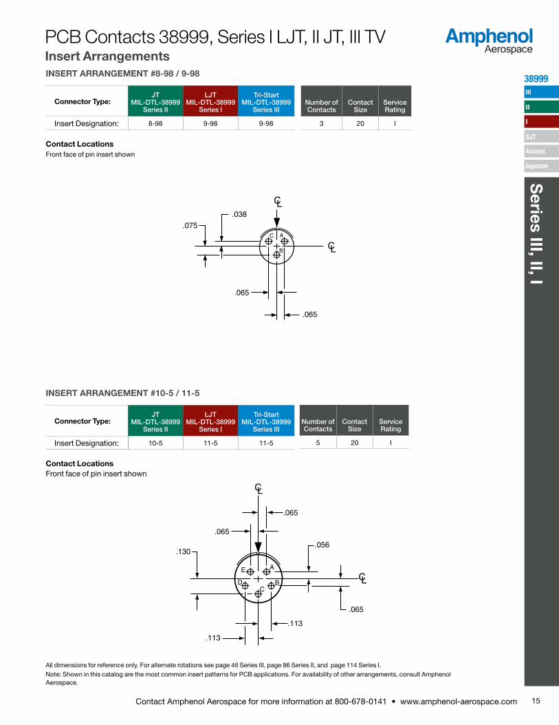
AC
B
.038
.075
.065
.065
INSERT ARRANGEMENT #8-98 / 9-98
Connector Type:JT
MIL-DTL-38999 Series II
LJT MIL-DTL-38999
Series I
Tri-Start MIL-DTL-38999
Series IIINumber of Contacts
Contact Size
Service Rating
Insert Designation: 8-98 9-98 9-98 3 20 I
Contact LocationsFront face of pin insert shown
AE
D BC
.065
.065
.130.056
.065
.113
.113
INSERT ARRANGEMENT #10-5 / 11-5
Connector Type:JT
MIL-DTL-38999 Series II
LJT MIL-DTL-38999
Series I
Tri-Start MIL-DTL-38999
Series III
Insert Designation: 10-5 11-5 11-5
Contact LocationsFront face of pin insert shown
All dimensions for reference only. For alternate rotations see page 46 Series III, page 86 Series II, and page 114 Series I.Note: Shown in this catalog are the most common insert patterns for PCB applications. For availability of other arrangements, consult Amphenol Aerospace.
Number of Contacts
Contact Size
Service Rating
5 20 I
15Contact Amphenol Aerospace for more information at 800-678-0141 • www.amphenol-aerospace.com
38999
Series III, II, I
III
SJT
I
II
Access
Aquacon
PCB Contacts 38999, Series I LJT, II JT, III TV Insert Arrangements
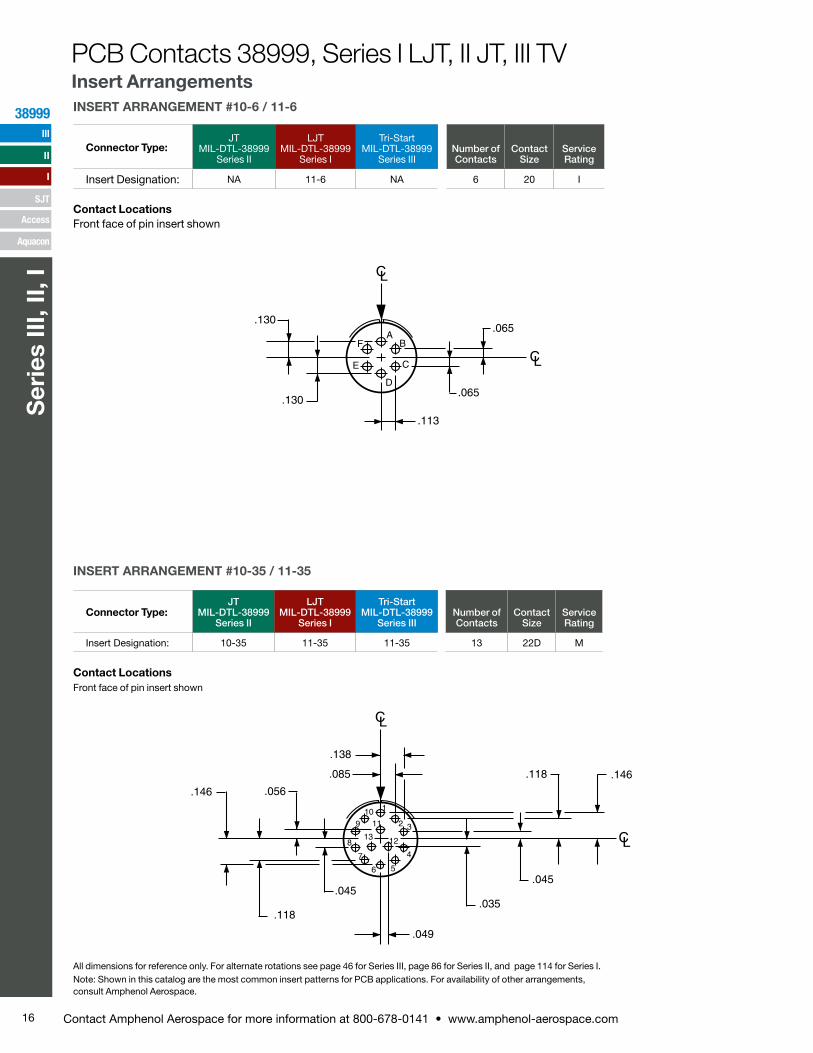
.118
.045
.035
.146
.049
.045
.118
.146 .056
.085
.138
5
2
133
1011
6
7
12
48
9
1
INSERT ARRANGEMENT #10-6 / 11-6
Connector Type:JT
MIL-DTL-38999 Series II
LJT MIL-DTL-38999
Series I
Tri-Start MIL-DTL-38999
Series IIINumber of Contacts
Contact Size
Service Rating
Insert Designation: NA 11-6 NA 6 20 I
Contact LocationsFront face of pin insert shown
All dimensions for reference only. For alternate rotations see page 46 for Series III, page 86 for Series II, and page 114 for Series I.Note: Shown in this catalog are the most common insert patterns for PCB applications. For availability of other arrangements, consult Amphenol Aerospace.
AB
C
D
E
F
.065
.113
.130
.065.130
INSERT ARRANGEMENT #10-35 / 11-35
Connector Type:JT
MIL-DTL-38999 Series II
LJT MIL-DTL-38999
Series I
Tri-Start MIL-DTL-38999
Series IIINumber of Contacts
Contact Size
Service Rating
Insert Designation: 10-35 11-35 11-35 13 22D M
Contact LocationsFront face of pin insert shown
PCB Contacts 38999, Series I LJT, II JT, III TV Insert Arrangements
16 Contact Amphenol Aerospace for more information at 800-678-0141 • www.amphenol-aerospace.com
38999
Ser
ies
III, I
I, I
III
SJT
I
II
Access
Aquacon
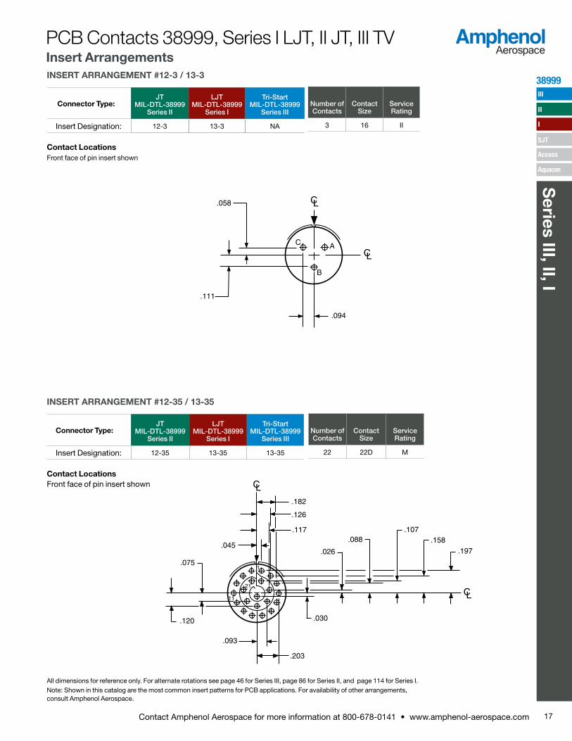
B
.094
.058
.111
AC
INSERT ARRANGEMENT #12-3 / 13-3
Connector Type:JT
MIL-DTL-38999 Series II
LJT MIL-DTL-38999
Series I
Tri-Start MIL-DTL-38999
Series III
Insert Designation: 12-3 13-3 NA
Contact LocationsFront face of pin insert shown
All dimensions for reference only. For alternate rotations see page 46 for Series III, page 86 for Series II, and page 114 for Series I.Note: Shown in this catalog are the most common insert patterns for PCB applications. For availability of other arrangements, consult Amphenol Aerospace.
11
.030
.026
.088.107
.158
.197
.203
.093
.120
.075
.045
.117
.126
.182
21
1
INSERT ARRANGEMENT #12-35 / 13-35
Connector Type:JT
MIL-DTL-38999 Series II
LJT MIL-DTL-38999
Series I
Tri-Start MIL-DTL-38999
Series III
Insert Designation: 12-35 13-35 13-35
Contact LocationsFront face of pin insert shown
Number of Contacts
Contact Size
Service Rating
22 22D M
Number of Contacts
Contact Size
Service Rating
3 16 II
PCB Contacts 38999, Series I LJT, II JT, III TV Insert Arrangements
17Contact Amphenol Aerospace for more information at 800-678-0141 • www.amphenol-aerospace.com
38999
Series III, II, I
III
SJT
I
II
Access
Aquacon
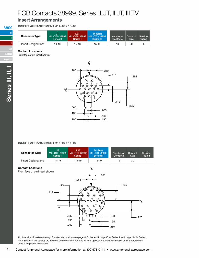
UT
S R
P
NM
L
K
J
H
G F E
D
A
B
C
.113
.225
.252.113
.260
.065
.130
.195.195
.130
.065
.260
INSERT ARRANGEMENT #14-18 / 15-18
Connector Type:JT
MIL-DTL-38999 Series II
LJT MIL-DTL-38999
Series I
Tri-Start MIL-DTL-38999
Series IIINumber of Contacts
Contact Size
Service Rating
Insert Designation: 14-18 15-18 15-18 18 20 I
Contact LocationsFront face of pin insert shown
All dimensions for reference only. For alternate rotations see page 46 for Series III, page 86 for Series II, and page 114 for Series I.Note: Shown in this catalog are the most common insert patterns for PCB applications. For availability of other arrangements, consult Amphenol Aerospace.
.065
C
BA
E
D
FG
J
H
U
T
L
K
N
M
V R
S
.225
.225
.065
.113
.113
.195
.260.195
.260
.130 .130
INSERT ARRANGEMENT #14-19 / 15-19
Connector Type:JT
MIL-DTL-38999 Series II
LJT MIL-DTL-38999
Series I
Tri-Start MIL-DTL-38999
Series IIINumber of Contacts
Contact Size
Service Rating
Insert Designation: 14-19 15-19 15-19 19 20 I
Contact LocationsFront face of pin insert shown
PCB Contacts 38999, Series I LJT, II JT, III TV Insert Arrangements
18 Contact Amphenol Aerospace for more information at 800-678-0141 • www.amphenol-aerospace.com
38999
Ser
ies
III, I
I, I
III
SJT
I
II
Access
Aquacon

Contact Hole Locations
Contact Number
Location
X Axis Y Axis
R –.131 +.293
S –.070 +.177
T +.070 +.177
U +.175 +.094
V +.178 –.036
W +.119 –.151
X .000 –.203
Y –.119 –.151
Z –.178 –.036
a –.175 +.094
b .000 +.065
c .000 –.065
F
E
AB
G
C
D
HJKL
M
N
P
RTS
U
V
WX
Y
Z
a b
c
Contact Hole Locations
Contact Number
Location
X Axis Y Axis
1 +.045 +.262
2 +.123 +.217
3 +.211 +.160
4 +.254 +.080
5 +.266 –.010
6 +.247 –.098
7 +.200 –.175
8 +.130 –.232
9 +.045 –.262
10 –.045 –.262
11 –.130 –.232
12 –.200 –.175
13 –.247 –.098
14 –.266 –.010
15 –.254 +.080
16 –.211 +.160
17 –.123 +.217
18 –.045 +.262
INSERT ARRANGEMENT #14-35 / 15-35
Connector Type:JT
MIL-DTL-38999 Series II
LJT MIL-DTL-38999
Series I
Tri-Start MIL-DTL-38999
Series IIINumber of Contacts
Contact Size
Service Rating
Insert Designation: 14-35 15-35 15-35 37 22D M
Contact LocationsFront face of pin insert shown
1
2131
11
All dimensions for reference only. For alternate rotations see page 46 for Series III, page 86 for Series II, and page 114 for Series I.Note: Shown in this catalog are the most common insert patterns for PCB applications. For availability of other arrangements, consult Amphenol Aerospace.
INSERT ARRANGEMENT #16-26 / 17-26
Connector Type:JT
MIL-DTL-38999 Series II
LJT MIL-DTL-38999
Series I
Tri-Start MIL-DTL-38999
Series IIINumber of Contacts
Contact Size
Service Rating
Insert Designation: NA 17-26 17-26 26 20 I
Contact LocationsFront face of pin insert shown
Contact Hole Locations
Contact Number
Location
X Axis Y Axis
A .000 +.321
B +.131 +.293
C +.239 +.214
D +.305 +.099
E +.319 –.034
F +.278 –.161
G +.189 –.260
H +.067 –.314
J –.067 –.314
K –.189 –.260
L –.278 –.161
M –.319 –.034
N –.305 +.099
P –.239 +.214
PCB Contacts 38999, Series I LJT, II JT, III TV Insert Arrangements
Contact Hole Locations
Contact Number
Location
X Axis Y Axis
19 +.045 +.172
20 +.123 +.119
21 +.170 +.040
22 +.170 –.050
23 +.123 –.127
24 +.045 –.172
25 –.045 –.172
26 –.123 –.127
27 –.170 –.050
28 –.170 +.040
29 –.123 +.119
30 –.045 +.172
31 +.045 +.074
32 +.090 –.004
33 +.045 –.082
34 –.045 –.082
35 –.090 –.004
36 –.045 +.074
37 .000 –.004
19Contact Amphenol Aerospace for more information at 800-678-0141 • www.amphenol-aerospace.com
38999
Series III, II, I
III
SJT
I
II
Access
Aquacon
All dimensions for reference only. For alternate rotations see page 46 for Series III, page 86 for Series II, and page 114 for Series I.Note: Shown in this catalog are the most common insert patterns for PCB applications. For availability of other arrangements, consult Amphenol Aerospace.
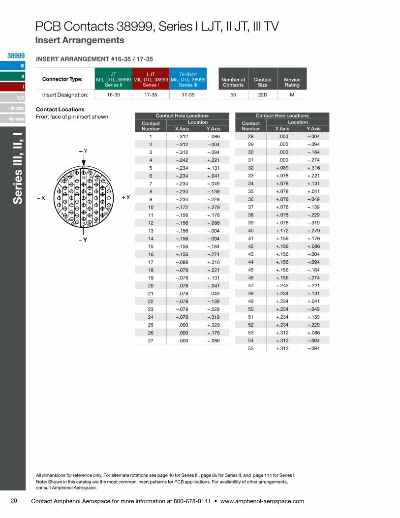
INSERT ARRANGEMENT #16-35 / 17-35
Connector Type:JT
MIL-DTL-38999 Series II
LJT MIL-DTL-38999
Series I
Tri-Start MIL-DTL-38999
Series IIINumber of Contacts
Contact Size
Service Rating
Insert Designation: 16-35 17-35 17-35 55 22D M
Contact LocationsFront face of pin insert shown Contact Hole Locations
Contact Number
LocationX Axis Y Axis
28 .000 –.004
29 .000 –.094
30 .000 –.184
31 .000 –.274
32 +.089 +.316
33 +.078 +.221
34 +.078 +.131
35 +.078 +.041
36 +.078 –.049
37 +.078 –.139
38 +.078 –.229
39 +.078 –.319
40 +.172 +.279
41 +.156 +.176
42 +.156 +.086
43 +.156 –.004
44 +.156 –.094
45 +.156 –.184
46 +.156 –.274
47 +.242 +.221
48 +.234 +.131
49 +.234 +.041
50 +.234 –.049
51 +.234 –.139
52 +.234 –.229
53 +.312 +.086
54 +.312 –.004
55 +.312 –.094
1710
4
1
39
1624 31
25 32
39
40
46
47
52
53
55
Contact Hole Locations
Contact Number
LocationX Axis Y Axis
1 –.312 +.086
2 –.312 –.004
3 –.312 –.094
4 –.242 +.221
5 –.234 +.131
6 –.234 +.041
7 –.234 –.049
8 –.234 –.139
9 –.234 –.229
10 –.172 +.279
11 –.156 +.176
12 –.156 +.086
13 –.156 –.004
14 –.156 –.094
15 –.156 –.184
16 –.156 –.274
17 –.089 +.316
18 –.078 +.221
19 –.078 +.131
20 –.078 +.041
21 –.078 –.049
22 –.078 –.139
23 –.078 –.229
24 –.078 –.319
25 .000 +.329
26 .000 +.176
27 .000 +.086
PCB Contacts 38999, Series I LJT, II JT, III TV Insert Arrangements
20 Contact Amphenol Aerospace for more information at 800-678-0141 • www.amphenol-aerospace.com
38999
Ser
ies
III, I
I, I
III
SJT
I
II
Access
Aquacon
L
K
J
H
G
F
E
D
A
B
C
.105
.132
.092
.053
.179
.275
.215.281
.260
.105
.250
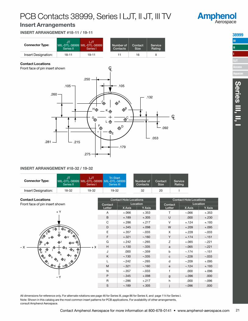
INSERT ARRANGEMENT #18-11 / 19-11
Connector Type:JT
MIL-DTL-38999 Series II
LJT MIL-DTL-38999
Series INumber of Contacts
Contact Size
Service Rating
Insert Designation: 18-11 19-11 11 16 II
Contact LocationsFront face of pin insert shown
UT
S
R
P
N
g
f
M
LK
JH
G
F
E
D
h
AB
C
ab
c
e
d
V
W
X
YZ
j
INSERT ARRANGEMENT #18-32 / 19-32
Connector Type:JT
MIL-DTL-38999 Series II
LJT MIL-DTL-38999
Series I
Tri-Start MIL-DTL-38999
Series IIINumber of Contacts
Contact Size
Service Rating
Insert Designation: 18-32 19-32 19-32 32 20 I
Contact LocationsFront face of pin insert shown
Contact Hole Locations
Contact Letter
LocationX Axis Y Axis
A +.066 +.353
B +.189 +.305
C +.286 +.217
D +.345 +.098
E +.357 –.033
F +.321 –.160
G +.242 –.265
H +.130 –.335
J .000 –.359
K –.130 –.335
L –.242 –.265
M –.321 –.160
N –.357 –.033
P –.345 +.098
R –.286 +.217
S –.189 +.305
Contact Hole Locations
Contact Letter
LocationX Axis Y Axis
T –.066 +.353
U .000 +.230
V +.124 +.193
W +.209 +.095
X +.228 –.033
Y +.174 –.151
Z +.065 –.221
a –.065 –.221
b –.174 –.151
c –.228 –.033
d –.209 +.095
e –.124 +.193
f .000 +.096
g +.096 .000
h .000 –.096
j –.096 .000
All dimensions for reference only. For alternate rotations see page 46 for Series III, page 86 for Series II, and page 114 for Series I.Note: Shown in this catalog are the most common insert patterns for PCB applications. For availability of other arrangements, consult Amphenol Aerospace.
PCB Contacts 38999, Series I LJT, II JT, III TV Insert Arrangements
21Contact Amphenol Aerospace for more information at 800-678-0141 • www.amphenol-aerospace.com
38999
Series III, II, I
III
SJT
I
II
Access
Aquacon
1
.357
.279
.201
.123
.045
.045
.090
.135
.180
.225
.270
.315.360
410
1725 34
4351
58
64
66
6357
5042332416
9
3
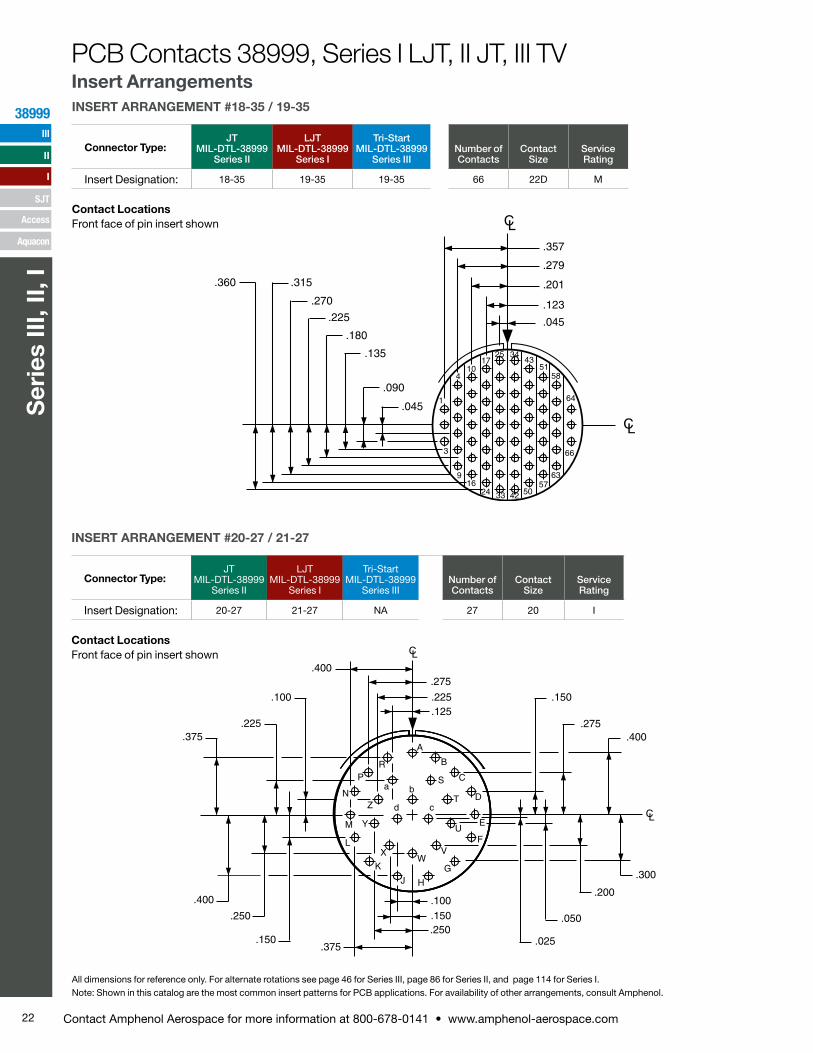
INSERT ARRANGEMENT #18-35 / 19-35
Connector Type:JT
MIL-DTL-38999 Series II
LJT MIL-DTL-38999
Series I
Tri-Start MIL-DTL-38999
Series IIINumber of Contacts
Contact Size
Service Rating
Insert Designation: 18-35 19-35 19-35 66 22D M
Contact LocationsFront face of pin insert shown
A
B
C
D
S
T
E
FU
V
G
H
W
J
c
b
K
X
d
aP
R
L
M Y
ZN
.275
.225
.125
.400
.150
.275
.300
.200
.050
.025
.100
.150
.250
.375.150
.250
.400
.225
.100
.375 .400
INSERT ARRANGEMENT #20-27 / 21-27
Connector Type:JT
MIL-DTL-38999 Series II
LJT MIL-DTL-38999
Series I
Tri-Start MIL-DTL-38999
Series IIINumber of Contacts
Contact Size
Service Rating
Insert Designation: 20-27 21-27 NA 27 20 I
Contact LocationsFront face of pin insert shown
All dimensions for reference only. For alternate rotations see page 46 for Series III, page 86 for Series II, and page 114 for Series I.Note: Shown in this catalog are the most common insert patterns for PCB applications. For availability of other arrangements, consult Amphenol.
PCB Contacts 38999, Series I LJT, II JT, III TV Insert Arrangements
22 Contact Amphenol Aerospace for more information at 800-678-0141 • www.amphenol-aerospace.com
38999
Ser
ies
III, I
I, I
III
SJT
I
II
Access
Aquacon
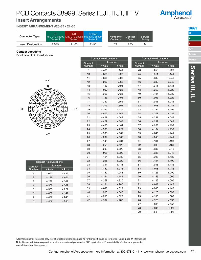
INSERT ARRANGEMENT #20-35 / 21-35
Connector Type:JT
MIL-DTL-38999 Series II
LJT MIL-DTL-38999
Series I
Tri-Start MIL-DTL-38999
Series IIINumber of Contacts
Contact Size
Service Rating
Insert Designation: 20-35 21-35 21-35 79 22D M
Contact LocationsFront face of pin insert shown
Contact Hole Locations
Contact Number
Location
X Axis Y Axis
1 +.053 +.426
2 +.146 +.404
3 +.232 +.362
4 +.306 +.302
5 +.365 +.227
6 +.406 +.141
7 +.427 +.048
8 +.427 –.048
Contact Hole Locations
Contact Number
Location
X Axis Y Axis
9 +.406 –.141
10 +.365 –.227
11 +.306 –.302
12 +.232 –.362
13 +.146 –.404
14 +.053 –.426
15 –.053 –.426
16 –.146 –.404
17 –.232 –.362
18 –.306 –.302
19 –.365 –.227
20 –.406 –.141
21 –.427 –.048
22 –.427 +.048
23 –.406 +.141
24 –.365 +.227
25 –.306 +.302
26 –.232 +.362
27 –.146 +.404
28 –.053 +.426
29 .000 +.323
30 +.098 +.322
31 +.184 +.280
32 +.258 +.220
33 +.311 +.141
34 +.332 +.048
35 +.332 –.048
36 +.311 –.141
37 +.258 –.220
38 +.184 –.280
39 +.098 –.322
40 .000 –.347
41 –.098 –.322
42 –.184 –.280
Contact Hole Locations
Contact Number
Location
X Axis Y Axis
43 –.258 –.220
44 –.311 –.141
45 –.332 –.048
46 –.332 +.048
47 –.311 +.141
48 –.258 +.220
49 –.184 +.280
50 –.098 +.322
51 –.048 +.241
52 +.048 +.241
53 +.134 +.199
54 +.208 +.139
55 +.237 +.048
56 +.237 –.048
57 +.208 –.139
58 +.134 –.199
59 +.048 –.241
60 –.048 –.241
61 –.134 –.199
62 –.208 –.139
63 –.237 –.048
64 –.237 +.048
65 –.208 +.139
66 –.134 +.199
67 –.048 +.146
68 +.048 +.146
69 +.125 +.090
70 +.155 .000
71 +.125 –.090
72 +.048 –.146
73 –.048 –.146
74 –.125 –.090
75 –.155 .000
76 –.125 +.090
77 .000 +.053
78 +.048 –.029
79 –.048 –.029
1
31
79
61
41
21
11
71
51
All dimensions for reference only. For alternate rotations see page 46 for Series III, page 86 for Series II, and page 114 for Series I.Note: Shown in this catalog are the most common insert patterns for PCB applications. For availability of other arrangements, consult Amphenol Aerospace.
PCB Contacts 38999, Series I LJT, II JT, III TV Insert Arrangements
23Contact Amphenol Aerospace for more information at 800-678-0141 • www.amphenol-aerospace.com
38999
Series III, II, I
III
SJT
I
II
Access
Aquacon
U
T
S
R
P
N
g
f
ML K
JH
G
F
E
D
sh
ij
VW A
kY
BC
mZ
ar
n
t
q p
b
c
e d
X
.300 DIA.
.567 DIA.
.835 DIA.
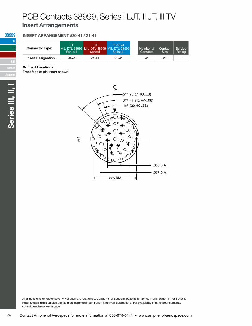
INSERT ARRANGEMENT #20-41 / 21-41
Connector Type:JT
MIL-DTL-38999 Series II
LJT MIL-DTL-38999
Series I
Tri-Start MIL-DTL-38999
Series IIINumber of Contacts
Contact Size
Service Rating
Insert Designation: 20-41 21-41 21-41 41 20 I
Contact LocationsFront face of pin insert shown
All dimensions for reference only. For alternate rotations see page 46 for Series III, page 86 for Series II, and page 114 for Series I.Note: Shown in this catalog are the most common insert patterns for PCB applications. For availability of other arrangements, consult Amphenol Aerospace.
PCB Contacts 38999, Series I LJT, II JT, III TV Insert Arrangements
24 Contact Amphenol Aerospace for more information at 800-678-0141 • www.amphenol-aerospace.com
38999
Ser
ies
III, I
I, I
III
SJT
I
II
Access
Aquacon
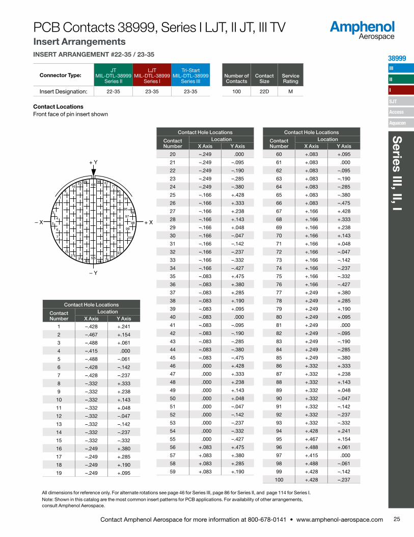
INSERT ARRANGEMENT #22-35 / 23-35
Connector Type:JT
MIL-DTL-38999 Series II
LJT MIL-DTL-38999
Series I
Tri-Start MIL-DTL-38999
Series IIINumber of Contacts
Contact Size
Service Rating
Insert Designation: 22-35 23-35 23-35 100 22D M
Contact LocationsFront face of pin insert shown
Contact Hole Locations
Contact Number
LocationX Axis Y Axis
1 –.428 +.241
2 –.467 +.154
3 –.488 +.061
4 –.415 .000
5 –.488 –.061
6 –.428 –.142
7 –.428 –.237
8 –.332 +.333
9 –.332 +.238
10 –.332 +.143
11 –.332 +.048
12 –.332 –.047
13 –.332 –.142
14 –.332 –.237
15 –.332 –.332
16 –.249 +.380
17 –.249 +.285
18 –.249 +.190
19 –.249 +.095
Contact Hole Locations
Contact Number
LocationX Axis Y Axis
20 –.249 .000
21 –.249 –.095
22 –.249 –.190
23 –.249 –.285
24 –.249 –.380
25 –.166 +.428
26 –.166 +.333
27 –.166 +.238
28 –.166 +.143
29 –.166 +.048
30 –.166 –.047
31 –.166 –.142
32 –.166 –.237
33 –.166 –.332
34 –.166 –.427
35 –.083 +.475
36 –.083 +.380
37 –.083 +.285
38 –.083 +.190
39 –.083 +.095
40 –.083 .000
41 –.083 –.095
42 –.083 –.190
43 –.083 –.285
44 –.083 –.380
45 –.083 –.475
46 .000 +.428
47 .000 +.333
48 .000 +.238
49 .000 +.143
50 .000 +.048
51 .000 –.047
52 .000 –.142
53 .000 –.237
54 .000 –.332
55 .000 –.427
56 +.083 +.475
57 +.083 +.380
58 +.083 +.285
59 +.083 +.190
Contact Hole Locations
Contact Number
LocationX Axis Y Axis
60 +.083 +.095
61 +.083 .000
62 +.083 –.095
63 +.083 –.190
64 +.083 –.285
65 +.083 –.380
66 +.083 –.475
67 +.166 +.428
68 +.166 +.333
69 +.166 +.238
70 +.166 +.143
71 +.166 +.048
72 +.166 –.047
73 +.166 –.142
74 +.166 –.237
75 +.166 –.332
76 +.166 –.427
77 +.249 +.380
78 +.249 +.285
79 +.249 +.190
80 +.249 +.095
81 +.249 .000
82 +.249 –.095
83 +.249 –.190
84 +.249 –.285
85 +.249 –.380
86 +.332 +.333
87 +.332 +.238
88 +.332 +.143
89 +.332 +.048
90 +.332 –.047
91 +.332 –.142
92 +.332 –.237
93 +.332 –.332
94 +.428 +.241
95 +.467 +.154
96 +.488 +.061
97 +.415 .000
98 +.488 –.061
99 +.428 –.142
100 +.428 –.237
95
9796
100
98
99
9385
76665 5
4 53 4
2 415
7
6
5
4
3
2
1
816
25 354 6
56 6777
86
94
All dimensions for reference only. For alternate rotations see page 46 for Series III, page 86 for Series II, and page 114 for Series I.Note: Shown in this catalog are the most common insert patterns for PCB applications. For availability of other arrangements, consult Amphenol Aerospace.
PCB Contacts 38999, Series I LJT, II JT, III TV Insert Arrangements
25Contact Amphenol Aerospace for more information at 800-678-0141 • www.amphenol-aerospace.com
38999
Series III, II, I
III
SJT
I
II
Access
Aquacon
B
Z
D
C
E
F
G
YXW
p
V
UT
nSm
AA qr
sa
b
DDtEE
uc
Hd
vw
eJK
Lf
gM
FFy
CCBB
GGz
iHH
xh
N
jP
R k
A.260
.225
.112
.336
.065
.450
.195
.455
.325
.130
.390
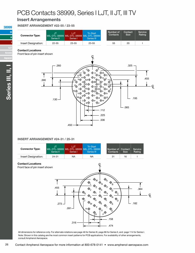
INSERT ARRANGEMENT #22-55 / 23-55
Connector Type:JT
MIL-DTL-38999 Series II
LJT MIL-DTL-38999
Series I
Tri-Start MIL-DTL-38999
Series III
Number of Contacts
Contact Size
Service Rating
Insert Designation: 22-55 23-55 23-55 55 20 I
Contact LocationsFront face of pin insert shown
A
.474
.158.316
.091
.273
.455
.182
.364
B
C
D
E
FG
H
J
K
YZ
Xe
d
T
WV
U
S
c
g
f
L
M
NP
Qb
a
R
INSERT ARRANGEMENT #24-31 / 25-31
Connector Type:JT
MIL-DTL-38999 Series II
LJT MIL-DTL-38999
Series I
Tri-Start MIL-DTL-38999
Series IIINumber of Contacts
Contact Size
Service Rating
Insert Designation: 24-31 NA NA 31 16 I
Contact LocationsFront face of pin insert shown
All dimensions for reference only. For alternate rotations see page 46 for Series III, page 86 for Series II, and page 114 for Series I.Note: Shown in this catalog are the most common insert patterns for PCB applications. For availability of other arrangements, consult Amphenol Aerospace.
PCB Contacts 38999, Series I LJT, II JT, III TV Insert Arrangements
26 Contact Amphenol Aerospace for more information at 800-678-0141 • www.amphenol-aerospace.com
38999
Ser
ies
III, I
I, I
III
SJT
I
II
Access
Aquacon

1
8 1525 36
4859
7182
94105115
125
121
114104
9381705847
3524
14
4
7
INSERT ARRANGEMENT #24-35 / 25-35
Connector Type:JT
MIL-DTL-38999 Series II
LJT MIL-DTL-38999
Series I
Tri-Start MIL-DTL-38999
Series IIINumber of Contacts
Contact Size
Service Rating
Insert Designation: 24-35 25-35 25-35 128 22D M
Contact LocationsFront face of pin insert shown
Contact Hole Locations
Contact Number
LocationX Axis Y Axis
1 –.479 +.2792 –.520 +.1903 –.546 +.0954 –.555 .0005 –.546 –.0956 –.520 –.1907 –.479 –.2798 –.424 +.3579 –.415 +.19010 –.415 +.09511 –.415 .00012 –.415 –.09513 –.415 –.19014 –.424 –.35715 –.332 +.44416 –.332 +.33217 –.332 +.23718 –.332 +.14219 –.332 +.04720 –.332 –.04721 –.332 –.14222 –.332 –.23723 –.332 –.33224 –.332 –.42725 –.249 +.49626 –.249 +.38027 –.249 +.28528 –.249 +.190
Contact Hole Locations
Contact Number
LocationX Axis Y Axis
29 –.249 +.09530 –.249 .00031 –.249 –.09532 –.249 –.19033 –.249 –.28534 –.249 –.38035 –.249 –.47536 –.160 +.53137 –.166 +.42738 –.166 +.33239 –.166 +.23740 –.166 +.14241 –.166 +.04742 –.166 –.04743 –.166 –.14244 –.166 –.23745 –.166 –.33246 –.166 –.42747 –.166 –.52248 –.083 +.47549 –.083 +.38050 –.083 +.28551 –.083 +.19052 –.083 +.09553 –.083 .00054 –.083 –.09555 –.083 –.19056 –.083 –.28557 –.083 –.38058 –.083 –.47559 .000 +.52260 .000 +.42761 .000 +.33262 .000 +.23763 .000 +.14264 .000 +.04765 .000 –.04766 .000 –.14267 .000 –.23768 .000 –.33269 .000 –.42770 .000 –.55571 +.083 +.47572 +.083 +.38073 +.083 +.28574 +.083 +.19075 +.083 +.09576 +.083 .00077 +.083 –.09578 +.083 –.190
Contact Hole Locations
Contact Number
LocationX Axis Y Axis
79 +.083 –.28580 +.083 –.38081 +.083 –.47582 +.160 +.53183 +.166 +.42784 +.166 +.33285 +.166 +.23786 +.166 +.14287 +.166 +.04788 +.166 –.04789 +.166 –.14290 +.166 –.23791 +.166 –.33292 +.166 –.42793 +.166 –.52294 +.249 +.49695 +.249 +.38096 +.249 +.28597 +.249 +.19098 +.249 +.09599 +.249 .000100 +.249 –.095101 +.249 –.190102 +.249 –.285103 +.249 –.380104 +.249 –.475105 +.332 +.444106 +.332 +.332107 +.332 +.237108 +.332 +.142109 +.332 +.047110 +.332 –.047111 +.332 –.142112 +.332 –.237113 +.332 –.332114 +.332 –.427115 +.424 +.357116 +.415 +.190117 +.415 +.095118 +.415 .000119 +.415 –.095120 +.415 –.190121 +.424 –.357122 +.479 +.279123 +.520 +.190124 +.546 +.095125 +.555 .000126 +.546 –.095127 +.520 –.190128 +.479 –.279
All dimensions for reference only. For alternate rotations see page 46 for Series III, page 86 for Series II, and page 114 for Series I.Note: Shown in this catalog are the most common insert patterns for PCB applications. For availability of other arrangements, consult Amphenol Aerospace.
PCB Contacts 38999, Series I LJT, II JT, III TV Insert Arrangements
27Contact Amphenol Aerospace for more information at 800-678-0141 • www.amphenol-aerospace.com
38999
Series III, II, I
III
SJT
I
II
Access
Aquacon
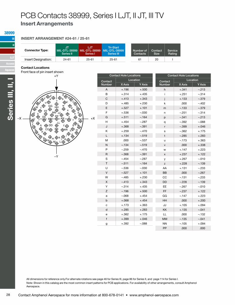
INSERT ARRANGEMENT #24-61 / 25-61
Connector Type:JT
MIL-DTL-38999 Series II
LJT MIL-DTL-38999
Series I
Tri-Start MIL-DTL-38999
Series IIINumber of Contacts
Contact Size
Service Rating
Insert Designation: 24-61 25-61 25-61 61 20 I
Contact LocationsFront face of pin insert shown
A
E
B
C
D
F
G
H
J
K
V
LMN
pR
S
T
U
XY
Za b
W
c
d
e
jkm
f
h
i
r
gq
s
t
uv
w
x
y
z
AABBCC
DD
EE
FF
GG HH
MM
NN JJPP
KK
LL
P
All dimensions for reference only.For alternate rotations see page 46 for Series III, page 86 for Series II, and page 114 for Series I.Note: Shown in this catalog are the most common insert patterns for PCB applications. For availability of other arrangements, consult Amphenol Aerospace.
Contact Hole Locations
Contact Number
Location
X Axis Y Axis
A +.196 +.500
B +.314 +.435
C +.413 +.343
D +.485 +.230
E +.527 +.101
F +.536 –.030
G +.511 –.164
H +.454 –.287
J +.368 –.391
K +.259 –.470
L +.134 –.519
M .000 –.537
N –.134 –.519
P –.259 –.470
R –.368 –.391
S –.454 –.287
T –.511 –.164
U –.536 –.030
V –.527 +.101
W –.485 +.230
X –.413 +.343
Y –.314 +.435
Z –.196 +.500
a –.068 +.454
b +.068 +.454
c +.173 +.363
d +.285 +.283
e +.362 +.175
f +.399 +.046
g +.392 –.088
Contact Hole Locations
Contact Number
Location
X Axis Y Axis
h +.341 –.213
i +.251 –.314
j +.133 –.379
k .000 –.402
m –.133 –.379
n –.251 –.314
p –.341 –.213
q –.392 –.088
r –.399 +.046
s –.362 +.175
t –.285 +.283
u –.173 +.363
v .000 +.338
w +.147 +.223
x +.237 +.122
y +.267 –.010
z +.228 –.139
AA +.131 –.233
BB .000 –.267
CC –.131 –.233
DD –.228 –.139
EE –.267 –.010
FF –.237 +.122
GG –.147 +.223
HH .000 +.200
JJ +.105 +.094
KK +.135 –.041
LL .000 –.132
MM –.135 –.041
NN –.105 +.094
PP .000 .000
28 Contact Amphenol Aerospace for more information at 800-678-0141 • www.amphenol-aerospace.com
38999
Ser
ies
III, I
I, I
III
SJT
I
II
Access
Aquacon
PCB Contacts 38999, Series I LJT, II JT, III TV Insert Arrangements
29Contact Amphenol Aerospace for more information at 800-678-0141 • www.amphenol-aerospace.com
38999
Series III, II, I, S
JT
III
SJT
I
II
Access
Aquacon
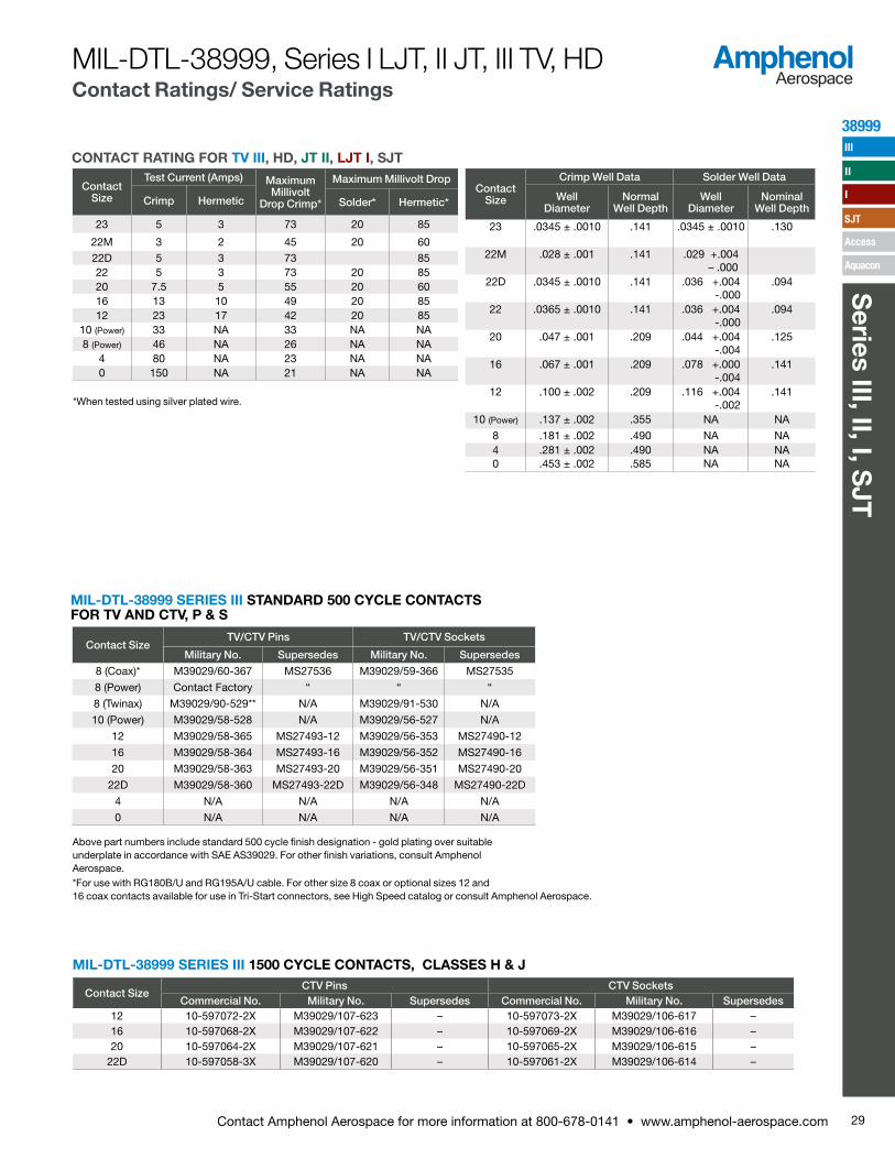
MIL-DTL-38999, Series I LJT, II JT, III TV, HDContact Ratings/ Service Ratings
CONTACT RATING FOR TV III, HD, JT II, LJT I, SJT
*When tested using silver plated wire.
Contact Size
Test Current (Amps) Maximum Millivolt
Drop Crimp*
Maximum Millivolt Drop
Crimp Hermetic Solder* Hermetic*
23 5 3 73 20 85
22M 3 2 45 20 6022D 5 3 73 8522 5 3 73 20 8520 7.5 5 55 20 6016 13 10 49 20 8512 23 17 42 20 85
10 (Power) 33 NA 33 NA NA8 (Power) 46 NA 26 NA NA
4 80 NA 23 NA NA0 150 NA 21 NA NA
Contact Size
Crimp Well Data Solder Well Data
Well Diameter
Normal Well Depth
Well Diameter
Nominal Well Depth
23 .0345 ± .0010 .141 .0345 ± .0010 .130
22M .028 ± .001 .141 .029 +.004– .000
22D .0345 ± .0010 .141 .036 +.004 -.000
.094
22 .0365 ± .0010 .141 .036 +.004 -.000
.094
20 .047 ± .001 .209 .044 +.004 -.004
.125
16 .067 ± .001 .209 .078 +.000 -.004
.141
12 .100 ± .002 .209 .116 +.004 -.002
.141
10 (Power) .137 ± .002 .355 NA NA
8 .181 ± .002 .490 NA NA4 .281 ± .002 .490 NA NA0 .453 ± .002 .585 NA NA
MIL-DTL-38999 SERIES III STANDARD 500 CYCLE CONTACTS FOR TV AND CTV, P & S
MIL-DTL-38999 SERIES III 1500 CYCLE CONTACTS, CLASSES H & J
Contact SizeCTV Pins CTV Sockets
Commercial No. Military No. Supersedes Commercial No. Military No. Supersedes12 10-597072-2X M39029/107-623 – 10-597073-2X M39029/106-617 –16 10-597068-2X M39029/107-622 – 10-597069-2X M39029/106-616 –20 10-597064-2X M39029/107-621 – 10-597065-2X M39029/106-615 –
22D 10-597058-3X M39029/107-620 – 10-597061-2X M39029/106-614 –
Contact SizeTV/CTV Pins TV/CTV Sockets
Military No. Supersedes Military No. Supersedes
8 (Coax)* M39029/60-367 MS27536 M39029/59-366 MS27535
8 (Power) Contact Factory “ “ “
8 (Twinax) M39029/90-529** N/A M39029/91-530 N/A
10 (Power) M39029/58-528 N/A M39029/56-527 N/A
12 M39029/58-365 MS27493-12 M39029/56-353 MS27490-12
16 M39029/58-364 MS27493-16 M39029/56-352 MS27490-16
20 M39029/58-363 MS27493-20 M39029/56-351 MS27490-20
22D M39029/58-360 MS27493-22D M39029/56-348 MS27490-22D
4 N/A N/A N/A N/A
0 N/A N/A N/A N/A
Above part numbers include standard 500 cycle finish designation - gold plating over suitable underplate in accordance with SAE AS39029. For other finish variations, consult Amphenol Aerospace. *For use with RG180B/U and RG195A/U cable. For other size 8 coax or optional sizes 12 and 16 coax contacts available for use in Tri-Start connectors, see High Speed catalog or consult Amphenol Aerospace.
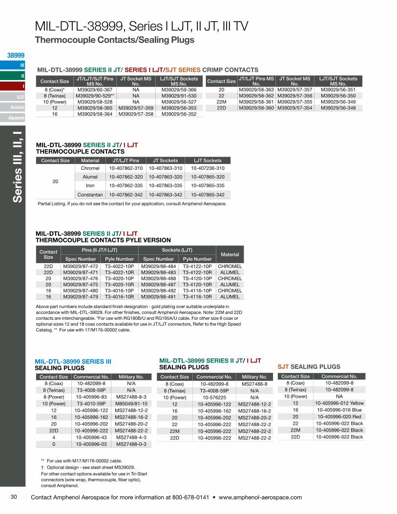
30 Contact Amphenol Aerospace for more information at 800-678-0141 • www.amphenol-aerospace.com
38999
Ser
ies
III, I
I, I
III
SJT
I
II
Access
Aquacon
Contact Size
Pins (II JT/I LJT) Sockets (LJT)Material
Spec Number Pyle Number Spec Number Pyle Number
22D M39029/87-472 T3-4022-10P M39029/88-484 T3-4122-10P CHROMEL22D M39029/87-471 T3-4022-10R M39029/88-483 T3-4122-10R ALUMEL20 M39029/87-476 T3-4020-10P M39029/88-488 TS-4120-10P CHROMEL20 M39029/87-475 T3-4020-10R M39029/88-487 T3-4120-10R ALUMEL16 M39029/87-480 T3-4016-10P M39029/88-492 T3-4116-10P CHROMEL16 M39029/87-479 T3-4016-10R M39029/88-491 T3-4116-10R ALUMEL
MIL-DTL-38999 SERIES II JT/ I LJT THERMOCOUPLE CONTACTS PYLE VERSION
Above part numbers include standard finish designation - gold plating over suitable underplate in accordance with MIL-DTL-39029. For other finishes, consult Amphenol Aerospace. Note: 22M and 22D contacts are interchangeable. *For use with RG180B/U and RG195A/U cable. For other size 8 coax or optional sizes 12 and 18 coax contacts available for use in JT/LJT connectors, Refer to the High Speed Catalog. ** For use with 17/M176-00002 cable.
MIL-DTL-38999 SERIES II JT/ SERIES I LJT/SJT SERIES CRIMP CONTACTS
Contact Size JT/LJT/SJT Pins MS No.
JT Socket MS No.
LJT/SJT Sockets MS No.
8 (Coax)* M39029/60-367 NA M39029/59-3668 (Twinax) M39029/90-529** NA M39029/91-53010 (Power) M39029/58-528 NA M39029/56-527
12 M39029/58-365 M39029/57-359 M39029/56-35316 M39029/58-364 M39029/57-358 M39029/56-352
Contact Size JT/LJT Pins MS No.
JT Socket MS No.
LJT/SJT Sockets MS No.
20 M39029/58-363 M39029/57-357 M39029/56-35122 M39029/58-362 M39029/57-356 M39029/56-350
22M M39029/58-361 M39029/57-355 M39029/56-34922D M39029/58-360 M39029/57-354 M39029/56-348
Contact Size Material JT/LJT Pins JT Sockets LJT Sockets
20
Chromel 10-407862-310 10-407863-310 10-407236-310
Alumel 10-407862-320 10-407863-320 10-407865-320
Iron 10-407862-335 10-407863-335 10-407865-335
Constantan 10-407862-342 10-407863-342 10-407865-342
MIL-DTL-38999 SERIES II JT/ I LJT THERMOCOUPLE CONTACTS
Partial Listing. If you do not see the contact for your application, consult Amphenol Aerospace.
MIL-DTL-38999 SERIES II JT/ I LJT SEALING PLUGS
Contact Size Commercial No. Military No.8 (Coax) 10-482099-8 MS27488-8
8 (Twinax) T3-4008-59P N/A10 (Power) 10-576225 N/A
12 10-405996-122 MS27488-12-216 10-405996-162 MS27488-16-220 10-405996-202 MS27488-20-222 10-405996-222 MS27488-22-2
22M 10-405996-222 MS27488-22-222D 10-405996-222 MS27488-22-2
** For use with M17/M176-00002 cable.† Optional design - see slash sheet MS39029.For other contact options available for use in Tri-Start connectors (wire wrap, thermocouple, fiber optic), consult Amphenol.
MIL-DTL-38999 SERIES III SEALING PLUGS
Contact Size Commercial No. Military No.8 (Coax) 10-482099-8 N/A
8 (Twinax) T3-4008-59P N/A8 (Power) 10-405996-83 MS27488-8-310 (Power) T3-4010-59P M85049/81-10
12 10-405996-122 MS27488-12-216 10-405996-162 MS27488-16-220 10-405996-202 MS27488-20-2
22D 10-405996-222 MS27488-22-24 10-405996-43 MS27488-4-30 10-405996-03 MS27488-0-3
Contact Size Commercial No. 8 (Coax) 10-482099-8
8 (Twinax) 10-482099-810 (Power) NA
12 10-405996-012 Yellow16 10-405996-016 Blue20 10-405996-020 Red22 10-405996-022 Black
22M 10-405996-022 Black22D 10-405996-022 Black
SJT SEALING PLUGS
MIL-DTL-38999, Series I LJT, II JT, III TVThermocouple Contacts/Sealing Plugs
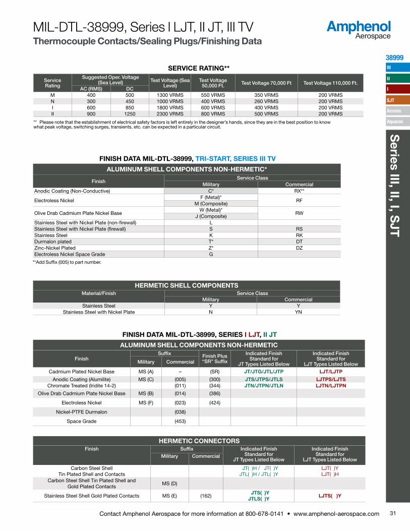
31Contact Amphenol Aerospace for more information at 800-678-0141 • www.amphenol-aerospace.com
38999
Series III, II, I, S
JT
III
SJT
I
II
Access
Aquacon
FINISH DATA MIL-DTL-38999, SERIES I LJT, II JT
ALUMINUM SHELL COMPONENTS NON-HERMETIC
FinishSuffix Finish Plus
“SR” Suffix
Indicated Finish Standard for
JT Types Listed Below
Indicated Finish Standard for
LJT Types Listed BelowMilitary Commercial
Cadmium Plated Nickel Base MS (A) – (SR) JT/JTG/JTL/JTP LJT/LJTP
Anodic Coating (Alumilite) MS (C) (005) (300) JTS/JTPS/JTLS LJTPS/LJTSChromate Treated (Iridite 14-2) (011) (344) JTN/JTPN/JTLN LJTN/LJTPN
Olive Drab Cadmium Plate Nickel Base MS (B) (014) (386)
Electroless Nickel MS (F) (023) (424)
Nickel-PTFE Durmalon (038)
Space Grade (453)
HERMETIC CONNECTORSFinish Suffix Indicated Finish
Standard for JT Types Listed Below
Indicated Finish Standard for
LJT Types Listed BelowMilitary Commercial
Carbon Steel Shell Tin Plated Shell and Contacts
JT( )H / JT( )Y JTL( )H / JTL( )Y
LJT( )Y LJT( )H
Carbon Steel Shell Tin Plated Shell and Gold Plated Contacts
MS (D)
Stainless Steel Shell Gold Plated Contacts MS (E) (162) JTS( )Y JTLS( )Y
LJTS( )Y
MIL-DTL-38999, Series I LJT, II JT, III TVThermocouple Contacts/Sealing Plugs/Finishing Data
FINISH DATA MIL-DTL-38999, TRI-START, SERIES III TV
ALUMINUM SHELL COMPONENTS NON-HERMETIC*
FinishService Class
Military CommercialAnodic Coating (Non-Conductive) C* RX**
Electroless NickelF (Metal)*
RFM (Composite)
Olive Drab Cadmium Plate Nickel BaseW (Metal)*
RWJ (Composite)
Stainless Steel with Nickel Plate (non-firewall) LStainless Steel with Nickel Plate (firewall) S RSStainless Steel K RKDurmalon plated T* DTZinc-Nickel Plated Z* DZElectroless Nickel Space Grade G
HERMETIC SHELL COMPONENTSMaterial/Finish Service Class
Military CommercialStainless Steel Y Y
Stainless Steel with Nickel Plate N YN
**Add Suffix (005) to part number.
Contact Size Commercial No. 8 (Coax) 10-482099-8
8 (Twinax) 10-482099-810 (Power) NA
12 10-405996-012 Yellow16 10-405996-016 Blue20 10-405996-020 Red22 10-405996-022 Black
22M 10-405996-022 Black22D 10-405996-022 Black
SERVICE RATING**
** Please note that the establishment of electrical safety factors is left entirely in the designer’s hands, since they are in the best position to know what peak voltage, switching surges, transients, etc. can be expected in a particular circuit.
ServiceRating
Suggested Oper. Voltage (Sea Level) Test Voltage (Sea
Level)Test Voltage 50,000 Ft. Test Voltage 70,000 Ft Test Voltage 110,000 Ft.
AC (RMS) DCM 400 500 1300 VRMS 550 VRMS 350 VRMS 200 VRMSN 300 450 1000 VRMS 400 VRMS 260 VRMS 200 VRMSI 600 850 1800 VRMS 600 VRMS 400 VRMS 200 VRMSII 900 1250 2300 VRMS 800 VRMS 500 VRMS 200 VRMS
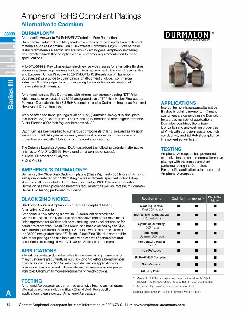
32 Contact Amphenol Aerospace for more information at 800-678-0141 • www.amphenol-aerospace.com
III
SJT
38999
I
II
Access
Aquacon
Ser
ies
III
A
DURMALON TMAlternative to Cadmium
Amphenol RoHS Compliant PlatingsAlternative to Cadmium
APPLICATIONSInterest for non-hazardous alternative finishes is gaining momentum & many customers are currently using Durmalon for a broad number of applications. Durmalon combines the unique lubrication and anti-wetting properties of PTFE with corrosion resistance, high conductivity and EU RoHS compliance in a non-reflective finish.
TESTINGAmphenol Aerospace has performed extensive testing on numerous alternative platings with the most consistent performer being the Durmalon. For specific applications please contact Amphenol Aerospace.
DURMALONTM
Amphenol’s Answer to EU RoHS/ELV/Cadmium Free Restrictions Commercial, industrial & military markets are rapidly moving away from restricted materials such as Cadmium (Cd) & Hexavalent Chromium (Cr(VI)). Both of these restricted materials are toxic and are known carcinogens. Amphenol is offering an alternative finish that complies with all customer requirements tied to these specifications.
MIL-DTL-38999, Rev L has established new service classes for alternative finishes addressing these requirements for Cadmium replacement. Amphenol is using this and European Union Directive 2002/95/EC RoHS (Regulation of Hazardous Substances) as a guide to qualification for all domestic, global, commercial, industrial, & military specifications requiring the reduction or elimination of these restricted materials.
Amphenol has qualified Durmalon, with internal part number coding “DT” finish, which meets or exceeds the 38999 designated class “T” finish, Nickel Fluorocarbon Polymer. Durmalon is also EU RoHS compliant and is Cadmium free, Lead free, and Hexavalent Chromium free.
We also offer additional platings such as “DX”, (Durmalon, heavy duty final plate) to support JSF, F-35 program. The DX plating is intended to meet higher corrosion Sulfur Dioxide (SO2)/salt fog requirements of JSF.
Cadmium has been applied to numerous components of land, sea and air weapon systems and NASA systems for many years as it provides sacrificial corrosion protection and excellent lubricity for threaded applications.
The Defense Logistics Agency (DLA) has added the following cadmium alternative finishes to MIL-DTL-38999, Rev L (and other connector specs):• Nickel Fluorocarbon Polymer• Zinc-Nickel
AMPHENOL’S DURMALONTM
Durmalon, like Olive-Drab Cadmium plating (Class W), meets 500 hours of dynamic salt spray, combined with 500 mating cycles and meets specified millivolt drop shell-to-shell conductivity. Durmalon also meets a 200° C temperature rating. Durmalon has been proven to meet this requirement as well as Potassium Formate-Deicer fluid testing performed by Boeing.
BLACK ZINC NICKEL Black Zinc Nickel is Amphenol’s 2nd RoHS Compliant Plating Alternative to CadmiumAmphenol is now offering a new RoHS compliant alternative to Cadmium. Black Zinc Nickel is a non-reflective and conductive black finish approved for 500 hrs salt spray making it an excellent choice for harsh environments. Black Zinc Nickel has been qualified by the DLA, with internal part number coding “DZ” finish, which meets or exceeds the 38999 designated class “Z” finish. Black Zinc Nickel is compatible with other platings and available on a wide variety of connectors and accessories including all MIL-DTL-38999 Series III connectors.
APPLICATIONSInterest for non-hazardous alternative finishes are gaining momentum & many customers are currently using Black Zinc Nickel for a broad number of applications. Black Zinc Nickel is typically used on applications for commercial aerospace and military defense, who are now moving away from toxic Cadmium to more environmentally friendly options.
TESTINGAmphenol Aerospace has performed extensive testing on numerous alternative platings including Black Zinc Nickel. For specific applications please contact Amphenol Aerospace.
Requirements Cadmium DurmalonTM Black Zinc Nickel
Coupling Torque Post 500 hr. salt
Shell to Shell Conductivity <2.5 millivolts
Cycles of Durability 500 mates
Salt Spray Dynamic 500 hours
Temperature Rating 175° C
Non-Reflective
EU RoHS/ELV Compliant*
Non-Magnetic
De-icing Fluid**
Note: Specifications are subject to change without notice.
* Meets EU RoHS/ELV maximum concentration values (MCV) of 1000 ppm (0.1% w/w) or (0.01% w/w) per homogenous material.
** Potassium Formate/Acetate based de-icing fluids.
33Contact Amphenol Aerospace for more information at 800-678-0141 • www.amphenol-aerospace.com
TABLE OF CONTENTS FOR SECTION ACombined MIL-DTL-38999 Series I, II, IIIShell Size & Insert Arrangements Availability . . . . . . . 2-5Insert Arrangement Drawings . . . . . . . . . . . . 6-13PCB Insert Arrangements . . . . . . . . . . . . . 14-28Contact - Ratings, Service Ratings, Finish Data . . . . . 29-31Amhenol RoHS Compliant Plating . . . . . . . . . . . 32
MIL-DTL-38999, Series III TVPerformance, Options . . . . . . . . . . . . . . .34, 35Test Data . . . . . . . . . . . . . . . . . . . . . 36Weight Comparison (Composite vs. Metal) . . . . . . . . 37Dualok . . . . . . . . . . . . . . . . . . . . . . 38HD38999, High Density . . . . . . . . . . . . . . . 39Custom . . . . . . . . . . . . . . . . . . . . . 40Configurator . . . . . . . . . . . . . . . . . . . 41How to Order (Military & Commercial) . . . . . . . . . 42-46How to Order (Boeing BACC63) . . . . . . . . . . . . 47
TV SHELL STYLES:Crimp Wall Mounting Receptacle TVP00R (D389999/20) /CTVP00R (Military D38999/20) . . . . . . . . . . . . 48Crimp Box Mounting Receptacle TVP02R / CTVP02R . . . 49Line Receptacle TV01, TVS01, CTV01, CTVS01 . . . . . . 50Crimp Jam Nut Receptacle TV07R (D38999/24) / CTV07R (Military D38999/24) . . . . . . . . . . . . . 51Straight Plug TV06, TVS06, CTV06, CTVS06 (Military D38999/26) . . . . . . . . . . . . . . . . . 52Crimp Flange Mounting Plug TV09R . . . . . . . . . . 53Dualok Plug/Receptacle TV56, TVS56, CTV56, CTVS56 . . . 54Crimp CLUTCH-LOK™ Straight Plug for High Vibration TV26/MTV26 . . . . . . . . . . . . . . . . . . . 55
PCB:PCB Wall Mounting, Back Panel TVP00, TVPS00 . . . . . 56PCBWall Mounting, Back Panel, Clinch Nuts, TVP10, TVPS10 57PCB Wall Mounting, Double Flange, TVP40, TVPS40 . . . . 58PCB Box Mounting Receptacle, TVP02, TVPS02 . . . . . 59PCB Box Mounting Receptacle, Clinch Nuts, TVP12, TVPS12 60PCB Jam Nut Receptacle, TV07, TVS07 . . . . . . . . . 61PCB Jam Nut Receptacle, Double Flange, TVP47, TVPS47 . 62PCB Hermetic Box, Jam Nut, Solder , Weld Mounting. . . 63-66
* Meets EU RoHS/ELV maximum concentration values (MCV) of1000 ppm (0.1% w/w) or (0.01% w/w) per homogenous material.
** Potassium Formate/Acetate based de-icing fluids.
HERMETIC:Hermetic Box Mounting TVPS02Y(D38999/21) . . . .67Hermetic Jam Nut Receptacle TVS07Y (D38999/23) . .68Hermetic Solder Mounting TVSIY (D38999/25) . . . .69 Hermetic Weld Mounting TVSHIY (D38999/27) . . . .69
BREAKAWAY: Breakaway Fail-Safe Connectors . . . . . . . . .70How to Order Breakaway (Military) . . . . . . . 71, 72How to Order Breakaway (Commercial) . . . . . . .73Fail-Safe Lanyard Release Plug . . . . . . . . . .74How to Order Breakaway MIL-STD-1760 (Military) . . .75TV Breakaway (D38999/31) for MIL-STD-1760 . . . .76TV Breakaway Commercial Version for D38999/31, Type 6 . . . . . . . . . . . . . . . . . . . .77How to Order Commercial Version D38999/31, Type 6 .78Insert Arrangements for Breakaway Fail-Safe . . . . .79Breakaway Fail-Safe 88-725041, 88-725014 . . . . .80Breakaway Hybrid, Low Profile Lanyard Release Plug. .81Stores Management Type II, Rail Launch (MIL-STD-1760) . . . . . . . . . . . . . . . .81
Accessories:Section F . . . . . . . . . . . . . . . . . 164-183
A
MIL-DTL-38999, Series III, TV
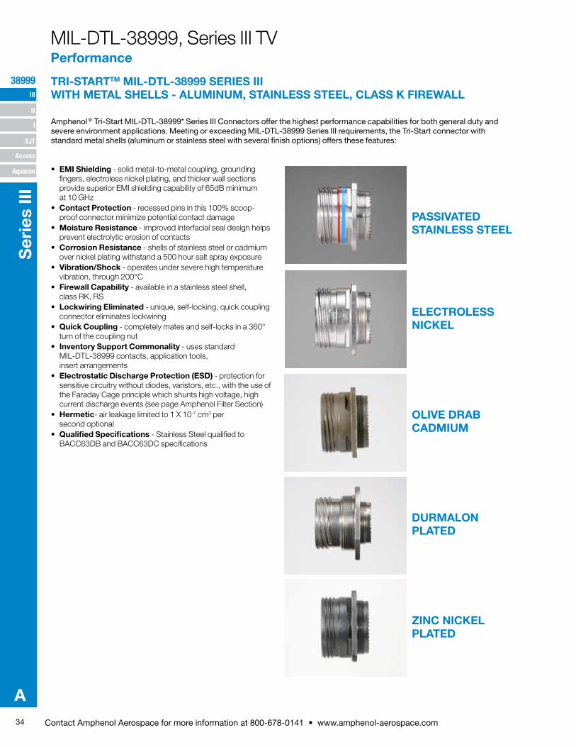
34 Contact Amphenol Aerospace for more information at 800-678-0141 • www.amphenol-aerospace.com
III
SJT
38999
I
II
Access
Aquacon
Ser
ies
III
A
MIL-DTL-38999, Series III TVPerformance
• EMI Shielding - solid metal-to-metal coupling, grounding fingers, electroless nickel plating, and thicker wall sec tions provide superior EMI shielding capability of 65dB minimum at 10 GHz
• Contact Protection - recessed pins in this 100% scoop- proof connector minimize potential contact damage• Moisture Resistance - improved interfacial seal design helps
prevent electrolytic erosion of contacts• Corrosion Resistance - shells of stainless steel or cad mium
over nickel plating withstand a 500 hour salt spray exposure• Vibration/Shock - operates under severe high tempera ture
vibration, through 200°C• Firewall Capability - available in a stainless steel shell,
class RK, RS• Lockwiring Eliminated - unique, self-locking, quick cou pling
connector eliminates lockwiring• Quick Coupling - completely mates and self-locks in a 360°
turn of the coupling nut• Inventory Support Commonality - uses standard
MIL-DTL-38999 contacts, application tools, insert arrangements
• Electrostatic Discharge Protection (ESD) - protection for sensitive circuitry without diodes, varistors, etc., with the use of the Faraday Cage principle which shunts high voltage, high current discharge events (see page Amphenol Filter Section)
• Hermetic- air leakage limited to 1 X 10⁻⁷ cm3 per second optional
• Qualified Specifications - Stainless Steel qualified to BACC63DB and BACC63DC specifications
TRI-STARTTM MIL-DTL-38999 SERIES III WITH METAL SHELLS - ALUMINUM, STAINLESS STEEL, CLASS K FIREWALL
Amphenol ® Tri-Start MIL-DTL-38999* Series III Connec tors offer the highest performance capabilities for both general duty and severe environment applications. Meeting or exceeding MIL-DTL-38999 Series III require ments, the Tri-Start connector with standard metal shells (aluminum or stainless steel with several finish options) offers these features:
PASSIVATED STAINLESS STEEL
ELECTROLESS NICKEL
OLIVE DRAB CADMIUM
DURMALON PLATED
ZINC NICKEL PLATED
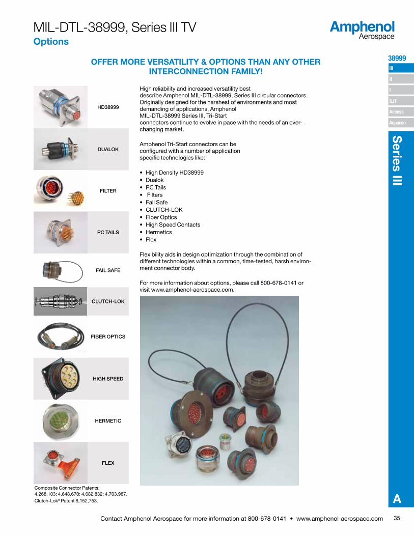
35Contact Amphenol Aerospace for more information at 800-678-0141 • www.amphenol-aerospace.com
38999 III
SJT
I
II
Access
Aquacon
Series III
A
Applicable Patents:Tri-StartTM Connector Patent 4,109,990.Composite Connector Patents: 4,268,103; 4,648,670; 4,682,832; 4,703,987.Clutch-Lok® Patent 6,152,753.
OFFER MORE VERSATILITY & OPTIONS THAN ANY OTHER INTERCONNECTION FAMILY!
High reliability and increased versatility best describe Amphenol MIL-DTL-38999, Series III circular connectors. Originally designed for the harshest of environments and most demanding of applications, Amphenol MIL-DTL-38999 Series III, Tri-Start connectors continue to evolve in pace with the needs of an ever-changing market.
Amphenol Tri-Start connectors can be configured with a number of application specific technologies like:
• High Density HD38999• Dualok• PC Tails• Filters• Fail Safe• CLUTCH-LOK• Fiber Optics• High Speed Contacts• Hermetics• Flex
Flexibility aids in design optimization through the combination of different technologies within a common, time-tested, harsh environ-ment connector body.
For more information about options, please call 800-678-0141 or visit www.amphenol-aerospace.com.
MIL-DTL-38999, Series III TVOptions
HD38999
DUALOK
FILTER
PC TAILS
FAIL SAFE
CLUTCH-LOK
FIBER OPTICS
HIGH SPEED
HERMETIC
FLEX
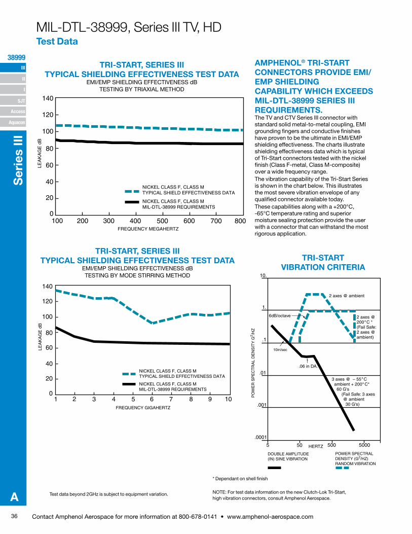
36 Contact Amphenol Aerospace for more information at 800-678-0141 • www.amphenol-aerospace.com
III
SJT
38999
I
II
Access
Aquacon
Ser
ies
III
A
TRI-START, SERIES III TYPICAL SHIELDING EFFECTIVENESS TEST DATA
EMI/EMP SHIELDING EFFECTIVENESS dB TESTING BY TRIAXIAL METHOD
TRI-START, SERIES III TYPICAL SHIELDING EFFECTIVENESS TEST DATA
EMI/EMP SHIELDING EFFECTIVENESS dB TESTING BY MODE STIRRING METHOD
Test data beyond 2GHz is subject to equipment variation.
* Dependant on shell finish
NOTE: For test data information on the new Clutch-Lok Tri-Start, high vibration connectors, consult Amphenol Aerospace.
AMPHENOL® TRI-START CONNECTORS PROVIDE EMI/EMP SHIELDING CAPABILITY WHICH EXCEEDS MIL-DTL-38999 SERIES III REQUIREMENTS.The TV and CTV Series III connector with standard solid metal-to-metal coupling, EMI grounding fin gers and conductive finishes have proven to be the ultimate in EMI/EMP shielding effectiveness. The charts illustrate shielding effectiveness data which is typical of Tri-Start connectors tested with the nickel finish (Class F-metal, Class M-composite) over a wide frequency range.The vibration capability of the Tri-Start Series is shown in the chart below. This illustrates the most severe vibration envelope of any qualified connec tor available today.These capabilities along with a +200°C, -65°C temperature rating and superior moisture sealing protection pro vide the user with a connector that can withstand the most rigorous application.
TRI-START VIBRATION CRITERIA
140
120
100
80
60
40
20
0100 200 300 400 500 600 700 800
NICKEL CLASS F, CLASS MTYPICAL SHIELD EFFECTIVENESS DATA
FREQUENCY MEGAHERTZ
NICKEL CLASS F, CLASS MMIL-DTL-38999 REQUIREMENTS
LEA
KA
GE
dB
140
120
100
80
60
40
20
01 2 3 4 5
NICKEL CLASS F, CLASS MMIL-DTL-38999 REQUIREMENTS
NICKEL CLASS F, CLASS MTYPICAL SHIELD EFFECTIVENESS DATA
6 7 8 9 10FREQUENCY GIGAHERTZ
LEA
KA
GE
dB
5 50 500 5000
.0001
.001
.01
.1
1.
10.
10in/sec
.06 in DA.
3 axes @ – 55 C ambient + 200 C* 60 G's (Fail Safe: 3 axes
@ ambient 30 G's)
2 axes @200 C *(Fail Safe:2 axes @ambient)
2 axes @ ambient
6dB/octave
HERTZ
DOUBLE AMPLITUDE(IN) SINE VIBRATION
POWER SPECTRALDENSITY (G2/HZ)RANDOM VIBRATION
PO
WE
R S
PE
CT
RA
L D
EN
SIT
Y G
2 /HZ
˚˚
˚
MIL-DTL-38999, Series III TV, HD Test Data
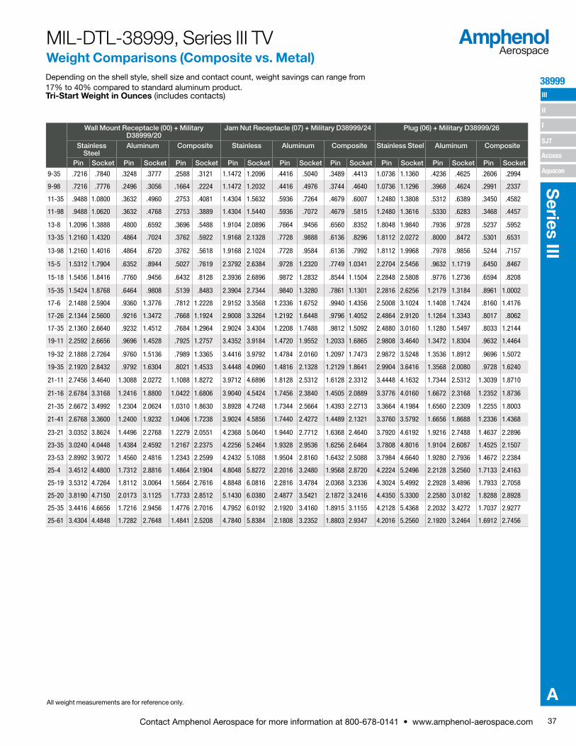
37Contact Amphenol Aerospace for more information at 800-678-0141 • www.amphenol-aerospace.com
38999 III
SJT
I
II
Access
Aquacon
Series III
A
MIL-DTL-38999, Series III TV Weight Comparisons (Composite vs. Metal)Depending on the shell style, shell size and contact count, weight savings can range from 17% to 40% compared to standard aluminum product.Tri-Start Weight in Ounces (includes contacts)
WEIGHT
Wall Mount Receptacle (00) + Military D38999/20
Jam Nut Receptacle (07) + Military D38999/24 Plug (06) + Military D38999/26
Stainless Steel
Aluminum Composite Stainless Aluminum Composite Stainless Steel Aluminum Composite
Pin Socket Pin Socket Pin Socket Pin Socket Pin Socket Pin Socket Pin Socket Pin Socket Pin Socket
9-35 .7216 .7840 .3248 .3777 .2588 .3121 1.1472 1.2096 .4416 .5040 .3489 .4413 1.0736 1.1360 .4236 .4625 .2606 .2994
9-98 .7216 .7776 .2496 .3056 .1664 .2224 1.1472 1.2032 .4416 .4976 .3744 .4640 1.0736 1.1296 .3968 .4624 .2991 .2337
11-35 .9488 1.0800 .3632 .4960 .2753 .4081 1.4304 1.5632 .5936 .7264 .4679 .6007 1.2480 1.3808 .5312 .6389 .3450 .4582
11-98 .9488 1.0620 .3632 .4768 .2753 .3889 1.4304 1.5440 .5936 .7072 .4679 .5815 1.2480 1.3616 .5330 .6283 .3468 .4457
13-8 1.2096 1.3888 .4800 .6592 .3696 .5488 1.9104 2.0896 .7664 .9456 .6560 .8352 1.8048 1.9840 .7936 .9728 .5237 .5952
13-35 1.2160 1.4320 .4864 .7024 .3762 .5922 1.9168 2.1328 .7728 .9888 .6136 .8296 1.8112 2.0272 .8000 .8472 .5301 .6531
13-98 1.2160 1.4016 .4864 .6720 .3762 .5618 1.9168 2.1024 .7728 .9584 .6136 .7992 1.8112 1.9968 .7978 .9856 .5244 .7157
15-5 1.5312 1.7904 .6352 .8944 .5027 .7619 2.3792 2.6384 .9728 1.2320 .7749 1.0341 2.2704 2.5456 .9632 1.1719 .6450 .8467
15-18 1.5456 1.8416 .7760 .9456 .6432 .8128 2.3936 2.6896 .9872 1.2832 .8544 1.1504 2.2848 2.5808 .9776 1.2736 .6594 .8208
15-35 1.5424 1.8768 .6464 .9808 .5139 .8483 2.3904 2.7344 .9840 1.3280 .7861 1.1301 2.2816 2.6256 1.2179 1.3184 .8961 1.0002
17-6 2.1488 2.5904 .9360 1.3776 .7812 1.2228 2.9152 3.3568 1.2336 1.6752 .9940 1.4356 2.5008 3.1024 1.1408 1.7424 .8160 1.4176
17-26 2.1344 2.5600 .9216 1.3472 .7668 1.1924 2.9008 3.3264 1.2192 1.6448 .9796 1.4052 2.4864 2.9120 1.1264 1.3343 .8017 .8062
17-35 2.1360 2.6640 .9232 1.4512 .7684 1.2964 2.9024 3.4304 1.2208 1.7488 .9812 1.5092 2.4880 3.0160 1.1280 1.5497 .8033 1.2144
19-11 2.2592 2.6656 .9696 1.4528 .7925 1.2757 3.4352 3.9184 1.4720 1.9552 1.2033 1.6865 2.9808 3.4640 1.3472 1.8304 .9632 1.4464
19-32 2.1888 2.7264 .9760 1.5136 .7989 1.3365 3.4416 3.9792 1.4784 2.0160 1.2097 1.7473 2.9872 3.5248 1.3536 1.8912 .9696 1.5072
19-35 2.1920 2.8432 .9792 1.6304 .8021 1.4533 3.4448 4.0960 1.4816 2.1328 1.2129 1.8641 2.9904 3.6416 1.3568 2.0080 .9728 1.6240
21-11 2.7456 3.4640 1.3088 2.0272 1.1088 1.8272 3.9712 4.6896 1.8128 2.5312 1.6128 2.3312 3.4448 4.1632 1.7344 2.5312 1.3039 1.8710
21-16 2.6784 3.3168 1.2416 1.8800 1.0422 1.6806 3.9040 4.5424 1.7456 2.3840 1.4505 2.0889 3.3776 4.0160 1.6672 2.3168 1.2352 1.8736
21-35 2.6672 3.4992 1.2304 2.0624 1.0310 1.8630 3.8928 4.7248 1.7344 2.5664 1.4393 2.2713 3.3664 4.1984 1.6560 2.2309 1.2255 1.8003
21-41 2.6768 3.3600 1.2400 1.9232 1.0406 1.7238 3.9024 4.5856 1.7440 2.4272 1.4489 2.1321 3.3760 3.5792 1.6656 1.8688 1.2336 1.4368
23-21 3.0352 3.8624 1.4496 2.2768 1.2279 2.0551 4.2368 5.0640 1.9440 2.7712 1.6368 2.4640 3.7920 4.6192 1.9216 2.7488 1.4637 2.2896
23-35 3.0240 4.0448 1.4384 2.4592 1.2167 2.2375 4.2256 5.2464 1.9328 2.9536 1.6256 2.6464 3.7808 4.8016 1.9104 2.6087 1.4525 2.1507
23-53 2.8992 3.9072 1.4560 2.4816 1.2343 2.2599 4.2432 5.1088 1.9504 2.8160 1.6432 2.5088 3.7984 4.6640 1.9280 2.7936 1.4672 2.2384
25-4 3.4512 4.4800 1.7312 2.8816 1.4864 2.1904 4.8048 5.8272 2.2016 3.2480 1.9568 2.8720 4.2224 5.2496 2.2128 3.2560 1.7133 2.4163
25-19 3.5312 4.7264 1.8112 3.0064 1.5664 2.7616 4.8848 6.0816 2.2816 3.4784 2.0368 3.2336 4.3024 5.4992 2.2928 3.4896 1.7933 2.7058
25-20 3.8190 4.7150 2.0173 3.1125 1.7733 2.8512 5.1430 6.0380 2.4877 3.5421 2.1872 3.2416 4.4350 5.3300 2.2580 3.0182 1.8288 2.8928
25-35 3.4416 4.6656 1.7216 2.9456 1.4776 2.7016 4.7952 6.0192 2.1920 3.4160 1.8915 3.1155 4.2128 5.4368 2.2032 3.4272 1.7037 2.9277
25-61 3.4304 4.4848 1.7282 2.7648 1.4841 2.5208 4.7840 5.8384 2.1808 3.2352 1.8803 2.9347 4.2016 5.2560 2.1920 3.2464 1.6912 2.7456
All weight measurements are for reference only.
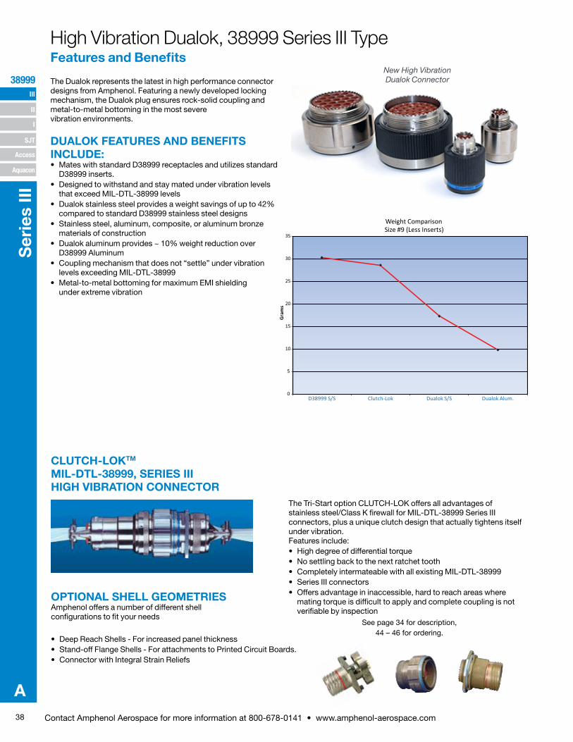
38 Contact Amphenol Aerospace for more information at 800-678-0141 • www.amphenol-aerospace.com
III
SJT
38999
I
II
Access
Aquacon
Ser
ies
III
A
The Dualok represents the latest in high performance connector designs from Amphenol. Featuring a newly developed locking mechanism, the Dualok plug ensures rock-solid coupling and metal-to-metal bottoming in the most severe vibration environments.
DUALOK FEATURES AND BENEFITS INCLUDE:• Mates with standard D38999 receptacles and utilizes standard
D38999 inserts.• Designed to withstand and stay mated under vibration levels
that exceed MIL-DTL-38999 levels• Dualok stainless steel provides a weight savings of up to 42%
compared to standard D38999 stainless steel designs• Stainless steel, aluminum, composite, or aluminum bronze
materials of construction• Dualok aluminum provides ~ 10% weight reduction over
D38999 Aluminum• Coupling mechanism that does not “settle” under vibration
levels exceeding MIL-DTL-38999• Metal-to-metal bottoming for maximum EMI shielding
under extreme vibration
New High Vibration Dualok Connector
High Vibration Dualok, 38999 Series III Type Features and Benefits
0
5
10
15
25
20
30
35
D38999 S/S Clutch-Lok Dualok S/S Dualok Alum.
Gra
ms
Weight Comparison
Size #9 (Less Inserts)
The Tri-Start option CLUTCH-LOK offers all advantages of stainless steel/Class K firewall for MIL-DTL-38999 Series III connectors, plus a unique clutch design that actually tightens itself under vibration. Features include:• High degree of differential torque • No settling back to the next ratchet tooth• Completely intermateable with all existing MIL-DTL-38999 • Series III connectors• Offers advantage in inaccessible, hard to reach areas where
mating torque is difficult to apply and complete coupling is not verifiable by inspection
See page 34 for description, 44 – 46 for ordering.
CLUTCH-LOKTM
MIL-DTL-38999, SERIES III HIGH VIBRATION CONNECTOR
OPTIONAL SHELL GEOMETRIESAmphenol offers a number of different shell configurations to fit your needs
• Deep Reach Shells - For increased panel thickness• Stand-off Flange Shells - For attachments to Printed Circuit Boards.• Connector with Integral Strain Reliefs

39Contact Amphenol Aerospace for more information at 800-678-0141 • www.amphenol-aerospace.com
38999 III
SJT
I
II
Access
Aquacon
Series III
A
ELECTRICAL:22 AWG: 5.0 AMPS24 AWG: 3.0 AMPS 26 AWG: 2.0 AMPS28 AWG: 1.5 AMPS
Insulation Resistance: 5000 megohms min.@500 VDC 25CDielectric Withstanding Voltage: 1000 VRMS@sea level
TECHNICAL DATAHD38999 series was designed to meet and/or exceed the specifications of MIL-DTL-38999. The connector series has been tested to all the requirements of 38999 with the use of AS39029 size 23 contacts. Test reports are available upon request. The following is a summary of some of the performance requirements.
MECHANICAL:Metallic Shells: Material: Aluminum alloy, Stainless Steel
Protection: Electroless Nickel, O.D. Cadmium, Durmalon (Nickel PTFE), Zinc Nickel
Composite Shells: Material: Thermoplastic Protection: Electroless Nickel, O.D. Cadmium,
Durmalon (Nickel PTFE), Zinc Nickel
Contacts: Material: Copper Alloy Protection: Gold over Nickel
Insert Retention to Shell: 100 psi in axial load
Durability: 500 full mating and unmating cycles
Vibration: 60G sine per MIL-DTL-38999L Para 4.5.23.2.1 5G2 Random per EIA-364-28E, Test condition A 1G2 Random per EIA-364-28E, Test condition I
Shock: Per EIA-364-27B, 300g
ENVIRONMENTAL:Operating Temperature: –65°C to +175°C
Salt Spray: Metallized: Electroless Nickel: 48 hours
Anodic Coating, O. D. Cadmium, Durmalon, Zinc Nickel: 500 hours
Salt Spray Composite: Electroless Nickel: 1000 hours
O. D. Cadmium, Durmalon, Zinc Nickel: 500 hours
140
120
100
80
60
40
20
0100 200 300 400 500 600 700 800
NICKEL CLASS F, CLASS MTYPICAL SHIELD EFFECTIVENESS DATA
FREQUENCY MEGAHERTZ
NICKEL CLASS F, CLASS MMIL-DTL-38999 REQUIREMENTS
LEA
KA
GE
dB
EMI SHIELDING EFFECTIVENESS:Solid metal to metal coupling, EMI grounding fingers and conductive finishes have proven to be the ultimate in EMI/EMP shielding effectiveness. The following chart illustrated shielding effectiveness data which is typical in HD38999 connectors.
140
120
100
80
60
40
20
01 2 3 4 5
NICKEL CLASS F, CLASS MTYPICAL SHIELD EFFECTIVENESS DATA
NICKEL CLASS F, CLASS MMIL-DTL-38999 REQUIREMENTS
6 7 8 9 10FREQUENCY GIGAHERTZ
LEA
KA
GE
dB
High Density InterconnectsHD38999: 9 to 187 Contacts
H 38999High Density
The HD38999 family of connectors has 30% more contact density than the highest density Mil Spec 38999 connectors of its size. This series of connectors was designed to utilize mil-specified 38999 components with the exception of the contacts and inserts arrangement. Utilizing existing mil-qualified 39029 size 23 contacts and 38999 insert materials, these connectors are essentially a drop-in replacement for the standard 38999 connector.
This connector design benefits users in a couple of different ways. For those users who need to increase the amount of contacts in their application, the HD38999 series allows them to do so without increasing the size of their connector. For users who are looking to decrease the overall size of their system, they can do so by using smaller shell sizes without decreasing the number of contacts.
Amphenol has qualified this series of connectors to the requirements of MIL-DTL-38999. Amphenol also manufacturers this high density series in Filter, Hermetic and customized versions to fit our customer’s needs. Please contact us if additional information is required.
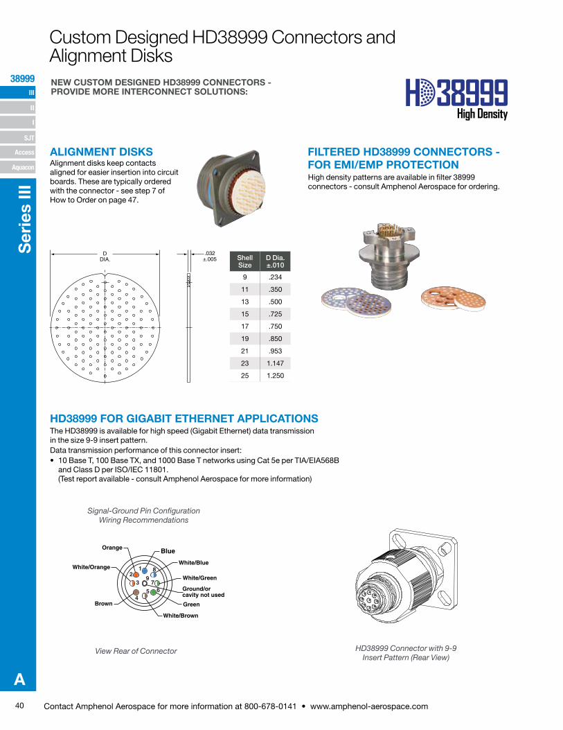
40 Contact Amphenol Aerospace for more information at 800-678-0141 • www.amphenol-aerospace.com
III
SJT
38999
I
II
Access
Aquacon
Ser
ies
III
A
H 38999High Density
HD38999 FOR GIGABIT ETHERNET APPLICATIONSThe HD38999 is available for high speed (Gigabit Ethernet) data transmission in the size 9-9 insert pattern.Data transmission performance of this connector insert:• 10 Base T, 100 Base TX, and 1000 Base T networks using Cat 5e per TIA/EIA568B
and Class D per ISO/IEC 11801.(Test report available - consult Amphenol Aerospace for more information)
Signal-Ground Pin Configuration Wiring Recommendations
View Rear of Connector
82
3
1
97
54
6
Blue
White/Blue
White/Green
Ground/or cavity not used
Green
White/Brown
Brown
White/Orange
Orange
NEW CUSTOM DESIGNED HD38999 CONNECTORS - PROVIDE MORE INTERCONNECT SOLUTIONS:
HD38999 Connector with 9-9 Insert Pattern (Rear View)
ALIGNMENT DISKSAlignment disks keep contacts aligned for easier insertion into circuit boards. These are typically ordered with the connector - see step 7 of How to Order on page 47.
FILTERED HD38999 CONNECTORS - FOR EMI/EMP PROTECTIONHigh density patterns are available in filter 38999 connectors - consult Amphenol Aerospace for ordering.
Shell Size
D Dia. ±.010
9 .234
11 .350
13 .500
15 .725
17 .750
19 .850
21 .953
23 1.147
25 1.250
DDIA.
.032±.005
Custom Designed HD38999 Connectors and Alignment Disks
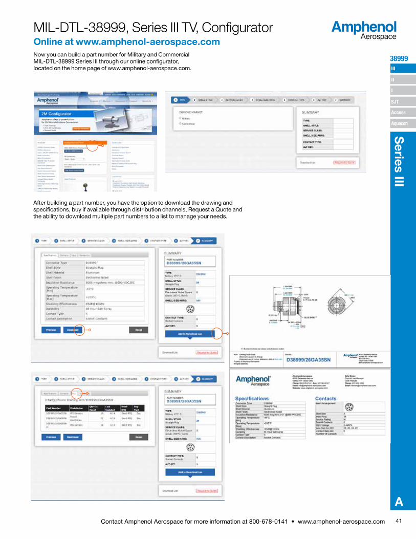
41Contact Amphenol Aerospace for more information at 800-678-0141 • www.amphenol-aerospace.com
38999 III
SJT
I
II
Access
Aquacon
Series III
A
Now you can build a part number for Military and Commercial MIL-DTL-38999 Series III through our online configurator, located on the home page of www.amphenol-aerospace.com.
MIL-DTL-38999, Series III TV, ConfiguratorOnline at www.amphenol-aerospace.com
After building a part number, you have the option to download the drawing and specifications, buy if available through distribution channels, Request a Quote and the ability to download multiple part numbers to a list to manage your needs.
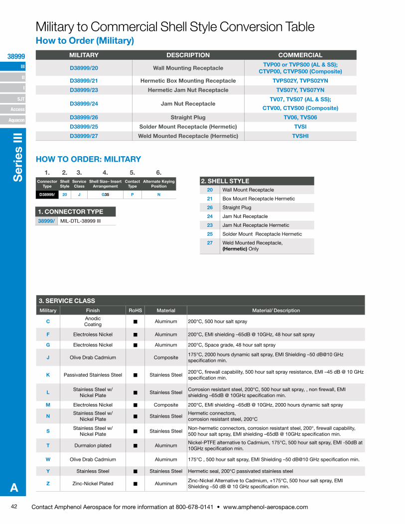
42 Contact Amphenol Aerospace for more information at 800-678-0141 • www.amphenol-aerospace.com
III
SJT
38999
I
II
Access
Aquacon
Ser
ies
III
A
Military to Commercial Shell Style Conversion Table How to Order (Military)
1. 2. 3. 4. 5. 6.Connector
TypeShell Style
Service Class
Shell Size– Insert Arrangement
Contact Type
Alternate Keying Position
D38999/ 20 J G35 P N
2. SHELL STYLE20 Wall Mount Receptacle
21 Box Mount Receptacle Hermetic
26 Straight Plug
24 Jam Nut Receptacle
23 Jam Nut Receptacle Hermetic
25 Solder Mount Receptacle Hermetic
27 Weld Mounted Receptacle, (Hermetic) Only
1. CONNECTOR TYPE38999/ MIL-DTL-38999 III
3. SERVICE CLASSMilitary Finish RoHS Material Material/ Description
C Anodic Coating ■ Aluminum 200°C, 500 hour salt spray
F Electroless Nickel ■ Aluminum 200°C, EMI shielding –65dB @ 10GHz, 48 hour salt spray
G Electroless Nickel ■ Aluminum 200°C, Space grade, 48 hour salt spray
J Olive Drab Cadmium Composite175°C, 2000 hours dynamic salt spray, EMI Shielding –50 dB@10 GHz specification min.
K Passivated Stainless Steel ■ Stainless Steel200°C, firewall capability, 500 hour salt spray resistance, EMI –45 dB @ 10 GHz specification min.
LStainless Steel w/
Nickel Plate ■ Stainless SteelCorrosion resistant steel, 200°C, 500 hour salt spray, , non firewall, EMI shielding –65dB @ 10GHz specification min.
M Electroless Nickel ■ Composite 200°C, EMI shielding –65dB @ 10GHz, 2000 hours dynamic salt spray
NStainless Steel w/
Nickel Plate ■ Stainless SteelHermetic connectors, corrosion resistant steel, 200°C
SStainless Steel w/
Nickel Plate ■ Stainless SteelNon-hermetic connectors, corrosion resistant steel, 200°, firewall capability, 500 hour salt spray, EMI shielding –65dB @ 10GHz specification min.
T Durmalon plated ■ AluminumNickel-PTFE alternative to Cadmium, 175°C, 500 hour salt spray, EMI -50dB at 10GHz specification min.
W Olive Drab Cadmium Aluminum 175°C , 500 hour salt spray, EMI Shielding –50 dB@10 GHz specification min.
Y Stainless Steel ■ Stainless Steel Hermetic seal, 200°C passivated stainless steel
Z Zinc-Nickel Plated ■ AluminumZinc-Nickel Alternative to Cadmium, +175°C, 500 hour salt spray, EMI Shielding –50 dB @ 10 GHz specification min.
MILITARY DESCRIPTION COMMERCIAL
D38999/20 Wall Mounting ReceptacleTVP00 or TVPS00 (AL & SS);
CTVP00, CTVPS00 (Composite)
D38999/21 Hermetic Box Mounting Receptacle TVPS02Y, TVPS02YN
D38999/23 Hermetic Jam Nut Receptacle TVS07Y, TVS07YN
D38999/24 Jam Nut ReceptacleTV07, TVS07 (AL & SS);
CTV00, CTVS00 (Composite)
D38999/26 Straight Plug TV06, TVS06
D38999/25 Solder Mount Receptacle (Hermetic) TVSI
D38999/27 Weld Mounted Receptacle (Hermetic) TVSHI
HOW TO ORDER: MILITARY
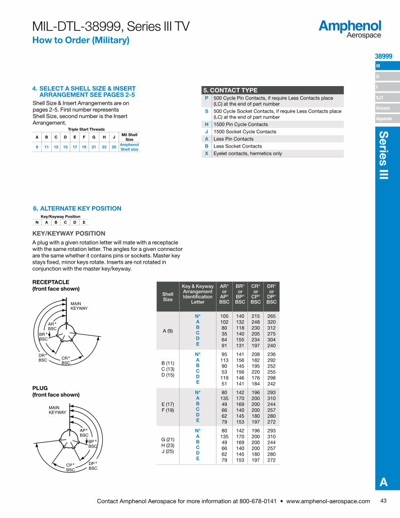
43Contact Amphenol Aerospace for more information at 800-678-0141 • www.amphenol-aerospace.com
38999 III
SJT
I
II
Access
Aquacon
Series III
A
MIL-DTL-38999, Series III TV How to Order (Military)
4. SELECT A SHELL SIZE & INSERTARRANGEMENT SEE PAGES 2-5
Shell Size & Insert Arrangements are on pages 2-5. First number represents Shell Size, second number is the Insert Arrangement.
Triple Start Threads
A B C D E F G H JMil Shell
Size
9 11 13 15 17 19 21 23 25Amphenol Shell size
5. CONTACT TYPEP 500 Cycle Pin Contacts, if require Less Contacts place
(LC) at the end of part number
S 500 Cycle Socket Contacts, if require Less Contacts place (LC) at the end of part number
H 1500 Pin Cycle Contacts
J 1500 Socket Cycle Contacts
A Less Pin Contacts
B Less Socket Contacts
X Eyelet contacts, hermetics only
6. ALTERNATE KEY POSITIONKey/Keyway Position
N A B C D E
KEY/KEYWAY POSITIONA plug with a given rotation letter will mate with a receptacle with the same rotation letter. The angles for a given connector are the same whether it contains pins or sockets. Master key stays fixed, minor keys rotate. Inserts are not rotated in conjunction with the master key/keyway.
PLUG (front face shown)
RECEPTACLE (front face shown)
MAINKEYWAY
APBSC
BPBSC
DPBSC
CPBSC
˚
˚
˚˚
DRBSC̊ CR
BSC̊
BRBSC̊
ARBSC̊
MAINKEYWAY
Shell Size
Key & Keyway Arrangement Identification
Letter
AR° or
AP° BSC
BR° or
BP° BSC
CR° or
CP° BSC
DR° or
DP° BSC
A (9)
N* A B C D E
10510280356491
140132118140155131
215248230205234197
265320312275304240
B (11) C (13) D (15)
N* A B C D E
95113905311951
141156145156146141
208182195220176184
236292252255298242
E (17) F (19)
N* A B C D E
8013549666279
142170169140145153
196200200200180197
293310244257280272
G (21) H (23) J (25)
N* A B C D E
8013549666279
142170169140145153
196200200200180197
293 310 244 257 280 272

44 Contact Amphenol Aerospace for more information at 800-678-0141 • www.amphenol-aerospace.com
III
SJT
38999
I
II
Access
Aquacon
Ser
ies
III
A
Wall Mount Receptacle (00, 20)
Line Receptacle(01)
Box Mount Receptacle(02, 21)
Straight Plug(06)
Lanyard Release Plug(29, 30, 31)
Jam NutReceptacle(07, 24)
Flange Mounting Plug(09)
Deep Reach Receptacle Consult Amphenol Aerospace
Solder Mount Hermetic Receptacle(I, 25)
MIL-DTL-38999, Series III TV How to Order (Commercial)
1. SELECT A TYPE & CLASS
Insert arrangements using multi-axial (i.e. coax, twinax, triax shielded) contacts should not be used in firewall applications. *Coaxial arrangements are not available in firewall classes.
ALUMINUMElectroless
NickelOlive Drab Cadmium
Durmalon Black Zinc Electroless Nickel (With Ground
Plane)
Olive Drab Cadmium
(With Ground Plane)
Marine Bronze
RAT
ES
Temperature 200˚C 175˚C 175˚C 175˚C 200˚C 175˚C 200˚C
Salt Spray 48 Hrs 500 Hrs 500 Hrs 500 Hrs 48 Hrs 500 Hrs 2,000 Hrs
EMI Shielding -65dB @10GHz
-65dB @10GHz
-50dB @10GHz
-50dB @10GHz
-65dB @ 10GHz-65dB @10GHz
-65dB @10GHz
RoHS RoHSAmphenol
EU/ 2002 / 95 / EC
RoHSAmphenol
EU/ 2002 / 95 / EC
RoHSAmphenol
EU/ 2002 / 95 / EC
RoHSAmphenol
EU/ 2002 / 95 / EC
CO
NN
EC
TOR
TY
PE
& S
TYLE
Rec
epta
cle Wall Mounting Receptacle TVPS00RF- TVP00RW- TVP00DT- TVP00DZ- TVP00RGF- TVP00RGW- TVPS00RB-
Box Mounting Receptacle TVPS02RF- TVP02RW- TVP02DT- TVP02DZ- TVP02RGF- TVP02RGW- TVPS02RB-
Line Receptacle TVS01RF- TV01RW- TV01DT- TV01DZ- TV01RGF- TV01RGW- TVS01RB-
Jam Nut Receptacle TVS07RF- TV07RW- TV07DT- TV07DZ- TV07RGF- TV07RGW- TVS07RB-
Plu
gs
Straight Plug TVS06RF- TV06RW- TV06DT- TV06DZ- TV06RGF- TV06RGW- TVS06RB-
Flange Mounted Plug TVS09RF- TV09RW- TV09DT- TV09DZ- TV09RGF- TV09RGW- TVS09RB-
Straight Plug w Dualok TVS56RF- TV56RW- TV56DT- TV56DZ- TV56RGF- TV56RGW- TVS56RB-
Straight Plug w Clutch-Lok* - - - - - - -
Prin
ted
Circ
uit
Boa
rd
Wall Mounting Receptacle TVPS00RF- TVP00RW- TVP00DT- TVP00DZ- - - TVPS00RB-
Box Mounting Receptacle TVPS02RF- TVP02RW- TVP02DT- TVP02DZ- - - TVPS02RB-
Jam Nut TVS07RF- TV07RW- TV07DT- TV07DZ- - - TVS07RB-
Wall Mount (Double Flange) TVPS40RF- TVP40RW- TVP40DT- TVP40DZ- - - TVPS40RB-
Jam Nut (Double Flange) TVS47RF- TV47RW- TV47DT- TV47DZ- - - TVS47RB-
Wall Mount (Clinch Nuts) TVPS10RF- TVP10RW- TVP10DT- TVP10DZ- - - TVPS10RB-
Box Mount (Clinch Nuts) TVPS12RF- TVP12RW- TVP12DT- TVP12DZ- - - TVPS12RB-
Her
met
ic
Box Mounting Receptacle
Hermetic only available in Stainless SteelJam Nut Receptacle
Solder Mount
Wall Mounting Receptacle
1. 2. 3. 4. 5.
Type & Class Shell Size- Insert Arrg.
Contact Type Alternate Position
PCB Length**
TVPS00RB- P
* Stamped with Mil-Spec #D38999
** If Required
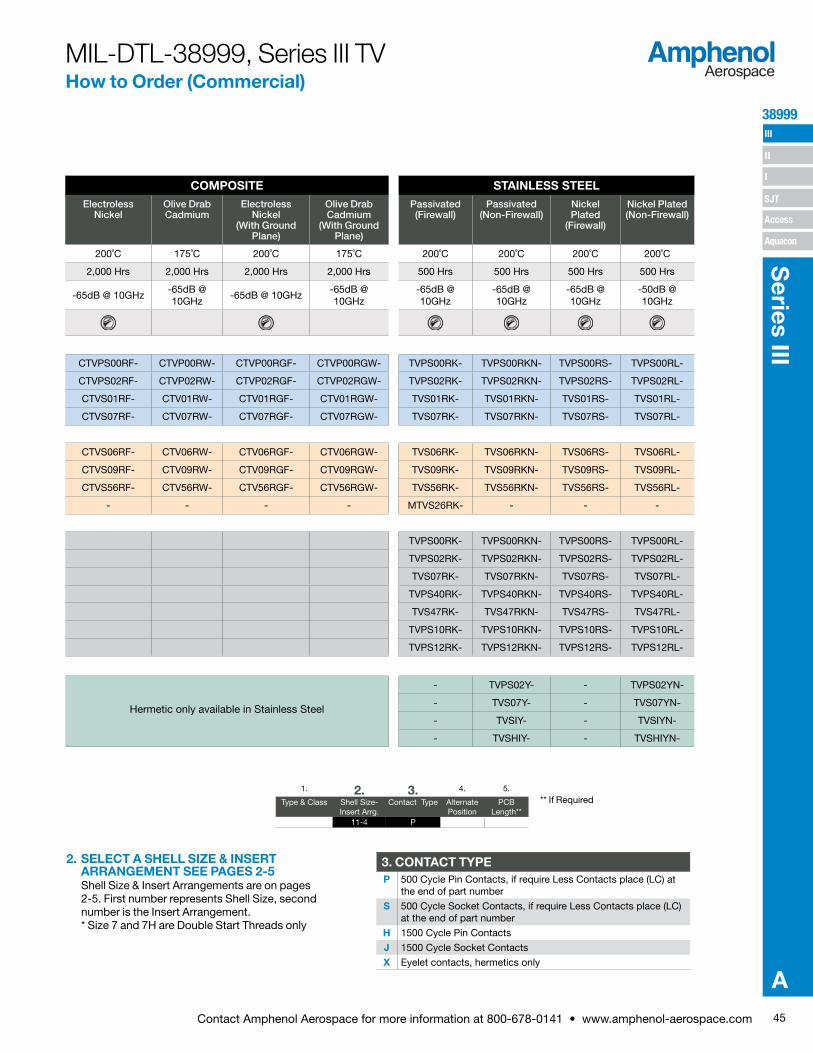
45Contact Amphenol Aerospace for more information at 800-678-0141 • www.amphenol-aerospace.com
38999 III
SJT
I
II
Access
Aquacon
Series III
A
MIL-DTL-38999, Series III TV How to Order (Commercial)
COMPOSITE STAINLESS STEELElectroless
NickelOlive Drab Cadmium
Electroless Nickel
(With Ground Plane)
Olive Drab Cadmium
(With Ground Plane)
Passivated (Firewall)
Passivated (Non-Firewall)
Nickel Plated
(Firewall)
Nickel Plated (Non-Firewall)
200˚C 175˚C 200˚C 175˚C 200˚C 200˚C 200˚C 200˚C
2,000 Hrs 2,000 Hrs 2,000 Hrs 2,000 Hrs 500 Hrs 500 Hrs 500 Hrs 500 Hrs
-65dB @ 10GHz-65dB @10GHz
-65dB @ 10GHz-65dB @10GHz
-65dB @10GHz
-65dB @10GHz
-65dB @10GHz
-50dB @10GHz
RoHSAmphenol
EU/ 2002 / 95 / EC
RoHSAmphenol
EU/ 2002 / 95 / EC
RoHSAmphenol
EU/ 2002 / 95 / EC
RoHSAmphenol
EU/ 2002 / 95 / EC
RoHSAmphenol
EU/ 2002 / 95 / EC
RoHSAmphenol
EU/ 2002 / 95 / EC
CTVPS00RF- CTVP00RW- CTVP00RGF- CTVP00RGW- TVPS00RK- TVPS00RKN- TVPS00RS- TVPS00RL-
CTVPS02RF- CTVP02RW- CTVP02RGF- CTVP02RGW- TVPS02RK- TVPS02RKN- TVPS02RS- TVPS02RL-
CTVS01RF- CTV01RW- CTV01RGF- CTV01RGW- TVS01RK- TVS01RKN- TVS01RS- TVS01RL-
CTVS07RF- CTV07RW- CTV07RGF- CTV07RGW- TVS07RK- TVS07RKN- TVS07RS- TVS07RL-
CTVS06RF- CTV06RW- CTV06RGF- CTV06RGW- TVS06RK- TVS06RKN- TVS06RS- TVS06RL-
CTVS09RF- CTV09RW- CTV09RGF- CTV09RGW- TVS09RK- TVS09RKN- TVS09RS- TVS09RL-
CTVS56RF- CTV56RW- CTV56RGF- CTV56RGW- TVS56RK- TVS56RKN- TVS56RS- TVS56RL-
- - - - MTVS26RK- - - -
TVPS00RK- TVPS00RKN- TVPS00RS- TVPS00RL-
TVPS02RK- TVPS02RKN- TVPS02RS- TVPS02RL-
TVS07RK- TVS07RKN- TVS07RS- TVS07RL-
TVPS40RK- TVPS40RKN- TVPS40RS- TVPS40RL-
TVS47RK- TVS47RKN- TVS47RS- TVS47RL-
TVPS10RK- TVPS10RKN- TVPS10RS- TVPS10RL-
TVPS12RK- TVPS12RKN- TVPS12RS- TVPS12RL-
Hermetic only available in Stainless Steel
- TVPS02Y- - TVPS02YN-
- TVS07Y- - TVS07YN-
- TVSIY- - TVSIYN-
- TVSHIY- - TVSHIYN-
2. SELECT A SHELL SIZE & INSERTARRANGEMENT SEE PAGES 2-5Shell Size & Insert Arrangements are on pages 2-5. First number represents Shell Size, second number is the Insert Arrangement. * Size 7 and 7H are Double Start Threads only
3. CONTACT TYPEP 500 Cycle Pin Contacts, if require Less Contacts place (LC) at
the end of part number
S 500 Cycle Socket Contacts, if require Less Contacts place (LC) at the end of part number
H 1500 Cycle Pin Contacts
J 1500 Cycle Socket Contacts
X Eyelet contacts, hermetics only
1. 2. 3. 4. 5.
Type & Class Shell Size- Insert Arrg.
Contact Type Alternate Position
PCB Length**
TVPS00RB- 11-4 P
** If Required

Contact Stickout
Pin Contacts
Pin Contacts with Alignment
Disk
.150” (P15) (P15AD)
.250” (P25) (P25AD)
.350” (P35) (P35AD)
Contact Stickout
Socket Contacts
Socket Contacts with
Alignment Disk
.150” (S15) (S15AD)
.250” (S25) (S25AD)
.350” (S35) (S35AD)
46 Contact Amphenol Aerospace for more information at 800-678-0141 • www.amphenol-aerospace.com
III
SJT
38999
I
II
Access
Aquacon
Ser
ies
III
A
4. SELECT A ALTERNATE KEYINGCOMMERCIAL
KEY/KEYWAY POSITIONA plug with a given rotation letter will mate with a receptacle with the same rotation letter. The angles for a given connector are the same whether it contains pins or sockets. Master key stays fixed, minor keys rotate. Inserts are not rotated in conjunction with the master key/keyway.
PLUG (FRONT FACE SHOWN)
RECEPTACLE (FRONT FACE SHOWN)
MAINKEYWAY
APBSC
BPBSC
DPBSC
CPBSC
˚
˚
˚˚DRBSC̊ CR
BSC̊
BRBSC̊
ARBSC̊
MAINKEYWAY
5. PCB LENGTH FOR COMMERCIAL ONLY
* An “N” designation is used on D38999 militarypart number but not on the commercial versions
1. 2. 3. 4. 5.
Type & Class Shell Size- Insert Arrg.
Contact Type Alternate Position
PCB Length**
TVPS00RB- 11-4 P N
MIL-DTL-38999, Series III TV How to Order (Alternate Keying) Commercial
5. PCB LENGTH FOR HD38999 ONLY9-9, 11-19, 13-32, 15-55, 17-73, 19-88, 21-121, 23-151, 25-187
* Not available in TV40 wall mount double flange receptacle or TV47 jam nut double flange receptacle styles. Note: Standard tail diameter is 0.019±.001 Stick out is measured from the end of the connector shell to end of the contact
Shell Size
D Dia. ±.010
9 .234
11 .350
13 .500
15 .725
17 .750
19 .850
21 .953
23 1.147
25 1.250
DDIA.
.032±.005
Alignment Disc
PCB tail stickout +/-.040 inch
Without Alignment Disk
With Alignment Disc
Pins Sockets Pins Sockets
.100” nominal (P1*) (S1) (P1AD) (S1AD)
.150” nominal (P15*) (S15) (P15AD) (S15AD)
.200” nominal (P2) (S2) (P2AD) (S2AD)
.250” nominal (P25*) (S25) (P25AD) (S25AD)
.300” nominal (P3*) (S3) (P3AD) (S3AD)
.350” nominal (P35) (S35) (P35AD) (S35AD)
** If Required
Shell Size
Key & Keyway Arrangement Identification
Letter
AR° or AP° BSC
BR° or
BP° BSC
CR° or
CP° BSC
DR° or
DP° BSC
7, 7H
N* 120 240
NA NA
A 132 248
B 80 230
C 140 275
D 155 234
E 131 197
9
N* 105 140 215 265
A 102 132 248 320
B 80 118 230 312
C 35 140 205 275
D 64 155 234 304
E 91 131 197 240
11, 13, and 15
N* 95 141 208 236
A 113 156 182 292
B 90 145 195 252
C 53 156 220 255
D 119 146 176 298
E 51 141 184 242
17 and 19
N* 80 142 196 293
A 135 170 200 310
B 49 169 200 244
C 66 140 200 257
D 62 145 180 280
E 79 153 197 272
21, 23, and 25
N* 80 142 196 293
A 135 170 200 310
B 49 169 200 244
C 66 140 200 257
D 62 145 180 280
E 79 153 197 272
25L, 33, and 37
N* 80 142 188 293
A 135 170 188 310
B 49 169 188 244
C 66 140 188 257
D 62 145 188 280
E 79 153 188 272

47Contact Amphenol Aerospace for more information at 800-678-0141 • www.amphenol-aerospace.com
38999 III
SJT
I
II
Access
Aquacon
Series III
A
1. 2. 3. 4. 5. 6. 7. 8.Boeing Basic
NumberStyle Shell Size Shell Finish &
ContactInsert
ArrangementContact
TypeAlternate
Keying PositionOrdering Option
BACC63 CT 15 — 19 P N H
HOW TO ORDER - BOEING BACC63 CT & CU
2. STYLECT Composite Plug
CU Composite Receptacle
4. SHELL FINISH & CONTACTC CT Style Only. Cadmium
Plated, Grounded
D Cadmium Plated, ungrounded
G Nickel Plated, Grounded
— Nickel Plated, Ungrounded
6. CONTACT TYPEP Pin
S Socket
1. 2. 3. 4. 5. 6.
Boeing Basic Number
Style Shell Size-Insert
Arrangement
Contact Type
Alternate Keying Position
Ordering Option
BACC63 DB 15-19 P N H
BACC63 DC 17-8 P N H
HOW TO ORDER - BOEING BACC63 DB & DC
2. SELECT A STYLEDB Stainless Steel Plug
DC Stainless Steel Receptacle
4. CONTACT TYPEP Pin
S Socket
6. ORDERING OPTION
H Without Contacts & Seal Plugs
Blank With Contacts & Seal Plugs
8. ORDERING OPTIONSH Without Contacts & Seal Plugs
Blank With Contacts & Seal Plugs
7. ALTERNATE KEYING POSITIONN Normal
A-E Alternates
3. SHELL SIZE15 One Shell Size
5. ALTERNATE KEYING POSITION
N Normal
A-E Alternates
Boeing BACC63 How to Order
COMPOSITE
STAINLESS STEEL
5. INSERT ARRANGEMENTS-Consult Amphenol Aerospace for insertarrangements available.
3. SELECT A SHELL SIZE &INSERT ARRANGEMENTSEE PAGES 2-5Shell Size & Insert Arrangements are on pages 2-5. First number represents Shell Size, second number is the Insert Arrangement. Please include the dash.
1. BOEING NUMBERBACC63 Boeing
1. BOEING NUMBERBACC63 Boeing

48 Contact Amphenol Aerospace for more information at 800-678-0141 • www.amphenol-aerospace.com
III
SJT
38999
I
II
Access
Aquacon
Ser
ies
III
A
M
M
.005
.13
T4 PLACES
TT4 PLACES
S2 PLACES
2 PLACES
2 PLACES
R1
R2
V THREADAABTHREAD
LL (TV)LL (CTV)1
M (TV)M (CTV)1
L (TV)L (CTV)1
1.240 MAX31.50 MAX
REDBAND†
BLUEBAND†† –A–
Z (TV)Z (CTV)1
.861 MAX21.87 MAX(TV)
.909 MAX23.09 MAX(CTV)
1.037 MAX26.34 MAX(TV)
1.084 MAX27.53 MAX(CTV)
D
VIEW DFOR SIZE 8 TWINAX ONLY,RELATIVE TO
VIEW DFOR SIZE 8 COAXIAL ONLY,RELATIVE TO
–A–
–A–
† Red band indicates fully mated†† Blue band indicates rear release contact retention system
Millimeters
Inches
All dimensions for reference only Designates true position dimensioning
BACK PANELMOUNTING
FRONT PANELMOUNTING
A1
A2
PANEL HOLE DIMENSIONS
Wall Mounting ReceptacleMilitary (D38999/20), Commercial (TVP00, TVPS00, CTVP00, CTVPS00)
Shell Size
MS Shell Size Code
B Thread Class 2A
0.1P=0.3L-TS (Plated)
L Max. (TV)
L1 Max. (CTV)
M +.000 –.005 (TV)
M1 +.000 –.005 (CTV)
R1 R2
S Max.
T ±.008
Z. Max. (TV)
Z1 Max. (CTV)
A1 Back Panel Mount
A2 Front Panel Mount
AA Max. Panel
Thickness
LL +.006 –.000 (TV)
LL1±.005(CTV)
TT±.008
9 A .6250 .469 .514 .820 .773 .719 .594 .948 .128 .153 .198 .655 .516 .234 .905 .908 .216
11 B .7500 .469 .514 .820 .773 .812 .719 1.043 .128 .153 .198 .796 .625 .234 .905 .908 .194
13 C .8750 .469 .514 .820 .773 .906 .812 1.137 .128 .153 .198 .922 .750 .234 .905 .908 .194
15 D 1.0000 .469 .514 .820 .773 .969 .906 1.232 .128 .153 .198 1.047 .906 .234 .905 .908 .173
17 E 1.1875 .469 .514 .820 .773 1.062 .969 1.323 .128 .153 .198 1.219 1.016 .234 .905 .908 .194
19 F 1.2500 .469 .514 .820 .773 1.156 1.062 1.449 .128 .153 .198 1.297 1.141 .234 .905 .908 .194
21 G 1.3750 .500 .545 .790 .741 1.250 1.156 1.575 .128 .183 .228 1.442 1.266 .204 .905 .904 .194
23 H 1.5000 .500 .545 .790 .741 1.375 1.250 1.701 .154 .183 .228 1.547 1.375 .204 .905 .904 .242
25 J 1.6250 .500 .545 .790 .741 1.500 1.375 1.823 .154 .183 .228 1.672 1.484 .204 .905 .904 .242
Shell Size
MS Shell Size Code
L Max. (TV)
L1 Max. (CTV)
M +.00 –.13 (TV)
M1 +.00 –.13
(CTV)
R1 R2
S Max.
T ±.20
V Thread Metric
Z. Max. (TV)
Z1 Max. (CTV)
A1 Back Panel Mount
A2 Front Panel Mount
AA Max.
LL +.15 –.00 (TV)
LL1±.13(CTV)
TT±.20
9 A 11.91 13.06 20.83 19.63 18.26 15.09 24.1 3.25 M12X1-6g 3.89 5.03 16.66 13.11 5.94 22.99 23.06 5.49
11 B 11.91 13.06 20.83 19.63 20.62 18.26 26.5 3.25 M15X1-6g 3.89 5.03 20.22 15.88 5.94 22.99 23.06 4.93
13 C 11.91 13.06 20.83 19.63 23.01 20.62 28.9 3.25 M18X1-6g 3.89 5.03 23.42 19.05 5.94 22.99 23.06 4.93
15 D 11.91 13.06 20.83 19.63 24.61 23.01 31.3 3.25 M22X1-6g 3.89 5.03 26.59 23.01 5.94 22.99 23.06 4.39
17 E 11.91 13.06 20.83 19.63 26.97 24.61 33.7 3.25 M25X1-6g 3.89 5.03 30.96 25.81 5.94 22.99 23.06 4.93
19 F 11.91 13.06 20.83 19.63 29.36 26.97 36.9 3.25 M28X1-6g 3.89 5.03 32.94 28.98 5.94 22.99 23.06 4.93
21 G 12.70 13.84 20.07 18.82 31.75 29.36 40.1 3.25 M31X1-6g 4.65 5.79 36.12 32.16 5.18 22.99 22.96 4.93
23 H 12.70 13.84 20.07 18.82 34.93 31.75 43.3 3.91 M34X1-6g 4.65 5.79 39.29 34.93 5.18 22.99 22.96 6.15
25 J 12.70 13.84 20.07 18.82 38.10 34.93 46.4 3.91 M37X1-6g 4.65 5.79 42.47 37.69 5.18 22.99 22.96 6.15
ALUMINUMTVPS00RF TVP00RWTVP00DT TVP00DZTVP00RGF TVP00RGWTVPS00RB
PART NUMBER BUILDER Page 42-46 ONLINE CONFIGURATOR www.amphenol-aerospace.com
COMPOSITECTVPS00RF CTVP00RWCTVP00RGF CTVP00RGW
STAINLESS STEELTVPS00RK TVPS00RKNTVPS00RS TVPS00RL
MILITARYD38999/20
Co
mm
erci
al
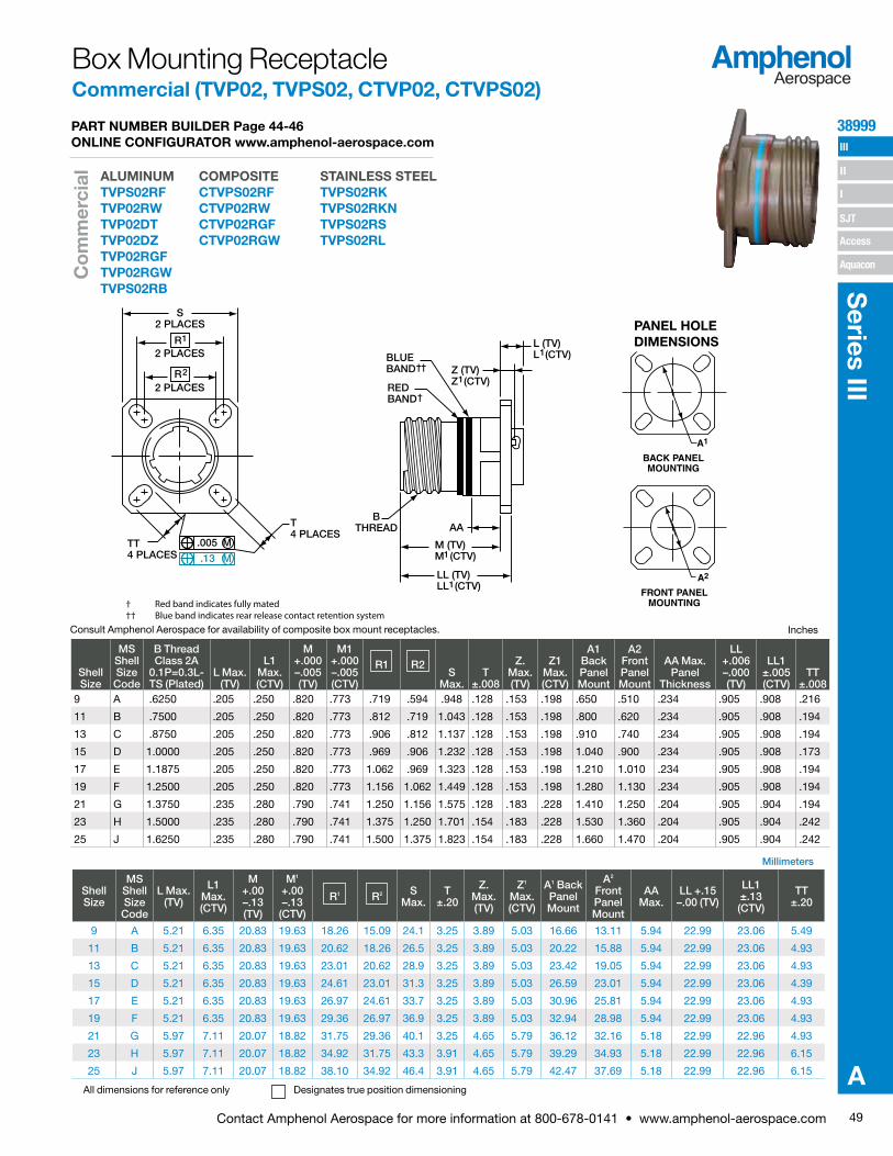
49Contact Amphenol Aerospace for more information at 800-678-0141 • www.amphenol-aerospace.com
38999 III
SJT
I
II
Access
Aquacon
Series III
A
Consult Amphenol Aerospace for availability of composite box mount receptacles.
Millimeters
Inches
M (TV)M (CTV)
LL (TV)LL (CTV)
1
1
AAB
THREAD
BLUEBAND††
REDBAND†
L (TV)L (CTV)1
Z (TV)Z (CTV)1
M
M
.005
.13
T4 PLACES
TT4 PLACES
S2 PLACES
2 PLACES
2 PLACES
R1
R2
† Red band indicates fully mated†† Blue band indicates rear release contact retention system
All dimensions for reference only Designates true position dimensioning
BACK PANELMOUNTING
FRONT PANELMOUNTING
A1
A2
PANEL HOLE DIMENSIONS
Box Mounting ReceptacleCommercial (TVP02, TVPS02, CTVP02, CTVPS02)
Shell Size
MS Shell Size Code
B Thread Class 2A
0.1P=0.3L-TS (Plated)
L Max. (TV)
L1 Max. (CTV)
M +.000 –.005 (TV)
M1 +.000 –.005 (CTV)
R1 R2S
Max.T
±.008
Z. Max. (TV)
Z1 Max. (CTV)
A1 Back Panel Mount
A2 Front Panel Mount
AA Max. Panel
Thickness
LL +.006 –.000 (TV)
LL1±.005(CTV)
TT±.008
9 A .6250 .205 .250 .820 .773 .719 .594 .948 .128 .153 .198 .650 .510 .234 .905 .908 .216
11 B .7500 .205 .250 .820 .773 .812 .719 1.043 .128 .153 .198 .800 .620 .234 .905 .908 .194
13 C .8750 .205 .250 .820 .773 .906 .812 1.137 .128 .153 .198 .910 .740 .234 .905 .908 .194
15 D 1.0000 .205 .250 .820 .773 .969 .906 1.232 .128 .153 .198 1.040 .900 .234 .905 .908 .173
17 E 1.1875 .205 .250 .820 .773 1.062 .969 1.323 .128 .153 .198 1.210 1.010 .234 .905 .908 .194
19 F 1.2500 .205 .250 .820 .773 1.156 1.062 1.449 .128 .153 .198 1.280 1.130 .234 .905 .908 .194
21 G 1.3750 .235 .280 .790 .741 1.250 1.156 1.575 .128 .183 .228 1.410 1.250 .204 .905 .904 .194
23 H 1.5000 .235 .280 .790 .741 1.375 1.250 1.701 .154 .183 .228 1.530 1.360 .204 .905 .904 .242
25 J 1.6250 .235 .280 .790 .741 1.500 1.375 1.823 .154 .183 .228 1.660 1.470 .204 .905 .904 .242
Shell Size
MS Shell Size Code
L Max. (TV)
L1 Max. (CTV)
M +.00 –.13 (TV)
M1 +.00 –.13
(CTV)
R1 R2 S Max.
T ±.20
Z. Max. (TV)
Z1 Max. (CTV)
A1 Back Panel Mount
A2 Front Panel Mount
AA Max.
LL +.15 –.00 (TV)
LL1±.13(CTV)
TT±.20
9 A 5.21 6.35 20.83 19.63 18.26 15.09 24.1 3.25 3.89 5.03 16.66 13.11 5.94 22.99 23.06 5.49
11 B 5.21 6.35 20.83 19.63 20.62 18.26 26.5 3.25 3.89 5.03 20.22 15.88 5.94 22.99 23.06 4.93
13 C 5.21 6.35 20.83 19.63 23.01 20.62 28.9 3.25 3.89 5.03 23.42 19.05 5.94 22.99 23.06 4.93
15 D 5.21 6.35 20.83 19.63 24.61 23.01 31.3 3.25 3.89 5.03 26.59 23.01 5.94 22.99 23.06 4.39
17 E 5.21 6.35 20.83 19.63 26.97 24.61 33.7 3.25 3.89 5.03 30.96 25.81 5.94 22.99 23.06 4.93
19 F 5.21 6.35 20.83 19.63 29.36 26.97 36.9 3.25 3.89 5.03 32.94 28.98 5.94 22.99 23.06 4.93
21 G 5.97 7.11 20.07 18.82 31.75 29.36 40.1 3.25 4.65 5.79 36.12 32.16 5.18 22.99 22.96 4.93
23 H 5.97 7.11 20.07 18.82 34.92 31.75 43.3 3.91 4.65 5.79 39.29 34.93 5.18 22.99 22.96 6.15
25 J 5.97 7.11 20.07 18.82 38.10 34.92 46.4 3.91 4.65 5.79 42.47 37.69 5.18 22.99 22.96 6.15
ALUMINUMTVPS02RF TVP02RWTVP02DT TVP02DZTVP02RGF TVP02RGWTVPS02RB
PART NUMBER BUILDER Page 44-46 ONLINE CONFIGURATOR www.amphenol-aerospace.com
COMPOSITECTVPS02RF CTVP02RWCTVP02RGF CTVP02RGW
STAINLESS STEELTVPS02RK TVPS02RKNTVPS02RS TVPS02RL
Co
mm
erci
al
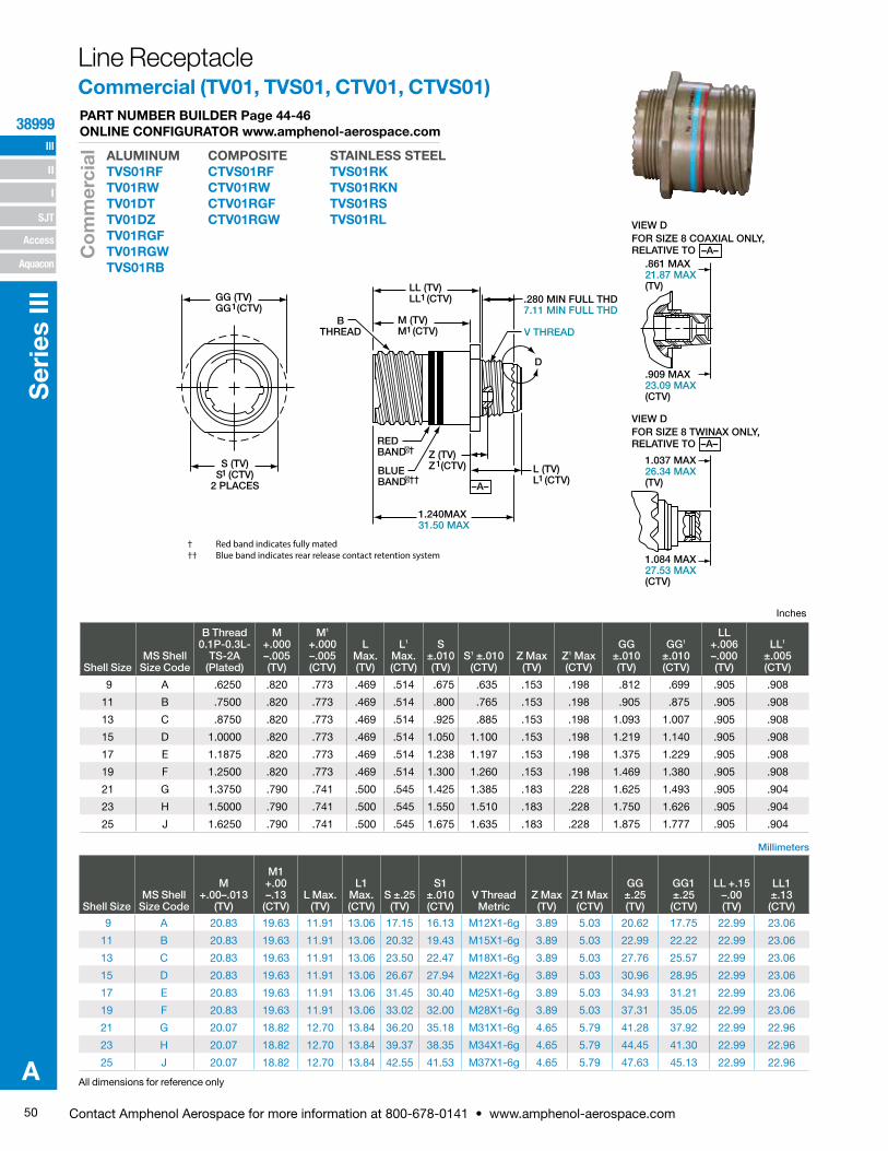
50 Contact Amphenol Aerospace for more information at 800-678-0141 • www.amphenol-aerospace.com
III
SJT
38999
I
II
Access
Aquacon
Ser
ies
III
A
GG (TV)GG (CTV)1
S (TV)S (CTV)
2 PLACES1
BTHREAD
LL (TV)LL (CTV)1
1M (TV)M (CTV)
.280 MIN FULL THD7.11 MIN FULL THD
L (TV)L (CTV)1
Z (TV)Z (CTV)1
1.240MAX31.50 MAX
V THREAD
D
–A–
REDBAND�†
BLUEBAND�††
.861 MAX21.87 MAX(TV)
.909 MAX23.09 MAX(CTV)
1.037 MAX26.34 MAX(TV)
1.084 MAX27.53 MAX(CTV)
VIEW DFOR SIZE 8 TWINAX ONLY,RELATIVE TO
VIEW DFOR SIZE 8 COAXIAL ONLY,RELATIVE TO
–A–
–A–
† Red band indicates fully mated†† Blue band indicates rear release contact retention system
Millimeters
All dimensions for reference only
Inches
Line ReceptacleCommercial (TV01, TVS01, CTV01, CTVS01)
Shell SizeMS Shell
Size Code
B Thread 0.1P-0.3L-
TS-2A (Plated)
M +.000 –.005 (TV)
M1
+.000 –.005 (CTV)
L Max. (TV)
L1 Max. (CTV)
S ±.010 (TV)
S1 ±.010 (CTV)
Z Max (TV)
Z1 Max (CTV)
GG ±.010 (TV)
GG1 ±.010 (CTV)
LL +.006 –.000 (TV)
LL1 ±.005 (CTV)
9 A .6250 .820 .773 .469 .514 .675 .635 .153 .198 .812 .699 .905 .908
11 B .7500 .820 .773 .469 .514 .800 .765 .153 .198 .905 .875 .905 .908
13 C .8750 .820 .773 .469 .514 .925 .885 .153 .198 1.093 1.007 .905 .908
15 D 1.0000 .820 .773 .469 .514 1.050 1.100 .153 .198 1.219 1.140 .905 .908
17 E 1.1875 .820 .773 .469 .514 1.238 1.197 .153 .198 1.375 1.229 .905 .908
19 F 1.2500 .820 .773 .469 .514 1.300 1.260 .153 .198 1.469 1.380 .905 .908
21 G 1.3750 .790 .741 .500 .545 1.425 1.385 .183 .228 1.625 1.493 .905 .904
23 H 1.5000 .790 .741 .500 .545 1.550 1.510 .183 .228 1.750 1.626 .905 .904
25 J 1.6250 .790 .741 .500 .545 1.675 1.635 .183 .228 1.875 1.777 .905 .904
Shell SizeMS Shell
Size Code
M +.00–.013
(TV)
M1 +.00 –.13
(CTV)L Max.
(TV)
L1 Max. (CTV)
S ±.25 (TV)
S1 ±.010 (CTV)
V Thread Metric
Z Max (TV)
Z1 Max (CTV)
GG ±.25 (TV)
GG1 ±.25 (CTV)
LL +.15 –.00 (TV)
LL1 ±.13 (CTV)
9 A 20.83 19.63 11.91 13.06 17.15 16.13 M12X1-6g 3.89 5.03 20.62 17.75 22.99 23.06
11 B 20.83 19.63 11.91 13.06 20.32 19.43 M15X1-6g 3.89 5.03 22.99 22.22 22.99 23.06
13 C 20.83 19.63 11.91 13.06 23.50 22.47 M18X1-6g 3.89 5.03 27.76 25.57 22.99 23.06
15 D 20.83 19.63 11.91 13.06 26.67 27.94 M22X1-6g 3.89 5.03 30.96 28.95 22.99 23.06
17 E 20.83 19.63 11.91 13.06 31.45 30.40 M25X1-6g 3.89 5.03 34.93 31.21 22.99 23.06
19 F 20.83 19.63 11.91 13.06 33.02 32.00 M28X1-6g 3.89 5.03 37.31 35.05 22.99 23.06
21 G 20.07 18.82 12.70 13.84 36.20 35.18 M31X1-6g 4.65 5.79 41.28 37.92 22.99 22.96
23 H 20.07 18.82 12.70 13.84 39.37 38.35 M34X1-6g 4.65 5.79 44.45 41.30 22.99 22.96
25 J 20.07 18.82 12.70 13.84 42.55 41.53 M37X1-6g 4.65 5.79 47.63 45.13 22.99 22.96
ALUMINUMTVS01RF TV01RWTV01DT TV01DZTV01RGFTV01RGWTVS01RB
PART NUMBER BUILDER Page 44-46 ONLINE CONFIGURATOR www.amphenol-aerospace.com
COMPOSITECTVS01RF CTV01RWCTV01RGF CTV01RGW
STAINLESS STEELTVS01RK TVS01RKNTVS01RS TVS01RL
Co
mm
erci
al
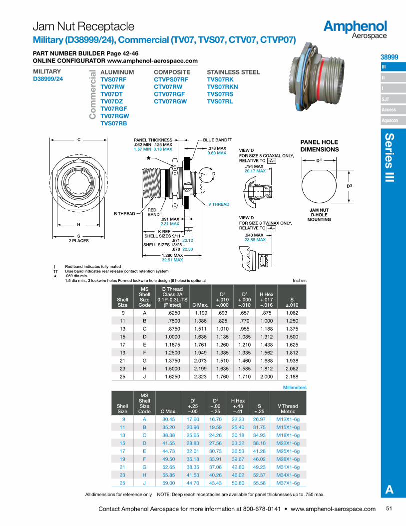
51Contact Amphenol Aerospace for more information at 800-678-0141 • www.amphenol-aerospace.com
38999 III
SJT
I
II
Access
Aquacon
Series III
A
C
H
S2 PLACES
PANEL THICKNESS.062 MIN .125 MAX1.57 MIN 3.18 MAX
BLUE BAND††
.378 MAX9.60 MAX
1.280 MAX32.51 MAX
K REFSHELL SIZES 9/11 –
.871 22.12SHELL SIZES 13/25 –
.878 22.30
.091 MAX2.31 MAX
B THREAD
V THREAD
D
REDBAND†
–A–
.794 MAX20.17 MAX
.940 MAX23.88 MAX
VIEW DFOR SIZE 8 TWINAX ONLY,RELATIVE TO
VIEW DFOR SIZE 8 COAXIAL ONLY,RELATIVE TO
–A–
–A–
† Red band indicates fully mated†† Blue band indicates rear release contact retention systemH .059 dia min.
1.5 dia min., 3 lockwire holes Formed lockwire hole design (6 holes) is optional
Millimeters
All dimensions for reference only NOTE: Deep reach receptacles are available for panel thicknesses up to .750 max.
PANEL HOLE DIMENSIONS
JAM NUTD-HOLE
MOUNTING
D1
D2
Inches
Jam Nut ReceptacleMilitary (D38999/24), Commercial (TV07, TVS07, CTV07, CTVP07)
Shell Size
MS Shell Size Code
B Thread Class 2A
0.1P-0.3L-TS (Plated) C Max.
D1
+.010 –.000
D2
+.000 –.010
H Hex+.017 –.016
S ±.010
9 A .6250 1.199 .693 .657 .875 1.062
11 B .7500 1.386 .825 .770 1.000 1.250
13 C .8750 1.511 1.010 .955 1.188 1.375
15 D 1.0000 1.636 1.135 1.085 1.312 1.500
17 E 1.1875 1.761 1.260 1.210 1.438 1.625
19 F 1.2500 1.949 1.385 1.335 1.562 1.812
21 G 1.3750 2.073 1.510 1.460 1.688 1.938
23 H 1.5000 2.199 1.635 1.585 1.812 2.062
25 J 1.6250 2.323 1.760 1.710 2.000 2.188
Shell Size
MS Shell Size Code C Max.
D1
+.25 –.00
D2
+.00 –.25
H Hex+.43 –.41
S ±.25
V Thread Metric
9 A 30.45 17.60 16.70 22.23 26.97 M12X1-6g
11 B 35.20 20.96 19.59 25.40 31.75 M15X1-6g
13 C 38.38 25.65 24.26 30.18 34.93 M18X1-6g
15 D 41.55 28.83 27.56 33.32 38.10 M22X1-6g
17 E 44.73 32.01 30.73 36.53 41.28 M25X1-6g
19 F 49.50 35.18 33.91 39.67 46.02 M28X1-6g
21 G 52.65 38.35 37.08 42.80 49.23 M31X1-6g
23 H 55.85 41.53 40.26 46.02 52.37 M34X1-6g
25 J 59.00 44.70 43.43 50.80 55.58 M37X1-6g
ALUMINUMTVS07RF TV07RWTV07DT TV07DZ TV07RGF TV07RGWTVS07RB
PART NUMBER BUILDER Page 42-46 ONLINE CONFIGURATOR www.amphenol-aerospace.com
COMPOSITECTVPS07RF CTV07RWCTV07RGF CTV07RGW
STAINLESS STEELTVS07RK TVS07RKNTVS07RS TVS07RL
MILITARYD38999/24
Co
mm
erci
al
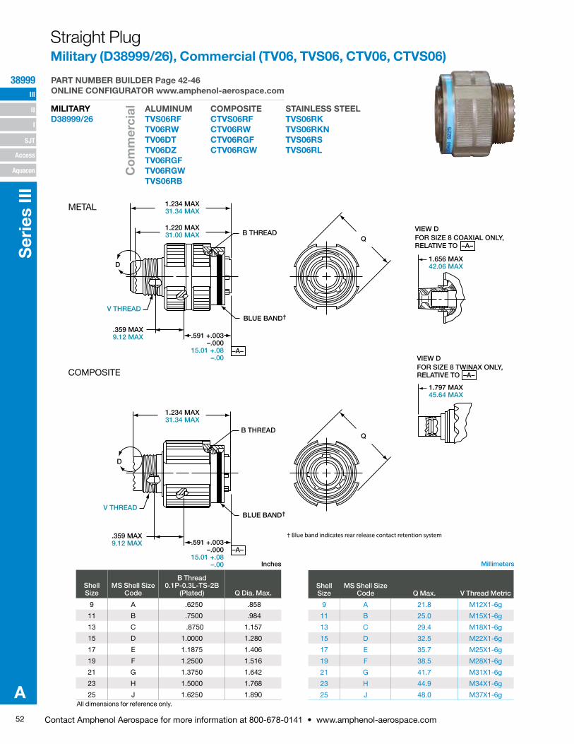
52 Contact Amphenol Aerospace for more information at 800-678-0141 • www.amphenol-aerospace.com
III
SJT
38999
I
II
Access
Aquacon
Ser
ies
III
A
1.234 MAX31.34 MAX
1.220 MAX31.00 MAX B THREAD
D
V THREAD
.359 MAX9.12 MAX
.359 MAX9.12 MAX
.591 +.003–.000
15.01 +.08–.00
BLUE BAND†
1.234 MAX31.34 MAX
Q
1.656 MAX42.06 MAX
1.797 MAX45.64 MAX
VIEW DFOR SIZE 8 TWINAX ONLY,RELATIVE TO
VIEW DFOR SIZE 8 COAXIAL ONLY,RELATIVE TO
–A–
–A–
–A–
V THREAD
.591 +.003–.000
15.01 +.08–.00
–A–
QB THREAD
D
BLUE BAND†
† Blue band indicates rear release contact retention system
All dimensions for reference only.
Inches Millimeters
COMPOSITE
Straight PlugMilitary (D38999/26), Commercial (TV06, TVS06, CTV06, CTVS06)
Shell Size
MS Shell Size Code
B Thread 0.1P-0.3L-TS-2B
(Plated) Q Dia. Max.
9 A .6250 .858
11 B .7500 .984
13 C .8750 1.157
15 D 1.0000 1.280
17 E 1.1875 1.406
19 F 1.2500 1.516
21 G 1.3750 1.642
23 H 1.5000 1.768
25 J 1.6250 1.890
Shell Size
MS Shell Size Code Q Max. V Thread Metric
9 A 21.8 M12X1-6g
11 B 25.0 M15X1-6g
13 C 29.4 M18X1-6g
15 D 32.5 M22X1-6g
17 E 35.7 M25X1-6g
19 F 38.5 M28X1-6g
21 G 41.7 M31X1-6g
23 H 44.9 M34X1-6g
25 J 48.0 M37X1-6g
METAL
ALUMINUMTVS06RF TV06RWTV06DT TV06DZTV06RGF TV06RGWTVS06RB
PART NUMBER BUILDER Page 42-46 ONLINE CONFIGURATOR www.amphenol-aerospace.com
COMPOSITECTVS06RF CTV06RWCTV06RGF CTV06RGW
STAINLESS STEELTVS06RK TVS06RKNTVS06RS TVS06RL
MILITARYD38999/26
Co
mm
erci
al

53Contact Amphenol Aerospace for more information at 800-678-0141 • www.amphenol-aerospace.com
38999 III
SJT
I
II
Access
Aquacon
Series III
A
BLUEBAND†
G.190 +.010–.000
4.82 +.26–.00
BTHREAD
Q
.591 +.003–.000
15.01+.08–.00
3.59 MAX9.12 MAX
GG
M.005
M.13
.138-32UNC-2BHELICAL COIL–A–
R
R
1.656 MAX42.06 MAX
1.797 MAX45.64 MAX
VIEW DFOR SIZE 8 TWINAX ONLY,RELATIVE TO
VIEW DFOR SIZE 8 COAXIAL ONLY,RELATIVE TO
–A–
–A–
D
† Blue band indicates rear release contact retention system
Designates true position dimensioning
Millimeters
All dimensions for reference only ** Partially tooled. Consult Amphenol Aerospace for availability
Inches
Shell Size
MS Shell Size
Coded
B Thread 0.1P-0.3L-TS-2A
(Plated) G ±.060 Q Dia. MaxR GG Dia
±.005
9** A .6250 1.106 .859 1.038 1.838
11 B .7500 1.106 .969 1.115 1.948
13** C .8750 1.106 1.141 1.240 2.124
15 D 1.0000 1.106 1.266 1.327 2.248
17 E 1.1875 1.106 1.391 1.417 2.375
19 F 1.2500 1.356 1.500 1.557 2.495
21 G 1.3750 1.356 1.625 1.624 2.568
23 H 1.5000 1.356 1.750 1.713 2.723
25 J 1.6250 1.356 1.875 1.801 2.848
Shell Size
MS Shell Size
Coded G ±.1.52 Q Dia. MaxR
GG Dia ±.13
9** A 28.09 21.82 26.37 46.69
11 B 28.09 24.62 28.32 49.48
13** C 28.09 28.98 31.50 53.95
15 D 28.09 32.16 33.71 57.10
17 E 28.09 35.33 35.99 60.33
19 F 34.44 38.10 39.55 63.37
21 G 34.44 41.28 41.25 65.23
23 H 34.44 44.45 43.51 69.16
25 J 34.44 47.63 45.75 72.34
Flange Mounting Plug Commercial (TV09, TVS09, CTV09, CTVPS09)
ALUMINUMTVS09RF TV09RWTV09DT TV09DZ TV09RGF TV09RGWTVS09RB
PART NUMBER BUILDER Page 44-46 ONLINE CONFIGURATOR www.amphenol-aerospace.com
COMPOSITECTVPS09RF CTV09RWCTV09RGF CTV09RGW
STAINLESS STEELTVS09RK TVS09RKNTVS09RS TVS09RL
Co
mm
erci
al
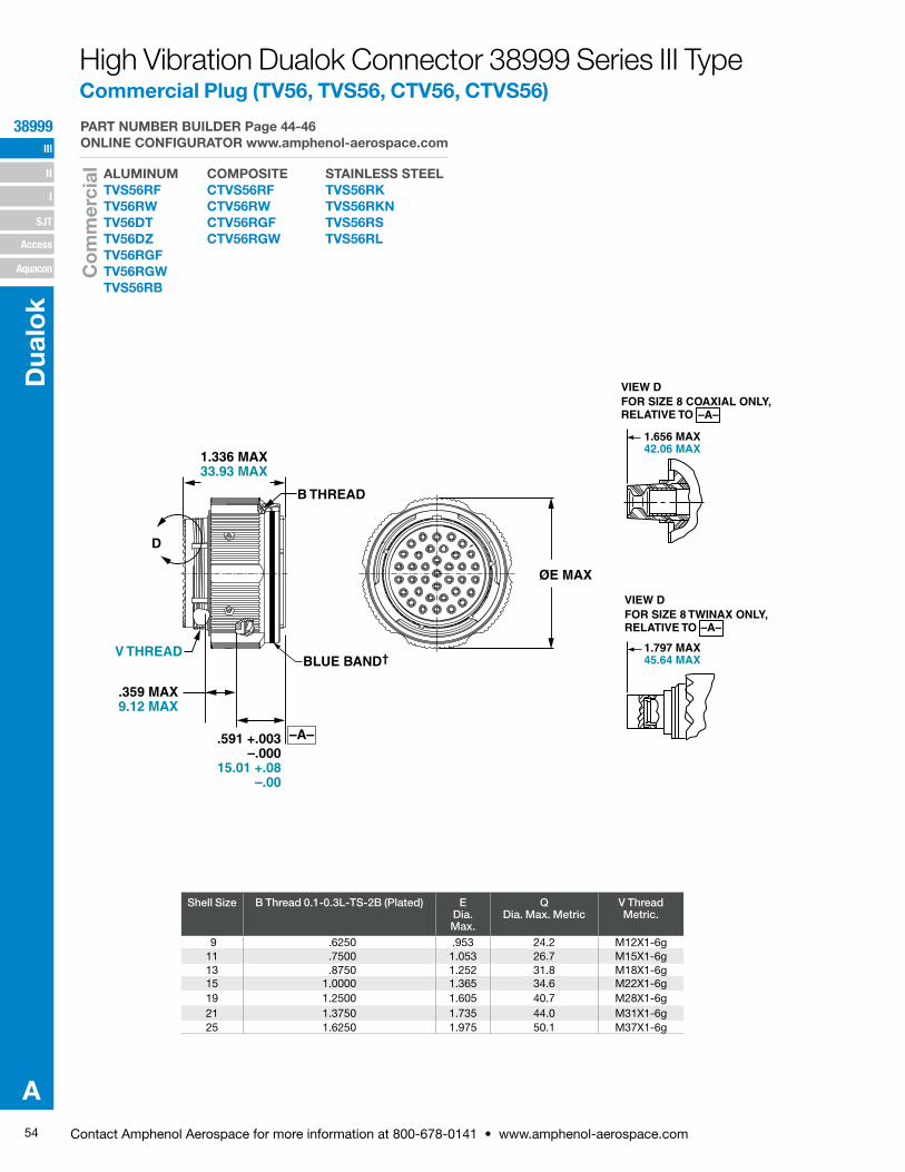
54 Contact Amphenol Aerospace for more information at 800-678-0141 • www.amphenol-aerospace.com
38999 III
SJT
I
II
Access
Aquacon
Dua
lok
A
1.336 MAX33.93 MAX
1.656 MAX42.06 MAX
1.797 MAX45.64 MAX
VIEW DFOR SIZE 8 TWINAX ONLY,RELATIVE TO
VIEW DFOR SIZE 8 COAXIAL ONLY,RELATIVE TO
–A–
–A–
ØE MAX
V THREAD
.359 MAX9.12 MAX
.591 +.003–.000
15.01 +.08–.00
–A–
BLUE BAND†
D
B THREAD
High Vibration Dualok Connector 38999 Series III TypeCommercial Plug (TV56, TVS56, CTV56, CTVS56)
ALUMINUMTVS56RF TV56RWTV56DT TV56DZTV56RGF TV56RGWTVS56RB
COMPOSITECTVS56RF CTV56RWCTV56RGF CTV56RGW
STAINLESS STEELTVS56RK TVS56RKNTVS56RS TVS56RL
PART NUMBER BUILDER Page 44-46 ONLINE CONFIGURATOR www.amphenol-aerospace.com
Co
mm
erci
al
Shell Size B Thread 0.1-0.3L-TS-2B (Plated) E Dia. Max.
Q Dia. Max. Metric
V Thread Metric.
9 .6250 .953 24.2 M12X1-6g11 .7500 1.053 26.7 M15X1-6g13 .8750 1.252 31.8 M18X1-6g15 1.0000 1.365 34.6 M22X1-6g19 1.2500 1.605 40.7 M28X1-6g21 1.3750 1.735 44.0 M31X1-6g25 1.6250 1.975 50.1 M37X1-6g
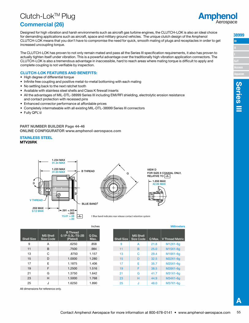
55Contact Amphenol Aerospace for more information at 800-678-0141 • www.amphenol-aerospace.com
38999 III
SJT
I
II
Access
Aquacon
Series III
A
Designed for high vibration and harsh environments such as aircraft gas turbine engines, the CLUTCH-LOK is also an ideal choice for demanding applications such as aircraft, space and military ground vehicles. The unique clutch design of the Amphenol CLUTCH-LOK means that you don’t have to compromise the need for quick, smooth mating of plugs and receptacles in order to get increased uncoupling torque.
The CLUTCH-LOK has proven to not only remain mated and pass all the Series III specification requirements, it also has proven to actually tighten itself under vibration. This is a powerful advantage over the traditionally high vibration application connectors. The CLUTCH-LOK is also a tremendous advantage in inaccessible, hard to reach areas where mating torque is difficult to apply and complete coupling is not verifiable by inspection.
CLUTCH-LOK FEATURES AND BENEFITS:• High degree of differential torque• Infinite free coupling and positive metal-to-metal bottoming with each mating• No settling back to the next ratchet tooth• Available with stainless steel shells and Class K firewall inserts• All the advantages of MIL-DTL-38999 Series III including EMI/RFI shielding, electrolytic erosion resistance
and contact protection with recessed pins• Enhanced connector performance at affordable prices• Completely intermateable with all existing MIL-DTL-38999 Series III connectors• Fully QPL’d
All dimensions for reference only.
Inches Millimeters
1.234 MAX31.34 MAX
1.220 MAX31.00 MAX B THREAD
D
V THREAD
.359 MAX9.12 MAX .591 +.003
–.00015.01 +.08
–.00
BLUE BAND†
Q
1.656 MAX42.06 MAX
VIEW DFOR SIZE 8 COAXIAL ONLY,RELATIVE TO –A–
–A– † Blue band indicates rear release contact retention system
Clutch-LokTM Plug Commercial (26)
Shell SizeMS Shell
Size Code
B Thread 0.1P-0.3L-TS-2B
(Plated)Q Dia. Max.
9 A .6250 .858
11 B .7500 .984
13 C .8750 1.157
15 D 1.0000 1.280
17 E 1.1875 1.406
19 F 1.2500 1.516
21 G 1.3750 1.642
23 H 1.5000 1.768
25 J 1.6250 1.890
Shell SizeMS Shell
Size Code Q Max. V Thread Metric
9 A 21.8 M12X1-6g
11 B 25.0 M15X1-6g
13 C 29.4 M18X1-6g
15 D 32.5 M22X1-6g
17 E 35.7 M25X1-6g
19 F 38.5 M28X1-6g
21 G 41.7 M31X1-6g
23 H 44.9 M34X1-6g
25 J 48.0 M37X1-6g
PART NUMBER BUILDER Page 44-46 ONLINE CONFIGURATOR www.amphenol-aerospace.com
STAINLESS STEEL MTV26RK
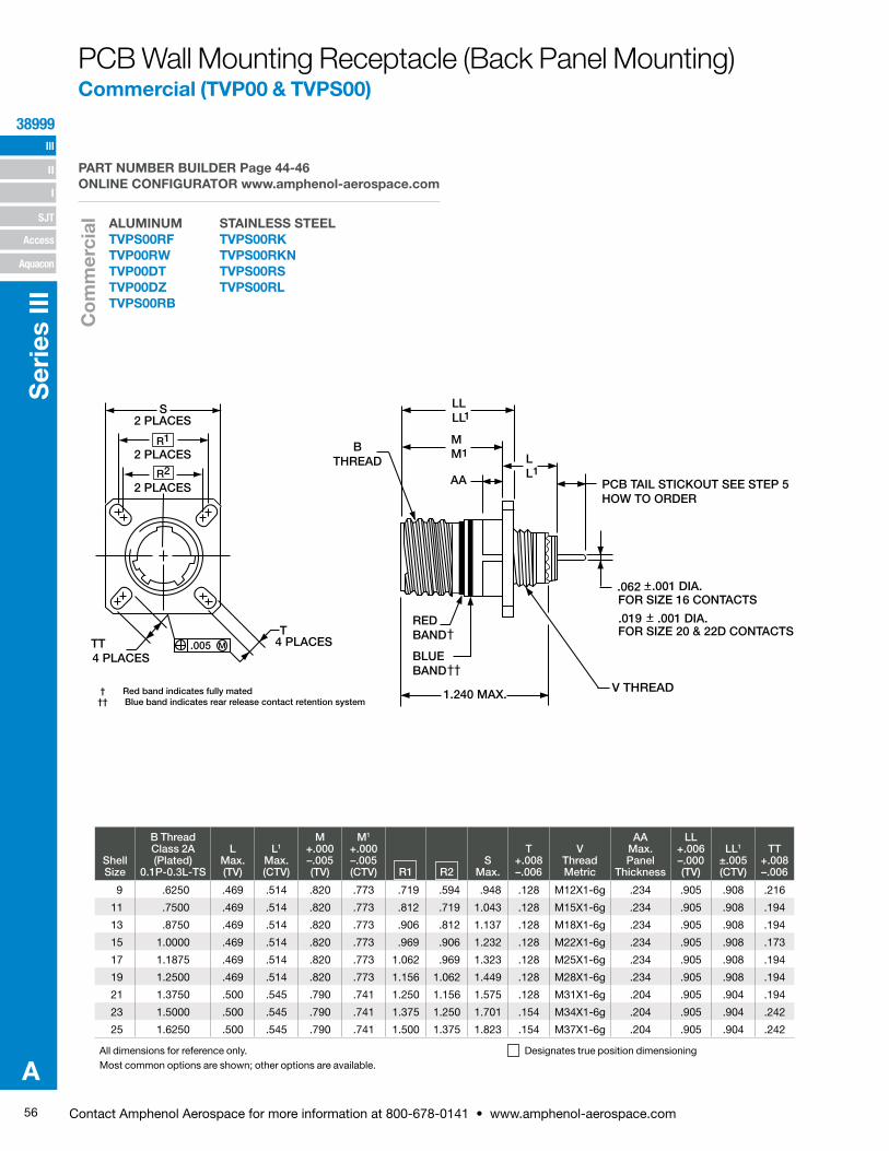
56 Contact Amphenol Aerospace for more information at 800-678-0141 • www.amphenol-aerospace.com
III
SJT
38999
I
II
Access
Aquacon
Ser
ies
III
A
Shell Size
B Thread Class 2A (Plated)
0.1P-0.3L-TS
L Max. (TV)
L1 Max. (CTV)
M +.000 –.005 (TV)
M1 +.000 –.005 (CTV) R1 R2
S Max.
T +.008 –.006
V Thread Metric
AA Max. Panel
Thickness
LL +.006 –.000 (TV)
LL1 ±.005 (CTV)
TT +.008 –.006
9 .6250 .469 .514 .820 .773 .719 .594 .948 .128 M12X1-6g .234 .905 .908 .216
11 .7500 .469 .514 .820 .773 .812 .719 1.043 .128 M15X1-6g .234 .905 .908 .194
13 .8750 .469 .514 .820 .773 .906 .812 1.137 .128 M18X1-6g .234 .905 .908 .194
15 1.0000 .469 .514 .820 .773 .969 .906 1.232 .128 M22X1-6g .234 .905 .908 .173
17 1.1875 .469 .514 .820 .773 1.062 .969 1.323 .128 M25X1-6g .234 .905 .908 .194
19 1.2500 .469 .514 .820 .773 1.156 1.062 1.449 .128 M28X1-6g .234 .905 .908 .194
21 1.3750 .500 .545 .790 .741 1.250 1.156 1.575 .128 M31X1-6g .204 .905 .904 .194
23 1.5000 .500 .545 .790 .741 1.375 1.250 1.701 .154 M34X1-6g .204 .905 .904 .242
25 1.6250 .500 .545 .790 .741 1.500 1.375 1.823 .154 M37X1-6g .204 .905 .904 .242
PCB Wall Mounting Receptacle (Back Panel Mounting)Commercial (TVP00 & TVPS00)
All dimensions for reference only. Most common options are shown; other options are available.
Designates true position dimensioning
R1
R2
S
2 PLACES
2 PLACES
2 PLACES
4 PLACES4 PLACES
.005 M
V THREAD
BTHREAD
PCB TAIL STICKOUT SEE STEP 5 HOW TO ORDER
AA
.062 .001 DIA. FOR SIZE 16 CONTACTS
.019 REDBAND
BLUEBAND
1.240 MAX.
TTT
.001 DIA.FOR SIZE 20 & 22D CONTACTS
LLLL1
MM1 L
L1
† Red band indicates fully mated†† Blue band indicates rear release contact retention system
PART NUMBER BUILDER Page 44-46 ONLINE CONFIGURATOR www.amphenol-aerospace.com
ALUMINUMTVPS00RF TVP00RWTVP00DT TVP00DZTVPS00RB
STAINLESS STEELTVPS00RK TVPS00RKNTVPS00RS TVPS00RL
Co
mm
erci
al
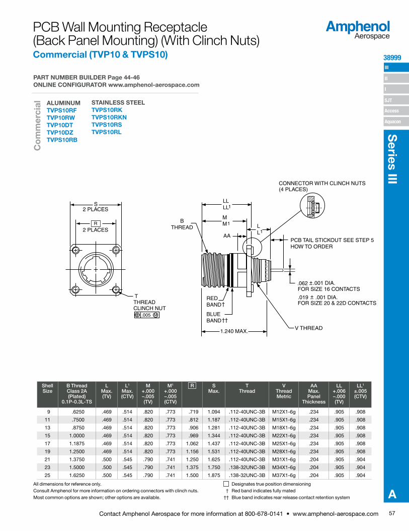
57Contact Amphenol Aerospace for more information at 800-678-0141 • www.amphenol-aerospace.com
38999 III
SJT
I
II
Access
Aquacon
Series III
A
Shell Size
B Thread Class 2A (Plated)
0.1P-0.3L-TS
L Max. (TV)
L1 Max. (CTV)
M +.000 –.005 (TV)
M1 +.000 –.005 (CTV)
R S Max.
T Thread
V Thread Metric
AA Max. Panel
Thickness
LL +.006 –.000 (TV)
LL1 ±.005 (CTV)
9 .6250 .469 .514 .820 .773 .719 1.094 .112-40UNC-3B M12X1-6g .234 .905 .908
11 .7500 .469 .514 .820 .773 .812 1.187 .112-40UNC-3B M15X1-6g .234 .905 .908
13 .8750 .469 .514 .820 .773 .906 1.281 .112-40UNC-3B M18X1-6g .234 .905 .908
15 1.0000 .469 .514 .820 .773 .969 1.344 .112-40UNC-3B M22X1-6g .234 .905 .908
17 1.1875 .469 .514 .820 .773 1.062 1.437 .112-40UNC-3B M25X1-6g .234 .905 .908
19 1.2500 .469 .514 .820 .773 1.156 1.531 .112-40UNC-3B M28X1-6g .234 .905 .908
21 1.3750 .500 .545 .790 .741 1.250 1.625 .112-40UNC-3B M31X1-6g .204 .905 .904
23 1.5000 .500 .545 .790 .741 1.375 1.750 .138-32UNC-3B M34X1-6g .204 .905 .904
25 1.6250 .500 .545 .790 .741 1.500 1.875 .138-32UNC-3B M37X1-6g .204 .905 .904
PCB Wall Mounting Receptacle (Back Panel Mounting) (With Clinch Nuts) Commercial (TVP10 & TVPS10)
Designates true position dimensioning † Red band indicates fully mated†† Blue band indicates rear release contact retention system
All dimensions for reference only. Consult Amphenol for more information on ordering connectors with clinch nuts.Most common options are shown; other options are available.
R
S
2 PLACES
2 PLACES
V THREAD
BTHREAD
PCB TAIL STICKOUT SEE STEP 5HOW TO ORDER
AA
.062 .001 DIA. FOR SIZE 16 CONTACTS
.019 REDBAND
BLUEBAND
1.240 MAX.
.001 DIA.FOR SIZE 20 & 22D CONTACTS
CONNECTOR WITH CLINCH NUTS(4 PLACES)
TTHREADCLINCH NUT
.005 M
LLLL1
MM1 L
L1
ALUMINUMTVPS10RF TVP10RWTVP10DT TVP10DZTVPS10RB
PART NUMBER BUILDER Page 44-46 ONLINE CONFIGURATOR www.amphenol-aerospace.com
STAINLESS STEELTVPS10RK TVPS10RKNTVPS10RS TVPS10RL
Co
mm
erci
al
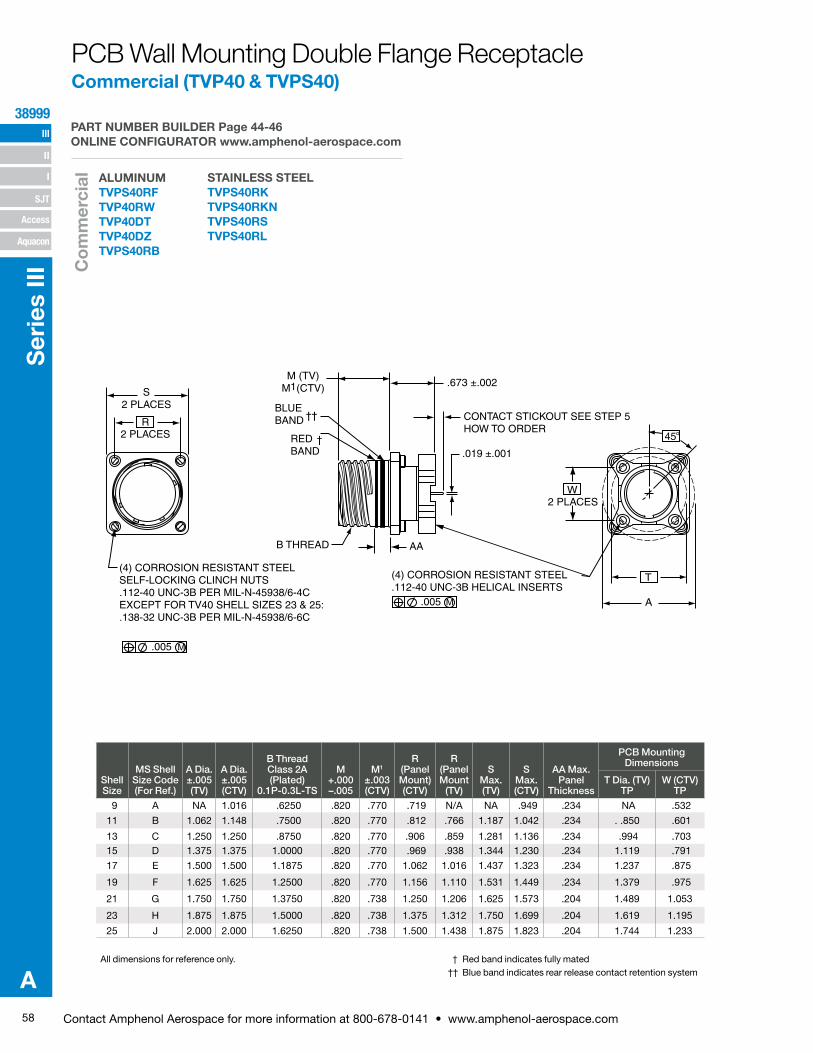
58 Contact Amphenol Aerospace for more information at 800-678-0141 • www.amphenol-aerospace.com
III
SJT
38999
I
II
Access
Aquacon
Ser
ies
III
A
PCB Wall Mounting Double Flange Receptacle Commercial (TVP40 & TVPS40)
Shell Size
MS Shell Size Code (For Ref.)
A Dia. ±.005 (TV)
A Dia. ±.005 (CTV)
B Thread Class 2A (Plated)
0.1P-0.3L-TS
M +.000 –.005
M1 ±.003 (CTV)
R (Panel Mount) (CTV)
R (Panel Mount
(TV)
S Max. (TV)
S Max. (CTV)
AA Max. Panel
Thickness
PCB Mounting Dimensions
T Dia. (TV) TP
W (CTV) TP
9 A NA 1.016 .6250 .820 .770 .719 N/A NA .949 .234 NA .532
11 B 1.062 1.148 .7500 .820 .770 .812 .766 1.187 1.042 .234 . .850 .601
13 C 1.250 1.250 .8750 .820 .770 .906 .859 1.281 1.136 .234 .994 .70315 D 1.375 1.375 1.0000 .820 .770 .969 .938 1.344 1.230 .234 1.119 .791
17 E 1.500 1.500 1.1875 .820 .770 1.062 1.016 1.437 1.323 .234 1.237 .875
19 F 1.625 1.625 1.2500 .820 .770 1.156 1.110 1.531 1.449 .234 1.379 .975
21 G 1.750 1.750 1.3750 .820 .738 1.250 1.206 1.625 1.573 .204 1.489 1.053
23 H 1.875 1.875 1.5000 .820 .738 1.375 1.312 1.750 1.699 .204 1.619 1.195
25 J 2.000 2.000 1.6250 .820 .738 1.500 1.438 1.875 1.823 .204 1.744 1.233
† Red band indicates fully mated †† Blue band indicates rear release contact retention system
All dimensions for reference only.
.005 M
(4) CORROSION RESISTANT STEEL.112-40 UNC-3B HELICAL INSERTS
A
T
W2 PLACES
B THREAD
M (TV)M (CTV) .673 ±.002
CONTACT STICKOUT SEE STEP 5HOW TO ORDER
.019 ±.001
AA
REDBAND
†
BLUEBAND ††
1S2 PLACES
R
.005 M
(4) CORROSION RESISTANT STEELSELF-LOCKING CLINCH NUTS.112-40 UNC-3B PER MIL-N-45938/6-4CEXCEPT FOR TV40 SHELL SIZES 23 & 25:.138-32 UNC-3B PER MIL-N-45938/6-6C
2 PLACES 45°
ALUMINUMTVPS40RF TVP40RWTVP40DT TVP40DZTVPS40RB
PART NUMBER BUILDER Page 44-46 ONLINE CONFIGURATOR www.amphenol-aerospace.com
STAINLESS STEELTVPS40RK TVPS40RKNTVPS40RS TVPS40RL
Co
mm
erci
al
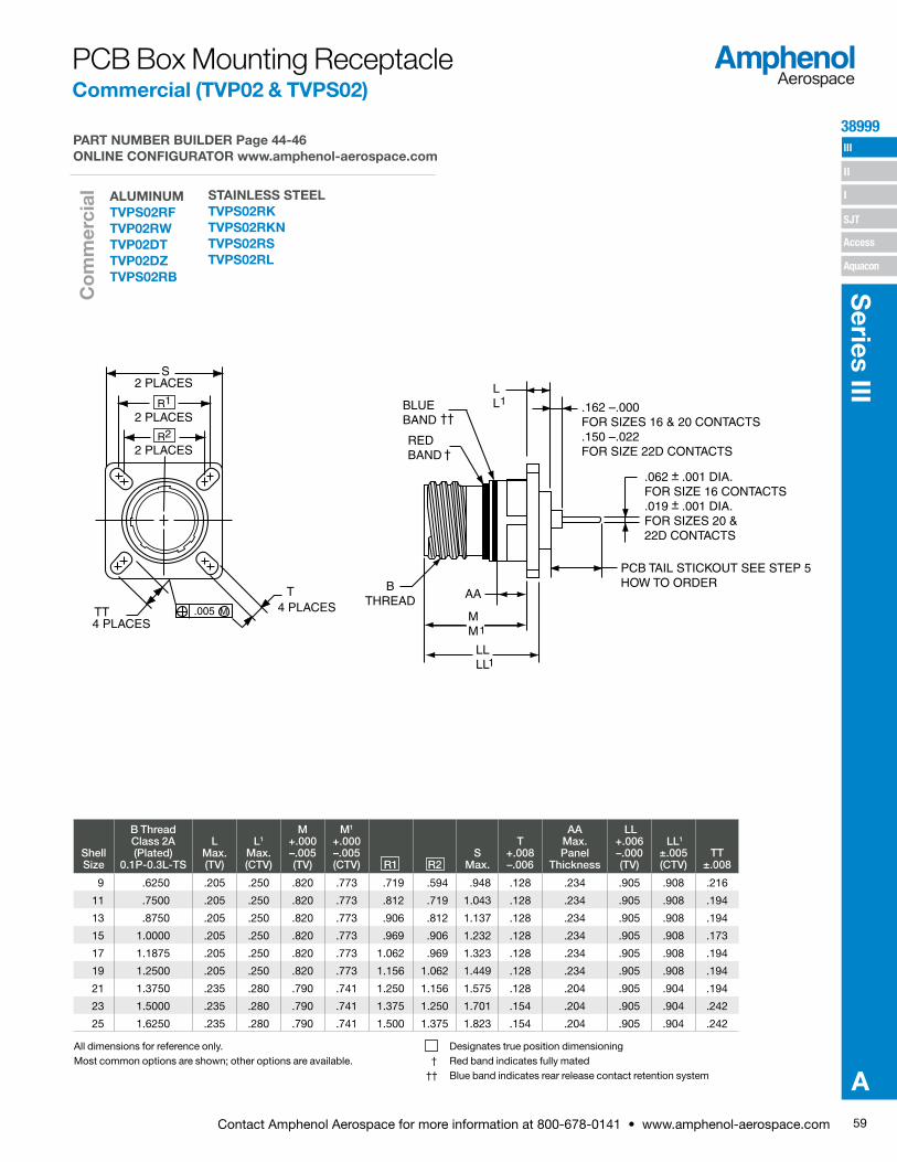
59Contact Amphenol Aerospace for more information at 800-678-0141 • www.amphenol-aerospace.com
38999 III
SJT
I
II
Access
Aquacon
Series III
A
Shell Size
B Thread Class 2A (Plated)
0.1P-0.3L-TS
L Max. (TV)
L1 Max. (CTV)
M +.000 –.005 (TV)
M1 +.000 –.005 (CTV) R1 R2
S Max.
T +.008 –.006
AA Max. Panel
Thickness
LL +.006 –.000 (TV)
LL1 ±.005 (CTV)
TT ±.008
9 .6250 .205 .250 .820 .773 .719 .594 .948 .128 .234 .905 .908 .216
11 .7500 .205 .250 .820 .773 .812 .719 1.043 .128 .234 .905 .908 .194
13 .8750 .205 .250 .820 .773 .906 .812 1.137 .128 .234 .905 .908 .194
15 1.0000 .205 .250 .820 .773 .969 .906 1.232 .128 .234 .905 .908 .173
17 1.1875 .205 .250 .820 .773 1.062 .969 1.323 .128 .234 .905 .908 .194
19 1.2500 .205 .250 .820 .773 1.156 1.062 1.449 .128 .234 .905 .908 .194
21 1.3750 .235 .280 .790 .741 1.250 1.156 1.575 .128 .204 .905 .904 .194
23 1.5000 .235 .280 .790 .741 1.375 1.250 1.701 .154 .204 .905 .904 .242
25 1.6250 .235 .280 .790 .741 1.500 1.375 1.823 .154 .204 .905 .904 .242
PCB Box Mounting Receptacle Commercial (TVP02 & TVPS02)
Designates true position dimensioning † Red band indicates fully mated†† Blue band indicates rear release contact retention system
All dimensions for reference only. Most common options are shown; other options are available.
BTHREAD
PCB TAIL STICKOUT SEE STEP 5HOW TO ORDER
.162 –.000FOR SIZES 16 & 20 CONTACTS.150 –.022FOR SIZE 22D CONTACTS
AA
REDBAND
BLUEBAND
LLLL1
LL1
MM1
R1
R2
S
2 PLACES
2 PLACES
2 PLACES
4 PLACES4 PLACES
.005 M
.062 .001 DIA.FOR SIZE 16 CONTACTS.019 .001 DIA.FOR SIZES 20 & 22D CONTACTS
T
TT
ALUMINUMTVPS02RF TVP02RWTVP02DT TVP02DZTVPS02RB
PART NUMBER BUILDER Page 44-46 ONLINE CONFIGURATOR www.amphenol-aerospace.com
STAINLESS STEELTVPS02RK TVPS02RKNTVPS02RS TVPS02RL
Co
mm
erci
al
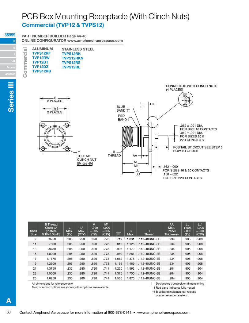
60 Contact Amphenol Aerospace for more information at 800-678-0141 • www.amphenol-aerospace.com
III
SJT
38999
I
II
Access
Aquacon
Ser
ies
III
A
Shell Size
B Thread Class 2A (Plated)
0.1P-0.3L-TS
L Max. (TV)
L1 Max. (CTV)
M +.000 –.005 (TV)
M1 +.000 –.005 (CTV) R
S Max.
T Thread
AA Max. Panel
Thickness
LL +.006 –.000 (TV)
LL1 +.006 –.000 (CTV)
9 .6250 .205 .250 .820 .773 .719 1.031 .112-40UNC-3B .234 .905 .908
11 .7500 .205 .250 .820 .773 .812 1.125 .112-40UNC-3B .234 .905 .908
13 .8750 .205 .250 .820 .773 .906 1.172 .112-40UNC-3B .234 .905 .908
15 1.0000 .205 .250 .820 .773 .969 1.281 .112-40UNC-3B .234 .905 .908
17 1.1875 .205 .250 .820 .773 1.062 1.375 .112-40UNC-3B .234 .905 .908
19 1.2500 .205 .250 .820 .773 1.156 1.469 .112-40UNC-3B .234 .905 .908
21 1.3750 .235 .280 .790 .741 1.250 1.562 .112-40UNC-3B .204 .905 .904
23 1.5000 .235 .280 .790 .741 1.375 1.750 .112-40UNC-3B .204 .905 .904
25 1.6250 .235 .280 .790 .741 1.500 1.875 .112-40UNC-3B .204 .905 .904
PCB Box Mounting Receptacle (With Clinch Nuts)Commercial (TVP12 & TVPS12)
Designates true position dimensioning † Red band indicates fully mated†† Blue band indicates rear release
contact retention system
All dimensions for reference only. Most common options are shown; other options are available.
BTHREAD
PCB TAIL STICKOUT SEE STEP 5HOW TO ORDER
AA
REDBAND
BLUEBAND
CONNECTOR WITH CLINCH NUTS(4 PLACES)
TTHREADCLINCH NUT
LL1
MM1
LLLL1
.162 –.000FOR SIZES 16 & 20 CONTACTS.150 –.022FOR SIZE 22D CONTACTS
R
S
2 PLACES
2 PLACES
.062 .001 DIA.FOR SIZE 16 CONTACTS.019 .001 DIA.FOR SIZES 20 & 22D CONTACTS
.005 M
ALUMINUMTVPS12RF TVP12RWTVP12DT TVP12DZTVPS12RB
PART NUMBER BUILDER Page 44-46 ONLINE CONFIGURATOR www.amphenol-aerospace.com
STAINLESS STEELTVPS12RK TVPS12RKNTVPS12RS TVPS12RL
Co
mm
erci
al
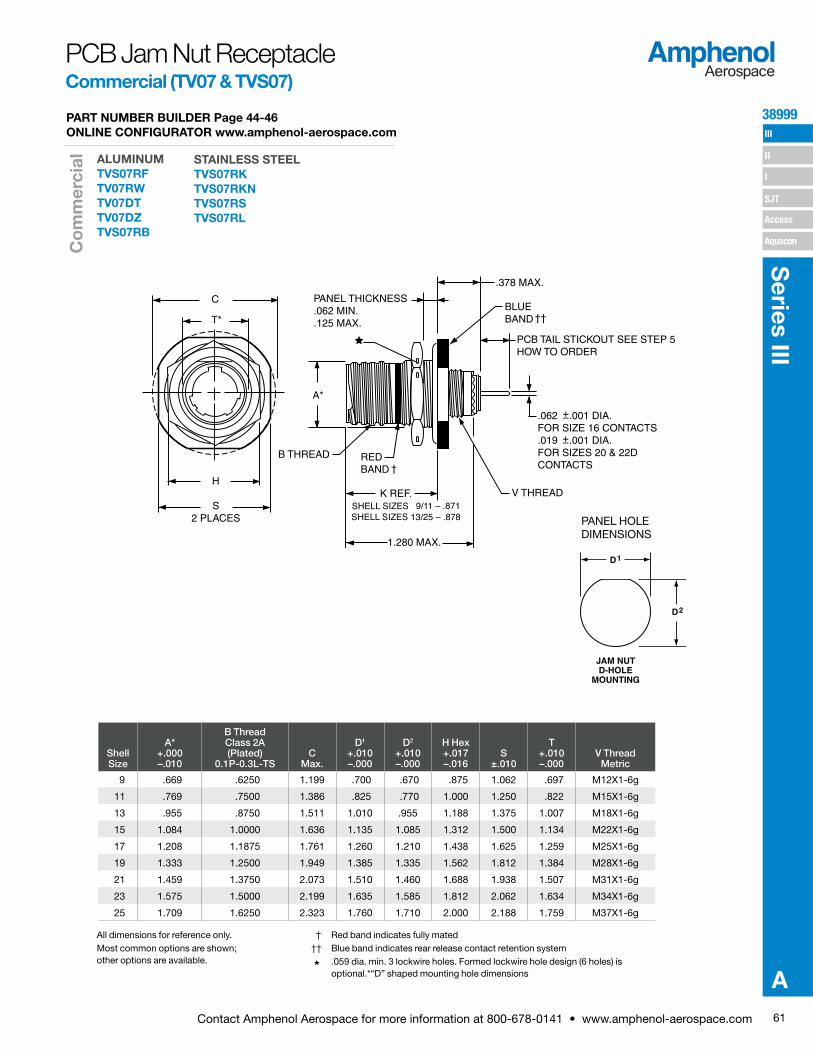
61Contact Amphenol Aerospace for more information at 800-678-0141 • www.amphenol-aerospace.com
38999 III
SJT
I
II
Access
Aquacon
Series III
A
PCB Jam Nut Receptacle Commercial (TV07 & TVS07)
Shell Size
A* +.000 –.010
B Thread Class 2A (Plated)
0.1P-0.3L-TSC
Max.
D1 +.010 –.000
D2 +.010 –.000
H Hex +.017 –.016
S ±.010
T +.010 –.000
V Thread Metric
9 .669 .6250 1.199 .700 .670 .875 1.062 .697 M12X1-6g
11 .769 .7500 1.386 .825 .770 1.000 1.250 .822 M15X1-6g
13 .955 .8750 1.511 1.010 .955 1.188 1.375 1.007 M18X1-6g
15 1.084 1.0000 1.636 1.135 1.085 1.312 1.500 1.134 M22X1-6g
17 1.208 1.1875 1.761 1.260 1.210 1.438 1.625 1.259 M25X1-6g
19 1.333 1.2500 1.949 1.385 1.335 1.562 1.812 1.384 M28X1-6g
21 1.459 1.3750 2.073 1.510 1.460 1.688 1.938 1.507 M31X1-6g
23 1.575 1.5000 2.199 1.635 1.585 1.812 2.062 1.634 M34X1-6g
25 1.709 1.6250 2.323 1.760 1.710 2.000 2.188 1.759 M37X1-6g
† Red band indicates fully mated †† Blue band indicates rear release contact retention systemH .059 dia. min. 3 lockwire holes. Formed lockwire hole design (6 holes) is
optional.*“D” shaped mounting hole dimensions
All dimensions for reference only. Most common options are shown; other options are available.
PANEL HOLE DIMENSIONS
JAM NUTD-HOLE
MOUNTING
D1
D2
C
S2 PLACES
H
PANEL THICKNESS.062 MIN..125 MAX.
B THREAD
1.280 MAX.
V THREAD
.062 .001 DIA.FOR SIZE 16 CONTACTS.019 .001 DIA.FOR SIZES 20 & 22DCONTACTS
BLUEBAND
.378 MAX.
REDBAND
PCB TAIL STICKOUT SEE STEP 5HOW TO ORDER
ALUMINUMTVS07RF TV07RWTV07DT TV07DZTVS07RB
PART NUMBER BUILDER Page 44-46 ONLINE CONFIGURATOR www.amphenol-aerospace.com
STAINLESS STEELTVS07RK TVS07RKNTVS07RS TVS07RL
Co
mm
erci
al

62 Contact Amphenol Aerospace for more information at 800-678-0141 • www.amphenol-aerospace.com
III
SJT
38999
I
II
Access
Aquacon
Ser
ies
III
A
PCB Jam Nut, Double Flange Receptacles Commercial (TVP47 & TVPS47)
Shell Size
MS Shell Size Code (For Ref.)
B Thread Class 2A
0.1P-0.3L-TS (Plated)
C ±.005
(Jam Nut Flange Dia.
D1 +.010 –.000
D2 +.000 –.010
H Hex
+.017 –.016
M Dia.
±.005(TV )
M Dia.
±.005(CTV)
R Thread Metric
(Plated)
S +.011 –.010
PCB Mounting Dimensions
V Dia. (TV) TP
W (CTV) TP
9 A .6250 1.188 .700 .670 .875 1.062 1.016 M17X1-6g0.100R 1.062 .753 .532
11 B .7500 1.375 .825 .770 1.000 1.062 1.148 M20X1-6g0.100R 1.250 .850 .601
13 C .8750 1.500 1.010 .955 1.188 1.250 1.250 M25X1-6g0.100R 1.375 .994 .703
15 D 1.0000 1.625 1.135 1.085 1.312 1.375 1.375 M28X1-6g0.100R 1.500 1.119 .791
17 E 1.1875 1.750 1.260 1.210 1.438 1.500 1.500 M32X1-6g0.100R 1.625 1.237 .875
19 F 1.2500 1.937 1.385 1.335 1.562 1.625 1.625 M35X1-6g0.100R 1.812 1.379 .975
21 G 1.3750 2.062 1.510 1.460 1.688 1.750 1.750 M38X1-6g0.100R 1.937 1.489 1.053
23 H 1.5000 2.188 1.635 1.585 1.812 1.875 1.875 M41X1-6g0.100R 2.062 1.644 1.145
25 J 1.6250 2.312 1.760 1.710 2.000 2.000 2.000 M44X1-6g0.100R 2.188 1.744 1.233
All dimensions for reference only.† Red band indicates fully mated†† Blue band indicates rear release contact retention system.
H .059 dia. min. (1.5 dia. min.) 3 lockwire holes. Formed lockwire hole design (6 holes) is optional.
S
C
HHEX
.673 ±.002
CONTACTSTICKOUT SEE STEP 5HOW TO ORDER
.019 ±.001
V
M
.889 MAX.
B THREAD
R THREAD .062-.125PANEL THICKNESS
(4) CORROSION RESISTANT STEEL.112-40 UNC-3B HELICAL INSERTS
45°REDBAND
†BLUEBAND
††
W2 PLACES
.005 M
PANEL HOLE DIMENSIONS
JAM NUTD-HOLE
MOUNTING
D1
D2
ALUMINUMTVPS47RF TVP47RWTVP47DT TVP47DZ
PART NUMBER BUILDER Page 44-46 ONLINE CONFIGURATOR www.amphenol-aerospace.com
STAINLESS STEELTVPS47RK TVPS47RKNTVPS47RS TVPS47RL
Co
mm
erci
al
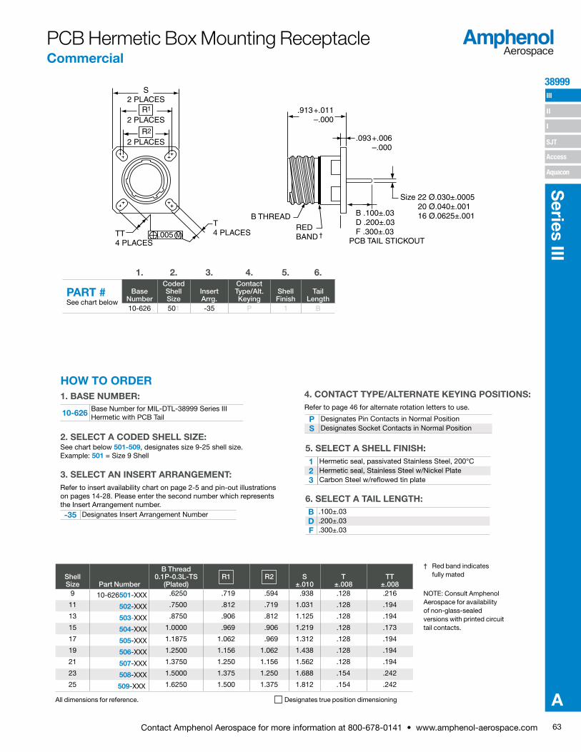
63Contact Amphenol Aerospace for more information at 800-678-0141 • www.amphenol-aerospace.com
38999 III
SJT
I
II
Access
Aquacon
Series III
A
† Red band indicates fully mated
NOTE: Consult Amphenol Aerospace for availability of non-glass-sealed versions with printed circuit tail contacts.
All dimensions for reference.
S2 PLACES
R
R2
1
2 PLACES
2 PLACES
TT4 PLACES
.005 M
T4 PLACES
B THREADREDBAND †
.913+.011–.000
.093+.006–.000
B .100±.03D .200±.03F .300±.03
Size 22 Ø.030±.0005 20 Ø.040±.001 16 Ø.0625±.001
PCB TAIL STICKOUT
PCB Hermetic Box Mounting Receptacle Commercial
Shell Size Part Number
B Thread 0.1P-0.3L-TS
(Plated)R1 R2 S
±.010T
±.008TT
±.0089 10-626501-XXX .6250 .719 .594 .938 .128 .216
11 502-XXX .7500 .812 .719 1.031 .128 .194
13 503-XXX .8750 .906 .812 1.125 .128 .194
15 504-XXX 1.0000 .969 .906 1.219 .128 .173
17 505-XXX 1.1875 1.062 .969 1.312 .128 .194
19 506-XXX 1.2500 1.156 1.062 1.438 .128 .194
21 507-XXX 1.3750 1.250 1.156 1.562 .128 .194
23 508-XXX 1.5000 1.375 1.250 1.688 .154 .242
25 509-XXX 1.6250 1.500 1.375 1.812 .154 .242
Designates true position dimensioning
-35 Designates Insert Arrangement Number
P Designates Pin Contacts in Normal PositionS Designates Socket Contacts in Normal Position
10-626 Base Number for MIL-DTL-38999 Series III Hermetic with PCB Tail
B .100±.03D .200±.03F .300±.03
1 Hermetic seal, passivated Stainless Steel, 200°C2 Hermetic seal, Stainless Steel w/Nickel Plate3 Carbon Steel w/reflowed tin plate
HOW TO ORDER1. BASE NUMBER:
2. SELECT A CODED SHELL SIZE:
4. CONTACT TYPE/ALTERNATE KEYING POSITIONS:Refer to page 46 for alternate rotation letters to use.
See chart below 501-509, designates size 9-25 shell size.Example: 501 = Size 9 Shell
3. SELECT AN INSERT ARRANGEMENT:Refer to insert availability chart on page 2-5 and pin-out illustrations on pages 14-28. Please enter the second number which represents the Insert Arrangement number.
5. SELECT A SHELL FINISH:
6. SELECT A TAIL LENGTH:
1. 2. 3. 4. 5. 6.
PART #See chart below
Base Number
Coded Shell Size
Insert Arrg.
Contact Type/Alt. Keying
Shell Finish
Tail Length
10-626 501 -35 P 1 B
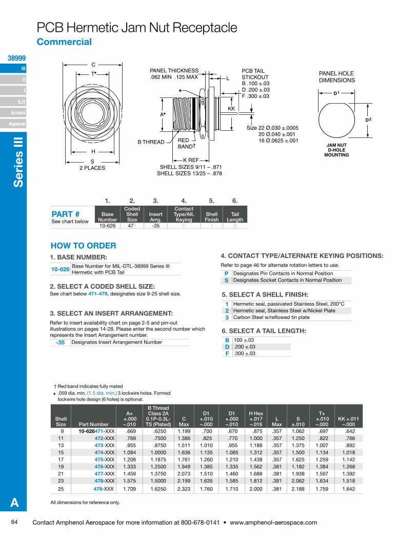
64 Contact Amphenol Aerospace for more information at 800-678-0141 • www.amphenol-aerospace.com
III
SJT
38999
I
II
Access
Aquacon
Ser
ies
III
A
C
T•
H
S2 PLACES
K REF
KK
REDBAND†
B THREAD
A•
LPANEL THICKNESS.062 MIN .125 MAX
SHELL SIZES 9/11 – .871SHELL SIZES 13/25 – .878
B .100 ±.03D .200 ±.03F .300 ±.03
PCB TAIL STICKOUT
Size 22 Ø.030 ±.0005 20 Ø.040 ±.001 16 Ø.0625 ±.001
PANEL HOLE DIMENSIONS
JAM NUTD-HOLE
MOUNTING
D1
D2
Shell Size Part Number
A+ +.000 –.010
B Thread Class 2A
0.1P-0.3L-TS (Plated)
C Max
D1 +.010 –.000
D1 +.000 –.010
H Hex +.017 –.016
L Max
S ±.010
T+ +.010 –.000
KK +.011 –.000
9 10-626471-XXX .669 .6250 1.199 .700 .670 .875 .357 1.062 .697 .64211 472-XXX .769 .7500 1.386 .825 .770 1.000 .357 1.250 .822 .76613 473-XXX .955 .8750 1.511 1.010 .955 1.188 .357 1.375 1.007 .89215 474-XXX 1.084 1.0000 1.636 1.135 1.085 1.312 .357 1.500 1.134 1.01817 475-XXX 1.208 1.1875 1.761 1.260 1.210 1.438 .357 1.625 1.259 1.14219 476-XXX 1.333 1.2500 1.949 1.385 1.335 1.562 .381 1.182 1.384 1.26821 477-XXX 1.459 1.3750 2.073 1.510 1.460 1.688 .381 1.938 1.507 1.39223 478-XXX 1.575 1.5000 2.199 1.635 1.585 1.812 .381 2.062 1.634 1.518
25 479-XXX 1.709 1.6250 2.323 1.760 1.710 2.000 .381 2.188 1.759 1.642
PCB Hermetic Jam Nut Receptacle Commercial
All dimensions for reference only.
† Red band indicates fully mated H .059 dia. min. (1.5 dia. min.) 3 lockwire holes. Formed
lockwire hole design (6 holes) is optional.
4. CONTACT TYPE/ALTERNATE KEYING POSITIONS:Refer to page 46 for alternate rotation letters to use.
10-626 Base Number for MIL-DTL-38999 Series III Hermetic with PCB Tail
-35 Designates Insert Arrangement Number
P Designates Pin Contacts in Normal PositionS Designates Socket Contacts in Normal Position
See chart below 471-479, designates size 9-25 shell size.
1. BASE NUMBER:
2. SELECT A CODED SHELL SIZE:
3. SELECT AN INSERT ARRANGEMENT:Refer to insert availability chart on page 2-5 and pin-out illustrations on pages 14-28. Please enter the second number which represents the Insert Arrangement number.
5. SELECT A SHELL FINISH:1 Hermetic seal, passivated Stainless Steel, 200°C2 Hermetic seal, Stainless Steel w/Nickel Plate3 Carbon Steel w/reflowed tin plate
6. SELECT A TAIL LENGTH:B 100 ±.03D .200 ±.03F .300 ±.03
1. 2. 3. 4. 5. 6.
PART #See chart below
Base Number
Coded Shell Size
Insert Arrg.
Contact Type/Alt. Keying
Shell Finish
Tail Length
10-626 471 -35 P 1 B
HOW TO ORDER
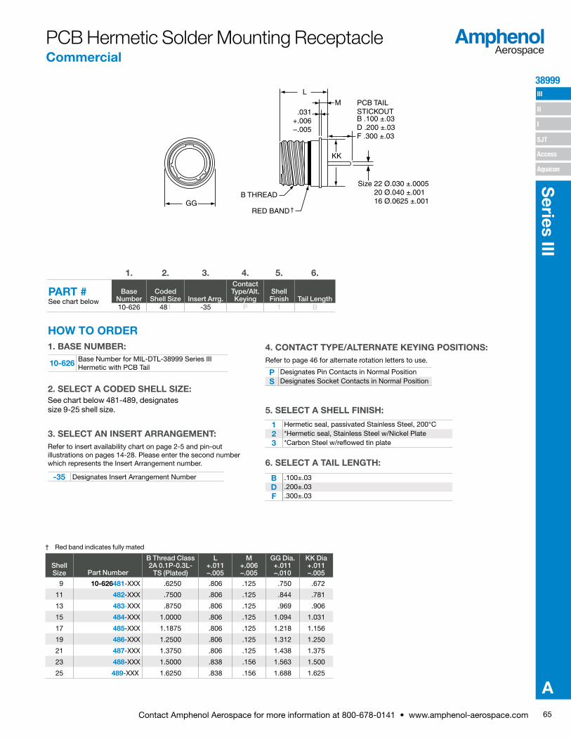
65Contact Amphenol Aerospace for more information at 800-678-0141 • www.amphenol-aerospace.com
38999 III
SJT
I
II
Access
Aquacon
Series III
A
† Red band indicates fully mated
PCB Hermetic Solder Mounting Receptacle Commercial
Shell Size Part Number
B Thread Class 2A 0.1P-0.3L-
TS (Plated)
L+.011–.005
M+.006–.005
GG Dia.+.011–.010
KK Dia+.011–.005
9 10-626481-XXX .6250 .806 .125 .750 .672
11 482-XXX .7500 .806 .125 .844 .781
13 483-XXX .8750 .806 .125 .969 .906
15 484-XXX 1.0000 .806 .125 1.094 1.031
17 485-XXX 1.1875 .806 .125 1.218 1.156
19 486-XXX 1.2500 .806 .125 1.312 1.250
21 487-XXX 1.3750 .806 .125 1.438 1.375
23 488-XXX 1.5000 .838 .156 1.563 1.500
25 489-XXX 1.6250 .838 .156 1.688 1.625
GGB THREAD
RED BAND†
KK
M
L
.031+.006–.005
B .100 ±.03D .200 ±.03F .300 ±.03
PCB TAIL STICKOUT
Size 22 Ø.030 ±.0005 20 Ø.040 ±.001 16 Ø.0625 ±.001
-35 Designates Insert Arrangement Number
P Designates Pin Contacts in Normal PositionS Designates Socket Contacts in Normal Position
10-626 Base Number for MIL-DTL-38999 Series III Hermetic with PCB Tail
1 Hermetic seal, passivated Stainless Steel, 200°C2 *Hermetic seal, Stainless Steel w/Nickel Plate3 *Carbon Steel w/reflowed tin plate
B .100±.03D .200±.03F .300±.03
1. BASE NUMBER:
See chart below 481-489, designates size 9-25 shell size.
2. SELECT A CODED SHELL SIZE:
3. SELECT AN INSERT ARRANGEMENT:Refer to insert availability chart on page 2-5 and pin-out illustrations on pages 14-28. Please enter the second number which represents the Insert Arrangement number.
4. CONTACT TYPE/ALTERNATE KEYING POSITIONS:Refer to page 46 for alternate rotation letters to use.
5. SELECT A SHELL FINISH:
6. SELECT A TAIL LENGTH:
1. 2. 3. 4. 5. 6.
PART #See chart below
Base Number
Coded Shell Size Insert Arrg.
Contact Type/Alt. Keying
Shell Finish Tail Length
10-626 481 -35 P 1 B
HOW TO ORDER

66 Contact Amphenol Aerospace for more information at 800-678-0141 • www.amphenol-aerospace.com
III
SJT
38999
I
II
Access
Aquacon
Ser
ies
III
A
† Red band indicates fully mated
Shell Size Part Number
B Thread Class 2A 0.1P-0.3L-TS
(Plated)
L+.011–.000
M+.006–.005
GG Dia.+.011–.010
9 10-626491-XXX .6250 .806 .125 .973
11 492-XXX .7500 .806 .125 1.095
13 493-XXX .8750 .806 .125 1.221
15 494-XXX 1.0000 .806 .125 1.347
17 495-XXX 1.1875 .806 .125 1.434
19 496-XXX 1.2500 .806 .125 1.579
21 497-XXX 1.3750 .806 .125 1.721
23 498-XXX 1.5000 .838 .156 1.886
25 499-XXX 1.6250 .838 .156 1.973
-35 Designates Insert Arrangement Number
P Designates Pin Contacts in Normal PositionS Designates Socket Contacts in Normal Position
10-626 Base Number for MIL-DTL-38999 Series III Hermetic with PCB Tail
1 Hermetic seal, passivated Stainless Steel, 200°C2 *Hermetic seal, Stainless Steel w/Nickel Plate3 *Carbon Steel w/reflowed tin plate
B .100±.03D .200±.03F .300±.03
* Not available for weld mount. All dimensions for reference only.
1. BASE NUMBER:
See chart below 491-499, designates size 9-25 shell size.
2. SELECT A CODED SHELL SIZE:
3. SELECT AN INSERT ARRANGEMENT:Refer to insert availability chart on page 2-5 and pin-out illustrations on pages 14-28. Please enter the second number which represents the Insert Arrangement number.
4. CONTACT TYPE/ALTERNATE KEYING POSITIONS:Refer to page 46 for alternate rotation letters to use.
5. SELECT A SHELL FINISH:
6. SELECT A TAIL LENGTH:
GG
B THREAD
RED BAND†
LM
B .100 ±.03D .200 ±.03F .300 ±.03
Size 22 Ø.030 ±.0005 20 Ø.040 ±.001 16 Ø.0625 ±.001
PCB TAIL STICKOUT
PCB Hermetic Weld Mounting Receptacle Commercial
1. 2. 3. 4. 5. 6.
PART #See chart below
Base Number
Coded Shell Size
Insert Arrg.
Contact Type/Alt. Keying
Shell Finish Tail Length
10-626 491 -35 P 1 B
HOW TO ORDER
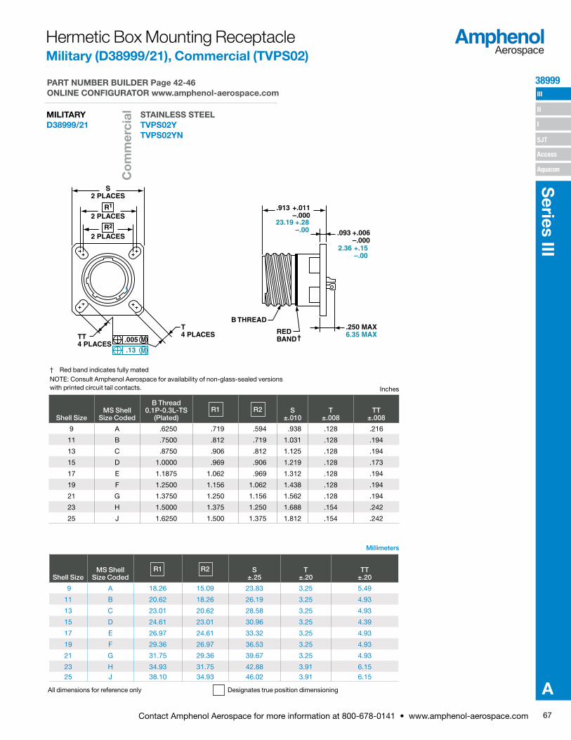
67Contact Amphenol Aerospace for more information at 800-678-0141 • www.amphenol-aerospace.com
38999 III
SJT
I
II
Access
Aquacon
Series III
A
† Red band indicates fully matedNOTE: Consult Amphenol Aerospace for availability of non-glass-sealed versions with printed circuit tail contacts.
Millimeters
All dimensions for reference only Designates true position dimensioning
Inches
S2 PLACES
R
R2
1
2 PLACES
2 PLACES
TT4 PLACES
.005
.13
M
M
T4 PLACES
B THREAD
REDBAND†
.250 MAX6.35 MAX
1
.913 +.011–.000
23.19 +.28–.00 .093 +.006
–.0002.36 +.15
–.00
Hermetic Box Mounting Receptacle Military (D38999/21), Commercial (TVPS02)
Shell SizeMS Shell
Size Coded
B Thread 0.1P-0.3L-TS
(Plated)R1 R2 S
±.010T
±.008TT
±.008
9 A .6250 .719 .594 .938 .128 .216
11 B .7500 .812 .719 1.031 .128 .194
13 C .8750 .906 .812 1.125 .128 .194
15 D 1.0000 .969 .906 1.219 .128 .173
17 E 1.1875 1.062 .969 1.312 .128 .194
19 F 1.2500 1.156 1.062 1.438 .128 .194
21 G 1.3750 1.250 1.156 1.562 .128 .194
23 H 1.5000 1.375 1.250 1.688 .154 .242
25 J 1.6250 1.500 1.375 1.812 .154 .242
Shell SizeMS Shell
Size CodedR1 R2 S
±.25T
±.20TT
±.20
9 A 18.26 15.09 23.83 3.25 5.49
11 B 20.62 18.26 26.19 3.25 4.93
13 C 23.01 20.62 28.58 3.25 4.93
15 D 24.61 23.01 30.96 3.25 4.39
17 E 26.97 24.61 33.32 3.25 4.93
19 F 29.36 26.97 36.53 3.25 4.93
21 G 31.75 29.36 39.67 3.25 4.93
23 H 34.93 31.75 42.88 3.91 6.1525 J 38.10 34.93 46.02 3.91 6.15
PART NUMBER BUILDER Page 42-46 ONLINE CONFIGURATOR www.amphenol-aerospace.com
STAINLESS STEELTVPS02Y TVPS02YN
MILITARYD38999/21
Co
mm
erci
al

68 Contact Amphenol Aerospace for more information at 800-678-0141 • www.amphenol-aerospace.com
III
SJT
38999
I
II
Access
Aquacon
Ser
ies
III
A
† Red band indicates fully matedH .059 dia min.
1.5 dia min. 3 lockwire holes Formed lockwire hole design (6 holes) is optional.
Millimeters
Inches
All dimensions for reference only
C
H
S2 PLACES
K REF
.200 MAX5.08 MAX
KK
REDBAND†B THREAD
L
PANEL THICKNESS.062 MIN .125 MAX1.57 MIN 3.18 MAX
SHELL SIZES 9/11 – .871 22.12SHELL SIZES 13/25 – .878 22.30
PANEL HOLE DIMENSIONS
JAM NUTD-HOLE
MOUNTING
D1
D2
Hermetic Jam Nut Receptacle Military (D38999/23), Commercial (TVS07)
Shell Size
MS Shell Size code
B Thread Class 2A
0.1P-0.3L-TS (Plated) C Max
D1 +.010 –.000
D2 +.000 –.010
H Hex +.017 –.016 L Max S ±.010
KK +.011 –.000
9 A .6250 1.199 .693 .657 .875 .357 1.062 .642
11 B .7500 1.386 .825 .770 1.000 .357 1.250 .766
13 C .8750 1.511 1.010 .955 1.188 .357 1.375 .892
15 D 1.0000 1.636 1.135 1.085 1.312 .357 1.500 1.018
17 E 1.1875 1.761 1.260 1.210 1.438 .357 1.625 1.142
19 F 1.2500 1.949 1.385 1.335 1.562 .381 1.812 1.268
21 G 1.3750 2.073 1.510 1.460 1.688 .381 1.938 1.392
23 H 1.5000 2.199 1.635 1.585 1.812 .381 2.062 1.518
25 J 1.6250 2.323 1.760 1.710 2.000 .381 2.188 1.642
Shell Size
MS Shell Size code C Max D1 +.25 –.00 D2 +.00 –.25
H Hex +.43 –.41 L Max S ±.25
KK +.28 –.00
9 A 30.45 17.60 16.70 22.23 9.07 26.97 16.31
11 B 35.20 20.96 19.59 25.40 9.07 31.75 19.46
13 C 38.38 25.65 24.26 30.18 9.07 34.93 22.66
15 D 41.55 28.83 27.56 33.32 9.07 38.10 25.86
17 E 44.73 32.01 30.73 36.53 9.07 41.28 29.01
19 F 49.50 35.18 33.91 39.67 9.68 46.02 32.21
21 G 52.65 38.35 37.08 42.80 9.68 49.23 35.36
23 H 55.85 41.53 40.26 46.02 9.68 52.37 38.56
25 J 59.00 44.70 43.43 50.80 9.68 55.58 41.71
PART NUMBER BUILDER Page 42-46 ONLINE CONFIGURATOR www.amphenol-aerospace.com
STAINLESS STEELTVS07Y TVS07YN
MILITARYD38999/23
Co
mm
erci
al
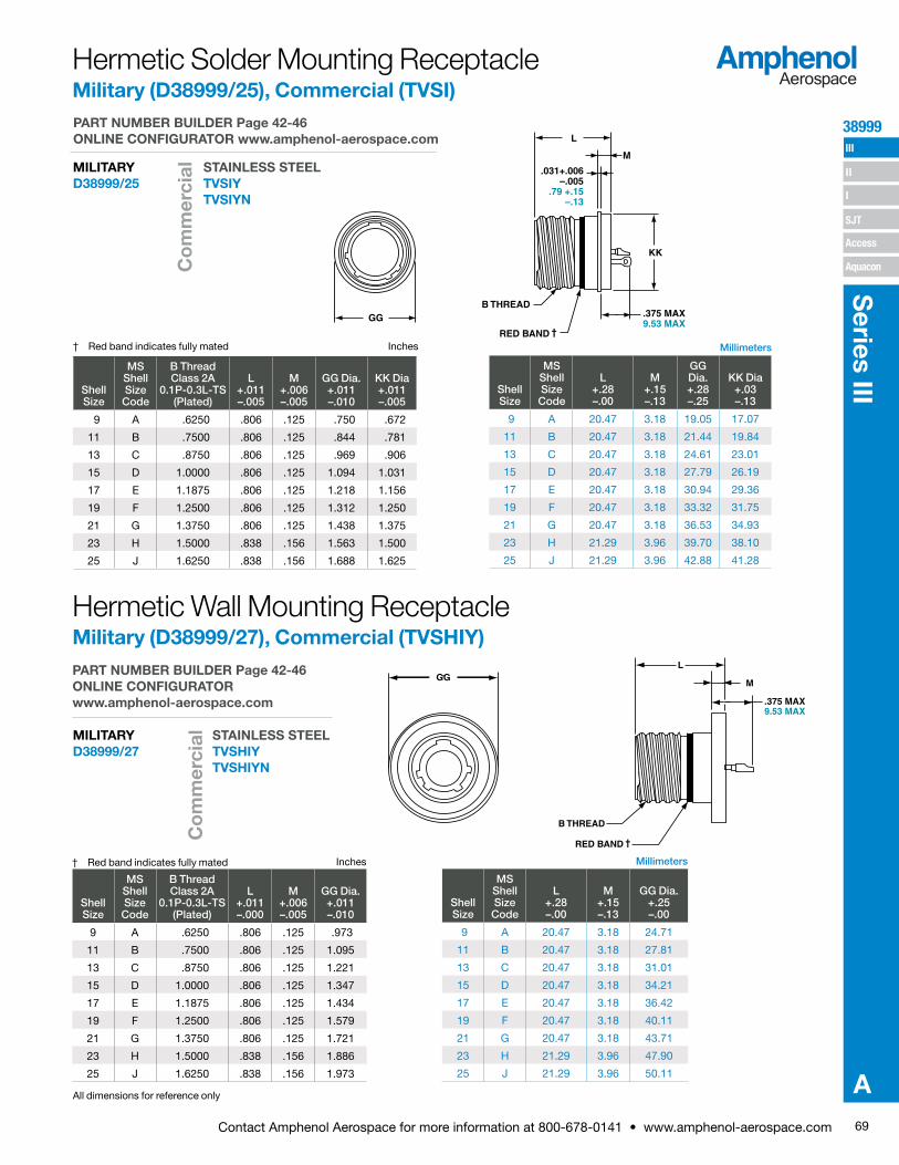
69Contact Amphenol Aerospace for more information at 800-678-0141 • www.amphenol-aerospace.com
38999 III
SJT
I
II
Access
Aquacon
Series III
A
MillimetersInches
All dimensions for reference only
† Red band indicates fully mated
GGB THREAD
RED BAND †
.375 MAX9.53 MAX
KK
M
L
.031+.006–.005
.79 +.15–.13
GG
B THREAD
RED BAND †
L
M
.375 MAX9.53 MAX
MillimetersInches† Red band indicates fully mated
Hermetic Solder Mounting ReceptacleMilitary (D38999/25), Commercial (TVSI)
Hermetic Wall Mounting ReceptacleMilitary (D38999/27), Commercial (TVSHIY)
Shell Size
MS Shell Size Code
B Thread Class 2A
0.1P-0.3L-TS (Plated)
L+.011–.005
M+.006–.005
GG Dia.+.011–.010
KK Dia+.011–.005
9 A .6250 .806 .125 .750 .672
11 B .7500 .806 .125 .844 .781
13 C .8750 .806 .125 .969 .906
15 D 1.0000 .806 .125 1.094 1.031
17 E 1.1875 .806 .125 1.218 1.156
19 F 1.2500 .806 .125 1.312 1.250
21 G 1.3750 .806 .125 1.438 1.375
23 H 1.5000 .838 .156 1.563 1.500
25 J 1.6250 .838 .156 1.688 1.625
Shell Size
MS Shell Size Code
L+.28–.00
M+.15–.13
GG Dia.+.28–.25
KK Dia+.03–.13
9 A 20.47 3.18 19.05 17.07
11 B 20.47 3.18 21.44 19.84
13 C 20.47 3.18 24.61 23.01
15 D 20.47 3.18 27.79 26.19
17 E 20.47 3.18 30.94 29.36
19 F 20.47 3.18 33.32 31.75
21 G 20.47 3.18 36.53 34.93
23 H 21.29 3.96 39.70 38.10
25 J 21.29 3.96 42.88 41.28
Shell Size
MS Shell Size Code
B Thread Class 2A
0.1P-0.3L-TS (Plated)
L+.011–.000
M+.006–.005
GG Dia.+.011–.010
9 A .6250 .806 .125 .973
11 B .7500 .806 .125 1.095
13 C .8750 .806 .125 1.221
15 D 1.0000 .806 .125 1.347
17 E 1.1875 .806 .125 1.434
19 F 1.2500 .806 .125 1.579
21 G 1.3750 .806 .125 1.721
23 H 1.5000 .838 .156 1.886
25 J 1.6250 .838 .156 1.973
Shell Size
MS Shell Size Code
L+.28–.00
M+.15–.13
GG Dia.+.25–.00
9 A 20.47 3.18 24.71
11 B 20.47 3.18 27.81
13 C 20.47 3.18 31.01
15 D 20.47 3.18 34.21
17 E 20.47 3.18 36.42
19 F 20.47 3.18 40.11
21 G 20.47 3.18 43.71
23 H 21.29 3.96 47.90
25 J 21.29 3.96 50.11
PART NUMBER BUILDER Page 42-46 ONLINE CONFIGURATOR www.amphenol-aerospace.com
STAINLESS STEELTVSIY TVSIYN
MILITARYD38999/25
PART NUMBER BUILDER Page 42-46 ONLINE CONFIGURATOR www.amphenol-aerospace.com
STAINLESS STEELTVSHIY TVSHIYN
MILITARYD38999/27
Co
mm
erci
alC
om
mer
cial

70 Contact Amphenol Aerospace for more information at 800-678-0141 • www.amphenol-aerospace.com
III
SJT
38999
I
II
Access
Aquacon
Ser
ies
III
A
Breakaway with Coax Contacts
Amphenol offers a variety of lanyard plug styles including MIL-STD-1760 types 1, 2 and 6 for Stores Management applications.
Series III, TV Breakaway Fail-Safe Connectors Quick-Disconnect with an Axial Pull of Lanyard
Amphenol® Tri-Start Breakaway Fail-Safe Connectors provide unequaled performance in environments requiring instant disengagement.The “Breakaway” Fail-Safe connector family offers a wide range of electrical and mechanical features:• Instant decoupling and damage
free separation• Completely intermateable with standard
receptacles (D38999/20 and /24)• Inventory support commonality through
the use of standard insert arrangements and contacts
Breakaway unmating is initiated by applying a pull force to the lanyard which causes the operating sleeve on the plug to move away from the receptacle. Coupling segments on the plug then move away from the mating receptacle while expanding, thus releasing the receptacle. After completion of the unmating sequence, spring compression returns the sleeve and segments to their original positions. Unmating of the plug may also be accomplished by normal rotation of the coupling ring without affecting the breakaway capability.
The Tri-Start Breakaway Fail-Safe connector exceeds the MIL-Spec Series III requirements for EMI/EMP shielding and features include:• Solid metal-to-metal coupling• EMI grounding fingers• Conductive finishes
Amphenol Breakaway Fail-Safe connectors are qualified to MIL-DTL-38999/29, /30 and /31 (for MIL-STD-1760 Stores Management applications). Amphenol also manufactures custom breakaway connectors including those with:• Highly durable non-metallic operating sleeves in a variety of lengths
and diameters• Increased pull-force capability• Low-profile designs• Custom lanyard lengths and backshells• Low force separation capabilities• Low insertion/separation force contacts• Non-cadmium finishes
Contact your local Amphenol representative. Whether you need a standard Breakaway, one of our custom Breakaways, or a unique Breakaway design.
Special configuration Fail-Safe used on space telescope application. Lanyard is replaced by a swivel ring for remote disconnect and “wing arms” have been added for manual actuation accessibility by gloved astronauts.
TYPE 2 TYPE 6 TYPE 1
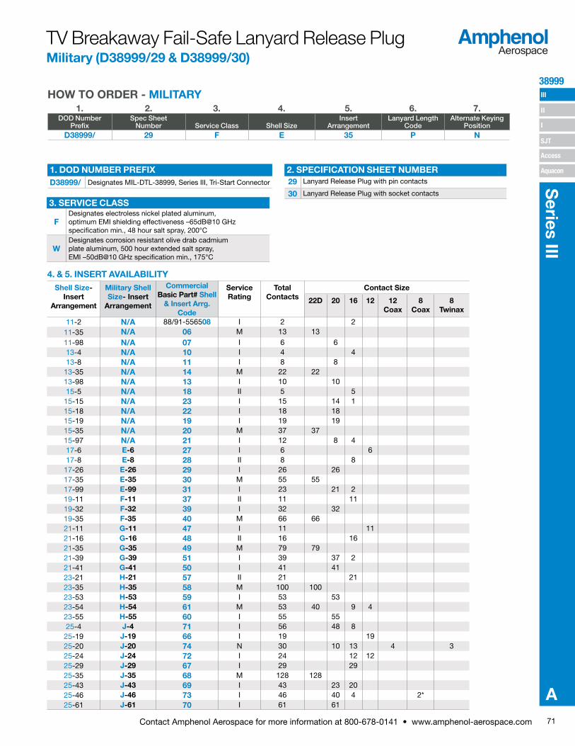
71Contact Amphenol Aerospace for more information at 800-678-0141 • www.amphenol-aerospace.com
38999 III
SJT
I
II
Access
Aquacon
Series III
A
TV Breakaway Fail-Safe Lanyard Release Plug Military (D38999/29 & D38999/30)
Shell Size- Insert
Arrangement
Military Shell Size- Insert
Arrangement
Commercial Basic Part# Shell
& Insert Arrg. Code
Service Rating
Total Contacts
Contact Size
22D 20 16 12 12 Coax
8 Coax
8 Twinax
11-2 N/A 88/91-556508 I 2 211-35 N/A 06 M 13 1311-98 N/A 07 I 6 613-4 N/A 10 I 4 413-8 N/A 11 I 8 8
13-35 N/A 14 M 22 2213-98 N/A 13 I 10 1015-5 N/A 18 II 5 515-15 N/A 23 I 15 14 115-18 N/A 22 I 18 1815-19 N/A 19 I 19 1915-35 N/A 20 M 37 3715-97 N/A 21 I 12 8 417-6 E-6 27 I 6 617-8 E-8 28 II 8 8
17-26 E-26 29 I 26 2617-35 E-35 30 M 55 5517-99 E-99 31 I 23 21 219-11 F-11 37 II 11 1119-32 F-32 39 I 32 3219-35 F-35 40 M 66 6621-11 G-11 47 I 11 1121-16 G-16 48 II 16 1621-35 G-35 49 M 79 7921-39 G-39 51 I 39 37 221-41 G-41 50 I 41 4123-21 H-21 57 II 21 2123-35 H-35 58 M 100 10023-53 H-53 59 I 53 5323-54 H-54 61 M 53 40 9 423-55 H-55 60 I 55 5525-4 J-4 71 I 56 48 825-19 J-19 66 I 19 1925-20 J-20 74 N 30 10 13 4 325-24 J-24 72 I 24 12 1225-29 J-29 67 I 29 2925-35 J-35 68 M 128 12825-43 J-43 69 I 43 23 2025-46 J-46 73 I 46 40 4 2*25-61 J-61 70 I 61 61
1. 2. 3. 4. 5. 6. 7.DOD Number
PrefixSpec Sheet
Number Service Class Shell SizeInsert
ArrangementLanyard Length
CodeAlternate Keying
PositionD38999/ 29 F E 35 P N
HOW TO ORDER - MILITARY
4. & 5. INSERT AVAILABILITY
2. SPECIFICATION SHEET NUMBER29 Lanyard Release Plug with pin contacts
30 Lanyard Release Plug with socket contacts3. SERVICE CLASS
FDesignates electroless nickel plated aluminum, optimum EMI shielding effectiveness –65dB@10 GHz specification min., 48 hour salt spray, 200°C
WDesignates corrosion resistant olive drab cadmium plate aluminum, 500 hour extended salt spray, EMI –50dB@10 GHz specification min., 175°C
1. DOD NUMBER PREFIXD38999/ Designates MIL-DTL-38999, Series III, Tri-Start Connector
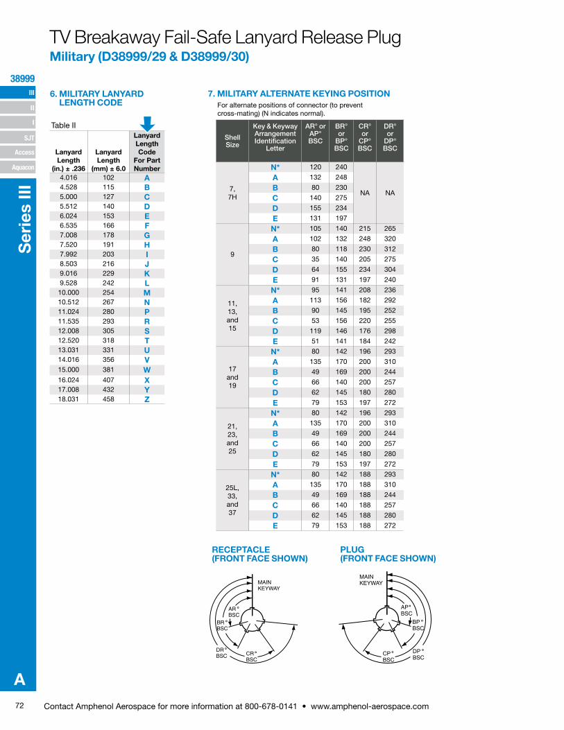
72 Contact Amphenol Aerospace for more information at 800-678-0141 • www.amphenol-aerospace.com
III
SJT
38999
I
II
Access
Aquacon
Ser
ies
III
A
TV Breakaway Fail-Safe Lanyard Release Plug Military (D38999/29 & D38999/30)
Lanyard Length
(in.) ± .236
Lanyard Length
(mm) ± 6.0
Lanyard Length Code
For Part Number
4.016 102 A4.528 115 B5.000 127 C5.512 140 D6.024 153 E6.535 166 F7.008 178 G7.520 191 H7.992 203 I8.503 216 J9.016 229 K9.528 242 L10.000 254 M10.512 267 N11.024 280 P11.535 293 R12.008 305 S12.520 318 T13.031 331 U14.016 356 V15.000 381 W16.024 407 X17.008 432 Y18.031 458 Z
6. MILITARY LANYARDLENGTH CODE For alternate positions of connector (to prevent
cross-mating) (N indicates normal).
7. MILITARY ALTERNATE KEYING POSITION
Table II
PLUG (FRONT FACE SHOWN)
RECEPTACLE (FRONT FACE SHOWN)
MAINKEYWAY
APBSC
BPBSC
DPBSC
CPBSC
˚
˚
˚˚DRBSC̊ CR
BSC̊
BRBSC̊
ARBSC̊
MAINKEYWAY
Shell Size
Key & Keyway Arrangement Identification
Letter
AR° or AP° BSC
BR° or
BP° BSC
CR° or
CP° BSC
DR° or
DP° BSC
7, 7H
N* 120 240
NA NA
A 132 248
B 80 230
C 140 275
D 155 234
E 131 197
9
N* 105 140 215 265
A 102 132 248 320
B 80 118 230 312
C 35 140 205 275
D 64 155 234 304
E 91 131 197 240
11, 13, and 15
N* 95 141 208 236
A 113 156 182 292
B 90 145 195 252
C 53 156 220 255
D 119 146 176 298
E 51 141 184 242
17 and 19
N* 80 142 196 293
A 135 170 200 310
B 49 169 200 244
C 66 140 200 257
D 62 145 180 280
E 79 153 197 272
21, 23, and 25
N* 80 142 196 293
A 135 170 200 310
B 49 169 200 244
C 66 140 200 257
D 62 145 180 280
E 79 153 197 272
25L, 33, and 37
N* 80 142 188 293
A 135 170 188 310
B 49 169 188 244
C 66 140 188 257
D 62 145 188 280
E 79 153 188 272
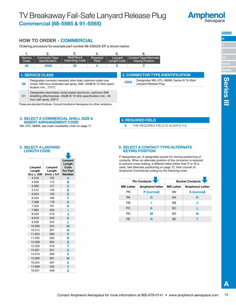
73Contact Amphenol Aerospace for more information at 800-678-0141 • www.amphenol-aerospace.com
38999 III
SJT
I
II
Access
Aquacon
Series III
A
Ordering procedure for example part number 88-556529-EP is shown below:
1. 2. 3. 4. 5. 6.Service Class
Connector Type Identification
Shell Size & Insert Arrg. Code
Required Field
Lanyard Length Code
Contact Type/Alternate Keying Position
88 -5565 29 0 E P
HOW TO ORDER - COMMERCIAL
These are standard finishes. Consult Amphenol Aerospace for other variations.
3. SELECT A COMMERCIAL SHELL SIZE &INSERT ARRANGEMENT CODE
MIL-DTL-38999, see insert availability chart on page 71.
P designates pin, S designates socket for normal positioning of contacts. When an alternate position of the connector is required to prevent cross-mating, a different letter (other than P or S) is used. See alternate positioning on page 72, then convert to Amphenol Commercial coding by the following chart.
6. SELECT A CONTACT TYPE/ALTERNATEKEYING POSITION
Pin Contacts Socket Contacts
MS Letter Amphenol letter MS Letter Amphenol Letter
PN P (normal) SN S (normal)
PA G SA H
PB I SB J
PC K SC L
PD M SD N
PE R SE T
5. SELECT A LANYARDLENGTH CODE
1. SERVICE CLASS
88Designates corrosion resistant olive drab cadmium plate over nickel, 500 hour extended salt spray, EMI –50dB @ 10 GHz speci-fication min., 175°C
91Designates electroless nickel plated aluminum, optimum EMI shielding effectiveness –65dB @ 10 GHz specification min., 48 hour salt spray, 200°C
2. CONNECTOR TYPE IDENTIFICATION
-5565 Designates MIL-DTL-38999, Series III Tri-Start Lanyard Release Plug
4. REQUIRED FIELD0 THE REQUIRED FIELD IS ALWAYS A 0
TV Breakaway Fail-Safe Lanyard Release Plug Commercial (88-5565 & 91-5565)
Lanyard Length
(in.) ± .236
Lanyard Length
(mm) ± 6.0
Lanyard Length Code
For Part Number
4.016 102 A4.528 115 B5.000 127 C5.512 140 D6.024 153 E6.535 166 F7.008 178 G7.520 191 H7.992 203 I8.503 216 J9.016 229 K9.528 242 L10.000 254 M10.512 267 N11.024 280 P11.535 293 R12.008 305 S12.520 318 T13.031 331 U14.016 356 V15.000 381 W16.024 407 X17.008 432 Y18.031 458 Z

74 Contact Amphenol Aerospace for more information at 800-678-0141 • www.amphenol-aerospace.com
III
SJT
38999
I
II
Access
Aquacon
Ser
ies
III
A
D
.374 MAX9.50 MAXOUTER SLEEVE MOVEMENTDURING UNMATING THREAD RELEASE
LANYARDPULLED TAUTAGAINST A .500 ±.03112.70 ±.79DIA MANDREL
V THREADMETRIC
1.781 MAX45.24 MAX
2.375 MAX60.33 MAX
BLUE BAND †
B
.359 MAX9.12 MAX
LANYARD LENGTH(See Lanyard Length Table)
† Blue band indicates rear release contact retention system
Millimeters
Inches
Fail-Safe Lanyard Release Plug-Crimp, MetalMilitary (D38999/29 & D38999/30), Commercial (88-5565 & 91-5565)
Shell Size MS Shell Size Code B MaxD Max
Accessory Dia.
11 B 1.846 1.109
13 C 1.972 1.250
15 D 2.079 1.375
17 E 2.205 1.500
19 F 2.301 1.625
21 G 2.472 1.750
23 H 2.594 1.875
25 J 2.705 2.000
Shell SizeMS Shell Size
Code B MaxD Max
Accessory Dia. V Thread Metric
11 B 46.89 28.17 M15X1.0-6g
13 C 50.09 31.75 M18X1.0-6g
15 D 52.81 34.93 M22X1.0-6g
17 E 56.01 38.10 M25X1.0-6g
19 F 58.45 41.28 M28X1.0-6g
21 G 62.79 44.45 M31X1.0-6g
23 H 65.89 47.63 M34X1.0-6g
25 J 68.71 50.08 M37X1.0-6g
METAL
PART NUMBER BUILDER Page 71-73 ONLINE CONFIGURATOR www.amphenol-aerospace.com
STAINLESS STEEL88-556591-5565
MILITARYD38999/29 PinD38999/30 Socket
Co
mm
erci
al

75Contact Amphenol Aerospace for more information at 800-678-0141 • www.amphenol-aerospace.com
38999 III
SJT
I
II
Access
Aquacon
Series III
A
HOW TO ORDER - BY MILITARY PART NUMBER FAIL-SAFE D38999/31Ordering procedure for example part number D38999/31WE20PN1 is shown below:
1. 2. 3. 4. 5. 6. 7. 8.DOD Number
PrefixSpec Sheet
NumberService Class
Lanyard Length Code
Insert Arrangement
Contact Style Alternate Keying Position
TypeNumber
D38999/ 31 W E 20 P N 1
4. LANYARD LENGTH CODELanyard Length (in.) ±.236
Lanyard Length (mm.) ± 6.0
Lanyard Length Code for Part Number
6.024 153.0 E6.535 166.0 F7.008 178.0 G7.520 191.0 H7.992 203.0 I8.504 216.0 J9.016 229.0 K9.528 242.0 L
TV Breakaway Fail-Safe Lanyard Release Military (D38999/31) Type 1 & 2 for MIL-STD-1760
3. SERVICE CLASS
FElectroless nickel plated aluminum, optimum EMI shielding effectiveness –65dB @ 10 GHz specification min., 48 hour salt spray, 200°C
WCorrosion resistant olive drab cadmium plate aluminum, 500 hour extended salt spray, EMI –50dB @ 10 GHz specification min., 175°C
1. DOD NUMBER PREFIX
D38999/ MIL-DTL-38999, Series III Tri-Start Connectors
2. SPECIFICATION SHEET NUMBER
31 Designates Lanyard Release Plug for MIL-STD-1760 with pin contacts
6. CONTACT STYLE-P & A ARE VALID OPTIONS
P Replaces the “no designation” option in the PIN on revision C and earlier revision of the Mil-Spec.
A Designates supplied less contacts.
7. ALTERNATE KEYING POSITION
N Is required for normal position.
8. TYPE NUMBERTYPE 1, 2 OR 6. SEE DRAWINGS ON PAGE 74.For accessories for lanyard release plugs see Accessories section.
Applications- Lanyard Release Plug
5. INSERT ARRANGEMENT
11 25-11
20 25-20

76 Contact Amphenol Aerospace for more information at 800-678-0141 • www.amphenol-aerospace.com
III
SJT
38999
I
II
Access
Aquacon
Ser
ies
III
A
2.008 MAX51.00 MAX
BLUEBAND †
1.687 MAX42.85 MAX
2.030 MAX51.56 MAX
**
.100 MAX2.54 MAXOUTER SLEEVE MOVEMENTDURING UNMATING THREAD RELEASE
2.000 MAX50.80 MAXACCESS.
DIA
LANYARD LENGTH(See Lanyard Length Table)
METRIC THREADM37X1.0-6g0.100R
**2.000 MAX50.80 MAXACCESS.
DIA
.374 MAX9.50 MAXOUTER SLEEVE MOVEMENTDURING UNMATING THREAD RELEASE
.359 MAX9.12 MAX
2.705 MAX68.71 MAX
BLUE BAND †
1.781 MAX45.24 MAX
2.375 MAX60.33 MAX
LANYARD LENGTH(See Lanyard Length Table)
METRICTHREADM37X1.0-6g0.100R
.359 MAX9.12 MAX
TYPE 6 TYPE 2
† Blue band indicates rear release contact retention system** Lanyard pulled taut against a .500 ± .13 dia. MandrelAll dimensions for reference only
PIN CONTACTS ONLY, SHELL SIZE 25 ONLY
BLUE BAND †
2.000 MAX50.80 MAXACCESS.
DIA
2.008 MAX51.00 MAX
.359 MAX9.12 MAX
METRIC THREADM37X1.0-6g0.100R
.280 MIN7.11 MINFULLTHREAD
LANYARD LENGTH(See Lanyard Length Table)
2.499 MAX63.47 MAX
TYPE 1 (LONGER SHELL)
A B
C
D
E
F
G
H
J
K
L
M
N
P
R
S
T
U
VWX
Y
Z
1
23
4
5
67
A
B
C
D
EF
G
HJ
KL
INSERT AVAILABILITY FAIL SAFE D38999/31 FOR MIL-STD-1760
25-20PRIMARY INTERFACE
SIGNAL SET
Contact Legend
8 (twinax) 10 (power) 12 (coax) 16 20
25-11AUXILIARY POWER
SIGNAL SET
TV Breakaway Fail-Safe Lanyard Release Military (D38999/31) for MIL-STD-1760 Crimp, Metal
TRI-START LANYARD SEPARATION FORCESShell Size
Straight Plug (lbs. max.)
15 Degree Pull (lbs. max.)
25 90 100
PIN CONTACT DATA FOR MIL-STD-1760
Insert ArrangementService Rating
Total Contacts
Contact
20 16 12 (Coax) 8 (Twinax)
25-20 N 30 10 13 4 3
CONTACTS FOR 25-20 PATTERN
Shell Size
Arrg. Number
Number of Contacts
Size Contacts
Service Rating
Contact Location
Standard Contacts
Pin Socket
25 -20
3 8 Twinax A, H, K M39029/90-529 M39029/91-530
4 12 Coax 2,3 M39029/28-211 M39029/75-416W, 5 M39029/102-558 M39029/103-559
13 16 N
C, D, E, F, J, M, N,
P, R, T, U, Y, Z
M39029/58-364 M39029/56-352
10 20 N B, G, L, S, V, X, 1, 4,
6, 7M39029/58-363 M39029/56-351
Insert Arrangement
Service Rating
Total Contacts
Contact Size
20 10 (power)
25-11 N 11 2 9
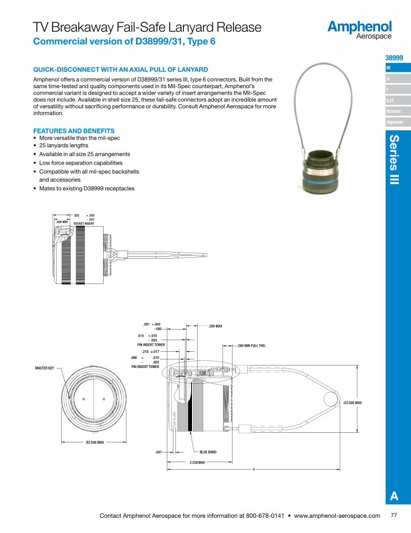
77Contact Amphenol Aerospace for more information at 800-678-0141 • www.amphenol-aerospace.com
38999 III
SJT
I
II
Access
Aquacon
Series III
A
Amphenol offers a commercial version of D38999/31 series III, type 6 connectors. Built from the same time-tested and quality components used in its Mil-Spec counterpart, Amphenol’s commercial variant is designed to accept a wider variety of insert arrangements the Mil-Spec does not include. Available in shell size 25, these fail-safe connectors adopt an incredible amount of versatility without sacrificing performance or durability. Consult Amphenol Aerospace for more information.
.280 MIN FULL THD.
.359 MAX
.218 ±.017
.066 + .010- .003
PIN INSERT TOWER
.014 + .010- .003
PIN INSERT TOWER
.591 +.003 -.000
2.030 MAX
.047
Ø2.008 MAX
MASTER KEY
BLUE BAND
R
.490 MIN
.583 + .005 - .001
SOCKET INSERT
Ø2.000 MAX
FEATURES AND BENEFITS• More versatile than the mil-spec• 25 lanyards lengths
• Available in all size 25 arrangements
• Low force separation capabilities
• Compatible with all mil-spec backshells and accessories
• Mates to existing D38999 receptacles
.280 MIN FULL THD.
.359 MAX
.218 ±.017
.066 + .010- .003
PIN INSERT TOWER
.014 + .010- .003
PIN INSERT TOWER
.591 +.003 -.000
2.030 MAX
.047
Ø2.008 MAX
MASTER KEY
BLUE BAND
R
.490 MIN
.583 + .005- .001
SOCKET INSERT
Ø2.000 MAX
TV Breakaway Fail-Safe Lanyard ReleaseCommercial version of D38999/31, Type 6
QUICK-DISCONNECT WITH AN AXIAL PULL OF LANYARD
8 (twinax) 10 (power) 12 (coax) 16 20
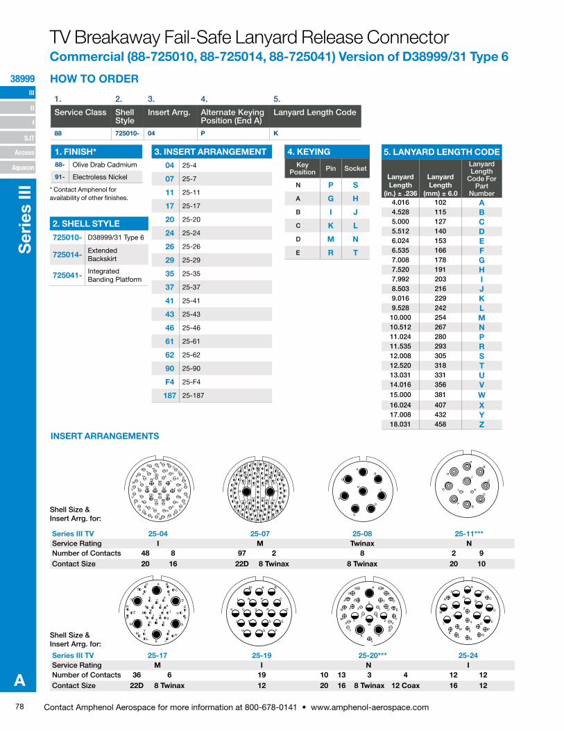
78 Contact Amphenol Aerospace for more information at 800-678-0141 • www.amphenol-aerospace.com
III
SJT
38999
I
II
Access
Aquacon
Ser
ies
III
A
HOW TO ORDER
INSERT ARRANGEMENTS
PDS-250-1
1. 2. 3. 4. 5.
Service Class Shell Style
Insert Arrg. Alternate KeyingPosition (End A)
Lanyard Length Code
88 725010- 04 P K
2. SHELL STYLE
725010- D38999/31 Type 6
725014- Extended Backskirt
725041- Integrated Banding Platform
1. FINISH*88- Olive Drab Cadmium
91- Electroless Nickel
3. INSERT ARRANGEMENT
04 25-4
07 25-7
11 25-11
17 25-17
20 25-20
24 25-24
26 25-26
29 25-29
35 25-35
37 25-37
41 25-41
43 25-43
46 25-46
61 25-61
62 25-62
90 25-90
F4 25-F4
187 25-187
4. KEYINGKey
Position Pin Socket
N P S
A G H
B I J
C K L
D M N
E R T
5. LANYARD LENGTH CODE
Lanyard Length
(in.) ± .236
Lanyard Length
(mm) ± 6.0
Lanyard Length
Code For Part
Number4.016 102 A4.528 115 B5.000 127 C5.512 140 D6.024 153 E6.535 166 F7.008 178 G7.520 191 H7.992 203 I8.503 216 J9.016 229 K9.528 242 L
10.000 254 M10.512 267 N11.024 280 P11.535 293 R12.008 305 S12.520 318 T13.031 331 U14.016 356 V15.000 381 W16.024 407 X17.008 432 Y18.031 458 Z
A
B
C
D
EF
G
HJ
KL
A B
C
D
E
F
G
H
JKL
M
N
P
R
S
T
U
V
W
XY
Z
ab
cd
e
f
gh
km
np
q r st
uv
w
A B
C
D
E
FGH
J
K
L
M
N P
R
ST
U V
A B
C
D
E
F
G
H
J
K
L
M
N
P
R
S
T
U
VWX
Y
Z
1
23
4
5
67
AB
C
D
E
F
GH
JK
L
M
N
P
RS
T
U
VW
X
Y Z
a
Series III TV 25-17 25-19 25-20*** 25-24Service Rating M I N INumber of Contacts 36 6 19 10 13 3 4 12 12Contact Size 22D 8 Twinax 12 20 16 8 Twinax 12 Coax 16 12
A BC
D
E
F
G
H
J
KL
M
NP
RS
T
U
V
W
X
YZ a
bc
d
ef
g
hk
mn
p
q
r
t
u
vw
x
y
zs JJ
KK
LL
AA
BBCC
DD
EE
FF
GG
HH
1
6
7
15
16
18
19
21
22
24
26
28
29
32
33
41
42
46
53
59
60
64
67
68
72
74
76
78
79
81
82
84
85
93
94
99
25 75
AB
C
D
E
F
G
H
Series III TV 25-04 25-07 25-08 25-11***Service Rating I M Twinax NNumber of Contacts 48 8 97 2 8 2 9Contact Size 20 16 22D 8 Twinax 8 Twinax 20 10
Shell Size & Insert Arrg. for:
Shell Size & Insert Arrg. for:
TV Breakaway Fail-Safe Lanyard Release ConnectorCommercial (88-725010, 88-725014, 88-725041) Version of D38999/31 Type 6
* Contact Amphenol for availability of other finishes.
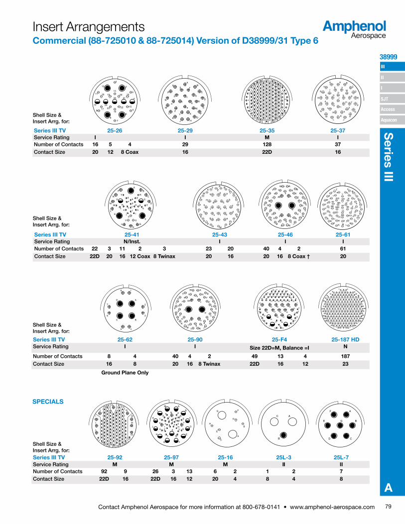
79Contact Amphenol Aerospace for more information at 800-678-0141 • www.amphenol-aerospace.com
38999 III
SJT
I
II
Access
Aquacon
Series III
A
SPECIALS
1
2
3
4
5
6
78
9
10
11
12
13
14
15
1617
18 19 20
21
222324
25
AB
C
D
E
F
GHJ
K
L
M
N
P
RS T
U
V
W
XY
Z
a
b c
d
e
f
1
4
7
8
14
15
24
25
35
36
47
48
58
59
70
71
81
82
93
94
104
105
114
115
121
125
128
Series III TV 25-26 25-29 25-35 25-37Service Rating I I M INumber of Contacts 16 5 4 29 128 37Contact Size 20 12 8 Coax 16 22D 16
A B
C
D
E
F
G
HJ
K
LM
N
P
R
S
T
U
VW
X
Y
Z
ab
c
d
e
fg
hk
m
np
qr
AB
C
D
E
F
G
H
JKL
M
N
P
R
S
T
U
V
W
XY
Za
b
cd
e
fgh
k
mn
p
qr
s
tu
v
w
xy
z
AA
Series III TV 25-41 25-43 25-46 25-61Service Rating N/Inst. I I INumber of Contacts 22 3 11 2 3 23 20 40 4 2 61Contact Size 22D 20 16 12 Coax 8 Twinax 20 16 20 16 8 Coax † 20
A BC
D
E
F
G
H
JK
LMNP
R
S
T
U
V
W
XY
Za
b
c
d
ef
g
h
k
m
n p
q
r
stu
v
w
x
BP
CN
DM
EL
F
GH
J
K
A
RY
X S
W
Z
T
UV
de
np
q g
ac
bj
k h
ms t
r
i
Series III TV 25-62 25-90 25-F4 25-187 HDService Rating I I Size 22D=M, Balance =I N
Number of Contacts 8 4 40 4 2 49 13 4 187Contact Size 16 8 20 16 8 Twinax 22D 16 12 23
Ground Plane Only
A
B
C
D
E
F
G
H
JKLM
N
a
P
R
S
T
U
V
W
X
Y
Z
b
c
d
efgh
AA
k
q
m
n
p
r
st
u
v
w
xy
z
1
17
18
19
49
35
20
21
22
23
1615
48
59
60 66 64
65
37 50 51 41 42 4331
3038 39 40 29
2726
25
24
54636261
36
325352
4455
56
57
46
3414
13
45
12
11
10
9
8
7
6
5
43
2
33
28
47
58
D A
C B
18
45
7 2
6 3
AB
C
D
E
F
G
H
J
KLMN
PR
S
T
U
V
W
X
YZa b
c
d
e
f
g
hi
jkmn
p
q
r
s
tu
v
w
x
y
z
BBCC
DD
EE
FF
GG HH
JJ
KK
LL
MM
NN
AA
PP
1
4 11
212012
32
33 45
46 59
60 72
73 86
87 101
102
142116
155
129
167
143
115128
177176
185
184
187
156
168
3
A
B
C
D
E
FG
H
A
B
C
A
B
CD
E
F
G
Series III TV 25-92 25-97 25-16 25L-3 25L-7Service Rating M M M II IINumber of Contacts 92 9 26 3 13 6 2 1 2 7Contact Size 22D 16 22D 16 12 20 4 8 4 8
98
100
101
90
7967
57
4624
36
13
5
1
4
1223
3545
56 66 7889
97
2
3
99
M A
L BN
K C
J D
H E
G F
Y W
Xa UZ Vr m
p n ksb
cd
e PR
S
Tjw
hgfu
vt
Shell Size & Insert Arrg. for:
Shell Size & Insert Arrg. for:
Shell Size & Insert Arrg. for:
Shell Size & Insert Arrg. for:
Insert ArrangementsCommercial (88-725010 & 88-725014) Version of D38999/31 Type 6
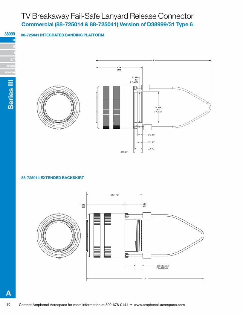
80 Contact Amphenol Aerospace for more information at 800-678-0141 • www.amphenol-aerospace.com
III
SJT
38999
I
II
Access
Aquacon
Ser
ies
III
A
88-725014 EXTENDED BACKSKIRT
88-725041 INTEGRATED BANDING PLATFORM
.787REF
1.747REF
.280 MINIMUM FULL THREAD
2.534 REF
R
2.186MAX
Ø1.400REF
2 PLACES
Ø1.456REF
2 PLACES
R
.216 REF
.255 REF
.379 REF
.419 REF
TV Breakaway Fail-Safe Lanyard Release ConnectorCommercial (88-725014 & 88-725041) Version of D38999/31 Type 6
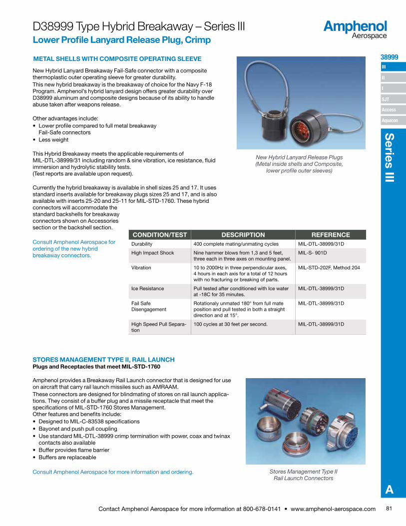
81Contact Amphenol Aerospace for more information at 800-678-0141 • www.amphenol-aerospace.com
38999 III
SJT
I
II
Access
Aquacon
Series III
A
D38999 Type Hybrid Breakaway – Series IIILower Profile Lanyard Release Plug, Crimp
New Hybrid Lanyard Breakaway Fail-Safe connector with a composite thermoplastic outer operating sleeve for greater durability.This new hybrid breakaway is the breakaway of choice for the Navy F-18 Program. Amphenol’s hybrid lanyard design offers greater durability over D38999 aluminum and composite designs because of its ability to handle abuse taken after weapons release.
Other advantages include:• Lower profile compared to full metal breakaway
Fail-Safe connectors• Less weight
This Hybrid Breakaway meets the applicable requirements of MIL-DTL-38999/31 including random & sine vibration, ice resistance, fluid immersion and hydrolytic stability tests. (Test reports are available upon request).
Currently the hybrid breakaway is available in shell sizes 25 and 17. It uses standard inserts available for breakaway plugs sizes 25 and 17, and is also available with inserts 25-20 and 25-11 for MIL-STD-1760. These hybrid connectors will accommodate the standard backshells for breakaway connectors shown on Accessories section or the backshell section.
Consult Amphenol Aerospace for ordering of the new hybrid breakaway connectors.
New Hybrid Lanyard Release Plugs (Metal inside shells and Composite,
lower profile outer sleeves)
STORES MANAGEMENT TYPE II, RAIL LAUNCHPlugs and Receptacles that meet MIL-STD-1760
Amphenol provides a Breakaway Rail Launch connector that is designed for use on aircraft that carry rail launch missiles such as AMRAAM.These connectors are designed for blindmating of stores on rail launch applica-tions. They consist of a buffer plug and a missile receptacle that meet the specifications of MIL-STD-1760 Stores Management. Other features and benefits include:• Designed to MIL-C-83538 specifications• Bayonet and push pull coupling• Use standard MIL-DTL-38999 crimp termination with power, coax and twinax
contacts also available• Buffer provides flame barrier• Buffers are replaceable
Consult Amphenol Aerospace for more information and ordering. Stores Management Type II Rail Launch Connectors
CONDITION/TEST DESCRIPTION REFERENCEDurability 400 complete mating/unmating cycles MIL-DTL-38999/31D
High Impact Shock Nine hammer blows from 1,3 and 5 feet, three each in three axes on mounting panel.
MIL-S- 901D
Vibration 10 to 2000Hz in three perpendicular axes, 4 hours in each axis for a total of 12 hours with no fracturing or breaking of parts.
MIL-STD-202F, Method 204
Ice Resistance Pull tested after conditioned with Ice water at -18C for 35 minutes.
MIL-DTL-38999/31D
Fail Safe Disengagement
Rotationaly unmated 180° from full mate position and pull tested in both a straight direction and at 15°.
MIL-DTL-38999/31D
High Speed Pull Separa-tion
100 cycles at 30 feet per second. MIL-DTL-38999/31D
METAL SHELLS WITH COMPOSITE OPERATING SLEEVE
Related Documents


![Artificial Intelligence · 2016-10-13 · Artificial Intelligence 2015-2016 Supervised Learning [6] Example: coin tossing (Bernoulli Trials) X X = 1 X = 0 P(X = 1) = , P(X = 0) =](https://static.cupdf.com/doc/110x72/5f500a3b7f1d8a71f1538353/artificial-intelligence-2016-10-13-artificial-intelligence-2015-2016-supervised.jpg)


![Perda no 1 2015 - no 3 2012...D v ] u v P W D v ] u v P W X X X X X X D v P ] v P W D v P ] v P W í X î X ï X ð X D dZ](https://static.cupdf.com/doc/110x72/608141d220d39869166f28fd/perda-no-1-2015-no-3-2012-d-v-u-v-p-w-d-v-u-v-p-w-x-x-x-x-x-x-d-v-p-.jpg)