MikroTik RouterOS™ V2.7 Reference Manual MikroTik

Welcome message from author
This document is posted to help you gain knowledge. Please leave a comment to let me know what you think about it! Share it to your friends and learn new things together.
Transcript

MikroTik RouterOS™ V2.7 Reference ManualMikroTik
Table of ContentsMikroTik RouterOS™ V2.7 Reference Manual..............................................................................................1
MikroTik RouterOS™ V2.7 Basic Setup Guide..............................................................................................2Table Of Contents....................................................................................................................................2Summary..................................................................................................................................................3Related Documents..................................................................................................................................3Description...............................................................................................................................................3Setting up MikroTik RouterOS™............................................................................................................4
Downloading and Installing the MikroTik RouterOS™...................................................................41. Download the basic installation archive file...........................................................................42. Create the installation media...................................................................................................43. Install the MikroTik RouterOS™ software............................................................................5Notes...........................................................................................................................................5
Obtaining the Software License........................................................................................................5Notes...........................................................................................................................................7
Logging into the MikroTik Router....................................................................................................7Adding Software Packages................................................................................................................7Software Licensing Issues.................................................................................................................7
Notes...........................................................................................................................................8Navigating the Terminal Console............................................................................................................8
Welcome Screen and Command Prompt...........................................................................................8Commands.........................................................................................................................................8Summary on executing the commands and moving between the menu levels...............................10
Notes.........................................................................................................................................10Accessing the Router Remotely Using Web Browser and WinBox Console........................................10
Summary.........................................................................................................................................10Description......................................................................................................................................10Starting the Winbox Console..........................................................................................................11Overview of Common Functions....................................................................................................15Troubleshooting for Winbox Console.............................................................................................15
Configuring Basic Functions.................................................................................................................15Working with Interfaces..................................................................................................................15
Use of the 'setup' Command.....................................................................................................16Notes.........................................................................................................................................16
Adding Addresses............................................................................................................................17Notes.........................................................................................................................................18
Configuring the Default Route........................................................................................................18Example....................................................................................................................................18Notes.........................................................................................................................................18
Testing the Network Connectivity.........................................................................................................19Example...........................................................................................................................................19Notes................................................................................................................................................19
Application Examples............................................................................................................................20Application Example with Masquerading.......................................................................................20
Notes.........................................................................................................................................20Application Example with Bandwidth Management......................................................................20
Notes.........................................................................................................................................21Application Example with NAT......................................................................................................21
MikroTik RouterOS™ V2.7 Reference Manual
i
Table of ContentsMikroTik RouterOS™ V2.7 Basic Setup Guide
Notes.........................................................................................................................................22
Terminal Console Manual................................................................................................................................23Table of Contents...................................................................................................................................23Summary................................................................................................................................................23Specifications.........................................................................................................................................23Related Documents................................................................................................................................23Overview of Common Functions...........................................................................................................24
Lists.................................................................................................................................................25Item Names......................................................................................................................................26Quick Typing...................................................................................................................................26Help.................................................................................................................................................27Internal Item numbers.....................................................................................................................27Multiple Items.................................................................................................................................28
General Commands................................................................................................................................28print.................................................................................................................................................28set.....................................................................................................................................................30add...................................................................................................................................................30remove.............................................................................................................................................31move................................................................................................................................................31find...................................................................................................................................................32export...............................................................................................................................................33enable/disable..................................................................................................................................33
Safe Mode..............................................................................................................................................33
Software Package Management.......................................................................................................................35Table of Contents...................................................................................................................................35Summary................................................................................................................................................35Specifications.........................................................................................................................................35Additional Documents...........................................................................................................................35Features..................................................................................................................................................35Software Package Installation (Upgrade)..............................................................................................36
Description......................................................................................................................................36Notes................................................................................................................................................36
Software Package List............................................................................................................................37System Software Package...............................................................................................................37Additional Software Feature Packages............................................................................................38
Software Package Uninstalling..............................................................................................................39Description......................................................................................................................................39Example...........................................................................................................................................39
Troubleshooting.....................................................................................................................................39
MikroTik RouterOS™ V2.7 Specifications Sheet..........................................................................................41Hardware................................................................................................................................................41Basic Network Platform.........................................................................................................................41
TCP/IP protocol suite......................................................................................................................41Special Protocols.............................................................................................................................42
MikroTik RouterOS™ V2.7 Reference Manual
ii
Table of ContentsMikroTik RouterOS™ V2.7 Specifications Sheet
Caching Features.............................................................................................................................42Administration.......................................................................................................................................42
General............................................................................................................................................42Scripting..........................................................................................................................................43
Hardware Supported..............................................................................................................................43Wireless Interfaces..........................................................................................................................43Synchronous....................................................................................................................................43Asynchronous Interfaces.................................................................................................................43Ethernet Interfaces...........................................................................................................................44ISDN Interfaces...............................................................................................................................44VoIP Interfaces................................................................................................................................44xDSL Interfaces...............................................................................................................................44HomePNA Interfaces......................................................................................................................45
Device Driver List.............................................................................................................................................46Table of Contents...................................................................................................................................46Summary................................................................................................................................................46Ethernet (system)...................................................................................................................................46Wireless (wireless).................................................................................................................................50Synchronous (synchronous)...................................................................................................................51Asynchronous (system)..........................................................................................................................51ISDN (isdn)............................................................................................................................................52VoIP (telephony)....................................................................................................................................52xDSL (synchronous)..............................................................................................................................52HomePNA (system)...............................................................................................................................52LCD (lcd)...............................................................................................................................................52PCMCIA Adapters (system)..................................................................................................................52
How to Read Reference Manual......................................................................................................................53Table of Contents...................................................................................................................................53Summary................................................................................................................................................53The Purpose...........................................................................................................................................53The Structure..........................................................................................................................................53Common Conventions...........................................................................................................................54Additional Resources.............................................................................................................................54
Glossary.............................................................................................................................................................55Table of Contents...................................................................................................................................55Summary................................................................................................................................................55Common Properties...............................................................................................................................55Terms and Abbreviations.......................................................................................................................55
Device Driver Management.............................................................................................................................58Table of Contents...................................................................................................................................58Summary................................................................................................................................................58Specifications.........................................................................................................................................58Related Documents................................................................................................................................58
MikroTik RouterOS™ V2.7 Reference Manual
iii

Table of ContentsDevice Driver Management
Loading Device Drivers.........................................................................................................................59Description......................................................................................................................................59Property Description........................................................................................................................59Notes................................................................................................................................................59Example...........................................................................................................................................60
Removing Device Drivers......................................................................................................................61Notes on PCMCIA Adapters.................................................................................................................61Troubleshooting.....................................................................................................................................61
General Interface Settings................................................................................................................................62Table Of Contents..................................................................................................................................62Summary................................................................................................................................................62Related Documents................................................................................................................................62Description.............................................................................................................................................63Interface Status.......................................................................................................................................63
Property Description........................................................................................................................63Notes................................................................................................................................................63Example...........................................................................................................................................63
Traffic monitoring..................................................................................................................................63Description......................................................................................................................................63Notes................................................................................................................................................63Example...........................................................................................................................................63
Wireless Client and Wireless Access Point Manual.......................................................................................65Table of Contents...................................................................................................................................65Summary................................................................................................................................................65Specifications.........................................................................................................................................65Related Documents................................................................................................................................66Wireless Networking Ranges.................................................................................................................66Description.............................................................................................................................................66
Hardware Notes...............................................................................................................................66Wireless Interface Configuration...........................................................................................................67
Description......................................................................................................................................67Property Description........................................................................................................................67Notes................................................................................................................................................68Example...........................................................................................................................................68
Registration Table..................................................................................................................................69Property Description........................................................................................................................69Example...........................................................................................................................................69
Access List.............................................................................................................................................70Description......................................................................................................................................70Property Description........................................................................................................................70Notes................................................................................................................................................70Example...........................................................................................................................................70
Info.........................................................................................................................................................70Description......................................................................................................................................71Property Description........................................................................................................................71
MikroTik RouterOS™ V2.7 Reference Manual
iv
Table of ContentsWireless Client and Wireless Access Point Manual
Notes................................................................................................................................................71Example...........................................................................................................................................71
AP Configuration Example....................................................................................................................72Additional Resources.............................................................................................................................74
Bridge Interface................................................................................................................................................75Table of Contents...................................................................................................................................75Overview................................................................................................................................................75Specifications.........................................................................................................................................76Related Documents................................................................................................................................76Description.............................................................................................................................................76Bridge Interface Setup...........................................................................................................................76
Description......................................................................................................................................76Property Description........................................................................................................................76Notes................................................................................................................................................77Example...........................................................................................................................................77
Port Settings...........................................................................................................................................77Description......................................................................................................................................77Property Description........................................................................................................................77Example...........................................................................................................................................77
Bridge Monitoring.................................................................................................................................77Property Description........................................................................................................................78Example...........................................................................................................................................78
Bridge Firewall......................................................................................................................................78Description......................................................................................................................................78Property Description........................................................................................................................78Example...........................................................................................................................................79
Application Example.............................................................................................................................79Additional Bridge Firewall Resources............................................................................................81
Troubleshooting.....................................................................................................................................81
MikroTik RouterOS V2.7 Arlan 655 2.4GHz 2Mbps Wireless Interface...................................................83Table of Contents...................................................................................................................................83Summary................................................................................................................................................83Specifications.........................................................................................................................................83Related Documents................................................................................................................................83Installation.............................................................................................................................................83
Example...........................................................................................................................................84Wireless Interface Configuration...........................................................................................................84
Description......................................................................................................................................84Property Description........................................................................................................................84Example...........................................................................................................................................85
Troubleshooting.....................................................................................................................................85Additional Resources.............................................................................................................................86
MikroTik RouterOS™ V2.7 Reference Manual
v
Table of ContentsCISCO/Aironet 2.4GHz 11Mbps Wireless Interface.....................................................................................87
Table of Contents...................................................................................................................................87Summary................................................................................................................................................87Specifications.........................................................................................................................................87Related Documents................................................................................................................................87Wireless Interface Configuration...........................................................................................................88
Description......................................................................................................................................88Property Description........................................................................................................................88Example...........................................................................................................................................89
Troubleshooting.....................................................................................................................................90Wireless Network Applications.............................................................................................................90
Point−to−Multipoint Wireless LAN................................................................................................90Point−to−Point Wireless LAN........................................................................................................92
Additional Resources.............................................................................................................................94
Cyclades PC300 PCI Adapters........................................................................................................................96Table of Contents...................................................................................................................................96Summary................................................................................................................................................96Specifications.........................................................................................................................................96Related Documents................................................................................................................................96Synchronous Interface Configuration....................................................................................................96
Description......................................................................................................................................97Property Description........................................................................................................................97
Troubleshooting.....................................................................................................................................97RSV/V.35 Synchronous Link Applications...........................................................................................98Additional Resources.............................................................................................................................99
Ethernet Interfaces.........................................................................................................................................101Table of Contents.................................................................................................................................101Summary..............................................................................................................................................101Specifications.......................................................................................................................................101Related Documents..............................................................................................................................101Ethernet Interface Configuration.........................................................................................................101
Property Description......................................................................................................................102Notes..............................................................................................................................................102Examples.......................................................................................................................................102
Monitoring the Interface Status...........................................................................................................102Example.........................................................................................................................................103
Notes....................................................................................................................................................103Additional Resources...........................................................................................................................103
Ethernet over IP (EoIP) Tunnel Interface....................................................................................................104Table of Contents.................................................................................................................................104Overview..............................................................................................................................................104Specifications.......................................................................................................................................104Related Documents..............................................................................................................................104Description...........................................................................................................................................105EoIP Setup...........................................................................................................................................105
MikroTik RouterOS™ V2.7 Reference Manual
vi
Table of ContentsEthernet over IP (EoIP) Tunnel Interface
Property Description......................................................................................................................105Notes..............................................................................................................................................105Example.........................................................................................................................................105
EoIP Application Example..................................................................................................................106
FarSync X.21 Interface...................................................................................................................................109Table of Contents.................................................................................................................................109Summary..............................................................................................................................................109Specifications.......................................................................................................................................109Related Documents..............................................................................................................................109Synchronous Interface Configuration..................................................................................................109
Description....................................................................................................................................110Property Description......................................................................................................................110Example.........................................................................................................................................110
Troubleshooting...................................................................................................................................111Synchronous Link Applications...........................................................................................................111
MikroTik router to MikroTik router..............................................................................................111MikroTik router to MikroTik router P2P using X21 line..............................................................112MikroTik router to Cisco ruter using X21 line..............................................................................113MikroTik router to MikroTik router using Frame Relay..............................................................115
Additional Resources...........................................................................................................................116
FrameRelay (PVC) Interfaces.......................................................................................................................117Table of Contents.................................................................................................................................117Summary..............................................................................................................................................117Specifications.......................................................................................................................................117Description...........................................................................................................................................117Configuring Frame Relay Interface.....................................................................................................117
Description....................................................................................................................................118Property Description......................................................................................................................118Notes..............................................................................................................................................118
Frame Relay Configuration Example with Cyclades Interface...........................................................118Frame Relay Configuration Example with MOXA Interface..............................................................119MikroTik Router to MikroTik Router.................................................................................................121Frame Relay Troubleshooting..............................................................................................................122Additional Resources...........................................................................................................................122
IP over IP (IPIP) Tunnel Interface................................................................................................................123Table of Contents.................................................................................................................................123Summary..............................................................................................................................................123Specifications.......................................................................................................................................123Related Documents..............................................................................................................................123IPIP Setup............................................................................................................................................124
Description....................................................................................................................................124Property Description......................................................................................................................124Notes..............................................................................................................................................124
IPIP Application Example...................................................................................................................124
MikroTik RouterOS™ V2.7 Reference Manual
vii

Table of ContentsIP over IP (IPIP) Tunnel Interface
Additional Resources...........................................................................................................................125
ISDN Interface................................................................................................................................................127Table of Contents.................................................................................................................................127Summary..............................................................................................................................................127Specifications.......................................................................................................................................127Related Documents..............................................................................................................................128Supported adapters and appropriate driver names...............................................................................128
Notes..............................................................................................................................................128ISDN Hardware and Software Installation..........................................................................................128
Property Description......................................................................................................................128ISDN Channels..............................................................................................................................128MSN and EAZ numbers................................................................................................................129
ISDN Client Interface Configuration...................................................................................................129Description....................................................................................................................................129Property Description......................................................................................................................129Example.........................................................................................................................................130
ISDN Server Interface Configuration..................................................................................................130Description....................................................................................................................................130Property Description......................................................................................................................130Example.........................................................................................................................................130
Troubleshooting...................................................................................................................................131ISDN Examples...................................................................................................................................131
ISDN Dial−out..............................................................................................................................131ISDN Dial−in................................................................................................................................132ISDN Backup................................................................................................................................133
Description..............................................................................................................................133Note.........................................................................................................................................133Example..................................................................................................................................133
Additional Resources...........................................................................................................................135
Layer 2 Tunnel Protocol (L2TP)...................................................................................................................136Table of Contents.................................................................................................................................136Summary..............................................................................................................................................136Specifications.......................................................................................................................................137Related Documents..............................................................................................................................137Description...........................................................................................................................................137L2TP Client Setup...............................................................................................................................137
Property Description......................................................................................................................138Example.........................................................................................................................................138
Monitoring L2TP Client......................................................................................................................138Property Description......................................................................................................................138Example.........................................................................................................................................139
L2TP Server Setup...............................................................................................................................139Description....................................................................................................................................139Property Description......................................................................................................................139Example.........................................................................................................................................139
MikroTik RouterOS™ V2.7 Reference Manual
viii

Table of ContentsLayer 2 Tunnel Protocol (L2TP)
L2TP Server Users...............................................................................................................................140Description....................................................................................................................................140Property Description......................................................................................................................140Example.........................................................................................................................................140
L2TP Router−to−Router Secure Tunnel Example...............................................................................140Connecting a Remote Client via L2TP Tunnel....................................................................................143L2TP Setup for Windows....................................................................................................................145Troubleshooting...................................................................................................................................145
MOXA C101 Synchronous Interface............................................................................................................147Table of Contents.................................................................................................................................147Summary..............................................................................................................................................147Specifications.......................................................................................................................................147Related Documents..............................................................................................................................147Installation...........................................................................................................................................148
MOXA C101 PCI variant cabling.................................................................................................148Synchronous Interface Configuration..................................................................................................148
Description....................................................................................................................................148Property Description......................................................................................................................148Notes..............................................................................................................................................149Example.........................................................................................................................................149
Troubleshooting...................................................................................................................................150Synchronous Link Applications...........................................................................................................150
MikroTik Router to MikroTik Router...........................................................................................150MikroTik Router to CISCO Router...............................................................................................151Notes..............................................................................................................................................153
Additional Resources...........................................................................................................................153
MOXA C502 Synchronous Interface............................................................................................................154Table of Contents.................................................................................................................................154Summary..............................................................................................................................................154Specifications.......................................................................................................................................154Related Documents..............................................................................................................................154Installation...........................................................................................................................................155Synchronous Interface Configuration..................................................................................................155
Description....................................................................................................................................155Property Description......................................................................................................................155Notes..............................................................................................................................................155Example.........................................................................................................................................155
Troubleshooting...................................................................................................................................156Synchronous Link Applications...........................................................................................................156
MikroTik Router to MikroTik Router...........................................................................................156MikroTik Router to CISCO Router...............................................................................................158Notes..............................................................................................................................................160
Additional Resources...........................................................................................................................160
MikroTik RouterOS™ V2.7 Reference Manual
ix

Table of ContentsPoint to Point Protocol (PPP) and Asynchronous Interfaces......................................................................161
Table of Contents.................................................................................................................................161Summary..............................................................................................................................................161Specifications.......................................................................................................................................161Related Documents..............................................................................................................................162Serial Port Configuration.....................................................................................................................162
Property Description......................................................................................................................162Notes..............................................................................................................................................162Example.........................................................................................................................................162
PPP Server Setup.................................................................................................................................163Description....................................................................................................................................163Property Description......................................................................................................................163Example.........................................................................................................................................163
PPP Client Setup..................................................................................................................................163Description....................................................................................................................................163Property Description......................................................................................................................164Notes..............................................................................................................................................164Example.........................................................................................................................................164
PPP Application Example....................................................................................................................164Additional Resources...........................................................................................................................166
Point to Point Protocol over Ethernet (PPPoE)...........................................................................................167Table of Contents.................................................................................................................................167Summary..............................................................................................................................................167Specifications.......................................................................................................................................168Related Documents..............................................................................................................................168PPPoE Client Setup.............................................................................................................................168
Description....................................................................................................................................168Property Description......................................................................................................................168Notes..............................................................................................................................................169Example.........................................................................................................................................169
Monitoring PPPoE Client....................................................................................................................169Property Description......................................................................................................................169Example.........................................................................................................................................169
PPPoE Server Setup (Access Concentrator)........................................................................................170Description....................................................................................................................................170Property Description......................................................................................................................170Notes..............................................................................................................................................170Example.........................................................................................................................................171
PPPoE Server Users.............................................................................................................................171Property Description......................................................................................................................171Example.........................................................................................................................................171
PPPoE Troubleshooting.......................................................................................................................171Application Examples..........................................................................................................................172
PPPoE in a multipoint wireless 802.11 network...........................................................................172Additional Resources...........................................................................................................................175
MikroTik RouterOS™ V2.7 Reference Manual
x

Table of ContentsPoint to Point Tunnel Protocol (PPTP).........................................................................................................176
Table of Contents.................................................................................................................................176Summary..............................................................................................................................................176Specifications.......................................................................................................................................177Related Documents..............................................................................................................................177Description...........................................................................................................................................177PPTP Client Setup...............................................................................................................................177
Property Description......................................................................................................................177Example.........................................................................................................................................178
Monitoring PPTP Client......................................................................................................................178Property Description......................................................................................................................178Example.........................................................................................................................................178
PPTP Server Setup...............................................................................................................................178Description....................................................................................................................................179Property Description......................................................................................................................179Example.........................................................................................................................................179
PPTP Server Users...............................................................................................................................179Description....................................................................................................................................179Property Description......................................................................................................................180Example.........................................................................................................................................180
PPTP Router−to−Router Secure Tunnel Example...............................................................................180Connecting a Remote Client via PPTP Tunnel....................................................................................183PPTP Setup for Windows....................................................................................................................185
Sample instructions for PPTP (VPN) installation and client setup – Windows 98se...................185Troubleshooting...................................................................................................................................185Additional Resources...........................................................................................................................186
PrismII Wireless Client and Wireless Access Point Manual......................................................................187Table of Contents.................................................................................................................................187Summary..............................................................................................................................................188Specifications.......................................................................................................................................188Related Documents..............................................................................................................................188Description...........................................................................................................................................188Wireless Interface Configuration.........................................................................................................189
Property Description......................................................................................................................189Notes..............................................................................................................................................189Example.........................................................................................................................................190
Monitoring the Interface Status...........................................................................................................190Property Description......................................................................................................................190Notes..............................................................................................................................................190Example.........................................................................................................................................190
Registration Table................................................................................................................................191Property Description......................................................................................................................191Example.........................................................................................................................................191
Access List...........................................................................................................................................191Description....................................................................................................................................192Property Description......................................................................................................................192Notes..............................................................................................................................................192
MikroTik RouterOS™ V2.7 Reference Manual
xi
Table of ContentsPrismII Wireless Client and Wireless Access Point Manual
Example.........................................................................................................................................192Network Scan.......................................................................................................................................192
Description....................................................................................................................................192Property Description......................................................................................................................193Example.........................................................................................................................................193
Troubleshooting...................................................................................................................................193Basic Configuration Examples............................................................................................................193
Station Mode Configuration..........................................................................................................193Description..............................................................................................................................193Example..................................................................................................................................194
Access Point Mode Configuration................................................................................................194Description..............................................................................................................................194Example..................................................................................................................................194
Registering the Access Point to another Access Point..................................................................194Description..............................................................................................................................195Example..................................................................................................................................195
Wireless Network Applications...........................................................................................................195Wireless Client..............................................................................................................................195
3rd Party Wireless AP Configuration.....................................................................................196MikroTik RouterOS Wireless Client Configuration...............................................................196
Wireless Access Point...................................................................................................................197Wireless Bridge.............................................................................................................................200
[MT−parent] Configuration....................................................................................................201[MT−child] Configuration......................................................................................................201
RadioLAN 5.8GHz Wireless Interface..........................................................................................................203Table of Contents.................................................................................................................................203Summary..............................................................................................................................................203Specifications.......................................................................................................................................203Related Documents..............................................................................................................................203
Installing the Wireless Adapter.....................................................................................................204Wireless Interface Configuration.........................................................................................................204
Description....................................................................................................................................204Property Description......................................................................................................................204Example.........................................................................................................................................205
Wireless Troubleshooting....................................................................................................................206Wireless Network Applications...........................................................................................................206
Point−to−Point Setup with Routing..............................................................................................206
Virtual LAN (VLAN) Interface.....................................................................................................................209Table of Contents.................................................................................................................................209Summary..............................................................................................................................................209Specifications.......................................................................................................................................209Related Documents..............................................................................................................................209Description...........................................................................................................................................210VLAN Setup........................................................................................................................................210
Property Description......................................................................................................................210
MikroTik RouterOS™ V2.7 Reference Manual
xii
Table of ContentsVirtual LAN (VLAN) Interface
Notes..............................................................................................................................................210Example.........................................................................................................................................210
Application Example...........................................................................................................................211Additional Resources...........................................................................................................................212Currently Supported Interfaces............................................................................................................212
Xpeed SDSL (Single−line Digital Subscriber Line) Interface.....................................................................213Table of Contents.................................................................................................................................213Summary..............................................................................................................................................213Specifications.......................................................................................................................................213Related Documents..............................................................................................................................213Xpeed Interface Configuration............................................................................................................214
Property Description......................................................................................................................214Example.........................................................................................................................................214
Frame Relay Configuration Examples.................................................................................................215MikroTik Router to MikroTik Router...........................................................................................215
Router r1 setup........................................................................................................................215Router r2 setup........................................................................................................................215
MikroTik Router to CISCO Router...............................................................................................216MikroTik router setup.............................................................................................................216CISCO router setup.................................................................................................................216
Troubleshooting...................................................................................................................................217Additional Resources...........................................................................................................................217
WaveLAN/ORiNOCO 2.4GHz 11Mbps Wireless Interface.......................................................................218Table of Contents.................................................................................................................................218Summary..............................................................................................................................................218Specifications.......................................................................................................................................218Wireless Interface Configuration.........................................................................................................218
Description....................................................................................................................................219Property Description......................................................................................................................219Example.........................................................................................................................................219
Wireless Troubleshooting....................................................................................................................220Application Example...........................................................................................................................220
Point−to−Multipoint Wireless LAN..............................................................................................221IP Network Configuration......................................................................................................222
Point−to−Point Wireless LAN......................................................................................................222IP Network Configuration......................................................................................................223Testing the Network Connectivity..........................................................................................224
Point−to−Point Wireless LAN with Windows Client...................................................................224IP Network Configuration......................................................................................................226Testing the Network Connectivity..........................................................................................226
Additional Resources...........................................................................................................................227
DHCP Client and Server................................................................................................................................228Table of Contents.................................................................................................................................228Summary..............................................................................................................................................228
MikroTik RouterOS™ V2.7 Reference Manual
xiii
Table of ContentsDHCP Client and Server
Specifications.......................................................................................................................................228Related Documents..............................................................................................................................229Description...........................................................................................................................................229DHCP Client Setup..............................................................................................................................229
Description....................................................................................................................................229Property Description......................................................................................................................229Notes..............................................................................................................................................229Example.........................................................................................................................................230
DHCP Server Setup.............................................................................................................................230Description....................................................................................................................................230Property Description......................................................................................................................230Notes..............................................................................................................................................231Example.........................................................................................................................................231
DHCP Server Leases............................................................................................................................232Description....................................................................................................................................232Property Description......................................................................................................................232Notes..............................................................................................................................................232Example.........................................................................................................................................232
Additional DHCP Resources...............................................................................................................233
DNS Client and Cache....................................................................................................................................234Table Of Contents................................................................................................................................234Summary..............................................................................................................................................234Specifications.......................................................................................................................................234Related Documents..............................................................................................................................234Description...........................................................................................................................................235DNS Client Configuration...................................................................................................................235
Description....................................................................................................................................235Property Description......................................................................................................................235Notes..............................................................................................................................................235Example.........................................................................................................................................235
DNS Cache Setup................................................................................................................................236Property Description......................................................................................................................236Notes..............................................................................................................................................236Example.........................................................................................................................................236
Adding Static DNS Entries..................................................................................................................237Description....................................................................................................................................237Property Description......................................................................................................................237Example.........................................................................................................................................237
Flushing DNS cache............................................................................................................................237Description....................................................................................................................................237Example.........................................................................................................................................237
Additional Resources...........................................................................................................................238
HotSpot Gateway............................................................................................................................................239Table of Contents.................................................................................................................................239Summary..............................................................................................................................................240
MikroTik RouterOS™ V2.7 Reference Manual
xiv

Table of ContentsHotSpot Gateway
Specifications.......................................................................................................................................240Related Documents..............................................................................................................................241Description...........................................................................................................................................241
The Initial Contact.........................................................................................................................242The Servlet....................................................................................................................................242Authentication...............................................................................................................................242Address Assignment with dhcp−pool Method..............................................................................243Logging Out..................................................................................................................................243
HotSpot Gateway Setup.......................................................................................................................243Property Description......................................................................................................................244Notes..............................................................................................................................................244Example.........................................................................................................................................245
HotSpot Server Settings.......................................................................................................................245Property Description......................................................................................................................245Notes..............................................................................................................................................245Example.........................................................................................................................................245
HotSpot AAA ......................................................................................................................................246HotSpot User Profiles....................................................................................................................246
Description..............................................................................................................................246Property Descriptions.............................................................................................................246Notes.......................................................................................................................................246Example..................................................................................................................................246
HotSpot Users................................................................................................................................247Property Description...............................................................................................................247Notes.......................................................................................................................................247Example..................................................................................................................................248
HotSpot Active Users....................................................................................................................248Description..............................................................................................................................248Property Description...............................................................................................................248Example..................................................................................................................................249
HotSpot User Statistics..................................................................................................................249Property Description...............................................................................................................249Notes.......................................................................................................................................249Example..................................................................................................................................249
HotSpot Remote AAA...................................................................................................................249Property Description...............................................................................................................250Notes.......................................................................................................................................250Example..................................................................................................................................250
HotSpot Cookies..................................................................................................................................250Property Description......................................................................................................................250Example.........................................................................................................................................250
Customizing Hotspot Servlet...............................................................................................................250Description....................................................................................................................................251Variable Description......................................................................................................................251Examples.......................................................................................................................................253
Resetting Hotspot Servlet customizations...........................................................................................254Description....................................................................................................................................254
MikroTik RouterOS™ V2.7 Reference Manual
xv

Table of ContentsHotSpot Gateway
Example.........................................................................................................................................254QuestionSetup......................................................................................................................................254
Questions.......................................................................................................................................254Notes..............................................................................................................................................255Example.........................................................................................................................................255
HotSpot Step−by−Step User Guide.....................................................................................................255dhcp−pool Method........................................................................................................................255
Planning the Configuration.....................................................................................................255Setup Example........................................................................................................................256
enabled−address Method...............................................................................................................258Planning the Configuration.....................................................................................................258Setup Example........................................................................................................................259
Optional Settings...........................................................................................................................261Troubleshooting...................................................................................................................................262
IP Addresses and Address Resolution Protocol (ARP)...............................................................................264Table of Contents.................................................................................................................................264Summary..............................................................................................................................................264Specifications.......................................................................................................................................264Related Documents..............................................................................................................................264IP Addressing.......................................................................................................................................265
Description....................................................................................................................................265Property Description......................................................................................................................265Example.........................................................................................................................................265
Address Resolution Protocol...............................................................................................................266Description....................................................................................................................................266Property Description......................................................................................................................266Notes..............................................................................................................................................266Example.........................................................................................................................................266
Using the Proxy−ARP Feature............................................................................................................267Description....................................................................................................................................267Example.........................................................................................................................................267
Using Unnumbered Interfaces.............................................................................................................268Description....................................................................................................................................268Example.........................................................................................................................................268
Troubleshooting...................................................................................................................................268Additional Resources...........................................................................................................................269
IP Pool Management.......................................................................................................................................270Table of Contents.................................................................................................................................270Summary..............................................................................................................................................270Specifications.......................................................................................................................................270Related Documents..............................................................................................................................270Description...........................................................................................................................................270IP Pool Setup.......................................................................................................................................271
Property Description......................................................................................................................271Example.........................................................................................................................................271
MikroTik RouterOS™ V2.7 Reference Manual
xvi

Table of ContentsIP Pool Management
Monitoring Used IP Addresses............................................................................................................271Property Description......................................................................................................................271Example.........................................................................................................................................271
IPsec.................................................................................................................................................................272Table of Contents.................................................................................................................................272Summary..............................................................................................................................................273Specifications.......................................................................................................................................273Related Documents..............................................................................................................................273Description...........................................................................................................................................273
Encryption.....................................................................................................................................273Decryption.....................................................................................................................................274Internet Key Exchange..................................................................................................................274Diffie−Hellman MODP Groups....................................................................................................275IKE Traffic....................................................................................................................................275Setup Steps....................................................................................................................................275
Policy Settings.....................................................................................................................................275Description....................................................................................................................................275Property Description......................................................................................................................276Notes..............................................................................................................................................277Example.........................................................................................................................................277
Peer......................................................................................................................................................277Description....................................................................................................................................277Property Description......................................................................................................................278Notes..............................................................................................................................................278Example.........................................................................................................................................278
Remote Peer Statistics.........................................................................................................................279Description....................................................................................................................................279Property Description......................................................................................................................279Example.........................................................................................................................................279
Manual SA...........................................................................................................................................279Property Description......................................................................................................................280Notes..............................................................................................................................................280Example.........................................................................................................................................280
Proposal...............................................................................................................................................281Description....................................................................................................................................281Property Description......................................................................................................................281Notes..............................................................................................................................................281Example.........................................................................................................................................281
Installed SA..........................................................................................................................................282Description....................................................................................................................................282Property Description......................................................................................................................282Example.........................................................................................................................................282
Flushing Installed SA table..................................................................................................................283Description....................................................................................................................................283Property Description......................................................................................................................283Example.........................................................................................................................................283
MikroTik RouterOS™ V2.7 Reference Manual
xvii
Table of ContentsIPsec
Counters...............................................................................................................................................283Property Description......................................................................................................................283Example.........................................................................................................................................284
Application examples...........................................................................................................................284IPsec setup between two RourerOS routers..................................................................................284IPsec Setup for Routing Between two Masquerading MikroTik Routers.....................................285IPsec Setup Between MikroTik and CISCO Routers....................................................................286
Configuring RouterOS............................................................................................................286Configuring Cisco...................................................................................................................286Testing....................................................................................................................................287
IPsec setup between RouterOS router and Windows SonicWall Client.......................................288Configuring RouterOS............................................................................................................289Configuring SonicWALL.......................................................................................................289Testing....................................................................................................................................293
Additional Resources...........................................................................................................................295
IP Telephony....................................................................................................................................................296Table Of Contents................................................................................................................................296Summary..............................................................................................................................................297Specifications.......................................................................................................................................297Related Documents..............................................................................................................................297Description...........................................................................................................................................298IP Telephony Specifications................................................................................................................298
Supported Hardware......................................................................................................................298Supported Standards......................................................................................................................298Implementation Options................................................................................................................299
IP Telephony Hardware Installation....................................................................................................299IP Telephony Configuration................................................................................................................299
Description....................................................................................................................................299Telephony Voice Ports..................................................................................................................300
Description..............................................................................................................................300Property Description...............................................................................................................300Notes.......................................................................................................................................300
Monitoring the Voice Ports...........................................................................................................300Property Description...............................................................................................................300Notes.......................................................................................................................................301Example..................................................................................................................................301
Voice−Port Statistics.....................................................................................................................301Notes.......................................................................................................................................301Example..................................................................................................................................301
Voice Port for Telephony cards.....................................................................................................302Property Description...............................................................................................................302Notes.......................................................................................................................................303
Voice Port for Voicetronix cards...................................................................................................303Property Description...............................................................................................................303Notes.......................................................................................................................................304
Voice Port for ISDN......................................................................................................................304
MikroTik RouterOS™ V2.7 Reference Manual
xviii
Table of ContentsIP Telephony
Property Description...............................................................................................................304Notes.......................................................................................................................................305Example..................................................................................................................................305
Voice Port for Voice over IP (voip)..............................................................................................305Description..............................................................................................................................305Property Description...............................................................................................................305Example..................................................................................................................................306
Numbers........................................................................................................................................306Description..............................................................................................................................306Property Description...............................................................................................................306Notes.......................................................................................................................................306Example..................................................................................................................................306
Regional Settings...........................................................................................................................308Description..............................................................................................................................308Property Description...............................................................................................................308Notes.......................................................................................................................................309Example..................................................................................................................................309
Audio CODEC..............................................................................................................................310Notes.......................................................................................................................................310Example..................................................................................................................................310
AAA.....................................................................................................................................................310Description....................................................................................................................................311Property Description......................................................................................................................311Notes..............................................................................................................................................312
IP Telephony Gatekeeper.....................................................................................................................312Property Description......................................................................................................................312Notes..............................................................................................................................................313Gatekeeper Configuration.............................................................................................................313
Example..................................................................................................................................313Notes.......................................................................................................................................314
IP Telephony Troubleshooting............................................................................................................315IP Telephony Applications..................................................................................................................315
Setting up the MikroTik IP Telephone..........................................................................................316Setting up the IP Telephony Gateway...........................................................................................317Setting up the Welltech IP Telephone...........................................................................................319Setting up the MikroTik Router and CISCO Router.....................................................................320Setting up PBX to PBX Connection over an IP Network.............................................................323
Additional Resources...........................................................................................................................324
IP Packet Packer Protocol (M3P)..................................................................................................................325Table Of Contents................................................................................................................................325Summary..............................................................................................................................................325Specifications.......................................................................................................................................325Related Documents..............................................................................................................................325MikroTik Packet Packer Protocol Description....................................................................................325MikroTik Packet Packer Protocol Setup..............................................................................................326
Description....................................................................................................................................326
MikroTik RouterOS™ V2.7 Reference Manual
xix

Table of ContentsIP Packet Packer Protocol (M3P)
Property Description......................................................................................................................326Notes..............................................................................................................................................326Example.........................................................................................................................................327
MikroTik Neighbor Discovery Protocol (MNDP)........................................................................................328Contents of the Manual........................................................................................................................328Summary..............................................................................................................................................328Specifications.......................................................................................................................................328Related Documents..............................................................................................................................328Description...........................................................................................................................................329MikroTik Neighbour Discovery Protocol Setup..................................................................................329
Property Description......................................................................................................................329Example.........................................................................................................................................329
Listing the Discovered Neighbours.....................................................................................................329Property Description......................................................................................................................329Example.........................................................................................................................................330
Firewall Filters and Network Address Translation (NAT).........................................................................331Table of Contents.................................................................................................................................331Summary..............................................................................................................................................332Specifications.......................................................................................................................................332Related documents...............................................................................................................................332Description...........................................................................................................................................332Packet Flow..........................................................................................................................................332
Description....................................................................................................................................333Firewall Setup......................................................................................................................................334
Description....................................................................................................................................334Firewall Chains..............................................................................................................................334
Description..............................................................................................................................334Notes.......................................................................................................................................335Example..................................................................................................................................335
Firewall Rules................................................................................................................................335Description..............................................................................................................................335Property Description...............................................................................................................335Notes.......................................................................................................................................336Example..................................................................................................................................336
Logging the Firewall Actions........................................................................................................337Network Address Translation..............................................................................................................337
Description....................................................................................................................................337Property Description......................................................................................................................337Masquerading and Source NAT....................................................................................................338
Description..............................................................................................................................338Property Description...............................................................................................................338Example..................................................................................................................................339
Redirection and Destination NAT.................................................................................................339Description..............................................................................................................................339Property Description...............................................................................................................340
MikroTik RouterOS™ V2.7 Reference Manual
xx

Table of ContentsFirewall Filters and Network Address Translation (NAT)
Example..................................................................................................................................340Understanding REDIRECT and MASQUERADE.......................................................................340
Marking the Packets (Mangle) and Changing the MSS.......................................................................341Description....................................................................................................................................341Property Description......................................................................................................................341Example.........................................................................................................................................342
Connection Tracking............................................................................................................................342Description....................................................................................................................................342Property Description......................................................................................................................343Connection timeouts......................................................................................................................343Example.........................................................................................................................................343
Service Ports........................................................................................................................................344Description....................................................................................................................................344Property Description......................................................................................................................344Example.........................................................................................................................................344
Troubleshooting...................................................................................................................................344General Network Suggestions..............................................................................................................344IP Firewall Applications......................................................................................................................345
Basic Firewall Building Principles................................................................................................345Example of Firewall Filters...........................................................................................................346Protecting the Router.....................................................................................................................347Protecting the Customer's Network...............................................................................................348Enforcing the "Internet Policy".....................................................................................................349Example of Source NAT (Masquerading).....................................................................................350Example of Destination NAT........................................................................................................351
Additional Resources...........................................................................................................................351
IP Route Management....................................................................................................................................352Table of Contents.................................................................................................................................352Summary..............................................................................................................................................352Specifications.......................................................................................................................................352Related Documents..............................................................................................................................352Description...........................................................................................................................................353Static Routes........................................................................................................................................353
Property Description......................................................................................................................353Notes..............................................................................................................................................354Example.........................................................................................................................................354
Policy Routing.....................................................................................................................................354Description....................................................................................................................................355Routing Tables..............................................................................................................................355
Description..............................................................................................................................355Property Description...............................................................................................................355Notes.......................................................................................................................................355Example..................................................................................................................................356
Policy rules....................................................................................................................................356Property Description...............................................................................................................356Notes.......................................................................................................................................357
MikroTik RouterOS™ V2.7 Reference Manual
xxi

Table of ContentsIP Route Management
Example..................................................................................................................................357Application Example...........................................................................................................................357Additional Resources...........................................................................................................................359
Services, Protocols, and Ports........................................................................................................................360Table of Contents.................................................................................................................................360Summary..............................................................................................................................................360Specifications.......................................................................................................................................360Related Documents..............................................................................................................................360Modifying service settings...................................................................................................................360
Property Description......................................................................................................................360Example.........................................................................................................................................361
List of Services....................................................................................................................................361Additional Resources...........................................................................................................................362
Universal Client Interface..............................................................................................................................363Table of Contents.................................................................................................................................363Summary..............................................................................................................................................363Specifications.......................................................................................................................................363Related Documents..............................................................................................................................363Description...........................................................................................................................................364Universal Client Interface Setup..........................................................................................................364
Property Description......................................................................................................................364Notes..............................................................................................................................................364Example.........................................................................................................................................364
Universal Client List............................................................................................................................365Description....................................................................................................................................365Property Description......................................................................................................................365Example.........................................................................................................................................365
Service Port..........................................................................................................................................365Description....................................................................................................................................365Property Description......................................................................................................................366Example.........................................................................................................................................366
Universal Plug and Play.................................................................................................................................367Table of Contents.................................................................................................................................367Summary..............................................................................................................................................367Specifications.......................................................................................................................................367Related Documents..............................................................................................................................367Description...........................................................................................................................................367Enabling Universal Plug−n−Play.........................................................................................................368
Property Description......................................................................................................................368Example.........................................................................................................................................368
UPnP Interfaces...................................................................................................................................368Property Description......................................................................................................................368Notes..............................................................................................................................................368Example.........................................................................................................................................368
MikroTik RouterOS™ V2.7 Reference Manual
xxii

Table of ContentsUniversal Plug and Play
Additional Resources...........................................................................................................................369
WEB Proxy......................................................................................................................................................370Table of Contents.................................................................................................................................370Summary..............................................................................................................................................370Specifications.......................................................................................................................................371Related Documents..............................................................................................................................371Description...........................................................................................................................................371MikroTik Web Proxy Setup.................................................................................................................371
Proprety Description......................................................................................................................372Notes..............................................................................................................................................372Example.........................................................................................................................................373
Monitoring the Web Proxy..................................................................................................................373Property Description......................................................................................................................373Example.........................................................................................................................................373
Access List...........................................................................................................................................374Description....................................................................................................................................374Property Description......................................................................................................................374Notes..............................................................................................................................................374Examples.......................................................................................................................................374
Direct Access List................................................................................................................................375Description....................................................................................................................................375Property Description......................................................................................................................375Notes..............................................................................................................................................375
Managing the Cache............................................................................................................................376Description....................................................................................................................................376Proprety Description......................................................................................................................376Notes..............................................................................................................................................376
Rebuilding the Cache...........................................................................................................................376Description....................................................................................................................................376Example.........................................................................................................................................377
Setup Example.....................................................................................................................................377Transparent Mode................................................................................................................................377Troubleshooting...................................................................................................................................378
Queues and Data Rate Management.............................................................................................................379Table of Contents.................................................................................................................................379Summary..............................................................................................................................................379Specifications.......................................................................................................................................380Related Documents..............................................................................................................................380Description...........................................................................................................................................380
Classless Queues...........................................................................................................................380Classful Queues.............................................................................................................................381Information Rates and Contention Ratios.....................................................................................381Virtual Interfaces...........................................................................................................................382Universal Client and Simple Queues.............................................................................................382
Queue Types........................................................................................................................................382
MikroTik RouterOS™ V2.7 Reference Manual
xxiii
Table of ContentsQueues and Data Rate Management
Description....................................................................................................................................382Property Description......................................................................................................................382Notes..............................................................................................................................................383Example.........................................................................................................................................383
Interface Default Queues.....................................................................................................................383Property Description......................................................................................................................383Example.........................................................................................................................................383
Configuring Simple Queues.................................................................................................................384Description....................................................................................................................................384Property Description......................................................................................................................384Notes..............................................................................................................................................384Example.........................................................................................................................................384
Configuring Queue Trees.....................................................................................................................385Description....................................................................................................................................385Property Description......................................................................................................................385Notes..............................................................................................................................................385Example.........................................................................................................................................386
Troubleshooting...................................................................................................................................386Queue Applications..............................................................................................................................386
Example of Emulating a 128k/64k Line........................................................................................387Example of Using Masquerading..................................................................................................389Example of Guaranteed Quality of Service...................................................................................390
Additional Resources...........................................................................................................................392
Open Shortest Path First (OSPF) Routing Protocol....................................................................................394Table of Contents.................................................................................................................................394Summary..............................................................................................................................................395Specifications.......................................................................................................................................395Related Documents..............................................................................................................................395Description...........................................................................................................................................395OSPF Setup..........................................................................................................................................396
Property Description......................................................................................................................396Notes..............................................................................................................................................397Example.........................................................................................................................................397
OSPF Areas..........................................................................................................................................397Property Description......................................................................................................................397Notes..............................................................................................................................................397Example.........................................................................................................................................398
OSPF Network.....................................................................................................................................398Description....................................................................................................................................398Property Description......................................................................................................................398Notes..............................................................................................................................................398Example.........................................................................................................................................398
OSPF Interfaces...................................................................................................................................398Description....................................................................................................................................399Prorerty Description......................................................................................................................399Example.........................................................................................................................................399
MikroTik RouterOS™ V2.7 Reference Manual
xxiv

Table of ContentsOpen Shortest Path First (OSPF) Routing Protocol
OSPF Virtual Links.............................................................................................................................399Description....................................................................................................................................399Property Description......................................................................................................................400Notes..............................................................................................................................................400Example.........................................................................................................................................400
OSPF Neighbours................................................................................................................................400Description....................................................................................................................................400Proprety Description......................................................................................................................400Notes..............................................................................................................................................401Example.........................................................................................................................................401
An Example of Running OSPF............................................................................................................401OSPF Troubleshooting........................................................................................................................401OSPF Backup without using Tunnel...................................................................................................402
OSPF_Main Router Setup.............................................................................................................403OSPF−peer−1 Router Setup..........................................................................................................403OSPF−peer−2 Router Setup..........................................................................................................404Routing Tables..............................................................................................................................405Routing Tables with Revised Link Cost........................................................................................406Functioning of the Backup............................................................................................................407
OSPF Backup using Encrypted Tunnel through a Third Party............................................................409OSPF_Main Router Setup.............................................................................................................410OSPF−peer−1 Router Setup..........................................................................................................411Routing Tables..............................................................................................................................412Functioning of the Backup............................................................................................................413
Additional Resources...........................................................................................................................413
Routing Prefix Lists........................................................................................................................................414Table of Contents.................................................................................................................................414Summary..............................................................................................................................................414Specifications.......................................................................................................................................414Related Documents..............................................................................................................................414Description...........................................................................................................................................414Prefix List Setup..................................................................................................................................415
Property Description......................................................................................................................415Notes..............................................................................................................................................415Exapmle.........................................................................................................................................415
Prefix List Rules..................................................................................................................................415Property Description......................................................................................................................415Notes..............................................................................................................................................415Example.........................................................................................................................................415
Routing Information Protocol (RIP).............................................................................................................417Table of Contents.................................................................................................................................417Summary..............................................................................................................................................417Specifications.......................................................................................................................................417Related Documents..............................................................................................................................418Description...........................................................................................................................................418
MikroTik RouterOS™ V2.7 Reference Manual
xxv

Table of ContentsRouting Information Protocol (RIP)
RIP Routing Setup...............................................................................................................................418Proprety Description......................................................................................................................418Notes..............................................................................................................................................419Example.........................................................................................................................................419
RIP Interfaces.......................................................................................................................................419Description....................................................................................................................................419Prorerty Description......................................................................................................................419Notes..............................................................................................................................................420Example.........................................................................................................................................420
RIP Networks.......................................................................................................................................420Description....................................................................................................................................420Proprety Description......................................................................................................................420Notes..............................................................................................................................................420Example.........................................................................................................................................420.............................................................................................................................................................421Description....................................................................................................................................421Proprety Description......................................................................................................................421Example.........................................................................................................................................421
RIP Routes...........................................................................................................................................421Property Description......................................................................................................................421Notes..............................................................................................................................................421Example.........................................................................................................................................421
RIP Examples......................................................................................................................................422The Configuration of the MikroTik Router...................................................................................422The Configuration of the Cisco Router.........................................................................................424
Additional Resources...........................................................................................................................424
Border Gateway Protocol (BGP) Routing Protocol.....................................................................................426Table of Contents.................................................................................................................................426Summary..............................................................................................................................................426Specifications.......................................................................................................................................426Related Documents..............................................................................................................................426Description...........................................................................................................................................427BGP Setup............................................................................................................................................427
Property Description......................................................................................................................427Notes..............................................................................................................................................428Example.........................................................................................................................................428
BGP Network.......................................................................................................................................428Description....................................................................................................................................428Property Description......................................................................................................................428Notes..............................................................................................................................................428Example.........................................................................................................................................429
BGP Peers............................................................................................................................................429Description....................................................................................................................................429Property Description......................................................................................................................429Example.........................................................................................................................................429
Troubleshooting...................................................................................................................................430Additional Resources...........................................................................................................................430
MikroTik RouterOS™ V2.7 Reference Manual
xxvi
Table of ContentsAuthentication, Authorization and Accounting...........................................................................................431
Table of Contents.................................................................................................................................431Summary..............................................................................................................................................432Specifications.......................................................................................................................................432Related Documents..............................................................................................................................432Description...........................................................................................................................................432Router User AAA................................................................................................................................433
Description....................................................................................................................................433Router User Groups.......................................................................................................................433
Property Description...............................................................................................................433Notes.......................................................................................................................................433Example..................................................................................................................................434
Router Users..................................................................................................................................434Property Description...............................................................................................................434Notes.......................................................................................................................................434Example..................................................................................................................................435
Monitoring Active Router Users...................................................................................................435Property Description...............................................................................................................435Example..................................................................................................................................435
Router User Remote AAA............................................................................................................435Property Description...............................................................................................................436Notes.......................................................................................................................................436Example..................................................................................................................................436
Local Point−to−Point AAA.................................................................................................................436Local P2P User Profiles................................................................................................................436
Description..............................................................................................................................436Property Descripion................................................................................................................436Notes.......................................................................................................................................437Example..................................................................................................................................437
Local P2P User Database..............................................................................................................438Description..............................................................................................................................438Property Description...............................................................................................................438Example..................................................................................................................................438
Monitoring Active P2P Users........................................................................................................438Property Description...............................................................................................................439Example..................................................................................................................................439
P2P User Remote AAA.................................................................................................................439Property Description...............................................................................................................439Notes.......................................................................................................................................439Example..................................................................................................................................439
Local IP Traffic Accounting................................................................................................................440Local IP Traffic Accounting Setup...............................................................................................440
Description..............................................................................................................................440Property Description...............................................................................................................440Notes.......................................................................................................................................440Example..................................................................................................................................441
Local IP Traffic Acounting Table.................................................................................................441Description..............................................................................................................................441
MikroTik RouterOS™ V2.7 Reference Manual
xxvii

Table of ContentsAuthentication, Authorization and Accounting
Property Description...............................................................................................................441Notes.......................................................................................................................................441Example..................................................................................................................................441
Web Access to the Local IP Traffic Accounting Table.................................................................442Description..............................................................................................................................442Property Description...............................................................................................................442Example..................................................................................................................................442
RADIUS Client Setup..........................................................................................................................442Description....................................................................................................................................442Property Description......................................................................................................................442Notes..............................................................................................................................................443Example.........................................................................................................................................443RADIUS Servers Suggested..........................................................................................................443
RADUIS Attributes Utilized................................................................................................................444Authentication data sent to server (Access−Request)...................................................................444Data received from server (Access−Accept).................................................................................445Accounting information sent to server (Accounting−Request).....................................................446RADIUS Attribute Numeric Values..............................................................................................447
Certificate Management.................................................................................................................................449Table of Contents.................................................................................................................................449General Information.............................................................................................................................449
Summary.......................................................................................................................................449Specifications................................................................................................................................449
Certificates...........................................................................................................................................449Property Description......................................................................................................................449Command Description...................................................................................................................450Notes..............................................................................................................................................450Examples.......................................................................................................................................451
Export and Import..........................................................................................................................................453Table of Contents.................................................................................................................................453Summary..............................................................................................................................................453Specifications.......................................................................................................................................453Related Documents..............................................................................................................................453
Description....................................................................................................................................453The Export Command..........................................................................................................................454
Example.........................................................................................................................................454The Import Command..........................................................................................................................455
Example.........................................................................................................................................455
Backup and Restore........................................................................................................................................456Table of Contents.................................................................................................................................456Summary..............................................................................................................................................456Specifications.......................................................................................................................................456Related Documents..............................................................................................................................456Description...........................................................................................................................................456
MikroTik RouterOS™ V2.7 Reference Manual
xxviii

Table of ContentsBackup and Restore
Configuration Save Command.............................................................................................................457Example.........................................................................................................................................457
Configuration Load Command............................................................................................................457Example.........................................................................................................................................457
FTP server.......................................................................................................................................................458Table Of Contents................................................................................................................................458Summary..............................................................................................................................................458Specifications.......................................................................................................................................458Related Documents..............................................................................................................................458File Transfer Protocol Server...............................................................................................................458
Description....................................................................................................................................458Property Description......................................................................................................................459Example.........................................................................................................................................459
GPS...................................................................................................................................................................460Table of Contents.................................................................................................................................460Summary..............................................................................................................................................460Specifications.......................................................................................................................................460Related Documents..............................................................................................................................460Description...........................................................................................................................................460Synchronizing with a GPS Receiver....................................................................................................461
Property Description......................................................................................................................461Notes..............................................................................................................................................461Example.........................................................................................................................................461
Monitoring GPS...................................................................................................................................462Description....................................................................................................................................462Property Description......................................................................................................................462Examples.......................................................................................................................................462
Additional Resources...........................................................................................................................462
Liquid Crystal Display (LCD) Manual.........................................................................................................463Table of Contents.................................................................................................................................463Summary..............................................................................................................................................463Specifications.......................................................................................................................................463Related Documents..............................................................................................................................463Description...........................................................................................................................................464
How to Connect PowerTip LCD to a Parallel Port.......................................................................464Crystalfontz LCD installation notes..............................................................................................465
Configuring the LCD's Settings...........................................................................................................465Property Description......................................................................................................................465Example.........................................................................................................................................465
LCD Information Display Configuration.............................................................................................466Description....................................................................................................................................466Property Description......................................................................................................................466Notes..............................................................................................................................................466Example.........................................................................................................................................466
MikroTik RouterOS™ V2.7 Reference Manual
xxix

Table of ContentsLiquid Crystal Display (LCD) Manual
LCD Troubleshooting..........................................................................................................................467
License Management......................................................................................................................................468Table of Contents.................................................................................................................................468Summary..............................................................................................................................................468Specifications.......................................................................................................................................468Related Documents..............................................................................................................................468Description...........................................................................................................................................468License Administration........................................................................................................................469
Property Description......................................................................................................................469Example.........................................................................................................................................469
Features List.........................................................................................................................................469Property Description......................................................................................................................469Example.........................................................................................................................................469Notes..............................................................................................................................................470
Log Management............................................................................................................................................471Table of Contents.................................................................................................................................471Summary..............................................................................................................................................471Specifications.......................................................................................................................................471Related Documents..............................................................................................................................471Description...........................................................................................................................................471General Settings...................................................................................................................................472
Property Description......................................................................................................................472Example.........................................................................................................................................472
Log Classification................................................................................................................................472Property Description......................................................................................................................472Notes..............................................................................................................................................473Example.........................................................................................................................................473
Log Messages.......................................................................................................................................473Property Description......................................................................................................................473Notes..............................................................................................................................................473Example.........................................................................................................................................474
MAC Telnet Server and Client......................................................................................................................475Contents of the Manual........................................................................................................................475Summary..............................................................................................................................................475Specifications.......................................................................................................................................475Related Documents..............................................................................................................................475MAC Telnet Server..............................................................................................................................475
Property Description......................................................................................................................475Notes..............................................................................................................................................476Example.........................................................................................................................................476
Monitoring Active Session List...........................................................................................................476Property Description......................................................................................................................476
MAC Telnet Client..............................................................................................................................476Example.........................................................................................................................................477
MikroTik RouterOS™ V2.7 Reference Manual
xxx
Table of ContentsNetwork Time Protocol (NTP).......................................................................................................................478
Table of Contents.................................................................................................................................478Summary..............................................................................................................................................478Specifications.......................................................................................................................................478Related Documents..............................................................................................................................478Description...........................................................................................................................................478NTP Client...........................................................................................................................................479
Property Description......................................................................................................................479Example.........................................................................................................................................480
NTP Server...........................................................................................................................................480Property Description......................................................................................................................480Notes..............................................................................................................................................480Example.........................................................................................................................................480
Time Zone............................................................................................................................................481Example.........................................................................................................................................481
Scripting Manual............................................................................................................................................482Table Of Contents................................................................................................................................482Summary..............................................................................................................................................483Specifications.......................................................................................................................................483Related Documents..............................................................................................................................483Description...........................................................................................................................................484Command Syntax.................................................................................................................................484
Description....................................................................................................................................484Property Description......................................................................................................................484Notes..............................................................................................................................................484Example.........................................................................................................................................485
Grouping..............................................................................................................................................485Description....................................................................................................................................485Notes..............................................................................................................................................485Example.........................................................................................................................................486
Variables..............................................................................................................................................486Description....................................................................................................................................486Notes..............................................................................................................................................487Example.........................................................................................................................................487
Command substitution, return values..................................................................................................488Description....................................................................................................................................488Example.........................................................................................................................................488
Operators..............................................................................................................................................489Description....................................................................................................................................489Example.........................................................................................................................................490
Value types...........................................................................................................................................492Description....................................................................................................................................492
Common Commands...........................................................................................................................494Description....................................................................................................................................494
Special Commands..............................................................................................................................496Monitor..........................................................................................................................................496Get.................................................................................................................................................496
MikroTik RouterOS™ V2.7 Reference Manual
xxxi

Table of ContentsScripting Manual
Notes..............................................................................................................................................497Monitor Example...........................................................................................................................497Get Example..................................................................................................................................497
Additional Features..............................................................................................................................497Scripts..................................................................................................................................................498
Description....................................................................................................................................498Property Description......................................................................................................................498Notes..............................................................................................................................................499Example.........................................................................................................................................499
Task Management................................................................................................................................499Description....................................................................................................................................499Property Description......................................................................................................................499Example.........................................................................................................................................499
Script Editor.........................................................................................................................................500Description....................................................................................................................................500Special Keys..................................................................................................................................500Notes..............................................................................................................................................500Example.........................................................................................................................................501
Network Watching Tool......................................................................................................................501Specifications................................................................................................................................501Description....................................................................................................................................501Property Description......................................................................................................................501Example.........................................................................................................................................502
System Scheduler.................................................................................................................................503Specifications................................................................................................................................503Description....................................................................................................................................503Property Description......................................................................................................................503Notes..............................................................................................................................................503Example.........................................................................................................................................504
Traffic Monitor....................................................................................................................................505Specifications................................................................................................................................505Description....................................................................................................................................506Property Description......................................................................................................................506Example.........................................................................................................................................506
Sigwatch...............................................................................................................................................506Specifications................................................................................................................................506Description....................................................................................................................................507Property Description......................................................................................................................507Notes..............................................................................................................................................507Example.........................................................................................................................................507
Serial Console and Terminal..........................................................................................................................509Table of Contents.................................................................................................................................509Summary..............................................................................................................................................509Specifications.......................................................................................................................................509Related Documents..............................................................................................................................509Description...........................................................................................................................................509
MikroTik RouterOS™ V2.7 Reference Manual
xxxii

Table of ContentsSerial Console and Terminal
Serial Console Configuration...............................................................................................................510Setting Serial Console..........................................................................................................................510
Property Description......................................................................................................................510Example.........................................................................................................................................510
Usind Serial Terminal..........................................................................................................................511Description....................................................................................................................................511Property Description......................................................................................................................511Notes..............................................................................................................................................511Example.........................................................................................................................................511
Troubleshooting...................................................................................................................................512Additional Resources...........................................................................................................................512
SSH (Secure Shell) Server and Client...........................................................................................................513Contents of the Manual........................................................................................................................513Summary..............................................................................................................................................513Specifications.......................................................................................................................................513Related Documents..............................................................................................................................514SSH Server...........................................................................................................................................514
Description....................................................................................................................................514Property Description......................................................................................................................514Example.........................................................................................................................................514
SSH Client...........................................................................................................................................514Example.........................................................................................................................................514
Additional Resources...........................................................................................................................515Links for Windows Client:............................................................................................................515Other links:....................................................................................................................................515
Support Output File........................................................................................................................................516Table of Contents.................................................................................................................................516Summary..............................................................................................................................................516Specifications.......................................................................................................................................516Generating Support Output File...........................................................................................................516
Example.........................................................................................................................................516
System Resource Management......................................................................................................................518Table of Contents.................................................................................................................................518Summary..............................................................................................................................................518Specifications.......................................................................................................................................519Related Documents..............................................................................................................................519System Resource Monitor....................................................................................................................519
Example.........................................................................................................................................519Notes..............................................................................................................................................519
IRQ Usage Monitor..............................................................................................................................519Description....................................................................................................................................520Example.........................................................................................................................................520
IO Port Usage Monitor.........................................................................................................................520Description....................................................................................................................................520
MikroTik RouterOS™ V2.7 Reference Manual
xxxiii

Table of ContentsSystem Resource Management
Example.........................................................................................................................................520Reboot..................................................................................................................................................521
Description....................................................................................................................................521Notes..............................................................................................................................................521Example.........................................................................................................................................521
Shutdown.............................................................................................................................................521Description....................................................................................................................................521Notes..............................................................................................................................................521Example.........................................................................................................................................521
Configuration Reset.............................................................................................................................522Description....................................................................................................................................522Example.........................................................................................................................................522
Router Identity.....................................................................................................................................522Description....................................................................................................................................522Example.........................................................................................................................................522
Date and Time......................................................................................................................................522Property Description......................................................................................................................522Notes..............................................................................................................................................523Example.........................................................................................................................................523
Configuration Change History.............................................................................................................523Description....................................................................................................................................523Command Description...................................................................................................................523Notes..............................................................................................................................................523Example.........................................................................................................................................524
Telnet Server and Client................................................................................................................................525Table of Contents.................................................................................................................................525Summary..............................................................................................................................................525Specifications.......................................................................................................................................525Related Documents..............................................................................................................................525Telnet Server........................................................................................................................................525
Description....................................................................................................................................525Example.........................................................................................................................................526
Telnet Client........................................................................................................................................526Description....................................................................................................................................526Example.........................................................................................................................................526
UPS Monitor....................................................................................................................................................528Table of Contents.................................................................................................................................528Summary..............................................................................................................................................528Specifications.......................................................................................................................................528Related Documents..............................................................................................................................529
Cabling..........................................................................................................................................529UPS Monitor Setup..............................................................................................................................529
Property Description......................................................................................................................529Notes..............................................................................................................................................530Example.........................................................................................................................................530
MikroTik RouterOS™ V2.7 Reference Manual
xxxiv
Table of ContentsUPS Monitor
Runtime Calibration.............................................................................................................................531Description....................................................................................................................................531Notes..............................................................................................................................................531Example.........................................................................................................................................531
UPS Monitoring...................................................................................................................................531Property Description......................................................................................................................531Example.........................................................................................................................................532
Additional Resources...........................................................................................................................532
Bandwidth Test...............................................................................................................................................533Table of Contents.................................................................................................................................533Summary..............................................................................................................................................533Specifications.......................................................................................................................................533Related Documents..............................................................................................................................533Description...........................................................................................................................................533
Protocol Description......................................................................................................................533Usage Notes...................................................................................................................................534
Server Configuration............................................................................................................................534Property Description:....................................................................................................................534Notes..............................................................................................................................................534Example.........................................................................................................................................535
Client Configuration............................................................................................................................535Property Description......................................................................................................................535
Example...............................................................................................................................................535
Dynamic DNS (DDNS) Update Tool.............................................................................................................537Contents of the Manual........................................................................................................................537Summary..............................................................................................................................................537Specifications.......................................................................................................................................537Related Documents..............................................................................................................................537Description...........................................................................................................................................537Dynamic DNS Update.........................................................................................................................538
Property Description......................................................................................................................538Notes..............................................................................................................................................538Example.........................................................................................................................................538
Additional Resources...........................................................................................................................538
ICMP Bandwidth Test....................................................................................................................................539Table of Contents.................................................................................................................................539Summary..............................................................................................................................................539Specifications.......................................................................................................................................539Related Documents..............................................................................................................................539ICMP Bandwith Test...........................................................................................................................539
Description....................................................................................................................................539Property Description......................................................................................................................540 Example........................................................................................................................................540
MikroTik RouterOS™ V2.7 Reference Manual
xxxv

Table of ContentsPacket Sniffer..................................................................................................................................................541
Table Of Contents................................................................................................................................541Summary..............................................................................................................................................541Specifications.......................................................................................................................................541Related Documents..............................................................................................................................542Description...........................................................................................................................................542Packet Sniffer Configuration...............................................................................................................542
Property Description......................................................................................................................542Notes..............................................................................................................................................543Example.........................................................................................................................................543
Running Packet Sniffer........................................................................................................................543Description....................................................................................................................................543Example.........................................................................................................................................543
Sniffed Packets.....................................................................................................................................544Description....................................................................................................................................544Property Description......................................................................................................................544Example.........................................................................................................................................545
Packet Sniffer Protocols.......................................................................................................................545Description....................................................................................................................................545Property Description......................................................................................................................545Example.........................................................................................................................................546
Packet Sniffer Hosts.............................................................................................................................546Description....................................................................................................................................546Property Description......................................................................................................................546Example.........................................................................................................................................547
Packet Sniffer Connections..................................................................................................................547Description....................................................................................................................................547Property Description......................................................................................................................547Example.........................................................................................................................................547
Ping...................................................................................................................................................................548Table of Contents.................................................................................................................................548Summary..............................................................................................................................................548Specifications.......................................................................................................................................548Related Documents..............................................................................................................................548Description...........................................................................................................................................548The Ping Command.............................................................................................................................549
Property Description......................................................................................................................549Notes..............................................................................................................................................549Examples.......................................................................................................................................549
MAC Ping Server.................................................................................................................................549Property Description......................................................................................................................549Example.........................................................................................................................................550
Realtime Traffic Monitor (torch)..................................................................................................................551Table Of Contents................................................................................................................................551Summary..............................................................................................................................................551Specifications.......................................................................................................................................551
MikroTik RouterOS™ V2.7 Reference Manual
xxxvi
Table of ContentsRealtime Traffic Monitor (torch)
Related Documents..............................................................................................................................551Description...........................................................................................................................................551The Torch Command...........................................................................................................................551
Property Description......................................................................................................................551Notes..............................................................................................................................................552Example.........................................................................................................................................552
Traceroute.......................................................................................................................................................554Table of Contents.................................................................................................................................554Summary..............................................................................................................................................554Specifications.......................................................................................................................................554Related Documents..............................................................................................................................554Description...........................................................................................................................................554The Traceroute Command...................................................................................................................555
Property Description......................................................................................................................555Notes..............................................................................................................................................555Example.........................................................................................................................................555
SNMP Service..................................................................................................................................................556Table of Contents.................................................................................................................................556Summary..............................................................................................................................................556Specifications.......................................................................................................................................556Related Documents..............................................................................................................................556Description...........................................................................................................................................557SNMP Setup........................................................................................................................................557
Property Description......................................................................................................................557SNMP Communities......................................................................................................................557Description....................................................................................................................................557Property Description......................................................................................................................557Example.........................................................................................................................................557
Available MIBs....................................................................................................................................558MIB objects supported..................................................................................................................558
RFC1493.................................................................................................................................558RFC2863.................................................................................................................................558RFC1213.................................................................................................................................558RFC2011.................................................................................................................................559RFC2096.................................................................................................................................559RFC1213.................................................................................................................................560RFC2790.................................................................................................................................560CISCO−AAA−SESSION−MIB.............................................................................................560
MIB objects reported as '0'............................................................................................................560RFC2863.................................................................................................................................560RFC2790.................................................................................................................................560
Tools for SNMP Data Collection and Analysis...................................................................................561Example of using MRTG with Mikrotik SNMP.................................................................................561Additional Resources...........................................................................................................................561
MikroTik RouterOS™ V2.7 Reference Manual
xxxvii
MikroTik RouterOS™ V2.7 Reference ManualPDF version (for printing)
Document revision 1.99 (30−Dev−2003)This document applies to the MikroTik RouterOS™ V2.7
© Copyright 1999−2003, MikroTik
MikroTik RouterOS™ V2.7 Reference Manual 1
MikroTik RouterOS™ V2.7 Basic Setup GuidePDF version
Document revision 1.3 (09−Jun−2003)This document applies to the MikroTik RouterOS™ V2.7
Table Of Contents
Table Of Contents• Summary• Related Documents• Description• Setting up MikroTik RouterOS™
Downloading and Installing the MikroTik RouterOS™1. Download the basic installation archive file.◊ 2. Create the installation media◊ 3. Install the MikroTik RouterOS™ software.◊ Notes◊
♦
Obtaining the Software LicenseNotes◊
♦
Logging into the MikroTik Router♦ Adding Software Packages♦ Software Licensing Issues
Notes◊ ♦
•
Navigating the Terminal ConsoleWelcome Screen and command prompt♦ Commands♦ Summary on executing the commands and moving between the menu levels
Notes◊ ♦
•
Accessing the Router Remotely Using Web Browser and WinBox ConsoleSummary♦ Description♦ Starting the Winbox Console♦ Overview of Common Functions♦ Troubleshooting for Winbox Console♦
•
Configuring Basic FunctionsWorking with Interfaces
Use of the 'setup' Command◊ Notes◊
♦
Adding AddressesNotes◊
♦
Configuring the Default RouteExample◊ Notes◊
♦
•
Testing the Network ConnectivityExample♦ Notes♦
•
Application ExamplesApplication Example with Masquerading♦
•
MikroTik RouterOS™ V2.7 Reference Manual 2
Notes◊ Application Example with Bandwidth Management
Notes◊ ♦
Application Example with NATNotes◊
♦
Summary
MikroTik RouterOS™ is independent Linux−based Operating System for PC−based routers and thinrouters. Itdoes not require any additional components and has no software prerequirements. It is designed witheasy−to−use yet powerful interface allowing network administrators to deploy network structures andfunctions, that would require long education elsewhere simply by following the Reference Manual (and evenwithout it).
Related Documents
Software Package Installation and UpgradingDevice Driver ListLicense ManagementPingQueues and Data Rate ManagementPacket Filter (Firewall) and NAT (Network Address Translation)
Description
MikroTik RouterOS™ turns a standard PC computer into a powerful network router. Just add standardnetwork PC interfaces to expand the router capabilities.
Remote control with easy real−time Windows application (WinBox)• Telnet/SSH/console/serial console control with RADIUS authentication• Advanced bandwidth control• Network firewall with packet−filtering, masquerading, network address translation, logging and connectionmonitoring
•
DHCP support• HotSpot gateway with RADIUS authentication• Ethernet 10/100/1000Mb/s• Wireless client and Access Point 2.4GHz 11Mb/s (IEEE802.11b), 5GHz 54Mb/s (IEEE802.11a) and2.4GHz 54Mb/s (IEEE802.11g) with RADIUS authentication for AP
•
V.35 synchronous 8.448Mb/s with Sync−PPP, HDLC or Frame Relay• X.21 synchronous 8.448Mb/s with Sync−PPP, HDLC or Frame Relay• Async PPP (up to 128 ports) with RADIUS authetication for modem pools• E1/T1 support• IP Telephony Gateway• Built−in Web−proxy• And much more
The Guide describes the basic steps of installing and configuring a dedicated PC router running MikroTikRouterOS™.
•
MikroTik RouterOS™ V2.7 Basic Setup Guide
MikroTik RouterOS™ V2.7 Reference Manual 3
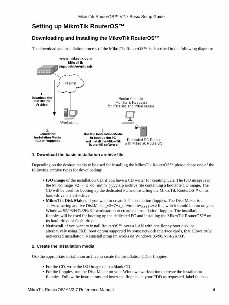
Setting up MikroTik RouterOS™
Downloading and Installing the MikroTik RouterOS™
The download and installation process of the MikroTik RouterOS™ is described in the following diagram:
1. Download the basic installation archive file.
Depending on the desired media to be used for installing the MikroTik RouterOS™ please chose one of thefollowing archive types for downloading:
ISO image of the installation CD, if you have a CD writer for creating CDs. The ISO image is inthe MTcdimage_v2−7−x_dd−mmm−yyyy.zip archive file containing a bootable CD image. TheCD will be used for booting up the dedicated PC and installing the MikroTik RouterOS™ on itshard−drive or flash−drive.
•
MikroTik Disk Maker, if you want to create 3.5" installation floppies. The Disk Maker is aself−extracting archive DiskMaker_v2−7−x_dd−mmm−yyyy.exe file, which should be run on yourWindows 95/98/NT4/2K/XP workstation to create the installation floppies. The installationfloppies will be used for booting up the dedicated PC and installing the MikroTik RouterOS™ onits hard−drive or flash−drive.
•
Netinstall, if you want to install RouterOS™ over a LAN with one floppy boot disk, oralternatively using PXE−boot option supported by some network interface cards, that allows trulynetworked installation. Netinstall program works on Windows 95/98/NT4/2K/XP.
•
2. Create the installation media
Use the appropriate installation archive to create the Installation CD or floppies.
For the CD, write the ISO image onto a blank CD.• For the floppies, run the Disk Maker on your Windows workstation to create the installationfloppies. Follow the instructions and insert the floppies in your FDD as requested, label them as
•
MikroTik RouterOS™ V2.7 Basic Setup Guide
MikroTik RouterOS™ V2.7 Reference Manual 4
Disk 1,2,3, etc.
3. Install the MikroTik RouterOS™ software.
Your dedicated PC router hardware should have:
An advanced 4th generation (core frequency 100MHz or more), 5th generation (Intel Pentium,Cyrix 6X86, AMD K5 or comparable) or newer Intel IA−32 (i386) compatible motherboard andprocessor (uniprocessor only, dual processors and other SMP configurations are not supported);
•
from 32MB to 1GB RAM (from 48MB suggested);• 30MB or more PRIMARY MASTER IDE HDD or IDE flashdrive.• A network adapter (NE2000 compatible PCI or ISA Ethernet card, or any other supported NIC,see the supported device list on our web page);
•
For installation purposes (and only for that time) you should also have:
A SECONDARY MASTER CD drive set as primary boot device, if you want to use the createdCD for installing the MikroTik RouterOS™ onto the primary master HDD;
•
A 3.5" FDD set as primary boot device, if you want to use the created set of floppies for installingthe MikroTik RouterOS™;
•
A monitor and keyboard for installation and initial setup of the MikroTik Router. The monitorand keyboard do not need to be connected to the router after it is set up for connecting to it over thenetwork.
•
Boot up your dedicated PC router from the Installation Media you created and follow the instructions on theconsole screen while the HDD is reformatted and MikroTik RouterOS™ installed on it.
After successful installation please remove the installation media from your CD or floppy disk drive and hit'Enter' to reboot the router. While the router will be starting up for the first time you will be given aSoftware ID for your installation and asked to supply a valid software license key (Software Key) for it.Write down the Software ID. You will need it to obtain the Software License through the MikroTikAccount Server. If you need extra time to obtain the Software License Key, you may want to power off therouter. Type shutdown in the Software key prompt and power the router off when the router is halted.
Notes
The installation from CD or network requires Base (paid) License. If you intend to obtain the Free DemoLicense, you should use the floppy installation media.
The hard disk will be entirely reformatted during the installation and all data on it will be lost!
You can move the hard drive with MikroTik RouterOS™ installed to a new hardware without loosing alicense, but you cannot move the RouterOS™ to a different hard drive without purchasing an anotherlicense (except hardware failure situations). For additional information write to key−[email protected]
Obtaining the Software License
The MikroTik RouterOS™ Software licensing process is described in the following diagram:
MikroTik RouterOS™ V2.7 Basic Setup Guide
MikroTik RouterOS™ V2.7 Reference Manual 5
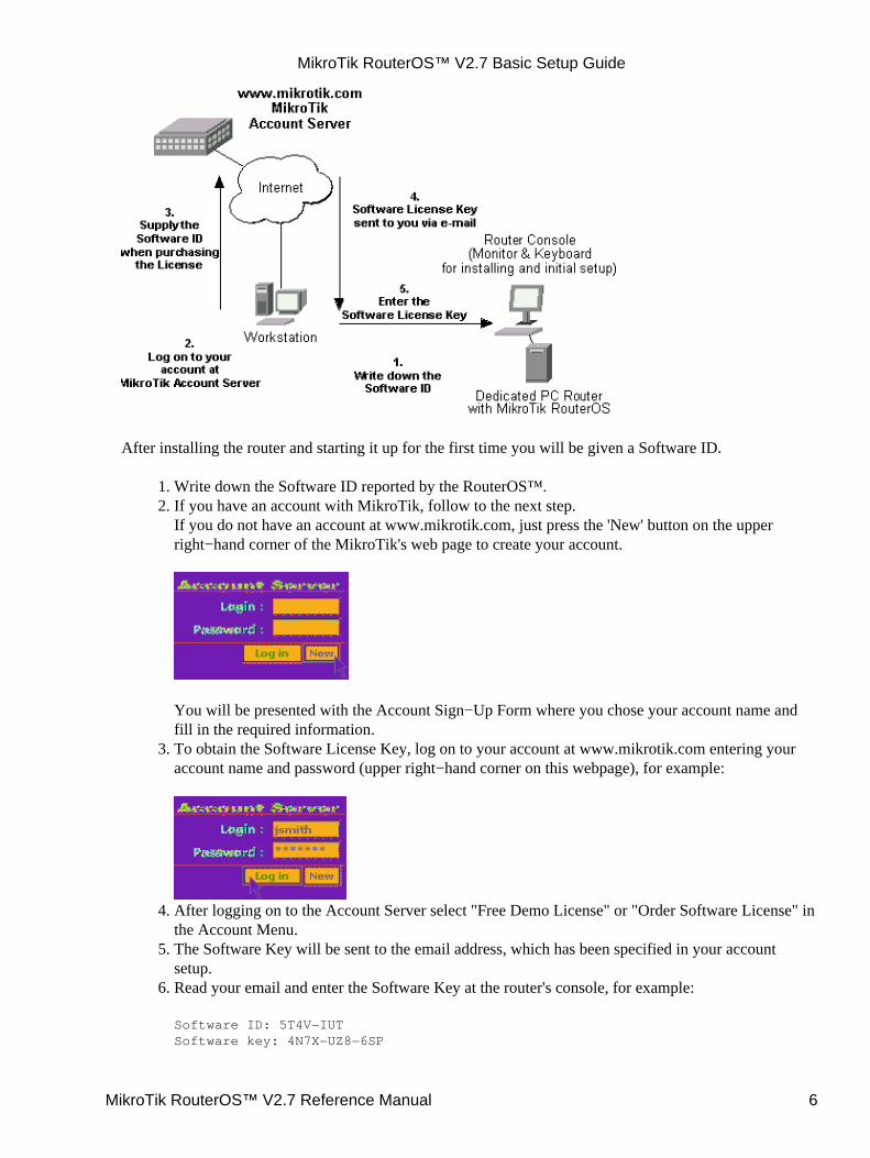
After installing the router and starting it up for the first time you will be given a Software ID.
Write down the Software ID reported by the RouterOS™.1. If you have an account with MikroTik, follow to the next step.If you do not have an account at www.mikrotik.com, just press the 'New' button on the upperright−hand corner of the MikroTik's web page to create your account.
You will be presented with the Account Sign−Up Form where you chose your account name andfill in the required information.
2.
To obtain the Software License Key, log on to your account at www.mikrotik.com entering youraccount name and password (upper right−hand corner on this webpage), for example:
3.
After logging on to the Account Server select "Free Demo License" or "Order Software License" inthe Account Menu.
4.
The Software Key will be sent to the email address, which has been specified in your accountsetup.
5.
Read your email and enter the Software Key at the router's console, for example:
Software ID: 5T4V−IUTSoftware key: 4N7X−UZ8−6SP
6.
MikroTik RouterOS™ V2.7 Basic Setup Guide
MikroTik RouterOS™ V2.7 Reference Manual 6
Instead of entering the license key you can enter shutdown to shut down the router and enter the licensekey later, or enter display to read the License Agreement, or help to see a help message.
After entering the correct Software License Key you will be presented with the MikroTik Router's loginprompt.
Notes
The CD or Netinstall installation cannot be 'unlocked' with the Free Demo Key. Use the Floppy installationor purchase a Licensed Key.
Logging into the MikroTik Router
When logging into the router via terminal console, you will be presented with the MikroTik RouterOS™login prompt. Use 'admin' and no password (hit 'Enter') for logging on to the router for the first time, forexample:
MikroTik v2.7Login: adminPassword:
The password can be changed with the /password command.
Adding Software Packages
The basic installation comes with only the "system" package and few other packages. This includes basic IProuting and router administration. To have additional features such as IP Telephony, OSPF, wireless and soon, you will need to download additional software packages.
The additional software packages should have the same version as the system package. If not, the packagewon't be installed. Please consult the MikroTik RouterOS™ Software Package Installation and UpgradingManual for more detailed information about installing additional software packages.
Software Licensing Issues
If you want to upgrade your 'free' version of MikroTik RouterOS™ installation to a 'paid' version, pleasepurchase the new Software License KEY for the Software ID you used when getting the 'free' demo license.Similarly, if additional license is required to enable the functionality of a software package, the licenseshould be obtained for the Software ID of your system. The new key should be entered using the /systemlicense set key command, and the router should be rebooted afterwards:
[admin@MikroTik] ip firewall src−nat> /system license print software−id: "SB6T−R8T" key: "3YIV−ZW8−DH2" upgradable−unitl: apr/01/2004[admin@MikroTik] system license> feature printFlags: X − disabled # FEATURE 0 X AP 1 X synchronous 2 X radiolan 3 X wireless−2.4gHz 4 licensed
MikroTik RouterOS™ V2.7 Basic Setup Guide
MikroTik RouterOS™ V2.7 Reference Manual 7
[admin@MikroTik] system license> set key=D46G−IJ6−QW3[admin@MikroTik] system license>/system rebootReboot, yes? [y/N]: ysystem will reboot shortly
Notes
If there is no appropriate license, the appropriate interfaces wont show up under the interface list, eventhough the packages can be installed on the MikroTik RouterOS™ and corresponding drivers loaded.
Navigating the Terminal Console
Welcome Screen and Command Prompt
After logging into the router you will be presented with the MikroTik RouterOS™ Welcome Screen andcommand prompt, for example:
MMM MMM KKK TTTTTTTTTTT KKK MMMM MMMM KKK TTTTTTTTTTT KKK MMM MMMM MMM III KKK KKK RRRRRR OOOOOO TTT III KKK KKK MMM MM MMM III KKKKK RRR RRR OOO OOO TTT III KKKKK MMM MMM III KKK KKK RRRRRR OOO OOO TTT III KKK KKK MMM MMM III KKK KKK RRR RRR OOOOOO TTT III KKK KKK
MikroTik RouterOS v2.7 (c) 1999−2003 http://www.mikrotik.com/
Terminal xterm detected, using multiline mode[admin@MikroTik] >
The command prompt shows the identity name of the router and the current menu level, for example:
[admin@MikroTik] > Base level menu[admin@MikroTik] interface> Interface configuration[admin@MikroTik] ip address> IP Address management
Commands
The list of available commands at any menu level can be obtained by entering the question mark '?', forexample:
[admin@MikroTik] > ?
driver Driver management file Local router file storage. import Run exported configuration script interface Interface configuration log System logs password Change password ping Send ICMP Echo packets port Serial ports quit Quit console radius Radius client settings redo Redo previosly undone action setup Do basic setup of system snmp SNMP settings
MikroTik RouterOS™ V2.7 Basic Setup Guide
MikroTik RouterOS™ V2.7 Reference Manual 8
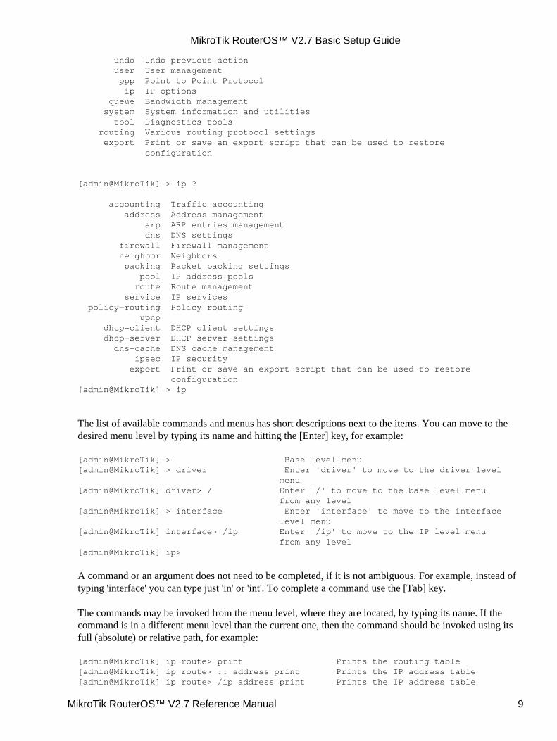
undo Undo previous action user User management ppp Point to Point Protocol ip IP options queue Bandwidth management system System information and utilities tool Diagnostics tools routing Various routing protocol settings export Print or save an export script that can be used to restore configuration
[admin@MikroTik] > ip ?
accounting Traffic accounting address Address management arp ARP entries management dns DNS settings firewall Firewall management neighbor Neighbors packing Packet packing settings pool IP address pools route Route management service IP services policy−routing Policy routing upnp dhcp−client DHCP client settings dhcp−server DHCP server settings dns−cache DNS cache management ipsec IP security export Print or save an export script that can be used to restore configuration[admin@MikroTik] > ip
The list of available commands and menus has short descriptions next to the items. You can move to thedesired menu level by typing its name and hitting the [Enter] key, for example:
[admin@MikroTik] > Base level menu[admin@MikroTik] > driver Enter 'driver' to move to the driver level menu[admin@MikroTik] driver> / Enter '/' to move to the base level menu from any level[admin@MikroTik] > interface Enter 'interface' to move to the interface level menu[admin@MikroTik] interface> /ip Enter '/ip' to move to the IP level menu from any level[admin@MikroTik] ip>
A command or an argument does not need to be completed, if it is not ambiguous. For example, instead oftyping 'interface' you can type just 'in' or 'int'. To complete a command use the [Tab] key.
The commands may be invoked from the menu level, where they are located, by typing its name. If thecommand is in a different menu level than the current one, then the command should be invoked using itsfull (absolute) or relative path, for example:
[admin@MikroTik] ip route> print Prints the routing table[admin@MikroTik] ip route> .. address print Prints the IP address table[admin@MikroTik] ip route> /ip address print Prints the IP address table
MikroTik RouterOS™ V2.7 Basic Setup Guide
MikroTik RouterOS™ V2.7 Reference Manual 9
The commands may have arguments. The arguments have their names and values. Some commands, mayhave a required argument that has no name.
Summary on executing the commands and moving between the menulevels
Command Actioncommand [Enter] Execute the command[?] Show the list of all available commandscommand [?] Display help on the command and the list of argumentscommand argument [?] Display help on the command's argument[Tab] Complete the command/word. If the input is ambiguous, a second [Tab] gives possible options/ Move up to the base level/command Execute the base level command.. Move up one level"" Enter an empty string"word1 word2" Enter 2 words that contain a space
You can abbreviate names of levels, commands and arguments.
For the IP address configuration, instead of using the 'address' and 'netmask' arguments, in most cases youcan specify the address together with the number of true bits in the network mask, i.e., there is no need tospecify the 'netmask' separately. Thus, the following two entries would be equivalent:
/ip address add address 10.0.0.1/24 interface ether1/ip address add address 10.0.0.1 netmask 255.255.255.0 interface ether1
Notes
You must specify the size of the network mask in the address argument, even if it is the 32−bit subnet, i.e.,use 10.0.0.1/32 for address 10.0.0.1 and netmask 255.255.255.255
Accessing the Router Remotely Using Web Browser andWinBox Console
Summary
The MikroTik router can also be accessed remotely using http and WinBox Console, for example, usingthe web browser of your workstation.
Description
The Winbox Console is used for accessing the MikroTik Router configuration and management featuresusing graphical user interface.
All Winbox interface functions are as close as possible to Console functions: all Winbox functions areexactly in the same place in Terminal Console and vice versa (except functions that are not implemented inWinbox). That is why there are no Winbox sections in the manual.
The Winbox Console plugin loader, the winbox.exe program, can be retrieved from the MikroTik router,
MikroTik RouterOS™ V2.7 Basic Setup Guide
MikroTik RouterOS™ V2.7 Reference Manual 10
the URL is http://router_address/winbox/winbox.exe Use any web browser on Windows95/98/ME/NT4.0/2000/XP to retrieve the router's web page with the mentioned link.
Note that if you change the default port for www service on the router, you will have to specify it just afterthe IP address separated by column (eg. 10.0.0.1:8080).
The winbox plugins are cached on the local disk for each MikroTik RouterOS™ version. The plugins arenot downloaded, if they are in the cache, and the router has not been upgraded since the last time it has beenaccessed.
Starting the Winbox Console
When connecting to the MikroTik router via http (TCP port 80 by default), the router's Welcome Page isdisplayed in the web browser, for example:
MikroTik RouterOS™ V2.7 Basic Setup Guide
MikroTik RouterOS™ V2.7 Reference Manual 11
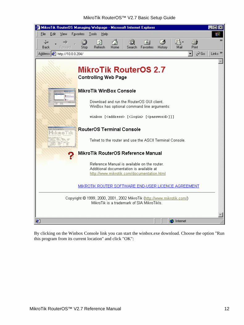
By clicking on the Winbox Console link you can start the winbox.exe download. Choose the option "Runthis program from its current location" and click "OK":
MikroTik RouterOS™ V2.7 Basic Setup Guide
MikroTik RouterOS™ V2.7 Reference Manual 12
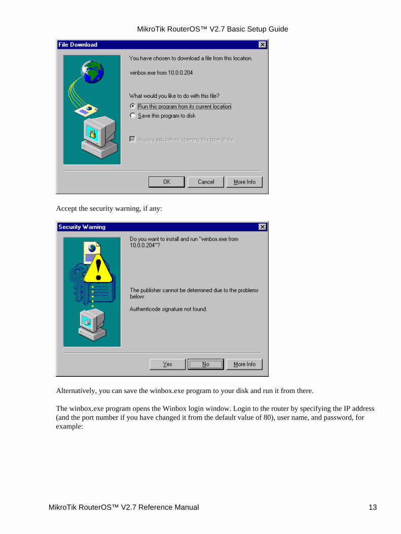
Accept the security warning, if any:
Alternatively, you can save the winbox.exe program to your disk and run it from there.
The winbox.exe program opens the Winbox login window. Login to the router by specifying the IP address(and the port number if you have changed it from the default value of 80), user name, and password, forexample:
MikroTik RouterOS™ V2.7 Basic Setup Guide
MikroTik RouterOS™ V2.7 Reference Manual 13
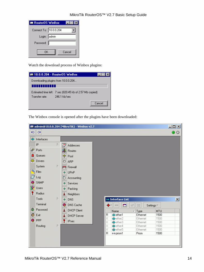
Watch the download process of Winbox plugins:
The Winbox console is opened after the plugins have been downloaded:
MikroTik RouterOS™ V2.7 Basic Setup Guide
MikroTik RouterOS™ V2.7 Reference Manual 14
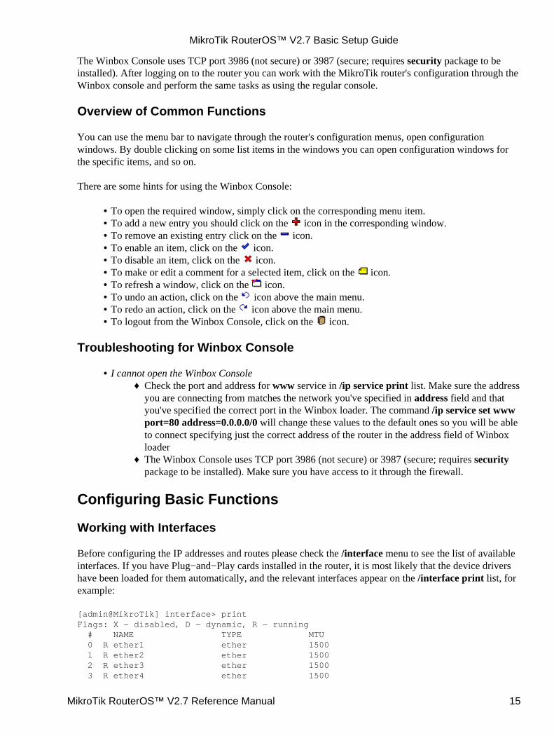
The Winbox Console uses TCP port 3986 (not secure) or 3987 (secure; requires security package to beinstalled). After logging on to the router you can work with the MikroTik router's configuration through theWinbox console and perform the same tasks as using the regular console.
Overview of Common Functions
You can use the menu bar to navigate through the router's configuration menus, open configurationwindows. By double clicking on some list items in the windows you can open configuration windows forthe specific items, and so on.
There are some hints for using the Winbox Console:
To open the required window, simply click on the corresponding menu item.• To add a new entry you should click on the icon in the corresponding window.• To remove an existing entry click on the icon.• To enable an item, click on the icon.• To disable an item, click on the icon.• To make or edit a comment for a selected item, click on the icon.• To refresh a window, click on the icon.• To undo an action, click on the icon above the main menu.• To redo an action, click on the icon above the main menu.• To logout from the Winbox Console, click on the icon.•
Troubleshooting for Winbox Console
I cannot open the Winbox ConsoleCheck the port and address for www service in /ip service print list. Make sure the addressyou are connecting from matches the network you've specified in address field and thatyou've specified the correct port in the Winbox loader. The command /ip service set wwwport=80 address=0.0.0.0/0 will change these values to the default ones so you will be ableto connect specifying just the correct address of the router in the address field of Winboxloader
♦
The Winbox Console uses TCP port 3986 (not secure) or 3987 (secure; requires securitypackage to be installed). Make sure you have access to it through the firewall.
♦
•
Configuring Basic Functions
Working with Interfaces
Before configuring the IP addresses and routes please check the /interface menu to see the list of availableinterfaces. If you have Plug−and−Play cards installed in the router, it is most likely that the device drivershave been loaded for them automatically, and the relevant interfaces appear on the /interface print list, forexample:
[admin@MikroTik] interface> printFlags: X − disabled, D − dynamic, R − running # NAME TYPE MTU 0 R ether1 ether 1500 1 R ether2 ether 1500 2 R ether3 ether 1500 3 R ether4 ether 1500
MikroTik RouterOS™ V2.7 Basic Setup Guide
MikroTik RouterOS™ V2.7 Reference Manual 15
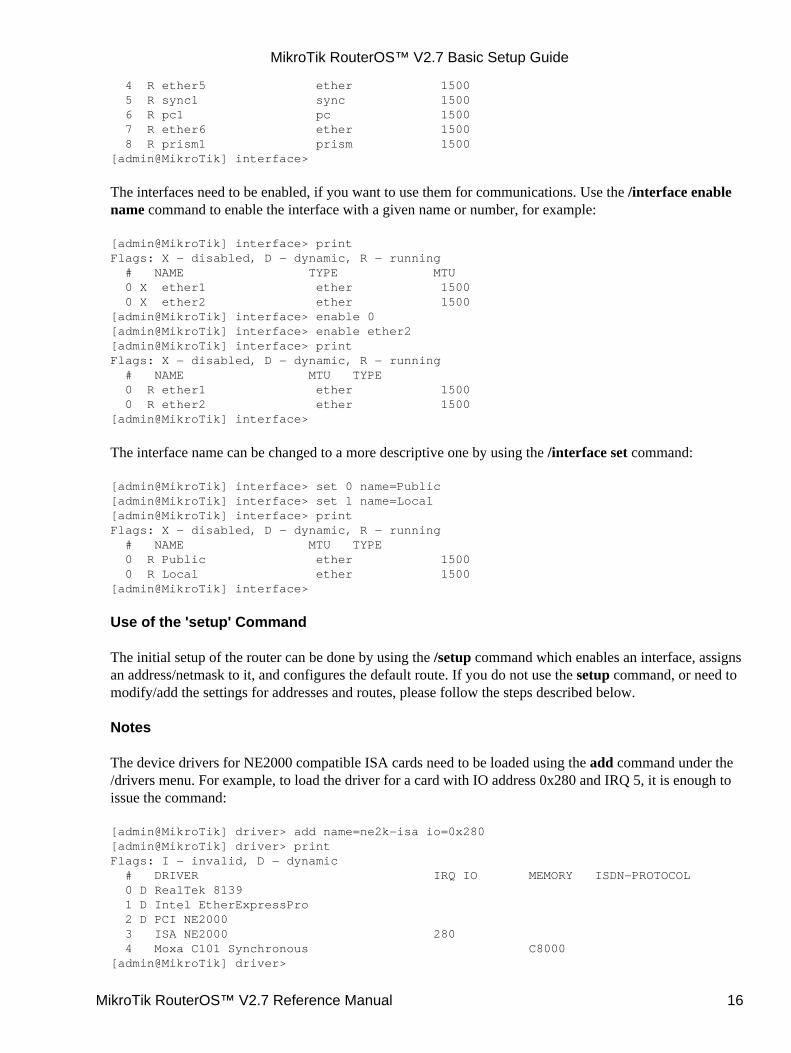
4 R ether5 ether 1500 5 R sync1 sync 1500 6 R pc1 pc 1500 7 R ether6 ether 1500 8 R prism1 prism 1500[admin@MikroTik] interface>
The interfaces need to be enabled, if you want to use them for communications. Use the /interface enablename command to enable the interface with a given name or number, for example:
[admin@MikroTik] interface> printFlags: X − disabled, D − dynamic, R − running # NAME TYPE MTU 0 X ether1 ether 1500 0 X ether2 ether 1500[admin@MikroTik] interface> enable 0[admin@MikroTik] interface> enable ether2[admin@MikroTik] interface> printFlags: X − disabled, D − dynamic, R − running # NAME MTU TYPE 0 R ether1 ether 1500 0 R ether2 ether 1500[admin@MikroTik] interface>
The interface name can be changed to a more descriptive one by using the /interface set command:
[admin@MikroTik] interface> set 0 name=Public[admin@MikroTik] interface> set 1 name=Local[admin@MikroTik] interface> printFlags: X − disabled, D − dynamic, R − running # NAME MTU TYPE 0 R Public ether 1500 0 R Local ether 1500[admin@MikroTik] interface>
Use of the 'setup' Command
The initial setup of the router can be done by using the /setup command which enables an interface, assignsan address/netmask to it, and configures the default route. If you do not use the setup command, or need tomodify/add the settings for addresses and routes, please follow the steps described below.
Notes
The device drivers for NE2000 compatible ISA cards need to be loaded using the add command under the/drivers menu. For example, to load the driver for a card with IO address 0x280 and IRQ 5, it is enough toissue the command:
[admin@MikroTik] driver> add name=ne2k−isa io=0x280[admin@MikroTik] driver> printFlags: I − invalid, D − dynamic # DRIVER IRQ IO MEMORY ISDN−PROTOCOL 0 D RealTek 8139 1 D Intel EtherExpressPro 2 D PCI NE2000 3 ISA NE2000 280 4 Moxa C101 Synchronous C8000[admin@MikroTik] driver>
MikroTik RouterOS™ V2.7 Basic Setup Guide
MikroTik RouterOS™ V2.7 Reference Manual 16
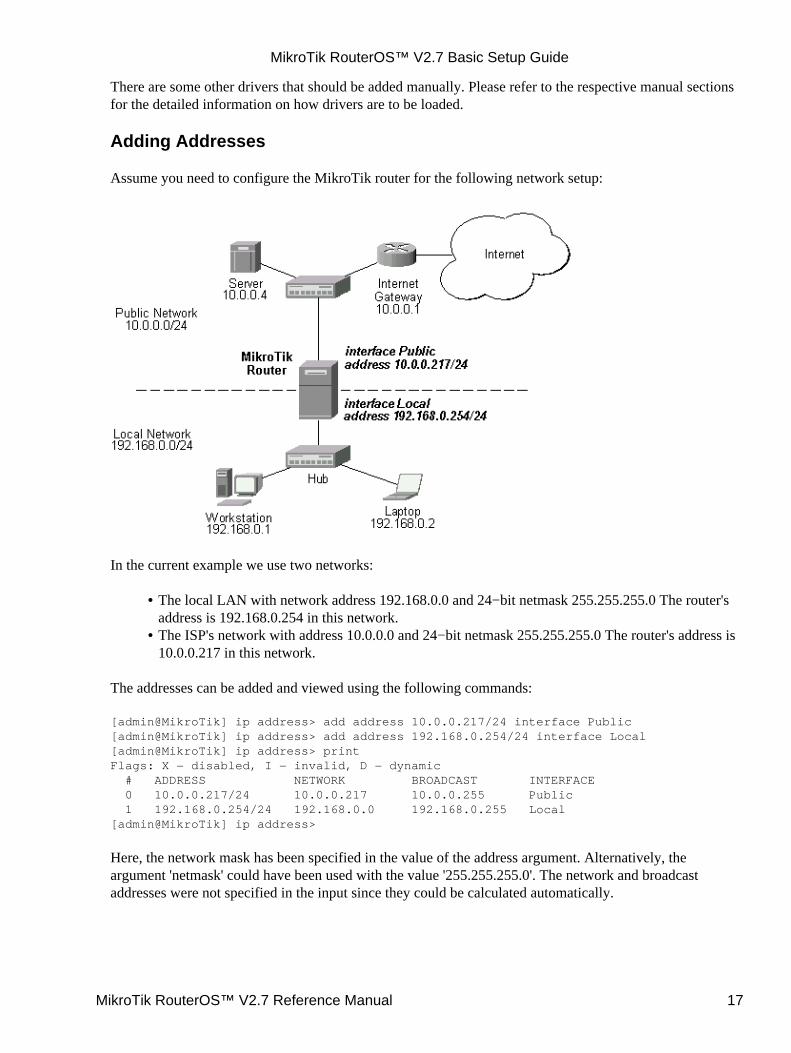
There are some other drivers that should be added manually. Please refer to the respective manual sectionsfor the detailed information on how drivers are to be loaded.
Adding Addresses
Assume you need to configure the MikroTik router for the following network setup:
In the current example we use two networks:
The local LAN with network address 192.168.0.0 and 24−bit netmask 255.255.255.0 The router'saddress is 192.168.0.254 in this network.
•
The ISP's network with address 10.0.0.0 and 24−bit netmask 255.255.255.0 The router's address is10.0.0.217 in this network.
•
The addresses can be added and viewed using the following commands:
[admin@MikroTik] ip address> add address 10.0.0.217/24 interface Public[admin@MikroTik] ip address> add address 192.168.0.254/24 interface Local[admin@MikroTik] ip address> printFlags: X − disabled, I − invalid, D − dynamic # ADDRESS NETWORK BROADCAST INTERFACE 0 10.0.0.217/24 10.0.0.217 10.0.0.255 Public 1 192.168.0.254/24 192.168.0.0 192.168.0.255 Local[admin@MikroTik] ip address>
Here, the network mask has been specified in the value of the address argument. Alternatively, theargument 'netmask' could have been used with the value '255.255.255.0'. The network and broadcastaddresses were not specified in the input since they could be calculated automatically.
MikroTik RouterOS™ V2.7 Basic Setup Guide
MikroTik RouterOS™ V2.7 Reference Manual 17
Notes
Please note that the addresses assigned to different interfaces of the router should belong to differentnetworks.
Configuring the Default Route
You can see two dynamic (D) and connected (C) routes, which have been added automatically when theaddresses were added in the example above:
[admin@MikroTik] ip route> printFlags: X − disabled, I − invalid, D − dynamic, J − rejected,C − connect, S − static, R − rip, O − ospf, B − bgp # DST−ADDRESS G GATEWAY DISTANCE INTERFACE 0 DC 192.168.0.0/24 r 0.0.0.0 0 Local 1 DC 10.0.0.0/24 r 0.0.0.0 0 Public[admin@MikroTik] ip route> print detailFlags: X − disabled, I − invalid, D − dynamic, J − rejected,C − connect, S − static, R − rip, O − ospf, B − bgp 0 DC dst−address=192.168.0.0/24 preferred−source=192.168.0.254 gateway=0.0.0.0 gateway−state=reachable distance=0 interface=Local
1 DC dst−address=10.0.0.0/24 preferred−source=10.0.0.217 gateway=0.0.0.0 gateway−state=reachable distance=0 interface=Public
[admin@MikroTik] ip route>
These routes show, that IP packets with destination to 10.0.0.0/24 would be sent through the interfacePublic, whereas IP packets with destination to 192.168.0.0/24 would be sent through the interface Local.However, you need to specify where the router should forward packets, which have destination other thannetworks connected directly to the router.
Example
In the following example the default route (destination 0.0.0.0, netmask 0.0.0.0) will be added. In this caseit is the ISP's gateway 10.0.0.1, which can be reached through the interface Public:
[admin@MikroTik] ip route> add gateway=10.0.0.1[admin@MikroTik] ip route> printFlags: X − disabled, I − invalid, D − dynamic, J − rejected,C − connect, S − static, R − rip, O − ospf, B − bgp # DST−ADDRESS G GATEWAY DISTANCE INTERFACE 0 S 0.0.0.0/0 r 10.0.0.1 1 Public 1 DC 192.168.0.0/24 r 0.0.0.0 0 Local 2 DC 10.0.0.0/24 r 0.0.0.0 0 Public[admin@MikroTik] ip route>
Here, the default route is listed under #0. As we see, the gateway 10.0.0.1 can be reached through theinterface 'Public'. If the gateway was specified incorrectly, the value for the argument 'interface' would beunknown.
Notes
You cannot add two routes to the same destination, i.e., destination−address/netmask! It applies to thedefault routes as well. Instead, you can enter multiple gateways for one destination. For more information
MikroTik RouterOS™ V2.7 Basic Setup Guide
MikroTik RouterOS™ V2.7 Reference Manual 18

on IP routes, please read the relevant topic in the Manual.
If you have added an unwanted static route accidentally, use the remove command to delete the unneededone. You will not be able to delete dynamic (DC) routes. They are added automatically and represent routesto the networks the router connected directly.
Testing the Network Connectivity
From now on, the /ping command can be used to test the network connectivity on both interfaces. You canreach any host on both connected networks from the router.
Example
In the example below it's seen, hows does ping command work:
[admin@MikroTik] ip route> /ping 10.0.0.410.0.0.4 64 byte ping: ttl=255 time=7 ms10.0.0.4 64 byte ping: ttl=255 time=5 ms10.0.0.4 64 byte ping: ttl=255 time=5 ms3 packets transmitted, 3 packets received, 0% packet lossround−trip min/avg/max = 5/5.6/7 ms[admin@MikroTik] ip route>[admin@MikroTik] ip route> /ping 192.168.0.1192.168.0.1 64 byte ping: ttl=255 time=1 ms192.168.0.1 64 byte ping: ttl=255 time=1 ms192.168.0.1 64 byte ping: ttl=255 time=1 ms3 packets transmitted, 3 packets received, 0% packet lossround−trip min/avg/max = 1/1.0/1 ms[admin@MikroTik] ip route>
The workstation and the laptop can reach (ping) the router at its local address 192.168.0.254, If the router'saddress 192.168.0.254 is specified as the default gateway in the TCP/IP configuration of both theworkstation and the laptop, then you should be able to ping the router:
C:\>ping 192.168.0.254Reply from 192.168.0.254: bytes=32 time=10ms TTL=253Reply from 192.168.0.254: bytes=32 time<10ms TTL=253Reply from 192.168.0.254: bytes=32 time<10ms TTL=253
C:\>ping 10.0.0.217Reply from 10.0.0.217: bytes=32 time=10ms TTL=253Reply from 10.0.0.217: bytes=32 time<10ms TTL=253Reply from 10.0.0.217: bytes=32 time<10ms TTL=253
C:\>ping 10.0.0.4Request timed out.Request timed out.Request timed out.
C:\>
Notes
You cannot access anything beyond the router (network 10.0.0.0/24 and the Internet), unless you do the oneof the following:
MikroTik RouterOS™ V2.7 Basic Setup Guide
MikroTik RouterOS™ V2.7 Reference Manual 19

Use source network address translation (masquerading) on the MikroTik router to 'hide' yourprivate LAN 192.168.0.0/24 (see the information below), or
•
Add a static route on the ISP's gateway 10.0.0.1, which specifies the host 10.0.0.217 as the gatewayto network 192.168.0.0/24. Then all hosts on the ISP's network, including the server, will be able tocommunicate with the hosts on the LAN.
•
To set up routing, it is required that you have some knowledge of configuring TCP/IP networks. There is acomprehensive list of IP resources compiled by Uri Raz at http://www.private.org.il/tcpip_rl.html Westrongly recommend that you obtain more knowledge, if you have difficulties configuring your networksetups.
Application Examples
Next will be discussed situation with 'hiding' the private LAN 192.168.0.0/24 'behind' one address10.0.0.217 given to you by the ISP.
Application Example with Masquerading
If you want to 'hide' the private LAN 192.168.0.0/24 'behind' one address 10.0.0.217 given to you by theISP, you should use the source network address translation (masquerading) feature of the MikroTik router.Masquerading is useful, if you want to access the ISP's network and the Internet appearing as all requestscoming from the host 10.0.0.217 of the ISP's network. The masquerading will change the source IP addressand port of the packets originated from the network 192.168.0.0/24 to the address 10.0.0.217 of the routerwhen the packet is routed through it.
Masquerading conserves the number of global IP addresses required and it lets the whole network use asingle IP address in its communication with the world.
To use masquerading, a source NAT rule with action 'masquerade' should be added to the firewallconfiguration:
[admin@MikroTik] ip firewall src−nat> add action=masquerade out−interface=Public[admin@MikroTik] ip firewall src−nat> printFlags: X − disabled, I − invalid, D − dynamic 0 src−address=0.0.0.0/0:0−65535 dst−address=0.0.0.0/0:0−65535 out−interface=Public protocol=all icmp−options=any:any flow="" connection="" content="" limit−count=0 limit−burst=0 limit−time=0s action=masquerade to−src−address=0.0.0.0 to−src−port=0−65535
[admin@MikroTik] ip firewall src−nat>
Notes
Please consult the Firewall Manual for more information on masquerading.
Application Example with Bandwidth Management
Mikrotik RouterOS™ V2.7 offers extensive queue management.
Assume you want to limit the bandwidth to 128kbps on downloads and 64kbps on uploads for all hosts onthe LAN. Bandwidth limitation is done by applying queues for outgoing interfaces regarding the traffic
MikroTik RouterOS™ V2.7 Basic Setup Guide
MikroTik RouterOS™ V2.7 Reference Manual 20
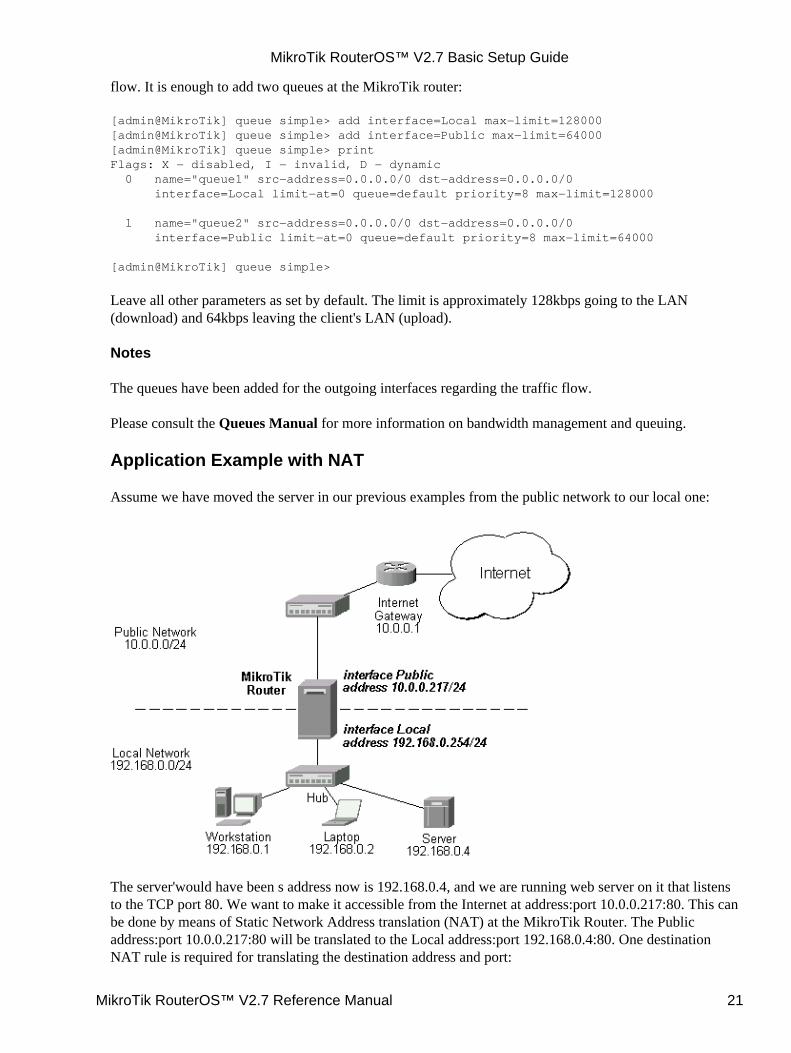
flow. It is enough to add two queues at the MikroTik router:
[admin@MikroTik] queue simple> add interface=Local max−limit=128000[admin@MikroTik] queue simple> add interface=Public max−limit=64000[admin@MikroTik] queue simple> printFlags: X − disabled, I − invalid, D − dynamic 0 name="queue1" src−address=0.0.0.0/0 dst−address=0.0.0.0/0 interface=Local limit−at=0 queue=default priority=8 max−limit=128000
1 name="queue2" src−address=0.0.0.0/0 dst−address=0.0.0.0/0 interface=Public limit−at=0 queue=default priority=8 max−limit=64000
[admin@MikroTik] queue simple>
Leave all other parameters as set by default. The limit is approximately 128kbps going to the LAN(download) and 64kbps leaving the client's LAN (upload).
Notes
The queues have been added for the outgoing interfaces regarding the traffic flow.
Please consult the Queues Manual for more information on bandwidth management and queuing.
Application Example with NAT
Assume we have moved the server in our previous examples from the public network to our local one:
The server'would have been s address now is 192.168.0.4, and we are running web server on it that listensto the TCP port 80. We want to make it accessible from the Internet at address:port 10.0.0.217:80. This canbe done by means of Static Network Address translation (NAT) at the MikroTik Router. The Publicaddress:port 10.0.0.217:80 will be translated to the Local address:port 192.168.0.4:80. One destinationNAT rule is required for translating the destination address and port:
MikroTik RouterOS™ V2.7 Basic Setup Guide
MikroTik RouterOS™ V2.7 Reference Manual 21
[admin@MikroTik] ip firewall dst−nat> add action=nat protocol=tcp \dst−address=10.0.0.217/32:80 to−dst−address=192.168.0.4[admin@MikroTik] ip firewall dst−nat> printFlags: X − disabled, I − invalid, D − dynamic 0 src−address=0.0.0.0/0:0−65535 in−interface=all dst−address=10.1.0.217/32:80 protocol=tcp icmp−options=any:any flow="" src−mac−address=00:00:00:00:00:00 limit−count=0 limit−burst=0 limit−time=0s action=nat to−dst−address=192.168.0.4 to−dst−port=0−65535
[admin@MikroTik] ip firewall dst−nat>
Notes
Please consult the Firewall Manual for more information on NAT.
© Copyright 1999−2003, MikroTik
MikroTik RouterOS™ V2.7 Basic Setup Guide
MikroTik RouterOS™ V2.7 Reference Manual 22
Terminal Console ManualDocument revision 1.1 (29−Jan−2003)This document applies to the MikroTik RouterOS v2.7
Table of Contents
Table of Contents• Summary• Specifications• Related Documents• Overview of Common Functions
Lists♦ Item Names♦ Quick Typing♦ Help♦ Internal Item numbers♦ Multiple Items♦
•
General Commandsprint♦ set♦ add♦ remove♦ move♦ find♦ export♦ enable/disable♦
•
Safe Mode•
Summary
The Terminal Console is used for accessing the MikroTik Router configuration and management featuresusing text terminals, i.e., remote terminal clients, as well as local monitor and keyboard. The TerminalConsole is used for writing scripts. This manual describes the general console operation principles. Pleaseconsult the Scripting Manual on some advanced console commands and on how to write scripts.
Specifications
Packages required : systemLicense required : AnyHome menu level : NoneProtocols utilized : NoneHardware usage: not significant
Related Documents
Scripting Manual
MikroTik RouterOS™ V2.7 Reference Manual 23

Overview of Common Functions
The console allows configuration of the router settings using text commands. The command structure issimilar to the Unix shell. Since there's a lot of available commands, they're split into hierarchy. For example,all (well, almost all) commands that work with routes start with ip route:
[admin@MikroTik] > ip route printFlags: X − disabled, I − invalid, D − dynamic, J − rejected,C − connect, S − static, R − rip, O − ospf, B − bgp # DST−ADDRESS G GATEWAY DISTANCE INTERFACE 0 S 0.0.0.0/0 r 10.0.0.1 1 ether6 r 192.168.1.254 ether4 1 DC 192.168.1.0/24 r 0.0.0.0 0 ether4 2 DC 10.10.10.0/24 r 0.0.0.0 0 prism1 3 DC 10.0.0.0/24 r 0.0.0.0 0 ether6[admin@MikroTik] > ip route set 0 gateway=10.0.0.1[admin@MikroTik] > ip route printFlags: X − disabled, I − invalid, D − dynamic, J − rejected,C − connect, S − static, R − rip, O − ospf, B − bgp # DST−ADDRESS G GATEWAY DISTANCE INTERFACE 0 S 0.0.0.0/0 r 10.0.0.1 1 ether6 1 DC 192.168.1.0/24 r 0.0.0.0 0 ether4 2 DC 10.10.10.0/24 r 0.0.0.0 0 prism1 3 DC 10.0.0.0/24 r 0.0.0.0 0 ether6[admin@MikroTik] >
Instead of typing ip route before each command, ip route can be typed once to "change into" that particularbranch of command hierarchy. Thus, the example above could also be executed like this:
[admin@MikroTik] > ip route[admin@MikroTik] ip route> printFlags: X − disabled, I − invalid, D − dynamic, J − rejected,C − connect, S − static, R − rip, O − ospf, B − bgp # DST−ADDRESS G GATEWAY DISTANCE INTERFACE 0 S 0.0.0.0/0 r 10.0.0.1 1 ether6 1 DC 192.168.1.0/24 r 0.0.0.0 0 ether4 2 DC 10.10.10.0/24 r 0.0.0.0 0 prism1 3 DC 10.0.0.0/24 r 0.0.0.0 0 ether6[admin@MikroTik] ip route>
Notice that prompt changes to show where in the command hierarchy you are located at the moment. Tochange to top level, type /
[admin@MikroTik] ip route> /[admin@MikroTik] >
To move up one command level, type ..
[admin@MikroTik] ip route> ..[admin@MikroTik] ip>
You can also use / and .. to execute commands from other levels without changing the current level:
[admin@MikroTik] ip route> /ping 10.0.0.1010.0.0.10 64 byte pong: ttl=128 time=5 ms10.0.0.10 64 byte pong: ttl=128 time=6 ms2 packets transmitted, 2 packets received, 0% packet loss
Terminal Console Manual
MikroTik RouterOS™ V2.7 Reference Manual 24
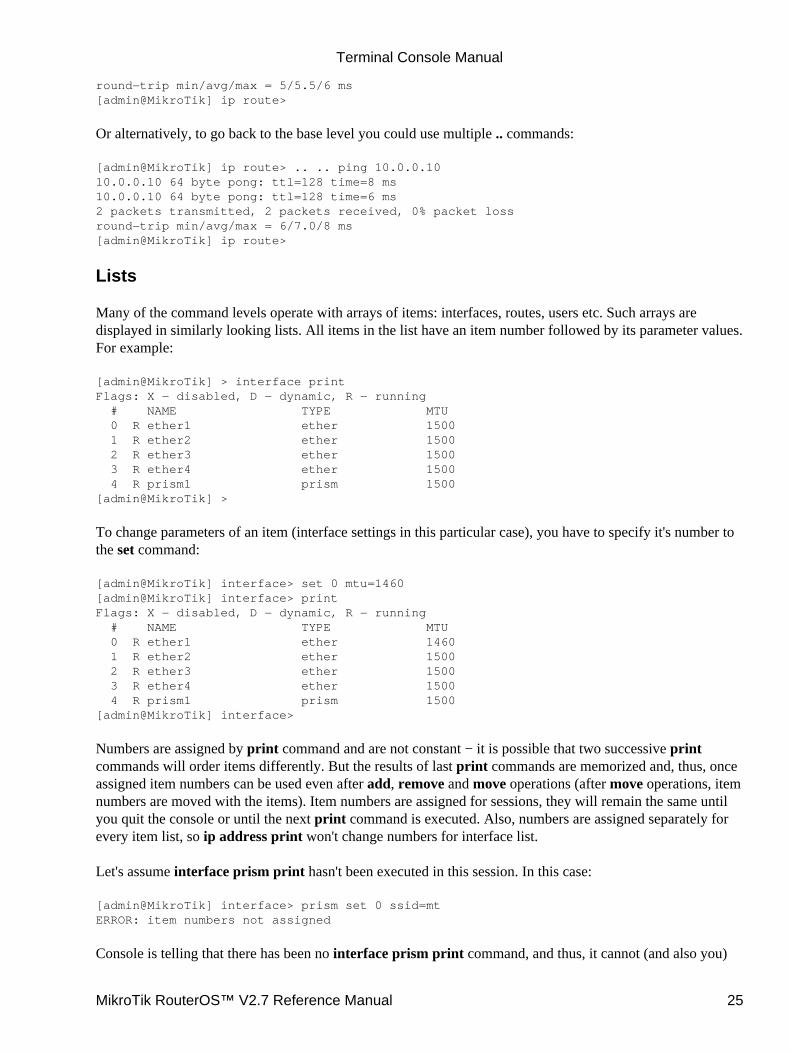
round−trip min/avg/max = 5/5.5/6 ms[admin@MikroTik] ip route>
Or alternatively, to go back to the base level you could use multiple .. commands:
[admin@MikroTik] ip route> .. .. ping 10.0.0.1010.0.0.10 64 byte pong: ttl=128 time=8 ms10.0.0.10 64 byte pong: ttl=128 time=6 ms2 packets transmitted, 2 packets received, 0% packet lossround−trip min/avg/max = 6/7.0/8 ms[admin@MikroTik] ip route>
Lists
Many of the command levels operate with arrays of items: interfaces, routes, users etc. Such arrays aredisplayed in similarly looking lists. All items in the list have an item number followed by its parameter values.For example:
[admin@MikroTik] > interface printFlags: X − disabled, D − dynamic, R − running # NAME TYPE MTU 0 R ether1 ether 1500 1 R ether2 ether 1500 2 R ether3 ether 1500 3 R ether4 ether 1500 4 R prism1 prism 1500[admin@MikroTik] >
To change parameters of an item (interface settings in this particular case), you have to specify it's number tothe set command:
[admin@MikroTik] interface> set 0 mtu=1460[admin@MikroTik] interface> printFlags: X − disabled, D − dynamic, R − running # NAME TYPE MTU 0 R ether1 ether 1460 1 R ether2 ether 1500 2 R ether3 ether 1500 3 R ether4 ether 1500 4 R prism1 prism 1500[admin@MikroTik] interface>
Numbers are assigned by print command and are not constant − it is possible that two successive printcommands will order items differently. But the results of last print commands are memorized and, thus, onceassigned item numbers can be used even after add, remove and move operations (after move operations, itemnumbers are moved with the items). Item numbers are assigned for sessions, they will remain the same untilyou quit the console or until the next print command is executed. Also, numbers are assigned separately forevery item list, so ip address print won't change numbers for interface list.
Let's assume interface prism print hasn't been executed in this session. In this case:
[admin@MikroTik] interface> prism set 0 ssid=mtERROR: item numbers not assigned
Console is telling that there has been no interface prism print command, and thus, it cannot (and also you)
Terminal Console Manual
MikroTik RouterOS™ V2.7 Reference Manual 25
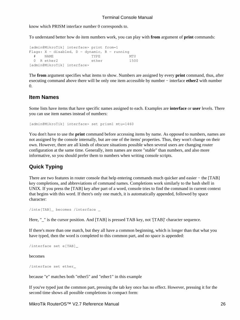
know which PRISM interface number 0 corresponds to.
To understand better how do item numbers work, you can play with from argument of print commands:
[admin@MikroTik] interface> print from=1Flags: X − disabled, D − dynamic, R − running # NAME TYPE MTU 0 R ether2 ether 1500[admin@MikroTik] interface>
The from argument specifies what items to show. Numbers are assigned by every print command, thus, afterexecuting command above there will be only one item accessible by number − interface ether2 with number0.
Item Names
Some lists have items that have specific names assigned to each. Examples are interface or user levels. Thereyou can use item names instead of numbers:
[admin@MikroTik] interface> set prism1 mtu=1460
You don't have to use the print command before accessing items by name. As opposed to numbers, names arenot assigned by the console internally, but are one of the items' properties. Thus, they won't change on theirown. However, there are all kinds of obscure situations possible when several users are changing routerconfiguration at the same time. Generally, item names are more "stable" than numbers, and also moreinformative, so you should prefer them to numbers when writing console scripts.
Quick Typing
There are two features in router console that help entering commands much quicker and easier − the [TAB]key completions, and abbreviations of command names. Completions work similarly to the bash shell inUNIX. If you press the [TAB] key after part of a word, console tries to find the command in current contextthat begins with this word. If there's only one match, it is automatically appended, followed by spacecharacter:
/inte[TAB]_ becomes /interface _
Here, "_" is the cursor position. And [TAB] is pressed TAB key, not '[TAB]' character sequence.
If there's more than one match, but they all have a common beginning, which is longer than that what youhave typed, then the word is completed to this common part, and no space is appended:
/interface set e[TAB]_
becomes
/interface set ether_
because "e" matches both "ether5" and "ether1" in this example
If you've typed just the common part, pressing the tab key once has no effect. However, pressing it for thesecond time shows all possible completions in compact form:
Terminal Console Manual
MikroTik RouterOS™ V2.7 Reference Manual 26
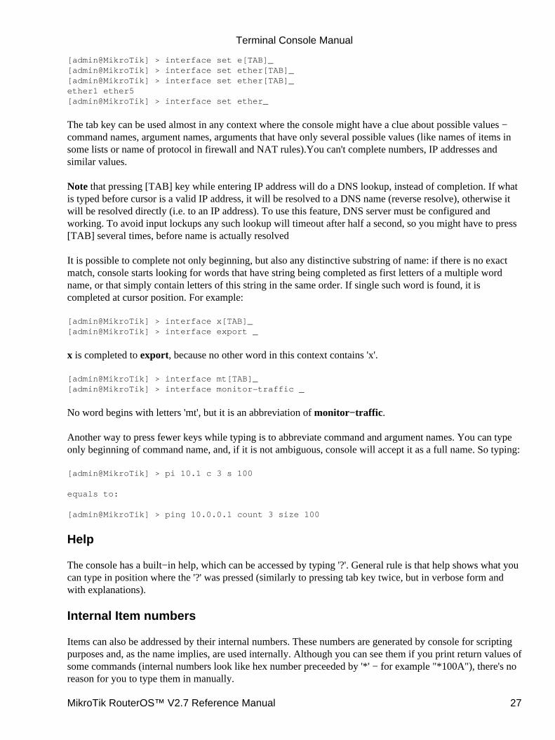
[admin@MikroTik] > interface set e[TAB]_[admin@MikroTik] > interface set ether[TAB]_[admin@MikroTik] > interface set ether[TAB]_ether1 ether5[admin@MikroTik] > interface set ether_
The tab key can be used almost in any context where the console might have a clue about possible values −command names, argument names, arguments that have only several possible values (like names of items insome lists or name of protocol in firewall and NAT rules).You can't complete numbers, IP addresses andsimilar values.
Note that pressing [TAB] key while entering IP address will do a DNS lookup, instead of completion. If whatis typed before cursor is a valid IP address, it will be resolved to a DNS name (reverse resolve), otherwise itwill be resolved directly (i.e. to an IP address). To use this feature, DNS server must be configured andworking. To avoid input lockups any such lookup will timeout after half a second, so you might have to press[TAB] several times, before name is actually resolved
It is possible to complete not only beginning, but also any distinctive substring of name: if there is no exactmatch, console starts looking for words that have string being completed as first letters of a multiple wordname, or that simply contain letters of this string in the same order. If single such word is found, it iscompleted at cursor position. For example:
[admin@MikroTik] > interface x[TAB]_[admin@MikroTik] > interface export _
x is completed to export, because no other word in this context contains 'x'.
[admin@MikroTik] > interface mt[TAB]_[admin@MikroTik] > interface monitor−traffic _
No word begins with letters 'mt', but it is an abbreviation of monitor−traffic.
Another way to press fewer keys while typing is to abbreviate command and argument names. You can typeonly beginning of command name, and, if it is not ambiguous, console will accept it as a full name. So typing:
[admin@MikroTik] > pi 10.1 c 3 s 100
equals to:
[admin@MikroTik] > ping 10.0.0.1 count 3 size 100
Help
The console has a built−in help, which can be accessed by typing '?'. General rule is that help shows what youcan type in position where the '?' was pressed (similarly to pressing tab key twice, but in verbose form andwith explanations).
Internal Item numbers
Items can also be addressed by their internal numbers. These numbers are generated by console for scriptingpurposes and, as the name implies, are used internally. Although you can see them if you print return values ofsome commands (internal numbers look like hex number preceeded by '*' − for example "*100A"), there's noreason for you to type them in manually.
Terminal Console Manual
MikroTik RouterOS™ V2.7 Reference Manual 27
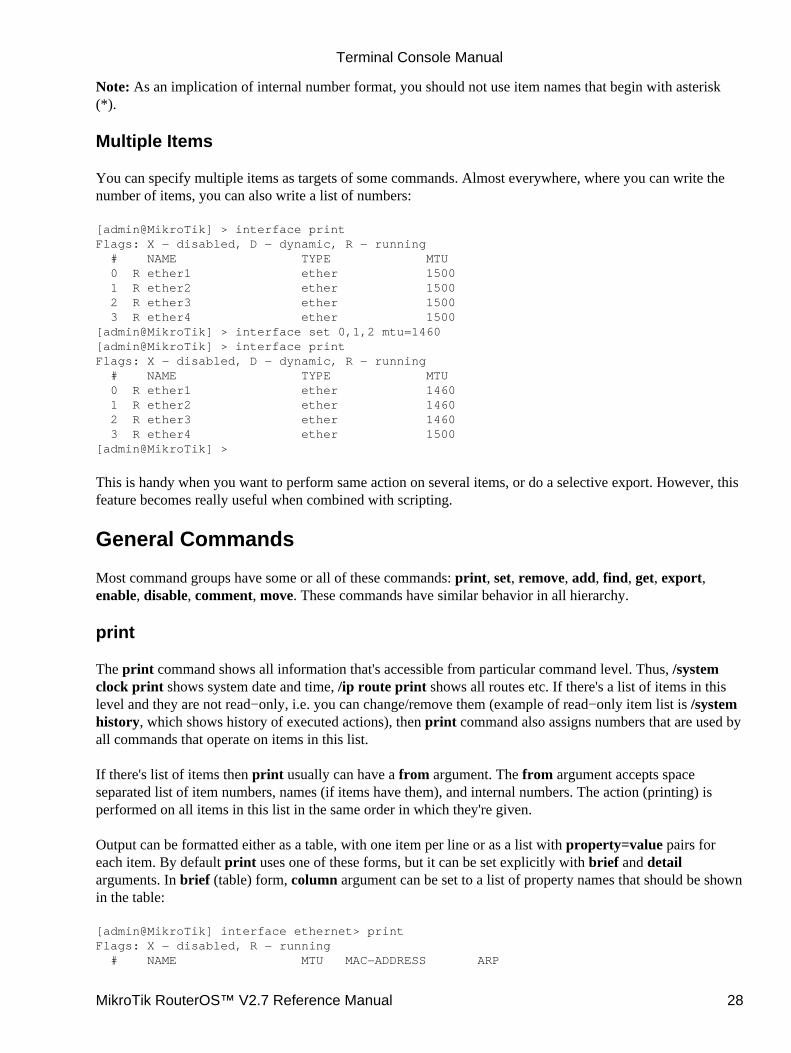
Note: As an implication of internal number format, you should not use item names that begin with asterisk(*).
Multiple Items
You can specify multiple items as targets of some commands. Almost everywhere, where you can write thenumber of items, you can also write a list of numbers:
[admin@MikroTik] > interface printFlags: X − disabled, D − dynamic, R − running # NAME TYPE MTU 0 R ether1 ether 1500 1 R ether2 ether 1500 2 R ether3 ether 1500 3 R ether4 ether 1500[admin@MikroTik] > interface set 0,1,2 mtu=1460[admin@MikroTik] > interface printFlags: X − disabled, D − dynamic, R − running # NAME TYPE MTU 0 R ether1 ether 1460 1 R ether2 ether 1460 2 R ether3 ether 1460 3 R ether4 ether 1500[admin@MikroTik] >
This is handy when you want to perform same action on several items, or do a selective export. However, thisfeature becomes really useful when combined with scripting.
General Commands
Most command groups have some or all of these commands: print, set, remove, add, find, get, export,enable, disable, comment, move. These commands have similar behavior in all hierarchy.
The print command shows all information that's accessible from particular command level. Thus, /systemclock print shows system date and time, /ip route print shows all routes etc. If there's a list of items in thislevel and they are not read−only, i.e. you can change/remove them (example of read−only item list is /systemhistory, which shows history of executed actions), then print command also assigns numbers that are used byall commands that operate on items in this list.
If there's list of items then print usually can have a from argument. The from argument accepts spaceseparated list of item numbers, names (if items have them), and internal numbers. The action (printing) isperformed on all items in this list in the same order in which they're given.
Output can be formatted either as a table, with one item per line or as a list with property=value pairs foreach item. By default print uses one of these forms, but it can be set explicitly with brief and detailarguments. In brief (table) form, column argument can be set to a list of property names that should be shownin the table:
[admin@MikroTik] interface ethernet> printFlags: X − disabled, R − running # NAME MTU MAC−ADDRESS ARP
Terminal Console Manual
MikroTik RouterOS™ V2.7 Reference Manual 28

0 R ether1 1460 00:50:08:00:00:F5 enabled 1 R ether2 1460 00:50:08:00:00:F6 enabled[admin@MikroTik] interface ethernet> print briefFlags: X − disabled, R − running # NAME MTU MAC−ADDRESS ARP 0 R ether1 1460 00:50:08:00:00:F5 enabled 1 R ether2 1460 00:50:08:00:00:F6 enabled[admin@MikroTik] interface ethernet> print detailFlags: X − disabled, R − running 0 R name="ether1" mtu=1460 mac−address=00:50:08:00:00:F5 arp=enabled disable−running−check=yes
1 R name="ether2" mtu=1460 mac−address=00:50:08:00:00:F6 arp=enabled disable−running−check=yes
[admin@MikroTik] interface ethernet> print brief column=mtu,arpFlags: X − disabled, R − running # MTU ARP 0 R 1460 enabled 1 R 1460 enabled[admin@MikroTik] interface ethernet> print
Rules that do some accounting (for example, ip firewall or queue rules) may have two additional views ofpackets and of bytes matched these rules:
[admin@MikroTik] ip firewall rule forward> print packetsFlags: X − disabled, I − invalid # SRC−ADDRESS DST−ADDRESS PACKETS 0 0.0.0.0/0:0−65535 0.0.0.0/0:0−65535 0[admin@MikroTik] ip firewall rule forward> print bytesFlags: X − disabled, I − invalid # SRC−ADDRESS DST−ADDRESS BYTES 0 0.0.0.0/0:0−65535 0.0.0.0/0:0−65535 0[admin@MikroTik] ip firewall rule forward>
To reset these counters reset−counters command is used.
Some items might have statistics other than matched bytes and packets. You can see it by using print statscommand:
[admin@MikroTik] ip ipsec> policy print statsFlags: X − disabled, I − invalid 0 src−address=10.0.0.205/32:any dst−address=10.0.0.201/32:any protocol=icmp ph2−state=no−phase2 in−accepted=0 in−dropped=0 out−accepted=0 out−dropped=0 encrypted=0 not−encrypted=0 decrypted=0 not−decrypted=0
[admin@MikroTik] ip ipsec>
There migtht also be print status command:
[admin@MikroTik] routing bgp peer> print status # REMOTE−ADDRESS REMOTE−AS STATE ROUTES−RECEIVED 0 159.148.42.158 2588 connected 1[admin@MikroTik] routing bgp>
Terminal Console Manual
MikroTik RouterOS™ V2.7 Reference Manual 29
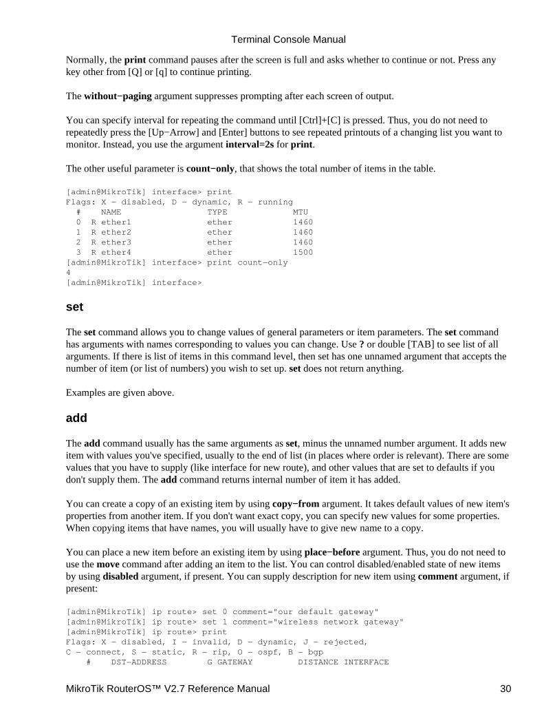
Normally, the print command pauses after the screen is full and asks whether to continue or not. Press anykey other from [Q] or [q] to continue printing.
The without−paging argument suppresses prompting after each screen of output.
You can specify interval for repeating the command until [Ctrl]+[C] is pressed. Thus, you do not need torepeatedly press the [Up−Arrow] and [Enter] buttons to see repeated printouts of a changing list you want tomonitor. Instead, you use the argument interval=2s for print.
The other useful parameter is count−only, that shows the total number of items in the table.
[admin@MikroTik] interface> printFlags: X − disabled, D − dynamic, R − running # NAME TYPE MTU 0 R ether1 ether 1460 1 R ether2 ether 1460 2 R ether3 ether 1460 3 R ether4 ether 1500[admin@MikroTik] interface> print count−only4[admin@MikroTik] interface>
set
The set command allows you to change values of general parameters or item parameters. The set commandhas arguments with names corresponding to values you can change. Use ? or double [TAB] to see list of allarguments. If there is list of items in this command level, then set has one unnamed argument that accepts thenumber of item (or list of numbers) you wish to set up. set does not return anything.
Examples are given above.
add
The add command usually has the same arguments as set, minus the unnamed number argument. It adds newitem with values you've specified, usually to the end of list (in places where order is relevant). There are somevalues that you have to supply (like interface for new route), and other values that are set to defaults if youdon't supply them. The add command returns internal number of item it has added.
You can create a copy of an existing item by using copy−from argument. It takes default values of new item'sproperties from another item. If you don't want exact copy, you can specify new values for some properties.When copying items that have names, you will usually have to give new name to a copy.
You can place a new item before an existing item by using place−before argument. Thus, you do not need touse the move command after adding an item to the list. You can control disabled/enabled state of new itemsby using disabled argument, if present. You can supply description for new item using comment argument, ifpresent:
[admin@MikroTik] ip route> set 0 comment="our default gateway"[admin@MikroTik] ip route> set 1 comment="wireless network gateway"[admin@MikroTik] ip route> printFlags: X − disabled, I − invalid, D − dynamic, J − rejected,C − connect, S − static, R − rip, O − ospf, B − bgp # DST−ADDRESS G GATEWAY DISTANCE INTERFACE
Terminal Console Manual
MikroTik RouterOS™ V2.7 Reference Manual 30
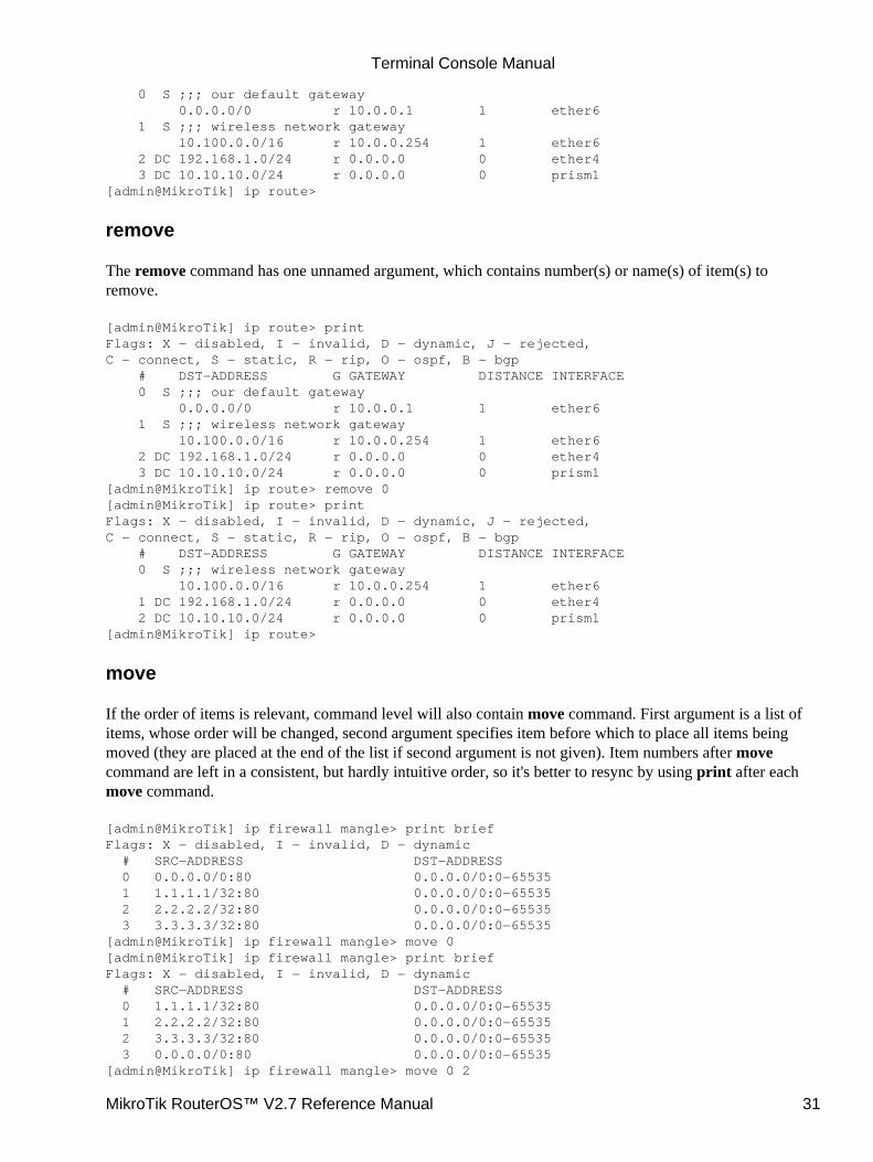
0 S ;;; our default gateway 0.0.0.0/0 r 10.0.0.1 1 ether6 1 S ;;; wireless network gateway 10.100.0.0/16 r 10.0.0.254 1 ether6 2 DC 192.168.1.0/24 r 0.0.0.0 0 ether4 3 DC 10.10.10.0/24 r 0.0.0.0 0 prism1[admin@MikroTik] ip route>
remove
The remove command has one unnamed argument, which contains number(s) or name(s) of item(s) toremove.
[admin@MikroTik] ip route> printFlags: X − disabled, I − invalid, D − dynamic, J − rejected,C − connect, S − static, R − rip, O − ospf, B − bgp # DST−ADDRESS G GATEWAY DISTANCE INTERFACE 0 S ;;; our default gateway 0.0.0.0/0 r 10.0.0.1 1 ether6 1 S ;;; wireless network gateway 10.100.0.0/16 r 10.0.0.254 1 ether6 2 DC 192.168.1.0/24 r 0.0.0.0 0 ether4 3 DC 10.10.10.0/24 r 0.0.0.0 0 prism1[admin@MikroTik] ip route> remove 0[admin@MikroTik] ip route> printFlags: X − disabled, I − invalid, D − dynamic, J − rejected,C − connect, S − static, R − rip, O − ospf, B − bgp # DST−ADDRESS G GATEWAY DISTANCE INTERFACE 0 S ;;; wireless network gateway 10.100.0.0/16 r 10.0.0.254 1 ether6 1 DC 192.168.1.0/24 r 0.0.0.0 0 ether4 2 DC 10.10.10.0/24 r 0.0.0.0 0 prism1[admin@MikroTik] ip route>
move
If the order of items is relevant, command level will also contain move command. First argument is a list ofitems, whose order will be changed, second argument specifies item before which to place all items beingmoved (they are placed at the end of the list if second argument is not given). Item numbers after movecommand are left in a consistent, but hardly intuitive order, so it's better to resync by using print after eachmove command.
[admin@MikroTik] ip firewall mangle> print briefFlags: X − disabled, I − invalid, D − dynamic # SRC−ADDRESS DST−ADDRESS 0 0.0.0.0/0:80 0.0.0.0/0:0−65535 1 1.1.1.1/32:80 0.0.0.0/0:0−65535 2 2.2.2.2/32:80 0.0.0.0/0:0−65535 3 3.3.3.3/32:80 0.0.0.0/0:0−65535[admin@MikroTik] ip firewall mangle> move 0[admin@MikroTik] ip firewall mangle> print briefFlags: X − disabled, I − invalid, D − dynamic # SRC−ADDRESS DST−ADDRESS 0 1.1.1.1/32:80 0.0.0.0/0:0−65535 1 2.2.2.2/32:80 0.0.0.0/0:0−65535 2 3.3.3.3/32:80 0.0.0.0/0:0−65535 3 0.0.0.0/0:80 0.0.0.0/0:0−65535[admin@MikroTik] ip firewall mangle> move 0 2
Terminal Console Manual
MikroTik RouterOS™ V2.7 Reference Manual 31
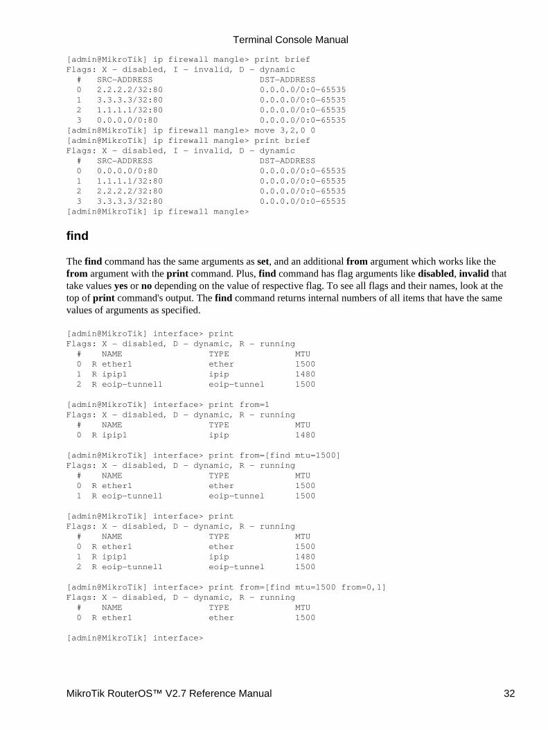
[admin@MikroTik] ip firewall mangle> print briefFlags: X − disabled, I − invalid, D − dynamic # SRC−ADDRESS DST−ADDRESS 0 2.2.2.2/32:80 0.0.0.0/0:0−65535 1 3.3.3.3/32:80 0.0.0.0/0:0−65535 2 1.1.1.1/32:80 0.0.0.0/0:0−65535 3 0.0.0.0/0:80 0.0.0.0/0:0−65535[admin@MikroTik] ip firewall mangle> move 3,2,0 0[admin@MikroTik] ip firewall mangle> print briefFlags: X − disabled, I − invalid, D − dynamic # SRC−ADDRESS DST−ADDRESS 0 0.0.0.0/0:80 0.0.0.0/0:0−65535 1 1.1.1.1/32:80 0.0.0.0/0:0−65535 2 2.2.2.2/32:80 0.0.0.0/0:0−65535 3 3.3.3.3/32:80 0.0.0.0/0:0−65535[admin@MikroTik] ip firewall mangle>
find
The find command has the same arguments as set, and an additional from argument which works like thefrom argument with the print command. Plus, find command has flag arguments like disabled, invalid thattake values yes or no depending on the value of respective flag. To see all flags and their names, look at thetop of print command's output. The find command returns internal numbers of all items that have the samevalues of arguments as specified.
[admin@MikroTik] interface> print Flags: X − disabled, D − dynamic, R − running # NAME TYPE MTU 0 R ether1 ether 1500 1 R ipip1 ipip 1480 2 R eoip−tunnel1 eoip−tunnel 1500
[admin@MikroTik] interface> print from=1 Flags: X − disabled, D − dynamic, R − running # NAME TYPE MTU 0 R ipip1 ipip 1480
[admin@MikroTik] interface> print from=[find mtu=1500] Flags: X − disabled, D − dynamic, R − running # NAME TYPE MTU 0 R ether1 ether 1500 1 R eoip−tunnel1 eoip−tunnel 1500
[admin@MikroTik] interface> print Flags: X − disabled, D − dynamic, R − running # NAME TYPE MTU 0 R ether1 ether 1500 1 R ipip1 ipip 1480 2 R eoip−tunnel1 eoip−tunnel 1500
[admin@MikroTik] interface> print from=[find mtu=1500 from=0,1]Flags: X − disabled, D − dynamic, R − running # NAME TYPE MTU 0 R ether1 ether 1500
[admin@MikroTik] interface>
Terminal Console Manual
MikroTik RouterOS™ V2.7 Reference Manual 32
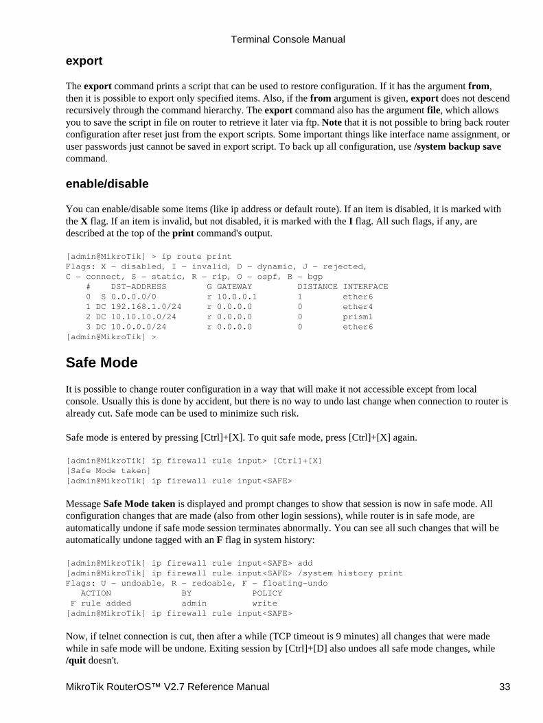
export
The export command prints a script that can be used to restore configuration. If it has the argument from,then it is possible to export only specified items. Also, if the from argument is given, export does not descendrecursively through the command hierarchy. The export command also has the argument file, which allowsyou to save the script in file on router to retrieve it later via ftp. Note that it is not possible to bring back routerconfiguration after reset just from the export scripts. Some important things like interface name assignment, oruser passwords just cannot be saved in export script. To back up all configuration, use /system backup savecommand.
enable/disable
You can enable/disable some items (like ip address or default route). If an item is disabled, it is marked withthe X flag. If an item is invalid, but not disabled, it is marked with the I flag. All such flags, if any, aredescribed at the top of the print command's output.
[admin@MikroTik] > ip route printFlags: X − disabled, I − invalid, D − dynamic, J − rejected,C − connect, S − static, R − rip, O − ospf, B − bgp # DST−ADDRESS G GATEWAY DISTANCE INTERFACE 0 S 0.0.0.0/0 r 10.0.0.1 1 ether6 1 DC 192.168.1.0/24 r 0.0.0.0 0 ether4 2 DC 10.10.10.0/24 r 0.0.0.0 0 prism1 3 DC 10.0.0.0/24 r 0.0.0.0 0 ether6[admin@MikroTik] >
Safe Mode
It is possible to change router configuration in a way that will make it not accessible except from localconsole. Usually this is done by accident, but there is no way to undo last change when connection to router isalready cut. Safe mode can be used to minimize such risk.
Safe mode is entered by pressing [Ctrl]+[X]. To quit safe mode, press [Ctrl]+[X] again.
[admin@MikroTik] ip firewall rule input> [Ctrl]+[X][Safe Mode taken][admin@MikroTik] ip firewall rule input<SAFE>
Message Safe Mode taken is displayed and prompt changes to show that session is now in safe mode. Allconfiguration changes that are made (also from other login sessions), while router is in safe mode, areautomatically undone if safe mode session terminates abnormally. You can see all such changes that will beautomatically undone tagged with an F flag in system history:
[admin@MikroTik] ip firewall rule input<SAFE> add[admin@MikroTik] ip firewall rule input<SAFE> /system history printFlags: U − undoable, R − redoable, F − floating−undo ACTION BY POLICY F rule added admin write[admin@MikroTik] ip firewall rule input<SAFE>
Now, if telnet connection is cut, then after a while (TCP timeout is 9 minutes) all changes that were madewhile in safe mode will be undone. Exiting session by [Ctrl]+[D] also undoes all safe mode changes, while/quit doesn't.
Terminal Console Manual
MikroTik RouterOS™ V2.7 Reference Manual 33
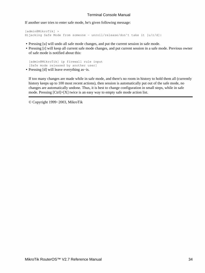
If another user tries to enter safe mode, he's given following message:
[admin@MikroTik] >Hijacking Safe Mode from someone − unroll/release/don't take it [u/r/d]:
Pressing [u] will undo all safe mode changes, and put the current session in safe mode.• Pressing [r] will keep all current safe mode changes, and put current session in a safe mode. Previous ownerof safe mode is notified about this:
[admin@MikroTik] ip firewall rule input[Safe mode released by another user]
•
Pressing [d] will leave everything as−is.
If too many changes are made while in safe mode, and there's no room in history to hold them all (currentlyhistory keeps up to 100 most recent actions), then session is automatically put out of the safe mode, nochanges are automatically undone. Thus, it is best to change configuration in small steps, while in safemode. Pressing [Ctrl]+[X] twice is an easy way to empty safe mode action list.
© Copyright 1999−2003, MikroTik
•
Terminal Console Manual
MikroTik RouterOS™ V2.7 Reference Manual 34

Software Package ManagementDocument revision 1.3 (06−Sep−2003)This document applies to the MikroTik RouterOS V2.7
Table of Contents
Table of Contents• Summary• Specifications• Additional Documents• Features• Software Package Installation (Upgrade)
Description♦ Notes♦
•
Software Package ListSystem Software Package♦ Additional Software Feature Packages♦
•
Software Package UninstallingDescription♦ Example♦
•
Troubleshooting•
Summary
The MikroTik RouterOS is distributed in the form of software packages. The basic functionality of the routerand the operating system itself is provided by the system software package. Other packages contain additionalsoftware features as well as support to various network interface cards (NICs).
Specifications
Packages required : NoneLicense required : AnyHome menu level : /system packageStandards and Technologies : FTP (RFC 959)Hardware usage : not significant
Additional Documents
Basic Setup GuideDevice Driver ManagementLicense management
Features
The modular software package system of MikroTik RouterOS has the following features:
Ability to add RouterOS functions by installing additional software packages•
MikroTik RouterOS™ V2.7 Reference Manual 35
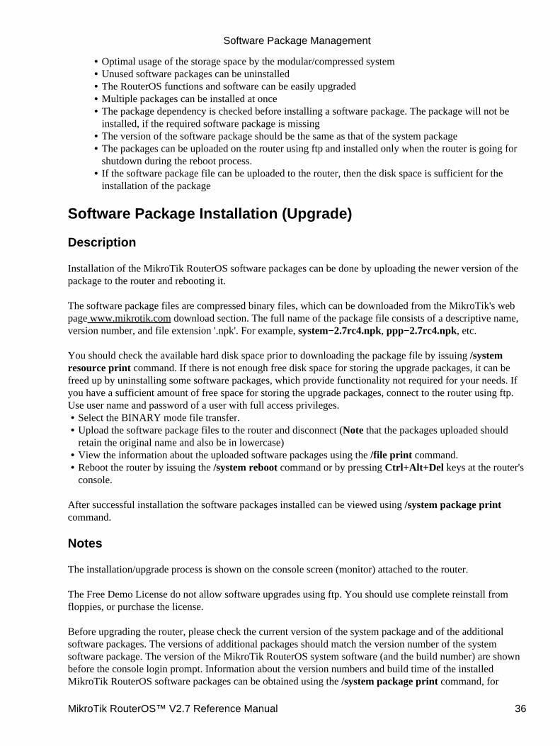
Optimal usage of the storage space by the modular/compressed system• Unused software packages can be uninstalled• The RouterOS functions and software can be easily upgraded• Multiple packages can be installed at once• The package dependency is checked before installing a software package. The package will not beinstalled, if the required software package is missing
•
The version of the software package should be the same as that of the system package• The packages can be uploaded on the router using ftp and installed only when the router is going forshutdown during the reboot process.
•
If the software package file can be uploaded to the router, then the disk space is sufficient for theinstallation of the package
•
Software Package Installation (Upgrade)
Description
Installation of the MikroTik RouterOS software packages can be done by uploading the newer version of thepackage to the router and rebooting it.
The software package files are compressed binary files, which can be downloaded from the MikroTik's webpage www.mikrotik.com download section. The full name of the package file consists of a descriptive name,version number, and file extension '.npk'. For example, system−2.7rc4.npk, ppp−2.7rc4.npk, etc.
You should check the available hard disk space prior to downloading the package file by issuing /systemresource print command. If there is not enough free disk space for storing the upgrade packages, it can befreed up by uninstalling some software packages, which provide functionality not required for your needs. Ifyou have a sufficient amount of free space for storing the upgrade packages, connect to the router using ftp.Use user name and password of a user with full access privileges.
Select the BINARY mode file transfer.• Upload the software package files to the router and disconnect (Note that the packages uploaded shouldretain the original name and also be in lowercase)
•
View the information about the uploaded software packages using the /file print command.• Reboot the router by issuing the /system reboot command or by pressing Ctrl+Alt+Del keys at the router'sconsole.
•
After successful installation the software packages installed can be viewed using /system package printcommand.
Notes
The installation/upgrade process is shown on the console screen (monitor) attached to the router.
The Free Demo License do not allow software upgrades using ftp. You should use complete reinstall fromfloppies, or purchase the license.
Before upgrading the router, please check the current version of the system package and of the additionalsoftware packages. The versions of additional packages should match the version number of the systemsoftware package. The version of the MikroTik RouterOS system software (and the build number) are shownbefore the console login prompt. Information about the version numbers and build time of the installedMikroTik RouterOS software packages can be obtained using the /system package print command, for
Software Package Management
MikroTik RouterOS™ V2.7 Reference Manual 36
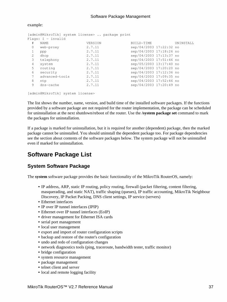
example:
[admin@MikroTik] system license> .. package printFlags: I − invalid # NAME VERSION BUILD−TIME UNINSTALL 0 web−proxy 2.7.11 sep/04/2003 17:22:32 no 1 ppp 2.7.11 sep/04/2003 17:18:26 no 2 dhcp 2.7.11 sep/04/2003 17:13:37 no 3 telephony 2.7.11 sep/04/2003 17:51:46 no 4 system 2.7.11 sep/05/2003 13:17:40 no 5 routing 2.7.11 sep/04/2003 17:20:20 no 6 security 2.7.11 sep/04/2003 17:12:36 no 7 advanced−tools 2.7.11 sep/04/2003 17:09:35 no 8 ntp 2.7.11 sep/04/2003 17:52:46 no 9 dns−cache 2.7.11 sep/04/2003 17:20:49 no
[admin@MikroTik] system license>
The list shows the number, name, version, and build time of the installed software packages. If the functionsprovided by a software package are not required for the router implementation, the package can be scheduledfor uninstallation at the next shutdown/reboot of the router. Use the /system package set command to markthe packages for uninstallation.
If a package is marked for uninstallation, but it is required for another (dependent) package, then the markedpackage cannot be uninstalled. You should uninstall the dependent package too. For package dependenciessee the section about contents of the software packages below. The system package will not be uninstalledeven if marked for uninstallation.
Software Package List
System Software Package
The system software package provides the basic functionality of the MikroTik RouterOS, namely:
IP address, ARP, static IP routing, policy routing, firewall (packet filtering, content filtering,masquerading, and static NAT), traffic shaping (queues), IP traffic accounting, MikroTik NeighbourDiscovery, IP Packet Packing, DNS client settings, IP service (servers)
•
Ethernet interfaces• IP over IP tunnel interfaces (IPIP)• Ethernet over IP tunnel interfaces (EoIP)• driver management for Ethernet ISA cards• serial port management• local user management• export and import of router configuration scripts• backup and restore of the router's configuration• undo and redo of configuration changes• network diagnostics tools (ping, traceroute, bandwidth tester, traffic monitor)• bridge configuration• system resource management• package management• telnet client and server• local and remote logging facility•
Software Package Management
MikroTik RouterOS™ V2.7 Reference Manual 37

It also includes winbox server as well as winbox executable with some plugins
After installing the MikroTik RouterOS, a license should be obtained from MikroTik to enable the basicsystem functionality.
Additional Software Feature Packages
The table below shows additional software feature packages, the provided functionality, the requiredprerequisites and additional licenses, if any.
Name Contents Prerequisites Additional License
advanced−toolsProvides email client,pingers, netwatch and otherutilities
− −
arlanProvides support for DSSS2.4GHz 2mbps Aironet ISAcards
−2.4GHz/5GHz WirelessClient
dhcpProvides DHCP server andclient support
− −
dns−cache DNS cache − −
hotspot HotSpot gateway − any additional license
isdn Provides ISDN support ppp −
lcdProvides LCD monitorsupport
− −
ntpProvides network timeprotocol support
− −
pppProvides support for PPP,PPTP, L2TP, PPPoE andISDN PPP
− −
radiolanProvides support for 5.8GHzRadioLAN cards
−2.4GHz/5GHz WirelessClient
routingProvides support for RIP,OSPF and BGP4
− −
securityProvides support for IPSEC,SSH and secure connectivitywith WinBox
− −
synchronous
Provides support forframerelay and Moxa C101,Moxa C512, Farsync,Cyclades PC300 and XPeedsynchronous cards
− Sync and Hotspot
upsProvides APC Smart ModeUPS support
− −
web−proxy HTTP Web proxy package − −
wireless −
Software Package Management
MikroTik RouterOS™ V2.7 Reference Manual 38
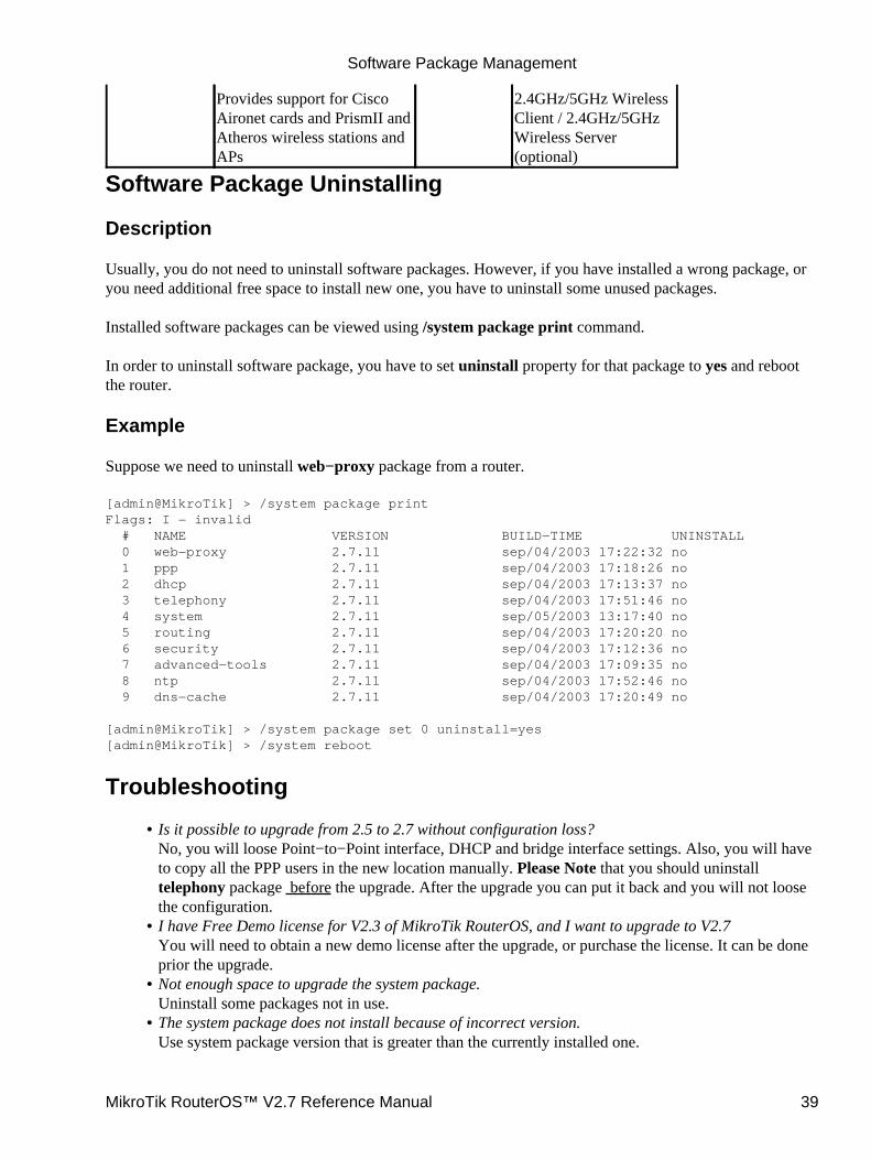
Provides support for CiscoAironet cards and PrismII andAtheros wireless stations andAPs
2.4GHz/5GHz WirelessClient / 2.4GHz/5GHzWireless Server(optional)
Software Package Uninstalling
Description
Usually, you do not need to uninstall software packages. However, if you have installed a wrong package, oryou need additional free space to install new one, you have to uninstall some unused packages.
Installed software packages can be viewed using /system package print command.
In order to uninstall software package, you have to set uninstall property for that package to yes and rebootthe router.
Example
Suppose we need to uninstall web−proxy package from a router.
[admin@MikroTik] > /system package printFlags: I − invalid # NAME VERSION BUILD−TIME UNINSTALL 0 web−proxy 2.7.11 sep/04/2003 17:22:32 no 1 ppp 2.7.11 sep/04/2003 17:18:26 no 2 dhcp 2.7.11 sep/04/2003 17:13:37 no 3 telephony 2.7.11 sep/04/2003 17:51:46 no 4 system 2.7.11 sep/05/2003 13:17:40 no 5 routing 2.7.11 sep/04/2003 17:20:20 no 6 security 2.7.11 sep/04/2003 17:12:36 no 7 advanced−tools 2.7.11 sep/04/2003 17:09:35 no 8 ntp 2.7.11 sep/04/2003 17:52:46 no 9 dns−cache 2.7.11 sep/04/2003 17:20:49 no
[admin@MikroTik] > /system package set 0 uninstall=yes[admin@MikroTik] > /system reboot
Troubleshooting
Is it possible to upgrade from 2.5 to 2.7 without configuration loss?No, you will loose Point−to−Point interface, DHCP and bridge interface settings. Also, you will haveto copy all the PPP users in the new location manually. Please Note that you should uninstalltelephony package before the upgrade. After the upgrade you can put it back and you will not loosethe configuration.
•
I have Free Demo license for V2.3 of MikroTik RouterOS, and I want to upgrade to V2.7You will need to obtain a new demo license after the upgrade, or purchase the license. It can be doneprior the upgrade.
•
Not enough space to upgrade the system package.Uninstall some packages not in use.
•
The system package does not install because of incorrect version.Use system package version that is greater than the currently installed one.
•
Software Package Management
MikroTik RouterOS™ V2.7 Reference Manual 39

Additional packages do not install because of incorrect version of the system package.Upgrade the system package first, then install the additional packages. The packages should be of thesame version as your system package.
•
The package file is corrupted after upload.Use BINARY mode for file transfer.
•
The package has been successfully installed and the driver loaded, but there is no interface in theinterface listObtain the required license to enable the functionality of provided by the software package.
•
The package files have been uploaded to the router, but they have not been installed.Reboot the router!
•
The version 2.2 has been upgraded to the version 2.7, but the connection to the router was lost afterthe reboot. The configuration has been lost.Using the console (monitor and keyboard attached to the router), restore the configuration.
•
© Copyright 1999−2003, MikroTik
Software Package Management
MikroTik RouterOS™ V2.7 Reference Manual 40
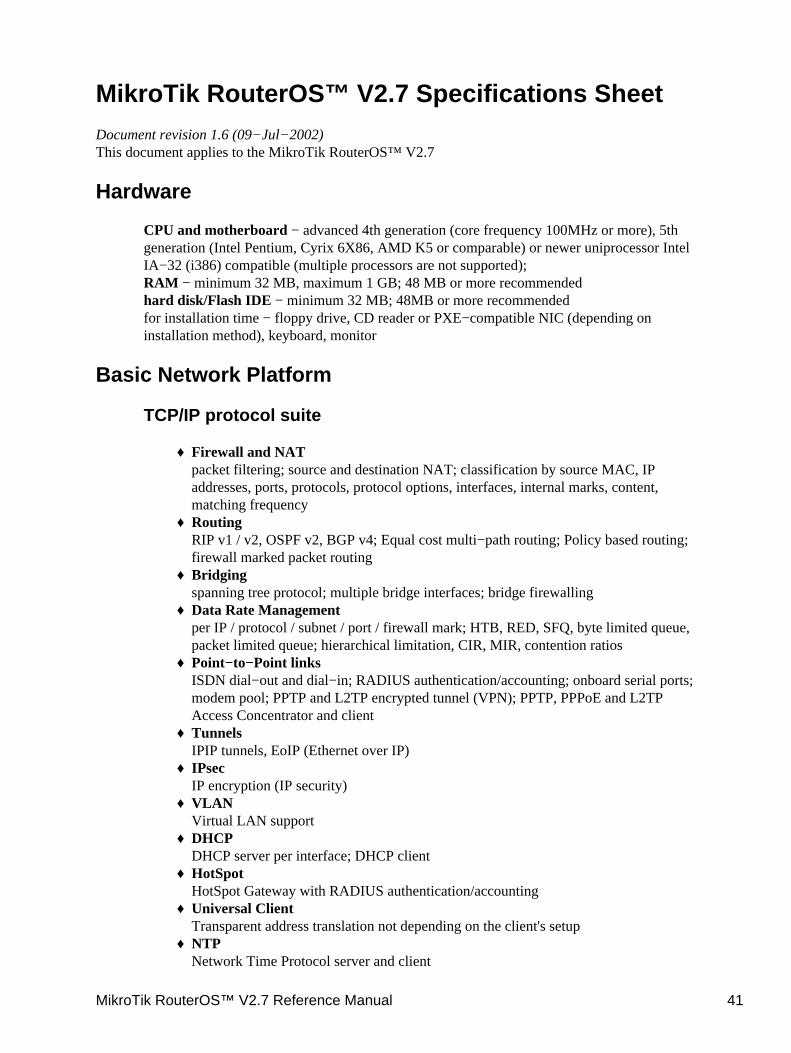
MikroTik RouterOS™ V2.7 Specifications SheetDocument revision 1.6 (09−Jul−2002)This document applies to the MikroTik RouterOS™ V2.7
Hardware
CPU and motherboard − advanced 4th generation (core frequency 100MHz or more), 5thgeneration (Intel Pentium, Cyrix 6X86, AMD K5 or comparable) or newer uniprocessor IntelIA−32 (i386) compatible (multiple processors are not supported);RAM − minimum 32 MB, maximum 1 GB; 48 MB or more recommendedhard disk/Flash IDE − minimum 32 MB; 48MB or more recommendedfor installation time − floppy drive, CD reader or PXE−compatible NIC (depending oninstallation method), keyboard, monitor
Basic Network Platform
TCP/IP protocol suite
Firewall and NATpacket filtering; source and destination NAT; classification by source MAC, IPaddresses, ports, protocols, protocol options, interfaces, internal marks, content,matching frequency
♦
RoutingRIP v1 / v2, OSPF v2, BGP v4; Equal cost multi−path routing; Policy based routing;firewall marked packet routing
♦
Bridgingspanning tree protocol; multiple bridge interfaces; bridge firewalling
♦
Data Rate Managementper IP / protocol / subnet / port / firewall mark; HTB, RED, SFQ, byte limited queue,packet limited queue; hierarchical limitation, CIR, MIR, contention ratios
♦
Point−to−Point linksISDN dial−out and dial−in; RADIUS authentication/accounting; onboard serial ports;modem pool; PPTP and L2TP encrypted tunnel (VPN); PPTP, PPPoE and L2TPAccess Concentrator and client
♦
TunnelsIPIP tunnels, EoIP (Ethernet over IP)
♦
IPsecIP encryption (IP security)
♦
VLANVirtual LAN support
♦
DHCPDHCP server per interface; DHCP client
♦
HotSpotHotSpot Gateway with RADIUS authentication/accounting
♦
Universal ClientTransparent address translation not depending on the client's setup
♦
NTPNetwork Time Protocol server and client
♦
MikroTik RouterOS™ V2.7 Reference Manual 41
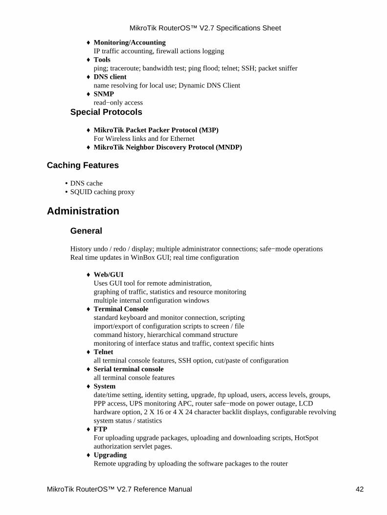
Monitoring/AccountingIP traffic accounting, firewall actions logging
♦
Toolsping; traceroute; bandwidth test; ping flood; telnet; SSH; packet sniffer
♦
DNS clientname resolving for local use; Dynamic DNS Client
♦
SNMPread−only access
♦
Special Protocols
MikroTik Packet Packer Protocol (M3P)For Wireless links and for Ethernet
♦
MikroTik Neighbor Discovery Protocol (MNDP)♦
Caching Features
DNS cache• SQUID caching proxy•
Administration
General
History undo / redo / display; multiple administrator connections; safe−mode operationsReal time updates in WinBox GUI; real time configuration
Web/GUIUses GUI tool for remote administration,graphing of traffic, statistics and resource monitoringmultiple internal configuration windows
♦
Terminal Consolestandard keyboard and monitor connection, scriptingimport/export of configuration scripts to screen / filecommand history, hierarchical command structuremonitoring of interface status and traffic, context specific hints
♦
Telnetall terminal console features, SSH option, cut/paste of configuration
♦
Serial terminal consoleall terminal console features
♦
Systemdate/time setting, identity setting, upgrade, ftp upload, users, access levels, groups,PPP access, UPS monitoring APC, router safe−mode on power outage, LCDhardware option, 2 X 16 or 4 X 24 character backlit displays, configurable revolvingsystem status / statistics
♦
FTPFor uploading upgrade packages, uploading and downloading scripts, HotSpotauthorization servlet pages.
♦
UpgradingRemote upgrading by uploading the software packages to the router
♦
MikroTik RouterOS™ V2.7 Specifications Sheet
MikroTik RouterOS™ V2.7 Reference Manual 42
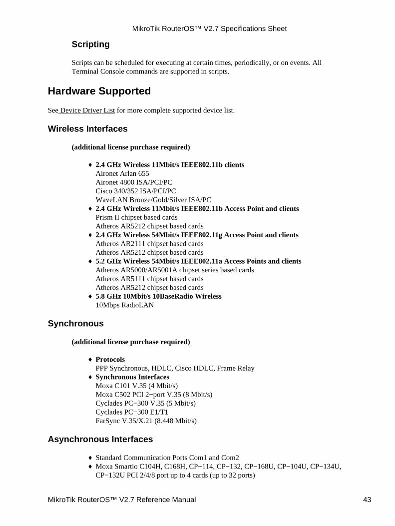
Scripting
Scripts can be scheduled for executing at certain times, periodically, or on events. AllTerminal Console commands are supported in scripts.
Hardware Supported
See Device Driver List for more complete supported device list.
Wireless Interfaces
(additional license purchase required)
2.4 GHz Wireless 11Mbit/s IEEE802.11b clientsAironet Arlan 655Aironet 4800 ISA/PCI/PCCisco 340/352 ISA/PCI/PCWaveLAN Bronze/Gold/Silver ISA/PC
♦
2.4 GHz Wireless 11Mbit/s IEEE802.11b Access Point and clientsPrism II chipset based cardsAtheros AR5212 chipset based cards
♦
2.4 GHz Wireless 54Mbit/s IEEE802.11g Access Point and clientsAtheros AR2111 chipset based cardsAtheros AR5212 chipset based cards
♦
5.2 GHz Wireless 54Mbit/s IEEE802.11a Access Points and clientsAtheros AR5000/AR5001A chipset series based cardsAtheros AR5111 chipset based cardsAtheros AR5212 chipset based cards
♦
5.8 GHz 10Mbit/s 10BaseRadio Wireless10Mbps RadioLAN
♦
Synchronous
(additional license purchase required)
ProtocolsPPP Synchronous, HDLC, Cisco HDLC, Frame Relay
♦
Synchronous InterfacesMoxa C101 V.35 (4 Mbit/s)Moxa C502 PCI 2−port V.35 (8 Mbit/s)Cyclades PC−300 V.35 (5 Mbit/s)Cyclades PC−300 E1/T1FarSync V.35/X.21 (8.448 Mbit/s)
♦
Asynchronous Interfaces
Standard Communication Ports Com1 and Com2♦ Moxa Smartio C104H, C168H, CP−114, CP−132, CP−168U, CP−104U, CP−134U,CP−132U PCI 2/4/8 port up to 4 cards (up to 32 ports)
♦
MikroTik RouterOS™ V2.7 Specifications Sheet
MikroTik RouterOS™ V2.7 Reference Manual 43
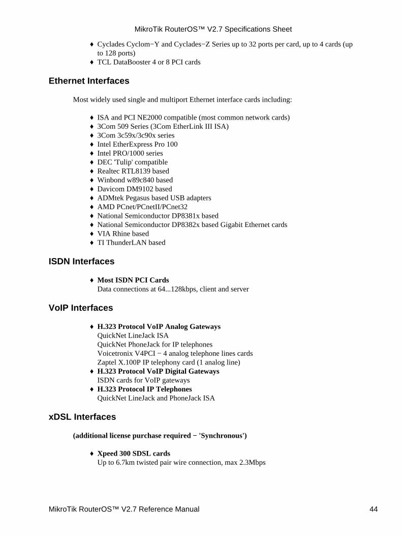
Cyclades Cyclom−Y and Cyclades−Z Series up to 32 ports per card, up to 4 cards (upto 128 ports)
♦
TCL DataBooster 4 or 8 PCI cards♦
Ethernet Interfaces
Most widely used single and multiport Ethernet interface cards including:
ISA and PCI NE2000 compatible (most common network cards)♦ 3Com 509 Series (3Com EtherLink III ISA)♦ 3Com 3c59x/3c90x series♦ Intel EtherExpress Pro 100♦ Intel PRO/1000 series♦ DEC 'Tulip' compatible♦ Realtec RTL8139 based♦ Winbond w89c840 based♦ Davicom DM9102 based♦ ADMtek Pegasus based USB adapters♦ AMD PCnet/PCnetII/PCnet32♦ National Semiconductor DP8381x based♦ National Semiconductor DP8382x based Gigabit Ethernet cards♦ VIA Rhine based♦ TI ThunderLAN based♦
ISDN Interfaces
Most ISDN PCI CardsData connections at 64...128kbps, client and server
♦
VoIP Interfaces
H.323 Protocol VoIP Analog GatewaysQuickNet LineJack ISAQuickNet PhoneJack for IP telephonesVoicetronix V4PCI − 4 analog telephone lines cardsZaptel X.100P IP telephony card (1 analog line)
♦
H.323 Protocol VoIP Digital GatewaysISDN cards for VoIP gateways
♦
H.323 Protocol IP TelephonesQuickNet LineJack and PhoneJack ISA
♦
xDSL Interfaces
(additional license purchase required − 'Synchronous')
Xpeed 300 SDSL cardsUp to 6.7km twisted pair wire connection, max 2.3Mbps
♦
MikroTik RouterOS™ V2.7 Specifications Sheet
MikroTik RouterOS™ V2.7 Reference Manual 44
HomePNA Interfaces
Linksys HomeLink PhoneLine Network CardUp to 10Mbps home network over telephone line.
♦
Phone: +371 7 317 700Fax: +371 7 317 701URL: http://www.mikrotik.comE−mail: [email protected] the office using our H.323 gateway: VoIP.MikroTik.COMOffice hours: Monday−Friday 9AM−5PM local time (GMT + 2)
© Copyright 1999−2003, MikroTik
MikroTik RouterOS™ V2.7 Specifications Sheet
MikroTik RouterOS™ V2.7 Reference Manual 45
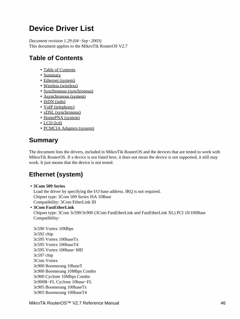
Device Driver ListDocument revision 1.29 (04−Sep−2003)This document applies to the MikroTik RouterOS V2.7
Table of Contents
Table of Contents• Summary• Ethernet (system)• Wireless (wireless)• Synchronous (synchronous)• Asynchronous (system)• ISDN (isdn)• VoIP (telephony)• xDSL (synchronous)• HomePNA (system)• LCD (lcd)• PCMCIA Adapters (system)•
Summary
The document lists the drivers, included in MikroTik RouterOS and the devices that are tested to work withMikroTik RouterOS. If a device is not listed here, it does not mean the device is not supported, it still maywork. It just means that the device is not tested.
Ethernet (system)
3Com 509 SeriesLoad the driver by specifying the I/O base address. IRQ is not required.Chipset type: 3Com 509 Series ISA 10BaseCompatibility: 3Com EtherLink III
•
3Com FastEtherLinkChipset type: 3Com 3c590/3c900 (3Com FastEtherLink and FastEtherLink XL) PCI 10/100BaseCompatibility:
3c590 Vortex 10Mbps3c592 chip3c595 Vortex 100baseTx3c595 Vortex 100baseT43c595 Vortex 100base−MII3c597 chip3Com Vortex3c900 Boomerang 10baseT3c900 Boomerang 10Mbps Combo3c900 Cyclone 10Mbps Combo3c900B−FL Cyclone 10base−FL3c905 Boomerang 100baseTx3c905 Boomerang 100baseT4
•
MikroTik RouterOS™ V2.7 Reference Manual 46
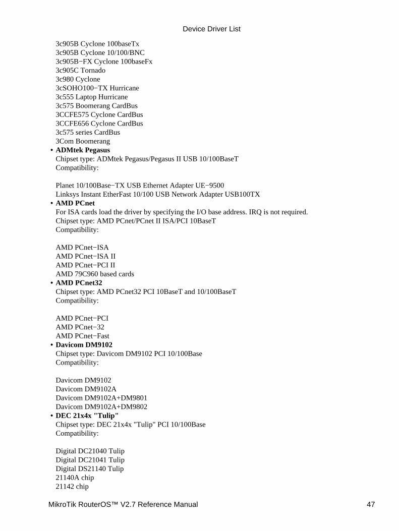
3c905B Cyclone 100baseTx3c905B Cyclone 10/100/BNC3c905B−FX Cyclone 100baseFx3c905C Tornado3c980 Cyclone3cSOHO100−TX Hurricane3c555 Laptop Hurricane3c575 Boomerang CardBus3CCFE575 Cyclone CardBus3CCFE656 Cyclone CardBus3c575 series CardBus3Com BoomerangADMtek PegasusChipset type: ADMtek Pegasus/Pegasus II USB 10/100BaseTCompatibility:
Planet 10/100Base−TX USB Ethernet Adapter UE−9500Linksys Instant EtherFast 10/100 USB Network Adapter USB100TX
•
AMD PCnetFor ISA cards load the driver by specifying the I/O base address. IRQ is not required.Chipset type: AMD PCnet/PCnet II ISA/PCI 10BaseTCompatibility:
AMD PCnet−ISAAMD PCnet−ISA IIAMD PCnet−PCI IIAMD 79C960 based cards
•
AMD PCnet32Chipset type: AMD PCnet32 PCI 10BaseT and 10/100BaseTCompatibility:
AMD PCnet−PCIAMD PCnet−32AMD PCnet−Fast
•
Davicom DM9102Chipset type: Davicom DM9102 PCI 10/100BaseCompatibility:
Davicom DM9102Davicom DM9102ADavicom DM9102A+DM9801Davicom DM9102A+DM9802
•
DEC 21x4x "Tulip"Chipset type: DEC 21x4x "Tulip" PCI 10/100BaseCompatibility:
Digital DC21040 TulipDigital DC21041 TulipDigital DS21140 Tulip21140A chip21142 chip
•
Device Driver List
MikroTik RouterOS™ V2.7 Reference Manual 47

Digital DS21143 TulipD−Link DFE 570TX 4−portLite−On 82c168 PNICMacronix 98713 PMACMacronix 98715 PMACMacronix 98725 PMACASIX AX88140Lite−On LC82C115 PNIC−IIADMtek AN981 CometCompex RL100−TXIntel 21145 TulipIMC QuikNic FXConexant LANfinityIntel EtherExpressProChipset type: Intel i82557 "Speedo3" (Intel EtherExpressPro) PCI 10/100BaseCompatibility: Intel i82557/i82558/i82559ER/i82801BA−7 EtherExpressPro PCI cards
•
Intel PRO/1000Chipset type: Intel i8254x (Intel PRO/1000) PCI 10/100/1000BaseCompatibility:
Intel PRO/1000 Gigabit Server Adapter (i82542, Board IDs: 700262−xxx, 717037−xxx)Intel PRO/1000 F Server Adapter (i82543, Board IDs: 738640−xxx, A38888−xxx)Intel PRO/1000 T Server Adapter (i82543, Board IDs: A19845−xxx, A33948−xxx)Intel PRO/1000 XT Server Adapter (i82544, Board IDs: A51580−xxx)Intel PRO/1000 XF Server Adapter (i82544, Board IDs: A50484−xxx)Intel PRO/1000 T Desktop Adapter (i82544, Board IDs: A62947−xxx)Intel PRO/1000 MT Desktop Adapter (i82540, Board IDs: A78408−xxx, C91016−xxx)Intel PRO/1000 MT Server Adapter (i82545, Board IDs: A92165−xxx, C31527−xxx)Intel PRO/1000 MT Dual Port Server Adapter (i82546, Board IDs: A92111−xxx, C29887−xxx)Intel PRO/1000 MT Quad Port Server Adapter (i82546, Board IDs: C32199−xxx)Intel PRO/1000 MF Server Adapter (i82545, Board IDs: A91622−xxx, C33915−xxx)Intel PRO/1000 MF Server Adapter (LX) (i82545, Board IDs: A91624−xxx, C33916−xxx)Intel PRO/1000 MF Dual Port Server Adapter (i82546, Board IDs: A91620−xxx, C30848−xxx)
•
National Semiconductor DP83810Chipset type: National Semiconductor DP83810 PCI 10/100BaseTCompatibility:
RouterBoard 200 built−in EthernetRouterBoard 24 4−port EthernetNS DP8381x−based cards
•
National Semiconductor DP83820Chipset type: National Semiconductor DP83820 PCI 10/100/1000BaseTCompatibility:
Planet ENW−9601TNS DP8382x−based cards
•
NE2000 ISALoad the driver by specifying the I/O base address. IRQ is not required.Chipset type: NE2000 ISA 10BaseCompatibility: various ISA cards
•
Device Driver List
MikroTik RouterOS™ V2.7 Reference Manual 48
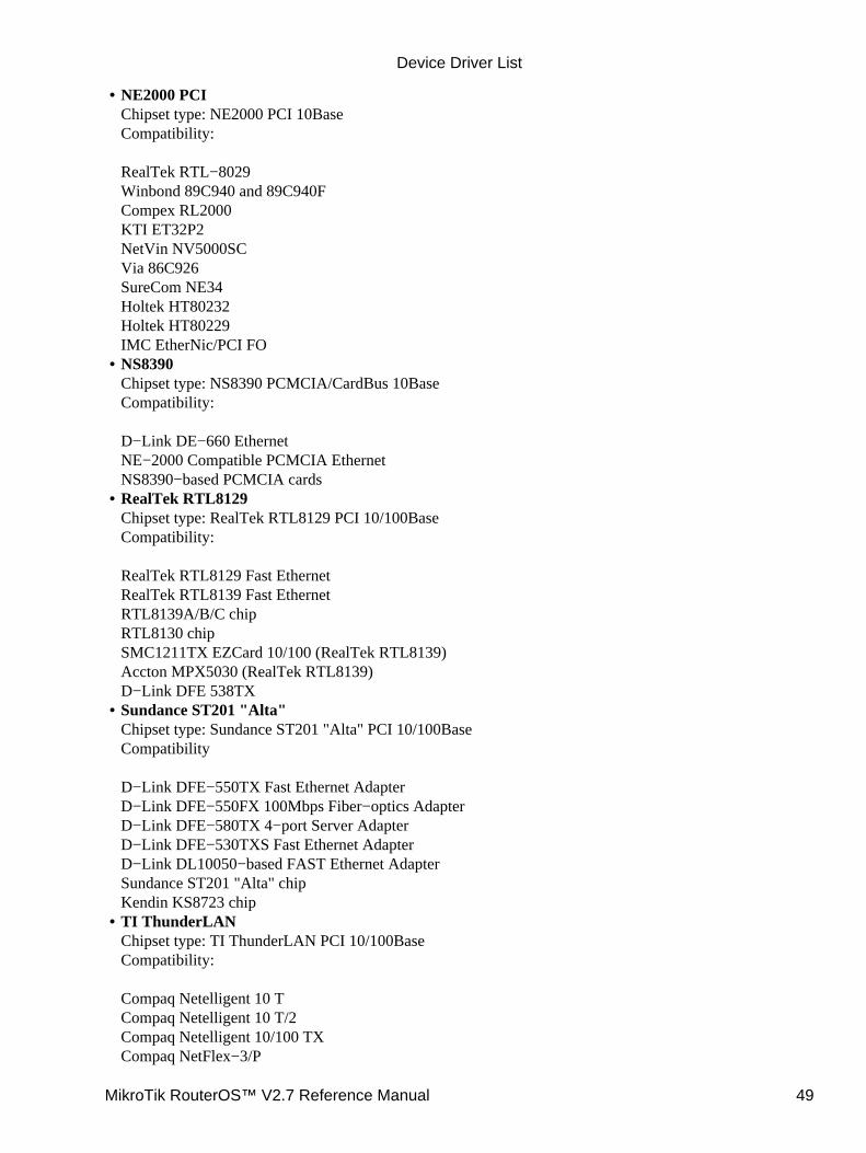
NE2000 PCIChipset type: NE2000 PCI 10BaseCompatibility:
RealTek RTL−8029Winbond 89C940 and 89C940FCompex RL2000KTI ET32P2NetVin NV5000SCVia 86C926SureCom NE34Holtek HT80232Holtek HT80229IMC EtherNic/PCI FO
•
NS8390Chipset type: NS8390 PCMCIA/CardBus 10BaseCompatibility:
D−Link DE−660 EthernetNE−2000 Compatible PCMCIA EthernetNS8390−based PCMCIA cards
•
RealTek RTL8129Chipset type: RealTek RTL8129 PCI 10/100BaseCompatibility:
RealTek RTL8129 Fast EthernetRealTek RTL8139 Fast EthernetRTL8139A/B/C chipRTL8130 chipSMC1211TX EZCard 10/100 (RealTek RTL8139)Accton MPX5030 (RealTek RTL8139)D−Link DFE 538TX
•
Sundance ST201 "Alta"Chipset type: Sundance ST201 "Alta" PCI 10/100BaseCompatibility
D−Link DFE−550TX Fast Ethernet AdapterD−Link DFE−550FX 100Mbps Fiber−optics AdapterD−Link DFE−580TX 4−port Server AdapterD−Link DFE−530TXS Fast Ethernet AdapterD−Link DL10050−based FAST Ethernet AdapterSundance ST201 "Alta" chipKendin KS8723 chip
•
TI ThunderLANChipset type: TI ThunderLAN PCI 10/100BaseCompatibility:
Compaq Netelligent 10 TCompaq Netelligent 10 T/2Compaq Netelligent 10/100 TXCompaq NetFlex−3/P
•
Device Driver List
MikroTik RouterOS™ V2.7 Reference Manual 49
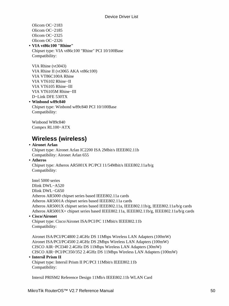
Olicom OC−2183Olicom OC−2185Olicom OC−2325Olicom OC−2326VIA vt86c100 "Rhine"Chipset type: VIA vt86c100 "Rhine" PCI 10/100BaseCompatibility:
VIA Rhine (vt3043)VIA Rhine II (vt3065 AKA vt86c100)VIA VT86C100A RhineVIA VT6102 Rhine−IIVIA VT6105 Rhine−IIIVIA VT6105M Rhine−IIID−Link DFE 530TX
•
Winbond w89c840Chipset type: Winbond w89c840 PCI 10/100BaseCompatibility:
Winbond W89c840Compex RL100−ATX
Wireless (wireless)
•
Aironet ArlanChipset type: Aironet Arlan IC2200 ISA 2Mbit/s IEEE802.11bCompatibility: Aironet Arlan 655
•
AtherosChipset type: Atheros AR5001X PC/PCI 11/54Mbit/s IEEE802.11a/b/gCompatibility:
Intel 5000 seriesDlink DWL−A520Dlink DWL−G650Atheros AR5000 chipset series based IEEE802.11a cardsAtheros AR5001A chipset series based IEEE802.11a cardsAtheros AR5001X chipset series based IEEE802.11a, IEEE802.11b/g, IEEE802.11a/b/g cardsAtheros AR5001X+ chipset series based IEEE802.11a, IEEE802.11b/g, IEEE802.11a/b/g cards
•
Cisco/AironetChipset type: Cisco/Aironet ISA/PCI/PC 11Mbit/s IEEE802.11bCompatibility:
Aironet ISA/PCI/PC4800 2.4GHz DS 11Mbps Wireless LAN Adapters (100mW)Aironet ISA/PCI/PC4500 2.4GHz DS 2Mbps Wireless LAN Adapters (100mW)CISCO AIR−PCI340 2.4GHz DS 11Mbps Wireless LAN Adapters (30mW)CISCO AIR−PCI/PC350/352 2.4GHz DS 11Mbps Wireless LAN Adapters (100mW)
•
Intersil Prism IIChipset type: Intersil Prism II PC/PCI 11Mbit/s IEEE802.11bCompatibility:
Intersil PRISM2 Reference Design 11Mb/s IEEE802.11b WLAN Card
•
Device Driver List
MikroTik RouterOS™ V2.7 Reference Manual 50
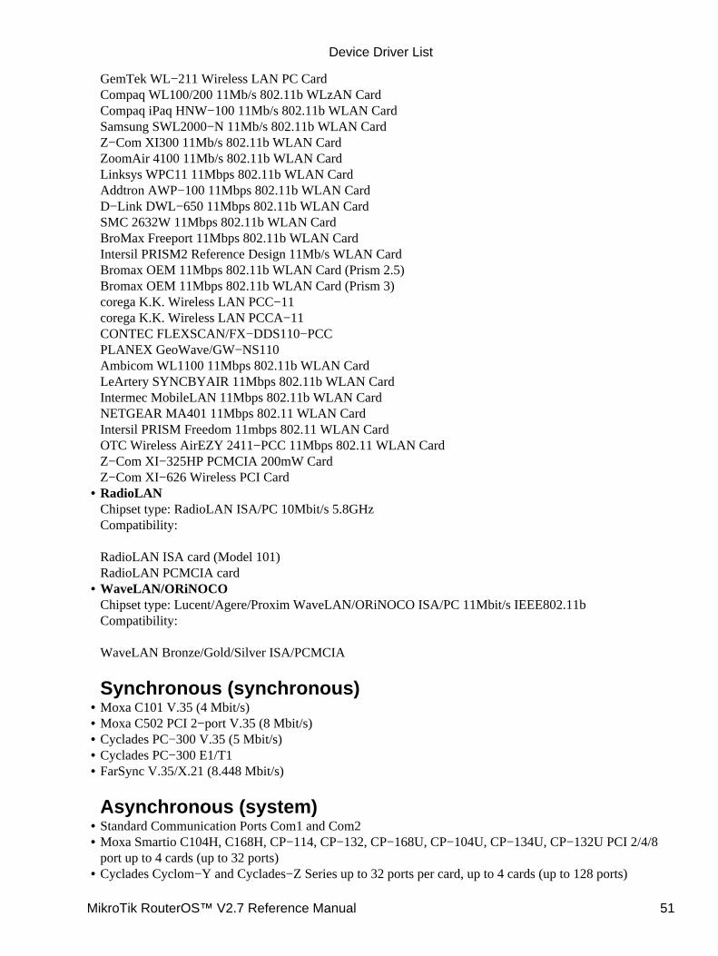
GemTek WL−211 Wireless LAN PC CardCompaq WL100/200 11Mb/s 802.11b WLzAN CardCompaq iPaq HNW−100 11Mb/s 802.11b WLAN CardSamsung SWL2000−N 11Mb/s 802.11b WLAN CardZ−Com XI300 11Mb/s 802.11b WLAN CardZoomAir 4100 11Mb/s 802.11b WLAN CardLinksys WPC11 11Mbps 802.11b WLAN CardAddtron AWP−100 11Mbps 802.11b WLAN CardD−Link DWL−650 11Mbps 802.11b WLAN CardSMC 2632W 11Mbps 802.11b WLAN CardBroMax Freeport 11Mbps 802.11b WLAN CardIntersil PRISM2 Reference Design 11Mb/s WLAN CardBromax OEM 11Mbps 802.11b WLAN Card (Prism 2.5)Bromax OEM 11Mbps 802.11b WLAN Card (Prism 3)corega K.K. Wireless LAN PCC−11corega K.K. Wireless LAN PCCA−11CONTEC FLEXSCAN/FX−DDS110−PCCPLANEX GeoWave/GW−NS110Ambicom WL1100 11Mbps 802.11b WLAN CardLeArtery SYNCBYAIR 11Mbps 802.11b WLAN CardIntermec MobileLAN 11Mbps 802.11b WLAN CardNETGEAR MA401 11Mbps 802.11 WLAN CardIntersil PRISM Freedom 11mbps 802.11 WLAN CardOTC Wireless AirEZY 2411−PCC 11Mbps 802.11 WLAN CardZ−Com XI−325HP PCMCIA 200mW CardZ−Com XI−626 Wireless PCI CardRadioLANChipset type: RadioLAN ISA/PC 10Mbit/s 5.8GHzCompatibility:
RadioLAN ISA card (Model 101)RadioLAN PCMCIA card
•
WaveLAN/ORiNOCOChipset type: Lucent/Agere/Proxim WaveLAN/ORiNOCO ISA/PC 11Mbit/s IEEE802.11bCompatibility:
WaveLAN Bronze/Gold/Silver ISA/PCMCIA
Synchronous (synchronous)
•
Moxa C101 V.35 (4 Mbit/s)• Moxa C502 PCI 2−port V.35 (8 Mbit/s)• Cyclades PC−300 V.35 (5 Mbit/s)• Cyclades PC−300 E1/T1• FarSync V.35/X.21 (8.448 Mbit/s)
Asynchronous (system)
•
Standard Communication Ports Com1 and Com2• Moxa Smartio C104H, C168H, CP−114, CP−132, CP−168U, CP−104U, CP−134U, CP−132U PCI 2/4/8port up to 4 cards (up to 32 ports)
•
Cyclades Cyclom−Y and Cyclades−Z Series up to 32 ports per card, up to 4 cards (up to 128 ports)•
Device Driver List
MikroTik RouterOS™ V2.7 Reference Manual 51
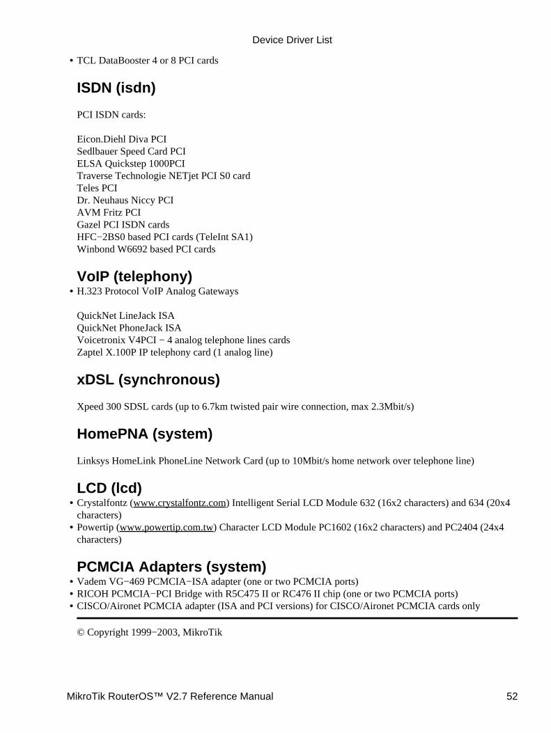
TCL DataBooster 4 or 8 PCI cards
ISDN (isdn)
PCI ISDN cards:
Eicon.Diehl Diva PCISedlbauer Speed Card PCIELSA Quickstep 1000PCITraverse Technologie NETjet PCI S0 cardTeles PCIDr. Neuhaus Niccy PCIAVM Fritz PCIGazel PCI ISDN cardsHFC−2BS0 based PCI cards (TeleInt SA1)Winbond W6692 based PCI cards
VoIP (telephony)
•
H.323 Protocol VoIP Analog Gateways
QuickNet LineJack ISAQuickNet PhoneJack ISAVoicetronix V4PCI − 4 analog telephone lines cardsZaptel X.100P IP telephony card (1 analog line)
xDSL (synchronous)
Xpeed 300 SDSL cards (up to 6.7km twisted pair wire connection, max 2.3Mbit/s)
HomePNA (system)
Linksys HomeLink PhoneLine Network Card (up to 10Mbit/s home network over telephone line)
LCD (lcd)
•
Crystalfontz (www.crystalfontz.com) Intelligent Serial LCD Module 632 (16x2 characters) and 634 (20x4characters)
•
Powertip (www.powertip.com.tw) Character LCD Module PC1602 (16x2 characters) and PC2404 (24x4characters)
PCMCIA Adapters (system)
•
Vadem VG−469 PCMCIA−ISA adapter (one or two PCMCIA ports)• RICOH PCMCIA−PCI Bridge with R5C475 II or RC476 II chip (one or two PCMCIA ports)• CISCO/Aironet PCMCIA adapter (ISA and PCI versions) for CISCO/Aironet PCMCIA cards only
© Copyright 1999−2003, MikroTik
•
Device Driver List
MikroTik RouterOS™ V2.7 Reference Manual 52
How to Read Reference ManualDocument revision 1.1 (15−Apr−2003)This document applies to the MikroTik RouterOS V2.7
Table of Contents
Table of Contents• Summary• The Purpose• The Structure• Common Conventions• Additional Resources•
Summary
This document contains general information on how to read Reference Manual. Here you can find informationabout Manual purposes, structure and common conventions.
The Purpose
The Reference Manual is designed to give information about all aspects of MikroTik RouterOS installation,configuration, maintenance and upgrading as well as some tupical examples.
The Structure
The full list of covered topics can be accessed within the main Manual page. Each topic consists of:
Main Header• Table of Contents• Summary• Specifications• Related Documents• [Description]• [Property Description]• Topic 1•
[Description]♦ [Property Description]♦ [Notes]♦ [Example]♦
Topic 2• [Subtopic 1]♦ [Subtopic 2]♦ ...♦ [Subtopic n]♦
...• Topic n• [Notes]•
MikroTik RouterOS™ V2.7 Reference Manual 53
[Example]• Additional Resources•
Note, that some items do not present in each Manual part. Such items are put in brackets [].• Main Header − here the theme and document revision are shown• Table of Contents − contains table of links to different subtopics of a theme• Summary − short summary of functions and (or) technology.• Specifications − holds information about packages and licences needed as well as utilized protocols andhardware requirements
•
Related Documents − contains links to related entries in the Manual• Description − General item description. Includes theoretical aspects and implementation specs• Property Description − Describes available arguments of commands (if any)• Notes − some facts worth to hold in mind• Example − shows typical example or (and) application example•
Each manual entry can contain subtopics which hold their own Description, Property Description, Notes andExample items.
Common Conventions
There are some common conventions through the entire Manual which are worth to know:All commands or arguments are in bold, i.e /ip adress add address=10.10.10.1/24• In case instead of actual value a range has been entered, it is in italics, id est dst−address (IP adress)• Default value of an argument is in bold and is prefixed by the keyword 'default' , i.e action (drop | accept,default: accept)
•
There are some access modifiers used in Property Description:read−only − the argument can not be modified by the user directly, exempli gratia from set command• multiple choice − these arguments can be selected in combinations, id estsupported−rates−a=6Mbps,9Mbps,12Mbps,18Mbps,24Mbps,36Mbps,48Mbps,54Mbps
•
Additional Resources
Key words for use in RFCs to Indicate Requirement Levels
© Copyright 1999−2003, MikroTik
How to Read Reference Manual
MikroTik RouterOS™ V2.7 Reference Manual 54

GlossaryDocument revision 1.0 (28−Apr−2003)This document applies to MikroTik RouterOS v2.7
Table of Contents
Table of Contents• Summary• Common Properties• Terms and Abbreviations•
Summary
The Glossary consists of two parts.The first part 'Common Properties' will give definitions to some common properties listed under 'PropertyDescription' subtopics as well as respective values description.The second part 'Terms and Abbreviations" will explain the meaning of technical terms, difficult worlds orphrases and abbreviations used throughout the Reference Manual.
Common Properties
arp (disabled | enabled | proxy−arp | reply−only; default: enabled) − Address Resolution Protocol (ARP)setting (for more information, see IP Addresses and Address Resolution Protocol):
disabled − the interface will not use ARP• enabled − the interface will use ARP• proxy−arp − the interface will use the ARP proxy feature• reply−only − the interface will only reply to the requests originated to its own IP addresses. NeighbourMAC addresses will be resolved using /ip arp statically set table only
•
card−type (read−only: type) − a string with some basic information about adapter type and model
mac−address (MAC address) − an IEEE Media Access Control (MAC) address. This is a hardware addressthat uniquely identifies each node of a network. It is shown as a sequence of six two−digits hexadecimalnumbers separated by colons, exempli gratia: 00:2f:21:c1:11:0a. In the console it also can be entered withoutdelimiters, id est 002f21c1110a
mtu (integer) − Maximum Transmission Unit, the largest physical packet size, measured in bytes, that anetwork can transmit. Any packets larger than the MTU are fragmented into smaller ones before being sentover the network; this slows down transmission speeds. There are some tupical settings of MTU: the MTU ofmany PPP connections is 576 while most ethernet networks have an MTU of 1500
name (name) − assigned feature name. Usually is used for inner reference and scripting
Terms and Abbreviations
Access Point − see AP
MikroTik RouterOS™ V2.7 Reference Manual 55

ad−hoc mode − a network framework provided by IEEE 802.11 standard set in which all communicationsbetween wireless clients are made without the use of an Access Point (AP). This mode sometimes is referredas a peer−to−peer mode
AP − short for Access Point, a set of hardware and software that acts as a communication hub for wirelessclients to connect to a wired LAN. APs are important for providing heightened wireless network security andfor extending the physical range of service a wireless client has access to.See infrastructure mode and ad−hoc mode.
ARP − short for address resolution protocol. This protocol is used to resolve IP addresses to MACaddresses
Basic Service Set − (BSS). A network setup with a set of wireless clients and one AP connected to a wirednetwork
dlci − short for data link connection identifier. Identifies the number of the logical circuit the data travelsover. DLCI is a number of a switched virtual or private circuit in a Frame Relay network, which is used todetermine how to route the data.
Extended Service Set − (ESS). A set of two or more BSSs that for one single subnetwork
IEEE − short for Institute of Electrical and Electronics Engineers. IEEE is best known for developing variousstandards for the computer and electronic industry
infrastructure mode − a network framework provided by IEEE 802.11 standard set in which allcommunications between wireless clients are made with a help of an Access Point (AP). In this mode,wireless devices can communicate either with each other or with a wired network. There are two possibleinfrastructure mode configurations referred as Basic Service Set (BSS) and Extended Service Set (ESS). Theinfrastructure mode is widely used in corporate networks in order to gain access to wired LAN services suchas file or application servers and printers
IP address − short for Internet Protocol address. This is a logical address belonging to the OSI layer 3.Consists of four (IPv4) or six (IPv6) binary octets. Usually is shown in decimal form, exempli gratia159.148.60.2.
MAC address − short for Media Access Control address. This is OSI layer 2 hardware address defined byIEEE standard and is used to deliver packets in the local network. It is sequence of six two−digitshexadecimal numbers separated by colons, exempli gratia: 00:2f:21:c1:11:0a.
RFC − short for request for comments. This is a set of technical and organizational notes about the Internet.Memos in the RFC series discuss many aspects of computer networking, including protocols, procedures,programs, and concepts
ssid − short for Service Set Identifier. The SSID is a 32−character identifier which is used in wirelessnetworking to separate different networks. All devices within the same network must have the same SSID.
EAP − short for Extensible Authentication Protocol defined in RFC 2284. It is general authentication protocolwhich supports various methods of authentication, such as passwords, public keys, Kerberos and smart cards.
In wireless communications using EAP, a user requests connection to a WLAN through an AP, which thenrequests the identity of the user and transmits that identity to an authentication server such as RADIUS. The
Glossary
MikroTik RouterOS™ V2.7 Reference Manual 56

server asks the AP for proof of identity, which the AP gets from the user and then sends back to the server tocomplete the authentication.
© Copyright 1999−2003, MikroTik
Glossary
MikroTik RouterOS™ V2.7 Reference Manual 57
Device Driver ManagementDocument revision 1.5 (15−May−2003)This document applies to the MikroTik RouterOS V2.7
Table of Contents
Table of Contents• Summary• Specifications• Related Documents• Loading Device Drivers
Description♦ Property Description♦ Notes♦ Example♦
•
Removing Device Drivers• Notes on PCMCIA Adapters• Troubleshooting•
Summary
Device drivers represent the software interface part of installed network devices. Some drivers are included inthe system software package and some in additional feature packages.
For complete list of supported devices and respective device driver names please consult the RelatedDocuments section.
The device drivers for PCI, miniPCI, PC (PCMCIA) and CardBus cards are loaded automatically. Othernetwork interface cards (most ISA and PCI ISDN cards) require the device drivers to be loaded manuallyusing the /driver add command.
Users cannot add their own device drivers, only drivers included in the Mikrotik RouterOS software packagescan be used. If you need a support for a device, which hasn't a driver yet, you are welcome to suggest it atsuggestion page on our web site.
Specifications
Packages required : appropriate for particular deviceLicense required : appropriate for particular deviceHome menu level : /driverStandards and Technologies : PCI, ISA, PCMCIA, miniPCI, CardBusHardware usage : not significant
Related Documents
Software Package Installation and UpgradingLicense Management
MikroTik RouterOS™ V2.7 Reference Manual 58
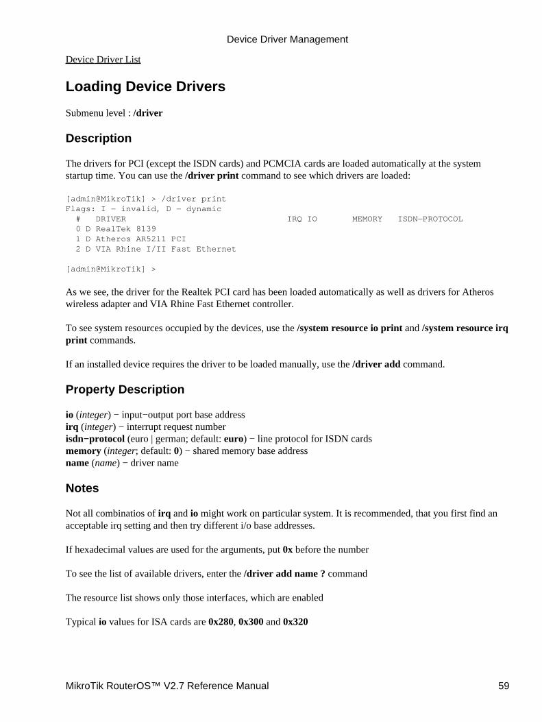
Device Driver List
Loading Device Drivers
Submenu level : /driver
Description
The drivers for PCI (except the ISDN cards) and PCMCIA cards are loaded automatically at the systemstartup time. You can use the /driver print command to see which drivers are loaded:
[admin@MikroTik] > /driver printFlags: I − invalid, D − dynamic # DRIVER IRQ IO MEMORY ISDN−PROTOCOL 0 D RealTek 8139 1 D Atheros AR5211 PCI 2 D VIA Rhine I/II Fast Ethernet
[admin@MikroTik] >
As we see, the driver for the Realtek PCI card has been loaded automatically as well as drivers for Atheroswireless adapter and VIA Rhine Fast Ethernet controller.
To see system resources occupied by the devices, use the /system resource io print and /system resource irqprint commands.
If an installed device requires the driver to be loaded manually, use the /driver add command.
Property Description
io (integer) − input−output port base addressirq (integer) − interrupt request numberisdn−protocol (euro | german; default: euro) − line protocol for ISDN cardsmemory (integer; default: 0) − shared memory base addressname (name) − driver name
Notes
Not all combinatios of irq and io might work on particular system. It is recommended, that you first find anacceptable irq setting and then try different i/o base addresses.
If hexadecimal values are used for the arguments, put 0x before the number
To see the list of available drivers, enter the /driver add name ? command
The resource list shows only those interfaces, which are enabled
Typical io values for ISA cards are 0x280, 0x300 and 0x320
Device Driver Management
MikroTik RouterOS™ V2.7 Reference Manual 59
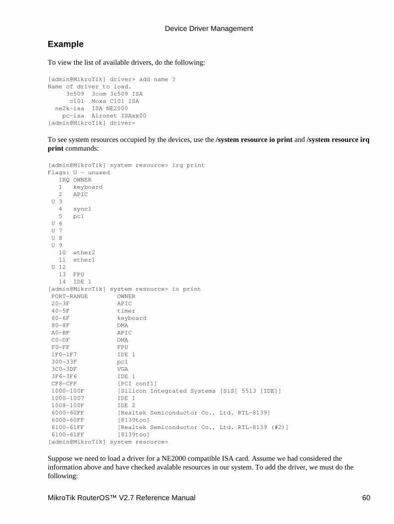
Example
To view the list of available drivers, do the following:
[admin@MikroTik] driver> add name ?Name of driver to load. 3c509 3com 3c509 ISA c101 Moxa C101 ISA ne2k−isa ISA NE2000 pc−isa Aironet ISAxx00[admin@MikroTik] driver>
To see system resources occupied by the devices, use the /system resource io print and /system resource irqprint commands:
[admin@MikroTik] system resource> irq printFlags: U − unused IRQ OWNER 1 keyboard 2 APIC U 3 4 sync1 5 pc1 U 6 U 7 U 8 U 9 10 ether2 11 ether1 U 12 13 FPU 14 IDE 1[admin@MikroTik] system resource> io print PORT−RANGE OWNER 20−3F APIC 40−5F timer 60−6F keyboard 80−8F DMA A0−BF APIC C0−DF DMA F0−FF FPU 1F0−1F7 IDE 1 300−33F pc1 3C0−3DF VGA 3F6−3F6 IDE 1 CF8−CFF [PCI conf1] 1000−100F [Silicon Integrated Systems [SiS] 5513 [IDE]] 1000−1007 IDE 1 1008−100F IDE 2 6000−60FF [Realtek Semiconductor Co., Ltd. RTL−8139] 6000−60FF [8139too] 6100−61FF [Realtek Semiconductor Co., Ltd. RTL−8139 (#2)] 6100−61FF [8139too][admin@MikroTik] system resource>
Suppose we need to load a driver for a NE2000 compatible ISA card. Assume we had considered theinformation above and have checked avalable resources in our system. To add the driver, we must do thefollowing:
Device Driver Management
MikroTik RouterOS™ V2.7 Reference Manual 60

[admin@MikroTik] driver> add name=ne2k−isa io=0x280[admin@MikroTik] driver> printFlags: I − invalid, D − dynamic # DRIVER IRQ IO MEMORY ISDN−PROTOCOL 0 D RealTek 8139 1 D Intel EtherExpressPro 2 D PCI NE2000 3 ISA NE2000 280 4 Moxa C101 Synchronous C8000[admin@MikroTik] driver>
Removing Device Drivers
You can remove only statically loaded drivers, id est those which do not have D flag before the driver name.The device drivers can be removed only if the appropriate interface has been disabled.
Use the /driver remove command to remove device drivers. Unloading a device driver is useful when youswap or remove a network device − it saves system resources avoiding to load drivers for removed devices.
Device driver needs to be removed and loaded again, if some parameters (memory range, i/o base address)have been changed for the network interface card.
Notes on PCMCIA Adapters
Currently only the following PCMCIA−ISA and PCMCIA−PCI adapters are tested to comply with MikroTikRouterOS:
RICOH PCMCIA−PCI Bridge with R5C475 II or RC476 II chip (one or two PCMCIA ports)• CISCO/Aironet PCMCIA adapter (ISA and PCI versions) for CISCO/Aironet PCMCIA cards only•
Other PCMCIA−ISA and PCMCIA−PCI adapters might not function properly.
The Ricoh adapter might not work properly with some older motherboards. When recognized properly by theBIOS during the boot up of the router, it should be reported under the PCI device listing as "PCI/CardBusbridge". Try using another motherboard, if the adapter or the Prism card are not recognized properly.
Note that the maximum number of PCMCIA ports for a single system is equal to 8. If you will try to install 9or more ports (no matter one−port or two−port adapters), no one will be recognized.
Troubleshooting
Driver for a PCI or PC card does not load automatically.Check for a possible IRQ or IO conflict with other devices.
•
The driver cannot be found on the system.Upload the required software package containing the required drivers and reboot the router.
•
The driver has been loaded, but the interface does not show up.Obtain the required software license to enable the functionality of the interface.
•
© Copyright 1999−2003, MikroTik
Device Driver Management
MikroTik RouterOS™ V2.7 Reference Manual 61
General Interface SettingsDocument revision 1.2 (15−Apr−2003)This document applies to the MikroTik RouterOS V2.7
Table Of Contents
Table Of Contents• Summary• Related Documents• Description• Interface Status
Property Description♦ Notes♦ Example♦
•
Traffic monitoringDescription♦ Notes♦ Example♦
•
Summary
MikroTik RouterOS supports a variety of Network Interface Cards as well as some virtual interfaces (likeVLAN, Bridge, etc.). Each of them has its own submenu, but there is also a list of all interfaces where somecommon properties can be configured.
Related Documents
Atheros 5GHz Wireless InterfaceBridge InterfacesCISCO/Aironet 2.4GHz 11Mbps Wireless InterfaceCyclades PC300 PCI AdaptersEthernet InterfacesEoIP (Ethernet over IP) Tunnel InterfaceFarSync X.21 InterfaceFrameRelay (PVC, Private Virtual Circuit) InterfaceIPIP (IP over IP) Tunnel InterfacesISDN InterfaceL2TP (Layer 2 Tunnel Protocol) InterfaceMOXA C101 Synchronous InterfaceMOXA C502 Dual−port Synchronous InterfacePPP (Point to Point Protocol) and Asynchronous InterfacesPPPoE (Point to Point Protocol over Ethernet) InterfacePPTP (Point to Point Tunnel Protocol) InterfacePrismII Wireless InterfaceRadioLAN 5.8GHz Wireless InterfaceVLAN (Virtual LAN) InterfaceXpeed SDSL (Single−line Digital Subscriber Line) Interface
MikroTik RouterOS™ V2.7 Reference Manual 62
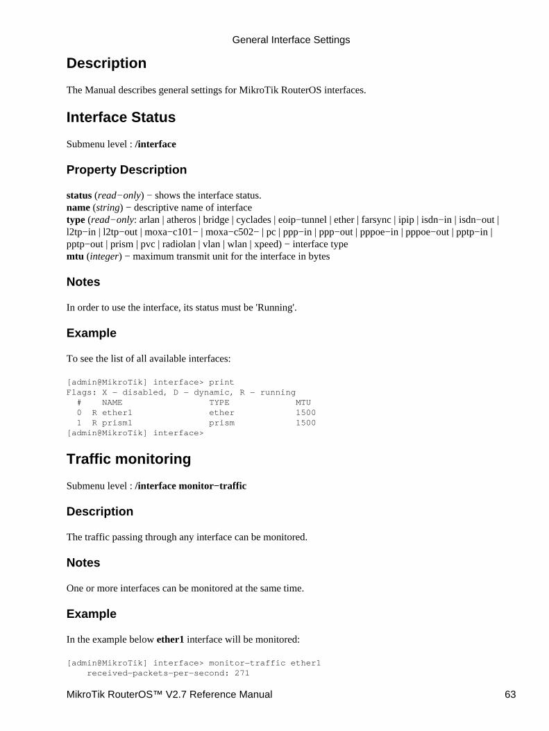
Description
The Manual describes general settings for MikroTik RouterOS interfaces.
Interface Status
Submenu level : /interface
Property Description
status (read−only) − shows the interface status.name (string) − descriptive name of interfacetype (read−only: arlan | atheros | bridge | cyclades | eoip−tunnel | ether | farsync | ipip | isdn−in | isdn−out |l2tp−in | l2tp−out | moxa−c101− | moxa−c502− | pc | ppp−in | ppp−out | pppoe−in | pppoe−out | pptp−in |pptp−out | prism | pvc | radiolan | vlan | wlan | xpeed) − interface typemtu (integer) − maximum transmit unit for the interface in bytes
Notes
In order to use the interface, its status must be 'Running'.
Example
To see the list of all available interfaces:
[admin@MikroTik] interface> printFlags: X − disabled, D − dynamic, R − running # NAME TYPE MTU 0 R ether1 ether 1500 1 R prism1 prism 1500[admin@MikroTik] interface>
Traffic monitoring
Submenu level : /interface monitor−traffic
Description
The traffic passing through any interface can be monitored.
Notes
One or more interfaces can be monitored at the same time.
Example
In the example below ether1 interface will be monitored:
[admin@MikroTik] interface> monitor−traffic ether1 received−packets−per−second: 271
General Interface Settings
MikroTik RouterOS™ V2.7 Reference Manual 63

received−bytes−per−second: 148.4kbps sent−packets−per−second: 600 sent−bytes−per−second: 6.72Mbps
[admin@MikroTik] interface>
In the next example we will monitor two interfaces at a time:
[admin@MikroTik] interface> monitor−traffic ether1,prism1 received−packets−per−second: 2 0 received−bits−per−second: 960.00bps 0.00bps sent−packets−per−second: 2 0 sent−bits−per−second: 2.57kbps 0.00bps
[admin@MikroTik] interface>
© Copyright 1999−2003, MikroTik
General Interface Settings
MikroTik RouterOS™ V2.7 Reference Manual 64

Wireless Client and Wireless Access Point ManualDocument revision 1.23 (30−Dec−2003)This document applies to the MikroTik RouterOS V2.7
Table of Contents
Table of Contents• Summary• Specifications• Related Documents• Wireless Networking Ranges• Description
Hardware Notes♦ •
Wireless Interface ConfigurationDescription♦ Property Description♦ Notes♦ Example♦
•
Registration TableProperty Description♦ Example♦
•
Access ListDescription♦ Property Description♦ Notes♦ Example♦
•
InfoDescription♦ Property Description♦ Notes♦ Example♦
•
AP Configuration Example• Additional Resources•
Summary
The MikroTik RouterOS supports the Atheros AR5111, AR5211, AR2111 chipset based wireless adaptercards for working as wireless clients (station mode), wireless bridges (bridge) mode and wireless accesspoints (ap−bridge mode).
On account of that MikroTik RouterOS provides a complete support for IEEE 802.11a, 802.11b and 802.11gwireless networking standards.
Specifications
Packages required : wirelessLicense required : 2.4/5GHz Wireless Client, 2.4/5Ghz Wireless Access Point (optional)Home menu level : /interface wireless
MikroTik RouterOS™ V2.7 Reference Manual 65
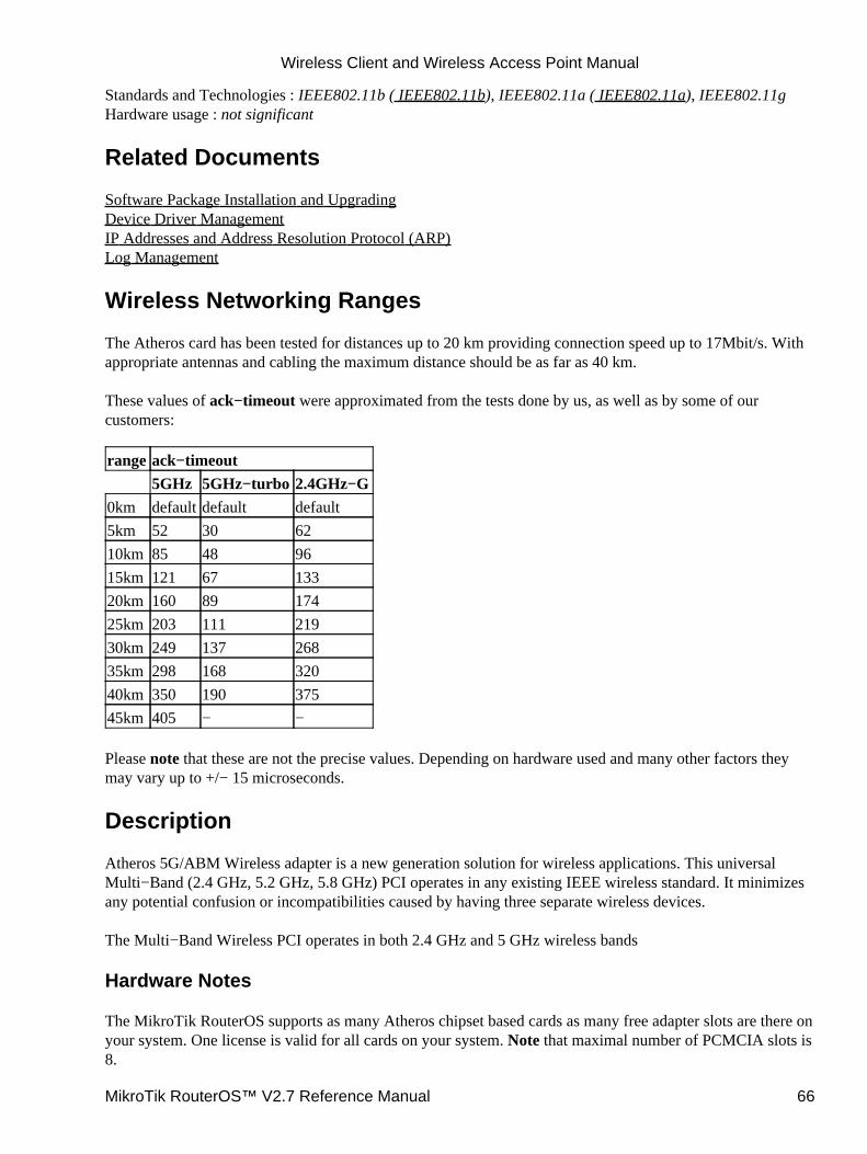
Standards and Technologies : IEEE802.11b ( IEEE802.11b), IEEE802.11a ( IEEE802.11a), IEEE802.11gHardware usage : not significant
Related Documents
Software Package Installation and UpgradingDevice Driver ManagementIP Addresses and Address Resolution Protocol (ARP)Log Management
Wireless Networking Ranges
The Atheros card has been tested for distances up to 20 km providing connection speed up to 17Mbit/s. Withappropriate antennas and cabling the maximum distance should be as far as 40 km.
These values of ack−timeout were approximated from the tests done by us, as well as by some of ourcustomers:
range ack−timeout
5GHz 5GHz−turbo 2.4GHz−G
0km defaultdefault default
5km 52 30 62
10km 85 48 96
15km 121 67 133
20km 160 89 174
25km 203 111 219
30km 249 137 268
35km 298 168 320
40km 350 190 375
45km 405 − −
Please note that these are not the precise values. Depending on hardware used and many other factors theymay vary up to +/− 15 microseconds.
Description
Atheros 5G/ABM Wireless adapter is a new generation solution for wireless applications. This universalMulti−Band (2.4 GHz, 5.2 GHz, 5.8 GHz) PCI operates in any existing IEEE wireless standard. It minimizesany potential confusion or incompatibilities caused by having three separate wireless devices.
The Multi−Band Wireless PCI operates in both 2.4 GHz and 5 GHz wireless bands
Hardware Notes
The MikroTik RouterOS supports as many Atheros chipset based cards as many free adapter slots are there onyour system. One license is valid for all cards on your system. Note that maximal number of PCMCIA slots is8.
Wireless Client and Wireless Access Point Manual
MikroTik RouterOS™ V2.7 Reference Manual 66
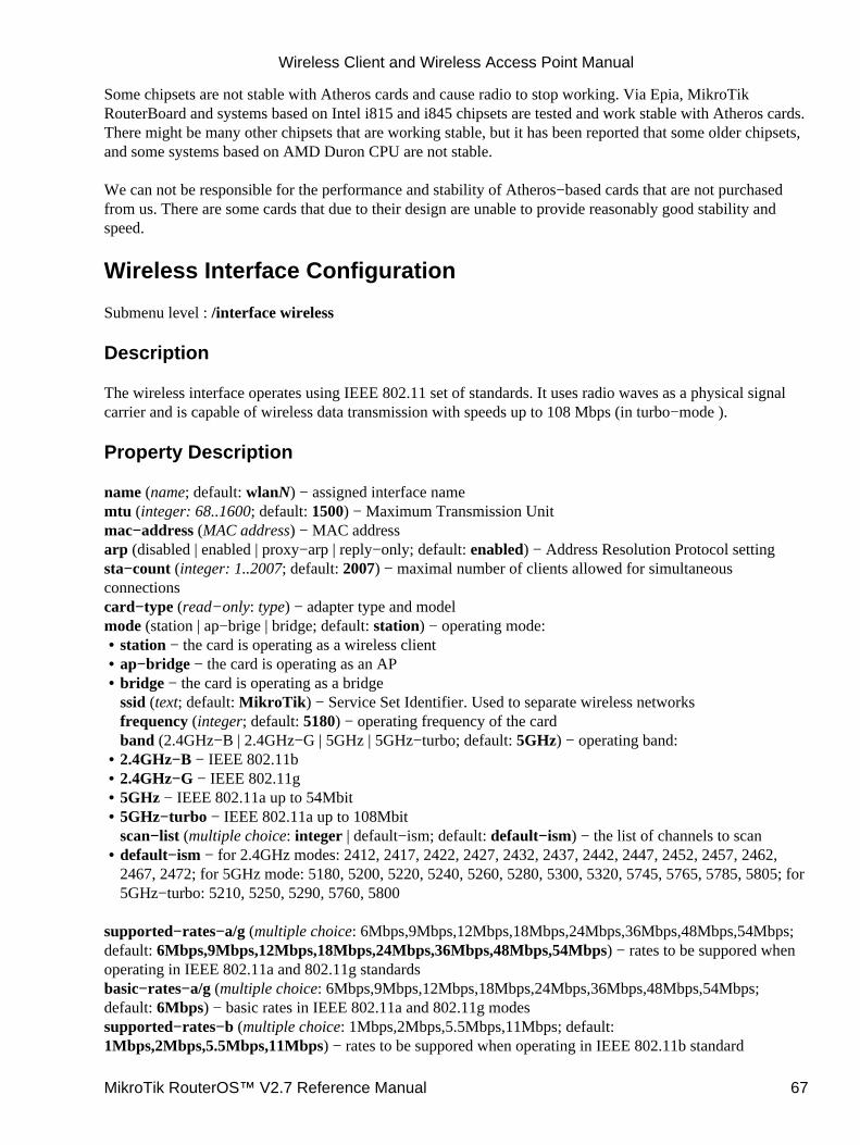
Some chipsets are not stable with Atheros cards and cause radio to stop working. Via Epia, MikroTikRouterBoard and systems based on Intel i815 and i845 chipsets are tested and work stable with Atheros cards.There might be many other chipsets that are working stable, but it has been reported that some older chipsets,and some systems based on AMD Duron CPU are not stable.
We can not be responsible for the performance and stability of Atheros−based cards that are not purchasedfrom us. There are some cards that due to their design are unable to provide reasonably good stability andspeed.
Wireless Interface Configuration
Submenu level : /interface wireless
Description
The wireless interface operates using IEEE 802.11 set of standards. It uses radio waves as a physical signalcarrier and is capable of wireless data transmission with speeds up to 108 Mbps (in turbo−mode ).
Property Description
name (name; default: wlanN) − assigned interface namemtu (integer: 68..1600; default: 1500) − Maximum Transmission Unitmac−address (MAC address) − MAC addressarp (disabled | enabled | proxy−arp | reply−only; default: enabled) − Address Resolution Protocol settingsta−count (integer: 1..2007; default: 2007) − maximal number of clients allowed for simultaneousconnectionscard−type (read−only: type) − adapter type and modelmode (station | ap−brige | bridge; default: station) − operating mode:
station − the card is operating as a wireless client• ap−bridge − the card is operating as an AP• bridge − the card is operating as a bridgessid (text; default: MikroTik) − Service Set Identifier. Used to separate wireless networksfrequency (integer; default: 5180) − operating frequency of the cardband (2.4GHz−B | 2.4GHz−G | 5GHz | 5GHz−turbo; default: 5GHz) − operating band:
•
2.4GHz−B − IEEE 802.11b• 2.4GHz−G − IEEE 802.11g• 5GHz − IEEE 802.11a up to 54Mbit• 5GHz−turbo − IEEE 802.11a up to 108Mbitscan−list (multiple choice: integer | default−ism; default: default−ism) − the list of channels to scan
•
default−ism − for 2.4GHz modes: 2412, 2417, 2422, 2427, 2432, 2437, 2442, 2447, 2452, 2457, 2462,2467, 2472; for 5GHz mode: 5180, 5200, 5220, 5240, 5260, 5280, 5300, 5320, 5745, 5765, 5785, 5805; for5GHz−turbo: 5210, 5250, 5290, 5760, 5800
•
supported−rates−a/g (multiple choice: 6Mbps,9Mbps,12Mbps,18Mbps,24Mbps,36Mbps,48Mbps,54Mbps;default: 6Mbps,9Mbps,12Mbps,18Mbps,24Mbps,36Mbps,48Mbps,54Mbps) − rates to be suppored whenoperating in IEEE 802.11a and 802.11g standardsbasic−rates−a/g (multiple choice: 6Mbps,9Mbps,12Mbps,18Mbps,24Mbps,36Mbps,48Mbps,54Mbps;default: 6Mbps) − basic rates in IEEE 802.11a and 802.11g modessupported−rates−b (multiple choice: 1Mbps,2Mbps,5.5Mbps,11Mbps; default:1Mbps,2Mbps,5.5Mbps,11Mbps) − rates to be suppored when operating in IEEE 802.11b standard
Wireless Client and Wireless Access Point Manual
MikroTik RouterOS™ V2.7 Reference Manual 67
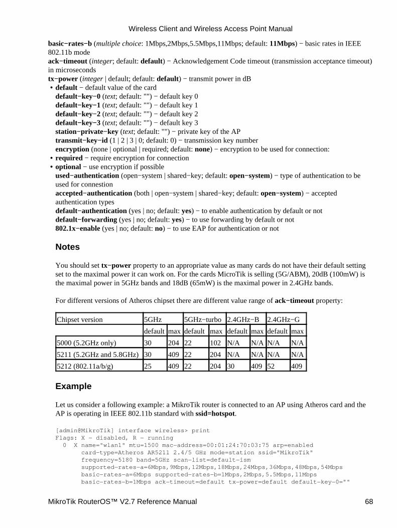
basic−rates−b (multiple choice: 1Mbps,2Mbps,5.5Mbps,11Mbps; default: 11Mbps) − basic rates in IEEE802.11b modeack−timeout (integer; default: default) − Acknowledgement Code timeout (transmission acceptance timeout)in microsecondstx−power (integer | default; default: default) − transmit power in dB
default − default value of the carddefault−key−0 (text; default: "") − default key 0default−key−1 (text; default: "") − default key 1default−key−2 (text; default: "") − default key 2default−key−3 (text; default: "") − default key 3station−private−key (text; default: "") − private key of the APtransmit−key−id (1 | 2 | 3 | 0; default: 0) − transmission key numberencryption (none | optional | required; default: none) − encryption to be used for connection:
•
required − require encryption for connection• optional − use encryption if possibleused−authentication (open−system | shared−key; default: open−system) − type of authentication to beused for connestionaccepted−authentication (both | open−system | shared−key; default: open−system) − acceptedauthentication typesdefault−authentication (yes | no; default: yes) − to enable authentication by default or notdefault−forwarding (yes | no; default: yes) − to use forwarding by default or not802.1x−enable (yes | no; default: no) − to use EAP for authentication or not
Notes
You should set tx−power property to an appropriate value as many cards do not have their default settingset to the maximal power it can work on. For the cards MicroTik is selling (5G/ABM), 20dB (100mW) isthe maximal power in 5GHz bands and 18dB (65mW) is the maximal power in 2.4GHz bands.
For different versions of Atheros chipset there are different value range of ack−timeout property:
Chipset version 5GHz 5GHz−turbo 2.4GHz−B 2.4GHz−G
default max default max default max default max
5000 (5.2GHz only) 30 204 22 102 N/A N/A N/A N/A
5211 (5.2GHz and 5.8GHz)30 409 22 204 N/A N/A N/A N/A
5212 (802.11a/b/g) 25 409 22 204 30 409 52 409
Example
Let us consider a following example: a MikroTik router is connected to an AP using Atheros card and theAP is operating in IEEE 802.11b standard with ssid=hotspot.
[admin@MikroTik] interface wireless> printFlags: X − disabled, R − running 0 X name="wlan1" mtu=1500 mac−address=00:01:24:70:03:75 arp=enabled card−type=Atheros AR5211 2.4/5 GHz mode=station ssid="MikroTik" frequency=5180 band=5GHz scan−list=default−ism supported−rates−a=6Mbps,9Mbps,12Mbps,18Mbps,24Mbps,36Mbps,48Mbps,54Mbps basic−rates−a=6Mbps supported−rates−b=1Mbps,2Mbps,5.5Mbps,11Mbps basic−rates−b=1Mbps ack−timeout=default tx−power=default default−key−0=""
•
Wireless Client and Wireless Access Point Manual
MikroTik RouterOS™ V2.7 Reference Manual 68
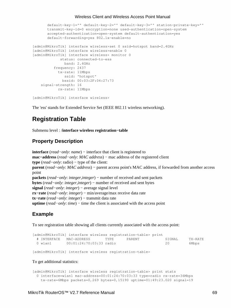
default−key−1="" default−key−2="" default−key−3="" station−private−key="" transmit−key−id=0 encryption=none used−authentication=open−system accepted−authentication=open−system default−authentication=yes default−forwarding=yes 802.1x−enable=no
[admin@MikroTik] interface wireless>set 0 ssid=hotspot band=2.4GHz[admin@MikroTik] interface wireless>enable 0[admin@MikroTik] interface wireless> monitor 0 status: connected−to−ess band: 2.4GHz frequency: 2437 tx−rate: 11Mbps ssid: "hotspot" bssid: 00:03:2F:04:27:73 signal−strength: 16 rx−rate: 11Mbps
[admin@MikroTik] interface wireless>
The 'ess' stands for Extended Service Set (IEEE 802.11 wireless networking).
Registration Table
Submenu level : /interface wireless registration−table
Property Description
interface (read−only: name) − interface that client is registered tomac−address (read−only: MAC address) − mac address of the registered clienttype (read−only: radio) − type of the client:parent (read−only: MAC address) − parent access point's MAC address, if forwarded from another accesspointpackets (read−only: integer,integer) − number of received and sent packetsbytes (read−only: integer,integer) − number of received and sent bytessignal (read−only: integer) − average signal levelrx−rate (read−only: integer) − min/average/max receive data ratetx−rate (read−only: integer) − transmit data rateuptime (read−only: time) − time the client is associated with the access point
Example
To see registration table showing all clients currently associated with the access point:
[admin@MikroTik] interface wireless registration−table> print # INTERFACE MAC−ADDRESS TYPE PARENT SIGNAL TX−RATE 0 wlan1 00:01:24:70:03:33 radio 20 6Mbps
[admin@MikroTik] interface wireless registration−table>
To get additional statistics:
[admin@MikroTik] interface wireless registration−table> print stats 0 interface=wlan1 mac−address=00:01:24:70:03:33 type=radio rx−rate=36Mbps tx−rate=6Mbps packets=0,269 bytes=0,15190 uptime=01:49:23.020 signal=19
Wireless Client and Wireless Access Point Manual
MikroTik RouterOS™ V2.7 Reference Manual 69
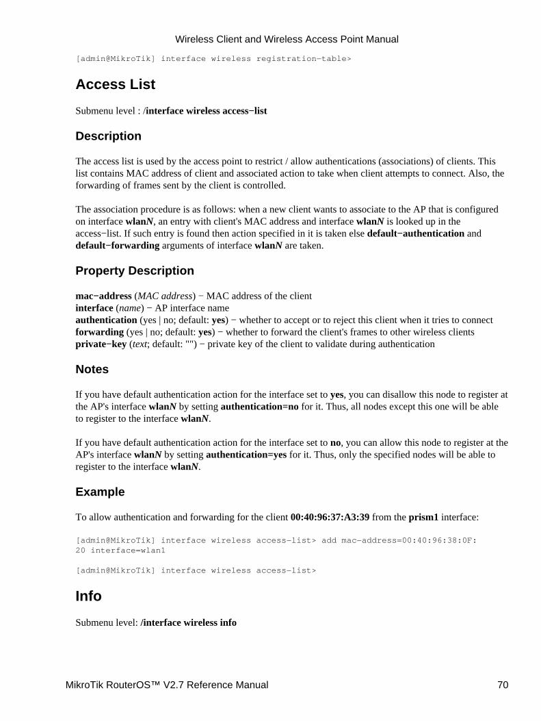
[admin@MikroTik] interface wireless registration−table>
Access List
Submenu level : /interface wireless access−list
Description
The access list is used by the access point to restrict / allow authentications (associations) of clients. Thislist contains MAC address of client and associated action to take when client attempts to connect. Also, theforwarding of frames sent by the client is controlled.
The association procedure is as follows: when a new client wants to associate to the AP that is configuredon interface wlanN, an entry with client's MAC address and interface wlanN is looked up in theaccess−list. If such entry is found then action specified in it is taken else default−authentication anddefault−forwarding arguments of interface wlanN are taken.
Property Description
mac−address (MAC address) − MAC address of the clientinterface (name) − AP interface nameauthentication (yes | no; default: yes) − whether to accept or to reject this client when it tries to connectforwarding (yes | no; default: yes) − whether to forward the client's frames to other wireless clientsprivate−key (text; default: "") − private key of the client to validate during authentication
Notes
If you have default authentication action for the interface set to yes, you can disallow this node to register atthe AP's interface wlanN by setting authentication=no for it. Thus, all nodes except this one will be ableto register to the interface wlanN.
If you have default authentication action for the interface set to no, you can allow this node to register at theAP's interface wlanN by setting authentication=yes for it. Thus, only the specified nodes will be able toregister to the interface wlanN.
Example
To allow authentication and forwarding for the client 00:40:96:37:A3:39 from the prism1 interface:
[admin@MikroTik] interface wireless access−list> add mac−address=00:40:96:38:0F:20 interface=wlan1
[admin@MikroTik] interface wireless access−list>
Info
Submenu level: /interface wireless info
Wireless Client and Wireless Access Point Manual
MikroTik RouterOS™ V2.7 Reference Manual 70
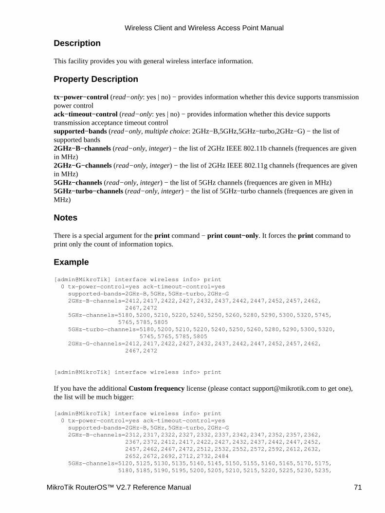
Description
This facility provides you with general wireless interface information.
Property Description
tx−power−control (read−only: yes | no) − provides information whether this device supports transmissionpower controlack−timeout−control (read−only: yes | no) − provides information whether this device supportstransmission acceptance timeout controlsupported−bands (read−only, multiple choice: 2GHz−B,5GHz,5GHz−turbo,2GHz−G) − the list ofsupported bands2GHz−B−channels (read−only, integer) − the list of 2GHz IEEE 802.11b channels (frequences are givenin MHz)2GHz−G−channels (read−only, integer) − the list of 2GHz IEEE 802.11g channels (frequences are givenin MHz)5GHz−channels (read−only, integer) − the list of 5GHz channels (frequences are given in MHz)5GHz−turbo−channels (read−only, integer) − the list of 5GHz−turbo channels (frequences are given inMHz)
Notes
There is a special argument for the print command − print count−only. It forces the print command toprint only the count of information topics.
Example
[admin@MikroTik] interface wireless info> print 0 tx−power−control=yes ack−timeout−control=yes supported−bands=2GHz−B,5GHz,5GHz−turbo,2GHz−G 2GHz−B−channels=2412,2417,2422,2427,2432,2437,2442,2447,2452,2457,2462, 2467,2472 5GHz−channels=5180,5200,5210,5220,5240,5250,5260,5280,5290,5300,5320,5745, 5765,5785,5805 5GHz−turbo−channels=5180,5200,5210,5220,5240,5250,5260,5280,5290,5300,5320, 5745,5765,5785,5805 2GHz−G−channels=2412,2417,2422,2427,2432,2437,2442,2447,2452,2457,2462, 2467,2472
[admin@MikroTik] interface wireless info> print
If you have the additional Custom frequency license (please contact [email protected] to get one),the list will be much bigger:
[admin@MikroTik] interface wireless info> print 0 tx−power−control=yes ack−timeout−control=yes supported−bands=2GHz−B,5GHz,5GHz−turbo,2GHz−G 2GHz−B−channels=2312,2317,2322,2327,2332,2337,2342,2347,2352,2357,2362, 2367,2372,2412,2417,2422,2427,2432,2437,2442,2447,2452, 2457,2462,2467,2472,2512,2532,2552,2572,2592,2612,2632, 2652,2672,2692,2712,2732,2484 5GHz−channels=5120,5125,5130,5135,5140,5145,5150,5155,5160,5165,5170,5175, 5180,5185,5190,5195,5200,5205,5210,5215,5220,5225,5230,5235,
Wireless Client and Wireless Access Point Manual
MikroTik RouterOS™ V2.7 Reference Manual 71

5240,5245,5250,5255,5260,5265,5270,5275,5280,5285,5290,5295, 5300,5305,5310,5315,5320,5325,5330,5335,5340,5345,5350,5355, 5360,5365,5370,5375,5380,5385,5390,5395,5400,5405,5410,5415, 5420,5425,5430,5435,5440,5445,5450,5455,5460,5465,5470,5475, 5480,5485,5490,5495,5500,5505,5510,5515,5520,5525,5530,5535, 5540,5545,5550,5555,5560,5565,5570,5575,5580,5585,5590,5595, 5600,5605,5610,5615,5620,5625,5630,5635,5640,5645,5650,5655, 5660,5665,5670,5675,5680,5685,5690,5695,5700,5705,5710,5715, 5720,5725,5730,5735,5740,5745,5750,5755,5760,5765,5770,5775, 5780,5785,5790,5795,5800,5805,5810,5815,5820,5825,5830,5835, 5840,5845,5850,5855,5860,5865,5870,5875,5880,5885,5890,5895, 5900,5905,5910,5915,5920,5925,5930,5935,5940,5945,5950,5955, 5960,5965,5970,5975,5980,5985,5990,5995,6000,6005,6010,6015, 6020,6025,6030,6035,6040,6045,6050,6055,6060,6065,6070,6075, 6080,6085,6090,6095,6100 5GHz−turbo−channels=5120,5125,5130,5135,5140,5145,5150,5155,5160,5165,5170, 5175,5180,5185,5190,5195,5200,5205,5210,5215,5220,5225, 5230,5235,5240,5245,5250,5255,5260,5265,5270,5275,5280, 5285,5290,5295,5300,5305,5310,5315,5320,5325,5330,5335, 5340,5345,5350,5355,5360,5365,5370,5375,5380,5385,5390, 5395,5400,5405,5410,5415,5420,5425,5430,5435,5440,5445, 5450,5455,5460,5465,5470,5475,5480,5485,5490,5495,5500, 5505,5510,5515,5520,5525,5530,5535,5540,5545,5550,5555, 5560,5565,5570,5575,5580,5585,5590,5595,5600,5605,5610, 5615,5620,5625,5630,5635,5640,5645,5650,5655,5660,5665, 5670,5675,5680,5685,5690,5695,5700,5705,5710,5715,5720, 5725,5730,5735,5740,5745,5750,5755,5760,5765,5770,5775, 5780,5785,5790,5795,5800,5805,5810,5815,5820,5825,5830, 5835,5840,5845,5850,5855,5860,5865,5870,5875,5880,5885, 5890,5895,5900,5905,5910,5915,5920,5925,5930,5935,5940, 5945,5950,5955,5960,5965,5970,5975,5980,5985,5990,5995, 6000,6005,6010,6015,6020,6025,6030,6035,6040,6045,6050, 6055,6060,6065,6070,6075,6080,6085,6090,6095,6100 2GHz−G−channels=2312,2317,2322,2327,2332,2337,2342,2347,2352,2357,2362, 2367,2372,2412,2417,2422,2427,2432,2437,2442,2447,2452, 2457,2462,2467,2472,2512,2532,2552,2572,2592,2612,2632, 2652,2672,2692,2712,2732,2484
[admin@MikroTik] interface wireless info>
AP Configuration Example
Consider the following example:
Wireless Client and Wireless Access Point Manual
MikroTik RouterOS™ V2.7 Reference Manual 72
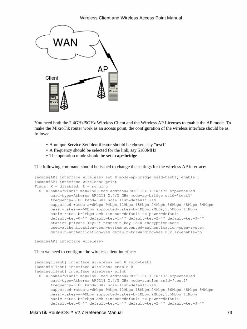
You need both the 2.4GHz/5GHz Wireless Client and the Wireless AP Licenses to enable the AP mode. Tomake the MikroTik router work as an access point, the configuration of the wireless interface should be asfollows:
A unique Service Set Identificator should be chosen, say "test1"• A frequency should be selected for the link, say 5180MHz• The operation mode should be set to ap−bridge•
The following command should be issued to change the settings for the wireless AP interface:
[admin@AP] interface wireless> set 0 mode=ap−bridge ssid=test1; enable 0[admin@AP] interface wireless> printFlags: X − disabled, R − running 0 R name="wlan1" mtu=1500 mac−address=00:01:24:70:03:75 arp=enabled card−type=Atheros AR5211 2.4/5 GHz mode=ap−bridge ssid="test1" frequency=5180 band=5GHz scan−list=default−ism supported−rates−a=6Mbps,9Mbps,12Mbps,18Mbps,24Mbps,36Mbps,48Mbps,54Mbps basic−rates−a=6Mbps supported−rates−b=1Mbps,2Mbps,5.5Mbps,11Mbps basic−rates−b=1Mbps ack−timeout=default tx−power=default default−key−0="" default−key−1="" default−key−2="" default−key−3="" station−private−key="" transmit−key−id=0 encryption=none used−authentication=open−system accepted−authentication=open−system default−authentication=yes default−forwarding=yes 802.1x−enable=no
[admin@AP] interface wireless>
Then we need to configure the wireless client interface:
[admin@client] interface wireless> set 0 ssid=test1[admin@client] interface wireless> enable 0[admin@client] interface wireless> print 0 R name="wlan1" mtu=1500 mac−address=00:01:24:70:03:33 arp=enabled card−type=Atheros AR5211 2.4/5 GHz mode=station ssid="test1" frequency=5180 band=5GHz scan−list=default−ism supported−rates−a=6Mbps,9Mbps,12Mbps,18Mbps,24Mbps,36Mbps,48Mbps,54Mbps basic−rates−a=6Mbps supported−rates−b=1Mbps,2Mbps,5.5Mbps,11Mbps basic−rates−b=1Mbps ack−timeout=default tx−power=default default−key−0="" default−key−1="" default−key−2="" default−key−3=""
Wireless Client and Wireless Access Point Manual
MikroTik RouterOS™ V2.7 Reference Manual 73
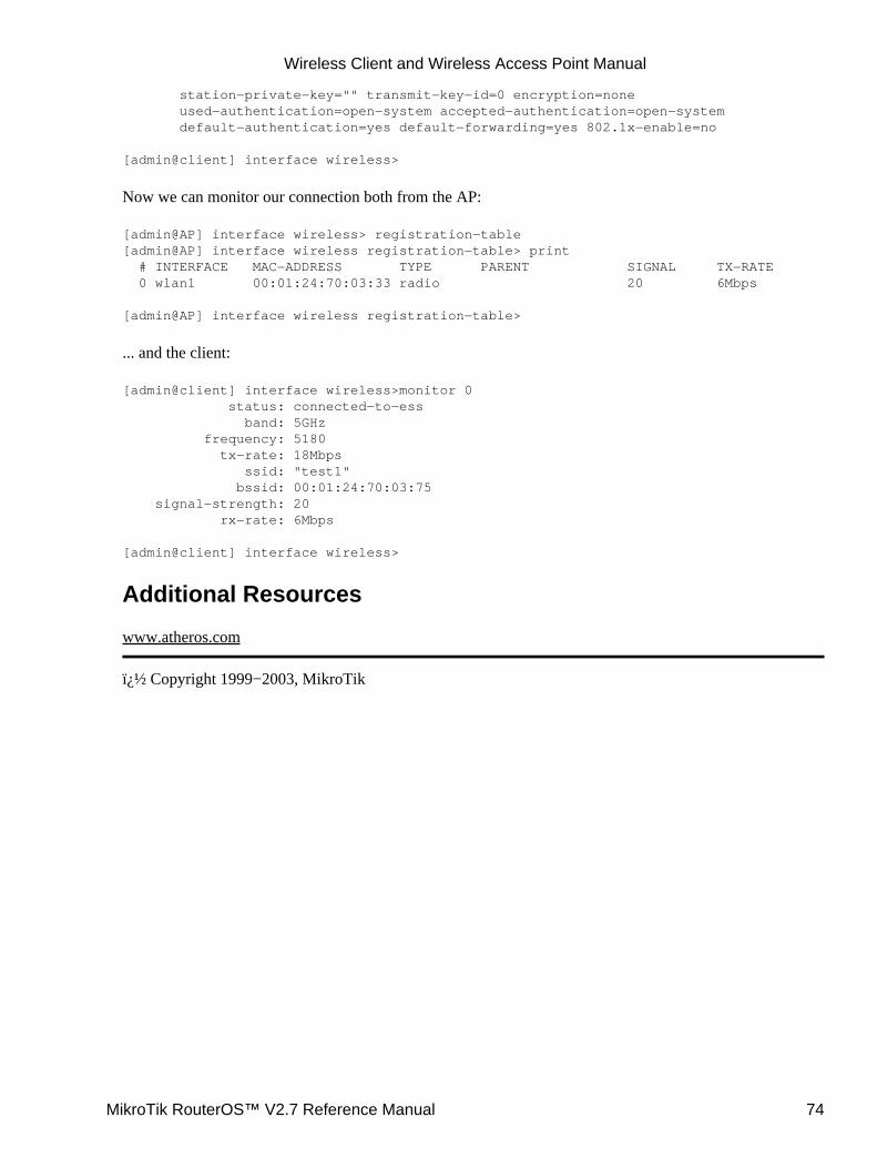
station−private−key="" transmit−key−id=0 encryption=none used−authentication=open−system accepted−authentication=open−system default−authentication=yes default−forwarding=yes 802.1x−enable=no
[admin@client] interface wireless>
Now we can monitor our connection both from the AP:
[admin@AP] interface wireless> registration−table[admin@AP] interface wireless registration−table> print # INTERFACE MAC−ADDRESS TYPE PARENT SIGNAL TX−RATE 0 wlan1 00:01:24:70:03:33 radio 20 6Mbps
[admin@AP] interface wireless registration−table>
... and the client:
[admin@client] interface wireless>monitor 0 status: connected−to−ess band: 5GHz frequency: 5180 tx−rate: 18Mbps ssid: "test1" bssid: 00:01:24:70:03:75 signal−strength: 20 rx−rate: 6Mbps
[admin@client] interface wireless>
Additional Resources
www.atheros.com
� Copyright 1999−2003, MikroTik
Wireless Client and Wireless Access Point Manual
MikroTik RouterOS™ V2.7 Reference Manual 74
Bridge InterfaceDocument revision 1.2 (12−May−2003)This document applies to the MikroTik RouterOS V2.7
Table of Contents
Table of Contents• Overview• Specifications• Related Documents• Description• Bridge Interface Setup
Description♦ Property Description♦ Notes♦ Example♦
•
Port SettingsDescription♦ Property Description♦ Example♦
•
Bridge MonitoringProperty Description♦ Example♦
•
Bridge FirewallDescription♦ Property Description♦ Example♦
•
Application ExampleAdditional Bridge Firewall Resources♦
•
Troubleshooting•
Overview
MAC level bridging of Ethernet packets is supported. Ethernet, Ethernet over IP (EoIP), Prism, Atheros andRadioLAN interfaces are supported. All 802.11b and 802.11a client wireless interfaces (both ad−hoc andinfrastructure or station modes) do not support this because of the limitations of 802.11 − it is possible tobridge over them using the Ethernet over IP protocol (please see documentation on EoIP).
Features include:
Spanning Tree Protocol (STP)• Multiple bridge interfaces• Bridge associations on a per interface basis• Protocol can be selected to be forwarded or discarded• MAC address table can be monitored in real time• IP address assignment for router access• Bridge interfaces can be firewalled•
MikroTik RouterOS™ V2.7 Reference Manual 75
Specifications
Packages required : NoneLicense required : NoneHome menu level : /interface bridgeStandards and Technologies : Media Access Control (MAC) Bridges (IEEE801.1D)Hardware usage : not significant
Related Documents
Software Package Installation and UpgradingIP Addresses and Address Resolution Protocol (ARP)EoIP (Ethernet over IP) Tunnel InterfacePacket Filter (Firewall) and NAT (Network Address Translation)
Description
Ethernet−like networks (Ethernet, Ethernet over IP, IEEE802.11 Wireless interfaces in AP mode) can beconnected together using MAC Bridges. The bridge feature allows the interconnection of stations connectedto separate LANs (using EoIP, geographically distributed networks can be bridged as well if any kind of IPnetwork interconnection exists between them) as if they were attached to a single LAN. As bridges aretransparent, they do not appear in traceroute list, and no utility can make a distinction between a host workingin one LAN and a host working in another LAN if these LANs are bridged (depending on the way the LANsare interconnected, latency and data rate between hosts may vary)
Bridge Interface Setup
Submenu level : /interface bridge
Description
To bridge a number of networks into one bridge, a bridge interface should be created, that will group all thebridged interfaces. One MAC address will be assigned to all the bridged interfaces.
Note that you may only assign IP addresses to the bridge interface (the one is created in this submenu level),not the bridged interfaces (the ones which will be grouped in the bridge).
Property Description
name (name; default: bridgeN) − a descriptive name of the interfacemtu (integer; default: 1500) − Maximum Transmission Unitarp (disabled | enabled | proxy−arp | reply−only; default: enabled) − Address Resolution Protocol settingmac−address (read−only: MAC address) − Media Access Control address for the interfaceforward−protocols (multiple choice: ip, arp, appletalk, ipx, ipv6, other; default:ip,arp,appletalk,ipx,ipv6,other) − list of forwarded protocols.
other − all other protocols than appletalk, arp, ip, ipv6, or ipx, e.g., netbeui, vlan, etc.priority − bridge interface priority (integer: 0..65535, default 1). The priority argument is used bySpanning Tree Protocol to determine, which port remains enabled if two ports form a loop
•
Bridge Interface
MikroTik RouterOS™ V2.7 Reference Manual 76
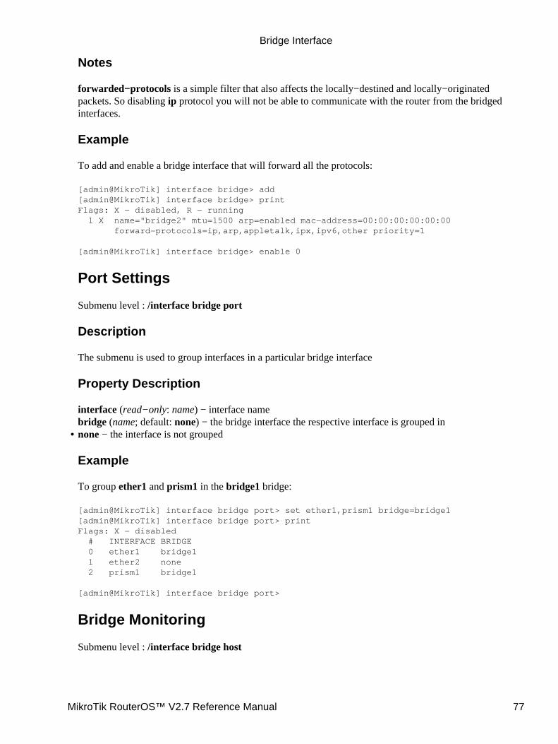
Notes
forwarded−protocols is a simple filter that also affects the locally−destined and locally−originatedpackets. So disabling ip protocol you will not be able to communicate with the router from the bridgedinterfaces.
Example
To add and enable a bridge interface that will forward all the protocols:
[admin@MikroTik] interface bridge> add[admin@MikroTik] interface bridge> printFlags: X − disabled, R − running 1 X name="bridge2" mtu=1500 arp=enabled mac−address=00:00:00:00:00:00 forward−protocols=ip,arp,appletalk,ipx,ipv6,other priority=1
[admin@MikroTik] interface bridge> enable 0
Port Settings
Submenu level : /interface bridge port
Description
The submenu is used to group interfaces in a particular bridge interface
Property Description
interface (read−only: name) − interface namebridge (name; default: none) − the bridge interface the respective interface is grouped innone − the interface is not grouped
Example
To group ether1 and prism1 in the bridge1 bridge:
[admin@MikroTik] interface bridge port> set ether1,prism1 bridge=bridge1[admin@MikroTik] interface bridge port> printFlags: X − disabled # INTERFACE BRIDGE 0 ether1 bridge1 1 ether2 none 2 prism1 bridge1
[admin@MikroTik] interface bridge port>
Bridge Monitoring
Submenu level : /interface bridge host
•
Bridge Interface
MikroTik RouterOS™ V2.7 Reference Manual 77
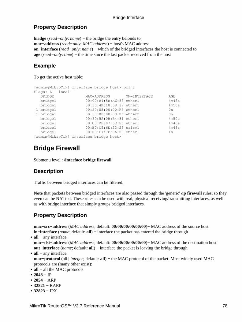
Property Description
bridge (read−only: name) − the bridge the entry belonds tomac−address (read−only: MAC address) − host's MAC addresson−interface (read−only: name) − which of the bridged interfaces the host is connected toage (read−only: time) − the time since the last packet received from the host
Example
To get the active host table:
[admin@MikroTik] interface bridge host> printFlags: L − local BRIDGE MAC−ADDRESS ON−INTERFACE AGE bridge1 00:00:B4:5B:A6:58 ether1 4m48s bridge1 00:30:4F:18:58:17 ether1 4m50s L bridge1 00:50:08:00:00:F5 ether1 0s L bridge1 00:50:08:00:00:F6 ether2 0s bridge1 00:60:52:0B:B4:81 ether1 4m50s bridge1 00:C0:DF:07:5E:E6 ether1 4m46s bridge1 00:E0:C5:6E:23:25 prism1 4m48s bridge1 00:E0:F7:7F:0A:B8 ether1 1s[admin@MikroTik] interface bridge host>
Bridge Firewall
Submenu level : /interface bridge firewall
Description
Traffic between bridged interfaces can be filtered.
Note that packets between bridged interfaces are also passed through the 'generic' /ip firewall rules, so theyeven can be NATted. These rules can be used with real, physical receiving/transmitting interfaces, as wellas with bridge interface that simply groups bridged interfaces.
Property Description
mac−src−address (MAC address; default: 00:00:00:00:00:00)− MAC address of the source hostin−interface (name; default: all) − interface the packet has entered the bridge throughall − any interfacemac−dst−address (MAC address; default: 00:00:00:00:00:00)− MAC address of the destination hostout−interface (name; default: all) − interface the packet is leaving the bridge through
•
all − any interfacemac−protocol (all | integer; default: all) − the MAC protocol of the packet. Most widely used MACprotocols are (many other exist):
•
all − all the MAC protocols• 2048 − IP• 2054 − ARP• 32821 − RARP• 32823 − IPX•
Bridge Interface
MikroTik RouterOS™ V2.7 Reference Manual 78
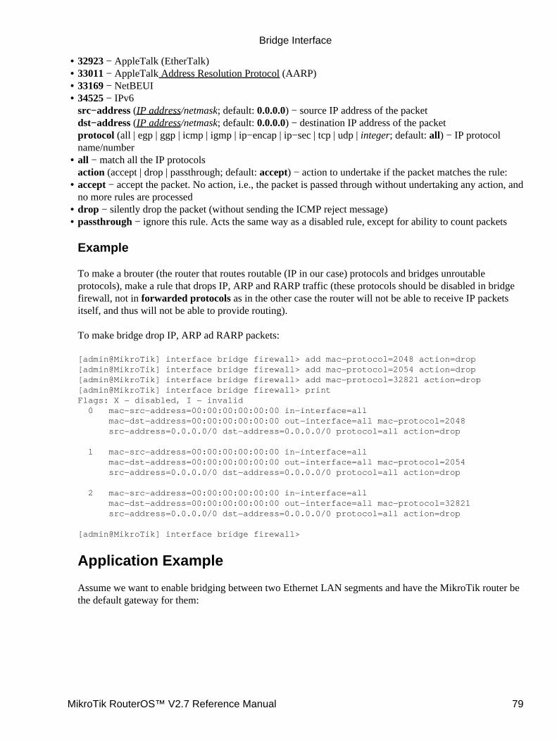
32923 − AppleTalk (EtherTalk)• 33011 − AppleTalk Address Resolution Protocol (AARP)• 33169 − NetBEUI• 34525 − IPv6src−address (IP address/netmask; default: 0.0.0.0) − source IP address of the packetdst−address (IP address/netmask; default: 0.0.0.0) − destination IP address of the packetprotocol (all | egp | ggp | icmp | igmp | ip−encap | ip−sec | tcp | udp | integer; default: all) − IP protocolname/number
•
all − match all the IP protocolsaction (accept | drop | passthrough; default: accept) − action to undertake if the packet matches the rule:
•
accept − accept the packet. No action, i.e., the packet is passed through without undertaking any action, andno more rules are processed
•
drop − silently drop the packet (without sending the ICMP reject message)• passthrough − ignore this rule. Acts the same way as a disabled rule, except for ability to count packets
Example
To make a brouter (the router that routes routable (IP in our case) protocols and bridges unroutableprotocols), make a rule that drops IP, ARP and RARP traffic (these protocols should be disabled in bridgefirewall, not in forwarded protocols as in the other case the router will not be able to receive IP packetsitself, and thus will not be able to provide routing).
To make bridge drop IP, ARP ad RARP packets:
[admin@MikroTik] interface bridge firewall> add mac−protocol=2048 action=drop[admin@MikroTik] interface bridge firewall> add mac−protocol=2054 action=drop[admin@MikroTik] interface bridge firewall> add mac−protocol=32821 action=drop[admin@MikroTik] interface bridge firewall> printFlags: X − disabled, I − invalid 0 mac−src−address=00:00:00:00:00:00 in−interface=all mac−dst−address=00:00:00:00:00:00 out−interface=all mac−protocol=2048 src−address=0.0.0.0/0 dst−address=0.0.0.0/0 protocol=all action=drop
1 mac−src−address=00:00:00:00:00:00 in−interface=all mac−dst−address=00:00:00:00:00:00 out−interface=all mac−protocol=2054 src−address=0.0.0.0/0 dst−address=0.0.0.0/0 protocol=all action=drop
2 mac−src−address=00:00:00:00:00:00 in−interface=all mac−dst−address=00:00:00:00:00:00 out−interface=all mac−protocol=32821 src−address=0.0.0.0/0 dst−address=0.0.0.0/0 protocol=all action=drop
[admin@MikroTik] interface bridge firewall>
Application Example
Assume we want to enable bridging between two Ethernet LAN segments and have the MikroTik router bethe default gateway for them:
•
Bridge Interface
MikroTik RouterOS™ V2.7 Reference Manual 79
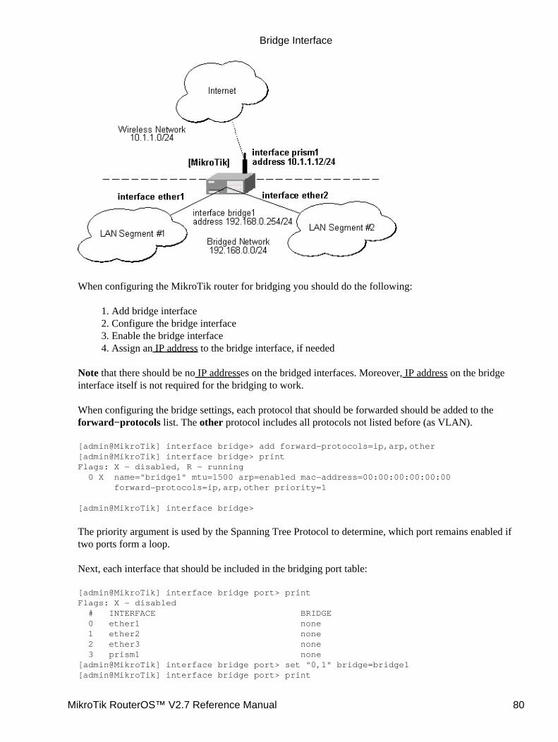
When configuring the MikroTik router for bridging you should do the following:
Add bridge interface1. Configure the bridge interface2. Enable the bridge interface3. Assign an IP address to the bridge interface, if needed4.
Note that there should be no IP addresses on the bridged interfaces. Moreover, IP address on the bridgeinterface itself is not required for the bridging to work.
When configuring the bridge settings, each protocol that should be forwarded should be added to theforward−protocols list. The other protocol includes all protocols not listed before (as VLAN).
[admin@MikroTik] interface bridge> add forward−protocols=ip,arp,other[admin@MikroTik] interface bridge> printFlags: X − disabled, R − running 0 X name="bridge1" mtu=1500 arp=enabled mac−address=00:00:00:00:00:00 forward−protocols=ip,arp,other priority=1
[admin@MikroTik] interface bridge>
The priority argument is used by the Spanning Tree Protocol to determine, which port remains enabled iftwo ports form a loop.
Next, each interface that should be included in the bridging port table:
[admin@MikroTik] interface bridge port> printFlags: X − disabled # INTERFACE BRIDGE 0 ether1 none 1 ether2 none 2 ether3 none 3 prism1 none[admin@MikroTik] interface bridge port> set "0,1" bridge=bridge1[admin@MikroTik] interface bridge port> print
Bridge Interface
MikroTik RouterOS™ V2.7 Reference Manual 80
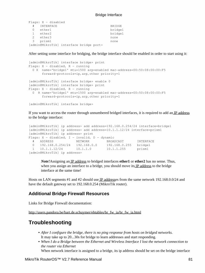
Flags: X − disabled # INTERFACE BRIDGE 0 ether1 bridge1 1 ether2 bridge1 2 ether3 none 3 prism1 none[admin@MikroTik] interface bridge port>
After setting some interface for bridging, the bridge interface should be enabled in order to start using it:
[admin@MikroTik] interface bridge> printFlags: X − disabled, R − running 0 X name="bridge1" mtu=1500 arp=enabled mac−address=00:50:08:00:00:F5 forward−protocols=ip,arp,other priority=1
[admin@MikroTik] interface bridge> enable 0[admin@MikroTik] interface bridge> printFlags: X − disabled, R − running 0 R name="bridge1" mtu=1500 arp=enabled mac−address=00:50:08:00:00:F5 forward−protocols=ip,arp,other priority=1
[admin@MikroTik] interface bridge>
If you want to access the router through unnumbered bridged interfaces, it is required to add an IP addressto the bridge interface:
[admin@MikroTik] ip address> add address=192.168.0.254/24 interface=bridge1[admin@MikroTik] ip address> add address=10.1.1.12/24 interface=prism1[admin@MikroTik] ip address> printFlags: X − disabled, I − invalid, D − dynamic # ADDRESS NETWORK BROADCAST INTERFACE 0 192.168.0.254/24 192.168.0.0 192.168.0.255 bridge1 1 10.1.1.12/24 10.1.1.0 10.1.1.255 prism1[admin@MikroTik] ip address>
Note!Assigning an IP address to bridged interfaces ether1 or ether2 has no sense. Thus,when you assign an interface to a bridge, you should move its IP address to the bridgeinterface at the same time!
Hosts on LAN segments #1 and #2 should use IP addresses from the same network 192.168.0.0/24 andhave the default gateway set to 192.168.0.254 (MikroTik router).
Additional Bridge Firewall Resources
Links for Bridge Firewall documentation:
http://users.pandora.be/bart.de.schuymer/ebtables/br_fw_ia/br_fw_ia.html
Troubleshooting
After I configure the bridge, there is no ping response from hosts on bridged networks.It may take up to 20...30s for bridge to learn addresses and start responding.
•
When I do a Bridge between the Ethernet and Wireless Interface I lost the network connection tothe router via EthernetWhen network interface is assigned to a bridge, its ip address should be set on the bridge interface
•
Bridge Interface
MikroTik RouterOS™ V2.7 Reference Manual 81

as well. Leaving IP address on a bridged interface has no sense.I have added a bridge interface, but no IP traffic is passed.You should include 'arp' in forwarded protocols list, e.g., 'forward−protocols=ip,arp,other'.
•
© Copyright 1999−2002, MikroTik
Bridge Interface
MikroTik RouterOS™ V2.7 Reference Manual 82
MikroTik RouterOS V2.7 Arlan 655 2.4GHz 2MbpsWireless InterfaceDocument revision 1.4 (25−Apr−2003)This document applies to the MikroTik RouterOS V2.7
Table of Contents
Table of Contents• Summary• Specifications• Related Documents• Installation
Example♦ •
Wireless Interface ConfigurationDescription♦ Property Description♦ Example♦
•
Troubleshooting• Additional Resources•
Summary
The MikroTik RouterOS supports Arlan 655 Wireless Interface client cards. This card fits in the ISAexpansion slot and provides transparent wireless communications to other network nodes.
Specifications
Packages required : arlanLicense required : 2.4/5GHz Wireless ClientHome menu level : /interface arlanStandards and Technologies : ProprietaryHardware usage : not significant
Related Documents
Software Package Installation and UpgradingDevice Driver ManagementIP Addresses and Address Resolution Protocol (ARP)Log Management
Installation
Assuming you have all necessary packages and licences installed, you need to load the device driver byissuing /driver add command.
MikroTik RouterOS™ V2.7 Reference Manual 83
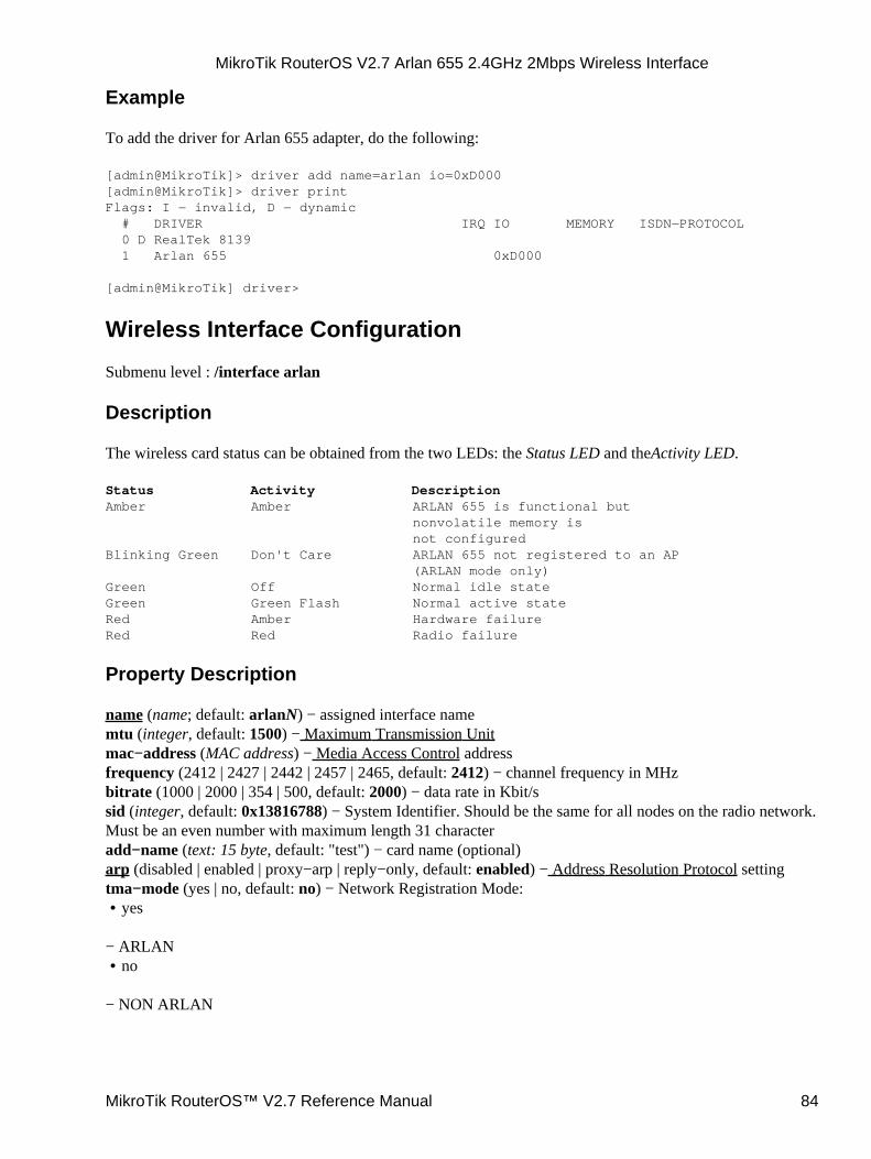
Example
To add the driver for Arlan 655 adapter, do the following:
[admin@MikroTik]> driver add name=arlan io=0xD000[admin@MikroTik]> driver printFlags: I − invalid, D − dynamic # DRIVER IRQ IO MEMORY ISDN−PROTOCOL 0 D RealTek 8139 1 Arlan 655 0xD000
[admin@MikroTik] driver>
Wireless Interface Configuration
Submenu level : /interface arlan
Description
The wireless card status can be obtained from the two LEDs: the Status LED and theActivity LED.
Status Activity DescriptionAmber Amber ARLAN 655 is functional but nonvolatile memory is not configuredBlinking Green Don't Care ARLAN 655 not registered to an AP (ARLAN mode only)Green Off Normal idle stateGreen Green Flash Normal active stateRed Amber Hardware failureRed Red Radio failure
Property Description
name (name; default: arlanN) − assigned interface namemtu (integer, default: 1500) − Maximum Transmission Unitmac−address (MAC address) − Media Access Control addressfrequency (2412 | 2427 | 2442 | 2457 | 2465, default: 2412) − channel frequency in MHzbitrate (1000 | 2000 | 354 | 500, default: 2000) − data rate in Kbit/ssid (integer, default: 0x13816788) − System Identifier. Should be the same for all nodes on the radio network.Must be an even number with maximum length 31 characteradd−name (text: 15 byte, default: "test") − card name (optional)arp (disabled | enabled | proxy−arp | reply−only, default: enabled) − Address Resolution Protocol settingtma−mode (yes | no, default: no) − Network Registration Mode:
yes•
− ARLANno•
− NON ARLAN
MikroTik RouterOS V2.7 Arlan 655 2.4GHz 2Mbps Wireless Interface
MikroTik RouterOS™ V2.7 Reference Manual 84
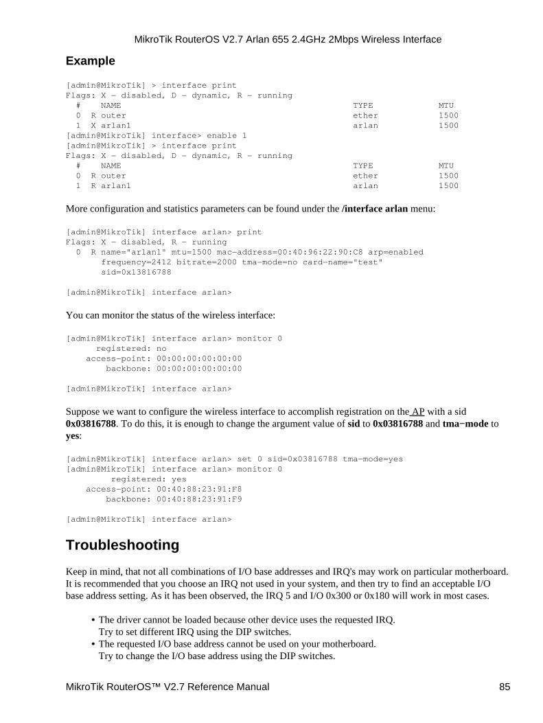
Example
[admin@MikroTik] > interface printFlags: X − disabled, D − dynamic, R − running # NAME TYPE MTU 0 R outer ether 1500 1 X arlan1 arlan 1500[admin@MikroTik] interface> enable 1[admin@MikroTik] > interface printFlags: X − disabled, D − dynamic, R − running # NAME TYPE MTU 0 R outer ether 1500 1 R arlan1 arlan 1500
More configuration and statistics parameters can be found under the /interface arlan menu:
[admin@MikroTik] interface arlan> printFlags: X − disabled, R − running 0 R name="arlan1" mtu=1500 mac−address=00:40:96:22:90:C8 arp=enabled frequency=2412 bitrate=2000 tma−mode=no card−name="test" sid=0x13816788
[admin@MikroTik] interface arlan>
You can monitor the status of the wireless interface:
[admin@MikroTik] interface arlan> monitor 0 registered: no access−point: 00:00:00:00:00:00 backbone: 00:00:00:00:00:00
[admin@MikroTik] interface arlan>
Suppose we want to configure the wireless interface to accomplish registration on the AP with a sid0x03816788. To do this, it is enough to change the argument value of sid to 0x03816788 and tma−mode toyes:
[admin@MikroTik] interface arlan> set 0 sid=0x03816788 tma−mode=yes[admin@MikroTik] interface arlan> monitor 0 registered: yes access−point: 00:40:88:23:91:F8 backbone: 00:40:88:23:91:F9
[admin@MikroTik] interface arlan>
Troubleshooting
Keep in mind, that not all combinations of I/O base addresses and IRQ's may work on particular motherboard.It is recommended that you choose an IRQ not used in your system, and then try to find an acceptable I/Obase address setting. As it has been observed, the IRQ 5 and I/O 0x300 or 0x180 will work in most cases.
The driver cannot be loaded because other device uses the requested IRQ.Try to set different IRQ using the DIP switches.
•
The requested I/O base address cannot be used on your motherboard.Try to change the I/O base address using the DIP switches.
•
MikroTik RouterOS V2.7 Arlan 655 2.4GHz 2Mbps Wireless Interface
MikroTik RouterOS™ V2.7 Reference Manual 85

The pc interface does not show up under the interfaces listObtain the required license for 2.4/5GHz Wireless Client feature.
•
The wireless card does not register to the APCheck the cabling and antenna alignment.
•
Additional Resources
www.aironet.comhttp://www.comptek.ru:8100/wireless/files/filearlan.html
© Copyright 1999−2003, MikroTik
MikroTik RouterOS V2.7 Arlan 655 2.4GHz 2Mbps Wireless Interface
MikroTik RouterOS™ V2.7 Reference Manual 86
CISCO/Aironet 2.4GHz 11Mbps Wireless InterfaceDocument revision 1.3 (11−Jun−2003)This document applies to the MikroTik RouterOS V2.7
Table of Contents
Table of Contents• Summary• Specifications• Related Documents• Wireless Interface Configuration
Description♦ Property Description♦ Example♦
•
Troubleshooting• Wireless Network Applications
Point−to−Multipoint Wireless LAN♦ Point−to−Point Wireless LAN♦
•
Additional Resources•
Summary
The MikroTik RouterOS supports the following CISCO/Aironet 2.4GHz Wireless ISA/PCI/PC Adapterhardware:
Aironet ISA/PCI/PC4800 2.4GHz DS 11Mbps Wireless LAN Adapters (100mW)• Aironet ISA/PCI/PC4500 2.4GHz DS 2Mbps Wireless LAN Adapters (100mW)• CISCO AIR−PCI340 2.4GHz DS 11Mbps Wireless LAN Adapters (30mW)• CISCO AIR−PCI/PC350/352 2.4GHz DS 11Mbps Wireless LAN Adapters (100mW)•
Specifications
Packages required : wirelessLicense required : 2.4GHz Wireless ClientHome menu level : /interface pcProtocols utilized : IEEE802.11b (IEEE802.11b)Hardware usage : not significant
Related Documents
Software Package Installation and UpgradingDevice Driver ManagementIP Addresses and Address Resolution Protocol (ARP)Log ManagementNotes on PCMCIA Adapters
MikroTik RouterOS™ V2.7 Reference Manual 87
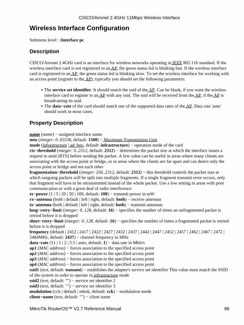
Wireless Interface Configuration
Submenu level : /interface pc
Description
CISCO/Aironet 2.4GHz card is an interface for wireless networks operating in IEEE 802.11b standard. If thewireless interface card is not registered to an AP, the green status led is blinking fast. If the wireless interfacecard is registered to an AP, the green status led is blinking slow. To set the wireless interface for working withan access point (register to the AP), typically you should set the following parameters:
The service set identifier. It should match the ssid of the AP. Can be blank, if you want the wirelessinterface card to register to an AP with any ssid. The ssid will be received from the AP, if the AP isbroadcasting its ssid.
•
The data−rate of the card should match one of the supported data rates of the AP. Data rate 'auto'should work in most cases.
•
Property Description
name (name) − assigned interface namemtu (integer: 0..65536, default: 1500) − Maximum Transmission Unitmode (infrastructure | ad−hoc, default: infrastructure) − operation mode of the cardrts−threshold (integer: 0..2312, default: 2312) − determines the packet size at which the interface issues arequest to send (RTS) before sending the packet. A low value can be useful in areas where many clients areassociating with the access point or bridge, or in areas where the clients are far apart and can detect only theaccess point or bridge and not each otherfragmentation−threshold (integer: 256..2312, default: 2312) − this threshold controls the packet size atwhich outgoing packets will be split into multiple fragments. If a single fragment transmit error occurs, onlythat fragment will have to be retransmitted instead of the whole packet. Use a low setting in areas with poorcommunication or with a great deal of radio interferencetx−power (1 | 5 | 20 | 50 | 100, default: 100) − transmit power in mWrx−antenna (both | default | left | right, default: both) − receive antennastx−antenna (both | default | left | right, default: both) − transmit antennaslong−retry−limit (integer: 0..128, default: 16) − specifies the number of times an unfragmented packet isretried before it is droppedshort−retry−limit (integer: 0..128, default :16) − specifies the number of times a fragmented packet is retriedbefore it is droppedfrequency (default | 2412 | 2417 | 2422 | 2427 | 2432 | 2437 | 2442 | 2447 | 2452 | 2457 | 2462 | 2467 | 2472 |2484MHz, default: 2437) − channel frequency in MHzdata−rate (11 | 1 | 2 | 5.5 | auto, default: 1) − data rate in Mbit/sap1 (MAC address) − forces association to the specified access pointap2 (MAC address) − forces association to the specified access pointap3 (MAC address) − forces association to the specified access pointap4 (MAC address) − forces association to the specified access pointssid1 (text, default: tsunami) − establishes the adapter's service set identifier This value must match the SSIDof the system in order to operate in infrastructure modessid2 (text, default: "") − service set identifier 2ssid3 (text, default: "") − service set identifier 3modulation (cck | default | mbok, default: cck) − modulation modeclient−name (text, default: "") − client name
CISCO/Aironet 2.4GHz 11Mbps Wireless Interface
MikroTik RouterOS™ V2.7 Reference Manual 88
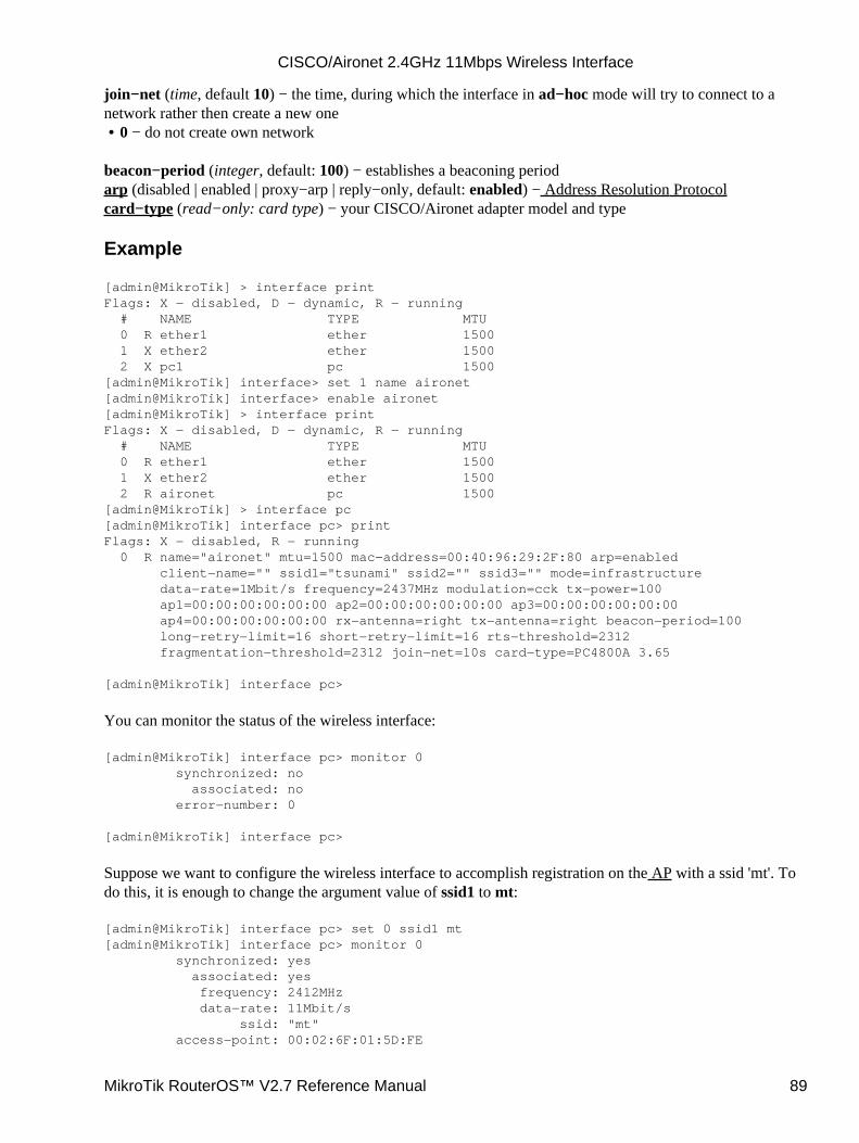
join−net (time, default 10) − the time, during which the interface in ad−hoc mode will try to connect to anetwork rather then create a new one
0 − do not create own network•
beacon−period (integer, default: 100) − establishes a beaconing periodarp (disabled | enabled | proxy−arp | reply−only, default: enabled) − Address Resolution Protocolcard−type (read−only: card type) − your CISCO/Aironet adapter model and type
Example
[admin@MikroTik] > interface printFlags: X − disabled, D − dynamic, R − running # NAME TYPE MTU 0 R ether1 ether 1500 1 X ether2 ether 1500 2 X pc1 pc 1500[admin@MikroTik] interface> set 1 name aironet[admin@MikroTik] interface> enable aironet[admin@MikroTik] > interface printFlags: X − disabled, D − dynamic, R − running # NAME TYPE MTU 0 R ether1 ether 1500 1 X ether2 ether 1500 2 R aironet pc 1500[admin@MikroTik] > interface pc[admin@MikroTik] interface pc> printFlags: X − disabled, R − running 0 R name="aironet" mtu=1500 mac−address=00:40:96:29:2F:80 arp=enabled client−name="" ssid1="tsunami" ssid2="" ssid3="" mode=infrastructure data−rate=1Mbit/s frequency=2437MHz modulation=cck tx−power=100 ap1=00:00:00:00:00:00 ap2=00:00:00:00:00:00 ap3=00:00:00:00:00:00 ap4=00:00:00:00:00:00 rx−antenna=right tx−antenna=right beacon−period=100 long−retry−limit=16 short−retry−limit=16 rts−threshold=2312 fragmentation−threshold=2312 join−net=10s card−type=PC4800A 3.65
[admin@MikroTik] interface pc>
You can monitor the status of the wireless interface:
[admin@MikroTik] interface pc> monitor 0 synchronized: no associated: no error−number: 0
[admin@MikroTik] interface pc>
Suppose we want to configure the wireless interface to accomplish registration on the AP with a ssid 'mt'. Todo this, it is enough to change the argument value of ssid1 to mt:
[admin@MikroTik] interface pc> set 0 ssid1 mt[admin@MikroTik] interface pc> monitor 0 synchronized: yes associated: yes frequency: 2412MHz data−rate: 11Mbit/s ssid: "mt" access−point: 00:02:6F:01:5D:FE
CISCO/Aironet 2.4GHz 11Mbps Wireless Interface
MikroTik RouterOS™ V2.7 Reference Manual 89
access−point−name: "" signal−quality: 132 signal−strength: −82 error−number: 0
[admin@MikroTik] interface pc>
Troubleshooting
Keep in mind, that not all combinations of I/O base addresses and IRQ's may work on particular motherboard.It is recommended that you choose an IRQ not used in your system, and then try to find an acceptable I/Obase address setting. As it has been observed, the IRQ 5 and I/O 0x300 or 0x180 will work in most cases.
The driver cannot be loaded because other device uses the requested IRQ.Try to set different IRQ using the DIP switches.
•
The requested I/O base address cannot be used on your motherboard.Try to change the I/O base address using the DIP switches.
•
The pc interface does not show up under the interfaces listObtain the required 2.4GHz Wireless Client license.
•
The wireless card does not register to the APCheck the cabling and antenna alignment.
•
Wireless Network Applications
Two possible wireless network configurations are discussed in the following examples:Point−to−Multipoint (Wireless Infrastructure)• Point−to−Point (Peer−to−Peer, or Ad−Hoc Wireless LAN)
Point−to−Multipoint Wireless LAN
Let us consider the following network setup with CISCO/Aironet Wireless Access Point as a base stationand MikroTik Wireless Router as a client:
•
CISCO/Aironet 2.4GHz 11Mbps Wireless Interface
MikroTik RouterOS™ V2.7 Reference Manual 90
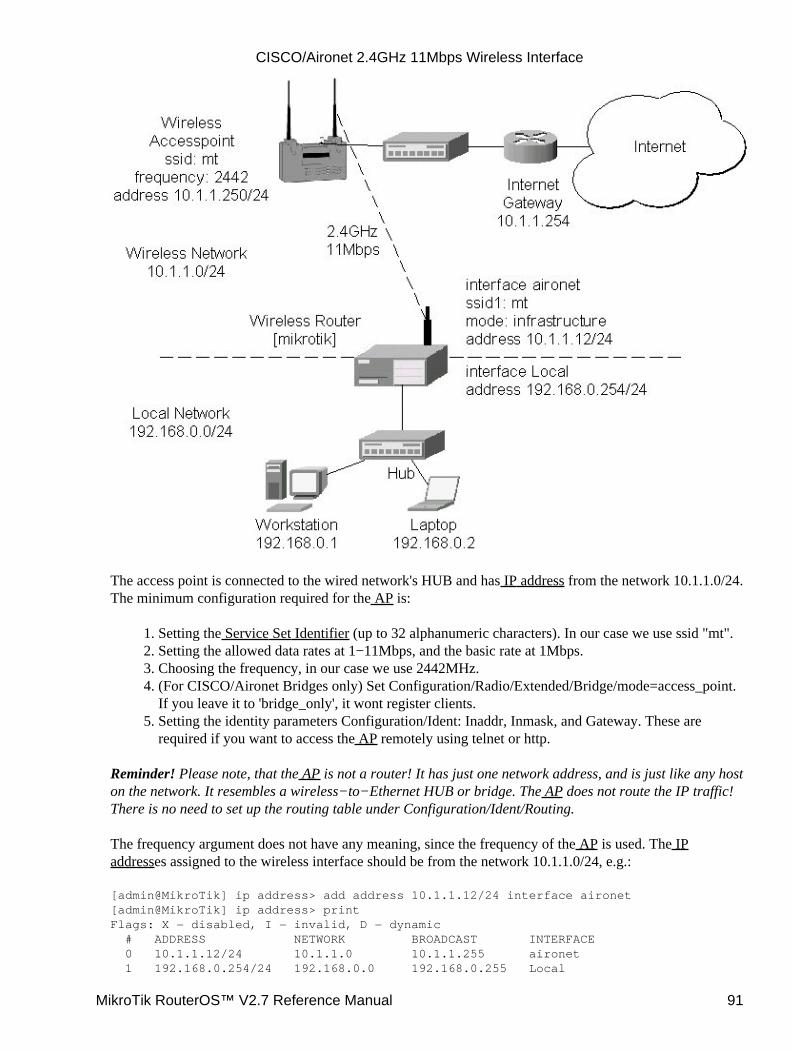
The access point is connected to the wired network's HUB and has IP address from the network 10.1.1.0/24.The minimum configuration required for the AP is:
Setting the Service Set Identifier (up to 32 alphanumeric characters). In our case we use ssid "mt".1. Setting the allowed data rates at 1−11Mbps, and the basic rate at 1Mbps.2. Choosing the frequency, in our case we use 2442MHz.3. (For CISCO/Aironet Bridges only) Set Configuration/Radio/Extended/Bridge/mode=access_point.If you leave it to 'bridge_only', it wont register clients.
4.
Setting the identity parameters Configuration/Ident: Inaddr, Inmask, and Gateway. These arerequired if you want to access the AP remotely using telnet or http.
5.
Reminder! Please note, that the AP is not a router! It has just one network address, and is just like any hoston the network. It resembles a wireless−to−Ethernet HUB or bridge. The AP does not route the IP traffic!There is no need to set up the routing table under Configuration/Ident/Routing.
The frequency argument does not have any meaning, since the frequency of the AP is used. The IPaddresses assigned to the wireless interface should be from the network 10.1.1.0/24, e.g.:
[admin@MikroTik] ip address> add address 10.1.1.12/24 interface aironet[admin@MikroTik] ip address> printFlags: X − disabled, I − invalid, D − dynamic # ADDRESS NETWORK BROADCAST INTERFACE 0 10.1.1.12/24 10.1.1.0 10.1.1.255 aironet 1 192.168.0.254/24 192.168.0.0 192.168.0.255 Local
CISCO/Aironet 2.4GHz 11Mbps Wireless Interface
MikroTik RouterOS™ V2.7 Reference Manual 91
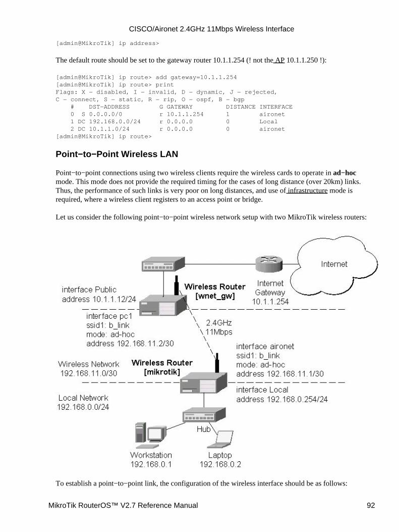
[admin@MikroTik] ip address>
The default route should be set to the gateway router 10.1.1.254 (! not the AP 10.1.1.250 !):
[admin@MikroTik] ip route> add gateway=10.1.1.254[admin@MikroTik] ip route> printFlags: X − disabled, I − invalid, D − dynamic, J − rejected,C − connect, S − static, R − rip, O − ospf, B − bgp # DST−ADDRESS G GATEWAY DISTANCE INTERFACE 0 S 0.0.0.0/0 r 10.1.1.254 1 aironet 1 DC 192.168.0.0/24 r 0.0.0.0 0 Local 2 DC 10.1.1.0/24 r 0.0.0.0 0 aironet[admin@MikroTik] ip route>
Point−to−Point Wireless LAN
Point−to−point connections using two wireless clients require the wireless cards to operate in ad−hocmode. This mode does not provide the required timing for the cases of long distance (over 20km) links.Thus, the performance of such links is very poor on long distances, and use of infrastructure mode isrequired, where a wireless client registers to an access point or bridge.
Let us consider the following point−to−point wireless network setup with two MikroTik wireless routers:
To establish a point−to−point link, the configuration of the wireless interface should be as follows:
CISCO/Aironet 2.4GHz 11Mbps Wireless Interface
MikroTik RouterOS™ V2.7 Reference Manual 92

A unique Service Set Identificator should be chosen for both ends, say "b_link"• A channel frequency should be selected for the link, say 2412MHz• The operation mode should be set to ad−hoc• One of the units (slave) should have wireless interface argument join−net set to 0s (never create anetwork), the other unit (master) should be set to 1s or whatever, say 10s. This will enable themaster unit to create a network and register the slave unit to it.
•
The following command should be issued to change the settings for the pc interface of the master unit:
[admin@MikroTik] interface pc> set 0 mode=ad−hoc ssid1=b_link frequency=2442MHz \\... bitrate=auto[admin@MikroTik] interface pc>
For 10 seconds (this is set by the argument join−net) the wireless card will look for a network to join. Thestatus of the card is not synchronized, and the green status light is blinking fast. If the card cannot find anetwork, it creates its own network. The status of the card becomes synchronized, and the green status ledbecomes solid. The monitor command shows the new status and the MAC address generated:
[admin@MikroTik] interface pc> monitor 0 synchronized: yes associated: yes frequency: 2442MHz data−rate: 11Mbit/s ssid: "b_link" access−point: 2E:00:B8:01:98:01 access−point−name: "" signal−quality: 35 signal−strength: −62 error−number: 0
[admin@MikroTik] interface pc>
The other router of the point−to−point link requires the operation mode set to ad−hoc, the System ServiceIdentificator set to "b_link", and the channel frequency set to 2412MHz. If the radios are able to establishRF connection, the status of the card should become synchronized, and the green status led should becomesolid immediately after entering the command:
[admin@wnet_gw] interface pc> set 0 mode=ad−hoc ssid1=b_link frequency=2412MHz \\... bitrate=auto[admin@wnet_gw] interface pc> monitor 0 synchronized: yes associated: no frequency: 2442MHz data−rate: 11Mbit/s ssid: "b_link" access−point: 2E:00:B8:01:98:01 access−point−name: "" signal−quality: 131 signal−strength: −83 error−number: 0
[admin@wnet_gw] interface pc>
As we see, the MAC address under the access−point parameter is the same as generated on the first router.
CISCO/Aironet 2.4GHz 11Mbps Wireless Interface
MikroTik RouterOS™ V2.7 Reference Manual 93

If desired, IP addresses can be assigned to the wireless interfaces of the pint−to−point linked routers using asmaller subnet, say 30−bit one:
[admin@MikroTik] ip address> add address 192.168.11.1/30 interface aironet[admin@MikroTik] ip address> printFlags: X − disabled, I − invalid, D − dynamic # ADDRESS NETWORK BROADCAST INTERFACE 0 192.168.11.1/30 192.168.11.0 192.168.11.3 aironet 1 192.168.0.254/24 192.168.0.0 192.168.0.255 Local[admin@MikroTik] ip address>
The second router will have address 192.168.11.2. The network connectivity can be tested by using ping orbandwidth test:
[admin@wnet_gw] ip address> add address 192.168.11.2/30 interface aironet[admin@wnet_gw] ip address> printFlags: X − disabled, I − invalid, D − dynamic # ADDRESS NETWORK BROADCAST INTERFACE 0 192.168.11.2/30 192.168.11.0 192.168.11.3 aironet 1 10.1.1.12/24 10.1.1.0 10.1.1.255 Public[admin@wnet_gw] ip address> /ping 192.168.11.1192.168.11.1 pong: ttl=255 time=3 ms192.168.11.1 pong: ttl=255 time=1 ms192.168.11.1 pong: ttl=255 time=1 ms192.168.11.1 pong: ttl=255 ping interrupted4 packets transmitted, 4 packets received, 0% packet lossround−trip min/avg/max = 1/1.5/3 ms[admin@wnet_gw] interface pc> /tool bandwidth−test 192.168.11.1 protocol tcp status: running rx−current: 4.61Mbps rx−10−second−average: 4.25Mbps rx−total−average: 4.27Mbps
[admin@wnet_gw] interface pc> /tool bandwidth−test 192.168.11.1 protocol udp size 1500 status: running rx−current: 5.64Mbps rx−10−second−average: 5.32Mbps rx−total−average: 4.87Mbps
[admin@wnet_gw] interface pc>
Additional Resources
www.aironet.comwww.cisco.com/warp/public/44/jump/wireless.shtmlCisco − Cisco Aironet 350 SeriesFor more information about the CISCO/Aironet PCI/ISA adapter hardware please see the relevant User’sGuides and Technical Reference Manuals in pdf format:
710−003638a0.pdf for PCI/ISA 4800 and 4500 series adapters• 710−004239B0.pdf for PC 4800 and 4500 series adapters•
Documentation about CISCO/Aironet Wireless Bridges and Access Points can be found in archives:
AP48MAN.exe for AP4800 Wireless Access Point•
CISCO/Aironet 2.4GHz 11Mbps Wireless Interface
MikroTik RouterOS™ V2.7 Reference Manual 94

BR50MAN.exe for BR500 Wireless Bridge•
© Copyright 1999−2002, MikroTik
CISCO/Aironet 2.4GHz 11Mbps Wireless Interface
MikroTik RouterOS™ V2.7 Reference Manual 95
Cyclades PC300 PCI AdaptersDocument revision 1.1 (15−Jul−2003)This document applies to the MikroTik RouterOS v2.7
Table of Contents
Table of Contents• Summary• Specifications• Related Documents• Synchronous Interface Configuration
Description♦ Property Description♦
•
Troubleshooting• RSV/V.35 Synchronous Link Applications• Additional Resources•
Summary
The MikroTik RouterOS supports the following Cyclades PC300 Adapter hardware:
RSV/V.35 (RSV models) with 1 or 2 RS−232/V.35 interfaces on standard DB25/M.34 connector,5Mbps, internal or external clock
•
T1/E1 (TE models) with 1 or 2 T1/E1/G.703 interfaces on standard RJ48C connector, Full/Fractional,internal or external clock
•
X.21 (X21 models) with 1 or 2 X.21 on standard DB−15 connector, 8Mbps, internal or external clock•
Specifications
Packages required : synchronousLicense required : Sync and HotspotHome menu level : /interface cycladesStandards and Technologies : X.21, V.35, T1/E1/G.703, Frame Relay, PPP, Cisco−HDLCHardware usage : not significant
Related Documents
Software Package Installation and UpgradingDevice Driver ManagementIP Addresses and Address Resolution Protocol (ARP)Log Management
Synchronous Interface Configuration
Submenu level : /interface cyclades
MikroTik RouterOS™ V2.7 Reference Manual 96
Description
You can install up to four Cyclades PC300 PCI Adapters in one PC box, if you have so many adapter slotsand IRQs available.
The Cyclades PC300/RSV Synchronous PCI Adapter comes with a V.35 cable. This cable should work for allstandard modems, which have V.35 connections. For synchronous modems, which have a DB−25 connection,you should use a standard DB−25 cable.
Connect a communication device, e.g., a baseband modem, to the V.35 port and turn it on. The MikroTikdriver for the Cyclades Synchronous PCI Adapter allows you to unplug the V.35 cable from one modem andplug it into another modem with a different clock speed, and you do not need to restart the interface or router.
Property Description
name (name; default: cycladesN) − assigned interface namemtu (integer; default: 1500) − Maximum Transmission Unitline−protocol (cisco−hdlc | frame−relay | sync−ppp; default: sync−ppp) − line protocolmedia−type (E1 | T1 | V24 | V35 | X21; default: V35) − the hardware media used for this interface:clock−rate (integer; default: 64000) − internal clock rate in bpsclock−source (external | internal | tx−internal; default: external) − source of the clockline−code (AMI | B8ZS | HDB3 | NRZ; default: B8ZS) − for T1/E1 channels only. Line modulation method:
AMI − Alternate Mark Inversion• B8ZS − Binary 8−Zero Substitution• HDB3 − High Density Bipolar 3 Code (ITU−T)• NRZ − Non−Return−To−Zeroframing−mode (CRC4 | D4 | ESF | Non−CRC4 | Unframed; default: ESF) − for T1/E1 channels only. Theframe mode:
•
Unframed − do not check frame integrity• Non−CRC4 − plain Cyclic Redundancy Check• CRC4 − Cyclic Redundancy Check 4−bit (E1 Signaling, Europe)• D4 − Fourth Generation Channel Bank (48 Voice Channels on 2 T−1s or 1 T−1c)• ESF − Extended Superframe Formatline−build−out (0dB | 15dB | 22.5dB | 7.5dB; default: 0) − for T1 channels only. Line Build Out SignalLevelrx−sensitivity (long−haul | short−haul; default: short−haul) − for T1/E1 channels only. Receiversensitivityactive−channels (multiple choice: integer; default: all) − for T1/E1 channels only. Numbers of activechannels (up to 32 for E1 and up to 24 for T1)chdlc−keepalive (time; default: 10s) − Cisco−HDLC keepalive interval in secondsframe−relay−dce (yes | no; default: no) − specifies whether the device operates in Data CommunicationEquipment mode. The value yes is suitable only for TE modelsframe−relay−lmi−type (ansi | ccitt; default: ansi) − Frame Relay Line Management Interface Protocoltype
Troubleshooting
The cyclades interface does not show up under the interfaces listObtain the required license for synchronous feature.
•
•
Cyclades PC300 PCI Adapters
MikroTik RouterOS™ V2.7 Reference Manual 97
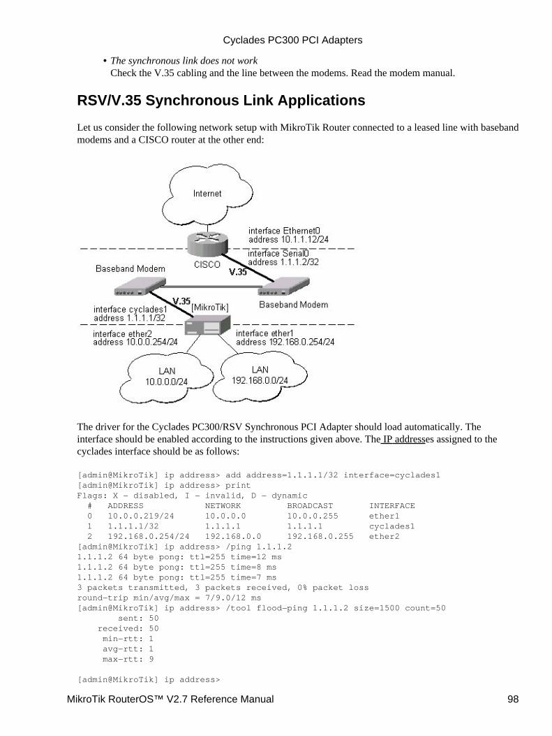
The synchronous link does not workCheck the V.35 cabling and the line between the modems. Read the modem manual.
•
RSV/V.35 Synchronous Link Applications
Let us consider the following network setup with MikroTik Router connected to a leased line with basebandmodems and a CISCO router at the other end:
The driver for the Cyclades PC300/RSV Synchronous PCI Adapter should load automatically. Theinterface should be enabled according to the instructions given above. The IP addresses assigned to thecyclades interface should be as follows:
[admin@MikroTik] ip address> add address=1.1.1.1/32 interface=cyclades1[admin@MikroTik] ip address> printFlags: X − disabled, I − invalid, D − dynamic # ADDRESS NETWORK BROADCAST INTERFACE 0 10.0.0.219/24 10.0.0.0 10.0.0.255 ether1 1 1.1.1.1/32 1.1.1.1 1.1.1.1 cyclades1 2 192.168.0.254/24 192.168.0.0 192.168.0.255 ether2[admin@MikroTik] ip address> /ping 1.1.1.21.1.1.2 64 byte pong: ttl=255 time=12 ms1.1.1.2 64 byte pong: ttl=255 time=8 ms1.1.1.2 64 byte pong: ttl=255 time=7 ms3 packets transmitted, 3 packets received, 0% packet lossround−trip min/avg/max = 7/9.0/12 ms[admin@MikroTik] ip address> /tool flood−ping 1.1.1.2 size=1500 count=50 sent: 50 received: 50 min−rtt: 1 avg−rtt: 1 max−rtt: 9
[admin@MikroTik] ip address>
Cyclades PC300 PCI Adapters
MikroTik RouterOS™ V2.7 Reference Manual 98
Note, that for the point−to−point link the network mask is set to 32 bits, the argument network is set to theIP address of the other end, and the broadcast address is set to 255.255.255.255. The default route should beset to the gateway router 1.1.1.2:
[admin@MikroTik] ip route> add gateway 1.1.1.2 interface cyclades1[admin@MikroTik] ip route> printFlags: X − disabled, I − invalid, D − dynamic, J − rejected,C − connect, S − static, R − rip, O − ospf, B − bgp # DST−ADDRESS G GATEWAY DISTANCE INTERFACE 0 S 0.0.0.0/0 r 1.1.1.2 1 cyclades1 1 DC 10.0.0.0/24 r 0.0.0.0 0 ether1 2 DC 192.168.0.0/24 r 0.0.0.0 0 ether2 3 DC 1.1.1.2/32 r 0.0.0.0 0 cyclades1[admin@MikroTik] ip route>
The configuration of the CISCO router at the other end (part of the configuration) is:
CISCO#show running−configBuilding configuration...
Current configuration:...!interface Ethernet0 description connected to EthernetLAN ip address 10.1.1.12 255.255.255.0!interface Serial0 description connected to MikroTik ip address 1.1.1.2 255.255.255.252 serial restart−delay 1!ip classlessip route 0.0.0.0 0.0.0.0 10.1.1.254!...end
CISCO#
Send ping packets to the MikroTik router:
CISCO#ping 1.1.1.1
Type escape sequence to abort.Sending 5, 100−byte ICMP Echos to 1.1.1.1, timeout is 2 seconds:!!!!!Success rate is 100 percent (5/5), round−trip min/avg/max = 28/32/40 msCISCO#
Additional Resources
For more information about the Cyclades PCI Adapter hardware please see the relevant documentation:
http://www.cyclades.com/products/svrbas/pc300.php − The product on−line documentation• Cyclades PC300 Installation Manual − The Installation Manual in .pdf format•
Cyclades PC300 PCI Adapters
MikroTik RouterOS™ V2.7 Reference Manual 99

© Copyright 1999−2003, MikroTik
Cyclades PC300 PCI Adapters
MikroTik RouterOS™ V2.7 Reference Manual 100
Ethernet InterfacesDocument revision 1.7 (21−May−2003)This document applies to the MikroTik RouterOS V2.7
Table of Contents
Table of Contents• Summary• Specifications• Related Documents• Ethernet Interface Configuration
Property Description♦ Notes♦ Examples♦
•
Monitoring the Interface StatusExample♦
•
Notes• Additional Resources•
Summary
MikroTik RouterOS supports the following types of Ethernet Network Interface Cards:most NE2000 compatible ISA and PCI cards• 3com 3c509 ISA cards• DEC/Intel Tulip chip based cards• Intel Pro Gigabit PCI cardsThe complete list of supported Ethernet NICs can be found in the Device Driver Management Manual.
Specifications
Packages required : NoneLicense required : AnyHome menu level : /interface ethernetStandards and Technologies : IEEE 802.3 (grouper.ieee.org/groups/802/3/)Hardware usage : not significant
Related Documents
Software Package Installation and UpgradingDevice Driver ManagementIP Addresses and Address Resolution Protocol (ARP)Dynamic Host Configuration Protocol (DHCP) Client and Server
Ethernet Interface Configuration
Submenu level : /interface ethernet
•
MikroTik RouterOS™ V2.7 Reference Manual 101
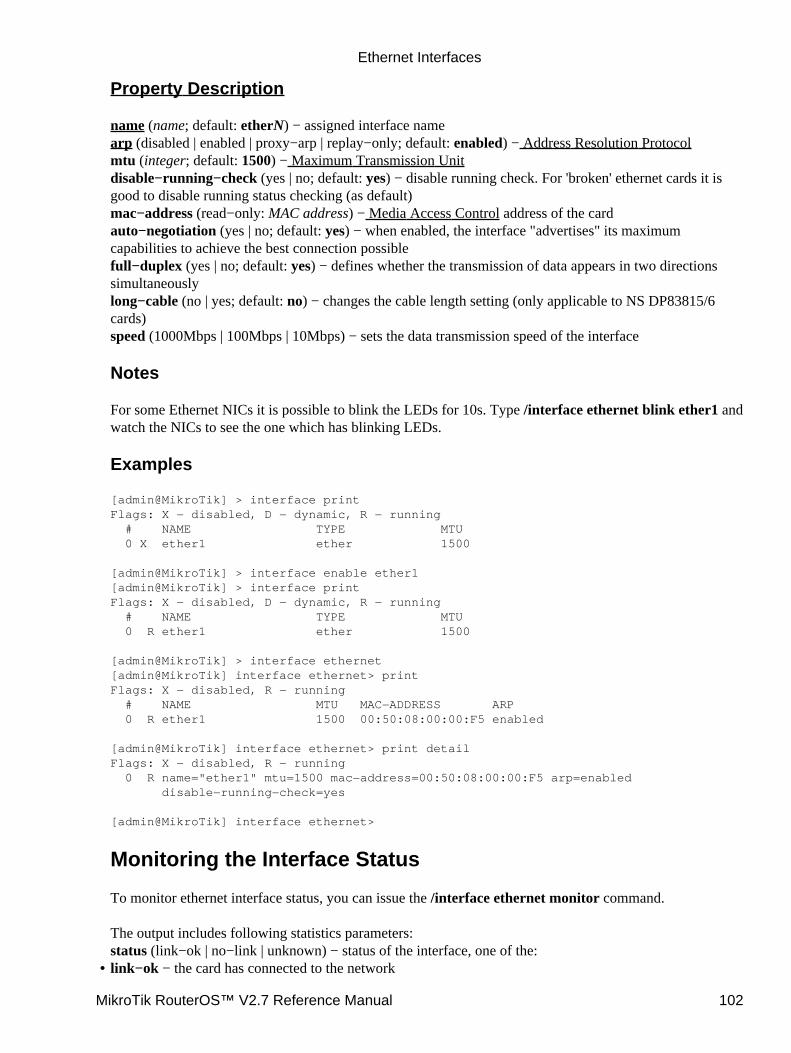
Property Description
name (name; default: etherN) − assigned interface namearp (disabled | enabled | proxy−arp | replay−only; default: enabled) − Address Resolution Protocolmtu (integer; default: 1500) − Maximum Transmission Unitdisable−running−check (yes | no; default: yes) − disable running check. For 'broken' ethernet cards it isgood to disable running status checking (as default)mac−address (read−only: MAC address) − Media Access Control address of the cardauto−negotiation (yes | no; default: yes) − when enabled, the interface "advertises" its maximumcapabilities to achieve the best connection possiblefull−duplex (yes | no; default: yes) − defines whether the transmission of data appears in two directionssimultaneouslylong−cable (no | yes; default: no) − changes the cable length setting (only applicable to NS DP83815/6cards)speed (1000Mbps | 100Mbps | 10Mbps) − sets the data transmission speed of the interface
Notes
For some Ethernet NICs it is possible to blink the LEDs for 10s. Type /interface ethernet blink ether1 andwatch the NICs to see the one which has blinking LEDs.
Examples
[admin@MikroTik] > interface printFlags: X − disabled, D − dynamic, R − running # NAME TYPE MTU 0 X ether1 ether 1500
[admin@MikroTik] > interface enable ether1[admin@MikroTik] > interface printFlags: X − disabled, D − dynamic, R − running # NAME TYPE MTU 0 R ether1 ether 1500
[admin@MikroTik] > interface ethernet[admin@MikroTik] interface ethernet> printFlags: X − disabled, R − running # NAME MTU MAC−ADDRESS ARP 0 R ether1 1500 00:50:08:00:00:F5 enabled
[admin@MikroTik] interface ethernet> print detailFlags: X − disabled, R − running 0 R name="ether1" mtu=1500 mac−address=00:50:08:00:00:F5 arp=enabled disable−running−check=yes
[admin@MikroTik] interface ethernet>
Monitoring the Interface Status
To monitor ethernet interface status, you can issue the /interface ethernet monitor command.
The output includes following statistics parameters:status (link−ok | no−link | unknown) − status of the interface, one of the:link−ok − the card has connected to the network•
Ethernet Interfaces
MikroTik RouterOS™ V2.7 Reference Manual 102
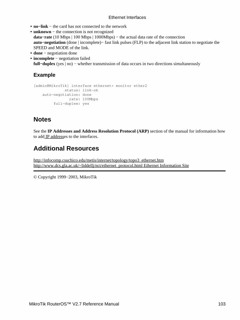
no−link − the card has not connected to the network• unknown − the connection is not recognizeddata−rate (10 Mbps | 100 Mbps | 1000Mbps) − the actual data rate of the connectionauto−negotiation (done | incomplete)− fast link pulses (FLP) to the adjacent link station to negotiate theSPEED and MODE of the link.
•
done − negotiation done• incomplete − negotiation failedfull−duplex (yes | no) − whether transmission of data occurs in two directions simultaneously
Example
[admin@MikroTik] interface ethernet> monitor ether2 status: link−ok auto−negotiation: done rate: 100Mbps full−duplex: yes
Notes
See the IP Addresses and Address Resolution Protocol (ARP) section of the manual for information howto add IP addresses to the interfaces.
Additional Resources
http://infocomp.csuchico.edu/metis/internet/topology/topo3_ethernet.htmhttp://www.dcs.gla.ac.uk/~liddellj/nct/ethernet_protocol.html Ethernet Information Site
© Copyright 1999−2003, MikroTik
•
Ethernet Interfaces
MikroTik RouterOS™ V2.7 Reference Manual 103
Ethernet over IP (EoIP) Tunnel InterfaceDocument revision 1.2 (30−May−2003)This document applies to the MikroTik RouterOS V2.7
Table of Contents
Table of Contents• Overview• Specifications• Related Documents• Description• EoIP Setup
Property Description♦ Notes♦ Example♦
•
EoIP Application Example•
Overview
Ethernet over IP (EoIP) Tunneling is a MikroTik RouterOS protocol that creates an Ethernet tunnel betweentwo routers on top of an IP connection. The EoIP interface appears as an Ethernet interface. When thebridging function of the router is enabled, all Ethernet level traffic (all Ethernet protocols) will be bridged justas if there where a physical Ethernet interface and cable between the two routers (with bridging enabled). Thisprotocol makes multiple network schemes possible.
Network setups with EoIP interfaces:
Possibility to bridge LANs over the Internet• Possibility to bridge LANs over encrypted tunnels• Possibility to bridge LANs over 802.11b 'ad−hoc' wireless networks•
Specifications
Packages required : NoneLicense required : Basic (DEMO license is limited to 4 tunnels)Home menu level : /interface eoipStandards and Technologies : GRE (RFC1701)Hardware usage: not significant
Related Documents
Software Package Installation and UpgradingIP Addresses and Address Resolution Protocol (ARP)Bridge InterfacesPPTP (Point to Point Tunnel Protocol) Interface
MikroTik RouterOS™ V2.7 Reference Manual 104
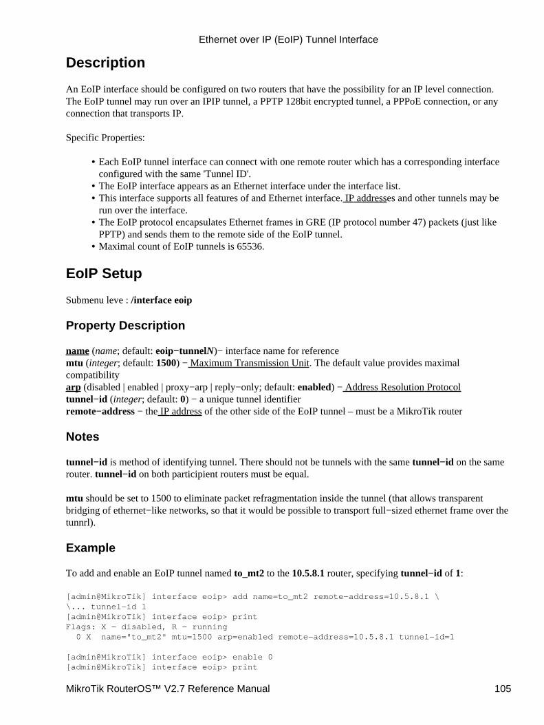
Description
An EoIP interface should be configured on two routers that have the possibility for an IP level connection.The EoIP tunnel may run over an IPIP tunnel, a PPTP 128bit encrypted tunnel, a PPPoE connection, or anyconnection that transports IP.
Specific Properties:
Each EoIP tunnel interface can connect with one remote router which has a corresponding interfaceconfigured with the same 'Tunnel ID'.
•
The EoIP interface appears as an Ethernet interface under the interface list.• This interface supports all features of and Ethernet interface. IP addresses and other tunnels may berun over the interface.
•
The EoIP protocol encapsulates Ethernet frames in GRE (IP protocol number 47) packets (just likePPTP) and sends them to the remote side of the EoIP tunnel.
•
Maximal count of EoIP tunnels is 65536.•
EoIP Setup
Submenu leve : /interface eoip
Property Description
name (name; default: eoip−tunnelN)− interface name for referencemtu (integer; default: 1500) − Maximum Transmission Unit. The default value provides maximalcompatibilityarp (disabled | enabled | proxy−arp | reply−only; default: enabled) − Address Resolution Protocoltunnel−id (integer; default: 0) − a unique tunnel identifierremote−address − the IP address of the other side of the EoIP tunnel – must be a MikroTik router
Notes
tunnel−id is method of identifying tunnel. There should not be tunnels with the same tunnel−id on the samerouter. tunnel−id on both participient routers must be equal.
mtu should be set to 1500 to eliminate packet refragmentation inside the tunnel (that allows transparentbridging of ethernet−like networks, so that it would be possible to transport full−sized ethernet frame over thetunnrl).
Example
To add and enable an EoIP tunnel named to_mt2 to the 10.5.8.1 router, specifying tunnel−id of 1:
[admin@MikroTik] interface eoip> add name=to_mt2 remote−address=10.5.8.1 \\... tunnel−id 1[admin@MikroTik] interface eoip> printFlags: X − disabled, R − running 0 X name="to_mt2" mtu=1500 arp=enabled remote−address=10.5.8.1 tunnel−id=1
[admin@MikroTik] interface eoip> enable 0[admin@MikroTik] interface eoip> print
Ethernet over IP (EoIP) Tunnel Interface
MikroTik RouterOS™ V2.7 Reference Manual 105
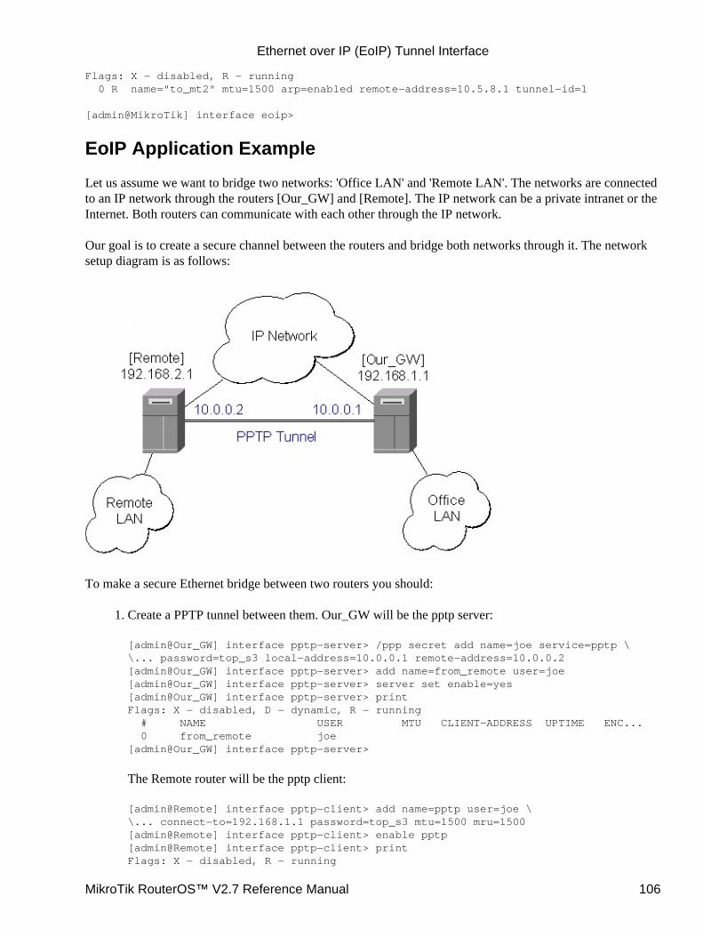
Flags: X − disabled, R − running 0 R name="to_mt2" mtu=1500 arp=enabled remote−address=10.5.8.1 tunnel−id=1
[admin@MikroTik] interface eoip>
EoIP Application Example
Let us assume we want to bridge two networks: 'Office LAN' and 'Remote LAN'. The networks are connectedto an IP network through the routers [Our_GW] and [Remote]. The IP network can be a private intranet or theInternet. Both routers can communicate with each other through the IP network.
Our goal is to create a secure channel between the routers and bridge both networks through it. The networksetup diagram is as follows:
To make a secure Ethernet bridge between two routers you should:
Create a PPTP tunnel between them. Our_GW will be the pptp server:
[admin@Our_GW] interface pptp−server> /ppp secret add name=joe service=pptp \\... password=top_s3 local−address=10.0.0.1 remote−address=10.0.0.2[admin@Our_GW] interface pptp−server> add name=from_remote user=joe[admin@Our_GW] interface pptp−server> server set enable=yes[admin@Our_GW] interface pptp−server> printFlags: X − disabled, D − dynamic, R − running # NAME USER MTU CLIENT−ADDRESS UPTIME ENC... 0 from_remote joe[admin@Our_GW] interface pptp−server>
The Remote router will be the pptp client:
[admin@Remote] interface pptp−client> add name=pptp user=joe \\... connect−to=192.168.1.1 password=top_s3 mtu=1500 mru=1500[admin@Remote] interface pptp−client> enable pptp[admin@Remote] interface pptp−client> printFlags: X − disabled, R − running
1.
Ethernet over IP (EoIP) Tunnel Interface
MikroTik RouterOS™ V2.7 Reference Manual 106
0 R name="pptp" mtu=1500 mru=1500 connect−to=192.168.1.1 user="joe" password="top_s2" profile=default add−default−route=no
[admin@Remote] interface pptp−client> monitor pptp status: "connected" uptime: 39m46s encoding: "none"
[admin@Remote] interface pptp−client>
See the PPTP Interface Manual for more details on setting up encrypted channels.Configure the EoIP tunnel by adding the eoip tunnel interfaces at both routers. Use the ip addresses ofthe pptp tunnel interfaces when specifying the argument values for the EoIP tunnel:
[admin@Our_GW] interface eoip> add name="eoip−remote" tunnel−id=0 \\... remote−address=10.0.0.2[admin@Our_GW] interface eoip> enable eoip−remote[admin@Our_GW] interface eoip> printFlags: X − disabled, R − running 0 name=eoip−remote mtu=1500 arp=enabled remote−address=10.0.0.2 tunnel−id=0[admin@Our_GW] interface eoip>
[admin@Remote] interface eoip> add name="eoip" tunnel−id=0 \\... remote−address=10.0.0.1[admin@Remote] interface eoip> enable eoip−main[admin@Remote] interface eoip> printFlags: X − disabled, R − running 0 name=eoip mtu=1500 arp=enabled remote−address=10.0.0.1 tunnel−id=0
[Remote] interface eoip>
2.
Enable bridging between the EoIP and Ethernet interfaces on both routers.
On the Our_GW:
[admin@Our_GW] interface bridge> add forward−protocols=ip,arp,other \\... disabled=no[admin@Our_GW] interface bridge> printFlags: X − disabled, R − running 0 R name="bridge1" mtu=1500 arp=enabled mac−address=00:00:00:00:00:00 forward−protocols=ip,arp,other priority=1
[admin@Our_GW] interface bridge> port printFlags: X − disabled # INTERFACE BRIDGE 0 eoip−remote none 1 office−eth none 2 isp none
[admin@Our_GW] interface bridge> port set "0,1" bridge=bridge1
And the same for the Remote:
[admin@Remote] interface bridge> add forward−protocols=ip,arp,other \\... disabled=no[admin@Remote] interface bridge> printFlags: X − disabled, R − running 0 R name="bridge1" mtu=1500 arp=enabled mac−address=00:00:00:00:00:00 forward−protocols=ip,arp,other priority=1
3.
Ethernet over IP (EoIP) Tunnel Interface
MikroTik RouterOS™ V2.7 Reference Manual 107

[admin@Remote] interface bridge> port printFlags: X − disabled # INTERFACE BRIDGE 0 ether none 1 adsl none 2 eoip−main none
[admin@Remote] interface bridge> port set "0,2" bridge=bridge1
Addresses from the same network can be used both in the Office LAN and in the Remote LAN4.
© Copyright 1999−2003, MikroTik
Ethernet over IP (EoIP) Tunnel Interface
MikroTik RouterOS™ V2.7 Reference Manual 108
FarSync X.21 InterfaceDocument revision 1.4 (23−Sep−2003)This document applies to the MikroTik RouterOS v2.7
Table of Contents
Table of Contents• Summary• Specifications• Related Documents• Synchronous Interface Configuration
Description♦ Property Description♦ Example♦
•
Troubleshooting• Synchronous Link Applications
MikroTik router to MikroTik router♦ MikroTik router to MikroTik router P2P using X21 line♦ MikroTik router to Cisco ruter using X21 line♦ MikroTik router to MikroTik router using Frame Relay♦
•
Additional Resources•
Summary
The MikroTik RouterOS supports FarSync T−Series X.21 synchronous adapter hardware. These cardsprovide versatile high performance connectivity to the Internet or to corporate networks over leased lines.
Specifications
Packages required : synchronousLicense required : Sync and HotspotHome menu level : /interface farsyncStandards and Technologies : X.21, Frame Relay, PPPHardware usage : not significant
Related Documents
Software Package Installation and UpgradingDevice Driver ManagementIP Addresses and Address Resolution Protocol (ARP)Log Management
Synchronous Interface Configuration
Submenu level : /interface farsync
MikroTik RouterOS™ V2.7 Reference Manual 109

Description
You can change the interface name to a more descriptive one using the set command. To enable the interface,use the enable command.
Property Description
hdlc−keepalive (time; default: 10s) − Cisco HDLC keepalive period in secondsclock−rate (integer; default: 64000) − the speed of internal clockclock−source (external | internal; default: external) − clock sourcedisabled (yes | no; default: yes) − shows whether the interface is disabledframe−relay−dce (yes | no; default: no) − Operate in Data Communications Equipment modeframe−relay−lmi−type (ansi | ccitt; default: ansi) − Frame Relay Local Management Interface typeline−protocol (cisco−hdlc | frame−relay | sync−ppp; default: sync−ppp) − line protocolmedia−type (V24 | V35 | X21; default: V35) − type of the mediamtu (integer; default: 1500) − Maximum Transmit Unitname (text; default: farsyncN) − assigned interface name
Example
[admin@MikroTik] > interface printFlags: X − disabled, D − dynamic, R − running # NAME TYPE MTU 0 R ether1 ether 1500 1 X farsync1 farsync 1500 2 X farsync2 farsync 1500[admin@MikroTik] interface>[admin@MikroTik] interface> enable 1[admin@MikroTik] interface> enable farsync2[admin@MikroTik] > interface printFlags: X − disabled, D − dynamic, R − running # NAME TYPE MTU 0 R ether1 ether 1500 1 farsync1 farsync 1500 2 farsync2 farsync 1500[admin@MikroTik] interface>farsync[admin@MikroTik] interface farsync> printFlags: X − disabled, R − running 0 name="farsync1" mtu=1500 line−protocol=sync−ppp media−type=V35 clock−rate=64000 clock−source=external chdlc−keepalive=10s frame−relay−lmi−type=ansi frame−relay−dce=no
1 name="farsync2" mtu=1500 line−protocol=sync−ppp media−type=V35 clock−rate=64000 clock−source=external chdlc−keepalive=10s frame−relay−lmi−type=ansi frame−relay−dce=no
[admin@MikroTik] interface farsync>
You can monitor the status of the synchronous interface:
[admin@MikroTik] interface farsync> monitor 0 card−type: T2P FarSync T−Series state: running firmware−id: 2 firmware−version: 0.7.0 physical−media: V35
FarSync X.21 Interface
MikroTik RouterOS™ V2.7 Reference Manual 110
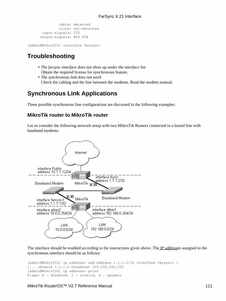
cable: detected clock: not−detected input−signals: CTS output−signals: RTS DTR
[admin@MikroTik] interface farsync>
Troubleshooting
The farsync interface does not show up under the interface listObtain the required license for synchronous feature.
•
The synchronous link does not workCheck the cabling and the line between the modems. Read the modem manual.
•
Synchronous Link Applications
Three possible synchronous line configurations are discussed in the following examples:
MikroTik router to MikroTik router
Let us consider the following network setup with two MikroTik Routers connected to a leased line withbaseband modems:
The interface should be enabled according to the instructions given above. The IP addresses assigned to thesynchronous interface should be as follows:
[admin@MikroTik] ip address> add address 1.1.1.1/32 interface farsync1 \\... network 1.1.1.2 broadcast 255.255.255.255[admin@MikroTik] ip address> printFlags: X − disabled, I − invalid, D − dynamic
FarSync X.21 Interface
MikroTik RouterOS™ V2.7 Reference Manual 111
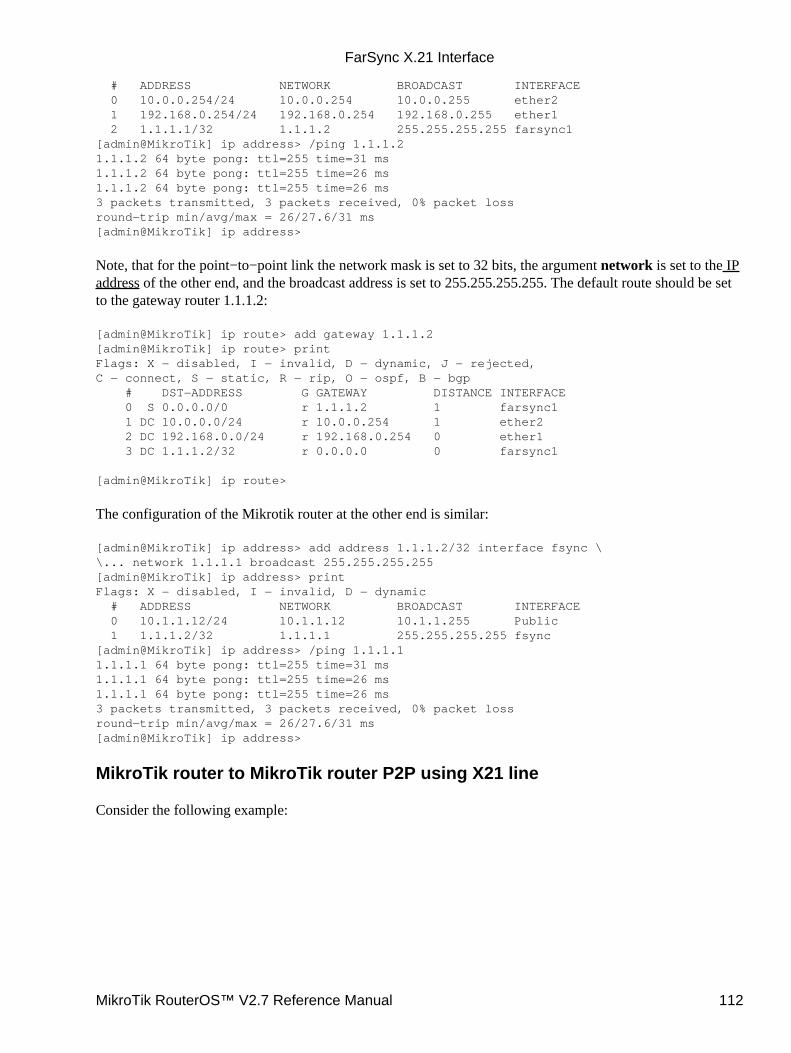
# ADDRESS NETWORK BROADCAST INTERFACE 0 10.0.0.254/24 10.0.0.254 10.0.0.255 ether2 1 192.168.0.254/24 192.168.0.254 192.168.0.255 ether1 2 1.1.1.1/32 1.1.1.2 255.255.255.255 farsync1[admin@MikroTik] ip address> /ping 1.1.1.21.1.1.2 64 byte pong: ttl=255 time=31 ms1.1.1.2 64 byte pong: ttl=255 time=26 ms1.1.1.2 64 byte pong: ttl=255 time=26 ms3 packets transmitted, 3 packets received, 0% packet lossround−trip min/avg/max = 26/27.6/31 ms[admin@MikroTik] ip address>
Note, that for the point−to−point link the network mask is set to 32 bits, the argument network is set to the IPaddress of the other end, and the broadcast address is set to 255.255.255.255. The default route should be setto the gateway router 1.1.1.2:
[admin@MikroTik] ip route> add gateway 1.1.1.2[admin@MikroTik] ip route> printFlags: X − disabled, I − invalid, D − dynamic, J − rejected,C − connect, S − static, R − rip, O − ospf, B − bgp # DST−ADDRESS G GATEWAY DISTANCE INTERFACE 0 S 0.0.0.0/0 r 1.1.1.2 1 farsync1 1 DC 10.0.0.0/24 r 10.0.0.254 1 ether2 2 DC 192.168.0.0/24 r 192.168.0.254 0 ether1 3 DC 1.1.1.2/32 r 0.0.0.0 0 farsync1
[admin@MikroTik] ip route>
The configuration of the Mikrotik router at the other end is similar:
[admin@MikroTik] ip address> add address 1.1.1.2/32 interface fsync \\... network 1.1.1.1 broadcast 255.255.255.255[admin@MikroTik] ip address> printFlags: X − disabled, I − invalid, D − dynamic # ADDRESS NETWORK BROADCAST INTERFACE 0 10.1.1.12/24 10.1.1.12 10.1.1.255 Public 1 1.1.1.2/32 1.1.1.1 255.255.255.255 fsync[admin@MikroTik] ip address> /ping 1.1.1.11.1.1.1 64 byte pong: ttl=255 time=31 ms1.1.1.1 64 byte pong: ttl=255 time=26 ms1.1.1.1 64 byte pong: ttl=255 time=26 ms3 packets transmitted, 3 packets received, 0% packet lossround−trip min/avg/max = 26/27.6/31 ms[admin@MikroTik] ip address>
MikroTik router to MikroTik router P2P using X21 line
Consider the following example:
FarSync X.21 Interface
MikroTik RouterOS™ V2.7 Reference Manual 112
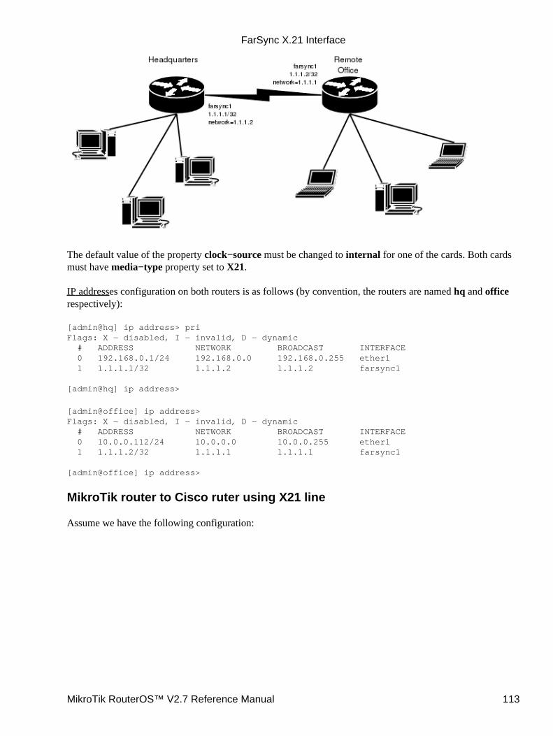
The default value of the property clock−source must be changed to internal for one of the cards. Both cardsmust have media−type property set to X21.
IP addresses configuration on both routers is as follows (by convention, the routers are named hq and officerespectively):
[admin@hq] ip address> priFlags: X − disabled, I − invalid, D − dynamic # ADDRESS NETWORK BROADCAST INTERFACE 0 192.168.0.1/24 192.168.0.0 192.168.0.255 ether1 1 1.1.1.1/32 1.1.1.2 1.1.1.2 farsync1
[admin@hq] ip address>
[admin@office] ip address>Flags: X − disabled, I − invalid, D − dynamic # ADDRESS NETWORK BROADCAST INTERFACE 0 10.0.0.112/24 10.0.0.0 10.0.0.255 ether1 1 1.1.1.2/32 1.1.1.1 1.1.1.1 farsync1
[admin@office] ip address>
MikroTik router to Cisco ruter using X21 line
Assume we have the following configuration:
FarSync X.21 Interface
MikroTik RouterOS™ V2.7 Reference Manual 113
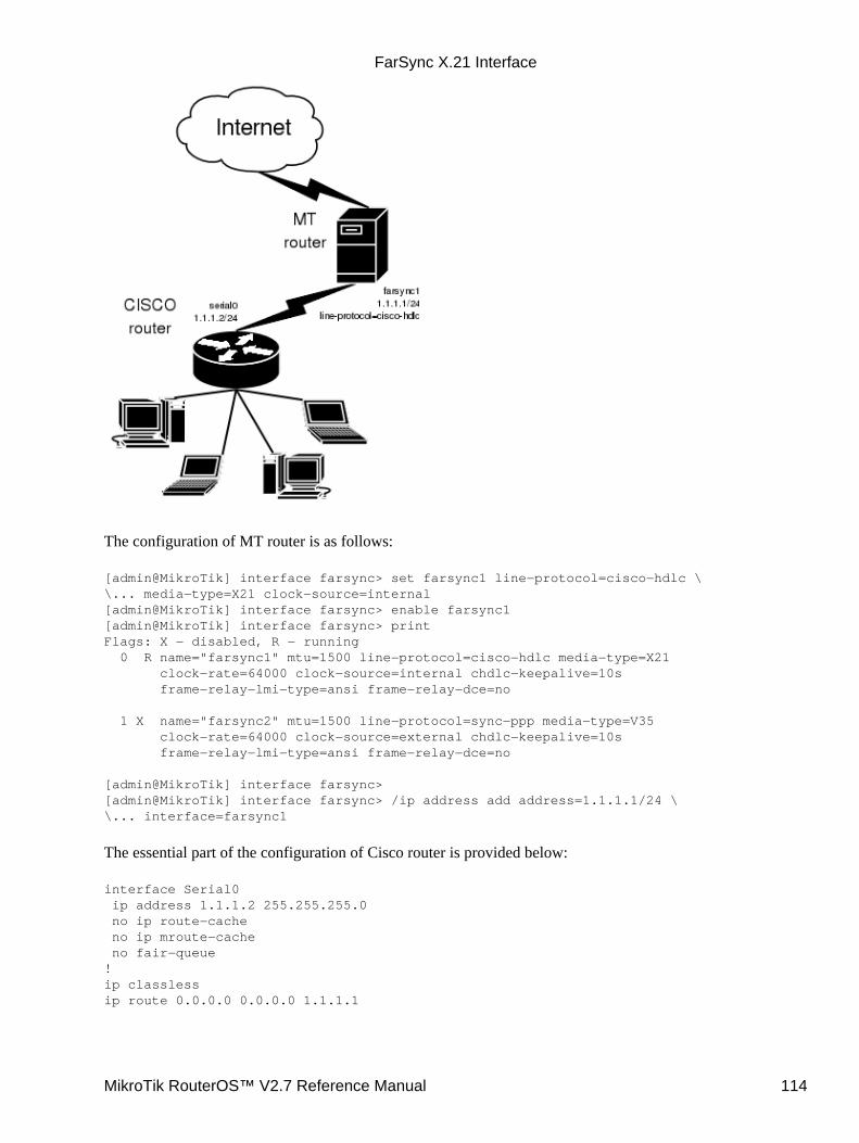
The configuration of MT router is as follows:
[admin@MikroTik] interface farsync> set farsync1 line−protocol=cisco−hdlc \\... media−type=X21 clock−source=internal[admin@MikroTik] interface farsync> enable farsync1[admin@MikroTik] interface farsync> printFlags: X − disabled, R − running 0 R name="farsync1" mtu=1500 line−protocol=cisco−hdlc media−type=X21 clock−rate=64000 clock−source=internal chdlc−keepalive=10s frame−relay−lmi−type=ansi frame−relay−dce=no
1 X name="farsync2" mtu=1500 line−protocol=sync−ppp media−type=V35 clock−rate=64000 clock−source=external chdlc−keepalive=10s frame−relay−lmi−type=ansi frame−relay−dce=no
[admin@MikroTik] interface farsync>[admin@MikroTik] interface farsync> /ip address add address=1.1.1.1/24 \\... interface=farsync1
The essential part of the configuration of Cisco router is provided below:
interface Serial0 ip address 1.1.1.2 255.255.255.0 no ip route−cache no ip mroute−cache no fair−queue!ip classlessip route 0.0.0.0 0.0.0.0 1.1.1.1
FarSync X.21 Interface
MikroTik RouterOS™ V2.7 Reference Manual 114
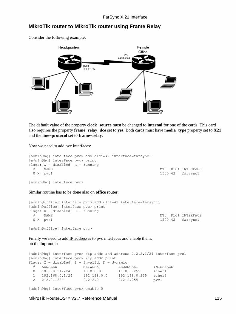
MikroTik router to MikroTik router using Frame Relay
Consider the following example:
The default value of the property clock−source must be changed to internal for one of the cards. This cardalso requires the property frame−relay−dce set to yes. Both cards must have media−type property set to X21and the line−protocol set to frame−relay.
Now we need to add pvc interfaces:
[admin@hq] interface pvc> add dlci=42 interface=farsync1[admin@hq] interface pvc> printFlags: X − disabled, R − running # NAME MTU DLCI INTERFACE 0 X pvc1 1500 42 farsync1
[admin@hq] interface pvc>
Similar routine has to be done also on office router:
[admin@office] interface pvc> add dlci=42 interface=farsync1[admin@office] interface pvc> printFlags: X − disabled, R − running # NAME MTU DLCI INTERFACE 0 X pvc1 1500 42 farsync1
[admin@office] interface pvc>
Finally we need to add IP addresses to pvc interfaces and enable them.on the hq router:
[admin@hq] interface pvc> /ip addr add address 2.2.2.1/24 interface pvc1[admin@hq] interface pvc> /ip addr printFlags: X − disabled, I − invalid, D − dynamic # ADDRESS NETWORK BROADCAST INTERFACE 0 10.0.0.112/24 10.0.0.0 10.0.0.255 ether1 1 192.168.0.1/24 192.168.0.0 192.168.0.255 ether2 2 2.2.2.1/24 2.2.2.0 2.2.2.255 pvc1
[admin@hq] interface pvc> enable 0
FarSync X.21 Interface
MikroTik RouterOS™ V2.7 Reference Manual 115
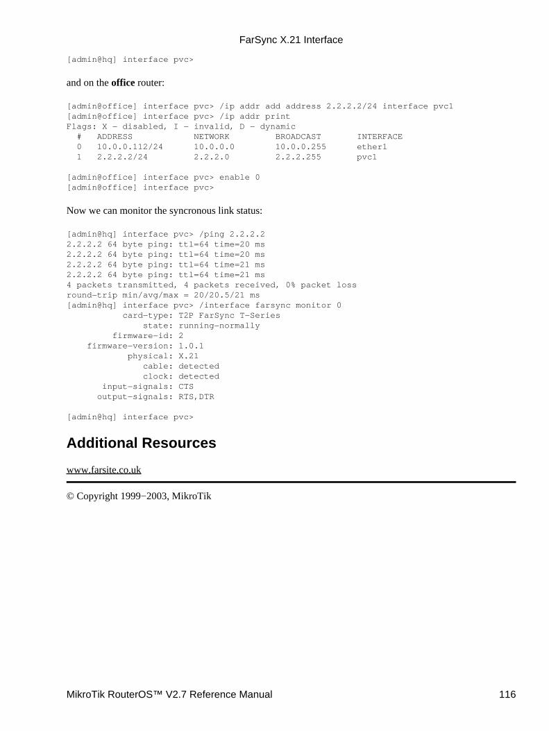
[admin@hq] interface pvc>
and on the office router:
[admin@office] interface pvc> /ip addr add address 2.2.2.2/24 interface pvc1[admin@office] interface pvc> /ip addr printFlags: X − disabled, I − invalid, D − dynamic # ADDRESS NETWORK BROADCAST INTERFACE 0 10.0.0.112/24 10.0.0.0 10.0.0.255 ether1 1 2.2.2.2/24 2.2.2.0 2.2.2.255 pvc1
[admin@office] interface pvc> enable 0[admin@office] interface pvc>
Now we can monitor the syncronous link status:
[admin@hq] interface pvc> /ping 2.2.2.22.2.2.2 64 byte ping: ttl=64 time=20 ms2.2.2.2 64 byte ping: ttl=64 time=20 ms2.2.2.2 64 byte ping: ttl=64 time=21 ms2.2.2.2 64 byte ping: ttl=64 time=21 ms4 packets transmitted, 4 packets received, 0% packet lossround−trip min/avg/max = 20/20.5/21 ms[admin@hq] interface pvc> /interface farsync monitor 0 card−type: T2P FarSync T−Series state: running−normally firmware−id: 2 firmware−version: 1.0.1 physical: X.21 cable: detected clock: detected input−signals: CTS output−signals: RTS,DTR
[admin@hq] interface pvc>
Additional Resources
www.farsite.co.uk
© Copyright 1999−2003, MikroTik
FarSync X.21 Interface
MikroTik RouterOS™ V2.7 Reference Manual 116

FrameRelay (PVC) InterfacesDocument revision 1.3 (30−Jun−2003)This document applies to MikroTik RouterOS v2.7
Table of Contents
Table of Contents• Summary• Specifications• Description• Configuring Frame Relay Interface
Description♦ Property Description♦ Notes♦
•
Frame Relay Configuration Example with Cyclades Interface• Frame Relay Configuration Example with MOXA Interface• MikroTik Router to MikroTik Router• Frame Relay Troubleshooting• Additional Resources•
Summary
Frame Relay is a multiplexed interface to packet switched network and is a simplified form of PacketSwitching similar in principle to X.25 in which synchronous frames of data are routed to different destinationsdepending on header information. Frame Relay uses the synchronous HDLC frame format.
Specifications
Packages required : synchronousLicense required : synchronousHome menu level : /interface pvcStandards and Technologies : Frame Relay (RFC1490)Hardware usage : not significant
Description
To use Frame Relay interface you must have already working synchronous interface. You can read how to setup synchronous boards supported by Mikrotik RouterOS:
Cyclades PC300 PCI AdaptersMoxa C101 Synchronous interfaceMoxa C502 Dual Port Synchronous interface
Configuring Frame Relay Interface
Submenu level : /interface pvc
MikroTik RouterOS™ V2.7 Reference Manual 117
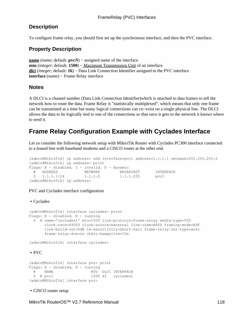
Description
To configure frame relay, you should first set up the synchronous interface, and then the PVC interface.
Property Description
name (name; default: pvcN) − assigned name of the interfacemtu (integer; default: 1500) − Maximum Transmission Unit of an interfacedlci (integer; default: 16) − Data Link Connection Identifier assigned to the PVC interfaceinterface (name) − Frame Relay interface
Notes
A DLCI is a channel number (Data Link Connection Identifier)which is attached to data frames to tell thenetwork how to route the data. Frame Relay is "statistically multiplexed", which means that only one framecan be transmitted at a time but many logical connections can co−exist on a single physical line. The DLCIallows the data to be logically tied to one of the connections so that once it gets to the network it knows whereto send it.
Frame Relay Configuration Example with Cyclades Interface
Let us consider the following network setup with MikroTik Router with Cyclades PC300 interface connectedto a leased line with baseband modems and a CISCO router at the other end.
[admin@MikroTik] ip address> add interface=pvc1 address=1.1.1.1 netmask=255.255.255.0[admin@MikroTik] ip address> printFlags: X − disabled, I − invalid, D − dynamic # ADDRESS NETWORK BROADCAST INTERFACE 0 1.1.1.1/24 1.1.1.0 1.1.1.255 pvc1[admin@MikroTik] ip address>
PVC and Cyclades interface configuration
Cyclades•
[admin@MikroTik] interface cyclades> printFlags: X − disabled, R − running 0 R name="cyclades1" mtu=1500 line−protocol=frame−relay media−type=V35 clock−rate=64000 clock−source=external line−code=B8ZS framing−mode=ESF line−build−out=0dB rx−sensitivity=short−haul frame−relay−lmi−type=ansi frame−relay−dce=no chdlc−keepalive=10s
[admin@MikroTik] interface cyclades>
PVC•
[admin@MikroTik] interface pvc> printFlags: X − disabled, R − running # NAME MTU DLCI INTERFACE 0 R pvc1 1500 42 cyclades1[admin@MikroTik] interface pvc>
CISCO router setup•
FrameRelay (PVC) Interfaces
MikroTik RouterOS™ V2.7 Reference Manual 118
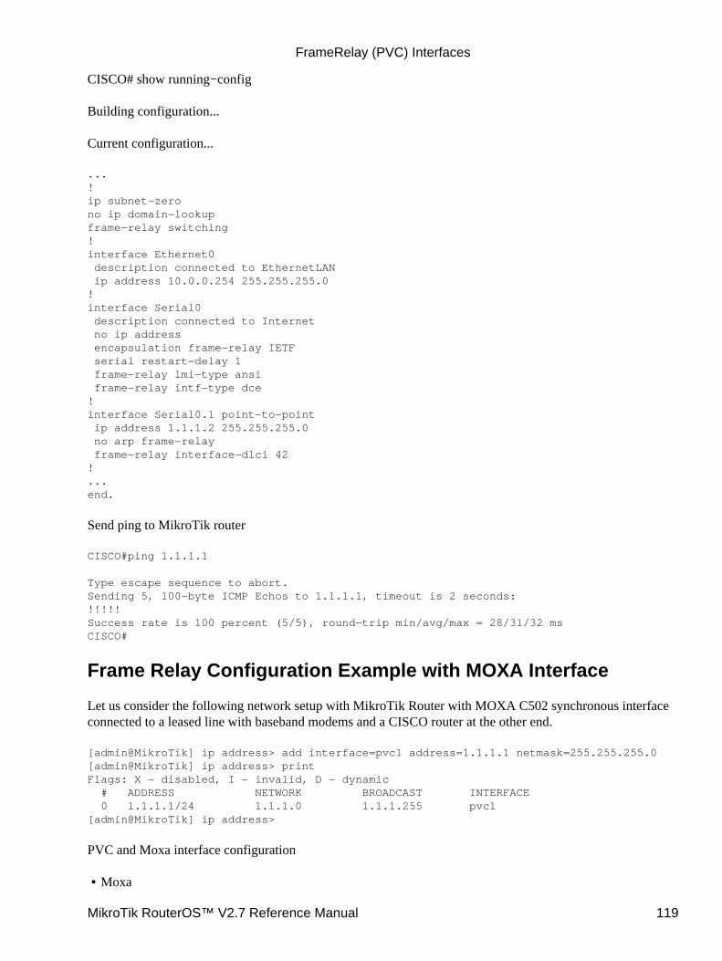
CISCO# show running−config
Building configuration...
Current configuration...
...!ip subnet−zerono ip domain−lookupframe−relay switching!interface Ethernet0 description connected to EthernetLAN ip address 10.0.0.254 255.255.255.0!interface Serial0 description connected to Internet no ip address encapsulation frame−relay IETF serial restart−delay 1 frame−relay lmi−type ansi frame−relay intf−type dce!interface Serial0.1 point−to−point ip address 1.1.1.2 255.255.255.0 no arp frame−relay frame−relay interface−dlci 42!...end.
Send ping to MikroTik router
CISCO#ping 1.1.1.1
Type escape sequence to abort.Sending 5, 100−byte ICMP Echos to 1.1.1.1, timeout is 2 seconds:!!!!!Success rate is 100 percent (5/5), round−trip min/avg/max = 28/31/32 msCISCO#
Frame Relay Configuration Example with MOXA Interface
Let us consider the following network setup with MikroTik Router with MOXA C502 synchronous interfaceconnected to a leased line with baseband modems and a CISCO router at the other end.
[admin@MikroTik] ip address> add interface=pvc1 address=1.1.1.1 netmask=255.255.255.0[admin@MikroTik] ip address> printFlags: X − disabled, I − invalid, D − dynamic # ADDRESS NETWORK BROADCAST INTERFACE 0 1.1.1.1/24 1.1.1.0 1.1.1.255 pvc1[admin@MikroTik] ip address>
PVC and Moxa interface configuration
Moxa•
FrameRelay (PVC) Interfaces
MikroTik RouterOS™ V2.7 Reference Manual 119
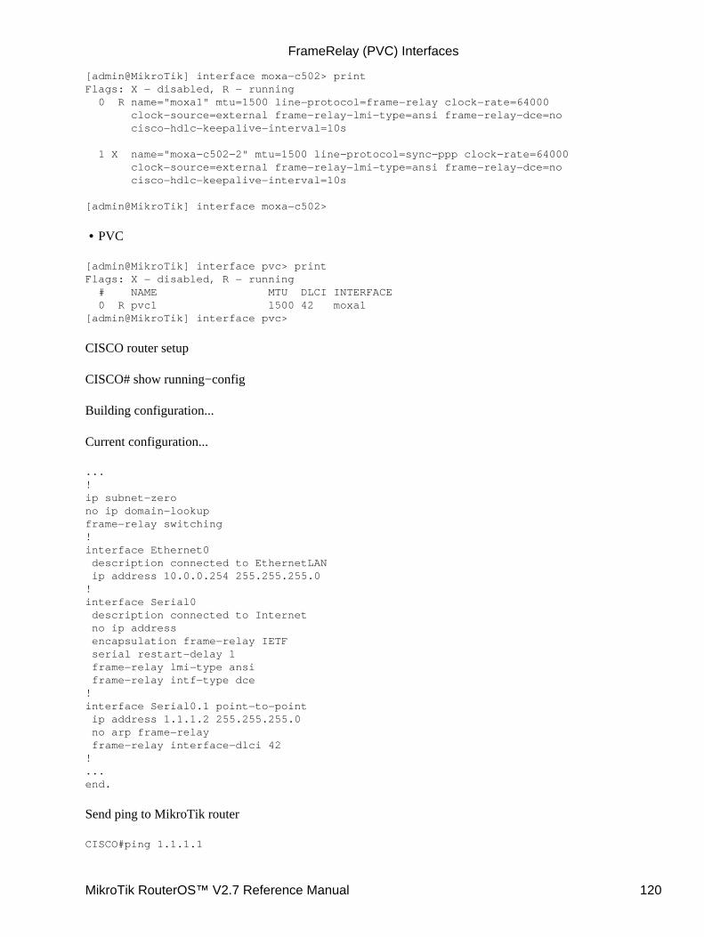
[admin@MikroTik] interface moxa−c502> printFlags: X − disabled, R − running 0 R name="moxa1" mtu=1500 line−protocol=frame−relay clock−rate=64000 clock−source=external frame−relay−lmi−type=ansi frame−relay−dce=no cisco−hdlc−keepalive−interval=10s
1 X name="moxa−c502−2" mtu=1500 line−protocol=sync−ppp clock−rate=64000 clock−source=external frame−relay−lmi−type=ansi frame−relay−dce=no cisco−hdlc−keepalive−interval=10s
[admin@MikroTik] interface moxa−c502>
PVC•
[admin@MikroTik] interface pvc> printFlags: X − disabled, R − running # NAME MTU DLCI INTERFACE 0 R pvc1 1500 42 moxa1[admin@MikroTik] interface pvc>
CISCO router setup
CISCO# show running−config
Building configuration...
Current configuration...
...!ip subnet−zerono ip domain−lookupframe−relay switching!interface Ethernet0 description connected to EthernetLAN ip address 10.0.0.254 255.255.255.0!interface Serial0 description connected to Internet no ip address encapsulation frame−relay IETF serial restart−delay 1 frame−relay lmi−type ansi frame−relay intf−type dce!interface Serial0.1 point−to−point ip address 1.1.1.2 255.255.255.0 no arp frame−relay frame−relay interface−dlci 42!...end.
Send ping to MikroTik router
CISCO#ping 1.1.1.1
FrameRelay (PVC) Interfaces
MikroTik RouterOS™ V2.7 Reference Manual 120
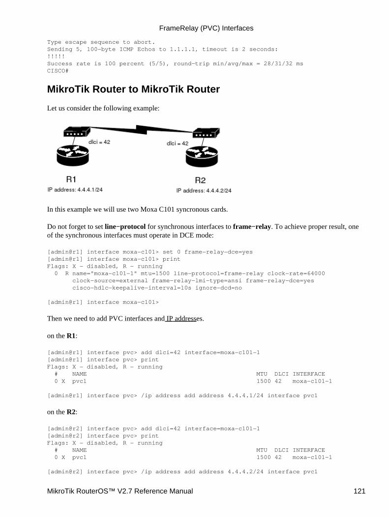
Type escape sequence to abort.Sending 5, 100−byte ICMP Echos to 1.1.1.1, timeout is 2 seconds:!!!!!Success rate is 100 percent (5/5), round−trip min/avg/max = 28/31/32 msCISCO#
MikroTik Router to MikroTik Router
Let us consider the following example:
In this example we will use two Moxa C101 syncronous cards.
Do not forget to set line−protocol for synchronous interfaces to frame−relay. To achieve proper result, oneof the synchronous interfaces must operate in DCE mode:
[admin@r1] interface moxa−c101> set 0 frame−relay−dce=yes[admin@r1] interface moxa−c101> printFlags: X − disabled, R − running 0 R name="moxa−c101−1" mtu=1500 line−protocol=frame−relay clock−rate=64000 clock−source=external frame−relay−lmi−type=ansi frame−relay−dce=yes cisco−hdlc−keepalive−interval=10s ignore−dcd=no
[admin@r1] interface moxa−c101>
Then we need to add PVC interfaces and IP addresses.
on the R1:
[admin@r1] interface pvc> add dlci=42 interface=moxa−c101−1[admin@r1] interface pvc> printFlags: X − disabled, R − running # NAME MTU DLCI INTERFACE 0 X pvc1 1500 42 moxa−c101−1
[admin@r1] interface pvc> /ip address add address 4.4.4.1/24 interface pvc1
on the R2:
[admin@r2] interface pvc> add dlci=42 interface=moxa−c101−1[admin@r2] interface pvc> printFlags: X − disabled, R − running # NAME MTU DLCI INTERFACE 0 X pvc1 1500 42 moxa−c101−1
[admin@r2] interface pvc> /ip address add address 4.4.4.2/24 interface pvc1
FrameRelay (PVC) Interfaces
MikroTik RouterOS™ V2.7 Reference Manual 121

Finally we must enable PVC interfaces:
[admin@r1] interface pvc> enable pvc1[admin@r1] interface pvc>
[admin@r2] interface pvc> enable pvc1[admin@r2] interface pvc>
Frame Relay Troubleshooting
I cannot ping through the synchronous frame relay interface between MikroTik router and a CiscorouterFrameRelay does not support address resolving and IETF encapsulation should be used. Please checkthe configuration on the Cisco router.
•
Additional Resources
Frame Relay forumwww2.rad.com/networks/1994/fram_rel/frame.htm
© Copyright 1999−2003, MikroTik
FrameRelay (PVC) Interfaces
MikroTik RouterOS™ V2.7 Reference Manual 122
IP over IP (IPIP) Tunnel InterfaceDocument revision 1.3 (09−May−2003)This document applies to the MikroTik RouterOS V2.7
Table of Contents
Table of Contents• Summary• Specifications• Related Documents• IPIP Setup
Description♦ Property Description♦ Notes♦
•
IPIP Application Example• Additional Resources•
Summary
The IPIP tunneling implementation on the MikroTik RouterOS is RFC 2003 compliant. IPIP tunnel is asimple protocol that encapsulates IP packets in IP to make a tunnel between two routers. The IPIP tunnelinterface appears as an interface under the interface list. Many routers, including Cisco and Linux based,support this protocol. This protocol makes multiple network schemes possible.
IPIP tunneling protocol adds the following possibilities to a network setups:
to tunnel Intranets over the Internet• to use it instead of using source routing•
Specifications
Packages required : NoneLicense required : AnyHome menu level : /interface ipipStandards and Technologies : IPIP ( RFC2003)Hardware usage : not significant
Related Documents
Software Package Installation and UpgradingDevice Driver ManagementIP Addresses and Address Resolution Protocol (ARP)Log Management
MikroTik RouterOS™ V2.7 Reference Manual 123
IPIP Setup
Submenu level : /interface ipip
Description
An IPIP interface should be configured on two routers that have the possibility for an IP level connection andare RFC 2003 compliant. The IPIP tunnel may run over any connection that transports IP. Each IPIP tunnelinterface can connect with one remote router that has a corresponding interface configured. An unlimitednumber of IPIP tunnels may be added to the router. For more details on IPIP tunnels, see RFC 2003.
Property Description
name (name; default: ipipN) − interface name for referencemtu (integer; default: 1480) − Maximum Transmission Unit. Should be set to 1480 bytes to avoidfragmentation of packets. May be set to 1500 bytes if mtu path discovery is not working properly on links.local−address (IP address) − Local address on router which sends IPIP traffic to the remote side.remote−address (IP address) − The IP address of the other side of the IPIP tunnel − may be any RFC 2003compliant router.
Use /ip address add command to assign an IP address to the IPIP interface.
There is no authentication or 'state' for this interface. The bandwidth usage of the interface may be monitoredwith the monitor feature from the interface menu.
Notes
MikroTik RouterOS IPIP implementation has been tested with Cisco 1005. The sample of the Cisco 1005configuration is given below:
interface Tunnel0 ip address 10.3.0.1 255.255.255.0 tunnel source 10.0.0.171 tunnel destination 10.0.0.204 tunnel mode ipip
IPIP Application Example
Suppose we want to add an IPIP tunnel between routers R1 and R2:
IP over IP (IPIP) Tunnel Interface
MikroTik RouterOS™ V2.7 Reference Manual 124
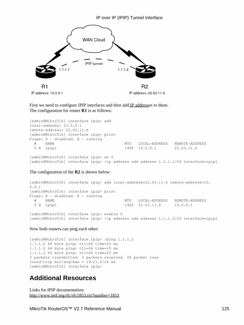
First we need to configure IPIP interfaces and then add IP addresses to them.The configuration for router R1 is as follows:
[admin@MikroTik] interface ipip> addlocal−address: 10.0.0.1remote−address: 22.63.11.6[admin@MikroTik] interface ipip> printFlags: X − disabled, R − running # NAME MTU LOCAL−ADDRESS REMOTE−ADDRESS 0 X ipip1 1480 10.0.0.1 22.63.11.6
[admin@MikroTik] interface ipip> en 0[admin@MikroTik] interface ipip> /ip address add address 1.1.1.1/24 interface=ipip1
The configuration of the R2 is shown below:
[admin@MikroTik] interface ipip> add local−address=22.63.11.6 remote−address=10.0.0.1[admin@MikroTik] interface ipip> printFlags: X − disabled, R − running # NAME MTU LOCAL−ADDRESS REMOTE−ADDRESS 0 X ipip1 1480 22.63.11.6 10.0.0.1
[admin@MikroTik] interface ipip> enable 0[admin@MikroTik] interface ipip> /ip address add address 1.1.1.2/24 interface=ipip1
Now both routers can ping each other:
[admin@MikroTik] interface ipip> /ping 1.1.1.21.1.1.2 64 byte ping: ttl=64 time=24 ms1.1.1.2 64 byte ping: ttl=64 time=19 ms1.1.1.2 64 byte ping: ttl=64 time=20 ms3 packets transmitted, 3 packets received, 0% packet lossround−trip min/avg/max = 19/21.0/24 ms[admin@MikroTik] interface ipip>
Additional Resources
Links for IPIP documentation:http://www.ietf.org/rfc/rfc1853.txt?number=1853
IP over IP (IPIP) Tunnel Interface
MikroTik RouterOS™ V2.7 Reference Manual 125

http://www.ietf.org/rfc/rfc2003.txt?number=2003http://www.ietf.org/rfc/rfc1241.txt?number=1241
© Copyright 1999−2003, MikroTik
IP over IP (IPIP) Tunnel Interface
MikroTik RouterOS™ V2.7 Reference Manual 126
ISDN InterfaceDocument revision 1.3 (20−Mar−2003)This document applies to MikroTik RouterOS V2.7
Table of Contents
Table of Contents• Summary• Specifications• Related Documents• Supported adapters and appropriate driver names
Notes♦ •
ISDN Hardware and Software InstallationProperty Description♦ ISDN Channels♦ MSN and EAZ numbers♦
•
ISDN Client Interface ConfigurationDescription♦ Property Description♦ Example♦
•
ISDN Server Interface ConfigurationDescription♦ Property Description♦ Example♦
•
Troubleshooting• ISDN Examples
ISDN Dial−out♦ ISDN Dial−in♦ ISDN Backup
Description◊ Note◊ Example◊
♦
•
Additional Resources•
Summary
The MikroTik router can act as an ISDN client for dialing out, or as an ISDN server for accepting incomingcalls. The dial−out connections may be set as dial−on−demand or as permanent connections (simulating aleased line). The remote IP address (provided by the ISP) can be used as the default gateway for the router.
Specifications
Packages required : isdn, pppLicense required : AnyHome menu level : /interface isdn−server, /interface isdn−clientProtocols utilized : PPP (RFC1661)Hardware usage: not significant
MikroTik RouterOS™ V2.7 Reference Manual 127
Related Documents
Software Package Installation and UpgradingDevice Driver ManagementLog Management
Supported adapters and appropriate driver names
MikroTik Router OS supports passive PCI adapters with Siemens chipset:
Eicon.Diehl Diva − diva• Sedlbauer Speed − sedlbauer• ELSA Quickstep 1000 − quickstep• NETjet − netjet• Teles − teles• Dr. Neuhaus Niccy − niccy• AVM − avm• Gazel − gazel• HFC 2BDS0 based adapters − hfc• W6692 based adapters − w6692•
For example, for the HFC based PCI card, it is enough to use /driver add name=hfc command to get thedriver loaded.
Notes
ISA ISDN adapters are not supported.
ISDN Hardware and Software Installation
Please install the ISDN adapter into the PC accordingly the instructions provided by the adapter manufacturer.
Appropriate packages have to be downloaded from MikroTik’s web page www.mikrotik.com. After all, theISDN driver should be loaded using the /driver add command.
Property Description
name (name) − Name of the driver.isdn−protocol (euro | german, default: euro) − Data channel protocol
ISDN Channels
ISDN channels are added to the system automatically when the ISDN card driver is loaded. Each channelcorresponds to one physical 64K ISDN data channel.
The list of available ISDN channels can be viewed using the /isdn−channels print command. The channelsare named channel1, channel2, and so on. E.g., if you have two ISDN channels, and one of them currentlyused by an ISDN interface, but the other available, the output should look like this:
ISDN Interface
MikroTik RouterOS™ V2.7 Reference Manual 128
[admin@MikroTik] isdn−channels> printFlags: X − disabled, E − exclusive # NAME CHANNEL DIR.. TYPE PHONE 0 channel1 0 1 channel2 1[admin@MikroTik] isdn−channels>
ISDN channels are very similar to PPP serial ports. Any number of ISDN interfaces can be configured on asingle channel, but only one interface can be enabled for that channel at a time. It means that every ISDNchannel is either available or used by an ISDN interface.
MSN and EAZ numbers
In Euro−ISDN a subscriber can assign more than one ISDN number to an ISDN line. For example, an ISDNline could have the numbers 1234067 and 1234068. Each of these numbers can be used to dial the ISDN line.These numbers are referred to as Multiple Subscriber Numbers (MSN).
A similar, but separate concept is EAZ numbering, which is used in German ISDN networking. EAZ numbercan be used in addition to dialed phone number to specify the required service.
For dial−out ISDN interfaces, MSN/EAZ number specifies the outgoing phone number (the calling end). Fordial−in ISDN interfaces, MSN/EAZ number specifies the phone number that will be answered. If you areunsure about your MSN/EAZ numbers, leave them blank (it is the default).
For example, if your ISDN line has numbers 1234067 and 1234068, you could configure your dial−in serverto answer only calls to 1234068, by specifying 1234068 as your MSN number. In a sense, MSN is just yourphone number.
ISDN Client Interface Configuration
Submenu Level: /interface isdn−client
Description
The ISDN client is used to connect to remote dial−in server (probably ISP) via ISDN. To set up an ISDNdial−out connection, use the ISDN dial−out configuration menu under the submenu.
ISDN client interfaces can be added using the add command:
Property Description
name (name, default: isdn−outX, where x = 1, 2, ...) − interface namemtu (integer; default: 1500) − Maximum Transmission Unitmru (integer; default: 1500) − Maximum Receive Unitphone (number; default: "") − phone number to dialmsn (number; default: "") − MSN/EAZ of ISDN line provided by the line operatordial−on−demand (yes | no; default: no) − use dialing on demandl2−protocol (hdlc | x75i | x75ui | x75bui; default: hdlc) − level 2 protocol to be useduser (name) − user name that will be provided to the remote serverpassword (password) − password that will be provided to the remote serveradd−default−route (yes |no; default: no) − add default route to remote host on connect
ISDN Interface
MikroTik RouterOS™ V2.7 Reference Manual 129
profile (name; default: default) − profile to use when connecting to the remote serveruse−peer−dns (yes | no; default: no) − Use or not peer DNS.bundle−128K (yes | no; default: yes) − use both channels instead of just one
Example
[admin@MikroTik] interface isdn−client> add msn="142" user="test" \\... password="test" phone="144" bundle−128K=no[admin@MikroTik] interface isdn−client> printFlags: X − disabled, R − running 0 X name="isdn−out1" mtu=1500 mru=1500 msn="142" user="test" password="test" profile=default phone="144" l2−protocol=hdlc bundle−128K=no dial−on−demand=no add−default−route=no use−peer−dns=no
[admin@MikroTik] interface isdn−client>
ISDN Server Interface Configuration
Submenu level : /interface isdn−client
Description
ISDN server is used to accept remote dial−in connections from ISDN clients. ISDN server interfaces can beadded using the add command:
Property Description
name (name, default: isdn−inX, where x = 1, 2, ...) − interface namemtu (integer, default: 1500) − Maximum Transmission Unitmru (integer, default: 1500) − Maximum Receive Unitphone (number, default: "") − phone number to dialmsn (number, default: "") − MSN/EAZ of ISDN line provided by the line operatorl2−protocol (hdlc | x75i | x75ui | x75bui, default: hdlc) − level 2 protocol to be usedprofile (name, default: default) − profile to use when connecting to the remote serverbundle−128K (yes | no, default: yes) − use both channels instead of just oneauthentication (pap | chap | mschap1 | mschap2, default: mschap2, mschap1,chap,pap) − Usedauthentication
Example
A sample printout of ISDN server interface is as follows:
[admin@MikroTik] interface isdn−server> add msn="142" bundle−128K=no[admin@MikroTik] interface isdn−server> printFlags: X − disabled, R − running 0 X name="isdn−in1" mtu=1500 mru=1500 msn="142" authentication=mschap2,chap,pap profile=default l2−protocol=x75bui bundle−128K=no
[admin@MikroTik] interface isdn−server>
ISDN Interface
MikroTik RouterOS™ V2.7 Reference Manual 130
Troubleshooting
The driver could not be loaded or the client/server don't work.There are some older motherboards, which don't support isdn cards. Try to change the motherboard.
•
The ISDN channels do not show up in the isdn−channel list.Check if you have loaded the driver with the /driver add command and if you have the isdn and theppp packages installed.
•
The ISDN client does not connect, the isdn server doesn't answer a call.Check if you have specified the msn and phone correctly.
•
ISDN Examples
The following examples of ISDN applications are discussed below:
ISDN Dial−out• ISDN Dial−in• ISDN Backup•
ISDN Dial−out
Dial−out ISDN connections allow a local router to connect to a remote dial−in server (ISP's) via ISDN.
Let's assume you would like to set up a router that connects your local LAN with your ISP via ISDN line.First you should load the corresponding ISDN card driver. Supposing you have an ISDN card with aW6692−based chip:
[admin@MikroTik]> /driver add name=w6692
Now additional channels should appear. Assuming you have only one ISDN card driver loaded, you shouldget following:
[admin@MikroTik] isdn−channels> printFlags: X − disabled, E − exclusive # NAME CHANNEL DIR.. TYPE PHONE 0 channel1 0 1 channel2 1[admin@MikroTik] isdn−channels>
Suppose you would like to use dial−on−demand to dial your ISP and automatically add a default route to it.Also, you would like to disconnect when there is more than 30s of network inactivity. Your ISP's phonenumber is 12345678 and the user name for authentication is 'john'. Your ISP assigns IP addressesautomatically. Add an outgoing ISDN interface and configure it in the following way:
[admin@mikrotik]> /interface isdn−client add name="isdn−isp" phone="12345678"user="john" password="31337!)" add−default−route=yes dial−on−demand=yes[admin@MikroTik] > /interface isdn−client printFlags: X − disabled, R − running 0 X name="isdn−isp" mtu=1500 mru=1500 msn="" user="john" password="31337!)" profile=default phone="12345678" l2−protocol=hdlc bundle−128K=no dial−on−demand=yes add−default−route=yes use−peer−dns=no
Configure PPP profile.
ISDN Interface
MikroTik RouterOS™ V2.7 Reference Manual 131
[admin@MikroTik] ppp profile> printFlags: * − default 0 * name="default" local−address=0.0.0.0 remote−address=0.0.0.0 session−timeout=0s idle−timeout=0s use−compression=no use−vj−compression=yes use−encryption=no require−encyrption=no only−one=no tx−bit−rate=0 rx−bit−rate=0 incoming−filter="" outgoing−filter=""
[admin@Mikrotik] ppp profile> set default idle−timeout=30s
(If you would like to remain connected all the time, i.e., as a leased line, then set the idle−timeout to 0s.)
All that remains is to enable the interface:
[admin@MikroTik] /interface set isdn−isp disabled=no
You can monitor the connection status with the following command:
[admin@MikroTik] /interface isdn−client monitor isdn−isp
ISDN Dial−in
Dial−in ISDN connections allow remote clients to connect to your router via ISDN.
Let us assume you would like to configure a router for accepting incoming ISDN calls from remote clients.You have an ethernet card connected to the LAN, and an ISDN card connected to the ISDN line. First youshould load the corresponding ISDN card driver. Supposing you have an ISDN card with an HFC chip:
[admin@MikroTik] /driver add name=hfc
Now additional channels should appear. Assuming you have only one ISDN card driver loaded, you shouldget the following:
[admin@MikroTik] isdn−channels> printFlags: X − disabled, E − exclusive # NAME CHANNEL DIR.. TYPE PHONE 0 channel1 0 1 channel2 1[admin@MikroTik] isdn−channels>
Add an incoming ISDN interface and configure it in the following way:
[admin@MikroTik] interface isdn−server> add msn="7542159" \\... authentication=chap,pap bundle−128K=no[admin@MikroTik] interface isdn−server> printFlags: X − disabled 0 X name="isdn−in1" mtu=1500 mru=1500 msn="7542159" authentication=chap,pap profile=default l2−protocol=hldc bundle−128K=no
Configure PPP settings and add users to router's database.
[admin@MikroTik] ppp profile> printFlags: * − default 0 * name="default" local−address=0.0.0.0 remote−address=0.0.0.0 session−timeout=0s idle−timeout=0s use−compression=no use−vj−compression=yes use−encryption=no require−encyrption=no only−one=no
ISDN Interface
MikroTik RouterOS™ V2.7 Reference Manual 132
tx−bit−rate=0 rx−bit−rate=0 incoming−filter="" outgoing−filter=""[admin@Mikrotik] ppp profile> set default idle−timeout=5s local−address=10.99.8.1 \\... remote−address=10.9.88.1
Add user 'john' to the router's user database. Assuming that the password is '31337!)':
[admin@MikroTik] ppp secret> add name=john password="31337!)" service=isdn[admin@MikroTik] ppp secret> print[admin@ISDN] ppp secret> printFlags: X − disabled # NAME SERVICE CALLER−ID PASSWORD PROFILE 0 john isdn 31337!) default[admin@MikroTik] ppp secret>
Check the status of the ISDN server interface and wait for the call:
[admin@MikroTik] interface isdn−server> monitor isdn−in1
status: Waiting for call...
ISDN Backup
Backup systems are used in specific cases, when you need to maintain a connection, even if a fault occurs. Forexample, if someone cuts the wires, the router can automatically connect to a different interface to continue itswork. Such a backup is based on an utility that monitors the status of the connection − netwatch, and a script,which runs the netwatch.
Description
This is an example of how to make simple router backup system. In this example we'll use an ISDNconnection for purpose to backup a standard ethernet connection. You can, however, use instead of the ISDNconnecion anything you need − PPP, for example. When the ethernet fail (the router nr.1 cannot ping therouter nr.2 to 2.2.2.2 (see picture) the router nr.1 will establish an ISDN connection, so−called backup link, tocontinue comunicating with the nr.2.
Note
You must keep in mind, that in our case there are just two routers, but this system can be extended to supportmore different networks.
Example
The backup system example is shown in the following picture:
ISDN Interface
MikroTik RouterOS™ V2.7 Reference Manual 133
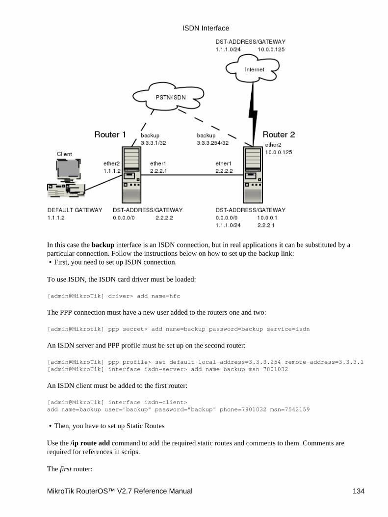
In this case the backup interface is an ISDN connection, but in real applications it can be substituted by aparticular connection. Follow the instructions below on how to set up the backup link:
First, you need to set up ISDN connection.•
To use ISDN, the ISDN card driver must be loaded:
[admin@MikroTik] driver> add name=hfc
The PPP connection must have a new user added to the routers one and two:
[admin@Mikrotik] ppp secret> add name=backup password=backup service=isdn
An ISDN server and PPP profile must be set up on the second router:
[admin@MikroTik] ppp profile> set default local−address=3.3.3.254 remote−address=3.3.3.1[admin@MikroTik] interface isdn−server> add name=backup msn=7801032
An ISDN client must be added to the first router:
[admin@MikroTik] interface isdn−client>add name=backup user="backup" password="backup" phone=7801032 msn=7542159
Then, you have to set up Static Routes•
Use the /ip route add command to add the required static routes and comments to them. Comments arerequired for references in scrips.
The first router:
ISDN Interface
MikroTik RouterOS™ V2.7 Reference Manual 134
[admin@Mikrotik] ip route> add gateway 2.2.2.2 comment "route1"
The second router:
[admin@Mikrotik] ip route> add gateway 2.2.2.1 comment "route1" dst−address 1.1.1.0/24
And finally, you have to add scripts.•
Add scripts in the submenu \system script using the following commands:
The first router:
[admin@Mikrotik] system script> add name=connection_down \\... source={/interface enable backup; /ip route set route1 gateway 3.3.3.254}[admin@Mikrotik] system script> add name=connection_up \\... source={/interface disable backup; /ip route set route1 gateway 2.2.2.2}
The second router:
[admin@Mikrotik] system script> add name=connection_down \\... source={/ip route set route1 gateway 3.3.3.1}[admin@Mikrotik] system script> add name=connection_up \\... source={/ip route set route1 gateway 2.2.2.1}
To get all above listed to work, set up Netwatch utility•
To use netwatch, you need the advanced tools feature package installed. Please upload it to the router andreboot. When installed, the advanced−tools package should be listed under the /system package print list.
Add the following settings to the first router:
[admin@Mikrotik] tool netwatch> add host=2.2.2.1 interval=5s \\... up−script=connection_up down−script=connection_down
Add the following settings to the second router:
[admin@Mikrotik] tool netwatch> add host=2.2.2.2 interval=5s \\... up−script=connection_up down−script=connection_down
Additional Resources
PPP over ISDNrfc3057 − ISDN Q.921−User Adaptation LayerMultiprotocol Interconnect on X.25 and ISDN in the Packet Mode
© Copyright 1999−2002, MikroTik
ISDN Interface
MikroTik RouterOS™ V2.7 Reference Manual 135
Layer 2 Tunnel Protocol (L2TP)Document revision 1.6 (19−May−2003)This document applies to MikroTik RouterOS v2.7
Table of Contents
Table of Contents• Summary• Specifications• Related Documents• Description• L2TP Client Setup
Property Description♦ Example♦
•
Monitoring L2TP ClientProperty Description♦ Example♦
•
L2TP Server SetupDescription♦ Property Description♦ Example♦
•
L2TP Server UsersDescription♦ Property Description♦ Example♦
•
L2TP Router−to−Router Secure Tunnel Example• Connecting a Remote Client via L2TP Tunnel• L2TP Setup for Windows• Troubleshooting•
Summary
L2TP (Layer 2 Tunnel Protocol) supports encrypted tunnels over IP. The MikroTik RouterOS implementationincludes support for L2TP client and server.
General applications of L2TP tunnels:
For secure router−to−router tunnels over the Internet• To link (bridge) local Intranets or LANs (when EoIP is also used)• To extend PPP user connections to a remote location (for example for ISP to authenticate and toprovide Internet access separately)
•
For mobile or remote clients to remotely access an Intranet/LAN of a company•
Each L2TP connection is composed of a server and a client. The MikroTik RouterOS may function as a serveror client – or, for various configurations, it may be the server for some connections and client for otherconnections. For example, the client created below could connect to a Cisco L2TP server, another MikroTikRouter, or another router which supports a L2TP server.
MikroTik RouterOS™ V2.7 Reference Manual 136
Specifications
Packages required : pppLicense required : Basic (DEMO license is limited to 4 tunnels)Home menu level : /interface l2tp−server, /interface l2tp−clientProtocols utilized : L2TP (RFC2661)Hardware usage: not significant
Related Documents
Software Package Installation and UpgradingIP Addresses and Address Resolution Protocol (ARP)Authentication, Authorization and AccountingEthernet over IP (EoIP) Tunnel InterfaceIP security (IPsec)
Description
L2TP is a secure tunnel for transporting IP traffic using PPP. L2TP encapsulates PPP in virtual lines that runover IP, FrameRelay and other protocols (that are not currently supported by Mikrotik RouterOS). L2TPincorporates PPP and MPPE (Microsoft Point to Point Encryption) to make encrypted links. The purpose ofthis protocol is to allow the Layer 2 and PPP endpoints to reside on different devices interconnected by apacket−switched network. With L2TP, a user has an Layer 2 connection to an access concentrator (e.g.,modem bank, ADSL DSLAM, etc.), and the concentrator then tunnels individual PPP frames to the NetworkAccess Server . This allows the actual processing of PPP packets to be divorced from the termination of theLayer 2 circuit. From the user's perspective, there is no functional difference between having the L2 circuitterminate in a NAS directly or using L2TP.
It may also be useful to use L2TP just as any other tunneling protocol with or without encryption. The L2TPstandard says that the most secure way to encrypt data is using L2TP over IPsec (Note that it is default modefor Microsoft L2TP client) as all L2TP control and data packets for a particular tunnel appear as homogeneousUDP/IP data packets to the IPsec system.
L2TP includes PPP authentication and accounting for each L2TP connection. Full authentication andaccounting of each connection may be done through a RADIUS client or locally.
MPPE 40bit RC4 and MPPE 128bit RC4 encryption are supported.
L2TP traffic uses UDP protocol for both control and data packets. UDP port 1701 is used only for linkestablishment, further traffic is using any available UDP port (which may or may not be 1701). This meansthat L2TP can be used with most firewalls and routers (even with NAT) by enabling UDP traffic to be routedthrough the firewall or router.
L2TP Client Setup
Submenu level : /interface l2tp−client
Layer 2 Tunnel Protocol (L2TP)
MikroTik RouterOS™ V2.7 Reference Manual 137
Property Description
name (name; default: l2tp−out1) − interface name for referencemtu (integer; default: 1460) − Maximum Transmit Unit. The optimal value is the MTU of the interface thetunnel is working over decreased by 40 (so, for 1500−byte ethernet link, set the MTU to 1460 to avoidfragmentation of packets)mru (integer; default: 1460) − Maximum Receive Unit. The optimal value is the MTU of the interface thetunnel is working over decreased by 40 (so, for 1500−byte ethernet link, set the MRU to 1460 to avoidfragmentation of packets)connect−to (IP address)− the IP address of the L2TP server to connect touser (string)− user name to use when logging on to the remote serverpassword (string; default: "")− user password to use when logging to the remote serverprofile (name; default: default) − profile to use when connecting to the remote serveradd−default−route (yes | no; default: no) − whether to use the server which this client is connected to as itsdefault router (gateway)
Example
To set up L2TP client named test2 using username john with password john to connect to the 10.1.1.12 L2TPserver and use it as the default gateway:
[admin@MikroTik] interface l2tp−client> add name=test2 connect−to=10.1.1.12 \\... user=john add−default−route=yes password=john[admin@MikroTik] interface l2tp−client> printFlags: X − disabled, R − running 0 X name="test2" mtu=1460 mru=1460 connect−to=10.1.1.12 user="john" password="john" profile=default add−default−route=yes
[admin@MikroTik] interface l2tp−client> enable 0
Monitoring L2TP Client
Command name : /interface l2tp−client monitor
Property Description
Statistics:
status (string) − status of the client:Dialing – attempting to make a connection• Verifying password... − connection has been established to the server, password verification in progress• Connected – self−explanatory• Terminated – interface is not enabled or the other side will not establish a connection uptime (time) −connection time displayed in days, hours, minutes, and secondsencoding (string) − encryption and encoding (if asymmetric, separated with '/') being used in thisconnection
•
Layer 2 Tunnel Protocol (L2TP)
MikroTik RouterOS™ V2.7 Reference Manual 138
Example
Example of an established connection:
[admin@MikroTik] interface l2tp−client> monitor test2 status: "connected" uptime: 4m27s encoding: "MPPE128 stateless"[admin@MikroTik] interface l2tp−client>
L2TP Server Setup
Submenu level : /interface l2tp−server server
[admin@MikroTik] interface l2tp−server server> print enabled: no mtu: 1460 mru: 1460 authentication: mschap2 default−profile: default[admin@MikroTik] interface l2tp−server server>
Description
The L2TP server supports unlimited connections from clients. For each current connection, a dynamicinterface is created.
Property Description
enabled (yes | no; default: no) − defines whether L2TP server is enabled or notmtu (integer; default: 1460) − Maximum Transmit Unit. The optimal value is the MTU of the interface thetunnel is working over decreased by 40 (so, for 1500−byte ethernet link, set the MTU to 1460 to avoidfragmentation of packets)mru (integer; default: 1460) − Maximum Receive Unit. The optimal value is the MTU of the interface thetunnel is working over decreased by 40 (so, for 1500−byte ethernet link, set the MTU to 1460 to avoidfragmentation of packets)authentication (multiple choice: pap | chap | mschap1 | mschap2; default: mschap2) − authenticationalgorithmdefault−profile − default profile to use
Example
To enable L2TP server:
[admin@MikroTik] interface l2tp−server server> set enabled=yes[admin@MikroTik] interface l2tp−server server> print enabled: yes mtu: 1460 mru: 1460 authentication: mschap2 default−profile: default[admin@MikroTik] interface l2tp−server server>
Layer 2 Tunnel Protocol (L2TP)
MikroTik RouterOS™ V2.7 Reference Manual 139
L2TP Server Users
Submenu level : /interface l2tp−server
Description
There are two types of items in L2TP server configuration − static users and dynamic connections. Adynamic connection can be established if the user database or the default−profile has its local−addressand remote−address set correctly. When static users are added, the default profile may be left with itsdefault values and only P2P user (in /ppp secret) should be configured. Note that in both cases P2P usersmust be configured properly.
Property Description
name − interface nameuser − the name of the user that is configured statically or added dynamically
Statistics:
mtu − shows (cannot be set here) client's MTUclient−address − shows (cannot be set here) the IP of the connected clientuptime − shows how long the client is connectedencoding (string) − encryption and encoding (if asymmetric, separated with '/') being used in thisconnection
Example
To add a static entry for ex1 user:
[admin@MikroTik] interface l2tp−server> add user=ex1[admin@MikroTik] interface l2tp−server> printFlags: X − disabled, D − dynamic, R − running # NAME USER MTU CLIENT−ADDRESS UPTIME ENC... 0 DR <l2tp−ex> ex 1460 10.0.0.202 6m32s none 1 l2tp−in1 ex1[admin@MikroTik] interface l2tp−server>
In this example an already connected user ex is shown besides the one we just added.
L2TP Router−to−Router Secure Tunnel Example
The following is an example of connecting two Intranets using an encrypted L2TP tunnel over the Internet.
Layer 2 Tunnel Protocol (L2TP)
MikroTik RouterOS™ V2.7 Reference Manual 140
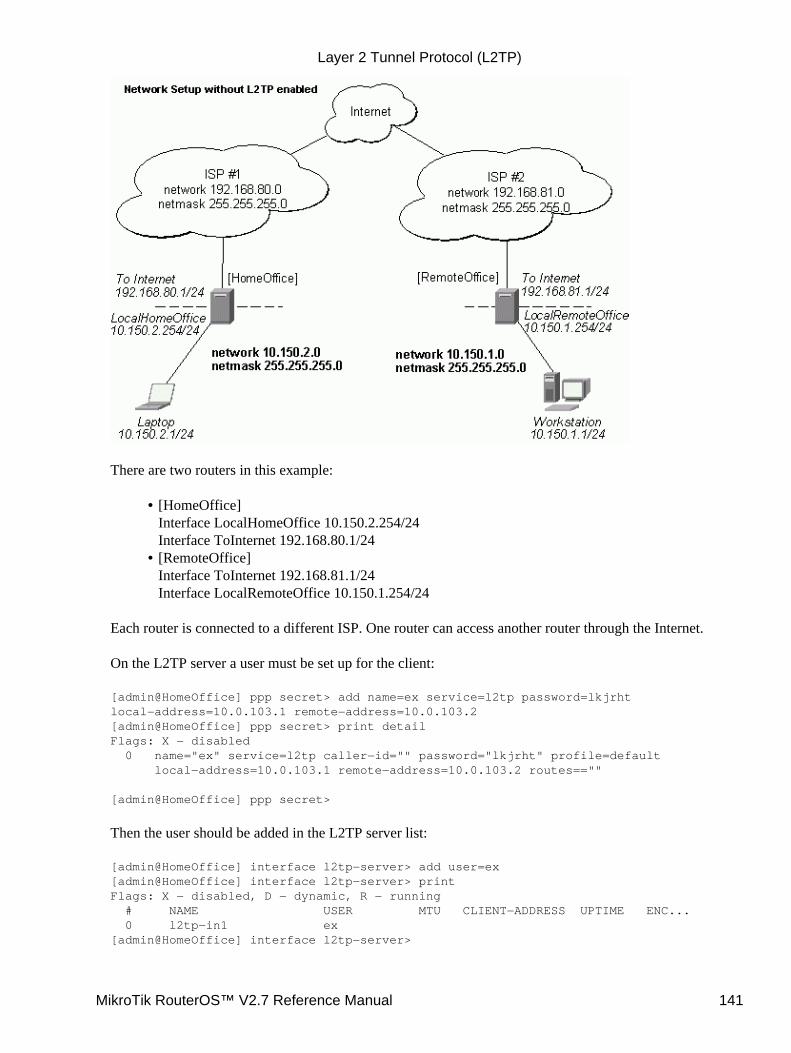
There are two routers in this example:
[HomeOffice]Interface LocalHomeOffice 10.150.2.254/24Interface ToInternet 192.168.80.1/24
•
[RemoteOffice]Interface ToInternet 192.168.81.1/24Interface LocalRemoteOffice 10.150.1.254/24
•
Each router is connected to a different ISP. One router can access another router through the Internet.
On the L2TP server a user must be set up for the client:
[admin@HomeOffice] ppp secret> add name=ex service=l2tp password=lkjrhtlocal−address=10.0.103.1 remote−address=10.0.103.2[admin@HomeOffice] ppp secret> print detailFlags: X − disabled 0 name="ex" service=l2tp caller−id="" password="lkjrht" profile=default local−address=10.0.103.1 remote−address=10.0.103.2 routes==""
[admin@HomeOffice] ppp secret>
Then the user should be added in the L2TP server list:
[admin@HomeOffice] interface l2tp−server> add user=ex[admin@HomeOffice] interface l2tp−server> printFlags: X − disabled, D − dynamic, R − running # NAME USER MTU CLIENT−ADDRESS UPTIME ENC... 0 l2tp−in1 ex[admin@HomeOffice] interface l2tp−server>
Layer 2 Tunnel Protocol (L2TP)
MikroTik RouterOS™ V2.7 Reference Manual 141
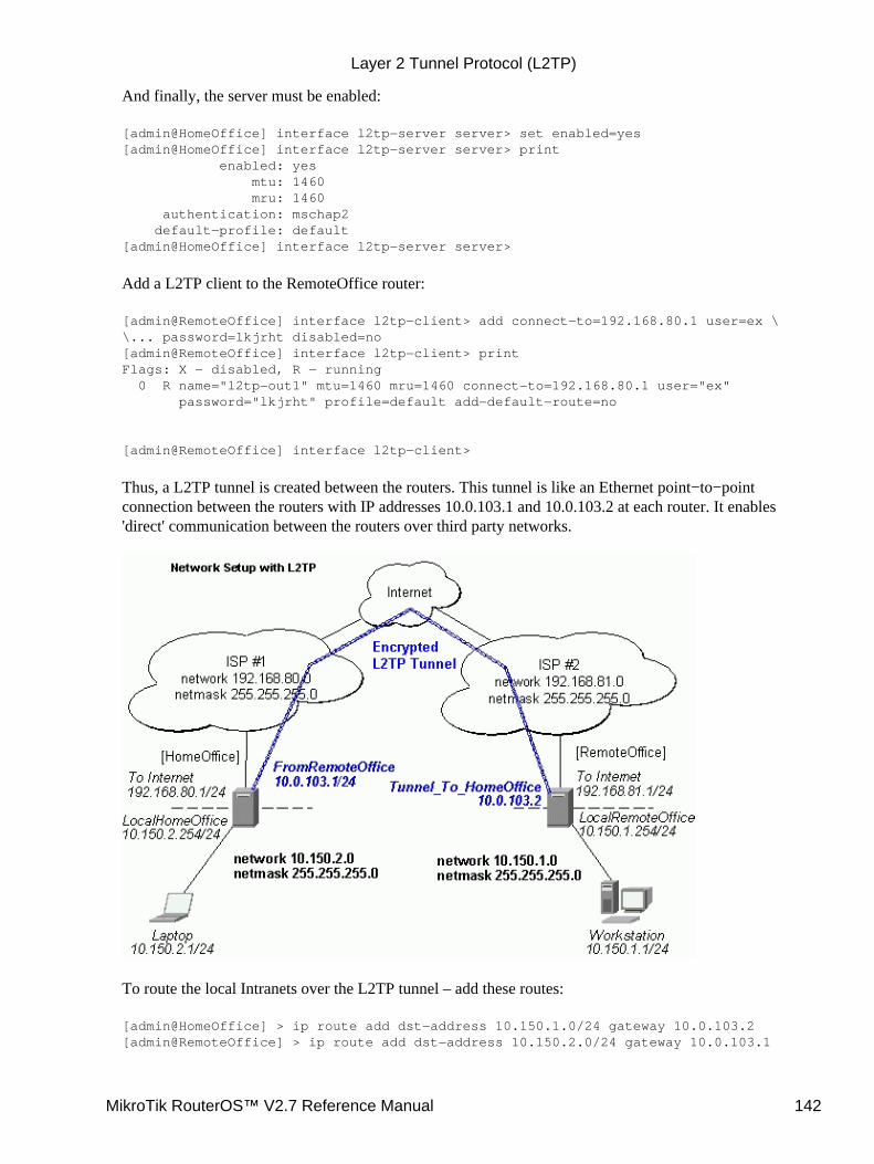
And finally, the server must be enabled:
[admin@HomeOffice] interface l2tp−server server> set enabled=yes[admin@HomeOffice] interface l2tp−server server> print enabled: yes mtu: 1460 mru: 1460 authentication: mschap2 default−profile: default[admin@HomeOffice] interface l2tp−server server>
Add a L2TP client to the RemoteOffice router:
[admin@RemoteOffice] interface l2tp−client> add connect−to=192.168.80.1 user=ex \\... password=lkjrht disabled=no[admin@RemoteOffice] interface l2tp−client> printFlags: X − disabled, R − running 0 R name="l2tp−out1" mtu=1460 mru=1460 connect−to=192.168.80.1 user="ex" password="lkjrht" profile=default add−default−route=no
[admin@RemoteOffice] interface l2tp−client>
Thus, a L2TP tunnel is created between the routers. This tunnel is like an Ethernet point−to−pointconnection between the routers with IP addresses 10.0.103.1 and 10.0.103.2 at each router. It enables'direct' communication between the routers over third party networks.
To route the local Intranets over the L2TP tunnel – add these routes:
[admin@HomeOffice] > ip route add dst−address 10.150.1.0/24 gateway 10.0.103.2[admin@RemoteOffice] > ip route add dst−address 10.150.2.0/24 gateway 10.0.103.1
Layer 2 Tunnel Protocol (L2TP)
MikroTik RouterOS™ V2.7 Reference Manual 142
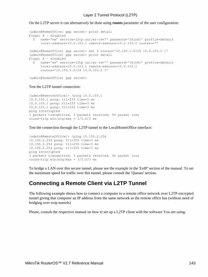
On the L2TP server it can alternatively be done using routes parameter of the user configuration:
[admin@HomeOffice] ppp secret> print detailFlags: X − disabled 0 name="ex" service=l2tp caller−id="" password="lkjrht" profile=default local−address=10.0.103.1 remote−address=10.0.103.2 routes==""
[admin@HomeOffice] ppp secret> set 0 routes="10.150.1.0/24 10.0.103.2 1"[admin@HomeOffice] ppp secret> print detailFlags: X − disabled 0 name="ex" service=l2tp caller−id="" password="lkjrht" profile=default local−address=10.0.103.1 remote−address=10.0.103.2 routes="10.150.1.0/24 10.0.103.2 1"
[admin@HomeOffice] ppp secret>
Test the L2TP tunnel connection:
[admin@RemoteOffice]> /ping 10.0.103.110.0.103.1 pong: ttl=255 time=3 ms10.0.103.1 pong: ttl=255 time=3 ms10.0.103.1 pong: ttl=255 time=3 msping interrupted3 packets transmitted, 3 packets received, 0% packet lossround−trip min/avg/max = 3/3.0/3 ms
Test the connection through the L2TP tunnel to the LocalHomeOffice interface:
[admin@RemoteOffice]> /ping 10.150.2.25410.150.2.254 pong: ttl=255 time=3 ms10.150.2.254 pong: ttl=255 time=3 ms10.150.2.254 pong: ttl=255 time=3 msping interrupted3 packets transmitted, 3 packets received, 0% packet lossround−trip min/avg/max = 3/3.0/3 ms
To bridge a LAN over this secure tunnel, please see the example in the 'EoIP' section of the manual. To setthe maximum speed for traffic over this tunnel, please consult the 'Queues' section.
Connecting a Remote Client via L2TP Tunnel
The following example shows how to connect a computer to a remote office network over L2TP encryptedtunnel giving that computer an IP address from the same network as the remote office has (without need ofbridging over eoip tunnels)
Please, consult the respective manual on how to set up a L2TP client with the software You are using.
Layer 2 Tunnel Protocol (L2TP)
MikroTik RouterOS™ V2.7 Reference Manual 143
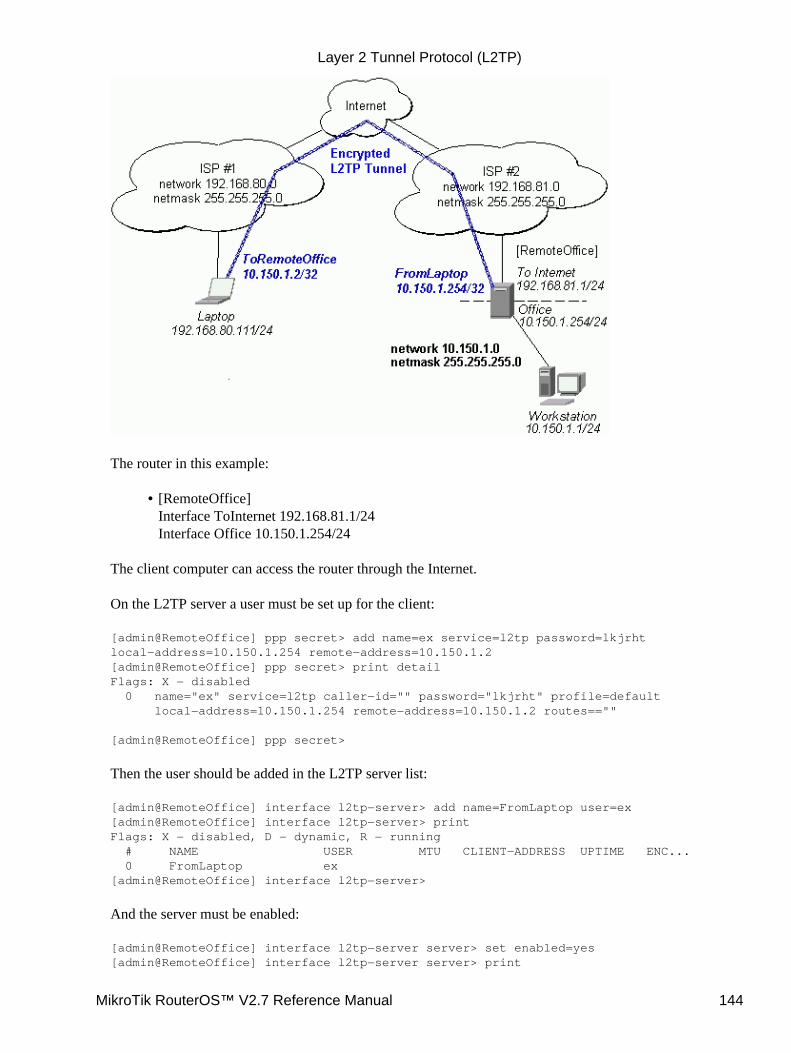
The router in this example:
[RemoteOffice]Interface ToInternet 192.168.81.1/24Interface Office 10.150.1.254/24
•
The client computer can access the router through the Internet.
On the L2TP server a user must be set up for the client:
[admin@RemoteOffice] ppp secret> add name=ex service=l2tp password=lkjrhtlocal−address=10.150.1.254 remote−address=10.150.1.2[admin@RemoteOffice] ppp secret> print detailFlags: X − disabled 0 name="ex" service=l2tp caller−id="" password="lkjrht" profile=default local−address=10.150.1.254 remote−address=10.150.1.2 routes==""
[admin@RemoteOffice] ppp secret>
Then the user should be added in the L2TP server list:
[admin@RemoteOffice] interface l2tp−server> add name=FromLaptop user=ex[admin@RemoteOffice] interface l2tp−server> printFlags: X − disabled, D − dynamic, R − running # NAME USER MTU CLIENT−ADDRESS UPTIME ENC... 0 FromLaptop ex[admin@RemoteOffice] interface l2tp−server>
And the server must be enabled:
[admin@RemoteOffice] interface l2tp−server server> set enabled=yes[admin@RemoteOffice] interface l2tp−server server> print
Layer 2 Tunnel Protocol (L2TP)
MikroTik RouterOS™ V2.7 Reference Manual 144
enabled: yes mtu: 1460 mru: 1460 authentication: mschap2 default−profile: default[admin@RemoteOffice] interface l2tp−server server>
Finally, the proxy APR must be enabled on the 'Office' interface:
[admin@RemoteOffice] interface ethernet> set Office arp=proxy−arp[admin@RemoteOffice] interface ethernet> printFlags: X − disabled, R − running # NAME MTU MAC−ADDRESS ARP 0 R ToInternet 1500 00:30:4F:0B:7B:C1 enabled 1 R Office 1500 00:30:4F:06:62:12 proxy−arp[admin@RemoteOffice] interface ethernet>
L2TP Setup for Windows
Microsoft provides L2TP client support for Windows XP, 2000, NT4, ME and 98. Windows 2000 and XPinclude support in the Windows setup or automatically install L2TP. For 98, NT and ME, installationrequires a download from Microsoft (L2TP/IPSec VPN Client)
For more information, see:Microsoft L2TP/IPSec VPN Client
On Windows 2000, L2TP setup without IPsec requires editting registry:Disabling IPSec for the Windows 2000 ClientDisabling IPSEC Policy Used with L2TP
Troubleshooting
I use firewall and I cannot establish L2TP connectionMake sure UDP connections can pass through both directions between your sites.
•
My Windows L2TP/IPSec VPN Client fails to connect to L2TP server with "Error 789" or "Error781"The error messages 789 and 781 occur when IPsec is not configured properly on both ends. See therespective documentation on how to configure IPsec in the Microsoft L2TP/IPSec VPN Client andin the MikroTik RouterOS. If you do not want to use IPsec, it can be easily switched off on theclient side.Note: if you are using Windows 2000, you need to edit system registry using regedt32.exe orregedit.exe. Add the following registry value toHKEY_LOCAL_MACHINE\System\CurrentControlSet\Services\Rasman\Parameters:
Value Name: ProhibitIpSecData Type: REG_DWORDValue: 1
You must restart the Windows 2000 for the changes to take effect
•
Layer 2 Tunnel Protocol (L2TP)
MikroTik RouterOS™ V2.7 Reference Manual 145

For more information on configuring Windows 2000, see:Configuring Cisco IOS and Windows 2000 Clients for L2TP Using Microsoft IASDisabling IPSEC Policy Used with L2TPHow to Configure a L2TP/IPSec Connection Using Pre−shared Key Authentication
© Copyright 1999−2003, MikroTik
Layer 2 Tunnel Protocol (L2TP)
MikroTik RouterOS™ V2.7 Reference Manual 146
MOXA C101 Synchronous InterfaceDocument revision 1.6 (19−Aug−2003)This document applies to the MikroTik RouterOS V2.7
Table of Contents
Table of Contents• Summary• Specifications• Related Documents• Installation
MOXA C101 PCI variant cabling♦ •
Synchronous Interface ConfigurationDescription♦ Property Description♦ Notes♦ Example♦
•
Troubleshooting• Synchronous Link Applications
MikroTik Router to MikroTik Router♦ MikroTik Router to CISCO Router♦ Notes♦
•
Additional Resources•
Summary
The MikroTik RouterOS supports the MOXA C101 Synchronous 4Mb/s Adapter hardware. The V.35synchronous interface is the standard for VSAT and other satellite modems. However, you must check withthe satellite system supplier for the modem interface type.
Specifications
Packages required : synchronousLicense required : synchronousHome menu level : /interface moxa−c101Protocols utilized :
CISCO/HDLC−X.25 (RFC1356)• Frame Relay (RFC1490)• PPP ( RFC−1661, RFC−1662 )•
Hardware usage : not significant
Related Documents
Software Package Installation and UpgradingDevice Driver ManagementIP Addresses and Address Resolution Protocol (ARP)
MikroTik RouterOS™ V2.7 Reference Manual 147
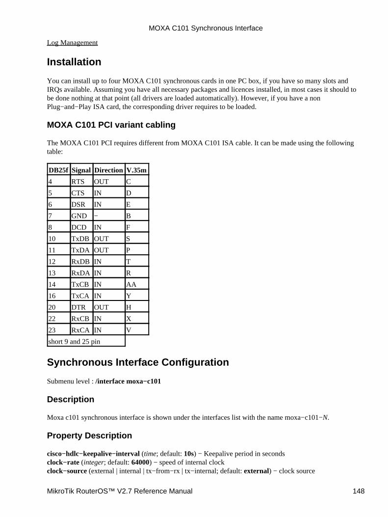
Log Management
Installation
You can install up to four MOXA C101 synchronous cards in one PC box, if you have so many slots andIRQs available. Assuming you have all necessary packages and licences installed, in most cases it should tobe done nothing at that point (all drivers are loaded automatically). However, if you have a nonPlug−and−Play ISA card, the corresponding driver requires to be loaded.
MOXA C101 PCI variant cabling
The MOXA C101 PCI requires different from MOXA C101 ISA cable. It can be made using the followingtable:
DB25f Signal Direction V.35m
4 RTS OUT C
5 CTS IN D
6 DSR IN E
7 GND − B
8 DCD IN F
10 TxDB OUT S
11 TxDA OUT P
12 RxDB IN T
13 RxDA IN R
14 TxCB IN AA
16 TxCA IN Y
20 DTR OUT H
22 RxCB IN X
23 RxCA IN V
short 9 and 25 pin
Synchronous Interface Configuration
Submenu level : /interface moxa−c101
Description
Moxa c101 synchronous interface is shown under the interfaces list with the name moxa−c101−N.
Property Description
cisco−hdlc−keepalive−interval (time; default: 10s) − Keepalive period in secondsclock−rate (integer; default: 64000) − speed of internal clockclock−source (external | internal | tx−from−rx | tx−internal; default: external) − clock source
MOXA C101 Synchronous Interface
MikroTik RouterOS™ V2.7 Reference Manual 148
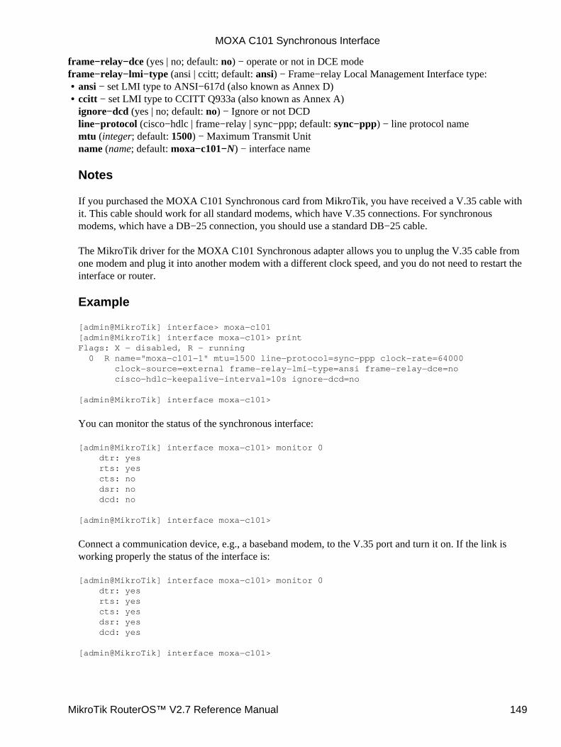
frame−relay−dce (yes | no; default: no) − operate or not in DCE modeframe−relay−lmi−type (ansi | ccitt; default: ansi) − Frame−relay Local Management Interface type:
ansi − set LMI type to ANSI−617d (also known as Annex D)• ccitt − set LMI type to CCITT Q933a (also known as Annex A)ignore−dcd (yes | no; default: no) − Ignore or not DCDline−protocol (cisco−hdlc | frame−relay | sync−ppp; default: sync−ppp) − line protocol namemtu (integer; default: 1500) − Maximum Transmit Unitname (name; default: moxa−c101−N) − interface name
Notes
If you purchased the MOXA C101 Synchronous card from MikroTik, you have received a V.35 cable withit. This cable should work for all standard modems, which have V.35 connections. For synchronousmodems, which have a DB−25 connection, you should use a standard DB−25 cable.
The MikroTik driver for the MOXA C101 Synchronous adapter allows you to unplug the V.35 cable fromone modem and plug it into another modem with a different clock speed, and you do not need to restart theinterface or router.
Example
[admin@MikroTik] interface> moxa−c101[admin@MikroTik] interface moxa−c101> printFlags: X − disabled, R − running 0 R name="moxa−c101−1" mtu=1500 line−protocol=sync−ppp clock−rate=64000 clock−source=external frame−relay−lmi−type=ansi frame−relay−dce=no cisco−hdlc−keepalive−interval=10s ignore−dcd=no
[admin@MikroTik] interface moxa−c101>
You can monitor the status of the synchronous interface:
[admin@MikroTik] interface moxa−c101> monitor 0 dtr: yes rts: yes cts: no dsr: no dcd: no
[admin@MikroTik] interface moxa−c101>
Connect a communication device, e.g., a baseband modem, to the V.35 port and turn it on. If the link isworking properly the status of the interface is:
[admin@MikroTik] interface moxa−c101> monitor 0 dtr: yes rts: yes cts: yes dsr: yes dcd: yes
[admin@MikroTik] interface moxa−c101>
•
MOXA C101 Synchronous Interface
MikroTik RouterOS™ V2.7 Reference Manual 149
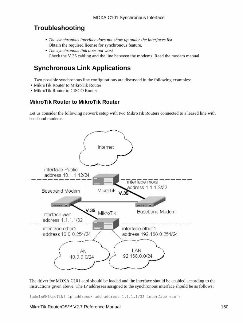
Troubleshooting
The synchronous interface does not show up under the interfaces listObtain the required license for synchronous feature.
•
The synchronous link does not workCheck the V.35 cabling and the line between the modems. Read the modem manual.
•
Synchronous Link Applications
Two possible synchronous line configurations are discussed in the following examples:MikroTik Router to MikroTik Router• MikroTik Router to CISCO Router•
MikroTik Router to MikroTik Router
Let us consider the following network setup with two MikroTik Routers connected to a leased line withbaseband modems:
The driver for MOXA C101 card should be loaded and the interface should be enabled according to theinstructions given above. The IP addresses assigned to the synchronous interface should be as follows:
[admin@MikroTik] ip address> add address 1.1.1.1/32 interface wan \
MOXA C101 Synchronous Interface
MikroTik RouterOS™ V2.7 Reference Manual 150
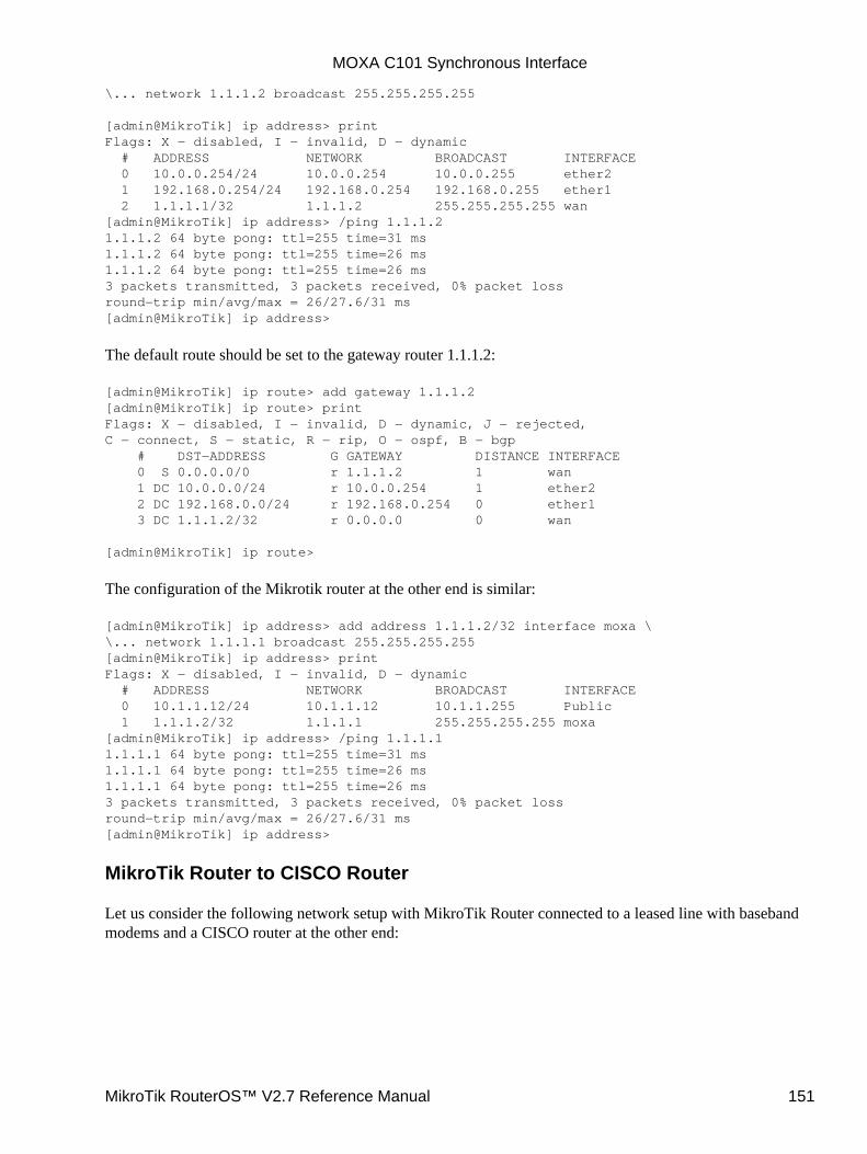
\... network 1.1.1.2 broadcast 255.255.255.255
[admin@MikroTik] ip address> printFlags: X − disabled, I − invalid, D − dynamic # ADDRESS NETWORK BROADCAST INTERFACE 0 10.0.0.254/24 10.0.0.254 10.0.0.255 ether2 1 192.168.0.254/24 192.168.0.254 192.168.0.255 ether1 2 1.1.1.1/32 1.1.1.2 255.255.255.255 wan[admin@MikroTik] ip address> /ping 1.1.1.21.1.1.2 64 byte pong: ttl=255 time=31 ms1.1.1.2 64 byte pong: ttl=255 time=26 ms1.1.1.2 64 byte pong: ttl=255 time=26 ms3 packets transmitted, 3 packets received, 0% packet lossround−trip min/avg/max = 26/27.6/31 ms[admin@MikroTik] ip address>
The default route should be set to the gateway router 1.1.1.2:
[admin@MikroTik] ip route> add gateway 1.1.1.2[admin@MikroTik] ip route> printFlags: X − disabled, I − invalid, D − dynamic, J − rejected,C − connect, S − static, R − rip, O − ospf, B − bgp # DST−ADDRESS G GATEWAY DISTANCE INTERFACE 0 S 0.0.0.0/0 r 1.1.1.2 1 wan 1 DC 10.0.0.0/24 r 10.0.0.254 1 ether2 2 DC 192.168.0.0/24 r 192.168.0.254 0 ether1 3 DC 1.1.1.2/32 r 0.0.0.0 0 wan
[admin@MikroTik] ip route>
The configuration of the Mikrotik router at the other end is similar:
[admin@MikroTik] ip address> add address 1.1.1.2/32 interface moxa \\... network 1.1.1.1 broadcast 255.255.255.255[admin@MikroTik] ip address> printFlags: X − disabled, I − invalid, D − dynamic # ADDRESS NETWORK BROADCAST INTERFACE 0 10.1.1.12/24 10.1.1.12 10.1.1.255 Public 1 1.1.1.2/32 1.1.1.1 255.255.255.255 moxa[admin@MikroTik] ip address> /ping 1.1.1.11.1.1.1 64 byte pong: ttl=255 time=31 ms1.1.1.1 64 byte pong: ttl=255 time=26 ms1.1.1.1 64 byte pong: ttl=255 time=26 ms3 packets transmitted, 3 packets received, 0% packet lossround−trip min/avg/max = 26/27.6/31 ms[admin@MikroTik] ip address>
MikroTik Router to CISCO Router
Let us consider the following network setup with MikroTik Router connected to a leased line with basebandmodems and a CISCO router at the other end:
MOXA C101 Synchronous Interface
MikroTik RouterOS™ V2.7 Reference Manual 151

The driver for MOXA C101 card should be loaded and the interface should be enabled according to theinstructions given above. The IP addresses assigned to the synchronous interface should be as follows:
[admin@MikroTik] ip address> add address 1.1.1.1/32 interface wan \\... network 1.1.1.2 broadcast 255.255.255.255[admin@MikroTik] ip address> printFlags: X − disabled, I − invalid, D − dynamic # ADDRESS NETWORK BROADCAST INTERFACE 0 10.0.0.254/24 10.0.0.254 10.0.0.255 ether2 1 192.168.0.254/24 192.168.0.254 192.168.0.255 ether1 2 1.1.1.1/32 1.1.1.2 255.255.255.255 wan[admin@MikroTik] ip address> /ping 1.1.1.21.1.1.2 64 byte pong: ttl=255 time=31 ms1.1.1.2 64 byte pong: ttl=255 time=26 ms1.1.1.2 64 byte pong: ttl=255 time=26 ms3 packets transmitted, 3 packets received, 0% packet lossround−trip min/avg/max = 26/27.6/31 ms[admin@MikroTik] ip address>
The default route should be set to the gateway router 1.1.1.2:
[admin@MikroTik] ip route> add gateway 1.1.1.2[admin@MikroTik] ip route> printFlags: X − disabled, I − invalid, D − dynamic, J − rejected,C − connect, S − static, R − rip, O − ospf, B − bgp # DST−ADDRESS G GATEWAY DISTANCE INTERFACE
MOXA C101 Synchronous Interface
MikroTik RouterOS™ V2.7 Reference Manual 152
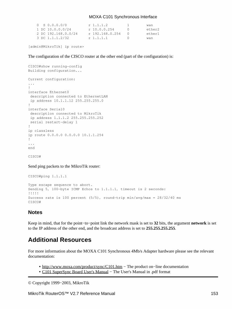
0 S 0.0.0.0/0 r 1.1.1.2 1 wan 1 DC 10.0.0.0/24 r 10.0.0.254 0 ether2 2 DC 192.168.0.0/24 r 192.168.0.254 0 ether1 3 DC 1.1.1.2/32 r 1.1.1.1 0 wan
[admin@MikroTik] ip route>
The configuration of the CISCO router at the other end (part of the configuration) is:
CISCO#show running−configBuilding configuration...
Current configuration:...!interface Ethernet0 description connected to EthernetLAN ip address 10.1.1.12 255.255.255.0!interface Serial0 description connected to MikroTik ip address 1.1.1.2 255.255.255.252 serial restart−delay 1!ip classlessip route 0.0.0.0 0.0.0.0 10.1.1.254!...end
CISCO#
Send ping packets to the MikroTik router:
CISCO#ping 1.1.1.1
Type escape sequence to abort.Sending 5, 100−byte ICMP Echos to 1.1.1.1, timeout is 2 seconds:!!!!!Success rate is 100 percent (5/5), round−trip min/avg/max = 28/32/40 msCISCO#
Notes
Keep in mind, that for the point−to−point link the network mask is set to 32 bits, the argument network is setto the IP address of the other end, and the broadcast address is set to 255.255.255.255.
Additional Resources
For more information about the MOXA C101 Synchronous 4Mb/s Adapter hardware please see the relevantdocumentation:
http://www.moxa.com/product/sync/C101.htm − The product on−line documentation• C101 SuperSync Board User's Manual − The User's Manual in .pdf format•
© Copyright 1999−2003, MikroTik
MOXA C101 Synchronous Interface
MikroTik RouterOS™ V2.7 Reference Manual 153

MOXA C502 Synchronous InterfaceDocument revision 1.3 (30−Jun−2002)This document applies to the MikroTik RouterOS V2.7
Table of Contents
Table of Contents• Summary• Specifications• Related Documents• Installation• Synchronous Interface Configuration
Description♦ Property Description♦ Notes♦ Example♦
•
Troubleshooting• Synchronous Link Applications
MikroTik Router to MikroTik Router♦ MikroTik Router to CISCO Router♦ Notes♦
•
Additional Resources•
Summary
The MikroTik RouterOS supports the MOXA C502 PCI Dual−port Synchronous 8Mb/s Adapter hardware.The V.35 synchronous interface is the standard for VSAT and other satellite modems. However, you mustcheck with the satellite system supplier for the modem interface type.
Specifications
Packages required : synchronousLicense required : synchronousHome menu level : /interface moxa−c502Protocols utilized :
CISCO/HDLC−X.25 (RFC1356)• Frame Relay (RFC1490)• PPP ( RFC−1661, RFC−1662 )•
Hardware usage : not significant
Related Documents
Software Package Installation and UpgradingDevice Driver ManagementIP Addresses and Address Resolution Protocol (ARP)Log Management
MikroTik RouterOS™ V2.7 Reference Manual 154
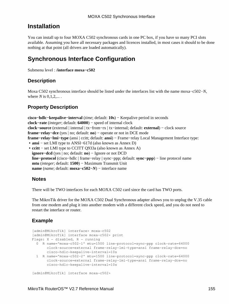
Installation
You can install up to four MOXA C502 synchronous cards in one PC box, if you have so many PCI slotsavailable. Assuming you have all necessary packages and licences installed, in most cases it should to be donenothing at that point (all drivers are loaded automatically).
Synchronous Interface Configuration
Submenu level : /interface moxa−c502
Description
Moxa C502 synchronous interface should be listed under the interfaces list with the name moxa−c502−N,where N is 0,1,2,... .
Property Description
cisco−hdlc−keepalive−interval (time; default: 10s) − Keepalive period in secondsclock−rate (integer; default: 64000) − speed of internal clockclock−source (external | internal | tx−from−rx | tx−internal; default: external) − clock sourceframe−relay−dce (yes | no; default: no) − operate or not in DCE modeframe−relay−lmi−type (ansi | ccitt; default: ansi) − Frame−relay Local Management Interface type:
ansi − set LMI type to ANSI−617d (also known as Annex D)• ccitt − set LMI type to CCITT Q933a (also known as Annex A)ignore−dcd (yes | no; default: no) − Ignore or not DCDline−protocol (cisco−hdlc | frame−relay | sync−ppp; default: sync−ppp) − line protocol namemtu (integer; default: 1500) − Maximum Transmit Unitname (name; default: moxa−c502−N) − interface name
Notes
There will be TWO interfaces for each MOXA C502 card since the card has TWO ports.
The MikroTik driver for the MOXA C502 Dual Synchronous adapter allows you to unplug the V.35 cablefrom one modem and plug it into another modem with a different clock speed, and you do not need torestart the interface or router.
Example
[admin@MikroTik] interface> moxa−c502[admin@MikroTik] interface moxa−c502> printFlags: X − disabled, R − running 0 R name="moxa−c502−1" mtu=1500 line−protocol=sync−ppp clock−rate=64000 clock−source=external frame−relay−lmi−type=ansi frame−relay−dce=no cisco−hdlc−keepalive−interval=10s 1 R name="moxa−c502−2" mtu=1500 line−protocol=sync−ppp clock−rate=64000 clock−source=external frame−relay−lmi−type=ansi frame−relay−dce=no cisco−hdlc−keepalive−interval=10s
[admin@MikroTik] interface moxa−c502>
•
MOXA C502 Synchronous Interface
MikroTik RouterOS™ V2.7 Reference Manual 155
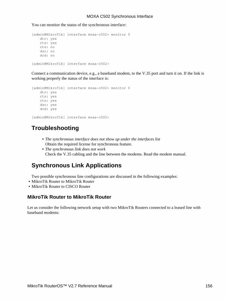
You can monitor the status of the synchronous interface:
[admin@MikroTik] interface moxa−c502> monitor 0 dtr: yes rts: yes cts: no dsr: no dcd: no
[admin@MikroTik] interface moxa−c502>
Connect a communication device, e.g., a baseband modem, to the V.35 port and turn it on. If the link isworking properly the status of the interface is:
[admin@MikroTik] interface moxa−c502> monitor 0 dtr: yes rts: yes cts: yes dsr: yes dcd: yes
[admin@MikroTik] interface moxa−c502>
Troubleshooting
The synchronous interface does not show up under the interfaces listObtain the required license for synchronous feature.
•
The synchronous link does not workCheck the V.35 cabling and the line between the modems. Read the modem manual.
•
Synchronous Link Applications
Two possible synchronous line configurations are discussed in the following examples:MikroTik Router to MikroTik Router• MikroTik Router to CISCO Router•
MikroTik Router to MikroTik Router
Let us consider the following network setup with two MikroTik Routers connected to a leased line withbaseband modems:
MOXA C502 Synchronous Interface
MikroTik RouterOS™ V2.7 Reference Manual 156
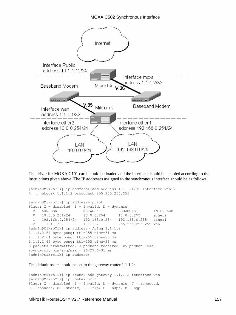
The driver for MOXA C101 card should be loaded and the interface should be enabled according to theinstructions given above. The IP addresses assigned to the synchronous interface should be as follows:
[admin@MikroTik] ip address> add address 1.1.1.1/32 interface wan \\... network 1.1.1.2 broadcast 255.255.255.255
[admin@MikroTik] ip address> printFlags: X − disabled, I − invalid, D − dynamic # ADDRESS NETWORK BROADCAST INTERFACE 0 10.0.0.254/24 10.0.0.254 10.0.0.255 ether2 1 192.168.0.254/24 192.168.0.254 192.168.0.255 ether1 2 1.1.1.1/32 1.1.1.2 255.255.255.255 wan[admin@MikroTik] ip address> /ping 1.1.1.21.1.1.2 64 byte pong: ttl=255 time=31 ms1.1.1.2 64 byte pong: ttl=255 time=26 ms1.1.1.2 64 byte pong: ttl=255 time=26 ms3 packets transmitted, 3 packets received, 0% packet lossround−trip min/avg/max = 26/27.6/31 ms[admin@MikroTik] ip address>
The default route should be set to the gateway router 1.1.1.2:
[admin@MikroTik] ip route> add gateway 1.1.1.2 interface wan[admin@MikroTik] ip route> printFlags: X − disabled, I − invalid, D − dynamic, J − rejected,C − connect, S − static, R − rip, O − ospf, B − bgp
MOXA C502 Synchronous Interface
MikroTik RouterOS™ V2.7 Reference Manual 157
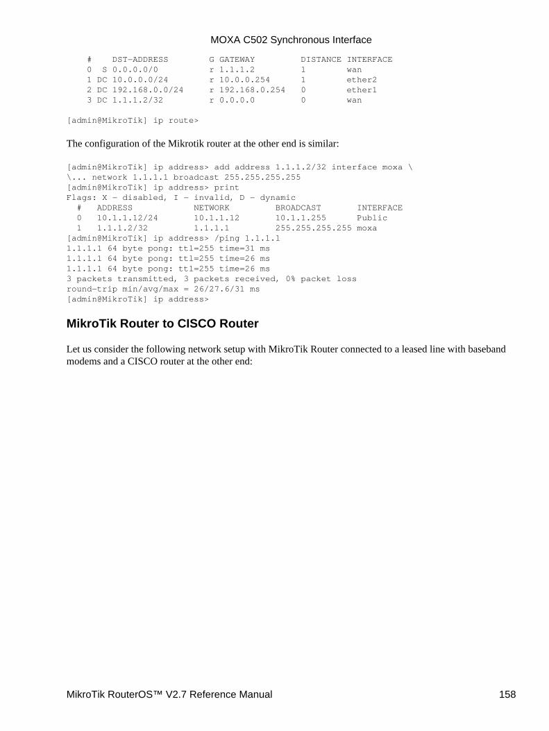
# DST−ADDRESS G GATEWAY DISTANCE INTERFACE 0 S 0.0.0.0/0 r 1.1.1.2 1 wan 1 DC 10.0.0.0/24 r 10.0.0.254 1 ether2 2 DC 192.168.0.0/24 r 192.168.0.254 0 ether1 3 DC 1.1.1.2/32 r 0.0.0.0 0 wan
[admin@MikroTik] ip route>
The configuration of the Mikrotik router at the other end is similar:
[admin@MikroTik] ip address> add address 1.1.1.2/32 interface moxa \\... network 1.1.1.1 broadcast 255.255.255.255[admin@MikroTik] ip address> printFlags: X − disabled, I − invalid, D − dynamic # ADDRESS NETWORK BROADCAST INTERFACE 0 10.1.1.12/24 10.1.1.12 10.1.1.255 Public 1 1.1.1.2/32 1.1.1.1 255.255.255.255 moxa[admin@MikroTik] ip address> /ping 1.1.1.11.1.1.1 64 byte pong: ttl=255 time=31 ms1.1.1.1 64 byte pong: ttl=255 time=26 ms1.1.1.1 64 byte pong: ttl=255 time=26 ms3 packets transmitted, 3 packets received, 0% packet lossround−trip min/avg/max = 26/27.6/31 ms[admin@MikroTik] ip address>
MikroTik Router to CISCO Router
Let us consider the following network setup with MikroTik Router connected to a leased line with basebandmodems and a CISCO router at the other end:
MOXA C502 Synchronous Interface
MikroTik RouterOS™ V2.7 Reference Manual 158
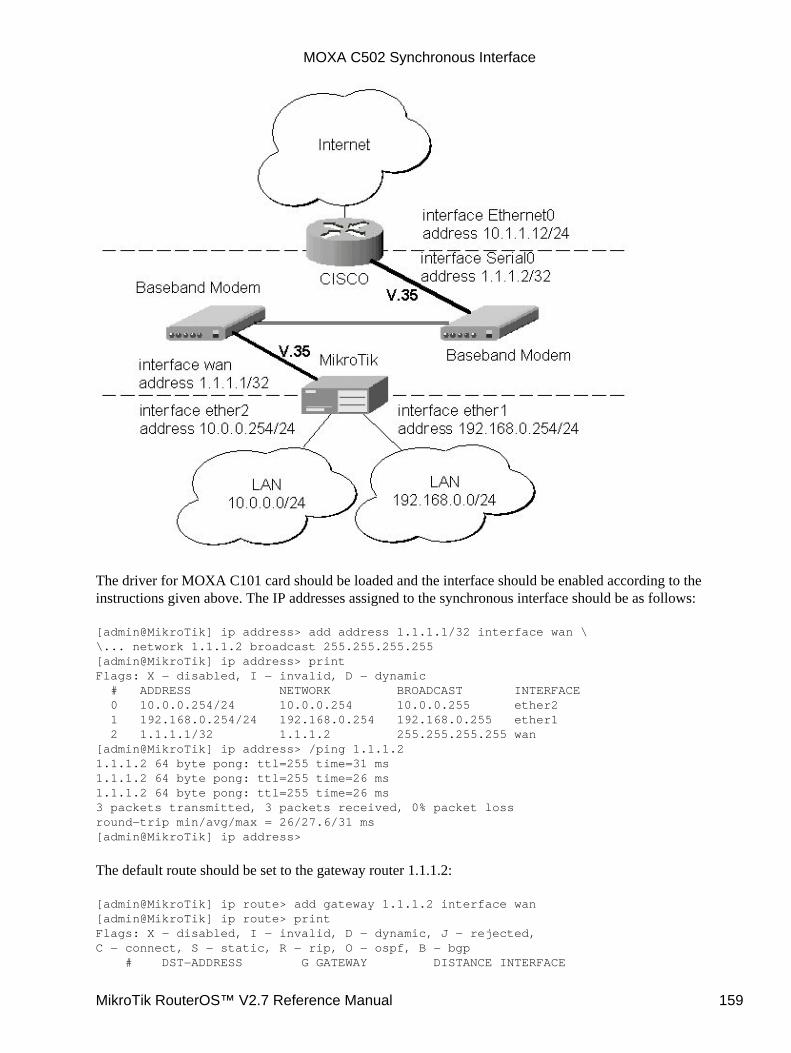
The driver for MOXA C101 card should be loaded and the interface should be enabled according to theinstructions given above. The IP addresses assigned to the synchronous interface should be as follows:
[admin@MikroTik] ip address> add address 1.1.1.1/32 interface wan \\... network 1.1.1.2 broadcast 255.255.255.255[admin@MikroTik] ip address> printFlags: X − disabled, I − invalid, D − dynamic # ADDRESS NETWORK BROADCAST INTERFACE 0 10.0.0.254/24 10.0.0.254 10.0.0.255 ether2 1 192.168.0.254/24 192.168.0.254 192.168.0.255 ether1 2 1.1.1.1/32 1.1.1.2 255.255.255.255 wan[admin@MikroTik] ip address> /ping 1.1.1.21.1.1.2 64 byte pong: ttl=255 time=31 ms1.1.1.2 64 byte pong: ttl=255 time=26 ms1.1.1.2 64 byte pong: ttl=255 time=26 ms3 packets transmitted, 3 packets received, 0% packet lossround−trip min/avg/max = 26/27.6/31 ms[admin@MikroTik] ip address>
The default route should be set to the gateway router 1.1.1.2:
[admin@MikroTik] ip route> add gateway 1.1.1.2 interface wan[admin@MikroTik] ip route> printFlags: X − disabled, I − invalid, D − dynamic, J − rejected,C − connect, S − static, R − rip, O − ospf, B − bgp # DST−ADDRESS G GATEWAY DISTANCE INTERFACE
MOXA C502 Synchronous Interface
MikroTik RouterOS™ V2.7 Reference Manual 159
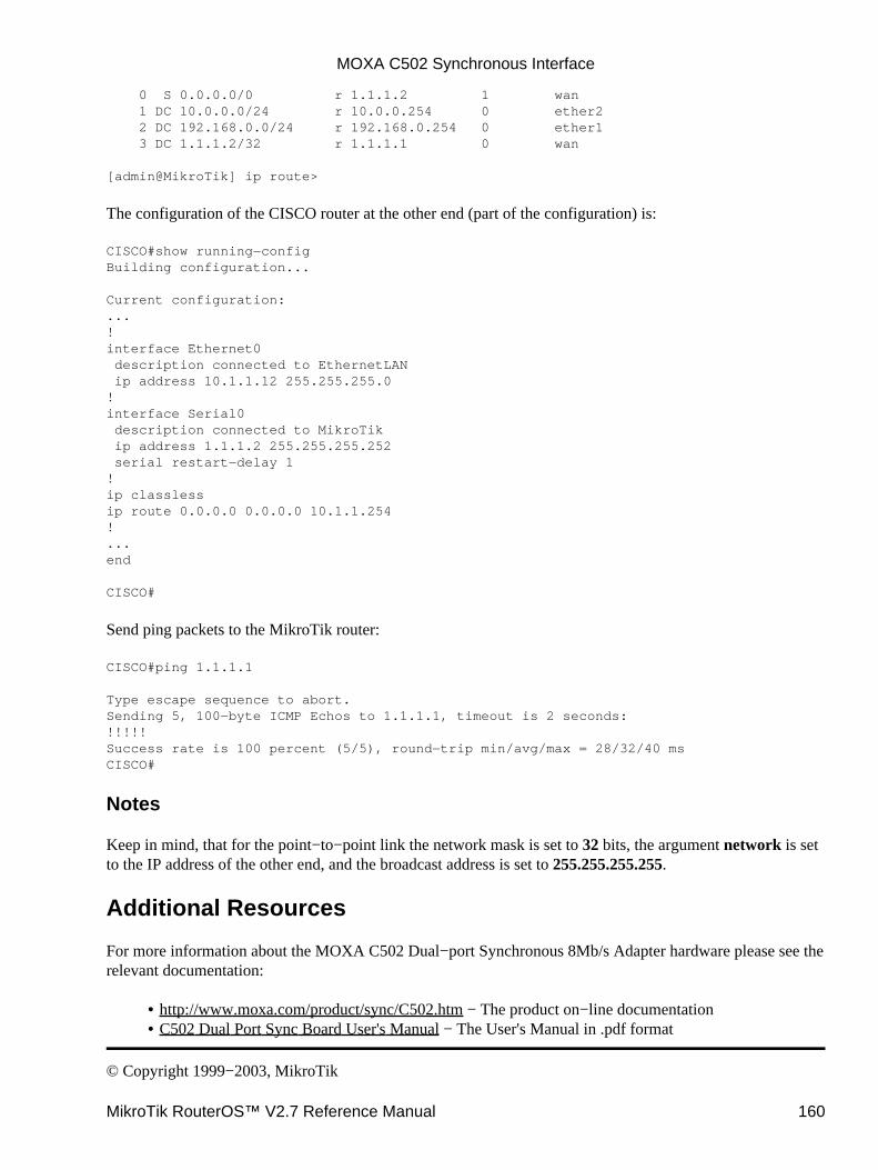
0 S 0.0.0.0/0 r 1.1.1.2 1 wan 1 DC 10.0.0.0/24 r 10.0.0.254 0 ether2 2 DC 192.168.0.0/24 r 192.168.0.254 0 ether1 3 DC 1.1.1.2/32 r 1.1.1.1 0 wan
[admin@MikroTik] ip route>
The configuration of the CISCO router at the other end (part of the configuration) is:
CISCO#show running−configBuilding configuration...
Current configuration:...!interface Ethernet0 description connected to EthernetLAN ip address 10.1.1.12 255.255.255.0!interface Serial0 description connected to MikroTik ip address 1.1.1.2 255.255.255.252 serial restart−delay 1!ip classlessip route 0.0.0.0 0.0.0.0 10.1.1.254!...end
CISCO#
Send ping packets to the MikroTik router:
CISCO#ping 1.1.1.1
Type escape sequence to abort.Sending 5, 100−byte ICMP Echos to 1.1.1.1, timeout is 2 seconds:!!!!!Success rate is 100 percent (5/5), round−trip min/avg/max = 28/32/40 msCISCO#
Notes
Keep in mind, that for the point−to−point link the network mask is set to 32 bits, the argument network is setto the IP address of the other end, and the broadcast address is set to 255.255.255.255.
Additional Resources
For more information about the MOXA C502 Dual−port Synchronous 8Mb/s Adapter hardware please see therelevant documentation:
http://www.moxa.com/product/sync/C502.htm − The product on−line documentation• C502 Dual Port Sync Board User's Manual − The User's Manual in .pdf format•
© Copyright 1999−2003, MikroTik
MOXA C502 Synchronous Interface
MikroTik RouterOS™ V2.7 Reference Manual 160

Point to Point Protocol (PPP) and AsynchronousInterfacesDocument revision 1.4 (01−Jun−2003)This document applies to the MikroTik RouterOS V2.7
Table of Contents
Table of Contents• Summary• Specifications• Related Documents• Serial Port Configuration
Property Description♦ Notes♦ Example♦
•
PPP Server SetupDescription♦ Property Description♦ Example♦
•
PPP Client SetupDescription♦ Property Description♦ Notes♦ Example♦
•
PPP Application Example• Additional Resources•
Summary
PPP (or Point−to−Point Protocol) provides a method for transmitting datagrams over serial point−to−pointlinks. Physically, it relies on com1 and com2 ports from standard PC hardware configurations. These appearas serial0 and serial1 automatically. You can add more serial ports to use the router for a modem pool usingthese adapters:
MOXA (www.moxa.com) Smartio C104H 4−port PCI multiport asynchronous board with maximum of 16ports (4 cards)
•
MOXA (www.moxa.com) Smartio C168H 8−port PCI multiport asynchronous board with maximum of 32ports (4 cards)
•
Cyclades (www.cyclades.com) Cyclom−Y Series PCI multiport asynchronous (serial) cards• Cyclades (www.cyclades.com) Cyclades−Z Series PCI multiport asynchronous (serial) cards• TCL (www.thetcl.com) DataBooster 4 or 8 port High Speed Buffered PCI Communication Controllers
Specifications
Packages required : pppLicense required : AnyHome menu level : /interface ppp−client, /interface ppp−serverStandards and Technologies : PPP (RFC−1661)
•
MikroTik RouterOS™ V2.7 Reference Manual 161
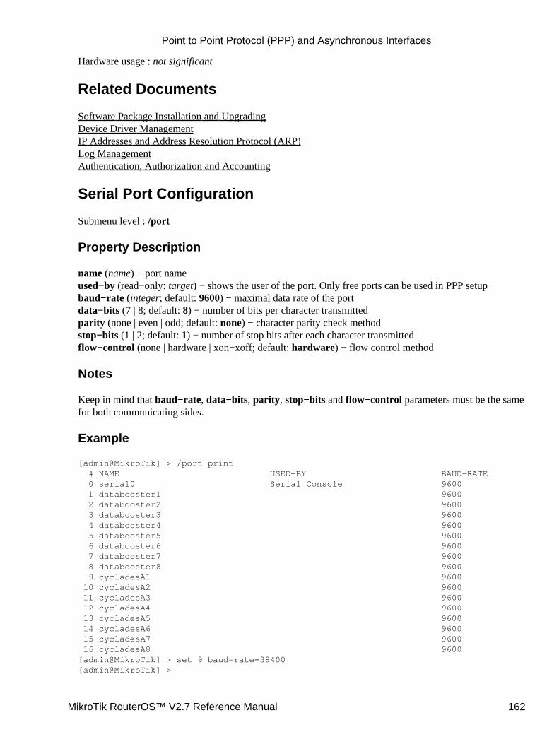
Hardware usage : not significant
Related Documents
Software Package Installation and UpgradingDevice Driver ManagementIP Addresses and Address Resolution Protocol (ARP)Log ManagementAuthentication, Authorization and Accounting
Serial Port Configuration
Submenu level : /port
Property Description
name (name) − port nameused−by (read−only: target) − shows the user of the port. Only free ports can be used in PPP setupbaud−rate (integer; default: 9600) − maximal data rate of the portdata−bits (7 | 8; default: 8) − number of bits per character transmittedparity (none | even | odd; default: none) − character parity check methodstop−bits (1 | 2; default: 1) − number of stop bits after each character transmittedflow−control (none | hardware | xon−xoff; default: hardware) − flow control method
Notes
Keep in mind that baud−rate, data−bits, parity, stop−bits and flow−control parameters must be the samefor both communicating sides.
Example
[admin@MikroTik] > /port print # NAME USED−BY BAUD−RATE 0 serial0 Serial Console 9600 1 databooster1 9600 2 databooster2 9600 3 databooster3 9600 4 databooster4 9600 5 databooster5 9600 6 databooster6 9600 7 databooster7 9600 8 databooster8 9600 9 cycladesA1 9600 10 cycladesA2 9600 11 cycladesA3 9600 12 cycladesA4 9600 13 cycladesA5 9600 14 cycladesA6 9600 15 cycladesA7 9600 16 cycladesA8 9600[admin@MikroTik] > set 9 baud−rate=38400[admin@MikroTik] >
Point to Point Protocol (PPP) and Asynchronous Interfaces
MikroTik RouterOS™ V2.7 Reference Manual 162
PPP Server Setup
Submenu level : /interface ppp−server
Description
PPP server provide a remote connection service for users. When dialing in, the users can be authenticatedlocally using the local user database in the /user menu, or at the RADIUS server specified in the /ip pppsettings.
Property Description
port (name; default: (unknown)) − serial portauthentication (multiple choice: mschap2,mschap1,chap,pap; default: mschap2,mschap1,chap,pap) −authentication protocolprofile (name; default: default) − profile name used for the linkmtu (integer; default: 1500) − Maximum Transmit Unit. Maximum packet size to be transmittedmru (integer; default: 1500) − Maximum Receive Unitnull−modem (no | yes; default: no) − enable/disable null−modem mode (when enabled, no modeminitialization strings are sent)modem−init (text; default: "") − modem initialization string. You may use "s11=40" to improve diallingspeedring−count (integer; default: 1) − number of rings to wait before answering phonename (text; default: ppp−inN) − interface name for reference
Example
You can add a PPP server using the add command:
[admin@MikroTik] interface ppp−server> add name=test port=serial1[admin@MikroTik] interface ppp−server> printFlags: X − disabled, R − running 0 X name="test" mtu=1500 mru=1500 port=serial1 authentication=mschap2,chap,pap profile=default modem−init="" ring−count=1 null−modem=no
[admin@MikroTik] interface ppp−server> enable 0[admin@MikroTik] interface ppp−server> monitor test status: "waiting for call..."
[admin@MikroTik] interface ppp−server>
PPP Client Setup
Submenu level : /interface ppp−client
Description
This section describes PPP clients configuration routines.
Point to Point Protocol (PPP) and Asynchronous Interfaces
MikroTik RouterOS™ V2.7 Reference Manual 163

Property Description
name (text; default: ppp−outN) − new interface nameport (name; default: (unknown)) − serial portuser (text; default: "") − P2P user name on the remote server to use for dialoutpassword (text; default: "") − P2P user password on the remote server to use for dialoutprofile (name; default: default) − local profile to use for dialoutphone (integer; default: "") − phone number for dialouttone−dial (yes | no; default: yes) − defines whether use tone dial or pulse dialmtu (integer; default: 1500) − Maximum Transmit Unit. Maximum packet size to be transmittedmru (integer; default: 1500) − Maximum Receive Unitnull−modem (no | yes; default: no) − enable/disable null−modem mode (when enabled, no modeminitialization strings are sent)modem−init (text; default: "") − modem initialization string. You may use "s11=40" to improve diallingspeeddial−on−demand (yes | no; default: no) − enable/disable dial on demandadd−default−route (yes | no; default: no) − add PPP remote address as a default routeuse−peer−dns (yes | no; default: no) − use DNS server settings from the remote server
NotesAdditional client profiles must be configured on the server side for clients to accomplish logon procedure.For more information see Related Documents section.
•
PPP client profiles must match at least partially (local−address and values related to encryption shouldmatch) with corresponding remote server values.
•
Example
You can add a PPP client using the add command:
[admin@MikroTik] interface ppp−client> add name=test user=test port=serial1 \\... add−default−route=yes[admin@MikroTik] interface ppp−client> printFlags: X − disabled, R − running 0 X name="test" mtu=1500 mru=1500 port=serial1 user="test" password="" profile=default phone="" tone−dial=yes modem−init="" null−modem=no dial−on−demand=no add−default−route=yes use−peer−dns=no
[admin@MikroTik] interface ppp−client> enable 0[admin@MikroTik] interface ppp−client> monitor test[admin@MikroTik] interface ppp−client> monitor 0 status: "dialing out..."
[admin@MikroTik] interface ppp−client>
PPP Application Example
In this example we will consider the following network setup:
Point to Point Protocol (PPP) and Asynchronous Interfaces
MikroTik RouterOS™ V2.7 Reference Manual 164
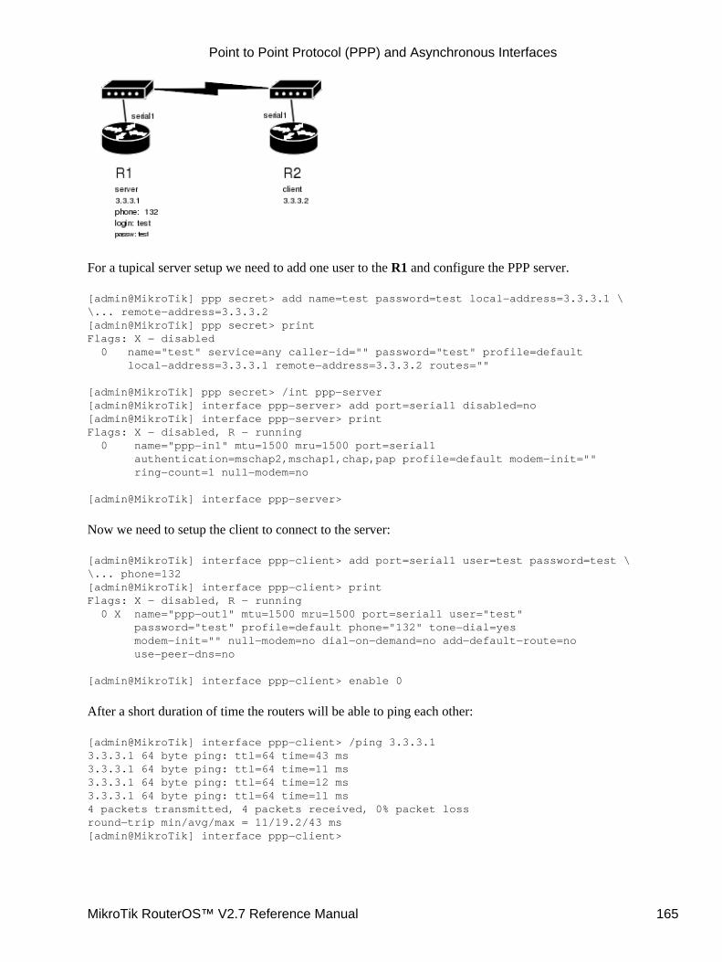
For a tupical server setup we need to add one user to the R1 and configure the PPP server.
[admin@MikroTik] ppp secret> add name=test password=test local−address=3.3.3.1 \\... remote−address=3.3.3.2[admin@MikroTik] ppp secret> printFlags: X − disabled 0 name="test" service=any caller−id="" password="test" profile=default local−address=3.3.3.1 remote−address=3.3.3.2 routes=""
[admin@MikroTik] ppp secret> /int ppp−server[admin@MikroTik] interface ppp−server> add port=serial1 disabled=no[admin@MikroTik] interface ppp−server> printFlags: X − disabled, R − running 0 name="ppp−in1" mtu=1500 mru=1500 port=serial1 authentication=mschap2,mschap1,chap,pap profile=default modem−init="" ring−count=1 null−modem=no
[admin@MikroTik] interface ppp−server>
Now we need to setup the client to connect to the server:
[admin@MikroTik] interface ppp−client> add port=serial1 user=test password=test \\... phone=132[admin@MikroTik] interface ppp−client> printFlags: X − disabled, R − running 0 X name="ppp−out1" mtu=1500 mru=1500 port=serial1 user="test" password="test" profile=default phone="132" tone−dial=yes modem−init="" null−modem=no dial−on−demand=no add−default−route=no use−peer−dns=no
[admin@MikroTik] interface ppp−client> enable 0
After a short duration of time the routers will be able to ping each other:
[admin@MikroTik] interface ppp−client> /ping 3.3.3.13.3.3.1 64 byte ping: ttl=64 time=43 ms3.3.3.1 64 byte ping: ttl=64 time=11 ms3.3.3.1 64 byte ping: ttl=64 time=12 ms3.3.3.1 64 byte ping: ttl=64 time=11 ms4 packets transmitted, 4 packets received, 0% packet lossround−trip min/avg/max = 11/19.2/43 ms[admin@MikroTik] interface ppp−client>
Point to Point Protocol (PPP) and Asynchronous Interfaces
MikroTik RouterOS™ V2.7 Reference Manual 165

Additional Resources
http://www.ietf.org/rfc/rfc2138.txt?number=2138http://www.ietf.org/rfc/rfc2138.txt?number=2139
© Copyright 1999−2003, MikroTik
Point to Point Protocol (PPP) and Asynchronous Interfaces
MikroTik RouterOS™ V2.7 Reference Manual 166
Point to Point Protocol over Ethernet (PPPoE)Document revision 1.4 (29−Dec−2003)This document applies to MikroTik RouterOS v2.7
Table of Contents
Table of Contents• Summary• Specifications• Related Documents• PPPoE Client Setup
Description♦ Property Description♦ Notes♦ Example♦
•
Monitoring PPPoE ClientProperty Description♦ Example♦
•
PPPoE Server Setup (Access Concentrator)Description♦ Property Description♦ Notes♦ Example♦
•
PPPoE Server UsersProperty Description♦ Example♦
•
PPPoE Troubleshooting• Application Examples
PPPoE in a multipoint wireless 802.11 network♦ •
Additional Resources•
Summary
The PPPoE (Point to Point Protocol over Ethernet) protocol provides extensive user management, networkmanagement and accounting benefits to ISPs and network administrators. Currently, PPPoE is used mainly byISPs to control client connections for xDSL and cable modems. PPPoE is an extension of the standard dial−upand synchronous protocol PPP. The transport is Ethernet, as opposed to modem transport.
Generally speaking, the PPPoE is used to hand out IP addresses to clients based on the user (and workstation,if desired) authentication as opposed to workstation only authentication, when static IP addresses or DHCP isused. Do not use static IP addresses or DHCP on interfaces, on which the PPPoE is used for security reasons.
A PPPoE connection is composed of a client and an access concentrator (server). The client may be aWindows computer that has the PPPoE client protocol installed. The MikroTik RouterOS supports both theclient and access concentrator implementations of PPPoE. The PPPoE client and server work over anyEthernet level interface on the router: wireless IEEE802.11 (Aironet, Cisco, WaveLAN, Prism, Atheros),10/100/1000 Mb/s Ethernet, RadioLAN, and EoIP (Ethernet over IP tunnel). No encryption, MPPE 40bitRSA, and MPPE 128bit RSA encryption are supported.
MikroTik RouterOS™ V2.7 Reference Manual 167
Supported connections:
MikroTik RouterOS PPPoE client to any PPPoE server (access concentrator)• MikroTik RouterOS server (access concentrator) to multiple PPPoE clients (clients are available foralmost all OSs and some routers)
•
Specifications
Packages required : pppLicense required : Basic (DEMO license is limited to 4 tunnels)Home menu level : /interface pppoe−server, /interface pppoe−clientProtocols utilized : PPPoE (RFC2516)Hardware usage: PPPoE server may require additional RAM (uses approx. 200KB for each connection) andCPU power, supports maximum of 10000 connections
Related Documents
Software Package Installation and UpgradingIP Addresses and Address Resolution Protocol (ARP)AAA (Authentication, Authorization and Accounting)
PPPoE Client Setup
Submenu level : /interface pppoe−client
Description
The PPPoE client supports high−speed connections. It is fully compatible with the MikroTik PPPoE server(access concentrator).
Note for Windows: Some connection instructions may use the form where the 'phone number' is'MikroTik_AC\mt1' to indicate that 'MikroTik_AC' is the access concentrator name and 'mt1' is the servicename.
Property Description
name (name; default: pppoe−out1) − name of the PPPoE interfaceinterface (name) − interface the PPPoE server can be connected throughmtu (integer; default: 1480) − Maximum Transmit Unit. The optimal value is the MTU of the interface thetunnel is working over decreased by 20 (so, for 1500−byte ethernet link, set the MTU to 1480 to avoidfragmentation of packets)mru (integer; default: 1480) − Maximum Receive Unit. The optimal value is the MTU of the interface thetunnel is working over decreased by 20 (so, for 1500−byte ethernet link, set the MTU to 1480 to avoidfragmentation of packets)user (string; default: "") − a user name that is present on the PPPoE serverpassword (string; default: "") − a user password used to connect the PPPoE serverprofile (name) − default profile for the connectionservice−name (string; default: "") − the service name set on the access concentrator. Many ISPs giveuser−name and address in the form of user−name@service−name
Point to Point Protocol over Ethernet (PPPoE)
MikroTik RouterOS™ V2.7 Reference Manual 168
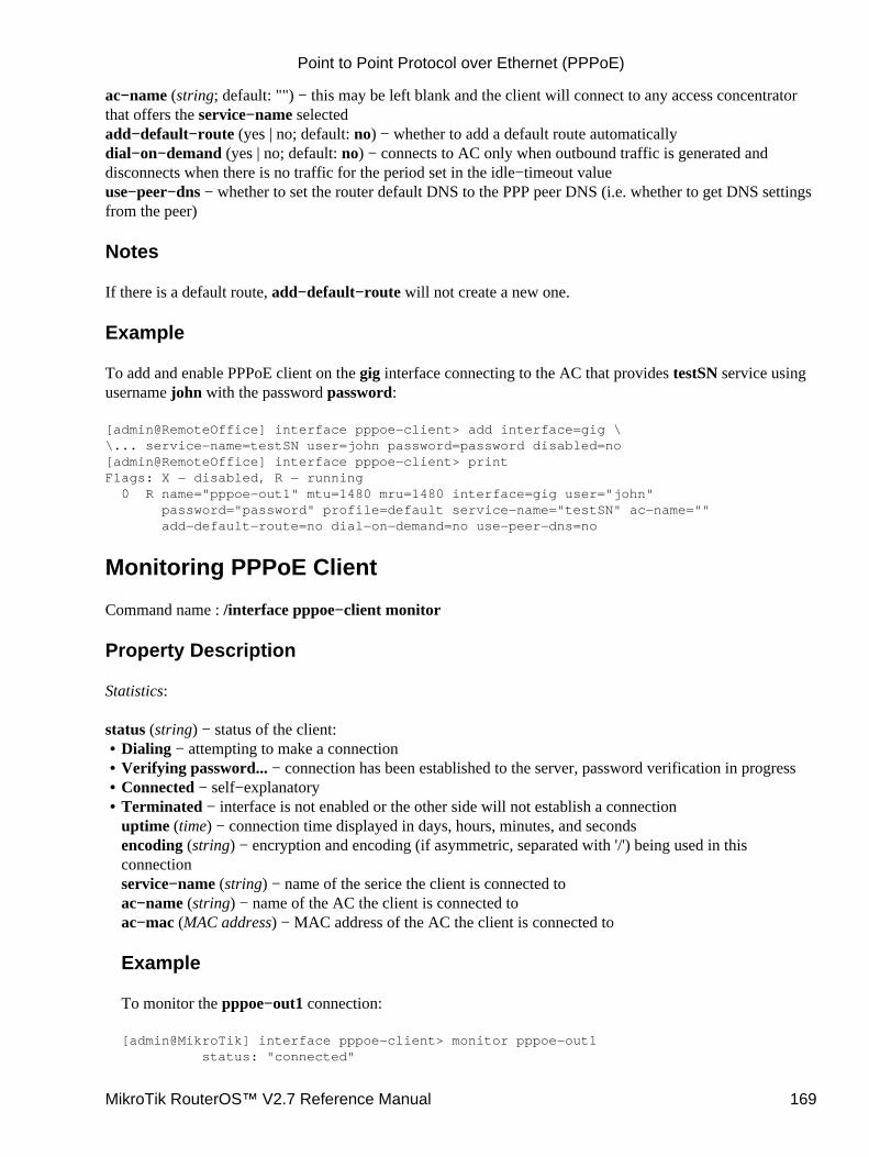
ac−name (string; default: "") − this may be left blank and the client will connect to any access concentratorthat offers the service−name selectedadd−default−route (yes | no; default: no) − whether to add a default route automaticallydial−on−demand (yes | no; default: no) − connects to AC only when outbound traffic is generated anddisconnects when there is no traffic for the period set in the idle−timeout valueuse−peer−dns − whether to set the router default DNS to the PPP peer DNS (i.e. whether to get DNS settingsfrom the peer)
Notes
If there is a default route, add−default−route will not create a new one.
Example
To add and enable PPPoE client on the gig interface connecting to the AC that provides testSN service usingusername john with the password password:
[admin@RemoteOffice] interface pppoe−client> add interface=gig \\... service−name=testSN user=john password=password disabled=no[admin@RemoteOffice] interface pppoe−client> printFlags: X − disabled, R − running 0 R name="pppoe−out1" mtu=1480 mru=1480 interface=gig user="john" password="password" profile=default service−name="testSN" ac−name="" add−default−route=no dial−on−demand=no use−peer−dns=no
Monitoring PPPoE Client
Command name : /interface pppoe−client monitor
Property Description
Statistics:
status (string) − status of the client:Dialing − attempting to make a connection• Verifying password... − connection has been established to the server, password verification in progress• Connected − self−explanatory• Terminated − interface is not enabled or the other side will not establish a connectionuptime (time) − connection time displayed in days, hours, minutes, and secondsencoding (string) − encryption and encoding (if asymmetric, separated with '/') being used in thisconnectionservice−name (string) − name of the serice the client is connected toac−name (string) − name of the AC the client is connected toac−mac (MAC address) − MAC address of the AC the client is connected to
Example
To monitor the pppoe−out1 connection:
[admin@MikroTik] interface pppoe−client> monitor pppoe−out1 status: "connected"
•
Point to Point Protocol over Ethernet (PPPoE)
MikroTik RouterOS™ V2.7 Reference Manual 169
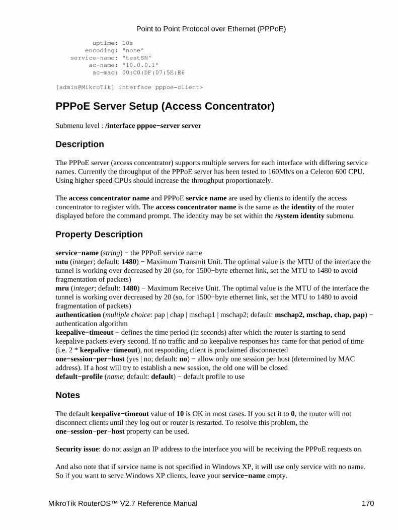
uptime: 10s encoding: "none" service−name: "testSN" ac−name: "10.0.0.1" ac−mac: 00:C0:DF:07:5E:E6
[admin@MikroTik] interface pppoe−client>
PPPoE Server Setup (Access Concentrator)
Submenu level : /interface pppoe−server server
Description
The PPPoE server (access concentrator) supports multiple servers for each interface with differing servicenames. Currently the throughput of the PPPoE server has been tested to 160Mb/s on a Celeron 600 CPU.Using higher speed CPUs should increase the throughput proportionately.
The access concentrator name and PPPoE service name are used by clients to identify the accessconcentrator to register with. The access concentrator name is the same as the identity of the routerdisplayed before the command prompt. The identity may be set within the /system identity submenu.
Property Description
service−name (string) − the PPPoE service namemtu (integer; default: 1480) − Maximum Transmit Unit. The optimal value is the MTU of the interface thetunnel is working over decreased by 20 (so, for 1500−byte ethernet link, set the MTU to 1480 to avoidfragmentation of packets)mru (integer; default: 1480) − Maximum Receive Unit. The optimal value is the MTU of the interface thetunnel is working over decreased by 20 (so, for 1500−byte ethernet link, set the MTU to 1480 to avoidfragmentation of packets)authentication (multiple choice: pap | chap | mschap1 | mschap2; default: mschap2, mschap, chap, pap) −authentication algorithmkeepalive−timeout − defines the time period (in seconds) after which the router is starting to sendkeepalive packets every second. If no traffic and no keepalive responses has came for that period of time(i.e. 2 * keepalive−timeout), not responding client is proclaimed disconnectedone−session−per−host (yes | no; default: no) − allow only one session per host (determined by MACaddress). If a host will try to establish a new session, the old one will be closeddefault−profile (name; default: default) − default profile to use
Notes
The default keepalive−timeout value of 10 is OK in most cases. If you set it to 0, the router will notdisconnect clients until they log out or router is restarted. To resolve this problem, theone−session−per−host property can be used.
Security issue: do not assign an IP address to the interface you will be receiving the PPPoE requests on.
And also note that if service name is not specified in Windows XP, it will use only service with no name.So if you want to serve Windows XP clients, leave your service−name empty.
Point to Point Protocol over Ethernet (PPPoE)
MikroTik RouterOS™ V2.7 Reference Manual 170
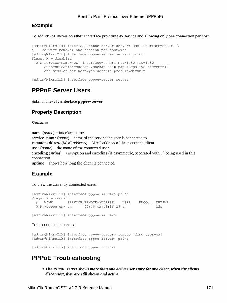
Example
To add PPPoE server on ether1 interface providing ex service and allowing only one connection per host:
[admin@MikroTik] interface pppoe−server server> add interface=ether1 \\... service−name=ex one−session−per−host=yes[admin@MikroTik] interface pppoe−server server> printFlags: X − disabled 0 X service−name="ex" interface=ether1 mtu=1480 mru=1480 authentication=mschap2,mschap,chap,pap keepalive−timeout=10 one−session−per−host=yes default−profile=default
[admin@MikroTik] interface pppoe−server server>
PPPoE Server Users
Submenu level : /interface pppoe−server
Property Description
Statistics:
name (name) − interface nameservice−name (name) − name of the service the user is connected toremote−address (MAC address) − MAC address of the connected clientuser (name) − the name of the connected userencoding (string) − encryption and encoding (if asymmetric, separated with '/') being used in thisconnectionuptime − shows how long the client is connected
Example
To view the currently connected users:
[admin@MikroTik] interface pppoe−server> printFlags: R − running # NAME SERVICE REMOTE−ADDRESS USER ENCO... UPTIME 0 R <pppoe−ex> ex 00:C0:CA:16:16:A5 ex 12s
[admin@MikroTik] interface pppoe−server>
To disconnect the user ex:
[admin@MikroTik] interface pppoe−server> remove [find user=ex][admin@MikroTik] interface pppoe−server> print
[admin@MikroTik] interface pppoe−server>
PPPoE Troubleshooting
The PPPoE server shows more than one active user entry for one client, when the clientsdisconnect, they are still shown and active
•
Point to Point Protocol over Ethernet (PPPoE)
MikroTik RouterOS™ V2.7 Reference Manual 171
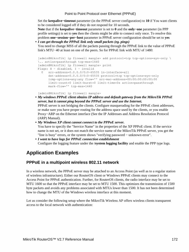
Set the keepalive−timeout parameter (in the PPPoE server configuration) to 10 if You want clientsto be considered logged off if they do not respond for 10 seconds.Note that if the keepalive−timeout parameter is set to 0 and the only−one parameter (in PPPprofile settings) is set to yes then the clients might be able to connect only once. To resolve thisproblem one−session−per−host parameter in PPPoE server configuration should be set to yesI can get through the PPPoE link only small packets (eg. pings)You need to change MSS of all the packets passing through the PPPoE link to the value of PPPoElink's MTU−40 at least on one of the peers. So for PPPoE link with MTU of 1480:
[admin@MikroTik] ip firewall mangle> add protocol=tcp tcp−options=syn−only \\.. action=passthrough tcp−mss=1440[admin@MikroTik] ip firewall mangle> printFlags: X − disabled, I − invalid 0 src−address=0.0.0.0/0:0−65535 in−interface=all dst−address=0.0.0.0/0:0−65535 protocol=tcp tcp−options=syn−only icmp−options=any:any flow="" src−mac−address=00:00:00:00:00:00 limit−count=0 limit−burst=0 limit−time=0s action=passthrough mark−flow="" tcp−mss=1440
[admin@MikroTik] ip firewall mangle>
•
My windows PPPoE client obtains IP address and default gateway from the MikroTik PPPoEserver, but it cannot ping beyond the PPPoE server and use the Internet.PPPoE server is not bridging the clients. Configure masquerading for the PPPoE client addresses,or make sure you have proper routing for the address space used by the clients, or you enableProxy−ARP on the Ethernet interface (See the IP Addresses and Address Resolution Protocol(ARP) Manual).
•
My Windows XP client cannot connect to the PPPoE server.You have to specify the "Service Name" in the properties of the XP PPPoE client. If the servicename is not set, or it does not match the service name of the MikroTik PPPoE server, you get the"line is busy" errors, or the system shows "verifying password − unknown error".
•
I want to have logs for PPPoE connection establishmentConfigure the logging feature under the /system logging facility and enable the PPP type logs.
•
Application Examples
PPPoE in a multipoint wireless 802.11 network
In a wireless network, the PPPoE server may be attached to an Access Point (as well as to a regular stationof wireless infrastructure). Either our RouterOS client or Windows PPPoE clients may connect to theAccess Point for PPPoE authentication. Further, for RouterOS clients, the radio interface may be set toMTU 1600 so that the PPPoE interface may be set to MTU 1500. This optimizes the transmission of 1500byte packets and avoids any problems associated with MTUs lower than 1500. It has not been determinedhow to change the MTU of the Windows wireless interface at this moment.
Let us consider the following setup where the MikroTik Wireless AP offers wireless clients transparentaccess to the local network with authentication:
Point to Point Protocol over Ethernet (PPPoE)
MikroTik RouterOS™ V2.7 Reference Manual 172
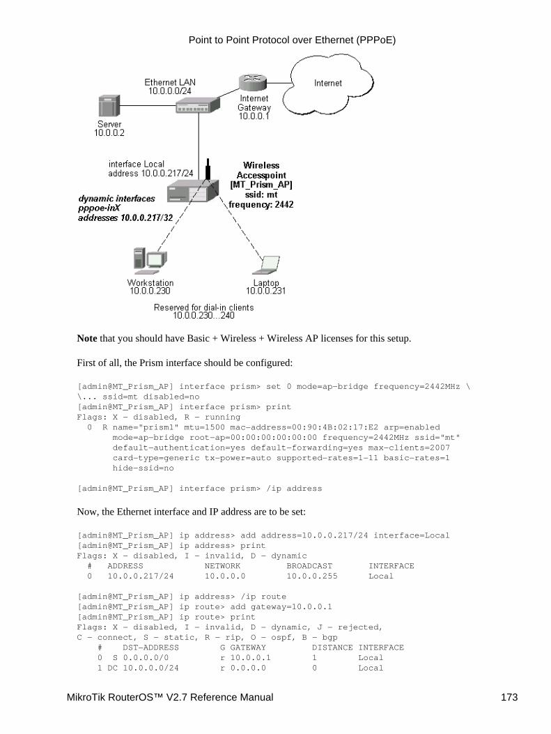
Note that you should have Basic + Wireless + Wireless AP licenses for this setup.
First of all, the Prism interface should be configured:
[admin@MT_Prism_AP] interface prism> set 0 mode=ap−bridge frequency=2442MHz \\... ssid=mt disabled=no[admin@MT_Prism_AP] interface prism> printFlags: X − disabled, R − running 0 R name="prism1" mtu=1500 mac−address=00:90:4B:02:17:E2 arp=enabled mode=ap−bridge root−ap=00:00:00:00:00:00 frequency=2442MHz ssid="mt" default−authentication=yes default−forwarding=yes max−clients=2007 card−type=generic tx−power=auto supported−rates=1−11 basic−rates=1 hide−ssid=no
[admin@MT_Prism_AP] interface prism> /ip address
Now, the Ethernet interface and IP address are to be set:
[admin@MT_Prism_AP] ip address> add address=10.0.0.217/24 interface=Local[admin@MT_Prism_AP] ip address> printFlags: X − disabled, I − invalid, D − dynamic # ADDRESS NETWORK BROADCAST INTERFACE 0 10.0.0.217/24 10.0.0.0 10.0.0.255 Local
[admin@MT_Prism_AP] ip address> /ip route[admin@MT_Prism_AP] ip route> add gateway=10.0.0.1[admin@MT_Prism_AP] ip route> printFlags: X − disabled, I − invalid, D − dynamic, J − rejected,C − connect, S − static, R − rip, O − ospf, B − bgp # DST−ADDRESS G GATEWAY DISTANCE INTERFACE 0 S 0.0.0.0/0 r 10.0.0.1 1 Local 1 DC 10.0.0.0/24 r 0.0.0.0 0 Local
Point to Point Protocol over Ethernet (PPPoE)
MikroTik RouterOS™ V2.7 Reference Manual 173
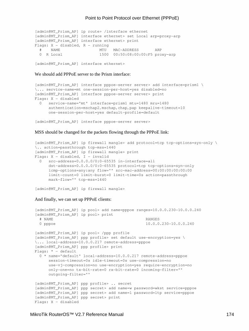
[admin@MT_Prism_AP] ip route> /interface ethernet[admin@MT_Prism_AP] interface ethernet> set Local arp=proxy−arp[admin@MT_Prism_AP] interface ethernet> printFlags: X − disabled, R − running # NAME MTU MAC−ADDRESS ARP 0 R Local 1500 00:50:08:00:00:F5 proxy−arp
[admin@MT_Prism_AP] interface ethernet>
We should add PPPoE server to the Prism interface:
[admin@MT_Prism_AP] interface pppoe−server server> add interface=prism1 \\... service−name=mt one−session−per−host=yes disabled=no[admin@MT_Prism_AP] interface pppoe−server server> printFlags: X − disabled 0 service−name="mt" interface=prism1 mtu=1480 mru=1480 authentication=mschap2,mschap,chap,pap keepalive−timeout=10 one−session−per−host=yes default−profile=default
[admin@MT_Prism_AP] interface pppoe−server server>
MSS should be changed for the packets flowing through the PPPoE link:
[admin@MT_Prism_AP] ip firewall mangle> add protocol=tcp tcp−options=syn−only \\.. action=passthrough tcp−mss=1440[admin@MT_Prism_AP] ip firewall mangle> printFlags: X − disabled, I − invalid 0 src−address=0.0.0.0/0:0−65535 in−interface=all dst−address=0.0.0.0/0:0−65535 protocol=tcp tcp−options=syn−only icmp−options=any:any flow="" src−mac−address=00:00:00:00:00:00 limit−count=0 limit−burst=0 limit−time=0s action=passthrough mark−flow="" tcp−mss=1440
[admin@MT_Prism_AP] ip firewall mangle>
And finally, we can set up PPPoE clients:
[admin@MT_Prism_AP] ip pool> add name=pppoe ranges=10.0.0.230−10.0.0.240[admin@MT_Prism_AP] ip pool> print # NAME RANGES 0 pppoe 10.0.0.230−10.0.0.240
[admin@MT_Prism_AP] ip pool> /ppp profile[admin@MT_Prism_AP] ppp profile> set default use−encryption=yes \\... local−address=10.0.0.217 remote−address=pppoe[admin@MT_Prism_AP] ppp profile> printFlags: * − default 0 * name="default" local−address=10.0.0.217 remote−address=pppoe session−timeout=0s idle−timeout=0s use−compression=no use−vj−compression=no use−encryption=yes require−encryption=no only−one=no tx−bit−rate=0 rx−bit−rate=0 incoming−filter="" outgoing−filter=""
[admin@MT_Prism_AP] ppp profile> .. secret[admin@MT_Prism_AP] ppp secret> add name=w password=wkst service=pppoe[admin@MT_Prism_AP] ppp secret> add name=l password=ltp service=pppoe[admin@MT_Prism_AP] ppp secret> printFlags: X − disabled
Point to Point Protocol over Ethernet (PPPoE)
MikroTik RouterOS™ V2.7 Reference Manual 174
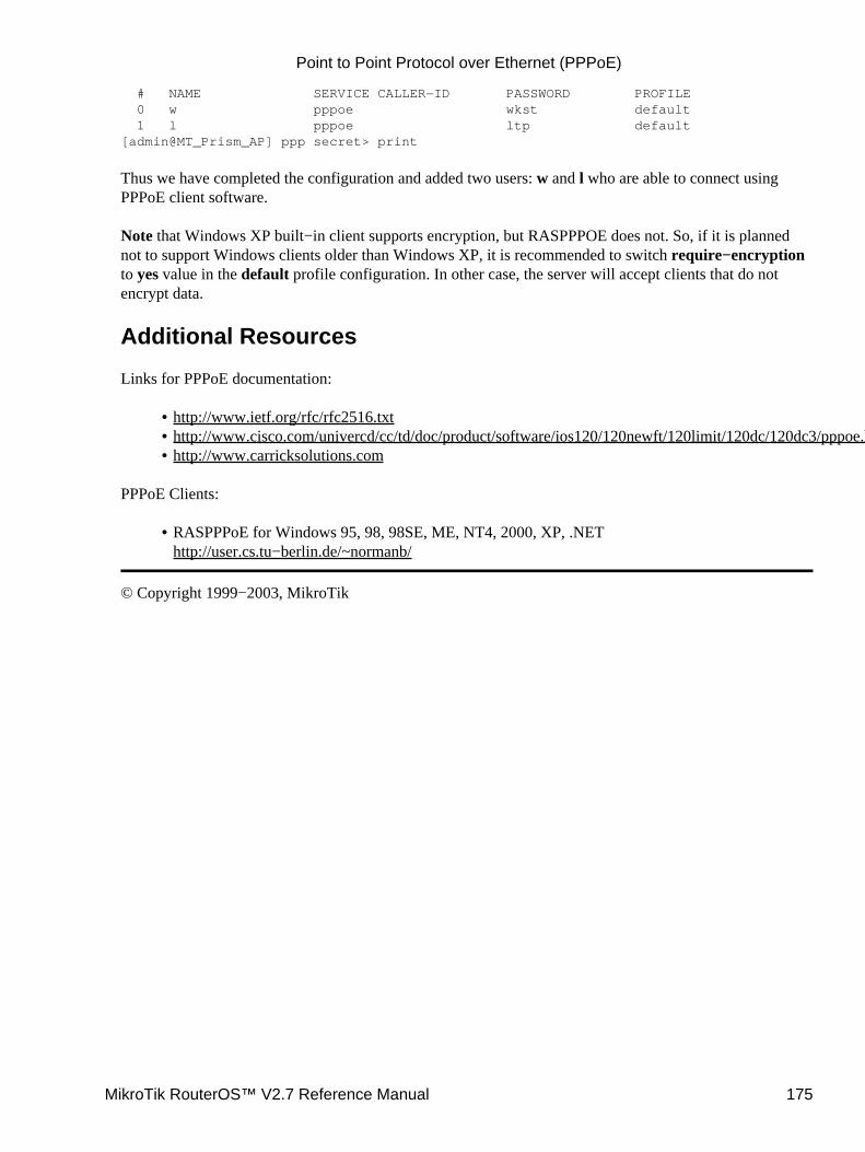
# NAME SERVICE CALLER−ID PASSWORD PROFILE 0 w pppoe wkst default 1 l pppoe ltp default[admin@MT_Prism_AP] ppp secret> print
Thus we have completed the configuration and added two users: w and l who are able to connect usingPPPoE client software.
Note that Windows XP built−in client supports encryption, but RASPPPOE does not. So, if it is plannednot to support Windows clients older than Windows XP, it is recommended to switch require−encryptionto yes value in the default profile configuration. In other case, the server will accept clients that do notencrypt data.
Additional Resources
Links for PPPoE documentation:
http://www.ietf.org/rfc/rfc2516.txt• http://www.cisco.com/univercd/cc/td/doc/product/software/ios120/120newft/120limit/120dc/120dc3/pppoe.htm• http://www.carricksolutions.com•
PPPoE Clients:
RASPPPoE for Windows 95, 98, 98SE, ME, NT4, 2000, XP, .NEThttp://user.cs.tu−berlin.de/~normanb/
•
© Copyright 1999−2003, MikroTik
Point to Point Protocol over Ethernet (PPPoE)
MikroTik RouterOS™ V2.7 Reference Manual 175

Point to Point Tunnel Protocol (PPTP)Document revision 1.8 (27−Mar−2003)This document applies to MikroTik RouterOS v2.7
Table of Contents
Table of Contents• Summary• Specifications• Related Documents• Description• PPTP Client Setup
Property Description♦ Example♦
•
Monitoring PPTP ClientProperty Description♦ Example♦
•
PPTP Server SetupDescription♦ Property Description♦ Example♦
•
PPTP Server UsersDescription♦ Property Description♦ Example♦
•
PPTP Router−to−Router Secure Tunnel Example• Connecting a Remote Client via PPTP Tunnel• PPTP Setup for Windows
Sample instructions for PPTP (VPN) installation and client setup – Windows 98se♦ •
Troubleshooting• Additional Resources•
Summary
PPTP (Point to Point Tunnel Protocol) supports encrypted tunnels over IP. The MikroTik RouterOSimplementation includes support fot PPTP client and server.
General applications of PPTP tunnels:
For secure router−to−router tunnels over the Internet• To link (bridge) local Intranets or LANs (when EoIP is also used)• For mobile or remote clients to remotely access an Intranet/LAN of a company (see PPTP setup forWindows for more information)
•
Each PPTP connection is composed of a server and a client. The MikroTik RouterOS may function as a serveror client – or, for various configurations, it may be the server for some connections and client for otherconnections. For example, the client created below could connect to a Windows 2000 server, anotherMikroTik Router, or another router which supports a PPTP server.
MikroTik RouterOS™ V2.7 Reference Manual 176
Specifications
Packages required : pppLicense required : Basic (DEMO license is limited to 4 tunnels)Home menu level : /interface pptp−server, /interface pptp−clientProtocols utilized : PPTP (RFC2637)Hardware usage: not significant
Related Documents
Software Package Installation and UpgradingIP Addresses and Address Resolution Protocol (ARP)Authentication, Authorization and AccountingEthernet over IP (EoIP) Tunnel Interface
Description
PPTP is a secure tunnel for transporting IP traffic using PPP. PPTP encapsulates PPP in virtual lines that runover IP. PPTP incorporates PPP and MPPE (Microsoft Point to Point Encryption) to make encrypted links.The purpose of this protocol is to make well−managed secure connections between routers as well as betweenrouters and PPTP clients (clients are available for and/or included in almost all OSs including Windows).
PPTP includes PPP authentication and accounting for each PPTP connection. Full authentication andaccounting of each connection may be done through a RADIUS client or locally.
MPPE 40bit RC4 and MPPE 128bit RC4 encryption are supported.
PPTP traffic uses TCP port 1723 and IP protocol GRE (Generic Routing Encapsulation, IP protocol ID 47), asassigned by the Internet Assigned Numbers Authority (IANA). PPTP can be used with most firewalls androuters by enabling traffic destined for TCP port 1723 and protocol 47 traffic to be routed through the firewallor router.
PPTP connections may be limited or impossible to setup though a masqueraded/NAT IP connection. Pleasesee the Microsoft and RFC links at the end of this section for more information.
PPTP Client Setup
Submenu level : /interface pptp−client
Property Description
name (name; default: pptp−out1) − interface name for referencemtu (integer; default: 1460) − Maximum Transmit Unit. The optimal value is the MTU of the interface thetunnel is working over decreased by 40 (so, for 1500−byte ethernet link, set the MTU to 1460 to avoidfragmentation of packets)mru (integer; default: 1460) − Maximum Receive Unit. The optimal value is the MTU of the interface thetunnel is working over decreased by 40 (so, for 1500−byte ethernet link, set the MRU to 1460 to avoidfragmentation of packets)connect−to (IP address)− the IP address of the PPTP server to connect to
Point to Point Tunnel Protocol (PPTP)
MikroTik RouterOS™ V2.7 Reference Manual 177
user (string)− user name to use when logging on to the remote serverpassword (string; default: "")− user password to use when logging to the remote serverprofile (name; default: default) − profile to use when connecting to the remote serveradd−default−route (yes | no; default: no) − whether to use the server which this client is connected to as itsdefault router (gateway)
Example
To set up PPTP client named test2 using username john with password john to connect to the 10.1.1.12 PPTPserver and use it as the default gateway:
[admin@MikroTik] interface pptp−client> add name=test2 connect−to=10.1.1.12 \\... user=john add−default−route=yes password=john[admin@MikroTik] interface pptp−client> printFlags: X − disabled, R − running 0 X name="test2" mtu=1460 mru=1460 connect−to=10.1.1.12 user="john" password="john" profile=default add−default−route=yes
[admin@MikroTik] interface pptp−client> enable 0
Monitoring PPTP Client
Command name : /interface pptp−client monitor
Property Description
Statistics:
uptime (time) − connection time displayed in days, hours, minutes, and secondsencoding (string) − encryption and encoding (if asymmetric, separated with '/') being used in this connectionstatus (string) − status of the client:
Dialing – attempting to make a connection• Verifying password... − connection has been established to the server, password verification in progress• Connected – self−explanatory• Terminated – interface is not enabled or the other side will not establish a connection
Example
Example of an established connection:
[admin@MikroTik] interface pptp−client> monitor test2 uptime: 4h35s encoding: MPPE 128 bit, stateless status: Connected[admin@MikroTik] interface pptp−client>
PPTP Server Setup
Submenu level : /interface pptp−server server
[admin@MikroTik] interface pptp−server server> print
•
Point to Point Tunnel Protocol (PPTP)
MikroTik RouterOS™ V2.7 Reference Manual 178
enabled: no mtu: 1460 mru: 1460 authentication: mschap2 default−profile: default[admin@MikroTik] interface pptp−server server>
Description
The PPTP server supports unlimited connections from clients. For each current connection, a dynamicinterface is created.
Property Description
enabled (yes | no; default: no) − defines whether PPTP server is enabled or notmtu (integer; default: 1460) − Maximum Transmit Unit. The optimal value is the MTU of the interface thetunnel is working over decreased by 40 (so, for 1500−byte ethernet link, set the MTU to 1460 to avoidfragmentation of packets)mru (integer; default: 1460) − Maximum Receive Unit. The optimal value is the MTU of the interface thetunnel is working over decreased by 40 (so, for 1500−byte ethernet link, set the MTU to 1460 to avoidfragmentation of packets)authentication (multiple choice: pap | chap | mschap1 | mschap2; default: mschap2) − authenticationalgorithmdefault−profile (name; default: default) − default profile to use
Example
To enable PPTP server:
[admin@MikroTik] interface pptp−server server> set enabled=yes[admin@MikroTik] interface pptp−server server> print enabled: yes mtu: 1460 mru: 1460 authentication: mschap2 default−profile: default[admin@MikroTik] interface pptp−server server>
PPTP Server Users
Submenu level : /interface pptp−server
Description
There are two types of items in PPTP server configuration − static users and dynamic connections. Adynamic connection can be established if the user database or the default−profile has its local−addressand remote−address set correctly. When static users are added, the default profile may be left with itsdefault values and only P2P user (in /ppp secret) should be configured. Note that in both cases P2P usersmust be configured properly.
Point to Point Tunnel Protocol (PPTP)
MikroTik RouterOS™ V2.7 Reference Manual 179
Property Description
name − interface nameuser − the name of the user that is configured statically or added dynamically
Statistics:
mtu − shows (cannot be set here) client's MTUclient−address − shows (cannot be set here) the IP of the connected clientuptime − shows how long the client is connectedencoding (string) − encryption and encoding (if asymmetric, separated with '/') being used in thisconnection
Example
To add a static entry for ex1 user:
[admin@MikroTik] interface pptp−server> add user=ex1[admin@MikroTik] interface pptp−server> printFlags: X − disabled, D − dynamic, R − running # NAME USER MTU CLIENT−ADDRESS UPTIME ENC... 0 DR <pptp−ex> ex 1460 10.0.0.202 6m32s none 1 pptp−in1 ex1[admin@MikroTik] interface pptp−server>
In this example an already connected user ex is shown besides the one we just added.
PPTP Router−to−Router Secure Tunnel Example
The following is an example of connecting two Intranets using an encrypted PPTP tunnel over the Internet.
Point to Point Tunnel Protocol (PPTP)
MikroTik RouterOS™ V2.7 Reference Manual 180
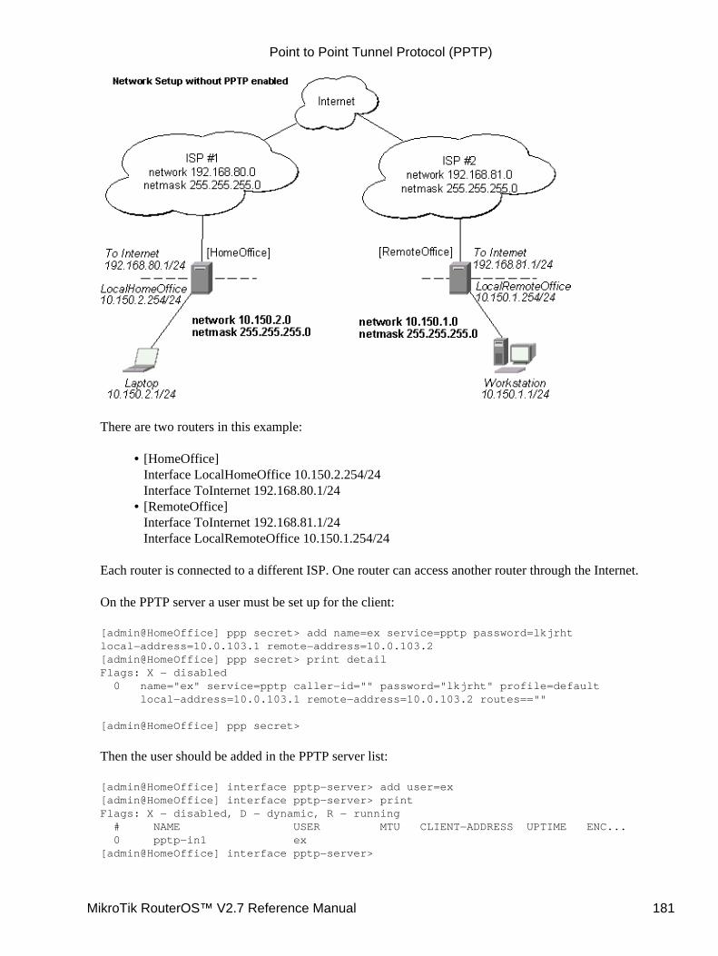
There are two routers in this example:
[HomeOffice]Interface LocalHomeOffice 10.150.2.254/24Interface ToInternet 192.168.80.1/24
•
[RemoteOffice]Interface ToInternet 192.168.81.1/24Interface LocalRemoteOffice 10.150.1.254/24
•
Each router is connected to a different ISP. One router can access another router through the Internet.
On the PPTP server a user must be set up for the client:
[admin@HomeOffice] ppp secret> add name=ex service=pptp password=lkjrhtlocal−address=10.0.103.1 remote−address=10.0.103.2[admin@HomeOffice] ppp secret> print detailFlags: X − disabled 0 name="ex" service=pptp caller−id="" password="lkjrht" profile=default local−address=10.0.103.1 remote−address=10.0.103.2 routes==""
[admin@HomeOffice] ppp secret>
Then the user should be added in the PPTP server list:
[admin@HomeOffice] interface pptp−server> add user=ex[admin@HomeOffice] interface pptp−server> printFlags: X − disabled, D − dynamic, R − running # NAME USER MTU CLIENT−ADDRESS UPTIME ENC... 0 pptp−in1 ex[admin@HomeOffice] interface pptp−server>
Point to Point Tunnel Protocol (PPTP)
MikroTik RouterOS™ V2.7 Reference Manual 181
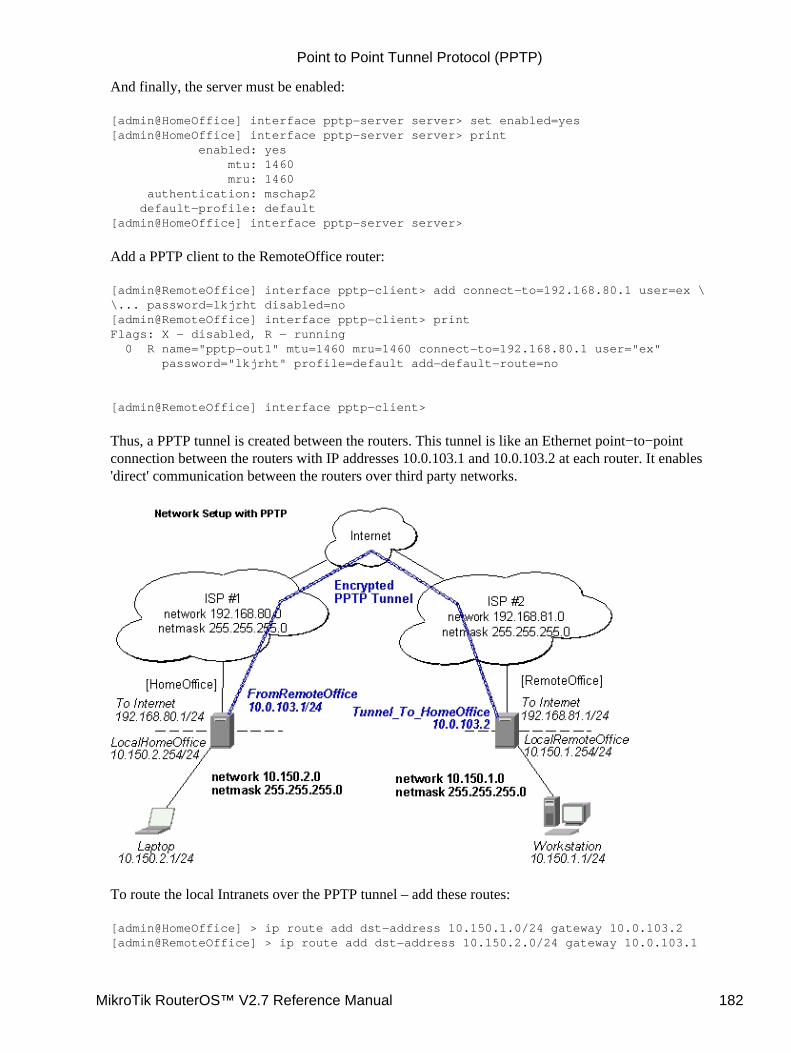
And finally, the server must be enabled:
[admin@HomeOffice] interface pptp−server server> set enabled=yes[admin@HomeOffice] interface pptp−server server> print enabled: yes mtu: 1460 mru: 1460 authentication: mschap2 default−profile: default[admin@HomeOffice] interface pptp−server server>
Add a PPTP client to the RemoteOffice router:
[admin@RemoteOffice] interface pptp−client> add connect−to=192.168.80.1 user=ex \\... password=lkjrht disabled=no[admin@RemoteOffice] interface pptp−client> printFlags: X − disabled, R − running 0 R name="pptp−out1" mtu=1460 mru=1460 connect−to=192.168.80.1 user="ex" password="lkjrht" profile=default add−default−route=no
[admin@RemoteOffice] interface pptp−client>
Thus, a PPTP tunnel is created between the routers. This tunnel is like an Ethernet point−to−pointconnection between the routers with IP addresses 10.0.103.1 and 10.0.103.2 at each router. It enables'direct' communication between the routers over third party networks.
To route the local Intranets over the PPTP tunnel – add these routes:
[admin@HomeOffice] > ip route add dst−address 10.150.1.0/24 gateway 10.0.103.2[admin@RemoteOffice] > ip route add dst−address 10.150.2.0/24 gateway 10.0.103.1
Point to Point Tunnel Protocol (PPTP)
MikroTik RouterOS™ V2.7 Reference Manual 182
On the PPTP server it can alternatively be done using routes parameter of the user configuration:
[admin@HomeOffice] ppp secret> print detailFlags: X − disabled 0 name="ex" service=pptp caller−id="" password="lkjrht" profile=default local−address=10.0.103.1 remote−address=10.0.103.2 routes==""
[admin@HomeOffice] ppp secret> set 0 routes="10.150.1.0/24 10.0.103.2 1"[admin@HomeOffice] ppp secret> print detailFlags: X − disabled 0 name="ex" service=pptp caller−id="" password="lkjrht" profile=default local−address=10.0.103.1 remote−address=10.0.103.2 routes="10.150.1.0/24 10.0.103.2 1"
[admin@HomeOffice] ppp secret>
Test the PPTP tunnel connection:
[admin@RemoteOffice]> /ping 10.0.103.110.0.103.1 pong: ttl=255 time=3 ms10.0.103.1 pong: ttl=255 time=3 ms10.0.103.1 pong: ttl=255 time=3 msping interrupted3 packets transmitted, 3 packets received, 0% packet lossround−trip min/avg/max = 3/3.0/3 ms
Test the connection through the PPTP tunnel to the LocalHomeOffice interface:
[admin@RemoteOffice]> /ping 10.150.2.25410.150.2.254 pong: ttl=255 time=3 ms10.150.2.254 pong: ttl=255 time=3 ms10.150.2.254 pong: ttl=255 time=3 msping interrupted3 packets transmitted, 3 packets received, 0% packet lossround−trip min/avg/max = 3/3.0/3 ms
To bridge a LAN over this secure tunnel, please see the example in the 'EoIP' section of the manual. To setthe maximum speed for traffic over this tunnel, please consult the 'Queues' section.
Connecting a Remote Client via PPTP Tunnel
The following example shows how to connect a computer to a remote office network over PPTP encryptedtunnel giving that computer an IP address from the same network as the remote office has (without need ofbridging over eoip tunnels)
Please, consult the respective manual on how to set up a PPTP client with the software You are using.
Point to Point Tunnel Protocol (PPTP)
MikroTik RouterOS™ V2.7 Reference Manual 183
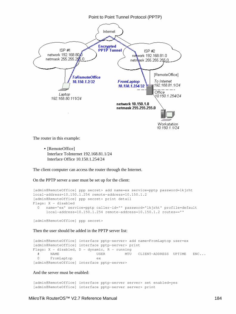
The router in this example:
[RemoteOffice]Interface ToInternet 192.168.81.1/24Interface Office 10.150.1.254/24
•
The client computer can access the router through the Internet.
On the PPTP server a user must be set up for the client:
[admin@RemoteOffice] ppp secret> add name=ex service=pptp password=lkjrhtlocal−address=10.150.1.254 remote−address=10.150.1.2[admin@RemoteOffice] ppp secret> print detailFlags: X − disabled 0 name="ex" service=pptp caller−id="" password="lkjrht" profile=default local−address=10.150.1.254 remote−address=10.150.1.2 routes==""
[admin@RemoteOffice] ppp secret>
Then the user should be added in the PPTP server list:
[admin@RemoteOffice] interface pptp−server> add name=FromLaptop user=ex[admin@RemoteOffice] interface pptp−server> printFlags: X − disabled, D − dynamic, R − running # NAME USER MTU CLIENT−ADDRESS UPTIME ENC... 0 FromLaptop ex[admin@RemoteOffice] interface pptp−server>
And the server must be enabled:
[admin@RemoteOffice] interface pptp−server server> set enabled=yes[admin@RemoteOffice] interface pptp−server server> print
Point to Point Tunnel Protocol (PPTP)
MikroTik RouterOS™ V2.7 Reference Manual 184
enabled: yes mtu: 1460 mru: 1460 authentication: mschap2 default−profile: default[admin@RemoteOffice] interface pptp−server server>
Finally, the proxy APR must be enabled on the 'Office' interface:
[admin@RemoteOffice] interface ethernet> set Office arp=proxy−arp[admin@RemoteOffice] interface ethernet> printFlags: X − disabled, R − running # NAME MTU MAC−ADDRESS ARP 0 R ToInternet 1500 00:30:4F:0B:7B:C1 enabled 1 R Office 1500 00:30:4F:06:62:12 proxy−arp[admin@RemoteOffice] interface ethernet>
PPTP Setup for Windows
Microsoft provides PPTP client support for Windows NT, 2000, ME, 98se, and 98. Windows 98se, 2000,and ME include support in the Windows setup or automatically install PPTP. For 95, NT, and 98,installation requires a download from Microsoft. Many ISPs have made help pages to assist clients withWindows PPTP installation.
http://www.real−time.com/Customer_Support/PPTP_Config/pptp_config.htmlhttp://www.microsoft.com/windows95/downloads/contents/WUAdminTools/S_WUNetworkingTools/W95WinsockUpgrade/Default.asp
Sample instructions for PPTP (VPN) installation and client setup – Windows98se
If the VPN (PPTP) support is installed, select 'Dial−up Networking' and 'Create a new connection'. Theoption to create a 'VPN' should be selected. If there is no 'VPN' options, then follow the installationinstructions below. When asked for the 'Host name or IP address of the VPN server', type the IP address ofthe router. Double−click on the 'new' icon and type the correct user name and password (must also be in theuser database on the router or RADIUS server used for authentication).
The setup of the connections takes nine seconds after selection the 'connect' button. It is suggested that theconnection properties be edited so that 'NetBEUI', 'IPX/SPX compatible', and 'Log on to network' areunselected. The setup time for the connection will then be two seconds after the 'connect' button is selected.
To install the 'Virtual Private Networking' support for Windows 98se, go to the 'Setting' menu from themain 'Start' menu. Select 'Control Panel', select 'Add/Remove Program', select the 'Windows setup' tab,select the 'Communications' software for installation and 'Details'. Go to the bottom of the list of softwareand select 'Virtual Private Networking' to be installed.
Troubleshooting
I use firewall and I cannot establish PPTP connectionMake sure the TCP connections to port 1723 can pass through both directions between your sites.Also, IP protocol 47 should be passed through.
•
Point to Point Tunnel Protocol (PPTP)
MikroTik RouterOS™ V2.7 Reference Manual 185

Additional Resources
Links for PPTP documentation:
http://msdn.microsoft.com/library/backgrnd/html/understanding_pptp.htmhttp://support.microsoft.com/support/kb/articles/q162/8/47.asphttp://www.ietf.org/rfc/rfc2637.txt?number=2637http://www.ietf.org/rfc/rfc3078.txt?number=3078http://www.ietf.org/rfc/rfc3079.txt?number=3079
© Copyright 1999−2003, MikroTik
Point to Point Tunnel Protocol (PPTP)
MikroTik RouterOS™ V2.7 Reference Manual 186

PrismII Wireless Client and Wireless Access PointManualDocument revision 1.5 (11−Aug−2003)This document applies to the MikroTik RouterOS V2.7
Table of Contents
Table of Contents• Summary• Specifications• Related Documents• Description• Wireless Interface Configuration
Property Description♦ Notes♦ Example♦
•
Monitoring the Interface StatusProperty Description♦ Notes♦ Example♦
•
Registration TableProperty Description♦ Example♦
•
Access ListDescription♦ Property Description♦ Notes♦ Example♦
•
Network ScanDescription♦ Property Description♦ Example♦
•
Troubleshooting• Basic Configuration Examples
Station Mode ConfigurationDescription◊ Example◊
♦
Access Point Mode ConfigurationDescription◊ Example◊
♦
Registering the Access Point to another Access PointDescription◊ Example◊
♦
•
Wireless Network ApplicationsWireless Client
3rd Party Wireless AP Configuration◊ MikroTik RouterOS Wireless Client Configuration◊
♦
Wireless Access Point♦
•
MikroTik RouterOS™ V2.7 Reference Manual 187
Wireless Bridge[MT−parent] Configuration◊ [MT−child] Configuration◊
♦
Summary
The MikroTik RouterOS supports the PrismII chipset based wireless adapter cards for working both aswireless clients (station mode) and wireless access points (ap−bridge or bridge mode).
Supports event logging.
Specifications
Packages required : wirelessLicense required : 2.4GHz Wireless, 2.4GHz Wireless Access Point (optional)Home menu level : /interface prismProtocols utilized : IEEE802.11b (IEEE802.11b)Hardware usage: not significant
Related Documents
Software Package Installation and UpgradingDevice Driver ManagementIP Addresses and Address Resolution Protocol (ARP)Log Management
Description
Prism−based cards can be used in the following network roles:Wireless Client − IEEE 802.11b wireless client (station) associating with an access point. The stationmode has been tested with MikroTik RouterOS PrismII based Access Points and CISCO/Aironet WirelessEthernet Bridges and Access Points.
•
Wireless Access Point − IEEE 802.11b wireless access point (requires the 2.4GHz AP Feature License).The access point can register wireless clients. The access point mode has been tested with PrismII,CISCO/Aironet and ORiNOCO/WaveLAN clients. The PrismII Access Point interface can also registerother access points. Thus, it is possible to bridge networks over wireless links.
•
Wireless Bridge − limited version of the Access Point mode which allows only one client to be registeredbut does not require the 2.4GHz Wireless AP Feature License, only the 2.4GHz Wireless License. Thus, itis possible to create point−to−point links and bridge networks over wireless links.
Important! Prism 2.5 200mW cards require firmware 1.3.6 or lower, if you want to bridgenetworks. Please see the troubleshooting section on how to check the firmware version anddowngrade it
The MikroTik RouterOS supports as many Prism chipset based cards as many free adapter slots are thereon your system. One license is valid for all cards on your system. Note that maximal number of PCMCIAsockets is 8.
•
PrismII Wireless Client and Wireless Access Point Manual
MikroTik RouterOS™ V2.7 Reference Manual 188
Wireless Interface Configuration
Submenu level : /interface prism
Property Description
name (name; default: prism1)− interface namemtu (integer; default: 1500) − maximum transfer unitmac−address (MAC address) − MAC address of card. In AP mode this will also be BSSID of BSSarp (disabled | enabled | proxy−arp | reply−only; default: enable) − Address Resolution Protocol:disabled − the interface will not use ARP protocol• enabled − the interface will use ARP protocol• proxy−arp − the interface will be an ARP proxy (see corresponding manual)• reply−only − the interface will only reply to the requests originated to its own IP addresses, but neighbourMAC addresses will be gathered from /ip arp statically set table onlymode (station | bridge | ap−bridge; default: station) − mode of the interface:
•
station − card works as station (client) for the wireless infrastructure• bridge − card works as access point, but can register only one client or access point• ap−bridge − card works as access point, i.e., it creates wireless infrastructureroot−ap (MAC address; default: 00:00:00:00:00:00) − MAC address of the root access point to register tofrequency (2412MHz, 2417MHz ... 2472MHz; default: 2412MHz) − frequency that AP will use to createBSSssid (string; default: MikroTik) − Service Set Identifier:
•
in station mode − SSID to connect to• in AP and P2P mode − SSID to use when creating BSS (can not be left blank)default−authentication (yes | no; default: yes) − what to do with client that wants to associate, but it is notin the access−listdefault−forwarding (yes | no; default:yes) − what to do with client that wants to send packets to otherwireless clients, but it is not in the access−listmax−clients (integer:1...2007; default: 2007) − maximum number of clients (including other accesspoints), that is allowed to associate with this access pointcard−type (100mW | 200mW | 30mW | generic; default: generic)− card type used for power settingstx−power (0dBm−1mW...23dBm−200mW | auto; default: auto)− transmit power level. Has no effect ifcard type is generic
•
auto − default setting of the cardsupported−rates (1 | 1−11 | 1−2 | 1−5.5 | 11 | 2 | 2−11 | 2−5.5 | 5.5 | 5.5−11; default: 1−11) − rates at whichthis node will workbasic−rates (1 | 1−11 | 1−2 | 1−5.5 | 11 | 2 | 2−11 | 2−5.5 | 5.5 | 5.5−11; default: 1) − rates that every clientthat plans to connect to this AP should be able to work at. It is recommended to set it to 1, since not allclients might support rates 1−11hide−ssid (yes | no; default: no) − whether to hide SSID (do not broadcast SSID over the wirelessinfrastructure)
Notes
root−ap, default−authentication, default−forwarding, max−clients, basic−rates properties are used inbridge and ap−bridge modes only.
•
PrismII Wireless Client and Wireless Access Point Manual
MikroTik RouterOS™ V2.7 Reference Manual 189
Example
To enable prism1 interface to connect to the wireless infrastructure test:
[admin@MikroTik] interface prism> set prism1 disabled=no ssid=test[admin@MikroTik] interface prism> printFlags: X − disabled, R − running 0 R name="prism1" mtu=1500 mac−address=00:02:6F:01:D2:7D arp=enabled mode=station root−ap=00:00:00:00:00:00 frequency=2412MHz ssid="test" default−authentication=yes default−forwarding=yes max−clients=2007 card−type=generic tx−power=auto supported−rates=1−11 basic−rates=1 hide−ssid=no
[admin@MikroTik] interface prism>
Monitoring the Interface Status
Command name:/interface prism monitor
Property Description
Statistics:
status (searching−for−network | connected−to−ess | out−of−range) − status of the interface:searching−for−network − the card has not registered to an AP and is searching for one to register to• connected−to−ess − the card has registered to an AP• out−of−range − the card has registered to an AP, but lost the connection to itdata−rate (1Mbps | 2Mbps | 5.5Mbps | 11Mbps) − the actual data rate of the connectionssid (string)− the Service Set Identifier.bssid (MAC address) − the Basic Service Set Identifier (actually, the MAC address of the access point)signal−quality (0...92) − the signal qualitysignal−level (27...154)− the average signal levelnoise−level (−100...0) − the average noise level
Notes
The monitor command does not work, if the interface is disabled, or the mode is ap−bridge or bridge.
Example
To monitor prism1 interface:
[admin@MikroTik] interface prism> monitor prism1 status: connected−to−ess data−rate: 11Mbps ssid: "test" bssid: 00:03:2F:04:25:10 signal−quality: 92 signal−level: 54 noise−level: −99
[admin@MikroTik] interface prism>
•
PrismII Wireless Client and Wireless Access Point Manual
MikroTik RouterOS™ V2.7 Reference Manual 190
Registration Table
Submenu level : /interface prism registration−table
Property Description
Statistics: interface (name) − interface that client is registered tomac−address (MAC address) − mac address of the registered clienttype (client | local | ap | forward | parent−ap)− type of the client:client − client registered to the interface• local − client learned from bridged interface• ap − client is an access point• forward − client is forwarded from another access point• parent−ap − the access point this interface is connected toparent (MAC address) − parent access point's MAC address, if forwarded from another access pointpackets (integer) − number of received and sent packetsbytes (integer) − number of received and sent bytessignal−level (min/average/max: 0...92) − min/average/max signal levelnoise−level (min/average/max: −100...0) − min/average/max noise leveldata−rate (min/average/max: (1 | 2 | 5.5 | 11)) − min/average/max receive data ratetx−rate (1 | 2 | 5.5 | 11) − transmit data ratelast−update (time) − time since the last updateuptime (time) − time the client is associated with the access point
Example
To see registration table showing all clients currently associated with the access point:
[admin@MikroTik] interface prism> registration−table print # INTERFACE MAC−ADDRESS TYPE PARENT 0 prism1 00:07:EB:30:E7:DA client 1 prism1 00:40:96:29:2F:80 client[admin@MikroTik] interface prism>
To get additional statistics:
[admin@MikroTik] interface prism> registration−table print stats 0 interface=prism1 mac−address=00:07:EB:30:E7:DA type=client packets=0,19 bytes=0,482 signal−level=69/75/138 noise−level=0/0/0 data−rate=10/110/110 tx−rate=10 last−update=00:00:00.840 uptime=00:02:59.180
1 interface=prism1 mac−address=00:40:96:29:2F:80 type=client packets=0,14 bytes=0,196 signal−level=66/72/84 noise−level=0/0/0 data−rate=10/10/10 tx−rate=10 last−update=00:00:08.380 uptime=00:02:42.220
[admin@MikroTik] interface prism>
Access List
Submenu level : /interface prism access−list
•
PrismII Wireless Client and Wireless Access Point Manual
MikroTik RouterOS™ V2.7 Reference Manual 191
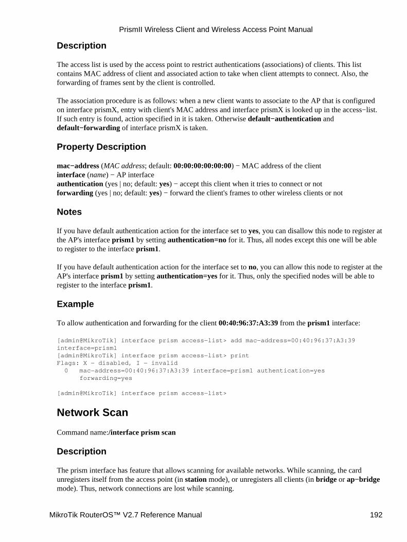
Description
The access list is used by the access point to restrict authentications (associations) of clients. This listcontains MAC address of client and associated action to take when client attempts to connect. Also, theforwarding of frames sent by the client is controlled.
The association procedure is as follows: when a new client wants to associate to the AP that is configuredon interface prismX, entry with client's MAC address and interface prismX is looked up in the access−list.If such entry is found, action specified in it is taken. Otherwise default−authentication anddefault−forwarding of interface prismX is taken.
Property Description
mac−address (MAC address; default: 00:00:00:00:00:00) − MAC address of the clientinterface (name) − AP interfaceauthentication (yes | no; default: yes) − accept this client when it tries to connect or notforwarding (yes | no; default: yes) − forward the client's frames to other wireless clients or not
Notes
If you have default authentication action for the interface set to yes, you can disallow this node to register atthe AP's interface prism1 by setting authentication=no for it. Thus, all nodes except this one will be ableto register to the interface prism1.
If you have default authentication action for the interface set to no, you can allow this node to register at theAP's interface prism1 by setting authentication=yes for it. Thus, only the specified nodes will be able toregister to the interface prism1.
Example
To allow authentication and forwarding for the client 00:40:96:37:A3:39 from the prism1 interface:
[admin@MikroTik] interface prism access−list> add mac−address=00:40:96:37:A3:39interface=prism1[admin@MikroTik] interface prism access−list> printFlags: X − disabled, I − invalid 0 mac−address=00:40:96:37:A3:39 interface=prism1 authentication=yes forwarding=yes
[admin@MikroTik] interface prism access−list>
Network Scan
Command name:/interface prism scan
Description
The prism interface has feature that allows scanning for available networks. While scanning, the cardunregisters itself from the access point (in station mode), or unregisters all clients (in bridge or ap−bridgemode). Thus, network connections are lost while scanning.
PrismII Wireless Client and Wireless Access Point Manual
MikroTik RouterOS™ V2.7 Reference Manual 192
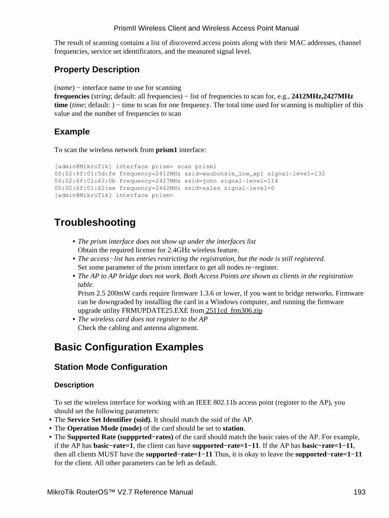
The result of scanning contains a list of discovered access points along with their MAC addresses, channelfrequencies, service set identificators, and the measured signal level.
Property Description
(name) − interface name to use for scanningfrequencies (string; default: all frequencies) − list of frequencies to scan for, e.g., 2412MHz,2427MHztime (time; default: ) − time to scan for one frequency. The total time used for scanning is multiplier of thisvalue and the number of frequencies to scan
Example
To scan the wireless network from prism1 interface:
[admin@MikroTik] interface prism> scan prism100:02:6f:01:5d:fe frequency=2412MHz ssid=waubonsie_low_ap1 signal−level=13200:02:6f:01:63:0b frequency=2427MHz ssid=john signal−level=11400:02:6f:01:62:ee frequency=2462MHz ssid=sales signal−level=0[admin@MikroTik] interface prism>
Troubleshooting
The prism interface does not show up under the interfaces listObtain the required license for 2.4GHz wireless feature.
•
The access−list has entries restricting the registration, but the node is still registered.Set some parameter of the prism interface to get all nodes re−register.
•
The AP to AP bridge does not work. Both Access Points are shown as clients in the registrationtable.Prism 2.5 200mW cards require firmware 1.3.6 or lower, if you want to bridge networks. Firmwarecan be downgraded by installing the card in a Windows computer, and running the firmwareupgrade utility FRMUPDATE25.EXE from 2511cd_frm306.zip
•
The wireless card does not register to the APCheck the cabling and antenna alignment.
•
Basic Configuration Examples
Station Mode Configuration
Description
To set the wireless interface for working with an IEEE 802.11b access point (register to the AP), youshould set the following parameters:The Service Set Identifier (ssid). It should match the ssid of the AP.• The Operation Mode (mode) of the card should be set to station.• The Supported Rate (suppprted−rates) of the card should match the basic rates of the AP. For example,if the AP has basic−rate=1, the client can have supported−rate=1−11. If the AP has basic−rate=1−11,then all clients MUST have the supported−rate=1−11 Thus, it is okay to leave the supported−rate=1−11for the client. All other parameters can be left as default.
•
PrismII Wireless Client and Wireless Access Point Manual
MikroTik RouterOS™ V2.7 Reference Manual 193
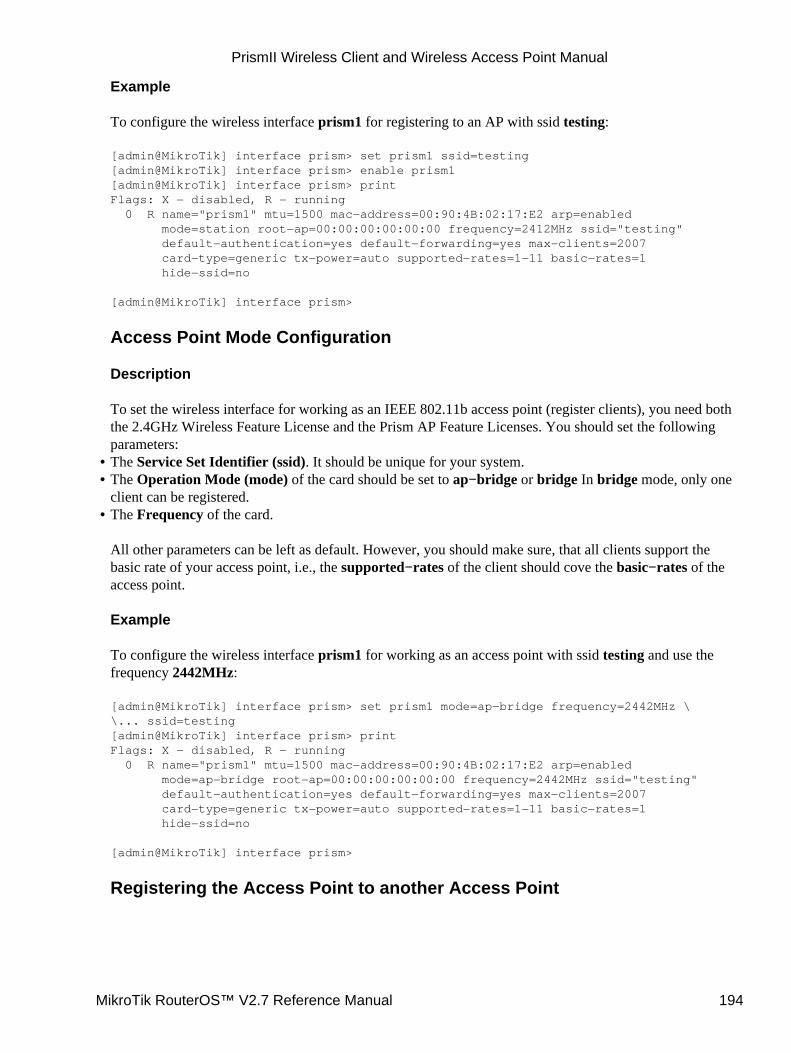
Example
To configure the wireless interface prism1 for registering to an AP with ssid testing:
[admin@MikroTik] interface prism> set prism1 ssid=testing[admin@MikroTik] interface prism> enable prism1[admin@MikroTik] interface prism> printFlags: X − disabled, R − running 0 R name="prism1" mtu=1500 mac−address=00:90:4B:02:17:E2 arp=enabled mode=station root−ap=00:00:00:00:00:00 frequency=2412MHz ssid="testing" default−authentication=yes default−forwarding=yes max−clients=2007 card−type=generic tx−power=auto supported−rates=1−11 basic−rates=1 hide−ssid=no
[admin@MikroTik] interface prism>
Access Point Mode Configuration
Description
To set the wireless interface for working as an IEEE 802.11b access point (register clients), you need boththe 2.4GHz Wireless Feature License and the Prism AP Feature Licenses. You should set the followingparameters:The Service Set Identifier (ssid). It should be unique for your system.• The Operation Mode (mode) of the card should be set to ap−bridge or bridge In bridge mode, only oneclient can be registered.
•
The Frequency of the card.
All other parameters can be left as default. However, you should make sure, that all clients support thebasic rate of your access point, i.e., the supported−rates of the client should cove the basic−rates of theaccess point.
Example
To configure the wireless interface prism1 for working as an access point with ssid testing and use thefrequency 2442MHz:
[admin@MikroTik] interface prism> set prism1 mode=ap−bridge frequency=2442MHz \\... ssid=testing[admin@MikroTik] interface prism> printFlags: X − disabled, R − running 0 R name="prism1" mtu=1500 mac−address=00:90:4B:02:17:E2 arp=enabled mode=ap−bridge root−ap=00:00:00:00:00:00 frequency=2442MHz ssid="testing" default−authentication=yes default−forwarding=yes max−clients=2007 card−type=generic tx−power=auto supported−rates=1−11 basic−rates=1 hide−ssid=no
[admin@MikroTik] interface prism>
Registering the Access Point to another Access Point
•
PrismII Wireless Client and Wireless Access Point Manual
MikroTik RouterOS™ V2.7 Reference Manual 194
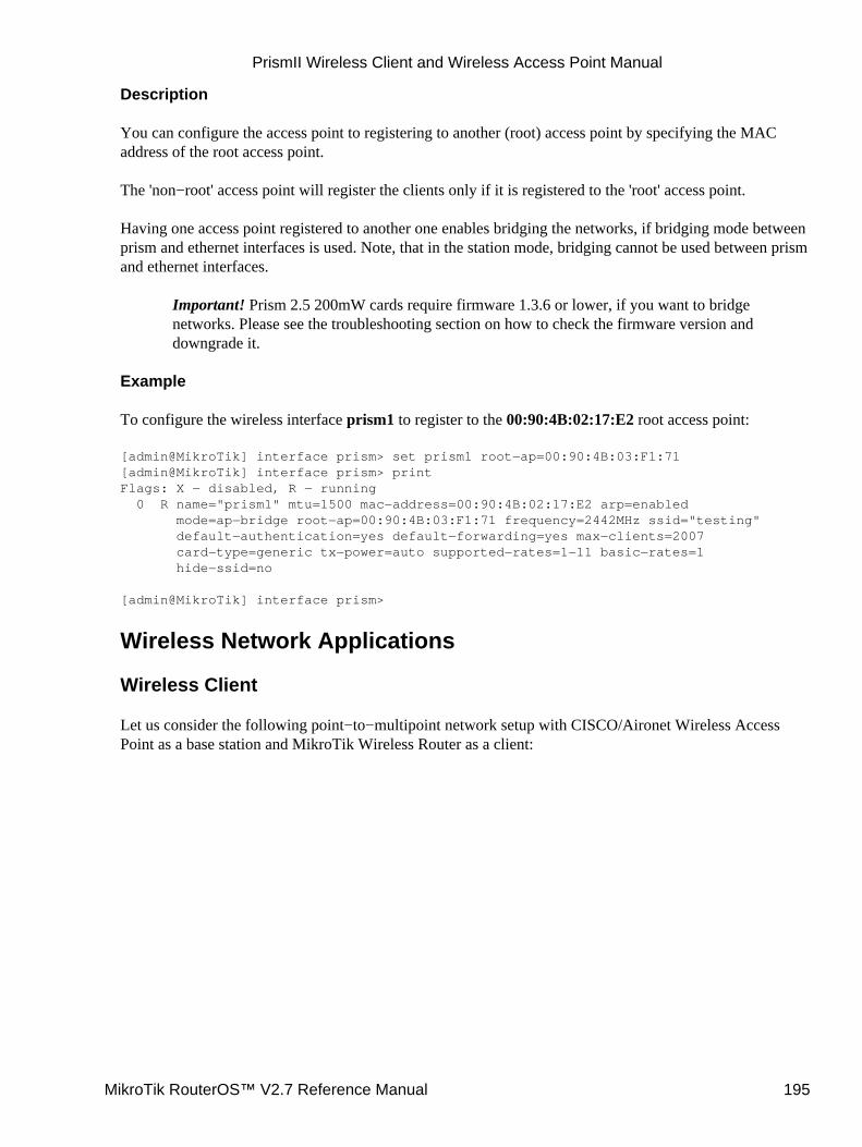
Description
You can configure the access point to registering to another (root) access point by specifying the MACaddress of the root access point.
The 'non−root' access point will register the clients only if it is registered to the 'root' access point.
Having one access point registered to another one enables bridging the networks, if bridging mode betweenprism and ethernet interfaces is used. Note, that in the station mode, bridging cannot be used between prismand ethernet interfaces.
Important! Prism 2.5 200mW cards require firmware 1.3.6 or lower, if you want to bridgenetworks. Please see the troubleshooting section on how to check the firmware version anddowngrade it.
Example
To configure the wireless interface prism1 to register to the 00:90:4B:02:17:E2 root access point:
[admin@MikroTik] interface prism> set prism1 root−ap=00:90:4B:03:F1:71[admin@MikroTik] interface prism> printFlags: X − disabled, R − running 0 R name="prism1" mtu=1500 mac−address=00:90:4B:02:17:E2 arp=enabled mode=ap−bridge root−ap=00:90:4B:03:F1:71 frequency=2442MHz ssid="testing" default−authentication=yes default−forwarding=yes max−clients=2007 card−type=generic tx−power=auto supported−rates=1−11 basic−rates=1 hide−ssid=no
[admin@MikroTik] interface prism>
Wireless Network Applications
Wireless Client
Let us consider the following point−to−multipoint network setup with CISCO/Aironet Wireless AccessPoint as a base station and MikroTik Wireless Router as a client:
PrismII Wireless Client and Wireless Access Point Manual
MikroTik RouterOS™ V2.7 Reference Manual 195
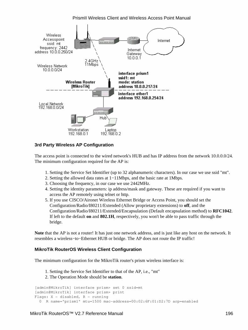
3rd Party Wireless AP Configuration
The access point is connected to the wired network's HUB and has IP address from the network 10.0.0.0/24.The minimum configuration required for the AP is:
Setting the Service Set Identifier (up to 32 alphanumeric characters). In our case we use ssid "mt".1. Setting the allowed data rates at 1−11Mbps, and the basic rate at 1Mbps.2. Choosing the frequency, in our case we use 2442MHz.3. Setting the identity parameters: ip address/mask and gateway. These are required if you want toaccess the AP remotely using telnet or http.
4.
If you use CISCO/Aironet Wireless Ethernet Bridge or Access Point, you should set theConfiguration/Radio/I80211/Extended (Allow proprietary extensions) to off, and theConfiguration/Radio/I80211/Extended/Encapsulation (Default encapsulation method) to RFC1042.If left to the default on and 802.1H, respectively, you won't be able to pass traffic through thebridge.
5.
Note that the AP is not a router! It has just one network address, and is just like any host on the network. Itresembles a wireless−to−Ethernet HUB or bridge. The AP does not route the IP traffic!
MikroTik RouterOS Wireless Client Configuration
The minimum configuration for the MikroTik router's prism wireless interface is:
Setting the Service Set Identifier to that of the AP, i.e., "mt"1. The Operation Mode should be station.2.
[admin@MikroTik] interface prism> set 0 ssid=mt[admin@MikroTik] interface prism> printFlags: X − disabled, R − running 0 R name="prism1" mtu=1500 mac−address=00:02:6F:01:D2:7D arp=enabled
PrismII Wireless Client and Wireless Access Point Manual
MikroTik RouterOS™ V2.7 Reference Manual 196
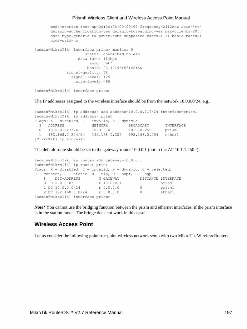
mode=station root−ap=00:00:00:00:00:00 frequency=2412MHz ssid="mt" default−authentication=yes default−forwarding=yes max−clients=2007 card−type=generic tx−power=auto supported−rates=1−11 basic−rates=1 hide−ssid=no
[admin@MikroTik] interface prism> monitor 0 status: connected−to−ess data−rate: 11Mbps ssid: "mt" bssid: 00:40:96:56:E2:AD signal−quality: 78 signal−level: 125 noise−level: −99
[admin@MikroTik] interface prism>
The IP addresses assigned to the wireless interface should be from the network 10.0.0.0/24, e.g.:
[admin@MikroTik] ip address> add address=10.0.0.217/24 interface=prism1[admin@MikroTik] ip address> printFlags: X − disabled, I − invalid, D − dynamic # ADDRESS NETWORK BROADCAST INTERFACE 0 10.0.0.217/24 10.0.0.0 10.0.0.255 prism1 1 192.168.0.254/24 192.168.0.254 192.168.0.254 ether1[MikroTik] ip address>
The default route should be set to the gateway router 10.0.0.1 (not to the AP 10.1.1.250 !):
[admin@MikroTik] ip route> add gateway=10.0.0.1[admin@MikroTik] ip route> printFlags: X − disabled, I − invalid, D − dynamic, J − rejected,C − connect, S − static, R − rip, O − ospf, B − bgp # DST−ADDRESS G GATEWAY DISTANCE INTERFACE 0 S 0.0.0.0/0 r 10.0.0.1 1 prism1 1 DC 10.0.0.0/24 r 0.0.0.0 0 prism1 2 DC 192.168.0.0/24 r 0.0.0.0 0 ether1[admin@MikroTik] interface prism>
Note! You cannot use the bridging function between the prism and ethernet interfaces, if the prism interfaceis in the station mode. The bridge does not work in this case!
Wireless Access Point
Let us consider the following point−to−point wireless network setup with two MikroTik Wireless Routers:
PrismII Wireless Client and Wireless Access Point Manual
MikroTik RouterOS™ V2.7 Reference Manual 197
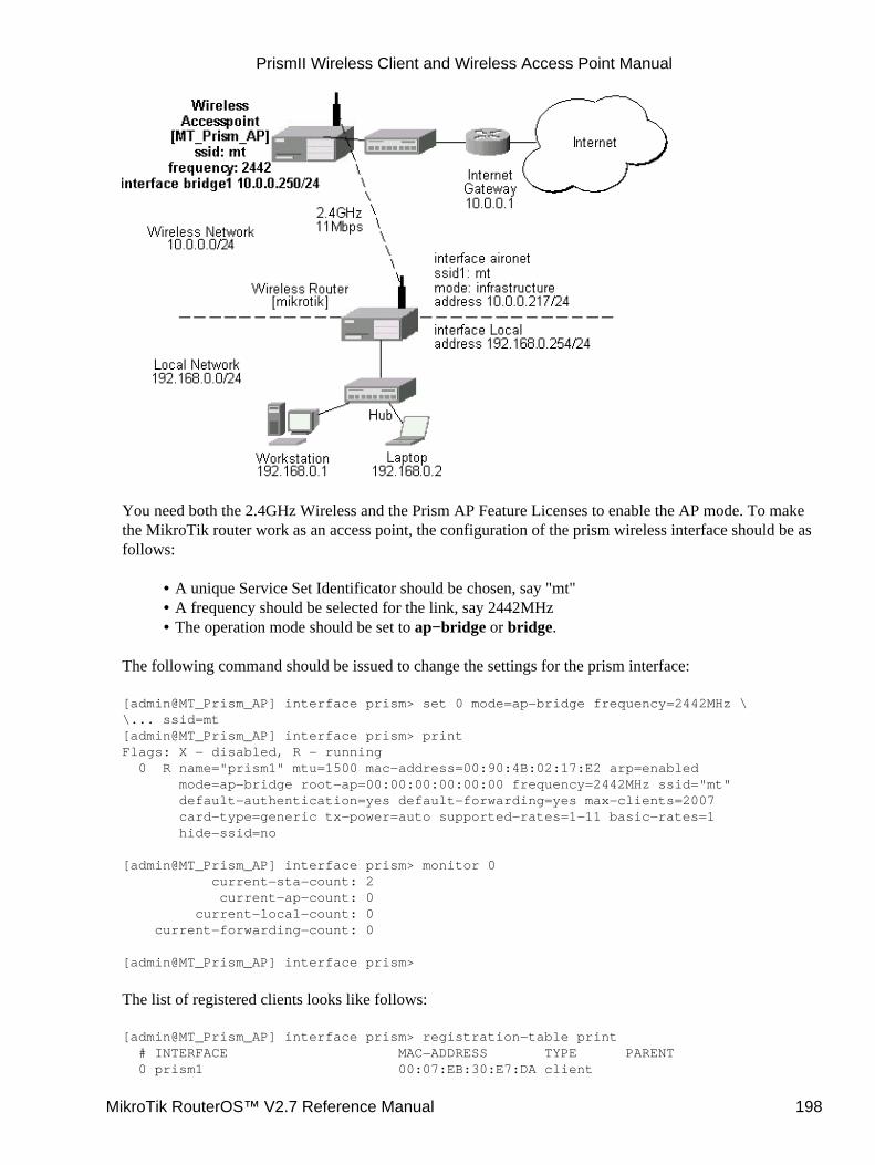
You need both the 2.4GHz Wireless and the Prism AP Feature Licenses to enable the AP mode. To makethe MikroTik router work as an access point, the configuration of the prism wireless interface should be asfollows:
A unique Service Set Identificator should be chosen, say "mt"• A frequency should be selected for the link, say 2442MHz• The operation mode should be set to ap−bridge or bridge.•
The following command should be issued to change the settings for the prism interface:
[admin@MT_Prism_AP] interface prism> set 0 mode=ap−bridge frequency=2442MHz \\... ssid=mt[admin@MT_Prism_AP] interface prism> printFlags: X − disabled, R − running 0 R name="prism1" mtu=1500 mac−address=00:90:4B:02:17:E2 arp=enabled mode=ap−bridge root−ap=00:00:00:00:00:00 frequency=2442MHz ssid="mt" default−authentication=yes default−forwarding=yes max−clients=2007 card−type=generic tx−power=auto supported−rates=1−11 basic−rates=1 hide−ssid=no
[admin@MT_Prism_AP] interface prism> monitor 0 current−sta−count: 2 current−ap−count: 0 current−local−count: 0 current−forwarding−count: 0
[admin@MT_Prism_AP] interface prism>
The list of registered clients looks like follows:
[admin@MT_Prism_AP] interface prism> registration−table print # INTERFACE MAC−ADDRESS TYPE PARENT 0 prism1 00:07:EB:30:E7:DA client
PrismII Wireless Client and Wireless Access Point Manual
MikroTik RouterOS™ V2.7 Reference Manual 198
1 prism1 00:02:6F:01:5D:FE client[admin@MT_Prism_AP] interface prism>
There are two possible ways of implementing the wireless access point feature:
Use it as a pure access point with bridging function enabled between the ethernet and prisminterfaces. The IP address can be assigned to the bridge interface.
•
Use it as a wireless access point router with routing functionality between the ethernet and prisminterfaces. It requires different IP addresses assigned to both the Ethernet and prism interfaces. Theaddresses should be from different networks as well!
•
To enable bridging between the ethernet and prism interfaces, do the following:
Add bridge interface with the desired forwarded protocols:
[admin@MT_Prism_AP] interface bridge> add forward−protocols=ip,arp,other[admin@MT_Prism_AP] interface bridge> printFlags: X − disabled, R − running 0 X name="bridge1" mtu=1500 arp=enabled mac−address=00:00:00:00:00:00 forward−protocols=ip,arp,other priority=1
[admin@MT_Prism_AP] interface bridge>
1.
Add the desired interfaces to the bridge interface:
[admin@MT_Prism_AP] interface bridge port> set "ether1,prism1" bridge=bridge1[admin@MT_Prism_AP] interface bridge port> printFlags: X − disabled # INTERFACE BRIDGE 0 ether1 bridge1 1 prism1 bridge1[admin@MT_Prism_AP] interface bridge port>
2.
Enable the bridge interface:
[admin@MT_Prism_AP] interface> printFlags: X − disabled, D − dynamic, R − running # NAME TYPE MTU 0 R ether1 ether 1500 1 R prism1 prism 1500 2 X bridge1 bridge 1500[admin@MT_Prism_AP] interface> enable bridge1[admin@MT_Prism_AP] interface> printFlags: X − disabled, D − dynamic, R − running # NAME TYPE MTU 0 R ether1 ether 1500 1 R prism1 prism 1500 2 R bridge1 bridge 1500[admin@MT_Prism_AP] interface>
3.
Assign an IP address to the bridge interface and specify the default gateway for the access point:
[admin@MT_Prism_AP] ip address> add address=10.0.0.250/24 interface=bridge1[admin@MT_Prism_AP] ip address> printFlags: X − disabled, I − invalid, D − dynamic # ADDRESS NETWORK BROADCAST INTERFACE 0 10.0.0.250/24 10.0.0.0 10.0.0.255 bridge1
4.
PrismII Wireless Client and Wireless Access Point Manual
MikroTik RouterOS™ V2.7 Reference Manual 199
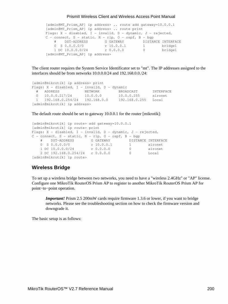
[admin@MT_Prism_AP] ip address> .. route add gateway=10.0.0.1[admin@MT_Prism_AP] ip address> .. route printFlags: X − disabled, I − invalid, D − dynamic, J − rejected,C − connect, S − static, R − rip, O − ospf, B − bgp # DST−ADDRESS G GATEWAY DISTANCE INTERFACE 0 S 0.0.0.0/0 r 10.0.0.1 1 bridge1 1 DC 10.0.0.0/24 r 0.0.0.0 0 bridge1[admin@MT_Prism_AP] ip address>
The client router requires the System Service Identificator set to "mt". The IP addresses assigned to theinterfaces should be from networks 10.0.0.0/24 and 192.168.0.0./24:
[admin@mikrotik] ip address> printFlags: X − disabled, I − invalid, D − dynamic # ADDRESS NETWORK BROADCAST INTERFACE 0 10.0.0.217/24 10.0.0.0 10.0.0.255 aironet 1 192.168.0.254/24 192.168.0.0 192.168.0.255 Local[admin@mikrotik] ip address>
The default route should be set to gateway 10.0.0.1 for the router [mikrotik]:
[admin@mikrotik] ip route> add gateway=10.0.0.1[admin@mikrotik] ip route> printFlags: X − disabled, I − invalid, D − dynamic, J − rejected,C − connect, S − static, R − rip, O − ospf, B − bgp # DST−ADDRESS G GATEWAY DISTANCE INTERFACE 0 S 0.0.0.0/0 r 10.0.0.1 1 aironet 1 DC 10.0.0.0/24 r 0.0.0.0 0 aironet 2 DC 192.168.0.254/24 r 0.0.0.0 0 Local[admin@mikrotik] ip route>
Wireless Bridge
To set up a wireless bridge between two networks, you need to have a "wireless 2.4GHz" or "AP" license.Configure one MikroTik RouterOS Prism AP to register to another MikroTik RouterOS Prism AP forpoint−to−point operation.
Important! Prism 2.5 200mW cards require firmware 1.3.6 or lower, if you want to bridgenetworks. Please see the troubleshooting section on how to check the firmware version anddowngrade it.
The basic setup is as follows:
PrismII Wireless Client and Wireless Access Point Manual
MikroTik RouterOS™ V2.7 Reference Manual 200
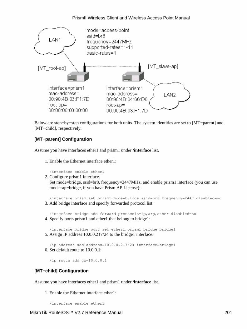
Below are step−by−step configurations for both units. The system identities are set to [MT−parent] and[MT−child], respectively.
[MT−parent] Configuration
Assume you have interfaces ether1 and prism1 under /interface list.
Enable the Ethernet interface ether1:
/interface enable ether1
1.
Configure prism1 interface.Set mode=bridge, ssid=br8, frequency=2447MHz, and enable prism1 interface (you can usemode=ap−bridge, if you have Prism AP License):
/interface prism set prism1 mode=bridge ssid=br8 frequency=2447 disabled=no
2.
Add bridge interface and specify forwarded protocol list:
/interface bridge add forward−protocols=ip,arp,other disabled=no
3.
Specify ports prism1 and ether1 that belong to bridge1:
/interface bridge port set ether1,prism1 bridge=bridge1
4.
Assign IP address 10.0.0.217/24 to the bridge1 interface:
/ip address add address=10.0.0.217/24 interface=bridge1
5.
Set default route to 10.0.0.1:
/ip route add gw=10.0.0.1
6.
[MT−child] Configuration
Assume you have interfaces ether1 and prism1 under /interface list.
Enable the Ethernet interface ether1:
/interface enable ether1
1.
PrismII Wireless Client and Wireless Access Point Manual
MikroTik RouterOS™ V2.7 Reference Manual 201

Configure prism1 interface.Here, you have to specify root−ap MAC address, so the Prism radio registers to the root AP.Set mode=bridge, ssid=br8, frequency=2447MHz, root−ap=xx:xx:xx:xx:xx:xx, and enable prism1interface (you can use mode=ap−bridge, if you have Prism AP License):
/interface prism set prism1 mode=bridge ssid=br8 frequency=2447 \root−ap=xx:xx:xx:xx:xx:xx disabled=no
Here, substitute the xx:xx:xx:xx:xx:xx with MAC address of [MT−parent] prism interface.
2.
Check your setup and see, if you have successfully registered to the root AP. Its MAC addressshould be listed as parent−ap in the registration table of prism interface, for example:
[admin@MT−child] interface prism> registration−table print # INTERFACE MAC−ADDRESS TYPE PARENT 0 prism1 00:02:6F:01:CE:2A parent−ap[admin@MT−child] interface prism>
3.
Add bridge interface and specify forwarded protocol list:
/interface bridge add forward−protocols=ip,arp,other disabled=no
4.
Specify ports prism1 and ether1 that belong to bridge1:
/interface bridge port set ether1,prism1 bridge=bridge1
5.
Assign IP address 10.0.0.218/24 to the bridge1 interface:
/ip address add address=10.0.0.218/24 interface=bridge1
6.
Set default route to 10.0.0.1:
/ip route add gw=10.0.0.1
7.
Note, that both LANs should use IP addresses from the same network 10.0.0.0/24. Both MikroTik routersbelong to the same network too. You should be able to ping through the wireless bridge from one LAN toother and to gateway 10.0.0.1.
© Copyright 1999−2003, MikroTik
PrismII Wireless Client and Wireless Access Point Manual
MikroTik RouterOS™ V2.7 Reference Manual 202
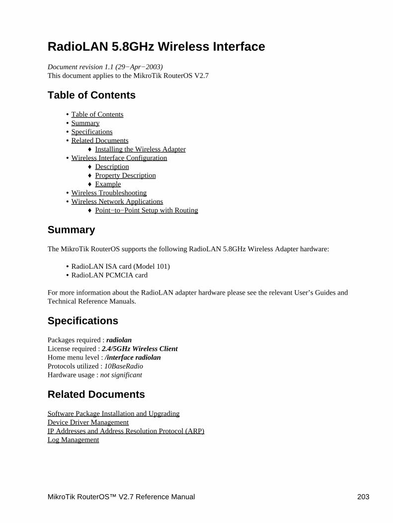
RadioLAN 5.8GHz Wireless InterfaceDocument revision 1.1 (29−Apr−2003)This document applies to the MikroTik RouterOS V2.7
Table of Contents
Table of Contents• Summary• Specifications• Related Documents
Installing the Wireless Adapter♦ •
Wireless Interface ConfigurationDescription♦ Property Description♦ Example♦
•
Wireless Troubleshooting• Wireless Network Applications
Point−to−Point Setup with Routing♦ •
Summary
The MikroTik RouterOS supports the following RadioLAN 5.8GHz Wireless Adapter hardware:
RadioLAN ISA card (Model 101)• RadioLAN PCMCIA card•
For more information about the RadioLAN adapter hardware please see the relevant User’s Guides andTechnical Reference Manuals.
Specifications
Packages required : radiolanLicense required : 2.4/5GHz Wireless ClientHome menu level : /interface radiolanProtocols utilized : 10BaseRadioHardware usage : not significant
Related Documents
Software Package Installation and UpgradingDevice Driver ManagementIP Addresses and Address Resolution Protocol (ARP)Log Management
MikroTik RouterOS™ V2.7 Reference Manual 203
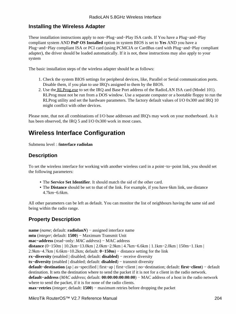
Installing the Wireless Adapter
These installation instructions apply to non−Plug−and−Play ISA cards. If You have a Plug−and−Playcompliant system AND PnP OS Installed option in system BIOS is set to Yes AND you have aPlug−and−Play compliant ISA or PCI card (using PCMCIA or CardBus card with Plug−and−Play compliantadapter), the driver should be loaded automatically. If it is not, these instructions may also apply to yoursystem
The basic installation steps of the wireless adapter should be as follows:
Check the system BIOS settings for peripheral devices, like, Parallel or Serial communication ports.Disable them, if you plan to use IRQ's assigned to them by the BIOS.
1.
Use the RLProg.exe to set the IRQ and Base Port address of the RadioLAN ISA card (Model 101).RLProg must not be run from a DOS window. Use a separate computer or a bootable floppy to run theRLProg utility and set the hardware parameters. The factory default values of I/O 0x300 and IRQ 10might conflict with other devices.
2.
Please note, that not all combinations of I/O base addresses and IRQ's may work on your motherboard. As ithas been observed, the IRQ 5 and I/O 0x300 work in most cases.
Wireless Interface Configuration
Submenu level : /interface radiolan
Description
To set the wireless interface for working with another wireless card in a point−to−point link, you should setthe following parameters:
The Service Set Identifier. It should match the sid of the other card.• The Distance should be set to that of the link. For example, if you have 6km link, use distance4.7km−6.6km.
•
All other parameters can be left as default. You can monitor the list of neighbours having the same sid andbeing within the radio range.
Property Description
name (name; default: radiolanN) − assigned interface namemtu (integer; default: 1500) − Maximum Transmit Unitmac−address (read−only: MAC address) − MAC addressdistance (0−150m | 10.2km−13.0km | 2.0km−2.9km | 4.7km−6.6km | 1.1km−2.0km | 150m−1.1km |2.9km−4.7km | 6.6km−10.2km; default: 0−150m) − distance setting for the linkrx−diversity (enabled | disabled; default: disabled) − receive diversitytx−diversity (enabled | disabled; default: disabled) − transmit diversitydefault−destination (ap | as−specified | first−ap | first−client | no−destination; default: first−client) − defaultdestination. It sets the destination where to send the packet if it is not for a client in the radio network.default−address (MAC address; default: 00:00:00:00:00:00) − MAC address of a host in the radio networkwhere to send the packet, if it is for none of the radio clients.max−retries (integer; default: 1500) − maximum retries before dropping the packet
RadioLAN 5.8GHz Wireless Interface
MikroTik RouterOS™ V2.7 Reference Manual 204
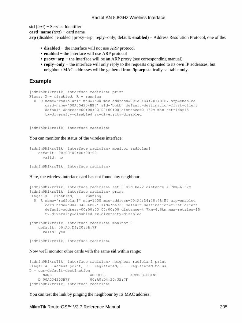
sid (text) − Service Identifiercard−name (text) − card namearp (disabled | enabled | proxy−arp | reply−only; default: enabled) − Address Resolution Protocol, one of the:
disabled − the interface will not use ARP protocol• enabled − the interface will use ARP protocol• proxy−arp − the interface will be an ARP proxy (see corresponding manual)• reply−only − the interface will only reply to the requests originated to its own IP addresses, butneighbour MAC addresses will be gathered from /ip arp statically set table only.
•
Example
[admin@MikroTik] interface radiolan> printFlags: X − disabled, R − running 0 R name="radiolan1" mtu=1500 mac−address=00:A0:D4:20:4B:E7 arp=enabled card−name="00A0D4204BE7" sid="bbbb" default−destination=first−client default−address=00:00:00:00:00:00 distance=0−150m max−retries=15 tx−diversity=disabled rx−diversity=disabled
[admin@MikroTik] interface radiolan>
You can monitor the status of the wireless interface:
[admin@MikroTik] interface radiolan> monitor radiolan1 default: 00:00:00:00:00:00 valid: no
[admin@MikroTik] interface radiolan>
Here, the wireless interface card has not found any neighbour.
[admin@MikroTik] interface radiolan> set 0 sid ba72 distance 4.7km−6.6km[admin@MikroTik] interface radiolan> printFlags: X − disabled, R − running 0 R name="radiolan1" mtu=1500 mac−address=00:A0:D4:20:4B:E7 arp=enabled card−name="00A0D4204BE7" sid="ba72" default−destination=first−client default−address=00:00:00:00:00:00 distance=4.7km−6.6km max−retries=15 tx−diversity=disabled rx−diversity=disabled
[admin@MikroTik] interface radiolan> monitor 0 default: 00:A0:D4:20:3B:7F valid: yes
[admin@MikroTik] interface radiolan>
Now we'll monitor other cards with the same sid within range:
[admin@MikroTik] interface radiolan> neighbor radiolan1 printFlags: A − access−point, R − registered, U − registered−to−us,D − our−default−destination NAME ADDRESS ACCESS−POINT D 00A0D4203B7F 00:A0:D4:20:3B:7F[admin@MikroTik] interface radiolan>
You can test the link by pinging the neighbour by its MAC address:
RadioLAN 5.8GHz Wireless Interface
MikroTik RouterOS™ V2.7 Reference Manual 205
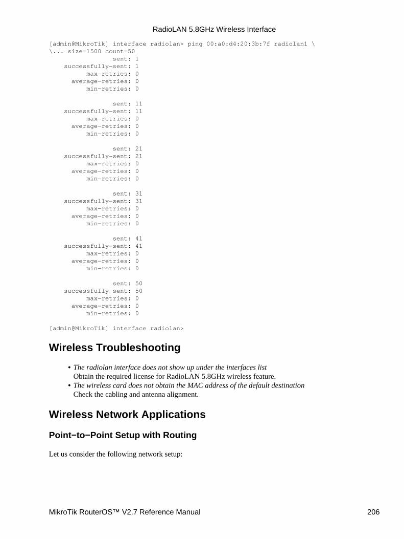
[admin@MikroTik] interface radiolan> ping 00:a0:d4:20:3b:7f radiolan1 \\... size=1500 count=50 sent: 1 successfully−sent: 1 max−retries: 0 average−retries: 0 min−retries: 0
sent: 11 successfully−sent: 11 max−retries: 0 average−retries: 0 min−retries: 0
sent: 21 successfully−sent: 21 max−retries: 0 average−retries: 0 min−retries: 0
sent: 31 successfully−sent: 31 max−retries: 0 average−retries: 0 min−retries: 0
sent: 41 successfully−sent: 41 max−retries: 0 average−retries: 0 min−retries: 0
sent: 50 successfully−sent: 50 max−retries: 0 average−retries: 0 min−retries: 0
[admin@MikroTik] interface radiolan>
Wireless Troubleshooting
The radiolan interface does not show up under the interfaces listObtain the required license for RadioLAN 5.8GHz wireless feature.
•
The wireless card does not obtain the MAC address of the default destinationCheck the cabling and antenna alignment.
•
Wireless Network Applications
Point−to−Point Setup with Routing
Let us consider the following network setup:
RadioLAN 5.8GHz Wireless Interface
MikroTik RouterOS™ V2.7 Reference Manual 206
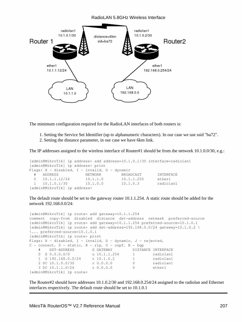
The minimum configuration required for the RadioLAN interfaces of both routers is:
Setting the Service Set Identifier (up to alphanumeric characters). In our case we use ssid "ba72".1. Setting the distance parameter, in our case we have 6km link.2.
The IP addresses assigned to the wireless interface of Router#1 should be from the network 10.1.0.0/30, e.g.:
[admin@MikroTik] ip address> add address=10.1.0.1/30 interface=radiolan1[admin@MikroTik] ip address> printFlags: X − disabled, I − invalid, D − dynamic # ADDRESS NETWORK BROADCAST INTERFACE 0 10.1.1.12/24 10.1.1.0 10.1.1.255 ether1 1 10.1.0.1/30 10.1.0.0 10.1.0.3 radiolan1[admin@MikroTik] ip address>
The default route should be set to the gateway router 10.1.1.254. A static route should be added for thenetwork 192.168.0.0/24:
[admin@MikroTik] ip route> add gateway=10.1.1.254comment copy−from disabled distance dst−address netmask preferred−source[admin@MikroTik] ip route> add gateway=10.1.1.254 preferred−source=10.1.0.1[admin@MikroTik] ip route> add dst−address=192.168.0.0/24 gateway=10.1.0.2 \\... preferred−source=10.1.0.1[admin@MikroTik] ip route> printFlags: X − disabled, I − invalid, D − dynamic, J − rejected,C − connect, S − static, R − rip, O − ospf, B − bgp # DST−ADDRESS G GATEWAY DISTANCE INTERFACE 0 S 0.0.0.0/0 u 10.1.1.254 1 radiolan1 1 S 192.168.0.0/24 r 10.1.0.2 1 radiolan1 2 DC 10.1.0.0/30 r 0.0.0.0 0 radiolan1 3 DC 10.1.1.0/24 r 0.0.0.0 0 ether1[admin@MikroTik] ip route>
The Router#2 should have addresses 10.1.0.2/30 and 192.168.0.254/24 assigned to the radiolan and Ethernetinterfaces respectively. The default route should be set to 10.1.0.1
RadioLAN 5.8GHz Wireless Interface
MikroTik RouterOS™ V2.7 Reference Manual 207

© Copyright 1999−2003, MikroTik
RadioLAN 5.8GHz Wireless Interface
MikroTik RouterOS™ V2.7 Reference Manual 208
Virtual LAN (VLAN) InterfaceDocument revision 1.3 (06−Mar−2003)This document applies to the MikroTik RouterOS V2.7
Table of Contents
Table of Contents• Summary• Specifications• Related Documents• Description• VLAN Setup
Property Description♦ Notes♦ Example♦
•
Application Example• Additional Resources• Currently Supported Interfaces•
Summary
VLAN is an implementation of the 802.1Q VLAN protocol for MikroTik RouterOS 2.7. It allows you to havemultiple Virtual LANs on a single ethernet cable, giving the ability to segregate LANs efficiently. It supportsup to 4094 vlan interfaces per ethernet device. Many routers, including Cisco and Linux based, and manyLayer 2 switches also support it.
A VLAN is a logical grouping that allows end users to communicate as if they were physically connected to asingle isolated LAN, independent of the physical configuration of the network. VLAN support adds a newdimension of security and cost savings permitting the sharing of a physical network while logicallymaintaining separation among unrelated users.
Specifications
Packages required : systemLicense required : AnyHome menu level : /interface vlanProtocols utilized : VLAN (IEEE802.1Q)Hardware usage : not significant
Related Documents
Software Package Installation and UpgradingIP Addresses and Address Resolution Protocol (ARP)
MikroTik RouterOS™ V2.7 Reference Manual 209
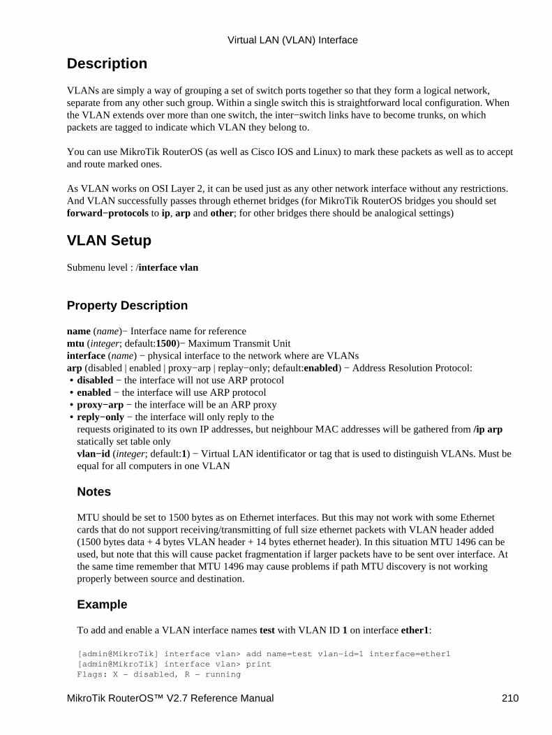
Description
VLANs are simply a way of grouping a set of switch ports together so that they form a logical network,separate from any other such group. Within a single switch this is straightforward local configuration. Whenthe VLAN extends over more than one switch, the inter−switch links have to become trunks, on whichpackets are tagged to indicate which VLAN they belong to.
You can use MikroTik RouterOS (as well as Cisco IOS and Linux) to mark these packets as well as to acceptand route marked ones.
As VLAN works on OSI Layer 2, it can be used just as any other network interface without any restrictions.And VLAN successfully passes through ethernet bridges (for MikroTik RouterOS bridges you should setforward−protocols to ip, arp and other; for other bridges there should be analogical settings)
VLAN Setup
Submenu level : /interface vlan
Property Description
name (name)− Interface name for referencemtu (integer; default:1500)− Maximum Transmit Unitinterface (name) − physical interface to the network where are VLANsarp (disabled | enabled | proxy−arp | replay−only; default:enabled) − Address Resolution Protocol:
disabled − the interface will not use ARP protocol• enabled − the interface will use ARP protocol• proxy−arp − the interface will be an ARP proxy• reply−only − the interface will only reply to therequests originated to its own IP addresses, but neighbour MAC addresses will be gathered from /ip arpstatically set table onlyvlan−id (integer; default:1) − Virtual LAN identificator or tag that is used to distinguish VLANs. Must beequal for all computers in one VLAN
Notes
MTU should be set to 1500 bytes as on Ethernet interfaces. But this may not work with some Ethernetcards that do not support receiving/transmitting of full size ethernet packets with VLAN header added(1500 bytes data + 4 bytes VLAN header + 14 bytes ethernet header). In this situation MTU 1496 can beused, but note that this will cause packet fragmentation if larger packets have to be sent over interface. Atthe same time remember that MTU 1496 may cause problems if path MTU discovery is not workingproperly between source and destination.
Example
To add and enable a VLAN interface names test with VLAN ID 1 on interface ether1:
[admin@MikroTik] interface vlan> add name=test vlan−id=1 interface=ether1[admin@MikroTik] interface vlan> printFlags: X − disabled, R − running
•
Virtual LAN (VLAN) Interface
MikroTik RouterOS™ V2.7 Reference Manual 210
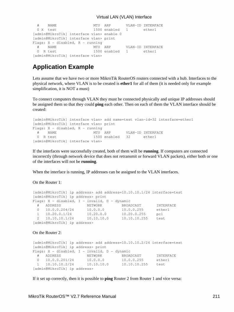
# NAME MTU ARP VLAN−ID INTERFACE 0 X test 1500 enabled 1 ether1[admin@MikroTik] interface vlan> enable 0[admin@MikroTik] interface vlan> printFlags: X − disabled, R − running # NAME MTU ARP VLAN−ID INTERFACE 0 R test 1500 enabled 1 ether1[admin@MikroTik] interface vlan>
Application Example
Lets assume that we have two or more MikroTik RouterOS routers connected with a hub. Interfaces to thephysical network, where VLAN is to be created is ether1 for all of them (it is needed only for examplesimplification, it is NOT a must)
To connect computers through VLAN they must be connected physically and unique IP addresses shouldbe assigned them so that they could ping each other. Then on each of them the VLAN interface should becreated:
[admin@MikroTik] interface vlan> add name=test vlan−id=32 interface=ether1[admin@MikroTik] interface vlan> printFlags: X − disabled, R − running # NAME MTU ARP VLAN−ID INTERFACE 0 R test 1500 enabled 32 ether1[admin@MikroTik] interface vlan>
If the interfaces were successfully created, both of them will be running. If computers are connectedincorrectly (through network device that does not retransmit or forward VLAN packets), either both or oneof the interfaces will not be running.
When the interface is running, IP addresses can be assigned to the VLAN interfaces.
On the Router 1:
[admin@MikroTik] ip address> add address=10.10.10.1/24 interface=test[admin@MikroTik] ip address> printFlags: X − disabled, I − invalid, D − dynamic # ADDRESS NETWORK BROADCAST INTERFACE 0 10.0.0.204/24 10.0.0.0 10.0.0.255 ether1 1 10.20.0.1/24 10.20.0.0 10.20.0.255 pc1 2 10.10.10.1/24 10.10.10.0 10.10.10.255 test[admin@MikroTik] ip address>
On the Router 2:
[admin@MikroTik] ip address> add address=10.10.10.2/24 interface=test[admin@MikroTik] ip address> printFlags: X − disabled, I − invalid, D − dynamic # ADDRESS NETWORK BROADCAST INTERFACE 0 10.0.0.201/24 10.0.0.0 10.0.0.255 ether1 1 10.10.10.2/24 10.10.10.0 10.10.10.255 test[admin@MikroTik] ip address>
If it set up correctly, then it is possible to ping Router 2 from Router 1 and vice versa:
Virtual LAN (VLAN) Interface
MikroTik RouterOS™ V2.7 Reference Manual 211
[admin@MikroTik] ip address> /ping 10.10.10.110.10.10.1 64 byte pong: ttl=255 time=3 ms10.10.10.1 64 byte pong: ttl=255 time=4 ms10.10.10.1 64 byte pong: ttl=255 time=10 ms10.10.10.1 64 byte pong: ttl=255 time=5 ms4 packets transmitted, 4 packets received, 0% packet lossround−trip min/avg/max = 3/10.5/10 ms[admin@MikroTik] ip address> /ping 10.10.10.210.10.10.2 64 byte pong: ttl=255 time=10 ms10.10.10.2 64 byte pong: ttl=255 time=11 ms10.10.10.2 64 byte pong: ttl=255 time=10 ms10.10.10.2 64 byte pong: ttl=255 time=13 ms4 packets transmitted, 4 packets received, 0% packet lossround−trip min/avg/max = 10/11/13 ms[admin@MikroTik] ip address>
Additional Resources
Links for VLAN documentation:
http://www.csd.uwo.ca/courses/CS457a/reports/handin/jpbojtos/A2/trunking.htmhttp://www.cisco.com/univercd/cc/td/doc/product/software/ios121/121newft/121t/121t3/dtbridge.htm#xtocid114533http://www.cisco.com/warp/public/473/27.html#tagginghttp://www.cisco.com/warp/public/538/7.htmlhttp://www.nwfusion.com/news/tech/2001/0305tech.htmlhttp://www.intel.com/network/connectivity/resources/doc_library/tech_brief/virtual_lans.htm
Currently Supported Interfaces
This is a list of network interfaces on which VLAN was tested and worked:Realtek 8139• Intel PRO/100• Intel PRO1000 server adapter
This is a list of network interfaces on which VLAN was tested and worked, but WITHOUT LARGEPACKET (>1496 bytes) SUPPORT:
•
3Com 3c59x PCI• DEC 21140 (tulip)
© Copyright 1999−2003, MikroTik
•
Virtual LAN (VLAN) Interface
MikroTik RouterOS™ V2.7 Reference Manual 212
Xpeed SDSL (Single−line Digital Subscriber Line)InterfaceDocument revision 1.4 (09−Apr−2003)This document applies to the MikroTik RouterOS V2.7
Table of Contents
Table of Contents• Summary• Specifications• Related Documents• Xpeed Interface Configuration
Property Description♦ Example♦
•
Frame Relay Configuration ExamplesMikroTik Router to MikroTik Router
Router r1 setup◊ Router r2 setup◊
♦
MikroTik Router to CISCO RouterMikroTik router setup◊ CISCO router setup◊
♦
•
Troubleshooting• Additional Resources•
Summary
The MikroTik RouterOS supports the Xpeed 300 SDSL PCI Adapter hardware with speeds up to 2.32Mbps.This device can operate either using Frame Relay or PPP type of connection. SDSL (Single−line DigitalSubscriber Line or Symmetric Digital Subscriber Line) stands for the type of DSL that uses only one of thetwo cable pairs for transmission. SDSL allows residential or small office users to share the same telephone fordata transmission and voice or fax telephony.
Specifications
Packages required : synchronousLicense required : synchronousHome menu level : /interface xpeedProtocols utilized : PPP ( RFC1661), Frame Relay (RFC1490)Hardware usage: not significant
Related Documents
Software Package Installation and UpgradingDevice Driver ManagementIP Addresses and Address Resolution Protocol (ARP)FrameRelay (PVC, Private Virtual Circuit) Interface
MikroTik RouterOS™ V2.7 Reference Manual 213
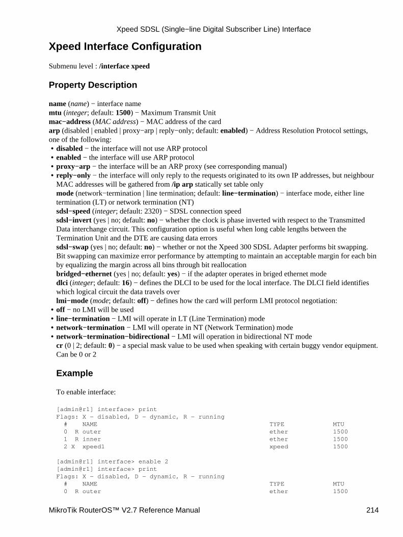
Xpeed Interface Configuration
Submenu level : /interface xpeed
Property Description
name (name) − interface namemtu (integer; default: 1500) − Maximum Transmit Unitmac−address (MAC address) − MAC address of the cardarp (disabled | enabled | proxy−arp | reply−only; default: enabled) − Address Resolution Protocol settings,one of the following:
disabled − the interface will not use ARP protocol• enabled − the interface will use ARP protocol• proxy−arp − the interface will be an ARP proxy (see corresponding manual)• reply−only − the interface will only reply to the requests originated to its own IP addresses, but neighbourMAC addresses will be gathered from /ip arp statically set table onlymode (network−termination | line termination; default: line−termination) − interface mode, either linetermination (LT) or network termination (NT)sdsl−speed (integer; default: 2320) − SDSL connection speedsdsl−invert (yes | no; default: no) − whether the clock is phase inverted with respect to the TransmittedData interchange circuit. This configuration option is useful when long cable lengths between theTermination Unit and the DTE are causing data errorssdsl−swap (yes | no; default: no) − whether or not the Xpeed 300 SDSL Adapter performs bit swapping.Bit swapping can maximize error performance by attempting to maintain an acceptable margin for each binby equalizing the margin across all bins through bit reallocationbridged−ethernet (yes | no; default: yes) − if the adapter operates in briged ethernet modedlci (integer; default: 16) − defines the DLCI to be used for the local interface. The DLCI field identifieswhich logical circuit the data travels overlmi−mode (mode; default: off) − defines how the card will perform LMI protocol negotiation:
•
off − no LMI will be used• line−termination − LMI will operate in LT (Line Termination) mode• network−termination − LMI will operate in NT (Network Termination) mode• network−termination−bidirectional − LMI will operation in bidirectional NT modecr (0 | 2; default: 0) − a special mask value to be used when speaking with certain buggy vendor equipment.Can be 0 or 2
Example
To enable interface:
[admin@r1] interface> printFlags: X − disabled, D − dynamic, R − running # NAME TYPE MTU 0 R outer ether 1500 1 R inner ether 1500 2 X xpeed1 xpeed 1500
[admin@r1] interface> enable 2[admin@r1] interface> printFlags: X − disabled, D − dynamic, R − running # NAME TYPE MTU 0 R outer ether 1500
•
Xpeed SDSL (Single−line Digital Subscriber Line) Interface
MikroTik RouterOS™ V2.7 Reference Manual 214
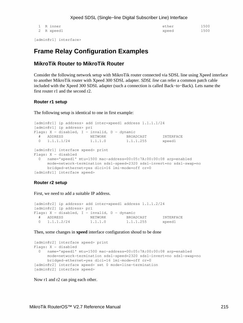
1 R inner ether 1500 2 R xpeed1 xpeed 1500
[admin@r1] interface>
Frame Relay Configuration Examples
MikroTik Router to MikroTik Router
Consider the following network setup with MikroTik router connected via SDSL line using Xpeed interfaceto another MikroTik router with Xpeed 300 SDSL adapter. SDSL line can refer a common patch cableincluded with the Xpeed 300 SDSL adapter (such a connection is called Back−to−Back). Lets name thefirst router r1 and the second r2.
Router r1 setup
The following setup is identical to one in first example:
[admin@r1] ip address> add inter=xpeed1 address 1.1.1.1/24[admin@r1] ip address> priFlags: X − disabled, I − invalid, D − dynamic # ADDRESS NETWORK BROADCAST INTERFACE 0 1.1.1.1/24 1.1.1.0 1.1.1.255 xpeed1
[admin@r1] interface xpeed> printFlags: X − disabled 0 name="xpeed1" mtu=1500 mac−address=00:05:7A:00:00:08 arp=enabled mode=network−termination sdsl−speed=2320 sdsl−invert=no sdsl−swap=no bridged−ethernet=yes dlci=16 lmi−mode=off cr=0[admin@r1] interface xpeed>
Router r2 setup
First, we need to add a suitable IP address.
[admin@r2] ip address> add inter=xpeed1 address 1.1.1.2/24[admin@r2] ip address> priFlags: X − disabled, I − invalid, D − dynamic # ADDRESS NETWORK BROADCAST INTERFACE 0 1.1.1.2/24 1.1.1.0 1.1.1.255 xpeed1
Then, some changes in xpeed interface configuration shoud to be done
[admin@r2] interface xpeed> printFlags: X − disabled 0 name="xpeed1" mtu=1500 mac−address=00:05:7A:00:00:08 arp=enabled mode=network−termination sdsl−speed=2320 sdsl−invert=no sdsl−swap=no bridged−ethernet=yes dlci=16 lmi−mode=off cr=0[admin@r2] interface xpeed> set 0 mode=line−termination[admin@r2] interface xpeed>
Now r1 and r2 can ping each other.
Xpeed SDSL (Single−line Digital Subscriber Line) Interface
MikroTik RouterOS™ V2.7 Reference Manual 215
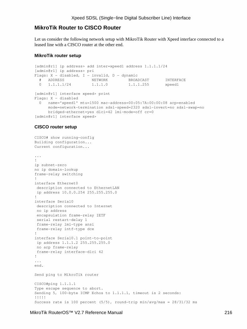
MikroTik Router to CISCO Router
Let us consider the following network setup with MikroTik Router with Xpeed interface connected to aleased line with a CISCO router at the other end.
MikroTik router setup
[admin@r1] ip address> add inter=xpeed1 address 1.1.1.1/24[admin@r1] ip address> priFlags: X − disabled, I − invalid, D − dynamic # ADDRESS NETWORK BROADCAST INTERFACE 0 1.1.1.1/24 1.1.1.0 1.1.1.255 xpeed1
[admin@r1] interface xpeed> printFlags: X − disabled 0 name="xpeed1" mtu=1500 mac−address=00:05:7A:00:00:08 arp=enabled mode=network−termination sdsl−speed=2320 sdsl−invert=no sdsl−swap=no bridged−ethernet=yes dlci=42 lmi−mode=off cr=0[admin@r1] interface xpeed>
CISCO router setup
CISCO# show running−configBuilding configuration...Current configuration...
...!ip subnet−zerono ip domain−lookupframe−relay switching!interface Ethernet0 description connected to EthernetLAN ip address 10.0.0.254 255.255.255.0!interface Serial0 description connected to Internet no ip address encapsulation frame−relay IETF serial restart−delay 1 frame−relay lmi−type ansi frame−relay intf−type dce!interface Serial0.1 point−to−point ip address 1.1.1.2 255.255.255.0 no arp frame−relay frame−relay interface−dlci 42!...end.
Send ping to MikroTik router
CISCO#ping 1.1.1.1Type escape sequence to abort.Sending 5, 100−byte ICMP Echos to 1.1.1.1, timeout is 2 seconds:!!!!!Success rate is 100 percent (5/5), round−trip min/avg/max = 28/31/32 ms
Xpeed SDSL (Single−line Digital Subscriber Line) Interface
MikroTik RouterOS™ V2.7 Reference Manual 216
CISCO#
TroubleshootingI tried to connect two routers as shown in MT−to−MT, but nothing happens.The link indicators on both cards must be on. If it's not, check the cable or interface configuration. Oneadapter should use LT mode and the other NT mode. You can also change sdsl−swap and sdsl−invertparameters on the router running LT mode if you have a very long line.
•
Additional Resources
Xpeed homepage
© Copyright 1999−2003, MikroTik
Xpeed SDSL (Single−line Digital Subscriber Line) Interface
MikroTik RouterOS™ V2.7 Reference Manual 217
WaveLAN/ORiNOCO 2.4GHz 11Mbps WirelessInterfaceDocument revision 1.0 (19−May−2003)This document applies to the MikroTik RouterOS V2.7
Table of Contents
Table of Contents• Summary• Specifications• Wireless Interface Configuration
Description♦ Property Description♦ Example♦
•
Wireless Troubleshooting• Application Example
Point−to−Multipoint Wireless LANIP Network Configuration◊
♦
Point−to−Point Wireless LANIP Network Configuration◊ Testing the Network Connectivity◊
♦
Point−to−Point Wireless LAN with Windows ClientIP Network Configuration◊ Testing the Network Connectivity◊
♦
•
Additional Resources•
Summary
The MikroTik RouterOS supports the following WaveLAN/ORiNOCO 2.4GHz 11Mbps Wireless Adapterhardware:
ORiNOCO 2.4GHz 11Mbps PC Card (Silver/Gold), firmware versions 4.xx...7.52.• ORiNOCO ISA and PCI adapters for using the PC card in desktop computers.•
Specifications
Packages required : wirelessLicense required : 2.4/5GHz Wireless ClientHome menu level : /interface wavelanStandards and Technologies : IEEE802.11b ( IEEE802.11b)Hardware usage : not significant
Wireless Interface Configuration
Submenu level : /interface wavelan
MikroTik RouterOS™ V2.7 Reference Manual 218
Description
WaveLAN/ORiNOCO 2.4GHz 11Mbps Wireless cards operate in 2.4 GHz band providing connection speedup to 11 Mbit/s.
Property Description
name (name; default: wavelanN) − assigned interface namemtu (integer: 256..2296; default: 1500) − Maximum Transmit Unitmac−address (read−only: MAC address) − MAC address of the cardfrequency (2412MHz | 2422MHz | 2432MHz | 2442MHz | 2452MHz | 2462MHz | 2472MHz | 2417MHz |2427MHz | 2437MHz | 2447MHz | 2457MHz | 2467MHz | 2484MHz; default: 2412MHz) − channelfrequencydata−rate (11Mbit/s | 1Mbit/s | 2Mbit/s | 5.5Mbit/s | auto; default: 11Mbit/s) − data ratemode (infrastructure | ad−hoc; default: ad−hoc) − operation mode of the cardssid (text: 0..32 chars; default: "") − Service Set Identifierclient−name (text: 0..32 chars; default: "") − client namekey1 (text; default: "") − encryption key #1key2 (text; default: "") − encryption key #2key3 (text; default: "") − encryption key #3key4 (text; default: "") − encryption key #4tx−key (key1 | key2 | key3 | key4; default: key1) − transmit keyencryption (no | yes; default: no) − specifies whether to use the encryptionarp (enabled | disabled | reply−only | proxy−arp; default: enabled) − ARP setting
Example
[admin@MikroTik] interface> printFlags: X − disabled, D − dynamic, R − running # NAME TYPE MTU 0 R Public 1500 ether 1 R Local 1500 ether 2 X wavelan1 1500 wavelan[MikroTik] interface> enable 2[admin@MikroTik] interface> printFlags: X − disabled, D − dynamic, R − running # NAME TYPE MTU 0 R Public 1500 ether 1 R Local 1500 ether 2 R wavelan1 1500 wavelan[admin@MikroTik] interface>
More configuration and statistics parameters can be found under the /interface wavelan menu:
[admin@MikroTik] interface> wavelan[admin@MikroTik] interface wavelan> printFlags: X − disabled, R − running 0 R name=wavelan1 mtu=1500 mac−address=00:02:2D:07:D8:44 arp=enabled frequency=2412MHz data−rate=11Mbit/s mode=ad−hoc ssid="" client−name="" key1="" key2="" key3="" key4="" tx−key=key1 encryption=no
[admin@MikroTik] interface wavelan>
You can monitor the status of the wireless interface:
WaveLAN/ORiNOCO 2.4GHz 11Mbps Wireless Interface
MikroTik RouterOS™ V2.7 Reference Manual 219
[admin@MikroTik] interface wavelan> moitor 0 bssid: 44:44:44:44:44:44 frequency: 2422MHz data−rate: 11Mbit/s ssid: tsunami signal−quality: 0 signal−level: 0 noise: 0
[admin@MikroTik] interface wavelan>
To set the wireless interface for working with an IEEE 802.11b access point (register to the AP), you shouldset the following parameters:
The Service Set Identifier. It should match the ssid of the AP.• The Operation Mode of the card should be set to infrastructure.• The Data Rate of the card should match one of the supported data rates of the AP. Data rate autoshould work for most of the cases.
•
All other parameters can be left as default. To configure the wireless interface for registering to an AP withssid "MT_w_AP", it is enough to change the argument value of ssid to "MT_w_AP":
[admin@MikroTik] interface wavelan> set 0 ssid MT_w_AP mode infrastructure[admin@MikroTik] interface wavelan> monitor wavelan1 bssid: 00:40:96:42:0C:9C frequency: 2437MHz data−rate: 11Mbit/s ssid: MT_w_AP signal−quality: 65 signal−level: 228 noise: 163
[admin@MikroTik] interface wavelan>
Wireless Troubleshooting
The wavelan interface does not show up under the interfaces listObtain the required license for 2.4GHz wireless feature.
•
The wireless card does not register to the APCheck the cabling and antenna alignment.
•
I get the wireless interface working and registering to the AP, but there is no data transmitted, Icannot ping the APThere is an IRQ conflict. You can try to use different motherboard or PCMCIA adapter.
•
Application Example
Two possible wireless network configurations are discussed in the following examples:
Point−to−Multipoint (Wireless Infrastructure)• Point−to−Point with MikroTik Client (Peer−to−Peer, or Ad−Hoc Wireless LAN)• Point−to−Point with Windows Client (Peer−to−Peer, or Ad−Hoc Wireless LAN)•
WaveLAN/ORiNOCO 2.4GHz 11Mbps Wireless Interface
MikroTik RouterOS™ V2.7 Reference Manual 220
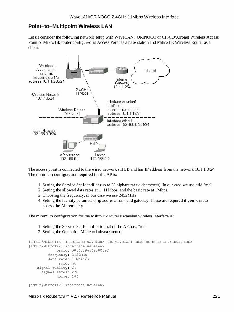
Point−to−Multipoint Wireless LAN
Let us consider the following network setup with WaveLAN / ORiNOCO or CISCO/Aironet Wireless AccessPoint or MikroTik router configured as Access Point as a base station and MikroTik Wireless Router as aclient:
The access point is connected to the wired network's HUB and has IP address from the network 10.1.1.0/24.The minimum configuration required for the AP is:
Setting the Service Set Identifier (up to 32 alphanumeric characters). In our case we use ssid "mt".1. Setting the allowed data rates at 1−11Mbps, and the basic rate at 1Mbps.2. Choosing the frequency, in our case we use 2452MHz.3. Setting the identity parameters: ip address/mask and gateway. These are required if you want toaccess the AP remotely.
4.
The minimum configuration for the MikroTik router's wavelan wireless interface is:
Setting the Service Set Identifier to that of the AP, i.e., "mt"1. Setting the Operation Mode to infrastructure2.
[admin@MikroTik] interface wavelan> set wavelan1 ssid mt mode infrastructure[admin@MikroTik] interface wavelan> bssid: 00:40:96:42:0C:9C frequency: 2437MHz data−rate: 11Mbit/s ssid: mt signal−quality: 64 signal−level: 228 noise: 163
[admin@MikroTik] interface wavelan>
WaveLAN/ORiNOCO 2.4GHz 11Mbps Wireless Interface
MikroTik RouterOS™ V2.7 Reference Manual 221
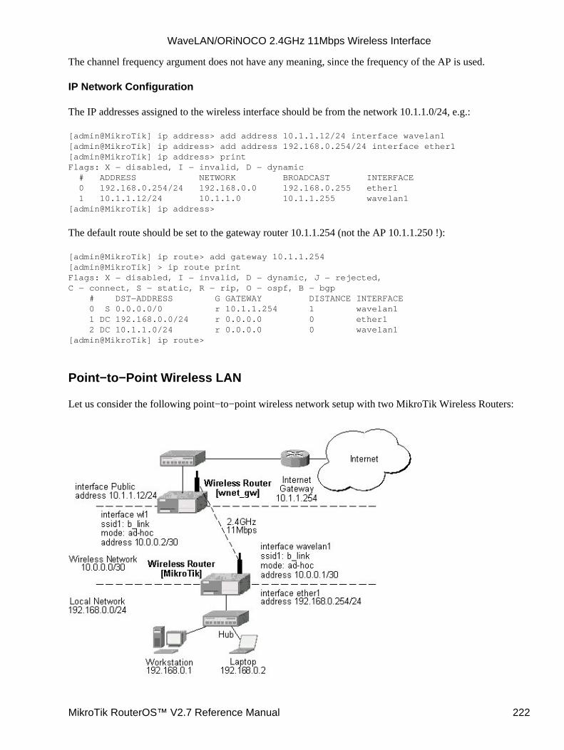
The channel frequency argument does not have any meaning, since the frequency of the AP is used.
IP Network Configuration
The IP addresses assigned to the wireless interface should be from the network 10.1.1.0/24, e.g.:
[admin@MikroTik] ip address> add address 10.1.1.12/24 interface wavelan1[admin@MikroTik] ip address> add address 192.168.0.254/24 interface ether1[admin@MikroTik] ip address> printFlags: X − disabled, I − invalid, D − dynamic # ADDRESS NETWORK BROADCAST INTERFACE 0 192.168.0.254/24 192.168.0.0 192.168.0.255 ether1 1 10.1.1.12/24 10.1.1.0 10.1.1.255 wavelan1[admin@MikroTik] ip address>
The default route should be set to the gateway router 10.1.1.254 (not the AP 10.1.1.250 !):
[admin@MikroTik] ip route> add gateway 10.1.1.254[admin@MikroTik] > ip route printFlags: X − disabled, I − invalid, D − dynamic, J − rejected,C − connect, S − static, R − rip, O − ospf, B − bgp # DST−ADDRESS G GATEWAY DISTANCE INTERFACE 0 S 0.0.0.0/0 r 10.1.1.254 1 wavelan1 1 DC 192.168.0.0/24 r 0.0.0.0 0 ether1 2 DC 10.1.1.0/24 r 0.0.0.0 0 wavelan1[admin@MikroTik] ip route>
Point−to−Point Wireless LAN
Let us consider the following point−to−point wireless network setup with two MikroTik Wireless Routers:
WaveLAN/ORiNOCO 2.4GHz 11Mbps Wireless Interface
MikroTik RouterOS™ V2.7 Reference Manual 222
To establish a point−to−point link, the configuration of the wireless interface should be as follows:
A unique Service Set Identificator should be chosen for both ends, say "b_link"• A channel frequency should be selected for the link, say 2412MHz• The operation mode should be set to ad−hoc•
The following command should be issued to change the settings for the wavelan interface:
[admin@MikroTik] interface wavelan> set 0 ssid b_link mode ad−hoc frewency 2412MHz[admin@MikroTik] interface wavelan> monitor wavelan1 bssid: 00:02:2D:07:17:23 frequency: 2412MHz data−rate: 11Mbit/s ssid: b_link signal−quality: 0 signal−level: 154 noise: 154[admin@MikroTik] interface wavelan>
The other router of the point−to−point link requires the same parameters to be set:
[admin@wnet_gw] interface wavelan> set 0 ssid b_link mode ad−hoc frequency 2412MHz[admin@wnet_gw] interface wavelan> enable 0[admin@wnet_gw] interface wavelan> monitor 0 bssid: 00:02:2D:07:17:23 frequency: 2412MHz data−rate: 11Mbit/s ssid: b_link signal−quality: 0 signal−level: 154 noise: 154[admin@wnet_gw] interface wavelan>
As we see, the MAC address under the 'bssid' parameter is the same as generated on the first router.
IP Network Configuration
If desired, IP addresses can be assigned to the wireless interfaces of the pint−to−point link routers using asmaller subnet, say 30−bit one:
[admin@MikroTik] ip address> add address 10.0.0.1/30 interface wavelan1[admin@MikroTik] ip address> add address 192.168.0.254/24 interface ether1[admin@MikroTik] ip address> print # ADDRESS NETMASK NETWORK BROADCAST INTERFACE 0 10.0.0.1 255.255.255.252 10.0.0.1 10.0.0.3 wavelan1 1 192.168.0.254 255.255.255.0 192.168.0.254 192.168.0.255 ether1[admin@MikroTik] ip address> /ip route add gateway 10.0.0.2[admin@MikroTik] > ip route printFlags: X − disabled, I − invalid, D − dynamic, J − rejected,C − connect, S − static, R − rip, O − ospf, B − bgp # DST−ADDRESS G GATEWAY DISTANCE INTERFACE 0 S 0.0.0.0/0 r 10.0.0.2 1 wavelan1 1 DC 10.0.0.0/30 r 0.0.0.0 0 wavelan1 2 DC 192.168.0.0/24 r 0.0.0.0 0 ether1[admin@MikroTik] ip address>
WaveLAN/ORiNOCO 2.4GHz 11Mbps Wireless Interface
MikroTik RouterOS™ V2.7 Reference Manual 223
The second router will have address 10.0.0.2, the default route to 10.1.1.254, and a static route for network192.168.0.0/24 to 10.0.0.1:
[admin@wnet_gw] ip address> add address 10.0.0.2/30 interface wl1[admin@wnet_gw] ip address> add address 10.1.1.12/24 interface Public[admin@wnet_gw] ip address> print # ADDRESS NETMASK NETWORK BROADCAST INTERFACE 0 10.0.0.2 255.255.255.252 10.0.0.2 10.0.0.3 wl1 1 10.1.1.12 255.255.255.0 10.1.1.12 10.1.1.255 Public[admin@wnet_gw] ip address> /ip route[admin@wnet_gw] ip route> add gateway 10.1.1.254 interface Public[admin@wnet_gw] ip route> add gateway 10.0.0.1 interface wl1 \\... dst−address 192.168.0.0/24[admin@MikroTik] > ip route printFlags: X − disabled, I − invalid, D − dynamic, J − rejected,C − connect, S − static, R − rip, O − ospf, B − bgp # DST−ADDRESS G GATEWAY DISTANCE INTERFACE 0 0.0.0.0/0 r 10.1.1.254 1 Public 1 192.168.0.0/24 r 10.0.0.1 1 wl1 2 10.0.0.0/30 r 0.0.0.0 0 wl1 3 10.1.1.0/24 r 0.0.0.0 0 Public[admin@wnet_gw] ip route>
Testing the Network Connectivity
The network connectivity can be tested by using ping:
[admin@MikroTik]> ping 10.0.0.210.0.0.2 pong: ttl=255 time=2 ms10.0.0.2 pong: ttl=255 time=2 ms10.0.0.2 pong: ttl=255 time=2 ms3 packets transmitted, 3 packets received, 0% packet lossround−trip min/avg/max = 2/2.0/2 ms[admin@MikroTik]>
Point−to−Point Wireless LAN with Windows Client
Let us consider the following point−to−point wireless network setup with one MikroTik Wireless Router anda laptop computer with Wavelan card:
WaveLAN/ORiNOCO 2.4GHz 11Mbps Wireless Interface
MikroTik RouterOS™ V2.7 Reference Manual 224
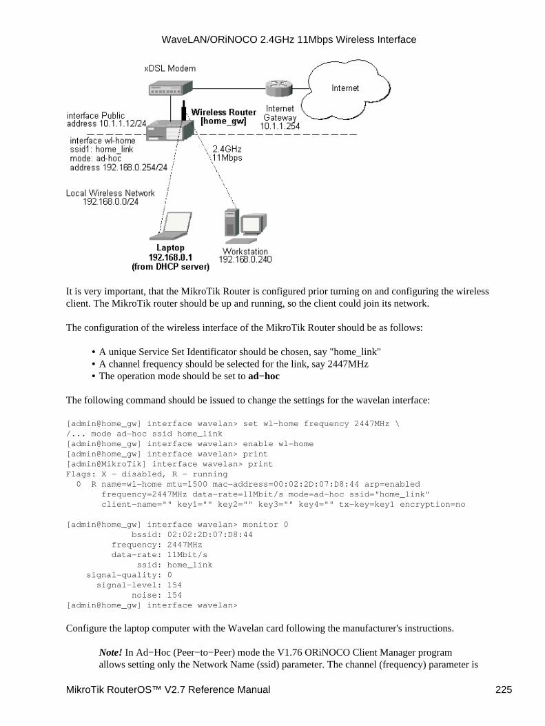
It is very important, that the MikroTik Router is configured prior turning on and configuring the wirelessclient. The MikroTik router should be up and running, so the client could join its network.
The configuration of the wireless interface of the MikroTik Router should be as follows:
A unique Service Set Identificator should be chosen, say "home_link"• A channel frequency should be selected for the link, say 2447MHz• The operation mode should be set to ad−hoc•
The following command should be issued to change the settings for the wavelan interface:
[admin@home_gw] interface wavelan> set wl−home frequency 2447MHz \/... mode ad−hoc ssid home_link[admin@home_gw] interface wavelan> enable wl−home[admin@home_gw] interface wavelan> print[admin@MikroTik] interface wavelan> printFlags: X − disabled, R − running 0 R name=wl−home mtu=1500 mac−address=00:02:2D:07:D8:44 arp=enabled frequency=2447MHz data−rate=11Mbit/s mode=ad−hoc ssid="home_link" client−name="" key1="" key2="" key3="" key4="" tx−key=key1 encryption=no
[admin@home_gw] interface wavelan> monitor 0 bssid: 02:02:2D:07:D8:44 frequency: 2447MHz data−rate: 11Mbit/s ssid: home_link signal−quality: 0 signal−level: 154 noise: 154[admin@home_gw] interface wavelan>
Configure the laptop computer with the Wavelan card following the manufacturer's instructions.
Note! In Ad−Hoc (Peer−to−Peer) mode the V1.76 ORiNOCO Client Manager programallows setting only the Network Name (ssid) parameter. The channel (frequency) parameter is
WaveLAN/ORiNOCO 2.4GHz 11Mbps Wireless Interface
MikroTik RouterOS™ V2.7 Reference Manual 225
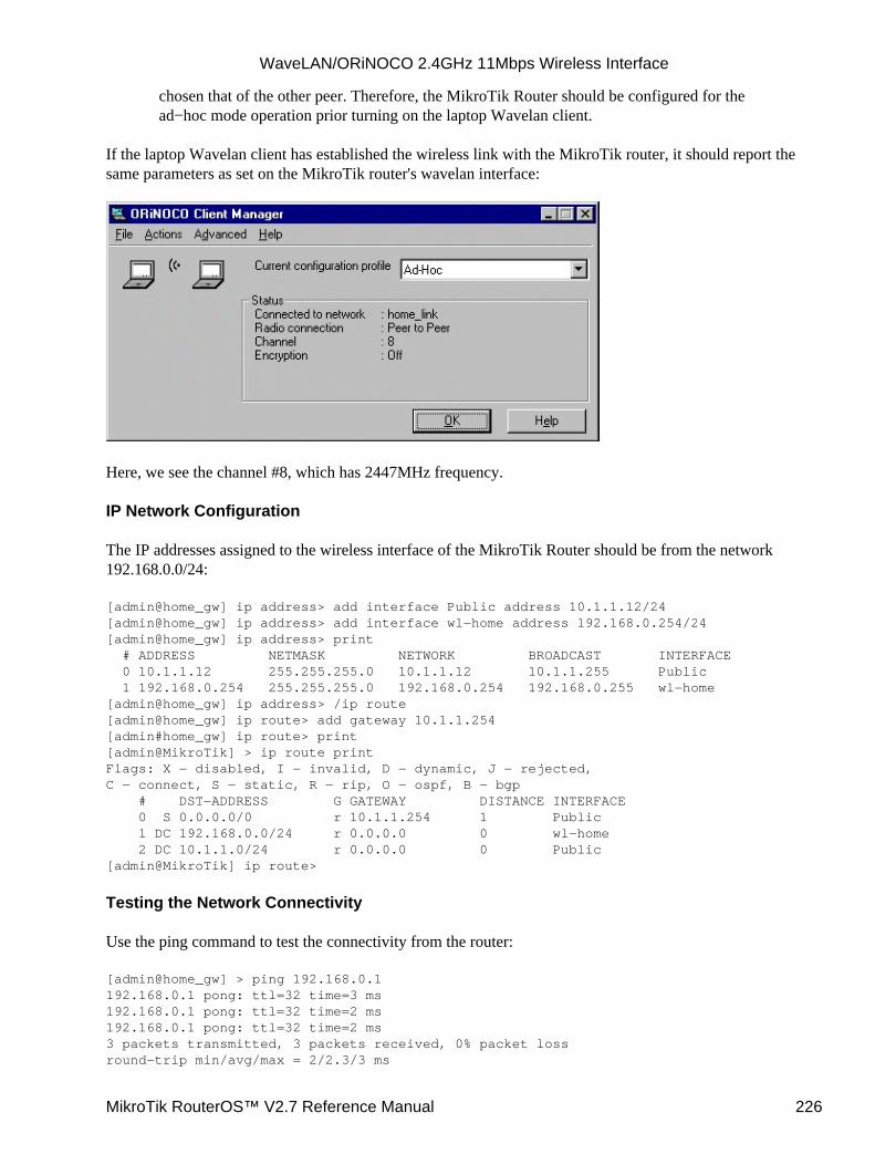
chosen that of the other peer. Therefore, the MikroTik Router should be configured for thead−hoc mode operation prior turning on the laptop Wavelan client.
If the laptop Wavelan client has established the wireless link with the MikroTik router, it should report thesame parameters as set on the MikroTik router's wavelan interface:
Here, we see the channel #8, which has 2447MHz frequency.
IP Network Configuration
The IP addresses assigned to the wireless interface of the MikroTik Router should be from the network192.168.0.0/24:
[admin@home_gw] ip address> add interface Public address 10.1.1.12/24[admin@home_gw] ip address> add interface wl−home address 192.168.0.254/24[admin@home_gw] ip address> print # ADDRESS NETMASK NETWORK BROADCAST INTERFACE 0 10.1.1.12 255.255.255.0 10.1.1.12 10.1.1.255 Public 1 192.168.0.254 255.255.255.0 192.168.0.254 192.168.0.255 wl−home[admin@home_gw] ip address> /ip route[admin@home_gw] ip route> add gateway 10.1.1.254[admin#home_gw] ip route> print[admin@MikroTik] > ip route printFlags: X − disabled, I − invalid, D − dynamic, J − rejected,C − connect, S − static, R − rip, O − ospf, B − bgp # DST−ADDRESS G GATEWAY DISTANCE INTERFACE 0 S 0.0.0.0/0 r 10.1.1.254 1 Public 1 DC 192.168.0.0/24 r 0.0.0.0 0 wl−home 2 DC 10.1.1.0/24 r 0.0.0.0 0 Public[admin@MikroTik] ip route>
Testing the Network Connectivity
Use the ping command to test the connectivity from the router:
[admin@home_gw] > ping 192.168.0.1192.168.0.1 pong: ttl=32 time=3 ms192.168.0.1 pong: ttl=32 time=2 ms192.168.0.1 pong: ttl=32 time=2 ms3 packets transmitted, 3 packets received, 0% packet lossround−trip min/avg/max = 2/2.3/3 ms
WaveLAN/ORiNOCO 2.4GHz 11Mbps Wireless Interface
MikroTik RouterOS™ V2.7 Reference Manual 226
[admin@home_gw] >
Additional Resources
For more information about the WaveLAN / ORiNOCO adapter hardware please see the relevant User’sGuides and Technical Reference Manuals in .pdf format from the manufacturer:
gsg_pc.pdf ORiNOCO PC Card Getting Started Guide• ug_pc.pdf ORiNOCO PC Card User's Guide• GSG_ISA.pdf ORiNOCO ISA Adapter Getting Started Guide• GSG_PCI.pdf ORiNOCO PCI Adapter Getting Started Guide•
Information about configuring the ORiNOCO wireless access point can be found there:
GSAP1000.pdf ORiNOCO Access Point 1000 (AP−1000) Getting Started Guide• ug_OM.pdf ORiNOCO Manager Suite User’s Guide•
© Copyright 1999−2003, MikroTik
WaveLAN/ORiNOCO 2.4GHz 11Mbps Wireless Interface
MikroTik RouterOS™ V2.7 Reference Manual 227

DHCP Client and ServerDocument revision 1.6 (05−May−2003)This document applies to the MikroTik RouterOS V2.7
Table of Contents
Table of Contents• Summary• Specifications• Related Documents• Description• DHCP Client Setup
Description♦ Property Description♦ Notes♦ Example♦
•
DHCP Server SetupDescription♦ Property Description♦ Notes♦ Example♦
•
DHCP Server LeasesDescription♦ Property Description♦ Notes♦ Example♦
•
Additional DHCP Resources•
Summary
DHCP (Dynamic Host Configuration Protocol) supports easy distribution of IP addresses for a network. TheMikroTik RouterOS implementation includes both server and client modes and is compliant with RFC2131.
General usage of DHCP:
IP assignment in LAN, cable−modem, and wireless systems• Obtaining IP settings on cable−modem systems•
IP addresses can be bound to MAC addresses using static lease feature.
DHCP server can be used with MikroTik RouterOS HotSpot feature to authenticate and account for DHCPclients. See the HotSpot Manual for more details.
Specifications
Packages required : dhcpLicense required : AnyHome menu level : /ip dhcp−client, /ip dhcp−server
MikroTik RouterOS™ V2.7 Reference Manual 228
Protocols utilized : DHCP (RFC2131)Hardware usage: not significant
Related Documents
Software Package Installation and UpgradingIP Addresses and Address Resolution Protocol (ARP)IP PoolsHotSpot Gateway
Description
The DHCP protocol gives and allocates IP addresses to IP clients. DHCP is basically insecure and should onlybe used on secure networks. DHCP server listens on UDP 67 port, DHCP client − on UDP 68 port.
DHCP Client Setup
Submenu level : /ip dhcp−client
Description
The MikroTik RouterOS DHCP client may be enabled on one Ethernet−like interface. The client will acceptan address, netmask, default gateway, and two dns server addresses. The IP address will be added to theinterface with the netmask. The default gateway will be added to the routing table as a dynamic entry. Whenthe DHCP client is disabled, the dynamic default route will be removed. If there is already a default routeinstalled prior the DHCP client obtains one, the route obtained by the DHCP client would be shown asinvalid.
The DNS−server from the DHCP server will be used as the router's default DNS if the router's DNS is set to0.0.0.0 under the /ip dns settings.
Property Description
enabled (yes | no, default: no) − whether the DHCP client is enabledinterface (name) − any Ethernet−like interface (this includes wireless and EoIP tunnels)host−name (string; default: "") − (optional) the host name of the clientclient−id (string; default: "") − (optional) corresponds to the settings suggested by the network administratoror ISPadd−default−route (yes | no, default: yes) − whether to add the default route to the gateway specified byDHCP serveruse−peer−dns (yes | no, default: yes) − whether to accept the DNS settings advertized by DHCP server (theywill appear in /ip dns settings)
Notes
If host−name property is not specified, client's system identity will be sent in the respective field of DHCPrequest.
DHCP Client and Server
MikroTik RouterOS™ V2.7 Reference Manual 229
If client−id property is not specified, client's MAC address will be sent in the respective field of DHCPrequest.
To renew current leases, use the renew command. If the renew operation was not successful, client tries toreinitialize lease (i.e. it starts lease request procedure as it has not received an IP address yet).
Example
To enable DHCP client on ether1 interface:
[admin@MikroTik] ip dhcp−client> set enabled=yes interface=ether1[admin@MikroTik] ip dhcp−client> print enabled: yes interface: ether1 host−name: "" client−id: "" add−default−route: yes use−peer−dns: yes
To show obtained leases:
[admin@MikroTik] ip dhcp−client> lease print address: 80.232.241.15/21 expires: oct/20/2002 09:43:50 gateway: 80.232.240.1 primary−dns: 195.13.160.52 secondary−dns: 195.122.1.59[admin@MikroTik] ip dhcp−client>
DHCP Server Setup
Submenu level : /ip dhcp−server
Description
The router supports an individual server for each Ethernet like interface. The MikroTik RouterOS DHCPserver supports the basic functions of giving each requesting client an IP address/netmask lease, defaultgateway, domain name, DNS−server(s) and WINS−server(s) (for Windows clients) information.
Property Description
name (name; default: "")− descriptive name for serverinterface (name) − Ethernet−like interface namelease−time (time; default: 72h) − the time that a client may use an address. The client will try to renew thisaddress after a half of this time and will request a new address after time limit expiresaddress−pool (name | static−only; default: static−only) − IP pool, from which to take IP addresses for clients
static−only − allow only the clients that have a static lease (i.e. no dynamic addresses will be given toclients, only the ones added in lease submenu)netmask (integer; default: 0) − the netmask to be used by DHCP clientgateway (IP address; default: 0.0.0.0) − the default gateway to be used by DHCP clientsrc−address (IP address; default: 0.0.0.0) − the address which the DHCP client must use to renew an IPaddress lease. If there is only one static address on the DHCP server interface and the source−address is left
•
DHCP Client and Server
MikroTik RouterOS™ V2.7 Reference Manual 230
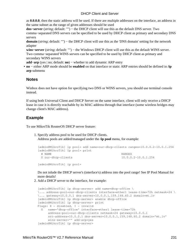
as 0.0.0.0, then the static address will be used. If there are multiple addresses on the interface, an address inthe same subnet as the range of given addresses should be useddns−server (string; default: "") − the DHCP client will use this as the default DNS server. Twocomma−separated DNS servers can be specified to be used by DHCP client as primary and secondary DNSserversdomain (string; default: "") − the DHCP client will use this as the 'DNS domain' setting for the networkadapterwins−server (string; default: "") − the Windows DHCP client will use this as the default WINS server.Two comma−separated WINS servers can be specified to be used by DHCP client as primary andsecondary WINS serversadd−arp (yes | no; default: no) − whether to add dynamic ARP entryno − either ARP mode should be enabled on that interface or static ARP entries should be defined in /iparp submenu
Notes
Winbox does not have option for specifying two DNS or WINS servers, you should use terminal consoleinstead.
If using both Universal Client and DHCP Server on the same interface, client will only receive a DHCPlease in case it is directly reachable by its MAC address through that interface (some wireless bridges maychange client's MAC address).
Example
To use MikroTik RouterOS DHCP server feature:
Specify address pool to be used for DHCP clients.Address pools are added/managed under the /ip pool menu, for example:
[admin@MikroTik] ip pool> add name=our−dhcp−clients ranges=10.0.0.2−10.0.1.254[admin@MikroTik] ip pool> print # NAME RANGES 0 our−dhcp−clients 10.0.0.2−10.0.1.254
[admin@MikroTik] ip pool>
Do not inlude the DHCP server's (interface's) address into the pool range! See IP Pool Manual formore details!
1.
Add a DHCP server to the interface, for example:
[admin@MikroTik] ip dhcp−server> add name=dhcp−office \\... address−pool=our−dhcp−clients interface=ether1 lease−time=72h netmask=24 \\... gateway=10.0.0.1 dns−server=10.0.0.1,159.148.60.2 domain=mt.lv[admin@MikroTik] ip dhcp−server> enable dhcp−office[admin@MikroTik] ip dhcp−server> printFlags: X − disabled, I − invalid 0 name="dhcp−office" interface=ether1 lease−time=72h address−pool=our−dhcp−clients netmask=24 gateway=10.0.0.1 src−address=10.0.0.1 dns−server=10.0.0.1,159.148.60.2 domain="mt.lv" wins−server="" add−arp=yes[admin@MikroTik] ip dhcp−server>
2.
•
DHCP Client and Server
MikroTik RouterOS™ V2.7 Reference Manual 231
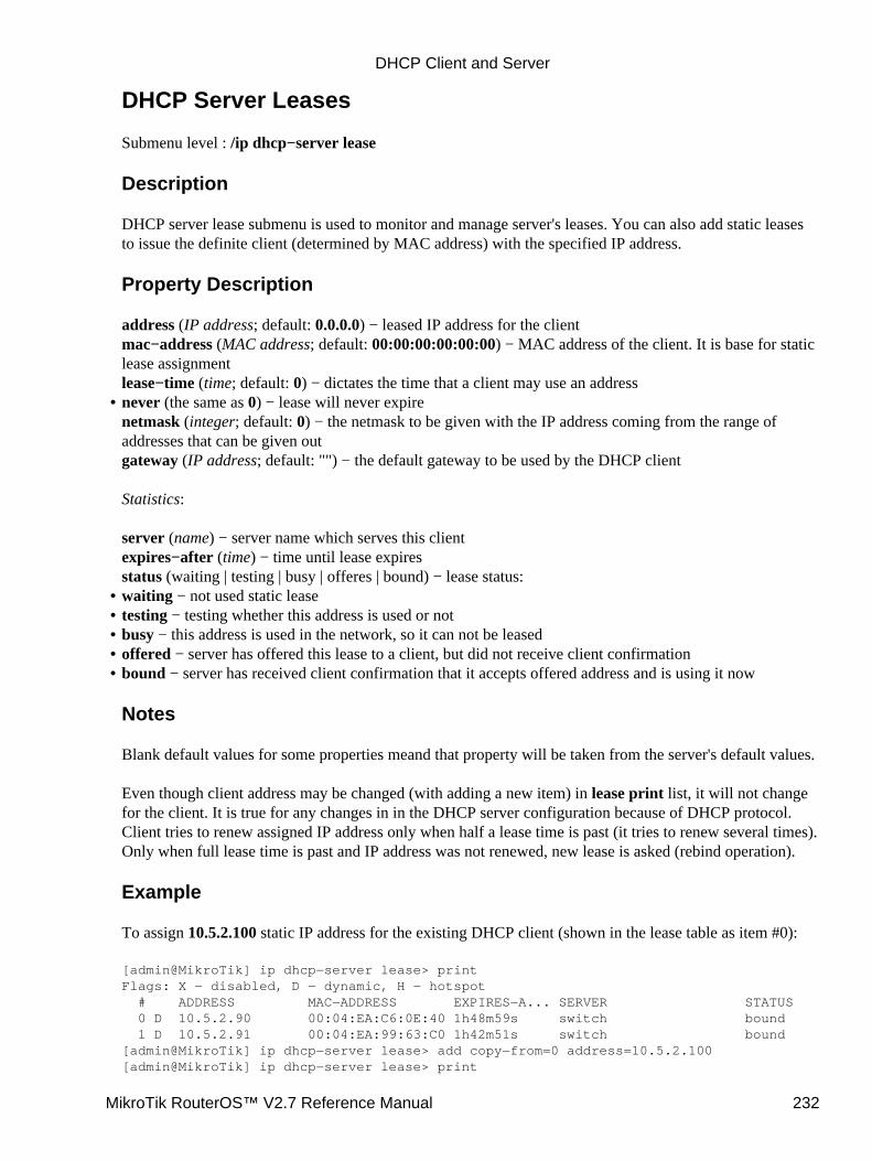
DHCP Server Leases
Submenu level : /ip dhcp−server lease
Description
DHCP server lease submenu is used to monitor and manage server's leases. You can also add static leasesto issue the definite client (determined by MAC address) with the specified IP address.
Property Description
address (IP address; default: 0.0.0.0) − leased IP address for the clientmac−address (MAC address; default: 00:00:00:00:00:00) − MAC address of the client. It is base for staticlease assignmentlease−time (time; default: 0) − dictates the time that a client may use an addressnever (the same as 0) − lease will never expirenetmask (integer; default: 0) − the netmask to be given with the IP address coming from the range ofaddresses that can be given outgateway (IP address; default: "") − the default gateway to be used by the DHCP client
Statistics:
server (name) − server name which serves this clientexpires−after (time) − time until lease expiresstatus (waiting | testing | busy | offeres | bound) − lease status:
•
waiting − not used static lease• testing − testing whether this address is used or not• busy − this address is used in the network, so it can not be leased• offered − server has offered this lease to a client, but did not receive client confirmation• bound − server has received client confirmation that it accepts offered address and is using it now
Notes
Blank default values for some properties meand that property will be taken from the server's default values.
Even though client address may be changed (with adding a new item) in lease print list, it will not changefor the client. It is true for any changes in in the DHCP server configuration because of DHCP protocol.Client tries to renew assigned IP address only when half a lease time is past (it tries to renew several times).Only when full lease time is past and IP address was not renewed, new lease is asked (rebind operation).
Example
To assign 10.5.2.100 static IP address for the existing DHCP client (shown in the lease table as item #0):
[admin@MikroTik] ip dhcp−server lease> printFlags: X − disabled, D − dynamic, H − hotspot # ADDRESS MAC−ADDRESS EXPIRES−A... SERVER STATUS 0 D 10.5.2.90 00:04:EA:C6:0E:40 1h48m59s switch bound 1 D 10.5.2.91 00:04:EA:99:63:C0 1h42m51s switch bound[admin@MikroTik] ip dhcp−server lease> add copy−from=0 address=10.5.2.100[admin@MikroTik] ip dhcp−server lease> print
•
DHCP Client and Server
MikroTik RouterOS™ V2.7 Reference Manual 232
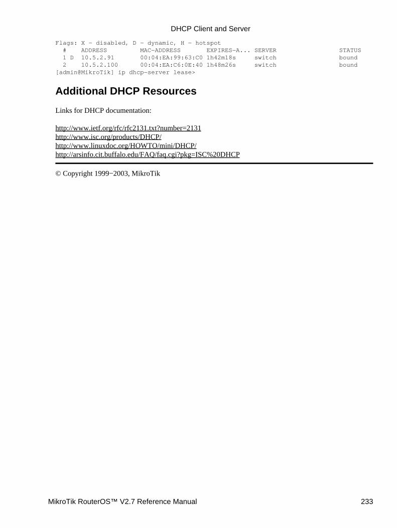
Flags: X − disabled, D − dynamic, H − hotspot # ADDRESS MAC−ADDRESS EXPIRES−A... SERVER STATUS 1 D 10.5.2.91 00:04:EA:99:63:C0 1h42m18s switch bound 2 10.5.2.100 00:04:EA:C6:0E:40 1h48m26s switch bound[admin@MikroTik] ip dhcp−server lease>
Additional DHCP Resources
Links for DHCP documentation:
http://www.ietf.org/rfc/rfc2131.txt?number=2131http://www.isc.org/products/DHCP/http://www.linuxdoc.org/HOWTO/mini/DHCP/http://arsinfo.cit.buffalo.edu/FAQ/faq.cgi?pkg=ISC%20DHCP
© Copyright 1999−2003, MikroTik
DHCP Client and Server
MikroTik RouterOS™ V2.7 Reference Manual 233
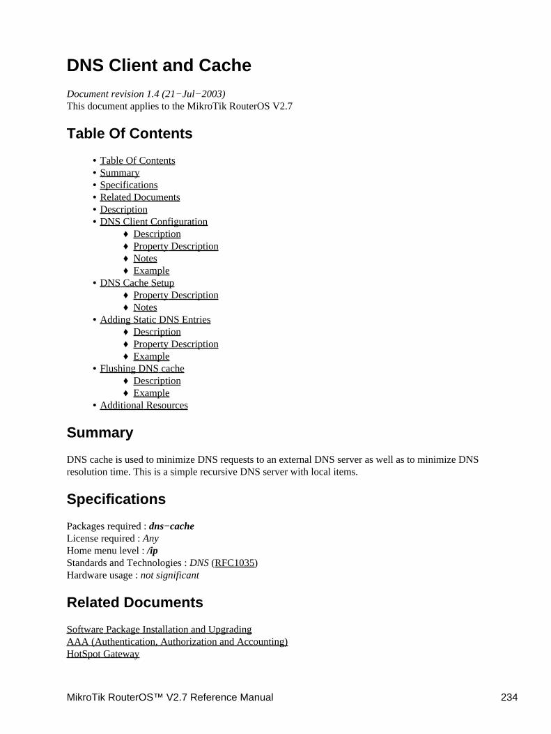
DNS Client and CacheDocument revision 1.4 (21−Jul−2003)This document applies to the MikroTik RouterOS V2.7
Table Of Contents
Table Of Contents• Summary• Specifications• Related Documents• Description• DNS Client Configuration
Description♦ Property Description♦ Notes♦ Example♦
•
DNS Cache SetupProperty Description♦ Notes♦
•
Adding Static DNS EntriesDescription♦ Property Description♦ Example♦
•
Flushing DNS cacheDescription♦ Example♦
•
Additional Resources•
Summary
DNS cache is used to minimize DNS requests to an external DNS server as well as to minimize DNSresolution time. This is a simple recursive DNS server with local items.
Specifications
Packages required : dns−cacheLicense required : AnyHome menu level : /ipStandards and Technologies : DNS (RFC1035)Hardware usage : not significant
Related Documents
Software Package Installation and UpgradingAAA (Authentication, Authorization and Accounting)HotSpot Gateway
MikroTik RouterOS™ V2.7 Reference Manual 234
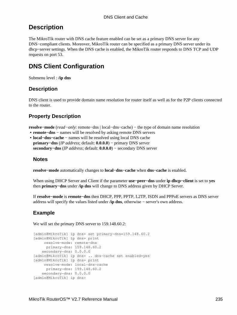
Description
The MikroTik router with DNS cache feature enabled can be set as a primary DNS server for anyDNS−compliant clients. Moreover, MikroTik router can be specified as a primary DNS server under itsdhcp−server settings. When the DNS cache is enabled, the MikroTik router responds to DNS TCP and UDPrequests on port 53.
DNS Client Configuration
Submenu level : /ip dns
Description
DNS client is used to provide domain name resolution for router itself as well as for the P2P clients connectedto the router.
Property Description
resolve−mode (read−only: remote−dns | local−dns−cache) − the type of domain name resolutionremote−dns − names will be resolved by asking remote DNS servers• local−dns−cache − names will be resolved using local DNS cacheprimary−dns (IP address; default: 0.0.0.0) − primary DNS serversecondary−dns (IP address; default: 0.0.0.0) − secondary DNS server
Notes
resolve−mode automatically changes to local−dns−cache when dns−cache is enabled.
When using DHCP Server and Client if the parameter use−peer−dns under ip dhcp−client is set to yesthen primary−dns under /ip dns will change to DNS address given by DHCP Server.
If resolve−mode is remote−dns then DHCP, PPP, PPTP, L2TP, ISDN and PPPoE servers as DNS serveraddress will specify the values listed under /ip dns, otherwise − server's own address.
Example
We will set the primary DNS server to 159.148.60.2:
[admin@MikroTik] ip dns> set primary−dns=159.148.60.2[admin@MikroTik] ip dns> print resolve−mode: remote−dns primary−dns: 159.148.60.2 secondary−dns: 0.0.0.0[admin@MikroTik] ip dns> .. dns−cache set enabled=yes[admin@MikroTik] ip dns> print resolve−mode: local−dns−cache primary−dns: 159.148.60.2 secondary−dns: 0.0.0.0[admin@MikroTik] ip dns>
•
DNS Client and Cache
MikroTik RouterOS™ V2.7 Reference Manual 235

You can see that resolve−mode has changed its value to local−dns−cache. It means that from this momentdomain names will be resolved using local DNS cache.
DNS Cache Setup
Submenu level : /ip dns−cache
[admin@MikroTik] ip dns−cache> print enabled: no size: 256 primary−server: 0.0.0.0 secondary−server: 0.0.0.0 running: no[admin@MikroTik] ip dns−cache>
Property Description
enabled (yes | no; default: no) − defines whether DNS cache (TCP and UDP port 53) is enabledsize (integer; default: 256) − size of cache in kilobytesprimary−server (IP address; default: 0.0.0.0) − primary DNS serversecondary−server (IP address; default: 0.0.0.0) − secondary DNS serverrunning (read only: yes | no) − whether the DNS cache is currently runningusage (read only: percentage) − percent of cache usedentries (read only: integer) − number of entries in cache
Notes
usage and entries are showed only when the DNS cache is running.
DNS servers are queried by DNS cache in the following order (the ones which are 0.0.0.0 are skipped):
ip dns−cache primary−server1. ip dns−cache secondary−server2. ip dns primary−server3. ip dns secondary−server4.
Example
To enable DNS cache using 159.148.60.2 as the router's primary DNS server:
[admin@MikroTik] ip dns−cache> set enabled=yes primary−server=159.148.60.2[admin@MikroTik] ip dns−cache> print enabled: yes size: 256 primary−server: 159.148.60.2 secondary−server: 0.0.0.0 running: yes usage: 0 % entries: 0[admin@MikroTik] ip dns−cache>
DNS Client and Cache
MikroTik RouterOS™ V2.7 Reference Manual 236
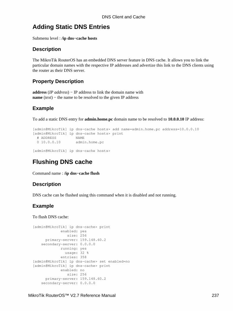
Adding Static DNS Entries
Submenu level : /ip dns−cache hosts
Description
The MikroTik RouterOS has an embedded DNS server feature in DNS cache. It allows you to link theparticular domain names with the respective IP addresses and advertize this link to the DNS clients usingthe router as their DNS server.
Property Description
address (IP address) − IP address to link the domain name withname (text) − the name to be resolved to the given IP address
Example
To add a static DNS entry for admin.home.pc domain name to be resolved to 10.0.0.10 IP address:
[admin@MikroTik] ip dns−cache hosts> add name=admin.home.pc address=10.0.0.10[admin@MikroTik] ip dns−cache hosts> print # ADDRESS NAME 0 10.0.0.10 admin.home.pc
[admin@MikroTik] ip dns−cache hosts>
Flushing DNS cache
Command name : /ip dns−cache flush
Description
DNS cache can be flushed using this command when it is disabled and not running.
Example
To flush DNS cache:
[admin@MikroTik] ip dns−cache> print enabled: yes size: 256 primary−server: 159.148.60.2 secondary−server: 0.0.0.0 running: yes usage: 32 % entries: 358[admin@MikroTik] ip dns−cache> set enabled=no[admin@MikroTik] ip dns−cache> print enabled: no size: 256 primary−server: 159.148.60.2 secondary−server: 0.0.0.0
DNS Client and Cache
MikroTik RouterOS™ V2.7 Reference Manual 237
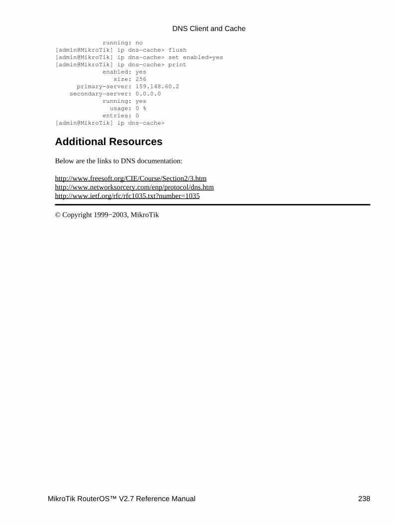
running: no[admin@MikroTik] ip dns−cache> flush[admin@MikroTik] ip dns−cache> set enabled=yes[admin@MikroTik] ip dns−cache> print enabled: yes size: 256 primary−server: 159.148.60.2 secondary−server: 0.0.0.0 running: yes usage: 0 % entries: 0[admin@MikroTik] ip dns−cache>
Additional Resources
Below are the links to DNS documentation:
http://www.freesoft.org/CIE/Course/Section2/3.htmhttp://www.networksorcery.com/enp/protocol/dns.htmhttp://www.ietf.org/rfc/rfc1035.txt?number=1035
© Copyright 1999−2003, MikroTik
DNS Client and Cache
MikroTik RouterOS™ V2.7 Reference Manual 238
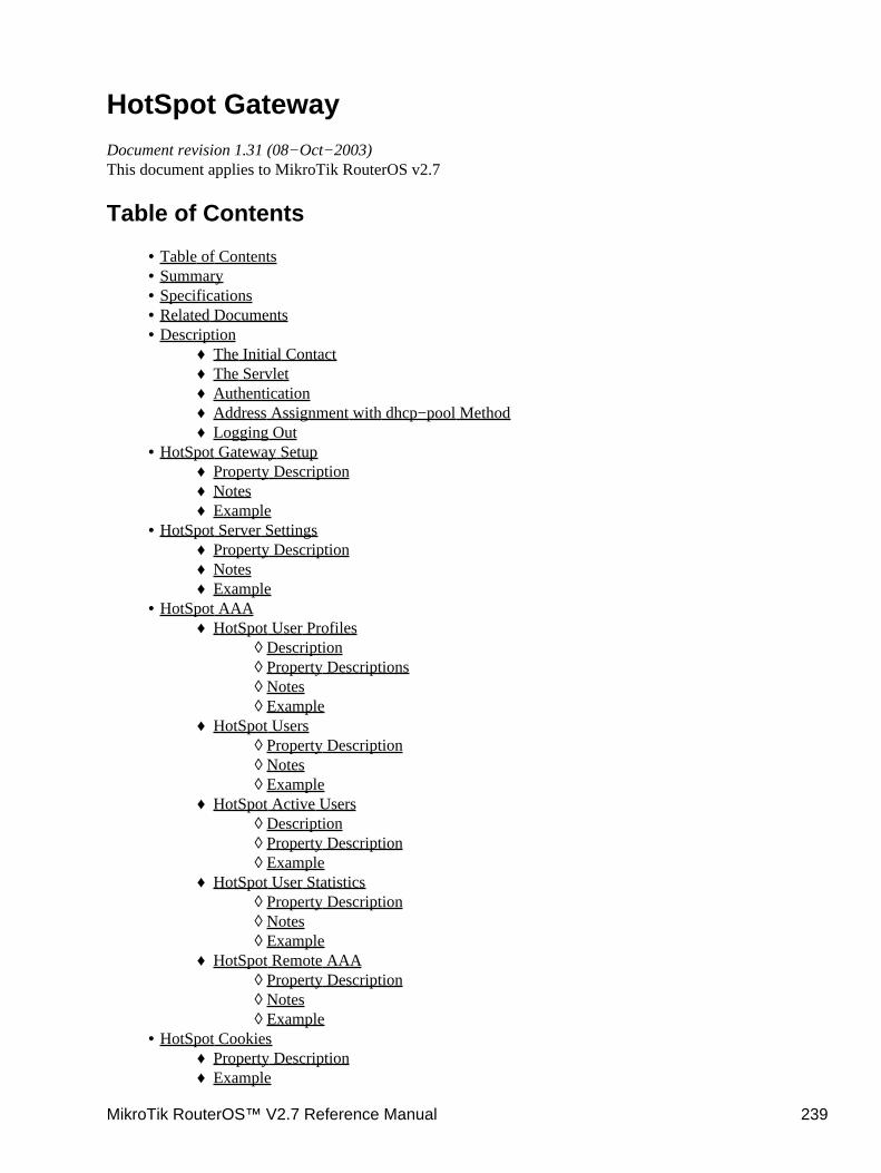
HotSpot GatewayDocument revision 1.31 (08−Oct−2003)This document applies to MikroTik RouterOS v2.7
Table of Contents
Table of Contents• Summary• Specifications• Related Documents• Description
The Initial Contact♦ The Servlet♦ Authentication♦ Address Assignment with dhcp−pool Method♦ Logging Out♦
•
HotSpot Gateway SetupProperty Description♦ Notes♦ Example♦
•
HotSpot Server SettingsProperty Description♦ Notes♦ Example♦
•
HotSpot AAAHotSpot User Profiles
Description◊ Property Descriptions◊ Notes◊ Example◊
♦
HotSpot UsersProperty Description◊ Notes◊ Example◊
♦
HotSpot Active UsersDescription◊ Property Description◊ Example◊
♦
HotSpot User StatisticsProperty Description◊ Notes◊ Example◊
♦
HotSpot Remote AAAProperty Description◊ Notes◊ Example◊
♦
•
HotSpot CookiesProperty Description♦ Example♦
•
MikroTik RouterOS™ V2.7 Reference Manual 239
Customizing Hotspot ServletDescription♦ Variable Description♦ Examples♦
•
Resetting Hotspot Servlet customizationsDescription♦ Example♦
•
QuestionSetupQuestions♦ Notes♦ Example♦
•
HotSpot Step−by−Step User Guidedhcp−pool Method
Planning the Configuration◊ Setup Example◊
♦
enabled−address MethodPlanning the Configuration◊ Setup Example◊
♦
Optional Settings♦
•
Troubleshooting•
Summary
The MikroTik HotSpot Gateway enables provision of public network access for clients using wireless orwired network connections.
HotSpot Gateway features:
authentication of clients using local client database, or RADIUS server• accounting using local log database, or RADIUS server• HotSpot Gateway can provide access for authorized clients using two different methods
dhcp−pool method uses DHCP server to assign temporary (not valid in outer networks) IPaddresses to clients prior to authentication. After successful authentication the DHCP serverassigns address to client from different pool. This method may be used to assign a fixed IPaddress to each user (i.e. no matter which computed does the user use, he/she will always usethe same IP address)
♦
enabled−address method enables traffic for authorized clients without IP address change♦
•
traffic and connection time accounting• clients can be limitated by
download/upload speed (tx/rx bitrate)♦ connection time♦ downloaded/uploaded traffic (bytes)♦
•
Universal Clinet feature may be used with HotSpot enabled−address method to provide IP network servicesregardless of client computers' IP network settings.
Specifications
Packages required : hotspot, dhcp(optional, required by dhcp−pool method), web−proxy (optional)License required : Basic plus any additional (limited to 4 active users otherwise)
HotSpot Gateway
MikroTik RouterOS™ V2.7 Reference Manual 240
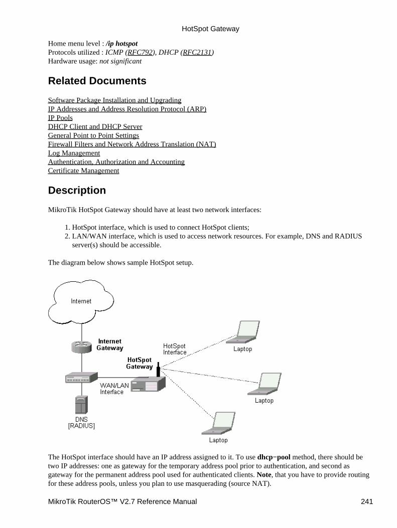
Home menu level : /ip hotspotProtocols utilized : ICMP (RFC792), DHCP (RFC2131)Hardware usage: not significant
Related Documents
Software Package Installation and UpgradingIP Addresses and Address Resolution Protocol (ARP)IP PoolsDHCP Client and DHCP ServerGeneral Point to Point SettingsFirewall Filters and Network Address Translation (NAT)Log ManagementAuthentication, Authorization and AccountingCertificate Management
Description
MikroTik HotSpot Gateway should have at least two network interfaces:
HotSpot interface, which is used to connect HotSpot clients;1. LAN/WAN interface, which is used to access network resources. For example, DNS and RADIUSserver(s) should be accessible.
2.
The diagram below shows sample HotSpot setup.
The HotSpot interface should have an IP address assigned to it. To use dhcp−pool method, there should betwo IP addresses: one as gateway for the temporary address pool prior to authentication, and second asgateway for the permanent address pool used for authenticated clients. Note, that you have to provide routingfor these address pools, unless you plan to use masquerading (source NAT).
HotSpot Gateway
MikroTik RouterOS™ V2.7 Reference Manual 241
Only in dhcp−pool case, the arp feature should be set to reply−only on HotSpot interface to prevent networkaccess using static IP addresses (the DHCP server will add static ARP entries for each DHCP client).
Physical network connection has to be established between the HotSpot user's computer and the gateway. Itcan be wireless (the wireless card should be registed to AP), or wired (the NIC card should be connected to aHUB or a switch).
Note that Universal Client feature cannot be used with dhcp−pool method.
The Initial Contact
One of two methods may be used for each client individually (you may choose one or allow it to be doneautomatically). The enabled−address method is preferred, so if it is configured correctly and the client has aproper IP address (that matches the one set in the user database), this method is to be used.
If the enabled−address method is not enabled or the client's IP address should be changed, the HotSpotGateway tries to use dhcp−pool method. In that case, MikroTik HotSpot Gateway's DHCP server assigns IPaddresses from the temporary address pool with a very short lease time (approx. 14s), so the address can bechanged after authentication.
If user tries to access network resources using web browser, the destination NAT rule redirects all TCPconnection requests to HotSpot service (port 8088 by default). This brings up the HotSpot Welcome/Loginpage.
It may be useful to have port 80 for HotSpot service because the users might want to see status and log outpages. If this is impossible, you may assign virtual IP address for hotspot service. It is done by redirecting allrequests going to that virtual IP to hotspot service.
Note that you may want to have DNS traffic enabled (or redirected to the router's DNS cache) so that theclient could be logged in connecting any valid web−page (using it's DNS name). Enabling ICMP ping mightbe useful as well, since it shows network connectivity. Other traffic should be dropped.
The Servlet
If user is not logged in, login page will be shown (where username and password has to be entered), but ifuser is logged in, status page will be shown (status: username, IP address, session time, bytes and packetstransferred, ...). There are 6 HTML pages that can be easily modified by creating HTML template pages anduploading them to the hotspot folder on MikroTik router. These pages are called 'servlet' in this document andare described in detailes later on.
Authentication
Going to any HTTP address with web browser will be redirected to HotSpot authentication page promptingfor username and password. Password together with HotSpot generated challenge string is hashed using MD5algorithm (which in this case is implemented using JavaScript) and is executed on client's computer by webbrowser. After that, the hash result together with username is sent over Ethernet network to HotSpot service.So, password is never sent in plain text over ip network.
Note that password encryption is the reason why web browsers, that do not support JavaScript (for example,Internet Explorer 2.0), will not be able to authenticate users. It is possible to allow unencrypted passwords to
HotSpot Gateway
MikroTik RouterOS™ V2.7 Reference Manual 242
be accepted, but it is not recommended to use this feature.
HotSpot can authenticate users using local user database or a RADIUS server (local database if consupledfirst, then − RADIUS server) If authentication is done locally, profile corresponding to that user is used,otherwise (in case of RADIUS) default profile is used to set default values for parameters, which are not set inRADIUS access−accept message.
If authentication by http cookie is enabled, then after each successful login cookie is sent to web browser andthe same cookie is added to active HTTP cookie list. Next time user will try to log in, web browser will sendhttp cookie. This cookie will be compared to the one on HotSpot and only if there is the same source MACaddress and the same randomly generated ID, user is automatically logged in. New cookie with differentrandom ID is sent to web browser. Old cookie is removed from local HotSpot active cookie list. New one withnew expire time is added.
Address Assignment with dhcp−pool Method
When user is successfully authenticated, HotSpot assigns another IP address for client (static or from some IPpool). On next clients DHCP request, the new IP address will be given by DHCP server to this client. Howmuch time this IP address change requires, depends on DHCP lease time for non authenticated users. HotSpotlogin−delay parameter should be set accordingly to this DHCP server lease time. If lease time is 10s, then reallogin−delay will be about 1..7 seconds. So, it is quite safe to set login−delay to 8s in this case.
While IP address is changed, user sees after−login (alogin.html) page. This page will automatically forwarduser to original destination address (or status page, if there was no original dst address) after login−delay timewill pass.
Logging Out
User can log out using status page. There is a link to http://HotSpot−IP/logout Going to this page will logoutuser. After that logout page (logout.html) will be shown to user.
HotSpot Gateway Setup
Submenu level : /ip hotspot
[admin@MikroTik] ip hotspot> print use−ssl: no hotspot−address: 0.0.0.0 dns−name: "" status−autorefresh: 1m universal−proxy: no auth−mac: no auth−mac−password: no auth−http−cookie: no http−cookie−lifetime: 1d allow−unencrypted−passwords: no split−user−domain: no[admin@MikroTik] ip hotspot>
HotSpot Gateway
MikroTik RouterOS™ V2.7 Reference Manual 243
Property Description
use−ssl (yes | no, default: no) − whether the servlet allows only HTTPS:yes − the regintration may only occur using the Secure HTTP (HTTPS) protocol• no − the registration may be accomplished using both HTTP and HTTPS protocolshotspot−address (IP address, default: 0.0.0.0) − IP address for HotSpot service (used for www access)status−autorefresh (time, default: 1m) − WWW status page autorefresh timeuniversal−proxy (yes | no; default: no) − whether to intercept the requests to HTTP proxy serversauth−mac (yes | no, default: no) − defines whether authentication by ethernet MAC address is enabledauth−mac−password (yes | no, default: no) − uses MAC address as password if MAC authorization isenabledauth−http−cookie (yes | no, default: no) − defines whether HTTP authentication by cookie is enabledhttp−cookie−lifetime (time, default: 1d) − validity time of HTTP cookiesallow−unencrypted−passwords (yes | no; default: no) − whether to authenticate user if plain−textpassword is receivedsplit−user−domain (yes | no; default: no) − whether to split username from domain name when theusername is given in "user@domain" or in "domain\user" format
Notes
If dns−name property is not specified, hotspot−address is used instead. If hotspot−address is also absent,then both are to be detected automatically.
If auth−mac is enabled, then client is not prompted for username and password if the MAC address of thiscomputer is in the user database (either local or on RADIUS). Nevertheless this method does not excuseclients from the common login procedure, just from filling out the registration form (i.e. regardless ofwhether MAC authorization is applicable for a client, he/she should open the Login page in order to getregistred)
universal−proxy requires web−proxy software package. This feature automatically creates DST−NATrules to redirect requests of each particular user to a proxy server he/she is using (it may be set in his/hersettings to use an unknown to us proxy server) to the local proxy server. To get it work you shuold haveweb proxy server up and running. This feature may be used in combination with Universal Client feature toprovide Internet access for users regardless of their network settings.
If you are using a parent proxy with universal proxy feature, you should add a rule to the Direct Access listfor each IP address HotSpot is running on allowing the requests destined to the local HotSpot server to beresolved directly by the local web proxy. For example, if the HotSpot server is running on 10.0.0.1 address:
/ip web−proxy direct add dst−address=10.0.0.1/32 action=allow
allow−unencrypted−passwords property makes it possible to authenticate with the browsers notsupporting JavaScript. It is also possible to log−in using telnet connection, just requesting the page/login?user=usernameword. An another use of this property is the possibility of hard−codedauthentication information in the servlet's login page simply creating the appropriate link.
The domain get from the username (enabling split−user−domain property) is used later in AAA process(for example, to specify different RADIUS servers for authentication depending on domain name)
•
HotSpot Gateway
MikroTik RouterOS™ V2.7 Reference Manual 244
Example
To enable cookie support:
[admin@MikroTik] ip hotspot> set auth−http−cookie=yes[admin@MikroTik] ip hotspot> print use−ssl: no hotspot−address: 0.0.0.0 dns−name: "" status−autorefresh: 1m universal−proxy: no auth−mac: no auth−mac−password: no auth−http−cookie: yes http−cookie−lifetime: 1d allow−unencrypted−passwords: no split−user−domain: no
HotSpot Server Settings
Submenu level : /ip hotspot server
Property Description
name (name, default: "") − server profile namedhcp−server (name) − DHCP server with which to use this profilelease−time (time, default: 1m) − DHCP lease time for logged in userlogin−delay (time, default: 10s) − Time required to log in useraddress−pool (name) − IP pool name, from which HotSpot client will get IP address if it is not given somestatic alreadynetmask (integer, default: 0)− network maskgateway (IP address, default: 0.0.0.0) − default gateway
Notes
This configuration is ignored by enabled−address method.
There can be added one server for each DHCP server. Which server profile to apply will depend on DHCPserver which gave DHCP lease to that client. Actually it means that if user will log in from differentinterfaces, then different server profiles will be used. It allows assigning different IP addresses on differentethernet interfaces.
Example
To add hotspot server named dhcp1 to the DHCP server hotspot−dhcp giving IP addresses from thehotspot pool with network mask 24 and gateway address 10.0.0.1:
[admin@MikroTik] ip hotspot server> add name=dhcp1 dhcp−server=hotspot−dhcp \\... address−pool=hotspot netmask=24 gateway=10.0.0.1[admin@MikroTik] ip hotspot server> print 0 name="dhcp1" dhcp−server=hotspot−dhcp lease−time=1m login−delay=10s address−pool=hotspot netmask=24 gateway=10.0.0.1
HotSpot Gateway
MikroTik RouterOS™ V2.7 Reference Manual 245
[admin@MikroTik] ip hotspot server>
HotSpot AAA
HotSpot User Profiles
Submenu level : /ip hotspot profile
Description
User profiles are used for common user settings. Profiles are like user groupes, they are grouping users withthe same limits
Property Descriptions
name (name) − profile namesession−timeout (time, default: 0s) − session timeout (maximal session time) for clientidle−timeout (time, default: 0s) − idle timeout (maximal period of inactivity) for clientonly−one (yes | no, default: yes) − only one simultaneous login per usertx−bit−rate (integer, default: 0) − transmit bitrate0 − no limitationrx−bit−rate (integer, default: 0) − receive bitrate
•
0 − no limitationincoming−filter (name, default: "") − firewall chain name for incoming packetsoutgoing−filter (name, default: "") − firewall chain name for outgoing packetsmark−flow (name, default: "") − traffic from logged in users will be marked by firewall mangle with thisflow namelogin−method (dhcp−pool | enabled−address | smart, default: smart) − the login method user will be using:
•
dhcp−pool − login by changing IP address via DHCP server• enabled−address − login by enabling access for client's existing IP address• smart − choose best login method for each casekeepalive−timeout (time, default: 2m) − keepalive timeout for client
Notes
To use enabled−address method, mark−flow should be set
To use dhcp−pool method, dhcp software package should be installed
idle−timeout is used to detect, that client is not using outer networks ( e.g. Internet), i.e., there is NOTRAFFIC coming from that client and going through the router. keepalive−timeout is used to detect, thatthe computer of the client is still alive and reachable. Server will check client's reachability. If check willfail during this period, client will be logged out.
Example
To use enabled−address method that uses logged−in mark and logs a client off if he disappears for morethen a minute:
[admin@MikroTik] ip hotspot profile> set default login−method=enabled−address \\... mark−flow=logged−in keepalive−timeout=1m
•
HotSpot Gateway
MikroTik RouterOS™ V2.7 Reference Manual 246
[admin@MikroTik] ip hotspot profile> printFlags: * − default 0 * name="default" session−timeout=0s idle−timeout=0s only−one=yes tx−bit−rate=0 rx−bit−rate=0 incoming−filter="" outgoing−filter="" mark−flow="logged−in" login−method=enabled−address keepalive−timeout=1m
[admin@MikroTik] ip hotspot profile>
To define an additional profile that also limits download speed to 64 kilobyte/s and upload data rate to 32kilobyte/s, and call it limited:
[admin@MikroTik] ip hotspot profile> add copy−from=default tx−bit−rate=65536 rx−bit−rate=32768 name=limited[admin@MikroTik] ip hotspot profile> printFlags: * − default 0 * name="default" session−timeout=0s idle−timeout=0s only−one=yes tx−bit−rate=0 rx−bit−rate=0 incoming−filter="" outgoing−filter="" mark−flow="logged−in" login−method=enabled−address keepalive−timeout=1m
1 name="limited" session−timeout=0s idle−timeout=0s only−one=yes tx−bit−rate=65536 rx−bit−rate=32768 incoming−filter="" outgoing−filter="" mark−flow="logged−in" login−method=enabled−address keepalive−timeout=1m
[admin@MikroTik] ip hotspot profile>
HotSpot Users
Submenu level : /ip hotspot user
Property Description
name (name) − user namepassword (string, default: "") − user passwordaddress (IP address, default: 0.0.0.0) − static IP address. If not 0.0.0.0, client will get always the same IPaddress. It implies, that only one simultaneous login for that user is allowedmac−address (MAC address, default: 00:00:00:00:00:00) − static MAC address. If not00:00:00:00:00:00, client is allowed to login only from that MAC addressprofile (name, default: default) − user profileroutes (string, default: "") − routes that appear on the server when the client is connected. The route formatis: "dst−address gateway metric" (for example, "10.1.0.0/ 24 10.0.0.1 1"). Several routes may be specifiedseparated with commaslimit−uptime (time, default: 0s) − total uptime limit for user (pre−paid time)limit−bytes−in (integer, default: 0) − maximum amount of bytes user can transmitlimit−bytes−out (integer, default: 0)− maximum amount of bytes user can receive
Notes
MAC address should be written in CAPITAL letters
HotSpot Gateway
MikroTik RouterOS™ V2.7 Reference Manual 247
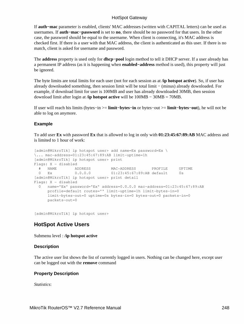
If auth−mac parameter is enabled, clients' MAC addresses (written with CAPITAL letters) can be used asusernames. If auth−mac−password is set to no, there should be no password for that users. In the othercase, the password should be equal to the username. When client is connecting, it's MAC address ischecked first. If there is a user with that MAC address, the client is authenticated as this user. If there is nomatch, client is asked for username and password.
The address property is used only for dhcp−pool login method to tell it DHCP server. If a user already hasa permanent IP address (as it is happening when enabled−address method is used), this property will justbe ignored.
The byte limits are total limits for each user (not for each session as at /ip hotspot active). So, if user hasalready downloaded something, then session limit will be total limit − (minus) already downloaded. Forexample, if download limit for user is 100MB and user has already downloaded 30MB, then sessiondownload limit after login at /ip hotspot active will be 100MB − 30MB = 70MB.
If user will reach his limits (bytes−in >= limit−bytes−in or bytes−out >= limit−bytes−out), he will not beable to log on anymore.
Example
To add user Ex with password Ex that is allowed to log in only with 01:23:45:67:89:AB MAC address andis limited to 1 hour of work:
[admin@MikroTik] ip hotspot user> add name=Ex password=Ex \\... mac−address=01:23:45:67:89:AB limit−uptime=1h[admin@MikroTik] ip hotspot user> printFlags: X − disabled # NAME ADDRESS MAC−ADDRESS PROFILE UPTIME 0 Ex 0.0.0.0 01:23:45:67:89:AB default 0s[admin@MikroTik] ip hotspot user> print detailFlags: X − disabled 0 name="Ex" password="Ex" address=0.0.0.0 mac−address=01:23:45:67:89:AB profile=default routes="" limit−uptime=1h limit−bytes−in=0 limit−bytes−out=0 uptime=0s bytes−in=0 bytes−out=0 packets−in=0 packets−out=0
[admin@MikroTik] ip hotspot user>
HotSpot Active Users
Submenu level : /ip hotspot active
Description
The active user list shows the list of currently logged in users. Nothing can be changed here, except usercan be logged out with the remove command
Property Description
Statistics:
HotSpot Gateway
MikroTik RouterOS™ V2.7 Reference Manual 248
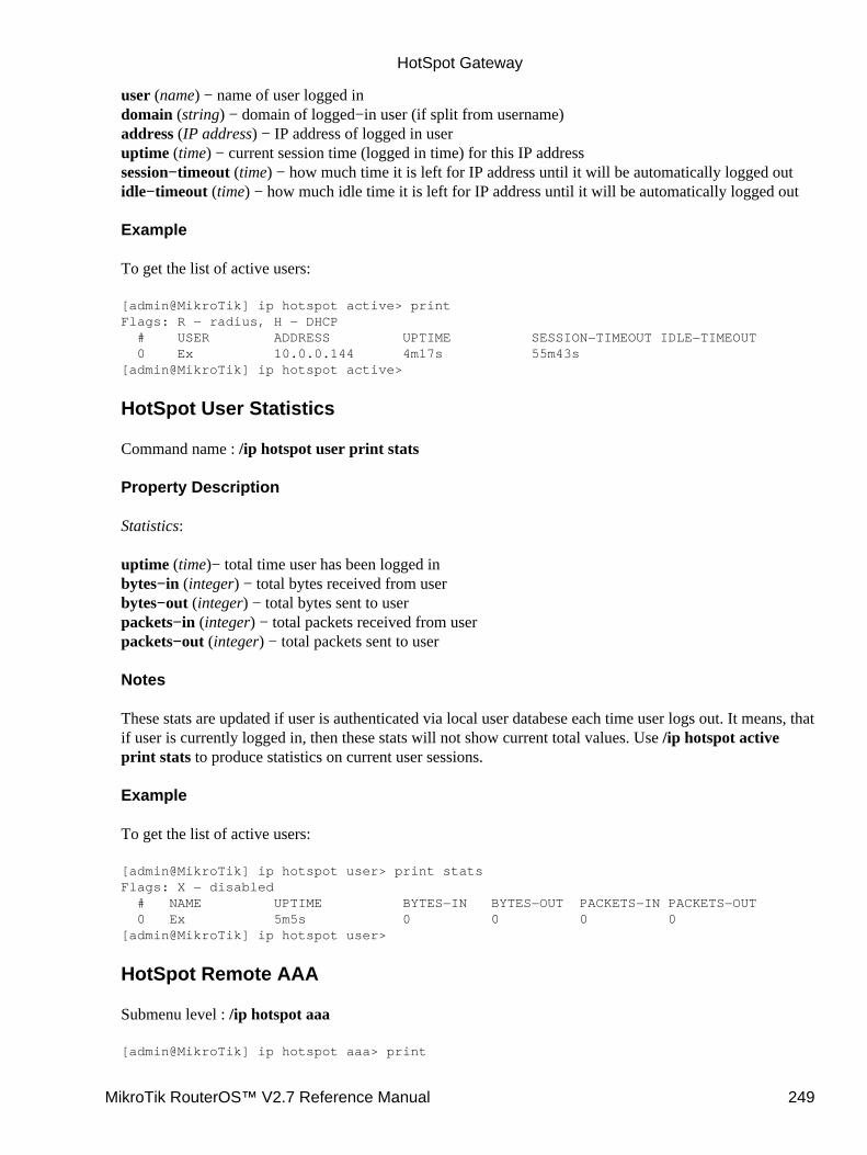
user (name) − name of user logged indomain (string) − domain of logged−in user (if split from username)address (IP address) − IP address of logged in useruptime (time) − current session time (logged in time) for this IP addresssession−timeout (time) − how much time it is left for IP address until it will be automatically logged outidle−timeout (time) − how much idle time it is left for IP address until it will be automatically logged out
Example
To get the list of active users:
[admin@MikroTik] ip hotspot active> printFlags: R − radius, H − DHCP # USER ADDRESS UPTIME SESSION−TIMEOUT IDLE−TIMEOUT 0 Ex 10.0.0.144 4m17s 55m43s[admin@MikroTik] ip hotspot active>
HotSpot User Statistics
Command name : /ip hotspot user print stats
Property Description
Statistics:
uptime (time)− total time user has been logged inbytes−in (integer) − total bytes received from userbytes−out (integer) − total bytes sent to userpackets−in (integer) − total packets received from userpackets−out (integer) − total packets sent to user
Notes
These stats are updated if user is authenticated via local user databese each time user logs out. It means, thatif user is currently logged in, then these stats will not show current total values. Use /ip hotspot activeprint stats to produce statistics on current user sessions.
Example
To get the list of active users:
[admin@MikroTik] ip hotspot user> print statsFlags: X − disabled # NAME UPTIME BYTES−IN BYTES−OUT PACKETS−IN PACKETS−OUT 0 Ex 5m5s 0 0 0 0[admin@MikroTik] ip hotspot user>
HotSpot Remote AAA
Submenu level : /ip hotspot aaa
[admin@MikroTik] ip hotspot aaa> print
HotSpot Gateway
MikroTik RouterOS™ V2.7 Reference Manual 249
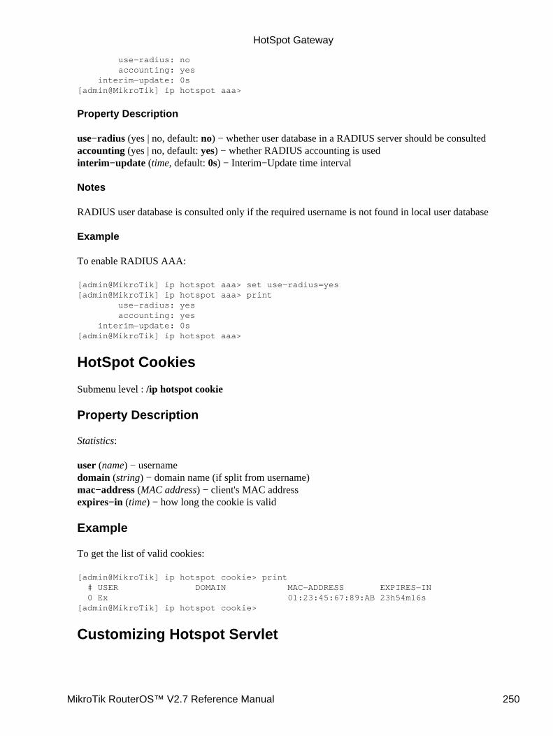
use−radius: no accounting: yes interim−update: 0s[admin@MikroTik] ip hotspot aaa>
Property Description
use−radius (yes | no, default: no) − whether user database in a RADIUS server should be consultedaccounting (yes | no, default: yes) − whether RADIUS accounting is usedinterim−update (time, default: 0s) − Interim−Update time interval
Notes
RADIUS user database is consulted only if the required username is not found in local user database
Example
To enable RADIUS AAA:
[admin@MikroTik] ip hotspot aaa> set use−radius=yes[admin@MikroTik] ip hotspot aaa> print use−radius: yes accounting: yes interim−update: 0s[admin@MikroTik] ip hotspot aaa>
HotSpot Cookies
Submenu level : /ip hotspot cookie
Property Description
Statistics:
user (name) − usernamedomain (string) − domain name (if split from username)mac−address (MAC address) − client's MAC addressexpires−in (time) − how long the cookie is valid
Example
To get the list of valid cookies:
[admin@MikroTik] ip hotspot cookie> print # USER DOMAIN MAC−ADDRESS EXPIRES−IN 0 Ex 01:23:45:67:89:AB 23h54m16s[admin@MikroTik] ip hotspot cookie>
Customizing Hotspot Servlet
HotSpot Gateway
MikroTik RouterOS™ V2.7 Reference Manual 250

Description
There are 6 HTML pages to interact with hotspot client:
login.html − login page• status.html − status page for logged in user• logout.html − after−logged−out page• error.html − various error messages• redirect.html − redirecting web browser to another url• alogin.html − page, which is shown after successful login while client gets new IP address fromDHCP server (for 10 seconds or so)
•
There are many possibilities to customize what the hotspot authentication pages look like:
The pages are easily modifiable. They are stored on the router's FTP server in hotspot directory.• By changing the variables, which client sends to the HotSpot servlet, it is possible to reducekeyword count to one (username or password; the client's MAC address may be used as the othervalue) or even to zero (License Agreement; some predefined values general for all users or client'sMAC address may be used as username and password)
•
Registration may occur on a different server. Client's MAC address may be passed to it, so that thisinformation need not be written in manually. After the registration, the server may change RADIUSdatabase enabling client to log in.
•
Variable Description
All of the pages use variables to show user specific values. For each variable there is an example includedin brackets.
Common variables (available in all pages):
hostname − IP address for hotspot www access ("10.5.50.1")• link−logout − link to logout page ("http://10.5.50.1/logout")• link−login − link to login page ("http://10.5.50.1/login?dst=http://www.mt.lv/")• link−status − link to status page ("http://10.5.50.1/status")• link−orig − link to original destination page ("http://www.mt.lv/")• session−id − value of 'session−id' parameter in last request• var − value of 'var' parameter in last request•
Page specific variables:
redirect.html:link−redirect − page to which redirect has to be done (for example, "http://www.mt.lv/")♦
•
login.html:mac − MAC address ("01:23:45:67:89:AB")♦ error − error message, if previous login failed ("invalid username or password")♦ input−user − name and value of username input field ("name=user value=john")♦ input−password − name of password input field ("name=password")♦ input−popup − name and value of popup input field ("name=popup checked")♦ form−input − name of input form and login JavaScript for password encoding("name=login onSubmit=...")
♦
•
HotSpot Gateway
MikroTik RouterOS™ V2.7 Reference Manual 251

main − MD5 encryption JavaScript and form for encrypted password♦ user − value of username input field ("john")♦ domain − value of domain ("mikrotik")♦ popup − value of pop−up checkbox ("true")♦ chap−id − value of chap ID ("\371")♦ chap−challenge − value of chap challenge("\357\015\330\013\021\234\145\245\303\253\142\246\133\175\375\316")
♦
Note that it is required login page to use use main variable. And it is strongly suggested to place itBEFORE form−input input form. Otherwise situation can happen, that user already has entered hisusername/password, but MD5 encryption JavaScript is not yet loaded. It may result in passwordbeing sent over network in plain text. And of course, that login will fail in this case, too (ifallow−unencrypted−password property is not set to yes).
Note that the resulting password to be sent to the HotSpot gateway is formed MD5−hashing theconcatenation of the following: chap−id, the password of the user and chap−challange (in thegiven order).alogin.html:
link−redirect − page to which redirect has to be done (for example, "http://www.mt.lv/")♦ login−time − time in seconds after which redirect has to be done ("9")♦ popup − true if alogin.html should pop−up status page in new window, false − otherwise♦
•
status.html, logout.html: information on logged in userusername − name ("john")♦ ip − IP address ("192.168.0.222")♦ mac − MAC address ("01:23:45:67:89:AB")♦ uptime − session uptime ("10h2m33s")♦ session−timeout − session timeout left for user ("5h" or "−−−" if none)♦ session−valid−till − date and time when session will expire ("Sep/21/2002 16:12:33" or"−−−" if there is no session−timeout)
♦
idle−timeout − idle timeout ("20m" or "−−−" if none)♦ bytes−in − number of bytes received from client ("15423")♦ bytes−out − number of bytes sent to client ("11352")♦ packets−in − number of packets received from client ("251")♦ packets−out − number of packets sent to client ("211")♦
•
status.html:refresh−time − time in seconds after which to automatically refresh status page♦ refresh−time−str − more friendly representation of refresh−time♦
•
error.html:error − error message ("DHCP lease not found")♦
•
To insert variable in some place in HTML file, variable name surrounded by % symbols is used. Forexample, to show link to login page, following construction can be used:
<a href="%link−login%">login</a>
It can be used in any hotspot HTML file.
Note, that to insert % symbol as a text (not as a part of variable construction), "%%" has to be used (ifthere is only one % symbol on a page or string between it and next % symbol is not a valid variable name,% may be used with the same result).
HotSpot Gateway
MikroTik RouterOS™ V2.7 Reference Manual 252

Examples
With basic HTML language knowledge and the information below it should be easy to implement the ideasdescribed above
To provide predefined value as username, in login.html change:
<input type="text" %input−user%>
to this line:
<input type="hidden" name="user" value="hsuser">
(where hsuser is the username you are providing)
1.
To provide predefined value as password, in login.html change:
<input type="password" %input−password%>
to this line:
<input type="hidden" name="password" value="hspass">
(where hspass is the password you are providing)
2.
To send client's MAC address to a registration server in form of:
https://www.server.serv/register.html?mac=XX:XX:XX:XX:XX:XX
change the Login button link in login.html to:
https://www.server.serv/register.html?mac=%mac%
(you should correct the link to point to your server)
3.
To show a banner after user login, in alogin.html after
if ('%popup%' == 'true') newWindow();
add the folowing line:
open('http://your.web.server/your−banner−page.html', 'my−banner−name','');
(you should correct the link to point to the page you want to show)
4.
To choose different page shown after login, in login.html change:
<input type="hidden" name="dst" value="%link_orig%">
to this line:
<input type="hidden" name="dst" value="http://your.web.server">
(you should correct the link to point to your server)
5.
HotSpot Gateway
MikroTik RouterOS™ V2.7 Reference Manual 253
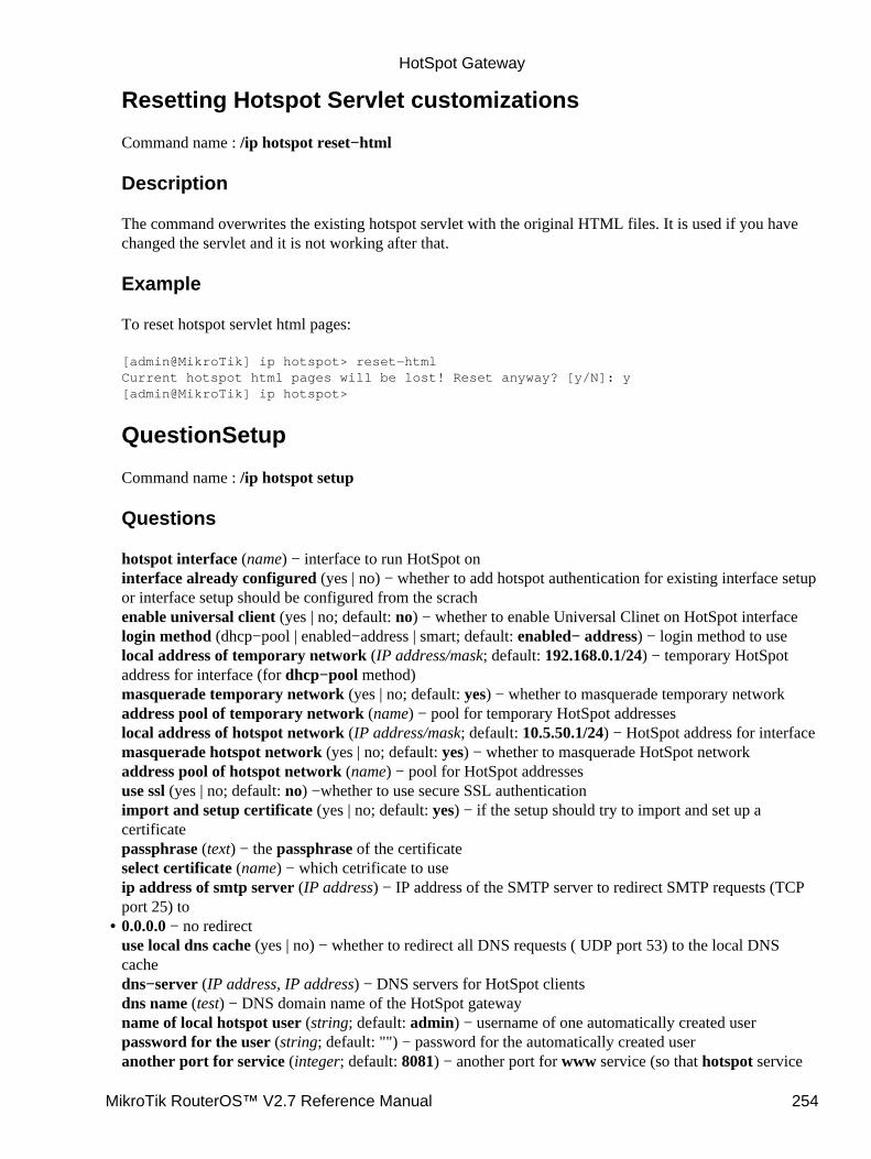
Resetting Hotspot Servlet customizations
Command name : /ip hotspot reset−html
Description
The command overwrites the existing hotspot servlet with the original HTML files. It is used if you havechanged the servlet and it is not working after that.
Example
To reset hotspot servlet html pages:
[admin@MikroTik] ip hotspot> reset−htmlCurrent hotspot html pages will be lost! Reset anyway? [y/N]: y[admin@MikroTik] ip hotspot>
QuestionSetup
Command name : /ip hotspot setup
Questions
hotspot interface (name) − interface to run HotSpot oninterface already configured (yes | no) − whether to add hotspot authentication for existing interface setupor interface setup should be configured from the scrachenable universal client (yes | no; default: no) − whether to enable Universal Clinet on HotSpot interfacelogin method (dhcp−pool | enabled−address | smart; default: enabled− address) − login method to uselocal address of temporary network (IP address/mask; default: 192.168.0.1/24) − temporary HotSpotaddress for interface (for dhcp−pool method)masquerade temporary network (yes | no; default: yes) − whether to masquerade temporary networkaddress pool of temporary network (name) − pool for temporary HotSpot addresseslocal address of hotspot network (IP address/mask; default: 10.5.50.1/24) − HotSpot address for interfacemasquerade hotspot network (yes | no; default: yes) − whether to masquerade HotSpot networkaddress pool of hotspot network (name) − pool for HotSpot addressesuse ssl (yes | no; default: no) −whether to use secure SSL authenticationimport and setup certificate (yes | no; default: yes) − if the setup should try to import and set up acertificatepassphrase (text) − the passphrase of the certificateselect certificate (name) − which cetrificate to useip address of smtp server (IP address) − IP address of the SMTP server to redirect SMTP requests (TCPport 25) to0.0.0.0 − no redirectuse local dns cache (yes | no) − whether to redirect all DNS requests ( UDP port 53) to the local DNScachedns−server (IP address, IP address) − DNS servers for HotSpot clientsdns name (test) − DNS domain name of the HotSpot gatewayname of local hotspot user (string; default: admin) − username of one automatically created userpassword for the user (string; default: "") − password for the automatically created useranother port for service (integer; default: 8081) − another port for www service (so that hotspot service
•
HotSpot Gateway
MikroTik RouterOS™ V2.7 Reference Manual 254
could be put on port 80use transparent web proxy (yes | no; default: no) − whether to use transparent web proxy for hotspotclients
Notes
Depending on current settings and answers to the previous questions, default values of following questionsmay be different. Some questions may disappear if they become redundant (for example, there is no use of'temporary network' when login method is enabled−address)
If Universal Client is enabled, and DNS cache is not used, DNS requests are redirected to the first DNSserver configured.
Example
To configure HotSpot on ether1 interface (which is already configured), enabling transparent web proxyand adding user admin with password rubbish:
[admin@MikroTik] ip hotspot> setupSelect interface to run HotSpot on
hotspot interface: ether1Use SSL authentication?
use ssl: noAdd hotspot authentication for existing interface setup?
interface already configured: yesCreate local hotspot user
name of local hotspot user: adminpassword for the user: rubbishUse transparent web proxy for hotspot clients?
use transparent web proxy: yes[admin@MikroTik] ip hotspot>
HotSpot Step−by−Step User Guide
dhcp−pool Method
Planning the Configuration
Let us consider following example HotSpot setup:
HotSpot Gateway
MikroTik RouterOS™ V2.7 Reference Manual 255
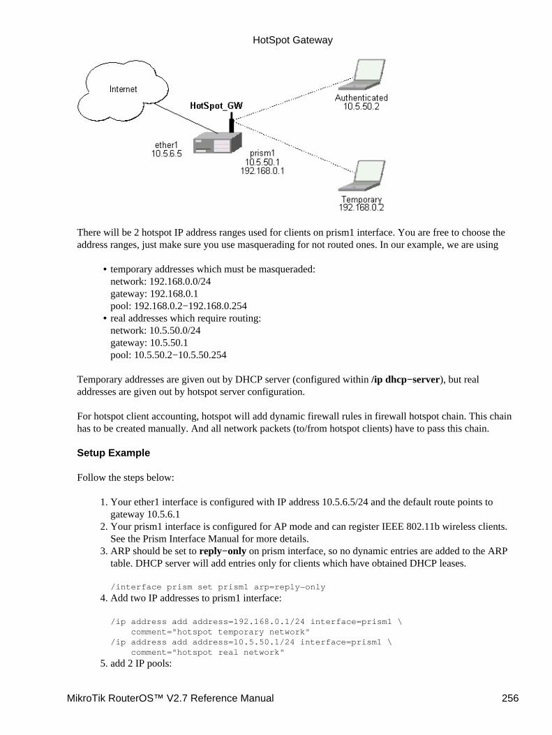
There will be 2 hotspot IP address ranges used for clients on prism1 interface. You are free to choose theaddress ranges, just make sure you use masquerading for not routed ones. In our example, we are using
temporary addresses which must be masqueraded:network: 192.168.0.0/24gateway: 192.168.0.1pool: 192.168.0.2−192.168.0.254
•
real addresses which require routing:network: 10.5.50.0/24gateway: 10.5.50.1pool: 10.5.50.2−10.5.50.254
•
Temporary addresses are given out by DHCP server (configured within /ip dhcp−server), but realaddresses are given out by hotspot server configuration.
For hotspot client accounting, hotspot will add dynamic firewall rules in firewall hotspot chain. This chainhas to be created manually. And all network packets (to/from hotspot clients) have to pass this chain.
Setup Example
Follow the steps below:
Your ether1 interface is configured with IP address 10.5.6.5/24 and the default route points togateway 10.5.6.1
1.
Your prism1 interface is configured for AP mode and can register IEEE 802.11b wireless clients.See the Prism Interface Manual for more details.
2.
ARP should be set to reply−only on prism interface, so no dynamic entries are added to the ARPtable. DHCP server will add entries only for clients which have obtained DHCP leases.
/interface prism set prism1 arp=reply−only
3.
Add two IP addresses to prism1 interface:
/ip address add address=192.168.0.1/24 interface=prism1 \ comment="hotspot temporary network"/ip address add address=10.5.50.1/24 interface=prism1 \ comment="hotspot real network"
4.
add 2 IP pools:5.
HotSpot Gateway
MikroTik RouterOS™ V2.7 Reference Manual 256
/ip pool add name=hs−pool−temp ranges=192.168.0.2−192.168.0.254/ip pool add name=hs−pool−real ranges=10.5.50.2−10.5.50.254
add masquerading rule for temporary IP pool, which is not routed:
/ip firewall src−nat add src−address=192.168.0.0/24 action=masquerade \ comment="masquereade hotspot temporary network"
Make sure you have routing for authenticated address space. Try to ping 10.5.50.1 from yourinternet gateway 10.5.6.1, for example. See the Basic Setup Guide on how to set up routing.
6.
Add dhcp server (for temporary IP addresses):
/ip dhcp−server add name="hs−dhcp−server" interface=prism1 lease−time=14s \ address−pool=hs−pool−temp netmask=24 gateway=192.168.0.1 \ dns−server=159.148.60.2,159.148.108.1 domain="mt.lv" add−arp=yes disabled=no
7.
Add hotspot server setup (for real IP addresses):
/ip hotspot server add name=hs−server dhcp−server=hs−dhcp−server \ address−pool=hs−pool−real netmask=24 gateway=10.5.50.1
8.
Add local hotspot user:
/ip hotspot user add name=Ex password=Ex
9.
Setup hotspot service to run on port 80 (www service has to be assigned another port, e.g., 8081):
/ip service set www port=8081/ip service set hotspot port=80
Note! Changing www service to other port than 80 requires thet you specify the new port whenconnecting to MikroTik router using WinBox, e.g., use 10.5.50.1:8081 in this case.
10.
Redirect all TCP requests from temporary IP addresses to hotspot service:
/ip firewall dst−nat add src−address=192.168.0.0/24 dst−port=443 protocol=tcp \ action=redirect to−dst−port=443\ comment="redirect unauthorized hotspot clients to hotspot service"/ip firewall dst−nat add src−address=192.168.0.0/24 protocol=tcp \ action=redirect to−dst−port=80 \ comment="redirect unauthorized hotspot clients to hotspot service"
11.
Allow DNS requests and ICMP ping from temporary addresses and reject everything else:
/ip firewall add name=hotspot−temp comment="limit unauthorized hotspot clients"
/ip firewall rule forward add src−address=192.168.0.0/24 action=jump \jump−target=hotspot−temp comment="limit access for unauthorized hotspot clients"
/ip firewall rule input add src−address=192.168.0.0/24 dst−port=80 \protocol=tcp action=accept comment="accept requests for hotspot servlet"/ip firewall rule input add src−address=192.168.0.0/24 dst−port=443 \protocol=tcp action=accept comment="accept request for hotspot servlet"/ip firewall rule input add src−address=192.168.0.0/24 dst−port=67 \protocol=udp action=accept comment="accept requests for local DHCP server"/ip firewall rule input add src−address=192.168.0.0/24 action=jump \jump−target=hotspot−temp comment="limit access for unauthorized hotspot clients"
/ip firewall rule hotspot−temp add protocol=icmp action=return \ comment="allow ping requests"/ip firewall rule hotspot−temp add protocol=udp dst−port=53 action=return \ comment="allow dns requests"/ip firewall rule hotspot−temp add action=reject \
12.
HotSpot Gateway
MikroTik RouterOS™ V2.7 Reference Manual 257
comment="reject access for unauthorized hotspot clients"
Add hotspot chain:
/ip firewall add name=hotspot comment="account authorized hotspot clients"
13.
Pass all through going traffic to hotspot chain:
/ip firewall rule forward add action=jump jump−target=hotspot \ comment="account traffic for authorized hotspot clients"
Note that in order to use SSL authentication, you should install an SSL certificate. This topic is notcovered by this manual section. Please see the respective manual section on how to installcertificates in MikroTik RouterOS
14.
If client has obtained temporary address, its lease is shown as:
[admin@HotSpot−GW] > ip dhcp−server lease printFlags: X − disabled, H − hotspot, D − dynamic # ADDRESS MAC−ADDRESS EXPIRES−A... SERVER STATUS 0 D 192.168.0.254 00:40:96:13:B3:47 8s hs−dhcp−server bound[admin@HotSpot−GW] >
After successful authorization its DHCP address is changed, and it is listed under active hotspot users:
[admin@HotSpot−GW] > ip dhcp−server lease printFlags: X − disabled, H − hotspot, D − dynamic # ADDRESS MAC−ADDRESS EXPIRES−A... SERVER STATUS 0 H 10.5.50.2 00:40:96:13:B3:47 56s hs−dhcp−server bound[admin@HotSpot−GW] > ip hotspot active printFlags: R − radius, H − DHCP # USER ADDRESS UPTIME SESSION−TIMEOUT IDLE−TIMEOUT 0 R Ex 10.5.50.2 2m25s[admin@HotSpot−GW] > /ip hotspot active print statsFlags: R − radius, H − DHCP # USER UPTIME BYTES−IN BYTES−OUT PACKETS−IN PACKETS−OUT 0 R Ex 13m26s 145268 264282 475 494[admin@HotSpot−GW] >
User statistics show accumulated values prior to current session.
[admin@HotSpot−GW] > ip hotspot user print statsFlags: X − disabled # NAME UPTIME BYTES−IN BYTES−OUT PACKETS−IN PACKETS−OUT 0 Ex 6m29s 9896 31156 80 77[admin@HotSpot−GW] >
User statistics values are updated after current session is closed. Values can be reset to '0' using thereset−counters command.
enabled−address Method
Planning the Configuration
Let us consider following example HotSpot setup:
HotSpot Gateway
MikroTik RouterOS™ V2.7 Reference Manual 258
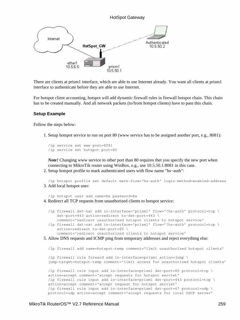
There are clients at prism1 interface, which are able to use Internet already. You want all clients at prism1interface to authenticate before they are able to use Internet.
For hotspot client accounting, hotspot will add dynamic firewall rules in firewall hotspot chain. This chainhas to be created manually. And all network packets (to/from hotspot clients) have to pass this chain.
Setup Example
Follow the steps below:
Setup hotspot service to run on port 80 (www service has to be assigned another port, e.g., 8081):
/ip service set www port=8081/ip service set hotspot port=80
Note! Changing www service to other port than 80 requires thet you specify the new port whenconnecting to MikroTik router using WinBox, e.g., use 10.5.50.1:8081 in this case.
1.
Setup hotspot profile to mark authenticated users with flow name "hs−auth":
/ip hotspot profile set default mark−flow="hs−auth" login−method=enabled−address
2.
Add local hotspot user:
/ip hotspot user add name=Ex password=Ex
3.
Redirect all TCP requests from unauthorized clients to hotspot service:
/ip firewall dst−nat add in−interface="prism1" flow="!hs−auth" protocol=tcp \ dst−port=443 action=redirect to−dst−port=443 \ comment="redirect unauthorized hotspot clients to hotspot service"/ip firewall dst−nat add in−interface="prism1" flow="!hs−auth" protocol=tcp \ action=redirect to−dst−port=80 \ comment="redirect unauthorized clients to hotspot service"
4.
Allow DNS requests and ICMP ping from temporary addresses and reject everything else:
/ip firewall add name=hotspot−temp comment="limit unauthorized hotspot clients"
/ip firewall rule forward add in−interface=prism1 action=jump \jump−target=hotspot−temp comment="limit access for unauthorized hotspot clients"
/ip firewall rule input add in−interface=prism1 dst−port=80 protocol=tcp \action=accept comment="accept requests for hotspot servlet"/ip firewall rule input add in−interface=prism1 dst−port=443 protocol=tcp \action=accept comment="accept request for hotspot servlet"/ip firewall rule input add in−interface=prism1 dst−port=67 protocol=udp \protocol=udp action=accept comment="accept requests for local DHCP server"
5.
HotSpot Gateway
MikroTik RouterOS™ V2.7 Reference Manual 259

/ip firewall rule input add in−interface=prism1 action=jump \jump−target=hotspot−temp comment="limit access for unauthorized hotspot clients"
/ip firewall rule hotspot−temp add flow="hs−auth" action=return \ comment="return if connection is authorized"/ip firewall rule hotspot−temp add protocol=icmp action=return \ comment="allow ping requests"/ip firewall rule hotspot−temp add protocol=udp dst−port=53 action=return \ comment="allow dns requests"/ip firewall rule hotspot−temp add action=reject \ comment="reject access for unauthorized clients"
Create hotspot chain for authorized hotspot clients:
/ip firewall add name=hotspot comment="account authorized hotspot clients"
6.
Pass all through going traffic to hotspot chain:
/ip firewall rule forward add action=jump jump−target=hotspot \ comment="account traffic for authorized hotspot clients"
Note that in order to use SSL authentication, you should install an SSL certificate. This topic is notcovered by this manual section. Please see the respective manual section on how to installcertificates in MikroTik RouterOS
7.
As we see from example, only hotspot interface is used − we don't care what IP addresses are there.
It is possible to add hotspot authentication for one more interface (prism2) by adding only 2 additionalfirewall rules:
Setup dst−nat to redirect unauthorized clients to hotspot service:
/ip firewall dst−nat add in−interface="prism2" flow="!hs−auth" protocol=tcp \action=redirect to−dst−port=80 \comment="redirect unauthorized prism2 clients to hotspot service"
1.
Limit access for unauthorized prism2 interface clients:
/ip firewall rule forward add in−interface=prism2 action=jump \jump−target=hotspot−temp comment="limit access for unauthorized prism2 clients"/ip firewall rule input add in−interface=prism2 action=jump \jump−target=hotspot−temp comment="limit access for unauthorized prism2 clients"
2.
After successful authorization client is listed under active hotspot users:
[admin@HotSpot−GW] > ip hotspot active printFlags: R − radius, H − DHCP # USER ADDRESS UPTIME SESSION−TIMEOUT IDLE−TIMEOUT 0 R Ex 10.5.50.2 2m25s[admin@HotSpot−GW] > /ip hotspot active print statsFlags: R − radius, H − DHCP # USER UPTIME BYTES−IN BYTES−OUT PACKETS−IN PACKETS−OUT 0 R Ex 13m26s 145268 264282 475 494[admin@HotSpot−GW] >
User statistics show accumulated values prior to current session.
[admin@HotSpot−GW] > ip hotspot user print statsFlags: X − disabled
HotSpot Gateway
MikroTik RouterOS™ V2.7 Reference Manual 260
# NAME UPTIME BYTES−IN BYTES−OUT PACKETS−IN PACKETS−OUT 0 Ex 6m29s 9896 31156 80 77[admin@HotSpot−GW] >
User statistics values are updated after current session is closed. Values can be reset to '0' using thereset−counters command.
Optional Settings
You may want to use same address space both for your LAN and HotSpot networks. Please consultthe IP Address and ARP Manual for proxy−arp feature.
1.
You may want to translate the destination address of all TCP port 25 connections (SMTP) fromHotSpot users to your mail sever for mail relaying. Thus, users can retain their mail client setup anduse your mail server for outgoing mail without reconfiguring their mail clients. If 10.5.6.100 isyour mail server accepting connections from network 10.5.50.0/24, then the required destinationNAT rule would be:
/ip firewall dst−nat add src−address=10.5.50.0/24 dst−port=25 protocol=tcp \ to−dst−address=10.5.6.100 action=nat \ comment="Translate SMTP TCP 25 port to our mail server"
2.
Another option is to allow access certain pages without authentication. This is useful, for example,to give access to some general information about HotSpot service provider or billing options.Include firewall rules into the hotspot−temp chain allowing access to certain IP addresses prior therule that rejects all other traffic from temporary addresses. Also, add rules excluding destinationNAT for these addresses. For example:
1) in dst−nat: don't redirect requests going to your web server (x.x.x.x:80) (this rule has to bebefore "redirect to hotspot service" rule!)
/ip firewall dst−nat add dst−address=x.x.x.x/32 dst−port=80 protocol=tcp\ action=accept
2) in hotspot−temp chain: accept requests going to your web server (this rule has to be before"reject access for unauthorized hotspot clients" rule!)
/ip firewal rule hotspot−temp add dst−address=x.x.x.x/32 dst−port=80 \ protocol=tcp action=return
3.
For HotSpot clients to use transparent web−proxy on the same router, following configuration canbe used:
1) make sure, web−proxy package is installed;2) it is assumed, that HotSpot is set up and successfully running. Hotspot clients are connected oninterface named 'prism1'.3) set up web−proxy to run on port 3128 using transparent mode:
/ip web−proxy set enabled=yes address=0.0.0.0:3128 transparent−proxy=yes
4) set up HotSpot to use one of router's local IP addresses (10.5.50.1):
/ip hotspot set hotspot−address=10.5.50.1
5) redirect all requests from hotspot interface to port 80 (except to 10.5.50.1), to web−proxy:
4.
HotSpot Gateway
MikroTik RouterOS™ V2.7 Reference Manual 261
/ip firewall dst−nat add in−interface=prism1 dst−address=!10.5.50.1/32 \ dst−port=80 protocol=tcp action=redirect to−dst−port=3128 comment="transparent proxy"
Now, everything should be working. Only traffic of redirected requests to web−proxy will not beaccounted. It's because this traffic will not pass through the forward chain.
6) to enable accounting for hotspot user traffic to/from transparent web−proxy, additional firewallrules should be added:
/ip firewall rule input add in−interface=prism1 dst−port=3128\ protocol=tcp action=jump jump−target=hotspot\ comment="account traffic from hotspot client to local web−proxy"/ip firewall rule output add src−port=3128 protocol=tcp\ out−interface=prism1 action=jump jump−target=hotspot\ comment="account traffic from local web−proxy to hotspot client"
You may want to allow multiple logins using the same username/password. Set the argument valueof only−one to no in hotspot profile, for example:
/ip hotspot profile set default only−one=no
5.
If you have dns−cache package installed, setup local DNS cache and specify HotSpot gateway'saddress as primary DNS server for DHCP clients, for example:
/ip dns−cache set primary−server=159.148.60.2 enabled=yes/ip dhcp−server set hs−dhcp−server dns−server=10.5.50.1,159.148.108.1
6.
Troubleshooting
User cannot log in because of "NO CHAP" error"NO CHAP" means, that hotspot server does not have a challenge for this IP address. It can becaused by:
logging in too slowly, i.e., client opens login page, but does login only after more than anhour;
♦
web browser gets login page from its own cache, without asking for it to hotspot server♦ So, in case of "NO CHAP" error, please reload login page from hotspot server (generally [F5]button in web browser).Don't use Back button of web browser to enter login page! That "old" login page has already usedchallenge value, which is not valid on hotspot server anymore.
•
User cannot log in, although username and password are proven correctWeb browsers, that do not support JavaScript (for example, Internet Explorer 2.0), are not be ableto authenticate users because of password encryption. In this case you may either update thebrowser or enable allow−unencrypted−passwords property in HotSpot Server's general settings,allowing plain−text passwords to travel in your network:
/ip hotspot set allow−unencrypted−passwords=yes
•
User cannot log in with Netscape 4.7x, bacause of "INVALID USER" errorIt is caused by uninitialized domain value, which has value of "++" for those Netscape browsers. Itwill be fixed in RouterOS version 2.7.4. Now this can be fixed by changing hotspot login.htmlpage. You will have to add line
<input type="hidden" name="domain" value="">
within form
•
HotSpot Gateway
MikroTik RouterOS™ V2.7 Reference Manual 262

<form %form−input%> ... </form>
� Copyright 1999−2003, MikroTik
HotSpot Gateway
MikroTik RouterOS™ V2.7 Reference Manual 263
IP Addresses and Address Resolution Protocol (ARP)Document revision 1.4 (29−Dec−2003)This document applies to the MikroTik RouterOS V2.7
Table of Contents
Table of Contents• Summary• Specifications• Related Documents• IP Addressing
Description♦ Property Description♦ Example♦
•
Address Resolution ProtocolDescription♦ Property Description♦ Notes♦ Example♦
•
Using the Proxy−ARP FeatureDescription♦ Example♦
•
Using Unnumbered InterfacesDescription♦ Example♦
•
Troubleshooting• Additional Resources•
Summary
The following Manual discusses managing IP addresses and the Address Resolution Protocol (ARP). IPaddresses serve as identification when communicating with other network devices using the TCP/IP protocol.In turn, communication between devices in one physical network proceeds with the help of AddressResolution Protocol and ARP addresses.
Specifications
Packages required : NoneLicense required : AnyHome menu level : /ip address, /ip arpProtocols utilized : IP (RFC791), ARP (RFC826)Hardware usage: not significant
Related Documents
Software Package Installation and Upgrading
MikroTik RouterOS™ V2.7 Reference Manual 264
IP Addressing
Submenu level : /ip address
Description
IP addresses serve for a general host identification purposes in IP networks. Tupical (IPv4) address consists offour octets. For correct addressing the router also needs the network mask value, id est which bits of thecomplete IP address refer to the address of the host, and which − to the address of the network. The networkaddress value is calculated by binary AND operation from network mask and IP address values. It's alsopossible to specify IP address followed by slash "/" and amount of bits assigned to a network mask.
In most cases, it is enough to specify the address, the netmask, and the interface arguments. The networkprefix and the broadcast address are calculated automatically.
It is possible to add multiple IP addresses to an interface or to leave the interface without any addressesassigned to it. Leaving a physical interface without an IP address is a must when the bridging betweeninterfaces is used. In case of bridging, the IP address is assigned to a bridge interface.
MikroTik RouterOS has following types of addresses:
Static IP Addresses are user−assigned addresses to the network interfaces.• Dynamic IP Addresses are assigned automatically when ppp, ppptp, or pppoe connections areestablished.
•
Property Description
address (IP address) − IP address of the hostbroadcast (IP address; default: 255.255.255.255) − broadcasting IP address, by default calculated from an IPaddress and a network maskcomment (text; default: "") − an optional comment for the IP addressdisabled (yes | no; default: no) − is the address disabled or notinterface (name) − the name of the interface IP address assigned tonetmask (IP address; default: 0.0.0.0) − specifies the network address part of an IP addressnetwork (IP address; default: 0.0.0.0) − IP address of the network. For the point−to−point links should be theaddress of the remote end
Example
[admin@MikroTik] ip address> add address=10.10.10.1/24 interface=ether2[admin@MikroTik] ip address> printFlags: X − disabled, I − invalid, D − dynamic # ADDRESS NETWORK BROADCAST INTERFACE 0 2.2.2.1/24 2.2.2.0 2.2.2.255 ether2 1 10.5.7.244/24 10.5.7.0 10.5.7.255 ether1 2 10.10.10.1/24 10.10.10.0 10.10.10.255 ether2
[admin@MikroTik] ip address>
IP Addresses and Address Resolution Protocol (ARP)
MikroTik RouterOS™ V2.7 Reference Manual 265

Address Resolution Protocol
Submenu level : /ip arp
Description
Address Resolution Protocol is used to map IP addreses to MAC layer addreses. A router has a table ofcurrently used ARP entries. Normally the table is built dynamically, but to increase network security, staticentries can be added.
Property Description
address (IP address) − IP addresscomment (text; default: "") − an optional commentdisabled (yes | no; default: no) − is the entry disabled or notinterface (name) − the name of the interfacemac−address (MAC address; default: 00:00:00:00:00:00) − MAC address to be mapped to
Notes
Maximal number of ARP entries is 1024.
If arp feature is turned off on interface, i.e., arp=disabled is used, ARP requests from clients are not answeredby the router. Therefore, static arp entry should be added to the clients as well. For example, the router's IPand MAC addresses should be added to the Windows workstations using the arp command:
C:\> arp −s 10.5.8.254 00−aa−00−62−c6−09
Example
[admin@MikroTik] ip arp> add address=10.10.10.10 interface=ether2 mac−address=06 \\\\... :21:00:56:00:12[admin@MikroTik] ip arp> printFlags: X − disabled, I − invalid, H − DHCP, D − dynamic # ADDRESS MAC−ADDRESS INTERFACE 0 D 2.2.2.2 00:30:4F:1B:B3:D9 ether2 1 D 10.5.7.242 00:A0:24:9D:52:A4 ether1 2 10.10.10.10 06:21:00:56:00:12 ether2[admin@MikroTik] ip arp>
If static arp entries are used for network security on an interface, you should set arp to 'reply−only' on thatinterface. Do it under the relevant /interfaces menu:
[admin@MikroTik] ip arp> /interface ethernet set ether2 arp=reply−only[admin@MikroTik] ip arp> printFlags: X − disabled, I − invalid, H − DHCP, D − dynamic # ADDRESS MAC−ADDRESS INTERFACE 0 D 10.5.7.242 00:A0:24:9D:52:A4 ether1 1 10.10.10.10 06:21:00:56:00:12 ether2
[admin@MikroTik] ip arp>
IP Addresses and Address Resolution Protocol (ARP)
MikroTik RouterOS™ V2.7 Reference Manual 266
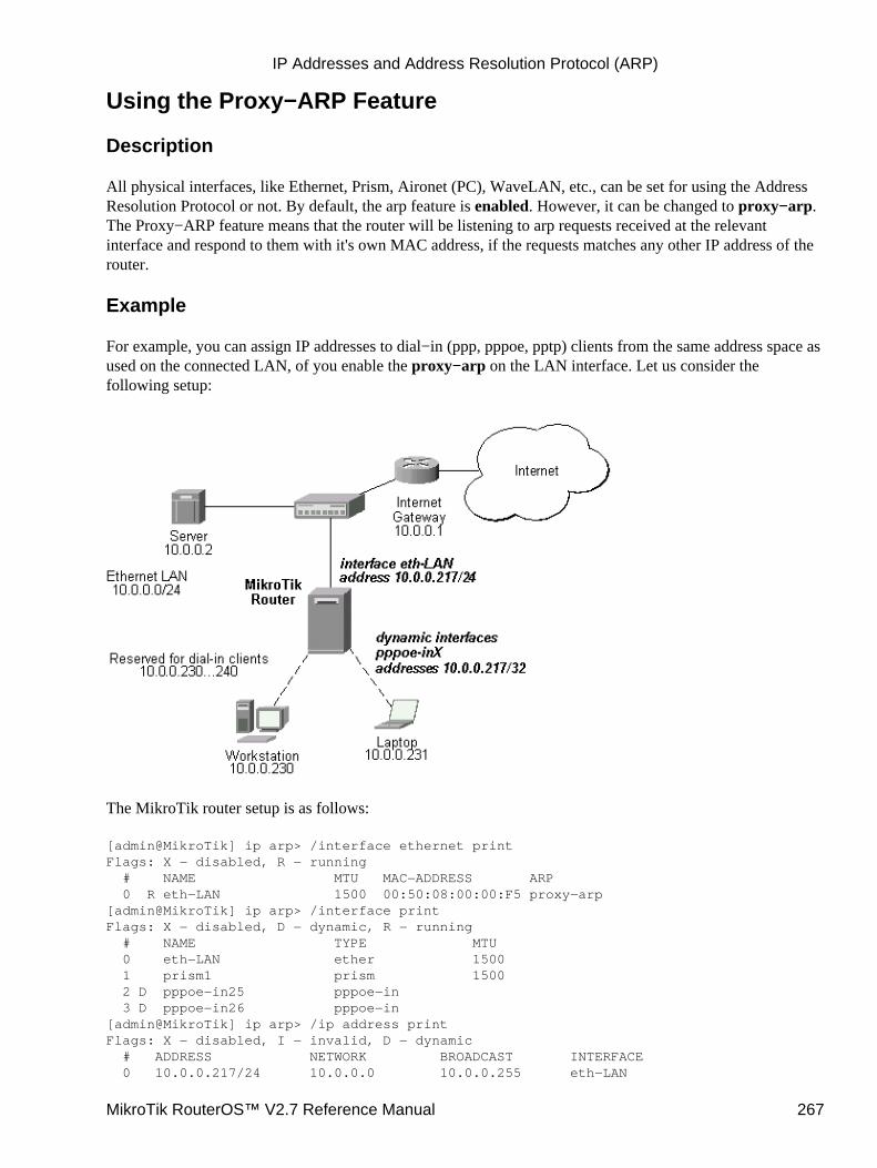
Using the Proxy−ARP Feature
Description
All physical interfaces, like Ethernet, Prism, Aironet (PC), WaveLAN, etc., can be set for using the AddressResolution Protocol or not. By default, the arp feature is enabled. However, it can be changed to proxy−arp.The Proxy−ARP feature means that the router will be listening to arp requests received at the relevantinterface and respond to them with it's own MAC address, if the requests matches any other IP address of therouter.
Example
For example, you can assign IP addresses to dial−in (ppp, pppoe, pptp) clients from the same address space asused on the connected LAN, of you enable the proxy−arp on the LAN interface. Let us consider thefollowing setup:
The MikroTik router setup is as follows:
[admin@MikroTik] ip arp> /interface ethernet printFlags: X − disabled, R − running # NAME MTU MAC−ADDRESS ARP 0 R eth−LAN 1500 00:50:08:00:00:F5 proxy−arp[admin@MikroTik] ip arp> /interface printFlags: X − disabled, D − dynamic, R − running # NAME TYPE MTU 0 eth−LAN ether 1500 1 prism1 prism 1500 2 D pppoe−in25 pppoe−in 3 D pppoe−in26 pppoe−in[admin@MikroTik] ip arp> /ip address printFlags: X − disabled, I − invalid, D − dynamic # ADDRESS NETWORK BROADCAST INTERFACE 0 10.0.0.217/24 10.0.0.0 10.0.0.255 eth−LAN
IP Addresses and Address Resolution Protocol (ARP)
MikroTik RouterOS™ V2.7 Reference Manual 267
1 D 10.0.0.217/32 10.0.0.230 0.0.0.0 pppoe−in25 2 D 10.0.0.217/32 10.0.0.231 0.0.0.0 pppoe−in26[admin@MikroTik] ip arp> /ip route printFlags: X − disabled, I − invalid, D − dynamic, J − rejected,C − connect, S − static, R − rip, O − ospf, B − bgp # DST−ADDRESS G GATEWAY DISTANCE INTERFACE 0 S 0.0.0.0/0 r 10.0.0.1 1 eth−LAN 1 DC 10.0.0.0/24 r 0.0.0.0 0 eth−LAN 2 DC 10.0.0.230/32 r 0.0.0.0 0 pppoe−in25 3 DC 10.0.0.231/32 r 0.0.0.0 0 pppoe−in26[admin@MikroTik] ip arp>
Using Unnumbered Interfaces
Description
The unnumbered interfaces can be used on serial point−to−point links, e.g., MOXA or Cyclades interfaces. Aprivate address should be put on the interface with the network being the same as an address on the router onthe other side of the p2p link (there may be no IP on that interface, but there is an ip for that router).
Example
[admin@MikroTik] ip address> add address=10.0.0.214/32 network=192.168.0.1 \\... interface=pppsync[admin@MikroTik] ip address> printFlags: X − disabled, I − invalid, D − dynamic # ADDRESS NETWORK BROADCAST INTERFACE 0 10.0.0.214/32 192.168.0.1 192.168.0.1 pppsync[admin@MikroTik] ip address>[admin@MikroTik] ip address> .. route print detailFlags: X − disabled, I − invalid, D − dynamic, J − rejected,C − connect, S − static, R − rip, O − ospf, B − bgp 0 S dst−address=0.0.0.0/0 preferred−source=0.0.0.0 gateway=192.168.0.1 gateway−state=reachable distance=1 interface=pppsync
1 DC dst−address=192.168.0.1/32 preferred−source=10.0.0.214 gateway=0.0.0.0 gateway−state=reachable distance=0 interface=pppsync
[admin@MikroTik] ip address>
Here, you can see, that a dynamic connected route has been automatically added to the routes list. If you wantthe default gateway be the other router of the p2p link, just add a static route for it. It is shown as #0 in theexample above.
Troubleshooting
I added IP addresses 10.0.0.1/24 and 10.0.0.2/24 to the interfaces ether1 and ether2, but nothingworks.Both addresses are from the same network 10.0.0.0/24, use addresses from different networks ondifferent interfaces, or enable proxy−arp on ether1 or ether2.
•
I was going to use static ARP and have my network secured that way. For the first 10 minuteseverything is fine, then router becomes totally unavailable.After you turn off ARP on router's interface, the dynamic ARP entries expire on the client computers.You should add the router's IP and MAC addresses to the static ARP entries of the workstations.
•
IP Addresses and Address Resolution Protocol (ARP)
MikroTik RouterOS™ V2.7 Reference Manual 268

Additional Resources
Addressing in Local Area Networks
© Copyright 1999−2003, MikroTik
IP Addresses and Address Resolution Protocol (ARP)
MikroTik RouterOS™ V2.7 Reference Manual 269

IP Pool ManagementDocument revision 1.1 (17−Feb−2003)This document applies to the MikroTik RouterOS v2.7
Table of Contents
Table of Contents• Summary• Specifications• Related Documents• Description• IP Pool Setup
Property Description♦ Example♦
•
Monitoring Used IP AddressesProperty Description♦ Example♦
•
Summary
IP pools are used to define range of IP addresses that is used for DHCP server and Point−to−Point servers
Specifications
Packages required : systemLicense required : AnyHome menu level : /ip poolProtocols utilized : NoneHardware usage: not significant
Related Documents
Software Package Installation and UpgradingIP Addresses and Address Resolution Protocol (ARP)Authentication, Authorization and AccountingDynamic Host Configuration Protocol (DHCP) Client and ServerHotSpot GatewayUniversal Client InterfaceGeneral Point to Point Settings
Description
IP pools simply group IP addresses for further usage. It is a single configuration point for all features thatassign IP addresses to clients.
Note that whenever possible, the same ip address is given out to each client (OWNER/INFO pair).
MikroTik RouterOS™ V2.7 Reference Manual 270
IP Pool Setup
Submenu level : /ip pool
Property Description
name (name) – name of the poolranges (string) − IP address list of non−overlapping IP address ranges in form of:from1−to1,from2−to2,...,fromN−toN. For example, 10.0.0.1−10.0.0.27,10.0.0.32−10.0.0.47
Example
To define a pool named ip−pool with the 10.0.0.1−10.0.0.125 address range excluding gateway's address10.0.0.1 and server's address 10.0.0.100, and the other pool dhcp−pool, with the 10.0.0.200−10.0.0.250address pool:
[admin@MikroTik] ip pool> add name=ip−pool ranges=10.0.0.2−10.0.0.99,10.0.0.10110.0.0.126[admin@MikroTik] ip pool> add name=dhcp−pool ranges=10.0.0.200−10.0.0.250[admin@MikroTik] ip pool> print # NAME RANGES 0 ip−pool 10.0.0.2−10.0.0.99 10.0.0.101−10.0.0.126 1 dhcp−pool 10.0.0.200−10.0.0.250
[admin@MikroTik] ip pool>
Monitoring Used IP Addresses
Command name : /ip pool used print
Property Description
Statistics:
pool (name) − name of the pool, the address is given fromaddress (IP address) − IP address assigned to the clientowner (string) − application name, that has given the address outinfo (string) − unique client identifier
Example
To see, what addresses are currently used:
[admin@MikroTik] ip pool> used print POOL ADDRESS OWNER INFO dhcp−pool 10.0.0.250 DHCP 00:e0:c5:6e:23:1d[admin@MikroTik] ip pool>
© Copyright 1999−2003, MikroTik
IP Pool Management
MikroTik RouterOS™ V2.7 Reference Manual 271
IPsecDocument revision 1.5 (17−Jun−2003)This document applies to MikroTik RouterOS v2.7
Table of Contents
Table of Contents• Summary• Specifications• Related Documents• Description
Encryption♦ Decryption♦ Internet Key Exchange♦ Diffie−Hellman MODP Groups♦ IKE Traffic♦ Setup Steps♦
•
Policy SettingsDescription♦ Property Description♦ Notes♦ Example♦
•
PeerDescription♦ Property Description♦ Notes♦ Example♦
•
Remote Peer StatisticsDescription♦ Property Description♦ Example♦
•
Manual SAProperty Description♦ Notes♦ Example♦
•
ProposalDescription♦ Property Description♦ Notes♦ Example♦
•
Installed SADescription♦ Property Description♦ Example♦
•
Flushing Installed SA tableDescription♦ Property Description♦ Example♦
•
Counters•
MikroTik RouterOS™ V2.7 Reference Manual 272
Property Description♦ Example♦
Application examplesIPsec setup between two RourerOS routers♦ IPsec Setup for Routing Between two Masquerading MikroTik Routers♦ IPsec Setup Between MikroTik and CISCO Routers
Configuring RouterOS◊ Configuring Cisco◊ Testing◊
♦
IPsec setup between RouterOS router and Windows SonicWall ClientConfiguring RouterOS◊ Configuring SonicWALL◊ Testing◊
♦
•
Additional Resources•
Summary
Specifications
Packages required : securityLicense required : AnyHome menu level : /ip ipsecProtocols utilized : IPsec (RFC2401)Hardware usage: consumes a lot of CPU time (Intel Pentium MMX or AMD K6 suggested as minimalconfiguration)
Related Documents
Software Package Installation and UpgradingIP Addresses and Address Resolution Protocol (ARP)Firewall Filters and Network Address Translation (NAT)
Description
IPsec (IP Security) supports secure (encrypted) communications over IP networks.
Encryption
After packet is src−natted, but before putting it into interface queue, IPsec policy database is consulted to findout if packet should be encrypted. Security Policy Database (SPD) is a list of rules that have two parts:
Packet matching: Packet source/destination, protocol and ports (for TCP and UDP) are compared to valuesin policy rules, one after another
•
Action: If rule matches action specified in rule is performed:
accept − continue with packet as if there was no IPsecdrop − drop packetencrypt − encrypt packet
•
IPsec
MikroTik RouterOS™ V2.7 Reference Manual 273
Each SPD rule can be associated with several Security Associations (SA) that determine packet encryptionparameters (key, algorithm, SPI).
Note that packet can only be encrypted if there is usable SA for policy rule. By setting SPD rule security"level" user can control what happens when there is no valid SA for policy rule:use − if there is no valid SA, send packet unencrypted (like accept rule)• acquire − send packet unencrypted, but ask IKE daemon to establish new SA• require − drop packet, and ask IKE daemon to establish new SA.
If packet can be encrypted, it is encrypted and sent as LOCALLY ORIGINATED packet − i.e. it isprocessed with "output" firewall, src−nat again and IPsec SPD again (this way one packet can be encryptedseveral times if encrypted packet has to be sent over encrypted tunnel itself). If packet matches the sameSPD rule that it matched before, it is sent out without encrypting (to avoid encryption loops).
Decryption
When encrypted packet is received for local host (after dst−nat and input filter), appropriate SA to decryptit is looked up (using packet source, destination, security protocol and SPI value). If no SA is found, packetis dropped. If SA is found, packet is decrypted. Then decrypted packets fields are compared to policy rulethat SA is linked to. If packet does not match policy rule it is dropped. If packet is decrypted fine (orauthenticated fine) it is "received once more" − it goes through dst−nat and routing (which finds out what todo − either forward or deliver locally) again.
Note that before forward and input firewall chains, packet that was not decrypted on local host iscompared with SPD reversing its matching rules. If SPD requires encryption (there is valid SA associatedwith matching SPD rule), packet is dropped. This is called incoming policy check.
Internet Key Exchange
The Internet Key Exchange (IKE) is a protocol that provides authenticated keying material for InternetSecurity Association and Key Management Protocol (ISAKMP) framework. There are other key exchangeschemes that work with ISAKMP, but IKE is the most widely used one. Together they provide means forauthentication of hosts and automatic management of security associations (SA).
Most of the time IKE daemon is doing nothing. There are two possible situations when it is activated:
•
Some traffic is caught by policy that needs to provide encryption or authentication, but doesn't have anySAs. It notifies IKE daemon about that, and IKE daemon initiates connection to remote host.
•
IKE daemon responds to remote connection.
In both cases, peers establish connection and execute 2 phases:
•
Phase 1 − peers agree on algorithms they will use in following IKE messages, authenticate. Also, keyingmaterial (used to derive keys for all SAs and to protect following ISAKMP exchanges between hosts) isgenerated.
•
Phase 2 − peers establish one or several SAs that will be used by IPsec to encrypt data. All SAs establishedby IKE daemon will have lifetime values (either limiting time, after which SA will become invalid, oramount of data that can be encrypted by this SA, or both).
There are two lifetime values − soft and hard. When SA reaches it's soft lifetime, IKE daemon receivesnotice about it and starts another phase 2 exchange to replace this SA with fresh one. If SA reaches hardlifetime, it is discarded.
•
IPsec
MikroTik RouterOS™ V2.7 Reference Manual 274
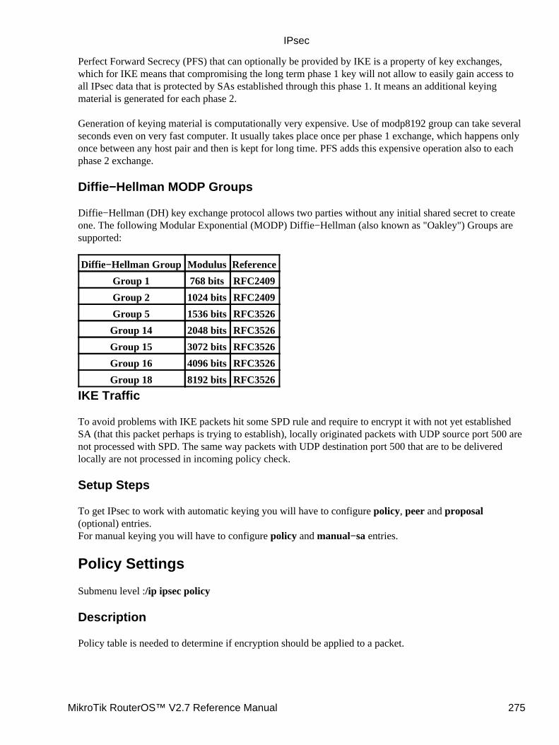
Perfect Forward Secrecy (PFS) that can optionally be provided by IKE is a property of key exchanges,which for IKE means that compromising the long term phase 1 key will not allow to easily gain access toall IPsec data that is protected by SAs established through this phase 1. It means an additional keyingmaterial is generated for each phase 2.
Generation of keying material is computationally very expensive. Use of modp8192 group can take severalseconds even on very fast computer. It usually takes place once per phase 1 exchange, which happens onlyonce between any host pair and then is kept for long time. PFS adds this expensive operation also to eachphase 2 exchange.
Diffie−Hellman MODP Groups
Diffie−Hellman (DH) key exchange protocol allows two parties without any initial shared secret to createone. The following Modular Exponential (MODP) Diffie−Hellman (also known as "Oakley") Groups aresupported:
Diffie−Hellman Group Modulus Reference
Group 1 768 bits RFC2409
Group 2 1024 bits RFC2409
Group 5 1536 bits RFC3526
Group 14 2048 bits RFC3526
Group 15 3072 bits RFC3526
Group 16 4096 bits RFC3526
Group 18 8192 bits RFC3526
IKE Traffic
To avoid problems with IKE packets hit some SPD rule and require to encrypt it with not yet establishedSA (that this packet perhaps is trying to establish), locally originated packets with UDP source port 500 arenot processed with SPD. The same way packets with UDP destination port 500 that are to be deliveredlocally are not processed in incoming policy check.
Setup Steps
To get IPsec to work with automatic keying you will have to configure policy, peer and proposal(optional) entries.For manual keying you will have to configure policy and manual−sa entries.
Policy Settings
Submenu level :/ip ipsec policy
Description
Policy table is needed to determine if encryption should be applied to a packet.
IPsec
MikroTik RouterOS™ V2.7 Reference Manual 275
Property Description
src−address (IP address/mask:ports; default: 0.0.0.0/32:any) − source IP addressdst−address (IP address/mask:ports; default: 0.0.0.0/32:any) − destination IP addressprotocol (name | integer; default: all) − name or number of protocolaction (accept | drop | encrypt; default: accept) − what to do with packet that matches policy:accept − pass the packet• drop − drop the packet• encrypt − apply transormations specified by this policy and it's securitylevel (acquire | require | use; default: require) − what to do if some of the SAs for this policy cannot befound:
•
use − skip this transform, don't drop packet, don't acquire SA from IKE daemon• acquire − skip this transform, but acquire SA for it from IKE daemon• require − drop packet, acquire SAipsec−protocols (multiple choice: ah , esp; default: esp) − specifies what combination of AuthenticationHeader and Encapsulating Security Payload protocols you want to apply to matched traffic. AH is appliedafter ESP, and in case of tunnel mode ESP will be applied in tunnel mode and AH − in transport modetunnel (yes | no; default: no) − whether to use tunnel modesa−src−address (IP address; default: 0.0.0.0) − SA sourcesa−dst−address (IP address; default: 0.0.0.0) − SA destinationproposal (name; default: default) − name of proposal info that will be sent by IKE daemon to establishSAs for this policymanual−sa (name; default: none) − name of manual−sa template that will be used to create SAs for thispolicy
•
none if you don't want to set up any manual keysdont−fragment (clear | inherit | set; default: clear)− The state of the Don't Fragment IP header field:
•
clear − clear (unset) the fiels, so that packets previously marked as Don't Fragment, got fragmented• inherit − do not change the field• set − set the fiels, so that each packet matching the rule, will not be fragmented
Statistics:
ph2−state (string) − progress of key establishing:
•
expired − there are some leftovers from previous phase2, it is similar to no−phase2• no−phase2 − nothing has happened• established − SAs are in place and everything should be workingAnything else falls between these last two statesin−accepted (integer) − how many incoming packets were passed through by policy without attemptingdecryptionin−dropped (integer) − how many incoming packets were dropped by policy without attemptingdecryptionout−accepted (integer) − how many outgoing packets were passed through by policy without encryptionout−dropped (integer) − how many outgoing packets were dropped by policy without attemptingencryptionencrypted (integer) − how many outgoing packets were encrypted and passed on successfullynot−encrypted (integer) − how many outgoing packets policy attempted to encrypt, but discarded for anyreasondecrypted (integer) − how many incoming packets policy decrypted and passed on successfullynot−decrypted (integer) − how many incoming packets policy tried to decrypt, but discarded for anyreason
•
IPsec
MikroTik RouterOS™ V2.7 Reference Manual 276
Notes
In tunnel mode all packets are IPIP encapsulated, and their new IP header src and dst are set to sa−src andsa−dst values of this policy. If you don't use tunnel mode (i.e. you use transport mode), then only packetswhose source and destination is the same as sa−src and sa−dst can be processed by this policy. Transportmode can only work with packets that originate at and are destined for IPsec peers (hosts that establishedsecurity associations). To encrypt traffic between networks (or network and host) you have to use tunnelmode.
It is good to have dont−fragment cleared because encrypted packets are always bigger than original andthus they may need fragmentation.
If you are using IKE to establish SAs automatically, then policies on both routers must be exactly matching,i.e. src−address=1.2.3.0/27 on one router and dst−address=1.2.3.0/28 on another won't work. src valueson one router MUST be equal to dst values on the other one, and vice versa.
Example
To add policy to encrypt all the traffic between us (10.0.0.147) and 10.0.0.148 host:
[admin@MikroTik] ip ipsec policy> add sa−src−address=10.0.0.147 \\... sa−dst−address=10.0.0.148 action=encrypt[admin@MikroTik] ip ipsec policy> printFlags: X − disabled, I − invalid 0 src−address=10.0.0.147/32:any dst−address=10.0.0.148/32:any protocol=all action=encrypt level=require ipsec−protocols=esp tunnel=no sa−src−address=10.0.0.147 sa−dst−address=10.0.0.148 proposal=default manual−sa=none dont−fragment=clear
[admin@MikroTik] ip ipsec policy>
To view the policy statistics:
[admin@MikroTik] ip ipsec policy> print statsFlags: X − disabled, I − invalid 0 src−address=10.0.0.147/32:any dst−address=10.0.0.148/32:any protocol=all ph2−state=no−phase2 in−accepted=0 in−dropped=0 out−accepted=0 out−dropped=0 encrypted=0 not−encrypted=0 decrypted=0 not−decrypted=0
[admin@MikroTik] ip ipsec policy>
Peer
Submenu level : /ip ipsec peer
Description
Peer configuration settings are used to establish connections between IKE daemons (phase 1 configuration).This connection then will be used to negotiate keys and algorithms for SAs.
IPsec
MikroTik RouterOS™ V2.7 Reference Manual 277
Property Description
address (IP address/mask:port; default: 0.0.0.0/32:500) − address prefix. If remote peer's address matchesthis prefix, then this peer configuration is used while authenticating and establishing phase 1. If severalpeer's address matches several configuration entries, the most specific one (i.e. the one with largestnetmask) will be usedsecret (string; default: "") − secret string. If it starts with '0x', it is parsed as a hexadecimal valuegenerate−policy (yes | no; default: no) − allow this peer to establish SA for non−existing policies. Suchpolicies are created dynamically for the lifetime of SA. This way it is possible, for example, to create IPsecsecured l2tp tunnels, or any other setup where remote peer's IP address is not known at configuration timeexchange−mode (main | aggressive | base; default: main) − see RFC 2408 for an overview of ISAKMPphase 1 exchange modes. Currently only main mode is testedsend−initial−contact (yes | no; default: yes) − yesproposal−check (claim | exact | obey | strict; default: strict) − phase 2 lifetime check logic:claim − take shortest of proposed and configured lifetimes, notify initiator about it• exact − lifetimes must be the same• obey − accept whatever is sent by initiator• strict − If initiator proposes longer lifetime than default, reject proposal, otherwise accept proposedlifetimeshash−algorithm (md5 | sha; default: md5) − hashing algorithm. SHA (Secure Hash Algorithm) is stronger,but slowerenc−algorithm (des | 3des | aes−128 | aes−192 | aes−256; default: 3des) − encryption algorithm.Algorithms are named in strength increasing orderdh−group (modp768 | modp1024 | modp1536 | modp2048 | modp3072 | modp4096 | modp8192; default:modp1024) − Diffie−Hellman MODP group (cipher strength). First three allowed strengths (768, 1024 and1536) are standard, others might be incompatible with similarly named groups in other implementationslifetime (integer; default: 1d) − phase 1 lifetime: how long the SA is valid; it is discarded after this timelifebytes (integer; default: 0) − phase 1 lifetime: how much bytes can be transferred before SA is discarded
•
0 − SA won't expire based on byte count
Notes
AES (Advanced Encryption Standard) encryption algorithms are much faster than DES, so it isrecommended to use this algorithm class whenever possible. But, AES's speed is also its drawback as itpotentially can be cracked faster, so use AES−256 when you need security and AES−128 when speed isalso important.
Both peers MUST have the same encryption and authentication algorithms, DH group and exchange mode.Some legacy hardware may support only DES and MD5.
You should only set generate−policy flag to yes for trusted peers, because there is no verification done forthe established policy. To protect yourself against possible unwanted events, add poilcies withaction=accept for all networks you don't want to be encrypted at the top of policy list. Since dynamicpolicies are added at the bottom of the list, they will not be able to override your configuration.
Example
To define new peer configuration for 10.0.0.147 peer with secret = gwejimezyfopmekun:
[admin@MikroTik] ip ipsec peer> add address=10.0.0.147/32 secret=gwejimezyfopmekun[admin@MikroTik] ip ipsec peer> print
•
IPsec
MikroTik RouterOS™ V2.7 Reference Manual 278
Flags: X − disabled 0 address=10.0.0.147/32:500 secret="gwejimezyfopmekun" generate−policy=no exchange−mode=main send−initial−contact=yes proposal−check=strict hash−algorithm=md5 enc−algorithm=3des dh−group=modp1024 lifetime=1d lifebytes=0
[admin@MikroTik] ip ipsec peer>
Remote Peer Statistics
Submenu level : /ip ipsec remote−peers
Description
You can see various statistics about remote peers that curently have phase 1 established with this router.Note that if peer doesn't show up here, it doesn't mean that no IPsec traffic is being exchanged with it. Forexample, manual SA configurations will not show up here.
Property Description
Statistics:
local−address (IP address) − local ISAKMP SA addressremote−address (IP address) − remote address of the peerstate (string) − state of phase 1 negotiation with this peerestablished is the normal working stateside (initiator | responder) − who spoke first:
•
initiator − phase 1 negotiation was started by this router• responder − phase 1 negotiation was started by peerestablished (sting) − data and time when phase 1 was established with this peerph2−active (integer) − how many phase 2 negotiations with this peer are currently taking placeph2−total (integer) − how many phase 2 negotiations with this peer took place
Example
To see currently established SA:
[admin@MikroTik] ip ipsec> remote−peers print 0 local−address=10.0.0.148 remote−address=10.0.0.147 state=established side=initiator established=jan/25/2003 03:34:45 ph2−active=0 ph2−total=1
[admin@MikroTik] ip ipsec>
Manual SA
Submenu level : ip ipsec manual−sa
•
IPsec
MikroTik RouterOS™ V2.7 Reference Manual 279
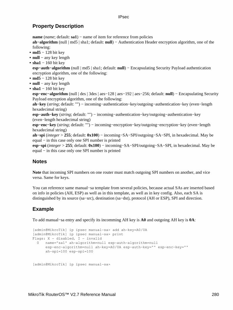
Property Description
name (name; default: sa1) − name of item for reference from policiesah−algorithm (null | md5 | sha1; default: null) − Authentication Header encryption algorithm, one of thefollowing:md5 − 128 bit key• null − any key length• sha1 − 160 bit keyesp−auth−algorithm (null | md5 | sha1; default: null) − Encapsulating Security Payload authenticationencryption algorithm, one of the following:
•
md5 − 128 bit key• null − any key length• sha1 − 160 bit keyesp−enc−algorithm (null | des | 3des | aes−128 | aes−192 | aes−256; default: null) − Encapsulating SecurityPayload encryption algorithm, one of the following:ah−key (string; default: "") − incoming−authentication−key/outgoing−authentication−key (even−lengthhexadecimal string)esp−auth−key (string; default: "") − incoming−authentication−key/outgoing−authentication−key(even−length hexadecimal string)esp−enc−key (string; default: "") − incoming−encryption−key/outgoing−encryption−key (even−lengthhexadecimal string)ah−spi (integer > 255; default: 0x100) − incoming−SA−SPI/outgoing−SA−SPI, in hexadecimal. May beequal − in this case only one SPI number is printedesp−spi (integer > 255; default: 0x100) − incoming−SA−SPI/outgoing−SA−SPI, in hexadecimal. May beequal − in this case only one SPI number is printed
Notes
Note that incoming SPI numbers on one router must match outgoing SPI numbers on another, and viceversa. Same for keys.
You can reference same manual−sa template from several policies, because actual SAs are inserted basedon info in policies (AH, ESP) as well as in this template, as well as in key config. Also, each SA isdistinguished by its source (sa−src), destination (sa−dst), protocol (AH or ESP), SPI and direction.
Example
To add manual−sa entry and specify its incomming AH key is A0 and outgoing AH key is 0A:
[admin@MikroTik] ip ipsec manual−sa> add ah−key=A0/0A[admin@MikroTik] ip ipsec manual−sa> printFlags: X − disabled, I − invalid 0 name="sa1" ah−algorithm=null esp−auth−algorithm=null esp−enc−algorithm=null ah−key=A0/0A esp−auth−key="" esp−enc−key="" ah−spi=100 esp−spi=100
[admin@MikroTik] ip ipsec manual−sa>
•
IPsec
MikroTik RouterOS™ V2.7 Reference Manual 280
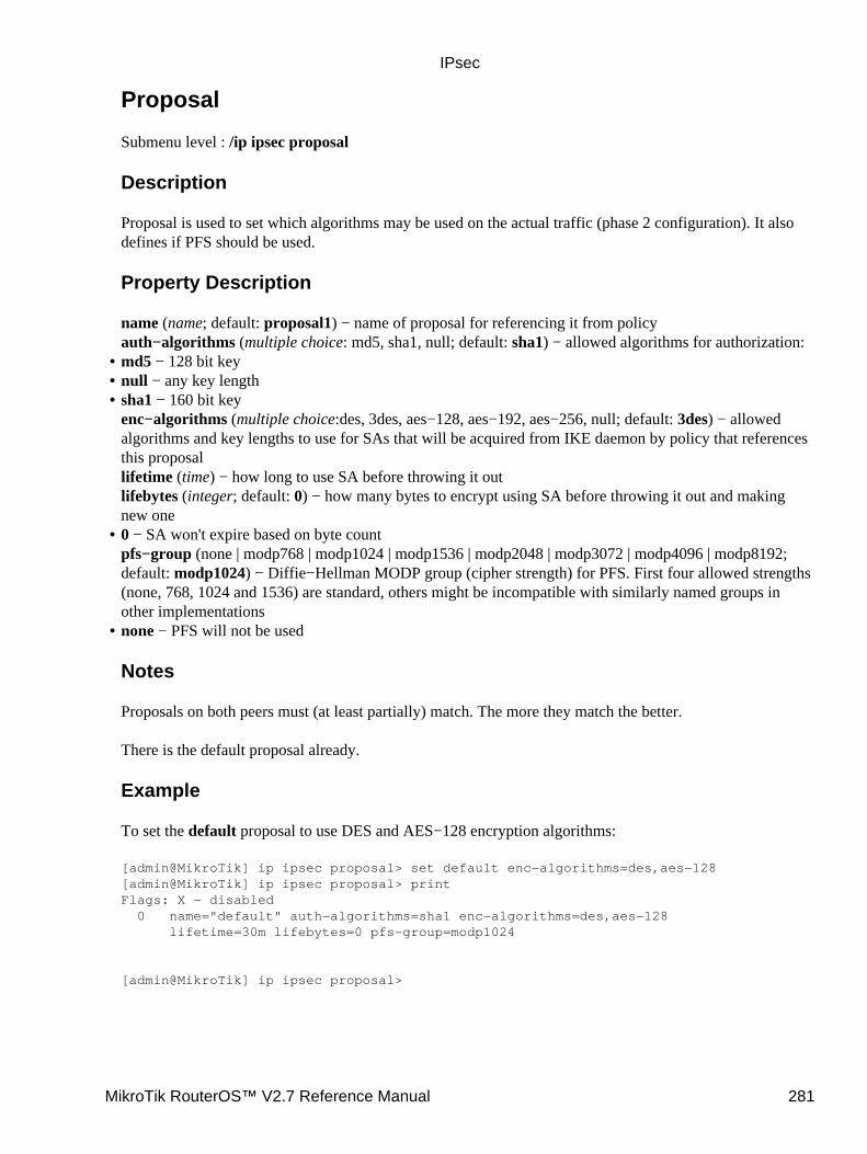
Proposal
Submenu level : /ip ipsec proposal
Description
Proposal is used to set which algorithms may be used on the actual traffic (phase 2 configuration). It alsodefines if PFS should be used.
Property Description
name (name; default: proposal1) − name of proposal for referencing it from policyauth−algorithms (multiple choice: md5, sha1, null; default: sha1) − allowed algorithms for authorization:md5 − 128 bit key• null − any key length• sha1 − 160 bit keyenc−algorithms (multiple choice:des, 3des, aes−128, aes−192, aes−256, null; default: 3des) − allowedalgorithms and key lengths to use for SAs that will be acquired from IKE daemon by policy that referencesthis proposallifetime (time) − how long to use SA before throwing it outlifebytes (integer; default: 0) − how many bytes to encrypt using SA before throwing it out and makingnew one
•
0 − SA won't expire based on byte countpfs−group (none | modp768 | modp1024 | modp1536 | modp2048 | modp3072 | modp4096 | modp8192;default: modp1024) − Diffie−Hellman MODP group (cipher strength) for PFS. First four allowed strengths(none, 768, 1024 and 1536) are standard, others might be incompatible with similarly named groups inother implementations
•
none − PFS will not be used
Notes
Proposals on both peers must (at least partially) match. The more they match the better.
There is the default proposal already.
Example
To set the default proposal to use DES and AES−128 encryption algorithms:
[admin@MikroTik] ip ipsec proposal> set default enc−algorithms=des,aes−128[admin@MikroTik] ip ipsec proposal> printFlags: X − disabled 0 name="default" auth−algorithms=sha1 enc−algorithms=des,aes−128 lifetime=30m lifebytes=0 pfs−group=modp1024
[admin@MikroTik] ip ipsec proposal>
•
IPsec
MikroTik RouterOS™ V2.7 Reference Manual 281
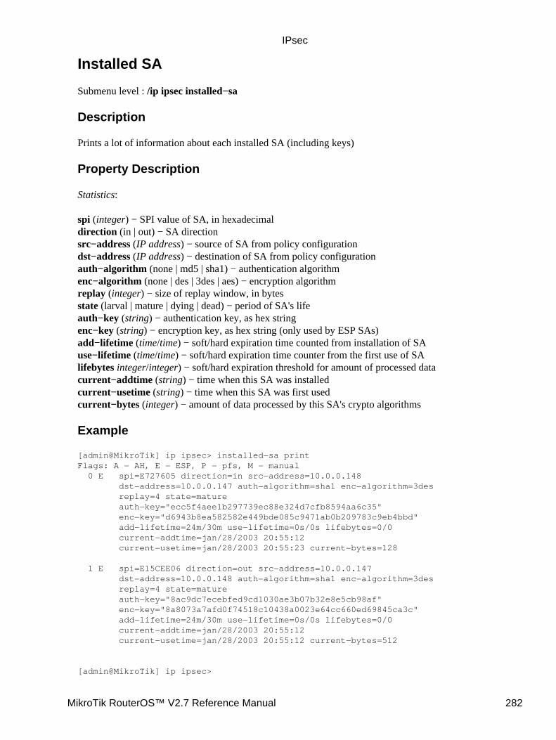
Installed SA
Submenu level : /ip ipsec installed−sa
Description
Prints a lot of information about each installed SA (including keys)
Property Description
Statistics:
spi (integer) − SPI value of SA, in hexadecimaldirection (in | out) − SA directionsrc−address (IP address) − source of SA from policy configurationdst−address (IP address) − destination of SA from policy configurationauth−algorithm (none | md5 | sha1) − authentication algorithmenc−algorithm (none | des | 3des | aes) − encryption algorithmreplay (integer) − size of replay window, in bytesstate (larval | mature | dying | dead) − period of SA's lifeauth−key (string) − authentication key, as hex stringenc−key (string) − encryption key, as hex string (only used by ESP SAs)add−lifetime (time/time) − soft/hard expiration time counted from installation of SAuse−lifetime (time/time) − soft/hard expiration time counter from the first use of SAlifebytes integer/integer) − soft/hard expiration threshold for amount of processed datacurrent−addtime (string) − time when this SA was installedcurrent−usetime (string) − time when this SA was first usedcurrent−bytes (integer) − amount of data processed by this SA's crypto algorithms
Example
[admin@MikroTik] ip ipsec> installed−sa printFlags: A − AH, E − ESP, P − pfs, M − manual 0 E spi=E727605 direction=in src−address=10.0.0.148 dst−address=10.0.0.147 auth−algorithm=sha1 enc−algorithm=3des replay=4 state=mature auth−key="ecc5f4aee1b297739ec88e324d7cfb8594aa6c35" enc−key="d6943b8ea582582e449bde085c9471ab0b209783c9eb4bbd" add−lifetime=24m/30m use−lifetime=0s/0s lifebytes=0/0 current−addtime=jan/28/2003 20:55:12 current−usetime=jan/28/2003 20:55:23 current−bytes=128
1 E spi=E15CEE06 direction=out src−address=10.0.0.147 dst−address=10.0.0.148 auth−algorithm=sha1 enc−algorithm=3des replay=4 state=mature auth−key="8ac9dc7ecebfed9cd1030ae3b07b32e8e5cb98af" enc−key="8a8073a7afd0f74518c10438a0023e64cc660ed69845ca3c" add−lifetime=24m/30m use−lifetime=0s/0s lifebytes=0/0 current−addtime=jan/28/2003 20:55:12 current−usetime=jan/28/2003 20:55:12 current−bytes=512
[admin@MikroTik] ip ipsec>
IPsec
MikroTik RouterOS™ V2.7 Reference Manual 282
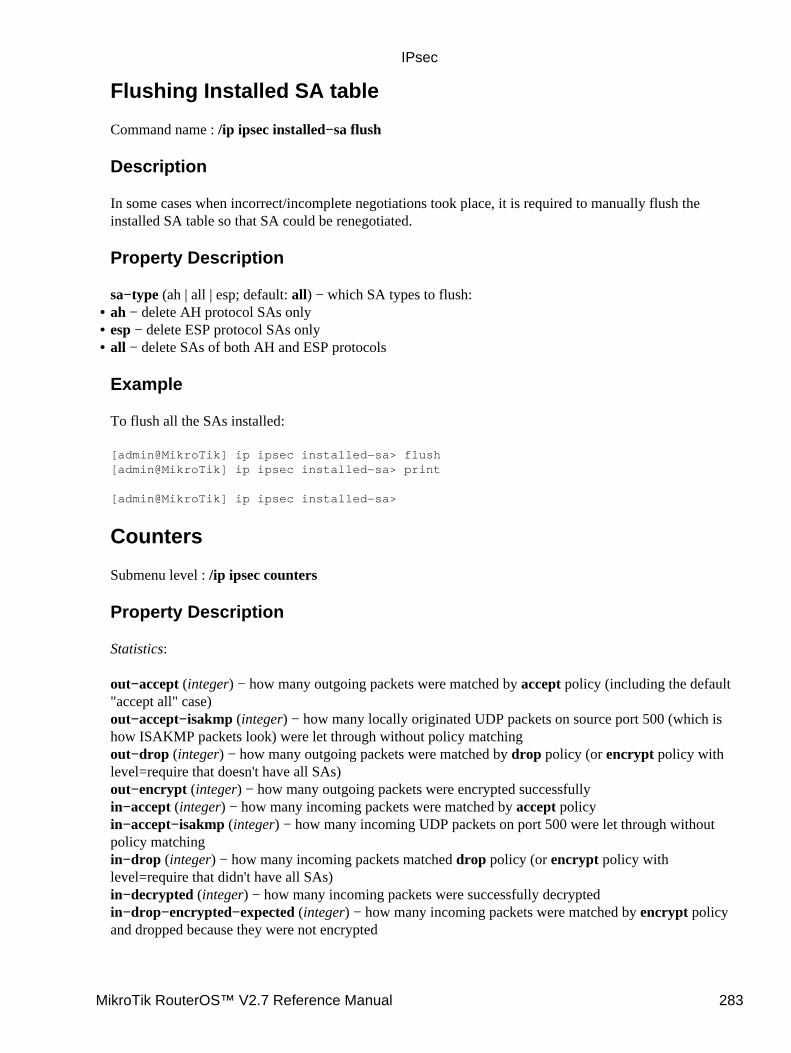
Flushing Installed SA table
Command name : /ip ipsec installed−sa flush
Description
In some cases when incorrect/incomplete negotiations took place, it is required to manually flush theinstalled SA table so that SA could be renegotiated.
Property Description
sa−type (ah | all | esp; default: all) − which SA types to flush:ah − delete AH protocol SAs only• esp − delete ESP protocol SAs only• all − delete SAs of both AH and ESP protocols
Example
To flush all the SAs installed:
[admin@MikroTik] ip ipsec installed−sa> flush[admin@MikroTik] ip ipsec installed−sa> print
[admin@MikroTik] ip ipsec installed−sa>
Counters
Submenu level : /ip ipsec counters
Property Description
Statistics:
out−accept (integer) − how many outgoing packets were matched by accept policy (including the default"accept all" case)out−accept−isakmp (integer) − how many locally originated UDP packets on source port 500 (which ishow ISAKMP packets look) were let through without policy matchingout−drop (integer) − how many outgoing packets were matched by drop policy (or encrypt policy withlevel=require that doesn't have all SAs)out−encrypt (integer) − how many outgoing packets were encrypted successfullyin−accept (integer) − how many incoming packets were matched by accept policyin−accept−isakmp (integer) − how many incoming UDP packets on port 500 were let through withoutpolicy matchingin−drop (integer) − how many incoming packets matched drop policy (or encrypt policy withlevel=require that didn't have all SAs)in−decrypted (integer) − how many incoming packets were successfully decryptedin−drop−encrypted−expected (integer) − how many incoming packets were matched by encrypt policyand dropped because they were not encrypted
•
IPsec
MikroTik RouterOS™ V2.7 Reference Manual 283
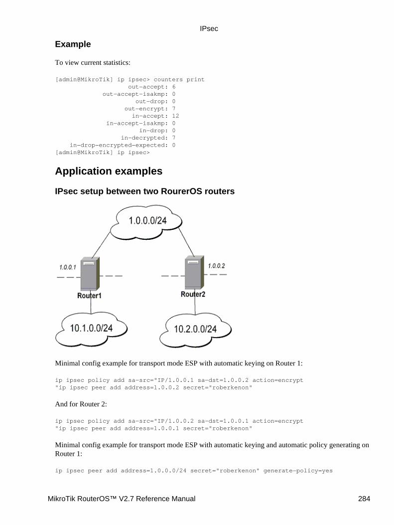
Example
To view current statistics:
[admin@MikroTik] ip ipsec> counters print out−accept: 6 out−accept−isakmp: 0 out−drop: 0 out−encrypt: 7 in−accept: 12 in−accept−isakmp: 0 in−drop: 0 in−decrypted: 7 in−drop−encrypted−expected: 0[admin@MikroTik] ip ipsec>
Application examples
IPsec setup between two RourerOS routers
Minimal config example for transport mode ESP with automatic keying on Router 1:
ip ipsec policy add sa−src="IP/1.0.0.1 sa−dst=1.0.0.2 action=encrypt"ip ipsec peer add address=1.0.0.2 secret="roberkenon"
And for Router 2:
ip ipsec policy add sa−src="IP/1.0.0.2 sa−dst=1.0.0.1 action=encrypt"ip ipsec peer add address=1.0.0.1 secret="roberkenon"
Minimal config example for transport mode ESP with automatic keying and automatic policy generating onRouter 1:
ip ipsec peer add address=1.0.0.0/24 secret="roberkenon" generate−policy=yes
IPsec
MikroTik RouterOS™ V2.7 Reference Manual 284
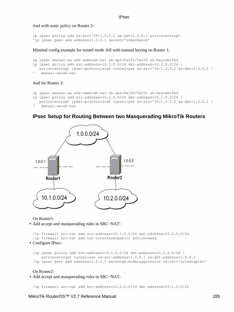
And with static policy on Router 2:
ip ipsec policy add sa−src="IP/1.0.0.2 sa−dst=1.0.0.1 action=encrypt"ip ipsec peer add address=1.0.0.1 secret="roberkenon"
Minimal config example for tunnel mode AH with manual keying on Router 1:
ip ipsec manual−sa add name=ah−sa1 ah−spi=0x101/0x100 ah−key=abcfedip ipsec policy add src−address=10.1.0.0/24 dst−address=10.2.0.0/24 \ action=encrypt ipsec−protocols=ah tunnel=yes sa−src="IP/1.0.0.1 sa−dst=1.0.0.2 \" manual−sa=ah−sa1
And for Router 2:
ip ipsec manual−sa add name=ah−sa1 ah−spi=0x100/0x101 ah−key=abcfedip ipsec policy add src−address=10.2.0.0/24 dst−address=10.1.0.0/24 \ action=encrypt ipsec−protocols=ah tunnel=yes sa−src="IP/1.0.0.2 sa−dst=1.0.0.1 \" manual−sa=ah−sa1
IPsec Setup for Routing Between two Masquerading MikroTik Routers
On Router1:Add accept and masquerading rules in SRC−NAT:
/ip firewall src−nat add src−address=10.1.0.0/24 dst−address=10.2.0.0/24/ip firewall src−nat add out−interface=public action=masq
•
Configure IPsec:
/ip ipsec policy add src−address=10.1.0.0/24 dst−address=10.2.0.0/24 \ action=encrypt tunnel=yes sa−src−address=1.0.0.1 sa−dst−address=1.0.0.2/ip ipsec peer add address=1.0.0.2 exchange−mode=aggressive secret="sviestapika"
On Router2:
•
Add accept and masquerading rules in SRC−NAT:
/ip firewall src−nat add src−address=10.2.0.0/24 dst−address=10.1.0.0/24
•
IPsec
MikroTik RouterOS™ V2.7 Reference Manual 285
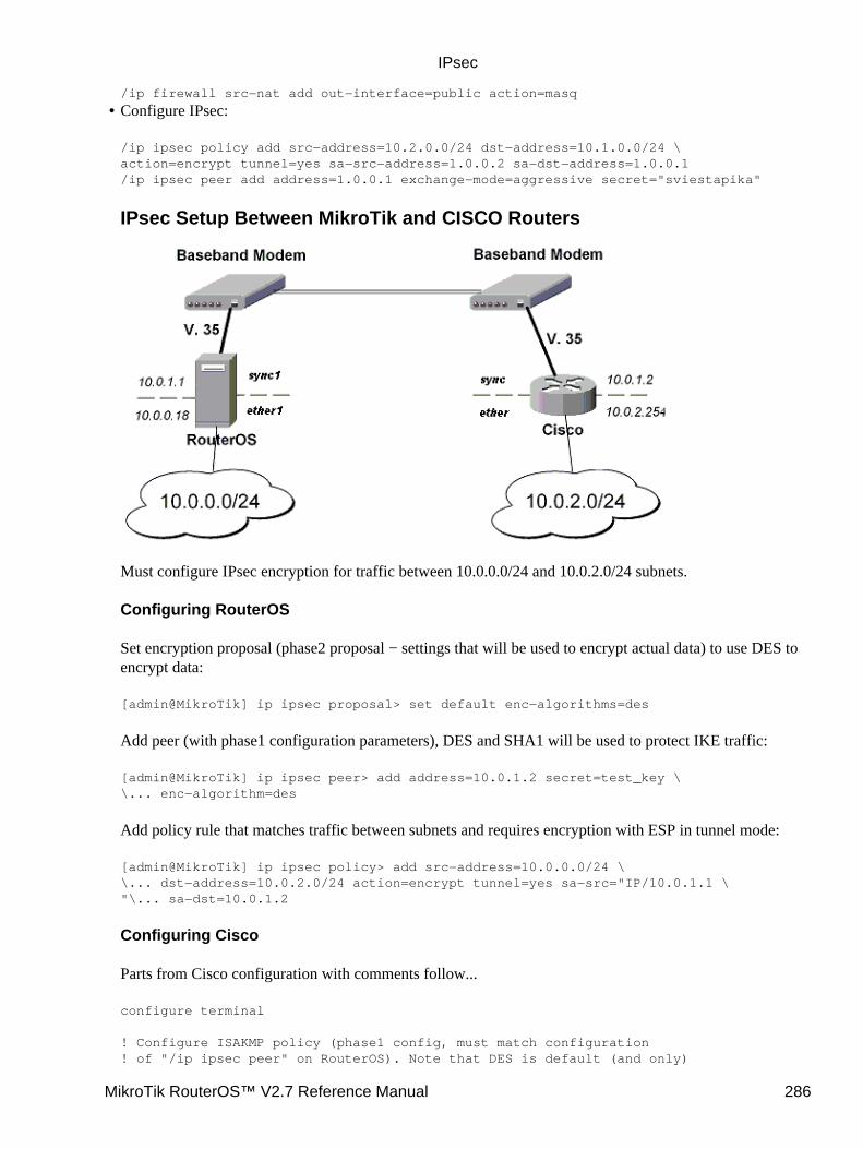
/ip firewall src−nat add out−interface=public action=masq
Configure IPsec:
/ip ipsec policy add src−address=10.2.0.0/24 dst−address=10.1.0.0/24 \action=encrypt tunnel=yes sa−src−address=1.0.0.2 sa−dst−address=1.0.0.1/ip ipsec peer add address=1.0.0.1 exchange−mode=aggressive secret="sviestapika"
IPsec Setup Between MikroTik and CISCO Routers
Must configure IPsec encryption for traffic between 10.0.0.0/24 and 10.0.2.0/24 subnets.
Configuring RouterOS
Set encryption proposal (phase2 proposal − settings that will be used to encrypt actual data) to use DES toencrypt data:
[admin@MikroTik] ip ipsec proposal> set default enc−algorithms=des
Add peer (with phase1 configuration parameters), DES and SHA1 will be used to protect IKE traffic:
[admin@MikroTik] ip ipsec peer> add address=10.0.1.2 secret=test_key \\... enc−algorithm=des
Add policy rule that matches traffic between subnets and requires encryption with ESP in tunnel mode:
[admin@MikroTik] ip ipsec policy> add src−address=10.0.0.0/24 \\... dst−address=10.0.2.0/24 action=encrypt tunnel=yes sa−src="IP/10.0.1.1 \"\... sa−dst=10.0.1.2
Configuring Cisco
Parts from Cisco configuration with comments follow...
configure terminal
! Configure ISAKMP policy (phase1 config, must match configuration! of "/ip ipsec peer" on RouterOS). Note that DES is default (and only)
•
IPsec
MikroTik RouterOS™ V2.7 Reference Manual 286
! encryption algorithm on this Cisco. SHA1 is default authentication! algorithmcrypto isakmp policy 9 encryption des group 2 hash md5 exit
! Add preshared key to be used when talking to RouterOScrypto isakmp key mykey address 10.0.1.1 255.255.255.255
! Create IPsec transform set − transformations that should be applied to! traffic − ESP encryption with DES and ESP authentication with SHA1! This must match "/ip ipsec proposal"crypto ipsec transform−set myset esp−des esp−sha−hmac mode tunnel exit
! Create access list that matches traffic that should be encryptedaccess−list 101 permit ip 10.0.2.0 0.0.0.255 10.0.0.0 0.0.0.255
! Create crypto map that will use transform set "myset", use peer 10.0.1.1! to establish SAs and encapsulate traffic and use access−list 101 to! match traffic that should be encryptedcrypto map mymap 10 ipsec−isakmp set peer 10.0.1.1 set transform−set myset set pfs group2 match address 101 exit
! And finally apply crypto map to serial interface:interface Serial 0 crypto map mymap exit
Testing
After this simply ping from some host in one network to some host in other network − after some time(~10sec) replies should start coming back because SAs are established and data is being encrypted.
On RouterOS we can see installed SAs:
[admin@MikroTik] ip ipsec installed−sa> printFlags: A − AH, E − ESP, P − pfs, M − manual 0 E spi=9437482 direction=out src−address=10.0.1.1 dst−address=10.0.1.2 auth−algorithm=sha1 enc−algorithm=des replay=4 state=mature auth−key="9cf2123b8b5add950e3e67b9eac79421d406aa09" enc−key="ffe7ec65b7a385c3" add−lifetime=24m/30m use−lifetime=0s/0s lifebytes=0/0 current−addtime=jul/12/2002 16:13:21 current−usetime=jul/12/2002 16:13:21 current−bytes=71896
1 E spi=319317260 direction=in src−address=10.0.1.2 dst−address=10.0.1.1 auth−algorithm=sha1 enc−algorithm=des replay=4 state=mature auth−key="7575f5624914dd312839694db2622a318030bc3b" enc−key="633593f809c9d6af" add−lifetime=24m/30m use−lifetime=0s/0s lifebytes=0/0 current−addtime=jul/12/2002 16:13:21 current−usetime=jul/12/2002 16:13:21 current−bytes=0
IPsec
MikroTik RouterOS™ V2.7 Reference Manual 287
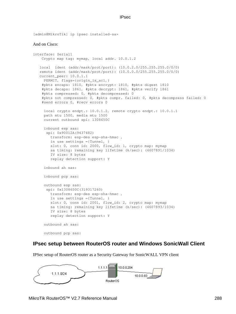
[admin@MikroTik] ip ipsec installed−sa>
And on Cisco:
interface: Serial1 Crypto map tag: mymap, local addr. 10.0.1.2
local ident (addr/mask/prot/port): (10.0.2.0/255.255.255.0/0/0) remote ident (addr/mask/prot/port): (10.0.0.0/255.255.255.0/0/0) current_peer: 10.0.1.1 PERMIT, flags={origin_is_acl,} #pkts encaps: 1810, #pkts encrypt: 1810, #pkts digest 1810 #pkts decaps: 1861, #pkts decrypt: 1861, #pkts verify 1861 #pkts compressed: 0, #pkts decompressed: 0 #pkts not compressed: 0, #pkts compr. failed: 0, #pkts decompress failed: 0 #send errors 0, #recv errors 0
local crypto endpt.: 10.0.1.2, remote crypto endpt.: 10.0.1.1 path mtu 1500, media mtu 1500 current outbound spi: 1308650C
inbound esp sas: spi: 0x90012A(9437482) transform: esp−des esp−sha−hmac , in use settings ={Tunnel, } slot: 0, conn id: 2000, flow_id: 1, crypto map: mymap sa timing: remaining key lifetime (k/sec): (4607891/1034) IV size: 8 bytes replay detection support: Y
inbound ah sas:
inbound pcp sas:
outbound esp sas: spi: 0x1308650C(319317260) transform: esp−des esp−sha−hmac , in use settings ={Tunnel, } slot: 0, conn id: 2001, flow_id: 2, crypto map: mymap sa timing: remaining key lifetime (k/sec): (4607893/1034) IV size: 8 bytes replay detection support: Y
outbound ah sas:
outbound pcp sas:
IPsec setup between RouterOS router and Windows SonicWall Client
IPSec setup of RouterOS router as a Security Gateway for SonicWALL VPN client
IPsec
MikroTik RouterOS™ V2.7 Reference Manual 288
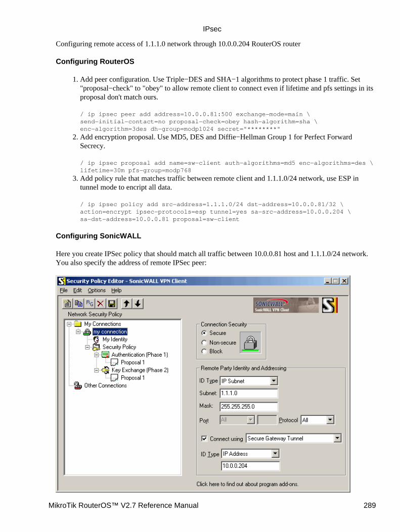
Configuring remote access of 1.1.1.0 network through 10.0.0.204 RouterOS router
Configuring RouterOS
Add peer configuration. Use Triple−DES and SHA−1 algorithms to protect phase 1 traffic. Set"proposal−check" to "obey" to allow remote client to connect even if lifetime and pfs settings in itsproposal don't match ours.
/ ip ipsec peer add address=10.0.0.81:500 exchange−mode=main \send−initial−contact=no proposal−check=obey hash−algorithm=sha \enc−algorithm=3des dh−group=modp1024 secret="********"
1.
Add encryption proposal. Use MD5, DES and Diffie−Hellman Group 1 for Perfect ForwardSecrecy.
/ ip ipsec proposal add name=sw−client auth−algorithms=md5 enc−algorithms=des \lifetime=30m pfs−group=modp768
2.
Add policy rule that matches traffic between remote client and 1.1.1.0/24 network, use ESP intunnel mode to encript all data.
/ ip ipsec policy add src−address=1.1.1.0/24 dst−address=10.0.0.81/32 \action=encrypt ipsec−protocols=esp tunnel=yes sa−src−address=10.0.0.204 \sa−dst−address=10.0.0.81 proposal=sw−client
3.
Configuring SonicWALL
Here you create IPSec policy that should match all traffic between 10.0.0.81 host and 1.1.1.0/24 network.You also specify the address of remote IPSec peer:
IPsec
MikroTik RouterOS™ V2.7 Reference Manual 289
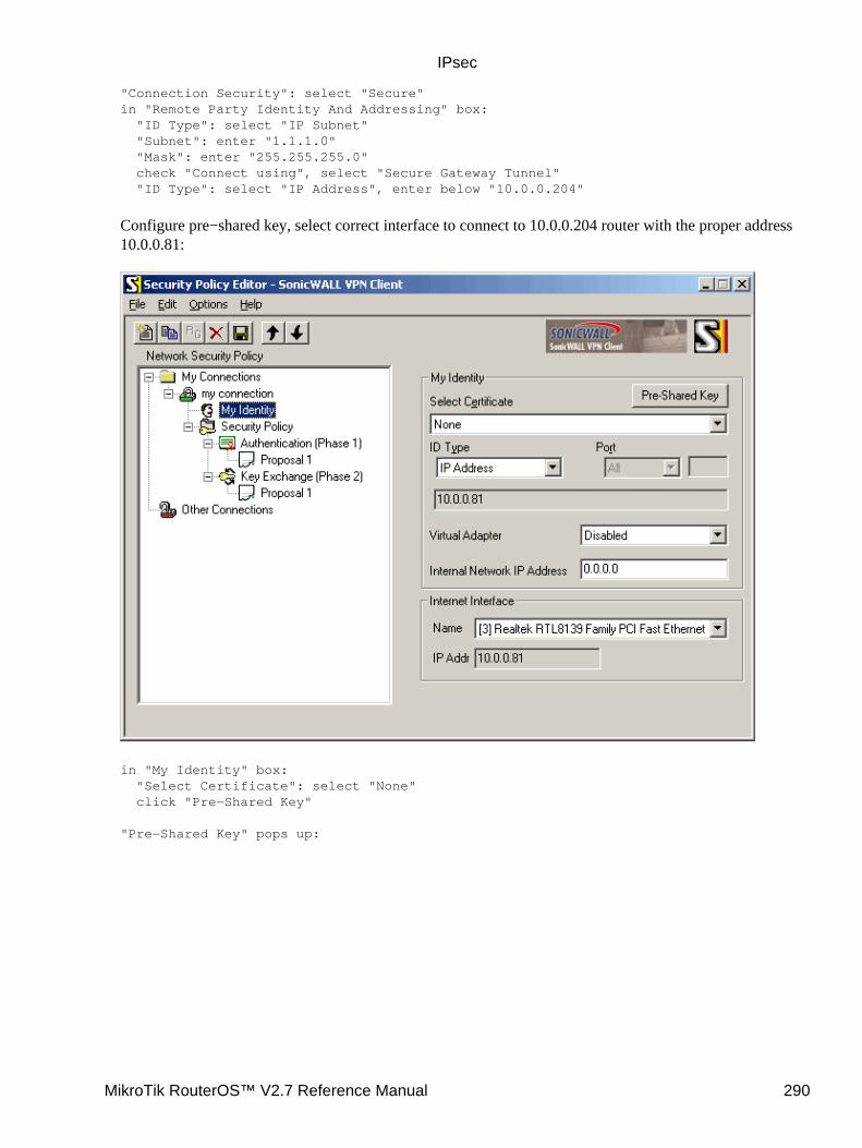
"Connection Security": select "Secure"in "Remote Party Identity And Addressing" box: "ID Type": select "IP Subnet" "Subnet": enter "1.1.1.0" "Mask": enter "255.255.255.0" check "Connect using", select "Secure Gateway Tunnel" "ID Type": select "IP Address", enter below "10.0.0.204"
Configure pre−shared key, select correct interface to connect to 10.0.0.204 router with the proper address10.0.0.81:
in "My Identity" box: "Select Certificate": select "None" click "Pre−Shared Key"
"Pre−Shared Key" pops up:
IPsec
MikroTik RouterOS™ V2.7 Reference Manual 290
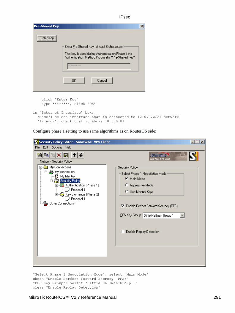
click "Enter Key" type ********, click "OK"
in "Internet Interface" box: "Name": select interface that is connected to 10.0.0.0/24 network "IP Addr": check that it shows 10.0.0.81
Configure phase 1 setting to use same algorithms as on RouterOS side:
"Select Phase 1 Negotiation Mode": select "Main Mode"check "Enable Perfect Forward Secrecy (PFS)""PFS Key Group": select "Diffie−Hellman Group 1"clear "Enable Replay Detection"
IPsec
MikroTik RouterOS™ V2.7 Reference Manual 291
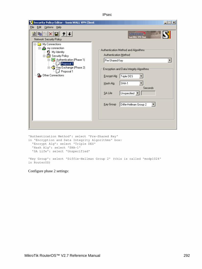
"Authentication Method": select "Pre−Shared Key"in "Encryption and Data Integrity Algorithms" box: "Encrypt Alg": select "Triple DES" "Hash Alg": select "SHA−1" "SA Life": select "Unspecified"
"Key Group": select "Diffie−Hellman Group 2" (this is called "modp1024"in RouterOS)
Configure phase 2 settings:
IPsec
MikroTik RouterOS™ V2.7 Reference Manual 292
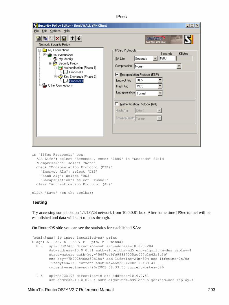
in "IPSec Protocols" box: "SA Life": select "Seconds", enter "1800" in "Seconds" field "Compression": select "None" check "Encapsulation Protocol (ESP)" "Encrypt Alg": select "DES" "Hash Alg": select "MD5" "Encapsulation": select "Tunnel" clear "Authentication Protocol (AH)"
click "Save" (on the toolbar)
Testing
Try accessing some host on 1.1.1.0/24 network from 10.0.0.81 box. After some time IPSec tunnel will beestablished and data will start to pass through.
On RouterOS side you can see the statistics for established SAs:
[admin@xxx] ip ipsec installed−sa> printFlags: A − AH, E − ESP, P − pfs, M − manual 0 E spi=3C3C7A8D direction=out src−address=10.0.0.204 dst−address=10.0.0.81 auth−algorithm=md5 enc−algorithm=des replay=4 state=mature auth−key="5697ee9fe98867005ac057e1b62a6c3b" enc−key="7b992840ea30b180" add−lifetime=24m/30m use−lifetime=0s/0s lifebytes=0/0 current−addtime=nov/26/2002 09:33:47 current−usetime=nov/26/2002 09:33:53 current−bytes=896
1 E spi=A472A105 direction=in src−address=10.0.0.81 dst−address=10.0.0.204 auth−algorithm=md5 enc−algorithm=des replay=4
IPsec
MikroTik RouterOS™ V2.7 Reference Manual 293
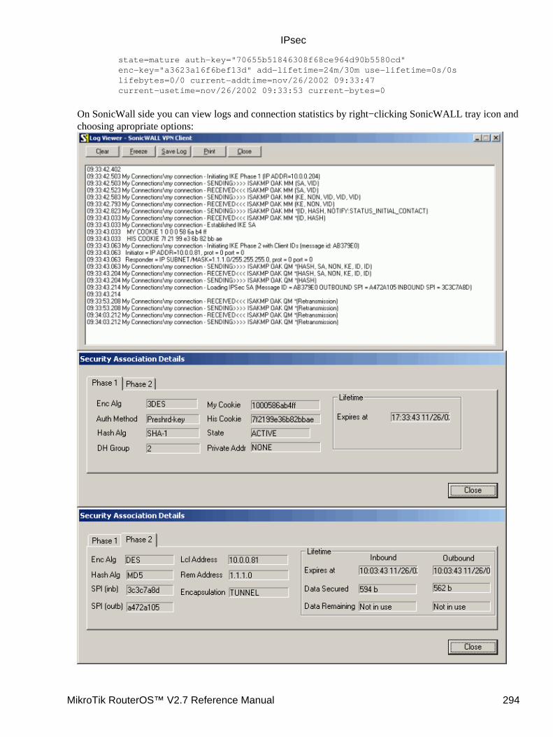
state=mature auth−key="70655b51846308f68ce964d90b5580cd" enc−key="a3623a16f6bef13d" add−lifetime=24m/30m use−lifetime=0s/0s lifebytes=0/0 current−addtime=nov/26/2002 09:33:47 current−usetime=nov/26/2002 09:33:53 current−bytes=0
On SonicWall side you can view logs and connection statistics by right−clicking SonicWALL tray icon andchoosing apropriate options:
IPsec
MikroTik RouterOS™ V2.7 Reference Manual 294

Additional Resources
How to Configure a L2TP/IPSec Connection Using Pre−shared Key Authentication
© Copyright 1999−2003, MikroTik
IPsec
MikroTik RouterOS™ V2.7 Reference Manual 295
IP TelephonyDocument revision 1.5 (11−Aug−2003)This document applies to the MikroTik RouterOS V2.7
Table Of Contents
Table Of Contents• Summary• Specifications• Related Documents• Description• IP Telephony Specifications
Supported Hardware♦ Supported Standards♦ Implementation Options♦
•
IP Telephony Hardware Installation• IP Telephony Configuration
Description♦ Telephony Voice Ports
Description◊ Property Description◊ Notes◊
♦
Monitoring the Voice PortsProperty Description◊ Notes◊ Example◊
♦
Voice−Port StatisticsNotes◊ Example◊
♦
Voice Port for Telephony cardsProperty Description◊ Notes◊
♦
Voice Port for Voicetronix cardsProperty Description◊ Notes◊
♦
Voice Port for ISDNProperty Description◊ Notes◊ Example◊
♦
Voice Port for Voice over IP (voip)Description◊ Property Description◊ Example◊
♦
NumbersDescription◊ Property Description◊ Notes◊ Example◊
♦
Regional Settings♦
•
MikroTik RouterOS™ V2.7 Reference Manual 296

Description◊ Property Description◊ Notes◊ Example◊
Audio CODECNotes◊ Example◊
♦
AAADescription♦ Property Description♦ Notes♦
•
IP Telephony GatekeeperProperty Description♦ Notes♦ Gatekeeper Configuration
Example◊ Notes◊
♦
•
IP Telephony Troubleshooting• IP Telephony Applications
Setting up the MikroTik IP Telephone♦ Setting up the IP Telephony Gateway♦ Setting up the Welltech IP Telephone♦ Setting up the MikroTik Router and CISCO Router♦ Setting up PBX to PBX Connection over an IP Network♦
•
Additional Resources•
Summary
The MikroTik RouterOS IP Telephony feature enables Voice over IP (VoIP) communications using routersequipped with the following voice port hardware:
Quicknet LineJACK or PhoneJACK analog telephony cards• ISDN cards• Voicetronix OpenLine4 (was V4PCI) − 4 analog telephone lines cards• Zaptel Wildcard X100P IP telephony card − 1 analog telephone line•
Specifications
Packages required : telephonyLicense required : AnyHome menu level : /ip telephonyProtocols utilized : Complete list of VoIP protocolsHardware usage: may require additional RAM (64MB recommended)
Related Documents
Software Package Installation and UpgradingISDN InterfaceAuthentication, Authorization and Accounting
IP Telephony
MikroTik RouterOS™ V2.7 Reference Manual 297

Description
IP telephony, known as Voice over IP (VoIP), is the transmission of telephone calls over a data network likeone of the many networks that make up the Internet. There are four ways that you might talk to someone usingVoIP:
Computer−to−computer − This is certainly the easiest way to use VoIP, and you don't have to pay forlong−distance calls.
•
Computer−to−telephone − This method allows you to call anyone (who has a phone) from yourcomputer. Like computer−to−computer calling, it requires a software client. The software is typicallyfree, but the calls may have a small per−minute charge.
•
Telephone−to−computer − Allows a standard telephone user to initiate a call to a computer user.• Telephone−to−telephone − Through the use of gateways, you can connect directly with any otherstandard telephone in the world.
•
IP Telephony Specifications
Supported Hardware
The MikroTik RouterOS V2.7 supports following telephony cards from Quicknet Technologies, Inc.(www.quicknet.net):
Internet PhoneJACK (ISA) for connecting an analog telephone,• Internet LineJACK (ISA) for connecting an analog telephone line or a telephone.•
For supported ISDN cards please see the ISDN Interface Manual.
The MikroTik RouterOS V2.7 supports the Voicetronix OpenLine4 card for connecting four (4) analogtelephone lines telephony cards from Voicetronix, Inc. (www.voicetronix.com.au)
The MikroTik RouterOS V2.7 supports the Zaptel Wildcard X100P IP telephony card for connecting oneanalog telephone line from Linux Support Services (www.digium.com)
Supported Standards
Standards for VoIPThe MikroTik RouterOS supports IP Telephony in compliance with the InternationalTelecommunications Union − Telecommunications (ITU−T) specification H.323v4. H.323 is aspecification for transmitting multimedia (voice, video, and data) across an IP network. H.323v4includes: H.245, H.225, Q.931, H.450.1, RTP(real−time protocol)
•
CODECsThe following audio CODECs are supported:G.711 − the 64 kbps Pulse code modulation (PCM) voice coding technique. The encoded voice isalready in the correct format for digital voice delivery in the PSTN or through PBXs.G.723.1 − the 6.3 kbps compression technique that can be used for compressing audio signal at verylow bit rate.GSM−06.10 − the 13.2 kbps codingLPC−10 − the 2.5 kbps codingG.729, G.729a − the 8 kbps CS−ACELP software coding
•
IP Telephony
MikroTik RouterOS™ V2.7 Reference Manual 298
G.728 − 16 kbps coding technique, supported only on Quicknet LineJACK cardsRFCsCompliant to the RFC1889(RTP) http://www.ietf.org/rfc/rfc1889.txt?number=1889
•
Regional StandardsQuicknet cards are approved in United States, United Kingdom, France, Germany, Australia, Japan.Voicetronix OpenLine4 is approved in Australia, Europe, New Zealand and USA (FCC).
•
Implementation Options
IP Telephony GatewayWhen connected to a PBX or PSTN telephone line, the MikroTik router can act as a gateway betweenthe telephone network and the VoIP network.
•
IP Telephone SystemWhen connecting an analog telephone, the MikroTik router acts as an IP Telephone
•
The MikroTik IP Telephones and IP Telephony Gateways are interoperable with the following H.323terminals:
Microsoft Netmeeting• Siemens IP phone HiNet LP 5100• Cisco ATA 186• Welltech LAN Phone 101• Most H.323 compatible devices•
IP Telephony Hardware Installation
Please install the telephony hardware into the PC accordingly the instructions provided by card manufacturer.Each installed Quicknet card requires IO memory range in the following sequence: the first card occupiesaddresses 0x300−0x31f, the second card 0x320−0x33f, the third 0x340−0x35f, and so on. Make sure there isno conflict in these ranges with other devices, e.g., network interface cards, etc.
If the MikroTik router will be used as
an IP telephone − connect an analog telephone with tone dialing capability to the PhoneJACK orLineJACK card,
•
an IP telephony gateway − connect an analog telephone line to the LineJACK, Voicetronix, Zaptelcard or ISDN telephone line to ISDN card.
•
Please consult the ISDN Manual for more information about installing the ISDN adapters.
IP Telephony Configuration
Submenu level : /ip telephony
Description
The IP Telephony requires IP network connection and configuration. The basic IP configuration can be doneunder the /ip address and /ip route menus.
IP Telephony
MikroTik RouterOS™ V2.7 Reference Manual 299

Telephony Voice Ports
Submenu level : /ip telephony voice−port
Description
This submenu is used for managing all IP telephony voice ports (linejack, phonejack, isdn, voip,voicetronix, zaptel).
Property Description
name − assigned name of the voice porttype (read−only: unknown | phonejack | linejack | phonejack−lite | phonejack−pci | voip | isdn | voicetronix |zaptel) − type of the installed telephony voice port:
unknown − unknown card type• phonejack − Quicknet PhoneJACK (ISA)• linejack − Quicknet LineJACK (ISA)• phonejack−lite − Quicknet PhoneJACK Lite Linux Edition (ISA)• phonejack−pci − Quicknet PhoneJACK (PCI)• voip − generic Voice over IP• isdn − ISDN cards• voicetronix − Voicetronix OpenLine4• zaptel − Zaptel Wildcard X100Pautodial (integer; default: "") − number to be dialed automatically, if call is coming in from this voice port
Notes
If autodial does not exactly match an item in /ip telephony numbers, there can be two possibilities:
•
if autodial is incomplete, rest of the number is asked (local voice port) or incoming call is denied (VoIP)• if autodial is invalid, line is hung up (PSTN line), busy tone is played (POTS) or incoming call is denied(VoIP)
Monitoring the Voice Ports
Property Description
status (read−only: on−hook | off−hook | ring | connection | busy) − current state of the port:
on−hook − the handset is on−hook, no activity• off−hook − the handset is off−hook, the number is being dialed• ring − call in progress, direction of the call is shown by the argument direction• connection − the connection has been established• busy − the connection has been terminated, the handset is still off−hook•
port (name) − (only for LineJACK) the active port of the card
phone − telephone connected to the card (POTS)• line − line connected to the linejack card (PSTN)•
direction (ip−to−port | port−to−ip) − direction of the call
•
IP Telephony
MikroTik RouterOS™ V2.7 Reference Manual 300
ip−to−port − call from the IP network to the voice card• port−to−ip − call from the voice card to an IP address•
line−status (plugged | unplugged) − (only for LineJACK and Zaptel) state of the PSTN line
plugged − the telephone line is connected to the PSTN port of the card• unplugged − there is no working line connected to the PSTN port of the card•
phone−number (integer) − the number which is being dialedremote−party−name (name, integer) − name and IP address of the remote partycodec (name) − CODEC used for the audio connectionduration (time) − duration of the audio call
Notes
Monitoring feature is not available for VoIP ports.
Use the monitor command under the corresponding menu to view the current state of the port.
Example
The following example will monitor linejack voice port:
[admin@MikroTik] ip telephony voice−port linejack> monitor PBX_Line status: connection port: phone direction: port−to−ip line−status: unplugged phone−number: 26 remote−party−name: pbx_20 [10.5.8.12] codec: G.723.1−6.3k/hw duration: 14s
[admin@MikroTik] ip telephony voice−port linejack>
Voice−Port Statistics
Notes
Voice−port statistics are available for all local voice ports (only VoIP voice ports do not provide thisability).
Use the show−stats command under the corresponding menu to view the statistics of current audioconnection.
Example
The following example will shows statistics of LineJACK card:
[admin@MikroTik] ip telephony voice−port linejack> show−stats PBX_Line round−trip−delay: 5ms packets−sent: 617 bytes−sent: 148080
IP Telephony
MikroTik RouterOS™ V2.7 Reference Manual 301
send−time: 31ms/30ms/29ms packets−received: 589 bytes−received: 141360 receive−time: 41ms/30ms/19ms average−jitter−delay: 59ms packets−lost: 0 packets−out−of−order: 0 packets−too−late: 2
[admin@MikroTik] ip telephony voice−port linejack>
The average−jitter−delay shows the approximate delay time till the received voice packet is forwarded tothe driver for playback. The value shown is never less than 30ms, although the actual delay time could beless. If the shown value is >40ms, then it is close (+/−1ms) to the real delay time.
The jitter buffer preserves quality of the voice signal against the loss or delay of packets while travelingover the network. The larger the jitter buffer, the larger the total delay, but fewer packets lost due totimeout. If the jitter−buffer=0, then it is adjusted automatically during the conversation to keep lost packetrate under 1%. The average−jitter−delay is the approximate average time from the moment of receivingan audio packet from the IP network till it is played back over the telephony voice port.
The total delay from the moment of recording the voice signal till its playback is the sum of following threedelay times:
delay time at the recording point (approx. 38ms),• delay time of the IP network (1..5ms and up),• delay time at the playback point (the jitter delay).•
A voice call can be terminated using the clear−call command (not available for VoIP voice ports). If thevoiceport has an active connection, the command clear−call voiceport terminates it. The command isuseful in cases, when the termination of connection has not been detected by one of the parties, and there isan "infinite call". It can also be used to terminate someone's call, if it is using up the line required foranother call.
Voice Port for Telephony cards
Property Description
name − name given by the user or the default onetype (read−only: phonejack | phonejack−lite | phonejack−pci) − (only for PhoneJACK) type of the card,cannot be changedautodial (integer; default: "") − phone number which will be dialed immediately after the handset has beenlifted. If this number is incomplete, then the remaining part has to be dialed on the dial−pad. If the numberis incorrect, busy tone is played. If the number is correct, then the appropriate number is dialed. If it is anincoming call from the PSTN line (linejack), then the directcall mode is used − the line is picked up onlyafter the remote party answers the call.playback−volume (integer; default: 0) − playback volume in dB, 0dB means no change, possible valuesare −48...48dBrecord−volume (integer; default: 0) − record volume in dB, 0dB means no change, possible values are−48...48dB.ring−cadence (string) − (only for quicknet cards) a 16−symbol ring cadence for the phone, each symbol is0.5 seconds, + means ringing, − means no ringing.
IP Telephony
MikroTik RouterOS™ V2.7 Reference Manual 302
region (australia | estonia | france | germany | japan | latvia | lithuania | mikrotik | uk | us; default: us) −regional setting for the voice port. For phonejack, this setting is used for generating the tones. For linejacks,this setting is used for setting the parameters of PSTN line, as well as for detecting and generating thetones.aec (yes | no; default: yes) − echo detection and cancellation.If the echo cancellation is on, then the following parameters are used:aec−tail−length (short | medium | long; default: short) − size of the buffer of echo detection.• aec−nlp−threshold (off | low | medium | high; default: low) − level of cancellation of silent sounds.• aec−attenuation−scaling (integer; default: 4) − factor of additional echo attenuation. Possible values are0...10.
•
aec−attenuation−boost (integer; default: 0) − level of additional echo attenuation. Possible values are 0 ...90dB.
•
software−aec (yes | no; default: no) − software echo canceller (experimental, for most of the cards.agc−on−playback (yes | no; default: no) − automatic gain control on playback (can not be used togetherwith hardware voice codecs)agc−on record (yes | no; default: no) − automatic gain control on record (can not be used together withhardware voice codecs)detect−cpt (yes | no; default: no) − automatically detect call progress tones
Notes
All commands relating the Quicknet, Voicetronix and Zaptel Wildcard cards are listed under the /iptelephony voice−port submenus:
[admin@MikroTik] ip telephony voice−port linejack> printFlags: X − disabled 0 name="linejack1" autodial="" region=us playback−volume=0 record−volume=0 ring−cadence="++−++−−− ++−++−−−" agc−on−playback=no agc−on−record=no aec=yes aec−tail−length=short aec−nlp−threshold=low aec−attenuation−scaling=4 aec−attenuation−boost=0 software−aec=no detect−cpt=yes
[admin@MikroTik] ip telephony voice−port linejack>
For linejacks, there is a command blink voiceport, which blinks the LEDs of the specified voiceport forfive seconds after it is invoked. This command can be used to locate the respective card from severallinejack cards.
Voice Port for Voicetronix cards
Submenu level : /ip telephony voice−port voicetronix
Property Description
Voicetronix telephony cards have some additional properties other cards haven't:
balance−registers (integer; default: 199) − registers which depend on telephone line impedance. Can beadjusted to get best echo cancellationbalance−status (read−only: integer) − shows quality of hardware echo cancellation in dBloop−drop−detection (yes | no; default: yes) − automatically clear call when loop drop is detected
•
IP Telephony
MikroTik RouterOS™ V2.7 Reference Manual 303
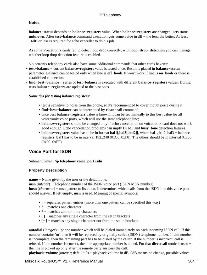
Notes
balance−status depends on balance−registers value. When balance−registers are changed, gets statusunknown. After test−balance command execution gets some value in dB − the less, the better. At least−6dB or less is required for echo canceller to do his job.
As some Voicetronix cards fail to detect loop drop correctly, with loop−drop−detection you can managewhether loop drop detection feature is enabled.
Voicetronix telephony cards also have some additional commands that other cards haven't:test−balance − current balance−registers value is tested once. Result is placed in balance−statusparameter. Balance can be tested only when line is off−hook. It won't work if line is on−hook or there isestablished connection.
•
find−best−balance − series of test−balance is executed with different balance−registers values. Duringtests balance−registers are updated to the best ones.
Some tips for testing balance registers:
test is sensitive to noise from the phone, so it's recommended to cover mouth peice during it;• find−best−balance can be interrupted by clean−call command;• once best balance−registers value is known, it can be set manually to this best value for allvoicetronix voice ports, which will use the same telephone line;
•
balance−registers should be changed only if echo cancellation on voicetronix card does not workgood enough. Echo cancellation problems can imply DTMF and busy−tone detection failures.
•
balance−registers value has to be in format bal1[,bal3[,bal2]], where bal1, bal2, bal3 − balanceregisters. bal1 has to be in interval 192..248 (0xC0..0xF8). The others should be in interval 0..255(0x00..0xFF).
•
Voice Port for ISDN
Submenu level : /ip telephony voice−port isdn
Property Description
name − Name given by the user or the default one.msn (integer) − Telephone number of the ISDN voice port (ISDN MSN number).lmsn (character) − msn pattern to listen on. It determines which calls from the ISDN line this voice portshould answer. If left empty, msn is used. Meaning of special symbols:
; − separates pattern entries (more than one pattern can be specified this way)• ? − matches one character• * − matches zero or more characters• [ ] − matches any single character from the set in brackets• [^ ] − matches any single character not from the set in brackets•
autodial (integer) − phone number which will be dialed immediately on each incoming ISDN call. If thisnumber contains 'm', then it will be replaced by originally called (ISDN) telephone number. If this numberis incomplete, then the remaining part has to be dialed by the caller. If the number is incorrect, call isrefused. If the number is correct, then the appropriate number is dialed. For that directcall mode is used −the line is picked up only after the remote party answers the call.playback−volume (integer; default: 0) − playback volume in dB, 0dB means no change, possible values
•
IP Telephony
MikroTik RouterOS™ V2.7 Reference Manual 304
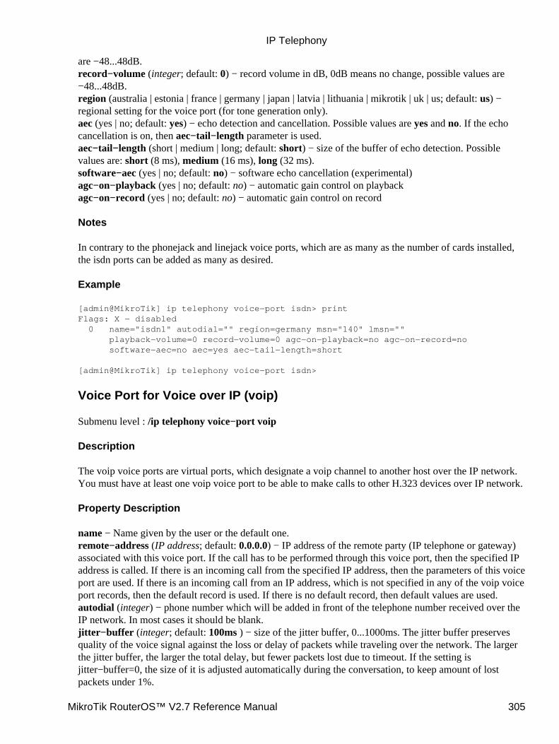
are −48...48dB.record−volume (integer; default: 0) − record volume in dB, 0dB means no change, possible values are−48...48dB.region (australia | estonia | france | germany | japan | latvia | lithuania | mikrotik | uk | us; default: us) −regional setting for the voice port (for tone generation only).aec (yes | no; default: yes) − echo detection and cancellation. Possible values are yes and no. If the echocancellation is on, then aec−tail−length parameter is used.aec−tail−length (short | medium | long; default: short) − size of the buffer of echo detection. Possiblevalues are: short (8 ms), medium (16 ms), long (32 ms).software−aec (yes | no; default: no) − software echo cancellation (experimental)agc−on−playback (yes | no; default: no) − automatic gain control on playbackagc−on−record (yes | no; default: no) − automatic gain control on record
Notes
In contrary to the phonejack and linejack voice ports, which are as many as the number of cards installed,the isdn ports can be added as many as desired.
Example
[admin@MikroTik] ip telephony voice−port isdn> printFlags: X − disabled 0 name="isdn1" autodial="" region=germany msn="140" lmsn="" playback−volume=0 record−volume=0 agc−on−playback=no agc−on−record=no software−aec=no aec=yes aec−tail−length=short
[admin@MikroTik] ip telephony voice−port isdn>
Voice Port for Voice over IP (voip)
Submenu level : /ip telephony voice−port voip
Description
The voip voice ports are virtual ports, which designate a voip channel to another host over the IP network.You must have at least one voip voice port to be able to make calls to other H.323 devices over IP network.
Property Description
name − Name given by the user or the default one.remote−address (IP address; default: 0.0.0.0) − IP address of the remote party (IP telephone or gateway)associated with this voice port. If the call has to be performed through this voice port, then the specified IPaddress is called. If there is an incoming call from the specified IP address, then the parameters of this voiceport are used. If there is an incoming call from an IP address, which is not specified in any of the voip voiceport records, then the default record is used. If there is no default record, then default values are used.autodial (integer) − phone number which will be added in front of the telephone number received over theIP network. In most cases it should be blank.jitter−buffer (integer; default: 100ms ) − size of the jitter buffer, 0...1000ms. The jitter buffer preservesquality of the voice signal against the loss or delay of packets while traveling over the network. The largerthe jitter buffer, the larger the total delay, but fewer packets lost due to timeout. If the setting isjitter−buffer=0, the size of it is adjusted automatically during the conversation, to keep amount of lostpackets under 1%.
IP Telephony
MikroTik RouterOS™ V2.7 Reference Manual 305
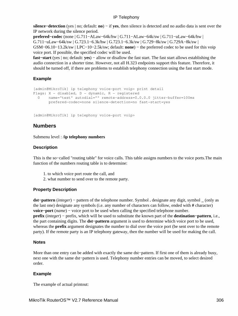
silence−detection (yes | no; default: no) − if yes, then silence is detected and no audio data is sent over theIP network during the silence period.prefered−codec (none | G.711−ALaw−64k/hw | G.711−ALaw−64k/sw | G.711−uLaw−64k/hw |G.711−uLaw−64k/sw | G.723.1−6.3k/hw | G.723.1−6.3k/sw | G.729−8k/sw | G.729A−8k/sw |GSM−06.10−13.2k/sw | LPC−10−2.5k/sw; default: none) − the preferred codec to be used for this voipvoice port. If possible, the specified codec will be used.fast−start (yes | no; default: yes) − allow or disallow the fast start. The fast start allows establishing theaudio connection in a shorter time. However, not all H.323 endpoints support this feature. Therefore, itshould be turned off, if there are problems to establish telephony connection using the fast start mode.
Example
[admin@MikroTik] ip telephony voice−port voip> print detailFlags: X − disabled, D − dynamic, R − registered 0 name="test" autodial="" remote−address=0.0.0.0 jitter−buffer=100ms prefered−codec=none silence−detection=no fast−start=yes
[admin@MikroTik] ip telephony voice−port voip>
Numbers
Submenu level : /ip telephony numbers
Description
This is the so−called "routing table" for voice calls. This table assigns numbers to the voice ports.The mainfunction of the numbers routing table is to determine:
to which voice port route the call, and1. what number to send over to the remote party.2.
Property Description
dst−pattern (integer) − pattern of the telephone number. Symbol . designate any digit, symbol _ (only asthe last one) designate any symbols (i.e. any number of characters can follow, ended with # character)voice−port (name) − voice port to be used when calling the specified telephone number.prefix (integer) − prefix, which will be used to substitute the known part of the destination−pattern, i.e.,the part containing digits. The dst−pattern argument is used to determine which voice port to be used,whereas the prefix argument designates the number to dial over the voice port (be sent over to the remoteparty). If the remote party is an IP telephony gateway, then the number will be used for making the call.
Notes
More than one entry can be added with exactly the same dst−pattern. If first one of them is already busy,next one with the same dst−pattern is used. Telephony number entries can be moved, to select desiredorder.
Example
The example of actual printout:
IP Telephony
MikroTik RouterOS™ V2.7 Reference Manual 306
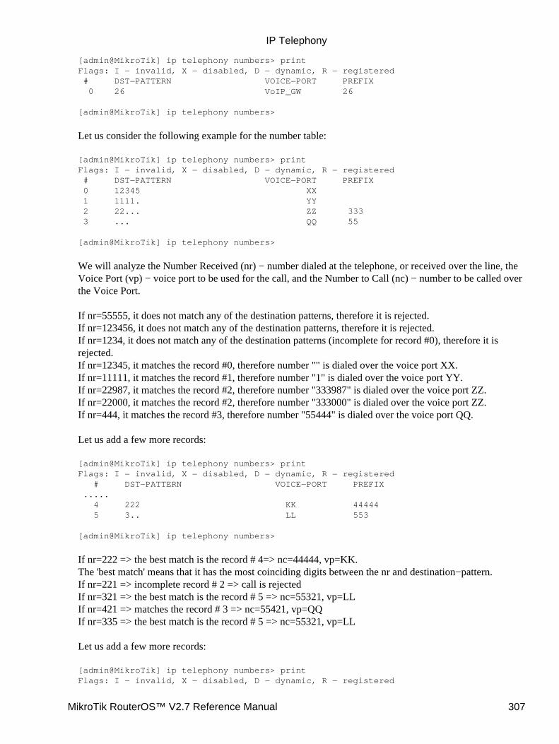
[admin@MikroTik] ip telephony numbers> printFlags: I − invalid, X − disabled, D − dynamic, R − registered # DST−PATTERN VOICE−PORT PREFIX 0 26 VoIP_GW 26
[admin@MikroTik] ip telephony numbers>
Let us consider the following example for the number table:
[admin@MikroTik] ip telephony numbers> printFlags: I − invalid, X − disabled, D − dynamic, R − registered # DST−PATTERN VOICE−PORT PREFIX 0 12345 XX 1 1111. YY 2 22... ZZ 333 3 ... QQ 55
[admin@MikroTik] ip telephony numbers>
We will analyze the Number Received (nr) − number dialed at the telephone, or received over the line, theVoice Port (vp) − voice port to be used for the call, and the Number to Call (nc) − number to be called overthe Voice Port.
If nr=55555, it does not match any of the destination patterns, therefore it is rejected.If nr=123456, it does not match any of the destination patterns, therefore it is rejected.If nr=1234, it does not match any of the destination patterns (incomplete for record #0), therefore it isrejected.If nr=12345, it matches the record #0, therefore number "" is dialed over the voice port XX.If nr=11111, it matches the record #1, therefore number "1" is dialed over the voice port YY.If nr=22987, it matches the record #2, therefore number "333987" is dialed over the voice port ZZ.If nr=22000, it matches the record #2, therefore number "333000" is dialed over the voice port ZZ.If nr=444, it matches the record #3, therefore number "55444" is dialed over the voice port QQ.
Let us add a few more records:
[admin@MikroTik] ip telephony numbers> printFlags: I − invalid, X − disabled, D − dynamic, R − registered # DST−PATTERN VOICE−PORT PREFIX ..... 4 222 KK 44444 5 3.. LL 553
[admin@MikroTik] ip telephony numbers>
If nr=222 => the best match is the record # 4=> nc=44444, vp=KK.The 'best match' means that it has the most coinciding digits between the nr and destination−pattern.If nr=221 => incomplete record # 2 => call is rejectedIf nr=321 => the best match is the record # 5 => nc=55321, vp=LLIf nr=421 => matches the record # 3 => nc=55421, vp=QQIf nr=335 => the best match is the record # 5 => nc=55321, vp=LL
Let us add a few more records:
[admin@MikroTik] ip telephony numbers> printFlags: I − invalid, X − disabled, D − dynamic, R − registered
IP Telephony
MikroTik RouterOS™ V2.7 Reference Manual 307
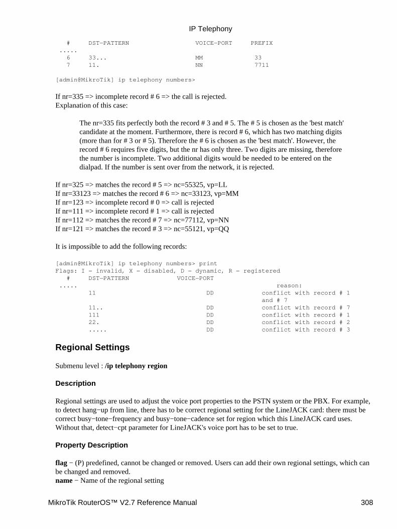
# DST−PATTERN VOICE−PORT PREFIX ..... 6 33... MM 33 7 11. NN 7711
[admin@MikroTik] ip telephony numbers>
If nr=335 => incomplete record # 6 => the call is rejected.Explanation of this case:
The nr=335 fits perfectly both the record # 3 and # 5. The # 5 is chosen as the 'best match'candidate at the moment. Furthermore, there is record # 6, which has two matching digits(more than for # 3 or # 5). Therefore the # 6 is chosen as the 'best match'. However, therecord # 6 requires five digits, but the nr has only three. Two digits are missing, thereforethe number is incomplete. Two additional digits would be needed to be entered on thedialpad. If the number is sent over from the network, it is rejected.
If nr=325 => matches the record # 5 => nc=55325, vp=LLIf nr=33123 => matches the record # 6 => nc=33123, vp=MMIf nr=123 => incomplete record # 0 => call is rejectedIf nr=111 => incomplete record # 1 => call is rejectedIf nr=112 => matches the record # 7 => nc=77112, vp=NNIf nr=121 => matches the record # 3 => nc=55121, vp=QQ
It is impossible to add the following records:
[admin@MikroTik] ip telephony numbers> printFlags: I − invalid, X − disabled, D − dynamic, R − registered # DST−PATTERN VOICE−PORT ..... reason: 11 DD conflict with record # 1 and # 7 11.. DD conflict with record # 7 111 DD conflict with record # 1 22. DD conflict with record # 2 ..... DD conflict with record # 3
Regional Settings
Submenu level : /ip telephony region
Description
Regional settings are used to adjust the voice port properties to the PSTN system or the PBX. For example,to detect hang−up from line, there has to be correct regional setting for the LineJACK card: there must becorrect busy−tone−frequency and busy−tone−cadence set for region which this LineJACK card uses.Without that, detect−cpt parameter for LineJACK's voice port has to be set to true.
Property Description
flag − (P) predefined, cannot be changed or removed. Users can add their own regional settings, which canbe changed and removed.name − Name of the regional setting
IP Telephony
MikroTik RouterOS™ V2.7 Reference Manual 308
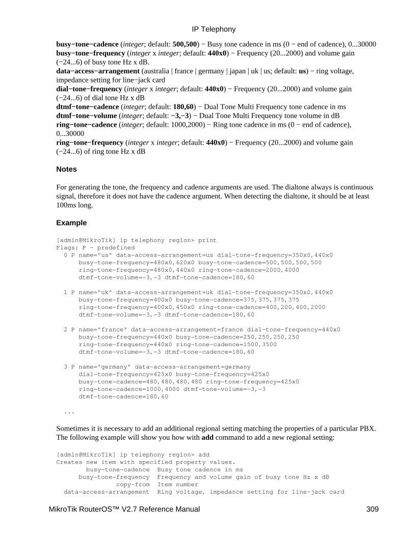
busy−tone−cadence (integer; default: 500,500) − Busy tone cadence in ms (0 − end of cadence), 0...30000busy−tone−frequency (integer x integer; default: 440x0) − Frequency (20...2000) and volume gain(−24...6) of busy tone Hz x dB.data−access−arrangement (australia | france | germany | japan | uk | us; default: us) − ring voltage,impedance setting for line−jack carddial−tone−frequency (integer x integer; default: 440x0) − Frequency (20...2000) and volume gain(−24...6) of dial tone Hz x dBdtmf−tone−cadence (integer; default: 180,60) − Dual Tone Multi Frequency tone cadence in msdtmf−tone−volume (integer; default: −3,−3) − Dual Tone Multi Frequency tone volume in dBring−tone−cadence (integer; default: 1000,2000) − Ring tone cadence in ms (0 − end of cadence),0...30000ring−tone−frequency (integer x integer; default: 440x0) − Frequency (20...2000) and volume gain(−24...6) of ring tone Hz x dB
Notes
For generating the tone, the frequency and cadence arguments are used. The dialtone always is continuoussignal, therefore it does not have the cadence argument. When detecting the dialtone, it should be at least100ms long.
Example
[admin@MikroTik] ip telephony region> printFlags: P − predefined 0 P name="us" data−access−arrangement=us dial−tone−frequency=350x0,440x0 busy−tone−frequency=480x0,620x0 busy−tone−cadence=500,500,500,500 ring−tone−frequency=480x0,440x0 ring−tone−cadence=2000,4000 dtmf−tone−volume=−3,−3 dtmf−tone−cadence=180,60
1 P name="uk" data−access−arrangement=uk dial−tone−frequency=350x0,440x0 busy−tone−frequency=400x0 busy−tone−cadence=375,375,375,375 ring−tone−frequency=400x0,450x0 ring−tone−cadence=400,200,400,2000 dtmf−tone−volume=−3,−3 dtmf−tone−cadence=180,60
2 P name="france" data−access−arrangement=france dial−tone−frequency=440x0 busy−tone−frequency=440x0 busy−tone−cadence=250,250,250,250 ring−tone−frequency=440x0 ring−tone−cadence=1500,3500 dtmf−tone−volume=−3,−3 dtmf−tone−cadence=180,60
3 P name="germany" data−access−arrangement=germany dial−tone−frequency=425x0 busy−tone−frequency=425x0 busy−tone−cadence=480,480,480,480 ring−tone−frequency=425x0 ring−tone−cadence=1000,4000 dtmf−tone−volume=−3,−3 dtmf−tone−cadence=180,60
...
Sometimes it is necessary to add an additional regional setting matching the properties of a particular PBX.The following example will show you how with add command to add a new regional setting:
[admin@MikroTik] ip telephony region> addCreates new item with specified property values. busy−tone−cadence Busy tone cadence in ms busy−tone−frequency Frequency and volume gain of busy tone Hz x dB copy−from Item number data−access−arrangement Ring voltage, impedance setting for line−jack card
IP Telephony
MikroTik RouterOS™ V2.7 Reference Manual 309
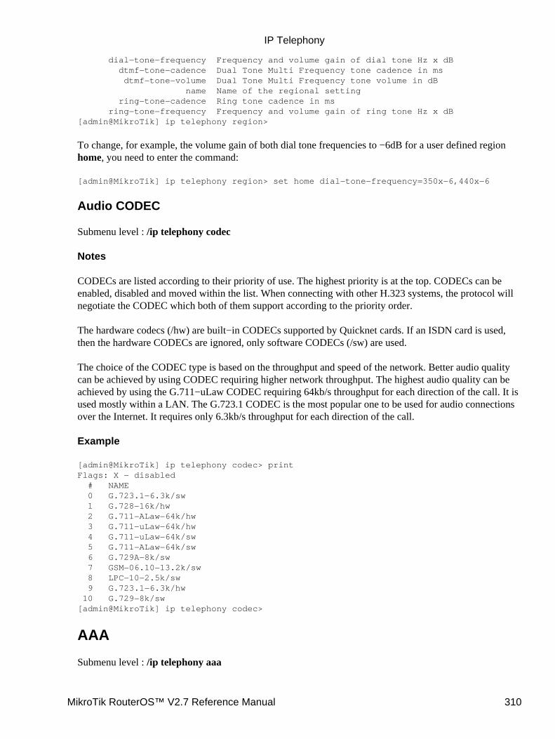
dial−tone−frequency Frequency and volume gain of dial tone Hz x dB dtmf−tone−cadence Dual Tone Multi Frequency tone cadence in ms dtmf−tone−volume Dual Tone Multi Frequency tone volume in dB name Name of the regional setting ring−tone−cadence Ring tone cadence in ms ring−tone−frequency Frequency and volume gain of ring tone Hz x dB[admin@MikroTik] ip telephony region>
To change, for example, the volume gain of both dial tone frequencies to −6dB for a user defined regionhome, you need to enter the command:
[admin@MikroTik] ip telephony region> set home dial−tone−frequency=350x−6,440x−6
Audio CODEC
Submenu level : /ip telephony codec
Notes
CODECs are listed according to their priority of use. The highest priority is at the top. CODECs can beenabled, disabled and moved within the list. When connecting with other H.323 systems, the protocol willnegotiate the CODEC which both of them support according to the priority order.
The hardware codecs (/hw) are built−in CODECs supported by Quicknet cards. If an ISDN card is used,then the hardware CODECs are ignored, only software CODECs (/sw) are used.
The choice of the CODEC type is based on the throughput and speed of the network. Better audio qualitycan be achieved by using CODEC requiring higher network throughput. The highest audio quality can beachieved by using the G.711−uLaw CODEC requiring 64kb/s throughput for each direction of the call. It isused mostly within a LAN. The G.723.1 CODEC is the most popular one to be used for audio connectionsover the Internet. It requires only 6.3kb/s throughput for each direction of the call.
Example
[admin@MikroTik] ip telephony codec> printFlags: X − disabled # NAME 0 G.723.1−6.3k/sw 1 G.728−16k/hw 2 G.711−ALaw−64k/hw 3 G.711−uLaw−64k/hw 4 G.711−uLaw−64k/sw 5 G.711−ALaw−64k/sw 6 G.729A−8k/sw 7 GSM−06.10−13.2k/sw 8 LPC−10−2.5k/sw 9 G.723.1−6.3k/hw 10 G.729−8k/sw[admin@MikroTik] ip telephony codec>
AAA
Submenu level : /ip telephony aaa
IP Telephony
MikroTik RouterOS™ V2.7 Reference Manual 310
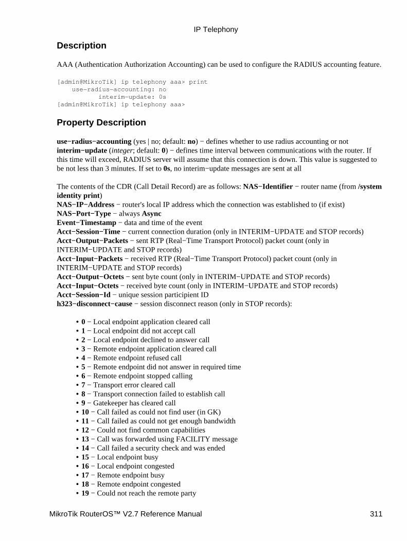
Description
AAA (Authentication Authorization Accounting) can be used to configure the RADIUS accounting feature.
[admin@MikroTik] ip telephony aaa> print use−radius−accounting: no interim−update: 0s[admin@MikroTik] ip telephony aaa>
Property Description
use−radius−accounting (yes | no; default: no) − defines whether to use radius accounting or notinterim−update (integer; default: 0) − defines time interval between communications with the router. Ifthis time will exceed, RADIUS server will assume that this connection is down. This value is suggested tobe not less than 3 minutes. If set to 0s, no interim−update messages are sent at all
The contents of the CDR (Call Detail Record) are as follows: NAS−Identifier − router name (from /systemidentity print)NAS−IP−Address − router's local IP address which the connection was established to (if exist)NAS−Port−Type − always AsyncEvent−Timestamp − data and time of the eventAcct−Session−Time − current connection duration (only in INTERIM−UPDATE and STOP records)Acct−Output−Packets − sent RTP (Real−Time Transport Protocol) packet count (only inINTERIM−UPDATE and STOP records)Acct−Input−Packets − received RTP (Real−Time Transport Protocol) packet count (only inINTERIM−UPDATE and STOP records)Acct−Output−Octets − sent byte count (only in INTERIM−UPDATE and STOP records)Acct−Input−Octets − received byte count (only in INTERIM−UPDATE and STOP records)Acct−Session−Id − unique session participient IDh323−disconnect−cause − session disconnect reason (only in STOP records):
0 − Local endpoint application cleared call• 1 − Local endpoint did not accept call• 2 − Local endpoint declined to answer call• 3 − Remote endpoint application cleared call• 4 − Remote endpoint refused call• 5 − Remote endpoint did not answer in required time• 6 − Remote endpoint stopped calling• 7 − Transport error cleared call• 8 − Transport connection failed to establish call• 9 − Gatekeeper has cleared call• 10 − Call failed as could not find user (in GK)• 11 − Call failed as could not get enough bandwidth• 12 − Could not find common capabilities• 13 − Call was forwarded using FACILITY message• 14 − Call failed a security check and was ended• 15 − Local endpoint busy• 16 − Local endpoint congested• 17 − Remote endpoint busy• 18 − Remote endpoint congested• 19 − Could not reach the remote party•
IP Telephony
MikroTik RouterOS™ V2.7 Reference Manual 311
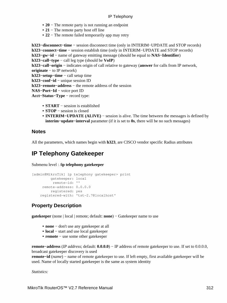
20 − The remote party is not running an endpoint• 21 − The remote party host off line• 22 − The remote failed temporarily app may retry•
h323−disconnect−time − session disconnect time (only in INTERIM−UPDATE and STOP records)h323−connect−time − session establish time (only in INTERIM−UPDATE and STOP records)h323−gw−id − name of gateway emitting message (should be equal to NAS−Identifier)h323−call−type − call leg type (should be VoIP)h323−call−origin − indicates origin of call relative to gateway (answer for calls from IP network,originate − to IP network)h323−setup−time − call setup timeh323−conf−id − unique session IDh323−remote−address − the remote address of the sessionNAS−Port−Id − voice port IDAcct−Status−Type − record type:
START − session is established• STOP − session is closed• INTERIM−UPDATE (ALIVE) − session is alive. The time between the messages is defined byinterim−update−interval parameter (if it is set to 0s, there will be no such messages)
•
Notes
All the parameters, which names begin with h323, are CISCO vendor specific Radius attributes
IP Telephony Gatekeeper
Submenu level : /ip telephony gatekeeper
[admin@MikroTik] ip telephony gatekeeper> print gatekeeper: local remote−id: "" remote−address: 0.0.0.0 registered: yes registered−with: "tst−2.7@localhost"
Property Description
gatekeeper (none | local | remote; default: none) − Gatekeeper name to use
none − don't use any gatekeeper at all• local − start and use local gatekeeper• remote − use some other gatekeeper•
remote−address (IP address; default: 0.0.0.0) − IP address of remote gatekeeper to use. If set to 0.0.0.0,broadcast gatekeeper discovery is usedremote−id (name) − name of remote gatekeeper to use. If left empty, first available gatekeeper will beused. Name of locally started gatekeeper is the same as system identity
Statistics:
IP Telephony
MikroTik RouterOS™ V2.7 Reference Manual 312
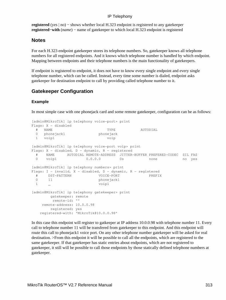
registered (yes | no) − shows whether local H.323 endpoint is registered to any gatekeeperregistered−with (name) − name of gatekeeper to which local H.323 endpoint is registered
Notes
For each H.323 endpoint gatekeeper stores its telephone numbers. So, gatekeeper knows all telephonenumbers for all registered endpoints. And it knows which telephone number is handled by which endpoint.Mapping between endpoints and their telephone numbers is the main functionality of gatekeepers.
If endpoint is registered to endpoint, it does not have to know every single endpoint and every singletelephone number, which can be called. Instead, every time some number is dialed, endpoint asksgatekeeper for destination endpoint to call by providing called telephone number to it.
Gatekeeper Configuration
Example
In most simple case with one phonejack card and some remote gatekeeper, configuration can be as follows:
[admin@MikroTik] ip telephony voice−port> printFlags: X − disabled # NAME TYPE AUTODIAL 0 phonejack1 phonejack 1 voip1 voip
[admin@MikroTik] ip telephony voice−port voip> printFlags: X − disabled, D − dynamic, R − registered # NAME AUTODIAL REMOTE−ADDRESS JITTER−BUFFER PREFERED−CODEC SIL FAS 0 voip1 0.0.0.0 0s none no yes
[admin@MikroTik] ip telephony numbers> printFlags: I − invalid, X − disabled, D − dynamic, R − registered # DST−PATTERN VOICE−PORT PREFIX 0 11 phonejack1 1 _ voip1
[admin@MikroTik] ip telephony gatekeeper> print gatekeeper: remote remote−id: "" remote−address: 10.0.0.98 registered: yes registered−with: "[email protected]"
In this case this endpoint will register to gatkeeper at IP address 10.0.0.98 with telephone number 11. Everycall to telephone number 11 will be transfered from gatekeeper to this endpoint. And this endpoint willroute this call to phonejack1 voice port. On any other telephone number gatekeeper will be asked for realdestination. >From this endpoint it will be possible to call all the endpoints, which are registered to thesame gatekeeper. If that gatekeeper has static entries about endpoints, which are not registered togatekeeper, it still will be possible to call those endpoints by those statically defined telephone numbers atgatekeeper.
IP Telephony
MikroTik RouterOS™ V2.7 Reference Manual 313
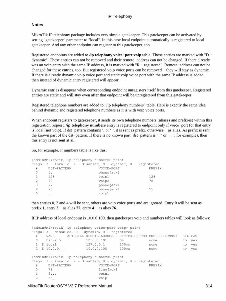
Notes
MikroTik IP telephony package includes very simple gatekeeper. This gatekeeper can be activated bysetting "gatekeeper" parameter to "local". In this case local endpoint automatically is registered to localgatekeeper. And any other endpoint can register to this gatekeeper, too.
Registered endpoints are added to /ip telephony voice−port voip table. Those entries are marked with "D −dynamic". These entries can not be removed and their remote−address can not be changed. If there alreadywas an voip entry with the same IP address, it is marked with "R − registered". Remote−address can not bechanged for these entries, too. But registered voip voice ports can be removed − they will stay as dynamic.If there is already dynamic voip voice port and static voip voice port with the same IP address is added,then instead of dynamic entry registered will appear.
Dynamic entries disappear when corresponding endpoint unregisters itself from this gatekeeper. Registeredentries are static and will stay even after that endpoint will be unregistered from this gatekeeper.
Registered telephone numbers are added to "/ip telephony numbers" table. Here is exactly the same ideabehind dynamic and registered telephone numbers as it is with voip voice ports.
When endpoint registers to gatekeeper, it sends its own telephone numbers (aliases and prefixes) within thisregistration request. /ip telephony numbers entry is registered to endpoint only if voice−port for that entryis local (not voip). If dst−pattern contains '.' or '_', it is sent as prefix, otherwise − as alias. As prefix is sentthe known part of the dst−pattern. If there is no known part (dst−pattern is "_" or "...", for example), thenthis entry is not sent at all.
So, for example, if numbers table is like this:
[admin@MikroTik] ip telephony numbers> printFlags: I − invalid, X − disabled, D − dynamic, R − registered # DST−PATTERN VOICE−PORT PREFIX 0 1. phonejack1 1 128 voip1 128 2 78 voip2 78 3 77 phonejack1 4 76 phonejack1 55 5 _ voip1
then entries 0, 3 and 4 will be sent, others are voip voice ports and are ignored. Entry 0 will be sent asprefix 1, entry 3 − as alias 77, entry 4 − as alias 76.
If IP address of local endpoint is 10.0.0.100, then gatekeeper voip and numbers tables will look as follows:
[admin@MikroTik] ip telephony voice−port voip> printFlags: X − disabled, D − dynamic, R − registered # NAME AUTODIAL REMOTE−ADDRESS JITTER−BUFFER PREFERED−CODEC SIL FAS 0 tst−2.5 10.0.0.101 0s none no yes 1 D local 127.0.0.1 100ms none no yes 2 D 10.0.0... 10.0.0.100 100ms none no yes
[admin@MikroTik] ip telephony numbers> printFlags: I − invalid, X − disabled, D − dynamic, R − registered # DST−PATTERN VOICE−PORT PREFIX 0 78 linejack1 1 3... vctx1 2 33_ voip1
IP Telephony
MikroTik RouterOS™ V2.7 Reference Manual 314
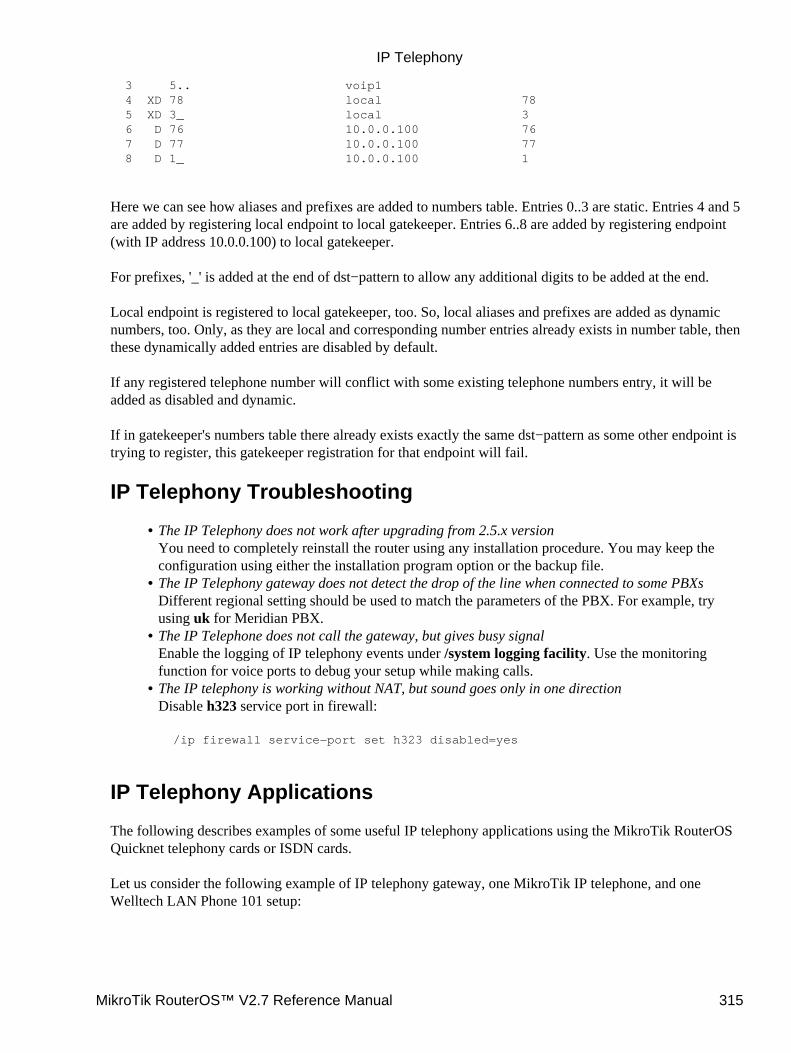
3 5.. voip1 4 XD 78 local 78 5 XD 3_ local 3 6 D 76 10.0.0.100 76 7 D 77 10.0.0.100 77 8 D 1_ 10.0.0.100 1
Here we can see how aliases and prefixes are added to numbers table. Entries 0..3 are static. Entries 4 and 5are added by registering local endpoint to local gatekeeper. Entries 6..8 are added by registering endpoint(with IP address 10.0.0.100) to local gatekeeper.
For prefixes, '_' is added at the end of dst−pattern to allow any additional digits to be added at the end.
Local endpoint is registered to local gatekeeper, too. So, local aliases and prefixes are added as dynamicnumbers, too. Only, as they are local and corresponding number entries already exists in number table, thenthese dynamically added entries are disabled by default.
If any registered telephone number will conflict with some existing telephone numbers entry, it will beadded as disabled and dynamic.
If in gatekeeper's numbers table there already exists exactly the same dst−pattern as some other endpoint istrying to register, this gatekeeper registration for that endpoint will fail.
IP Telephony Troubleshooting
The IP Telephony does not work after upgrading from 2.5.x versionYou need to completely reinstall the router using any installation procedure. You may keep theconfiguration using either the installation program option or the backup file.
•
The IP Telephony gateway does not detect the drop of the line when connected to some PBXsDifferent regional setting should be used to match the parameters of the PBX. For example, tryusing uk for Meridian PBX.
•
The IP Telephone does not call the gateway, but gives busy signalEnable the logging of IP telephony events under /system logging facility. Use the monitoringfunction for voice ports to debug your setup while making calls.
•
The IP telephony is working without NAT, but sound goes only in one directionDisable h323 service port in firewall:
/ip firewall service−port set h323 disabled=yes
•
IP Telephony Applications
The following describes examples of some useful IP telephony applications using the MikroTik RouterOSQuicknet telephony cards or ISDN cards.
Let us consider the following example of IP telephony gateway, one MikroTik IP telephone, and oneWelltech LAN Phone 101 setup:
IP Telephony
MikroTik RouterOS™ V2.7 Reference Manual 315

Setting up the MikroTik IP Telephone
The QuickNet LineJACK or PhoneJACK card and the MikroTik RouterOS telephony package should beinstalled in the MikroTik router (IP telephone) 10.0.0.224x. An analog telephone should be connected tothe 'phone' port of the QuickNet card. If you pick up the handset, a dialtone should be heard.
The basic telephony configuration should be as follows:
Add a voip voice port to the /ip telephony voice−port voip for each of the devices you want tocall, or want to receive calls from, i.e., (the IP telephony gateway 10.1.1.12 and the Welltech IPtelephone 10.5.8.2):
[admin@Joe] ip telephony voice−port voip> add name=gw remote−address=10.1.1.12[admin@Joe] ip telephony voice−port voip> add name=rob remote−address=10.5.8.2[admin@Joe] ip telephony voice−port voip> printFlags: X − disabled, D − dynamic, R − registered # NAME AUTODIAL REMOTE−ADDRESS JITTER−BUFFER PREFERED−CODEC SIL FAS 0 gw 10.1.1.12 100ms none no yes 1 rob 10.5.8.2 100ms none no yes[admin@Joe] ip telephony voice−port voip>
You should have three vioce ports now:
[admin@Joe] ip telephony voice−port> printFlags: X − disabled # NAME TYPE AUTODIAL 0 linejack1 linejack 1 gw voip 2 rob voip[admin@Joe] ip telephony voice−port>
1.
Add a at least one unique number to the /ip telephony numbers for each voice port. This number2.
IP Telephony
MikroTik RouterOS™ V2.7 Reference Manual 316
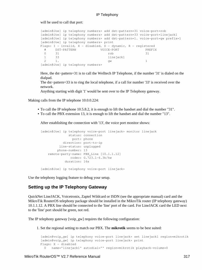
will be used to call that port:
[admin@Joe] ip telephony numbers> add dst−pattern=31 voice−port=rob[admin@Joe] ip telephony numbers> add dst−pattern=33 voice−port=linejack1[admin@Joe] ip telephony numbers> add dst−pattern=1. voice−port=gw prefix=1[admin@Joe] ip telephony numbers> printFlags: I − invalid, X − disabled, D − dynamic, R − registered # DST−PATTERN VOICE−PORT PREFIX 0 31 rob 31 1 33 linejack1 2 1. gw 1[admin@Joe] ip telephony numbers>
Here, the dst−pattern=31 is to call the Welltech IP Telephone, if the number '31' is dialed on thedialpad.The dst−pattern=33 is to ring the local telephone, if a call for number '33' is received over thenetwork.Anything starting with digit '1' would be sent over to the IP Telephony gateway.
Making calls from the IP telephone 10.0.0.224:
To call the IP telephone 10.5.8.2, it is enough to lift the handset and dial the number "31".• To call the PBX extension 13, it is enough to lift the handset and dial the number "13".
After establishing the connection with '13', the voice port monitor shows:
[admin@Joe] ip telephony voice−port linejack> monitor linejack status: connection port: phone direction: port−to−ip line−status: unplugged phone−number: 13 remote−party−name: PBX_Line [10.1.1.12] codec: G.723.1−6.3k/hw duration: 16s
[admin@Joe] ip telephony voice−port linejack>
•
Use the telephony logging feature to debug your setup.
Setting up the IP Telephony Gateway
QuickNet LineJACK, Voicetronix, Zaptel Wildcard or ISDN (see the appropriate manual) card and theMikroTik RouterOS telephony package should be installed in the MikroTik router (IP telephony gateway)10.1.1.12. A PBX line should be connected to the 'line' port of the card. For LineJACK card the LED nextto the 'line' port should be green, not red.
The IP telephony gateway [voip_gw] requires the following configuration:
Set the regional setting to match our PBX. The mikrotik seems to be best suited:
[admin@voip_gw] ip telephony voice−port linejack> set linejack1 region=mikrotik[admin@voip_gw] ip telephony voice−port linejack> printFlags: X − disabled 0 name="linejack1" autodial="" region=mikrotik playback−volume=0
1.
IP Telephony
MikroTik RouterOS™ V2.7 Reference Manual 317
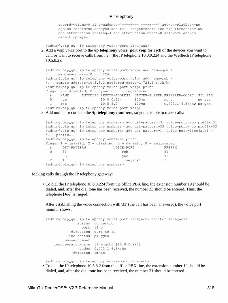
record−volume=0 ring−cadence="++−++−−− ++−++−−−" agc−on−playback=no agc−on−record=no aec=yes aec−tail−length=short aec−nlp−threshold=low aec−attenuation−scaling=4 aec−attenuation−boost=0 software−aec=no detect−cpt=yes
[admin@voip_gw] ip telephony voice−port linejack>
Add a voip voice port to the /ip telephony voice−port voip for each of the devices you want tocall, or want to receive calls from, i.e., (the IP telephone 10.0.0.224 and the Welltech IP telephone10.5.8.2):
[admin@voip_gw] ip telephony voice−port voip> add name=joe \\... remote−address=10.0.0.224[admin@voip_gw] ip telephony voice−port voip> add name=rob \\... remote−address=10.5.8.2 prefered−codec=G.723.1−6.3k/hw[admin@voip_gw] ip telephony voice−port voip> printFlags: X − disabled, D − dynamic, R − registered # NAME AUTODIAL REMOTE−ADDRESS JITTER−BUFFER PREFERED−CODEC SIL FAS 0 joe 10.0.0.224 100ms none no yes 1 rob 10.5.8.2 100ms G.723.1−6.3k/hw no yes[admin@voip_gw] ip telephony voice−port voip>
2.
Add number records to the /ip telephony numbers, so you are able to make calls:
[admin@voip_gw] ip telephony numbers> add dst−pattern=31 voice−port=rob prefix=31[admin@voip_gw] ip telephony numbers> add dst−pattern=33 voice−port=joe prefix=33[admin@voip_gw] ip telephony numbers> add dst−pattern=1. voice−port=linejack1 \\... prefix=1[admin@voip_gw] ip telephony numbers> printFlags: I − invalid, X − disabled, D − dynamic, R − registered # DST−PATTERN VOICE−PORT PREFIX 0 31 rob 31 1 33 joe 33 2 1. linejack1 1[admin@voip_gw] ip telephony numbers>
3.
Making calls through the IP telephony gateway:
To dial the IP telephone 10.0.0.224 from the office PBX line, the extension number 19 should bedialed, and, after the dial tone has been received, the number 33 should be entered. Thus, thetelephone [Joe] is ringed.
After establishing the voice connection with '33' (the call has been answered), the voice portmonitor shows:
[admin@voip_gw] ip telephony voice−port linejack> monitor linejack1 status: connection port: line direction: port−to−ip line−status: plugged phone−number: 33 remote−party−name: linejack1 [10.0.0.224] codec: G.723.1−6.3k/hw duration: 1m46s
[admin@voip_gw] ip telephony voice−port linejack>
•
To dial the IP telephone 10.5.8.2 from the office PBX line, the extension number 19 should bedialed, and, after the dial tone has been received, the number 31 should be entered.
•
IP Telephony
MikroTik RouterOS™ V2.7 Reference Manual 318
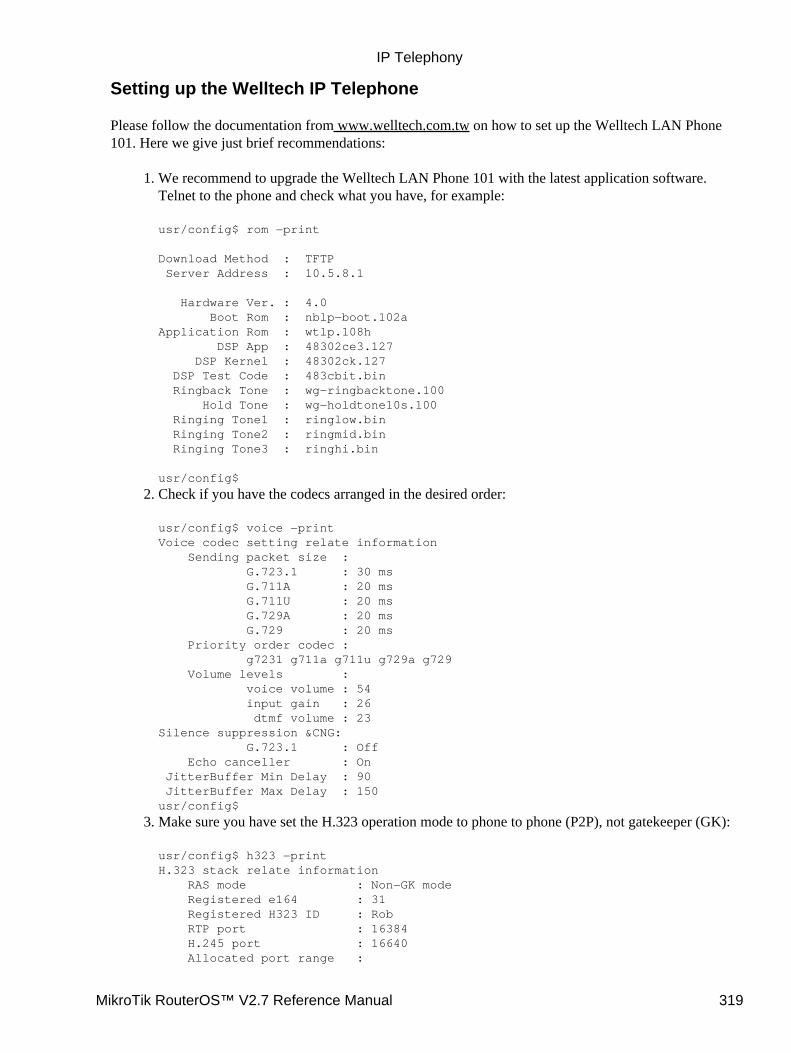
Setting up the Welltech IP Telephone
Please follow the documentation from www.welltech.com.tw on how to set up the Welltech LAN Phone101. Here we give just brief recommendations:
We recommend to upgrade the Welltech LAN Phone 101 with the latest application software.Telnet to the phone and check what you have, for example:
usr/config$ rom −print
Download Method : TFTP Server Address : 10.5.8.1
Hardware Ver. : 4.0 Boot Rom : nblp−boot.102aApplication Rom : wtlp.108h DSP App : 48302ce3.127 DSP Kernel : 48302ck.127 DSP Test Code : 483cbit.bin Ringback Tone : wg−ringbacktone.100 Hold Tone : wg−holdtone10s.100 Ringing Tone1 : ringlow.bin Ringing Tone2 : ringmid.bin Ringing Tone3 : ringhi.bin
usr/config$
1.
Check if you have the codecs arranged in the desired order:
usr/config$ voice −printVoice codec setting relate information Sending packet size : G.723.1 : 30 ms G.711A : 20 ms G.711U : 20 ms G.729A : 20 ms G.729 : 20 ms Priority order codec : g7231 g711a g711u g729a g729 Volume levels : voice volume : 54 input gain : 26 dtmf volume : 23Silence suppression &CNG: G.723.1 : Off Echo canceller : On JitterBuffer Min Delay : 90 JitterBuffer Max Delay : 150usr/config$
2.
Make sure you have set the H.323 operation mode to phone to phone (P2P), not gatekeeper (GK):
usr/config$ h323 −printH.323 stack relate information RAS mode : Non−GK mode Registered e164 : 31 Registered H323 ID : Rob RTP port : 16384 H.245 port : 16640 Allocated port range :
3.
IP Telephony
MikroTik RouterOS™ V2.7 Reference Manual 319
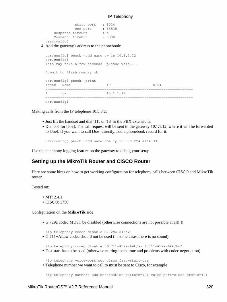
start port : 1024 end port : 65535 Response timeOut : 5 Connect timeOut : 5000usr/config$
Add the gateway's address to the phonebook:
usr/config$ pbook −add name gw ip 10.1.1.12usr/config$This may take a few seconds, please wait....
Commit to flash memory ok!
usr/config$ pbook −printindex Name IP E164======================================================================1 gw 10.1.1.12−−−−−−−−−−−−−−−−−−−−−−−−−−−−−−−−−−−−−−−−−−−−−−−−−−−−−−−−−−−−−−−−−−−−−−usr/config$
4.
Making calls from the IP telephone 10.5.8.2:
Just lift the handset and dial '11', or '13' fo the PBX extensions.• Dial '33' for [Joe]. The call request will be sent to the gateway 10.1.1.12, where it will be forwardedto [Joe]. If you want to call [Joe] directly, add a phonebook record for it:
usr/config$ pbook −add name Joe ip 10.0.0.224 e164 33
•
Use the telephony logging feature on the gateway to debug your setup.
Setting up the MikroTik Router and CISCO Router
Here are some hints on how to get working configuration for telephony calls between CISCO and MikroTikrouter.
Tested on:
MT: 2.4.1• CISCO: 1750•
Configuration on the MikroTik side:
G.729a codec MUST be disabled (otherwise connections are not possible at all)!!!
/ip telephony codec disable G.729A−8k/sw
•
G.711−ALaw codec should not be used (in some cases there is no sound)
/ip telephony codec disable "G.711−ALaw−64k/sw G.711−ALaw−64k/hw"
•
Fast start has to be used (otherwise no ring−back tone and problems with codec negotiation)
/ip telephony voice−port set cisco fast−start=yes
•
Telephone number we want to call to must be sent to Cisco, for example
/ip telephony numbers add destination−pattern=101 voice−port=cisco prefix=101
•
IP Telephony
MikroTik RouterOS™ V2.7 Reference Manual 320
Telephone number, cisco will call us, must be assigned to some voice port, for example,
/ip telephony numbers add destination−pattern=098 voice−port=linejack
•
Configuration on the CISCO side:
IP routing has to be enabled
ip routing
•
Default values for fast start can be used
voice service pots default h323 call start exitvoice service voip default h323 call start exit
•
Enable opening of RTP streams
voice rtp send−recv
•
Assign some E.164 number for local telephone, for example, 101 to port 0/0
dial−peer voice 1 pots destination−pattern 101 port 0/0 exit
•
create preferred codec listing
voice class codec codec_class_number codec preference 1 g711ulaw codec preference 2 g723r63 exit
NOTE: g723r53 codec can be used, too
•
Tell, that some foreign E.164 telephone number can be reached by calling to some IP address, forexample, 098 by calling to 10.0.0.98
dial−peer voice 11 voip destination−pattern 098 session target ipv4:10.0.0.98 voice−class codec codec_class_number exit
NOTE: instead of codec class, one specified codec could be specified:
codec g711ulaw
•
For reference, following is an exported CISCO configuration, that works:
!version 12.1no service single−slot−reload−enableservice timestamps debug uptimeservice timestamps log uptimeno service password−encryption!
IP Telephony
MikroTik RouterOS™ V2.7 Reference Manual 321
hostname Router!logging rate−limit console 10 except errorsenable secret 5 $1$bTMC$nDGl9/n/pc3OMbtWxADMg1enable password 123!memory−size iomem 25ip subnet−zerono ip finger!call rsvp−syncvoice rtp send−recv!voice class codec 1 codec preference 1 g711ulaw codec preference 2 g723r63!interface FastEthernet0 ip address 10.0.0.101 255.255.255.0 no ip mroute−cache speed auto half−duplex!ip classlessip route 0.0.0.0 0.0.0.0 10.0.0.1no ip http server!dialer−list 1 protocol ip permitdialer−list 1 protocol ipx permit!voice−port 0/0!voice−port 0/1!voice−port 2/0!voice−port 2/1!dial−peer voice 1 pots destination−pattern 101 port 0/0!dial−peer voice 97 voip destination−pattern 097 session target ipv4:10.0.0.97 codec g711ulaw!dial−peer voice 98 voip destination−pattern 098 voice−class codec 1 session target ipv4:10.0.0.98!!line con 0 transport input noneline aux 0line vty 0 4 password 123 login!end
IP Telephony
MikroTik RouterOS™ V2.7 Reference Manual 322
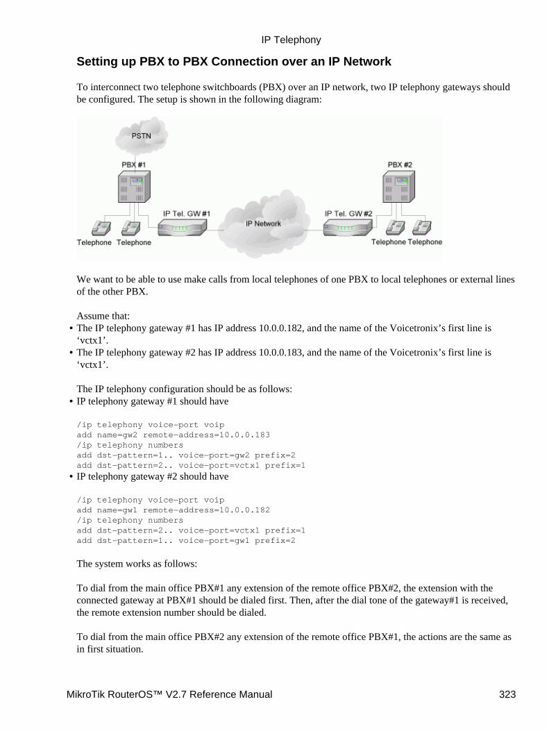
Setting up PBX to PBX Connection over an IP Network
To interconnect two telephone switchboards (PBX) over an IP network, two IP telephony gateways shouldbe configured. The setup is shown in the following diagram:
We want to be able to use make calls from local telephones of one PBX to local telephones or external linesof the other PBX.
Assume that:The IP telephony gateway #1 has IP address 10.0.0.182, and the name of the Voicetronix’s first line is‘vctx1’.
•
The IP telephony gateway #2 has IP address 10.0.0.183, and the name of the Voicetronix’s first line is‘vctx1’.
The IP telephony configuration should be as follows:
•
IP telephony gateway #1 should have
/ip telephony voice−port voipadd name=gw2 remote−address=10.0.0.183/ip telephony numbersadd dst−pattern=1.. voice−port=gw2 prefix=2add dst−pattern=2.. voice−port=vctx1 prefix=1
•
IP telephony gateway #2 should have
/ip telephony voice−port voipadd name=gw1 remote−address=10.0.0.182/ip telephony numbersadd dst−pattern=2.. voice−port=vctx1 prefix=1add dst−pattern=1.. voice−port=gw1 prefix=2
The system works as follows:
To dial from the main office PBX#1 any extension of the remote office PBX#2, the extension with theconnected gateway at PBX#1 should be dialed first. Then, after the dial tone of the gateway#1 is received,the remote extension number should be dialed.
To dial from the main office PBX#2 any extension of the remote office PBX#1, the actions are the same asin first situation.
•
IP Telephony
MikroTik RouterOS™ V2.7 Reference Manual 323

Additional Resources
IP Telephony Online
© Copyright 1999−2003, MikroTik
IP Telephony
MikroTik RouterOS™ V2.7 Reference Manual 324
IP Packet Packer Protocol (M3P)Document revision 1.5 (13−Jun−2003)This document applies to the MikroTik RouterOS v2.7
Table Of Contents
Table Of Contents• Summary• Specifications• Related Documents• MikroTik Packet Packer Protocol Description• MikroTik Packet Packer Protocol Setup
Description♦ Property Description♦ Notes♦ Example♦
•
Summary
The MikroTik Packet Packer Protocol (M3P) optimizes the data rate usage of links using protocols that have ahigh overhead per packet transmitted. The basic purpose of this protocol is to better enable wireless networksto transport VoIP traffic and other traffic that uses small packet sizes of around 100 bytes.
M3P features:
enabled by a per interface setting• other routers with MikroTik Discovery Protocol enabled will broadcast M3P settings• significantly increases bandwidth availability over some wireless links – by approximately four times• offer configuration settings to customize this feature•
Specifications
Packages required : systemLicense required : AnyHome menu level : /ip packingProtocols utilized : noneHardware usage: not significant
Related Documents
Software Package Installation and UpgradingMikroTik Neighbor Discovery Protocol (MNDP)
MikroTik Packet Packer Protocol Description
The wireless protocol IEEE 802.11 and, due to a lesser extent, Ethernet protocol have a high overhead perpacket as for each packet it is necessary to access the media, check for errors, resend in case of errors occured,
MikroTik RouterOS™ V2.7 Reference Manual 325
and send network maintenance messages (network maintenance is only for wireless). The MikroTik PacketPacker Protocol improves network performance by aggregating many small packets into a big packet, therebyminimizing the network per packet overhead cost. The M3P is very effective when the average packet size is50−300 bytes – the common size of VoIP packets.
Specific Properties:
may work on any Ethernet−like media• is disabled by default for all interfaces• when older version on the RouterOS are upgraded from a version without M3P to a version withdiscovery, current wireless interfaces will not be automatically enabled for M3P
•
small packets going to the same MAC level destination (regardless of IP destination) are collectedaccording to the set configuration and aggregated into a large packet according to the set size
•
the packet is sent as soon as the maximum aggregated−packet packet size is reached or a maximumtime of 15ms (+/−5ms)
•
MikroTik Packet Packer Protocol Setup
Submenu level : /ip packing
Description
IP MikroTik Packet Packer Protocol is working only between MikroTik routers, which are discovered withMikroTik Neighbor Discovery Protocol (MNDP). When M3P is enabled router needs to know which of itsneighbouring hosts have enabled M3P. MNDP is used to negotiate unpacking settings of neighbours,therefore it has to be enabled on interfaces you wish to enable M3P. Consult MNDP manual on how to do it.
Property Description
aggregated−size (integer; default: 1500) – the maximum size of the aggregated packetinterface (name) − interface to enable M3P onpacking (compress−all | compress−headers | none | simple; default: simple) − set the packing mode supportedon interface
none − no packing is applied to packets• simple − aggregate many small packets in one big packet, minimizing the network per packet overhead cost• compress−headers − further increase network performace by applying packet header compression (usesmore CPU resource)
•
compress−all − increase network performance even more by using header and data compression (extensiveCPU usage)unpacking (compress−all | compress−headers | none | simple; default: simple) −
•
none − accept only usual packets• simple − accept aggregated packets without compression and usual packets• compress−headers − accept all packets except those with data compression• compress−all − accept all packets
Notes
Level of packet compression increases like this: none −> simple −> compress−headers −> compress−all.
•
IP Packet Packer Protocol (M3P)
MikroTik RouterOS™ V2.7 Reference Manual 326

When router has to send a packet it choses minimum level of packet compression from what its ownpacking type is set and what other router's unpacking type is set. Same is with aggregated−size setting −minimum value of both endds is actual maximum size of aggregated packet used.
aggregated−size can be bigger than interface MTU if network device allows it to be (i.e., it supportssending and receiving frames bigger than 1514 bytes)
Example
To enable maximal compression on the ether1 interface:
[admin@MikroTik] ip packing> add interface=ether1 packing=compress−all \\... unpacking=compress−all[admin@MikroTik] ip packing> printFlags: X − disabled # INTERFACE PACKING UNPACKING AGGREGATED−SIZE 0 ether1 compress−all compress−all 1500
[admin@MikroTik] ip packing>
© Copyright 1999−2003, MikroTik
IP Packet Packer Protocol (M3P)
MikroTik RouterOS™ V2.7 Reference Manual 327
MikroTik Neighbor Discovery Protocol (MNDP)Document revision 1.6 (23−May−2003)This document applies to the MikroTik RouterOS v2.7
Contents of the Manual
Contents of the Manual• Summary• Specifications• Related Documents• Description• MikroTik Neighbour Discovery Protocol Setup
Property Description♦ Example♦
•
Listing the Discovered RoutersProperty Description♦ Example♦
•
Summary
The MikroTik Neighbor Discovery Protocol (MNDP) eases network configuration and management byenabling each MikroTik router to discover other connected MikroTik routers and learn information about thesystem along with features which are enabled. The MikroTik routers can then automatically use learnedinformation to set up some features with minimal or no configuration.
MNDP features:
works on IP level connections• works on all non−dynamic interfaces• distributes basic information on the software version• distributes information on configured features that should interoperate with other MikroTik routers•
MikroTik RouterOS is able to discover both MNDP and CDP (Cisco Discovery Protocol) devices.
Specifications
Packages required : systemLicense required : AnyHome menu level : /ip neighbourStandards and Technologies : MNDPHardware usage : not significant
Related Documents
Software Package Installation and UpgradingM3P (MikroTik Packet Packer Protocol)
MikroTik RouterOS™ V2.7 Reference Manual 328
Description
MNDP basic function is to assist with automatic configuration of features that are only available betweenMikroTik routers. Currently this is used for the 'Packet Packer' feature. The 'Packet Packer' may be enabled ona per interface basis. The MNDP protocol will then keep information about what routers have enabled the'unpack' feature and the 'Packet Packer' will be used for traffic between these routers.
Specific Properties:
works on interfaces that support IP protocol and have at least one IP address and on all ethernet−likeinterfaces even without IP addresses
•
is enabled by default for all new Ethernet−like interfaces −− Ethernet, wireless, EoIP, IPIP tunnels,PPTP−static−server
•
when older version on the RouterOS are upgraded from a version without discovery to a version withdiscovery, current Ethernet like interfaces will not be automatically enabled for MNDP
•
uses UDP protocol port 5678• an UDP packet with router info is broadcasted over the interface every 60 seconds• every 30 seconds, the router checks if some of the neighbor entries are not stale• if no info is received from a neighbor for more than 180 seconds the neighbor information isdiscarded
•
MikroTik Neighbour Discovery Protocol Setup
Submenu level : /ip neighbor discovery
Property Description
name (read−only: name)− interface name for referencediscover (yes | no; default: yes) − defines if discover is enabled or disabled
Example
To disable MNDP protocol on Public interface:
[admin@MikroTik] ip neighbor discovery> set Public discover=no[admin@MikroTik] ip neighbor discovery> print # NAME DISCOVER 0 Public no 1 Local yes
Listing the Discovered Neighbours
Submenu level : /ip neighbor
Property Description
interface (read−only: name) − local interface the neighbor is connected toaddress (read−only: address) − IP address of the neighbor router
MikroTik Neighbor Discovery Protocol (MNDP)
MikroTik RouterOS™ V2.7 Reference Manual 329
mac−address (read−only: mac−address) − MAC−address of the neighbor routeridentity (read−only: string) − identity of the neighbour routerversion (read−only: string) − router version of the neighbour routerunpack (read−only: none | simple | compress−headers | compress−all) − identifies if the interface of theneighbour router is unpacking 'Packed Packets'
Example
To view the table of discovered neighbours:
[admin@MikroTik] ip neighbor> print # INTERFACE ADDRESS MAC−ADDRESS IDENTITY VERSION 0 eth100... 10.5.2.100 00:04:EA:C6:0E:6F HP_10.5... Revisio... 1 jevg_v... 10.5.1.1 00:40:96:58:20:14 0040965... Cisco 3... 2 local_... 10.5.5.50 00:40:63:C1:23:C4 10.5.7.1 2.7rc4 3 local_... 10.5.5.51 00:E0:C5:6E:23:25 GW_10.5... 2.7rc4[admin@MikroTik] ip neighbor> print detail 0 interface=eth100−temp address=10.5.2.100 mac−address=00:04:EA:C6:0E:6F identity="HP_10.5.2.100 Basement(0004ea−c60e40)" platform="HP 2524" version="Revision F.02.11 /sw/code/build/info(f00)" unpack=none age=12s
1 interface=jevg_vlan2 address=10.5.1.1 mac−address=00:40:96:58:20:14 identity="004096582014platform="AIR−BR350" version="Cisco 350 Series Bridge 11.21" unpack=none age=34s
2 interface=local_vlan5 address=10.5.5.50 mac−address=00:40:63:C1:23:C4 identity="10.5.7.1" platform="MikroTik" version="2.7rc4" unpack=none age=48s
3 interface=local_vlan5 address=10.5.5.51 mac−address=00:E0:C5:6E:23:25 identity="GW_10.5.51.1" platform="MikroTik" version="2.7rc4" unpack=none age=45s
[admin@MikroTik] ip neighbor>
As you can see, not only MikroTik RouterOS routers were discovered, but HP Procurve 2524 switch andCisco 350 Series Wireless Bridge
© Copyright 1999−2003, MikroTik
MikroTik Neighbor Discovery Protocol (MNDP)
MikroTik RouterOS™ V2.7 Reference Manual 330
Firewall Filters and Network Address Translation(NAT)Document revision 1.12 (06−Sep−2003)This document applies to the MikroTik RouterOS V2.7
Table of Contents
Table of Contents• Summary• Specifications• Related documents• Description• Packet Flow
Description♦ •
Firewall SetupDescription♦ Firewall Chains
Description◊ Notes◊ Example◊
♦
Firewall RulesDescription◊ Property Description◊ Notes◊ Example◊
♦
Logging the Firewall Actions♦
•
Network Address TranslationDescription♦ Property Description♦ Masquerading and Source NAT
Description◊ Property Description◊ Example◊
♦
Redirection and Destination NATDescription◊ Property Description◊ Example◊
♦
Understanding REDIRECT and MASQUERADE♦
•
Marking the Packets (Mangle) and Changing the MSSDescription♦ Property Description♦ Example♦
•
Connection TrackingDescription♦ Property Description♦ Connection timeouts♦ Example♦
•
Service Ports•
MikroTik RouterOS™ V2.7 Reference Manual 331
Description♦ Property Description♦ Example♦
Troubleshooting• General Network Suggestions• IP Firewall Applications
Basic Firewall Building Principles♦ Example of Firewall Filters♦ Protecting the Router♦ Protecting the Customer's Network♦ Enforcing the "Internet Policy"♦ Example of Source NAT (Masquerading)♦ Example of Destination NAT♦
•
Additional Resources•
Summary
The firewall supports filtering and security functions that are used to manage data flows to the router, throughthe router, and from the router. Along with the Network Address Translation it serve as security tools forpreventing unauthorized access to networks.
Specifications
Packages required : systemLicence required : AnyHome menu level : /ip firewallProtocols utilized : IP (RFC791)Hardware usage : Increases with rules count
Related documents
Software Package Installation and UpgradingIP Addresses and Address Resolution Protocol (ARP)IP Route Management
Description
Network firewalls keep outside threats away from sensitive data available inside the network. Wheneverdifferent networks are joined together, there is always a threat that someone from outside of your network willbreak into your LAN. Such break−ins may result in private data being stolen and distributed, valuable databeing altered or destroyed, or entire hard drives being erased. Firewalls are used as a means of preventing orminimizing the security risks inherent in connecting to other networks. MikroTik RouterOS implements widefirewalling features as well as masquerading capabilities, which allows you to hide your networkinfrastructure from outside world.
Packet Flow
Firewall Filters and Network Address Translation (NAT)
MikroTik RouterOS™ V2.7 Reference Manual 332

Description
MikroTik RouterOS simplifies the creation and deployment of a sophisticated firewall policies. In fact, youcan easily create a simple one to filter your traffic or enable source NAT without need to know how packetsare processed in the router. But in case you want to create more complicated policies, it is worth to know theunderlying process details. IP packet flow through the router is depicted in the following diagram:
As we can see, a packet can enter the conveyer in two ways: whether the packet has come from an interface orwhether it has been originated by the router. Analogically, a packet has two ways to leave the conveyer:through an outgoing interface or, in case the packet is locally destined, in the local process.
When the packet arrives to the router's interface, firewall rules are applied in the following order:
The NAT rules are applied first. The firewall rules of the input chain and routing are applied after thepacket has passed the NAT rule set.
•
If the packet should be forwarded through the router, the firewall rules of the forward chain areapplied next.
•
When a packet leaves an interface, firewall rules of the output chain are applied first, then the NATrules and queuing.
•
Additional arrows from IPsec boxes shows the processing of encrypted packets (they need to be encrypted /decrypted first and then processed as usual, id est from the point an typical packet enters the router).
Firewall Filters and Network Address Translation (NAT)
MikroTik RouterOS™ V2.7 Reference Manual 333
If the packet is bridged one, the 'Routing Decision' changes to 'Bridge Forwarding Decision'. And in case thebridge is forwarding non−IP packets, all things regarding IP protocol are not applicable ('Universal Client','Conntrack', 'Mangle', et cetera).
Firewall Setup
Submenu level : /ip firewallFirewall can be managed through the WinBox Console as well. Go to IP Firewall and select the desiredchain. Press the List button to access the rules of the selected chain.
Description
To view the byte and packet counters, use commands print bytes and print packets, correspondingly. Toreset the counters, use the command reset−counters.
Firewall Chains
Submenu level: /ip firewall
Description
The firewall filtering rules are grouped together in chains. It is very advantageous, if packets can be matchedagainst one common criterion in one chain, and then passed over for processing against some other commoncriteria to another chain. Let us assume that, for example, packets must be matched against the IP addressesand ports. Then matching against the IP addresses can be done in one chain without specifying the protocolports. Matching against the protocol ports can be done in a separate chain without specifying the IP addresses.
The chain input is used to process packets entering the router through one of the interfaces with thedestination of the router. Packets passing through the router are not processed against the rules of the inputchain.
The chain forward is used to process packets passing through the router.
The chain output is used to process originated from the router and leaving it through one of the interfaces.Packets passing through the router are not processed against the rules of the output chain.These three chains cannot be deleted.
When processing a chain, rules are taken from the chain in the order they are listed there from the top to thebottom. If it matches the criteria of the rule, then the specified action is performed on the packet, and no morerules are processed in that chain. If the packet has not matched any rule within the chain, then the defaultpolicy action of the chain is performed.
The available policy actions are:
accept − Accept the packet• drop − Silently drop the packet (without sending the ICMP reject message)• none − N/A•
You can change the chain policies by using the /ip firewall set command.
Firewall Filters and Network Address Translation (NAT)
MikroTik RouterOS™ V2.7 Reference Manual 334
Usually packets should be matched against several criteria. More general filtering rules can be groupedtogether in a separate chain. To process the rules of additional chains, the jump action should be used to thischain from another chain.
The policy of user added chains is none, and it cannot be changed. Chains cannot be removed, if they containrules (are not empty).
Notes
Because the NAT rules are applied first, it is important to hold this in mind when setting up firewallrules, since the original packets might be already modified by the NAT.
•
The packets passing through the router are not processed against the rules of neither the input, noroutput chains!
•
Be careful about changing the default policy action to these chains! You may lose the connection tothe router, if you change the policy to drop, and there are no rules in the chain, that allow connectionto the router.
•
Example
The list of currently defined chains can be viewed using the /ip firewall print command:
[admin@MikroTik] ip firewall> print # NAME POLICY 0 input accept 1 forward accept 2 output accept[admin@MikroTik] ip firewall>
To add a new chain, use the /ip firewall add command:
[admin@MikroTik] ip firewall> add name=router[admin@MikroTik] ip firewall> print # NAME POLICY 0 input accept 1 forward accept 2 output accept 3 router none[admin@MikroTik] ip firewall>
Firewall Rules
Submenu level : /ip firewall rule chain_name
Description
Management of the firewall rules can be accessed by selecting the desired chain. If you use the WinBoxconsole, select the desired chain and then press the List button on the toolbar to open the window with therules.
Property Description
action (accept | drop | jump | passthrough | reject | return; default: accept) − ation to undertake if the packetmatches the rule, one of the:
Firewall Filters and Network Address Translation (NAT)
MikroTik RouterOS™ V2.7 Reference Manual 335
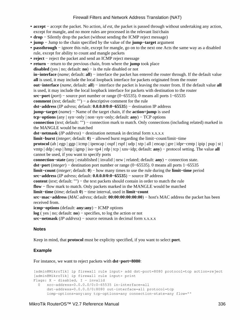
accept − accept the packet. No action, id est, the packet is passed through without undertaking any action,except for mangle, and no more rules are processed in the relevant list/chain
•
drop − Silently drop the packet (without sending the ICMP reject message)• jump − Jump to the chain specified by the value of the jump−target argument• passthrough − ignore this rule, except for mangle, go on to the next one Acts the same way as a disabledrule, except for ability to count and mangle packets
•
reject − reject the packet and send an ICMP reject message• return − return to the previous chain, from where the jump took placedisabled (yes | no; default: no) − is the rule disabled or notin−interface (name; default: all) − interface the packet has entered the router through. If the default valueall is used, it may include the local loopback interface for packets originated from the routerout−interface (name, default: all) − interface the packet is leaving the router from. If the default value allis used, it may include the local loopback interface for packets with destination to the routersrc−port (port) − source port number or range (0−65535). 0 means all ports 1−65535comment (text; default: "") − a descriptive comment for the ruledst−address (IP adress; default: 0.0.0.0/0:0−65535) − destination IP addressjump−target (name) − Name of the target chain, if the action=jump is usedtcp−options (any | syn−only | non−syn−only; default: any) − TCP optionsconnection (text; default: "") − connection mark to match. Only connections (including related) marked inthe MANGLE would be matcheddst−netmask (IP address) − destination netmask in decimal form x.x.x.xlimit−burst (integer; default: 0) − allowed burst regarding the limit−count/limit−timeprotocol (ah | egp | ggp | icmp | ipencap | ospf | rspf | udp | xtp | all | encap | gre | idpr−cmtp | ipip | pup | st |vmtp | ddp | esp | hmp | igmp | iso−tp4 | rdp | tcp | xns−idp; default: any) − protocol setting. The value allcannot be used, if you want to specify portsconnection−state (any | established | invalid | new | related; default: any) − connection state.dst−port (integer) − destination port number or range (0−65535). 0 means all ports 1−65535limit−count (integer; default: 0) − how many times to use the rule during the limit−time periodsrc−address (IP adress; default: 0.0.0.0/0:0−65535) − source IP addresscontent (text; default: "") − the text packets should contain in order to match the ruleflow − flow mark to match. Only packets marked in the MANGLE would be matchedlimit−time (time; default 0) − time interval, used in limit−countsrc−mac−address (MAC adress; default: 00:00:00:00:00:00) − host's MAC address the packet has beenreceived from.icmp−options (default: any:any) − ICMP optionslog ( yes | no; default: no) − specifies, to log the action or notsrc−netmask (IP address) − source netmask in decimal form x.x.x.x
Notes
Keep in mind, that protocol must be explicity specified, if you want to select port.
Example
For instance, we want to reject packets with dst−port=8080:
[admin@MikroTik] ip firewall rule input> add dst−port=8080 protocol=tcp action=reject[admin@MikroTik] ip firewall rule input> printFlags: X − disabled, I − invalid 0 src−address=0.0.0.0/0:0−65535 in−interface=all dst−address=0.0.0.0/0:8080 out−interface=all protocol=tcp icmp−options=any:any tcp−options=any connection−state=any flow=""
•
Firewall Filters and Network Address Translation (NAT)
MikroTik RouterOS™ V2.7 Reference Manual 336
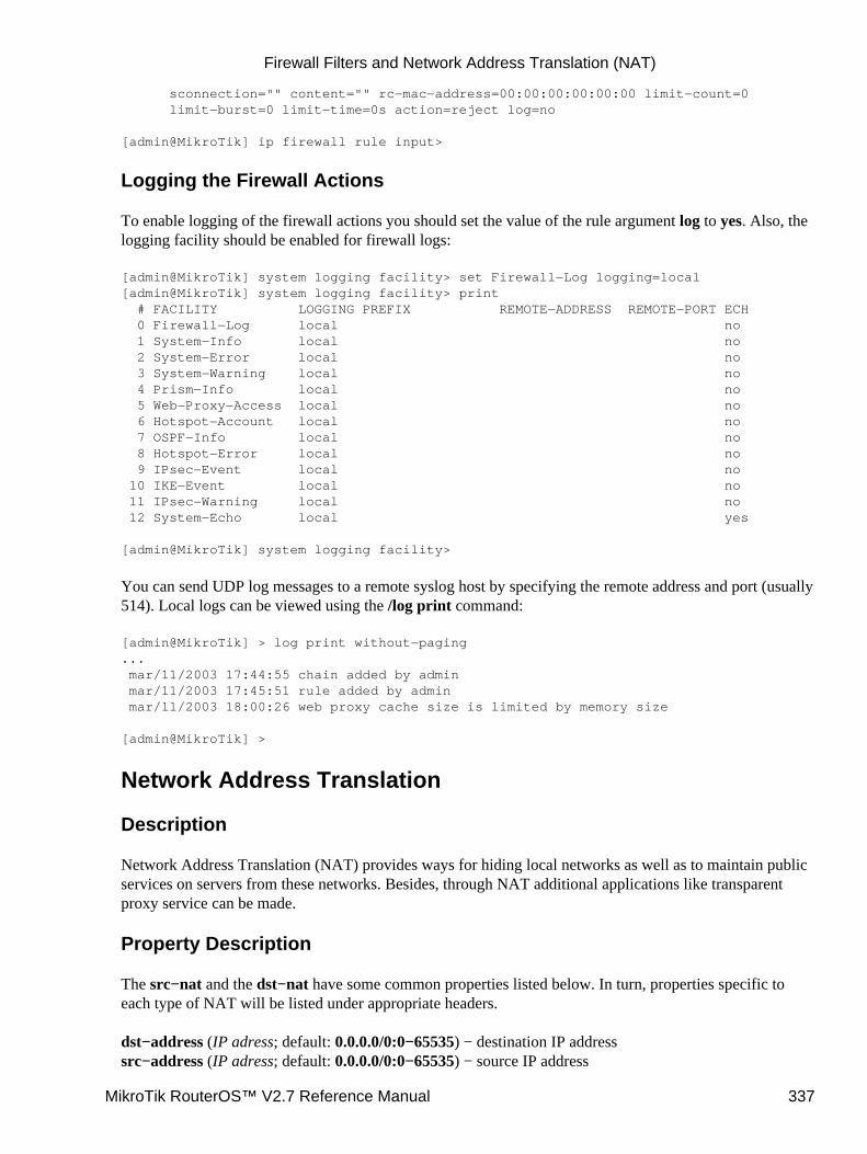
sconnection="" content="" rc−mac−address=00:00:00:00:00:00 limit−count=0 limit−burst=0 limit−time=0s action=reject log=no
[admin@MikroTik] ip firewall rule input>
Logging the Firewall Actions
To enable logging of the firewall actions you should set the value of the rule argument log to yes. Also, thelogging facility should be enabled for firewall logs:
[admin@MikroTik] system logging facility> set Firewall−Log logging=local[admin@MikroTik] system logging facility> print # FACILITY LOGGING PREFIX REMOTE−ADDRESS REMOTE−PORT ECH 0 Firewall−Log local no 1 System−Info local no 2 System−Error local no 3 System−Warning local no 4 Prism−Info local no 5 Web−Proxy−Access local no 6 Hotspot−Account local no 7 OSPF−Info local no 8 Hotspot−Error local no 9 IPsec−Event local no 10 IKE−Event local no 11 IPsec−Warning local no 12 System−Echo local yes
[admin@MikroTik] system logging facility>
You can send UDP log messages to a remote syslog host by specifying the remote address and port (usually514). Local logs can be viewed using the /log print command:
[admin@MikroTik] > log print without−paging... mar/11/2003 17:44:55 chain added by admin mar/11/2003 17:45:51 rule added by admin mar/11/2003 18:00:26 web proxy cache size is limited by memory size
[admin@MikroTik] >
Network Address Translation
Description
Network Address Translation (NAT) provides ways for hiding local networks as well as to maintain publicservices on servers from these networks. Besides, through NAT additional applications like transparentproxy service can be made.
Property Description
The src−nat and the dst−nat have some common properties listed below. In turn, properties specific toeach type of NAT will be listed under appropriate headers.
dst−address (IP adress; default: 0.0.0.0/0:0−65535) − destination IP addresssrc−address (IP adress; default: 0.0.0.0/0:0−65535) − source IP address
Firewall Filters and Network Address Translation (NAT)
MikroTik RouterOS™ V2.7 Reference Manual 337
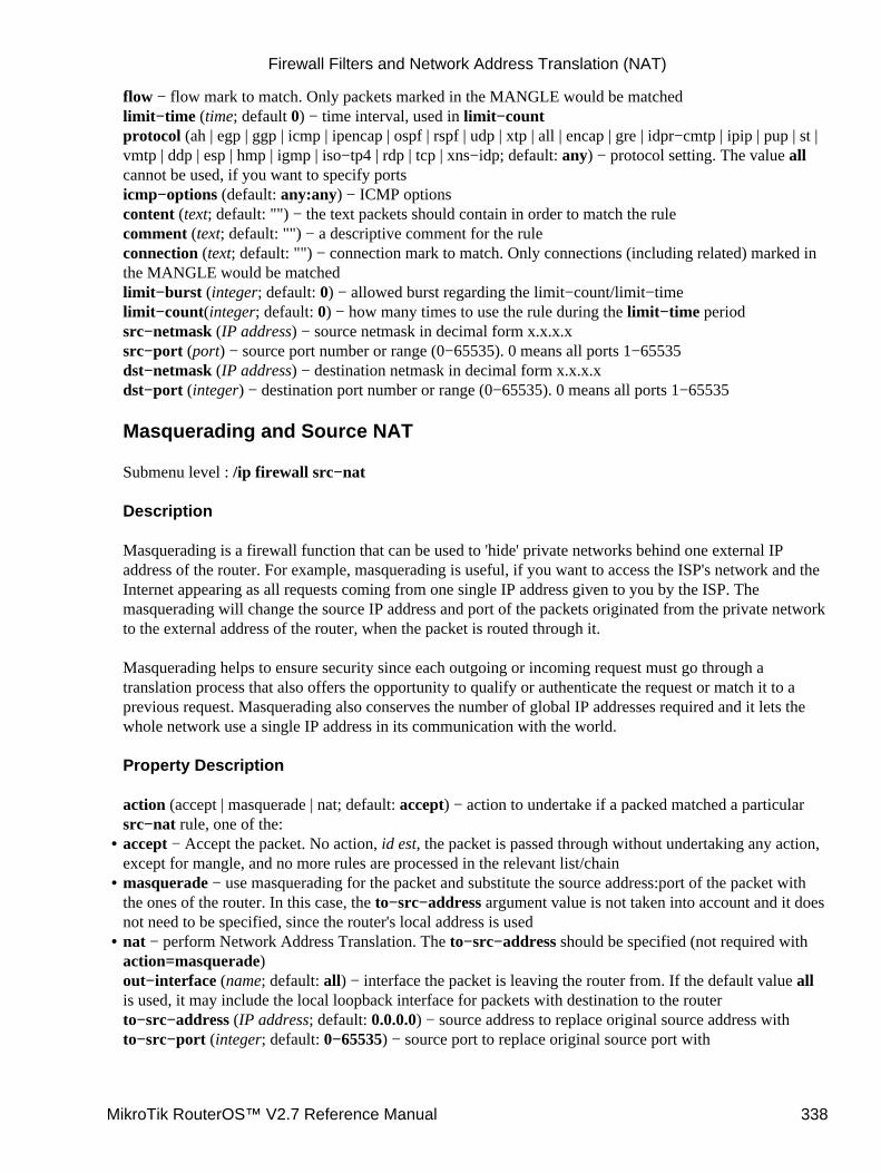
flow − flow mark to match. Only packets marked in the MANGLE would be matchedlimit−time (time; default 0) − time interval, used in limit−countprotocol (ah | egp | ggp | icmp | ipencap | ospf | rspf | udp | xtp | all | encap | gre | idpr−cmtp | ipip | pup | st |vmtp | ddp | esp | hmp | igmp | iso−tp4 | rdp | tcp | xns−idp; default: any) − protocol setting. The value allcannot be used, if you want to specify portsicmp−options (default: any:any) − ICMP optionscontent (text; default: "") − the text packets should contain in order to match the rulecomment (text; default: "") − a descriptive comment for the ruleconnection (text; default: "") − connection mark to match. Only connections (including related) marked inthe MANGLE would be matchedlimit−burst (integer; default: 0) − allowed burst regarding the limit−count/limit−timelimit−count(integer; default: 0) − how many times to use the rule during the limit−time periodsrc−netmask (IP address) − source netmask in decimal form x.x.x.xsrc−port (port) − source port number or range (0−65535). 0 means all ports 1−65535dst−netmask (IP address) − destination netmask in decimal form x.x.x.xdst−port (integer) − destination port number or range (0−65535). 0 means all ports 1−65535
Masquerading and Source NAT
Submenu level : /ip firewall src−nat
Description
Masquerading is a firewall function that can be used to 'hide' private networks behind one external IPaddress of the router. For example, masquerading is useful, if you want to access the ISP's network and theInternet appearing as all requests coming from one single IP address given to you by the ISP. Themasquerading will change the source IP address and port of the packets originated from the private networkto the external address of the router, when the packet is routed through it.
Masquerading helps to ensure security since each outgoing or incoming request must go through atranslation process that also offers the opportunity to qualify or authenticate the request or match it to aprevious request. Masquerading also conserves the number of global IP addresses required and it lets thewhole network use a single IP address in its communication with the world.
Property Description
action (accept | masquerade | nat; default: accept) − action to undertake if a packed matched a particularsrc−nat rule, one of the:accept − Accept the packet. No action, id est, the packet is passed through without undertaking any action,except for mangle, and no more rules are processed in the relevant list/chain
•
masquerade − use masquerading for the packet and substitute the source address:port of the packet withthe ones of the router. In this case, the to−src−address argument value is not taken into account and it doesnot need to be specified, since the router's local address is used
•
nat − perform Network Address Translation. The to−src−address should be specified (not required withaction=masquerade)out−interface (name; default: all) − interface the packet is leaving the router from. If the default value allis used, it may include the local loopback interface for packets with destination to the routerto−src−address (IP address; default: 0.0.0.0) − source address to replace original source address withto−src−port (integer; default: 0−65535) − source port to replace original source port with
•
Firewall Filters and Network Address Translation (NAT)
MikroTik RouterOS™ V2.7 Reference Manual 338

Example
To use masquerading, a source NAT rule with action=masquerade should be added to the src−nat ruleset:
[admin@MikroTik] ip firewall src−nat> add src−address=10.5.91.0/24:0 \\... out−interface=Public action=masquerade[admin@MikroTik] ip firewall src−nat> printFlags: X − disabled, I − invalid, D − dynamic 0 src−address=10.5.91.0/24:0−65535 dst−address=0.0.0.0/0:0−65535 out−interface=Public protocol=all icmp−options=any:any flow="" connection="" content="" limit−count=0 limit−burst=0 limit−time=0s action=masquerade to−src−address=0.0.0.0 to−src−port=0−65535
[admin@MikroTik] ip firewall src−nat>
If the packet matches the masquerade rule, then the router opens a connection to the destination, and sendsout a modified packet with its own address and a port allocated for this connection. The router keeps trackabout masqueraded connections and performs the "demasquerading" of packets, which arrive for theopened connections. For filtering purposes, you may want to specify the to−src−ports argument value, say,to 60000−65535.
If you want to change the source address:port to specific adress:port, use the action=nat instead ofaction=masquerade:
[admin@MikroTik] ip firewall src−nat> add src−address=192.168.0.1/32 action=nat \\... out−interface=Public to−src−address=10.10.10.5[admin@MikroTik] ip firewall src−nat> printFlags: X − disabled, I − invalid, D − dynamic 4 src−address=192.168.0.1/32:0−65535 dst−address=0.0.0.0/0:0−65535 out−interface=Public protocol=all icmp−options=any:any flow="" connection="" content="" limit−count=0 limit−burst=0 limit−time=0s action=nat to−src−address=10.10.10.5 to−src−port=0−65535
[[admin@MikroTik] ip firewall src−nat>
Here, thesrc−address − can be IP host's address, for example, 192.168.0.1/32, or network address 192.168.0.0/24to−src−address − can be one address, or a range, say 10.0.0.217−10.0.0.219. The addresses should beadded to the router's interface, or should be routed to it from the gateway router.
The source nat can masquerade several private networks, and use individual to−src−address for each ofthem.
Redirection and Destination NAT
Submenu level : /ip firewall dst−nat
Description
Redirection and destination NAT should be used when you need to give access to services located on aprivate network from the outside world.
Firewall Filters and Network Address Translation (NAT)
MikroTik RouterOS™ V2.7 Reference Manual 339

Property Description
action (accept | nat | redirect; default: accept) − action to undertake if a packed matched a particulardst−nat rule, one of the:accept − Accept the packet. No action, id est, the packet is passed through without undertaking any action,except for mangle, and no more rules are processed in the relevant list/chain
•
redirect − redirects to the local address:port of the router. In this case, the to−dst−address argument valueis not taken into account and it does not need to be specified, since the router's local address is used.
•
nat − perform Network Address Translation. The to−dst−address should be specified (not required withaction=redirect)in−interface (name; default: all) − interface the packet has entered the router through. If the default valueall is used, it may include the local loopback interface for packets originated from the routerto−dst−port (integer; default: 0−65535) − destination port to replace original withsrc−mac−address (MAC adress; default: 00:00:00:00:00:00) − host's MAC address the packet has beenreceived fromto−dst−address (IP address; default: 0.0.0.0) − destination IP address to replace original with
Example
To add a destination NAT rule that gives access to the http server 192.168.0.4 on the local network viaexternal address 10.0.0.217, use the following command:
[admin@MikroTik] ip firewall dst−nat> add action=nat protocol=tcp \\... dst−address=10.0.0.217/32:80 to−dst−address=192.168.0.4[admin@MikroTik] ip firewall dst−nat> printFlags: X − disabled, I − invalid, D − dynamic 0 src−address=0.0.0.0/0:0−65535 in−interface=all dst−address=10.0.0.217/32:80 protocol=tcp icmp−options=any:any flow="" connection="" content="" src−mac−address=00:00:00:00:00:00 limit−count=0 limit−burst=0 limit−time=0s action=nat to−dst−address=192.168.0.4 to−dst−port=0−65535
[admin@MikroTik] ip firewall dst−nat>
Here, if you want to redirect to the router's local address, use action=redirect and do not specify theto−dst−address.
Understanding REDIRECT and MASQUERADE
REDIRECT is similar to regular destination NAT in the same way as MASQUERADING is similar tosource NAT − masquerading is source NAT, except you do not have to specify to−src−address − outgoinginterface address is used automatically. The same with REDIRECT − it is destination NAT whereto−dst−address is not used − incoming interface address is used instead. So there is no use of specifyingto−src−address for src−nat rules with action=masquerade, and no use of specifying to−dst−address fordst−nat rules with action=redirect. Note that to−dst−port is meaningful for REDIRECT rules − this isport on which service on router that will handle these requests is sitting (e.g. web proxy).
When packet is dst−natted (no matter − action=nat or action=redirect), dst address is changed.Information about translation of addresses (including original dst address) is kept in router's internal tables.Transparent web proxy working on router (when web requests get redirected to proxy port on router) canaccess this information from internal tables and get address of web server from them. If you are dst−nattingto some different proxy server, it has no way to find web server's address from IP header (because dst
•
Firewall Filters and Network Address Translation (NAT)
MikroTik RouterOS™ V2.7 Reference Manual 340

address of IP packet that previously was address of web server has changed to address of proxy server).Starting from HTTP/1.1 there is special header in HTTP request which tells web server address, so proxyserver can use it, instead of dst address of IP packet. If there is no such header (older HTTP version onclient), proxy server can not determine web server address and therefore can not work.
It means, that it is impossible to correctly transparently redirect HTTP traffic from router to some othertransparent−proxy box. Only correct way is to add transparent proxy on the router itself, and configure it sothat your "real" proxy is parent−proxy. In this situation your "real" proxy does not have to be transparentany more, as proxy on router will be transparent and will forward proxy−style requests (according tostandard; these requests include all necessary information about web server) to "real" proxy.
Marking the Packets (Mangle) and Changing the MSS
Submenu level : /ip firewall mangle
Description
Packets entering the router can be marked for further processing them against the rules of firewall chains,source or destination NAT rules, as well as for applying queuing to them.
It is also possible to mark the packets associated (including related) with the same connection as the markedpacket (in other words, to mark a connection with all related connections, you need to mark only one packetbelonging to that connection).
You may also want to change the TCP Maximum Segment Size (MSS), to a value which is your desiredMTU value less 40. The MSS can be set only for TCP SYN packets.
Property Description
action (accept | passthrough; default: accept) − ation to undertake if the packet matches the rule, one of the:accept − accept the packet applying the appropriate attributes (marks, MSS), and no more rules areprocessed in the list
•
passthrough − apply the appropriate attributes (marks, MSS), and go on to the next ruledisabled (yes | no; default: no) − is the rule disabled or notin−interface (name; default: all) − interface the packet has entered the router through. If the default valueall is used, it may include the local loopback interface for packets originated from the routersrc−address (IP adress; default: 0.0.0.0/0:0−65535) − source IP addresssrc−netmask (IP address) − source netmask in decimal form x.x.x.xsrc−port (port) − source port number or range (0−65535). 0 means all ports 1−65535comment (text; default: "") − a descriptive comment for the ruledst−address (IP adress; default: 0.0.0.0/0:0−65535) − destination IP addressdst−netmask (IP address) − destination netmask in decimal form x.x.x.xdst−port (integer) − destination port number or range (0−65535). 0 means all ports 1−65535tcp−options (any | syn−only | non−syn−only; default: any) − TCP optionsicmp−options (default: any:any) − ICMP optionsprotocol (ah | egp | ggp | icmp | ipencap | ospf | rspf | udp | xtp | all | encap | gre | idpr−cmtp | ipip | pup | st |vmtp | ddp | esp | hmp | igmp | iso−tp4 | rdp | tcp | xns−idp; default: any) − protocol setting. The value allcannot be used, if you want to specify portscontent (text; default: "") − the text packets should contain in order to match the ruleflow (text; default: "") − flow mark to match. Only packets marked in the MANGLE would be matched
•
Firewall Filters and Network Address Translation (NAT)
MikroTik RouterOS™ V2.7 Reference Manual 341
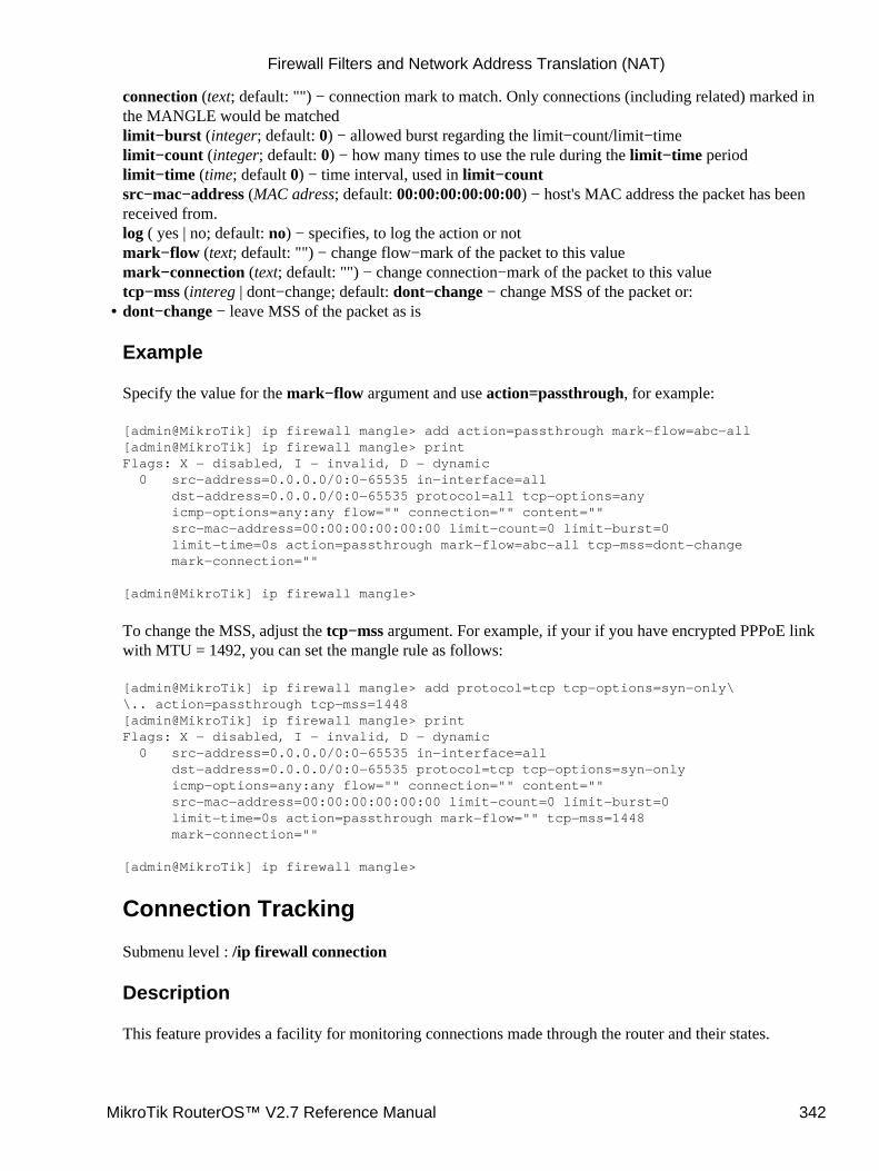
connection (text; default: "") − connection mark to match. Only connections (including related) marked inthe MANGLE would be matchedlimit−burst (integer; default: 0) − allowed burst regarding the limit−count/limit−timelimit−count (integer; default: 0) − how many times to use the rule during the limit−time periodlimit−time (time; default 0) − time interval, used in limit−countsrc−mac−address (MAC adress; default: 00:00:00:00:00:00) − host's MAC address the packet has beenreceived from.log ( yes | no; default: no) − specifies, to log the action or notmark−flow (text; default: "") − change flow−mark of the packet to this valuemark−connection (text; default: "") − change connection−mark of the packet to this valuetcp−mss (intereg | dont−change; default: dont−change − change MSS of the packet or:dont−change − leave MSS of the packet as is
Example
Specify the value for the mark−flow argument and use action=passthrough, for example:
[admin@MikroTik] ip firewall mangle> add action=passthrough mark−flow=abc−all[admin@MikroTik] ip firewall mangle> printFlags: X − disabled, I − invalid, D − dynamic 0 src−address=0.0.0.0/0:0−65535 in−interface=all dst−address=0.0.0.0/0:0−65535 protocol=all tcp−options=any icmp−options=any:any flow="" connection="" content="" src−mac−address=00:00:00:00:00:00 limit−count=0 limit−burst=0 limit−time=0s action=passthrough mark−flow=abc−all tcp−mss=dont−change mark−connection=""
[admin@MikroTik] ip firewall mangle>
To change the MSS, adjust the tcp−mss argument. For example, if your if you have encrypted PPPoE linkwith MTU = 1492, you can set the mangle rule as follows:
[admin@MikroTik] ip firewall mangle> add protocol=tcp tcp−options=syn−only\\.. action=passthrough tcp−mss=1448[admin@MikroTik] ip firewall mangle> printFlags: X − disabled, I − invalid, D − dynamic 0 src−address=0.0.0.0/0:0−65535 in−interface=all dst−address=0.0.0.0/0:0−65535 protocol=tcp tcp−options=syn−only icmp−options=any:any flow="" connection="" content="" src−mac−address=00:00:00:00:00:00 limit−count=0 limit−burst=0 limit−time=0s action=passthrough mark−flow="" tcp−mss=1448 mark−connection=""
[admin@MikroTik] ip firewall mangle>
Connection Tracking
Submenu level : /ip firewall connection
Description
This feature provides a facility for monitoring connections made through the router and their states.
•
Firewall Filters and Network Address Translation (NAT)
MikroTik RouterOS™ V2.7 Reference Manual 342
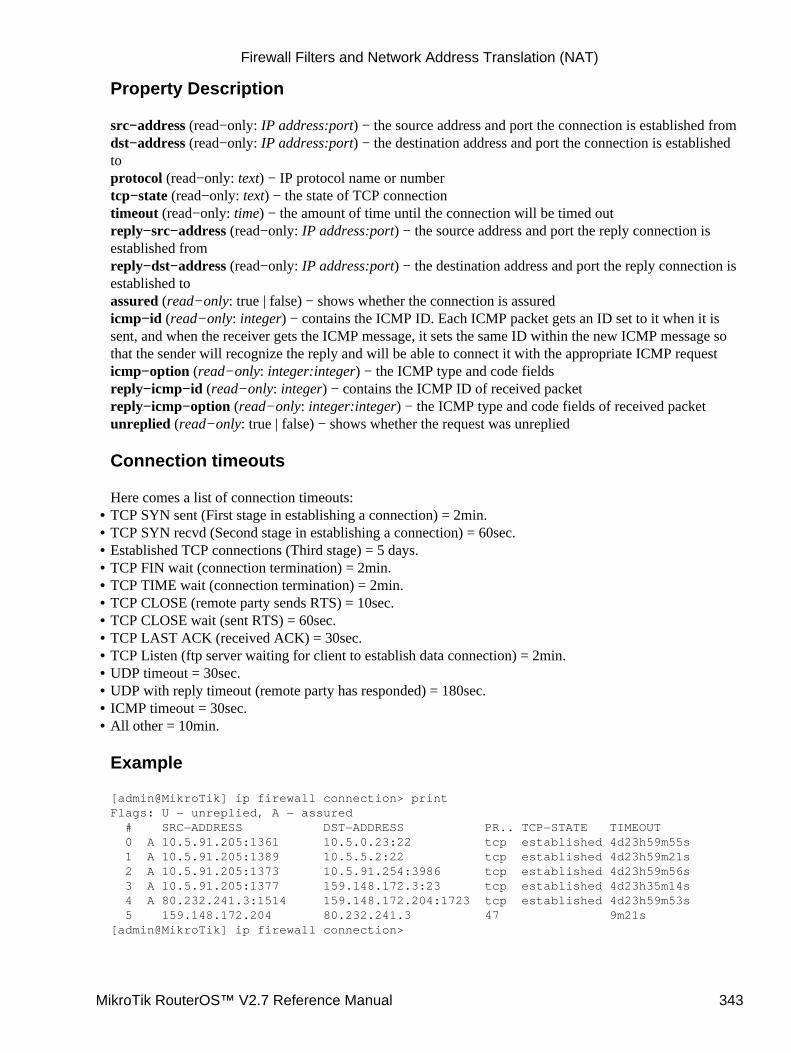
Property Description
src−address (read−only: IP address:port) − the source address and port the connection is established fromdst−address (read−only: IP address:port) − the destination address and port the connection is establishedtoprotocol (read−only: text) − IP protocol name or numbertcp−state (read−only: text) − the state of TCP connectiontimeout (read−only: time) − the amount of time until the connection will be timed outreply−src−address (read−only: IP address:port) − the source address and port the reply connection isestablished fromreply−dst−address (read−only: IP address:port) − the destination address and port the reply connection isestablished toassured (read−only: true | false) − shows whether the connection is assuredicmp−id (read−only: integer) − contains the ICMP ID. Each ICMP packet gets an ID set to it when it issent, and when the receiver gets the ICMP message, it sets the same ID within the new ICMP message sothat the sender will recognize the reply and will be able to connect it with the appropriate ICMP requesticmp−option (read−only: integer:integer) − the ICMP type and code fieldsreply−icmp−id (read−only: integer) − contains the ICMP ID of received packetreply−icmp−option (read−only: integer:integer) − the ICMP type and code fields of received packetunreplied (read−only: true | false) − shows whether the request was unreplied
Connection timeouts
Here comes a list of connection timeouts:TCP SYN sent (First stage in establishing a connection) = 2min.• TCP SYN recvd (Second stage in establishing a connection) = 60sec.• Established TCP connections (Third stage) = 5 days.• TCP FIN wait (connection termination) = 2min.• TCP TIME wait (connection termination) = 2min.• TCP CLOSE (remote party sends RTS) = 10sec.• TCP CLOSE wait (sent RTS) = 60sec.• TCP LAST ACK (received ACK) = 30sec.• TCP Listen (ftp server waiting for client to establish data connection) = 2min.• UDP timeout = 30sec.• UDP with reply timeout (remote party has responded) = 180sec.• ICMP timeout = 30sec.• All other = 10min.
Example
[admin@MikroTik] ip firewall connection> printFlags: U − unreplied, A − assured # SRC−ADDRESS DST−ADDRESS PR.. TCP−STATE TIMEOUT 0 A 10.5.91.205:1361 10.5.0.23:22 tcp established 4d23h59m55s 1 A 10.5.91.205:1389 10.5.5.2:22 tcp established 4d23h59m21s 2 A 10.5.91.205:1373 10.5.91.254:3986 tcp established 4d23h59m56s 3 A 10.5.91.205:1377 159.148.172.3:23 tcp established 4d23h35m14s 4 A 80.232.241.3:1514 159.148.172.204:1723 tcp established 4d23h59m53s 5 159.148.172.204 80.232.241.3 47 9m21s[admin@MikroTik] ip firewall connection>
•
Firewall Filters and Network Address Translation (NAT)
MikroTik RouterOS™ V2.7 Reference Manual 343
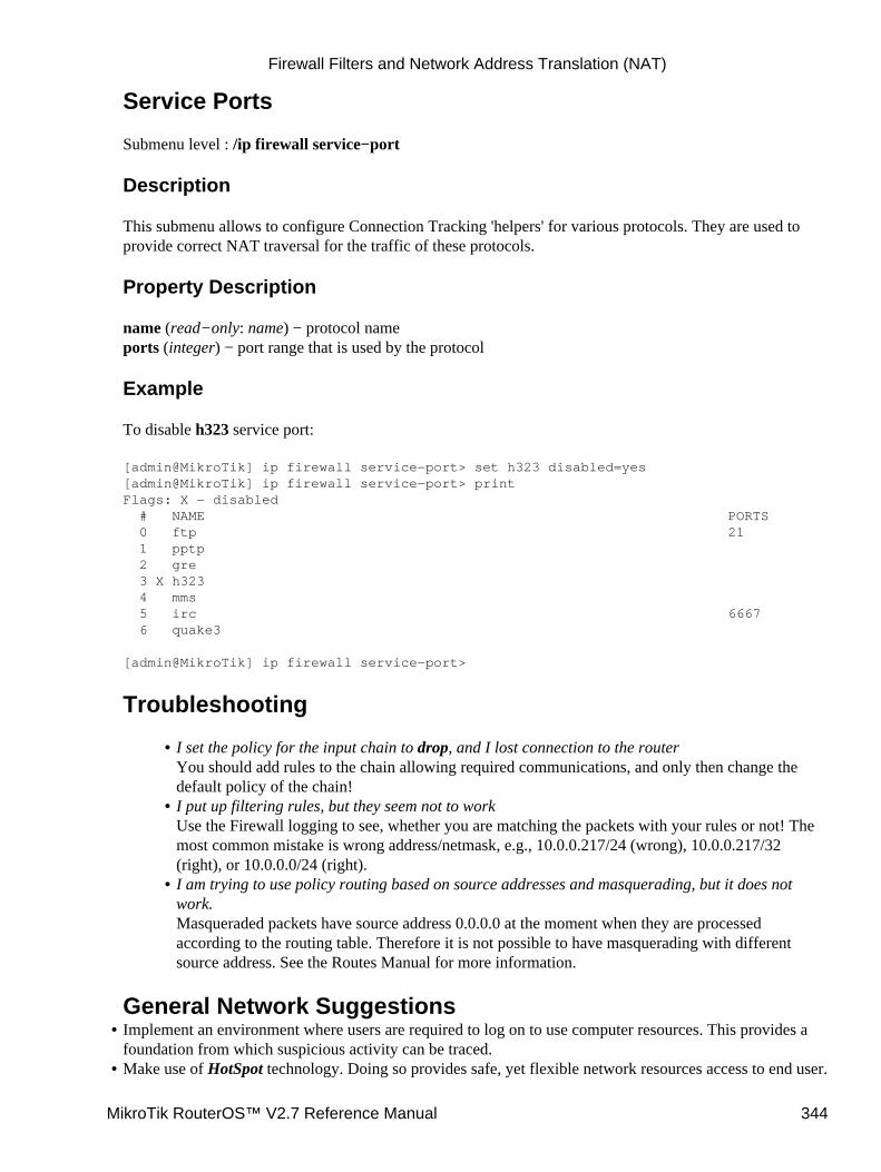
Service Ports
Submenu level : /ip firewall service−port
Description
This submenu allows to configure Connection Tracking 'helpers' for various protocols. They are used toprovide correct NAT traversal for the traffic of these protocols.
Property Description
name (read−only: name) − protocol nameports (integer) − port range that is used by the protocol
Example
To disable h323 service port:
[admin@MikroTik] ip firewall service−port> set h323 disabled=yes[admin@MikroTik] ip firewall service−port> printFlags: X − disabled # NAME PORTS 0 ftp 21 1 pptp 2 gre 3 X h323 4 mms 5 irc 6667 6 quake3
[admin@MikroTik] ip firewall service−port>
Troubleshooting
I set the policy for the input chain to drop, and I lost connection to the routerYou should add rules to the chain allowing required communications, and only then change thedefault policy of the chain!
•
I put up filtering rules, but they seem not to workUse the Firewall logging to see, whether you are matching the packets with your rules or not! Themost common mistake is wrong address/netmask, e.g., 10.0.0.217/24 (wrong), 10.0.0.217/32(right), or 10.0.0.0/24 (right).
•
I am trying to use policy routing based on source addresses and masquerading, but it does notwork.Masqueraded packets have source address 0.0.0.0 at the moment when they are processedaccording to the routing table. Therefore it is not possible to have masquerading with differentsource address. See the Routes Manual for more information.
•
General Network SuggestionsImplement an environment where users are required to log on to use computer resources. This provides afoundation from which suspicious activity can be traced.
•
Make use of HotSpot technology. Doing so provides safe, yet flexible network resources access to end user.•
Firewall Filters and Network Address Translation (NAT)
MikroTik RouterOS™ V2.7 Reference Manual 344
Provide sufficient training to end−users. Especially be sure that users are aware of the dangers of notlogging off their computers. Such dangers include the ability of a third−party to sit at an "open" computerand assume the user’s identity. The unauthorized person has all the rights and privileges of the logged inuser. Any suspicious activity will be traced back to the user’s login, not to the unauthorized person.
•
Make use of user activities and system activity logs analysis. Doing so enables the organization to detectsuspicious activity before a full−blown break−in occurs.
•
Some public structures like libraries, univercities, airport and some schools have "public" computersanyone can use. In order to minimize the threat of unauthorized access to network resources, install thesecomputers on a "public" network segment, so that internal network resources can not be reachable withoutauthorization.
IP Firewall Applications
In this section some IP firewalling common applications and examples of them are discussed.
Basic Firewall Building Principles
Assume we have a router that connects a customer's network to the Internet. The basic firewall buildingprinciples can be grouped as follows:
Protection of the router from unauthorized accessConnections to the addresses assigned to the router itself should be monitored. Only access fromcertain hosts to certain TCP ports of the router should be allowed.
This can be done by putting rules in the input chain to match packets with the destination address ofthe router entering the router through all interfaces.
•
Protection of the customer's hostsConnections to the addresses assigned to the customer's network should be monitored. Only accessto certain hosts and services should be allowed.
This can be done by putting rules in the forward chain to match packets passing through the routerwith the destination addresses of customer's network.
•
Using source NAT (masquerading) to 'Hide' the Private Network behind one ExternalAddressAll connections form the private addresses are masqueraded, and appear as coming from oneexternal address − that of the router.
This can be done by enabling the masquerading action for source NAT rules.
•
Enforcing the Internet Usage Policy from the Customer's NetworkConnections from the customer's network should be monitored.
This can be done by putting rules in the forward chain, or/and by masquerading (source NAT) onlythose connections, that are allowed.
•
Filtering has some impact on the router's performance. To minimize it, the filtering rules that match packetsfor established connections should be placed on top of the chain. These are TCP packets with optionsnon−syn−only.
Examples of setting up firewalls are discussed below.
•
Firewall Filters and Network Address Translation (NAT)
MikroTik RouterOS™ V2.7 Reference Manual 345
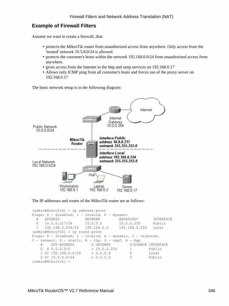
Example of Firewall Filters
Assume we want to create a firewall, that:
protects the MikroTik router from unauthorized access from anywhere. Only access from the'trusted' network 10.5.8.0/24 is allowed.
•
protects the customer's hosts within the network 192.168.0.0/24 from unauthorized access fromanywhere.
•
gives access from the Internet to the http and smtp services on 192.168.0.17• Allows only ICMP ping from all customer's hosts and forces use of the proxy server on192.168.0.17
•
The basic network setup is in the following diagram:
The IP addresses and routes of the MikroTik router are as follows:
[admin@MikroTik] > ip address printFlags: X − disabled, I − invalid, D − dynamic # ADDRESS NETWORK BROADCAST INTERFACE 0 10.0.0.217/24 10.0.0.0 10.0.0.255 Public 1 192.168.0.254/24 192.168.0.0 192.168.0.255 Local[admin@MikroTik] > ip route printFlags: X − disabled, I − invalid, D − dynamic, J − rejected,C − connect, S − static, R − rip, O − ospf, B − bgp # DST−ADDRESS G GATEWAY DISTANCE INTERFACE 0 S 0.0.0.0/0 r 10.0.0.254 1 Public 1 DC 192.168.0.0/24 r 0.0.0.0 0 Local 2 DC 10.0.0.0/24 r 0.0.0.0 0 Public[admin@MikroTik] >
Firewall Filters and Network Address Translation (NAT)
MikroTik RouterOS™ V2.7 Reference Manual 346
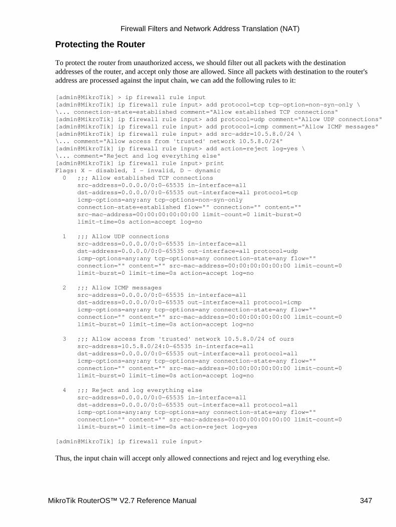
Protecting the Router
To protect the router from unauthorized access, we should filter out all packets with the destinationaddresses of the router, and accept only those are allowed. Since all packets with destination to the router'saddress are processed against the input chain, we can add the following rules to it:
[admin@MikroTik] > ip firewall rule input[admin@MikroTik] ip firewall rule input> add protocol=tcp tcp−option=non−syn−only \\... connection−state=established comment="Allow established TCP connections"[admin@MikroTik] ip firewall rule input> add protocol=udp comment="Allow UDP connections"[admin@MikroTik] ip firewall rule input> add protocol=icmp comment="Allow ICMP messages"[admin@MikroTik] ip firewall rule input> add src−addr=10.5.8.0/24 \\... comment="Allow access from 'trusted' network 10.5.8.0/24"[admin@MikroTik] ip firewall rule input> add action=reject log=yes \\... comment="Reject and log everything else"[admin@MikroTik] ip firewall rule input> printFlags: X − disabled, I − invalid, D − dynamic 0 ;;; Allow established TCP connections src−address=0.0.0.0/0:0−65535 in−interface=all dst−address=0.0.0.0/0:0−65535 out−interface=all protocol=tcp icmp−options=any:any tcp−options=non−syn−only connection−state=established flow="" connection="" content="" src−mac−address=00:00:00:00:00:00 limit−count=0 limit−burst=0 limit−time=0s action=accept log=no
1 ;;; Allow UDP connections src−address=0.0.0.0/0:0−65535 in−interface=all dst−address=0.0.0.0/0:0−65535 out−interface=all protocol=udp icmp−options=any:any tcp−options=any connection−state=any flow="" connection="" content="" src−mac−address=00:00:00:00:00:00 limit−count=0 limit−burst=0 limit−time=0s action=accept log=no
2 ;;; Allow ICMP messages src−address=0.0.0.0/0:0−65535 in−interface=all dst−address=0.0.0.0/0:0−65535 out−interface=all protocol=icmp icmp−options=any:any tcp−options=any connection−state=any flow="" connection="" content="" src−mac−address=00:00:00:00:00:00 limit−count=0 limit−burst=0 limit−time=0s action=accept log=no
3 ;;; Allow access from 'trusted' network 10.5.8.0/24 of ours src−address=10.5.8.0/24:0−65535 in−interface=all dst−address=0.0.0.0/0:0−65535 out−interface=all protocol=all icmp−options=any:any tcp−options=any connection−state=any flow="" connection="" content="" src−mac−address=00:00:00:00:00:00 limit−count=0 limit−burst=0 limit−time=0s action=accept log=no
4 ;;; Reject and log everything else src−address=0.0.0.0/0:0−65535 in−interface=all dst−address=0.0.0.0/0:0−65535 out−interface=all protocol=all icmp−options=any:any tcp−options=any connection−state=any flow="" connection="" content="" src−mac−address=00:00:00:00:00:00 limit−count=0 limit−burst=0 limit−time=0s action=reject log=yes
[admin@MikroTik] ip firewall rule input>
Thus, the input chain will accept only allowed connections and reject and log everything else.
Firewall Filters and Network Address Translation (NAT)
MikroTik RouterOS™ V2.7 Reference Manual 347
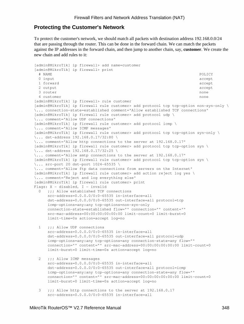
Protecting the Customer's Network
To protect the customer's network, we should match all packets with destination address 192.168.0.0/24that are passing through the router. This can be done in the forward chain. We can match the packetsagainst the IP addresses in the forward chain, and then jump to another chain, say, customer. We create thenew chain and add rules to it:
[admin@MikroTik] ip firewall> add name=customer[admin@MikroTik] ip firewall> print # NAME POLICY 0 input accept 1 forward accept 2 output accept 3 router none 4 customer none[admin@MikroTik] ip firewall> rule customer[admin@MikroTik] ip firewall rule customer> add protocol tcp tcp−option non−syn−only \\... connection−state=established comment="Allow established TCP connections"[admin@MikroTik] ip firewall rule customer> add protocol udp \\... comment="Allow UDP connections"[admin@MikroTik] ip firewall rule customer> add protocol icmp \\... comment="Allow ICMP messages"[admin@MikroTik] ip firewall rule customer> add protocol tcp tcp−option syn−only \\... dst−address 192.168.0.17/32:80 \\... comment="Allow http connections to the server at 192.168.0.17"[admin@MikroTik] ip firewall rule customer> add protocol tcp tcp−option syn \\... dst−address 192.168.0.17/32:25 \\... comment="Allow smtp connections to the server at 192.168.0.17"[admin@MikroTik] ip firewall rule customer> add protocol tcp tcp−option syn \\... src−port 20 dst−port 1024−65535 \\... comment="Allow ftp data connections from servers on the Internet"[admin@MikroTik] ip firewall rule customer> add action reject log yes \\... comment="Reject and log everything else"[admin@MikroTik] ip firewall rule customer> printFlags: X − disabled, I − invalid 0 ;;; Allow established TCP connections src−address=0.0.0.0/0:0−65535 in−interface=all dst−address=0.0.0.0/0:0−65535 out−interface=all protocol=tcp icmp−options=any:any tcp−options=non−syn−only connection−state=established flow="" connection="" content="" src−mac−address=00:00:00:00:00:00 limit−count=0 limit−burst=0 limit−time=0s action=accept log=no
1 ;;; Allow UDP connections src−address=0.0.0.0/0:0−65535 in−interface=all dst−address=0.0.0.0/0:0−65535 out−interface=all protocol=udp icmp−options=any:any tcp−options=any connection−state=any flow="" connection="" content="" src−mac−address=00:00:00:00:00:00 limit−count=0 limit−burst=0 limit−time=0s action=accept log=no
2 ;;; Allow ICMP messages src−address=0.0.0.0/0:0−65535 in−interface=all dst−address=0.0.0.0/0:0−65535 out−interface=all protocol=icmp icmp−options=any:any tcp−options=any connection−state=any flow="" connection="" content="" src−mac−address=00:00:00:00:00:00 limit−count=0 limit−burst=0 limit−time=0s action=accept log=no
3 ;;; Allow http connections to the server at 192.168.0.17 src−address=0.0.0.0/0:0−65535 in−interface=all
Firewall Filters and Network Address Translation (NAT)
MikroTik RouterOS™ V2.7 Reference Manual 348
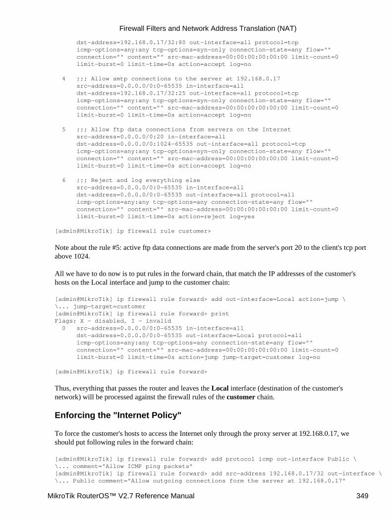
dst−address=192.168.0.17/32:80 out−interface=all protocol=tcp icmp−options=any:any tcp−options=syn−only connection−state=any flow="" connection="" content="" src−mac−address=00:00:00:00:00:00 limit−count=0 limit−burst=0 limit−time=0s action=accept log=no
4 ;;; Allow smtp connections to the server at 192.168.0.17 src−address=0.0.0.0/0:0−65535 in−interface=all dst−address=192.168.0.17/32:25 out−interface=all protocol=tcp icmp−options=any:any tcp−options=syn−only connection−state=any flow="" connection="" content="" src−mac−address=00:00:00:00:00:00 limit−count=0 limit−burst=0 limit−time=0s action=accept log=no
5 ;;; Allow ftp data connections from servers on the Internet src−address=0.0.0.0/0:20 in−interface=all dst−address=0.0.0.0/0:1024−65535 out−interface=all protocol=tcp icmp−options=any:any tcp−options=syn−only connection−state=any flow="" connection="" content="" src−mac−address=00:00:00:00:00:00 limit−count=0 limit−burst=0 limit−time=0s action=accept log=no
6 ;;; Reject and log everything else src−address=0.0.0.0/0:0−65535 in−interface=all dst−address=0.0.0.0/0:0−65535 out−interface=all protocol=all icmp−options=any:any tcp−options=any connection−state=any flow="" connection="" content="" src−mac−address=00:00:00:00:00:00 limit−count=0 limit−burst=0 limit−time=0s action=reject log=yes
[admin@MikroTik] ip firewall rule customer>
Note about the rule #5: active ftp data connections are made from the server's port 20 to the client's tcp portabove 1024.
All we have to do now is to put rules in the forward chain, that match the IP addresses of the customer'shosts on the Local interface and jump to the customer chain:
[admin@MikroTik] ip firewall rule forward> add out−interface=Local action=jump \\... jump−target=customer[admin@MikroTik] ip firewall rule forward> printFlags: X − disabled, I − invalid 0 src−address=0.0.0.0/0:0−65535 in−interface=all dst−address=0.0.0.0/0:0−65535 out−interface=Local protocol=all icmp−options=any:any tcp−options=any connection−state=any flow="" connection="" content="" src−mac−address=00:00:00:00:00:00 limit−count=0 limit−burst=0 limit−time=0s action=jump jump−target=customer log=no
[admin@MikroTik] ip firewall rule forward>
Thus, everything that passes the router and leaves the Local interface (destination of the customer'snetwork) will be processed against the firewall rules of the customer chain.
Enforcing the "Internet Policy"
To force the customer's hosts to access the Internet only through the proxy server at 192.168.0.17, weshould put following rules in the forward chain:
[admin@MikroTik] ip firewall rule forward> add protocol icmp out−interface Public \\... comment="Allow ICMP ping packets"[admin@MikroTik] ip firewall rule forward> add src−address 192.168.0.17/32 out−interface \\... Public comment="Allow outgoing connections form the server at 192.168.0.17"
Firewall Filters and Network Address Translation (NAT)
MikroTik RouterOS™ V2.7 Reference Manual 349
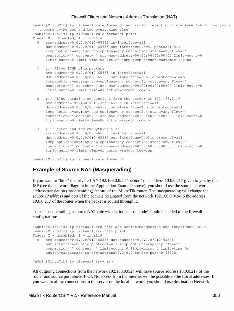
[admin@MikroTik] ip firewall rule forward> add action reject out−interface Public log yes \\... comment="Reject and log everything else"[admin@MikroTik] ip firewall rule forward> printFlags: X − disabled, I − invalid 0 src−address=0.0.0.0/0:0−65535 in−interface=all dst−address=0.0.0.0/0:0−65535 out−interface=Local protocol=all icmp−options=any:any tcp−options=any connection−state=any flow="" connection="" content="" src−mac−address=00:00:00:00:00:00 limit−count=0 limit−burst=0 limit−time=0s action=jump jump−target=customer log=no
1 ;;; Allow ICMP ping packets src−address=0.0.0.0/0:0−65535 in−interface=all dst−address=0.0.0.0/0:0−65535 out−interface=Public protocol=icmp icmp−options=any:any tcp−options=any connection−state=any flow="" connection="" content="" src−mac−address=00:00:00:00:00:00 limit−count=0 limit−burst=0 limit−time=0s action=accept log=no
2 ;;; Allow outgoing connections form the server at 192.168.0.17 src−address=192.168.0.17/32:0−65535 in−interface=all dst−address=0.0.0.0/0:0−65535 out−interface=Public protocol=all icmp−options=any:any tcp−options=any connection−state=any flow="" connection="" content="" src−mac−address=00:00:00:00:00:00 limit−count=0 limit−burst=0 limit−time=0s action=accept log=no
3 ;;; Reject and log everything else src−address=0.0.0.0/0:0−65535 in−interface=all dst−address=0.0.0.0/0:0−65535 out−interface=Public protocol=all icmp−options=any:any tcp−options=any connection−state=any flow="" connection="" content="" src−mac−address=00:00:00:00:00:00 limit−count=0 limit−burst=0 limit−time=0s action=reject log=yes
[admin@MikroTik] ip firewall rule forward>
Example of Source NAT (Masquerading)
If you want to "hide" the private LAN 192.168.0.0/24 "behind" one address 10.0.0.217 given to you by theISP (see the network diagram in the Application Example above), you should use the source networkaddress translation (masquerading) feature of the MikroTik router. The masquerading will change thesource IP address and port of the packets originated from the network 192.168.0.0/24 to the address10.0.0.217 of the router when the packet is routed through it.
To use masquerading, a source NAT rule with action 'masquerade' should be added to the firewallconfiguration:
[admin@MikroTik] ip firewall src−nat> add action=masquerade out−interface=Public[admin@MikroTik] ip firewall src−nat> printFlags: X − disabled, I − invalid 0 src−address=0.0.0.0/0:0−65535 dst−address=0.0.0.0/0:0−65535 out−interface=Public protocol=all icmp−options=any:any flow="" connection="" content="" limit−count=0 limit−burst=0 limit−time=0s action=masquerade to−src−address=0.0.0.0 to−src−port=0−65535
[admin@MikroTik] ip firewall src−nat>
All outgoing connections from the network 192.168.0.0/24 will have source address 10.0.0.217 of therouter and source port above 1024. No access from the Internet will be possible to the Local addresses. Ifyou want to allow connections to the server on the local network, you should use destination Network
Firewall Filters and Network Address Translation (NAT)
MikroTik RouterOS™ V2.7 Reference Manual 350
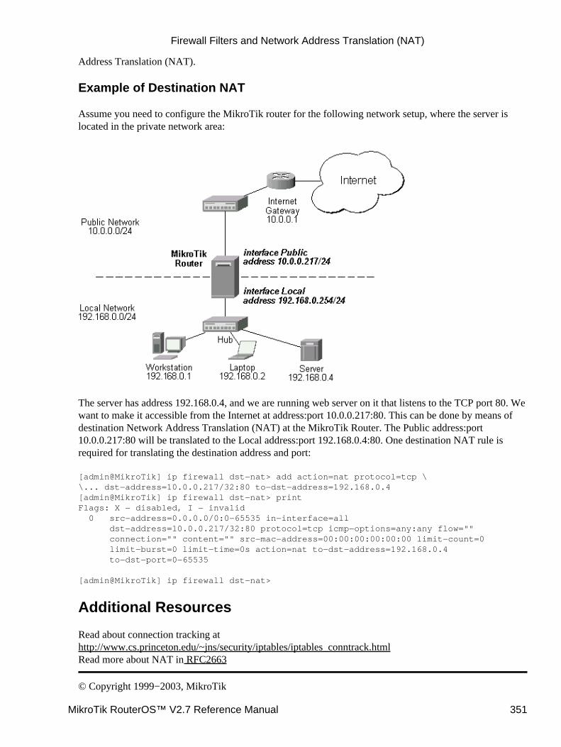
Address Translation (NAT).
Example of Destination NAT
Assume you need to configure the MikroTik router for the following network setup, where the server islocated in the private network area:
The server has address 192.168.0.4, and we are running web server on it that listens to the TCP port 80. Wewant to make it accessible from the Internet at address:port 10.0.0.217:80. This can be done by means ofdestination Network Address Translation (NAT) at the MikroTik Router. The Public address:port10.0.0.217:80 will be translated to the Local address:port 192.168.0.4:80. One destination NAT rule isrequired for translating the destination address and port:
[admin@MikroTik] ip firewall dst−nat> add action=nat protocol=tcp \\... dst−address=10.0.0.217/32:80 to−dst−address=192.168.0.4[admin@MikroTik] ip firewall dst−nat> printFlags: X − disabled, I − invalid 0 src−address=0.0.0.0/0:0−65535 in−interface=all dst−address=10.0.0.217/32:80 protocol=tcp icmp−options=any:any flow="" connection="" content="" src−mac−address=00:00:00:00:00:00 limit−count=0 limit−burst=0 limit−time=0s action=nat to−dst−address=192.168.0.4 to−dst−port=0−65535
[admin@MikroTik] ip firewall dst−nat>
Additional Resources
Read about connection tracking athttp://www.cs.princeton.edu/~jns/security/iptables/iptables_conntrack.htmlRead more about NAT in RFC2663
© Copyright 1999−2003, MikroTik
Firewall Filters and Network Address Translation (NAT)
MikroTik RouterOS™ V2.7 Reference Manual 351

IP Route ManagementDocument revision 1.4 (01−Jun−2003)This document applies to the MikroTik RouterOS V2.7
Table of Contents
Table of Contents• Summary• Specifications• Related Documents• Description• Static Routes
Property Description♦ Notes♦ Example♦
•
Policy RoutingDescription♦ Routing Tables
Description◊ Property Description◊ Notes◊ Example◊
♦
Policy rulesProperty Description◊ Notes◊ Example◊
♦
•
Application Example• Additional Resources•
Summary
The following Manual discusses managing the IP routes, equal−cost multi−path (ECMP) routing technique aswell as policy−based routing, which give opportunity to select routes in order to restrict the use of networkresources to certain classes of customers.
Specifications
Packages required : systemLicense required : AnyHome menu level : /ip route, /ip policy−routingProtocols utilized : IP (RFC791)Hardware usage: not significant
Related Documents
Software Package Installation and UpgradingIP Addresses and Address Resolution Protocol (ARP)
MikroTik RouterOS™ V2.7 Reference Manual 352
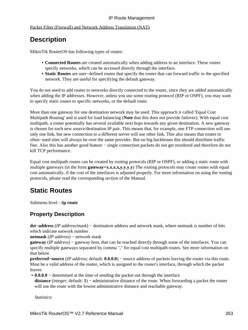
Packet Filter (Firewall) and Network Address Translation (NAT)
Description
MikroTik RouterOS has following types of routes:
Connected Routes are created automatically when adding address to an interface. These routesspecify networks, which can be accessed directly through the interface.
•
Static Routes are user−defined routes that specify the router that can forward traffic to the specifiednetwork. They are useful for specifying the default gateway.
•
You do not need to add routes to networks directly connected to the router, since they are added automaticallywhen adding the IP addresses. However, unless you use some routing protocol (RIP or OSPF), you may wantto specify static routes to specific networks, or the default route.
More than one gateway for one destination network may be used. This approach ir called 'Equal CostMultipath Routing' and is used for load balancing (Note that this does not provide failover). With equal costmultipath, a router potentially has several available next hops towards any given destination. A new gatewayis chosen for each new source/destination IP pair. This means that, for example, one FTP connection will useonly one link, but new connection to a different server will use other link. This also means that routes tooften−used sites will always be over the same provider. But on big backbones this should distribute trafficfine. Also this has another good feature − single connection packets do not get reordered and therefore do notkill TCP performance.
Equal cost multipath routes can be created by routing protocols (RIP or OSPF), or adding a static route withmultiple gateways (in the form gateway=x.x.x.x,y.y.y.y) The routing protocols may create routes with equalcost automatically, if the cost of the interfaces is adjusted properly. For more information on using the routingprotocols, please read the corresponding section of the Manual.
Static Routes
Submenu level : /ip route
Property Description
dst−address (IP address/mask) − destination address and network mask, where netmask is number of bitswhich indicate natwork numbernetmask (IP address) − network maskgateway (IP address) − gateway host, that can be reached directly through some of the interfaces. You canspecify multiple gateways separated by comma "," for equal cost multipath routes. See more information onthat belowpreferred−source (IP address; default: 0.0.0.0) − source address of packets leaving the router via this route.Must be a valid address of the router, which is assigned to the router's interface, through which the packetleaves
0.0.0.0 − determined at the time of sending the packet out through the interfacedistance (integer; default: 1) − administrative distance of the route. When forwarding a packet the routerwill use the route with the lowest administrative distance and reachable gateway.
Statistics:
•
IP Route Management
MikroTik RouterOS™ V2.7 Reference Manual 353
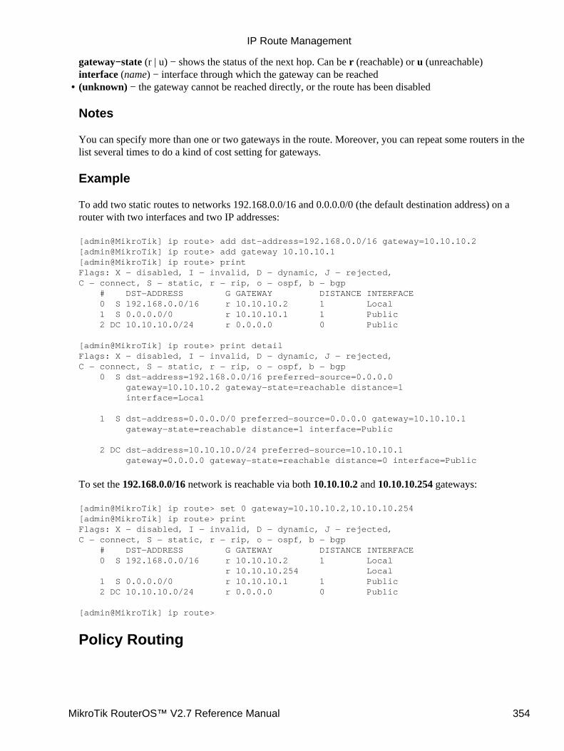
gateway−state (r | u) − shows the status of the next hop. Can be r (reachable) or u (unreachable)interface (name) − interface through which the gateway can be reached(unknown) − the gateway cannot be reached directly, or the route has been disabled
Notes
You can specify more than one or two gateways in the route. Moreover, you can repeat some routers in thelist several times to do a kind of cost setting for gateways.
Example
To add two static routes to networks 192.168.0.0/16 and 0.0.0.0/0 (the default destination address) on arouter with two interfaces and two IP addresses:
[admin@MikroTik] ip route> add dst−address=192.168.0.0/16 gateway=10.10.10.2[admin@MikroTik] ip route> add gateway 10.10.10.1[admin@MikroTik] ip route> printFlags: X − disabled, I − invalid, D − dynamic, J − rejected,C − connect, S − static, r − rip, o − ospf, b − bgp # DST−ADDRESS G GATEWAY DISTANCE INTERFACE 0 S 192.168.0.0/16 r 10.10.10.2 1 Local 1 S 0.0.0.0/0 r 10.10.10.1 1 Public 2 DC 10.10.10.0/24 r 0.0.0.0 0 Public
[admin@MikroTik] ip route> print detailFlags: X − disabled, I − invalid, D − dynamic, J − rejected,C − connect, S − static, r − rip, o − ospf, b − bgp 0 S dst−address=192.168.0.0/16 preferred−source=0.0.0.0 gateway=10.10.10.2 gateway−state=reachable distance=1 interface=Local
1 S dst−address=0.0.0.0/0 preferred−source=0.0.0.0 gateway=10.10.10.1 gateway−state=reachable distance=1 interface=Public
2 DC dst−address=10.10.10.0/24 preferred−source=10.10.10.1 gateway=0.0.0.0 gateway−state=reachable distance=0 interface=Public
To set the 192.168.0.0/16 network is reachable via both 10.10.10.2 and 10.10.10.254 gateways:
[admin@MikroTik] ip route> set 0 gateway=10.10.10.2,10.10.10.254[admin@MikroTik] ip route> printFlags: X − disabled, I − invalid, D − dynamic, J − rejected,C − connect, S − static, r − rip, o − ospf, b − bgp # DST−ADDRESS G GATEWAY DISTANCE INTERFACE 0 S 192.168.0.0/16 r 10.10.10.2 1 Local r 10.10.10.254 Local 1 S 0.0.0.0/0 r 10.10.10.1 1 Public 2 DC 10.10.10.0/24 r 0.0.0.0 0 Public
[admin@MikroTik] ip route>
Policy Routing
•
IP Route Management
MikroTik RouterOS™ V2.7 Reference Manual 354

Description
Policy routing allows select routes in order to variate the use of network resources to certain classes of users(in other words, you can set different routes to the same networks depending on some classifiers). This isimplemented using multiple routing tables and a list of rules specifying how these tables should be used.
The Policy Routing is implemented in the MikroTik RouterOS based on source and destination addresses ofa packet, the interface the packet arrives to the router and the firewall mark that may be associated withsome packets.
When finding the route for a packet, the packet is matched against policy routing rules one after another,until some rule matches the packet. Then action specified in that rule is executed. If no rule matches thepacket, it is assumed that there is no route to given host and appropriate action is taken (packet dropped andICMP error sent back to the source).
If a routing table does not have a route for the packet, next rule after the one that directed to the currenttable is examined, until the route is found, end of rule list is reached or some rule with action drop orunreachable is hit. Thus it is good to have last rule say "from everywhere to everywhere, all interfaces,lookup main route table", because then gateways can be found (connected routes are entered in the maintable only).
Note that the only way for packet to be forwarded is to have some rule direct to some routing table thatcontains route to packet destination.
Routing Tables
Submenu level : /ip policy−routing
Description
Routing tables is a way to organize routing rules into groups for a purpose of easy management. Thesetables can be created/deleted in the /ip policy−routing menu.
The routes in the routing tables are managed the same way as the static routes described above, but in thesubmenu /ip policy−routing table name submenu, where name is name of the table
Property Description
name (name) − table name
Notes
There is always the table main − this one can not be deleted and its name can not be changed. The maintable can be managed in in the /ip route submenu as well:
[admin@MikroTik] ip policy−routing> table main[admin@MikroTik] ip policy−routing table main> printFlags: X − disabled, I − invalid, D − dynamic, R − rejected # TYPE DST−ADDRESS G GATEWAY DISTANCE INTERFACE 0 static 192.168.1.0/24 r 192.168.0.50 1 Local 1 static 0.0.0.0/0 r 10.0.0.1 1 Public 2 D connect 192.168.0.0/24 r 0.0.0.0 0 Local
IP Route Management
MikroTik RouterOS™ V2.7 Reference Manual 355
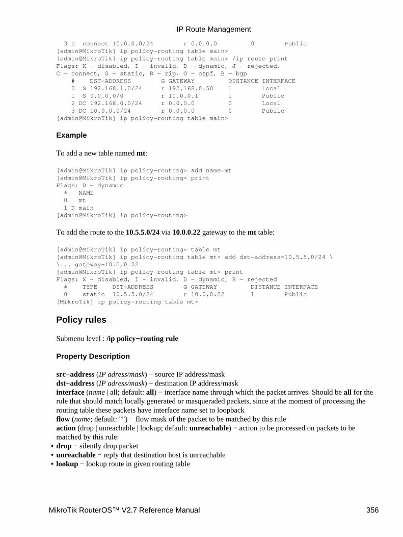
3 D connect 10.0.0.0/24 r 0.0.0.0 0 Public[admin@MikroTik] ip policy−routing table main>[admin@MikroTik] ip policy−routing table main> /ip route printFlags: X − disabled, I − invalid, D − dynamic, J − rejected,C − connect, S − static, R − rip, O − ospf, B − bgp # DST−ADDRESS G GATEWAY DISTANCE INTERFACE 0 S 192.168.1.0/24 r 192.168.0.50 1 Local 1 S 0.0.0.0/0 r 10.0.0.1 1 Public 2 DC 192.168.0.0/24 r 0.0.0.0 0 Local 3 DC 10.0.0.0/24 r 0.0.0.0 0 Public[admin@MikroTik] ip policy−routing table main>
Example
To add a new table named mt:
[admin@MikroTik] ip policy−routing> add name=mt[admin@MikroTik] ip policy−routing> printFlags: D − dynamic # NAME 0 mt 1 D main[admin@MikroTik] ip policy−routing>
To add the route to the 10.5.5.0/24 via 10.0.0.22 gateway to the mt table:
[admin@MikroTik] ip policy−routing> table mt[admin@MikroTik] ip policy−routing table mt> add dst−address=10.5.5.0/24 \\... gateway=10.0.0.22[admin@MikroTik] ip policy−routing table mt> printFlags: X − disabled, I − invalid, D − dynamic, R − rejected # TYPE DST−ADDRESS G GATEWAY DISTANCE INTERFACE 0 static 10.5.5.0/24 r 10.0.0.22 1 Public[MikroTik] ip policy−routing table mt>
Policy rules
Submenu level : /ip policy−routing rule
Property Description
src−address (IP adress/mask) − source IP address/maskdst−address (IP adress/mask) − destination IP address/maskinterface (name | all; default: all) − interface name through which the packet arrives. Should be all for therule that should match locally generated or masqueraded packets, since at the moment of processing therouting table these packets have interface name set to loopbackflow (name; default: "") − flow mask of the packet to be matched by this ruleaction (drop | unreachable | lookup; default: unreachable) − action to be processed on packets to bematched by this rule:drop − silently drop packet• unreachable − reply that destination host is unreachable• lookup − lookup route in given routing table•
IP Route Management
MikroTik RouterOS™ V2.7 Reference Manual 356
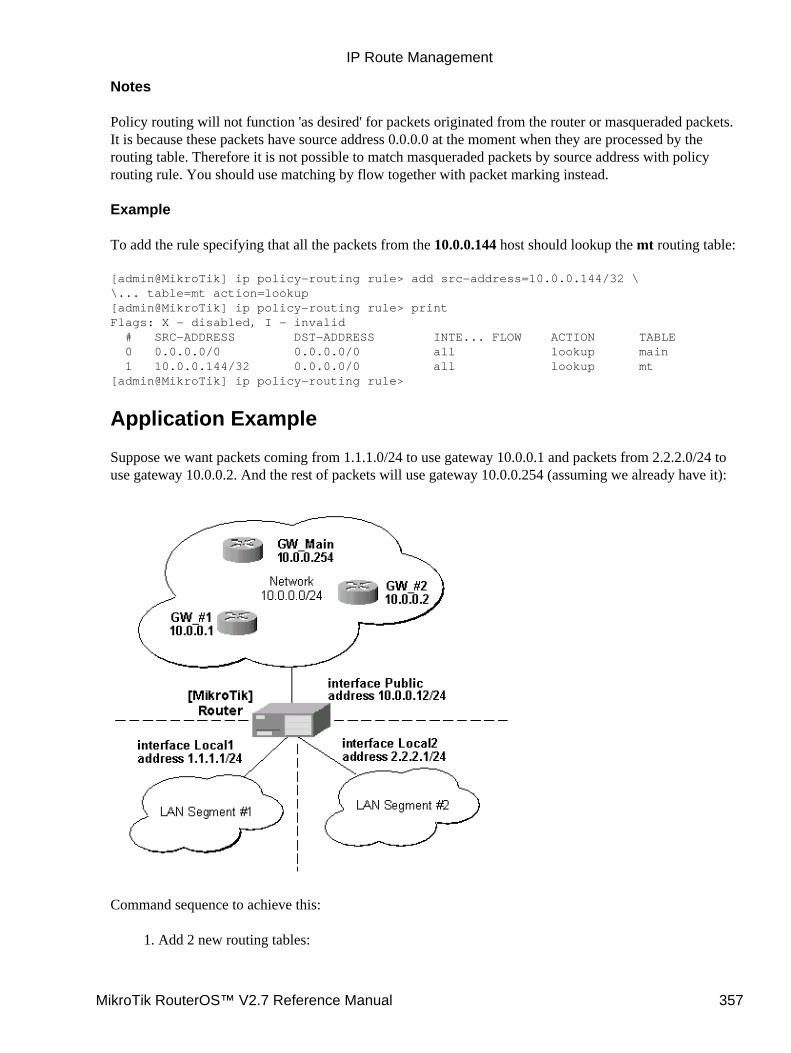
Notes
Policy routing will not function 'as desired' for packets originated from the router or masqueraded packets.It is because these packets have source address 0.0.0.0 at the moment when they are processed by therouting table. Therefore it is not possible to match masqueraded packets by source address with policyrouting rule. You should use matching by flow together with packet marking instead.
Example
To add the rule specifying that all the packets from the 10.0.0.144 host should lookup the mt routing table:
[admin@MikroTik] ip policy−routing rule> add src−address=10.0.0.144/32 \\... table=mt action=lookup[admin@MikroTik] ip policy−routing rule> printFlags: X − disabled, I − invalid # SRC−ADDRESS DST−ADDRESS INTE... FLOW ACTION TABLE 0 0.0.0.0/0 0.0.0.0/0 all lookup main 1 10.0.0.144/32 0.0.0.0/0 all lookup mt[admin@MikroTik] ip policy−routing rule>
Application Example
Suppose we want packets coming from 1.1.1.0/24 to use gateway 10.0.0.1 and packets from 2.2.2.0/24 touse gateway 10.0.0.2. And the rest of packets will use gateway 10.0.0.254 (assuming we already have it):
Command sequence to achieve this:
Add 2 new routing tables:1.
IP Route Management
MikroTik RouterOS™ V2.7 Reference Manual 357
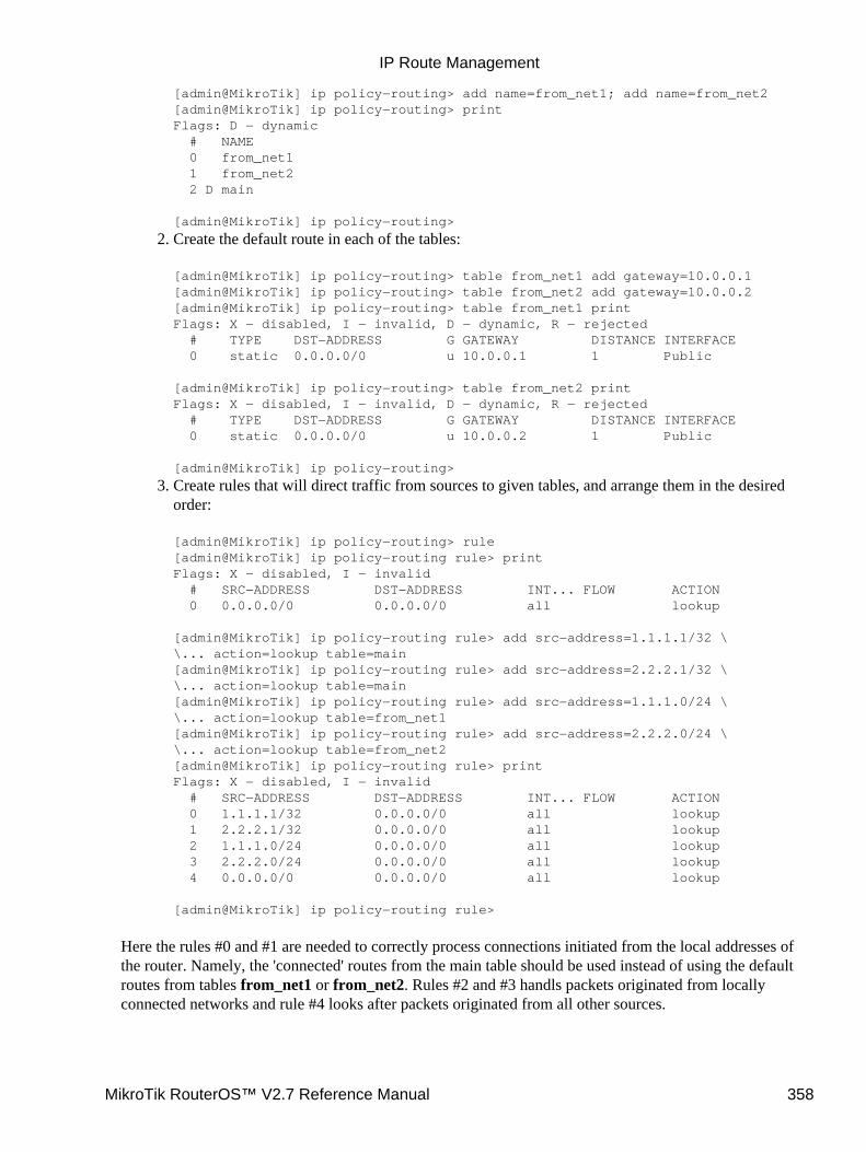
[admin@MikroTik] ip policy−routing> add name=from_net1; add name=from_net2[admin@MikroTik] ip policy−routing> printFlags: D − dynamic # NAME 0 from_net1 1 from_net2 2 D main
[admin@MikroTik] ip policy−routing>
Create the default route in each of the tables:
[admin@MikroTik] ip policy−routing> table from_net1 add gateway=10.0.0.1[admin@MikroTik] ip policy−routing> table from_net2 add gateway=10.0.0.2[admin@MikroTik] ip policy−routing> table from_net1 printFlags: X − disabled, I − invalid, D − dynamic, R − rejected # TYPE DST−ADDRESS G GATEWAY DISTANCE INTERFACE 0 static 0.0.0.0/0 u 10.0.0.1 1 Public
[admin@MikroTik] ip policy−routing> table from_net2 printFlags: X − disabled, I − invalid, D − dynamic, R − rejected # TYPE DST−ADDRESS G GATEWAY DISTANCE INTERFACE 0 static 0.0.0.0/0 u 10.0.0.2 1 Public
[admin@MikroTik] ip policy−routing>
2.
Create rules that will direct traffic from sources to given tables, and arrange them in the desiredorder:
[admin@MikroTik] ip policy−routing> rule[admin@MikroTik] ip policy−routing rule> printFlags: X − disabled, I − invalid # SRC−ADDRESS DST−ADDRESS INT... FLOW ACTION 0 0.0.0.0/0 0.0.0.0/0 all lookup
[admin@MikroTik] ip policy−routing rule> add src−address=1.1.1.1/32 \\... action=lookup table=main[admin@MikroTik] ip policy−routing rule> add src−address=2.2.2.1/32 \\... action=lookup table=main[admin@MikroTik] ip policy−routing rule> add src−address=1.1.1.0/24 \\... action=lookup table=from_net1[admin@MikroTik] ip policy−routing rule> add src−address=2.2.2.0/24 \\... action=lookup table=from_net2[admin@MikroTik] ip policy−routing rule> printFlags: X − disabled, I − invalid # SRC−ADDRESS DST−ADDRESS INT... FLOW ACTION 0 1.1.1.1/32 0.0.0.0/0 all lookup 1 2.2.2.1/32 0.0.0.0/0 all lookup 2 1.1.1.0/24 0.0.0.0/0 all lookup 3 2.2.2.0/24 0.0.0.0/0 all lookup 4 0.0.0.0/0 0.0.0.0/0 all lookup
[admin@MikroTik] ip policy−routing rule>
3.
Here the rules #0 and #1 are needed to correctly process connections initiated from the local addresses ofthe router. Namely, the 'connected' routes from the main table should be used instead of using the defaultroutes from tables from_net1 or from_net2. Rules #2 and #3 handls packets originated from locallyconnected networks and rule #4 looks after packets originated from all other sources.
IP Route Management
MikroTik RouterOS™ V2.7 Reference Manual 358

Additional Resources
Recommended readings for guidelines on routing issues:
RFC2328• RFC2992• RFC1102•
© Copyright 1999−2003, MikroTik
IP Route Management
MikroTik RouterOS™ V2.7 Reference Manual 359
Services, Protocols, and PortsDocument revision 1.2 (10−Oct−2003)This document applies to the MikroTik RouterOS V2.7
Table of Contents
Table of Contents• Summary• Specifications• Related Documents• Modifying service settings
Property Description♦ Example♦
•
List of Services• Additional Resources•
Summary
This document lists protocols and ports used by various MikroTik RouterOS services. It helps you todetermine why your MikroTik router listens to certain ports, and what you need to block/allow if you want toprevent or grant access to the certain services. Please see the relevant sections of the Manual for moreexplanations.
Specifications
Packages required : Depends on actual serviceLicense required : Depends on actual serviceHome menu level : /ip serviceProtocols utilized : Depends on actual serviceHardware usage: Depends on actual service
Related Documents
Firewall Filters and Network Address Translation (NAT)Certificate Management
Modifying service settings
Submenu level : /ip service
Property Description
name (name) − service nameport (1...65535) − port the service listens onaddress (IP address/mask; default: 0.0.0.0/0) − IP address from which the service is accessiblecertificate (name | none; default: none)− name of the certificate used by this service (absent for the servicesthat do not need certificates)
MikroTik RouterOS™ V2.7 Reference Manual 360
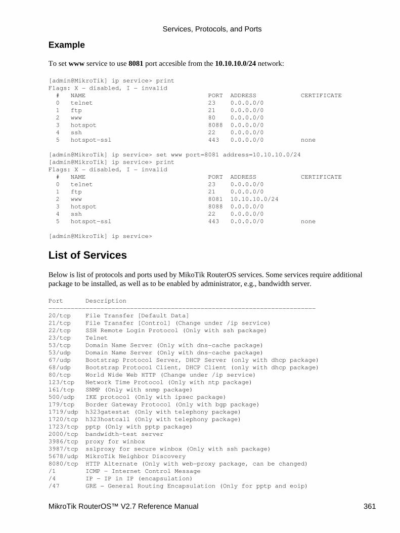
Example
To set www service to use 8081 port accesible from the 10.10.10.0/24 network:
[admin@MikroTik] ip service> printFlags: X − disabled, I − invalid # NAME PORT ADDRESS CERTIFICATE 0 telnet 23 0.0.0.0/0 1 ftp 21 0.0.0.0/0 2 www 80 0.0.0.0/0 3 hotspot 8088 0.0.0.0/0 4 ssh 22 0.0.0.0/0 5 hotspot−ssl 443 0.0.0.0/0 none
[admin@MikroTik] ip service> set www port=8081 address=10.10.10.0/24[admin@MikroTik] ip service> printFlags: X − disabled, I − invalid # NAME PORT ADDRESS CERTIFICATE 0 telnet 23 0.0.0.0/0 1 ftp 21 0.0.0.0/0 2 www 8081 10.10.10.0/24 3 hotspot 8088 0.0.0.0/0 4 ssh 22 0.0.0.0/0 5 hotspot−ssl 443 0.0.0.0/0 none
[admin@MikroTik] ip service>
List of Services
Below is list of protocols and ports used by MikoTik RouterOS services. Some services require additionalpackage to be installed, as well as to be enabled by administrator, e.g., bandwidth server.
Port Description−−−−−−−−−−−−−−−−−−−−−−−−−−−−−−−−−−−−−−−−−−−−−−−−−−−−−−−−−−−−−−−−−−−−−−−−20/tcp File Transfer [Default Data]21/tcp File Transfer [Control] (Change under /ip service)22/tcp SSH Remote Login Protocol (Only with ssh package)23/tcp Telnet53/tcp Domain Name Server (Only with dns−cache package)53/udp Domain Name Server (Only with dns−cache package)67/udp Bootstrap Protocol Server, DHCP Server (only with dhcp package)68/udp Bootstrap Protocol Client, DHCP Client (only with dhcp package)80/tcp World Wide Web HTTP (Change under /ip service)123/tcp Network Time Protocol (Only with ntp package)161/tcp SNMP (Only with snmp package)500/udp IKE protocol (Only with ipsec package)179/tcp Border Gateway Protocol (Only with bgp package)1719/udp h323gatestat (Only with telephony package)1720/tcp h323hostcall (Only with telephony package)1723/tcp pptp (Only with pptp package)2000/tcp bandwidth−test server3986/tcp proxy for winbox3987/tcp sslproxy for secure winbox (Only with ssh package)5678/udp MikroTik Neighbor Discovery8080/tcp HTTP Alternate (Only with web−proxy package, can be changed)/1 ICMP − Internet Control Message/4 IP − IP in IP (encapsulation)/47 GRE − General Routing Encapsulation (Only for pptp and eoip)
Services, Protocols, and Ports
MikroTik RouterOS™ V2.7 Reference Manual 361

/50 ESP − Encap Security Payload for IPv6 (Only with ipsec package)/51 AH − Authentication Header for IPv6 (Only with ipsec package)/89 OSPFIGP − OSPF Interior Gateway Protocol−−−−−−−−−−−−−−−−−−−−−−−−−−−−−−−−−−−−−−−−−−−−−−−−−−−−−−−−−−−−−−−−−−−−−−−−
Additional Resources
Complete list of protocol numbers can be found at http://www.iana.org/assignments/protocol−numbersComplete list of port numbers can be found at http://www.iana.org/assignments/port−numbers
© Copyright 1999−2003, MikroTik
Services, Protocols, and Ports
MikroTik RouterOS™ V2.7 Reference Manual 362

Universal Client InterfaceDocument revision 1.2 (01−Jun−2003)This document applies to MikroTik RouterOS v2.7
Table of Contents
Table of Contents• Summary• Specifications• Related Documents• Description• Universal Client Interface Setup
Property Description♦ Example♦
•
Universal Client ListDescription♦ Property Description♦ Example♦
•
Service PortDescription♦ Property Description♦ Example♦
•
Summary
Universal Client Interface allows to work with clients regardless of their IP addresses translating theseaddresses to the ones you are able to work with. It gives a possibility to provide network access (for example,Internet access) to mobile clients that are not willing to change their networking settings. The feature isintended to use with HotSpot, but may be useful even without HotSpot.
Specifications
Packages required : hotspotLicense required : AnyHome menu level : /ip hotspot universalProtocols utilized : NoneHardware usage: not significant
Related Documents
Software Package Installation and UpgradingIP Addresses and Address Resolution Protocol (ARP)IP PoolsDHCP Client and DHCP ServerHotSpot GatewayFirewall Filters and Network Address Translation (NAT)
MikroTik RouterOS™ V2.7 Reference Manual 363
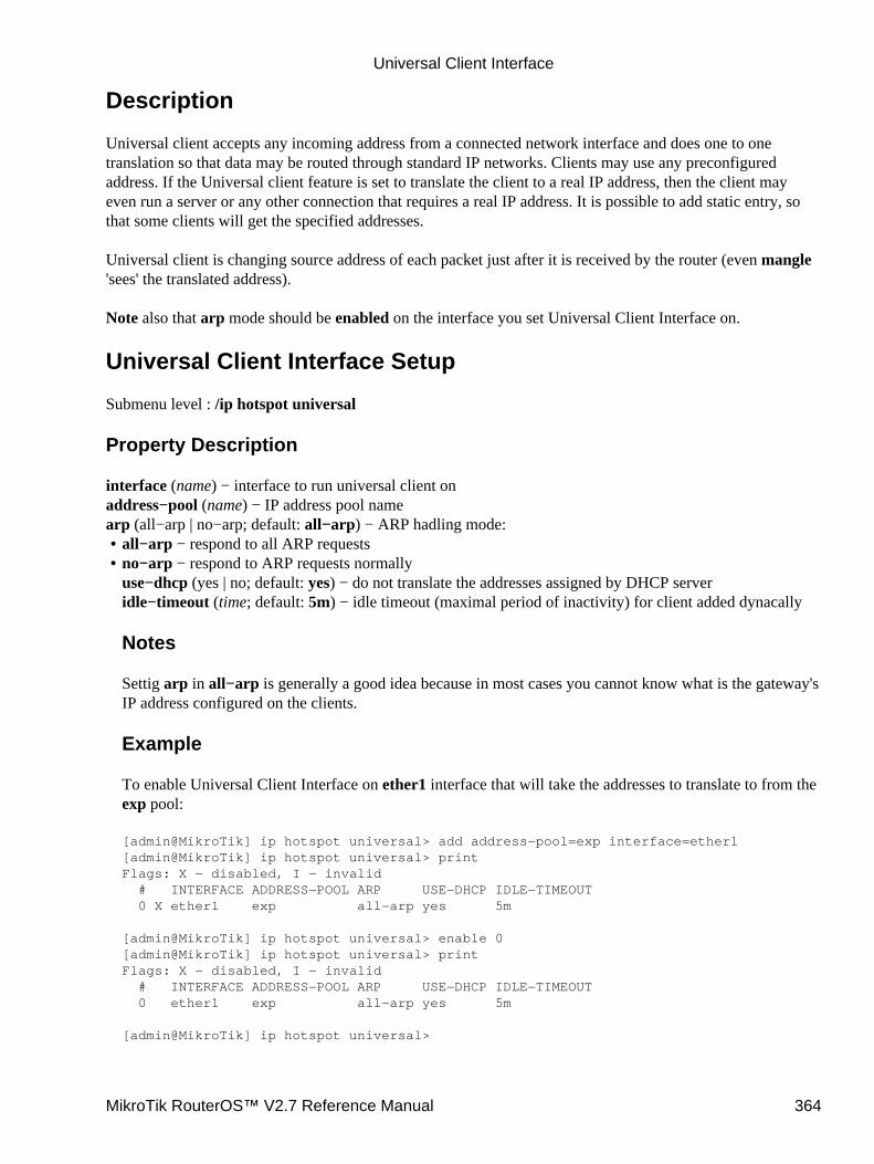
Description
Universal client accepts any incoming address from a connected network interface and does one to onetranslation so that data may be routed through standard IP networks. Clients may use any preconfiguredaddress. If the Universal client feature is set to translate the client to a real IP address, then the client mayeven run a server or any other connection that requires a real IP address. It is possible to add static entry, sothat some clients will get the specified addresses.
Universal client is changing source address of each packet just after it is received by the router (even mangle'sees' the translated address).
Note also that arp mode should be enabled on the interface you set Universal Client Interface on.
Universal Client Interface Setup
Submenu level : /ip hotspot universal
Property Description
interface (name) − interface to run universal client onaddress−pool (name) − IP address pool namearp (all−arp | no−arp; default: all−arp) − ARP hadling mode:
all−arp − respond to all ARP requests• no−arp − respond to ARP requests normallyuse−dhcp (yes | no; default: yes) − do not translate the addresses assigned by DHCP serveridle−timeout (time; default: 5m) − idle timeout (maximal period of inactivity) for client added dynacally
Notes
Settig arp in all−arp is generally a good idea because in most cases you cannot know what is the gateway'sIP address configured on the clients.
Example
To enable Universal Client Interface on ether1 interface that will take the addresses to translate to from theexp pool:
[admin@MikroTik] ip hotspot universal> add address−pool=exp interface=ether1[admin@MikroTik] ip hotspot universal> printFlags: X − disabled, I − invalid # INTERFACE ADDRESS−POOL ARP USE−DHCP IDLE−TIMEOUT 0 X ether1 exp all−arp yes 5m
[admin@MikroTik] ip hotspot universal> enable 0[admin@MikroTik] ip hotspot universal> printFlags: X − disabled, I − invalid # INTERFACE ADDRESS−POOL ARP USE−DHCP IDLE−TIMEOUT 0 ether1 exp all−arp yes 5m
[admin@MikroTik] ip hotspot universal>
•
Universal Client Interface
MikroTik RouterOS™ V2.7 Reference Manual 364
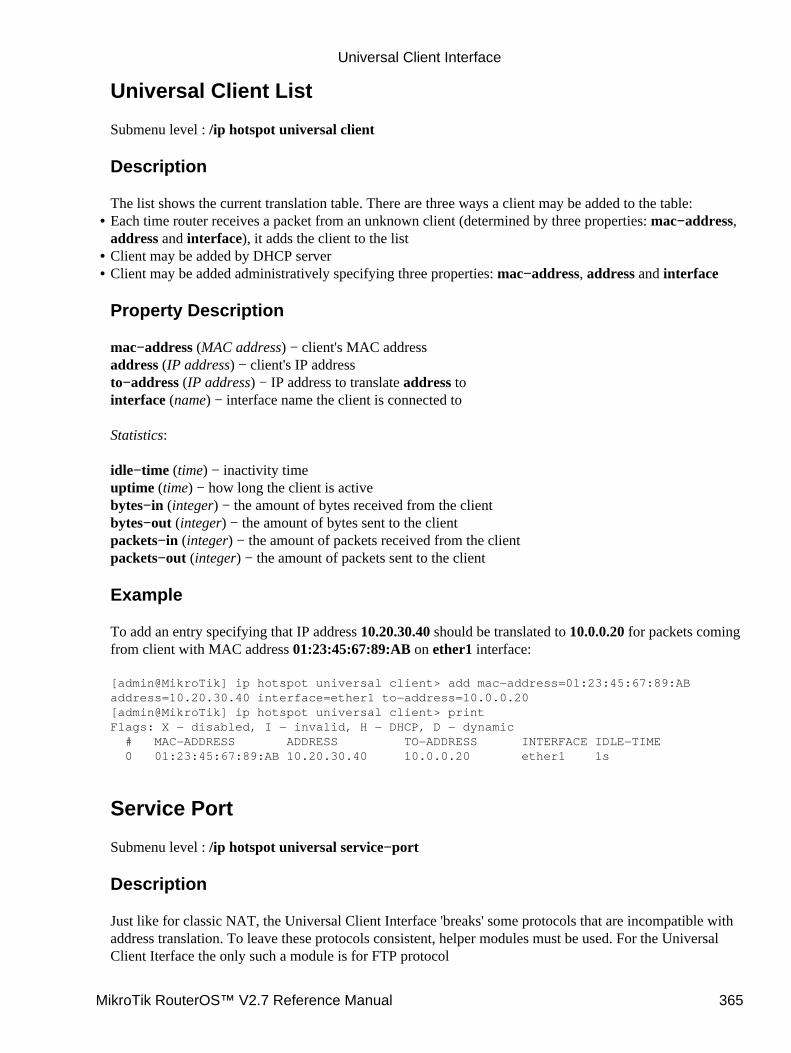
Universal Client List
Submenu level : /ip hotspot universal client
Description
The list shows the current translation table. There are three ways a client may be added to the table:Each time router receives a packet from an unknown client (determined by three properties: mac−address,address and interface), it adds the client to the list
•
Client may be added by DHCP server• Client may be added administratively specifying three properties: mac−address, address and interface
Property Description
mac−address (MAC address) − client's MAC addressaddress (IP address) − client's IP addressto−address (IP address) − IP address to translate address tointerface (name) − interface name the client is connected to
Statistics:
idle−time (time) − inactivity timeuptime (time) − how long the client is activebytes−in (integer) − the amount of bytes received from the clientbytes−out (integer) − the amount of bytes sent to the clientpackets−in (integer) − the amount of packets received from the clientpackets−out (integer) − the amount of packets sent to the client
Example
To add an entry specifying that IP address 10.20.30.40 should be translated to 10.0.0.20 for packets comingfrom client with MAC address 01:23:45:67:89:AB on ether1 interface:
[admin@MikroTik] ip hotspot universal client> add mac−address=01:23:45:67:89:ABaddress=10.20.30.40 interface=ether1 to−address=10.0.0.20[admin@MikroTik] ip hotspot universal client> printFlags: X − disabled, I − invalid, H − DHCP, D − dynamic # MAC−ADDRESS ADDRESS TO−ADDRESS INTERFACE IDLE−TIME 0 01:23:45:67:89:AB 10.20.30.40 10.0.0.20 ether1 1s
Service Port
Submenu level : /ip hotspot universal service−port
Description
Just like for classic NAT, the Universal Client Interface 'breaks' some protocols that are incompatible withaddress translation. To leave these protocols consistent, helper modules must be used. For the UniversalClient Iterface the only such a module is for FTP protocol
•
Universal Client Interface
MikroTik RouterOS™ V2.7 Reference Manual 365
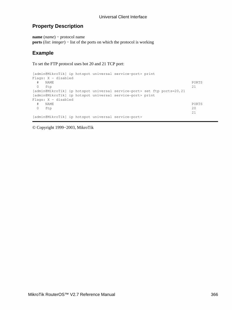
Property Description
name (name) − protocol nameports (list: integer) − list of the ports on which the protocol is working
Example
To set the FTP protocol uses bot 20 and 21 TCP port:
[admin@MikroTik] ip hotspot universal service−port> printFlags: X − disabled # NAME PORTS 0 ftp 21[admin@MikroTik] ip hotspot universal service−port> set ftp ports=20,21[admin@MikroTik] ip hotspot universal service−port> printFlags: X − disabled # NAME PORTS 0 ftp 20 21[admin@MikroTik] ip hotspot universal service−port>
© Copyright 1999−2003, MikroTik
Universal Client Interface
MikroTik RouterOS™ V2.7 Reference Manual 366
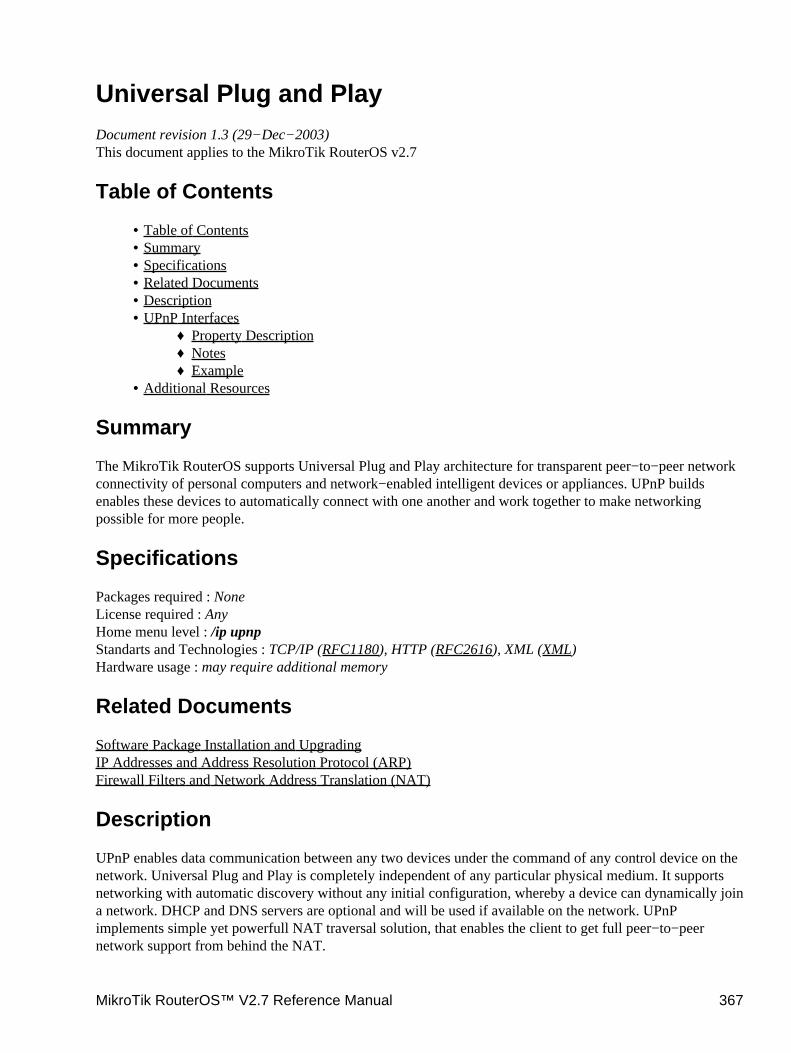
Universal Plug and PlayDocument revision 1.3 (29−Dec−2003)This document applies to the MikroTik RouterOS v2.7
Table of Contents
Table of Contents• Summary• Specifications• Related Documents• Description• UPnP Interfaces
Property Description♦ Notes♦ Example♦
•
Additional Resources•
Summary
The MikroTik RouterOS supports Universal Plug and Play architecture for transparent peer−to−peer networkconnectivity of personal computers and network−enabled intelligent devices or appliances. UPnP buildsenables these devices to automatically connect with one another and work together to make networkingpossible for more people.
Specifications
Packages required : NoneLicense required : AnyHome menu level : /ip upnpStandarts and Technologies : TCP/IP (RFC1180), HTTP (RFC2616), XML (XML)Hardware usage : may require additional memory
Related Documents
Software Package Installation and UpgradingIP Addresses and Address Resolution Protocol (ARP)Firewall Filters and Network Address Translation (NAT)
Description
UPnP enables data communication between any two devices under the command of any control device on thenetwork. Universal Plug and Play is completely independent of any particular physical medium. It supportsnetworking with automatic discovery without any initial configuration, whereby a device can dynamically joina network. DHCP and DNS servers are optional and will be used if available on the network. UPnPimplements simple yet powerfull NAT traversal solution, that enables the client to get full peer−to−peernetwork support from behind the NAT.
MikroTik RouterOS™ V2.7 Reference Manual 367

There are two interface types for UPnP: internal (the one local clients are connected to) and external (the onethe Internet is connected to). A router may only have one external interface with a 'public' IP address on it,and as many internal IP addresses as needed, all with source−NATted 'internal' IP addresses.
The UPnP protocol is used for most of DirectX games as well as for various Windows Messenger features(remote asisstance, application sharing, file transfer, voice, video) from behind a firewall.
Enabling Universal Plug−n−Play
Submenu level : /ip upnp
Property Description
enabled (yes | no; default: no) − whether UPnP feature is enabled
Example
To enable UPnP feature:
[admin@MikroTik] ip upnp> set enable=yes[admin@MikroTik] ip upnp> print enabled: yes[admin@MikroTik] ip upnp>
UPnP Interfaces
Submenu level : /ip upnp interfaces
Property Description
interface (name) − interface name UPnP will be run ontype (external | internal | unused) − interface type, one of the:
external − the interface global IP address is assigned to• internal − router's local interface• unused − the interface is not used by UPnP
Notes
It is highly recommended to upgrade DirectX runtime libraries to version 9.0a DirectX 9.0 and WindowsMessenger to version 5.0 Windows Messenger 5.0 in order to get things to work properly.
Example
Suppose we have a following example:
•
Universal Plug and Play
MikroTik RouterOS™ V2.7 Reference Manual 368
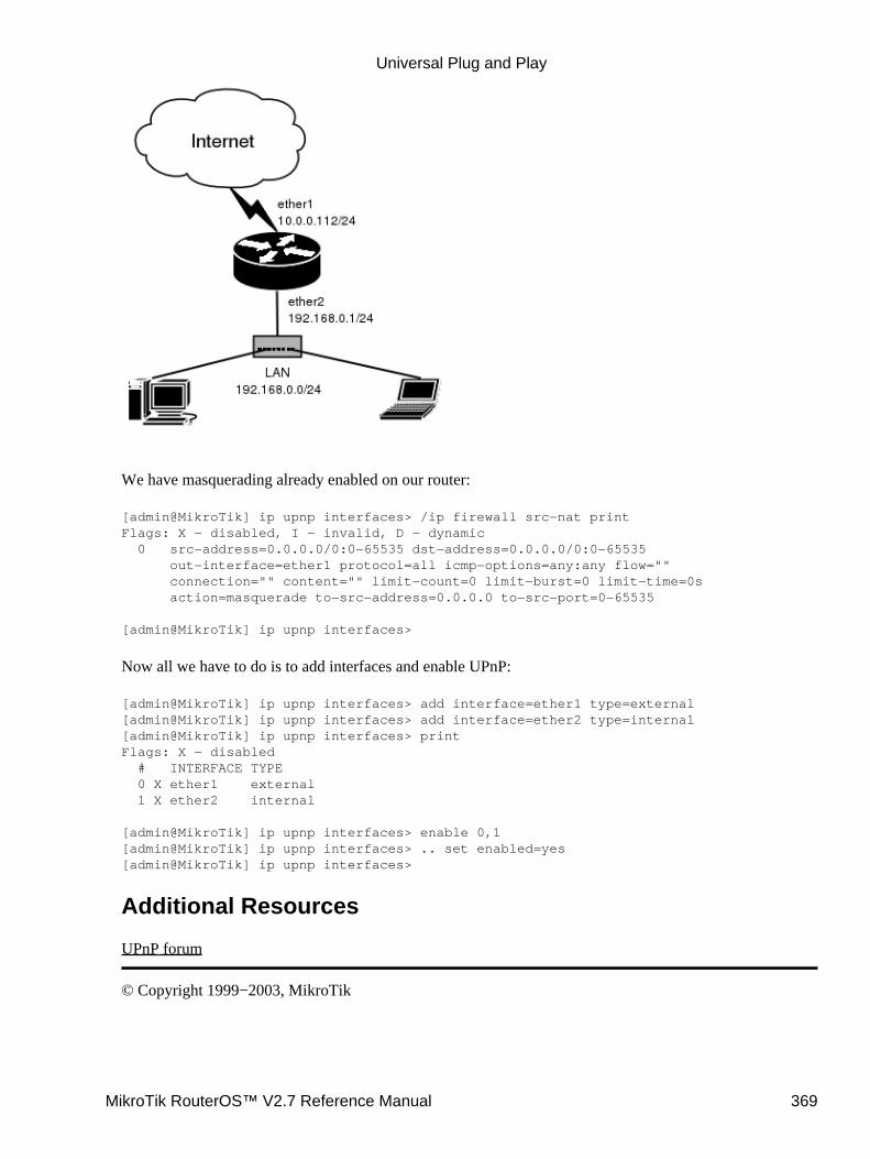
We have masquerading already enabled on our router:
[admin@MikroTik] ip upnp interfaces> /ip firewall src−nat printFlags: X − disabled, I − invalid, D − dynamic 0 src−address=0.0.0.0/0:0−65535 dst−address=0.0.0.0/0:0−65535 out−interface=ether1 protocol=all icmp−options=any:any flow="" connection="" content="" limit−count=0 limit−burst=0 limit−time=0s action=masquerade to−src−address=0.0.0.0 to−src−port=0−65535
[admin@MikroTik] ip upnp interfaces>
Now all we have to do is to add interfaces and enable UPnP:
[admin@MikroTik] ip upnp interfaces> add interface=ether1 type=external[admin@MikroTik] ip upnp interfaces> add interface=ether2 type=internal[admin@MikroTik] ip upnp interfaces> printFlags: X − disabled # INTERFACE TYPE 0 X ether1 external 1 X ether2 internal
[admin@MikroTik] ip upnp interfaces> enable 0,1[admin@MikroTik] ip upnp interfaces> .. set enabled=yes[admin@MikroTik] ip upnp interfaces>
Additional Resources
UPnP forum
© Copyright 1999−2003, MikroTik
Universal Plug and Play
MikroTik RouterOS™ V2.7 Reference Manual 369

WEB ProxyDocument revision 1.3 (12−Nov−2003)This document applies to MikroTik RouterOS v2.7
Table of Contents
Table of Contents• Summary• Specifications• Related Documents• Description• MikroTik Web Proxy Setup
Proprety Description♦ Notes♦ Example♦
•
Monitoring the Web ProxyProperty Description♦ Example♦
•
Access ListDescription♦ Property Description♦ Notes♦ Examples♦
•
Direct Access ListDescription♦ Property Description♦ Notes♦
•
Managing the CacheDescription♦ Proprety Description♦ Notes♦
•
Rebuilding the CacheDescription♦ Example♦
•
Setup Example• Transparent Mode• Troubleshooting•
Summary
The MikroTik RouterOS has the squid proxy server implementation.
Proxy server features:
Regular http proxy• Transparent proxy. Can be transparent and regular at the same time• Access list by source, destination, URL and requested method• Cache access list (specifies which objects to cache, and which not)•
MikroTik RouterOS™ V2.7 Reference Manual 370
Direct Access List (specifies which resources should be accessed directly, and which − through ananother proxy server)
•
Logging facility•
Specifications
Packages required : web−proxyLicense required : BasicHome menu level : /ip web−proxyProtocols utilized : HTTP/1.0 (RFC1945), HTTP/1.1 (RFC2616), FTP (RFC959)Hardware usage: uses disk space, if available (see description below)
Related Documents
Software Package Installation and UpgradingIP Addresses and Address Resolution Protocol (ARP)Firewall Filters and Network Address Translation (NAT)Log Management
Description
The web proxy can be used as transparent and normal web proxy at the same time. In transparent mode it ispossible to use it as standard web proxy, too. However, in this case, proxy users may have trouble to reachweb pages which are accessed transparently.
When setting up Web proxy, make sure it serves only your clients, and is not misused as relay. Please read thesecurity notice in the Access List Section!
Note that it may be useful to have Web proxy running even with no cache when you want to use it assomething like HTTP and FTP firewall (for example, denying access to mp3 files) or to redirect requests toexternal proxy transparently
MikroTik Web Proxy Setup
Submenu level : /ip web−proxy
[admin@MikroTik] ip web−proxy> print enabled: no address: 0.0.0.0:3128 hostname: "" transparent−proxy: no parent−proxy: 0.0.0.0:0 cache−administrator: "webmaster" max−object−size: 4096 kB max−cache−size: unlimited status: stopped reserved−for−cache: 10240 kB[admin@MikroTik] ip web−proxy>
WEB Proxy
MikroTik RouterOS™ V2.7 Reference Manual 371
Proprety Description
enabled (yes | no, default: no) − whether web−proxy is enabled or notaddress (IP address:port, default: 0.0.0.0:3128) − IP address (0.0.0.0 for any) and port (mandatory) on whichproxy will be listening for requestshostname (string, default: "") − hostname (DNS or IP address) of the web proxytransparent−proxy (yes | no, default: no) − use transparent modeparent−proxy (IP address:port, default: 0.0.0.0:0) − upper−level proxy
0.0.0.0:0 − disables parent proxy servermax−object−size (integer, default: 4096) − objects larger than this size will not be saved on disk. Thevalue is specified in kilobytes. If you wish to get a high bytes hit ratio, you should probably increase this(one 32 MB object hit counts for 3200 10KB hits). If you wish to increase speed more than your want tosave bandwidth you should leave this lowmax−cache−size (none | unlimited | integer) − maximal cache size in MB
•
none − web proxy will not use cache• unlimited − web proxy will use as much drivespace, as possible
Statistics:
status (string) − displays status of the proxy server:
•
stopped − proxy is disabled and is not running• rebuilding−cache − proxy is enabled and running, existing cache is being verified• running − proxy is enabled and running• stopping − proxy is shutting down (max 10s)• clearing−cache − proxy is stopped, cache files are being removed• creating−cache − proxy is stopped, cache directory structure is being created• dns−missing − proxy is enabled, but not running because of unknown DNS server (you should specify itunder /ip dns)
•
invalid−address − proxy is enabled, but not running because of invalid address (you should change addressor port)
•
invalid−cache−administrator − proxy is enabled, but not running because of invalidcache−administrator's e−mail address
•
invalid−hostname − proxy is enabled, but not running because of invalid hostname (you should set a validhostname value)
•
error−logged − proxy is not running because of unknown error. This error is logged as System−Error.Please, send us this error and some description, how it happenedreserved−for−cache (integer) − maximal cache size, that is accessible to web−proxy
Notes
By default the proxy cache can use as much disk space as there is allocated for it. When the systemallocates the space for the proxy cache, 1/7th of the total partition (disk) size is reserved for the system, butnot less than 50MB. The rest is left for the proxy cache. The system RAM size is considered as well whenallocating the cache size. The cache size is limited so, that there are at least 11.2MB of RAM per 1GB ofcache plus 32MB of RAM is reserved for the system. max−cache−size is also taken in account, so thecache will not occupy more than it is specified in this property. The effective limit is calculated as aminimum of all three limits.
Expire time of cache entries can be different for each HTML page (specified in headers). But, if there is nosuch header, the entry will be considered fresh for max 72 hours.
•
WEB Proxy
MikroTik RouterOS™ V2.7 Reference Manual 372
Example
To enable the proxy on port 8080:
[admin@MikroTik] ip web−proxy> set enabled=yes address=0.0.0.0:8080[admin@MikroTik] ip web−proxy> print enabled: yes address: 0.0.0.0:8080 hostname: "" transparent−proxy: no parent−proxy: 0.0.0.0:0 cache−administrator: "webmaster" max−object−size: 4096 kB max−cache−size: unlimited status: rebuilding−cache reserved−for−cache: 10240 kB[admin@MikroTik] ip web−proxy>
Monitoring the Web Proxy
Command name : /ip web−proxy monitor
Property Description
Statistics:
status (string) − the same as for /ip web−proxy printuptime (time) − uptime of the proxy serverclients (integer) − number of present and past proxy clients with different IP addresses (in current uptime)requests (integer) − total number of requests to the proxy (in current uptime)hits (integer) − number of requests satisfied with proxy's cache (in current uptime)cache−size (integer) − current cache size in kilobytesreceived−from−servers (integer) − how many kilobytes did proxy receive from remote servers (in currentuptime)sent−to−clients (integer) − how many kilobytes did proxy send to the clients to resolve their requests (incurrent uptime)hits−sent−to−clients (integer) − how many kilobytes of sent traffic were taken from the cache (in currentuptime)
Example
To monitor the web proxy:
[admin@MikroTik] > ip web−proxy monitor status: running uptime: 4d19h8m14s clients: 9 requests: 10242 hits: 3839 cache−size: 328672 kB received−from−servers: 58108 kB sent−to−clients: 65454 kB hits−sent−to−clients: 7552 kB
WEB Proxy
MikroTik RouterOS™ V2.7 Reference Manual 373
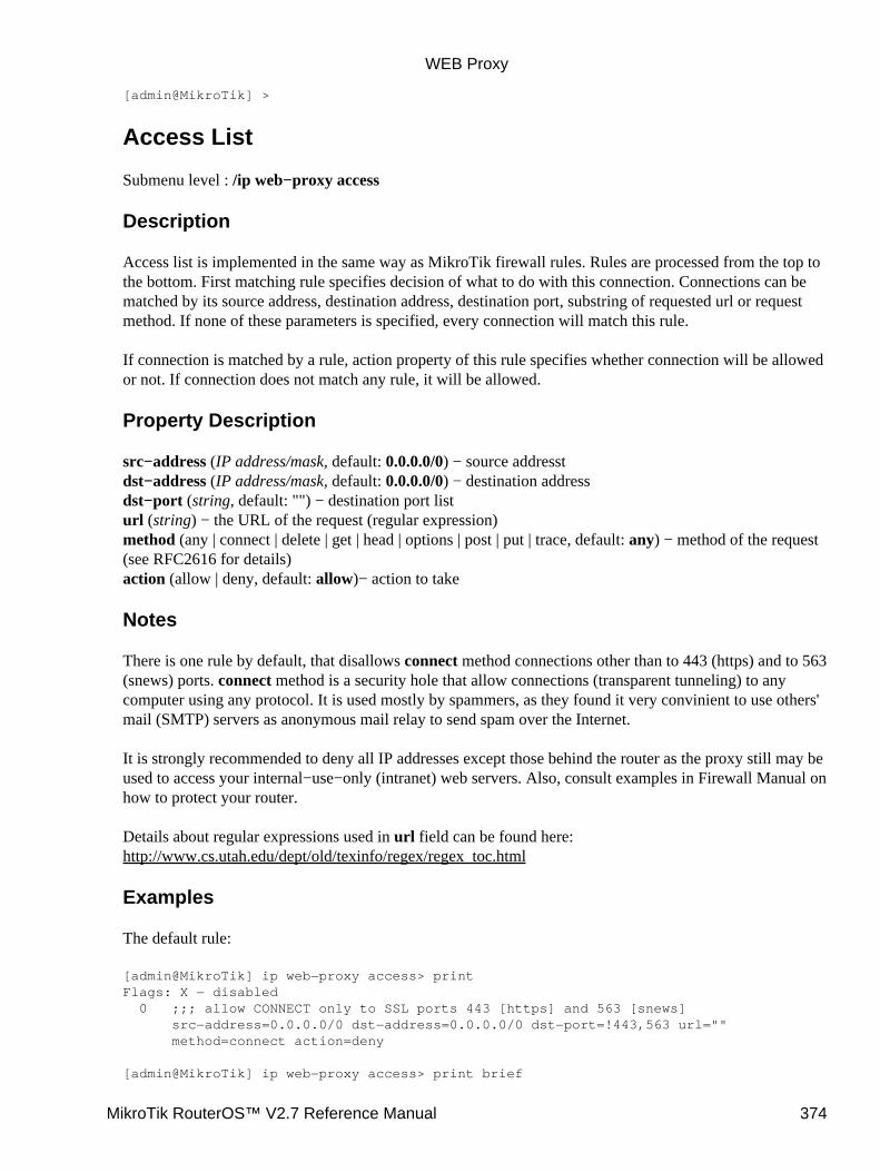
[admin@MikroTik] >
Access List
Submenu level : /ip web−proxy access
Description
Access list is implemented in the same way as MikroTik firewall rules. Rules are processed from the top tothe bottom. First matching rule specifies decision of what to do with this connection. Connections can bematched by its source address, destination address, destination port, substring of requested url or requestmethod. If none of these parameters is specified, every connection will match this rule.
If connection is matched by a rule, action property of this rule specifies whether connection will be allowedor not. If connection does not match any rule, it will be allowed.
Property Description
src−address (IP address/mask, default: 0.0.0.0/0) − source addresstdst−address (IP address/mask, default: 0.0.0.0/0) − destination addressdst−port (string, default: "") − destination port listurl (string) − the URL of the request (regular expression)method (any | connect | delete | get | head | options | post | put | trace, default: any) − method of the request(see RFC2616 for details)action (allow | deny, default: allow)− action to take
Notes
There is one rule by default, that disallows connect method connections other than to 443 (https) and to 563(snews) ports. connect method is a security hole that allow connections (transparent tunneling) to anycomputer using any protocol. It is used mostly by spammers, as they found it very convinient to use others'mail (SMTP) servers as anonymous mail relay to send spam over the Internet.
It is strongly recommended to deny all IP addresses except those behind the router as the proxy still may beused to access your internal−use−only (intranet) web servers. Also, consult examples in Firewall Manual onhow to protect your router.
Details about regular expressions used in url field can be found here:http://www.cs.utah.edu/dept/old/texinfo/regex/regex_toc.html
Examples
The default rule:
[admin@MikroTik] ip web−proxy access> printFlags: X − disabled 0 ;;; allow CONNECT only to SSL ports 443 [https] and 563 [snews] src−address=0.0.0.0/0 dst−address=0.0.0.0/0 dst−port=!443,563 url="" method=connect action=deny
[admin@MikroTik] ip web−proxy access> print brief
WEB Proxy
MikroTik RouterOS™ V2.7 Reference Manual 374
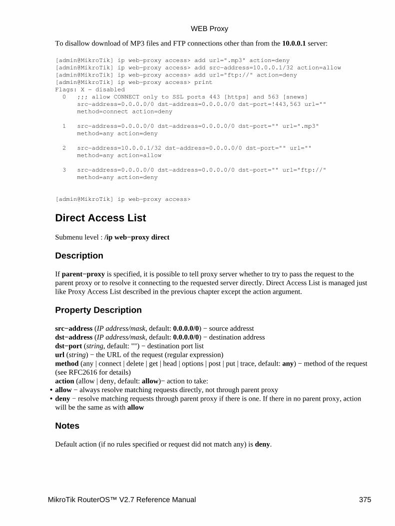
To disallow download of MP3 files and FTP connections other than from the 10.0.0.1 server:
[admin@MikroTik] ip web−proxy access> add url=".mp3" action=deny[admin@MikroTik] ip web−proxy access> add src−address=10.0.0.1/32 action=allow[admin@MikroTik] ip web−proxy access> add url="ftp://" action=deny[admin@MikroTik] ip web−proxy access> printFlags: X − disabled 0 ;;; allow CONNECT only to SSL ports 443 [https] and 563 [snews] src−address=0.0.0.0/0 dst−address=0.0.0.0/0 dst−port=!443,563 url="" method=connect action=deny
1 src−address=0.0.0.0/0 dst−address=0.0.0.0/0 dst−port="" url=".mp3" method=any action=deny
2 src−address=10.0.0.1/32 dst−address=0.0.0.0/0 dst−port="" url="" method=any action=allow
3 src−address=0.0.0.0/0 dst−address=0.0.0.0/0 dst−port="" url="ftp://" method=any action=deny
[admin@MikroTik] ip web−proxy access>
Direct Access List
Submenu level : /ip web−proxy direct
Description
If parent−proxy is specified, it is possible to tell proxy server whether to try to pass the request to theparent proxy or to resolve it connecting to the requested server directly. Direct Access List is managed justlike Proxy Access List described in the previous chapter except the action argument.
Property Description
src−address (IP address/mask, default: 0.0.0.0/0) − source addresstdst−address (IP address/mask, default: 0.0.0.0/0) − destination addressdst−port (string, default: "") − destination port listurl (string) − the URL of the request (regular expression)method (any | connect | delete | get | head | options | post | put | trace, default: any) − method of the request(see RFC2616 for details)action (allow | deny, default: allow)− action to take:allow − always resolve matching requests directly, not through parent proxy• deny − resolve matching requests through parent proxy if there is one. If there in no parent proxy, actionwill be the same as with allow
Notes
Default action (if no rules specified or request did not match any) is deny.
•
WEB Proxy
MikroTik RouterOS™ V2.7 Reference Manual 375
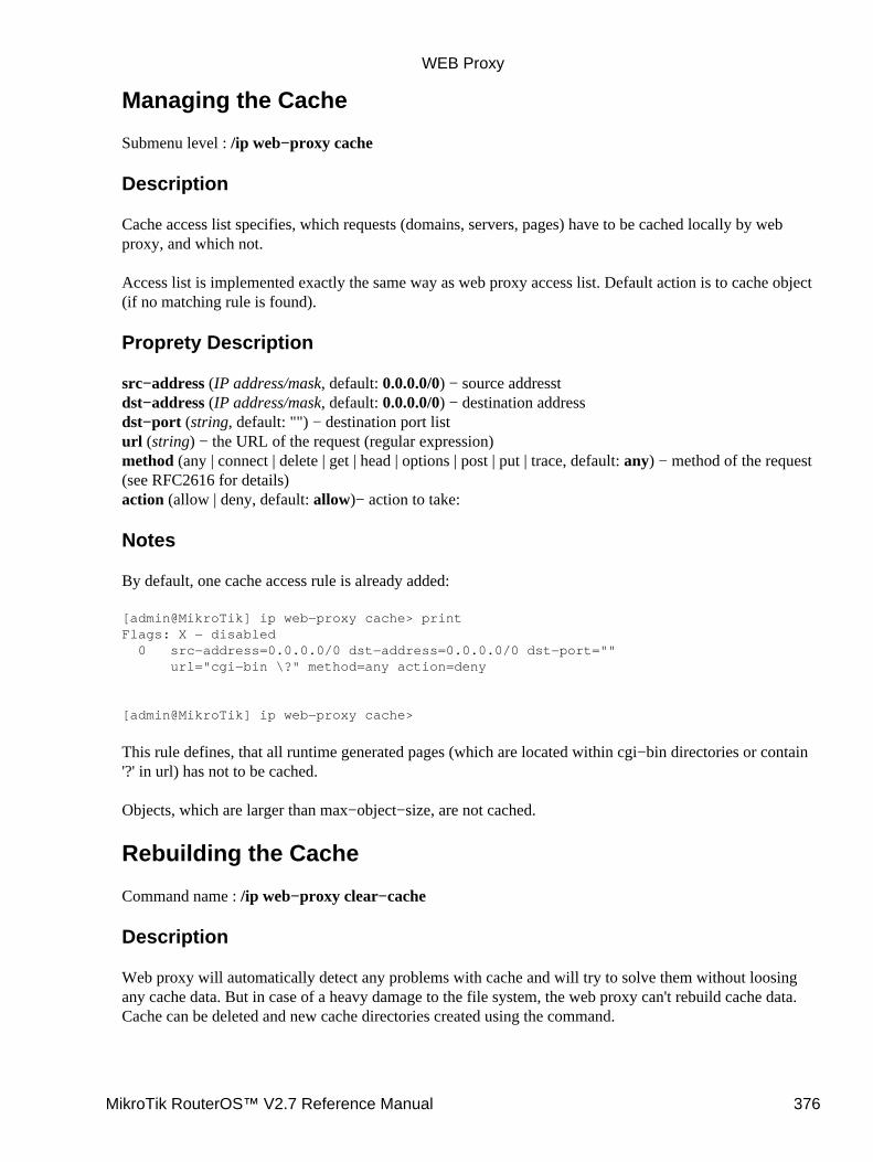
Managing the Cache
Submenu level : /ip web−proxy cache
Description
Cache access list specifies, which requests (domains, servers, pages) have to be cached locally by webproxy, and which not.
Access list is implemented exactly the same way as web proxy access list. Default action is to cache object(if no matching rule is found).
Proprety Description
src−address (IP address/mask, default: 0.0.0.0/0) − source addresstdst−address (IP address/mask, default: 0.0.0.0/0) − destination addressdst−port (string, default: "") − destination port listurl (string) − the URL of the request (regular expression)method (any | connect | delete | get | head | options | post | put | trace, default: any) − method of the request(see RFC2616 for details)action (allow | deny, default: allow)− action to take:
Notes
By default, one cache access rule is already added:
[admin@MikroTik] ip web−proxy cache> printFlags: X − disabled 0 src−address=0.0.0.0/0 dst−address=0.0.0.0/0 dst−port="" url="cgi−bin \?" method=any action=deny
[admin@MikroTik] ip web−proxy cache>
This rule defines, that all runtime generated pages (which are located within cgi−bin directories or contain'?' in url) has not to be cached.
Objects, which are larger than max−object−size, are not cached.
Rebuilding the Cache
Command name : /ip web−proxy clear−cache
Description
Web proxy will automatically detect any problems with cache and will try to solve them without loosingany cache data. But in case of a heavy damage to the file system, the web proxy can't rebuild cache data.Cache can be deleted and new cache directories created using the command.
WEB Proxy
MikroTik RouterOS™ V2.7 Reference Manual 376
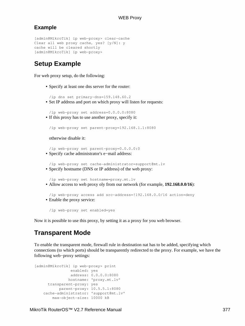
Example
[admin@MikroTik] ip web−proxy> clear−cacheClear all web proxy cache, yes? [y/N]: ycache will be cleared shortly[admin@MikroTik] ip web−proxy>
Setup Example
For web proxy setup, do the following:
Specify at least one dns server for the router:
/ip dns set primary−dns=159.148.60.2
•
Set IP address and port on which proxy will listen for requests:
/ip web−proxy set address=0.0.0.0:8080
•
If this proxy has to use another proxy, specify it:
/ip web−proxy set parent−proxy=192.168.1.1:8080
otherwise disable it:
/ip web−proxy set parent−proxy=0.0.0.0:0
•
Specify cache administrator's e−mail address:
/ip web−proxy set cache−[email protected]
•
Specify hostname (DNS or IP address) of the web proxy:
/ip web−proxy set hostname=proxy.mt.lv
•
Allow access to web proxy oly from our network (for example, 192.168.0.0/16):
/ip web−proxy access add src−address=!192.168.0.0/16 action=deny
•
Enable the proxy service:
/ip web−proxy set enabled=yes
•
Now it is possible to use this proxy, by setting it as a proxy for you web browser.
Transparent Mode
To enable the transparent mode, firewall rule in destination nat has to be added, specifying whichconnections (to which ports) should be transparently redirected to the proxy. For example, we have thefollowing web−proxy settings:
[admin@MikroTik] ip web−proxy> print enabled: yes address: 0.0.0.0:8080 hostname: "proxy.mt.lv" transparent−proxy: yes parent−proxy: 10.5.5.1:8080 cache−administrator: "[email protected]" max−object−size: 10000 kB
WEB Proxy
MikroTik RouterOS™ V2.7 Reference Manual 377
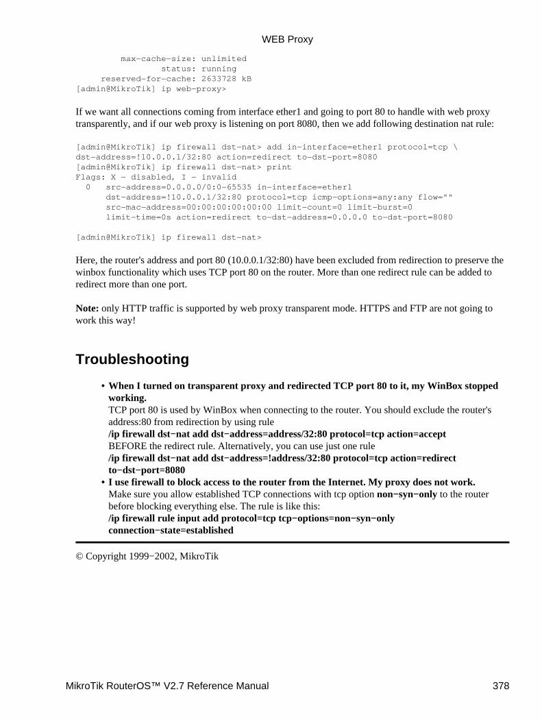
max−cache−size: unlimited status: running reserved−for−cache: 2633728 kB[admin@MikroTik] ip web−proxy>
If we want all connections coming from interface ether1 and going to port 80 to handle with web proxytransparently, and if our web proxy is listening on port 8080, then we add following destination nat rule:
[admin@MikroTik] ip firewall dst−nat> add in−interface=ether1 protocol=tcp \dst−address=!10.0.0.1/32:80 action=redirect to−dst−port=8080[admin@MikroTik] ip firewall dst−nat> printFlags: X − disabled, I − invalid 0 src−address=0.0.0.0/0:0−65535 in−interface=ether1 dst−address=!10.0.0.1/32:80 protocol=tcp icmp−options=any:any flow="" src−mac−address=00:00:00:00:00:00 limit−count=0 limit−burst=0 limit−time=0s action=redirect to−dst−address=0.0.0.0 to−dst−port=8080
[admin@MikroTik] ip firewall dst−nat>
Here, the router's address and port 80 (10.0.0.1/32:80) have been excluded from redirection to preserve thewinbox functionality which uses TCP port 80 on the router. More than one redirect rule can be added toredirect more than one port.
Note: only HTTP traffic is supported by web proxy transparent mode. HTTPS and FTP are not going towork this way!
Troubleshooting
When I turned on transparent proxy and redirected TCP port 80 to it, my WinBox stoppedworking.TCP port 80 is used by WinBox when connecting to the router. You should exclude the router'saddress:80 from redirection by using rule/ip firewall dst−nat add dst−address=address/32:80 protocol=tcp action=acceptBEFORE the redirect rule. Alternatively, you can use just one rule/ip firewall dst−nat add dst−address=!address/32:80 protocol=tcp action=redirectto−dst−port=8080
•
I use firewall to block access to the router from the Internet. My proxy does not work.Make sure you allow established TCP connections with tcp option non−syn−only to the routerbefore blocking everything else. The rule is like this:/ip firewall rule input add protocol=tcp tcp−options=non−syn−onlyconnection−state=established
•
© Copyright 1999−2002, MikroTik
WEB Proxy
MikroTik RouterOS™ V2.7 Reference Manual 378

Queues and Data Rate ManagementDocument revision 1.7 (01−Aug−2003)This document applies to MikroTik RouterOS v2.7
Table of Contents
Table of Contents• Summary• Specifications• Related Documents• Description
Classless Queues♦ Classful Queues♦ Information Rates and Contention Ratios♦ Virtual Interfaces♦ Universal Client and Simple Queues♦
•
Queue TypesDescription♦ Property Description♦ Notes♦ Example♦
•
Interface Default QueuesProperty Description♦ Example♦
•
Configuring Simple QueuesDescription♦ Property Description♦ Notes♦ Example♦
•
Configuring Queue TreesDescription♦ Property Description♦ Notes♦ Example♦
•
Troubleshooting• Queue Applications
Example of Emulating a 128k/64k Line♦ Example of Using Masquerading♦ Example of Guaranteed Quality of Service♦
•
Additional Resources•
Summary
Queuing is a mechanism that control data rate allocation, delay variability, timely delivery, and deliveryreliability. The MikroTik RouterOS supports the following queuing mechanisms:
PFIFO − Packets First−In First−Out,BFIFO − Bytes First−In First−Out,
MikroTik RouterOS™ V2.7 Reference Manual 379
SFQ − Stochastic Fair QueuingRED − Random Early DetectionHTB − Hierarchical Token Bucket
The queuing can be used for limiting the data rate for certain IP addresses, protocols or ports. The queuing isperformed for packets leaving the router through a real interface. It means that the queues should always beconfigured on the outgoing interface regarding the traffic flow. There are two additional virtual interfaceswhich are used to limit all the traffic coming to (global−in) or leaving (global−out) the router regardless ofphysical interface.
Specifications
Packages required : systemLicense required : Basic (DEMO license is limited to 4 queues)Home menu level : /queueProtocols utilized : NoneHardware usage: significant
Related Documents
Software Package Installation and UpgradingIP Addresses and Address Resolution Protocol (ARP)Packet Filter (Firewall) and Network Address Translation (NAT)
Description
Classless Queues
There are four types of simple queues implemented in RouterOS: PFIFO, BFIFO, SFQ and RED. With BytesFirst−In First−Out (BFIFO) and Packets First−In First−Out (PFIFO) packets are served in the same order asthey are received. The only difference between BFIFO and PFIFO is that PFIFO has a length measured inpackets, BFIFO in bytes. Generally, you do not want to use BFIFO or PFIFO as traffic shapers. It's better touse them just for statistics as they are pretty fast. The only exception is when you are running out of resourceswith RED and/or with complicated queue tree.
Stochastic Fair Queuing (SFQ) cannot limit traffic at all. Its main idea is to equalize sessions (not computertraffic, but session traffic, it is sometimes mentioned as SFQ drawback) when your link is completely full. Itworks in round−robin fashion, giving each session a chance to send sfq−allot bytes. Its algorithm candistinguish only 1024 sessions, and that is why several sessions can be treated as one. Each sfq−perturbseconds it drops internal table mixing all the connections and creates a new table. As it is very fast, you maywant to use it as a child queue.
The normal behavior of queues is called tail−drop. Tail−drop works by queuing up to a certain amount, thendropping all traffic that 'spills over'. Random Early Detection (RED is also known as Random Early Dropbecause it actually works that way) statistically drops packets from flows before it reaches its hard limit. Thiscauses a congested backbone link to slow more gracefully. It starts dropping packets when threshold reachesred−min−threshold mark randomly with increasing probability as threshold rising. Maximum probability isused when traffic reaches red−max−threshold mark. Then packets are simply thrown away. burst parameteris the number of packets allowed to burst through the interface when the link is empty (generally value of
Queues and Data Rate Management
MikroTik RouterOS™ V2.7 Reference Manual 380
(min+min+max)/3 works fine). The minimum value that can be used here is equal to the value ofred−min−threshold.
Classful Queues
Classful queues are very useful if you have different kinds of traffic which should have different treatment.Generally, we can set only one queue on the interface, but in RouterOS even simple queues (known asclassless queues) are attached to the main (attached to the root, which represent real interface) HierarchicalToken Bucket (HTB) and thus have some properties derived from that parent queue. With classful queues it ispossible to deploy hierarchical queue trees. For example, we can set a maximum data rate for a workgroupand then distribute that amount of traffic between the members of that group as we can do with simple queuesattached to the main HTB, but with upper limit.
Each queue represents a virtual interface with the allowed data rate. It can be borrowed from sibling queues(queues that are children of one queue) when max−limit is greater than limit−at. If so, the queue would useover the allocated data rate whenever possible. Only when other queues are getting too long and a connectionis not to be satisfied, then the borrowing queues would be limited at their allocated data rate.
When a parent is allowed to send some amount of traffic, it asks its inner queues in order of priority(priorities are processed one after another, from 1 to 8, where 1 means the highest priority). When the a queuereached its limit−at value, its priority is not to be taken in account, such a queue will be less−prioritative thanthe ones not reached this limit.
Information Rates and Contention Ratios
Quality of Service (QoS) means that router should prioritize and shape network traffic. QoS is not so muchabout limiting, it is more about providing quality. The main terms used to describe the level of QoS fornetwork applications are:
CIR (Committed Information Rate) − the guaranteed data rate. It means that traffic not exceeding this rateshould always be delivered.
•
MIR (Maximal Information Rate) − the maximal data rate router will provide.• Contention Ratio − the ratio to which the defined data rate is shared between users (i.e., data rate isallocated to a number of subscribers). For example, the contention ratio of 1:4 means that the allocated datarate may be shared between no more than 4 users.
•
Priority − the order of importance in what traffic will be processed. You can give priority to some traffic inorder it to be handeled befor some other traffic.
MikroTik RouterOS may be used to provide CIR and MIR with some contention level and priority. Herewe will talk in terms of queues (which represent either real or virtual interface) and classes (children of aqueue; each class has an another queue attached to it).
•
limit−at property is used to specify CIR. If the queue will be able to provide that data rate, it will (i.e, theparent queue (and the link the router is connected to) should be able to provide the total data rate equal orgreater that the sum of all CIRs the queue should satisfy in order to quarantee these CIRs). CIRs will besatisfied in order of their priority.
•
max−limit property is used to specify MIR. If the queue has satisfied all the CIRs and it is able to providesome additional data rate, it will try to distribute that additional data rate between all its classes regardlessof their priorities and not exceeding their MIRs.
•
Filters in RouterOS are very powerful and flexible. Providing Contention Ratio is only one application ofwhat they can do. Using firewall mangle you can mark some a number of hosts with a flow−mark, so thedata rate allocated for that mark will be shared between these hosts.
•
Queues and Data Rate Management
MikroTik RouterOS™ V2.7 Reference Manual 381
Virtual Interfaces
In addition to real interfaces, there are two vitrual interfaces you can attach queues to:global−out − represents all the output interfaces in general. Queues attached to it applies before the onesattached to a specific interface.
•
global−in − represents all the input interfaces in general (INGRESS queue). Please note that queuesattached to global−in applies to incomming traffic, not outgoing. global−in queueing is taking place justafter mangle and before DST−NAT.
Universal Client and Simple Queues
Universal client should catch traffic when it leaves the router − in order to be able to function properly. Butinterface queues are made to catch the traffic last. Due to this obvious conflict, a not expected behavior(which cannot be considered as a bug, it is just the way interface queues work) is observed: while firewallfilters and virtual interface queues (global−in and global−out) are working with the translated addresses,simple queues attached to the interface Universal Client is functioning on 'see' the original, not translated,IP address. So if it is necessary to match the download (outgoing to the client) traffic by the addressUniversal Client assigns to the client, either global−out queue or queue trees should be used.
Queue Types
Submenu level : /queue type
Description
The queue types are used to specify some common argument values for queues. There are four defaultbuilt−in queue types: default, ethernet−default, wireless−default, and synchronous−default. Thebuilt−in queue types cannot be removed.
Property Description
name (name)− name for the queue typekind (pfifo | bfifo | red | sfq; default: pfifo) − kind of the queuing algorithm used:
•
pfifo − Packets First−In First−Out• bfifo − Bytes First−In First−Out• red − Random Early Detection• sfq − Stochastic Fair Queuingbfifo−limit (integer; default: 15000) − BFIFO queue limit. Maximum packet number that queue can holdpfifo−limit (integer; default: 10) − PFIFO queue limit. Maximum byte number that queue can holdred−limit (integer; default: 60) − RED queue limitred−min−threshold (integer; default: 10) − RED minimum thresholdred−max−threshold (integer; default: 50) − RED maximum thresholdred−burst (integer; default: 20) − RED burstsfq−perturb (integer; default: 5) − how often to change hash functionsfq−allot (integer; default: 1514) − amount of data in bytes that can be sent in one round−robin round
•
Queues and Data Rate Management
MikroTik RouterOS™ V2.7 Reference Manual 382
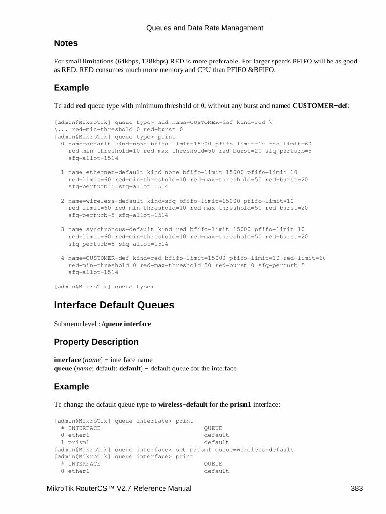
Notes
For small limitations (64kbps, 128kbps) RED is more preferable. For larger speeds PFIFO will be as goodas RED. RED consumes much more memory and CPU than PFIFO &BFIFO.
Example
To add red queue type with minimum threshold of 0, without any burst and named CUSTOMER−def:
[admin@MikroTik] queue type> add name=CUSTOMER−def kind=red \\... red−min−threshold=0 red−burst=0[admin@MikroTik] queue type> print 0 name=default kind=none bfifo−limit=15000 pfifo−limit=10 red−limit=60 red−min−threshold=10 red−max−threshold=50 red−burst=20 sfq−perturb=5 sfq−allot=1514
1 name=ethernet−default kind=none bfifo−limit=15000 pfifo−limit=10 red−limit=60 red−min−threshold=10 red−max−threshold=50 red−burst=20 sfq−perturb=5 sfq−allot=1514
2 name=wireless−default kind=sfq bfifo−limit=15000 pfifo−limit=10 red−limit=60 red−min−threshold=10 red−max−threshold=50 red−burst=20 sfq−perturb=5 sfq−allot=1514
3 name=synchronous−default kind=red bfifo−limit=15000 pfifo−limit=10 red−limit=60 red−min−threshold=10 red−max−threshold=50 red−burst=20 sfq−perturb=5 sfq−allot=1514
4 name=CUSTOMER−def kind=red bfifo−limit=15000 pfifo−limit=10 red−limit=60 red−min−threshold=0 red−max−threshold=50 red−burst=0 sfq−perturb=5 sfq−allot=1514
[admin@MikroTik] queue type>
Interface Default Queues
Submenu level : /queue interface
Property Description
interface (name) − interface namequeue (name; default: default) − default queue for the interface
Example
To change the default queue type to wireless−default for the prism1 interface:
[admin@MikroTik] queue interface> print # INTERFACE QUEUE 0 ether1 default 1 prism1 default[admin@MikroTik] queue interface> set prism1 queue=wireless−default[admin@MikroTik] queue interface> print # INTERFACE QUEUE 0 ether1 default
Queues and Data Rate Management
MikroTik RouterOS™ V2.7 Reference Manual 383
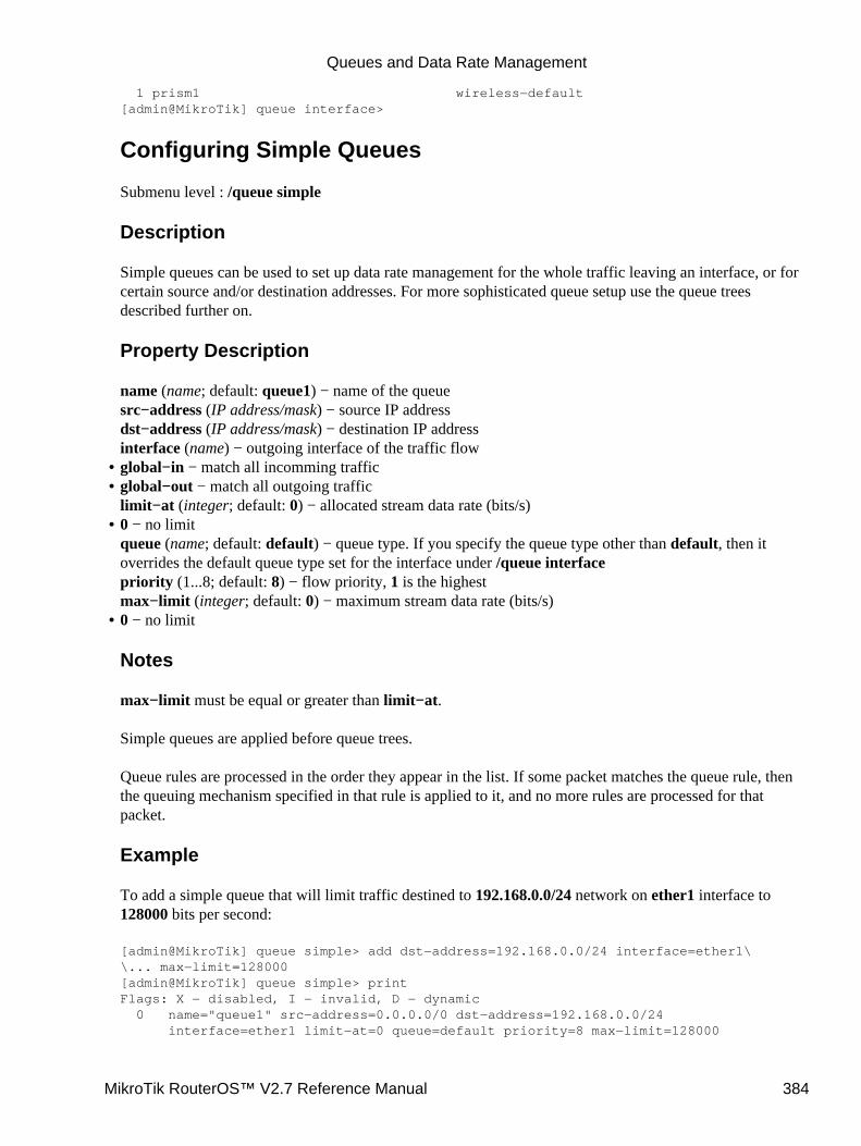
1 prism1 wireless−default[admin@MikroTik] queue interface>
Configuring Simple Queues
Submenu level : /queue simple
Description
Simple queues can be used to set up data rate management for the whole traffic leaving an interface, or forcertain source and/or destination addresses. For more sophisticated queue setup use the queue treesdescribed further on.
Property Description
name (name; default: queue1) − name of the queuesrc−address (IP address/mask) − source IP addressdst−address (IP address/mask) − destination IP addressinterface (name) − outgoing interface of the traffic flowglobal−in − match all incomming traffic• global−out − match all outgoing trafficlimit−at (integer; default: 0) − allocated stream data rate (bits/s)
•
0 − no limitqueue (name; default: default) − queue type. If you specify the queue type other than default, then itoverrides the default queue type set for the interface under /queue interfacepriority (1...8; default: 8) − flow priority, 1 is the highestmax−limit (integer; default: 0) − maximum stream data rate (bits/s)
•
0 − no limit
Notes
max−limit must be equal or greater than limit−at.
Simple queues are applied before queue trees.
Queue rules are processed in the order they appear in the list. If some packet matches the queue rule, thenthe queuing mechanism specified in that rule is applied to it, and no more rules are processed for thatpacket.
Example
To add a simple queue that will limit traffic destined to 192.168.0.0/24 network on ether1 interface to128000 bits per second:
[admin@MikroTik] queue simple> add dst−address=192.168.0.0/24 interface=ether1\\... max−limit=128000[admin@MikroTik] queue simple> printFlags: X − disabled, I − invalid, D − dynamic 0 name="queue1" src−address=0.0.0.0/0 dst−address=192.168.0.0/24 interface=ether1 limit−at=0 queue=default priority=8 max−limit=128000
•
Queues and Data Rate Management
MikroTik RouterOS™ V2.7 Reference Manual 384
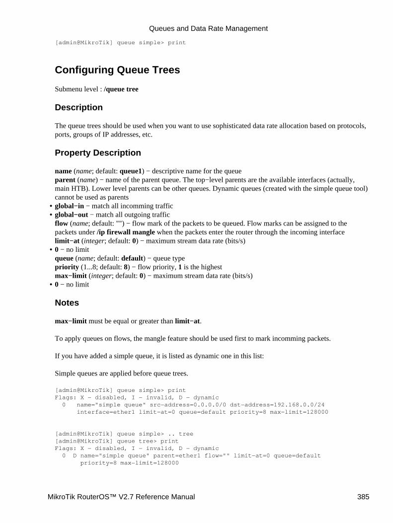
[admin@MikroTik] queue simple> print
Configuring Queue Trees
Submenu level : /queue tree
Description
The queue trees should be used when you want to use sophisticated data rate allocation based on protocols,ports, groups of IP addresses, etc.
Property Description
name (name; default: queue1) − descriptive name for the queueparent (name) − name of the parent queue. The top−level parents are the available interfaces (actually,main HTB). Lower level parents can be other queues. Dynamic queues (created with the simple queue tool)cannot be used as parentsglobal−in − match all incomming traffic• global−out − match all outgoing trafficflow (name; default: "") − flow mark of the packets to be queued. Flow marks can be assigned to thepackets under /ip firewall mangle when the packets enter the router through the incoming interfacelimit−at (integer; default: 0) − maximum stream data rate (bits/s)
•
0 − no limitqueue (name; default: default) − queue typepriority (1...8; default: 8) − flow priority, 1 is the highestmax−limit (integer; default: 0) − maximum stream data rate (bits/s)
•
0 − no limit
Notes
max−limit must be equal or greater than limit−at.
To apply queues on flows, the mangle feature should be used first to mark incomming packets.
If you have added a simple queue, it is listed as dynamic one in this list:
Simple queues are applied before queue trees.
[admin@MikroTik] queue simple> printFlags: X − disabled, I − invalid, D − dynamic 0 name="simple queue" src−address=0.0.0.0/0 dst−address=192.168.0.0/24 interface=ether1 limit−at=0 queue=default priority=8 max−limit=128000
[admin@MikroTik] queue simple> .. tree[admin@MikroTik] queue tree> printFlags: X − disabled, I − invalid, D − dynamic 0 D name="simple queue" parent=ether1 flow="" limit−at=0 queue=default priority=8 max−limit=128000
•
Queues and Data Rate Management
MikroTik RouterOS™ V2.7 Reference Manual 385
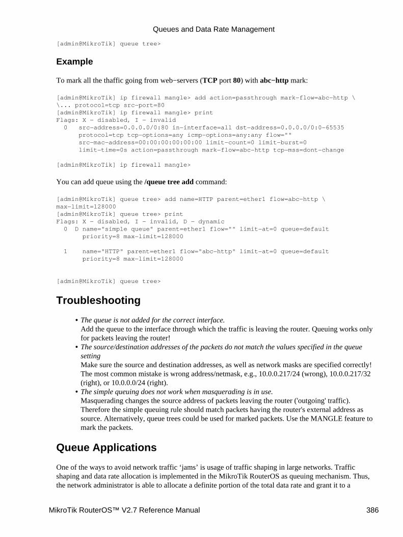
[admin@MikroTik] queue tree>
Example
To mark all the thaffic going from web−servers (TCP port 80) with abc−http mark:
[admin@MikroTik] ip firewall mangle> add action=passthrough mark−flow=abc−http \\... protocol=tcp src−port=80[admin@MikroTik] ip firewall mangle> printFlags: X − disabled, I − invalid 0 src−address=0.0.0.0/0:80 in−interface=all dst−address=0.0.0.0/0:0−65535 protocol=tcp tcp−options=any icmp−options=any:any flow="" src−mac−address=00:00:00:00:00:00 limit−count=0 limit−burst=0 limit−time=0s action=passthrough mark−flow=abc−http tcp−mss=dont−change
[admin@MikroTik] ip firewall mangle>
You can add queue using the /queue tree add command:
[admin@MikroTik] queue tree> add name=HTTP parent=ether1 flow=abc−http \max−limit=128000[admin@MikroTik] queue tree> printFlags: X − disabled, I − invalid, D − dynamic 0 D name="simple queue" parent=ether1 flow="" limit−at=0 queue=default priority=8 max−limit=128000
1 name="HTTP" parent=ether1 flow="abc−http" limit−at=0 queue=default priority=8 max−limit=128000
[admin@MikroTik] queue tree>
Troubleshooting
The queue is not added for the correct interface.Add the queue to the interface through which the traffic is leaving the router. Queuing works onlyfor packets leaving the router!
•
The source/destination addresses of the packets do not match the values specified in the queuesettingMake sure the source and destination addresses, as well as network masks are specified correctly!The most common mistake is wrong address/netmask, e.g., 10.0.0.217/24 (wrong), 10.0.0.217/32(right), or 10.0.0.0/24 (right).
•
The simple queuing does not work when masquerading is in use.Masquerading changes the source address of packets leaving the router ('outgoing' traffic).Therefore the simple queuing rule should match packets having the router's external address assource. Alternatively, queue trees could be used for marked packets. Use the MANGLE feature tomark the packets.
•
Queue Applications
One of the ways to avoid network traffic ‘jams’ is usage of traffic shaping in large networks. Trafficshaping and data rate allocation is implemented in the MikroTik RouterOS as queuing mechanism. Thus,the network administrator is able to allocate a definite portion of the total data rate and grant it to a
Queues and Data Rate Management
MikroTik RouterOS™ V2.7 Reference Manual 386
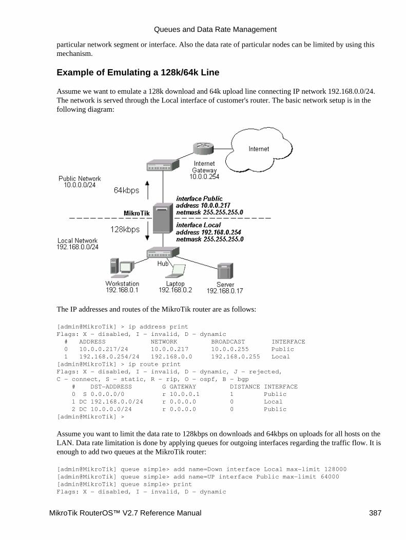
particular network segment or interface. Also the data rate of particular nodes can be limited by using thismechanism.
Example of Emulating a 128k/64k Line
Assume we want to emulate a 128k download and 64k upload line connecting IP network 192.168.0.0/24.The network is served through the Local interface of customer's router. The basic network setup is in thefollowing diagram:
The IP addresses and routes of the MikroTik router are as follows:
[admin@MikroTik] > ip address printFlags: X − disabled, I − invalid, D − dynamic # ADDRESS NETWORK BROADCAST INTERFACE 0 10.0.0.217/24 10.0.0.217 10.0.0.255 Public 1 192.168.0.254/24 192.168.0.0 192.168.0.255 Local[admin@MikroTik] > ip route printFlags: X − disabled, I − invalid, D − dynamic, J − rejected,C − connect, S − static, R − rip, O − ospf, B − bgp # DST−ADDRESS G GATEWAY DISTANCE INTERFACE 0 S 0.0.0.0/0 r 10.0.0.1 1 Public 1 DC 192.168.0.0/24 r 0.0.0.0 0 Local 2 DC 10.0.0.0/24 r 0.0.0.0 0 Public[admin@MikroTik] >
Assume you want to limit the data rate to 128kbps on downloads and 64kbps on uploads for all hosts on theLAN. Data rate limitation is done by applying queues for outgoing interfaces regarding the traffic flow. It isenough to add two queues at the MikroTik router:
[admin@MikroTik] queue simple> add name=Down interface Local max−limit 128000[admin@MikroTik] queue simple> add name=UP interface Public max−limit 64000[admin@MikroTik] queue simple> printFlags: X − disabled, I − invalid, D − dynamic
Queues and Data Rate Management
MikroTik RouterOS™ V2.7 Reference Manual 387

0 name="Down" src−address=0.0.0.0/0 dst−address=0.0.0.0/0 interface=Local limit−at=0 queue=default priority=8 max−limit=128000
1 name="UP" src−address=0.0.0.0/0 dst−address=0.0.0.0/0 interface=Public limit−at=0 queue=default priority=8 max−limit=64000
[admin@MikroTik] queue simple> .. tree printFlags: X − disabled, I − invalid, D − dynamic 0 D name="Down" parent=Local flow="" limit−at=0 queue=default priority=8 max−limit=128000
1 D name="UP" parent=Public flow="" limit−at=0 queue=default priority=8 max−limit=64000
[admin@MikroTik] queue simple>
Leave all other parameters as set by default. The limit is approximately 128kbps going to the LAN and64kbps leaving the client's LAN. Please note, that the queues have been added for the outgoing interfacesregarding the traffic flow.
To monitor the traffic flow through the interface while doing file transfer, use the /interfacemonitor−traffic command:
[admin@MikroTik] interface> monitor−traffic Public once received−packets−per−second: 9 received−bits−per−second: 4.32kbps sent−packets−per−second: 6 sent−bits−per−second: 65.58kbps
[admin@MikroTik] interface> monitor−traffic Public once received−packets−per−second: 7 received−bits−per−second: 3.36kbps sent−packets−per−second: 10 sent−bits−per−second: 65.15kbps
[admin@MikroTik] interface> monitor−traffic Public once received−packets−per−second: 11 received−bits−per−second: 5.66kbps sent−packets−per−second: 7 sent−bits−per−second: 52.70kbps
[admin@MikroTik] interface>
If you want to exclude the server from being limited, add two queues for it with max−limit=0 (no limit)and move them to the top:
[admin@MikroTik] queue simple> add name=Serv_D interface=Local \\... dst−address=192.168.0.17/32 max−limit=0[admin@MikroTik] queue simple> add name=Serv_U interface Public \\... src−address=192.168.0.17/32 max−limit=0[admin@MikroTik] queue simple> printFlags: X − disabled, I − invalid, D − dynamic 0 name="Down" src−address=0.0.0.0/0 dst−address=0.0.0.0/0 interface=Local limit−at=0 queue=default priority=8 max−limit=128000
1 name="UP" src−address=0.0.0.0/0 dst−address=0.0.0.0/0 interface=Public limit−at=0 queue=default priority=8 max−limit=64000
Queues and Data Rate Management
MikroTik RouterOS™ V2.7 Reference Manual 388
2 name="Serv_D" src−address=0.0.0.0/0 dst−address=192.168.0.17/32 interface=Local limit−at=0 queue=default priority=8 max−limit=0
3 name="Serv_U" src−address=192.168.0.17/32 dst−address=0.0.0.0/0 interface=Public limit−at=0 queue=default priority=8 max−limit=0
[admin@MikroTik] queue simple> move 2 0[admin@MikroTik] queue simple> move 3 1[admin@MikroTik] queue simple> printFlags: X − disabled, I − invalid, D − dynamic 0 name="Serv_D" src−address=0.0.0.0/0 dst−address=192.168.0.17/32 interface=Local limit−at=0 queue=default priority=8 max−limit=0
1 name="Serv_U" src−address=192.168.0.17/32 dst−address=0.0.0.0/0 interface=Public limit−at=0 queue=default priority=8 max−limit=0
2 name="Down" src−address=0.0.0.0/0 dst−address=0.0.0.0/0 interface=Local limit−at=0 queue=default priority=8 max−limit=128000
3 name="UP" src−address=0.0.0.0/0 dst−address=0.0.0.0/0 interface=Public limit−at=0 queue=default priority=8 max−limit=64000
[admin@MikroTik] queue simple>
Example of Using Masquerading
If masquerading is used for the local address space 192.168.0.0/24 of the client computers in the previousexample setup, then the outgoing traffic has masqueraded source address 10.0.0.217, i.e., the outgoingpackets have external address of the router as the source.
If you use simple queues, as in the previous example, the queuing rule for incoming traffic should matchthe customer's local addresses, whereas the rule for outgoing traffic should match the router's externaladdress as the source address. The previous example would work fine, but you cannot exclude the serverfrom being limited.
To apply specific queuing for the server, use /ip firewall mangle to mark the packets originated from theserver:
[admin@MikroTik] ip firewall mangle> add src−address=192.168.0.17/32 \\... action=passthrough mark−flow=Serv_Up[admin@MikroTik] ip firewall mangle> add in−interface=Local action=passthrough \\... mark−flow=Local−all[admin@MikroTik] ip firewall mangle> printFlags: X − disabled, I − invalid 0 src−address=192.168.0.17/32:0−65535 in−interface=all dst−address=0.0.0.0/0:0−65535 protocol=all tcp−options=any icmp−options=any:any src−mac−address=00:00:00:00:00:00 limit−count=0 limit−burst=0 limit−time=0s action=passthrough mark−flow=Serv_Up tcp−mss=dont−change
1 src−address=0.0.0.0/0:0−65535 in−interface=Local dst−address=0.0.0.0/0:0−65535 protocol=all tcp−options=any icmp−options=any:any src−mac−address=00:00:00:00:00:00 limit−count=0 limit−burst=0 limit−time=0s action=passthrough mark−flow=Local−all tcp−mss=dont−change
[admin@MikroTik] ip firewall mangle>
Queues and Data Rate Management
MikroTik RouterOS™ V2.7 Reference Manual 389

Add a queue to the queue tree, which uses the flow mark:
[admin@MikroTik] queue tree> add name=Server parent=Public flow=Serv_Up[admin@MikroTik] queue tree> add name=Workst parent=Public flow=Local−all \\... max−limit=64000[admin@MikroTik] queue tree> printFlags: X − disabled, I − invalid, D − dynamic 0 name=Server parent=Public flow=Serv_Up limit−at=0 queue=default priority=8 max−limit=0
1 name=Workst parent=Public flow=Local−all limit−at=0 queue=default priority=8 max−limit=128000
[admin@MikroTik] queue tree>
Thus, we used queue trees for limiting the upload. Use the same simple queues as in the previous examplefor limiting the download.
Example of Guaranteed Quality of Service
This example shows how to limit data rate on a channel and guarantee minimum speed to the FTP serverallowing other traffic to use the rest of the channel.
Assume we want to emulate a 128k download and 64k upload line connecting IP network 192.168.0.0/24 asin the previous examples. But if these speeds are the best that you can get from your Internet connection,you may want to guarantee certain speeds to the 192.168.0.17 server so that your customers coulddownload from and upload to this server with the speeds not dependent on the other traffic using the samechannel (for example, we will guarantee this server the minimum data rate of 32k for each flow direction).
First of all, you should limit the interface speed:
[admin@MikroTik] queue tree> add name=Up parent=Public max−limit=64000[admin@MikroTik] queue tree> printFlags: X − disabled, I − invalid, D − dynamic 0 name="Up" parent=Public flow="" limit−at=0 queue=default priority=8 max−limit=64000
[admin@MikroTik] queue tree>
Next, mark the traffic from the FTP server. We will mark only TCP ports 20−21 because these ports areused to send and receive FTP data and control messages.
[admin@MikroTik] ip firewall mangle> add src−address=192.168.0.17/32:20−21 \\... protocol=tcp mark−flow=Server_Up in−interface=Local[admin@MikroTik] ip firewall mangle> printFlags: X − disabled, I − invalid, D − dynamic 0 src−address=192.168.0.17/32:20−21 in−interface=Local dst−address=0.0.0.0/0:0−65535 protocol=tcp tcp−options=any icmp−options=any:any flow="" src−mac−address=00:00:00:00:00:00 limit−count=0 limit−burst=0 limit−time=0s action=accept mark−flow=Server_Up tcp−mss=dont−change
[admin@MikroTik] ip firewall mangle>
The second mangle rule will match the rest of the traffic from the network:
Queues and Data Rate Management
MikroTik RouterOS™ V2.7 Reference Manual 390

[admin@MikroTik] ip firewall mangle> add src−address=0.0.0.0/0 \\... mark−flow=Local_Up in−interface=Local[admin@MikroTik] ip firewall mangle> printFlags: X − disabled, I − invalid, D − dynamic 0 src−address=192.168.0.17/32:20−21 in−interface=Local dst−address=0.0.0.0/0:0−65535 protocol=tcp tcp−options=any icmp−options=any:any flow="" src−mac−address=00:00:00:00:00:00 limit−count=0 limit−burst=0 limit−time=0s action=accept mark−flow=Server_Up tcp−mss=dont−change
1 src−address=0.0.0.0/0:0−65535 in−interface=Local dst−address=0.0.0.0/0:0−65535 protocol=tcp tcp−options=any icmp−options=any:any flow="" src−mac−address=00:00:00:00:00:00 limit−count=0 limit−burst=0 limit−time=0s action=accept mark−flow=Local_Up tcp−mss=dont−change
[admin@MikroTik] ip firewall mangle>
Finally shaping the traffic:
[admin@MikroTik] queue tree> add name=Server_Up parent=Up limit−at=32000 \\... flow=Server_Up max−limit=64000 priority=7[admin@MikroTik] queue tree> add name=Local_Up parent=Up limit−at=0 \\... flow=Local_Up[admin@MikroTik] queue tree> printFlags: X − disabled, I − invalid, D − dynamic 0 name="Up" parent=Public flow="" limit−at=0 queue=default priority=8 max−limit=64000
1 name="Server_Up" parent=Up flow="Server_Up" limit−at=32000 queue=default priority=7 max−limit=64000
2 name="Local_Up" parent=Up flow="Local_Up" limit−at=0 queue=default priority=8 max−limit=0
[admin@MikroTik] queue tree>
Thus, we used queue trees for limiting the upload. The download speed can be limited the same way simplychanging the interface names and matching the packets destinated to the server (use 'external' server addressif you are using DST−NAT):
[admin@MikroTik] queue tree> add name=Down parent=Local max−limit=128000[admin@MikroTik] queue tree> printFlags: X − disabled, I − invalid, D − dynamic 0 name="Up" parent=Public flow="" limit−at=0 queue=default priority=8 max−limit=64000
1 name="Server_Up" parent=Up flow="Server_Up" limit−at=32000 queue=default priority=7 max−limit=64000
2 name="Local_Up" parent=Up flow="Local_Up" limit−at=0 queue=default priority=8 max−limit=0
3 name="Down" parent=Local flow="" limit−at=0 queue=default priority=8 max−limit=128000
[admin@MikroTik] queue tree> /ip firewall mangle[admin@MikroTik] ip firewall mangle> add dst−address=192.168.0.17/32:20−21 \\... protocol=tcp mark−flow=Server_Down in−interface=Public[admin@MikroTik] ip firewall mangle> add dst−address=0.0.0.0/0 \
Queues and Data Rate Management
MikroTik RouterOS™ V2.7 Reference Manual 391

\... mark−flow=Local_Down in−interface=Public[admin@MikroTik] ip firewall mangle> printFlags: X − disabled, I − invalid, D − dynamic 0 src−address=192.168.0.17/32:20−21 in−interface=Local dst−address=0.0.0.0/0:0−65535 protocol=tcp tcp−options=any icmp−options=any:any flow="" src−mac−address=00:00:00:00:00:00 limit−count=0 limit−burst=0 limit−time=0s action=accept mark−flow=Server_Up tcp−mss=dont−change
1 src−address=0.0.0.0/0:0−65535 in−interface=Local dst−address=0.0.0.0/0:0−65535 protocol=tcp tcp−options=any icmp−options=any:any flow="" src−mac−address=00:00:00:00:00:00 limit−count=0 limit−burst=0 limit−time=0s action=accept mark−flow=Local_Up tcp−mss=dont−change
2 src−address=0.0.0.0/0:0−65535 in−interface=Public dst−address=192.168.0.17/32:20−21 protocol=tcp tcp−options=any icmp−options=any:any flow="" src−mac−address=00:00:00:00:00:00 limit−count=0 limit−burst=0 limit−time=0s action=accept mark−flow=Server_Down tcp−mss=dont−change
3 src−address=0.0.0.0/0:0−65535 in−interface=Public dst−address=0.0.0.0/0:0−65535 protocol=tcp tcp−options=any icmp−options=any:any flow="" src−mac−address=00:00:00:00:00:00 limit−count=0 limit−burst=0 limit−time=0s action=accept mark−flow=Local_Down tcp−mss=dont−change
[admin@MikroTik] ip firewall mangle> /queue tree[admin@MikroTik] queue tree> add name=Server_Down parent=Down limit−at=32000 \\... flow=Server_Down max−limit=128000 priority=7[admin@MikroTik] queue tree> add name=Local_Down parent=Down limit−at=0 \\... flow=Local_Down[admin@MikroTik] queue tree> printFlags: X − disabled, I − invalid, D − dynamic 0 name="Up" parent=Public flow="" limit−at=0 queue=default priority=8 max−limit=64000
1 name="Server_Up" parent=Up flow="Server_Up" limit−at=32000 queue=default priority=7 max−limit=64000
2 name="Local_Up" parent=Up flow="Local_Up" limit−at=0 queue=default priority=8 max−limit=0
3 name="Down" parent=Local flow="" limit−at=0 queue=default priority=8 max−limit=128000
4 name="Server_Down" parent=Down flow="Server_Down" limit−at=32000 queue=default priority=7 max−limit=128000
5 name="Local_Down" parent=Down flow="Local_Down" limit−at=0 queue=default priority=8 max−limit=0
[admin@MikroTik] queue tree>
Additional ResourcesHome of Hierarchical Token Bucket (HTB)• Paper on Random Early Detection (RED)• More complete information on Traffic Cotrol•
Queues and Data Rate Management
MikroTik RouterOS™ V2.7 Reference Manual 392

© Copyright 1999−2003, MikroTik
Queues and Data Rate Management
MikroTik RouterOS™ V2.7 Reference Manual 393
Open Shortest Path First (OSPF) Routing ProtocolDocument revision 1.4 (08−Aug−2003)This document applies to the MikroTik RouterOS V2.7
Table of Contents
Table of Contents• Summary• Specifications• Related Documents• Description• OSPF Setup
Property Description♦ Notes♦ Example♦
•
OSPF AreasProperty Description♦ Notes♦ Example♦
•
OSPF NetworkDescription♦ Property Description♦ Notes♦ Example♦
•
OSPF InterfacesDescription♦ Prorerty Description♦ Example♦
•
OSPF Virtual LinksDescription♦ Property Description♦ Notes♦ Example♦
•
OSPF NeighboursDescription♦ Proprety Description♦ Notes♦ Example♦
•
An Example of Running OSPF• OSPF Troubleshooting• OSPF Backup without using Tunnel
OSPF_Main Router Setup♦ OSPF−peer−1 Router Setup♦ OSPF−peer−2 Router Setup♦ Routing Tables♦ Routing Tables with Revised Link Cost♦ Functioning of the Backup♦
•
OSPF Backup using Encrypted Tunnel through a Third PartyOSPF_Main Router Setup♦
•
MikroTik RouterOS™ V2.7 Reference Manual 394
OSPF−peer−1 Router Setup♦ Routing Tables♦ Functioning of the Backup♦
Additional Resources•
Summary
MikroTik RouterOS implements OSPF Version 2 (RFC 2328). The OSPF protocol is the link−state protocolthat takes care of the routes in the dynamic network structure that can employ different paths to itssubnetworks. It always chooses shortest path to the subnetwork first.
Supports event logging.
Specifications
Packages required : routingLicense required : AnyHome menu level : /routing ospfProtocols utilized : OSPF (RFC2328)Hardware usage : not significant
Related Documents
Software Package Installation and UpgradingIP Addresses and Address Resolution Protocol (ARP)Routes, Equal Cost Multipath Routing, Policy RoutingLog Management
Description
Open Shortest Path First (OSPF) dynamic routing protocol distributes routing information between the routersbelonging to a single autonomous system (AS). An AS is a group of routers exchanging routing informationvia a common routing protocol.
When deploy the OSPF, all routers should be configured in a coordinated manner (note that it also means thatthe routers should have the same MTU for the all the networks advertized by OSPF protocol). Routersbelonging to one area should have the same area ID configured. Although Mikrotik RouterOS supportsmultiple areas, it is not likely that you will deploy structures with many of them.
After you have divided your networks in areas, you have to configure the following settings on each OSPFrouter:
Change general OSPF settings of redistributing connected, static and default routes. The default routeshould be distributed only from border routers of your area;
1.
Configure additional areas, if any;2. If you're using encryption, you also should configure keys in /routing ospf interface command level;3. Add OSPF network records for all networks you want the OSPF to run on.4.
The OSPF is started after adding record to the ospf network list.
Open Shortest Path First (OSPF) Routing Protocol
MikroTik RouterOS™ V2.7 Reference Manual 395
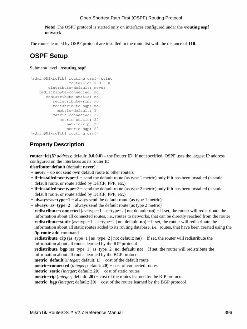
Note! The OSPF protocol is started only on interfaces configured under the /routing ospfnetwork
The routes learned by OSPF protocol are installed in the route list with the distance of 110.
OSPF Setup
Submenu level : /routing ospf
[admin@MikroTik] routing ospf> print router−id: 0.0.0.0 distribute−default: never redistribute−connected: no redistribute−static: no redistribute−rip: no redistribute−bgp: no metric−default: 1 metric−connected: 20 metric−static: 20 metric−rip: 20 metric−bgp: 20[admin@MikroTik] routing ospf>
Property Description
router−id (IP address; default: 0.0.0.0) – the Router ID. If not specified, OSPF uses the largest IP addressconfigured on the interfaces as its router IDdistribute−default (default: never) :
never − do not send own default route to other routers• if−installed−as−type−1 − send the default route (as type 1 metric) only if it has been installed (a staticdefault route, or route added by DHCP, PPP, etc.)
•
if−installed−as−type−2 − send the default route (as type 2 metric) only if it has been installed (a staticdefault route, or route added by DHCP, PPP, etc.)
•
always−as−type−1 − always send the default route (as type 1 metric)• always−as−type−2 − always send the default route (as type 2 metric)redistribute−connected (as−type−1 | as−type−2 | no; default: no) − if set, the router will redistribute theinformation about all connected routes, i.e., routes to networks, that can be directly reached from the routerredistribute−static (as−type−1 | as−type−2 | no; default: no) − if set, the router will redistribute theinformation about all static routes added to its routing database, i.e., routes, that have been created using the/ip route add commandredistribute−rip (as−type−1 | as−type−2 | no; default: no) − If set, the router will redistribute theinformation about all routes learned by the RIP protocolredistribute−bgp (as−type−1 | as−type−2 | no; default: no) − If set, the router will redistribute theinformation about all routes learned by the BGP protocolmetric−default (integer; default: 1) − cost of the default routemetric−connected (integer; default: 20) − cost of connected routesmetric−static (integer; default: 20) − cost of static routesmetric−rip (integer; default: 20) − cost of the routes learned by the RIP protocolmetric−bgp (integer; default: 20) − cost of the routes learned by the BGP protocol
•
Open Shortest Path First (OSPF) Routing Protocol
MikroTik RouterOS™ V2.7 Reference Manual 396

Notes
Within an area, only the router that is connected to an another AS (i.e. border router) should have thepropagation of the default route enabled.
OSPF protocol will try to use the shortest path (path with the least total cost) if available.
OSPF protocol supports two types of metrics:type 1 metrics are internal ('cheap') metrics• type 2 metrics are external ('expensive') metrics. Any type 2 metric is considered greater than the cost ofany internal path
Example
To enable OSPF protocol redisrtibute routes to the connected networks as type 1 metrics with the cost of 1:
[admin@MikroTik] routing ospf> set redistribute−connected=as−type−1 \\... metric−connected=1[admin@MikroTik] routing ospf> print router−id: 0.0.0.0 distribute−default: never redistribute−connected: as−type−1 redistribute−static: no redistribute−rip: no redistribute−bgp: no metric−default: 1 metric−connected: 1 metric−static: 20 metric−rip: 20 metric−bgp: 20[admin@MikroTik] routing ospf>
OSPF Areas
Submenu level : /routing ospf area
Property Description
name (name; default: "") − area namearea−id (IP address; default: 0.0.0.0) − area IDdefault−cost (integer; default: 1) − cost for the default summary route used for a stub area. Only for areaboundary routerstub (yes | no; default: no) − area typeauthentication (md5 | none | simple; default: none) − authentication method for OSPF:
•
none − no authentication• simple − plain text authentication• md5 − Keyed Message Digest 5 (MD5) authentication
Notes
There is one area that is configured by default − the backbone area (area ID 0.0.0.0). name and area−idcannot be changed for this area.
•
Open Shortest Path First (OSPF) Routing Protocol
MikroTik RouterOS™ V2.7 Reference Manual 397
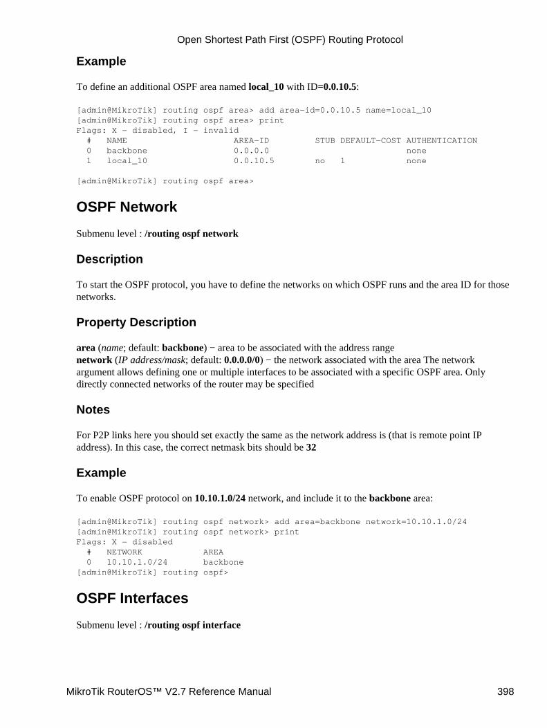
Example
To define an additional OSPF area named local_10 with ID=0.0.10.5:
[admin@MikroTik] routing ospf area> add area−id=0.0.10.5 name=local_10[admin@MikroTik] routing ospf area> printFlags: X − disabled, I − invalid # NAME AREA−ID STUB DEFAULT−COST AUTHENTICATION 0 backbone 0.0.0.0 none 1 local_10 0.0.10.5 no 1 none
[admin@MikroTik] routing ospf area>
OSPF Network
Submenu level : /routing ospf network
Description
To start the OSPF protocol, you have to define the networks on which OSPF runs and the area ID for thosenetworks.
Property Description
area (name; default: backbone) − area to be associated with the address rangenetwork (IP address/mask; default: 0.0.0.0/0) − the network associated with the area The networkargument allows defining one or multiple interfaces to be associated with a specific OSPF area. Onlydirectly connected networks of the router may be specified
Notes
For P2P links here you should set exactly the same as the network address is (that is remote point IPaddress). In this case, the correct netmask bits should be 32
Example
To enable OSPF protocol on 10.10.1.0/24 network, and include it to the backbone area:
[admin@MikroTik] routing ospf network> add area=backbone network=10.10.1.0/24[admin@MikroTik] routing ospf network> printFlags: X − disabled # NETWORK AREA 0 10.10.1.0/24 backbone[admin@MikroTik] routing ospf>
OSPF Interfaces
Submenu level : /routing ospf interface
Open Shortest Path First (OSPF) Routing Protocol
MikroTik RouterOS™ V2.7 Reference Manual 398
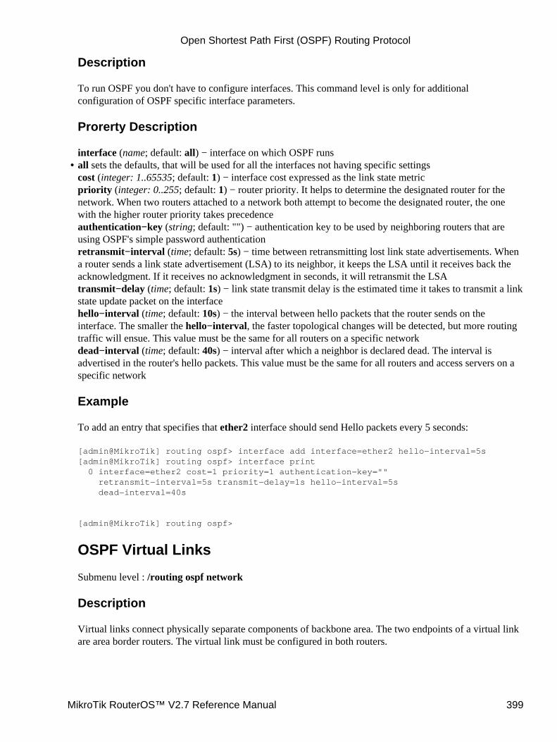
Description
To run OSPF you don't have to configure interfaces. This command level is only for additionalconfiguration of OSPF specific interface parameters.
Prorerty Description
interface (name; default: all) − interface on which OSPF runsall sets the defaults, that will be used for all the interfaces not having specific settingscost (integer: 1..65535; default: 1) − interface cost expressed as the link state metricpriority (integer: 0..255; default: 1) − router priority. It helps to determine the designated router for thenetwork. When two routers attached to a network both attempt to become the designated router, the onewith the higher router priority takes precedenceauthentication−key (string; default: "") − authentication key to be used by neighboring routers that areusing OSPF's simple password authenticationretransmit−interval (time; default: 5s) − time between retransmitting lost link state advertisements. Whena router sends a link state advertisement (LSA) to its neighbor, it keeps the LSA until it receives back theacknowledgment. If it receives no acknowledgment in seconds, it will retransmit the LSAtransmit−delay (time; default: 1s) − link state transmit delay is the estimated time it takes to transmit a linkstate update packet on the interfacehello−interval (time; default: 10s) − the interval between hello packets that the router sends on theinterface. The smaller the hello−interval, the faster topological changes will be detected, but more routingtraffic will ensue. This value must be the same for all routers on a specific networkdead−interval (time; default: 40s) − interval after which a neighbor is declared dead. The interval isadvertised in the router's hello packets. This value must be the same for all routers and access servers on aspecific network
Example
To add an entry that specifies that ether2 interface should send Hello packets every 5 seconds:
[admin@MikroTik] routing ospf> interface add interface=ether2 hello−interval=5s[admin@MikroTik] routing ospf> interface print 0 interface=ether2 cost=1 priority=1 authentication−key="" retransmit−interval=5s transmit−delay=1s hello−interval=5s dead−interval=40s
[admin@MikroTik] routing ospf>
OSPF Virtual Links
Submenu level : /routing ospf network
Description
Virtual links connect physically separate components of backbone area. The two endpoints of a virtual linkare area border routers. The virtual link must be configured in both routers.
•
Open Shortest Path First (OSPF) Routing Protocol
MikroTik RouterOS™ V2.7 Reference Manual 399

Property Description
neighbor−id (IP address; default: 0.0.0.0) − router−id of the neighbourtransit−area (name; default: backbone) − non−backbone area the two routers have in common
Notes
Virtual links cannot be established through stub areas.
Example
To add a virtual link with the 10.0.0.201 router through the ex area:
[admin@MikroTik] routing ospf virtual−link> add neighbor−id=10.0.0.201 \\... transit−area=ex[admin@MikroTik] routing ospf virtual−link> printFlags: X − disabled, I − invalid # NEIGHBOR−ID TRANSIT−AREA 0 10.0.0.201 ex[admin@MikroTik] routing ospf virtual−link>
OSPF Neighbours
Submenu level : /routing ospf neighbor
Description
The submenu provides an access to the list of OSPF neighbors for the router, with brief statistics
Proprety Description
router−id (read−only: IP address) − router−id parameter of the OSPF neighbouraddress (read−only: IP address) − appropriate IP address of the OSPF neighborpriority (read−only: integer) − priority of neighbor which is used in designated router elections on thisnetworkstate (read−only: text) − state of the connection:Down − the connection is down• Attempt − sending Hello packet• Init − Hello packet received from the neighbour• 2−Way − bidirectional communication established• ExStart − negotiating Exchange state• Exchange − exchanging with hole Link−State DataBase• Loading − receiving information from the neighbour• Full − the neighboring routers are fully adjacent (the link−state databases are completely synchronized)state−changes (read−only: integer) − number of state changes of the connectionls−retransmits (read−only: integer) − number of Link State retransmitsls−requests (read−only: integer) − number of Link State requestsdb−summaries (read−only: integer) − number of records in link−state database advertised by theneighbourdr−id (read−only: IP address) − router id of designated router for this neighbor
•
Open Shortest Path First (OSPF) Routing Protocol
MikroTik RouterOS™ V2.7 Reference Manual 400
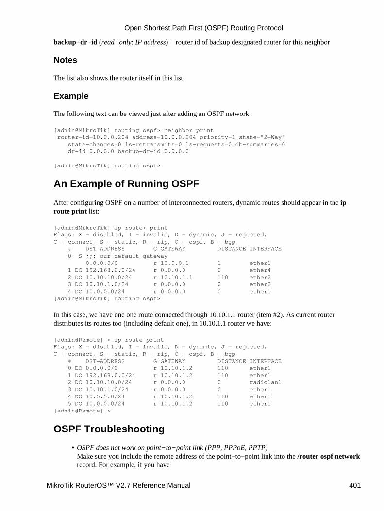
backup−dr−id (read−only: IP address) − router id of backup designated router for this neighbor
Notes
The list also shows the router itself in this list.
Example
The following text can be viewed just after adding an OSPF network:
[admin@MikroTik] routing ospf> neighbor print router−id=10.0.0.204 address=10.0.0.204 priority=1 state="2−Way" state−changes=0 ls−retransmits=0 ls−requests=0 db−summaries=0 dr−id=0.0.0.0 backup−dr−id=0.0.0.0
[admin@MikroTik] routing ospf>
An Example of Running OSPF
After configuring OSPF on a number of interconnected routers, dynamic routes should appear in the iproute print list:
[admin@MikroTik] ip route> printFlags: X − disabled, I − invalid, D − dynamic, J − rejected,C − connect, S − static, R − rip, O − ospf, B − bgp # DST−ADDRESS G GATEWAY DISTANCE INTERFACE 0 S ;;; our default gateway 0.0.0.0/0 r 10.0.0.1 1 ether1 1 DC 192.168.0.0/24 r 0.0.0.0 0 ether4 2 DO 10.10.10.0/24 r 10.10.1.1 110 ether2 3 DC 10.10.1.0/24 r 0.0.0.0 0 ether2 4 DC 10.0.0.0/24 r 0.0.0.0 0 ether1[admin@MikroTik] routing ospf>
In this case, we have one one route connected through 10.10.1.1 router (item #2). As current routerdistributes its routes too (including default one), in 10.10.1.1 router we have:
[admin@Remote] > ip route printFlags: X − disabled, I − invalid, D − dynamic, J − rejected,C − connect, S − static, R − rip, O − ospf, B − bgp # DST−ADDRESS G GATEWAY DISTANCE INTERFACE 0 DO 0.0.0.0/0 r 10.10.1.2 110 ether1 1 DO 192.168.0.0/24 r 10.10.1.2 110 ether1 2 DC 10.10.10.0/24 r 0.0.0.0 0 radiolan1 3 DC 10.10.1.0/24 r 0.0.0.0 0 ether1 4 DO 10.5.5.0/24 r 10.10.1.2 110 ether1 5 DO 10.0.0.0/24 r 10.10.1.2 110 ether1[admin@Remote] >
OSPF Troubleshooting
OSPF does not work on point−to−point link (PPP, PPPoE, PPTP)Make sure you include the remote address of the point−to−point link into the /router ospf networkrecord. For example, if you have
•
Open Shortest Path First (OSPF) Routing Protocol
MikroTik RouterOS™ V2.7 Reference Manual 401
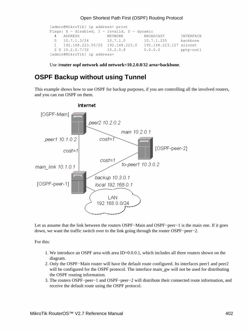
[admin@MikroTik] ip address> printFlags: X − disabled, I − invalid, D − dynamic # ADDRESS NETWORK BROADCAST INTERFACE 0 10.7.1.3/24 10.7.1.0 10.7.1.255 backbone 1 192.168.223.55/25 192.168.223.0 192.168.223.127 aironet 2 D 10.2.0.7/32 10.2.0.8 0.0.0.0 pptp−out1[admin@MikroTik] ip address>
Use /router ospf network add network=10.2.0.8/32 area=backbone.
OSPF Backup without using Tunnel
This example shows how to use OSPF for backup purposes, if you are controlling all the involved routers,and you can run OSPF on them.
Let us assume that the link between the routers OSPF−Main and OSPF−peer−1 is the main one. If it goesdown, we want the traffic switch over to the link going through the router OSPF−peer−2.
For this:
We introduce an OSPF area with area ID=0.0.0.1, which includes all three routers shown on thediagram.
1.
Only the OSPF−Main router will have the default route configured. Its interfaces peer1 and peer2will be configured for the OSPF protocol. The interface main_gw will not be used for distributingthe OSPF routing information.
2.
The routers OSPF−peer−1 and OSPF−peer−2 will distribute their connected route information, andreceive the default route using the OSPF protocol.
3.
Open Shortest Path First (OSPF) Routing Protocol
MikroTik RouterOS™ V2.7 Reference Manual 402
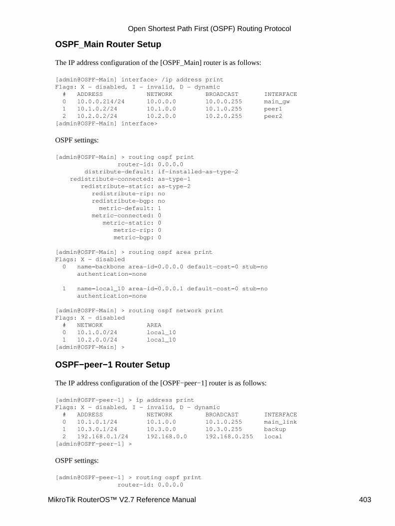
OSPF_Main Router Setup
The IP address configuration of the [OSPF_Main] router is as follows:
[admin@OSPF−Main] interface> /ip address printFlags: X − disabled, I − invalid, D − dynamic # ADDRESS NETWORK BROADCAST INTERFACE 0 10.0.0.214/24 10.0.0.0 10.0.0.255 main_gw 1 10.1.0.2/24 10.1.0.0 10.1.0.255 peer1 2 10.2.0.2/24 10.2.0.0 10.2.0.255 peer2[admin@OSPF−Main] interface>
OSPF settings:
[admin@OSPF−Main] > routing ospf print router−id: 0.0.0.0 distribute−default: if−installed−as−type−2 redistribute−connected: as−type−1 redistribute−static: as−type−2 redistribute−rip: no redistribute−bgp: no metric−default: 1 metric−connected: 0 metric−static: 0 metric−rip: 0 metric−bgp: 0
[admin@OSPF−Main] > routing ospf area printFlags: X − disabled 0 name=backbone area−id=0.0.0.0 default−cost=0 stub=no authentication=none
1 name=local_10 area−id=0.0.0.1 default−cost=0 stub=no authentication=none
[admin@OSPF−Main] > routing ospf network printFlags: X − disabled # NETWORK AREA 0 10.1.0.0/24 local_10 1 10.2.0.0/24 local_10[admin@OSPF−Main] >
OSPF−peer−1 Router Setup
The IP address configuration of the [OSPF−peer−1] router is as follows:
[admin@OSPF−peer−1] > ip address printFlags: X − disabled, I − invalid, D − dynamic # ADDRESS NETWORK BROADCAST INTERFACE 0 10.1.0.1/24 10.1.0.0 10.1.0.255 main_link 1 10.3.0.1/24 10.3.0.0 10.3.0.255 backup 2 192.168.0.1/24 192.168.0.0 192.168.0.255 local[admin@OSPF−peer−1] >
OSPF settings:
[admin@OSPF−peer−1] > routing ospf print router−id: 0.0.0.0
Open Shortest Path First (OSPF) Routing Protocol
MikroTik RouterOS™ V2.7 Reference Manual 403
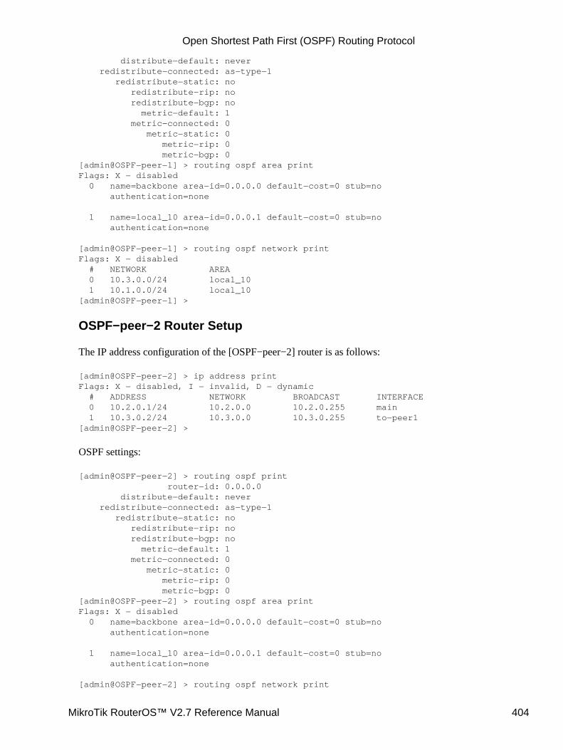
distribute−default: never redistribute−connected: as−type−1 redistribute−static: no redistribute−rip: no redistribute−bgp: no metric−default: 1 metric−connected: 0 metric−static: 0 metric−rip: 0 metric−bgp: 0[admin@OSPF−peer−1] > routing ospf area printFlags: X − disabled 0 name=backbone area−id=0.0.0.0 default−cost=0 stub=no authentication=none
1 name=local_10 area−id=0.0.0.1 default−cost=0 stub=no authentication=none
[admin@OSPF−peer−1] > routing ospf network printFlags: X − disabled # NETWORK AREA 0 10.3.0.0/24 local_10 1 10.1.0.0/24 local_10[admin@OSPF−peer−1] >
OSPF−peer−2 Router Setup
The IP address configuration of the [OSPF−peer−2] router is as follows:
[admin@OSPF−peer−2] > ip address printFlags: X − disabled, I − invalid, D − dynamic # ADDRESS NETWORK BROADCAST INTERFACE 0 10.2.0.1/24 10.2.0.0 10.2.0.255 main 1 10.3.0.2/24 10.3.0.0 10.3.0.255 to−peer1[admin@OSPF−peer−2] >
OSPF settings:
[admin@OSPF−peer−2] > routing ospf print router−id: 0.0.0.0 distribute−default: never redistribute−connected: as−type−1 redistribute−static: no redistribute−rip: no redistribute−bgp: no metric−default: 1 metric−connected: 0 metric−static: 0 metric−rip: 0 metric−bgp: 0[admin@OSPF−peer−2] > routing ospf area printFlags: X − disabled 0 name=backbone area−id=0.0.0.0 default−cost=0 stub=no authentication=none
1 name=local_10 area−id=0.0.0.1 default−cost=0 stub=no authentication=none
[admin@OSPF−peer−2] > routing ospf network print
Open Shortest Path First (OSPF) Routing Protocol
MikroTik RouterOS™ V2.7 Reference Manual 404
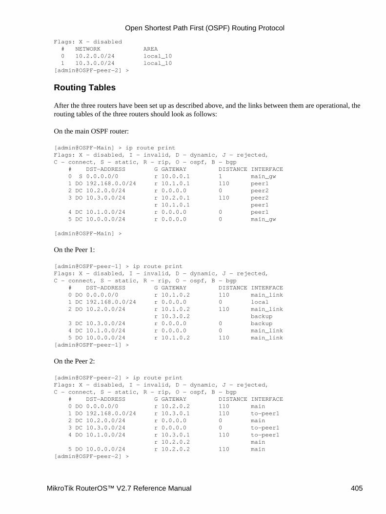
Flags: X − disabled # NETWORK AREA 0 10.2.0.0/24 local_10 1 10.3.0.0/24 local_10[admin@OSPF−peer−2] >
Routing Tables
After the three routers have been set up as described above, and the links between them are operational, therouting tables of the three routers should look as follows:
On the main OSPF router:
[admin@OSPF−Main] > ip route printFlags: X − disabled, I − invalid, D − dynamic, J − rejected,C − connect, S − static, R − rip, O − ospf, B − bgp # DST−ADDRESS G GATEWAY DISTANCE INTERFACE 0 S 0.0.0.0/0 r 10.0.0.1 1 main_gw 1 DO 192.168.0.0/24 r 10.1.0.1 110 peer1 2 DC 10.2.0.0/24 r 0.0.0.0 0 peer2 3 DO 10.3.0.0/24 r 10.2.0.1 110 peer2 r 10.1.0.1 peer1 4 DC 10.1.0.0/24 r 0.0.0.0 0 peer1 5 DC 10.0.0.0/24 r 0.0.0.0 0 main_gw
[admin@OSPF−Main] >
On the Peer 1:
[admin@OSPF−peer−1] > ip route printFlags: X − disabled, I − invalid, D − dynamic, J − rejected,C − connect, S − static, R − rip, O − ospf, B − bgp # DST−ADDRESS G GATEWAY DISTANCE INTERFACE 0 DO 0.0.0.0/0 r 10.1.0.2 110 main_link 1 DC 192.168.0.0/24 r 0.0.0.0 0 local 2 DO 10.2.0.0/24 r 10.1.0.2 110 main_link r 10.3.0.2 backup 3 DC 10.3.0.0/24 r 0.0.0.0 0 backup 4 DC 10.1.0.0/24 r 0.0.0.0 0 main_link 5 DO 10.0.0.0/24 r 10.1.0.2 110 main_link[admin@OSPF−peer−1] >
On the Peer 2:
[admin@OSPF−peer−2] > ip route printFlags: X − disabled, I − invalid, D − dynamic, J − rejected,C − connect, S − static, R − rip, O − ospf, B − bgp # DST−ADDRESS G GATEWAY DISTANCE INTERFACE 0 DO 0.0.0.0/0 r 10.2.0.2 110 main 1 DO 192.168.0.0/24 r 10.3.0.1 110 to−peer1 2 DC 10.2.0.0/24 r 0.0.0.0 0 main 3 DC 10.3.0.0/24 r 0.0.0.0 0 to−peer1 4 DO 10.1.0.0/24 r 10.3.0.1 110 to−peer1 r 10.2.0.2 main 5 DO 10.0.0.0/24 r 10.2.0.2 110 main[admin@OSPF−peer−2] >
Open Shortest Path First (OSPF) Routing Protocol
MikroTik RouterOS™ V2.7 Reference Manual 405
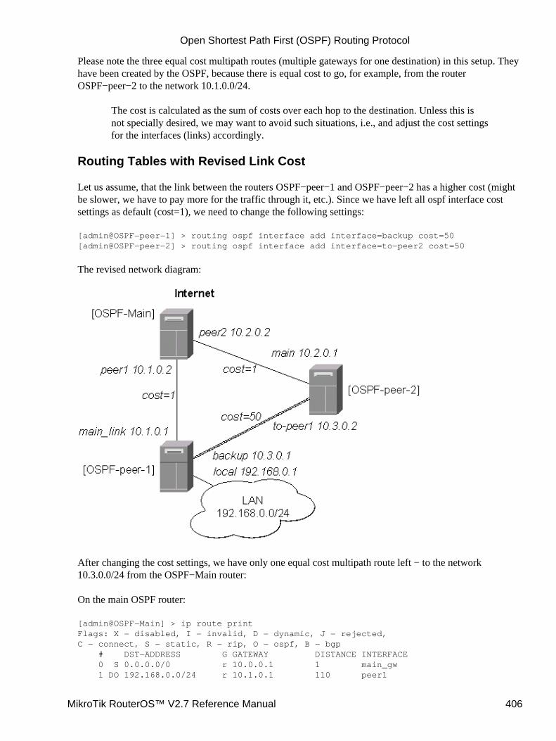
Please note the three equal cost multipath routes (multiple gateways for one destination) in this setup. Theyhave been created by the OSPF, because there is equal cost to go, for example, from the routerOSPF−peer−2 to the network 10.1.0.0/24.
The cost is calculated as the sum of costs over each hop to the destination. Unless this isnot specially desired, we may want to avoid such situations, i.e., and adjust the cost settingsfor the interfaces (links) accordingly.
Routing Tables with Revised Link Cost
Let us assume, that the link between the routers OSPF−peer−1 and OSPF−peer−2 has a higher cost (mightbe slower, we have to pay more for the traffic through it, etc.). Since we have left all ospf interface costsettings as default (cost=1), we need to change the following settings:
[admin@OSPF−peer−1] > routing ospf interface add interface=backup cost=50[admin@OSPF−peer−2] > routing ospf interface add interface=to−peer2 cost=50
The revised network diagram:
After changing the cost settings, we have only one equal cost multipath route left − to the network10.3.0.0/24 from the OSPF−Main router:
On the main OSPF router:
[admin@OSPF−Main] > ip route printFlags: X − disabled, I − invalid, D − dynamic, J − rejected,C − connect, S − static, R − rip, O − ospf, B − bgp # DST−ADDRESS G GATEWAY DISTANCE INTERFACE 0 S 0.0.0.0/0 r 10.0.0.1 1 main_gw 1 DO 192.168.0.0/24 r 10.1.0.1 110 peer1
Open Shortest Path First (OSPF) Routing Protocol
MikroTik RouterOS™ V2.7 Reference Manual 406
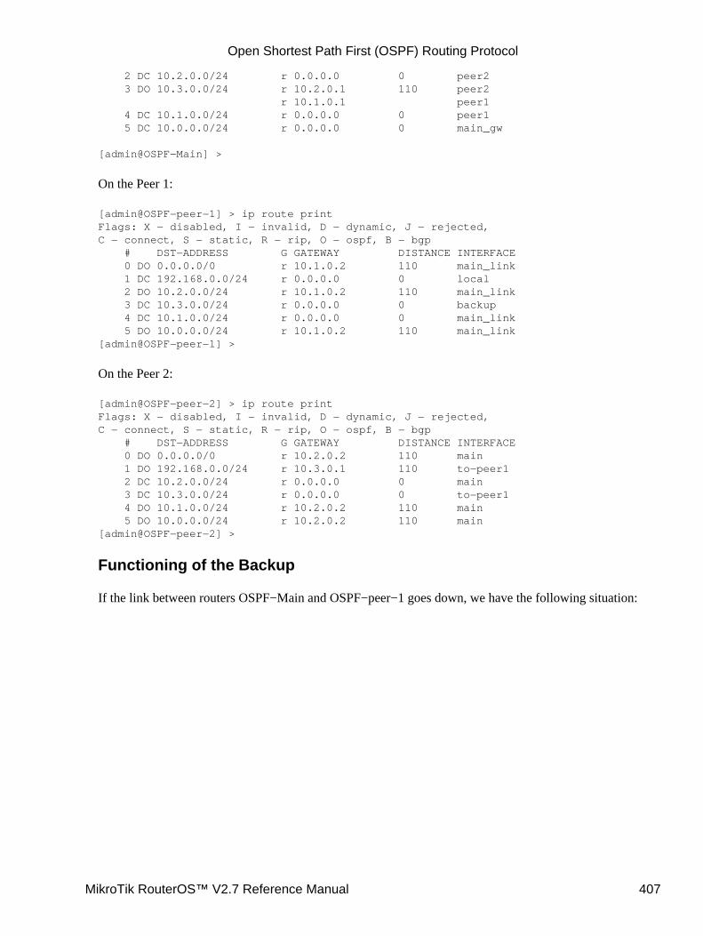
2 DC 10.2.0.0/24 r 0.0.0.0 0 peer2 3 DO 10.3.0.0/24 r 10.2.0.1 110 peer2 r 10.1.0.1 peer1 4 DC 10.1.0.0/24 r 0.0.0.0 0 peer1 5 DC 10.0.0.0/24 r 0.0.0.0 0 main_gw
[admin@OSPF−Main] >
On the Peer 1:
[admin@OSPF−peer−1] > ip route printFlags: X − disabled, I − invalid, D − dynamic, J − rejected,C − connect, S − static, R − rip, O − ospf, B − bgp # DST−ADDRESS G GATEWAY DISTANCE INTERFACE 0 DO 0.0.0.0/0 r 10.1.0.2 110 main_link 1 DC 192.168.0.0/24 r 0.0.0.0 0 local 2 DO 10.2.0.0/24 r 10.1.0.2 110 main_link 3 DC 10.3.0.0/24 r 0.0.0.0 0 backup 4 DC 10.1.0.0/24 r 0.0.0.0 0 main_link 5 DO 10.0.0.0/24 r 10.1.0.2 110 main_link[admin@OSPF−peer−1] >
On the Peer 2:
[admin@OSPF−peer−2] > ip route printFlags: X − disabled, I − invalid, D − dynamic, J − rejected,C − connect, S − static, R − rip, O − ospf, B − bgp # DST−ADDRESS G GATEWAY DISTANCE INTERFACE 0 DO 0.0.0.0/0 r 10.2.0.2 110 main 1 DO 192.168.0.0/24 r 10.3.0.1 110 to−peer1 2 DC 10.2.0.0/24 r 0.0.0.0 0 main 3 DC 10.3.0.0/24 r 0.0.0.0 0 to−peer1 4 DO 10.1.0.0/24 r 10.2.0.2 110 main 5 DO 10.0.0.0/24 r 10.2.0.2 110 main[admin@OSPF−peer−2] >
Functioning of the Backup
If the link between routers OSPF−Main and OSPF−peer−1 goes down, we have the following situation:
Open Shortest Path First (OSPF) Routing Protocol
MikroTik RouterOS™ V2.7 Reference Manual 407
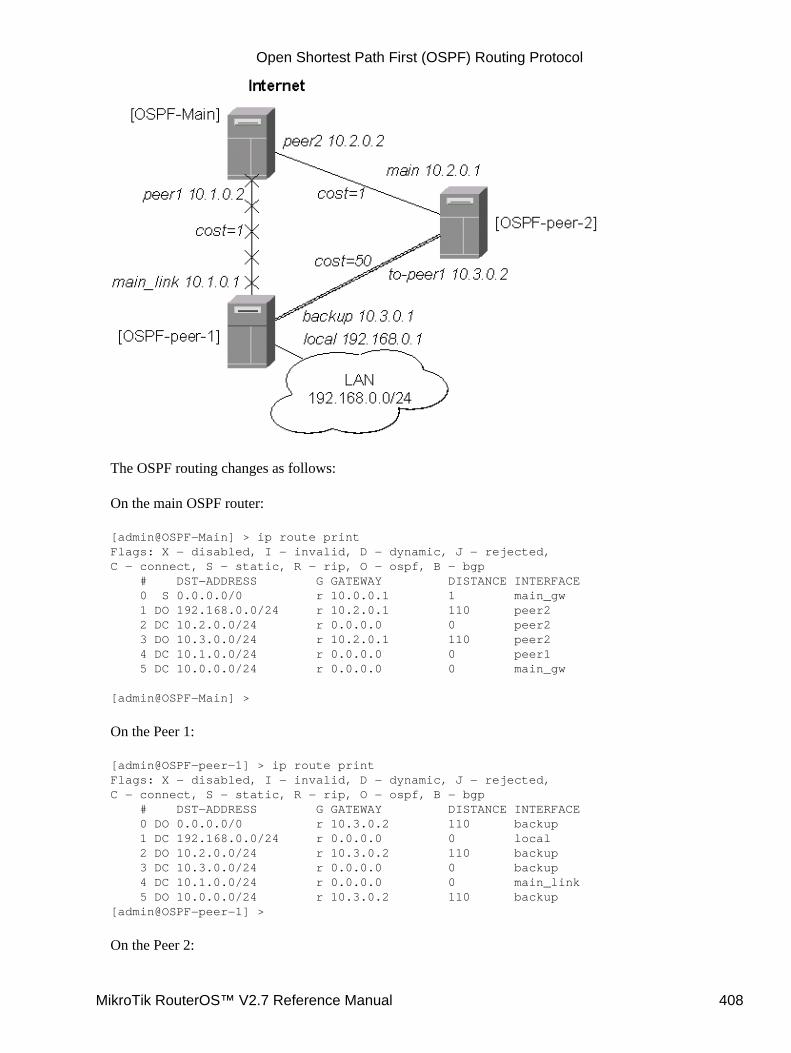
The OSPF routing changes as follows:
On the main OSPF router:
[admin@OSPF−Main] > ip route printFlags: X − disabled, I − invalid, D − dynamic, J − rejected,C − connect, S − static, R − rip, O − ospf, B − bgp # DST−ADDRESS G GATEWAY DISTANCE INTERFACE 0 S 0.0.0.0/0 r 10.0.0.1 1 main_gw 1 DO 192.168.0.0/24 r 10.2.0.1 110 peer2 2 DC 10.2.0.0/24 r 0.0.0.0 0 peer2 3 DO 10.3.0.0/24 r 10.2.0.1 110 peer2 4 DC 10.1.0.0/24 r 0.0.0.0 0 peer1 5 DC 10.0.0.0/24 r 0.0.0.0 0 main_gw
[admin@OSPF−Main] >
On the Peer 1:
[admin@OSPF−peer−1] > ip route printFlags: X − disabled, I − invalid, D − dynamic, J − rejected,C − connect, S − static, R − rip, O − ospf, B − bgp # DST−ADDRESS G GATEWAY DISTANCE INTERFACE 0 DO 0.0.0.0/0 r 10.3.0.2 110 backup 1 DC 192.168.0.0/24 r 0.0.0.0 0 local 2 DO 10.2.0.0/24 r 10.3.0.2 110 backup 3 DC 10.3.0.0/24 r 0.0.0.0 0 backup 4 DC 10.1.0.0/24 r 0.0.0.0 0 main_link 5 DO 10.0.0.0/24 r 10.3.0.2 110 backup[admin@OSPF−peer−1] >
On the Peer 2:
Open Shortest Path First (OSPF) Routing Protocol
MikroTik RouterOS™ V2.7 Reference Manual 408
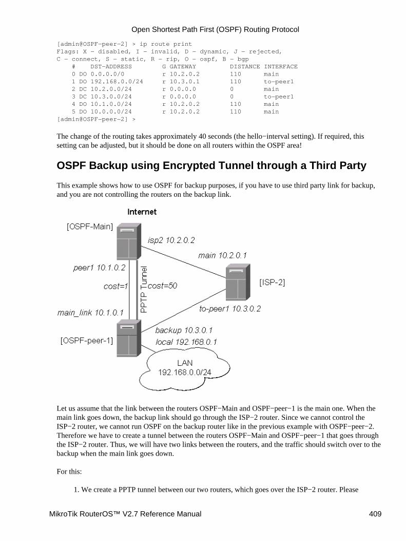
[admin@OSPF−peer−2] > ip route printFlags: X − disabled, I − invalid, D − dynamic, J − rejected,C − connect, S − static, R − rip, O − ospf, B − bgp # DST−ADDRESS G GATEWAY DISTANCE INTERFACE 0 DO 0.0.0.0/0 r 10.2.0.2 110 main 1 DO 192.168.0.0/24 r 10.3.0.1 110 to−peer1 2 DC 10.2.0.0/24 r 0.0.0.0 0 main 3 DC 10.3.0.0/24 r 0.0.0.0 0 to−peer1 4 DO 10.1.0.0/24 r 10.2.0.2 110 main 5 DO 10.0.0.0/24 r 10.2.0.2 110 main[admin@OSPF−peer−2] >
The change of the routing takes approximately 40 seconds (the hello−interval setting). If required, thissetting can be adjusted, but it should be done on all routers within the OSPF area!
OSPF Backup using Encrypted Tunnel through a Third Party
This example shows how to use OSPF for backup purposes, if you have to use third party link for backup,and you are not controlling the routers on the backup link.
Let us assume that the link between the routers OSPF−Main and OSPF−peer−1 is the main one. When themain link goes down, the backup link should go through the ISP−2 router. Since we cannot control theISP−2 router, we cannot run OSPF on the backup router like in the previous example with OSPF−peer−2.Therefore we have to create a tunnel between the routers OSPF−Main and OSPF−peer−1 that goes throughthe ISP−2 router. Thus, we will have two links between the routers, and the traffic should switch over to thebackup when the main link goes down.
For this:
We create a PPTP tunnel between our two routers, which goes over the ISP−2 router. Please1.
Open Shortest Path First (OSPF) Routing Protocol
MikroTik RouterOS™ V2.7 Reference Manual 409
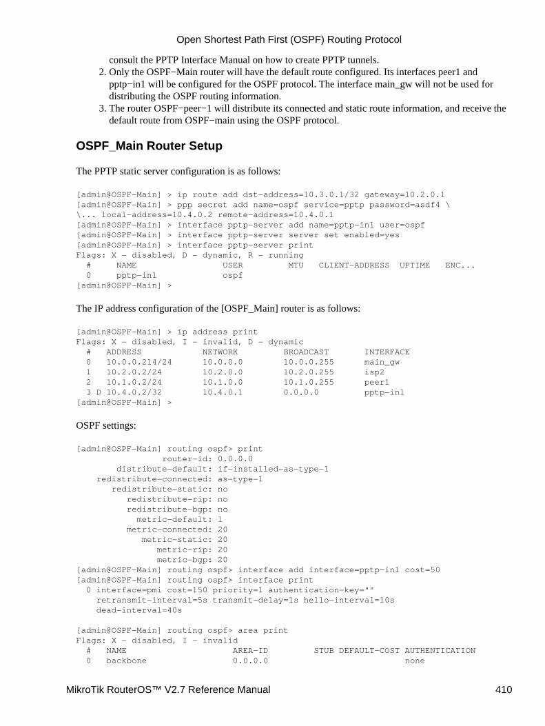
consult the PPTP Interface Manual on how to create PPTP tunnels.Only the OSPF−Main router will have the default route configured. Its interfaces peer1 andpptp−in1 will be configured for the OSPF protocol. The interface main_gw will not be used fordistributing the OSPF routing information.
2.
The router OSPF−peer−1 will distribute its connected and static route information, and receive thedefault route from OSPF−main using the OSPF protocol.
3.
OSPF_Main Router Setup
The PPTP static server configuration is as follows:
[admin@OSPF−Main] > ip route add dst−address=10.3.0.1/32 gateway=10.2.0.1[admin@OSPF−Main] > ppp secret add name=ospf service=pptp password=asdf4 \\... local−address=10.4.0.2 remote−address=10.4.0.1[admin@OSPF−Main] > interface pptp−server add name=pptp−in1 user=ospf[admin@OSPF−Main] > interface pptp−server server set enabled=yes[admin@OSPF−Main] > interface pptp−server printFlags: X − disabled, D − dynamic, R − running # NAME USER MTU CLIENT−ADDRESS UPTIME ENC... 0 pptp−in1 ospf[admin@OSPF−Main] >
The IP address configuration of the [OSPF_Main] router is as follows:
[admin@OSPF−Main] > ip address printFlags: X − disabled, I − invalid, D − dynamic # ADDRESS NETWORK BROADCAST INTERFACE 0 10.0.0.214/24 10.0.0.0 10.0.0.255 main_gw 1 10.2.0.2/24 10.2.0.0 10.2.0.255 isp2 2 10.1.0.2/24 10.1.0.0 10.1.0.255 peer1 3 D 10.4.0.2/32 10.4.0.1 0.0.0.0 pptp−in1[admin@OSPF−Main] >
OSPF settings:
[admin@OSPF−Main] routing ospf> print router−id: 0.0.0.0 distribute−default: if−installed−as−type−1 redistribute−connected: as−type−1 redistribute−static: no redistribute−rip: no redistribute−bgp: no metric−default: 1 metric−connected: 20 metric−static: 20 metric−rip: 20 metric−bgp: 20[admin@OSPF−Main] routing ospf> interface add interface=pptp−in1 cost=50[admin@OSPF−Main] routing ospf> interface print 0 interface=pmi cost=150 priority=1 authentication−key="" retransmit−interval=5s transmit−delay=1s hello−interval=10s dead−interval=40s
[admin@OSPF−Main] routing ospf> area printFlags: X − disabled, I − invalid # NAME AREA−ID STUB DEFAULT−COST AUTHENTICATION 0 backbone 0.0.0.0 none
Open Shortest Path First (OSPF) Routing Protocol
MikroTik RouterOS™ V2.7 Reference Manual 410
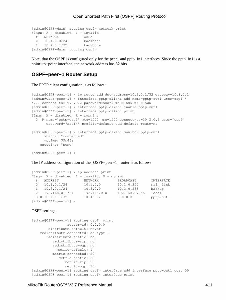
[admin@OSPF−Main] routing ospf> network printFlags: X − disabled, I − invalid # NETWORK AREA 0 10.1.0.0/24 backbone 1 10.4.0.1/32 backbone[admin@OSPF−Main] routing ospf>
Note, that the OSPF is configured only for the peer1 and pptp−in1 interfaces. Since the pptp−in1 is apoint−to−point interface, the network address has 32 bits.
OSPF−peer−1 Router Setup
The PPTP client configuration is as follows:
[admin@OSPF−peer−1] > ip route add dst−address=10.2.0.2/32 gateway=10.3.0.2[admin@OSPF−peer−1] > interface pptp−client add name=pptp−out1 user=ospf \\... connect−to=10.2.0.2 password=asdf4 mtu=1500 mru=1500[admin@OSPF−peer−1] > interface pptp−client enable pptp−out1[admin@OSPF−peer−1] > interface pptp−client printFlags: X − disabled, R − running 0 R name="pptp−out1" mtu=1500 mru=1500 connect−to=10.2.0.2 user="ospf" password="asdf4" profile=default add−default−route=no
[admin@OSPF−peer−1] > interface pptp−client monitor pptp−out1 status: "connected" uptime: 39m46s encoding: "none"
[admin@OSPF−peer−1] >
The IP address configuration of the [OSPF−peer−1] router is as follows:
[admin@OSPF−peer−1] > ip address printFlags: X − disabled, I − invalid, D − dynamic # ADDRESS NETWORK BROADCAST INTERFACE 0 10.1.0.1/24 10.1.0.0 10.1.0.255 main_link 1 10.3.0.1/24 10.3.0.0 10.3.0.255 backup 2 192.168.0.1/24 192.168.0.0 192.168.0.255 local 3 D 10.4.0.1/32 10.4.0.2 0.0.0.0 pptp−out1[admin@OSPF−peer−1] >
OSPF settings:
[admin@OSPF−peer−1] routing ospf> print router−id: 0.0.0.0 distribute−default: never redistribute−connected: as−type−1 redistribute−static: no redistribute−rip: no redistribute−bgp: no metric−default: 1 metric−connected: 20 metric−static: 20 metric−rip: 20 metric−bgp: 20[admin@OSPF−peer−1] routing ospf> interface add interface=pptp−out1 cost=50[admin@OSPF−peer−1] routing ospf> interface print
Open Shortest Path First (OSPF) Routing Protocol
MikroTik RouterOS™ V2.7 Reference Manual 411
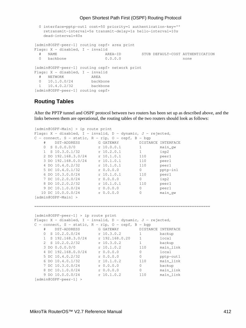
0 interface=pptp−out1 cost=50 priority=1 authentication−key="" retransmit−interval=5s transmit−delay=1s hello−interval=10s dead−interval=40s
[admin@OSPF−peer−1] routing ospf> area printFlags: X − disabled, I − invalid # NAME AREA−ID STUB DEFAULT−COST AUTHENTICATION 0 backbone 0.0.0.0 none
[admin@OSPF−peer−1] routing ospf> network printFlags: X − disabled, I − invalid # NETWORK AREA 0 10.1.0.0/24 backbone 1 10.4.0.2/32 backbone[admin@OSPF−peer−1] routing ospf>
Routing Tables
After the PPTP tunnel and OSPF protocol between two routers has been set up as described above, and thelinks between them are operational, the routing tables of the two routers should look as follows:
[admin@OSPF−Main] > ip route printFlags: X − disabled, I − invalid, D − dynamic, J − rejected,C − connect, S − static, R − rip, O − ospf, B − bgp # DST−ADDRESS G GATEWAY DISTANCE INTERFACE 0 S 0.0.0.0/0 r 10.0.0.1 1 main_gw 1 S 10.3.0.1/32 r 10.2.0.1 1 isp2 2 DO 192.168.3.0/24 r 10.1.0.1 110 peer1 3 DO 192.168.0.0/24 r 10.1.0.1 110 peer1 4 DO 10.4.0.2/32 r 10.1.0.1 110 peer1 5 DC 10.4.0.1/32 r 0.0.0.0 0 pptp−in1 6 DO 10.3.0.0/24 r 10.1.0.1 110 peer1 7 DC 10.2.0.0/24 r 0.0.0.0 0 isp2 8 DO 10.2.0.2/32 r 10.1.0.1 110 peer1 9 DC 10.1.0.0/24 r 0.0.0.0 0 peer1 10 DC 10.0.0.0/24 r 0.0.0.0 0 main_gw[admin@OSPF−Main] >
=============================================================================
[admin@OSPF−peer−1] > ip route printFlags: X − disabled, I − invalid, D − dynamic, J − rejected,C − connect, S − static, R − rip, O − ospf, B − bgp # DST−ADDRESS G GATEWAY DISTANCE INTERFACE 0 S 10.2.0.0/24 r 10.3.0.2 1 backup 1 S 192.168.3.0/24 r 192.168.0.20 1 local 2 S 10.2.0.2/32 r 10.3.0.2 1 backup 3 DO 0.0.0.0/0 r 10.1.0.2 110 main_link 4 DC 192.168.0.0/24 r 0.0.0.0 0 local 5 DC 10.4.0.2/32 r 0.0.0.0 0 pptp−out1 6 DO 10.4.0.1/32 r 10.1.0.2 110 main_link 7 DC 10.3.0.0/24 r 0.0.0.0 0 backup 8 DC 10.1.0.0/24 r 0.0.0.0 0 main_link 9 DO 10.0.0.0/24 r 10.1.0.2 110 main_link[admin@OSPF−peer−1] >
Open Shortest Path First (OSPF) Routing Protocol
MikroTik RouterOS™ V2.7 Reference Manual 412
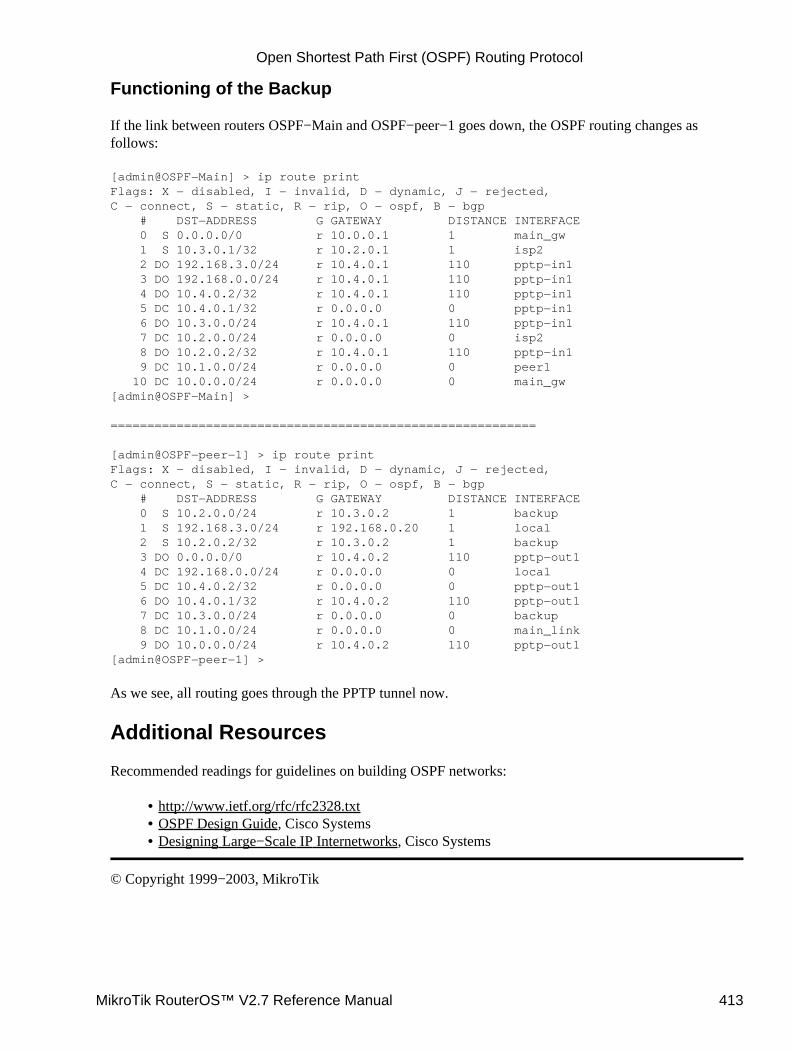
Functioning of the Backup
If the link between routers OSPF−Main and OSPF−peer−1 goes down, the OSPF routing changes asfollows:
[admin@OSPF−Main] > ip route printFlags: X − disabled, I − invalid, D − dynamic, J − rejected,C − connect, S − static, R − rip, O − ospf, B − bgp # DST−ADDRESS G GATEWAY DISTANCE INTERFACE 0 S 0.0.0.0/0 r 10.0.0.1 1 main_gw 1 S 10.3.0.1/32 r 10.2.0.1 1 isp2 2 DO 192.168.3.0/24 r 10.4.0.1 110 pptp−in1 3 DO 192.168.0.0/24 r 10.4.0.1 110 pptp−in1 4 DO 10.4.0.2/32 r 10.4.0.1 110 pptp−in1 5 DC 10.4.0.1/32 r 0.0.0.0 0 pptp−in1 6 DO 10.3.0.0/24 r 10.4.0.1 110 pptp−in1 7 DC 10.2.0.0/24 r 0.0.0.0 0 isp2 8 DO 10.2.0.2/32 r 10.4.0.1 110 pptp−in1 9 DC 10.1.0.0/24 r 0.0.0.0 0 peer1 10 DC 10.0.0.0/24 r 0.0.0.0 0 main_gw[admin@OSPF−Main] >
==========================================================
[admin@OSPF−peer−1] > ip route printFlags: X − disabled, I − invalid, D − dynamic, J − rejected,C − connect, S − static, R − rip, O − ospf, B − bgp # DST−ADDRESS G GATEWAY DISTANCE INTERFACE 0 S 10.2.0.0/24 r 10.3.0.2 1 backup 1 S 192.168.3.0/24 r 192.168.0.20 1 local 2 S 10.2.0.2/32 r 10.3.0.2 1 backup 3 DO 0.0.0.0/0 r 10.4.0.2 110 pptp−out1 4 DC 192.168.0.0/24 r 0.0.0.0 0 local 5 DC 10.4.0.2/32 r 0.0.0.0 0 pptp−out1 6 DO 10.4.0.1/32 r 10.4.0.2 110 pptp−out1 7 DC 10.3.0.0/24 r 0.0.0.0 0 backup 8 DC 10.1.0.0/24 r 0.0.0.0 0 main_link 9 DO 10.0.0.0/24 r 10.4.0.2 110 pptp−out1[admin@OSPF−peer−1] >
As we see, all routing goes through the PPTP tunnel now.
Additional Resources
Recommended readings for guidelines on building OSPF networks:
http://www.ietf.org/rfc/rfc2328.txt• OSPF Design Guide, Cisco Systems• Designing Large−Scale IP Internetworks, Cisco Systems•
© Copyright 1999−2003, MikroTik
Open Shortest Path First (OSPF) Routing Protocol
MikroTik RouterOS™ V2.7 Reference Manual 413
Routing Prefix ListsDocument revision 1.0 (21−Jan−2003)This document applies to MikroTik RouterOS v2.7
Table of Contents
Table of Contents• Summary• Specifications• Related Documents• Description• Prefix List Setup
Property Description♦ Notes♦ Exapmle♦
•
Prefix List RulesProperty Description♦ Notes♦ Example♦
•
Summary
Prefix lists are used to filter routes received from or sent to other routers.
Specifications
Packages required : routingLicense required : AnyHome menu level : /routing prefix−listProtocols utilized : NoneHardware usage: not significant
Related Documents
Software Package Installation and UpgradingIP Addresses and Address Resolution Protocol (ARP)Routes, Equal Cost Multipath Routing, Policy RoutingRIP, Router Information ProtocolBGP, Border Gateway Protocol
Description
Filtering by prefix list involves matching the prefixes of routes with those listed in the prefix list. When thereis a match, the route is used. The prefix lists are used when specifying the BGP peers under /routing bgp peeror RIP interfaces under /routing rip interface.
MikroTik RouterOS™ V2.7 Reference Manual 414
To match a prefix−list entry, route should have its prefix (i.e. destination address) matching prefix property ofthe entry, and it should have the length of its prefix (i.e. mask of destination address) matching prefix−lengthproperty of the entry.
Prefix List Setup
Submenu level : /routing prefix−list
Property Description
name (name, default: "") − name for the prefix listdefault−action (accept | reject, default: accept) − default action for all members of this list
Notes
An empty prefix list permits or rejects all prefixes.
Exapmle
To add a cybernet list that rejects the routes by default:
[admin@MikroTik] routing prefix−list> add name=cybernet default−action=reject[admin@MikroTik] routing prefix−list> print # NAME DEFAULT−ACTION 0 cybernet reject[admin@MikroTik] routing prefix−list>
Prefix List Rules
Submenu level : /routing prefix−list list listname
Property Description
prefix (IP address/mask, default: 0.0.0.0/0) − network prefixprefix−length (integer−integer, default: 0−32) − length (range) of the network prefix in bitsaction (accept | reject, default: accept) − action for the list member
Notes
There are two different values to match − prefix (i.e. destination address of the route applying the networkmask) and prefix length. Prefix length match network mask of the received route.
For example, if prefix=172.16.0.0/16 and prefix=length=16−24, then received route for 172.16.24.0/24 willmatch, but route for 172.16.24.0/25 will not.
Example
To accept the routes to the 172.16.0.0/16 network and any of it's subnetworks that has their network maskbetween 16 and 24.
Routing Prefix Lists
MikroTik RouterOS™ V2.7 Reference Manual 415

[admin@MikroTik] routing prefix−list> list cybernet[admin@MikroTik] routing prefix−list list cybernet> add prefix=172.16.0.0/16 \\... prefix−length=16−24[admin@MikroTik] routing prefix−list list cybernet> print # PREFIX PREFIX−LENGTH ACTION 0 172.16.0.0/16 16−24 accept[admin@MikroTik] routing prefix−list list cybernet>
© Copyright 1999−2003, MikroTik
Routing Prefix Lists
MikroTik RouterOS™ V2.7 Reference Manual 416
Routing Information Protocol (RIP)Document revision 1.1 (02−May−2003)This document applies to MikroTik RouterOS v2.7
Table of Contents
Table of Contents• Summary• Specifications• Related Documents• Description• RIP Routing Setup
Proprety Description♦ Notes♦ Example♦
•
RIP InterfacesDescription♦ Prorerty Description♦ Notes♦ Example♦
•
RIP NetworksDescription♦ Proprety Description♦ Notes♦ Example♦
•
RIP NeighborsDescription♦ Proprety Description♦ Example♦
•
RIP RoutesProperty Description♦ Notes♦ Example♦
•
RIP ExamplesThe Configuration of the MikroTik Router♦ The Configuration of the Cisco Router♦
•
Additional Resources•
Summary
MikroTik RouterOS implements RIP Version 1 (RFC1058) and Version 2 (RFC 2453). RIP lets routers in thesame autonomous system exchange routing information. It always uses the best path (the path with te fewestnumber of hops (i.e. routers)) available.
Specifications
Packages required : routingLicense required : Any
MikroTik RouterOS™ V2.7 Reference Manual 417
Home menu level : /routing ripProtocols utilized : RIPv1 (RFC1058), RIPv2 (RFC2453)Hardware usage: not significant
Related Documents
Software Package Installation and UpgradingIP Addresses and Address Resolution Protocol (ARP)Routes, Equal Cost Multipath Routing, Policy RoutingPrefix Lists
Description
Routing Information Protocol (RIP) is one protocol in a series of routing protocols based on Bellman−Ford(or distance vector) algorithm. This Interior Gateway Protocol (IGP) lets routers in the same autonomoussystem exchange routing information in the way of periodic RIP updates. Routers transmit their own RIPupdates to neighboring networks and listen to the RIP updates from the routers on those neighboring networksto ensure their routing table reflects current state of the network and all the best paths are available. Best pathis a path with the fewest hops (routers gateways).
The routes learned by RIP protocol are installed in the route list with the distance of 120.
RIP Routing Setup
Submenu level : /routing rip
[admin@MikroTik] routing rip> print redistribute−static: no redistribute−connected: no redistribute−ospf: no redistribute−bgp: no metric−static: 1 metric−connected: 1 metric−ospf: 1 metric−bgp: 1 update−timer: 30s timeout−timer: 3m garbage−timer: 2m[admin@MikroTik] routing rip>
Proprety Description
redistribute−static (yes | no, default: no) − redistribution of static routes to neighbor routersredistribute−connected (yes | no, default: no) − redistribution of connected routes to neighbor routersredistribute−ospf (yes | no, default: no) − redistribution of routes learned by OSPF to neighbor routersredistribute−bgp (yes | no, default: no) − redistribution of routes learned by BGP to neighbor routersmetric−static (integer, default: 1) − metric, the distance to the destination for static routesmetric−connected (integer, default: 1) − metric, the distance to the destination for connected routesmetric−ospf (integer, default: 1) − metric, the distance to the destination for OSPF routesmetric−bgp (integer, default: 1) − metric, the distance to the destination for BGP routesupdate−timer (time, default: 30s) − time period for RIP update to start
Routing Information Protocol (RIP)
MikroTik RouterOS™ V2.7 Reference Manual 418
timeout−timer (time, default: 3m)− time period after route is not valid moregarbage−timer (time, default: 2m)− time period after dropped out route is dropped from neighbor router table
Notes
The maximum metric of RIP route can be 15. Metric higher than 15 is considered 'infinity' and routes withsuch metric are considered unreachable. Thus RIP cannot be used on networks with more than 15 hopsbetween any two routers, and using redistribute metrics larger that 1 further reduces this maximum hop count.
Example
To enable RIP protocol to redistribute the routes to the connected networks:
[admin@MikroTik] routing rip> set redistribute−connected=yes[admin@MikroTik] routing rip> print redistribute−static: no redistribute−connected: yes redistribute−ospf: no redistribute−bgp: no metric−static: 1 metric−connected: 1 metric−ospf: 1 metric−bgp: 1 update−timer: 30s timeout−timer: 3m garbage−timer: 2m[admin@MikroTik] routing rip>
RIP Interfaces
Submenu level : /routing rip interface
Description
To run RIP you don't have to configure interfaces. This command level is only for additional configuration ofRIP specific interface parameters.
Prorerty Description
interface (name, default: all) − interface on which rus RIPall sets the defaults, that will be used for all the interfaces not having specific settingssend (v1 | v1−2 | v2, default: v2) − distributed RIP protocol versionsreceive (v1 | v1−2 | v2, default: v2) − RIP protocol versions the router can receiveauthentication (none | simple | md5, default: none) − authentication method for RIP messages:
•
none − no authentication• simple − clear text authentication• md5 − Keyed Message Digest 5 (MD5) authenticationauthentication−key (string, default: "") − authentication key for RIP messagesprefix−list−in (name, default: "") − name of the filtering prefix list for receiving routesprefix−list−out (name, default: "") − name of the filtering prefix list for advertising routes
•
Routing Information Protocol (RIP)
MikroTik RouterOS™ V2.7 Reference Manual 419
Notes
Security issue: it is recommended not to use RIP version 1 when it is possible.
Example
To add an entry that specifies that sending routes to the ether1 interface, prefix list plout should be applied:
[admin@MikroTik] routing rip> interface add interface=ether1 \\... prefix−list−out=plout[admin@MikroTik] routing rip> interface printFlags: I − inactive 0 interface=ether1 receive=v2 send=v2 authentication=none authentication−key="" prefix−list−in=plout prefix−list−out=none
[admin@MikroTik] routing rip>
RIP Networks
Submenu level : /routing rip network
Description
To start the RIP protocol, you have to define the networks on which RIP runs.
Proprety Description
address (IP address/mask, dafault: 0.0.0.0/0) − the network on which RIP is running. It allows defining oneor multiple interfaces RIP to be run on. Only directly connected networks of the router may be specifiednetwork (IP address, default: 0.0.0.0) − specifies the network mask of the address (if it is not specified inthe address argument)
Notes
For P2P links here you should set exactly the same as the network address is (that is remote point IPaddress). In this case, the correct netmask bits should be 32
Example
To enable RIP protocol on 10.10.1.0/24 network:
[admin@MikroTik] routing rip network> add address=10.10.1.0/24[admin@MikroTik] routing rip network> print # ADDRESS 0 10.10.1.0/24[admin@MikroTik] routing rip>
Routing Information Protocol (RIP)
MikroTik RouterOS™ V2.7 Reference Manual 420
RIP Neighbors
Description
The submenu is used to define a neighboring router with which to exchange routing information. Normallythere is no need to add the neighbors, if the multicasting is working properly within the network. If thereare problems with exchanging the routing information, the neighbors can be added to the list. It will force toexchange the routing information with the neighbor.
Proprety Description
address (IP address, dafault: 0.0.0.0) − the neighbour's address
Example
To force RIP protocol to exchange routing information with the 10.0.0.1 router:
[admin@MikroTik] routing rip> neighbor add address=10.0.0.1[admin@MikroTik] routing rip> neighbor printFlags: I − inactive # ADDRESS 0 10.0.0.1[admin@MikroTik] routing rip>
RIP Routes
Submenu level : /routing rip route
Property Description
Statistics:
dst−address (IP address/mask) − destination network address and netmaskgateway (IP address) − last gateway to destination addressmetric (integer) − distance vector length to the networkfrom (IP address) − from which router this route was received
Notes
This list shows the routes learned by all dynamic routing protocols (RIP, OSPF, BGP)
Example
To view the routes:
[admin@MikroTik] routing rip route> printFlags: S − static, R − rip, O − ospf, C − connect, B − bgp 0 O dst−address=0.0.0.0/32 gateway=10.7.1.254 metric=1 from=0.0.0.0
...
Routing Information Protocol (RIP)
MikroTik RouterOS™ V2.7 Reference Manual 421
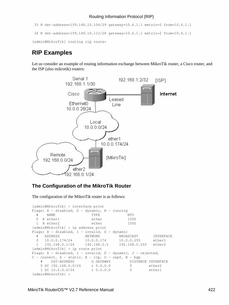
33 R dst−address=159.148.10.104/29 gateway=10.6.1.1 metric=2 from=10.6.1.1
34 R dst−address=159.148.10.112/28 gateway=10.6.1.1 metric=2 from=10.6.1.1
[admin@MikroTik] routing rip route>
RIP Examples
Let us consider an example of routing information exchange between MikroTik router, a Cisco router, andthe ISP (also mikrotik) routers:
The Configuration of the MikroTik Router
The configuration of the MikroTik router is as follows:
[admin@MikroTik] > interface printFlags: X − disabled, D − dynamic, R − running # NAME TYPE MTU 0 R ether1 ether 1500 1 R ether2 ether 1500[admin@MikroTik] > ip address printFlags: X − disabled, I − invalid, D − dynamic # ADDRESS NETWORK BROADCAST INTERFACE 0 10.0.0.174/24 10.0.0.174 10.0.0.255 ether1 1 192.168.0.1/24 192.168.0.0 192.168.0.255 ether2[admin@MikroTik] > ip route printFlags: X − disabled, I − invalid, D − dynamic, J − rejected,C − connect, S − static, R − rip, O − ospf, B − bgp # DST−ADDRESS G GATEWAY DISTANCE INTERFACE 0 DC 192.168.0.0/24 r 0.0.0.0 0 ether2 1 DC 10.0.0.0/24 r 0.0.0.0 0 ether1[admin@MikroTik] >
Routing Information Protocol (RIP)
MikroTik RouterOS™ V2.7 Reference Manual 422
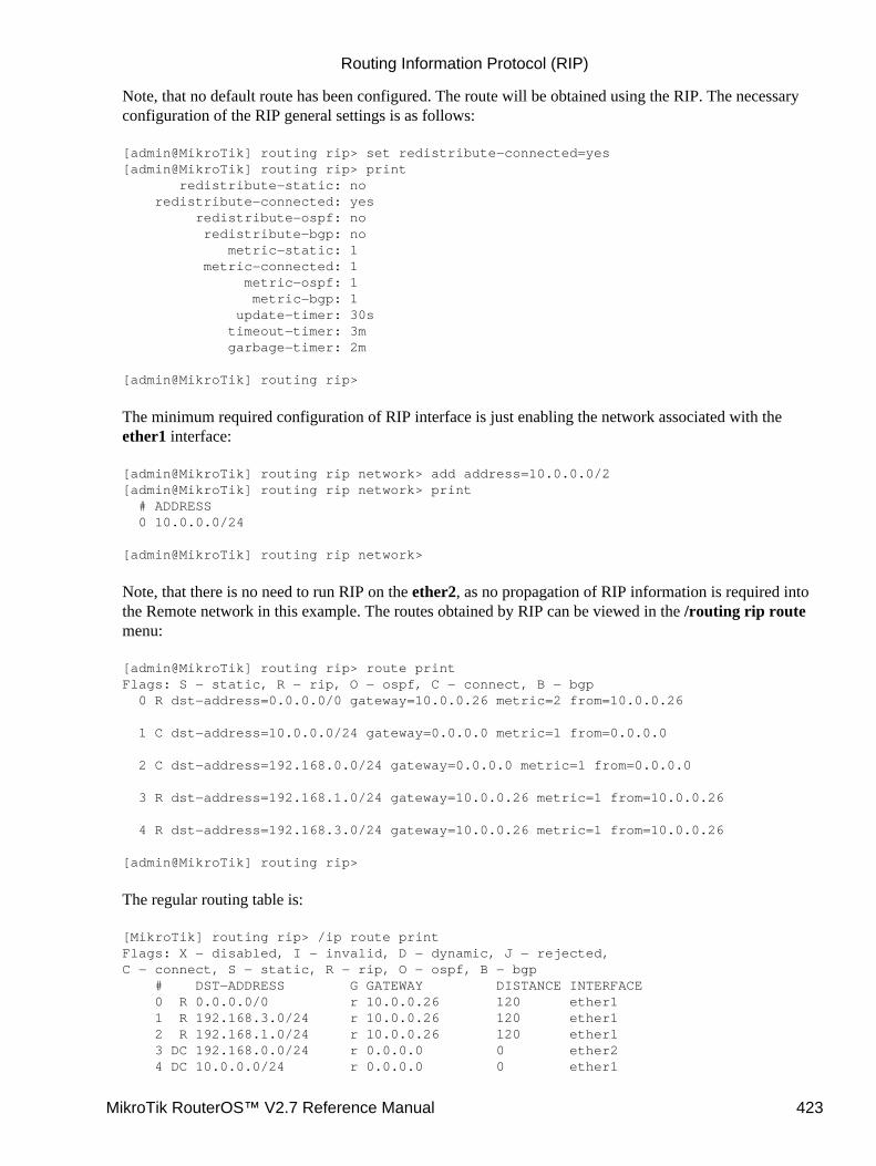
Note, that no default route has been configured. The route will be obtained using the RIP. The necessaryconfiguration of the RIP general settings is as follows:
[admin@MikroTik] routing rip> set redistribute−connected=yes[admin@MikroTik] routing rip> print redistribute−static: no redistribute−connected: yes redistribute−ospf: no redistribute−bgp: no metric−static: 1 metric−connected: 1 metric−ospf: 1 metric−bgp: 1 update−timer: 30s timeout−timer: 3m garbage−timer: 2m
[admin@MikroTik] routing rip>
The minimum required configuration of RIP interface is just enabling the network associated with theether1 interface:
[admin@MikroTik] routing rip network> add address=10.0.0.0/2[admin@MikroTik] routing rip network> print # ADDRESS 0 10.0.0.0/24
[admin@MikroTik] routing rip network>
Note, that there is no need to run RIP on the ether2, as no propagation of RIP information is required intothe Remote network in this example. The routes obtained by RIP can be viewed in the /routing rip routemenu:
[admin@MikroTik] routing rip> route printFlags: S − static, R − rip, O − ospf, C − connect, B − bgp 0 R dst−address=0.0.0.0/0 gateway=10.0.0.26 metric=2 from=10.0.0.26
1 C dst−address=10.0.0.0/24 gateway=0.0.0.0 metric=1 from=0.0.0.0
2 C dst−address=192.168.0.0/24 gateway=0.0.0.0 metric=1 from=0.0.0.0
3 R dst−address=192.168.1.0/24 gateway=10.0.0.26 metric=1 from=10.0.0.26
4 R dst−address=192.168.3.0/24 gateway=10.0.0.26 metric=1 from=10.0.0.26
[admin@MikroTik] routing rip>
The regular routing table is:
[MikroTik] routing rip> /ip route printFlags: X − disabled, I − invalid, D − dynamic, J − rejected,C − connect, S − static, R − rip, O − ospf, B − bgp # DST−ADDRESS G GATEWAY DISTANCE INTERFACE 0 R 0.0.0.0/0 r 10.0.0.26 120 ether1 1 R 192.168.3.0/24 r 10.0.0.26 120 ether1 2 R 192.168.1.0/24 r 10.0.0.26 120 ether1 3 DC 192.168.0.0/24 r 0.0.0.0 0 ether2 4 DC 10.0.0.0/24 r 0.0.0.0 0 ether1
Routing Information Protocol (RIP)
MikroTik RouterOS™ V2.7 Reference Manual 423
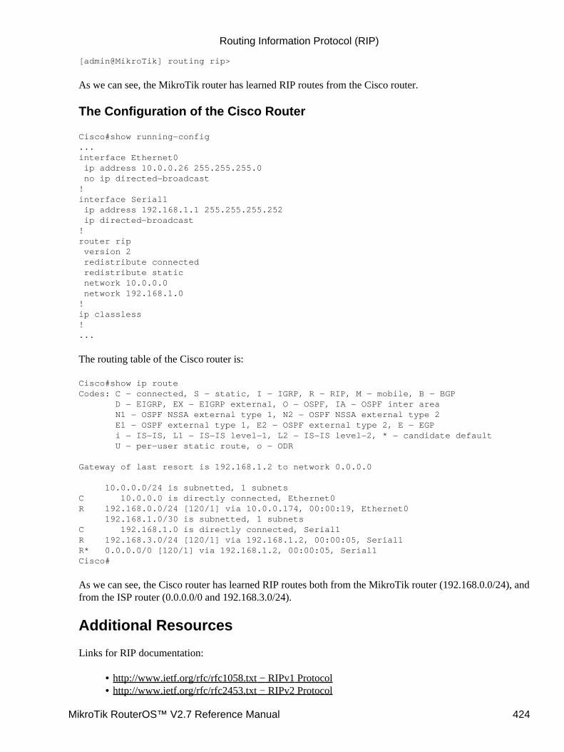
[admin@MikroTik] routing rip>
As we can see, the MikroTik router has learned RIP routes from the Cisco router.
The Configuration of the Cisco Router
Cisco#show running−config...interface Ethernet0 ip address 10.0.0.26 255.255.255.0 no ip directed−broadcast!interface Serial1 ip address 192.168.1.1 255.255.255.252 ip directed−broadcast!router rip version 2 redistribute connected redistribute static network 10.0.0.0 network 192.168.1.0!ip classless!...
The routing table of the Cisco router is:
Cisco#show ip routeCodes: C − connected, S − static, I − IGRP, R − RIP, M − mobile, B − BGP D − EIGRP, EX − EIGRP external, O − OSPF, IA − OSPF inter area N1 − OSPF NSSA external type 1, N2 − OSPF NSSA external type 2 E1 − OSPF external type 1, E2 − OSPF external type 2, E − EGP i − IS−IS, L1 − IS−IS level−1, L2 − IS−IS level−2, * − candidate default U − per−user static route, o − ODR
Gateway of last resort is 192.168.1.2 to network 0.0.0.0
10.0.0.0/24 is subnetted, 1 subnetsC 10.0.0.0 is directly connected, Ethernet0R 192.168.0.0/24 [120/1] via 10.0.0.174, 00:00:19, Ethernet0 192.168.1.0/30 is subnetted, 1 subnetsC 192.168.1.0 is directly connected, Serial1R 192.168.3.0/24 [120/1] via 192.168.1.2, 00:00:05, Serial1R* 0.0.0.0/0 [120/1] via 192.168.1.2, 00:00:05, Serial1Cisco#
As we can see, the Cisco router has learned RIP routes both from the MikroTik router (192.168.0.0/24), andfrom the ISP router (0.0.0.0/0 and 192.168.3.0/24).
Additional Resources
Links for RIP documentation:
http://www.ietf.org/rfc/rfc1058.txt − RIPv1 Protocol• http://www.ietf.org/rfc/rfc2453.txt − RIPv2 Protocol•
Routing Information Protocol (RIP)
MikroTik RouterOS™ V2.7 Reference Manual 424

Cisco Systems RIP protocol overview•
© Copyright 1999−2003, MikroTik
Routing Information Protocol (RIP)
MikroTik RouterOS™ V2.7 Reference Manual 425
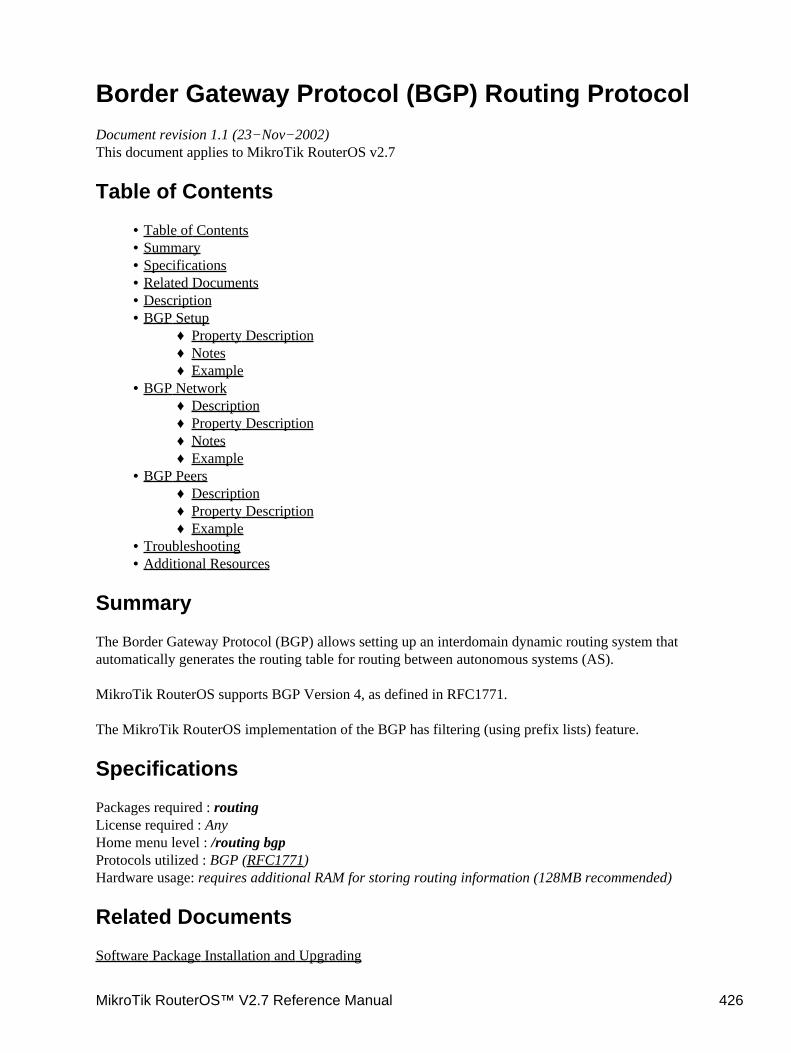
Border Gateway Protocol (BGP) Routing ProtocolDocument revision 1.1 (23−Nov−2002)This document applies to MikroTik RouterOS v2.7
Table of Contents
Table of Contents• Summary• Specifications• Related Documents• Description• BGP Setup
Property Description♦ Notes♦ Example♦
•
BGP NetworkDescription♦ Property Description♦ Notes♦ Example♦
•
BGP PeersDescription♦ Property Description♦ Example♦
•
Troubleshooting• Additional Resources•
Summary
The Border Gateway Protocol (BGP) allows setting up an interdomain dynamic routing system thatautomatically generates the routing table for routing between autonomous systems (AS).
MikroTik RouterOS supports BGP Version 4, as defined in RFC1771.
The MikroTik RouterOS implementation of the BGP has filtering (using prefix lists) feature.
Specifications
Packages required : routingLicense required : AnyHome menu level : /routing bgpProtocols utilized : BGP (RFC1771)Hardware usage: requires additional RAM for storing routing information (128MB recommended)
Related Documents
Software Package Installation and Upgrading
MikroTik RouterOS™ V2.7 Reference Manual 426
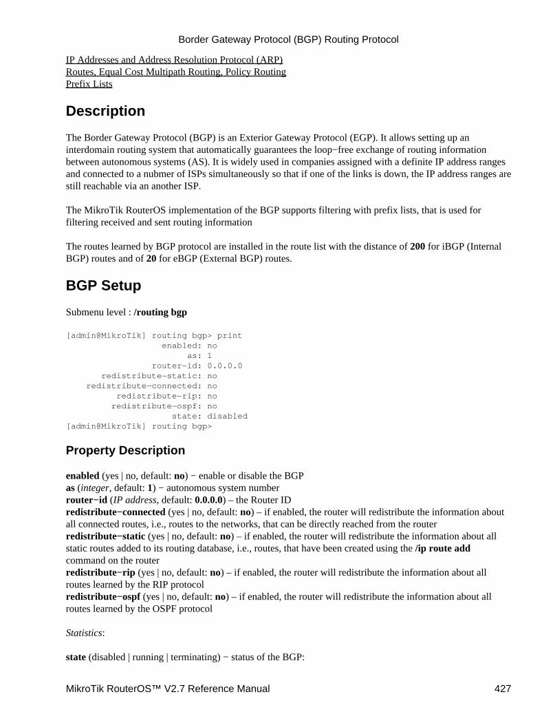
IP Addresses and Address Resolution Protocol (ARP)Routes, Equal Cost Multipath Routing, Policy RoutingPrefix Lists
Description
The Border Gateway Protocol (BGP) is an Exterior Gateway Protocol (EGP). It allows setting up aninterdomain routing system that automatically guarantees the loop−free exchange of routing informationbetween autonomous systems (AS). It is widely used in companies assigned with a definite IP address rangesand connected to a nubmer of ISPs simultaneously so that if one of the links is down, the IP address ranges arestill reachable via an another ISP.
The MikroTik RouterOS implementation of the BGP supports filtering with prefix lists, that is used forfiltering received and sent routing information
The routes learned by BGP protocol are installed in the route list with the distance of 200 for iBGP (InternalBGP) routes and of 20 for eBGP (External BGP) routes.
BGP Setup
Submenu level : /routing bgp
[admin@MikroTik] routing bgp> print enabled: no as: 1 router−id: 0.0.0.0 redistribute−static: no redistribute−connected: no redistribute−rip: no redistribute−ospf: no state: disabled[admin@MikroTik] routing bgp>
Property Description
enabled (yes | no, default: no) − enable or disable the BGPas (integer, default: 1) − autonomous system numberrouter−id (IP address, default: 0.0.0.0) – the Router IDredistribute−connected (yes | no, default: no) – if enabled, the router will redistribute the information aboutall connected routes, i.e., routes to the networks, that can be directly reached from the routerredistribute−static (yes | no, default: no) – if enabled, the router will redistribute the information about allstatic routes added to its routing database, i.e., routes, that have been created using the /ip route addcommand on the routerredistribute−rip (yes | no, default: no) – if enabled, the router will redistribute the information about allroutes learned by the RIP protocolredistribute−ospf (yes | no, default: no) – if enabled, the router will redistribute the information about allroutes learned by the OSPF protocol
Statistics:
state (disabled | running | terminating) − status of the BGP:
Border Gateway Protocol (BGP) Routing Protocol
MikroTik RouterOS™ V2.7 Reference Manual 427
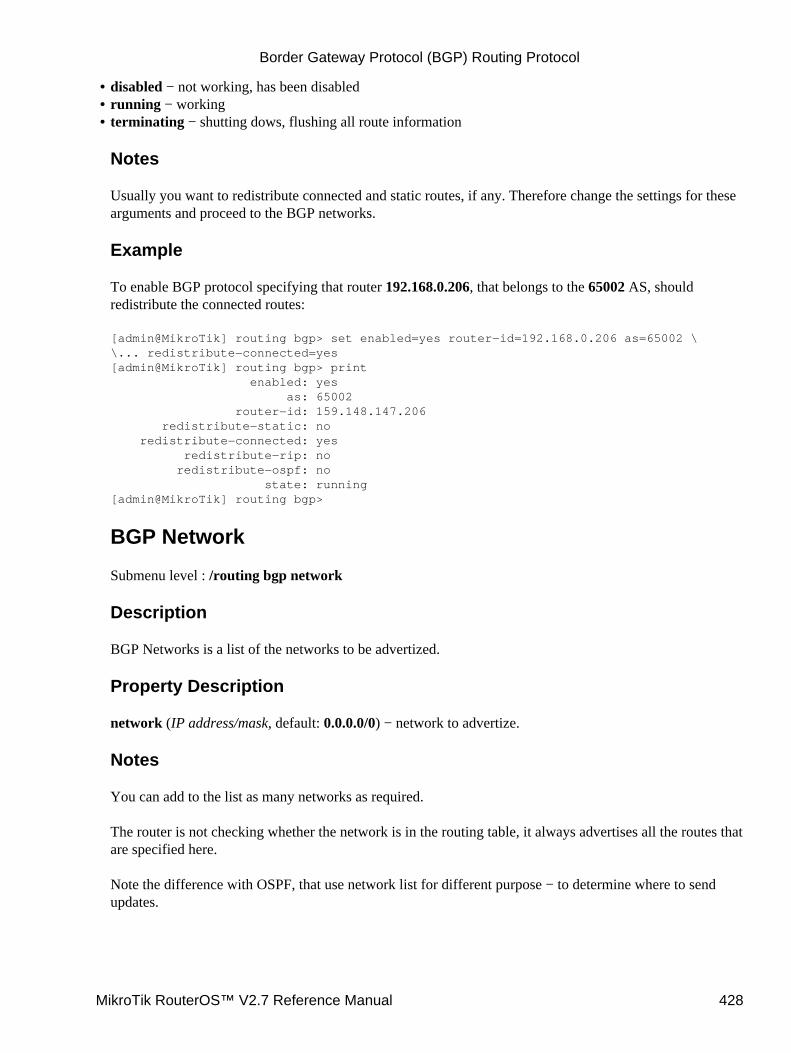
disabled − not working, has been disabled• running − working• terminating − shutting dows, flushing all route information
Notes
Usually you want to redistribute connected and static routes, if any. Therefore change the settings for thesearguments and proceed to the BGP networks.
Example
To enable BGP protocol specifying that router 192.168.0.206, that belongs to the 65002 AS, shouldredistribute the connected routes:
[admin@MikroTik] routing bgp> set enabled=yes router−id=192.168.0.206 as=65002 \\... redistribute−connected=yes[admin@MikroTik] routing bgp> print enabled: yes as: 65002 router−id: 159.148.147.206 redistribute−static: no redistribute−connected: yes redistribute−rip: no redistribute−ospf: no state: running[admin@MikroTik] routing bgp>
BGP Network
Submenu level : /routing bgp network
Description
BGP Networks is a list of the networks to be advertized.
Property Description
network (IP address/mask, default: 0.0.0.0/0) − network to advertize.
Notes
You can add to the list as many networks as required.
The router is not checking whether the network is in the routing table, it always advertises all the routes thatare specified here.
Note the difference with OSPF, that use network list for different purpose − to determine where to sendupdates.
•
Border Gateway Protocol (BGP) Routing Protocol
MikroTik RouterOS™ V2.7 Reference Manual 428

Example
To specify the router should advertize the 159.148.150.192/27 network:
[admin@MikroTik] routing bgp network> add network=159.148.150.192/27[admin@MikroTik] routing bgp network> print # NETWORK 0 192.168.150.192/27[admin@MikroTik] routing bgp network>
BGP Peers
Submenu level : /routing bgp peer
Description
You need to specify the BGP peer with whom you want to exchange the routing information. The BGPexchanges routing information only if it can establish a TCP connection to its peer. You can add as manypeers as required
Property Description
remote−address (IP address, default: 0.0.0.0) − address of the remote peerremote−as (integer, default: 0) − AS number of the remote peermultihop (yes | no, default: no) − if enabled, allows BGP sessions, even when the neighbor is not on adirectly connected segment. The multihop session is not established if the only route to the multi−hop peer'saddress is the default route (0.0.0.0/0)route−reflect (yes | no, default: no) − defines whether to redistribute further the routes learned from therouter of the same AS or not. If enabled, can significantly reduce traffic between routers in the same ASprefix−list−in (name, default: "") − name of the filtering prefix list for receiving routesprefix−list−out (name, default: "") − name of the filtering prefix list for advertising routes
Statistics:
state (connected | not−connected) − the status of the BGP connection to the peerroutes−received − the number of received routes from this peer
Example
To enable routing information exchange with the neigbour (non−multihop) 192.168.0.254 that belongs to65002 AS:
[admin@MikroTik] routing bgp peer> add remote−address=192.168.0.254 remote−as=217[admin@MikroTik] routing bgp peer> print # REMOTE−ADDRESS REMOTE−AS MULTIHOP ROUTE−REFLECT PREFIX−LIS... PREFIX−LI... 0 192.168.0.254 65002 no no none none[admin@MikroTik] routing bgp> peer print status # REMOTE−ADDRESS REMOTE−AS STATE ROUTES−RECEIVED 0 192.168.0.254 65002 connected 1[admin@MikroTik] routing bgp>
Border Gateway Protocol (BGP) Routing Protocol
MikroTik RouterOS™ V2.7 Reference Manual 429

Troubleshooting
The BGP does not learn routes from its peer.Try to see if the peer is directly attached, or you should use the multihop flag when defining thepeer and static routing to get the connection between the peers.
•
I can ping from one peer to the other one, but no routing exchange takes place.Check the status of the peer using /routing bgp peer print detail command. See if you do not havefirewall that blocks TCP port 179.
•
Additional Resources
Recommended readings for guidelines on building BGP networks:
BGP − 4, http://www.ietf.org/rfc/rfc1771.txt• http://www.cisco.com/univercd/cc/td/doc/cisintwk/ics/icsbgp4.htm• Designing Large−Scale IP Internetworks, Cisco Systems•
© Copyright 1999−2003, MikroTik
Border Gateway Protocol (BGP) Routing Protocol
MikroTik RouterOS™ V2.7 Reference Manual 430

Authentication, Authorization and AccountingDocument revision 1.14 (06−Oct−2003)This document applies to MikroTik RouterOS v2.7
Table of Contents
Table of Contents• Summary• Specifications• Related Documents• Description• Router User AAA
Description♦ Router User Groups
Property Description◊ Notes◊ Example◊
♦
Router UsersProperty Description◊ Notes◊ Example◊
♦
Monitoring Active Router UsersProperty Description◊ Example◊
♦
Router User Remote AAAProperty Description◊ Notes◊ Example◊
♦
•
Local Point−to−Point AAALocal P2P User Profiles
Description◊ Property Descripion◊ Notes◊ Example◊
♦
Local P2P User DatabaseDescription◊ Property Description◊ Example◊
♦
Monitoring Active P2P UsersProperty Description◊ Example◊
♦
P2P User Remote AAAProperty Description◊ Notes◊ Example◊
♦
•
Local IP Traffic AccountingLocal IP Traffic Accounting Setup
Description◊ Property Description◊
♦ •
MikroTik RouterOS™ V2.7 Reference Manual 431

Notes◊ Example◊
Local IP Traffic Acounting TableDescription◊ Property Description◊ Notes◊ Example◊
♦
Web Access to the Local IP Traffic Accounting TableDescription◊ Property Description◊ Example◊
♦
RADIUS Client SetupDescription♦ Property Description♦ Notes♦ Example♦ RADIUS Servers Suggested♦
•
RADUIS Attributes UtilizedAuthentication data sent to server (Access−Request)♦ Data received from server (Access−Accept)♦ Accounting information sent to server (Accounting−Request)♦ RADIUS Attribute Numeric Values♦
•
Summary
Authentication, Authorization and Accounting feature provides a possibility of local and/or remote (onRADIUS server) Point−to−Point and HotSpot user management and traffic accounting (all IP traffic passingthe router is accounted)
Specifications
Packages required : systemLicense required : AnyHome menu level : /user, /ppp, /ip accounting, /radiusProtocols utilized : RADIUS (RFC2865)Hardware usage: local traffic accounting requires some memory
Related Documents
Software Package Installation and UpgradingIP Addresses and Address Resolution Protocol (ARP)HotSpot Gateway
Description
The MikroTik RouterOS provides scalable Authentication Athorization and Accounting (AAA) functionality.
Local authentication is done consulting User Database and Profile Database. The configuration is collectedfrom the respective item in User Database (determined by the username), from the item in Profile Database,
Authentication, Authorization and Accounting
MikroTik RouterOS™ V2.7 Reference Manual 432
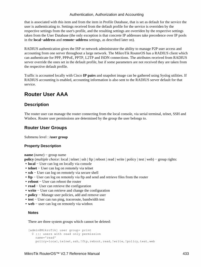
that is associated with this item and from the item in Profile Database, that is set as default for the service theuser is authenticating to. Settings received from the default profile for the service is overriden by therespective settings from the user's profile, and the resulting settings are overriden by the respective settingstaken from the User Database (the only exception is that concrete IP addresses take precedence over IP poolsin the local−address and remote−address settings, as described later on).
RADIUS authentication gives the ISP or network administrator the ability to manage P2P user access andaccounting from one server throughout a large network. The MikroTik RouterOS has a RADIUS client whichcan authenticate for PPP, PPPoE, PPTP, L2TP and ISDN connections. The attributes received from RADIUSserver override the ones set in the default profile, but if some parameters are not received they are taken fromthe respective default profile.
Traffic is accounted locally with Cisco IP pairs and snapshot image can be gathered using Syslog utilities. IfRADIUS accounting is enabled, accounting information is also sent to the RADIUS server default for thatservice.
Router User AAA
Description
The router user can manage the router connecting from the local console, via serial terminal, telnet, SSH andWinbox. Router user permissions are determined by the group the user belongs to.
Router User Groups
Submenu level : /user group
Property Description
name (name) − group namepolicy (multiple choice: local | telnet | ssh | ftp | reboot | read | write | policy | test | web) − group rights:
local − User can log on locally via console• telnet − User can log on remotely via telnet• ssh − User can log on remotely via secure shell• ftp − User can log on remotely via ftp and send and retrieve files from the router• reboot − User can reboot the router• read − User can retrieve the configuration• write − User can retrieve and change the configuration• policy − Manage user policies, add and remove user• test − User can run ping, traceroute, bandwidth test• web − user can log on remotely via winbox
Notes
There are three system groups which cannot be deleted:
[admin@MikroTik] user group> print 0 ;;; users with read only permission name="read" policy=local,telnet,ssh,!ftp,reboot,read,!write,!policy,test,web
•
Authentication, Authorization and Accounting
MikroTik RouterOS™ V2.7 Reference Manual 433
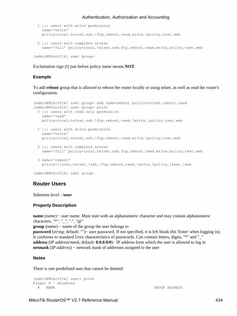
1 ;;; users with write permission name="write" policy=local,telnet,ssh,!ftp,reboot,read,write,!policy,test,web
2 ;;; users with complete access name="full" policy=local,telnet,ssh,ftp,reboot,read,write,policy,test,web
[admin@MikroTik] user group>
Exclamation sign (!) just before policy name means NOT.
Example
To add reboot group that is allowed to reboot the router locally or using telnet, as well as read the router'sconfiguration:
[admin@MikroTik] user group> add name=reboot policy=telnet,reboot,read[admin@MikroTik] user group> print 0 ;;; users with read only permission name="read" policy=local,telnet,ssh,!ftp,reboot,read,!write,!policy,test,web
1 ;;; users with write permission name="write" policy=local,telnet,ssh,!ftp,reboot,read,write,!policy,test,web
2 ;;; users with complete access name="full" policy=local,telnet,ssh,ftp,reboot,read,write,policy,test,web
3 name="reboot" policy=!local,telnet,!ssh,!ftp,reboot,read,!write,!policy,!test,!web
[admin@MikroTik] user group>
Router Users
Submenu level : /user
Property Description
name (name) − user name. Must start with an alphanumeric character and may contain alphanumericcharacters, "*", "_", ".", "@"group (name) − name of the group the user belongs topassword (string; default: "")− user password. If not specified, it is left blank (hit 'Enter' when logging in).It conforms to standard Unix characteristics of passwords. Can contain letters, digits, "*" and "_"address (IP address/mask; default: 0.0.0.0/0)− IP address form which the user is allowed to log innetmask (IP address) − network mask of addresses assigned to the user
Notes
There is one predefined user that cannot be deleted:
[admin@MikroTik] user> printFlags: X − disabled # NAME GROUP ADDRESS
Authentication, Authorization and Accounting
MikroTik RouterOS™ V2.7 Reference Manual 434
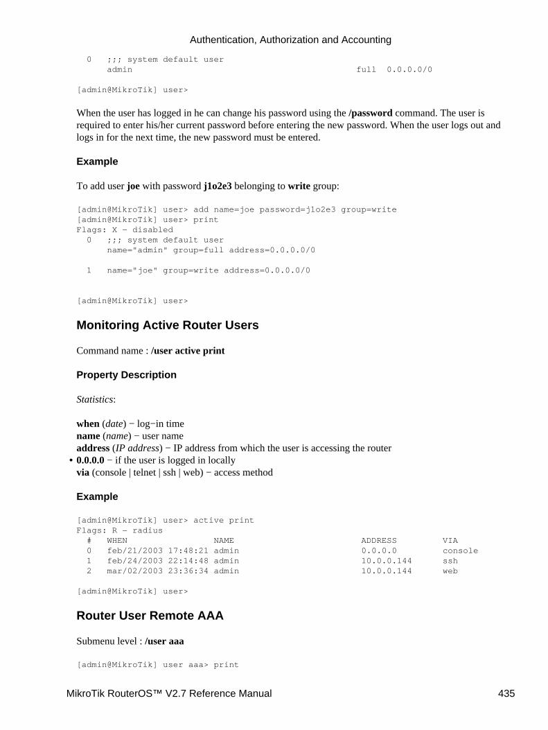
0 ;;; system default user admin full 0.0.0.0/0
[admin@MikroTik] user>
When the user has logged in he can change his password using the /password command. The user isrequired to enter his/her current password before entering the new password. When the user logs out andlogs in for the next time, the new password must be entered.
Example
To add user joe with password j1o2e3 belonging to write group:
[admin@MikroTik] user> add name=joe password=j1o2e3 group=write[admin@MikroTik] user> printFlags: X − disabled 0 ;;; system default user name="admin" group=full address=0.0.0.0/0
1 name="joe" group=write address=0.0.0.0/0
[admin@MikroTik] user>
Monitoring Active Router Users
Command name : /user active print
Property Description
Statistics:
when (date) − log−in timename (name) − user nameaddress (IP address) − IP address from which the user is accessing the router0.0.0.0 − if the user is logged in locallyvia (console | telnet | ssh | web) − access method
Example
[admin@MikroTik] user> active printFlags: R − radius # WHEN NAME ADDRESS VIA 0 feb/21/2003 17:48:21 admin 0.0.0.0 console 1 feb/24/2003 22:14:48 admin 10.0.0.144 ssh 2 mar/02/2003 23:36:34 admin 10.0.0.144 web
[admin@MikroTik] user>
Router User Remote AAA
Submenu level : /user aaa
[admin@MikroTik] user aaa> print
•
Authentication, Authorization and Accounting
MikroTik RouterOS™ V2.7 Reference Manual 435

use−radius: no accounting: yes interim−update: 0s default−group: read[admin@MikroTik] user aaa>
Property Description
use−radius (yes | no, default: no) − whether user database in a RADIUS server should be consultedaccounting (yes | no, default: yes) − whether RADIUS accounting is usedinterim−update (time, default: 0s) − Interim−Update time intervaldefault−group (name; default: read) − group used by default for users authenticated via RADIUS server
Notes
RADIUS user database is consulted only if the required username is not found in local user database
Example
To enable RADIUS AAA:
[admin@MikroTik] user aaa> set use−radius=yes[admin@MikroTik] user aaa> print use−radius: yes accounting: yes interim−update: 0s default−group: read[admin@MikroTik] user aaa>
Local Point−to−Point AAA
Local P2P User Profiles
Submenu level : /ppp profile
Description
P2P profiles are used to define default values to users managed in /ppp secret submenu. Settings in /pppsecret override corresponding /ppp profile settings except in the case when local−address orremote−address are configured in both /ppp secret and /ppp profile, but in one of them ip pool isreferred, concrete IP addresses always take precedence.
Property Descripion
name (name) − profile namelocal−address (IP address | name; default: 0.0.0.0) − either address or pool of the P2P serverremote−address (IP address | name; default: 0.0.0.0) − either address or pool of the P2P clientsession−timeout (time; default: 0s) − the maximum time the connection can stay up0s − no timeoutidle−timeout (time; default: 0s) − the link will be terminated if there is no activity within the time set
•
0s − no timeoutuse−compression (yes | no, default: no) − defines whether compress traffic or not
•
Authentication, Authorization and Accounting
MikroTik RouterOS™ V2.7 Reference Manual 436
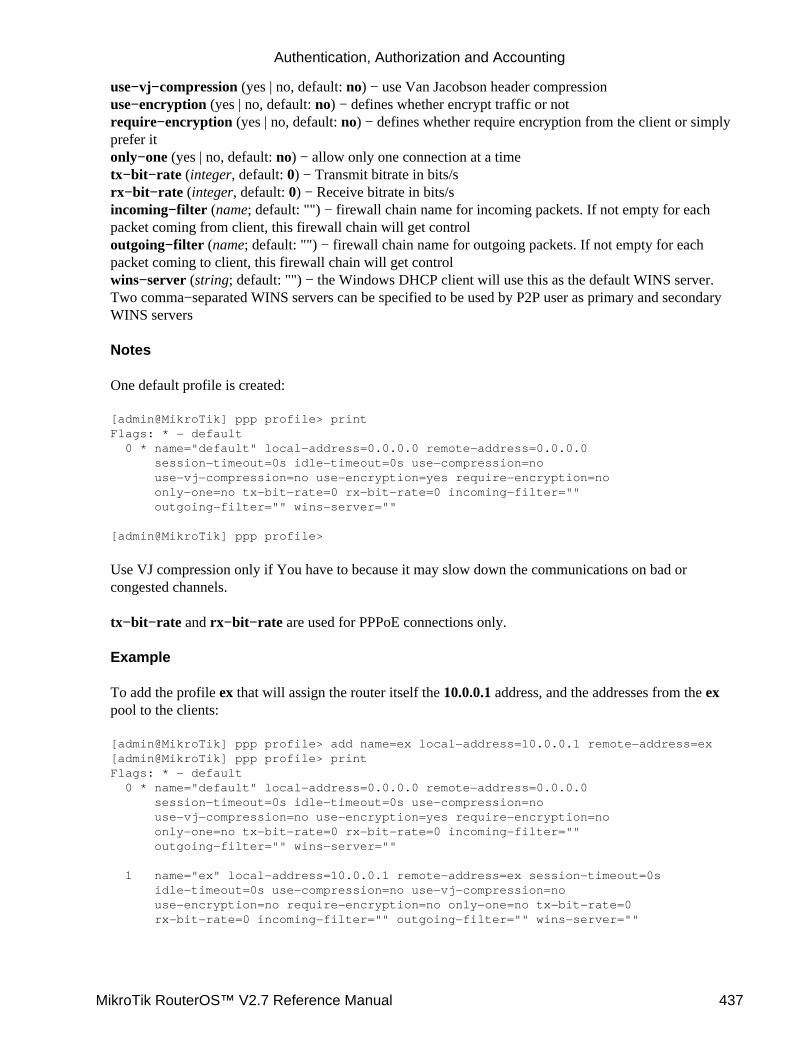
use−vj−compression (yes | no, default: no) − use Van Jacobson header compressionuse−encryption (yes | no, default: no) − defines whether encrypt traffic or notrequire−encryption (yes | no, default: no) − defines whether require encryption from the client or simplyprefer itonly−one (yes | no, default: no) − allow only one connection at a timetx−bit−rate (integer, default: 0) − Transmit bitrate in bits/srx−bit−rate (integer, default: 0) − Receive bitrate in bits/sincoming−filter (name; default: "") − firewall chain name for incoming packets. If not empty for eachpacket coming from client, this firewall chain will get controloutgoing−filter (name; default: "") − firewall chain name for outgoing packets. If not empty for eachpacket coming to client, this firewall chain will get controlwins−server (string; default: "") − the Windows DHCP client will use this as the default WINS server.Two comma−separated WINS servers can be specified to be used by P2P user as primary and secondaryWINS servers
Notes
One default profile is created:
[admin@MikroTik] ppp profile> printFlags: * − default 0 * name="default" local−address=0.0.0.0 remote−address=0.0.0.0 session−timeout=0s idle−timeout=0s use−compression=no use−vj−compression=no use−encryption=yes require−encryption=no only−one=no tx−bit−rate=0 rx−bit−rate=0 incoming−filter="" outgoing−filter="" wins−server=""
[admin@MikroTik] ppp profile>
Use VJ compression only if You have to because it may slow down the communications on bad orcongested channels.
tx−bit−rate and rx−bit−rate are used for PPPoE connections only.
Example
To add the profile ex that will assign the router itself the 10.0.0.1 address, and the addresses from the expool to the clients:
[admin@MikroTik] ppp profile> add name=ex local−address=10.0.0.1 remote−address=ex[admin@MikroTik] ppp profile> printFlags: * − default 0 * name="default" local−address=0.0.0.0 remote−address=0.0.0.0 session−timeout=0s idle−timeout=0s use−compression=no use−vj−compression=no use−encryption=yes require−encryption=no only−one=no tx−bit−rate=0 rx−bit−rate=0 incoming−filter="" outgoing−filter="" wins−server=""
1 name="ex" local−address=10.0.0.1 remote−address=ex session−timeout=0s idle−timeout=0s use−compression=no use−vj−compression=no use−encryption=no require−encryption=no only−one=no tx−bit−rate=0 rx−bit−rate=0 incoming−filter="" outgoing−filter="" wins−server=""
Authentication, Authorization and Accounting
MikroTik RouterOS™ V2.7 Reference Manual 437
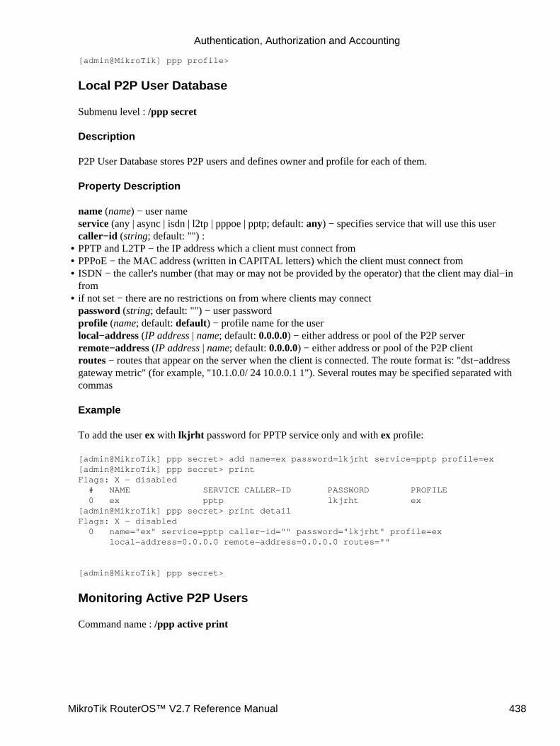
[admin@MikroTik] ppp profile>
Local P2P User Database
Submenu level : /ppp secret
Description
P2P User Database stores P2P users and defines owner and profile for each of them.
Property Description
name (name) − user nameservice (any | async | isdn | l2tp | pppoe | pptp; default: any) − specifies service that will use this usercaller−id (string; default: "") :PPTP and L2TP − the IP address which a client must connect from• PPPoE − the MAC address (written in CAPITAL letters) which the client must connect from• ISDN − the caller's number (that may or may not be provided by the operator) that the client may dial−infrom
•
if not set − there are no restrictions on from where clients may connectpassword (string; default: "") − user passwordprofile (name; default: default) − profile name for the userlocal−address (IP address | name; default: 0.0.0.0) − either address or pool of the P2P serverremote−address (IP address | name; default: 0.0.0.0) − either address or pool of the P2P clientroutes − routes that appear on the server when the client is connected. The route format is: "dst−addressgateway metric" (for example, "10.1.0.0/ 24 10.0.0.1 1"). Several routes may be specified separated withcommas
Example
To add the user ex with lkjrht password for PPTP service only and with ex profile:
[admin@MikroTik] ppp secret> add name=ex password=lkjrht service=pptp profile=ex[admin@MikroTik] ppp secret> printFlags: X − disabled # NAME SERVICE CALLER−ID PASSWORD PROFILE 0 ex pptp lkjrht ex[admin@MikroTik] ppp secret> print detailFlags: X − disabled 0 name="ex" service=pptp caller−id="" password="lkjrht" profile=ex local−address=0.0.0.0 remote−address=0.0.0.0 routes=""
[admin@MikroTik] ppp secret>
Monitoring Active P2P Users
Command name : /ppp active print
•
Authentication, Authorization and Accounting
MikroTik RouterOS™ V2.7 Reference Manual 438
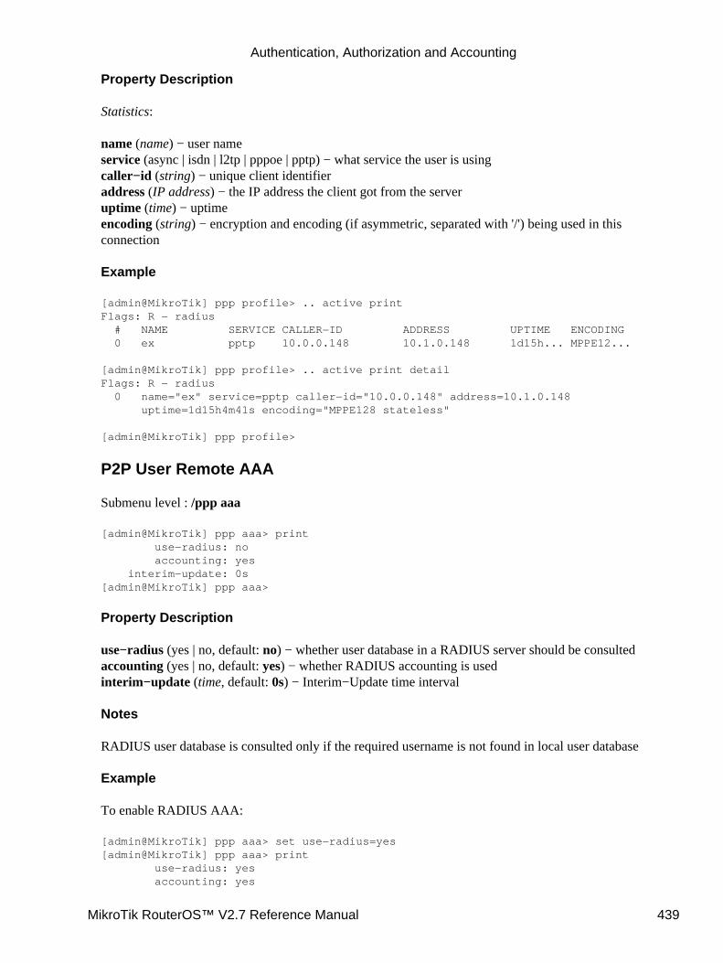
Property Description
Statistics:
name (name) − user nameservice (async | isdn | l2tp | pppoe | pptp) − what service the user is usingcaller−id (string) − unique client identifieraddress (IP address) − the IP address the client got from the serveruptime (time) − uptimeencoding (string) − encryption and encoding (if asymmetric, separated with '/') being used in thisconnection
Example
[admin@MikroTik] ppp profile> .. active printFlags: R − radius # NAME SERVICE CALLER−ID ADDRESS UPTIME ENCODING 0 ex pptp 10.0.0.148 10.1.0.148 1d15h... MPPE12...
[admin@MikroTik] ppp profile> .. active print detailFlags: R − radius 0 name="ex" service=pptp caller−id="10.0.0.148" address=10.1.0.148 uptime=1d15h4m41s encoding="MPPE128 stateless"
[admin@MikroTik] ppp profile>
P2P User Remote AAA
Submenu level : /ppp aaa
[admin@MikroTik] ppp aaa> print use−radius: no accounting: yes interim−update: 0s[admin@MikroTik] ppp aaa>
Property Description
use−radius (yes | no, default: no) − whether user database in a RADIUS server should be consultedaccounting (yes | no, default: yes) − whether RADIUS accounting is usedinterim−update (time, default: 0s) − Interim−Update time interval
Notes
RADIUS user database is consulted only if the required username is not found in local user database
Example
To enable RADIUS AAA:
[admin@MikroTik] ppp aaa> set use−radius=yes[admin@MikroTik] ppp aaa> print use−radius: yes accounting: yes
Authentication, Authorization and Accounting
MikroTik RouterOS™ V2.7 Reference Manual 439
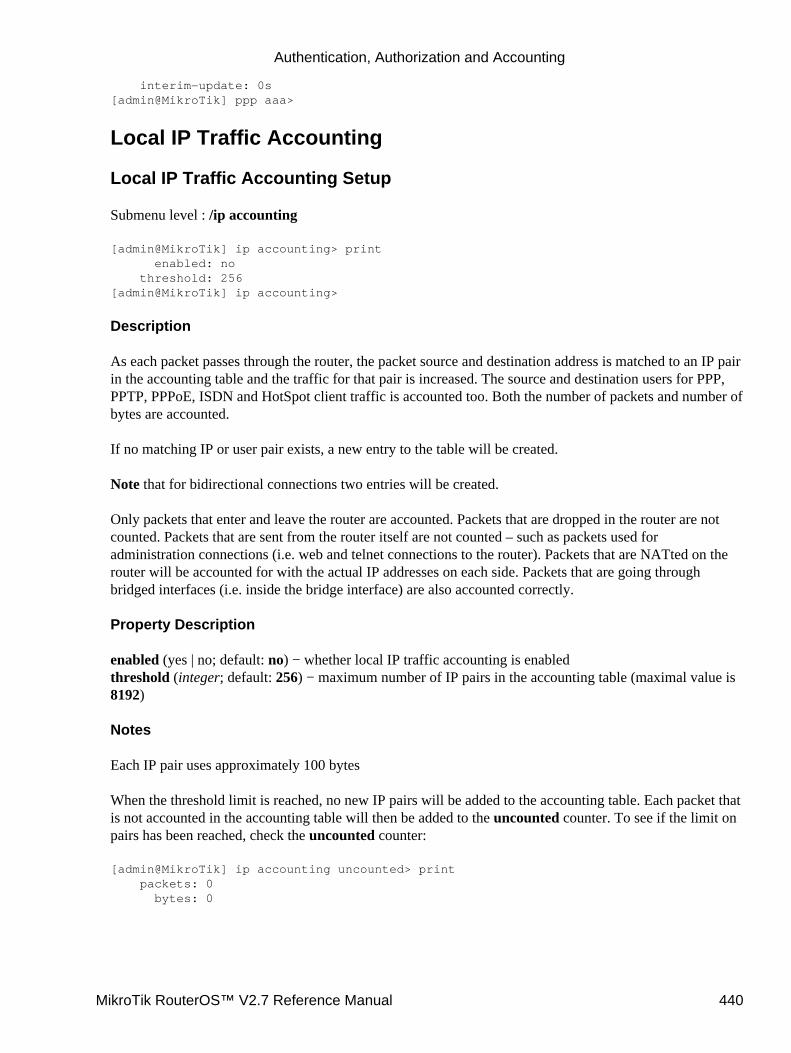
interim−update: 0s[admin@MikroTik] ppp aaa>
Local IP Traffic Accounting
Local IP Traffic Accounting Setup
Submenu level : /ip accounting
[admin@MikroTik] ip accounting> print enabled: no threshold: 256[admin@MikroTik] ip accounting>
Description
As each packet passes through the router, the packet source and destination address is matched to an IP pairin the accounting table and the traffic for that pair is increased. The source and destination users for PPP,PPTP, PPPoE, ISDN and HotSpot client traffic is accounted too. Both the number of packets and number ofbytes are accounted.
If no matching IP or user pair exists, a new entry to the table will be created.
Note that for bidirectional connections two entries will be created.
Only packets that enter and leave the router are accounted. Packets that are dropped in the router are notcounted. Packets that are sent from the router itself are not counted – such as packets used foradministration connections (i.e. web and telnet connections to the router). Packets that are NATted on therouter will be accounted for with the actual IP addresses on each side. Packets that are going throughbridged interfaces (i.e. inside the bridge interface) are also accounted correctly.
Property Description
enabled (yes | no; default: no) − whether local IP traffic accounting is enabledthreshold (integer; default: 256) − maximum number of IP pairs in the accounting table (maximal value is8192)
Notes
Each IP pair uses approximately 100 bytes
When the threshold limit is reached, no new IP pairs will be added to the accounting table. Each packet thatis not accounted in the accounting table will then be added to the uncounted counter. To see if the limit onpairs has been reached, check the uncounted counter:
[admin@MikroTik] ip accounting uncounted> print packets: 0 bytes: 0
Authentication, Authorization and Accounting
MikroTik RouterOS™ V2.7 Reference Manual 440
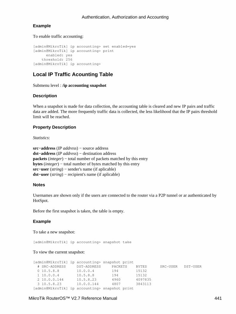
Example
To enable traffic accounting:
[admin@MikroTik] ip accounting> set enabled=yes[admin@MikroTik] ip accounting> print enabled: yes threshold: 256[admin@MikroTik] ip accounting>
Local IP Traffic Acounting Table
Submenu level : /ip accounting snapshot
Description
When a snapshot is made for data collection, the accounting table is cleared and new IP pairs and trafficdata are added. The more frequently traffic data is collected, the less likelihood that the IP pairs thresholdlimit will be reached.
Property Description
Statistics:
src−address (IP address) − source addressdst−address (IP address) − destination addresspackets (integer) − total number of packets matched by this entrybytes (integer) − total number of bytes matched by this entrysrc−user (string) − sender's name (if aplicable)dst−user (string) − recipient's name (if aplicable)
Notes
Usernames are shown only if the users are connected to the router via a P2P tunnel or ar authenticated byHotSpot.
Before the first snapshot is taken, the table is empty.
Example
To take a new snapshot:
[admin@MikroTik] ip accounting> snapshot take
To view the current snapshot:
[admin@MikroTik] ip accounting> snapshot print # SRC−ADDRESS DST−ADDRESS PACKETS BYTES SRC−USER DST−USER 0 10.5.8.8 10.0.0.4 194 15132 1 10.0.0.4 10.5.8.8 194 15132 2 10.0.0.144 10.5.8.23 4960 4097835 3 10.5.8.23 10.0.0.144 4807 3843113[admin@MikroTik] ip accounting> snapshot print
Authentication, Authorization and Accounting
MikroTik RouterOS™ V2.7 Reference Manual 441
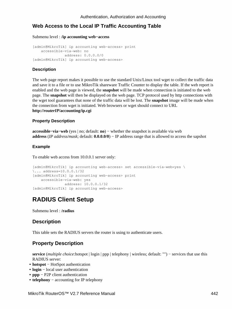
Web Access to the Local IP Traffic Accounting Table
Submenu level : /ip accounting web−access
[admin@MikroTik] ip accounting web−access> print accessible−via−web: no address: 0.0.0.0/0[admin@MikroTik] ip accounting web−access>
Description
The web page report makes it possible to use the standard Unix/Linux tool wget to collect the traffic dataand save it to a file or to use MikroTik shareware Traffic Counter to display the table. If the web report isenabled and the web page is viewed, the snapshot will be made when connection is initiated to the webpage. The snapshot will then be displayed on the web page. TCP protocol used by http connections withthe wget tool guarantees that none of the traffic data will be lost. The snapshot image will be made whenthe connection from wget is initiated. Web browsers or wget should connect to URLhttp://routerIP/accounting/ip.cgi
Property Description
accessible−via−web (yes | no; default: no) − whether the snapshot is available via webaddress (IP address/mask; default: 0.0.0.0/0) − IP address range that is allowed to access the sapshot
Example
To enable web access from 10.0.0.1 server only:
[admin@MikroTik] ip accounting web−access> set accessible−via−web=yes \\... address=10.0.0.1/32[admin@MikroTik] ip accounting web−access> print accessible−via−web: yes address: 10.0.0.1/32[admin@MikroTik] ip accounting web−access>
RADIUS Client Setup
Submenu level : /radius
Description
This table sets the RADIUS servers the router is using to authenticate users.
Property Description
service (multiple choice:hotspot | login | ppp | telephony | wireless; default: "") − services that use thisRADIUS server:hotspot − HotSpot authentication• login − local user authentication• ppp − P2P client authentication• telephony − accounting for IP telephony•
Authentication, Authorization and Accounting
MikroTik RouterOS™ V2.7 Reference Manual 442
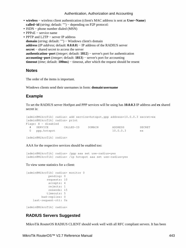
wireless − wireless client authentication (client's MAC address is sent as User−Name)called−id (string; default: "") − depending on P2P protocol:
•
ISDN − phone number dialed (MSN)• PPPoE − service name• PPTP and L2TP − server IP addressdomain (string; default: "") − Windows client's domainaddress (IP address; default: 0.0.0.0) − IP address of the RADIUS serversecret − shared secret to access the serverauthentication−port (integer; default: 1812) − server's port for authenticationaccounting−port (integer; default: 1813) − server's port for accountingtimeout (time; default: 100ms) − timeout, after which the request should be resent
Notes
The order of the items is important.
Windows clients send their usernames in form: domain\username
Example
To set the RADIUS server HotSpot and PPP services will be using has 10.0.0.3 IP address and ex sharedsecret is:
[admin@MikroTik] radius> add service=hotspot,ppp address=10.0.0.3 secret=ex[admin@MikroTik] radius> printFlags: X − disabled # SERVICE CALLED−ID DOMAIN ADDRESS SECRET 0 ppp,hotspot 10.0.0.3 ex
[admin@MikroTik] radius>
AAA for the respective services should be enabled too:
[admin@MikroTik] radius> /ppp aaa set use−radius=yes[admin@MikroTik] radius> /ip hotspot aaa set use−radius=yes
To view some statistics for a client:
[admin@MikroTik] radius> monitor 0 pending: 0 requests: 10 accepts: 4 rejects: 1 resends: 15 timeouts: 5 bad−replies: 0 last−request−rtt: 0s
[admin@MikroTik] radius>
RADIUS Servers Suggested
MikroTik RouterOS RADIUS CLIENT should work well with all RFC compliant servers. It has been
•
Authentication, Authorization and Accounting
MikroTik RouterOS™ V2.7 Reference Manual 443
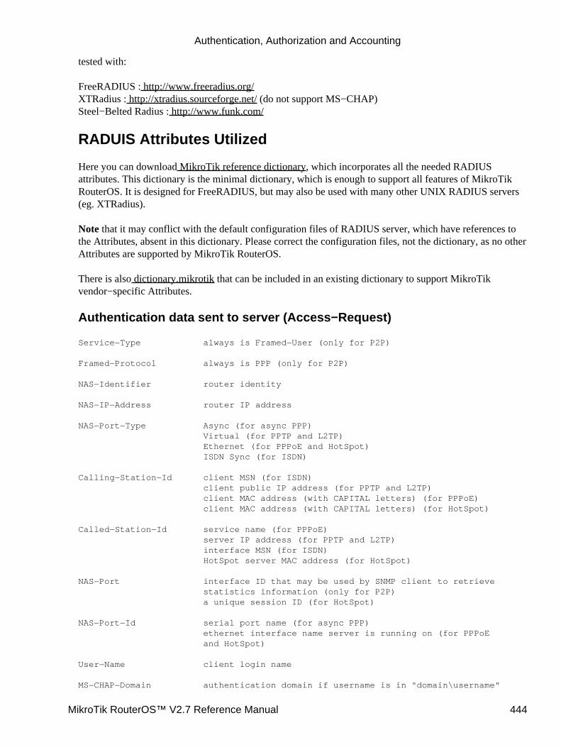
tested with:
FreeRADIUS : http://www.freeradius.org/XTRadius : http://xtradius.sourceforge.net/ (do not support MS−CHAP)Steel−Belted Radius : http://www.funk.com/
RADUIS Attributes Utilized
Here you can download MikroTik reference dictionary, which incorporates all the needed RADIUSattributes. This dictionary is the minimal dictionary, which is enough to support all features of MikroTikRouterOS. It is designed for FreeRADIUS, but may also be used with many other UNIX RADIUS servers(eg. XTRadius).
Note that it may conflict with the default configuration files of RADIUS server, which have references tothe Attributes, absent in this dictionary. Please correct the configuration files, not the dictionary, as no otherAttributes are supported by MikroTik RouterOS.
There is also dictionary.mikrotik that can be included in an existing dictionary to support MikroTikvendor−specific Attributes.
Authentication data sent to server (Access−Request)
Service−Type always is Framed−User (only for P2P)
Framed−Protocol always is PPP (only for P2P)
NAS−Identifier router identity
NAS−IP−Address router IP address
NAS−Port−Type Async (for async PPP) Virtual (for PPTP and L2TP) Ethernet (for PPPoE and HotSpot) ISDN Sync (for ISDN)
Calling−Station−Id client MSN (for ISDN) client public IP address (for PPTP and L2TP) client MAC address (with CAPITAL letters) (for PPPoE) client MAC address (with CAPITAL letters) (for HotSpot)
Called−Station−Id service name (for PPPoE) server IP address (for PPTP and L2TP) interface MSN (for ISDN) HotSpot server MAC address (for HotSpot)
NAS−Port interface ID that may be used by SNMP client to retrieve statistics information (only for P2P) a unique session ID (for HotSpot)
NAS−Port−Id serial port name (for async PPP) ethernet interface name server is running on (for PPPoE and HotSpot)
User−Name client login name
MS−CHAP−Domain authentication domain if username is in "domain\username"
Authentication, Authorization and Accounting
MikroTik RouterOS™ V2.7 Reference Manual 444
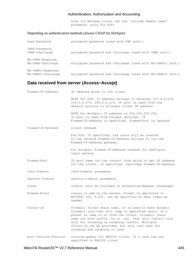
form (if Windows client set the "include domain name" parameter (only for P2P)
Depending on authentication methods (always CHAP for HotSpot):
User−Password encrypted password (used with PAP auth.)
CHAP−Password,CHAP−Challenge encrypted password and challenge (used with CHAP auth.)
MS−CHAP−Response,MS−CHAP−Challenge encrypted password and challenge (used with MS−CHAPv1 auth.)
MS−CHAP2−Response,MS−CHAP2−Challenge encrypted password and challenge (used with MS−CHAPv2 auth.)
Data received from server (Access−Accept)
Framed−IP−Address IP address given to the client
NOTE for P2P: If address belongs to networks 127.0.0.0/8, 224.0.0.0/4, 240.0.0.0/4, IP pool is used from the default profile to allocate client IP address
NOTE for HotSpot: If address is 255.255.255.254, IP pool is used from hotspot settings. If Framed−IP−Address is specified, Framed−Pool is ignored
Framed−IP−Netmask client netmask
For P2P: If specified, the route will be created to the network Framed−IP−Address belongs to via the Framed−IP−Address gateway.
For HotSpot: Framed−IP−Address netmask for DHCP−pool login method.
Framed−Pool IP pool name (on the router) from which to get IP address for the client. If specified, overrides Framed−IP−Address
Idle−Timeout idle−timeout parameter
Session−Timeout session−timeout parameter
Class cookie, will be included in Accounting−Request unchanged
Framed−Route routes to add on the server. Format is specified in RFC2865 (Ch. 5.22), can be specified as many times as needed
Filter−Id firewall filter chain name. It is used to make dynamic firewall rule that will jump to specified chain, if a packet is came to or from the client. Firewall chain name can have suffix .in or .out, that will install rule only for incoming or outgoing traffic. Multiple filter−id can be provided, but only last ones for incoming and outgoing is used
Acct−Interim−Interval interim−update for RADIUS client, if 0 uses the one specified in RADIUS client
Authentication, Authorization and Accounting
MikroTik RouterOS™ V2.7 Reference Manual 445
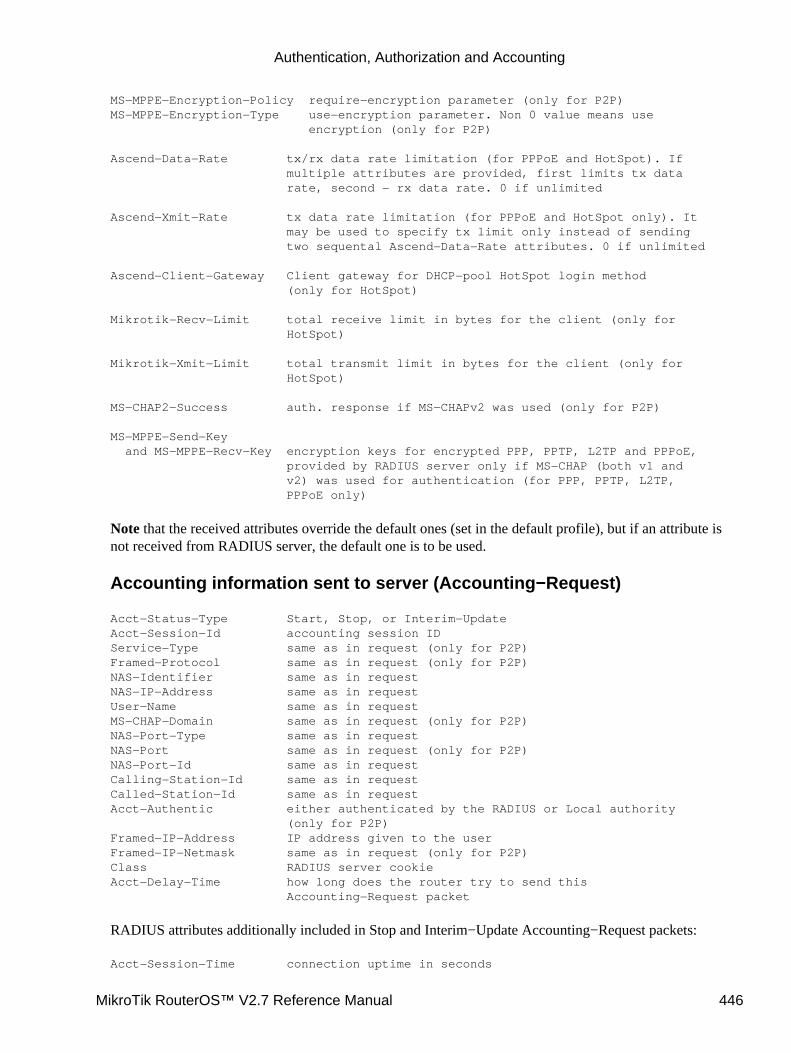
MS−MPPE−Encryption−Policy require−encryption parameter (only for P2P)MS−MPPE−Encryption−Type use−encryption parameter. Non 0 value means use encryption (only for P2P)
Ascend−Data−Rate tx/rx data rate limitation (for PPPoE and HotSpot). If multiple attributes are provided, first limits tx data rate, second − rx data rate. 0 if unlimited
Ascend−Xmit−Rate tx data rate limitation (for PPPoE and HotSpot only). It may be used to specify tx limit only instead of sending two sequental Ascend−Data−Rate attributes. 0 if unlimited
Ascend−Client−Gateway Client gateway for DHCP−pool HotSpot login method (only for HotSpot)
Mikrotik−Recv−Limit total receive limit in bytes for the client (only for HotSpot)
Mikrotik−Xmit−Limit total transmit limit in bytes for the client (only for HotSpot)
MS−CHAP2−Success auth. response if MS−CHAPv2 was used (only for P2P)
MS−MPPE−Send−Key and MS−MPPE−Recv−Key encryption keys for encrypted PPP, PPTP, L2TP and PPPoE, provided by RADIUS server only if MS−CHAP (both v1 and v2) was used for authentication (for PPP, PPTP, L2TP, PPPoE only)
Note that the received attributes override the default ones (set in the default profile), but if an attribute isnot received from RADIUS server, the default one is to be used.
Accounting information sent to server (Accounting−Request)
Acct−Status−Type Start, Stop, or Interim−UpdateAcct−Session−Id accounting session IDService−Type same as in request (only for P2P)Framed−Protocol same as in request (only for P2P)NAS−Identifier same as in requestNAS−IP−Address same as in requestUser−Name same as in requestMS−CHAP−Domain same as in request (only for P2P)NAS−Port−Type same as in requestNAS−Port same as in request (only for P2P)NAS−Port−Id same as in requestCalling−Station−Id same as in requestCalled−Station−Id same as in requestAcct−Authentic either authenticated by the RADIUS or Local authority (only for P2P)Framed−IP−Address IP address given to the userFramed−IP−Netmask same as in request (only for P2P)Class RADIUS server cookieAcct−Delay−Time how long does the router try to send this Accounting−Request packet
RADIUS attributes additionally included in Stop and Interim−Update Accounting−Request packets:
Acct−Session−Time connection uptime in seconds
Authentication, Authorization and Accounting
MikroTik RouterOS™ V2.7 Reference Manual 446

Acct−Input−Octects bytes received from the clientAcct−Input−Packets packets received from the clientAcct−Output−Octets bytes sent to the clientAcct−Output−Packets packets sent to the client
Stop Accounting−Request packets can additionally have:
Acct−Terminate−Cause session termination cause (described in RFC2866 Ch. 5.10)
RADIUS Attribute Numeric Values
Acct−Authentic 45 RFC2866
Acct−Delay−Time 41 RFC2866
Acct−Input−Octects 42 RFC2866
Acct−Input−Packets 47 RFC2866
Acct−Interim−Interval 85 RFC2869
Acct−Output−Octets 43 RFC2866
Acct−Output−Packets 48 RFC2866
Acct−Session−Id 44 RFC2866
Acct−Session−Time 46 RFC2866
Acct−Status−Type 40 RFC2866
Acct−Terminate−Cause 49 RFC2866
Ascend−Client−Gatway 529 132
Ascend−Data−Rate 529 197
Ascend−Xmit−Rate 529 255
Called−Station−Id 30 RFC2865
Calling−Station−Id 31 RFC2865
CHAP−Challenge 60 RFC2866
CHAP−Password 3 RFC2865
Class 25 RFC2865
Filter−Id 11 RFC2865
Framed−IP−Address 8 RFC2865
Framed−IP−Netmask 9 RFC2865
Framed−Pool 88 RFC2869
Framed−Protocol 7 RFC2865
Framed−Route 22 RFC2865
Idle−Timeout 28 RFC2865
MS−CHAP−Challenge 311 11 RFC2548
MS−CHAP−Domain 311 10 RFC2548
MS−CHAP−Response 311 1 RFC2548
MS−CHAP2−Response 311 25 RFC2548
MS−CHAP2−Success 311 26 RFC2548
MS−MPPE−Encryption−Policy311 7 RFC2548
MS−MPPE−Encryption−Type311 8 RFC2548
Authentication, Authorization and Accounting
MikroTik RouterOS™ V2.7 Reference Manual 447
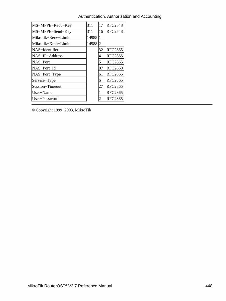
MS−MPPE−Recv−Key 311 17 RFC2548
MS−MPPE−Send−Key 311 16 RFC2548
Mikrotik−Recv−Limit 149881
Mikrotik−Xmit−Limit 149882
NAS−Identifier 32 RFC2865
NAS−IP−Address 4 RFC2865
NAS−Port 5 RFC2865
NAS−Port−Id 87 RFC2869
NAS−Port−Type 61 RFC2865
Service−Type 6 RFC2865
Session−Timeout 27 RFC2865
User−Name 1 RFC2865
User−Password 2 RFC2865
© Copyright 1999−2003, MikroTik
Authentication, Authorization and Accounting
MikroTik RouterOS™ V2.7 Reference Manual 448

Certificate ManagementDocument revision 2.1 (09−Oct−2003)This document applies to MikroTik RouterOS V2.7
Table of Contents
Table of Contents• General Information•
Summary• Specifications•
Certificates•
Specifications• Property Description• Command Description• Notes• Examples•
General Information
Summary
In MikroTik RouterOS certificates are used for SSL security protocol
Specifications
Packages required: securityLicense required: AnySubmenu level: /certificateHardware usage: high CPU usage
Certificates
Submenu level: /certificate
Property Description
name (name) − reference name
subject (read−only: text) − subject of the certificate
issuer (read−only: text) − issuer of the certificate
MikroTik RouterOS™ V2.7 Reference Manual 449
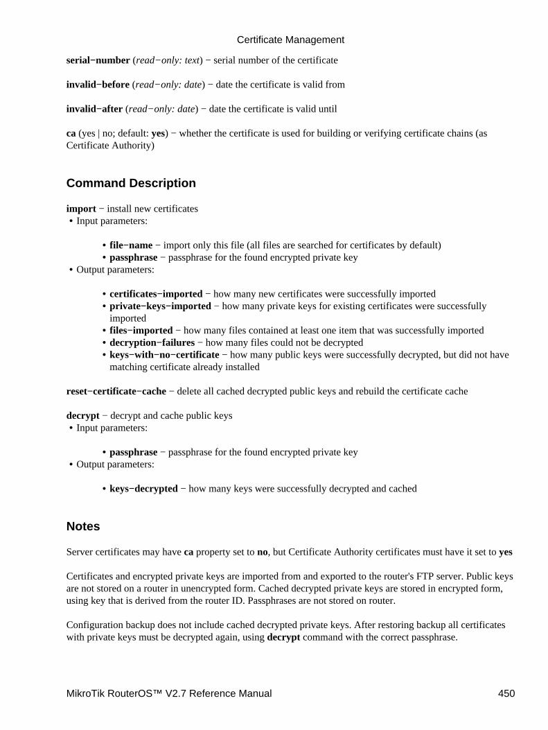
serial−number (read−only: text) − serial number of the certificate
invalid−before (read−only: date) − date the certificate is valid from
invalid−after (read−only: date) − date the certificate is valid until
ca (yes | no; default: yes) − whether the certificate is used for building or verifying certificate chains (asCertificate Authority)
Command Description
import − install new certificatesInput parameters:
file−name − import only this file (all files are searched for certificates by default)• passphrase − passphrase for the found encrypted private key•
•
Output parameters:
certificates−imported − how many new certificates were successfully imported• private−keys−imported − how many private keys for existing certificates were successfullyimported
•
files−imported − how many files contained at least one item that was successfully imported• decryption−failures − how many files could not be decrypted• keys−with−no−certificate − how many public keys were successfully decrypted, but did not havematching certificate already installed
•
•
reset−certificate−cache − delete all cached decrypted public keys and rebuild the certificate cache
decrypt − decrypt and cache public keysInput parameters:
passphrase − passphrase for the found encrypted private key•
•
Output parameters:
keys−decrypted − how many keys were successfully decrypted and cached•
•
Notes
Server certificates may have ca property set to no, but Certificate Authority certificates must have it set to yes
Certificates and encrypted private keys are imported from and exported to the router's FTP server. Public keysare not stored on a router in unencrypted form. Cached decrypted private keys are stored in encrypted form,using key that is derived from the router ID. Passphrases are not stored on router.
Configuration backup does not include cached decrypted private keys. After restoring backup all certificateswith private keys must be decrypted again, using decrypt command with the correct passphrase.
Certificate Management
MikroTik RouterOS™ V2.7 Reference Manual 450
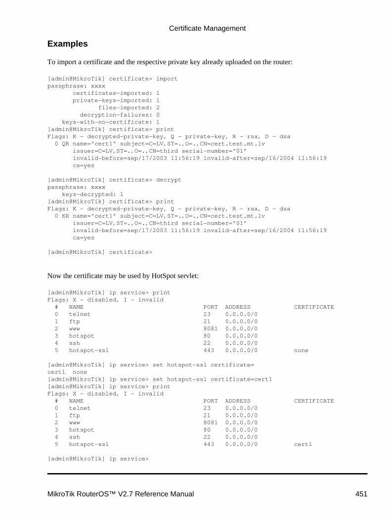
Examples
To import a certificate and the respective private key already uploaded on the router:
[admin@MikroTik] certificate> importpassphrase: xxxx certificates−imported: 1 private−keys−imported: 1 files−imported: 2 decryption−failures: 0 keys−with−no−certificate: 1[admin@MikroTik] certificate> printFlags: K − decrypted−private−key, Q − private−key, R − rsa, D − dsa 0 QR name="cert1" subject=C=LV,ST=.,O=.,CN=cert.test.mt.lv issuer=C=LV,ST=.,O=.,CN=third serial−number="01" invalid−before=sep/17/2003 11:56:19 invalid−after=sep/16/2004 11:56:19 ca=yes
[admin@MikroTik] certificate> decryptpassphrase: xxxx keys−decrypted: 1[admin@MikroTik] certificate> printFlags: K − decrypted−private−key, Q − private−key, R − rsa, D − dsa 0 KR name="cert1" subject=C=LV,ST=.,O=.,CN=cert.test.mt.lv issuer=C=LV,ST=.,O=.,CN=third serial−number="01" invalid−before=sep/17/2003 11:56:19 invalid−after=sep/16/2004 11:56:19 ca=yes
[admin@MikroTik] certificate>
Now the certificate may be used by HotSpot servlet:
[admin@MikroTik] ip service> printFlags: X − disabled, I − invalid # NAME PORT ADDRESS CERTIFICATE 0 telnet 23 0.0.0.0/0 1 ftp 21 0.0.0.0/0 2 www 8081 0.0.0.0/0 3 hotspot 80 0.0.0.0/0 4 ssh 22 0.0.0.0/0 5 hotspot−ssl 443 0.0.0.0/0 none
[admin@MikroTik] ip service> set hotspot−ssl certificate=cert1 none[admin@MikroTik] ip service> set hotspot−ssl certificate=cert1[admin@MikroTik] ip service> printFlags: X − disabled, I − invalid # NAME PORT ADDRESS CERTIFICATE 0 telnet 23 0.0.0.0/0 1 ftp 21 0.0.0.0/0 2 www 8081 0.0.0.0/0 3 hotspot 80 0.0.0.0/0 4 ssh 22 0.0.0.0/0 5 hotspot−ssl 443 0.0.0.0/0 cert1
[admin@MikroTik] ip service>
Certificate Management
MikroTik RouterOS™ V2.7 Reference Manual 451

© Copyright 1999−2003, MikroTik
Certificate Management
MikroTik RouterOS™ V2.7 Reference Manual 452
Export and ImportDocument revision 1.1 (31−Jan−2003)This document applies to MikroTik RouterOS v2.7
Table of Contents
Table of Contents• Summary• Specifications• Related Documents
Description♦ •
The Export CommandExample♦
•
The Import CommandExample♦
•
Summary
Configuration export feature is used to dump the part or whole RouterOS configuation. Then it can be editedand imported to the same or to an another router.
Specifications
Packages required : systemLicense required : AnyHome menu level : /Protocols utilized : NoneHardware usage: not significant
Related Documents
Software Package Installation and UpgradingIP Addresses and Address Resolution Protocol (ARP)Configuration Backup and Restore
Description
The configuration export can be used for dumping out MikroTik RouterOS configuration to the consolescreen or to a text (script) file, which can be downloaded from the router using ftp. The configuration importcan be used to import the router configuration script from a text file.
The export command prints a script that can be used to restore configuration. The command can be invokedat any menu level, and it acts for that menu level and all menu levels below it. If the argument from is used,then it is possible to export only specified items. In this case export does not descend recursively through thecommand hierarchy. export also has the argument file, which allows you to save the script in a file on therouter to retrieve it later via ftp.
MikroTik RouterOS™ V2.7 Reference Manual 453
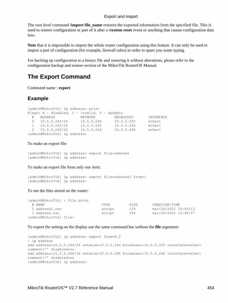
The root level command /import file_name restores the exported information from the specified file. This isused to restore configuration or part of it after a /system reset event or anything that causes configuration dataloss.
Note that it is impossible to import the whole router configuration using this feature. It can only be used toimport a part of configuration (for example, firewall rules) in order to spare you some typing.
For backing up configuration to a binary file and restoring it without alterations, please refer to theconfiguration backup and restore section of the MikroTik RouterOS Manual.
The Export Command
Command name : export
Example
[admin@MikroTik] ip address> printFlags: X − disabled, I − invalid, D − dynamic # ADDRESS NETWORK BROADCAST INTERFACE 0 10.5.5.244/24 10.5.5.244 10.5.5.255 ether1 1 10.5.5.245/32 10.5.5.245 10.5.5.245 ether1 2 10.5.5.246/32 10.5.5.246 10.5.5.246 ether1[admin@MikroTik] ip address>
To make an export file:
[admin@MikroTik] ip address> export file=address[admin@MikroTik] ip address>
To make an export file from only one item:
[admin@MikroTik] ip address> export file=address1 from=1[admin@MikroTik] ip address>
To see the files stored on the router:
[admin@MikroTik] > file print # NAME TYPE SIZE CREATION−TIME 0 address1.rsc script 128 mar/26/2002 16:00:13 1 address.rsc script 354 mar/26/2002 15:48:57[admin@MikroTik] file>
To export the setting on the display use the same command but without the file argument:
[admin@MikroTik] ip address> export from=0,2/ ip addressadd address=10.5.5.244/24 network=10.5.5.244 broadcast=10.5.5.255 interface=ether1comment="" disabled=noadd address=10.5.5.246/32 network=10.5.5.246 broadcast=10.5.5.246 interface=ether1comment="" disabled=no[admin@MikroTik] ip address>
Export and Import
MikroTik RouterOS™ V2.7 Reference Manual 454

The Import Command
Command name : /import
Example
To load the saved export file use the following command:
[admin@MikroTik] > import address1.rsc[admin@MikroTik] >
© Copyright 1999−2003, MikroTik
Export and Import
MikroTik RouterOS™ V2.7 Reference Manual 455
Backup and RestoreDocument revision 1.0 (31−Jan−2003)This document applies to MikroTik RouterOS v2.7
Table of Contents
Table of Contents• Summary• Specifications• Related Documents• Description• Configuration Save Command
Example♦ •
Configuration Load CommandExample♦
•
Summary
The configuration backup can be used for backing up MikroTik RouterOS configuration to a binary file,which can be stored on the router or downloaded from it using ftp. The configuration restore can be used forrestoring the router's configuration from a backup file. For exporting configuration or part of it to a text(script) file and importing it, please refer to the configuration export and import section of the MikroTikRouterOS Manual.
Specifications
Packages required : systemLicense required : AnyHome menu level : /system backupProtocols utilized : NoneHardware usage: not significant
Related Documents
Software Package Installation and UpgradingConfiguration Export and Import
Description
The save command is used to store the entire router configuration in a backup file. The file is shown in the/file submenu. You can download this it via ftp to keep it as a backup for your configuration.
To restore the system configuration, for example, after a /system reset, you can upload that file via ftp andthen load that backup file, using load command in /system backup submenu.
MikroTik RouterOS™ V2.7 Reference Manual 456
Configuration Save Command
Command name : /system backup save
Example
To save the router configuration to file test:
[admin@MikroTik] system backup> save name=testConfiguration backup saved[admin@MikroTik] system backup>
To see the files stored on the router:
[admin@MikroTik] > file print # NAME TYPE SIZE CREATION−TIME 0 test.backup backup 12567 aug/12/2002 21:07:50[admin@MikroTik] >
Configuration Load Command
Command name : /system backup load
Example
To load the saved backup file test:
[admin@MikroTik] system backup> load name=testRestore and reboot? [y/N]:
© Copyright 1999−2003, MikroTik
Backup and Restore
MikroTik RouterOS™ V2.7 Reference Manual 457
FTP serverDocument revision 1.2 (05−May−2003)This document applies to the MikroTik RouterOS V2.7
Table Of Contents
Table Of Contents• Summary• Specifications• Related Documents• File Transfer Protocol Server
Description♦ Property Description♦ Example♦
•
Summary
MicroTik RouterOS implements File Transfer Protocol (FTP) server feature. It is intended to use for softwarepackages uploading as well as configuration script exporting and importing procedures.
Specifications
Packages required : NoneLicense required : AnyHome menu level : /fileStandards and Technologies : FTP (RFC 959)Hardware usage : not significant
Related Documents
Software Package Installation and UpgradingConfiguration Export and ImportConfiguration Backup and Restore HotSpot Gateway
File Transfer Protocol Server
Submenu level : /file
Description
MikroTik RouterOS has an industry standard FTP server feature. It uses ports 20 and 21 for communicationwith other hosts on the network. Do not disable these ports on your router!
Uploaded files as well as exported configuration or backup files can be accessed under /file menu. There youcan also delete unwanted files from your router.
Authorization via ftp uses router's system user account names and passwords.
MikroTik RouterOS™ V2.7 Reference Manual 458
Property Description
name (read−only: text) − item nametype (read−only: file | directory | unknown) − item typepackage size (read−only: integer) − package sizecreation−time (read−only: time) − item creation date and timepackage−name (read−only: name) − package namepackage−version (read−only: text) − package versionpackage−build−time (read−only: time) − build time of the package
Example
Suppose we need to upload a software package system−2.7rc4.npk to a router with IP address 192.168.0.2using generic text mode FTP client from a Linux workstation (the procedure and commands are the same alsofor Windows workstations):
user@wildcat:~/work$ ftp 192.168.0.2Connected to 192.168.0.2.220 MikroTik FTP server (MikroTik v2.7rc3) readyName (192.168.0.2:root): admin331 Password required for adminPassword:230 User admin logged inRemote system type is UNIX.ftp> binary200 Type set to Iftp> send(local−file) /home/psi/system−2.7rc4.npk(remote−file) system−2.7rc4.npklocal: /home/psi/system−2.7rc4.npk remote: system−2.7rc4.npk200 PORT command successful150 Opening BINARY mode data connection for '/system−2.7rc4.npk'226 Transfer complete8391343 bytes sent in 12.61 secs (649.7 kB/s)ftp> close221 Closingftp> quituser@wildcat:~/work$
Now you can see this package on the router:
[admin@MikroTik] file> print # NAME TYPE SIZE CREATION−TIME 0 system−2.7rc4.npk package 8391343 apr/30/2003 17:09:55 1 hotspot directory mar/08/2003 16:14:19
[admin@MikroTik] file>
© Copyright 1999−2003, MikroTik
FTP server
MikroTik RouterOS™ V2.7 Reference Manual 459
GPSDocument revision 1.1 (25−Jul−2003)This document applies to MikroTik RouterOS v2.7
Table of Contents
Table of Contents• Summary• Specifications• Related Documents• Description• Synchronizing with a GPS Receiver
Property Description♦ Notes♦ Example♦
•
Monitoring GPSDescription♦ Property Description♦ Examples♦
•
Additional Resources•
Summary
Global Positioning System (GPS) receiver can be used by MikroTik RouterOS to get the precise location andtime (which may be used as NTP time source)
Specifications
Packages required : gpsLicense required : AnyHome menu level : /system gpsStandards and Technologies : GPS, NMEA 0183, Simple Text Output ProtocolHardware usage: not significant
Related Documents
Software Package Installation and UpgradingNetwork Time Protocol (NTP)
Description
Global Positioning System (GPS) is used for determining precise location of a GPS receiver. There are twotypes of GPS service:
Precise Positioning Service (PPS) that is used only by U. S. and Allied military, certain U. S. Governmentagencies, and selected civil users specifically approved by the U. S. Government. Its accuracy is 22mhorizontally, 27.7m vertically and 200ns of time
•
MikroTik RouterOS™ V2.7 Reference Manual 460
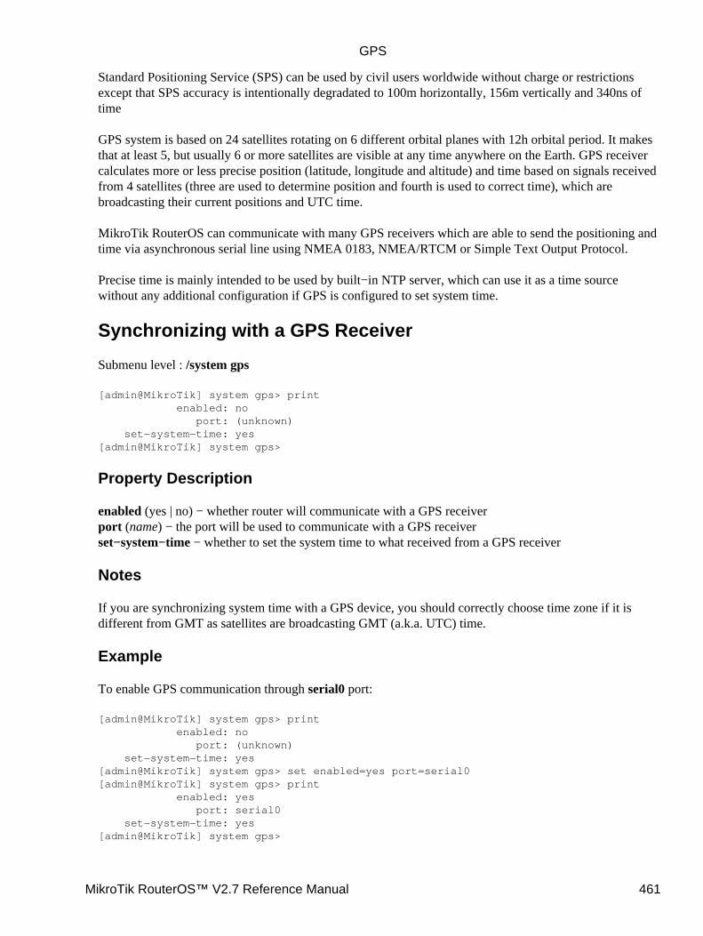
Standard Positioning Service (SPS) can be used by civil users worldwide without charge or restrictionsexcept that SPS accuracy is intentionally degradated to 100m horizontally, 156m vertically and 340ns oftime
GPS system is based on 24 satellites rotating on 6 different orbital planes with 12h orbital period. It makesthat at least 5, but usually 6 or more satellites are visible at any time anywhere on the Earth. GPS receivercalculates more or less precise position (latitude, longitude and altitude) and time based on signals receivedfrom 4 satellites (three are used to determine position and fourth is used to correct time), which arebroadcasting their current positions and UTC time.
MikroTik RouterOS can communicate with many GPS receivers which are able to send the positioning andtime via asynchronous serial line using NMEA 0183, NMEA/RTCM or Simple Text Output Protocol.
Precise time is mainly intended to be used by built−in NTP server, which can use it as a time sourcewithout any additional configuration if GPS is configured to set system time.
Synchronizing with a GPS Receiver
Submenu level : /system gps
[admin@MikroTik] system gps> print enabled: no port: (unknown) set−system−time: yes[admin@MikroTik] system gps>
Property Description
enabled (yes | no) − whether router will communicate with a GPS receiverport (name) − the port will be used to communicate with a GPS receiverset−system−time − whether to set the system time to what received from a GPS receiver
Notes
If you are synchronizing system time with a GPS device, you should correctly choose time zone if it isdifferent from GMT as satellites are broadcasting GMT (a.k.a. UTC) time.
Example
To enable GPS communication through serial0 port:
[admin@MikroTik] system gps> print enabled: no port: (unknown) set−system−time: yes[admin@MikroTik] system gps> set enabled=yes port=serial0[admin@MikroTik] system gps> print enabled: yes port: serial0 set−system−time: yes[admin@MikroTik] system gps>
GPS
MikroTik RouterOS™ V2.7 Reference Manual 461
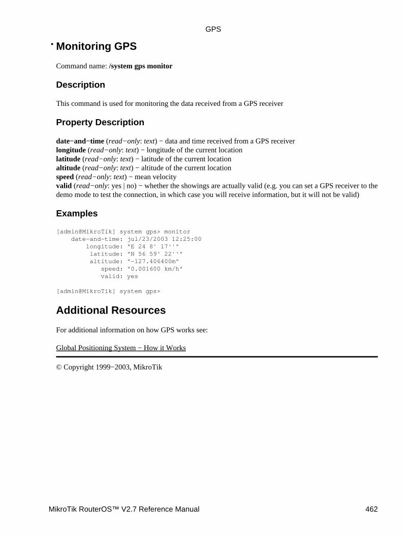
Monitoring GPS
Command name: /system gps monitor
Description
This command is used for monitoring the data received from a GPS receiver
Property Description
date−and−time (read−only: text) − data and time received from a GPS receiverlongitude (read−only: text) − longitude of the current locationlatitude (read−only: text) − latitude of the current locationaltitude (read−only: text) − altitude of the current locationspeed (read−only: text) − mean velocityvalid (read−only: yes | no) − whether the showings are actually valid (e.g. you can set a GPS receiver to thedemo mode to test the connection, in which case you will receive information, but it will not be valid)
Examples
[admin@MikroTik] system gps> monitor date−and−time: jul/23/2003 12:25:00 longitude: "E 24 8' 17''" latitude: "N 56 59' 22''" altitude: "−127.406400m" speed: "0.001600 km/h" valid: yes
[admin@MikroTik] system gps>
Additional Resources
For additional information on how GPS works see:
Global Positioning System − How it Works
© Copyright 1999−2003, MikroTik
•
GPS
MikroTik RouterOS™ V2.7 Reference Manual 462
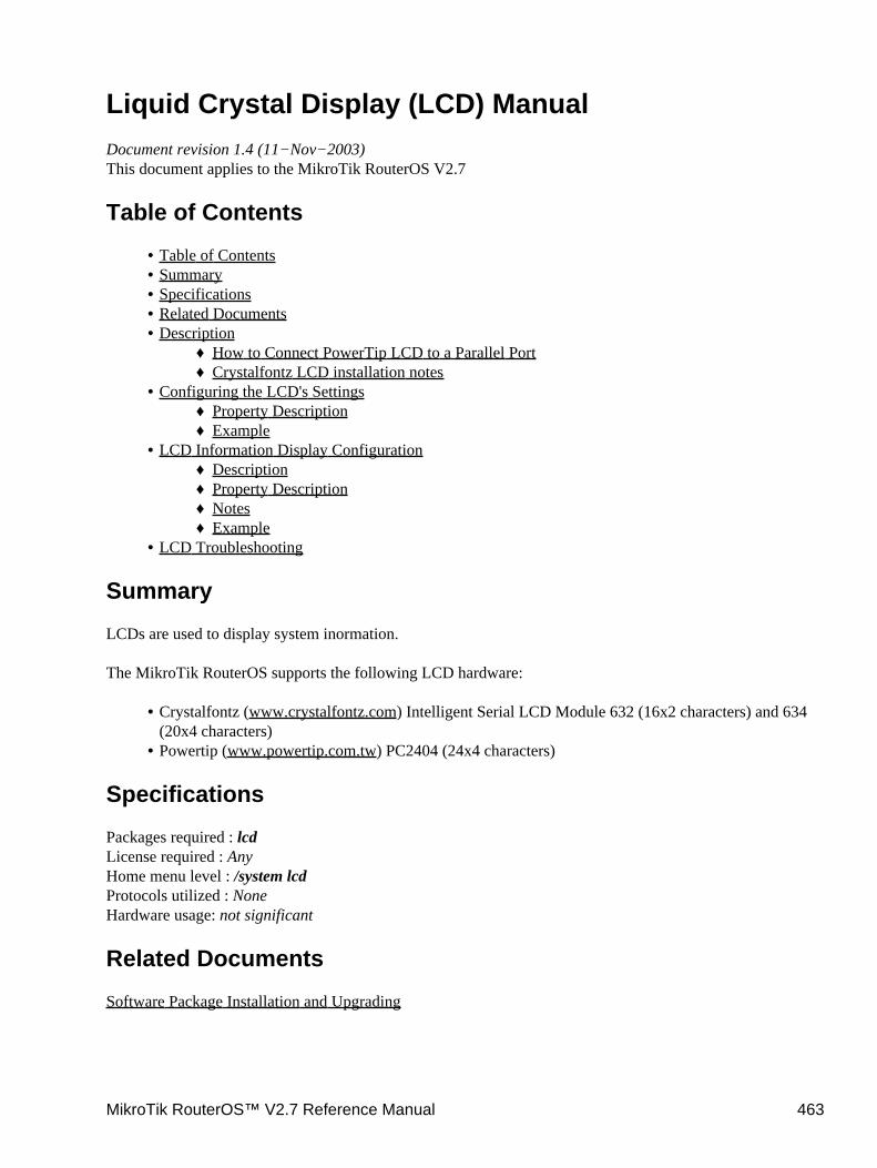
Liquid Crystal Display (LCD) ManualDocument revision 1.4 (11−Nov−2003)This document applies to the MikroTik RouterOS V2.7
Table of Contents
Table of Contents• Summary• Specifications• Related Documents• Description
How to Connect PowerTip LCD to a Parallel Port♦ Crystalfontz LCD installation notes♦
•
Configuring the LCD's SettingsProperty Description♦ Example♦
•
LCD Information Display ConfigurationDescription♦ Property Description♦ Notes♦ Example♦
•
LCD Troubleshooting•
Summary
LCDs are used to display system inormation.
The MikroTik RouterOS supports the following LCD hardware:
Crystalfontz (www.crystalfontz.com) Intelligent Serial LCD Module 632 (16x2 characters) and 634(20x4 characters)
•
Powertip (www.powertip.com.tw) PC2404 (24x4 characters)•
Specifications
Packages required : lcdLicense required : AnyHome menu level : /system lcdProtocols utilized : NoneHardware usage: not significant
Related Documents
Software Package Installation and Upgrading
MikroTik RouterOS™ V2.7 Reference Manual 463

Description
How to Connect PowerTip LCD to a Parallel Port
Data signals are connected that way:
DB25m Signal LCD Panel
1 Enable (Strobe)6
2 Data 0 7
3 Data 1 8
4 Data 2 9
5 Data 3 10
6 Data 4 11
7 Data 5 12
8 Data 6 13
9 Data 7 14
14 Register Select4
18−25, GND Ground 1,5,16
Powering:
As there are only 16 pins for the PC1602 modules, you need not connect power to the 17th pin
GND and +5V can be taken from computer's internal power supply (use Black wire for GND and Red wire for+5V).
WARNING! Be very careful connecting power supply. We do not recommend using external power supplies.In no event shall MikroTik be liable for any hardware damages.
Note that there are some PowerTip PC2404A modules that have different pin−out. Compare:
From www.powertip.com.tw (probably newer one)From www.actron.de (probably older one)
Some LCDs may be connected without resistors:
Liquid Crystal Display (LCD) Manual
MikroTik RouterOS™ V2.7 Reference Manual 464
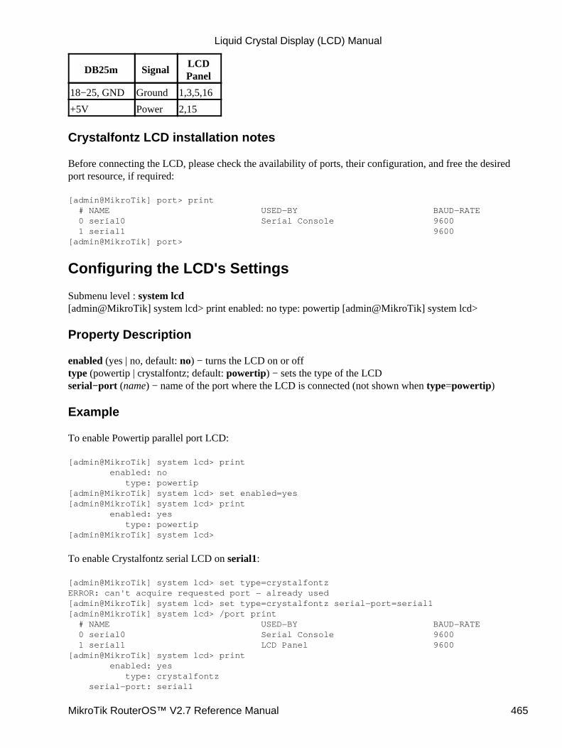
DB25m SignalLCDPanel
18−25, GND Ground 1,3,5,16
+5V Power 2,15
Crystalfontz LCD installation notes
Before connecting the LCD, please check the availability of ports, their configuration, and free the desiredport resource, if required:
[admin@MikroTik] port> print # NAME USED−BY BAUD−RATE 0 serial0 Serial Console 9600 1 serial1 9600[admin@MikroTik] port>
Configuring the LCD's Settings
Submenu level : system lcd[admin@MikroTik] system lcd> print enabled: no type: powertip [admin@MikroTik] system lcd>
Property Description
enabled (yes | no, default: no) − turns the LCD on or offtype (powertip | crystalfontz; default: powertip) − sets the type of the LCDserial−port (name) − name of the port where the LCD is connected (not shown when type=powertip)
Example
To enable Powertip parallel port LCD:
[admin@MikroTik] system lcd> print enabled: no type: powertip[admin@MikroTik] system lcd> set enabled=yes[admin@MikroTik] system lcd> print enabled: yes type: powertip[admin@MikroTik] system lcd>
To enable Crystalfontz serial LCD on serial1:
[admin@MikroTik] system lcd> set type=crystalfontzERROR: can't acquire requested port − already used[admin@MikroTik] system lcd> set type=crystalfontz serial−port=serial1[admin@MikroTik] system lcd> /port print # NAME USED−BY BAUD−RATE 0 serial0 Serial Console 9600 1 serial1 LCD Panel 9600[admin@MikroTik] system lcd> print enabled: yes type: crystalfontz serial−port: serial1
Liquid Crystal Display (LCD) Manual
MikroTik RouterOS™ V2.7 Reference Manual 465
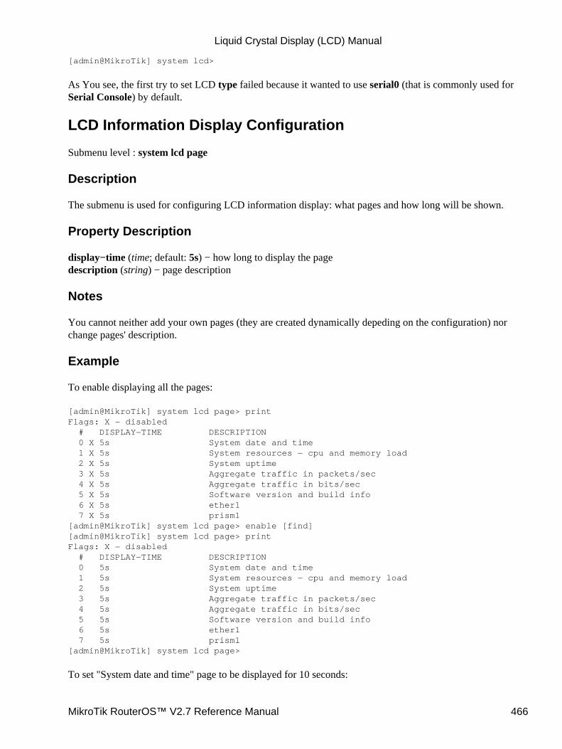
[admin@MikroTik] system lcd>
As You see, the first try to set LCD type failed because it wanted to use serial0 (that is commonly used forSerial Console) by default.
LCD Information Display Configuration
Submenu level : system lcd page
Description
The submenu is used for configuring LCD information display: what pages and how long will be shown.
Property Description
display−time (time; default: 5s) − how long to display the pagedescription (string) − page description
Notes
You cannot neither add your own pages (they are created dynamically depeding on the configuration) norchange pages' description.
Example
To enable displaying all the pages:
[admin@MikroTik] system lcd page> printFlags: X − disabled # DISPLAY−TIME DESCRIPTION 0 X 5s System date and time 1 X 5s System resources − cpu and memory load 2 X 5s System uptime 3 X 5s Aggregate traffic in packets/sec 4 X 5s Aggregate traffic in bits/sec 5 X 5s Software version and build info 6 X 5s ether1 7 X 5s prism1[admin@MikroTik] system lcd page> enable [find][admin@MikroTik] system lcd page> printFlags: X − disabled # DISPLAY−TIME DESCRIPTION 0 5s System date and time 1 5s System resources − cpu and memory load 2 5s System uptime 3 5s Aggregate traffic in packets/sec 4 5s Aggregate traffic in bits/sec 5 5s Software version and build info 6 5s ether1 7 5s prism1[admin@MikroTik] system lcd page>
To set "System date and time" page to be displayed for 10 seconds:
Liquid Crystal Display (LCD) Manual
MikroTik RouterOS™ V2.7 Reference Manual 466
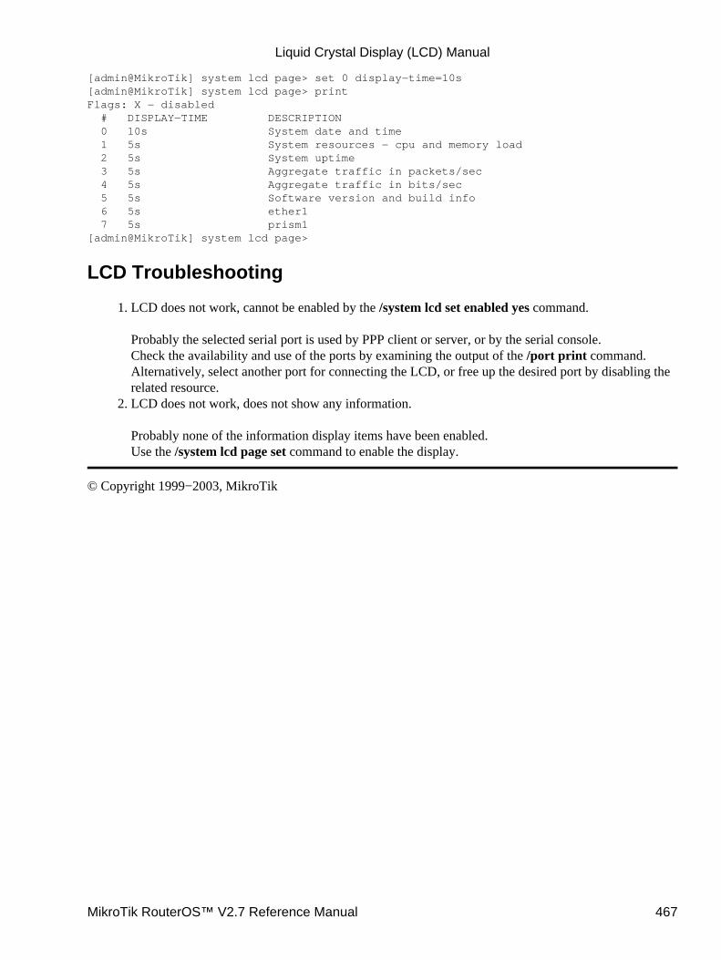
[admin@MikroTik] system lcd page> set 0 display−time=10s[admin@MikroTik] system lcd page> printFlags: X − disabled # DISPLAY−TIME DESCRIPTION 0 10s System date and time 1 5s System resources − cpu and memory load 2 5s System uptime 3 5s Aggregate traffic in packets/sec 4 5s Aggregate traffic in bits/sec 5 5s Software version and build info 6 5s ether1 7 5s prism1[admin@MikroTik] system lcd page>
LCD Troubleshooting
LCD does not work, cannot be enabled by the /system lcd set enabled yes command.
Probably the selected serial port is used by PPP client or server, or by the serial console.Check the availability and use of the ports by examining the output of the /port print command.Alternatively, select another port for connecting the LCD, or free up the desired port by disabling therelated resource.
1.
LCD does not work, does not show any information.
Probably none of the information display items have been enabled.Use the /system lcd page set command to enable the display.
2.
© Copyright 1999−2003, MikroTik
Liquid Crystal Display (LCD) Manual
MikroTik RouterOS™ V2.7 Reference Manual 467

License ManagementDocument revision 1.3 (28−Apr−2003)This document applies to the MikroTik RouterOS v2.7
Table of Contents
Table of Contents• Summary• Specifications• Related Documents• Description• License Administration
Property Description♦ Example♦
•
Features ListProperty Description♦ Example♦ Notes♦
•
Summary
MikroTik RouterOS software has a licensing system with Software License (Software Key) issued for eachindividual installation of the RouterOS.
Specifications
Packages required : systemLicense required : AnyHome menu level : /system licenseProtocols utilized : noneHardware usage : not significant
Related Documents
Software Package Installation and UpgradingBasic Setup Guide
Description
The Software License can be obtained through the Account Server at www.mikrotik.com after the MikroTikRouterOS has been installed. The Software ID of the installation is required when obtaining the SoftwareLicense. Please read the MikroTik RouterOS Basic Setup Guide for detailed explanation of the installationand licensing process.
MikroTik RouterOS™ V2.7 Reference Manual 468
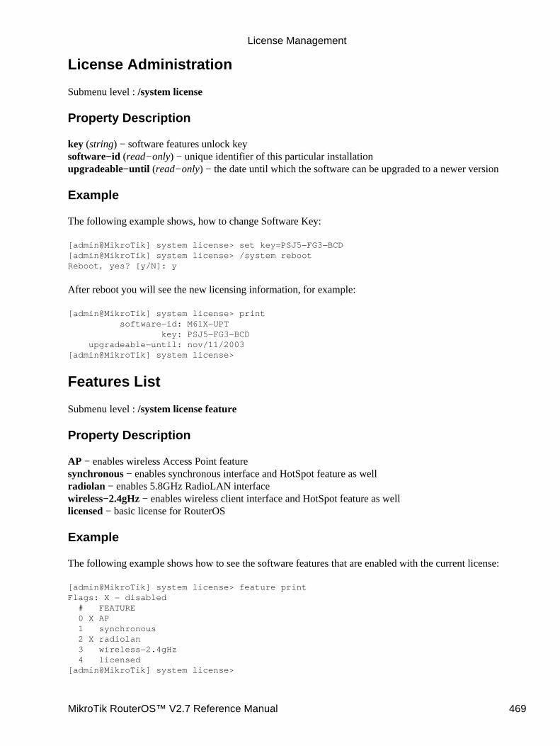
License Administration
Submenu level : /system license
Property Description
key (string) − software features unlock keysoftware−id (read−only) − unique identifier of this particular installationupgradeable−until (read−only) − the date until which the software can be upgraded to a newer version
Example
The following example shows, how to change Software Key:
[admin@MikroTik] system license> set key=PSJ5−FG3−BCD[admin@MikroTik] system license> /system rebootReboot, yes? [y/N]: y
After reboot you will see the new licensing information, for example:
[admin@MikroTik] system license> print software−id: M61X−UPT key: PSJ5−FG3−BCD upgradeable−until: nov/11/2003[admin@MikroTik] system license>
Features List
Submenu level : /system license feature
Property Description
AP − enables wireless Access Point featuresynchronous − enables synchronous interface and HotSpot feature as wellradiolan − enables 5.8GHz RadioLAN interfacewireless−2.4gHz − enables wireless client interface and HotSpot feature as welllicensed − basic license for RouterOS
Example
The following example shows how to see the software features that are enabled with the current license:
[admin@MikroTik] system license> feature printFlags: X − disabled # FEATURE 0 X AP 1 synchronous 2 X radiolan 3 wireless−2.4gHz 4 licensed[admin@MikroTik] system license>
License Management
MikroTik RouterOS™ V2.7 Reference Manual 469

Here we see, that the software has full license (not the demo version), and the 2.4GHz Wireless andSynchronous features are enabled.
Notes
To enable additional MikroTik RouterOS software features, or to enable upgrading (if it has expired), a newSoftware Key should be obtained from the Account Server at www.mikrotik.com. The new Software Keymust be supplied to the router and the system must be rebooted:
© Copyright 1999−2003, MikroTik
License Management
MikroTik RouterOS™ V2.7 Reference Manual 470
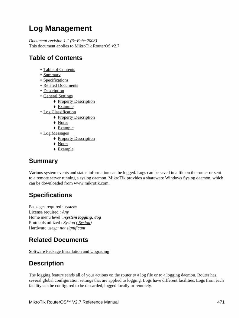
Log ManagementDocument revision 1.1 (3−Feb−2003)This document applies to MikroTik RouterOS v2.7
Table of Contents
Table of Contents• Summary• Specifications• Related Documents• Description• General Settings
Property Description♦ Example♦
•
Log ClassificationProperty Description♦ Notes♦ Example♦
•
Log MessagesProperty Description♦ Notes♦ Example♦
•
Summary
Various system events and status information can be logged. Logs can be saved in a file on the router or sentto a remote server running a syslog daemon. MikroTik provides a shareware Windows Syslog daemon, whichcan be downloaded from www.mikrotik.com.
Specifications
Packages required : systemLicense required : AnyHome menu level : /system logging, /logProtocols utilized : Syslog ( Syslog)Hardware usage: not significant
Related Documents
Software Package Installation and Upgrading
Description
The logging feature sends all of your actions on the router to a log file or to a logging daemon. Router hasseveral global configuration settings that are applied to logging. Logs have different facilities. Logs from eachfacility can be configured to be discarded, logged locally or remotely.
MikroTik RouterOS™ V2.7 Reference Manual 471
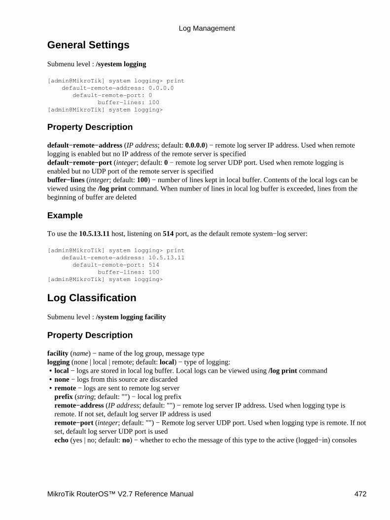
General Settings
Submenu level : /syestem logging
[admin@MikroTik] system logging> print default−remote−address: 0.0.0.0 default−remote−port: 0 buffer−lines: 100 [admin@MikroTik] system logging>
Property Description
default−remote−address (IP address; default: 0.0.0.0) − remote log server IP address. Used when remotelogging is enabled but no IP address of the remote server is specifieddefault−remote−port (integer; default: 0 − remote log server UDP port. Used when remote logging isenabled but no UDP port of the remote server is specifiedbuffer−lines (integer; default: 100) − number of lines kept in local buffer. Contents of the local logs can beviewed using the /log print command. When number of lines in local log buffer is exceeded, lines from thebeginning of buffer are deleted
Example
To use the 10.5.13.11 host, listening on 514 port, as the default remote system−log server:
[admin@MikroTik] system logging> print default−remote−address: 10.5.13.11 default−remote−port: 514 buffer−lines: 100[admin@MikroTik] system logging>
Log Classification
Submenu level : /system logging facility
Property Description
facility (name) − name of the log group, message typelogging (none | local | remote; default: local) − type of logging:
local − logs are stored in local log buffer. Local logs can be viewed using /log print command• none − logs from this source are discarded• remote − logs are sent to remote log serverprefix (string; default: "") − local log prefixremote−address (IP address; default: "") − remote log server IP address. Used when logging type isremote. If not set, default log server IP address is usedremote−port (integer; default: "") − Remote log server UDP port. Used when logging type is remote. If notset, default log server UDP port is usedecho (yes | no; default: no) − whether to echo the message of this type to the active (logged−in) consoles
•
Log Management
MikroTik RouterOS™ V2.7 Reference Manual 472
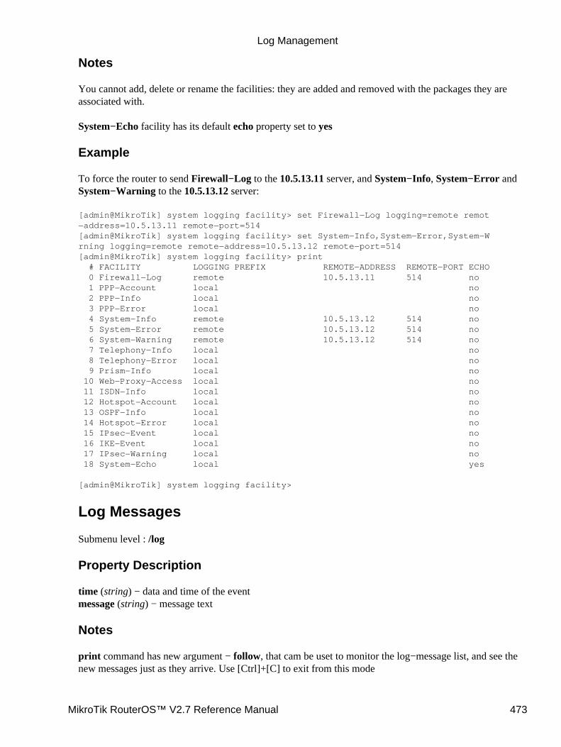
Notes
You cannot add, delete or rename the facilities: they are added and removed with the packages they areassociated with.
System−Echo facility has its default echo property set to yes
Example
To force the router to send Firewall−Log to the 10.5.13.11 server, and System−Info, System−Error andSystem−Warning to the 10.5.13.12 server:
[admin@MikroTik] system logging facility> set Firewall−Log logging=remote remot−address=10.5.13.11 remote−port=514[admin@MikroTik] system logging facility> set System−Info,System−Error,System−Wrning logging=remote remote−address=10.5.13.12 remote−port=514[admin@MikroTik] system logging facility> print # FACILITY LOGGING PREFIX REMOTE−ADDRESS REMOTE−PORT ECHO 0 Firewall−Log remote 10.5.13.11 514 no 1 PPP−Account local no 2 PPP−Info local no 3 PPP−Error local no 4 System−Info remote 10.5.13.12 514 no 5 System−Error remote 10.5.13.12 514 no 6 System−Warning remote 10.5.13.12 514 no 7 Telephony−Info local no 8 Telephony−Error local no 9 Prism−Info local no 10 Web−Proxy−Access local no 11 ISDN−Info local no 12 Hotspot−Account local no 13 OSPF−Info local no 14 Hotspot−Error local no 15 IPsec−Event local no 16 IKE−Event local no 17 IPsec−Warning local no 18 System−Echo local yes
[admin@MikroTik] system logging facility>
Log Messages
Submenu level : /log
Property Description
time (string) − data and time of the eventmessage (string) − message text
Notes
print command has new argument − follow, that cam be uset to monitor the log−message list, and see thenew messages just as they arrive. Use [Ctrl]+[C] to exit from this mode
Log Management
MikroTik RouterOS™ V2.7 Reference Manual 473
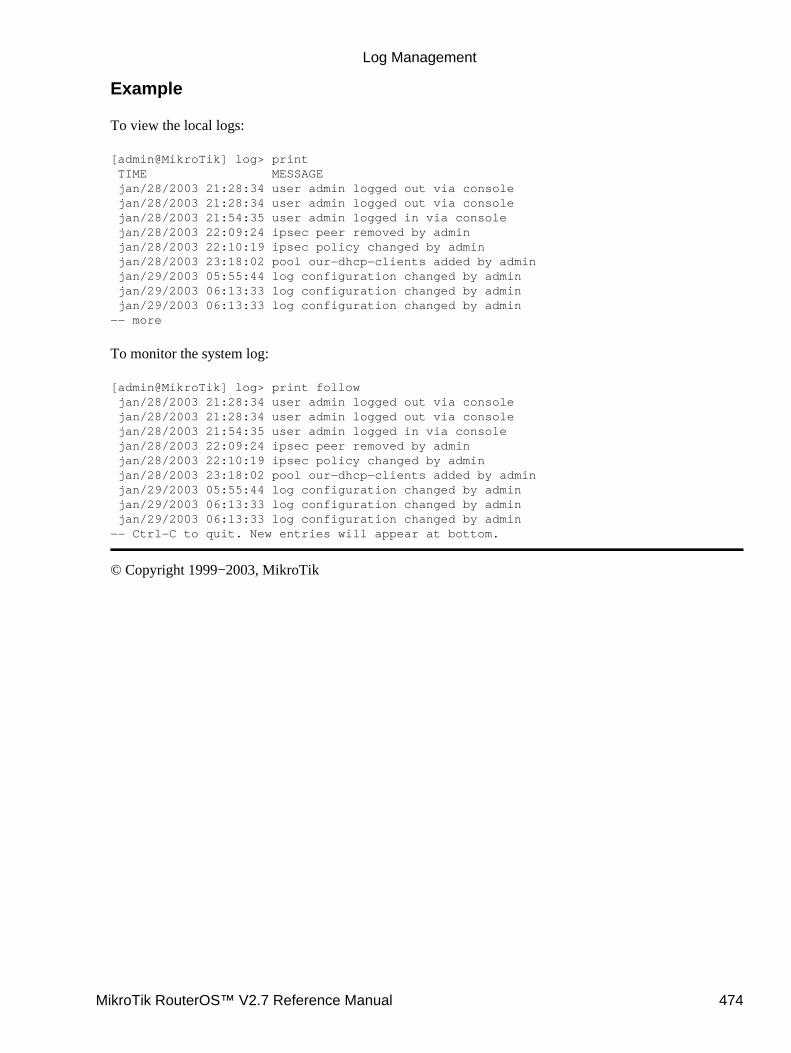
Example
To view the local logs:
[admin@MikroTik] log> print TIME MESSAGE jan/28/2003 21:28:34 user admin logged out via console jan/28/2003 21:28:34 user admin logged out via console jan/28/2003 21:54:35 user admin logged in via console jan/28/2003 22:09:24 ipsec peer removed by admin jan/28/2003 22:10:19 ipsec policy changed by admin jan/28/2003 23:18:02 pool our−dhcp−clients added by admin jan/29/2003 05:55:44 log configuration changed by admin jan/29/2003 06:13:33 log configuration changed by admin jan/29/2003 06:13:33 log configuration changed by admin −− more
To monitor the system log:
[admin@MikroTik] log> print follow jan/28/2003 21:28:34 user admin logged out via console jan/28/2003 21:28:34 user admin logged out via console jan/28/2003 21:54:35 user admin logged in via console jan/28/2003 22:09:24 ipsec peer removed by admin jan/28/2003 22:10:19 ipsec policy changed by admin jan/28/2003 23:18:02 pool our−dhcp−clients added by admin jan/29/2003 05:55:44 log configuration changed by admin jan/29/2003 06:13:33 log configuration changed by admin jan/29/2003 06:13:33 log configuration changed by admin−− Ctrl−C to quit. New entries will appear at bottom.
© Copyright 1999−2003, MikroTik
Log Management
MikroTik RouterOS™ V2.7 Reference Manual 474
MAC Telnet Server and ClientDocument revision 1.2 (07−May−2003)This document applies to the MikroTik RouterOS V2.7
Contents of the Manual
Contents of the Manual• Summary• Specifications• Related Documents• MAC Telnet Server
Property Description♦ Notes♦ Example♦
•
Monitoring Active Session ListProperty Description♦
•
MAC Telnet ClientExample♦
•
Summary
MAC telnet is used to provide access to a router that have no IP address set. It works just like IP telnet. MACtelnet is possible between two MikroTik RouterOS routers only.
Specifications
Packages required : NoneLicense required : AnyHome menu level : /tool, /tool mac−serverProtocols utilized : MAC TelnetHardware usage : not significant
Related Documents
Software Package Installation and UpgradingPingMNDP (MikroTik Neighbor Discovery Protocol)
MAC Telnet Server
Submenu level : /tool mac−server
Property Description
interface (name|all) − interface nameall − all interfaces•
MikroTik RouterOS™ V2.7 Reference Manual 475
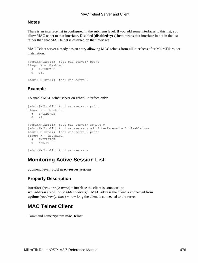
Notes
There is an interface list in configured in the submenu level. If you add some interfaces to this list, youallow MAC telnet to that interface. Disabled (disabled=yes) item means that interface in not in the listrather than that MAC telnet is disabled on that interface.
MAC Telnet server already has an entry allowing MAC telnets from all interfaces after MikroTik routerinstallation:
[admin@MikroTik] tool mac−server> printFlags: X − disabled # INTERFACE 0 all
[admin@MikroTik] tool mac−server>
Example
To enable MAC telnet server on ether1 interface only:
[admin@MikroTik] tool mac−server> printFlags: X − disabled # INTERFACE 0 all
[admin@MikroTik] tool mac−server> remove 0[admin@MikroTik] tool mac−server> add interface=ether1 disabled=no[admin@MikroTik] tool mac−server> printFlags: X − disabled # INTERFACE 0 ether1
[admin@MikroTik] tool mac−server>
Monitoring Active Session List
Submenu level : /tool mac−server sessions
Property Description
interface (read−only: name) − interface the client is connected tosrc−address (read−only: MAC address) − MAC address the client is connected fromuptime (read−only: time) − how long the client is connected to the server
MAC Telnet Client
Command name:/system mac−telnet
MAC Telnet Server and Client
MikroTik RouterOS™ V2.7 Reference Manual 476
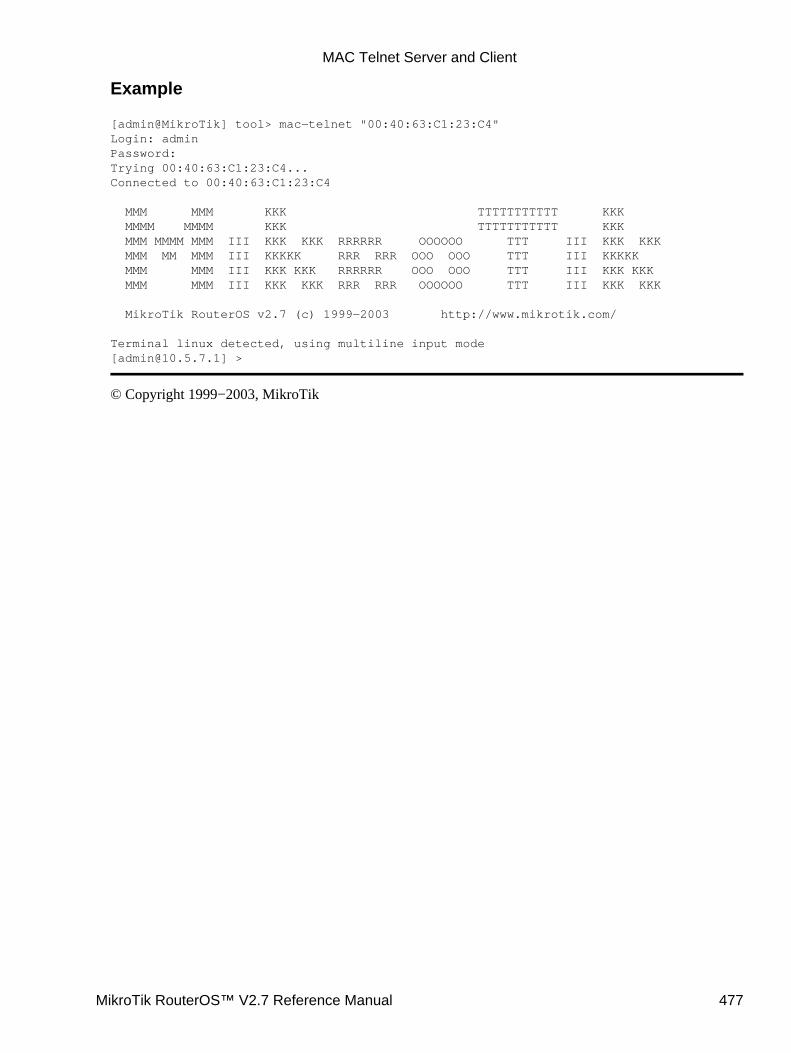
Example
[admin@MikroTik] tool> mac−telnet "00:40:63:C1:23:C4"Login: adminPassword:Trying 00:40:63:C1:23:C4...Connected to 00:40:63:C1:23:C4
MMM MMM KKK TTTTTTTTTTT KKK MMMM MMMM KKK TTTTTTTTTTT KKK MMM MMMM MMM III KKK KKK RRRRRR OOOOOO TTT III KKK KKK MMM MM MMM III KKKKK RRR RRR OOO OOO TTT III KKKKK MMM MMM III KKK KKK RRRRRR OOO OOO TTT III KKK KKK MMM MMM III KKK KKK RRR RRR OOOOOO TTT III KKK KKK
MikroTik RouterOS v2.7 (c) 1999−2003 http://www.mikrotik.com/
Terminal linux detected, using multiline input mode[[email protected]] >
© Copyright 1999−2003, MikroTik
MAC Telnet Server and Client
MikroTik RouterOS™ V2.7 Reference Manual 477
Network Time Protocol (NTP)Document revision 1.3 (04−Sep−2003)This document applies to the MikroTik RouterOS V2.7
Table of Contents
Table of Contents• Summary• Specifications• Related Documents• Description• NTP Client
Property Description♦ Example♦
•
NTP ServerProperty Description♦ Notes♦ Example♦
•
Time ZoneExample♦
•
Summary
NTP protocol allows synchronizing time among computers in network. The best is if there is internetconnection available and local NTP server is synchronized to correct time source. List of public NTP serversis available: http://www.eecis.udel.edu/~mills/ntp/servers.html
Specifications
Packages required : ntpLicense required : AnyHome menu level : /system ntpProtocols utilized : NTP (RFC958)Hardware usage: not significant
Related Documents
Software Package Installation and UpgradingIP Addresses and Address Resolution Protocol (ARP)Firewall Filters and Network Address Translation (NAT)
Description
Network Time Protocol (NTP) is used to synchronize time with some NTP servers in a network. MikroTikRouterOS privides both NTP client and NTP server.
MikroTik RouterOS™ V2.7 Reference Manual 478
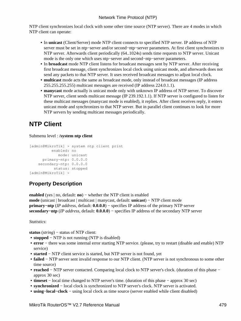
NTP client synchronizes local clock with some other time source (NTP server). There are 4 modes in whichNTP client can operate:
In unicast (Client/Server) mode NTP client connects to specified NTP server. IP address of NTPserver must be set in ntp−server and/or second−ntp−server parameters. At first client synchronizes toNTP server. Afterwards client periodically (64..1024s) sends time requests to NTP server. Unicastmode is the only one which uses ntp−server and second−ntp−server parameters.
•
In broadcast mode NTP client listens for broadcast messages sent by NTP server. After receivingfirst broadcast message, client synchronizes local clock using unicast mode, and afterwards does notsend any packets to that NTP server. It uses received broadcast messages to adjust local clock.
•
multicast mode acts the same as broadcast mode, only instead of broadcast messages (IP address255.255.255.255) multicast messages are received (IP address 224.0.1.1).
•
manycast mode actually is unicast mode only with unknown IP address of NTP server. To discoverNTP server, client sends multicast message (IP 239.192.1.1). If NTP server is configured to listen forthese multicast messages (manycast mode is enabled), it replies. After client receives reply, it entersunicast mode and synchronizes to that NTP server. But in parallel client continues to look for moreNTP servers by sending multicast messages periodically.
•
NTP Client
Submenu level : /system ntp client
[admin@MikroTik] > system ntp client print enabled: no mode: unicast primary−ntp: 0.0.0.0 secondary−ntp: 0.0.0.0 status: stopped[admin@MikroTik] >
Property Description
enabled (yes | no, default: no) − whether the NTP client is enabledmode (unicast | broadcast | multicast | manycast, default: unicast) − NTP client modeprimary−ntp (IP address, default: 0.0.0.0) − specifies IP address of the primary NTP serversecondary−ntp (IP address, default: 0.0.0.0) − specifies IP address of the secondary NTP server
Statistics:
status (string) − status of NTP client:stopped − NTP is not running (NTP is disabled)• error − there was some internal error starting NTP service. (please, try to restart (disable and enable) NTPservice)
•
started − NTP client service is started, but NTP server is not found, yet• failed − NTP server sent invalid response to our NTP client. (NTP server is not synchronous to some othertime source)
•
reached − NTP server contacted. Comparing local clock to NTP server's clock. (duration of this phase −approx 30 sec)
•
timeset − local time changed to NTP server's time. (duration of this phase − approx 30 sec)• synchronized − local clock is synchronized to NTP server's clock. NTP server is activated.• using−local−clock − using local clock as time source (server enabled while client disabled)•
Network Time Protocol (NTP)
MikroTik RouterOS™ V2.7 Reference Manual 479
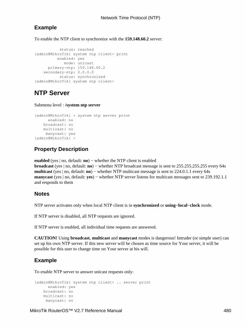
Example
To enable the NTP client to synchronize with the 159.148.60.2 server:
status: reached[admin@MikroTik] system ntp client> print enabled: yes mode: unicast primary−ntp: 159.148.60.2 secondary−ntp: 0.0.0.0 status: synchronized[admin@MikroTik] system ntp client>
NTP Server
Submenu level : /system ntp server
[admin@MikroTik] > system ntp server print enabled: no broadcast: no multicast: no manycast: yes[admin@MikroTik] >
Property Description
enabled (yes | no, default: no) − whether the NTP client is enabledbroadcast (yes | no, default: no) − whether NTP broadcast message is sent to 255.255.255.255 every 64smulticast (yes | no, default: no) − whether NTP multicast message is sent to 224.0.1.1 every 64smanycast (yes | no, default: yes) − whether NTP server listens for multicast messages sent to 239.192.1.1and responds to them
Notes
NTP server activates only when local NTP client is in synchronized or using−local−clock mode.
If NTP server is disabled, all NTP requests are ignored.
If NTP server is enabled, all individual time requests are answered.
CAUTION! Using broadcast, multicast and manycast modes is dangerous! Intruder (or simple user) canset up his own NTP server. If this new server will be chosen as time source for Your server, it will bepossible for this user to change time on Your server at his will.
Example
To enable NTP server to answer unicast requests only:
[admin@MikroTik] system ntp client> .. server print enabled: yes broadcast: no multicast: no manycast: no
Network Time Protocol (NTP)
MikroTik RouterOS™ V2.7 Reference Manual 480
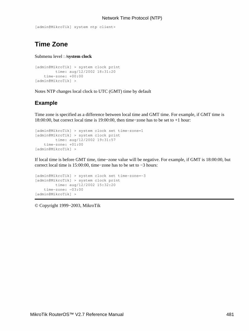
[admin@MikroTik] system ntp client>
Time Zone
Submenu level : /system clock
[admin@MikroTik] > system clock print time: aug/12/2002 18:31:20 time−zone: +00:00[admin@MikroTik] >
Notes NTP changes local clock to UTC (GMT) time by default
Example
Time zone is specified as a difference between local time and GMT time. For example, if GMT time is18:00:00, but correct local time is 19:00:00, then time−zone has to be set to +1 hour:
[admin@MikroTik] > system clock set time−zone=1[admin@MikroTik] > system clock print time: aug/12/2002 19:31:57 time−zone: +01:00[admin@MikroTik] >
If local time is before GMT time, time−zone value will be negative. For example, if GMT is 18:00:00, butcorrect local time is 15:00:00, time−zone has to be set to −3 hours:
[admin@MikroTik] > system clock set time−zone=−3[admin@MikroTik] > system clock print time: aug/12/2002 15:32:20 time−zone: −03:00[admin@MikroTik] >
© Copyright 1999−2003, MikroTik
Network Time Protocol (NTP)
MikroTik RouterOS™ V2.7 Reference Manual 481

Scripting ManualDocument revision 1.7 (15−May−2003)This document applies to the MikroTik RouterOS V2.7
Table Of Contents
Table Of Contents• Summary• Specifications• Related Documents• Description• Command Syntax
Description♦ Property Description♦ Notes♦ Example♦
•
GroupingDescription♦ Notes♦ Example♦
•
VariablesDescription♦ Notes♦ Example♦
•
Command substitution, return valuesDescription♦ Example♦
•
OperatorsDescription♦ Example♦
•
Value typesDescription♦
•
Common CommandsDescription♦
•
Special CommandsMonitor♦ Get♦ Notes♦ Monitor Example♦ Get Example♦
•
Additional Features• Scripts
Description♦ Property Description♦ Notes♦ Example♦
•
Task ManagementDescription♦ Property Description♦
•
MikroTik RouterOS™ V2.7 Reference Manual 482
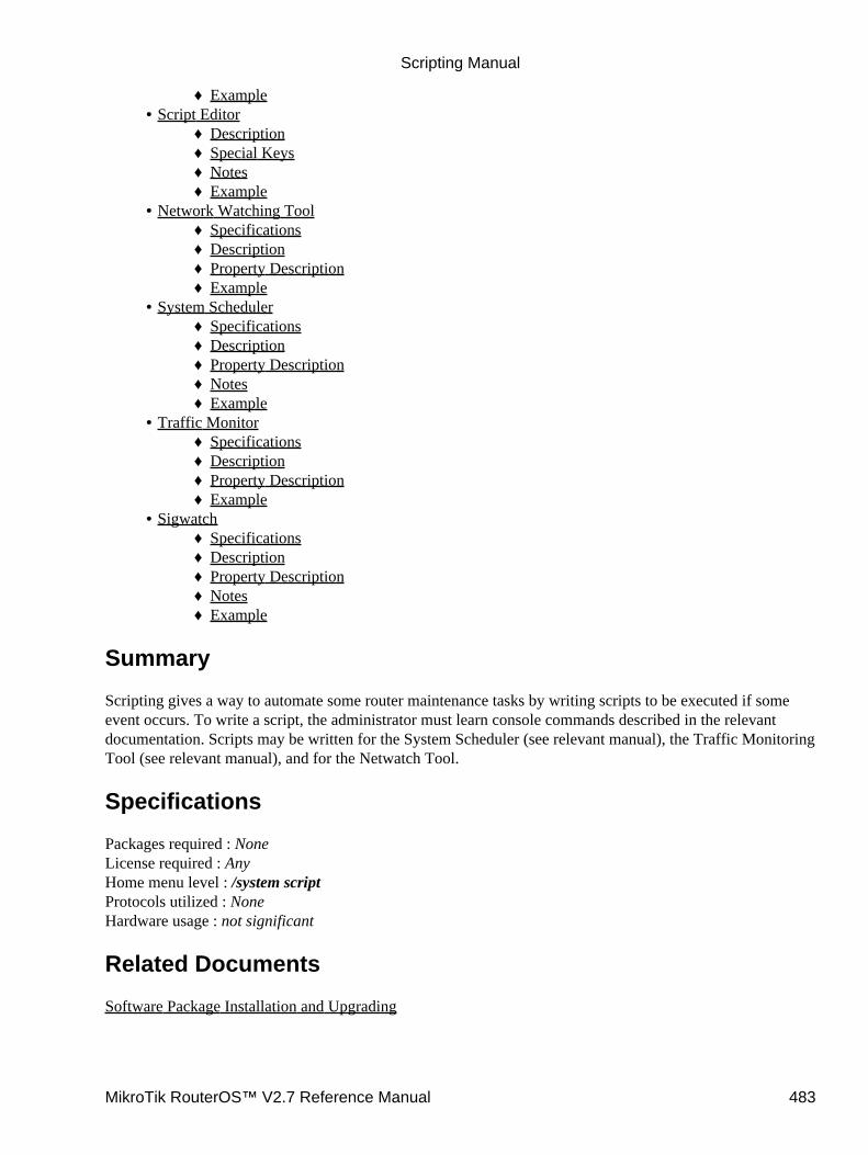
Example♦ Script Editor
Description♦ Special Keys♦ Notes♦ Example♦
•
Network Watching ToolSpecifications♦ Description♦ Property Description♦ Example♦
•
System SchedulerSpecifications♦ Description♦ Property Description♦ Notes♦ Example♦
•
Traffic MonitorSpecifications♦ Description♦ Property Description♦ Example♦
•
SigwatchSpecifications♦ Description♦ Property Description♦ Notes♦ Example♦
•
Summary
Scripting gives a way to automate some router maintenance tasks by writing scripts to be executed if someevent occurs. To write a script, the administrator must learn console commands described in the relevantdocumentation. Scripts may be written for the System Scheduler (see relevant manual), the Traffic MonitoringTool (see relevant manual), and for the Netwatch Tool.
Specifications
Packages required : NoneLicense required : AnyHome menu level : /system scriptProtocols utilized : NoneHardware usage : not significant
Related Documents
Software Package Installation and Upgrading
Scripting Manual
MikroTik RouterOS™ V2.7 Reference Manual 483
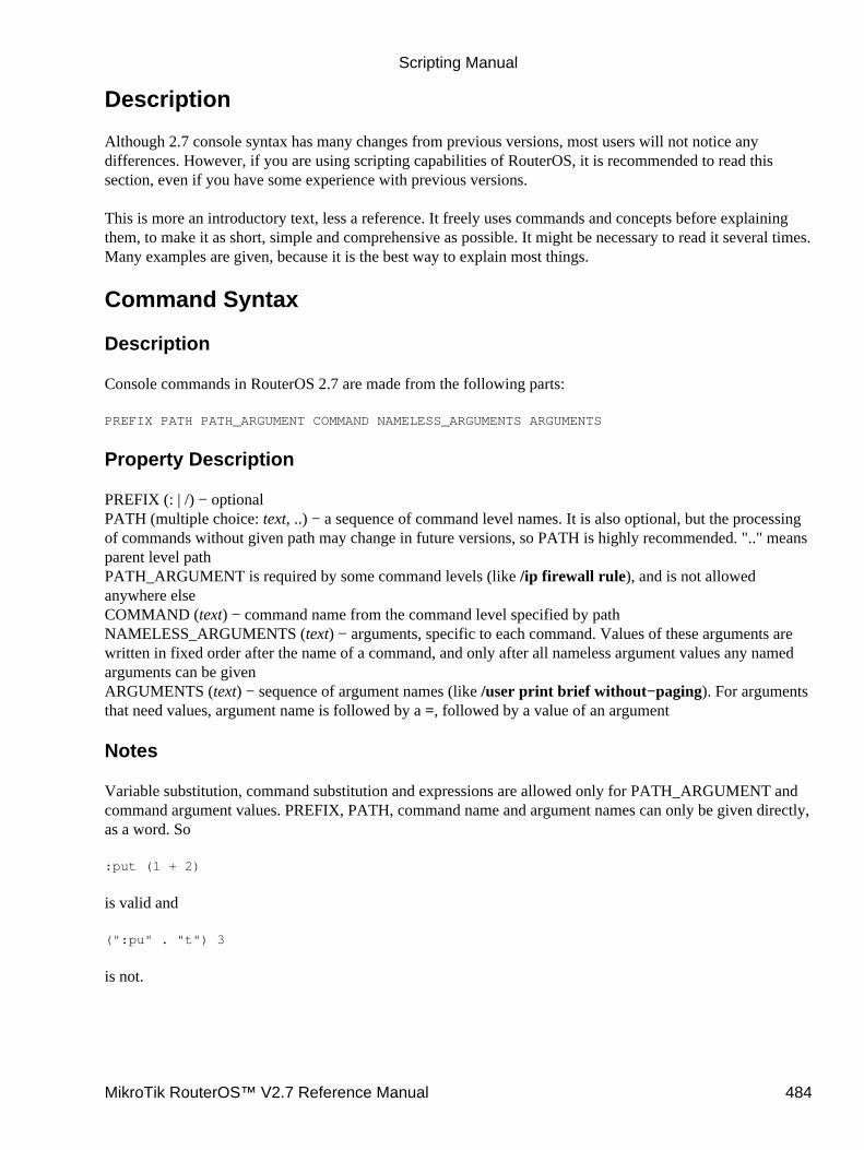
Description
Although 2.7 console syntax has many changes from previous versions, most users will not notice anydifferences. However, if you are using scripting capabilities of RouterOS, it is recommended to read thissection, even if you have some experience with previous versions.
This is more an introductory text, less a reference. It freely uses commands and concepts before explainingthem, to make it as short, simple and comprehensive as possible. It might be necessary to read it several times.Many examples are given, because it is the best way to explain most things.
Command Syntax
Description
Console commands in RouterOS 2.7 are made from the following parts:
PREFIX PATH PATH_ARGUMENT COMMAND NAMELESS_ARGUMENTS ARGUMENTS
Property Description
PREFIX (: | /) − optionalPATH (multiple choice: text, ..) − a sequence of command level names. It is also optional, but the processingof commands without given path may change in future versions, so PATH is highly recommended. ".." meansparent level pathPATH_ARGUMENT is required by some command levels (like /ip firewall rule), and is not allowedanywhere elseCOMMAND (text) − command name from the command level specified by pathNAMELESS_ARGUMENTS (text) − arguments, specific to each command. Values of these arguments arewritten in fixed order after the name of a command, and only after all nameless argument values any namedarguments can be givenARGUMENTS (text) − sequence of argument names (like /user print brief without−paging). For argumentsthat need values, argument name is followed by a =, followed by a value of an argument
Notes
Variable substitution, command substitution and expressions are allowed only for PATH_ARGUMENT andcommand argument values. PREFIX, PATH, command name and argument names can only be given directly,as a word. So
:put (1 + 2)
is valid and
(":pu" . "t") 3
is not.
Scripting Manual
MikroTik RouterOS™ V2.7 Reference Manual 484
Example
The console commands' parts can be seen in the following examples:
/ping 10.0.0.13 count=5 PREFIX − "/" COMMAND − "ping" NAMELESS_ARGUMENTS − "10.0.0.13"ARGUMENTS − "count=5"
... ip firewall rule inputPATH − ".. ip firewall rule"PATH_ARGUMENT − "input"
:for i from=1 to=10 do={:put $i}
PREFIX − ":"COMMAND − "for"NAMELESS_ARGUMENTS − "i"ARGUMENTS − "from=1 to=10 do={:put $i}"
/interface monitor−traffic ether1,ether2,ipip1
PREFIX − "/"PATH − "interface"COMMAND − "monitor−traffic"NAMELESS_ARGUMENTS − "ether1,ether2,ipip1"
Grouping
Description
It is possible to execute several commands from the same command level, by grouping them with braces '{}'.
Notes
You should not change current command level in scripts by typing just it's path, without any command, likeyou when working with console interactively. Such changes have no effect in scripts. Consider:
[admin@MikroTik] ip address> /user {{... /ip route{... print{... }Flags: X − disabled 0 ;;; system default user name="admin" group=full address=0.0.0.0/0
1 name="x" group=write address=0.0.0.0/0
2 name="y" group=read address=0.0.0.0/0
[admin@MikroTik] ip route>
Although the current command level is changed to /ip route, it has effect only on next command entered fromprompt, print command is still considered to be /user print.
Scripting Manual
MikroTik RouterOS™ V2.7 Reference Manual 485

Example
We will add two users to the user menu in the example below:
[admin@MikroTik] ip address> /user {{... add name=x password=y group=write{... add name=y password=z group=read{... print{... }Flags: X − disabled 0 ;;; system default user name="admin" group=full address=0.0.0.0/0
1 name="x" group=write address=0.0.0.0/0
2 name="y" group=read address=0.0.0.0/0
[admin@MikroTik] ip address>
Variables
Description
Console allows you to create and use global (system wide) and local (only usable within one script) variables.Variables can be accessed by writing '$' followed by name of variable. Variable names can contain letters,digits and '−' character. A variable must be declared prior to using it in scripts. There are three types ofdeclaration available:
global•
Global variables can be accessed by all scripts and console logins on the same router. There is no waycurrently to remove global variable, except rebooting router. Variables are not kept across reboots.
local•
Local variables are not shared with any other script, other instance of the same script or other console logins.Its value is lost when script finishes or when variable name is freed by :unset.
loop index variables•
These are used only in do= block of commands and are removed after command completes.monitor commands, that have do= argument•
See details below.
You can assign new value to variable using :set command. It has two unnamed arguments: the name of thevariable and the new value of the variable.
Scripting Manual
MikroTik RouterOS™ V2.7 Reference Manual 486
Notes
Loop variables "shadows" already introduced local variables with the same name.
Introducing variable has no effect on other scripts that may be running. It just tells the current script whatvariable names can be used, and where to get their values. After variable is no longer needed, it's name can befreed by :unset command. If you free local variable, it's value is lost. If you free global variable, it's value isstill kept in router, it just becomes inaccessible from current script.
Example
[admin@MikroTik] ip route> :put $aERROR: unknown variable a[admin@MikroTik] ip route>
You must first declare a variable.Like this:
[admin@MikroTik] ip route> /[admin@MikroTik] > :global g1[admin@MikroTik] > :set g1 "this is global variable"[admin@MikroTik] > :put $g1this is global variable[admin@MikroTik] >
or like this:
[admin@MikroTik] > :local l1[admin@MikroTik] > :set l1 "this is local variable"[admin@MikroTik] > :put $l1this is local variable[admin@MikroTik] >
or, finally, like this:
[admin@MikroTik] > :for l1 from=1 to=3 do={:put $l1}123[admin@MikroTik] > :put $l1this is local variable[admin@MikroTik] >
The following example will create a local variable with start value 0 and then will increase it by 1:
[admin@MikroTik] > :local counter[admin@MikroTik] > :set counter 0[admin@MikroTik] > :put $counter0[admin@MikroTik] > :set counter ($counter + 1)[admin@MikroTik] > :put $counter1[admin@MikroTik] >
Scripting Manual
MikroTik RouterOS™ V2.7 Reference Manual 487
Because increasing or decreasing variable's value by one is such a common case, there are two commands thatdo just that. :incr increases value of variable by 1, and :decr decreases it by 1.
[admin@MikroTik] > :incr counter[admin@MikroTik] > :put $counter2[admin@MikroTik] >
Command substitution, return values
Description
Some console commands are most useful if their output can be used as an argument value in other commands.In console, this is done by "returning" value from commands. Return value is not displayed on the screen.When you type such a command between square brackets '[' ']', this command is executed and it's return valueis used as the value of these brackets. This is called command substitution.
Example
Consider find command.
[admin@MikroTik] > /interface[admin@MikroTik] interface> find type=ether[admin@MikroTik] interface>
It displays nothing on screen, and returns internal numbers of items with matching property values. This ishow return value looks:
[admin@MikroTik] interface> :put [find type=ether]*A,*B[admin@MikroTik] interface>
and this is how it can be used in other commands
[admin@MikroTik] interface> enable [find type=ether][admin@MikroTik] interface>
Besides find, some other commands also return useful values. /ping returns number of successful pings:
[admin@MikroTik] interface> :put [/ping 10.0.0.1 count=3]10.0.0.1 64 byte pong: ttl=64 time<1 ms10.0.0.1 64 byte pong: ttl=64 time<1 ms10.0.0.1 64 byte pong: ttl=64 time<1 ms3 packets transmitted, 3 packets received, 0 packet lossround−trip min/avg/max = 0/0.0/0 ms3[admin@MikroTik] interface>
:set returns value of it's second argument. :time returns the measured time value. :incr and :decr return newvalue of variable. Another important case is add command, which return internal number of newly createditem.
[admin@MikroTik] interface> /user[admin@MikroTik] user> :put [add name=z password=x group=full]
Scripting Manual
MikroTik RouterOS™ V2.7 Reference Manual 488

*7[admin@MikroTik] user>
This way you can store it in variable for later use.
Operators
Description
Console can do simple calculations with numbers, time values, ip addresses, strings and lists. It is achieved bywriting expressions and putting them in parentheses '(' and ')'.
Supported operations are:! − logical NOT•
Unary operator. Argument is a boolean value. Result is an opposite boolean value.− − unary minus•
Unary operator. Argument and result is a number.~ − bit inversion•
Unary operator. Inverts bits in IP address.+ − sum•
Binary operator. Adds two numbers, two time values, or add number to an IP address.− − subtraction•
Binary operator. Subtracts two numbers one from another, two time values, two IP addresses or an IP addressand a number.
* − multiplication•
Binary operator. Multiplies two numbers, or multiply a time value by a number./ − division•
Binary operator. Divides one number by another (gives an integer), or a time value by a number (gives timevalue).
comparison operators•
< − less> − more<= − less or equal>= − more or equal
Scripting Manual
MikroTik RouterOS™ V2.7 Reference Manual 489
Binary operators. Compare two numbers, two time values, or two IP addresses. Give boolean value.!= − not equal= − equalBinary operators. Compare two values of the same type. Arrays are equal if their respective elements areequal.
− logical AND•
|| − logical OR•
Binary operators. Logical operation on two boolean values. Result of is true, if both operands are true.Result of || is true if either operand is true.
bitwise operators•
− bitwise and| − bitwise or^ − bitwise xorBinary operators. Bitwise operations on two IP addresses. Result is also an IP address.<< − shift left>> − shift rightBinary operators. Shift IP value left or right by given amount of bits. First argument is an IP addressand second argument is an integer. Result is an IP address.
. − concatenation•
Binary operator. Concatenates two strings, or appends one list to another, or appends an element to alist.
Example
[admin@MikroTik] user> :put (1 + 2)3[admin@MikroTik] user> /interface[admin@MikroTik] interface> :put ([find type=ipip ] . [find type=ether ])*6,*A,*B[admin@MikroTik] interface>
logical NOT
[admin@MikroTik] interface> :put (!true)false[admin@MikroTik] interface> :put (!(2>3))true[admin@MikroTik] interface>
unary minus
[admin@MikroTik] interface> :put (−1 :put (−−1)1
bit inversion
Scripting Manual
MikroTik RouterOS™ V2.7 Reference Manual 490
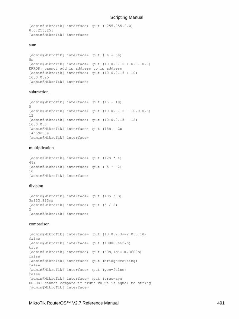
[admin@MikroTik] interface> :put (~255.255.0.0)0.0.255.255[admin@MikroTik] interface>
sum
[admin@MikroTik] interface> :put (3s + 5s)8s[admin@MikroTik] interface> :put (10.0.0.15 + 0.0.10.0)ERROR: cannot add ip address to ip address[admin@MikroTik] interface> :put (10.0.0.15 + 10)10.0.0.25[admin@MikroTik] interface>
subtraction
[admin@MikroTik] interface> :put (15 − 10)5[admin@MikroTik] interface> :put (10.0.0.15 − 10.0.0.3)12[admin@MikroTik] interface> :put (10.0.0.15 − 12)10.0.0.3[admin@MikroTik] interface> :put (15h − 2s)14h59m58s[admin@MikroTik] interface>
multiplication
[admin@MikroTik] interface> :put (12s * 4)48s[admin@MikroTik] interface> :put (−5 * −2)10[admin@MikroTik] interface>
division
[admin@MikroTik] interface> :put (10s / 3)3s333.333ms[admin@MikroTik] interface> :put (5 / 2)2[admin@MikroTik] interface>
comparison
[admin@MikroTik] interface> :put (10.0.2.3<=2.0.3.10)false[admin@MikroTik] interface> :put (100000s>27h)true[admin@MikroTik] interface> :put (60s,1d!=1m,3600s)false[admin@MikroTik] interface> :put (bridge=routing)false[admin@MikroTik] interface> :put (yes=false)false[admin@MikroTik] interface> :put (true=aye)ERROR: cannot compare if truth value is equal to string[admin@MikroTik] interface>
Scripting Manual
MikroTik RouterOS™ V2.7 Reference Manual 491
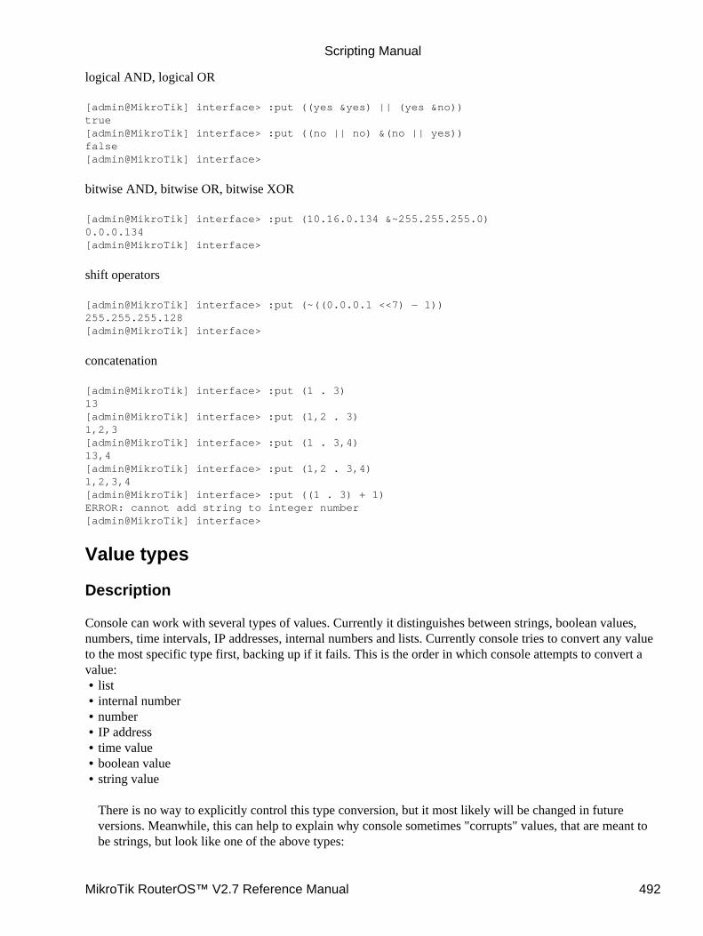
logical AND, logical OR
[admin@MikroTik] interface> :put ((yes &yes) || (yes &no))true[admin@MikroTik] interface> :put ((no || no) &(no || yes))false[admin@MikroTik] interface>
bitwise AND, bitwise OR, bitwise XOR
[admin@MikroTik] interface> :put (10.16.0.134 &~255.255.255.0)0.0.0.134[admin@MikroTik] interface>
shift operators
[admin@MikroTik] interface> :put (~((0.0.0.1 <<7) − 1))255.255.255.128[admin@MikroTik] interface>
concatenation
[admin@MikroTik] interface> :put (1 . 3)13[admin@MikroTik] interface> :put (1,2 . 3)1,2,3[admin@MikroTik] interface> :put (1 . 3,4)13,4[admin@MikroTik] interface> :put (1,2 . 3,4)1,2,3,4[admin@MikroTik] interface> :put ((1 . 3) + 1)ERROR: cannot add string to integer number[admin@MikroTik] interface>
Value types
Description
Console can work with several types of values. Currently it distinguishes between strings, boolean values,numbers, time intervals, IP addresses, internal numbers and lists. Currently console tries to convert any valueto the most specific type first, backing up if it fails. This is the order in which console attempts to convert avalue:
list• internal number• number• IP address• time value• boolean value• string value
There is no way to explicitly control this type conversion, but it most likely will be changed in futureversions. Meanwhile, this can help to explain why console sometimes "corrupts" values, that are meant tobe strings, but look like one of the above types:
•
Scripting Manual
MikroTik RouterOS™ V2.7 Reference Manual 492

[admin@MikroTik] interface> :put 1s1d900392d1h40s[admin@MikroTik] interface>
In console integers are internally represented as 64 bit signed numbers, so the range of variable values canbe from −9223372036854775808 to 9223372036854775807. It is possible to input them as hexadecimalnumbers, by prefixing with "0x":
[admin@MikroTik] interface> :put 0x123ABCDEF45678901313569907099990160[admin@MikroTik] interface> /[admin@MikroTik] >
Lists are written as comma separated sequence of values. Putting whitespaces around commas is notrecommended, because it might confuse console about word boundaries.
[admin@MikroTik] > :foreach i in 1,2,3 do {:put $i}123[admin@MikroTik] > :foreach i in 1, 2, 3 do {:put $i}ERROR: no such argument (2,)[admin@MikroTik] >
Boolean values are written as either true or false. Console also accepts yes for true, and no for false.
Internal numbers begin with '*'.
Time intervals are written as sequence of numbers, that can be followed by letters specifying the units oftime measure. The default is a second. Numbers may have decimal point. It is also possible to use theHH:MM:SS notation. Here are some examples:
[admin@MikroTik] > :put "1000s"16m40s[admin@MikroTik] > :put "1day 1day 1day"3d[admin@MikroTik] > :put "1day day 1day"1day day 1day[admin@MikroTik] > :put "1.5hours"1h30m[admin@MikroTik] > :put "1:15"1h15m[admin@MikroTik] > :put "0:3:2.05"3m2s50ms[admin@MikroTik] >
Accepted time units:
d, day, days − unit is 24 hoursh, hour, hours − unit is 1 hourm − unit is 1 minutes − unit is 1 secondms − unit is 1 millisecond (0.001 second)
Scripting Manual
MikroTik RouterOS™ V2.7 Reference Manual 493
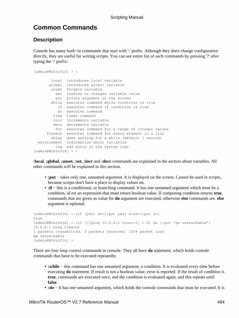
Common Commands
Description
Console has many built−in commands that start with ':' prefix. Although they don't change configurationdirectly, they are useful for writing scripts. You can see entire list of such commands by pressing '?' aftertyping the ':' prefix:
[admin@MikroTik] > :
local introduces local variable global introduces global variable unset forgets variable set creates or changes variable value put prints argument on the screen while executes command while condition is true if executes command if condition is true do executes command time times command incr increments variable decr decrements variable for executes command for a range of integer values foreach executes command for every element in a list delay does nothing for a while (default 1 second) environment information about variables log add entry in the system logs[admin@MikroTik] > :
:local, :global, :unset, :set, :incr and :decr commands are explained in the section about variables. Allother commands will be explained in this section.
:put − takes only one, unnamed argument. It is displayed on the screen. Cannot be used in scripts,because scripts don't have a place to display values on.
•
:if − this is a conditional, or branching command. It has one unnamed argument which must be acondition, id est an expression that must return boolean value. If computing condition returns true,commands that are given as value for do argument are executed, otherwise else commands are. elseargument is optional.
•
[admin@MikroTik] > :if (yes) do={:put yes} else={:put no}true[admin@MikroTik] > :if ([/ping 10.0.0.1 count=1] = 0) do {:put "gw unreachable"}10.0.0.1 pong timeout1 packets transmitted, 0 packets received, 100% packet lossgw unreachable[admin@MikroTik] >
There are four loop control commands in console. They all have do statement, which holds consolecommands that have to be executed repeatedly.
:while − this command has one unnamed argument, a condition. It is evaluated every time beforeexecuting do statement. If result is not a boolean value, error is reported. If the result of condition istrue, commands are executed once, and the condition is evaluated again, and this repeats untilfalse.
•
:do − It has one unnamed argument, which holds the console commands that must be executed. It is•
Scripting Manual
MikroTik RouterOS™ V2.7 Reference Manual 494

similar to the do statement of other commands. If no other arguments are given, :do just executesthese commands once. There is not much use in that. If you specify a condition as a value for whileargument, it is evaluated after executing commands, and if it returns true, do statement is executedagain, and this is repeated until the condition returns false. If you specify a condition for ifargument, it is computed only once, before doing anything else, and if it is false, nothing is done. Ifit is true, everything is executed as usual. Note that :do A while=B is different from :while Bdo=A, because :do evaluates condition after executing command, not before, like :while does.However, :do A if=B and :if B do=A do exactly the same thing.:for − It has one unnamed argument, the name of the loop variable. from argument is the startingvalue for the loop counter, to value is the final value. This command counts loop variable up ordown starting at from and ending with to, inclusive, and for each value it executes the dostatement. It is possible to change the increment from the default 1 (or −1), by specifying the stepargument.
[admin@MikroTik] > :for i from=1 to=100 step=37 do={:put ($i . " − " . 1000/$i)}1 − 100038 − 2675 − 13[admin@MikroTik] >
•
:foreach − The unnamed argument is the name of the loop variable. in argument is treated as a list.Each value in sequence is assigned to the loop variable, and do statement is executed for this value.If in value is not a list, do statement is executed only once. If in value is empty, do statement isn'texecuted at all. This is made to work good with find command, which return lists of internalnumbers, and may return empty list or just one internal number. This example prints all ethernetinterfaces, each followed by all addresses that are assigned to it:
[admin@MikroTik] > :foreach i in=[/interface find type=ether ] do={{... :put [/interface get $i name]{... :foreach j in=[/ip address find interface=$i] do={{{... :put [/ip address get $j address]{{... }{... }ether1ether210.0.0.65/24[admin@MikroTik] >
•
:delay − This command does nothing for a given amount of time. The unnamed argument shouldbe a time interval value. It is optional, and if :delay is executed without any arguments, it doesnothing for one second.
•
:time − This command takes one unnamed argument containing console commands. Commandsare executed, and the time it took to execute them is printed, and returned.
[admin@MikroTik] > :time {:delay 1756ms}1.755333s[admin@MikroTik] > :put [:time {:delay}]1.007464s1s7.464ms[admin@MikroTik] >
•
:log − This command adds an entry to the system logs. message argument is the text of log entry.facility argument tells at which logging facility (see /system logging facility) this message shouldbe logged, the default is System−Info.
[admin@MikroTik] > :log facility=System−Warning message="Very Bad Thing happened"[admin@MikroTik] >
•
Scripting Manual
MikroTik RouterOS™ V2.7 Reference Manual 495
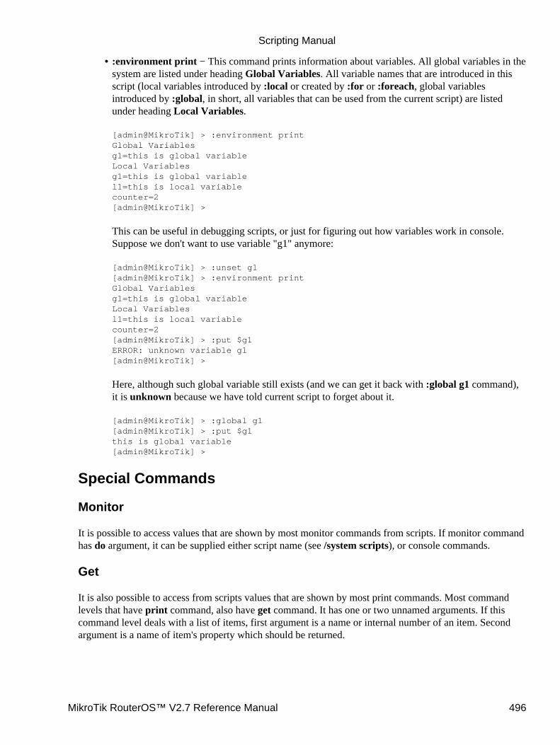
:environment print − This command prints information about variables. All global variables in thesystem are listed under heading Global Variables. All variable names that are introduced in thisscript (local variables introduced by :local or created by :for or :foreach, global variablesintroduced by :global, in short, all variables that can be used from the current script) are listedunder heading Local Variables.
[admin@MikroTik] > :environment printGlobal Variablesg1=this is global variableLocal Variablesg1=this is global variablel1=this is local variablecounter=2[admin@MikroTik] >
This can be useful in debugging scripts, or just for figuring out how variables work in console.Suppose we don't want to use variable "g1" anymore:
[admin@MikroTik] > :unset g1[admin@MikroTik] > :environment printGlobal Variablesg1=this is global variableLocal Variablesl1=this is local variablecounter=2[admin@MikroTik] > :put $g1ERROR: unknown variable g1[admin@MikroTik] >
Here, although such global variable still exists (and we can get it back with :global g1 command),it is unknown because we have told current script to forget about it.
[admin@MikroTik] > :global g1[admin@MikroTik] > :put $g1this is global variable[admin@MikroTik] >
•
Special Commands
Monitor
It is possible to access values that are shown by most monitor commands from scripts. If monitor commandhas do argument, it can be supplied either script name (see /system scripts), or console commands.
Get
It is also possible to access from scripts values that are shown by most print commands. Most commandlevels that have print command, also have get command. It has one or two unnamed arguments. If thiscommand level deals with a list of items, first argument is a name or internal number of an item. Secondargument is a name of item's property which should be returned.
Scripting Manual
MikroTik RouterOS™ V2.7 Reference Manual 496
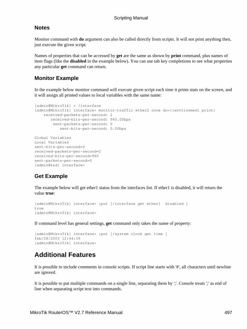
Notes
Monitor command with do argument can also be called directly from scripts. It will not print anything then,just execute the given script.
Names of properties that can be accessed by get are the same as shown by print command, plus names ofitem flags (like the disabled in the example below). You can use tab key completions to see what propertiesany particular get command can return.
Monitor Example
In the example below monitor command will execute given script each time it prints stats on the screen, andit will assign all printed values to local variables with the same name:
[admin@MikroTik] > /interface[admin@MikroTik] interface> monitor−traffic ether2 once do={:environment print} received−packets−per−second: 2 received−bits−per−second: 960.00bps sent−packets−per−second: 0 sent−bits−per−second: 0.00bps
Global VariablesLocal Variablessent−bits−per−second=0received−packets−per−second=2received−bits−per−second=960sent−packets−per−second=0[admin@kzd] interface>
Get Example
The example below will get ether1 status from the interfaces list. If ether1 is disabled, it will return thevalue true:
[admin@MikroTik] interface> :put [/interface get ether1 disabled ]true[admin@MikroTik] interface>
If command level has general settings, get command only takes the name of property:
[admin@MikroTik] interface> :put [/system clock get time ]feb/28/2003 12:44:39[admin@MikroTik] interface>
Additional Features
It is possible to include comments in console scripts. If script line starts with '#', all characters until newlineare ignored.
It is possible to put multiple commands on a single line, separating them by ';'. Console treats ';' as end ofline when separating script text into commands.
Scripting Manual
MikroTik RouterOS™ V2.7 Reference Manual 497
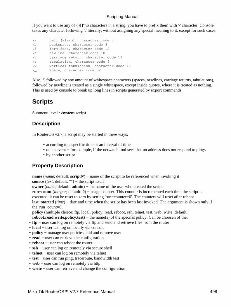
If you want to use any of {}[]"'\$ characters in a string, you have to prefix them with '\' character. Consoletakes any character following '\' literally, without assigning any special meaning to it, except for such cases:
\a bell (alarm), character code 7\b backspace, character code 8\f form feed, character code 12\n newline, character code 10\r carriage return, character code 13\t tabulation, character code 9\v vertical tabulation, character code 11\_ space, character code 32
Also, '\' followed by any amount of whitespace characters (spaces, newlines, carriage returns, tabulations),followed by newline is treated as a single whitespace, except inside quotes, where it is treated as nothing.This is used by console to break up long lines in scripts generated by export commands.
Scripts
Submenu level : /system script
Description
In RouterOS v2.7, a script may be started in three ways:
according to a specific time or an interval of time• on an event − for example, if the netwatch tool sees that an address does not respond to pings• by another script•
Property Description
name (name; default: scriptN) − name of the script to be referenced when invoking itsource (text; default: "") − the script itselfowner (name; default: admin) − the name of the user who created the scriptrun−count (integer; default: 0) − usage counter. This counter is incremented each time the script isexecuted, it can be reset to zero by setting 'run−counter=0'. The counters will reset after reboot.last−started (time) − date and time when the script has been last invoked. The argument is shown only ifthe 'run−count=0'.policy (multiple choice: ftp, local, policy, read, reboot, ssh, telnet, test, web, write; default:reboot,read,write,policy,test) − the name(s) of the specific policy. Can be choosen of the:ftp − user can log on remotely via ftp and send and retrieve files from the router• local − user can log on locally via console• policy − manage user policies, add and remove user• read − user can retrieve the configuration• reboot − user can reboot the router• ssh − user can log on remotely via secure shell• telnet − user can log on remotely via telnet• test − user can run ping, traceroute, bandwidth test• web − user can log on remotely via http• write − user can retrieve and change the configuration•
Scripting Manual
MikroTik RouterOS™ V2.7 Reference Manual 498
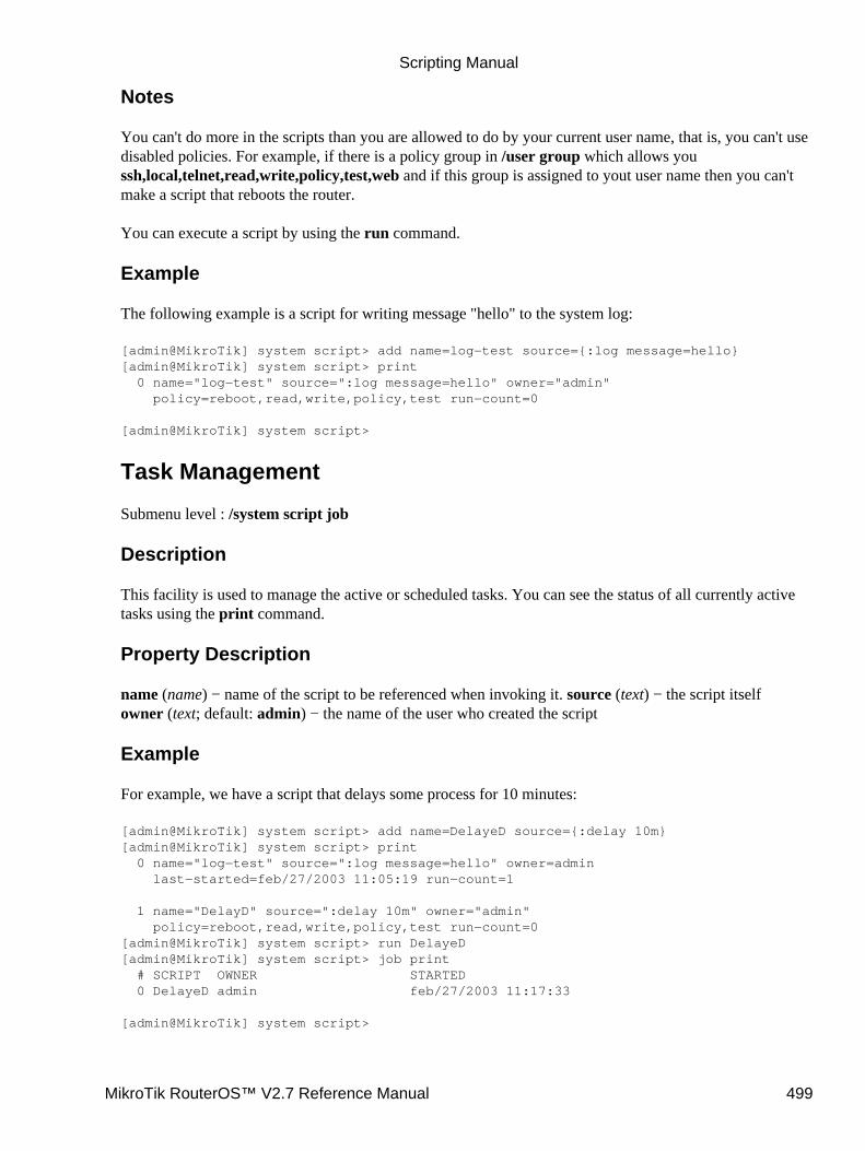
Notes
You can't do more in the scripts than you are allowed to do by your current user name, that is, you can't usedisabled policies. For example, if there is a policy group in /user group which allows youssh,local,telnet,read,write,policy,test,web and if this group is assigned to yout user name then you can'tmake a script that reboots the router.
You can execute a script by using the run command.
Example
The following example is a script for writing message "hello" to the system log:
[admin@MikroTik] system script> add name=log−test source={:log message=hello}[admin@MikroTik] system script> print 0 name="log−test" source=":log message=hello" owner="admin" policy=reboot,read,write,policy,test run−count=0
[admin@MikroTik] system script>
Task Management
Submenu level : /system script job
Description
This facility is used to manage the active or scheduled tasks. You can see the status of all currently activetasks using the print command.
Property Description
name (name) − name of the script to be referenced when invoking it. source (text) − the script itselfowner (text; default: admin) − the name of the user who created the script
Example
For example, we have a script that delays some process for 10 minutes:
[admin@MikroTik] system script> add name=DelayeD source={:delay 10m}[admin@MikroTik] system script> print 0 name="log−test" source=":log message=hello" owner=admin last−started=feb/27/2003 11:05:19 run−count=1
1 name="DelayD" source=":delay 10m" owner="admin" policy=reboot,read,write,policy,test run−count=0[admin@MikroTik] system script> run DelayeD[admin@MikroTik] system script> job print # SCRIPT OWNER STARTED 0 DelayeD admin feb/27/2003 11:17:33
[admin@MikroTik] system script>
Scripting Manual
MikroTik RouterOS™ V2.7 Reference Manual 499
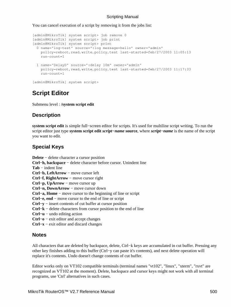
You can cancel execution of a script by removing it from the jobs list:
[admin@MikroTik] system script> job remove 0[admin@MikroTik] system script> job print[admin@MikroTik] system script> print 0 name="log−test" source=":log message=hello" owner="admin" policy=reboot,read,write,policy,test last−started=feb/27/2003 11:05:13 run−count=1
1 name="DelayD" source=":delay 10m" owner="admin" policy=reboot,read,write,policy,test last−started=feb/27/2003 11:17:33 run−count=1
[admin@MikroTik] system script>
Script Editor
Submenu level : /system script edit
Description
system script edit is simple full−screen editor for scripts. It's used for multiline script writing. To run thescript editor just type system script edit script−name source, where script−name is the name of the scriptyou want to edit.
Special Keys
Delete − delete character a cursor positionCtrl−h, backspace − delete character before cursor. Unindent lineTab − indent lineCtrl−b, LeftArrow − move cursor leftCtrl−f, RightArrow − move cursor rightCtrl−p, UpArrow − move cursor upCtrl−n, DownArrow − move cursor downCtrl−a, Home − move cursor to the beginning of line or scriptCtrl−e, end − move cursor to the end of line or scriptCtrl−y − insert contents of cut buffer at cursor positionCtrl−k − delete characters from cursor position to the end of lineCtrl−u − undo editing actionCtrl−o − exit editor and accept changesCtrl−x − exit editor and discard changes
Notes
All characters that are deleted by backspace, delete, Ctrl−k keys are accumulated in cut buffer. Pressing anyother key finishes adding to this buffer (Ctrl−y can paste it's contents), and next delete operation willreplace it's contents. Undo doesn't change contents of cut buffer.
Editor works only on VT102 compatible terminals (terminal names "vt102", "linux", "xterm", "rxvt" arerecognized as VT102 at the moment). Delete, backspace and cursor keys might not work with all terminalprograms, use 'Ctrl' alternatives in such cases.
Scripting Manual
MikroTik RouterOS™ V2.7 Reference Manual 500
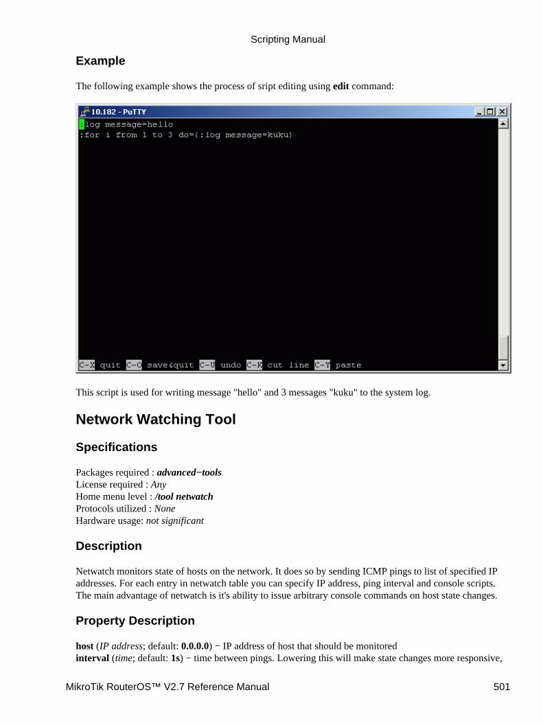
Example
The following example shows the process of sript editing using edit command:
This script is used for writing message "hello" and 3 messages "kuku" to the system log.
Network Watching Tool
Specifications
Packages required : advanced−toolsLicense required : AnyHome menu level : /tool netwatchProtocols utilized : NoneHardware usage: not significant
Description
Netwatch monitors state of hosts on the network. It does so by sending ICMP pings to list of specified IPaddresses. For each entry in netwatch table you can specify IP address, ping interval and console scripts.The main advantage of netwatch is it's ability to issue arbitrary console commands on host state changes.
Property Description
host (IP address; default: 0.0.0.0) − IP address of host that should be monitoredinterval (time; default: 1s) − time between pings. Lowering this will make state changes more responsive,
Scripting Manual
MikroTik RouterOS™ V2.7 Reference Manual 501

but can create unnecessary traffic and consume system resourcestimeout (time; default: 1s) − timeout for each ping. If no reply from a host is received in this time, the hostis considered unreachable (down)up−script (name) − console script that is executed once when state of a host changes from unknown ordown to updown−script (name) − console script that is executed once when state of a host changes from unknown orup to downsince (read−only: time) − time when state of host changed last timestatus (read−only: up | down | unknown) − tells the current status of the hostup − the host is up• down − the host is down• unknown − when any properties of this list entry are changed, or it is enabled or disabled
Example
This example will run the scripts gw_1 or gw_2 which change the default gateway depending on the statusof one of the gateways:
[admin@MikroTik] system script> add name=gw_1 source={/ip route set{... [/ip route find dst 0.0.0.0] gateway 10.0.0.1}[admin@MikroTik] system script> add name=gw_2 source={/ip route set {.. [/ip route find dst 0.0.0.0] gateway 10.0.0.217}[admin@MikroTik] system script> /tool netwatch[admin@MikroTik] tool netwatch> add host=10.0.0.217 interval=10s timeout=998ms \\... up−script=gw_2 down−script=gw_1[admin@MikroTik] tool netwatch> printFlags: X − disabled # HOST TIMEOUT INTERVAL STATUS 0 10.0.0.217 997ms 10s up[admin@MikroTik] tool netwatch> print detailFlags: X − disabled 0 host=10.0.0.217 timeout=997ms interval=10s since=feb/27/2003 14:01:03 status=up up−script=gw_2 down−script=gw_1
[admin@MikroTik] tool netwatch>
Without scripts, netwatch can be used just as an information tool to see which links are up, or whichspecific hosts are running at the moment.
Let's look at the example above − it changes default route if gateway becomes unreachable. How it's done?There are two scripts. The script "gw_2" is executed once when status of host changes to up. In our case,it's equivalent to entering this console command:
[MikroTik] > /ip route set [/ip route find dst 0.0.0.0] gateway 10.0.0.217
The /ip route find dst 0.0.0.0 command returns list of all routes whose dst−address value is zero. Usuallythat's the default route. It is substituted as first argument to /ip route set command, which changes gatewayof this route to 10.0.0.217
The script "gw_1" is executed once when status of host becomes down. It does the following:
[MikroTik] > /ip route set [/ip route find dst 0.0.0.0] gateway 10.0.0.1
It changes the default gateway if 10.0.0.217 address has become unreachable.
•
Scripting Manual
MikroTik RouterOS™ V2.7 Reference Manual 502
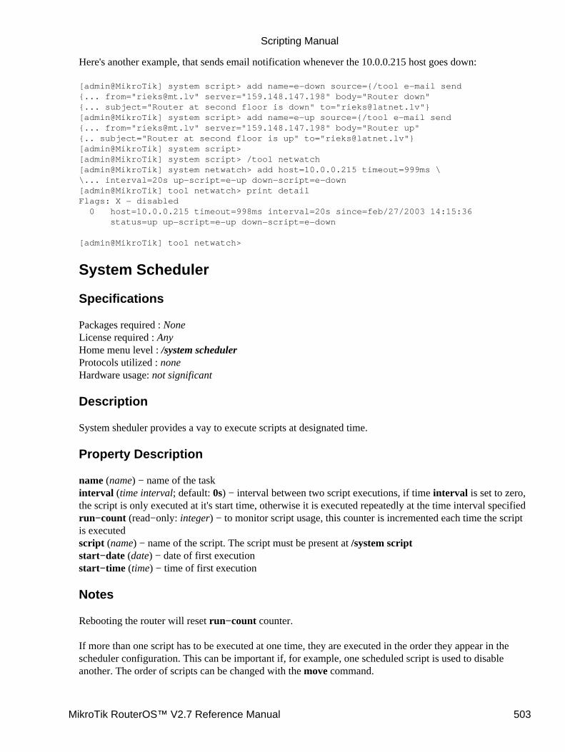
Here's another example, that sends email notification whenever the 10.0.0.215 host goes down:
[admin@MikroTik] system script> add name=e−down source={/tool e−mail send{... from="[email protected]" server="159.148.147.198" body="Router down"{... subject="Router at second floor is down" to="[email protected]"}[admin@MikroTik] system script> add name=e−up source={/tool e−mail send{... from="[email protected]" server="159.148.147.198" body="Router up"{.. subject="Router at second floor is up" to="[email protected]"}[admin@MikroTik] system script>[admin@MikroTik] system script> /tool netwatch[admin@MikroTik] system netwatch> add host=10.0.0.215 timeout=999ms \\... interval=20s up−script=e−up down−script=e−down[admin@MikroTik] tool netwatch> print detailFlags: X − disabled 0 host=10.0.0.215 timeout=998ms interval=20s since=feb/27/2003 14:15:36 status=up up−script=e−up down−script=e−down
[admin@MikroTik] tool netwatch>
System Scheduler
Specifications
Packages required : NoneLicense required : AnyHome menu level : /system schedulerProtocols utilized : noneHardware usage: not significant
Description
System sheduler provides a vay to execute scripts at designated time.
Property Description
name (name) − name of the taskinterval (time interval; default: 0s) − interval between two script executions, if time interval is set to zero,the script is only executed at it's start time, otherwise it is executed repeatedly at the time interval specifiedrun−count (read−only: integer) − to monitor script usage, this counter is incremented each time the scriptis executedscript (name) − name of the script. The script must be present at /system scriptstart−date (date) − date of first executionstart−time (time) − time of first execution
Notes
Rebooting the router will reset run−count counter.
If more than one script has to be executed at one time, they are executed in the order they appear in thescheduler configuration. This can be important if, for example, one scheduled script is used to disableanother. The order of scripts can be changed with the move command.
Scripting Manual
MikroTik RouterOS™ V2.7 Reference Manual 503
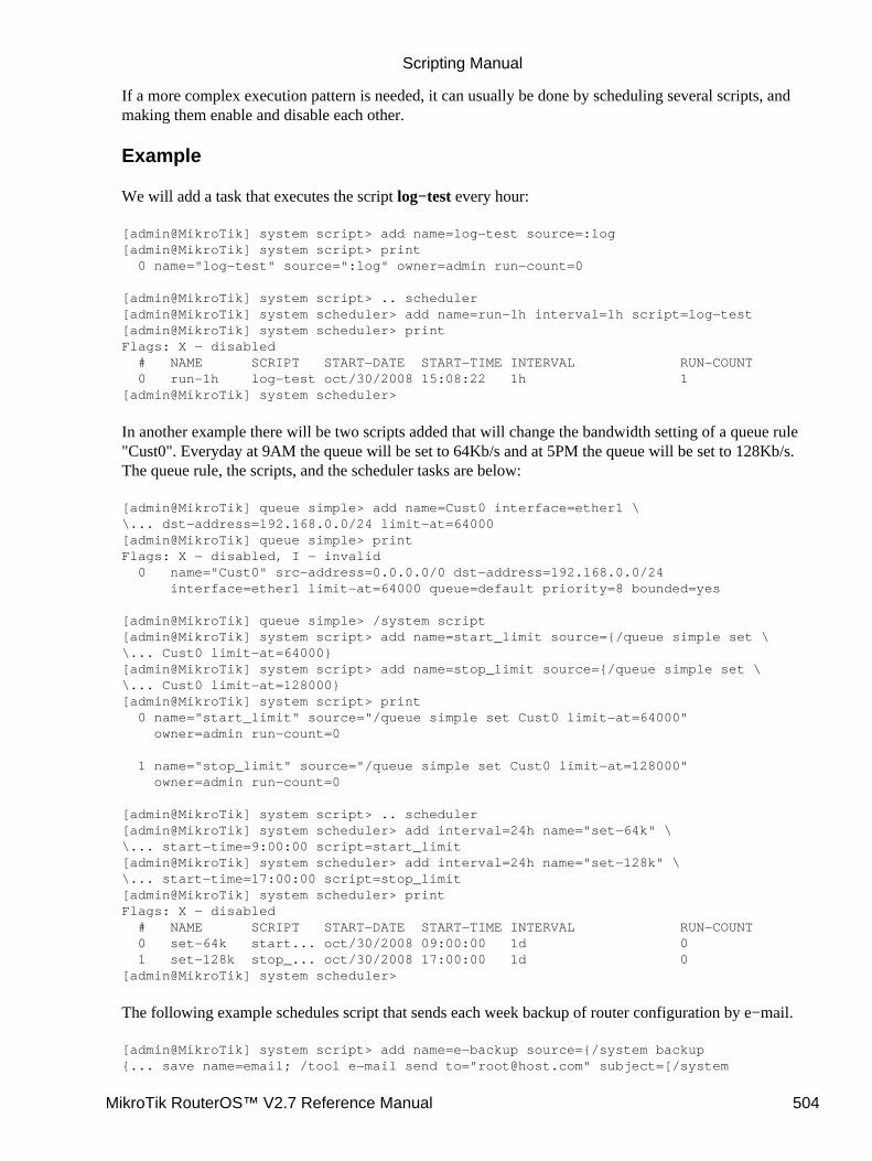
If a more complex execution pattern is needed, it can usually be done by scheduling several scripts, andmaking them enable and disable each other.
Example
We will add a task that executes the script log−test every hour:
[admin@MikroTik] system script> add name=log−test source=:log[admin@MikroTik] system script> print 0 name="log−test" source=":log" owner=admin run−count=0
[admin@MikroTik] system script> .. scheduler[admin@MikroTik] system scheduler> add name=run−1h interval=1h script=log−test[admin@MikroTik] system scheduler> printFlags: X − disabled # NAME SCRIPT START−DATE START−TIME INTERVAL RUN−COUNT 0 run−1h log−test oct/30/2008 15:08:22 1h 1[admin@MikroTik] system scheduler>
In another example there will be two scripts added that will change the bandwidth setting of a queue rule"Cust0". Everyday at 9AM the queue will be set to 64Kb/s and at 5PM the queue will be set to 128Kb/s.The queue rule, the scripts, and the scheduler tasks are below:
[admin@MikroTik] queue simple> add name=Cust0 interface=ether1 \\... dst−address=192.168.0.0/24 limit−at=64000[admin@MikroTik] queue simple> printFlags: X − disabled, I − invalid 0 name="Cust0" src−address=0.0.0.0/0 dst−address=192.168.0.0/24 interface=ether1 limit−at=64000 queue=default priority=8 bounded=yes
[admin@MikroTik] queue simple> /system script[admin@MikroTik] system script> add name=start_limit source={/queue simple set \\... Cust0 limit−at=64000}[admin@MikroTik] system script> add name=stop_limit source={/queue simple set \\... Cust0 limit−at=128000}[admin@MikroTik] system script> print 0 name="start_limit" source="/queue simple set Cust0 limit−at=64000" owner=admin run−count=0
1 name="stop_limit" source="/queue simple set Cust0 limit−at=128000" owner=admin run−count=0
[admin@MikroTik] system script> .. scheduler[admin@MikroTik] system scheduler> add interval=24h name="set−64k" \\... start−time=9:00:00 script=start_limit[admin@MikroTik] system scheduler> add interval=24h name="set−128k" \\... start−time=17:00:00 script=stop_limit[admin@MikroTik] system scheduler> printFlags: X − disabled # NAME SCRIPT START−DATE START−TIME INTERVAL RUN−COUNT 0 set−64k start... oct/30/2008 09:00:00 1d 0 1 set−128k stop_... oct/30/2008 17:00:00 1d 0[admin@MikroTik] system scheduler>
The following example schedules script that sends each week backup of router configuration by e−mail.
[admin@MikroTik] system script> add name=e−backup source={/system backup{... save name=email; /tool e−mail send to="[email protected]" subject=[/system
Scripting Manual
MikroTik RouterOS™ V2.7 Reference Manual 504
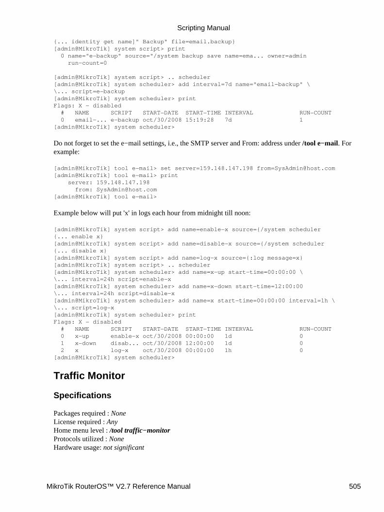
{... identity get name]" Backup" file=email.backup}[admin@MikroTik] system script> print 0 name="e−backup" source="/system backup save name=ema... owner=admin run−count=0
[admin@MikroTik] system script> .. scheduler[admin@MikroTik] system scheduler> add interval=7d name="email−backup" \\... script=e−backup[admin@MikroTik] system scheduler> printFlags: X − disabled # NAME SCRIPT START−DATE START−TIME INTERVAL RUN−COUNT 0 email−... e−backup oct/30/2008 15:19:28 7d 1[admin@MikroTik] system scheduler>
Do not forget to set the e−mail settings, i.e., the SMTP server and From: address under /tool e−mail. Forexample:
[admin@MikroTik] tool e−mail> set server=159.148.147.198 [email protected][admin@MikroTik] tool e−mail> print server: 159.148.147.198 from: [email protected][admin@MikroTik] tool e−mail>
Example below will put 'x' in logs each hour from midnight till noon:
[admin@MikroTik] system script> add name=enable−x source={/system scheduler{... enable x}[admin@MikroTik] system script> add name=disable−x source={/system scheduler{... disable x}[admin@MikroTik] system script> add name=log−x source={:log message=x}[admin@MikroTik] system script> .. scheduler[admin@MikroTik] system scheduler> add name=x−up start−time=00:00:00 \\... interval=24h script=enable−x[admin@MikroTik] system scheduler> add name=x−down start−time=12:00:00\... interval=24h script=disable−x[admin@MikroTik] system scheduler> add name=x start−time=00:00:00 interval=1h \\... script=log−x[admin@MikroTik] system scheduler> printFlags: X − disabled # NAME SCRIPT START−DATE START−TIME INTERVAL RUN−COUNT 0 x−up enable−x oct/30/2008 00:00:00 1d 0 1 x−down disab... oct/30/2008 12:00:00 1d 0 2 x log−x oct/30/2008 00:00:00 1h 0[admin@MikroTik] system scheduler>
Traffic Monitor
Specifications
Packages required : NoneLicense required : AnyHome menu level : /tool traffic−monitorProtocols utilized : NoneHardware usage: not significant
Scripting Manual
MikroTik RouterOS™ V2.7 Reference Manual 505
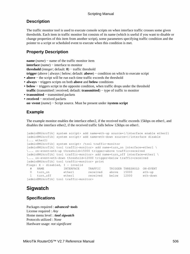
Description
The traffic monitor tool is used to execute console scripts on when interface traffic crosses some giventhresholds. Each item in traffic monitor list consists of its name (which is useful if you want to disable orchange properties of this item from another script), some parameters specifying traffic condition and thepointer to a script or scheduled event to execute when this condition is met.
Property Description
name (name) − name of the traffic monitor iteminterface (name) − interface to monitorthreshold (integer; default: 0) − traffic thresholdtrigger (above | always | below; default: above) − condition on which to execute scriptabove − the script will be run each time traffic exceeds the threshold• always − triggers scripts on both above and below conditions• below − triggers script in the opposite condition, when traffic drops under the thresholdtraffic (transmitted | received; default: transmitted) − type of traffic to monitor
•
transmitted − transmitted packets• received − received packetson−event (name) − Script source. Must be present under /system script
Example
The example monitor enables the interface ether2, if the received traffic exceeds 15kbps on ether1, anddisables the interface ether2, if the received traffic falls below 12kbps on ether1.
[admin@MikroTik] system script> add name=eth−up source={/interface enable ether2}[admin@MikroTik] system script> add name=eth−down source={/interface disable{... ether2}[admin@MikroTik] system script> /tool traffic−monitor[admin@MikroTik] tool traffic−monitor> add name=turn_on interface=ether1 \\... on−event=eth−up threshold=15000 trigger=above traffic=received[admin@MikroTik] tool traffic−monitor> add name=turn_off interface=ether1 \\... on−event=eth−down threshold=12000 trigger=below traffic=received[admin@MikroTik] tool traffic−monitor> printFlags: X − disabled, I − invalid # NAME INTERFACE TRAFFIC TRIGGER THRESHOLD ON−EVENT 0 turn_on ether1 received above 15000 eth−up 1 turn_off ether1 received below 12000 eth−down[admin@MikroTik] tool traffic−monitor>
Sigwatch
Specifications
Packages required : advanced−toolsLicense required : AnyHome menu level : /tool sigwatchProtocols utilized : NoneHardware usage: not significant
•
Scripting Manual
MikroTik RouterOS™ V2.7 Reference Manual 506
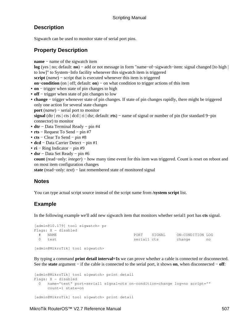
Description
Sigwatch can be used to monitor state of serial port pins.
Property Description
name − name of the sigwatch itemlog (yes | no; default: no) − add or not message in form "name−of−sigwatch−item: signal changed [to high |to low]" to System−Info facility whenever this sigwatch item is triggeredscript (name) − script that is executed whenever this item is triggeredon−condition (on | off; default: on) − on what condition to trigger actions of this itemon − trigger when state of pin changes to high• off − trigger when state of pin changes to low• change − trigger whenever state of pin changes. If state of pin changes rapidly, there might be triggeredonly one action for several state changesport (name) − serial port to monitorsignal (dtr | rts | cts | dcd | ri | dsr; default: rts) − name of signal or number of pin (for standard 9−pinconnector) to monitor
•
dtr − Data Terminal Ready − pin #4• rts − Request To Send − pin #7• cts − Clear To Send − pin #8• dcd − Data Carrier Detect − pin #1• ri − Ring Indicator − pin #9• dsr − Data Set Ready − pin #6count (read−only: integer) − how many time event for this item was triggered. Count is reset on reboot andon most item configuration changesstate (read−only: text) − last remembered state of monitored signal
Notes
You can type actual script source instead of the script name from /system script list.
Example
In the following example we'll add new sigwatch item that monitors whether serial1 port has cts signal.
[[email protected]] tool sigwatch> prFlags: X − disabled # NAME PORT SIGNAL ON−CONDITION LOG 0 test serial1 cts change no
[admin@MikroTik] tool sigwatch>
By typing a command print detail interval=1s we can prove whether a cable is connected or disconnected.See the state argument − if the cable is connected to the serial port, it shows on, when disconnected − off:
[admin@MikroTik] tool sigwatch> print detailFlags: X − disabled 0 name="test" port=serial1 signal=cts on−condition=change log=no script="" count=1 state=on
[admin@MikroTik] tool sigwatch> print detail
•
Scripting Manual
MikroTik RouterOS™ V2.7 Reference Manual 507

Flags: X − disabled 0 name="test" port=serial1 signal=cts on−condition=change log=no script="" count=1 state=on
[admin@MikroTik] tool sigwatch> print detailFlags: X − disabled 0 name="test" port=serial1 signal=cts on−condition=change log=no script="" count=2 state=off
[admin@MikroTik] tool sigwatch> print detailFlags: X − disabled 0 name="test" port=serial1 signal=cts on−condition=change log=no script="" count=2 state=off
[admin@MikroTik] tool sigwatch>
In the port menu it's seen what signal is used by serial cable. For example, without any cables it looks likethis:
[admin@MikroTik] port> print stats 0 name="serial0" line−state=dtr,rts
1 name="serial1" line−state=dtr,rts[admin@MikroTik] port>
But after adding a serial cable to the serial port:
[admin@MikroTik] port> print stats 0 name="serial0" line−state=dtr,rts
1 name="serial1" line−state=dtr,rts,cts[admin@MikroTik] port>
It means that the line−state beside the dtr and rts signals has also cts when a serial cable is connected.
The example below will execute a script whenever on−condition changes to off:
[[email protected]] tool sigwatch> pr detailFlags: X − disabled 0 name="cts_rest" port=serial1 signal=cts on−condition=off log=no script=/system shutdown count=0 state=on
It means that if a serial cable is connected to the serial port, all works fine, but as soon as it's disconnected −the router shuts down. It will continue all the time until the serial cable will not be connected again.
© Copyright 1999−2003, MikroTik
Scripting Manual
MikroTik RouterOS™ V2.7 Reference Manual 508
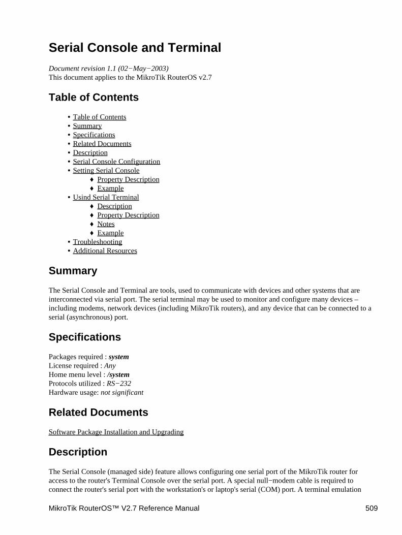
Serial Console and TerminalDocument revision 1.1 (02−May−2003)This document applies to the MikroTik RouterOS v2.7
Table of Contents
Table of Contents• Summary• Specifications• Related Documents• Description• Serial Console Configuration• Setting Serial Console
Property Description♦ Example♦
•
Usind Serial TerminalDescription♦ Property Description♦ Notes♦ Example♦
•
Troubleshooting• Additional Resources•
Summary
The Serial Console and Terminal are tools, used to communicate with devices and other systems that areinterconnected via serial port. The serial terminal may be used to monitor and configure many devices –including modems, network devices (including MikroTik routers), and any device that can be connected to aserial (asynchronous) port.
Specifications
Packages required : systemLicense required : AnyHome menu level : /systemProtocols utilized : RS−232Hardware usage: not significant
Related Documents
Software Package Installation and Upgrading
Description
The Serial Console (managed side) feature allows configuring one serial port of the MikroTik router foraccess to the router's Terminal Console over the serial port. A special null−modem cable is required toconnect the router's serial port with the workstation's or laptop's serial (COM) port. A terminal emulation
MikroTik RouterOS™ V2.7 Reference Manual 509
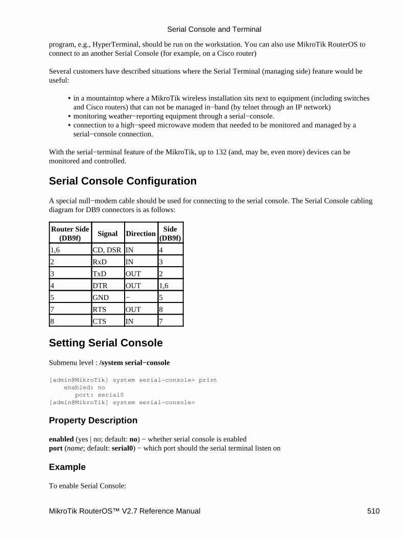
program, e.g., HyperTerminal, should be run on the workstation. You can also use MikroTik RouterOS toconnect to an another Serial Console (for example, on a Cisco router)
Several customers have described situations where the Serial Terminal (managing side) feature would beuseful:
in a mountaintop where a MikroTik wireless installation sits next to equipment (including switchesand Cisco routers) that can not be managed in−band (by telnet through an IP network)
•
monitoring weather−reporting equipment through a serial−console.• connection to a high−speed microwave modem that needed to be monitored and managed by aserial−console connection.
•
With the serial−terminal feature of the MikroTik, up to 132 (and, may be, even more) devices can bemonitored and controlled.
Serial Console Configuration
A special null−modem cable should be used for connecting to the serial console. The Serial Console cablingdiagram for DB9 connectors is as follows:
Router Side(DB9f)
Signal DirectionSide
(DB9f)
1,6 CD, DSR IN 4
2 RxD IN 3
3 TxD OUT 2
4 DTR OUT 1,6
5 GND − 5
7 RTS OUT 8
8 CTS IN 7
Setting Serial Console
Submenu level : /system serial−console
[admin@MikroTik] system serial−console> print enabled: no port: serial0[admin@MikroTik] system serial−console>
Property Description
enabled (yes | no; default: no) − whether serial console is enabledport (name; default: serial0) − which port should the serial terminal listen on
Example
To enable Serial Console:
Serial Console and Terminal
MikroTik RouterOS™ V2.7 Reference Manual 510
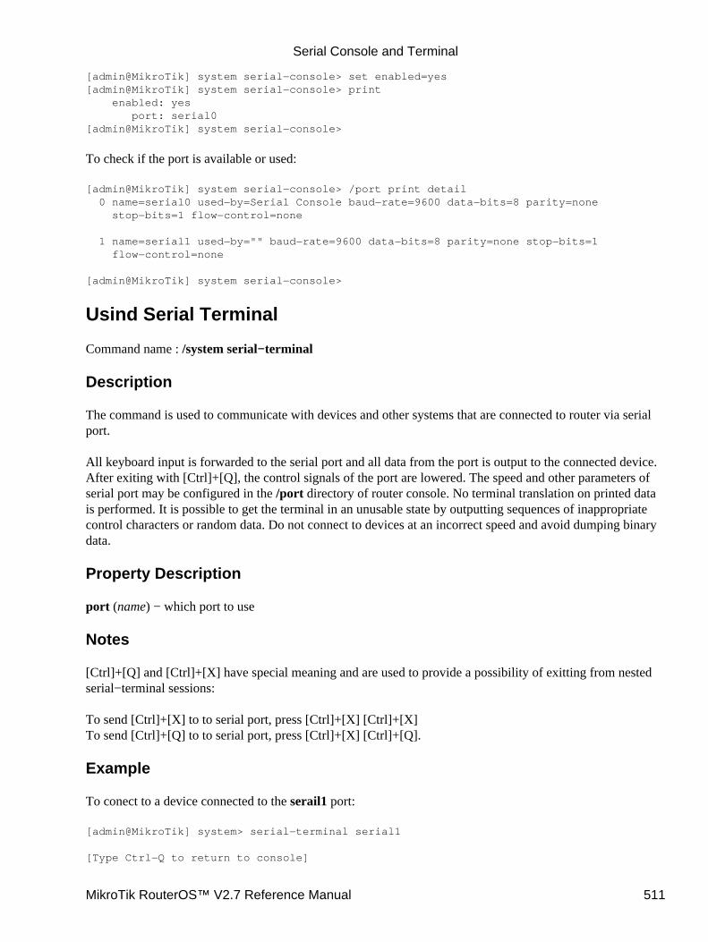
[admin@MikroTik] system serial−console> set enabled=yes[admin@MikroTik] system serial−console> print enabled: yes port: serial0[admin@MikroTik] system serial−console>
To check if the port is available or used:
[admin@MikroTik] system serial−console> /port print detail 0 name=serial0 used−by=Serial Console baud−rate=9600 data−bits=8 parity=none stop−bits=1 flow−control=none
1 name=serial1 used−by="" baud−rate=9600 data−bits=8 parity=none stop−bits=1 flow−control=none
[admin@MikroTik] system serial−console>
Usind Serial Terminal
Command name : /system serial−terminal
Description
The command is used to communicate with devices and other systems that are connected to router via serialport.
All keyboard input is forwarded to the serial port and all data from the port is output to the connected device.After exiting with [Ctrl]+[Q], the control signals of the port are lowered. The speed and other parameters ofserial port may be configured in the /port directory of router console. No terminal translation on printed datais performed. It is possible to get the terminal in an unusable state by outputting sequences of inappropriatecontrol characters or random data. Do not connect to devices at an incorrect speed and avoid dumping binarydata.
Property Description
port (name) − which port to use
Notes
[Ctrl]+[Q] and [Ctrl]+[X] have special meaning and are used to provide a possibility of exitting from nestedserial−terminal sessions:
To send [Ctrl]+[X] to to serial port, press [Ctrl]+[X] [Ctrl]+[X]To send [Ctrl]+[Q] to to serial port, press [Ctrl]+[X] [Ctrl]+[Q].
Example
To conect to a device connected to the serail1 port:
[admin@MikroTik] system> serial−terminal serial1
[Type Ctrl−Q to return to console]
Serial Console and Terminal
MikroTik RouterOS™ V2.7 Reference Manual 511
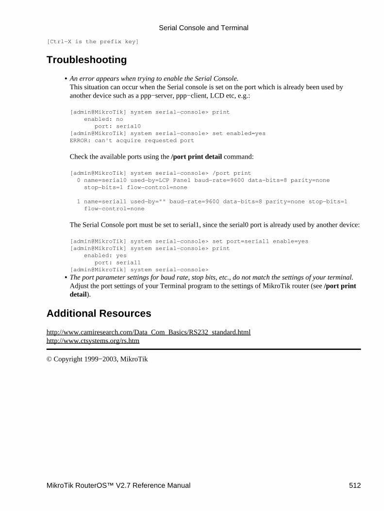
[Ctrl−X is the prefix key]
Troubleshooting
An error appears when trying to enable the Serial Console.This situation can occur when the Serial console is set on the port which is already been used byanother device such as a ppp−server, ppp−client, LCD etc, e.g.:
[admin@MikroTik] system serial−console> print enabled: no port: serial0[admin@MikroTik] system serial−console> set enabled=yesERROR: can't acquire requested port
Check the available ports using the /port print detail command:
[admin@MikroTik] system serial−console> /port print 0 name=serial0 used−by=LCP Panel baud−rate=9600 data−bits=8 parity=none stop−bits=1 flow−control=none
1 name=serial1 used−by="" baud−rate=9600 data−bits=8 parity=none stop−bits=1 flow−control=none
The Serial Console port must be set to serial1, since the serial0 port is already used by another device:
[admin@MikroTik] system serial−console> set port=serial1 enable=yes[admin@MikroTik] system serial−console> print enabled: yes port: serial1[admin@MikroTik] system serial−console>
•
The port parameter settings for baud rate, stop bits, etc., do not match the settings of your terminal.Adjust the port settings of your Terminal program to the settings of MikroTik router (see /port printdetail).
•
Additional Resources
http://www.camiresearch.com/Data_Com_Basics/RS232_standard.htmlhttp://www.ctsystems.org/rs.htm
© Copyright 1999−2003, MikroTik
Serial Console and Terminal
MikroTik RouterOS™ V2.7 Reference Manual 512

SSH (Secure Shell) Server and ClientDocument revision v 1.1 (25−Apr−2003)This document applies to the MikroTik RouterOS V2.7
Contents of the Manual
Contents of the Manual• Summary• Specifications• Related Documents• SSH Server
Description♦ Property Description♦ Example♦
•
SSH ClientExample♦
•
Additional ResourcesLinks for Windows Client:♦ Other links:♦
•
Summary
SSH Client authenticates server and encrypts traffic between the client and server. You can use SSH just thesame way as telnet − you run the client, tell it where you want to connect to, give your username andpassword, and everything is the same after that. After that you won't be able to tell that you're using SSH. TheSSH feature can be used with various SSH Telnet clients to securely connect to and administrate the router.
The MikroTik RouterOS supports:
SSH 1.3, 1.5, and 2.0 protocol standards• server functions for secure administration of the router• telnet session termination with 40 bit RSA SSH encryption is supported• secure ftp is not supported• Winbox connection encryption (TSL)•
The MikroTik RouterOS has been tested with the following SSH telnet terminals:
PuTTY• Secure CRT• Most SSH compatible telnet clients•
Specifications
Packages required : securityLicense required : AnyHome menu level : /system sshProtocols utilized : SSHHardware usage : not significant
MikroTik RouterOS™ V2.7 Reference Manual 513
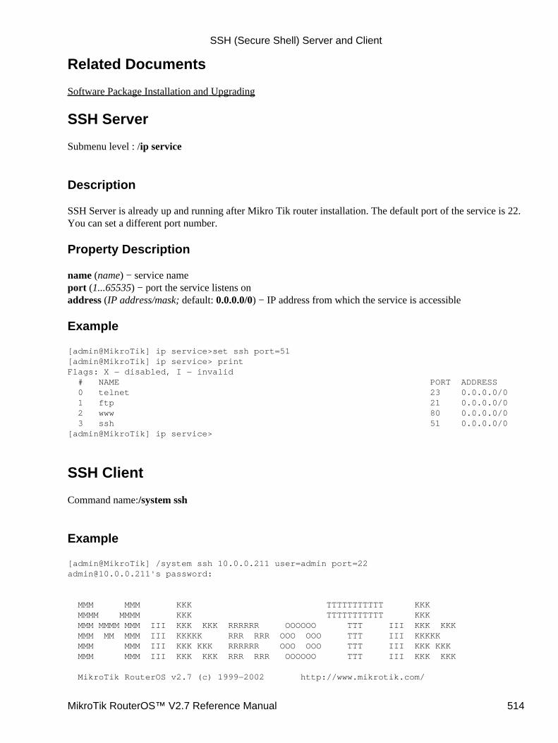
Related Documents
Software Package Installation and Upgrading
SSH Server
Submenu level : /ip service
Description
SSH Server is already up and running after Mikro Tik router installation. The default port of the service is 22.You can set a different port number.
Property Description
name (name) − service nameport (1...65535) − port the service listens onaddress (IP address/mask; default: 0.0.0.0/0) − IP address from which the service is accessible
Example
[admin@MikroTik] ip service>set ssh port=51[admin@MikroTik] ip service> printFlags: X − disabled, I − invalid # NAME PORT ADDRESS 0 telnet 23 0.0.0.0/0 1 ftp 21 0.0.0.0/0 2 www 80 0.0.0.0/0 3 ssh 51 0.0.0.0/0[admin@MikroTik] ip service>
SSH Client
Command name:/system ssh
Example
[admin@MikroTik] /system ssh 10.0.0.211 user=admin [email protected]'s password:
MMM MMM KKK TTTTTTTTTTT KKK MMMM MMMM KKK TTTTTTTTTTT KKK MMM MMMM MMM III KKK KKK RRRRRR OOOOOO TTT III KKK KKK MMM MM MMM III KKKKK RRR RRR OOO OOO TTT III KKKKK MMM MMM III KKK KKK RRRRRR OOO OOO TTT III KKK KKK MMM MMM III KKK KKK RRR RRR OOOOOO TTT III KKK KKK
MikroTik RouterOS v2.7 (c) 1999−2002 http://www.mikrotik.com/
SSH (Secure Shell) Server and Client
MikroTik RouterOS™ V2.7 Reference Manual 514
Terminal vt100 detected, using single line input mode[[email protected]] >
Additional Resources
Links for Windows Client:
http://www.zip.com.au/~roca/ttssh.htmlhttp://www.chiark.greenend.org.uk/~sgtatham/putty.htmlhttp://pgpdist.mit.edu/FiSSH/index.htmlhttp://telneat.lipetsk.ru/http://support.jgaa.com/?cmd=ShowArticlehttp://akson.sgh.waw.pl/~chopin/ssh/index_en.htmlhttp://cs.mscd.edu/MSSH/index.htmlhttp://www.networksimplicity.com/openssh/
Other links:
http://www.openssh.com/http://www.freessh.org/
© Copyright 1999−2003, MikroTik
SSH (Secure Shell) Server and Client
MikroTik RouterOS™ V2.7 Reference Manual 515
Support Output FileDocument revision 1.2 (10−Mar−2003)This document applies to MikroTik RouterOS v2.7
Table of Contents
Table of Contents• Summary• Specifications• Generating Support Output File
Example♦ •
Summary
The support file is used for debugging MikroTik RouterOS and to solve the support questions faster. AllMikroTik Router information is saved in a binary file, which is stored on the router and can be downloadedfrom the router using ftp.
Specifications
Packages required : systemLicense required : AnyHome menu level : /systemHardware usage: There is no significant resource usage
Generating Support Output File
Command name : /system sup−output
Example
To make a Support Output File:
[admin@MikroTik] > system sup−outputcreating supout.rif file, might take a while..................Accomplished![admin@MikroTik] >
To see the files stored on the router:
[admin@MikroTik] > file print # NAME TYPE SIZE CREATION−TIME 0 supout.rif unknown 38662 feb/28/2003 16:12:04[admin@MikroTik] >
MikroTik RouterOS™ V2.7 Reference Manual 516

Connect to the router using FTP and download the supout.rif file using BINARY file transfer mode. Send thesupout.rif file to MikroTik Support [email protected] with detailed description of the problem.
© Copyright 1999−2003, MikroTik
Support Output File
MikroTik RouterOS™ V2.7 Reference Manual 517

System Resource ManagementDocument revision 20−Jan−2003This document applies to the MikroTik RouterOS v2.7
Table of Contents
Table of Contents• Summary• Specifications• Related Documents• System Resource Monitor
Example♦ Notes♦
•
IRQ Usage MonitorDescription♦ Example♦
•
IO Port Usage MonitorDescription♦ Example♦
•
RebootDescription♦ Notes♦ Example♦
•
ShutdownDescription♦ Notes♦ Example♦
•
Configuration ResetDescription♦ Example♦
•
Router IdentityDescription♦ Example♦
•
Date and TimeProperty Description♦ Notes♦ Example♦
•
Configuration Change HistoryDescription♦ Command Description♦ Notes♦ Example♦
•
Summary
MikroTik RouterOS offers several features for monitoring and managing the system resources.
MikroTik RouterOS™ V2.7 Reference Manual 518
Specifications
Packages required : systemLicense required : AnyHome menu level : /systemProtocols utilized : NoneHardware usage: not significant
Related Documents
Software Package Installation and UpgradingNetwork Time Protocol (NTP)
System Resource Monitor
Submenu level : /system resource
Example
To view the basic system resource status:
[admin@MikroTik] system resource> print uptime: 1d23h32m6s free−memory: 1112 kB total−memory: 29528 kB cpu: "WinChip" cpu−load: 0 free−hdd−space: 6400 kB total−hdd−space: 46478 kB[admin@MikroTik] system resource>
To view the current system CPU usage and free memory:
[admin@MikroTik] system resource> monitor cpu−used: 3 free−memory: 1112
[admin@MikroTik] system resource>
Notes
The propery names are self−explanatory.
In monitor command printout the values for cpu usage and free memory are in percentage and kilobytes,respectively.
IRQ Usage Monitor
Command name : /system resource irq print
System Resource Management
MikroTik RouterOS™ V2.7 Reference Manual 519
Description
IRQ usage shows which IRQ (Interrupt requests) are currently used by hardware.
Example
[admin@MikroTik] system resource> irq printFlags: U − unused IRQ OWNER 1 keyboard 2 APIC U 3 4 sync1 5 pc1 U 6 U 7 U 8 U 9 10 ether2 11 ether1 U 12 13 FPU 14 IDE 1[admin@MikroTik] system resource>
IO Port Usage Monitor
Command name : /system resource io print
Description
IO usage shows which IO (Input/Output) ports are currently used by hardware.
Example
[admin@MikroTik] system resource> io print PORT−RANGE OWNER 20−3F APIC 40−5F timer 60−6F keyboard 80−8F DMA A0−BF APIC C0−DF DMA F0−FF FPU 1F0−1F7 IDE 1 300−33F pc1 3C0−3DF VGA 3F6−3F6 IDE 1 CF8−CFF [PCI conf1] 1000−100F [Silicon Integrated Systems [SiS] 5513 [IDE]] 1000−1007 IDE 1 1008−100F IDE 2 6000−60FF [Realtek Semiconductor Co., Ltd. RTL−8139] 6000−60FF [8139too] 6100−61FF [Realtek Semiconductor Co., Ltd. RTL−8139 (#2)] 6100−61FF [8139too]
System Resource Management
MikroTik RouterOS™ V2.7 Reference Manual 520

[admin@MikroTik] system resource>
Reboot
Command name : /system reboot
Description
The system reboot is required when upgrading or installing new software packages. The packages are installedduring the system shutdown.
The reboot process sends termination signal to all running processes, unmounts the file systems, and rebootsthe router.
Notes
Only users, which are members of groups with reboot privileges are permitted to reboot the router
Reboot can be called from scripts, in which case it does not prompt for confirmation
Example
[admin@MikroTik] system> rebootReboot, yes? [y/N]: ysystem will reboot shortly
Shutdown
Command name : /system shutdown
Description
Before turning the power off for the router, the system should be brought to halt. The shutdown process sendstermination signal to all running processes, unmounts the file systems, and halts the router.
For most systems, it is necessary to wait approximately 30 seconds for a safe power down.
Notes
Only users, which are members of groups with reboot privileges are permitted to shutdown the router
Shutdown can be called from scripts, in which case it does not prompt for confirmation
Example
[admin@MikroTik] system> shutdownShutdown, yes? [y/N]: ysystem will shutdown promptly
System Resource Management
MikroTik RouterOS™ V2.7 Reference Manual 521
Configuration Reset
Command name : /system reset
Description
The command clears all configuration of the router and sets it to the default including the login name andpassword ('admin' and no password).
The router is rebooted after the reset command.
Example
[admin@MikroTik] system> resetDangerous! Reset anyway? [y/N]:
Router Identity
Submenu level : /system identity
Description
The router identity is displayed before the command prompt. It is also used for DHCP client as 'host name'parameter when reporting it to the DHCP server.
Example
To view the router identity:
[admin@MikroTik] system identity> print name: "MikroTik"[admin@MikroTik] system identity>
To set the router identity:
[admin@MikroTik] system identity> set name=Our_GW[admin@Our_GW] system identity>
Date and Time
Submenu level : /system clock
Property Description
time (string) − date and time in format: "mm/DD/YYYY HH:MM:SS"time−zone (string) − UTC timezome
System Resource Management
MikroTik RouterOS™ V2.7 Reference Manual 522
Notes
It is recommended that you reboot the router after time change to obviate the possible errors in timemeasurments and logging
Date and time settings become permanent and effect BIOS settings.
Example
To view the current date and time settings
[admin@MikroTik] system clock> print time: aug/09/2002 21:27:29 time−zone: +03:00[admin@MikroTik] system resource>
To set the system date and time:
[adminMikroTik] system clock> set date=mar/26/2002 time=14:41:00 time−zone=+02:00[admin@MikroTik] system clock> print time: mar/26/2002 16:41:12 time−zone: +02:00[admin@MikroTik] system clock>
Configuration Change History
Submenu level : /system history Command name : /undo Command name : /redo
Description
The history of system configuration changes is held until the next router shutdown. The invoked commandscan be 'undone' (in reverse order they have been invoked). The 'undone' commands may be 'redone' (in reverseorder they have been 'undone').
Command Description
/undo − undoes previous configuration changing command (except another /undo command)/redo − undoes previous /undo command/system history print − print a list of last configuration changes, specifying whether the action can be undoneor redone
Notes
Floating−undo actions are created within the current SAFE mode session. They are automatically converted toundoable and redoable when SAFE mode terminated successfully, and are all undone irreverively when SAFEmode terminated insuccessfully.
Undo command cannot undo commands past start of the SAFE mode.
System Resource Management
MikroTik RouterOS™ V2.7 Reference Manual 523
Example
To show the list of configuration changes:
[admin@MikroTik] system history> printFlags: U − undoable, R − redoable, F − floating−undo ACTION BY POLICY U new traffic monitor script added U DNS server configuration changed U device changed U marking rule moved admin U route changed U route added U routing table added U ipsec manual sa ex1 added[admin@MikroTik] system history>
The undo command's effect:
[MikroTik] system history> /undo[admin@MikroTik] system history> printFlags: U − undoable, R − redoable ACTION BY POLICY R new traffic monitor script added U DNS server configuration changed U device changed U marking rule moved admin U route changed U route added U routing table added U ipsec manual sa ex1 added[admin@MikroTik] system history>
© Copyright 1999−2003, MikroTik
System Resource Management
MikroTik RouterOS™ V2.7 Reference Manual 524
Telnet Server and ClientDocument revision 1.2 (05−May−2003)This document applies to the MikroTik RouterOS v2.7
Table of Contents
Table of Contents• Summary• Specifications• Related Documents• Telnet Server
Description♦ Example♦
•
Telnet ClientDescription♦ Example♦
•
Summary
MikroTik RouterOS has a build−in Telnet server and client features. These two are used to communicate withother systems over a network.
Specifications
Packages required : NoneLicense required : AnyHome menu level : /system, /ip serviceStandards and Technologies : Telnet (RFC 854)Hardware usage : not significant
Related Documents
Software Package Installation and UpgradingServices, Protocols and PortsConfiguration Backup and Restore
Telnet Server
Submenu level : /ip service
Description
Telnet protocol is intended to provide a fairly general, bi−directional, eight−bit byte oriented communicationsfacility. The main goal is to allow a standard method of interfacing terminal devices to each other.
MikroTik RouterOS implements industry standard Telnet server. It uses port 23, which must not be disabledon the router in order to use the feature.
MikroTik RouterOS™ V2.7 Reference Manual 525
You can enable/disable this service or allow the use of the service to certain IP addresses.
Example
[admin@MikroTik] ip service> print detailFlags: X − disabled, I − invalid 0 name="telnet" port=23 address=0.0.0.0/0
1 name="ftp" port=21 address=0.0.0.0/0
2 name="www" port=80 address=0.0.0.0/0
[admin@MikroTik] ip service> set 0 address 10.10.10.0/24[admin@MikroTik] ip service>
Telnet Client
Command name : /system telnet
Description
MikroTik RouterOS telnet client is used to connect to other hosts in the network via Telnet protocol.
You can type something that cannot be treated as an IP address into the telnet prompt in order to use advancedtelnet mode. This is for advanced users only.
Example
A simple example of Telnet connection:
[admin@MikroTik] > /system telnet 192.168.0.2Trying 192.168.0.2...Connected to 192.168.0.2.Escape character is '^]'.
MikroTik v2.7rc4Login: adminPassword:
MMM MMM KKK TTTTTTTTTTT KKK MMMM MMMM KKK TTTTTTTTTTT KKK MMM MMMM MMM III KKK KKK RRRRRR OOOOOO TTT III KKK KKK MMM MM MMM III KKKKK RRR RRR OOO OOO TTT III KKKKK MMM MMM III KKK KKK RRRRRR OOO OOO TTT III KKK KKK MMM MMM III KKK KKK RRR RRR OOOOOO TTT III KKK KKK
MikroTik RouterOS v2.7 (c) 1999−2003 http://www.mikrotik.com/
Terminal unknown detected, using single line input mode[admin@MikroTik] >
Advanced Telnet command mode:
[admin@MikroTik] > system telnet
Telnet Server and Client
MikroTik RouterOS™ V2.7 Reference Manual 526
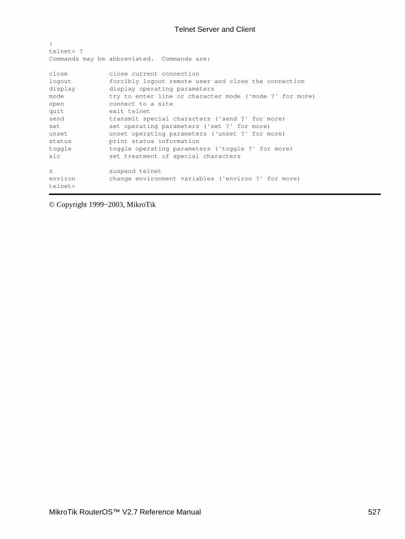
:telnet> ?Commands may be abbreviated. Commands are:
close close current connectionlogout forcibly logout remote user and close the connectiondisplay display operating parametersmode try to enter line or character mode ('mode ?' for more)open connect to a sitequit exit telnetsend transmit special characters ('send ?' for more)set set operating parameters ('set ?' for more)unset unset operating parameters ('unset ?' for more)status print status informationtoggle toggle operating parameters ('toggle ?' for more)slc set treatment of special characters
z suspend telnetenviron change environment variables ('environ ?' for more)telnet>
© Copyright 1999−2003, MikroTik
Telnet Server and Client
MikroTik RouterOS™ V2.7 Reference Manual 527

UPS MonitorDocument revision 1.1 (21−Jan−2003)This document applies to the MikroTik RouterOS v2.7
Table of Contents
Table of Contents• Summary• Specifications• Related Documents
Cabling♦ •
UPS Monitor SetupProperty Description♦ Notes♦ Example♦
•
Runtime CalibrationDescription♦ Notes♦ Example♦
•
UPS MonitoringProperty Description♦ Example♦
•
Additional Resources•
Summary
The UPS monitor feature works with APC UPS units that support “smart” signaling. This feature enables thenetwork administrator to monitor the UPS and set the router to ‘gracefully’ handle any power outage with nocorruption or damage to the router. The basic purpose of this feature is to ensure that the router will comeback online after an extended power failure. To do this, the router will monitor the UPS and set itself tohibernate mode when the ‘utility’ power is down and the UPS battery is has less than 10% of its battery powerleft. The router will then continue to monitor the UPS (while in hibernate mode) and then restart itself afterwhen the ‘utility’ power returns. If the UPS battery is drained and the router loses all power, the router willpower back to full operation when the ‘utility’ power returns.
The UPS monitor feature on the MikroTik RouterOS supports:
hibernate and safe reboot on power and battery failure• UPS battery test and run time calibration test• monitoring of all “smart” mode status information supported by UPS• logging of power changes•
Specifications
Packages required : upsLicense required : AnyHome menu level : /system upsProtocols utilized : APC's smart protocol
MikroTik RouterOS™ V2.7 Reference Manual 528

Hardware usage: not significant
Related Documents
Software Package Installation and Upgrading
Cabling
The APC UPS (BackUPS Pro or SmartUPS) requires a special serial cable. If no cable came with the UPS, acable may be ordered from APC or one can be made "in−house". Use the following diagram:
Router Side(DB9f)
Signal DirectionUPSSide
(DB9m)
2 Receive IN 2
3 Send OUT 1
5 Ground 4
7 CTS IN 6
UPS Monitor Setup
Submenu level : /system ups
[admin@MikroTik] system> ups[admin@MikroTik] system ups> print enabled: no port: (unknown) off−line−time: 5m min−run−time: 5m alarm−setting: immediate rtc−alarm−setting: none[admin@MikroTik] system ups>
Property Description
enabled (yes | no, default: no) − status of the monitoring is disabled by defaultport (name)− s communication port of the routeroff−line−time (time, default: 5m) − how long to work on batteries. The router waits that amount of time andthen goes into hibernate mode until the UPS reports that the ‘utility’ power is back
0 − the router will go into hibernate mode according the min−run−time setting and 10% of battery powerevent. In this case, the router will wait until the UPS reports that the battery power is below 10%min−run−time (time, default: 5m) − minimal run time remainingAfter a ‘utility’ failure, the router will monitor the run−time−left value. When the value reaches themin−run−time value, the router will go to hibernate mode
•
0 − the router will go to hibernate mode when the “battery low” signal is sent indicating that the batterypower is below 10%alarm−setting (delayed | immediate | low−battery | none, default: immediate) − UPS sound alarm setting:
•
delayed − alarm is delayed to the on−battery event• immediate − alarm immediately after the on−battery event•
UPS Monitor
MikroTik RouterOS™ V2.7 Reference Manual 529
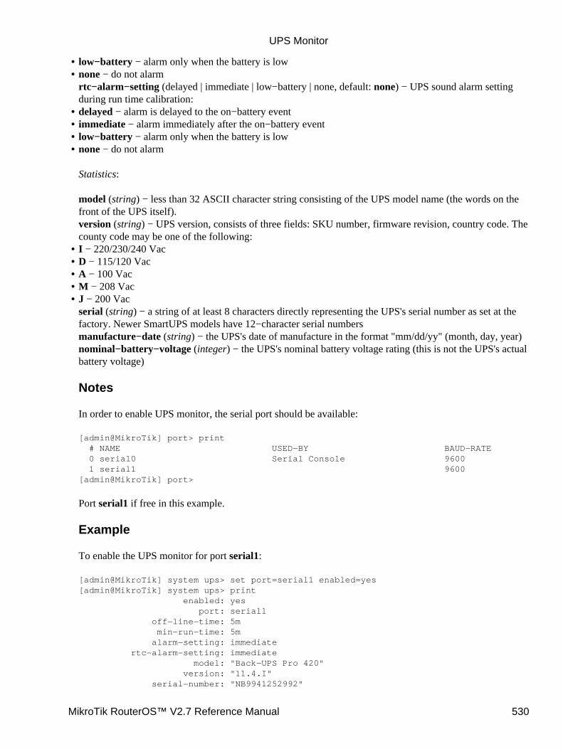
low−battery − alarm only when the battery is low• none − do not alarmrtc−alarm−setting (delayed | immediate | low−battery | none, default: none) − UPS sound alarm settingduring run time calibration:
•
delayed − alarm is delayed to the on−battery event• immediate − alarm immediately after the on−battery event• low−battery − alarm only when the battery is low• none − do not alarm
Statistics:
model (string) − less than 32 ASCII character string consisting of the UPS model name (the words on thefront of the UPS itself).version (string) − UPS version, consists of three fields: SKU number, firmware revision, country code. Thecounty code may be one of the following:
•
I − 220/230/240 Vac• D − 115/120 Vac• A − 100 Vac• M − 208 Vac• J − 200 Vacserial (string) − a string of at least 8 characters directly representing the UPS's serial number as set at thefactory. Newer SmartUPS models have 12−character serial numbersmanufacture−date (string) − the UPS's date of manufacture in the format "mm/dd/yy" (month, day, year)nominal−battery−voltage (integer) − the UPS's nominal battery voltage rating (this is not the UPS's actualbattery voltage)
Notes
In order to enable UPS monitor, the serial port should be available:
[admin@MikroTik] port> print # NAME USED−BY BAUD−RATE 0 serial0 Serial Console 9600 1 serial1 9600[admin@MikroTik] port>
Port serial1 if free in this example.
Example
To enable the UPS monitor for port serial1:
[admin@MikroTik] system ups> set port=serial1 enabled=yes[admin@MikroTik] system ups> print enabled: yes port: serial1 off−line−time: 5m min−run−time: 5m alarm−setting: immediate rtc−alarm−setting: immediate model: "Back−UPS Pro 420" version: "11.4.I" serial−number: "NB9941252992"
•
UPS Monitor
MikroTik RouterOS™ V2.7 Reference Manual 530
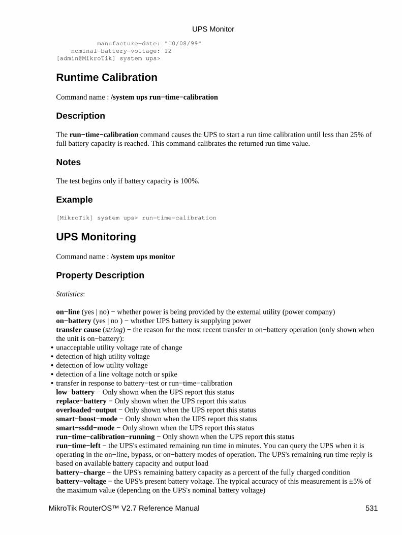
manufacture−date: "10/08/99" nominal−battery−voltage: 12[admin@MikroTik] system ups>
Runtime Calibration
Command name : /system ups run−time−calibration
Description
The run−time−calibration command causes the UPS to start a run time calibration until less than 25% offull battery capacity is reached. This command calibrates the returned run time value.
Notes
The test begins only if battery capacity is 100%.
Example
[MikroTik] system ups> run−time−calibration
UPS Monitoring
Command name : /system ups monitor
Property Description
Statistics:
on−line (yes | no) − whether power is being provided by the external utility (power company)on−battery (yes | no ) − whether UPS battery is supplying powertransfer cause (string) − the reason for the most recent transfer to on−battery operation (only shown whenthe unit is on−battery):unacceptable utility voltage rate of change• detection of high utility voltage• detection of low utility voltage• detection of a line voltage notch or spike• transfer in response to battery−test or run−time−calibrationlow−battery − Only shown when the UPS report this statusreplace−battery − Only shown when the UPS report this statusoverloaded−output − Only shown when the UPS report this statussmart−boost−mode − Only shown when the UPS report this statussmart−ssdd−mode − Only shown when the UPS report this statusrun−time−calibration−running − Only shown when the UPS report this statusrun−time−left − the UPS's estimated remaining run time in minutes. You can query the UPS when it isoperating in the on−line, bypass, or on−battery modes of operation. The UPS's remaining run time reply isbased on available battery capacity and output loadbattery−charge − the UPS's remaining battery capacity as a percent of the fully charged conditionbattery−voltage − the UPS's present battery voltage. The typical accuracy of this measurement is ±5% ofthe maximum value (depending on the UPS's nominal battery voltage)
•
UPS Monitor
MikroTik RouterOS™ V2.7 Reference Manual 531
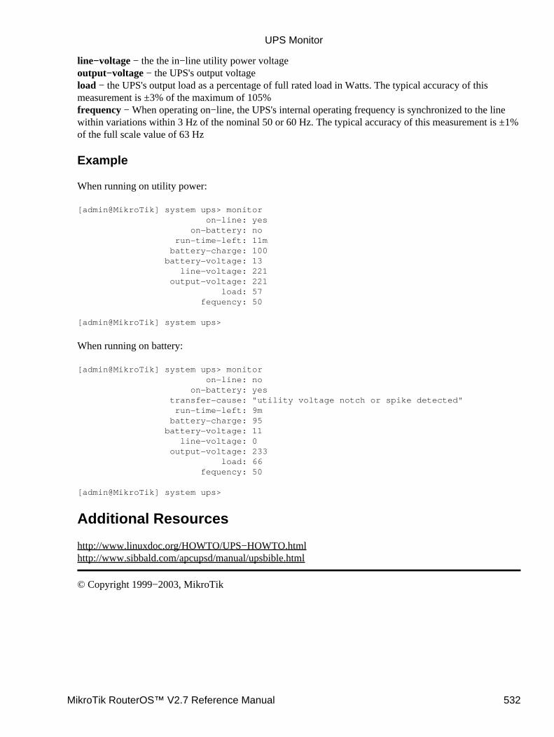
line−voltage − the the in−line utility power voltageoutput−voltage − the UPS's output voltageload − the UPS's output load as a percentage of full rated load in Watts. The typical accuracy of thismeasurement is ±3% of the maximum of 105%frequency − When operating on−line, the UPS's internal operating frequency is synchronized to the linewithin variations within 3 Hz of the nominal 50 or 60 Hz. The typical accuracy of this measurement is ±1%of the full scale value of 63 Hz
Example
When running on utility power:
[admin@MikroTik] system ups> monitor on−line: yes on−battery: no run−time−left: 11m battery−charge: 100 battery−voltage: 13 line−voltage: 221 output−voltage: 221 load: 57 fequency: 50
[admin@MikroTik] system ups>
When running on battery:
[admin@MikroTik] system ups> monitor on−line: no on−battery: yes transfer−cause: "utility voltage notch or spike detected" run−time−left: 9m battery−charge: 95 battery−voltage: 11 line−voltage: 0 output−voltage: 233 load: 66 fequency: 50
[admin@MikroTik] system ups>
Additional Resources
http://www.linuxdoc.org/HOWTO/UPS−HOWTO.htmlhttp://www.sibbald.com/apcupsd/manual/upsbible.html
© Copyright 1999−2003, MikroTik
UPS Monitor
MikroTik RouterOS™ V2.7 Reference Manual 532

Bandwidth TestDocument revision 1.4 (06−Aug−2003)This document applies to MikroTik RouterOS v2.7
Table of Contents
Table of Contents• Summary• Specifications• Related Documents• Description
Protocol Description♦ Usage Notes♦
•
Server ConfigurationProperty Description:♦ Notes♦ Example♦
•
Client ConfigurationProperty Description♦
•
Example•
Summary
The Bandwidth Tester can be used to monitor the throughput only to a remote MikroTik router (either wiredor wireless) and thereby help to discover network ‘bottlenecks’.
Specifications
Packages required : systemLicense required : AnyHome menu level : /toolProtocols utilized : TCP (RFC793, UDP (RFC768)Hardware usage: high
Related Documents
Software Package Installation and Upgrading
Description
Protocol Description
The TCP test uses the standard TCP protocol with acknowledgments and follows the TCP algorithm on howmany packets to send according to latency, dropped packets, and other features in the TCP algorithm. Pleasereview the TCP protocol for details on its internal speed settings and how to analyze its behavior. Statistics forthroughput are calculated using the entire size of the TCP packet. As acknowledgments are an internalworking of TCP, their size and usage of the link are not included in the throughput statistics. Therefore this
MikroTik RouterOS™ V2.7 Reference Manual 533
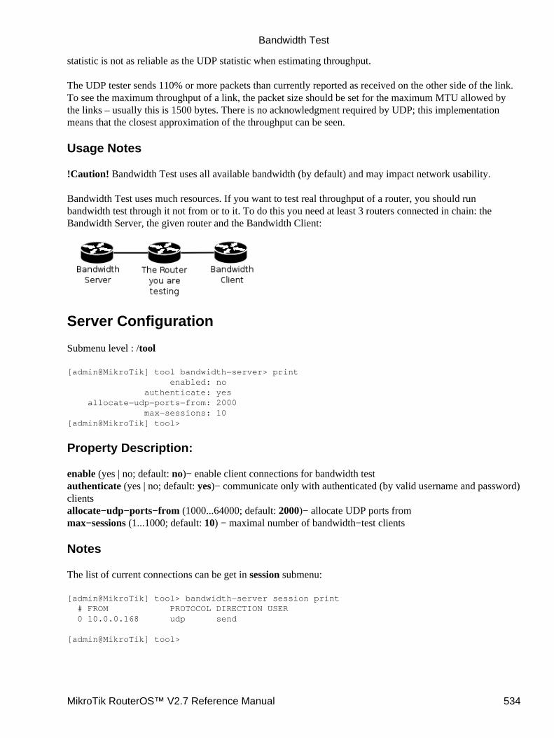
statistic is not as reliable as the UDP statistic when estimating throughput.
The UDP tester sends 110% or more packets than currently reported as received on the other side of the link.To see the maximum throughput of a link, the packet size should be set for the maximum MTU allowed bythe links – usually this is 1500 bytes. There is no acknowledgment required by UDP; this implementationmeans that the closest approximation of the throughput can be seen.
Usage Notes
!Caution! Bandwidth Test uses all available bandwidth (by default) and may impact network usability.
Bandwidth Test uses much resources. If you want to test real throughput of a router, you should runbandwidth test through it not from or to it. To do this you need at least 3 routers connected in chain: theBandwidth Server, the given router and the Bandwidth Client:
Server Configuration
Submenu level : /tool
[admin@MikroTik] tool bandwidth−server> print enabled: no authenticate: yes allocate−udp−ports−from: 2000 max−sessions: 10[admin@MikroTik] tool>
Property Description:
enable (yes | no; default: no)− enable client connections for bandwidth testauthenticate (yes | no; default: yes)− communicate only with authenticated (by valid username and password)clientsallocate−udp−ports−from (1000...64000; default: 2000)− allocate UDP ports frommax−sessions (1...1000; default: 10) − maximal number of bandwidth−test clients
Notes
The list of current connections can be get in session submenu:
[admin@MikroTik] tool> bandwidth−server session print # FROM PROTOCOL DIRECTION USER 0 10.0.0.168 udp send
[admin@MikroTik] tool>
Bandwidth Test
MikroTik RouterOS™ V2.7 Reference Manual 534
Example
To enable bandwidth−test server without client authentication:
[admin@MikroTik] tool bandwidth−server> set enabled=yes authenticate=no[admin@MikroTik] tool bandwidth−server> print enabled: yes authenticate: no allocate−udp−ports−from: 2000 max−sessions: 10[admin@MikroTik] tool>
Client Configuration
Command name : /tool bandwidth−test
Property Description
address (IP address) − IP address of destination hostassume−lost−time (time; default: 0s) − assume that connection is lost if Bandwidth Server is not respondingfor that timedirection (receive/transmit/both; default: transmit) − the direction of the testdo (name | string; default: "") − script sourceduration (time; default: 0s) − duration of the test
0s − test duration is not limitedinterval (20ms...5s;; default: 1s)− delay between reports (in seconds)local−tx−speed (integer; default: 0)− transfer test maximum speed (bits per second)
•
0 − no speed limitationspassword (string; default: "") − password for remote userprotocol (udp | tcp; default: tcp)− protocol to useremote−tx−speed (integer; default: 0)− receive test maximum speed (bits per second)
•
0 − no speed limitationssize (50..1500; default: 512) − packet size in bytes (only for UDP protocol)user (name; default: "") − remote user
Example
To run 15−second long bandwidth−test to the 10.0.0.211 host sending and receiving 1000−byte UDPpackets and using username admin to connect
[admin@MikroTik] tool> bandwidth−test 10.0.0.211 duration=15s direction=both \\... size=1000 protocol=udp user=admin status: done testing duration: 15s tx−current: 3.62Mbps tx−10−second−average: 3.87Mbps tx−total−average: 3.53Mbps rx−current: 3.33Mbps rx−10−second−average: 3.68Mbps rx−total−average: 3.49Mbps
[admin@MikroTik] tool>
•
Bandwidth Test
MikroTik RouterOS™ V2.7 Reference Manual 535

© Copyright 1999−2003, MikroTik
Bandwidth Test
MikroTik RouterOS™ V2.7 Reference Manual 536
Dynamic DNS (DDNS) Update ToolDocument revision 1.3 (30−Dec−2003)This document applies to the MikroTik RouterOS V2.7
Contents of the Manual
Contents of the Manual• Summary• Specifications• Related Documents• Description• Dynamic DNS Update
Property Description♦ Notes♦ Example♦
•
Additional Resources•
Summary
Dynamic DNS Update Tool gives a way to keep domain name pointing to dynamic IP address. It works bysending domain name system update request to name server, which has a zone to be updated. Secure DNSupdates are also supported. TSIG (transport signature) with HMAC−MD5 algorithm is used in this case toauthenticate updates.
Also note that the clock of both parties (the router and the DDNS server) must not be different more than by 5minutes. The update will be ignored otherwise.
Specifications
Packages required : advanced−toolsLicense required : AnyHome menu level : /toolProtocols utilized : Dynamic Updates in the DNS (RFC 2136), Secure DNS Dynamic Update (RFC 3007)Hardware usage: not significant
Related Documents
Software Package Installation and Upgrading
Description
Dynamic DNS Update is a tool that should be manually run to update dynamic DNS server
Note that you have to have a DNS server that supports DNS updates properly configured
MikroTik RouterOS™ V2.7 Reference Manual 537
Dynamic DNS Update
Command level : /tool dns−update
Property Description
address (IP address) − defines IP address associated with the domain namedns−server (IP address) − DNS server to send update tokey (string; default: "") − authorization key (password of a kind) to access the serverkey−name (string; default: "") − authorization key name (username of a kind) to access the servername (string) − name to attach with the IP addressttl (integer; default: 0) − time to live for the item (in seconds)zone (string) − DNS zone where to update the domain name in
Notes
To delete a DDNS entry that has not yet been timed out, you should add the same entry with ttl of 0>.
Example
To tell 23.34.45.56 DNS server to (re)associate mydomain name in the myzone.com zone with 68.42.14.4 IPaddress specifying that the name of the key is dns−update−key and the actual key is update:
[admin@MikroTik] tool> dns−update dns−server=23.34.45.56 name=mydomain \\... zone=myzone.com address=68.42.14.4 key−name=dns−update−key key=update
Additional Resources
DNS related RFCs
© Copyright 1999−2003, MikroTik
Dynamic DNS (DDNS) Update Tool
MikroTik RouterOS™ V2.7 Reference Manual 538
ICMP Bandwidth TestDocument revision 1.0 (28−Apr−2003)This document applies to MikroTik RouterOS v2.7
Table of Contents
Table of Contents• Summary• Specifications• Related Documents• ICMP Bandwith Test
Description♦ Property Description♦ Example♦
•
Summary
The ICMP Bandwidth Tester (Ping Speed) can be used to approximately evaluate the throughput to anyremote computer and thereby help to discover network 'bottlenecks'.
Specifications
Packages required : advanced−toolsLicense required : AnyHome menu level : /toolStandards and Technologies : ICMP (RFC792)Hardware usage : not significant
Related Documents
Software Package Installation and UpgradingIP Addresses and Address Resolution Protocol (ARP)Log Management
ICMP Bandwith Test
Command name : /tool ping−speed
Description
The ICMP test uses two standard echo−requests per second. The time between these pings can be changed.Ping packet size variation makes it possible to approximately evaluate connection parameters and speed withdifferent packet sizes. Statistics for throughput is calculated using the size of the ICMP packet, the intervalbetween ICMP echo−request and echo−reply and the differences between parameters of the first and thesecond packet.
MikroTik RouterOS™ V2.7 Reference Manual 539
Property Description
do (name) − assigned name of the script to startfirst−ping−size (integer: 32..64000; default: 32) − first ICMP packet sizesecond−ping−size (integer: 32..64000; default: 1500) − second ICMP packet sizetime between pings (integer) − the time between first and second ICMP echo−requests in seconds. A newICMP−packet pair will never be sent before the previous pair is completely sent and the algorithm itself willnever send more than two requests in one secondonce (option) − specifies that the ping will be performed only onceinterval (time: 20ms..5s) − time interval between two ping repetitions
Example
In the following example we will test the bandwith to a host with an IP address 159.148.60.2. The intervalbetween repetitions will be 1 second.
[admin@MikroTik] tool> ping−speed 159.148.60.2 interval=1s current: 2.23Mbps average: 2.61Mbps
[admin@MikroTik] tool>
© Copyright 1999−2003, MikroTik
ICMP Bandwidth Test
MikroTik RouterOS™ V2.7 Reference Manual 540
Packet SnifferDocument revision 1.6 (02−May−2003)This document applies to the MikroTik RouterOS v2.7
Table Of Contents
Table Of Contents• Summary• Specifications• Related Documents• Description• Packet Sniffer Configuration
Property Description♦ Notes♦ Example♦
•
Running Packet SnifferDescription♦
•
Sniffed PacketsDescription♦ Property Description♦ Example♦
•
Packet Sniffer ProtocolsDescription♦ Property Description♦ Example♦
•
Packet Sniffer HostsDescription♦ Property Description♦ Example♦
•
Packet Sniffer ConnectionsDescription♦ Property Description♦ Example♦
•
Summary
Packet sniffer is a feature that catches all the data travelling over the network, that it is able to get (when usingswitched network, a computer may catch only the data addressed to it or is forwarded through it)
Specifications
Packages required : NoneLicense required : AnyHome menu level : /tool snifferProtocols utilized : noneHardware usage: not significant
MikroTik RouterOS™ V2.7 Reference Manual 541
Related Documents
Software Package Installation and Upgrading
Description
It allows you to "sniff" packets going through the router (and any other traffic that gets to the router, whenthere is no switching in the network) and view them using specific software.
Packet Sniffer Configuration
Submenu level : /tool sniffer
[admin@MikroTik] tool sniffer> print interface: all only−headers: no memory−limit: 10 file−name: "" file−limit: 10 streaming−enabled: no streaming−server: 0.0.0.0 filter−stream: yes filter−protocol: ip−only filter−address1: 0.0.0.0/0:0−65535 filter−address2: 0.0.0.0/0:0−65535 running: no[admin@MikroTik] tool sniffer>
Property Description
interface (name | all; default: all) − the name of the interface receives the packetsonly−headers (yes | no; default: no) − whether to save in the memory packets' headers only (not the wholepacket)memory−limit (integer; default: 10) − maximal amount of memory to use. Sniffer will stop after this limit isreachedfile−name (string; default: "") − the name of the file that the sniffed packets are to be saved tofile−limit (integer; default: 10) − the limit of the file in KB. Sniffer will stop after this limit is reachedstreaming−enabled (yes | no; default: no) − whether to send sniffed packets to a remote serverstreaming−server (IP address; default: 0.0.0.0) − Tazmen Sniffer Protocol (TZSP) stream receiverfilter−stream (yes | no; default: yes) − whether to ignore sniffed packets that are destined to the stream serverfilter−protocol (all−frames | ip−only | mac−only−no−ip; default: ip−only) − specific protocol group to filter:
mac−only−no−ip − sniff non−IP packets only• all−frames − sniff all packets• ip−only − sniff IP packets onlyfilter−address1 (IP address/mask:ports; default: 0.0.0.0/0:0−65535) − criterion of choosing the packets toprocessfilter−address2 (IP address/mask:ports; default: 0.0.0.0/0:0−65535) − criterion of choosing the packets toprocessrunning (yes | no; default: no) − if the sniffer is started then the value is yes otherwise no
•
Packet Sniffer
MikroTik RouterOS™ V2.7 Reference Manual 542
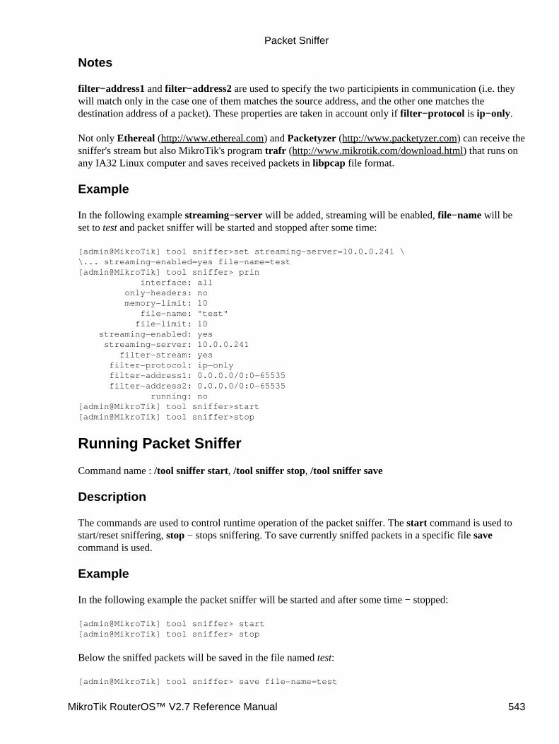
Notes
filter−address1 and filter−address2 are used to specify the two participients in communication (i.e. theywill match only in the case one of them matches the source address, and the other one matches thedestination address of a packet). These properties are taken in account only if filter−protocol is ip−only.
Not only Ethereal (http://www.ethereal.com) and Packetyzer (http://www.packetyzer.com) can receive thesniffer's stream but also MikroTik's program trafr (http://www.mikrotik.com/download.html) that runs onany IA32 Linux computer and saves received packets in libpcap file format.
Example
In the following example streaming−server will be added, streaming will be enabled, file−name will beset to test and packet sniffer will be started and stopped after some time:
[admin@MikroTik] tool sniffer>set streaming−server=10.0.0.241 \\... streaming−enabled=yes file−name=test[admin@MikroTik] tool sniffer> prin interface: all only−headers: no memory−limit: 10 file−name: "test" file−limit: 10 streaming−enabled: yes streaming−server: 10.0.0.241 filter−stream: yes filter−protocol: ip−only filter−address1: 0.0.0.0/0:0−65535 filter−address2: 0.0.0.0/0:0−65535 running: no[admin@MikroTik] tool sniffer>start[admin@MikroTik] tool sniffer>stop
Running Packet Sniffer
Command name : /tool sniffer start, /tool sniffer stop, /tool sniffer save
Description
The commands are used to control runtime operation of the packet sniffer. The start command is used tostart/reset sniffering, stop − stops sniffering. To save currently sniffed packets in a specific file savecommand is used.
Example
In the following example the packet sniffer will be started and after some time − stopped:
[admin@MikroTik] tool sniffer> start[admin@MikroTik] tool sniffer> stop
Below the sniffed packets will be saved in the file named test:
[admin@MikroTik] tool sniffer> save file−name=test
Packet Sniffer
MikroTik RouterOS™ V2.7 Reference Manual 543
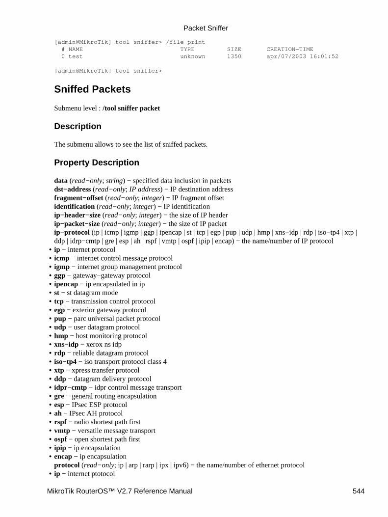
[admin@MikroTik] tool sniffer> /file print # NAME TYPE SIZE CREATION−TIME 0 test unknown 1350 apr/07/2003 16:01:52
[admin@MikroTik] tool sniffer>
Sniffed Packets
Submenu level : /tool sniffer packet
Description
The submenu allows to see the list of sniffed packets.
Property Description
data (read−only; string) − specified data inclusion in packetsdst−address (read−only; IP address) − IP destination addressfragment−offset (read−only; integer) − IP fragment offsetidentification (read−only; integer) − IP identificationip−header−size (read−only; integer) − the size of IP headerip−packet−size (read−only; integer) − the size of IP packetip−protocol (ip | icmp | igmp | ggp | ipencap | st | tcp | egp | pup | udp | hmp | xns−idp | rdp | iso−tp4 | xtp |ddp | idrp−cmtp | gre | esp | ah | rspf | vmtp | ospf | ipip | encap) − the name/number of IP protocolip − internet protocol• icmp − internet control message protocol• igmp − internet group management protocol• ggp − gateway−gateway protocol• ipencap − ip encapsulated in ip• st − st datagram mode• tcp − transmission control protocol• egp − exterior gateway protocol• pup − parc universal packet protocol• udp − user datagram protocol• hmp − host monitoring protocol• xns−idp − xerox ns idp• rdp − reliable datagram protocol• iso−tp4 − iso transport protocol class 4• xtp − xpress transfer protocol• ddp − datagram delivery protocol• idpr−cmtp − idpr control message transport• gre − general routing encapsulation• esp − IPsec ESP protocol• ah − IPsec AH protocol• rspf − radio shortest path first• vmtp − versatile message transport• ospf − open shortest path first• ipip − ip encapsulation• encap − ip encapsulationprotocol (read−only; ip | arp | rarp | ipx | ipv6) − the name/number of ethernet protocol
•
ip − internet ptotocol•
Packet Sniffer
MikroTik RouterOS™ V2.7 Reference Manual 544
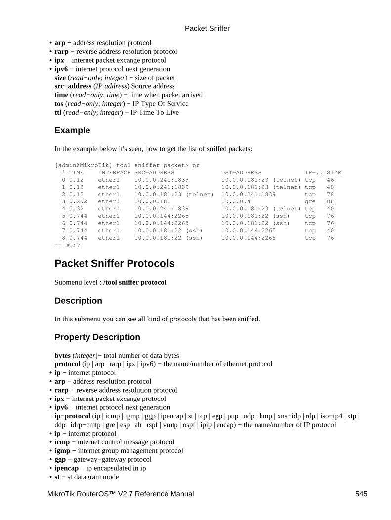
arp − address resolution protocol• rarp − reverse address resolution protocol• ipx − internet packet excange protocol• ipv6 − internet protocol next generationsize (read−only; integer) − size of packetsrc−address (IP address) Source addresstime (read−only; time) − time when packet arrivedtos (read−only; integer) − IP Type Of Servicettl (read−only; integer) − IP Time To Live
Example
In the example below it's seen, how to get the list of sniffed packets:
[admin@MikroTik] tool sniffer packet> pr # TIME INTERFACE SRC−ADDRESS DST−ADDRESS IP−.. SIZE 0 0.12 ether1 10.0.0.241:1839 10.0.0.181:23 (telnet) tcp 46 1 0.12 ether1 10.0.0.241:1839 10.0.0.181:23 (telnet) tcp 40 2 0.12 ether1 10.0.0.181:23 (telnet) 10.0.0.241:1839 tcp 78 3 0.292 ether1 10.0.0.181 10.0.0.4 gre 88 4 0.32 ether1 10.0.0.241:1839 10.0.0.181:23 (telnet) tcp 40 5 0.744 ether1 10.0.0.144:2265 10.0.0.181:22 (ssh) tcp 76 6 0.744 ether1 10.0.0.144:2265 10.0.0.181:22 (ssh) tcp 76 7 0.744 ether1 10.0.0.181:22 (ssh) 10.0.0.144:2265 tcp 40 8 0.744 ether1 10.0.0.181:22 (ssh) 10.0.0.144:2265 tcp 76−− more
Packet Sniffer Protocols
Submenu level : /tool sniffer protocol
Description
In this submenu you can see all kind of protocols that has been sniffed.
Property Description
bytes (integer)− total number of data bytesprotocol (ip | arp | rarp | ipx | ipv6) − the name/number of ethernet protocol
•
ip − internet ptotocol• arp − address resolution protocol• rarp − reverse address resolution protocol• ipx − internet packet excange protocol• ipv6 − internet protocol next generationip−protocol (ip | icmp | igmp | ggp | ipencap | st | tcp | egp | pup | udp | hmp | xns−idp | rdp | iso−tp4 | xtp |ddp | idrp−cmtp | gre | esp | ah | rspf | vmtp | ospf | ipip | encap) − the name/number of IP protocol
•
ip − internet protocol• icmp − internet control message protocol• igmp − internet group management protocol• ggp − gateway−gateway protocol• ipencap − ip encapsulated in ip• st − st datagram mode•
Packet Sniffer
MikroTik RouterOS™ V2.7 Reference Manual 545
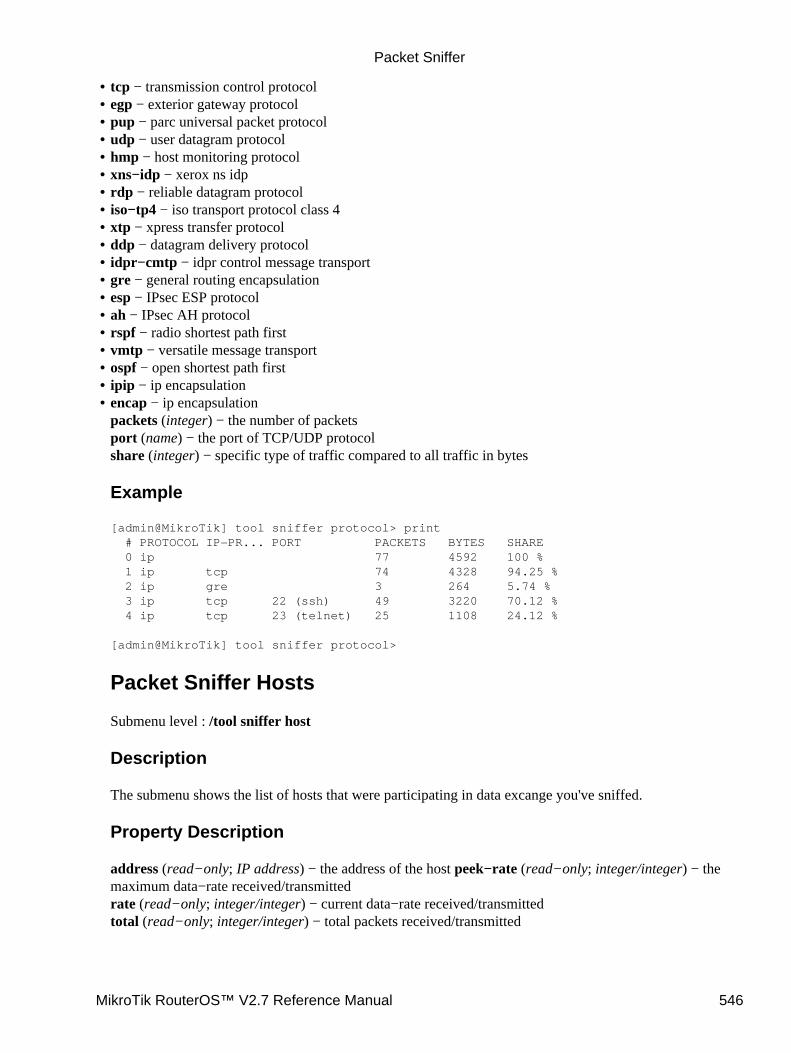
tcp − transmission control protocol• egp − exterior gateway protocol• pup − parc universal packet protocol• udp − user datagram protocol• hmp − host monitoring protocol• xns−idp − xerox ns idp• rdp − reliable datagram protocol• iso−tp4 − iso transport protocol class 4• xtp − xpress transfer protocol• ddp − datagram delivery protocol• idpr−cmtp − idpr control message transport• gre − general routing encapsulation• esp − IPsec ESP protocol• ah − IPsec AH protocol• rspf − radio shortest path first• vmtp − versatile message transport• ospf − open shortest path first• ipip − ip encapsulation• encap − ip encapsulationpackets (integer) − the number of packetsport (name) − the port of TCP/UDP protocolshare (integer) − specific type of traffic compared to all traffic in bytes
Example
[admin@MikroTik] tool sniffer protocol> print # PROTOCOL IP−PR... PORT PACKETS BYTES SHARE 0 ip 77 4592 100 % 1 ip tcp 74 4328 94.25 % 2 ip gre 3 264 5.74 % 3 ip tcp 22 (ssh) 49 3220 70.12 % 4 ip tcp 23 (telnet) 25 1108 24.12 %
[admin@MikroTik] tool sniffer protocol>
Packet Sniffer Hosts
Submenu level : /tool sniffer host
Description
The submenu shows the list of hosts that were participating in data excange you've sniffed.
Property Description
address (read−only; IP address) − the address of the host peek−rate (read−only; integer/integer) − themaximum data−rate received/transmittedrate (read−only; integer/integer) − current data−rate received/transmittedtotal (read−only; integer/integer) − total packets received/transmitted
•
Packet Sniffer
MikroTik RouterOS™ V2.7 Reference Manual 546
Example
In the following example we'll see the list of hosts:
[admin@MikroTik] tool sniffer host> print # ADDRESS RATE PEEK−RATE TOTAL 0 10.0.0.4 0bps/0bps 704bps/0bps 264/0 1 10.0.0.144 0bps/0bps 6.24kbps/12.2kbps 1092/2128 2 10.0.0.181 0bps/0bps 12.2kbps/6.24kbps 2994/1598 3 10.0.0.241 0bps/0bps 1.31kbps/4.85kbps 242/866
[admin@MikroTik] tool sniffer host>
Packet Sniffer Connections
Submenu level : /tool sniffer connection
Description
Here you can get a list of the connections have been watched during the sniffing time.
Property Description
active (read−only; yes | no) − if yes the find active connectionsbytes (read−only; integer) − bytes in the current connectiondst−address (read−only; IP address) − destination addressmss (read−only; integer) − Maximum Segment Sizeresends (read−only; integer) − the number of packets resends in the current connectionsrc−address (read−only; IP address) − source address
Example
The example shows how to get the list of connections:
[admin@MikroTik] tool sniffer connection> print Flags: A − active # SRC−ADDRESS DST−ADDRESS BYTES RESENDS MSS 0 A 10.0.0.241:1839 10.0.0.181:23 (telnet) 6/42 60/0 0/0 1 A 10.0.0.144:2265 10.0.0.181:22 (ssh) 504/252 504/0 0/0
[admin@MikroTik] tool sniffer connection>
© Copyright 1999−2003, MikroTik
Packet Sniffer
MikroTik RouterOS™ V2.7 Reference Manual 547
PingDocument revision 1.9 (30−Apr−2003)This document applies to MikroTik RouterOS v2.7
Table of Contents
Table of Contents• Summary• Specifications• Related Documents• Description• The Ping Command
Property Description♦ Notes♦ Examples♦
•
MAC Ping ServerProperty Description♦ Example♦
•
Summary
Ping uses Internet Control Message Protocol (ICMP) Echo messages to determine if a remote host is active orinactive and to determine the round−trip delay when communicating with it.
Specifications
Packages required : systemLicense required : AnyHome menu level : /, /tool mac−server pingProtocols utilized : ICMP (RFC792)Hardware usage: not significant
Related Documents
Software Package Installation and UpgradingIP Addresses and Address Resolution Protocol (ARP)ICMP Bandwidth TestTraceroute MAC Telnet Server and Client
Description
Ping sends ICMP echo (ICMP type 8) message to the host and waits for the ICMP echo−reply (ICMP type 0)from that host. The interval between these events is called round trip. If the response (that is called pong) hasnot come until the end of the interval, we assume it has timed out. The second significant parameter reportedis ttl (Time to Live). Is is decremented at each machine in which the packet is processed. The packet willreach its destination only when the ttl is greater than the number of routers between the source and thedestination
MikroTik RouterOS™ V2.7 Reference Manual 548
The Ping Command
Command name: /ping
Property Description
(IP address | MAC address) − IP or MAC address for destination hostsize (28...65535, default: 64) − Size of the IP packet (in bytes, including the IP and ICMP headers)do−not−fragment − If added, packets will not be fragmentedinterval (10ms...5s, default: 1s) − Delay between messagescount (integer, default: 0) − How many times ICMP packets will be sent
0 − Ping continues till [Ctrl]+[C] is pressedttl (1...255, default: 255) − Time To Live (TTL) value of the ICMP packet
Notes
If DNS service is configured, it is possible to ping by DNS address. To do it from Winbox, you shouldresolve DNS address first, pressing right mouse button over it address and choosing Lookup Address.
Packet size may not be greater than the interface's mtu. If 'pinging' by MAC address, minimal packet size iz50.
Only neighbour MikroTik RouterOS routers with MAC−ping feature enabled can be 'pinged' by MACaddress.
Examples
[admin@MikroTik] > ping 159.148.60.2 count=5 interval=40ms size=64159.148.60.2 64 byte pong: ttl=247 time=32 ms159.148.60.2 64 byte pong: ttl=247 time=30 ms159.148.60.2 64 byte pong: ttl=247 time=40 ms159.148.60.2 pong timeout159.148.60.2 64 byte pong: ttl=247 time=28 ms5 packets transmitted, 4 packets received, 20% packet lossround−trip min/avg/max = 28/32.5/40 ms[admin@MikroTik] >
MAC Ping Server
Submenu level : /tool mac−server ping
[admin@MikroTik] tool mac−server ping> print enabled: yes[admin@MikroTik] tool mac−server ping>
Property Description
enabled (yes | no) − whether MAC pings to this router are allowed
•
Ping
MikroTik RouterOS™ V2.7 Reference Manual 549

Example
To disable MAC pings:
[admin@MikroTik] tool mac−server ping> set enabled=no[admin@MikroTik] tool mac−server ping> print enabled: no[admin@MikroTik] tool mac−server ping>
© Copyright 1999−2003, MikroTik
Ping
MikroTik RouterOS™ V2.7 Reference Manual 550
Realtime Traffic Monitor (torch)Document revision 1.2 (17−Apr−2003)This document applies to the MikroTik RouterOS v2.7
Table Of Contents
Table Of Contents• Summary• Specifications• Related Documents• Description• The Torch Command
Property Description♦ Notes♦ Example♦
•
Summary
Realtime traffic monitor may be used to monitor the traffic flow through an interface
Specifications
Packages required : systemLicense required : AnyHome menu level : /toolProtocols utilized : noneHardware usage: not significant
Related Documents
Software Package Installation and Upgrading
Description
Realtime Traffic Monitor called also torch is used for monitoring traffic going through an interface. You canmonitor traffic classified by protocol name, source address, destination address, port. Torch shows theprotocols you have chosen and mean transmitted and received data rate for each of them.
The Torch Command
Command name : /tool torch
Property Description
interface (name) − the name of the interface to monitorprotocol (any | any−ip | icmp | igmp | ipip | ospf | pup | tcp | udp| integer) − the name or number of the proocol
MikroTik RouterOS™ V2.7 Reference Manual 551
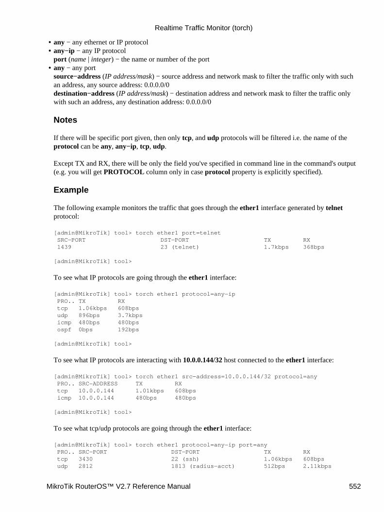
any − any ethernet or IP protocol• any−ip − any IP protocolport (name | integer) − the name or number of the port
•
any − any portsource−address (IP address/mask) − source address and network mask to filter the traffic only with suchan address, any source address: 0.0.0.0/0destination−address (IP address/mask) − destination address and network mask to filter the traffic onlywith such an address, any destination address: 0.0.0.0/0
Notes
If there will be specific port given, then only tcp, and udp protocols will be filtered i.e. the name of theprotocol can be any, any−ip, tcp, udp.
Except TX and RX, there will be only the field you've specified in command line in the command's output(e.g. you will get PROTOCOL column only in case protocol property is explicitly specified).
Example
The following example monitors the traffic that goes through the ether1 interface generated by telnetprotocol:
[admin@MikroTik] tool> torch ether1 port=telnet SRC−PORT DST−PORT TX RX 1439 23 (telnet) 1.7kbps 368bps
[admin@MikroTik] tool>
To see what IP protocols are going through the ether1 interface:
[admin@MikroTik] tool> torch ether1 protocol=any−ip PRO.. TX RX tcp 1.06kbps 608bps udp 896bps 3.7kbps icmp 480bps 480bps ospf 0bps 192bps
[admin@MikroTik] tool>
To see what IP protocols are interacting with 10.0.0.144/32 host connected to the ether1 interface:
[admin@MikroTik] tool> torch ether1 src−address=10.0.0.144/32 protocol=any PRO.. SRC−ADDRESS TX RX tcp 10.0.0.144 1.01kbps 608bps icmp 10.0.0.144 480bps 480bps
[admin@MikroTik] tool>
To see what tcp/udp protocols are going through the ether1 interface:
[admin@MikroTik] tool> torch ether1 protocol=any−ip port=any PRO.. SRC−PORT DST−PORT TX RX tcp 3430 22 (ssh) 1.06kbps 608bps udp 2812 1813 (radius−acct) 512bps 2.11kbps
•
Realtime Traffic Monitor (torch)
MikroTik RouterOS™ V2.7 Reference Manual 552

tcp 1059 139 (netbios−ssn) 248bps 360bps[admin@MikroTik] tool>
© Copyright 1999−2003, MikroTik
Realtime Traffic Monitor (torch)
MikroTik RouterOS™ V2.7 Reference Manual 553
TracerouteDocument revision 1.1 (31−Jan−2003)This document applies to MikroTik RouterOS v2.7
Table of Contents
Table of Contents• Summary• Specifications• Related Documents• Description• The Traceroute Command
Property Description♦ Notes♦ Example♦
•
Summary
Traceroute determines how packets are being routed to a particular host
Specifications
Packages required : systemLicense required : AnyHome menu level : /toolStandards and Technologies : ICMP (RFC792), UDP(RFC768, Traceroute (RFC2925)Hardware usage : not significant
Related Documents
Software Package Installation and UpgradingIP Addresses and Address Resolution Protocol (ARP)Firewall Filters and Network Address Translation (NAT)ICMP Bandwidth TestPing
Description
Traceroute is a TCP/IP protocol−based utility, which allows user to determine how packets are being routed toa particular host. Traceroute works by increasing the time−to−live value of packets and seeing how far theyget until they reach the given destination; thus, a lengthening trail of hosts passed through is built up.
Traceroute shows the number of hops to the given host address of every passed gateway. Traceroute utilitysends packets three times to each passed gateway so it shows three timeout values for each gateway in ms.
MikroTik RouterOS™ V2.7 Reference Manual 554
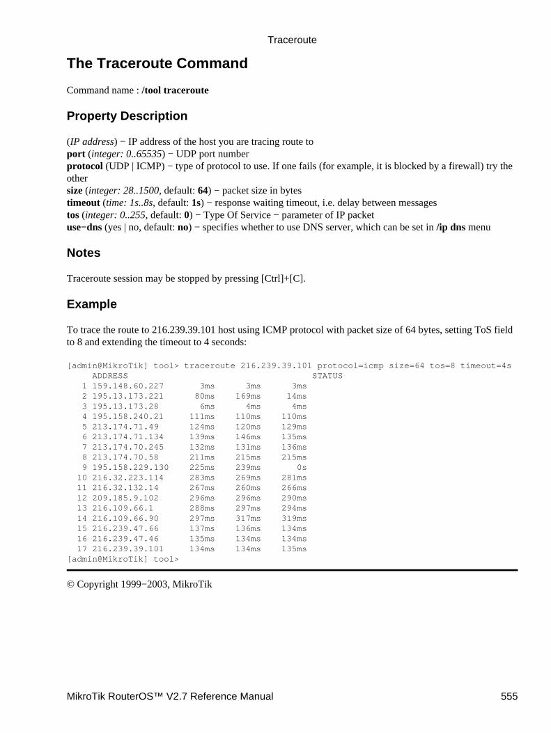
The Traceroute Command
Command name : /tool traceroute
Property Description
(IP address) − IP address of the host you are tracing route toport (integer: 0..65535) − UDP port numberprotocol (UDP | ICMP) − type of protocol to use. If one fails (for example, it is blocked by a firewall) try theothersize (integer: 28..1500, default: 64) − packet size in bytestimeout (time: 1s..8s, default: 1s) − response waiting timeout, i.e. delay between messagestos (integer: 0..255, default: 0) − Type Of Service − parameter of IP packetuse−dns (yes | no, default: no) − specifies whether to use DNS server, which can be set in /ip dns menu
Notes
Traceroute session may be stopped by pressing [Ctrl]+[C].
Example
To trace the route to 216.239.39.101 host using ICMP protocol with packet size of 64 bytes, setting ToS fieldto 8 and extending the timeout to 4 seconds:
[admin@MikroTik] tool> traceroute 216.239.39.101 protocol=icmp size=64 tos=8 timeout=4s ADDRESS STATUS 1 159.148.60.227 3ms 3ms 3ms 2 195.13.173.221 80ms 169ms 14ms 3 195.13.173.28 6ms 4ms 4ms 4 195.158.240.21 111ms 110ms 110ms 5 213.174.71.49 124ms 120ms 129ms 6 213.174.71.134 139ms 146ms 135ms 7 213.174.70.245 132ms 131ms 136ms 8 213.174.70.58 211ms 215ms 215ms 9 195.158.229.130 225ms 239ms 0s 10 216.32.223.114 283ms 269ms 281ms 11 216.32.132.14 267ms 260ms 266ms 12 209.185.9.102 296ms 296ms 290ms 13 216.109.66.1 288ms 297ms 294ms 14 216.109.66.90 297ms 317ms 319ms 15 216.239.47.66 137ms 136ms 134ms 16 216.239.47.46 135ms 134ms 134ms 17 216.239.39.101 134ms 134ms 135ms[admin@MikroTik] tool>
© Copyright 1999−2003, MikroTik
Traceroute
MikroTik RouterOS™ V2.7 Reference Manual 555
SNMP ServiceDocument revision 1.4 (22−Oct−2003)This document applies to the MikroTik RouterOS V2.7
Table of Contents
Table of Contents• Summary• Specifications• Related Documents• Description• SNMP Setup
Property Description♦ SNMP Communities♦ Description♦ Property Description♦ Example♦
•
Available MIBs• Tools for SNMP Data Collection and Analysis• Example of using MRTG with Mikrotik SNMP• Additional Resources•
Summary
SNMP is a network protocol that allows managing many network devices from one location.
The MikroTik RouterOS supports:
SNMPv1 only;• Read−only access is provided to the NMS (network management system);• User defined communities are supported;• No Trap support.•
Specifications
Packages required : system, ppp (optional)License required : AnyHome menu level : /snmpProtocols utilized : SNMP (RFC1157)Hardware usage: not significant
Related Documents
Software Package Installation and UpgradingIP Addresses and Address Resolution Protocol (ARP)
MikroTik RouterOS™ V2.7 Reference Manual 556
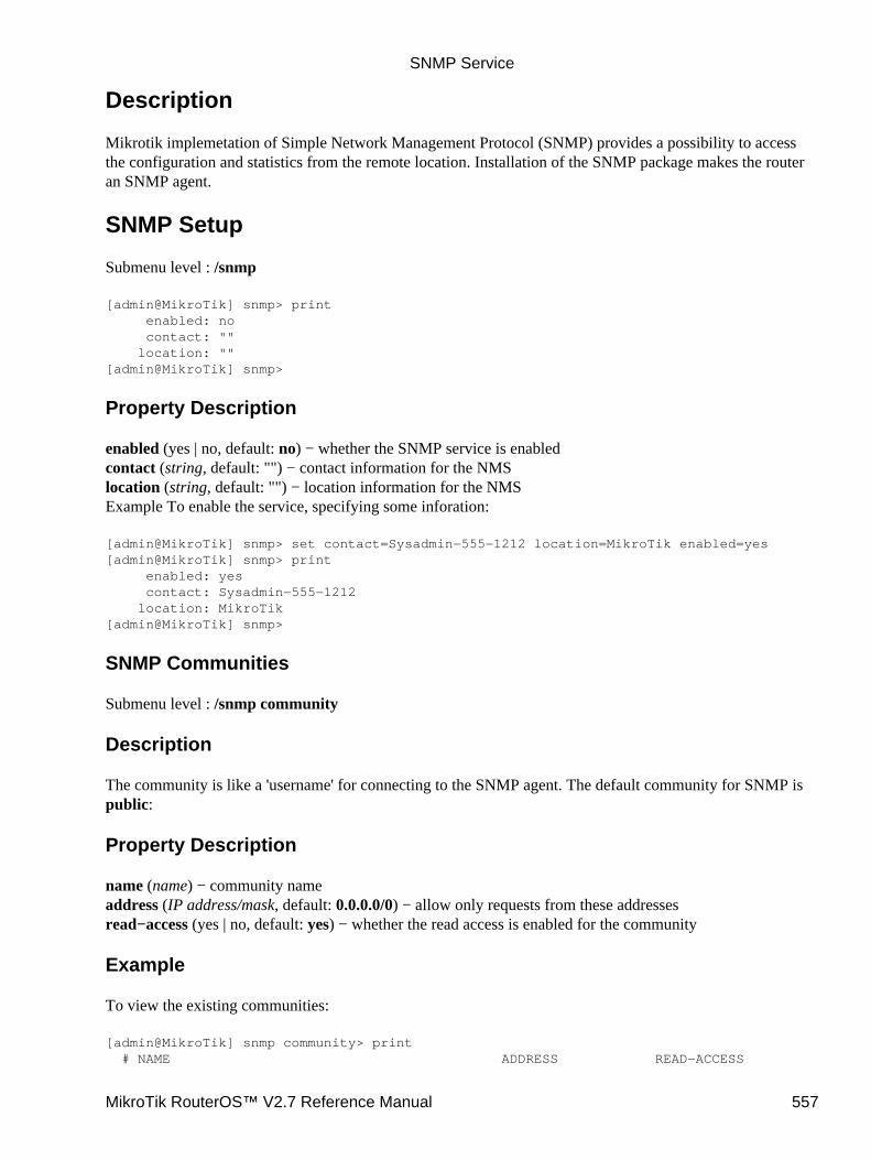
Description
Mikrotik implemetation of Simple Network Management Protocol (SNMP) provides a possibility to accessthe configuration and statistics from the remote location. Installation of the SNMP package makes the routeran SNMP agent.
SNMP Setup
Submenu level : /snmp
[admin@MikroTik] snmp> print enabled: no contact: "" location: ""[admin@MikroTik] snmp>
Property Description
enabled (yes | no, default: no) − whether the SNMP service is enabledcontact (string, default: "") − contact information for the NMSlocation (string, default: "") − location information for the NMSExample To enable the service, specifying some inforation:
[admin@MikroTik] snmp> set contact=Sysadmin−555−1212 location=MikroTik enabled=yes[admin@MikroTik] snmp> print enabled: yes contact: Sysadmin−555−1212 location: MikroTik[admin@MikroTik] snmp>
SNMP Communities
Submenu level : /snmp community
Description
The community is like a 'username' for connecting to the SNMP agent. The default community for SNMP ispublic:
Property Description
name (name) − community nameaddress (IP address/mask, default: 0.0.0.0/0) − allow only requests from these addressesread−access (yes | no, default: yes) − whether the read access is enabled for the community
Example
To view the existing communities:
[admin@MikroTik] snmp community> print # NAME ADDRESS READ−ACCESS
SNMP Service
MikroTik RouterOS™ V2.7 Reference Manual 557
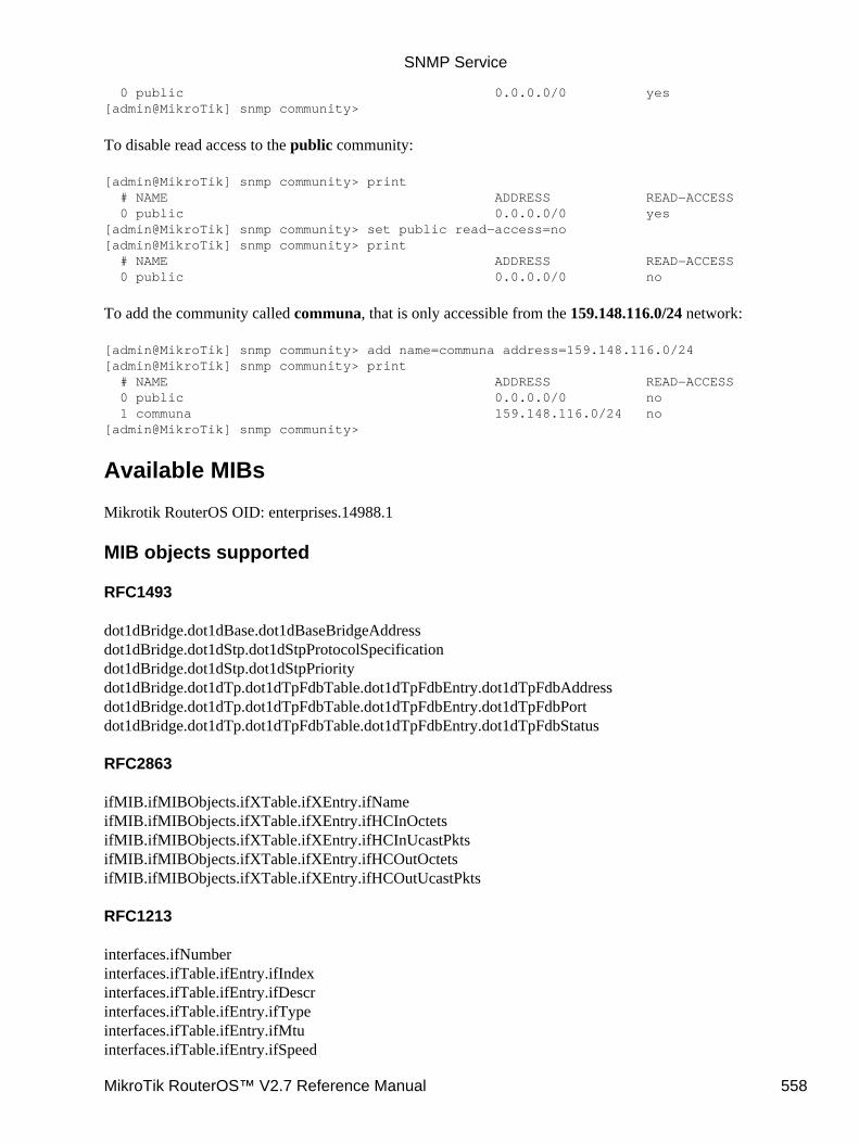
0 public 0.0.0.0/0 yes[admin@MikroTik] snmp community>
To disable read access to the public community:
[admin@MikroTik] snmp community> print # NAME ADDRESS READ−ACCESS 0 public 0.0.0.0/0 yes[admin@MikroTik] snmp community> set public read−access=no[admin@MikroTik] snmp community> print # NAME ADDRESS READ−ACCESS 0 public 0.0.0.0/0 no
To add the community called communa, that is only accessible from the 159.148.116.0/24 network:
[admin@MikroTik] snmp community> add name=communa address=159.148.116.0/24[admin@MikroTik] snmp community> print # NAME ADDRESS READ−ACCESS 0 public 0.0.0.0/0 no 1 communa 159.148.116.0/24 no[admin@MikroTik] snmp community>
Available MIBs
Mikrotik RouterOS OID: enterprises.14988.1
MIB objects supported
RFC1493
dot1dBridge.dot1dBase.dot1dBaseBridgeAddressdot1dBridge.dot1dStp.dot1dStpProtocolSpecificationdot1dBridge.dot1dStp.dot1dStpPrioritydot1dBridge.dot1dTp.dot1dTpFdbTable.dot1dTpFdbEntry.dot1dTpFdbAddressdot1dBridge.dot1dTp.dot1dTpFdbTable.dot1dTpFdbEntry.dot1dTpFdbPortdot1dBridge.dot1dTp.dot1dTpFdbTable.dot1dTpFdbEntry.dot1dTpFdbStatus
RFC2863
ifMIB.ifMIBObjects.ifXTable.ifXEntry.ifNameifMIB.ifMIBObjects.ifXTable.ifXEntry.ifHCInOctetsifMIB.ifMIBObjects.ifXTable.ifXEntry.ifHCInUcastPktsifMIB.ifMIBObjects.ifXTable.ifXEntry.ifHCOutOctetsifMIB.ifMIBObjects.ifXTable.ifXEntry.ifHCOutUcastPkts
RFC1213
interfaces.ifNumberinterfaces.ifTable.ifEntry.ifIndexinterfaces.ifTable.ifEntry.ifDescrinterfaces.ifTable.ifEntry.ifTypeinterfaces.ifTable.ifEntry.ifMtuinterfaces.ifTable.ifEntry.ifSpeed
SNMP Service
MikroTik RouterOS™ V2.7 Reference Manual 558

interfaces.ifTable.ifEntry.ifPhysAddressinterfaces.ifTable.ifEntry.ifAdminStatusinterfaces.ifTable.ifEntry.ifOperStatusinterfaces.ifTable.ifEntry.ifLastChangeinterfaces.ifTable.ifEntry.ifInOctetsinterfaces.ifTable.ifEntry.ifInUcastPktsinterfaces.ifTable.ifEntry.ifInNUcastPktsinterfaces.ifTable.ifEntry.ifInDiscardsinterfaces.ifTable.ifEntry.ifInErrorsinterfaces.ifTable.ifEntry.ifInUnknownProtosinterfaces.ifTable.ifEntry.ifOutOctetsinterfaces.ifTable.ifEntry.ifOutUcastPktsinterfaces.ifTable.ifEntry.ifOutNUcastPktsinterfaces.ifTable.ifEntry.ifOutDiscardsinterfaces.ifTable.ifEntry.ifOutErrorsinterfaces.ifTable.ifEntry.ifOutQLen
RFC2011
ip.ipForwardingip.ipDefaultTTLip.ipAddrTable.ipAddrEntry.ipAdEntAddrip.ipAddrTable.ipAddrEntry.ipAdEntIfIndexip.ipAddrTable.ipAddrEntry.ipAdEntNetMaskip.ipAddrTable.ipAddrEntry.ipAdEntBcastAddrip.ipAddrTable.ipAddrEntry.ipAdEntReasmMaxSizeip.ipNetToMediaTable.ipNetToMediaEntry.ipNetToMediaIfIndexip.ipNetToMediaTable.ipNetToMediaEntry.ipNetToMediaPhysAddressip.ipNetToMediaTable.ipNetToMediaEntry.ipNetToMediaNetAddressip.ipNetToMediaTable.ipNetToMediaEntry.ipNetToMediaType
RFC2096
ip.ipForward.ipCidrRouteNumberip.ipForward.ipCidrRouteTable.ipCidrRouteEntry.ipCidrRouteDestip.ipForward.ipCidrRouteTable.ipCidrRouteEntry.ipCidrRouteMaskip.ipForward.ipCidrRouteTable.ipCidrRouteEntry.ipCidrRouteTosip.ipForward.ipCidrRouteTable.ipCidrRouteEntry.ipCidrRouteNextHopip.ipForward.ipCidrRouteTable.ipCidrRouteEntry.ipCidrRouteIfIndexip.ipForward.ipCidrRouteTable.ipCidrRouteEntry.ipCidrRouteTypeip.ipForward.ipCidrRouteTable.ipCidrRouteEntry.ipCidrRouteProtoip.ipForward.ipCidrRouteTable.ipCidrRouteEntry.ipCidrRouteAgeip.ipForward.ipCidrRouteTable.ipCidrRouteEntry.ipCidrRouteInfoip.ipForward.ipCidrRouteTable.ipCidrRouteEntry.ipCidrRouteNextHopASip.ipForward.ipCidrRouteTable.ipCidrRouteEntry.ipCidrRouteMetric1ip.ipForward.ipCidrRouteTable.ipCidrRouteEntry.ipCidrRouteMetric2ip.ipForward.ipCidrRouteTable.ipCidrRouteEntry.ipCidrRouteMetric3ip.ipForward.ipCidrRouteTable.ipCidrRouteEntry.ipCidrRouteMetric4ip.ipForward.ipCidrRouteTable.ipCidrRouteEntry.ipCidrRouteMetric5ip.ipForward.ipCidrRouteTable.ipCidrRouteEntry.ipCidrRouteStatus
SNMP Service
MikroTik RouterOS™ V2.7 Reference Manual 559
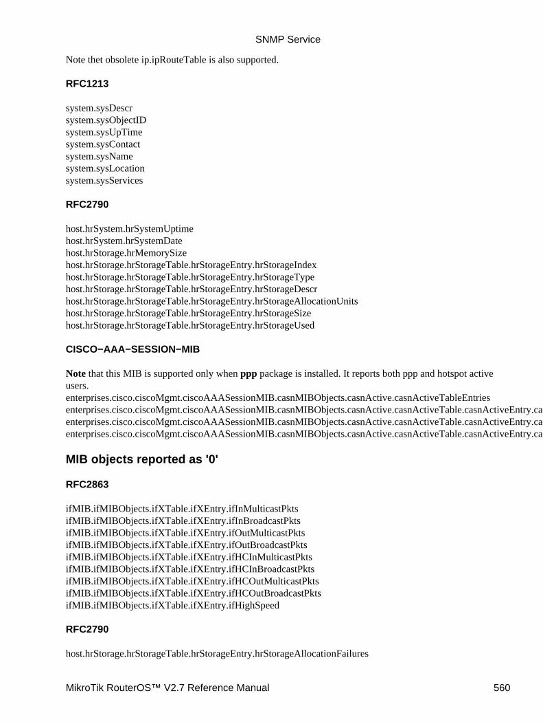
Note thet obsolete ip.ipRouteTable is also supported.
RFC1213
system.sysDescrsystem.sysObjectIDsystem.sysUpTimesystem.sysContactsystem.sysNamesystem.sysLocationsystem.sysServices
RFC2790
host.hrSystem.hrSystemUptimehost.hrSystem.hrSystemDatehost.hrStorage.hrMemorySizehost.hrStorage.hrStorageTable.hrStorageEntry.hrStorageIndexhost.hrStorage.hrStorageTable.hrStorageEntry.hrStorageTypehost.hrStorage.hrStorageTable.hrStorageEntry.hrStorageDescrhost.hrStorage.hrStorageTable.hrStorageEntry.hrStorageAllocationUnitshost.hrStorage.hrStorageTable.hrStorageEntry.hrStorageSizehost.hrStorage.hrStorageTable.hrStorageEntry.hrStorageUsed
CISCO−AAA−SESSION−MIB
Note that this MIB is supported only when ppp package is installed. It reports both ppp and hotspot activeusers.enterprises.cisco.ciscoMgmt.ciscoAAASessionMIB.casnMIBObjects.casnActive.casnActiveTableEntriesenterprises.cisco.ciscoMgmt.ciscoAAASessionMIB.casnMIBObjects.casnActive.casnActiveTable.casnActiveEntry.casnSessionIdenterprises.cisco.ciscoMgmt.ciscoAAASessionMIB.casnMIBObjects.casnActive.casnActiveTable.casnActiveEntry.casnUserIdenterprises.cisco.ciscoMgmt.ciscoAAASessionMIB.casnMIBObjects.casnActive.casnActiveTable.casnActiveEntry.casnIpAddr
MIB objects reported as '0'
RFC2863
ifMIB.ifMIBObjects.ifXTable.ifXEntry.ifInMulticastPktsifMIB.ifMIBObjects.ifXTable.ifXEntry.ifInBroadcastPktsifMIB.ifMIBObjects.ifXTable.ifXEntry.ifOutMulticastPktsifMIB.ifMIBObjects.ifXTable.ifXEntry.ifOutBroadcastPktsifMIB.ifMIBObjects.ifXTable.ifXEntry.ifHCInMulticastPktsifMIB.ifMIBObjects.ifXTable.ifXEntry.ifHCInBroadcastPktsifMIB.ifMIBObjects.ifXTable.ifXEntry.ifHCOutMulticastPktsifMIB.ifMIBObjects.ifXTable.ifXEntry.ifHCOutBroadcastPktsifMIB.ifMIBObjects.ifXTable.ifXEntry.ifHighSpeed
RFC2790
host.hrStorage.hrStorageTable.hrStorageEntry.hrStorageAllocationFailures
SNMP Service
MikroTik RouterOS™ V2.7 Reference Manual 560
Tools for SNMP Data Collection and Analysis
MRTG (Multi Router Traffic Grapher) is the most commonly used SNMP monitor.
http://ee−staff.ethz.ch/~oetiker/webtools/mrtg/
Example of using MRTG with Mikrotik SNMP
Here is a example configuration file for MRTG to monitor network card traffic on Mikrotik RouterOS Thisfile was created with MRTG v2.9.17 cfgmaker on a linux computer. This is a only an example file.
MRTG Sample Configuration
For more information read the MRTG documentation: Configuration Reference
Additional Resources
http://www.ietf.org/rfc/rfc1157.txthttp://www.cisco.com/univercd/cc/td/doc/cisintwk/ito_doc/snmp.htm
© Copyright 1999−2003, MikroTik
SNMP Service
MikroTik RouterOS™ V2.7 Reference Manual 561
Related Documents