SETUP MANUAL MIGATRONIC ROBOT SETUP FANUC – PROFIBUS – TIG/PLASMA 50115033 Valid from 2020 week 19

Welcome message from author
This document is posted to help you gain knowledge. Please leave a comment to let me know what you think about it! Share it to your friends and learn new things together.
Transcript
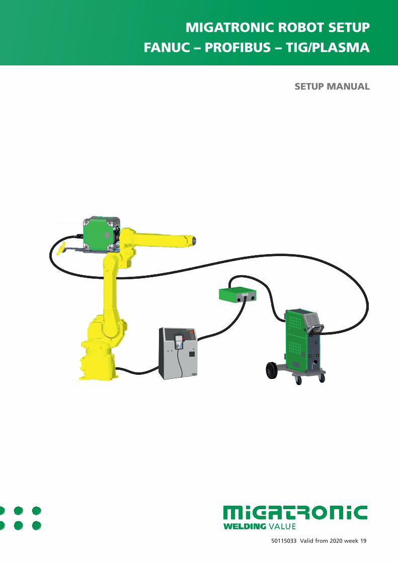
SETUP MANUAL
MIGATRONIC ROBOT SETUPFANUC – PROFIBUS – TIG/PLASMA
50115033 Valid from 2020 week 19

2 3
Dansk ..................................................................3
English ..............................................................17
2 3
Indholdsfortegnelse
Klargøring af strømkilden .........................................................................4
Opsætning af robottens Profibus Master data ........................................4
Opsætning af robottens Profibus Slave data ...........................................5
Opsætning af robottens Analoge Profibus kanaler .................................7
Hold analoge værdier efter endt svejsning ..............................................7
Indstil I/O til manuel opsætning ................................................................7
Vendor ID for svejseinterface ....................................................................8
Konfigurer Digitale I/O ...............................................................................9
Konfigurer Weld I/O ..................................................................................10
Skaler Analoge kanaler til svejsning ......................................................11
Konfigurer Analoge I/O ............................................................................12
Konfigurer Group I/O ................................................................................13
Tips .............................................................................................................14
Background Logic ..................................................................................14
Svejseprogrammer ................................................................................15
4 5
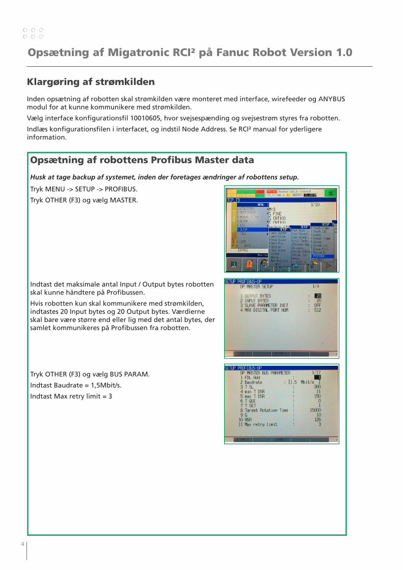
Opsætning af Migatronic RCI² på Fanuc Robot Version 1.0
Klargøring af strømkilden
Inden opsætning af robotten skal strømkilden være monteret med interface, wirefeeder og ANYBUS modul for at kunne kommunikere med strømkilden.
Vælg interface konfigurationsfil 10010605, hvor svejsespænding og svejsestrøm styres fra robotten.
Indlæs konfigurationsfilen i interfacet, og indstil Node Address. Se RCI² manual for yderligere information.
Opsætning af robottens Profibus Master data
Husk at tage backup af systemet, inden der foretages ændringer af robottens setup.
Tryk MENU -> SETUP -> PROFIBUS.
Tryk OTHER (F3) og vælg MASTER.
Indtast det maksimale antal Input / Output bytes robotten skal kunne håndtere på Profibussen.
Hvis robotten kun skal kommunikere med strømkilden, indtastes 20 Input bytes og 20 Output bytes. Værdierne skal bare være større end eller lig med det antal bytes, der samlet kommunikeres på Profibussen fra robotten.
Tryk OTHER (F3) og vælg BUS PARAM.
Indtast Baudrate = 1,5Mbit/s.
Indtast Max retry limit = 3
4 5
Opsætning af Migatronic RCI² på Fanuc Robot Version 1.0
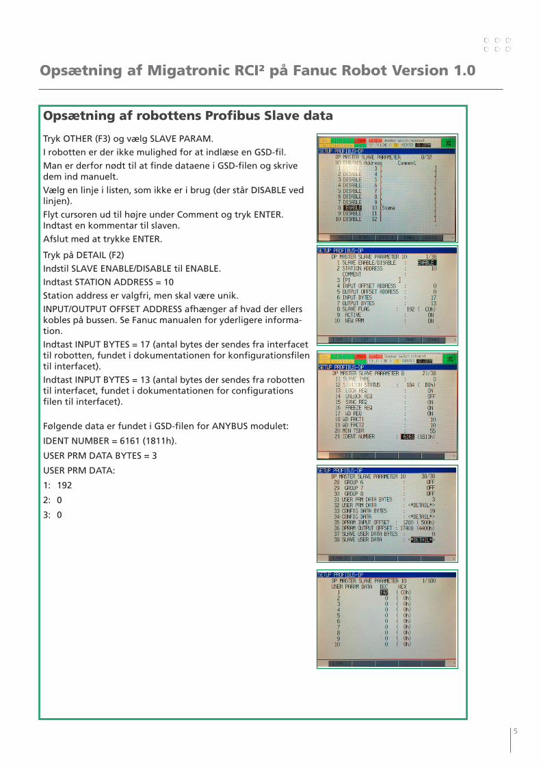
Opsætning af robottens Profibus Slave data
Tryk OTHER (F3) og vælg SLAVE PARAM.
I robotten er der ikke mulighed for at indlæse en GSD-fil.
Man er derfor nødt til at finde dataene i GSD-filen og skrive dem ind manuelt.
Vælg en linje i listen, som ikke er i brug (der står DISABLE ved linjen).
Flyt cursoren ud til højre under Comment og tryk ENTER. Indtast en kommentar til slaven.
Afslut med at trykke ENTER.
Tryk på DETAIL (F2)
Indstil SLAVE ENABLE/DISABLE til ENABLE.
Indtast STATION ADDRESS = 10
Station address er valgfri, men skal være unik.
INPUT/OUTPUT OFFSET ADDRESS afhænger af hvad der ellers kobles på bussen. Se Fanuc manualen for yderligere informa-tion.
Indtast INPUT BYTES = 17 (antal bytes der sendes fra interfacet til robotten, fundet i dokumentationen for konfigurationsfilen til interfacet).
Indtast INPUT BYTES = 13 (antal bytes der sendes fra robotten til interfacet, fundet i dokumentationen for configurations filen til interfacet).
Følgende data er fundet i GSD-filen for ANYBUS modulet:
IDENT NUMBER = 6161 (1811h).
USER PRM DATA BYTES = 3
USER PRM DATA:
1: 192
2: 0
3: 0
6 7
Opsætning af Migatronic RCI² på Fanuc Robot Version 1.0
Opsætning af robottens Profibus Slave data
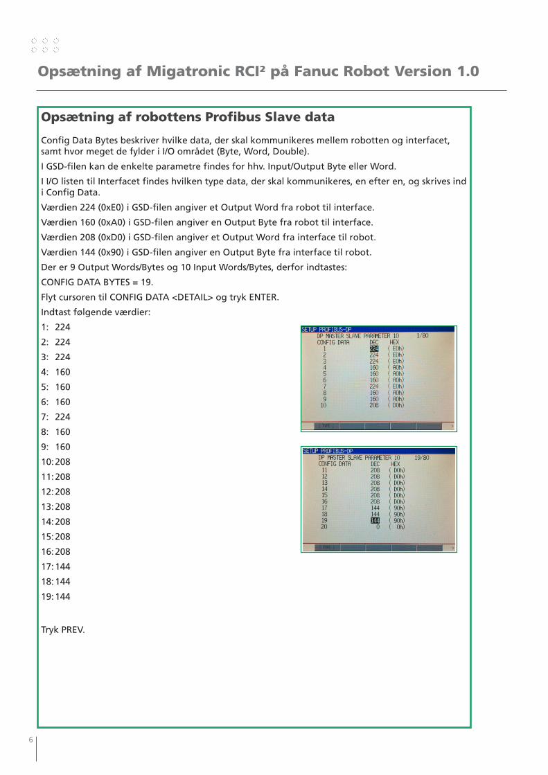
Config Data Bytes beskriver hvilke data, der skal kommunikeres mellem robotten og interfacet, samt hvor meget de fylder i I/O området (Byte, Word, Double).
I GSD-filen kan de enkelte parametre findes for hhv. Input/Output Byte eller Word.
I I/O listen til Interfacet findes hvilken type data, der skal kommunikeres, en efter en, og skrives ind i Config Data.
Værdien 224 (0xE0) i GSD-filen angiver et Output Word fra robot til interface.
Værdien 160 (0xA0) i GSD-filen angiver en Output Byte fra robot til interface.
Værdien 208 (0xD0) i GSD-filen angiver et Output Word fra interface til robot.
Værdien 144 (0x90) i GSD-filen angiver en Output Byte fra interface til robot.
Der er 9 Output Words/Bytes og 10 Input Words/Bytes, derfor indtastes:
CONFIG DATA BYTES = 19.
Flyt cursoren til CONFIG DATA <DETAIL> og tryk ENTER.
Indtast følgende værdier:
1: 224
2: 224
3: 224
4: 160
5: 160
6: 160
7: 224
8: 160
9: 160
10: 208
11: 208
12: 208
13: 208
14: 208
15: 208
16: 208
17: 144
18: 144
19: 144
Tryk PREV.
6 7
Opsætning af Migatronic RCI² på Fanuc Robot Version 1.0
Hold analoge værdier efter endt svejsning
Det kan være praktisk, at strømkilden viser den strøm, der sidst har været svejset med.
Som standard sætter en Fanuc Robot de analoge værdier til 0 efter endt svejsning.
Det kan ændres ved at indstille systemvariablen $AWEPCR[1].AE_HOLD_AO = TRUE.
Variablerne findes ved at trykke MENU -> NEXT -> SYSTEM -> VARIABLES
Indstil I/O til manuel opsætning
For at forhindre at robotten selv forsøger at opsætte I/O moduler, indstilles system-variablerne:
$IO_AUTO_CFG = FALSE
$IO_AUTO_UOP = FALSE
Variablerne findes ved at trykke MENU -> NEXT -> SYSTEM -> VARIABLES
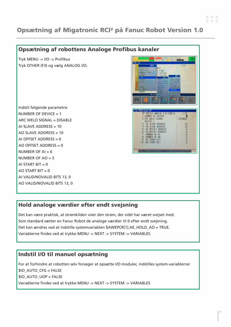
Opsætning af robottens Analoge Profibus kanaler
Tryk MENU -> I/O -> Profibus
Tryk OTHER (F3) og vælg ANALOG I/O.
Indstil følgende parametre:
NUMBER OF DEVICE = 1
ARC WELD SIGNAL = DISABLE
AI SLAVE ADDRESS = 10
AO SLAVE ADDRESS = 10
AI OFFSET ADDRESS = 0
AO OFFSET ADDRESS = 0
NUMBER OF AI = 6
NUMBER OF AO = 3
AI START BIT = 0
AO START BIT = 0
AI VALID/NOVALID BITS 13, 0
AO VALID/NOVALID BITS 13, 0
8 9
Opsætning af Migatronic RCI² på Fanuc Robot Version 1.0
Vendor ID for svejseinterface
Afhængig af hvilken software, der er installeret på robotten, kan det i nogle tilfælde være nødvendigt at indstille systemvariablen $AWEPRR.$VENDOR_ID = 108
Hvis ikke det gøres, kan følgende fejl optræde:
• Robotten kører programmerne igennem uden at starte svejsning.
• Alarmen “ARC-045 Weld EQ is OFFLINE” vises.
• Alarmen “ARC-040 EQi Missing I/O” vises.
Variablerne findes ved at trykke MENU -> NEXT -> SYSTEM -> VARIABLES
Afslut opsætningen med gå til Profibus menuen, og trykke NEXT -> CLR_ASG (F1).
OBS! Herved slettes al opsætning af adresser i DI/DO, AI/AO og GI/GO området. Husk derfor at notere de opsætninger, der skal genanvendes inden, så de kan genskabes.
Afslut med at genstarte robotten.
8 9
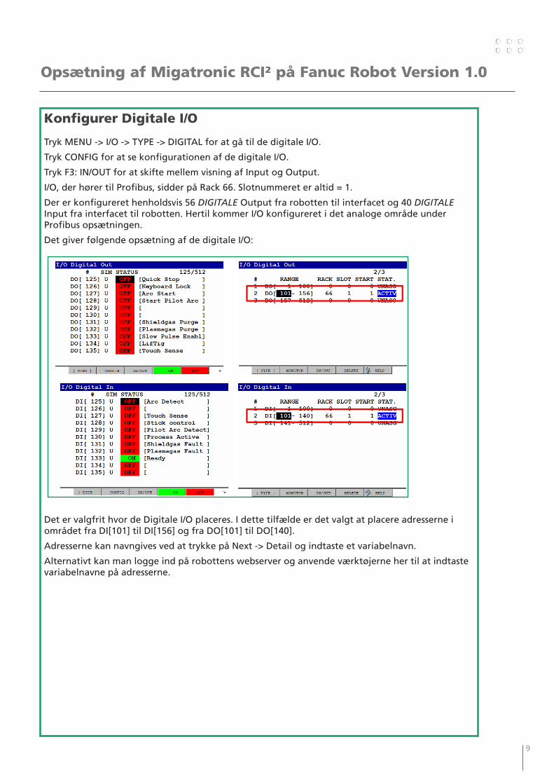
Konfigurer Digitale I/O
Tryk MENU -> I/O -> TYPE -> DIGITAL for at gå til de digitale I/O.
Tryk CONFIG for at se konfigurationen af de digitale I/O.
Tryk F3: IN/OUT for at skifte mellem visning af Input og Output.
I/O, der hører til Profibus, sidder på Rack 66. Slotnummeret er altid = 1.
Der er konfigureret henholdsvis 56 DIGITALE Output fra robotten til interfacet og 40 DIGITALE Input fra interfacet til robotten. Hertil kommer I/O konfigureret i det analoge område under Profibus opsætningen.
Det giver følgende opsætning af de digitale I/O:
Det er valgfrit hvor de Digitale I/O placeres. I dette tilfælde er det valgt at placere adresserne i området fra DI[101] til DI[156] og fra DO[101] til DO[140].
Adresserne kan navngives ved at trykke på Next -> Detail og indtaste et variabelnavn.
Alternativt kan man logge ind på robottens webserver og anvende værktøjerne her til at indtaste variabelnavne på adresserne.
Opsætning af Migatronic RCI² på Fanuc Robot Version 1.0
10 11
Opsætning af Migatronic RCI² på Fanuc Robot Version 1.0
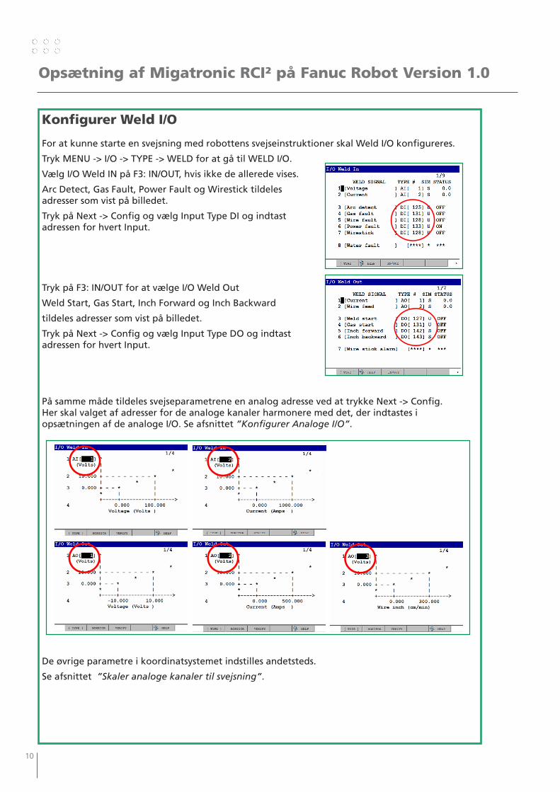
Konfigurer Weld I/O
For at kunne starte en svejsning med robottens svejseinstruktioner skal Weld I/O konfigureres.
Tryk MENU -> I/O -> TYPE -> WELD for at gå til WELD I/O.
Vælg I/O Weld IN på F3: IN/OUT, hvis ikke de allerede vises.
Arc Detect, Gas Fault, Power Fault og Wirestick tildeles adresser som vist på billedet.
Tryk på Next -> Config og vælg Input Type DI og indtast adressen for hvert Input.
Tryk på F3: IN/OUT for at vælge I/O Weld Out
Weld Start, Gas Start, Inch Forward og Inch Backward
tildeles adresser som vist på billedet.
Tryk på Next -> Config og vælg Input Type DO og indtast adressen for hvert Input.
På samme måde tildeles svejseparametrene en analog adresse ved at trykke Next -> Config. Her skal valget af adresser for de analoge kanaler harmonere med det, der indtastes i opsætningen af de analoge I/O. Se afsnittet ”Konfigurer Analoge I/O”.
De øvrige parametre i koordinatsystemet indstilles andetsteds.
Se afsnittet ”Skaler analoge kanaler til svejsning”.
10 11
Opsætning af Migatronic RCI² på Fanuc Robot Version 1.0
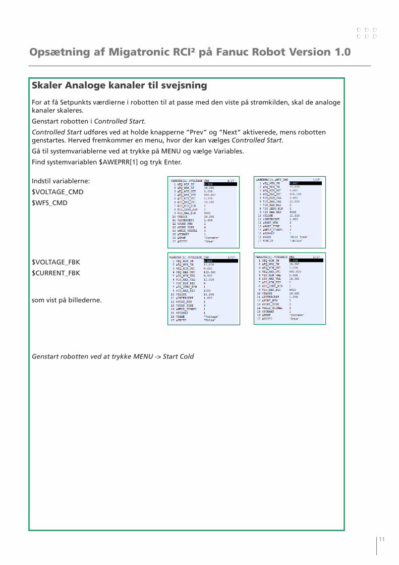
Skaler Analoge kanaler til svejsning
For at få Setpunkts værdierne i robotten til at passe med den viste på strømkilden, skal de analoge kanaler skaleres.
Genstart robotten i Controlled Start.
Controlled Start udføres ved at holde knapperne ”Prev” og ”Next” aktiverede, mens robotten genstartes. Herved fremkommer en menu, hvor der kan vælges Controlled Start.
Gå til systemvariablerne ved at trykke på MENU og vælge Variables.
Find systemvariablen $AWEPRR[1] og tryk Enter.
Indstil variablerne:
$VOLTAGE_CMD
$WFS_CMD
$VOLTAGE_FBK
$CURRENT_FBK
som vist på billederne.
Genstart robotten ved at trykke MENU -> Start Cold

12 13
Opsætning af Migatronic RCI² på Fanuc Robot Version 1.0
Konfigurer Analoge I/O
Tryk MENU -> I/O -> TYPE -> ANALOG for at gå til de analoge I/O.
Tryk CONFIG for at se konfigurationen af de analoge I/O.
Tryk F3 for at skifte mellem visning af Input og Output.
I/O, der hører til Profibus, sidder på Rack 66. Slotnummeret referer til det Device No., der blev valgt under opsætningen af den analoge del af Profibus opsætningen.
Der er konfigureret henholdsvis 6 Input fra interfacet til robotten og 3 Output fra robotten til interfacet.
Det giver følgende opsætning af de analoge I/O:
Det er valgfrit, hvor de analoge I/O placeres. Det skal blot harmonere med opsætningen under Weld I/O.
I dette tilfælde er det valgt at placere adresserne i området fra AI[1] til AI[6] og fra AO[1] til AO[3].
Adresserne kan navngives ved at trykke på Next -> Detail og indtaste et variabelnavn.
Alternativt kan man logge ind på robottens webserver og anvende værktøjerne her til at indtaste variabelnavne på adresserne.
12 13
Opsætning af Migatronic RCI² på Fanuc Robot Version 1.0
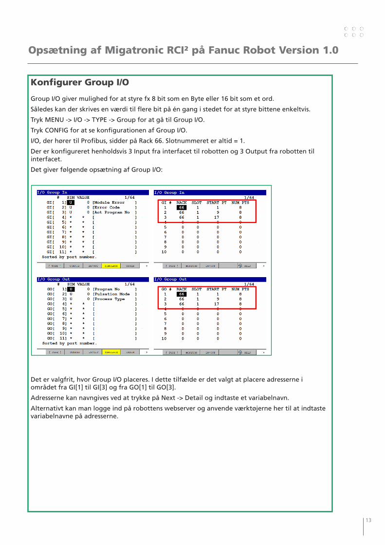
Konfigurer Group I/O
Group I/O giver mulighed for at styre fx 8 bit som en Byte eller 16 bit som et ord.
Således kan der skrives en værdi til flere bit på én gang i stedet for at styre bittene enkeltvis.
Tryk MENU -> I/O -> TYPE -> Group for at gå til Group I/O.
Tryk CONFIG for at se konfigurationen af Group I/O.
I/O, der hører til Profibus, sidder på Rack 66. Slotnummeret er altid = 1.
Der er konfigureret henholdsvis 3 Input fra interfacet til robotten og 3 Output fra robotten til interfacet.
Det giver følgende opsætning af Group I/O:
Det er valgfrit, hvor Group I/O placeres. I dette tilfælde er det valgt at placere adresserne i området fra GI[1] til GI[3] og fra GO[1] til GO[3].
Adresserne kan navngives ved at trykke på Next -> Detail og indtaste et variabelnavn.
Alternativt kan man logge ind på robottens webserver og anvende værktøjerne her til at indtaste variabelnavne på adresserne.
14 15
Tips
Der er mange muligheder for at kontrollere parametre og indstillinger med Migatronic RCI².
Se Migatronics anbefalinger til programmøren:
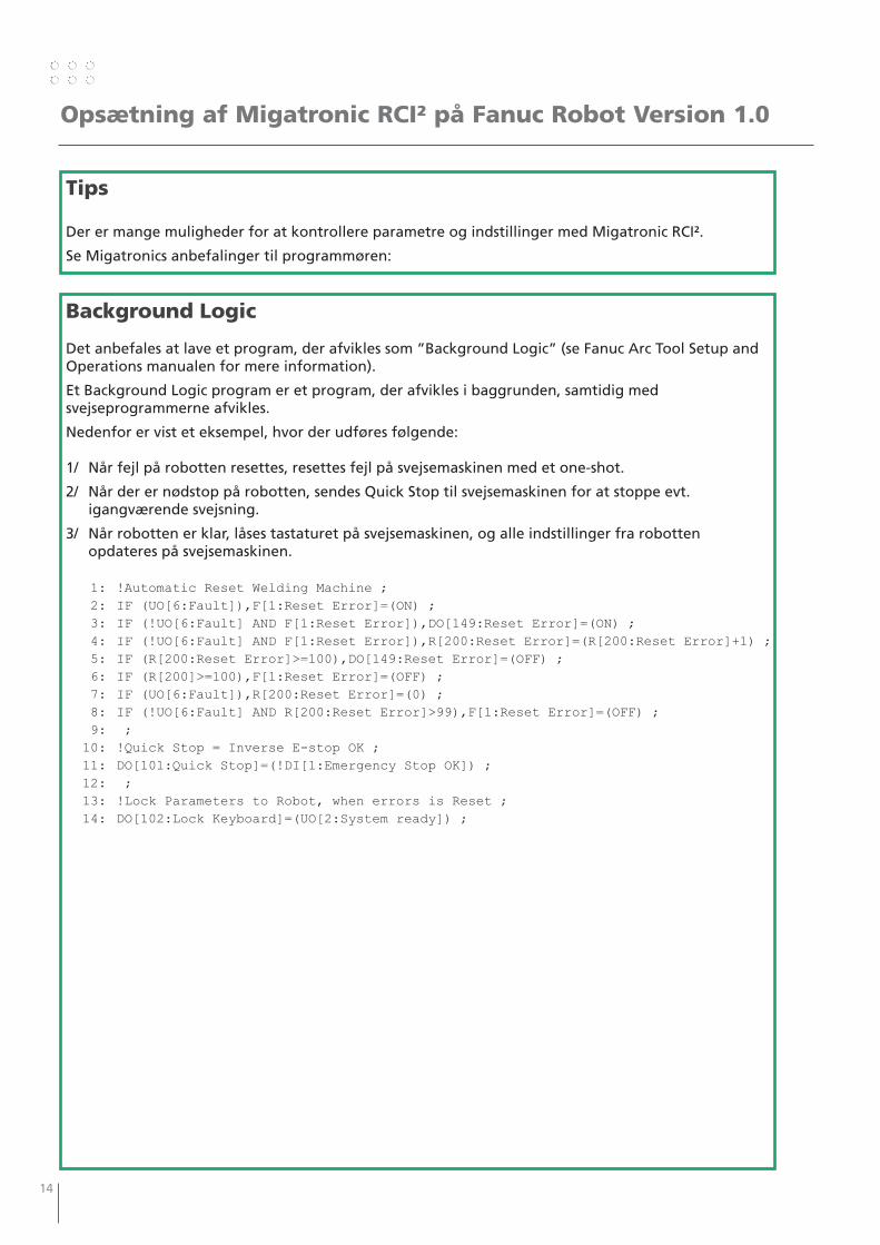
Background Logic
Det anbefales at lave et program, der afvikles som ”Background Logic” (se Fanuc Arc Tool Setup and Operations manualen for mere information).
Et Background Logic program er et program, der afvikles i baggrunden, samtidig med svejseprogrammerne afvikles.
Nedenfor er vist et eksempel, hvor der udføres følgende:
1/ Når fejl på robotten resettes, resettes fejl på svejsemaskinen med et one-shot.
2/ Når der er nødstop på robotten, sendes Quick Stop til svejsemaskinen for at stoppe evt. igangværende svejsning.
3/ Når robotten er klar, låses tastaturet på svejsemaskinen, og alle indstillinger fra robotten opdateres på svejsemaskinen.
1: !Automatic Reset Welding Machine ; 2: IF (UO[6:Fault]),F[1:Reset Error]=(ON) ; 3: IF (!UO[6:Fault] AND F[1:Reset Error]),DO[149:Reset Error]=(ON) ; 4: IF (!UO[6:Fault] AND F[1:Reset Error]),R[200:Reset Error]=(R[200:Reset Error]+1) ; 5: IF (R[200:Reset Error]>=100),DO[149:Reset Error]=(OFF) ; 6: IF (R[200]>=100),F[1:Reset Error]=(OFF) ; 7: IF (UO[6:Fault]),R[200:Reset Error]=(0) ; 8: IF (!UO[6:Fault] AND R[200:Reset Error]>99),F[1:Reset Error]=(OFF) ; 9: ; 10: !Quick Stop = Inverse E-stop OK ; 11: DO[101:Quick Stop]=(!DI[1:Emergency Stop OK]) ; 12: ; 13: !Lock Parameters to Robot, when errors is Reset ; 14: DO[102:Lock Keyboard]=(UO[2:System ready]) ;
Opsætning af Migatronic RCI² på Fanuc Robot Version 1.0
14 15
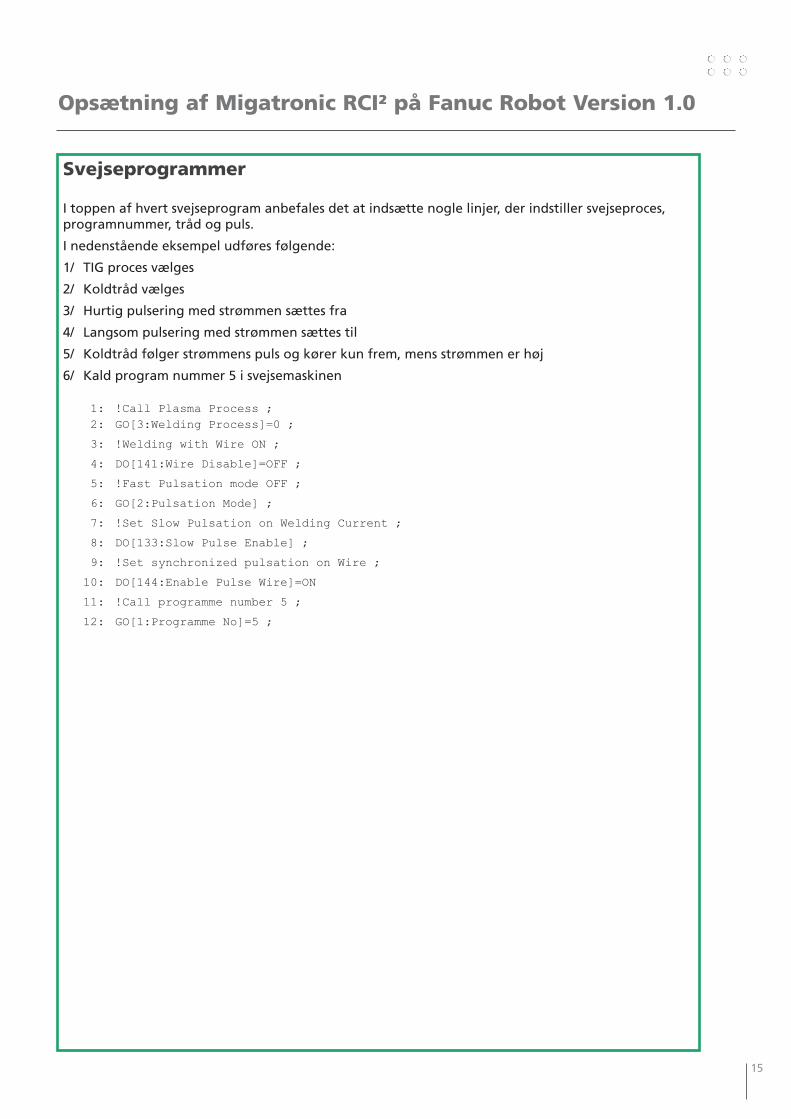
Svejseprogrammer
I toppen af hvert svejseprogram anbefales det at indsætte nogle linjer, der indstiller svejseproces, programnummer, tråd og puls.
I nedenstående eksempel udføres følgende:
1/ TIG proces vælges
2/ Koldtråd vælges
3/ Hurtig pulsering med strømmen sættes fra
4/ Langsom pulsering med strømmen sættes til
5/ Koldtråd følger strømmens puls og kører kun frem, mens strømmen er høj
6/ Kald program nummer 5 i svejsemaskinen
1: !Call Plasma Process ; 2: GO[3:Welding Process]=0 ;
3: !Welding with Wire ON ;
4: DO[141:Wire Disable]=OFF ;
5: !Fast Pulsation mode OFF ;
6: GO[2:Pulsation Mode] ;
7: !Set Slow Pulsation on Welding Current ;
8: DO[133:Slow Pulse Enable] ;
9: !Set synchronized pulsation on Wire ;
10: DO[144:Enable Pulse Wire]=ON
11: !Call programme number 5 ;
12: GO[1:Programme No]=5 ;
Opsætning af Migatronic RCI² på Fanuc Robot Version 1.0

16 17
16 17
Contents
Making ready the Power Source..............................................................18
Setting up the Robot Profibus Master Data ...........................................18
Setting up the Robot Profibus Slave Data ..............................................19
Setting up the Robot Analog Profibus Channels ...................................21
Holding Analog Values after Welding .....................................................21
Setting I/O at Manual Setup .....................................................................21
Vendor ID for Welding Interface .............................................................22
Configuring Digital I/O .............................................................................23
Configuring Weld I/O ................................................................................24
Scaling Analog Channels for Welding .....................................................25
Configuring Analog I/O ............................................................................26
Configuring Group I/O ..............................................................................27
Tips .............................................................................................................28
Background Logic ..................................................................................28
Welding Programs .................................................................................29
18 19
Setting up Migatronic RCI² at Fanuc Robot Version 1.0
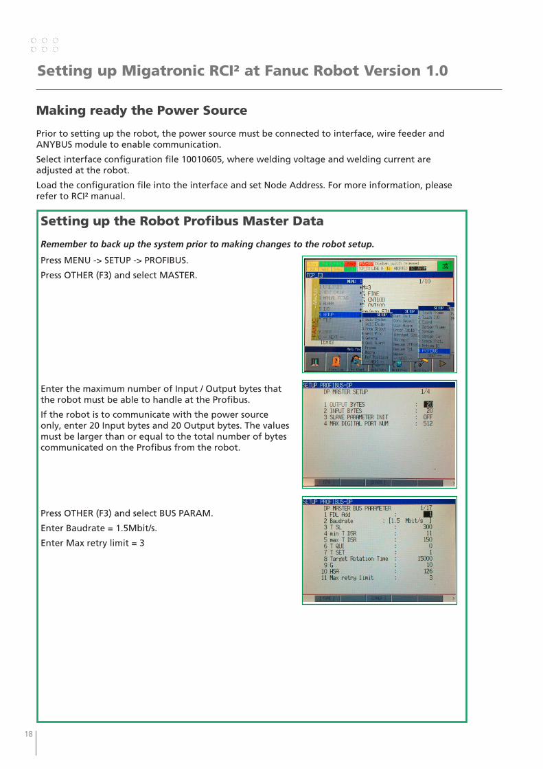
Making ready the Power Source
Prior to setting up the robot, the power source must be connected to interface, wire feeder and ANYBUS module to enable communication.
Select interface configuration file 10010605, where welding voltage and welding current are adjusted at the robot.
Load the configuration file into the interface and set Node Address. For more information, please refer to RCI² manual.
Setting up the Robot Profibus Master Data
Remember to back up the system prior to making changes to the robot setup.
Press MENU -> SETUP -> PROFIBUS.
Press OTHER (F3) and select MASTER.
Enter the maximum number of Input / Output bytes that the robot must be able to handle at the Profibus.
If the robot is to communicate with the power source only, enter 20 Input bytes and 20 Output bytes. The values must be larger than or equal to the total number of bytes communicated on the Profibus from the robot.
Press OTHER (F3) and select BUS PARAM.
Enter Baudrate = 1.5Mbit/s.
Enter Max retry limit = 3
18 19
Setting up Migatronic RCI² at Fanuc Robot Version 1.0
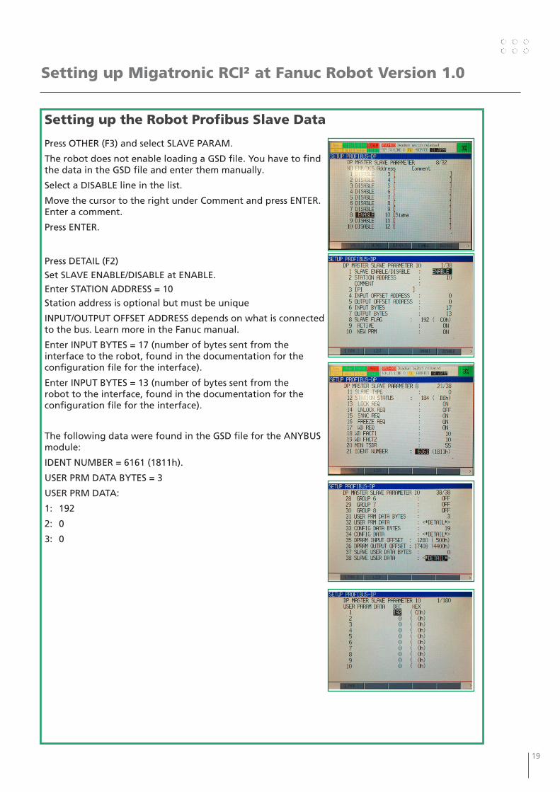
Setting up the Robot Profibus Slave Data
Press OTHER (F3) and select SLAVE PARAM.
The robot does not enable loading a GSD file. You have to find the data in the GSD file and enter them manually.
Select a DISABLE line in the list.
Move the cursor to the right under Comment and press ENTER. Enter a comment.
Press ENTER.
Press DETAIL (F2)
Set SLAVE ENABLE/DISABLE at ENABLE.
Enter STATION ADDRESS = 10
Station address is optional but must be unique
INPUT/OUTPUT OFFSET ADDRESS depends on what is connected to the bus. Learn more in the Fanuc manual.
Enter INPUT BYTES = 17 (number of bytes sent from the interface to the robot, found in the documentation for the configuration file for the interface).
Enter INPUT BYTES = 13 (number of bytes sent from the robot to the interface, found in the documentation for the configuration file for the interface).
The following data were found in the GSD file for the ANYBUS module:
IDENT NUMBER = 6161 (1811h).
USER PRM DATA BYTES = 3
USER PRM DATA:
1: 192
2: 0
3: 0
20 21
Setting up Migatronic RCI² at Fanuc Robot Version 1.0
Setting up the Robot Profibus Slave Data
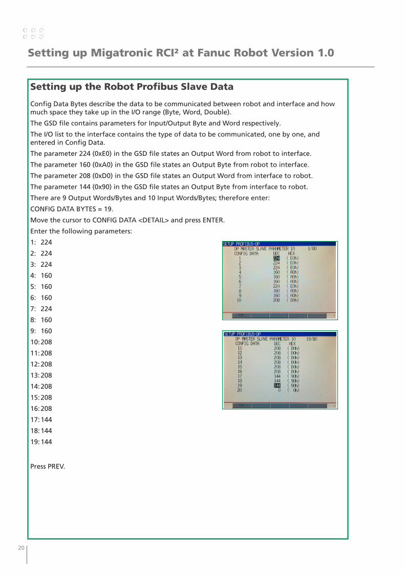
Config Data Bytes describe the data to be communicated between robot and interface and how much space they take up in the I/O range (Byte, Word, Double).
The GSD file contains parameters for Input/Output Byte and Word respectively.
The I/O list to the interface contains the type of data to be communicated, one by one, and entered in Config Data.
The parameter 224 (0xE0) in the GSD file states an Output Word from robot to interface.
The parameter 160 (0xA0) in the GSD file states an Output Byte from robot to interface.
The parameter 208 (0xD0) in the GSD file states an Output Word from interface to robot.
The parameter 144 (0x90) in the GSD file states an Output Byte from interface to robot.
There are 9 Output Words/Bytes and 10 Input Words/Bytes; therefore enter:
CONFIG DATA BYTES = 19.
Move the cursor to CONFIG DATA <DETAIL> and press ENTER.
Enter the following parameters:
1: 224
2: 224
3: 224
4: 160
5: 160
6: 160
7: 224
8: 160
9: 160
10: 208
11: 208
12: 208
13: 208
14: 208
15: 208
16: 208
17: 144
18: 144
19: 144
Press PREV.
20 21
Setting up Migatronic RCI² at Fanuc Robot Version 1.0
Holding Analog Values after Welding
It may be practical if the power source displays the most recently used welding current.
A Fanuc robot sets the analog values at 0 by default after welding.
Set the system variable $AWEPCR[1].AE_HOLD_AO = TRUE to change it.
Press MENU -> NEXT -> SYSTEM -> VARIABLES to find the variables.
Setting I/O at manual Setup
To prevent the robot from trying to set up I/O modules, set the system variables:
$IO_AUTO_CFG = FALSE
$IO_AUTO_UOP = FALSE
Press MENU -> NEXT -> SYSTEM -> VARIABLES to find the variables.
Setting up the Robot Analog Profibus Channels
Press MENU -> I/O -> Profibus
Press OTHER (F3) and select ANALOG I/O.
Set the following parameters:
NUMBER OF DEVICE = 1
ARC WELD SIGNAL = DISABLE
AI SLAVE ADDRESS = 10
AO SLAVE ADDRESS = 10
AI OFFSET ADDRESS = 0
AO OFFSET ADDRESS = 0
NUMBER OF AI = 6
NUMBER OF AO = 3
AI START BIT = 0
AO START BIT = 0
AI VALID/NOVALID BITS 13, 0
AO VALID/NOVALID BITS 13, 0
22 23
Setting up Migatronic RCI² at Fanuc Robot Version 1.0
Vendor ID for Weld Interface
Depending on the robot software, it may be necessary to set the system variable $AWEPRR.$VENDOR_ID = 108.
Failure to do so may result in the following errors:
• The robot runs the programs without starting to weld.
• The alarm “ARC-045 Weld EQ is OFFLINE” is displayed.
• The alarm “ARC-040 EQi Missing I/O” is displayed.
Press MENU -> NEXT -> SYSTEM -> VARIABLES to find the variables.
Go to the Profibus menu and press NEXT -> CLR_ASG (F1) to finalise setting.
Note! This deletes setup of addresses in the DI/DO, AI/AO and GI/GO ranges. So remember to note the setups to be able to restore them.
Restart the robot.
22 23
Setting up Migatronic RCI² at Fanuc Robot Version 1.0
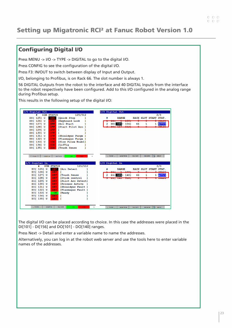
Configuring Digital I/O
Press MENU -> I/O -> TYPE -> DIGITAL to go to the digital I/O.
Press CONFIG to see the configuration of the digital I/O.
Press F3: IN/OUT to switch between display of Input and Output.
I/O, belonging to Profibus, is on Rack 66. The slot number is always 1.
56 DIGITAL Outputs from the robot to the interface and 40 DIGITAL Inputs from the interface to the robot respectively have been configured. Add to this I/O configured in the analog range during Profibus setup.
This results in the following setup of the digital I/O:
The digital I/O can be placed according to choice. In this case the addresses were placed in the DI[101] - DI[156] and DO[101] - DO[140] ranges.
Press Next -> Detail and enter a variable name to name the addresses.
Alternatively, you can log in at the robot web server and use the tools here to enter variable names of the addresses.
24 25
Setting up Migatronic RCI² at Fanuc Robot Version 1.0
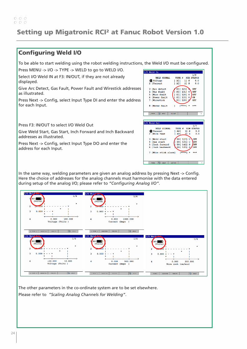
Configuring Weld I/O
To be able to start welding using the robot welding instructions, the Weld I/O must be configured.
Press MENU -> I/O -> TYPE -> WELD to go to WELD I/O.
Select I/O Weld IN at F3: IN/OUT, if they are not already displayed.
Give Arc Detect, Gas Fault, Power Fault and Wirestick addresses as illustrated.
Press Next -> Config, select Input Type DI and enter the address for each Input.
Press F3: IN/OUT to select I/O Weld Out
Give Weld Start, Gas Start, Inch Forward and Inch Backward addresses as illustrated.
Press Next -> Config, select Input Type DO and enter the address for each Input.
In the same way, welding parameters are given an analog address by pressing Next -> Config. Here the choice of addresses for the analog channels must harmonise with the data entered during setup of the analog I/O; please refer to ”Configuring Analog I/O”.
The other parameters in the co-ordinate system are to be set elsewhere.
Please refer to ”Scaling Analog Channels for Welding”.
24 25
Setting up Migatronic RCI² at Fanuc Robot Version 1.0
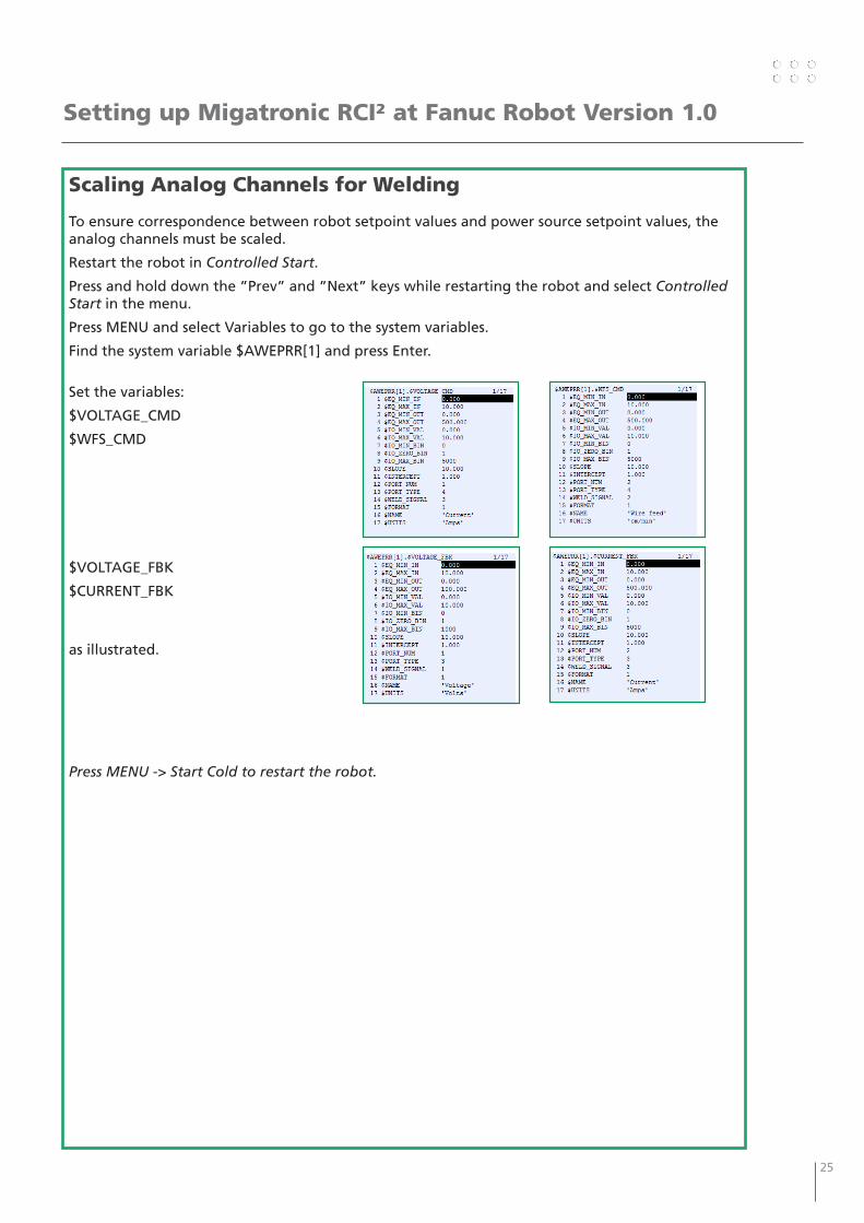
Scaling Analog Channels for Welding
To ensure correspondence between robot setpoint values and power source setpoint values, the analog channels must be scaled.
Restart the robot in Controlled Start.
Press and hold down the ”Prev” and ”Next” keys while restarting the robot and select Controlled Start in the menu.
Press MENU and select Variables to go to the system variables.
Find the system variable $AWEPRR[1] and press Enter.
Set the variables:
$VOLTAGE_CMD
$WFS_CMD
$VOLTAGE_FBK
$CURRENT_FBK
as illustrated.
Press MENU -> Start Cold to restart the robot.
26 27
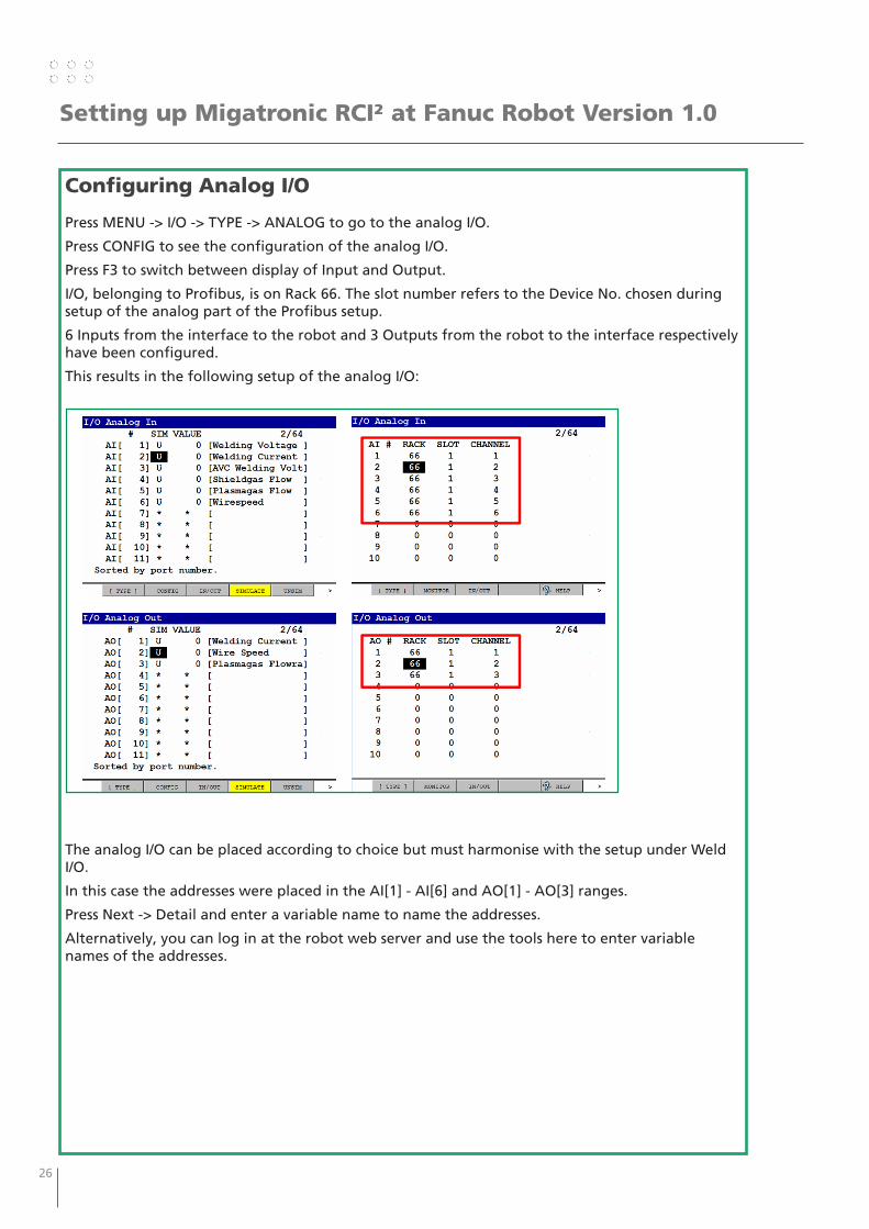
Configuring Analog I/O
Press MENU -> I/O -> TYPE -> ANALOG to go to the analog I/O.
Press CONFIG to see the configuration of the analog I/O.
Press F3 to switch between display of Input and Output.
I/O, belonging to Profibus, is on Rack 66. The slot number refers to the Device No. chosen during setup of the analog part of the Profibus setup.
6 Inputs from the interface to the robot and 3 Outputs from the robot to the interface respectively have been configured.
This results in the following setup of the analog I/O:
The analog I/O can be placed according to choice but must harmonise with the setup under Weld I/O.
In this case the addresses were placed in the AI[1] - AI[6] and AO[1] - AO[3] ranges.
Press Next -> Detail and enter a variable name to name the addresses.
Alternatively, you can log in at the robot web server and use the tools here to enter variable names of the addresses.
Setting up Migatronic RCI² at Fanuc Robot Version 1.0
26 27
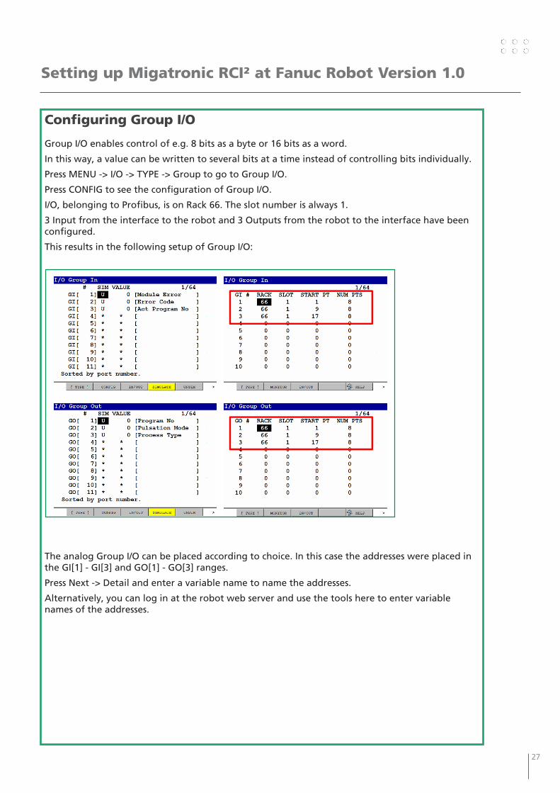
Configuring Group I/O
Group I/O enables control of e.g. 8 bits as a byte or 16 bits as a word.
In this way, a value can be written to several bits at a time instead of controlling bits individually.
Press MENU -> I/O -> TYPE -> Group to go to Group I/O.
Press CONFIG to see the configuration of Group I/O.
I/O, belonging to Profibus, is on Rack 66. The slot number is always 1.
3 Input from the interface to the robot and 3 Outputs from the robot to the interface have been configured.
This results in the following setup of Group I/O:
The analog Group I/O can be placed according to choice. In this case the addresses were placed in the GI[1] - GI[3] and GO[1] - GO[3] ranges.
Press Next -> Detail and enter a variable name to name the addresses.
Alternatively, you can log in at the robot web server and use the tools here to enter variable names of the addresses.
Setting up Migatronic RCI² at Fanuc Robot Version 1.0
28 29
Setting up Migatronic RCI² at Fanuc Robot Version 1.0
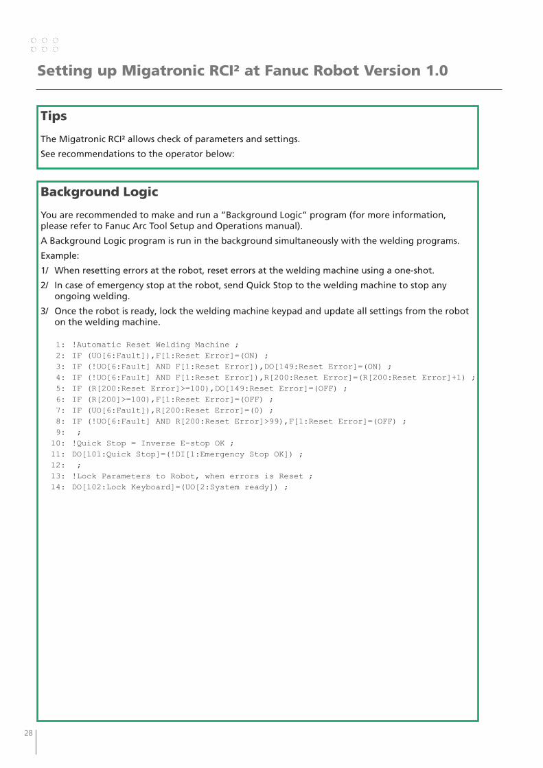
Tips
The Migatronic RCI² allows check of parameters and settings.
See recommendations to the operator below:
Background Logic
You are recommended to make and run a ”Background Logic” program (for more information, please refer to Fanuc Arc Tool Setup and Operations manual).
A Background Logic program is run in the background simultaneously with the welding programs.
Example:
1/ When resetting errors at the robot, reset errors at the welding machine using a one-shot.
2/ In case of emergency stop at the robot, send Quick Stop to the welding machine to stop any ongoing welding.
3/ Once the robot is ready, lock the welding machine keypad and update all settings from the robot on the welding machine.
1: !Automatic Reset Welding Machine ; 2: IF (UO[6:Fault]),F[1:Reset Error]=(ON) ; 3: IF (!UO[6:Fault] AND F[1:Reset Error]),DO[149:Reset Error]=(ON) ; 4: IF (!UO[6:Fault] AND F[1:Reset Error]),R[200:Reset Error]=(R[200:Reset Error]+1) ; 5: IF (R[200:Reset Error]>=100),DO[149:Reset Error]=(OFF) ; 6: IF (R[200]>=100),F[1:Reset Error]=(OFF) ; 7: IF (UO[6:Fault]),R[200:Reset Error]=(0) ; 8: IF (!UO[6:Fault] AND R[200:Reset Error]>99),F[1:Reset Error]=(OFF) ; 9: ; 10: !Quick Stop = Inverse E-stop OK ; 11: DO[101:Quick Stop]=(!DI[1:Emergency Stop OK]) ; 12: ; 13: !Lock Parameters to Robot, when errors is Reset ; 14: DO[102:Lock Keyboard]=(UO[2:System ready]) ;
28 29
Setting up Migatronic RCI² at Fanuc Robot Version 1.0
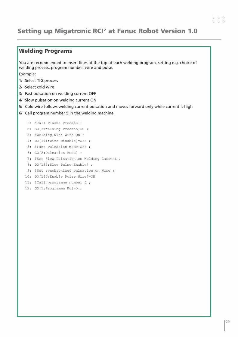
Welding Programs
You are recommended to insert lines at the top of each welding program, setting e.g. choice of welding process, program number, wire and pulse.
Example:
1/ Select TIG process
2/ Select cold wire
3/ Fast pulsation on welding current OFF
4/ Slow pulsation on welding current ON
5/ Cold wire follows welding current pulsation and moves forward only while current is high
6/ Call program number 5 in the welding machine
1: !Call Plasma Process ;
2: GO[3:Welding Process]=0 ;
3: !Welding with Wire ON ;
4: DO[141:Wire Disable]=OFF ;
5: !Fast Pulsation mode OFF ;
6: GO[2:Pulsation Mode] ;
7: !Set Slow Pulsation on Welding Current ;
8: DO[133:Slow Pulse Enable] ;
9: !Set synchronized pulsation on Wire ;
10: DO[144:Enable Pulse Wire]=ON
11: !Call programme number 5 ;
12: GO[1:Programme No]=5 ;

30 31

30 31

DENMARK:
Main officeMIGATRONIC A/SAggersundvej 33, DK-9690 Fjerritslev, DenmarkTel. +45 96 500 600, www.migatronic.com
MIGATRONIC EUROPE:
Great BritainMIGATRONIC WELDING EQUIPMENT LTD21 Jubilee Drive, Belton Park, LoughboroughGB-Leicestershire LE11 5XS, Great BritainTel. +44 01509/267499, www.migatronic.com
FranceMIGATRONIC EQUIPEMENT DE SOUDURE S.A.R.L. Parc Avenir II, 313 Rue Marcel Merieux FR-69530 Brignais, France Tel. +33 04 78 50 65 11, www.migatronic.com
ItalyMIGATRONIC s.r.l. IMPIANTI PER SALDATURA Via Dei Quadri 40, IT-20871 Vimercate (MB), Italy Tel. +39 039 9278093, www.migatronic.com
NorwayMIGATRONIC NORGE AS Industriveien 6, N-3300 Hokksund, Norway Tel. +47 32 25 69 00, www.migatronic.com
Czech RepublicMIGATRONIC CZ a.s. Tolstého 451, CZ-415 03 Teplice 3, Czech Republic Tel. +420 411 135 600, www.migatronic.com
HungaryMIGATRONIC KERESKEDELMI KFT. Futó utca 37. 6. emelet, H-1082 Budapest, Hungary Tel. +36 70 630 0604 www.migatronic.com
MIGATRONIC ASIA:
IndiaMIGATRONIC INDIA PRIVATE LTD.No.22 & 39/20H Sowri Street, IN-Alandur, Chennai – 600 016, IndiaTel. +91 44 2233 0074 www.migatronic.com
MIGATRONIC AUTOMATION A/SKnøsgårdvej 112, DK-9440 Aabybro, DenmarkTel. +45 96 96 27 00, www.migatronic-automation.com
FinlandMIGATRONIC OY c/o Migatronic A/S Aggersundvej 33, DK-9690 Fjerritslev, Finland Tel. +358 0102 176 500, www.migatronic.com
HollandMIGATRONIC NEDERLAND B.V. Ericssonstraat 2, NL-5121 ML Rijen, Holland Tel. +31 (0)161-747840, www.migatronic.com
SwedenMIGATRONIC SVETSMASKINER ABNääs Fabriker, Box 5015,S-448 50 Tollered, Sweden Tel. +46 031 44 00 45, www.migatronic.com
GermanyMIGATRONIC SCHWEISSMASCHINEN GMBH Sandusweg 12, D-35435 Wettenberg-Launsbach, Germany Tel. +49 0641/98284-0, www.migatronic.com
Related Documents