TECHNICAL INFORMATION T 980x and T 982x Dryers (US Models) © 2012 Miele USA

Miele Gas Dryer T9820 Service Manual
May 16, 2015
Service Manual for Miele Gas Dryer T9800, T9820, T98XX (US Model)
Welcome message from author
This document is posted to help you gain knowledge. Please leave a comment to let me know what you think about it! Share it to your friends and learn new things together.
Transcript
TECHNICAL INFORMATION T 980x and T 982x Dryers (US Models)
© 2012 Miele USA

Technical Information
2
T 980x/T 982x
Table of Contents A Warning and Safety Instructions ............................................................ 6
1 General Information ................................................................................... 6 2 Gas Dryers ................................................................................................ 6 3 Fire Danger Due To Excessive Lint ........................................................... 7 4 Restoring the Ground Connection after Dismantling the Front and Side
Panels ........................................................................................................ 7
B Modification History ................................................................................. 8 C Technical Data .......................................................................................... 9 D Layout of Electrical Components ......................................................... 10
1 T 980x ...................................................................................................... 10 2 T 982x ...................................................................................................... 11
010 Casing, Front Panel ............................................................................... 12 1 Technical Data ......................................................................................... 13 4 Service ..................................................................................................... 13
4.1 Lid Removal ................................................................................. 13 4.2 Removing the Front Panel ........................................................... 14 4.3 Side Panel Removal .................................................................... 14
020 Door, Lock .............................................................................................. 16 1 Technical Data ......................................................................................... 17 2 Function ................................................................................................... 17
2.1 Door Lock (A2) ............................................................................. 17 4 Service ..................................................................................................... 17
4.1 Door Removal .............................................................................. 17 4.2 Door Hinge Removal ................................................................... 18 4.3 Installing the Door Hinge ............................................................. 18 4.4 Removing the Door Lock ............................................................. 19
030 Drum, Rear Bearing, Residual Moisture Sensor, Heater Bank ........... 20 1 Technical Data ......................................................................................... 21 2 Function ................................................................................................... 22
2.1 No-Load Detection ....................................................................... 22 2.2 Residual Moisture Measurement ................................................. 22 2.3 Heater Control ............................................................................. 23 2.4 Temperature Limiter with Manual Reset (1F1, 2F1, 3F1) ............ 23 2.5 Drying Air NTC (1R30) ................................................................. 23 2.6 Heater Bank NTC (2R30) ............................................................ 23 2.7 Interior Drum Light (H3/6) ............................................................ 23
3 Fault Repair ............................................................................................. 23 3.1 Temperature Limiter with Manual Reset (F1) Has Tripped .......... 23
4 Service ..................................................................................................... 24 4.1 Heater Bank Removal (T 980x) ................................................... 24 4.2 Rear Bearing Removal ................................................................ 25

Technical Information
3
T 980x/T 982x
4.3 Residual Moisture Sensor Removal ............................................ 27 4.4 Drum Light Removal .................................................................... 27 4.5 Lightbulb Replacement ................................................................ 27
031 Gas Heating (T 982x) .............................................................................. 28 1 Technical Data ......................................................................................... 29 2 Function ................................................................................................... 29
2.1 Gas Unit ....................................................................................... 29 4 Service ..................................................................................................... 33
4.1 Checking the Gas Burner ............................................................ 33 4.2 Removing the Gas Solenoid ........................................................ 35 4.3 Installing the Gas Solenoid Valve ................................................ 36 4.4 Removing the Gas Burner ........................................................... 38 4.5 Installing the Gas Burner ............................................................. 39
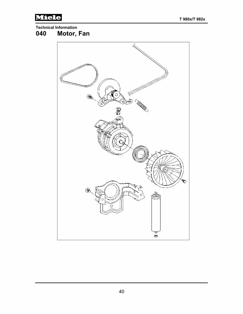
040 Motor, Fan ............................................................................................... 40 1 Technical Data ......................................................................................... 41 4 Service ..................................................................................................... 41
4.1 Fan Impeller Replacement ........................................................... 41 4.2 Motor Replacement ..................................................................... 43
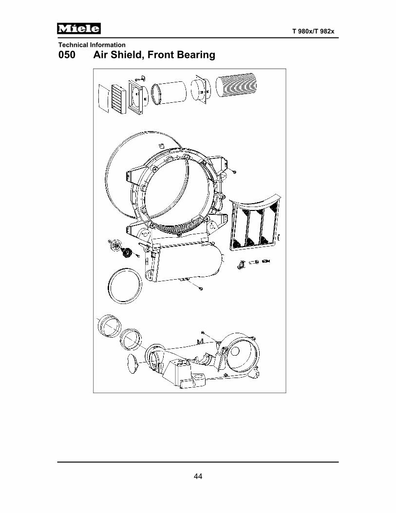
050 Air Shield, Front Bearing ....................................................................... 44 1 Technical Data ......................................................................................... 45 3 Fault Repair ............................................................................................. 45
3.1 Vibration Noises from the Base Plate .......................................... 45 4 Service ..................................................................................................... 46
4.1 Air Shield Removal ...................................................................... 46 4.2 Felt Seal Replacement ................................................................ 47
090 Fascia Panel, Electronic ........................................................................ 49 1 Technical Data ......................................................................................... 50 2 Function ................................................................................................... 50
2.1 Reversing (Electric) (T 980x) ....................................................... 50 2.2 Reversing (Gas) (T 982x) ............................................................ 50 2.3 Dryer Function after a Power Interruption .................................... 50 2.4 Programming Functions ............................................................... 50 2.5 Residual Moisture Sensing .......................................................... 51 2.6 Overriding the Time Control ......................................................... 52 2.7 Insufficient Air Detection .............................................................. 52 2.8 Operating Hours Counter ............................................................. 52 2.9 Low-Voltage Detection ................................................................. 52
3 Fault Repair ............................................................................................. 53 3.1 “End” LED Is Steadily Lit .............................................................. 53 3.2 “Check Filter/Vent” LED Is Steadily Lit ........................................ 53 3.3 “Check Filter/Vent” LED Flashes Rapidly .................................... 54 3.4 “Rotary Iron” LED Flashes ........................................................... 54 3.5 “Hand Iron” LED Flashes ............................................................. 54 3.6 All Program LEDs Flash .............................................................. 55 3.7 F0: No Fault ................................................................................. 55 3.8 F1: Short Circuit in Heater Bank NTC (2R30) .............................. 55
Technical Information
4
T 980x/T 982x
3.9 F2: Open Circuit in Heater Bank NTC (2R30) ............................. 55 3.10 F3: Drying Air NTC (1R30) Short Circuit ...................................... 56 3.11 F4: Drying Air NTC (1R30) Open Circuit ..................................... 57 3.12 F50: Motor Stalls and Heater Is On for 3 Seconds ...................... 57 3.13 F55: Overriding Time Limit Exceeded ......................................... 57 3.14 F66: Air Leakage ......................................................................... 58 3.15 F98: No Gas Ignition (T 982x only) .............................................. 58 3.16 F99: Appliance Lockdown ............................................................ 59 3.17 Laundry Is Overdried/F55 (Overriding Time Limit Exceeded) ..... 59 3.18 Dryer Shuts Itself Off ................................................................... 59 3.19 Top 4 LEDs Flash ........................................................................ 60
4 Service ..................................................................................................... 60 4.1 Programming Mode Summary ..................................................... 60 4.2 Activating/Deactivating the Demonstration Mode ........................ 62 4.3 Service Mode Summary .............................................................. 62 4.4 Removing the Fascia, Electronic and Electronic Support Panel .. 65
100 Electrical System ................................................................................... 66 1 Technical Data ......................................................................................... 67 4 Service ..................................................................................................... 67
4.1 Fuse Replacement (T 980x only) ................................................. 67 4.2 Heater Relay Removal ................................................................. 67 4.3 Pressure Switch B9/3 Removal ................................................... 68
110 Technical Service Bulletins ................................................................... 69 1 T 9820 Gas Dryer Airflow ........................................................................ 69 2 Dryer Venting Information ........................................................................ 69 3 Dryer Will Power Up, Push Buttons Inoperable ....................................... 71 4 How to Diagnose and Repair Specific Internal Ducting Issues ............... 72 5 T 9800, T 9820 Moisture Sensor Testing ................................................ 73 6 Insulation Mats on Some SLC Laundry Machines May Come Loose ..... 73 7 Broken Belts in T 9800 & T 9820 SLC Dryers ......................................... 73 8 F97 and the T 9820 Dryer ....................................................................... 75 9 Laundry Detergent Notice: Purex Complete 3-in1 Laundry Sheets ......... 75 10 SLC Dryers Repeatedly Displaying the Filter/Vent Warning ................... 76 11 T 9822 Flame Control Circuit Update ...................................................... 77 12 SLC Dryers, T 98XX and Low Voltage .................................................... 79 13 SLC Dryer Impeller Update: T 98xx ......................................................... 80 14 Dryer Duct Length ................................................................................... 81
List of Figures Figure D-1: T 980x Component Layout ........................................................................... 10 Figure D-2: T 982x Component Layout ........................................................................... 11 Figure 010-1: Lid Removal .............................................................................................. 13 Figure 010-2: Front Panel Removal ................................................................................ 14 Figure 010-3: Side Panel Removal ................................................................................. 15 Figure 020-1: Door Removal ........................................................................................... 18 Figure 020-2: Door Lock Removal .................................................................................. 19

Technical Information
5
T 980x/T 982x
Figure 030-1: Heater Bank Removal ............................................................................... 25 Figure 030-2: Bearing Housing Attachment .................................................................... 26 Figure 030-3: Rear Bearing ............................................................................................. 26 Figure 031-1: Gas Ignition Schematic ............................................................................. 30 Figure 031-2: Onset of Drying Process, Before Gas Starts to Flow ................................ 30 Figure 031-3: Drying Process, After Gas Has Started to Flow ........................................ 31 Figure 031-4: Drying Process, Flowing Gas Ignites the Flame ....................................... 31 Figure 031-5: Drying Process after Flame Has Gone Out .............................................. 32 Figure 031-6: Port for Measuring Jet Pressure ............................................................... 34 Figure 031-7: Gas Regulation Valve ............................................................................... 35 Figure 031-8: Disconnecting the Gas Regulation Valve ................................................. 36 Figure 031-9: Attaching the Gas Connecting Line to the Gas Regulation Valve ............ 36 Figure 031-10: Tightening the Gas Regulation Valve ..................................................... 37 Figure 031-11: Gas Regulation Valve ............................................................................. 37 Figure 031-12: Gas Regulation Valve ............................................................................. 38 Figure 031-13: Gas Regulation Valve ............................................................................. 39 Figure 040-1: Fan Impeller Removal ............................................................................... 42 Figure 050-1: Sealing Strip Installation ........................................................................... 45 Figure 050-2: Air Shield Removal ................................................................................... 46 Figure 050-3: Felt Seal Installation ................................................................................. 47 Figure 090-1: Removing the Fascia, Electronic, and Electronic Support Panel .............. 65 Figure 100-1: Fuse Replacement .................................................................................... 67 List of Tables Table C-1: General Technical Data ................................................................................... 9 Table 010-1: Casing Technical Data ............................................................................... 13 Table 020-1: Door Technical Data .................................................................................. 17 Table 030-1: Drum Data .................................................................................................. 21 Table 030-2: Heater Data ................................................................................................ 21 Table 030-3: Heater Bank and Drying Air NTC Resistance Values ................................ 22 Table 031-1: Gas Heating Data ...................................................................................... 29 Table 040-1: Fan and Motor Data ................................................................................... 41 Table 050-1: Air Shield Data ........................................................................................... 45 Table 090-1: Technical Data ........................................................................................... 50 Table 090-2: Residual Moisture, Delicates ..................................................................... 51 Table 090-3: Values for Low-Voltage Detection .............................................................. 52 Table 090-4: Programming Mode Summary ................................................................... 61 Table 090-5: Service Mode Summary ............................................................................. 64 Table 100-1: Electrical System Data ............................................................................... 67

Technical Information
6
T 980x/T 982x
A Warning and Safety Instructions 1 General Information
Danger! Danger of high voltages when working on small components.
In a single-board control, as in this appliance's electronic (EPWL 3xx), there is no structural galvanic potential disconnection to the power supply. Therefore, be careful when working on small components, as they may be carrying voltage if the dryer is not disconnected completely from its power supply.
Components with sharp edges may stick out. Wear protective gloves and goggles and use edge shields to prevent cuts by sharp-edged components.
Note: All repairs should be performed by a trained technician in strict
accordance with national, state and local codes. Any repairs or maintenance performed by unqualified personnel could be dangerous. When servicing, modifying, testing or maintaining appliances, all applicable laws, regulations and accident prevention guidelines must be observed.
After work has been completed, a visual as well as an operational check should always be performed.
After work has been completed, do a touch current measurement on machines with a ground connection on all accessible conductive parts that are not grounded.
Before starting any service work, disconnect the dryer from its power source. Even with the appliance switched off, voltage may exist on some components.
2 Gas Dryers
Warning!
Before starting any service or repair work, it is essential to disconnect the dryer from its gas supply.
Service work may only be performed by a technician trained in gas technology, and in keeping with all relevant safety standards.
Prior to the start of service work, check all gas lines and components to make sure that they are sealed.
If there is a gas odor, shut the gas tap. Avoid sparks or any fire source, and air out all rooms.
Technical Information
7
T 980x/T 982x
3 Fire Danger Due To Excessive Lint
Danger!
The dryer must not be operated if there are leaks in the air shield, such as those caused by a defective seal.
If the dryer is operated regardless of these leaks, this will result in heavy lint in the appliance interior. Moisture can make this excessive lint soggy, which will lead to electrical short circuits and possibly fire.
Indications of excessive lint: a poorly maintained dryer, long running time (fixed maximum time has been exceeded), water under the fascia panel.
Remedy: - Remove all lint from the dryer. - Find and repair leaks.
4 Restoring the Ground Connection after Dismantling the
Front and Side Panels
The ground connection for laundry-care appliances is established via screws: raised-head screws with teeth or serrated washers underneath connect the ground lead to the interference-suppression filter, the front panel, the side panels and the housing frame. These screws are different from the rest of the appliance screws in their diameter, type of thread, and type and material of the washer.
The ground connection is made only if the ground screws are screwed into their correct positions during reassembly.
When dismantling the front and side panels, mark the positions of the ground screws. During reassembly, screw the ground screws into these same positions.
To check the proper screw positions, measure the resistance of the ground connection loop.
Technical Information
8
T 980x/T 982x
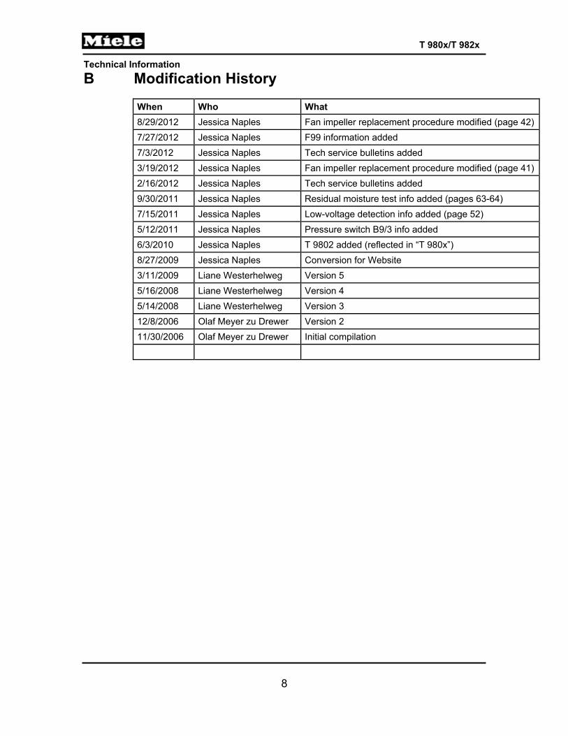
B Modification History
When Who What 8/29/2012 Jessica Naples Fan impeller replacement procedure modified (page 42)7/27/2012 Jessica Naples F99 information added 7/3/2012 Jessica Naples Tech service bulletins added 3/19/2012 Jessica Naples Fan impeller replacement procedure modified (page 41)2/16/2012 Jessica Naples Tech service bulletins added 9/30/2011 Jessica Naples Residual moisture test info added (pages 63-64) 7/15/2011 Jessica Naples Low-voltage detection info added (page 52) 5/12/2011 Jessica Naples Pressure switch B9/3 info added 6/3/2010 Jessica Naples T 9802 added (reflected in “T 980x”) 8/27/2009 Jessica Naples Conversion for Website 3/11/2009 Liane Westerhelweg Version 5 5/16/2008 Liane Westerhelweg Version 4 5/14/2008 Liane Westerhelweg Version 3 12/8/2006 Olaf Meyer zu Drewer Version 2 11/30/2006 Olaf Meyer zu Drewer Initial compilation
Technical Information
9
T 980x/T 982x
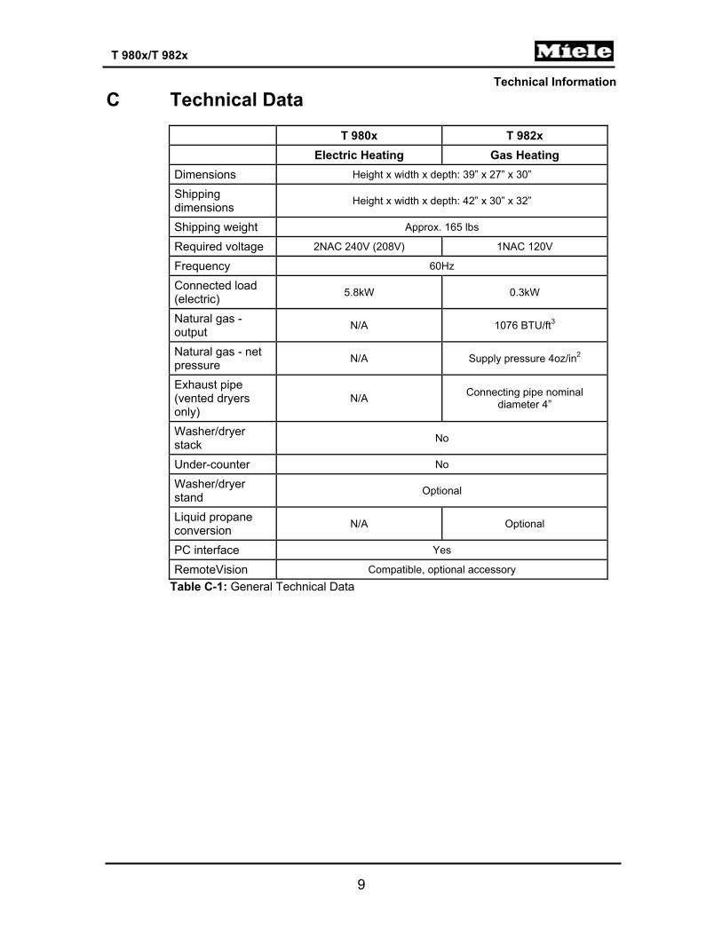
C Technical Data
T 980x T 982x Electric Heating Gas Heating Dimensions Height x width x depth: 39” x 27” x 30”
Shipping dimensions Height x width x depth: 42” x 30” x 32”
Shipping weight Approx. 165 lbs
Required voltage 2NAC 240V (208V) 1NAC 120V
Frequency 60Hz
Connected load (electric) 5.8kW 0.3kW
Natural gas - output N/A 1076 BTU/ft3
Natural gas - net pressure N/A Supply pressure 4oz/in2
Exhaust pipe (vented dryers only)
N/A Connecting pipe nominal diameter 4”
Washer/dryer stack No
Under-counter No
Washer/dryer stand Optional
Liquid propane conversion N/A Optional
PC interface Yes
RemoteVision Compatible, optional accessory Table C-1: General Technical Data

Technical Information
10
T 980x/T 982x
D Layout of Electrical Components 1 T 980x
Figure D-1: T 980x Component Layout 1 (Z/1) Interference suppression capacitor 11 (A2) Door lock 2 (X3/1) Terminal block 12 (B3/1) Residual moisture sensor - Drum rib 3 (F2) Fuse 13 (WLAN) RemoteVision (optional) 4 (1K1/1) Heater relay 14 (C5) Motor capacitor 5 (2K1/1) Heater relay 15 (M5) Motor 6 (3K1/1) Heater relay 16 (1R30) Drying air NTC 7 (B3/1) Residual moisture sensor 17 (3F1) Temperature limiter w/manual reset 8 (1N1) Electronic (EPWL) 18 (2F1) Temperature limiter w/manual reset 9 (H3/6) Drum light 19 (2R30) Heater bank NTC 10 (R1, R2, R3) Heater bank 20 (1F1) Temperature limiter w/manual reset
Technical Information
11
T 980x/T 982x
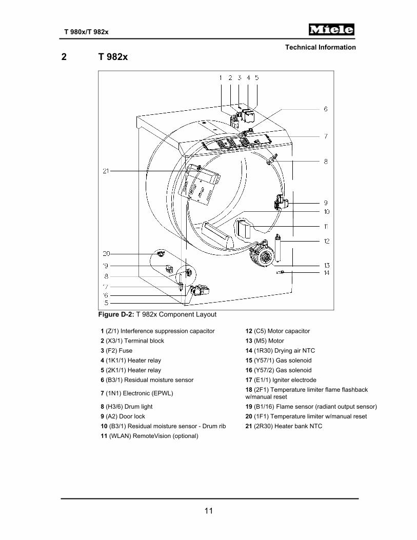
2 T 982x
Figure D-2: T 982x Component Layout 1 (Z/1) Interference suppression capacitor 12 (C5) Motor capacitor 2 (X3/1) Terminal block 13 (M5) Motor 3 (F2) Fuse 14 (1R30) Drying air NTC 4 (1K1/1) Heater relay 15 (Y57/1) Gas solenoid 5 (2K1/1) Heater relay 16 (Y57/2) Gas solenoid 6 (B3/1) Residual moisture sensor 17 (E1/1) Igniter electrode
7 (1N1) Electronic (EPWL) 18 (2F1) Temperature limiter flame flashback w/manual reset
8 (H3/6) Drum light 19 (B1/16) Flame sensor (radiant output sensor)9 (A2) Door lock 20 (1F1) Temperature limiter w/manual reset 10 (B3/1) Residual moisture sensor - Drum rib 21 (2R30) Heater bank NTC 11 (WLAN) RemoteVision (optional)
Technical Information
12
T 980x/T 982x
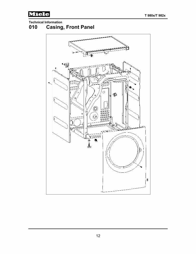
010 Casing, Front Panel
Technical Information
13
T 980x/T 982x
1 Technical Data
Design Upright, frame construction, side walls embossed for reinforcement
Table 010-1: Casing Technical Data
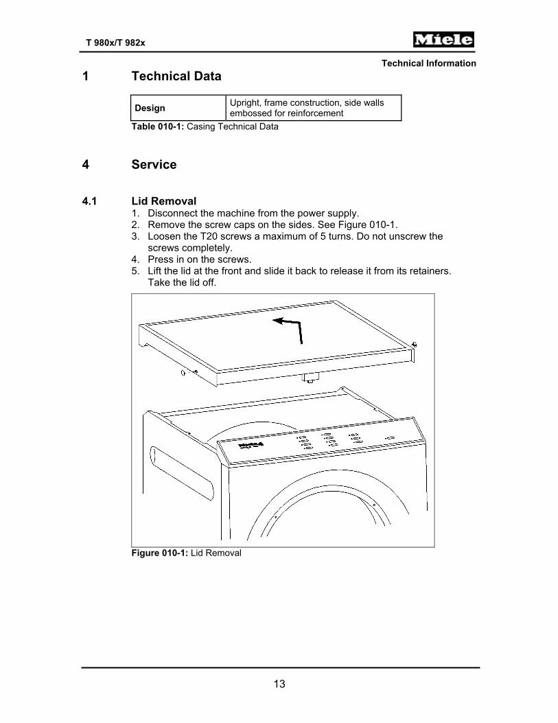
4 Service 4.1 Lid Removal
1. Disconnect the machine from the power supply. 2. Remove the screw caps on the sides. See Figure 010-1. 3. Loosen the T20 screws a maximum of 5 turns. Do not unscrew the
screws completely. 4. Press in on the screws. 5. Lift the lid at the front and slide it back to release it from its retainers.
Take the lid off.
Figure 010-1: Lid Removal

Technical Information
14
T 980x/T 982x
4.2 Removing the Front Panel
1. Disconnect the machine from the power supply. 2. Remove the dryer lid; refer to Section 010-4.1. 3. Remove the fascia, the electronic, and the electronic's support panel; refer
to Section 090-4.4. 4. Open the door. 5. Remove the five T20 screws securing the front of the front panel. See
Figure 010-2, Item 1. 6. Close the door. 7. Remove the two T20 screws securing the top of the front panel. See
Figure 010-2, Item 2. 8. Disconnect the door lock Molex connection. 9. Pull the front panel upwards to remove.
Figure 010-2: Front Panel Removal
4.3 Side Panel Removal
1. Disconnect the machine from the power supply. 2. Remove the lid; refer to Section 010-4.1. 3. Remove the front panel; refer to Section 010-4.2.

Technical Information
15
T 980x/T 982x
4. Remove the side panel retaining screws (nine T20s per panel). See Figure 010-3.
5. Take the side panel(s) off.
Figure 010-3: Side Panel Removal
Note: When re-installing the side panels, ensure that the screws with serrated washers (ground screws) are installed in the correct positions.

Technical Information
16
T 980x/T 982x
020 Door, Lock
Technical Information
17
T 980x/T 982x
1 Technical Data
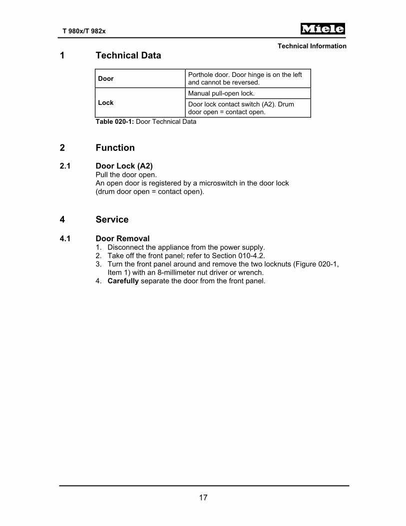
Door Porthole door. Door hinge is on the left and cannot be reversed.
Lock Manual pull-open lock. Door lock contact switch (A2). Drum door open = contact open.
Table 020-1: Door Technical Data 2 Function 2.1 Door Lock (A2)
Pull the door open. An open door is registered by a microswitch in the door lock (drum door open = contact open).
4 Service 4.1 Door Removal
1. Disconnect the appliance from the power supply. 2. Take off the front panel; refer to Section 010-4.2. 3. Turn the front panel around and remove the two locknuts (Figure 020-1,
Item 1) with an 8-millimeter nut driver or wrench. 4. Carefully separate the door from the front panel.

Technical Information
18
T 980x/T 982x
Figure 020-1: Door Removal
4.2 Door Hinge Removal
1. Disconnect the appliance from the power supply. 2. Remove the door; refer to Section 020-4.1. 3. Turn the door over; lay it on a soft mat or cloth so that the door glass
does not get damaged. 4. Remove the two T20 bolts securing the hinge to the door (Figure 020-1, Item 2). 5. Insert a flathead screwdriver under the bottom of the hinge and lift up to
release the hinge from its base on the door (Figure 020-1, Item 3). 4.3 Installing the Door Hinge
1. Open the hinge and slide it back onto its base. 2. Close the hinge and re-secure it with the two T20 bolts.
Note: Make sure that the hinge lines up with the welded seam of the door seal.
Technical Information
19
T 980x/T 982x
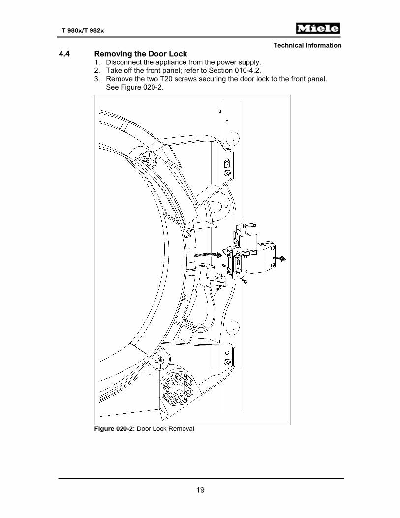
4.4 Removing the Door Lock 1. Disconnect the appliance from the power supply. 2. Take off the front panel; refer to Section 010-4.2. 3. Remove the two T20 screws securing the door lock to the front panel.
See Figure 020-2.
Figure 020-2: Door Lock Removal

Technical Information
20
T 980x/T 982x
030 Drum, Rear Bearing, Residual Moisture Sensor, Heater Bank

Technical Information
21
T 980x/T 982x
1 Technical Data
Maximum load 17.6 lbs (8 kg) Drum volume 48 gal (180L) Drum speed 48 rpm
Table 030-1: Drum Data
Heating mode Electric; for gas, refer to Table 031-1. Heater type Duct heater bank (R1, R2, R3); 3-filament Heater output 5.2kW (1.90kW, 1.70kW, 1.60kW) Temperature sensor Heater bank NTC (2R30) Temperature limiter 3 x 3/4“ temperature limiter (F1) with manual reset, 16A
Drum light (H3/6) E 14 bayonet closure, activation via relay on the electronic (EPWL). USA: 120V, 15W
Table 030-2: Heater Data
Temperature Resistance (kΩ)
°F °C Heater bank NTC (2R30)
Drying air NTC (1R30)
32 0 340 38.0
41 5 261 29.7
50 10 203 23.4
59 15 159 18.6
68 20 126 14.9
77 25 100 12.0
86 30 80.2 9.73
95 35 64.8 7.96
104 40 52.7 6.55
113 45 43.1 5.42
122 50 35.5 4.52
131 55 29.4 3.78
140 60 24.5 3.19
149 65 20.5 2.70
158 70 17.3 2.29
167 75 14.6 1.96
176 80 12.5 1.68
185 85 10.6 1.45
194 90 9.13 1.25
199 93 8.34 1.15
203 95 7.86 1.09
Technical Information
22
T 980x/T 982x
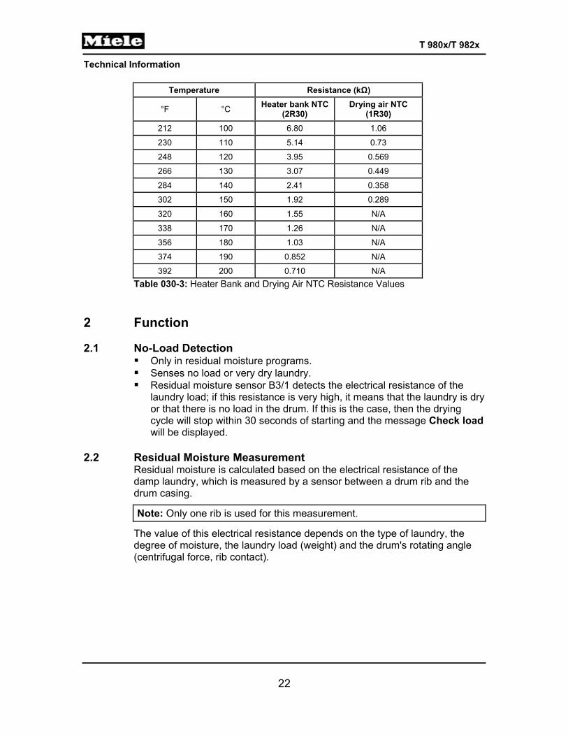
Temperature Resistance (kΩ)
°F °C Heater bank NTC (2R30)
Drying air NTC (1R30)
212 100 6.80 1.06
230 110 5.14 0.73
248 120 3.95 0.569
266 130 3.07 0.449
284 140 2.41 0.358
302 150 1.92 0.289
320 160 1.55 N/A
338 170 1.26 N/A
356 180 1.03 N/A
374 190 0.852 N/A
392 200 0.710 N/A Table 030-3: Heater Bank and Drying Air NTC Resistance Values
2 Function 2.1 No-Load Detection
Only in residual moisture programs. Senses no load or very dry laundry. Residual moisture sensor B3/1 detects the electrical resistance of the
laundry load; if this resistance is very high, it means that the laundry is dry or that there is no load in the drum. If this is the case, then the drying cycle will stop within 30 seconds of starting and the message Check load will be displayed.
2.2 Residual Moisture Measurement
Residual moisture is calculated based on the electrical resistance of the damp laundry, which is measured by a sensor between a drum rib and the drum casing.
Note: Only one rib is used for this measurement.
The value of this electrical resistance depends on the type of laundry, the degree of moisture, the laundry load (weight) and the drum's rotating angle (centrifugal force, rib contact).
Technical Information
23
T 980x/T 982x
2.3 Heater Control Safety function: If the drying air NTC (1R30) is defective, then the heater will not be switched on. The heater is switched off as soon as the heater relay has been running for more than 5 seconds without the motor relay being activated as well. Heater reactivation is delayed by 10 seconds; the auxiliary heater is switched off before, during and after a reversing pause.
2.4 Temperature Limiter with Manual Reset (1F1, 2F1, 3F1) Three closed 3/4-inch temperature limiters, with manual reset via pushbutton, are on the heater bank (T 980x only).
2.5 Drying Air NTC (1R30) If the drying air NTC detects temperatures lower than 5°F (-15°C) or higher than 320°F (160°C), then this NTC is defective.
2.6 Heater Bank NTC (2R30) An open circuit in the heater bank NTC can only be detected at temperatures higher than 57°F (14°C). Since lower temperatures can exist during dryer operation, sensor readings will be evaluated only after the heater has been running for at least 1 minute.
Note: If the heater is defective, fault F4 (heater bank NTC) is issued.
If the heater bank NTC has a short circuit (corresponding to 482°F), the heater will be switched off immediately.
2.7 Interior Drum Light (H3/6) Time controlled: 1 second after the door is opened. Shutoff delay: 5 minutes. The light is always switched off when the door is closed.
3 Fault Repair 3.1 Temperature Limiter with Manual Reset (F1) Has Tripped
Symptom: The temperature limiter has tripped repeatedly.
Cause: Clogged lint screen. Remedy: Clean the lint screen.
Technical Information
24
T 980x/T 982x
Cause: Clogged air duct vents. Remedy: Clean the air duct openings.
Cause: Clogged air vents/exhaust vents. Remedy: Clean the air vents/exhaust vents.
Cause: Drum is sluggish. Remedy: 1. Check the front bearing seals (front and back needle felting) for correct
position. 2. Check and adjust the bearing of the front support rollers.
Cause: Intermediate (small) drive is faulty. Remedy: Check the intermediate drive for dirt deposits, wear and tear, and tension (also check the tension spring).
Cause: Drum belt is faulty. Remedy: Check the drum belt for dirt deposits, wear and tear, and tension (tension spring on intermediate drive).
4 Service 4.1 Heater Bank Removal (T 980x)
1. Disconnect the appliance from the power supply. 2. Remove the dryer lid; refer to Section 010-4.1. 3. Remove the front panel; refer to Section 010-4.2. 4. Remove the right side panel; refer to Section 010-4.3. 5. Remove the four T20 screws securing the service panel door at the back
of the dryer (Figure 030-1, Item 1). 6. Remove the wiring harness from the cable clip inside the rear panel of the
appliance. 7. Disconnect all electrical connections. 8. Remove the two T20s securing the heater bank (Figure 030-1, Item 2)
and detach the heater bank to remove.
Technical Information
25
T 980x/T 982x
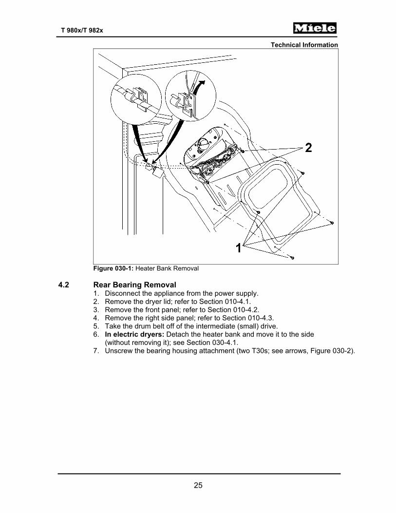
Figure 030-1: Heater Bank Removal
4.2 Rear Bearing Removal
1. Disconnect the appliance from the power supply. 2. Remove the dryer lid; refer to Section 010-4.1. 3. Remove the front panel; refer to Section 010-4.2. 4. Remove the right side panel; refer to Section 010-4.3. 5. Take the drum belt off of the intermediate (small) drive. 6. In electric dryers: Detach the heater bank and move it to the side
(without removing it); see Section 030-4.1. 7. Unscrew the bearing housing attachment (two T30s; see arrows, Figure 030-2).
Technical Information
26
T 980x/T 982x
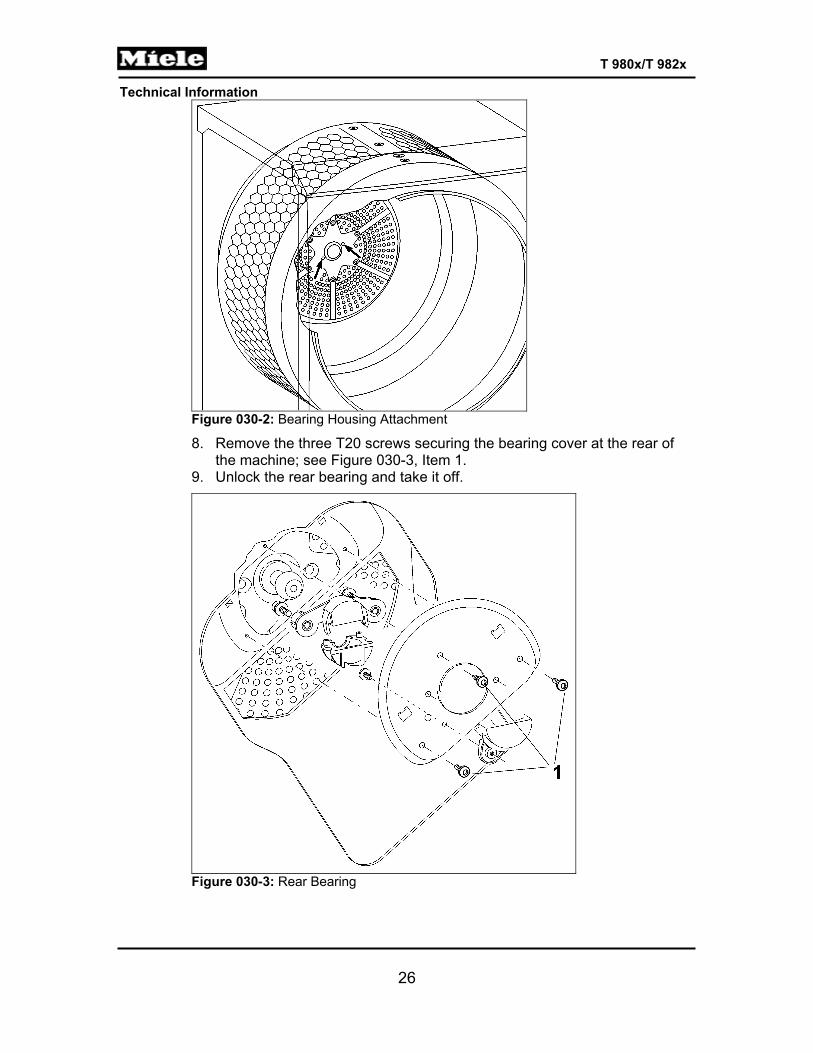
Figure 030-2: Bearing Housing Attachment
8. Remove the three T20 screws securing the bearing cover at the rear of the machine; see Figure 030-3, Item 1.
9. Unlock the rear bearing and take it off.
Figure 030-3: Rear Bearing
Technical Information
27
T 980x/T 982x
4.3 Residual Moisture Sensor Removal 1. Disconnect the appliance from the power supply. 2. Remove the dryer lid; refer to Section 010-4.1.
Note: The residual moisture sensor is located at Figure D-1, Item 7.
3. Unhook the spring. 4. Press up on the plastic support to free it from the retainers on the cable
guide on the side panel. 5. Disconnect the two-pin Molex connector from the electronic, as well as
the ground wire from the rear panel of the appliance. 4.4 Drum Light Removal
1. Disconnect the machine from the power supply. 2. Remove the front panel. See Section 010-4.2. 3. Twist the light half a turn (180° counterclockwise) and remove it from its
housing on the air shield (see Figure D-1, Item 9, for location). 4. Free the two-pin wiring harness from the zip tie on the air shield (cut the
zip tie, if necessary) and the cable guide on the metal support plate. 4.5 Lightbulb Replacement
See the operating manual.
Technical Information
28
T 980x/T 982x
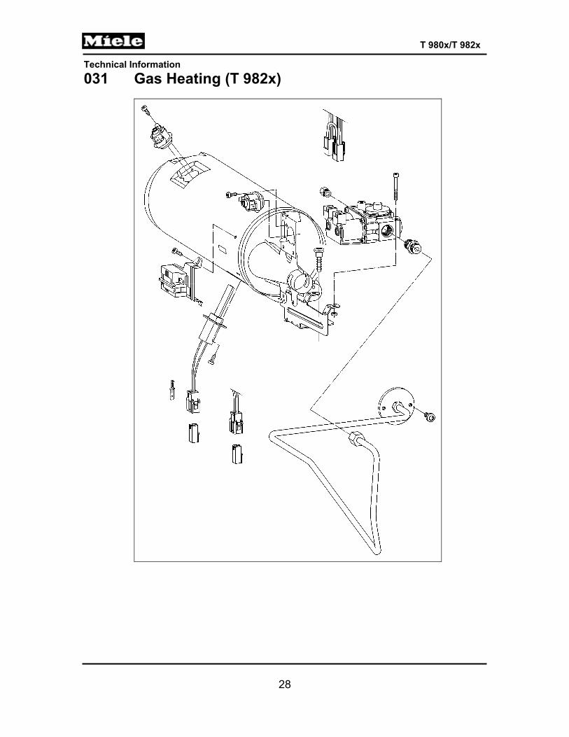
031 Gas Heating (T 982x)

Technical Information
29
T 980x/T 982x
1 Technical Data
Heating mode Gas; for electric, refer to Table 030-2. Gas burner Gas burner, pipe configuration, 5.7kW. Model: Venturi Natural-gas version - output 5.4kW ANSI Gas A, 1076 BTU/ft3
Temperature sensor Heater bank NTC (2R30)
Temperature limiter Two 3/4” bi-metal temperature limiters (1F1, 2F1) with manual reset, 16A, 248°F/212°F ± 5 K
Safety time; refer to Section 031-2.1.3 ≤ 90 seconds
Table 031-1: Gas Heating Data 2 Function 2.1 Gas Unit 2.1.1 Gas Solenoid Valve (Y57)
In gas dryers, gas solenoid valve Y57 is activated via heater relays 1K1/1 and 2K1/1.
Gas solenoid valve Y57 consists of gas solenoid valves Y57/1 and Y57/2. Gas solenoid valve Y57/1, in turn, consists of a maintaining coil and a
booster coil. Gas solenoid valve Y57 only opens when both solenoid valves (Y57/1
and Y57/2) are opened. Gas solenoid valve Y57/1 only opens when its maintaining and booster
coils carry voltage. Once gas solenoid valve Y57/1 is open, it remains in this state as long as
its maintaining coil carries voltage.
Technical Information
30
T 980x/T 982x
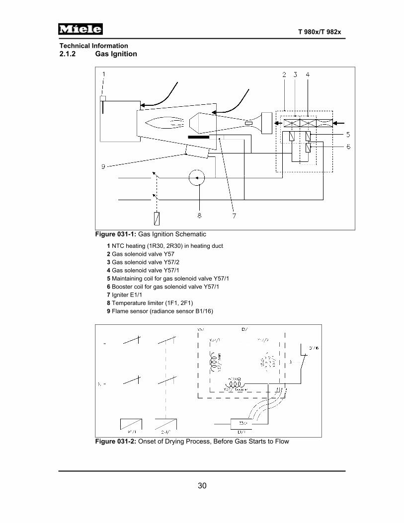
2.1.2 Gas Ignition
Figure 031-1: Gas Ignition Schematic
1 NTC heating (1R30, 2R30) in heating duct 2 Gas solenoid valve Y57 3 Gas solenoid valve Y57/2 4 Gas solenoid valve Y57/1 5 Maintaining coil for gas solenoid valve Y57/1 6 Booster coil for gas solenoid valve Y57/1 7 Igniter E1/1 8 Temperature limiter (1F1, 2F1) 9 Flame sensor (radiance sensor B1/16)
Figure 031-2: Onset of Drying Process, Before Gas Starts to Flow
Technical Information
31
T 980x/T 982x
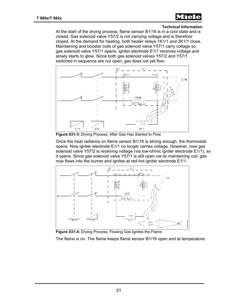
At the start of the drying process, flame sensor B1/16 is in a cool state and is closed. Gas solenoid valve Y57/2 is not carrying voltage and is therefore closed. At the demand for heating, both heater relays 1K1/1 and 2K1/1 close. Maintaining and booster coils of gas solenoid valve Y57/1 carry voltage so gas solenoid valve Y57/1 opens; igniter electrode E1/1 receives voltage and slowly starts to glow. Since both gas solenoid valves Y57/2 and Y57/1 switched in sequence are not open, gas does not yet flow.
Figure 031-3: Drying Process, After Gas Has Started to Flow
Once the heat radiance on flame sensor B1/16 is strong enough, the thermostat opens. Now igniter electrode E1/1 no longer carries voltage. However, now gas solenoid valve Y57/2 is receiving voltage (via low-ohmic igniter electrode E1/1), so it opens. Since gas solenoid valve Y57/1 is still open via its maintaining coil, gas now flows into the burner and ignites at red-hot igniter electrode E1/1.
Figure 031-4: Drying Process, Flowing Gas Ignites the Flame
The flame is on. The flame keeps flame sensor B1/16 open and at temperature.

Technical Information
32
T 980x/T 982x
Figure 031-5: Drying Process after Flame Has Gone Out
If the flame goes out, the sluggishness of flame sensor B1/16 will cause gas to continue flowing until gas solenoid valve Y57/2 closes and stops the gas flow. For safety time, refer to Section 031-2.1.3. If the burner overheats, the thermostat/temperature limiter (1F1, 2F1) interrupts the voltage circuit of gas solenoid Y57, so gas solenoids Y57/1 and Y57/2 shut off.
2.1.3 Safety Time The safety time is the time span between the point when the flame goes out and the gas supply shuts off.
2.1.4 Heater Bank NTC (2R30) Heater bank NTC 2R30 is located at the reflective plate, under the back service panel. For NTC resistance values, refer to Table 030-3.
2.1.5 Temperature Limiters (1F1, 2F1) Two ¾” bi-metal temperature limiters (1F1, 2F1) with manual reset at the burner. The bi-metal temperature limiter 1F1 at the burner exit detects any overheating of the burner due to insufficient air or air leakage. The bi-metal temperature limiter 2F1 at the burner entrance detects any flame flashback.

Technical Information
33
T 980x/T 982x
4 Service
Note: When working on a gas dryer (T 982x), the drum door must be closed. If the front panel is off, the opening to the drum needs to be blocked off.
4.1 Checking the Gas Burner
Danger! Danger of burning. Gas will ignite at igniter electrode E1/1 once the electrode has received voltage and begun to glow.
Note: There is a measuring port for jet pressure at the gas valve, but no measuring port for the gas-tapping pressure.
1. Test the gas resting pressure (target value: 4 ounces per square inch
(17.4 millibars)).
Note: Gas resting pressure is the pressure of gas that is stationary, without tapping the gas.
2. Check the gas-tapping pressure (target value: 1.9 ounces per square inch (8.2 millibars)).
Note: Gas-tapping pressure is the gas flow pressure at the connection of the dryer, with the burner running. This pressure can only be measured while operating, with a functional burner.
3. Check the temperature limiters (1F1, 2F1) for continuity.
Warning! If the front temperature limiter (2F1) has tripped, assume that the burner and its connecting cables have sustained thermal damage by a flashback. In this case, replace the burner and its connecting cables. At the same time, check the general area of the burner for heat damage.
Warning! If the rear temperature limiter (1F1) has tripped, check the exhaust air duct and the fan for heat damage.

Technical Information
34
T 980x/T 982x
4. Check the function of the exhaust air duct and the fan. 5. Check the flame sensor (B1/16) for continuity (at room temperature).
Danger! Danger of high voltage when working on the appliance while it's opened. Components carry voltage.
6. Start the drying program. 7. Check if the heater relays (1K1/1) and (2K1/1) close. 8. Check if the maintaining coil and the booster coil of gas solenoid Y57/1
are receiving voltage, and if the gas solenoid opens audibly.
Note: No gas flow since gas solenoid Y57/2 is closed.
Figure 031-6: Port for Measuring Jet Pressure
9. Check that no gas flows out, and measure the gas-tapping pressure; refer to Figure 031-6.
10. Check if igniter electrode E1/1 carries voltage and starts glowing. 11. With igniter electrode E1/1 red-hot, check if flame sensor B1/16 opens. 12. Now check if gas solenoid valve Y57/2 receives voltage via low-ohmic
igniter electrode E1/1 and opens. For jet pressure, refer to Figure 031-6. 13. Check if gas solenoid Y57/1 continues to be open via the maintaining coil
of the gas solenoid. 14. With the flame gone out, check if gas solenoid Y57/2 closes flame sensor
B1/16 within the safety time and shuts off the gas stream. For safety time, refer to Section 031-2.1.3.
Technical Information
35
T 980x/T 982x
4.2 Removing the Gas Solenoid
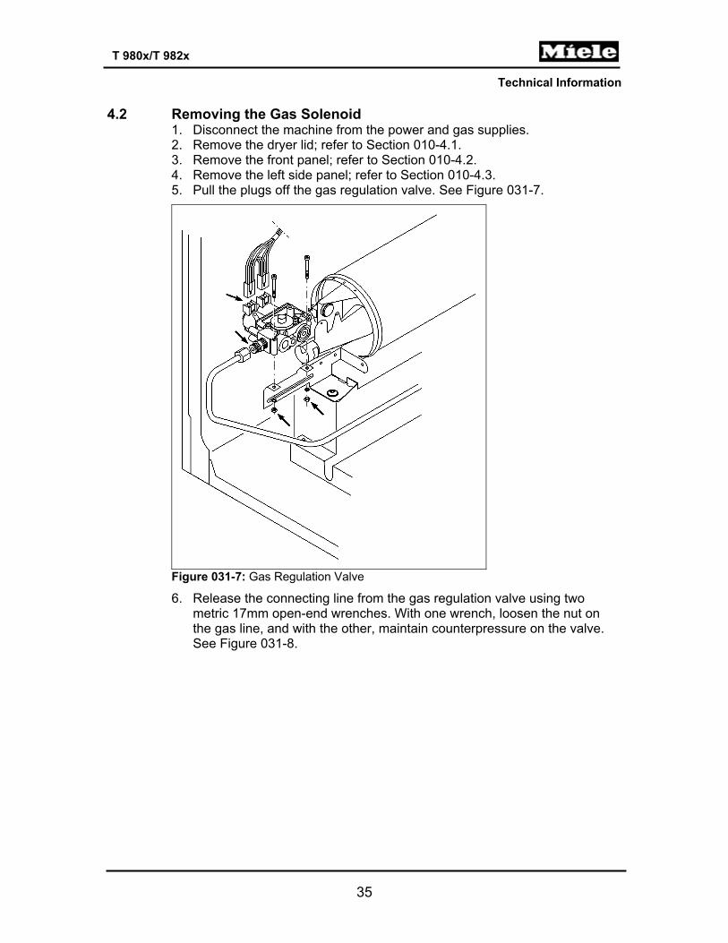
1. Disconnect the machine from the power and gas supplies. 2. Remove the dryer lid; refer to Section 010-4.1. 3. Remove the front panel; refer to Section 010-4.2. 4. Remove the left side panel; refer to Section 010-4.3. 5. Pull the plugs off the gas regulation valve. See Figure 031-7.
Figure 031-7: Gas Regulation Valve
6. Release the connecting line from the gas regulation valve using two metric 17mm open-end wrenches. With one wrench, loosen the nut on the gas line, and with the other, maintain counterpressure on the valve. See Figure 031-8.
Technical Information
36
T 980x/T 982x
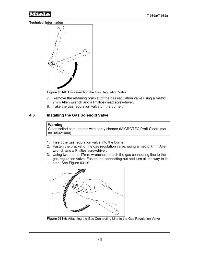
Figure 031-8: Disconnecting the Gas Regulation Valve
7. Remove the retaining bracket of the gas regulation valve using a metric 7mm Allen wrench and a Phillips-head screwdriver.
8. Take the gas regulation valve off the burner. 4.3 Installing the Gas Solenoid Valve
Warning! Clean soiled components with spray cleaner (MICROTEC Profi-Clean, mat. no. 05321000).
1. Insert the gas regulation valve into the burner. 2. Fasten the bracket of the gas regulation valve, using a metric 7mm Allen
wrench and a Phillips screwdriver. 3. Using two metric 17mm wrenches, attach the gas connecting line to the
gas regulation valve. Fasten the connecting nut and turn all the way to its stop. See Figure 031-9.
Figure 031-9: Attaching the Gas Connecting Line to the Gas Regulation Valve
Technical Information
37
T 980x/T 982x
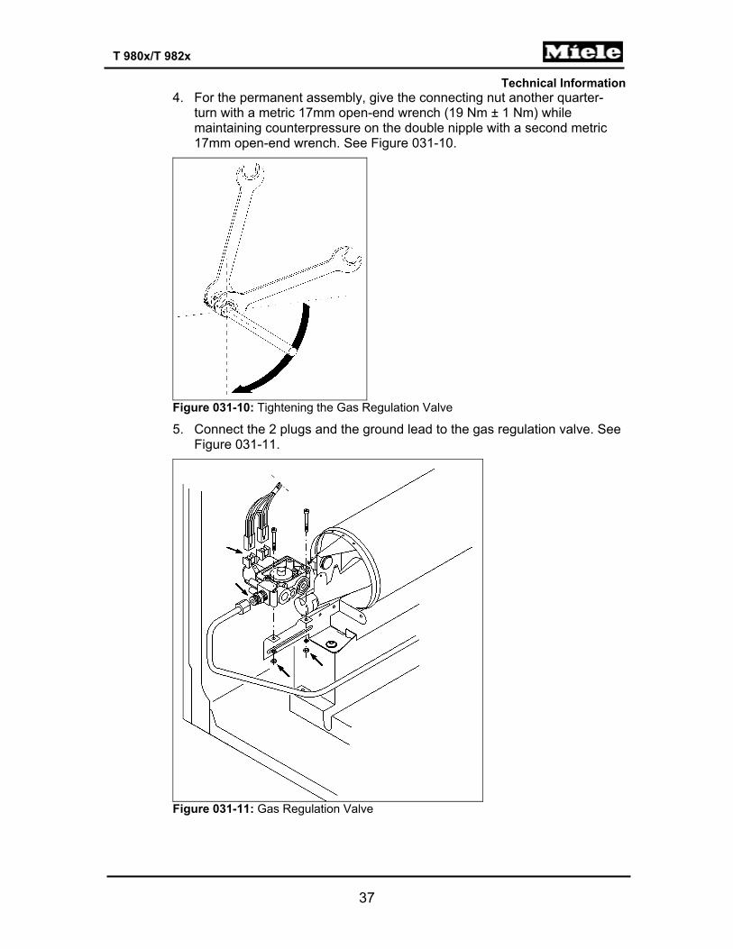
4. For the permanent assembly, give the connecting nut another quarter-turn with a metric 17mm open-end wrench (19 Nm ± 1 Nm) while maintaining counterpressure on the double nipple with a second metric 17mm open-end wrench. See Figure 031-10.
Figure 031-10: Tightening the Gas Regulation Valve
5. Connect the 2 plugs and the ground lead to the gas regulation valve. See Figure 031-11.
Figure 031-11: Gas Regulation Valve

Technical Information
38
T 980x/T 982x
6. Attach the right side panel. 7. Attach the front panel. 8. Attach the fascia panel. 9. Attach the dryer lid.
Warning! Perform an electrical safety check. Perform a gas safety check. With the system under normal gas pressure, check the gas connections for a tight seal using a spray such as Leak Test. Check the dryer for correct function.
4.4 Removing the Gas Burner
1. Disconnect the machine from the power and gas supplies. 2. Remove the dryer lid; refer to Section 010-4.1. 3. Remove the front panel; refer to Section 010-4.2. 4. Remove the left side panel; refer to Section 010-4.3. 5. Remove the gas solenoid valve; refer to Section 031-4.2. 6. Loosen the burner retaining screw and take the burner off. See Figure 031-12.
Figure 031-12: Gas Regulation Valve
Technical Information
39
T 980x/T 982x
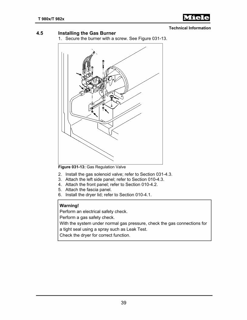
4.5 Installing the Gas Burner 1. Secure the burner with a screw. See Figure 031-13.
Figure 031-13: Gas Regulation Valve
2. Install the gas solenoid valve; refer to Section 031-4.3. 3. Attach the left side panel; refer to Section 010-4.3. 4. Attach the front panel; refer to Section 010-4.2. 5. Attach the fascia panel. 6. Install the dryer lid; refer to Section 010-4.1.
Warning! Perform an electrical safety check. Perform a gas safety check. With the system under normal gas pressure, check the gas connections for a tight seal using a spray such as Leak Test. Check the dryer for correct function.
Technical Information
40
T 980x/T 982x
040 Motor, Fan
Technical Information
41
T 980x/T 982x
1 Technical Data
Vented Dryer Gas Dryer Motor, fan Approx. motor rating 400W Fan, volume flow, free flowing
Approx. 200cfm (66' pipe, d = 4”, straight-run without additional structures)
Table 040-1: Fan and Motor Data 4 Service 4.1 Fan Impeller Replacement
1. Disconnect the machine from the power supply. 2. Remove the dryer lid; refer to Section 010-4.1. 3. Remove the fascia, the electronic, and the electronic's support panel; refer
to Section 090-4.4. 4. Remove the front panel; refer to Section 010-4.2. 5. Remove the right side panel; refer to Section 010-4.3. 6. Remove the air shield; see Section 050-4.1. 7. Prop up the front of the drum to reduce any strain on the rear bearing. 8. Hold the rear motor shaft (behind the fan) in place with a 13-millimeter
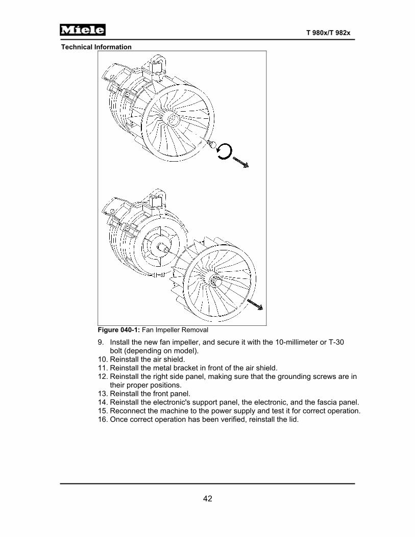
wrench. Loosen the fan impeller bolt by turning it counterclockwise using a 10-millimeter or a T-30 socket, depending on model (use a ratcheting wrench with an extension to generate enough torque). See Figure 040-1. Pull the impeller forward to remove.
Technical Information
42
T 980x/T 982x
Figure 040-1: Fan Impeller Removal
9. Install the new fan impeller, and secure it with the 10-millimeter or T-30 bolt (depending on model).
10. Reinstall the air shield. 11. Reinstall the metal bracket in front of the air shield. 12. Reinstall the right side panel, making sure that the grounding screws are in
their proper positions. 13. Reinstall the front panel. 14. Reinstall the electronic's support panel, the electronic, and the fascia panel. 15. Reconnect the machine to the power supply and test it for correct operation. 16. Once correct operation has been verified, reinstall the lid.
Technical Information
43
T 980x/T 982x
4.2 Motor Replacement 1. Disconnect the machine from the power supply. 2. Remove the dryer lid; refer to Section 010-4.1. 3. Remove the fascia, the electronic, and the electronic's support panel; refer to
Section 090-4.4. 4. Remove the front panel; refer to Section 010-4.2. 5. Remove the right side panel; refer to Section 010-4.3. 6. Unhook the spring from the intermediate drive notch (located directly below the
drum belt). 7. Release the drum belt. 8. Prop up the front of the drum to reduce any strain on the rear bearing. 9. Remove the air shield; see Section 050-4.1. 10. Remove the fan impeller. See Section 040-4.1. 11. Remove the T30 screw securing the left rear of the motor bracket, and the T30
screw securing the bottom of the motor bracket. Disconnect the Molex connection and the ground wire (use needlenose pliers, if necessary).
12. Lift the motor up and out from the right side of the machine. 13. Install the new motor. Secure the motor bracket with the two T30 screws.
Reconnect the Molex connection and the ground wire. 14. Reinstall the fan impeller. 15. Reinstall the air shield. 16. Reinstall the heater bank. 17. Reinstall the drum, the rear bearing, and the drum belt. 18. Hook the tension spring back onto the intermediate drive notch, using
needlenose pliers if necessary. 19. Reposition the drum belt and spin the drum to ensure proper installation on the
motor drive. 20. Reinstall the metal bracket in front of the air shield. 21. Reinstall the right side panel, making sure that the grounding screws are in
their proper positions. 22. Reinstall the front panel. 23. Reinstall the electronic's support panel, the electronic, and the fascia panel. 24. Reconnect the machine to the power supply and test it for correct operation. 25. Once correct operation has been verified, reinstall the lid.
Technical Information
44
T 980x/T 982x
050 Air Shield, Front Bearing

Technical Information
45
T 980x/T 982x
1 Technical Data
Filter Flat filter Drying air temperature sensor NTC (1R30)
Table 050-1: Air Shield Data 3 Fault Repair 3.1 Vibration Noises from the Base Plate
Cause: The exhaust module vibrates during appliance operation, which causes vibrations in the base plate of the appliance. A buzzing or humming noise is generated.
Remedy: Insert a sealing strip (mat. no. 06808080) between the exhaust module and the base plate: 1. Disconnect the machine from the power supply. 2. Remove the front panel; see Section 010-4.2 3. Place a thin flathead screwdriver between the exhaust module and the
base plate. 4. Use a thicker screwdriver to widen the gap between the exhaust module
and the base plate. 5. Remove the protective film from the sealing strip. 6. Insert the sealing strip into the gap and adhere it under the groove under
the exhaust module, making sure that the strip is centered. 7. Remove the thin screwdriver. 8. Replace the front panel.
Figure 050-1: Sealing Strip Installation
Technical Information
46
T 980x/T 982x
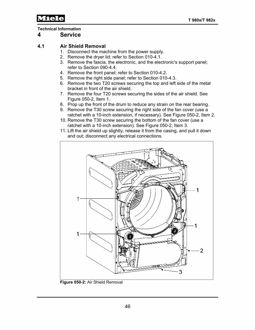
4 Service 4.1 Air Shield Removal
1. Disconnect the machine from the power supply. 2. Remove the dryer lid; refer to Section 010-4.1. 3. Remove the fascia, the electronic, and the electronic's support panel;
refer to Section 090-4.4. 4. Remove the front panel; refer to Section 010-4.2. 5. Remove the right side panel; refer to Section 010-4.3. 6. Remove the two T20 screws securing the top and left side of the metal
bracket in front of the air shield. 7. Remove the four T20 screws securing the sides of the air shield. See
Figure 050-2, Item 1. 8. Prop up the front of the drum to reduce any strain on the rear bearing. 9. Remove the T30 screw securing the right side of the fan cover (use a
ratchet with a 10-inch extension, if necessary). See Figure 050-2, Item 2. 10. Remove the T30 screw securing the bottom of the fan cover (use a
ratchet with a 10-inch extension). See Figure 050-2, Item 3. 11. Lift the air shield up slightly, release it from the casing, and pull it down
and out; disconnect any electrical connections.
Figure 050-2: Air Shield Removal
Technical Information
47
T 980x/T 982x
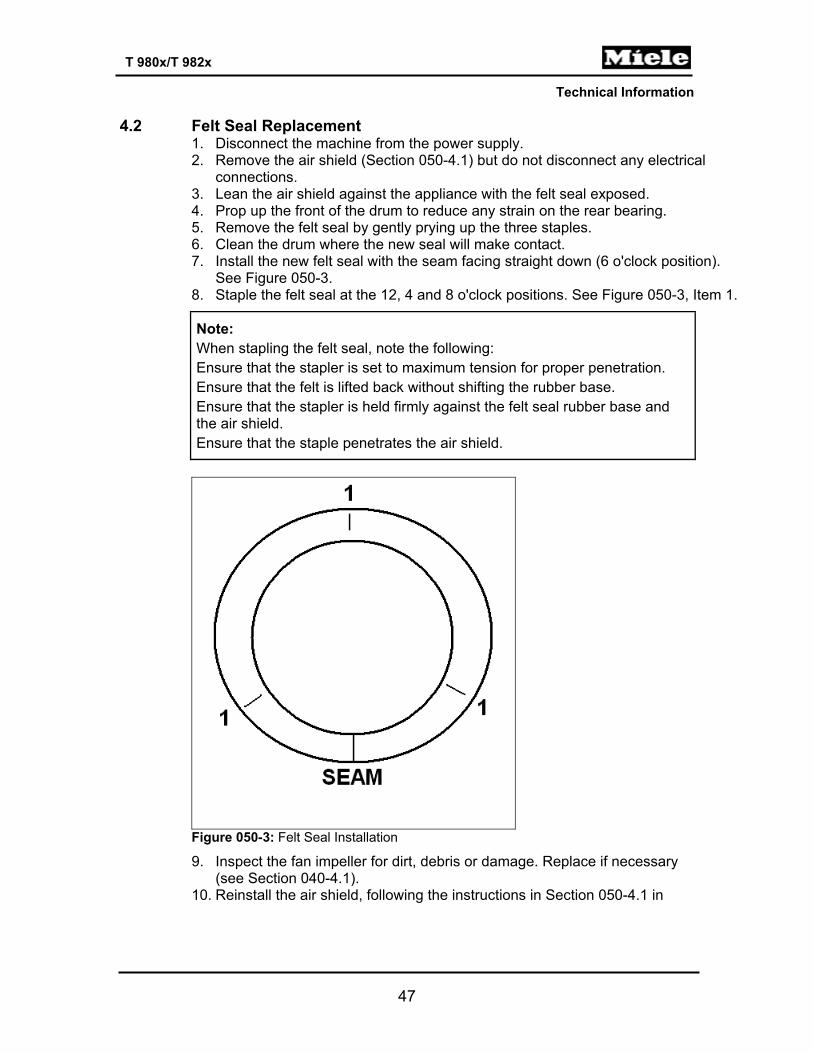
4.2 Felt Seal Replacement
1. Disconnect the machine from the power supply. 2. Remove the air shield (Section 050-4.1) but do not disconnect any electrical
connections. 3. Lean the air shield against the appliance with the felt seal exposed. 4. Prop up the front of the drum to reduce any strain on the rear bearing. 5. Remove the felt seal by gently prying up the three staples. 6. Clean the drum where the new seal will make contact. 7. Install the new felt seal with the seam facing straight down (6 o'clock position).
See Figure 050-3. 8. Staple the felt seal at the 12, 4 and 8 o'clock positions. See Figure 050-3, Item 1.
Note: When stapling the felt seal, note the following: Ensure that the stapler is set to maximum tension for proper penetration. Ensure that the felt is lifted back without shifting the rubber base. Ensure that the stapler is held firmly against the felt seal rubber base and the air shield. Ensure that the staple penetrates the air shield.
Figure 050-3: Felt Seal Installation
9. Inspect the fan impeller for dirt, debris or damage. Replace if necessary (see Section 040-4.1).
10. Reinstall the air shield, following the instructions in Section 050-4.1 in

Technical Information
48
T 980x/T 982x
reverse order. 11. Reinstall the metal bracket in front of the air shield. 12. Hook the tension spring back onto the intermediate drive notch, using
needlenose pliers if necessary. 13. Reinstall the right side panel, making sure that the grounding screws are in
their proper positions. 14. Reinstall the front panel. 15. Reinstall the electronic's support panel, the electronic, and the fascia panel. 16. Reconnect the machine to the power supply and test it for correct
operation. 17. Once correct operation has been verified, reinstall the lid.

Technical Information
49
T 980x/T 982x
090 Fascia Panel, Electronic
Technical Information
50
T 980x/T 982x
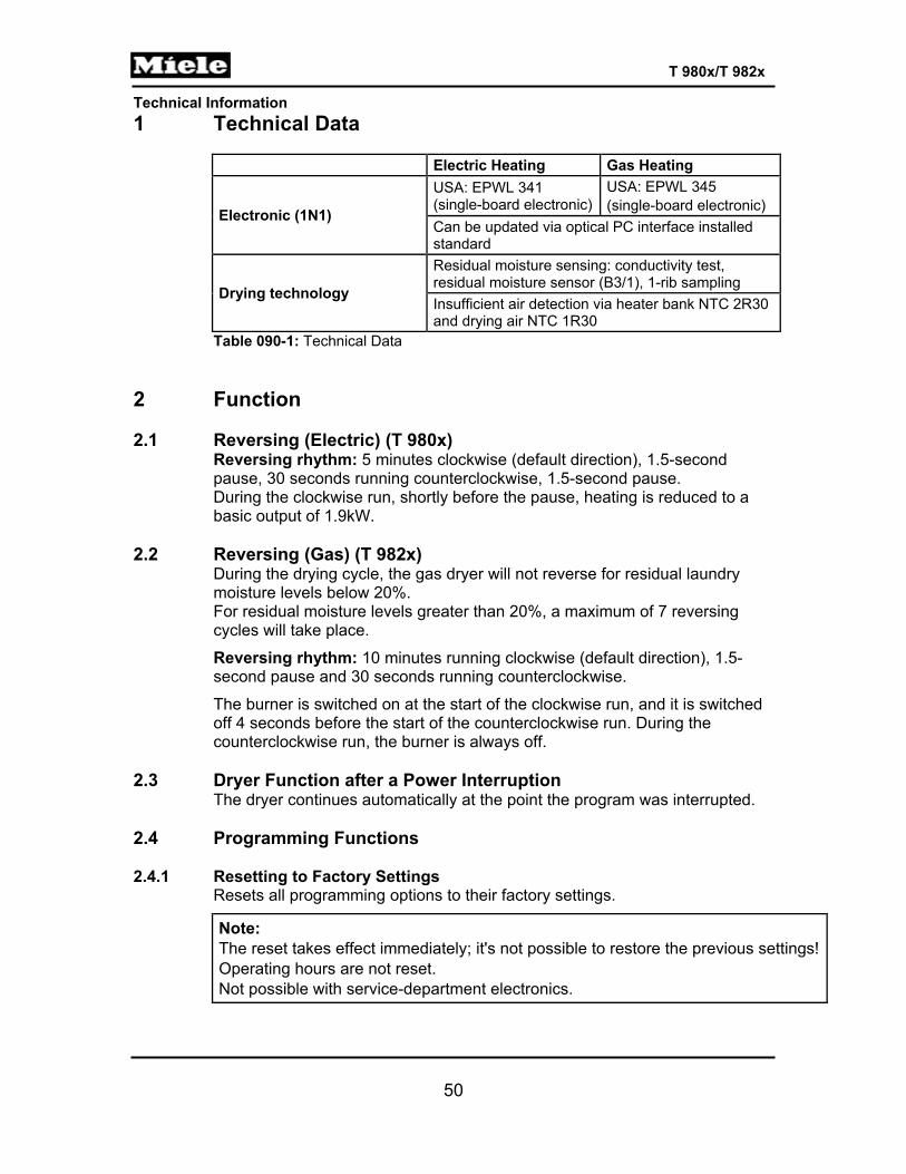
1 Technical Data
Electric Heating Gas Heating
Electronic (1N1)
USA: EPWL 341 (single-board electronic)
USA: EPWL 345 (single-board electronic)
Can be updated via optical PC interface installed standard
Drying technology
Residual moisture sensing: conductivity test, residual moisture sensor (B3/1), 1-rib sampling Insufficient air detection via heater bank NTC 2R30 and drying air NTC 1R30
Table 090-1: Technical Data 2 Function 2.1 Reversing (Electric) (T 980x)
Reversing rhythm: 5 minutes clockwise (default direction), 1.5-second pause, 30 seconds running counterclockwise, 1.5-second pause. During the clockwise run, shortly before the pause, heating is reduced to a basic output of 1.9kW.
2.2 Reversing (Gas) (T 982x)
During the drying cycle, the gas dryer will not reverse for residual laundry moisture levels below 20%. For residual moisture levels greater than 20%, a maximum of 7 reversing cycles will take place.
Reversing rhythm: 10 minutes running clockwise (default direction), 1.5-second pause and 30 seconds running counterclockwise.
The burner is switched on at the start of the clockwise run, and it is switched off 4 seconds before the start of the counterclockwise run. During the counterclockwise run, the burner is always off.
2.3 Dryer Function after a Power Interruption
The dryer continues automatically at the point the program was interrupted. 2.4 Programming Functions 2.4.1 Resetting to Factory Settings
Resets all programming options to their factory settings.
Note: The reset takes effect immediately; it's not possible to restore the previous settings!Operating hours are not reset. Not possible with service-department electronics.
Technical Information
51
T 980x/T 982x
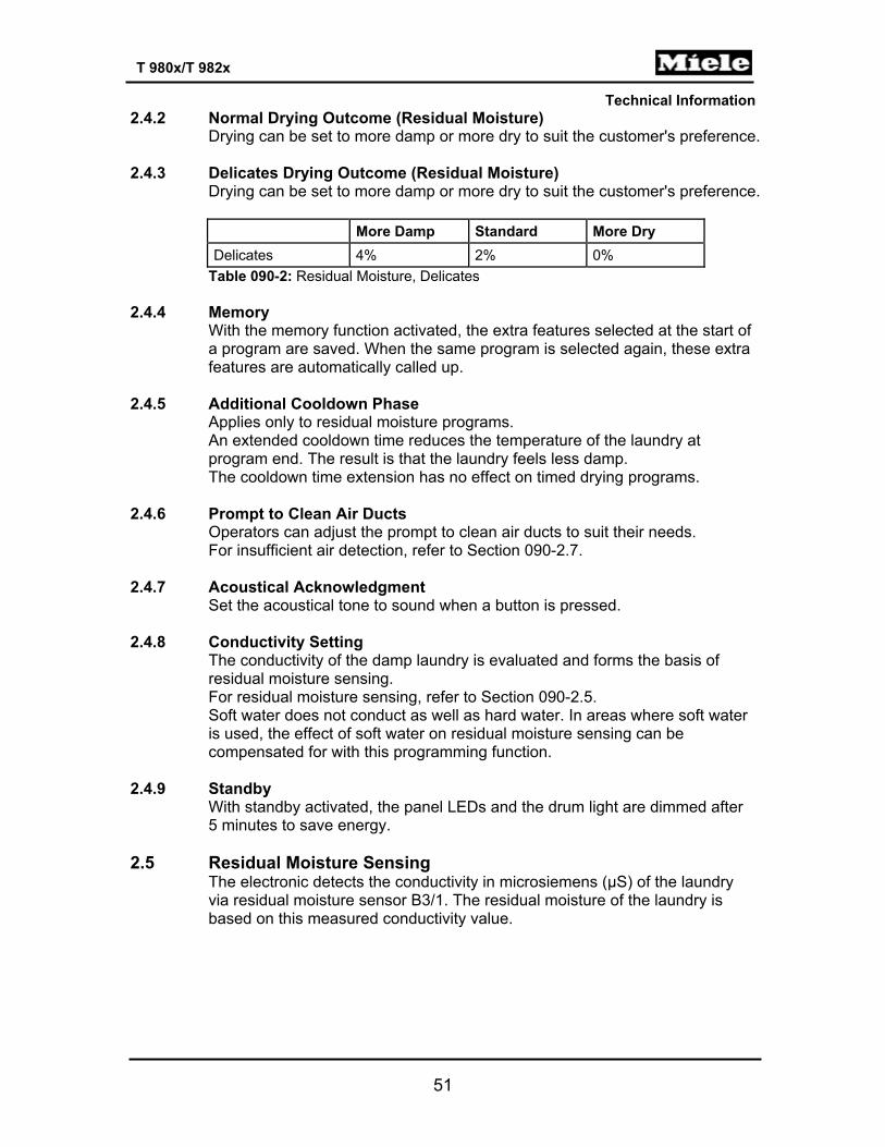
2.4.2 Normal Drying Outcome (Residual Moisture) Drying can be set to more damp or more dry to suit the customer's preference.
2.4.3 Delicates Drying Outcome (Residual Moisture)
Drying can be set to more damp or more dry to suit the customer's preference.
More Damp Standard More Dry Delicates 4% 2% 0%
Table 090-2: Residual Moisture, Delicates 2.4.4 Memory
With the memory function activated, the extra features selected at the start of a program are saved. When the same program is selected again, these extra features are automatically called up.
2.4.5 Additional Cooldown Phase
Applies only to residual moisture programs. An extended cooldown time reduces the temperature of the laundry at program end. The result is that the laundry feels less damp. The cooldown time extension has no effect on timed drying programs.
2.4.6 Prompt to Clean Air Ducts
Operators can adjust the prompt to clean air ducts to suit their needs. For insufficient air detection, refer to Section 090-2.7.
2.4.7 Acoustical Acknowledgment
Set the acoustical tone to sound when a button is pressed. 2.4.8 Conductivity Setting
The conductivity of the damp laundry is evaluated and forms the basis of residual moisture sensing. For residual moisture sensing, refer to Section 090-2.5. Soft water does not conduct as well as hard water. In areas where soft water is used, the effect of soft water on residual moisture sensing can be compensated for with this programming function.
2.4.9 Standby
With standby activated, the panel LEDs and the drum light are dimmed after 5 minutes to save energy.
2.5 Residual Moisture Sensing
The electronic detects the conductivity in microsiemens (µS) of the laundry via residual moisture sensor B3/1. The residual moisture of the laundry is based on this measured conductivity value.
Technical Information
52
T 980x/T 982x
2.6 Overriding the Time Control A fixed maximum time of approximately 180 minutes is imposed on all residual moisture drying programs at program start. After this time has elapsed, any drying program is stopped and the cooldown phase for faults is carried out. There is no anti-crease action, and no fault code is indicated, but the fault is saved and can be called up in service mode.
2.7 Insufficient Air Detection
The heater bank NTC (2R30) monitors the temperature increase in the heater bank. If the air paths are clogged during heating, the temperature in the heater bank rises rapidly. This is detected and the fault message Insufficient air is displayed. If the temperature at the heater bank NTC exceeds 356°F (180°C), fault code F66 (Leaking air) is issued.
2.8 Operating Hours Counter
The time is counted from program start to the end of cooldown, without the time for delay start and anti-crease action.
2.9 Low-Voltage Detection
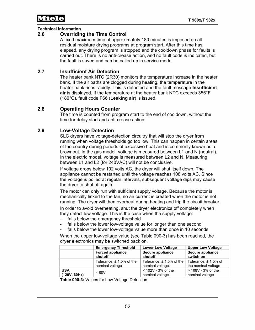
SLC dryers have voltage-detection circuitry that will stop the dryer from running when voltage thresholds go too low. This can happen in certain areas of the country during periods of excessive heat and is commonly known as a brownout. In the gas model, voltage is measured between L1 and N (neutral). In the electric model, voltage is measured between L2 and N. Measuring between L1 and L2 (for 240VAC) will not be conclusive. If voltage drops below 102 volts AC, the dryer will shut itself down. The appliance cannot be restarted until the voltage reaches 108 volts AC. Since the voltage is polled at regular intervals, subsequent voltage dips may cause the dryer to shut off again. The motor can only run with sufficient supply voltage. Because the motor is mechanically linked to the fan, no air current is created when the motor is not running. The dryer will then overheat during heating and trip the circuit breaker. In order to avoid overheating, shut the dryer electronics off completely when they detect low voltage. This is the case when the supply voltage: - falls below the emergency threshold - falls below the lower low-voltage value for longer than one second - falls below the lower low-voltage value more than once in 10 seconds When the upper low-voltage value (see Table 090-3) has been reached, the dryer electronics may be switched back on. Emergency Threshold Lower Low Voltage Upper Low Voltage
Forced appliance shutoff
Secure appliance shutoff
Secure appliance switch-on
Tolerance: ± 1.5% of the nominal voltage
Tolerance: ± 1.5% of the nominal voltage
Tolerance: ± 1.5% of the nominal voltage
USA (120V, 60Hz) < 80V < 102V - 3% of the
nominal voltage > 108V - 3% of the nominal voltage
Table 090-3: Values for Low-Voltage Detection
Technical Information
53
T 980x/T 982x
3 Fault Repair 3.1 “End” LED Is Steadily Lit
Symptom: This fault occurs in the normal operating mode (residual moisture programs only). Program stop, cooling air phase, intermittent buzzer tone. Opening and then closing the door deletes this fault message.
Cause: The drum is empty, or loaded with only a few laundry items. The laundry is too dry. The residual moisture sensor (B3/1) voltage circuit is high-ohmic, and the residual moisture sensor has no-load detection; this is not a technical fault. For no-load detection, refer to Section 030-2.1. Remedy: Adjust the load, or switch to a timed program.
Cause: Defective residual moisture sensor (B3/1). Remedy: Check the residual moisture sensor (B3/1) for low-ohmic (continuity) status; refer to Section 090-4.3.
3.2 “Check Filter/Vent” LED Is Steadily Lit
Symptom: Normal program run. Fault indication at the end of the cooling cycle. Insufficient air detection; refer to Section 090-2.7. Opening and closing the door deletes this fault code indication.
Cause: Air paths are clogged. Remedy: Clean the lint filter (refer to the operating instructions). Clean the air paths in the dryer.
Cause: The fault message Clean air paths is issued prematurely. Remedy: Reprogram the Clean air paths fault message indication; see the operating instructions or Section 090-4.1.
Technical Information
54
T 980x/T 982x
3.3 “Check Filter/Vent” LED Flashes Rapidly Symptom: Program stop, cooling phase, buzzer sounds intermittently for 2 minutes. Fault code F66 (Leaking air fault) in the fault memory.
Cause: Air paths are clogged. Insufficient air measurement; refer to Section 090-2.7. Remedy: Clean air paths. Delete the fault memory; refer to Section 090-4.3.
3.4 “Rotary Iron” LED Flashes
Symptom: Program stop, cooling phase, buzzer sounds intermittently for 2 minutes. Fault code F1 (Heater bank NTC short circuit) or F2 (Heater bank NTC open circuit) in the fault memory.
Cause: Heater bank NTC short- or open-circuited. Remedy: Check the wires and connectors of heater bank NTC 2R30 for a short or open circuit. For heater bank NTC resistance values, refer to Table 030-3. Delete the fault memory; see Section 090-4.3.
3.5 “Hand Iron” LED Flashes
Symptom: Program stop, cooling phase, buzzer sounds intermittently for 2 minutes. Fault code F3 (Drying air NTC (1R30) short circuit) or F4 (Drying air NTC (1R30) open circuit) in the fault memory.
Cause: Drying air NTC (1R30) open circuit (below 68°F); evaluation only after the heater has been running for at least 1 minute. Remedy: Check the wires and connectors of drying air NTC 1R30 for a short or open circuit. For drying air NTC resistance values, refer to Table 030-3.
Cause: Heater bank is not heating. Unheated, the sensor is below the measuring threshold of 68°F (electric dryers only). Remedy: Check the heater element (R1) for a short or open circuit.
Cause: Defective heater relay (K1/1) (electric dryers only). Remedy: Check the heater relay (K1/1).
Technical Information
55
T 980x/T 982x
Cause: Temperature limiter with manual reset (F1) has tripped (electric dryers only). Remedy: 1. Reset the temperature limiter. 2. Find and rectify the cause for the temperature limiter tripping.
Cause: Gas burner is not heating (gas dryers only). Remedy: Check the burner; refer to Section 031-4.1.
3.6 All Program LEDs Flash
Symptom: No program start and no access to the programming or service mode.
Cause: Demo mode is activated. Remedy: Deactivate the demo mode; refer to Section 090-4.2.
3.7 F0: No Fault
Cause: No fault is saved in the fault memory. Remedy: None.
3.8 F1: Short Circuit in Heater Bank NTC (2R30)
Symptom: Program stop, cooling phase, intermittent buzzer tone. Only the timed program “cold air” still works. The “Rotary iron” LED flashes. The “Check Filter/Vent” LED flashes. Opening and closing the door deletes this fault indication.
Cause: Short circuit in heater bank NTC (above 480°F). Remedy: Check the wires and connectors of the heater bank NTC for a short or open circuit. For heater bank NTC resistance values, refer to Table 030-3.
3.9 F2: Open Circuit in Heater Bank NTC (2R30)
Symptom: Program stop, cooling phase, intermittent buzzer tone. Only the timed program “cold air” still works. The “Rotary iron” LED flashes. The “Check Filter/Vent” LED flashes. Opening and closing the door deletes this fault indication.
Technical Information
56
T 980x/T 982x
Cause: Open circuit at heater bank NTC (below 68°F); evaluation only after the heater has been running for at least 1 minute. Remedy: Check the wires and connectors of heater bank NTC 2R30 for a short or open circuit. For heater bank NTC resistance values, refer to Table 030-3.
Cause: Heater bank is not heating. Without heat, the sensor is below the measuring threshold of 68°F (electric dryers only). Remedy: Check the heater bank (R1) for a short or open circuit.
Cause: Heater relay (K1/1) (electric dryers only). Remedy: Check the heater relay (K1/1).
Cause: Temperature limiter with manual reset (F1) has tripped (electric dryers only). Remedy: Reset the temperature limiter. Find and rectify the cause for the temperature limiter tripping.
Cause: Gas burner not heating (gas dryers only). Remedy: Check the gas burner; refer to Section 031-4.1.
3.10 F3: Drying Air NTC (1R30) Short Circuit
Symptom: Program stop, cooling phase, intermittent buzzer tone. Only the timed program “cold air” still works. The “Hand iron” LED flashes. The “Check Filter/Vent” LED flashes. Opening and closing the door deletes this fault indication.
Cause: Short circuit (above 320°F) in drying air NTC 1R30. Remedy: Check the wires and connectors of drying air NTC 1R30 for a short or open circuit. For drying air NTC resistance values, refer to Table 030-3.
Technical Information
57
T 980x/T 982x
3.11 F4: Drying Air NTC (1R30) Open Circuit Symptom: Program stop, cooling phase, intermittent buzzer tone. Only the timed program “cold air” still works. The “Hand iron” LED flashes. The “Check Filter/Vent” LED flashes. Opening and closing the door deletes this fault indication.
Cause: Open circuit (below 5°F) in the drying air NTC (1R30). Remedy: Check the wires and connectors of drying air NTC 1R30 for a short or open circuit. For drying air NTC resistance values, refer to Table 030-3.
3.12 F50: Motor Stalls and Heater Is On for 3 Seconds
Symptom: The motor (M5) stalls. Program stop, cooling phase, intermittent buzzer tone. Opening and closing the door deletes this fault indication.
Cause: This is an internal electronic fault. Remedy: 1. Check the motor. 2. Replace the electronic.
3.13 F55: Overriding Time Limit Exceeded
Symptom: Only in residual moisture programs. Program stop, cooling phase, intermittent buzzer tone for 2 minutes. The “End” LED lights up steadily. The “Check Filter/Vent” LED lights up steadily. Opening and closing the door deletes this fault indication. The safety time has been exceeded; refer to Section 090-2.6.
Cause: Laundry too wet, or dryer overloaded. Remedy: Spin the laundry more thoroughly in the washer, or reduce the laundry load.
Cause: Laundry is electrically conductive (low-ohmic), due to a metal zipper, for example. Remedy: Run a timed warm-air program.
Cause: Air path clogged. Remedy: Check and clean the air paths.
Technical Information
58
T 980x/T 982x
Cause: Heater bank is not heating. Remedy: Check the heater element (R1) for a short or open circuit.
Cause: Heater relay (K1/1). Remedy: Check the heater relay (K1/1).
Cause: Temperature limiter (SOD, F2). Remedy: Check the temperature limiter (SOD, F2) for an open circuit.
Cause: Defective residual moisture sensor (B3/1). Remedy: Residual moisture sensor (B3/1): Check the sampler. Check the residual moisture sensor (B3/1) voltage circuit for high ohmic (isolation) status; see Section 090-4.3.
3.14 F66: Air Leakage
Symptom: Program stop, cooling phase, intermittent buzzer tone for 2 minutes.
Cause: Air paths clogged. Insufficient air measurement; refer to Section 090-2.7. Remedy: Clean the air paths.
3.15 F98: No Gas Ignition (T 982x only)
Symptom: Program stop, cooling phase, intermittent buzzer tone.
Cause: The burner has not ignited after 10 attempts. Remedy: Check the following: - Gas supply is open - Gasline pressure is available - Exhaust passageway is clear - Gas jet is clear - Ignition electrode is functioning
Note: In order to clear this fault message, open and close the door with the appliance switched on.
Technical Information
59
T 980x/T 982x
3.16 F99: Appliance Lockdown Symptom: The top 4 LEDs flash. Program stop, cooling phase, intermittent buzzer tone.
Cause: F98 is often saved in the fault memory. If the electronic has registered an F98 fault 3 times, this generates an F99 fault and locks the machine. Remedy: To lift the lock, the diagnostic software (MDU) is required.
Note: If the fault memory is not cleared, the lockdown remains activated.
3.17 Laundry Is Overdried/F55 (Overriding Time Limit Exceeded) Symptom: Very long operating time. F 55 is stored in the fault memory.
Cause: Short circuit at drum contact strip. A metal bracket of the drum contact strip is touching the drum casing and has caused a short circuit. Therefore, the electronics are detecting moisture, even though the laundry is already dry. Remedy: Insulate the bracket from the drum casing by placing an insulating sleeve (mat. no. 07244210) around the bracket.
Note: In order to clear this fault message, open and close the door with the appliance switched on.
3.18 Dryer Shuts Itself Off
Symptom: Dryer shuts itself off suddenly during operation. No fault message; no additional symptoms.
Cause: Not enough supply voltage available. See Section 090-2.9. Remedy: No remedy needed, because the electronics will switch the dryer on again when they have detected sufficient voltage.
Cause: The electronic prematurely detects a low voltage. The values for low-voltage detection have been adjusted. For current low-voltage detection values, see Table 090-3.

Technical Information
60
T 980x/T 982x
Remedy: Measure the input voltage to determine if the dryer has shut off in accordance with the values shown in the table. If possible, measure the voltage while a drying program is running and heating is switched on. If the dryer has shut off prematurely, replace the electronic.
3.19 Top 4 LEDs Flash
Symptom: Program stop, cooling phase, intermittent buzzer tone.
Cause: Machine is locked. Remedy: See Section 090-3.16.
Note: If the fault memory is not cleared, the lockdown remains activated.
4 Service 4.1 Programming Mode Summary
Initial requirements: 1. End the current program as well as the demo mode. 2. Open the door.
Accessing:
Note: Access has to be completed within 10 seconds.
1. Press and hold the Start/Stop button. 2. Close the door. 3. As soon as the “Start/Stop” LED flashes, release the Start/Stop button. 4. Immediately press Start/Stop 5 times and on the 5th time hold it until the
“Start/Stop” LED flashes rapidly (5 flashes per second).
Acknowledgement indicator: “Start/Stop” LED flashes rapidly (5 flashes per second). If access is not successful, the machine will automatically revert to standard operating mode.
Options: 1. Press the Buzzer button to select a programming function. 2. The “Buzzer” LED flashes to indicate the selected function. See Table 090-4. 3. Press the Start/Stop button to select options. 4. The “Drying” LED flashes to indicate the selected option. See Table 090-4.

Technical Information
61
T 980x/T 982x
Warning! For the dryer to function properly, specific options for the country it is operating in have to be selected. The appropriate electronic must be installed. Factory settings are indicated in bold.
Programming Function Option
“Buzzer” LED long short “Drying” LED short
Reset, refer to Section 090-2.4.1 -- 1
adapted options 0 delivery condition 1
Normal drying outcome (residual moisture), refer to Section 090-2.4.2
-- 2
more damp 0
standard 1
more dry 2
Delicates drying outcome (residual moisture), refer to Section 090-2.4.3
-- 3
more damp 0
standard 1
more dry 2
Memory, refer to Section 090-2.4.4 -- 6
off, memory function not activated
0
on, memory function activated
1
Additional cooldown phase, refer to Section 090-2.4.5
-- 7
off 0
5 min 1
10 min 2
Insufficient air alert, refer to Section 090-2.4.6
1 --
off 0 more sensitive 1 standard 2 less sensitive 3
Button tones, refer to Section 090-2.4.7 1 1
off 0 on 1
Conductivity setting, refer to Section 090-2.4.8
1 2 normal 0
low (<150µS) 1
Standby, refer to Section 090.2.4.9 1 3
off 0 on 1
Table 090-4: Programming Mode Summary

Technical Information
62
T 980x/T 982x
Save and quit: Open the door.
Note: Programming selections are saved in the electronic.
4.2 Activating/Deactivating the Demonstration Mode
Initial requirements: 1. End the current program. 2. Open the door.
Accessing:
Note: Access has to be completed within 10 seconds.
1. Press and hold the Start/Stop button. 2. Close the door. 3. As soon as the “Start/Stop” LED lights up steadily (after about 4
seconds), release the Start/Stop button. 4. Immediately press Start/Stop again and hold until the “Start/Stop” LED
goes out (about 3 seconds).
Acknowledgement indicator: The demo program starts running. LEDs light up one at a time and the “Start/Stop” LED blinks. If access is not successful, the machine will automatically revert to standard operating mode.
Options: A demo program cycle lasts about 40 seconds, then there is a short pause, and the demo program starts again. Operating simulation/Interactive demo mode: In interactive demo mode, the appliance can be operated without starting a program.
Save and quit: To deactivate the demo mode, repeat the access procedure.
4.3 Service Mode Summary
Initial requirements: 1. End the current program as well as the demo mode. 2. Open the door.
Accessing:
Note: Access has to be completed within 10 seconds.
1. Press and hold the Start/Stop button. 2. Close the door. 3. As soon as the “Start/Stop” LED flashes, release the Start/Stop button. 4. Immediately press Start/Stop 3 times and on the 3rd time hold it until the
Technical Information
63
T 980x/T 982x
“Start/Stop” LED flashes slowly (1 flash per second).
Acknowledgement indicator: “Start/Stop” LED flashes slowly (1 flash per second). If access is not successful, the machine will automatically revert to standard operating mode.
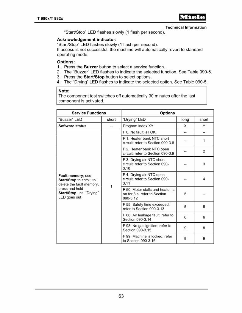
Options: 1. Press the Buzzer button to select a service function. 2. The “Buzzer” LED flashes to indicate the selected function. See Table 090-5. 3. Press the Start/Stop button to select options. 4. The “Drying” LED flashes to indicate the selected option. See Table 090-5.
Note: The component test switches off automatically 30 minutes after the last component is activated.
Service Functions Options
“Buzzer” LED short “Drying” LED long short Software status -- Program index XY X Y
Fault memory; use Start/Stop to scroll; to delete the fault memory, press and hold Start/Stop until “Drying” LED goes out
1
F 0, No fault; all OK. -- --
F 1, Heater bank NTC short circuit; refer to Section 090-3.8 -- 1
F 2, Heater bank NTC open circuit; refer to Section 090-3.9 -- 2
F 3, Drying air NTC short circuit; refer to Section 090-3.10
-- 3
F 4, Drying air NTC open circuit; refer to Section 090-3.11
-- 4
F 50, Motor stalls and heater is on for 3 s; refer to Section 090-3.12
5 --
F 55, Safety time exceeded; refer to Section 090-3.13 5 5
F 66, Air leakage fault; refer to Section 090-3.14 6 6
F 98, No gas ignition; refer to Section 090-3.15 9 8
F 99, Machine is locked; refer to Section 090-3.16 9 9

Technical Information
64
T 980x/T 982x
Service Functions Options
“Buzzer” LED short “Drying” LED long short
Component test 2
All components inactive --
Motor on in a rhythm of 10 s left / 2 s pause / 10 s right / 2 s pause 1
Heater relay 1K1/1, heater R1 on and motor on in a rhythm of 10 s left / 2 s pause / 10 s right / 2 s pause.
2
Check the residual moisture sensor (B3/1) for low ohmic status (continuity). Requires an electrical connection between drum and sensor rib. The "Normal" LED flashes: characteristic value too low. The "Normal" LED lights up: correct characteristic value.
4
Check the residual moisture sensor (B3/1) for high ohmic status (isolation). Requires no electrical connection between drum and sensor rib. "Normal" LED flashes: Characteristic value too high. "Normal" LED lights up: Correct characteristic value.
5
Steady buzzer tone 6
LEDs flash (1x per second) 7
Heater relay 2K1/1 and motor on 8
Heater relays (1K1/1, 2K1/1, 3K1/1), heaters (R1, R2, R3) and motor on 9
Sensor test 3
All sensors inactive --
Door lock (A2): Door closed = switch closed = buzzer on. Door open = switch open = buzzer off.
1
Operating hours, Section 090-2.8 4
Electronic's operating hours: Long flashing signal for the number of 1000s, short flashing signal for the number of 100s (e.g., 12 times long + 6 times short = 12000 h + 600 h = 12600 h).
x000 h y00 h
Table 090-5: Service Mode Summary
Save and quit: Open the door.
Note: Delete the fault memory before ending.

Technical Information
65
T 980x/T 982x
4.4 Removing the Fascia, Electronic and Electronic Support Panel 1. Disconnect the appliance from the power supply. 2. Remove the lid; see Section 010-4.1. 3. Pry off the fascia panel using a small flathead screwdriver. 4. Remove the two T20 screws securing the electronic (see Figure 090-1),
press in on the retaining tabs, and remove the electronic partway. Disconnect all connections to the electronic and remove it completely.
5. Remove the four T20 screws securing the electronic support panel (see Figure 090-1).
6. Lift the support panel out to remove.
Figure 090-1: Removing the Fascia, Electronic, and Electronic Support Panel

Technical Information
66
T 980x/T 982x
100 Electrical System

Technical Information
67
T 980x/T 982x
1 Technical Data
Electric Heating Gas Heating
Electrical system
Dryer fuses (F2); 7 A T, 6.3 mm x 32 mm (0.25” x 1.25”) --
Heater relays (1K1/1, 2K1/1, 3K1/1): single-anchor relays, rating 11A; coil: 12VDC, 200Ω
Heater relays (1K1/1, 2K1/1)
Table 100-1: Electrical System Data 4 Service 4.1 Fuse Replacement (T 980x only)
1. Disconnect the appliance from the power supply. 2. Remove the lid; see Section 010-4.1. 3. Unscrew the black fuse cap (see arrow, Figure 100-1) and remove the fuse. 4. Insert the new fuse into the black cap and screw the cap back into place.
Figure 100-1: Fuse Replacement
4.2 Heater Relay Removal
1. Disconnect the appliance from the power supply. 2. Remove the dryer lid; refer to Section 010-4.1. 3. Disconnect the electrical connections from the appropriate relay. (Relays
are located in front of the fuse; refer to Figure 100-1, if necessary.) 4. Press in on the locking tab and slide the relay forward to remove.

Technical Information
68
T 980x/T 982x
4.3 Pressure Switch B9/3 Removal 1. Disconnect the appliance from the power supply. 2. Remove the dryer lid; refer to Section 010-4.1. 3. Disconnect the switch connections from the heater relay and the
electronic. 4. Disconnect the air hose from the switch. 5. Remove the 2 small Phillips-head screws securing the switch to the
mounting bracket. 6. Remove the switch from the bracket.

Technical Information
69
T 980x/T 982x
110 Technical Service Bulletins 1 T 9820 Gas Dryer Airflow
Question: Does the airflow reverse when the drum reverses?
This question came up recently about the T 9820 gas dryer. "When the drum rotates in the counterclockwise direction, are flue gases drawn back into the dryer?"
The answer is - absolutely not! During reverse rotation, the airflow only decreases; it never changes direction.
2 Dryer Venting Information
The four most common dryer venting options are shown below along with their benefits and limitations. Any one of the four will allow the dryer to exhaust effectively and safely. The major differences are their ease of installation and the amount noise you can here while using them. This information applies to all dryers, but noise levels in general will always increase as the air flow produced by the dryer increases.
The options are shown in the order of most commonly to least commonly used.
4” Flexible Foil Ducting Benefits Limitations Easy to install Noisiest type of
ducting
Easier to move machine once installed
Has a tendency to kink and bend if not careful
Inexpensive Least efficient at exhausting heat
No angle adapters needed
4” flexible foil ducting is the easiest to install in most applications. Due to its flexibility this ducting can twist, bend, and kink if installations are not carefully done. During dryer operation the duct may move and bounce due to the airflow inside. This movement, along with the bends and internal ribbing, creates turbulence in the airflow, which we hear as noise. This noise is normal and cannot be reduced unless different ducting is installed. If installed properly, this type of ducting works satisfactorily, but the noise may prompt a call from customers, who think there is a problem with the dryer.
To determine whether the dryer is making noise or if it’s the ducting, disconnect the duct from the dryer and run the dryer empty. If the noise disappears after the ducting is removed, the problem is not with the appliance.
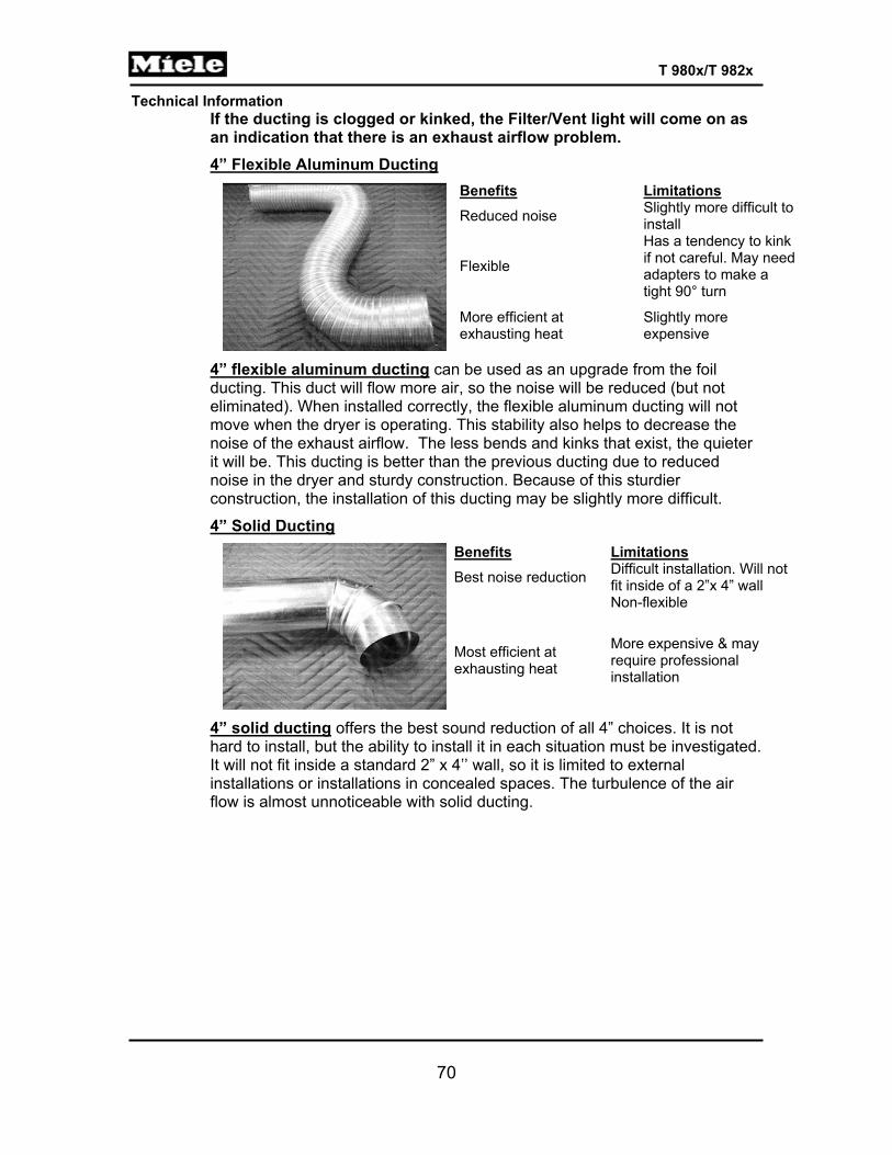
Technical Information
70
T 980x/T 982x
If the ducting is clogged or kinked, the Filter/Vent light will come on as an indication that there is an exhaust airflow problem. 4” Flexible Aluminum Ducting
Benefits Limitations Reduced noise Slightly more difficult to
install
Flexible
Has a tendency to kink if not careful. May need adapters to make a tight 90° turn
More efficient at exhausting heat
Slightly more expensive
4” flexible aluminum ducting can be used as an upgrade from the foil ducting. This duct will flow more air, so the noise will be reduced (but not eliminated). When installed correctly, the flexible aluminum ducting will not move when the dryer is operating. This stability also helps to decrease the noise of the exhaust airflow. The less bends and kinks that exist, the quieter it will be. This ducting is better than the previous ducting due to reduced noise in the dryer and sturdy construction. Because of this sturdier construction, the installation of this ducting may be slightly more difficult.
4” Solid Ducting Benefits Limitations Best noise reduction Difficult installation. Will not
fit inside of a 2”x 4” wall Non-flexible
Most efficient at exhausting heat
More expensive & may require professional installation
4” solid ducting offers the best sound reduction of all 4” choices. It is not hard to install, but the ability to install it in each situation must be investigated. It will not fit inside a standard 2” x 4’’ wall, so it is limited to external installations or installations in concealed spaces. The turbulence of the air flow is almost unnoticeable with solid ducting.

Technical Information
71
T 980x/T 982x
5” Solid Ducting Benefits Limitations Noise almost eliminated Same as 4” solid
ducting
Highest efficiency at transferring heat
Requires a 4” – 5” adapter at the dryer connection
3 Dryer Will Power Up, Push Buttons Inoperable Affected part: Power/control electronic
Cause: When the electronic has been replaced and the machine push buttons do not operate, it may be due to wires behind the electronic not being fed through the harness holders. The wire harness bunches up behind the electronic. When the board is tightened down it places undue pressure on the board, causing it to bow and rendering the push buttons inoperable.
Symptom: The dryer will power up but the push buttons will be inoperable.
Remedy: When replacing the electronic, ensure that the wire harness is correctly routed through the holders so that there is adequate clearance behind the board.

Technical Information
72
T 980x/T 982x
4 How to Diagnose and Repair Specific Internal Ducting Issues The T 9820 SLC dryer will exhibit some specific symptoms if one or two of the inner duct caps has become dislodged or fallen off. Any of the following symptoms should prompt the service technician to check these caps. Phone techs encountering any of these symptoms should indicate in the work order to check the caps.
• Prolonged drying times (60-75 minutes longer than normal) • Condensation is leaking or dripping from dryer • The safety limiter has tripped (2F1 near gas valve) • Excessive lint accumulation in dryer (outside the drum/air path). This can
be observed by removing the lid.
If the matching washer and dryer were installed at the same time, the dryer will always have fewer operating hours than the washer. If there is a loose cap, the dryer will have equal or higher operating hours.
To check the caps, the rear panel screws can be removed, the panels pried out gently, and the caps can be checked by hand.
In the case of a loose cap, push it back on to the duct until you hear a distinct click. Also at this point it would be wise to remove all panels and thoroughly vacuum out the interior of the dryer cabinet.
Wire Harness Holders

Technical Information
73
T 980x/T 982x
5 T 9800, T 9820 Moisture Sensor Testing The moisture sensor in the SLC dryer can be tested via service mode from the control panel. When conducting these tests (low ohmic and high ohmic) observe the state of the ‘Normal’ LED on the control panel once the test concludes. If the LED lights steadily, the test has passed. If the LED flashes, the test has failed. Be sure to make sure your jumper is fastened securely for the low ohmic test and that the jumper is removed for the high ohmic test.
If you use the MDU software to conduct these tests, the program will clearly display whether or not the test was successful.
6 Insulation Mats on Some SLC Laundry Machines May
Come Loose The insulation mat under the lid of an SLC laundry machine may come loose due to poor adhesion. The proper way to repair this condition is to order a new mat (damping plate) and replace it. The adhesive has been improved on the replacement parts. Be sure to consult the parts CD to determine which item you need.
This applies to the W 4800, W 4840, T 9800, T 9820. 7 Broken Belts in T 9800 & T 9820 SLC Dryers
If you encounter a broken belt in one of these SLC dryers, you must diagnose the underlying cause before replacing the belt. Please check the front felt seal/bearing ring part # 7158610 shown below. If this ring is worn or deteriorated, it can cause the drum to stop turning; this will cause the pulley to burn and break the belt.
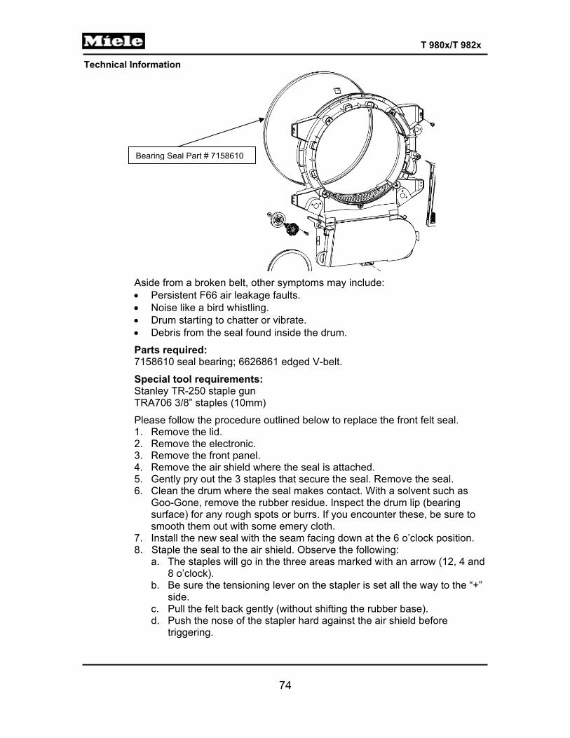
Technical Information
74
T 980x/T 982x
Aside from a broken belt, other symptoms may include: • Persistent F66 air leakage faults. • Noise like a bird whistling. • Drum starting to chatter or vibrate. • Debris from the seal found inside the drum.
Parts required: 7158610 seal bearing; 6626861 edged V-belt.
Special tool requirements: Stanley TR-250 staple gun TRA706 3/8” staples (10mm)
Please follow the procedure outlined below to replace the front felt seal. 1. Remove the lid. 2. Remove the electronic. 3. Remove the front panel. 4. Remove the air shield where the seal is attached. 5. Gently pry out the 3 staples that secure the seal. Remove the seal. 6. Clean the drum where the seal makes contact. With a solvent such as
Goo-Gone, remove the rubber residue. Inspect the drum lip (bearing surface) for any rough spots or burrs. If you encounter these, be sure to smooth them out with some emery cloth.
7. Install the new seal with the seam facing down at the 6 o’clock position. 8. Staple the seal to the air shield. Observe the following:
a. The staples will go in the three areas marked with an arrow (12, 4 and 8 o’clock).
b. Be sure the tensioning lever on the stapler is set all the way to the “+” side.
c. Pull the felt back gently (without shifting the rubber base). d. Push the nose of the stapler hard against the air shield before
triggering.
Bearing Seal Part # 7158610

Technical Information
75
T 980x/T 982x
e. If the staple does not fully penetrate, remove it and try again – push down harder.
9. Check the impeller for any dirt inside and clean it.
10. Replace the belt (if needed). 11. Re-install the air shield, front panel, and electronic. 12. Run a test. 13. Affix the lid.
8 F97 and the T 9820 Dryer
When connecting with the optical interface to an SLC gas dryer, you may encounter a stored fault, F97, with the text message “Ignition Unit Life Expired”. This fault can be ignored; it does not present itself to the customer. No parts need to be replaced because of this fault code. Simply update the software ID with your laptop to ID 1533. The fault will go away.
9 Laundry Detergent Notice: Purex Complete 3-in1
Laundry Sheets At this time, we recommend that customers do not use this product in Miele laundry machines. They may get caught in the drain pumps and pipework.

Technical Information
76
T 980x/T 982x
10 SLC Dryers Repeatedly Displaying the Filter/Vent
Warning Detailed diagnosis procedures The filter/vent alarm is triggered when the temperature differential between the front (blower) and rear (heat source) NTCs is too wide. This indicates that the airflow through the drum is insufficient to remove enough heat from the heat source and pull it through the wet clothing. This can easily be caused by a clogged lint filter or any restriction in the venting system.
A more serious fault (F66 – air leakage fault) occurs when the temperature differential is so wide that the rear NTC reports a temperature greater than 356°F. This can occur when the integrity of the airflow is disrupted to the point where virtually no air is being drawn through the heat source. This can be caused by a shattered impeller, motor stoppage (for any reason) or the intrusion of cool room air through a faulty door seal or a faulty drum seal. In our experience, the front drum bearing seal (07158610) is a likely suspect in these cases. The felt bearing seal, as it degrades, can also cause the drum to bind and stop turning – this can cause the belt to break.
Diagnosis strategy – Gas (T 9820): Aside from the filter/vent warning and F66 faults, you may also find that one or both of the thermal overlimits on the gas burner have tripped. This means the distorted airflow has caused the flame to ‘bloom’ and touch one of these limiters. The following steps should be taken if any of the above symptoms have appeared. Open the dryer – top, front and side panels. Check for any collection of
lint or fluff inside the cabinet. Lint or fluff in here can indicate air leakage

Technical Information
77
T 980x/T 982x
or debris from a degrading felt seal. Any lint should be vacuumed out. Remove the air shield and inspect the front bearing seal. There were two
seals used in production, a grey seal and the newer seal that has a light yellow color. If you encounter the grey seal – it must be replaced. (The replacement procedure can be found on page 74.) Follow the procedure exactly. If you find that either style seal looks worn, be sure to inspect (feel) the drum lip to make sure there are no rough spots or burrs. Smooth out any rough spots or burrs with emery cloth. Also inspect the belt for any worn or hardened spots – replace the belt if you see any damage.
Inspect the impeller. Check it for cracks by flexing it by hand. If the impeller part number is anything lower than 05608563, replace it.
Inspect the gas burner. There should be no lint in or around the burner. Remove it, if necessary, and inspect the venturi tube & burner head for any lint accumulation. Clean it thoroughly, taking care not to damage the fragile gas igniter. Inspect the wiring harness for any signs of melting or burning – replace the burner assembly if you find this condition.
Finally, inspect the left and right caps on the extraction module. Secure them with foil tape if you find them at all loose.
Diagnosis strategy - Electric (T 9800): Aside from the filter/vent warning and F66 faults, you may also find that one or both of the thermal overlimits on the burner box have tripped. This means the temperature has risen so quickly that the electronic could not turn off the elements in time. This indicates a motor or blower stoppage. The following steps should be taken if any of the above symptoms have appeared. Open the dryer – top, front and side panels. Check for any collection of
lint or fluff inside the cabinet. Lint or fluff in here can indicate air leakage or debris from a degrading felt seal. Any lint should be vacuumed out.
Remove the air shield and inspect the front bearing seal. There were two seals used in production, a grey seal and the newer seal that has a light yellow color. If you encounter the grey seal – it must be replaced. (The replacement procedure can be found on page 74.) Follow the procedure exactly. If you find that either style seal looks worn, be sure to inspect (feel) the drum lip to make sure there are no rough spots or burrs. Smooth out any rough spots or burrs with emery cloth. Also inspect the belt for any worn or hardened spots – replace the belt if you see any damage.
Inspect the impeller. Check it for cracks by flexing it by hand. If the impeller part number is anything lower than 05608563, replace it.
Inspect the burner box. There should be no lint on or around the elements. Clean it thoroughly, using your vacuum.
Finally, inspect the left and right caps on the extraction module. Secure them with foil tape if you find them at all loose.
11 T 9822 Flame Control Circuit Update
The T 9822 gas dryer now has an additional component in the flame control

Technical Information
78
T 980x/T 982x
circuitry. All production dryers now have this component and they are starting to appear in customers’ homes.
The additional component: The factory has added a differential pressure switch to the gas burner control circuit. You are probably already familiar with this type of switch; it is similar to the heater pressure switch on a dishwasher. In this case, a differential switch is used. This means there are two pressure inlets, one that monitors the pressure inside the air channel (created by the blower wheel) and one that monitors the ambient air pressure. This is done so that the difference between the blower pressure and normal air pressure can be monitored. This type of pressure switch will function accurately even at higher altitudes where the ambient air pressure is lower.
How it works: When the dryer blower is functioning properly, there will be a difference between the internal air pressure and the ambient air pressure. If, however, the air pressure differential reaches zero (i.e. no blower action) the circuit to the gas burner will be interrupted and the flame will immediately shut off. Note that this new protection control circuitry also requires a new software ID. This ID is currently being prepared for the MDU, and you will be notified when it becomes available. Until your laptop is updated, you may not be able to connect to one of these dryers.
In summary: A partial wiring diagram is included with this document illustrating the new switch, B9_3. As you can see, if this switch is not closed, no power will flow to the gas burner. All associated documents, service manuals and training materials will be updated over the next few weeks to reflect this improvement. The latest updated parts CD and Web ETD already show the new parts. A serial number break for all new machines will be posted later. Unfortunately, there are 650 non-sequential dryers that were also updated prior to their leaving the factory, so serial number will not be a definitive indicator as to whether a particular dryer has the new switch or not. (The switch is mounted on the same bracket as the 1K1 & 2K1 heating relays. It is quite visible.)

Technical Information
79
T 980x/T 982x
12 SLC Dryers, T 98XX and Low Voltage
Seasonal reminder: Our SLC dryers have voltage detection circuitry that will stop the dryer from running when voltage thresholds go too low. This is for the safety of the dryer and the clothing inside. This can happen in certain areas of the country during periods of excessive heat; this is commonly known as a brownout. In the gas dryer model, voltage is measured between L1 and neutral. In the electric model, voltage is measured between L2 and neutral. Measuring between L1 and L2 (for 240V) will not be conclusive.
If voltage drops below 102 volts, the dryer will shut itself down. You will not be able to restart the unit until the voltage reaches 108. Since the voltage is polled at regular intervals, subsequent voltage dips (such as those caused by a hard-starting AC compressor) may cause the dryer to
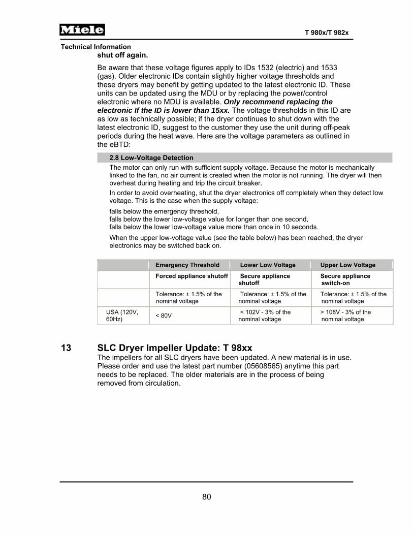
Technical Information
80
T 980x/T 982x
shut off again. Be aware that these voltage figures apply to IDs 1532 (electric) and 1533 (gas). Older electronic IDs contain slightly higher voltage thresholds and these dryers may benefit by getting updated to the latest electronic ID. These units can be updated using the MDU or by replacing the power/control electronic where no MDU is available. Only recommend replacing the electronic If the ID is lower than 15xx. The voltage thresholds in this ID are as low as technically possible; if the dryer continues to shut down with the latest electronic ID, suggest to the customer they use the unit during off-peak periods during the heat wave. Here are the voltage parameters as outlined in the eBTD:
2.8 Low-Voltage Detection The motor can only run with sufficient supply voltage. Because the motor is mechanically linked to the fan, no air current is created when the motor is not running. The dryer will then overheat during heating and trip the circuit breaker. In order to avoid overheating, shut the dryer electronics off completely when they detect low voltage. This is the case when the supply voltage: falls below the emergency threshold, falls below the lower low-voltage value for longer than one second, falls below the lower low-voltage value more than once in 10 seconds. When the upper low-voltage value (see the table below) has been reached, the dryer electronics may be switched back on.
Emergency Threshold Lower Low Voltage Upper Low Voltage
Forced appliance shutoff Secure appliance shutoff
Secure appliance switch-on
Tolerance: ± 1.5% of the nominal voltage
Tolerance: ± 1.5% of the nominal voltage
Tolerance: ± 1.5% of the nominal voltage
USA (120V, 60Hz) < 80V < 102V - 3% of the
nominal voltage > 108V - 3% of the nominal voltage
13 SLC Dryer Impeller Update: T 98xx The impellers for all SLC dryers have been updated. A new material is in use. Please order and use the latest part number (05608565) anytime this part needs to be replaced. The older materials are in the process of being removed from circulation.

Technical Information
81
T 980x/T 982x
14 Dryer Duct Length
Calculating the maximum allowable length for 4" (100 mm) ducting When using 4" ducting, adequate air extraction is possible for an effective duct length of up to 66 ft. (792 in.).
To calculate the effective duct length, proceed as follows:
A) Measure the total length of the proposed ducting, including any bends. B) Determine the amount, angle, and type of bends that will be required. C) Determine what type of fitting will be used to terminate the duct at the
outer wall (flap vent, louvered vent, grill, etc.). D) Using the chart below, add the additional length factor of the bends and
fittings that will be used to the total length measured in Step A above. If the sum is less than 66 ft. (792 inches), the appliance will be able to exhaust the air without any problem. If the sum is greater than 66 ft., a larger duct diameter may be required.
Type of bend or fitting Angle of bend Radius of bend Additional length factor Smooth bend 90° 4 inches 14 inches Elbow bend (Sharp – no radius
90° 90 inches
Corrugated bend 90° 8 inches 28 inches Flexible metal duct 45° Up to 16 inches 12 inches 90° Up to 16 inches 20 inches Wall vent with flap 99 inches Wall vent with louvers 142 inches
R
Smooth Bend 90° Elbow
R
Corrugated Bend

Technical Information
82
T 980x/T 982x
Calculating the maximum allowable length for 5" (125 mm) ducting When using 5" ducting, adequate air extraction is possible for an effective duct length of up to 115 ft. (1378 in.)
To calculate the effective duct length, proceed as follows:
A) Measure the total length of the proposed ducting, including any bends. B) Determine the amount, angle, and type of bends that will be required. C) Determine what type of fitting will be used to terminate the duct at the
outer wall (flap vent, louvered vent, grill, etc.). D) Using the chart below, add the additional length factor of the bends and
fittings that will be used to the total length measured in Step A above. If the sum is less than 115 ft. (1378 inches), the hood will be able to exhaust the air without any problem. If the sum is greater than 115 ft., an external fan may be required.
Type of bend or fitting Angle of bend Radius of bend Additional length factor Smooth bend 45° 4 inches 8 inches 45° 8 inches 4 inches 90° 4 inches 12 inches 90° 8 inches 8 inches Elbow bend 45° 18 inches 90° 71 inches Corrugated bend 90° 22 inches Flexible metal duct 45° 5 inches 8 inches 45° 10 inches 6 inches 45° 20 inches 4 inches 90° 5 inches 14 inches 90° 10 inches 12 inches 90° 20 inches 8 inches Wall vent with flap 63 inches Wall vent with louvers 157 inches
Calculating the maximum allowable length for 6" (150mm) ducting When using 6" ducting, adequate air extraction is possible for an effective duct length of up to 108 ft. (1296 in.)
To calculate the effective duct length, proceed as follows:
A) Measure the total length of the proposed ducting, including any bends. B) Determine the amount, angle, and type of bends that will be required. C) Determine what type of fitting will be used to terminate the duct at the
R
Smooth Bend 90° Elbow
R
Corrugated Bend

Technical Information
83
T 980x/T 982x
outer wall (flap vent, louvered vent, grill, etc.). D) Using the chart below, add the additional length factor of the bends and
fittings that will be used to the total length measured in Step A above. If the sum is less than 108 ft. (1296 inches), the hood will be able to exhaust the air without any problem. If the sum is greater than 108 ft., an external fan may be required.
Type of bend or fitting Angle of bend Radius of bend Additional length factor Smooth bend 45° 4 inches 16 inches 45° 8 inches 10 inches 90° 4 inches 28 inches 90° 8 inches 19 inches Elbow bend 45° 32 inches 90° 152 inches Corrugated bend 90° 54 inches Flexible metal duct 45° 8 inches 40 inches 45° 16 inches 32 inches 90° 8 inches 46 inches 90° 16 inches 37 inches Wall vent with flap 63 inches Wall vent with louvers 157 inches
R
Smooth Bend 90° Elbow
R
Corrugated Bend
Related Documents