47 tiated in areas where they could be contained to consume the small- diameter forest thinnings (SDTs) that might serve as fuel for future fires. These thinnings were most commonly made up of various pine and fir species. Although this controlled burn technique has gener- ally been effective, it has been stated to offer no economic benefits while carrying many risks. There are many uses for the small-diameter trees that make up most of the forest thinnings—including lumber, structural round wood, wood composites, wood fiber products, compost, mulch, energy, and fuels (3). One proposal is to remove the forest thinnings and sell them for use in various products, hopefully recovering the cost of remov- ing the material. A large number of end products have the potential to recover the costs associated with removing SDTs. Therefore, more uses for SDTs must be developed (4). Guardrail post production was a possible application under consid- eration for using SDTs. SDTs used in guardrail systems would pro- vide a new application for thinnings and also reduce the cost of the barrier system. However, further research was deemed necessary to determine the structural properties of SDT material so that the use of round wood in new value-added markets (i.e., longitudinal barrier systems) can be expanded. LONGITUDINAL BARRIER SYSTEMS For more than 50 years, longitudinal barrier systems have been con- structed along the nation’s highways and roadways to prevent errant motorists from colliding with dangerous fixed objects or traversing hazardous roadside geometries beyond the edge of the traveled way. Although several different longitudinal barrier systems can be found throughout the United States, strong-post W-beam guardrail systems historically have been the most common. Typical design details for these common barrier systems can be found in AASHTO’s Roadside Design Guide (5) as well as in AASHTO’s Task Force 13 Report, A Guide to Standardized Highway Barrier Hardware (6). Longitudinal, W-beam barrier systems generally consist of a W-beam guardrail element, evenly spaced support posts, and blockouts or post spacers. The W-beam rail is available in two thicknesses—2.66 mm (12 gauge) and 3.42 mm (10 gauge)—although most installations have used 2.66-mm (12-gauge) rail sections. Guardrail posts have been manufactured from both wood and steel materials. For the steel alternative, both the W152×12.6 (W6×8.5) and W152×13.4 (W6×9) wide-flange post sections have been used. For the wood alternative, 152- × 203-mm (6- × 8-in.) rectangular and 184-mm (7.25-in.) diameter round-post cross sections have been successfully used and generally manufactured from Grade 1 or better southern yellow pine (SYP) material. Although several post options Midwest Guardrail System with Round Timber Posts Ronald K. Faller, John D. Reid, David E. Kretschmann, Jason A. Hascall, and Dean L. Sicking A modified Midwest Guardrail System (MGS) was developed by using small-diameter round wood posts. The barrier system was configured with three timber species: Douglas fir (DF), ponderosa pine (PP), and southern yellow pine (SYP). Barrier VII computer simulation, com- bined with cantilever post testing in a rigid sleeve and soil, was used to determine the required post diameter for each species. The recom- mended nominal sizes were 184 mm (7.25 in.) for DF, 203 mm (8 in.) for PP, and 190 mm (7.5 in.) for SYP. A grading criterion limiting knot size and ring density was established for each species. The recom- mended knot sizes were limited to 38 mm (1.5 in.) or smaller for DF, 89 mm (3.5 in.) or smaller for PP, and 64 mm (2.5 in.) or smaller for SYP. The minimum ring densities equaled or exceeded 6 rings per inch (rpi) for DF, 6 rpi for PP, and 4 rpi for SYP. Two guardrail systems— one using DF posts and another using PP posts—were crash tested according to the Test Level 3 requirements specified in NCHRP Report 350: Recommended Procedures for the Safety Performance Evaluation of Highway Features. Crash testing was not conducted on the SYP sys- tem because of the adequacy of previous testing on 184-mm (7.25-in.) diameter SYP posts in a standard W-beam guardrail system and post design strength comparable to that in the other two species. Both crash tests showed that the modified MGS functioned adequately for both wood species. Three round wood post alternatives were recommended as an acceptable substitute for the standard W152×13.4 (W6×9) steel post used in the MGS. Prompted by the devastating forest fire season of 2000, President William J. Clinton initiated the development of what would become the National Fire Plan. It established four main goals: improve fire prevention and suppression, reduce the amount of hazardous fuels, restore fire-adapted ecosystems, and promote community assistance (1). One of the most commonly used fire-prevention techniques is fuel management, an idea that has been around for many years. In the 1960s, the Forest Service of the U.S. Department of Agriculture began managing fuels with controlled burn techniques (2); fires were ini- R. K. Faller, J. D. Reid, and D. L. Sicking, Midwest Roadside Safety Facility, 527 Nebraska Hall, Lincoln, University of Nebraska–Lincoln, NE 68588-0529. D. E. Kretschmann, Forest Products Laboratory, Forest Service, U.S. Department of Agriculture, 1 Gifford Pinchot Drive, Madison, WI 53726. J. A. Hascall, Wallace Engineering, 818 Grand Boulevard, Suite 1100, Kansas City, MO 64106-1910. Corresponding author: R. K. Faller, [email protected]. Transportation Research Record: Journal of the Transportation Research Board, No. 2120, Transportation Research Board of the National Academies, Washington, D.C., 2009, pp. 47–59. DOI: 10.3141/2120-06

Welcome message from author
This document is posted to help you gain knowledge. Please leave a comment to let me know what you think about it! Share it to your friends and learn new things together.
Transcript
47
tiated in areas where they could be contained to consume the small-diameter forest thinnings (SDTs) that might serve as fuel for futurefires. These thinnings were most commonly made up of various pineand fir species. Although this controlled burn technique has gener-ally been effective, it has been stated to offer no economic benefitswhile carrying many risks.
There are many uses for the small-diameter trees that make up mostof the forest thinnings—including lumber, structural round wood,wood composites, wood fiber products, compost, mulch, energy, andfuels (3). One proposal is to remove the forest thinnings and sell themfor use in various products, hopefully recovering the cost of remov-ing the material. A large number of end products have the potentialto recover the costs associated with removing SDTs. Therefore, moreuses for SDTs must be developed (4).
Guardrail post production was a possible application under consid-eration for using SDTs. SDTs used in guardrail systems would pro-vide a new application for thinnings and also reduce the cost of thebarrier system. However, further research was deemed necessary todetermine the structural properties of SDT material so that the useof round wood in new value-added markets (i.e., longitudinal barriersystems) can be expanded.
LONGITUDINAL BARRIER SYSTEMS
For more than 50 years, longitudinal barrier systems have been con-structed along the nation’s highways and roadways to prevent errantmotorists from colliding with dangerous fixed objects or traversinghazardous roadside geometries beyond the edge of the traveled way.Although several different longitudinal barrier systems can be foundthroughout the United States, strong-post W-beam guardrail systemshistorically have been the most common. Typical design details forthese common barrier systems can be found in AASHTO’s RoadsideDesign Guide (5) as well as in AASHTO’s Task Force 13 Report, AGuide to Standardized Highway Barrier Hardware (6).
Longitudinal, W-beam barrier systems generally consist of a W-beam guardrail element, evenly spaced support posts, andblockouts or post spacers. The W-beam rail is available in twothicknesses—2.66 mm (12 gauge) and 3.42 mm (10 gauge)—althoughmost installations have used 2.66-mm (12-gauge) rail sections.Guardrail posts have been manufactured from both wood and steelmaterials. For the steel alternative, both the W152×12.6 (W6×8.5)and W152×13.4 (W6×9) wide-flange post sections have been used.For the wood alternative, 152- × 203-mm (6- × 8-in.) rectangularand 184-mm (7.25-in.) diameter round-post cross sections have beensuccessfully used and generally manufactured from Grade 1 or bettersouthern yellow pine (SYP) material. Although several post options
Midwest Guardrail System with Round Timber Posts
Ronald K. Faller, John D. Reid, David E. Kretschmann, Jason A. Hascall, and Dean L. Sicking
A modified Midwest Guardrail System (MGS) was developed by usingsmall-diameter round wood posts. The barrier system was configuredwith three timber species: Douglas fir (DF), ponderosa pine (PP), andsouthern yellow pine (SYP). Barrier VII computer simulation, com-bined with cantilever post testing in a rigid sleeve and soil, was used todetermine the required post diameter for each species. The recom-mended nominal sizes were 184 mm (7.25 in.) for DF, 203 mm (8 in.)for PP, and 190 mm (7.5 in.) for SYP. A grading criterion limiting knotsize and ring density was established for each species. The recom-mended knot sizes were limited to 38 mm (1.5 in.) or smaller for DF,89 mm (3.5 in.) or smaller for PP, and 64 mm (2.5 in.) or smaller forSYP. The minimum ring densities equaled or exceeded 6 rings per inch(rpi) for DF, 6 rpi for PP, and 4 rpi for SYP. Two guardrail systems—one using DF posts and another using PP posts—were crash testedaccording to the Test Level 3 requirements specified in NCHRP Report350: Recommended Procedures for the Safety Performance Evaluationof Highway Features. Crash testing was not conducted on the SYP sys-tem because of the adequacy of previous testing on 184-mm (7.25-in.)diameter SYP posts in a standard W-beam guardrail system and postdesign strength comparable to that in the other two species. Both crashtests showed that the modified MGS functioned adequately for bothwood species. Three round wood post alternatives were recommendedas an acceptable substitute for the standard W152×13.4 (W6×9) steelpost used in the MGS.
Prompted by the devastating forest fire season of 2000, PresidentWilliam J. Clinton initiated the development of what would becomethe National Fire Plan. It established four main goals: improvefire prevention and suppression, reduce the amount of hazardousfuels, restore fire-adapted ecosystems, and promote communityassistance (1).
One of the most commonly used fire-prevention techniques is fuelmanagement, an idea that has been around for many years. In the1960s, the Forest Service of the U.S. Department of Agriculture beganmanaging fuels with controlled burn techniques (2); fires were ini-
R. K. Faller, J. D. Reid, and D. L. Sicking, Midwest Roadside Safety Facility, 527Nebraska Hall, Lincoln, University of Nebraska–Lincoln, NE 68588-0529. D. E. Kretschmann, Forest Products Laboratory, Forest Service, U.S. Departmentof Agriculture, 1 Gifford Pinchot Drive, Madison, WI 53726. J. A. Hascall, WallaceEngineering, 818 Grand Boulevard, Suite 1100, Kansas City, MO 64106-1910.Corresponding author: R. K. Faller, [email protected].
Transportation Research Record: Journal of the Transportation Research Board,No. 2120, Transportation Research Board of the National Academies, Washington,D.C., 2009, pp. 47–59.DOI: 10.3141/2120-06
have been available throughout the United States, rectangular woodand wide-flange steel posts traditionally have been used. Blockoutshave been incorporated into barriers to position the W-beam rail awayfrom the traffic-side face of posts. This rail offset reduces the propen-sity for vehicles to snag on the posts, raises the rail section during postrotation, and decreases the potential for vehicular instabilities androllover. Over the last two decades, most post spacers were manu-factured from wood materials and were generally the same size as therectangular post. However, over the last 15 years, several compa-nies have also developed blockouts manufactured from recycledpolymer materials to promote the positive environmental aspects ofkeeping used tires out of landfills.
Three post types have been commonly used in strong-post, W-beamguardrail systems: W152×13.4 (W6×9) steel posts, 152- × 203-mm(6- × 8-in.) rectangular wood posts, and 184-mm (7.25-in.) diameterround wood posts. Round timber posts traditionally have been theleast costly. Although round SYP posts have been the most economicones, large-scale implementation of round-post, W-beam barrier sys-tems has been mostly limited to the state of Texas, with most of theresearch and development of these barrier systems conducted at theTexas Transportation Institute (7–10). As such, significant opportu-nities exist for increased use of round posts of multiple timber speciesin crashworthy, strong-post, W-beam guardrail systems.
In 2000, the Midwest Roadside Safety Facility (MwRSF), incooperation with the Midwest States Pooled Fund Program, devel-oped a guardrail system that would improve barrier performance forhigher center-of-mass vehicles, provide reasonable barrier heighttolerances, and reduce the potential for W-beam rupture (11–14).This W-beam guardrail system later became known as the MidwestGuardrail System (MGS). Design changes incorporated into theW-beam barrier system included a nominal W-beam rail top mount-ing height of 787 mm (31 in.), a reduced guardrail post-embedmentdepth of 1,016 mm (40 in.), an increased blockout depth from 203 to305 mm (8 to 12 in.), and a repositioning of the guardrail splice frompost to midspan locations. Prior crash testing has demonstrated thatthe MGS was capable of containing and redirecting both 0.75-tonpickup trucks and small cars according to current impact safety stan-dards. On the basis of these successes, the researchers decided to usethe MGS for this study.
RESEARCH OBJECTIVES
Several objectives were identified for this research project. Thefirst objective was to determine the structural properties of roundwood posts manufactured from Douglas fir (DF), ponderosa pine(PP), and SYP when subjected to impact loading conditions. Asecond objective was to determine an acceptable diameter, grad-ing specification, and embedment depth for each wood species toallow its use as a substitute for the rectangular SYP and wide-flange steel posts used in guardrail applications, including theMGS. Nonlinear, dynamic vehicle-to-barrier impact analysis wasused to investigate MGS failure criteria and to evaluate barrierperformance. The final research objective was to conduct a safetyperformance evaluation of the MGS with round wood posts accord-ing to guidelines in NCHRP Report 350: Recommended Proceduresfor the Safety Performance Evaluation of Highway Features (15).Upon project completion, an installation manual and standardcomputer-aided drafting plans were prepared for the round-postMGS using PP, DF, and SYP posts.
48 Transportation Research Record 2120
WOOD SAMPLING AND PREPARATION OF SPECIMENS
Initially, a post diameter was selected for the three species based onthe success of 184-mm (7.25-in.) diameter, SYP guardrail postsfrom full-scale crash tests conducted by Texas Transportation Insti-tute researchers (7–10). Preliminary sizes for the two species weredetermined by using tabulated strength values for DF and PP tocarry a bending moment equivalent to that of the SYP posts. Thesesizes were 216 mm (8.5 in.) for PP and 190 mm (7.5 in.) for DF.The diameter for SYP was maintained at 184 mm (7.25 in.). The1,981-mm (78-in.) length was arbitrarily selected to ensure sufficientlength to increase the post-embedment depth, if needed.
Unlike some materials, wood is highly variable. Its strength canchange drastically with variation in species, ring density, knot sizeand density, moisture content, and even region of origin. As such,three categories of posts were defined to investigate the effects ofthe two most influential variables—knots and ring density. Theselected categories were low ring density (LRD) without knots orwith small knots (SKN), LRD with big knots (BKN), and high ringdensity (HRD) SKN. Posts were categorized according to ring den-sity, knot frequency, and knots. Posts with four or fewer rings per inch(rpi) were defined as LRD and those with six or more rpi were definedas HRD. Posts with any knots larger than 64 mm (2.5 in.) in diame-ter were classified in the BKN category, and posts with knots thatwere less than 38 mm (1.5 in.) in diameter were classified in theSKN category and were considered to be without knots. A portionof the testing was intended to isolate the properties of posts in thesethree categories, and a portion was intended to determine the prop-erties of the random population. Additional details about the postpopulation, sampling methodology, and preservative treatments havebeen previously reported (16–19).
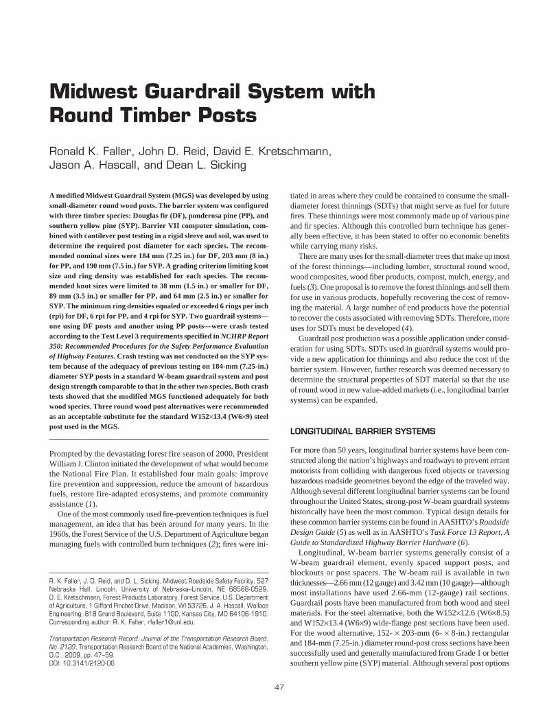
Each round post was weighed, measured, documented, and knotmapped. A typical round timber post is shown in Figure 1. The stresswave modulus of elasticity (SWMOE) for each post was estimatedwith a standard stress wave technique (20); each post was tappedonce with a hammer, sending a stress wave through the post. At thesame time, a sensor determined the time for the stress wave to travelto the other end of the post and return. According to the time andthe post length, the wave velocity was calculated and used with themass density to determine the SWMOE. Posts were ranked in eachcategory by the estimated SWMOE values. The posts for static anddynamic testing were sorted by SWMOE and randomly assigned tothe Forest Service’s Forest Products Laboratory for static testing orto MwRSF for dynamic testing.
Moisture contents were measured with a pin-type moisture meterat three locations from the post bottom: 533 mm (21 in.), 991 mm(39 in.), and 1,448 mm (57 in.). The area within this region wasdefined as the critical zone—the zone where fracture was likely tooccur. Circumference was also measured in the three critical zonelocations and at the top and bottom of the post. Weights and lengthswere measured to determine an approximate density. Ring countswere taken over a 3-in. length, and knots were carefully documented.Each post was also photographed during documentation. As themoisture content of a wood post increases up to 23%, the strengthof the wood fibers within the post decreases. Beyond 23%, the woodstrength is fairly constant. In actual use in the ground, the moisturecontent may exceed 23%, and therefore the posts would be satu-rated. Upon completion of post documentation, the timber posts wereplaced in a 1,219-mm (48-in.) deep tank of water in an effort to sat-
urate the critical zone of the posts, replicating the worst-case sce-nario that the posts may encounter when used in a guardrail system.The moisture content and weight of the posts were measured againon test day to give a more accurate representation of the posts afterthey had been soaked in water.
COMPONENT TESTING
The component testing program consisted of two phases. Phase I testing included static and dynamic evaluation of the structural properties for the three wood species when subjected to cantileveredloading. For Phase I, two rounds of testing were conducted to deter-mine the optimum size of the round posts. During Phase II, dynamictesting of posts embedded in soil was performed on each wood speciesby cantilevered loading while varying the soil embedment depths.
Faller, Reid, Kretschmann, Hascall, and Sicking 49
Phase I
The static tests for Phase I were conducted with a million-poundtest frame at the Forest Products Laboratory with a loading rate of0.008 m/min (0.3 in./min). Loads were recorded on a 222.4-kN(50,000-lb) load cell in Round 1 and on a 133.4-kN (30,000-lb)load cell in Round 2. Deflections were recorded with linear variabledifferential transducers.
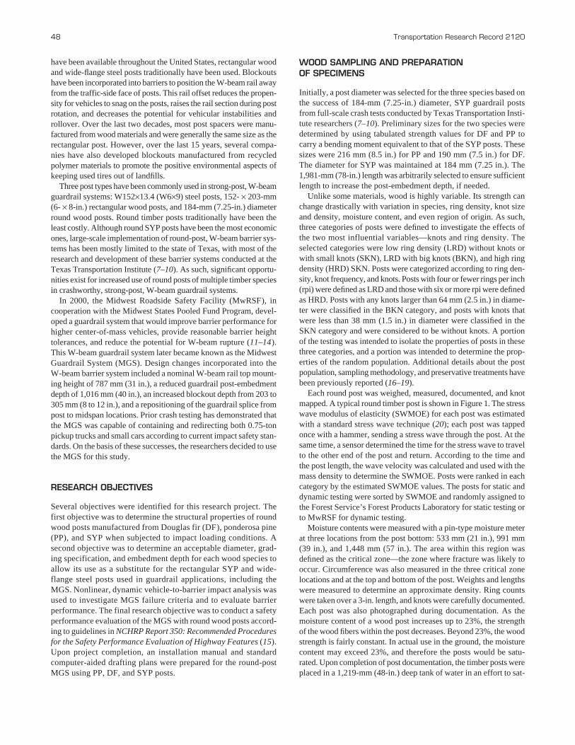
The Phase I dynamic tests were conducted at the MwRSF with a728-kg (1,605-lb) rigid-frame bogie vehicle, as shown in Figure 2.The bogie vehicle traveled at about 32 km/h (20 mph) in Round 1and 21.7 km/h (13.5 mph) in Round 2. Bogie accelerations wererecorded with onboard accelerometers.
(a)
(b)
FIGURE 1 Typical round timber post.
(a)
(b)
FIGURE 2 Phase I dynamic test setup with rigid bogie vehicle.
50 Transportation Research Record 2120
For each round of testing, 10 posts for each species and knot–ringcategory were identified to have the appropriate knot–ring combi-nations. An additional 45 posts were collected from the larger postpopulation for static testing. The test matrix for the cantilever testsis presented in Table 1. The study was set up so that both static anddynamic tests would be performed on three knot–ring combinations(BKN LRD, SKN LRD, and SKN HRD). The two types of knots—BKN and SKN—varied depending on the species. There were alsotwo rpi categories: low (≤4 rpi) and high (≥6 rpi). Further tests of alarger sample more representative of the expected post populationwere also tested statically. Grading supervisors from Timber Prod-ucts Inspection, Inc., assisted in identifying posts with the requireddiameter knot and rpi categories.
The Round 1 and 2 static and dynamic testing results are pre-sented in Table 2 and include comparisons for SWMOE, modulusof rupture (MOR), and peak load.
After Round 1 testing, the results for peak load and MOR wereevaluated to determine whether the post size could be modified.Traditionally, the size of the guardrail post is based on its abilityto rotate backward in soil without post fracture as well as its abil-ity to carry the post–soil forces generated along its length as itrotates. On the basis of prior MGS post testing of steel guardrailposts embedded in soil, it was determined that a peak load capac-ity of 42.3 to 44.5 kN (9.5 to 10 kips) would be adequate for theround wood posts when the load was applied 632 mm (24.875 in.)above the ground.
During Round 1 testing, the targeted post diameters were 190 mm(7.5 in.), 216 mm (8.5 in.), and 184 mm (7.25 in.) for DF, PP, andSYP, respectively. During testing, the peak load capacity of the PPposts was found to be considerably higher than the desired value andthe load capacities observed for the DF and SYP posts. As such, theresearch team determined that the SYP and DF post diameters couldbe reduced slightly to perform adequately in the MGS, while a largerreduction in post diameter was warranted for the PP posts. AfterRound 1 testing, new post sizes were ordered with the following tar-geted diameters: 171 mm (6.75 in.) for DF, 190 mm (7.5 in.) for PP,and 178 mm (7.0 in.) for SYP.
After the first round of dynamic testing and a more detailed inves-tigation, the standard methods used in the dynamic cantilever bogie
testing program were found to provide inaccurate test results forpeak load. For example, the post strength may have been overesti-mated by as much as 50% because of the effects of inertia, thus lead-ing to inaccurate diameter calculations. An alternative procedure wasinvestigated in a series of three additional cantilever post bogie tests.These tests confirmed the problem and showed that a reduction in thebogie impact speed would substantially reduce the effects of inertia,thus leading to a more accurate prediction of ultimate fiber stress.Unfortunately, these results were not identified in time to modify thepost sizes after Round 1 testing. However, the testing methods wereadjusted during Round 2.
After Round 2 testing, the population results suggested that thediameters for the DF and SYP posts were close to the desired peakload range. However, the PP posts appeared to require an increasedpost diameter. In addition, knot size did not have a consistent impacton the post’s load capacity. The knots and rpi data indicated thatthe most substantial gains in post strength were observed by rais-ing the rpi value. A higher rpi count increased the average MORand peak loads for all species by 40% and consistently placed thematerial tested in the upper part of the population distribution. Acomparison of the results from the Round 1 and 2 static and dynamictesting programs suggested a dynamic magnification factor from20% to 30%.
Before conducting the Phase II post–soil embedment tests, it wasdeemed necessary to determine a modified post diameter for eachspecies. By using a 42.3-kN (9.5-kip) load capacity, a 3% failurerate was established as an acceptable level of risk for the guardrailsystem to fail due to the fracture of four consecutive posts whensubjected to Test Level 3 (TL-3) pickup truck testing accordingto NCHRP Report 350 (15). A discussion on the failure risk analysiswas detailed by Hascall (16, 18). The minimum post size was thendetermined with elastic bending equations and the estimated MOR.Sixty percent of the posts were needed to withstand an impactforce of 42.3 kN (9.5 kips) at a height of 632 mm (24.875 in.) ora bending moment capacity of 26.7 kN-m (236 kip-in.). The result-ing target post sizes were found to be 165 mm (6.5 in.), 184 mm(7.25 in.), and 171 mm (6.75 in.) for DF, PP, and SYP posts, respec-tively, and for use in the initial Phase II post–soil embedment testingprogram.
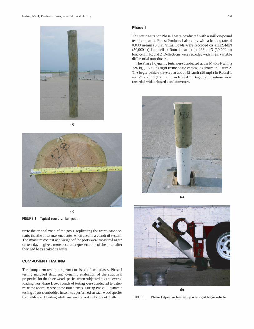
TABLE 1 Test Matrix for Phase I Cantilever Beam Tests
Number of Static (ST) and Dynamic (DY) Tests in Rounds 1 and 2 for Various Sizes of DF, PP, and SYP postsa
Round 1 Round 2
DF, 190 mm PP, 216 mm SYP, 184 mm DF, 171 mm PP, 190 mm SYP, 178 mm
Variable ST DY ST DY ST DY ST DY ST DY ST DY Total
BKN LRDb 5 5 5 5 5 5 5 5 5 5 5 5 60
SKN LRDb 5 5 5 5 5 5 5 5 5 5 5 5 60
SKN HRDc 5 5 5 5 5 5 5 5 5 5 5 5 60
Populationd 45 45 45 45 45 45 270
Total tests 60 15 60 15 60 15 60 15 60 15 60 15 450
aStatic tests were conducted at Forest Products Laboratory, dynamic tests at MwRSF.b≤4 rpi.c≥6 rpi.dRandom mixture of posts.
Faller, Reid, Kretschmann, Hascall, and Sicking 51
Phase II
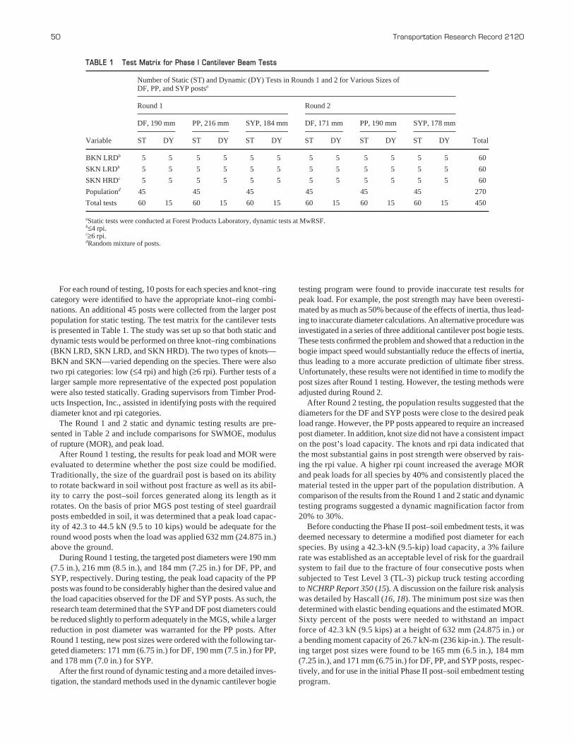
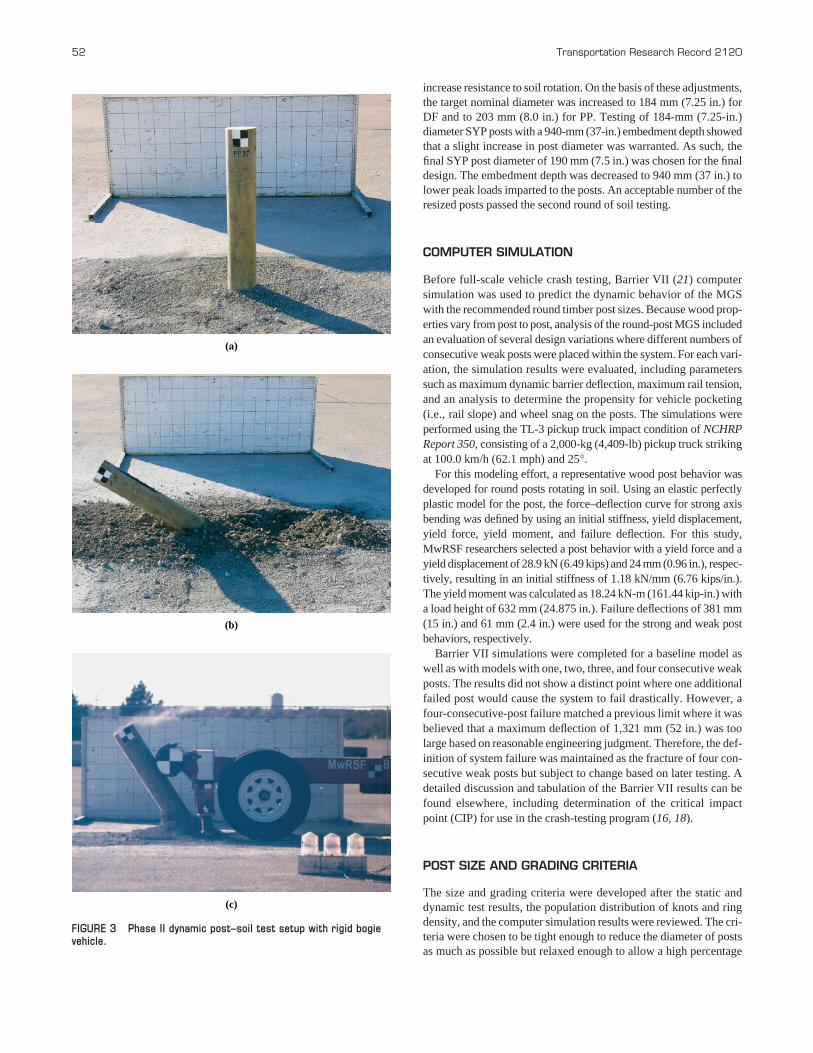
For Phase II dynamic testing, 18 post-embedment tests were con-ducted to determine the response of round posts in compactedsoil, as shown in Figure 3. A rigid-frame bogie vehicle was usedto strike the posts at about 40 km/h (25 mph) and at a load heightof 632 mm (24.875 in.). This velocity was chosen so that the kineticenergy of the bogie vehicle exceeded the energy absorbed in pre-vious MGS post–soil tests. Two post-embedment depths in soilwere investigated: 940 and 1,016 mm (37 and 40 in.). Two postdiameters were investigated for the PP and DF species, and onediameter was studied for the SYP species. Two of the 18 post–soiltests were performed on rectangular SYP posts to serve as a baselinecomparison. Details about the component testing program have beenpreviously reported (16–19).
Initially, six soil tests were completed for DF [165 mm (6.5 in.)]and PP [184 mm (7.25 in.)] posts, three for each species. An embed-ment depth of 1,016 mm (40 in.), the standard for MGS posts, wasused as a starting point. From the initial dynamic post–soil tests, theaverage peak forces observed in the DF and PP posts were 51.7 kN(11.6 kips) and 48.7 kN (11.0 kips), respectively. These resultsshowed that the targeted post load capacity of 42.3 kN (9.5 kips) wasabout 16% less than the actual soil forces generated through theposts. These results indicated that the post diameters needed to beincreased.
A second set of embedment tests was conducted to evaluate thelarger posts. The anticipated peak force was increased to 53.4 kN(12 kips) for DF and 57.8 kN (13 kips) for PP. The anticipated forcewas higher for PP to account for the larger diameter because the postwould have to move more soil and a flatter cross section, which would
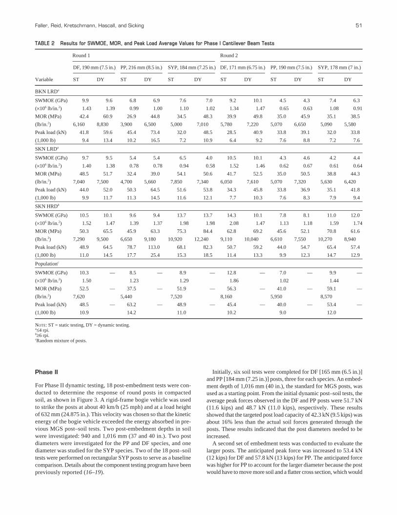
TABLE 2 Results for SWMOE, MOR, and Peak Load Average Values for Phase I Cantilever Beam Tests
Round 1 Round 2
DF, 190 mm (7.5 in.) PP, 216 mm (8.5 in.) SYP, 184 mm (7.25 in.) DF, 171 mm (6.75 in.) PP, 190 mm (7.5 in.) SYP, 178 mm (7 in.)
Variable ST DY ST DY ST DY ST DY ST DY ST DY
BKN LRDa
SWMOE (GPa) 9.9 9.6 6.8 6.9 7.6 7.0 9.2 10.1 4.5 4.3 7.4 6.3
(×106 lb/in.2) 1.43 1.39 0.99 1.00 1.10 1.02 1.34 1.47 0.65 0.63 1.08 0.91
MOR (MPa) 42.4 60.9 26.9 44.8 34.5 48.3 39.9 49.8 35.0 45.9 35.1 38.5
(lb/in.2) 6,160 8,830 3,900 6,500 5,000 7,010 5,780 7,220 5,070 6,650 5,090 5,580
Peak load (kN) 41.8 59.6 45.4 73.4 32.0 48.5 28.5 40.9 33.8 39.1 32.0 33.8
(1,000 lb) 9.4 13.4 10.2 16.5 7.2 10.9 6.4 9.2 7.6 8.8 7.2 7.6
SKN LRDa
SWMOE (GPa) 9.7 9.5 5.4 5.4 6.5 4.0 10.5 10.1 4.3 4.6 4.2 4.4
(×106 lb/in.2) 1.40 1.38 0.78 0.78 0.94 0.58 1.52 1.46 0.62 0.67 0.61 0.64
MOR (MPa) 48.5 51.7 32.4 39.0 54.1 50.6 41.7 52.5 35.0 50.5 38.8 44.3
(lb/in.2) 7,040 7,500 4,700 5,660 7,850 7,340 6,050 7,610 5,070 7,320 5,630 6,420
Peak load (kN) 44.0 52.0 50.3 64.5 51.6 53.8 34.3 45.8 33.8 36.9 35.1 41.8
(1,000 lb) 9.9 11.7 11.3 14.5 11.6 12.1 7.7 10.3 7.6 8.3 7.9 9.4
SKN HRDb
SWMOE (GPa) 10.5 10.1 9.6 9.4 13.7 13.7 14.3 10.1 7.8 8.1 11.0 12.0
(×106 lb/in.2) 1.52 1.47 1.39 1.37 1.98 1.98 2.08 1.47 1.13 1.18 1.59 1.74
MOR (MPa) 50.3 65.5 45.9 63.3 75.3 84.4 62.8 69.2 45.6 52.1 70.8 61.6
(lb/in.2) 7,290 9,500 6,650 9,180 10,920 12,240 9,110 10,040 6,610 7,550 10,270 8,940
Peak load (kN) 48.9 64.5 78.7 113.0 68.1 82.3 50.7 59.2 44.0 54.7 65.4 57.4
(1,000 lb) 11.0 14.5 17.7 25.4 15.3 18.5 11.4 13.3 9.9 12.3 14.7 12.9
Populationc
SWMOE (GPa) 10.3 — 8.5 — 8.9 — 12.8 — 7.0 — 9.9 —
(×106 lb/in.2) 1.50 1.23 1.29 1.86 1.02 1.44
MOR (MPa) 52.5 — 37.5 — 51.9 — 56.3 — 41.0 — 59.1 —
(lb/in.2) 7,620 5,440 7,520 8,160 5,950 8,570
Peak load (kN) 48.5 — 63.2 — 48.9 — 45.4 — 40.0 — 53.4 —
(1,000 lb) 10.9 14.2 11.0 10.2 9.0 12.0
NOTE: ST = static testing, DY = dynamic testing.a≤4 rpi.b≥6 rpi.cRandom mixture of posts.
52 Transportation Research Record 2120
increase resistance to soil rotation. On the basis of these adjustments,the target nominal diameter was increased to 184 mm (7.25 in.) forDF and to 203 mm (8.0 in.) for PP. Testing of 184-mm (7.25-in.)diameter SYP posts with a 940-mm (37-in.) embedment depth showedthat a slight increase in post diameter was warranted. As such, thefinal SYP post diameter of 190 mm (7.5 in.) was chosen for the finaldesign. The embedment depth was decreased to 940 mm (37 in.) tolower peak loads imparted to the posts. An acceptable number of theresized posts passed the second round of soil testing.
COMPUTER SIMULATION
Before full-scale vehicle crash testing, Barrier VII (21) computersimulation was used to predict the dynamic behavior of the MGSwith the recommended round timber post sizes. Because wood prop-erties vary from post to post, analysis of the round-post MGS includedan evaluation of several design variations where different numbers ofconsecutive weak posts were placed within the system. For each vari-ation, the simulation results were evaluated, including parameterssuch as maximum dynamic barrier deflection, maximum rail tension,and an analysis to determine the propensity for vehicle pocketing(i.e., rail slope) and wheel snag on the posts. The simulations wereperformed using the TL-3 pickup truck impact condition of NCHRPReport 350, consisting of a 2,000-kg (4,409-lb) pickup truck strikingat 100.0 km/h (62.1 mph) and 25°.
For this modeling effort, a representative wood post behavior wasdeveloped for round posts rotating in soil. Using an elastic perfectlyplastic model for the post, the force–deflection curve for strong axisbending was defined by using an initial stiffness, yield displacement,yield force, yield moment, and failure deflection. For this study,MwRSF researchers selected a post behavior with a yield force and ayield displacement of 28.9 kN (6.49 kips) and 24 mm (0.96 in.), respec-tively, resulting in an initial stiffness of 1.18 kN/mm (6.76 kips/in.).The yield moment was calculated as 18.24 kN-m (161.44 kip-in.) witha load height of 632 mm (24.875 in.). Failure deflections of 381 mm(15 in.) and 61 mm (2.4 in.) were used for the strong and weak postbehaviors, respectively.
Barrier VII simulations were completed for a baseline model aswell as with models with one, two, three, and four consecutive weakposts. The results did not show a distinct point where one additionalfailed post would cause the system to fail drastically. However, afour-consecutive-post failure matched a previous limit where it wasbelieved that a maximum deflection of 1,321 mm (52 in.) was toolarge based on reasonable engineering judgment. Therefore, the def-inition of system failure was maintained as the fracture of four con-secutive weak posts but subject to change based on later testing. Adetailed discussion and tabulation of the Barrier VII results can befound elsewhere, including determination of the critical impactpoint (CIP) for use in the crash-testing program (16, 18).
POST SIZE AND GRADING CRITERIA
The size and grading criteria were developed after the static anddynamic test results, the population distribution of knots and ringdensity, and the computer simulation results were reviewed. The cri-teria were chosen to be tight enough to reduce the diameter of postsas much as possible but relaxed enough to allow a high percentage
(a)
(b)
(c)
FIGURE 3 Phase II dynamic post–soil test setup with rigid bogievehicle.
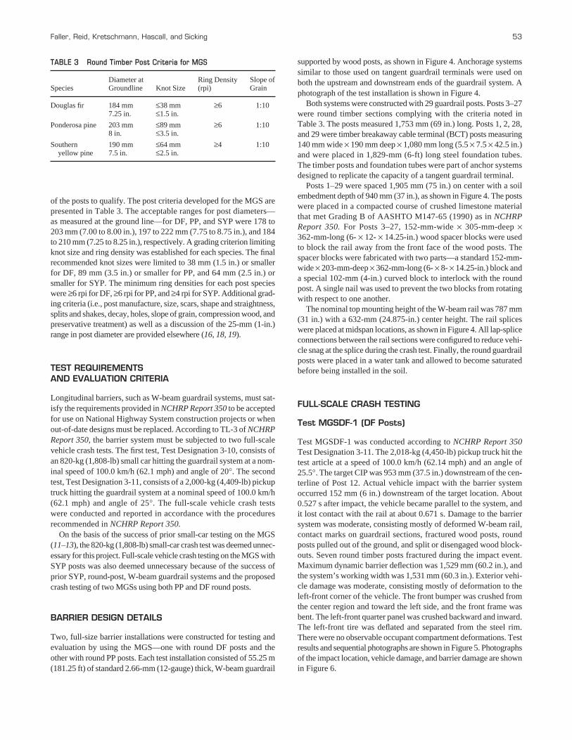
of the posts to qualify. The post criteria developed for the MGS arepresented in Table 3. The acceptable ranges for post diameters—as measured at the ground line—for DF, PP, and SYP were 178 to 203 mm (7.00 to 8.00 in.), 197 to 222 mm (7.75 to 8.75 in.), and 184to 210 mm (7.25 to 8.25 in.), respectively. A grading criterion limitingknot size and ring density was established for each species. The finalrecommended knot sizes were limited to 38 mm (1.5 in.) or smallerfor DF, 89 mm (3.5 in.) or smaller for PP, and 64 mm (2.5 in.) orsmaller for SYP. The minimum ring densities for each post specieswere ≥6 rpi for DF, ≥6 rpi for PP, and ≥4 rpi for SYP. Additional grad-ing criteria (i.e., post manufacture, size, scars, shape and straightness,splits and shakes, decay, holes, slope of grain, compression wood, andpreservative treatment) as well as a discussion of the 25-mm (1-in.)range in post diameter are provided elsewhere (16, 18, 19).
TEST REQUIREMENTS AND EVALUATION CRITERIA
Longitudinal barriers, such as W-beam guardrail systems, must sat-isfy the requirements provided in NCHRP Report 350 to be acceptedfor use on National Highway System construction projects or whenout-of-date designs must be replaced. According to TL-3 of NCHRPReport 350, the barrier system must be subjected to two full-scalevehicle crash tests. The first test, Test Designation 3-10, consists ofan 820-kg (1,808-lb) small car hitting the guardrail system at a nom-inal speed of 100.0 km/h (62.1 mph) and angle of 20°. The secondtest, Test Designation 3-11, consists of a 2,000-kg (4,409-lb) pickuptruck hitting the guardrail system at a nominal speed of 100.0 km/h(62.1 mph) and angle of 25°. The full-scale vehicle crash testswere conducted and reported in accordance with the proceduresrecommended in NCHRP Report 350.
On the basis of the success of prior small-car testing on the MGS(11–13), the 820-kg (1,808-lb) small-car crash test was deemed unnec-essary for this project. Full-scale vehicle crash testing on the MGS withSYP posts was also deemed unnecessary because of the success ofprior SYP, round-post, W-beam guardrail systems and the proposedcrash testing of two MGSs using both PP and DF round posts.
BARRIER DESIGN DETAILS
Two, full-size barrier installations were constructed for testing andevaluation by using the MGS—one with round DF posts and theother with round PP posts. Each test installation consisted of 55.25 m(181.25 ft) of standard 2.66-mm (12-gauge) thick, W-beam guardrail
Faller, Reid, Kretschmann, Hascall, and Sicking 53
supported by wood posts, as shown in Figure 4. Anchorage systemssimilar to those used on tangent guardrail terminals were used onboth the upstream and downstream ends of the guardrail system. Aphotograph of the test installation is shown in Figure 4.
Both systems were constructed with 29 guardrail posts. Posts 3–27were round timber sections complying with the criteria noted inTable 3. The posts measured 1,753 mm (69 in.) long. Posts 1, 2, 28,and 29 were timber breakaway cable terminal (BCT) posts measuring140 mm wide × 190 mm deep × 1,080 mm long (5.5 × 7.5 × 42.5 in.)and were placed in 1,829-mm (6-ft) long steel foundation tubes.The timber posts and foundation tubes were part of anchor systemsdesigned to replicate the capacity of a tangent guardrail terminal.
Posts 1–29 were spaced 1,905 mm (75 in.) on center with a soilembedment depth of 940 mm (37 in.), as shown in Figure 4. The postswere placed in a compacted course of crushed limestone materialthat met Grading B of AASHTO M147-65 (1990) as in NCHRPReport 350. For Posts 3–27, 152-mm-wide × 305-mm-deep ×362-mm-long (6- × 12- × 14.25-in.) wood spacer blocks were usedto block the rail away from the front face of the wood posts. Thespacer blocks were fabricated with two parts—a standard 152-mm-wide × 203-mm-deep × 362-mm-long (6- × 8- × 14.25-in.) block anda special 102-mm (4-in.) curved block to interlock with the roundpost. A single nail was used to prevent the two blocks from rotatingwith respect to one another.
The nominal top mounting height of the W-beam rail was 787 mm(31 in.) with a 632-mm (24.875-in.) center height. The rail spliceswere placed at midspan locations, as shown in Figure 4. All lap-spliceconnections between the rail sections were configured to reduce vehi-cle snag at the splice during the crash test. Finally, the round guardrailposts were placed in a water tank and allowed to become saturatedbefore being installed in the soil.
FULL-SCALE CRASH TESTING
Test MGSDF-1 (DF Posts)
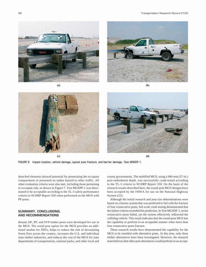
Test MGSDF-1 was conducted according to NCHRP Report 350Test Designation 3-11. The 2,018-kg (4,450-lb) pickup truck hit thetest article at a speed of 100.0 km/h (62.14 mph) and an angle of25.5°. The target CIP was 953 mm (37.5 in.) downstream of the cen-terline of Post 12. Actual vehicle impact with the barrier systemoccurred 152 mm (6 in.) downstream of the target location. About0.527 s after impact, the vehicle became parallel to the system, andit lost contact with the rail at about 0.671 s. Damage to the barriersystem was moderate, consisting mostly of deformed W-beam rail,contact marks on guardrail sections, fractured wood posts, roundposts pulled out of the ground, and split or disengaged wood block-outs. Seven round timber posts fractured during the impact event.Maximum dynamic barrier deflection was 1,529 mm (60.2 in.), andthe system’s working width was 1,531 mm (60.3 in.). Exterior vehi-cle damage was moderate, consisting mostly of deformation to theleft-front corner of the vehicle. The front bumper was crushed fromthe center region and toward the left side, and the front frame wasbent. The left-front quarter panel was crushed backward and inward.The left-front tire was deflated and separated from the steel rim.There were no observable occupant compartment deformations. Testresults and sequential photographs are shown in Figure 5. Photographsof the impact location, vehicle damage, and barrier damage are shownin Figure 6.
TABLE 3 Round Timber Post Criteria for MGS
Diameter at Ring Density Slope ofSpecies Groundline Knot Size (rpi) Grain
Douglas fir 184 mm ≤38 mm ≥6 1:107.25 in. ≤1.5 in.
Ponderosa pine 203 mm ≤89 mm ≥6 1:108 in. ≤3.5 in.
Southern 190 mm ≤64 mm ≥4 1:10yellow pine 7.5 in. ≤2.5 in.
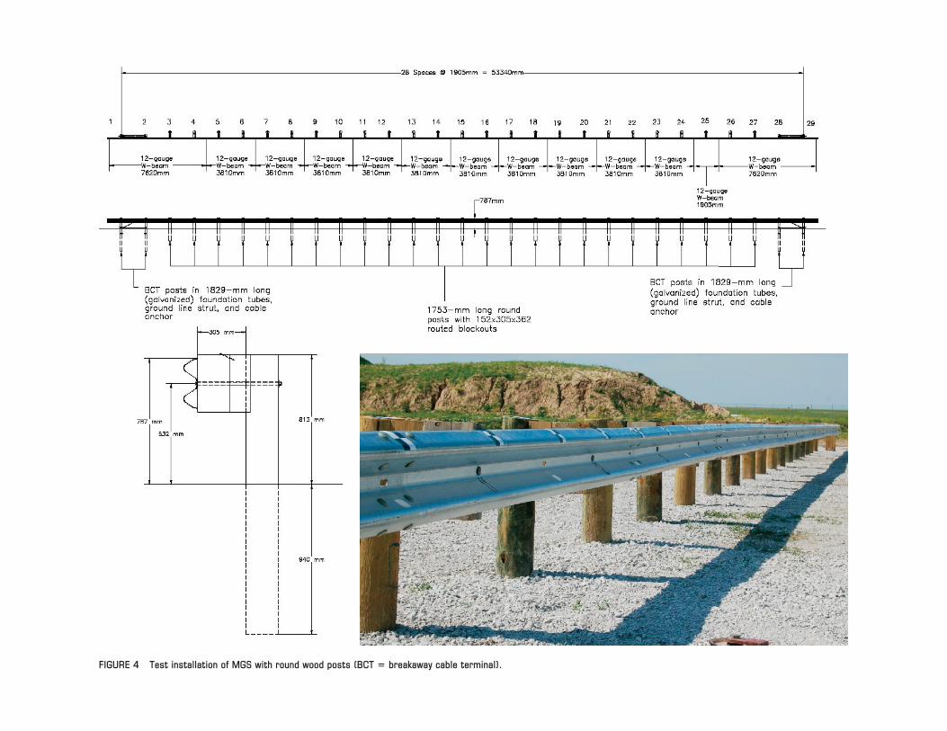
FIGURE 4 Test installation of MGS with round wood posts (BCT � breakaway cable terminal).
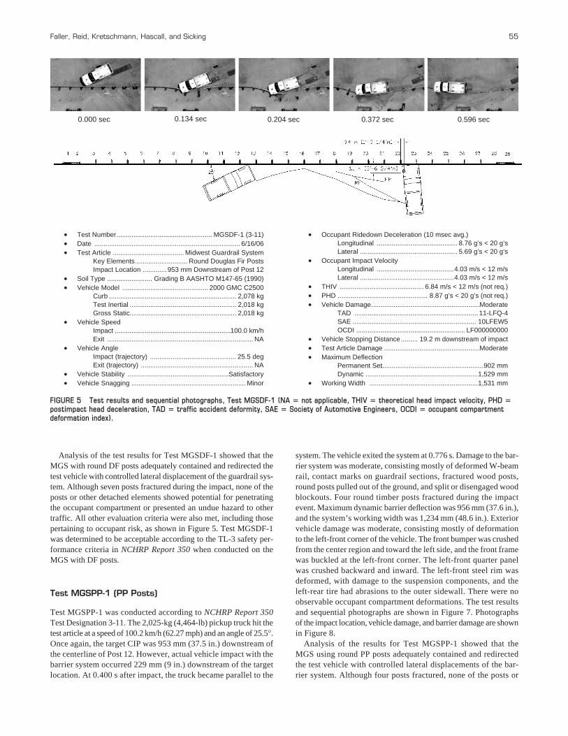
Analysis of the test results for Test MGSDF-1 showed that theMGS with round DF posts adequately contained and redirected thetest vehicle with controlled lateral displacement of the guardrail sys-tem. Although seven posts fractured during the impact, none of theposts or other detached elements showed potential for penetratingthe occupant compartment or presented an undue hazard to othertraffic. All other evaluation criteria were also met, including thosepertaining to occupant risk, as shown in Figure 5. Test MGSDF-1was determined to be acceptable according to the TL-3 safety per-formance criteria in NCHRP Report 350 when conducted on theMGS with DF posts.
Test MGSPP-1 (PP Posts)
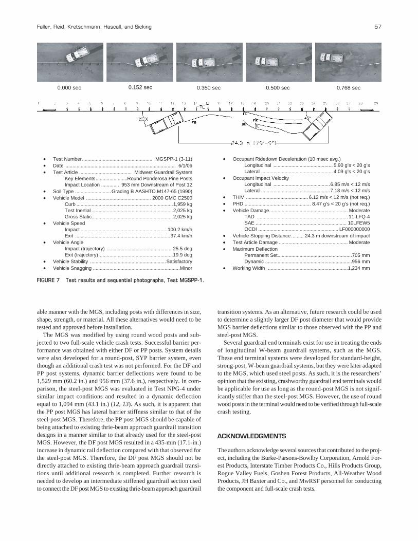
Test MGSPP-1 was conducted according to NCHRP Report 350Test Designation 3-11. The 2,025-kg (4,464-lb) pickup truck hit thetest article at a speed of 100.2 km/h (62.27 mph) and an angle of 25.5°.Once again, the target CIP was 953 mm (37.5 in.) downstream ofthe centerline of Post 12. However, actual vehicle impact with thebarrier system occurred 229 mm (9 in.) downstream of the targetlocation. At 0.400 s after impact, the truck became parallel to the
Faller, Reid, Kretschmann, Hascall, and Sicking 55
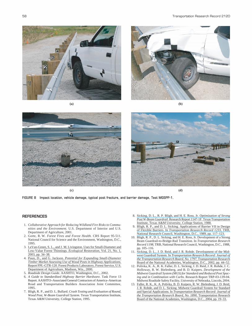
system. The vehicle exited the system at 0.776 s. Damage to the bar-rier system was moderate, consisting mostly of deformed W-beamrail, contact marks on guardrail sections, fractured wood posts,round posts pulled out of the ground, and split or disengaged woodblockouts. Four round timber posts fractured during the impactevent. Maximum dynamic barrier deflection was 956 mm (37.6 in.),and the system’s working width was 1,234 mm (48.6 in.). Exteriorvehicle damage was moderate, consisting mostly of deformationto the left-front corner of the vehicle. The front bumper was crushedfrom the center region and toward the left side, and the front framewas buckled at the left-front corner. The left-front quarter panelwas crushed backward and inward. The left-front steel rim wasdeformed, with damage to the suspension components, and theleft-rear tire had abrasions to the outer sidewall. There were noobservable occupant compartment deformations. The test resultsand sequential photographs are shown in Figure 7. Photographsof the impact location, vehicle damage, and barrier damage are shownin Figure 8.
Analysis of the results for Test MGSPP-1 showed that the MGS using round PP posts adequately contained and redirectedthe test vehicle with controlled lateral displacements of the bar-rier system. Although four posts fractured, none of the posts or
Test Number................................................... MGSDF-1 (3-11)Date .............................................................................. 6/16/06Test Article ...................................... Midwest Guardrail System
Key Elements............................ Round Douglas Fir PostsImpact Location .............953 mm Downstream of Post 12
Soil Type ........................ Grading B AASHTO M147-65 (1990)Vehicle Model .............................................. 2000 GMC C2500
Curb .................................................................... 2,078 kgTest Inertial ......................................................... 2,018 kgGross Static......................................................... 2,018 kg
Vehicle Speed Impact ..............................................................100.0 km/hExit .............................................................................. NA
Vehicle Angle Impact (trajectory) .............................................. 25.5 degExit (trajectory) ............................................................ NA
Vehicle Stability ......................................................SatisfactoryVehicle Snagging ............................................................. Minor
Occupant Ridedown Deceleration (10 msec avg.) Longitudinal ........................................... 8.76 g’s < 20 g’sLateral .................................................... 5.69 g’s < 20 g’s
Occupant Impact Velocity Longitudinal .........................................4.03 m/s < 12 m/sLateral ..................................................4.03 m/s < 12 m/s
THIV ............................................. 6.84 m/s < 12 m/s (not req.)PHD ................................................ 8.87 g’s < 20 g’s (not req.)Vehicle Damage..........................................................Moderate
TAD .................................................................. 11-LFQ-4SAE .................................................................. 10LFEW5OCDI .......................................................... LF000000000
Vehicle Stopping Distance ......... 19.2 m downstream of impactTest Article Damage ...................................................ModerateMaximum Deflection
Permanent Set.......................................................902 mmDynamic ............................................................1,529 mm
Working Width ..........................................................1,531 mm
0.000 sec 0.134 sec 0.204 sec 0.372 sec 0.596 sec
FIGURE 5 Test results and sequential photographs, Test MGSDF-1 (NA � not applicable, THIV � theoretical head impact velocity, PHD �postimpact head deceleration, TAD � traffic accident deformity, SAE � Society of Automotive Engineers, OCDI � occupant compartmentdeformation index).
56 Transportation Research Record 2120
(a) (b)
(c) (d)
FIGURE 6 Impact location, vehicle damage, typical post fracture, and barrier damage, Test MGSDF-1.
detached elements showed potential for penetrating the occupantcompartment or presented an undue hazard to other traffic. Allother evaluation criteria were also met, including those pertainingto occupant risk, as shown in Figure 7. Test MGSPP-1 was deter-mined to be acceptable according to the TL-3 safety performancecriteria in NCHRP Report 350 when performed on the MGS withPP posts.
SUMMARY, CONCLUSIONS, AND RECOMMENDATIONS
Round, DF, PP, and SYP timber posts were developed for use inthe MGS. The wood post option for the MGS provides an addi-tional market for SDTs, helps to reduce the risk of devastatingforest fires across the country, increases the U.S. and individualstate timber industries, and reduces the cost of the MGS for statedepartments of transportation, national parks, and other local and
county governments. The modified MGS, using a 940-mm (37-in.)post-embedment depth, was successfully crash-tested accordingto the TL-3 criteria in NCHRP Report 350. On the basis of theresearch results described here, the round-post MGS designs havebeen accepted by the FHWA for use on the National HighwaySystem (22).
Although the initial research and post size determinations werebased on a barrier system that was predicted to fail with the fractureof four consecutive posts, full-scale crash testing demonstrated thatthe failure criteria exceeded this prediction. In Test MGSDF-1, sevenconsecutive posts failed, yet the system effectively redirected thecolliding vehicle. This result indicates that the round-post MGS hasthe capability to perform in an acceptable manner when more thanfour consecutive posts fracture.
These research results have demonstrated the capability for theMGS to be installed with alternative posts. At this time, only threetimber alternatives have been investigated. However, the researchteam believes that other post alternatives would perform in an accept-
able manner with the MGS, including posts with differences in size,shape, strength, or material. All these alternatives would need to betested and approved before installation.
The MGS was modified by using round wood posts and sub-jected to two full-scale vehicle crash tests. Successful barrier per-formance was obtained with either DF or PP posts. System detailswere also developed for a round-post, SYP barrier system, eventhough an additional crash test was not performed. For the DF andPP post systems, dynamic barrier deflections were found to be1,529 mm (60.2 in.) and 956 mm (37.6 in.), respectively. In com-parison, the steel-post MGS was evaluated in Test NPG-4 undersimilar impact conditions and resulted in a dynamic deflectionequal to 1,094 mm (43.1 in.) (12, 13). As such, it is apparent thatthe PP post MGS has lateral barrier stiffness similar to that of thesteel-post MGS. Therefore, the PP post MGS should be capable ofbeing attached to existing thrie-beam approach guardrail transitiondesigns in a manner similar to that already used for the steel-postMGS. However, the DF post MGS resulted in a 435-mm (17.1-in.)increase in dynamic rail deflection compared with that observed forthe steel-post MGS. Therefore, the DF post MGS should not bedirectly attached to existing thrie-beam approach guardrail transi-tions until additional research is completed. Further research isneeded to develop an intermediate stiffened guardrail section usedto connect the DF post MGS to existing thrie-beam approach guardrail
Faller, Reid, Kretschmann, Hascall, and Sicking 57
transition systems. As an alternative, future research could be usedto determine a slightly larger DF post diameter that would provideMGS barrier deflections similar to those observed with the PP andsteel-post MGS.
Several guardrail end terminals exist for use in treating the endsof longitudinal W-beam guardrail systems, such as the MGS.These end terminal systems were developed for standard-height,strong-post, W-beam guardrail systems, but they were later adaptedto the MGS, which used steel posts. As such, it is the researchers’opinion that the existing, crashworthy guardrail end terminals wouldbe applicable for use as long as the round-post MGS is not signif-icantly stiffer than the steel-post MGS. However, the use of roundwood posts in the terminal would need to be verified through full-scalecrash testing.
ACKNOWLEDGMENTS
The authors acknowledge several sources that contributed to the proj-ect, including the Burke-Parsons-Bowlby Corporation, Arnold For-est Products, Interstate Timber Products Co., Hills Products Group,Rogue Valley Fuels, Goshen Forest Products, All-Weather WoodProducts, JH Baxter and Co., and MwRSF personnel for conductingthe component and full-scale crash tests.
Test Number................................................... MGSPP-1 (3-11)Date ................................................................................ 6/1/06Test Article ...................................... Midwest Guardrail System
Key Elements.......................Round Ponderosa Pine PostsImpact Location ............. 953 mm Downstream of Post 12
Soil Type ..........................Grading B AASHTO M147-65 (1990)Vehicle Model ............................................... 2000 GMC C2500
Curb ......................................................................1,959 kgTest Inertial ...........................................................2,025 kgGross Static...........................................................2,025 kg
Vehicle Speed Impact ...............................................................100.2 km/hExit .....................................................................37.4 km/h
Vehicle Angle Impact (trajectory) ................................................25.5 degExit (trajectory) .....................................................19.9 deg
Vehicle Stability .......................................................SatisfactoryVehicle Snagging ...............................................................Minor
Occupant Ridedown Deceleration (10 msec avg.) Longitudinal ........................................... 5.90 g’s < 20 g’sLateral .................................................... 4.09 g’s < 20 g’s
Occupant Impact Velocity Longitudinal .........................................6.85 m/s < 12 m/sLateral ..................................................7.18 m/s < 12 m/s
THIV ............................................. 6.12 m/s < 12 m/s (not req.)PHD ................................................ 8.47 g’s < 20 g’s (not req.)Vehicle Damage......................................................... Moderate
TAD .................................................................. 11-LFQ-4SAE .................................................................. 10LFEW5OCDI .......................................................... LF000000000
Vehicle Stopping Distance ......... 24.3 m downstream of impactTest Article Damage .................................................. ModerateMaximum Deflection
Permanent Set.......................................................705 mmDynamic ...............................................................956 mm
Working Width ..........................................................1,234 mm
0.000 sec 0.152 sec 0.350 sec 0.500 sec 0.768 sec
FIGURE 7 Test results and sequential photographs, Test MGSPP-1.
58 Transportation Research Record 2120
(a) (b)
(c) (d)
FIGURE 8 Impact location, vehicle damage, typical post fracture, and barrier damage, Test MGSPP-1.
REFERENCES
1. Collaborative Approach for Reducing Wildland Fire Risks to Commu-nities and the Environment. U.S. Department of Interior and U.S.Department of Agriculture, 2001.
2. Gorte, R. W. Forest Fires and Forest Health. CRS Report 95-511.National Council for Science and the Environment, Washington, D.C.,1995.
3. LeVan-Green, S. L., and J. M. Livingston. Uses for Small-Diameter andLow-Value Forest Thinnings. Ecological Restoration, Vol. 21, No. 1,2003, pp. 34–38.
4. Paun, D., and G. Jackson. Potential for Expanding Small-DiameterTimber Market Assessing Use of Wood Posts in Highway Applications.Report FPL-GTR-120. Forest Products Laboratory, Forest Service, U.S.Department of Agriculture, Madison, Wis., 2000.
5. Roadside Design Guide. AASHTO, Washington, D.C., 2002.6. A Guide to Standardized Highway Barrier Hardware. Task Force 13
Report. AASHTO–Associated General Contractors of America–AmericanRoad and Transportation Builders Association Joint Committee,1995.
7. Bligh, R. P., and D. L. Bullard. Crash Testing and Evaluation of Round,Wood Post, W-Beam Guardrail System. Texas Transportation Institute,Texas A&M University, College Station, 1995.
8. Sicking, D. L., R. P. Bligh, and H. E. Ross, Jr. Optimization of StrongPost W-Beam Guardrail. Research Report 1147-1F. Texas TransportationInstitute, Texas A&M University, College Station, 1988.
9. Bligh, R. P., and D. L. Sicking. Applications of Barrier VII in Designof Flexible Barriers. In Transportation Research Record 1233, TRB,National Research Council, Washington, D.C., 1989, pp. 117–123.
10. Bligh, R. P., D. L. Sicking, and H. E. Ross, Jr. Development of a StrongBeam Guardrail-to-Bridge-Rail Transition. In Transportation ResearchRecord 1198, TRB, National Research Council, Washington, D.C., 1988,pp. 105–116.
11. Sicking, D. L., J. D. Reid, and J. R. Rohde. Development of the Mid-west Guardrail System. In Transportation Research Record: Journal ofthe Transportation Research Board, No. 1797, Transportation ResearchBoard of the National Academies, Washington, D.C., 2002, pp. 44–52.
12. Polivka, K. A., R. K. Faller, D. L. Sicking, J. D. Reid, J. R. Rohde, J. C.Holloway, R. W. Bielenberg, and B. D. Kuipers. Development of theMidwest Guardrail System (MGS) for Standard and Reduced Post Spac-ing and in Combination with Curbs. Research Report TRP-03-139-04.Midwest Roadside Safety Facility, University of Nebraska, Lincoln, 2004.
13. Faller, R. K., K. A. Polivka, B. D. Kuipers, R. W. Bielenberg, J. D. Reid,J. R. Rohde, and D. L. Sicking. Midwest Guardrail System for Standardand Special Applications. In Transportation Research Record: Journal ofthe Transportation Research Board, No. 1890, Transportation ResearchBoard of the National Academies, Washington, D.C., 2004, pp. 19–33.
14. Kuipers, B. D., and J. D. Reid. W152×23.8 (W6×16) Steel Posts—SoilEmbedment Depth Study for the Midwest Guardrail System (Non-Proprietary Guardrail System). Research Report TRP-03-136-03. Mid-west Roadside Safety Facility, University of Nebraska, Lincoln, 2003.
15. Ross, H. E., Jr., D. E. Sicking, R. A. Zimmer, and J. D. Michie. NCHRPReport 350: Recommended Procedures for the Safety PerformanceEvaluation of Highway Features. TRB, National Research Council,Washington, D.C., 1993.
16. Hascall, J. A., R. K. Faller, J. D. Reid, D. L. Sicking, and D. E.Kretschmann. Investigating the Use of Small-Diameter Softwood asGuardrail Posts (Dynamic Test Results). Report TRP-03-179-07. Mid-west Roadside Safety Facility, Civil Engineering Department, Universityof Nebraska, Lincoln, 2007.
17. Kretschmann, D. E., R. K. Faller, J. D. Reid, J. A. Hascall, D. L. Sicking,and J. R. Rohde. Small-Diameter Roundwood, Strong-Post W-BeamGuardrail Systems. Proc., 9th World Conference on Timber Engineering,Aug. 6–10, 2006, Portland, Ore.
18. Hascall, J. A. Investigating the Use of Small-Diameter Softwood asGuardrail Posts. Master’s thesis. University of Nebraska, Lincoln, 2005.
19. Kretschmann, D. E., R. K. Faller, J. A. Hascall, J. D. Reid, J. R. Rohde,D. Shilts, and T. Nelson. Investigating the Use of Small-Diameter Soft-
Faller, Reid, Kretschmann, Hascall, and Sicking 59
wood as Guardrail Posts. Research Paper FPL-RP-640. Forest ProductsLaboratory, Forest Service, U.S. Department of Agriculture, Madison,Wis., 2007.
20. Ross, R. J., and R. F. Pellerin. Nondestructive Testing for AssessingWood Members in Structures: A Review. General Technical ReportFPL-GTR-70. Forest Products Laboratory, Forest Service, U.S. Depart-ment of Agriculture, Madison, Wis., 1994.
21. Powell, G. H. Barrier VII—A Computer Program for Evaluation of Auto-mobile Barrier Systems. Report FHWA-RD-73-51. FHWA, Washington,D.C., 1973.
22. Nicol, D. A. Midwest Guardrail System (MGS) with Round Posts:Douglas Fir, Ponderosa Pine, and Southern Yellow Pine. FHWA,Washington, D.C., 2008.
The contents of this paper reflect the views of the authors, who are responsiblefor the facts and the accuracy of the data. The contents do not necessarily reflectthe official views or policies of the Forest Products Laboratory, Forest Service,U.S. Department of Agriculture, or of FHWA. This report does not constitute astandard, specification, or regulation.
The Roadside Safety Design Committee sponsored publication of this paper.
Related Documents


