MID energy meters Product manual Version 2. 5

Welcome message from author
This document is posted to help you gain knowledge. Please leave a comment to let me know what you think about it! Share it to your friends and learn new things together.
Transcript
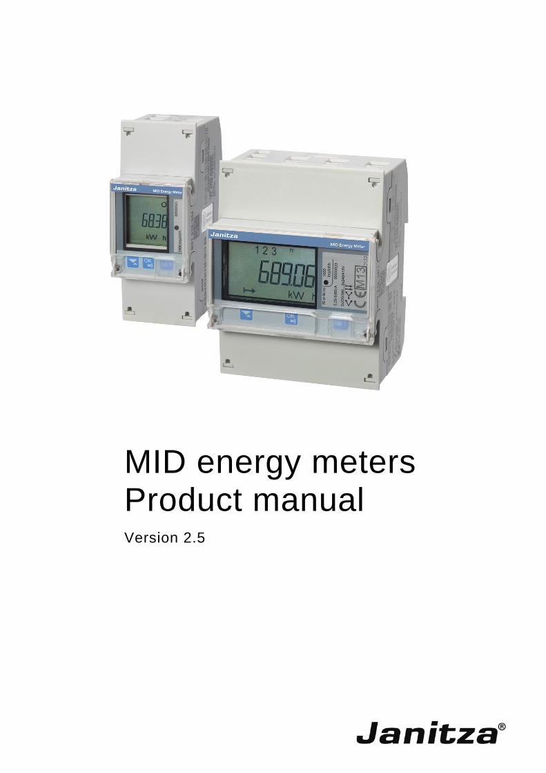
MID energy meters Product manual Version 2.5

MID energy meters Contents
Janitza electronics GmbH 2.100.006.2 i
Contents Page
1 General 3 1.1 Use of the product manual ........................................................................................................ 3 1.1.1 Notes......................................................................................................................................... 4 1.2 Product and function overview .................................................................................................. 5
2 Device technology 7 2.1 General B23/B24 ...................................................................................................................... 7 2.1.1 Component, operating and display elements ............................................................................ 8 2.1.2 Product label ............................................................................................................................. 9 2.1.3 B23 connection diagrams ........................................................................................................ 10 2.1.4 B24 connection diagrams ........................................................................................................ 11 2.1.5 Scale picture ........................................................................................................................... 12 2.2 General B21 ............................................................................................................................ 13 2.2.1 Component, operating and display elements .......................................................................... 14 2.2.2 Product label ........................................................................................................................... 15 2.2.3 Connection diagram ................................................................................................................ 16 2.2.4 Scale picture ........................................................................................................................... 17 2.3 Technical data B21, B23, B24 ................................................................................................. 18 2.4 Interface connection diagrams ................................................................................................ 20 2.4.1 Inputs/outputs ......................................................................................................................... 20 2.4.2 RS-485 (Modbus RTU) ........................................................................................................... 20 2.4.3 M-Bus...................................................................................................................................... 20 2.5 Display and indications ........................................................................................................... 21
3 Commissioning 25 3.1 Mounting and installation ........................................................................................................ 25 3.2 Settings ................................................................................................................................... 27 3.2.1 Setting the transformer ratio .................................................................................................... 28 3.2.2 Setting measuring units........................................................................................................... 30 3.2.3 Setting the pulse output .......................................................................................................... 31 3.2.4 Setting output 2 ....................................................................................................................... 34 3.2.5 Setting alarm for output 2 ........................................................................................................ 35 3.2.6 Setting the M-Bus ................................................................................................................... 39 3.2.7 Modbus settings ...................................................................................................................... 41 3.2.8 Infra-red interface (only for internal use) ................................................................................. 43 3.2.9 Protocol details ....................................................................................................................... 45 3.2.10 Setting upgrade authorisation ................................................................................................. 46 3.2.11 Setting the pulse LED ............................................................................................................. 47 3.2.12 Tariff settings (2 tariffs available) ............................................................................................ 48 3.2.13 Resetting intermediate meters (not available with B21, B23 and B24).................................... 49 3.3 Technical description .............................................................................................................. 51 3.3.1 Energy values ......................................................................................................................... 51 3.3.2 Measured values ..................................................................................................................... 52 3.3.3 Alarms ..................................................................................................................................... 53 3.3.4 Inputs and outputs .................................................................................................................. 54 3.3.5 Tariff inputs ............................................................................................................................. 54 3.3.6 Pulse outputs .......................................................................................................................... 55 3.3.7 Protocol storage logs .............................................................................................................. 56
4 Communication with Modbus 63 4.1 Modbus protocol ..................................................................................................................... 63 4.1.1 Function code 3 (reading the holding register) ........................................................................ 64 4.1.2 Function code 16 (writing multiple registers) ........................................................................... 65 4.1.3 Function code 6 (writing a single register) ............................................................................... 66
MID energy meters Contents
ii 2.100.006.2 Janitza electronics GmbH
4.1.4 Exception responses ............................................................................................................... 66 4.2 Reading and writing in the register .......................................................................................... 67 4.3 Mapping tables - standard register compatible with UMG devices .......................................... 68 4.4 Mapping tables - special register ............................................................................................ 70
5 Communication with M-Bus 77 5.1 Protocol description ................................................................................................................ 77 5.1.1 Telegram format ...................................................................................................................... 87 5.1.1.1 Field description ...................................................................................................................... 87 5.1.2 Field codes for value information ............................................................................................ 93 5.1.2.1 Standard VIF codes ................................................................................................................ 93 5.1.2.2 Standard codes for VIFE with connection indicator FDh ......................................................... 94 5.1.2.3 Standard codes for VIFE ......................................................................................................... 94 5.1.2.4 First manufacturer-specific VIFE codes .................................................................................. 95 5.1.2.5 VIFE codes for error messages (meter to master) .................................................................. 97 5.1.2.6 VIFE codes for object actions (master to meter) ..................................................................... 97 5.1.2.7 2nd manufacturer-specific VIFE after VIFE 1111 1000 (F8 hex): ............................................ 97 5.1.2.8 2nd manufacturer-specific VIFE after VIFE 1111 1001 (F9 hex): ............................................ 97 5.1.3 Communication process.......................................................................................................... 98 5.1.3.1 Selection and secondary addressing ...................................................................................... 99 5.2 Standard readout of meter data ............................................................................................ 100 5.2.1 Example for telegrams 1 to 4 with B21 (all values are hexadecimal) .................................... 100 5.2.2 Example for telegrams 1 to 6 with B23 (all values are hexadecimal) .................................... 111 5.2.3 Example for telegrams 1 to 6 with B24 (all values are hexadecimal) .................................... 132 5.3 Sending data to the meters ................................................................................................... 154 5.3.1 Tariff setting .......................................................................................................................... 155 5.3.2 Setting the primary address .................................................................................................. 155 5.3.3 Changing the Baud rate ........................................................................................................ 156 5.3.4 Resetting the power failure meter ......................................................................................... 156 5.3.5 Setting the current transformer conversion ratio (CT) - meter ............................................... 157 5.3.6 Setting the current transformer conversion ratio (CT) - denominator .................................... 157 5.3.7 Selecting status information .................................................................................................. 158 5.3.8 Resetting the stored status for input 1................................................................................... 158 5.3.9 Resetting the stored status for input 2................................................................................... 159 5.3.10 Resetting the input meter 1 ................................................................................................... 160 5.3.11 Resetting the input meter 2 ................................................................................................... 160 5.3.12 Setting output 1 ..................................................................................................................... 161 5.3.13 Setting output 2 ..................................................................................................................... 162 5.3.14 Resetting power failure time duration .................................................................................... 163 5.3.15 Sending a password ............................................................................................................. 163 5.3.16 Setting up a password........................................................................................................... 164 5.3.17 Resetting logs ....................................................................................................................... 164 5.3.18 Setting the level of write access ............................................................................................ 165 5.3.19 Setting tariff sources ............................................................................................................. 166
A Annex 169 A.1 Order information .................................................................................................................. 169

MID energy meters Contents
Janitza electronics GmbH 2.100.006.2 iii


MID energy meters General
Janitza electronics GmbH 2.100.006.2 3
1 General
Climate change and increasingly scarce resources are major challenges of our time. Efficient and sustainable use of energy is therefore essential. Only when armed with the knowledge of how much energy is consumed is it possible to implement expedient optimisation measures.
With the MID energy meters, Janitza offers comprehensive possibilities for logging energy data and passing this on to systems for evaluation or control.
1.1 Use of the product manual
This manual provides you with detailed technical information regarding the function, mounting and programming of the power supply. Application is explained on the basis of examples.
The manual is divided up into the following chapters:
Chapter 1 General
Chapter 2 Device technology
Chapter 3 Commissioning
Chapter 4 Communication with Modbus
Chapter 5 Communication with M-Bus
Chapter A Annex
MID energy meters General
4 2.100.006.2 Janitza electronics GmbH
1.1.1 Notes
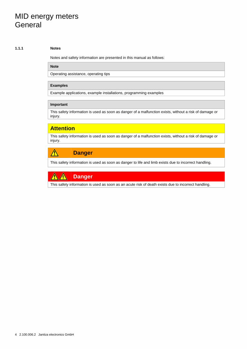
Notes and safety information are presented in this manual as follows:
Note
Operating assistance, operating tips
Examples
Example applications, example installations, programming examples
Important
This safety information is used as soon as danger of a malfunction exists, without a risk of damage or injury.
Attention This safety information is used as soon as danger of a malfunction exists, without a risk of damage or injury.
Danger
This safety information is used as soon as danger to life and limb exists due to incorrect handling.
Danger This safety information is used as soon as an acute risk of death exists due to incorrect handling.
MID energy meters General
Janitza electronics GmbH 2.100.006.2 5
1.2 Product and function overview
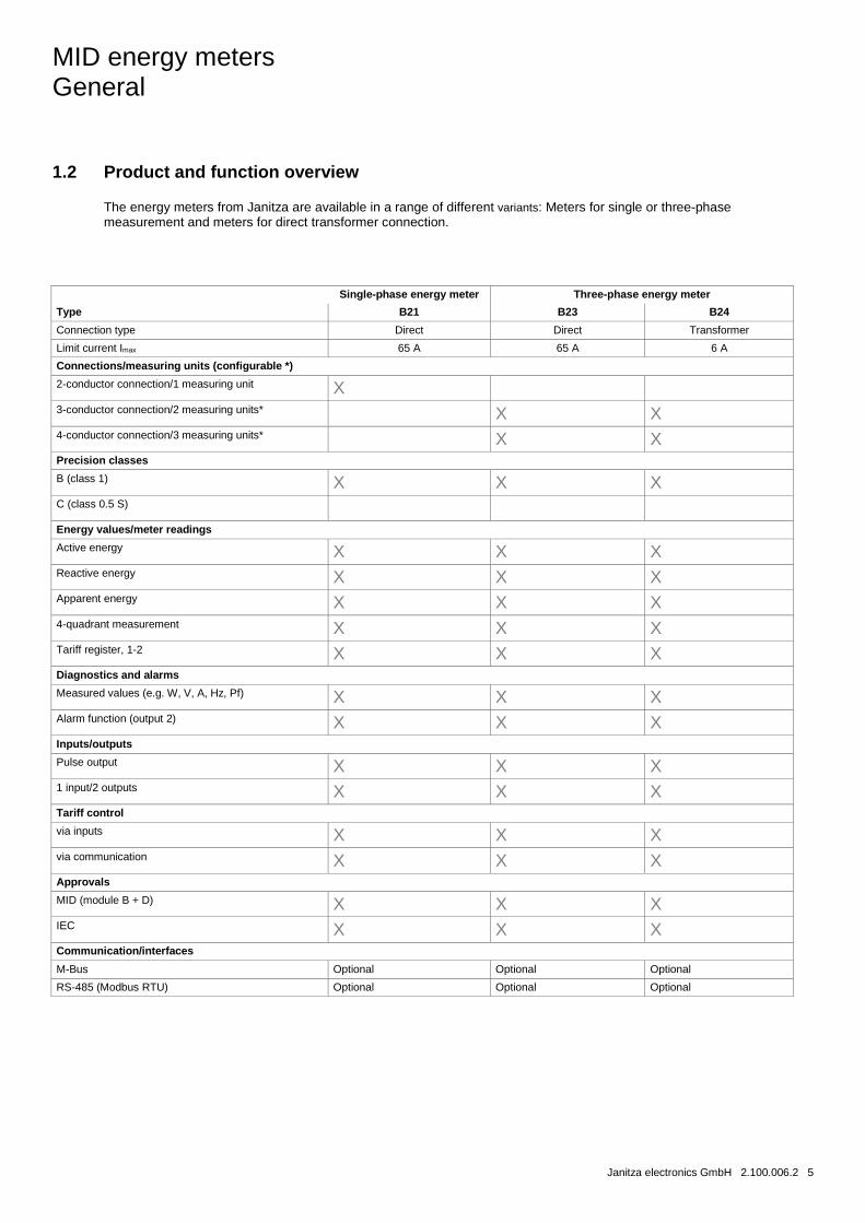
The energy meters from Janitza are available in a range of different variants: Meters for single or three-phase measurement and meters for direct transformer connection.
< B-series >
< A-series >
Single-phase energy meter Three-phase energy meter
Type B21 B23 B24
Connection type Direct Direct Transformer
Limit current Imax 65 A 65 A 6 A
Connections/measuring units (configurable *)
2-conductor connection/1 measuring unit X 3-conductor connection/2 measuring units* X X 4-conductor connection/3 measuring units* X X Precision classes
B (class 1) X X X C (class 0.5 S) Energy values/meter readings
Active energy X X X Reactive energy X X X Apparent energy X X X 4-quadrant measurement X X X Tariff register, 1-2 X X X Diagnostics and alarms
Measured values (e.g. W, V, A, Hz, Pf) X X X Alarm function (output 2) X X X Inputs/outputs
Pulse output X X X 1 input/2 outputs X X X Tariff control
via inputs X X X via communication X X X Approvals
MID (module B + D) X X X IEC X X X Communication/interfaces
M-Bus Optional Optional Optional
RS-485 (Modbus RTU) Optional Optional Optional

MID energy meters General
6 2.100.006.2 Janitza electronics GmbH
MID energy meters Device technology
Janitza electronics GmbH 2.100.006.2 7
2 Device technology
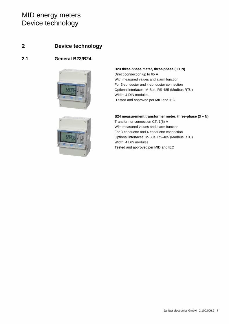
2.1 General B23/B24
B23 three-phase meter, three-phase (3 + N)
Direct connection up to 65 A
With measured values and alarm function
For 3-conductor and 4-conductor connection
Optional interfaces: M-Bus, RS-485 (Modbus RTU)
Width: 4 DIN modules.
.Tested and approved per MID and IEC
B24 measurement transformer meter, three-phase (3 + N)
Transformer connection CT, 1(6) A
With measured values and alarm function
For 3-conductor and 4-conductor connection
Optional interfaces: M-Bus, RS-485 (Modbus RTU)
Width: 4 DIN modules
Tested and approved per MID and IEC
MID energy meters Device technology
8 2.100.006.2 Janitza electronics GmbH
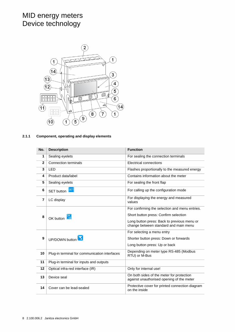
2.1.1 Component, operating and display elements
No. Description Function
1 Sealing eyelets For sealing the connection terminals
2 Connection terminals Electrical connections
3 LED Flashes proportionally to the measured energy
4 Product data/label Contains information about the meter
5 Sealing eyelets For sealing the front flap
6 SET button For calling up the configuration mode
7 LC display For displaying the energy and measured values
8 OK button
For confirming the selection and menu entries.
Short button press: Confirm selection
Long button press: Back to previous menu or change between standard and main menu
9 UP/DOWN button
For selecting a menu entry
Shorter button press: Down or forwards
Long button press: Up or back
10 Plug-in terminal for communication interfaces Depending on meter type RS-485 (Modbus RTU) or M-Bus
11 Plug-in terminal for inputs and outputs
12 Optical infra-red interface (IR) Only for internal use!
13 Device seal On both sides of the meter for protection against unauthorised opening of the meter
14 Cover can be lead-sealed Protective cover for printed connection diagram on the inside
MID energy meters Device technology
Janitza electronics GmbH 2.100.006.2 9
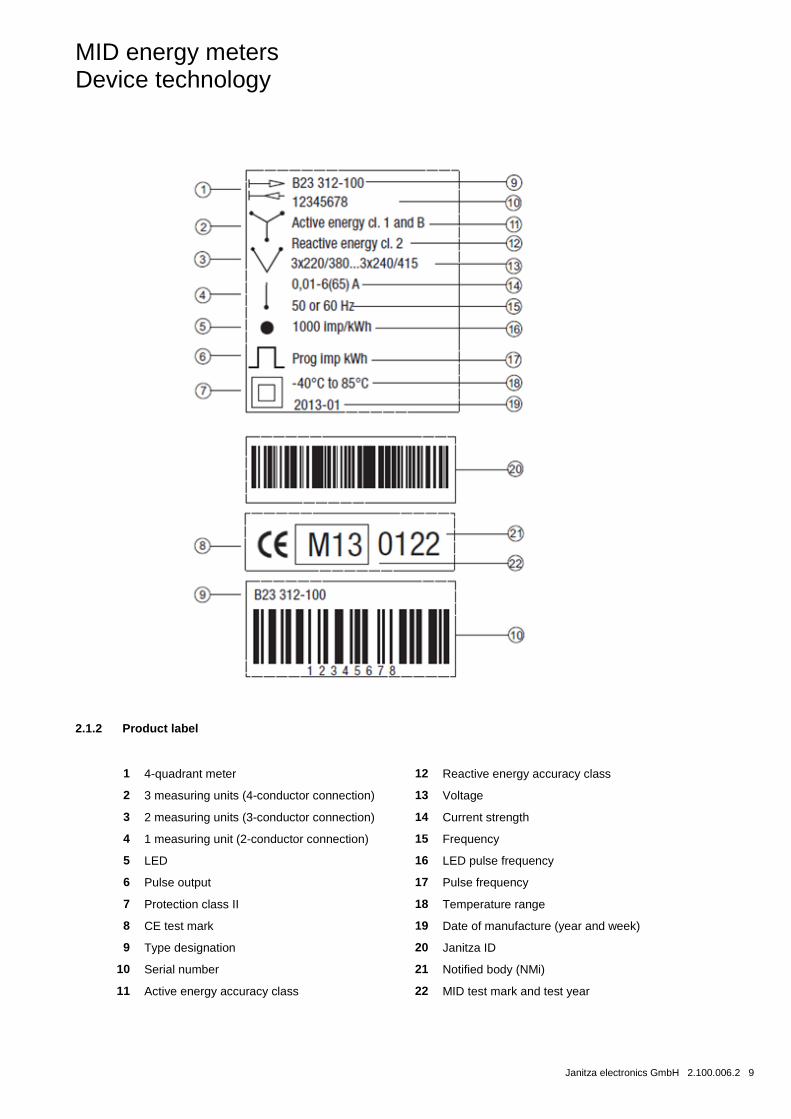
2.1.2 Product label
1 4-quadrant meter 12 Reactive energy accuracy class
2 3 measuring units (4-conductor connection) 13 Voltage
3 2 measuring units (3-conductor connection) 14 Current strength
4 1 measuring unit (2-conductor connection) 15 Frequency
5 LED 16 LED pulse frequency
6 Pulse output 17 Pulse frequency
7 Protection class II 18 Temperature range
8 CE test mark 19 Date of manufacture (year and week)
9 Type designation 20 Janitza ID
10 Serial number 21 Notified body (NMi)
11 Active energy accuracy class 22 MID test mark and test year
MID energy meters Device technology
10 2.100.006.2 Janitza electronics GmbH
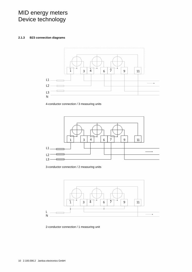
2.1.3 B23 connection diagrams
4-conductor connection / 3 measuring units
3-conductor connection / 2 measuring units
2-conductor connection / 1 measuring unit
MID energy meters Device technology
Janitza electronics GmbH 2.100.006.2 11
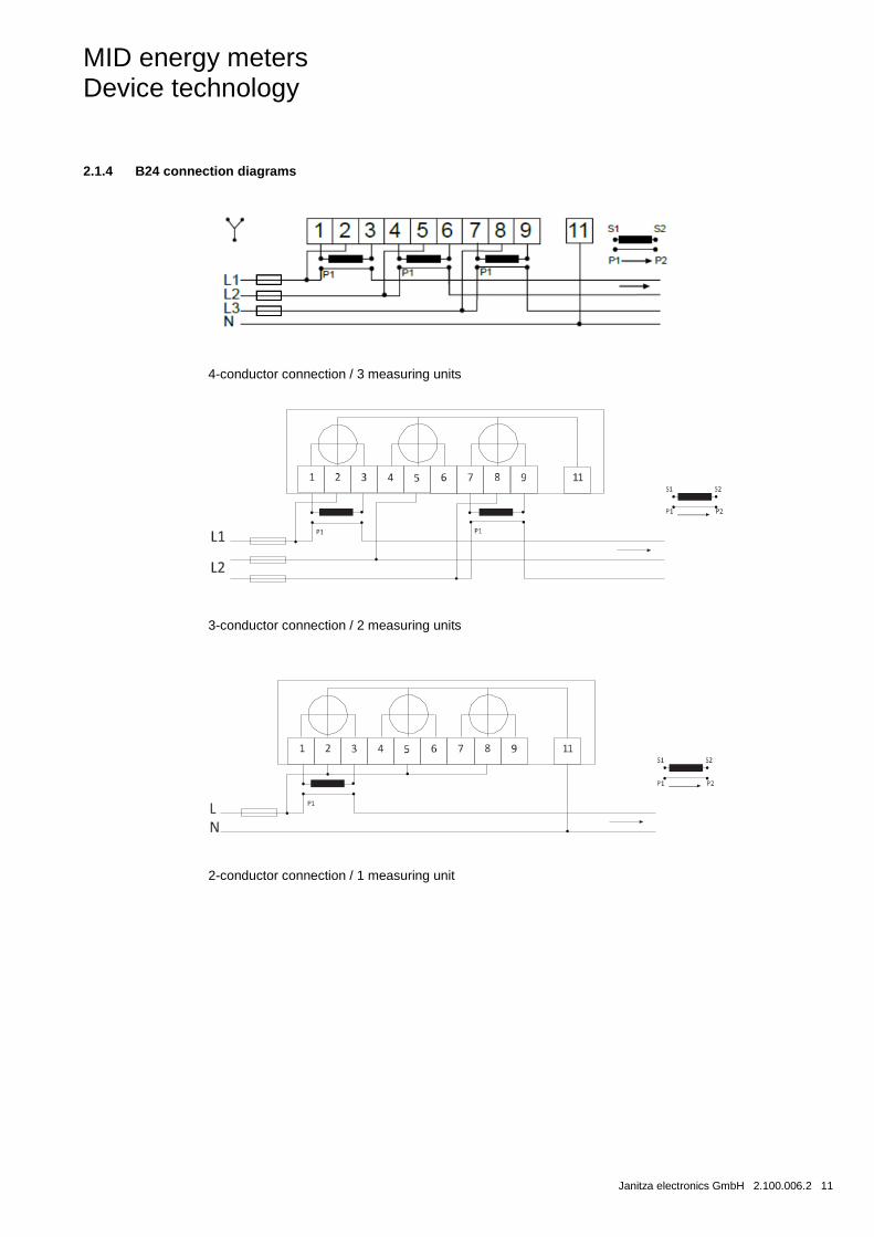
2.1.4 B24 connection diagrams
4-conductor connection / 3 measuring units
3-conductor connection / 2 measuring units
2-conductor connection / 1 measuring unit
MID energy meters Device technology
12 2.100.006.2 Janitza electronics GmbH
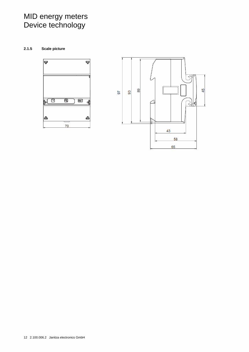
2.1.5 Scale picture
MID energy meters Device technology
Janitza electronics GmbH 2.100.006.2 13
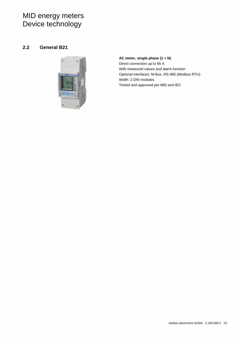
2.2 General B21
AC meter, single phase (1 + N)
Direct connection up to 65 A
With measured values and alarm function
Optional interfaces: M-Bus, RS-485 (Modbus RTU)
Width: 2 DIN modules.
Tested and approved per MID and IEC
MID energy meters Device technology
14 2.100.006.2 Janitza electronics GmbH
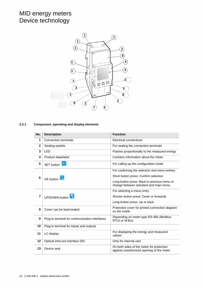
2.2.1 Component, operating and display elements
No. Description Function
1 Connection terminals Electrical connections
2 Sealing eyelets For sealing the connection terminals
3 LED Flashes proportionally to the measured energy
4 Product data/label Contains information about the meter
5 SET button For calling up the configuration mode
6 OK button
For confirming the selection and menu entries.
Short button press: Confirm selection
Long button press: Back to previous menu or change between standard and main menu
7 UP/DOWN button
For selecting a menu entry
Shorter button press: Down or forwards
Long button press: Up or back
8 Cover can be lead-sealed Protective cover for printed connection diagram on the inside
9 Plug-in terminal for communication interfaces Depending on meter type RS-485 (Modbus RTU) or M-Bus
10 Plug-in terminal for inputs and outputs
11 LC display For displaying the energy and measured values
12 Optical infra-red interface (IR) Only for internal use!
13 Device seal On both sides of the meter for protection against unauthorised opening of the meter
1 1 1
2 2
8
4 1
3 1
2 1 2 5
1
8
2 9 2 7 6
MID energy meters Device technology
Janitza electronics GmbH 2.100.006.2 15
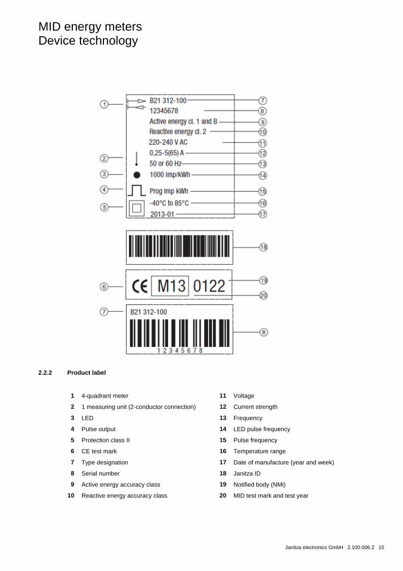
2.2.2 Product label
1 4-quadrant meter 11 Voltage
2 1 measuring unit (2-conductor connection) 12 Current strength
3 LED 13 Frequency
4 Pulse output 14 LED pulse frequency
5 Protection class II 15 Pulse frequency
6 CE test mark 16 Temperature range
7 Type designation 17 Date of manufacture (year and week)
8 Serial number 18 Janitza ID
9 Active energy accuracy class 19 Notified body (NMi)
10 Reactive energy accuracy class 20 MID test mark and test year

MID energy meters Device technology
16 2.100.006.2 Janitza electronics GmbH
2.2.3 Connection diagram
2-conductor connection / 1 measuring unit
MID energy meters Device technology
Janitza electronics GmbH 2.100.006.2 17
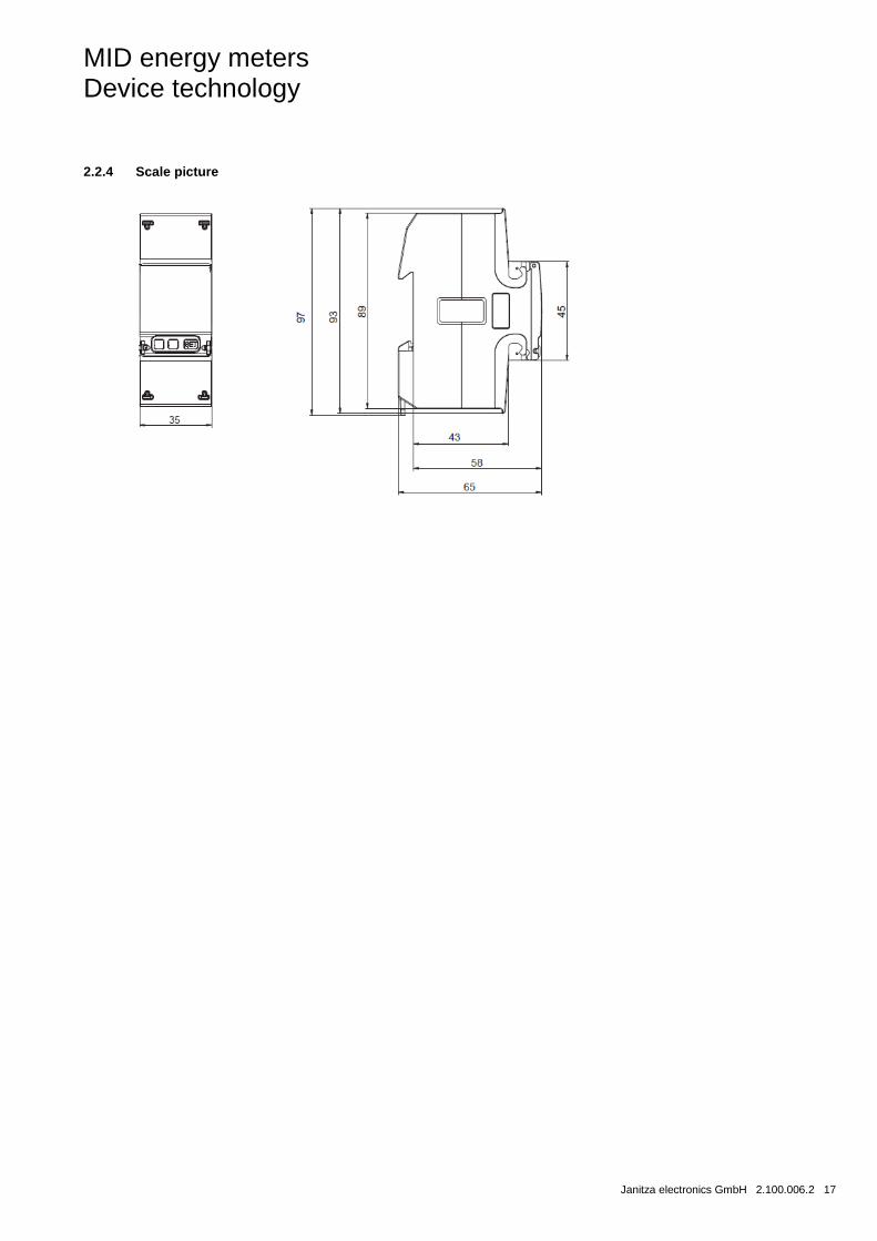
2.2.4 Scale picture
MID energy meters Device technology
18 2.100.006.2 Janitza electronics GmbH
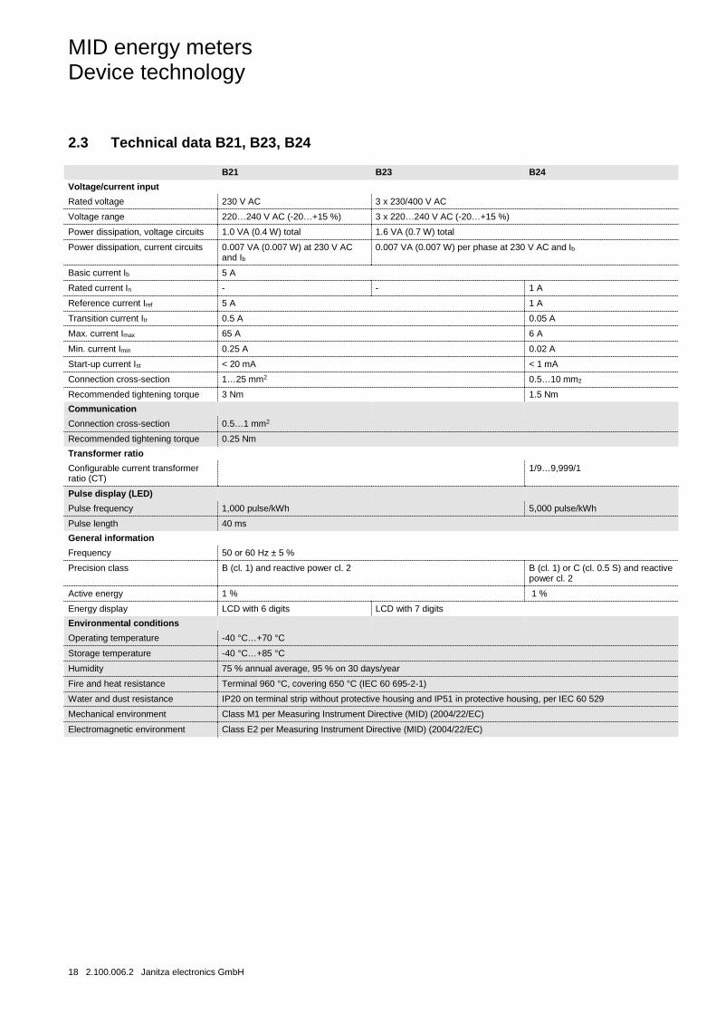
2.3 Technical data B21, B23, B24
B21 B23 B24
Voltage/current input
Rated voltage 230 V AC 3 x 230/400 V AC
Voltage range 220…240 V AC (-20…+15 %) 3 x 220…240 V AC (-20…+15 %)
Power dissipation, voltage circuits 1.0 VA (0.4 W) total 1.6 VA (0.7 W) total
Power dissipation, current circuits 0.007 VA (0.007 W) at 230 V AC and Ib
0.007 VA (0.007 W) per phase at 230 V AC and Ib
Basic current Ib 5 A
Rated current In - - 1 A
Reference current Iref 5 A 1 A
Transition current Itr 0.5 A 0.05 A
Max. current Imax 65 A 6 A
Min. current Imin 0.25 A 0.02 A
Start-up current Ist < 20 mA < 1 mA
Connection cross-section 1…25 mm2 0.5…10 mm2
Recommended tightening torque 3 Nm 1.5 Nm
Communication
Connection cross-section 0.5…1 mm2
Recommended tightening torque 0.25 Nm
Transformer ratio
Configurable current transformer ratio (CT)
1/9…9,999/1
Pulse display (LED)
Pulse frequency 1,000 pulse/kWh 5,000 pulse/kWh
Pulse length 40 ms
General information
Frequency 50 or 60 Hz ± 5 %
Precision class B (cl. 1) and reactive power cl. 2 B (cl. 1) or C (cl. 0.5 S) and reactive power cl. 2
Active energy 1 % 1 %
Energy display LCD with 6 digits LCD with 7 digits
Environmental conditions
Operating temperature -40 °C…+70 °C
Storage temperature -40 °C…+85 °C
Humidity 75 % annual average, 95 % on 30 days/year
Fire and heat resistance Terminal 960 °C, covering 650 °C (IEC 60 695-2-1)
Water and dust resistance IP20 on terminal strip without protective housing and IP51 in protective housing, per IEC 60 529
Mechanical environment Class M1 per Measuring Instrument Directive (MID) (2004/22/EC)
Electromagnetic environment Class E2 per Measuring Instrument Directive (MID) (2004/22/EC)
MID energy meters Device technology
Janitza electronics GmbH 2.100.006.2 19
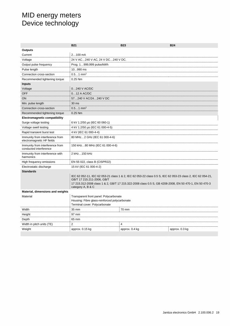
B21 B23 B24
Outputs
Current 2…100 mA
Voltage 24 V AC…240 V AC, 24 V DC…240 V DC.
Output pulse frequency Prog. 1…999,999 pulse/kWh
Pulse length 10...990 ms
Connection cross-section 0.5…1 mm2
Recommended tightening torque 0.25 Nm
Inputs
Voltage 0…240 V AC/DC
OFF 0…12 A AC/DC
ON 57…240 V AC/24…240 V DC
Min. pulse length 30 ms
Connection cross-section 0.5…1 mm2
Recommended tightening torque 0.25 Nm
Electromagnetic compatibility
Surge voltage testing 6 kV 1.2/50 µs (IEC 60 060-1)
Voltage swell testing 4 kV 1.2/50 µs (IEC 61 000-4-5)
Rapid transient burst test 4 kV (IEC 61 000-4-4)
Immunity from interference from electromagnetic HF fields
80 MHz…2 GHz (IEC 61 000-4-6)
Immunity from interference from conducted interference
150 kHz…80 MHz (IEC 61 000-4-6)
Immunity from interference with harmonics
2 kHz…150 kHz
High frequency emissions EN 55 022, class B (CISPR22)
Electrostatic discharge 15 kV (IEC 61 000-4-2)
Standards
IEC 62 052-11, IEC 62 053-21 class 1 & 2, IEC 62 053-22 class 0.5 S, IEC 62 053-23 class 2, IEC 62 054-21, GB/T 17 215.211-2006, GB/T 17 215.312-2008 class 1 & 2, GB/T 17 215.322-2008 class 0.5 S, GB 4208-2008, EN 50 470-1, EN 50 470-3 category A, B & C
Material, dimensions and weights
Material Transparent front panel: Polycarbonate Housing: Fibre glass-reinforced polycarbonate Terminal cover: Polycarbonate
Width 35 mm 70 mm
Height 97 mm
Depth 65 mm
Width in pitch units (TE) 2 4
Weight approx. 0.15 kg approx. 0.4 kg approx. 0.3 kg
MID energy meters Device technology
20 2.100.006.2 Janitza electronics GmbH
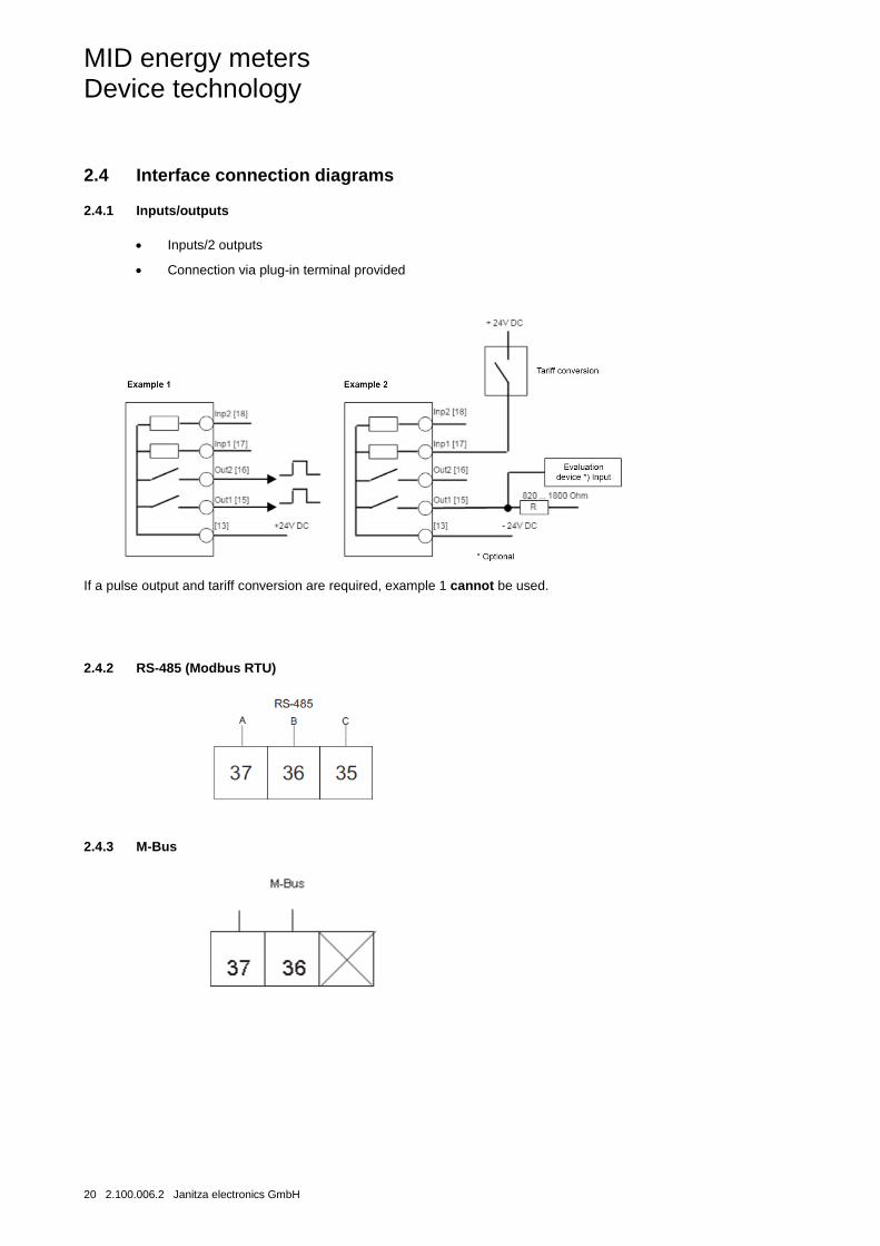
2.4 Interface connection diagrams
2.4.1 Inputs/outputs
• Inputs/2 outputs
• Connection via plug-in terminal provided
If a pulse output and tariff conversion are required, example 1 cannot be used.
2.4.2 RS-485 (Modbus RTU)
2.4.3 M-Bus
MID energy meters Device technology
Janitza electronics GmbH 2.100.006.2 21
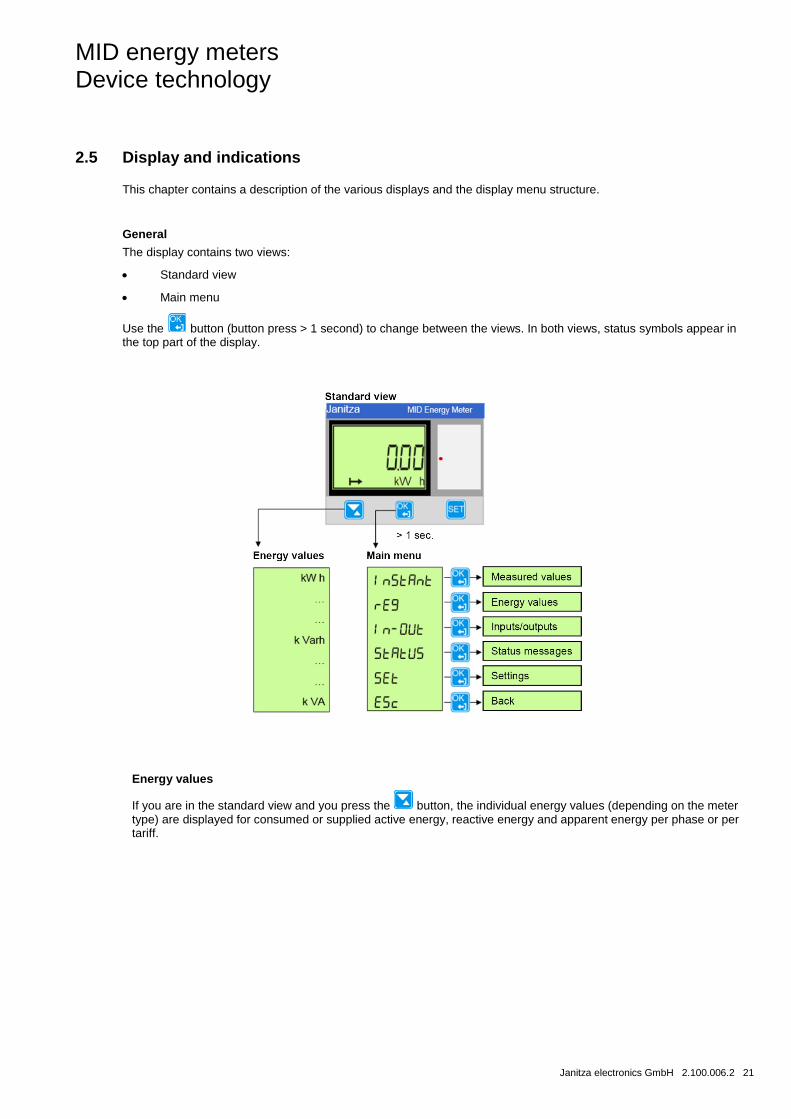
2.5 Display and indications
This chapter contains a description of the various displays and the display menu structure.
General
The display contains two views:
• Standard view
• Main menu
Use the button (button press > 1 second) to change between the views. In both views, status symbols appear in the top part of the display.
Energy values
If you are in the standard view and you press the button, the individual energy values (depending on the meter type) are displayed for consumed or supplied active energy, reactive energy and apparent energy per phase or per tariff.
MID energy meters Device technology
22 2.100.006.2 Janitza electronics GmbH
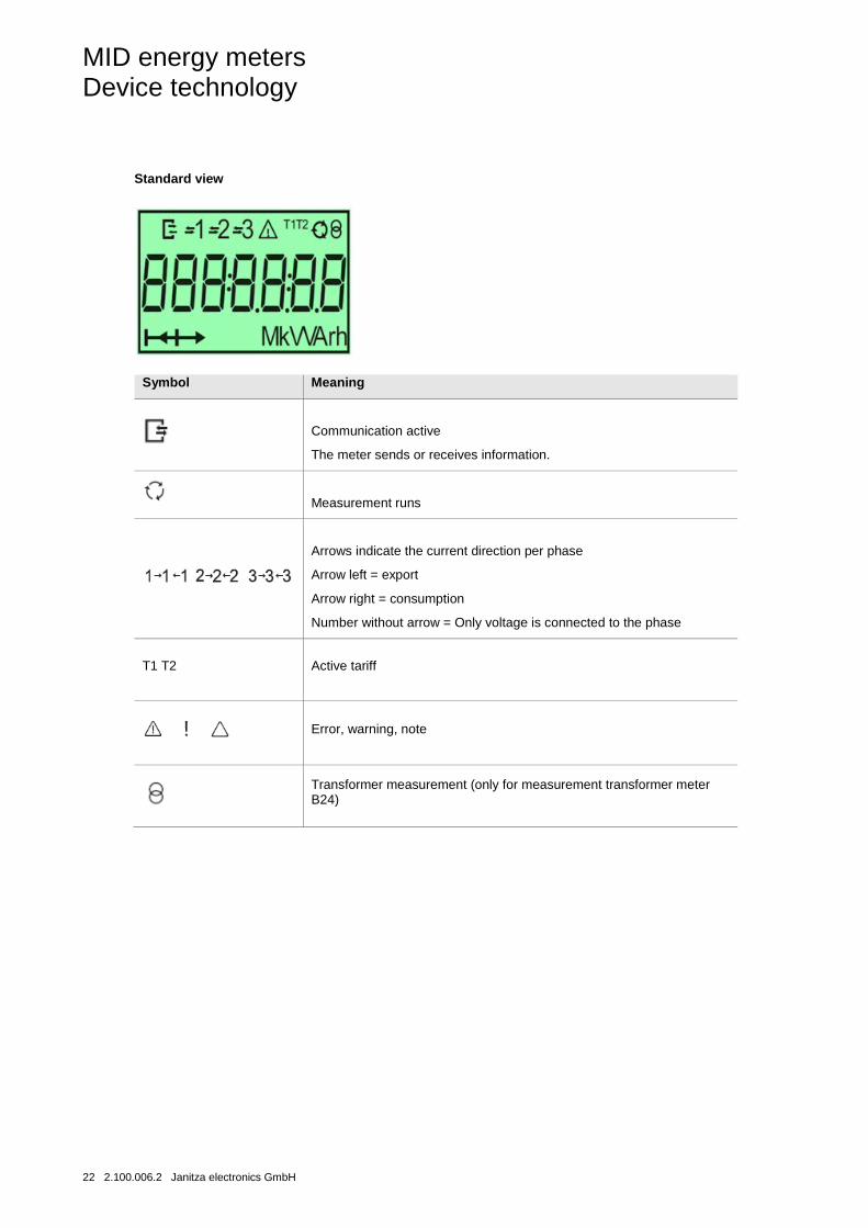
Standard view
Symbol Meaning
Communication active
The meter sends or receives information.
Measurement runs
Arrows indicate the current direction per phase
Arrow left = export
Arrow right = consumption
Number without arrow = Only voltage is connected to the phase
T1 T2 Active tariff
Error, warning, note
Transformer measurement (only for measurement transformer meter B24)
MID energy meters Device technology
Janitza electronics GmbH 2.100.006.2 23
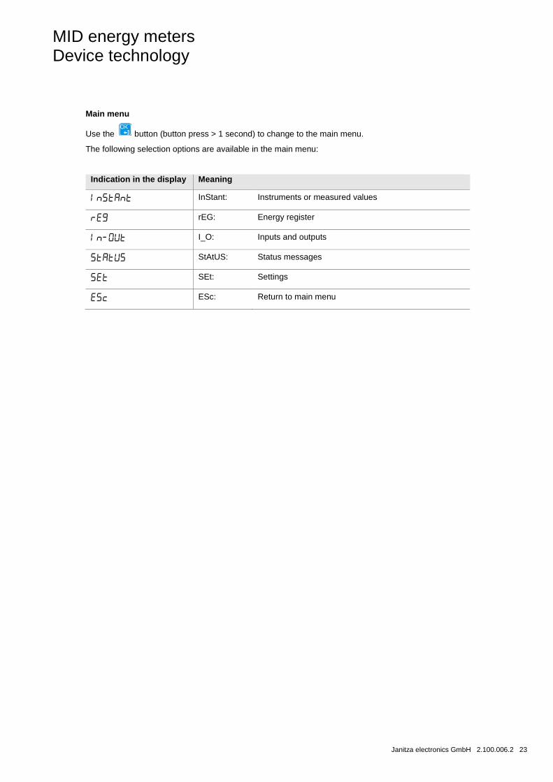
Main menu
Use the button (button press > 1 second) to change to the main menu.
The following selection options are available in the main menu:
Indication in the display Meaning
InStant: Instruments or measured values
rEG: Energy register
I_O: Inputs and outputs
StAtUS: Status messages
SEt: Settings
ESc: Return to main menu
MID energy meters Device technology
24 2.100.006.2 Janitza electronics GmbH
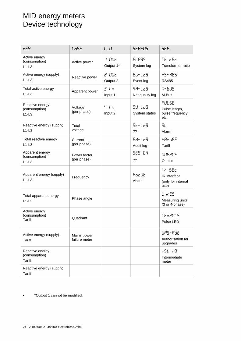
Active energy (consumption)
L1-L3 Active power
Output 1*
System log
Transformer ratio
Active energy (supply)
L1-L3 Reactive power
Output 2
Event log
RS485
Total active energy
L1-L3 Apparent power
Input 1
Net quality log
M-Bus
Reactive energy (consumption)
L1-L3
Voltage (per phase)
Input 2
System status
Pulse length, pulse frequency, etc.
Reactive energy (supply)
L1-L3 Total voltage
??
Alarm
Total reactive energy
L1-L3 Current (per phase)
Audit log
Tariff
Apparent energy (consumption)
L1-L3
Power factor (per phase)
??
Output
Apparent energy (supply)
L1-L3 Frequency
About
IR interface
(only for internal use)
Total apparent energy
L1-L3 Phase angle
Measuring units (3 or 4-phase)
Active energy (consumption) Tariff
Quadrant
Pulse LED
Active energy (supply)
Tariff Mains power failure meter
Authorisation for upgrades
Reactive energy (consumption)
Tariff
Intermediate meter
Reactive energy (supply)
Tariff
• *Output 1 cannot be modified.
MID energy meters Commissioning
Janitza electronics GmbH 2.100.006.2 25
3 Commissioning
This section contains a description of the mounting and installation process, as well as the procedure for setting the device functions.
3.1 Mounting and installation
The energy meters are designed for mounting on DIN rails (DIN 50 022). The meters are fastened by latching into the locking mechanism of the DIN rails.
Accessibility of the device for operation, testing, inspection, maintenance and repair must be ensured in accordance with DIN VDE 0100-520.
Mounting and commissioning must be performed by an electrician. When planning and installing electrical systems, it is necessary to observe the relevant standards, directives, regulations and provisions.
• Protect device from moisture, dirt and damage during transport, storage and operation.
• Only operate the device within the specified technical data!
• Only operate the device in an enclosed housing (distributor)!
Observe the following steps when installing and testing the meter:
Step Action
1 Shut off the power supply.
2 Position the meter on the DIN rail and latch it in place.
3 Remove the cable insulation to the length specified on the meter.
4 Connect the cables to the meter in accordance with the connection diagram and tighten the screws (3.0 Nm for meters with a direct connection and 1.5 Nm for meters with a transformer connection).
5
Install the line protection:
Meters with direct connection: 65 A MCB, C-system or 65 A fuse type gL-gG
Meters with transformer connection: 10 A MCB, B-system or safety fuse, flink.
6 If inputs and outputs are used: Connect the cables to the meter in accordance with the connection diagram and tighten the screws (0.25 Nm). Establish the connection with the external power supply (max. 240 V).
7 If communication (M-Bus, Modbus RTU) is used: Connect the cables to the meter in accordance with the connection diagram and tighten the screws (0.25 Nm).
8 Check that the meter is connected to the correct voltage and whether the phase connections and neutral conductors (if used) are connected to the correct terminals.
9 When using measurement transformer meters, make sure the flow direction of the primary and secondary current of the external current transformer is correct. Also check that the current transformers are connected to the meter with the correct terminals.
10 Activate the current connection. If the display shows a warning symbol, refer to chapter Protocol storage logs, p. 56 ff for the description.
11
Check under the menu item "Instantaneous Values" in the meter whether the values for the voltage, current strength, energy and power factors lie within the normal range and whether the current direction is correct (the total energy should be positive for an energy-consuming load). For comprehensive testing insofar as possible, the meter should be connected to the desired load, if possible a load with a current strength greater than zero to all phases.
MID energy meters Commissioning
26 2.100.006.2 Janitza electronics GmbH
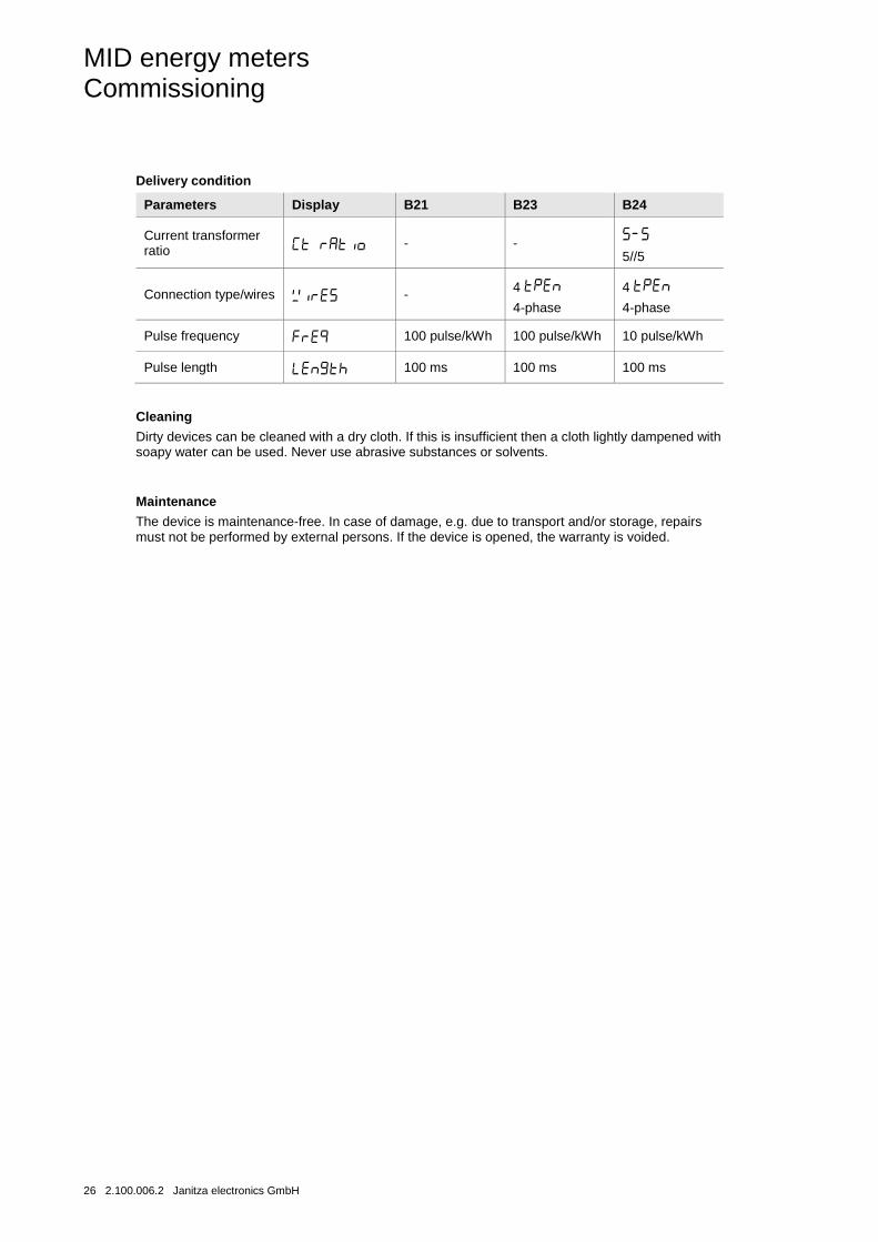
Delivery condition
Parameters Display B21 B23 B24
Current transformer ratio - -
5//5
Connection type/wires - 4
4-phase
4
4-phase
Pulse frequency 100 pulse/kWh 100 pulse/kWh 10 pulse/kWh
Pulse length 100 ms 100 ms 100 ms
Cleaning
Dirty devices can be cleaned with a dry cloth. If this is insufficient then a cloth lightly dampened with soapy water can be used. Never use abrasive substances or solvents.
Maintenance
The device is maintenance-free. In case of damage, e.g. due to transport and/or storage, repairs must not be performed by external persons. If the device is opened, the warranty is voided.
MID energy meters Commissioning
Janitza electronics GmbH 2.100.006.2 27
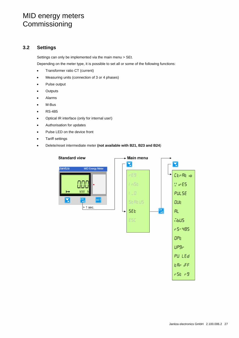
3.2 Settings
Settings can only be implemented via the main menu > SEt.
Depending on the meter type, it is possible to set all or some of the following functions:
• Transformer ratio CT (current)
• Measuring units (connection of 3 or 4 phases)
• Pulse output
• Outputs
• Alarms
• M-Bus
• RS-485
• Optical IR interface (only for internal use!)
• Authorisation for updates
• Pulse LED on the device front
• Tariff settings
• Delete/reset intermediate meter (not available with B21, B23 and B24)
MID energy meters Commissioning
28 2.100.006.2 Janitza electronics GmbH
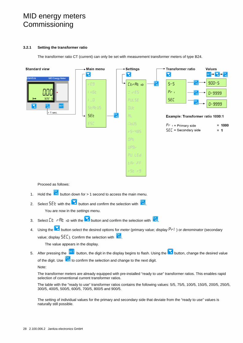
3.2.1 Setting the transformer ratio
The transformer ratio CT (current) can only be set with measurement transformer meters of type B24.
Proceed as follows:
1. Hold the button down for > 1 second to access the main menu.
2. Select with the button and confirm the selection with .
You are now in the settings menu.
3. Select with the button and confirm the selection with .
4. Using the button select the desired options for meter (primary value; display ) or denominator (secondary
value; display ). Confirm the selection with .
The value appears in the display.
5. After pressing the button, the digit in the display begins to flash. Using the button, change the desired value
of the digit. Use to confirm the selection and change to the next digit.
Note:
The transformer meters are already equipped with pre-installed “ready to use” transformer ratios. This enables rapid selection of conventional current transformer ratios.
The table with the “ready to use“ transformer ratios contains the following values: 5/5, 75/5, 100/5, 150/5, 200/5, 250/5, 300/5, 400/5, 500/5, 600/5, 700/5, 800/5 and 900/5.
The setting of individual values for the primary and secondary side that deviate from the “ready to use” values is naturally still possible.
MID energy meters Commissioning
Janitza electronics GmbH 2.100.006.2 29
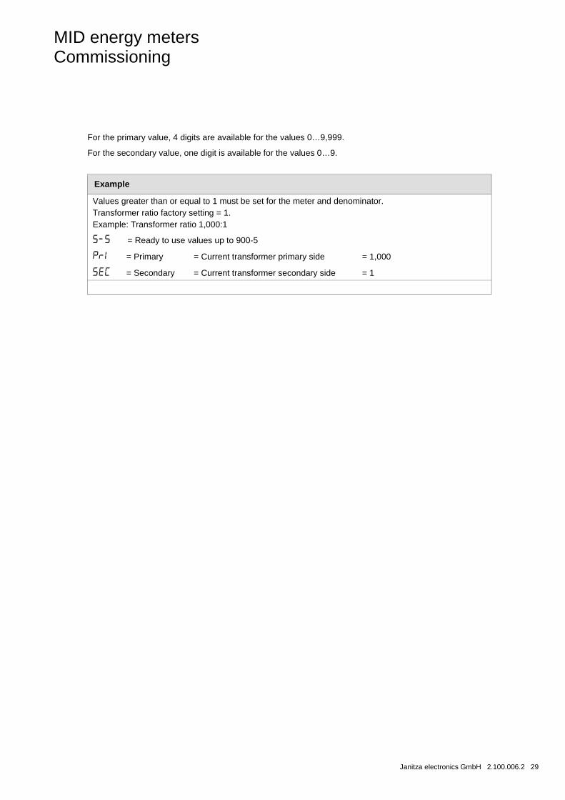
For the primary value, 4 digits are available for the values 0…9,999.
For the secondary value, one digit is available for the values 0…9.
Example
Values greater than or equal to 1 must be set for the meter and denominator. Transformer ratio factory setting = 1. Example: Transformer ratio 1,000:1
= Ready to use values up to 900-5
= Primary = Current transformer primary side = 1,000
= Secondary = Current transformer secondary side = 1
MID energy meters Commissioning
30 2.100.006.2 Janitza electronics GmbH
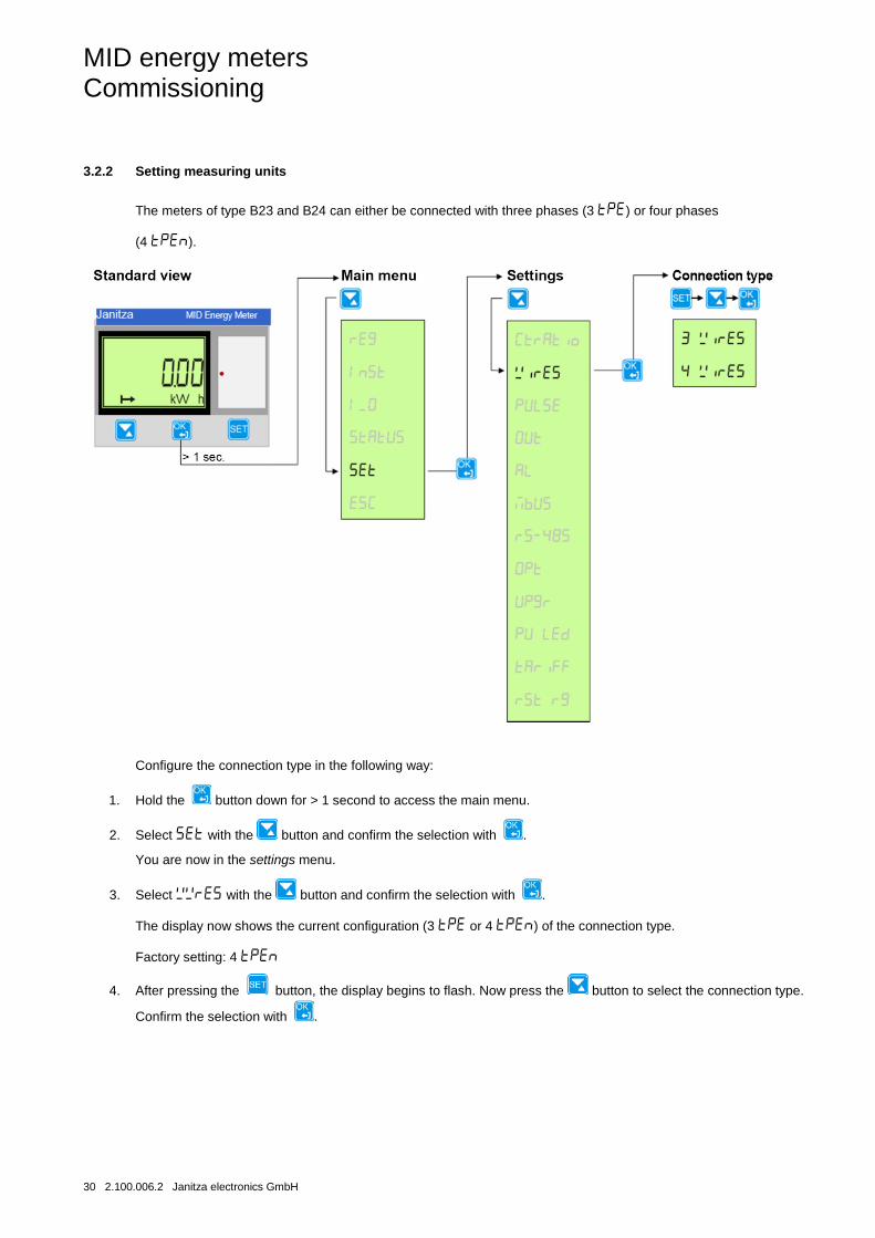
3.2.2 Setting measuring units
The meters of type B23 and B24 can either be connected with three phases (3 ) or four phases
(4 ).
Configure the connection type in the following way:
1. Hold the button down for > 1 second to access the main menu.
2. Select with the button and confirm the selection with .
You are now in the settings menu.
3. Select with the button and confirm the selection with .
The display now shows the current configuration (3 or 4 ) of the connection type.
Factory setting: 4
4. After pressing the button, the display begins to flash. Now press the button to select the connection type.
Confirm the selection with .
MID energy meters Commissioning
Janitza electronics GmbH 2.100.006.2 31
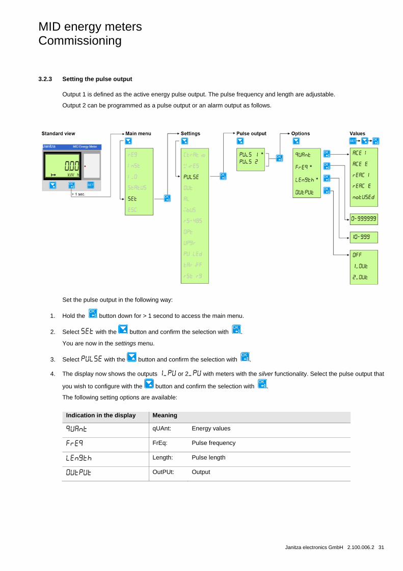
3.2.3 Setting the pulse output
Output 1 is defined as the active energy pulse output. The pulse frequency and length are adjustable.
Output 2 can be programmed as a pulse output or an alarm output as follows.
Set the pulse output in the following way:
1. Hold the button down for > 1 second to access the main menu.
2. Select with the button and confirm the selection with .
You are now in the settings menu.
3. Select with the button and confirm the selection with .
4. The display now shows the outputs or 2 with meters with the silver functionality. Select the pulse output that
you wish to configure with the button and confirm the selection with .
The following setting options are available:
Indication in the display Meaning
qUAnt: Energy values
FrEq: Pulse frequency
Length: Pulse length
OutPUt: Output
MID energy meters Commissioning
32 2.100.006.2 Janitza electronics GmbH
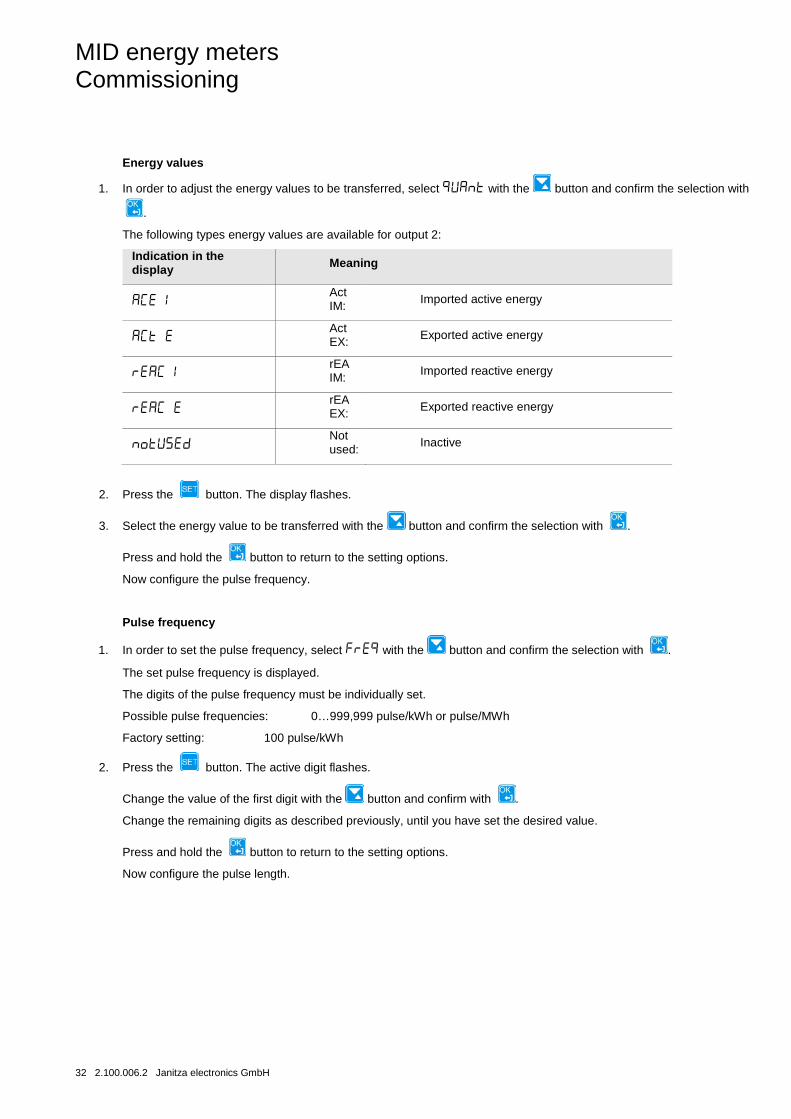
Energy values
1. In order to adjust the energy values to be transferred, select with the button and confirm the selection with
.
The following types energy values are available for output 2:
Indication in the display Meaning
Act IM: Imported active energy
Act EX: Exported active energy
rEA IM: Imported reactive energy
rEA EX: Exported reactive energy
Not used:
Inactive
2. Press the button. The display flashes.
3. Select the energy value to be transferred with the button and confirm the selection with .
Press and hold the button to return to the setting options.
Now configure the pulse frequency.
Pulse frequency
1. In order to set the pulse frequency, select with the button and confirm the selection with .
The set pulse frequency is displayed.
The digits of the pulse frequency must be individually set.
Possible pulse frequencies: 0…999,999 pulse/kWh or pulse/MWh
Factory setting: 100 pulse/kWh
2. Press the button. The active digit flashes.
Change the value of the first digit with the button and confirm with .
Change the remaining digits as described previously, until you have set the desired value.
Press and hold the button to return to the setting options.
Now configure the pulse length.
MID energy meters Commissioning
Janitza electronics GmbH 2.100.006.2 33
Pulse length
1. In order to set the pulse length, select with the button and confirm the selection with .
The set pulse length is displayed.
The digits of the pulse length must be individually set.
Possible pulse length: 10…990 ms
Factory setting: 100 ms
2. Press the button. The active digit flashes.
Change the value of the first digit with the button and confirm with .
Change the remaining digits as described previously, until you have set the desired value.
Press and hold the button to return to the setting options.
Now configure the outputs.
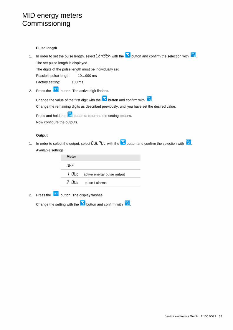
Output
1. In order to select the output, select with the button and confirm the selection with .
Available settings:
Meter
active energy pulse output
pulse / alarms
2. Press the button. The display flashes.
Change the setting with the button and confirm with .
MID energy meters Commissioning
34 2.100.006.2 Janitza electronics GmbH
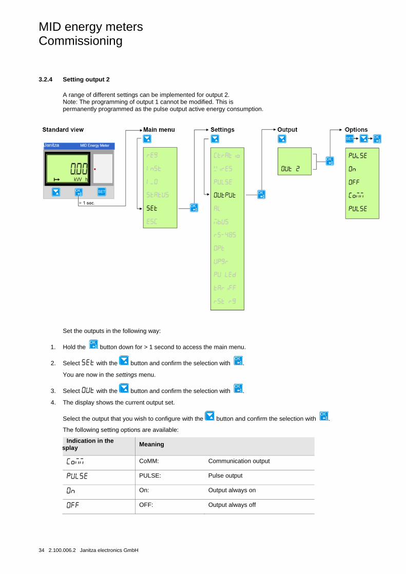
3.2.4 Setting output 2
A range of different settings can be implemented for output 2. Note: The programming of output 1 cannot be modified. This is permanently programmed as the pulse output active energy consumption.
Set the outputs in the following way:
1. Hold the button down for > 1 second to access the main menu.
2. Select with the button and confirm the selection with .
You are now in the settings menu.
3. Select with the button and confirm the selection with .
4. The display shows the current output set.
Select the output that you wish to configure with the button and confirm the selection with .
The following setting options are available:
Indication in the splay Meaning
CoMM: Communication output
PULSE: Pulse output
On: Output always on
OFF: Output always off
MID energy meters Commissioning
Janitza electronics GmbH 2.100.006.2 35
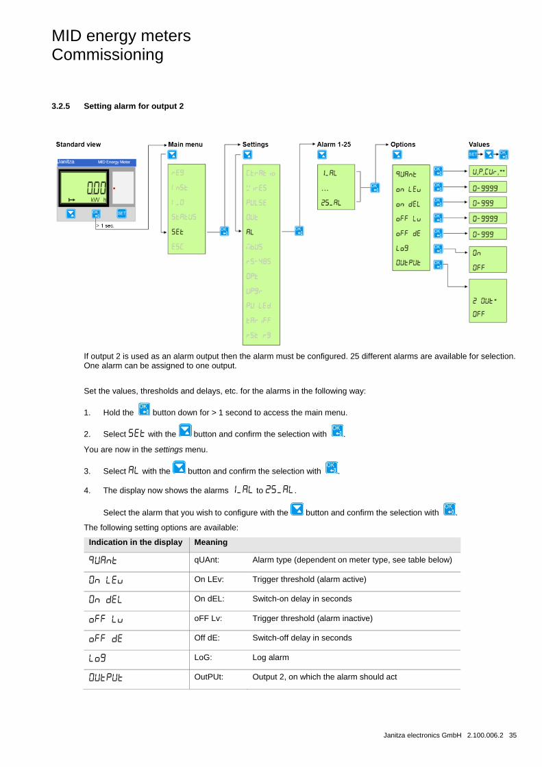
3.2.5 Setting alarm for output 2
If output 2 is used as an alarm output then the alarm must be configured. 25 different alarms are available for selection. One alarm can be assigned to one output.
Set the values, thresholds and delays, etc. for the alarms in the following way:
1. Hold the button down for > 1 second to access the main menu.
2. Select with the button and confirm the selection with .
You are now in the settings menu.
3. Select with the button and confirm the selection with .
4. The display now shows the alarms to .
Select the alarm that you wish to configure with the button and confirm the selection with .
The following setting options are available:
Indication in the display Meaning
qUAnt: Alarm type (dependent on meter type, see table below)
On LEv: Trigger threshold (alarm active)
On dEL: Switch-on delay in seconds
oFF Lv: Trigger threshold (alarm inactive)
Off dE: Switch-off delay in seconds
LoG: Log alarm
OutPUt: Output 2, on which the alarm should act
MID energy meters Commissioning
36 2.100.006.2 Janitza electronics GmbH
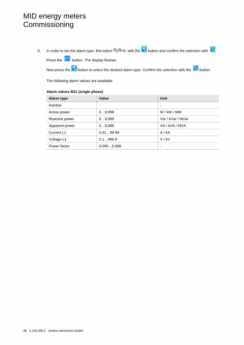
5. In order to set the alarm type, first select with the button and confirm the selection with .
Press the button. The display flashes.
Now press the button to select the desired alarm type. Confirm the selection with the button.
The following alarm values are available:
Alarm values B21 (single phase)
Alarm type Value Unit
Inactive - -
Active power 0…9,999 W / kW / MW
Reactive power 0…9,999 Var / kVar / MVar
Apparent power 0…9,999 VA / kVA / MVA
Current L1 0.01…99.99 A / kA
Voltage L1 0.1…999.9 V / kV
Power factor 0.000…0.999 -
MID energy meters Commissioning
Janitza electronics GmbH 2.100.006.2 37
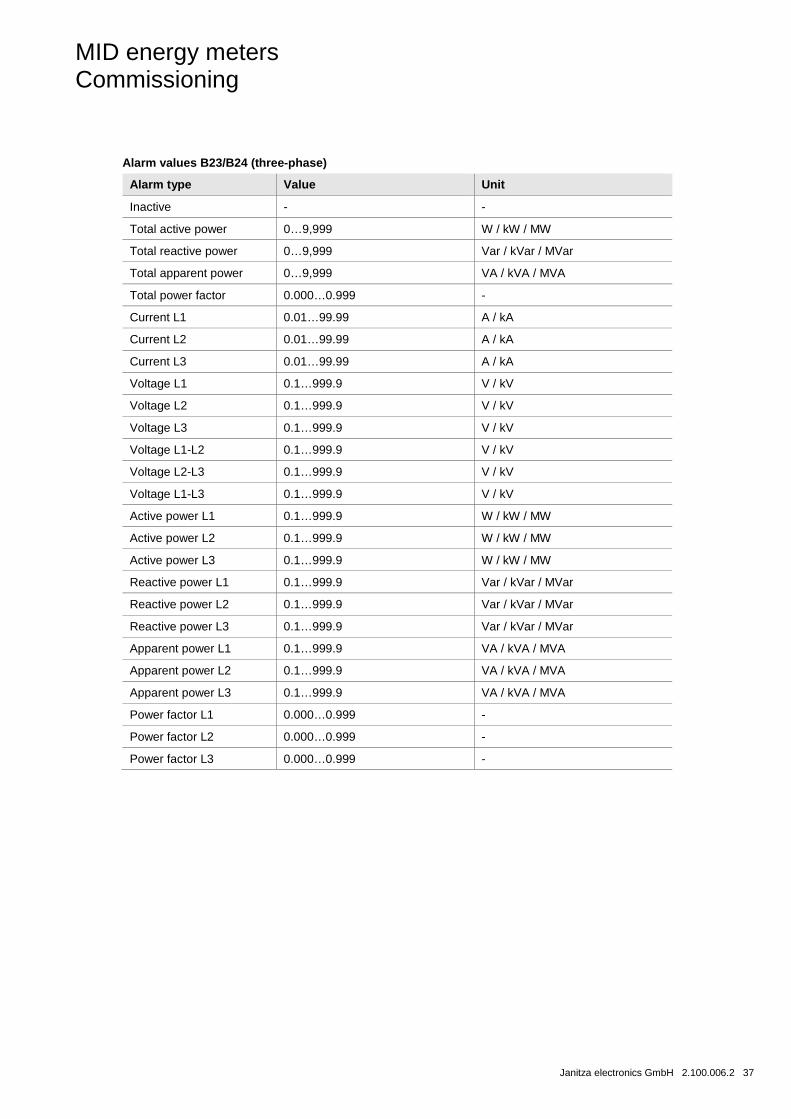
Alarm values B23/B24 (three-phase)
Alarm type Value Unit
Inactive - -
Total active power 0…9,999 W / kW / MW
Total reactive power 0…9,999 Var / kVar / MVar
Total apparent power 0…9,999 VA / kVA / MVA
Total power factor 0.000…0.999 -
Current L1 0.01…99.99 A / kA
Current L2 0.01…99.99 A / kA
Current L3 0.01…99.99 A / kA
Voltage L1 0.1…999.9 V / kV
Voltage L2 0.1…999.9 V / kV
Voltage L3 0.1…999.9 V / kV
Voltage L1-L2 0.1…999.9 V / kV
Voltage L2-L3 0.1…999.9 V / kV
Voltage L1-L3 0.1…999.9 V / kV
Active power L1 0.1…999.9 W / kW / MW
Active power L2 0.1…999.9 W / kW / MW
Active power L3 0.1…999.9 W / kW / MW
Reactive power L1 0.1…999.9 Var / kVar / MVar
Reactive power L2 0.1…999.9 Var / kVar / MVar
Reactive power L3 0.1…999.9 Var / kVar / MVar
Apparent power L1 0.1…999.9 VA / kVA / MVA
Apparent power L2 0.1…999.9 VA / kVA / MVA
Apparent power L3 0.1…999.9 VA / kVA / MVA
Power factor L1 0.000…0.999 -
Power factor L2 0.000…0.999 -
Power factor L3 0.000…0.999 -
MID energy meters Commissioning
38 2.100.006.2 Janitza electronics GmbH
6. In order to set the trigger threshold at which an alarm is activated or deactivated, select the option or
with the button and confirm the selection with .
Press the button. The display flashes.
Using the button, it is now possible to select the desired value (e.g. 285 V) for the trigger threshold. Confirm
the selection with the button.
7. In order that an alarm is activated or deactivated, it is possible to set a switch-on or switch-off delay. If the previously set trigger threshold is exceeded or undercut for the set time duration, the alarm is activated or deactivated. In order to set the switch-on or switch-off delay at which an alarm is activated or deactivated, select
the option or with the button and confirm the selection with .
Press the button. The display flashes. Now press the button to select the desired time duration in
seconds. Confirm the selection with the button.
8. In order to log an alarm, select the option with the button and confirm the selection with .
Press the button. The display flashes. Using the button, select the desired setting (ON: Log, OFF: Do
not log). Confirm the selection with the button.
9. In order to set the output on which the alarm settings should act, select the option with the button
and confirm the selection with .
Available settings:
Meter
Press the button. The display flashes. Using the button, select the desired setting. Confirm the selection
with the button.
MID energy meters Commissioning
Janitza electronics GmbH 2.100.006.2 39
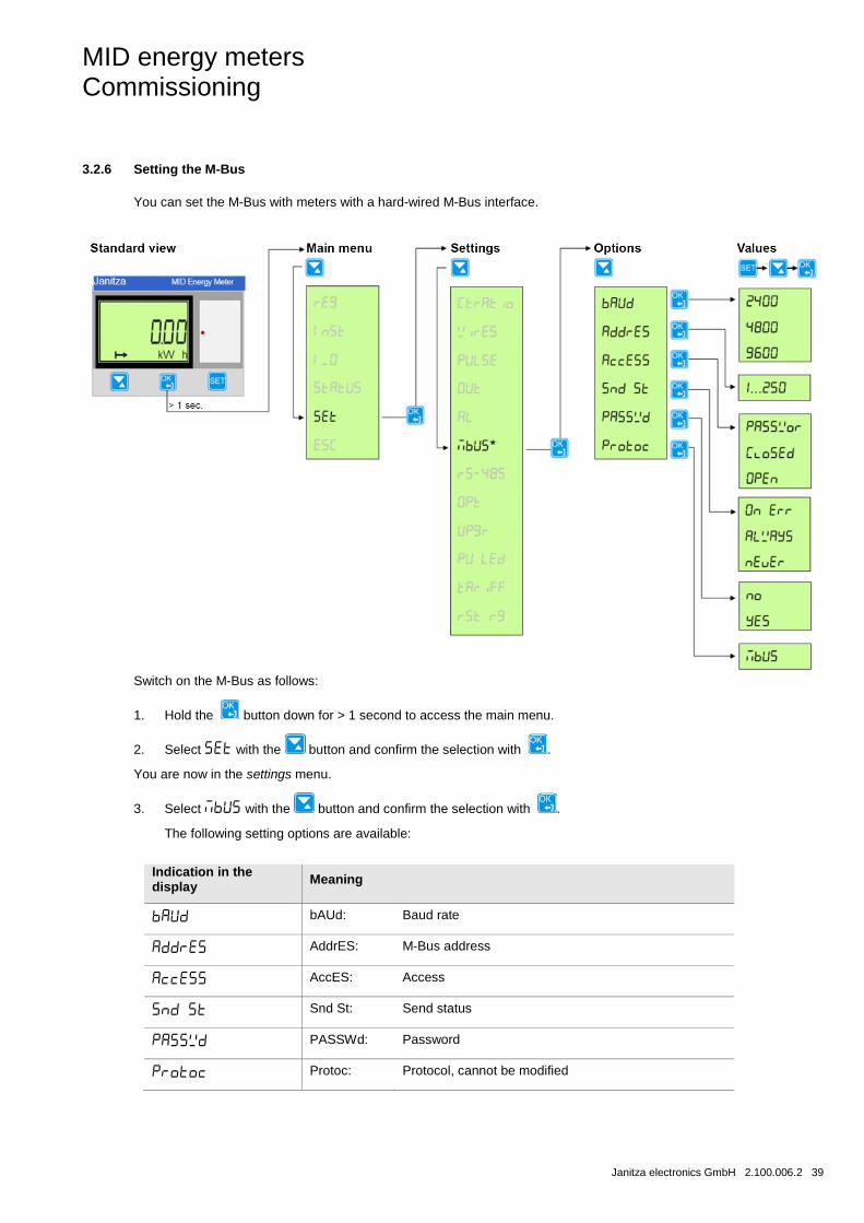
3.2.6 Setting the M-Bus
You can set the M-Bus with meters with a hard-wired M-Bus interface.
Switch on the M-Bus as follows:
1. Hold the button down for > 1 second to access the main menu.
2. Select with the button and confirm the selection with .
You are now in the settings menu.
3. Select with the button and confirm the selection with .
The following setting options are available:
Indication in the display Meaning
bAUd: Baud rate
AddrES: M-Bus address
AccES: Access
Snd St: Send status
PASSWd: Password
Protoc: Protocol, cannot be modified

MID energy meters Commissioning
40 2.100.006.2 Janitza electronics GmbH
4. In order to implement a setting, select the desired option with the button and confirm the selection with
. The display shows the current value set.
Press the button. The value in the display flashes.
Now press the button to select the desired value. Confirm the selection with the button.
5. Proceed as described in point 4, in order to implement further settings.
For further settings please refer to Table Protocol details on p. 45.
MID energy meters Commissioning
Janitza electronics GmbH 2.100.006.2 41
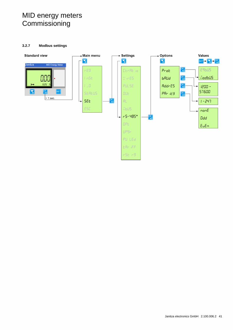
3.2.7 Modbus settings
MID energy meters Commissioning
42 2.100.006.2 Janitza electronics GmbH
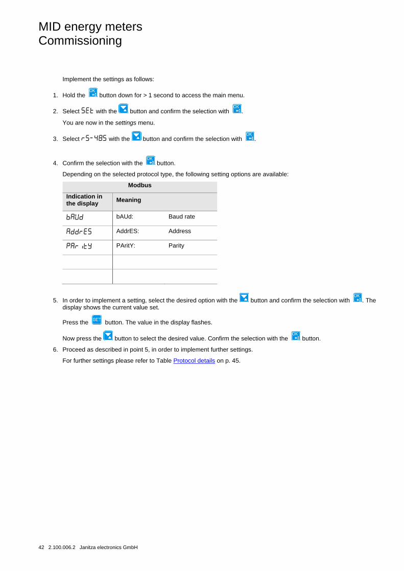
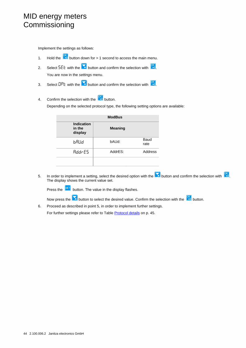
Implement the settings as follows:
1. Hold the button down for > 1 second to access the main menu.
2. Select with the button and confirm the selection with .
You are now in the settings menu.
3. Select with the button and confirm the selection with .
4. Confirm the selection with the button.
Depending on the selected protocol type, the following setting options are available:
Modbus
Indication in the display Meaning
bAUd: Baud rate
AddrES: Address
PAritY: Parity
5. In order to implement a setting, select the desired option with the button and confirm the selection with . The display shows the current value set.
Press the button. The value in the display flashes.
Now press the button to select the desired value. Confirm the selection with the button.
6. Proceed as described in point 5, in order to implement further settings.
For further settings please refer to Table Protocol details on p. 45.
MID energy meters Commissioning
Janitza electronics GmbH 2.100.006.2 43
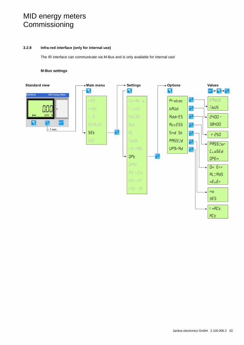
3.2.8 Infra-red interface (only for internal use)
The IR interface can communicate via M-Bus and is only available for internal use!
M-Bus settings
MID energy meters Commissioning
44 2.100.006.2 Janitza electronics GmbH
Implement the settings as follows:
1. Hold the button down for > 1 second to access the main menu.
2. Select with the button and confirm the selection with .
You are now in the settings menu.
3. Select with the button and confirm the selection with .
4. Confirm the selection with the button.
Depending on the selected protocol type, the following setting options are available:
ModBus
Indication in the display
Meaning
bAUd: Baud rate
AddrES: Address
5. In order to implement a setting, select the desired option with the button and confirm the selection with . The display shows the current value set.
Press the button. The value in the display flashes.
Now press the button to select the desired value. Confirm the selection with the button.
6. Proceed as described in point 5, in order to implement further settings.
For further settings please refer to Table Protocol details on p. 45.
MID energy meters Commissioning
Janitza electronics GmbH 2.100.006.2 45
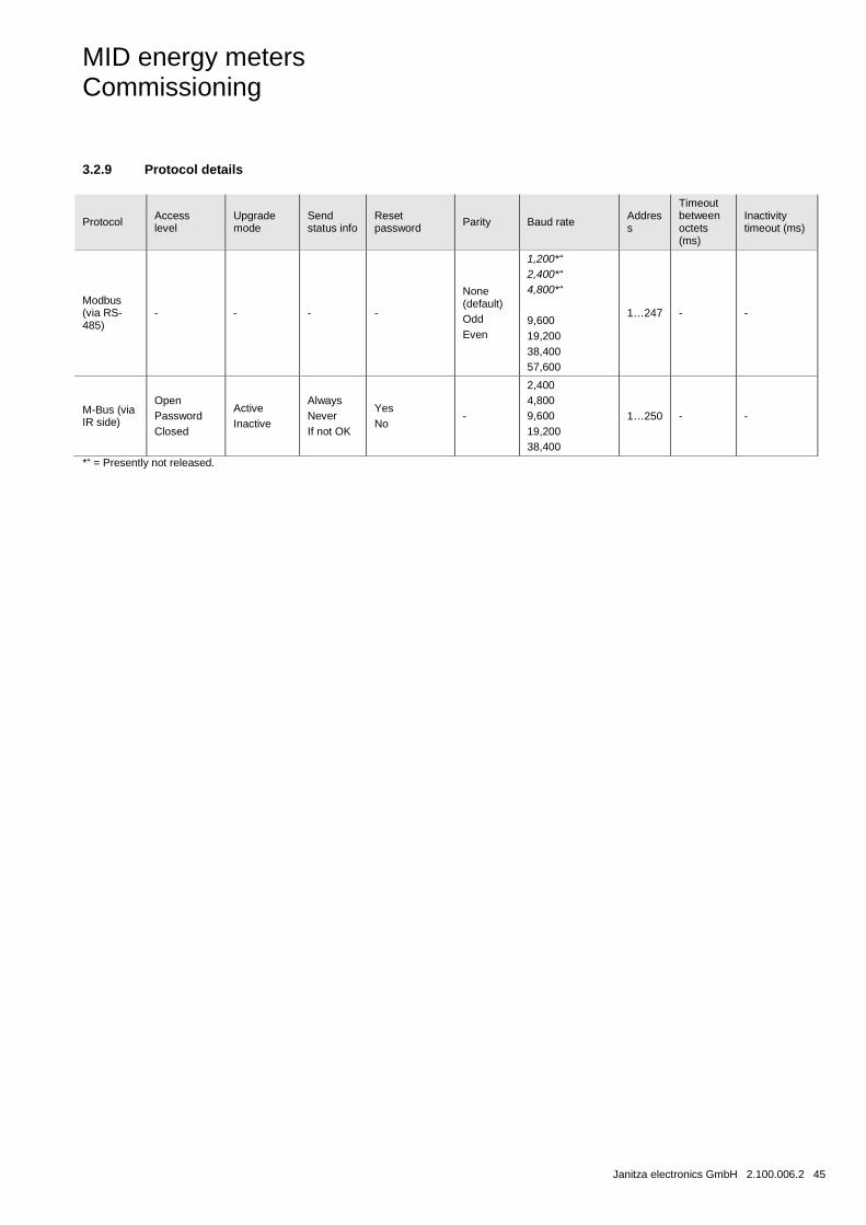
3.2.9 Protocol details
Protocol Access level
Upgrade mode
Send status info
Reset password Parity Baud rate Addres
s
Timeout between octets (ms)
Inactivity timeout (ms)
Modbus (via RS-485)
- - - -
None (default) Odd Even
1,200*“ 2,400*“ 4,800*“ 9,600 19,200 38,400 57,600
1…247 - -
M-Bus (via IR side)
Open Password Closed
Active Inactive
Always Never If not OK
Yes No
-
2,400 4,800 9,600 19,200 38,400
1…250 - -
*“ = Presently not released.
MID energy meters Commissioning
46 2.100.006.2 Janitza electronics GmbH
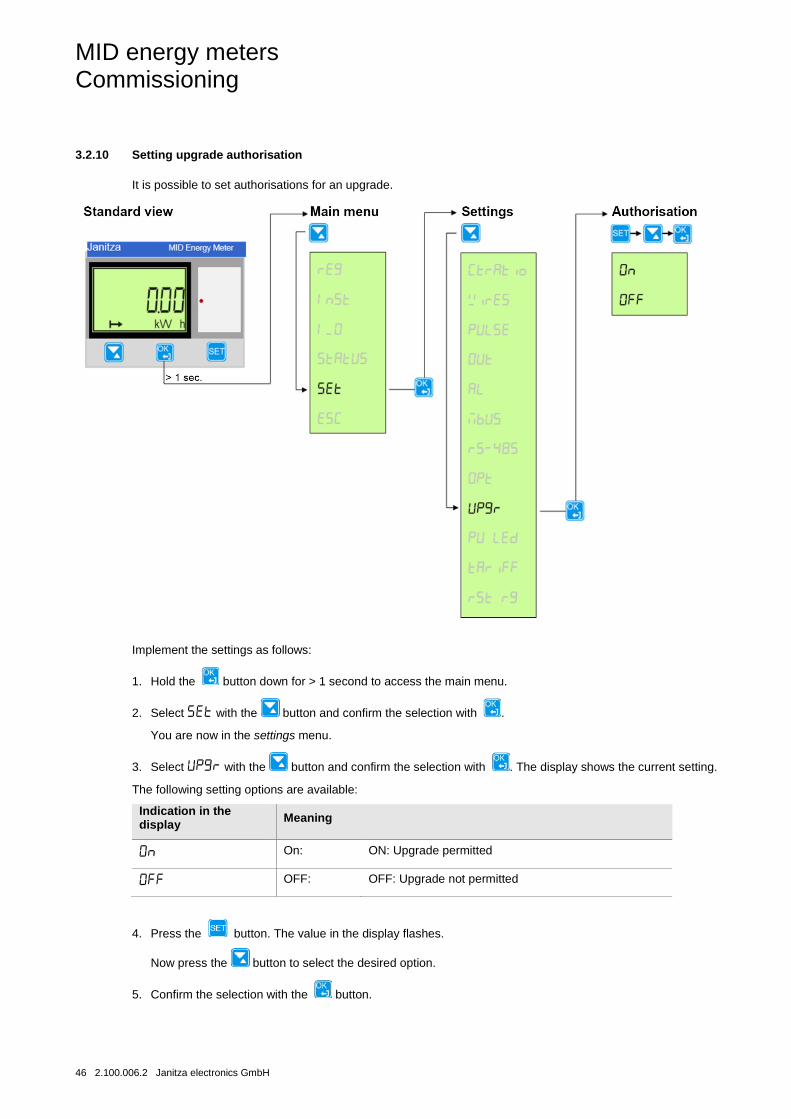
3.2.10 Setting upgrade authorisation
It is possible to set authorisations for an upgrade.
Implement the settings as follows:
1. Hold the button down for > 1 second to access the main menu.
2. Select with the button and confirm the selection with .
You are now in the settings menu.
3. Select with the button and confirm the selection with . The display shows the current setting.
The following setting options are available:
Indication in the display Meaning
On: ON: Upgrade permitted
OFF: OFF: Upgrade not permitted
4. Press the button. The value in the display flashes.
Now press the button to select the desired option.
5. Confirm the selection with the button.
MID energy meters Commissioning
Janitza electronics GmbH 2.100.006.2 47
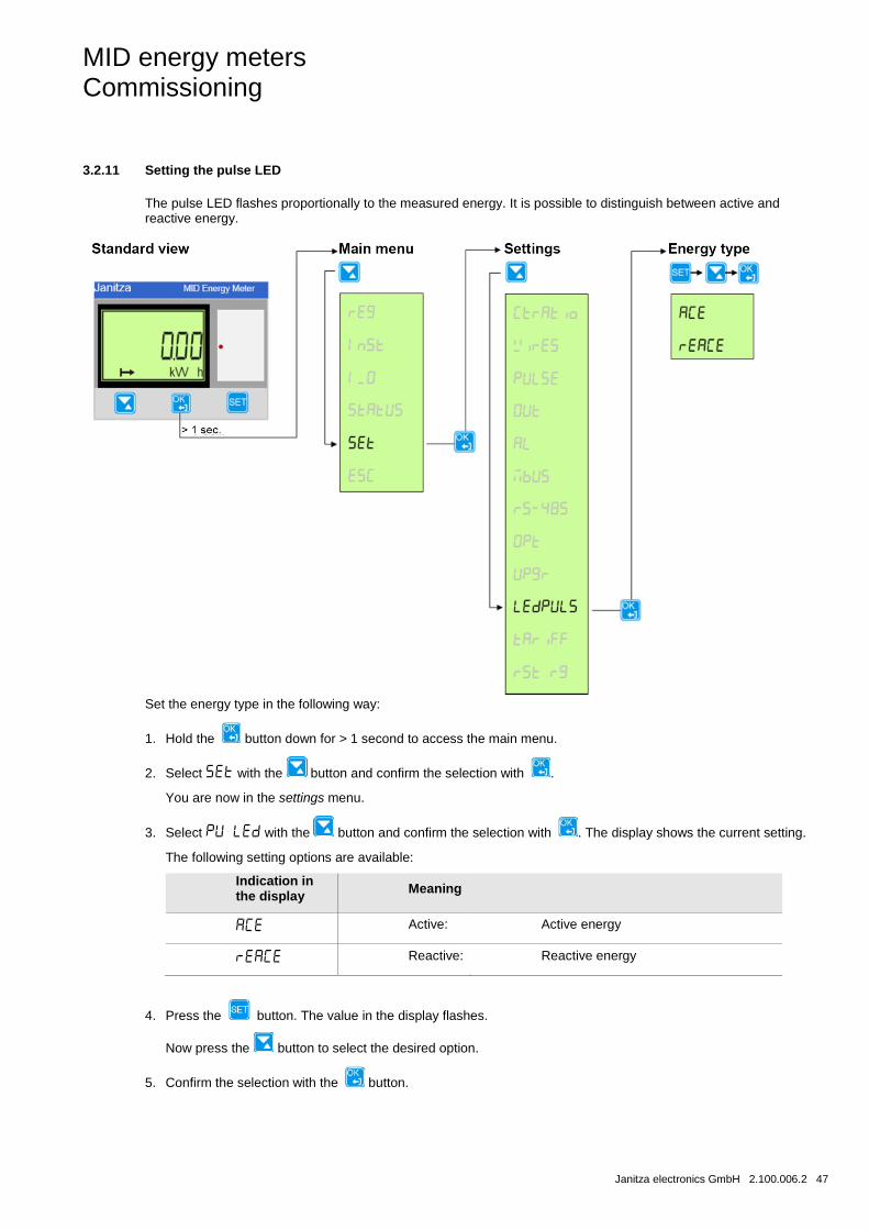
3.2.11 Setting the pulse LED
The pulse LED flashes proportionally to the measured energy. It is possible to distinguish between active and reactive energy.
Set the energy type in the following way:
1. Hold the button down for > 1 second to access the main menu.
2. Select with the button and confirm the selection with .
You are now in the settings menu.
3. Select with the button and confirm the selection with . The display shows the current setting.
The following setting options are available:
Indication in the display Meaning
Active: Active energy
Reactive: Reactive energy
4. Press the button. The value in the display flashes.
Now press the button to select the desired option.
5. Confirm the selection with the button.
MID energy meters Commissioning
48 2.100.006.2 Janitza electronics GmbH
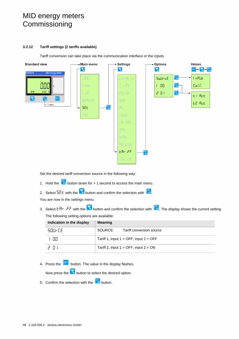
3.2.12 Tariff settings (2 tariffs available)
Tariff conversion can take place via the communication interface or the inputs.
Set the desired tariff conversion source in the following way:
1. Hold the button down for > 1 second to access the main menu.
2. Select with the button and confirm the selection with .
You are now in the settings menu.
3. Select with the button and confirm the selection with . The display shows the current setting.
The following setting options are available:
Indication in the display Meaning
SOURCE: Tariff conversion source
Tariff 1, input 1 = OFF, input 2 = OFF
Tariff 2, input 1 = OFF, input 2 = ON
4. Press the button. The value in the display flashes.
Now press the button to select the desired option.
5. Confirm the selection with the button.
MID energy meters Commissioning
Janitza electronics GmbH 2.100.006.2 49
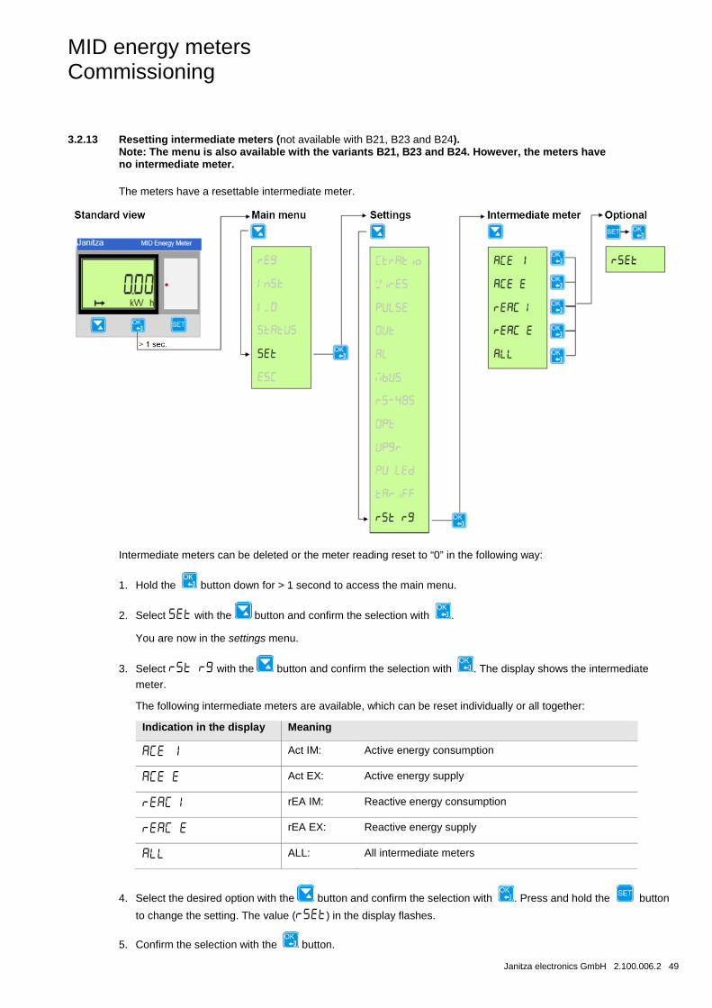
3.2.13 Resetting intermediate meters (not available with B21, B23 and B24). Note: The menu is also available with the variants B21, B23 and B24. However, the meters have no intermediate meter.
The meters have a resettable intermediate meter.
Intermediate meters can be deleted or the meter reading reset to “0” in the following way:
1. Hold the button down for > 1 second to access the main menu.
2. Select with the button and confirm the selection with .
You are now in the settings menu.
3. Select with the button and confirm the selection with . The display shows the intermediate
meter.
The following intermediate meters are available, which can be reset individually or all together:
Indication in the display Meaning
Act IM: Active energy consumption
Act EX: Active energy supply
rEA IM: Reactive energy consumption
rEA EX: Reactive energy supply
ALL: All intermediate meters
4. Select the desired option with the button and confirm the selection with . Press and hold the button
to change the setting. The value () in the display flashes.
5. Confirm the selection with the button.

MID energy meters Commissioning
50 2.100.006.2 Janitza electronics GmbH
MID energy meters Commissioning
Janitza electronics GmbH 2.100.006.2 51
3.3 Technical description
This chapter contains the technical descriptions of the meter functions.
3.3.1 Energy values
The energy values are stored in energy registers. The various energy registers are divided into:
• Registers for active, reactive and apparent energy
• Resettable registers
• Registers for current or historical values
The energy values can either be read off by communication or directly in the display with the help of the buttons.
Primary values
For transformer meters with external current transformers, the register value is multiplied by the transformer conversion ratio before display or sending via communication. This value is also referred to as the primary value.
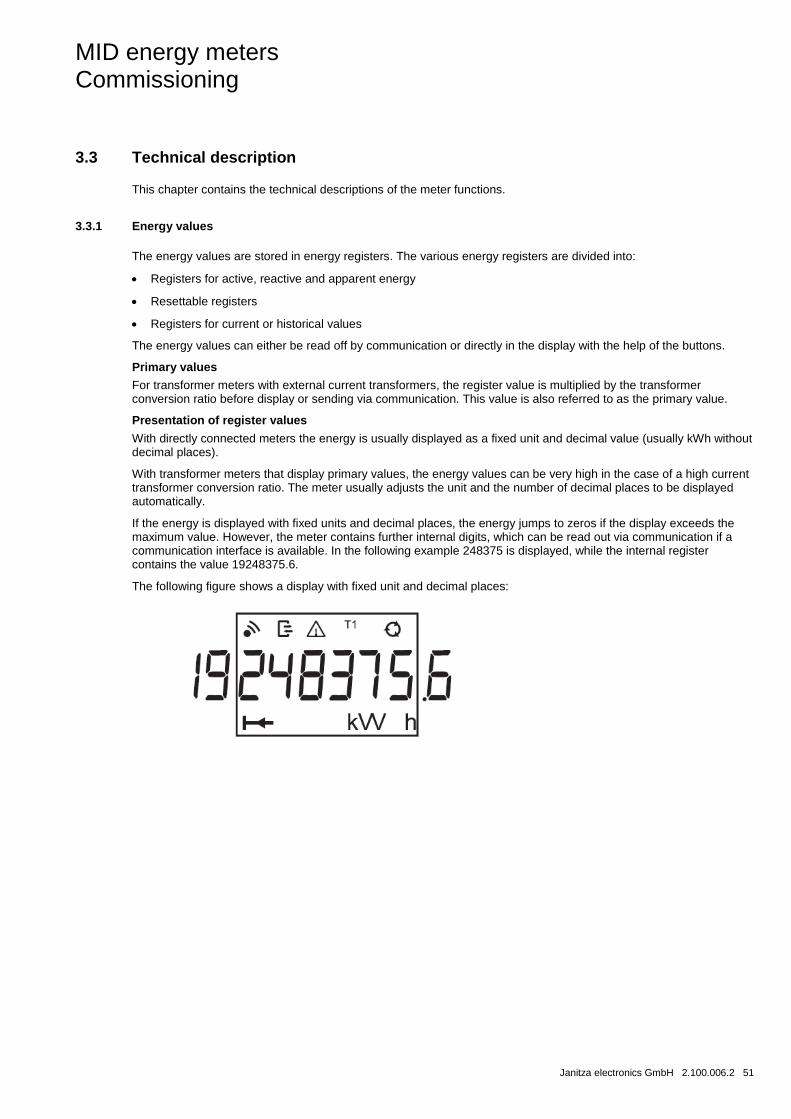
Presentation of register values
With directly connected meters the energy is usually displayed as a fixed unit and decimal value (usually kWh without decimal places).
With transformer meters that display primary values, the energy values can be very high in the case of a high current transformer conversion ratio. The meter usually adjusts the unit and the number of decimal places to be displayed automatically.
If the energy is displayed with fixed units and decimal places, the energy jumps to zeros if the display exceeds the maximum value. However, the meter contains further internal digits, which can be read out via communication if a communication interface is available. In the following example 248375 is displayed, while the internal register contains the value 19248375.6.
The following figure shows a display with fixed unit and decimal places:
MID energy meters Commissioning
52 2.100.006.2 Janitza electronics GmbH
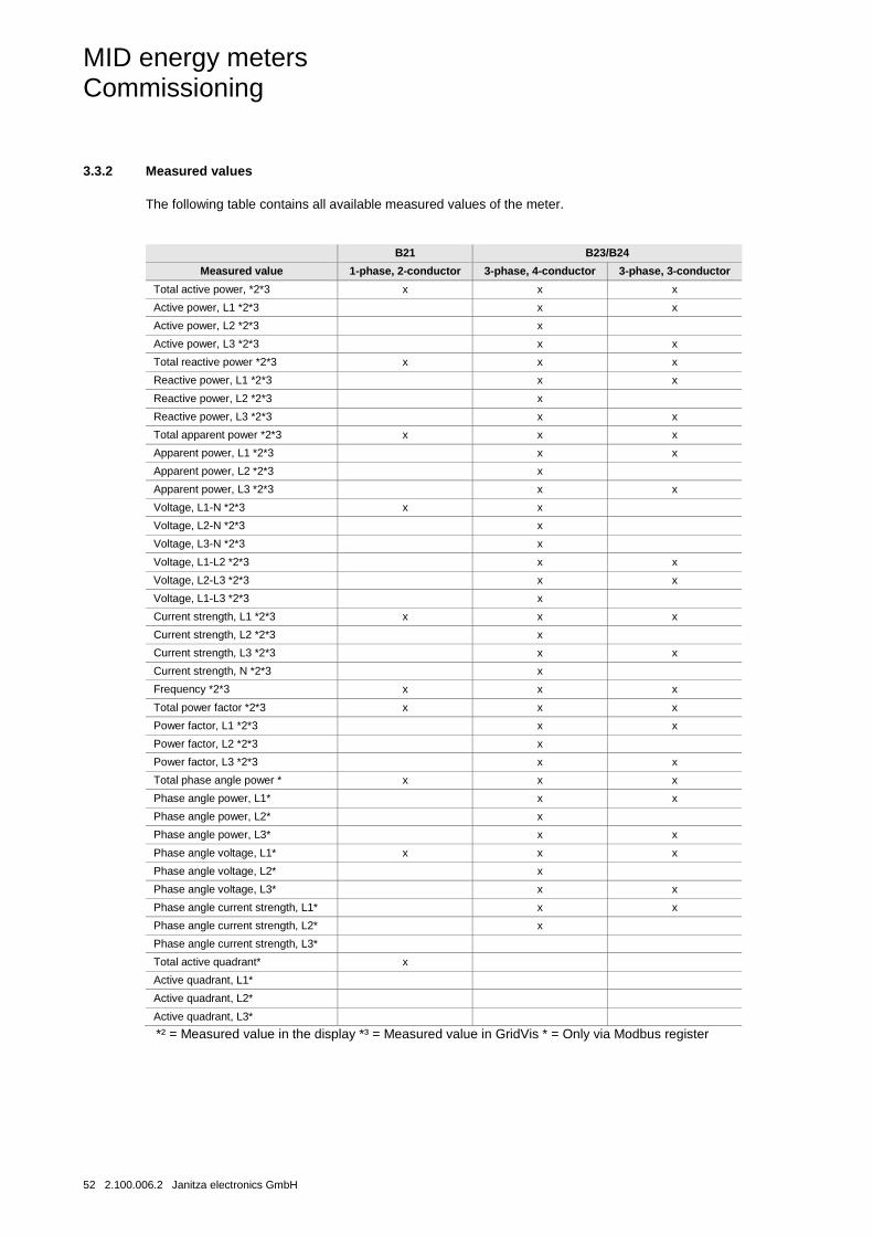
3.3.2 Measured values
The following table contains all available measured values of the meter.
B21 B23/B24
Measured value 1-phase, 2-conductor 3-phase, 4-conductor 3-phase, 3-conductor
Total active power, *2*3 x x x
Active power, L1 *2*3 x x
Active power, L2 *2*3 x
Active power, L3 *2*3 x x
Total reactive power *2*3 x x x
Reactive power, L1 *2*3 x x
Reactive power, L2 *2*3 x
Reactive power, L3 *2*3 x x
Total apparent power *2*3 x x x
Apparent power, L1 *2*3 x x
Apparent power, L2 *2*3 x
Apparent power, L3 *2*3 x x
Voltage, L1-N *2*3 x x
Voltage, L2-N *2*3 x
Voltage, L3-N *2*3 x
Voltage, L1-L2 *2*3 x x
Voltage, L2-L3 *2*3 x x
Voltage, L1-L3 *2*3 x
Current strength, L1 *2*3 x x x
Current strength, L2 *2*3 x
Current strength, L3 *2*3 x x
Current strength, N *2*3 x
Frequency *2*3 x x x
Total power factor *2*3 x x x
Power factor, L1 *2*3 x x
Power factor, L2 *2*3 x
Power factor, L3 *2*3 x x
Total phase angle power * x x x
Phase angle power, L1* x x
Phase angle power, L2* x
Phase angle power, L3* x x
Phase angle voltage, L1* x x x
Phase angle voltage, L2* x
Phase angle voltage, L3* x x
Phase angle current strength, L1* x x
Phase angle current strength, L2* x
Phase angle current strength, L3*
Total active quadrant* x
Active quadrant, L1*
Active quadrant, L2*
Active quadrant, L3*
*² = Measured value in the display *³ = Measured value in GridVis * = Only via Modbus register
MID energy meters Commissioning
Janitza electronics GmbH 2.100.006.2 53
Accuracy
The accuracy of the data is defined within a voltage range of 20 % of the specified rated voltage and a current strength range of 5 % of the basic current to the maximum current strength.
The accuracy of all data reflects the specified accuracy for the energy measurement with the exception of the phase angle for voltage and current.
The accuracy of the phase angle for voltage and current is 2 degrees.
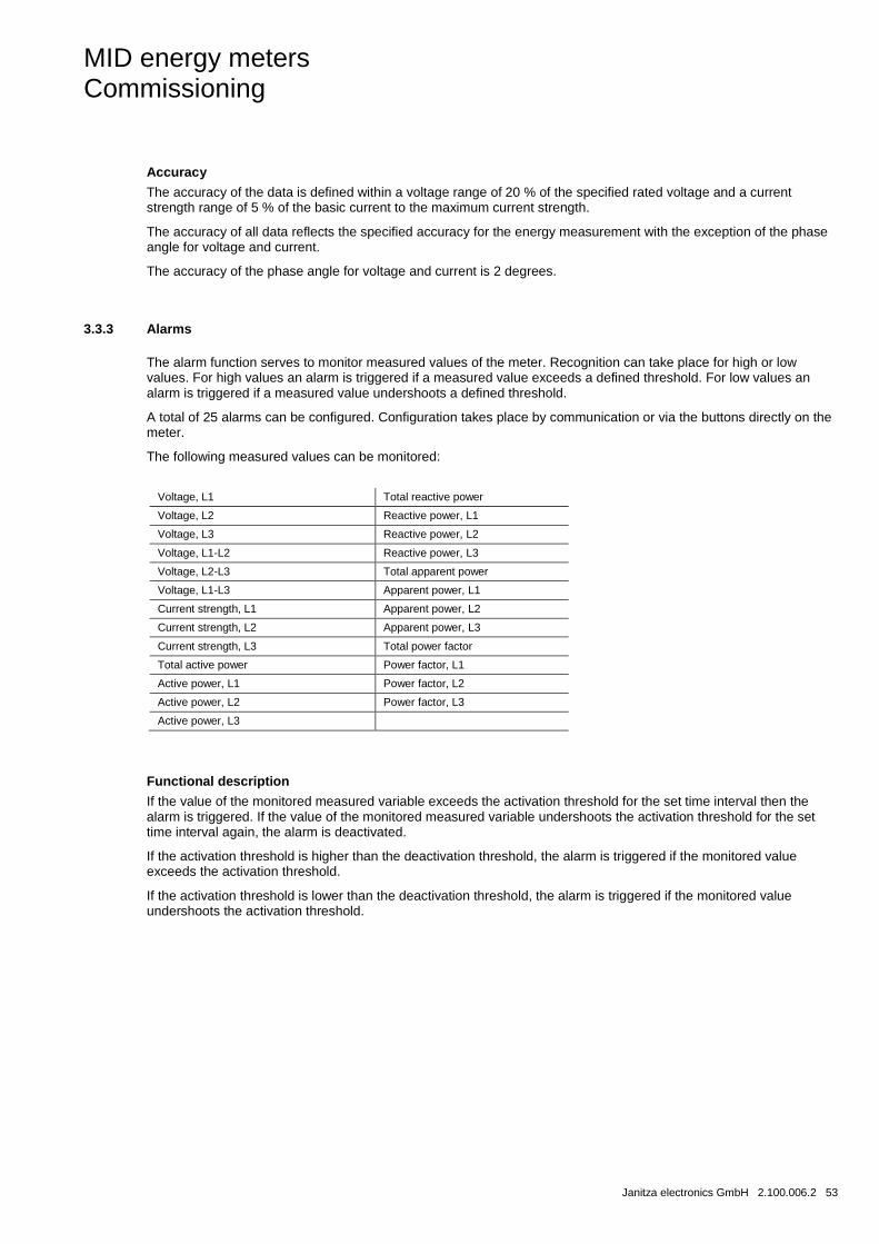
3.3.3 Alarms
The alarm function serves to monitor measured values of the meter. Recognition can take place for high or low values. For high values an alarm is triggered if a measured value exceeds a defined threshold. For low values an alarm is triggered if a measured value undershoots a defined threshold.
A total of 25 alarms can be configured. Configuration takes place by communication or via the buttons directly on the meter.
The following measured values can be monitored:
Voltage, L1 Total reactive power
Voltage, L2 Reactive power, L1
Voltage, L3 Reactive power, L2
Voltage, L1-L2 Reactive power, L3
Voltage, L2-L3 Total apparent power
Voltage, L1-L3 Apparent power, L1
Current strength, L1 Apparent power, L2
Current strength, L2 Apparent power, L3
Current strength, L3 Total power factor
Total active power Power factor, L1
Active power, L1 Power factor, L2
Active power, L2 Power factor, L3
Active power, L3
Functional description
If the value of the monitored measured variable exceeds the activation threshold for the set time interval then the alarm is triggered. If the value of the monitored measured variable undershoots the activation threshold for the set time interval again, the alarm is deactivated.
If the activation threshold is higher than the deactivation threshold, the alarm is triggered if the monitored value exceeds the activation threshold.
If the activation threshold is lower than the deactivation threshold, the alarm is triggered if the monitored value undershoots the activation threshold.
MID energy meters Commissioning
54 2.100.006.2 Janitza electronics GmbH
3.3.4 Inputs and outputs
Inputs and outputs have optocouplers and are galvanically separated from the remaining meter electronics. These are polarity-independent and can conduct DC and alternating current.
Inputs that are not connected are not live / connected to voltage.
Functions of the inputs
The input counts pulses, detects activity and the current status. The meter values can be read directly off the display on the meter or via communication.
The input registers can be reset via communication or via the buttons directly on the meter.
Functions of the outputs
The outputs can be controlled via communication or alarm.
3.3.5 Tariff inputs
Tariff control
In the case of meters with a tariff function, the tariffs can either be controlled via communication or via 1 tariff input.
Tariff control via the input takes place through a suitable combination of “voltage” or “no voltage” at the input or inputs. For every combination of “voltage/no voltage”, the meter counts the energy in a certain tariff register.
In 4-quadrant meters with active and reactive energy measurement, the meter readings of both energy types are controlled via the same inputs. The active tariff for active and reactive energy is always the same.
Display of the active tariff
The active tariff is shown in the LCD display by the text “Tx” in the status field, whereby x is the tariff number. The active tariff can also be read out via communication.
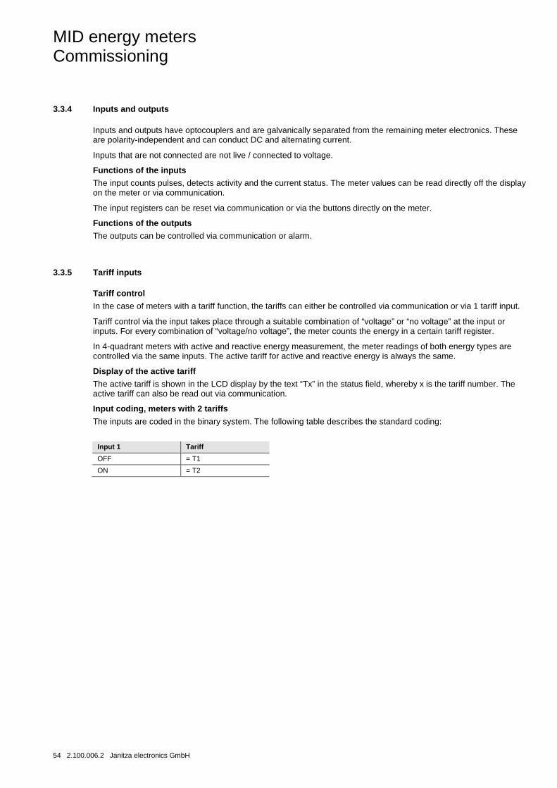
Input coding, meters with 2 tariffs
The inputs are coded in the binary system. The following table describes the standard coding:
Input 1 Tariff
OFF = T1
ON = T2
MID energy meters Commissioning
Janitza electronics GmbH 2.100.006.2 55
3.3.6 Pulse outputs
The meters equipped with pulse outputs have up to 2 outputs. The meter sends a certain number of pulses (pulse frequency) per kilowatt hour (kVar for reactive energy) via pulse outputs.
In the case of transformer meters (B24), the pulse outputs send primary values. This means that the pulses are sent proportional to the real primary energy, whereby the current transformer conversion ratios programmed in the meter are taken into consideration.
For directly connected meters (B21 and B23), no external transformers are used and the number of pulses sent is directly proportional to the energy that the meter measures.
Pulse frequency and pulse length
The pulse frequency and pulse length can be set with the buttons on the meter or via communication. In the case of meters with more than one pulse output, all outputs have the same pulse frequency and pulse length.
The pulse frequency can be configured and can be set to a value of 1…9,999 pulses. The value must be a whole number. The unit is variable. Available for selection are pulse/kWh, pulse/Wh and pulse/MWh.
The pulse length can be set to a value of 10…990 ms.
Specifying pulse frequency/length
If the energy is too high for a certain pulse frequency and pulse length then there is a risk of the pulses overlapping. In this case the meter sends a new pulse (relay closed), before the previous pulse ends (relay open), and the pulse is lost. In the worst case, the relay remains constantly closed. As such, the maximum permissible pulse frequency should be calculated for a location with consideration to the estimated maximum energy consumption and pulse output data of the meter.
The following formula applies to this calculation:
Max. pulse frequency = 1000*3600 / U / I /n / (Ppause + Plength)
U and I are the estimated maximum values for voltage (in volts) and current strength (in ampere) here, and n is the number of phases (1-3).
Plength and Ppause are the pulse length and required pulse pause (in seconds).
A common minimum pulse length and pulse pause is 30 ms. This reflects the S0 and IEC standards.
Note
U and I must be the primary values in transformer meters, if external current transformers are programmed in the meter.
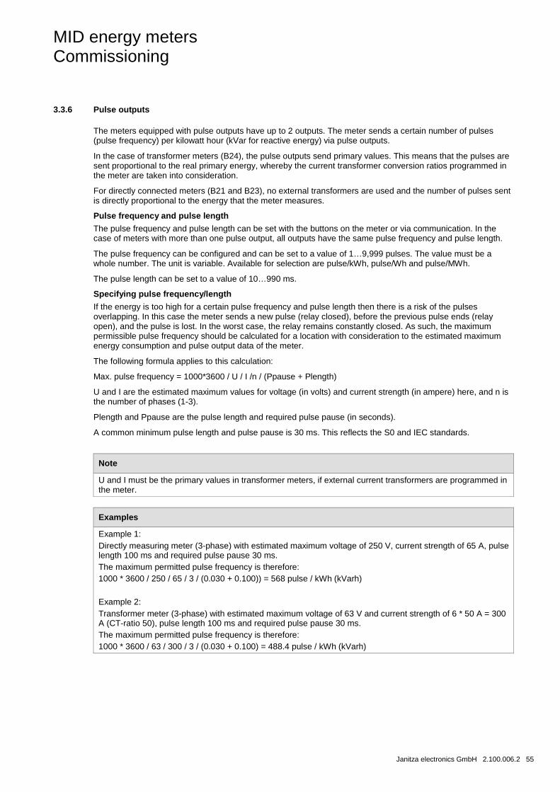
Examples
Example 1: Directly measuring meter (3-phase) with estimated maximum voltage of 250 V, current strength of 65 A, pulse length 100 ms and required pulse pause 30 ms. The maximum permitted pulse frequency is therefore: 1000 * 3600 / 250 / 65 / 3 / (0.030 + 0.100)) = 568 pulse / kWh (kVarh) Example 2: Transformer meter (3-phase) with estimated maximum voltage of 63 V and current strength of 6 * 50 A = 300 A (CT-ratio 50), pulse length 100 ms and required pulse pause 30 ms. The maximum permitted pulse frequency is therefore: 1000 * 3600 / 63 / 300 / 3 / (0.030 + 0.100) = 488.4 pulse / kWh (kVarh)

MID energy meters Commissioning
56 2.100.006.2 Janitza electronics GmbH
3.3.7 Protocol storage logs
The meter has a total of five different protocol stores, also known as logs:
• System log
• Event log
• Power quality log
• Audit log
• Settings log
Log entries can be read directly off the display on the meter.
In the system log, event log and power quality log it is possible to store up to 500 log entries. When this maximum is reached, the oldest entries are overwritten.
In the audit log it is possible to store up to 40 log entries. When this maximum is reached, no further entries can be stored. Firmware upgrades will fail in this case, because it is not possible to save any further log entries.
In the settings log it is possible to store up to 80 log entries. When this maximum is reached, no further entries can be stored. New settings for CT or a change to the connection type (3 or 4-phase) are no longer accepted because no further log entries can be saved.
The entries in the system log, event log and power quality log can be deleted via communication.
System log
This log saves error events in the meter.
The following events are stored in this log:
• Program CRC errors - errors when testing the firmware consistency.
• Errors in the data memory - the data in the long-term memory is damaged.
MID energy meters Commissioning
Janitza electronics GmbH 2.100.006.2 57
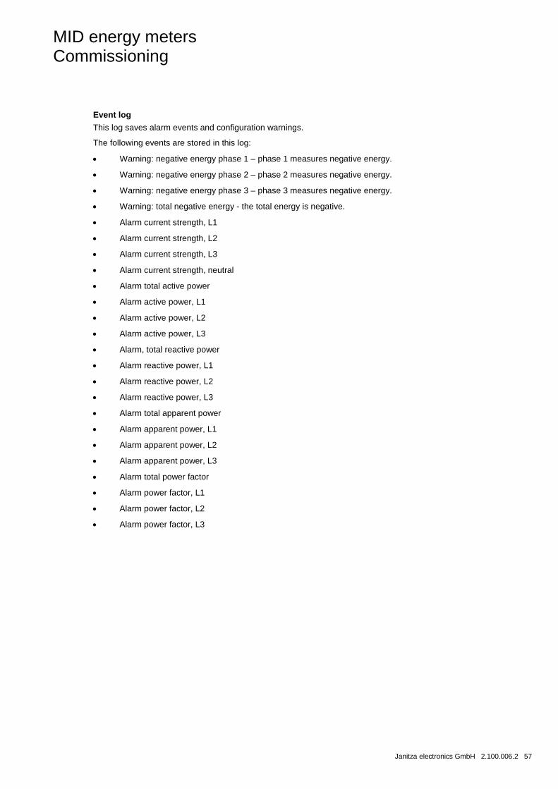
Event log
This log saves alarm events and configuration warnings.
The following events are stored in this log:
• Warning: negative energy phase 1 – phase 1 measures negative energy.
• Warning: negative energy phase 2 – phase 2 measures negative energy.
• Warning: negative energy phase 3 – phase 3 measures negative energy.
• Warning: total negative energy - the total energy is negative.
• Alarm current strength, L1
• Alarm current strength, L2
• Alarm current strength, L3
• Alarm current strength, neutral
• Alarm total active power
• Alarm active power, L1
• Alarm active power, L2
• Alarm active power, L3
• Alarm, total reactive power
• Alarm reactive power, L1
• Alarm reactive power, L2
• Alarm reactive power, L3
• Alarm total apparent power
• Alarm apparent power, L1
• Alarm apparent power, L2
• Alarm apparent power, L3
• Alarm total power factor
• Alarm power factor, L1
• Alarm power factor, L2
• Alarm power factor, L3
MID energy meters Commissioning
58 2.100.006.2 Janitza electronics GmbH
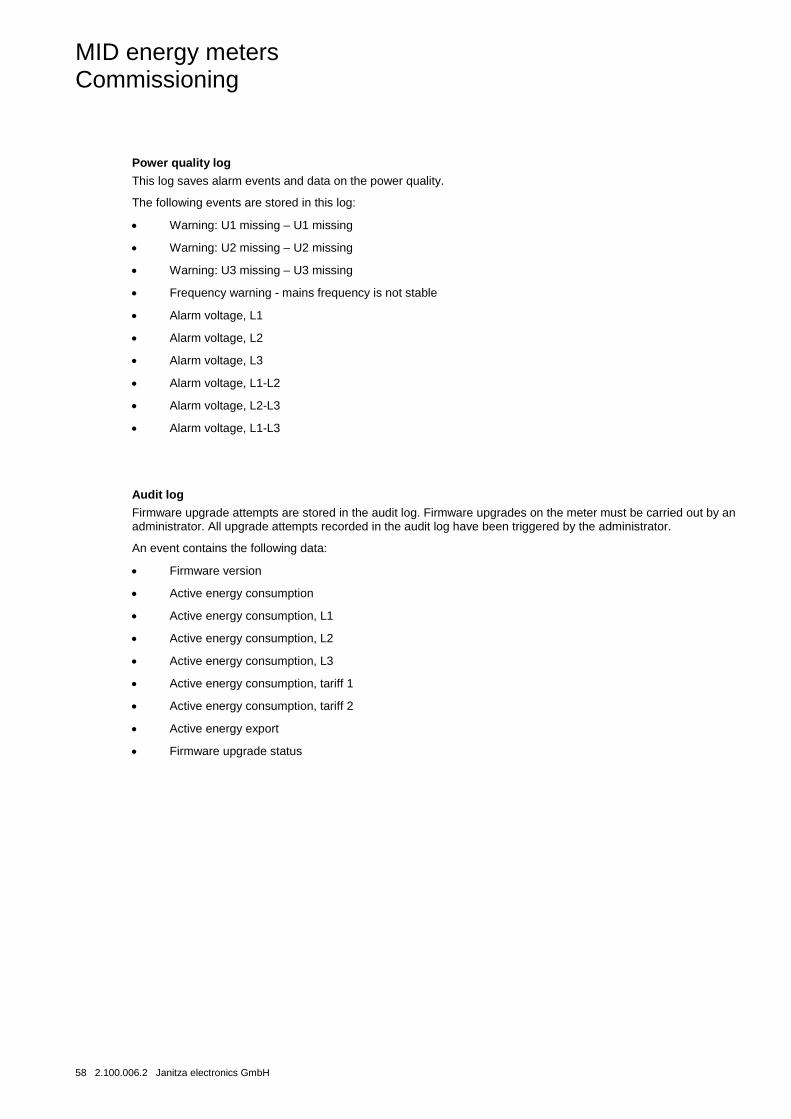
Power quality log
This log saves alarm events and data on the power quality.
The following events are stored in this log:
• Warning: U1 missing – U1 missing
• Warning: U2 missing – U2 missing
• Warning: U3 missing – U3 missing
• Frequency warning - mains frequency is not stable
• Alarm voltage, L1
• Alarm voltage, L2
• Alarm voltage, L3
• Alarm voltage, L1-L2
• Alarm voltage, L2-L3
• Alarm voltage, L1-L3
Audit log
Firmware upgrade attempts are stored in the audit log. Firmware upgrades on the meter must be carried out by an administrator. All upgrade attempts recorded in the audit log have been triggered by the administrator.
An event contains the following data:
• Firmware version
• Active energy consumption
• Active energy consumption, L1
• Active energy consumption, L2
• Active energy consumption, L3
• Active energy consumption, tariff 1
• Active energy consumption, tariff 2
• Active energy export
• Firmware upgrade status
MID energy meters Commissioning
Janitza electronics GmbH 2.100.006.2 59
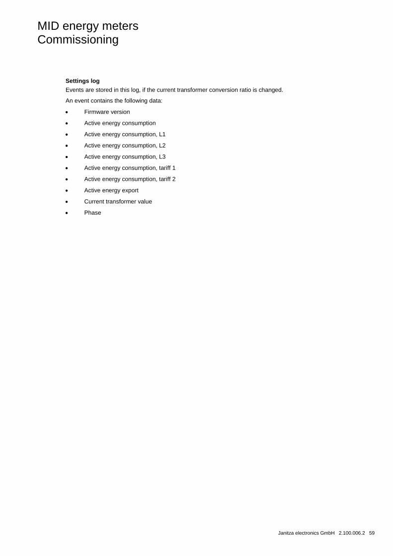
Settings log
Events are stored in this log, if the current transformer conversion ratio is changed.
An event contains the following data:
• Firmware version
• Active energy consumption
• Active energy consumption, L1
• Active energy consumption, L2
• Active energy consumption, L3
• Active energy consumption, tariff 1
• Active energy consumption, tariff 2
• Active energy export
• Current transformer value
• Phase
MID energy meters Commissioning
60 2.100.006.2 Janitza electronics GmbH
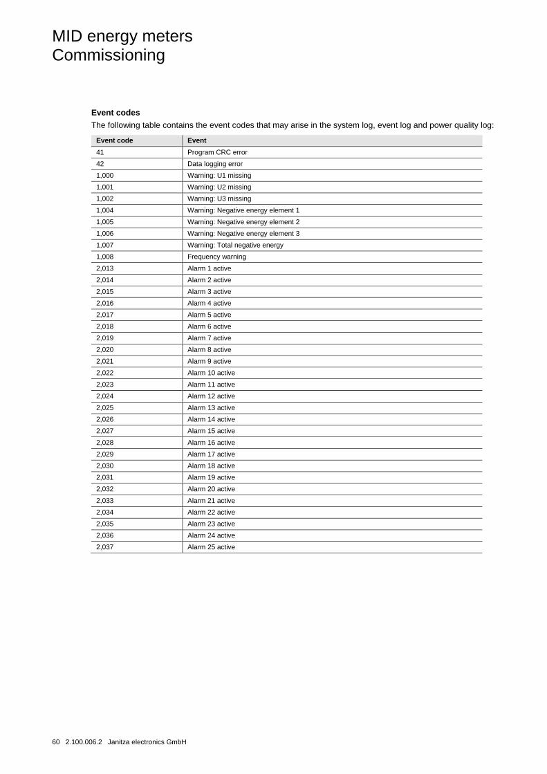
Event codes
The following table contains the event codes that may arise in the system log, event log and power quality log:
Event code Event
41 Program CRC error
42 Data logging error
1,000 Warning: U1 missing
1,001 Warning: U2 missing
1,002 Warning: U3 missing
1,004 Warning: Negative energy element 1
1,005 Warning: Negative energy element 2
1,006 Warning: Negative energy element 3
1,007 Warning: Total negative energy
1,008 Frequency warning
2,013 Alarm 1 active
2,014 Alarm 2 active
2,015 Alarm 3 active
2,016 Alarm 4 active
2,017 Alarm 5 active
2,018 Alarm 6 active
2,019 Alarm 7 active
2,020 Alarm 8 active
2,021 Alarm 9 active
2,022 Alarm 10 active
2,023 Alarm 11 active
2,024 Alarm 12 active
2,025 Alarm 13 active
2,026 Alarm 14 active
2,027 Alarm 15 active
2,028 Alarm 16 active
2,029 Alarm 17 active
2,030 Alarm 18 active
2,031 Alarm 19 active
2,032 Alarm 20 active
2,033 Alarm 21 active
2,034 Alarm 22 active
2,035 Alarm 23 active
2,036 Alarm 24 active
2,037 Alarm 25 active

MID energy meters Commissioning
Janitza electronics GmbH 2.100.006.2 61


MID energy meters Communication with Modbus
Janitza electronics GmbH 2.100.006.2 63
4 Communication with Modbus
This chapter describes the mapping of meter data to the Modbus, as well as reading and writing in the register.
4.1 Modbus protocol
Modbus is a master-slave communication protocol that supports up to 247 slaves organised as a multidrop bus. The communication is half-duplex.
The services on the Modbus are determined on the basis of function codes.
The function codes are used for reading or writing 16-Bit registers.
All measured data, such as active energy, voltage or firmware version, are represented by one or more such registers.
For further information regarding the relationship between the number of registers and measured data, see chapter Mapping tables, p. 68.
The Modbus protocol is described in its entirety in the Modbus application protocol specification V1.1b. The document is available under http://www.modbus.org.
Supported function codes
The following function codes are supported:
• Function code 3 (reading the holding register)
• Function code 6 (writing a single register)
• Function code 16 (writing multiple registers)
Modbus request telegram
A Modbus request telegram usually exhibits the following structure:
Slave address Function code Data Error check
Slave address Modbus slave address, 1 byte
Function code Decides the service to be performed
Data Dependent on the function code. The length varies.
Error check CRC, 2 bytes
Message types
The network messages may be request response or transfer type messages. The request response command sends a request from the master to an individual slave, and a response generally follows this.
The transfer command sends a message to all slaves, and a response never follows this. The transfer is supported by the function codes 6 and 16.
MID energy meters Communication with Modbus
64 2.100.006.2 Janitza electronics GmbH
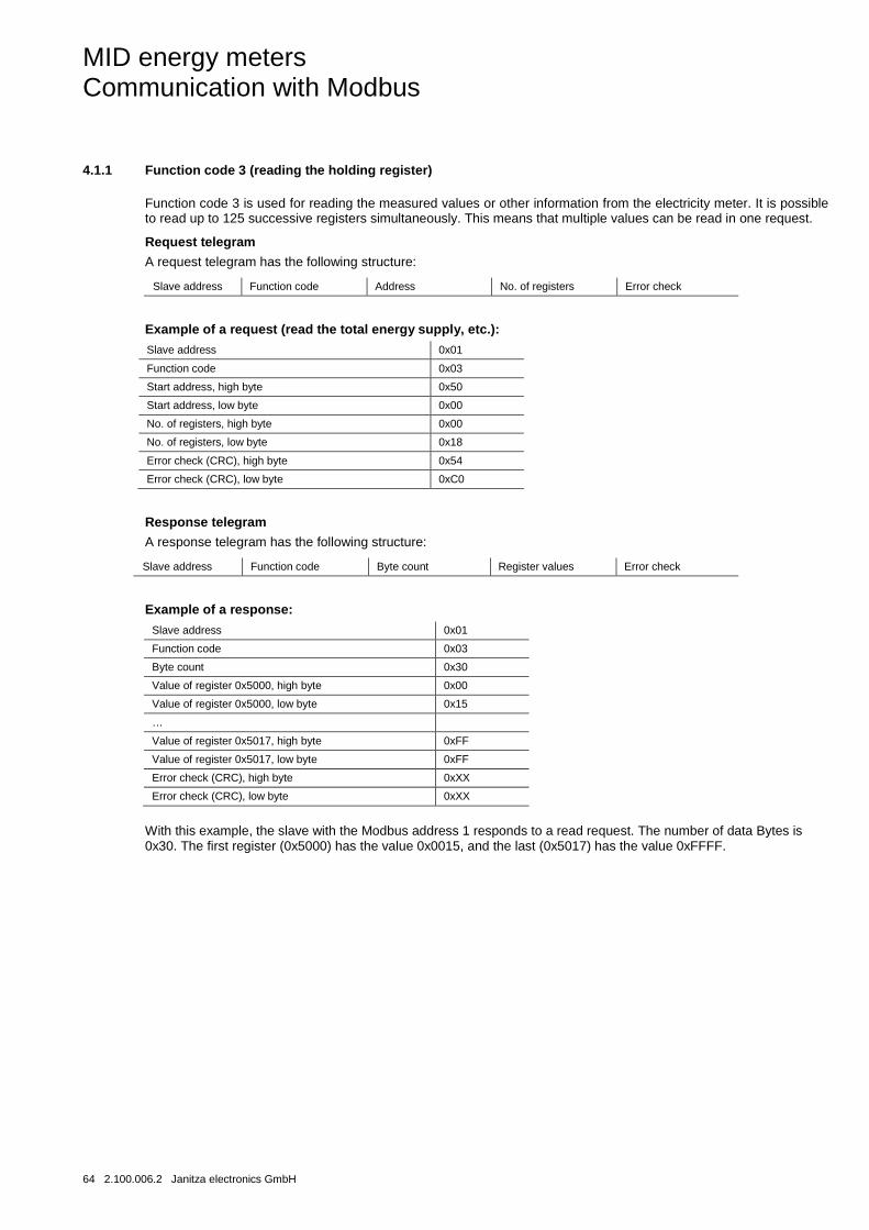
4.1.1 Function code 3 (reading the holding register)
Function code 3 is used for reading the measured values or other information from the electricity meter. It is possible to read up to 125 successive registers simultaneously. This means that multiple values can be read in one request.
Request telegram
A request telegram has the following structure:
Slave address Function code Address No. of registers Error check
Example of a request (read the total energy supply, etc.):
Slave address 0x01
Function code 0x03
Start address, high byte 0x50
Start address, low byte 0x00
No. of registers, high byte 0x00
No. of registers, low byte 0x18
Error check (CRC), high byte 0x54
Error check (CRC), low byte 0xC0
Response telegram
A response telegram has the following structure:
Slave address Function code Byte count Register values Error check
Example of a response:
Slave address 0x01
Function code 0x03
Byte count 0x30
Value of register 0x5000, high byte 0x00
Value of register 0x5000, low byte 0x15
…
Value of register 0x5017, high byte 0xFF
Value of register 0x5017, low byte 0xFF
Error check (CRC), high byte 0xXX
Error check (CRC), low byte 0xXX
With this example, the slave with the Modbus address 1 responds to a read request. The number of data Bytes is 0x30. The first register (0x5000) has the value 0x0015, and the last (0x5017) has the value 0xFFFF.
MID energy meters Communication with Modbus
Janitza electronics GmbH 2.100.006.2 65
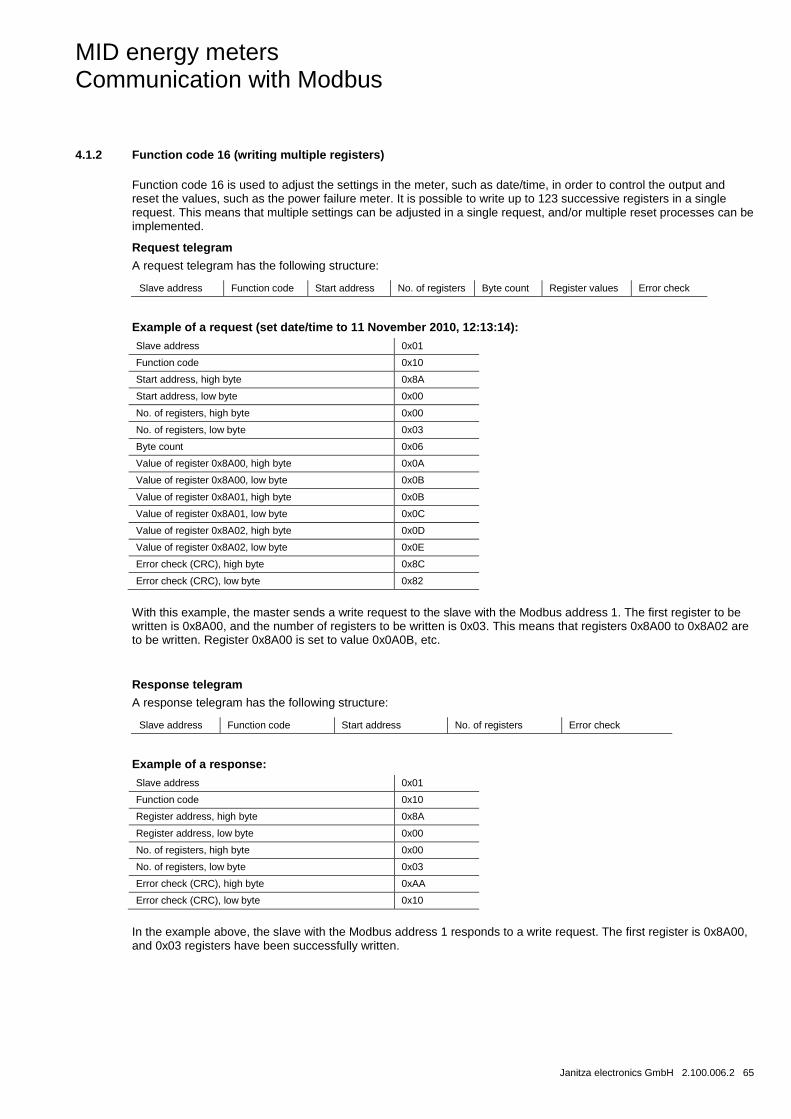
4.1.2 Function code 16 (writing multiple registers)
Function code 16 is used to adjust the settings in the meter, such as date/time, in order to control the output and reset the values, such as the power failure meter. It is possible to write up to 123 successive registers in a single request. This means that multiple settings can be adjusted in a single request, and/or multiple reset processes can be implemented.
Request telegram
A request telegram has the following structure:
Slave address Function code Start address No. of registers Byte count Register values Error check
Example of a request (set date/time to 11 November 2010, 12:13:14):
Slave address 0x01
Function code 0x10
Start address, high byte 0x8A
Start address, low byte 0x00
No. of registers, high byte 0x00
No. of registers, low byte 0x03
Byte count 0x06
Value of register 0x8A00, high byte 0x0A
Value of register 0x8A00, low byte 0x0B
Value of register 0x8A01, high byte 0x0B
Value of register 0x8A01, low byte 0x0C
Value of register 0x8A02, high byte 0x0D
Value of register 0x8A02, low byte 0x0E
Error check (CRC), high byte 0x8C
Error check (CRC), low byte 0x82
With this example, the master sends a write request to the slave with the Modbus address 1. The first register to be written is 0x8A00, and the number of registers to be written is 0x03. This means that registers 0x8A00 to 0x8A02 are to be written. Register 0x8A00 is set to value 0x0A0B, etc.
Response telegram
A response telegram has the following structure:
Slave address Function code Start address No. of registers Error check
Example of a response:
Slave address 0x01
Function code 0x10
Register address, high byte 0x8A
Register address, low byte 0x00
No. of registers, high byte 0x00
No. of registers, low byte 0x03
Error check (CRC), high byte 0xAA
Error check (CRC), low byte 0x10
In the example above, the slave with the Modbus address 1 responds to a write request. The first register is 0x8A00, and 0x03 registers have been successfully written.
MID energy meters Communication with Modbus
66 2.100.006.2 Janitza electronics GmbH
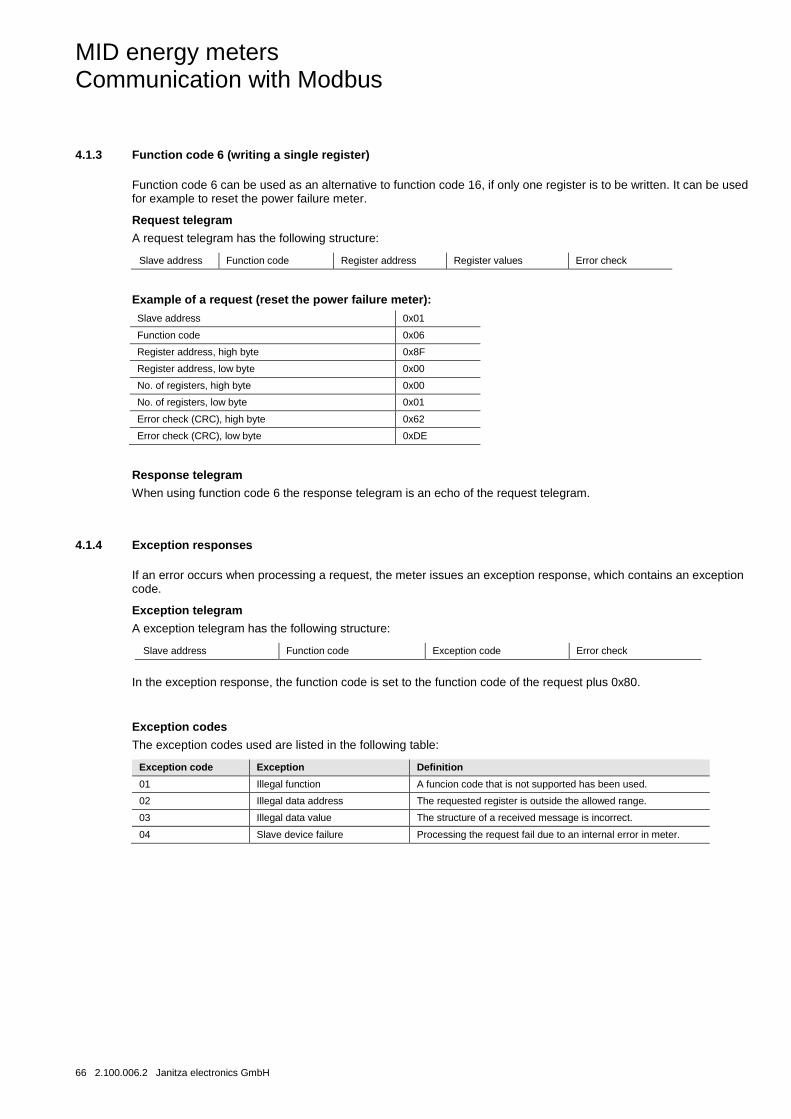
4.1.3 Function code 6 (writing a single register)
Function code 6 can be used as an alternative to function code 16, if only one register is to be written. It can be used for example to reset the power failure meter.
Request telegram
A request telegram has the following structure:
Slave address Function code Register address Register values Error check
Example of a request (reset the power failure meter):
Slave address 0x01
Function code 0x06
Register address, high byte 0x8F
Register address, low byte 0x00
No. of registers, high byte 0x00
No. of registers, low byte 0x01
Error check (CRC), high byte 0x62
Error check (CRC), low byte 0xDE
Response telegram
When using function code 6 the response telegram is an echo of the request telegram.
4.1.4 Exception responses
If an error occurs when processing a request, the meter issues an exception response, which contains an exception code.
Exception telegram
A exception telegram has the following structure:
Slave address Function code Exception code Error check
In the exception response, the function code is set to the function code of the request plus 0x80.
Exception codes
The exception codes used are listed in the following table:
Exception code Exception Definition
01 Illegal function A funcion code that is not supported has been used.
02 Illegal data address The requested register is outside the allowed range.
03 Illegal data value The structure of a received message is incorrect.
04 Slave device failure Processing the request fail due to an internal error in meter.

MID energy meters Communication with Modbus
Janitza electronics GmbH 2.100.006.2 67
4.2 Reading and writing in the register
Legible registers
The legible range in the Modbus mapping comprises the registers 1000-8EFF (hexadecimal). Reading registers within this range leads to a normal Modbus response. It is possible to read an arbitrary number of registers between 1 and 125, i.e. it is not necessary to read out all registers in a telegram. All attempts to read outside of this range lead to an exception due to an impermissible data address (Modbus exception code 2).
Multiple register values
With quantities that are presented as more than 1 register, the most important Byte is in the high Byte of the first (lowest) register. The least important Byte is in the low Byte of the last (highest) register.
Unused registers
Unused registers within the mapping range, e.g. missing quantities in a connected meter, lead to a normal Modbus response, but the value of the register is set to “invalid”.
In the case of quantities with the data type “unsigned”, the value in all registers is FFFF. In the case of quantities with the data type “signed”, the value is the highest value suitable for expressing. This means that the quantity represented by just one register has the value 7FFFF. A quantity represented by two registers has the value 7FFFFFFF, etc.
Writing in the registers
Writing in the registers is only permissible for registers that are listed in the mapping tables as writable. The attempt to write in a register that is listed as writable, but that is not supported by a meter, leads to an error indication.
Note
It is not possible to modify parts of a setting.
Verification of the settings values
Once you have set a value in the meter, it is advisable to read the value in order to verify the result, because verification is not possible if a write process of the Modbus response was successful.
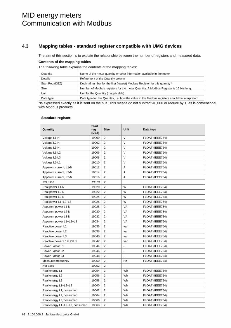
MID energy meters Communication with Modbus
68 2.100.006.2 Janitza electronics GmbH
4.3 Mapping tables - standard register compatible with UMG devices
The aim of this section is to explain the relationship between the number of registers and measured data.
Contents of the mapping tables
The following table explains the contents of the mapping tables:
Quantity Name of the meter quantity or other information available in the meter
Details Refinement of the Quantity column
Start Reg (DEZ) Decimal number for the first (lowest) Modbus Register for this quantity *
Size Number of Modbus registers for the meter Quantity. A Modbus Register is 16 bits long.
Unit Unit for the Quantity (if applicable)
Data type Data type for this Quantity, i.e. how the value in the Modbus registers should be interpreted
*Is expressed exactly as it is sent on the bus. This means do not subtract 40,000 or reduce by 1, as is conventional with Modbus products.
Standard register:
Quantity Start reg (DEZ)
Size Unit Data type
Voltage L1-N 19000 2 V FLOAT (IEEE754)
Voltage L2-N 19002 2 V FLOAT (IEEE754)
Voltage L3-N 19004 2 V FLOAT (IEEE754)
Voltage L1-L2 19006 2 V FLOAT (IEEE754)
Voltage L2-L3 19008 2 V FLOAT (IEEE754)
Voltage L3-L1 19010 2 V FLOAT (IEEE754)
Apparent current, L1-N 19012 2 A FLOAT (IEEE754)
Apparent current, L2-N 19014 2 A FLOAT (IEEE754)
Apparent current, L3-N 19016 2 A FLOAT (IEEE754)
Not used 19018 2
Real power L1-N 19020 2 W FLOAT (IEEE754)
Real power L2-N 19022 2 W FLOAT (IEEE754)
Real power L3-N 19024 2 W FLOAT (IEEE754)
Real power L1+L2+L3 19026 2 W FLOAT (IEEE754)
Apparent power L1-N 19028 2 VA FLOAT (IEEE754)
Apparent power L2-N 19030 2 VA FLOAT (IEEE754)
Apparent power L3-N 19032 2 VA FLOAT (IEEE754)
Apparent power L1+L2+L3 19034 2 VA FLOAT (IEEE754)
Reactive power L1 19036 2 var FLOAT (IEEE754)
Reactive power L2 19038 2 var FLOAT (IEEE754)
Reactive power L3 19040 2 var FLOAT (IEEE754)
Reactive power L1+L2+L3 19042 2 var FLOAT (IEEE754)
Power Factor L1 19044 2 - FLOAT (IEEE754)
Power Factor L2 19046 2 - FLOAT (IEEE754)
Power Factor L3 19048 2 - FLOAT (IEEE754)
Measured frequency 19050 2 Hz FLOAT (IEEE754)
Not used 19052 2
Real energy L1 19054 2 Wh FLOAT (IEEE754)
Real energy L2 19056 2 Wh FLOAT (IEEE754)
Real energy L3 19058 2 Wh FLOAT (IEEE754)
Real energy L1+L2+L3 19060 2 Wh FLOAT (IEEE754)
Real energy L1, consumed 19062 2 Wh FLOAT (IEEE754)
Real energy L2, consumed 19064 2 Wh FLOAT (IEEE754)
Real energy L3, consumed 19066 2 Wh FLOAT (IEEE754)
Real energy L1+L2+L3, consumed 19068 2 Wh FLOAT (IEEE754)
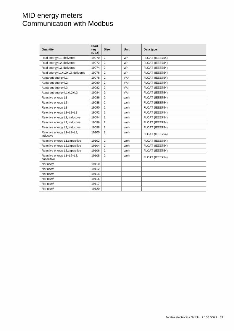
MID energy meters Communication with Modbus
Janitza electronics GmbH 2.100.006.2 69
Quantity Start reg (DEZ)
Size Unit Data type
Real energy L1, delivered 19070 2 Wh FLOAT (IEEE754)
Real energy L2, delivered 19072 2 Wh FLOAT (IEEE754)
Real energy L3, delivered 19074 2 Wh FLOAT (IEEE754)
Real energy L1+L2+L3, delivered 19076 2 Wh FLOAT (IEEE754)
Apparent energy L1 19078 2 VAh FLOAT (IEEE754)
Apparent energy L2 19080 2 VAh FLOAT (IEEE754)
Apparent energy L3 19082 2 VAh FLOAT (IEEE754)
Apparent energy L1+L2+L3 19084 2 VAh FLOAT (IEEE754)
Reactive energy L1 19086 2 varh FLOAT (IEEE754)
Reactive energy L2 19088 2 varh FLOAT (IEEE754)
Reactive energy L3 19090 2 varh FLOAT (IEEE754)
Reactive energy L1+L2+L3 19092 2 varh FLOAT (IEEE754)
Reactive energy L1, inductive 19094 2 varh FLOAT (IEEE754)
Reactive energy L2, inductive 19096 2 varh FLOAT (IEEE754)
Reactive energy L3, inductive 19098 2 varh FLOAT (IEEE754)
Reactive energy L1+L2+L3, inductive
19100 2 varh FLOAT (IEEE754)
Reactive energy L1,capacitive 19102 2 varh FLOAT (IEEE754)
Reactive energy L2,capacitive 19104 2 varh FLOAT (IEEE754)
Reactive energy L3,capacitive 19106 2 varh FLOAT (IEEE754)
Reactive energy L1+L2+L3, capacitive
19108 2 varh FLOAT (IEEE754)
Not used 19110
Not used 19112
Not used 19114
Not used 19116
Not used 19117
Not used 19120
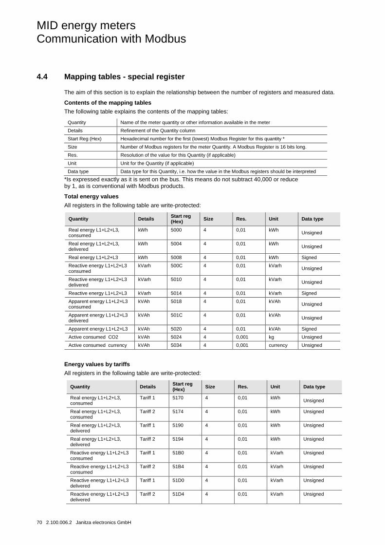
MID energy meters Communication with Modbus
70 2.100.006.2 Janitza electronics GmbH
4.4 Mapping tables - special register
The aim of this section is to explain the relationship between the number of registers and measured data.
Contents of the mapping tables
The following table explains the contents of the mapping tables:
Quantity Name of the meter quantity or other information available in the meter
Details Refinement of the Quantity column
Start Reg (Hex) Hexadecimal number for the first (lowest) Modbus Register for this quantity *
Size Number of Modbus registers for the meter Quantity. A Modbus Register is 16 bits long.
Res. Resolution of the value for this Quantity (if applicable)
Unit Unit for the Quantity (if applicable)
Data type Data type for this Quantity, i.e. how the value in the Modbus registers should be interpreted
*Is expressed exactly as it is sent on the bus. This means do not subtract 40,000 or reduce by 1, as is conventional with Modbus products.
Total energy values
All registers in the following table are write-protected:
Quantity Details Start reg (Hex) Size Res. Unit Data type
Real energy L1+L2+L3, consumed
kWh 5000 4 0,01 kWh Unsigned
Real energy L1+L2+L3, delivered
kWh 5004 4 0,01 kWh Unsigned
Real energy L1+L2+L3 kWh 5008 4 0,01 kWh Signed
Reactive energy L1+L2+L3 consumed
kVarh 500C 4 0,01 kVarh Unsigned
Reactive energy L1+L2+L3 delivered
kVarh 5010 4 0,01 kVarh Unsigned
Reactive energy L1+L2+L3 kVarh 5014 4 0,01 kVarh Signed
Apparent energy L1+L2+L3 consumed
kVAh 5018 4 0,01 kVAh Unsigned
Apparent energy L1+L2+L3 delivered
kVAh 501C 4 0,01 kVAh Unsigned
Apparent energy L1+L2+L3 kVAh 5020 4 0,01 kVAh Signed
Active consumed CO2 kVAh 5024 4 0,001 kg Unsigned
Active consumed currency kVAh 5034 4 0,001 currency Unsigned
Energy values by tariffs
All registers in the following table are write-protected:
Quantity Details Start reg (Hex) Size Res. Unit Data type
Real energy L1+L2+L3, consumed
Tariff 1 5170 4 0,01 kWh Unsigned
Real energy L1+L2+L3, consumed
Tariff 2 5174 4 0,01 kWh Unsigned
Real energy L1+L2+L3, delivered
Tariff 1 5190 4 0,01 kWh Unsigned
Real energy L1+L2+L3, delivered
Tariff 2 5194 4 0,01 kWh Unsigned
Reactive energy L1+L2+L3 consumed
Tariff 1 51B0 4 0,01 kVarh Unsigned
Reactive energy L1+L2+L3 consumed
Tariff 2 51B4 4 0,01 kVarh Unsigned
Reactive energy L1+L2+L3 delivered
Tariff 1 51D0 4 0,01 kVarh Unsigned
Reactive energy L1+L2+L3 delivered
Tariff 2 51D4 4 0,01 kVarh Unsigned
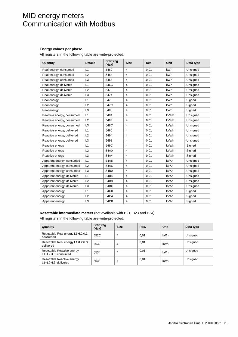
MID energy meters Communication with Modbus
Janitza electronics GmbH 2.100.006.2 71
Energy values per phase
All registers in the following table are write-protected:
Quantity Details Start reg (Hex) Size Res. Unit Data type
Real energy, consumed L1 5460 4 0,01 kWh Unsigned
Real energy, consumed L2 5464 4 0,01 kWh Unsigned
Real energy, consumed L3 5468 4 0,01 kWh Unsigned
Real energy, delivered L1 546C 4 0,01 kWh Unsigned
Real energy, delivered L2 5470 4 0,01 kWh Unsigned
Real energy, delivered L3 5474 4 0,01 kWh Unsigned
Real energy L1 5478 4 0,01 kWh Signed
Real energy L2 547C 4 0,01 kWh Signed
Real energy L3 5480 4 0,01 kWh Signed
Reactive energy, consumed L1 5484 4 0,01 kVarh Unsigned
Reactive energy, consumed L2 5488 4 0,01 kVarh Unsigned
Reactive energy, consumed L3 548C 4 0,01 kVarh Unsigned
Reactive energy, delivered L1 5490 4 0,01 kVarh Unsigned
Reactive energy, delivered L2 5494 4 0,01 kVarh Unsigned
Reactive energy, delivered L3 5498 4 0,01 kVarh Unsigned
Reactive energy L1 549C 4 0,01 kVarh Signed
Reactive energy L2 54A0 4 0,01 kVarh Signed
Reactive energy L3 54A4 4 0,01 kVarh Signed
Apparent energy, consumed L1 54A8 4 0,01 kVAh Unsigned
Apparent energy, consumed L2 54AC 4 0,01 kVAh Unsigned
Apparent energy, consumed L3 54B0 4 0,01 kVAh Unsigned
Apparent energy, delivered L1 54B4 4 0,01 kVAh Unsigned
Apparent energy, delivered L2 54B8 4 0,01 kVAh Unsigned
Apparent energy, delivered L3 54BC 4 0,01 kVAh Unsigned
Apparent energy L1 54C0 4 0,01 kVAh Signed
Apparent energy L2 54C4 4 0,01 kVAh Signed
Apparent energy L3 54C8 4 0,01 kVAh Signed
Resettable intermediate meters (not available with B21, B23 and B24)
All registers in the following table are write-protected:
Quantity Start reg (Hex) Size Res. Unit Data type
Resettable Real energy L1+L2+L3, consumed 552C 4 0,01 kWh Unsigned
Resettable Real energy L1+L2+L3, delivered 5530 4 0,01 kWh Unsigned
Resettable Reactive energy L1+L2+L3, consumed 5534 4 0,01 kWh Unsigned
Resettable Reactive energy L1+L2+L3, delivered 5538 4 0,01 kWh Unsigned
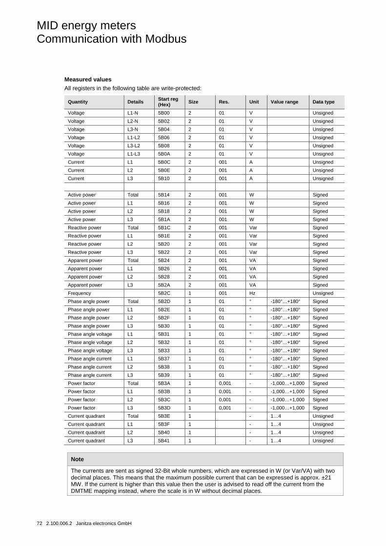
MID energy meters Communication with Modbus
72 2.100.006.2 Janitza electronics GmbH
Measured values
All registers in the following table are write-protected:
Quantity Details Start reg (Hex) Size Res. Unit Value range Data type
Voltage L1-N 5B00 2 01 V Unsigned
Voltage L2-N 5B02 2 01 V Unsigned
Voltage L3-N 5B04 2 01 V Unsigned
Voltage L1-L2 5B06 2 01 V Unsigned
Voltage L3-L2 5B08 2 01 V Unsigned
Voltage L1-L3 5B0A 2 01 V Unsigned
Current L1 5B0C 2 001 A Unsigned
Current L2 5B0E 2 001 A Unsigned
Current L3 5B10 2 001 A Unsigned
Active power Total 5B14 2 001 W Signed
Active power L1 5B16 2 001 W Signed
Active power L2 5B18 2 001 W Signed
Active power L3 5B1A 2 001 W Signed
Reactive power Total 5B1C 2 001 Var Signed
Reactive power L1 5B1E 2 001 Var Signed
Reactive power L2 5B20 2 001 Var Signed
Reactive power L3 5B22 2 001 Var Signed
Apparent power Total 5B24 2 001 VA Signed
Apparent power L1 5B26 2 001 VA Signed
Apparent power L2 5B28 2 001 VA Signed
Apparent power L3 5B2A 2 001 VA Signed
Frequency 5B2C 1 001 Hz Unsigned
Phase angle power Total 5B2D 1 01 ° -180°…+180° Signed
Phase angle power L1 5B2E 1 01 ° -180°…+180° Signed
Phase angle power L2 5B2F 1 01 ° -180°…+180° Signed
Phase angle power L3 5B30 1 01 ° -180°…+180° Signed
Phase angle voltage L1 5B31 1 01 ° -180°…+180° Signed
Phase angle voltage L2 5B32 1 01 ° -180°…+180° Signed
Phase angle voltage L3 5B33 1 01 ° -180°…+180° Signed
Phase angle current L1 5B37 1 01 ° -180°…+180° Signed
Phase angle current L2 5B38 1 01 ° -180°…+180° Signed
Phase angle current L3 5B39 1 01 ° -180°…+180° Signed
Power factor Total 5B3A 1 0,001 - -1,000…+1,000 Signed
Power factor L1 5B3B 1 0,001 - -1,000…+1,000 Signed
Power factor L2 5B3C 1 0,001 - -1,000…+1,000 Signed
Power factor L3 5B3D 1 0,001 - -1,000…+1,000 Signed
Current quadrant Total 5B3E 1 - 1…4 Unsigned
Current quadrant L1 5B3F 1 - 1…4 Unsigned
Current quadrant L2 5B40 1 - 1…4 Unsigned
Current quadrant L3 5B41 1 - 1…4 Unsigned
Note
The currents are sent as signed 32-Bit whole numbers, which are expressed in W (or Var/VA) with two decimal places. This means that the maximum possible current that can be expressed is approx. ±21 MW. If the current is higher than this value then the user is advised to read off the current from the DMTME mapping instead, where the scale is in W without decimal places.
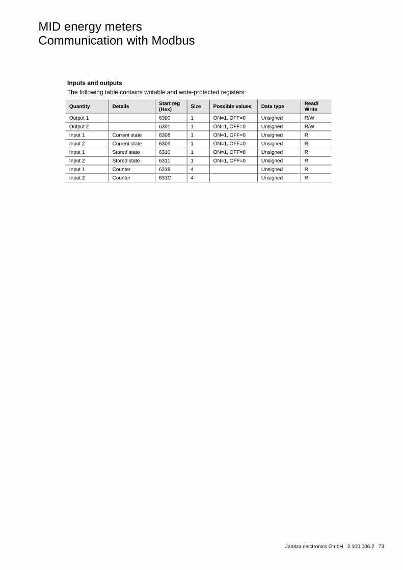
MID energy meters Communication with Modbus
Janitza electronics GmbH 2.100.006.2 73
Inputs and outputs
The following table contains writable and write-protected registers:
Quantity Details Start reg (Hex) Size Possible values Data type Read/
Write
Output 1 6300 1 ON=1, OFF=0 Unsigned R/W
Output 2 6301 1 ON=1, OFF=0 Unsigned R/W
Input 1 Current state 6308 1 ON=1, OFF=0 Unsigned R
Input 2 Current state 6309 1 ON=1, OFF=0 Unsigned R
Input 1 Stored state 6310 1 ON=1, OFF=0 Unsigned R
Input 2 Stored state 6311 1 ON=1, OFF=0 Unsigned R
Input 1 Counter 6318 4 Unsigned R
Input 2 Counter 631C 4 Unsigned R
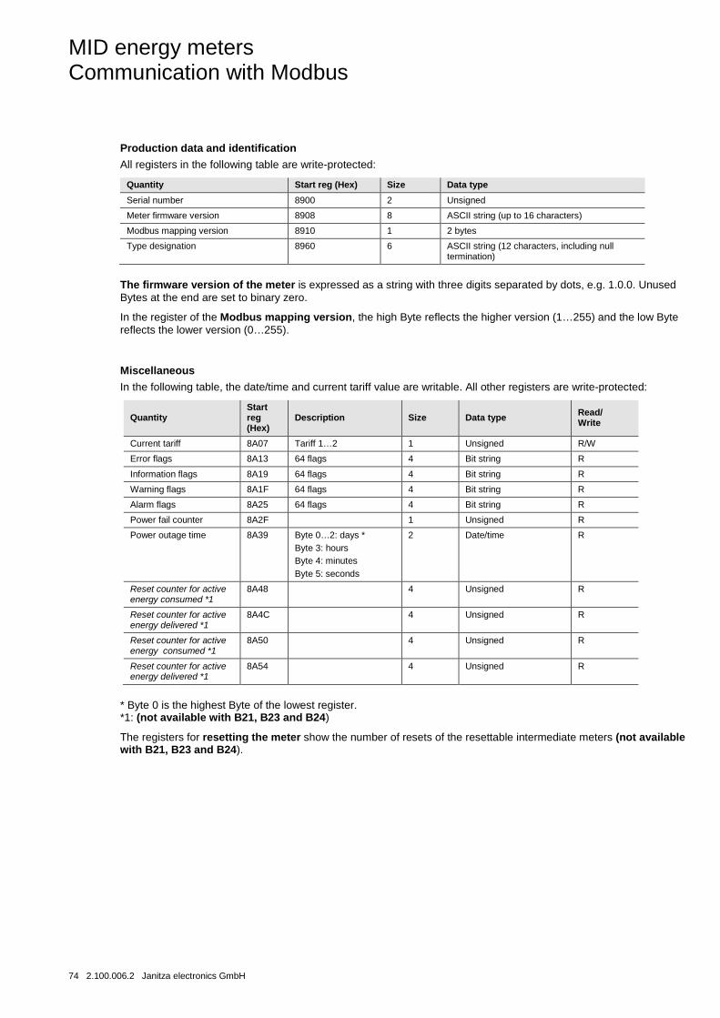
MID energy meters Communication with Modbus
74 2.100.006.2 Janitza electronics GmbH
Production data and identification
All registers in the following table are write-protected:
Quantity Start reg (Hex) Size Data type
Serial number 8900 2 Unsigned
Meter firmware version 8908 8 ASCII string (up to 16 characters)
Modbus mapping version 8910 1 2 bytes
Type designation 8960 6 ASCII string (12 characters, including null termination)
The firmware version of the meter is expressed as a string with three digits separated by dots, e.g. 1.0.0. Unused Bytes at the end are set to binary zero.
In the register of the Modbus mapping version, the high Byte reflects the higher version (1…255) and the low Byte reflects the lower version (0…255).
Miscellaneous
In the following table, the date/time and current tariff value are writable. All other registers are write-protected:
Quantity Start reg (Hex)
Description Size Data type Read/ Write
Current tariff 8A07 Tariff 1…2 1 Unsigned R/W
Error flags 8A13 64 flags 4 Bit string R
Information flags 8A19 64 flags 4 Bit string R
Warning flags 8A1F 64 flags 4 Bit string R
Alarm flags 8A25 64 flags 4 Bit string R
Power fail counter 8A2F 1 Unsigned R
Power outage time 8A39 Byte 0…2: days * Byte 3: hours Byte 4: minutes Byte 5: seconds
2 Date/time R
Reset counter for active energy consumed *1
8A48 4 Unsigned R
Reset counter for active energy delivered *1
8A4C 4 Unsigned R
Reset counter for active energy consumed *1
8A50 4 Unsigned R
Reset counter for active energy delivered *1
8A54 4 Unsigned R
* Byte 0 is the highest Byte of the lowest register. *1: (not available with B21, B23 and B24)
The registers for resetting the meter show the number of resets of the resettable intermediate meters (not available with B21, B23 and B24).
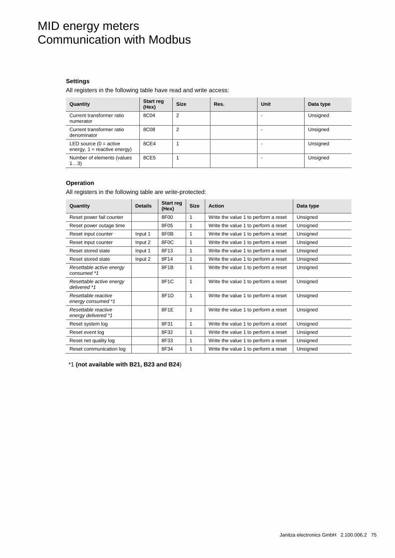
MID energy meters Communication with Modbus
Janitza electronics GmbH 2.100.006.2 75
Settings
All registers in the following table have read and write access:
Quantity Start reg (Hex) Size Res. Unit Data type
Current transformer ratio numerator
8C04 2 - Unsigned
Current transformer ratio denominator
8C08 2 - Unsigned
LED source (0 = active energy, 1 = reactive energy)
8CE4 1 - Unsigned
Number of elements (values 1…3)
8CE5 1 - Unsigned
Operation
All registers in the following table are write-protected:
Quantity Details Start reg (Hex) Size Action Data type
Reset power fail counter 8F00 1 Write the value 1 to perform a reset Unsigned
Reset power outage time 8F05 1 Write the value 1 to perform a reset Unsigned
Reset input counter Input 1 8F0B 1 Write the value 1 to perform a reset Unsigned
Reset input counter Input 2 8F0C 1 Write the value 1 to perform a reset Unsigned
Reset stored state Input 1 8F13 1 Write the value 1 to perform a reset Unsigned
Reset stored state Input 2 8F14 1 Write the value 1 to perform a reset Unsigned
Resettable active energy consumed *1
8F1B 1 Write the value 1 to perform a reset Unsigned
Resettable active energy delivered *1
8F1C 1 Write the value 1 to perform a reset Unsigned
Resettable reactive energy consumed *1
8F1D 1 Write the value 1 to perform a reset Unsigned
Resettable reactive energy delivered *1
8F1E 1 Write the value 1 to perform a reset Unsigned
Reset system log 8F31 1 Write the value 1 to perform a reset Unsigned
Reset event log 8F32 1 Write the value 1 to perform a reset Unsigned
Reset net quality log 8F33 1 Write the value 1 to perform a reset Unsigned
Reset communication log 8F34 1 Write the value 1 to perform a reset Unsigned
*1 (not available with B21, B23 and B24)

MID energy meters Communication with Modbus
76 2.100.006.2 Janitza electronics GmbH
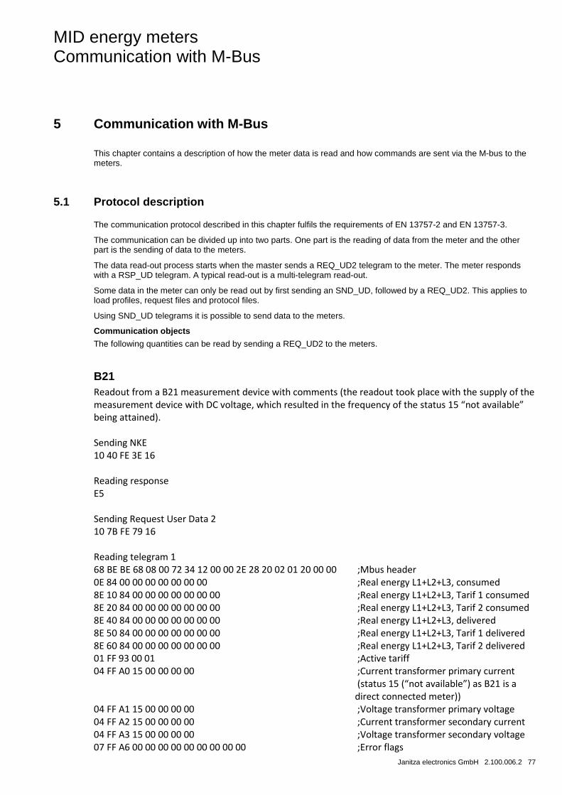
MID energy meters Communication with M-Bus
Janitza electronics GmbH 2.100.006.2 77
5 Communication with M-Bus
This chapter contains a description of how the meter data is read and how commands are sent via the M-bus to the meters.
5.1 Protocol description
The communication protocol described in this chapter fulfils the requirements of EN 13757-2 and EN 13757-3.
The communication can be divided up into two parts. One part is the reading of data from the meter and the other part is the sending of data to the meters.
The data read-out process starts when the master sends a REQ_UD2 telegram to the meter. The meter responds with a RSP_UD telegram. A typical read-out is a multi-telegram read-out.
Some data in the meter can only be read out by first sending an SND_UD, followed by a REQ_UD2. This applies to load profiles, request files and protocol files.
Using SND_UD telegrams it is possible to send data to the meters.
Communication objects
The following quantities can be read by sending a REQ_UD2 to the meters.
B21 Readout from a B21 measurement device with comments (the readout took place with the supply of the measurement device with DC voltage, which resulted in the frequency of the status 15 “not available” being attained). Sending NKE 10 40 FE 3E 16 Reading response E5 Sending Request User Data 2 10 7B FE 79 16 Reading telegram 1 68 BE BE 68 08 00 72 34 12 00 00 2E 28 20 02 01 20 00 00 ;Mbus header 0E 84 00 00 00 00 00 00 00 ;Real energy L1+L2+L3, consumed 8E 10 84 00 00 00 00 00 00 00 ;Real energy L1+L2+L3, Tarif 1 consumed 8E 20 84 00 00 00 00 00 00 00 ;Real energy L1+L2+L3, Tarif 2 consumed 8E 40 84 00 00 00 00 00 00 00 ;Real energy L1+L2+L3, delivered 8E 50 84 00 00 00 00 00 00 00 ;Real energy L1+L2+L3, Tarif 1 delivered 8E 60 84 00 00 00 00 00 00 00 ;Real energy L1+L2+L3, Tarif 2 delivered 01 FF 93 00 01 ;Active tariff 04 FF A0 15 00 00 00 00 ;Current transformer primary current (status 15 (“not available”) as B21 is a direct connected meter)) 04 FF A1 15 00 00 00 00 ;Voltage transformer primary voltage 04 FF A2 15 00 00 00 00 ;Current transformer secondary current 04 FF A3 15 00 00 00 00 ;Voltage transformer secondary voltage 07 FF A6 00 00 00 00 00 00 00 00 00 ;Error flags
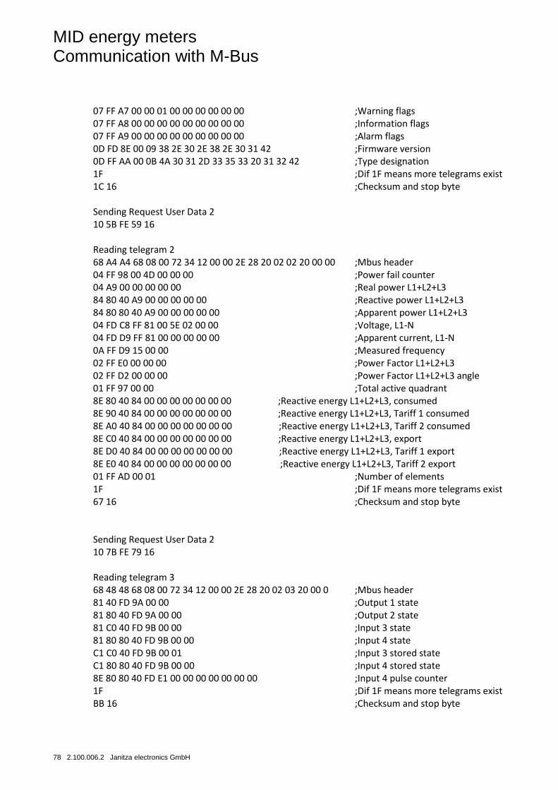
MID energy meters Communication with M-Bus
78 2.100.006.2 Janitza electronics GmbH
07 FF A7 00 00 01 00 00 00 00 00 00 ;Warning flags 07 FF A8 00 00 00 00 00 00 00 00 00 ;Information flags 07 FF A9 00 00 00 00 00 00 00 00 00 ;Alarm flags 0D FD 8E 00 09 38 2E 30 2E 38 2E 30 31 42 ;Firmware version 0D FF AA 00 0B 4A 30 31 2D 33 35 33 20 31 32 42 ;Type designation 1F ;Dif 1F means more telegrams exist 1C 16 ;Checksum and stop byte Sending Request User Data 2 10 5B FE 59 16 Reading telegram 2 68 A4 A4 68 08 00 72 34 12 00 00 2E 28 20 02 02 20 00 00 ;Mbus header 04 FF 98 00 4D 00 00 00 ;Power fail counter 04 A9 00 00 00 00 00 ;Real power L1+L2+L3 84 80 40 A9 00 00 00 00 00 ;Reactive power L1+L2+L3 84 80 80 40 A9 00 00 00 00 00 ;Apparent power L1+L2+L3 04 FD C8 FF 81 00 5E 02 00 00 ;Voltage, L1-N 04 FD D9 FF 81 00 00 00 00 00 ;Apparent current, L1-N 0A FF D9 15 00 00 ;Measured frequency 02 FF E0 00 00 00 ;Power Factor L1+L2+L3 02 FF D2 00 00 00 ;Power Factor L1+L2+L3 angle 01 FF 97 00 00 ;Total active quadrant 8E 80 40 84 00 00 00 00 00 00 00 ;Reactive energy L1+L2+L3, consumed 8E 90 40 84 00 00 00 00 00 00 00 ;Reactive energy L1+L2+L3, Tariff 1 consumed 8E A0 40 84 00 00 00 00 00 00 00 ;Reactive energy L1+L2+L3, Tariff 2 consumed 8E C0 40 84 00 00 00 00 00 00 00 ;Reactive energy L1+L2+L3, export 8E D0 40 84 00 00 00 00 00 00 00 ;Reactive energy L1+L2+L3, Tariff 1 export 8E E0 40 84 00 00 00 00 00 00 00 ;Reactive energy L1+L2+L3, Tariff 2 export 01 FF AD 00 01 ;Number of elements 1F ;Dif 1F means more telegrams exist 67 16 ;Checksum and stop byte Sending Request User Data 2 10 7B FE 79 16 Reading telegram 3 68 48 48 68 08 00 72 34 12 00 00 2E 28 20 02 03 20 00 0 ;Mbus header 81 40 FD 9A 00 00 ;Output 1 state 81 80 40 FD 9A 00 00 ;Output 2 state 81 C0 40 FD 9B 00 00 ;Input 3 state 81 80 80 40 FD 9B 00 00 ;Input 4 state C1 C0 40 FD 9B 00 01 ;Input 3 stored state C1 80 80 40 FD 9B 00 00 ;Input 4 stored state 8E 80 80 40 FD E1 00 00 00 00 00 00 00 ;Input 4 pulse counter 1F ;Dif 1F means more telegrams exist BB 16 ;Checksum and stop byte
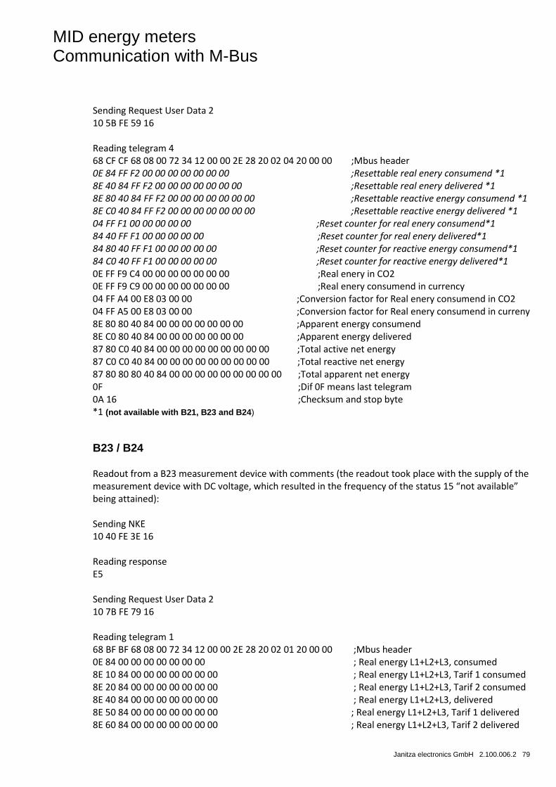
MID energy meters Communication with M-Bus
Janitza electronics GmbH 2.100.006.2 79
Sending Request User Data 2 10 5B FE 59 16 Reading telegram 4 68 CF CF 68 08 00 72 34 12 00 00 2E 28 20 02 04 20 00 00 ;Mbus header 0E 84 FF F2 00 00 00 00 00 00 00 ;Resettable real enery consumend *1 8E 40 84 FF F2 00 00 00 00 00 00 00 ;Resettable real enery delivered *1 8E 80 40 84 FF F2 00 00 00 00 00 00 00 ;Resettable reactive energy consumend *1 8E C0 40 84 FF F2 00 00 00 00 00 00 00 ;Resettable reactive energy delivered *1 04 FF F1 00 00 00 00 00 ;Reset counter for real enery consumend*1 84 40 FF F1 00 00 00 00 00 ;Reset counter for real enery delivered*1 84 80 40 FF F1 00 00 00 00 00 ;Reset counter for reactive energy consumend*1 84 C0 40 FF F1 00 00 00 00 00 ;Reset counter for reactive energy delivered*1 0E FF F9 C4 00 00 00 00 00 00 00 ;Real enery in CO2 0E FF F9 C9 00 00 00 00 00 00 00 ;Real enery consumend in currency 04 FF A4 00 E8 03 00 00 ;Conversion factor for Real enery consumend in CO2 04 FF A5 00 E8 03 00 00 ;Conversion factor for Real enery consumend in curreny 8E 80 80 40 84 00 00 00 00 00 00 00 ;Apparent energy consumend 8E C0 80 40 84 00 00 00 00 00 00 00 ;Apparent energy delivered 87 80 C0 40 84 00 00 00 00 00 00 00 00 00 ;Total active net energy 87 C0 C0 40 84 00 00 00 00 00 00 00 00 00 ;Total reactive net energy 87 80 80 80 40 84 00 00 00 00 00 00 00 00 00 ;Total apparent net energy 0F ;Dif 0F means last telegram 0A 16 ;Checksum and stop byte *1 (not available with B21, B23 and B24)
B23 / B24 Readout from a B23 measurement device with comments (the readout took place with the supply of the measurement device with DC voltage, which resulted in the frequency of the status 15 “not available” being attained): Sending NKE 10 40 FE 3E 16 Reading response E5 Sending Request User Data 2 10 7B FE 79 16 Reading telegram 1 68 BF BF 68 08 00 72 34 12 00 00 2E 28 20 02 01 20 00 00 ;Mbus header 0E 84 00 00 00 00 00 00 00 ; Real energy L1+L2+L3, consumed 8E 10 84 00 00 00 00 00 00 00 ; Real energy L1+L2+L3, Tarif 1 consumed 8E 20 84 00 00 00 00 00 00 00 ; Real energy L1+L2+L3, Tarif 2 consumed 8E 40 84 00 00 00 00 00 00 00 ; Real energy L1+L2+L3, delivered 8E 50 84 00 00 00 00 00 00 00 ; Real energy L1+L2+L3, Tarif 1 delivered 8E 60 84 00 00 00 00 00 00 00 ; Real energy L1+L2+L3, Tarif 2 delivered
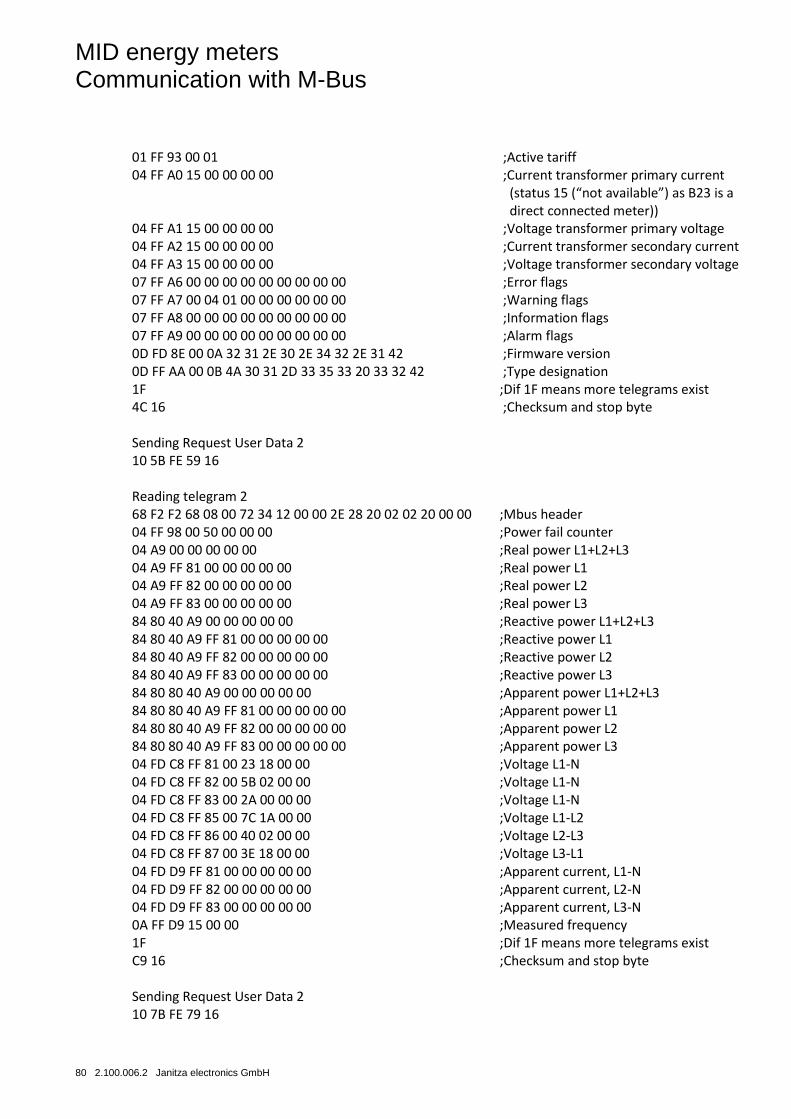
MID energy meters Communication with M-Bus
80 2.100.006.2 Janitza electronics GmbH
01 FF 93 00 01 ;Active tariff 04 FF A0 15 00 00 00 00 ;Current transformer primary current (status 15 (“not available”) as B23 is a direct connected meter)) 04 FF A1 15 00 00 00 00 ;Voltage transformer primary voltage 04 FF A2 15 00 00 00 00 ;Current transformer secondary current 04 FF A3 15 00 00 00 00 ;Voltage transformer secondary voltage 07 FF A6 00 00 00 00 00 00 00 00 00 ;Error flags 07 FF A7 00 04 01 00 00 00 00 00 00 ;Warning flags 07 FF A8 00 00 00 00 00 00 00 00 00 ;Information flags 07 FF A9 00 00 00 00 00 00 00 00 00 ;Alarm flags 0D FD 8E 00 0A 32 31 2E 30 2E 34 32 2E 31 42 ;Firmware version 0D FF AA 00 0B 4A 30 31 2D 33 35 33 20 33 32 42 ;Type designation 1F ;Dif 1F means more telegrams exist 4C 16 ;Checksum and stop byte Sending Request User Data 2 10 5B FE 59 16 Reading telegram 2 68 F2 F2 68 08 00 72 34 12 00 00 2E 28 20 02 02 20 00 00 ;Mbus header 04 FF 98 00 50 00 00 00 ;Power fail counter 04 A9 00 00 00 00 00 ;Real power L1+L2+L3 04 A9 FF 81 00 00 00 00 00 ;Real power L1 04 A9 FF 82 00 00 00 00 00 ;Real power L2 04 A9 FF 83 00 00 00 00 00 ;Real power L3 84 80 40 A9 00 00 00 00 00 ;Reactive power L1+L2+L3 84 80 40 A9 FF 81 00 00 00 00 00 ;Reactive power L1 84 80 40 A9 FF 82 00 00 00 00 00 ;Reactive power L2 84 80 40 A9 FF 83 00 00 00 00 00 ;Reactive power L3 84 80 80 40 A9 00 00 00 00 00 ;Apparent power L1+L2+L3 84 80 80 40 A9 FF 81 00 00 00 00 00 ;Apparent power L1 84 80 80 40 A9 FF 82 00 00 00 00 00 ;Apparent power L2 84 80 80 40 A9 FF 83 00 00 00 00 00 ;Apparent power L3 04 FD C8 FF 81 00 23 18 00 00 ;Voltage L1-N 04 FD C8 FF 82 00 5B 02 00 00 ;Voltage L1-N 04 FD C8 FF 83 00 2A 00 00 00 ;Voltage L1-N 04 FD C8 FF 85 00 7C 1A 00 00 ;Voltage L1-L2 04 FD C8 FF 86 00 40 02 00 00 ;Voltage L2-L3 04 FD C8 FF 87 00 3E 18 00 00 ;Voltage L3-L1 04 FD D9 FF 81 00 00 00 00 00 ;Apparent current, L1-N 04 FD D9 FF 82 00 00 00 00 00 ;Apparent current, L2-N 04 FD D9 FF 83 00 00 00 00 00 ;Apparent current, L3-N 0A FF D9 15 00 00 ;Measured frequency 1F ;Dif 1F means more telegrams exist C9 16 ;Checksum and stop byte Sending Request User Data 2 10 7B FE 79 16
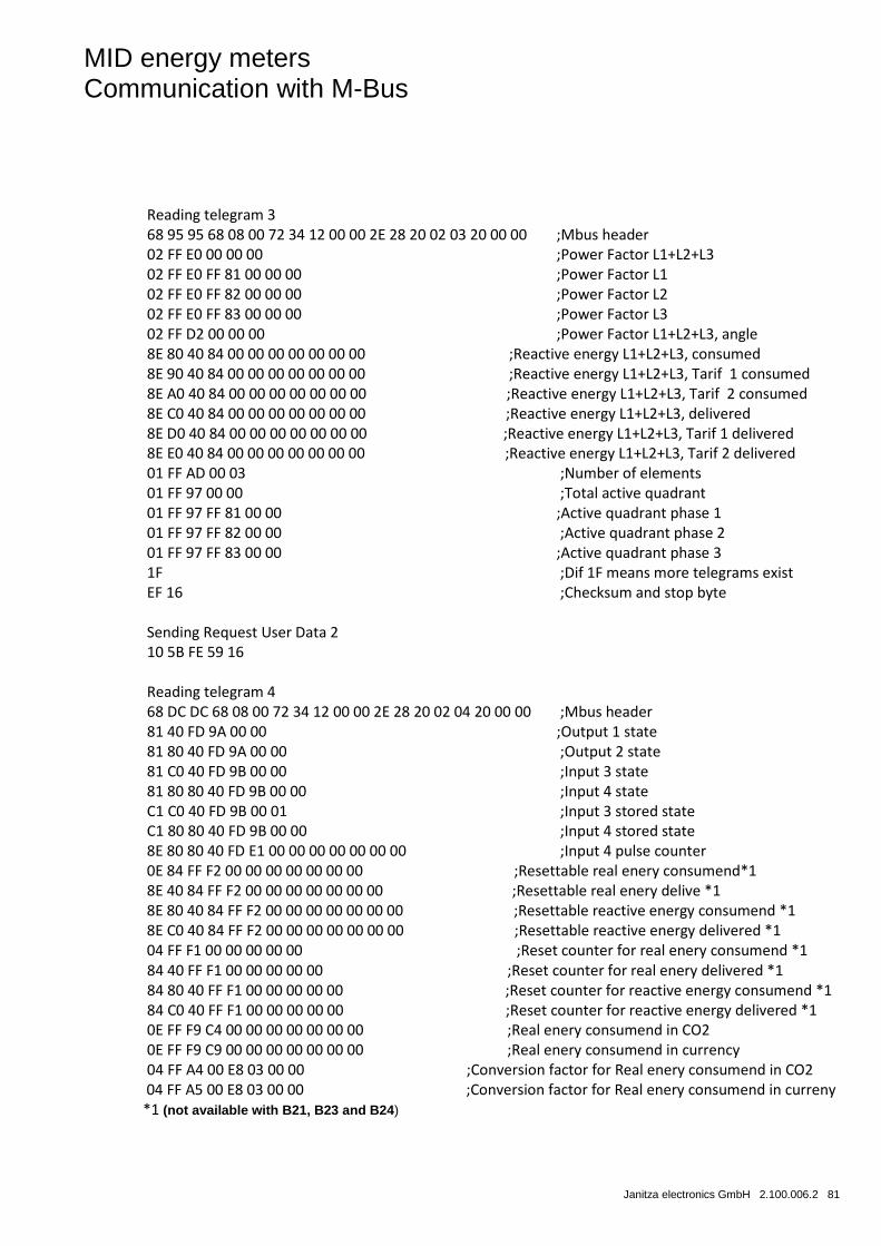
MID energy meters Communication with M-Bus
Janitza electronics GmbH 2.100.006.2 81
Reading telegram 3 68 95 95 68 08 00 72 34 12 00 00 2E 28 20 02 03 20 00 00 ;Mbus header 02 FF E0 00 00 00 ;Power Factor L1+L2+L3 02 FF E0 FF 81 00 00 00 ;Power Factor L1 02 FF E0 FF 82 00 00 00 ;Power Factor L2 02 FF E0 FF 83 00 00 00 ;Power Factor L3 02 FF D2 00 00 00 ;Power Factor L1+L2+L3, angle 8E 80 40 84 00 00 00 00 00 00 00 ;Reactive energy L1+L2+L3, consumed 8E 90 40 84 00 00 00 00 00 00 00 ;Reactive energy L1+L2+L3, Tarif 1 consumed 8E A0 40 84 00 00 00 00 00 00 00 ;Reactive energy L1+L2+L3, Tarif 2 consumed 8E C0 40 84 00 00 00 00 00 00 00 ;Reactive energy L1+L2+L3, delivered 8E D0 40 84 00 00 00 00 00 00 00 ;Reactive energy L1+L2+L3, Tarif 1 delivered 8E E0 40 84 00 00 00 00 00 00 00 ;Reactive energy L1+L2+L3, Tarif 2 delivered 01 FF AD 00 03 ;Number of elements 01 FF 97 00 00 ;Total active quadrant 01 FF 97 FF 81 00 00 ;Active quadrant phase 1 01 FF 97 FF 82 00 00 ;Active quadrant phase 2 01 FF 97 FF 83 00 00 ;Active quadrant phase 3 1F ;Dif 1F means more telegrams exist EF 16 ;Checksum and stop byte Sending Request User Data 2 10 5B FE 59 16 Reading telegram 4 68 DC DC 68 08 00 72 34 12 00 00 2E 28 20 02 04 20 00 00 ;Mbus header 81 40 FD 9A 00 00 ;Output 1 state 81 80 40 FD 9A 00 00 ;Output 2 state 81 C0 40 FD 9B 00 00 ;Input 3 state 81 80 80 40 FD 9B 00 00 ;Input 4 state C1 C0 40 FD 9B 00 01 ;Input 3 stored state C1 80 80 40 FD 9B 00 00 ;Input 4 stored state 8E 80 80 40 FD E1 00 00 00 00 00 00 00 ;Input 4 pulse counter 0E 84 FF F2 00 00 00 00 00 00 00 ;Resettable real enery consumend*1 8E 40 84 FF F2 00 00 00 00 00 00 00 ;Resettable real enery delive *1 8E 80 40 84 FF F2 00 00 00 00 00 00 00 ;Resettable reactive energy consumend *1 8E C0 40 84 FF F2 00 00 00 00 00 00 00 ;Resettable reactive energy delivered *1 04 FF F1 00 00 00 00 00 ;Reset counter for real enery consumend *1 84 40 FF F1 00 00 00 00 00 ;Reset counter for real enery delivered *1 84 80 40 FF F1 00 00 00 00 00 ;Reset counter for reactive energy consumend *1 84 C0 40 FF F1 00 00 00 00 00 ;Reset counter for reactive energy delivered *1 0E FF F9 C4 00 00 00 00 00 00 00 ;Real enery consumend in CO2 0E FF F9 C9 00 00 00 00 00 00 00 ;Real enery consumend in currency 04 FF A4 00 E8 03 00 00 ;Conversion factor for Real enery consumend in CO2
04 FF A5 00 E8 03 00 00 ;Conversion factor for Real enery consumend in curreny *1 (not available with B21, B23 and B24)
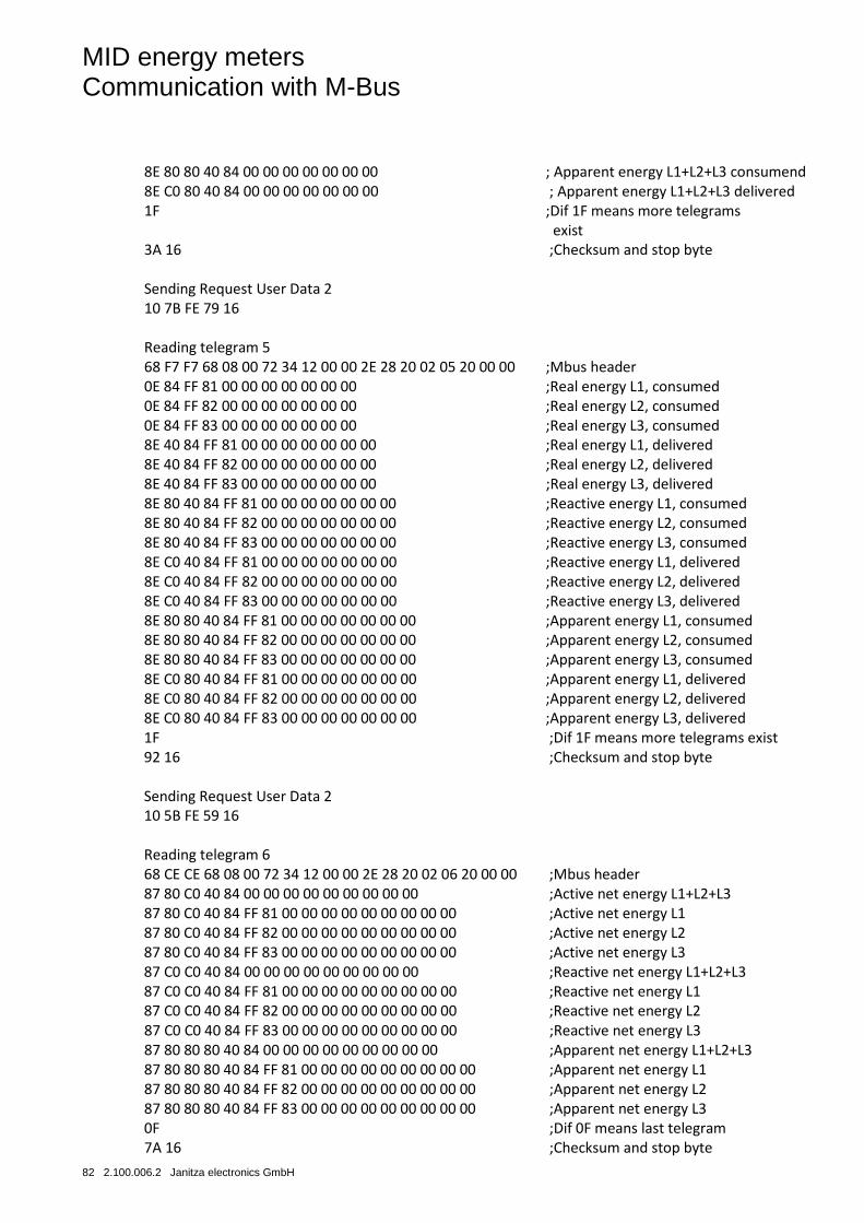
MID energy meters Communication with M-Bus
82 2.100.006.2 Janitza electronics GmbH
8E 80 80 40 84 00 00 00 00 00 00 00 ; Apparent energy L1+L2+L3 consumend 8E C0 80 40 84 00 00 00 00 00 00 00 ; Apparent energy L1+L2+L3 delivered 1F ;Dif 1F means more telegrams exist 3A 16 ;Checksum and stop byte Sending Request User Data 2 10 7B FE 79 16 Reading telegram 5 68 F7 F7 68 08 00 72 34 12 00 00 2E 28 20 02 05 20 00 00 ;Mbus header 0E 84 FF 81 00 00 00 00 00 00 00 ;Real energy L1, consumed 0E 84 FF 82 00 00 00 00 00 00 00 ;Real energy L2, consumed 0E 84 FF 83 00 00 00 00 00 00 00 ;Real energy L3, consumed 8E 40 84 FF 81 00 00 00 00 00 00 00 ;Real energy L1, delivered 8E 40 84 FF 82 00 00 00 00 00 00 00 ;Real energy L2, delivered 8E 40 84 FF 83 00 00 00 00 00 00 00 ;Real energy L3, delivered 8E 80 40 84 FF 81 00 00 00 00 00 00 00 ;Reactive energy L1, consumed 8E 80 40 84 FF 82 00 00 00 00 00 00 00 ;Reactive energy L2, consumed 8E 80 40 84 FF 83 00 00 00 00 00 00 00 ;Reactive energy L3, consumed 8E C0 40 84 FF 81 00 00 00 00 00 00 00 ;Reactive energy L1, delivered 8E C0 40 84 FF 82 00 00 00 00 00 00 00 ;Reactive energy L2, delivered 8E C0 40 84 FF 83 00 00 00 00 00 00 00 ;Reactive energy L3, delivered 8E 80 80 40 84 FF 81 00 00 00 00 00 00 00 ;Apparent energy L1, consumed 8E 80 80 40 84 FF 82 00 00 00 00 00 00 00 ;Apparent energy L2, consumed 8E 80 80 40 84 FF 83 00 00 00 00 00 00 00 ;Apparent energy L3, consumed 8E C0 80 40 84 FF 81 00 00 00 00 00 00 00 ;Apparent energy L1, delivered 8E C0 80 40 84 FF 82 00 00 00 00 00 00 00 ;Apparent energy L2, delivered 8E C0 80 40 84 FF 83 00 00 00 00 00 00 00 ;Apparent energy L3, delivered 1F ;Dif 1F means more telegrams exist 92 16 ;Checksum and stop byte Sending Request User Data 2 10 5B FE 59 16 Reading telegram 6 68 CE CE 68 08 00 72 34 12 00 00 2E 28 20 02 06 20 00 00 ;Mbus header 87 80 C0 40 84 00 00 00 00 00 00 00 00 00 ;Active net energy L1+L2+L3 87 80 C0 40 84 FF 81 00 00 00 00 00 00 00 00 00 ;Active net energy L1 87 80 C0 40 84 FF 82 00 00 00 00 00 00 00 00 00 ;Active net energy L2 87 80 C0 40 84 FF 83 00 00 00 00 00 00 00 00 00 ;Active net energy L3 87 C0 C0 40 84 00 00 00 00 00 00 00 00 00 ;Reactive net energy L1+L2+L3 87 C0 C0 40 84 FF 81 00 00 00 00 00 00 00 00 00 ;Reactive net energy L1 87 C0 C0 40 84 FF 82 00 00 00 00 00 00 00 00 00 ;Reactive net energy L2 87 C0 C0 40 84 FF 83 00 00 00 00 00 00 00 00 00 ;Reactive net energy L3 87 80 80 80 40 84 00 00 00 00 00 00 00 00 00 ;Apparent net energy L1+L2+L3 87 80 80 80 40 84 FF 81 00 00 00 00 00 00 00 00 00 ;Apparent net energy L1 87 80 80 80 40 84 FF 82 00 00 00 00 00 00 00 00 00 ;Apparent net energy L2 87 80 80 80 40 84 FF 83 00 00 00 00 00 00 00 00 00 ;Apparent net energy L3 0F ;Dif 0F means last telegram 7A 16 ;Checksum and stop byte
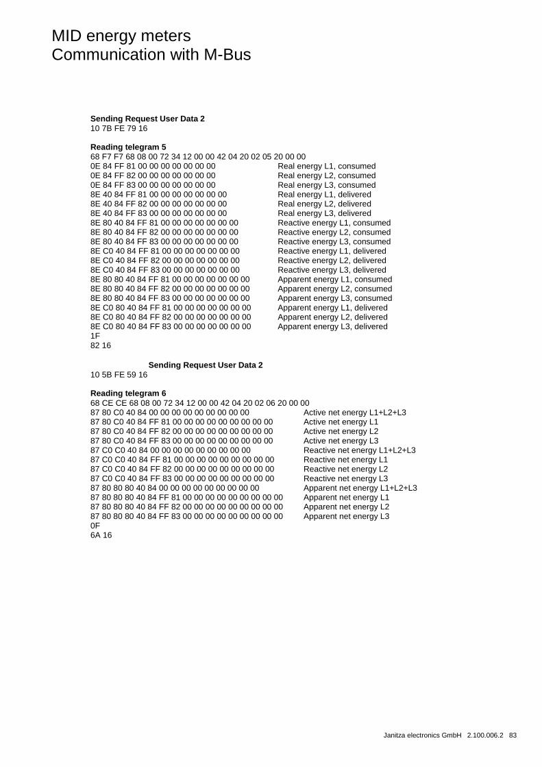
MID energy meters Communication with M-Bus
Janitza electronics GmbH 2.100.006.2 83
Sending Request User Data 2 10 7B FE 79 16 Reading telegram 5 68 F7 F7 68 08 00 72 34 12 00 00 42 04 20 02 05 20 00 00 0E 84 FF 81 00 00 00 00 00 00 00 Real energy L1, consumed 0E 84 FF 82 00 00 00 00 00 00 00 Real energy L2, consumed 0E 84 FF 83 00 00 00 00 00 00 00 Real energy L3, consumed 8E 40 84 FF 81 00 00 00 00 00 00 00 Real energy L1, delivered 8E 40 84 FF 82 00 00 00 00 00 00 00 Real energy L2, delivered 8E 40 84 FF 83 00 00 00 00 00 00 00 Real energy L3, delivered 8E 80 40 84 FF 81 00 00 00 00 00 00 00 Reactive energy L1, consumed 8E 80 40 84 FF 82 00 00 00 00 00 00 00 Reactive energy L2, consumed 8E 80 40 84 FF 83 00 00 00 00 00 00 00 Reactive energy L3, consumed 8E C0 40 84 FF 81 00 00 00 00 00 00 00 Reactive energy L1, delivered 8E C0 40 84 FF 82 00 00 00 00 00 00 00 Reactive energy L2, delivered 8E C0 40 84 FF 83 00 00 00 00 00 00 00 Reactive energy L3, delivered 8E 80 80 40 84 FF 81 00 00 00 00 00 00 00 Apparent energy L1, consumed 8E 80 80 40 84 FF 82 00 00 00 00 00 00 00 Apparent energy L2, consumed 8E 80 80 40 84 FF 83 00 00 00 00 00 00 00 Apparent energy L3, consumed 8E C0 80 40 84 FF 81 00 00 00 00 00 00 00 Apparent energy L1, delivered 8E C0 80 40 84 FF 82 00 00 00 00 00 00 00 Apparent energy L2, delivered 8E C0 80 40 84 FF 83 00 00 00 00 00 00 00 Apparent energy L3, delivered 1F 82 16 Sending Request User Data 2 10 5B FE 59 16 Reading telegram 6 68 CE CE 68 08 00 72 34 12 00 00 42 04 20 02 06 20 00 00 87 80 C0 40 84 00 00 00 00 00 00 00 00 00 Active net energy L1+L2+L3 87 80 C0 40 84 FF 81 00 00 00 00 00 00 00 00 00 Active net energy L1 87 80 C0 40 84 FF 82 00 00 00 00 00 00 00 00 00 Active net energy L2 87 80 C0 40 84 FF 83 00 00 00 00 00 00 00 00 00 Active net energy L3 87 C0 C0 40 84 00 00 00 00 00 00 00 00 00 Reactive net energy L1+L2+L3 87 C0 C0 40 84 FF 81 00 00 00 00 00 00 00 00 00 Reactive net energy L1 87 C0 C0 40 84 FF 82 00 00 00 00 00 00 00 00 00 Reactive net energy L2 87 C0 C0 40 84 FF 83 00 00 00 00 00 00 00 00 00 Reactive net energy L3 87 80 80 80 40 84 00 00 00 00 00 00 00 00 00 Apparent net energy L1+L2+L3 87 80 80 80 40 84 FF 81 00 00 00 00 00 00 00 00 00 Apparent net energy L1 87 80 80 80 40 84 FF 82 00 00 00 00 00 00 00 00 00 Apparent net energy L2 87 80 80 80 40 84 FF 83 00 00 00 00 00 00 00 00 00 Apparent net energy L3 0F 6A 16

MID energy meters Communication with M-Bus
84 2.100.006.2 Janitza electronics GmbH
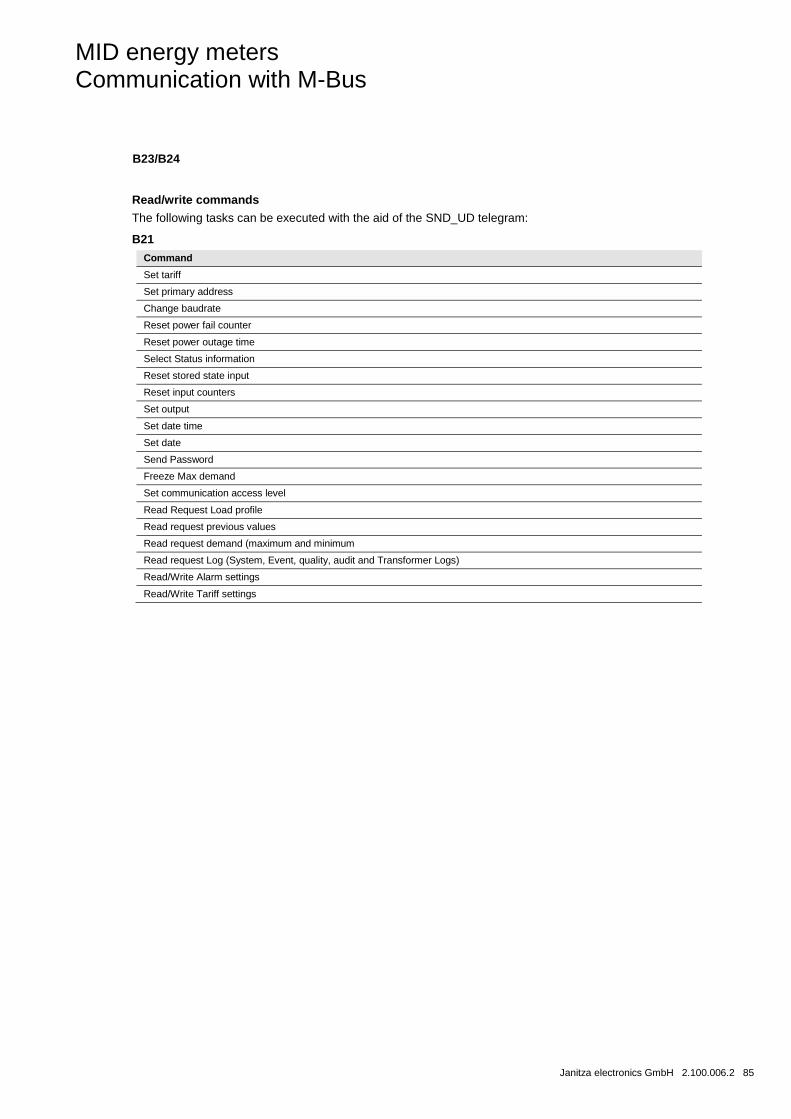
MID energy meters Communication with M-Bus
Janitza electronics GmbH 2.100.006.2 85
B23/B24
Read/write commands
The following tasks can be executed with the aid of the SND_UD telegram:
B21
Command
Set tariff
Set primary address
Change baudrate
Reset power fail counter
Reset power outage time
Select Status information
Reset stored state input
Reset input counters
Set output
Set date time
Set date
Send Password
Freeze Max demand
Set communication access level
Read Request Load profile
Read request previous values
Read request demand (maximum and minimum
Read request Log (System, Event, quality, audit and Transformer Logs)
Read/Write Alarm settings
Read/Write Tariff settings
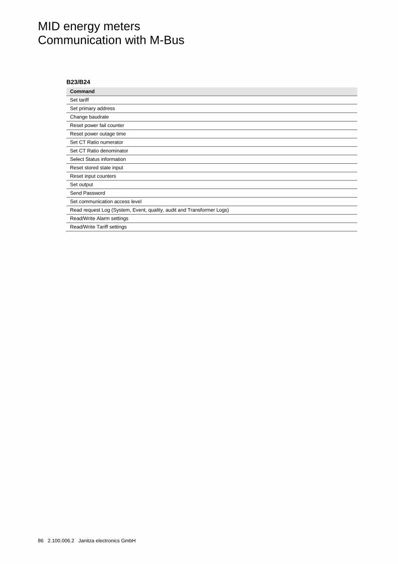
MID energy meters Communication with M-Bus
86 2.100.006.2 Janitza electronics GmbH
B23/B24
Command
Set tariff
Set primary address
Change baudrate
Reset power fail counter
Reset power outage time
Set CT Ratio numerator
Set CT Ratio denominator
Select Status information
Reset stored state input
Reset input counters
Set output
Send Password
Set communication access level
Read request Log (System, Event, quality, audit and Transformer Logs)
Read/Write Alarm settings
Read/Write Tariff settings
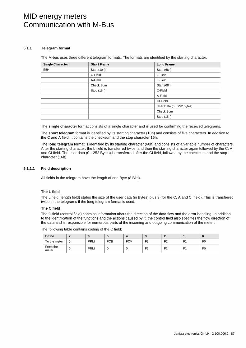
MID energy meters Communication with M-Bus
Janitza electronics GmbH 2.100.006.2 87
5.1.1 Telegram format
The M-bus uses three different telegram formats. The formats are identified by the starting character.
Single Character Short Frame Long Frame
E5H Start (10h) Start (68h)
C-Field L-Field
A-Field L-Field
Check Sum Start (68h)
Stop (16h) C-Field
A-Field
CI-Field
User Data (0…252 Bytes)
Check Sum
Stop (16h)
The single character format consists of a single character and is used for confirming the received telegrams.
The short telegram format is identified by its starting character (10h) and consists of five characters. In addition to the C and A field, it contains the checksum and the stop character 16h.
The long telegram format is identified by its starting character (68h) and consists of a variable number of characters. After the starting character, the L field is transferred twice, and then the starting character again followed by the C, A and CI field. The user data (0…252 Bytes) is transferred after the CI field, followed by the checksum and the stop character (16h).
5.1.1.1 Field description
All fields in the telegram have the length of one Byte (8 Bits).
The L field
The L field (length field) states the size of the user data (in Bytes) plus 3 (for the C, A and CI field). This is transferred twice in the telegrams if the long telegram format is used.
The C field
The C field (control field) contains information about the direction of the data flow and the error handling. In addition to the identification of the functions and the actions caused by it, the control field also specifies the flow direction of the data and is responsible for numerous parts of the incoming and outgoing communication of the meter.
The following table contains coding of the C field:
Bit no. 7 6 5 4 3 2 1 0
To the meter 0 PRM FCB FCV F3 F2 F1 F0
From the meter 0 PRM 0 0 F3 F2 F1 F0
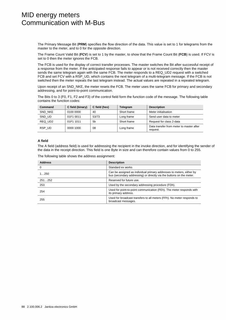
MID energy meters Communication with M-Bus
88 2.100.006.2 Janitza electronics GmbH
The Primary Message Bit (PRM) specifies the flow direction of the data. This value is set to 1 for telegrams from the master to the meter, and to 0 for the opposite direction.
The Frame Count Valid Bit (FCV) is set to 1 by the master, to show that the Frame Count Bit (FCB) is used. If FCV is set to 0 then the meter ignores the FCB.
The FCB is used for the display of correct transfer processes. The master switches the Bit after successful receipt of a response from the meter. If the anticipated response fails to appear or is not received correctly then the master sends the same telegram again with the same FCB. The meter responds to a REQ_UD2 request with a switched FCB and set FCV with a RSP_UD, which contains the next telegram of a multi-telegram message. If the FCB is not switched then the meter repeats the last telegram instead. The actual values are repeated in a repeated telegram.
Upon receipt of an SND_NKE, the meter resets the FCB. The meter uses the same FCB for primary and secondary addressing, and for point-to-point communication.
The Bits 0 to 3 (F0, F1, F2 and F3) of the control field form the function code of the message. The following table contains the function codes:
Command C field (binary) C field (hex) Telegram Description
SND_NKE 0100 0000 40 Short frame Meter initialisation
SND_UD 01F1 0011 53/73 Long frame Send user data to meter
REQ_UD2 01F1 1011 5b Short frame Request for class 2-data
RSP_UD 0000 1000 08 Long frame Data transfer from meter to master after request.
A field
The A field (address field) is used for addressing the recipient in the invoke direction, and for identifying the sender of the data in the receipt direction. This field is one Byte in size and can therefore contain values from 0 to 255.
The following table shows the address assignment:
Address Description
0 Standard ex works
1…250 Can be assigned as individual primary addresses to meters, either by bus (secondary addressing) or directly via the buttons on the meter.
251…252 Reserved for future use.
253 Used by the secondary addressing procedure (FDh).
254 Used for point-to-point communication (FEh). The meter responds with its primary address.
255 Used for broadcast transfers to all meters (FFh). No meter responds to broadcast messages.
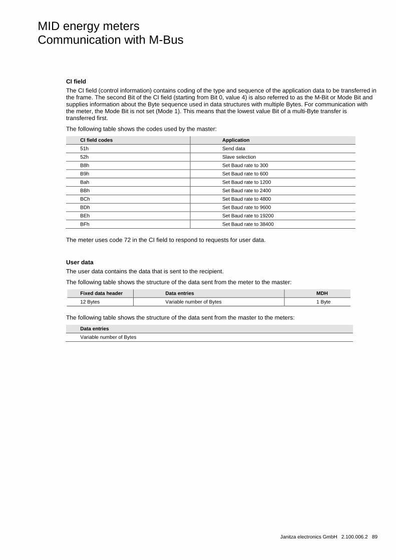
MID energy meters Communication with M-Bus
Janitza electronics GmbH 2.100.006.2 89
CI field
The CI field (control information) contains coding of the type and sequence of the application data to be transferred in the frame. The second Bit of the CI field (starting from Bit 0, value 4) is also referred to as the M-Bit or Mode Bit and supplies information about the Byte sequence used in data structures with multiple Bytes. For communication with the meter, the Mode Bit is not set (Mode 1). This means that the lowest value Bit of a multi-Byte transfer is transferred first.
The following table shows the codes used by the master:
CI field codes Application
51h Send data
52h Slave selection
B8h Set Baud rate to 300
B9h Set Baud rate to 600
Bah Set Baud rate to 1200
BBh Set Baud rate to 2400
BCh Set Baud rate to 4800
BDh Set Baud rate to 9600
BEh Set Baud rate to 19200
BFh Set Baud rate to 38400
The meter uses code 72 in the CI field to respond to requests for user data.
User data
The user data contains the data that is sent to the recipient.
The following table shows the structure of the data sent from the meter to the master:
Fixed data header Data entries MDH
12 Bytes Variable number of Bytes 1 Byte
The following table shows the structure of the data sent from the master to the meters:
Data entries
Variable number of Bytes
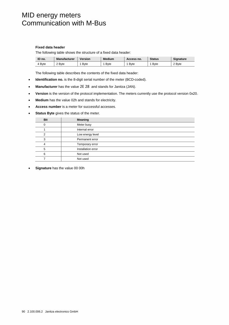
MID energy meters Communication with M-Bus
90 2.100.006.2 Janitza electronics GmbH
Fixed data header
The following table shows the structure of a fixed data header:
ID no. Manufacturer Version Medium Access no. Status Signature
4 Byte 2 Byte 1 Byte 1 Byte 1 Byte 1 Byte 2 Byte
The following table describes the contents of the fixed data header:
• Identification no. is the 8-digit serial number of the meter (BCD-coded).
• Manufacturer has the value 2E 28 and stands for Janitza (JAN).
• Version is the version of the protocol implementation. The meters currently use the protocol version 0x20.
• Medium has the value 02h and stands for electricity.
• Access number is a meter for successful accesses.
• Status Byte gives the status of the meter.
Bit Meaning
0 Meter busy
1 Internal error
2 Low energy level
3 Permanent error
4 Temporary error
5 Installation error
6 Not used
7 Not used
• Signature has the value 00 00h
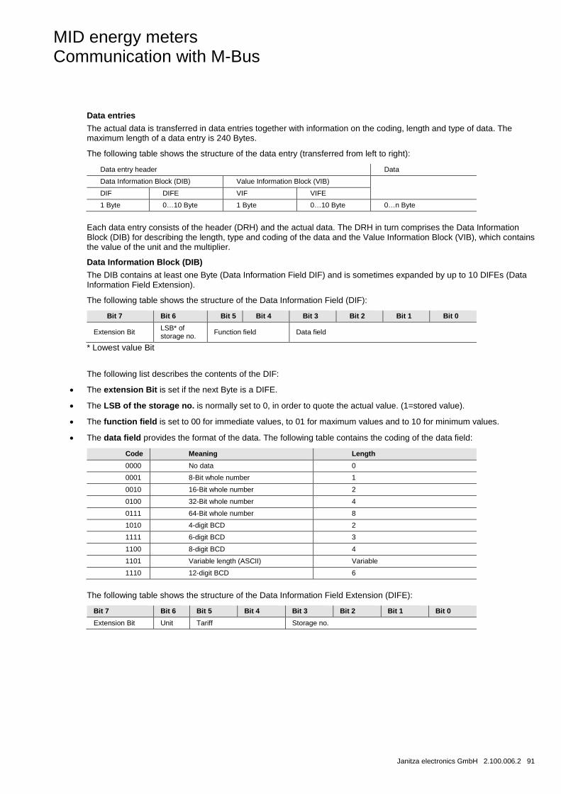
MID energy meters Communication with M-Bus
Janitza electronics GmbH 2.100.006.2 91
Data entries
The actual data is transferred in data entries together with information on the coding, length and type of data. The maximum length of a data entry is 240 Bytes.
The following table shows the structure of the data entry (transferred from left to right):
Data entry header Data
Data Information Block (DIB) Value Information Block (VIB)
DIF DIFE VIF VIFE
1 Byte 0…10 Byte 1 Byte 0…10 Byte 0…n Byte
Each data entry consists of the header (DRH) and the actual data. The DRH in turn comprises the Data Information Block (DIB) for describing the length, type and coding of the data and the Value Information Block (VIB), which contains the value of the unit and the multiplier.
Data Information Block (DIB)
The DIB contains at least one Byte (Data Information Field DIF) and is sometimes expanded by up to 10 DIFEs (Data Information Field Extension).
The following table shows the structure of the Data Information Field (DIF):
Bit 7 Bit 6 Bit 5 Bit 4 Bit 3 Bit 2 Bit 1 Bit 0
Extension Bit LSB* of storage no. Function field Data field
* Lowest value Bit
The following list describes the contents of the DIF:
• The extension Bit is set if the next Byte is a DIFE.
• The LSB of the storage no. is normally set to 0, in order to quote the actual value. (1=stored value).
• The function field is set to 00 for immediate values, to 01 for maximum values and to 10 for minimum values.
• The data field provides the format of the data. The following table contains the coding of the data field:
Code Meaning Length
0000 No data 0
0001 8-Bit whole number 1
0010 16-Bit whole number 2
0100 32-Bit whole number 4
0111 64-Bit whole number 8
1010 4-digit BCD 2
1111 6-digit BCD 3
1100 8-digit BCD 4
1101 Variable length (ASCII) Variable
1110 12-digit BCD 6
The following table shows the structure of the Data Information Field Extension (DIFE):
Bit 7 Bit 6 Bit 5 Bit 4 Bit 3 Bit 2 Bit 1 Bit 0
Extension Bit Unit Tariff Storage no.

MID energy meters Communication with M-Bus
92 2.100.006.2 Janitza electronics GmbH
The following list describes the contents of the DIFE:
• Unit shows the respective type of current or energy for current and energy values. This field also contains the number of inputs and outputs and an offset when accessing data of the event log.
• Tariff is used with energy values to specify tariff data.
• Storage number is set to 0, to specify momentary values. A storage number greater than 0 indicates previously stored values, which were saved at a certain point in the past.
Value Information Block (VIB)
VIB follows a DIF or DIFE without extension Bit. The VIB contains an information field (VIF) and is sometimes extended by up to 10 Value Information Field Extensions (VIFE).
The following table shows the structure of the Value Information Field (VIF):
Bit 7 Bit 6 Bit 5 Bit 4 Bit 3 Bit 2 Bit 1 Bit 0
Extension Bit Data values
The data values contain information on the value (unit, status, etc.). The extension Bit is set if the next Byte is a VIFE. If VIF or VIFE = FFh, then the next VIFE is manufacturer-specific. The manufacturer-specific VIFE has the same structure as a VIF. If the extension Bit of the manufacturer-specific VIFE is set and the VIFE is lower than 1111 1000, the next Byte is a standard VIFE, otherwise it is the first data Byte. If the extension Bit of the manufacturer-specific VIFE is set and the VIFE is greater than or equal to 1111 1000, the next Byte is an extension of the manufacturer-specific VIFE.
Data
The data follows a VIF or VIFE without set extension Bit.
Manufacturer Data Header (MDH)
The Manufacturer Data Header (MDH) either consists of the combination 1Fh to specify that the further data follows in the next Bit, or 0Fh to signal the last telegram.
Checksum
The checksum is used to recognise transfer and synchronisation errors. It is calculated from the arithmetic sum total of the Bytes from the control field to the last user data, without taking carry-overs into consideration.
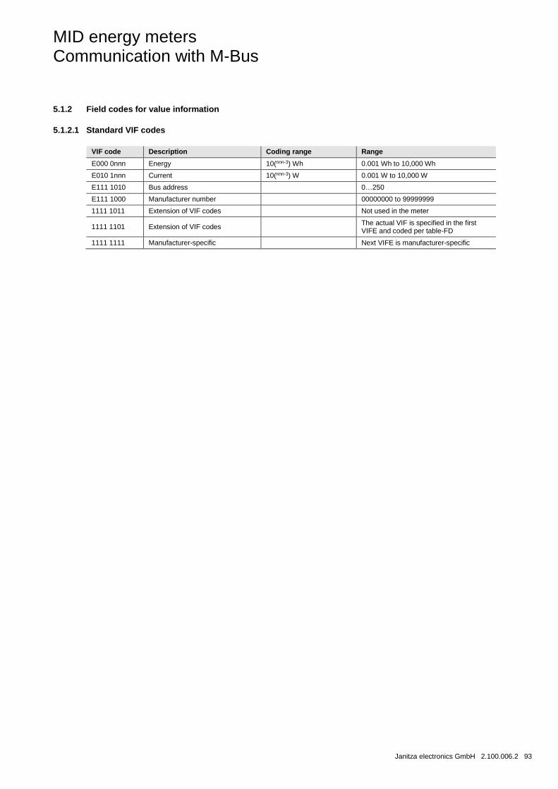
MID energy meters Communication with M-Bus
Janitza electronics GmbH 2.100.006.2 93
5.1.2 Field codes for value information
5.1.2.1 Standard VIF codes
VIF code Description Coding range Range
E000 0nnn Energy 10(nnn-3) Wh 0.001 Wh to 10,000 Wh
E010 1nnn Current 10(nnn-3) W 0.001 W to 10,000 W
E111 1010 Bus address 0…250
E111 1000 Manufacturer number 00000000 to 99999999
1111 1011 Extension of VIF codes Not used in the meter
1111 1101 Extension of VIF codes The actual VIF is specified in the first VIFE and coded per table-FD
1111 1111 Manufacturer-specific Next VIFE is manufacturer-specific
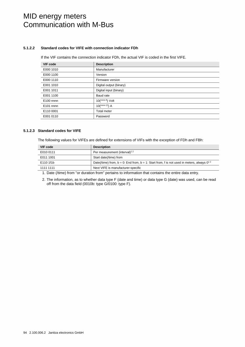
MID energy meters Communication with M-Bus
94 2.100.006.2 Janitza electronics GmbH
5.1.2.2 Standard codes for VIFE with connection indicator FDh
If the VIF contains the connection indicator FDh, the actual VIF is coded in the first VIFE.
VIF code Description
E000 1010 Manufacturer
E000 1100 Version
E000 1110 Firmware version
E001 1010 Digital output (binary)
E001 1011 Digital input (binary)
E001 1100 Baud rate
E100 nnnn 10(nnnn-9) Volt
E101 nnnn 10(nnnn-12) A
E110 0001 Total meter
E001 0110 Password
5.1.2.3 Standard codes for VIFE
The following values for VIFEs are defined for extensions of VIFs with the exception of FDh and FBh:
VIF code Description
E010 0111 Per measurement (interval)1 2
E011 1001 Start date(/time) from
E110 1f1b Date(/time) from, b = 0: End from, b = 1: Start from, f is not used in meters, always 01 2
1111 1111 Next VIFE is manufacturer-specific
1. Date (/time) from "or duration from" pertains to information that contains the entire data entry.
2. The information, as to whether data type F (date and time) or data type G (date) was used, can be read off from the data field (0010b: type G/0100: type F).
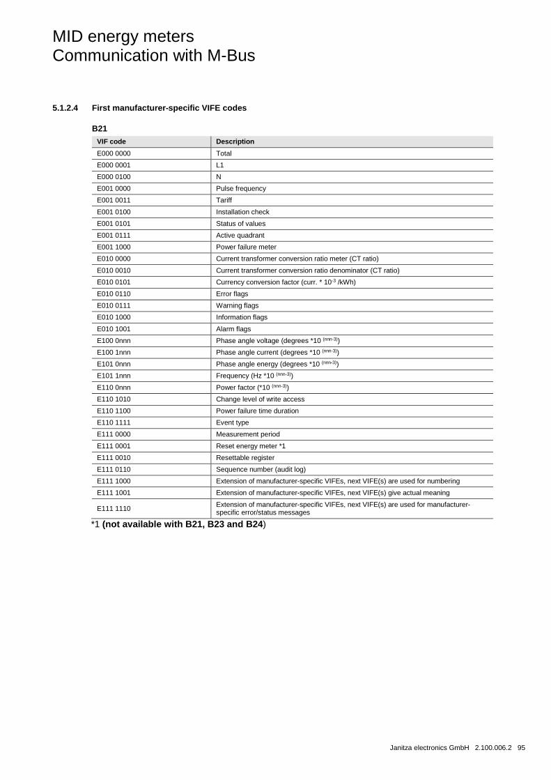
MID energy meters Communication with M-Bus
Janitza electronics GmbH 2.100.006.2 95
5.1.2.4 First manufacturer-specific VIFE codes
B21
VIF code Description
E000 0000 Total
E000 0001 L1
E000 0100 N
E001 0000 Pulse frequency
E001 0011 Tariff
E001 0100 Installation check
E001 0101 Status of values
E001 0111 Active quadrant
E001 1000 Power failure meter
E010 0000 Current transformer conversion ratio meter (CT ratio)
E010 0010 Current transformer conversion ratio denominator (CT ratio)
E010 0101 Currency conversion factor (curr. * 10-3 /kWh)
E010 0110 Error flags
E010 0111 Warning flags
E010 1000 Information flags
E010 1001 Alarm flags
E100 0nnn Phase angle voltage (degrees *10 (nnn-3))
E100 1nnn Phase angle current (degrees *10 (nnn-3))
E101 0nnn Phase angle energy (degrees *10 (nnn-3))
E101 1nnn Frequency (Hz *10 (nnn-3))
E110 0nnn Power factor (*10 (nnn-3))
E110 1010 Change level of write access
E110 1100 Power failure time duration
E110 1111 Event type
E111 0000 Measurement period
E111 0001 Reset energy meter *1
E111 0010 Resettable register
E111 0110 Sequence number (audit log)
E111 1000 Extension of manufacturer-specific VIFEs, next VIFE(s) are used for numbering
E111 1001 Extension of manufacturer-specific VIFEs, next VIFE(s) give actual meaning
E111 1110 Extension of manufacturer-specific VIFEs, next VIFE(s) are used for manufacturer-specific error/status messages
*1 (not available with B21, B23 and B24)
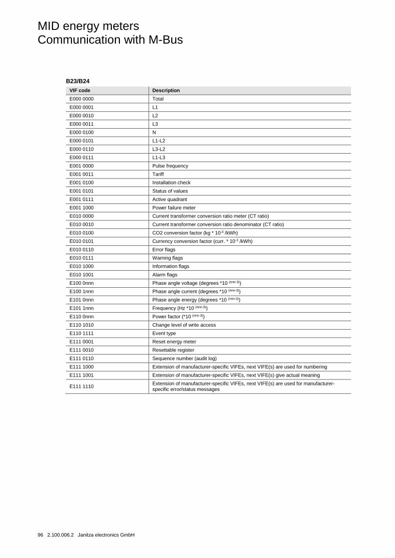
MID energy meters Communication with M-Bus
96 2.100.006.2 Janitza electronics GmbH
B23/B24
VIF code Description
E000 0000 Total
E000 0001 L1
E000 0010 L2
E000 0011 L3
E000 0100 N
E000 0101 L1-L2
E000 0110 L3-L2
E000 0111 L1-L3
E001 0000 Pulse frequency
E001 0011 Tariff
E001 0100 Installation check
E001 0101 Status of values
E001 0111 Active quadrant
E001 1000 Power failure meter
E010 0000 Current transformer conversion ratio meter (CT ratio)
E010 0010 Current transformer conversion ratio denominator (CT ratio)
E010 0100 CO2 conversion factor (kg * 10-3 /kWh)
E010 0101 Currency conversion factor (curr. * 10-3 /kWh)
E010 0110 Error flags
E010 0111 Warning flags
E010 1000 Information flags
E010 1001 Alarm flags
E100 0nnn Phase angle voltage (degrees *10 (nnn-3))
E100 1nnn Phase angle current (degrees *10 (nnn-3))
E101 0nnn Phase angle energy (degrees *10 (nnn-3))
E101 1nnn Frequency (Hz *10 (nnn-3))
E110 0nnn Power factor (*10 (nnn-3))
E110 1010 Change level of write access
E110 1111 Event type
E111 0001 Reset energy meter
E111 0010 Resettable register
E111 0110 Sequence number (audit log)
E111 1000 Extension of manufacturer-specific VIFEs, next VIFE(s) are used for numbering
E111 1001 Extension of manufacturer-specific VIFEs, next VIFE(s) give actual meaning
E111 1110 Extension of manufacturer-specific VIFEs, next VIFE(s) are used for manufacturer-specific error/status messages
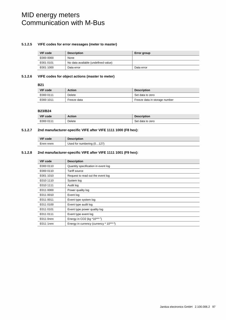
MID energy meters Communication with M-Bus
Janitza electronics GmbH 2.100.006.2 97
5.1.2.5 VIFE codes for error messages (meter to master)
VIF code Description Error group
E000 0000 None
E001 0101 No data available (undefined value)
E001 1000 Data error Data error
5.1.2.6 VIFE codes for object actions (master to meter)
B21
VIF code Action Description
E000 0111 Delete Set data to zero
E000 1011 Freeze data Freeze data in storage number
B23/B24
VIF code Action Description
E000 0111 Delete Set data to zero
5.1.2.7 2nd manufacturer-specific VIFE after VIFE 1111 1000 (F8 hex):
VIF code Description
Ennn nnnn Used for numbering (0…127)
5.1.2.8 2nd manufacturer-specific VIFE after VIFE 1111 1001 (F9 hex):
VIF code Description
E000 0110 Quantity specification in event log
E000 0110 Tariff source
E001 1010 Request to read out the event log
E010 1110 System log
E010 1111 Audit log
E011 0000 Power quality log
E011 0010 Event log
E011 0011 Event type system log
E011 0100 Event type audit log
E011 0101 Event type power quality log
E011 0111 Event type event log
E011 0nnn Energy in CO2 (kg *10nnn-7)
E011 1nnn Energy in currency (currency * 10nnn-3)

MID energy meters Communication with M-Bus
98 2.100.006.2 Janitza electronics GmbH
5.1.3 Communication process
The data linking level uses two types of transfer service:
Send/Confirm SND/CON
Request/Respond REQ/RSP
If a meter receives a correct telegram then it waits between 35 and 80 ms before it responds. A telegram is deemed to be correct if it passes the following tests:
• Start/parity/stop Bits per character
• Start/checksum/stop characters per telegram format
• In case of a long frame, the number of additional characters received must reflect the L field (= L-field + 6).
• The received data must make sense
The interval between a response from the meter and a new message from the master must be at least 20 ms.
Send / confirmation procedure
SND_NKE is used to initiate communication with the meter. If the meter receives an NKE followed by a REQ_UD2 (see description below) then the first telegram is sent by the meter.
If the meter has been selected for secondary addressing then the selection is rescinded. The value of the FCB is reset in the meter, i.e. the meter expects that the first telegram from a master with FCV=1 contains an FCB=1.
The meter can either confirm the correct receipt with the simple character E5h) or omit confirmation if the telegram was not received correctly.
SND_UD is used to send data to the meter. The meter can either confirm receipt of a correct message or omit confirmation if the telegram was not received correctly.
Request / response procedure REQ_UD2 is used by the master to request data from the meter.
REQ_UD2 is used by the meter to transfer data to the master. The meter can send 1Fh as the last user data, in order to specify to the master that further data will follow in the next telegram.
If the meter does not respond to the REQ_UD2 then this means that the message was not received correctly or that the address did not match.
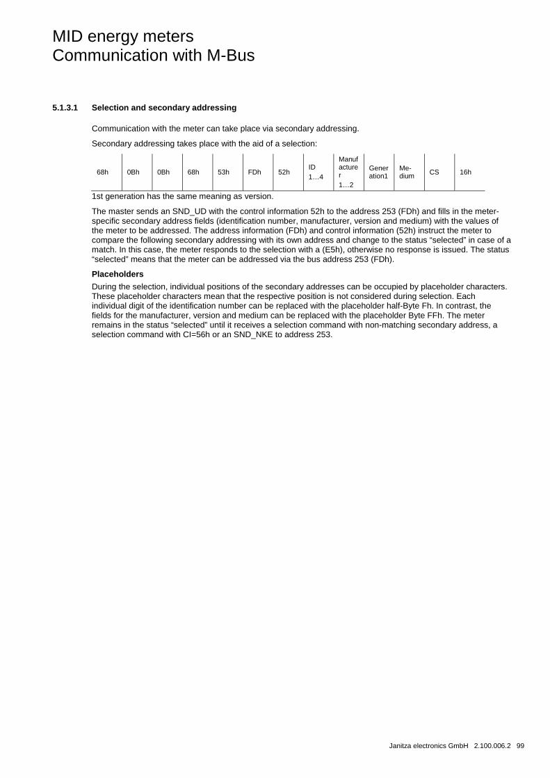
MID energy meters Communication with M-Bus
Janitza electronics GmbH 2.100.006.2 99
5.1.3.1 Selection and secondary addressing
Communication with the meter can take place via secondary addressing.
Secondary addressing takes place with the aid of a selection:
68h 0Bh 0Bh 68h 53h FDh 52h ID 1…4
Manufacturer 1…2
Generation1
Me-dium CS 16h
1st generation has the same meaning as version.
The master sends an SND_UD with the control information 52h to the address 253 (FDh) and fills in the meter-specific secondary address fields (identification number, manufacturer, version and medium) with the values of the meter to be addressed. The address information (FDh) and control information (52h) instruct the meter to compare the following secondary addressing with its own address and change to the status “selected” in case of a match. In this case, the meter responds to the selection with a (E5h), otherwise no response is issued. The status “selected” means that the meter can be addressed via the bus address 253 (FDh).
Placeholders
During the selection, individual positions of the secondary addresses can be occupied by placeholder characters. These placeholder characters mean that the respective position is not considered during selection. Each individual digit of the identification number can be replaced with the placeholder half-Byte Fh. In contrast, the fields for the manufacturer, version and medium can be replaced with the placeholder Byte FFh. The meter remains in the status “selected” until it receives a selection command with non-matching secondary address, a selection command with CI=56h or an SND_NKE to address 253.
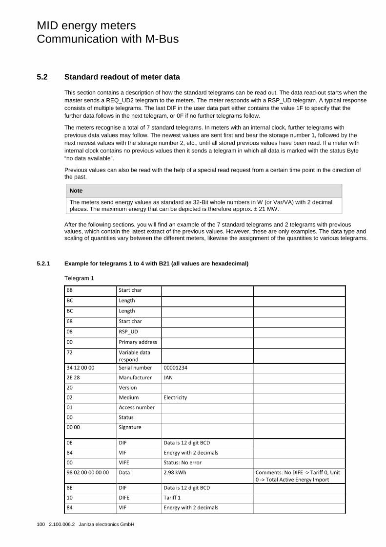
MID energy meters Communication with M-Bus
100 2.100.006.2 Janitza electronics GmbH
5.2 Standard readout of meter data
This section contains a description of how the standard telegrams can be read out. The data read-out starts when the master sends a REQ_UD2 telegram to the meters. The meter responds with a RSP_UD telegram. A typical response consists of multiple telegrams. The last DIF in the user data part either contains the value 1F to specify that the further data follows in the next telegram, or 0F if no further telegrams follow.
The meters recognise a total of 7 standard telegrams. In meters with an internal clock, further telegrams with previous data values may follow. The newest values are sent first and bear the storage number 1, followed by the next newest values with the storage number 2, etc., until all stored previous values have been read. If a meter with internal clock contains no previous values then it sends a telegram in which all data is marked with the status Byte “no data available”.
Previous values can also be read with the help of a special read request from a certain time point in the direction of the past.
Note
The meters send energy values as standard as 32-Bit whole numbers in W (or Var/VA) with 2 decimal places. The maximum energy that can be depicted is therefore approx. ± 21 MW.
After the following sections, you will find an example of the 7 standard telegrams and 2 telegrams with previous values, which contain the latest extract of the previous values. However, these are only examples. The data type and scaling of quantities vary between the different meters, likewise the assignment of the quantities to various telegrams.
5.2.1 Example for telegrams 1 to 4 with B21 (all values are hexadecimal)
Telegram 1
68 Start char
BC Length
BC Length
68 Start char
08 RSP_UD
00 Primary address
72 Variable data respond
34 12 00 00 Serial number 00001234
2E 28 Manufacturer JAN
20 Version
02 Medium Electricity
01 Access number
00 Status
00 00 Signature
0E DIF Data is 12 digit BCD
84 VIF Energy with 2 decimals
00 VIFE Status: No error
98 02 00 00 00 00 Data 2.98 kWh Comments: No DIFE -> Tariff 0, Unit 0 -> Total Active Energy Import
8E DIF Data is 12 digit BCD
10 DIFE Tariff 1
84 VIF Energy with 2 decimals
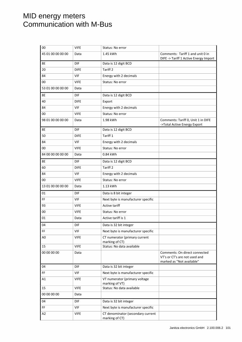
MID energy meters Communication with M-Bus
Janitza electronics GmbH 2.100.006.2 101
00 VIFE Status: No error
45 01 00 00 00 00 Data 1.45 kWh Comments: Tariff 1 and unit 0 in DIFE -> Tariff 1 Active Energy Import
8E DIF Data is 12 digit BCD
20 DIFE Tariff 2
84 VIF Energy with 2 decimals
00 VIFE Status: No error
53 01 00 00 00 00 Data
8E DIF Data is 12 digit BCD
40 DIFE Export
84 VIF Energy with 2 decimals
00 VIFE Status: No error
98 01 00 00 00 00 Data 1.98 kWh Comments: Tariff 0, Unit 1 in DIFE ->Total Active Energy Export
8E DIF Data is 12 digit BCD
50 DIFE Tariff 1
84 VIF Energy with 2 decimals
00 VIFE Status: No error
84 00 00 00 00 00 Data 0.84 kWh
8E DIF Data is 12 digit BCD
60 DIFE Tariff 2
84 VIF Energy with 2 decimals
00 VIFE Status: No error
13 01 00 00 00 00 Data 1.13 kWh
01 DIF Data is 8 bit integer
FF VIF Next byte is manufacturer specific
93 VIFE Active tariff
00 VIFE Status: No error
01 Data Active tariff is 1
04 DIF Data is 32 bit integer
FF VIF Next byte is manufacturer specific
A0 VIFE CT numerator (primary current marking of CT)
15 VIFE Status: No data available
00 00 00 00 Data Comments: On direct connected VT's or CT's are not used and marked as "Not available"
04 DIF Data is 32 bit integer
FF VIF Next byte is manufacturer specific
A1 VIFE VT numerator (primary voltage marking of VT)
15 VIFE Status: No data available
00 00 00 00 Data
04 DIF Data is 32 bit integer
FF VIF Next byte is manufacturer specific
A2 VIFE CT denominator (secondary current marking of CT)
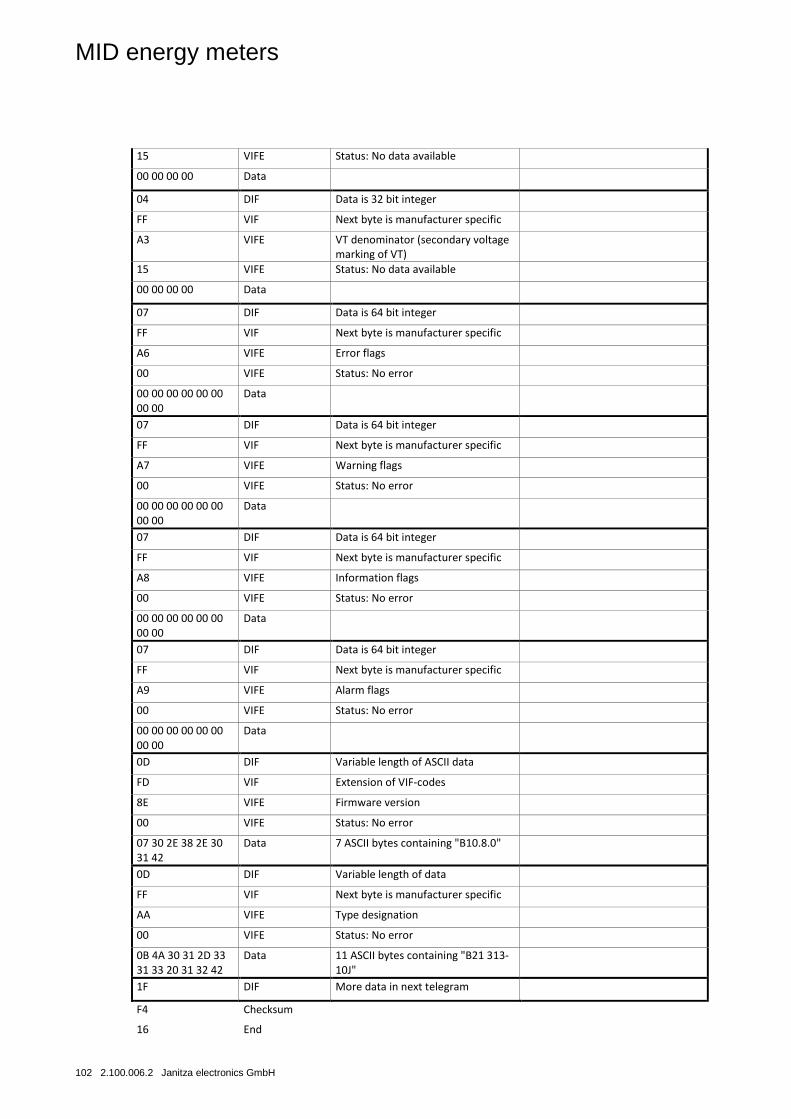
MID energy meters
102 2.100.006.2 Janitza electronics GmbH
15 VIFE Status: No data available
00 00 00 00 Data
04 DIF Data is 32 bit integer
FF VIF Next byte is manufacturer specific
A3 VIFE VT denominator (secondary voltage marking of VT)
15 VIFE Status: No data available
00 00 00 00 Data
07 DIF Data is 64 bit integer
FF VIF Next byte is manufacturer specific
A6 VIFE Error flags
00 VIFE Status: No error
00 00 00 00 00 00 00 00
Data
07 DIF Data is 64 bit integer
FF VIF Next byte is manufacturer specific
A7 VIFE Warning flags
00 VIFE Status: No error
00 00 00 00 00 00 00 00
Data
07 DIF Data is 64 bit integer
FF VIF Next byte is manufacturer specific
A8 VIFE Information flags
00 VIFE Status: No error
00 00 00 00 00 00 00 00
Data
07 DIF Data is 64 bit integer
FF VIF Next byte is manufacturer specific
A9 VIFE Alarm flags
00 VIFE Status: No error
00 00 00 00 00 00 00 00
Data
0D DIF Variable length of ASCII data
FD VIF Extension of VIF-codes
8E VIFE Firmware version
00 VIFE Status: No error
07 30 2E 38 2E 30 31 42
Data 7 ASCII bytes containing "B10.8.0"
0D DIF Variable length of data
FF VIF Next byte is manufacturer specific
AA VIFE Type designation
00 VIFE Status: No error
0B 4A 30 31 2D 33 31 33 20 31 32 42
Data 11 ASCII bytes containing "B21 313-10J"
1F DIF More data in next telegram
F4 Checksum
16 End
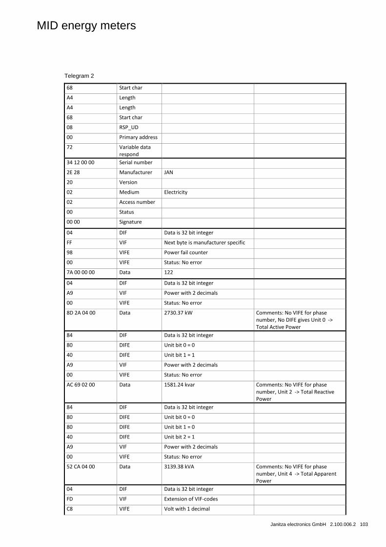
MID energy meters
Janitza electronics GmbH 2.100.006.2 103
Telegram 2
68 Start char
A4 Length
A4 Length
68 Start char
08 RSP_UD
00 Primary address
72 Variable data respond
34 12 00 00 Serial number
2E 28 Manufacturer JAN
20 Version
02 Medium Electricity
02 Access number
00 Status
00 00 Signature
04 DIF Data is 32 bit integer
FF VIF Next byte is manufacturer specific
98 VIFE Power fail counter
00 VIFE Status: No error
7A 00 00 00 Data 122
04 DIF Data is 32 bit integer
A9 VIF Power with 2 decimals
00 VIFE Status: No error
8D 2A 04 00 Data 2730.37 kW Comments: No VIFE for phase number, No DIFE gives Unit 0 -> Total Active Power
84 DIF Data is 32 bit integer
80 DIFE Unit bit 0 = 0
40 DIFE Unit bit 1 = 1
A9 VIF Power with 2 decimals
00 VIFE Status: No error
AC 69 02 00 Data 1581.24 kvar Comments: No VIFE for phase number, Unit 2 -> Total Reactive Power
84 DIF Data is 32 bit integer
80 DIFE Unit bit 0 = 0
80 DIFE Unit bit 1 = 0
40 DIFE Unit bit 2 = 1
A9 VIF Power with 2 decimals
00 VIFE Status: No error
52 CA 04 00 Data 3139.38 kVA Comments: No VIFE for phase number, Unit 4 -> Total Apparent Power
04 DIF Data is 32 bit integer
FD VIF Extension of VIF-codes
C8 VIFE Volt with 1 decimal
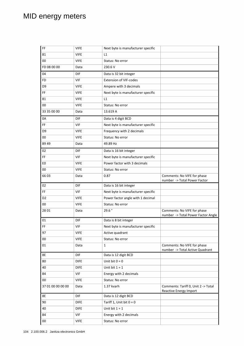
MID energy meters
104 2.100.006.2 Janitza electronics GmbH
FF VIFE Next byte is manufacturer specific
81 VIFE L1
00 VIFE Status: No error
FD 08 00 00 Data 230.6 V
04 DIF Data is 32 bit integer
FD VIF Extension of VIF-codes
D9 VIFE Ampere with 3 decimals
FF VIFE Next byte is manufacturer specific
81 VIFE L1
00 VIFE Status: No error
33 35 00 00 Data 13.619 A
0A DIF Data is 4 digit BCD
FF VIF Next byte is manufacturer specific
D9 VIFE Frequency with 2 decimals
00 VIFE Status: No error
89 49 Data 49.89 Hz
02 DIF Data is 16 bit integer
FF VIF Next byte is manufacturer specific
E0 VIFE Power factor with 3 decimals
00 VIFE Status: No error
66 03 Data 0.87 Comments: No VIFE for phase number -> Total Power Factor
02 DIF Data is 16 bit integer
FF VIF Next byte is manufacturer specific
D2 VIFE Power factor angle with 1 decimal
00 VIFE Status: No error
28 01 Data 29.6 ° Comments: No VIFE for phase number -> Total Power Factor Angle
01 DIF Data is 8 bit integer
FF VIF Next byte is manufacturer specific
97 VIFE Active quadrant
00 VIFE Status: No error
01 Data 1 Comments: No VIFE for phase number -> Total Active Quadrant
8E DIF Data is 12 digit BCD
80 DIFE Unit bit 0 = 0
40 DIFE Unit bit 1 = 1
84 VIF Energy with 2 decimals
00 VIFE Status: No error
37 01 00 00 00 00 Data 1.37 kvarh Comments: Tariff 0, Unit 2 -> Total Reactive Energy Import
8E DIF Data is 12 digit BCD
90 DIFE Tariff 1, Unit bit 0 = 0
40 DIFE Unit bit 1 = 1
84 VIF Energy with 2 decimals
00 VIFE Status: No error
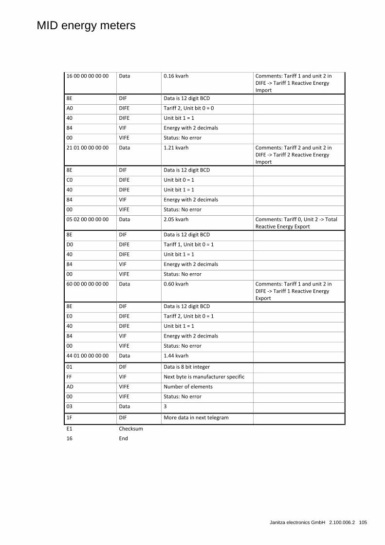
MID energy meters
Janitza electronics GmbH 2.100.006.2 105
16 00 00 00 00 00 Data 0.16 kvarh Comments: Tariff 1 and unit 2 in DIFE -> Tariff 1 Reactive Energy Import
8E DIF Data is 12 digit BCD
A0 DIFE Tariff 2, Unit bit 0 = 0
40 DIFE Unit bit 1 = 1
84 VIF Energy with 2 decimals
00 VIFE Status: No error
21 01 00 00 00 00 Data 1.21 kvarh Comments: Tariff 2 and unit 2 in DIFE -> Tariff 2 Reactive Energy Import
8E DIF Data is 12 digit BCD
C0 DIFE Unit bit 0 = 1
40 DIFE Unit bit 1 = 1
84 VIF Energy with 2 decimals
00 VIFE Status: No error
05 02 00 00 00 00 Data 2.05 kvarh Comments: Tariff 0, Unit 2 -> Total Reactive Energy Export
8E DIF Data is 12 digit BCD
D0 DIFE Tariff 1, Unit bit 0 = 1
40 DIFE Unit bit 1 = 1
84 VIF Energy with 2 decimals
00 VIFE Status: No error
60 00 00 00 00 00 Data 0.60 kvarh Comments: Tariff 1 and unit 2 in DIFE -> Tariff 1 Reactive Energy Export
8E DIF Data is 12 digit BCD
E0 DIFE Tariff 2, Unit bit 0 = 1
40 DIFE Unit bit 1 = 1
84 VIF Energy with 2 decimals
00 VIFE Status: No error
44 01 00 00 00 00 Data 1.44 kvarh
01 DIF Data is 8 bit integer
FF VIF Next byte is manufacturer specific
AD VIFE Number of elements
00 VIFE Status: No error
03 Data 3
1F DIF More data in next telegram
E1 Checksum
16 End
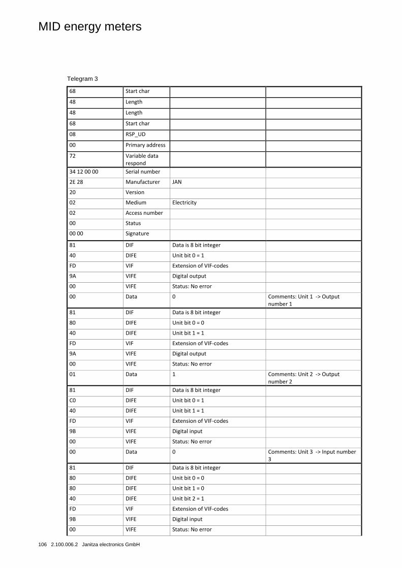
MID energy meters
106 2.100.006.2 Janitza electronics GmbH
Telegram 3
68 Start char
48 Length
48 Length
68 Start char
08 RSP_UD
00 Primary address
72 Variable data respond
34 12 00 00 Serial number
2E 28 Manufacturer JAN
20 Version
02 Medium Electricity
02 Access number
00 Status
00 00 Signature
81 DIF Data is 8 bit integer
40 DIFE Unit bit 0 = 1
FD VIF Extension of VIF-codes
9A VIFE Digital output
00 VIFE Status: No error
00 Data 0 Comments: Unit 1 -> Output number 1
81 DIF Data is 8 bit integer
80 DIFE Unit bit 0 = 0
40 DIFE Unit bit 1 = 1
FD VIF Extension of VIF-codes
9A VIFE Digital output
00 VIFE Status: No error
01 Data 1 Comments: Unit 2 -> Output number 2
81 DIF Data is 8 bit integer
C0 DIFE Unit bit 0 = 1
40 DIFE Unit bit 1 = 1
FD VIF Extension of VIF-codes
9B VIFE Digital input
00 VIFE Status: No error
00 Data 0 Comments: Unit 3 -> Input number 3
81 DIF Data is 8 bit integer
80 DIFE Unit bit 0 = 0
80 DIFE Unit bit 1 = 0
40 DIFE Unit bit 2 = 1
FD VIF Extension of VIF-codes
9B VIFE Digital input
00 VIFE Status: No error
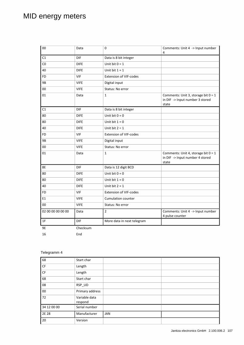
MID energy meters
Janitza electronics GmbH 2.100.006.2 107
00 Data 0 Comments: Unit 4 -> Input number 4
C1 DIF Data is 8 bit integer
C0 DIFE Unit bit 0 = 1
40 DIFE Unit bit 1 = 1
FD VIF Extension of VIF-codes
9B VIFE Digital input
00 VIFE Status: No error
01 Data 1 Comments: Unit 3, storage bit 0 = 1 in DIF -> Input number 3 stored state
C1 DIF Data is 8 bit integer
80 DIFE Unit bit 0 = 0
80 DIFE Unit bit 1 = 0
40 DIFE Unit bit 2 = 1
FD VIF Extension of VIF-codes
9B VIFE Digital input
00 VIFE Status: No error
01 Data 1 Comments: Unit 4, storage bit 0 = 1 in DIF -> Input number 4 stored state
8E DIF Data is 12 digit BCD
80 DIFE Unit bit 0 = 0
80 DIFE Unit bit 1 = 0
40 DIFE Unit bit 2 = 1
FD VIF Extension of VIF-codes
E1 VIFE Cumulation counter
00 VIFE Status: No error
02 00 00 00 00 00 Data 2 Comments: Unit 4 -> Input number 4 pulse counter
1F DIF More data in next telegram
9E Checksum
16 End
Telegramm 4
68 Start char
CF Length
CF Length
68 Start char
08 RSP_UD
00 Primary address
72 Variable data respond
34 12 00 00 Serial number
2E 28 Manufacturer JAN
20 Version
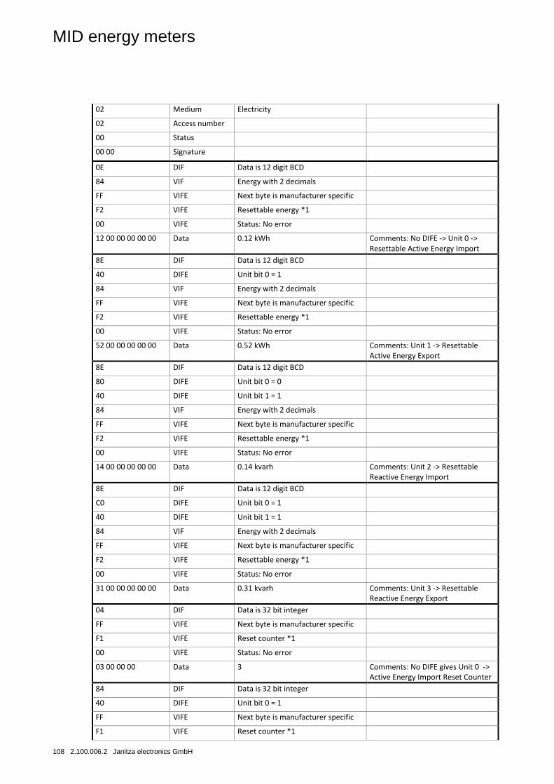
MID energy meters
108 2.100.006.2 Janitza electronics GmbH
02 Medium Electricity
02 Access number
00 Status
00 00 Signature
0E DIF Data is 12 digit BCD
84 VIF Energy with 2 decimals
FF VIFE Next byte is manufacturer specific
F2 VIFE Resettable energy *1
00 VIFE Status: No error
12 00 00 00 00 00 Data 0.12 kWh Comments: No DIFE -> Unit 0 -> Resettable Active Energy Import
8E DIF Data is 12 digit BCD
40 DIFE Unit bit 0 = 1
84 VIF Energy with 2 decimals
FF VIFE Next byte is manufacturer specific
F2 VIFE Resettable energy *1
00 VIFE Status: No error
52 00 00 00 00 00 Data 0.52 kWh Comments: Unit 1 -> Resettable Active Energy Export
8E DIF Data is 12 digit BCD
80 DIFE Unit bit 0 = 0
40 DIFE Unit bit 1 = 1
84 VIF Energy with 2 decimals
FF VIFE Next byte is manufacturer specific
F2 VIFE Resettable energy *1
00 VIFE Status: No error
14 00 00 00 00 00 Data 0.14 kvarh Comments: Unit 2 -> Resettable Reactive Energy Import
8E DIF Data is 12 digit BCD
C0 DIFE Unit bit 0 = 1
40 DIFE Unit bit 1 = 1
84 VIF Energy with 2 decimals
FF VIFE Next byte is manufacturer specific
F2 VIFE Resettable energy *1
00 VIFE Status: No error
31 00 00 00 00 00 Data 0.31 kvarh Comments: Unit 3 -> Resettable Reactive Energy Export
04 DIF Data is 32 bit integer
FF VIFE Next byte is manufacturer specific
F1 VIFE Reset counter *1
00 VIFE Status: No error
03 00 00 00 Data 3 Comments: No DIFE gives Unit 0 -> Active Energy Import Reset Counter
84 DIF Data is 32 bit integer
40 DIFE Unit bit 0 = 1
FF VIFE Next byte is manufacturer specific
F1 VIFE Reset counter *1
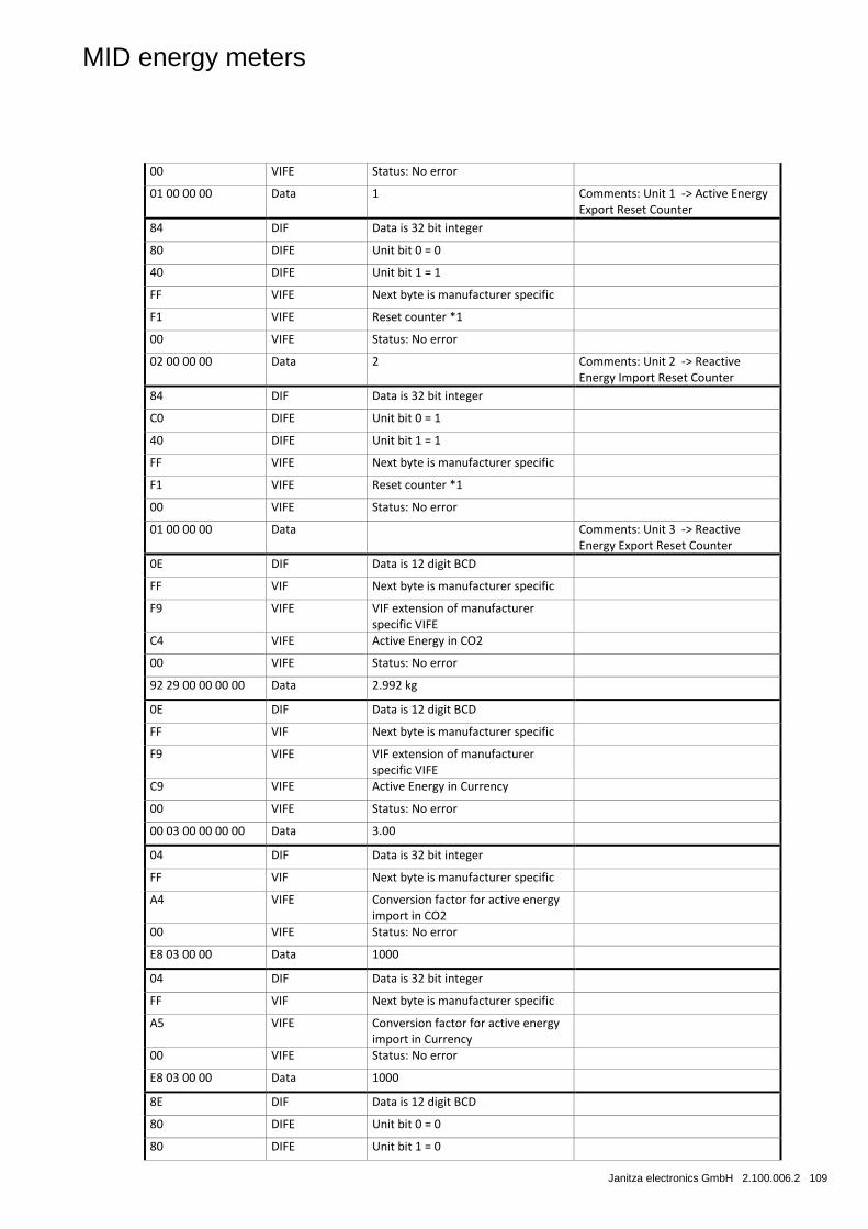
MID energy meters
Janitza electronics GmbH 2.100.006.2 109
00 VIFE Status: No error
01 00 00 00 Data 1 Comments: Unit 1 -> Active Energy Export Reset Counter
84 DIF Data is 32 bit integer
80 DIFE Unit bit 0 = 0
40 DIFE Unit bit 1 = 1
FF VIFE Next byte is manufacturer specific
F1 VIFE Reset counter *1
00 VIFE Status: No error
02 00 00 00 Data 2 Comments: Unit 2 -> Reactive Energy Import Reset Counter
84 DIF Data is 32 bit integer
C0 DIFE Unit bit 0 = 1
40 DIFE Unit bit 1 = 1
FF VIFE Next byte is manufacturer specific
F1 VIFE Reset counter *1
00 VIFE Status: No error
01 00 00 00 Data Comments: Unit 3 -> Reactive Energy Export Reset Counter
0E DIF Data is 12 digit BCD
FF VIF Next byte is manufacturer specific
F9 VIFE VIF extension of manufacturer specific VIFE
C4 VIFE Active Energy in CO2
00 VIFE Status: No error
92 29 00 00 00 00 Data 2.992 kg
0E DIF Data is 12 digit BCD
FF VIF Next byte is manufacturer specific
F9 VIFE VIF extension of manufacturer specific VIFE
C9 VIFE Active Energy in Currency
00 VIFE Status: No error
00 03 00 00 00 00 Data 3.00
04 DIF Data is 32 bit integer
FF VIF Next byte is manufacturer specific
A4 VIFE Conversion factor for active energy import in CO2
00 VIFE Status: No error
E8 03 00 00 Data 1000
04 DIF Data is 32 bit integer
FF VIF Next byte is manufacturer specific
A5 VIFE Conversion factor for active energy import in Currency
00 VIFE Status: No error
E8 03 00 00 Data 1000
8E DIF Data is 12 digit BCD
80 DIFE Unit bit 0 = 0
80 DIFE Unit bit 1 = 0
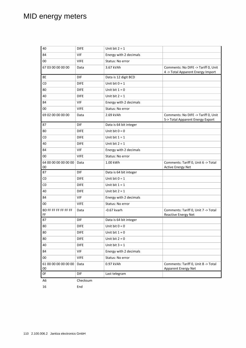
MID energy meters
110 2.100.006.2 Janitza electronics GmbH
40 DIFE Unit bit 2 = 1
84 VIF Energy with 2 decimals
00 VIFE Status: No error
67 03 00 00 00 00 Data 3.67 kVAh Comments: No DIFE -> Tariff 0, Unit 4 -> Total Apparent Energy Import
8E DIF Data is 12 digit BCD
C0 DIFE Unit bit 0 = 1
80 DIFE Unit bit 1 = 0
40 DIFE Unit bit 2 = 1
84 VIF Energy with 2 decimals
00 VIFE Status: No error
69 02 00 00 00 00 Data 2.69 kVAh Comments: No DIFE -> Tariff 0, Unit 5-> Total Apparent Energy Export
87 DIF Data is 64 bit integer
80 DIFE Unit bit 0 = 0
C0 DIFE Unit bit 1 = 1
40 DIFE Unit bit 2 = 1
84 VIF Energy with 2 decimals
00 VIFE Status: No error
64 00 00 00 00 00 00 00
Data 1.00 kWh Comments: Tariff 0, Unit 6 -> Total Active Energy Net
87 DIF Data is 64 bit integer
C0 DIFE Unit bit 0 = 1
C0 DIFE Unit bit 1 = 1
40 DIFE Unit bit 2 = 1
84 VIF Energy with 2 decimals
00 VIFE Status: No error
BD FF FF FF FF FF FF FF
Data -0.67 kvarh Comments: Tariff 0, Unit 7 -> Total Reactive Energy Net
87 DIF Data is 64 bit integer
80 DIFE Unit bit 0 = 0
80 DIFE Unit bit 1 = 0
80 DIFE Unit bit 2 = 0
40 DIFE Unit bit 3 = 1
84 VIF Energy with 2 decimals
00 VIFE Status: No error
61 00 00 00 00 00 00 00
Data 0.97 kVAh Comments: Tariff 0, Unit 8 -> Total Apparent Energy Net
0F DIF Last telegram
A6 Checksum
16 End
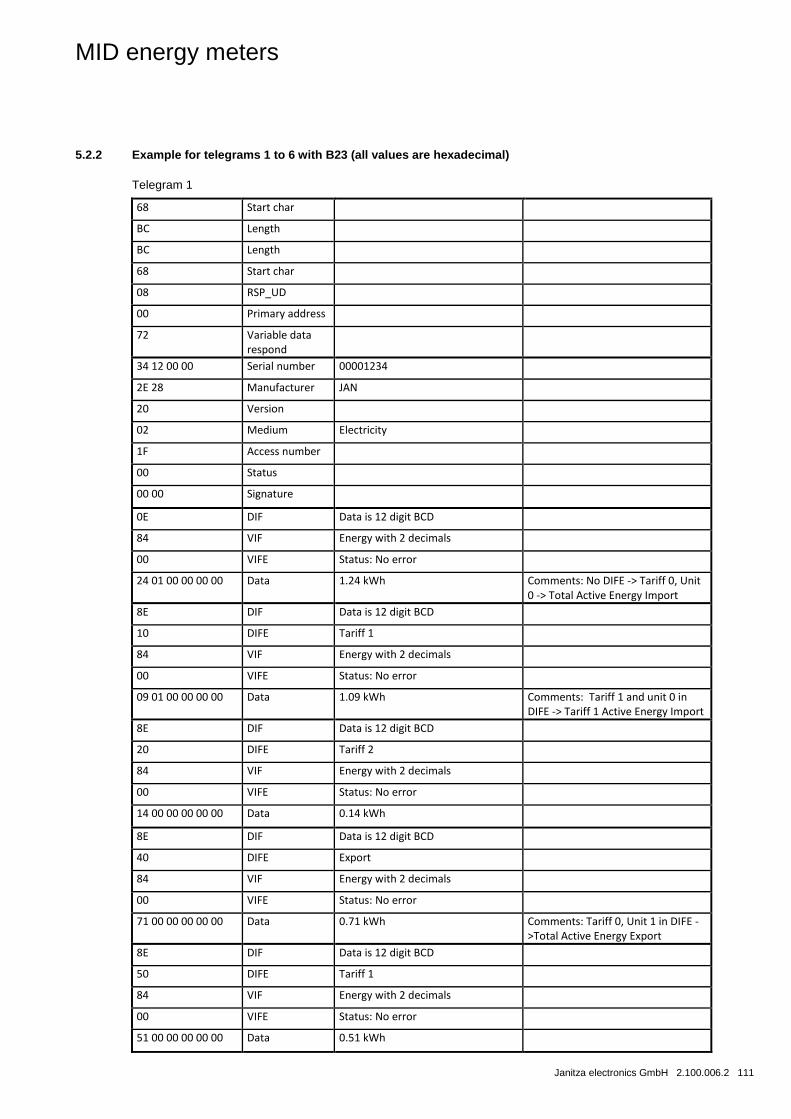
MID energy meters
Janitza electronics GmbH 2.100.006.2 111
5.2.2 Example for telegrams 1 to 6 with B23 (all values are hexadecimal)
Telegram 1
68 Start char
BC Length
BC Length
68 Start char
08 RSP_UD
00 Primary address
72 Variable data respond
34 12 00 00 Serial number 00001234
2E 28 Manufacturer JAN
20 Version
02 Medium Electricity
1F Access number
00 Status
00 00 Signature
0E DIF Data is 12 digit BCD
84 VIF Energy with 2 decimals
00 VIFE Status: No error
24 01 00 00 00 00 Data 1.24 kWh Comments: No DIFE -> Tariff 0, Unit 0 -> Total Active Energy Import
8E DIF Data is 12 digit BCD
10 DIFE Tariff 1
84 VIF Energy with 2 decimals
00 VIFE Status: No error
09 01 00 00 00 00 Data 1.09 kWh Comments: Tariff 1 and unit 0 in DIFE -> Tariff 1 Active Energy Import
8E DIF Data is 12 digit BCD
20 DIFE Tariff 2
84 VIF Energy with 2 decimals
00 VIFE Status: No error
14 00 00 00 00 00 Data 0.14 kWh
8E DIF Data is 12 digit BCD
40 DIFE Export
84 VIF Energy with 2 decimals
00 VIFE Status: No error
71 00 00 00 00 00 Data 0.71 kWh Comments: Tariff 0, Unit 1 in DIFE ->Total Active Energy Export
8E DIF Data is 12 digit BCD
50 DIFE Tariff 1
84 VIF Energy with 2 decimals
00 VIFE Status: No error
51 00 00 00 00 00 Data 0.51 kWh
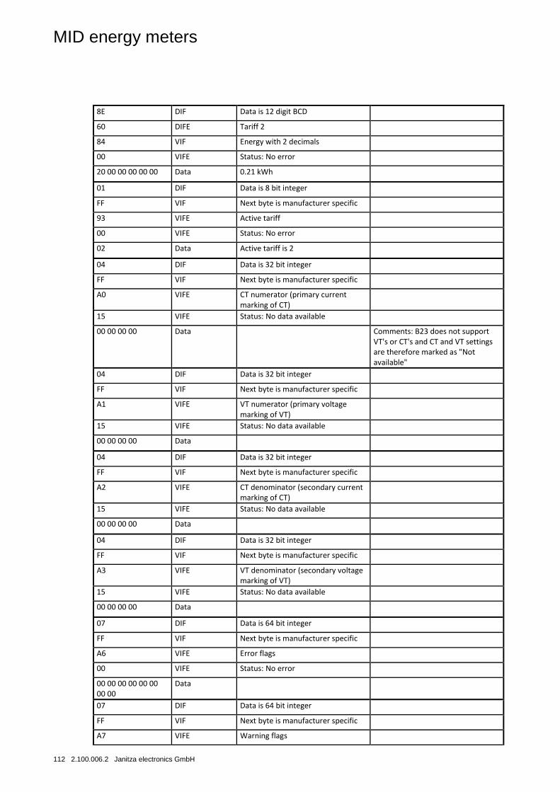
MID energy meters
112 2.100.006.2 Janitza electronics GmbH
8E DIF Data is 12 digit BCD
60 DIFE Tariff 2
84 VIF Energy with 2 decimals
00 VIFE Status: No error
20 00 00 00 00 00 Data 0.21 kWh
01 DIF Data is 8 bit integer
FF VIF Next byte is manufacturer specific
93 VIFE Active tariff
00 VIFE Status: No error
02 Data Active tariff is 2
04 DIF Data is 32 bit integer
FF VIF Next byte is manufacturer specific
A0 VIFE CT numerator (primary current marking of CT)
15 VIFE Status: No data available
00 00 00 00 Data Comments: B23 does not support VT's or CT's and CT and VT settings are therefore marked as "Not available"
04 DIF Data is 32 bit integer
FF VIF Next byte is manufacturer specific
A1 VIFE VT numerator (primary voltage marking of VT)
15 VIFE Status: No data available
00 00 00 00 Data
04 DIF Data is 32 bit integer
FF VIF Next byte is manufacturer specific
A2 VIFE CT denominator (secondary current marking of CT)
15 VIFE Status: No data available
00 00 00 00 Data
04 DIF Data is 32 bit integer
FF VIF Next byte is manufacturer specific
A3 VIFE VT denominator (secondary voltage marking of VT)
15 VIFE Status: No data available
00 00 00 00 Data
07 DIF Data is 64 bit integer
FF VIF Next byte is manufacturer specific
A6 VIFE Error flags
00 VIFE Status: No error
00 00 00 00 00 00 00 00
Data
07 DIF Data is 64 bit integer
FF VIF Next byte is manufacturer specific
A7 VIFE Warning flags
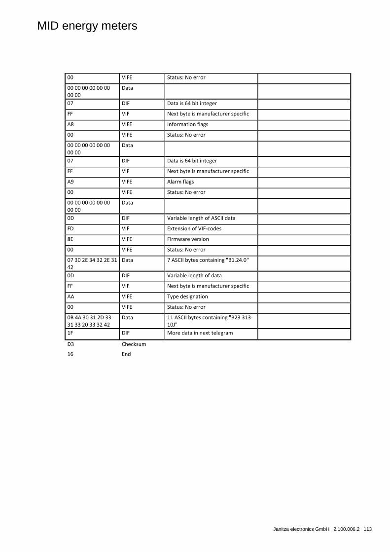
MID energy meters
Janitza electronics GmbH 2.100.006.2 113
00 VIFE Status: No error
00 00 00 00 00 00 00 00
Data
07 DIF Data is 64 bit integer
FF VIF Next byte is manufacturer specific
A8 VIFE Information flags
00 VIFE Status: No error
00 00 00 00 00 00 00 00
Data
07 DIF Data is 64 bit integer
FF VIF Next byte is manufacturer specific
A9 VIFE Alarm flags
00 VIFE Status: No error
00 00 00 00 00 00 00 00
Data
0D DIF Variable length of ASCII data
FD VIF Extension of VIF-codes
8E VIFE Firmware version
00 VIFE Status: No error
07 30 2E 34 32 2E 31 42
Data 7 ASCII bytes containing "B1.24.0"
0D DIF Variable length of data
FF VIF Next byte is manufacturer specific
AA VIFE Type designation
00 VIFE Status: No error
0B 4A 30 31 2D 33 31 33 20 33 32 42
Data 11 ASCII bytes containing "B23 313-10J"
1F DIF More data in next telegram
D3 Checksum
16 End
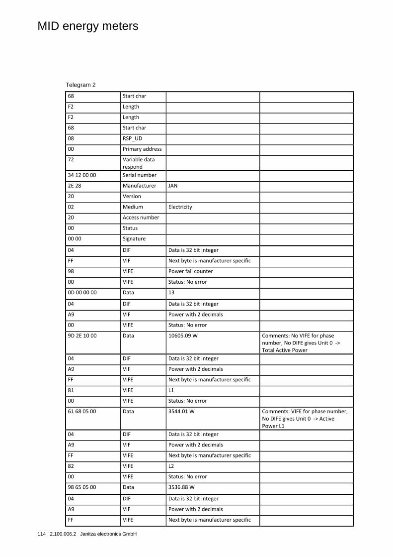
MID energy meters
114 2.100.006.2 Janitza electronics GmbH
Telegram 2
68 Start char
F2 Length
F2 Length
68 Start char
08 RSP_UD
00 Primary address
72 Variable data respond
34 12 00 00 Serial number 2E 28 Manufacturer JAN 20 Version 02 Medium Electricity 20 Access number 00 Status
00 00 Signature
04 DIF Data is 32 bit integer
FF VIF Next byte is manufacturer specific
98 VIFE Power fail counter
00 VIFE Status: No error
0D 00 00 00 Data 13
04 DIF Data is 32 bit integer
A9 VIF Power with 2 decimals
00 VIFE Status: No error
9D 2E 10 00 Data 10605.09 W Comments: No VIFE for phase number, No DIFE gives Unit 0 -> Total Active Power
04 DIF Data is 32 bit integer
A9 VIF Power with 2 decimals
FF VIFE Next byte is manufacturer specific
81 VIFE L1
00 VIFE Status: No error
61 68 05 00 Data 3544.01 W Comments: VIFE for phase number, No DIFE gives Unit 0 -> Active Power L1
04 DIF Data is 32 bit integer
A9 VIF Power with 2 decimals
FF VIFE Next byte is manufacturer specific
82 VIFE L2
00 VIFE Status: No error
98 65 05 00 Data 3536.88 W
04 DIF Data is 32 bit integer
A9 VIF Power with 2 decimals
FF VIFE Next byte is manufacturer specific
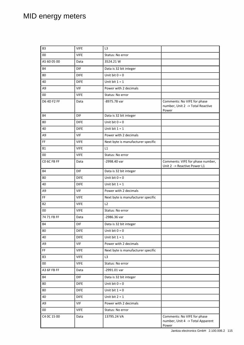
MID energy meters
Janitza electronics GmbH 2.100.006.2 115
83 VIFE L3
00 VIFE Status: No error
A5 60 05 00 Data 3524.21 W
84 DIF Data is 32 bit integer
80 DIFE Unit bit 0 = 0
40 DIFE Unit bit 1 = 1
A9 VIF Power with 2 decimals
00 VIFE Status: No error
D6 4D F2 FF Data -8975.78 var Comments: No VIFE for phase number, Unit 2 -> Total Reactive Power
84 DIF Data is 32 bit integer
80 DIFE Unit bit 0 = 0
40 DIFE Unit bit 1 = 1
A9 VIF Power with 2 decimals
FF VIFE Next byte is manufacturer specific
81 VIFE L1
00 VIFE Status: No error
C0 6C FB FF Data -2998.40 var Comments: VIFE for phase number, Unit 2 -> Reactive Power L1
84 DIF Data is 32 bit integer
80 DIFE Unit bit 0 = 0
40 DIFE Unit bit 1 = 1
A9 VIF Power with 2 decimals
FF VIFE Next byte is manufacturer specific
82 VIFE L2
00 VIFE Status: No error
74 71 FB FF Data -2986.36 var
84 DIF Data is 32 bit integer
80 DIFE Unit bit 0 = 0
40 DIFE Unit bit 1 = 1
A9 VIF Power with 2 decimals
FF VIFE Next byte is manufacturer specific
83 VIFE L3
00 VIFE Status: No error
A3 6F FB FF Data -2991.01 var
84 DIF Data is 32 bit integer
80 DIFE Unit bit 0 = 0
80 DIFE Unit bit 1 = 0
40 DIFE Unit bit 2 = 1
A9 VIF Power with 2 decimals
00 VIFE Status: No error
C4 0C 15 00 Data 13795.24 VA Comments: No VIFE for phase number, Unit 4 -> Total Apparent Power
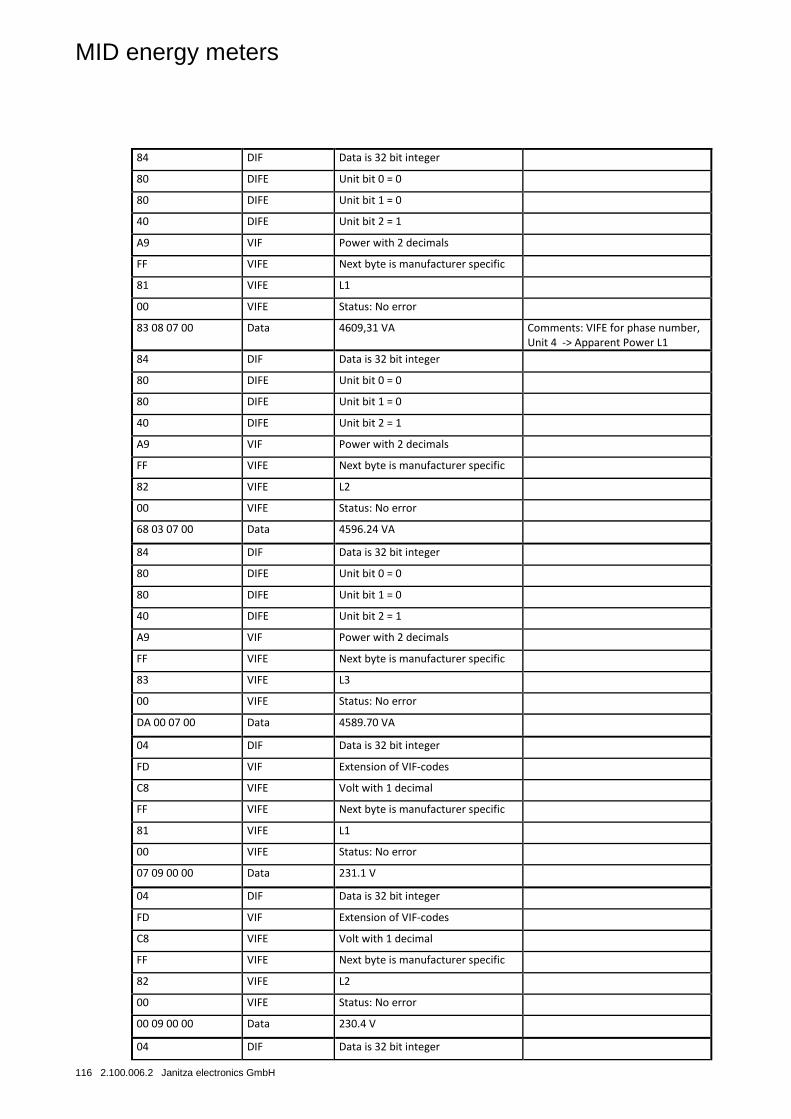
MID energy meters
116 2.100.006.2 Janitza electronics GmbH
84 DIF Data is 32 bit integer
80 DIFE Unit bit 0 = 0
80 DIFE Unit bit 1 = 0
40 DIFE Unit bit 2 = 1
A9 VIF Power with 2 decimals
FF VIFE Next byte is manufacturer specific
81 VIFE L1
00 VIFE Status: No error
83 08 07 00 Data 4609,31 VA Comments: VIFE for phase number, Unit 4 -> Apparent Power L1
84 DIF Data is 32 bit integer
80 DIFE Unit bit 0 = 0
80 DIFE Unit bit 1 = 0
40 DIFE Unit bit 2 = 1
A9 VIF Power with 2 decimals
FF VIFE Next byte is manufacturer specific
82 VIFE L2
00 VIFE Status: No error
68 03 07 00 Data 4596.24 VA
84 DIF Data is 32 bit integer
80 DIFE Unit bit 0 = 0
80 DIFE Unit bit 1 = 0
40 DIFE Unit bit 2 = 1
A9 VIF Power with 2 decimals
FF VIFE Next byte is manufacturer specific
83 VIFE L3
00 VIFE Status: No error
DA 00 07 00 Data 4589.70 VA
04 DIF Data is 32 bit integer
FD VIF Extension of VIF-codes
C8 VIFE Volt with 1 decimal
FF VIFE Next byte is manufacturer specific
81 VIFE L1
00 VIFE Status: No error
07 09 00 00 Data 231.1 V
04 DIF Data is 32 bit integer
FD VIF Extension of VIF-codes
C8 VIFE Volt with 1 decimal
FF VIFE Next byte is manufacturer specific
82 VIFE L2
00 VIFE Status: No error
00 09 00 00 Data 230.4 V
04 DIF Data is 32 bit integer
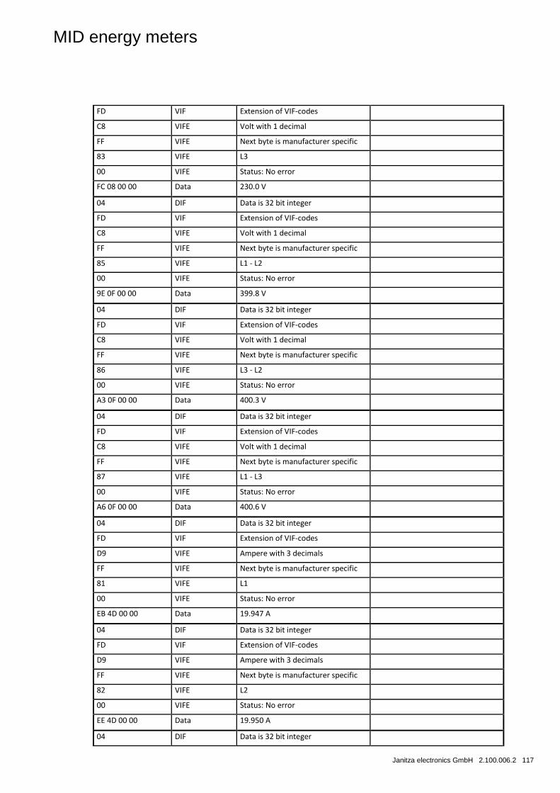
MID energy meters
Janitza electronics GmbH 2.100.006.2 117
FD VIF Extension of VIF-codes
C8 VIFE Volt with 1 decimal
FF VIFE Next byte is manufacturer specific
83 VIFE L3
00 VIFE Status: No error
FC 08 00 00 Data 230.0 V
04 DIF Data is 32 bit integer
FD VIF Extension of VIF-codes
C8 VIFE Volt with 1 decimal
FF VIFE Next byte is manufacturer specific
85 VIFE L1 - L2
00 VIFE Status: No error
9E 0F 00 00 Data 399.8 V
04 DIF Data is 32 bit integer
FD VIF Extension of VIF-codes
C8 VIFE Volt with 1 decimal
FF VIFE Next byte is manufacturer specific
86 VIFE L3 - L2
00 VIFE Status: No error
A3 0F 00 00 Data 400.3 V
04 DIF Data is 32 bit integer
FD VIF Extension of VIF-codes
C8 VIFE Volt with 1 decimal
FF VIFE Next byte is manufacturer specific
87 VIFE L1 - L3
00 VIFE Status: No error
A6 0F 00 00 Data 400.6 V
04 DIF Data is 32 bit integer
FD VIF Extension of VIF-codes
D9 VIFE Ampere with 3 decimals
FF VIFE Next byte is manufacturer specific
81 VIFE L1
00 VIFE Status: No error
EB 4D 00 00 Data 19.947 A
04 DIF Data is 32 bit integer
FD VIF Extension of VIF-codes
D9 VIFE Ampere with 3 decimals
FF VIFE Next byte is manufacturer specific
82 VIFE L2
00 VIFE Status: No error
EE 4D 00 00 Data 19.950 A
04 DIF Data is 32 bit integer
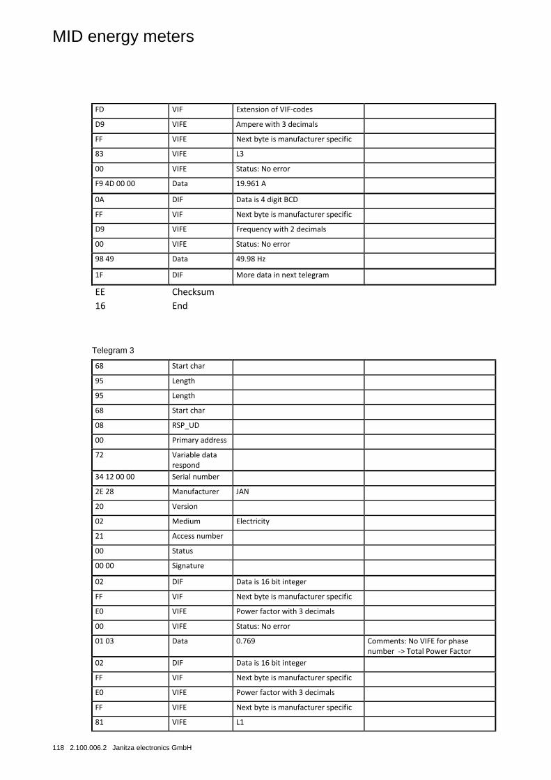
MID energy meters
118 2.100.006.2 Janitza electronics GmbH
FD VIF Extension of VIF-codes
D9 VIFE Ampere with 3 decimals
FF VIFE Next byte is manufacturer specific
83 VIFE L3
00 VIFE Status: No error
F9 4D 00 00 Data 19.961 A
0A DIF Data is 4 digit BCD
FF VIF Next byte is manufacturer specific
D9 VIFE Frequency with 2 decimals
00 VIFE Status: No error
98 49 Data 49.98 Hz
1F DIF More data in next telegram
EE Checksum
16 End
Telegram 3
68 Start char
95 Length
95 Length
68 Start char
08 RSP_UD
00 Primary address
72 Variable data respond
34 12 00 00 Serial number
2E 28 Manufacturer JAN
20 Version
02 Medium Electricity
21 Access number
00 Status
00 00 Signature
02 DIF Data is 16 bit integer
FF VIF Next byte is manufacturer specific
E0 VIFE Power factor with 3 decimals
00 VIFE Status: No error
01 03 Data 0.769 Comments: No VIFE for phase number -> Total Power Factor
02 DIF Data is 16 bit integer
FF VIF Next byte is manufacturer specific
E0 VIFE Power factor with 3 decimals
FF VIFE Next byte is manufacturer specific
81 VIFE L1
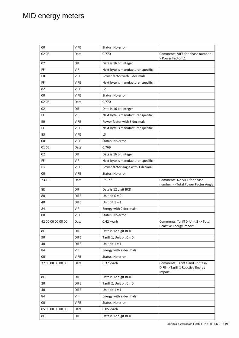
MID energy meters
Janitza electronics GmbH 2.100.006.2 119
00 VIFE Status: No error
02 03 Data 0.770 Comments: VIFE for phase number -> Power Factor L1
02 DIF Data is 16 bit integer
FF VIF Next byte is manufacturer specific
E0 VIFE Power factor with 3 decimals
FF VIFE Next byte is manufacturer specific
82 VIFE L2
00 VIFE Status: No error
02 03 Data 0.770
02 DIF Data is 16 bit integer
FF VIF Next byte is manufacturer specific
E0 VIFE Power factor with 3 decimals
FF VIFE Next byte is manufacturer specific
83 VIFE L3
00 VIFE Status: No error
01 03 Data 0.769
02 DIF Data is 16 bit integer
FF VIF Next byte is manufacturer specific
D2 VIFE Power factor angle with 1 decimal
00 VIFE Status: No error
73 FE Data -39.7 ° Comments: No VIFE for phase number -> Total Power Factor Angle
8E DIF Data is 12 digit BCD
80 DIFE Unit bit 0 = 0
40 DIFE Unit bit 1 = 1
84 VIF Energy with 2 decimals
00 VIFE Status: No error
42 00 00 00 00 00 Data 0.42 kvarh Comments: Tariff 0, Unit 2 -> Total Reactive Energy Import
8E DIF Data is 12 digit BCD
90 DIFE Tariff 1, Unit bit 0 = 0
40 DIFE Unit bit 1 = 1
84 VIF Energy with 2 decimals
00 VIFE Status: No error
37 00 00 00 00 00 Data 0.37 kvarh Comments: Tariff 1 and unit 2 in DIFE -> Tariff 1 Reactive Energy Import
8E DIF Data is 12 digit BCD
20 DIFE Tariff 2, Unit bit 0 = 0
40 DIFE Unit bit 1 = 1
84 VIF Energy with 2 decimals
00 VIFE Status: No error
05 00 00 00 00 00 Data 0.05 kvarh
8E DIF Data is 12 digit BCD
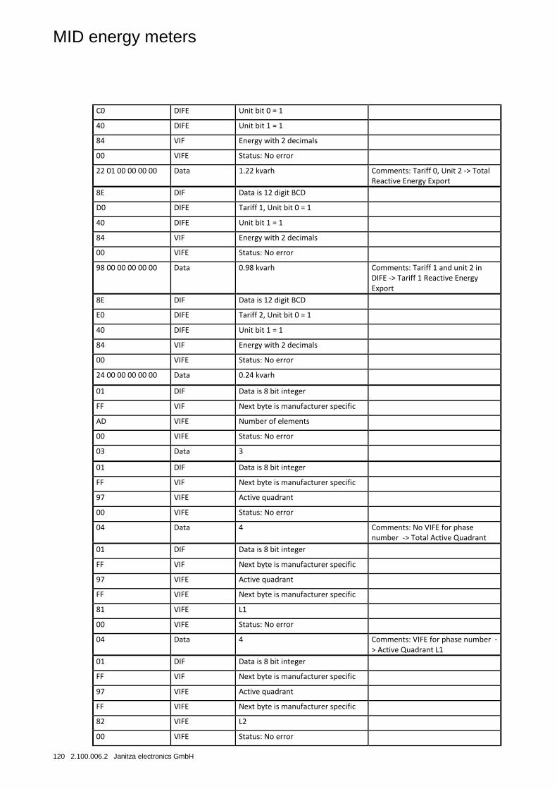
MID energy meters
120 2.100.006.2 Janitza electronics GmbH
C0 DIFE Unit bit 0 = 1
40 DIFE Unit bit 1 = 1
84 VIF Energy with 2 decimals
00 VIFE Status: No error
22 01 00 00 00 00 Data 1.22 kvarh Comments: Tariff 0, Unit 2 -> Total Reactive Energy Export
8E DIF Data is 12 digit BCD
D0 DIFE Tariff 1, Unit bit 0 = 1
40 DIFE Unit bit 1 = 1
84 VIF Energy with 2 decimals
00 VIFE Status: No error
98 00 00 00 00 00 Data 0.98 kvarh Comments: Tariff 1 and unit 2 in DIFE -> Tariff 1 Reactive Energy Export
8E DIF Data is 12 digit BCD
E0 DIFE Tariff 2, Unit bit 0 = 1
40 DIFE Unit bit 1 = 1
84 VIF Energy with 2 decimals
00 VIFE Status: No error
24 00 00 00 00 00 Data 0.24 kvarh
01 DIF Data is 8 bit integer
FF VIF Next byte is manufacturer specific
AD VIFE Number of elements
00 VIFE Status: No error
03 Data 3
01 DIF Data is 8 bit integer
FF VIF Next byte is manufacturer specific
97 VIFE Active quadrant
00 VIFE Status: No error
04 Data 4 Comments: No VIFE for phase number -> Total Active Quadrant
01 DIF Data is 8 bit integer
FF VIF Next byte is manufacturer specific
97 VIFE Active quadrant
FF VIFE Next byte is manufacturer specific
81 VIFE L1
00 VIFE Status: No error
04 Data 4 Comments: VIFE for phase number -> Active Quadrant L1
01 DIF Data is 8 bit integer
FF VIF Next byte is manufacturer specific
97 VIFE Active quadrant
FF VIFE Next byte is manufacturer specific
82 VIFE L2
00 VIFE Status: No error
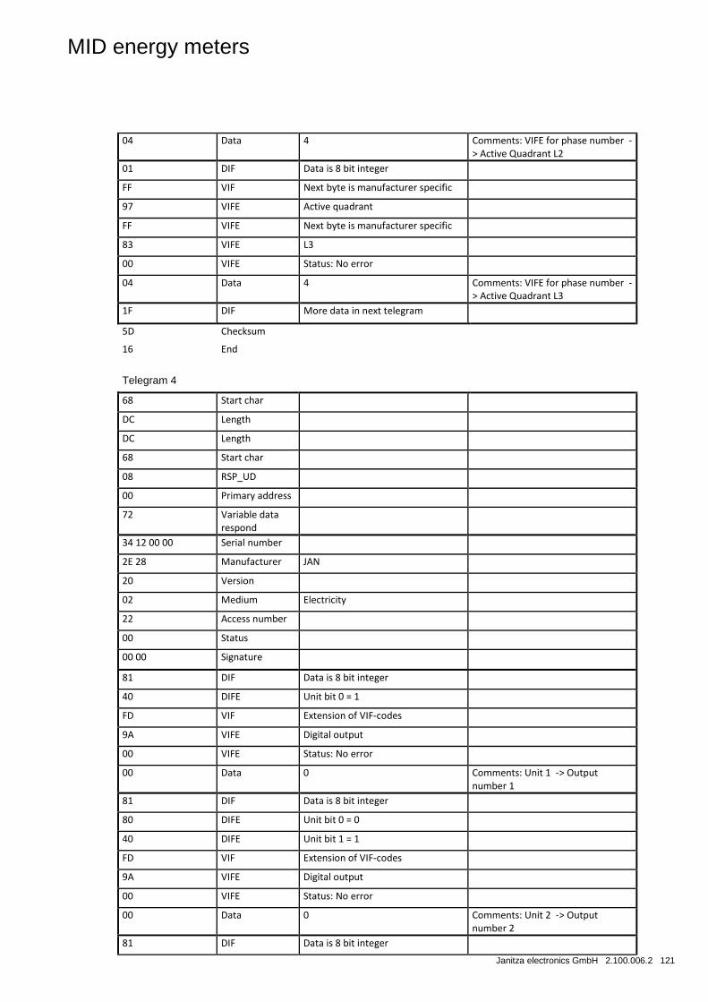
MID energy meters
Janitza electronics GmbH 2.100.006.2 121
04 Data 4 Comments: VIFE for phase number -> Active Quadrant L2
01 DIF Data is 8 bit integer
FF VIF Next byte is manufacturer specific
97 VIFE Active quadrant
FF VIFE Next byte is manufacturer specific
83 VIFE L3
00 VIFE Status: No error
04 Data 4 Comments: VIFE for phase number -> Active Quadrant L3
1F DIF More data in next telegram
5D Checksum
16 End
Telegram 4
68 Start char
DC Length
DC Length
68 Start char
08 RSP_UD
00 Primary address
72 Variable data respond
34 12 00 00 Serial number
2E 28 Manufacturer JAN
20 Version
02 Medium Electricity
22 Access number
00 Status
00 00 Signature
81 DIF Data is 8 bit integer
40 DIFE Unit bit 0 = 1
FD VIF Extension of VIF-codes
9A VIFE Digital output
00 VIFE Status: No error
00 Data 0 Comments: Unit 1 -> Output number 1
81 DIF Data is 8 bit integer
80 DIFE Unit bit 0 = 0
40 DIFE Unit bit 1 = 1
FD VIF Extension of VIF-codes
9A VIFE Digital output
00 VIFE Status: No error
00 Data 0 Comments: Unit 2 -> Output number 2
81 DIF Data is 8 bit integer
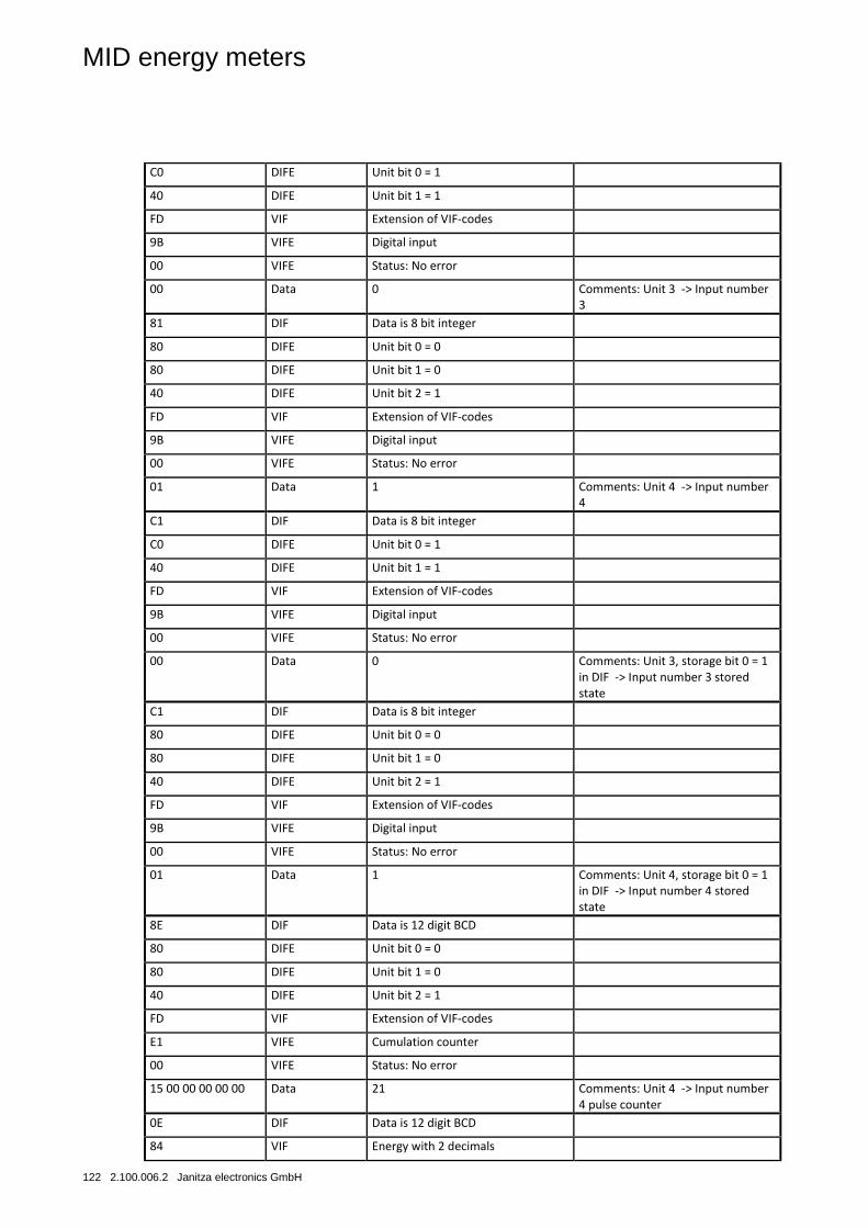
MID energy meters
122 2.100.006.2 Janitza electronics GmbH
C0 DIFE Unit bit 0 = 1
40 DIFE Unit bit 1 = 1
FD VIF Extension of VIF-codes
9B VIFE Digital input
00 VIFE Status: No error
00 Data 0 Comments: Unit 3 -> Input number 3
81 DIF Data is 8 bit integer
80 DIFE Unit bit 0 = 0
80 DIFE Unit bit 1 = 0
40 DIFE Unit bit 2 = 1
FD VIF Extension of VIF-codes
9B VIFE Digital input
00 VIFE Status: No error
01 Data 1 Comments: Unit 4 -> Input number 4
C1 DIF Data is 8 bit integer
C0 DIFE Unit bit 0 = 1
40 DIFE Unit bit 1 = 1
FD VIF Extension of VIF-codes
9B VIFE Digital input
00 VIFE Status: No error
00 Data 0 Comments: Unit 3, storage bit 0 = 1 in DIF -> Input number 3 stored state
C1 DIF Data is 8 bit integer
80 DIFE Unit bit 0 = 0
80 DIFE Unit bit 1 = 0
40 DIFE Unit bit 2 = 1
FD VIF Extension of VIF-codes
9B VIFE Digital input
00 VIFE Status: No error
01 Data 1 Comments: Unit 4, storage bit 0 = 1 in DIF -> Input number 4 stored state
8E DIF Data is 12 digit BCD
80 DIFE Unit bit 0 = 0
80 DIFE Unit bit 1 = 0
40 DIFE Unit bit 2 = 1
FD VIF Extension of VIF-codes
E1 VIFE Cumulation counter
00 VIFE Status: No error
15 00 00 00 00 00 Data 21 Comments: Unit 4 -> Input number 4 pulse counter
0E DIF Data is 12 digit BCD
84 VIF Energy with 2 decimals
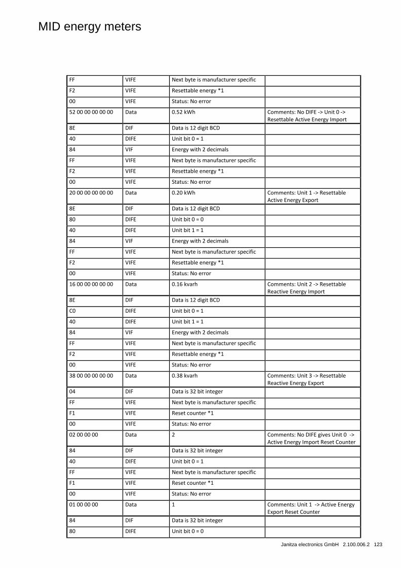
MID energy meters
Janitza electronics GmbH 2.100.006.2 123
FF VIFE Next byte is manufacturer specific
F2 VIFE Resettable energy *1
00 VIFE Status: No error
52 00 00 00 00 00 Data 0.52 kWh Comments: No DIFE -> Unit 0 -> Resettable Active Energy Import
8E DIF Data is 12 digit BCD
40 DIFE Unit bit 0 = 1
84 VIF Energy with 2 decimals
FF VIFE Next byte is manufacturer specific
F2 VIFE Resettable energy *1
00 VIFE Status: No error
20 00 00 00 00 00 Data 0.20 kWh Comments: Unit 1 -> Resettable Active Energy Export
8E DIF Data is 12 digit BCD
80 DIFE Unit bit 0 = 0
40 DIFE Unit bit 1 = 1
84 VIF Energy with 2 decimals
FF VIFE Next byte is manufacturer specific
F2 VIFE Resettable energy *1
00 VIFE Status: No error
16 00 00 00 00 00 Data 0.16 kvarh Comments: Unit 2 -> Resettable Reactive Energy Import
8E DIF Data is 12 digit BCD
C0 DIFE Unit bit 0 = 1
40 DIFE Unit bit 1 = 1
84 VIF Energy with 2 decimals
FF VIFE Next byte is manufacturer specific
F2 VIFE Resettable energy *1
00 VIFE Status: No error
38 00 00 00 00 00 Data 0.38 kvarh Comments: Unit 3 -> Resettable Reactive Energy Export
04 DIF Data is 32 bit integer
FF VIFE Next byte is manufacturer specific
F1 VIFE Reset counter *1
00 VIFE Status: No error
02 00 00 00 Data 2 Comments: No DIFE gives Unit 0 -> Active Energy Import Reset Counter
84 DIF Data is 32 bit integer
40 DIFE Unit bit 0 = 1
FF VIFE Next byte is manufacturer specific
F1 VIFE Reset counter *1
00 VIFE Status: No error
01 00 00 00 Data 1 Comments: Unit 1 -> Active Energy Export Reset Counter
84 DIF Data is 32 bit integer
80 DIFE Unit bit 0 = 0
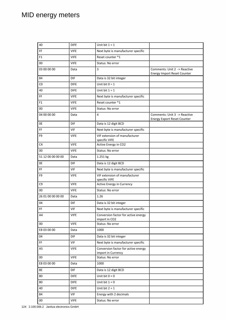
MID energy meters
124 2.100.006.2 Janitza electronics GmbH
40 DIFE Unit bit 1 = 1
FF VIFE Next byte is manufacturer specific
F1 VIFE Reset counter *1
00 VIFE Status: No error
03 00 00 00 Data 3 Comments: Unit 2 -> Reactive Energy Import Reset Counter
84 DIF Data is 32 bit integer
C0 DIFE Unit bit 0 = 1
40 DIFE Unit bit 1 = 1
FF VIFE Next byte is manufacturer specific
F1 VIFE Reset counter *1
00 VIFE Status: No error
04 00 00 00 Data 4 Comments: Unit 3 -> Reactive Energy Export Reset Counter
0E DIF Data is 12 digit BCD
FF VIF Next byte is manufacturer specific
F9 VIFE VIF extension of manufacturer specific VIFE
C4 VIFE Active Energy in CO2
00 VIFE Status: No error
51 12 00 00 00 00 Data 1.251 kg
0E DIF Data is 12 digit BCD
FF VIF Next byte is manufacturer specific
F9 VIFE VIF extension of manufacturer specific VIFE
C9 VIFE Active Energy in Currency
00 VIFE Status: No error
26 01 00 00 00 00 Data 1.26
04 DIF Data is 32 bit integer
FF VIF Next byte is manufacturer specific
A4 VIFE Conversion factor for active energy import in CO2
00 VIFE Status: No error
E8 03 00 00 Data 1000
04 DIF Data is 32 bit integer
FF VIF Next byte is manufacturer specific
A5 VIFE Conversion factor for active energy import in Currency
00 VIFE Status: No error
E8 03 00 00 Data 1000
8E DIF Data is 12 digit BCD
80 DIFE Unit bit 0 = 0
80 DIFE Unit bit 1 = 0
40 DIFE Unit bit 2 = 1
84 VIF Energy with 2 decimals
00 VIFE Status: No error
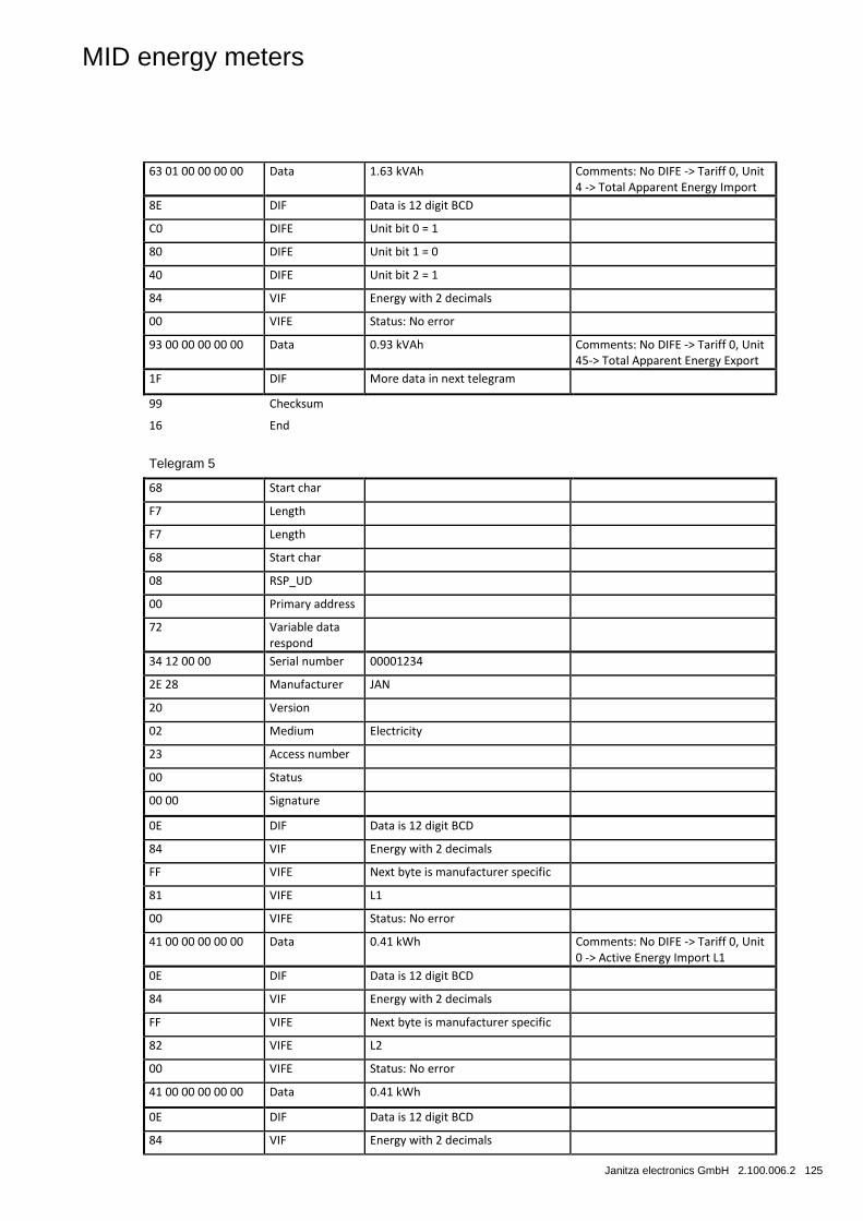
MID energy meters
Janitza electronics GmbH 2.100.006.2 125
63 01 00 00 00 00 Data 1.63 kVAh Comments: No DIFE -> Tariff 0, Unit 4 -> Total Apparent Energy Import
8E DIF Data is 12 digit BCD
C0 DIFE Unit bit 0 = 1
80 DIFE Unit bit 1 = 0
40 DIFE Unit bit 2 = 1
84 VIF Energy with 2 decimals
00 VIFE Status: No error
93 00 00 00 00 00 Data 0.93 kVAh Comments: No DIFE -> Tariff 0, Unit 45-> Total Apparent Energy Export
1F DIF More data in next telegram
99 Checksum
16 End
Telegram 5
68 Start char
F7 Length
F7 Length
68 Start char
08 RSP_UD
00 Primary address
72 Variable data respond
34 12 00 00 Serial number 00001234
2E 28 Manufacturer JAN
20 Version
02 Medium Electricity
23 Access number
00 Status
00 00 Signature
0E DIF Data is 12 digit BCD
84 VIF Energy with 2 decimals
FF VIFE Next byte is manufacturer specific
81 VIFE L1
00 VIFE Status: No error
41 00 00 00 00 00 Data 0.41 kWh Comments: No DIFE -> Tariff 0, Unit 0 -> Active Energy Import L1
0E DIF Data is 12 digit BCD
84 VIF Energy with 2 decimals
FF VIFE Next byte is manufacturer specific
82 VIFE L2
00 VIFE Status: No error
41 00 00 00 00 00 Data 0.41 kWh
0E DIF Data is 12 digit BCD
84 VIF Energy with 2 decimals
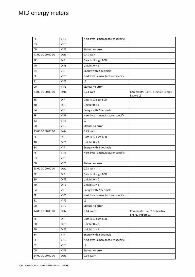
MID energy meters
126 2.100.006.2 Janitza electronics GmbH
FF VIFE Next byte is manufacturer specific
83 VIFE L3
00 VIFE Status: No error
41 00 00 00 00 00 Data 0.41 kWh
8E DIF Data is 12 digit BCD
40 DIFE Unit bit 0 = 1
84 VIF Energy with 2 decimals
FF VIFE Next byte is manufacturer specific
81 VIFE L1
00 VIFE Status: No error
23 00 00 00 00 00 Data 0.23 kWh Comments: Unit 1 -> Active Energy Export L1
8E DIF Data is 12 digit BCD
40 DIFE Unit bit 0 = 1
84 VIF Energy with 2 decimals
FF VIFE Next byte is manufacturer specific
82 VIFE L2
00 VIFE Status: No error
23 00 00 00 00 00 Data 0.23 kWh
8E DIF Data is 12 digit BCD
40 DIFE Unit bit 0 = 1
84 VIF Energy with 2 decimals
FF VIFE Next byte is manufacturer specific
83 VIFE L3
00 VIFE Status: No error
23 00 00 00 00 00 Data 0.23 kWh
8E DIF Data is 12 digit BCD
80 DIFE Unit bit 0 = 0
40 DIFE Unit bit 1 = 1
84 VIF Energy with 2 decimals
FF VIFE Next byte is manufacturer specific
81 VIFE L1
00 VIFE Status: No error
14 00 00 00 00 00 Data 0.14 kvarh Comments: Unit 2 -> Reactive Energy Import L1
8E DIF Data is 12 digit BCD
80 DIFE Unit bit 0 = 0
40 DIFE Unit bit 1 = 1
84 VIF Energy with 2 decimals
FF VIFE Next byte is manufacturer specific
82 VIFE L2
00 VIFE Status: No error
14 00 00 00 00 00 Data 0.14 kvarh
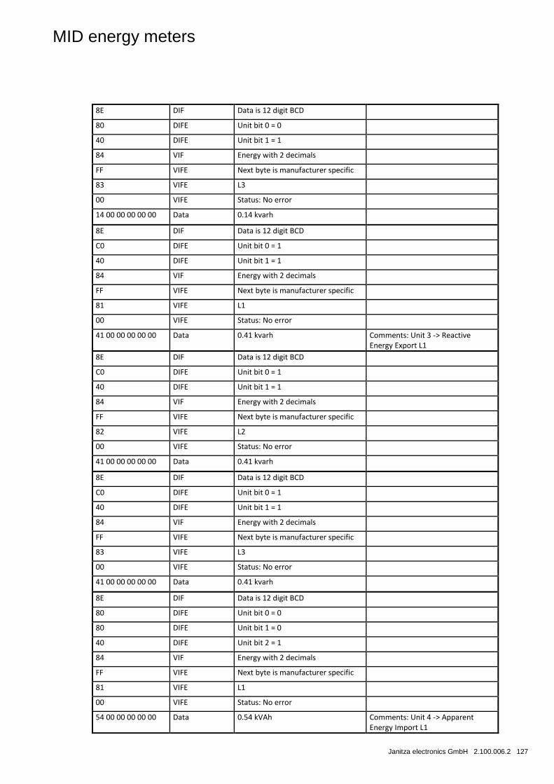
MID energy meters
Janitza electronics GmbH 2.100.006.2 127
8E DIF Data is 12 digit BCD
80 DIFE Unit bit 0 = 0
40 DIFE Unit bit 1 = 1
84 VIF Energy with 2 decimals
FF VIFE Next byte is manufacturer specific
83 VIFE L3
00 VIFE Status: No error
14 00 00 00 00 00 Data 0.14 kvarh
8E DIF Data is 12 digit BCD
C0 DIFE Unit bit 0 = 1
40 DIFE Unit bit 1 = 1
84 VIF Energy with 2 decimals
FF VIFE Next byte is manufacturer specific
81 VIFE L1
00 VIFE Status: No error
41 00 00 00 00 00 Data 0.41 kvarh Comments: Unit 3 -> Reactive Energy Export L1
8E DIF Data is 12 digit BCD
C0 DIFE Unit bit 0 = 1
40 DIFE Unit bit 1 = 1
84 VIF Energy with 2 decimals
FF VIFE Next byte is manufacturer specific
82 VIFE L2
00 VIFE Status: No error
41 00 00 00 00 00 Data 0.41 kvarh
8E DIF Data is 12 digit BCD
C0 DIFE Unit bit 0 = 1
40 DIFE Unit bit 1 = 1
84 VIF Energy with 2 decimals
FF VIFE Next byte is manufacturer specific
83 VIFE L3
00 VIFE Status: No error
41 00 00 00 00 00 Data 0.41 kvarh
8E DIF Data is 12 digit BCD
80 DIFE Unit bit 0 = 0
80 DIFE Unit bit 1 = 0
40 DIFE Unit bit 2 = 1
84 VIF Energy with 2 decimals
FF VIFE Next byte is manufacturer specific
81 VIFE L1
00 VIFE Status: No error
54 00 00 00 00 00 Data 0.54 kVAh Comments: Unit 4 -> Apparent Energy Import L1
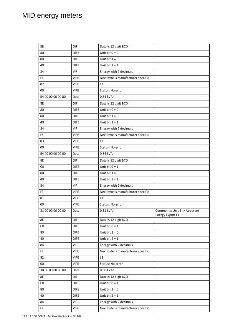
MID energy meters
128 2.100.006.2 Janitza electronics GmbH
8E DIF Data is 12 digit BCD
80 DIFE Unit bit 0 = 0
80 DIFE Unit bit 1 = 0
40 DIFE Unit bit 2 = 1
84 VIF Energy with 2 decimals
FF VIFE Next byte is manufacturer specific
82 VIFE L2
00 VIFE Status: No error
54 00 00 00 00 00 Data 0.54 kVAh
8E DIF Data is 12 digit BCD
80 DIFE Unit bit 0 = 0
80 DIFE Unit bit 1 = 0
40 DIFE Unit bit 2 = 1
84 VIF Energy with 2 decimals
FF VIFE Next byte is manufacturer specific
83 VIFE L3
00 VIFE Status: No error
54 00 00 00 00 00 Data 0.54 kVAh
8E DIF Data is 12 digit BCD
C0 DIFE Unit bit 0 = 1
80 DIFE Unit bit 1 = 0
40 DIFE Unit bit 2 = 1
84 VIF Energy with 2 decimals
FF VIFE Next byte is manufacturer specific
81 VIFE L1
00 VIFE Status: No error
31 00 00 00 00 00 Data 0.31 kVAh Comments: Unit 5 -> Apparent Energy Export L1
8E DIF Data is 12 digit BCD
C0 DIFE Unit bit 0 = 1
80 DIFE Unit bit 1 = 0
40 DIFE Unit bit 2 = 1
84 VIF Energy with 2 decimals
FF VIFE Next byte is manufacturer specific
82 VIFE L2
00 VIFE Status: No error
30 00 00 00 00 00 Data 0.30 kVAh
8E DIF Data is 12 digit BCD
C0 DIFE Unit bit 0 = 1
80 DIFE Unit bit 1 = 0
40 DIFE Unit bit 2 = 1
84 VIF Energy with 2 decimals
FF VIFE Next byte is manufacturer specific
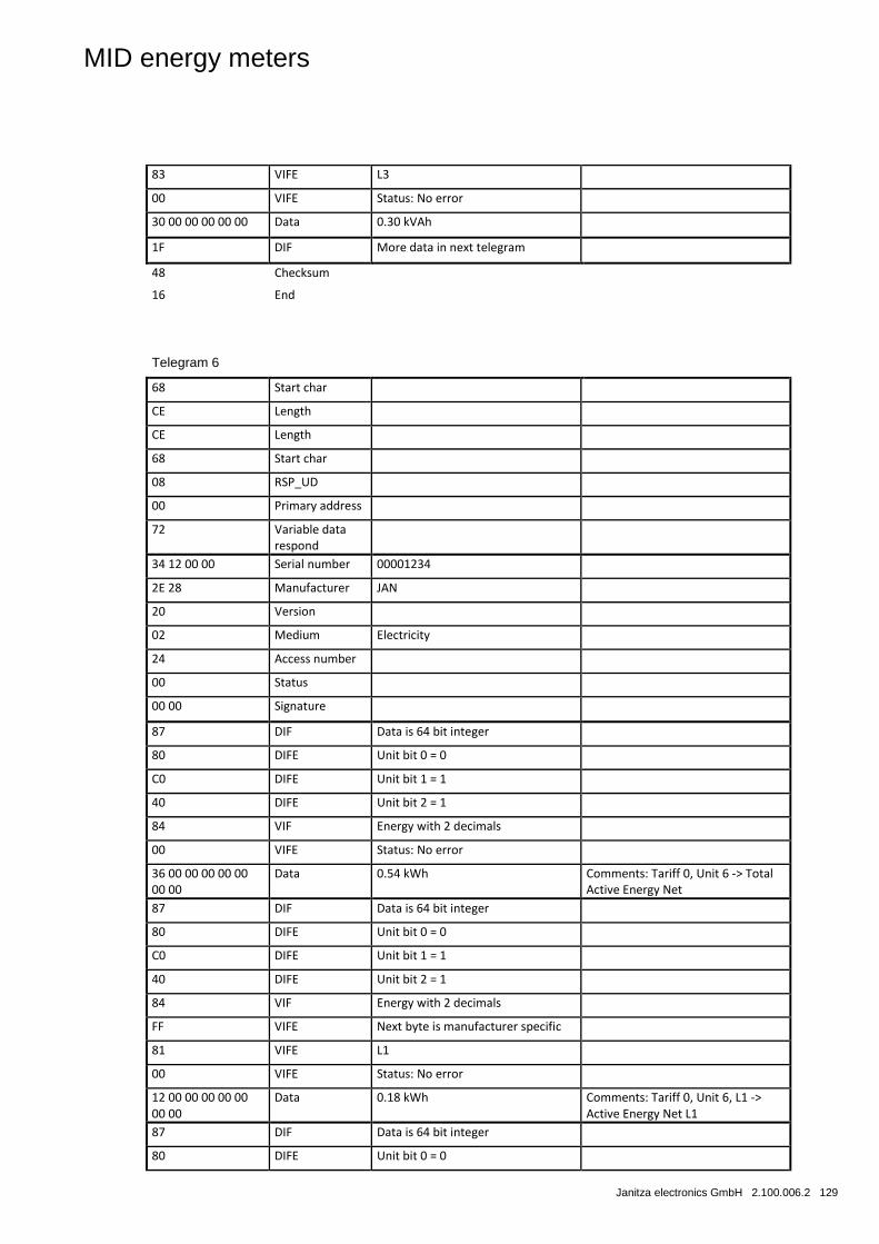
MID energy meters
Janitza electronics GmbH 2.100.006.2 129
83 VIFE L3
00 VIFE Status: No error
30 00 00 00 00 00 Data 0.30 kVAh
1F DIF More data in next telegram
48 Checksum
16 End
Telegram 6
68 Start char
CE Length
CE Length
68 Start char
08 RSP_UD
00 Primary address
72 Variable data respond
34 12 00 00 Serial number 00001234
2E 28 Manufacturer JAN
20 Version
02 Medium Electricity
24 Access number
00 Status
00 00 Signature
87 DIF Data is 64 bit integer
80 DIFE Unit bit 0 = 0
C0 DIFE Unit bit 1 = 1
40 DIFE Unit bit 2 = 1
84 VIF Energy with 2 decimals
00 VIFE Status: No error
36 00 00 00 00 00 00 00
Data 0.54 kWh Comments: Tariff 0, Unit 6 -> Total Active Energy Net
87 DIF Data is 64 bit integer
80 DIFE Unit bit 0 = 0
C0 DIFE Unit bit 1 = 1
40 DIFE Unit bit 2 = 1
84 VIF Energy with 2 decimals
FF VIFE Next byte is manufacturer specific
81 VIFE L1
00 VIFE Status: No error
12 00 00 00 00 00 00 00
Data 0.18 kWh Comments: Tariff 0, Unit 6, L1 -> Active Energy Net L1
87 DIF Data is 64 bit integer
80 DIFE Unit bit 0 = 0
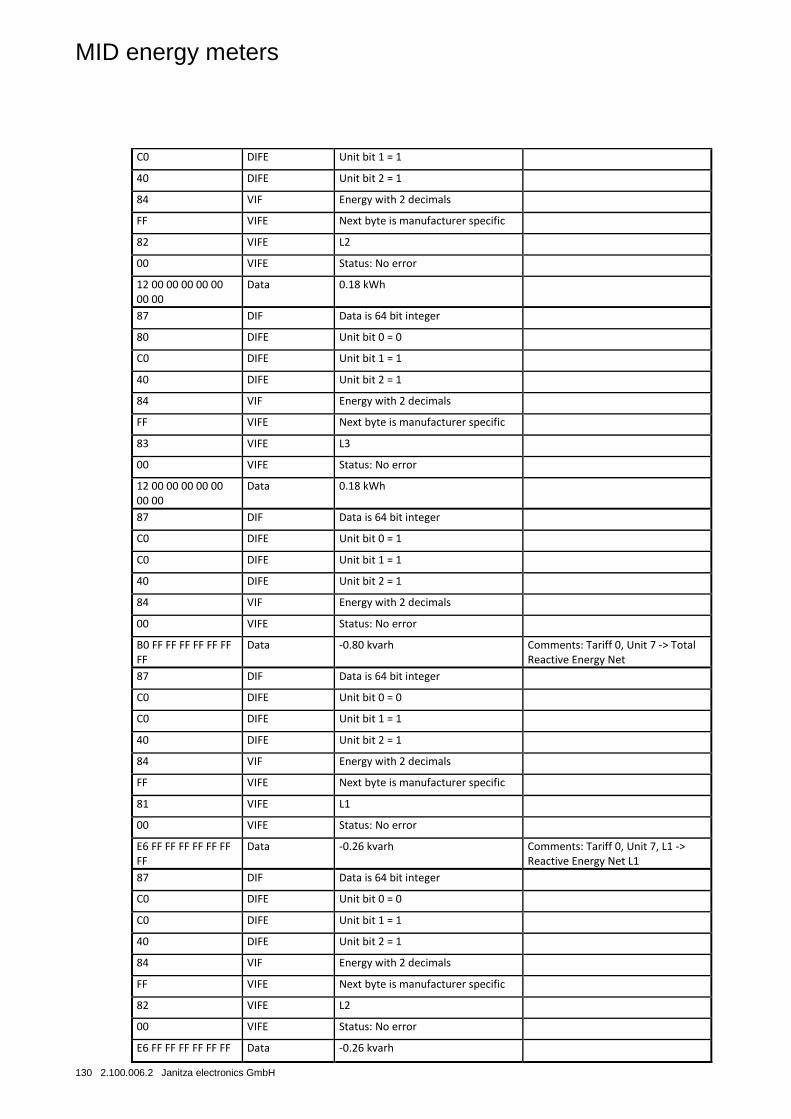
MID energy meters
130 2.100.006.2 Janitza electronics GmbH
C0 DIFE Unit bit 1 = 1
40 DIFE Unit bit 2 = 1
84 VIF Energy with 2 decimals
FF VIFE Next byte is manufacturer specific
82 VIFE L2
00 VIFE Status: No error
12 00 00 00 00 00 00 00
Data 0.18 kWh
87 DIF Data is 64 bit integer
80 DIFE Unit bit 0 = 0
C0 DIFE Unit bit 1 = 1
40 DIFE Unit bit 2 = 1
84 VIF Energy with 2 decimals
FF VIFE Next byte is manufacturer specific
83 VIFE L3
00 VIFE Status: No error
12 00 00 00 00 00 00 00
Data 0.18 kWh
87 DIF Data is 64 bit integer
C0 DIFE Unit bit 0 = 1
C0 DIFE Unit bit 1 = 1
40 DIFE Unit bit 2 = 1
84 VIF Energy with 2 decimals
00 VIFE Status: No error
B0 FF FF FF FF FF FF FF
Data -0.80 kvarh Comments: Tariff 0, Unit 7 -> Total Reactive Energy Net
87 DIF Data is 64 bit integer
C0 DIFE Unit bit 0 = 0
C0 DIFE Unit bit 1 = 1
40 DIFE Unit bit 2 = 1
84 VIF Energy with 2 decimals
FF VIFE Next byte is manufacturer specific
81 VIFE L1
00 VIFE Status: No error
E6 FF FF FF FF FF FF FF
Data -0.26 kvarh Comments: Tariff 0, Unit 7, L1 -> Reactive Energy Net L1
87 DIF Data is 64 bit integer
C0 DIFE Unit bit 0 = 0
C0 DIFE Unit bit 1 = 1
40 DIFE Unit bit 2 = 1
84 VIF Energy with 2 decimals
FF VIFE Next byte is manufacturer specific
82 VIFE L2
00 VIFE Status: No error
E6 FF FF FF FF FF FF Data -0.26 kvarh
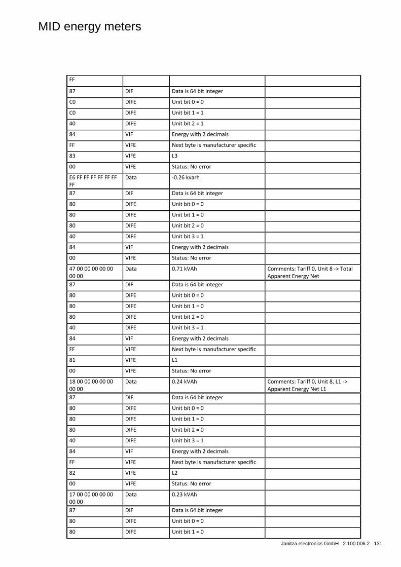
MID energy meters
Janitza electronics GmbH 2.100.006.2 131
FF
87 DIF Data is 64 bit integer
C0 DIFE Unit bit 0 = 0
C0 DIFE Unit bit 1 = 1
40 DIFE Unit bit 2 = 1
84 VIF Energy with 2 decimals
FF VIFE Next byte is manufacturer specific
83 VIFE L3
00 VIFE Status: No error
E6 FF FF FF FF FF FF FF
Data -0.26 kvarh
87 DIF Data is 64 bit integer
80 DIFE Unit bit 0 = 0
80 DIFE Unit bit 1 = 0
80 DIFE Unit bit 2 = 0
40 DIFE Unit bit 3 = 1
84 VIF Energy with 2 decimals
00 VIFE Status: No error
47 00 00 00 00 00 00 00
Data 0.71 kVAh Comments: Tariff 0, Unit 8 -> Total Apparent Energy Net
87 DIF Data is 64 bit integer
80 DIFE Unit bit 0 = 0
80 DIFE Unit bit 1 = 0
80 DIFE Unit bit 2 = 0
40 DIFE Unit bit 3 = 1
84 VIF Energy with 2 decimals
FF VIFE Next byte is manufacturer specific
81 VIFE L1
00 VIFE Status: No error
18 00 00 00 00 00 00 00
Data 0.24 kVAh Comments: Tariff 0, Unit 8, L1 -> Apparent Energy Net L1
87 DIF Data is 64 bit integer
80 DIFE Unit bit 0 = 0
80 DIFE Unit bit 1 = 0
80 DIFE Unit bit 2 = 0
40 DIFE Unit bit 3 = 1
84 VIF Energy with 2 decimals
FF VIFE Next byte is manufacturer specific
82 VIFE L2
00 VIFE Status: No error
17 00 00 00 00 00 00 00
Data 0.23 kVAh
87 DIF Data is 64 bit integer
80 DIFE Unit bit 0 = 0
80 DIFE Unit bit 1 = 0
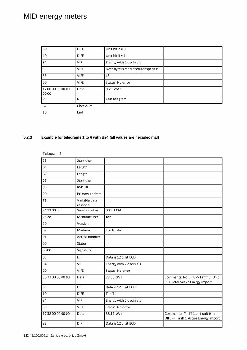
MID energy meters
132 2.100.006.2 Janitza electronics GmbH
80 DIFE Unit bit 2 = 0
40 DIFE Unit bit 3 = 1
84 VIF Energy with 2 decimals
FF VIFE Next byte is manufacturer specific
83 VIFE L3
00 VIFE Status: No error
17 00 00 00 00 00 00 00
Data 0.23 kVAh
0F DIF Last telegram
B7 Checksum
16 End
5.2.3 Example for telegrams 1 to 6 with B24 (all values are hexadecimal)
Telegram 1
68 Start char
BC Length
BC Length
68 Start char
08 RSP_UD
00 Primary address
72 Variable data respond
34 12 00 00 Serial number 00001234
2E 28 Manufacturer JAN
20 Version
02 Medium Electricity
01 Access number
00 Status
00 00 Signature
0E DIF Data is 12 digit BCD
84 VIF Energy with 2 decimals
00 VIFE Status: No error
36 77 00 00 00 00 Data 77.36 kWh Comments: No DIFE -> Tariff 0, Unit 0 -> Total Active Energy Import
8E DIF Data is 12 digit BCD
10 DIFE Tariff 1
84 VIF Energy with 2 decimals
00 VIFE Status: No error
17 38 00 00 00 00 Data 38.17 kWh Comments: Tariff 1 and unit 0 in DIFE -> Tariff 1 Active Energy Import
8E DIF Data is 12 digit BCD
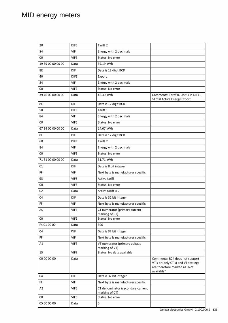
MID energy meters
Janitza electronics GmbH 2.100.006.2 133
20 DIFE Tariff 2
84 VIF Energy with 2 decimals
00 VIFE Status: No error
19 39 00 00 00 00 Data 39.19 kWh
8E DIF Data is 12 digit BCD
40 DIFE Export
84 VIF Energy with 2 decimals
00 VIFE Status: No error
39 46 00 00 00 00 Data 46.39 kWh Comments: Tariff 0, Unit 1 in DIFE ->Total Active Energy Export
8E DIF Data is 12 digit BCD
50 DIFE Tariff 1
84 VIF Energy with 2 decimals
00 VIFE Status: No error
67 14 00 00 00 00 Data 14.67 kWh
8E DIF Data is 12 digit BCD
60 DIFE Tariff 2
84 VIF Energy with 2 decimals
00 VIFE Status: No error
71 31 00 00 00 00 Data 31.71 kWh
01 DIF Data is 8 bit integer
FF VIF Next byte is manufacturer specific
93 VIFE Active tariff
00 VIFE Status: No error
02 Data Active tariff is 2
04 DIF Data is 32 bit integer
FF VIF Next byte is manufacturer specific
A0 VIFE CT numerator (primary current marking of CT)
00 VIFE Status: No error
F4 01 00 00 Data 500
04 DIF Data is 32 bit integer
FF VIF Next byte is manufacturer specific
A1 VIFE VT numerator (primary voltage marking of VT)
15 VIFE Status: No data available
00 00 00 00 Data Comments: B24 does not support VT's or (only CT's) and VT settings are therefore marked as "Not available"
04 DIF Data is 32 bit integer
FF VIF Next byte is manufacturer specific
A2 VIFE CT denominator (secondary current marking of CT)
00 VIFE Status: No error
05 00 00 00 Data 5
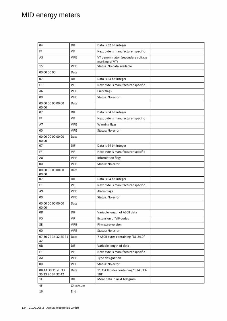
MID energy meters
134 2.100.006.2 Janitza electronics GmbH
04 DIF Data is 32 bit integer
FF VIF Next byte is manufacturer specific
A3 VIFE VT denominator (secondary voltage marking of VT)
15 VIFE Status: No data available
00 00 00 00 Data
07 DIF Data is 64 bit integer
FF VIF Next byte is manufacturer specific
A6 VIFE Error flags
00 VIFE Status: No error
00 00 00 00 00 00 00 00
Data
07 DIF Data is 64 bit integer
FF VIF Next byte is manufacturer specific
A7 VIFE Warning flags
00 VIFE Status: No error
00 00 00 00 00 00 00 00
Data
07 DIF Data is 64 bit integer
FF VIF Next byte is manufacturer specific
A8 VIFE Information flags
00 VIFE Status: No error
00 00 00 00 00 00 00 00
Data
07 DIF Data is 64 bit integer
FF VIF Next byte is manufacturer specific
A9 VIFE Alarm flags
00 VIFE Status: No error
00 00 00 00 00 00 00 00
Data
0D DIF Variable length of ASCII data
FD VIF Extension of VIF-codes
8E VIFE Firmware version
00 VIFE Status: No error
07 30 2E 34 32 2E 31 42
Data 7 ASCII bytes containing "B1.24.0"
0D DIF Variable length of data
FF VIF Next byte is manufacturer specific
AA VIFE Type designation
00 VIFE Status: No error
0B 4A 30 31 2D 33 35 33 20 34 32 42
Data 11 ASCII bytes containing "B24 313-10J"
1F DIF More data in next telegram
4F Checksum
16 End
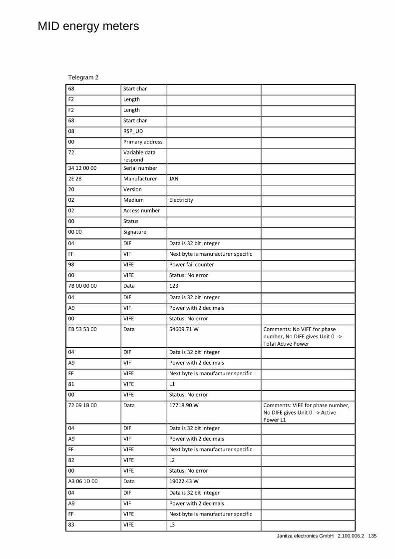
MID energy meters
Janitza electronics GmbH 2.100.006.2 135
Telegram 2
68 Start char
F2 Length
F2 Length
68 Start char
08 RSP_UD
00 Primary address
72 Variable data respond
34 12 00 00 Serial number
2E 28 Manufacturer JAN
20 Version
02 Medium Electricity
02 Access number
00 Status
00 00 Signature
04 DIF Data is 32 bit integer
FF VIF Next byte is manufacturer specific
98 VIFE Power fail counter
00 VIFE Status: No error
7B 00 00 00 Data 123
04 DIF Data is 32 bit integer
A9 VIF Power with 2 decimals
00 VIFE Status: No error
EB 53 53 00 Data 54609.71 W Comments: No VIFE for phase number, No DIFE gives Unit 0 -> Total Active Power
04 DIF Data is 32 bit integer
A9 VIF Power with 2 decimals
FF VIFE Next byte is manufacturer specific
81 VIFE L1
00 VIFE Status: No error
72 09 1B 00 Data 17718.90 W Comments: VIFE for phase number, No DIFE gives Unit 0 -> Active Power L1
04 DIF Data is 32 bit integer
A9 VIF Power with 2 decimals
FF VIFE Next byte is manufacturer specific
82 VIFE L2
00 VIFE Status: No error
A3 06 1D 00 Data 19022.43 W
04 DIF Data is 32 bit integer
A9 VIF Power with 2 decimals
FF VIFE Next byte is manufacturer specific
83 VIFE L3
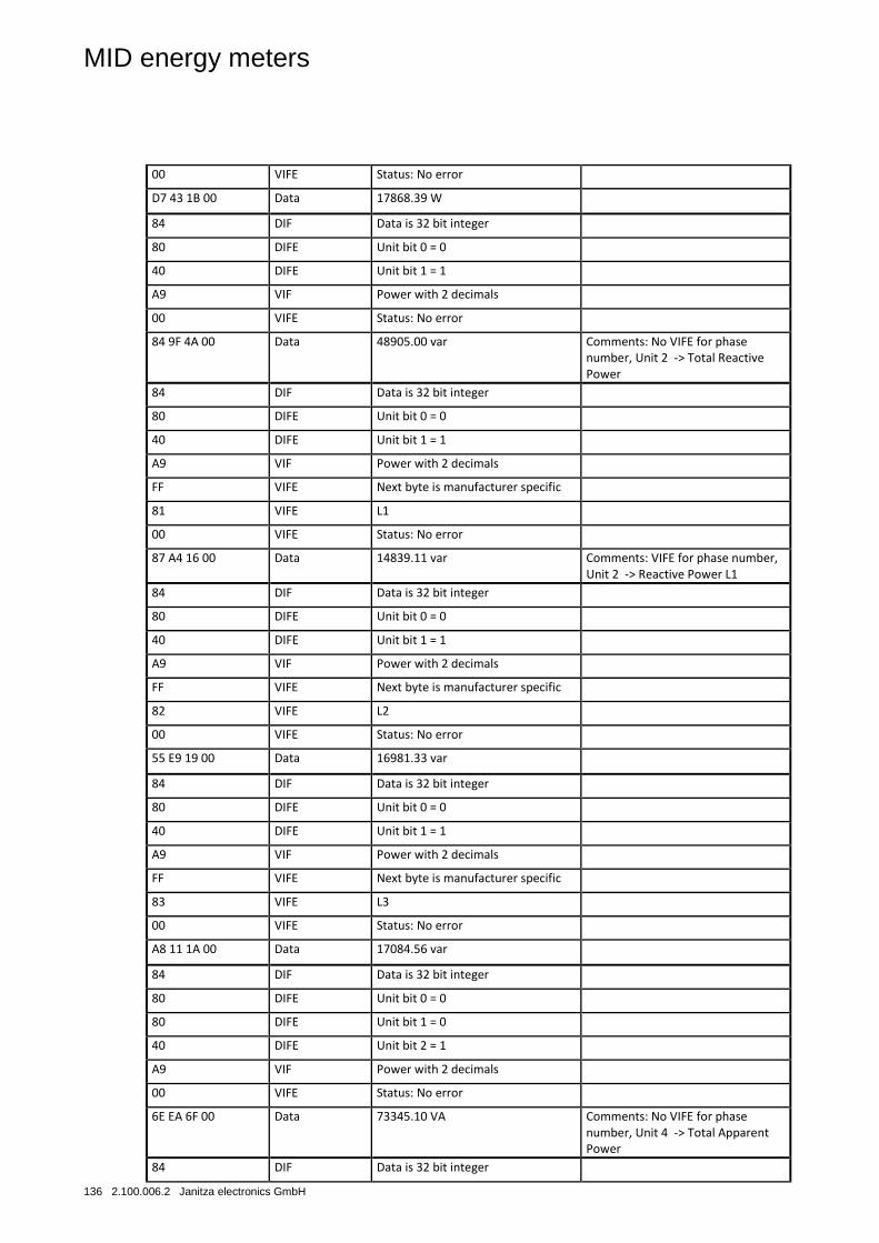
MID energy meters
136 2.100.006.2 Janitza electronics GmbH
00 VIFE Status: No error
D7 43 1B 00 Data 17868.39 W
84 DIF Data is 32 bit integer
80 DIFE Unit bit 0 = 0
40 DIFE Unit bit 1 = 1
A9 VIF Power with 2 decimals
00 VIFE Status: No error
84 9F 4A 00 Data 48905.00 var Comments: No VIFE for phase number, Unit 2 -> Total Reactive Power
84 DIF Data is 32 bit integer
80 DIFE Unit bit 0 = 0
40 DIFE Unit bit 1 = 1
A9 VIF Power with 2 decimals
FF VIFE Next byte is manufacturer specific
81 VIFE L1
00 VIFE Status: No error
87 A4 16 00 Data 14839.11 var Comments: VIFE for phase number, Unit 2 -> Reactive Power L1
84 DIF Data is 32 bit integer
80 DIFE Unit bit 0 = 0
40 DIFE Unit bit 1 = 1
A9 VIF Power with 2 decimals
FF VIFE Next byte is manufacturer specific
82 VIFE L2
00 VIFE Status: No error
55 E9 19 00 Data 16981.33 var
84 DIF Data is 32 bit integer
80 DIFE Unit bit 0 = 0
40 DIFE Unit bit 1 = 1
A9 VIF Power with 2 decimals
FF VIFE Next byte is manufacturer specific
83 VIFE L3
00 VIFE Status: No error
A8 11 1A 00 Data 17084.56 var
84 DIF Data is 32 bit integer
80 DIFE Unit bit 0 = 0
80 DIFE Unit bit 1 = 0
40 DIFE Unit bit 2 = 1
A9 VIF Power with 2 decimals
00 VIFE Status: No error
6E EA 6F 00 Data 73345.10 VA Comments: No VIFE for phase number, Unit 4 -> Total Apparent Power
84 DIF Data is 32 bit integer
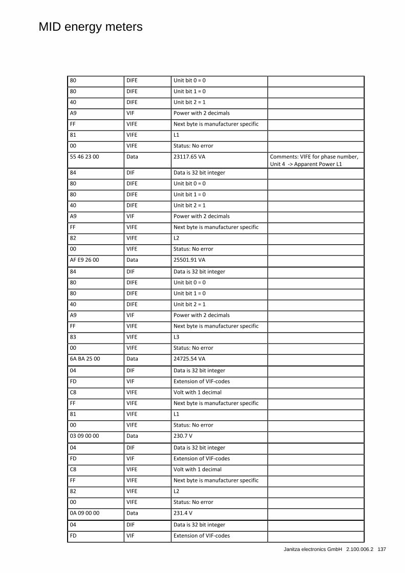
MID energy meters
Janitza electronics GmbH 2.100.006.2 137
80 DIFE Unit bit 0 = 0
80 DIFE Unit bit 1 = 0
40 DIFE Unit bit 2 = 1
A9 VIF Power with 2 decimals
FF VIFE Next byte is manufacturer specific
81 VIFE L1
00 VIFE Status: No error
55 46 23 00 Data 23117.65 VA Comments: VIFE for phase number, Unit 4 -> Apparent Power L1
84 DIF Data is 32 bit integer
80 DIFE Unit bit 0 = 0
80 DIFE Unit bit 1 = 0
40 DIFE Unit bit 2 = 1
A9 VIF Power with 2 decimals
FF VIFE Next byte is manufacturer specific
82 VIFE L2
00 VIFE Status: No error
AF E9 26 00 Data 25501.91 VA
84 DIF Data is 32 bit integer
80 DIFE Unit bit 0 = 0
80 DIFE Unit bit 1 = 0
40 DIFE Unit bit 2 = 1
A9 VIF Power with 2 decimals
FF VIFE Next byte is manufacturer specific
83 VIFE L3
00 VIFE Status: No error
6A BA 25 00 Data 24725.54 VA
04 DIF Data is 32 bit integer
FD VIF Extension of VIF-codes
C8 VIFE Volt with 1 decimal
FF VIFE Next byte is manufacturer specific
81 VIFE L1
00 VIFE Status: No error
03 09 00 00 Data 230.7 V
04 DIF Data is 32 bit integer
FD VIF Extension of VIF-codes
C8 VIFE Volt with 1 decimal
FF VIFE Next byte is manufacturer specific
82 VIFE L2
00 VIFE Status: No error
0A 09 00 00 Data 231.4 V
04 DIF Data is 32 bit integer
FD VIF Extension of VIF-codes
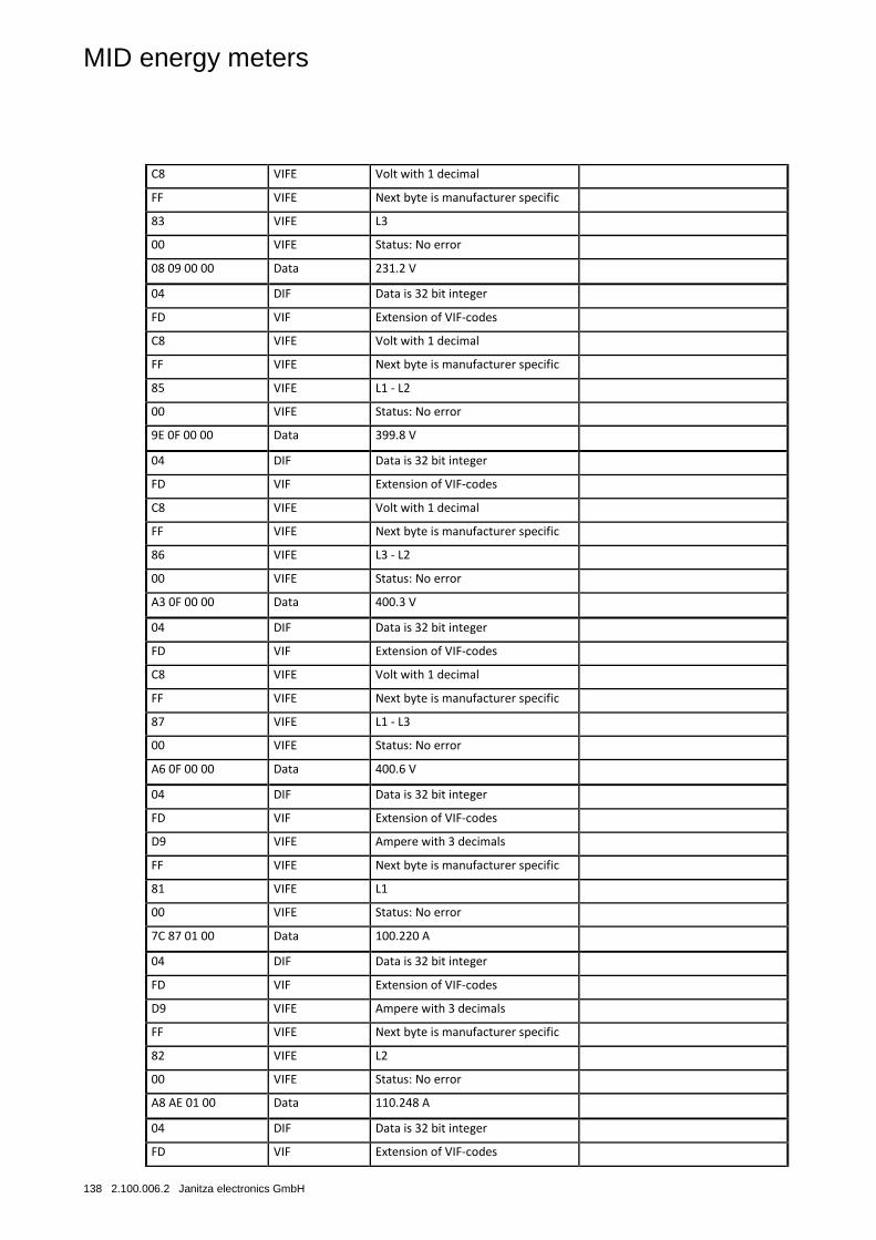
MID energy meters
138 2.100.006.2 Janitza electronics GmbH
C8 VIFE Volt with 1 decimal
FF VIFE Next byte is manufacturer specific
83 VIFE L3
00 VIFE Status: No error
08 09 00 00 Data 231.2 V
04 DIF Data is 32 bit integer
FD VIF Extension of VIF-codes
C8 VIFE Volt with 1 decimal
FF VIFE Next byte is manufacturer specific
85 VIFE L1 - L2
00 VIFE Status: No error
9E 0F 00 00 Data 399.8 V
04 DIF Data is 32 bit integer
FD VIF Extension of VIF-codes
C8 VIFE Volt with 1 decimal
FF VIFE Next byte is manufacturer specific
86 VIFE L3 - L2
00 VIFE Status: No error
A3 0F 00 00 Data 400.3 V
04 DIF Data is 32 bit integer
FD VIF Extension of VIF-codes
C8 VIFE Volt with 1 decimal
FF VIFE Next byte is manufacturer specific
87 VIFE L1 - L3
00 VIFE Status: No error
A6 0F 00 00 Data 400.6 V
04 DIF Data is 32 bit integer
FD VIF Extension of VIF-codes
D9 VIFE Ampere with 3 decimals
FF VIFE Next byte is manufacturer specific
81 VIFE L1
00 VIFE Status: No error
7C 87 01 00 Data 100.220 A
04 DIF Data is 32 bit integer
FD VIF Extension of VIF-codes
D9 VIFE Ampere with 3 decimals
FF VIFE Next byte is manufacturer specific
82 VIFE L2
00 VIFE Status: No error
A8 AE 01 00 Data 110.248 A
04 DIF Data is 32 bit integer
FD VIF Extension of VIF-codes
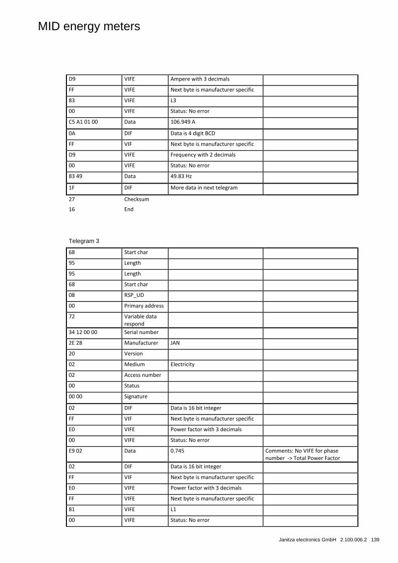
MID energy meters
Janitza electronics GmbH 2.100.006.2 139
D9 VIFE Ampere with 3 decimals
FF VIFE Next byte is manufacturer specific
83 VIFE L3
00 VIFE Status: No error
C5 A1 01 00 Data 106.949 A
0A DIF Data is 4 digit BCD
FF VIF Next byte is manufacturer specific
D9 VIFE Frequency with 2 decimals
00 VIFE Status: No error
83 49 Data 49.83 Hz
1F DIF More data in next telegram
27 Checksum
16 End
Telegram 3
68 Start char
95 Length
95 Length
68 Start char
08 RSP_UD
00 Primary address
72 Variable data respond
34 12 00 00 Serial number
2E 28 Manufacturer JAN
20 Version
02 Medium Electricity
02 Access number
00 Status
00 00 Signature
02 DIF Data is 16 bit integer
FF VIF Next byte is manufacturer specific
E0 VIFE Power factor with 3 decimals
00 VIFE Status: No error
E9 02 Data 0.745 Comments: No VIFE for phase number -> Total Power Factor
02 DIF Data is 16 bit integer
FF VIF Next byte is manufacturer specific
E0 VIFE Power factor with 3 decimals
FF VIFE Next byte is manufacturer specific
81 VIFE L1
00 VIFE Status: No error
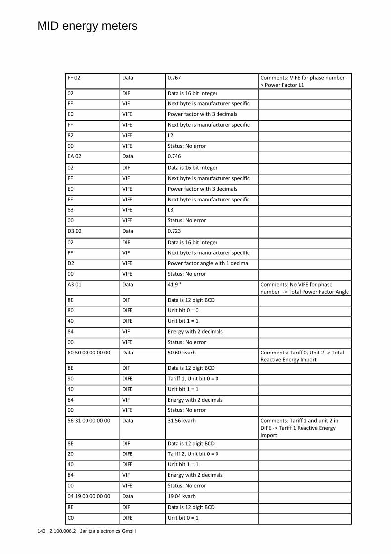
MID energy meters
140 2.100.006.2 Janitza electronics GmbH
FF 02 Data 0.767 Comments: VIFE for phase number -> Power Factor L1
02 DIF Data is 16 bit integer
FF VIF Next byte is manufacturer specific
E0 VIFE Power factor with 3 decimals
FF VIFE Next byte is manufacturer specific
82 VIFE L2
00 VIFE Status: No error
EA 02 Data 0.746
02 DIF Data is 16 bit integer
FF VIF Next byte is manufacturer specific
E0 VIFE Power factor with 3 decimals
FF VIFE Next byte is manufacturer specific
83 VIFE L3
00 VIFE Status: No error
D3 02 Data 0.723
02 DIF Data is 16 bit integer
FF VIF Next byte is manufacturer specific
D2 VIFE Power factor angle with 1 decimal
00 VIFE Status: No error
A3 01 Data 41.9 ° Comments: No VIFE for phase number -> Total Power Factor Angle
8E DIF Data is 12 digit BCD
80 DIFE Unit bit 0 = 0
40 DIFE Unit bit 1 = 1
84 VIF Energy with 2 decimals
00 VIFE Status: No error
60 50 00 00 00 00 Data 50.60 kvarh Comments: Tariff 0, Unit 2 -> Total Reactive Energy Import
8E DIF Data is 12 digit BCD
90 DIFE Tariff 1, Unit bit 0 = 0
40 DIFE Unit bit 1 = 1
84 VIF Energy with 2 decimals
00 VIFE Status: No error
56 31 00 00 00 00 Data 31.56 kvarh Comments: Tariff 1 and unit 2 in DIFE -> Tariff 1 Reactive Energy Import
8E DIF Data is 12 digit BCD
20 DIFE Tariff 2, Unit bit 0 = 0
40 DIFE Unit bit 1 = 1
84 VIF Energy with 2 decimals
00 VIFE Status: No error
04 19 00 00 00 00 Data 19.04 kvarh
8E DIF Data is 12 digit BCD
C0 DIFE Unit bit 0 = 1
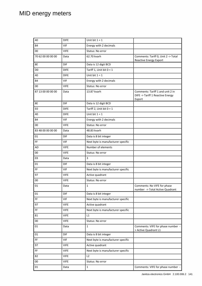
MID energy meters
Janitza electronics GmbH 2.100.006.2 141
40 DIFE Unit bit 1 = 1
84 VIF Energy with 2 decimals
00 VIFE Status: No error
70 62 00 00 00 00 Data 62.70 kvarh Comments: Tariff 0, Unit 2 -> Total Reactive Energy Export
8E DIF Data is 12 digit BCD
D0 DIFE Tariff 1, Unit bit 0 = 1
40 DIFE Unit bit 1 = 1
84 VIF Energy with 2 decimals
00 VIFE Status: No error
87 13 00 00 00 00 Data 13.87 kvarh Comments: Tariff 1 and unit 2 in DIFE -> Tariff 1 Reactive Energy Export
8E DIF Data is 12 digit BCD
E0 DIFE Tariff 2, Unit bit 0 = 1
40 DIFE Unit bit 1 = 1
84 VIF Energy with 2 decimals
00 VIFE Status: No error
83 48 00 00 00 00 Data 48.83 kvarh
01 DIF Data is 8 bit integer
FF VIF Next byte is manufacturer specific
AD VIFE Number of elements
00 VIFE Status: No error
03 Data 3
01 DIF Data is 8 bit integer
FF VIF Next byte is manufacturer specific
97 VIFE Active quadrant
00 VIFE Status: No error
01 Data 1 Comments: No VIFE for phase number -> Total Active Quadrant
01 DIF Data is 8 bit integer
FF VIF Next byte is manufacturer specific
97 VIFE Active quadrant
FF VIFE Next byte is manufacturer specific
81 VIFE L1
00 VIFE Status: No error
01 Data 1 Comments: VIFE for phase number -> Active Quadrant L1
01 DIF Data is 8 bit integer
FF VIF Next byte is manufacturer specific
97 VIFE Active quadrant
FF VIFE Next byte is manufacturer specific
82 VIFE L2
00 VIFE Status: No error
01 Data 1 Comments: VIFE for phase number -
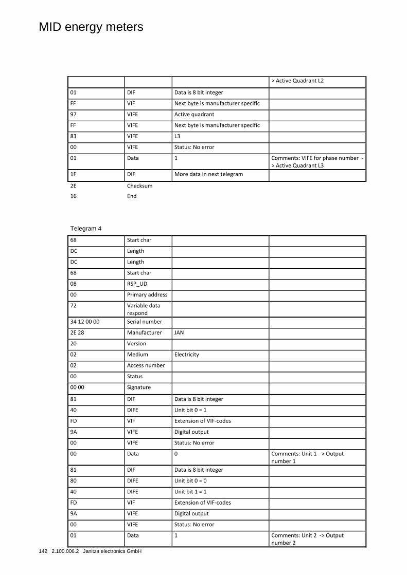
MID energy meters
142 2.100.006.2 Janitza electronics GmbH
> Active Quadrant L2
01 DIF Data is 8 bit integer
FF VIF Next byte is manufacturer specific
97 VIFE Active quadrant
FF VIFE Next byte is manufacturer specific
83 VIFE L3
00 VIFE Status: No error
01 Data 1 Comments: VIFE for phase number -> Active Quadrant L3
1F DIF More data in next telegram
2E Checksum
16 End
Telegram 4
68 Start char
DC Length
DC Length
68 Start char
08 RSP_UD
00 Primary address
72 Variable data respond
34 12 00 00 Serial number
2E 28 Manufacturer JAN
20 Version
02 Medium Electricity
02 Access number
00 Status
00 00 Signature
81 DIF Data is 8 bit integer
40 DIFE Unit bit 0 = 1
FD VIF Extension of VIF-codes
9A VIFE Digital output
00 VIFE Status: No error
00 Data 0 Comments: Unit 1 -> Output number 1
81 DIF Data is 8 bit integer
80 DIFE Unit bit 0 = 0
40 DIFE Unit bit 1 = 1
FD VIF Extension of VIF-codes
9A VIFE Digital output
00 VIFE Status: No error
01 Data 1 Comments: Unit 2 -> Output number 2
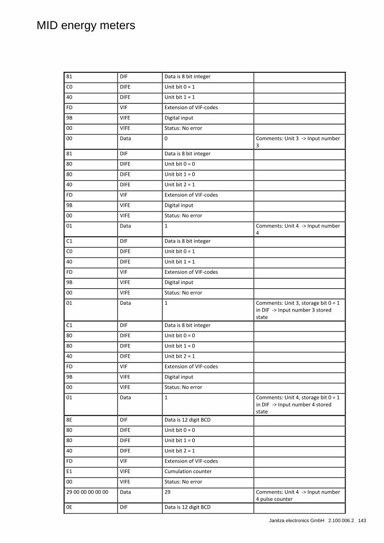
MID energy meters
Janitza electronics GmbH 2.100.006.2 143
81 DIF Data is 8 bit integer
C0 DIFE Unit bit 0 = 1
40 DIFE Unit bit 1 = 1
FD VIF Extension of VIF-codes
9B VIFE Digital input
00 VIFE Status: No error
00 Data 0 Comments: Unit 3 -> Input number 3
81 DIF Data is 8 bit integer
80 DIFE Unit bit 0 = 0
80 DIFE Unit bit 1 = 0
40 DIFE Unit bit 2 = 1
FD VIF Extension of VIF-codes
9B VIFE Digital input
00 VIFE Status: No error
01 Data 1 Comments: Unit 4 -> Input number 4
C1 DIF Data is 8 bit integer
C0 DIFE Unit bit 0 = 1
40 DIFE Unit bit 1 = 1
FD VIF Extension of VIF-codes
9B VIFE Digital input
00 VIFE Status: No error
01 Data 1 Comments: Unit 3, storage bit 0 = 1 in DIF -> Input number 3 stored state
C1 DIF Data is 8 bit integer
80 DIFE Unit bit 0 = 0
80 DIFE Unit bit 1 = 0
40 DIFE Unit bit 2 = 1
FD VIF Extension of VIF-codes
9B VIFE Digital input
00 VIFE Status: No error
01 Data 1 Comments: Unit 4, storage bit 0 = 1 in DIF -> Input number 4 stored state
8E DIF Data is 12 digit BCD
80 DIFE Unit bit 0 = 0
80 DIFE Unit bit 1 = 0
40 DIFE Unit bit 2 = 1
FD VIF Extension of VIF-codes
E1 VIFE Cumulation counter
00 VIFE Status: No error
29 00 00 00 00 00 Data 29 Comments: Unit 4 -> Input number 4 pulse counter
0E DIF Data is 12 digit BCD
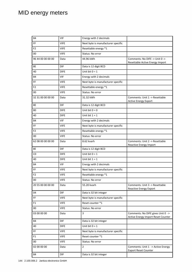
MID energy meters
144 2.100.006.2 Janitza electronics GmbH
84 VIF Energy with 2 decimals
FF VIFE Next byte is manufacturer specific
F2 VIFE Resettable energy *1
00 VIFE Status: No error
96 44 00 00 00 00 Data 44.96 kWh Comments: No DIFE -> Unit 0 -> Resettable Active Energy Import
8E DIF Data is 12 digit BCD
40 DIFE Unit bit 0 = 1
84 VIF Energy with 2 decimals
FF VIFE Next byte is manufacturer specific
F2 VIFE Resettable energy *1
00 VIFE Status: No error
32 31 00 00 00 00 Data 31.32 kWh Comments: Unit 1 -> Resettable Active Energy Export
8E DIF Data is 12 digit BCD
80 DIFE Unit bit 0 = 0
40 DIFE Unit bit 1 = 1
84 VIF Energy with 2 decimals
FF VIFE Next byte is manufacturer specific
F2 VIFE Resettable energy *1
00 VIFE Status: No error
62 08 00 00 00 00 Data 8.62 kvarh Comments: Unit 2 -> Resettable Reactive Energy Import
8E DIF Data is 12 digit BCD
C0 DIFE Unit bit 0 = 1
40 DIFE Unit bit 1 = 1
84 VIF Energy with 2 decimals
FF VIFE Next byte is manufacturer specific
F2 VIFE Resettable energy *1
00 VIFE Status: No error
20 55 00 00 00 00 Data 55.20 kvarh Comments: Unit 3 -> Resettable Reactive Energy Export
04 DIF Data is 32 bit integer
FF VIFE Next byte is manufacturer specific
F1 VIFE Reset counter *1
00 VIFE Status: No error
03 00 00 00 Data 3 Comments: No DIFE gives Unit 0 -> Active Energy Import Reset Counter
84 DIF Data is 32 bit integer
40 DIFE Unit bit 0 = 1
FF VIFE Next byte is manufacturer specific
F1 VIFE Reset counter *1
00 VIFE Status: No error
02 00 00 00 Data 2 Comments: Unit 1 -> Active Energy Export Reset Counter
84 DIF Data is 32 bit integer
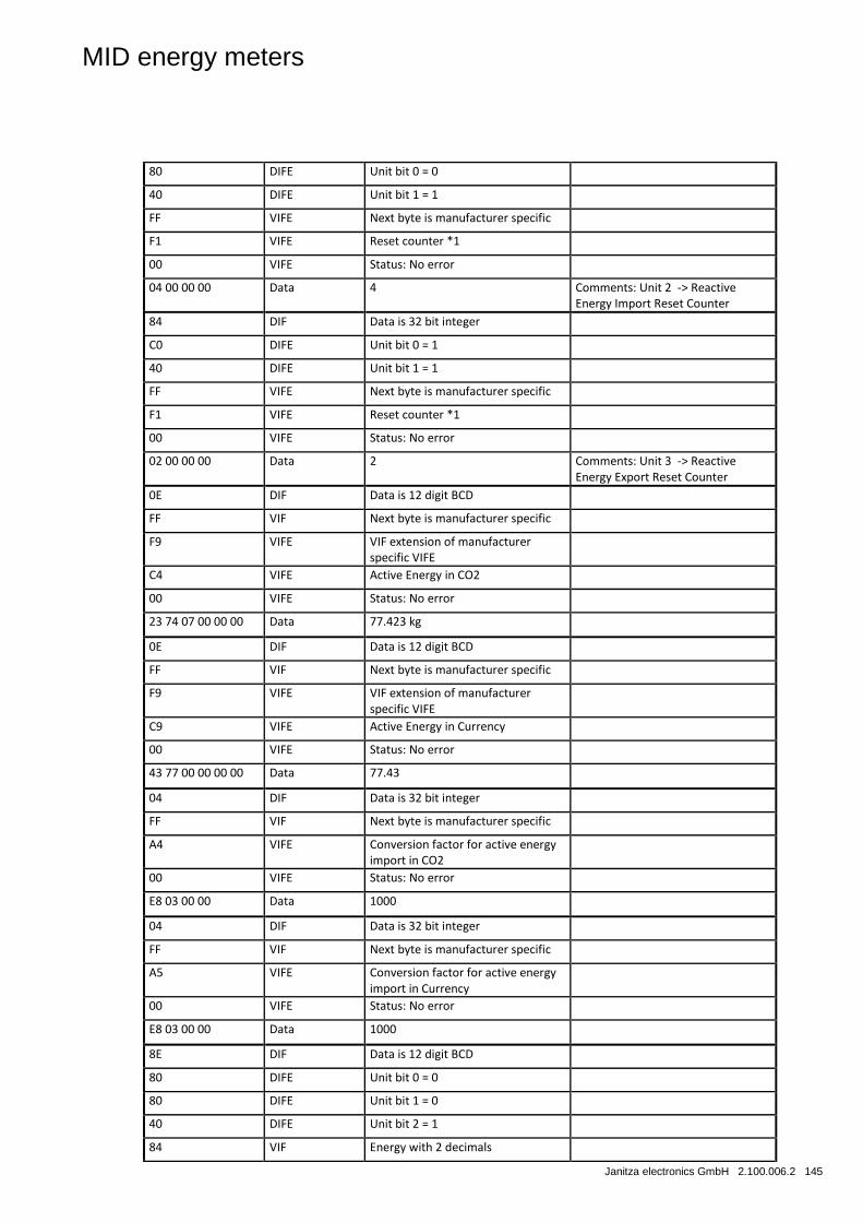
MID energy meters
Janitza electronics GmbH 2.100.006.2 145
80 DIFE Unit bit 0 = 0
40 DIFE Unit bit 1 = 1
FF VIFE Next byte is manufacturer specific
F1 VIFE Reset counter *1
00 VIFE Status: No error
04 00 00 00 Data 4 Comments: Unit 2 -> Reactive Energy Import Reset Counter
84 DIF Data is 32 bit integer
C0 DIFE Unit bit 0 = 1
40 DIFE Unit bit 1 = 1
FF VIFE Next byte is manufacturer specific
F1 VIFE Reset counter *1
00 VIFE Status: No error
02 00 00 00 Data 2 Comments: Unit 3 -> Reactive Energy Export Reset Counter
0E DIF Data is 12 digit BCD
FF VIF Next byte is manufacturer specific
F9 VIFE VIF extension of manufacturer specific VIFE
C4 VIFE Active Energy in CO2
00 VIFE Status: No error
23 74 07 00 00 00 Data 77.423 kg
0E DIF Data is 12 digit BCD
FF VIF Next byte is manufacturer specific
F9 VIFE VIF extension of manufacturer specific VIFE
C9 VIFE Active Energy in Currency
00 VIFE Status: No error
43 77 00 00 00 00 Data 77.43
04 DIF Data is 32 bit integer
FF VIF Next byte is manufacturer specific
A4 VIFE Conversion factor for active energy import in CO2
00 VIFE Status: No error
E8 03 00 00 Data 1000
04 DIF Data is 32 bit integer
FF VIF Next byte is manufacturer specific
A5 VIFE Conversion factor for active energy import in Currency
00 VIFE Status: No error
E8 03 00 00 Data 1000
8E DIF Data is 12 digit BCD
80 DIFE Unit bit 0 = 0
80 DIFE Unit bit 1 = 0
40 DIFE Unit bit 2 = 1
84 VIF Energy with 2 decimals
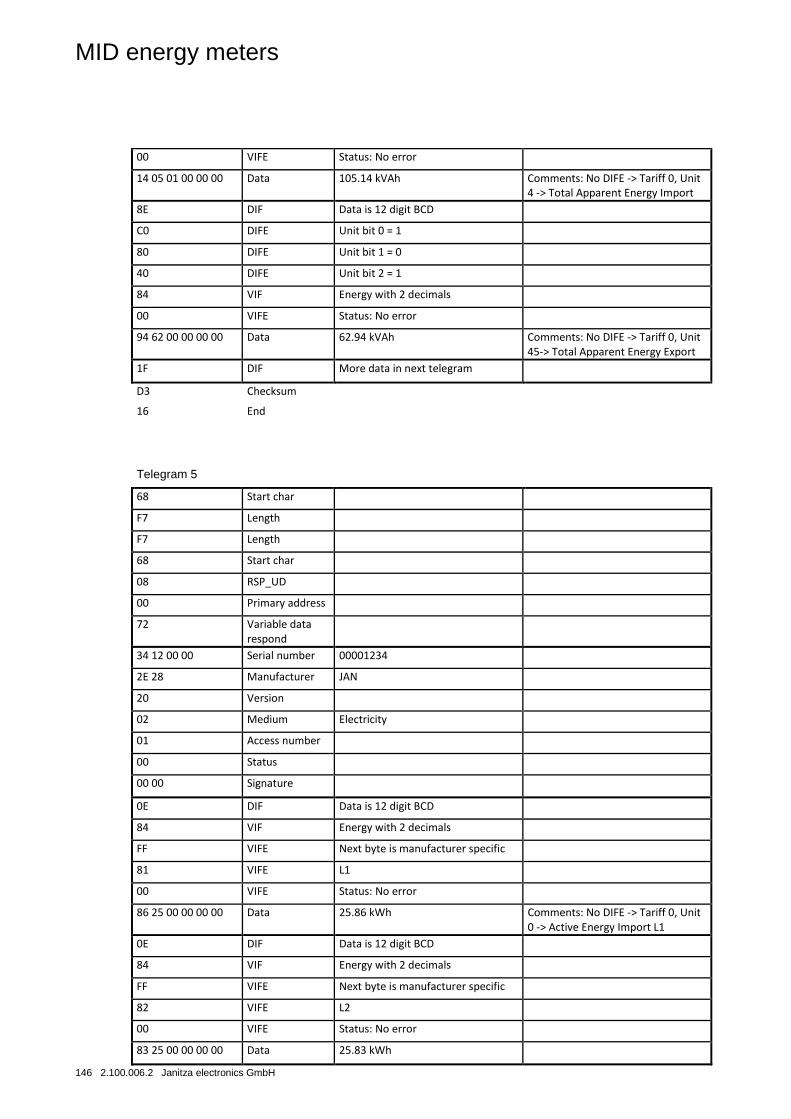
MID energy meters
146 2.100.006.2 Janitza electronics GmbH
00 VIFE Status: No error
14 05 01 00 00 00 Data 105.14 kVAh Comments: No DIFE -> Tariff 0, Unit 4 -> Total Apparent Energy Import
8E DIF Data is 12 digit BCD
C0 DIFE Unit bit 0 = 1
80 DIFE Unit bit 1 = 0
40 DIFE Unit bit 2 = 1
84 VIF Energy with 2 decimals
00 VIFE Status: No error
94 62 00 00 00 00 Data 62.94 kVAh Comments: No DIFE -> Tariff 0, Unit 45-> Total Apparent Energy Export
1F DIF More data in next telegram
D3 Checksum
16 End
Telegram 5
68 Start char
F7 Length
F7 Length
68 Start char
08 RSP_UD
00 Primary address
72 Variable data respond
34 12 00 00 Serial number 00001234
2E 28 Manufacturer JAN
20 Version
02 Medium Electricity
01 Access number
00 Status
00 00 Signature
0E DIF Data is 12 digit BCD
84 VIF Energy with 2 decimals
FF VIFE Next byte is manufacturer specific
81 VIFE L1
00 VIFE Status: No error
86 25 00 00 00 00 Data 25.86 kWh Comments: No DIFE -> Tariff 0, Unit 0 -> Active Energy Import L1
0E DIF Data is 12 digit BCD
84 VIF Energy with 2 decimals
FF VIFE Next byte is manufacturer specific
82 VIFE L2
00 VIFE Status: No error
83 25 00 00 00 00 Data 25.83 kWh
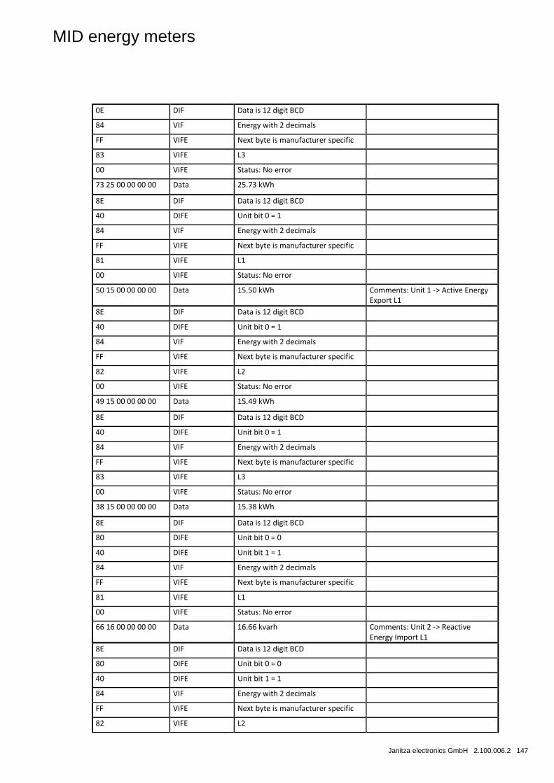
MID energy meters
Janitza electronics GmbH 2.100.006.2 147
0E DIF Data is 12 digit BCD
84 VIF Energy with 2 decimals
FF VIFE Next byte is manufacturer specific
83 VIFE L3
00 VIFE Status: No error
73 25 00 00 00 00 Data 25.73 kWh
8E DIF Data is 12 digit BCD
40 DIFE Unit bit 0 = 1
84 VIF Energy with 2 decimals
FF VIFE Next byte is manufacturer specific
81 VIFE L1
00 VIFE Status: No error
50 15 00 00 00 00 Data 15.50 kWh Comments: Unit 1 -> Active Energy Export L1
8E DIF Data is 12 digit BCD
40 DIFE Unit bit 0 = 1
84 VIF Energy with 2 decimals
FF VIFE Next byte is manufacturer specific
82 VIFE L2
00 VIFE Status: No error
49 15 00 00 00 00 Data 15.49 kWh
8E DIF Data is 12 digit BCD
40 DIFE Unit bit 0 = 1
84 VIF Energy with 2 decimals
FF VIFE Next byte is manufacturer specific
83 VIFE L3
00 VIFE Status: No error
38 15 00 00 00 00 Data 15.38 kWh
8E DIF Data is 12 digit BCD
80 DIFE Unit bit 0 = 0
40 DIFE Unit bit 1 = 1
84 VIF Energy with 2 decimals
FF VIFE Next byte is manufacturer specific
81 VIFE L1
00 VIFE Status: No error
66 16 00 00 00 00 Data 16.66 kvarh Comments: Unit 2 -> Reactive Energy Import L1
8E DIF Data is 12 digit BCD
80 DIFE Unit bit 0 = 0
40 DIFE Unit bit 1 = 1
84 VIF Energy with 2 decimals
FF VIFE Next byte is manufacturer specific
82 VIFE L2
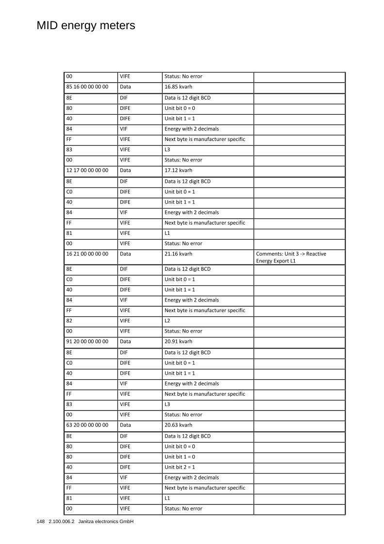
MID energy meters
148 2.100.006.2 Janitza electronics GmbH
00 VIFE Status: No error
85 16 00 00 00 00 Data 16.85 kvarh
8E DIF Data is 12 digit BCD
80 DIFE Unit bit 0 = 0
40 DIFE Unit bit 1 = 1
84 VIF Energy with 2 decimals
FF VIFE Next byte is manufacturer specific
83 VIFE L3
00 VIFE Status: No error
12 17 00 00 00 00 Data 17.12 kvarh
8E DIF Data is 12 digit BCD
C0 DIFE Unit bit 0 = 1
40 DIFE Unit bit 1 = 1
84 VIF Energy with 2 decimals
FF VIFE Next byte is manufacturer specific
81 VIFE L1
00 VIFE Status: No error
16 21 00 00 00 00 Data 21.16 kvarh Comments: Unit 3 -> Reactive Energy Export L1
8E DIF Data is 12 digit BCD
C0 DIFE Unit bit 0 = 1
40 DIFE Unit bit 1 = 1
84 VIF Energy with 2 decimals
FF VIFE Next byte is manufacturer specific
82 VIFE L2
00 VIFE Status: No error
91 20 00 00 00 00 Data 20.91 kvarh
8E DIF Data is 12 digit BCD
C0 DIFE Unit bit 0 = 1
40 DIFE Unit bit 1 = 1
84 VIF Energy with 2 decimals
FF VIFE Next byte is manufacturer specific
83 VIFE L3
00 VIFE Status: No error
63 20 00 00 00 00 Data 20.63 kvarh
8E DIF Data is 12 digit BCD
80 DIFE Unit bit 0 = 0
80 DIFE Unit bit 1 = 0
40 DIFE Unit bit 2 = 1
84 VIF Energy with 2 decimals
FF VIFE Next byte is manufacturer specific
81 VIFE L1
00 VIFE Status: No error
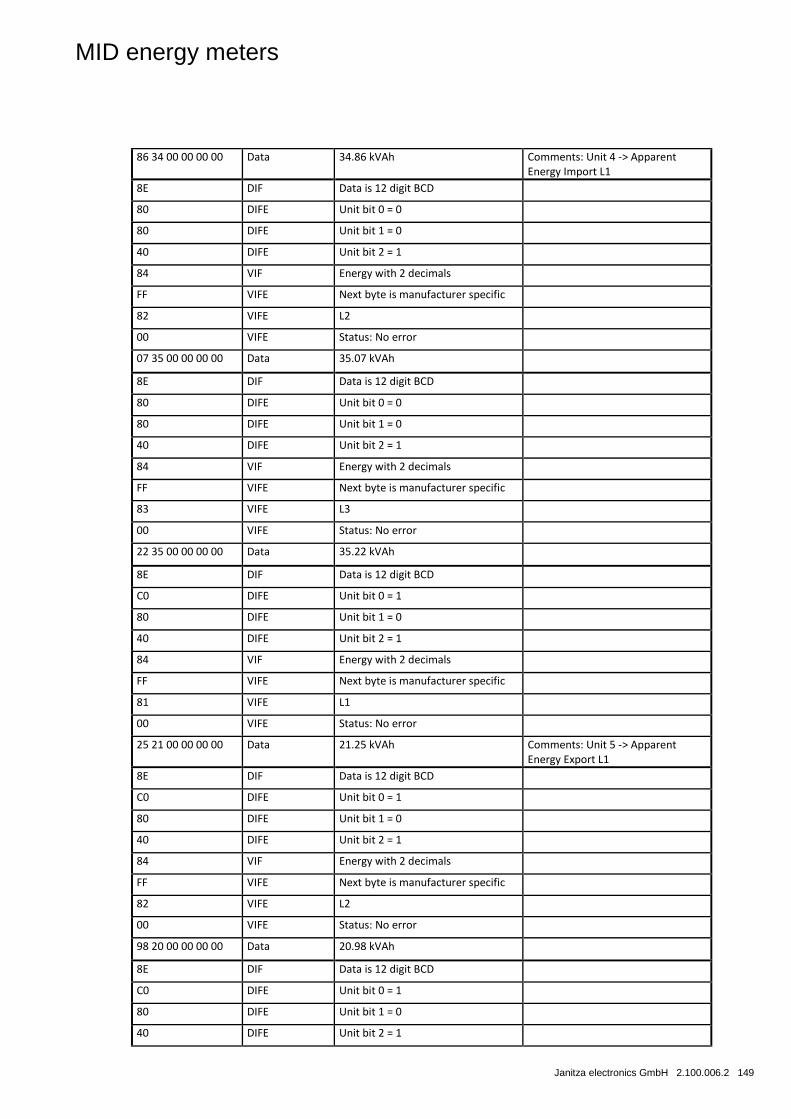
MID energy meters
Janitza electronics GmbH 2.100.006.2 149
86 34 00 00 00 00 Data 34.86 kVAh Comments: Unit 4 -> Apparent Energy Import L1
8E DIF Data is 12 digit BCD
80 DIFE Unit bit 0 = 0
80 DIFE Unit bit 1 = 0
40 DIFE Unit bit 2 = 1
84 VIF Energy with 2 decimals
FF VIFE Next byte is manufacturer specific
82 VIFE L2
00 VIFE Status: No error
07 35 00 00 00 00 Data 35.07 kVAh
8E DIF Data is 12 digit BCD
80 DIFE Unit bit 0 = 0
80 DIFE Unit bit 1 = 0
40 DIFE Unit bit 2 = 1
84 VIF Energy with 2 decimals
FF VIFE Next byte is manufacturer specific
83 VIFE L3
00 VIFE Status: No error
22 35 00 00 00 00 Data 35.22 kVAh
8E DIF Data is 12 digit BCD
C0 DIFE Unit bit 0 = 1
80 DIFE Unit bit 1 = 0
40 DIFE Unit bit 2 = 1
84 VIF Energy with 2 decimals
FF VIFE Next byte is manufacturer specific
81 VIFE L1
00 VIFE Status: No error
25 21 00 00 00 00 Data 21.25 kVAh Comments: Unit 5 -> Apparent Energy Export L1
8E DIF Data is 12 digit BCD
C0 DIFE Unit bit 0 = 1
80 DIFE Unit bit 1 = 0
40 DIFE Unit bit 2 = 1
84 VIF Energy with 2 decimals
FF VIFE Next byte is manufacturer specific
82 VIFE L2
00 VIFE Status: No error
98 20 00 00 00 00 Data 20.98 kVAh
8E DIF Data is 12 digit BCD
C0 DIFE Unit bit 0 = 1
80 DIFE Unit bit 1 = 0
40 DIFE Unit bit 2 = 1
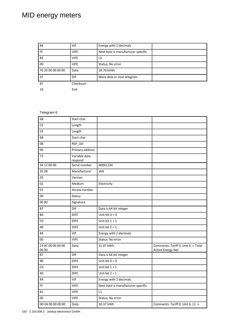
MID energy meters
150 2.100.006.2 Janitza electronics GmbH
84 VIF Energy with 2 decimals
FF VIFE Next byte is manufacturer specific
83 VIFE L3
00 VIFE Status: No error
70 20 00 00 00 00 Data 20.70 kVAh
1F DIF More data in next telegram
EF Checksum
16 End
Telegram 6
68 Start char
CE Length
CE Length
68 Start char
08 RSP_UD
00 Primary address
72 Variable data respond
34 12 00 00 Serial number 00001234
2E 28 Manufacturer JAN
20 Version
02 Medium Electricity
01 Access number
00 Status
00 00 Signature
87 DIF Data is 64 bit integer
80 DIFE Unit bit 0 = 0
C0 DIFE Unit bit 1 = 1
40 DIFE Unit bit 2 = 1
84 VIF Energy with 2 decimals
00 VIFE Status: No error
23 0C 00 00 00 00 00 00
Data 31.07 kWh Comments: Tariff 0, Unit 6 -> Total Active Energy Net
87 DIF Data is 64 bit integer
80 DIFE Unit bit 0 = 0
C0 DIFE Unit bit 1 = 1
40 DIFE Unit bit 2 = 1
84 VIF Energy with 2 decimals
FF VIFE Next byte is manufacturer specific
81 VIFE L1
00 VIFE Status: No error
0D 04 00 00 00 00 Data 10.37 kWh Comments: Tariff 0, Unit 6, L1 ->
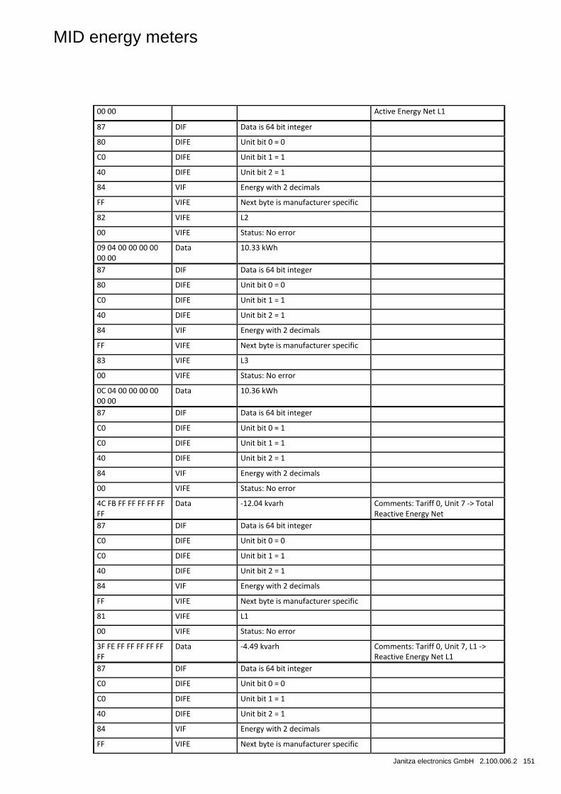
MID energy meters
Janitza electronics GmbH 2.100.006.2 151
00 00 Active Energy Net L1
87 DIF Data is 64 bit integer
80 DIFE Unit bit 0 = 0
C0 DIFE Unit bit 1 = 1
40 DIFE Unit bit 2 = 1
84 VIF Energy with 2 decimals
FF VIFE Next byte is manufacturer specific
82 VIFE L2
00 VIFE Status: No error
09 04 00 00 00 00 00 00
Data 10.33 kWh
87 DIF Data is 64 bit integer
80 DIFE Unit bit 0 = 0
C0 DIFE Unit bit 1 = 1
40 DIFE Unit bit 2 = 1
84 VIF Energy with 2 decimals
FF VIFE Next byte is manufacturer specific
83 VIFE L3
00 VIFE Status: No error
0C 04 00 00 00 00 00 00
Data 10.36 kWh
87 DIF Data is 64 bit integer
C0 DIFE Unit bit 0 = 1
C0 DIFE Unit bit 1 = 1
40 DIFE Unit bit 2 = 1
84 VIF Energy with 2 decimals
00 VIFE Status: No error
4C FB FF FF FF FF FF FF
Data -12.04 kvarh Comments: Tariff 0, Unit 7 -> Total Reactive Energy Net
87 DIF Data is 64 bit integer
C0 DIFE Unit bit 0 = 0
C0 DIFE Unit bit 1 = 1
40 DIFE Unit bit 2 = 1
84 VIF Energy with 2 decimals
FF VIFE Next byte is manufacturer specific
81 VIFE L1
00 VIFE Status: No error
3F FE FF FF FF FF FF FF
Data -4.49 kvarh Comments: Tariff 0, Unit 7, L1 -> Reactive Energy Net L1
87 DIF Data is 64 bit integer
C0 DIFE Unit bit 0 = 0
C0 DIFE Unit bit 1 = 1
40 DIFE Unit bit 2 = 1
84 VIF Energy with 2 decimals
FF VIFE Next byte is manufacturer specific
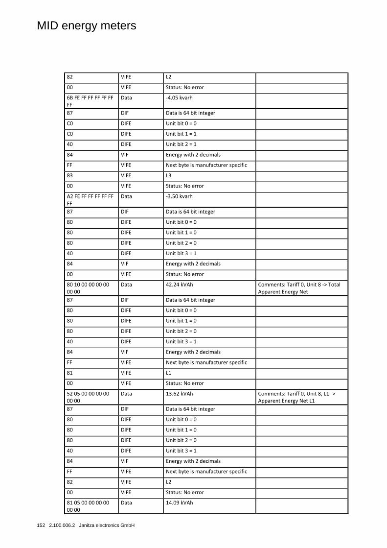
MID energy meters
152 2.100.006.2 Janitza electronics GmbH
82 VIFE L2
00 VIFE Status: No error
6B FE FF FF FF FF FF FF
Data -4.05 kvarh
87 DIF Data is 64 bit integer
C0 DIFE Unit bit 0 = 0
C0 DIFE Unit bit 1 = 1
40 DIFE Unit bit 2 = 1
84 VIF Energy with 2 decimals
FF VIFE Next byte is manufacturer specific
83 VIFE L3
00 VIFE Status: No error
A2 FE FF FF FF FF FF FF
Data -3.50 kvarh
87 DIF Data is 64 bit integer
80 DIFE Unit bit 0 = 0
80 DIFE Unit bit 1 = 0
80 DIFE Unit bit 2 = 0
40 DIFE Unit bit 3 = 1
84 VIF Energy with 2 decimals
00 VIFE Status: No error
80 10 00 00 00 00 00 00
Data 42.24 kVAh Comments: Tariff 0, Unit 8 -> Total Apparent Energy Net
87 DIF Data is 64 bit integer
80 DIFE Unit bit 0 = 0
80 DIFE Unit bit 1 = 0
80 DIFE Unit bit 2 = 0
40 DIFE Unit bit 3 = 1
84 VIF Energy with 2 decimals
FF VIFE Next byte is manufacturer specific
81 VIFE L1
00 VIFE Status: No error
52 05 00 00 00 00 00 00
Data 13.62 kVAh Comments: Tariff 0, Unit 8, L1 -> Apparent Energy Net L1
87 DIF Data is 64 bit integer
80 DIFE Unit bit 0 = 0
80 DIFE Unit bit 1 = 0
80 DIFE Unit bit 2 = 0
40 DIFE Unit bit 3 = 1
84 VIF Energy with 2 decimals
FF VIFE Next byte is manufacturer specific
82 VIFE L2
00 VIFE Status: No error
81 05 00 00 00 00 00 00
Data 14.09 kVAh
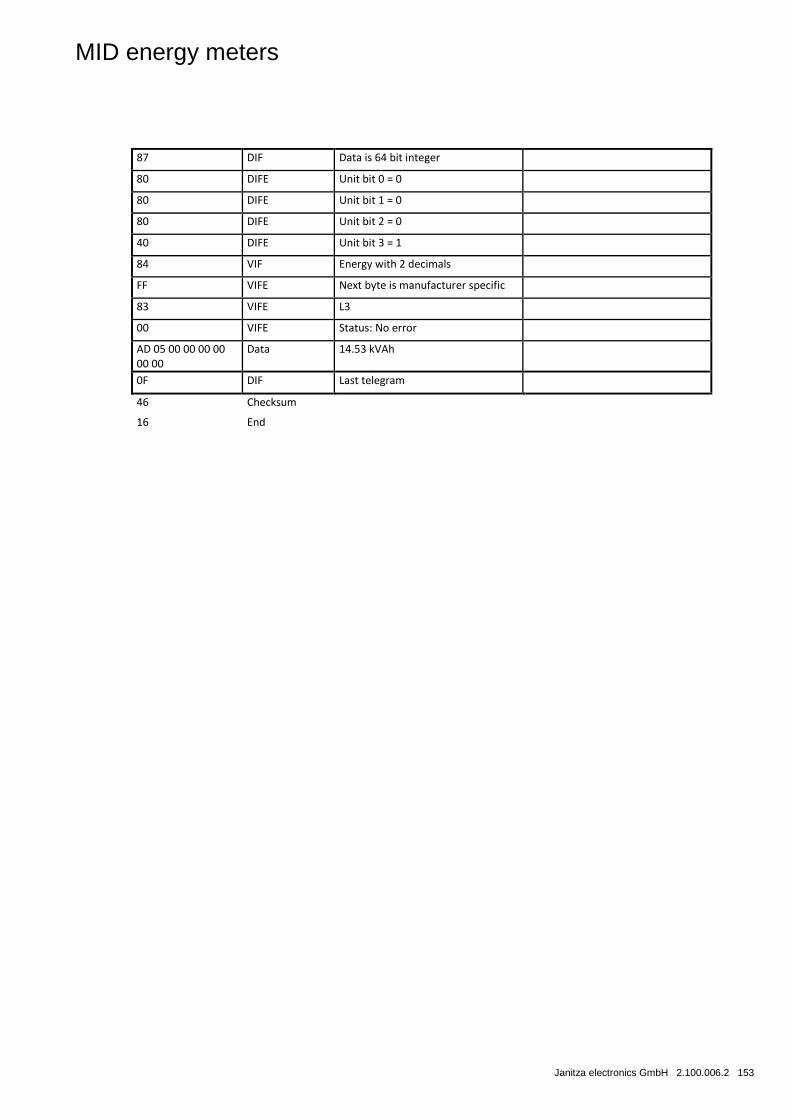
MID energy meters
Janitza electronics GmbH 2.100.006.2 153
87 DIF Data is 64 bit integer
80 DIFE Unit bit 0 = 0
80 DIFE Unit bit 1 = 0
80 DIFE Unit bit 2 = 0
40 DIFE Unit bit 3 = 1
84 VIF Energy with 2 decimals
FF VIFE Next byte is manufacturer specific
83 VIFE L3
00 VIFE Status: No error
AD 05 00 00 00 00 00 00
Data 14.53 kVAh
0F DIF Last telegram
46 Checksum
16 End
MID energy meters
154 2.100.006.2 Janitza electronics GmbH
5.3 Sending data to the meters
This section contains a description of how the telegrams can be sent to the meters. Some telegrams contain data and others do not. The data from the telegrams is sometimes stored in the meter and sometimes used for the execution of certain actions. Telegrams without data usually trigger a certain action in the meter.
Level of write access
Some commands can be protected with a password. Three different write access levels exist in total:
• Open
• Open with password
• Closed
The write access level can either be set via the buttons directly on the meter or via communication with the command level of write access.
If the write access level is set to open then the meter always accepts the command, as long as the meter is correctly addressed and the syntax and checksum are correct.
If the write access level is set to open with password then a command send password must be sent to the meter before the command, so that it accepts the command.
If the write access level is set to closed then the meter does not accept any commands, but instead merely responds with a confirmation character (E5 hex). In order to change this access level, this must be set to open with the buttons directly on the meter.
Note
For commands that are not affected by the access level, a correct message with correct address, syntax and checksum is merely required.
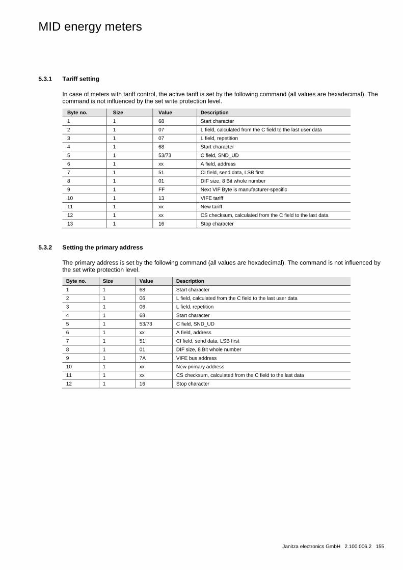
MID energy meters
Janitza electronics GmbH 2.100.006.2 155
5.3.1 Tariff setting
In case of meters with tariff control, the active tariff is set by the following command (all values are hexadecimal). The command is not influenced by the set write protection level.
Byte no. Size Value Description
1 1 68 Start character
2 1 07 L field, calculated from the C field to the last user data
3 1 07 L field, repetition
4 1 68 Start character
5 1 53/73 C field, SND_UD
6 1 xx A field, address
7 1 51 CI field, send data, LSB first
8 1 01 DIF size, 8 Bit whole number
9 1 FF Next VIF Byte is manufacturer-specific
10 1 13 VIFE tariff
11 1 xx New tariff
12 1 xx CS checksum, calculated from the C field to the last data
13 1 16 Stop character
5.3.2 Setting the primary address
The primary address is set by the following command (all values are hexadecimal). The command is not influenced by the set write protection level.
Byte no. Size Value Description
1 1 68 Start character
2 1 06 L field, calculated from the C field to the last user data
3 1 06 L field, repetition
4 1 68 Start character
5 1 53/73 C field, SND_UD
6 1 xx A field, address
7 1 51 CI field, send data, LSB first
8 1 01 DIF size, 8 Bit whole number
9 1 7A VIFE bus address
10 1 xx New primary address
11 1 xx CS checksum, calculated from the C field to the last data
12 1 16 Stop character
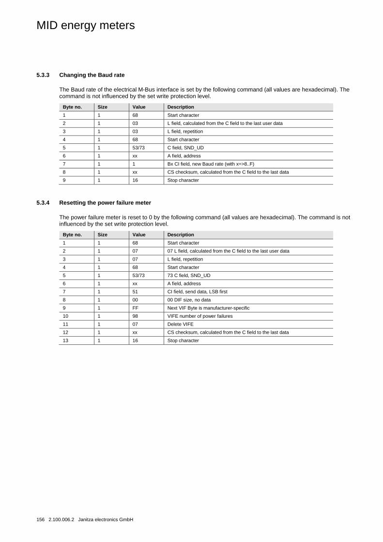
MID energy meters
156 2.100.006.2 Janitza electronics GmbH
5.3.3 Changing the Baud rate
The Baud rate of the electrical M-Bus interface is set by the following command (all values are hexadecimal). The command is not influenced by the set write protection level.
Byte no. Size Value Description
1 1 68 Start character
2 1 03 L field, calculated from the C field to the last user data
3 1 03 L field, repetition
4 1 68 Start character
5 1 53/73 C field, SND_UD
6 1 xx A field, address
7 1 1 Bx CI field, new Baud rate (with x=>8..F)
8 1 xx CS checksum, calculated from the C field to the last data
9 1 16 Stop character
5.3.4 Resetting the power failure meter
The power failure meter is reset to 0 by the following command (all values are hexadecimal). The command is not influenced by the set write protection level.
Byte no. Size Value Description
1 1 68 Start character
2 1 07 07 L field, calculated from the C field to the last user data
3 1 07 L field, repetition
4 1 68 Start character
5 1 53/73 73 C field, SND_UD
6 1 xx A field, address
7 1 51 CI field, send data, LSB first
8 1 00 00 DIF size, no data
9 1 FF Next VIF Byte is manufacturer-specific
10 1 98 VIFE number of power failures
11 1 07 Delete VIFE
12 1 xx CS checksum, calculated from the C field to the last data
13 1 16 Stop character
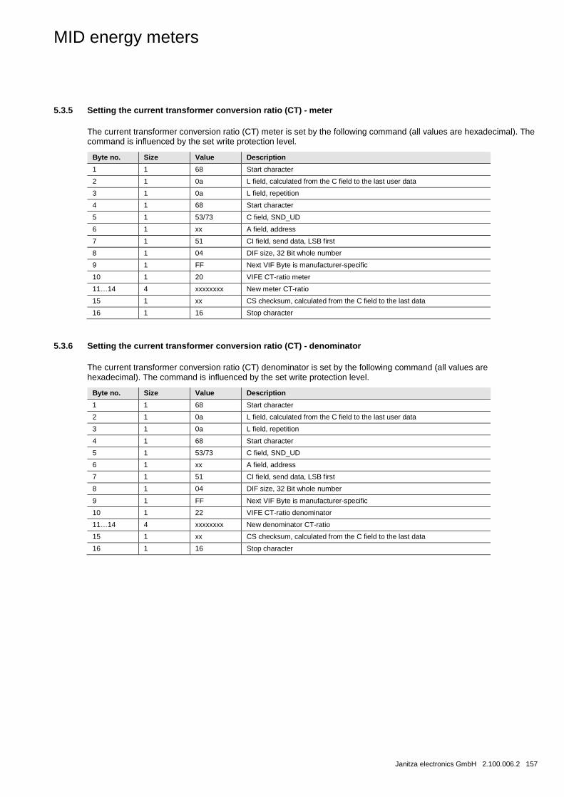
MID energy meters
Janitza electronics GmbH 2.100.006.2 157
5.3.5 Setting the current transformer conversion ratio (CT) - meter
The current transformer conversion ratio (CT) meter is set by the following command (all values are hexadecimal). The command is influenced by the set write protection level.
Byte no. Size Value Description
1 1 68 Start character
2 1 0a L field, calculated from the C field to the last user data
3 1 0a L field, repetition
4 1 68 Start character
5 1 53/73 C field, SND_UD
6 1 xx A field, address
7 1 51 CI field, send data, LSB first
8 1 04 DIF size, 32 Bit whole number
9 1 FF Next VIF Byte is manufacturer-specific
10 1 20 VIFE CT-ratio meter
11…14 4 xxxxxxxx New meter CT-ratio
15 1 xx CS checksum, calculated from the C field to the last data
16 1 16 Stop character
5.3.6 Setting the current transformer conversion ratio (CT) - denominator
The current transformer conversion ratio (CT) denominator is set by the following command (all values are hexadecimal). The command is influenced by the set write protection level.
Byte no. Size Value Description
1 1 68 Start character
2 1 0a L field, calculated from the C field to the last user data
3 1 0a L field, repetition
4 1 68 Start character
5 1 53/73 C field, SND_UD
6 1 xx A field, address
7 1 51 CI field, send data, LSB first
8 1 04 DIF size, 32 Bit whole number
9 1 FF Next VIF Byte is manufacturer-specific
10 1 22 VIFE CT-ratio denominator
11…14 4 xxxxxxxx New denominator CT-ratio
15 1 xx CS checksum, calculated from the C field to the last data
16 1 16 Stop character
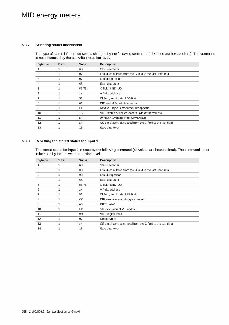
MID energy meters
158 2.100.006.2 Janitza electronics GmbH
5.3.7 Selecting status information
The type of status information sent is changed by the following command (all values are hexadecimal). The command is not influenced by the set write protection level.
Byte no. Size Value Description
1 1 68 Start character
2 1 07 L field, calculated from the C field to the last user data
3 1 07 L field, repetition
4 1 68 Start character
5 1 53/73 C field, SND_UD
6 1 xx A field, address
7 1 51 CI field, send data, LSB first
8 1 01 DIF size, 8 Bit whole number
9 1 FF Next VIF Byte is manufacturer-specific
10 1 15 VIFE status of values (status Byte of the values)
11 1 xx 0=never, 1=status if not OK=always
12 1 xx CS checksum, calculated from the C field to the last data
13 1 16 Stop character
5.3.8 Resetting the stored status for input 1
The stored status for input 1 is reset by the following command (all values are hexadecimal). The command is not influenced by the set write protection level.
Byte no. Size Value Description
1 1 68 Start character
2 1 08 L field, calculated from the C field to the last user data
3 1 08 L field, repetition
4 1 68 Start character
5 1 53/73 C field, SND_UD
6 1 xx A field, address
7 1 51 CI field, send data, LSB first
8 1 C0 DIF size, no data, storage number
9 1 40 DIFE unit=1
10 1 FD VIF extension of VIF codes
11 1 9B VIFE digital input
12 1 07 Delete VIFE
13 1 xx CS checksum, calculated from the C field to the last data
14 1 16 Stop character
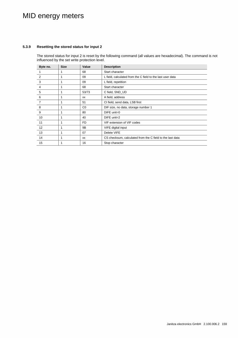
MID energy meters
Janitza electronics GmbH 2.100.006.2 159
5.3.9 Resetting the stored status for input 2
The stored status for input 2 is reset by the following command (all values are hexadecimal). The command is not influenced by the set write protection level.
Byte no. Size Value Description
1 1 68 Start character
2 1 09 L field, calculated from the C field to the last user data
3 1 09 L field, repetition
4 1 68 Start character
5 1 53/73 C field, SND_UD
6 1 xx A field, address
7 1 51 CI field, send data, LSB first
8 1 C0 DIF size, no data, storage number 1
9 1 80 DIFE unit=0
10 1 40 DIFE unit=2
11 1 FD VIF extension of VIF codes
12 1 9B VIFE digital input
13 1 07 Delete VIFE
14 1 xx CS checksum, calculated from the C field to the last data
15 1 16 Stop character
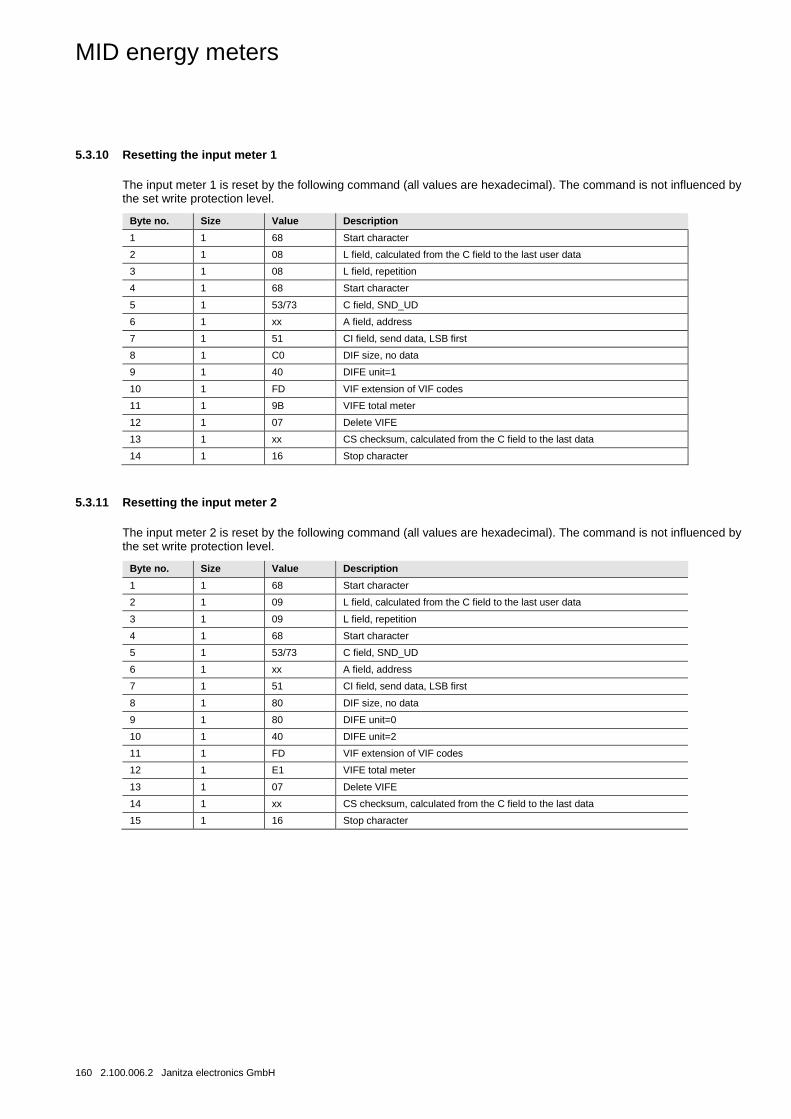
MID energy meters
160 2.100.006.2 Janitza electronics GmbH
5.3.10 Resetting the input meter 1
The input meter 1 is reset by the following command (all values are hexadecimal). The command is not influenced by the set write protection level.
Byte no. Size Value Description
1 1 68 Start character
2 1 08 L field, calculated from the C field to the last user data
3 1 08 L field, repetition
4 1 68 Start character
5 1 53/73 C field, SND_UD
6 1 xx A field, address
7 1 51 CI field, send data, LSB first
8 1 C0 DIF size, no data
9 1 40 DIFE unit=1
10 1 FD VIF extension of VIF codes
11 1 9B VIFE total meter
12 1 07 Delete VIFE
13 1 xx CS checksum, calculated from the C field to the last data
14 1 16 Stop character
5.3.11 Resetting the input meter 2
The input meter 2 is reset by the following command (all values are hexadecimal). The command is not influenced by the set write protection level.
Byte no. Size Value Description
1 1 68 Start character
2 1 09 L field, calculated from the C field to the last user data
3 1 09 L field, repetition
4 1 68 Start character
5 1 53/73 C field, SND_UD
6 1 xx A field, address
7 1 51 CI field, send data, LSB first
8 1 80 DIF size, no data
9 1 80 DIFE unit=0
10 1 40 DIFE unit=2
11 1 FD VIF extension of VIF codes
12 1 E1 VIFE total meter
13 1 07 Delete VIFE
14 1 xx CS checksum, calculated from the C field to the last data
15 1 16 Stop character
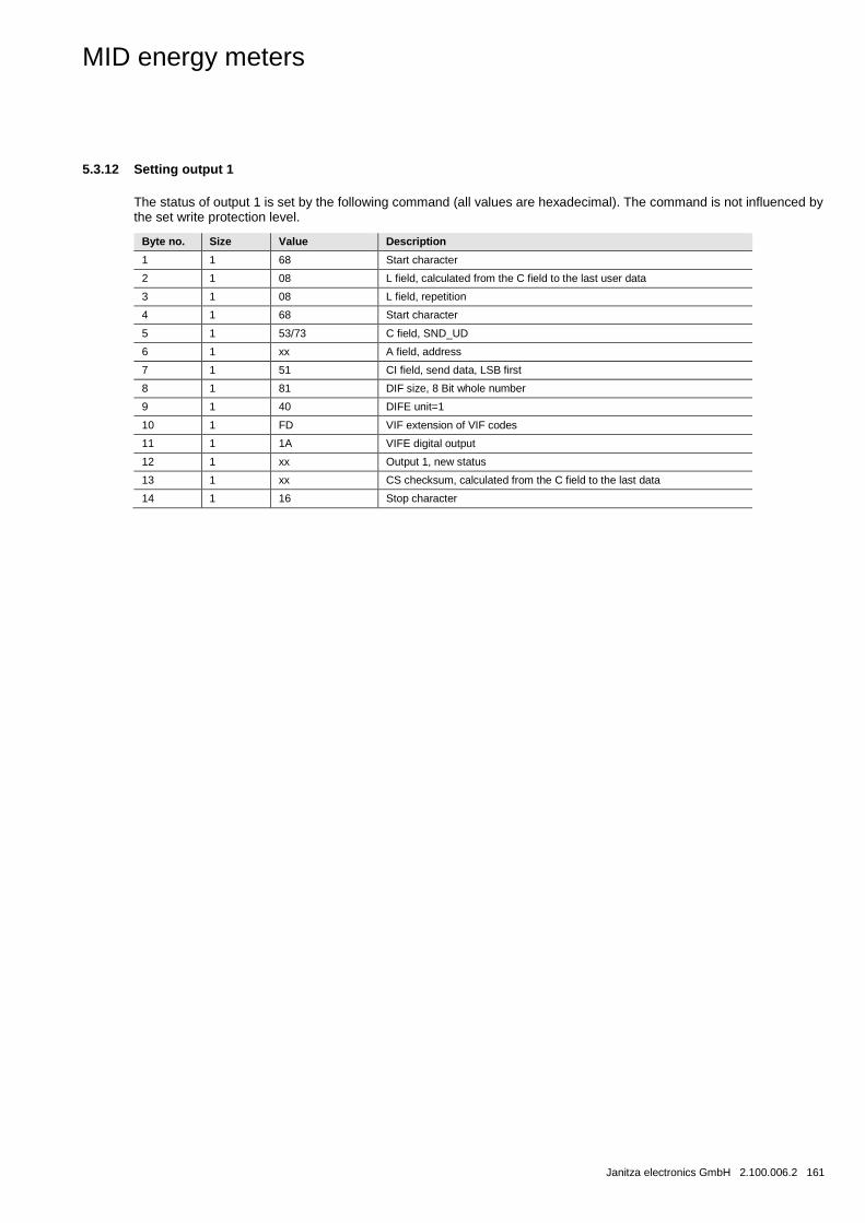
MID energy meters
Janitza electronics GmbH 2.100.006.2 161
5.3.12 Setting output 1
The status of output 1 is set by the following command (all values are hexadecimal). The command is not influenced by the set write protection level.
Byte no. Size Value Description
1 1 68 Start character
2 1 08 L field, calculated from the C field to the last user data
3 1 08 L field, repetition
4 1 68 Start character
5 1 53/73 C field, SND_UD
6 1 xx A field, address
7 1 51 CI field, send data, LSB first
8 1 81 DIF size, 8 Bit whole number
9 1 40 DIFE unit=1
10 1 FD VIF extension of VIF codes
11 1 1A VIFE digital output
12 1 xx Output 1, new status
13 1 xx CS checksum, calculated from the C field to the last data
14 1 16 Stop character
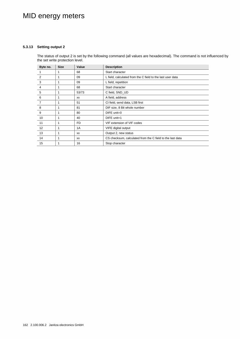
MID energy meters
162 2.100.006.2 Janitza electronics GmbH
5.3.13 Setting output 2
The status of output 2 is set by the following command (all values are hexadecimal). The command is not influenced by the set write protection level.
Byte no. Size Value Description
1 1 68 Start character
2 1 09 L field, calculated from the C field to the last user data
3 1 09 L field, repetition
4 1 68 Start character
5 1 53/73 C field, SND_UD
6 1 xx A field, address
7 1 51 CI field, send data, LSB first
8 1 81 DIF size, 8 Bit whole number
9 1 80 DIFE unit=0
10 1 40 DIFE unit=1
11 1 FD VIF extension of VIF codes
12 1 1A VIFE digital output
13 1 xx Output 2, new status
14 1 xx CS checksum, calculated from the C field to the last data
15 1 16 Stop character
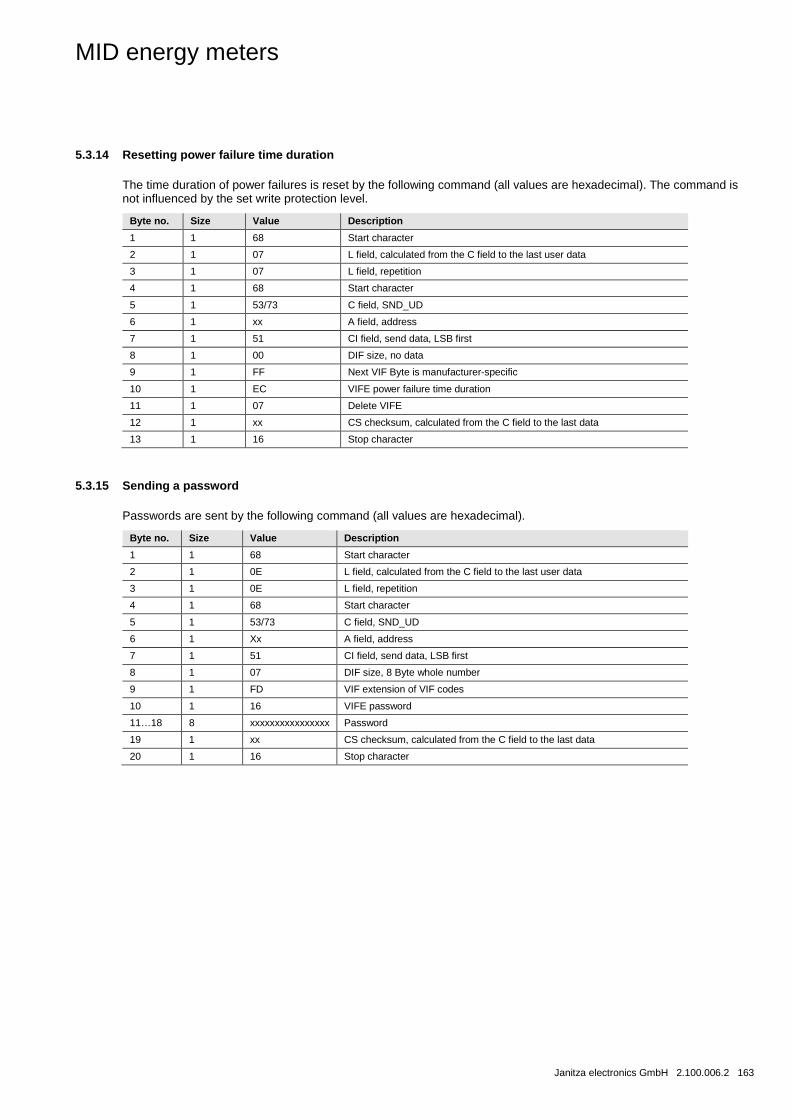
MID energy meters
Janitza electronics GmbH 2.100.006.2 163
5.3.14 Resetting power failure time duration
The time duration of power failures is reset by the following command (all values are hexadecimal). The command is not influenced by the set write protection level.
Byte no. Size Value Description
1 1 68 Start character
2 1 07 L field, calculated from the C field to the last user data
3 1 07 L field, repetition
4 1 68 Start character
5 1 53/73 C field, SND_UD
6 1 xx A field, address
7 1 51 CI field, send data, LSB first
8 1 00 DIF size, no data
9 1 FF Next VIF Byte is manufacturer-specific
10 1 EC VIFE power failure time duration
11 1 07 Delete VIFE
12 1 xx CS checksum, calculated from the C field to the last data
13 1 16 Stop character
5.3.15 Sending a password
Passwords are sent by the following command (all values are hexadecimal).
Byte no. Size Value Description
1 1 68 Start character
2 1 0E L field, calculated from the C field to the last user data
3 1 0E L field, repetition
4 1 68 Start character
5 1 53/73 C field, SND_UD
6 1 Xx A field, address
7 1 51 CI field, send data, LSB first
8 1 07 DIF size, 8 Byte whole number
9 1 FD VIF extension of VIF codes
10 1 16 VIFE password
11…18 8 xxxxxxxxxxxxxxxx Password
19 1 xx CS checksum, calculated from the C field to the last data
20 1 16 Stop character
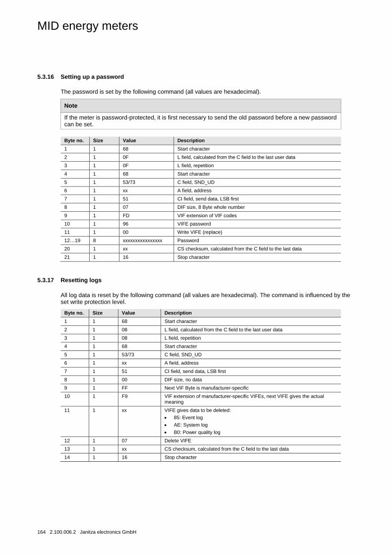
MID energy meters
164 2.100.006.2 Janitza electronics GmbH
5.3.16 Setting up a password
The password is set by the following command (all values are hexadecimal).
Note
If the meter is password-protected, it is first necessary to send the old password before a new password can be set.
Byte no. Size Value Description
1 1 68 Start character
2 1 0F L field, calculated from the C field to the last user data
3 1 0F L field, repetition
4 1 68 Start character
5 1 53/73 C field, SND_UD
6 1 xx A field, address
7 1 51 CI field, send data, LSB first
8 1 07 DIF size, 8 Byte whole number
9 1 FD VIF extension of VIF codes
10 1 96 VIFE password
11 1 00 Write VIFE (replace)
12…19 8 xxxxxxxxxxxxxxxx Password
20 1 xx CS checksum, calculated from the C field to the last data
21 1 16 Stop character
5.3.17 Resetting logs
All log data is reset by the following command (all values are hexadecimal). The command is influenced by the set write protection level.
Byte no. Size Value Description
1 1 68 Start character
2 1 08 L field, calculated from the C field to the last user data
3 1 08 L field, repetition
4 1 68 Start character
5 1 53/73 C field, SND_UD
6 1 xx A field, address
7 1 51 CI field, send data, LSB first
8 1 00 DIF size, no data
9 1 FF Next VIF Byte is manufacturer-specific
10 1 F9 VIF extension of manufacturer-specific VIFEs, next VIFE gives the actual meaning
11 1 xx VIFE gives data to be deleted: • 85: Event log
• AE: System log
• B0: Power quality log
12 1 07 Delete VIFE
13 1 xx CS checksum, calculated from the C field to the last data
14 1 16 Stop character
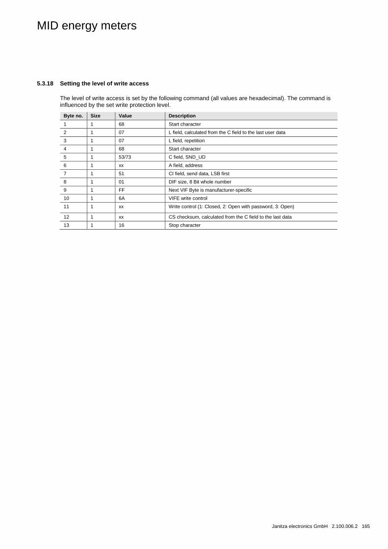
MID energy meters
Janitza electronics GmbH 2.100.006.2 165
5.3.18 Setting the level of write access
The level of write access is set by the following command (all values are hexadecimal). The command is influenced by the set write protection level.
Byte no. Size Value Description
1 1 68 Start character
2 1 07 L field, calculated from the C field to the last user data
3 1 07 L field, repetition
4 1 68 Start character
5 1 53/73 C field, SND_UD
6 1 xx A field, address
7 1 51 CI field, send data, LSB first
8 1 01 DIF size, 8 Bit whole number
9 1 FF Next VIF Byte is manufacturer-specific
10 1 6A VIFE write control
11 1 xx Write control (1: Closed, 2: Open with password, 3: Open)
12 1 xx CS checksum, calculated from the C field to the last data
13 1 16 Stop character
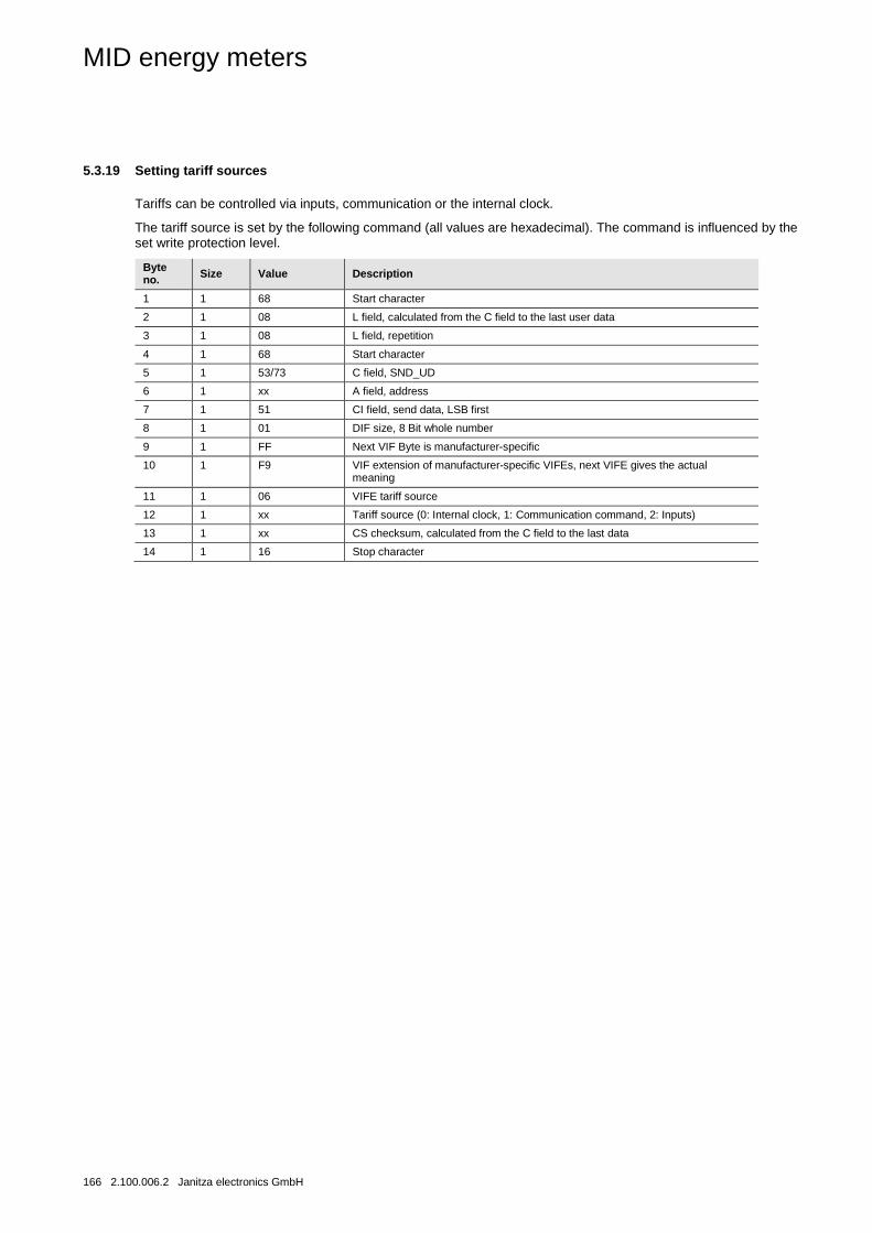
MID energy meters
166 2.100.006.2 Janitza electronics GmbH
5.3.19 Setting tariff sources
Tariffs can be controlled via inputs, communication or the internal clock.
The tariff source is set by the following command (all values are hexadecimal). The command is influenced by the set write protection level.
Byte no. Size Value Description
1 1 68 Start character
2 1 08 L field, calculated from the C field to the last user data
3 1 08 L field, repetition
4 1 68 Start character
5 1 53/73 C field, SND_UD
6 1 xx A field, address
7 1 51 CI field, send data, LSB first
8 1 01 DIF size, 8 Bit whole number
9 1 FF Next VIF Byte is manufacturer-specific
10 1 F9 VIF extension of manufacturer-specific VIFEs, next VIFE gives the actual meaning
11 1 06 VIFE tariff source
12 1 xx Tariff source (0: Internal clock, 1: Communication command, 2: Inputs)
13 1 xx CS checksum, calculated from the C field to the last data
14 1 16 Stop character

MID energy meters
Janitza electronics GmbH 2.100.006.2 167

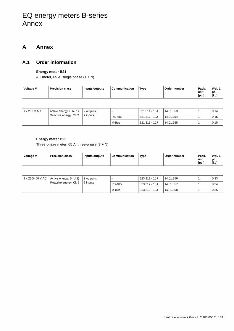
EQ energy meters B-series Annex
Janitza electronics GmbH 2.100.006.2 169
A Annex
A.1 Order information
Energy meter B21
AC meter, 65 A, single phase (1 + N)
Voltage V Precision class Inputs/outputs Communication Type Order number Pack.
unit [pc.]
Wei. 1 pc. [kg]
1 x 230 V AC Active energy: B (cl.1) Reactive energy: Cl. 2
2 outputs, 2 inputs
- B21 311 - 10J 14.01.353 1 0.14
RS-485 B21 312 - 10J 14.01.354 1 0.15
M-Bus B21 313 - 10J 14.01.355 1 0.15
Energy meter B23
Three-phase meter, 65 A, three-phase (3 + N)
Voltage V Precision class Inputs/outputs Communication Type Order number Pack.
unit [pc.]
Wei. 1 pc. [kg]
3 x 230/400 V AC Active energy: B (cl.1) Reactive energy: Cl. 2
2 outputs, 2 inputs
- B23 311 - 10J 14.01.356 1 0.33
RS-485 B23 312 - 10J 14.01.357 1 0.34
M-Bus B23 313 - 10J 14.01.358 1 0.35
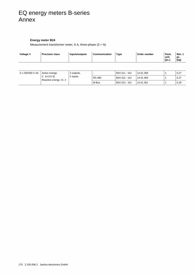
EQ energy meters B-series Annex
170 2.100.006.2 Janitza electronics GmbH
Energy meter B24
Measurement transformer meter, 6 A, three-phase (3 + N)
Voltage V Precision class Inputs/outputs Communication Type Order number Pack.
unit [pc.]
Wei. 1 pc. [kg]
3 x 230/400 V AC Active energy: C (cl.0.5 S) Reactive energy: Cl. 2
2 outputs, 2 inputs
- B24 311 - 10J 14.01.359 1 0.27
RS-485 B24 312 - 10J 14.01.360 1 0.27
M-Bus B24 313 - 10J 14.01.361 1 0.29

Contact
D
oc. n
o. 2
.100
.006
.2 –
04/
2018
Janitza electronics GmbH Vor dem Polstück 6 35633 Lahnau / Germany Tel.: +49 6441 9642-0 Fax: +49 6441 9642-30 Internet: www.janitza.de E-mail: [email protected]
Note: We reserve the right to make technical changes to the products and changes to the contents of this document at any time without notice. In case of orders, the agreed characteristics are decisive. Janitza GmbH accepts no responsibility whatsoever for any errors or incomplete information in this document. We reserve all rights to this document and the objects and figures contained within it. Duplication, disclosure to third parties and exploitation of its contents - also extracts thereof - are prohibited without the prior written permission of Janitza GmbH. Copyright© 2016 All rights reserved
Related Documents