MICROWAVE REFLECTOMETER FOR SOIL MOISTURE AND PERMITTIVITY MEASUREMENT THEN YI LUNG UNIVERSITI TEKNOLOGI MALAYSIA

Welcome message from author
This document is posted to help you gain knowledge. Please leave a comment to let me know what you think about it! Share it to your friends and learn new things together.
Transcript

MICROWAVE REFLECTOMETER FOR SOIL MOISTURE AND
PERMITTIVITY MEASUREMENT
THEN YI LUNG
UNIVERSITI TEKNOLOGI MALAYSIA

MICROWAVE REFLECTOMETER FOR SOIL MOISTURE AND
PERMITTIVITY MEASUREMENT
THEN YI LUNG
A thesis submitted in fulfilment of the
requirements for the award of the degree of
Doctor of Philosophy (Electrical Engineering)
Faculty of Electrical Engineering
Universiti Teknologi Malaysia
JANUARY 2016

iii
To my beloved family and friends,

iv
ACKNOWLEDGEMENT
I would like to express my deepest gratitude to my main supervisor, Dr. You
Kok Yeow, who made all this possible, for his help, guidance, patient and support
throughout this study. I am grateful to two of my co-supervisors, Assoc. Prof. Dr.
Ngasri Dimon and Dr. Tan Tian Swee, who have given advices and suggestions that
contributed directly to this thesis.
I appreciate Universiti Teknologi Malaysia for providing me with Zamalah
Scholarships for three years and also Ministry of Higher Education Malaysia for
providing research grants in order for our research works to proceed. Many thanks to
the officers in Radar Communication Laboratory, Faculty of Electrical Engineering,
Universiti Teknologi Malaysia.
Finally, special thanks to my family and friends for their continuous
encouragement and support throughout the time.

v
ABSTRACT
Microwave sensors are commonly used for aquametry measurements due to
strong tendency of water molecule in absorbing microwave signals. Nowadays,
meter-based microwave system is in demand as more applications need concept of
being portable and simple. This thesis presents a microwave reflectometer, which
operates between 2.2 GHz and 4.4 GHz. It can measure soil moisture content, m.c.
up to 26 % with mean deviation between predicted and actual m.c. determined at ±
2.0 %. Five common soil samples found in southern region of Peninsular Malaysia,
Johor were characterized based on macroscopic and microscopic experiments.
Throughout the research, four microstrip ring resonantor sensors operating between
2.2 GHz and 4.4 GHz were designed with different angles of microstrip bends.
(Conventional Sensor = 0.98 rad., Sensor A = 1.34 rad., Sensor B = 1.57 rad., and
Sensor C = 1.64 rad.). Sensor B was chosen as the soil sensor. A critical study on the
use of microstrip ring resonator sensors for the determination of both permittivity, εr
and m.c. from the measured scattering parameters (S-parameters) in conjunction with
E5071C vector network analyzer (VNA) was presented. The relationship between the
measured εr and m.c. obtained from the oven drying method was established. From
the results, it was observed that two dielectric relaxation conditions (bound and free
water) exist in soil-water mixture. A semi-empirical equivalent lumped element
model was created based on simulation data obtained from Microwave Office
(AWR) software. The predicted εr results from the model agree with the measured
data using commercial HP85070D dielectric probe. The model successfully
estimated εr for the five common soil types with error of 2.5 %. By using inverse
algorithm from the model, m.c. was predicted and was in good agreement with the
standard oven drying method with its average error within ± 1.5 % for all soil
samples. In general, microwave reflectometer with the proposed MRR sensor,
provide nondestructive measurement for rapid determination of soil m.c. and εr.
vi
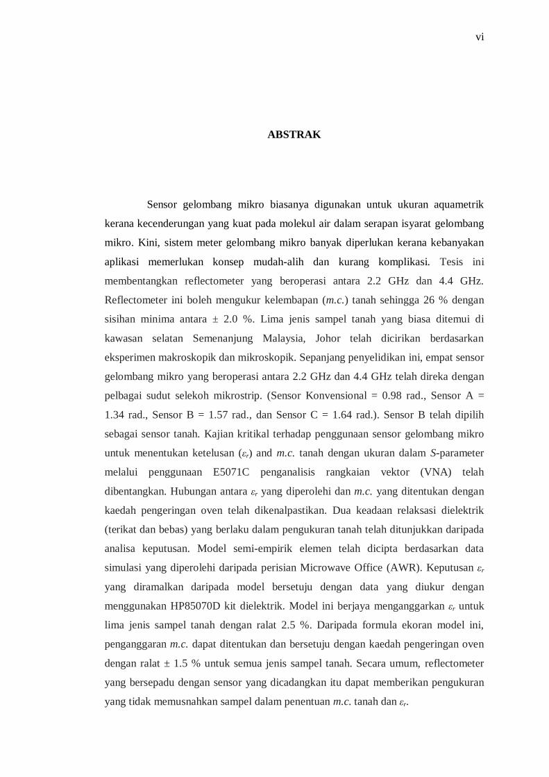
ABSTRAK
Sensor gelombang mikro biasanya digunakan untuk ukuran aquametrik
kerana kecenderungan yang kuat pada molekul air dalam serapan isyarat gelombang
mikro. Kini, sistem meter gelombang mikro banyak diperlukan kerana kebanyakan
aplikasi memerlukan konsep mudah-alih dan kurang komplikasi. Tesis ini
membentangkan reflectometer yang beroperasi antara 2.2 GHz dan 4.4 GHz.
Reflectometer ini boleh mengukur kelembapan (m.c.) tanah sehingga 26 % dengan
sisihan minima antara ± 2.0 %. Lima jenis sampel tanah yang biasa ditemui di
kawasan selatan Semenanjung Malaysia, Johor telah dicirikan berdasarkan
eksperimen makroskopik dan mikroskopik. Sepanjang penyelidikan ini, empat sensor
gelombang mikro yang beroperasi antara 2.2 GHz dan 4.4 GHz telah direka dengan
pelbagai sudut selekoh mikrostrip. (Sensor Konvensional = 0.98 rad., Sensor A =
1.34 rad., Sensor B = 1.57 rad., dan Sensor C = 1.64 rad.). Sensor B telah dipilih
sebagai sensor tanah. Kajian kritikal terhadap penggunaan sensor gelombang mikro
untuk menentukan ketelusan (εr) and m.c. tanah dengan ukuran dalam S-parameter
melalui penggunaan E5071C penganalisis rangkaian vektor (VNA) telah
dibentangkan. Hubungan antara εr yang diperolehi dan m.c. yang ditentukan dengan
kaedah pengeringan oven telah dikenalpastikan. Dua keadaan relaksasi dielektrik
(terikat dan bebas) yang berlaku dalam pengukuran tanah telah ditunjukkan daripada
analisa keputusan. Model semi-empirik elemen telah dicipta berdasarkan data
simulasi yang diperolehi daripada perisian Microwave Office (AWR). Keputusan εr
yang diramalkan daripada model bersetuju dengan data yang diukur dengan
menggunakan HP85070D kit dielektrik. Model ini berjaya menganggarkan εr untuk
lima jenis sampel tanah dengan ralat 2.5 %. Daripada formula ekoran model ini,
penganggaran m.c. dapat ditentukan dan bersetuju dengan kaedah pengeringan oven
dengan ralat ± 1.5 % untuk semua jenis sampel tanah. Secara umum, reflectometer
yang bersepadu dengan sensor yang dicadangkan itu dapat memberikan pengukuran
yang tidak memusnahkan sampel dalam penentuan m.c. tanah dan εr.

vii
TABLE OF CONTENTS
CHAPTER TITLE PAGE
DECLARATION
ii
DEDICATION iii
ACKNOWLEDGEMENTS iv
ABSTRACT v
ABSTRAK vi
TABLE OF CONTENTS vii
LIST OF TABLES xii
LIST OF FIGURES xv
LIST OF ABBREVIATIONS xxiv
LIST OF SYMBOLS xxvi
LIST OF APPENDICES xxix
1
INTRODUCTION
1
1.1 Research Background
1.2 Problem Statement
1.3 Research Objectives
1.4 Scope of work
1.5 Research Contributions
1.6 Thesis Organization
1
4
6
6
8
11
2
LITERATURE REVIEW
13
2.1 Microwave Aquametry Techniques 13
2.1.1 Microwave Sensors 14
2.2.2 Design Art of Microwave Sensors (Soil
viii
Measurement Applications) 15
2.1.3 Design Art of Microwave Sensors (For
Arbitrary Material)
22
2.1.4 Microwave Sensor Study Summary 24
2.2 Soil Type and Quality Study 28
2.2.1 Moisture Measurements 28
2.2.2 pH Measurements 30
2.3 Moisture Measurement Technologies and Trends 31
2.3.1 Oven Drying Method 31
2.3.2 Nuclear Method 31
2.3.3 Optical Method 32
2.3.4 Tension Method 32
2.3.5 Electrical Method 33
2.3.6 Microwave Method 33
2.3.7 Summary of Moisture Measurements 34
2.4 Microwave Reflectometer 36
2.4.1 Microwave Signal Generator 38
2.4.2 Power Detector 39
2.5 Microstrip Ring Resonator (MRR) 39
2.5.1 Magnetic Wall Model 40
2.5.2 Wall Admittance Formulation 43
2.5.2.1 Mutual Admittance 43
2.5.2.2 Self-Admittance 45
2.5.2.3 Input Impedance Formulation for the
Dominant Mode
47
2.5.3 Conducting Grounded Plane 50
2.5.4 Four-Legged Element Structure 51
2.5.5 Characteristic Impedance Matching of
Microstrip Line
52
2.5.6 Mitered Bends in MRR 53
2.5.7 Lumped-Element Equivalent Circuit 55
2.6 3-dB Branch-Line Directional Coupler 56
2.6.1 Multi Branch-Line Directional Coupler 57
ix
2.6.2 Miniaturized Multi Branch-Line Directional
Coupler
58
2.7 Permittivity and Conductivity Measurements 61
2.7.1 Resonance and Quality Factor 62
2.7.2 Reflection Scattering Measurement 63
2.7.3 Permittivity and Conductivity Measurements
Using Frequency-variation Method
64
2.8 Chapter Summary 65
3
METHODOLOGY AND DESIGN PROCEDURES
67
3.1 Fabrication of Reflectometer for Soil Measurements 68
3.1.1 Fabrication of Wideband Branch-Line
Directional Coupler
69
3.1.2 Reflectometer Assembly 69
3.1.3 Graphical User Interface (GUI) 70
3.2 Design and Simulation of MRR Sensor 71
3.3 Fabrication of MRR Sensors 72
3.4 Soil Under Test (SUT) 73
3.4.1 SUT Preparation 73
3.4.2 Measurement of pH and Relative Permittivity
of Various Soil Types
75
3.4.3 Determination of Soil Particles and Content 76
3.5 Soil Measurement 77
3.6 Chapter Summary 78
4
MRR SENSORS AND SOIL REFLECTOMETER FOR
MICROWAVE AQUAMETRY MEASUREMENTS
79
4.1 Characteristics Design of MRR Sensors 79
4.1.1 General Input Impedance Based on
Admittance Model
82
4.1.2 Effects of Mitered Bending Structures 83
4.1.3 S-Parameters Measurements for MRR Sensors 84
4.1.4 Power Loss of MRR Sensors 86

x
4.1.5 Equivalent Distributed Lumped Element
Model
87
4.1.6 Contour Mapping of Magnetic Field for MRR 89
4.1.7 Significant Sample Thickness of MRR Sensors 90
4.2 Soil Reflectometer System 90
4.2.1 Four-Port Branch-Line Directional Coupler 92
4.2.1.1 Implementation of Open Stubs 93
4.2.1.2 S-Parameters Measurements for Four-
Port Branch-Line Directional Coupler
95
4.2.1.3 Phase Difference between Transmitted
and Coupled Port
96
4.2.1.4 Performances of Four-Port Branch-
Line Directional Coupler
97
4.2.2 Simulation and Measurement for Soil
Reflectometer
98
4.2.3 Development of GUI for Soil Reflectometer 99
4.3 Chapter Summary 100
5
STATISTICAL PROPERTIES OF SOIL QUALITY
FOR MICROWAVE AQUAMETRY APPLICATION
IN MALAYSIA
101
5.1 Physical Tests for Various Soil Types 103
5.1.1 Magnification Images for Various Soil Types
with Respective Bulk Density
103
5.1.2 Trace Element Content for Various Soil Types 108
5.1.3 Soil Moisture and Its Influence on Soil pH 109
5.1.4 Dielectric Properties for Various Soil Types In
Dry Condition
112
5.1.4.1 Resonance Technique (MRR) 112
5.1.4.2 Cavity Perturbation Technique
(Coaxial Cavity Sensor)
114
5.1.4.3 Open-Ended Coaxial Probe Technique
(Dielctric Probe HP85070D)
115

xi
5.1.4.4 Dielectric Properties Determination 116
5.1.5 Soil Sample Classifications 118
5.2 Determination of Bound and Free Water 118
5.3 Determination Permittivity and Conductivity in Soil-
Water Mixture
123
5.4 Lumped Element Modelling for Soil Moisture and
Dielectric Prediction
135
5.4.1 Phase Adjustment and Correction of Return
Loss
136
5.4.2 Prediction Procedures with Objective Function 137
5.4.3 Soil Dielectric Prediction 138
5.4.4 Soil Moisture Prediction (Lumped Element
Model)
141
5.5 Soil Measurement Using Microwave Reflectometer 144
5.5.1 Soil Moisture Measurement Using
Reflectometer
145
5.5.2 Soil Dielectric Measurement Using
Reflectometer
147
5.5.3 Performances of Soil Reflectometer in
Microwave Aquametry Application
149
5.6 Chapter Summary 150
6
CONCLUSION AND FUTURE WORKS
152
6.1 Conclusion 152
6.2 Future Works 153
REFERENCES 155
Appendices AF 161175

xii
LIST OF TABLES
TABLE NO. TITLE PAGE
2.1 Characteristics of Microwave Sensor (Soil Measurement
Applications).
26
2.2 Soil separates and their diameter ranges for three soil
types. (Rice, 2002).
28
2.3 pH ranges and influence on plant growth potential
(Whiting et al., 2014).
30
2.4 Moisture Measurement Techniques. 35
2.5 Specification Operation for ZX47-50+ Power Detector. 39
2.6 Characteristics of four port directional coupler (Muraguchi
et al., 1983).
58
3.1 Calculated respective bulk density, ρdrysoil for various soil
types.
75
4.1 Characteristics of open stubs for multi branch-line
directional coupler.
92
4.2 Dimensions for modified four-port branch-line directional
coupler.
95
4.3 Summary of performances of four-port branch-line
directional couplers.
98
5.1 Trace element contents in weight (%) through EDX
scanning analysis.
108
5.2 Trace element contents in atomic (%) through EDX
scanning analysis.
108
5.3 Relationship between soil pH and moisture content based
on gravimetric and volumetric methods for various soil
types.
111

xiii
5.4 Calculation of D for each sensor with respective mean
squared error (MSE) values.
117
5.5 Comparison between different measurement techniques for
permittivity of various soil types.
117
5.6 Classifications of soil samples found in southern region of
Peninsular Malaysia, Johor.
118
5.7 Determination of BW and FW conditions based on
gravimetric and volumetric methods.
123
5.8 Comparison between different measurement techniques for
permittivity of white soil at m.c.g level range between 0 %
and 30 %.
124
5.9 Comparison between different measurement techniques for
permittivity of yellow soil at m.c.g level range between 0 %
and 30 %.
125
5.10 Comparison between different measurement techniques for
permittivity of loam soil at m.c.g level range between 0 %
and 30 %.
126
5.11 Comparison between different measurement techniques for
permittivity of peat soil at m.c.g level range between 0 %
and 26 %.
127
5.12 Comparison between different measurement techniques for
permittivity of sand soil at m.c.g level range between 0 %
and 22 %.
128
5.13 Polynomial regression values for the relationship between
εr′ and m.c.g (Top) and relationship between εr′ and m.c.v
(Bottom) of white soil.
130
5.14 Polynomial regression values for the relationship between
εr′ and m.c.g (Top) and relationship between εr′ and m.c.v
(Bottom) of yellow soil.
131
5.15 Polynomial regression values for the relationship between
εr′ and m.c.g (Top) and relationship between εr′ and m.c.v
(Bottom) of loam soil.
132
5.16 Polynomial regression values for the relationship between
xiv
εr′ and m.c.g (Top) and relationship between εr′ and m.c.v
(Bottom) of peat soil.
133
5.17 Polynomial regression values for the relationship between
εr′ and m.c.g (Top) and relationship between εr′ and m.c.v
(Bottom) of sand soil.
134
5.18 Relationship between dielectric properties and various
moisture level by using gravimetric m.c.g and volumetric
m.c.v for different soil types.
142
5.19 Parametric RLC in Equation (4.4) as a polynomial
functions of relative permittivity and loss tangent.
143
5.20 Polynomial regression values for Equations (5.10), (5.11),
and (5.12).
146
5.21 Polynomial regression values for Equations (5.13), (5.14),
and (5.15).
147
5.22 Polynomial regression values for Equations (5.16), (5.17),
and (5.18).
149

xv
LIST OF FIGURES
FIGURE NO. TITLE PAGE
2.1 MRR with the strip width, ws and the ring perimeter, l
designed at 0.37 cm and 11.35 cm, respectively
(Sarabandi and Eric, 1997).
15
2.2 (a) Fabricated soil meter, (b) Architecture of microwave
soil meter consisting of a microcontroller, a voltage-
controlled oscillator (VCO), a directional coupler, and a
power detector, and (c) Dimensions and cross sectional
view of the monopole sensor (You et al., 2014).
16
2.3 (a) Fabricated HYMENET probe, with two electrodes’
length measured at 36 cm. Other details include ø = 50
mm in diameter; D = 90 mm between the axes, and h = 45
mm and (b) Dimensions and cross sectional view of the
monopole sensor (Frangi et al., 2009).
17
2.4 (a) Dimensions of the microstrip line sensor (w = 2 mm, h
= 1.6 mm) and fabricated soil moisture sensor consisting
of (b) sensor head (70 mm in length) and (c) electronic
transceiver (Rezaei et al., 2012).
17
2.5 A 1186.55 mm rectangular cavity resonator was attached
to the Vector Network Analyzer (VNA) for oil sands
measurement (Erdogan et al., 2011).
18
2.6 (a) Dimensions and cross sectional view, (b) Sensor with
filled soil sample, (c) In-situ measurement setup, and (d)
Designed helmet with (i) adapter for outer conductor and
(ii) adapter for inner conductor (Lauer et al., 2012).
18
2.7 (a) Cross-section of coaxial transmission lines (Dc = 54

xvi
mm, Hc = 44 mm, and dc = 23.5 mm), (b) Proposed
adapter with the improved Kopecky cylinder, and (c)
Kopecky sensor kits (Kitić and Bergin, 2013).
19
2.8 (a) Lengths of 1, 2, and 3 cm of two wire stainless steel
rod (D = 13 mm and ø = 2 mm in diameter), (b)
specification details of the probe, and (c) the interface
between coaxial and parallel waveguides (Skierucha and
Wilezek, 2010).
19
2.9 The coaxial probe technique for soil measurement as for
reference.
20
2.10 Dimensions for (a) Single resonant patch and (b) Dual-
resonant patch and (c) Acrylic soil holder up to 60 mm on
top of the rectangular antenna patch sensor (You et al.,
2010).
21
2.11 Dimension configurations of band-stop filter type sensors
on 12.7 mm thick Taconic CeR-10 dielectric substrate
with operating frequency at (a) 2.54 GHz and (b) 2.75
GHz (Birgermajer et al., 2011).
22
2.12 Geometry of the microstrip ring resonator on an alumina
substrate (εr = 9.98) with h = 0.0635 cm, Ro = 0.2143 cm,
Ri = 0.1543 cm, w = 0.0635 cm, and S = 0.09525 cm
(Abegaonkar et al., 1999).
22
2.13 (a) Geometry of the monopole sensor and (b)
Measurement set-up (Ansarudin et al., 2012).
23
2.14 The microstrip patch soil sensors with communication
distance of 30 m for (a) a 1.6 mm thick rigid FR4
substrate and (b) a 0.025 mm thick flexible PI substrate
(Toba and Kitagawa, 2011).
24
2.15 The block diagram of reflectometer (Plumb and Ma,
1993).
37
2.16 The cascaded bridged-T attenuators proposed in
improving directional coupler for broadband
measurements (Choi et al., 2005).
37

xvii
2.17 The microwave signal generator by Windfreak, operating
between 137.5 MHz and 4.4 GHz frequency range.
38
2.18 Magnetic wall model of the ring resonator (Chang and
Hsieh, 2004).
41
2.19 Dimensions of MRR (Chang and Hsieh, 2004). 43
2.20 The MRR modeled as radial transmission lines and load
admittances (Chang and Hsieh, 2004).
47
2.21 (a) The equivalent π-network and (b) the simplified circuit
model of the MRR (Chang and Hsieh, 2004).
49
2.22 Electric field leakage for different substrate boards: (a)
Teflon epoxy (εr = 2.55) and (b) Alumina (εr =10) (Pozar,
2012).
50
2.23 Geometry of dielectric substrate plane (a) ungrounded
metal plate and (b) grounded metal plate (Chen et al.,
2004).
51
2.24 Geometry of four-legged element structure (Munk, 2000). 52
2.25 Configuration of structures for the compensation of
MRR’s corner bends.
54
2.26 Configuration of mitered bends of MRR with its
dimensions (Douville et al., 2000).
55
2.27 Lumped element model of MRR for the input impedance,
Zin.
56
2.28 Configurations of a 3-dB four-port directional coupler. 58
2.29 Size reduction scheme using lumped to distributed
elements (Then et al., 2013).
60
2.30 Calculations of half-power bandwidth (Chen et al., 2004). 62
2.31 Determination of half-power width from S11for measuring
quality factor (Chen et al., 2004).
63
2.32 Frequency shifting for each soil type with A = fUnload and B
= fLoaded.
65
3.1 The flowchart of the overall research work. 68
3.2 The architecture of the microwave reflectometer with
MRR sensor attached at port 2 of the directional coupler.
70

xviii
3.3 The architecture of the microwave reflectometer system
with PC and DAQ as monitoring and collecting data,
respectively.
70
3.4 The flowchart of designing and simulating MRR sensors. 71
3.5 The proper working steps on fabricating the MRR sensors. 72
3.6 SUT preparation by using (a) Drying oven and (b) Kern
weighing meter.
74
3.7 (a) Cavity cube with filled SUT and (b) Soil weighing
setup. The SUT as shown is sand soil.
74
3.8 Determination of pH and dielectric properties of various
soil types by using (a) HI98127 pH tester, (b) pH meter
buried into soil sample, and (c) HP85070D dielectric
probe, respectively at room temperature (25±1) ˚C.
75
3.9 (a) Hitachi TM3000 tabletop microscopy instrument and
(b) Soil sample was placed on top of a nickel or iron alloy
with thickness 38 nm.
76
3.10 (a) Measurement setup to determine significant sample
thickness. And (b) Soil measurement setup via vector
network analyzer.
78
4.1 (a) Dimensions for the conventional microstrip ring
resonator (MRR) design with red dotted ring, representing
the calculated ring design and (b) Side view for MRR
sensor, which is grounded on an aluminium plate.
81
4.2 Flowchart of the calculation of admittance model for the
calculated ring design with resonant at 3.2 GHz. (w = 4.93
mm and l = 109.6 mm).
82
4.3 General input impedance, Zin of calculated ring design (w
= 4.93 mm and l = 109.6 mm) based on admittance model
with resultant resonance at 3.2 GHz.
83
4.4 MRR configuration structure (a) Conventional Sensor, (b)
Sensor A, (c) Sensor B, and (d) Sensor C.
84
4.5 Proposed MRR sensors with two SMA connectors at both
ends, which were attached later to the Agilent E5071C for

xix
soil measurement. 85
4.6 Simulated and measured S-parameters in response to
operating frequency between 2GHz and 4 GHz for (a)
Conventional Sensor, (b) Sensor A, (c) Sensor B, and (d)
Sensor C.
85
4.7 Simulated and measured (a) power loss and (b) operating
resonance frequency in response to different mitered
bending angles.
86
4.8 Resistor-Inductor-Capacitor (RLC) distributed lumped
element circuit model for the input impedance, Zin of
MRR.
88
4.9 Lumped capacitance values for (a) Capacitor 1, C1 and (b)
Capacitor 2, C2 in response to different mitered bending
angles of the four proposed MRR sensors.
88
4.10 Contour mapping of magnetic field, Hø surrounding
structure designs for (a) conventional sensor, (b) Sensor
A, (c) Sensor B, and (d) Sensor C.
89
4.11 Variation in magnitude of return loss with air thickness, d
at respective operating frequency for four MRR sensors.
90
4.12 (a) Architecture of microwave soil reflectometer and (b)
Microwave sensor system for microwave soil aquametry
measurements.
91
4.13 Simulated S-parameters of the four-port branch-line
directional coupler based on different stub length, Stub A
= 5.8 mm in length; Stub B = 6.4 mm in length and Stub C
= 8.8 mm in length.
94
4.14 Modified four-port branch-line directional coupler design
with the allocation of stub B.
94
4.15 (a) Fabricated directional coupler with size reduction of
40 % and (b) Comparison between conventional and
modified directional coupler.
96
4.16 Simulated and measured S-parameters of the modified
directional coupler.
96

xx
4.17 Simulated and measured phase difference between S21 and
S31 of the modified four-port branch-line directional
coupler at 90˚.
97
4.18 The microstrip design for the combination of 4-port
branch-line directional coupler and Sensor B.
98
4.19 Return loss, S11 for air measurement by using simulated
and actual soil reflectometer at room temperature (25 °C).
99
5.1 The general flow of the investigation results of soil quality
determination for MRR sensors and microwave
reflectometer.
102
5.2 Images taken on the SEM for white soil with three
magnification scales of (a) ×500, (b) ×1000, and (c)
×3000.
104
5.3 Images taken on the SEM for yellow soil with three
magnification scales of (a) ×500, (b) ×1000, and (c)
×3000.
105
5.4 Images taken on the SEM for loam soil with three
magnification scales of (a) ×500, (b) ×1000, and (c)
×3000.
106
5.5 Images taken on the SEM for peat soil with three
magnification scales of (a) ×500, (b) ×1000, and (c)
×3000.
106
5.6 Images taken on the SEM for sand soil with three
magnification scales of (a) ×500, (b) ×1000, and (c)
×3000.
107
5.7 Relationship between soil pH and soil moisture based on
two methods: (a) Gravimetric and (b) Volumetric.
109
5.8 Frequency shifting for each soil type with MRR sensors:
(a) Conventional Sensor, (b) Sensor A, (c) Sensor B, and
(d) Sensor C; with A = fUnload and B = fLoaded.
113
5.9 Sensitivity, S of the MRR sensors in response to various
soil types at room temperature (25 ± 1) °C.
114
5.10 Coaxial cavity waveguide sensor with (a) Components of

xxi
coaxial cavity sensor, (b) Measurement setup, and (c)
Dimensions of coaxial cavity sensor.
115
5.11 Measurement setup with (a) HP85070D dielectric probe
and (b) soil permittivity measurements setup.
116
5.12 Measured return loss, S11 for each gravimetric m.c.g values
up to 30 % of white soil type for (a) Conventional, (b)
Sensor A, (c) Sensor B, and (d) Sensor C at room
temperature (25 ± 1) °C.
119
5.13 Measured return loss, S11 for each gravimetric m.c.g values
up to 30 % of yellow soil type for (a) Conventional, (b)
Sensor A, (c) Sensor B, and (d) Sensor C at room
temperature (25 ± 1) °C.
120
5.14 Measured return loss, S11 for each gravimetric m.c.g values
up to 30 % of loam soil type for (a) Conventional, (b)
Sensor A, (c) Sensor B, and (d) Sensor C at room
temperature (25 ± 1) °C.
121
5.15 Measured return loss, S11 for each gravimetric m.c.g values
up to 26 % of peat soil type for (a) Conventional, (b)
Sensor A, (c) Sensor B, and (d) Sensor C at room
temperature (25 ± 1) °C.
121
5.16 Measured return loss, S11 for each gravimetric m.c.g values
up to 22 % of sand soil type for (a) Conventional, (b)
Sensor A, (c) Sensor B, and (d) Sensor C at room
temperature (25 ± 1) °C.
122
5.17 Variations in relative dielectric constant and loss factor of
white soil. (a) Gravimetric method: 0 – 30 % m.c.g and (b)
Volumetric method: 0 – 25.1 % m.c.v at room temperature
(25 ± 1) °C.
130
5.18 Variations in relative dielectric constant and loss factor of
yellow soil. (a) Gravimetric method: 0 – 30 % m.c.g and
(b) Volumetric method: 0 – 27.6 % m.c.v at room
temperature (25 ± 1) °C.
131
5.19 Variations in relative dielectric constant and loss factor of
xxii
loam soil. (a) Gravimetric method: 0 – 30 % m.c.g and (b)
Volumetric method: 0 – 28.2 % m.c.v at room temperature
(25 ± 1) °C.
132
5.20 Variations in relative dielectric constant and loss factor of
peat soil. (a) Gravimetric method: 0 – 26 % m.c.g and (b)
Volumetric method: 0 – 24.5 % m.c.v at room temperature
(25 ± 1) °C.
133
5.21 Variations in relative dielectric constant and loss factor of
sand soil. (a) Gravimetric method: 0 – 22 % m.c.g and (b)
Volumetric method: 0 – 31.7 % m.c.v at room temperature
(25 ± 1) °C.
134
5.22 Simulated data for empirical lumped element model for
Sensor B by using AWR simulator for relative dielectric
constant, εr′ (1 to 10) and loss tangent, tan δ (0.01 to 0.2).
135
5.23 Side view of MRR on an aluminium plate with SMA
connector.
136
5.24 (a) Simulated and measured |S11| for Sensor B, and (d)
Simulated, measured, and measured phase shifting by
Equation (5.6) for Sensor B.
137
5.25 The variations in relative dielectric constant, εr′ for (a)
white soil, (b) yellow soil, (c) loam soil, (d) peat soil, and
(e) sand soil with changes in gravimetric moisture content,
m.c.g at room temperature (25 ± 1) oC.
139
5.26 The comparison between predicted and measured
moisture content, m.c.g of white, yellow, loam, peat, and
sand soil at room temperature (25 ± 1) oC.
141
5.27 Variation in return loss, |S11| with frequency, f of various
gravimetric (left) and volumetric (right) m.c. level for (a)
White soil, (b) Yellow soil, (c) Loam soil, (d) Peat soil,
and (e) Sand soil at room temperature (25 ± 1) oC.
144
5.28 The comparison between predicted and measured
moisture content, m.c. of white, yellow, loam, peat, and
sand soil at room temperature (25 ± 1) oC.
146

xxiii
5.29 The comparison between measured dielectric constant, ε′r
using HP85070D dielectric probe and fabricated
microwave reflectometer at room temperature (25 ± 1) oC.
148
xxiv
LIST OF ABBREVIATIONS
BW - Bound Water
CST - Computer Simulation Technology
DAQ - Data Acquisition Unit
DC - Direct Current
DGS - Defected Ground Structure
EDX - Energy-Dispersive X-ray
EM - Electromagnetic
FDR - Frequency Domain Reflectometry
FSS - Frequency Selective Surfaces
FW - Free Water
GDP - Gross Domestic Product
GUI - Graphical User Interface
HYMENET - Hygrometric Measurement Network
ISM - Industrial, Scientific, and Medical
MRR - Microstrip Ring Resonator
MSE - Mean Squared Error
NI - National Instrument
NPK - Nitrogen, Phosphorus, and Potassium Analysis
PC - Personal Computer
PCB - Printed Circuit Board
RF - Radio Frequency
RLC - Resistor-Inductor-Capacitor
RMSE - Root Mean Square Error
SEM - Scanning Electron Microscope
SMA - SubMiniature version A
SUT - Soil Under Test
SWR - Standing Wave Ratio

xxv
TDR - Time Domain Reflectometry
TE - Transverse Electric
TM - Transverse Magnetic
VCO - Voltage Controlled Oscillator
VNA - Vector Network Analyzer
VSWR - Voltage Standing Wave Ratio
xxvi
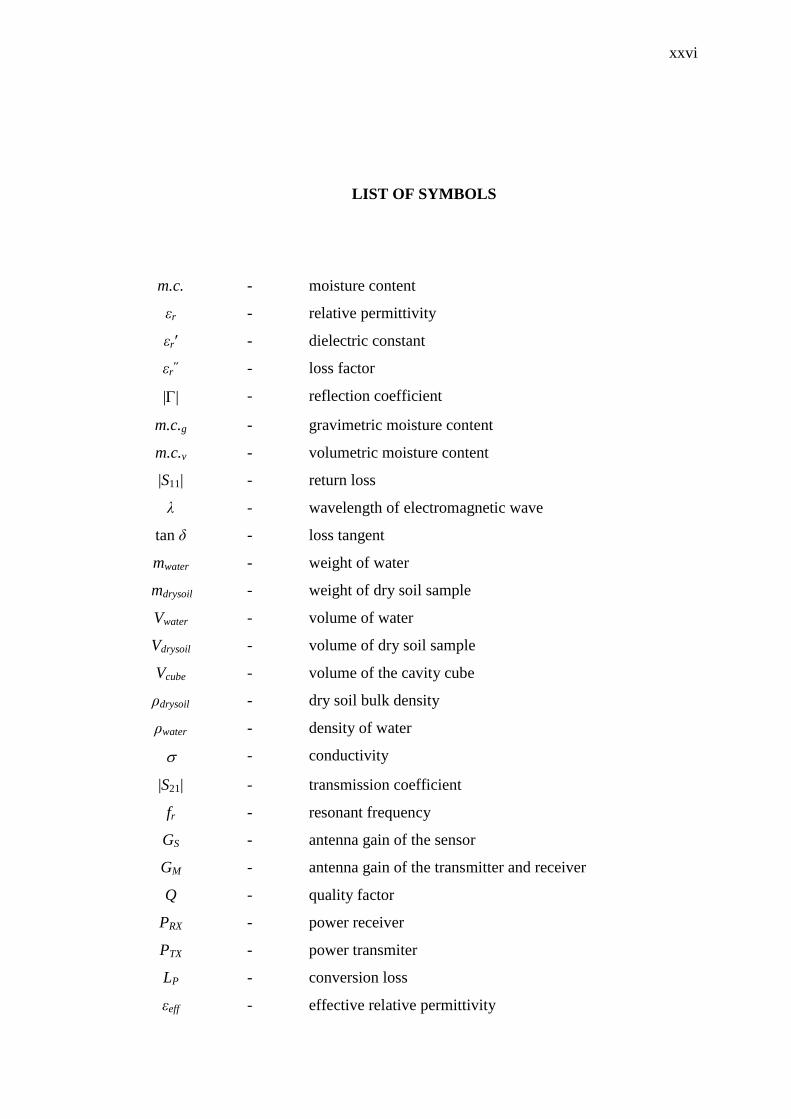
LIST OF SYMBOLS
m.c. - moisture content
εr - relative permittivity
εr′ - dielectric constant
εr˝ - loss factor
|| - reflection coefficient
m.c.g - gravimetric moisture content
m.c.v - volumetric moisture content
|S11| - return loss
λ - wavelength of electromagnetic wave
tan δ - loss tangent
mwater - weight of water
mdrysoil - weight of dry soil sample
Vwater - volume of water
Vdrysoil - volume of dry soil sample
Vcube - volume of the cavity cube
ρdrysoil - dry soil bulk density
ρwater - density of water
- conductivity
|S21| - transmission coefficient
fr - resonant frequency
GS - antenna gain of the sensor
GM - antenna gain of the transmitter and receiver
Q - quality factor
PRX - power receiver
PTX - power transmiter
LP - conversion loss
εeff - effective relative permittivity

xxvii
r - mean radius of the ring
n - mode number
c - speed of light in vacuum
λg - guided wavelength
a - inside radius of ring
b - outside radius of ring
c - feed point radius of ring
ψ - specific field function
k - propagation constant
ω - angular frequency
µ0 - permeability of free space
ε0 - permittivity of free space
Jn - nth-order Bessel function
Yn - nth-order Neumann function
Ym - mutual admittance
Ea - radial electric fringing aperture fields at a
Eb - radial electric fringing aperture fields at b
Ys - self- admittance
gs - self-conductance
bs - wall susceptances
Zin - input impedance
θi - incident angle
d - thickness of grounded plane
w - microstrip line’s copper width
h - substrate thickness
Ploss - power loss
L - inductance
C - capacitance
R - resistance
Z0 - characteristic impedance of the feed line
θ - electrical length
B01 - susceptance for stubs
θs - degree of freedom

xxviii
βi - coupling coefficients
QL - loaded quality factor
Q0 - unloaded quality factor
fUnload - unloaded resonant frequency
fLoaded - loaded resonant frequency
D - filling factor
VA - reflected voltage
VB - incident voltage
ø - bending angle
Z01 - impedance of open stub
θ01 - electrical of open stub
SR - size reduction
Smax - maximum sensitivity
Smin - minimum sensitivity
S - sensitivity
Rs - resolution
ko - propagation constant
z - distance of transmission line in coaxial cavity
TLoaded - transmission coefficient with sample
TUnload - transmission coefficient without sample
fBW - bandwidth
A - calculated deviation length of MRR
G - relative average error
fs - frequency shifting

xxix
LIST OF APPENDICES
APPENDIX TITLE PAGE
A List of Publications 161
B Graphical User Interface for Microwave
Reflectometer
162
C MATLAB Code for MRR Admittance Wall Model 163
D MATLAB Code for Dielectric Prediction Using
Lumped Element Model
166
E Bound and Free Water Conditions (Volumetric
Methods)
168
F Relationship Between Permittivity and Volumetric
m.c.
171

CHAPTER 1
INTRODUCTION
1.1 Research Background
Microwaves in radio frequency (RF) engineering are a form of
electromagnetic radiation with wavelengths ranging from as long as one meter to as
short as one millimeter. Microwaves as designated in S-band frequency (2 GHz to 4
GHz) are commonly used in human applications, such as microwave oven and
communication devices. Since the discovery and development of microwave
technologies, these technologies have become common in different fields of study,
both commercial and private industries. For this reason, recently, the microwave
electronic components are widespread in the market with affordable price. This
situation becomes an absolute advantage for researchers to apply microwave
technologies to other fields of science, such as food industry, biomedical
applications, and agricultural industry. One of the most common microwave
products, microwave oven has been introduced in our daily life. The concept of using
microwaves in heating the food is due to the polarization of water molecule
contained in the sample which is sensitive, and is showing significant response when
exposed to microwave energy. Besides, the tendency of water molecule to absorb
microwaves, allowing the microwave techniques to be successfully applied in
microwave aquametry research with ideas of determining moisture content, m.c. in a
materials containing water (Troughton, 1969 and Sarabandi and Eric, 1997).
In developing world, agriculture is often seen as a “leading edge” of a region
or country’s early commercial growth which has a multiplier effect on the overall
economy (Miller, 1995). The concern with soil quality and maintaining it under
intensively cropped systems is important. The development of civil engineering due

2
to increase of population in Malaysia has also brought soil quality into significant
research study. Soil quality is important in the fact that building cement blocks are
made up of soil, water, and cement. Therefore, good monitoring of soil quality will
lead to strong building structures. Soil quality is macroscopically and
microscopically determined based on physical properties (soil texture, moisture
content, m.c. and relative permittivity, εr) and chemical properties (pH, base
saturation, and soil acidity).
Soil moisture content, m.c. is categorized as one of the most necessary
physical characteristics in various sectors such as agriculture, civil engineering,
landscaping, irrigation engineering, and hydrology, since the consistency and
workability of a clayey soil strongly depend on its m.c. Moisture content, m.c. is
divided into bound water and free water conditions. You et al., (2013) stated that
different soil types may have different bound water and free water levels. There are
two standard methods of determining m.c. of soil, which are divided into the direct
and indirect methods. Direct method determines m.c. by removing the water
molecules from the soil-water mixture sample with the oven drying technique. This
method is accurate but it is not preferable due to time consuming. On the contrary,
indirect method requires the measurement of the electrical properties in the soil-
water sample by using fabricated instrument, so-called moisture detection meter. The
change in electrical properties will be directly correlated with a change in the actual
m.c. of the respective soil obtained from oven drying method (direct method).
Recently, indirect methods become more popular than the direct method due to well
continuity of testing, real time measurement, good sensitivity, instantaneous results,
and with good user-friendly features (Skierucha and Wilezek, 2010 and You et al.,
2013).
The interaction between agri-foods materials with microwave can be
described by the complex relative permittivity, εr in Equation (1.1).
rrr j (1.1)
where the real part of permittivity which is known as dielectric constant, εr′ is an
important parameter in food and agricultural industries processing using microwave
techniques. On the other hand, the imaginary part, εr″ is the dielectric loss factor

3
which is influenced the energy absorption or attenuation of the material. In fact, εr˝
varies greatly between soil types (Skierucha et al., 2010) due to different trace
elements content in soils, terrain either in vegetative or mountainuous structure
(Lesmes et al., 1999), and moisture content, m.c. (Sarabandi and Eric, 1997, Storme
et al., 1999, and You et al., 2013). Both εr′ and εr″ are highly correlated with
moisture content, since at microwave frequencies, the electromagnetic energy are
mainly absorbed by water and the volume of moisture in the total volume of material
most heavily influences the effective relative permittivity of the material. This is due
to the relative permittivity of water (εr = 80 at DC stage) normally being much
greater than that of the other constituents in soil (mineral soil: 4, organic matter: 4,
air: 1). If the value of the effective relative permittivity changes in the soil sample,
the microwave device will measure a change in reflection /transmission coefficient or
resonant frequency that can be directly correlated with a change in moisture content,
m.c. of the soil, which was obtained from oven drying method. Thus, the dielectric
measurements can be used to monitor the moisture content, m.c. inside the soil under
test. Although measurement of permittivity, εr is well established, there is a lack of
dielectric characterization study based on different soil types and this further gives
great motivation for this overall study. In addition, reliable microwave aquametry
measurement system which appears as a useful tool to investigate and determine
permittivity, εr and moisture content, m.c. level of various soil types also not
diffusely available worldwide.
There are numerous microwave techniques to determine εr′, such as
microstrip ring resonator (MRR) technique, which has different working principles
comparing with the dielectric probe technique, monopole sensing technique, and
coaxial cavity technique. Since soil particles are not uniformly distributed, air gap do
exists in between soil individual particles. Although dielectric probe technique is
fast, but it is less preferred for good measurement technique due to its high
sensitivity toward the presence of air gaps and also the applied pressure, which
contributes to degradation in term of the accuracy (Sarabandi and Eric, 1997).
Generally, monopole structure sensor technique is slightly difficult when burying the
sensor into the soil for measurement. Commonly, measurement by using monopole
sensor is too sensitive and the obtained results often provide large uncertainties (You
et al., 2013). Consequently, decreases the precision and repeatability of the
measurement. Coaxial cavity techniques had been widely used to perform
4
nondestructive dielectric constant measurements of materials. This technique is
accurate but it is related to difficulties in loading and unloading samples (Joshi et al.,
1997). Resonant methods have higher accuracies and sensitivities, and they are most
suitable for low-loss samples; in this case; soil samples (Chen et al., 2004).
As a consequence, permittivity, εr and moisture content, m.c. level of various
soil types remain as interesting research topics to be explored by the microwave
propagation communities. This research work aimed to fill these knowledge gaps by
investigating several physical phenomena and specificities of various soils types
particularly in southern region of Peninsular Malaysia, Johor using microwave
sensing that could possibly lead to agricultural processing industry using microwave
techniques.
1.2 Problem Statement
First problem statement discussed on the necessity for microwave soil
aquametry sensor and such measurement is represented in frequency-domain
analysis. Time-domain reflectometer, which firstly introduced in 1970’s is
commonly applied now in most soil measurement study. However, these DC time-
domain type sensors can only detect the existence of water and no-water conditions
but cannot exactly display a range percentage of moisture content, m.c., which is
required at most. Infrared sensor is less precise and sensitive as compared to
microwave sensor due to soil sample is in-homogenous and infrared sensing is based
on one particular dotted area. Optical technique is also used in soil measurement
study. The optical calculation is based on the change of refractive index of sample, n.
For microwave sensor, it is based on the change of permittivity, εr. As know that, n2=
εr. Thus, principally, microwave sensor is more sensitive as compared to optical-type
sensor. Moreover, this kind of measurement system cannot provide insight and point
out properties that are hard to discern or observe such as the soil permittivity.
Representation of soil characteristics is more convenient and intuitive when working
in the frequency-domain because signal can be represented by magnitude and phase
as functions of frequency.
Malaysia has been a successful developing country, excellent in agriculture

5
and civil construction sectors. Agriculture sector is the main economic supporter in
Malaysia. Nearly twenty four percent of Malaysia’s land area is composed of land
dedicated to agriculture alone. Palm oil is the main commodity in Malaysia’s
agricultural sector and contributes nearly 9 percent to the Gross Domestic Product
(GDP). Malaysia is the second largest producer of palm oil in the world and is
responsible for one third of the world’s rubber exports. Other agriculture products
including rice, cocoa, timber, coconut, and pineapple also contribute to the
economics’ growth. Soil provides proper nutrition, growth, and life of plants. The
optimal soil moisture level is the main factor that affects plants’ growth and well
development. Recently, civil construction is rapidly developed in Malaysia to
provide more homes due to increased of population. Soil is important ingredients in
the cement mixture and water defines the soil quality. Consistency in mixing and
moisture is the key to good quality concrete block. Maintaining right quantity usage
of soil and water in cement block mix not only produces good quality blocks but also
cost savings in long term. Therefore, proper control and monitor of soil quality is
significant for strong fundamental of buildings. Since water is an important
characteristic of many natural and man-made products or is introduced during
technological processes, it is quite obvious that measurement and control of moisture
content, m.c. have great economic contribution and technical importance. Hence, in
order to estimate reliable specific moisture content, m.c. values of soils for some
plantations and constructions, it is therefore of key importance to carefully assess the
relationship between soil quality and moisture content, m.c. rates from times to
times.
Third factor is due to inconsistent soil classifications for every country. The
first classification, the International System, was first proposed by Albert Atterberg
in 1905, and was based on his studies in southern Sweden for that time agricultural
purposes. The soil classification may differ from our country due to different climatic
regions. Till today, there is still no uniform data for soil classifications in Malaysia
yet. Through the macroscopic and microscopic testing on various soil types in
Malaysia, it is possible to find out the interaction between the measurement data and
establish the relationship between soil particle sizes and soil dielectric properties. By
determining the particle sizes based on soil dielectric properties is considered a novel
and non-destructive technique for soil research industry. This is another milestone
for us to determine our own particle sizes classifications for Malaysia based on
6
tropical climate. Even though the collected soil database may not applicable for
universal use but it is possible to be used as references for current ongoing and future
soil research studies.
1.3 Research Objectives
In regards to recent technological advances and problems mentioned above,
the main goal of this study is to provide critical information for the moisture
variation and permittivity of various soil types, particularly in southern region of
Peninsular Malaysia, Johor by developing the reflectometer with resonator type of
sensors. More specifically, the main research objectives are listed below:
i. To construct a reflectometer for microwave aquametry measurement
at S-band and develop a distributed element model to suite the
microstrip resonator ring (MRR) sensor for m.c. and εr measurements
of various soil types in Malaysia.
ii. To investigate the relation between m.c. and εr of various soil types as
well as resonant frequency shifting of reflection coefficient, || and
propose a soil quality classification using microwave measurement
techniques. This database can also be applied for soil in tropical
regions around the world.
1.4 Scopes of work
The scope of this research is given as follow:
(1) Review on influence of moisture content, m.c. on soil permittivity, εr
with assumption that higher m.c. value will result in higher soil εr.
Next, investigate frequency-variation method by using microstrip ring
resonator (MRR) sensor to differentiate various soil types based on
7
respective soil dielectric constant, εr′ and determine moisture content,
m.c. of respective common soil types. The proposed sensors are
designed to operate from 2 GHz to 4 GHz (cover the industrial,
scientific and medical (ISM) band) with resonance frequency range
between 2.9 GHz and 3.3 GHz.
(2) Design a four-port branch-line directional coupler for the remote
sensing S-band soil reflectometer. Next, develop the PC controllable
configuration for the reflectometer with NI LABVIEW as Graphical
User Interface (GUI). MRR sensor is attached together with the meter
device for sensing purposes. The calibrated equations are programmed
in MATLAB for rapid and real-time determination of soil m.c. and
soil permittivity, εr for various soil types in this study.
(3) Analyze the suitable microstrip ring resonant (MRR) sensor via
empirical resistor-inductor-capacitor (RLC) distributed element model.
The model is developed by applying basic fitting method with
simulated values obtained using the microwave office (AWR)
simulator from 0.5 GHz to 4.5 GHz over a wide range of relative
dielectric constant, εr′ (1 to 10) and loss tangent, tan δ (0.01 to 0.2).
The values for the seven elements (three inductors, two capacitors,
and two resistors) are expressed as polynomial functions of εr′ and tan
δ and by using the inverse algorithm with an objective function
computed in MATLAB program, the model is sufficient to predict soil
permittivity, εr and consequently, determining moisture content, m.c.
of respective soil samples.
(4) Macroscopically testing analysis on respective soil samples for
physical properties determination, such as soil’s relative permittivity,
pH, and moisture content, m.c. is performed by using experimental
tools, such as HP85070D dielectric probe, HI98127 pH meter, and
designed sensors via Keysight 8071C Vector Network Analyzer. On
the other hand, microscopic analysis by magnifying the texture of soil

8
sample using scanning electron microscope (SEM) is carried out to
observe the particles’ shape and sizes of respective soil samples in
different bulk samples. From the captured images, the trace elements
contained in respective soil samples can be obtained.
(5) Describe the relationship for relative dielectric properties, εr and soil
pH based on different moisture content, m.c. for various soil types and
perform polynomial regression analysis to establish these two
relationships.
i. Develop calibration equations which relate both dielectric
properties and various moisture levels by using gravimetric
m.c.g and volumetric m.c.v for different soil types for the
designed sensors.
ii. Develop calibration equations which relate which relate both
soil pH and moisture content, m.c. of various soil types by
using gravimetric and volumetric methods for the designed
sensors.
(6) Determine bound water and free water conditions based on
relationship between measured return loss, |S11| and moisture content,
m.c. for various soil types. Consequently, develop a concise soil
quality classifications based on these dependant factors, together with
(4) and (5) for agricultural purposes in Malaysia. Due to time
constraint, the measurements will be done on five common soil types
(white, yellow, loam, peat, and sand soil) in southern Peninsular
Malaysia, Johor. Limitations such as environment and temperature
change were excluded because measurements were done inside lab
with room temperature (25°C).
1.5 Research Contributions
Different climatic regions and inadequate sensor system result in poor soil

9
study and measurement. In order to establish reliable soil measurement model in
tropical climatic regions, accurate significant soil study model with respect to the
local climatic study is required. To this aim, this work mainly focused on the
characterization of five common soil types specifically devoted to their physical and
chemical behavior. The following has been identified to be the main contribution for
the requirement of significant soil study model:
i. The main contribution is the development of a frequency domain
reflectometer. In electronics, a four-port branch-line directional
coupler contains power detectors in both arms of the auxiliary line
(Incident and Reflected ports) so as to measure the electrical power
flowing in both directions in the main line. From incident and
reflected voltages, reflection coefficient, || of the sample under test
can be determined. This fabricated microwave reflectometer is a PC
controllable measurement system, which attached with suitable
microstrip ring resonator (MRR) acting as sensor device that is
capable to determine soil gravimetric moisture content, m.c.g up to 26
% m.c.g with mean deviation between actual and predicted within ± 2
% m.c.g.
ii. The second contribution is the design and fabrication of microstrip
ring resonator (MRR) sensors, operating at S-band frequency range.
MRR sensor was applied in microwave aquametry measurements due
to its highest sensitivity towards the presence of water. The designed
MRR sensors were successfully used in this study to characterize
various soil types, with average error values of less than 5 %, which
are in fine agreement with commercial dielectric probe and cavity
perturbation technique. In this study, Sensor B chosen as the suitable
sensor for soil measurement via proposed microwave reflectometer.
iii. The third contribution is the application of distributed element model
for the characterization of the microstrip ring resonator (MRR) sensor
in different operating frequencies. This study also utilizes this model
according to its microstrip bending angle for every sensor design and
10
determines the suitable operating frequency for suitable agriculture
products and also various soil types. By using the inverse algorithm
from polynomial functions of εr′ and tan δ with an objective function
computed in MATLAB program, the model is sufficient to predict soil
permittivity, εr and thus, the prediction of m.c. can be done. The mean
deviation between actual and predicted was calculated within ± 1.5 %
m.c.g. The main advantage of this model lies in its adaptability to the
local soil measurement. For this case, the soil samples are commonly
found in Malaysia. This model is specifically applicable to soil types
in tropical countries. Besides, the flexibility of this model may
contribute to more sensor designs for other agriculture products, such
as pineapple, palm oil, rice, and cocoa.
iv. The forth contribution is the determination of relationship between
soil complex relative permittivity, εr and soil moisture content, m.c.
and also the relationship between soil pH and soil moisture content,
m.c. The relationships were expressed into polynomial regression
equations to determine actual soil moisture content, m.c. and soil pH
in the absence of the actual moisture and pH measurement.
v. The fifth contribution concerned the soil quality determination. Five
common soil samples (white, yellow, peat, loam, and sand) in
southern region of Peninsular Malaysia were identified through the
soil analysis based on macroscopic and microscopic experimental
testing. The physical properties (soil texture, moisture content, m.c.
and relative permittivity, εr) and chemical properties (pH and soil
acidity). Statistical significant bound and free water conditions were
investigated for each soil type. These parameters are particularly
important for proper irrigation process and stored as soil database for
future references.

11
1.6 Thesis Organization
This thesis is presented in six chapters. This chapter introduces the
background of the investigated research study, followed by identifying the problem
statements and motivations which have led to narrow study into this research. The
scientific objectives and significant contributions from this research work are
outlined and highlighted with a clear identification of the novel content in the work.
Chapter 2 reviews study on past, recent, and ongoing microwave aquametry
research studies with various microwave measurement techniques and applications,
followed by the history of evolution and development in agriculture sectors. Some
research gaps on the past techniques and sensors are reviewed with relevant data and
proofs. It continues with the soil type and quality study based on two main dependant
factors, such as moisture content, m.c. and pH measurements. Next, study on the
reflectometer and architecture of the development, following by the design of
microstrip ring resonator (MRR) and also modified design of MRR based on four-
legged element structure with different mitered bending angles are reviewed.
Besides, study on MRR sensor based on wall admittance calculation and lumped
element equivalent circuit formulations are presented. This chapter also presents
procedures of modification in lumped element circuit with open stub technique at
conventional branch-line directional coupler to achieve smaller branch-line
directional coupler and with better performances. Finally, resonant method based on
MRR sensor with reflection technique and frequency variation method to determine
permittivity and conductivity for respective soil types are presented.
Chapter 3 describes on the research methodology for the design of the
proposed MRR sensors and development of microwave soil quality meter for soil
quality measurement. It begins with detailed explanation of the research
methodology, which consists of five main stages. Section 3.1 describes on MRR
sensors’ design and simulation, while Section 3.2 presents the fabrication of MRR
sensors. Section 3.3 explains on fabrication of the soil meter system, which includes
the design of four-port miniaturized branch-line directional coupler. Section 3.4
includes soil under test (SUT) preparation procedures and setup instruments. Last
section presents the soil measurement process.
Chapter 4 presents MRR sensor with investigations on admittance model,
mitered angle bending’s effects on MRR design, power loss and sensitivity, as well
12
as contour mapping of magnetic field. Lumped element modelling consisting of
resistor, R inductor, L, and capacitor, C on MRR sensors was presented as follows.
The second section discussed on the design of four-port branch-line directional
coupler based on performances of coupling, return loss, bandwidth, phase angle
between ports as to produce a reliable microwave reflectometer for soil quality
determination. Besides, discussions on the assembly of microwave reflectometer and
initial results, together with the development of graphical user interface (GUI) for the
meter were presented.
Chapter 5 describes the physical and chemical properties of the five common
soil samples in Malaysia, namely white, yellow, loam, peat, and sand soil. Besides,
the relationships for relative dielectric properties, εr and soil pH based on different
moisture content, m.c. are presented with implementations of polynomial regression
equations for the respective soil types by using proposed microwave MRR sensors
via vector network analyzer. A lumped element prediction model for suitable
microwave MRR sensor based on some key concepts of the distributed elements
(resistor, R, inductor, L and capacitor, C) circuits was proposed to estimate the
respective soil dielectric constant, εr′ and consequently, the soil m.c. determination.
Such predictions are found to be in good agreement with dielectric measurements
obtained from a commercial dielectric probe (HP85070D) and actual m.c.
determination using oven drying technique. This chapter continues with discussions
on the results for determining soil εr′ and m.c. by using fabricated microwave soil
quality reflectometer. The relationship between shifting frequency, fs of soil samples
and various moisture levels is presented and programmed in MATLAB for results
study and analysis. Finally, a soil database based on the above dependant factors for
the five common soil types is established and can be used as reference for agriculture
sectors and civil engineering in Malaysia.
Chapter 6 discusses the conclusion and future works. The major works in this
thesis are concluded and summarized, followed by some constructive
recommendations on the further work are given.

155
REFERENCES
Abegaonkar, M. P., Karekar, R. N., and Aiyer, R. C. (1999). A Microwave Ring
Resonator as A Moisture Sensor for Biomaterials: Application to Wheat Grains.
Meas. Sci. Technol. 10, 195-200.
Ansarudin, F., Abbas, Z., Hassan, J., Yahaya, N. Z., and Ismail, M. A. (2012). A
Simple Insulated Monopole Sensor Technique for Determination of Moisture
Content in Hevea Rubber Latex. Meas. Sci. Rev. 12(6), 249-254.
Avitabile, G., Gentili, G. B., and Sottani, N. (2001). A Rugged Active Sensor for
Microwave Aquametry. IEEE MTT-S Digest. 2259-2262.
Banos, B. G., Soto, F. C., Griol, A., Civera, J. M. C., and Pitarch, J. (2006).
Enhancement of Sensitivity of Microwave Planar Sensors with EBG Structures.
IEEE Sens. J. 6(6), 1518-1522.
Behari, J. (2005). Microwave Dielectric Behavior of Wet Soils. New York: Springer.
Bernard, P. A. and Gautray, J. M. (1991). Measurement of Dielectric Constant using
A Microstrip Ring Resonator. IEEE Trans. Microw. Theory Tech. 39, 592-595.
Birgermajer, S., Kitić, G., and Bengin V. C. (2011). Microwave Soil Moisture Sensor
Based On Phase Shift Detection of Transmission Coefficient in Band-Stop
Structures. 19th Telecommunications Forum TELFOR. 22-24 November. Serbia,
Belgrade, 27-30.
Briggs, L. J. (1908). An Electrical Resistance Method for the Rapid Determination of
the Moisture Content of Grain. U.S. Dept. Agric.: Bureau Plant Industry
Corcular.
Casanova, J. J., Evett, S. R., and Schwartz, R. C. (2012). Design of Access-Tube
TDR Sensor for Soil Water Content: Testing. IEEE Sensors J. 12(6), 2064-2070.
Cataldo, A., Monti, G., De Benedetto, E., Cannazza, G., and Tarricone, L. (2009). A
Noninvasive Resonance-Based Method for Moisture Content Evaluation
Through Microstrip Antennas. IEEE Trans. Instrum. Meas. 58(5), 1420-1426.
156
Cauer, W. (1927). Die Verwirklichung der Wechselstromwiderstände
vorgeschriebener Frequenzabhängigkeit. Arch. Electrotech. 17, 355-388.
Chang, K. and Hsieh, L. H. (2004). Microwave Ring Circuits and Related Structures.
(2nd ed.). Hoboken, New Jersey: John Wiley & Sons.
Chen, L. F., Ong, C. K., Neo, C. P., Varadan, V. V., and Varadan, V. K. (2004).
Microwave Electronics: Measurement and Materials Characterization.
Hoboken, New Jersey: John Wiley & Sons. Choi, M. K., Zhao, M., Hagness, S. C., and Weide, D. W. (2005). Compact Mixer-
Based 1-12 GHz Reflectometer. IEEE Microw. Wirel. Compon. Lett. 15(11),
781-783.
Chongcheawchamnan, M., Phromloungsri, R., Krairiksh, M., and Robertson, I. D.
(2007). Microstrip Ring Resonator Filter with Inductively-Compensated
Parallel-Coupled Feed and Stepped-Impedance Design. Electron. Lett. 43(23),
1288-1290.
Chun, Y. H. and Hong, J. S. (2006). Compact Wide-Band Branch-Line Hybrids.
IEEE Trans. Microw. Theory Tech. 54, 704-709.
Douville, R. J. P. and James, D. S. (1978). Experimental Study of Symmetric
Microstrip Bends and Their Compensation. IEEE Trans. Microw. Theory Tech.
26, 175-181.
Engen, G. F. (1992). Microwave Circuit Theory and Foundations of Microwave
Metrology. London, United Kingdom: Peter Peregrinus Ltd.
Erdogan, L., Akyel, C., and Ghannouchi, F. M. (2011). Dielectric Properties of Oil
Sands at 2.45 GHz with TE1,0,11 Mode Determined by a Rectangular Cavity
Resonator. J. Microw. Power Electromagn. Energy. 45(1), 15-23.
Frangi, J-P., Richard, D-C., Chavanne, X., Bexi I., and Sagnard F., and Guilbert V.
(2009). New In Situ Techniques for the Estimation of the Dielectric Properties
and Moisture Content of Soils. C. R. Geoscience. 341, 831-845.
Foster, R. M. (1924). A Reactance Theorem. Bell Syst. Tech. J. 3, 259-267.
Fowler, W. B. and Lopushinsky, W. (1989). An Economical, Digital Meter for
Gypsum Soil Moisture Blocks. Soil Sci. Soc. AM. J. 53, 302-305.
Gopinath, A. and Gupta, C. (1978). Capaciance Parameters of Discontinuities in
Microstrip Lines. IEEE Trans. Microw. Theory Tech. MTT-26, 831-836.
Gopinath, A. (1981). Maximum Q-Factor of Microstrip Resonators. IEEE Trans.
Microw. Theory Tech. MTT-29(2), 128-131.

157
Guo, C. and Liu, R.C. (2012). Development of a Micro-strip Resonator Soil Moisture
Sensor. 14th International Conference on Ground Penetrating Radar (GPR). 4-8
June. Shanghai, China, 676-679.
Hammerstad, E. and Jensen, O. (1980). Accurate Models for Microstrip Computer-
Aided Design. IEEE MTT Int. Microw. Symp. Dig. May. Washington, DC, 407-
409.
Hoefer, W. J. R. and Chattopadhyay, A. (1975). Evaluation of the Equivalent Circuit
Parameters of Microstrip Discontinuities through Perturbation of A Resonant
Ring. IEEE Trans. Microw. Theory Tech. 23, 1067-1071.
Hofman, M. (2012). A Microwave Sensing System for Aqueous Concentration
Measurements. Microwave Symposium Digest (MTT). 17-22 June. Canada, 1-3.
Joshi, K. K., Abegaonkar, R. N., and Aiyer, R. C. (1997). Microstrip Ring Resonator
as a Mositure Sensor for Wheat Grains. IEEE MTT-S Digest. 1679-1682.
Joshi, K. K., and Pollard, R. D. (1997). Microstrip Resonator Technique for Non-
Destructive Moisture/Permittivity Measurement. IEEE MTT-S Digest. 1863-
1866.
Kamitani, G. and Mori, T. (2005). Low Cost Millimeter-wave Vector Reflectometer.
Microwave Conference Proceedings 4. 4-7 Dec.
Kirschning, M., Jansen, R. H., and Koster, N. H. L. (1981). Accurate Model for
Open End Effect of Microstrip Lines. IET Electron. Lett. 17(3), 123-125.
Kitić, G. and Bengin, V. C. (2013). A Sensor for the Measurement of the Moisture of
Undisturbed Soil Samples. Sensors. 13, 1692-1705.
Knöchel, R., Daschner, F., and Taute, W. (2001). Resonant Microwave Sensors for
Instantaneous Determination of Moisture in Food Stuffs. Food Control. 12, 447-
458.
Kraszewski, A. W., You, T-S., and Nelson, S. O. (1989). Microwave Resonator
Technique for Moisture Content Determination in Single Soybean Seeds. IEEE
Trans. Instrum. Meas. 38(1), 79-84.
Kraszewski, A. W. and Nelson, S. O. (1994). Microwave Resonator Technique for
Moisture Content and Mass Determination in Single Soybean Seeds. IEEE
Trans. Instrum. Meas. 43(3), 487-489.
Karazewski, A. (1998). Microwave Aquametry - Recent Advances. Third
International Symposium on Humidity and Moisture. 6-8 April. London,
England, 187-194.
158
Kim, K. -B., Kim, J. -H., Lee, S. S. and Noh, S. H. (2002). Measurement of Grain
Moisture Content Using Microwave Attenuation at 10.5 GHz and Moisture
Density. IEEE Trans. Instrum. Meas. 51(1), 72-77.
Kumar, S., Tannous, C., and Danshin, T. (1995). A Multisection Broadband
Impedance Transforming Branch-Line Hybrid. IEEE Trans. Microw. Theory
Tech. 43, 2517-2523.
Lauer, K., Wagner, N., and Henningsen, P. H. (2012). A New Technique for
Measuring Broadband Dielectric Spectra of Undisturbed Soil Samples. Eur. J.
Soil Sci. 63, 224-238.
Lesmes, D. P., Herbstzuber, R. J., and Wertz, D. (1999). Terrain Permittivity
Mapping: GPR Measurements of Near-Surface Soil Moisture. Symposium on the
Application of Geophysics to Engineering and Environmental Problem. 575-
582.
Miller, F. P. and Wali, M. K. (1995). Soils, Land Use, and Sustainable Agriculture:
A Review. Can. J. Soil Sci. 75, 413-422.
Mirsal, I. A. (2008). Soil Pollution. Origin, Monitoring & Remediation. Berlin:
Springer.
Miyamoto, T. and Maruyama, A. (2004). Dielectric Coated Water Content
Reflectometer for Improved Monitoring of Near Surface Soil Moisture in
Heavily Fertilized Paddy Field. Agric. Water Manag. 64(2), 161-168.
Mun, H. K., You, K. Y., and Dimon, M. N. (2013). Broken Rice Detection Based On
Microwave Measurement Technique using Microstrip Wide-Ring Sensor and
Microstrip Coupled-Line. Aust. J. Crop Sci. 7, 2079-2090.
Munk, B. A. (2000). Frequency Selective Surfaces. New York: Wiley-Interscience.
Muraguchi, M., Yukitake, T., and Naito, Y. (1983). Optimum Design of 3dB Branch-
Line Couplers using Microstrip Lines. IEEE Trans. Microw. Theory Tech. MTT-
31(8), 674-678.
Nelson, S. O. (1977). Use of Electrical Properties for Grain-Moisture Measurement.
J. Microw. Power. 12(1), 67-72.
Nyfors, N. and Vainikainen, P. (1989). Industrial Microwave Sensors. Norwood,
MA: Artech House.
Peplinski, N. R., Ulaby, F. T., and Dobson, M. C. (1995). Dielectric Properties of
Soils in the 0.3-1.3 GHz Range. IEEE Trans. Geosci. Remote Sens. 33(3), 803-
807.

159
Plumb, R. G. and Ma, H. (1993). Swept Frequency Reflectometer Design for In-Situ
Permittivity Measurements. IEEE Trans. Instrum. Meas. 42 (3), 730-734.
Pozar, D. M. (2012). Microwave Engineering. (4th ed.). Hoboken, New Jersey:
John Wiley & Sons.
Pyper, J. W. (1985). The Determination of Moisture in Solids: A Selected Review.
Analytica Chimica Acta. 170, 159-175.
Rashidian, A., Aligodarz, M. T., and Klymyshyn, D.M. (2012). Dielectric
Characterization of Materials using a Modified Microstrip Ring Resonator
Technique. IEEE Trans. Dielectr. Electr. Insul. 19(4), 1392-1399.
Rezaei, M., Ebrahimi, E., Naseh S., and Mohajerpour, M. (2012). A New 1.4-GHz
Soil Moisture Sensor. Measurement. 45, 1723-1728.
Rice, T. J. (2002) Importance of Soil Texture to Vineyard Management. Practical
Winery & Vineyard Journal. 23(3), 22-23.
Sarabandi, K. and Eric, S. L. (1997). Microstrip Ring Resonator for Soil Moisture
Measurements. IEEE Trans. Geosci. Remote Sens. 35(5), 1223-1231.
Seyfried, M. S. and Murdock, M. D. (2001). Response of A New Soil Water Sensor
to Variable Soil, Water Content, and Temperature. Soil Sci. Soc. AM. J. 65, 28-
34.
Skierucha, W. and Wilezek, A. (2010). A FDR Sensor for Measuring Complex Soil
Dielectric Permittivity in the 10-500 MHz Frequency Range. Sensors. 10, 3314-
3329.
Sokoll, T. and Jacob, A. F. (2006). A Self-Calibrating Low-Cost Sensor System for
Moisture Monitoring of Buildings. Micrwave Symposium Digest. 11-16 June.
San Francisco, CA, 1584-1587.
Storme, M., Huynen, I., and Vorst, A. V. (1999). Characterization of Wet Soils in the
2-18 GHz Frequency Range. Microw. Opt. Technol. Lett. 21, 333-335.
Sucher, M. and Fox, J. (1963). Handbook of Microwave Measurements. (3rd ed.).
New York: Polytechnic Press of the Polytechnic Institute of Brooklyn.
Trabelsi, S. and Nelson, S.O. (2007). Inexpensive Microwave Moisture Sensor for
Granular Materials. IEEE Antennas and Propagation Society International
Symposium. 10-15 June. Hawaii, USA, 297-300.
Topp, G. C., Davis, J. L., and Annan, A. P. (1980). Electromagnetic Determination
of Soil Water Content: Measurements in Coaxial Transmission Lines. Water
Resources Research. 16, 574-582.

160
Troughton, P. (1968). High Q Factor Resonators in Microstrip. Electron. Lett. 4(24),
520-522.
Troughton, P. (1969). Measurement Technique in Microstrip. Electron. Lett. 5, 25-
26.
Toba, T. and Kitagawa, A. (2011). Wireless Moisture Sensor Using A Microstrip
Antenna. J. Sensors.1-6.
Wang, S. J., Niu, M. D., and Xu, D. M. (1998). A Frequency-Varying Method for
Simultaneous Measurement of Complex Permittivity and Permeability with An
Open-Ended Coaxial Probe. IEEE Trans. Microw. Theory Tech. 46(12), 2145-
2147.
Whiting, D., Card, A., Wilson, C., and Reeder, J. (2014). Soil pH. Colorado State
University: CMG GardenNotes.
Wolff, I. and Knoppik, N. (1971). Microstrip Ring Resonator and Dispersion
Measurement on Microstrip Lines from 2 to 12 GHz. Electron. Lett. 7(26), 779-
781.
Xing, H., Li, J., and Liu R. (2005). 2.4 GHz On-Board Parallel Plate Soil Moisture
Sensor System. Sensors for Industry Conference (SIcon). 8-10 February.
Houston, Texas, USA, 35-38.
Yarman, B. S. (2008). Design of Ultra Wideband Antenna Matching Networks.
Germany: Springer Science.
You, K. Y., Salleh, J., Abbas, Z., and You, L. L. (2010). A Rectangular Patch
Antenna Technique for the Determination of Moisture Content in Soil. Progress
in Electromagnetics Research Symposium Proceedings. 5-8 July. Cambridge,
USA, 850-854.
You, K. Y. and Mun, H.K. (2012). Dielectric Measurement Using a Planar Ring
Sensor for Low-Loss Powder Form Materials. Progress in Electromagnetics
Research Symposium Proceedings. 27-30 March. Kuala Lumpur, Malaysia,
1385-1388.
You, K. Y., Lee, C. Y., Then, Y. L., Chong, S. H. C., You, L. L., Abbas, Z., and
Cheng, E. M. (2013). Precise Moisture Monitoring for Various Soil Types Using
Handheld Microwave-Sensor Meter. IEEE Sens. J. 13(7), 2563 – 2570.
Zazueta, F. S. and Xin, J. (1994). Soil Moisture Sensors. University of Florida:
Florida Cooperative Extension Service, Institute of Food and Agricultural
Sciences. Bulletin 292.
Related Documents