Distributed Biomass Conversion Petter Heyerdahl and Geoffrey Gilpin Norwegian University of Life Sciences - Institute for Mathematics & Technology Roger Ruan, Paul Chen, Fei Yu, Kevin Hennessy, Yuanhua Wang, Jianping Wu, Alf Tunheim Center for Biorefining Department of Bioproducts and Biosystems Engineering University of Minnesota

Welcome message from author
This document is posted to help you gain knowledge. Please leave a comment to let me know what you think about it! Share it to your friends and learn new things together.
Transcript
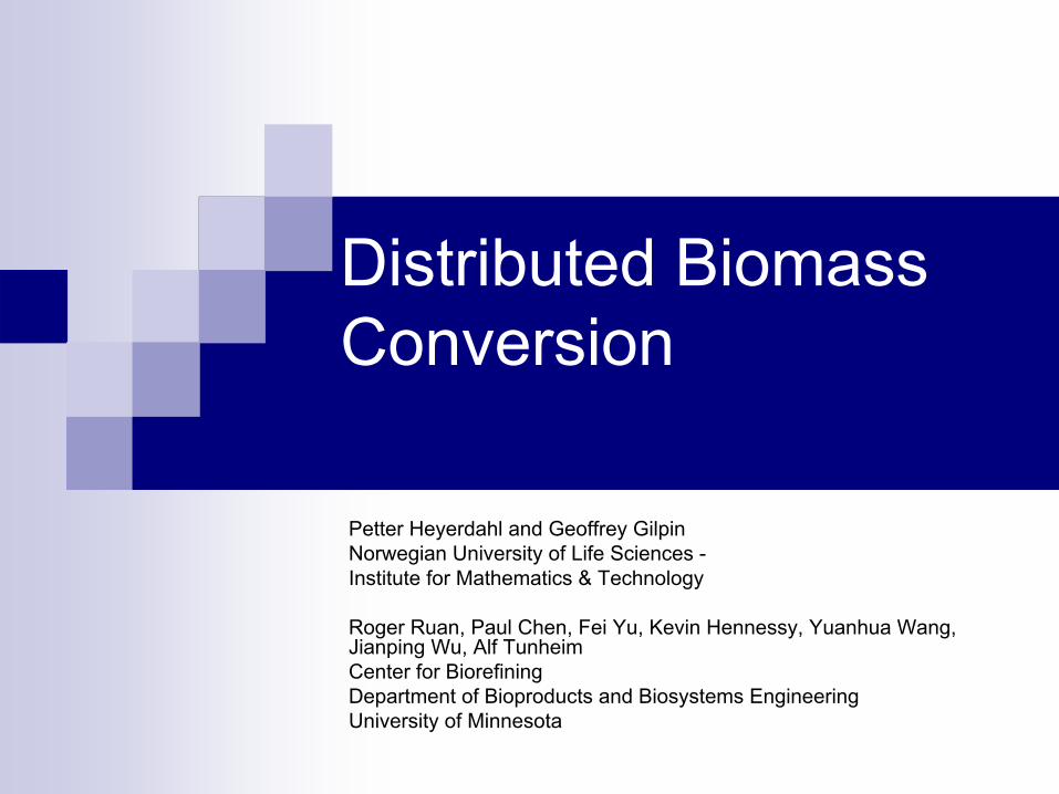
Distributed Biomass Conversion
Petter Heyerdahl and Geoffrey Gilpin Norwegian University of Life Sciences -Institute for Mathematics & Technology
Roger Ruan, Paul Chen, Fei Yu, Kevin Hennessy, Yuanhua Wang, Jianping Wu, Alf TunheimCenter for BiorefiningDepartment of Bioproducts and Biosystems EngineeringUniversity of Minnesota
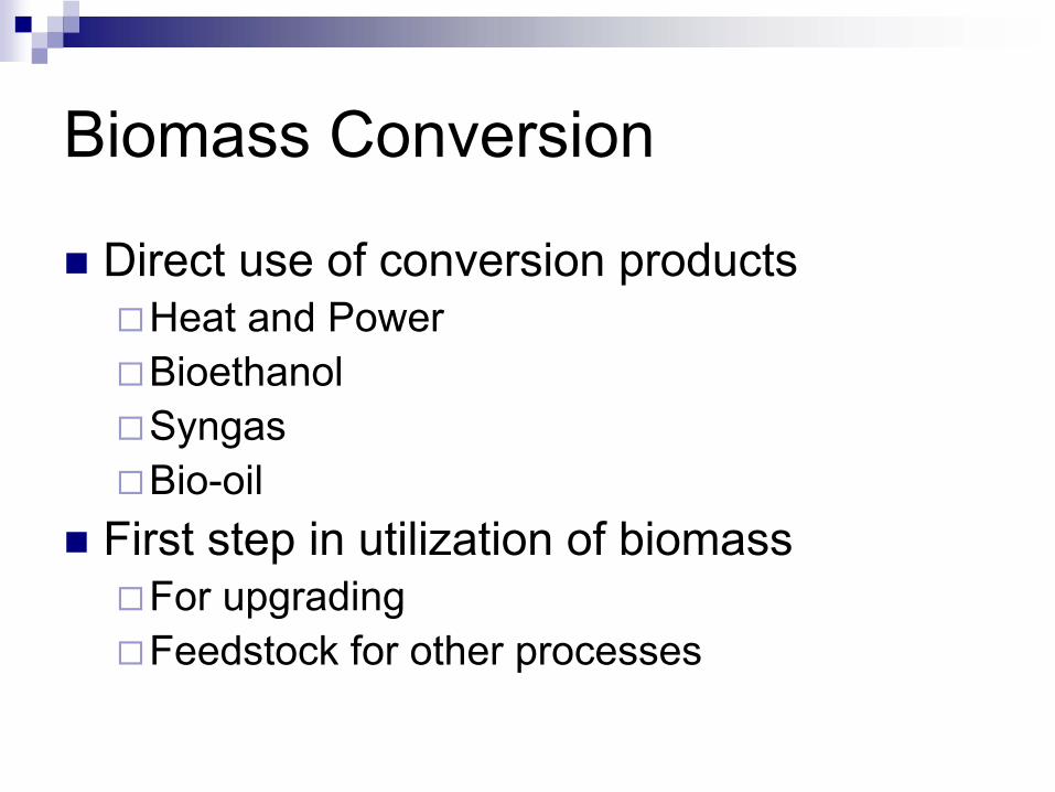
Biomass Conversion
Direct use of conversion productsHeat and PowerBioethanolSyngasBio-oil
First step in utilization of biomassFor upgradingFeedstock for other processes
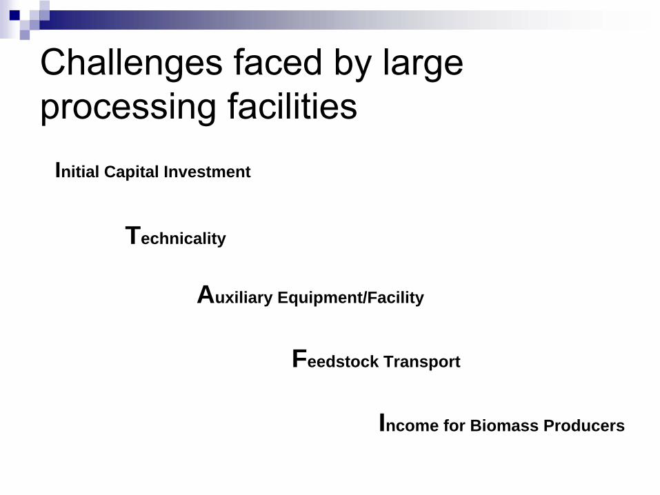
Initial Capital Investment
Technicality
Auxiliary Equipment/Facility
Feedstock Transport
Income for Biomass Producers
Challenges faced by large processing facilities

Distributed Conversion/Refining System
Biomass
Transport Central Processing Facility (CPF)
On-Site or Mobil ProcessingFacility (OSPF) Products
Densified
ChemicalFeedstock (DCF)
Bulk Biomass
Fractionation& Conversion
Refining

Conversion
Bale to Barrel
1,000lb, 100ft3
10lb/ft3
7,500,000BTU75,000BTU/ft3
One round hay balediameter = 5ftlength = 5ft
1.2 barrel500lb, 6.7ft3, 75lb/ft3
3,750,000BTU562,500BTU/ft3
1,500,000BTU
As fertilizer back to field for biomass production
Power for conversion
2,250,000BTU
Gas

Distributed biomass processing scheme

Scalable distributed thermochemical conversion technologies
ProcessesMicrowave assisted pyrolysisHydrothermal pyrolysis Liquefaction
Product possibilitiesBio-oils
Heating oil, transportation fuelsBio-polymersAdhesives
SyngasGas turbine to generate electricityFermentation to produce high value chemicalsReforming to produce fuels

Commercial
Scale
MWP Reactor
UMB-IMT & X-Waste
International
4.5 kW powercomputer centralcontrolled process10 kg/h through-putvarious input materials

Pyrolysis Chamberair tight hopper system w. 1 m3 capacityhorisontal-, cyclindricalreaction chamberw. auger transport systemmicrowave inlets x 3ventilation/under-pressurevapour outletdry fraction outet/collectionw. heatinginert gas linestemperature measurement
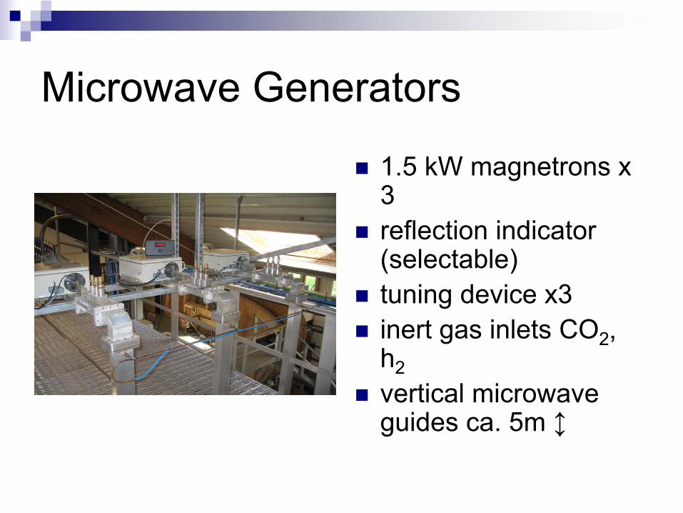
Microwave Generators
1.5 kW magnetrons x 3reflection indicator(selectable)tuning device x3inert gas inlets CO2, h2vertical microwaveguides ca. 5m ↕
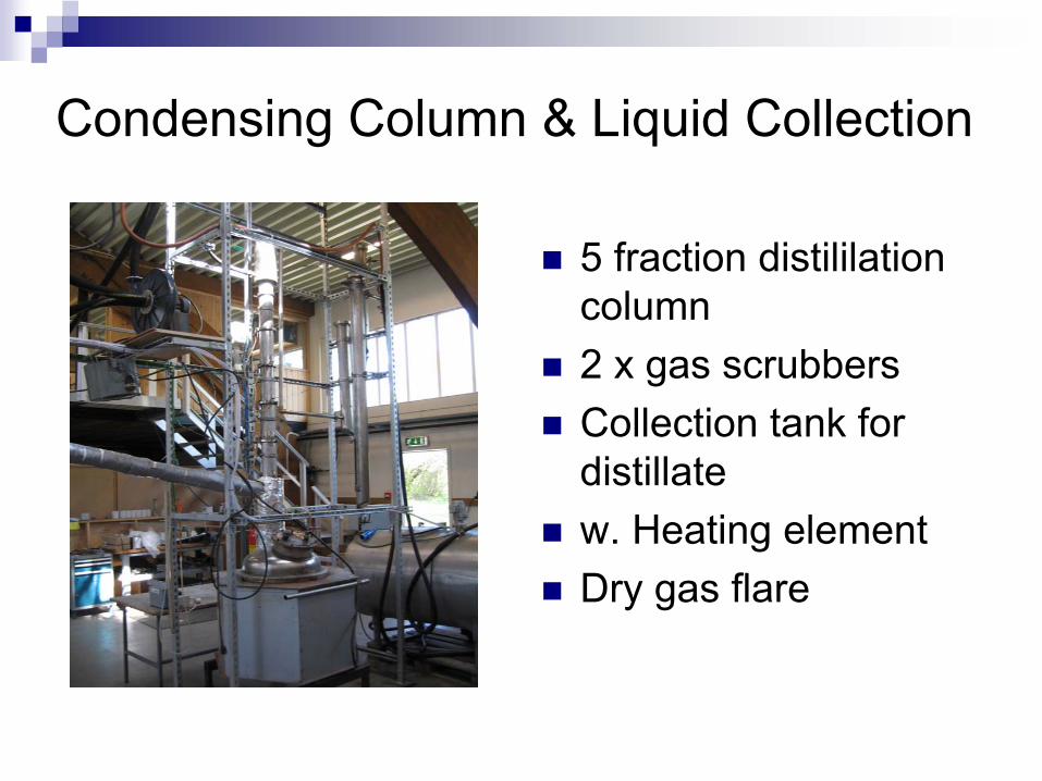
Condensing
Column
& Liquid
Collection
5 fraction distililationcolumn2 x gas scrubbersCollection tank for distillatew. Heating elementDry gas flare
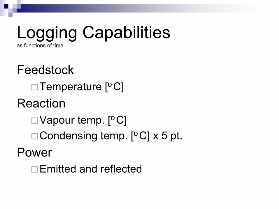
Logging Capabilities as functions
of
time
FeedstockTemperature [ºC]
ReactionVapour temp. [ºC]Condensing temp. [ºC] x 5 pt.
PowerEmitted and reflected

Laboratory MWP ReactorBatch operation1-2 l input material capacitynear limitless input materials capability≤ 1200 ºCin-time gas sampling and analysis (06.07)Insured safe workingenvironment (microwave, gas leakage)

Reaction Chamber CEM -
Max
1.5 kW magnetron≤ 1200 ºCprogrammable (start, running, cool-down)Aluminum oxide furnace chambersilica-carbide archbuilt-in scale (± 0.1 g)thermocouplecomputer terminal connections
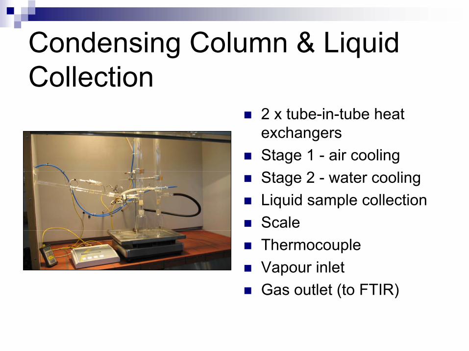
Condensing Column & Liquid Collection2 x tube-in-tube heat exchangersStage 1 - air coolingStage 2 - water coolingLiquid sample collectionScaleThermocoupleVapour inletGas outlet (to FTIR)

Logging Capabilities as functions
of
time
FeedstockWeight loss [g & %] (± 0.1 g) Temperature [ºC]
ReactionVapour temp. [ºC]Condensing temp. [ºC] x 2 pt.
LiquidWeight increase [g] (± 0.1g)
GasPlanned; volume flow [l/s]
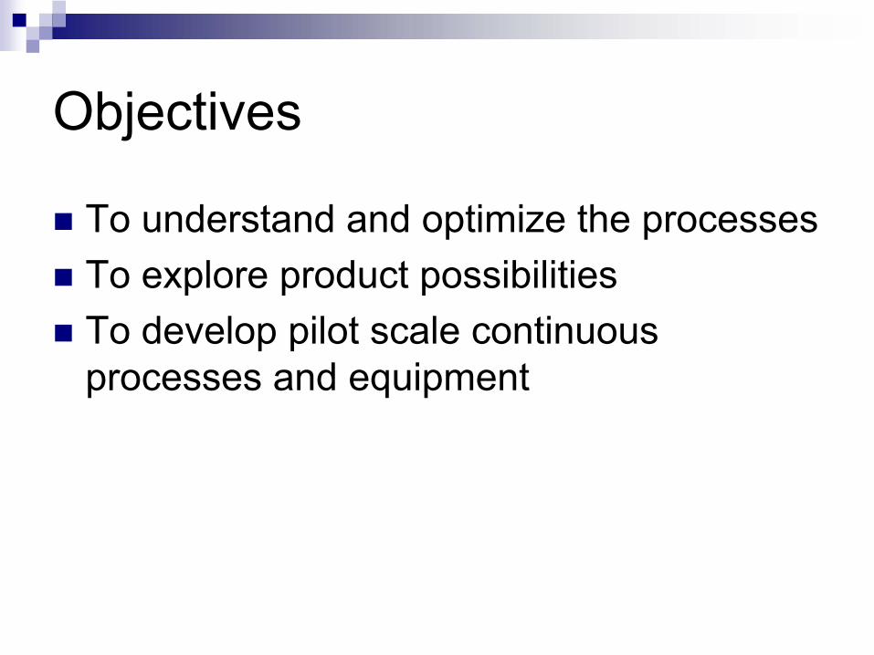
Objectives
To understand and optimize the processesTo explore product possibilitiesTo develop pilot scale continuous processes and equipment
Work accomplished
Experiments to investigate product yields and properties under different conditionsTesting different feedstockBurning and engine testing of bio-oilsDevelopment of bio-polymers from bio-oilsDevelopment of continuous microwave pyrolysis and hydrothermal pyrolysis systems


MicrowaveMicrowave--Assisted Biomass Pyrolysis SystemAssisted Biomass Pyrolysis System(UMN Generation II)(UMN Generation II)
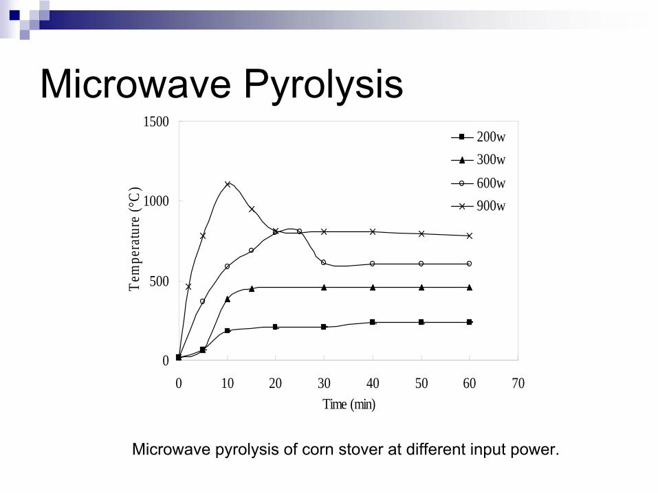
Microwave Pyrolysis
Microwave pyrolysis of corn stover at different input power.
0
500
1000
1500
0 10 20 30 40 50 60 70Time (min)
Tem
pera
ture
(°C
)200w300w600w900w
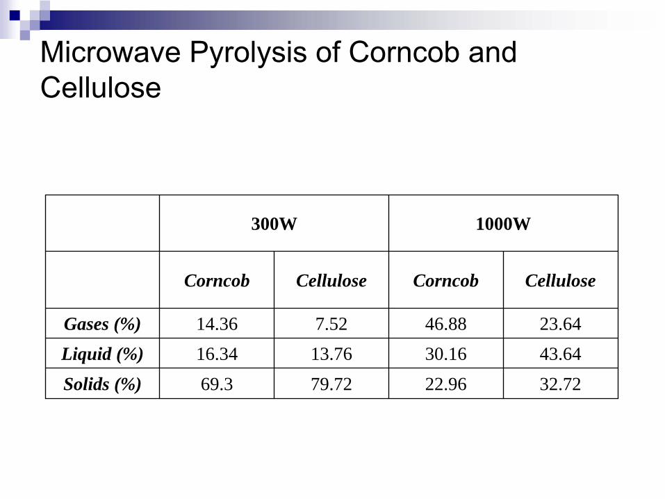
Microwave Pyrolysis of Corncob and Cellulose
300W 1000W
Corncob Cellulose Corncob Cellulose
Gases (%) 14.36 7.52 46.88 23.64Liquid (%) 16.34 13.76 30.16 43.64Solids (%) 69.3 79.72 22.96 32.72
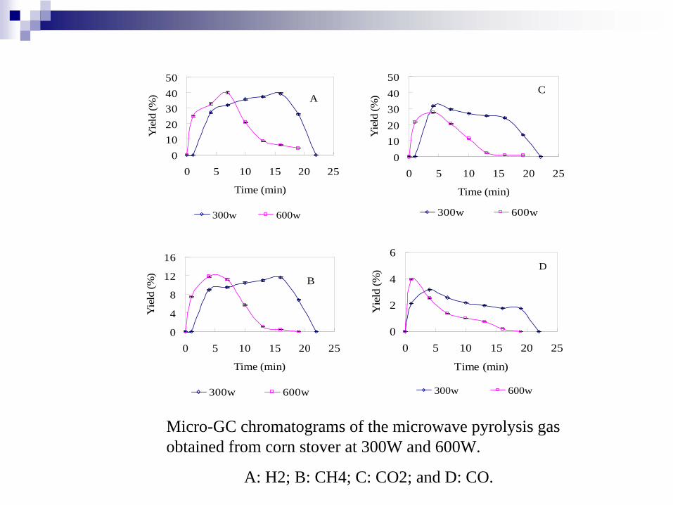
Micro-GC chromatograms of the microwave pyrolysis gas obtained from corn stover at 300W and 600W.
A: H2; B: CH4; C: CO2; and D: CO.
01020304050
0 5 10 15 20 25
Time (min)
Yie
ld (%
)
300w 600w
A
01020304050
0 5 10 15 20 25
Time (min)
Yie
ld (%
)
300w 600w
C
0
4
8
12
16
0 5 10 15 20 25
Time (min)
Yie
ld (%
)
300w 600w
B
0
2
4
6
0 5 10 15 20 25
Time (min)Y
ield
(%)
300w 600w
D
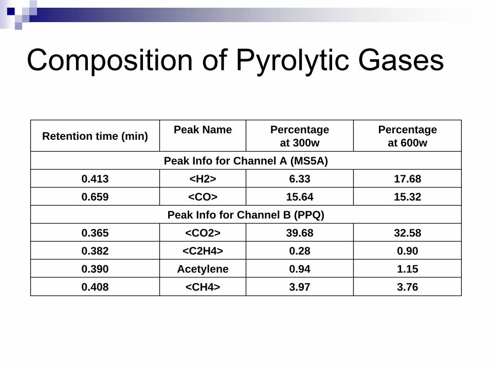
Composition of Pyrolytic Gases
Retention time (min) Peak Name Percentage at 300w
Percentage at 600w
Peak Info for Channel A (MS5A)0.413 <H2> 6.33 17.680.659 <CO> 15.64 15.32
Peak Info for Channel B (PPQ)0.365 <CO2> 39.68 32.580.382 <C2H4> 0.28 0.900.390 Acetylene 0.94 1.150.408 <CH4> 3.97 3.76
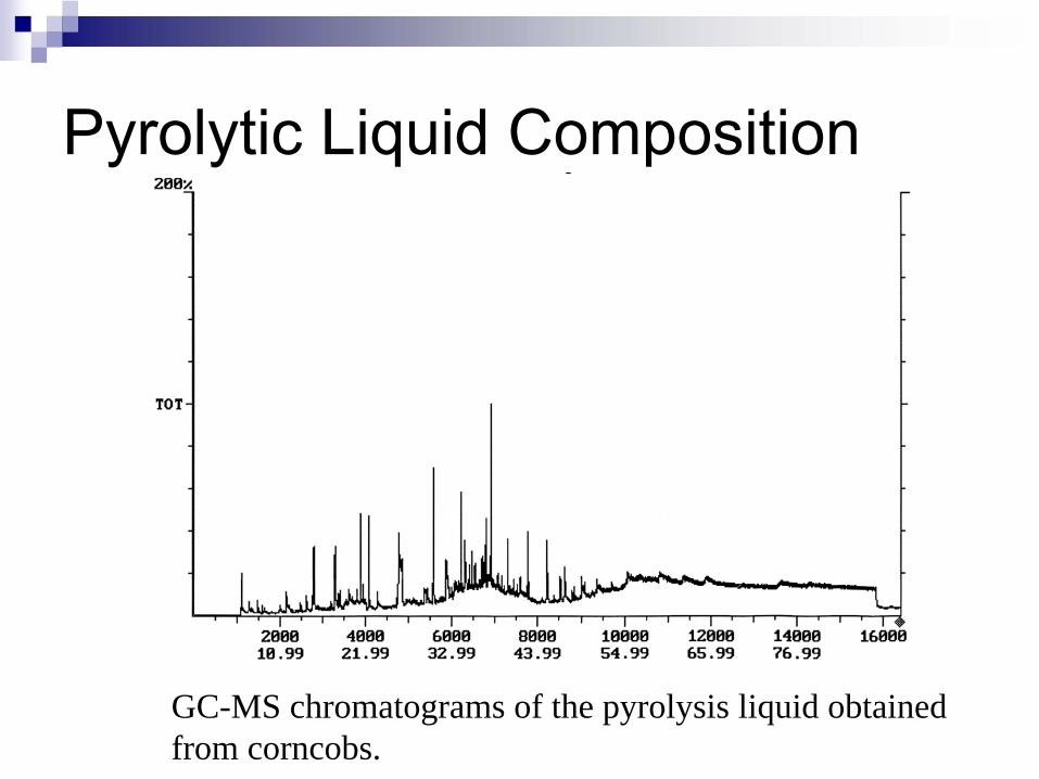
Pyrolytic Liquid Composition
GC-MS chromatograms of the pyrolysis liquid obtained from corncobs.
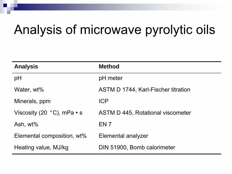
Analysis of microwave pyrolytic
oils
Analysis Method
pH pH meter
Water, wt% ASTM D 1744, Karl-Fischer titration
Minerals, ppm ICP
Viscosity (20 ° C), mPa
∙
s ASTM D 445, Rotational viscometer
Ash, wt% EN 7
Elemental composition, wt% Elemental analyzer
Heating value, MJ/kg DIN 51900, Bomb calorimeter

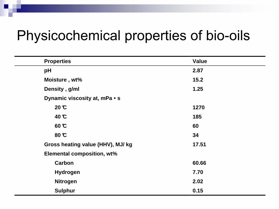
Physicochemical properties of bio-oils Properties ValuepH 2.87Moisture , wt% 15.2Density , g/ml 1.25Dynamic viscosity at, mPa ∙
s 20°C 1270 40°C 18560°C 6080°C 34
Gross heating value (HHV), MJ/ kg 17.51Elemental composition, wt%
Carbon 60.66 Hydrogen 7.70 Nitrogen 2.02Sulphur 0.15

Minerals of Bio-oils by Inductive Coupled Plasma (ICP) Analysis
Mineral Al B Ca Cd Cr Cu Fe K
Content (ppm) 4.922 2.848 6.833 0.059 0.307 0.397 7.589 3.127
Mineral Mg Mn Na Ni P Pb Zn
Content (ppm) 1.858 0.034 1.816 0.953 1.518 0.822 0.792

High heating value of bio-oils and bio-oils with solvent addition
Samples High heating value (MJ/kg)
Bio-oils 17.51
Aqueous phase 1.2
Bio-oils with 10 wt% methanol 16.21
Bio-oils with 20 wt% methanol 15.96
Bio-oils with 30 wt% methanol 13.47
Bio-oils with 10 wt% ethanol 14.51
Bio-oils with 20 wt% ethanol 12.07
Bio-oils with 30 wt% ethanol 11.98
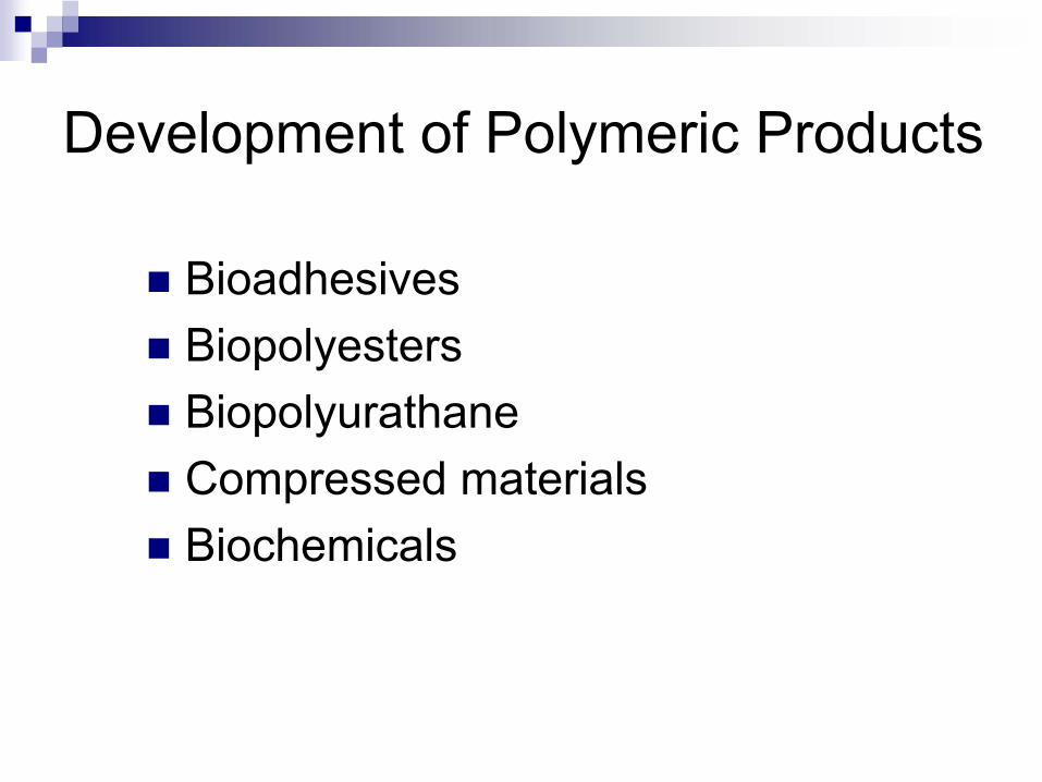
Development of Polymeric Products
BioadhesivesBiopolyestersBiopolyurathaneCompressed materialsBiochemicals

Polyester + DGGComposite Polyester + fibers
CompositePolyester film
Wood Adhesive
Sample Bioproducts
Produced from Biooils
Polyurethane foam
Bio-oils
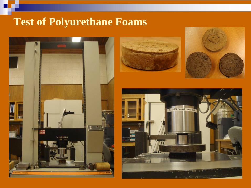
Test of Polyurethane Foams

Generation II Continuous Equipment Development
Continuous processLarger capacityClosed-system: gas turbine for electricity generationTwo-state processes: pyrolysis and gasificationCompletion: estimated in July or August
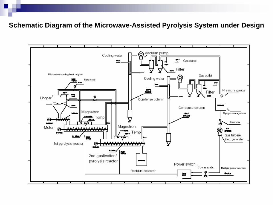
Schematic Diagram of the Microwave-Assisted Pyrolysis System under Design
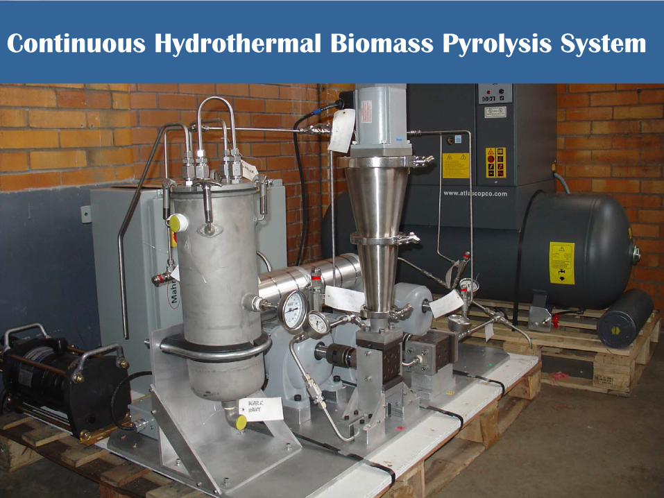
Continuous Hydrothermal Biomass Pyrolysis System
Related Documents


![Microwave Pyrolysis of Plastic - Longdom...however, there have been few studies of plastic wastes pyrolysis [17-19]. The benefits of the pyrolysis are recycling some of the stored](https://static.cupdf.com/doc/110x72/5edc1041ad6a402d66669242/microwave-pyrolysis-of-plastic-longdom-however-there-have-been-few-studies.jpg)