Microwave Optics Adam Parry Mark Curtis Sam Meek Santosh Shah Acknowledgements: Fred, Geoff, Lise and Phil Junior Lab 2002

Welcome message from author
This document is posted to help you gain knowledge. Please leave a comment to let me know what you think about it! Share it to your friends and learn new things together.
Transcript
Microwave OpticsAdam Parry
Mark Curtis
Sam Meek
Santosh Shah
Acknowledgements:
Fred, Geoff, Lise and Phil Junior Lab 2002
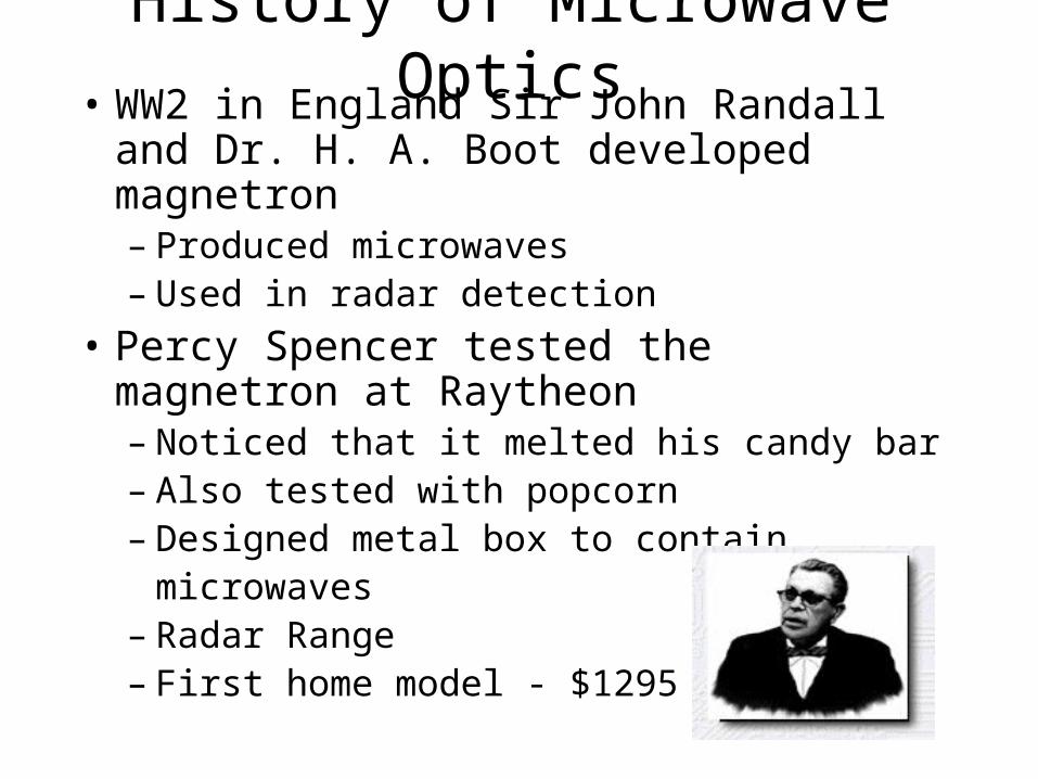
History of Microwave Optics• WW2 in England Sir John Randall and Dr.
H. A. Boot developed magnetron – Produced microwaves– Used in radar detection
• Percy Spencer tested the magnetron at Raytheon– Noticed that it melted his candy bar– Also tested with popcorn– Designed metal box to contain
microwaves– Radar Range– First home model - $1295
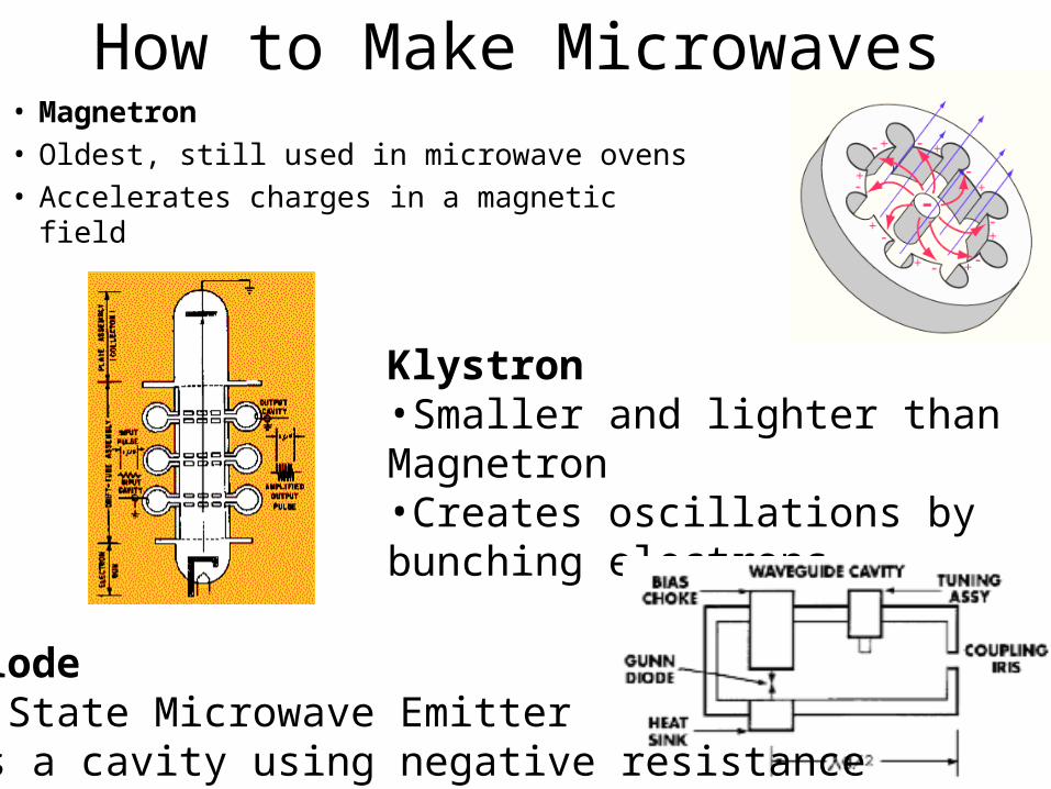
• Magnetron• Oldest, still used in microwave ovens• Accelerates charges in a magnetic field
Klystron•Smaller and lighter than Magnetron•Creates oscillations by bunching electrons
How to Make Microwaves
Gunn Diode•Solid State Microwave Emitter•Drives a cavity using negative resistance

Equipment Used
transmitter
receiver
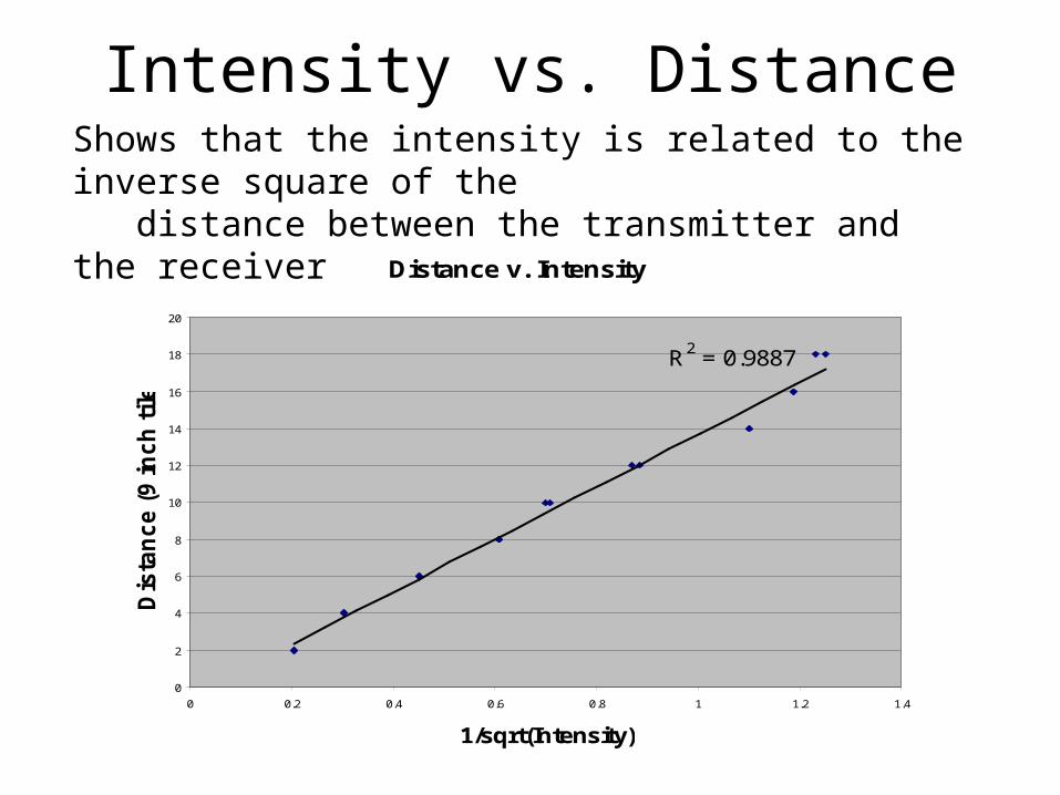
Intensity vs. DistanceShows that the intensity is related to the inverse square of the distance between the transmitter and the receiver
Distance v. Intensity
R2 = 0.9887
0
2
4
6
8
10
12
14
16
18
20
0 0.2 0.4 0.6 0.8 1 1.2 1.4
1/sqrt(Intensity)
Dis
tan
ce (
9 in
ch
tiles)
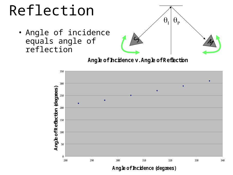
Reflection
• Angle of incidence equals angle of reflection
MS
Angle of Incidence v. Angle of Reflection
0
50
100
150
200
250
300
350
280 290 300 310 320 330 340
Angle of Incidence (degrees)
Ang
le o
f Ref
lect
ion
(deg
rees
)
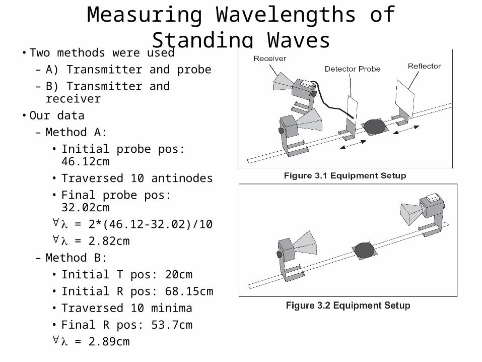
Measuring Wavelengths of Standing Waves• Two methods were used
– A) Transmitter and probe
– B) Transmitter and receiver
• Our data
– Method A:
• Initial probe pos: 46.12cm
• Traversed 10 antinodes
• Final probe pos: 32.02cm = 2*(46.12-32.02)/10 = 2.82cm
– Method B:
• Initial T pos: 20cm
• Initial R pos: 68.15cm
• Traversed 10 minima
• Final R pos: 53.7cm = 2.89cm

Refraction Through a Prism• Used wax lens to collimate beam
• No prism – max = 179o
• Empty prism – max = 177o
• Empty prism absorbs only small amount
• Prism w/ pellets – max = 173o
• Measured angles of prism w/ protractor 1 = 22 +/- 1o
2 = 28 +/- 2o
– Used these to determine n for pellets
• n = 1.25 +/- 0.1
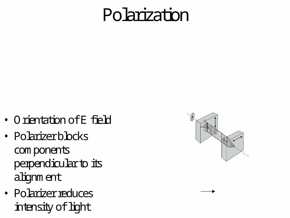
Polarization
• Orientation of E field
• Polarizer blocks components perpendicular to its alignment
• Polarizer reduces intensity of light

PolarizationPolarization
-0.1
0
0.1
0.2
0.3
0.4
0.5
0 100 200 300 400
Angle of receiver (deg.)
Inte
nsit
y (
mA
) at
30x
Series1
• Microwaves used are vertically polarized• Intensity depends on angle of receiver• Vertical and horizontal slats block parallel
components of electric field

Single Slit InterferenceUsed 7 cm and 13 cm slit widths
This equation assumes that we are near the Fraunhofer (far-field) limit
nd sin
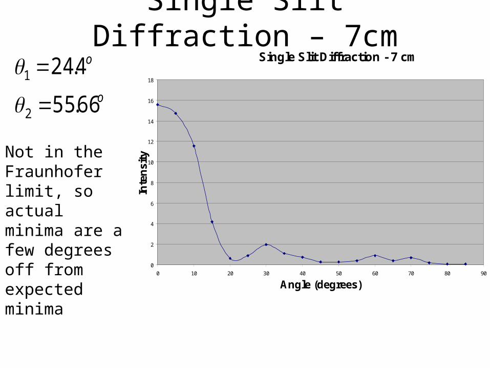
Single Slit Diffraction – 7cmSingle Slit Diffraction - 7 cm
0
2
4
6
8
10
12
14
16
18
0 10 20 30 40 50 60 70 80 90
Angle (degrees)
Inte
nsi
ty
o
o
66.55
4.24
2
1
Not in the Fraunhofer limit, so actual minima are a few degrees off from expected minima

Single Slit Diffraction – 13cm
o
o
4.26
8.12
2
1
Single Slit Diffraction - 13 cm
0
1
2
3
4
5
6
0 10 20 30 40 50 60 70 80 90
Angle (degrees)
Inte
nsity
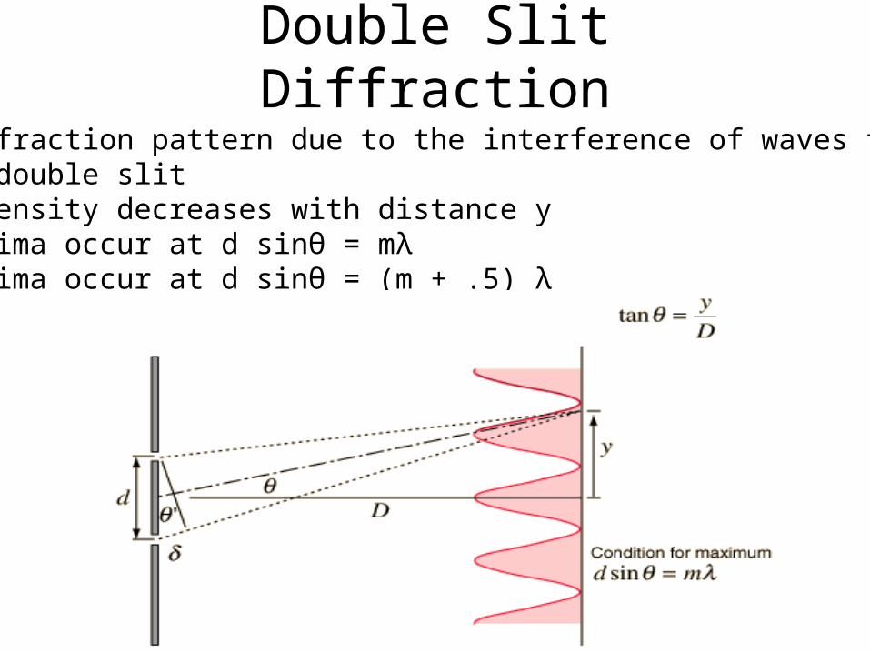
Double Slit Diffraction• Diffraction pattern due to the interference of waves from a double slit• Intensity decreases with distance y• Minima occur at d sinθ = mλ• Maxima occur at d sinθ = (m + .5) λ
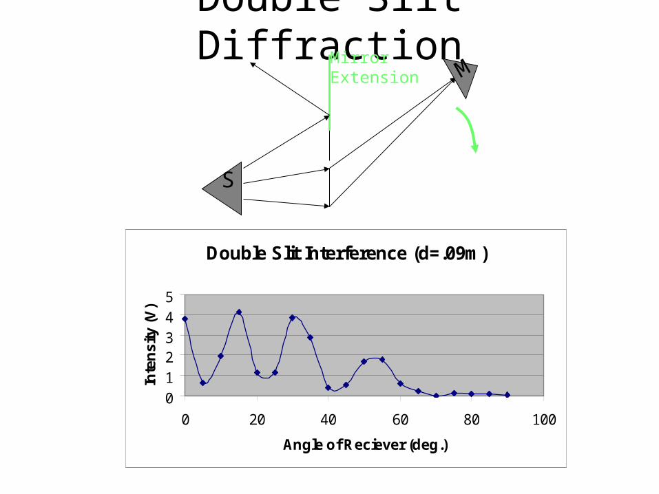
Double Slit Diffraction
Double Slit Interference (d=.09m)
012345
0 20 40 60 80 100
Angle of Reciever (deg.)
Inte
nsi
ty (V
)
MirrorExtension
S
M
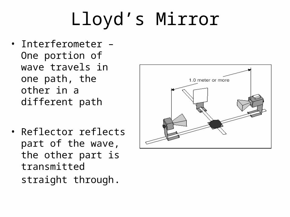
• Interferometer – One portion of wave travels in one path, the other in a different path
• Reflector reflects part of the wave, the other part is transmitted straight through.
Lloyd’s Mirror
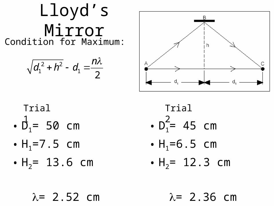
Lloyd’s Mirror
• D1= 50 cm
• H1=7.5 cm
• H2= 13.6 cm
= 2.52 cm
2 21 1 2
nd h d
Condition for Maximum:
• D1= 45 cm
• H1=6.5 cm
• H2= 12.3 cm
= 2.36 cm
Trial 1 Trial 2
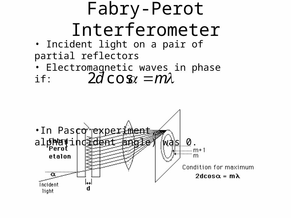
Fabry-Perot Interferometer• Incident light on a pair of partial reflectors• Electromagnetic waves in phase if:
•In Pasco experiment, alpha(incident angle) was 0.
md cos2
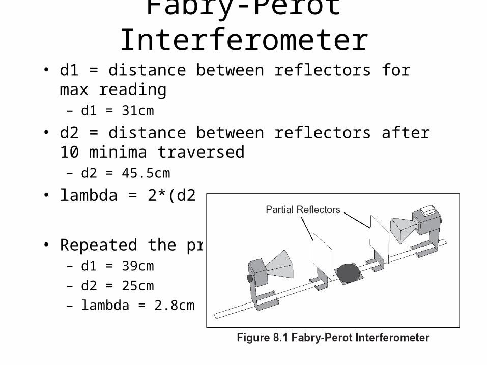
Fabry-Perot Interferometer
• d1 = distance between reflectors for max reading – d1 = 31cm
• d2 = distance between reflectors after 10 minima traversed– d2 = 45.5cm
• lambda = 2*(d2 – d1)/10 = 2.9cm
• Repeated the process– d1 = 39cm
– d2 = 25cm
– lambda = 2.8cm

• Studies interference between two split beams that are brought back together.
Michelson Interferometer

Michelson Interferometer
Constructive Interference occurs when:
nLL fm 2
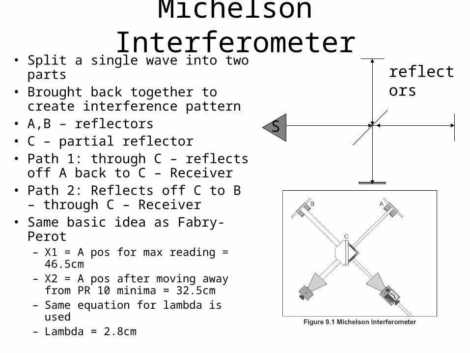
Michelson Interferometer• Split a single wave into two parts• Brought back together to create
interference pattern• A,B – reflectors• C – partial reflector• Path 1: through C – reflects off A
back to C – Receiver• Path 2: Reflects off C to B –
through C – Receiver• Same basic idea as Fabry-Perot
– X1 = A pos for max reading = 46.5cm– X2 = A pos after moving away from
PR 10 minima = 32.5cm– Same equation for lambda is used– Lambda = 2.8cm
S
M
reflectors
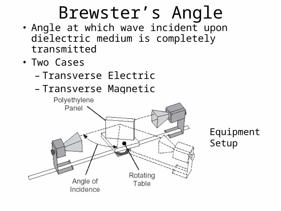
Brewster’s Angle• Angle at which wave incident upon dielectric
medium is completely transmitted• Two Cases
– Transverse Electric– Transverse Magnetic
Equipment Setup

TE Case
• Electric Field transverse to boundary
• Using Maxwell’s Equations (1 = 2 =1)
Transverse Electric Case at oblique incidence
sin( )
sin( )
2sin cos
sin( )
r
i
t
i
E
E
E
E
NO BREWSTER’S ANGLE
S polarization

• Electric Field Parallel to Boundary
• Using Maxwell’s Equations (1 = 2 =1)
Transverse Magnetic Case at oblique incidence
P polarization
tan( )
tan( )
2sin cos
sin( )cos( )
r
t
t
t
E
E
E
E
TM Case

• Plotting reflection and transmission(for reasonable n1 and n2)
Brewster’s Angle

Brewster’s Angle (our results)
Brewster's Angle
0
1
2
3
4
5
6
0 10 20 30 40 50 60 70 80
Angle (degrees)
Inte
nsi
ty
Horizontal
Vertical
Setting the T and R for vertical polarization, we found the maximum reflection for several angles of incident.We then did the same for the horizontal polarization and plotted I vs. thetaWe were unable to detect Brewster’s Angle in our experiment.

Bragg Diffraction
• Study of Interference patterns of microwave transmissions in a crystal
• Two Experiments– Pasco ( d = 0.4 cm, λ = 2.85 cm)
– Unilab (d = 4 cm, λ = 2.85 cm).
nd sin2
Condition for constructive interference

Bragg Diffraction (Pasco)
Bragg Diffraction [100] Symmetry
0
0.5
1
1.5
2
2.5
3
3.5
0 10 20 30 40
Grazing Angle (deg.)
Inte
ns
ity
(V
)
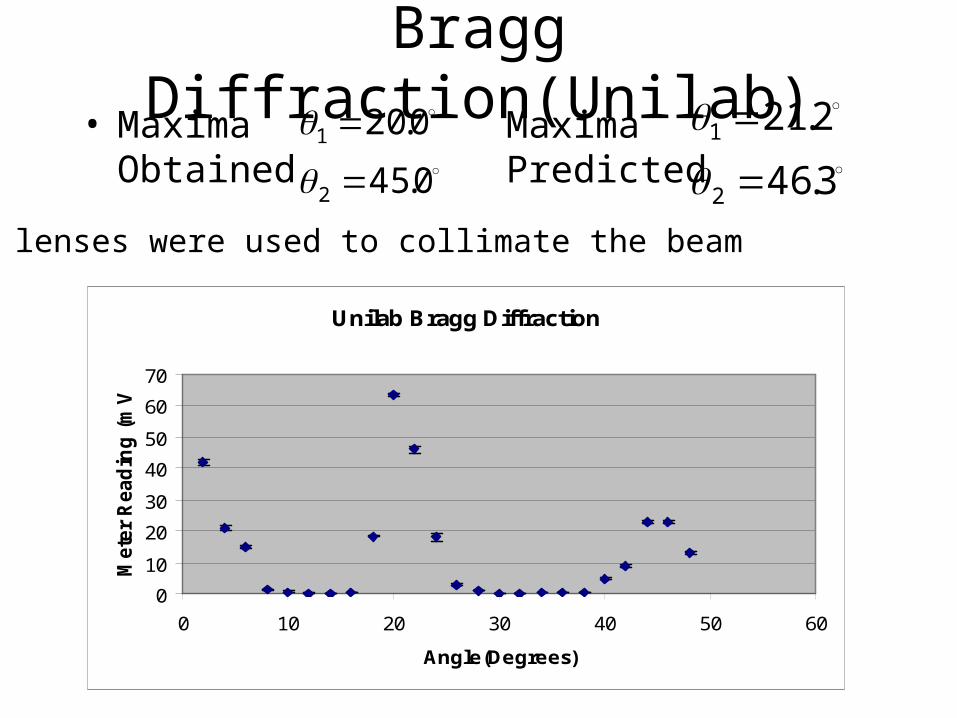
Bragg Diffraction(Unilab)• Maxima
Obtained
Unilab Bragg Diffraction
0
10
20
30
40
50
60
70
0 10 20 30 40 50 60
Angle(Degrees)
Mete
r R
ead
ing
(m
V)
0.45
0.20
2
1
3.46
2.21
2
1
Maxima Predicted
Wax lenses were used to collimate the beam

Frustrated Total Internal Reflection
• Two prisms filled with oil
• Air in between
• Study of transmittance with prism separation
• Presence of second prism “disturbs” total internal reflection.
Transmitter
Detector
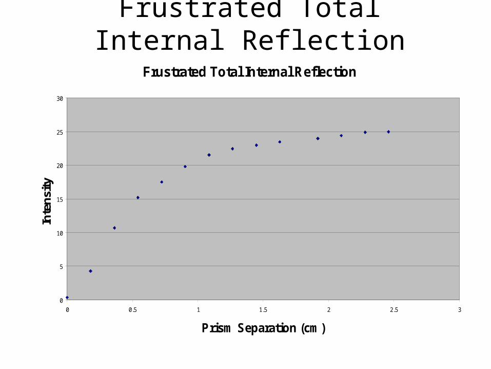
Frustrated Total Internal Reflection
Frustrated Total Internal Reflection
0
5
10
15
20
25
30
0 0.5 1 1.5 2 2.5 3
Prism Separation (cm)
Inte
nsi
ty

Optical Activity Analogue • E-field induces current in
springs
• Current is rotated by the curve of the springs
• E-field reemitted at a different polarization
• Red block (right-handed springs) rotates polarization –25o
• Black block (left-handed springs) rotates polarization 25o

References
• www.joecartoon.com
• www.mathworld.wolfram.com
• www.hyperphysics.phy-astr.gsu.edu/hbase
• www.pha.jhu.edu/~broholm/I30/node5.html
Related Documents