© 2010 M ETS MALA Basic Microwave Engineering AJAL.A.J - Dept of ECE

Microwave engineering basics
Jul 16, 2015
Welcome message from author
This document is posted to help you gain knowledge. Please leave a comment to let me know what you think about it! Share it to your friends and learn new things together.
Transcript

© 2010 M ETS MALA
Basic Microwave Engineering
AJAL.A.J - Dept of ECE
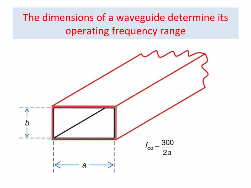
The dimensions of a waveguide determine its operating frequency range

Electric (E ) and magnetic (H) fields in a rectangular waveguide.


Coaxial to waveguide transition
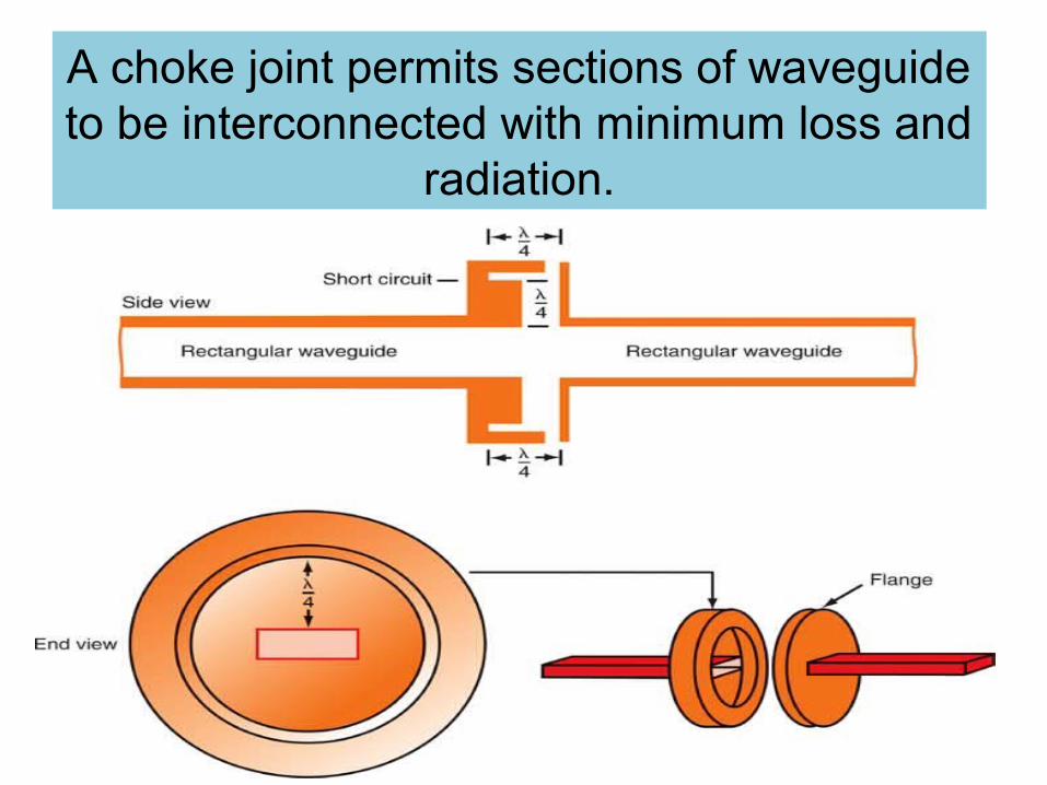
A choke joint permits sections of waveguide to be interconnected with minimum loss and
radiation.
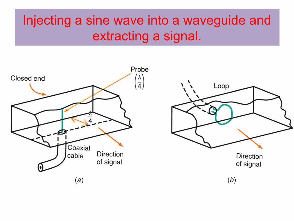
Injecting a sine wave into a waveguide and extracting a signal.

Coupling Loops
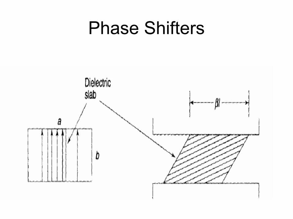
Phase Shifters

Microwave Junction


MAGIC -T
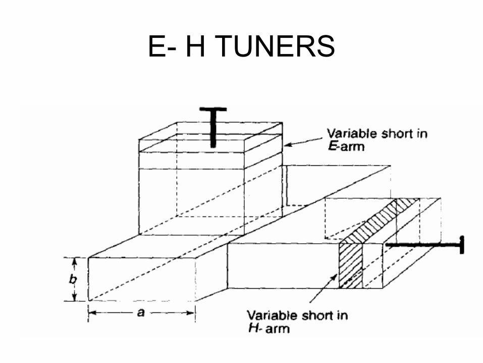
E- H TUNERS

Microwave Mixer

Isolators
• An isolator is a two-port non-reciprocal device which produces a minimum attenuation to wave propagation in one direction and very high attenuation in the opposite direction.
Working
• Thus when inserted between a signal source and load almost all the signal power can be transmitted to the load and any reflected power from the load is not fed back to the generator output port.

Advantages
• This eliminates variations of source power output and frequency pulling due to changing loads.

Isolator - construction

Faraday rotation isolator

Circulators
– A circulator is a three-port microwave device used for coupling energy in only one direction around a closed loop.
– Microwave energy is applied to one port and passed to another with minor attenuation, however the signal will be greatly attenuated on its way to a third port.
– The primary application of a circulator is a diplexer, which allows a single antenna to be shared by a transmitter and receiver.
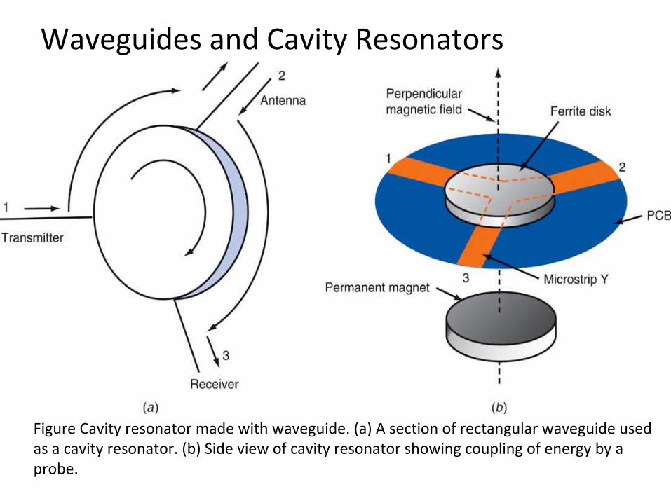
Waveguides and Cavity Resonators
Figure Cavity resonator made with waveguide. (a) A section of rectangular waveguide used as a cavity resonator. (b) Side view of cavity resonator showing coupling of energy by a probe.

Circulators
• A circulator is a multi port junction in which the wave can travel from one port to next immediate port in one direction only.
• Commonly used circulators are three-port or four-port devices although more number of ports is possible.
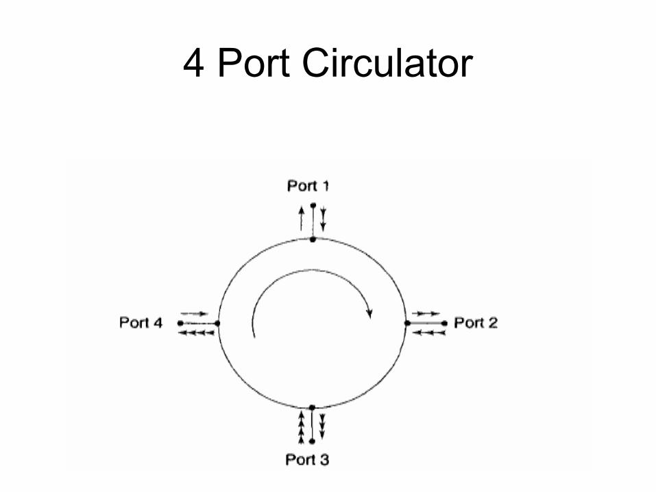
4 Port Circulator

4 Port Circulator
3 Port Circulator
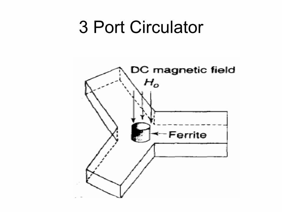
3 Port Circulator
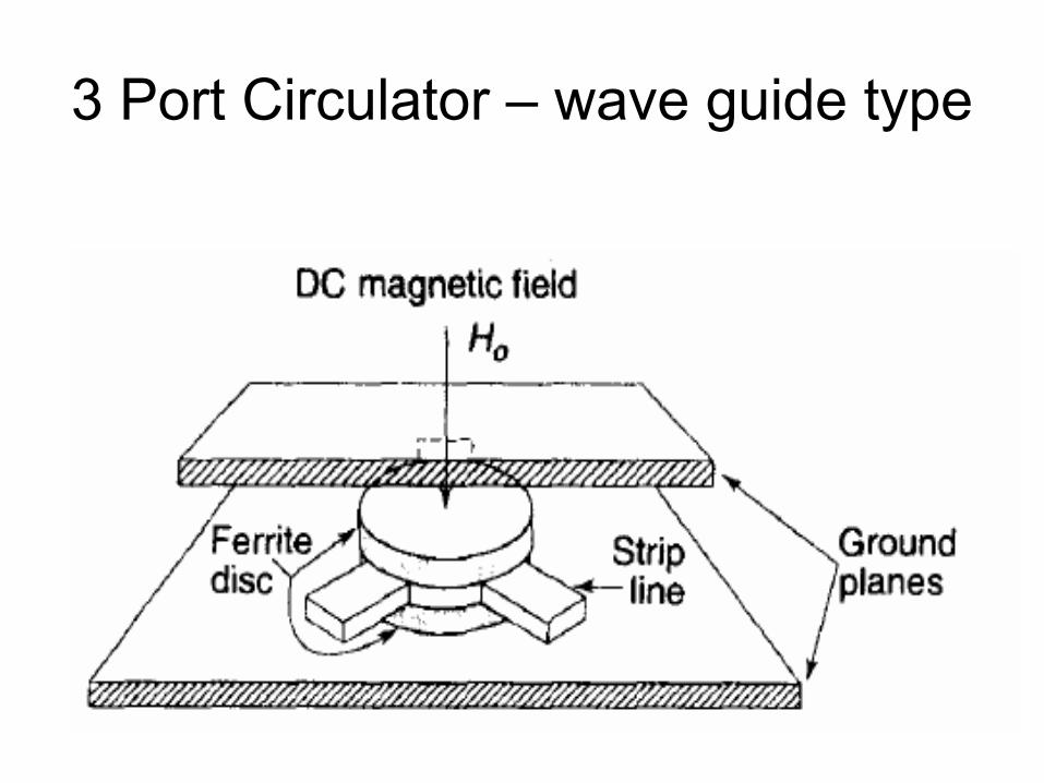
3 Port Circulator – wave guide type

Directional Coupler
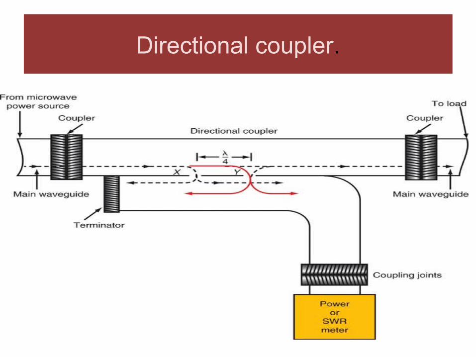
Directional coupler.

Directional Coupler - DEFINITION
• A directional coupler is a four-port passive device commonly used for coupling a known fraction of the microwave power to a port (coupled port) in the auxiliary line while flowing from input port to output port in the main line.
The remaining port is ideally isolated port and matched terminated.

There are three basic types of directional couplers.
• One is a multiple aperture waveguide type,
• second one is a coupled coaxial, or strip or micro strip line,
and the
• third one is branch line couplers

Directional Coupler

Directional Coupler
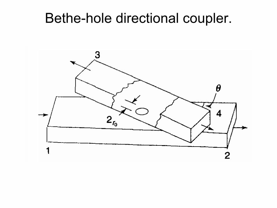
Bethe-hole directional coupler.
• The theory of the waveguide coupler was first established by ‘ Bethe’ , using a single hole in the common broad wall of two rectangular waveguides.
• Commonly known as Bethe-hole directional coupler.
Bethe-hole directional coupler.
Practical SCENARIO
• Practical waveguide directional couplers are multi hole couplers in which the desired coupling response vs frequency can be achieved by proper selection of the number of holes and size of the holes.
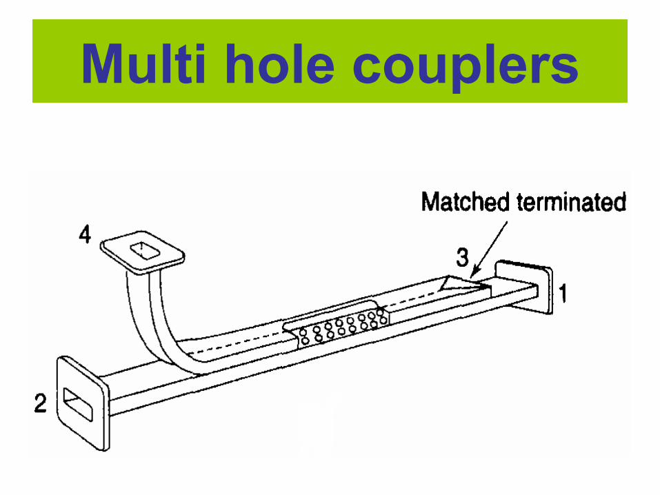
Multi hole couplers
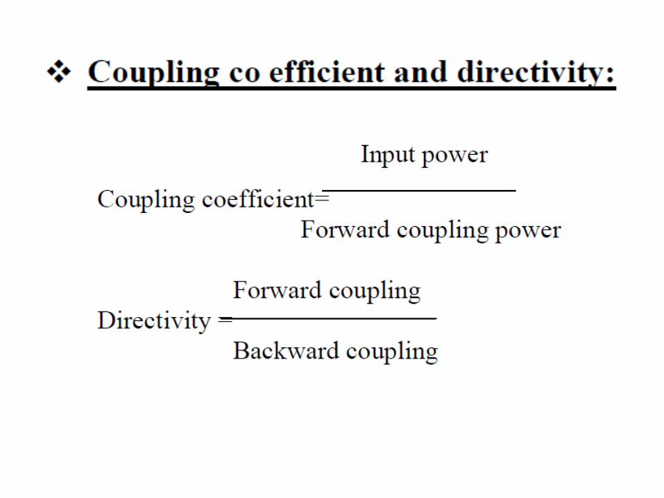
The performance of a directional coupler is measured in terms of
four basic parameters, i.e.,
1. coupling (C)
2. transmission loss
3. directivity (D)
and the
4. re turn loss (R)
when all the ports are matched.

THANK YOU
Related Documents