1 | Page Introduction to Microwave Microwave communication is the transmission of signals by means of series of microwave towers. It is also known as “line of sight” propagation which means nothing should obstruct the data being transmitted or received. Microwave refers to electromagnetic energy having a frequency higher than 1GHz corresponding to wavelength shorter than 30cm. This part of the radio spectrum ranges from 1GHz up to 30GHz. A studio-transmitter link (or STL) sends a radio station or television station's audio and video from the broadcast studio to a transmitter in another location. The best locations to place antennas are the mountainous areas, in which needed towers are shorter but putting up a studio is impractical. In flat regions, it is not advisable to place the center of the station near the community, for the people might frown the antenna, thus the antennas should be placed several miles or kilometers away. Depending on the locations that must be connected, a station may choose either a point to point (PTP) link on another special radio frequency, or a newer all-digital wired link via a dedicated T1 or E1 (or larger-capacity) line. Radio links can also be digital, or the older analog type, or a hybrid of the two. Even on older all-analog systems, multiple audio and data channels can be sent using subcarriers. Stations that employ an STL usually also have a transmitter-studio link (TSL) to return telemetry information. Both the STL and TSL are considered broadcast auxiliary services (BAS).

Welcome message from author
This document is posted to help you gain knowledge. Please leave a comment to let me know what you think about it! Share it to your friends and learn new things together.
Transcript

7/23/2019 Microwave Design PDF
http://slidepdf.com/reader/full/microwave-design-pdf 1/48
1 | P a g e
Introduction to Microwave
Microwave communication is the transmission of signals by means of series of microwave
towers. It is also known as “line of sight” propagation which means nothing should obstruct
the data being transmitted or received.
Microwave refers to electromagnetic energy having a frequency higher than 1GHz
corresponding to wavelength shorter than 30cm. This part of the radio spectrum ranges from
1GHz up to 30GHz.
A studio-transmitter link (or STL) sends a radio station or television station's audio and
video from the broadcast studio to a transmitter in another location.
The best locations to place antennas are the mountainous areas, in which needed towers are
shorter but putting up a studio is impractical. In flat regions, it is not advisable to place the
center of the station near the community, for the people might frown the antenna, thus the
antennas should be placed several miles or kilometers away.
Depending on the locations that must be connected, a station may choose either a point to
point (PTP) link on another special radio frequency, or a newer all-digital wired link via a
dedicated T1 or E1 (or larger-capacity) line. Radio links can also be digital, or the older analog
type, or a hybrid of the two. Even on older all-analog systems, multiple audio and data channels
can be sent using subcarriers.
Stations that employ an STL usually also have a transmitter-studio link (TSL) to return
telemetry information. Both the STL and TSL are considered broadcast auxiliary services
(BAS).

7/23/2019 Microwave Design PDF
http://slidepdf.com/reader/full/microwave-design-pdf 2/48
2 | P a g e
Site Demographic Profile
Site A: Moncada, Tarlac
Moncada is a populated place in the region of Tarlac, the country of The Philippines with an
average elevation of 19 meter above sea level. According to the 2010 census, it has a population
of 54,547 people in 10,144 households. The area is mildly densely populated with 444 people per
km2
Geographical Coordinates:
15° 44' 12" North, 120° 34' 28" East
Access Roads:
Exit SCTex La Paz Toll Gate then take Tarlac City junction to Gerona Bypass Road reaching
Paniqui junction to Moncada proper.

7/23/2019 Microwave Design PDF
http://slidepdf.com/reader/full/microwave-design-pdf 3/48
3 | P a g e
Site Demographic Profile
Weather Conditions:
Moncada has a humid climate. The land area is totally cultivated, not much natural vegetation is
left. The landscape is mostly covered with rainfed croplands. The climate is classified as a tropical
monsoon (short dry season, monsoon rains other months), with a tropical wet forest biozone . The
soil in the area is high in nitosols, andosols (nt), soil with deep, clay-enriched lower horizon with
shiny ped surfaces.
April is warmest with an average temperature of 34.3 °C at noon. January is coldest with an
average temperature of 20.5 °C at night. Moncada has no distinct temperature seasons, the
temperature is relatively constant during the year. The temperatures at night are cooler than during
daytime. April is on average the month with most sunshine. The wet season has a rainfall peak
around July, the dry season is around the month of December.
Physical Characteristics:
Terrain Type: relatively flat with cultivated lands around
Power, Communications and other Industries:
Telephone, Internet and Cable TV Providers: PLDT Tarlac, Sun Cellular, SMART
Communications, Globe Telecom, HI-TECH CABLE TV, INC.
Power lines: Tarlac Power Corporation, Tarlac Electric, Inc.

7/23/2019 Microwave Design PDF
http://slidepdf.com/reader/full/microwave-design-pdf 4/48
4 | P a g e
Site Demographic Profile
Site R (Repeater): Tarlac City, Tarlac
The city is situated at the center of the province. To its north is Gerona and Santa Ignacia, west
is San Jose, south is Capas and Concepcion and eastern boundaries are Victoria and La Paz. This
is also the location of Tarlac River.
Tarlac City is approximately 24 metres (79 ft) above sea level on some parts but reaching even 50
metres (160 ft) on large western portions. Tarlac City was historically a part of what is now Porac,
Pampanga. Parts of Tarlac city are claimed to be among the few portions of land in the province
which was not created by ancient eruptions from Mount Pinatubo.
Geographical Coordinates:
15°28′N 120°35′E
Access Roads:
From McArthur Highway, take right to Luisita Road.
Alternate Route: NLEX, take SCTEX after Dau Pampanga then take left to Luisita Road.

7/23/2019 Microwave Design PDF
http://slidepdf.com/reader/full/microwave-design-pdf 5/48
5 | P a g e
Site Demographic Profile
Weather Conditions:
Tarlac City has a humid climate. The land area is totally cultivated, not much natural vegetation is
left. The landscape is mostly covered with rain-fed croplands. The climate is classified as a tropical
monsoon (short dry season, monsoon rains other months), with a subtropical wet forest biozone .
The soil in the area is high in nitosols, andosols (nt), soil with deep, clay-enriched lower horizon
with shiny pad surfaces.
April is warmest with an average temperature of 34.2 °C at noon. February is coldest with an
average temperature of 20.6 °C at night. San Miguel has no distinct temperature seasons; the
temperature is relatively constant during the year. The temperatures at night are cooler than during
daytime. April is on average the month with most sunshine. The wet season has a rainfall peak
around October; the dry season is around the month of March.
Physical Characteristics:
Terrain Type: relatively flat with swamps and massive cultivated land.
Power, Communications and other Industries:
Telephone, Internet and Cable TV Providers: PLDT Tarlac, Sun Cellular, SMART
Communications, Globe Telecom, HI-TECH CABLE TV, INC.
Power lines: Tarlac Power Corporation, Tarlac Electric, Inc.

7/23/2019 Microwave Design PDF
http://slidepdf.com/reader/full/microwave-design-pdf 6/48
6 | P a g e
Site Demographic Profile
Site B: Mabalacat, Pampanga
Mabalacat, officially Mabalacat, is a component city in the northern part of
the province of Pampanga, Philippines. The former municipality was officially converted into a
city following a referendum on July 21, 2012, and became the third in Pampanga after Angeles
City and City of San Fernando. According to the 2010 census, it has a population of 215,610
people. The city's name is derived from the ancient "balacat " trees which were found abundantly
in the area.
Mabalacat has a land area of 83.18 square kilometres (32.12 sq mi). Roughly 60% of the Clark
Freeport Zone is located in Mabalacat, the rest in nearby Angeles City, where the Clark main gate
is located and which is served by the Clark International Airport with its numerous hotels, casinos,
golf courses, and resorts.
Geographical Coordinates:
15°13′N 120°35′E
Access Roads:
Through Mc Arthur Highway and through NLEX.

7/23/2019 Microwave Design PDF
http://slidepdf.com/reader/full/microwave-design-pdf 7/48
7 | P a g e
Weather Conditions:
Mabalacat has a humid climate. The land area is totally cultivated, not much natural vegetation is
left. The landscape is mostly covered with rain-fed croplands. The climate is classified as a tropical
monsoon (short dry season, monsoon rains other months), with a subtropical wet forest biozone .The soil in the area is high in nitosols, andosols (nt), soil with deep, clay-enriched lower horizon
with shiny pad surfaces.
April is warmest with an average temperature of 34.2 °C at noon. February is coldest with an
average temperature of 20.6 °C at night. Mabalacat has no distinct temperature seasons; the
temperature is relatively constant during the year. The temperatures at night are cooler than during
daytime. April is on average the month with most sunshine. The wet season has a rainfall peak
around October; the dry season is around the month of March.
Physical Characteristics:
The soil is charcoal black and shiny, a sign of fertility, and is suitable for growing rice, sugarcane
and other rootcrops. Like Porac, Santa Rita, Magalang, and Angeles City, this city never gets
inundated by floods from heavy rain because it is situated on an elevated plain known as the "Upper
Pampanga".
Power, Communications and other Industries:
Telephone, Internet and Cable TV Providers: PLDT Pampanga, Sun Cellular, SMART
Communications, Globe Telecom, HI-TECH CABLE TV, INC.
Power Lines: Pampanga Electric Cooperative, Inc
7/23/2019 Microwave Design PDF
http://slidepdf.com/reader/full/microwave-design-pdf 8/48
8 | P a g e
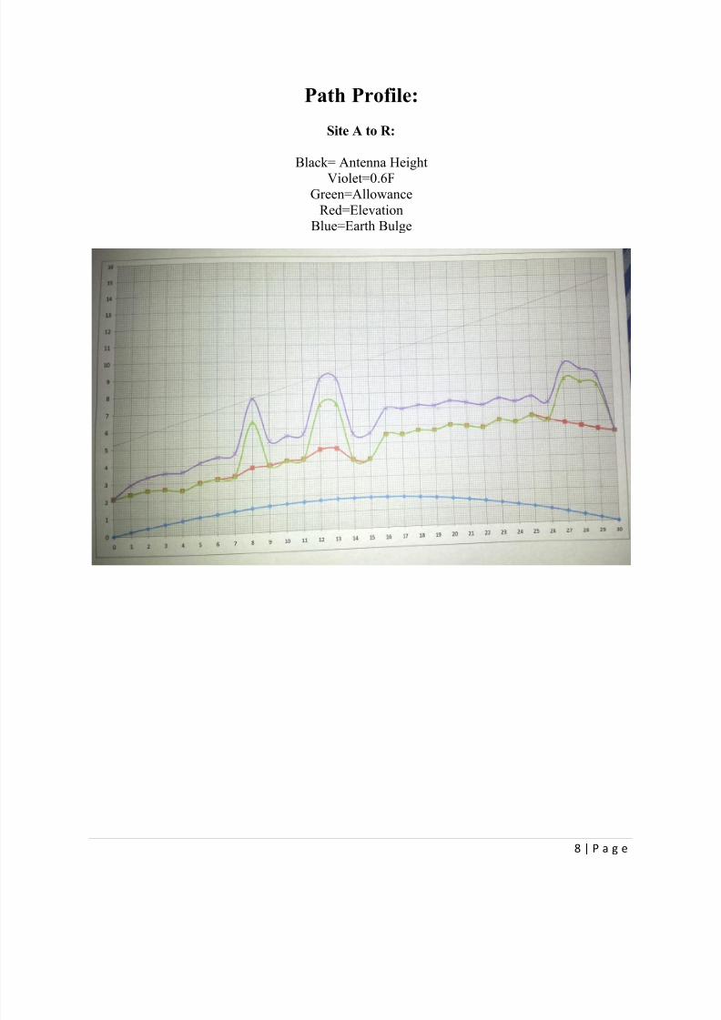
Path Profile:
Site A to R:
Black= Antenna Height
Violet=0.6FGreen=Allowance
Red=ElevationBlue=Earth Bulge

7/23/2019 Microwave Design PDF
http://slidepdf.com/reader/full/microwave-design-pdf 9/48
9 | P a g e
Site R to A:
Black= Antenna HeightViolet=0.6F
Green=Allowance
Red=ElevationBlue=Earth Bulge

7/23/2019 Microwave Design PDF
http://slidepdf.com/reader/full/microwave-design-pdf 10/48
10 | P a g e
Site R to B:
Black= Antenna HeightViolet=0.6F
Green=Allowance
Red=ElevationBlue=Earth Bulge

7/23/2019 Microwave Design PDF
http://slidepdf.com/reader/full/microwave-design-pdf 11/48
11 | P a g e
Site B to R:
Black= Antenna HeightViolet=0.6F
Green=Allowance
Red=ElevationBlue=Earth Bulge

7/23/2019 Microwave Design PDF
http://slidepdf.com/reader/full/microwave-design-pdf 12/48
12 | P a g e
Path Data Sheet
Point A to R F=5.935Ghz
D1 (km) D2 (km) Earth Bulge (m) Elevation (m) Terrain Allowance F1(First Fresnel) 0.6(F1)0 30 0 16.1 Settlement 0 0 0
1 29 1.705882353 16.1 Rice Fields 0 6.981907859 4.189144715
2 28 3.294117647 16.1 Rice Fields 0 9.702175532 5.821305319
3 27 4.764705882 15 Rice Fields 0 11.66856967 7.001141801
4 26 6.117647059 13 Rice Fields 0 13.22183654 7.933101925
5 25 7.352941176 14.8 Rice Fields 0 14.49539721 8.697238326
6 24 8.470588235 15.2 Rice Fields 0 15.55809289 9.334855735
7 23 9.470588235 15.2 Rice Fields 0 16.450839 9.870503402
8 22 10.35294118 17.7 Settlement 20 17.20011886 10.32007131
9 21 11.11764706 17.7 Rice Fields 0 17.82403459 10.6944207510 20 11.76470588 18.8 Rice Fields 0 18.33538831 11.00123299
11 19 12.29411765 18.8 Rice Fields 0 18.74339498 11.24603699
12 18 12.70588235 22.4 Settlement 20 19.05469448 11.43281669
13 17 13 22.4 Settlement 20 19.27397321 11.56438393
14 16 13.17647059 17 Rice Fields 0 19.40435106 11.64261064
15 15 13.23529412 17 Rice Fields 0 19.44761611 11.66856967
16 14 13.17647059 28 Rice Fields 0 19.40435106 11.64261064
17 13 13 28 Rice Fields 0 19.27397321 11.56438393
18 12 12.70588235 30 Rice Fields 0 19.05469448 11.43281669
19 11 12.29411765 30.3 Rice Fields 0 18.74339498 11.24603699
20 10 11.76470588 33 Lahar 0 18.33538831 11.00123299
21 9 11.11764706 33 Lahar 0 17.82403459 10.69442075
22 8 10.35294118 33 Lahar 0 17.20011886 10.32007131
23 7 9.470588235 37.1 Lahar 0 16.450839 9.870503402
24 6 8.470588235 37.1 Lahar 0 15.55809289 9.334855735
25 5 7.352941176 41 Lahar 0 14.49539721 8.697238326
26 4 6.117647059 40.2 Lahar 0 13.22183654 7.933101925
27 3 4.764705882 40 Settlement 20 11.66856967 7.001141801
28 2 3.294117647 40 Settlement 20 9.702175532 5.821305319
29 1 1.705882353 40 Settlement 20 6.981907859 4.189144715
30 0 0 40.5 Settlement 0 0 0

7/23/2019 Microwave Design PDF
http://slidepdf.com/reader/full/microwave-design-pdf 13/48
13 | P a g e
Path Data Sheet
Point R to A F=6.215Ghz
D1 (km) D2 (km) Earth Bulge (m) Elevation (m) Terrain Allowance F1(First Fresnel) 0.6(F1)0 30 0 40.5 Settlement 0 0 0
1 29 1.705882353 40 Settlement 20 6.822819912 4.093691947
2 28 3.294117647 40 Settlement 20 9.481104269 5.688662561
3 27 4.764705882 40 Settlement 20 11.40269266 6.841615594
4 26 6.117647059 40.2 Lahar 0 12.92056719 7.752340316
5 25 7.352941176 41 Lahar 0 14.16510884 8.499065303
6 24 8.470588235 37.1 Lahar 0 15.20359021 9.122154126
7 23 9.470588235 37.1 Lahar 0 16.07599444 9.645596664
8 22 10.35294118 33 Lahar 0 16.8082014 10.08492084
9 21 11.11764706 33 Lahar 0 17.41790074 10.4507404510 20 11.76470588 33 Lahar 0 17.91760289 10.75056174
11 19 12.29411765 30.3 Rice Fields 0 18.31631283 10.9897877
12 18 12.70588235 30 Rice Fields 0 18.62051914 11.17231148
13 17 13 28 Rice Fields 0 18.83480144 11.30088086
14 16 13.17647059 28 Rice Fields 0 18.96220854 11.37732512
15 15 13.23529412 17 Rice Fields 0 19.00448776 11.40269266
16 14 13.17647059 17 Rice Fields 0 18.96220854 11.37732512
17 13 13 22.4 Settlement 20 18.83480144 11.30088086
18 12 12.70588235 22.4 Settlement 20 18.62051914 11.17231148
19 11 12.29411765 18.8 Rice Fields 0 18.31631283 10.9897877
20 10 11.76470588 18.8 Rice Fields 0 17.91760289 10.75056174
21 9 11.11764706 17.7 Rice Fields 0 17.41790074 10.45074045
22 8 10.35294118 17.7 Settlement 20 16.8082014 10.08492084
23 7 9.470588235 15.2 Rice Fields 0 16.07599444 9.645596664
24 6 8.470588235 15.2 Rice Fields 0 15.20359021 9.122154126
25 5 7.352941176 14.8 Rice Fields 0 14.16510884 8.499065303
26 4 6.117647059 13 Rice Fields 0 12.92056719 7.752340316
27 3 4.764705882 15 Rice Fields 0 11.40269266 6.841615594
28 2 3.294117647 16.1 Rice Fields 0 9.481104269 5.688662561
29 1 1.705882353 16.1 Rice Fields 0 6.822819912 4.093691947
30 0 0 16.1 Settlement 0 0 0

7/23/2019 Microwave Design PDF
http://slidepdf.com/reader/full/microwave-design-pdf 14/48
14 | P a g e
Path Data Sheet
Point R to B F=5.975Ghz
D1 (km) D2 (km) Earth Bulge (m)Elevation
(m) Terrain Allowance (m)F1(FirstFresnel) 0.6(F1)
0 27 0 40.5 Settlement 0 0 0
1 26 1.529411765 46.6 Settlement 20 6.945154961 4.167092977
2 25 2.941176471 46.6 Settlement 20 9.63119705 5.77871823
3 24 4.235294118 46.6 Tropical Grass 6.1 11.55743646 6.934461876
4 23 5.411764706 53.2 Rice Fields 0 13.0643913 7.838634783
5 22 6.470588235 53.2 Rice Fields 0 14.2853738 8.571224279
6 21 7.411764706 52.5 Rice Fields 0 15.28905133 9.1734308
7 20 8.235294118 52.5 Rice Fields 0 16.11607516 9.669645095
8 19 8.941176471 59 Rice Fields 0 16.79256586 10.07553951
9 18 9.529411765 53 Rice Fields 0 17.33615469 10.40169281
10 17 10 53 Rice Fields 0 17.75904988 10.65542993
11 16 10.35294118 53 Settlement 20 18.06972737 10.84183642
12 15 10.58823529 48.3 Rice Fields 0 18.27391156 10.96434694
13 14 10.70588235 48.3 Rice Fields 0 18.37515284 11.02509171
14 13 10.70588235 48.3 Settlement 20 18.37515284 11.02509171
15 12 10.58823529 46.2 Rice Fields 0 18.27391156 10.96434694
16 11 10.35294118 46.2 Rice Fields 0 18.06972737 10.84183642
17 10 10 46.2 Settlement 20 17.75904988 10.65542993
18 9 9.529411765 52.3 Rice Fields 0 17.33615469 10.40169281
19 8 8.941176471 52.3 Rice Fields 0 16.79256586 10.07553951
20 7 8.235294118 67.2 Rice Fields 0 16.11607516 9.669645095
21 6 7.411764706 67.2 Rice Fields 0 15.28905133 9.1734308
22 5 6.470588235 67.2 Tropical Grass 6.1 14.2853738 8.571224279
23 4 5.411764706 60 Tropical Grass 6.1 13.0643913 7.838634783
24 3 4.235294118 70 Lahar 0 11.55743646 6.934461876
25 2 2.941176471 80 Settlement 20 9.63119705 5.77871823
26 1 1.529411765 80 Woodland 6.1 6.945154961 4.167092977
27 0 0 80 Settlement 0 0 0

7/23/2019 Microwave Design PDF
http://slidepdf.com/reader/full/microwave-design-pdf 15/48
15 | P a g e
Path Data Sheet
Point B to R F=6.255Ghz
D1 (km) D2 (km)
Earth Bulge
(m)
Elevation
(m) Terrain
Allowance
(m)
F1(First
Fresnel) 0.6(F1)0 27 0 80 Settlement 0 0 0
1 26 1.529411765 80 Woodland 6.1 6.787928171 4.072756903
2 25 2.941176471 80 Settlement 20 9.413162721 5.647897633
3 24 4.235294118 70 Lahar 0 11.29579527 6.777477159
4 23 5.411764706 60 Tropical Grass 6.1 12.76863515 7.661181091
5 22 6.470588235 67.2 Tropical Grass 6.1 13.96197663 8.377185976
6 21 7.411764706 67.2 Rice Fields 0 14.94293257 8.96575954
7 20 8.235294118 67.2 Rice Fields 0 15.75123394 9.450740366
8 19 8.941176471 52.3 Rice Fields 0 16.41241002 9.84744601
9 18 9.529411765 52.3 Rice Fields 0 16.9436929 10.1662157410 17 10 46.2 Settlement 20 17.35701444 10.41420866
11 16 10.35294118 46.2 Rice Fields 0 17.66065871 10.59639523
12 15 10.58823529 46.2 Rice Fields 0 17.86022051 10.71613231
13 14 10.70588235 48.3 Settlement 20 17.95916986 10.77550191
14 13 10.70588235 48.3 Rice Fields 0 17.95916986 10.77550191
15 12 10.58823529 48.3 Rice Fields 0 17.86022051 10.71613231
16 11 10.35294118 53 Settlement 20 17.66065871 10.59639523
17 10 10 53 Rice Fields 0 17.35701444 10.41420866
18 9 9.529411765 53 Rice Fields 0 16.9436929 10.16621574
19 8 8.941176471 59 Rice Fields 0 16.41241002 9.84744601
20 7 8.235294118 52.5 Rice Fields 0 15.75123394 9.450740366
21 6 7.411764706 52.5 Rice Fields 0 14.94293257 8.96575954
22 5 6.470588235 53.2 Rice Fields 0 13.96197663 8.377185976
23 4 5.411764706 53.2 Rice Fields 0 12.76863515 7.661181091
24 3 4.235294118 46.6 Tropical Grass 6.1 11.29579527 6.777477159
25 2 2.941176471 46.6 Settlement 20 9.413162721 5.647897633
26 1 1.529411765 46.6 Settlement 20 6.787928171 4.072756903
27 0 0 40.5 Settlement 0 0 0

7/23/2019 Microwave Design PDF
http://slidepdf.com/reader/full/microwave-design-pdf 16/48
16 | P a g e
Path Data Calculation Sheet
Point A to R
Company: FEU Telecoms Project Name: FEU Microwave Relay Station
Transmitter Site: Moncada, Tarlac 15° 44' 12" North, 120° 34' 28" EastReceiver Site: Tarlac City, Tarlac 15°28′ North 120°35′ East
Operating Frequency: 5.935 Ghz
SITE A SITE R
ANTENNA AZIMUTH ±5 ±5
ANTENNA DIAMETER (ft) 4 4
ANTENNA GAIN (dB) 35.00961429 35.00961429
ANTENNA HEIGHT (m) 22.9 71.25
FSL (dB) 137.4108396
CIRCULATOR LOSS (dB) 0.18 0.18
CONNECTOR LOSS (dB) 0.01 0.01
RADOME LOSS (dB) 0.5 0.5
WAVEGUIDE LOSS (dB) 3.935 dB/100m 3.935 dB/100m
WAVEGUIDE TYPE Elliptical
WAVEGUIDE LENGTH (m) 29 77.35
TOTAL LOSS (dB) 142.9757121
TRANSMITTER POWER (dBm) 33
RSL (dBm) -39.95648352
FADE MARGIN (dB) -45.04351648
RELIABILITY (%) 99.99961806%
7/23/2019 Microwave Design PDF
http://slidepdf.com/reader/full/microwave-design-pdf 17/48
17 | P a g e
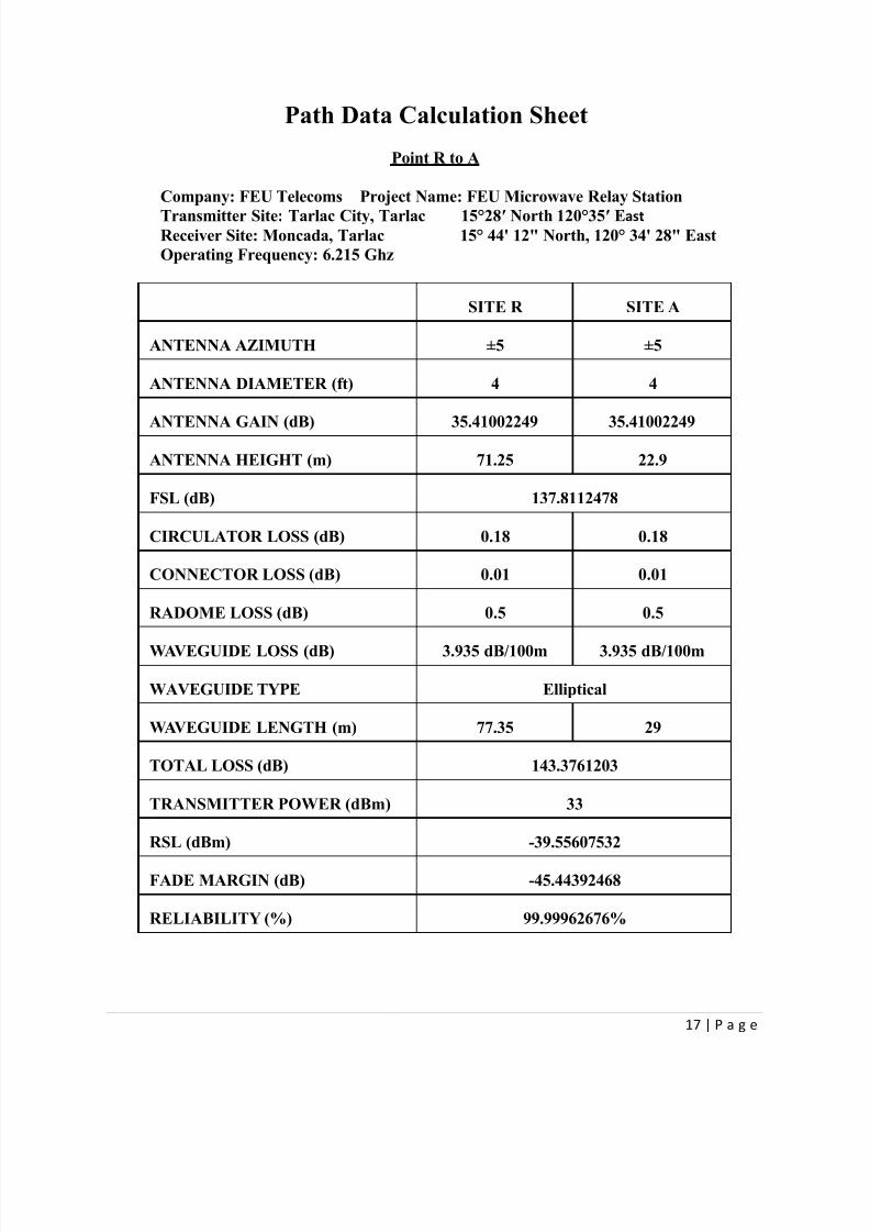
Path Data Calculation Sheet
Point R to A
Company: FEU Telecoms Project Name: FEU Microwave Relay Station
Transmitter Site: Tarlac City, Tarlac 15°28′ North 120°35′ East Receiver Site: Moncada, Tarlac 15° 44' 12" North, 120° 34' 28" East
Operating Frequency: 6.215 Ghz
SITE R SITE A
ANTENNA AZIMUTH ±5 ±5
ANTENNA DIAMETER (ft) 4 4
ANTENNA GAIN (dB) 35.41002249 35.41002249
ANTENNA HEIGHT (m) 71.25 22.9
FSL (dB) 137.8112478
CIRCULATOR LOSS (dB) 0.18 0.18
CONNECTOR LOSS (dB) 0.01 0.01
RADOME LOSS (dB) 0.5 0.5
WAVEGUIDE LOSS (dB) 3.935 dB/100m 3.935 dB/100m
WAVEGUIDE TYPE Elliptical
WAVEGUIDE LENGTH (m) 77.35 29
TOTAL LOSS (dB) 143.3761203
TRANSMITTER POWER (dBm) 33
RSL (dBm) -39.55607532
FADE MARGIN (dB) -45.44392468
RELIABILITY (%) 99.99962676%

7/23/2019 Microwave Design PDF
http://slidepdf.com/reader/full/microwave-design-pdf 18/48
18 | P a g e
Path Data Calculation Sheet
Point R to B
Company: FEU Telecoms Project Name: FEU Microwave Relay Station
Transmitter Site: Tarlac City, Tarlac 15°28′ North 120°35′ East Receiver Site: Mabalacat, Pampanga 15°13′North 120°35′ East
Operating Frequency: 5.975 Ghz
SITE R SITE B
ANTENNA AZIMUTH ±5 ±5
ANTENNA DIAMETER (ft) 4 4
ANTENNA GAIN (dB) 35.06795802 35.06795802
ANTENNA HEIGHT (m) 42 31
FSL (dB) 137.8112478
CIRCULATOR LOSS (dB) 0.18 0.18
CONNECTOR LOSS (dB) 0.01 0.01
RADOME LOSS (dB) 0.5 0.5
WAVEGUIDE LOSS (dB) 3.935 dB/100m 3.935 dB/100m
WAVEGUIDE TYPE Elliptical
WAVEGUIDE LENGTH (m) 48.1 37.1
TOTAL LOSS (dB) 141.2866535
TRANSMITTER POWER (dBm) 33
RSL (dBm) -38.15073746
FADE MARGIN (dB) -46.84926254
RELIABILITY (%) 99.99981442%
7/23/2019 Microwave Design PDF
http://slidepdf.com/reader/full/microwave-design-pdf 19/48
19 | P a g e
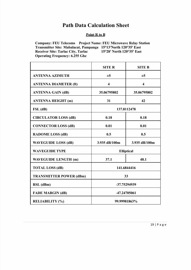
Path Data Calculation Sheet
Point R to B
Company: FEU Telecoms Project Name: FEU Microwave Relay Station
Transmitter Site: Mabalacat, Pampanga 15°13′North 120°35′ EastReceiver Site: Tarlac City, Tarlac 15°28′ North 120°35′ East
Operating Frequency: 6.255 Ghz
SITE R SITE B
ANTENNA AZIMUTH ±5 ±5
ANTENNA DIAMETER (ft) 4 4
ANTENNA GAIN (dB) 35.06795802 35.06795802
ANTENNA HEIGHT (m) 31 42
FSL (dB) 137.8112478
CIRCULATOR LOSS (dB) 0.18 0.18
CONNECTOR LOSS (dB) 0.01 0.01
RADOME LOSS (dB) 0.5 0.5
WAVEGUIDE LOSS (dB) 3.935 dB/100m 3.935 dB/100m
WAVEGUIDE TYPE Elliptical
WAVEGUIDE LENGTH (m) 37.1 48.1
TOTAL LOSS (dB) 141.6844416
TRANSMITTER POWER (dBm) 33
RSL (dBm) -37.75294939
FADE MARGIN (dB) -47.24705061
RELIABILITY (%) 99.99981863%

7/23/2019 Microwave Design PDF
http://slidepdf.com/reader/full/microwave-design-pdf 20/48
20 | P a g e
Transmission Calculation
Earth Bulge(m) Point A to R
( 0 * 30 ) / ( 12.75 * (4/3) )= 0
( 1 * 29 ) / ( 12.75 * (4/3) )= 1.705882353
( 2 * 28 ) / ( 12.75 * (4/3) )= 3.294117647
( 3 * 27 ) / ( 12.75 * (4/3) )= 4.764705882
( 4 * 26 ) / ( 12.75 * (4/3) )= 6.117647059
( 5 * 25 ) / ( 12.75 * (4/3) )= 7.352941176
( 6 * 24 ) / ( 12.75 * (4/3) )= 8.470588235
( 7 * 23 ) / ( 12.75 * (4/3) )= 9.470588235
( 8 * 22 ) / ( 12.75 * (4/3) )= 10.35294118
( 9 * 21 ) / ( 12.75 * (4/3) )= 11.11764706
( 10 * 20 ) / ( 12.75 * (4/3) )= 11.76470588
( 11 * 19 ) / ( 12.75 * (4/3) )= 12.29411765( 12 * 18 ) / ( 12.75 * (4/3) )= 12.70588235
( 13 * 17 ) / ( 12.75 * (4/3) )= 13
( 14 * 16 ) / ( 12.75 * (4/3) )= 13.17647059
( 15 * 15 ) / ( 12.75 * (4/3) )= 13.23529412
( 16 * 14 ) / ( 12.75 * (4/3) )= 13.17647059
( 17 * 13 ) / ( 12.75 * (4/3) )= 13
( 18 * 12 ) / ( 12.75 * (4/3) )= 12.70588235
( 19 * 11 ) / ( 12.75 * (4/3) )= 12.29411765
( 20 * 10 ) / ( 12.75 * (4/3) )= 11.76470588
( 21 * 9 ) / ( 12.75 * (4/3) )= 11.11764706( 22 * 8 ) / ( 12.75 * (4/3) )= 10.35294118
( 23 * 7 ) / ( 12.75 * (4/3) )= 9.470588235
( 24 * 6 ) / ( 12.75 * (4/3) )= 8.470588235
( 25 * 5 ) / ( 12.75 * (4/3) )= 7.352941176
( 26 * 4 ) / ( 12.75 * (4/3) )= 6.117647059
( 27 * 3 ) / ( 12.75 * (4/3) )= 4.764705882
( 28 * 2 ) / ( 12.75 * (4/3) )= 3.294117647
( 29 * 1 ) / ( 12.75 * (4/3) )= 1.705882353
( 30 * 0 ) / ( 12.75 * (4/3) )= 0

7/23/2019 Microwave Design PDF
http://slidepdf.com/reader/full/microwave-design-pdf 21/48
21 | P a g e
Transmission Calculation
Earth Bulge(m) Point R to A
( 0 * 30 ) / ( 12.75 * (4/3) )= 0
( 1 * 29 ) / ( 12.75 * (4/3) )= 1.705882353
( 2 * 28 ) / ( 12.75 * (4/3) )= 3.294117647
( 3 * 27 ) / ( 12.75 * (4/3) )= 4.764705882
( 4 * 26 ) / ( 12.75 * (4/3) )= 6.117647059
( 5 * 25 ) / ( 12.75 * (4/3) )= 7.352941176
( 6 * 24 ) / ( 12.75 * (4/3) )= 8.470588235
( 7 * 23 ) / ( 12.75 * (4/3) )= 9.470588235
( 8 * 22 ) / ( 12.75 * (4/3) )= 10.35294118
( 9 * 21 ) / ( 12.75 * (4/3) )= 11.11764706
( 10 * 20 ) / ( 12.75 * (4/3) )= 11.76470588
( 11 * 19 ) / ( 12.75 * (4/3) )= 12.29411765( 12 * 18 ) / ( 12.75 * (4/3) )= 12.70588235
( 13 * 17 ) / ( 12.75 * (4/3) )= 13
( 14 * 16 ) / ( 12.75 * (4/3) )= 13.17647059
( 15 * 15 ) / ( 12.75 * (4/3) )= 13.23529412
( 16 * 14 ) / ( 12.75 * (4/3) )= 13.17647059
( 17 * 13 ) / ( 12.75 * (4/3) )= 13
( 18 * 12 ) / ( 12.75 * (4/3) )= 12.70588235
( 19 * 11 ) / ( 12.75 * (4/3) )= 12.29411765
( 20 * 10 ) / ( 12.75 * (4/3) )= 11.76470588
( 21 * 9 ) / ( 12.75 * (4/3) )= 11.11764706( 22 * 8 ) / ( 12.75 * (4/3) )= 10.35294118
( 23 * 7 ) / ( 12.75 * (4/3) )= 9.470588235
( 24 * 6 ) / ( 12.75 * (4/3) )= 8.470588235
( 25 * 5 ) / ( 12.75 * (4/3) )= 7.352941176
( 26 * 4 ) / ( 12.75 * (4/3) )= 6.117647059
( 27 * 3 ) / ( 12.75 * (4/3) )= 4.764705882
( 28 * 2 ) / ( 12.75 * (4/3) )= 3.294117647
( 29 * 1 ) / ( 12.75 * (4/3) )= 1.705882353
( 30 * 0 ) / ( 12.75 * (4/3) )= 0

7/23/2019 Microwave Design PDF
http://slidepdf.com/reader/full/microwave-design-pdf 22/48
22 | P a g e
Transmission Calculation
Earth Bulge(m) Point R to B
( 0 * 27 ) / ( 12.75 * (4/3) )= 0
( 1 * 26 ) / ( 12.75 * (4/3) )= 1.529411765
( 2 * 25 ) / ( 12.75 * (4/3) )= 2.941176471
( 3 * 24 ) / ( 12.75 * (4/3) )= 4.235294118
( 4 * 23 ) / ( 12.75 * (4/3) )= 5.411764706
( 5 * 22 ) / ( 12.75 * (4/3) )= 6.470588235
( 6 * 21 ) / ( 12.75 * (4/3) )= 7.411764706
( 7 * 20 ) / ( 12.75 * (4/3) )= 8.235294118
( 8 * 19 ) / ( 12.75 * (4/3) )= 8.941176471
( 9 * 18 ) / ( 12.75 * (4/3) )= 9.529411765
( 10 * 17 ) / ( 12.75 * (4/3) )= 10( 11 * 16 ) / ( 12.75 * (4/3) )= 10.35294118
( 12 * 15 ) / ( 12.75 * (4/3) )= 10.58823529
( 13 * 14 ) / ( 12.75 * (4/3) )= 10.70588235
( 14 * 13 ) / ( 12.75 * (4/3) )= 10.70588235
( 15 * 12 ) / ( 12.75 * (4/3) )= 10.58823529
( 16 * 11 ) / ( 12.75 * (4/3) )= 10.35294118
( 17 * 10 ) / ( 12.75 * (4/3) )= 10
( 18 * 9 ) / ( 12.75 * (4/3) )= 9.529411765
( 19 * 8 ) / ( 12.75 * (4/3) )= 8.941176471
( 20 * 7 ) / ( 12.75 * (4/3) )= 8.235294118( 21 * 6 ) / ( 12.75 * (4/3) )= 7.411764706
( 22 * 5 ) / ( 12.75 * (4/3) )= 6.470588235
( 23 * 4 ) / ( 12.75 * (4/3) )= 5.411764706
( 24 * 3 ) / ( 12.75 * (4/3) )= 4.235294118
( 25 * 2 ) / ( 12.75 * (4/3) )= 2.941176471
( 26 * 1 ) / ( 12.75 * (4/3) )= 1.529411765
( 27 * 0 ) / ( 12.75 * (4/3) )= 0

7/23/2019 Microwave Design PDF
http://slidepdf.com/reader/full/microwave-design-pdf 23/48
23 | P a g e
Transmission Calculation
Earth Bulge(m) Point B to R
( 0 * 27 ) / ( 12.75 * (4/3) )= 0
( 1 * 26 ) / ( 12.75 * (4/3) )= 1.529411765
( 2 * 25 ) / ( 12.75 * (4/3) )= 2.941176471
( 3 * 24 ) / ( 12.75 * (4/3) )= 4.235294118
( 4 * 23 ) / ( 12.75 * (4/3) )= 5.411764706
( 5 * 22 ) / ( 12.75 * (4/3) )= 6.470588235
( 6 * 21 ) / ( 12.75 * (4/3) )= 7.411764706
( 7 * 20 ) / ( 12.75 * (4/3) )= 8.235294118
( 8 * 19 ) / ( 12.75 * (4/3) )= 8.941176471
( 9 * 18 ) / ( 12.75 * (4/3) )= 9.529411765
( 10 * 17 ) / ( 12.75 * (4/3) )= 10
( 11 * 16 ) / ( 12.75 * (4/3) )= 10.35294118( 12 * 15 ) / ( 12.75 * (4/3) )= 10.58823529
( 13 * 14 ) / ( 12.75 * (4/3) )= 10.70588235
( 14 * 13 ) / ( 12.75 * (4/3) )= 10.70588235
( 15 * 12 ) / ( 12.75 * (4/3) )= 10.58823529
( 16 * 11 ) / ( 12.75 * (4/3) )= 10.35294118
( 17 * 10 ) / ( 12.75 * (4/3) )= 10
( 18 * 9 ) / ( 12.75 * (4/3) )= 9.529411765
( 19 * 8 ) / ( 12.75 * (4/3) )= 8.941176471
( 20 * 7 ) / ( 12.75 * (4/3) )= 8.235294118
( 21 * 6 ) / ( 12.75 * (4/3) )= 7.411764706( 22 * 5 ) / ( 12.75 * (4/3) )= 6.470588235
( 23 * 4 ) / ( 12.75 * (4/3) )= 5.411764706
( 24 * 3 ) / ( 12.75 * (4/3) )= 4.235294118
( 25 * 2 ) / ( 12.75 * (4/3) )= 2.941176471
( 26 * 1 ) / ( 12.75 * (4/3) )= 1.529411765
( 27 * 0 ) / ( 12.75 * (4/3) )= 0

7/23/2019 Microwave Design PDF
http://slidepdf.com/reader/full/microwave-design-pdf 24/48
24 | P a g e
Transmission Calculation
F1 Point A to R F=5.935Ghz
17.3 *√ (( 0 * 30 )/( 5.935 * ( 0 + 30 )))= 0
17.3 *√ (( 1 * 29 )/( 5.935 * ( 1 + 29 )))= 6.981907859
17.3 *√ (( 2 * 28 )/( 5.935 * ( 2 + 28 )))= 9.702175532
17.3 *√ (( 3 * 27 )/( 5.935 * ( 3 + 27 )))= 11.66856967
17.3 *√ (( 4 * 26 )/( 5.935 * ( 4 + 26 )))= 13.22183654
17.3 *√ (( 5 * 25 )/( 5.935 * ( 5 + 25 )))= 14.49539721
17.3 *√ (( 6 * 24 )/( 5.935 * ( 6 + 24 )))= 15.55809289
17.3 *√ (( 7 * 23 )/( 5.935 * ( 7 + 23 )))= 16.450839
17.3 *√ (( 8 * 22 )/( 5.935 * ( 8 + 22 )))= 17.20011886
17.3 *√ (( 9 * 21 )/( 5.935 * ( 9 + 21 )))= 17.82403459
17.3 *√ (( 10 * 20 )/( 5.935 * ( 10 + 20 )))= 18.33538831
17.3 *√ (( 11 * 19 )/( 5.935 * ( 11 + 19 )))= 18.7433949817.3 *√ (( 12 * 18 )/( 5.935 * ( 12 + 18 )))= 19.05469448
17.3 *√ (( 13 * 17 )/( 5.935 * ( 13 + 17 )))= 19.27397321
17.3 *√ (( 14 * 16 )/( 5.935 * ( 14 + 16 )))= 19.40435106
17.3 *√ (( 15 * 15 )/( 5.935 * ( 15 + 15 )))= 19.44761611
17.3 *√ (( 16 * 14 )/( 5.935 * ( 16 + 14 )))= 19.40435106
17.3 *√ (( 17 * 13 )/( 5.935 * ( 17 + 13 )))= 19.27397321
17.3 *√ (( 18 * 12 )/( 5.935 * ( 18 + 12 )))= 19.05469448
17.3 *√ (( 19 * 11 )/( 5.935 * ( 19 + 11 )))= 18.74339498
17.3 *√ (( 20 * 10 )/( 5.935 * ( 20 + 10 )))= 18.33538831
17.3 *√ (( 21 * 9 )/( 5.935 * ( 21 + 9 )))= 17.8240345917.3 *√ (( 22 * 8 )/( 5.935 * ( 22 + 8 )))= 17.20011886
17.3 *√ (( 23 * 7 )/( 5.935 * ( 23 + 7 )))= 16.450839
17.3 *√ (( 24 * 6 )/( 5.935 * ( 24 + 6 )))= 15.55809289
17.3 *√ (( 25 * 5 )/( 5.935 * ( 25 + 5 )))= 14.49539721
17.3 *√ (( 26 * 4 )/( 5.935 * ( 26 + 4 )))= 13.22183654
17.3 *√ (( 27 * 3 )/( 5.935 * ( 27 + 3 )))= 11.66856967
17.3 *√ (( 28 * 2 )/( 5.935 * ( 28 + 2 )))= 9.702175532
17.3 *√ (( 29 * 1 )/( 5.935 * ( 29 + 1 )))= 6.981907859
17.3 *√ (( 30 * 0 )/( 5.935 * ( 30 + 0 )))= 0

7/23/2019 Microwave Design PDF
http://slidepdf.com/reader/full/microwave-design-pdf 25/48
25 | P a g e
Transmission Calculation
F1 Point R to A F=6.215Ghz
17.3 *√ (( 0 * 30 )/( 6.215 * ( 0 + 30 )))= 0
17.3 *√ (( 1 * 29 )/( 6.215 * ( 1 + 29 )))= 6.822819912
17.3 *√ (( 2 * 28 )/( 6.215 * ( 2 + 28 )))= 9.481104269
17.3 *√ (( 3 * 27 )/( 6.215 * ( 3 + 27 )))= 11.40269266
17.3 *√ (( 4 * 26 )/( 6.215 * ( 4 + 26 )))= 12.92056719
17.3 *√ (( 5 * 25 )/( 6.215 * ( 5 + 25 )))= 14.16510884
17.3 *√ (( 6 * 24 )/( 6.215 * ( 6 + 24 )))= 15.20359021
17.3 *√ (( 7 * 23 )/( 6.215 * ( 7 + 23 )))= 16.07599444
17.3 *√ (( 8 * 22 )/( 6.215 * ( 8 + 22 )))= 16.8082014
17.3 *√ (( 9 * 21 )/( 6.215 * ( 9 + 21 )))= 17.41790074
17.3 *√ (( 10 * 20 )/( 6.215 * ( 10 + 20 )))= 17.91760289
17.3 *√ (( 11 * 19 )/( 6.215 * ( 11 + 19 )))= 18.3163128317.3 *√ (( 12 * 18 )/( 6.215 * ( 12 + 18 )))= 18.62051914
17.3 *√ (( 13 * 17 )/( 6.215 * ( 13 + 17 )))= 18.83480144
17.3 *√ (( 14 * 16 )/( 6.215 * ( 14 + 16 )))= 18.96220854
17.3 *√ (( 15 * 15 )/( 6.215 * ( 15 + 15 )))= 19.00448776
17.3 *√ (( 16 * 14 )/( 6.215 * ( 16 + 14 )))= 18.96220854
17.3 *√ (( 17 * 13 )/( 6.215 * ( 17 + 13 )))= 18.83480144
17.3 *√ (( 18 * 12 )/( 6.215 * ( 18 + 12 )))= 18.62051914
17.3 *√ (( 19 * 11 )/( 6.215 * ( 19 + 11 )))= 18.31631283
17.3 *√ (( 20 * 10 )/( 6.215 * ( 20 + 10 )))= 17.91760289
17.3 *√ (( 21 * 9 )/( 6.215 * ( 21 + 9 )))= 17.4179007417.3 *√ (( 22 * 8 )/( 6.215 * ( 22 + 8 )))= 16.8082014
17.3 *√ (( 23 * 7 )/( 6.215 * ( 23 + 7 )))= 16.07599444
17.3 *√ (( 24 * 6 )/( 6.215 * ( 24 + 6 )))= 15.20359021
17.3 *√ (( 25 * 5 )/( 6.215 * ( 25 + 5 )))= 14.16510884
17.3 *√ (( 26 * 4 )/( 6.215 * ( 26 + 4 )))= 12.92056719
17.3 *√ (( 27 * 3 )/( 6.215 * ( 27 + 3 )))= 11.40269266
17.3 *√ (( 28 * 2 )/( 6.215 * ( 28 + 2 )))= 9.481104269
17.3 *√ (( 29 * 1 )/( 6.215 * ( 29 + 1 )))= 6.822819912
17.3 *√ (( 30 * 0 )/( 6.215 * ( 30 + 0 )))= 0

7/23/2019 Microwave Design PDF
http://slidepdf.com/reader/full/microwave-design-pdf 26/48
26 | P a g e
Transmission Calculation
F1 Point R to B F=5.975Ghz
17.3 *√ (( 0 * 27 )/( 5.975 * ( 0 + 27 )))= 0
17.3 *√ (( 1 * 26 )/( 5.975 * ( 1 + 26 )))= 6.945154961
17.3 *√ (( 2 * 25 )/( 5.975 * ( 2 + 25 )))= 9.63119705
17.3 *√ (( 3 * 24 )/( 5.975 * ( 3 + 24 )))= 11.55743646
17.3 *√ (( 4 * 23 )/( 5.975 * ( 4 + 23 )))= 13.0643913
17.3 *√ (( 5 * 22 )/( 5.975 * ( 5 + 22 )))= 14.2853738
17.3 *√ (( 6 * 21 )/( 5.975 * ( 6 + 21 )))= 15.28905133
17.3 *√ (( 7 * 20 )/( 5.975 * ( 7 + 20 )))= 16.11607516
17.3 *√ (( 8 * 19 )/( 5.975 * ( 8 + 19 )))= 16.79256586
17.3 *√ (( 9 * 18 )/( 5.975 * ( 9 + 18 )))= 17.33615469
17.3 *√ (( 10 * 17 )/( 5.975 * ( 10 + 17 )))= 17.75904988
17.3 *√ (( 11 * 16 )/( 5.975 * ( 11 + 16 )))= 18.0697273717.3 *√ (( 12 * 15 )/( 5.975 * ( 12 + 15 )))= 18.27391156
17.3 *√ (( 13 * 14 )/( 5.975 * ( 13 + 14 )))= 18.37515284
17.3 *√ (( 14 * 13 )/( 5.975 * ( 14 + 13 )))= 18.37515284
17.3 *√ (( 15 * 12 )/( 5.975 * ( 15 + 12 )))= 18.27391156
17.3 *√ (( 16 * 11 )/( 5.975 * ( 16 + 11 )))= 18.06972737
17.3 *√ (( 17 * 10 )/( 5.975 * ( 17 + 10 )))= 17.75904988
17.3 *√ (( 18 * 9 )/( 5.975 * ( 18 + 9 )))= 17.33615469
17.3 *√ (( 19 * 8 )/( 5.975 * ( 19 + 8 )))= 16.79256586
17.3 *√ (( 20 * 7 )/( 5.975 * ( 20 + 7 )))= 16.11607516
17.3 *√ (( 21 * 6 )/( 5.975 * ( 21 + 6 )))= 15.2890513317.3 *√ (( 22 * 5 )/( 5.975 * ( 22 + 5 )))= 14.2853738
17.3 *√ (( 23 * 4 )/( 5.975 * ( 23 + 4 )))= 13.0643913
17.3 *√ (( 24 * 3 )/( 5.975 * ( 24 + 3 )))= 11.55743646
17.3 *√ (( 25 * 2 )/( 5.975 * ( 25 + 2 )))= 9.63119705
17.3 *√ (( 26 * 1 )/( 5.975 * ( 26 + 1 )))= 6.945154961
17.3 *√ (( 27 * 0 )/( 5.975 * ( 27 + 0 )))= 0
7/23/2019 Microwave Design PDF
http://slidepdf.com/reader/full/microwave-design-pdf 27/48
27 | P a g e
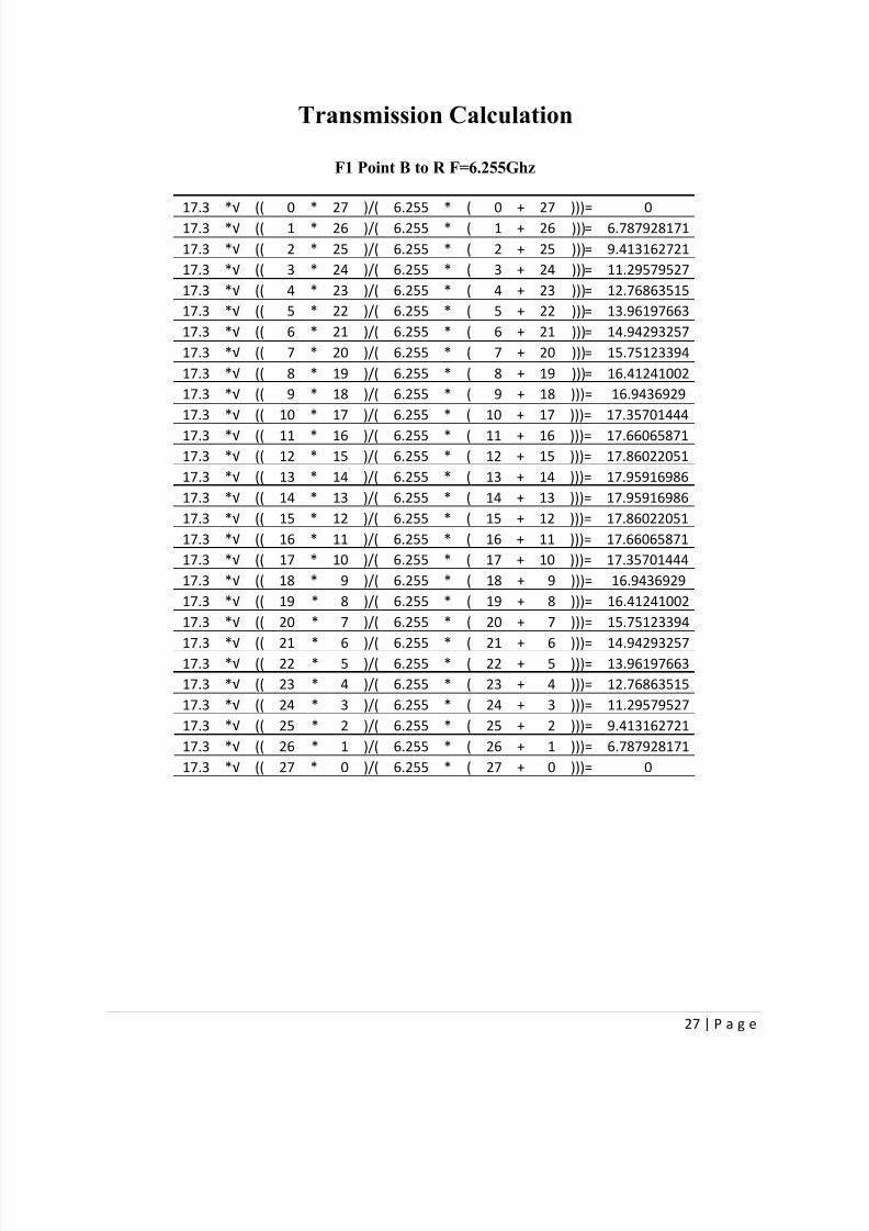
Transmission Calculation
F1 Point B to R F=6.255Ghz
17.3*√
(( 0 * 27 )/( 6.255 * ( 0 + 27 )))= 017.3 *√ (( 1 * 26 )/( 6.255 * ( 1 + 26 )))= 6.787928171
17.3 *√ (( 2 * 25 )/( 6.255 * ( 2 + 25 )))= 9.413162721
17.3 *√ (( 3 * 24 )/( 6.255 * ( 3 + 24 )))= 11.29579527
17.3 *√ (( 4 * 23 )/( 6.255 * ( 4 + 23 )))= 12.76863515
17.3 *√ (( 5 * 22 )/( 6.255 * ( 5 + 22 )))= 13.96197663
17.3 *√ (( 6 * 21 )/( 6.255 * ( 6 + 21 )))= 14.94293257
17.3 *√ (( 7 * 20 )/( 6.255 * ( 7 + 20 )))= 15.75123394
17.3 *√ (( 8 * 19 )/( 6.255 * ( 8 + 19 )))= 16.41241002
17.3 *√ (( 9 * 18 )/( 6.255 * ( 9 + 18 )))= 16.9436929
17.3 *√ (( 10 * 17 )/( 6.255 * ( 10 + 17 )))= 17.35701444
17.3 *√ (( 11 * 16 )/( 6.255 * ( 11 + 16 )))= 17.66065871
17.3 *√ (( 12 * 15 )/( 6.255 * ( 12 + 15 )))= 17.86022051
17.3 *√ (( 13 * 14 )/( 6.255 * ( 13 + 14 )))= 17.95916986
17.3 *√ (( 14 * 13 )/( 6.255 * ( 14 + 13 )))= 17.95916986
17.3 *√ (( 15 * 12 )/( 6.255 * ( 15 + 12 )))= 17.86022051
17.3 *√ (( 16 * 11 )/( 6.255 * ( 16 + 11 )))= 17.66065871
17.3 *√ (( 17 * 10 )/( 6.255 * ( 17 + 10 )))= 17.35701444
17.3 *√ (( 18 * 9 )/( 6.255 * ( 18 + 9 )))= 16.9436929
17.3 *√ (( 19 * 8 )/( 6.255 * ( 19 + 8 )))= 16.41241002
17.3 *√ (( 20 * 7 )/( 6.255 * ( 20 + 7 )))= 15.75123394
17.3 *√ (( 21 * 6 )/( 6.255 * ( 21 + 6 )))= 14.94293257
17.3 *√ (( 22 * 5 )/( 6.255 * ( 22 + 5 )))= 13.96197663
17.3 *√ (( 23 * 4 )/( 6.255 * ( 23 + 4 )))= 12.76863515
17.3 *√ (( 24 * 3 )/( 6.255 * ( 24 + 3 )))= 11.29579527
17.3 *√ (( 25 * 2 )/( 6.255 * ( 25 + 2 )))= 9.413162721
17.3 *√ (( 26 * 1 )/( 6.255 * ( 26 + 1 )))= 6.787928171
17.3 *√ (( 27 * 0 )/( 6.255 * ( 27 + 0 )))= 0
7/23/2019 Microwave Design PDF
http://slidepdf.com/reader/full/microwave-design-pdf 28/48
28 | P a g e
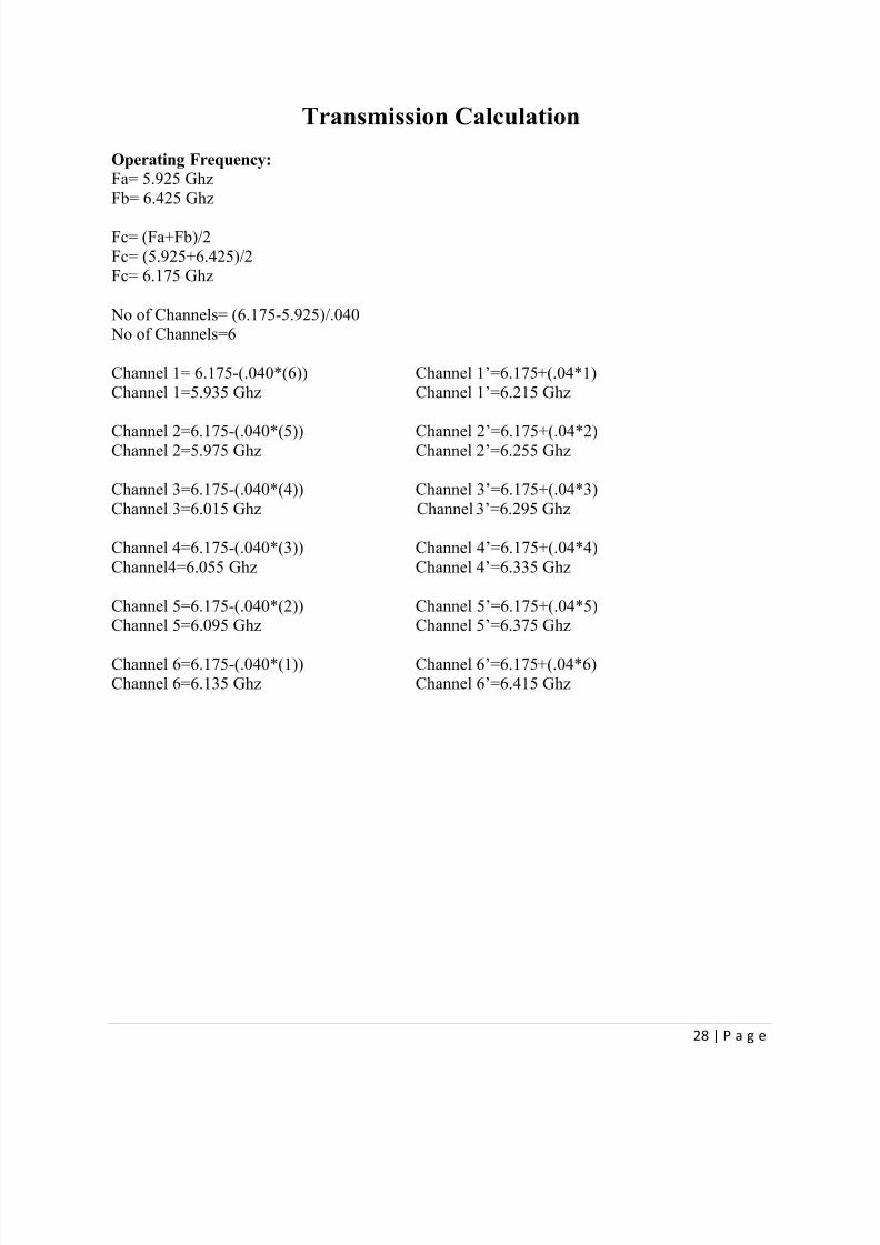
Transmission Calculation
Operating Frequency:
Fa= 5.925 Ghz
Fb= 6.425 Ghz
Fc= (Fa+Fb)/2
Fc= (5.925+6.425)/2Fc= 6.175 Ghz
No of Channels= (6.175-5.925)/.040 No of Channels=6
Channel 1= 6.175-(.040*(6)) Channel 1’=6.175+(.04*1)
Channel 1=5.935 Ghz Channel 1’=6.215 Ghz
Channel 2=6.175-(.040*(5)) Channel 2’=6.175+(.04*2) Channel 2=5.975 Ghz Channel 2’=6.255 Ghz
Channel 3=6.175-(.040*(4)) Channel 3’=6.175+(.04*3)
Channel 3=6.015 Ghz Channel 3’=6.295 Ghz
Channel 4=6.175-(.040*(3)) Channel 4’=6.175+(.04*4)
Channel4=6.055 Ghz Channel 4’=6.335 Ghz
Channel 5=6.175-(.040*(2)) Channel 5’=6.175+(.04*5) Channel 5=6.095 Ghz Channel 5’=6.375 Ghz
Channel 6=6.175-(.040*(1)) Channel 6’=6.175+(.04*6)Channel 6=6.135 Ghz Channel 6’=6.415 Ghz

7/23/2019 Microwave Design PDF
http://slidepdf.com/reader/full/microwave-design-pdf 29/48
29 | P a g e
Transmission Calculation
Site A to R:
Specifications Used:
Output Power= 33dBmThreshold/Sensitivity= -85dBm
Waveguide Attenuation=3.935/100mCirculator Loss=0.18dB/site
Connector Loss=.01dB/site
Radome loss=0.5dB/antennaRayleigh Fade Margin=38dB or 99.99% reliability
Frequency=5.935 Ghz
Antenna Height:H(A)=5.2(7.5)-16.1
H(A)=22.9 meters
H(R)=14.9(7.5)-40.5H(R)=71.25 meters
Waveguide Loss:WL=(3.935 dB/100m)(22.9+71.25+6.1+6.1)
WL=4.1848725 dB
Free Space Loss:FSL= 92.4 + 20log (Distance) + 20log (Frequency)
FSL= 92.4 + 20log (30) + 20log (5.935)FSL=137.4108396 dB
Circulator Loss:
CiL=0.18 For A + 0.18For RCiL=0.36 dB
Connector Loss:
CoL=0.01 For A + 0.01 For RCoL=0.02 dB
Radome Loss:RL=(0.5) For A + (0.5) For RRL=1 dB
Total Loss:TL=FSL + WL + CiL + CoL + RL
TL=137.4108396+4.1848725+0.36+.02+1
TL=142.9757121 dB

7/23/2019 Microwave Design PDF
http://slidepdf.com/reader/full/microwave-design-pdf 30/48
30 | P a g e
RSL:
RSL= Sensitivity + FMRSL= -85 + 38
RSL= -47 dBm
Gt and Gr:RSL=Output Power + Gt + Gr – Total Loss
(since Gt and Gr are equal we change it to 2G)
-47 = 33 + 2G – 142.9757121Gt=Gr=31.48785605 dB
Diameter of Antenna:
G=7.5 + 20log(Frequency) + 20log(Diameter)32.16664355=7.5 +20log(5.935) +20log(Diameter)
Diameter= 2.666687218 ft
The closest available diameter is 4ft
Greal:
G=7.5 + 20log(Frequency) + 20log(Diameter)
G=7.5 +20log(5.935) +20log(4)G=35.00961429 dB
RSLreal:RSL=Output Power + Gt + Gr – Total Loss
(since Gt and Gr are equal we change it to 2G)
RSL=33 + 2(35.00961429) – 142.9757121
RSLreal= -39.95648352 dBm
Fade Margin:
RSLreal=Sensitivity+FMFM= -39.95648352 + 85
FM= -45.04351648 dB
Unavailability for a=1 b=1/4:
U= ab(10-5)((f/4)1.5)(Distance3)(10-FM/10)
U= (1)(1/4)( 10-5)((5.935/4)1.5)(303)(10-45.04351648/10)
U=0.000003819
Reliability:
R=(1-U)*100
R=(1-0.000030555)*100R=99.99961806%

7/23/2019 Microwave Design PDF
http://slidepdf.com/reader/full/microwave-design-pdf 31/48
31 | P a g e
Transmission Calculation
Site R to A:
Specifications Used:
Output Power= 33dBmThreshold/Sensitivity= -85dBm
Waveguide Attenuation=3.935/100mCirculator Loss=0.18dB/site
Connector Loss=.01dB/site
Radome loss=0.5dB/antennaRayleigh Fade Margin=38dB or 99.99% reliability
Frequency=6.215 Ghz
Antenna Height:H(A)=5.2(7.5)-16.1
H(A)= 22.9 meters
H(R)=14.9(7.5)-40.5H(R)= 71.25 meters
Waveguide Loss:WL=(3.935 dB/100m)(22.9+71.25+6.1+6.1)
WL=4.1848725 dB
Free Space Loss:FSL= 92.4 + 20log (Distance) + 20log (Frequency)
FSL= 92.4 + 20log (30) + 20log (6.215)FSL=137.8112478 dB
Circulator Loss:
CiL=0.18 For A + 0.18For RCiL=0.36 dB
Connector Loss:
CoL=0.01 For A + 0.01 For RCoL=0.02 dB
Radome Loss:RL=(0.5) For A + (0.5) For RRL=1 dB
Total Loss:TL=FSL + WL + CiL + CoL + RL
TL=137.8112478+4.1848725 +0.36+.02+1
TL=143.3761203 dB

7/23/2019 Microwave Design PDF
http://slidepdf.com/reader/full/microwave-design-pdf 32/48
32 | P a g e
RSL:
RSL= Sensitivity + FMRSL= -85 + 38
RSL= -47 dBm
Gt and Gr:RSL=Output Power + Gt + Gr – Total Loss
(since Gt and Gr are equal we change it to 2G)
-47 = 33 + 2G – 143.3761203Gt=Gr=31.68806015 dB
Diameter of Antenna:
G=7.5 + 20log(Frequency) + 20log(Diameter)31.68806015 =7.5 +20log(6.215) +20log(Diameter)
Diameter= 2.605924773 ft
The closest available diameter is 4ft
Greal:
G=7.5 + 20log(Frequency) + 20log(Diameter)
G=7.5 +20log(6.215) +20log(4)G=35.41002249 dB
RSLreal:RSL=Output Power + Gt + Gr – Total Loss
(since Gt and Gr are equal we change it to 2G)
RSL=33 + 2(35.41002249) – 143.3761203
RSLreal= -39.55607532 dBm
Fade Margin:
RSLreal=Sensitivity+FMFM= -39.55607532 + 85
FM= -45.44392468 dB
Unavailability for a=1 b=1/4:
U= ab(10-5)((f/4)1.5)(Distance3)(10-FM/10)
U= (1)(1/4)( 10-5)((6.215/4)1.5)(303)(10-45.44392468/10)
U=0.000003732
Reliability:
R=(1-U)*100
R=(1-0.000029858)*100R=99.99962676%

7/23/2019 Microwave Design PDF
http://slidepdf.com/reader/full/microwave-design-pdf 33/48
33 | P a g e
Transmission Calculation
Site R to B:
Specifications Used:
Output Power= 33dBmThreshold/Sensitivity= -85dBm
Waveguide Attenuation=3.935/100mCirculator Loss=0.18dB/site
Connector Loss=.01dB/site
Radome loss=0.5dB/antennaRayleigh Fade Margin=38dB or 99.99% reliability
Frequency=5.975 Ghz
Antenna Height:H(R)=11(7.5)-40.5
H(R)=42 meters
H(B)=14.8(7.5)-80H(B)=31 meters
Waveguide Loss:WL=(3.935 dB/100m)(42+31+6.1+6.1)
WL=3.35262 dB
Free Space Loss:FSL= 92.4 + 20log (Distance) + 20log (Frequency)
FSL= 92.4 + 20log (27) + 20log (5.975)FSL=136.5540335 dB
Circulator Loss:
CiL=0.18 For A + 0.18For RCiL=0.36 dB
Connector Loss:
CoL=0.01 For A + 0.01 For RCoL=0.02 dB
Radome Loss:RL=(0.5) For A + (0.5) For RRL=1 dB
Total Loss:TL=FSL + WL + CiL + CoL + RL
TL=136.5540335 +3.35262 +0.36+.02+1
TL=141.2866535 dB

7/23/2019 Microwave Design PDF
http://slidepdf.com/reader/full/microwave-design-pdf 34/48
34 | P a g e
RSL:
RSL= Sensitivity + FM
RSL= -85 + 38RSL= -47 dBm
Gt and Gr:RSL=Output Power + Gt + Gr – Total Loss(since Gt and Gr are equal we change it to 2G)
-47 = 33 + 2G – 141.2866535
Gt=Gr=30.64332675 dB
Diameter of Antenna:
G=7.5 + 20log(Frequency) + 20log(Diameter)
30.64332675 =7.5 +20log(5.975) +20log(Diameter)Diameter= 2.403413121 ft
The closest available diameter is 4ft
Greal:
G=7.5 + 20log(Frequency) + 20log(Diameter)
G=7.5 +20log(5.975) +20log(4)
G=35.06795802 dB
RSLreal:
RSL=Output Power + Gt + Gr – Total Loss(since Gt and Gr are equal we change it to 2G)
RSL=33 + 2(35.06795802) – 141.2866535
RSLreal= -38.15073746 dBm
Fade Margin:
RSLreal=Sensitivity+FM
FM= -38.15073746 + 85FM= -46.84926254 dB
Unavailability for a=1 b=1/4:U= ab(10-5)((f/4)1.5)(Distance3)(10-FM/10)
U= (1)(1/4)( 10-5)((5.975/4)1.5)(273)(10-46.84926254/10)
U=0.000001855
Reliability:
R=(1-U)*100
R=(1-0.000014697)*100
R=99.99981442%

7/23/2019 Microwave Design PDF
http://slidepdf.com/reader/full/microwave-design-pdf 35/48
35 | P a g e
Transmission Calculation
Site B to R:
Specifications Used:
Output Power= 33dBmThreshold/Sensitivity= -85dBm
Waveguide Attenuation=3.935/100mCirculator Loss=0.18dB/site
Connector Loss=.01dB/site
Radome loss=0.5dB/antennaRayleigh Fade Margin=38dB or 99.99% reliability
Frequency=6.255 Ghz
Antenna Height:H(R)=11(7.5)-40.5
H(R)=42 meters
H(B)=14.8(7.5)-80H(B)=31 meters
Waveguide Loss:WL=(3.935 dB/100m)(42+31+6.1+6.1)
WL=3.35262 dB
Free Space Loss:FSL= 92.4 + 20log (Distance) + 20log (Frequency)
FSL= 92.4 + 20log (27) + 20log (6.255)FSL=136.9518216 dB
Circulator Loss:
CiL=0.18 For A + 0.18For RCiL=0.36 dB
Connector Loss:
CoL=0.01 For A + 0.01 For RCoL=0.02 dB
Radome Loss:RL=(0.5) For A + (0.5) For RRL=1 dB
Total Loss:TL=FSL + WL + CiL + CoL + RL
TL=136.9518216 +3.35262 +0.36+.02+1
TL=141.6844416 dB

7/23/2019 Microwave Design PDF
http://slidepdf.com/reader/full/microwave-design-pdf 36/48
36 | P a g e
RSL:
RSL= Sensitivity + FMRSL= -85 + 38
RSL= -47 dBm
Gt and Gr:RSL=Output Power + Gt + Gr – Total Loss
(since Gt and Gr are equal we change it to 2G)
-47 = 33 + 2G – 141.6844416Gt=Gr=30.8422208 dB
Diameter of Antenna:
G=7.5 + 20log(Frequency) + 20log(Diameter)30.8422208 =7.5 +20log(6.255) +20log(Diameter)
Diameter= 2.349003836 ft
The closest available diameter is 4ft
Greal:
G=7.5 + 20log(Frequency) + 20log(Diameter)
G=7.5 +20log(6.255) +20log(4)G=35.46574611 dB
RSLreal:RSL=Output Power + Gt + Gr – Total Loss
(since Gt and Gr are equal we change it to 2G)
RSL=33 + 2(35.46574611) – 141.6844416
RSLreal= -37.75294939 dBm
Fade Margin:
RSLreal=Sensitivity+FMFM= -37.75294939 + 85
FM= -47.24705061 dB
Unavailability for a=1 b=1/4:
U= ab(10-5)((f/4)1.5)(Distance3)(10-FM/10)
U= (1)(1/4)( 10-5)(6.2551.5)(273)(10-47.24705061/10)
U=0.000001813
Reliability:
R=(1-U)*100
R=(1-0.000014697)*100R=99.99981863%

7/23/2019 Microwave Design PDF
http://slidepdf.com/reader/full/microwave-design-pdf 37/48
37 | P a g e
Specification Sheets
Antenna

7/23/2019 Microwave Design PDF
http://slidepdf.com/reader/full/microwave-design-pdf 38/48
38 | P a g e
Elliptical Waveguide
EWP52-56W
Construction Materials
Jacket Material PE
Conductor Material Corrugated copper
Jacket Color Black
Dimensions
Cable Volume 1045.0 L/km | 11.3 ft³/kft
Cable Weight 0.88 kg/m | 0.59 lb/ft
Diameter Over Jacket (E Plane) 57.20 mm | 2.25 in
Diameter Over Jacket (H Plane) 33.30 mm | 1.31 in
Electrical Specifications
Operating Frequency Band 5.6 – 6.425 GHz
eTE11 Mode Cutoff 3.650 GHz
Group Delay126 ns/100 ft @ 6.200 GHz
413 ns/100 m @ 6.200 GHz
Environmental Specifications
Installation Temperature -40 °C to +60 °C (-40 °F to +140 °F)
Operating Temperature -55 °C to +85 °C (-67 °F to +185 °F)

7/23/2019 Microwave Design PDF
http://slidepdf.com/reader/full/microwave-design-pdf 39/48
39 | P a g e
Storage Temperature -70 °C to +85 °C (-94 °F to +185 °F)
General Specifications
Brand HELIAX®
Mechanical Specifications
Maximum Twist 3.00 °/m | 1.00 °/ft
Minimum Bend Radius, Multiple Bends (E Plane) 305.00 mm | 12.00 in
Minimum Bend Radius, Multiple Bends (H Plane) 810.00 mm | 32.00 in
Minimum Bend Radius, Single Bend (E Plane) 200.00 mm | 8.00 in
Minimum Bend Radius, Single Bend (H Plane) 560.00 mm | 22.00 in
Note
Performance Note Values typical, unless otherwise stated
Standard Conditions
Attenuation, Ambient Temperature 24 °C | 75 °F
Average Power, Ambient Temperature 40 °C | 104 °F
Average Power, Temperature Rise 42 °C | 76 °F
Return Loss/VSWR
Frequency Band VSWR Return Loss (dB)
5.6 –
6.425 GHz 1.06 30.70
* VSWR/Return Loss indicated is for lengths up to 300 ft (91.4 m)
* VSWR/Return Loss is guaranteed for factory-fit and typical for field-fit assemblies
* Custom length performance: Call +1-800-255-1479 (N. America), 1-779-435-6500 (Int’l.), or your
local Andrew representative

7/23/2019 Microwave Design PDF
http://slidepdf.com/reader/full/microwave-design-pdf 40/48
40 | P a g e
Attenuation
Frequency (GHz) Attenuation (dB/100 ft) Attenuation (dB/100 m) Av
6 1.199 3.935 5.9
Regulatory Compliance/Certifications
Agency Classification
RoHS 2002/95/EC Compliant
China RoHS SJ/T 11364-
2006Below Maximum Concentration Value (MCV)
ISO 9001:2008 Designed, manufactured and/or distributed under this quality managementsystem
Waveguide Connector
Fixed-tuned CPR137G for elliptical waveguide 52
General Specifications
Body Style Straight, fixed-tuned
Interface CPR137G

7/23/2019 Microwave Design PDF
http://slidepdf.com/reader/full/microwave-design-pdf 41/48
41 | P a g e
Waveguide Size WR137 | WG14 | R70
Brand HELIAX®
Material Type Brass
Electrical Specifications
Operating Frequency Band 5.0 – 6.425 GHz
Insertion Loss, typical 0.01 dB
Peak Power, maximum 92.00 kW @ 6.00 GHz
Mechanical Specifications
Attachment Method Tab-flare | Tool-flare
Inner Contact Plating Unplated
Outer Contact Plating Unplated
Pressurizable Yes
Dimensions
Length 114.55 mm | 4.51 in
Transition Length 75.69 mm | 2.98 in
Weight 1.80 kg | 3.97 lb
Width 88.90 mm | 3.50 in
Environmental Specifications
Operating Temperature -55 °C to +85 °C (-67 °F to +185 °F)
Storage Temperature -55 °C to +85 °C (-67 °F to +185 °F)

7/23/2019 Microwave Design PDF
http://slidepdf.com/reader/full/microwave-design-pdf 42/48
42 | P a g e
Regulatory Compliance/Certifications
Agency Classification
RoHS 2002/95/EC Compliant by Exemption
China RoHS SJ/T 11364-2006 Above Maximum Concentration Value (MCV)
ISO 9001:2008 Designed, manufactured and/or distributed under this quality manag

7/23/2019 Microwave Design PDF
http://slidepdf.com/reader/full/microwave-design-pdf 43/48
43 | P a g e
Waveguide Circulator

7/23/2019 Microwave Design PDF
http://slidepdf.com/reader/full/microwave-design-pdf 44/48
44 | P a g e
Tower

7/23/2019 Microwave Design PDF
http://slidepdf.com/reader/full/microwave-design-pdf 45/48
45 | P a g e
Transmitter/Receiver

7/23/2019 Microwave Design PDF
http://slidepdf.com/reader/full/microwave-design-pdf 46/48
46 | P a g e

7/23/2019 Microwave Design PDF
http://slidepdf.com/reader/full/microwave-design-pdf 47/48
47 | P a g e
Conclusion
In the design, Using the following components in order to create a microwave antenna to
transmit and receive between the following places: Moncada, Tarlac to Tarlac City, Tarlac and
vice versa, Tarlac City,Tarlac to Mabalacat, Pampanga and vice versa. The reason for the following
destinations chosen primarily is the ease of transportation, meaning the site can be reached without
difficulty due to roads near it. The proponents used an antenna with a 4 feet diameter since the
calculated antenna diameter is larger than the commercially available 2 feet. The proponents also
used a EWP52-56W waveguide which is elliptical. The design is purely theoretical since there is
much more study needed in order to properly design the antenna in the area chosen by the
proponents.
Recommendation(s):
After undergoing all the necessary steps in designing a double-hop microwave transmission
system, the company had the following recommendations:
The company recommends that practical improvement should be imposed on the system
so it can move along with the flow of current technology.
The area involved in the proposed project should be surveyed first before putting up any
line of sight communication link.
Path profiling must be at least the 60% of the first Fresnel zone radius and must not hit the highest
point of ground elevation throughout the path.
Since the sites are exposed and prone to high wind velocities, the company would like to
recommend further wind loading measures to ensure the safety stability of the antenna
towers and the security of the personnel within the perimeter.
To ensure the reliability of the system will be met, the company also recommends monthly
maintenance and equipment check up.
Other security measures such as grounding, lightning protection and the likes must be
properly observed to achieve the full functionality of the system.
To impose security for the system as a whole, the company recommends safety measures

7/23/2019 Microwave Design PDF
http://slidepdf.com/reader/full/microwave-design-pdf 48/48
such as installing hidden security cameras and placing metal fences around the perimeter
of the chosen sites.
Since the company will utilize a tower that is greater than needed, the client can lease the
tower and generate an additional amount of income. Thus, the payment for the said leasing
will be depending on the agreement of the client and the person who’s leasing the tower.
Related Documents