move to back page Steel Products Microwave Antenna Application Guide Structural Support Products

Welcome message from author
This document is posted to help you gain knowledge. Please leave a comment to let me know what you think about it! Share it to your friends and learn new things together.
Transcript

move to back page
Steel Products
Microwave Antenna Application GuideStructural Support Products


Tower Mounts . . . . . . . . . . . . . . . . . . . . . . . . . . . . . . . . . . . . . . . . . . . . . . . . . . . . . . . . . . . . . . . . . . . . . . . . . . . . . . . . . . . . . . 1 Leg Mounting Solutions . . . . . . . . . . . . . . . . . . . . . . . . . . . . . . . . . . . . . . . . . . . . . . . . . . . . . . . . . . . . . . . . . . . . . . . . . . . . . 2 Application Guide . . . . . . . . . . . . . . . . . . . . . . . . . . . . . . . . . . . . . . . . . . . . . . . . . . . . . . . . . . . . . . . . . . . . . . . . . . . . . .5-9 Face Mounting Solutions . . . . . . . . . . . . . . . . . . . . . . . . . . . . . . . . . . . . . . . . . . . . . . . . . . . . . . . . . . . . . . . . . . . . . . . . . . . 10 Application Guide . . . . . . . . . . . . . . . . . . . . . . . . . . . . . . . . . . . . . . . . . . . . . . . . . . . . . . . . . . . . . . . . . . . . . . . . . . . .17-19 SE-Series Mounting Solutions . . . . . . . . . . . . . . . . . . . . . . . . . . . . . . . . . . . . . . . . . . . . . . . . . . . . . . . . . . . . . . . . . . 20-21 Waveguide Shield . . . . . . . . . . . . . . . . . . . . . . . . . . . . . . . . . . . . . . . . . . . . . . . . . . . . . . . . . . . . . . . . . . . . . . . . . . . . . . . . 22
Monopole Mounts . . . . . . . . . . . . . . . . . . . . . . . . . . . . . . . . . . . . . . . . . . . . . . . . . . . . . . . . . . . . . . . . . . . . . . . . . . . . . . . . . . 23 Low Profile Chain Mounts . . . . . . . . . . . . . . . . . . . . . . . . . . . . . . . . . . . . . . . . . . . . . . . . . . . . . . . . . . . . . . . . . . . . . . . . . . 24 Light Duty Chain Mounts . . . . . . . . . . . . . . . . . . . . . . . . . . . . . . . . . . . . . . . . . . . . . . . . . . . . . . . . . . . . . . . . . . . . . . . . . . . 25 Heavy Duty Chain Mounts . . . . . . . . . . . . . . . . . . . . . . . . . . . . . . . . . . . . . . . . . . . . . . . . . . . . . . . . . . . . . . . . . . . . . . . . . . 26 Microwave Components . . . . . . . . . . . . . . . . . . . . . . . . . . . . . . . . . . . . . . . . . . . . . . . . . . . . . . . . . . . . . . . . . . . . . . . . . . . . 27 Application Guide . . . . . . . . . . . . . . . . . . . . . . . . . . . . . . . . . . . . . . . . . . . . . . . . . . . . . . . . . . . . . . . . . . . . . . . . . . . .28-29 Customs . . . . . . . . . . . . . . . . . . . . . . . . . . . . . . . . . . . . . . . . . . . . . . . . . . . . . . . . . . . . . . . . . . . . . . . . . . . . . . . . . . . . 30
Roof-top Mounts . . . . . . . . . . . . . . . . . . . . . . . . . . . . . . . . . . . . . . . . . . . . . . . . . . . . . . . . . . . . . . . . . . . . . . . . . . . . . . . . . . . 31 Tripod Mounts . . . . . . . . . . . . . . . . . . . . . . . . . . . . . . . . . . . . . . . . . . . . . . . . . . . . . . . . . . . . . . . . . . . . . . . . . . . . . . . . .32-33 Mounting Components . . . . . . . . . . . . . . . . . . . . . . . . . . . . . . . . . . . . . . . . . . . . . . . . . . . . . . . . . . . . . . . . . . . . . . . . . . .34-35 Customs . . . . . . . . . . . . . . . . . . . . . . . . . . . . . . . . . . . . . . . . . . . . . . . . . . . . . . . . . . . . . . . . . . . . . . . . . . . . . . . . . . . . 36
Waveguide . . . . . . . . . . . . . . . . . . . . . . . . . . . . . . . . . . . . . . . . . . . . . . . . . . . . . . . . . . . . . . . . . . . . . . . . . . . . . . . . . . . . . . . . 37 Coaxial Support Components . . . . . . . . . . . . . . . . . . . . . . . . . . . . . . . . . . . . . . . . . . . . . . . . . . . . . . . . . . . . . . . . . . . . . . . 38 Waveguide Bridge Kits . . . . . . . . . . . . . . . . . . . . . . . . . . . . . . . . . . . . . . . . . . . . . . . . . . . . . . . . . . . . . . . . . . . . . . . . . . . . 39 Cable Ladder Kits . . . . . . . . . . . . . . . . . . . . . . . . . . . . . . . . . . . . . . . . . . . . . . . . . . . . . . . . . . . . . . . . . . . . . . . . . . . . . . . . 40
Site Related . . . . . . . . . . . . . . . . . . . . . . . . . . . . . . . . . . . . . . . . . . . . . . . . . . . . . . . . . . . . . . . . . . . . . . . . . . . . . . . . . . . . . . . 41 Microwave Ice Shields . . . . . . . . . . . . . . . . . . . . . . . . . . . . . . . . . . . . . . . . . . . . . . . . . . . . . . . . . . . . . . . . . . . . . . . . . . .42-45 Power Telco Racks . . . . . . . . . . . . . . . . . . . . . . . . . . . . . . . . . . . . . . . . . . . . . . . . . . . . . . . . . . . . . . . . . . . . . . . . . . . . . . . . 46 Equipment Platforms . . . . . . . . . . . . . . . . . . . . . . . . . . . . . . . . . . . . . . . . . . . . . . . . . . . . . . . . . . . . . . . . . . . . . . . . . . . . . . 46
table of contentsTable of Contents

Selection Guide
Coaxial SupportsPage 38
Universal Cable Ladder KitsPage 40
Universal Tripod MountsPage 32
Roof-top Peak MountsPage 35
Low-profile Chain MountsPage 24
Heavy Duty Chain MountsPage 26
Low-profile Co-location KitsPage 27
Universal Pipe Mount KitsPage 2
Microwave Dish Strut SupportPage 4
Tower Mounts
Monopole Mounts
Roof-top Mounts
Waveguide
Site Related Components
Equipment PlatformsPage 46
Microwave Antenna Ice ShieldsPage 42
Waveguide Bridge KitsPage 39
Power Telco RacksPage 46
Wall MountsPage 34
Tower Face MountsPage 10

TOW
ER
MO
UN
TSTO
WE
R M
OU
NTS
• Tower Leg Mounting Solutions
• Tower Face Mounting Solutions

Tower Mounts
2
7-1/2" or 14”(190 mm or 355.6 mm)
SLOT 4-1/2" Long(114.3 mm)
2-3/8" or 4-1/2" OD(60.3 mm or 114.3 mm)
NOTE: Not recommended for use on the climbing leg of tower. Use PM-SC series (see page 3).
Universal Sliding Pipe Mount Kits
Application: Lattice towers
Size: 2-3/8" (60 .3 mm) OD or 4-1/2" (114 .3 mm) OD
Design: Pipe with saddle mount and adjustable clamps
Feature: Universal sliding bracket with up to 7° of taper
Mounts to: Straight or tapered legs up to 16" (406 .4 mm) OD, 16" (406 .4 mm) angle 60°, or 12" (304 .8 mm) angle 90°
Material: Hot dip galvanized steel
Includes: Universal saddle mount, sliding pipe mount brackets, with or without pipe
Order Separately: Pipes for base kits
Wind Rating*: 120 mph (BWS) per latest revision of TIA/EIA-222 at 150' AGL
*Typical installation of one 8' microwave antenna with stiff arm
Part Number Description Weight, lb (kg) Universal Sliding Pipe Mount Kits, for Round or 60° Angle Legs up to 8" (203.2 mm), or 6" (152.4 mm) 90° Angle Legs, 2-3/8" (60.3 mm) Antenna Mounting PipePM-SU2-B Base Kit, Order Pipe Separately, Kit of 2 80 (32.3)PM-SU2-72 2-3/8" OD x 72" (60.3 mm OD x 1.8 m) 101 (45.8)PM-SU2-96 2-3/8" OD x 96" (60.3 mm OD x 2.4 m) 114 (51.7) Universal Sliding Pipe Mount Kits, for Round or 60° Angle Legs up to 16" (406.4 mm), or 12" (304.8 mm) 90° Angle Legs, 2-3/8" (60.3 mm) Antenna Mounting PipePML-SU2-B Base Kit, Order Pipe Separately, Kit of 2 80 (32.3)PML-SU2-72 2-3/8" OD x 72" (60.3 mm OD x 1.8 m) 101 (45.8)PML-SU2-96 2-3/8" OD x 96" (60.3 mm OD x 2.4 m) 114 (51.7) Universal Sliding Pipe Mount Kits, for Round or 60° Angle Legs up to 8" (203.2 mm), or 6" (152.4 mm) 90° Angle Legs, 14" (355.6 mm) Stand-off, 2-3/8" (60.3 mm) Antenna Mounting PipePM-SU2L-B Base Kit, Order Pipe Separately, Kit of 2 90 (40.9)PM-SU2L-72 2-3/8" OD x 72" (60.3 mm OD x 1.8 m) 110 (49.9)PM-SU2L-96 2-3/8" OD x 96" (60.3 mm OD x 2.4 m) 121 (54.9) Universal Sliding Pipe Mount Kits, for Round or 60° Angle Legs up to 16" (406.4 mm), or 12" (304.8 mm) 90° Angle Legs, 14" (355.6 mm) Stand-off, 2-3/8" (60.3 mm) Antenna Mounting PipePML-SU2L-B Base Kit, Order Pipe Separately, Kit of 2 90 (40.9)PML-SU2L-72 2-3/8" OD x 72" (60.3 mm OD x 1.8 m) 110 (49.9)PML-SU2L-96 2-3/8" OD x 96" (60.3 mm OD x 2.4 m) 121 (54.9) Universal Sliding Pipe Mount Kits, for Round or 60° Angle Legs up to 8" (203.2 mm), or 6" (152.4 mm) 90° Angle Legs, 4-1/2" (114.3 mm) Antenna Mounting PipePM-SU4-B Base Kit, Order Pipe Separately, Kit of 2 81 (36.8)PM-SU4-63 4-1/2" OD x 63" (114.3 mm OD x 1.6 m) 138 (62.6)PM-SU4-96 4-1/2" OD x 96" (114.3 mm OD x 2.4 m) 169 (76.7) Universal Sliding Pipe Mount Kits, for Round or 60° Angle Legs up to 16" (406.4 mm), or 12" (304.8 mm) 90° Angle Legs, 4-1/2" (114.3 mm) Antenna Mounting PipePML-SU4-B Base Kit, Order Pipe Separately, Kit of 2 81 (36.8)PML-SU4-63 4-1/2" OD x 63" (114.3 mm OD x 1.6 m) 138 (62.6)PML-SU4-96 4-1/2" OD x 96" (114.3 mm OD x 2.4 m) 169 (76.7) Universal Sliding Pipe Mount Kits, for Round or 60° Angle Legs up to 8" (203.2 mm), or 6" (152.4 mm) 90° Angle Legs, 14" (355.6 mm) Stand-off 4-1/2" (114.3 mm) Antenna Mounting PipePM-SU4L-B Base Kit, Order Pipe Separately, Kit of 2 90 (40.9)PM-SU4L-63 4-1/2" OD x 63" (114.3 mm OD x 1.6 m) 145 (65.8)PM-SU4L-96 4-1/2" OD x 96" (114.3 mm OD x 2.4 m) 175 (79.4) Universal Sliding Pipe Mount Kits, for Round or 60° Angle Legs up to 16" (406.4 mm), or 12" (304.8 mm) 90° Angle Legs, 14" (355.6 mm) Stand-off, 4-1/2" (114.3 mm) Antenna Mounting PipePML-SU4L-B Base Kit, Order Pipe Separately, Kit of 2 90 (40.9)PML-SU4L-63 4-1/2" OD x 63" (114.3 mm OD x 1.6 m) 145 (65.8)PML-SU4L-96 4-1/2" OD x 96" (114.3 mm OD x 2.4 m) 175 (79.4)
Leg Mounting Solutions
Andrew Solutions • www.commscope.com/andrew

Universal Pipe Mount Kits
Application: Antenna leg mounting for round or angle towers
Size: 2-3/8" (60 .3 mm) OD or 4-1/2" (114 .3 mm) OD
Design: Pipe with saddle mount and adjustable clamps
Feature: Open face taper adjustment
Mounts to: Straight or tapered legs up to 16" (406 .4 mm) OD, 16" (406 .4 mm) angle 60°, or 12" (304 .8 mm) angle 90°
Material: Hot dip galvanized steel
Includes: Universal saddle mount, taper adjustment brackets, with or without pipe
Order Separately: Pipes for base kits
Wind Rating*: 120 mph (BWS) per latest revision of TIA/EIA-222 at 150' AGL
*Typical installation of one 8' microwave antenna with stiff arm
Part Number Description Universal Pipe Mount Kit With Open Face Taper Adjustment, for Round or 60° Angle Legs up to 8" (203.2 mm) or 6" (152.4 mm) 90° Angle LegsPM-SC2-72 2-3/8" x 72" (60.3 mm x 1.8 m) Antenna Mounting PipePM-SC2-96 2-3/8" x 96" (60.3 mm x 2.4 m) Antenna Mounting PipePM-SC2-B Pipe Ordered SeparatelyPM-SC4-63 4-1/2" x 63" (114.3 mm x 1.6 m) Antenna Mounting PipePM-SC4-96 4-1/2" x 96" (114.3 mm x 2.4 m) Antenna Mounting PipePM-SC4-B Pipe Ordered Separately Universal Pipe Mount Kit With Open Face Taper Adjustment, for Round or 60° Angle Legs up to 16" (406.4 mm), or 12" (304.8 mm) 90° Angle LegsPML-SC2-72 2-3/8" x 72" (60.3 mm x 1.8 m) Antenna Mounting PipePML-SC2-96 2-3/8" x 96" (60.3 mm x 2.4 m) Antenna Mounting PipePML-SC2-B Pipe Ordered SeparatelyPML-SC4-63 4-1/2" x 63" (114.3 mm x 1.6 m) Antenna Mounting PipePML-SC4-96 4-1/2" x 96" (114.3 mm x 2.4 m) Antenna Mounting PipePML-SC4-B Pipe Ordered Separately
2-3/8" or 4-1/2" OD(60.3 mm or 114.3 mm)
• PM-SC2-72
3Andrew Solutions • www.commscope.com/andrew
Tower Mounts
Leg Mounting Solutions

Part Number Description Tower Face Mounted Microwave Dish Channel Support Kit, for Round or 60° Angle Legs up to 8" (203.2 mm), or 6"(152.4 mm) 90° Angle LegsMD-CS-6R 6' (1.8 m) Plain End PipeMD-CS-8R 8' (2.4 m) Plain End PipeMD-CS-10R 10' (3.1 m) Plain End Pipe Tower Face Mounted Microwave Dish Channel Support Kit, for 8" (203.2 mm) to 16" (406.4 mm) Round, or 8" (203.2 mm) to 16" (406.4 mm) 60° Angle Legs or 6" (152.4 mm) to 12" (304.8 mm) 90° Angle LegsMDL-CS-6R 6' (1.8 m) Plain End PipeMDL-CS-8R 8' (2.4 m) Plain End PipeMDL-CS-10R 10' (3.1 m) Plain End Pipe Tower Leg Mounted Microwave Dish Strut Support, for Round or 90° Angle Legs up to 8" (203.2 mm), or 6" (152.4 mm) 60° Angle LegsMD-SS-6R 6' (1.8 m) Pipe MD-SS-8R 8' (2.4 m) Pipe Tower Leg Mounted Microwave Dish Strut Support Kit, for 8" (203.2 mm) to 16" (406.4 mm) Round, or 8" (203.2 mm) to 16" (406.4 mm) 60° Angle Legs or 6" (152.4 mm) to 12" (304.8 mm) 90° Angle LegsMDL-SS-6R 6' (1.8 m) PipeMDL-SS-8R 8' (2.4 m) Pipe Tower Leg Mounted Microwave Dish Strut Support, for Round or 60° Angle Legs up to 8" (203.2 mm), or 6" (152.4 mm) 90° Angle LegsMD-SSA4 4' (1.2 m) AngleMD-SSA6 6' (1.8 m) Angle Tower Leg Mounted Microwave Dish Strut Support Kit, for 8" (203.2 mm) to 16" (406.4 mm) Round, or 8" (203.2 mm) to 16" (406.4 mm) 60° Angle Legs or 6" (152.4 mm) to 12" (304.8 mm) 90° Angle LegsMDL-SSA4 4' (1.2 m) Angle MDL-SSA6 6' (1.8 m) Angle Angle for MD-CS SeriesMD-CSA4 3/8" x 3-1/2" x 3-1/2" x 4' (9.5 mm x 88.9 mm x 88.9 mm x 1.2 m)MD-CSA6 3/8" x 3-1/2" x 3-1/2" x 6' (9.5 mm x 88.9 mm x 88.9 mm x 1.8 m)MD-CSA8 3/8" x 3-1/2" x 3-1/2" x 8' (9.5 mm x 88.9 mm x 88.9 mm x 2.4 m) Microwave Dish Face Strut SupportMD-FSS 3/8" x 3" x 3" x 5' 6" (9.5 mm x 76.2 mm x 76.2 mm x 1.7m)
Microwave Dish Support
Application: Structural strut supports for round or angle tower legs
Size: 4', 6', 8', or 10' (1 .2 m, 1 .8 m, 2 .4 m, or 3 .1 m) Tower faces
Design: Round or angle strut support kits
Feature: Tower face strut support kits
Mounts to: Straight or tapered legs up to 16" (406 .4 mm) OD, 16" (406 .4 mm) angle 60°, or 12" (304 .8 mm) angle 90°
Material: Hot dip galvanized steel
• MD-CS-6R
• MD-SSA4
• MD-CSA4
• MD-SS-6R
• MD-FSS
Tower Mounts
4
Leg Mounting Solutions
Andrew Solutions • www.commscope.com/andrew

USAGE MD-SSA4 MD-SSA6 MD-SSA8
Saddle Mount Attached in Center of Angle
Max. distance from leg (d) 24" 36" 48"
Acceptable Load 2000 lb 1500 lb 1000 lb
USAGE MD-CSA4 MD-CSA6 MD-CSA8
Angle Attached at Each End to Tower Leg Mount
Max. distance from legs (d) 24" 36" 48"
Acceptable Load 2500 lb 2500 lb 2000 lb
d
USAGE MD-SS6R MD-SS8R MD-SS10R
Saddle Mount Attached in Center of Pipe
Max. distance from leg (d) 36" 48" 60"
Acceptable Load 2500 lb 2000 lb 1500 lb
d
USAGE MD-SS6R MD-SS8R MD-SS10R
Saddle Mount Attached at One End of Pipe
Max. distance from leg (d) 60" 84" 108"
Acceptable Load 1500 lb 1000 lb 500 lb
d
USAGE MD-CS6R MD-CS8R MD-CS10R
Pipe Attached at Each End to Tower Leg Mount
Max. distance from legs (d) 36" 48" 60"
Acceptable Load 2500 lb 2500 lb 2500 lb
d
d
NOTE: It is assumed that a qualified structural engineer has reviewed the tower structure for the loads created by the microwave antennas and strut supports .
• MD-SSA4 • MD-CSA4
• MD-SS6R
• MD-SS6R
• MD-CS6R
5Andrew Solutions • www.commscope.com/andrew
Tower Mounts
Leg Mounting Solutions

Size ft. (m) Adjustable Strut Force, lb (N) Fixed Strut Force, lb (N)
4 (1.2) 500 (2200) -
6 (1.8) 1400 (9207) _
8 (2.4) 958 (4261) 1265 (5627)
10 (3.0) 1320 (5871) 1987 (8838)
12 (3.7) 1799 (8001) 2585 (11498)
NOTE:
A 4' dish stiff arm can see in survival winds up to 600 lbs. of load, and in working load wind conditions the mount cannot flex or deflect more than 0.1". A six foot dish stiff arm can see in survival winds up to 1400 lbs of load, and in working load wind condi-tions the mount cannot flex or deflect more than 0.1". In addition this arm must have a horizontal angle of less than 25° and less than 5° in the vertical direction."(Illustration on Page 19)
Tower Mounts
6
Adjustable Strut Load
+25°-25°
Out Board Strut Load
Adjustable Strut Load
+25°-25°
+25°-25°
Leg Mounting Solutions
Andrew Solutions • www.commscope.com/andrew

Part Number Description Microwave Dish Strut Support Bracket for Round or 60° Angle Legs up to 8" (203.2 mm), or 6" (152.4 mm) 90° Angle LegsMD-CS Universal, for Mounting up to 3-1/2" (88.9 mm) Face Pipes on Round or Angle Legs (Kit of 1)MD-CSL Universal, for Mounting up to 4-1/2" (114.3 mm) Face Pipes on Round or Angle Legs (Kit of 1)MD-CS-F Face Mounted, for Mounting up to 3-1/2" (88.9 mm) Face Pipes on Round or Angle Legs (Kit of 2)MD-CS-B Face Mounted, (Kit of 1) Microwave Dish Strut Support Bracket, for 8" (203.2 mm) to 16" (406.4 mm) Round, or 8" (203.2 mm), to 16" (406.4 mm) 60° Angle Legs or 6" (152.4 mm) to 12" (304.8 mm) 90° Angle LegsMDL-CS Universal, for Mounting up to 3-1/2" (88.9 mm) Face Pipes on Round or Angle Legs (Kit of 1)MDL-CSL Universal, for Mounting up to 4-1/2" (114.3 mm) Face Pipes on Round or Angle Legs (Kit of 1) MDL-CS-F Face Mounted, for Mounting up to 3-1/2" (88.9 mm) Face Pipes on Round or Angle Legs (Kit of 2) MDL-CS-B Face Mounted, (Kit of 1) Microwave Dish Vertical Strut SupportMD-VSS-B Microwave Dish Vertical Strut Support Microwave Strut Attachment BracketTF-MSS-BK2 For 2-3/8" (60.3 mm) OD PipeTF-MSS-BK For 3-1/2" (88.9 mm) OD PipeTF-MSS-BK45 For 4-1/2" (114.3 mm) OD Pipe
Microwave Strut Support
Application: Structural strut supports for round or angle tower legs
Size: 21" (533 .4 mm) channel
Design: Universal support bracket
Feature: Universal strut attachment
Mounts to: Straight or tapered legs up to 16" (406 .4 mm) OD, 16" (406 .4 mm) angle 60°, or 12" (304 .8 mm) angle 90°
Material: Hot dip galvanized steel
Includes: Support bracket, attachment hardware
Order Separately: Microwave strut pipe or angle, u-bolt
• MD-CS / • MD-CSL
• MD-CS-F
Set up with U-bolt on Face
• MD-CS-B
Set up with
bolts on face
• MD-VSS-B
• TF-MSS-BK
7Andrew Solutions • www.commscope.com/andrew
Tower Mounts
Leg Mounting Solutions

1
a
3
b
Key Part Number Description Page #
1 PM-SC4-63 Universal Pipe Mount Kit With Open Face 2
2 MD-VSS Microwave Dish Vertical Strut Support 7
3 MD-FSS Microwave Dish Face Strut Support 4
a. Open face allows safety climb to pass throughb. Strut returns back to tower at recommended anglec. Taper adjustment allows for vertical mounting solution
a
1
1
b1
c
* Shown with Andrew PX2F series antennas and supports
b
1
a
2
1
b
a. Sliding taper brackets allow for 7° of non-incremental adjustmentb. Strut returns straight back to towerc. Universal saddle mounts up to 8" (203.2 mm) dia. straight or taper legs
2NOTE: If safety guide passes through mount it is recommended to add a cable guide above and below the mount to ensure the cable does not rub .
Tower Mounts
8
Application Guide
Andrew Solutions • www.commscope.com/andrew

Key Part Number Description Page #
1 PM-SC4-63 Universal Pipe Mount Kit With Open Face 34
2 PM-SU4-63 Universal Pipe Mount Kit 2
3 MD-CS-6R Tower Face Mounted Dish Strut Support Kit 4
4 MD-SS-6R Tower Leg Mounted Dish Strut Support Kit 4
5 MD-CS-B Microwave Dish Strut Support Bracket 7
6 MD-CS-F Tower Face Mounted Dish Strut Support Kit 7
7 MD-CSA6 Microwave Dish Strut Support Angle 4
8 TF-M3-8 Tower Face Mount with Dual Face Support 10
a. MD-SS-6R Provides strut support for offset single leg attachments
b. MD-CS-B Universal strut support for round or angle legs
c. Strut returns straight back to tower at recommended angle
d. MD-CS-F Will allow MD-CSA6 to attach to tower face with universal attachment brackets
c
84
c 5
e
1
b
a
6 7d
d
ee. MD-CS-6R Provides strut support for the tower face with universal leg attachment brackets
* Shown with Andrew VHLP and HPX series antennas and supports
c
3
6 7
3
2
9Andrew Solutions • www.commscope.com/andrew
Tower Mounts
Application Guide

* TF-M and TFL-M Series typical applications
• TF-M3-8
Tower Mounts
10
16” All Thread(406.4 mm)
4-1/2” X 63”Antenna Mounting Pipe
(included)(114.3 mm X 1.6 m)
2-3/8”, 3-1/2”, or 4-1/2” OD Pipe
(60.3 mm, 88.9 mm, or 114.3 mm OD)
8’, 14’, or 20’ Face Pipe(2.4 m, 4.3 m, or 6.1 m)
4’(0.1 m)
Face Mounting Solutions
Tower Face Mounts
Application: Microwave antenna face mounting for round or angle, straight or tapered legs
Size: 8' (2 .4 m), 14' (4 .2 m), or 20' (6 .1 m) face widths
Design: Pipe with saddle mounts and adjustable clamps
Feature: Universal taper adjustment for up to 9° of taper with 48" of separation
Mounts to: Straight or tapered legs up to 16" (406 .4 mm) OD, 16" (406 .4 mm) angle 60°, or 12" (304 .8 mm) angle 90°
Material: Hot dip galvanized steel
Includes: Universal saddle mounts, slider brackets, pipe, crossover plates, hardware
Order Separately: Strut support kits, stand-off brackets
Part Number Description Tower Face Mount With Dual Face Supports. Includes 4-1/2" OD x 63" (114.3 mm OD x 1.6 m) Antenna Pipe up to 8" (203.2 mm) LegsTF-M2-8 8' x 2-3/8" OD (2.4 m x 60.3 mm OD) TF-M2-14 14' x 2-3/8" OD (4.3 m x 60.3 mm OD)TF-M2-20 20' x 2-3/8" OD (6.1 m x 60.3 mm OD)TF-M3-8 8' x 3-1/2" OD (2.4 m x 88.9 mm OD)TF-M3-14 14' x 3-1/2" OD (4.3 m x 88.9 mm OD)TF-M3-20 20' x 3-1/2" OD (6.1 m x 88.9 mm OD)TF-M4-8 8' x 4-1/2" OD (2.4 m x 114.3 mm OD)TF-M4-14 14' x 4-1/2" OD (4.3 m x 114.3 mm OD) Tower Face Mount With Dual Face Supports. Includes 4-1/2" OD x 63" (114.3 mm OD x 1.6 m) Antenna Pipe, for up to 16" (406.4 mm) LegsTFL-M2-8 8' x 2-3/8" OD (2.4 m x 60.3 mm OD)TFL-M2-14 14' x 2-3/8" OD (4.3 m x 60.3 mm OD)TFL-M2-20 20' x 2-3/8" OD (6.1 m x 60.3 mm OD)TFL-M3-8 8' x 3-1/2" OD (2.4 m x 88.9 mm OD)TFL-M3-14 14' x 3-1/2" OD (4.3 m x 88.9 mm OD)TFL-M3-20 20' x 3-1/2" OD (6.1 m x 88.9 mm OD)TFL-M4-8 8' x 4-1/2" OD (2.4 m x 114.3 mm OD)TFL-M4-14 14' x 4-1/2" OD (4.3 m x 114.3 mm OD)
Andrew Solutions • www.commscope.com/andrew

NOTE: A good practice, after the path is set, is to cut the excess stiff arm 12" past the mount point, to prevent falling ice from hitting the strut and affecting the path . Treat cut edge per ASTM A123 .
3ft dish shown on 4ft face tower using TF-M2S-8 series mount.
10ft dish shown on 20ft face tower using TF-M3S2-20
series mount.
See Note Below
11Andrew Solutions • www.commscope.com/andrew
Tower Mounts
MicrowaveAntennaDiameter
Tower Face Mount
TF-M
2-8
TF-M
2-14
TF-M
2-20
TF-M
3-8
TF-M
3-14
TF-M
3-20
TF-M
4-8
TF-M
4-14
2' (0.6 m) X X X X X X X X
4' (1.2 m) X X X X X X X X
6' (1.8 m) X - - X X X X X
8' (2.4 m) - - - X X X X X
10' (3.1 m) - - - X X X X X
12' (3.7 m) - - - X X - X X
15' (4.6 m) - - - - - - X -
Face Mounting Solutions

• TF-M3S Series
• TFL-M3S2 Series
Tower Mounts
12
Part Number Description Tower Face Mount, Includes 4-1/2" OD x 63" (114.3 mm OD x 1.6 m) Antenna Pipe With One 2-3/8" x 63" (60.3 mm x 1.6 m) Strut Support up to 8" (203.2 mm) LegsTF-M2S-8 8' x 2-3/8" OD (2.4 m x 60.3 mm OD)TF-M2S-14 14' x 2-3/8" OD (4.3 m x 60.3 mm OD)TF-M2S-20 20' x 2-3/8" OD (6.1 m x 60.3 mm OD)TF-M3S-8 8' x 3-1/2" OD (2.4 m x 88.9 mm OD)TF-M3S-14 14' x 3-1/2" OD (4.3 m x 88.9 mm OD)TF-M3S-20 20' x 3-1/2" OD (6.1 m x 88.9 mm OD)TF-M4S-8 8' x 4-1/2" OD (2.4 m x 114.3 mm OD)TF-M4S-14 14' x 4-1/2" OD (4.3 m x 114.3 mm OD) Tower Face Mount With Dual Face Supports. Includes 4-1/2" OD x 63" (114.3 mm OD x 1.6 m) Antenna Pipe With One 2-3/8" x 63" (60.3 mm x 1.6 m) Strut Support, for up to 16" (406.4 mm) LegsTFL-M2S-8 8' x 2-3/8" OD (2.4 m x 60.3 mm OD)TFL-M2S-14 14' x 2-3/8" OD (4.3 m x 60.3 mm OD)TFL-M2S-20 20' x 2-3/8" OD (6.1 m x 60.3 mm OD)TFL-M3S-8 8' x 3-1/2" OD (2.4 m x 88.9 mm OD)TFL-M3S-14 14' x 3-1/2" OD (4.3 m x 88.9 mm OD)TFL-M3S-20 20' x 3-1/2" OD (6.1 m x 88.9 mm OD)TFL-M4S-8 8' x 4-1/2" OD (2.4 m x 114.3 mm OD)TFL-M4S-14 14' x 4-1/2" OD (4.3 m x 114.3 mm OD) Tower Face Mount With Dual Face Supports. Includes 4-1/2" OD x 63" (114.3 mm OD x 1.6 m) Antenna Pipe With Two 2-3/8" x 63" (60.3 mm x 1.6 m) Strut Support up to 8" (203.2 mm) LegsTF-M2S2-8 8' x 2-3/8" OD (2.4 m x 60.3 mm OD)TF-M2S2-14 14' x 2-3/8" OD (4.3 m x 60.3 mm OD)TF-M2S2-20 20' x 2-3/8" OD (6.1 m x 60.3 mm OD)TF-M3S2-8 8' x 3-1/2" OD (2.4 m x 88.9 mm OD)TF-M3S2-14 14' x 3-1/2" OD (4.3 m x 88.9 mm OD)TF-M3S2-20 20' x 3-1/2" OD (6.1 m x 88.9 mm OD)TF-M4S2-8 8' x 4-1/2" OD (2.4 m x 114.3 mm OD)TF-M4S2-14 14' x 4-1/2" OD (4.3 m x 114.3 mm OD) Tower Face Mount With Dual Face Supports. Includes 4-1/2" OD x 63" (114.3 mm OD x 1.6 m) Antenna Pipe With Two 2-3/8" x 63" (60.3 mm x 1.6 m) Strut Support, for up to 16" (406.4 mm) LegsTFL-M2S2-8 8' x 2-3/8" OD (2.4 m x 60.3 mm OD)TFL-M2S2-14 14' x 2-3/8" OD (4.3 m x 60.3 mm OD)TFL-M2S2-20 20' x 2-3/8" OD (6.1 m x 60.3 mm OD)TFL-M3S2-8 8' x 3-1/2" OD (2.4 m x 88.9 mm OD)TFL-M3S2-14 14' x 3-1/2" OD (4.3 m x 88.9 mm OD)TFL-M3S2-20 20' x 3-1/2" OD (6.1 m x 88.9 mm OD)TFL-M4S2-8 8' x 4-1/2" OD (2.4 m x 114.3 mm OD)TFL-M4S2-14 14' x 4-1/2" OD (4.3 m x 114.3 mm OD)
Face Mounts With Single Strut or Dual Strut Support
Application: Microwave antenna face mounting for round or angle, straight or tapered legs
Size: 8', 14', or 20' (2 .4 m, 4 .2 m, or 6 .1 m) Face widths
Design: Pipe with saddle mounts and adjustable clamps
Feature: Universal taper adjustment for up to 9° of taper with 48" (1 .2 m) of separation
Mounts to: Straight or tapered legs up to 16" (406 .4 mm) OD, 16" (406 .4 mm) angle 60°, or 12" (304 .8 mm) angle 90°
Material: Hot dip galvanized steel
Includes: Universal saddle mounts, slider brackets, pipe, crossover plates, tieback supports, hardware
Order Separately: Stand-off brackets
Face Mounting Solutions
Andrew Solutions • www.commscope.com/andrew

• TF-ML4S Series
• TF-ML3S Series
13Andrew Solutions • www.commscope.com/andrew
Tower Mounts
Part Number Description Tower Face Mount With Dual Face Supports. Includes 4-1/2" OD x 63" (114.3 mm OD x 1.6 m) Antenna Pipe With 14" (355.6 mm) Stand-offTF-ML2-8 8' x 2-3/8" OD (2.4 m x 60.3 mm OD)TF-ML2-14 14' x 2-3/8" OD (4.3 m x 60.3 mm OD)TF-ML2-20 20' x 2-3/8" OD (6.1 m x 60.3 mm OD)TF-ML3-8 8' x 3-1/2" OD (2.4 m x 88.9 mm OD)TF-ML3-14 14' x 3-1/2" OD (4.3 m x 88.9 mm OD)TF-ML3-20 20' x 3-1/2" OD (6.1 m x 88.9 mm OD)TF-ML4-8 8' x 4-1/2" OD (2.4 m x 114.3 mm OD)TF-ML4-14 14' x 4-1/2" OD (4.3 m x 114.3 mm OD) Tower Face Mount With Dual Face Supports. Includes 4-1/2" OD x 63" (114.3 mm OD x 1.6 m) Antenna Pipe With 14" (355.6 mm) Stand-off, for up to 16" (406.4 mm) LegsTFL-ML2-8 8' x 2-3/8" OD (2.4 m x 60.3 mm OD)TFL-ML2-14 14' x 2-3/8" OD (4.3 m x 60.3 mm OD)TFL-ML2-20 20' x 2-3/8" OD (6.1 m x 60.3 mm OD)TFL-ML3-8 8' x 3-1/2" OD (2.4 m x 88.9 mm OD)TFL-ML3-14 14' x 3-1/2" OD (4.3 m x 88.9 mm OD)TFL-ML3-20 20' x 3-1/2" OD (6.1 m x 88.9 mm OD)TFL-ML4-8 8' x 4-1/2" OD (2.4 m x 114.3 mm OD)TFL-ML4-14 14' x 4-1/2" OD (4.3 m x 114.3 mm OD) Tower Face Mount With Dual Face Supports. Includes 4-1/2" OD x 63" (114.3 mm OD x 1.6 m) Antenna Pipe With 14" (355.6 mm) Stand-off, One 2-3/8" x 63" (60.3 mm x 1.6 m) Strut Support TF-ML2S-8 8' x 2-3/8" OD (2.4 m x 60.3 mm OD)TF-ML2S-14 14' x 2-3/8" OD (4.3 m x 60.3 mm OD)TF-ML2S-20 20' x 2-3/8" OD (6.1 m x 60.3 mm OD)TF-ML3S-8 8' x 3-1/2" OD (2.4 m x 88.9 mm OD)TF-ML3S-14 14' x 3-1/2" OD (4.3 m x 88.9 mm OD)TF-ML3S-20 20' x 3-1/2" OD (6.1 m x 88.9 mm OD)TF-ML4S-8 8' x 4-1/2" OD (2.4 m x 114.3 mm OD)TF-ML4S-14 14' x 4-1/2" OD (4.3 m x 114.3 mm OD) Tower Face Mount With Dual Face Supports. Includes 4-1/2" OD x 63" (114.3 mm OD x 1.6 m) Antenna Pipe With 14" (355.6 mm) Stand-off, One 2-3/8" x 63" (60.3 mm x 1.6 m) Strut Support, for up to 16" (406.4 mm) Legs TFL-ML2S-8 8' x 2-3/8" OD (2.4 m x 60.3 mm OD)TFL-ML2S-14 14' x 2-3/8" OD (4.3 m x 60.3 mm OD)TFL-ML2S-20 20' x 2-3/8" OD (6.1 m x 60.3 mm OD)TFL-ML3S-8 8' x 3-1/2" OD (2.4 m x 88.9 mm OD)TFL-ML3S-14 14' x 3-1/2" OD (4.3 m x 88.9 mm OD)TFL-ML3S-20 20' x 3-1/2" OD (6.1 m x 88.9 mm OD)TFL-ML4S-8 8' x 4-1/2" OD (2.4 m x 114.3 mm OD)TFL-ML4S-14 14' x 4-1/2" OD (4.3 m x 114.3 mm OD)
Face Mounting Solutions

• TF-ML3S2 Series
NOTE: Supports 2500 lb . load .
Tower Mounts
14
Part Number Description Tower Face Mount With Dual Face Supports. Includes 4-1/2" OD x 63" (114.3 mm OD x 1.6 m) Antenna Pipe With 14" (355.6 mm) Stand-off and Two 2-3/8" x 63" (60.3 mm x 1.6 m) Strut Support up to 8" (203.2 mm) LegsTF-ML2S2-8 8' x 2-3/8" OD (2.4 m x 60.3 mm OD)TF-ML2S2-14 14' x 2-3/8" OD (4.3 m x 60.3 mm OD)TF-ML2S2-20 20' x 2-3/8" OD (6.1 m x 60.3 mm OD)TF-ML3S2-8 8' x 3-1/2" OD (2.4 m x 88.9 mm OD)TF-ML3S2-14 14' x 3-1/2" OD (4.3 m x 88.9 mm OD)TF-ML3S2-20 20' x 3-1/2" OD (6.1 m x 88.9 mm OD)TF-ML4S2-8 8' x 4-1/2" OD (2.4 m x 114.3 mm OD)TF-ML4S2-14 14' x 4-1/2" OD (4.3 m x 114.3 mm OD) Tower Face Mount With Dual Face Supports. Includes 4-1/2" OD x 63" (114.3 mm OD x 1.6 m) Antenna Pipe With 14" (355.6 mm) Stand-off and Two 2-3/8" x 63" (60.3 mm x 1.6 m) Strut Support, for up to 16" (406.4 mm) LegsTFL-ML2S2-8 8' x 2-3/8" OD (2.4 m x 60.3 mm OD)TFL-ML2S2-14 14' x 2-3/8" OD (4.3 m x 60.3 mm OD)TFL-ML2S2-20 20' x 2-3/8" OD (6.1 m x 60.3 mm OD)TFL-ML3S2-8 8' x 3-1/2" OD (2.4 m x 88.9 mm OD)TFL-ML3S2-14 14' x 3-1/2" OD (4.3 m x 88.9 mm OD)TFL-ML3S2-20 20' x 3-1/2" OD (6.1 m x 88.9 mm OD)TFL-ML4S2-8 8' x 4-1/2" OD (2.4 m x 114.3 mm OD)TFL-ML4S2-14 14' x 4-1/2" OD (4.3 m x 114.3 mm OD)
Face Mounting Solutions
Part Number Description Weight, lb (kg) Tower Face Mount Strut Support Kits, 2-3/8" OD x 63" PipeTF-MSS-2 2-3/8" OD x 2-3/8" OD (60.3 mm x 60.3 mm) 42 (19.1)TF-MSS-3 2-3/8" OD x 3-1/2" OD (60.3 mm x 88.9 mm) 44 (20.2)TF-MSS-4 2-3/8" OD x 4-1/2" OD (60.3 mm x 114.3 mm) 48 (21.8)
Tower Face Mount Strut Support Kits
Application: Support for mounting strut of TF-M series face mount
Size: Three versions
Design: Pipe with crossover plates
Feature: Can be adjusted to mount anywhere on tower face mount
Mounts to: Tower face mount kits
Material: Hot dip galvanized steel
Includes: Plates, strut support, hardware, pipe
Order Separately: Tower face mount kit
2-3/8” X 63” Pipe(60.3 mm X 1.6 m)
• TF-MSS-2
Andrew Solutions • www.commscope.com/andrew

NOTE: The length of pipe must be considered for the type of dish used and the loads from the dish and or the stiff arm attached.
15Andrew Solutions • www.commscope.com/andrew
Tower Mounts
Face Mounting Solutions
Part Number Description Weight, lb (kg) Tower Face Mount Stand-off BracketTF-ST 14" (355.6 mm) Stand-off 65 (29.5)
Tower Face Mount Stand-off Bracket
Application: Support for standing microwave antenna off of TF-M series face mount
Size: 4-1/2" (114 .3 mm) OD
Design: 4-1/2" (114 .3 mm) OD pipe mount stand-off
Feature: 14" (355 .6 mm) stand-off
Mounts to: Tower face mount kits
Material: Hot dip galvanized steel
Includes: Stand-off, attachment hardware
Order Separately: Tower face mount kit
Pipe Ordered Separately
Fits 2-3/8” (60.3 mm) to 4-1/2” (114.3 mm) OD Pipe
Part Number Description Weight, lb (kg) Plain End PipesMT-650 2-3/8" OD x 48" (60.3 mm OD x 1.2 m) 14 (6.4)MT-651 2-3/8" OD x 72" (60.3 mm OD x 1.8 m) 21 (9.5)MT-651-96 2-3/8" OD x 96" (60.3 mm OD x 2.4 m) 33.5 (15.2)MT-537 2-3/8" OD x 126" (60.3 mm OD x 3.2 m) 39.7 (18)MT-537-170 2-3/8" OD x 170" (60.3 mm OD x 4.3 m) 52.7 (23.9)MT-538 2-3/8" OD x 21' (60.3 mm OD x 6.4 m) 77.7 (35.2)MT-547-48 3-1/2" OD x 48" (88.9 mm OD x 1.2 m) 46.7 (21.2)MT-547-72 3-1/2" OD x 72" (88.9 mm OD x 1.8 m) 70 (31.8)MT-547-96 3-1/2" OD x 96" (88.9 mm OD x 2.4 m) 93.3 (42.3)MT-547-126 3-1/2" OD x 126" (88.9 mm OD x 3.2 m) 125 (56.7)MT-547 3-1/2" OD x 21' (88.9 mm OD x 6.4 m) 158.8 (72.1)MT-653-63 4-1/2" OD x 63" (114.3 mm OD x 1.6 m) 57 (25.86)MT-654-96 4-1/2" OD x 96" (114.3 mm OD x 2.4 m) 88 (39.92)MT-539 4-1/2" OD x 126" (114.3 mm OD x 3.2 m) 114 (51.71)MT-654-150 4-1/2" OD x 150" (114.3 mm OD x 3.8 m) 156 (70.76)MTC987205 4-1/2" OD x 14' (114.3 mm OD x 4.3 m) GUB-4240 1/2" x 2-1/2" x 4" (12.7 mm x 63.5 mm x 0.6 (0.27) 101.6 mm) Galvanized U-boltGUB-4355 1/2" x 3-5/8" x 5" (12.7 mm x 92.1 mm x 0.8 (0.36) 127 mm) Galvanized U-bolt Assembly
• TF-ST
a. Strut returns back to tower at recommended angle
b. Tapered leg
c. Channel supports adjust for inclination of tower leg taper
d. True vertical antenna support
e. Dual face support allows four point connection to structure
f. Optional TF-ST allows greater work space and elliptical path
g. 6" (152.4 mm) 60° Angle tower legh. 8' (2.4 m) HSX8 series antenna and supportsi. 10' (3.0 m) Tower face
b
a
h g
Key Part Number Description Page #
1 TF-M3-14 Tower Face Mount With 14' (4.2 m) Face Pipes 3-1/2"OD (88.9 mm) 10
2 TF-ST Tower Face Mount Stand-off Bracket 15
3 TF-MSS-3 Tower Face Mount Strut Support Kit 2-3/8" OD x 3-1/2" OD (60.3 mm x 88.9 mm) 14
c
d
e
i
* Shown with Andrew HSX series antennas and supports
2
3
3
1
2
Tower Mounts
16
Application Guide
Andrew Solutions • www.commscope.com/andrew

Key Part Number Description Page #
1 TFL-M3S2-14 Tower Face Mount Kit With 14' (4.2 m) Face Pipes 3-1/2"OD (88.9 mm) Kit Includes Two TF-MSS-3's 12
2 MD-CS-B Microwave Dish Strut Support Bracket 7
a. Strut returns back to tower at recommended angle
b. Optional strut attachment back to tower leg at recommended angle
c. Strut attachment allows for vertical adjustment
d. Universal saddle mounts up to up to 16" (406.4 mm) OD straight or tapered legs
e. Mount can be positioned along horizontal support for azimuth adjustment
f. 10" (254 mm) 60° Angle tapered tower legg. 10' (3 m) HP10 series antenna and supportsh. 12' (3.6 m) Tower face
ag
f
h
cd
b
e
* Shown with Andrew HP series antennas and supports
2
1
17Andrew Solutions • www.commscope.com/andrew
Tower Mounts
Application Guide

Key Part Number Description Page #
1 MD-IS2 Microwave Dish Cable Ice Shield 16,41
2 TF-M2S-8 Tower Face Mount Kit With 8' (2.4 m) Face Pipes 2-3/8" OD (60.3 mm) Kit Includes One TF-MSS-2 12
3 MD-IS4 Microwave Dish Cable Ice Shield 16,41
d
a
e
a. 6" (152.4 mm) 60° Tapered tower legb. Mounts to existing 4-1/2" OD (114.3 mm) vertical pipe mountc. Offers multiple attachment points on gratingd. 3' (1.0 m) Dishe. 6' (1.8 m) Tower face
a. Grating can be mounted at any azimuth to protect and follow elliptical waveguideb. Threaded support rod for elliptical waveguide c. 10' (3.0 m) HP series dishd. 6" (152.4 mm) 60° Tapered tower leg
c
d
a
b
* Shown with Andrew PX2F and HP series antennas and supports
b
c
2
1
3
3
NOTE: A good practice, after the path is set, is to cut the excess stiff arm 12" past the mount point, to prevent falling ice from hitting the strut and affecting the path . Treat cut edge per ASTM A123 .
Tower Mounts
18
Application Guide
Andrew Solutions • www.commscope.com/andrew

TYPICAL STRUT POSITIONS
19Andrew Solutions • www.commscope.com/andrew
Tower Mounts
+5°+25°
-25°-5°
+5°+25°
-25°-5°
+5°
-25°-5°
+25°Out Board Strut Load
Adjustable Strut Load
+25°-25°
+25°-25°
Adjustable Strut Load
+25°-25°
Application Guide

Tower Mounts
20
Leg Mounting Solutions for SE-Series Microwave Antennas
Part Number Description Weight, lb (kg) Leg Mounting Solutions for SE-SeriesDMHD-46 Heavy Duty Dish Mount, 4' - 6' (1.2 m - 1.8 m) 503 (227.8)DMHD-810 Heavy Duty Dish Mount, 8' - 10' (2.4 m - 3.1 m) 557 (252.3)DMHD-12 Heavy Duty Dish Mount, 12' (3.7 m) 598 (270)
Leg Mounting Solutions for SE-Series Microwave Antennas
Application: Pipe mount for mounting SE-series antenna to round or angle tower legs
Size: Three sizes
Design: Four point mounting solution
Feature: Up to 8" of taper adjustment
Mounts to: Straight or tapered legs up to 12" OD round, 12" angle 60° or 9" angle 90°
Material: Hot dip galvanized steel
Includes: Saddlemount, attachment hardware, struts
Order Separately: Strut brackets as needed
Microwave Antenna Strut Adjustment Bracket
Application: Lattice towers
Size: 2-3/8" (60 .3 mm) OD
Design: Adjustable clamps
Feature: Allows for strut adjustment
Mounts to: 2-3/8" (60 .3 mm) OD strut pipe
Material: Hot dip galvanized steel
Includes: Adjustable brackets, attachment hardware
Order Separately: Microwave strut
Part Number Description Weight, lb (kg) Microwave Antenna Strut Adjustable BracketMD-AK-2 Microwave Antenna Strut Adjustment Bracket 16 (7.3) for 2-3/8" OD Struts
Andrew Solutions • www.commscope.com/andrew

Front view of DMHD-46 shown with an SE-Series Microwave Antenna and a MD-S6 Ice Shield
Rear view of DMHD-46 mounted on tower leg
SE-Series Antennas:Feature a wind speed rating of 320 km/h (200 mph) . They also feature a corrosion resistance package . The SE-Series antennas attach to the tower interface via four stainless steel studs instead of the standard 115 mm (4 .5") OD diameter pipeGeneral features for the SE-Series are listed below .
21Andrew Solutions • www.commscope.com/andrew
Tower Mounts
Leg Mounting Solutions for SE-Series Microwave Antennas
Antenna Reflector & 4-Point Teglar Feed Radome Edge Mount Assembly Radome Bumper Protection
1.2 m (4')
Shielded 1 1
1.8 m (6')
Shielded 1 1 1 1
2.4 m (8')
Shielded 1 1 1 1
3.0 m (10')
Shielded 1 1 1 1
3.7 m (12')
Shielded 1 1 1 1

• MD-IS2
• MD-WS
• MD-IS4
NOTE:
It is recommended that the EW line is supported every three feet in the horizontal and within 12" of the connector so there is no stress on the feed horn.
Tower Mounts
22
Waveguide Protection Solutions
Microwave Dish Waveguide Shields
Application: Waveguide protection for behind microwave antenna
Size: Three versions (see table)
Design: Support and protection for waveguide
Feature: Protects waveguide from falling debris
Mounts to: 4-1/2” (114 .3 mm) OD pipe
Material: Hot dip galvanized steel
Includes: Ice shield and all attachment hardware
Order Separately: Pipe mount
Part Number Description Weight, lb (kg) Microwave Dish Waveguide ShieldsMD-IS2 Microwave Dish Waveguide Shield, 42 (19.1) 12" x 24" (304.8 mm x 610 mm) ShieldMD-IS4 Microwave Dish Waveguide Shield, 61 (27.7) 12" x 48" (304.8 mm x 1.2 m) ShieldMD-WS Microwave Dish Waveguide Shield, 24" 12 (5.4) (610 mm) Angle
Andrew Solutions • www.commscope.com/andrew

• Low-Profile Chain Mounts
• Light Duty Chain Mounts
• Heavy Duty Chain Mounts
• Microwave Components
MO
NO
PO
LE M
OU
NTS

NOTE 2: To avoid future maintenance issues, excess chain should be removed after final installation.
NOTE:
Monopoles can sway due to wind loading. The amount of sway is dependent on the monopole design, antennas, and the wind speed. A typical 100 ft. monopole can sway 2-4 ft. during 90 mph wind conditions.
NOTE 1: Low Profile Chain Mounts can be used with microwave antennas 3' and smaller.
24
Monopole Mounts
Low-profile Chain Mounts
Application: Chain mount solution for mounting antennas or monopoles
Size: 2-3/8" (60 .3 mm) OD pipe mounts
Design: Single antenna chain mounts
Feature: Universal, low-profile mount
Mounts to: 8" to 60" (203 .2 mm to 1524 mm) OD
Material: Hot dip galvanized steel
Includes: See description
Part Number Description Weight, lb (kg) Chain Mount Kits, 8" to 30" (203.2 mm to 711.2 mm) OD, 25" to 94.2" (635 mm to 2393 mm) Circumference, 8' (2.4 m) Chain Single Chain Mount Kit CM-30S-B Base Kit, 2-3/8" (60.3 mm) OD, 26.76 (12.1) Pipe Ordered Separately CM-30S-72 One 2-3/8" OD x 72" (60.3 mm OD x 1.8 m) Pipe 47.76 (21.7)CM-30S-96 One 2-3/8" OD x 96" (60.3 mm OD x 2.4 m) Pipe 60.26 (27.3) Single Chain Mount Kits With Stand-off, 8" to 30" (203.2 mm to 711.2 mm) OD, 25" to 94.2" (635 mm to 2393 mm) Circumference, 8' (2.4 m) ChainCML-30S-B Base Kit, 2-3/8" (60.3 mm) OD, 70 (31.8) Pipe Ordered Separately CML-30S-72 One 2-3/8" OD x 72" (60.3 mm OD x 1.8 m) 90 (40.8) Pipe CML-30S-96 One 2-3/8" OD x 96" (60.3 mm OD x 2.4 m) 105.76 (48.0) Pipe Chain Mount Kits, 8" to 60" (203.2 mm to 1524 mm) OD, 25" to 188" (635 mm to 4785 mm) Circumference, 16' (4.9 m) Chain Single Chain Mount KitCM-60S-B Base Kit, 2-3/8" (60.3 mm) OD 38.78 (17.6) Pipe Ordered SeparatelyCM-60S-72 One 2-3/8" OD x 72" (60.3 mm OD x 1.8 m) Pipe 59.76 (27.1)CM-60S-96 One 2-3/8" OD x 96" (60.3 mm OD x 2.4 m) Pipe 72.26 (32.8) Single Chain Mount Kits With Stand-off, 8" to 60" (203.2 mm to 1524 mm) OD, 25" to 188" (635 mm to 4785 mm) Circumference, 16' (4.9 m) ChainCML-60S-B Base Kit, 2-3/8" (60.3 mm) OD, 80 (36.3) Pipe Ordered Separately CML-60S-72 One 2-3/8" OD x 72" (60.3 mm OD x 1.8 m) 105 (47.6) PipeCML-60S-96 One 2-3/8" OD x 96" (60.3 mm OD x 2.4 m) 117.76 (53.4) Pipe
Man Rating: 250 lb vertical man load at 15 mph (BWS)
Wind Rating*: 120 mph (BWS) 1/2" radial ice at 100' AGL per latest revision of TIA/EIA-222
*Typical installation of one 3' (1.0 m) microwave antenna per sector
Low-profile Chain Mounts
2-3/8” (60.3 mm) OD Pipe
• CM-30S-72
Andrew Solutions • www.commscope.com/andrew

• CM-L30-63 with CM-SL30
• CML-L30-63
NOTE: Shown with 3' (1.0 m) microwave antenna.
NOTE: Antenna should mount with load plane of dish as shown below
Monopole Mounts
25Andrew Solutions • www.commscope.com/andrew
Light Duty Chain Mounts
Light Duty Chain Mounts
Application: Chain mount solution for mounting antennas on monopoles
Size: 4-1/2" (114 .3 mm) OD pipe mounts
Design: Single antenna mount
Feature: Single chain support
Mounts to: 8" to 60" (203 .2 mm to 1 .5 m) OD
Material: Hot dip galvanized steel
Includes: Pipe mounts and chains
Order Separately: Stiff arm and pipe mounts as needed
Part Number Description Wt. lb (kg) Light Duty Chain Mount Kits, 8" to 30" (203.2 mm to 711.2 mm) OD, 25" to 94.2" (635 mm to 2393 mm) Circumference, 8' (2.4 m) ChainCM-L30-B Base Kit, Pipe Mount Ordered Separately 26.14 (11.9)CM-L30-63 4-1/2" OD x 63" (114.3 mm OD x 1.6 m) 90.64 (41.1) Pipe Mount Light Duty Chain Mount Kits With Stand-off, 8" to 30" (203.2 mm to 711.2 mm) OD, 25" to 94.2" (635 mm to 2393 mm) Circumference, 8' (2.4 m) ChainCML-L30-B Base Kit, Pipe Mount Ordered Separately 30 (13.6)CML-L30-63 4-1/2" OD x 63" (114.3 mm OD x 1.6 m) 130 (59.0) Pipe Mount Light Duty Chain Mount Kits, 8" to 60" (203.2 mm to 1524 mm) OD, 25" to 188" (635 mm to 4785 mm) Circumference, 16' (4.9 m) ChainCM-L60-B Base Kit, Pipe Mount Ordered Separately 38.14 (17.3)CM-L60-63 4-1/2" OD x 63" (114.3 mm OD x 1.6 m) 102.64 (46.6) Pipe Mount Light Duty Chain Mount Kits With Stand-off, 8" to 60" (203.2 mm to 1524 mm) OD, 25" to 188" (635 mm to 4785 mm) Circumference, 16' (4.9 m) ChainCML-L60-B Base Kit, Pipe Mount Ordered Separately 40 (18.1)CML-L60-63 4-1/2" OD x 63" (114.3 mm OD x 1.6 m) 140 (63.5) Pipe Mount
4-1/2” OD Pipe(114.3 mm)
• CM-L30-63

NOTE: Supports up to 1,000 lbs. load at end, or 2,000 lbs. 10" from end
NOTE: Use Heavy Duty Chain Mounts for 3' (1 m) and larger microwave antennas
NOTE: Use CM-SL30for 2' dish or smaller
26
Monopole Mounts
4-1/2” OD Pipe (114.3 mm)
Heavy Duty Chain Mounts
Application: Chain mount solution for mounting antennas on monopoles
Size: 4-1/2" (114 .3 mm) OD pipe mounts
Design: Single antenna mount
Feature: Double chain support
Mounts to: 8" to 60" (203 .2 mm to 1 .5 m) OD
Material: Hot dip galvanized steel
Includes: Pipe mounts and chains
Order Separately: Stiff arm and pipe mounts as needed
Part Number Description Weight, lb (kg) Heavy Duty Chain Mount Kits, 8" to 30" (203.2 mm to 711.2 mm) OD, 25" to 94.2" (635 mm to 2393 mm) Circumference, 8' (2.4 m) ChainCM-H30-B Base Kit, Pipe Mount Ordered Separately 52.12 (23.6)CM-H30-63 4-1/2" OD x 63" (114.3 mm OD x 1.6 m) 116.62 (52.9) Pipe Mount Heavy Duty Chain Mount Kits, 8" to 60" (203.2 mm to 1524 mm) OD, 25" to 188" (635 mm to 4785 mm) Circumference, 16' (4.9 m) ChainCM-H60-B Base Kit, Pipe Mount Ordered Separately 76.12 (34.5)CM-H60-63 4-1/2" OD x 63" (114.3 mm OD x 1.6 m) 140.62 (63.8) Pipe Mount
Monopole Stiff Arm Mounts
Application: Chainmount solution for attaching struts on monopoles
Size: 48" (1 .2 m) arm
Design: Chain mounted support arm
Feature: Adapts stiff arm to monopole
Mounts to: 8" to 60" (203 .2 mm to 1 .5 m) OD
Material: Hot dip galvanized steel
Includes: Arm and chains
Order Separately: Antenna chain mount and stiff arm
Part Number Description Weight, lb (kg) Monopole Stiff Arm Mount Kits, 8" to 30" (203.2 mm to 711.2 mm) OD, 25" to 94.2" (635 mm to 2393 mm) CircumferenceCM-SL30 Light Duty Stiff Arm Mount, 37.0 (16.8) Single 8' (2.4 m) Chain CM-SH30 Heavy Duty Stiff Arm Mount, 50.0 (22.7) Double 8' (2.4 m) Chains Monopole Stiff Arm Mount Kits, 8" to 60" (203.2 mm to 1524 mm) OD, 25" to 188" (635 mm to 4785 mm) CircumferenceCM-SL60 Light Duty Stiff Arm Mount, 43.0 (19.5) Single 16' (4.9 m) Chain CM-SH60 Heavy Duty Stiff Arm Mount, 62.0 (28.1) Double 16' (4.9 m) Chains
Heavy Duty Chain Mounts
46”(1.16 m)
46”(1.16 m)
• CM-H30-63
• CM-SL30 • CM-SH60
Andrew Solutions • www.commscope.com/andrew

NOTE: Shown with 3' (1 m) microwave antenna
Monopole Mounts
27Andrew Solutions • www.commscope.com/andrew
Low-profile Adjustable Co-location Kit
Application: Co-location kit for monopoles
Size: 57" (1 .4 m) face with 48" (1 .2 m) separation
Design: Universal double antenna mount
Feature: Down tilt capabilities
Mounts to: 12" to 50" (304 .8 mm to 1 .27 m) OD monopoles
Material: Hot dip galvanized steel
Includes: Mount, weldment, hardware
Order Separately: Available with or without pipe
Part Number Description Weight, lb (kg) Universal Monopole Co-location Kit, 12" to 50" (304.8 mm to 1.27 m) OD Pole, Without Pipe MountsMC-DPMM-B Pipe Mounts Ordered Separately 335 (152.0) Universal Monopole Co-location Kit, 12" to 50" (304.8 mm to 1.27 m) OD Pole, With 2-3/8" (60.3 mm) OD Pipe MountsMC-DPM2M-6-B Pipes Ordered Separately 545 (247.2)MC-DPM2M-6-72 Six 2-3/8" OD x 72" (60.3 mm OD x 1.8 m) 675 (306.2)MC-DPM2M-6-96 Six 2-3/8" OD x 96" (60.3 mm OD x 2.4 m) 720 (326.6)MC-DPM2M-6-126 Six 2-3/8" OD x 126" (60.3 mm OD x 3.2 m) 775 (351.5) Universal Monopole Co-location Kit, 12" to 50" (304.8 mm to 1.27 m) OD Pole, With 2-7/8" (73 mm) OD Pipe MountsMC-DPM3M-6-B Pipes Ordered Separately 555 (251.7)MC-DPM3M-6-72 Six 2-7/8" OD x 72" (73 mm OD x 1.8 m) 765 (347.0)MC-DPM3M-6-96 Six 2-7/8" OD x 96" (73 mm OD x 2.4 m) 835 (378.8)MC-DPM3M-6-126 Six 2-7/8" OD x 126" (73 mm OD x 3.2 m) 925 (419.6) Universal Monopole Co-location Kit, 12" to 50" (304.8 mm to 1.27 m) OD Pole, With 3-1/2" (88.9 mm) OD Pipe MountsMC-DPM35M-6-B Pipes Ordered Separately 555 (251.7)MC-DPM35M-6-72 Six 3-1/2" OD x 72" (88.9 mm OD x 1.8 m) 830 (376.5)MC-DPM35M-6-96 Six 3-1/2" OD x 96" (88.9 mm OD x 2.4 m) 925 (419.6)MC-DPM35M-6-126 Six 3-1/2" OD x 126" (88.9 mm OD x 3.2 m) 1035 (469.5)
Man Rating: 250 lb vertical man load at 15 mph (BWS)
Wind Rating*: 120 mph (BWS) per latest revision of TIA/EIA-222 140 mph 3-second gust, Exposure “D” per FBC, at 150' AGL
Microwave Components

a. Single point locking adjustmentb. Mounts to both round and polygon polesc. Chain support offers 360° of azimuth adjustabilityd. Low-profile clearance allows for unobstructed climbing
Key Part Number Description Page #
1 CM-30S-72 Low-profile Single Chain Mount Kit 22
* Shown with VHLP Series Antennas
28
Monopole Mounts
Application Guide
NOTE:
It is recommended that the EW line is supported every three feet in the horizontal and within 12" of the connector so there is no stress on the feed horn.
Andrew Solutions • www.commscope.com/andrew

a. Sliding brackets allow for double supports at desired azimuthb. Stiff arm mount provides strut support at recommended anglec. Dual chain supports for larger antenna
Key Part Number Description Page #
1 CM-30D-72 Low-profile Double Chain Mount Kit 22
2 CM-H30-63 Heavy Duty Chain Mount Kit 24
3 CM-SH30 Monopole Stiff Arm Mount Kit 24
* Shown with VHLP and PXF2 Series Antennas
Monopole Mounts
29Andrew Solutions • www.commscope.com/andrew
Application Guide
1
2
3
3
30
Monopole Mounts
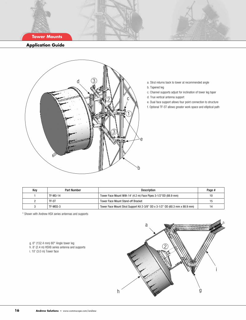
Custom Mount for Multiple Dishes With 84" (2 .1 m)
Face and 3-1/2" (88 .9 mm) Vertical Pipe
Customs
Andrew Solutions • www.commscope.com/andrew

• Roof Frames
• Mounting Components
• Customs
RO
OF-TO
P M
OU
NTS

Part Number Description Weight, lb (kg) Universal Tripod Mount, 2-7/8" or 3-1/2" (73 mm or 88.9 mm) ODTP-G300-B Base Only for 2-7/8" (73 mm) or 114.3 (51.8) 3-1/2" (88.9 mm) OD, Pipe Ordered SeparatelyTP-G300-72 2-7/8" OD x 72" (73 mm OD x 1.8 m) 145 (65.8)TP-G300-96 2-7/8" OD x 96" (73 mm OD x 2.4 m) 160 (72.6)TP-G300-126 2-7/8" OD x 126" (73 mm OD x 3.2 m) 170 (77.1)TP-G312-72 3-1/2" OD x 72" (88.9 mm OD x 1.8 m) 150 (68.0)TP-G312-96 3-1/2" OD x 96" (88.9 mm OD x 2.4 m) 170 (77.1)TP-G312-126 3-1/2" OD x 126" (88.9 mm OD x 3.2 m) 190 (86.2) Universal Tripod Mount, 4-1/2" (114.3 mm) ODTP-G412-B Base Only for 4-1/2" (114.3 mm) OD, 173.4 (78.7) Pipe Ordered Separately TP-G412-72 4-1/2" OD x 72" (114.3 mm OD x 1.8 m) 238.2 (108.0)TP-G412-96 4-1/2" OD x 96" (114.3 mm OD x 2.4 m) 259.8 (117.8)TP-G412-126 4-1/2" OD x 126" (114.3 mm OD x 3.2 m) 286.8 (130.1)TP-G412-150 4-1/2" OD x 150" (114.3 mm OD x 3.8 m) 308.4 (139.9)
1-1/8”(28.6 mm)
35-3/8”(898.5 mm)
17-5/8”(449.2 mm)
5’ 1-1/4”(1556.3 mm)
Non-penetrating Roof Ballast Sled for Tripods
Application: Non-penetrating solution for TP-G series mounts
Size: 87" (2 .2 m) faces
Design: Converts tripods to non-penetrating
Feature: Three ballast trays
Material: Hot dip galvanized steel
Includes: Sled only
Order Separately: Tripod and rubber mats
Part Number Description Weight, lb (kg) Non-penetrating Roof Ballast Sled for TripodsMT-416 Non-penetrating Roof Sled, 171.7 (77.9) Tripod Mount Ordered Separately MT-F1637 Rubber Mat, 1/2" x 18" x 48" 16.2 (7.3) (12.7 mm x 0.5 m x 1.2 m), Six Mats Required for Ballast Tray
18”(457.2 mm)
84-3/8”(2143 mm)
42”(1067 mm)
Wind Rating*: 85 mph (BWS) per latest revision of TIA/EIA-222 Exposure “C” per UBC, at 100' AGL
*Typical installation of one 6' standard microwave antenna using 4-1/2" pipe mast. See Engineering Data Table for ballast
• TP-G412-72 with MT-416
Universal Tripod Mounts
Application: Roof-top mounting for one antenna
Size: 2-7/8" (73 mm), 3-1/2" (88 .9 mm), or 4-1/2" (114 .3 mm) OD
Design: Heavy duty tripod mount
Feature: Interchangeable base unit
Material: Hot dip galvanized steel
Includes: Mount, with or without pipe
Order Separately: Roof sled and pipe
Roof-Top Mounts
32 Andrew Solutions • www.commscope.com/andrew
Roof Frames
• TP-G300-96

• RT-MPT-BT• RT-MPT-3
• RT-MPT-B2S
• RT-MPT-B2
• RT-MPT-5
33Andrew Solutions • www.commscope.com/andrew
Roof-Top Mounts
LR-1M
RT-MPT-C
Roof-top Monopole Tripods
Application: Single antenna mount for roof-tops
Design: Spliced center pole with angle kicker legs
Feature: Splice vertical post
Mounts to: Roof-top
Material: Hot dip galvanized steel
Includes: Center post, kicker angles, hardware
Part Number Description Weight, lb (kg) Monopole Tripod AssembliesRT-MPT-3 Roof-top Monopole Tripod Assembly, 380 (172.4) 3 Meter (9'-9") MastRT-MPT-4 Roof-top Monopole Tripod Assembly, 405 (183.7) 4 Meter (13'-1") MastRT-MPT-5 Roof-top Monopole Tripod Assembly, 470 (213.2) 5 Meter (16'-5") MastRT-MPT-6 Roof-top Monopole Tripod Assembly, 505 (229.1) 6 Meter (19'-8") MastRT-MPT-7 Roof-top Monopole Tripod Assembly, 565 (256.3) 7 Meter (22'-11") MastRT-MPT-B1 Roof-Top Monopole Antenna Section, 39-1/2" (1.0 m), No Step PegsRT-MPT-B2 Roof-Top Monopole Section, 78-1/2" (2.0 m), No Step PegsRT-MPT-B2S Roof-Top Monopole Section, 78-1/2" (2.0 m), With Step PegsRT-MPT-BT Roof-Top Monopole Tripod Kit for 157" (4.0 m) to 276-1/2" (7.0 m) Tall MonopoleRT-MPT-BT-3 Roof-Top Monopole Tripod Kit for 78-1/2" (2.0 m) Tall MonopoleRT-MPT-C Roof-Top Monopole Section CoverLR-1M Lightning Rod, 39-1/2" (1.0 m)
Custom Assemblies Available
Roof Frames

Mounting PipeOrdered Separately
Stand-off Wall Mount
Application: 3' Stand-off for wall mounting antennas
Size: 36" (914 .4 mm) stand-off
Design: Welded stand-off mount
Feature: Heavy duty for microwave antennas
Mounts to: Walls
Material: Hot dip galvanized steel
Includes: Bracket, stiff-arm, and wall mount hardware
Order Separately: 3-1/2" (88 .9 mm) or 4-1/2" (114 .3 mm) OD pipe
Part Number Description Weight, lb (kg) Stand-off Wall MountDM-300 Stand-off Wall Mount, 36" (914 mm), for Solid 151 (68.4) and Hollow Walls, Includes 72" (1.8 m) Stiff Arm
Roof-Top Mounts
34 Andrew Solutions • www.commscope.com/andrew
Corner Wall Mounts
Application: Antenna mounting for corners of buildings
Design: V-shaped corner mount
Feature: Adjustable clamp spacing
Mounts to: Wall corners
Material: Hot dip galvanized steel
Includes: Two brackets, pipe mount, and wall mount hardware
Part Number Description Weight, lb (kg) Corner Wall Mount With 2-3/8" (60.3 mm) OD Antenna PipeCW-M2-63 63" (1.6 m) Pipe 123.7 (56.1)CW-M2-96 96" (2.4 m) Pipe 133.6 (60.6) Corner Wall Mount With 4-1/2" (114.3 mm) OD Antenna PipeCW-M4-63 63" (1.6 m) Pipe 161.5 (73.3)CW-M4-96 96" (2.4 m) Pipe 191.2 (86.7)
Mounting Components
2-3/8” or 4-1/2” OD Pipe(60.3 mm or 114.3 mm)
5”(127 mm)
3”(76.2 mm)
11”(279.4 mm)
23”(584.2 mm)
• DM-300
• CW-M4-63

• Hollow Wall Mount
• Solid Wall Mount
35Andrew Solutions • www.commscope.com/andrew
Roof-Top Mounts
Adjustable Wall Mounts
Application: Mounting antennas on hollow or solid walls
Size: 12" (304 .8 mm) Square plate, 6-1/4" (158 .75 mm) or 12" (304 .8 mm) deep
Design: Welded dual brackets
Feature: Variable spacing flexibility
Mounts to: Versions for hollow or solid walls
Material: Hot dip galvanized steel
Includes: Two wall brackets and backing plates or anchors
Order Separately: U-bolts and 2-3/8" through 4-1/2" OD (60 .3 mm through 114 .3 mm) pipe
Part Number Description Weight, lb (kg) Adjustable Wall Mounts, 6" (152.4 mm) Stand-offMT-221 For Hollow Walls, Includes Backing Plates, 68.6 (31.1) Kit of 2MT-222 For Solid Walls, Includes Wall Anchors, Kit of 2 45.5 (20.6) Adjustable Wall Mounts, 12" (304.8 mm) Stand-offMT-221L For Hollow Walls, Includes Backing Plates, 75.3 (34.2) Kit of 2MT-222L For Solid Walls, Includes Wall Anchors, Kit of 2 50.7 (23.0) Optional Backing PlateMT-223 Backing Plate Kit 23.1 (10.5)
Mounting Components
U-Bolts for 2-3/8” - 4-1/2” OD(sold separately)
(60.3 mm - 114.3 mm OD)
Antenna Mounting Pipes(ordered separately)
6-1/4” or 12”(159 mm or 305 mm)
6”(152.4 mm)
6”(152.4 mm)
Non-penetrating Roof-top Peak Frames
Application: Mounting of antennas on roof-top peaks
Size: 36" (914 .4 mm) Wide ballast trays
Design: Non-penetrating design
Feature: Accepts 2-3/8" to 4-1/2" OD (60 .3 mm to 114 .3 mm) antenna mounting pipes
Mounts to: Peaked roofs
Material: Hot dip galvanized steel
Includes: Ballast tray, tie down angles, mount, hardware
Order Separately: Antenna mounting pipes
Part Number Description Weight, lb (kg) Non-penetrating Roof-top Peak FramesRT-PM-B Non-penetrating Roof-top Peak Frame, Base Kit. 105 (47.6) 2-3/8" to 4-1/2" OD (60.3 mm x 114.3 mm OD) Pipe Ordered Separately
36”(914.4 mm)
Pipe Ordered
Separately
Roof-Top Mounts
36 Andrew Solutions • www.commscope.com/andrew
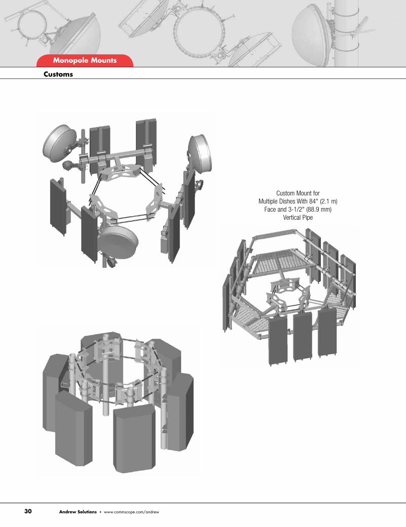
Custom Mounts for Specific Applications
Customs

• Coaxial Support Components
• Waveguide Bridge Kits
• Cable Ladder Kits
WA
VE
GU
IDE

Star Support Brackets
Application: Coaxial support on round or angle members
Size: 3/4" (19 .1 mm) and 7/16" (11 .1 mm) holes
Design: Bolt together stand-off mount
Feature: Six or twelve hole solution
Mounts to: Round and angle members
Material: Hot dip galvanized steel
Includes: Bracket
Part Number Description Weight, lb (kg) Star Support Tee BracketSS-TB2550 1-1/2" to 5-9/16" OD (38.1 mm to 8 (3.6) 141.3 mm OD) Round Members and 2-1/2" to 5" (50.8 mm to 127 mm) Angle Members SS-TB6080 4" to 10-3/4" OD (101.6 mm to 10 (4.5) 273.1 mm OD) Round Members and 4" to 8" (101.6 mm to 203.2 mm) Angle Members
Universal Round Member Support Bracket
Application: Coaxial support for monopoles
Size: 3/4" (19 .1 mm) and 7/16" (11 .1 mm) holes
Design: Coaxial cable support for round members
Feature: Ideal for co-location
Mounts to: Round members
Material: Hot dip galvanized steel
Includes: Bracket
Order Separately: Banding
Part Number Description Weight, lb (kg) Universal Round Member Support BracketRM-USBG Universal Round Member Support Bracket 9.0 (4.1) for 6 Runs, (Kit of 10)
• SS-TB2550
• RM-USBG
Waveguide
38 Andrew Solutions • www.commscope.com/andrew
Coaxial Support Components

12" or 24" Two-post Waveguide Bridge Kits
Application: Covered waveguide support from tower to cabinets
Design: Two-post, 10' (3 .0 m) safety grating
Feature: Complete kit for coaxial cable support
Material: Hot dip galvanized steel
Includes: Channel, posts, support brackets, caps, trapeze, and hardware
Order Separately: Additional accessories
Part Number Description Weight, lb (kg) 12" (0.3 m) Wide Two-post Safety Grated Waveguide Bridge KitWB-K110-B Two 13'-4" (4.1 m) Direct Burial Posts 325.0 (147.4)WB-K110-S Two 10'-6" (3.2 m) Base Shoe Posts 308.0 (139.7)
10’(3.0 m)
12”(305 mm)
3-1/2” OD(89 mm)
13’-4”(4.1 m)
• WB-K110-B
10’-6”(3.2 m)
12”(305 mm)
10’(3.0 m)
3-1/2” OD(89 mm)
• WB-K110-S
GPS Antenna Wall Mount
Application: Solid or hollow walls GPS mount
Size: 3/4" OD x 48" (19 .1 mm OD x 1 .2 m)
Design: Welded mount with 6" (152 .4 mm) stand-off
Feature: Threaded end for GPS antennas
Mounts to: Walls
Material: Hot dip galvanized steel
Includes: Mount
Order Separately: Anchoring hardware
Part Number Description Wt lb (kg) GPS Antenna Wall MountVC-GPSWM 3/4" OD x 48" (19.1 mm x 1.2 m) 10.5 (4.8)
8” Square(2.0 mm)
6”(152.4 mm)
48”(1.2 m)
• VC-GPSWM
Waveguide
39Andrew Solutions • www.commscope.com/andrew
Waveguide Bridge Kits
Waveguide
40 Andrew Solutions • www.commscope.com/andrew
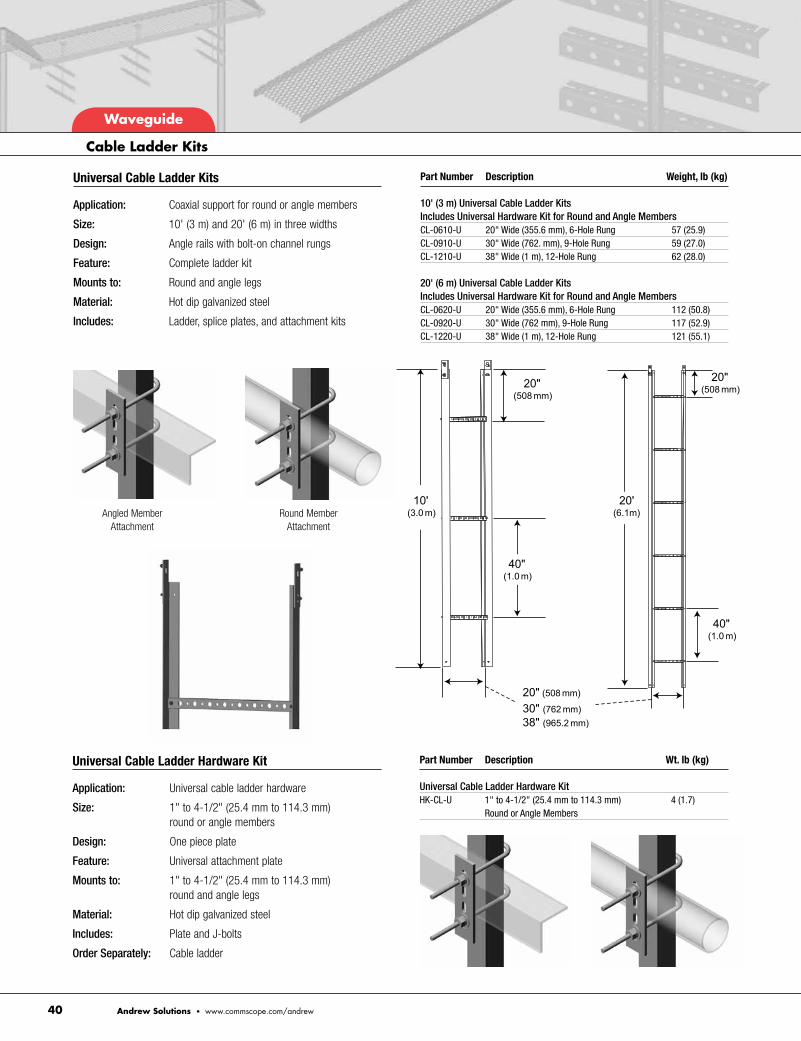
Universal Cable Ladder Kits
Application: Coaxial support for round or angle members
Size: 10' (3 m) and 20' (6 m) in three widths
Design: Angle rails with bolt-on channel rungs
Feature: Complete ladder kit
Mounts to: Round and angle legs
Material: Hot dip galvanized steel
Includes: Ladder, splice plates, and attachment kits
Part Number Description Weight, lb (kg) 10' (3 m) Universal Cable Ladder Kits Includes Universal Hardware Kit for Round and Angle MembersCL-0610-U 20" Wide (355.6 mm), 6-Hole Rung 57 (25.9)CL-0910-U 30" Wide (762. mm), 9-Hole Rung 59 (27.0)CL-1210-U 38" Wide (1 m), 12-Hole Rung 62 (28.0) 20' (6 m) Universal Cable Ladder Kits Includes Universal Hardware Kit for Round and Angle MembersCL-0620-U 20" Wide (355.6 mm), 6-Hole Rung 112 (50.8)CL-0920-U 30" Wide (762 mm), 9-Hole Rung 117 (52.9)CL-1220-U 38" Wide (1 m), 12-Hole Rung 121 (55.1)
Angled MemberAttachment
Round MemberAttachment
Universal Cable Ladder Hardware Kit
Application: Universal cable ladder hardware
Size: 1" to 4-1/2" (25 .4 mm to 114 .3 mm) round or angle members
Design: One piece plate
Feature: Universal attachment plate
Mounts to: 1" to 4-1/2" (25 .4 mm to 114 .3 mm) round and angle legs
Material: Hot dip galvanized steel
Includes: Plate and J-bolts
Order Separately: Cable ladder
Part Number Description Wt. lb (kg) Universal Cable Ladder Hardware KitHK-CL-U 1" to 4-1/2" (25.4 mm to 114.3 mm) 4 (1.7) Round or Angle Members
Cable Ladder Kits

• Microwave Ice Shields
• Power Telco Rack
• Equipment Platforms
SITE
RE
LATE
D

Microwave Antenna Ice Shield
Application: Protection microwave antenna from falling debris
Design: Heavy duty
Feature: Bolt together, light weight panels
Mounts to: 4-1/2" (114 .3 mm) OD pipe
Material: Hot dip galvanized steel
Includes: Ice shield and all attachment hardware
Order Separately: Pipe mount
Existing tower leg or pipe mount
75”, 100”, 126”, 140” or 160” long(1.9 m, 2.5 m, 3.2 m, or 4.1 m)
3-1/2” (88.9 mm) OD pipe included
3’, 4’, 6’, 8’, 10’ or 12’ Lengths(0.9 m, 1.2 m, 1.8 m, 2.4 m, 3.0 m or 3.7 m)
Part Number Description Weight, lb (kg) Microwave Antenna ShieldsMD-S3 Microwave Antenna Shield, 3' (914.4 mm) Antenna 260 (117.9)MD-S4 Microwave Antenna Shield, 4' (1.21 m) Antenna 290 (131.6)MD-S6 Microwave Antenna Shield, 6' (1.8 m) Antenna 443 (200.9)MD-S8 Microwave Antenna Shield, 8' (2.4 m) Antenna 571 (259.1)MD-S10 Microwave Antenna Shield, 10' (3 m) Antenna 649 (294.4)MD-S12 Microwave Antenna Shield, 12' (3.6 m) Antenna 763 (346.1)
Custom lightweight or additional sizes available . Contact our Customer Support Center for details .
• MD-S8
Site Related Components
42 Andrew Solutions • www.commscope.com/andrew
Microwave Ice Shields

Site Related Components
43Andrew Solutions • www.commscope.com/andrew
Universal Saddle Mount Attachment Kit
Application: Lattice towers
Design: Saddle mount and eye bolts
Feature: Two piece formed saddles
Mounts to: Straight or tapered legs up to 8-5/8" OD (219 .1 mm OD), 8" (203 .2 mm) angle 60°, or 6" (152 .4 mm) angle 90°
Material: Hot dip galvanized steel
Includes: Universal saddle mount, eye bolts
Order Separately: Microwave dish shield
Part Number Description Weight, lb (kg) Universal Saddle Mount for Attaching MD-S Series MountsSM-UMDS Universal Saddle Mount for Attaching MD-S 55 (24.9) Guy Wire Supports. Includes Seven Eye BoltsGB-05SB 5/8" x 1-3/4" Shouldered Eye Bolt
Microwave Shield Mounts

Site Related Components
44 Andrew Solutions • www.commscope.com/andrew
Microwave Ice Shields
SM-UMDS
MD-SSA4
MD-S Series Dish Shield
MD-FSS
PM-SC Series

Part Number Description Weight, lb (kg) Square Antenna Ice ShieldsMD-SQ2 Square Antenna Ice Shield, 2' (609.5 mm) Square 125 (56.7)MD-SQ3 Square Antenna Ice Shield, 3' (914.4 mm) Square 150 (68.0)MD-SQ4 Square Antenna Ice Shield, 4' (1.21 m) Square 190 (86.2)
Square Antenna Ice Shields
Application: Protection from falling debris
Design: Heavy duty
Feature: Protects antenna from falling ice
Mounts to: 4-1/2" (114 .3 mm) OD pipe
Material: Hot dip galvanized steel
Includes: Ice shield, mounting hardware
Order Separately: 4-1/2" (114 .3 mm) OD pipe mount
• MD-IS2 • MD-IS4
Microwave Dish Waveguide Shields
Application: Waveguide protection from falling debris
Size: Three versions (see table)
Design: Support and protection for waveguide
Feature: Protects waveguide from falling debris
Mounts to: 4-1/2” (114 .3 mm) OD pipe
Material: Hot dip galvanized steel
Includes: Ice shield and all attachment hardware
Order Separately: Pipe mount
Part Number Description Weight, lb (kg) Microwave Dish Waveguide ShieldsMD-IS2 Microwave Dish Waveguide Shield, 42 (19.1) 12" x 24" (304.8 mm x 610 mm)ShieldMD-IS4 Microwave Dish Waveguide Shield, 61 (27.7) 12" x 48" (304.8 mm x 1.2 m) ShieldMD-WS Microwave Dish Waveguide Shield, 24" 12 (5.4) (610 mm) Angle
Site Related Components
45Andrew Solutions • www.commscope.com/andrew
Microwave Ice Shields

Power Telco Racks
Application: Rack for mounting telco racks
Size: 13'-4" (4 .1 m) Posts
Design: Two posts, unistrut
Feature: Burial posts
Material: Hot dip galvanized steel
Includes: Posts, horizontal struts, mounting hardware
Part Number Description Weight, lb (kg) Telco Racks With 13'-4" (4.1 m) Burial Posts and 80" (2 m) Horizontal RailsPT-R102 Power Telco Rack, Two 80" Rungs, 13'-4" Burial Posts 135 (62.0)PT-R103 Power Telco Rack, Three 80" Rungs, 13'-4" Burial Posts 150 (68.0)PT-R104 Power Telco Rack, Four 80" Rungs, 13'-4" Burial Posts 165 (75.0)
Part Number Description Equipment Platform Bases, 4" (101.6 mm) Channel, Light Duty, for Up to 3500 lb (1587 kg) LoadingEQ-P4C0404-B 4' x 4' (1.2 m x 1.2 m) Base OnlyEQ-P4C0404-AL 4' x 4' (1.2 m x 1.2 m) Base With Four Adjustable LegsEQ-P4C0406-B 4' x 6' (1.2 m x 1.8 m) Base OnlyEQ-P4C0406-AL 4' x 6' (1.2 m x 1.8 m) Base With Four Adjustable LegsEQ-P4C0408-B 4' x 8' (1.2 m x 2.4 m) Base OnlyEQ-P4C0408-AL 4' x 8' (1.2 m x 2.4 m) Base With Four Adjustable Legs
• EQ-P4C0408-AL
4" Channel Equipment Platforms
Application: Base or elevated platform for cabinets
Design: Platforms with or without jackable legs
Feature: Easy-to-assemble, bolt together design
Material: Hot dip galvanized steel
Includes: Frame, grating, hardware
Order Separately: Adjustable legs for base platforms
13’-4”(4.1m)
6’-8”(2032 mm)
• PT-R104
Site Related Components
46 Andrew Solutions • www.commscope.com/andrew
Components

Inches Fraction Inches Decimal Millimeters
Fraction/Decimal/Metric Chart
NOTE: Not applicable to coaxial cables
1/16 0.0625 1.6
1/8 0.1250 3.2
3/16 0.1875 4.8
1/4 0.2500 6.4
5/16 0.3125 7.9
3/8 0.3750 9.5
7/16 0.4375 11.1
1/2 0.5000 12.7
9/16 0.5625 14.3
5/8 0.6250 15.9
11/16 0.6875 17.5
3/4 0.7500 19.1
13/16 0.8125 20.6
7/8 0.8750 22.2
15/16 0.9375 23.8
1 1.0000 25.4
Pipe Size OD (Inches) OD (mm)
Pipe Dimensions
1/2" 0.84 21.34
3/4" 1.05 26.67
1" 1.32 33.40
1-1/4" 1.66 42.16
1-1/2" 1.90 48.26
2" 2.38 60.33
2-1/2" 2.88 73.03
3" 3.50 88.90
3-1/2" 4.00 101.60
4" 4.50 114.30
5" 5.56 141.30
6" 6.63 168.30
8" 8.63 219.08
Gage Thickness (Inches) Thickness (mm)
Steel Thicknesses
10 0.1345 3.416
11 0.1196 3.038
12 0.1046 2.657
13 0.0897 2.278
14 0.0747 1.897
15 0.0673 1.709
16 0.0598 1.519
Stranded, OD (overall) Solid, OD AWG Size Inch Millimeter Inch Millimeter
AWG Wire Sizes
4/0 0.528 13.41 0.460 11.68
2/0 0.419 10.64 0.409 10.39
1/0 0.373 9.47 0.324 8.23
2 0.292 7.42 0.257 6.53
4 0.232 5.88 0.204 5.18
6 0.184 4.66 0.162 4.11
8 0.146 3.70 0.128 3.25
10 0.116 2.94 0.102 2.59
Convert From Convert To Multiply By
Conversion Factors
Length
foot (ft) meter (m) 0.3048
inch (in) meter (m) 0.0254
inch (in) centimeter (cm) 2.5400
meter (m) foot (ft) 3.2808
meter (m) inch (in) 39.3700
centimeter (cm) inch (in) 0.3937
millimeter (mm) inch (in) 0.0393
Area
square foot (ft2) square meter (m2) 0.0929
square meter (m2) square foot (ft2) 10.7639
Circle
radius diameter 2.0000
diameter radius 0.5000
diameter circumference 3.1416
radius circumference 6.2832
Weight
pound (lb) kilogram (kg) 0.4536
kilogram (kg) pound (lb) 2.2046

www.commscope.com/andrewVisit our Web site or contact your local Andrew Solutions representative for more information.
© 2012 CommScope, Inc. All rights reserved.
Andrew Solutions is a trademark of CommScope. All trademarks identified by ® or ™ are registered trademarks or trademarks, respectively, of CommScope. This document is for planning purposes only and is not intended to modify or supplement any specifications or warranties relating to Andrew Solutions products or services.
CA-105584-EN
Related Documents