Microscale adaptive optics: wave-front control with a m-mirror array and a VLSI stochastic gradient descent controller Thomas Weyrauch, Mikhail A. Vorontsov, Thomas G. Bifano, Jay A. Hammer, Marc Cohen, and Gert Cauwenberghs The performance of adaptive systems that consist of microscale on-chip elements @microelectromechanical mirror ~m-mirror! arrays and a VLSI stochastic gradient descent microelectronic control system# is analyzed. The m-mirror arrays with 5 3 5 and 6 3 6 actuators were driven with a control system composed of two mixed-mode VLSI chips implementing model-free beam-quality metric optimization by the stochastic parallel perturbative gradient descent technique. The adaptation rate achieved was near 6000 iterationsys. A secondary ~learning! feedback loop was used to control system parameters during the adaptation process, further increasing the adaptation rate. © 2001 Optical Society of America OCIS codes: 010.0010, 010.1080, 230.3990. 1. Introduction Microelectromechanical system ~MEMS! technology is a promising solution for resolving several obstacles that adaptive optics has faced during the past decade: system complexity, high cost, and difficulties in ex- tending the spatial resolution of wave-front- aberration correction. From a MEMS point of view, adaptive optics is an important and challenging ap- plication that takes full advantage of the unique fea- tures of micromachined technology such as the ability to fabricate thousands of microscale mechanical ac- tuators and optical elements ~including lenses, la- sers, and sensors! on a single silicon chip and the potential integration of this micromachined optical bench with control circuits and imaging sensors. 1–3 Combined efforts in both adaptive optics and MEMS technologies can lead to the development of affordable, high-resolution, fast microscale inte- grated adaptive-optics systems. Despite clearly out- lined goals, the transition to MEMS-based adaptive optics is not a simple matter of replacing a conven- tional deformable mirror with an advanced microma- chined mirror @or microelectromechanical mirror ~m mirror!#. A number of groups of researchers are now in- volved in developing micromachined adaptive mirrors. 4 –10 Unfortunately, newly developed m mir- rors are not often available for examination in actual adaptive-optics systems, and this makes comparing the performance of these devices difficult. Also, we have learned that MEMS-based adaptive optics is rather expensive. In most cases micromachined mirrors are unique, and only the possibility of mass production promises to bring down the cost of such mirrors; no one expects that m mirrors will soon be as popular and in such demand as car airbag MEMS sensors. There are also more fundamental problems related to the integration of MEMS and adaptive-optics tech- nologies. Assume that high-resolution, good optical quality, inexpensive micromachined mirrors are available. Is conventional adaptive optics ready to accept these m-mirror innovations, leading to an en- tire adaptive system with high resolution, low cost, and small size? With traditional adaptive-optics ap- proaches the transition to MEMS-based high- resolution wave-front control will require the development of small, high-resolution wave-front T. Weyrauch and M. A. Vorontsov ~[email protected]! are with the U.S. Army Research Laboratory, Computational and Information Sciences Directorate, Adelphi, Maryland 20783. T. G. Bifano is with the Department of Manufacturing Engineer- ing, Boston University, Brookline, Massachusetts 02446. J. A. Hammer is with MEMS Optical, Incorporated, 205 Import Circle, Huntsville, Alabama 35806. M. Cohen and G. Cauwenberghs are with the Department of Electrical and Computer Engineering, Johns Hopkins University, Baltimore, Maryland 21218. Received 6 October 2000; revised manuscript received 28 April 2001. 0003-6935y01y244243-11$15.00y0 © 2001 Optical Society of America 20 August 2001 y Vol. 40, No. 24 y APPLIED OPTICS 4243

Welcome message from author
This document is posted to help you gain knowledge. Please leave a comment to let me know what you think about it! Share it to your friends and learn new things together.
Transcript

itstaaptttspb
Microscale adaptive optics: wave-front controlwith a m-mirror array and a VLSI stochasticgradient descent controller
Thomas Weyrauch, Mikhail A. Vorontsov, Thomas G. Bifano, Jay A. Hammer, Marc Cohen,and Gert Cauwenberghs
The performance of adaptive systems that consist of microscale on-chip elements @microelectromechanicalmirror ~m-mirror! arrays and a VLSI stochastic gradient descent microelectronic control system# isanalyzed. The m-mirror arrays with 5 3 5 and 6 3 6 actuators were driven with a control systemcomposed of two mixed-mode VLSI chips implementing model-free beam-quality metric optimization bythe stochastic parallel perturbative gradient descent technique. The adaptation rate achieved was near6000 iterationsys. A secondary ~learning! feedback loop was used to control system parameters duringthe adaptation process, further increasing the adaptation rate. © 2001 Optical Society of America
OCIS codes: 010.0010, 010.1080, 230.3990.
1. Introduction
Microelectromechanical system ~MEMS! technologys a promising solution for resolving several obstacleshat adaptive optics has faced during the past decade:ystem complexity, high cost, and difficulties in ex-ending the spatial resolution of wave-front-berration correction. From a MEMS point of view,daptive optics is an important and challenging ap-lication that takes full advantage of the unique fea-ures of micromachined technology such as the abilityo fabricate thousands of microscale mechanical ac-uators and optical elements ~including lenses, la-ers, and sensors! on a single silicon chip and theotential integration of this micromachined opticalench with control circuits and imaging sensors.1–3
Combined efforts in both adaptive optics andMEMS technologies can lead to the development of
T. Weyrauch and M. A. Vorontsov [email protected]!are with the U.S. Army Research Laboratory, Computational andInformation Sciences Directorate, Adelphi, Maryland 20783.T. G. Bifano is with the Department of Manufacturing Engineer-ing, Boston University, Brookline, Massachusetts 02446. J. A.Hammer is with MEMS Optical, Incorporated, 205 Import Circle,Huntsville, Alabama 35806. M. Cohen and G. Cauwenberghs arewith the Department of Electrical and Computer Engineering,Johns Hopkins University, Baltimore, Maryland 21218.
Received 6 October 2000; revised manuscript received 28 April2001.
0003-6935y01y244243-11$15.00y0© 2001 Optical Society of America
affordable, high-resolution, fast microscale inte-grated adaptive-optics systems. Despite clearly out-lined goals, the transition to MEMS-based adaptiveoptics is not a simple matter of replacing a conven-tional deformable mirror with an advanced microma-chined mirror @or microelectromechanical mirror ~mmirror!#.
A number of groups of researchers are now in-volved in developing micromachined adaptivemirrors.4–10 Unfortunately, newly developed m mir-rors are not often available for examination in actualadaptive-optics systems, and this makes comparingthe performance of these devices difficult. Also, wehave learned that MEMS-based adaptive optics israther expensive. In most cases micromachinedmirrors are unique, and only the possibility of massproduction promises to bring down the cost of suchmirrors; no one expects that m mirrors will soon be aspopular and in such demand as car airbag MEMSsensors.
There are also more fundamental problems relatedto the integration of MEMS and adaptive-optics tech-nologies. Assume that high-resolution, good opticalquality, inexpensive micromachined mirrors areavailable. Is conventional adaptive optics ready toaccept these m-mirror innovations, leading to an en-tire adaptive system with high resolution, low cost,and small size? With traditional adaptive-optics ap-proaches the transition to MEMS-based high-resolution wave-front control will require thedevelopment of small, high-resolution wave-front
20 August 2001 y Vol. 40, No. 24 y APPLIED OPTICS 4243

ot
ct
tn
wpaHwcms
achTm
4
sensors and corresponding microscale phase-reconstruction computational hardware. This can-not be easily achieved with existing wave-frontsensing techniques. Thus the arrival of high-resolution m-mirror arrays demands the developmentf new MEMS-friendly adaptive wave-front controlechniques.
Among recent adaptive wave-front control algo-rithms the stochastic parallel gradient descent opti-mization technique is perhaps the most promising forMEMS-based adaptive optics.11–14 This algorithmdoes not require wave-front sensing and providescompact, low-power, scalable to high-resolution hard-ware implementation in a VLSI adaptive controllerinterfaced ~or potentially integrated! with microma-hined mirror arrays. Such a VLSI adaptive con-roller ~e.g., the AdOpt control system15! has been
developed and used in recent experiments with a127-element liquid-crystal phase modulator and a 37-control-channel continuously deformable micromach-ined mirror.16
The AdOpt control system architecture is ideal forevaluation of MEMS-based adaptive optics. Be-cause stochastic parallel gradient descent control ismodel free and independent of m-mirror characteris-tics, different types of micromachined mirror device
Fig. 1. Microphotographs of micromachined mirror arrays used in4 3 4 elements ~5 3 5 actuators!,5 ~b! MOz piston-type mirror arspring,6 ~d! BU12 12 3 12 actuator tip-tilt mirror array, ~e! UC pistoMO and UC mirrors are shown without lenslet arrays. PhotographMirror array structural elements are marked by capital letters: Mand BU12 are made without a metallic reflecting coating and thus
244 APPLIED OPTICS y Vol. 40, No. 24 y 20 August 2001
can be examined by use of the same adaptive systemconfiguration. The high operational rate of theVLSI controller ~up to 200 kHz! well exceeds the dy-namic range of all existing m mirrors, which makeshe entire adaptation rate dependent only on the dy-amic properties of the micromachined mirrors.We begin this paper with an attempt to proceedith MEMS-based adaptive optics through the incor-oration of recently developed micromachined mirrorrrays and VLSI microelectronic control systems.ere we analyze and compare the performance ofhat are to our knowledge the first adaptive systems
omposed only of microscale on-chip elements:-mirror arrays and a VLSI stochastic gradient de-cent microelectronic control system.
2. Microelectromechanical Mirror Arrays
Photographs of the micromachined mirror arraysused in the experiments described below are shown inFigs. 1~a!–1~e!. For adequate comparison ofdaptive-system performance we carried out thelosed-loop experiments with m-mirror arrays thatad approximately the same numbers of elements.hese mirrors are the 5 3 5 element tip-tilt control mirror developed at Boston University ~the BUtt mir-
ror! in Fig. 1~a! and two types of 6 3 6 element
experiments: ~a! BUtt segmented membrane tip-tilt mirror withith zig-zag spring, ~c! MOs piston-type mirror array with spiral
e 12 3 12 mirror array,7,17 ~f ! OKO continuous-membrane mirror.8agnified mirror elements are shown at the bottom right in ~a!–~e!.
ror elements; S, spring ~flexure!; and P, actuator post. Both BUtt
polysilicon membrane surface is partially transparent.
theray wn-typs of m, mirthe

aadtTt
M
co
foM
tca
pwcftpar~
~
piston-only control mirror made by MEMS Optical,Inc. ~the MOz and MOs mirrors! shown in Figs. 1~b!nd 1~c!. The BUtt mirror in Fig. 1~a! is composed ofsegmented silicone membrane supported by an un-erlying array of electrostatic parallel-plate actua-ors ~posts! located at the mirror element corners.he mirror surface contains the print-through pat-
ern that is visible in Fig. 1~a!. The MOz and MOsmirrors in Figs. 1~b! and 1~c! have differently shapedsprings S holding mirror elements M: zigzag for the
Oz and spiral-shaped for the MOs mirrors.We also examined ~in an open-loop system only! the
haracteristics of two 12 3 12 mirror arrays devel-ped at Boston University @tip-tilt-type BU12 mirror
in Fig. 1~d!# and of one from the University of Colo-rado at Boulder @piston-type UC mirror shown in Fig.1~e!# and a 37-electrode micromachined deformablemirror from OKO Technologies @Fig. 1~f !#. To in-crease the fill factor and partially overcome problemsrelated to the optical quality of the mirror surfaces weused all mirror arrays except the BU m mirrors andthe OKO mirror with a lenslet array attached to them-mirror chip. The experiments showed that a len-slet array composed of short ~6-mm or less! focal-length lenses introduces additional phase distortions~defocus and spherical aberrations! that cannot becompensated for by the adaptive system itself. Inaddition, use of the lenslet array typically provides afill factor of less than 75% and requires rather preciseadjustment, to ensure 90° illumination of the mirrorsurface.
The interference and focal-plane intensity patternspresented in Fig. 2 illustrate the optical quality of themicromachined mirrors in the absence of appliedvoltages. The elements of the BUtt mirror array inFigs. 2~a! and 2~b! display the presence of a ratherstrong unwanted curvature. In the more-recent mmirror @BU12 mirror in Figs. 2~c! and 2~d!# this cur-vature was almost completely eliminated by ion-induced compression of the mirror surface. Thetypical interference and focal-plane intensity pat-terns of the MOs mirror with the lenslet array in Figs.2~e! and 2~f ! display the presence of severe wave-ront aberrations that result from the optical qualityf both the mirror surface and the lenslet array. TheOz mirror with the lenslet array had an optical
quality similar to that shown in Figs. 2~e! and 2~f !.Typically, m-mirror electromechanical characteris-
ics are described in terms of voltage-deflectionurves ~the dependence of the actuator’s deflection onpplied voltage!.5,18 For analysis of the adaptive
system based on performance metric optimization de-scribed below, it is more appropriate to use a differentcharacteristic, which we call Strehl ratio sensitivitycurves. We estimated the electromechanical char-acteristics of the m-mirror elements by measuring thedependence of Strehl ratio ~St! on voltages uj ~ j 51, . . . , N! applied to various m-mirror electrodes ~N isthe number of actuators!. The Strehl ratio is de-fined as St~uj! 5 P~uj!yP0, where P~uj! and P0 5P~uj 5 0! are optical power values measured inside a50-mm pinhole placed in the focal plane of a lens with
focal length F 5 15 cm ~Fig. 3!. Results of the Strehlratio measurements are presented in Fig. 4 for MOsand for BUtt mirror chips for three different actuatorlocations. For the piston-type MOs mirror the de-
endencies St~uj! are periodic functions @Fig. 4~a!#ith approximately equal-amplitude maxima that
orrespond to 2p rad phase shifts. As can be seenrom Fig. 4~a!, the mirror stroke depends on the ac-uator’s location and varies from ;1.27 mm ~3.75 phase shift! for the corner element to 1.5 mm for thectuator located in the mirror center. The Strehlatio sensitivity curves for the tip-tilt mirror arrayBUtt mirror! presented in Fig. 4~b! are quite different
Fig. 2. ~a!, ~c!, ~e! Mirror surface interference patterns and ~b!, ~d!,~f ! corresponding far-field intensity distributions with no appliedvoltages for ~a!, ~b! the BUtt mirror, ~c!, ~d! the BU12 mirror, and ~e!,f ! the MOs mirror with a diffractive lenslet array ~e, f !.
Fig. 3. Schematic of the experimental setup for Strehl ratio mea-surements.
20 August 2001 y Vol. 40, No. 24 y APPLIED OPTICS 4245

ar
fin
l
raoi
cpmFmvcta
a
a
5
sw
4
from the corresponding curves for the piston-typemirror @cf. the curves in Figs. 4~a! and 4~b!#. Thesecurves are also periodic with 2p rad phase shiftsbetween local maxima, but, Fig. 4~b! shows, the am-plitude of the Strehl ratio local maximum decreaseswith an increase in the actuator displacement. Thedependence of the sensitivity curve on actuator loca-tion is more pronounced for the tip-tilt mirror thanfor the piston-type mirror in Fig. 4~a!. Spatial non-uniformity in the actuator sensitivity and the presenceof local maxima complicates control-system design, es-pecially if the corresponding m mirror is used in aphase-conjugation-type adaptive optical system.19
A technique similar to the one described above wasused for evaluation of the m-mirror elements’ dy-namic characteristics. In the scheme in Fig. 3 asmall-amplitude probe voltage u~t! 5 a sin~nt! 1 a0was applied to a single m-mirror actuator, where and v are the ac component amplitude and frequency,espectively, and a0 is an offset voltage. The mea-
sured dependencies of Strehl ratio amplitude St~n! onrequency n ~Strehl ratio resonance curves! are shownn Fig. 5 for several m-mirror types. The first reso-ance was observed at frequencies n0 > 2 kHz for the
OKO mirror, n0 > 5.3 kHz for the MOs mirror, and n0> 5.8 kHz for the MOz mirror. For both the BUttand the UC mirrors the observed dependencies St~n!had no resonance peaks within the examined fre-quency bands of 100 and 20 kHz, respectively. TheBUtt mirror chip displayed relatively uniform dy-namic characteristics within a frequency bandwidthof ;10 kHz. The major characteristics of the m mir-rors that we examined are summarized in Table 1.
Based on the previous analysis, the following mmirrors were chosen for closed-loop experiments withthe microscale ~MEMS–VLSI! adaptive system: the
Fig. 4. Dependence of Strehl ratio on voltage applied to a singleactuator for ~a! the MOs and ~b! the BUtt mirrors. Strehl ratioensitivity curves 1, 2, and 3 correspond to three actuator locationsithin the mirror array, as shown at the bottom left ~M is a mirror
element; P is an actuator post!.
246 APPLIED OPTICS y Vol. 40, No. 24 y 20 August 2001
tip-tilt type 5 3 5 mirror array from Boston Univer-sity ~BUtt mirror! and two piston-type 6 3 6 mirrorarrays from MEMS Optical, Inc. ~the MOs and MOzmirrors!. The rationale behind this choice is as fol-ows: The BUtt mirror chip provides the best dy-
namic operational range among the m mirrorsexamined, but it cannot be interfaced directly withthe AdOpt VLSI controller in its present form, fabri-cated in a standard complementary metal-oxidesemiconductor process. The output control voltagesfrom the VLSI controller chips are within the range of25 to 15 V. These voltages are not sufficiently highto drive the BUtt mirror array. As can be seen fromthe sensitivity curves in Fig. 4~b!, the BUtt mirrorequires an ;200-V control voltage range to provide
2p phase shift. For this reason amplifiers withutput voltages in the range 0–300 V were used tonterface the BUtt mirror with the VLSI controller.
The set of 26 amplifiers developed at Boston Univer-sity was built onto one 6.50 3 4.50 ~16.51 cm 3 11.43m! board. The need for external high-voltage am-lifiers is highly undesirable for the future develop-ent of high-resolution microscale adaptive systems.rom this point of view the low-voltage MO and UCirrors have the obvious advantage ~unless high-
oltage amplifiers are integrated onto the MEMShip!: both of these mirrors can be interfaced withhe VLSI controller directly to form a microscaledaptive system.In the closed-loop experiments with MO mirrors an
dditional constant ~offset! voltage u0 was applied tothe mirrors’ common electrode to permit direct inter-facing of the VLSI controller with the MOs mirrorrray. With the offset voltage u0 5 225 V, the MOs
mirror operated with input control voltages thatranged from 20 to 30 V and provided an approxi-mately 4p wave-front phase shift @see the sensitivitycurves in Fig. 4~a!#. For the MOz mirror an offsetvoltage of 210 V was sufficient to provide a phaseshift near 3.5p, with the control voltage ranging from
to 15 V.
Fig. 5. Strehl ratio resonance curves for the micromachined mir-rors examined. Resonance curves for OKO, UC, MOs, and MOz
mirrors are shown in linear scales and the BU mirror on a loga-rithmic frequency scale.

6msc
htTsopbd
m
mmmdim
Table 1. Parameters of the m-Mirror Chips Used in the Experiments
3. Microscale MEMS–VLSI Adaptive System
A. Experimental Setup
A schematic of the microscale VLSI–MEMS-basedadaptive system is shown in Fig. 6. Key system el-ements include a micromachined mirror, a VLSI con-troller, and a photodetector, as presented in Fig. 7.The expanded input laser beam from the semiconduc-tor laser ~l 5 0.69 mm! with a diameter of ;8 mm wassplit into two equal parts by beam splitter BS1 ~Fig.!. Reference mirror M and micromachined mirror–M formed an interferometer that was used to vi-ualize the wave-front phase pattern in the plane ofamera CCD1. An imaging system composed of
lenses L1 and L2 formed a magnified image of them-mirror surface at the camera chip. The wave re-flected from the m mirror was focused by lens L1 andbeam splitter BS2 onto the plane of the 50-mm pin-
ole. To prevent the reference beam from enteringhe pinhole we slightly tilted the reference mirror.he laser beam’s power inside the pinhole was mea-ured with a photodetector, and the photodetector’sutput voltage was used as the adaptive system’serformance metric ~beam-quality metric! J. Thiseam-quality metric is proportional to the previouslyefined Strehl ratio St and depends on voltages $uj%
applied to the m-mirror electrodes: J 5 J~u1, . . . ,uN!, where N 5 25 for BUtt and N 5 36 for MOmirrors. Accordingly, maximization of beam-quality metric J is equivalent to Strehl ratio maxi-
ization. Lens L3 and beam splitter BS3 were used
Fig. 6. Schematic of the microscale adaptive-optics system basedon the AdOpt VLSI controller and micromachined mirrors used inthe experiments.
Mirror Type of MotionNumber ofActuators
MirrorElement Size
MOz Piston 36 160 mm 5MOs Piston 36 100 mm 5UC Piston 128 ~36 used! 74 mm 2BUtt Tip-tilt 25 242 mm 2OKO Continuous
membrane37 12-mm active
aperture1
to magnify the image of the laser beam’s intensitydistribution in the plane conjugate to the pinhole.This intensity distribution was registered by cameraCCD2. Iris diaphragm D placed in the focal plane oflens L1 was used as a low-pass spatial filter to cut offthe higher-order spectral components that resultedfrom laser beam diffraction off the periodic structureof the m-mirror array.
B. VLSI Feedback Controller
Adaptive feedback control of the m-mirror arrays wasachieved with VLSI implementation of the parallelstochastic perturbative gradient descent algorithm~AdOpt control system architecture!.15,16 The VLSIcontroller performed iterative parallel computation~upgrade! of control voltages $uj% applied to the
-mirror electrodes, leading to maximization–inimization of the externally supplied performanceetric J. A single AdOpt chip provided parallel up-
ates for 19 output-control signals. Correspond-ngly, two AdOpt chips were enough to control the
icromachined mirror arrays used in the experi-
Fig. 7. Photograph of the key elements ~VLSI controller board, mmirror, and photodetector! of the microscale adaptive-optics sys-tem based on stochastic parallel gradient descent optimization.The VLSI controller board comprises 7 AdOpt chips and can pro-vide control of as many as 133 channels. The U.S. quarter coin atthe bottom right is used to indicate the scale.
ctuator Pitch
ActuatorVoltage
Range ~V!Stroke~mm!
ResonanceFrequency
m ~rectangular! 0–15 0.7 5.8 kHzm ~rectangular! 0–30 1.1 5.3 kHzm ~rectangular! 0–11 0.9 Not observedm ~rectangular! 0–300 0.9 Not observedm ~hexagonal! 0–210 6 ~center! 2 kHz ~1st peak!
A
00 m00 m50 m50 m.75 m
20 August 2001 y Vol. 40, No. 24 y APPLIED OPTICS 4247

t
bnVw
i
e
attc
st
ur
t
ivtog
pca
4
ments. The VLSI controller requires both analogand digital externally supplied control signals gener-ated by a desktop PC with two analog–digital input–output cards ~ComputerBoards CIO-DAS1602y12!.The computer generated the timing signals, con-trolled measurements of beam-quality metric J, andupdated the algorithm parameters. Controlling theVLSI system parameters permitted implementationof a secondary control-loop system designed to modifythe algorithm parameters during the adaptation pro-cess to increase its convergence rate ~see Subsection4.D below!. Using a computer to control the AdOptsystem was convenient for analysis of system perfor-mance. In actual microscale systems the computercan be replaced by a microcontroller integrated on theAdOpt board.
As an illustration of VLSI controller operationalprinciples, consider the simplified timing diagramshown in Fig. 8. A single iteration cycle of the con-trol voltage’s update at the nth iterative step consistsof the following phases:
~1! A clock signal from the computer board is appliedto the VLSI controller digital input at the moment t 5
0. This signal activates on-chip generation of an un-correlated pseudorandom parallel stream of coin-flipsignals ~perturbations! $duj
~n!% that have identical am-plitudes uduj
~n!u 5 p and a Bernoulli probability distri-ution P@duj
~n! 5 1p# 5 0.5 for all j 5 1, . . . N and all. These perturbations are applied in parallel to theLSI system’s output electrodes interfaced directlyith the micromachined mirror electrodes ~for MOs
and MOz mirrors! or through amplifiers ~for the BUttmirror!. Voltage perturbations result in a variationn the laser beam power inside the pinhole and hence
Fig. 8. Simplified timing diagrams for a single iteration cycle ofthe AdOpt system: sequence of external clock signals supplied tothe AdOpt chips ~top!, clock signals used for beam-quality metricmeasurements ~middle!, corresponding sequence of changes inbeam-quality metric J ~bottom!.
248 APPLIED OPTICS y Vol. 40, No. 24 y 20 August 2001
in a variation of the photodetector’s output voltagethat corresponds to beam-quality metric J. The per-turbed beam-quality metric value J1
~n! 5 J@u1~n! 1
du1~n!, . . . , uN
~n! 1 duN~n!# is measured at the moment
t1 5 t0 1 tdel after a time delay tdel introduced by thePC computer. The controllable time delay was in-troduced to prevent m-mirror dynamics from influ-ncing metric measurement: tdel ' 1.5tm, where
tm 5 2pyn0 is the m mirror’s characteristic responsetime and n0 is resonance frequency.
~2! When metric value J1~n! has been measured ~at
t2 5 t1 1 tm, where tm > 45 ms!, the computer boardctivates on-chip generation of complementary per-urbations $2duj
~n!% at moment t3. These perturba-ions applied to the m-mirror array result in aorresponding change in beam-quality metric J2
~n! 5J@u1
~n! 2 du1~n!, . . . , uN
~n! 2 duN~n!#.
~3! After the computer introduces time delay tdel,the perturbed beam-quality metric value J2
~n! is mea-ured and digitized. In the timing diagram in Fig. 8his measurement corresponds to moment t4 5 t3 1
tdel. After the measurement ~at time t5 5 t4 1 tm!,perturbation voltages are deactivated.
~4! Using perturbed beam-quality metric valuesJ1
~n! and J2~n!, the computer calculates the following
quantities: metric perturbation, dJ~n! 5 J1~n! 2 J2
~n!;averaged metric, J~n! 5 1⁄2 @J1
~n! 1 J2~n!#; sign@dJ~n!#;
and the product of gdJ~n!, where g is a predefinedpgrade coefficient. With a 400-MHz PC the timeequired for these calculations, tcal, is less than 0.1
ms. Parameter g controls the update rate and theoptimization mode of the performance metric: Pos-itive g corresponds to metric maximization; negative,to metric minimization. The product g dJ~n! is usedo generate the update pulse tup 5 gudJ~n!uDtc applied
to the VLSI chip input, where Dtc is the duration ofthe clock pulses. In the feedback control system de-scribed here, Dtc > 1.0 ms.
The control-voltage update phase starts at time t6and lasts a duration of tup ~typically tup varies fromDtc to 25Dtc!. During this time the VLSI controllercomputes updated control-output voltages accordingto the following gradient descent procedure:
uj~n11! 5 uj
~n! 1 g9udJ~n!usign@dJ~n!#sign@duj~n!#, (1)
where g9 is a constant that is proportional to g. Us-ng the AdOpt system, one can obtain the output-oltage change for each control channel @the seconderm in Eq. ~1!# by charging–discharging a set ofn-chip capacitors during the update time tup 5udJ~n!uDtc. The value sign@dJ~n!# is supplied to the
chip input through the PC board, and the valuessign@duj
~n!# are stored on-chip.With the use of a 1.0-MHz external-clock generator
and two analog–digital input–output boards ~Com-uterBoards CIO-DAS1602y12!, one iteration of theontrol-voltages update required tit ' 160 ms ~in thebsence of the computer-introduced time delay tdel!.
Using commercially available fast analog–digitalconverters, one can further decrease the time re-quired for a single iteration to tit ' 100 ms.
e
c
5toapFw
t~
4. Self-Induced Phase-Distortion Compensation
A. Characterization of Adaptive-System Performance
Adaptive-system performance was characterized bythe self-induced aberration-compensation techniquedescribed in Refs. 15 and 16. In this method randomphase distortions are introduced by an adaptive sys-tem as a result of minimization of the beam-qualitymetric. For statistical analysis of system operationwe used a large number M of consecutively repeatedadaptation trials ~typically M 5 500!. Each adapta-tion trial included a sequence of Nit 5 4096 iterationsteps n ~control-voltage updates! executed by theAdOpt system ~n 5 1, . . . , Nit!. During the first2048 iteration steps the update parameter g set bythe computer was negative, which corresponded tominimization of the beam-quality metric. This ad-aptation mode was used to generate random phasedistortions that resulted in a highly distorted laserbeam intensity distribution in the plane of the pho-todetector. At the iteration n 5 ~1⁄2Nit 1 1! 5 2049the sign of update parameter g, and hence the adap-tation mode, was changed. At this second phase ofthe adaptation trial ~from n 5 2049 to n 5 4096! theadaptive system maximized the beam-quality met-ric such that the laser beam’s power was concen-trated inside the pinhole. At each iteration themeasured perturbed beam-quality metric valuesJ1
~n! and J2~n! were averaged: J~n! 5 @J1
~n! 1 J2~n!#y2.
The metric values $J~n!% ~n 5 1, . . . , 4096! as well asthe metric perturbation values $dJ~n!% were stored incomputer memory. The complete set of data usedfor statistical analysis of adaptive-system perfor-mance included metric values $J~n!% and $dJ~n!% col-lected for M consecutively repeated adaptation trials.
B. Convergence Rate and Adaptation Speed
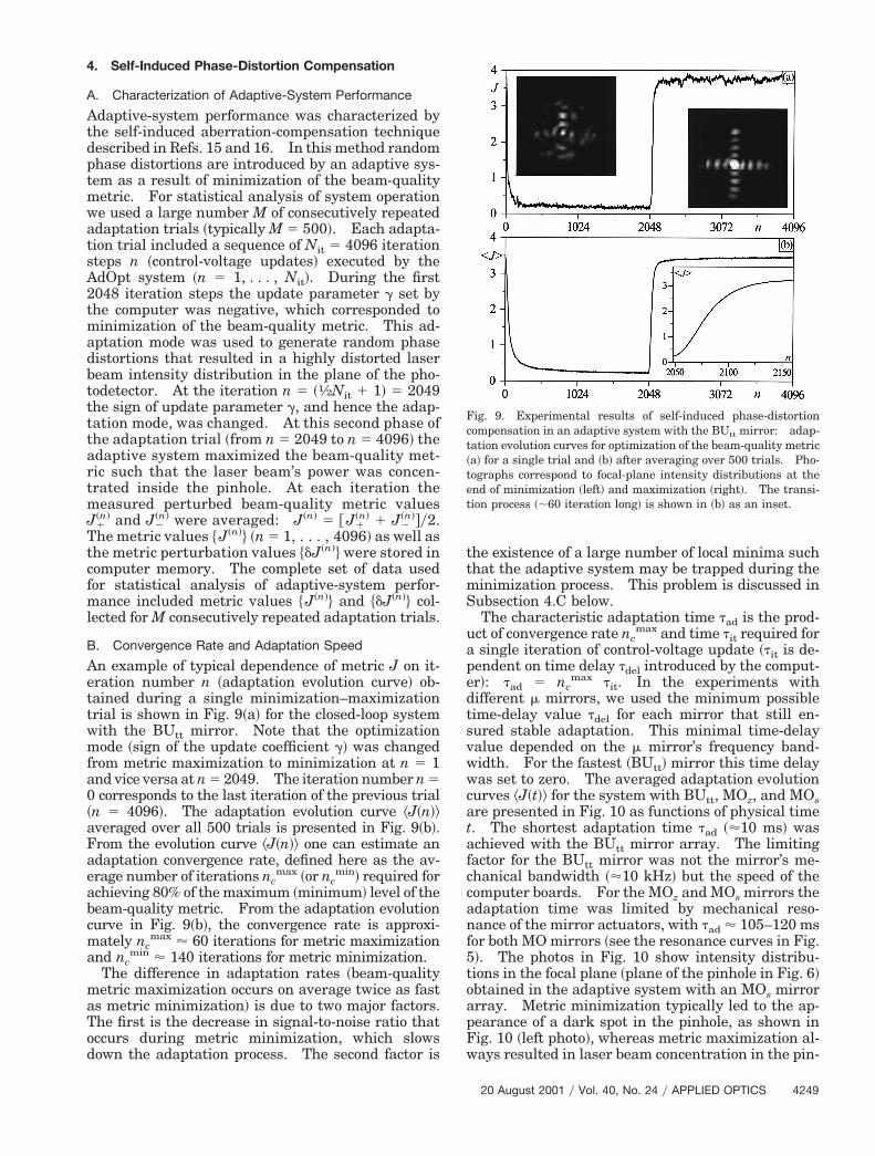
An example of typical dependence of metric J on it-eration number n ~adaptation evolution curve! ob-tained during a single minimization–maximizationtrial is shown in Fig. 9~a! for the closed-loop systemwith the BUtt mirror. Note that the optimizationmode ~sign of the update coefficient g! was changedfrom metric maximization to minimization at n 5 1and vice versa at n 5 2049. The iteration number n 50 corresponds to the last iteration of the previous trial~n 5 4096!. The adaptation evolution curve ^J~n!&averaged over all 500 trials is presented in Fig. 9~b!.From the evolution curve ^J~n!& one can estimate anadaptation convergence rate, defined here as the av-erage number of iterations nc
max ~or ncmin! required for
achieving 80% of the maximum ~minimum! level of thebeam-quality metric. From the adaptation evolutioncurve in Fig. 9~b!, the convergence rate is approxi-mately nc
max ' 60 iterations for metric maximizationand nc
min ' 140 iterations for metric minimization.The difference in adaptation rates ~beam-quality
metric maximization occurs on average twice as fastas metric minimization! is due to two major factors.The first is the decrease in signal-to-noise ratio thatoccurs during metric minimization, which slowsdown the adaptation process. The second factor is
the existence of a large number of local minima suchthat the adaptive system may be trapped during theminimization process. This problem is discussed inSubsection 4.C below.
The characteristic adaptation time tad is the prod-uct of convergence rate nc
max and time tit required fora single iteration of control-voltage update ~tit is de-pendent on time delay tdel introduced by the comput-r!: tad 5 nc
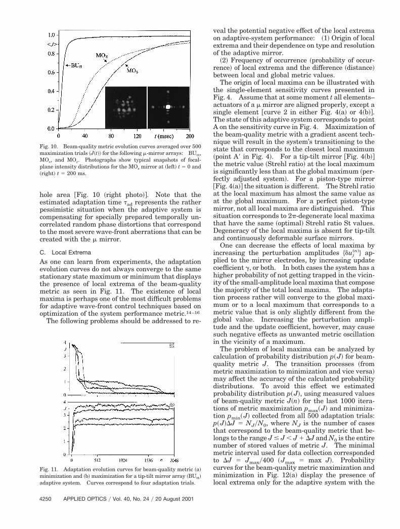
max tit. In the experiments withdifferent m mirrors, we used the minimum possibletime-delay value tdel for each mirror that still en-sured stable adaptation. This minimal time-delayvalue depended on the m mirror’s frequency band-width. For the fastest ~BUtt! mirror this time delaywas set to zero. The averaged adaptation evolutioncurves ^J~t!& for the system with BUtt, MOz, and MOsare presented in Fig. 10 as functions of physical timet. The shortest adaptation time tad ~'10 ms! wasachieved with the BUtt mirror array. The limitingfactor for the BUtt mirror was not the mirror’s me-hanical bandwidth ~'10 kHz! but the speed of the
computer boards. For the MOz and MOs mirrors theadaptation time was limited by mechanical reso-nance of the mirror actuators, with tad ' 105–120 msfor both MO mirrors ~see the resonance curves in Fig.!. The photos in Fig. 10 show intensity distribu-ions in the focal plane ~plane of the pinhole in Fig. 6!btained in the adaptive system with an MOs mirrorrray. Metric minimization typically led to the ap-earance of a dark spot in the pinhole, as shown inig. 10 ~left photo!, whereas metric maximization al-ays resulted in laser beam concentration in the pin-
Fig. 9. Experimental results of self-induced phase-distortioncompensation in an adaptive system with the BUtt mirror: adap-ation evolution curves for optimization of the beam-quality metrica! for a single trial and ~b! after averaging over 500 trials. Pho-
tographs correspond to focal-plane intensity distributions at theend of minimization ~left! and maximization ~right!. The transi-tion process ~;60 iteration long! is shown in ~b! as an inset.
20 August 2001 y Vol. 40, No. 24 y APPLIED OPTICS 4249
TAtns~tif@aamstDa
i
p
cml
M
4
hole area @Fig. 10 ~right photo!#. Note that theestimated adaptation time tad represents the ratherpessimistic situation when the adaptive system iscompensating for specially prepared temporally un-correlated random phase distortions that correspondto the most severe wave-front aberrations that can becreated with the m mirror.
C. Local Extrema
As one can learn from experiments, the adaptationevolution curves do not always converge to the samestationary state maximum or minimum that displaysthe presence of local extrema of the beam-qualitymetric as seen in Fig. 11. The existence of localmaxima is perhaps one of the most difficult problemsfor adaptive wave-front control techniques based onoptimization of the system performance metric.14–16
The following problems should be addressed to re-
Fig. 10. Beam-quality metric evolution curves averaged over 500maximization trials ^J~t!& for the following m-mirror arrays: BUtt,
Os, and MOz. Photographs show typical snapshots of focal-plane intensity distributions for the MOs mirror at ~left! t 5 0 and~right! t 5 200 ms.
Fig. 11. Adaptation evolution curves for beam-quality metric ~a!minimization and ~b! maximization for a tip-tilt mirror array ~BUtt!adaptive system. Curves correspond to four adaptation trials.
250 APPLIED OPTICS y Vol. 40, No. 24 y 20 August 2001
veal the potential negative effect of the local extremaon adaptive-system performance: ~1! Origin of localextrema and their dependence on type and resolutionof the adaptive mirror.
~2! Frequency of occurrence ~probability of occur-rence! of local extrema and the difference ~distance!between local and global metric values.
The origin of local maxima can be illustrated withthe single-element sensitivity curves presented inFig. 4. Assume that at some moment t all elements–actuators of a m mirror are aligned properly, except asingle element @curve 2 in either Fig. 4~a! or 4~b!#.
he state of this adaptive system corresponds to pointon the sensitivity curve in Fig. 4. Maximization of
he beam-quality metric with a gradient ascent tech-ique will result in the system’s transitioning to thetate that corresponds to the closest local maximumpoint A9 in Fig. 4!. For a tip-tilt mirror @Fig. 4~b!#he metric value ~Strehl ratio! at the local maximums significantly less than at the global maximum ~per-ectly adjusted system!. For a piston-type mirrorFig. 4~a!# the situation is different. The Strehl ratiot the local maximum has almost the same value ast the global maximum. For a perfect piston-typeirror, not all local maxima are distinguished. This
ituation corresponds to 2p-degenerate local maximahat have the same ~optimal! Strehl ratio St values.egeneracy of the local maxima is absent for tip-tiltnd continuously deformable surface mirrors.One can decrease the effects of local maxima by
ncreasing the perturbation amplitudes $duj~n!% ap-
plied to the mirror electrodes, by increasing updatecoefficient g, or both. In both cases the system has ahigher probability of not getting trapped in the vicin-ity of the small-amplitude local maxima that composethe majority of the total local maxima. The adapta-tion process rather will converge to the global maxi-mum or to a local maximum that corresponds to ametric value that is only slightly different from theglobal value. Increasing the perturbation ampli-tude and the update coefficient, however, may causesuch negative effects as unwanted metric oscillationin the vicinity of a maximum.
The problem of local maxima can be analyzed bycalculation of probability distribution p~J! for beam-quality metric J. The transition processes ~frommetric maximization to minimization and vice versa!may affect the accuracy of the calculated probabilitydistributions. To avoid this effect we estimatedprobability distribution p~J!, using measured valuesof beam-quality metric J~n! for the last 1000 itera-tions of metric maximization pmax~J! and minimiza-tion pmin~J! collected from all 500 adaptation trials:
~J!DJ 5 NJyN0, where NJ is the number of casesthat correspond to the beam-quality metric that be-longs to the range J # J , J 1 DJ and N0 is the entirenumber of stored values of metric J. The minimalmetric interval used for data collection correspondedto DJ 5 Jmaxy400 ~Jmax 5 max J!. Probabilityurves for the beam-quality metric maximization andinimization in Fig. 12~a! display the presence of
ocal extrema only for the adaptive system with the
it
ai
mtsTt
ptrprti
mcl
tv
tip-tilt type BUtt mirror. The probabilities for theselocal extrema are relatively small. As expected, theprobability distributions for the adaptive system withthe piston-type MOs mirror are unimodal: All localextrema are 2p degenerate and have approximatelythe same metric values. In the case of the tip-tilt-type BUtt mirror, increasing the update coefficientvalue g eliminated local states in the adaptive sys-tem’s dynamics but at the expense of widening theprobability-density curves because of the increase inmetric oscillations that occurs in the vicinity of theglobal maximum, as shown in Fig. 12~b!.
D. Control of Adaptation Rate: Change in UpdateCoefficient through Learning
As we mentioned in Subsection 3.B, the system’s ad-aptation rate depends on the value of update coeffi-cient g that is externally supplied to the VLSI chips.Thus the AdOpt control system architecture permitson-the-fly ~at each iteration! control of the updatecoefficient. For control of coefficient g the followinginformation was available: the perturbed beam-quality metric values J1
~n! and J2~n! measured at each
teration and the calculated difference ~metric per-urbation! dJ~n! 5 J1
~n! 2 J2~n!. In the experiments
described below we also performed at each iterationan additional measurement of the unperturbed met-ric value J~n! and calculated two additional metricperturbations: DJ1
~n! 5 J1~n! 2 J~n! and DJ2
~n! 5 J2~n! 2
J~n!. The measurement of J~n! lasted ;25 ms. Inthe absence of the introduced time delay tdel thisdditional measurement resulted in a nearly 15%ncrease in the time tit required for a single iteration.
A portion of the obtained data was saved in computermemory, thus permitting the use of data from previ-ous l 5 1, . . . , L iterations ~control with L-step-long
emory!. With a 400-MHz PC computer the addi-ional time required for the calculations and datatorage was less then 1.5 ms and can be neglected.he question is how to use this available informationo control the update coefficient.
First, consider the dependence of the adaptationrocess’s convergence rate nc
max ~number of itera-ions required to reach 80% of the beam-quality met-ic’s maximum value! on the update coefficient g asresented in Fig. 13. As expected, an increase in gesulted in acceleration of the convergence speed ofhe adaptation ~nc
max decrease!. However, decreas-ng nc
max increased the normalized standard devia-tion of beam-quality metric fluctuations, defined ass# J 5 0.001 ¥n53097
4096 $^@~J~n! 2 ^J~n!&1y2y^J~n!&%.Standard deviation s# J included averaging over thelast 1000 iterations of each optimization trial. Thevalues s# J obtained in the experiment are shown inparentheses in Fig. 13. Increasing g is advanta-geous only during the transition phase of the adap-tation process and is unfavorable when the adaptivesystem is near the extremum.
It follows that adaptive control should provide foran automatic increase in the update coefficient dur-ing the transition phase and for a decrease otherwise.The problem is to determine the current phase of theadaptation process ~transition, near minimum, near
aximum! and use this information for iterativehange of the upgrade coefficient. We used the fol-owing three quantities ~indicators! H~n! to identify
phase in the adaptation process:
H1~n! 5 usign@DJ1
~n!# 2 sign@DJ2~n!# u,
H2~n! 5 udJ~n!u,
H3~n! 5 (
l51
L
uJ~n! 2 J~n2l !u. (2)
Fig. 13. Convergence rate ncmax of the adaptation process relative
to update coefficient g for maximization of the beam-quality metricin an adaptive system with the BUtt mirror. The metric fluctua-ion level is characterized by the normalized standard-deviationalues s# J shown in parentheses. The diamond represents results
obtained in the system with a change in the adaptive updatecoefficient. The fluctuation level in the system without adapta-tion was near 0.01.
Fig. 12. Probability-density distributions of beam-quality metricspmax and pmin obtained during 500 adaptation trials: ~a! adaptivesystem with the MOs and BUtt m mirrors and fixed update coeffi-cient g 5 60 and ~b! probability distribution pmax for the adaptivesystem with the BUtt m mirror for three values of the updatecoefficient g. Beam-quality metric J is normalized by its maxi-mum value Jmax.
20 August 2001 y Vol. 40, No. 24 y APPLIED OPTICS 4251
~n!
w
tTtsm
dv
dtst
sr
Maadw
na
zesdapdrt
i
4
It is easy to see that at the transition phase all Hindicators have higher values ~on average! than thecorresponding values for adaptive-system operationnear an extremum. The length of memory L in Eqs.~2! should be less than the typical convergence ratenc
max of the adaptation process. In the experimentswe used L 5 5. To decrease the influence of noise weaveraged the quantities in Eqs. ~2! over a few itera-tions M1 5 5:
H# i~n! 5
1M1
(m50
M1
Hi~n2m!, i 5 1, 2, 3. (3)
For a better understanding of the iterative algorithmused for update coefficient control, consider itscontinuous-time analog:
tdg
dt5 ~g0 2 g! 1 ε0H# ~t!, (4)
here H# ~t! 5 H# 1~t!H# 2~t!H# 3~t! and t, g0, and ε0 areconstants ~algorithm parameters!. In Eq. ~4!, con-inuous time t is used instead of iteration number n.he introduced function H# ~t! is the product of allhree indicators defined in Eq. ~3!. For adaptive-ystem operation near an extremum ~maximum orinimum! the function H# 1 vanishes because in the
absence of noise the perturbations DJ1~n! and DJ2
~n!
have the same sign and their difference ~the functionon which H# 1 depends! is zero. Correspondingly, up-
ate coefficient g in Eq. ~4! approaches the constantalue g0. At the transition phase the indicator func-
tion H# ~t! is positive and increases with increase of thetransition process slope. In the accordance with Eq.~4! this procedure creates an increase in update coef-ficient g. The dynamic process of Eq. ~4! representsa kind of learning rule that is reminiscent ofcontinuous-type equations in neural network modelsfor changes in weight coefficient through learning~called long-term memory traces!.20
The following discrete analog of control algorithm~5! was used in the experiments to control the updatecoefficient during the adaptation process:
g~n11! 5 g~n! 1 a@g0 2 g~n!# 1 εH# 1~n!H# 2
~n!H# 3~n!, (5)
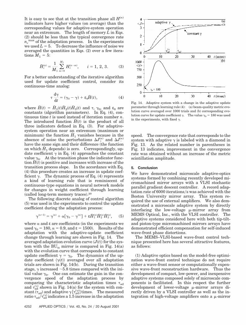
where a and ε are coefficients ~in the experiments weused g0 5 180, a 5 0.9, and ε 5 1500!. Results of theadaptation with the adaptive-update coefficientchange through learning are shown in Fig. 14. Theaveraged adaptation evolution curve ^J~t!& for the sys-tem with the BUtt mirror is compared in Fig. 14~a!with the evolution curve that corresponds to constantupdate coefficient g 5 g0. The dynamics of the up-
ate coefficient ^g~t!& averaged over all adaptationrials are shown in Fig. 14~b!. During the transitiontage, g increased ;5.8 times compared with the ini-ial value g0. One can estimate the gain in the con-
vergence speed of the adaptation process bycomparing the characteristic adaptation times tadand tad
~g! shown in Fig. 14~a! for the system with con-tant ~tad! and adaptive g @tad
~g!# times. The measuredatio tadytad
~g! indicates a 1.5 increase in the adaptation
252 APPLIED OPTICS y Vol. 40, No. 24 y 20 August 2001
speed. The convergence rate that corresponds to thesystem with adaptive g is labeled with a diamond inFig. 13. As the related number in parentheses inFig. 13 indicates, improvement in the convergencerate was obtained without an increase of the metricscintillation amplitude.
5. Conclusion
We have demonstrated microscale adaptive-opticssystems formed by combining recently developed mi-cromachined mirror arrays with a VLSI stochasticparallel gradient descent controller. A record adap-tation rate of 6000 iterationsys was achieved with theBoston University mirror array. This system re-quired the use of external amplifiers. We also dem-onstrated a microscale adaptive system by directlyinterfacing the low-voltage m-mirror array from
EMS Optical, Inc., with the VLSI controller. Thedaptive systems considered here with both tip-tilt-nd piston-type micromachined mirrors arrays haveemonstrated efficient compensation for self-inducedave-front phase distortions.The MEMS–VLSI-based wave-front control tech-
ique presented here has several attractive features,s follows:
~1! Adaptive optics based on the model-free optimi-ation wave-front control technique do not requireither a wave-front sensor or computationally expen-ive wave-front reconstruction hardware. Thus theevelopment of compact, low-power, and inexpensivedaptive systems composed solely of microscale com-onents is facilitated. In this respect the furtherevelopment of lower-voltage m-mirror arrays di-ectly driven by a VLSI controller as well as the in-egration of high-voltage amplifiers onto a m-mirror
Fig. 14. Adaptive system with a change in the adaptive updateparameter through learning rule ~4!: ~a! beam-quality metric evo-lution curve averaged over 1000 trials and ~b! corresponding evo-lution curve for update coefficient g. The value g0 5 180 was usedn the experiments, with fixed g.

kpofctharf
Vaotpwmcbaplm
ooCJmARieUvtOiUsSSMNA
reault, N. Vandelli, M. N. Horenstein, and D. A. Castanon,
chip are important directions for further research formicroscale adaptive optics.~2! Micromachined mirror arrays with multi-ilohertz operational bandwidths are capable oferforming tens of thousands of iterations per sec-nd. This is exactly what iteration-hungry, model-ree optimization-based adaptive optics needs forompensation of quickly changing atmospheric-urbulence-induced wave-front aberrations. As weave demonstrated, the convergence rate of the ad-ptation process can also be increased by incorpo-ation of an additional long-term memory learningeedback loop.
~3! Both the micromachined mirror arrays and theLSI stochastic gradient descent controller are scal-ble microscale components that facilitate the devel-pment of high-resolution adaptive systems withhousands of wave-front phase-control channels. Aotential obstacle to this development is the so-callediring problem. The ability to control mirror ele-ents in parallel is the major advantage of the sto-
hastic gradient optimization technique and shoulde preserved during a transition to high-resolutiondaptive systems. Possible solutions of the wiringroblem are on-chip integration of the VLSI control-er with m-mirror arrays and flip-chip bonding of-mirror and VLSI controller chips.
The authors thank Victor Bright, who generouslyffered the m-mirror array designed at the Universityf Colorado for examination in our experiments, Garyarhart for assisting with the computer code, andennifer Ricklin for technical and editorial com-ents. This research was performed at the U.S.rmy Research Laboratory’s Intelligent Optics Lab.esearch was supported in part through the follow-
ng U.S. Army and U.S. Air Force programs: Coop-rative Agreement DAAD17-99-2-0070 between the.S. Army Research Laboratory and the Boston Uni-ersity Photonic Center; grant DAAG55-97-1-0114hrough the U.S. Army Research Office under theDDR&E MURI97 program to the Center for Dynam-
cs and Control of Smart Structures ~through Harvardniversity!; U.S. Air Force Office of Scientific Re-
earch contract F49620-99-1-0342 with New Mexicotate University; and U.S. Army Research Officemall Business Innovative Research grant A98-021 toEMS Optical, Inc. T. Weyrauch currently holds aational Research Council Research Associateshipward at the U.S. Army Research Laboratory.
References1. N. Maluf, An Introduction to Microelectromechanical Systems
Engineering ~Artech House, Norwood, Mass., 2000!.2. M. C. Wu, “Micromachining for optical and optoelectronic sys-
tems,” Proc. IEEE 85, 1833–1856 ~1997!.3. R. L. Clark, J. R. Karpinisky, J. A. Hammer, R. B. Anderson,
R. L. Lindsey, D. M. Brown, and P. H. Merritt, “Micro-opto-electro-mechanical ~MOEM! adaptive optic system,” in Minia-turized Systems with Micro-Optics and Micromechanics II,M. E. Motamedi, L. J. Hornbeck, and K. S. Pister, eds., Proc.SPIE 3008, 12–24 ~1997!.
4. T. G. Bifano, R. Krishnamoorthy Mali, J. K. Dorton, J. Per-
“Continuous-membrane surface-micromachined silicon de-formable mirror,” Opt. Eng. 36, 1354–1360 ~1997!.
5. T. G. Bifano, J. Perrault, R. Krishnamoorthy Mali, and M. N.Horenstein, “Microelectromechanical deformable mirrors,”IEEE J. Sel. Top. Quantum Electron. 5, 83–89 ~1999!.
6. J. A. Hammer, J. Karpinsky, R. L. Clark, and R. Lindsey,“Micro mirrors in adaptive optics systems,” in Proceedings ofthe World Automation Congress ~WAC ’98!, M. Jamshidi andC. W. de Silva, eds., Vol. 6 of TSI Press Series ~TSI, Albuquer-que, N.M., 1998!, pp. 575–581.
7. M. K. Lee, W. D. Cowan, B. M. Welsh, V. M. Bright, and M. C.Roggemann, “Aberration-correction results from a segmentedmicroelectromechanical deformable mirror and refractive len-slet array,” Opt. Lett. 23, 645–647 ~1998!.
8. G. Vdovin, S. Middelhoek, and P. M. Sarro, “Technology andapplications of micromachined silicon adaptive mirrors,” Opt.Eng. 36, 1382–1390 ~1997!.
9. J. H. Comtois, V. M. Bright, S. C. Gustafson, and M. A. Michal-icek, “Implementation of hexagonal micromirror arrays asphase-mostly spatial light modulator,” in MicroelectronicStructures and Microelectromechanical Devices for OpticalProcessing and Multimedia Applications, W. Bailey, M. E.Motamedi, and F.-C. Luo, eds., Proc. SPIE 2641, 76–87 ~1995!.
10. J. Mansell and R. L. Byer, “Micromachined silicon deformablemirror,” in Adaptive Optical System Technologies, D. Bonac-cini and R. K. Tyson, eds., Proc. SPIE 3353, 896–901 ~1998!.
11. J. C. Spall, “A stochastic approximation technique for generat-ing maximum likelihood parameter estimates,” in Proceedingsof the American Control Conference ~Institute of Electrical andElectronics Engineers, Piscataway, N.J., 1987!, pp. 1161–1167.
12. G. Cauwenberghs, “A fast stochastic error-descent algorithmfor supervised learning and optimization,” in Advances in Neu-ral Information Processing Systems, S. J. Hanson, J. D. Cowan,and C. L. Giles, eds. ~Morgan Kaufman, San Mateo, Calif.,1993!, Vol. 5, pp. 244–251.
13. M. A. Vorontsov, G. W. Carhart, and J. C. Ricklin, “Adaptivephase-distortion correction based on parallel gradient-descentoptimization,” Opt. Lett. 22, 907–909 ~1997!.
14. M. A. Vorontsov and V. P. Sivokon, “Stochastic parallel gradi-ent descent technique for high-resolution wave-front phasedistortion correction,” J. Opt. Soc. Am. A 15, 2745–2758 ~1998!.
15. R. T. Edwards, M. Cohen, G. Cauwenberghs, M. A. Vorontsov,and G. W. Carhart, “Analog VLSI parallel stochastic optimi-zation for adaptive optics,” in Learning on Silicon, G. Cauwen-berghs and M. A. Bazoumi, eds. ~Kluwer Academic, Boston,Mass., 1999!, pp. 359–382.
16. M. A. Vorontsov, G. W. Carhart, M. Cohen, and G. Cauwen-berghs, “Adaptive optics based on analog parallel stochasticoptimization: analysis and experimental demonstration,” J.Opt. Soc. Am. A 17, 1440–1453 ~2000!.
17. A. Tuantranont, V. M. Bright, W. Zhang, and Y. C. Lee, “Flipchip integration of lenslet arrays on segmented deformable mi-cromirrors,” in Design, Test, and Microfabrication of MEMS andMOEMS, B. Courtois, S. B. Crary, W. Ehrfeld, H. Fujita, J.-M.Karam, and K. W. Markus, eds., Proc. SPIE 3680, 668–678~1999!.
18. M. C. Roggeman, V. M. Bright, B. M. Welsh, S. R. Hick, P. C.Roberts, W. D. Cowan, and J. H. Comtois, “Use of micro-electro-mechanical deformable mirrors to control aberrationsin optical systems: theoretical and experimental results,”Opt. Eng. 36, 1326–1338 ~1997!.
19. L. Zhu, P.-C. Sun, D.-U. Bartsch, W. R. Freeman, and Y.Fainman, “Adaptive control of a micromachined continuous-membrane deformable mirror for aberration compensation,”Appl. Opt. 38, 168–176 ~1999!.
20. S. Grossberg, “Nonlinear neural networks: principles, mech-anisms, and architectures,” Neural Networks 1, 17–61 ~1988!.
20 August 2001 y Vol. 40, No. 24 y APPLIED OPTICS 4253
Related Documents


![Ô w;Æ != ' b...[taputwo-si]の音便変化の過程を以下に示す。 (4) σ σ σ σ σ σ σ σ σ σ ∧ ∧ μ μ μ μ μ μ μ μ μ μ μ μ ∧ ∧ ∧ ∧ ∧ ∧](https://static.cupdf.com/doc/110x72/5fb2438e6081653dab6d91d0/-w-b-taputwo-sieoeecc-i4i.jpg)