Microprocessor Motor Control Spring 2004

Microprocessor Motor Control Spring 2004. Introduction Stamp projects Robots Sensors Motor control Logic Rocketry Reading acceleration (“g”
Dec 15, 2015
Welcome message from author
This document is posted to help you gain knowledge. Please leave a comment to let me know what you think about it! Share it to your friends and learn new things together.
Transcript
Microprocessor Motor Control
Spring 2004
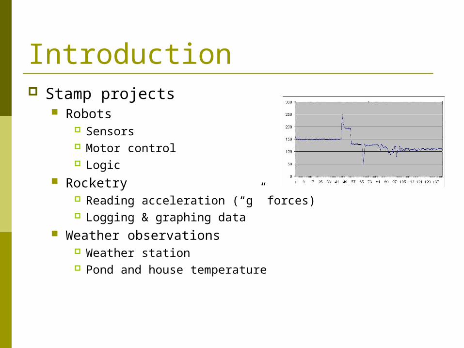
Introduction Stamp projects
Robots Sensors Motor control Logic
Rocketry Reading acceleration (“g” forces) Logging & graphing data
Weather observations Weather station Pond and house temperature

Objectives for Train Controller The train will be able to accelerate and
decelerate smoothly, run at a constant speed, stop and sense its location on the track
All motor control will be solid state The model train will operate from batteries

Objectives for Train Controller A microprocessor will control the train’s motion The microprocessor will must use interrupts to
detect crossing over a magnet so that no magnet crossings are missed
Motor speed control will be by PWM It will be possible to change some settings
without reprogramming Programs will be easy to create and revise

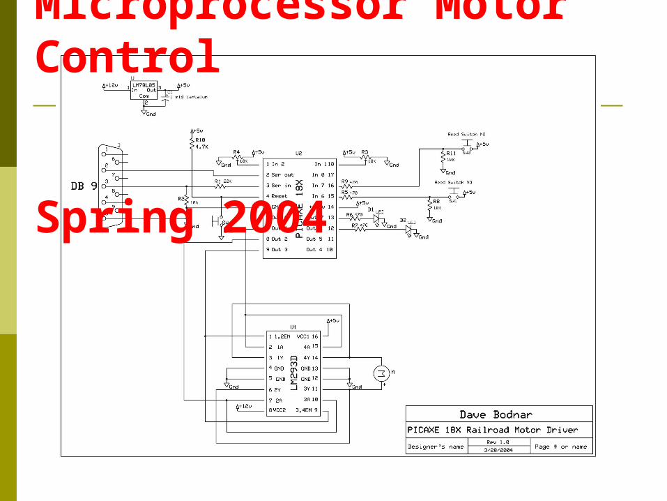
Hardware – Microprocessor
The microprocessor is a PICAXE 18X This 18 pin device is programmed in a
simplified version of the BASIC language It has 8 pins that can be used as outputs
and 5 pins for inputs. In this project the input pins will be used
to detect switch closures and the position of two potentiometers
The output pins will operate the motor and give us some feedback with LEDs
It can use interrupts to sense magnets It can control motor speed with PWM

Hardware – H-Bridge Motor control is accomplished with
an LM293D H-Bridge chip This 16 pin device can control the
speed and direction of two DC motors, each drawing up to 600 ma.
In order to increase the amperage available to the motor the two independent circuits on the LM293D chip will be wired in parallel. This will provide more than 1 amp of power to the motor.
Three pins on the LM293 will be connected to the PICAXE. Two are used for direction control and the third for PWM speed control
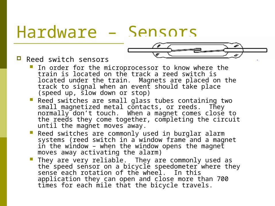
Hardware – Sensors Reed switch sensors
In order for the microprocessor to know where the train is located on the track a reed switch is located under the train. Magnets are placed on the track to signal when an event should take place (speed up, slow down or stop)
Reed switches are small glass tubes containing two small magnetized metal contacts, or reeds. They normally don’t touch. When a magnet comes close to the reeds they come together, completing the circuit until the magnet moves away.
Reed switches are commonly used in burglar alarm systems (reed switch in a window frame and a magnet in the window – when the window opens the magnet moves away activating the alarm)
They are very reliable. They are commonly used as the speed sensor on a bicycle speedometer where they sense each rotation of the wheel. In this application they can open and close more than 700 times for each mile that the bicycle travels.

Hardware - Other parts LEDs are small lights that can be run directly
from the output pins on the PICAXE. All that is needed is a 470 ohm resistor in series with the output pin to limit the amount of current that the LED draws.
Potentiometers are variable resistors having three connections, one at each end of a fixed resistor and a third that is a wiper that moves across the fixed resistor giving variable resistance readings. In this application two will be used to set the motor’s maximum speed and the amount of time that the motor will be off when it pauses between direction changes.

Hardware - Other parts A 78L05 voltage regulator is
used to supply a steady 5 volt power supply to the PICAXE. Connecting the microprocessor directly to the 14.4 volt power supply would instantly destroy it.
Capacitors are used in the power supply circuit to filter out electrical noise that may be introduced into the circuit by sparking in the motor. Without these devices the microprocessors can reset randomly and give unreliable operation.

Prototype – Schematic

Prototype – Hand Wired Board

PC Board design and creation
PC Board Software free on-line at
www.expresspcb.com All communication done with the
program Three day service Revision
Fine tune component placement Correct errors

Building and testing Time to construct went from 3 hours
+ to 20 minutes Errors almost eliminated
Solder bridges Incorrect component placement

Software to test LED & Switch Load the “testLED.bas” program into the
computer. It simply flashes the two LEDs until you put a magnet next to the reed switch. When the reed switch is activated the LEDs stay on for 5 seconds then start flashing again.
start:high 7:low 6if pin6 =1 then reed:pause 300low 7:high 6if pin6 =1 then reed:pause 300goto start:
reed:high 6high 7pause 5000goto start:

Software to test Motor Load the “testMOTOR.bas”
program and download it to the PICAXE
The motor should slowly accelerate, pause for 5 seconds, decelerate, stop, pause and repeat.
high 1low 2start:for w1= 200 to 1000 step 40pwmout 3, 249, w1pause 400next w1pause 5000
for w1= 1000 to 200 step -40pwmout 3, 249, w1pause 400next w1pause 5000toggle 1toggle 2goto start:

Software to test Speed & Pause Time
The last test determines if the potentiometers are working. This test uses a built in function of the programming language that automatically sends information to the computer screen. It is called “debug”
Load the “testpot.bas”program and download it to the PICAXE
In a few moments a “debug window”should appear on the computer’s screen.
Make sure “Byte”is selected at the bottom of the debug screen, not “Word”
Watch the value of B0 and B1 – as you turn the potentiometers one way or the other these values should vary from 0 to 255.
start:readadc 1, b0readadc 2, b1debug b0, b1goto start:
Other projects Pond temperature House temperature

Thank You! Questions?

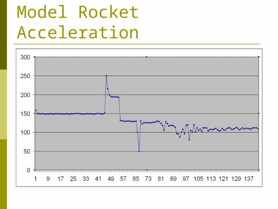
Model Rocket Acceleration
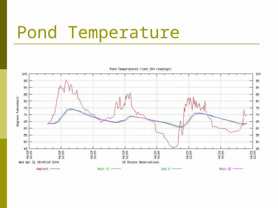
Pond Temperature

House Temperature
Related Documents