1 1 Michigan Technological University David R. Shonnard Chapter 9: Operating Bioreactors David Shonnard Department of Chemical Engineering Michigan Technological University 2 Michigan Technological University David R. Shonnard Presentation Outline: l Choosing Cultivation Methods l Modifying Batch and Continuous Reactors l Immobilized Cell Systems

Welcome message from author
This document is posted to help you gain knowledge. Please leave a comment to let me know what you think about it! Share it to your friends and learn new things together.
Transcript
1
1Michigan Technological UniversityDavid R. Shonnard
Chapter 9: Operating Bioreactors
David ShonnardDepartment of Chemical Engineering
Michigan Technological University
2Michigan Technological UniversityDavid R. Shonnard
Presentation Outline:
l Choosing Cultivation Methods
l Modifying Batch and Continuous Reactors
l Immobilized Cell Systems
2
3Michigan Technological UniversityDavid R. Shonnard
The Choice of Bioreactor Affects Many Aspects of Bioprocessing.
1. Product concentration and purity2. Degree of substrate conversion3. Yields of cells and products4. Capitol cost in a process (>50% total capital expenses)
Further Considerations in Choosing a Bioreactor.1. Biocatalyst. (immobilized or suspended)2. Separations and purification processes
Choosing the Cultivation Method
4Michigan Technological UniversityDavid R. Shonnard
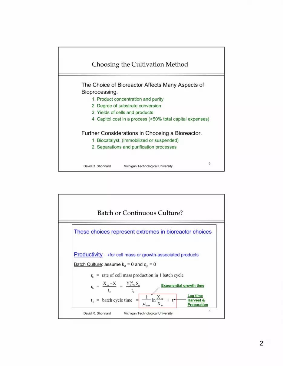
rb = rate of cell mass production in 1 batch cycle
rb = Xm - X
tc
= YX / S
M So
tc
tc = batch cycle time = 1
µmax
lnX m
X o
+ tl
Batch or Continuous Culture?
These choices represent extremes in bioreactor choices
Productivity →for cell mass or growth-associated products
Batch Culture: assume kd = 0 and qp = 0
Exponential growth time
Lag timeHarvest &Preparation

3
5Michigan Technological UniversityDavid R. Shonnard
Batch or Continuous Culture? (cont.)
Continuous Culture: assume kd = 0 and qp = 0
rc = rate of cell mass production in continuous culture
rc = DoptXopt
set dDXdD
= 0 ⇒ Dopt = µmax (1-KS
KS
+ So
)
Xopt = YX / SM (So -
KS Dopt
µmax - Dopt
) = YX / SM (So + KS - (KS(So + KS) )
DoptXopt = YX / SM µmax (1-
KS
KS + So
) (So + KS - (KS(So + KS ) )
≈ YX /SM µmax So when KS << So
6Michigan Technological UniversityDavid R. Shonnard
Batch or Continuous Culture? (cont.)
Comparing Rates in Batch and Continuous Culture
rcrb
= YX /S
M µmax So
YX /SM So /
1µmax
lnXm
Xo
+ t l
= lnXm
Xo
+ t lµmax
A commercial fermentation with
X m
Xo
= 20, tl = 5 hr, and µmax = 1.0 hr-1
rcrb
= 8 ⇒ Continuous culture method is ~ 10 times more productive for primary products(biomass & growth associated products
4
7Michigan Technological UniversityDavid R. Shonnard
Batch or Continuous Culture? (cont.)
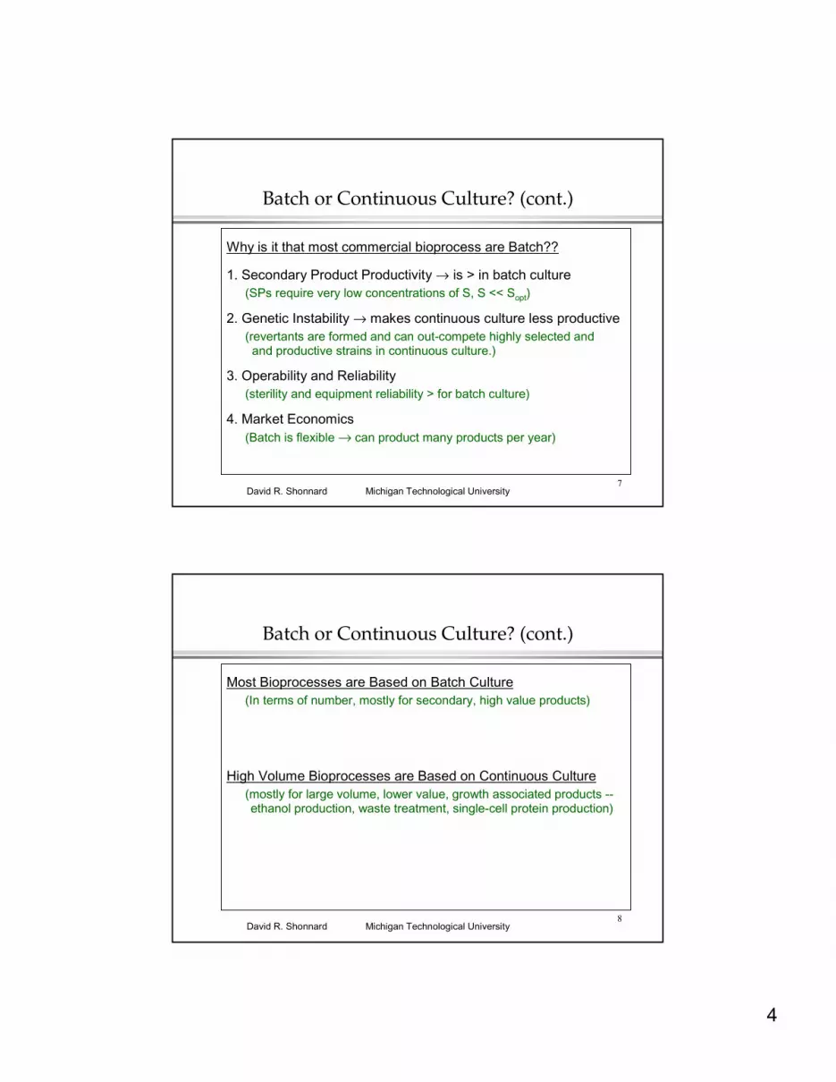
Why is it that most commercial bioprocess are Batch??
1. Secondary Product Productivity → is > in batch culture(SPs require very low concentrations of S, S << Sopt)
2. Genetic Instability → makes continuous culture less productive(revertants are formed and can out-compete highly selected and
and productive strains in continuous culture.)
3. Operability and Reliability (sterility and equipment reliability > for batch culture)
4. Market Economics (Batch is flexible → can product many products per year)
8Michigan Technological UniversityDavid R. Shonnard
Batch or Continuous Culture? (cont.)
Most Bioprocesses are Based on Batch Culture(In terms of number, mostly for secondary, high value products)
High Volume Bioprocesses are Based on Continuous Culture(mostly for large volume, lower value, growth associated products --ethanol production, waste treatment, single-cell protein production)
5
9Michigan Technological UniversityDavid R. Shonnard
Modified Bioreactors: Chemostat with Recycle
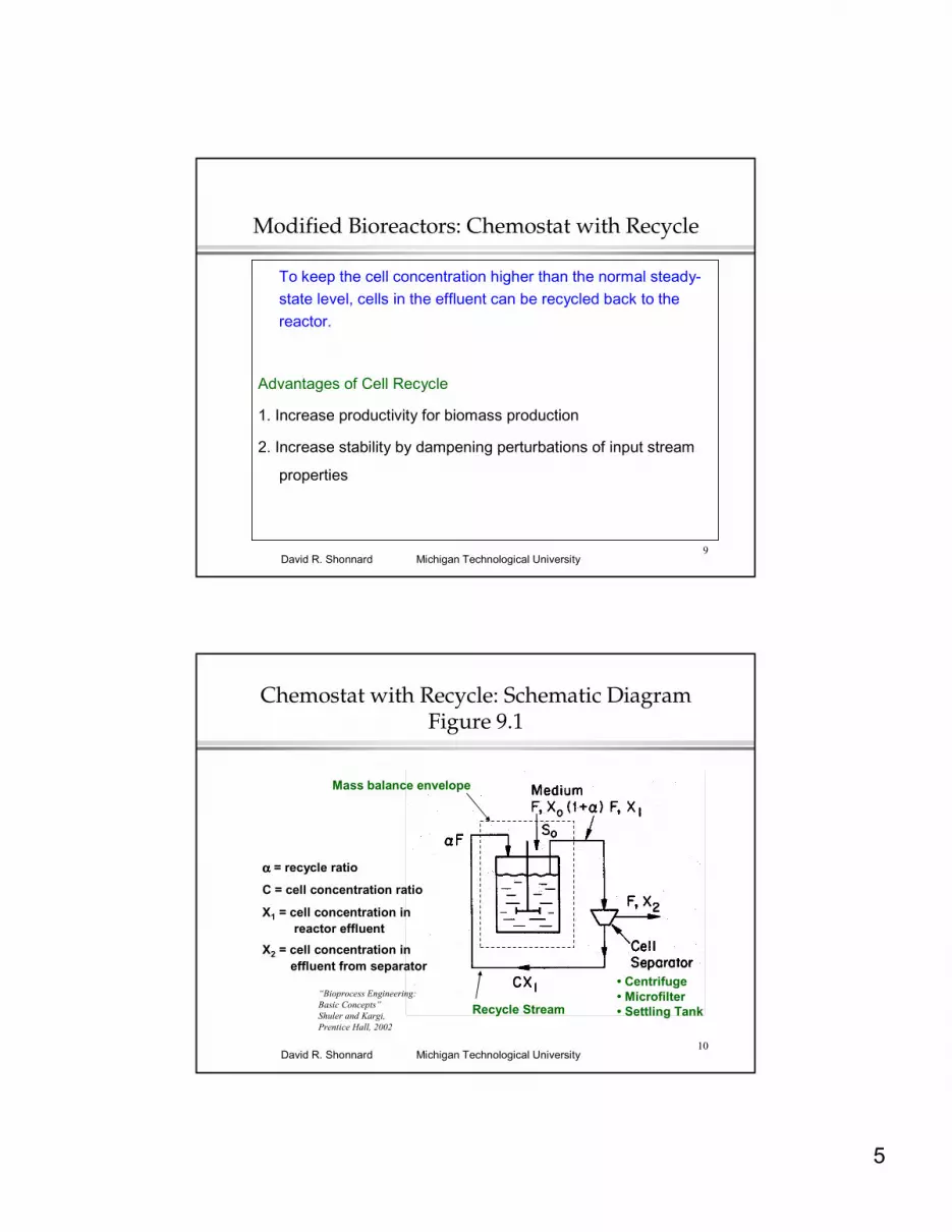
To keep the cell concentration higher than the normal steady-state level, cells in the effluent can be recycled back to the reactor.
Advantages of Cell Recycle
1. Increase productivity for biomass production
2. Increase stability by dampening perturbations of input stream
properties
10Michigan Technological UniversityDavid R. Shonnard
Chemostat with Recycle: Schematic DiagramFigure 9.1
• Centrifuge• Microfilter• Settling Tank
Mass balance envelope
αααα = recycle ratio
C = cell concentration ratio
X1 = cell concentration in reactor effluent
X2 = cell concentration in effluent from separator
Recycle Stream“Bioprocess Engineering: Basic Concepts”Shuler and Kargi, Prentice Hall, 2002
6
11Michigan Technological UniversityDavid R. Shonnard
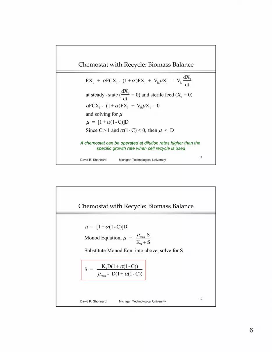
Chemostat with Recycle: Biomass Balance
FXo + αFCX1 - (1 +α )FX1 + VR µX1 = VR
dX1
dt
at steady - state (dX
1
dt= 0) and sterile feed (Xo = 0)
αFCX1 - (1+ α )FX1 + VRµX1 = 0
and solving for µµ = [1 +α (1- C)]D
Since C > 1 and α (1- C) < 0, then µ < D
A chemostat can be operated at dilution rates higher than the specific growth rate when cell recycle is used
12Michigan Technological UniversityDavid R. Shonnard
Chemostat with Recycle: Biomass Balance
µ = [1 +α (1- C)]D
Monod Equation, µ = µmax S
KS + S
Substitute Monod Eqn. into above, solve for S
S = KSD(1+ α(1- C))
µmax - D(1+ α(1- C))
7
13Michigan Technological UniversityDavid R. Shonnard
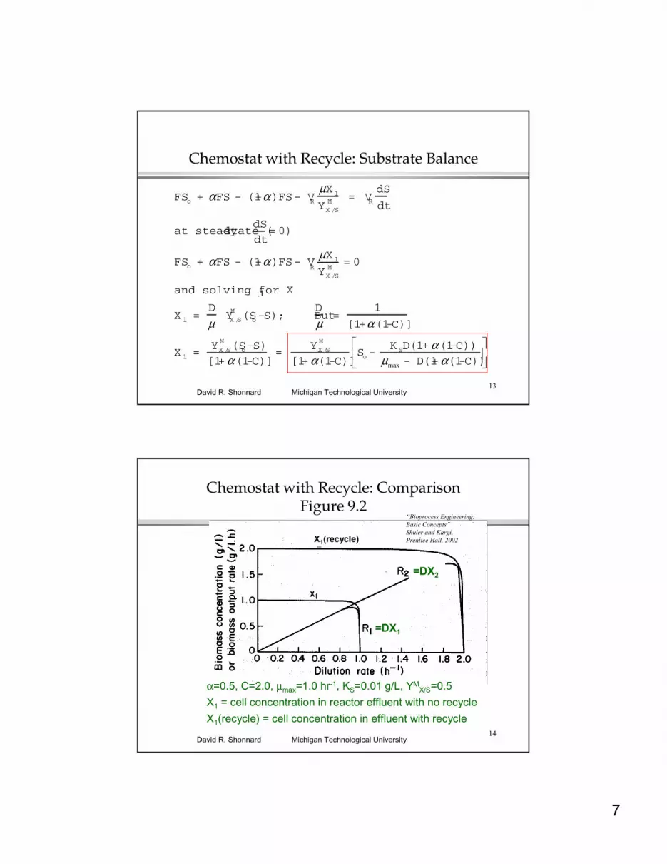
FSo + αFS - (1+α)FS - VRµX 1
YX /SM = VR
dS
dt
at steady-state (dS
dt= 0)
FSo + αFS - (1+α)FS - VR
µX 1
YX /SM
= 0
and solving for X1
X 1 = D
µ YX /S
M (So-S); But D
µ =
1
[1+α(1-C)]
X 1 = YX /S
M (So-S)
[1+α(1-C)] =
YX /SM
[1+α(1-C)]So-
K SD(1+α(1-C))µmax - D(1+α(1-C))
Chemostat with Recycle: Substrate Balance
1
14Michigan Technological UniversityDavid R. Shonnard
Chemostat with Recycle: ComparisonFigure 9.2
α=0.5, C=2.0, µmax=1.0 hr-1, KS=0.01 g/L, YMX/S=0.5
X1 = cell concentration in reactor effluent with no recycle
X1(recycle) = cell concentration in effluent with recycle
=DX1
=DX2
“Bioprocess Engineering: Basic Concepts”Shuler and Kargi, Prentice Hall, 2002X1(recycle)
8
15Michigan Technological UniversityDavid R. Shonnard
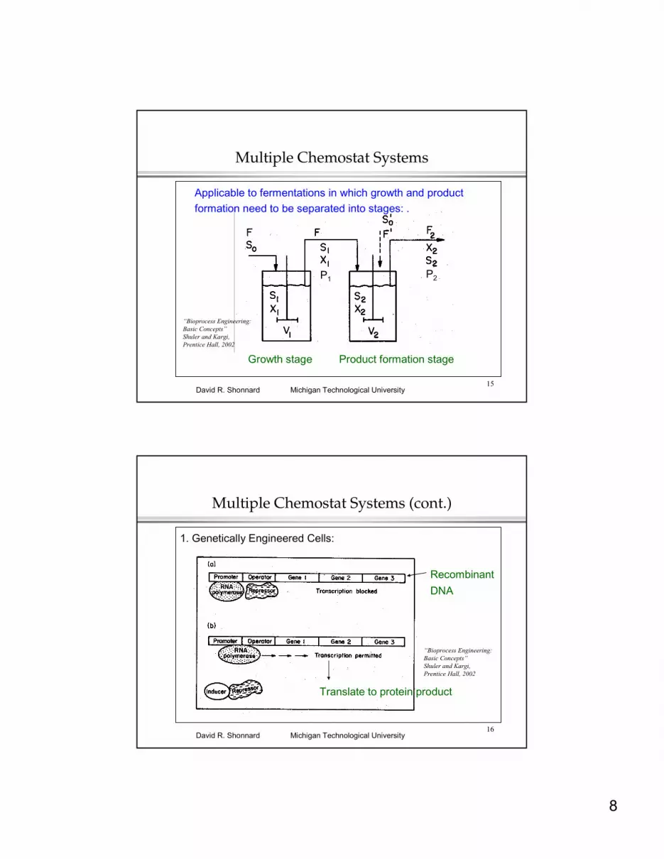
Multiple Chemostat Systems
Applicable to fermentations in which growth and product formation need to be separated into stages: .
Growth stage Product formation stage
P1 P2
“Bioprocess Engineering: Basic Concepts”Shuler and Kargi, Prentice Hall, 2002
16Michigan Technological UniversityDavid R. Shonnard
Multiple Chemostat Systems (cont.)
1. Genetically Engineered Cells:
Recombinant
DNA
Translate to protein product
“Bioprocess Engineering: Basic Concepts”Shuler and Kargi, Prentice Hall, 2002
9
17Michigan Technological UniversityDavid R. Shonnard
Multiple Chemostat Systems (cont.)
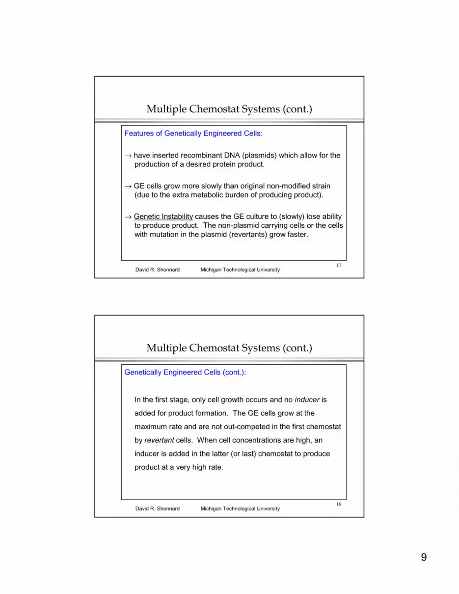
Features of Genetically Engineered Cells:
→ have inserted recombinant DNA (plasmids) which allow for the production of a desired protein product.
→ GE cells grow more slowly than original non-modified strain (due to the extra metabolic burden of producing product).
→ Genetic Instability causes the GE culture to (slowly) lose ability to produce product. The non-plasmid carrying cells or the cells with mutation in the plasmid (revertants) grow faster.
18Michigan Technological UniversityDavid R. Shonnard
Multiple Chemostat Systems (cont.)
Genetically Engineered Cells (cont.):
In the first stage, only cell growth occurs and no inducer is
added for product formation. The GE cells grow at the
maximum rate and are not out-competed in the first chemostat
by revertant cells. When cell concentrations are high, an
inducer is added in the latter (or last) chemostat to produce
product at a very high rate.

10
19Michigan Technological UniversityDavid R. Shonnard
Multiple Chemostat Systems (cont.)
2-Stage Chemostat System Analysis
Stage 1 - cell growth conditions, kd=0, qp=0, steady-state
µ1 = µmax S
1
KS + S1
= D1 from biomass balance
rearranging, S1 = KS D1
µmax - D1
where D1 =
F
V1
X1 = Y
X / SM (So - S
1) from substrate balance
20Michigan Technological UniversityDavid R. Shonnard
Multiple Chemostat Systems (cont.)
2-Stage Chemostat System Analysis
Stage 2 - product formation conditions, kd=0, F ‘=0, steady-state
FX1 - FX2 + V2µ2X2 = V2
dX2
dt = 0 biomass balance
µ2 = µmax S2
KS + S2
= D2 (1-X1
X2
) where D2 = F
V2
FS1 - FS
2 - V
2
µ2X2
YX/SM
- V2
qPX2
YP /S
= V2
dS2
dt = 0 substrate balance
FP1 - FP2 + V2qPX2 = V2
dP2
dt = 0 product balance

11
21Michigan Technological UniversityDavid R. Shonnard
Multiple Chemostat Systems (cont.)
2-Stage Chemostat System Analysis
Stage 2 - product formation conditions, kd=0, F ‘=0, steady-state
µ2 = µmax S2
KS + S
2
= D2 (1-X1
X2
) biomass balance
S2 = S
1 -
µ 2 X2
D2 YX /SM
+ qP X2
D2 YP/ S
substrate balance
2 equations, 2 unknowns (S2,X2 )
FP1 - FP2 + V2qPX2 = V2
dP2
dt = 0 product balance
use X2 in product balance to solve for P2
22Michigan Technological UniversityDavid R. Shonnard
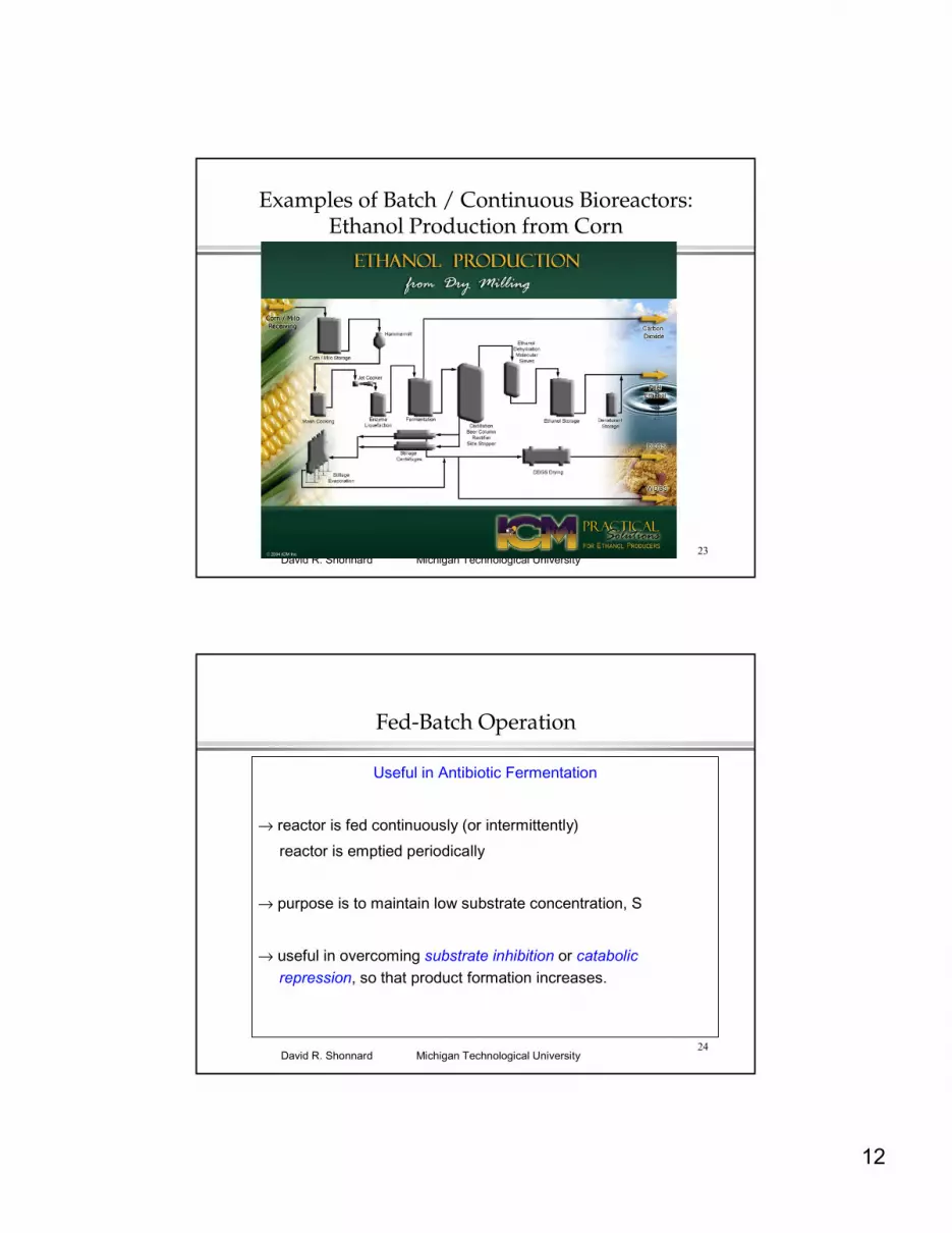
Examples of Batch / Continuous Bioreactors:Ethanol Production from Corn
• 3.5 billion gallons EtOH / yr in the US
• Small distributed plants; , <100 million gallons EtOH/yrGlacial Lakes Energy, LLC; Watertown, SD
Badger State Ethanol,Monroe, WI
VeraSun Energy, LLC; Aurora, SD
12
23Michigan Technological UniversityDavid R. Shonnard
Examples of Batch / Continuous Bioreactors:Ethanol Production from Corn
24Michigan Technological UniversityDavid R. Shonnard
Fed-Batch Operation
Useful in Antibiotic Fermentation
→ reactor is fed continuously (or intermittently)
reactor is emptied periodically
→ purpose is to maintain low substrate concentration, S
→ useful in overcoming substrate inhibition or catabolic repression, so that product formation increases.
13
25Michigan Technological UniversityDavid R. Shonnard
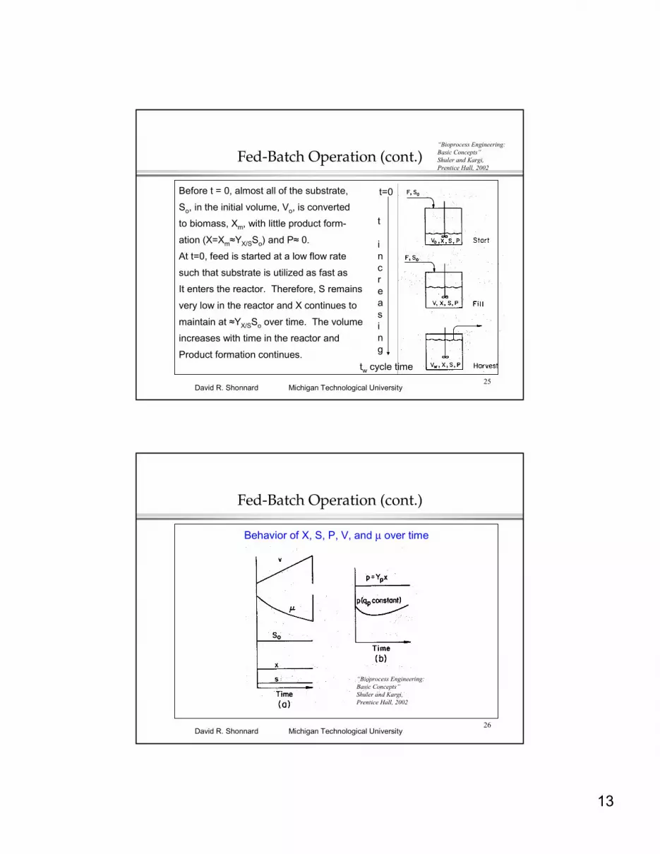
Fed-Batch Operation (cont.)
Before t = 0, almost all of the substrate,
So, in the initial volume, Vo, is converted
to biomass, Xm, with little product form-
ation (X=Xm≈YX/SSo) and P≈ 0.
At t=0, feed is started at a low flow rate
such that substrate is utilized as fast as
It enters the reactor. Therefore, S remains
very low in the reactor and X continues to
maintain at ≈YX/SSo over time. The volume
increases with time in the reactor and
Product formation continues.
t
increasing
t=0
tw cycle time
“Bioprocess Engineering: Basic Concepts”Shuler and Kargi, Prentice Hall, 2002
26Michigan Technological UniversityDavid R. Shonnard
Fed-Batch Operation (cont.)
Behavior of X, S, P, V, and µ over time
“Bioprocess Engineering: Basic Concepts”Shuler and Kargi, Prentice Hall, 2002

14
27Michigan Technological UniversityDavid R. Shonnard
Fed-Batch Operation (cont.)
Analysis of Fed-Batch Operation
Volume: dVdt
= F ⇒ V = Vo + Ft
Biomass: FXo + VµX = d(XV)
dt = V
dX
dt+ X
dV
dt
VµX = XdV
dt ⇒ µ =
1
V
dV
dt =
F
V = D
µ = FV
= F
Vo + Ft =
Do
1 + Dot
0 0
28Michigan Technological UniversityDavid R. Shonnard
Fed-Batch Operation (cont.)
Analysis of Fed-Batch Operation (cont.)
Total Biomass: X t (g cells) vs time
dXdt
= 0 or d
X t
V
dt =
VdX t
dt
− X t
dV
dt
V2 = 0
rearranging dX t
dt =
X t
V
dV
dt = XmF = YX / SSoF
integrating Xt = Xto + YX /S
SoFt = (Vo + Ft)X m
15
29Michigan Technological UniversityDavid R. Shonnard
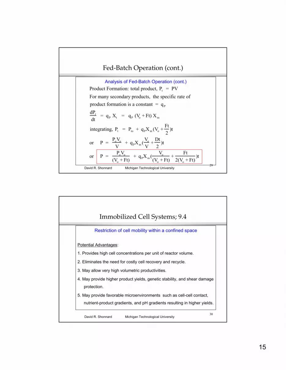
Fed-Batch Operation (cont.)
Analysis of Fed-Batch Operation (cont.)
Product Formation: total product, Pt = PV
For many secondary products, the specific rate of
product formation is a constant = qP
dPt
dt = qP Xt = qP (Vo + Ft) X m
integrating, Pt = Pto + qPX m (Vo +Ft
2)t
or P = PoVo
V + qPX m (
Vo
V+
Dt
2)t
or P = PoVo
(Vo + Ft) + qPX m (
Vo
(Vo + Ft)+
Ft
2(Vo + Ft))t
30Michigan Technological UniversityDavid R. Shonnard
Immobilized Cell Systems; 9.4
Restriction of cell mobility within a confined space
Potential Advantages:
1. Provides high cell concentrations per unit of reactor volume.
2. Eliminates the need for costly cell recovery and recycle.
3. May allow very high volumetric productivities.
4. May provide higher product yields, genetic stability, and shear damage
protection.
5. May provide favorable microenvironments such as cell-cell contact,
nutrient-product gradients, and pH gradients resulting in higher yields.

16
31Michigan Technological UniversityDavid R. Shonnard
Immobilized Cell Systems; 9.4
Potential Disadvantages/Problems:
1. If cells are growing (as opposed to being in stationary phase) and/or
evolve gas (CO2), physical disruption of immobilization matrix could
result.
2. Products must be excreted from the cell to be recovered easily.
3. Mass transfer limitations may occur as in immobilized enzyme
systems.
32Michigan Technological UniversityDavid R. Shonnard
Methods of Immobilization
Active Immobilization:
1. Entrapment in a Porous Matrix:
cellsInert/solid core
porous polymer matrix
Polymers:agar, alginateκ-carrageenanpolyacrylamidegelatin, collagen
Polymeric Beads:
17
33Michigan Technological UniversityDavid R. Shonnard
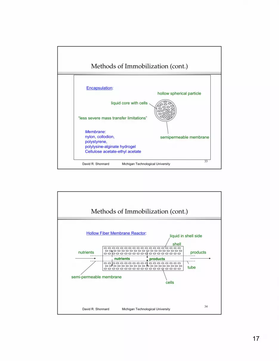
Methods of Immobilization (cont.)
liquid core with cells
hollow spherical particle
semipermeable membraneMembrane:nylon, collodion,polystyrene,polylysine-alginate hydrogelCellulose acetate-ethyl acetate
Encapsulation:
“less severe mass transfer limitations”
34Michigan Technological UniversityDavid R. Shonnard
Methods of Immobilization (cont.)
nutrients
liquid in shell side
semi-permeable membrane
Hollow Fiber Membrane Reactor:
products
shell
nutrients products
tube
cells

18
35Michigan Technological UniversityDavid R. Shonnard
Methods of Immobilization (cont.)
2. Cell Binding to Inert Supports:
microporesdP>4 dC• cells in micropores
porous glass, porous silica, aluminaceramics, gelatin, activated carbonWood chips, poly propylene ion-exchange resins(DEAE-Sephadex, CMC-), Sepharose
Micro-porous Supports:
“mass transfer limitations occur”
36Michigan Technological UniversityDavid R. Shonnard
Methods of Immobilization (cont.)
Binding Forces:
ion exchangesupport
Electrostatic Attraction --
-- -- --
+
+++
Hydrogen BondingsupportHO
C-O-
||O
cell
19
37Michigan Technological UniversityDavid R. Shonnard
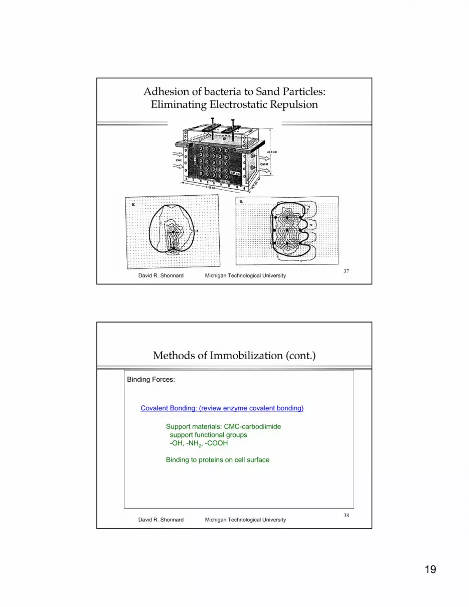
Adhesion of bacteria to Sand Particles: Eliminating Electrostatic Repulsion
38Michigan Technological UniversityDavid R. Shonnard
Methods of Immobilization (cont.)
Binding Forces:
Covalent Bonding: (review enzyme covalent bonding)
Support materials: CMC-carbodiimidesupport functional groups-OH, -NH2, -COOH
Binding to proteins on cell surface
20
39Michigan Technological UniversityDavid R. Shonnard
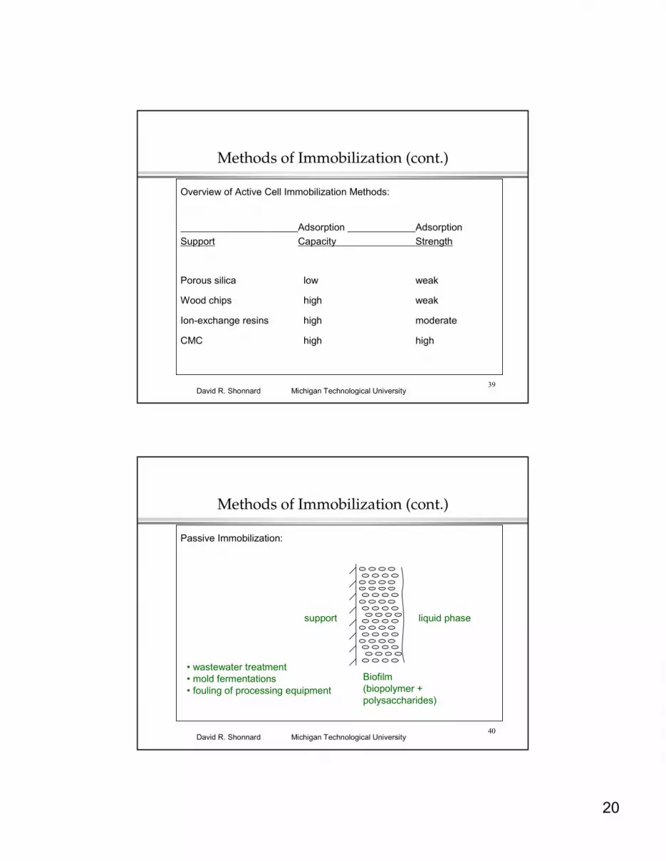
Methods of Immobilization (cont.)
Overview of Active Cell Immobilization Methods:
Adsorption AdsorptionSupport Capacity Strength
Porous silica low weak
Wood chips high weak
Ion-exchange resins high moderate
CMC high high
40Michigan Technological UniversityDavid R. Shonnard
Methods of Immobilization (cont.)
Passive Immobilization:
liquid phasesupport
Biofilm(biopolymer + polysaccharides)
• wastewater treatment• mold fermentations• fouling of processing equipment

21
41Michigan Technological UniversityDavid R. Shonnard
Analysis of Biofilm Mass TransferFigures 9.1, 9.12
O2 diffusion in biofilmsSubstrate/product diffusion in biofilms
“Bioprocess Engineering: Basic Concepts”Shuler and Kargi, Prentice Hall, 2002
42Michigan Technological UniversityDavid R. Shonnard
Analysis of Biofilm Mass Transfer (cont.)
Differential Substrate Balance:
∆x
∆y∆z
Material volume in biofilm, ∆V = ∆x ∆y ∆z
Rate of diffusion in through the area ∆x ∆z
-De
dS
dy y
∆x ∆zyy+∆y
Rate of diffusion out through the area ∆x ∆z
-De
dS
dy y +∆y
∆x ∆z
Rate of substrate consumption in the volume ∆V = ∆x ∆y ∆z(due to cell growth, orproduct formation)
1
YX / SM
µmax S
KS + S X ∆x ∆y ∆z
1
YP /S
qp S
KS + S X ∆x ∆y ∆z

22
43Michigan Technological UniversityDavid R. Shonnard
Analysis of Biofilm Mass Transfer (cont.)
Differential Substrate Balance at Steady-State:
-De
dS
dy y
∆x ∆z - -De
dS
dy y+ ∆y
∆x ∆z
-
1
YX / SM
µmax S
KS + S X ∆x ∆y ∆z = 0
Divide through by ∆x ∆y ∆z and switch order of first 2 terms
De
dSdy y +∆y
- De
dSdy y
∆y-
1Y
X /SM
µmax SK
S+ S
X = 0
Rate of diffusion in through the area ∆x ∆z
Rate of diffusion out through the area ∆x ∆z
Rate of substrate consumption in the volume ∆V = ∆x ∆y ∆z
- - = 0
44Michigan Technological UniversityDavid R. Shonnard
Analysis of Biofilm Mass Transfer (cont.)
Differential Substrate Balance at Steady-State:
De
d2Sdy2 =
1YX / S
M µmax SKS + S
X eqn 9.49
Boundary Conditions
S = Soi at y = 0 (at the biofilm / liquid interface)
dSdy
= 0, at y = L (at the biofilm / support interface)
23
45Michigan Technological UniversityDavid R. Shonnard
Analysis of Biofilm Mass Transfer (cont.)
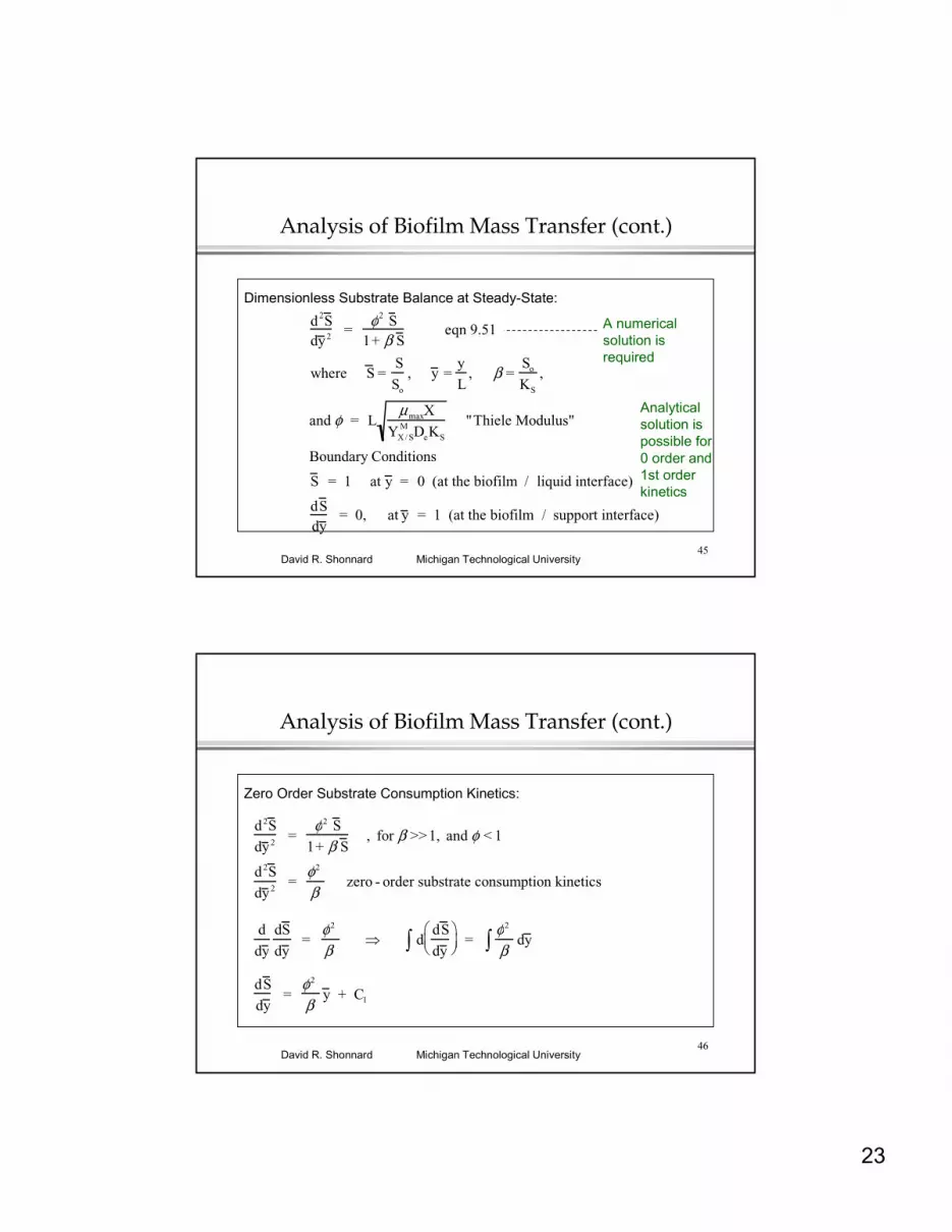
Dimensionless Substrate Balance at Steady-State:
d2S dy 2
= φ2 S
1+ β S eqn 9.51
where S =S
So
, y =y
L, β =
So
KS
,
and φ = LµmaxX
YX / SM DeKS
"Thiele Modulus"
Boundary Conditions
S = 1 at y = 0 (at the biofilm / liquid interface)
dS dy
= 0, at y = 1 (at the biofilm / support interface)
A numerical solution is required
Analyticalsolution is possible for0 order and 1st order kinetics
46Michigan Technological UniversityDavid R. Shonnard
Analysis of Biofilm Mass Transfer (cont.)
Zero Order Substrate Consumption Kinetics:
d2S
dy 2 =
φ2 S
1+ β S , for β >>1, and φ < 1
d2S
dy 2 =
φ2
β zero - order substrate consumption kinetics
d
dy
dS
dy =
φ2
β ⇒ d
dS
dy
∫ =
φ2
β dy ∫
dS
dy =
φ2
β y + C1
24
47Michigan Technological UniversityDavid R. Shonnard
Analysis of Biofilm Mass Transfer (cont.)
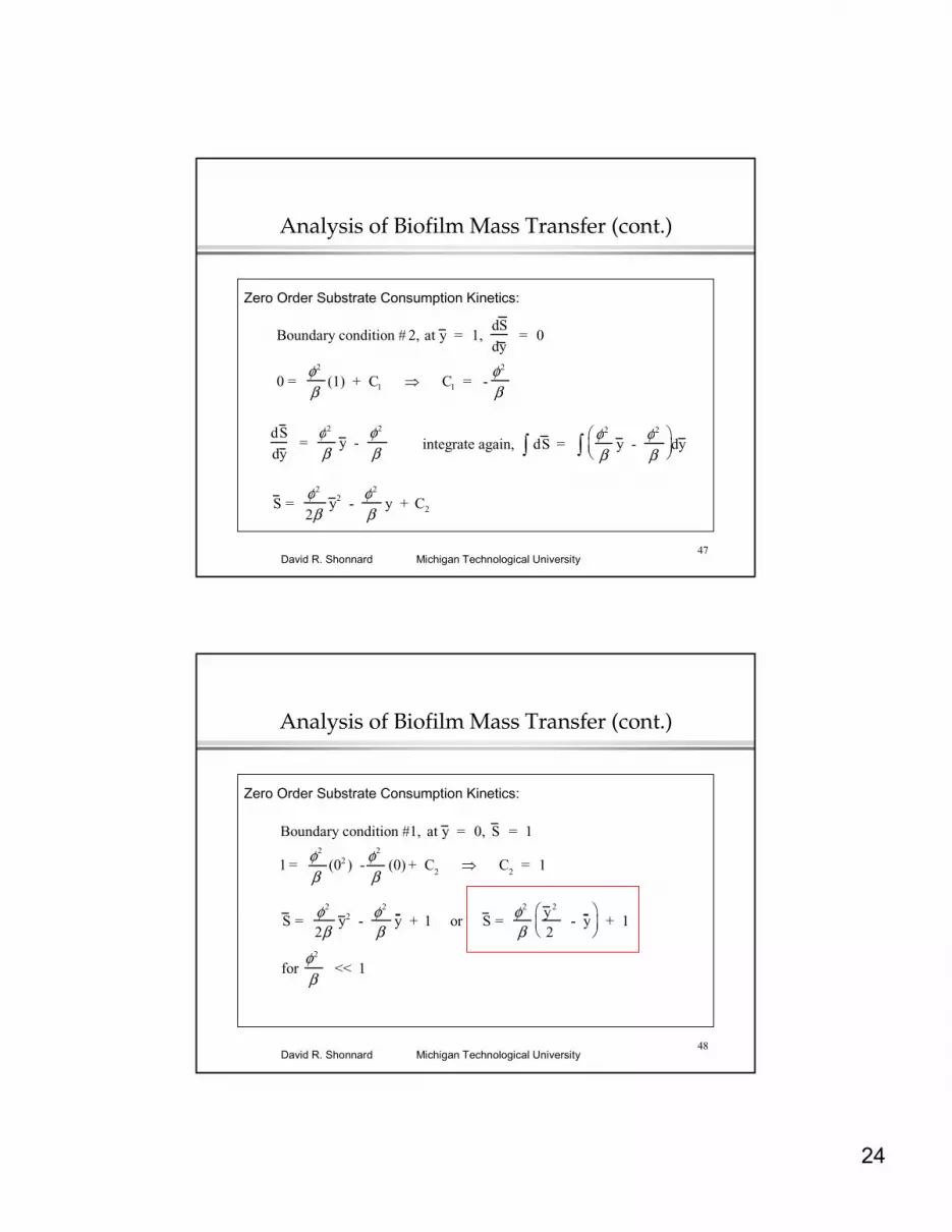
Zero Order Substrate Consumption Kinetics:
Boundary condition # 2, at y = 1, dS
dy = 0
0 = φ2
β (1) + C1 ⇒ C1 = -
φ2
β
dS
dy =
φ2
β y -
φ2
β integrate again, dS ∫ =
φ2
β y -
φ2
β
∫ dy
S =
φ2 2β
y 2 - φ2 β
y + C2
48Michigan Technological UniversityDavid R. Shonnard
Analysis of Biofilm Mass Transfer (cont.)
Zero Order Substrate Consumption Kinetics:
Boundary condition #1, at y = 0, S = 1
1 = φ2
β (02 ) -
φ2
β (0) + C2 ⇒ C2 = 1
S = φ2 2β
y 2 - φ2 β
y + 1 or S = φ2 β
y 2 2
- y
+ 1
for φ2
β << 1

25
49Michigan Technological UniversityDavid R. Shonnard
Biofilm Effectiveness
The effectiveness factor is calculated by dividing the rate of substrate diffusion into the biofilm by the maximum substrate consumption rate.
Solve for the Effectiveness Factor, η
NSAS = - ASDe
dS
dy y =0
= η µmax So X
YX / SM (KS + So)
(ASL)
Rate of substrate diffusion into biofilmthrough an area AS at the surface at y = 0
Volumetric rate of substrate consumption within the biofilm in a volume (ASL)
50Michigan Technological UniversityDavid R. Shonnard
Effectiveness Factor
Biofilm is most effective for β >>1
η increases as φdecreases for any value of β
“Bioprocess Engineering: Basic Concepts”Shuler and Kargi, Prentice Hall, 2002

26
51Michigan Technological UniversityDavid R. Shonnard
Spherical Particle of Immobilized CellsFigure 9.14
VP is particle volumeAP is particle area
“Bioprocess Engineering: Basic Concepts”Shuler and Kargi, Prentice Hall, 2002
52Michigan Technological UniversityDavid R. Shonnard
Analysis of Mass Transfer in Spherical Particle
Dimensionless Substrate Balance at Steady-State:
d2S dr 2
+ 2r
dS dr
= φ2 S
1+ β S eqn 9.58
where S =SSo
, r =rR
, β =So
KS
,
and φ = RµmaxX
YX / SM DeKS
"Thiele Modulus"
Boundary Conditions
S = 1 at r = 1 (at the particle / liquid interface)
dS dr
= 0, at r = 0 (at the particle center)
27
53Michigan Technological UniversityDavid R. Shonnard
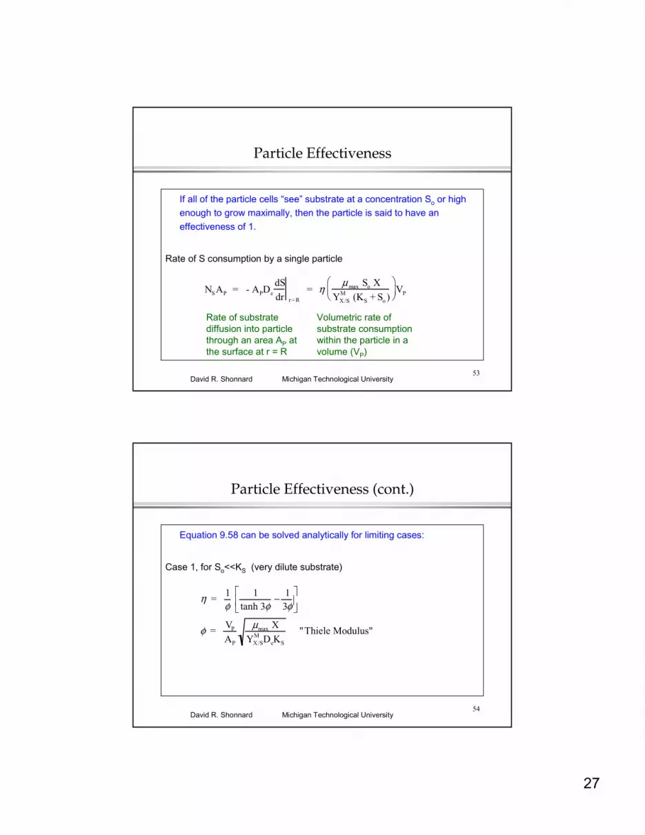
Particle Effectiveness
If all of the particle cells “see” substrate at a concentration So or high enough to grow maximally, then the particle is said to have an effectiveness of 1.
Rate of S consumption by a single particle
NSAP = - APDe
dS
dr r= R
= η µ max So X
YX /SM (KS + So )
VP
Rate of substrate diffusion into particle through an area AP at the surface at r = R
Volumetric rate of substrate consumption within the particle in a volume (VP)
54Michigan Technological UniversityDavid R. Shonnard
Particle Effectiveness (cont.)
Equation 9.58 can be solved analytically for limiting cases:
Case 1, for So<<KS (very dilute substrate)
η = 1φ
1
tanh 3φ− 1
3φ
φ = VP
AP
µmax X
YX /SM DeKS
"Thiele Modulus"

28
55Michigan Technological UniversityDavid R. Shonnard
Particle Effectiveness (cont.)
Equation 9.58 can be solved analytically for limiting cases:
Case 2, for So>>KS (very concentrated substrate)
De
d2S
dr2 +
2
r
dS
dr
=
µmaxS
YX / SM (KS + S)
X = µmaxX
YX / SM
Boundary Conditions
S = So at r = R (at the particle / liquid interface)
dS
dr = 0, at r = 0 (at the particle center)
56Michigan Technological UniversityDavid R. Shonnard
Particle Effectiveness (cont.)
Equation 9.58 can be solved analytically for limiting cases:
Case 2, for So>>KS
Use a variable transformation, S=S’/r
1
r
d2S'
dr2 =
µmaxX
YX /SM De
Solution for S is;
S = So - µmaxX
6 YX / SM De
(R2 - r2)
At a critical radius (rcr ), S = 0
0 = So - µmaxX
6 YX /SM De
(R2 - rcr2)
rcr
R
2
= 1 - 6 De So YX / S
M
µmax X R2
29
57Michigan Technological UniversityDavid R. Shonnard
Particle Effectiveness (cont.)
Equation 9.58 can be solved analytically for limiting cases:
Case 2, for So>>KS
η =
µmaxXY
X / SM
43
π (R3 - rcr3 )
µmaxX
YX /SM
4
3π R3
= 1- rcr
R
3
or
η = 1- 1 - 6 De So YX / S
M
µmax X R 2
3
2
58Michigan Technological UniversityDavid R. Shonnard
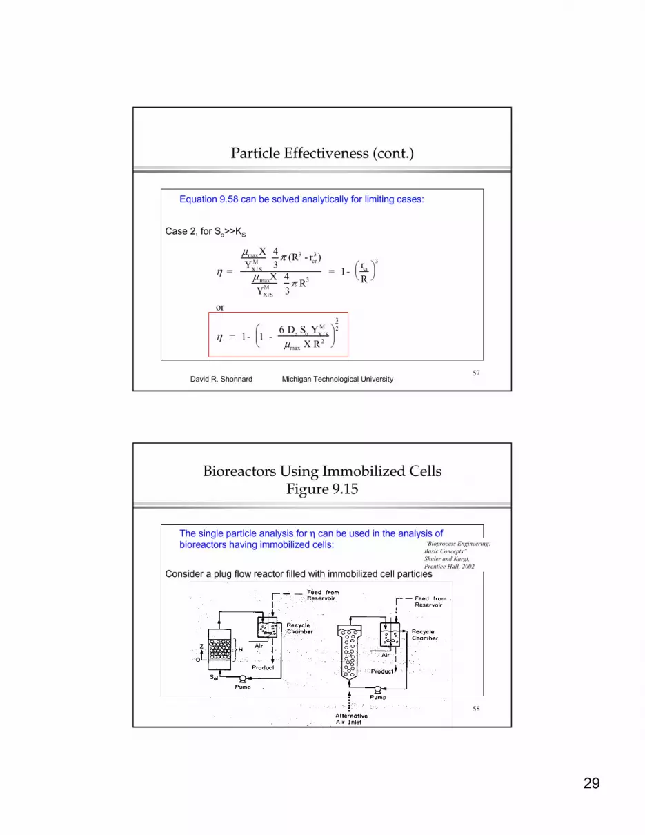
Bioreactors Using Immobilized CellsFigure 9.15
The single particle analysis for η can be used in the analysis of bioreactors having immobilized cells:
Consider a plug flow reactor filled with immobilized cell particles
“Bioprocess Engineering: Basic Concepts”Shuler and Kargi, Prentice Hall, 2002

30
59Michigan Technological UniversityDavid R. Shonnard
Bioreactors Using Immobilized Cells (cont.)
A differential balance on a thin slice of particles within the reactor:
Soi
So
0
z
H
F, So
F, So-dSo
z
z+dz
differential volume element
FSo z - FSo z +dz = NS a A dz
Rate of substrate flow into element
Rate of masstransfer intoparticles within element
Rate of substrate flow out of element
=-
60Michigan Technological UniversityDavid R. Shonnard
Bioreactors Using Immobilized Cells (cont.)
Using the definition of η:
NSAP = η µmax So X
YX /SM (KS + So )
VP
-FdSo
dz = η
µmax So X
YX / SM (KS + So)
VP
A P
a A
where a = surface area of particle per unit volume of bed (cm2 / cm3 bed)
A = cross - sectional area of the bed (cm2 )

31
61Michigan Technological UniversityDavid R. Shonnard
Bioreactors Using Immobilized Cells (cont.)
At z = 0, So = Soi: integrating assuming η is constant
KS lnSoi
So
+ (Soi - So) = η µmax VP X a A
YX /SM F AP
H
for low substrate concentration (Soi << KS )
lnSo
Soi
= - η µmax V
P X a A
YX /SM F AP KS
H
note x = xVP
AP
a (average cell mass conc. in the bed)
Related Documents