MicroFlex e100 servo drive

Welcome message from author
This document is posted to help you gain knowledge. Please leave a comment to let me know what you think about it! Share it to your friends and learn new things together.
Transcript

MicroFlex e100 servo drive


ContentsContents
1 General Information
2 Introduction2.1 MicroFlex e100 features . . . . . . . . . . . . . . . . . . . . . . . . . . . . . . . . 2-1
2.2 Receiving and inspection. . . . . . . . . . . . . . . . . . . . . . . . . . . . . . . . 2-22.2.1 Identifying the catalog number . . . . . . . . . . . . . . . . . . . . . . . . . . . . . . . . . . . 2-2
2.3 Units and abbreviations . . . . . . . . . . . . . . . . . . . . . . . . . . . . . . . . . 2-3
3 Basic Installation3.1 Introduction . . . . . . . . . . . . . . . . . . . . . . . . . . . . . . . . . . . . . . . . . . 3-1
3.1.1 Power sources . . . . . . . . . . . . . . . . . . . . . . . . . . . . . . . . . . . . . . . . . . . . . . . 3-13.1.2 Hardware requirements. . . . . . . . . . . . . . . . . . . . . . . . . . . . . . . . . . . . . . . . . 3-13.1.3 Tools and miscellaneous hardware. . . . . . . . . . . . . . . . . . . . . . . . . . . . . . . . 3-23.1.4 Other information needed for installation . . . . . . . . . . . . . . . . . . . . . . . . . . . 3-2
3.2 Mechanical installation and cooling requirements . . . . . . . . . . . . . 3-33.2.1 Dimensions . . . . . . . . . . . . . . . . . . . . . . . . . . . . . . . . . . . . . . . . . . . . . . . . . . 3-43.2.2 Mounting and cooling the MicroFlex e100 . . . . . . . . . . . . . . . . . . . . . . . . . . 3-53.2.3 Derating characteristic - 3 A model . . . . . . . . . . . . . . . . . . . . . . . . . . . . . . . . 3-63.2.4 Derating characteristic - 6 A model . . . . . . . . . . . . . . . . . . . . . . . . . . . . . . . . 3-73.2.5 Derating characteristic - 9 A model . . . . . . . . . . . . . . . . . . . . . . . . . . . . . . . . 3-83.2.6 Overtemperature trips . . . . . . . . . . . . . . . . . . . . . . . . . . . . . . . . . . . . . . . . . . 3-83.2.7 Heat dissipation. . . . . . . . . . . . . . . . . . . . . . . . . . . . . . . . . . . . . . . . . . . . . . . 3-9
3.3 Connector locations . . . . . . . . . . . . . . . . . . . . . . . . . . . . . . . . . . . 3-103.3.1 Front panel connectors . . . . . . . . . . . . . . . . . . . . . . . . . . . . . . . . . . . . . . . . 3-103.3.2 Top panel connectors . . . . . . . . . . . . . . . . . . . . . . . . . . . . . . . . . . . . . . . . . 3-11
3.4 Power connections . . . . . . . . . . . . . . . . . . . . . . . . . . . . . . . . . . . 3-123.4.1 Earthing / grounding . . . . . . . . . . . . . . . . . . . . . . . . . . . . . . . . . . . . . . . . . . 3-123.4.2 Earth leakage . . . . . . . . . . . . . . . . . . . . . . . . . . . . . . . . . . . . . . . . . . . . . . . 3-133.4.3 Single-phase or three-phase power connections . . . . . . . . . . . . . . . . . . . . 3-143.4.4 Input power conditioning . . . . . . . . . . . . . . . . . . . . . . . . . . . . . . . . . . . . . . . 3-153.4.5 Power disconnect and protection devices. . . . . . . . . . . . . . . . . . . . . . . . . . 3-163.4.6 Recommended fuses, circuit breakers and wire sizes . . . . . . . . . . . . . . . . 3-173.4.7 Drive overload protection . . . . . . . . . . . . . . . . . . . . . . . . . . . . . . . . . . . . . . 3-173.4.8 Power supply filters . . . . . . . . . . . . . . . . . . . . . . . . . . . . . . . . . . . . . . . . . . . 3-183.4.9 24 V control circuit supply . . . . . . . . . . . . . . . . . . . . . . . . . . . . . . . . . . . . . . 3-19
3.5 Motor connections . . . . . . . . . . . . . . . . . . . . . . . . . . . . . . . . . . . . 3-203.5.1 Motor circuit contactors . . . . . . . . . . . . . . . . . . . . . . . . . . . . . . . . . . . . . . . . 3-213.5.2 Sinusoidal filter . . . . . . . . . . . . . . . . . . . . . . . . . . . . . . . . . . . . . . . . . . . . . . 3-213.5.3 Thermal switch connection . . . . . . . . . . . . . . . . . . . . . . . . . . . . . . . . . . . . . 3-223.5.4 Motor brake connection. . . . . . . . . . . . . . . . . . . . . . . . . . . . . . . . . . . . . . . . 3-23
MN1942WEN Contents i

3.6 Brake (regeneration) resistor. . . . . . . . . . . . . . . . . . . . . . . . . . . . .3-243.6.1 Braking capacity. . . . . . . . . . . . . . . . . . . . . . . . . . . . . . . . . . . . . . . . . . . . . .3-24
3.7 Brake resistor selection . . . . . . . . . . . . . . . . . . . . . . . . . . . . . . . . .3-253.7.1 Required information . . . . . . . . . . . . . . . . . . . . . . . . . . . . . . . . . . . . . . . . . .3-253.7.2 Braking energy . . . . . . . . . . . . . . . . . . . . . . . . . . . . . . . . . . . . . . . . . . . . . .3-263.7.3 Braking power and average power . . . . . . . . . . . . . . . . . . . . . . . . . . . . . . .3-263.7.4 Resistor choice. . . . . . . . . . . . . . . . . . . . . . . . . . . . . . . . . . . . . . . . . . . . . . .3-273.7.5 Resistor derating . . . . . . . . . . . . . . . . . . . . . . . . . . . . . . . . . . . . . . . . . . . . .3-283.7.6 Resistor pulse load rating. . . . . . . . . . . . . . . . . . . . . . . . . . . . . . . . . . . . . . .3-293.7.7 Duty cycle. . . . . . . . . . . . . . . . . . . . . . . . . . . . . . . . . . . . . . . . . . . . . . . . . . .3-30
4 Feedback4.1 Introduction . . . . . . . . . . . . . . . . . . . . . . . . . . . . . . . . . . . . . . . . . . .4-1
4.1.1 Incremental encoder feedback. . . . . . . . . . . . . . . . . . . . . . . . . . . . . . . . . . . .4-24.1.2 BiSS interface . . . . . . . . . . . . . . . . . . . . . . . . . . . . . . . . . . . . . . . . . . . . . . . .4-64.1.3 SSI feedback . . . . . . . . . . . . . . . . . . . . . . . . . . . . . . . . . . . . . . . . . . . . . . . . .4-74.1.4 EnDat (absolute encoder) feedback. . . . . . . . . . . . . . . . . . . . . . . . . . . . . . . .4-84.1.5 Smart Abs interface . . . . . . . . . . . . . . . . . . . . . . . . . . . . . . . . . . . . . . . . . . . .4-94.1.6 SinCos feedback . . . . . . . . . . . . . . . . . . . . . . . . . . . . . . . . . . . . . . . . . . . . .4-10
5 Input / Output5.1 Introduction . . . . . . . . . . . . . . . . . . . . . . . . . . . . . . . . . . . . . . . . . . .5-1
5.2 Digital I/O. . . . . . . . . . . . . . . . . . . . . . . . . . . . . . . . . . . . . . . . . . . . .5-25.2.1 Drive enable input . . . . . . . . . . . . . . . . . . . . . . . . . . . . . . . . . . . . . . . . . . . . .5-35.2.2 General purpose digital input DIN0 . . . . . . . . . . . . . . . . . . . . . . . . . . . . . . . .5-55.2.3 General purpose digital inputs DIN1 & DIN2 . . . . . . . . . . . . . . . . . . . . . . . . .5-75.2.4 Special functions on inputs DIN1 & DIN2. . . . . . . . . . . . . . . . . . . . . . . . . . . .5-85.2.5 General purpose / status output DOUT0 . . . . . . . . . . . . . . . . . . . . . . . . . . .5-115.2.6 General purpose output DOUT1 . . . . . . . . . . . . . . . . . . . . . . . . . . . . . . . . .5-13
5.3 USB communication . . . . . . . . . . . . . . . . . . . . . . . . . . . . . . . . . . .5-155.3.1 USB port. . . . . . . . . . . . . . . . . . . . . . . . . . . . . . . . . . . . . . . . . . . . . . . . . . . .5-15
5.4 RS485 communication . . . . . . . . . . . . . . . . . . . . . . . . . . . . . . . . .5-155.4.1 RS485 port (2-wire) . . . . . . . . . . . . . . . . . . . . . . . . . . . . . . . . . . . . . . . . . . .5-15
5.5 Ethernet interface . . . . . . . . . . . . . . . . . . . . . . . . . . . . . . . . . . . . .5-175.5.1 TCP/IP . . . . . . . . . . . . . . . . . . . . . . . . . . . . . . . . . . . . . . . . . . . . . . . . . . . . .5-175.5.2 Ethernet POWERLINK . . . . . . . . . . . . . . . . . . . . . . . . . . . . . . . . . . . . . . . . .5-195.5.3 Ethernet connectors . . . . . . . . . . . . . . . . . . . . . . . . . . . . . . . . . . . . . . . . . . .5-20
5.6 CAN interface . . . . . . . . . . . . . . . . . . . . . . . . . . . . . . . . . . . . . . . .5-215.6.1 CAN connector. . . . . . . . . . . . . . . . . . . . . . . . . . . . . . . . . . . . . . . . . . . . . . .5-215.6.2 CAN wiring . . . . . . . . . . . . . . . . . . . . . . . . . . . . . . . . . . . . . . . . . . . . . . . . . .5-215.6.3 CANopen . . . . . . . . . . . . . . . . . . . . . . . . . . . . . . . . . . . . . . . . . . . . . . . . . . .5-23
5.7 Other I/O . . . . . . . . . . . . . . . . . . . . . . . . . . . . . . . . . . . . . . . . . . . .5-255.7.1 Node ID selector switches . . . . . . . . . . . . . . . . . . . . . . . . . . . . . . . . . . . . . .5-25
5.8 Connection summary - recommended system wiring . . . . . . . . . .5-28
ii Contents MN1942WEN
6 Configuration6.1 Introduction . . . . . . . . . . . . . . . . . . . . . . . . . . . . . . . . . . . . . . . . . . 6-1
6.1.1 Connecting the MicroFlex e100 to the PC . . . . . . . . . . . . . . . . . . . . . . . . . . 6-16.1.2 Installing Mint WorkBench. . . . . . . . . . . . . . . . . . . . . . . . . . . . . . . . . . . . . . . 6-1
6.2 Starting the MicroFlex e100. . . . . . . . . . . . . . . . . . . . . . . . . . . . . . 6-26.2.1 Preliminary checks . . . . . . . . . . . . . . . . . . . . . . . . . . . . . . . . . . . . . . . . . . . . 6-26.2.2 Power on checks. . . . . . . . . . . . . . . . . . . . . . . . . . . . . . . . . . . . . . . . . . . . . . 6-26.2.3 Installing the USB driver . . . . . . . . . . . . . . . . . . . . . . . . . . . . . . . . . . . . . . . . 6-36.2.4 Configuring the TCP/IP connection (optional) . . . . . . . . . . . . . . . . . . . . . . . . 6-4
6.3 Mint Machine Center . . . . . . . . . . . . . . . . . . . . . . . . . . . . . . . . . . . 6-56.3.1 Starting MMC . . . . . . . . . . . . . . . . . . . . . . . . . . . . . . . . . . . . . . . . . . . . . . . . 6-7
6.4 Mint WorkBench . . . . . . . . . . . . . . . . . . . . . . . . . . . . . . . . . . . . . . 6-86.4.1 Help file . . . . . . . . . . . . . . . . . . . . . . . . . . . . . . . . . . . . . . . . . . . . . . . . . . . . . 6-96.4.2 Starting Mint WorkBench . . . . . . . . . . . . . . . . . . . . . . . . . . . . . . . . . . . . . . 6-106.4.3 Commissioning Wizard . . . . . . . . . . . . . . . . . . . . . . . . . . . . . . . . . . . . . . . . 6-126.4.4 Further tuning - no load attached . . . . . . . . . . . . . . . . . . . . . . . . . . . . . . . . 6-156.4.5 Further tuning - with load attached . . . . . . . . . . . . . . . . . . . . . . . . . . . . . . . 6-176.4.6 Optimizing the velocity response . . . . . . . . . . . . . . . . . . . . . . . . . . . . . . . . 6-186.4.7 Performing test moves - continuous jog . . . . . . . . . . . . . . . . . . . . . . . . . . . 6-216.4.8 Performing test moves - relative positional move . . . . . . . . . . . . . . . . . . . . 6-22
6.5 Further configuration . . . . . . . . . . . . . . . . . . . . . . . . . . . . . . . . . . 6-236.5.1 Fine-tuning tool . . . . . . . . . . . . . . . . . . . . . . . . . . . . . . . . . . . . . . . . . . . . . . 6-236.5.2 Parameters tool . . . . . . . . . . . . . . . . . . . . . . . . . . . . . . . . . . . . . . . . . . . . . . 6-256.5.3 Spy window . . . . . . . . . . . . . . . . . . . . . . . . . . . . . . . . . . . . . . . . . . . . . . . . . 6-266.5.4 Other tools and windows. . . . . . . . . . . . . . . . . . . . . . . . . . . . . . . . . . . . . . . 6-27
7 Troubleshooting7.1 Introduction . . . . . . . . . . . . . . . . . . . . . . . . . . . . . . . . . . . . . . . . . . 7-1
7.1.1 Problem diagnosis. . . . . . . . . . . . . . . . . . . . . . . . . . . . . . . . . . . . . . . . . . . . . 7-17.1.2 SupportMe feature . . . . . . . . . . . . . . . . . . . . . . . . . . . . . . . . . . . . . . . . . . . . 7-17.1.3 Power-cycling the MicroFlex e100 . . . . . . . . . . . . . . . . . . . . . . . . . . . . . . . . 7-1
7.2 MicroFlex e100 indicators . . . . . . . . . . . . . . . . . . . . . . . . . . . . . . . 7-27.2.1 STATUS LED . . . . . . . . . . . . . . . . . . . . . . . . . . . . . . . . . . . . . . . . . . . . . . . . 7-27.2.2 CAN LEDs. . . . . . . . . . . . . . . . . . . . . . . . . . . . . . . . . . . . . . . . . . . . . . . . . . . 7-37.2.3 ETHERNET LEDs . . . . . . . . . . . . . . . . . . . . . . . . . . . . . . . . . . . . . . . . . . . . . 7-47.2.4 Communication . . . . . . . . . . . . . . . . . . . . . . . . . . . . . . . . . . . . . . . . . . . . . . . 7-57.2.5 Power on . . . . . . . . . . . . . . . . . . . . . . . . . . . . . . . . . . . . . . . . . . . . . . . . . . . . 7-57.2.6 Mint WorkBench . . . . . . . . . . . . . . . . . . . . . . . . . . . . . . . . . . . . . . . . . . . . . . 7-57.2.7 Tuning . . . . . . . . . . . . . . . . . . . . . . . . . . . . . . . . . . . . . . . . . . . . . . . . . . . . . . 7-67.2.8 Ethernet. . . . . . . . . . . . . . . . . . . . . . . . . . . . . . . . . . . . . . . . . . . . . . . . . . . . . 7-67.2.9 CANopen. . . . . . . . . . . . . . . . . . . . . . . . . . . . . . . . . . . . . . . . . . . . . . . . . . . . 7-7
8 Specifications8.1 Introduction . . . . . . . . . . . . . . . . . . . . . . . . . . . . . . . . . . . . . . . . . . 8-1
8.1.1 AC input power and DC bus voltage (X1) . . . . . . . . . . . . . . . . . . . . . . . . . . . 8-1
MN1942WEN Contents iii

8.1.2 24 V control circuit supply input (X2) . . . . . . . . . . . . . . . . . . . . . . . . . . . . . . .8-38.1.3 Motor output power (X1) . . . . . . . . . . . . . . . . . . . . . . . . . . . . . . . . . . . . . . . .8-38.1.4 Braking (X1) . . . . . . . . . . . . . . . . . . . . . . . . . . . . . . . . . . . . . . . . . . . . . . . . . .8-48.1.5 Digital inputs - drive enable and DIN0 general purpose (X3). . . . . . . . . . . . .8-48.1.6 Digital inputs DIN1, DIN2 - high speed general purpose (X3) . . . . . . . . . . . .8-58.1.7 Digital outputs DOUT0, DOUT1 - status and general purpose (X3) . . . . . . .8-58.1.8 Incremental encoder feedback option (X8) . . . . . . . . . . . . . . . . . . . . . . . . . .8-58.1.9 BiSS interface (X8). . . . . . . . . . . . . . . . . . . . . . . . . . . . . . . . . . . . . . . . . . . . .8-68.1.10 SSI encoder feedback option (X8) . . . . . . . . . . . . . . . . . . . . . . . . . . . . . . . . .8-68.1.11 Smart Abs interface (X8) . . . . . . . . . . . . . . . . . . . . . . . . . . . . . . . . . . . . . . . .8-68.1.12 SinCos / EnDat encoder feedback option (X8) . . . . . . . . . . . . . . . . . . . . . . .8-78.1.13 Ethernet interface (E1 / E2) . . . . . . . . . . . . . . . . . . . . . . . . . . . . . . . . . . . . . .8-78.1.14 CAN interface (OPT 1) . . . . . . . . . . . . . . . . . . . . . . . . . . . . . . . . . . . . . . . . . .8-78.1.15 RS485 interface . . . . . . . . . . . . . . . . . . . . . . . . . . . . . . . . . . . . . . . . . . . . . . .8-78.1.16 Environmental . . . . . . . . . . . . . . . . . . . . . . . . . . . . . . . . . . . . . . . . . . . . . . . .8-88.1.17 Weights and dimensions . . . . . . . . . . . . . . . . . . . . . . . . . . . . . . . . . . . . . . . .8-8
Appendices
A AccessoriesA.1 Introduction . . . . . . . . . . . . . . . . . . . . . . . . . . . . . . . . . . . . . . . . . . A-1
A.1.1 Fan tray . . . . . . . . . . . . . . . . . . . . . . . . . . . . . . . . . . . . . . . . . . . . . . . . . . . . A-2A.1.2 Footprint filter (single-phase only) . . . . . . . . . . . . . . . . . . . . . . . . . . . . . . . . A-3A.1.3 24 V power supplies. . . . . . . . . . . . . . . . . . . . . . . . . . . . . . . . . . . . . . . . . . . A-3A.1.4 EMC filters . . . . . . . . . . . . . . . . . . . . . . . . . . . . . . . . . . . . . . . . . . . . . . . . . . A-4A.1.5 Brake resistors . . . . . . . . . . . . . . . . . . . . . . . . . . . . . . . . . . . . . . . . . . . . . . . A-7
A.2 Cables . . . . . . . . . . . . . . . . . . . . . . . . . . . . . . . . . . . . . . . . . . . . . . A-8A.2.1 Motor power cables . . . . . . . . . . . . . . . . . . . . . . . . . . . . . . . . . . . . . . . . . . . A-8A.2.2 Feedback cable part numbers . . . . . . . . . . . . . . . . . . . . . . . . . . . . . . . . . . . A-9A.2.3 Ethernet cables . . . . . . . . . . . . . . . . . . . . . . . . . . . . . . . . . . . . . . . . . . . . . . A-9
B Control SystemB.1 Introduction . . . . . . . . . . . . . . . . . . . . . . . . . . . . . . . . . . . . . . . . . . B-1
B.1.1 Servo configuration . . . . . . . . . . . . . . . . . . . . . . . . . . . . . . . . . . . . . . . . . . . B-2B.1.2 Torque servo configuration . . . . . . . . . . . . . . . . . . . . . . . . . . . . . . . . . . . . . B-4
C Mint Keyword SummaryC.1 Introduction . . . . . . . . . . . . . . . . . . . . . . . . . . . . . . . . . . . . . . . . . . C-1
C.1.1 Keyword listing . . . . . . . . . . . . . . . . . . . . . . . . . . . . . . . . . . . . . . . . . . . . . . . C-1
D CE, UL and environmentalD.1 Outline . . . . . . . . . . . . . . . . . . . . . . . . . . . . . . . . . . . . . . . . . . . . . . D-1
D.1.1 CE marking . . . . . . . . . . . . . . . . . . . . . . . . . . . . . . . . . . . . . . . . . . . . . . . . . D-1
iv Contents MN1942WEN

D.1.2 Compliance with the EMC Directive . . . . . . . . . . . . . . . . . . . . . . . . . . . . . . .D-1D.1.3 Compliance with the Low Voltage Directive . . . . . . . . . . . . . . . . . . . . . . . . .D-2D.1.4 Use of CE compliant components. . . . . . . . . . . . . . . . . . . . . . . . . . . . . . . . .D-2D.1.5 EMC wiring technique . . . . . . . . . . . . . . . . . . . . . . . . . . . . . . . . . . . . . . . . . .D-2D.1.6 EMC installation suggestions . . . . . . . . . . . . . . . . . . . . . . . . . . . . . . . . . . . .D-3D.1.7 Wiring of shielded (screened) cables . . . . . . . . . . . . . . . . . . . . . . . . . . . . . .D-4
D.2 C-tick marking . . . . . . . . . . . . . . . . . . . . . . . . . . . . . . . . . . . . . . . . D-4D.2.1 RCM marking . . . . . . . . . . . . . . . . . . . . . . . . . . . . . . . . . . . . . . . . . . . . . . . .D-4
D.3 RoHS compliance . . . . . . . . . . . . . . . . . . . . . . . . . . . . . . . . . . . . . D-4D.3.1 China RoHS compliance . . . . . . . . . . . . . . . . . . . . . . . . . . . . . . . . . . . . . . . .D-5D.3.2 WEEE notice . . . . . . . . . . . . . . . . . . . . . . . . . . . . . . . . . . . . . . . . . . . . . . . . .D-5
D.4 UL file numbers . . . . . . . . . . . . . . . . . . . . . . . . . . . . . . . . . . . . . . . D-6
MN1942WEN Contents v

vi Contents MN1942WEN

General Information1 General Information
LT0262A07EN Copyright ABB Oy (c) 2017. All rights reserved.
This manual is copyrighted and all rights are reserved. This document or attached software may not,in whole or in part, be copied or reproduced in any form without the prior written consent of ABB.ABB makes no representations or warranties with respect to the contents hereof and specificallydisclaims any implied warranties of fitness for any particular purpose. The information in thisdocument is subject to change without notice. ABB assumes no responsibility for any errors that mayappear in this document.
Mint™ and MicroFlex™ are registered trademarks of Baldor, a member of the ABB group.Windows XP, Windows Vista and Windows 7 are registered trademarks of the Microsoft Corporation.UL and cUL are registered trademarks of Underwriters Laboratories.
MicroFlex e100 is UL listed; file NMMS.E470302.
ABB Motion Ltd6 Hawkley DriveBristol, BS32 0BFUnited Kingdom
Telephone: +44 (0) 1454 850000Fax: +44 (0) 1454 859001E-mail: [email protected] site: www.abbmotion.com
See rear cover for other international offices.
1
MN1942WEN General Information 1-1

Product noticeOnly qualified personnel should attempt the start-up procedure or troubleshoot this equipment.This equipment may be connected to other machines that have rotating parts or parts that arecontrolled by this equipment. Improper use can cause serious or fatal injury.
Safety NoticeIntended use: These drives are intended for use in stationary ground based applications in industrialpower installations according to the standards EN60204 and VDE0160. They are designed formachine applications that require variable speed controlled three-phase brushless AC motors. Thesedrives are not intended for use in applications such as:
Home appliances
Medical instrumentation
Mobile vehicles
Ships
Airplanes.
Unless otherwise specified, this drive is intended for installation in a suitable enclosure. Theenclosure must protect the drive from exposure to excessive or corrosive moisture, dust and dirt orabnormal ambient temperatures. The exact operating specifications are found in section 8 of thismanual. The installation, connection and control of drives is a skilled operation, disassembly or repairmust not be attempted. In the event that a drive fails to operate correctly, contact the place ofpurchase for return instructions.
PrecautionsDo not touch any circuit board, power device or electrical connection before you firstensure that no high voltage is present at this equipment or other equipment to which it isconnected. Electrical shock can cause serious or fatal injury. Only qualified personnelshould attempt to start-up, program or troubleshoot this equipment.
The motor circuit might have high voltages present whenever AC power is applied, evenwhen the motor is not moving. Electrical shock can cause serious or fatal injury.
If a motor is driven mechanically, it might generate hazardous voltages that areconducted to its power terminals. The enclosure must be earthed/grounded to preventpossible shock hazard.
Be sure the system is properly earthed/grounded before applying power. Do not applyAC power before you ensure that earths/grounds are connected. Electrical shock cancause serious or fatal injury.
Be sure that you are completely familiar with the safe operation and programming of thisequipment. This equipment may be connected to other machines that have rotating partsor parts that are controlled by this equipment. Improper use can cause serious or fatalinjury.
MEDICAL DEVICE / PACEMAKER DANGER: Magnetic and electromagnetic fields in thevicinity of current carrying conductors and industrial motors can result in a serious healthhazard to persons with cardiac pacemakers, internal cardiac defibrillators,neurostimulators, metal implants, cochlear implants, hearing aids, and other medicaldevices. To avoid risk, stay away from the area surrounding a motor and its currentcarrying conductors.
WARNING
WARNING
WARNING
WARNING
WARNING
WARNING
1-2 General Information MN1942WEN

Be sure all wiring complies with the National Electrical Code and all regional and localcodes. Improper wiring may result in unsafe conditions.
The stop input to this equipment should not be used as the single means of achieving asafety critical stop. Drive disable, motor disconnect, motor brake and other meansshould be used as appropriate.
Improper operation or programming of the drive may cause violent motion of the motorand driven equipment. Be certain that unexpected motor movement will not cause injuryto personnel or damage to equipment. Peak torque of several times the rated motortorque can occur during control failure.
If the drive enable signal is already present when power is applied to the MicroFlex e100,the motor could begin to move immediately.
The metal heatsink on the left side of the MicroFlex e100 can become very hot duringnormal operation.
When operating a rotary motor with no load coupled to its shaft, remove the shaft key toprevent it flying out when the shaft rotates.
A brake resistor may generate enough heat to ignite combustible materials. To avoid firehazard, keep all combustible materials and flammable vapors away from the brakeresistors. Some brake resistors are neither internally fused nor thermally protected andunder extreme conditions, can cause a fire hazard if not suitably protected or rated forthe application.
To prevent equipment damage, be certain that the input power has correctly sizedprotective devices installed.
To ensure reliable performance of this equipment be certain that all signals to/from thedrive are shielded correctly.
Suitable for use on a circuit capable of delivering not more than the RMS symmetricalshort circuit amperes listed here, at the rated maximum voltage:Horsepower RMS Symmetrical Amperes1-50 5,000
Avoid locating the drive immediately above or beside heat generating equipment, ordirectly below water or steam pipes.
Avoid locating the drive in the vicinity of corrosive substances or vapors, metal particlesand dust.
Do not connect AC power to the drive terminals U, V and W. Connecting AC power tothese terminals may result in damage to the drive.
CAUTION
CAUTION
CAUTION
CAUTION
CAUTION
NOTICEi
NOTICEi
NOTICEi
NOTICEi
NOTICEi
NOTICEi
NOTICEi
NOTICEi
MN1942WEN General Information 1-3

ABB does not recommend using “Grounded Leg Delta” transformer power leads thatmay create earth/ground loops and degrade system performance. Instead, werecommend using a four wire Wye.
Drives are intended to be connected to a permanent main power source, not a portablepower source. Suitable fusing and circuit protection devices are required.
The safe integration of the drive into a machine system is the responsibility of themachine designer. Be sure to comply with the local safety requirements at the placewhere the machine is to be used. In Europe these are the Machinery Directive, theElectroMagnetic Compatibility Directive and the Low Voltage Directive. In the UnitedStates this is the National Electrical code and local codes.
Drives must be installed inside an electrical cabinet that provides environmental controland protection. Installation information for the drive is provided in this manual. Motorsand controlling devices that connect to the drive should have specifications compatible tothe drive.
Failure to meet cooling air flow requirements will result in reduced product lifetime and/ordrive overtemperature trips.
Violent jamming (stopping) of the motor during operation may damage the motor anddrive.
Operating the MicroFlex e100 in Torque mode with no load attached to the motor cancause the motor to accelerate rapidly to excessive speed.
Do not tin (solder) exposed wires. Solder contracts over time and may cause looseconnections. Use crimp connections where possible.
Electrical components can be damaged by static electricity. Use ESD (electrostaticdischarge) procedures when handling this drive.
If the drive is subjected to high potential (‘hipot’) testing, only DC voltages may beapplied. AC voltage hipot tests could damage the drive. For further information pleasecontact your local ABB representative.
Ensure that encoder wires are properly connected. Incorrect installation may result inimproper movement.
The threaded holes in the top and bottom of the case are for cable clamps. The holes are11.5 mm deep and accept M4 screws, which must be screwed in to a depth of at least8 mm.
Removing the cover will invalidate UL certification.
Motor overtemperature sensing is required to satisfy UL 508C. The drive has noprovisions for motor overtemperature protection, so external provisions are required.
NOTICEi
NOTICEi
NOTICEi
NOTICEi
NOTICEi
NOTICEi
NOTICEi
NOTICEi
NOTICEi
NOTICEi
NOTICEi
NOTICEi
NOTICEi
NOTICEi
1-4 General Information MN1942WEN

Introduction2 Introduction
2.1 MicroFlex e100 featuresThe MicroFlex e100 is a versatile brushless servo drive, providing a flexible and powerfulmotion control solution for rotary and linear motors. Standard features include:
Single axis AC brushless drive.
Range of models with continuous current ratings of 3 A,6 A or 9 A.
Direct connection to 115 V AC or 230 V AC single-phase or 230 V AC three-phase supplies.
Universal feedback interface supporting incrementalencoder, BiSS, SSI, EnDat, Smart Abs or SinCosfeedback.
Position, velocity and current control.
Auto-tuning wizard (including position loop) andsoftware oscilloscope facilities provided by MintWorkBench configuration software.
3 optically isolated general purpose digital inputs. Twoinputs have ‘fast input’ capability, providing real-timeposition capture.
1 optically isolated drive enable input.
1 optically isolated general purpose digital output.
1 optically isolated digital output to indicate errorconditions.
USB 1.1 serial port (compatible with USB 2.0 and USB3.0).
CANopen protocol for communication with Mintcontrollers and other third party CANopen devices.
Ethernet POWERLINK & TCP/IP support: Twin Ethernetports with integrated hub for communication with hostPC or other Ethernet POWERLINK devices.
Programmable in Mint.
MicroFlex e100 will operate with a large range of brushless rotary and linear servo motors. Itcan also operate induction motors using closed-loop vector control. For information onselecting Baldor servo motors, please see the sales brochure BR1202 available from yourlocal ABB representative.
This manual is intended to guide you through the installation of MicroFlex e100. The sectionsshould be read in sequence.
The Basic Installation section describes the mechanical installation of the MicroFlex e100,the power supply connections and motor connections. The other sections require knowledgeof the low level input/output requirements of the installation and an understanding ofcomputer software installation. If you are not qualified in these areas you should seekassistance before proceeding.
2
MN1942WEN Introduction 2-1

2.2 Receiving and inspectionWhen you receive your MicroFlex e100, there are several things you should do immediately:
1. Check the condition of the shipping container and report any damage immediately to thecarrier that delivered your MicroFlex e100.
2. Remove the MicroFlex e100 from the shipping container and remove all packingmaterial. The container and packing materials may be retained for future shipment.
3. Verify that the catalog number of the MicroFlex e100 you received is the same as thecatalog number listed on your purchase order. The catalog number is described in thenext section.
4. Inspect the MicroFlex e100 for external damage during shipment and report any damageto the carrier that delivered your MicroFlex e100.
5. If MicroFlex e100 is to be stored for several weeks before use, be sure that it is stored ina location that conforms to the storage humidity and temperature specifications shown insection 8.1.16.
2.2.1 Identifying the catalog numberThe MicroFlex e100 is available with different current ratings. The catalog number is markedon the side of the unit. It is a good idea to look for the catalog number (sometimes shown asID/No:) and write it in the space provided here:
A description of a catalog number is shown here, using the example MFE230A003x:
2.2.1.1 Serial number
The first digit of the serial number refers to the manufacturing plant. The next four digits referto the unit’s manufacturing year and week, respectively. The remaining digits complete theserial number so that there are no two units with the same number.
Meaning Alternatives
MFE MicroFlex e100 family -
230 Requires an AC supply voltage of 115-230 Volts, 1Φ or 3Φ -
A003 Continuous current rating of 3 A A006=6 A; A009=9 A
xA letter indicating the hardware revision.This does not affect the capabilities of the MicroFlex e100 unless otherwise stated.
-
Catalog number: MFE_____________________________
Installed at: ______________________________________ Date: _____________
2-2 Introduction MN1942WEN

2.3 Units and abbreviationsThe following units and abbreviations may appear in this manual:
V . . . . . . . . . . . . . . . .Volt (also V AC and V DC)W . . . . . . . . . . . . . . .WattA . . . . . . . . . . . . . . . .AmpereΩ . . . . . . . . . . . . . . . .OhmμF . . . . . . . . . . . . . . .microfaradpF . . . . . . . . . . . . . . .picofaradmH . . . . . . . . . . . . . .millihenry
Φ . . . . . . . . . . . . . . . .phasems . . . . . . . . . . . . . . .millisecondμs . . . . . . . . . . . . . . .microsecondns . . . . . . . . . . . . . . .nanosecond
mm . . . . . . . . . . . . . .millimeterm. . . . . . . . . . . . . . . .meterin . . . . . . . . . . . . . . . .inchft . . . . . . . . . . . . . . . .feetlbf-in . . . . . . . . . . . . .pound force inch (torque)N·m . . . . . . . . . . . . . .Newton meter (torque)
ADC . . . . . . . . . . . . .Analog to Digital ConverterASCII . . . . . . . . . . . .American Standard Code for Information InterchangeAWG . . . . . . . . . . . . .American Wire GaugeCAL. . . . . . . . . . . . . .CAN Application LayerCAN . . . . . . . . . . . . .Controller Area NetworkCDROM . . . . . . . . . .Compact Disc Read Only MemoryCiA . . . . . . . . . . . . . .CAN in Automation International Users and Manufacturers Group e.V.CTRL+E . . . . . . . . . .on the PC keyboard, press Ctrl then E at the same time.DAC . . . . . . . . . . . . .Digital to Analog ConverterDS301. . . . . . . . . . . .CiA CANopen Application Layer and Communication ProfileDS401. . . . . . . . . . . .CiA Device Profile for Generic I/O DevicesDS402. . . . . . . . . . . .CiA Device Profile for Drives and Motion ControlDS403. . . . . . . . . . . .CiA Device Profile for HMIsEDS . . . . . . . . . . . . .Electronic Data SheetEMC . . . . . . . . . . . . .Electromagnetic CompatibilityEPL . . . . . . . . . . . . . .Ethernet POWERLINKHMI . . . . . . . . . . . . . .Human Machine InterfaceISO . . . . . . . . . . . . . .International Standards OrganizationKbaud . . . . . . . . . . . .kilobaud (the same as Kbit/s in most applications)LCD. . . . . . . . . . . . . .Liquid Crystal DisplayMbps . . . . . . . . . . . . .megabits/sMB . . . . . . . . . . . . . .megabytesMMC . . . . . . . . . . . . .Mint Machine Center(NC) . . . . . . . . . . . . .Not ConnectedRF . . . . . . . . . . . . . . .Radio FrequencySSI . . . . . . . . . . . . . .Synchronous Serial InterfaceTCP/IP . . . . . . . . . . .Transmission Control Protocol / Internet ProtocolUDP . . . . . . . . . . . . .User Datagram Protocol
MN1942WEN Introduction 2-3

2-4 Introduction MN1942WEN

Basic Installation3 Basic Installation
3.1 IntroductionYou should read all the sections in Basic Installation to ensure safe installation.This section describes the mechanical and electrical installation of the MicroFlex e100 in thefollowing stages:
Location considerations
Mounting the MicroFlex e100
Connecting the AC power supply
Connecting the 24 V DC control circuit supply
Connecting the motor
Installing a brake resistor
Connecting the feedback device
These stages should be read and followed in sequence.
3.1.1 Power sourcesA 115 - 230 V AC power source (IEC1010 over-voltage category III or less) in the installationarea is required. This may be single-phase or three-phase. An AC power filter is required tocomply with the CE directive for which the MicroFlex e100 was tested (see section 3.4.8).
The 24 V DC control circuit supply must be a regulated power supply with a continuouscurrent supply capability of 1 A (4 A power on surge).
3.1.2 Hardware requirementsThe components you will need to complete the basic installation are:
24 V DC power supply.
AC power supply filter (for CE compliance).
The motor that will be connected to the MicroFlex e100.
A motor power cable.
An incremental encoder feedback cable, SSI cable, or BiSS / EnDat / SinCos cable. A separate Hall cable might also be required for linear motors.
A USB cable.
(Optional) A brake resistor might be required, depending on the application. Without thebrake resistor, the drive may produce an overvoltage fault. All MicroFlex e100 modelshave overvoltage sensing circuitry. Brake resistors may be purchased separately - seeAppendix A.
A cooling fan may be required to allow operation of the MicroFlex e100 at full ratedcurrent (see section 3.2.2).
3
MN1942WEN Basic Installation 3-1

A PC that fulfills the following specification:
* The Ethernet configuration used by a normal office PC is not suitable for directcommunication with the MicroFlex e100. It is recommended to install a separate dedicatedEthernet adapter in the PC, which can be configured for use with the MicroFlex e100. Seesection 6.2.4.
3.1.3 Tools and miscellaneous hardware Your PC operating system user manual might be useful if you are not familiar with
Windows.
Small screwdriver(s) with a blade width of 3 mm or less for connector X1, and 2.5 mm (1/10 in) or less for connector X3.
M5 screws or bolts for mounting the MicroFlex e100.
3.1.4 Other information needed for installationThis information is useful (but not essential) to complete the installation:
The data sheet or manual provided with your motor, describing the wiring information ofthe motor cables/connectors.
Knowledge of whether the digital input signals will be ‘Active Low’ or ‘Active High’.
Minimum specification
Processor 1 GHz
RAM 512 MB
Hard disk space 2 GB
CD-ROM A CD-ROM drive
Serial portUSB port
orEthernet* port
Screen 1024 x 768, 16-bit color
Mouse A mouse or similar pointing device
Operatingsystem
Windows XP or newer, 32-bit or 64-bit
3-2 Basic Installation MN1942WEN

3.2 Mechanical installation and cooling requirementsIt is essential that you read and understand this section before beginning theinstallation.
To prevent equipment damage, be certain that the input power has correctlyrated protective devices installed.
To prevent equipment damage, be certain that input and output signals arepowered and referenced correctly.
To ensure reliable performance of this equipment be certain that all signals to/from the MicroFlex e100 are shielded correctly.
Avoid locating the MicroFlex e100 immediately above or beside heat generatingequipment, or directly below water steam pipes.
Avoid locating the MicroFlex e100 in the vicinity of corrosive substances orvapors, metal particles and dust.
Failure to meet cooling air flow requirements will result in reduced productlifetime and/or drive overtemperature trips.
The safe operation of this equipment depends upon its use in the appropriate environment.The following points must be considered:
The MicroFlex e100 must be installed indoors, permanently fixed and located so that itcan only be accessed by service personnel using tools.
The maximum suggested operating altitude is 1000 m (3300 ft). The MicroFlex e100 must be installed where the pollution degree according to
IEC 60664-1 shall not exceed 2. The 24 V DC control circuit supply must be installed so that the 24 V DC supplied to the
unit is isolated from the AC supply using double or reinforced insulation. The input of the control circuit must be limited to Safety Extra Low Voltage circuits. Both the AC supply and the 24 V DC supply must be fused. The atmosphere must not contain flammable gases or vapors. There must not be abnormal levels of nuclear radiation or X-rays. To comply with CE directive 89/336/EEC an appropriate AC filter must be installed. The MicroFlex e100 must be secured by the slots in the flange. The protective earth/
ground (the threaded hole on the top of the MicroFlex e100) must be bonded to a safetyearth/ground using either a 25 A conductor or a conductor of three times the peakcurrent rating - whichever is the greater.
The threaded holes in the top and bottom of the case are for cable clamps. The holes arethreaded for M4 bolts no longer than 11 mm (0.43 in) in length.
The D-type connectors on the front panel of the MicroFlex e100 are secured using twohexagonal jack screws (sometimes known as “screwlocks”). If a jack screw is removedaccidentally or lost it must be replaced with a #4-40 UNC jack screw with an externalmale threaded section no longer than 10 mm (0.4 in).
NOTICEi
NOTICEi
NOTICEi
NOTICEi
NOTICEi
NOTICEi
MN1942WEN Basic Installation 3-3

3.2.1 Dimensions
Figure 1: Mounting and overall dimensions
Mounting hole and slot detail
Dimensions shown as: mm (inches).
Depth: 157 mm (6.2 in)Weight: 3A: 1.45 kg (3.2 lb)
6A: 1.50 kg (3.3 lb)9A: 1.55 kg (3.4 lb)
80(3.2)
63.4(2.5)
11(0.4)
5(0.2)
6(0
.24
)1
67
.3(6
.59
)
18
0(7
.1)
6(0
.24
)
6 mm
3-4 Basic Installation MN1942WEN

3.2.2 Mounting and cooling the MicroFlex e100Ensure you have read and understood the Mechanical installation and location requirementsin section 3.2. Mount the MicroFlex e100 vertically on its rear side, the side opposite the frontpanel. M5 bolts or screws should be used to mount the MicroFlex e100. Detailed dimensionsare shown in section 3.2.1.
For effective cooling, the MicroFlex e100 must be mounted upright on a smooth verticalmetal surface. The MicroFlex e100 is designed to operate in an ambient temperature of 0 °Cto 45 °C (32 °F to 113 °F). Output current must be derated between 45 °C (113 °F) and theabsolute maximum ambient temperature of 55 °C (131 °F). Within the ambient temperaturerange:
The 3 A model is designed to operate without any additional cooling methods.The 6 A and 9 A models require a forced air flow, passing vertically from the bottom to thetop of the MicroFlex e100 case, to allow full rated current at 45 °C (113 °F).
Temperature derating characteristics are shown in sections 3.2.3 to 3.2.5.
Note: Failure to meet cooling air flow requirements will result in reduced product life-time and/or drive overtemperature trips. It is recommended to check periodicallythe operation of the cooling equipment. Optional fan tray FAN001-024, mountedexactly as shown in section A.1.1., ensures that correct cooling is provided andallows the MicroFlex e100 to be UL listed.
3.2.2.1 Effects of mounting surface and proximity
The proximity of the MicroFlex e100 to othercomponents could affect cooling efficiency. Ifthe MicroFlex e100 is mounted beside anotherMicroFlex e100 (or other obstruction), thereshould be a minimum space of 15 mm tomaintain effective cooling.
If the MicroFlex e100 is mounted above orbelow another MicroFlex e100 (or otherobstruction), there should be a minimum spaceof 90 mm to maintain effective cooling.Remember that when a MicroFlex e100 ismounted above another MicroFlex e100 or heatsource, it will be receiving air that has beenalready heated by the device(s) below it.Multiple MicroFlex e100 units mounted aboveeach other should be aligned, not offset, topromote air flow across the heatsinks.
The derating characteristics assume theMicroFlex e100 is mounted on 3 mm thick (orless) metal plate. If the MicroFlex e100 ismounted on 10 mm plate then the currentcharacteristics shown in sections 3.2.3 to 3.2.5may be increased by up to 7% if there is noforced air cooling, or 15% if forced air cooling ispresent.
It is recommended to allow approximately60 mm at the front to accommodate wiring andconnectors.
Figure 2: Cooling and proximity
Metal backplane
Fo
rce
d a
ir f
low
Co
ol
Wa
rmH
ot
Fan Fan
15 mm
15 mm
90 mm
MN1942WEN Basic Installation 3-5

3.2.3 Derating characteristic - 3 A modelThe following derating characteristics are for model MFE230A003.
Single-phase AC supply
Three-phase AC supply
1m/s forced air
Natural cooling
1m/s forced air
Natural cooling
Ambient temperature (°C)
Ra
ted
ou
tpu
t cu
rre
nt (
Arm
s)R
ated
ou
tpu
t cu
rre
nt (
Arm
s)
Ambient temperature (°C)
Notes:Load power factor = 0.75Overload limit for model MFE230A003 is 6 A
3-6 Basic Installation MN1942WEN

3.2.4 Derating characteristic - 6 A modelThe following derating characteristics are for model MFE230A006.
Single-phase AC supply
Three-phase AC supply
1m/s forced air
Natural cooling
1m/s forced air
Natural cooling
Ambient temperature (°C)
Rat
ed o
utp
ut c
urre
nt (
Arm
s)R
ate
d o
utp
ut c
urre
nt (
Arm
s)
1.5m/s forced air
1.5m/s forced air
Ambient temperature (°C)
Notes:Load power factor = 0.75Overload limit for model MFE230A006 is 12 A
MN1942WEN Basic Installation 3-7

3.2.5 Derating characteristic - 9 A modelThe following derating characteristics are for model MFE230A009.
3.2.6 Overtemperature tripsThe MicroFlex e100 contains internal temperature sensors that will cause it to trip anddisable if the temperature exceeds 80 °C on the 3 A model, or 75 °C on the 6 A and 9 Amodels. This limit can be read using the TEMPERATURELIMITFATAL keyword - see the Minthelp file for details.
Single-phase AC supply
Three-phase AC supply
1m/s forced air
Natural cooling
1m/s forced air
Natural cooling
Ambient temperature (°C)
Rat
ed
out
put
cu
rren
t (A
rms)
Rat
ed
out
put c
urr
ent
(Arm
s)
1.5m/s forced air
1.5m/s forced air
2.5m/s forced air
3.5m/s forced air
2.5m/s forced air
3.5m/s forced air
Ambient temperature (°C)
Notes:Load power factor = 0.78Overload limit for model MFE230A009 is 18 A
3-8 Basic Installation MN1942WEN

3.2.7 Heat dissipationThe MicroFlex e100 emits heat during normal operation. The installation cabinet mustprovide sufficient ventilation to maintain the air temperature within the operating limits of allcomponents in the cabinet. The power dissipation of the MicroFlex e100 can be calculatedfrom the following formulae:
where the DC bus voltage Vout = 305 V DC with a single phase AC supply or 321 V DC witha three phase AC supply. Iout is the nominal output phase current (see section 8.1.3) and0.85 is a typical power factor.
where 0.95 is the typical drive efficiency.
These formulae provide the figures shown in Table 1:
MicroFlex e100catalog number
Heat dissipation (Pdiss)
AC input: 1Φ
W BTU / hr
MFE230A003 50 172
MFE230A006 101 343
MFE230A009 151 515
Table 1: Typical heat dissipation at rated output current
Pout 3 Vout Iout 0.85=
Pin Pout 0.95=
Pdiss Pin Pout–=
MN1942WEN Basic Installation 3-9

3.3 Connector locations
3.3.1 Front panel connectorsX1 Power
1 (NC)2 Data-3 Data+4 GND
LEDs
Node ID
USB
The STATUS, CAN and ETHERNET LEDs are described in section 7.2.1.
These switches set the MicroFlex e100’s node ID for Ethernet POWERLINK, and the final value of the IP address when using TCP/IP. See sections 5.7.1 and 6.2.4.
1 TXA2 TXB3 GND4 +7V out5 (NC)6 (NC)
X6 RS485 port (2-wire)
X3 Input/Output
X8 Feedback In
X2 Control circuit power
1 Status-2 DGND3 DOUT1-4 DIN2-5 DGND6 DIN1-7 DIN0-8 DGND9 Drive enable-10 Shield
11 Status+12 DGND13 DOUT1+14 DIN2+15 DGND16 DIN1+17 DIN0+18 DGND19 Drive enable+20 Shield
Pin Incremental SinCos BiSS / SSI EnDat1 CHA+ (NC) Data+ Data+2 CHB+ (NC) Clock+ Clock+3 CHZ+ (NC) (NC) (NC)4 Sense Sense Sense Sense5 Hall U- Sin- (NC) Sin-*6 Hall U+ Sin+ (NC) Sin+*7 Hall V- Cos- (NC) Cos-*8 Hall V+ Cos+ (NC) Cos+*9 CHA- (NC) Data- Data-10 CHB- (NC) Clock- Clock-11 CHZ- (NC) (NC) (NC)12 +5V out +5V out +5V out +5V out13 DGND DGND DGND DGND14 Hall W- (NC) (NC) (NC)15 Hall W+ (NC) (NC) (NC)Shell Shield Shield Shield Shield
* EnDat v2.1 only. EnDat v2.2 does not use the Sin and Cos signals
(NC) = Not Connected. Do not make a connection to this pin
0 V+24 V
Tightening torque for terminal block connections (X1 & X2) is 0.5-0.6 N·m (4.4-5.3 lb-in). Maximum wire sizes: X1: 2.5 mm2; X3: 0.5 mm2. Connector X3 is designed to accept bare wires only; do not use bootlace ferrules.
Earth/Ground
Earth/Ground
(NC)
L1 AC Phase 1 / L
L2 AC Phase 2 / N
L3 ACPhase 3
U Motor U
V Motor V
W Motor W
R1 Brake resistor
R2 Brake resistor
3-10 Basic Installation MN1942WEN

3.3.2 Top panel connectors
1 (NC)2 CAN-3 CAN GND4 (NC)5 Shield6 CAN GND7 CAN+8 (NC)9 CAN V+
OPT 1 CAN
Ethernet1 TX+2 TX-3 RX+4 (NC)5 (NC)6 RX-7 (NC)8 (NC)
Both connectors have identical pinouts.
MN1942WEN Basic Installation 3-11

3.4 Power connectionsThis section provides instructions for connecting the AC power supply.
The installer of this equipment is responsible for complying with NEC (National ElectricCode) guidelines or CE (Conformite Europeene) directives and application codes that governwiring protection, earthing/grounding, disconnects and other current protection.
Electrical shock can cause serious or fatal injury. Do not touch any powerdevice or electrical connection before you first ensure that power has beendisconnected and there is no high voltage present from this equipment orother equipment to which it is connected.
MicroFlex e100 drives are designed to be powered from standard single and three-phaselines that are electrically symmetrical with respect to earth/ground. The power supply modulewithin all MicroFlex e100 models provides rectification, smoothing and current surgeprotection. Fuses or circuit breakers are required in the input lines for cable protection.
Note: A Residual Current Device (RCD) must not be used for fusing the drive.An appropriate type of circuit breaker or fuse must be used.
All interconnection wires should be in metal conduits between the MicroFlex e100, AC powersource, motor, host controller and any operator interface stations. Use UL listed closed loopconnectors that are of appropriate size for the wire gauge being used. Connectors are to beinstalled using only the crimp tool specified by the manufacturer of the connector.
3.4.1 Earthing / groundingA permanent earth/ground bonding point is provided on the heatsink, which must be used asthe protective earth. It is labeled with the protective earth symbol in the casting and does notform any other mechanical function.
Connector X1 contains earth terminals, but these must not be used as protective earth sincethe connector does not guarantee earth connection first, disconnection last. Earthingmethods are shown in section 3.4.3.
Note: When using unearthed/ungrounded distribution systems, an isolation trans-former with an earthed/grounded secondary is recommended. This providesthree-phase AC power that is symmetrical with respect to earth/ground and canprevent equipment damage.
WARNING
3-12 Basic Installation MN1942WEN

3.4.2 Earth leakageMaximum earth leakage from the MicroFlex e100 is 3.4 mA per phase (230 V, 50 Hz supply).This value does not include the earth leakage from the AC power filter, which could be muchlarger (see section A.1.4).
If the MicroFlex e100 and filter are mounted in a cabinet, the minimum size of the protectiveearthing conductor shall comply with the local safety regulations for high protective earthing
conductor current equipment. The conductor must be 10 mm2 (copper), 16 mm2 (aluminium),or larger to satisfy EN61800-5-1.
3.4.2.1 Protection class
User protection has been achieved using Protective Class I (EN61800-5-1, 3.2.20), whichrequires an earth connection to the unit whenever hazardous voltages are applied. Theequipment provides protection against electric shock by:
Means of connection of protective earth to accessible live conductive parts.
Basic insulation.
MN1942WEN Basic Installation 3-13

3.4.3 Single-phase or three-phase power connections
Note: * The MicroFlex e100 will operate at lower input voltages, although performancecould be impaired. The drive will trip if the DC-bus voltage falls below 50 V or60% of the no-load voltage, whichever occurs first.
For three phase supplies, connect supply to L1, L2 and L3 as shown in Figure 3. For singlephase supplies, connect the supply and neutral to any two line inputs, for example L1 andL2.
For CE compliance, an AC filter must be connected between the AC power supply and theMicroFlex e100. If local codes do not specify different regulations, use at least the samegauge wire for earth/ground as is used for L1, L2 and L3.
Tightening torque for terminal block connections is 0.5-0.6 N·m (4.4-5.3 lb-in). The threadedhole in the top and bottom of the case may be used as an additional functional earth/groundconnection for signals on connector X3. They may also be used to attach shield or strainrelief clamps. The holes are threaded for M4 bolts no longer than 11 mm (0.43 in) in length.
Figure 3: Single or three-phase power connections
LocationConnector X1 (Mating connector: Phoenix COMBICON
MSTB 2,5HC/11-ST-5,08)
Nominal input voltage 115 V AC or 230 V AC, 1Φ or 3Φ line to line
Minimum input voltage 105 V AC, 1Φ or 3Φ line to line (see Note*)
Maximum input voltage 250 V AC, 1Φ or 3Φ line to line
Connect earth/ground to
protective earth on top of driveAC
Supply
Route L1, L2, L3 and earth/ground together
in conduit or cable
Circuit breaker or fuses. See section 3.4.5
AC filter. See section
3.4.8
To earth/ground outer shield, use 360° clamps connected to
enclosure backplane
Isolating switch
Incoming safety earth/ground (PE)
STAR POINT
Line (L1)
Line (L2)
Line (L3)
3-14 Basic Installation MN1942WEN

3.4.4 Input power conditioningCertain power line conditions must be avoided; an AC line reactor, an isolation transformer ora step up/step down transformer may be required for some power conditions:
If the feeder or branch circuit that provides power to the MicroFlex e100 has permanentlyconnected power factor correction capacitors, an input AC line reactor or an isolationtransformer must be connected between the power factor correction capacitors and theMicroFlex e100 to limit the maximum symmetrical short circuit current to 5000 A.
If the feeder or branch circuit that provides power to the MicroFlex e100 has power factorcorrection capacitors that are switched on line and off line, the capacitors must not beswitched while the drive is connected to the AC power line. If the capacitors are switchedon line while the drive is still connected to the AC power line, additional protection isrequired. A Transient Voltage Surge Suppressor (TVSS) of the proper rating must beinstalled between the AC line reactor (or isolation transformer) and the AC input to theMicroFlex e100.
3.4.4.1 Input power-cycling and inrush
If AC power has been removed from the MicroFlex e100, it should remain disconnected forthe period specified in Table 2, before it is reapplied.
This delay allows the input surge protection circuit to perform correctly, ensuring that theinrush current (typically 1.7 A) is below the drive rated current. Power-cycling the drive morefrequently could cause high inrush current and corresponding nuisance operation of circuitbreakers or fuses. Repeated failure to observe the delay period could reduce the lifetime ofthe MicroFlex e100.
3.4.4.2 Discharge period
After AC power has been removed from the MicroFlex e100, high voltages(greater than 50 V DC) can remain on the brake resistor connections untilthe DC-bus circuitry has discharged. The high voltage can remain for theperiod specified in Table 3.
MicroFlex e100current rating
Minimum power cycle delay period(seconds)
3 A 25
6 A 45
9 A 65
Table 2: Power cycle intervals
MicroFlex e100current rating
Time for DC-bus to discharge to 50 V or less(maximum, seconds)
3 A 83
6 A 166
9 A 248
Table 3: DC-bus discharge periods
WARNING
MN1942WEN Basic Installation 3-15
3.4.4.3 Supplying input power from a variac (variable transformer)
When AC power is supplied from a variac, the MicroFlex e100’s pre-charge circuit may notoperate correctly. To ensure that the pre-charge circuitry operates correctly, increase thevariac voltage to the desired level and then power cycle the 24 V DC control circuit supply.This will restart the pre-charge circuit and allow it to operate correctly.
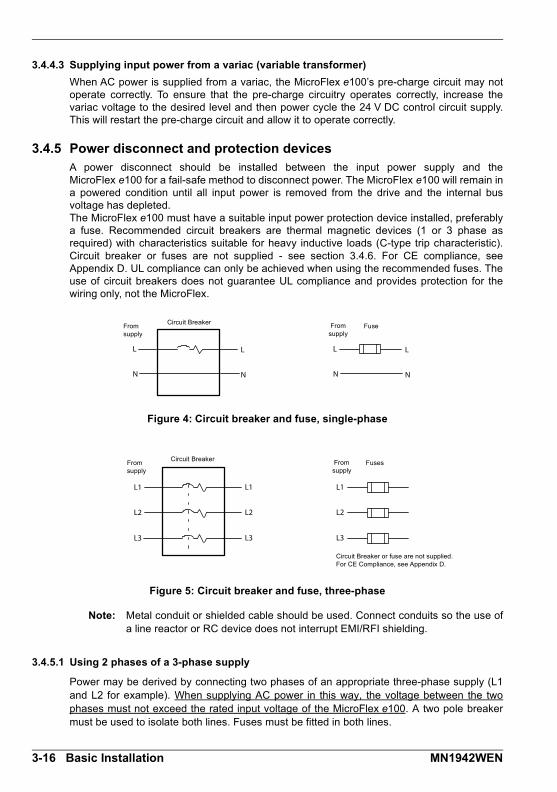
3.4.5 Power disconnect and protection devicesA power disconnect should be installed between the input power supply and theMicroFlex e100 for a fail-safe method to disconnect power. The MicroFlex e100 will remain ina powered condition until all input power is removed from the drive and the internal busvoltage has depleted. The MicroFlex e100 must have a suitable input power protection device installed, preferablya fuse. Recommended circuit breakers are thermal magnetic devices (1 or 3 phase asrequired) with characteristics suitable for heavy inductive loads (C-type trip characteristic).Circuit breaker or fuses are not supplied - see section 3.4.6. For CE compliance, seeAppendix D. UL compliance can only be achieved when using the recommended fuses. Theuse of circuit breakers does not guarantee UL compliance and provides protection for thewiring only, not the MicroFlex.
Figure 4: Circuit breaker and fuse, single-phase
Figure 5: Circuit breaker and fuse, three-phase
Note: Metal conduit or shielded cable should be used. Connect conduits so the use ofa line reactor or RC device does not interrupt EMI/RFI shielding.
3.4.5.1 Using 2 phases of a 3-phase supply
Power may be derived by connecting two phases of an appropriate three-phase supply (L1and L2 for example). When supplying AC power in this way, the voltage between the twophases must not exceed the rated input voltage of the MicroFlex e100. A two pole breakermust be used to isolate both lines. Fuses must be fitted in both lines.
L
N
L
N
L
N
L
N
From supply
From supply
FuseCircuit Breaker
L1
L2
L3
L1
L2
L3
L1
L2
L3
Circuit Breaker or fuse are not supplied. For CE Compliance, see Appendix D.
From supply
From supply
FusesCircuit Breaker
3-16 Basic Installation MN1942WEN

3.4.6 Recommended fuses, circuit breakers and wire sizesTable 4 describes the recommended fuses, circuit breakers and suitable wires sizes to beused for power connections.
Note: All wire sizes are based on 75 °C (167 °F) copper wire. Higher temperaturesmaller gauge wire may be used per National Electric Code (NEC) and localcodes. Recommended fuses are based on 25 °C (77 °F) ambient, maximumcontinuous control output current and no harmonic current. Earth/ground wiresmust be the same gauge, or larger, than the Line wires.
3.4.7 Drive overload protection
The MicroFlex e100 will immediately trip and disable if there is an overload condition. Theparameters for managing drive overloads are configured automatically by theCommissioning Wizard (see section 6.4.3). If they need to be changed, use the Parameterstool in Mint WorkBench (see section 6.5.2).
CatalogNumber
Cont.OutputAmps(RMS)
ACSupplyType
Input FuseCircuitbreaker(C-type)
MinimumWire Gauge
AWG mm2
MFE..A003 3 A
1Φ
Ferraz Shawmut:6x32 FA series, 10 A (W084314P)
orBS88 2.5 URGS 10 A (N076648)
10 A 14 2.0
3Φ
Ferraz Shawmut:6x32 FA series, 8 A (V084313P)
orBS88 2.5 URGS, 7 A (M076647)
8 A 14 2.0
MFE..A006 6 A
1Φ
Ferraz Shawmut:6x32 FA series, 20 A (A084318P)
orBS88 2.5 URGS, 20 A (L097507)
20 A 14 2.0
3Φ
Ferraz Shawmut:6x32 FA series, 12.5 A
(X084315P)or
BS88 2.5 URGS, 12 A (P076649)
12.5 A 14 2.0
MFE..A009 9 A
1ΦFerraz Shawmut:
BS88 2.5 URGS, 25 A (R076651)25 A 14 2.5
3Φ
Ferraz Shawmut:6x32 FA series, 20 A (A084318P)
orBS88 2.5 URGS, 20 A (L097507)
20 A 14 2.0
Table 4: Protection device and wire ratings
MN1942WEN Basic Installation 3-17

3.4.8 Power supply filtersTo comply with EEC directive 89/336/EEC, an AC power filter of the appropriate type must beconnected. This can be supplied by ABB and will ensure that the MicroFlex e100 complieswith the CE specifications for which it has been tested. Ideally, one filter should be providedfor each MicroFlex e100; filters should not be shared between drives or other equipment.Table 5 lists the appropriate filters:
Maximum earth leakage from the MicroFlex e100 is 3.4 mA per phase (230 V, 50 Hz supply).This value does not include the earth leakage from the AC power filter, which could be muchlarger (see section A.1.4).
3.4.8.1 Harmonic suppression
When operating the 3 A MicroFlex e100 (part MFE230A003) on a single-phase AC supply, a13 mH, 4 Arms (10 A peak) line reactor is required to ensure compliance with EN61000-3-2:2000 class A limits, when the total equipment supply load is less than 1 kW.
3.4.8.2 Reversing the filter
When using filters FI0015A00 or FI0015A02 as specified in Table 5, they must be reversed toensure that the MicroFlex e100 complies with the CE specifications for which it has beentested. The AC power supply should be connected to the filter terminals marked as theoutputs, with the MicroFlex e100 connected to the filter terminals marked as the inputs.
This recommendation applies only to filters FI0015A00 and FI0015A02.Alternative filters or protection devices must be connected as specified bythe manufacturer.
MicroFlex e100current
rating
Input voltages
230 V AC, 1Φ 230 V AC, 3Φ
3 A FI0015A00 + line reactor(see sections 3.4.8.1 and 3.4.8.2) or FI0029A00 (see section A.1.2)
FI0018A00
6 A FI0015A02 (see section 3.4.8.2) or FI0029A00 (see section A.1.2)
FI0018A00
9 A FI0029A00 (see section A.1.2) FI0018A03
Table 5: Filter part numbers
WARNING
3-18 Basic Installation MN1942WEN

3.4.9 24 V control circuit supplyA 24 V DC supply must be provided to power the controlling electronics. This is useful forsafety reasons where AC power needs to be removed from the power stage but thecontrolling electronics must remain powered to retain position and I/O information.
A separate fused 24 V supply should be provided for the MicroFlex e100. If other devices arelikely to be powered from the same 24 V supply, a filter (part FI0014A00) should be installedto isolate the MicroFlex e100 from the rest of the system. Alternatively, a ferrite sleeve maybe attached to the supply cable near connector X2.
Tightening torque for terminal block connections is 0.5-0.6 N·m (4.4-5.3 lb-in).
Figure 6: 24 V control circuit supply connections
Location Connector X2
Nominal inputvoltage
24 V DC
Range 20-30 V DC
Input currentMaximum
Typical1 A continuous (4 A typical power on surge, limited by NTC)0.5 A - 0.6 A (not powering feedback device)0.6 A - 0.8 A (powering feedback device)
STAR POINT
24 V filter (optional)
Incoming safety earth/ground (PE)
Customer supplier 24 V DC
Ferrite sleeve**
Use a twisted pair cable, with ferrite sleeve attached close to
connector X2.
* Recommended fuse: Bussman S504 20 x 5 mm anti-surge 2 A** Recommended ferrite sleeve: Fair-Rite part 0431164281 or similar
Fuse *+24 V
GND
MN1942WEN Basic Installation 3-19
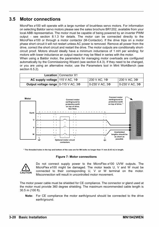
3.5 Motor connectionsMicroFlex e100 will operate with a large number of brushless servo motors. For informationon selecting Baldor servo motors please see the sales brochure BR1202, available from yourlocal ABB representative. The motor must be capable of being powered by an inverter PWMoutput - see section 8.1.3 for details. The motor can be connected directly to theMicroFlex e100 or through a motor contactor (M-Contactor). If the drive trips on a motorphase short circuit it will not restart unless AC power is removed. Remove all power from thedrive, correct the short circuit and restart the drive. The motor outputs are conditionally short-circuit proof. Motors should ideally have a minimum inductance of 1 mH per winding; formotors with lower inductance an output reactor may be fitted in series with the motor.When using a Baldor motor, the parameters for managing motor overloads are configuredautomatically by the Commissioning Wizard (see section 6.4.3). If they need to be changed,or you are using an alternative motor, use the Parameters tool in Mint WorkBench (seesection 6.5.2).
Figure 7: Motor connections
Do not connect supply power to the MicroFlex e100 UVW outputs. TheMicroFlex e100 might be damaged. The motor leads U, V and W must beconnected to their corresponding U, V or W terminal on the motor.Misconnection will result in uncontrolled motor movement.
The motor power cable must be shielded for CE compliance. The connector or gland used atthe motor must provide 360 degree shielding. The maximum recommended cable length is30.5 m (100 ft).
Note: For CE compliance the motor earth/ground should be connected to the driveearth/ground.
Location Connector X1
AC supply voltage 115 V AC, 1Φ 230 V AC, 1Φ 230 V AC, 3Φ
Output voltage range 0-115 V AC, 3Φ 0-230 V AC, 3Φ 0-230 V AC, 3Φ
Connect motor earth/ground to protective earth on top of drive.
See Note.
* The threaded holes in the top and bottom of the case are for M4 bolts no longer than 11 mm (0.43 in) in length.
Optional motor circuit contactors
Unshielded lengths should be
as short as possible
Motor
Earth
Connect motor earth/ground to protective earth on top of drive. *
U
V
W
CAUTION
3-20 Basic Installation MN1942WEN

3.5.1 Motor circuit contactorsIf required by local codes or for safety reasons, an M-Contactor (motor circuit contactor) maybe installed to provide a physical disconnection of the motor windings from theMicroFlex e100 (see section 3.5). Opening the M-Contactor ensures that the MicroFlex e100cannot drive the motor, which may be necessary during equipment maintenance or similaroperations. Under certain circumstances, it may also be necessary to fit a brake to a rotarymotor. This is important with hanging loads where disconnecting the motor windings couldresult in the load falling. Contact your local supplier for details of appropriate brakes.
If an M-Contactor is installed, the MicroFlex e100 must be disabled at least20 ms before the M-Contactor is opened. If the M-Contactor is opened while theMicroFlex e100 is supplying voltage and current to the motor, theMicroFlex e100 may be damaged. Incorrect installation or failure of the M-Contactor or its wiring may result in damage to the MicroFlex e100.
Ensure that shielding of the motor cable is continued on both sides of the contactor.
3.5.2 Sinusoidal filterA sinusoidal filter is used to provide a better quality waveform to the motor, reducing motornoise, temperature and mechanical stress. It will reduce or eliminate harmful dV/dt values(voltage rise over time) and voltage doubling effects which can damage motor insulation.This effect occurs most noticeably when using very long motor cables, for example 30 m(100 ft) or more. Baldor motors intended to be used with drives are designed to withstand theeffects of large dV/dt and overvoltage effects. However, if very long motor cables areunavoidable and are causing problems, then a sinusoidal filter may be beneficial.
CAUTION
MN1942WEN Basic Installation 3-21

3.5.3 Thermal switch connectionYou might wish to wire the motor’s thermal switch contacts (normally closed), using a relay, to adigital input on connector X3 (see section 3.3.1). Using the Mint WorkBench Digital I/O tool, theinput can be configured to be the motor trip input. This allows the MicroFlex e100 to respond tomotor over-temperature conditions. The Mint keyword MOTORTEMPERATUREINPUT can alsobe used to configure a digital input for this purpose. A typical circuit, using DIN1 as the input, isshown in Figure 8.
Figure 8: Motor thermal switch circuit
The 24 V DC power supply connected to the thermal switch must be a separatesupply as shown in Figure 8. Do not use the 24 V DC supply used for the driveenable signal, or the internally generated supply (if present). The thermal switchwires often carry noise that could cause erratic drive operation or damage. Thethermal switch contacts must never be wired directly to a digital input or any partof the logic supply for other components in the system.
The separate 24 V DC supply used for the thermal switch may also be used forthe motor brake circuit (section 3.5.4).
A
B
16
6
‘X3’The relay has normally open contacts and is shown deactivated (contacts open, motor overheated).
motorthermal
switch
Separate customer supplied 24 V DC
supply
Customer supplied 24 V
DC supply
Relay
DIN1+
DIN1-
+24 V +24 V0 V 0 V
CAUTION
3-22 Basic Installation MN1942WEN

3.5.4 Motor brake connectionYou might wish to wire a motor’s brake, via relays, to digital outputs on connector X3 (seesection 3.3.1). This provides a way for the MicroFlex e100 to control the motor’s brake. Atypical circuit is shown in Figure 9.
Figure 9: Motor brake control circuit
This circuit uses the drive enable signal (configured using DRIVEENABLEOUTPUT to appearon DOUT0) in conjunction with DOUT1 (configured as the MOTORBRAKEOUTPUT). See theMint help file for details. With this configuration, the following sequences can be used tocontrol the brake.
To engage the brake: The motor is brought to rest under normal control;
Relay 2 is deactivated, causing the brake to engage;
The drive is disabled. This removes power from the motor and causes Relay 1 to bedeactivated.
To disengage the brake: The drive is enabled, activating Relay 1;
Power is applied to the motor to hold position under normal control;
Relay 2 is activated, causing the brake to be disengaged.
It may be necessary to include a small delay, after Relay 2 has been activated, beforestarting motion. This delay will allow time for the relay contacts to engage and the brake torelease.
The 24 V DC power supply used to power the brake must be a separate supplyas shown in Figure 9. Do not use the supply that is powering the MicroFlex e100digital outputs. The brake wires often carry noise that could cause erratic driveoperation or damage. The brake contacts must never be wired directly to thedigital outputs. The relay(s) should be fitted with a protective flyback diode, asshown. The separate 24 V DC supply used for the motor brake may also beused to power the relay in the thermal switch circuit (section 3.5.3).
C
D
11
1
13
3
‘X3’
The relays have normally open contacts and are shown deactivated (contacts open, brake engaged).
Separate customer supplied
24 V DC supply
Relay 1
+24 V 0 V
Relay 2
The inner shield surrounding the brake wires should be earthed/grounded at one point only
from motor brake connections
User supply GND
User supply V+
DOUT0+
DOUT1+
DOUT0-
DOUT1-
CAUTION
MN1942WEN Basic Installation 3-23
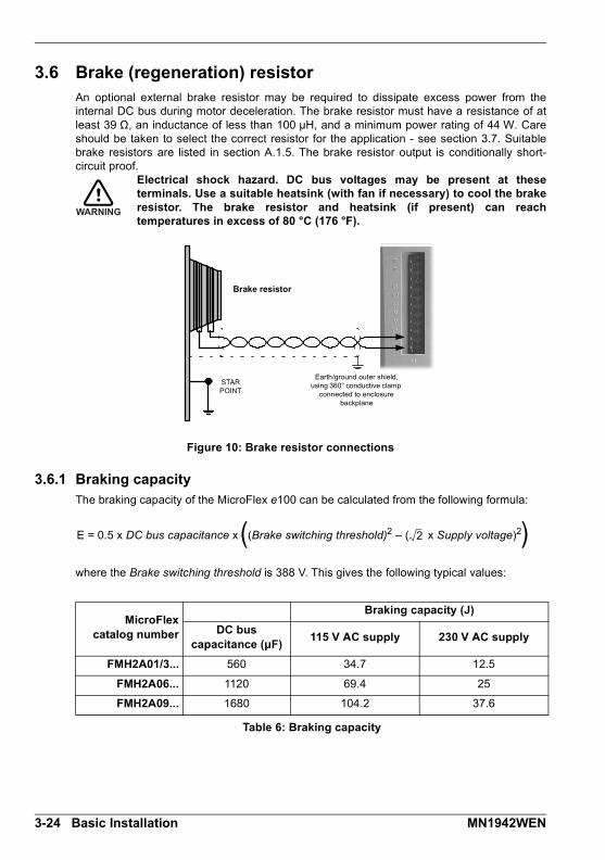
3.6 Brake (regeneration) resistorAn optional external brake resistor may be required to dissipate excess power from theinternal DC bus during motor deceleration. The brake resistor must have a resistance of atleast 39 Ω, an inductance of less than 100 μH, and a minimum power rating of 44 W. Careshould be taken to select the correct resistor for the application - see section 3.7. Suitablebrake resistors are listed in section A.1.5. The brake resistor output is conditionally short-circuit proof.
Electrical shock hazard. DC bus voltages may be present at theseterminals. Use a suitable heatsink (with fan if necessary) to cool the brakeresistor. The brake resistor and heatsink (if present) can reachtemperatures in excess of 80 °C (176 °F).
Figure 10: Brake resistor connections
3.6.1 Braking capacityThe braking capacity of the MicroFlex e100 can be calculated from the following formula:
where the Brake switching threshold is 388 V. This gives the following typical values:
MicroFlexcatalog number
Braking capacity (J)
DC buscapacitance (μF)
115 V AC supply 230 V AC supply
FMH2A01/3... 560 34.7 12.5
FMH2A06... 1120 69.4 25
FMH2A09... 1680 104.2 37.6
Table 6: Braking capacity
WARNING
STAR POINT
Earth/ground outer shield, using 360° conductive clamp
connected to enclosure backplane
Brake resistor
E = 0.5 x DC bus capacitance x (Brake switching threshold)2 – ( x Supply voltage)22( )
3-24 Basic Installation MN1942WEN

3.7 Brake resistor selectionThe following calculations can be used to estimate the type of brake resistor that will berequired for the application.
3.7.1 Required informationTo complete the calculation, some basic information is required. Remember to use the worst-case scenario to ensure that the braking power is not underestimated. For example, use themaximum possible motor speed, maximum inertia, minimum deceleration time and minimumcycle time that the application might encounter.
Requirement Enter value here
a) Initial motor speed, before deceleration begins, in radians per second.
Multiply RPM by 0.1047 to give radians per second.
Initial motor speed, U = _________ rad/s
b) Final motor speed after deceleration is complete, in radians per second.
Multiply RPM by 0.1047 to get radians per second. This value will be zero if the load is going to be stopped.
Final motor speed, V = _________ rad/s
c) The deceleration time from initial speed to final speed, in seconds.
Decel time, D = _________ s
d) The total cycle time (i.e. how frequently the process is repeated), in seconds.
Cycle time, C = _________ s
e) Total inertia.
This is the total inertia seen by the drive, accounting for motor inertia, load inertia and gearing. Use the Mint WorkBench Autotune tool to tune the motor, with the load attached, to determine the value. This will be displayed in kg·m2 in the Autotune tool. If you already know the motor inertia (from the motor spec.) and the load inertia (by calculation) insert the total here.
Multiply kg·cm2 by 0.0001 to give kg·m2.
Multiply lb-ft2 by 0.04214 to give kg·m2.
Multiply lb-in-s2 by 0.113 to give kg·m2.
Total inertia, J = ________ kg·m2
MN1942WEN Basic Installation 3-25

3.7.2 Braking energy The braking energy to be dissipated, E, is the difference between the initial energy in thesystem (before deceleration begins) and the final energy in the system (after decelerationhas finished). If the system is brought to rest then the final energy is zero.
The energy of a rotating object is given by the formula:
where E is energy, J is the moment of inertia, and ω is the angular velocity.
The braking energy, which is the difference between the initial energy and the final energy, istherefore:
= ________________ J (joules)
Calculate E using the values for J, U and V entered in section 3.7.1. If E is less than thedrive’s braking capacity, shown in Table 6 on page 3-24, a brake resistor will not be required. If E is greater than the drive’s braking capacity, then continue to section 3.7.3 to calculate thebraking and average power dissipation.
3.7.3 Braking power and average powerThe braking power, Pr , is the rate at which the braking energy is dissipated. This rate isdefined by the deceleration period, D. The shorter the deceleration period, the greater thebraking power.
= ________________ W (watts)
Although the resistors shown in Table 7 can withstand brief overloads, the average powerdissipation, Pav, must not exceed the stated power rating. The average power dissipation isdetermined by the proportion of the application cycle time spent braking. The greater theproportion of time spent braking, the greater the average power dissipation.
= ________________ W (watts)
E12--- J 2=
E12--- J U
2 1
2--- J V
2 –=
12--- J U
2 V2 –=
PrED----=
Pav PrDC----=
3-26 Basic Installation MN1942WEN

3.7.4 Resistor choicePav is the value to use when assessing which brake resistor to use. However, a safetymargin of 1.25 times is recommended to ensure the resistor operates well within its limits, so:
Required resistor power rating = 1.25 x Pav
= ________________ W (watts)
The range of suitable brake resistors is shown in Table 7. Choose the resistor that has apower rating equal to or greater than the value calculated above.
The brake resistance must be 39 Ω or greater to ensure the drive’s maximumregeneration switching current (10 A) is not exceeded. Failure to observe theminimum resistance could result in damage to the drive.
Dimensions are shown in section A.1.5.
* The brake resistors listed in Table 7 can withstand a brief overload of 10 times the ratedpower for 5 seconds. Please contact ABB if larger power ratings are required.
Resistor part Resistance Power rating
RGJ139 39 Ω 100 W
RGJ160 60 Ω 100 W
RGJ260 60 Ω 200 W
RGJ360 60 Ω 300 W
Table 7: Brake resistors
WARNING
MN1942WEN Basic Installation 3-27
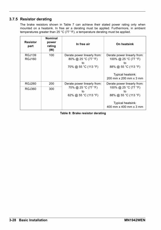
3.7.5 Resistor deratingThe brake resistors shown in Table 7 can achieve their stated power rating only whenmounted on a heatsink. In free air a derating must be applied. Furthermore, in ambienttemperatures greater than 25 °C (77 °F), a temperature derating must be applied.
Resistorpart
Nominalpowerrating
(W)
In free air On heatsink
RGJ139RGJ160
100 Derate power linearly from:80% @ 25 °C (77 °F)
to70% @ 55 °C (113 °F)
Derate power linearly from:100% @ 25 °C (77 °F)
to88% @ 55 °C (113 °F)
Typical heatsink:200 mm x 200 mm x 3 mm
RGJ260 200 Derate power linearly from:70% @ 25 °C (77 °F)
to62% @ 55 °C (113 °F)
Derate power linearly from:100% @ 25 °C (77 °F)
to88% @ 55 °C (113 °F)
Typical heatsink:400 mm x 400 mm x 3 mm
RGJ360 300
Table 8: Brake resistor derating
3-28 Basic Installation MN1942WEN

3.7.6 Resistor pulse load ratingThe brake resistors shown in Table 7 can dissipate power levels greater than the statedcontinuous power rating, provided the duty cycle (see section 3.7.7) is reduced, as shown inFigure 11.
Figure 11: Brake resistor pulse load rating
15000
14000
13000
12000
11000
10000
9000
8000
7000
6000
5000
4000
3000
2000
1000
0
1
23
absolute 0.08 0.17 0.25 0.33 0.42 0.5
on:off (s) 10:120 20:120 30:120 40:120 50:120 60:120
Duty cycle
Po
we
r (W
)
1 100 W models: Maximum pulse 5 kW for 1 s, 120 s off.2 200 W models: Maximum pulse 10 kW for 1 s, 120 s off.3 300 W models: Maximum pulse 5 kW for 1 s, 120 s off.
MN1942WEN Basic Installation 3-29

3.7.7 Duty cycleThe braking duty cycle is the amount of time taken braking as a proportion of the overallapplication cycle time. For example, Figure 12 shows a system which performs a trapezoidalmove profile, with braking during part of the deceleration phase.
The braking duty is 0.2 (0.5 second braking / 2.5 second cycle time):
Figure 12: Duty cycle = 0.2
t
vDecel time Braking active
2.5 s(Cycle time)
2.5 s(Cycle time)
2.5 s(Cycle time)
0.5 s 0.5 s 0.5 s
3-30 Basic Installation MN1942WEN

Feedback4 Feedback
4.1 IntroductionMicroFlex e100 supports many feedback options for use with linear and rotary motors,including incremental encoder, encoder with BiSS (Bi-directional Synchronous Serialinterface), encoder with SSI (Synchronous Serial Interface), EnDat or Smart Abs absoluteencoder or SinCos encoder. All suitable types of feedback device can be connected to theuniversal feedback interface available on connector X8.
There are some important considerations when wiring the feedback device:
The feedback device wiring must be separated from power wiring.
Where feedback device wiring runs parallel to power cables, they must be separated byat least 76 mm (3 in)
Feedback device wiring must cross power wires at right angles only.
To prevent contact with other conductors or earths/grounds, unearthed/ungrounded endsof shields must often be insulated.
Linear motors use two separate cables (encoder and Hall). The cores of these twocables will need to be wired to the appropriate pins of the 15-pin D-type matingconnector.
The inputs are not isolated.
4
MN1942WEN Feedback 4-1

4.1.1 Incremental encoder feedbackThe incremental encoder connections (ABZ channels and Hall signals) are made using the15-pin D-type female connector X8. The encoder inputs (CHA, CHB and CHZ) acceptdifferential signals only. Twisted pairs must be used for each complementary signal pair e.g.CHA+ and CHA-. The Hall inputs may be used as differential inputs (recommended forimproved noise immunity) or single ended inputs. When used as single ended inputs, leavethe Hall U-, Hall V- and Hall W- pins unconnected. The overall cable shield (screen) must beconnected to the metallic shell of the D-type connector. Connector X8 includes a ‘Sense’ pin,which is used to detect the voltage drop on long cable runs. This allows the MicroFlex e100to increase the encoder supply voltage on pin 12 to maintain a 5 V supply at the encoder(200 mA max).
Figure 13: Encoder channel input circuit - Channel A shown
Pin Incremental encoder function
1 CHA+
2 CHB+
3 CHZ+
4 Sense
5 Hall U-
6 Hall U+
7 Hall V-
8 Hall V+
9 CHA-
10 CHB-
11 CHZ-
12 +5 V out
13 DGND
14 Hall W-
15 Hall W+
1
8
9
15
120R
1
9
MicroFlex e100
MAX3096 Differential line receiver
to CPU
CHA+
CHA-
to encoder signal loss detection
DGND
4-2 Feedback MN1942WEN
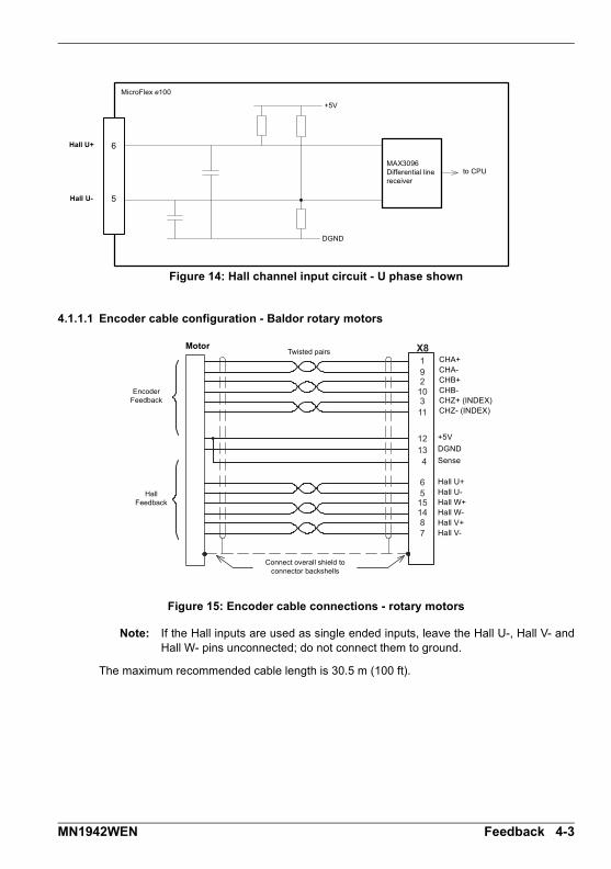
Figure 14: Hall channel input circuit - U phase shown
4.1.1.1 Encoder cable configuration - Baldor rotary motors
Figure 15: Encoder cable connections - rotary motors
Note: If the Hall inputs are used as single ended inputs, leave the Hall U-, Hall V- andHall W- pins unconnected; do not connect them to ground.
The maximum recommended cable length is 30.5 m (100 ft).
6
5
MicroFlex e100
MAX3096 Differential line receiver
to CPU
Hall U+
Hall U-
+5V
DGND
192
10311
12
X8
65
151487
134
Connect overall shield to connector backshells
Twisted pairsMotor
CHA+CHA-CHB+CHB-CHZ+ (INDEX)CHZ- (INDEX)
Hall U+Hall U-Hall W+Hall W-Hall V+Hall V-
+5V
DGND
Sense
Encoder Feedback
Hall Feedback
MN1942WEN Feedback 4-3

4.1.1.2 Encoders without Halls
Incremental encoders without Hall feedback connections may be connected to theMicroFlex e100. However, if Hall connections are not present, it will be necessary for theMicroFlex e100 to perform an automatic phase search sequence each time it is powered.This will cause motor movement of up to 1 turn on rotary motors, or one pole-pitch on linearmotors.
Figure 16: Encoder cable connections without halls - rotary motors
4.1.1.3 Halls-only feedback devices
Feedback devices using only Hall sensors may be connected to the MicroFlex e100.However, since there are no encoder connections, the MicroFlex e100 will not be able toperform speed control or positioning control.
Figure 17: Halls-only feedback cable connections - rotary motors
Note: If the Hall inputs are used as single ended inputs, leave the Hall U-, Hall V- andHall W- pins unconnected; do not connect them to ground.
192
1031112
X8
134
Connect overall shield to connector backshells
Twisted pairs
Encoder Feedback
Motor
CHA+CHA-CHB+CHB-CHZ+ (INDEX)CHZ- (INDEX)
+5V out
DGND
Sense
12
X8
65
151487
13
4
Connect overall shield to connector backshells
Hall Feedback
Motor
Hall U+Hall U-Hall W+Hall W-Hall V+Hall V-
Sense
+5V outDGND
4-4 Feedback MN1942WEN

4.1.1.4 Encoder cable pin configuration - Baldor linear motors
Baldor linear motors use two separate cables (encoder and Hall). The cores of these twocables must be wired to the appropriate pins of the 15-pin D-type mating connector:
Figure 18: Encoder cable connections - linear motors
192
1031112
X8
65
151487
13
Connect overall shield to connector backshells
Twisted pairs
Encoder Feedback
Hall Feedback
Motor
CHA+CHA-CHB+CHB-CHZ+ (INDEX)CHZ- (INDEX)+5VDGND
Hall U+Hall U-Hall W+Hall W-Hall V+Hall V-
Leave pins 5, 7 & 14 unconnected
MN1942WEN Feedback 4-5

4.1.2 BiSS interfaceThe BiSS (Bi-directional Serial Synchronous interface) is an open-source interface that canbe used with many types of absolute encoder. The BiSS interface connections are madeusing the 15-pin D-type female connector X8. Twisted pair cables must be used for thecomplementary signal pairs e.g. Data+ and Data-. The overall cable shield (screen) must beconnected to the metallic shell of the D-type connector. Connector X8 includes a ‘Sense’ pin,which is used to detect the voltage drop on long cable runs. This allows the MicroFlex e100to increase the supply voltage on pin 12 to maintain a 5 V DC supply at the encoder (200 mAmax).
Figure 19: BiSS interface cable connections
The maximum recommended cable length is 30.5m (100ft).
Pin BiSS function
1 Data+
2 Clock+
3 (NC)
4 Sense
5 Sin- Note: If your cable has Sin and Cos pairs they may be connected here. However, these signals are not required or used by the MicroFlex e100 for BiSS operation.
6 Sin+
7 Cos-
8 Cos+
9 Data-
10 Clock-
11 (NC)
12 +5 V out
13 DGND
14 (NC)
15 (NC)
1
8
9
15
19
1213
102
X8
4
Connect overall shield to connector backshells
Twisted pairs
Absolute Encoder
Motor
Data+Data-Clock+Clock-+5V outDGNDSense
Chassis
Connect internal shields to pin 13.
BiS
S
Inte
rfa
ce
4-6 Feedback MN1942WEN
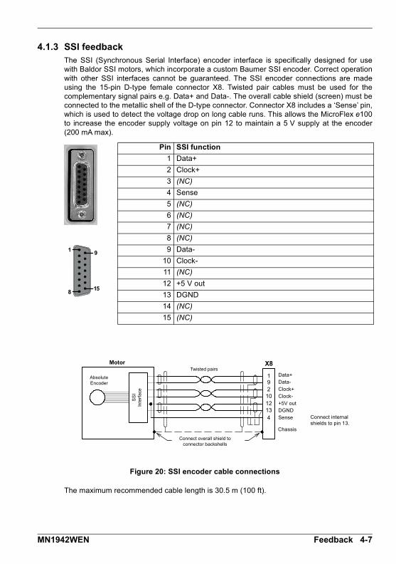
4.1.3 SSI feedbackThe SSI (Synchronous Serial Interface) encoder interface is specifically designed for usewith Baldor SSI motors, which incorporate a custom Baumer SSI encoder. Correct operationwith other SSI interfaces cannot be guaranteed. The SSI encoder connections are madeusing the 15-pin D-type female connector X8. Twisted pair cables must be used for thecomplementary signal pairs e.g. Data+ and Data-. The overall cable shield (screen) must beconnected to the metallic shell of the D-type connector. Connector X8 includes a ‘Sense’ pin,which is used to detect the voltage drop on long cable runs. This allows the MicroFlex e100to increase the encoder supply voltage on pin 12 to maintain a 5 V supply at the encoder(200 mA max).
Figure 20: SSI encoder cable connections
The maximum recommended cable length is 30.5 m (100 ft).
Pin SSI function
1 Data+
2 Clock+
3 (NC)
4 Sense
5 (NC)
6 (NC)
7 (NC)
8 (NC)
9 Data-
10 Clock-
11 (NC)
12 +5 V out
13 DGND
14 (NC)
15 (NC)
1
8
9
15
19
1213
102
X8
4
Connect overall shield to connector backshells
Twisted pairs
Absolute Encoder
Motor
Data+Data-
Clock+Clock-
+5V outDGND
Sense
Chassis
Connect internal shields to pin 13.
SS
I In
terf
ace
MN1942WEN Feedback 4-7

4.1.4 EnDat (absolute encoder) feedbackThe absolute encoder interface supports both incremental and absolute (multi and singleturn) feedback using EnDat technology. It is possible to read and write information to theencoder. The absolute encoder connections are made using the 15-pin D-type femaleconnector X8. Twisted pair cables must be used for the complementary signal pairs e.g. Sin+and Sin-. The overall cable shield (screen) must be connected to the metallic shell of the D-type connector. Connector X8 includes a ‘Sense’ pin, which is used to detect the voltagedrop on long cable runs. This allows the MicroFlex e100 to increase the encoder supplyvoltage on pin 12 to maintain a 5 V supply at the encoder (200 mA max). Version 2.2 EnDatencoders do not use the Sin and Cos channels.
Figure 21: Absolute encoder cable connections
The maximum recommended cable length is 30.5 m (100 ft).
Pin Absolute encoder function
1 Data+
2 Clock+
3 (NC)
4 Sense
5 Sin-
6 Sin+
7 Cos-
8 Cos+
9 Data-
10 Clock-
11 (NC)
12 +5 V out
13 DGND
14 (NC)
15 (NC)
1
8
9
15
19
78
56
X8
102
4
1213
Connect overall shield to connector backshells
Twisted pairs
Absolute Encoder
Motor
Data+Data-Sin-Sin+Cos-Cos+Clock+Clock-+5V outDGNDSense
Connect internal shields to DGND.
4-8 Feedback MN1942WEN

4.1.5 Smart Abs interfaceThe Smart Abs encoder connections are made using the 15-pin D-type female connector X8.Twisted pair cables must be used for the complementary signal pairs e.g. Data+ and Data-.The overall cable shield (screen) must be connected to the metallic shell of the D-typeconnector. Connector X8 includes a ‘Sense’ pin, which is used to detect the voltage drop onlong cable runs. This allows the MicroFlex e100 to increase the supply voltage on pin 12 tomaintain a 5 V DC supply at the encoder (200 mA max).
Figure 22: Smart Abs interface cable connections
The maximum recommended cable length is 30.5 m (100 ft).
Pin Smart Abs function
1 Data+
2 (NC)
3 (NC)
4 Sense
5 (NC) Note: If your cable has Sin and Cos pairs they may be connected here. However, these signals are not required or used by the MicroFlex e100 for Smart Abs.
6 (NC)
7 (NC)
8 (NC)
9 Data-
10 (NC)
11 (NC)
12 +5 V out
13 DGND
14 (NC)
15 (NC)
1
8
9
15
19
1213
102
X8
4
Connect overall shield to connector backshells
Twisted pairs
Absolute Encoder
Motor
Data+Data-Clock+Clock-+5V outDGNDSense
Chassis
Connect internal shields to pin 13.
Sm
art
Ab
s In
terf
ace
MN1942WEN Feedback 4-9
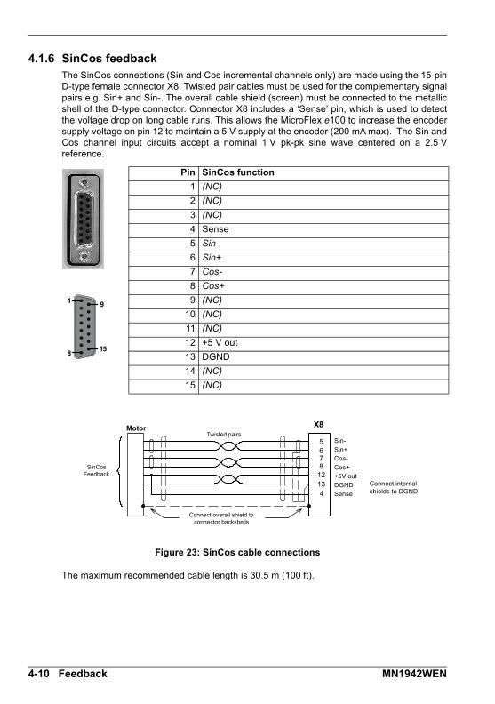
4.1.6 SinCos feedbackThe SinCos connections (Sin and Cos incremental channels only) are made using the 15-pinD-type female connector X8. Twisted pair cables must be used for the complementary signalpairs e.g. Sin+ and Sin-. The overall cable shield (screen) must be connected to the metallicshell of the D-type connector. Connector X8 includes a ‘Sense’ pin, which is used to detectthe voltage drop on long cable runs. This allows the MicroFlex e100 to increase the encodersupply voltage on pin 12 to maintain a 5 V supply at the encoder (200 mA max). The Sin andCos channel input circuits accept a nominal 1 V pk-pk sine wave centered on a 2.5 Vreference.
Figure 23: SinCos cable connections
The maximum recommended cable length is 30.5 m (100 ft).
Pin SinCos function
1 (NC)
2 (NC)
3 (NC)
4 Sense
5 Sin-
6 Sin+
7 Cos-
8 Cos+
9 (NC)
10 (NC)
11 (NC)
12 +5 V out
13 DGND
14 (NC)
15 (NC)
1
8
9
15
5678
12
X8
134
Connect overall shield to connector backshells
Twisted pairs
SinCos Feedback
Motor
Sin-
Sin+Cos-
Cos++5V out
DGNDSense
Connect internal shields to DGND.
4-10 Feedback MN1942WEN

Input / Output5 Input / Output
5.1 IntroductionThis section describes the various digital and analog input and output capabilities of theMicroFlex e100, with descriptions of each of the connectors on the front panel.
The following conventions are used to refer to the inputs and outputs:
I/O . . . . . . . . . . . . Input / OutputDIN . . . . . . . . . . . Digital InputDOUT . . . . . . . . . Digital OutputAIN . . . . . . . . . . . Analog Input
5
MN1942WEN Input / Output 5-1

5.2 Digital I/OThe MicroFlex e100 provides as standard:
3 general purpose digital inputs.
1 dedicated drive enable input.
1 general purpose digital output.
1 general purpose / drive status output.
The general purpose digital inputs can be configured for typical input functions:
Error input
Reset input
Stop input
Forward / reverse limit input - see important details in section 5.2.2.1 or 5.2.3.1.
Home input.
5-2 Input / Output MN1942WEN
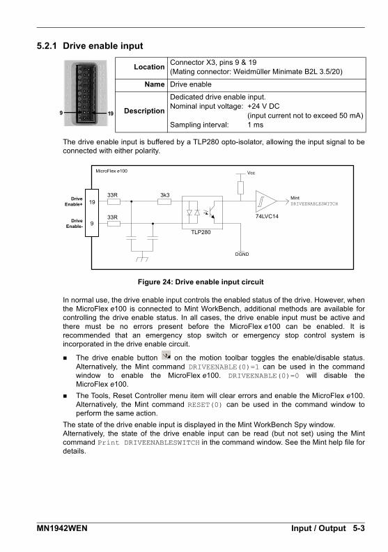
5.2.1 Drive enable input
The drive enable input is buffered by a TLP280 opto-isolator, allowing the input signal to beconnected with either polarity.
Figure 24: Drive enable input circuit
In normal use, the drive enable input controls the enabled status of the drive. However, whenthe MicroFlex e100 is connected to Mint WorkBench, additional methods are available forcontrolling the drive enable status. In all cases, the drive enable input must be active andthere must be no errors present before the MicroFlex e100 can be enabled. It isrecommended that an emergency stop switch or emergency stop control system isincorporated in the drive enable circuit.
The drive enable button on the motion toolbar toggles the enable/disable status.Alternatively, the Mint command DRIVEENABLE(0)=1 can be used in the commandwindow to enable the MicroFlex e100. DRIVEENABLE(0)=0 will disable theMicroFlex e100.
The Tools, Reset Controller menu item will clear errors and enable the MicroFlex e100.Alternatively, the Mint command RESET(0) can be used in the command window toperform the same action.
The state of the drive enable input is displayed in the Mint WorkBench Spy window.Alternatively, the state of the drive enable input can be read (but not set) using the Mintcommand Print DRIVEENABLESWITCH in the command window. See the Mint help file fordetails.
LocationConnector X3, pins 9 & 19(Mating connector: Weidmüller Minimate B2L 3.5/20)
Name Drive enable
Description
Dedicated drive enable input.Nominal input voltage: +24 V DC
(input current not to exceed 50 mA)Sampling interval: 1 ms
199
3k3
TLP280
33R 74LVC14
19
9
33R
MicroFlex e100
DriveEnable+
MintDRIVEENABLESWITCH
Vcc
DGND
DriveEnable-
MN1942WEN Input / Output 5-3
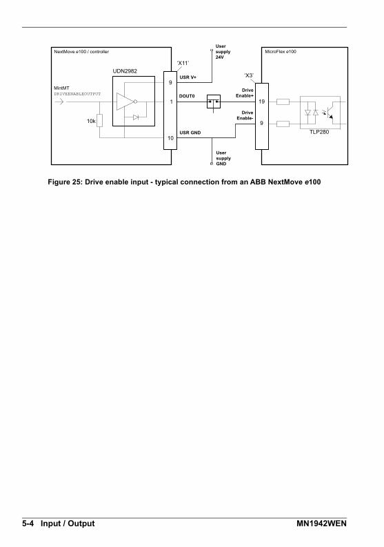
Figure 25: Drive enable input - typical connection from an ABB NextMove e100
10k
1
10
UDN2982
9
‘X11’
‘X3’
TLP280
19
9
MicroFlex e100
DriveEnable+
MintMTDRIVEENABLEOUTPUT
DriveEnable-
User supply 24V
User supply GND
NextMove e100 / controller
USR V+
DOUT0
USR GND
5-4 Input / Output MN1942WEN

5.2.2 General purpose digital input DIN0
This general purpose digital input is buffered by a TLP280 opto-isolator, allowing the inputsignal to be connected with either polarity. The state of the digital input is displayed in theMint WorkBench Spy window. The input can be can be configured for different user definablefunctions.
Figure 26: General purpose digital input circuit
When the MicroFlex e100 is connected to Mint WorkBench, the digital input can be configuredusing the Digital I/O tool. Alternatively, Mint keywords including RESETINPUT, ERRORINPUT,STOPINPUT, FORWARDLIMITINPUT, REVERSELIMITINPUT, POWERREADYINPUT andHOMEINPUT can be used in the command window. The state of the digital input can be viewedusing the Mint WorkBench Spy window’s Axis tab. See the Mint help file for details.
5.2.2.1 Using a digital input as a home switch input
When the MicroFlex e100 is being controlled over EPL by a manager node (e.g.NextMove e100), the home switch input must be wired to the MicroFlex e100, not themanager node. This is because the manager node only triggers the homing sequence, whichis then performed entirely by the MicroFlex e100. It is therefore the MicroFlex e100 whichmust receive the home switch input signal, otherwise it will not be able to complete itshoming routine. Similarly, it is the MicroFlex e100’s own HOME... keyword parameters thatdefine the homing sequence.
LocationConnector X3, pins 7 & 17(Mating connector: Weidmüller Minimate B2L 3.5/20)
Name DIN0
Description
General purpose opto-isolated digital input.Nominal input voltage: +24 V DC
(input current not to exceed 50 mA)Sampling interval: 1 ms
177
3k3
TLP280
74LVC14
17
733R
33R
MicroFlex e100
DIN0+ Mint
Vcc
DGND
DIN0-
MN1942WEN Input / Output 5-5
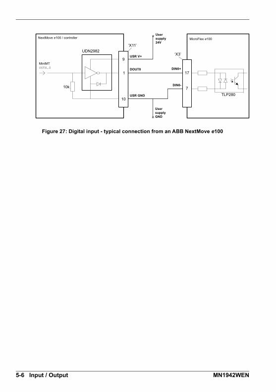
Figure 27: Digital input - typical connection from an ABB NextMove e100
10k
1
10
UDN2982
9
‘X11’
‘X3’
TLP280
17
7
MicroFlex e100
DIN0+
MintMTOUTX.0
DIN0-
User supply 24V
User supply GND
NextMove e100 / controller
USR V+
DOUT0
USR GND
5-6 Input / Output MN1942WEN
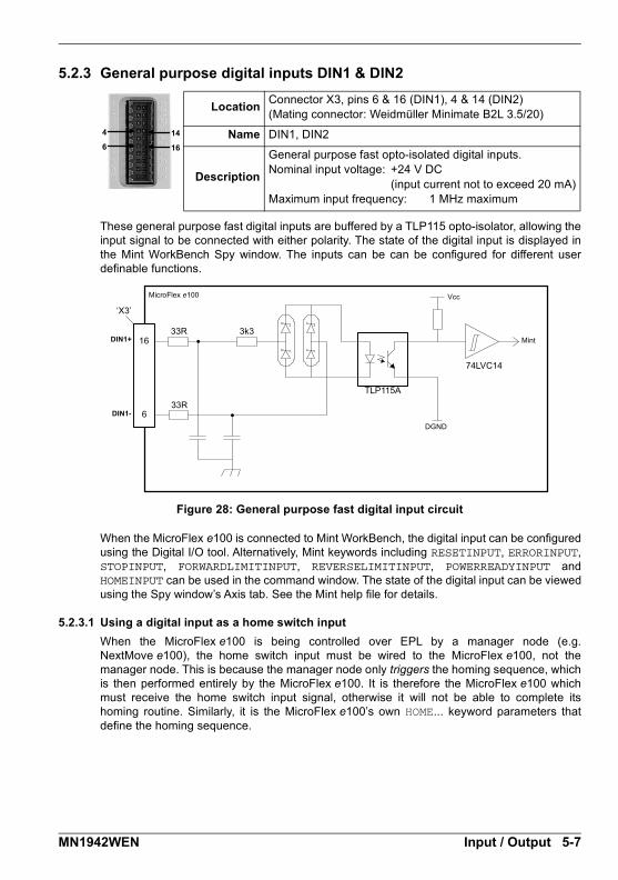
5.2.3 General purpose digital inputs DIN1 & DIN2
These general purpose fast digital inputs are buffered by a TLP115 opto-isolator, allowing theinput signal to be connected with either polarity. The state of the digital input is displayed inthe Mint WorkBench Spy window. The inputs can be can be configured for different userdefinable functions.
Figure 28: General purpose fast digital input circuit
When the MicroFlex e100 is connected to Mint WorkBench, the digital input can be configuredusing the Digital I/O tool. Alternatively, Mint keywords including RESETINPUT, ERRORINPUT,STOPINPUT, FORWARDLIMITINPUT, REVERSELIMITINPUT, POWERREADYINPUT andHOMEINPUT can be used in the command window. The state of the digital input can be viewedusing the Spy window’s Axis tab. See the Mint help file for details.
5.2.3.1 Using a digital input as a home switch input
When the MicroFlex e100 is being controlled over EPL by a manager node (e.g.NextMove e100), the home switch input must be wired to the MicroFlex e100, not themanager node. This is because the manager node only triggers the homing sequence, whichis then performed entirely by the MicroFlex e100. It is therefore the MicroFlex e100 whichmust receive the home switch input signal, otherwise it will not be able to complete itshoming routine. Similarly, it is the MicroFlex e100’s own HOME... keyword parameters thatdefine the homing sequence.
LocationConnector X3, pins 6 & 16 (DIN1), 4 & 14 (DIN2)(Mating connector: Weidmüller Minimate B2L 3.5/20)
Name DIN1, DIN2
Description
General purpose fast opto-isolated digital inputs.Nominal input voltage: +24 V DC
(input current not to exceed 20 mA)Maximum input frequency: 1 MHz maximum
166144
TLP115A
16
6
‘X3’
3k3
33R
74LVC14
33R
MicroFlex e100
DIN1+ Mint
Vcc
DGND
DIN1-
MN1942WEN Input / Output 5-7
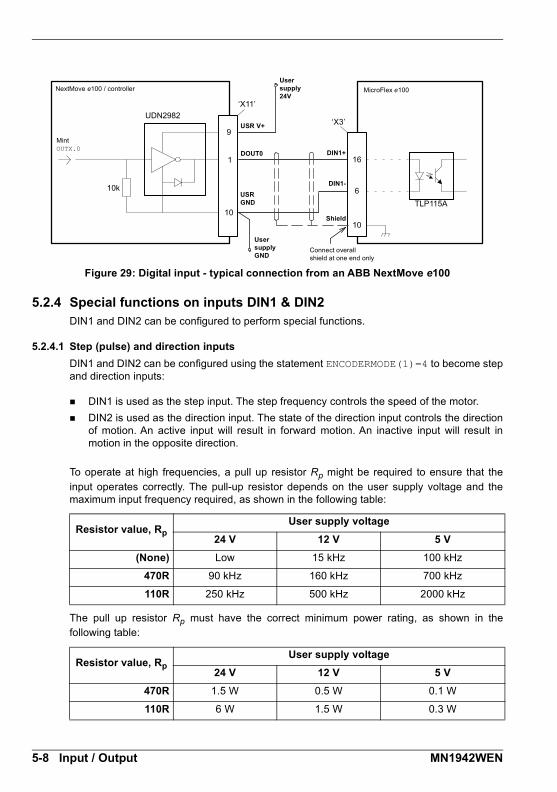
Figure 29: Digital input - typical connection from an ABB NextMove e100
5.2.4 Special functions on inputs DIN1 & DIN2DIN1 and DIN2 can be configured to perform special functions.
5.2.4.1 Step (pulse) and direction inputs
DIN1 and DIN2 can be configured using the statement ENCODERMODE(1)=4 to become stepand direction inputs:
DIN1 is used as the step input. The step frequency controls the speed of the motor.
DIN2 is used as the direction input. The state of the direction input controls the directionof motion. An active input will result in forward motion. An inactive input will result inmotion in the opposite direction.
To operate at high frequencies, a pull up resistor Rp might be required to ensure that theinput operates correctly. The pull-up resistor depends on the user supply voltage and themaximum input frequency required, as shown in the following table:
The pull up resistor Rp must have the correct minimum power rating, as shown in thefollowing table:
Resistor value, RpUser supply voltage
24 V 12 V 5 V
(None) Low 15 kHz 100 kHz
470R 90 kHz 160 kHz 700 kHz
110R 250 kHz 500 kHz 2000 kHz
Resistor value, RpUser supply voltage
24 V 12 V 5 V
470R 1.5 W 0.5 W 0.1 W
110R 6 W 1.5 W 0.3 W
10k
1
10
UDN2982
9
‘X11’
‘X3’
16
6TLP115A
10
MicroFlex e100
DIN1+
MintOUTX.0
DIN1-
User supply 24V
User supply GND
NextMove e100 / controller
USR V+
DOUT0
USR GND
Shield
Connect overall shield at one end only
5-8 Input / Output MN1942WEN

Figure 30: Step and direction inputs - typical connections from an external controller
6
16
‘X3’
4
14
Rp
Rp
PLC / controller MicroFlex e100
StepOutput
GND
DirectionOutput
GND
STEP
DIR
DGND
User supply V+
User supply GND
DIN1+
DIN2+
DIN1-
DIN2-
Step
Direction
MN1942WEN Input / Output 5-9
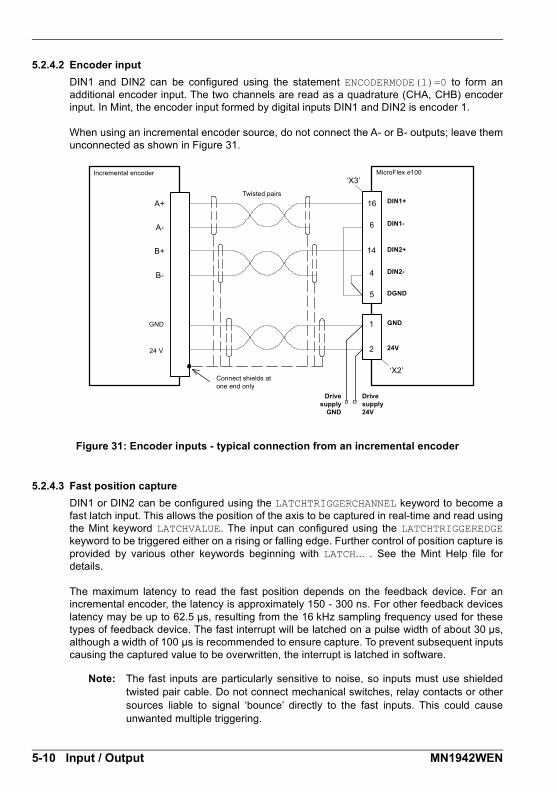
5.2.4.2 Encoder input
DIN1 and DIN2 can be configured using the statement ENCODERMODE(1)=0 to form anadditional encoder input. The two channels are read as a quadrature (CHA, CHB) encoderinput. In Mint, the encoder input formed by digital inputs DIN1 and DIN2 is encoder 1.
When using an incremental encoder source, do not connect the A- or B- outputs; leave themunconnected as shown in Figure 31.
Figure 31: Encoder inputs - typical connection from an incremental encoder
5.2.4.3 Fast position capture
DIN1 or DIN2 can be configured using the LATCHTRIGGERCHANNEL keyword to become afast latch input. This allows the position of the axis to be captured in real-time and read usingthe Mint keyword LATCHVALUE. The input can configured using the LATCHTRIGGEREDGEkeyword to be triggered either on a rising or falling edge. Further control of position capture isprovided by various other keywords beginning with LATCH... . See the Mint Help file fordetails.
The maximum latency to read the fast position depends on the feedback device. For anincremental encoder, the latency is approximately 150 - 300 ns. For other feedback deviceslatency may be up to 62.5 μs, resulting from the 16 kHz sampling frequency used for thesetypes of feedback device. The fast interrupt will be latched on a pulse width of about 30 μs,although a width of 100 μs is recommended to ensure capture. To prevent subsequent inputscausing the captured value to be overwritten, the interrupt is latched in software.
Note: The fast inputs are particularly sensitive to noise, so inputs must use shieldedtwisted pair cable. Do not connect mechanical switches, relay contacts or othersources liable to signal ‘bounce’ directly to the fast inputs. This could causeunwanted multiple triggering.
‘X3’
16
14
A+
A-
B+
B-
6
4
1
‘X2’
2
5
Incremental encoder
DIN1+
DIN2+
DIN1-
MicroFlex e100
DIN2-
Drive supply 24V
Drivesupply
GND
24 V
GND
Twisted pairs
DGND
GND
24V
Connect shields at one end only
5-10 Input / Output MN1942WEN

5.2.5 General purpose / status output DOUT0
The optically isolated general purpose / status output is designed to source current from theuser supply as shown in Figure 32. The TLP127 has a maximum power dissipation of150 mW at 25 °C.
The output includes a self-resetting fuse that operates at approximately 200 mA. The fusemay take up to 20 seconds to reset after the load has been removed. If the output is used todirectly drive a relay, a suitably rated diode must be fitted across the relay coil, observing thecorrect polarity. This is to protect the output from the back-EMF generated by the relay coilwhen it is de-energized. The sense of the output can be configured in Mint WorkBench, andits state is displayed in the Spy window.
Figure 32: DOUT0 output circuit
By default, DOUT0 is configured as an error status output, which becomes inactive in theevent of an error. When the MicroFlex e100 is connected to Mint WorkBench, the active levelof the output can be configured using the Digital I/O tool. Alternatively, the Mint keywordOUTPUTACTIVELEVEL can be used in the command window. See the Mint help file fordetails.
LocationConnector X3, pins 1 & 11(Mating connector: Weidmüller Minimate B2L 3.5/20)
Name Status / DOUT0
Description
General purpose opto-isolated digital outputOutput current: 100 mA maximumUser supply +28 V DC maximumUpdate interval: 1 ms
111
TLP 127
11
1
‘X3’
MicroFlex e100User supply V+
User supply GND
Load (Relay with diode shown)
Fuse
[Error]
200 mA
DOUT0+
DOUT0-
MN1942WEN Input / Output 5-11
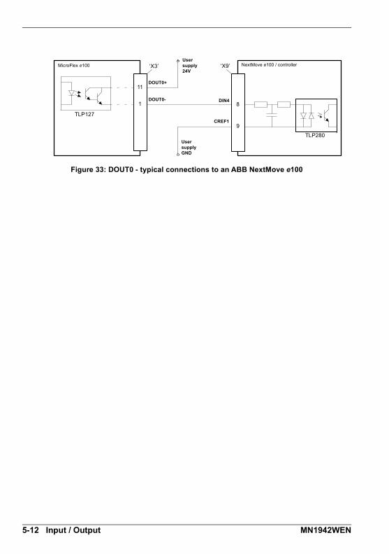
Figure 33: DOUT0 - typical connections to an ABB NextMove e100
8
9
TLP127
TLP280
11
1
‘X3’ ‘X9’MicroFlex e100
DOUT0+
DOUT0- DIN4
CREF1
User supply 24V
User supply GND
NextMove e100 / controller
5-12 Input / Output MN1942WEN
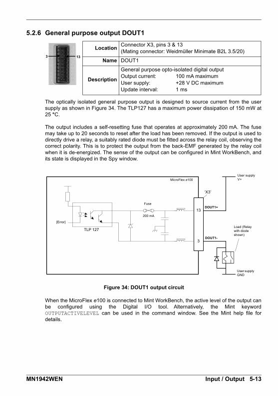
5.2.6 General purpose output DOUT1
The optically isolated general purpose output is designed to source current from the usersupply as shown in Figure 34. The TLP127 has a maximum power dissipation of 150 mW at25 °C.
The output includes a self-resetting fuse that operates at approximately 200 mA. The fusemay take up to 20 seconds to reset after the load has been removed. If the output is used todirectly drive a relay, a suitably rated diode must be fitted across the relay coil, observing thecorrect polarity. This is to protect the output from the back-EMF generated by the relay coilwhen it is de-energized. The sense of the output can be configured in Mint WorkBench, andits state is displayed in the Spy window.
Figure 34: DOUT1 output circuit
When the MicroFlex e100 is connected to Mint WorkBench, the active level of the output canbe configured using the Digital I/O tool. Alternatively, the Mint keywordOUTPUTACTIVELEVEL can be used in the command window. See the Mint help file fordetails.
LocationConnector X3, pins 3 & 13(Mating connector: Weidmüller Minimate B2L 3.5/20)
Name DOUT1
Description
General purpose opto-isolated digital outputOutput current: 100 mA maximumUser supply: +28 V DC maximumUpdate interval: 1 ms
133
TLP 127
13
3
‘X3’
MicroFlex e100User supply V+
User supply GND
Load (Relay with diode shown)
Fuse
[Error]
200 mA
DOUT1+
DOUT1-
MN1942WEN Input / Output 5-13

Figure 35: DOUT1 - typical connections to an ABB NextMove e100
8
9
TLP127
13
3
‘X3’ ‘X9’
TLP280
MicroFlex e100
DOUT1+
DOUT1- DIN4
CREF1
User supply 24V
User supply GND
NextMove e100 / controller
5-14 Input / Output MN1942WEN

5.3 USB communication
5.3.1 USB port
The USB connector is used to connect the MicroFlex e100 to a PC running Mint WorkBench.The MicroFlex e100 is a self-powered, USB 1.1 (12 Mbps) compatible device. If it isconnected to a slower USB 1.0 host PC or hub, communication speed will be limited to theUSB 1.0 specification (1.5 Mbps). If it is connected to a faster USB 2.0 (480 Mbps) orUSB 3.0 (5 Gbps) host PC or hub, communication speed will remain at the USB 1.1specification of the MicroFlex e100.
Ideally, the MicroFlex e100 should be connected directly to a USB port on the host PC. If it isconnected to a hub shared by other USB devices, communication could be affected by theactivity of the other devices. The maximum recommended cable length is 5 m (16.4 ft).
5.4 RS485 communication
5.4.1 RS485 port (2-wire)
The RS485 2-wire port is used to connect third-party serial devices such as operator panels.The Baldor Keypad and Baldor HMI panel range cannot be connected to this port. The 7 Vsupply on pin 4 is provided for future ABB accessories, so care should be taken to ensurethis supply will not damage connected devices. The RS485 port could be damaged if a USBplug is accidentally inserted while the drive is powered.
LocationUSBMating connector: USB Type B (downstream) plug
Pin Name Description
1 VBUS USB +5 V
2 D- Data-
3 D+ Data+
4 GND Ground
LocationX6Mating connector: RJ11 plug
Pin Name Description
1 TXA Transmit / receive +
2 TXB Transmit / receive -
3 GND Ground
4 +7 V out 7 V supply for ABB accessories
5 (NC) -
6 (NC) -
1 42 3
16
MN1942WEN Input / Output 5-15

The Mint keyword Print can be used to send characters to the attached device. The Mintkeyword InKey can be used to receive characters. MicroFlex e100 supports variousprotocols over the RS485 interface, such as Modbus RTU and HCP (Host Comms Protocol),as well as simple ASCII character handling. See the Mint WorkBench help file for details.
Figure 36: RS485 port - typical connections to an RS485 2-wire operator panel
Note: The MicroFlex e100 and other ABB equipment use ‘big endian’ word order andbyte order for Modbus protocols. If this is incompatible with other Modbusequipment, the word and byte order for the MicroFlex e100 can be changed inMint WorkBench. See the Mint WorkBench help file for details.
SN65HVD10D
1
2
‘X6’
3
MicroFlex e100
GND
Operator panel
TXA
TXB
GND
TXA
TXB
5-16 Input / Output MN1942WEN

5.5 Ethernet interface The Ethernet interface provides TCP/IP, Modbus TCP and Ethernet POWERLINK (EPL)networking capabilities.
5.5.1 TCP/IP Transmission Control Protocol / Internet Protocol (TCP/IP) is a common set of protocolsused to transfer information between devices over a network, including the internet. TCPenables two devices to establish a connection, and guarantees the delivery of packets(datagrams) of information in the correct order. IP specifies the format of the individualpackets (which includes the destination address of the receiving device) but has no influenceon whether the packet is delivered correctly.
TCP/IP allows the MicroFlex e100 to support standard Ethernet communication with a hostPC running Mint WorkBench. The connection uses a high level ICM (Immediate CommandMode) protocol to allow Mint commands, Mint programs and even firmware to be sent to thecontroller over the Ethernet network.
When operating in standard Ethernet mode, TCP/IP cannot be used to communicate with acontroller on a daisy-chained network. This is due to cumulative timing errors caused byeach controller’s internal hub. It is necessary to connect the host PC to the controller eitherdirectly or via a switch or hub, as shown in Figure 37. A switch is preferable to a hub as it willprovide faster performance when there is a large amount of data being transmitted.
Figure 37: Connecting to drives using TCP/IP in standard Ethernet mode
Note: The MicroFlex e100 and other ABB equipment use ‘big endian’ word order andbyte order for Modbus protocols. If this is incompatible with other Modbusequipment, the word and byte order for the MicroFlex e100 can be changed inMint WorkBench. See the Mint WorkBench help file for details.
Host PC
External switch
MicroFlex e100 drives
MN1942WEN Input / Output 5-17

When operating in EPL mode, in conjunction with an EPL compatible router, the host PC canuse TCP/IP to communicate with controllers on a daisy-chained network. In this situation, therouter will use TCP/IP only within EPL’s asynchronous time slots. See the Mint help file forfurther details.
Figure 38: Connecting to daisy-chained drives using TCP/IP and EPL mode
Host PC
MicroFlex e100 drivesEthernet POWERLINK
compatible router
NextMove e100 Master Node
5-18 Input / Output MN1942WEN

5.5.2 Ethernet POWERLINKMicroFlex e100 supports the deterministic Ethernet POWERLINK (EPL) protocol. Thisprotocol provides very precise and predictable ‘real-time’ communication over a 100 Mbit/s(100Base-T) Fast Ethernet (IEEE 802.3u) connection. This makes it suitable for thetransmission of control and feedback signals between the MicroFlex e100 and other EPLenabled controllers such as NextMove e100. The EPL protocol implemented in Mint is basedon the CANopen DS402 Device Profile for Drives and Motion Control. The structure of thephysical network is informal so does not need to reflect the logical relationship betweennodes.
MicroFlex e100 incorporates a built-in repeating hub, providing two ports for connection toother equipment. This allows nodes to be connected as a ‘daisy-chain’ network. Each nodeintroduces a delay of approximately 500 ns, so in time-critical applications this could limit thenumber of nodes in a chain. Propagation delays due to cabling should also be considered.Hubs may be used if necessary, but Ethernet switches must not be used in EPL networks astheir timing cannot be guaranteed.
Figure 39: Simple daisy-chained EPL network
Figure 40: Example multi-branch EPL network
...
NextMove e100 Manager Node
NextMove e100 Controlled Node
NextMove e100 Controlled Node
NextMove e100 Controlled Node
1 2 3 4 5 6 7 8 9...
1 2 3 4 5 6 7...
1 2 3 4...
...
...
...
NextMove e100 Manager Node
NextMove e100 Controlled Node
External hub
Machine 1MicroFlex e100 drive group A (Controlled Nodes)
Machine 1MicroFlex e100 drive group B (Controlled Nodes)
Machine 2MicroFlex e100 drive group C (Controlled Nodes)
MN1942WEN Input / Output 5-19

5.5.3 Ethernet connectorsEthernet connections are made using the identical RJ45 Ethernet receptacles.
To connect the MicroFlex e100 to other EPL devices use CAT5e Ethernet cables - either S/UTP (screened unshielded twisted pairs) or preferably S/FTP (screened fully shieldedtwisted pairs).
The MicroFlex e100 Ethernet interface is galvanically isolated from the rest of theMicroFlex e100 circuitry by magnetic isolation modules incorporated in each of the Ethernetconnectors. This provides protection up to 1.5 kV. The connector/cable screen is connecteddirectly to the chassis earth of the MicroFlex e100. Termination components are incorporatedin each of the Ethernet connectors, so no further termination is required. To ensure CEcompliance, especially where Ethernet cables are frequently unplugged, all Ethernet cablesshould be bonded to the metal backplane using conductive clamps at one point at least (seesection D.1.7). Cables longer than 3 m should be S/FTP cables bonded to the metalbackplane at both ends. Do not run Ethernet cables close to AC supply cables, motor powercables, or other sources of noise as this can sometimes cause spurious errors to bereported.
Cables may be up to 100 m (328 ft) long. Two varieties of CAT5e cable are available;‘straight’ or ‘crossed’. Straight cables have the TX pins of the connector at one end of thecable wired to the TX pins of the RJ45 connector at the other end of the cable. Crossovercables have the TX pins of the connector at one end of the cable wired to the RX pins of theRJ45 connector at the other end of the cable. Provided the network consists of only ABBEPL controllers and drives (and any hub), straight or crossed cables may be used. This isbecause many Ethernet devices, including hubs and all ABB EPL products, incorporateAuto-MDIX switching technology which automatically compensates for the wiring of thestraight cable. However, if other manufacturer’s EPL nodes are included in the network,crossover cables should be used as recommended by the Ethernet POWERLINKStandardization Group (EPSG). Similarly, if a host PC does not provide Auto-MDIX on itsEthernet port, then a crossed cable will be essential for the connection between the PC andan EPL router, e.g. OPT036-501.
The EPL network supports the 100Base-TX (100 Mbit/s) system only, so attempting toconnect slower 10Base-T (10 Mbit/s) nodes will cause a network error.
Location E1 & E2
Pin Name Description
1 TX+ Transmit+
2 TX- Transmit-
3 RX+ Receive+
4 - (NC)
5 - (NC)
6 RX- Receive-
7 - (NC)
8 - (NC)
1
8
5-20 Input / Output MN1942WEN

5.6 CAN interfaceThe CAN bus is a serial based network originally developed for automotive applications, butnow used for a wide range of industrial applications. It offers low-cost serial communicationswith very high reliability in an industrial environment; the probability of an undetected error is
4.7x10⁻¹¹. It is optimized for the transmission of small data packets and therefore offers fastupdate of I/O devices (peripheral devices) connected to the bus.
The CAN protocol only defines the physical attributes of the network, i.e. the electrical,mechanical, functional and procedural parameters of the physical connection betweendevices. The higher level network functionality on MicroFlex e100 is defined by the CANopenprotocol, one of the most used standards for machine control.
5.6.1 CAN connector
5.6.2 CAN wiringA very low error bit rate over CAN can only be achieved with a suitable wiring scheme, so thefollowing points should be observed:
The two-wire data bus line may be routed parallel, twisted and/or shielded, depending onEMC requirements. ABB recommends a twisted pair cable with the shield/screenconnected to the connector backshell, in order to reduce RF emissions and provideimmunity to conducted interference.
The bus must be terminated at both ends only (not at intermediate points) with resistorsof a nominal value of 120 Ω. This is to reduce reflections of the electrical signals on thebus, which helps a node to interpret the bus voltage levels correctly. If theMicroFlex e100 is at the end of the network then ensure that a 120 Ω resistor is fitted(normally inside the D-type connector).
All cables and connectors should have a nominal impedance of 120 Ω. Cables shouldhave a length related resistance of 70 mΩ/m and a nominal line delay of 5 ns/m.
Location OPT 1Mating connector: 9-pin female D-type
Pin Name Description
1 - (NC)
2 CAN- CAN channel negative
3 CAN GND Ground/earth reference for CAN signals
4 - (NC)
5 Shield Shield connection
6 CAN GND Ground/earth reference for CAN signals
7 CAN+ CAN channel positive
8 - (NC)
9 CAN V+ CAN power V+ (12-24 V)
1
5
6
9
MN1942WEN Input / Output 5-21

The maximum bus length depends on the bit-timing configuration (baud rate). The tableopposite shows the approximate maximum buslength (worst-case), assuming 5 ns/mpropagation delay and a total effective deviceinternal in-out delay of 210 ns at 1 Mbit/s, 300 nsat 500 - 250 Kbit/s, 450 ns at 125 Kbit/s and1.5 ms at 50 - 10 Kbit/s.
(1) For bus lengths greater than about 1000 m,bridge or repeater devices may be needed.
The compromise between bus length and CANbaud rate must be determined for eachapplication. The CAN baud rate can be set using the BUSBAUD keyword. It is essentialthat all nodes on the network are configured to run at the same baud rate.
The wiring topology of a CAN network should be as close as possible to a single line/busstructure. However, stub lines are allowed provided they are kept to a minimum (<0.3 mat 1 Mbit/s).
The 0 V connection of all of the nodes on the network must be tied together through theCAN cabling. This ensures that the CAN signal levels transmitted by MicroFlex e100 orCAN peripheral devices are within the common mode range of the receiver circuitry ofother nodes on the network.
5.6.2.1 Opto-isolation
On the MicroFlex e100, the CAN channel is opto-isolated. A voltage in the range 12-24 V DCmust be applied between pin 9 (+24 V) and pin 3 or 6 (0 V) of the CAN connector. From thissupply, an internal voltage regulator provides the 5 V at 100 mA required for the isolatedCAN circuit. To allow easy connection of the 12-24 V DC supply, adaptor part OPT-CNV002can be used, allowing connection by ordinary CAT 5e Ethernet cables. The adaptor alsoprovides flying lead connections for the application of the CAN power supply.
Figure 41: OPT-CNV002
Alternatively, a connector such as the Phoenix Contact SUBCON-PLUS F3 (part 2761871)provides a 9-pin D-type female connector with easily accessible terminal block connections(see Figure 42). CAN cables supplied by ABB are ‘category 5’ and have a maximum currentrating of 1 A, so the maximum number of MicroFlex e100 units that may be used on onenetwork is limited to 10.
CAN Baud Rate
Maximum Bus Length
1 Mbit/s500 Kbit/s250 Kbit/s125 Kbit/s100 Kbit/s50 Kbit/s20 Kbit/s10 Kbit/s
25 m100 m250 m500 m600 m1000 m
2500 m(1)
5000 m(1)
5-22 Input / Output MN1942WEN

5.6.3 CANopenABB has implemented a CANopen protocol in Mint (based on the ‘Communication Profile’CiA DS-301) which supports both direct access to device parameters and time-criticalprocess data communication. The MicroFlex e100 can use CANopen to extend its Mintcapabilities by becoming a CANopen master to a variety of devices including:
Digital and analog I/O devices that are compliant with the ‘CANopen device profile forgeneric I/O modules’ (CiA DS-401).
Baldor HMI (Human Machine Interface) operator panels, which are based on the old‘CANopen device profile for Human Machine Interfaces’ (DS403 – no longer supportedby the CiA).
Third party encoder devices that are compliant with the ‘CANopen device profile forencoders’ (CiA-DS406).
Other ABB controllers with CANopen support for peer-to-peer access using extensionsto the CiA specifications (DS301 and DS302).
Any other CANopen devices that are also based on the ‘Communication Profile’ CiA DS-301should be able to communicate with MicroFlex e100, but with limited capabilities, e.g. noPDO communications possible, only SDO.
The functionality and characteristics of all ABB CANopen devices are defined in individualstandardized (ASCII format) Electronic Data Sheets (EDS) which can be found on the MintMotion Toolkit CD (OPT-SW-001), or downloaded from www.abbmotion.com. Figure 42shows a typical CANopen network with a NextMove e100 manager node, oneMicroFlex e100 slave node and a Baldor HMI operator panel:
Figure 42: Typical CANopen network connections
Note: The MicroFlex e100 CAN channel is opto-isolated, so a voltage in the range 12-24 V must be applied between pin 9 and pin 6 of the OPT 1 connector.
The configuration and management of a CANopen network must be carried out by a singlenode acting as the network manager (for example NextMove e100), or by a third partyCANopen manager device. Up to 126 CANopen nodes (node IDs 2 to 127) can be added tothe network by the manager node using the Mint NODESCAN keyword. If successful, the
7
2
6
9
7
2TR TR
7
2
6
9
7
2
6
9
6
5 55
2
1
‘X1’
Baldor HMI Operator Panel
Twisted pairsTwisted pair
MicroFlex e100 D-type
NextMove e100 D-type
End nodeCANopen
D-type
Phoenix SUBCON-PLUS F3
24 V
0 V
MN1942WEN Input / Output 5-23

nodes can then be connected to using the Mint CONNECT keyword. Any network and noderelated events can then be monitored using the Mint BUS1 event.
Note: All CAN related Mint keywords are referenced to CANopen using the ‘bus’ dotparameter. For CANopen the ‘bus’ dot parameter must be set to 1. Please referto the Mint help file for further details on CANopen, Mint keywords and dotparameters.
5-24 Input / Output MN1942WEN
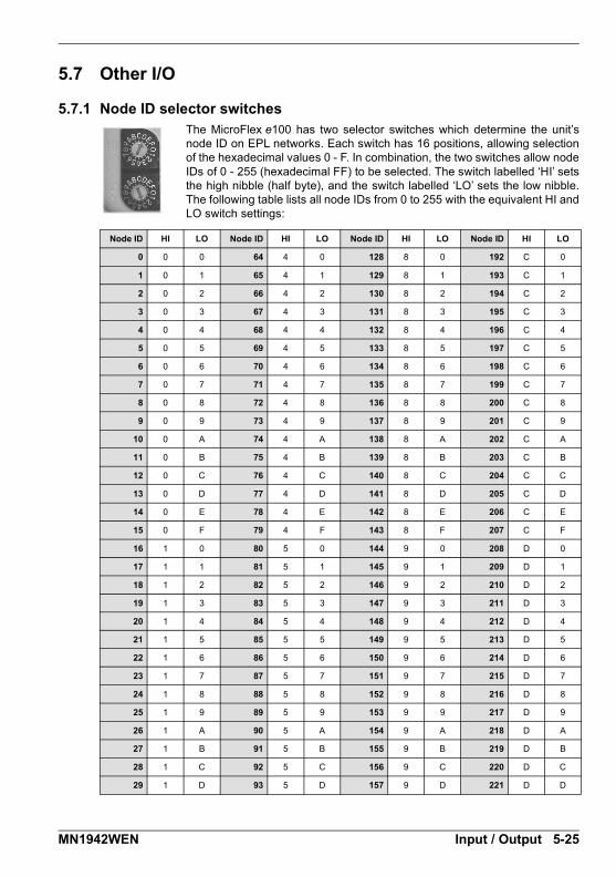
5.7 Other I/O
5.7.1 Node ID selector switchesThe MicroFlex e100 has two selector switches which determine the unit’snode ID on EPL networks. Each switch has 16 positions, allowing selectionof the hexadecimal values 0 - F. In combination, the two switches allow nodeIDs of 0 - 255 (hexadecimal FF) to be selected. The switch labelled ‘HI’ setsthe high nibble (half byte), and the switch labelled ‘LO’ sets the low nibble.The following table lists all node IDs from 0 to 255 with the equivalent HI andLO switch settings:
Node ID HI LO Node ID HI LO Node ID HI LO Node ID HI LO
0 0 0 64 4 0 128 8 0 192 C 0
1 0 1 65 4 1 129 8 1 193 C 1
2 0 2 66 4 2 130 8 2 194 C 2
3 0 3 67 4 3 131 8 3 195 C 3
4 0 4 68 4 4 132 8 4 196 C 4
5 0 5 69 4 5 133 8 5 197 C 5
6 0 6 70 4 6 134 8 6 198 C 6
7 0 7 71 4 7 135 8 7 199 C 7
8 0 8 72 4 8 136 8 8 200 C 8
9 0 9 73 4 9 137 8 9 201 C 9
10 0 A 74 4 A 138 8 A 202 C A
11 0 B 75 4 B 139 8 B 203 C B
12 0 C 76 4 C 140 8 C 204 C C
13 0 D 77 4 D 141 8 D 205 C D
14 0 E 78 4 E 142 8 E 206 C E
15 0 F 79 4 F 143 8 F 207 C F
16 1 0 80 5 0 144 9 0 208 D 0
17 1 1 81 5 1 145 9 1 209 D 1
18 1 2 82 5 2 146 9 2 210 D 2
19 1 3 83 5 3 147 9 3 211 D 3
20 1 4 84 5 4 148 9 4 212 D 4
21 1 5 85 5 5 149 9 5 213 D 5
22 1 6 86 5 6 150 9 6 214 D 6
23 1 7 87 5 7 151 9 7 215 D 7
24 1 8 88 5 8 152 9 8 216 D 8
25 1 9 89 5 9 153 9 9 217 D 9
26 1 A 90 5 A 154 9 A 218 D A
27 1 B 91 5 B 155 9 B 219 D B
28 1 C 92 5 C 156 9 C 220 D C
29 1 D 93 5 D 157 9 D 221 D D
MN1942WEN Input / Output 5-25

Figure 43: Decimal node IDs and equivalent HI / LO hexadecimal switch settings
Note: If the node ID selector switches are set to FF, the node’s firmware will not run onpower up. However, Mint WorkBench will still be able to detect theMicroFlex e100 and download new firmware.
Node ID HI LO Node ID HI LO Node ID HI LO Node ID HI LO
30 1 E 94 5 E 158 9 E 222 D E
31 1 F 95 5 F 159 9 F 223 D F
32 2 0 96 6 0 160 A 0 224 E 0
33 2 1 97 6 1 161 A 1 225 E 1
34 2 2 98 6 2 162 A 2 226 E 2
35 2 3 99 6 3 163 A 3 227 E 3
36 2 4 100 6 4 164 A 4 228 E 4
37 2 5 101 6 5 165 A 5 229 E 5
38 2 6 102 6 6 166 A 6 230 E 6
39 2 7 103 6 7 167 A 7 231 E 7
40 2 8 104 6 8 168 A 8 232 E 8
41 2 9 105 6 9 169 A 9 233 E 9
42 2 A 106 6 A 170 A A 234 E A
43 2 B 107 6 B 171 A B 235 E B
44 2 C 108 6 C 172 A C 236 E C
45 2 D 109 6 D 173 A D 237 E D
46 2 E 110 6 E 174 A E 238 E E
47 2 F 111 6 F 175 A F 239 E F
48 3 0 112 7 0 176 B 0 240 F 0
49 3 1 113 7 1 177 B 1 241 F 1
50 3 2 114 7 2 178 B 2 242 F 2
51 3 3 115 7 3 179 B 3 243 F 3
52 3 4 116 7 4 180 B 4 244 F 4
53 3 5 117 7 5 181 B 5 245 F 5
54 3 6 118 7 6 182 B 6 246 F 6
55 3 7 119 7 7 183 B 7 247 F 7
56 3 8 120 7 8 184 B 8 248 F 8
57 3 9 121 7 9 185 B 9 249 F 9
58 3 A 122 7 A 186 B A 250 F A
59 3 B 123 7 B 187 B B 251 F B
60 3 C 124 7 C 188 B C 252 F C
61 3 D 125 7 D 189 B D 253 F D
62 3 E 126 7 E 190 B E 254 F E
63 3 F 127 7 F 191 B F 255 F F
5-26 Input / Output MN1942WEN

In many networking environments, the node ID may also be referred to as the address. OnEPL networks, limitations apply to the node IDs that may be selected:
Node ID 0 (00) is reserved for special purposes and cannot be used.
Node IDs 1 - 239 (01 - EF) cause the node to become a ‘controlled node’, a node that willaccept commands from the manager node.
Node ID 240 (F0) is reserved for the EPL manager node (for example NextMove e100)so cannot be used by MicroFlex e100.
Node IDs 241 - 255 (F1 - FF) are reserved for special purposes and cannot be used.
For all other communication channels such as CANopen and USB, the node ID is set insoftware. Each channel can have a different node ID, selected using the Mint WorkBenchConnectivity Wizard or the Mint BUSNODE keyword. See the Mint help file for details.
MN1942WEN Input / Output 5-27
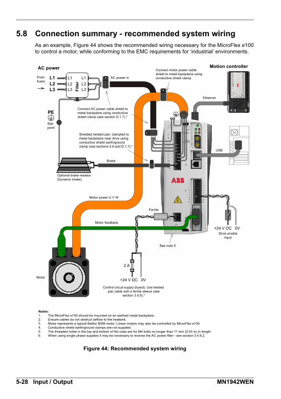
5.8 Connection summary - recommended system wiringAs an example, Figure 44 shows the recommended wiring necessary for the MicroFlex e100to control a motor, while conforming to the EMC requirements for ‘industrial’ environments.
Figure 44: Recommended system wiring
2 A
L1L2
L1L2L3
L1L2L3L3
PE
Motion controllerAC power Connect motor power cable shield to metal backplane using conductive shield clamp
USB
Star point
From fuses
Connect AC power cable shield to metal backplane using conductive shield clamp (see section D.1.7).*
Shielded twisted pair, clampled to metal backplane near drive using conductive shield earth/ground clamp (see sections 3.6 and D.1.7).*
Brake
Motor feedback
Motor power U V W
Optional brake resistor(Dynamic brake)
Control circuit supply (fused). Use twisted pair cable with a ferrite sleeve (see
section 3.4.9).*
Notes:1. The MicroFlex e100 should be mounted on an earthed metal backplane.2. Ensure cables do not obstruct airflow to the heatsink.3. Motor represents a typical Baldor BSM motor. Linear motors may also be controlled by MicroFlex e1004. Conductive shield earth/ground clamps are not supplied.5. The threaded holes in the top and bottom of the case are for M4 bolts no longer than 11 mm (0.43 in) in length.6. When using single phase supplies it may be necessary to reverse the AC power filter - see section 3.4.8.2.
AC power inF
ilte
r
Ethernet
Ferrite
Drive enable input
See note 5
Motor+24 V DC 0V
+24 V DC 0V
5-28 Input / Output MN1942WEN
Configuration6 Configuration
6.1 IntroductionBefore powering the MicroFlex e100 you will need to connect it to the PC using a USB orEthernet cable and install the Mint WorkBench software. This includes a number ofapplications and utilities to allow you to configure, tune and program the MicroFlex e100.Mint WorkBench and other utilities can be found on the Mint Motion Toolkit CD (OPT-SW-001), or downloaded from www.abbmotion.com.
6.1.1 Connecting the MicroFlex e100 to the PCThe MicroFlex e100 can be connected to the PC using either USB (recommended) or TCP/IP.
To use USB, connect a USB cable between a PC USB port and the MicroFlex e100 USBport. Your PC must be using Windows XP, Windows Vista or Windows 7.
To use TCP/IP, connect a CAT5e Ethernet cable between the PC and one of theMicroFlex e100 Ethernet ports.
You cannot connect an ordinary office PC to the MicroFlex e100 without firstaltering the PC’s Ethernet adapter configuration. However, if you have installed asecond Ethernet adapter dedicated for use with the MicroFlex e100, then thisadapter’s configuration can be altered without affecting the PC’s office Ethernetconnection. If you are unsure about making changes to your PC’s Ethernetadapter configuration, or are prevented by user permission levels, ask your I.T.administrator to assist you.
If there is a EPL manager node (node ID 240) on the Ethernet network, then thenetwork will be operating in EPL mode. This means any TCP/IP connection fromthe PC must pass through an EPL compatible router.
6.1.2 Installing Mint WorkBenchThe Windows user account requires administrative user rights to install Mint WorkBench.
6.1.2.1 To install Mint WorkBench from the CD (OPT-SW-001)
1. Insert the CD into the drive.
2. After a few seconds the setup wizard should start automatically. If the setup wizard doesnot appear, select Run... from the Windows Start menu and type
d:\start
where d represents the drive letter of the CD device.Follow the on-screen instructions to install Mint WorkBench.
6.1.2.2 To install Mint WorkBench from the website
To install Mint WorkBench from www.abbmotion.com, download the application and run it.
NOTICEi
NOTICEi
6
MN1942WEN Configuration 6-1

6.2 Starting the MicroFlex e100If you have followed the instructions in the previous sections, you should now haveconnected all the power sources, inputs and outputs, and the Ethernet cable or USB cablelinking the PC to the MicroFlex e100.
6.2.1 Preliminary checksBefore you apply power for the first time, it is very important to verify the following:
Disconnect the load from the motor until instructed to apply a load. If this cannot bedone, disconnect the motor wires at connector X1.
Verify that the AC line voltage matches the specification of the MicroFlex e100.
Inspect all power connections for accuracy, workmanship and tightness.
Verify that all wiring conforms to applicable codes.
Verify that the MicroFlex e100 and motor are properly earthed/grounded.
Check all signal wiring for accuracy.
6.2.2 Power on checksIf at any time the Status LED flashes red, the drive has detected a fault - see section 7.
1. Turn on the 24 V DC supply.
2. Turn on the AC supply.
3. Within approximately 20-30 seconds, the test sequence should complete and the StatusLED should illuminate red. If the Status LED is not lit then re-check the power supplyconnections. If the Status LED flashes red, this indicates that the MicroFlex e100 hasdetected a fault - see section 7. Note that after downloading firmware, startup may takemore than 1 minute.
4. If the motor wires were disconnected in section 6.2.1, turn off the AC supply andreconnect the motor wires. Turn on the AC supply.
5. To allow the Commissioning Wizard to function, the drive enable signal will need to bepresent on connector X3 to allow the MicroFlex e100 to be enabled (see section 5.2.1). Ifyou do not wish to enable the MicroFlex e100 yet, the Commissioning Wizard will informyou when this step is necessary.
6-2 Configuration MN1942WEN

6.2.3 Installing the USB driverWhen the MicroFlex e100 is powered, Windows will automatically detect the controller andrequest the driver. 1. Windows will prompt for the driver. On Windows XP, click Next on the following dialogs
and Windows will locate and install the driver. For Windows Vista and newer, nointeraction should be necessary.
2. When installation is complete, a new Motion Control category will be listed in WindowsDevice Manager.
The MicroFlex e100 is now ready to be configured using Mint WorkBench.
Note: If the MicroFlex e100 is later connected to a different USB port on the hostcomputer, Windows may report that it has found new hardware. Either install thedriver files again for the new USB port, or connect the MicroFlex e100 to theoriginal USB port where it will be recognized in the usual way.
MN1942WEN Configuration 6-3

6.2.4 Configuring the TCP/IP connection (optional)If you have connected the MicroFlex e100 to the PC using the Ethernet connection, it will benecessary to alter the PC’s Ethernet adapter configuration to operate correctly with theMicroFlex e100.
You cannot connect an ordinary office PC to the MicroFlex e100 without firstaltering the PC’s Ethernet adapter configuration. However, if you have installed asecond Ethernet adapter dedicated for use with the MicroFlex e100, then thisadapter’s configuration can be altered without affecting the PC’s office Ethernetconnection. If you are unsure about making changes to your PC’s Ethernetadapter configuration, or are prevented by user permission levels, ask your I.T.administrator to assist you.
The following explanation assumes the PC is connected directly to the MicroFlex e100, andnot across an intermediate Ethernet network. If you wish to attempt the connection throughan intermediate Ethernet network, then the network administrator must be consulted toensure that the necessary IP addresses will be allowed and are not already allocated on thenetwork. The MicroFlex e100 has a fixed IP address of the format 192.168.100.xxx. The lastnumber, xxx, is the decimal value defined by the MicroFlex e100’s node ID selector switches(see section 5.7.1).
1. On the Windows Start menu, select Settings, Network Connections.
2. In the Network Connections Window, right-click the ‘Local Area Connection’ entry for therequired Ethernet adapter and choose Properties.
3. In the Local Area Connection Properties dialog, in the ‘This connection uses thefollowing items’ list, select the ‘Internet Protocol (TCP/IP)’ entry and click Properties.
4. In the Internet Protocol (TCP/IP) Properties dialog, on the General tab, make a note ofthe existing settings. Click Advanced... and make a note of any existing settings. Clickthe Alternate Configuration tab and make a note of any existing settings.
5. On the General tab, choose the ‘Use the following IP address’ option.
6. In the IP address box, enter the IP address 192.168.100.241. This is the IP address thatwill be assigned to the Ethernet adapter. The value 241 is deliberately chosen as it isoutside the range that can be used by MicroFlex e100, so avoiding possible conflicts.
7. In the Subnet mask box, enter 255.255.255.0 and click OK.Click OK to close the Local Area Connection Properties dialog.
8. On the Windows Start menu, select Command Prompt (often found under Accessories).
9. n the Command Prompt window, type PING 192.168.100.16, where the final value (16 inthis example) is the value selected by the MicroFlex e100’s node ID selector switches. Inthis example, the MicroFlex e100’s switches would be set to HI=1 LO=0, whichrepresents hexadecimal 10, equivalent to decimal 16 (see section 5.7.1 for a list ofhexadecimal / decimal equivalents). A reply message should be returned.
10. It should now be possible to run Mint WorkBench and connect to the MicroFlex e100using the Ethernet / TCP/IP connection.
NOTICEi
6-4 Configuration MN1942WEN
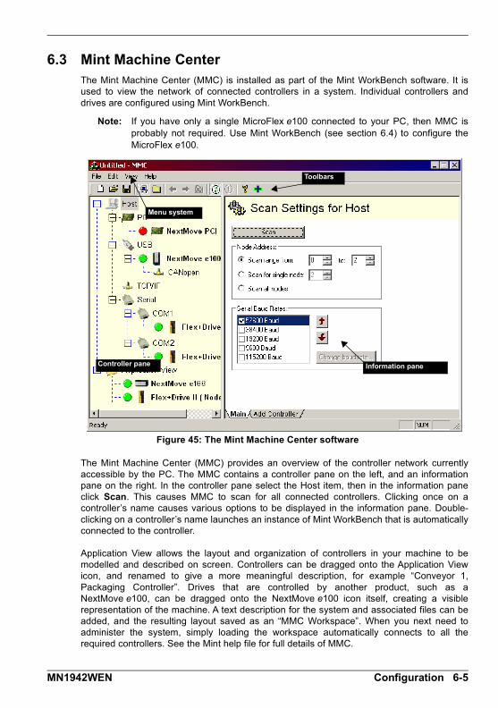
6.3 Mint Machine CenterThe Mint Machine Center (MMC) is installed as part of the Mint WorkBench software. It isused to view the network of connected controllers in a system. Individual controllers anddrives are configured using Mint WorkBench.
Note: If you have only a single MicroFlex e100 connected to your PC, then MMC isprobably not required. Use Mint WorkBench (see section 6.4) to configure theMicroFlex e100.
Figure 45: The Mint Machine Center software
The Mint Machine Center (MMC) provides an overview of the controller network currentlyaccessible by the PC. The MMC contains a controller pane on the left, and an informationpane on the right. In the controller pane select the Host item, then in the information paneclick Scan. This causes MMC to scan for all connected controllers. Clicking once on acontroller’s name causes various options to be displayed in the information pane. Double-clicking on a controller’s name launches an instance of Mint WorkBench that is automaticallyconnected to the controller.
Application View allows the layout and organization of controllers in your machine to bemodelled and described on screen. Controllers can be dragged onto the Application Viewicon, and renamed to give a more meaningful description, for example “Conveyor 1,Packaging Controller”. Drives that are controlled by another product, such as aNextMove e100, can be dragged onto the NextMove e100 icon itself, creating a visiblerepresentation of the machine. A text description for the system and associated files can beadded, and the resulting layout saved as an “MMC Workspace”. When you next need toadminister the system, simply loading the workspace automatically connects to all therequired controllers. See the Mint help file for full details of MMC.
Toolbars
Controller pane
Menu system
Information pane
MN1942WEN Configuration 6-5
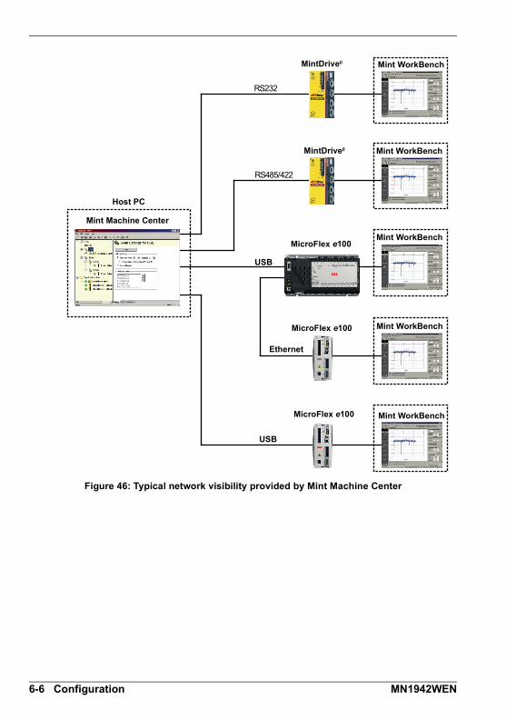
Figure 46: Typical network visibility provided by Mint Machine Center
RS232
RS485/422
Host PC
Mint Machine Center
Mint WorkBench
Mint WorkBench
Mint WorkBench
Mint WorkBench
Mint WorkBenchMicroFlex e100
MicroFlex e100
MicroFlex e100
MintDriveII
MintDriveII
USB
Ethernet
USB
6-6 Configuration MN1942WEN

6.3.1 Starting MMC1. On the Windows Start menu, select Programs, Mint WorkBench, Mint Machine Center.
2. In the controller pane, ensure that Host isselected. In the information pane, clickScan.
3. When the search is complete, click onceon ‘MicroFlex e100’ in the controller paneto select it, then double click to open aninstance of Mint WorkBench. TheMicroFlex e100 will be already connectedto the instance of Mint WorkBench, readyto configure.
MN1942WEN Configuration 6-7

6.4 Mint WorkBenchMint WorkBench is a fully featured application for commissioning the MicroFlex e100. Themain Mint WorkBench window contains a menu system, the Toolbox and other toolbars.Many functions can be accessed from the menu or by clicking a button - use whichever youprefer. Most buttons include a ‘tool-tip’; hold the mouse pointer over the button (don’t click)and its description will appear.
Figure 47: The Mint WorkBench software
Menu system ToolbarsToolbars
Toolbox
Menu system
Control and test area
6-8 Configuration MN1942WEN

6.4.1 Help fileMint WorkBench includes a comprehensive help file that contains information about everyMint keyword, how to use Mint WorkBench and background information on motion controltopics. The help file can be displayed at any time by pressing F1. On the left of the help
window, the Contents tab shows the tree structure of the help file. Each book contains a
number of topics . The Index tab provides an alphabetic list of all topics in the file, andallows you to search for them by name. The Search tab allows you to search for words orphrases appearing anywhere in the help file. Many words and phrases are underlined andhighlighted with a color (normally blue) to show that they are links. Just click on the link to goto an associated keyword. Most keyword topics begin with a list of relevant See Also links.
Figure 48: The Mint WorkBench help file
For help on using Mint WorkBench, click the Contents tab, then click the small plus sign
beside the Mint WorkBench & Mint Machine Center book icon. Double click a topicname to display it.
MN1942WEN Configuration 6-9
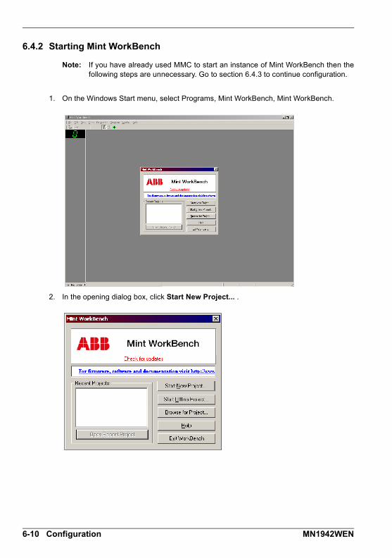
6.4.2 Starting Mint WorkBench
Note: If you have already used MMC to start an instance of Mint WorkBench then thefollowing steps are unnecessary. Go to section 6.4.3 to continue configuration.
1. On the Windows Start menu, select Programs, Mint WorkBench, Mint WorkBench.
2. In the opening dialog box, click Start New Project... .
6-10 Configuration MN1942WEN

3. In the Select Controller dialog, click Scan to search for the MicroFlex e100. MintWorkBench will scan the PC’s ports for the MicroFlex e100.
When the search is complete, click ‘MicroFlex e100’ in the list to select it, then clickSelect.
Note: If the MicroFlex e100 is not listed, check the USB or Ethernet cable between theMicroFlex e100 and the PC. Check that the MicroFlex e100 is powered correctly.Click Scan to re-scan the ports.
This check box is already selected for you. When you click Select, it means that the Commissioning Wizard will start automatically.
MN1942WEN Configuration 6-11
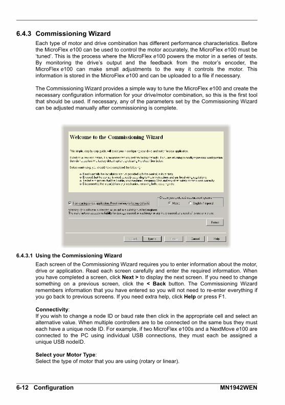
6.4.3 Commissioning WizardEach type of motor and drive combination has different performance characteristics. Beforethe MicroFlex e100 can be used to control the motor accurately, the MicroFlex e100 must be‘tuned’. This is the process where the MicroFlex e100 powers the motor in a series of tests.By monitoring the drive’s output and the feedback from the motor’s encoder, theMicroFlex e100 can make small adjustments to the way it controls the motor. Thisinformation is stored in the MicroFlex e100 and can be uploaded to a file if necessary.
The Commissioning Wizard provides a simple way to tune the MicroFlex e100 and create thenecessary configuration information for your drive/motor combination, so this is the first toolthat should be used. If necessary, any of the parameters set by the Commissioning Wizardcan be adjusted manually after commissioning is complete.
6.4.3.1 Using the Commissioning Wizard
Each screen of the Commissioning Wizard requires you to enter information about the motor,drive or application. Read each screen carefully and enter the required information. Whenyou have completed a screen, click Next > to display the next screen. If you need to changesomething on a previous screen, click the < Back button. The Commissioning Wizardremembers information that you have entered so you will not need to re-enter everything ifyou go back to previous screens. If you need extra help, click Help or press F1.
Connectivity:If you wish to change a node ID or baud rate then click in the appropriate cell and select analternative value. When multiple controllers are to be connected on the same bus they musteach have a unique node ID. For example, if two MicroFlex e100s and a NextMove e100 areconnected to the PC using individual USB connections, they must each be assigned aunique USB nodeID.
Select your Motor Type:Select the type of motor that you are using (rotary or linear).
6-12 Configuration MN1942WEN

Select your Motor:Carefully enter the details of your motor. If you are using a Baldor Motor, the catalog numberor spec. number can be found stamped on the motor’s nameplate. If you are using a motorwith EnDat feedback, are not using a Baldor motor, or need to enter the specificationmanually, select the I would like to define a custom motor option.
Confirm Motor and Drive information:If you entered the catalog or spec. number on the previous page, it is not necessary tochange anything on this screen; all the required data will be entered already. However, if youselected the I would like to define a custom motor option, it will be necessary to enter therequired information before continuing.
Motor Feedback:If you entered the catalog or spec. number on the previous page, it is not necessary tochange anything on this screen; the feedback resolution will be entered already. However, ifyou selected the I would like to define a custom motor option, it will be necessary to enter thefeedback resolution before continuing.
Drive Setup complete:This screen confirms that drive setup is complete.
Select Operating Mode and Source:In the Operating Mode section, choose the required operating mode. In the ReferenceSource section, it is important to select ‘Host/Mint’ as the Control Ref. Source. This will allowthe Autotune Wizard to operate correctly, and allow further initial testing to be performedusing Mint WorkBench. Although the MicroFlex e100 may eventually be controlled overEthernet POWERLINK (EPL), the ‘EPL’ reference source should only be selected after theMicroFlex e100 has been commissioned and is ready to add to the EPL network. This can beselected by choosing the Operating Mode tool in the Toolbox.
Application Limits:It is not necessary to change anything on this screen. However, if you wish to adjust theapplication peak current (App. Peak Current) and/or application maximum speed (App. Max.Speed), then click in the appropriate box and enter a value.
Scale Factor:It is not necessary to change anything on this screen. However, it is recommended to selecta user unit for position, velocity and acceleration. This allows Mint WorkBench to displaydistances, speeds and accelerations using meaningful units, instead of encoder counts. Forexample, selecting a Position User Unit of Revs (r) will mean that all position values enteredor displayed in Mint WorkBench will represent revolutions. The Position Scale Factor valuewill change automatically to represent the required scale factor (the number of quadraturecounts per revolution). If you need to use an alternative unit, for example degrees, type“Degrees” in the Position User Unit box and enter a suitable value in the Position ScaleFactor box. Separate velocity and acceleration units can also be defined. See the Mint helpfile for more information about scale factors.
Profile Parameters:It is not necessary to change anything on this screen. However, if you wish to adjust theparameters for any control method, click in the appropriate box and enter a value.
MN1942WEN Configuration 6-13
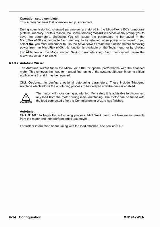
Operation setup complete:This screen confirms that operation setup is complete.
During commissioning, changed parameters are stored in the MicroFlex e100’s temporary(volatile) memory. For this reason, the Commissioning Wizard will occasionally prompt you tosave the parameters. Selecting Yes will cause the parameters to be saved in theMicroFlex e100’s non-volatile flash memory, to be retained when power is removed. If youselect No, you must remember to use the Save Drive Parameters function before removingpower from the MicroFlex e100; this function is available on the Tools menu, or by clicking
the button on the Mode toolbar. Saving parameters into flash memory will cause theMicroFlex e100 to be reset.
6.4.3.2 Autotune Wizard
The Autotune Wizard tunes the MicroFlex e100 for optimal performance with the attachedmotor. This removes the need for manual fine-tuning of the system, although in some criticalapplications this still may be required.
Click Options... to configure optional autotuning parameters. These include TriggeredAutotune which allows the autotuning process to be delayed until the drive is enabled.
The motor will move during autotuning. For safety it is advisable to disconnectany load from the motor during initial autotuning. The motor can be tuned withthe load connected after the Commissioning Wizard has finished.
AutotuneClick START to begin the auto-tuning process. Mint WorkBench will take measurementsfrom the motor and then perform small test moves.
For further information about tuning with the load attached, see section 6.4.5.
CAUTION
6-14 Configuration MN1942WEN
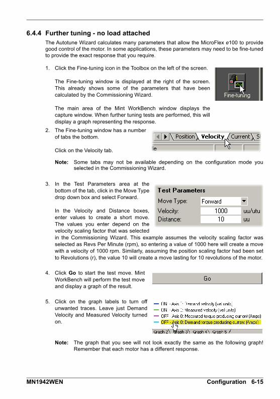
6.4.4 Further tuning - no load attachedThe Autotune Wizard calculates many parameters that allow the MicroFlex e100 to providegood control of the motor. In some applications, these parameters may need to be fine-tunedto provide the exact response that you require.
1. Click the Fine-tuning icon in the Toolbox on the left of the screen.
The Fine-tuning window is displayed at the right of the screen.This already shows some of the parameters that have beencalculated by the Commissioning Wizard.
The main area of the Mint WorkBench window displays thecapture window. When further tuning tests are performed, this willdisplay a graph representing the response.
2. The Fine-tuning window has a numberof tabs the bottom.
Click on the Velocity tab.
Note: Some tabs may not be available depending on the configuration mode youselected in the Commissioning Wizard.
3. In the Test Parameters area at thebottom of the tab, click in the Move Typedrop down box and select Forward.
In the Velocity and Distance boxes,enter values to create a short move.The values you enter depend on thevelocity scaling factor that was selectedin the Commissioning Wizard. This example assumes the velocity scaling factor wasselected as Revs Per Minute (rpm), so entering a value of 1000 here will create a movewith a velocity of 1000 rpm. Similarly, assuming the position scaling factor had been setto Revolutions (r), the value 10 will create a move lasting for 10 revolutions of the motor.
4. Click Go to start the test move. MintWorkBench will perform the test moveand display a graph of the result.
5. Click on the graph labels to turn offunwanted traces. Leave just DemandVelocity and Measured Velocity turnedon.
Note: The graph that you see will not look exactly the same as the following graph!Remember that each motor has a different response.
MN1942WEN Configuration 6-15
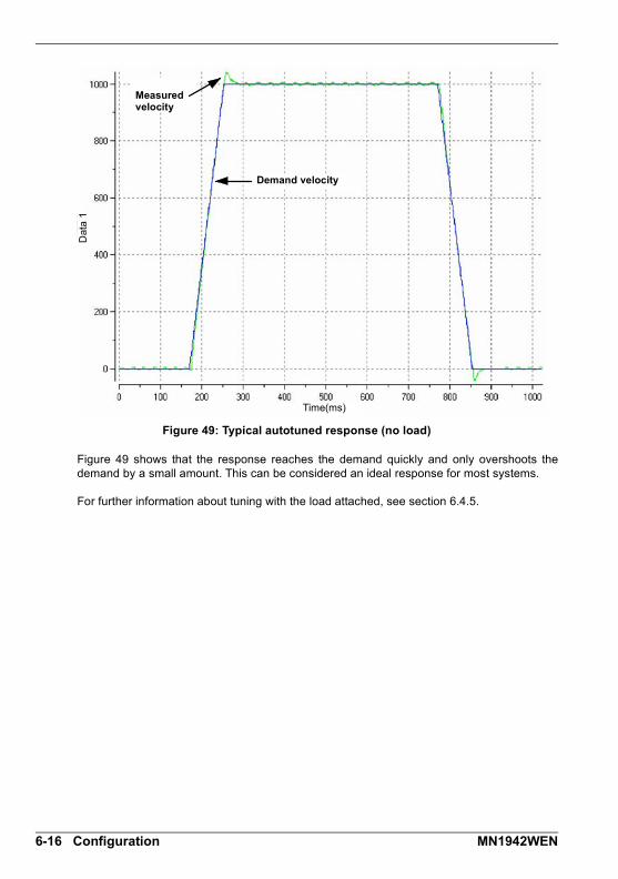
Figure 49: Typical autotuned response (no load)
Figure 49 shows that the response reaches the demand quickly and only overshoots thedemand by a small amount. This can be considered an ideal response for most systems.
For further information about tuning with the load attached, see section 6.4.5.
Measured velocity
Demand velocity
Dat
a 1
Time(ms)
6-16 Configuration MN1942WEN

6.4.5 Further tuning - with load attachedTo allow Mint WorkBench to adjust the basic tuning to compensate for the intended load, it isnecessary to attach the load to the motor and then perform the autotune procedure again.
1. Attach the load to the motor.
2. Click the Autotune icon in the Toolbox on the left of the screen.
3. Click the Autotune on load check box.
4. Click START to begin the auto-tuning process. Mint WorkBenchwill take measurements from the motor and then perform smalltest moves.
5. Click the Fine-tuning icon in the Toolbox on the left of the screen.
6. In the Velocity tab’s Test Parametersarea, ensure the same moveparameters are entered and then clickGo to start the test move.
Mint WorkBench will perform the testmove and display a graph of the result.
MN1942WEN Configuration 6-17
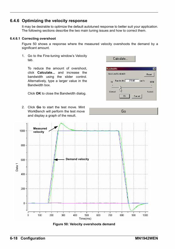
6.4.6 Optimizing the velocity responseIt may be desirable to optimize the default autotuned response to better suit your application.The following sections describe the two main tuning issues and how to correct them.
6.4.6.1 Correcting overshoot
Figure 50 shows a response where the measured velocity overshoots the demand by asignificant amount.
1. Go to the Fine-tuning window’s Velocitytab.
To reduce the amount of overshoot,click Calculate... and increase thebandwidth using the slider control.Alternatively, type a larger value in theBandwidth box.
Click OK to close the Bandwidth dialog.
2. Click Go to start the test move. MintWorkBench will perform the test moveand display a graph of the result.
Figure 50: Velocity overshoots demand
Measured velocity
Demand velocity
Dat
a 1
Time(ms)
6-18 Configuration MN1942WEN

6.4.6.2 Correcting zero-speed noise in the velocity response
Figure 51 shows a response where there is very little overshoot but a significant amount ofzero-speed noise. This can cause undesirable humming or ringing in the motor.
1. Go to the Fine-tuning window’s Velocitytab.
To reduce the amount of noise, clickCalculate... and decrease thebandwidth using the slider control.Alternatively, type a smaller value in theBandwidth box.
Click OK to close the Bandwidth dialog.
2. Click Go to start the test move. MintWorkBench will perform the test moveand display a graph of the result.
Figure 51: Zero-speed noise
Demand velocity
Dat
a 1
Time(ms)
Noise in measured velocity at zero-speed
MN1942WEN Configuration 6-19
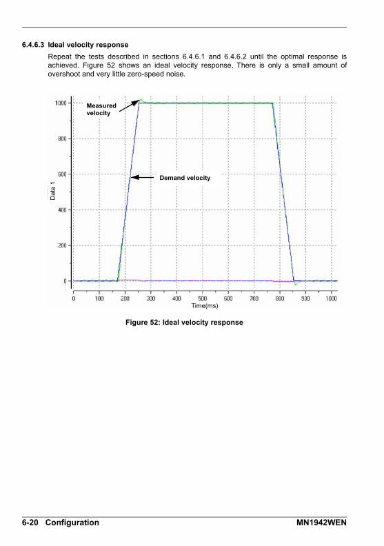
6.4.6.3 Ideal velocity response
Repeat the tests described in sections 6.4.6.1 and 6.4.6.2 until the optimal response isachieved. Figure 52 shows an ideal velocity response. There is only a small amount ofovershoot and very little zero-speed noise.
Figure 52: Ideal velocity response
Measured velocity
Dat
a 1
Time(ms)
Demand velocity
6-20 Configuration MN1942WEN
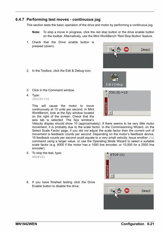
6.4.7 Performing test moves - continuous jogThis section tests the basic operation of the drive and motor by performing a continuous jog.
Note: To stop a move in progress, click the red stop button or the drive enable buttonon the toolbar. Alternatively, use the Mint WorkBench ‘Red Stop Button’ feature.
1. Check that the Drive enable button ispressed (down).
2. In the Toolbox, click the Edit & Debug icon.
3. Click in the Command window.
4. Type:JOG(0)=10
This will cause the motor to movecontinuously at 10 units per second. In MintWorkBench, look at the Spy window locatedon the right of the screen. Check that theaxis tab is selected. The Spy window’sVelocity display should show 10 (approximately). If there seems to be very little motormovement, it is probably due to the scale factor. In the Commissioning Wizard, on theSelect Scale Factor page, if you did not adjust the scale factor then the current unit ofmovement is feedback counts per second. Depending on the motor’s feedback device,10 feedback counts per second could equate to a very small velocity. Issue another JOGcommand using a larger value, or use the Operating Mode Wizard to select a suitablescale factor (e.g. 4000 if the motor has a 1000 line encoder, or 10,000 for a 2500 lineencoder).
5. To stop the test, type:STOP(0)
6. If you have finished testing click the DriveEnable button to disable the drive.
MN1942WEN Configuration 6-21

6.4.8 Performing test moves - relative positional moveThis section tests the basic operation of the drive and motor by performing a positional move.
Note: To stop a move in progress, click the red stop button or the drive enable buttonon the toolbar. Alternatively, use the Mint WorkBench ‘Red Stop Button’ feature.
1. Check that the Drive enable button is pressed(down).
2. In the Toolbox, click the Edit & Debug icon.
3. Click in the Command window.
4. Type:MOVER(0)=10GO(0)
This will cause the motor to move to aposition 10 units from its current position.
The move will stop when completed.
5. If you have finished testing click the DriveEnable button to disable the drive.
6-22 Configuration MN1942WEN

6.5 Further configurationMint WorkBench provides a number of other tools for testing and configuring the MicroFlexe100. Every tool is explained fully in the help file. Press F1 to display the help file, thennavigate to the Mint WorkBench book. Inside this is the Toolbox book.
6.5.1 Fine-tuning toolThe Commissioning Wizard calculates many parameters that allow the MicroFlex e100 toprovide basic control of the motor. These parameters may need to be fine-tuned to providethe exact response that you require. The Fine-tuning screen allows you to do this.
1. Click the Fine-tuning icon in the Toolbox on the left of the screen.
The Fine-tuning window is displayed at the right of the screen.This already shows some of the parameters that have beencalculated by the Commissioning Wizard.
The main area of the Mint WorkBench window displays the capture window. Whenfurther tuning tests are performed, this will display a graph representing the response.
2. The Fine-tuning window has severaltabs at the bottom - Position, Velocity,Current, SRamp etc. Click on a tab toselect it.
Click the tab for the type of tests you wish to perform.
Note: Some tabs may not be available depending on the configuration mode youselected in the Commissioning Wizard.
6.5.1.1 Fine-tuning - Position tab
The Position tab allows you to adjust position loop settings and perform test moves. TheCommissioning Wizard may have already set some of these values, depending on the typeof system selected on the mode screen.
Enter new values in the required boxes and then click Apply to download the values to theMicroFlex e100. To perform tests, go to the Test Parameters area at the bottom of the tab.Enter test values and then click Go to perform the test move. If you need help, just press F1to display the help file.
6.5.1.2 Fine-tuning - Velocity tab
The Velocity tab allows you to set velocity loop gains and perform test moves. TheCommissioning Wizard may have already set some of these values, depending on the typeof system selected on the mode screen.
Enter new values in the required boxes and then click Apply to download the values to theMicroFlex e100. To perform tests, go to the Test Parameters area at the bottom of the tab.Enter test values and then click Go to perform the test move. If you need help, just press F1to display the help file.
MN1942WEN Configuration 6-23

6.5.1.3 Fine-tuning - Current tab
The Current tab allows you to set current loop gains and perform test moves. TheCommissioning Wizard may have already set some of these values, depending on the typeof system selected on the mode screen. Normally, it should not be necessary to alter thesevalues.
Enter new values in the required boxes and then click Apply to download the values to theMicroFlex e100. To perform tests, go to the Test Parameters area at the bottom of the tab.Enter test values and then click Go to perform the test move. If you need help, just press F1to display the help file.
The additional Measure and Feedback alignment buttons can be used to repeat the samemeasurement and alignment tests that are used by the Commissioning Wizard.
6.5.1.4 Fine-tuning - SRamp / Simple SRamp tabs
The SRamp and Simple SRamp tabs allow you to set parameters and perform test movesusing S-ramped profiles. These profiles cause the normal trapezoidal move profile to bemodified to create smoother acceleration and decleration.
Enter new values in the required boxes and then click Preview to see an example of theintended move profile. Click Go to perform the test move. If you need help, just press F1 todisplay the help file.
6.5.1.5 Fine-tuning - Filter tab
The Filter tab allows you to set the properties of the MicroFlex e100’s two torque filters. Itshould only be necessary to use the torque filters if there is a particular problem withresonant frequencies in the load.
Enter new values in the required boxes and then click Apply to download the values to theMicroFlex e100. To perform tests, go to the Frequency Response Params area at the bottomof the tab. Enter test values and then click Go to perform the test move. If you need help, justpress F1 to display the help file.
6.5.1.6 Fine-tuning - Flux tab
The Flux tab allows you to set gains and perform test moves when using induction motors.
Enter new values in the required boxes and then click Apply to download the values to theMicroFlex e100. Click Go to perform the test move. If you need help, just press F1 to displaythe help file.
6-24 Configuration MN1942WEN

6.5.2 Parameters toolThe Parameters tool can be used to view or change most of the drive’s parameters.
1. Click the Parameters icon in the Toolbox onthe left of the screen.
The main area of the Mint WorkBenchwindow displays the Parameters editorscreen.
Items listed with a grey icon are Read Only so cannot be changed.
Items listed with a green icon are currently set to their Factory Default value.
Items listed with a yellow icon have been altered from their factory default value,either during the commissioning process or by the user.
2. In the parameters tree, scroll to the requireditem. Click on the small + sign beside theitem’s name.
The list will expand to show all items in thecategory.
Click on the item you wish to edit.
3. The adjacent table will list the chosen item. Click in the Active Table cell and enter avalue. This immediately sets the parameter,which will remain in the MicroFlex e100 untilanother value is defined. The icon to the leftof the item will become yellow to indicate thatthe value has been changed.
Many of the MicroFlex e100’s parameters are set automatically by the CommissioningWizard, or when tests are performed in the fine-tuning window.
MN1942WEN Configuration 6-25

6.5.3 Spy windowThe Spy window can be used to monitor and capture parameters in real-time. If you tried thetest moves in section 6.4.7 or 6.4.8 then you have already seen the Spy window, as it isdisplayed in conjunction with Edit & Debug mode. See the Mint help file for full details of eachtab.
1. Click the Edit & Debug icon in the Toolbox onthe left of the screen.
The Spy Window is displayed on the right ofthe screen. Click on the tabs at the bottom ofthe window to select the required function.
2. The Axis tab displays the five most commonlymonitored parameters, together with the state ofspecial purpose inputs and outputs.
3. The I/O tab displays the state of all the digital inputsand outputs.
Clicking on an output LED will toggle the output on/off.
4. The Monitor tab allows up to six parameters to beselected for monitoring.
Click in a drop down box to select a parameter.
At the bottom of the Monitor tab, real-time datacapture can be configured.
6-26 Configuration MN1942WEN
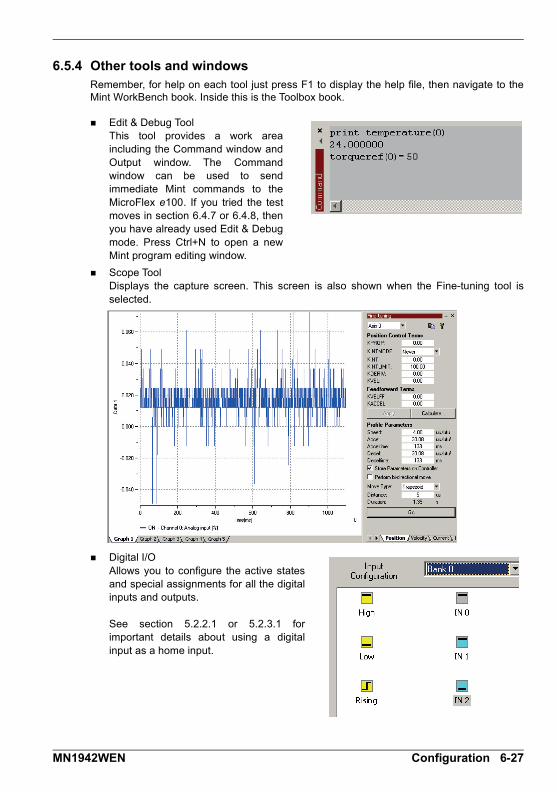
6.5.4 Other tools and windowsRemember, for help on each tool just press F1 to display the help file, then navigate to theMint WorkBench book. Inside this is the Toolbox book.
Edit & Debug ToolThis tool provides a work areaincluding the Command window andOutput window. The Commandwindow can be used to sendimmediate Mint commands to theMicroFlex e100. If you tried the testmoves in section 6.4.7 or 6.4.8, thenyou have already used Edit & Debugmode. Press Ctrl+N to open a newMint program editing window.
Scope ToolDisplays the capture screen. This screen is also shown when the Fine-tuning tool isselected.
Digital I/OAllows you to configure the active statesand special assignments for all the digitalinputs and outputs.
See section 5.2.2.1 or 5.2.3.1 forimportant details about using a digitalinput as a home input.
MN1942WEN Configuration 6-27

6-28 Configuration MN1942WEN

Troubleshooting7 Troubleshooting
7.1 IntroductionThis section explains common problems that may be encountered, together with possiblesolutions. If you want to know the meaning of the LED indicators, see section 7.2.
7.1.1 Problem diagnosisIf you have followed all the instructions in this manual in sequence, you should have fewproblems installing the MicroFlex e100. If you do have a problem, read this section first.In Mint WorkBench, use the Error Log tool to view recent errors and then check the help file.If you cannot solve the problem or the problem persists, the SupportMe feature can be used.
7.1.2 SupportMe feature
The SupportMe feature is available from the Help menu or by clicking the button on themotion toolbar. SupportMe can be used to gather information which can then be e-mailed,saved as a text file, or copied to another application. The PC must have e-mail facilities touse the e-mail feature. If you prefer to contact technical support by telephone or fax, contactdetails are provided at the front of this manual. Please have the following information ready:
The serial number of your MicroFlex e100 (if known).
Use the Help, SupportMe menu item in Mint WorkBench to view details about yoursystem.
The catalog and specification numbers of the motor that you are using.
A clear description of what you are trying to do, for example trying to establishcommunications with Mint WorkBench or trying to perform fine-tuning.
A clear description of the symptoms that you can observe, for example the Status LED,error messages displayed in Mint WorkBench, or errors reported by the Mint errorkeywords ERRORREADCODE or ERRORREADNEXT.
The type of motion generated in the motor shaft.
Give a list of any parameters that you have setup, for example the motor data youentered/selected in the Commissioning Wizard, the gain settings generated during thetuning process and any gain settings you have entered yourself.
7.1.3 Power-cycling the MicroFlex e100The term “Power-cycle the MicroFlex e100” is used in the Troubleshooting sections. Removethe 24 V supply, wait for the MicroFlex e100 to power down completely (the Status LED willturn off), then re-apply the 24 V supply.
7
MN1942WEN Troubleshooting 7-1

7.2 MicroFlex e100 indicators
7.2.1 STATUS LEDThe Status LED indicates general MicroFlex e100 status information.
Solid green:Drive enabled (normal operation).
Flickering / blinking green: Firmware download / update in progress.
Solid red:Drive disabled, but no errors are latched.
Flashing red:Powerbase fault or error(s) present. The number of flashes indicates which error has occurred. For example, to display error 3 (overcurrent trip), the LED flashes 3 times at 0.1 second intervals, followed by a 0.5 second pause. The sequence is repeated continuously.
Error code Meaning(no. of flashes)
1 . . . . . . . . . . . . . . DC bus overvoltage trip.2 . . . . . . . . . . . . . . IPM (integrated power module) trip.3 . . . . . . . . . . . . . . Overcurrent trip.4 . . . . . . . . . . . . . . Overspeed trip.5 . . . . . . . . . . . . . . Feedback trip.
6 . . . . . . . . . . . . . . Motor overload (I2t) trip.7 . . . . . . . . . . . . . . Overtemperature trip.8 . . . . . . . . . . . . . . Drive overload (It) trip.9 . . . . . . . . . . . . . . Following error trip.10 . . . . . . . . . . . . . Error input triggered.11. . . . . . . . . . . . . . Phase search error.12 . . . . . . . . . . . . . All other errors, including: Internal supply error, encoder
supply error, parameter restore failure, power base not recognized.
If multiple errors occur at the same time, the lowest numbered error code will be flashed. For example, a MicroFlex e100 which has tripped on both feedback error (code 5) and over-current error (code 3) will flash error code 3. If the drive is already displaying an error code when a new error with a lower code occurs, the drive will start flashing the new code. Note that undervoltage trip does not appear in the table because it is already indicated by the green/red flashing state. If an undervoltage trip occurs in conjunction with another error, the drive will flash the code of the additional error.Further details about error codes can be found in the Mint WorkBench help file. Press F1 and locate the Error Handling book.Alternate red/green flashing:Undervoltage warning (no AC power), but no errors are latched.
The DC-bus voltage has dropped below the powerbase undervoltage level (see DRIVEBUSUNDERVOLTS). This error will only be generated if the drive is in the enabled state. Check the AC power is connected.
7-2 Troubleshooting MN1942WEN

7.2.2 CAN LEDsThe CAN LEDs display the overall condition of the CANopen interface,once the startup sequence has completed. The LED codes conform tothe CAN in Automation (CiA) DR303_3 indicator standard. The greenLED indicates the state of the node’s internal CANopen ‘statemachine’. The red LED indicates the state of the physical CANopenbus.
Green (run)
Off: Node initializing or not powered.
1 flash: Node in STOPPED state.3 flashes: Software is being downloaded to the node.Continuous flashing: Node in PRE-OPERATIONAL state.Flickering (very fast flashing): Auto-baudrate detection or LSS services in progress; flickers alternately with red LED.
Continuously illuminated, not flashing: Node in OPERATIONAL state.
Red (error)
Off: No errors or not powered.
1 flash: Warning - too many error frames.2 flashes: Guard event or heartbeat event has occurred.3 flashes: The SYNC message has not been received within the timeout period.Flickering (very fast flashing): Auto-baudrate detection or LSS services in progress; flickers alternately with green LED.
Continuously illuminated, not flashing: The node’s CAN controller is in the BUS OFF state, preventing it from taking part in any CANopen communication.
MN1942WEN Troubleshooting 7-3

7.2.3 ETHERNET LEDsThe ETHERNET LEDs display the overall condition of the Ethernetinterface once the startup sequence has completed. The LED codesconform to the Ethernet POWERLINK Standardization Group(EPSG) standard at the time of production.
Green (status)
Off: Node in NOT ACTIVE state. The controlled node is waiting to be triggered by the manager node.
1 flash: Node in PRE-OPERATIONAL1 state. EPL mode is starting.
2 flashes: Node in PRE-OPERATIONAL2 state. EPL mode is starting.
3 flashes: Node in READY TO OPERATE state. The node is signalling its readiness to operate.
Blinking (continuous flashing): Node in STOPPED state. The controlled node has been deactivated.
Flickering (very fast flashing): Node in BASIC ETHERNET state (EPL is not operating, but other Ethernet protocols may be used).
Continuously illuminated, not flashing: Node in OPERATIONAL state. EPL is operating normally.
Red (error)
Off: EPL is working correctly.
Continuously illuminated: An error has occurred.
7-4 Troubleshooting MN1942WEN

7.2.4 CommunicationStatus LED is off:
Check that the 24 V DC control circuit supply is connected correctly to connector X2 andis switched on.
ETHERNET LEDs blinking green and red simultaneously:
Does the MicroFlex e100 have firmware in it? If you tried to download new firmware andthe download failed, the controller may not have firmware. Download new firmware.
Mint WorkBench fails to detect the MicroFlex e100:
Ensure that the MicroFlex e100 is powered and the Status LED is illuminated (seesection 7.2.1).
Check that the Ethernet or USB cable is connected between the PC and MicroFlex e100.
Try an alternative cable or different port on the PC.
In the “Search up to Nodexx” option in Mint WorkBench’s Select Controller dialog, checkthat the MicroFlex e100’s node ID is not higher than the selected value, or search up to agreater node ID.
For USB connections, check that the cable is properly connected. Check the USBconnector socket pins for damage or sticking. Check that the USB device driver hasbeen installed; a ‘USB Motion Controller’ device should be listed in Windows DeviceManager.
Check that the PC’s Ethernet port has been correctly configured for TCP/IP operation(see section 6.2.4).
7.2.5 Power onDrive does not start when applying AC power:
Check that the motor output phases are not short circuited. If the drive trips on a motorphase short circuit it will not restart unless AC power is removed. Remove all power fromthe drive, correct the short circuit and restart the drive.
The Status LED is flashing red:
The MicroFlex e100 has detected a motion error. Click the Error button on the motiontoolbar to view a description of the error. Alternatively, select the Error Log tool to view alist of errors. Click the Clear Errors button on the motion toolbar.
7.2.6 Mint WorkBenchThe Spy window does not update:
The system refresh has been disabled. Go to the Tools, Options menu item, select theSystem tab and then choose a System Refresh Rate (500 ms is recommended).
Cannot communicate with the controller after downloading firmware:
After firmware download, always power cycle the MicroFlex e100 (remove 24 V powerand then reconnect).
Mint WorkBench loses contact with MicroFlex e100 while connected using USB:
Check that the MicroFlex e100 is powered.
Check that a ‘USB Motion Controller’ device is listed in Windows Device Manager. If not,there could be a problem with the PC’s USB interface.
MN1942WEN Troubleshooting 7-5
7.2.7 TuningCannot enable the MicroFlex e100 because there is an error 10010:
Check the drive enable input on connector X3 pins 9 and 19 is connected and poweredcorrectly.
When the MicroFlex is enabled the motor is unstable:
Check that the load is firmly coupled to the motor.
Use the Mint WorkBench Drive Setup Wizard to confirm that the correct motor data hasbeen entered.
Use the Mint WorkBench Autotune Wizard to retune the motor.
If the motor is still unstable, select the Mint WorkBench Autotune Wizard once more.Click Options.... On the Bandwidth tab, move the Current and/or Position and SpeedControl sliders to a slower position to select to a lower bandwidth. Click OK to exit andthen start the Autotune Wizard again.
7.2.8 EthernetCannot connect to the drive over TCP/IP:
Check that there is not an EPL manager node (for example NextMove e100 with node ID240) on the network. If there is a manager node on the network, then an EPL compatiblerouter must be used to allow TCP/IP communication on the EPL network.
Check that the PC’s Ethernet adapter has been correctly configured, as described insection 6.2.4.
There is a slow response when issuing a command from a host application:
The drive automatically closes the TCP/IP socket after 30 seconds of inactivity. If thesocket has closed, there is a delay before the drive responds to the next command. Tokeep the socket open, include in your application a timed procedure, with a period of lessthan 30 seconds, that issues a command (e.g. reading AAABuild).
The Ethernet POWERLINK network does not seem to be operating correctly:
Confirm that only one device on the network is set to be the Ethernet POWERLINKmanager node (node ID 240, selector switches LO = F, HI = 0).
Confirm that the reference source on all controlled nodes has been set to EPL in the MintWorkBench Operating Mode Wizard, and that the manager node has been configuredcorrectly. For a NextMove e100 manager node, this requires the System Config Wizardto be used in Mint WorkBench.
Confirm that each device on the network has a different node ID.
Confirm that there are no more than 10 ‘daisy-chained’ devices on each branch of thenetwork.
7-6 Troubleshooting MN1942WEN

7.2.9 CANopenThe CANopen bus is ‘passive’:
This means that the internal CAN controller in the MicroFlex e100 is experiencing a numberof Tx and/or Rx errors, greater than the passive threshold of 127. Check: 12-24 V is being applied between pin 9 (+24 V) and pin 6 or 3 (0 V) of the OPT 1
connector, to power the opto-isolators.
There is at least one other CANopen node in the network.
The network is terminated only at the ends, not at intermediate nodes.
All nodes on the network are running at the same baud rate.
All nodes have been assigned a unique node ID.
The integrity of the CAN cables.
The MicroFlex e100 should recover from the ‘passive’ state once the problem has beenrectified (this may take several seconds).
The CANopen bus is ‘off’:
This means that the internal CAN controller in the MicroFlex e100 has experienced a fatalnumber of Tx and/or Rx errors, greater than the off threshold of 255. At this point the nodewill have switched itself to a state whereby it cannot influence the bus. Check: 12-24 V is being applied between pin 9 (+24 V) and pin 6 or 3 (0 V) of the OPT 1
connector, to power the opto-isolators.
There is at least one other CANopen node in the network.
The network is terminated only at the ends, not at intermediate nodes.
All nodes on the network are running at the same baud rate.
All nodes have been assigned a unique node ID.
The integrity of the CAN cables.
To recover from the ‘off’ state, the source of the errors must be removed and bus then reset.This can be done using the Mint BUSRESET keyword, or by resetting the MicroFlex e100.
The Manager node cannot scan/recognize a node on the network using the MintNODESCAN keyword:
Assuming that the network is working correctly (see previous symptoms) and the bus is in an‘Operational’ state, check: Only nodes that conform to DS401, DS403 and other ABB CANopen nodes are
recognized by the Mint NODESCAN keyword. Other types of node will be identified with atype “unknown” (255) when using the Mint NODETYPE keyword.
Check that the node in question has been assigned a unique node ID.
The node must support the node guarding process. MicroFlex e100 does not support theHeartbeat process.
Try power-cycling the node in question.
If the node in question does not conform to DS401 or DS403 and is not an ABB CANopennode, communication is still possible using a set of general purpose Mint keywords. See theMint help file for further details.
MN1942WEN Troubleshooting 7-7

The node has been successfully scanned / recognized by the Manager node, butcommunication is still not possible:
For communication to be allowed, a connection must be made to a node after it has beenscanned: Controller nodes are automatically connected to after being scanned.
Nodes that conform to DS401, DS403 must have the connections made manually usingthe Mint CONNECT keyword.
If a connection attempt using CONNECT fails then it may be because the node beingconnected to does not support an object which needs to be accessed in order to setup theconnection.
7-8 Troubleshooting MN1942WEN

Specifications8 Specifications
8.1 IntroductionThis section provides technical specifications for the MicroFlex e100.
8.1.1 AC input power and DC bus voltage (X1)
* The MicroFlex e100 will operate at lower input voltages, although the drive will trip if theDC-bus voltage falls below 50 V or 60% of the no-load voltage, whichever occurs first.
8.1.1.1 Effect of AC power supply voltage on DC-bus voltage
All models UnitAC input
1Φ 3Φ
Nominal input voltage
V AC
115 or 230
Minimum input voltage 105*
Maximum input voltage 250
Nominal DC-bus voltage@230 V AC input
V DC 305 321
3 A 6 A 9 A 3 A 6 A 9 A
Nominal input current@ maximum rated output current
A 7.5 15 22 4 8 12
Single-phase AC supply
Three-phase AC supply
DC
-bu
s vo
ltage
(V
DC
)
AC supply voltage (rms)
8
MN1942WEN Specifications 8-1
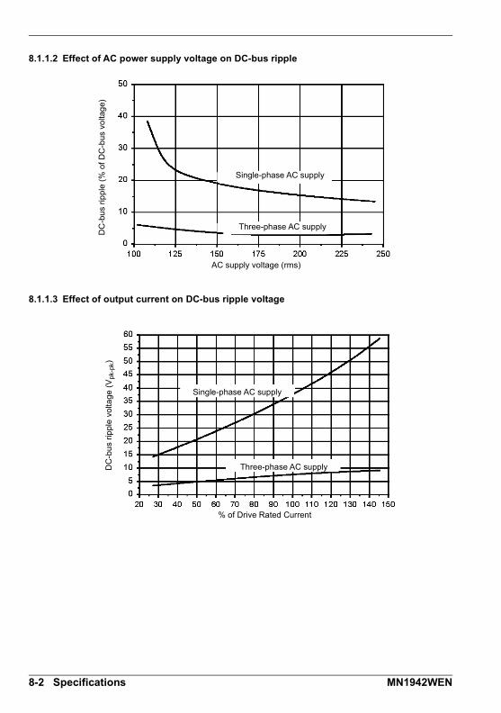
8.1.1.2 Effect of AC power supply voltage on DC-bus ripple
8.1.1.3 Effect of output current on DC-bus ripple voltage
Single-phase AC supply
Three-phase AC supply
DC
-bu
s rip
ple
(% o
f D
C-b
us v
olta
ge)
AC supply voltage (rms)
Single-phase AC supply
Three-phase AC supplyDC
-bu
s rip
ple
vol
tage
(V
pk-
pk)
% of Drive Rated Current
8-2 Specifications MN1942WEN
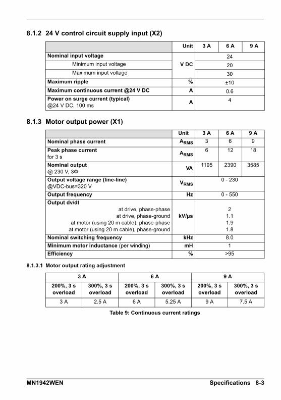
8.1.2 24 V control circuit supply input (X2)
8.1.3 Motor output power (X1)
8.1.3.1 Motor output rating adjustment
Unit 3 A 6 A 9 A
Nominal input voltage
V DC
24Minimum input voltage 20Maximum input voltage 30
Maximum ripple % ±10
Maximum continuous current @24 V DC A 0.6Power on surge current (typical)@24 V DC, 100 ms
A 4
Unit 3 A 6 A 9 A
Nominal phase current ARMS 3 6 9
Peak phase currentfor 3 s
ARMS6 12 18
Nominal output@ 230 V, 3Φ
VA1195 2390 3585
Output voltage range (line-line)@VDC-bus=320 V
VRMS0 - 230
Output frequency Hz 0 - 550
Output dv/dtat drive, phase-phase
at drive, phase-groundat motor (using 20 m cable), phase-phase
at motor (using 20 m cable), phase-ground
kV/μs2
1.11.91.8
Nominal switching frequency kHz 8.0
Minimum motor inductance (per winding) mH 1
Efficiency % >95
3 A 6 A 9 A
200%, 3 soverload
300%, 3 soverload
200%, 3 soverload
300%, 3 soverload
200%, 3 soverload
300%, 3 soverload
3 A 2.5 A 6 A 5.25 A 9 A 7.5 A
Table 9: Continuous current ratings
MN1942WEN Specifications 8-3

8.1.4 Braking (X1)
8.1.5 Digital inputs - drive enable and DIN0 general purpose (X3)
Unit 3 A 6 A 9 A
Nominal switching threshold (typical) V DC on: 388, off: 376
Nominal power(10% power cycle, R=57Ω)
kW0.25
Peak power (10% power cycle, R=57Ω)
kW2.7
Maximum switching current APK 10
Minimum load resistance Ω 39
Maximum load inductance μH 100
Unit All models
Type Opto-isolated inputs
Input voltageNominalMinimumMaximumActiveInactive
V DC
241230
> 12< 2
Input current (maximum, per input) mA 50
Sampling interval ms 1
Minimum pulse width μs 5
8-4 Specifications MN1942WEN

8.1.6 Digital inputs DIN1, DIN2 - high speed general purpose (X3)
8.1.7 Digital outputs DOUT0, DOUT1 - status and general purpose (X3)
8.1.8 Incremental encoder feedback option (X8)
Unit All models
Type Opto-isolated inputs
Input voltageNominalMinimumMaximumActiveInactive
V DC
241230
> 12< 2
Input current (maximum, per input) mA 20
Maximum input frequency MHz 1
Minimum pulse width ns 250
Minimum step time ns 250
Minimum space time ns 250
Direction input setup time ns 100
Direction input hold time ns 100
Unit All models
User supply (maximum) V 28
Output current (max. continuous) mA 100
FuseApproximate trip current
Reset timemA
s200<20
Update interval ms 1
Unit All models
Encoder input RS422 A/B Differential, Z index
Maximum input frequency(quadrature)
MHz 8
Hall inputs RS422 A/B Differential
Output power supply to encoder 5 V (±7%), 200 mA max.
Maximum recommended cable length 30.5 m (100 ft)
MN1942WEN Specifications 8-5
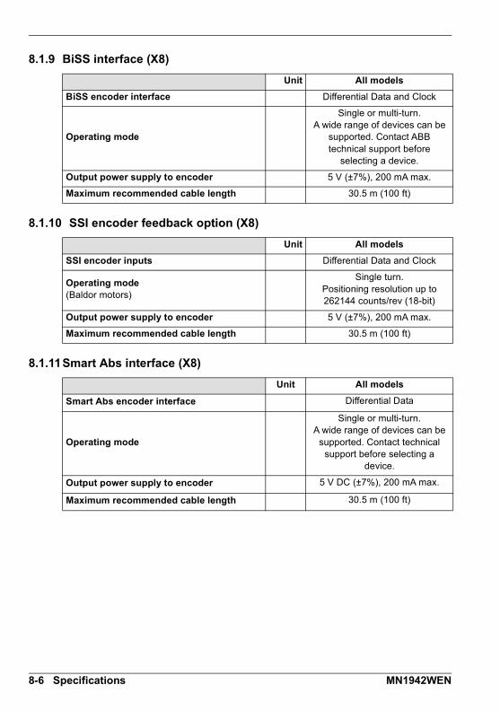
8.1.9 BiSS interface (X8)
8.1.10 SSI encoder feedback option (X8)
8.1.11Smart Abs interface (X8)
Unit All models
BiSS encoder interface Differential Data and Clock
Operating mode
Single or multi-turn.A wide range of devices can be
supported. Contact ABB technical support before
selecting a device.
Output power supply to encoder 5 V (±7%), 200 mA max.
Maximum recommended cable length 30.5 m (100 ft)
Unit All models
SSI encoder inputs Differential Data and Clock
Operating mode(Baldor motors)
Single turn.Positioning resolution up to 262144 counts/rev (18-bit)
Output power supply to encoder 5 V (±7%), 200 mA max.
Maximum recommended cable length 30.5 m (100 ft)
Unit All models
Smart Abs encoder interface Differential Data
Operating mode
Single or multi-turn.A wide range of devices can be
supported. Contact technical support before selecting a
device.
Output power supply to encoder 5 V DC (±7%), 200 mA max.
Maximum recommended cable length 30.5 m (100 ft)
8-6 Specifications MN1942WEN
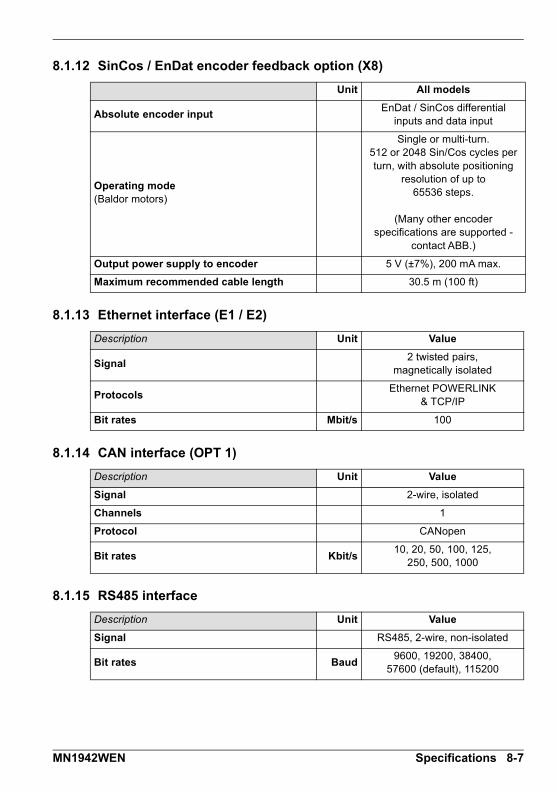
8.1.12 SinCos / EnDat encoder feedback option (X8)
8.1.13 Ethernet interface (E1 / E2)
8.1.14 CAN interface (OPT 1)
8.1.15 RS485 interface
Unit All models
Absolute encoder inputEnDat / SinCos differential
inputs and data input
Operating mode(Baldor motors)
Single or multi-turn.512 or 2048 Sin/Cos cycles per turn, with absolute positioning
resolution of up to65536 steps.
(Many other encoder specifications are supported -
contact ABB.)
Output power supply to encoder 5 V (±7%), 200 mA max.
Maximum recommended cable length 30.5 m (100 ft)
Description Unit Value
Signal2 twisted pairs,
magnetically isolated
ProtocolsEthernet POWERLINK
& TCP/IP
Bit rates Mbit/s 100
Description Unit Value
Signal 2-wire, isolated
Channels 1
Protocol CANopen
Bit rates Kbit/s10, 20, 50, 100, 125,
250, 500, 1000
Description Unit Value
Signal RS485, 2-wire, non-isolated
Bit rates Baud9600, 19200, 38400,
57600 (default), 115200
MN1942WEN Specifications 8-7

8.1.16 Environmental
* MicroFlex e100 complies with the following environmental test standards:
BS EN60068-2-1:1993 low temperature operational 0°C.BS EN60068-2-2:1993 high temperature operational 45°C.BS EN60068-2-1:1993 low temperature storage/transportation -40°C.BS EN60068-2-2:1993 high temperature storage/transportation +85°C.BS 2011:part2.1 Cb: 1990: 45°C 93%RH humidity/high temperature operational.DIN IEC 68-2-6/29
** MicroFlex e100 complies with EN61800-5-1:2003 part 5.2.2.5.3 (Impact test), provided allfront panel connectors are inserted.
8.1.17 Weights and dimensions
All models Unit All models
Operating temperature range* °C °F
MinimumMaximum
Derate
+0+45
See sections3.2.2 to 3.2.6
+32+113
See sections3.2.2 to 3.2.6
Storage temperature range* -40 to +85 -40 to +185
Humidity (maximum)* % 93
3 A 6 A 9 A
Forced air cooling flow(vertical, from bottom to top)
m/sNone required 1 2.5
Maximum installation altitude(above m.s.l.)
m
ft
1000Derate 1.1% / 100 m over 1000 m
3300Derate 1.1% / 330 ft over 3300 ft
Shock* 10 G
Vibration* 1 G, 10-150 Hz
IP rating IP20**
Description 3 A 6 A 9 A
Weight1.45 kg(3.2 lb)
1.5 kg(3.3 lb)
1.55 kg(3.4 lb)
Nominal overall dimensions180 mm x 80 mm x 157 mm
(7.1 in x 3.2 in x 6.2 in)
8-8 Specifications MN1942WEN

AccessoriesA Accessories
A.1 IntroductionThis section describes accessories and options that you may need to use with yourMicroFlex e100. Shielded (screened) cables provide EMI / RFI shielding and are required forcompliance with CE regulations. All connectors and other components must be compatiblewith the shielded cable.
A
MN1942WEN Accessories A-1
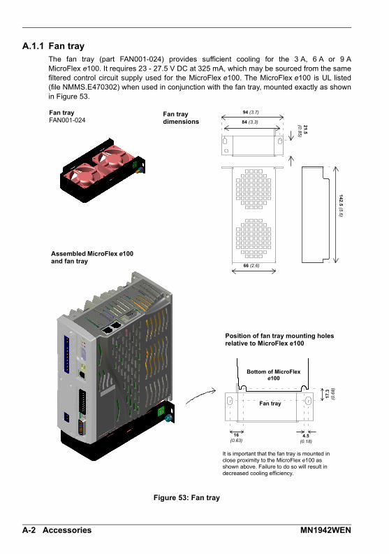
A.1.1 Fan tray The fan tray (part FAN001-024) provides sufficient cooling for the 3 A, 6 A or 9 AMicroFlex e100. It requires 23 - 27.5 V DC at 325 mA, which may be sourced from the samefiltered control circuit supply used for the MicroFlex e100. The MicroFlex e100 is UL listed(file NMMS.E470302) when used in conjunction with the fan tray, mounted exactly as shownin Figure 53.
Figure 53: Fan tray
Fan tray FAN001-024
Fan tray dimensions
Assembled MicroFlex e100 and fan tray
Position of fan tray mounting holes relative to MicroFlex e100
Bottom of MicroFlex e100
Fan tray
It is important that the fan tray is mounted in close proximity to the MicroFlex e100 as shown above. Failure to do so will result in decreased cooling efficiency.
84 (3.3)
66 (2.6)
94 (3.7)
21
.5
(0.8
5)
14
2.5
(5.6
)
4.5 (0.18)
16 (0.63)
17
.3
(0.6
8)
A-2 Accessories MN1942WEN

A.1.2 Footprint filter (single-phase only)The single-phase footprint AC power filter (part FI0029A00) provides mounting holes for theMicroFlex e100 and fan tray. This allows the filter, fan tray and MicroFlex e100 to useminimal panel mounting space. See section A.1.4 for details of filter FI0029A00.
Figure 54: Assembled footprint filter, fan tray and MicroFlex e100
A.1.3 24 V power suppliesA range of compact 24 V DIN rail mounting power supplies are available. The suppliesinclude short circuit, overload, over-voltage and thermal protection.
Part Input voltage Output voltage Output rating
DR-75-24
110-230 V AC 24 V DC
75 W (3.2 A)
DR-120-24 120 W (5 A)
DRP-240-24 240 W (10 A)
Table 10: 24 V power supplies
Footprint filterFI0029A00
MicroFlex e100MFE230A00x
Fan trayFAN001-024
MN1942WEN Accessories A-3

A.1.4 EMC filtersAC filters remove high frequency noise from the AC power supply, protecting theMicroFlex e100. These filters also prevent high frequency signals from being transmittedback onto the power lines and help meet EMC requirements. To select the correct filter, seesections 3.4.8 and 3.4.9.
A.1.4.1 Part numbers
Figure 55: Filter dimensions, types FI0018A00 and FI0018A03
Part Manufacturer Ratedvolts
Ratedamps
@ 40°C
Leakage current
(mA)
Weightkg (lbs)
FI0014A00 Schaffner FN9675-3/06 250 3 0.4 0.27 (0.6)
FI0015A00 Schaffner FN2070-6/06 250 6 0.4 0.45 (0.99)
FI0015A02 Schaffner FN2070-12/06 250 12 0.4 0.73 (1.61)
FI0018A00 Schaffner FN3258-7/45 480 7 33 0.5 (1.1)
FI0018A03 Schaffner FN3258-16-44 480 16 33 0.8 (1.76)
FI0029A00 Epcos B84142A22R215 250 22 33 3.0 (6.6)
Dimensions mm (inches)
Dimension FI0018A00 FI0018A03
A 190 (7.48) 250 (9.84)
B 160 (6.30) 220 (8.66)
C 180 (7.09) 235 (9.25)
D 20 (0.79) 25 (0.98)
E 4.5 (0.18) 5.4 (0.21)
F 71 (2.80) 70 (2.76)
G 40 (1.57) 45 (1.77)
B
M5
A
F
C
ED G
A-4 Accessories MN1942WEN

Figure 56: Filter dimensions, types FI0014A00, FI0015A00, FI0015A02
Dimensions mm (inches)
Dimension FI0014A00 FI0015A00 FI0015A02
A 85 (3.35) 113.5 (4.47) 156 (6.14)
B 54 (2.13) 57.5 (2.26)
C 40 (1.57) 46.6 (1.83)
D 65 (2.56) 94 (3.70) 130.5 (5.14)
E 75 (2.95) 103 (4.06) 143 (5.63)
F 27 (1.06) 25 (0.98)
G 12 (0.47) 12.4 (0.49)
H 29.5 (1.16) 32.4 (1.28)
J 5.3 (0.21) 4.4 (0.17) 5.3 (0.21)
K 6.3 (0.25) 6 (0.24)
L 13.5 (0.53) 15.5 (0.61)
L
KJ
H
GF
ED
C
B
A
MN1942WEN Accessories A-5
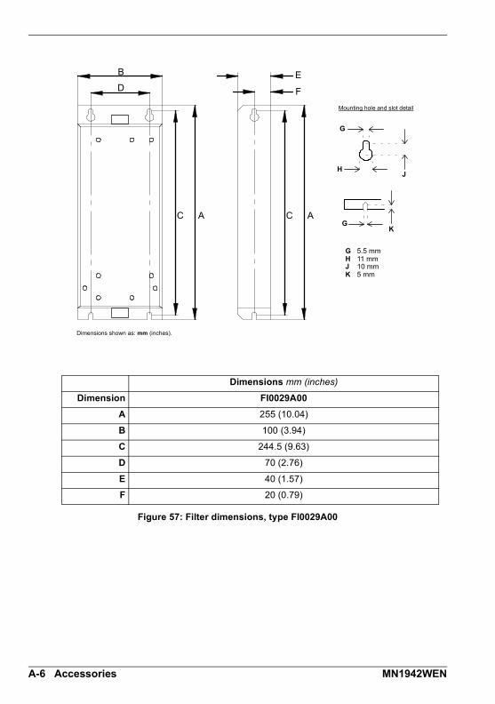
Figure 57: Filter dimensions, type FI0029A00
Dimensions mm (inches)
Dimension FI0029A00
A 255 (10.04)
B 100 (3.94)
C 244.5 (9.63)
D 70 (2.76)
E 40 (1.57)
F 20 (0.79)
B
D
AC
G
HJ
G 5.5 mmH 11 mmJ 10 mmK 5 mm
GK
AC
F
E
Mounting hole and slot detail
Dimensions shown as: mm (inches).
A-6 Accessories MN1942WEN
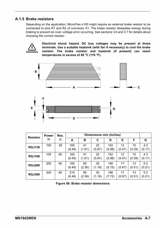
A.1.5 Brake resistorsDepending on the application, MicroFlex e100 might require an external brake resistor to beconnected to pins R1 and R2 of connector X1. The brake resistor dissipates energy duringbraking to prevent an over–voltage error occurring. See sections 3.6 and 3.7 for details aboutchoosing the correct resistor.
Electrical shock hazard. DC bus voltages may be present at theseterminals. Use a suitable heatsink (with fan if necessary) to cool the brakeresistor. The brake resistor and heatsink (if present) can reachtemperatures in excess of 80 °C (176 °F).
Figure 58: Brake resistor dimensions
ResistorPower
WRes.Ω
Dimensions mm (inches)
A B C D E F G
RGJ139100 39 165
(6.49)41
(1.61)22
(0.87)152
(5.98)12
(0.47)10
(0.39)4.3
(0.17)
RGJ160100 60 165
(6.49)41
(1.61)22
(0.87)152
(5.98)12
(0.47)10
(0.39)4.3
(0.17)
RGJ260200 60 165
(6.49)60
(2.36)30
(1.18)146
(5.75)17
(0.67)13
(0.51)5.3
(0.21)
RGJ360300 60 215
(8.46)60
(2.36)30
(1.18)196
(7.72)17
(0.67)13
(0.51)5.3
(0.21)
WARNING
A
B
C
E
D
G
F
MN1942WEN Accessories A-7

A.2 CablesA wide range of motor and feedback cables are available from ABB.
A.2.1 Motor power cablesFor easier installation, it is recommended that a color-coded motor power cable is used. The part number for a BSM rotary motor power cable is derived as follows:
Larger motors requiring 35 A cable or greater normally use terminal box connections, so amotor power connector is not required. For this reason connectors are not available on 35 A- 90 A cable.
Examples:
A 6.1 m cable, with a CE threaded standard connector, rated for 12 A has part numberCBL061SP-12.
A 30.5 m cable, with a CE threaded stainless steel connector, rated for 20 A has part numberCBL305SP-20S. A 50 ft cable, with no connector, rated for 50 A has part number CBL152RP-50.
m ft
1.5 5*2.5 8.23.0 10*5.0 16.46.1 20*7.5 24.69.1 30*10 32.815 49.215.2 50*20 65.622.9 75*30.5 100*
SP BSM style threaded motor connector (motor end only)
WP SDM style threaded motor connector (motor end only)
RP Raw cable (no connector)
Current(Amps)
61220355090
- Standard connector
S Stainless steel
CBL 025 SP -12 S
* North America only
A-8 Accessories MN1942WEN
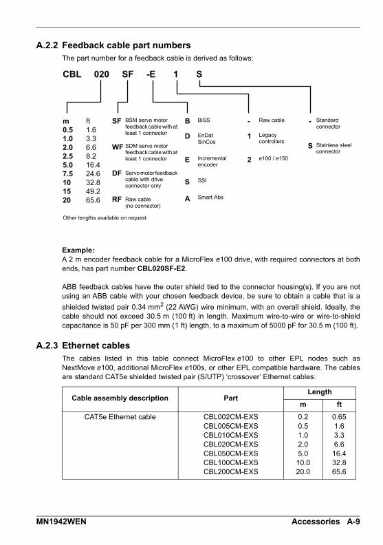
A.2.2 Feedback cable part numbersThe part number for a feedback cable is derived as follows:
Example:A 2 m encoder feedback cable for a MicroFlex e100 drive, with required connectors at bothends, has part number CBL020SF-E2.
ABB feedback cables have the outer shield tied to the connector housing(s). If you are notusing an ABB cable with your chosen feedback device, be sure to obtain a cable that is a
shielded twisted pair 0.34 mm2 (22 AWG) wire minimum, with an overall shield. Ideally, thecable should not exceed 30.5 m (100 ft) in length. Maximum wire-to-wire or wire-to-shieldcapacitance is 50 pF per 300 mm (1 ft) length, to a maximum of 5000 pF for 30.5 m (100 ft).
A.2.3 Ethernet cablesThe cables listed in this table connect MicroFlex e100 to other EPL nodes such asNextMove e100, additional MicroFlex e100s, or other EPL compatible hardware. The cablesare standard CAT5e shielded twisted pair (S/UTP) ‘crossover’ Ethernet cables:
Cable assembly description PartLength
m ft
CAT5e Ethernet cable CBL002CM-EXSCBL005CM-EXSCBL010CM-EXSCBL020CM-EXSCBL050CM-EXSCBL100CM-EXSCBL200CM-EXS
0.20.51.02.05.010.020.0
0.651.63.36.616.432.865.6
CBL 020 SF -E 1 S
RF
DF
WF
SF
D
B
E
S
A
1
-
2
S
-m ft0.5 1.61.0 3.32.0 6.62.5 8.25.0 16.47.5 24.610 32.815 49.220 65.6
Raw cable Standardconnector
Stainless steel connector
Incremental encoder
EnDatSinCos
BiSSBSM servo motor feedback cable with at least 1 connector
Raw cable(no connector)
Other lengths available on request
Legacy controllers
e100 / e150
SSI
Smart Abs
Servo motor feedback cable with drive connector only
SDM servo motor feedback cable with at least 1 connector
MN1942WEN Accessories A-9

A-10 Accessories MN1942WEN

Control SystemB Control System
B.1 IntroductionThe MicroFlex e100 can use two main control configurations:
Servo (Position).
Torque Servo (Current).
Each configuration supports different control modes, selected by using the Tools, ControlMode menu item or by using the CONTROLMODE keyword in the Command window (see theMint help file). The control configurations are described in the following sections.
B
MN1942WEN Control System B-1

B.1.1 Servo configurationThe servo configuration is the default configuration for the drive, allowing the motor controlsystem to operate as a torque controller, a velocity controller or a position controller. Thisconfiguration comprises 3 nested control loops; a current control loop, a velocity control loopand a position control loop, as shown in Figure 59.
The universal encoder interface reads rotor position from the encoder and estimates velocity.The commutation block uses the position to calculate the electrical angle of the rotor. Thecurrent sensor system measures U and V phase currents. These are fed into a currentconversion block that converts them into quantities representing torque producing andmagnetizing currents (the ’vector’ currents which are locked to the rotor).
In the current control loop, a current demand and the final measured current values form theinputs to a PI (Proportional, Integral) control system. This control system generates a set ofvoltage demands that are fed into a PWM (pulse-width modulation) block. The PWM blockuses the space-vector modulation method to convert these voltage demands into asequence of U, V and W phase switching signals, which are applied to the output bridge ofthe drive. The PWM block uses the measured DC bus voltage to compensate for variationsin supply voltage. The torque controller converts a torque demand into a current demand and compensates forvarious load non-linearities. A 2-stage notch or low-pass filter allows the effects of loadcompliance to be reduced. To avoid motor damage, a user-defined application current limit isalso applied, as well as individual positive and negative torque limits.
In the velocity control loop, a velocity demand and measured velocity form the inputs to a PIcontrol system. The output of the control system is a torque demand which, when the driveis operating as a velocity controller, forms the input to the current control loop.
Finally, in the position control loop, a position demand and measured position form the inputsto a PID (Proportional, Integral, Differential) control system incorporating velocity feedback,velocity feed-forward and acceleration feed-forward. The output of the position controlsystem is a velocity demand which, when the drive is operating as a position controller, formsthe input to the velocity control loop.
B-2 Control System MN1942WEN

++
++
++
+--
----
--
U V
T
P,V
PV
E
Fig
ure
59
: S
erv
o c
on
fig
ura
tio
n c
on
tro
l s
tru
ctu
re
Torq
ue
co
ntr
ol
Po
sitio
n c
on
tro
ller
Co
ntr
ol m
od
e
switc
hV
elo
city
co
ntr
olle
rC
on
tro
l mo
de
sw
itch
Ele
ctri
cal a
ng
le
Co
mm
uta
tion
PID
PI
+ T
F
Torq
ue
filt
ers
Lim
itin
g
PI
+ T
F
Cu
rre
nt
con
tro
llers
Mo
tor
Tem
pe
ratu
re d
rift
co
mp
en
satio
n
Un
ive
rsal
E
nco
de
r In
terf
ace
Cu
rre
nt
Co
nv
Offs
et
Com
pC
urr
en
t S
en
sors
En
cod
er
Me
asu
red
to
rqu
e a
nd
m
ag
ne
tisin
g c
urr
en
ts
PV
M
Bu
s V
olta
ge
M
ea
sure
me
nt
DRIVEBUSVOLTS
EFFORT
KIPROP
KIINT
KITRACK
TORQUELIMITPOS
TORQUELIMITNEG
CURRENTLIMIT
TORQUEFILTERTYPE
TORQUEFILTERFREQ
TORQUEFILTERBAND
TORQUEFILTERDEPTH
KACCEL
KVPROP
KVINT
KVTRACK
VELERROR
KVELFF
KPROP
KINT
KINTMODE
KINTLIMIT
KDERIV
TORQUEDEMAND
ACCELDEMAND
VELDEMAND FOLERROR
POSDEMAND
KVEL
VEL
POS
CURRENTMEAS
MN1942WEN Control System B-3

B.1.2 Torque servo configurationFigure 60 shows the torque-servo control configuration. Here, the velocity loop has beenremoved and the output of the position controller is fed into the current loop via the torquefilters.
The torque servo configuration is useful when the drive is operating as a closed-loop positioncontroller and settling time must be minimized. Although the servo configuration tends togive better velocity tracking when operating in position mode, settling times can be longer.
The control mode switch allows the drive to operate in either torque or position modes, butnot velocity mode.
B-4 Control System MN1942WEN
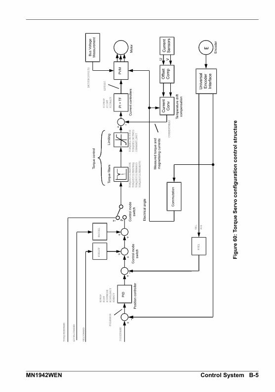
++
+
++
++
----
--
U V
T P
E
Fig
ure
60
: To
rqu
e S
erv
o c
on
fig
ura
tio
n c
on
tro
l s
tru
ctu
re
Torq
ue
co
ntr
ol
Po
sitio
n c
on
tro
ller
Co
ntr
ol m
od
e
switc
hC
on
tro
l mo
de
sw
itch
Ele
ctri
cal a
ng
le
Co
mm
uta
tion
PID
Torq
ue
filt
ers
Lim
itin
g
PI
+ T
F
Cu
rre
nt
con
tro
llers
Mo
tor
Tem
pe
ratu
re d
rift
co
mp
en
satio
n
Un
ive
rsal
E
nco
de
r In
terf
ace
Cu
rre
nt
Co
nv
Offs
et
Co
mp
Cu
rre
nt
Se
nso
rs
En
cod
er
Me
asu
red
to
rqu
e a
nd
m
ag
ne
tisin
g c
urr
en
ts
PV
M
Bu
s V
olta
ge
M
ea
sure
me
nt
KPROP
KINT
KINTMODE
KINTLIMIT
KDERIV
TORQUEDEMAND
ACCELDEMAND
VELDEMAND
FOLERROR
POSDEMAND
KVEL
VEL
POS
KACCEL
KVELFF
TORQUELIMITPOS
TORQUELIMITNEG
CURRENTLIMIT
TORQUEFILTERTYPE
TORQUEFILTERFREQ
TORQUEFILTERBAND
TORQUEFILTERDEPTH
DRIVEBUSVOLTS
EFFORT
KIPROP
KIINT
KITRACK
CURRENTMEAS
MN1942WEN Control System B-5

B-6 Control System MN1942WEN

Mint Keyword SummaryC Mint Keyword Summary
C.1 IntroductionThe following table summarizes the Mint keywords supported by the MicroFlex e100. Notethat due to continuous developments of the MicroFlex e100 and the Mint language, this list issubject to change. Check the latest Mint help file for full details of new or changed keywords.
C.1.1 Keyword listing
Keyword Description
ABORT To abort motion on all axes.
ABORTMODE To control the default action taken in the event of an abort.
ABSENCODER To read the current EnDat encoder position.
ABSENCODERTURNS To set or read the number of turns of unique information available on an absolute encoder.
ACCEL To define the acceleration rate of an axis.
ACCELDEMAND To read the instantaneous demand acceleration.
ACCELJERK To define the jerk rate to be used during periods of acceleration.
ACCELJERKTIME To define the jerk rate to be used during periods of acceleration.
ACCELSCALEFACTOR To scale axis encoder counts, or steps, into user defined acceleration units.
ACCELSCALEUNITS To define a text description for the acceleration scale factor.
ACCELTIME To define the acceleration rate of an axis.
ACCELTIMEMAX To define the acceleration rate of an axis.
AXISMODE To return the current mode of motion.
AXISPOSENCODER To select the source of the position signal used in dual encoder feedback systems.
AXISVELENCODER To select the source of the velocity signal used in dual encoder feedback systems.
BUSBAUD To specify the bus baud rate.
BUSENABLE To enable or disable the operation of a fieldbus.
C
MN1942WEN Mint Keyword Summary C-1

BUSEVENT Returns the next event in the bus event queue of a specific bus.
BUSEVENTINFO Returns the additional information associated with a bus event.
BUSNODE To set or read the node ID used by this node for the specified bus.
BUSPROTOCOL To read the protocol currently supported on a particular fieldbus.
BUSRESET Resets the bus controller.
BUSSTATE Returns the status of the bus controller.
CANCEL To stop motion and clear errors on an axis.
CANCELALL To stop motion and clear errors on all axes.
CAPTUREBUFFERSIZE To read the total size of the capture buffer.
CAPTURECOMMAND Controls the operation of capture.
CAPTUREDURATION To define the total duration of the data capture.
CAPTUREMODE To set or read the mode on a capture channel.
CAPTUREMODEPARAMETER To specify a parameter associated with CAPTUREMODE.
CAPTURENUMPOINTS To read the number of captured points per channel.
CAPTUREPERIOD To define the interval between data captures.
CAPTUREPRETRIGGER-DURATION
To set the duration of the pre-trigger phase.
CAPTUREPROGRESS To return the progress of the pre-trigger or post-trigger capture phase.
CAPTURESTATUS To return the progress of the capture.
CAPTURETRIGGER To generate a capture trigger.
CAPTURETRIGGERABSOLUTE To ignore the sign of the trigger value when triggering from a capture channel source.
CAPTURETRIGGERCHANNEL To set the channel to be used as the reference source for triggering.
CAPTURETRIGGERMODE To set the method used to evaluate the trigger source.
CAPTURETRIGGERSOURCE To set the reference source to be used for triggering.
CAPTURETRIGGERVALUE To set the trigger value when triggering from a capture channel source.
COMMS Accesses the reserved comms array.
Keyword Description
C-2 Mint Keyword Summary MN1942WEN
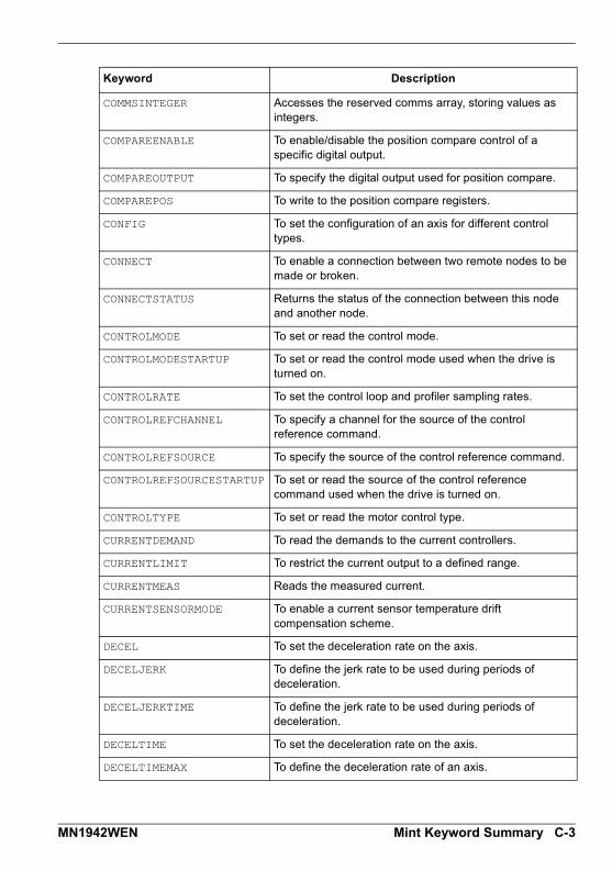
COMMSINTEGER Accesses the reserved comms array, storing values as integers.
COMPAREENABLE To enable/disable the position compare control of a specific digital output.
COMPAREOUTPUT To specify the digital output used for position compare.
COMPAREPOS To write to the position compare registers.
CONFIG To set the configuration of an axis for different control types.
CONNECT To enable a connection between two remote nodes to be made or broken.
CONNECTSTATUS Returns the status of the connection between this node and another node.
CONTROLMODE To set or read the control mode.
CONTROLMODESTARTUP To set or read the control mode used when the drive is turned on.
CONTROLRATE To set the control loop and profiler sampling rates.
CONTROLREFCHANNEL To specify a channel for the source of the control reference command.
CONTROLREFSOURCE To specify the source of the control reference command.
CONTROLREFSOURCESTARTUP To set or read the source of the control reference command used when the drive is turned on.
CONTROLTYPE To set or read the motor control type.
CURRENTDEMAND To read the demands to the current controllers.
CURRENTLIMIT To restrict the current output to a defined range.
CURRENTMEAS Reads the measured current.
CURRENTSENSORMODE To enable a current sensor temperature drift compensation scheme.
DECEL To set the deceleration rate on the axis.
DECELJERK To define the jerk rate to be used during periods of deceleration.
DECELJERKTIME To define the jerk rate to be used during periods of deceleration.
DECELTIME To set the deceleration rate on the axis.
DECELTIMEMAX To define the deceleration rate of an axis.
Keyword Description
MN1942WEN Mint Keyword Summary C-3
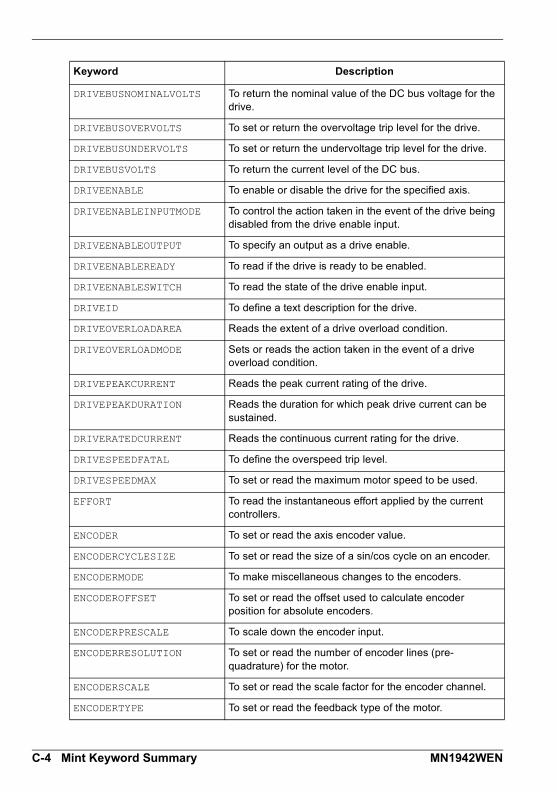
DRIVEBUSNOMINALVOLTS To return the nominal value of the DC bus voltage for the drive.
DRIVEBUSOVERVOLTS To set or return the overvoltage trip level for the drive.
DRIVEBUSUNDERVOLTS To set or return the undervoltage trip level for the drive.
DRIVEBUSVOLTS To return the current level of the DC bus.
DRIVEENABLE To enable or disable the drive for the specified axis.
DRIVEENABLEINPUTMODE To control the action taken in the event of the drive being disabled from the drive enable input.
DRIVEENABLEOUTPUT To specify an output as a drive enable.
DRIVEENABLEREADY To read if the drive is ready to be enabled.
DRIVEENABLESWITCH To read the state of the drive enable input.
DRIVEID To define a text description for the drive.
DRIVEOVERLOADAREA Reads the extent of a drive overload condition.
DRIVEOVERLOADMODE Sets or reads the action taken in the event of a drive overload condition.
DRIVEPEAKCURRENT Reads the peak current rating of the drive.
DRIVEPEAKDURATION Reads the duration for which peak drive current can be sustained.
DRIVERATEDCURRENT Reads the continuous current rating for the drive.
DRIVESPEEDFATAL To define the overspeed trip level.
DRIVESPEEDMAX To set or read the maximum motor speed to be used.
EFFORT To read the instantaneous effort applied by the current controllers.
ENCODER To set or read the axis encoder value.
ENCODERCYCLESIZE To set or read the size of a sin/cos cycle on an encoder.
ENCODERMODE To make miscellaneous changes to the encoders.
ENCODEROFFSET To set or read the offset used to calculate encoder position for absolute encoders.
ENCODERPRESCALE To scale down the encoder input.
ENCODERRESOLUTION To set or read the number of encoder lines (pre-quadrature) for the motor.
ENCODERSCALE To set or read the scale factor for the encoder channel.
ENCODERTYPE To set or read the feedback type of the motor.
Keyword Description
C-4 Mint Keyword Summary MN1942WEN

ENCODERVEL To read the velocity from an encoder channel.
ENCODERWRAP To set or read the encoder wrap range for the encoder channel.
ENCODERZLATCH To get and reset the state of an axis’ encoder Z latch.
ERRCODE To return the last error code read from the error list.
ERRDATA To return data associated with the last error read from the error list.
ERRLINE To return the line number of the last error read from the error list.
ERRORCLEAR To clear all errors in the specified group.
ERRORDECEL To set the deceleration rate on the axis for powered stops, in the event of an error or stop input.
ERRORINPUT To set or return the digital input to be used as the error input for the specified axis.
ERRORINPUTMODE To control the default action taken in the event of an external error input.
ERRORPRESENT To determine if errors in a particular group are present in the error list.
ERRORREADCODE To determine if a particular error is present in the error list.
ERRORREADNEXT Returns the next entry in the specified group from the error list.
ERRORSWITCH To return the state of the error input.
ERRSTRING To return the error string for the last error code read from the error list.
ERRTIME To return the time stamp for the last error code read from the error list.
EVENTACTIVE To indicate whether an event is currently active.
EVENTDISABLE To selectively enable and disable Mint events.
EVENTPEND To manually cause an event to occur.
EVENTPENDING To indicate whether an event is currently pending.
FACTORYDEFAULTS To reset parameter table entries to their default values.
FIRMWARERELEASE To read the release number of the firmware.
FOLERROR To return the instantaneous following error value.
Keyword Description
MN1942WEN Mint Keyword Summary C-5

FOLERRORFATAL To set the maximum permissible following error before an error is generated.
FOLERRORMODE To determine the action taken on the axis in the event of a following error.
FOLLOW To enable encoder following with a specified gear ratio.
FOLLOWMODE To define the mode of operation of the FOLLOW keyword.
FOLLOWNUMERATOR To set or read the follow ratio’s numerator.
GLOBALERROROUTPUT Allows the user to specify a global error output which will be deactivated in the event of an error.
GO To begin synchronized motion.
HALL To read the current Hall state on feedback devices which use Hall sensors.
HALLFORWARDANGLE To define the electrical angles at which Hall states change, when the motor is running in the forward direction, for feedback devices which use Hall sensors.
HALLREVERSEANGLE To define the electrical angles at which Hall states change, when the motor is running in the reverse direction, for feedback devices which use Hall sensors.
HALLTABLE To define the Hall table for an encoder motor.
HOME To find the home position on an axis.
HOMEACCEL To set the acceleration rate for the homing profile.
HOMEBACKOFF To set the home back-off speed factor.
HOMECREEPSPEED To set the creep speed for homing moves.
HOMEDECEL To set the deceleration rate for the homing profile.
HOMEINPUT To set a digital input to be the home switch input for the specified axis.
HOMEPHASE To find the phase of the homing sequence currently in progress.
HOMEPOS To read the axis position at the completion of the homing sequence.
HOMEREFPOS To define a reference position for homing moves.
HOMESPEED To set the speed for the initial seek phase of the homing sequence.
HOMESTATUS To set or read the status of a homing sequence.
HOMESWITCH To return the state of the home input.
Keyword Description
C-6 Mint Keyword Summary MN1942WEN

HOMETYPE To set the homing mode to be performed at start-up.
IDLE Indicates if a move has finished executing and the axis has finished moving.
IDLEMODE To control the checks performed when determining if an axis idle.
IDLEPOS Reads or sets the idle following error limit.
IDLESETTLINGTIME To read the time taken for an axis to become idle.
IDLETIME To specify the period for which the axis must meet its idle conditions before becoming idle.
IDLEVEL Reads or sets the idle velocity limit.
IN To read the state of all the inputs on an input bank.
INCA To set up an incremental move to an absolute position.
INCR To set up an incremental move to a relative position.
INPUTACTIVELEVEL To set the active level on the digital inputs.
INPUTDEBOUNCE To set or return the number of samples used to ’debounce’ a digital input bank.
INPUTMODE To set or return the sum of a bit pattern describing which of the user digital inputs should be edge or level triggered.
INPUTNEGTRIGGER To set or return the user inputs that become active on negative edges.
INPUTPOSTRIGGER To set or return the user inputs that become active on positive edges.
INSTATE To read the state of all digital inputs.
INSTATEX To read the state of an individual digital input.
INX To read the state of an individual digital input.
JOG To set an axis for speed control.
KACCEL To set the servo loop acceleration feed forward gain.
KASINT
KASPROP
KDERIV To set the servo loop derivative gain on the servo axes.
KFINT To set or read the integral gain of the flux controller for induction motor control.
KFPROP To set or read the proportional gain of the flux controller for induction motor control.
Keyword Description
MN1942WEN Mint Keyword Summary C-7

KIINT To set the integral gain used by the current controller.
KINT To set the servo loop integral gain.
KINTLIMIT To restrict the overall effect of the integral gain KINT.
KINTMODE To control when integral action will be applied in the servo loop.
KIPROP To set the proportional gain used by the current controller.
KITRACK To set the tracking factor used by the current controller.
KPROP To set the proportional gain for the position controller.
KVEL To set the servo loop velocity feedback gain term.
KVELFF To set the velocity feedforward term for the position controller.
KVINT To set the integral gain used by the speed controller.
KVPROP To set the proportional gain used by the speed controller.
KVTIME To set the time constant of a low pass filter, applied to measured speed.
KVTRACK To set the tracking factor used by the speed controller.
LATCH To read the state of a fast latch channel.
LATCHENABLE Manually re-enables a fast latch channel.
LATCHINHIBITTIME To specify a period during which further fast triggers will be ignored.
LATCHINHIBITVALUE To specify a range of values within which further fast triggers will be ignored.
LATCHMODE To set the default action to be taken to clear a fast latch.
LATCHSOURCE To define the source of data to be latched by a fast latch channel.
LATCHSOURCECHANNEL To define the channel of the source of data to be latched by a fast latch channel.
LATCHTRIGGERCHANNEL To select which of the fast latch inputs (or outputs) will trigger a fast latch channel.
LATCHTRIGGEREDGE To define which edge polarity should cause the fast latch to be triggered.
LATCHTRIGGERMODE To select whether a fast latch is triggered by a digital input or a digital output.
Keyword Description
C-8 Mint Keyword Summary MN1942WEN
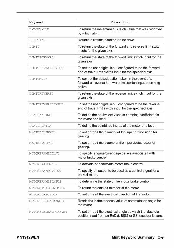
LATCHVALUE To return the instantaneous latch value that was recorded by a fast latch.
LIFETIME Returns a lifetime counter for the drive.
LIMIT To return the state of the forward and reverse limit switch inputs for the given axis.
LIMITFORWARD To return the state of the forward limit switch input for the given axis.
LIMITFORWARDINPUT To set the user digital input configured to be the forward end of travel limit switch input for the specified axis.
LIMITMODE To control the default action taken in the event of a forward or reverse hardware limit switch input becoming active.
LIMITREVERSE To return the state of the reverse limit switch input for the given axis.
LIMITREVERSEINPUT To set the user digital input configured to be the reverse end of travel limit switch input for the specified axis.
LOADDAMPING To define the equivalent viscous damping coefficient for the motor and load.
LOADINERTIA To define the combined inertia of the motor and load.
MASTERCHANNEL To set or read the channel of the input device used for gearing.
MASTERSOURCE To set or read the source of the input device used for gearing.
MOTORBRAKEDELAY To specify engage/disengage delays associated with motor brake control.
MOTORBRAKEMODE To activate or deactivate motor brake control.
MOTORBRAKEOUTPUT To specify an output to be used as a control signal for a braked motor.
MOTORBRAKESTATUS To determine the state of the motor brake control.
MOTORCATALOGNUMBER To return the catalog number of the motor.
MOTORDIRECTION To set or read the electrical direction of the motor.
MOTORFEEDBACKANGLE Reads the instantaneous value of commutation angle for the motor.
MOTORFEEDBACKOFFSET To set or read the electrical angle at which the absolute position read from an EnDat, BiSS or SSI encoder is zero.
Keyword Description
MN1942WEN Mint Keyword Summary C-9
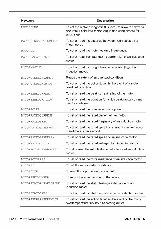
MOTORFLUX To set the motor’s magnetic flux level, to allow the drive to accurately calculate motor torque and compensate for back-EMF.
MOTORLINEARPOLEPITCH To set or read the distance between north poles on a linear motor.
MOTORLS To set or read the motor leakage inductance.
MOTORMAGCURRENT To set or read the magnetizing current (Im) of an induction
motor.
MOTORMAGIND To set or read the magnetizing inductance (Lm) of an
induction motor.
MOTOROVERLOADAREA Reads the extent of an overload condition.
MOTOROVERLOADMODE To set or read the action taken in the event of a motor overload condition.
MOTORPEAKCURRENT To set or read the peak current rating of the motor.
MOTORPEAKDURATION To set or read the duration for which peak motor current can be sustained.
MOTORPOLES To set or read the number of motor poles.
MOTORRATEDCURRENT To set or read the rated current of the motor.
MOTORRATEDFREQ To set or read the rated frequency of an induction motor.
MOTORRATEDSPEEDMMPS To set or read the rated speed of a linear induction motor in millimeters per second.
MOTORRATEDSPEEDRPM To set or read the rated speed of an induction motor.
MOTORRATEDVOLTS To set or read the rated voltage of an induction motor.
MOTORROTORLEAKAGEIND To set or read the rotor leakage inductance of an induction motor.
MOTORROTORRES To set or read the rotor resistance of an induction motor.
MOTORRS To set the motor stator resistance.
MOTORSLIP To read the slip of an induction motor.
MOTORSPECNUMBER To return the spec number of the motor.
MOTORSTATORLEAKAGEIND To set or read the stator leakage inductance of an induction motor.
MOTORSTATORRES To set or read the stator resistance of an induction motor.
MOTORTEMPERATUREMODE To set or read the action taken in the event of the motor overtemperature trip input becoming active
Keyword Description
C-10 Mint Keyword Summary MN1942WEN
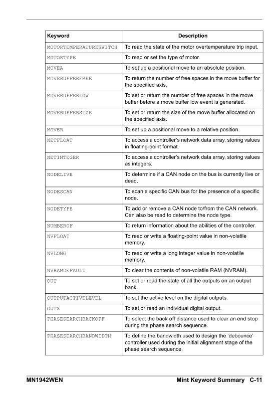
MOTORTEMPERATURESWITCH To read the state of the motor overtemperature trip input.
MOTORTYPE To read or set the type of motor.
MOVEA To set up a positional move to an absolute position.
MOVEBUFFERFREE To return the number of free spaces in the move buffer for the specified axis.
MOVEBUFFERLOW To set or return the number of free spaces in the move buffer before a move buffer low event is generated.
MOVEBUFFERSIZE To set or return the size of the move buffer allocated on the specified axis.
MOVER To set up a positional move to a relative position.
NETFLOAT To access a controller’s network data array, storing values in floating-point format.
NETINTEGER To access a controller’s network data array, storing values as integers.
NODELIVE To determine if a CAN node on the bus is currently live or dead.
NODESCAN To scan a specific CAN bus for the presence of a specific node.
NODETYPE To add or remove a CAN node to/from the CAN network. Can also be read to determine the node type.
NUMBEROF To return information about the abilities of the controller.
NVFLOAT To read or write a floating-point value in non-volatile memory.
NVLONG To read or write a long integer value in non-volatile memory.
NVRAMDEFAULT To clear the contents of non-volatile RAM (NVRAM).
OUT To set or read the state of all the outputs on an output bank.
OUTPUTACTIVELEVEL To set the active level on the digital outputs.
OUTX To set or read an individual digital output.
PHASESEARCHBACKOFF To select the back-off distance used to clear an end stop during the phase search sequence.
PHASESEARCHBANDWIDTH To define the bandwidth used to design the ’debounce’ controller used during the initial alignment stage of the phase search sequence.
Keyword Description
MN1942WEN Mint Keyword Summary C-11
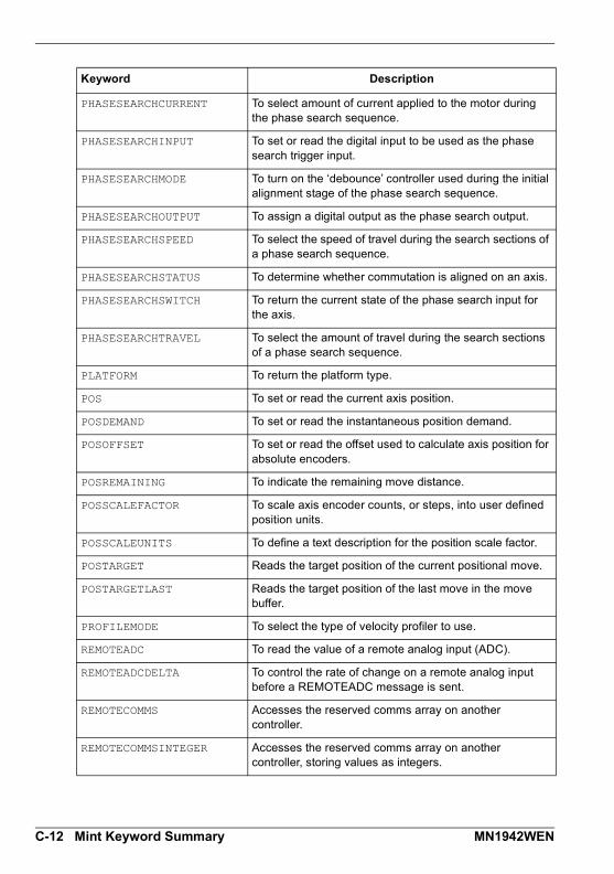
PHASESEARCHCURRENT To select amount of current applied to the motor during the phase search sequence.
PHASESEARCHINPUT To set or read the digital input to be used as the phase search trigger input.
PHASESEARCHMODE To turn on the ‘debounce’ controller used during the initial alignment stage of the phase search sequence.
PHASESEARCHOUTPUT To assign a digital output as the phase search output.
PHASESEARCHSPEED To select the speed of travel during the search sections of a phase search sequence.
PHASESEARCHSTATUS To determine whether commutation is aligned on an axis.
PHASESEARCHSWITCH To return the current state of the phase search input for the axis.
PHASESEARCHTRAVEL To select the amount of travel during the search sections of a phase search sequence.
PLATFORM To return the platform type.
POS To set or read the current axis position.
POSDEMAND To set or read the instantaneous position demand.
POSOFFSET To set or read the offset used to calculate axis position for absolute encoders.
POSREMAINING To indicate the remaining move distance.
POSSCALEFACTOR To scale axis encoder counts, or steps, into user defined position units.
POSSCALEUNITS To define a text description for the position scale factor.
POSTARGET Reads the target position of the current positional move.
POSTARGETLAST Reads the target position of the last move in the move buffer.
PROFILEMODE To select the type of velocity profiler to use.
REMOTEADC To read the value of a remote analog input (ADC).
REMOTEADCDELTA To control the rate of change on a remote analog input before a REMOTEADC message is sent.
REMOTECOMMS Accesses the reserved comms array on another controller.
REMOTECOMMSINTEGER Accesses the reserved comms array on another controller, storing values as integers.
Keyword Description
C-12 Mint Keyword Summary MN1942WEN

REMOTEDAC To control the value of a remote analog output channel (DAC). The value is a percentage (positive and negative) of the full-scale output value.
REMOTEEMERGENCYMESSAGE Returns the error code from the last emergency message received from a particular CANopen node.
REMOTEENCODER To read the value of a remote encoder channel.
REMOTEERROR Reads the CANopen error register information reported within the last emergency message received from a specific node.
REMOTEIN To read the state of all the digital inputs on a remote CAN node.
REMOTEINBANK To read the state of a bank of digital inputs on a remote CAN node.
REMOTEINX To read the state of individual digital inputs from a remote CAN node.
REMOTEMODE To control the update mode for a remote node.
REMOTEOBJECT To access the Object Dictionary of any CANopen node present on the network.
REMOTEOBJECTFLOAT To access ‘floating-point’ entries in the Object Dictionary of a remote node present on the network.
REMOTEOBJECTSTRING To access ’Vis-String’ entries in the Object Dictionary of any CANopen node present on the network.
REMOTEOUT To control the state of digital outputs on a remote CAN node.
REMOTEOUTBANK To read the state of a bank of digital outputs on a remote CAN node.
REMOTEOUTX To control the state of individual digital outputs on a remote CAN node.
REMOTEPDOIN To request data from a node in the form of a PDO message.
REMOTEPDOOUT To force a controller node to transmit a variable length PDO message with a specific COB-ID. The PDO will contain up to 64 bits of data that can be passed in the form of two 32-bit values.
REMOTESTATUS To set or read the status register on a remote CAN node.
RESETINPUT To define the reset input for an axis.
Keyword Description
MN1942WEN Mint Keyword Summary C-13
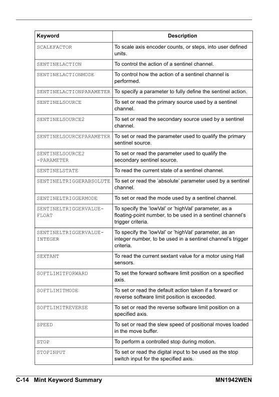
SCALEFACTOR To scale axis encoder counts, or steps, into user defined units.
SENTINELACTION To control the action of a sentinel channel.
SENTINELACTIONMODE To control how the action of a sentinel channel is performed.
SENTINELACTIONPARAMETER To specify a parameter to fully define the sentinel action.
SENTINELSOURCE To set or read the primary source used by a sentinel channel.
SENTINELSOURCE2 To set or read the secondary source used by a sentinel channel.
SENTINELSOURCEPARAMETER To set or read the parameter used to qualify the primary sentinel source.
SENTINELSOURCE2-PARAMETER
To set or read the parameter used to qualify the secondary sentinel source.
SENTINELSTATE To read the current state of a sentinel channel.
SENTINELTRIGGERABSOLUTE To set or read the ’absolute’ parameter used by a sentinel channel.
SENTINELTRIGGERMODE To set or read the mode used by a sentinel channel.
SENTINELTRIGGERVALUE-FLOAT
To specify the ’lowVal’ or ’highVal’ parameter, as a floating-point number, to be used in a sentinel channel’s trigger criteria.
SENTINELTRIGGERVALUE-INTEGER
To specify the ’lowVal’ or ’highVal’ parameter, as an integer number, to be used in a sentinel channel’s trigger criteria.
SEXTANT To read the current sextant value for a motor using Hall sensors.
SOFTLIMITFORWARD To set the forward software limit position on a specified axis.
SOFTLIMITMODE To set or read the default action taken if a forward or reverse software limit position is exceeded.
SOFTLIMITREVERSE To set or read the reverse software limit position on a specified axis.
SPEED To set or read the slew speed of positional moves loaded in the move buffer.
STOP To perform a controlled stop during motion.
STOPINPUT To set or read the digital input to be used as the stop switch input for the specified axis.
Keyword Description
C-14 Mint Keyword Summary MN1942WEN
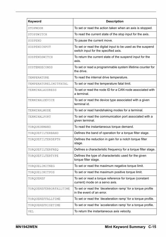
STOPMODE To set or read the action taken when an axis is stopped.
STOPSWITCH To read the current state of the stop input for the axis.
SUSPEND To pause the current move.
SUSPENDINPUT To set or read the digital input to be used as the suspend switch input for the specified axis.
SUSPENDSWITCH To return the current state of the suspend input for the axis.
SYSTEMSECONDS To set or read a programmable system lifetime counter for the drive.
TEMPERATURE To read the internal drive temperature.
TEMPERATURELIMITFATAL To set or read the temperature fatal limit.
TERMINALADDRESS To set or read the node ID for a CAN node associated with a terminal.
TERMINALDEVICE To set or read the device type associated with a given terminal id.
TERMINALMODE To set or read handshaking modes for a terminal.
TERMINALPORT To set or read the communication port associated with a given terminal.
TORQUEDEMAND To read the instantaneous torque demand.
TORQUEFILTERBAND Defines the band of operation for a torque filter stage.
TORQUEFILTERDEPTH Defines the reduction in gain for a notch torque filter stage.
TORQUEFILTERFREQ Defines a characteristic frequency for a torque filter stage.
TORQUEFILTERTYPE Defines the type of characteristic used for the given torque filter stage.
TORQUELIMITNEG To set or read the maximum negative torque limit.
TORQUELIMITPOS To set or read the maximum positive torque limit.
TORQUEREF To set or read a torque reference for torque (constant current) mode on a servo axis.
TORQUEREFERRORFALLTIME To set or read the ’deceleration ramp’ for a torque profile in the event of an error.
TORQUEREFFALLTIME To set or read the ’deceleration ramp’ for a torque profile.
TORQUEREFRISETIME To set or read the ’acceleration ramp’ for a torque profile.
VEL To return the instantaneous axis velocity.
Keyword Description
MN1942WEN Mint Keyword Summary C-15
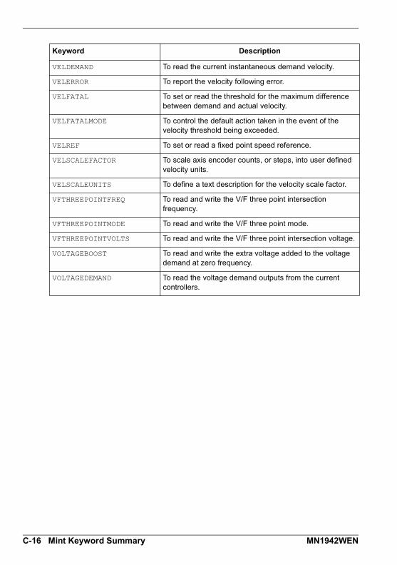
VELDEMAND To read the current instantaneous demand velocity.
VELERROR To report the velocity following error.
VELFATAL To set or read the threshold for the maximum difference between demand and actual velocity.
VELFATALMODE To control the default action taken in the event of the velocity threshold being exceeded.
VELREF To set or read a fixed point speed reference.
VELSCALEFACTOR To scale axis encoder counts, or steps, into user defined velocity units.
VELSCALEUNITS To define a text description for the velocity scale factor.
VFTHREEPOINTFREQ To read and write the V/F three point intersection frequency.
VFTHREEPOINTMODE To read and write the V/F three point mode.
VFTHREEPOINTVOLTS To read and write the V/F three point intersection voltage.
VOLTAGEBOOST To read and write the extra voltage added to the voltage demand at zero frequency.
VOLTAGEDEMAND To read the voltage demand outputs from the current controllers.
Keyword Description
C-16 Mint Keyword Summary MN1942WEN

CE, UL and environmentalD CE, UL and environmental
D.1 OutlineThis section provides general information regardingrecommended methods of installation for CE compliance. Itis not intended as an exhaustive guide to good practice andwiring techniques. It is assumed that the installer of theMicroFlex e100 is sufficiently qualified to perform the task,and is aware of local regulations and requirements. A CEmark is attached to the drive to verify that the unit follows theprovisions of the European, EMC, and machinery directives.A duly signed CE declaration of conformity is available fromABB.
D.1.1 CE markingThe CE marking indicates a product’s compliance with EU legislation and so enables the freemovement of products within the European market. By affixing the CE marking to a product,a manufacturer declares, on his sole responsibility, that the product meets all the legalrequirements for the CE marking, which means that the product can be sold throughout theEuropean Economic Area.
However, not all products must bear the CE marking, only product categories mentioned inspecific EU directives on the CE marking. The purpose of the directives is to state aminimum technical requirement common to all the member states within the EuropeanUnion. In turn, these minimum technical requirements are intended to enhance the levels ofsafety both directly and indirectly.
D.1.2 Compliance with the EMC DirectiveEU directive 2004/108/EC relating to Electro Magnetic Compliance (EMC) indicates that it isthe responsibility of the system integrator to ensure that the entire system complies with allprotection requirements at the time of installing into service.
Motors and controls are used as components of a system, per the EMC directive. Hence allcomponents, installation of the components, interconnection between components, andshielding and grounding of the system as a whole determines EMC compliance.
Compliance with the EN 61800-3The drive meets the requirements of the EMC Directive with the following provisions:
The drive is equipped with optional mains filter.
The motor and control cables are selected as specified in chapter 3.
The drive is installed according to the instructions given in this manual.
Motor cable length does not exceed 30 metres (98 ft).
D
MN1942WEN CE, UL and environmental D-1

D.1.3 Compliance with the Low Voltage DirectiveThe drive has been designed, constructed and equipped in such a way that when installed asinstructed in this manual, all hazards of an electrical nature are, or can be, prevented. Thedrive complies with EN 61800-5-1 which specifies safety requirements in terms of electrical,thermal and energy.
Note: The final assembler of the machinery must take the necessary precautions to preventall hazards of an electrical nature when integrating this equipment. General specifications fordesign of electrical equipment of machinery is given in EN 60204-1 and EN 60204-11.Specifications for electrical equipment are also given in many standards for specificcategories of machinery.
D.1.4 Use of CE compliant componentsThe following points should be considered:
Using CE approved components will not guarantee a CE compliant system!
The components used in the drive, installation methods used, materials selected forinterconnection of components are important.
The installation methods, interconnection materials, shielding, filtering and earthing /grounding of the system as a whole will determine CE compliance.
The responsibility of CE mark compliance rests entirely with the party who offers the endsystem for sale (such as an OEM or system integrator).
D.1.5 EMC wiring techniqueCabinetUsing a typical electroplated zinc coated enclosure, connected to earth/ground, means thatall parts mounted on the back plane are connected to earth/ground and all outer shield(screen) connections can be connected to earth/ground. Within the cabinet there should be aspatial separation between power wiring (motor and AC power cables) and control wiring.
Shield (screen) connectionsAll connections between components must use shielded cables. The cable shields must beconnected to the enclosure. Use conductive clamps to ensure good earth/groundconnection. With this technique, a good earth/ground shield can be achieved.
EMC filtersThe filter should be mounted next to the MicroFlex e100. The connections between theMicroFlex e100 and the filter should use shielded (screened) cables. The cable shieldsshould be connected to shield clamps at both ends.
Earthing/groundingFor safety reasons (VDE0160), all components must be connected to earth/ground with aseparate wire. Earth/ground connections must be made from the central earth/ground (starpoint) to the brake resistor enclosure and from the central earth/ground (star point) to thepower supply.
D-2 CE, UL and environmental MN1942WEN

D.1.6 EMC installation suggestionsTo ensure electromagnetic compatibility (EMC), the following installation points should beconsidered to help reduce interference:
Earthing/grounding of all system elements to a central earth/ground point (star point)
Shielding of all cables and signal wires
Filtering of power lines.
A proper enclosure should have the following characteristics:
All metal conducting parts of the enclosure must be electrically connected to the backplane. These connections should be made with an earthing/grounding strap from each
element to a central earthing/grounding point (star point). * Keep the power wiring (motor and power cable) and control wiring separated. If these
wires must cross, be sure they cross at 90 degrees to minimize noise due to induction.
The shield connections of the signal and power cables should be connected to the shieldrails or clamps. The shield rails or clamps should be conductive clamps fastened to the
cabinet. ** The cable to the brake resistor must be shielded. The shield must be connected to earth/
ground at both ends.
The location of the AC filter has to be situated close to the drive so the AC power wiresare as short as possible.
Wires inside the enclosure should be placed as close as possible to conducting metal,
cabinet walls and plates. It is advised to terminate unused wires to chassis ground.* To reduce earth/ground current, use the largest suitable wire available for earth/ground
connections.
* Earthing/grounding in general describes all metal parts which can be connected to aprotective conductor, e.g. housing of cabinet, motor housing, etc. to a central earth/ground point (star point). This central earth/ground point (star point) is then connected tothe main plant (or building) earth/ground.
** Or run as twisted pair at minimum.
MN1942WEN CE, UL and environmental D-3

D.1.7 Wiring of shielded (screened) cables
Figure 61: Earthing/grounding cable shields
Figure 62: Encoder signal cable grounding
D.2 C-tick marking"C-tick" marking is required in Australia and New Zealand. A "C-tick" mark isattached to each drive in order to verify compliance with the relevant standard (IEC61800-3, Adjustable speed electrical power drive systems - Part 3: EMC productstandard including specific test methods), mandated by the Trans-Tasman MutualRecognition Arrangement (TTMRA).
D.2.1 RCM markingRCM marking is pending for the drive.
D.3 RoHS complianceMicroFlex e100 is in conformity with Directive 2011/65/EU of the European parliament and ofthe council of 8th June 2011 on the restriction of the use of certain hazardous substances inelectrical and electronic equipment. The RoHS declaration 3AXD10000429153 is availableon www.abb.com/drives.
Remove the outer insulation to expose the overall shield. Clamp should provide 360° contact with the cable. Flat or p-type
conductive clamp
192
103111213
Encoder Connector Housing
Connect overall shield to connector backshell
Connect overall shield to connector backshell
Twisted pairs
CableMicroFlex e100
X8
CHA+CHA-CHB+CHB-CHZ+CHZ-+5V
DGND
D-4 CE, UL and environmental MN1942WEN

D.3.1 China RoHS complianceThe People's Republic of China Electronic Industry Standard SJ/T 11364-2014specifies the marking requirements for hazardous substances in electronic andelectrical products. The '20' logo indicates the period, in years, during which thehazardous substances contained in the product will not leak or causeenvironmental pollution, bodily injury, or damage to other assets during normaluse of the product.
D.3.2 WEEE noticeAccording to the requirements of the Waste Electrical and Electronic EquipmentDirective (WEEE) the following information is provided.This symbol indicates that the product must not be disposed of with other generalwaste. It is your responsibility to dispose of your waste electrical equipment byhanding it over to a designated collection point for the recycling of wasteelectrical and electronic equipment. The separate collection and recycling of your
waste equipment at the time of disposal will help conserve natural resources and ensure thatit is recycled in a manner that protects human health and the environment. For moreinformation about where you can recycle your waste, please contact your local authority.
Part Hazardous substances
Lead(Pb)
Mercury(Hg)
Cadmium(Cd)
Hexavalent chromium
(Cr(VI))
Polybrominated biphenyls
(PBB)
Polybrominated diphenyl ethers
(PBDE)
PCB O O O O O O
Heat sink X O O O O O
Metal parts O O O O O O
Plastic parts O O O O O O
Other non-metal parts
O O O O O O
Fans O O O O O O
Cables/wires O O O O O O
The table is prepared in accordance with the provision of SJ/T 11364.O: Indicates that said hazardous substance contained in all of the homogeneous materials for this part is below the limit requirement of GB/T 26572. X: Indicates that said hazardous substance contained in at least one of the homogeneous materials used for this part is above the limit requirement of GB/T 26572. The limits are:
Pb: 1000 ppm (0.1%)Cr6+: 1000 ppm (0.1%)
Hg: 1000 ppm (0.1%)PBB: 1000 ppm (0.1%)
Cd: 100 ppm (0.01%)PBDE: 1000 ppm (0.1%)
PCBA: Includes Printed Circuit Board and the components.Depending on the model/type of the product, it may not contain all of the above parts. It is subject to the actual model/type purchased.The environmental protection period applies only when the product is used according to the conditions required by the user manual. To protect the environment and human health:1.The scrapped product should be separated from domestic waste and sent to a qualified place of disposal.2.Recycling center should use appropriate methods to recycle/deal with the materials.For more information about recycling this product, please contact local government, recycling center or your local dealer.
MN1942WEN CE, UL and environmental D-5

D.4 UL file numbersThe following table lists UL file numbers for ABB products (formerly Baldor) and otheraccessories. Note that UL file numbers for accessories that not manufactured by ABB arebeyond ABB’s control and therefore subject to change without notice.
UL file number
Company Description
E470302 ABB Motion Ltd. Drives
E46145 Baldor Electric Co. Motors
E132956 Cabloswiss s.p.a. Power cables (6A, 12A, 20A, 25A, 50A, 90A)Encoder cablesResolver/SSI cablesEnDat cables
E192076 Unika Special Cables s.p.a Power cables (6A, 12A, 20A, 25A, 50A, 90A)Encoder cablesResolver/SSI cablesEnDat cables
E153698 Coninvers GmbH Connectors
E64388 Schaffner EMV AG AC filters
E70122 Epcos AG AC filters
E212934 Frizlen GmbH & Co. KG Brake resistors
E227820 RARA Electronics Corp. Brake resistors
D-6 CE, UL and environmental MN1942WEN

IndexIndex
AAbbreviations See Units and Abbreviations
Accessories, A-124 V power supplies, A-3brake resistors, A-7EMC filters, A-4fan tray, A-2footprint filter, A-3motor power cables, A-8
BBasic Installation, 3-1
BiSSinterface, 4-6, 4-9specification, 8-6
Brakecapacity, 3-24duty cycle, 3-30energy, 3-26power, 3-26resistor, 3-24resistor, duty cycle derating, 3-29resistor, selection, 3-25specification, 8-4
CCAN interface
CANopen, 5-23connector, 5-21introduction, 5-21LEDs, 7-3opto-isolation, 5-22specifications, 8-7termination, 5-21wiring, 5-21
Catalog numberidentifying, 2-2
CE Guidelines, C-1, D-1
Circuit breakers, 3-17
Command window, 6-27
Commissioning Wizard, 6-12using, 6-12
Configuration, 6-23
ConnectionsSee also Input / Outputfeedback, 4-1motor, 3-20power, 3-12, 3-14
ConnectorsCAN, 5-21Ethernet, 5-17, 5-20I/O, 5-3locations, 3-10, 3-11RS485, 5-15USB, 5-15
Control system, B-1servo configuration, B-2torque servo configuration, B-4
Cooling, 3-5, 3-6, 3-7, 3-8, A-2, A-9heat dissipation, 3-9overtemperature trips, 3-8
DDemand outputs, 6-21, 6-22
Derating, 3-6, 3-7, 3-8
Digital I/O, 5-2digital input DIN0, 5-5, 8-4digital inputs DIN1 & DIN2, 5-7, 8-5digital output DOUT0, 5-11, 8-5digital output DOUT1, 5-13, 8-5drive enable input, 5-3, 8-4fast position capture, 5-9special functions on DIN1 & DIN2, 5-8step & direction, 5-8
Dimensions, 3-4
EEarthing (grounding)
MN1942WEN Index

leakage, 3-13protection class, 3-13protective earth (PE), 3-12
Encoder, incrementalcable, 4-3feedback, 4-2specification, 8-5without Halls, 4-4
EnDat (absolute) encoderfeedback, 4-8specification, 8-7
Environmentalcooling, 3-3location, 3-3specification, 8-8
Ethernet connector, 5-20
Ethernet interfacecables, A-9connector, 5-20Ethernet POWERLINK, 5-19introduction, 5-17LEDs, 7-4specifications, 8-7TCP/IP, 5-17
FFast position capture, 5-10
Features, 2-1
FeedbackBiSS, 4-6, 4-9connections, 4-1encoder without Halls, 4-4EnDat (absolute), 4-8Halls-only feedback, 4-4incremental encoder, 4-2SinCos, 4-10SSI, 4-7
Filters24 V control circuit supply, 3-19AC power (EMC), 3-18, A-4part numbers, A-4
Footprint filter, A-3
Fuses, 3-17
GGeneral Information, 1-1
Grounding See Earthing (grounding)
HHardware requirements, 3-1
Heat dissipation, 3-9
Help file, 6-9
IIncremental encoder
cable, 4-3feedback, 4-2specification, 8-5without Halls, 4-4
IndicatorsCAN LEDs, 7-3ETHERNET LEDs, 7-4STATUS LED, 7-2
Input / Output, 4-1, 5-1CAN interface, 5-21connection summary, 5-28digital input DIN0, 5-5, 8-4digital inputs DIN1 & DIN2, 5-7, 8-5digital output DOUT0, 5-11, 8-5digital output DOUT1, 5-13, 8-5drive enable input, 5-3, 8-4encoder interface, 4-1Ethernet interface, 5-17node ID selector switches, 5-25RS485 port, 5-15serial port, 5-15USB port, 5-15
InstallationSee also Basic Installationcooling, 3-5dimensions, 3-4mechanical, 3-3Mint WorkBench, 6-1mounting, 3-5TCP/IP configuration, 6-4USB driver, 6-3
Index MN1942WEN

KKeyword summary, C-1
LLED indicators
CAN LEDs, 7-3ETHERNET LEDs, 7-4STATUS LED, 7-2
LED status indicator, 7-2
Linear motorcable configuration, 4-5
MMint keyword summary, C-1
Mint Machine Center (MMC), 6-5starting, 6-7
Mint WorkBench, 6-8Commissioning Wizard, 6-12fine-tuning tool, 6-23help file, 6-9other tools and windows, 6-27parameters tool, 6-25, 6-26starting, 6-10
Motorbrake connection, 3-23circuit contactors, 3-21connections, 3-20power cable, A-8sinusoidal filter, 3-21thermal switch, 3-22
Mounting, 3-5
NNode ID selector switches, 5-25
OOperation, 6-1
configuring the TCP/IP connection, 6-4connecting to the PC, 6-1installing Mint WorkBench, 6-1installing the USB driver, 6-3power on checks, 6-2preliminary checks, 6-2starting, 6-2
Overloadsdrive, 3-17motor, 3-20overtemperature trips, 3-8
PParameters tool, 6-25, 6-26
Power24 V control circuit supply, 3-1924 V power supplies, A-3connections, 3-12discharge period, 3-15disconnect and protection devices, 3-16input conditioning, 3-15input cycling, 3-15, 7-1inrush, 3-15sources, 3-1supply filters, 3-18, A-4using a variac, 3-16
Precautions, 1-2
Product Notice, 1-2
RReceiving and Inspection, 2-2
Regeneration See Brake
RS485port, 5-15
RS485 interfacespecifications, 8-7
SSafety Notice, 1-2
Servo axistesting the demand output, 6-21, 6-22
SinCosfeedback, 4-10specification, 8-6, 8-7
Specifications, 8-124 V control supply, 8-3AC input power and bus voltage, 8-1BiSS interface, 8-6braking, 8-4CAN interface, 8-7digital input DIN0, 8-4
MN1942WEN Index

digital input DIN1, 8-5digital input DIN2, 8-5digital output DOUT0, 8-5digital output DOUT1, 8-5drive enable input, 8-4EnDat feedback, 8-7environmental, 8-8Ethernet interface, 8-7incremental encoder feedback, 8-5motor output, 8-3RS485 interface, 8-7SinCos feedback, 8-7SinCos interface, 8-6SSI encoder feedback, 8-6weights and dimensions, 8-8
SSIfeedback, 4-7specification, 8-6
Status LED, 7-2
Step & DirectionDIN1/2, 5-8specification, 8-5
TTCP/IP
configuring, 6-4
Testingdemand output, 6-21, 6-22
Thermal switch connection, 3-22
Tools, 3-2
Troubleshooting, 6-1, 7-1CAN LEDs, 7-3CANopen, 7-7communication, 7-5Ethernet, 7-6ETHERNET LEDs, 7-4Mint WorkBench, 7-5power cycling, 7-1power on, 7-5problem diagnosis, 7-1STATUS LED, 7-2SupportMe, 7-1tuning, 7-6
UUL file numbers, D-6
Units and abbreviations, 2-3
USBinstalling the driver, 6-3port, 5-15
WWeights and dimensions, 8-8
Wires sizes, 3-17
WorkBench See Mint WorkBench
Index MN1942WEN

Comments
If you have any suggestions for improvements to this manual, please let us know. Write yourcomments in the space provided below, remove this page from the manual and mail it to:
ManualsABB Motion Ltd6 Hawkley DriveBristolBS32 0BFUnited Kingdom.
Alternatively, you can e-mail your comments to:
Comment:
continued...
MN1942WEN Comments

Thank you for taking the time to help us.
Comments MN1942WEN


Contact us
ABB OyDrivesP.O. Box 184FI-00381 HELSINKIFINLANDTelephone +358 10 22 11Fax +358 10 22 22681www.abb.com/drives
ABB Inc.Automation TechnologiesDrives & Motors16250 West Glendale DriveNew Berlin, WI 53151USATelephone 262 785-3200
1-800-HELP-365Fax 262 780-5135www.abb.com/drives
ABB Beijing Drive Systems Co. Ltd.No. 1, Block D, A-10 Jiuxianqiao BeiluChaoyang DistrictBeijing, P.R. China, 100015Telephone +86 10 5821 7788Fax +86 10 5821 7618www.abb.com/drives
ABB Motion Ltd6 Hawkley DriveBristol, BS32 0BFUnited KingdomTelephone +44 (0) 1454 850000Fax +44 (0) 1454 859001www.abb.com/drives
Related Documents