Microfabricated Atomic Magnetometers and Applications John Kitching, Svenja Knappe, Vishal Shah, Peter Schwindt, Clark Griffith, Ricardo Jimenez and Jan Preusser Time and Frequency Division National Institute of Standards and Technology Boulder, CO USA [email protected] L.-A. Liew and J. Moreland Electromagnetics Division National Institute of Standards and Technology Boulder, CO USA Abstract—We describe recent work at NIST to develop compact, sensitive atomic magnetometers using a combination of precision optical spectroscopy, atomic physics and techniques of micro- electro-mechanical systems (MEMS). These instruments have sensor head volumes in the range of a few cubic millimeters but are capable of sensing magnetic fields of a few picotesla per root- hertz in the earth’s field and as weak as 70 femtotesla per root- hertz in a shielded, low-field environment. We discuss the design, fabrication and testing of several of these devices and propose several applications for which such instruments might be of use. I. INTRODUCTION Magnetic fields are ubiquitous in the world around us and are generated most commonly by electrical currents or by permanently magnetized ferromagnetic materials. Sensing these fields enables a characterization at some level of the source in a non-invasive, remote manner. Existing magnetic field sensors exploit a wide range of physical phenomena and include inductive pick-up coils, Hall probes, magnetoresistive elements, magneto-optic devices, flux-gates and superconducting quantum interference devices (SQUIDs) [1]. Applications range from industrial, for example, the sensing of the position of a moving metallic component in a machine, to the detection of exquisitely weak fields produced by biological systems. Particles that have both angular momentum and a magnetic moment precess in a magnetic field at their Larmor frequency ω γ = L B , (1) where γ is the gyromagnetic constant (the ratio of the magnetic dipole moment to the angular momentum) of the atom and B is the local magnetic field. Atomic (or optical) magnetometers [2, 3] are based on a measurement of the Larmor precession by use of an optical field tuned to an appropriate optical transition in the atoms. While the measurement of the resonant Larmor precession is commonly used to monitor the magnetic field, there is also a “low-field” mode of operation [4], in which a weak magnetic field simply reorients the atomic spin slightly without causing a resonant precession. This regime is achieved when the atomic spin relaxation rate is much larger than the Larmor precession rate. These two regimes are shown schematically in Fig. 1. B 0 P at P at Probe Probe B 0 Pump Pump (a) (b) Figure 1. Modes of operation of an atomic magnetometer. (a) The resonant mode, in which the atoms are polarized along the direction of the strong magnetic field B 0 and then resonantly driven into a precessing state. (b) The low-field configuration, in which the orientation of the atoms polarized by the pump field is rotated slightly by the presence of a weak field B 0. In both cases, the transverse polarization is monitored with a weak probe field. Atomic magnetometers range from large, highly precise laboratory apparatus to smaller, but less sensitive instruments that can be used in the field. Magnetometers are typically characterized by their sensitivity, but also by a range of other features such as vector or scalar operation, bandwidth, heading error, size, weight, power, cost and reliability. These characteristics determine the range of applications for which the magnetometer is suitable. Commercial atomic magnetometers are used most frequently for the detection of magnetic anomalies produced by metallic objects such as unexploded ordinance, geophysical structures, vehicles, and ships. Recently, new applications for atomic magnetometers have emerged in This work was supported by NIST, DARPA and SERDP. This work is a contribution of NIST, an agency of the federal government and is not subject to copyright. 978-1-4244-1795-7/08/$25.00 ©2008 IEEE 789

Welcome message from author
This document is posted to help you gain knowledge. Please leave a comment to let me know what you think about it! Share it to your friends and learn new things together.
Transcript
Microfabricated Atomic Magnetometers and Applications
John Kitching, Svenja Knappe, Vishal Shah, Peter Schwindt, Clark Griffith, Ricardo Jimenez and Jan
Preusser Time and Frequency Division
National Institute of Standards and Technology Boulder, CO USA
L.-A. Liew and J. Moreland Electromagnetics Division
National Institute of Standards and Technology Boulder, CO USA
Abstract—We describe recent work at NIST to develop compact, sensitive atomic magnetometers using a combination of precision optical spectroscopy, atomic physics and techniques of micro-electro-mechanical systems (MEMS). These instruments have sensor head volumes in the range of a few cubic millimeters but are capable of sensing magnetic fields of a few picotesla per root-hertz in the earth’s field and as weak as 70 femtotesla per root-hertz in a shielded, low-field environment. We discuss the design, fabrication and testing of several of these devices and propose several applications for which such instruments might be of use.
I. INTRODUCTION Magnetic fields are ubiquitous in the world around us and
are generated most commonly by electrical currents or by permanently magnetized ferromagnetic materials. Sensing these fields enables a characterization at some level of the source in a non-invasive, remote manner. Existing magnetic field sensors exploit a wide range of physical phenomena and include inductive pick-up coils, Hall probes, magnetoresistive elements, magneto-optic devices, flux-gates and superconducting quantum interference devices (SQUIDs) [1]. Applications range from industrial, for example, the sensing of the position of a moving metallic component in a machine, to the detection of exquisitely weak fields produced by biological systems.
Particles that have both angular momentum and a magnetic moment precess in a magnetic field at their Larmor frequency
ω γ=L B , (1)
where γ is the gyromagnetic constant (the ratio of the magnetic dipole moment to the angular momentum) of the atom and B is the local magnetic field. Atomic (or optical) magnetometers [2, 3] are based on a measurement of the Larmor precession by use of an optical field tuned to an appropriate optical transition in the atoms. While the measurement of the resonant Larmor precession is commonly used to monitor the magnetic field, there is also a “low-field” mode of operation [4], in which a weak magnetic field simply reorients the atomic spin slightly
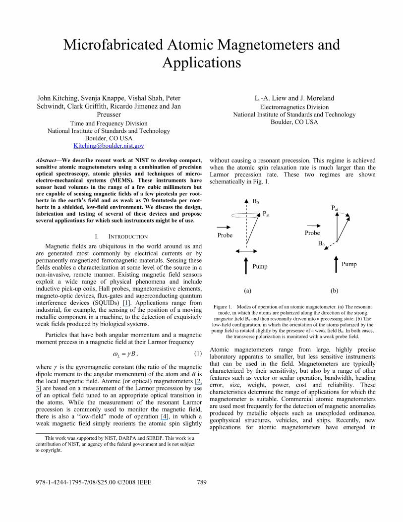
without causing a resonant precession. This regime is achieved when the atomic spin relaxation rate is much larger than the Larmor precession rate. These two regimes are shown schematically in Fig. 1.
B0 Pat
Pat
Probe Probe
B0
Pump Pump
(a) (b)
Figure 1. Modes of operation of an atomic magnetometer. (a) The resonant mode, in which the atoms are polarized along the direction of the strong
magnetic field B0 and then resonantly driven into a precessing state. (b) The low-field configuration, in which the orientation of the atoms polarized by the pump field is rotated slightly by the presence of a weak field B0. In both cases,
the transverse polarization is monitored with a weak probe field.
Atomic magnetometers range from large, highly precise laboratory apparatus to smaller, but less sensitive instruments that can be used in the field. Magnetometers are typically characterized by their sensitivity, but also by a range of other features such as vector or scalar operation, bandwidth, heading error, size, weight, power, cost and reliability. These characteristics determine the range of applications for which the magnetometer is suitable. Commercial atomic magnetometers are used most frequently for the detection of magnetic anomalies produced by metallic objects such as unexploded ordinance, geophysical structures, vehicles, and ships. Recently, new applications for atomic magnetometers have emerged in
This work was supported by NIST, DARPA and SERDP. This work is a contribution of NIST, an agency of the federal government and is not subject to copyright.
978-1-4244-1795-7/08/$25.00 ©2008 IEEE 789
research laboratories, including the detection of biomagnetic signals [5, 6], the detection of nuclear magnetization [7-9] and the detection of magnetic particles [10]. While atomic magnetometers await widespread adoption by these new fields, the combination of sensitivity with ease of use compared to SQUID-based sensors, which require cryogenics, make them a promising alternative for detecting the weakest magnetic fields.
Over the last few years, we have adapted the processes and designs developed at NIST for chip-scale atomic clocks [11-14] to compact atomic magnetometers. The basic idea behind many chip-scale atomic devices is to combine the use of advanced, low-power diode lasers (usually vertical-cavity surface emitting lasers or VCSELs) with the existing techniques of atomic spectroscopy and processes common in MEMS. This allows us to develop millimeter-scale structures that operate at low power, but retain much of the precision of their larger counterparts.
We review here several recent magnetometer instruments constructed at NIST over the last few years and compare the performance. In addition, we discuss several promising applications where these instruments may find use and assess the remaining difficulties of implementing the technology in these emerging areas.
II. MAGNETOMETER DESIGNS
A. Coherent Population Trapping Magnetometer The first chip-scale atomic magnetometer constructed at
NIST [15] was based on magnetically sensitive coherent population trapping resonances at the atomic hyperfine frequency. Similar, large-scale magnetometers had been demonstrated previously with sensitivities in the range of 10 pT/√Hz [16]. CPT resonances here are observed by illuminating the atomic sample with a modulated optical field generated by a diode laser. When the modulation frequency corresponds to a subharmonic of one of the Zeeman-split hyperfine resonances (near 6.8 GHz, in the case of 87Rb), the optical power absorbed by the atomic sample decreases and the resonance can be observed.
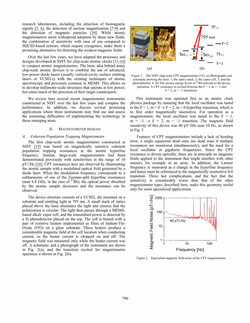
The device structure consists of a VCSEL die mounted on a substrate and emitting light at 795 nm. A small stack of optics placed above the laser attenuates the light and ensures that the polarization is circular. The light then passes through a MEMS-based alkali vapor cell, and the transmitted power is detected by a Si photodetector placed on the top. The cell is heated with a pair of resistive heaters implemented as films of Indium-Tin-Oxide (ITO) on a glass substrate. These heaters produce a considerable magnetic field at the cell location when conducting current, so the heater current is chopped on and off. The magnetic field was measured only while the heater current was off. A schematic and a photograph of the instrument are shown in Fig. 2(a), and the transition excited for magnetometer operation is shown in Fig. 2(b).
ħω0,ħω-1,-1
5P1/5P1/2
795 nmF=2
5S1/5 S1/20,0
F=1 (a) (b)
Figure 2. The NIST chip-scale CPT magnetometer [15]. (a) Photographs and schematic showing the laser, 1; the optics stack, 2; the vapor cell, 3; and the photodetector, 4. (b) The atomic energy levels of 87Rb relevant to the device
operation. A CPT resonance is excited between the F = 1, m = –1 and F = 2, m = –1 transitions.
This instrument was operated first as an atomic clock physics package by ensuring that the local oscillator was tuned to the F = 1, m = 0 → F = 2, m = 0 hyperfine transition, which is to first order magnetically insensitive. For operation as a magnetometer, the local oscillator was tuned to the F = 1, m = –1 → F = 2, m = –1 transition. The magnetic field sensitivity of this device was 40 pT/√Hz near 10 Hz, as shown in Fig. 3.
Features of CPT magnetometers include a lack of heading error, a single equatorial dead zone (no dead zone if multiple resonances are monitored simultaneously), and the need for a local oscillator at gigahertz frequencies. Since the CPT resonance is driven optically, there are in principle no magnetic fields applied to the instrument that might interfere with other sensors, for example in an array. In addition, the Larmor frequency is measured as a change in the hyperfine frequency and hence must be referenced to the magnetically insensitive 0-0 transition. These last complications, and the fact that the sensitivity is considerably worse than that of the other magnetometer types described here, make this geometry useful only for some specialized applications.
1 10 1001
10
100
1000
Mag
netic
Fie
ld N
oise
[pT/
√Hz]
Frequency [Hz]
40 pT/√Hz
Figure 3. Equivalent magnetic field noise of the CPT magnetometer.
790
B. Mx Magnetmeter The Mx magnetometer configuration is based on a direct
optical measurement of the Larmor precession frequency. The atomic spins are pumped into an oriented state with circularly polarized light. A coherent precession about the static magnetic field to be measured is then excited with an applied RF field at the Larmor frequency. The response of the atoms to the drive field is monitored with a probe optical field. In many cases, as is the case here, the pumping and probing can be done with a single optical field that has components lying both along and perpendicular to the magnetic field direction.
4.5
mm
1.7 mm12
3
6
4
(a) (b)
5
4.5
mm
1.7 mm12
3
6
4
(a) (b)
5
5S1/
5P1/
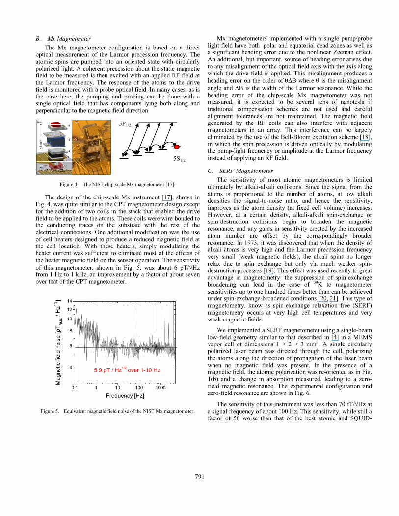
Figure 4. The NIST chip-scale Mx magnetometer [17].
The design of the chip-scale Mx instrument [17], shown in Fig. 4, was quite similar to the CPT magnetometer design except for the addition of two coils in the stack that enabled the drive field to be applied to the atoms. These coils were wire-bonded to the conducting traces on the substrate with the rest of the electrical connections. One additional modification was the use of cell heaters designed to produce a reduced magnetic field at the cell location. With these heaters, simply modulating the heater current was sufficient to eliminate most of the effects of the heater magnetic field on the sensor operation. The sensitivity of this magnetometer, shown in Fig. 5, was about 6 pT/√Hz from 1 Hz to 1 kHz, an improvement by a factor of about seven over that of the CPT magnetometer.
0.1 1 10 100 1000
4
6
8
10
12
14
Mag
netic
fiel
d no
ise
[pT R
MS /
Hz1/
2 ]
Frequency [Hz]
5.9 pT / Hz1/2 over 1-10 Hz
Figure 5. Equivalent magnetic field noise of the NIST Mx magnetometer.
Mx magnetometers implemented with a single pump/probe light field have both polar and equatorial dead zones as well as a significant heading error due to the nonlinear Zeeman effect. An additional, but important, source of heading error arises due to any misalignment of the optical field axis with the axis along which the drive field is applied. This misalignment produces a heading error on the order of θΔB where θ is the misalignment angle and ΔB is the width of the Larmor resonance. While the heading error of the chip-scale Mx magnetometer was not measured, it is expected to be several tens of nanotesla if traditional compensation schemes are not used and careful alignment tolerances are not maintained. The magnetic field generated by the RF coils can also interfere with adjacent magnetometers in an array. This interference can be largely eliminated by the use of the Bell-Bloom excitation scheme [18], in which the spin precession is driven optically by modulating the pump-light frequency or amplitude at the Larmor frequency instead of applying an RF field.
5P1/2
5S1/2
C. SERF Magnetometer The sensitivity of most atomic magnetometers is limited
ultimately by alkali-alkali collisions. Since the signal from the atoms is proportional to the number of atoms, at low alkali densities the signal-to-noise ratio, and hence the sensitivity, improves as the atom density (at fixed cell volume) increases. However, at a certain density, alkali-alkali spin-exchange or spin-destruction collisions begin to broaden the magnetic resonance, and any gains in sensitivity created by the increased atom number are offset by the correspondingly broader resonance. In 1973, it was discovered that when the density of alkali atoms is very high and the Larmor precession frequency very small (weak magnetic fields), the alkali spins no longer relax due to spin exchange but only via much weaker spin-destruction processes [19]. This effect was used recently to great advantage in magnetometry: the suppression of spin-exchange broadening can lead in the case of 39K to magnetometer sensitivities up to one hundred times better than can be achieved under spin-exchange-broadened conditions [20, 21]. This type of magnetometry, know as spin-exchange relaxation free (SERF) magnetometry occurs at very high cell temperatures and very weak magnetic fields.
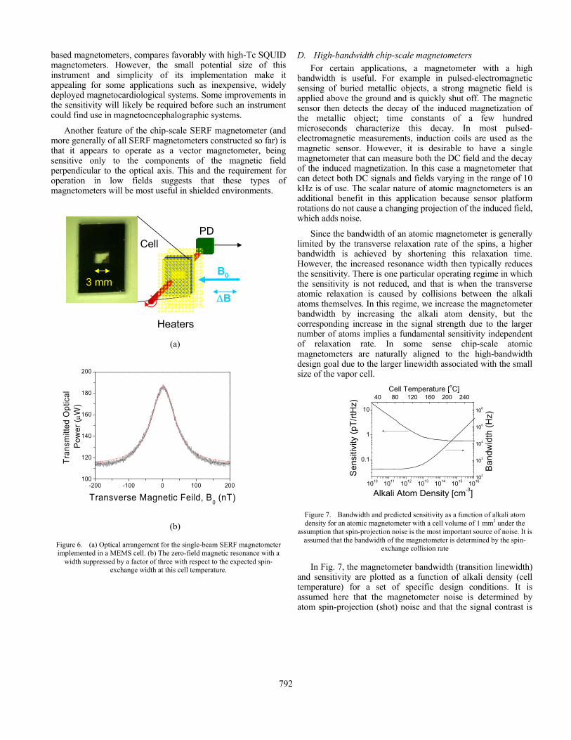
We implemented a SERF magnetometer using a single-beam low-field geometry similar to that described in [4] in a MEMS vapor cell of dimensions 1 × 2 × 3 mm3. A single circularly polarized laser beam was directed through the cell, polarizing the atoms along the direction of propagation of the laser beam when no magnetic field was present. In the presence of a magnetic field, the atomic polarization was re-oriented as in Fig. 1(b) and a change in absorption measured, leading to a zero-field magnetic resonance. The experimental configuration and zero-field resonance are shown in Fig. 6.
The sensitivity of this instrument was less than 70 fT/√Hz at a signal frequency of about 100 Hz. This sensitivity, while still a factor of 50 worse than that of the best atomic and SQUID-
791
based magnetometers, compares favorably with high-Tc SQUID magnetometers. However, the small potential size of this instrument and simplicity of its implementation make it appealing for some applications such as inexpensive, widely deployed magnetocardiological systems. Some improvements in the sensitivity will likely be required before such an instrument could find use in magnetoencephalographic systems.
Another feature of the chip-scale SERF magnetometer (and more generally of all SERF magnetometers constructed so far) is that it appears to operate as a vector magnetometer, being sensitive only to the components of the magnetic field perpendicular to the optical axis. This and the requirement for operation in low fields suggests that these types of magnetometers will be most useful in shielded environments.
B0
PDCell
3 mm3 mmΔB
Heaters (a)
-200 -100 0 100 200100
120
140
160
180
200
Tran
smitt
ed O
ptic
al P
ower
( μW
)
Transverse Magnetic Feild, B0 (nT)
(b)
Figure 6. (a) Optical arrangement for the single-beam SERF magnetometer implemented in a MEMS cell. (b) The zero-field magnetic resonance with a
width suppressed by a factor of three with respect to the expected spin-exchange width at this cell temperature.
D. High-bandwidth chip-scale magnetometers For certain applications, a magnetometer with a high
bandwidth is useful. For example in pulsed-electromagnetic sensing of buried metallic objects, a strong magnetic field is applied above the ground and is quickly shut off. The magnetic sensor then detects the decay of the induced magnetization of the metallic object; time constants of a few hundred microseconds characterize this decay. In most pulsed-electromagnetic measurements, induction coils are used as the magnetic sensor. However, it is desirable to have a single magnetometer that can measure both the DC field and the decay of the induced magnetization. In this case a magnetometer that can detect both DC signals and fields varying in the range of 10 kHz is of use. The scalar nature of atomic magnetometers is an additional benefit in this application because sensor platform rotations do not cause a changing projection of the induced field, which adds noise.
Since the bandwidth of an atomic magnetometer is generally limited by the transverse relaxation rate of the spins, a higher bandwidth is achieved by shortening this relaxation time. However, the increased resonance width then typically reduces the sensitivity. There is one particular operating regime in which the sensitivity is not reduced, and that is when the transverse atomic relaxation is caused by collisions between the alkali atoms themselves. In this regime, we increase the magnetometer bandwidth by increasing the alkali atom density, but the corresponding increase in the signal strength due to the larger number of atoms implies a fundamental sensitivity independent of relaxation rate. In some sense chip-scale atomic magnetometers are naturally aligned to the high-bandwidth design goal due to the larger linewidth associated with the small size of the vapor cell.
1010 1011 1012 1013 1014 1015 1016
0.1
1
10
102
103
104
105
106
40 80 120 160 200 240
Sen
sitiv
ity (p
T/rtH
z)
Alkali Atom Density [cm-3] B
andw
idth
(Hz)
Cell Temperature [oC]
Figure 7. Bandwidth and predicted sensitivity as a function of alkali atom density for an atomic magnetometer with a cell volume of 1 mm3 under the
assumption that spin-projection noise is the most important source of noise. It is assumed that the bandwidth of the magnetometer is determined by the spin-
exchange collision rate
In Fig. 7, the magnetometer bandwidth (transition linewidth) and sensitivity are plotted as a function of alkali density (cell temperature) for a set of specific design conditions. It is assumed here that the magnetometer noise is determined by atom spin-projection (shot) noise and that the signal contrast is
792
unity. At low alkali densities, the bandwidth is determined by the relaxation processes independent of alkali density (collisions with the walls of the cell, and with buffer-gas atoms), and the sensitivity improves with alkali density because of the increased number of alkali atoms that produce the signal. At higher alkali atom densities, the bandwidth begins to increase due to the broadening due to alkali-alkali collisions, while the sensitivity remains constant. While this plot illustrates the basic principle of the high-bandwidth magnetometer design, there are of course many additional physical and design factors that are not included in the model that will potentially degrade the sensitivity. These factors include: photon shot noise and laser AM and FM noise, optical absorption of the atoms, and the presence of magnetic field gradients.
E. Photonic Magnetometer It is often advantageous to have a magnetic field sensor that
itself creates no magnetic fields that might perturb the field source or interfere with other nearby sensors. This is particularly important when designing array-based magnetometers for imaging of localized field sources, for example, in animal heart or brain tissue. The chip-scale magnetometer designs described above have sources of magnetic fields within the instruments themselves. These sources include:
• Currents that drive the cell heaters
• The current that drives the laser
• The drive field coils in the Mx design
• Thermal currents in the metallic components and traces near the cell.
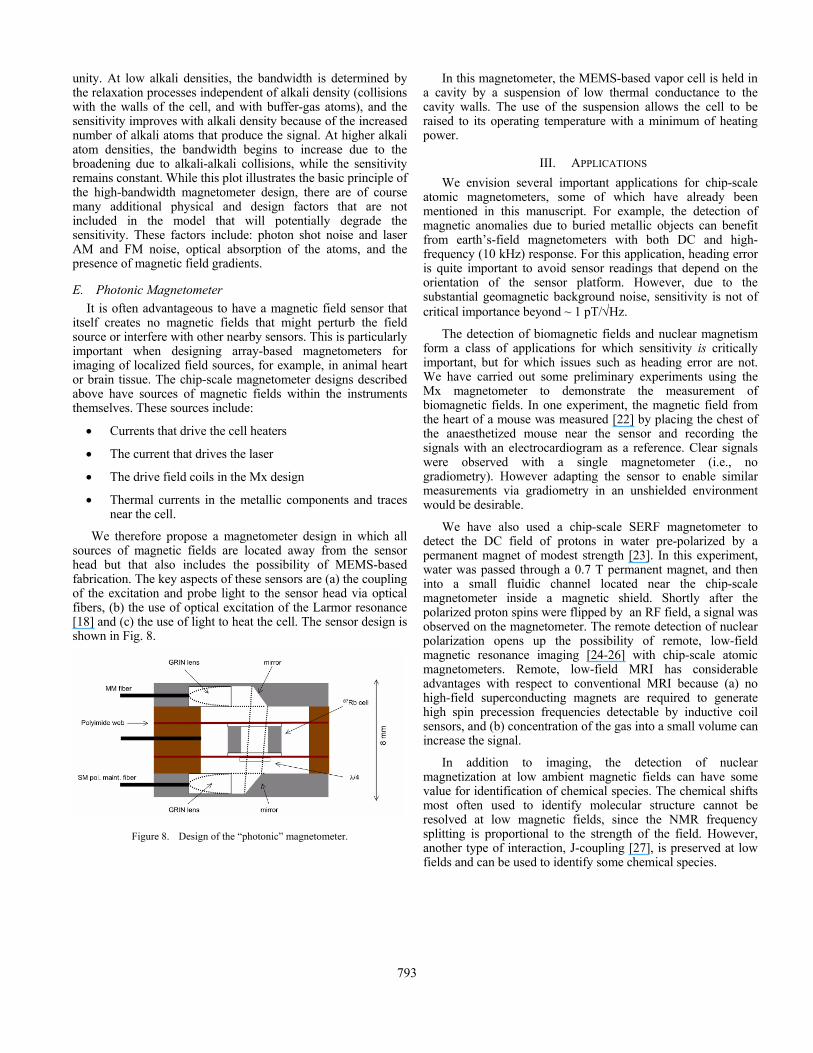
We therefore propose a magnetometer design in which all sources of magnetic fields are located away from the sensor head but that also includes the possibility of MEMS-based fabrication. The key aspects of these sensors are (a) the coupling of the excitation and probe light to the sensor head via optical fibers, (b) the use of optical excitation of the Larmor resonance [18] and (c) the use of light to heat the cell. The sensor design is shown in Fig. 8.
Figure 8. Design of the “photonic” magnetometer.
In this magnetometer, the MEMS-based vapor cell is held in a cavity by a suspension of low thermal conductance to the cavity walls. The use of the suspension allows the cell to be raised to its operating temperature with a minimum of heating power.
III. APPLICATIONS We envision several important applications for chip-scale
atomic magnetometers, some of which have already been mentioned in this manuscript. For example, the detection of magnetic anomalies due to buried metallic objects can benefit from earth’s-field magnetometers with both DC and high-frequency (10 kHz) response. For this application, heading error is quite important to avoid sensor readings that depend on the orientation of the sensor platform. However, due to the substantial geomagnetic background noise, sensitivity is not of critical importance beyond ~ 1 pT/√Hz.
The detection of biomagnetic fields and nuclear magnetism form a class of applications for which sensitivity is critically important, but for which issues such as heading error are not. We have carried out some preliminary experiments using the Mx magnetometer to demonstrate the measurement of biomagnetic fields. In one experiment, the magnetic field from the heart of a mouse was measured [22] by placing the chest of the anaesthetized mouse near the sensor and recording the signals with an electrocardiogram as a reference. Clear signals were observed with a single magnetometer (i.e., no gradiometry). However adapting the sensor to enable similar measurements via gradiometry in an unshielded environment would be desirable.
We have also used a chip-scale SERF magnetometer to detect the DC field of protons in water pre-polarized by a permanent magnet of modest strength [23]. In this experiment, water was passed through a 0.7 T permanent magnet, and then into a small fluidic channel located near the chip-scale magnetometer inside a magnetic shield. Shortly after the polarized proton spins were flipped by an RF field, a signal was observed on the magnetometer. The remote detection of nuclear polarization opens up the possibility of remote, low-field magnetic resonance imaging [24-26] with chip-scale atomic magnetometers. Remote, low-field MRI has considerable advantages with respect to conventional MRI because (a) no high-field superconducting magnets are required to generate high spin precession frequencies detectable by inductive coil sensors, and (b) concentration of the gas into a small volume can increase the signal.
In addition to imaging, the detection of nuclear magnetization at low ambient magnetic fields can have some value for identification of chemical species. The chemical shifts most often used to identify molecular structure cannot be resolved at low magnetic fields, since the NMR frequency splitting is proportional to the strength of the field. However, another type of interaction, J-coupling [27], is preserved at low fields and can be used to identify some chemical species.
793
IV. CONCLUSIONS
We have described a number of implementations of “chip-scale” atomic magnetometers based on millimeter-scale microfabricated alkali vapor cells. These instruments have sensitivities in the range of 50 fT/√Hz to 50 pT/√Hz, and the sensitivity depends on the mechanism by which the field is sensed. Self-contained physics packages with a volume of 12 mm3 and suitable for earth’s field-operation have been shown to operate at 6 pT/√Hz. It is anticipated that, with suitable thermal isolation [28], the power required to operate the physics package could be reduced to a few tens of milliwatts. A remaining question is the magnitude of the heading error, and whether there are methods to reduce it. In a shielded environment, chip-scale sensors have demonstrated a sensitivity of 70 fT/√Hz. These sensors might find use in biomedical applications such as the detection of magnetic fields produced by the heart or the brain. In addition, there appear to be significant applications for nuclear magnetic resonance including imaging and identification of chemical species. Finally, high-bandwidth magnetometers are being developed based on an operating regime at high alkali density, where alkali-alkali collisional broadening is large. [1] P. Ripka, "Magnetic Sensors and Magnetometers." Norwood, MA: Artech
House, Inc., 2001. [2] H. G. Dehmelt, "Modulation of a Light Beam by Precessing Absorbing
Atoms," Physical Review, vol. 105, pp. 1924, 1957. [3] W. E. Bell and A. Bloom, "Optical detection of magnetic resonance in
alkali metal vapor," Physical Review, vol. 107, pp. 1559-1565, 1957. [4] J. Dupont-Roc, S. Haroche, and C. Cohen-Tannoudji, "Detection of very
weak magnetic fields (10−9gauss) by 87Rb zero-field level crossing resonances," Physics Letters A, vol. 28, pp. 638, 1969.
[5] G. Bison, R. Wynands, and A. Weis, "Dynamical mapping of the human cardiomagnetic field with a room-temperature, laser-optical sensor," Optics Express, vol. 11, pp. 904-909, 2003.
[6] H. Xia, A. B.-A. Baranga, D. Hoffman, and M. V. Romalis, "Magnetoencephalography with an atomic magnetometer," Applied Physics Letters, vol. 89, pp. 211104, 2006.
[7] V. V. Yashchuk, J. Granwehr, D. F. Kimball, S. M. Rochester, A. H. Trabesinger, J. T. Urban, D. Budker, and A. Pines, "Hyperpolarized xenon nuclear spins detected by optical atomic magnetometry," Physical Review Letters, vol. 93, pp. 160801, 2004.
[8] S.-K. Lee, K. L. Sauer, S. J. Seltzer, O. Alem, and M. V. Romalis, "Subfemtotesla radio-frequency atomic magnetometer for detection of nuclear quadrupole resonance," Applied Physics Letters, vol. 89, pp. 214106, 2006.
[9] I. M. Savukov and M. V. Romalis, "NMR detection with an atomic magnetometer," Physical Review Letters, vol. 94, pp. 123001, 2005.
[10] S. J. Xu, M. H. Donaldson, A. Pines, S. Rochester, D. Budker, and V. V. Yashchuk, "Application of atomic magnetometry in magnetic particle detection," Applied Physics Letters, vol. 89, pp. 224105, 2006.
[11] L. A. Liew, S. Knappe, J. Moreland, H. Robinson, L. Hollberg, and J. Kitching, "Microfabricated alkali atom vapor cells," Applied Physics Letters, vol. 84, pp. 2694-2696, 2004.
[12] S. Knappe, V. Shah, P. D. D. Schwindt, L. Hollberg, J. Kitching, L. A. Liew, and J. Moreland, "A microfabricated atomic clock," Applied Physics Letters, vol. 85, pp. 1460-1462, 2004.
[13] S. Knappe, V. Gerginov, P. D. D. Schwindt, V. Shah, H. G. Robinson, L. Hollberg, and J. Kitching, "Atomic vapor cells for chip-scale atomic clocks with improved long-term frequency stability," Optics Letters, vol. 30, pp. 2351-2353, 2005.
[14] V. Gerginov, S. Knappe, P. D. D. Schwindt, V. Shah, L. Liew, J. Moreland, H. G. Robinson, L. Hollberg, J. Kitching, A. Brannon, J. Breitbarth, and Z. Popovic, "Component-Level Demonstration of a Microfabricated Atomic Frequency Reference," proceedings of the Joint IEEE International Frequency Control Symposium and Precise Time and Time Interval (PTTI) Systems and Applications Meeting, Vancouver, Canada, 2005.
[15] P. D. D. Schwindt, S. Knappe, V. Shah, L. Hollberg, J. Kitching, L. A. Liew, and J. Moreland, "Chip-scale atomic magnetometer," Applied Physics Letters, vol. 85, pp. 6409-6411, 2004.
[16] M. Stahler, S. Knappe, C. Affolderbach, W. Kemp, and R. Wynands, "Picotesla magnetometry with coherent dark states," Europhysics Letters, vol. 54, pp. 323-328, 2001.
[17] P. D. D. Schwindt, B. Lindseth, S. Knappe, V. Shah, J. Kitching, and L.-A. Liew, "A chip-scale atomic magnetometer with improved sensitivity using the Mx technique," Applied Physics Letters, vol. 90, pp. 081102, 2007.
[18] W. E. Bell and A. L. Bloom, "Optically driven spin precession," Physical Review Letters, vol. 6, pp. 280-283, 1961.
[19] W. Happer and H. Tang, "Spin-exchange shift and narrowing of magnetic resonance lines in optically pumped alkali vapors," Physical Review Letters, vol. 31, pp. 273-276, 1973.
[20] J. C. Allred, R. N. Lyman, T. W. Kornack, and M. V. Romalis, "High-sensitivity atomic magnetometer unaffected by spin-exchange relaxation," Physical Review Letters, vol. 89, pp. 130801, 2002.
[21] I. K. Kominis, T. W. Kornack, J. C. Allred, and M. V. Romalis, "A subfemtotesla multichannel atomic magnetometer," Nature, vol. 422, pp. 596-599, 2003.
[22] B. Lindseth, P. Schwindt, J. Kitching, D. Fischer, and V. Shusterman, "Non-contact measurement of cardiac electromagnetic field in mice by use of a microfabricated atomic magnetometers," Computers in Cardiology, 2007.
[23] M. P. Ledbetter, I. M. Savukov, D. Budker, V. Shah, S. Knappe, J. Kitching, D. J. Michalak, S. Xu, and A. Pines, "Zero-field remote detection of NMR with a microfabricated atomic magnetometer," Proceedings of the National Academy of Sciences, vol. 105, pp. 2286-2290, 2008.
[24] S. J. Xu, V. V. Yashchuk, M. H. Donaldson, S. M. Rochester, D. Budker, and A. Pines, "Magnetic resonance imaging with an optical atomic magnetometer," Proceedings of the National Academy of Sciences of the United States of America, vol. 103, pp. 12668-12671, 2006.
[25] J. Granwehr, E. Harel, S. Han, S. Garcia, A. Pines, P. N. Sen, and Y. Q. Song, "Time-of-flight flow imaging using NMR remote detection," Physical Review Letters, vol. 95, 2005.
[26] R. McDermott, S. K. Lee, B. ten Haken, A. H. Trabesinger, A. Pines, and J. Clarke, "Microtesla MRI with a superconducting quantum interference device," Proceedings of the National Academy of Sciences of the United States of America, vol. 101, pp. 7857-7861, 2004.
[27] A. Abragam, Principles of Nuclear Magnetism. Oxford: Oxford University Press, 1961.
[28] M. J. Mescher, R. Lutwak, and M. Varghese, "An ultra-low-power physics package for a chip-scale atomic clock," Transducers '05, IEEE International Conference on Solid-State Sensors and Actuators, Seoul, Korea, 2005.
794
Related Documents