International Journal of Trend in Research and Development, Volume 4(1), ISSN: 2394-9333 www.ijtrd.com IJTRD | Jan-Feb 2017 Available [email protected] 132 Microcontroller Based Automatic Power Factor Correction System Myint Myint Than Department of Electronic Engineering, Yangon Technological University, Yangon, Republic of the Union of Myanmar Abstract—This paper deals with the design and construction of power factor correction (PFC) system using solid state switched capacitors that are controlled by the Arduino UNO controller. The main objectives are to reduce the line losses, reactive power flows on the line and to avoid switching surge overvoltage due to switching on/off the capacitors. The power factor from the load is measured by using zero crossing circuit and phase shift detector, and then calculate the power factor according to the program and LCD will be used for display. This paper provides implementation done on Arduino UNO microcontroller using C language software to program the microcontroller. Arduino program to determine time lag between current and voltage, and control the power factor to get target point by the program according to the load. This system senses the power factor and with the help of microcontroller switches, required number of capacitors in the capacitor bank to achieve target power factor. In this system, the reactive power will be generated by the bank of static capacitors. Design and construction will be done by using the LM 358, CD4070BC, MOC 3052, BTA 41 ICs, Arduino UNO Microcontroller and LCD display in this system. Keywords —Power Factor, LM358, CD4070 BC, MOC 3052, BTA 41 ICs LCD, C language, Arduino UNO microcontroller. I. INTRODUCTION In electrical plants, the loads draw from the network electric power (active) as power supply source (e.g. personal computers, printers, diagnostic equipment, etc.) or convert it into other form of energy (e.g. electrical lamps or stoves) or into mechanical output (e.g. electrical motors). To get this, it is often necessary that the load exchanges with the network (with net null consumption) and the reactive energy is produced mainly from inductive type. This energy, even if not immediately converted into other forms, contributes to increase the total power flowing through in the electrical network, from the generators, all along the conductors, to the users. To smooth such negative effect, the power factor correction of the electrical plants is carried out. The power factor correction obtained by using capacitor banks to generate locally the reactive energy necessary for the transfer of electrical useful power, allows a better and more rational technical-economical management of the plants.[1] There are so many industries around the world and so are in Myanmar. Most of the industrial plants are using the inductive loads in infrastructure such as transformers and motors. Among them, the large industrial motors are essentially used in the industrial plants. Induction motors receive the grate reactive power from network for their proper function. Reactive power consumption causes the reduction of voltage of feeder in the plants and on the other hand, it causes the reduction of power factor of the whole plants. Therefore, to improve the power factor is very important for all of the plants and even in the domestic industries and home appliances. According to that point, one of the best methods for the power factor improvement is the power factor correction (PFC)technique. The block diagram of power factor correction system is shown in Fig.1. Figure 1: Block diagram of power factor measuring system II. TECHNOLOGY This system presents power factor correction (PFC) technique using solid state switched capacitors. This systemdescribes the design and simulation of power factor correction using ArduinoUNO controller.Measuring the power factor from the load by using LM358 zero crossing circuit and CD4070BCphase shift detector, and then calculating the power factor have been done according to the program and LCD will be used for display. If the power is not in the range, the switches are on/off conditioned by the controller unit and capacitors are activate/deactivate and improve the power factor. This system provides implementation done onArduino UNO microcontroller using C language software to program the microcontroller, Arduino program to determine time lag between current and voltage and Proteus 7.7 to simulate the power factor according to the load. A. Power Factor Power factor represents the percentage of electricity that is being used to do useful work. It is defined as the ratio of active or actual power used in the circuit measured in watts or kilowatts (W or kW), to the apparent power expressed in volt- amperes or kilo volt-amperes (VA or kVA). Power factor = Active Power Apparent Power or W VA The apparent power also referred to as total power delivered by utility company has two components. Productive Power that powers the equipment and performs the useful work. It is measured in kW (kilowatts). Reactive Power that generates magnetic fields to produce flux necessary for the operation of induction devices (AC motors, transformer, inductive furnaces, ovens etc.). It is measured in kVAR (kilovolt-Ampere- Reactance).[1]

Welcome message from author
This document is posted to help you gain knowledge. Please leave a comment to let me know what you think about it! Share it to your friends and learn new things together.
Transcript

International Journal of Trend in Research and Development, Volume 4(1), ISSN: 2394-9333
www.ijtrd.com
IJTRD | Jan-Feb 2017 Available [email protected] 132
Microcontroller Based Automatic Power Factor
Correction System Myint Myint Than
Department of Electronic Engineering, Yangon Technological University, Yangon, Republic of the Union of Myanmar
Abstract—This paper deals with the design and construction of
power factor correction (PFC) system using solid state
switched capacitors that are controlled by the Arduino UNO
controller. The main objectives are to reduce the line losses,
reactive power flows on the line and to avoid switching surge
overvoltage due to switching on/off the capacitors. The power
factor from the load is measured by using zero crossing circuit
and phase shift detector, and then calculate the power factor
according to the program and LCD will be used for display.
This paper provides implementation done on Arduino UNO
microcontroller using C language software to program the
microcontroller. Arduino program to determine time lag
between current and voltage, and control the power factor to
get target point by the program according to the load. This
system senses the power factor and with the help of
microcontroller switches, required number of capacitors in the
capacitor bank to achieve target power factor. In this system,
the reactive power will be generated by the bank of static
capacitors. Design and construction will be done by using the
LM 358, CD4070BC, MOC 3052, BTA 41 ICs, Arduino UNO
Microcontroller and LCD display in this system.
Keywords —Power Factor, LM358, CD4070 BC, MOC 3052,
BTA 41 ICs LCD, C language, Arduino UNO microcontroller.
I. INTRODUCTION
In electrical plants, the loads draw from the network
electric power (active) as power supply source (e.g. personal
computers, printers, diagnostic equipment, etc.) or convert it
into other form of energy (e.g. electrical lamps or stoves) or
into mechanical output (e.g. electrical motors). To get this, it is
often necessary that the load exchanges with the network (with
net null consumption) and the reactive energy is produced
mainly from inductive type. This energy, even if not
immediately converted into other forms, contributes to increase
the total power flowing through in the electrical network, from
the generators, all along the conductors, to the users. To
smooth such negative effect, the power factor correction of the
electrical plants is carried out. The power factor correction
obtained by using capacitor banks to generate locally the
reactive energy necessary for the transfer of electrical useful
power, allows a better and more rational technical-economical
management of the plants.[1]
There are so many industries around the world and so are
in Myanmar. Most of the industrial plants are using the
inductive loads in infrastructure such as transformers and
motors. Among them, the large industrial motors are
essentially used in the industrial plants. Induction motors
receive the grate reactive power from network for their proper
function. Reactive power consumption causes the reduction of
voltage of feeder in the plants and on the other hand, it causes
the reduction of power factor of the whole plants.
Therefore, to improve the power factor is very important
for all of the plants and even in the domestic industries and
home appliances. According to that point, one of the best
methods for the power factor improvement is the power factor
correction (PFC)technique. The block diagram of power factor
correction system is shown in Fig.1.
Figure 1: Block diagram of power factor measuring system
II. TECHNOLOGY
This system presents power factor correction (PFC)
technique using solid state switched capacitors. This
systemdescribes the design and simulation of power factor
correction using ArduinoUNO controller.Measuring the power
factor from the load by using LM358 zero crossing circuit and
CD4070BCphase shift detector, and then calculating the power
factor have been done according to the program and LCD will
be used for display. If the power is not in the range, the
switches are on/off conditioned by the controller unit and
capacitors are activate/deactivate and improve the power
factor. This system provides implementation done onArduino
UNO microcontroller using C language software to program
the microcontroller, Arduino program to determine time lag
between current and voltage and Proteus 7.7 to simulate the
power factor according to the load.
A. Power Factor
Power factor represents the percentage of electricity that is
being used to do useful work. It is defined as the ratio of active
or actual power used in the circuit measured in watts or
kilowatts (W or kW), to the apparent power expressed in volt-
amperes or kilo volt-amperes (VA or kVA).
Power factor = Active Power
Apparent Poweror
W
VA
The apparent power also referred to as total power
delivered by utility company has two components.
Productive Power that powers the equipment and
performs the useful work. It is measured in kW
(kilowatts).
Reactive Power that generates magnetic fields to
produce flux necessary for the operation of induction
devices (AC motors, transformer, inductive furnaces,
ovens etc.). It is measured in kVAR (kilovolt-Ampere-
Reactance).[1]
International Journal of Trend in Research and Development, Volume 4(1), ISSN: 2394-9333
www.ijtrd.com
IJTRD | Jan-Feb 2017 Available [email protected] 133
Reactive Power produces no productive work. An
inductive motor with power applied and no load on its shaft
should draw almost nil productive power, since no output
work is being accomplished until a load is applied. The current
associated with no-load motor readings is almost entirely
"Reactive" Power. As a load is applied to the shaft of the
motor, the "Reactive" Power requirement will change only a
small amount. The Productive Power is the power that is
transferred from electrical energy to some other form of
energy (i.e. such as heat energy or mechanical energy). The
apparent power is always in excess of the productive power for
inductive loads and is dependent on the type of machine in
use. The working power (kW) and reactive power (kVAR)
together make up apparent power, which is measured in
kilovolt amperes (kVA). Graphically it can be represented as:
Power factor =kW (Productive Power )
kVA (Total Power )
The cosine of the phase angle θ between the kVA and the
kW components represents the power factor of the load. kVAR
represents the non-productive reactive power and θ is lagging
phase angle [1].
Benefits of Power Factor Correction are:
1. Reduce Utility Power Bills,
2. Increase System Capacity,
3. Improve System Operating Characteristics (Gain
Voltage), and
4. Improve System Operating Characteristics (Reduce
Line Losses).[2]
B. Zero Crossing Detector
Zero crossing detector is used to detect sine wave zero
crossing from positive half cycle to negative half cycle or
negative half cycle. To measure time difference between two
waves is to detect zero crossing of two waves. The 230 V, 50
Hz is step downed using voltage transformer and current
transformer is used to extract the waveforms of current.
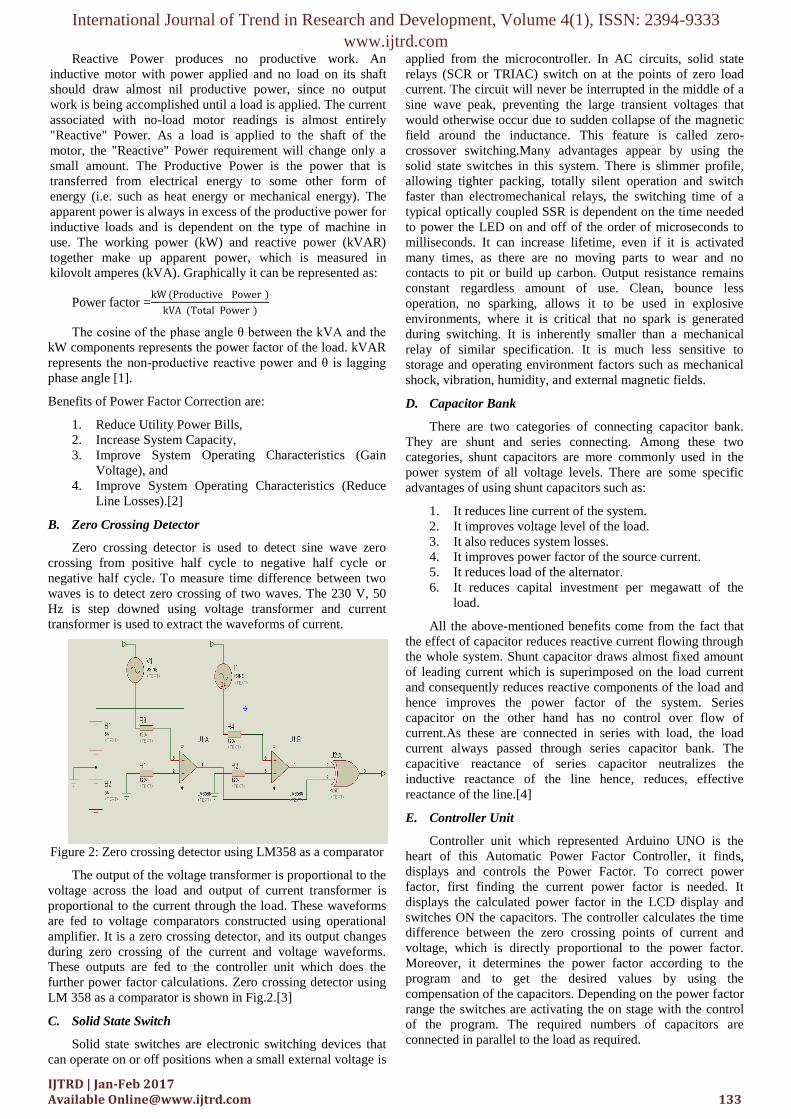
Figure 2: Zero crossing detector using LM358 as a comparator
The output of the voltage transformer is proportional to the
voltage across the load and output of current transformer is
proportional to the current through the load. These waveforms
are fed to voltage comparators constructed using operational
amplifier. It is a zero crossing detector, and its output changes
during zero crossing of the current and voltage waveforms.
These outputs are fed to the controller unit which does the
further power factor calculations. Zero crossing detector using
LM 358 as a comparator is shown in Fig.2.[3]
C. Solid State Switch
Solid state switches are electronic switching devices that
can operate on or off positions when a small external voltage is
applied from the microcontroller. In AC circuits, solid state
relays (SCR or TRIAC) switch on at the points of zero load
current. The circuit will never be interrupted in the middle of a
sine wave peak, preventing the large transient voltages that
would otherwise occur due to sudden collapse of the magnetic
field around the inductance. This feature is called zero-
crossover switching.Many advantages appear by using the
solid state switches in this system. There is slimmer profile,
allowing tighter packing, totally silent operation and switch
faster than electromechanical relays, the switching time of a
typical optically coupled SSR is dependent on the time needed
to power the LED on and off of the order of microseconds to
milliseconds. It can increase lifetime, even if it is activated
many times, as there are no moving parts to wear and no
contacts to pit or build up carbon. Output resistance remains
constant regardless amount of use. Clean, bounce less
operation, no sparking, allows it to be used in explosive
environments, where it is critical that no spark is generated
during switching. It is inherently smaller than a mechanical
relay of similar specification. It is much less sensitive to
storage and operating environment factors such as mechanical
shock, vibration, humidity, and external magnetic fields.
D. Capacitor Bank
There are two categories of connecting capacitor bank.
They are shunt and series connecting. Among these two
categories, shunt capacitors are more commonly used in the
power system of all voltage levels. There are some specific
advantages of using shunt capacitors such as:
1. It reduces line current of the system.
2. It improves voltage level of the load.
3. It also reduces system losses.
4. It improves power factor of the source current.
5. It reduces load of the alternator.
6. It reduces capital investment per megawatt of the
load.
All the above-mentioned benefits come from the fact that
the effect of capacitor reduces reactive current flowing through
the whole system. Shunt capacitor draws almost fixed amount
of leading current which is superimposed on the load current
and consequently reduces reactive components of the load and
hence improves the power factor of the system. Series
capacitor on the other hand has no control over flow of
current.As these are connected in series with load, the load
current always passed through series capacitor bank. The
capacitive reactance of series capacitor neutralizes the
inductive reactance of the line hence, reduces, effective
reactance of the line.[4]
E. Controller Unit
Controller unit which represented Arduino UNO is the
heart of this Automatic Power Factor Controller, it finds,
displays and controls the Power Factor. To correct power
factor, first finding the current power factor is needed. It
displays the calculated power factor in the LCD display and
switches ON the capacitors. The controller calculates the time
difference between the zero crossing points of current and
voltage, which is directly proportional to the power factor.
Moreover, it determines the power factor according to the
program and to get the desired values by using the
compensation of the capacitors. Depending on the power factor
range the switches are activating the on stage with the control
of the program. The required numbers of capacitors are
connected in parallel to the load as required.

International Journal of Trend in Research and Development, Volume 4(1), ISSN: 2394-9333
www.ijtrd.com
IJTRD | Jan-Feb 2017 Available [email protected] 134
F. Circuit Diagram of the System
Complete circuit diagram of this system is shown in Fig. 3.
Figure 3: Circuit Diagram of the System
III. DESIGN CALCULATION
A. Calculation of Compensated Capacitor Units
This calculation describes the compensated capacitors for
different conditions.To calculate the required PFC capacitance
it is necessary to know the existing reactive power QL of
electrical system and choose desired PF. There are several
ways of estimating QL, discussed below. It is important to point
out the fact that reactive power of a motor slightly varies with
the load. Therefore, to avoid over correction, ideally VAR
value of the motor should be determined at no load. Phasor
diagram for inductive load is shown in Fig. 4.
Figure 4: Phasor Diagram for Inductive Load Source: [5]
Quncorrected= P × tan θ1
Qcorrected = P × tan θ2
QC = Quncorrected
Qcorrected = P × (tan θ1- tan θ2)
Qc = P × K
Where,
P is the active power;
Q1, 𝜃1 are the reactive power and the phase displacement angle
before power factor correction;
Q2, 𝜽𝟐 are the reactive power and the phase displacement
angle after power factor correction;
Qc is the reactive power for power factor correction.
K= factor K (kvar/kW)
Motor 2 ON
V = 230V, I = 2.5205A
Initial power factor = cos θ1 = 0.42
θ1 = 65.1654˚
Target power factor = cos θ2 = 0.92
θ2 = 23.0739˚
P1 = VIcosθ1 = 230 × 2.5205× 0.42= 243.4803W
Qc = Q1 − Q2
= P (tan θ1-tan θ2)
= 243.4803 (tan 65.1654 – tan 23.0739)
= 422.3830Var
For capacitor C =k Var
2πfV2×10−3
=422.3830x10⁻³
2π × 50 × 2302 × 10−3
= 25.4156 μF
Motor 1,2 and 3 ON
V=230V,
I=5.8791
Initial power factor = cos θ1 = 0.46
θ1 = 62.6129˚
Target power factor = cos θ2 = 0.92
θ2 = 23.0739˚
P = VIcosθ1
= 230 × 5.8791× 0.46= 622.0088 W
Qc = Q1 − Q2
= P (tan θ1-tan θ2)
= 622.0088 (tan 62.6219 – tan 23.0739)
= 936.1256Var
For capacitor C =k Var
2πfV2×10−3
=936.1256 × 10⁻³
2π × 50 × 2302 × 10−3
=56.32855 μF
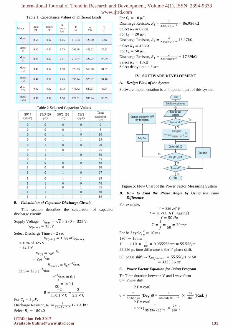
In table 1, shows the compensated capacitors’ values for
different loads on conditions and table 2 describes the selected
capacitors’ values of this system.
International Journal of Trend in Research and Development, Volume 4(1), ISSN: 2394-9333
www.ijtrd.com
IJTRD | Jan-Feb 2017 Available [email protected] 135
Table 1: Capacitance Values of Different Loads
Motor Initial
PF
Target
PF
K
kvar/
kW
P
W
𝑄𝑐
Var
C
μF
Motor
1 0.56 0.92 1.05 119.33 125.30 7.56
Motor
2 0.42 0.92 1.73 243.48 421.22 25.42
Motor
3 0.38 0.92 2.01 212.57 427.27 25.69
Motor
1,2 0.46 0.92 1.50 379.73 569.60 34.37
Motor
1,3 0.47 0.92 1.45 393.74 570.92 34.40
Motor
2,3 0.42 0.92 1.73 478.42 827.67 49.94
Motor
1,2,3 0.46 0.92 1.50 622.01 936.24 56.33
Table 2 Selected Capacitor Values
B. Calculation of Capacitor Discharge Circuit
This section describes the calculation of capacitor
discharge circuit:
Supply Voltage, Vmax = 2 × 230 = 325 V, VC(max ) = 325V
Select Discharge Time t = 2 sec
VC(min ) = 10% ofVC(max )
= 10% of 325 V
= 32.5 V
VC(t) = V0e−tτ
= V0e−tRC
Vc(min ) = V0e−2R×C
32.5 = 325 e−2R×C
e−2R×C = 0.1
−2
RC= ln 0.1
R =−2
ln 0.1 × C=
2
2.3 × C
For 𝐶1 = 5 𝜇𝐹,
Discharge Resistor, 𝑅1 =2
2.3×5×10−6 173.91kΩ
Select 𝑅1 = 180kΩ
For 𝐶2 = 10 𝜇𝐹,
Discharge Resistor, 𝑅2 =2
2.3×10×10−6 = 86.956kΩ
Select 𝑅2 = 82kΩ
For 𝐶3 = 20 𝜇𝐹,
Discharge Resistor, 𝑅3 =2
2.3×20×10−6 43.47kΩ
Select 𝑅3 = 43 kΩ
For 𝐶4 = 50 𝜇𝐹,
Discharge Resistor, 𝑅4 =2
2.3𝑥50×10−6 = 17.39kΩ
Select 𝑅4 = 18kΩ
Select delay time = 3 sec
IV. SOFTWARE DEVELOPMENT
A. Design Flow of the System
Software implementation is an important part of this system.
Figure 5: Flow Chart of the Power Factor Measuring System
B. How to Find the Phase Angle by Using the Time
Difference
For example, 𝑉 = 230 ∠0˚ 𝑉
𝐼 = 20∠60˚A Lagging
𝑓 = 50 𝐻𝑧
𝑇 =1
𝑓=
1
50= 20 𝑚𝑠
For half cycle, 𝑇
2= 10 𝑚𝑠
180˚ → 10 ms
1˚ → 10 × 1
180= 0.055556𝑚𝑠 = 55.556𝜇𝑠
55.556 µs time difference is the 1˚ phase shift.
60˚ phase shift → 𝑇𝑑𝑖𝑓𝑓𝑒𝑟𝑒𝑛𝑐𝑒 = 55.556𝜇𝑠 × 60
= 3333.36 𝜇𝑠
C. Power Factor Equation for Using Program
T= Time duration between V and I waveform
θ = Phase shift
P.F = cosθ
θ = 𝑇
55.556 𝜇𝑠 (Deg:)θ =
𝑇
55.556 ×10−6 × 2𝜋
360 (Rad: )
P.F = cosθ
= cos ( T
55.556 ×10−6 ×2π
360 )

International Journal of Trend in Research and Development, Volume 4(1), ISSN: 2394-9333
www.ijtrd.com
IJTRD | Jan-Feb 2017 Available [email protected] 136
V. TEST AND RESULTS
In this section, the overall testing and results are described
in detail with some figures. No Load condition. In Fig. 6,
because the total loads are off condition, LCD displays “No
Load”.
Figure 6: No Load Condition
Motor 1 ON condition
In Fig. 7, the load 1 is on condition and load 2& 3 off. The
power factor 0.94 is seen on LCD and the capacitor C1is
activate.
Figure 7: Motor 1 ON Condition
Switch 1 ON
C = 5µF
Power Factor =0.94
Motor 2 ON Condition
In Fig. 8 shows (Motor 2) on condition Load 2 is on condition,
the compensated capacitors 1 and 3 are activated and the power
factor increases from 0.42 to 0.98.
Figure 8: Motor 2 ON Condition
Switch 1 and 3 ON
C= 5 µF + 20 µF= 25 µF
Power Factor = 0.98
Motor 1 & 2 ON Condition
In Fig. 9 shows Motor 1& 2 on condition. In this
condition the compensated capacitors 1 and 3 are activated and
the power factor increases from 0.46 to 0.94.
Figure 9: Motor 1,2 ON with Compensated Capacitors
Switch 3 and 1 ON
C = 5µF +20µF = 25µF
Power Factor =0.94
Tested Values of Compensated Capacitors
The improved power factor and the values of
compensated capacitors are shown in Table 3.
Table 3 Compensated Capacitors Values for Different Loads
On
Condition
Initial
Power
Factor
Target
Power
Factor
Actual
Final
Power
Factor
Compensated
Capacitors
(µF)
Motor1 0.56 0.92 0.94 5
Motor2 0.42 0.92 0.95 20
Motor3 0.38 0.92 0.98 25
Motor1,2 0.46 0.92 0.92 25

International Journal of Trend in Research and Development, Volume 4(1), ISSN: 2394-9333
www.ijtrd.com
IJTRD | Jan-Feb 2017 Available [email protected] 137
Motor1,3 0.47 0.92 0.97 30
Motor2,3 0.42 0.92 0.94 35
Motor1,2,3 0.46 0.92 0.94 50
CONCLUSIONS
The PFC System with solid state switched capacitor is
constructed completely. Compensated capacitor’s value may
be changed according to the current condition even the same
load. This system senses the power factor and with the help of
microcontroller switches, required number of capacitors in the
capacitor bank to achieve target power factor. Arduino UNO
controller is very popular at this event, likewise easily to write
the program by using the high level language. By the using of
solid state switches, it can compare with the mechanical relays,
so many reliable and efficient outcomes are appearing. This is
the very efficient system for various loads, by using the
different sizes capacitors and trigger the switches which was
controlled by the program.
Acknowledgment
The author would like to express her deepest gratitude to
her family for their noble support, encouragement and unique
loving kindness to attain her destination without any troubles.
The author would like to thank Dr. Thet Paing Phyo (Head of
Electronic Engineering Department, Yangon Technological
University, Myanmar) for his helpful advice. The author would
be grateful to Dr. TunNaing (Deputy Minister of Electric
Power and Energy) for giving his suggestions supervision
and support during the preparation of this paper. The author
sincerely wishes to thank all persons who helped her directly or
indirectly towards the completion of this paper.
References
[1] A.Bhatia, 2012, “Power Factor in Electrical Energy Management”,
5272 Meadow Estates Drive, Fairfax, VA 22030-6658, Phone & Fax: 703-988-0088, www.PDHonline.org , www.PDHcenter.com.
[2] NOKIAN CAPACITORS, September, 2015, “Power Factor
Correction”, Tel: +358 3 388 311, Telefax: +358 3 3883 360, [Online]. Available: http://www.nokiancapacitors.com
[3] Rod, E. 2005. “Zero Crossing Detectors and Comparators”, The
Umsung Heroes of Modern Electronics Design, June 2015. [Online]. Available:
http://sound.westhost.com/appnotes/an005.htm
[4] Anonymous. 2011. “Shunt Capacitors and Their Applications”, Power Quality in Electrical Systems, June 2011.
[5] Anonymous. 2010. “Power Factor Correction and Harmonic Filtering
in Electrical Plants”, Technical Application Papers, no. 8, August 2010 www.abb.com
[6] Brian Evans. 2011. “Beginning Arduino Programming”. February
2015. <www. it-ebooks- info> [7] Anonymous. 2015.“Datasheet of LM358”. January 2015.
www.onsemi.com [8] Anonymous. 2002. “CD4070BC Quad 2-Input EXCLUSIVE-OR
Gate”. July 2015. www.Fairchildsemi.com
[9] Anonymous. 1995. “6-Pin DIP Random- Phase OptoisolatorsTriac Drivers”. http://Design- NET.com
[10] Anonymous. 2009. “Data sheet of BTA 40, BTA 4, BTB 41”.
www.st.com
Related Documents