1 Lecture 3-1 Electrical & Computer Engineering – Microcomputers Microcomputers Logical and Control Operations Lecture 3-2 Electrical & Computer Engineering – Microcomputers C Arithmetic operators The above are C operators that we would like to implement in PIC24 assembly language. Multiplication and division will be covered in a later lecture. Operator Description +,- (+) addition, (–) subtraction ++, -- (++) increment, (––) decrement *, / (*) multiplication, (/) division >>, << right shift (>>), left shift (<<) &, |, ^ bitwise AND (&), OR (|), XOR (^) ~ bitwise complement

Welcome message from author
This document is posted to help you gain knowledge. Please leave a comment to let me know what you think about it! Share it to your friends and learn new things together.
Transcript
1
Lecture 3-1Electrical & Computer Engineering – Microcomputers
Microcomputers
Logical and Control Operations
Lecture 3-2Electrical & Computer Engineering – Microcomputers
C Arithmetic operators
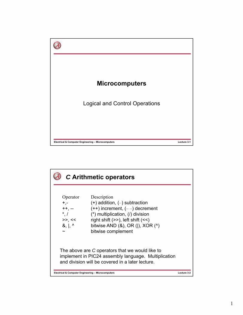
The above are C operators that we would like to implement in PIC24 assembly language. Multiplication and division will be covered in a later lecture.
Operator Description+,- (+) addition, (–) subtraction++, -- (++) increment, (– –) decrement*, / (*) multiplication, (/) division>>, << right shift (>>), left shift (<<)&, |, ^ bitwise AND (&), OR (|), XOR (^)~ bitwise complement

2
Lecture 3-3Electrical & Computer Engineering – Microcomputers
Bit-wise Logical operations
• Bitwise AND operation
AND.{B} Wb,Ws,Wd (Wb)&(Ws)Wd j = k & i;
AND.{B} f (f)&(WREG) f j = j & k;
AND.{B} f, WREG (f)&(WREG) WREG j = j & k;
AND.{B} #lit10,Wn lit10&(Wn) Wn j = j & literal;
• Bitwise Inclusive OR operation
IOR.{B} Wb,Ws,Wd (Wb)|(Ws)Wd j = k | i;
IOR.{B} f (f)|(WREG) f j = j | k;
IOR.{B} f, WREG (f)|(WREG) WREG j = j | k;
IOR.{B} #lit10,Wn lit10|(Wn) Wn j = j | literal;
Lecture 3-4Electrical & Computer Engineering – Microcomputers
Bit-wise Logical operations (continued)
• Bitwise XOR operationXOR.{B} Wb,Ws,Wd (Wb)^(Ws)Wd j = k ^ i;
XOR.{B} f (f)^(WREG) f j = j ^ k;
XOR.{B} f, WREG (f)^(WREG) WREG j = j ^ k;
XOR.{B} #lit10,Wn lit10^(Wn) Wn j = j ^ literal;
• Bitwise complement operationCOM.{B} Ws,Wd ~(Ws)Wd j = ~k;
COM.{B} f ~(f)f j = ~j;
COM.{B} f, WREG ~(f)WREG j = ~k;

3
Lecture 3-5Electrical & Computer Engineering – Microcomputers
Bit-wise Logical operations (continued)
• Clear ALL bits
CLR.{B} f 0f j = 0;
CLR.{B} WREG 0WREG j = 0;
CLR.{B} Wd 0Wd j = 0;
• Set ALL bits
SETM.{B} f 111..111f
SETM.{B} WREG 111..111 WREG
SETM.{B} Wd 111..111 Wd
Lecture 3-6Electrical & Computer Engineering – Microcomputers
Clearing a group of bits
Location contents
(i) 0x0800 0x2C
Data Memory
(j) 0x0801 0xB2
(k) 0x0802 0x8A
Clear upper four bits of i .
In C:uint8 i;i = i & 0x0F;
In PIC24 C assembly
mov.b #0x0F, W0 ; W0 = maskand.b i ; i = i & 0x0f
i = 0x2C = 0010 1100&&&& &&&&
mask= 0x0F = 0000 1111 ---------
result = 0000 1100= 0x0C
AND: mask bit = ‘1’, result bit is same as operand.mask bit = ‘0’, result bit is cleared
The ‘mask’
4
Lecture 3-7Electrical & Computer Engineering – Microcomputers
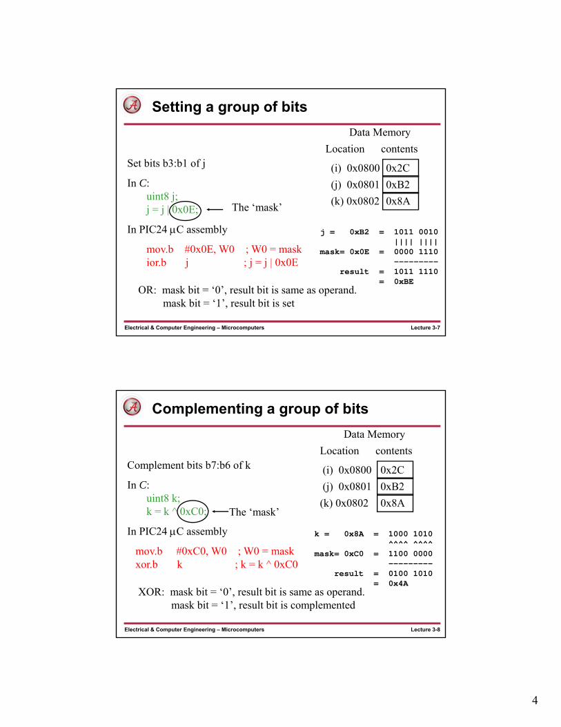
Setting a group of bits
Location contents
(i) 0x0800 0x2C
Data Memory
(j) 0x0801 0xB2
(k) 0x0802 0x8A
Set bits b3:b1 of j
In C:uint8 j; j = j | 0x0E;
In PIC24 C assembly
mov.b #0x0E, W0 ; W0 = maskior.b j ; j = j | 0x0E
j = 0xB2 = 1011 0010|||| ||||
mask= 0x0E = 0000 1110 ---------
result = 1011 1110= 0xBE
OR: mask bit = ‘0’, result bit is same as operand.mask bit = ‘1’, result bit is set
The ‘mask’
Lecture 3-8Electrical & Computer Engineering – Microcomputers
Complementing a group of bits
Location contents
(i) 0x0800 0x2C
Data Memory
(j) 0x0801 0xB2
(k) 0x0802 0x8A
Complement bits b7:b6 of k
In C:uint8 k;k = k ^ 0xC0;
In PIC24 C assembly
mov.b #0xC0, W0 ; W0 = maskxor.b k ; k = k ^ 0xC0
k = 0x8A = 1000 1010^^^^ ^^^^
mask= 0xC0 = 1100 0000 ---------
result = 0100 1010= 0x4A
XOR: mask bit = ‘0’, result bit is same as operand.mask bit = ‘1’, result bit is complemented
The ‘mask’

5
Lecture 3-9Electrical & Computer Engineering – Microcomputers
Complementing all bits
Location contents
(i) 0x0800 0x2C
Data Memory
(j) 0x0801 0xB2
(k) 0x0802 0x8A
Complement all bits of k
In C:uint8 k;k = ~k ;
In PIC24 C assembly
com.b k ; k = ~kk = 0x8A = 1000 1010
After complement
result = 0111 0101= 0x75
Lecture 3-10Electrical & Computer Engineering – Microcomputers
Bit set, Bit Clear, Bit Toggle instructions
Can set/clear/complement one bit of a data memory location by using the AND/OR/XOR operations, but takes multiple instructions as previously seen.
The bit clear (bcf), bit set (bsf), bit toggle (btg) instructions clear/set/complement one bit of data memory or working registers using one instruction.
6
Lecture 3-11Electrical & Computer Engineering – Microcomputers
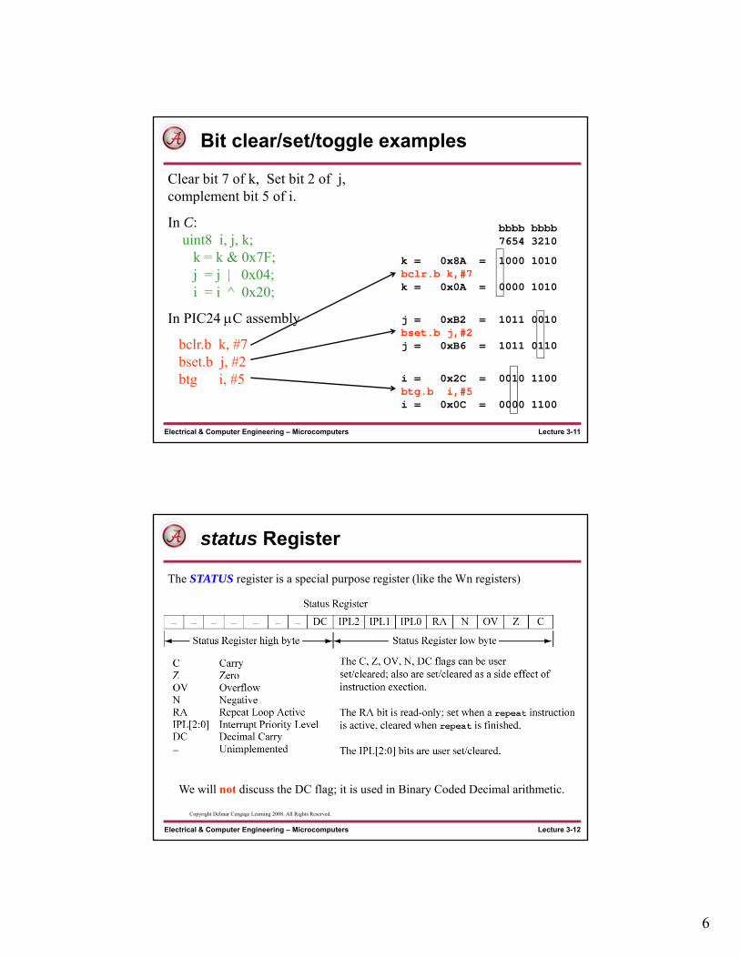
Bit clear/set/toggle examples
Clear bit 7 of k, Set bit 2 of j, complement bit 5 of i.
In C:uint8 i, j, k;
k = k & 0x7F;j = j | 0x04;i = i ^ 0x20;
In PIC24 C assembly
bclr.b k, #7 bset.b j, #2 btg i, #5
bbbb bbbb7654 3210
k = 0x8A = 1000 1010bclr.b k,#7k = 0x0A = 0000 1010
j = 0xB2 = 1011 0010bset.b j,#2j = 0xB6 = 1011 0110
i = 0x2C = 0010 1100btg.b i,#5i = 0x0C = 0000 1100
Lecture 3-12Electrical & Computer Engineering – Microcomputers
status Register
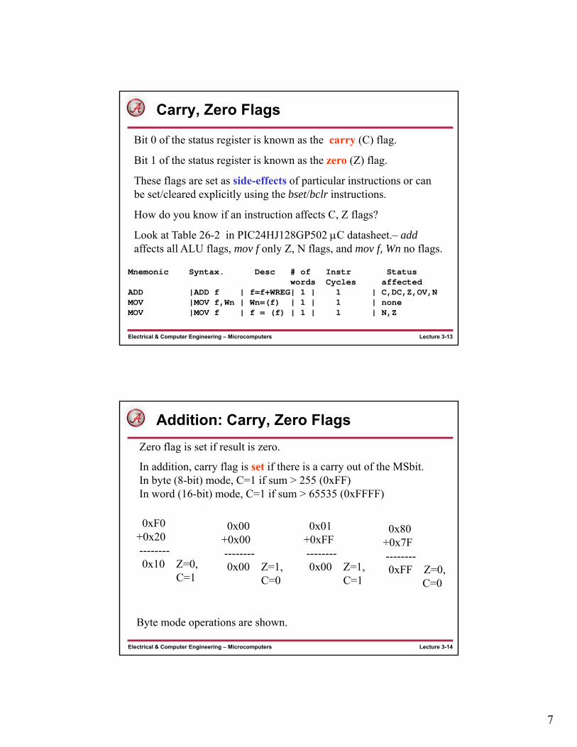
The STATUS register is a special purpose register (like the Wn registers)
We will not discuss the DC flag; it is used in Binary Coded Decimal arithmetic.
Copyright Delmar Cengage Learning 2008. All Rights Reserved.
7
Lecture 3-13Electrical & Computer Engineering – Microcomputers
Carry, Zero Flags
Bit 0 of the status register is known as the carry (C) flag.
Bit 1 of the status register is known as the zero (Z) flag.
These flags are set as side-effects of particular instructions or can be set/cleared explicitly using the bset/bclr instructions.
How do you know if an instruction affects C, Z flags?
Look at Table 26-2 in PIC24HJ128GP502 C datasheet.– addaffects all ALU flags, mov f only Z, N flags, and mov f, Wn no flags.
Mnemonic Syntax. Desc # of Instr Status words Cycles affected
ADD |ADD f | f=f+WREG| 1 | 1 | C,DC,Z,OV,NMOV |MOV f,Wn | Wn=(f) | 1 | 1 | noneMOV |MOV f | f = (f) | 1 | 1 | N,Z
Lecture 3-14Electrical & Computer Engineering – Microcomputers
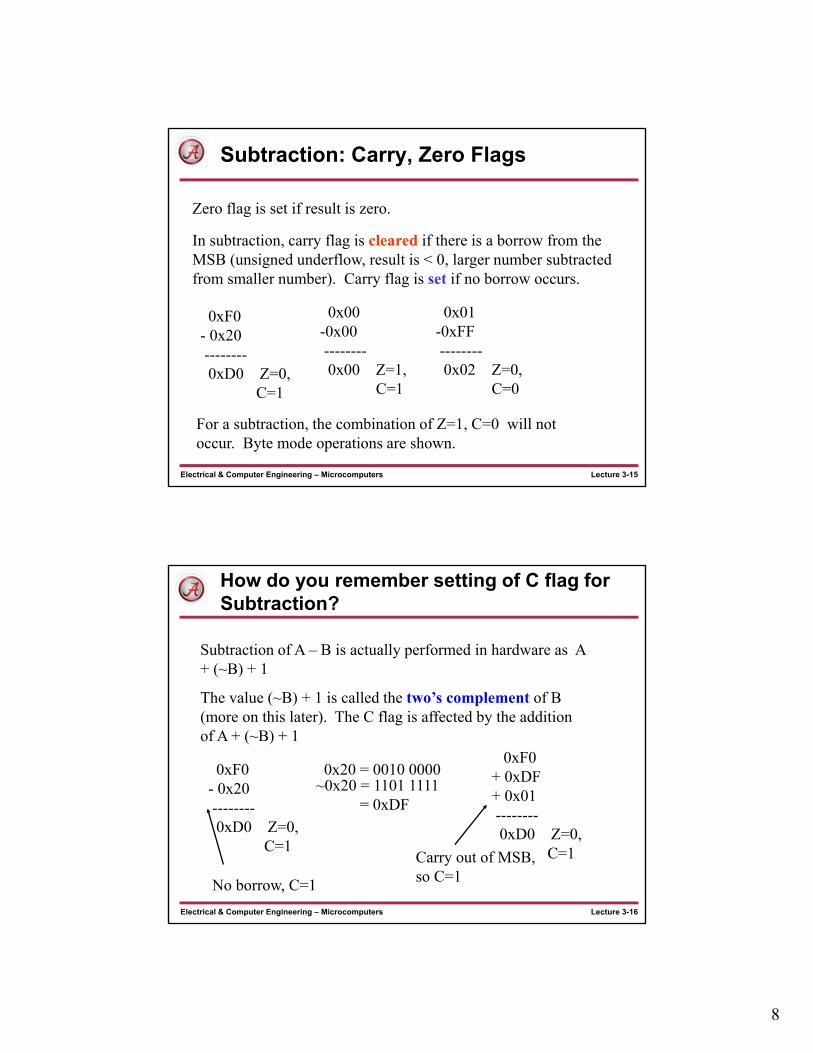
Addition: Carry, Zero Flags
In addition, carry flag is set if there is a carry out of the MSbit. In byte (8-bit) mode, C=1 if sum > 255 (0xFF)In word (16-bit) mode, C=1 if sum > 65535 (0xFFFF)
0xF0+0x20--------0x10 Z=0,
C=1
Zero flag is set if result is zero.
0x00+0x00--------0x00 Z=1,
C=0
0x01+0xFF--------0x00 Z=1,
C=1
0x80+0x7F--------0xFF Z=0,
C=0
Byte mode operations are shown.
8
Lecture 3-15Electrical & Computer Engineering – Microcomputers
Subtraction: Carry, Zero Flags
In subtraction, carry flag is cleared if there is a borrow from the MSB (unsigned underflow, result is < 0, larger number subtracted from smaller number). Carry flag is set if no borrow occurs.
0xF0- 0x20--------0xD0 Z=0,
C=1
Zero flag is set if result is zero.
0x00-0x00--------0x00 Z=1,
C=1
0x01-0xFF--------0x02 Z=0,
C=0
For a subtraction, the combination of Z=1, C=0 will not occur. Byte mode operations are shown.
Lecture 3-16Electrical & Computer Engineering – Microcomputers
How do you remember setting of C flag for Subtraction?
Subtraction of A – B is actually performed in hardware as A + (~B) + 1
The value (~B) + 1 is called the two’s complement of B (more on this later). The C flag is affected by the addition of A + (~B) + 1
0xF0- 0x20--------0xD0 Z=0,
C=1
0xF0+ 0xDF+ 0x01--------0xD0 Z=0,
C=1
0x20 = 0010 0000~0x20 = 1101 1111
= 0xDF
No borrow, C=1
Carry out of MSB, so C=1

9
Lecture 3-17Electrical & Computer Engineering – Microcomputers
C Shift Left, Shift Right
logical Shift right i >> 1all bits shift to right by one, ‘0’ into MSB (8-bit right shift shown)
b7 b6 b5 b4 b3 b2 b1 b0 original value
0 b7 b6 b5 b4 b3 b2 b1 i >> 1 (right shift by one)
Shift left i << 1all bits shift to left by one, ‘0’ into LSB (8-bit left shift shown)
b7 b6 b5 b4 b3 b2 b1 b0 original value
b6 b5 b4 b3 b2 b1 b0 0 i << 1 (left shift by one)
Lecture 3-18Electrical & Computer Engineering – Microcomputers
PIC24 Family Unsigned Right Shifts
b7 b6 b5 b4 b3 b2 b1 b0 Cflag0LogicalShiftRight
Descr: Syntax OperationLog. Shift Right f LSR{.B} f f >> 1 f
LSR{.B} f,WREG f >> 1 WREG
Log. Shift Right Ws LSR{.B} Ws,Wd Ws>> 1 WdLog. Shift Right by LSR Wb, #lit4, Wd Wb>>lit4 Wdshort Literal
Log. Shift Right by LSR Wb, Ws, Wd Wb>>Ws Wd Ws
The last two logical shifts can shift multiple positions in one instruction cycle (up to 15 positions), but only as word operations. There is an arithmetic right shift that will be covered in a later lecture.
b15 b14 . . . . . b1 b0 Cflag0
8-bit
16-bit
10
Lecture 3-19Electrical & Computer Engineering – Microcomputers
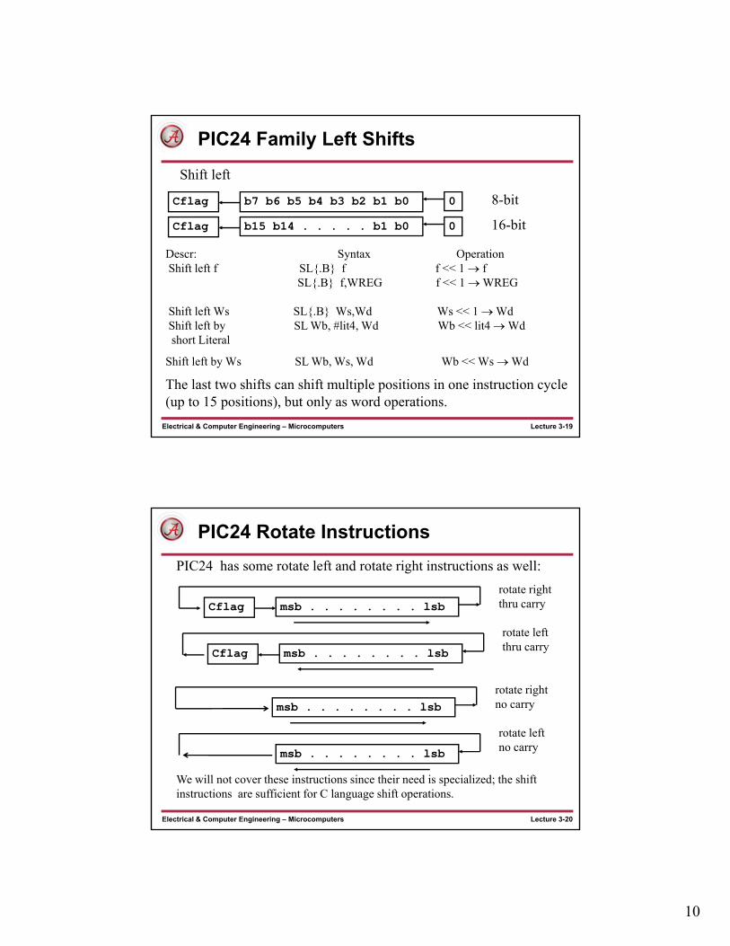
PIC24 Family Left Shifts
b7 b6 b5 b4 b3 b2 b1 b0Cflag
Shift left
0
b15 b14 . . . . . b1 b0Cflag 0
8-bit
16-bit
Descr: Syntax OperationShift left f SL{.B} f f << 1 f
SL{.B} f,WREG f << 1 WREG
Shift left Ws SL{.B} Ws,Wd Ws << 1 WdShift left by SL Wb, #lit4, Wd Wb << lit4 Wdshort Literal
Shift left by Ws SL Wb, Ws, Wd Wb << Ws Wd
The last two shifts can shift multiple positions in one instruction cycle (up to 15 positions), but only as word operations.
Lecture 3-20Electrical & Computer Engineering – Microcomputers
PIC24 Rotate Instructions
PIC24 has some rotate left and rotate right instructions as well:
msb . . . . . . . . lsbCflagrotate right thru carry
msb . . . . . . . . lsbCflag
rotate left thru carry
msb . . . . . . . . lsbrotate right no carry
msb . . . . . . . . lsb
rotate left no carry
We will not cover these instructions since their need is specialized; the shift instructions are sufficient for C language shift operations.

11
Lecture 3-21Electrical & Computer Engineering – Microcomputers
C Shift operations
It is sometimes more efficient to repeat a single position shift instruction performing a multi-bit shift.
Copyright Delmar Cengage Learning 2008. All Rights Reserved.
From: Reese/Bruce/Jones, “Microcontrollers: From Assembly to C with the PIC24 Family”.
Lecture 3-22Electrical & Computer Engineering – Microcomputers
Mixed 8-bit, 16-bit operations
Copyright Delmar Cengage Learning 2008. All Rights Reserved.
From: Reese/Bruce/Jones, “Microcontrollers: From Assembly to C with the PIC24 Family”.
12
Lecture 3-23Electrical & Computer Engineering – Microcomputers
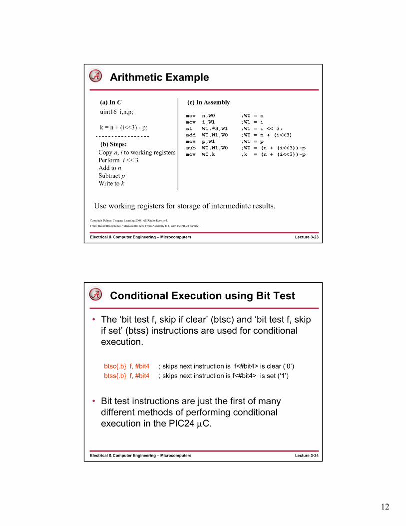
Arithmetic Example
Use working registers for storage of intermediate results.
Copyright Delmar Cengage Learning 2008. All Rights Reserved.
From: Reese/Bruce/Jones, “Microcontrollers: From Assembly to C with the PIC24 Family”.
Lecture 3-24Electrical & Computer Engineering – Microcomputers
Conditional Execution using Bit Test
• The ‘bit test f, skip if clear’ (btsc) and ‘bit test f, skip if set’ (btss) instructions are used for conditional execution.
btsc{.b} f, #bit4 ; skips next instruction is f<#bit4> is clear (‘0’)
btss{.b} f, #bit4 ; skips next instruction is f<#bit4> is set (‘1’)
• Bit test instructions are just the first of many different methods of performing conditional execution in the PIC24 C.
13
Lecture 3-25Electrical & Computer Engineering – Microcomputers
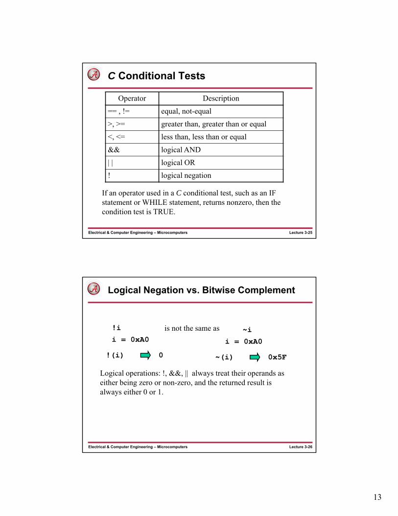
C Conditional Tests
Operator Description
== , != equal, not-equal
>, >= greater than, greater than or equal
<, <= less than, less than or equal
&& logical AND
| | logical OR
! logical negation
If an operator used in a C conditional test, such as an IF statement or WHILE statement, returns nonzero, then the condition test is TRUE.
Lecture 3-26Electrical & Computer Engineering – Microcomputers
Logical Negation vs. Bitwise Complement
!(i)
!i is not the same as ~i
0
i = 0xA0
~(i) 0x5F
i = 0xA0
Logical operations: !, &&, || always treat their operands as either being zero or non-zero, and the returned result is always either 0 or 1.
14
Lecture 3-27Electrical & Computer Engineering – Microcomputers
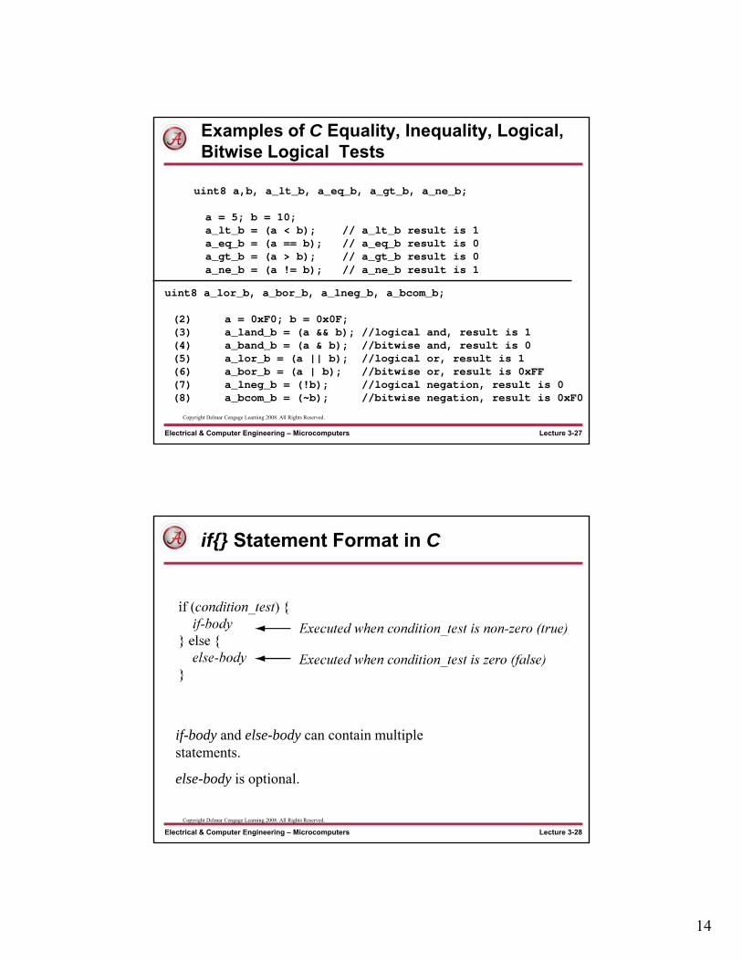
Examples of C Equality, Inequality, Logical, Bitwise Logical Tests
uint8 a,b, a_lt_b, a_eq_b, a_gt_b, a_ne_b;
a = 5; b = 10;a_lt_b = (a < b); // a_lt_b result is 1a_eq_b = (a == b); // a_eq_b result is 0a_gt_b = (a > b); // a_gt_b result is 0a_ne_b = (a != b); // a_ne_b result is 1
uint8 a_lor_b, a_bor_b, a_lneg_b, a_bcom_b;
(2) a = 0xF0; b = 0x0F;(3) a_land_b = (a && b); //logical and, result is 1(4) a_band_b = (a & b); //bitwise and, result is 0(5) a_lor_b = (a || b); //logical or, result is 1(6) a_bor_b = (a | b); //bitwise or, result is 0xFF(7) a_lneg_b = (!b); //logical negation, result is 0(8) a_bcom_b = (~b); //bitwise negation, result is 0xF0
Copyright Delmar Cengage Learning 2008. All Rights Reserved.
Lecture 3-28Electrical & Computer Engineering – Microcomputers
if{} Statement Format in C
if-body and else-body can contain multiple statements.
else-body is optional.
Copyright Delmar Cengage Learning 2008. All Rights Reserved.
15
Lecture 3-29Electrical & Computer Engineering – Microcomputers
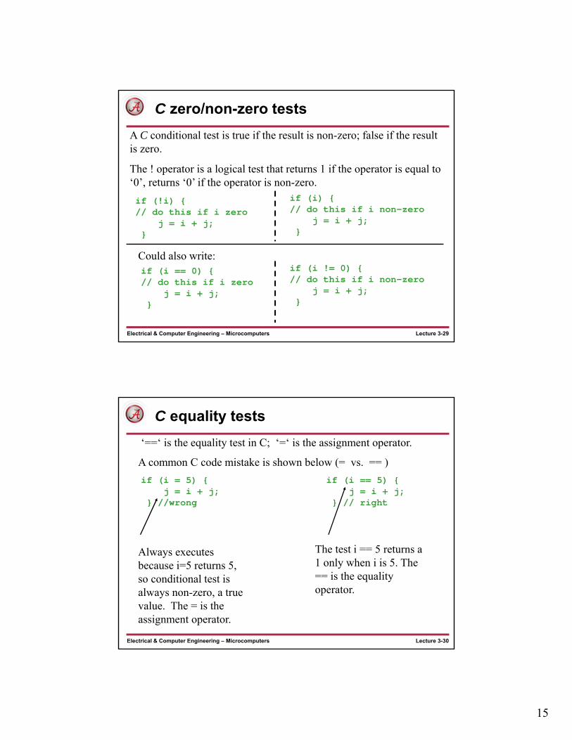
C zero/non-zero tests
A C conditional test is true if the result is non-zero; false if the result is zero.
The ! operator is a logical test that returns 1 if the operator is equal to ‘0’, returns ‘0’ if the operator is non-zero.
if (!i) {// do this if i zero
j = i + j;}
if (i) {// do this if i non-zero
j = i + j;}
Could also write:if (i == 0) {// do this if i zero
j = i + j;}
if (i != 0) {// do this if i non-zero
j = i + j;}
Lecture 3-30Electrical & Computer Engineering – Microcomputers
C equality tests
A common C code mistake is shown below (= vs. == )
if (i = 5) {j = i + j;
} //wrong
if (i == 5) {j = i + j;
} // right
Always executes because i=5 returns 5, so conditional test is always non-zero, a true value. The = is the assignment operator.
The test i == 5 returns a 1 only when i is 5. The == is the equality operator.
‘==‘ is the equality test in C; ‘=‘ is the assignment operator.

16
Lecture 3-31Electrical & Computer Engineering – Microcomputers
C Bitwise logical vs. Logical AND
The ‘&’ operator is a bitwise logical AND. The ‘&&’ operator is a logical AND and treats its operands as either zero or non-zero.
if (i && j) {/* do this */}
is read as:
If ( (i is nonzero) AND (j is nonzero) ) then do this.
if (i & j) {/* do this */}
If ( (i bitwise AND j) is nonzero) ) then do this.
(i && j) (i & j)
is read as:
i = 0xA0, j = 0x0B;
1
i = 0xA0, j = 0x0B;
0x0
Lecture 3-32Electrical & Computer Engineering – Microcomputers
C Bitwise logical vs. Logical OR
The ‘|’ operator is a bitwise logical OR. The ‘||’ operator is a logical OR and treats its operands as either zero or non-zero.
if (i || j) {/* do this */}
is read as:
If ( (i is nonzero) OR (j is nonzero) ) { do...
if (i | j) {/* do this */}
If ( (i bitwise OR j) is nonzero) ) { do....
is read as:
(i || j) (i | j)
i = 0xA0, j = 0x0B;
1
i = 0xA0, j = 0x0B;
0xAB

17
Lecture 3-33Electrical & Computer Engineering – Microcomputers
Non-Zero Test
The mov k instruction just moves k back onto itself! Does no useful work except to affect the Z, N flags.
labels for SFRs defined in p24Hxxxx.inc; use for clarity!!!!
Copyright Delmar Cengage Learning 2008. All Rights Reserved.
From: Reese/Bruce/Jones, “Microcontrollers: From Assembly to C with the PIC24 Family”.
Lecture 3-34Electrical & Computer Engineering – Microcomputers
Conditional Execution using branches
• A branch functions as a conditional goto based upon the setting of one more flags
• Simple branches test only one flag:BRA Z, <label> branch to label if Z=1
BRA NZ, <label> branch to label if Z=0 (not zero)
BRA C, <label> branch to label if C=1
BRA NC, <label> branch to label if C=0 (no carry)
BRA N, <label> branch to label if N=1
BRA NN, <label> branch to label if N=0 (not negative)
BRA <label> unconditional branch to <label>
• Using branch instructions instead of btsc/btss generally results in fewer instructions, and improves code clarity.
18
Lecture 3-35Electrical & Computer Engineering – Microcomputers
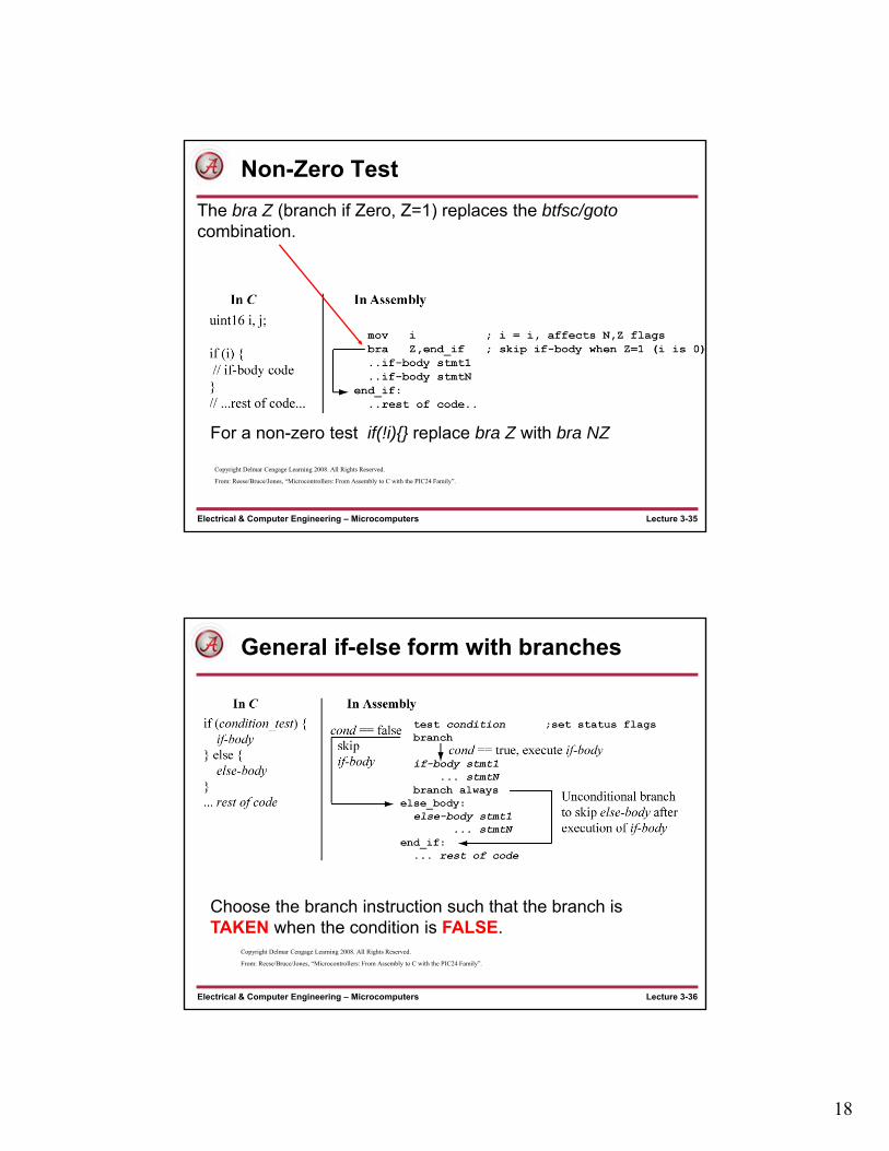
Non-Zero Test
The bra Z (branch if Zero, Z=1) replaces the btfsc/gotocombination.
For a non-zero test if(!i){} replace bra Z with bra NZ
Copyright Delmar Cengage Learning 2008. All Rights Reserved.
From: Reese/Bruce/Jones, “Microcontrollers: From Assembly to C with the PIC24 Family”.
Lecture 3-36Electrical & Computer Engineering – Microcomputers
General if-else form with branches
Choose the branch instruction such that the branch is TAKEN when the condition is FALSE.
Copyright Delmar Cengage Learning 2008. All Rights Reserved.
From: Reese/Bruce/Jones, “Microcontrollers: From Assembly to C with the PIC24 Family”.
19
Lecture 3-37Electrical & Computer Engineering – Microcomputers
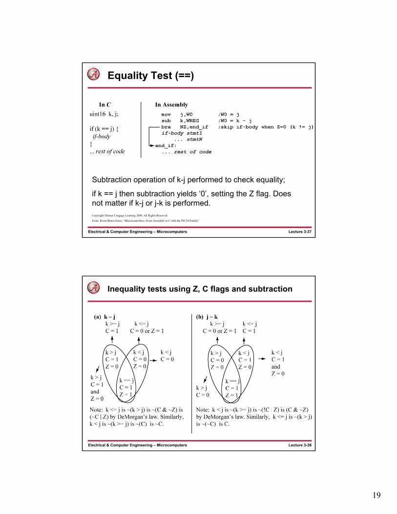
Equality Test (==)
Subtraction operation of k-j performed to check equality;
if k == j then subtraction yields ‘0’, setting the Z flag. Does not matter if k-j or j-k is performed.Copyright Delmar Cengage Learning 2008. All Rights Reserved.
From: Reese/Bruce/Jones, “Microcontrollers: From Assembly to C with the PIC24 Family”.
Lecture 3-38Electrical & Computer Engineering – Microcomputers
Inequality tests using Z, C flags and subtraction
20
Lecture 3-39Electrical & Computer Engineering – Microcomputers
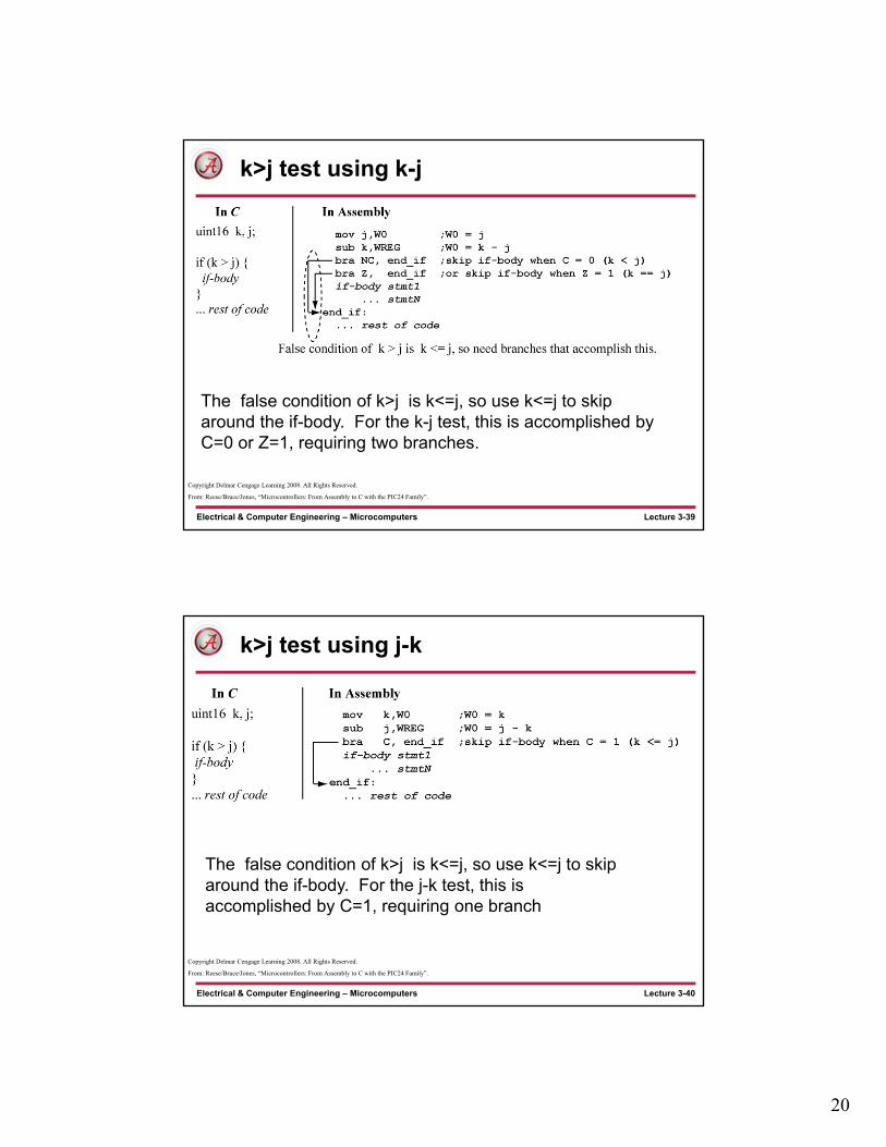
k>j test using k-j
The false condition of k>j is k<=j, so use k<=j to skip around the if-body. For the k-j test, this is accomplished by C=0 or Z=1, requiring two branches.
Copyright Delmar Cengage Learning 2008. All Rights Reserved.
From: Reese/Bruce/Jones, “Microcontrollers: From Assembly to C with the PIC24 Family”.
Lecture 3-40Electrical & Computer Engineering – Microcomputers
k>j test using j-k
The false condition of k>j is k<=j, so use k<=j to skip around the if-body. For the j-k test, this is accomplished by C=1, requiring one branch
Copyright Delmar Cengage Learning 2008. All Rights Reserved.
From: Reese/Bruce/Jones, “Microcontrollers: From Assembly to C with the PIC24 Family”.
21
Lecture 3-41Electrical & Computer Engineering – Microcomputers
Comparison, Unsigned Branches
• Using subtraction, and simple branches can be confusing, since it can be difficult to remember which subtraction to perform and which branch to use.
• Also, the subtraction operation overwrites a register value.
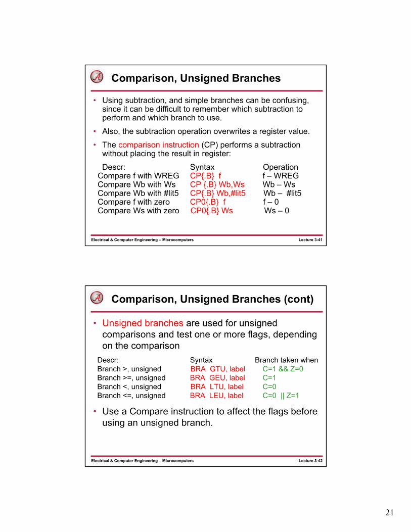
• The comparison instruction (CP) performs a subtraction without placing the result in register:
Descr: Syntax OperationCompare f with WREG CP{.B} f f – WREGCompare Wb with Ws CP {.B} Wb,Ws Wb – WsCompare Wb with #lit5 CP{.B} Wb,#lit5 Wb – #lit5Compare f with zero CP0{.B} f f – 0Compare Ws with zero CP0{.B} Ws Ws – 0
Lecture 3-42Electrical & Computer Engineering – Microcomputers
Comparison, Unsigned Branches (cont)
• Unsigned branches are used for unsigned comparisons and test one or more flags, depending on the comparison
Descr: Syntax Branch taken whenBranch >, unsigned BRA GTU, label C=1 && Z=0Branch >=, unsigned BRA GEU, label C=1Branch <, unsigned BRA LTU, label C=0Branch <=, unsigned BRA LEU, label C=0 || Z=1
• Use a Compare instruction to affect the flags before using an unsigned branch.

22
Lecture 3-43Electrical & Computer Engineering – Microcomputers
Unsigned Comparison (> test)
For k > j test, use the LEU (less than or equal unsigned) branch to skip IF body if k <= j
Copyright Delmar Cengage Learning 2008. All Rights Reserved.
From: Reese/Bruce/Jones, “Microcontrollers: From Assembly to C with the PIC24 Family”.
Lecture 3-44Electrical & Computer Engineering – Microcomputers
If-else Example
Must use unconditional branch at end of if-body to skip the else-body.
Copyright Delmar Cengage Learning 2008. All Rights Reserved.
From: Reese/Bruce/Jones, “Microcontrollers: From Assembly to C with the PIC24 Family”.

23
Lecture 3-45Electrical & Computer Engineering – Microcomputers
Unsigned literal Comparison
Copyright Delmar Cengage Learning 2008. All Rights Reserved.
From: Reese/Bruce/Jones, “Microcontrollers: From Assembly to C with the PIC24 Family”.
Lecture 3-46Electrical & Computer Engineering – Microcomputers
switch Statement in C
A switch statement is a shorthand version of an if-elsechain where the same variable is compared for equality against different values.
Copyright Delmar Cengage Learning 2008. All Rights Reserved.
From: Reese/Bruce/Jones, “Microcontrollers: From Assembly to C with the PIC24 Family”.

24
Lecture 3-47Electrical & Computer Engineering – Microcomputers
switch Statement in assembly language
Lecture 3-48Electrical & Computer Engineering – Microcomputers
Unsigned, Zero, Equality, Comparison Summary
Condition Test True Branch False Branch
i == 0 i 0 bra Z bra NZ
i != 0 i 0 bra NZ bra Z
i == k i k bra Z bra NZ
i != k i k bra NZ bra Zi > k i k bra GTU bra LEU
i >= k i k bra GEU bra LTU
i < k i k bra LTU bra GEU
i <= k i k bra LEU bra GTU

25
Lecture 3-49Electrical & Computer Engineering – Microcomputers
Complex Conditions (&&)
Copyright Delmar Cengage Learning 2008. All Rights Reserved.
From: Reese/Bruce/Jones, “Microcontrollers: From Assembly to C with the PIC24 Family”.
Lecture 3-50Electrical & Computer Engineering – Microcomputers
Complex Condition Example (&&)
Copyright Delmar Cengage Learning 2008. All Rights Reserved.
From: Reese/Bruce/Jones, “Microcontrollers: From Assembly to C with the PIC24 Family”.

26
Lecture 3-51Electrical & Computer Engineering – Microcomputers
Complex Conditions (||)
Copyright Delmar Cengage Learning 2008. All Rights Reserved.
From: Reese/Bruce/Jones, “Microcontrollers: From Assembly to C with the PIC24 Family”.
Careful of last branch!Different from others!
Lecture 3-52Electrical & Computer Engineering – Microcomputers
Complex Condition Example (||)
Copyright Delmar Cengage Learning 2008. All Rights Reserved.
From: Reese/Bruce/Jones, “Microcontrollers: From Assembly to C with the PIC24 Family”.

27
Lecture 3-53Electrical & Computer Engineering – Microcomputers
while loop Structure
Observe that at the end of the loop, there is a jump back to top_while after the while-body is performed. The body of a while loop will not execute if the condition test is initially false.
Copyright Delmar Cengage Learning 2008. All Rights Reserved.
From: Reese/Bruce/Jones, “Microcontrollers: From Assembly to C with the PIC24 Family”.
Lecture 3-54Electrical & Computer Engineering – Microcomputers
while loop Example
Copyright Delmar Cengage Learning 2008. All Rights Reserved.
From: Reese/Bruce/Jones, “Microcontrollers: From Assembly to C with the PIC24 Family”.
28
Lecture 3-55Electrical & Computer Engineering – Microcomputers
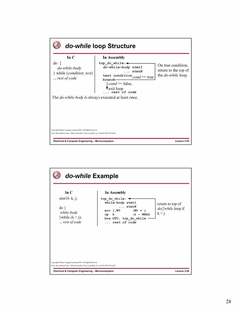
do-while loop Structure
Copyright Delmar Cengage Learning 2008. All Rights Reserved.
From: Reese/Bruce/Jones, “Microcontrollers: From Assembly to C with the PIC24 Family”.
Lecture 3-56Electrical & Computer Engineering – Microcomputers
do-while Example
Copyright Delmar Cengage Learning 2008. All Rights Reserved.
From: Reese/Bruce/Jones, “Microcontrollers: From Assembly to C with the PIC24 Family”.

29
Lecture 3-57Electrical & Computer Engineering – Microcomputers
Aside: for loops in C
A for loop is just another way to write a while loop. Typically used to implement a counting loop (a loop that is executed a fixed number of times).
uint16 i,j;
i = 0;while (i != 10) {
k = k + j;i++;
}/* ..do stuff..*/
unsigned int i,j;
for (i = 0; i!= 10; i++){k = k + j;
} /* do stuff */
These statements executed 10 times. Both code blocks are equivalent.
executed once, before test.
executed each loop iteration after body
loop test
Lecture 3-58Electrical & Computer Engineering – Microcomputers
What instructions do you use?
• You will discover that there are many ways for accomplishing the same thing using different instruction sequences.
• Which method do you use?
• The method that you understand......(and have not MEMORIZED), since memorization of code fragments will fail if faced with a situation different from what is memorized.
30
Lecture 3-59Electrical & Computer Engineering – Microcomputers
What do you need to know?
• Logical operations (and, or, xor, complement)
• Clearing/setting/complementing groups of bits
• Bit set/clear/test instructions
• Shift left (<<), shift right (>>)
• ==, !=, >, <, >=, <= tests on 8-bit, 16-bit unsigned variables
• Loop structures
Related Documents