Microbial Fuel Cell Technologies‐‐ MxCs: Can they scale? (Yes!) Bruce E. Logan Penn State University Engineering Energy & Environmental Institute

Welcome message from author
This document is posted to help you gain knowledge. Please leave a comment to let me know what you think about it! Share it to your friends and learn new things together.
Transcript

Microbial Fuel Cell Technologies‐‐MxCs Can they scale
(Yes) Bruce E Logan
Penn State University
Engineering Energy amp Environmental Institute
MFCs
Anode
Fuel (wastes)
Oxidation products
(CO2)
Bacteria that make electrical current
Electrical power generation in a Microbial Fuel Cell (MFC) using exoelectrogenic microorganisms
load e - e - Cathode
Oxidant (O2)
Reduced oxidant (H2O)
Liu e t al (2004) Environ Sci Technol
H+
2
3
Scaling up MFCs amp MECs MFCs= fuel cells make electricity MECs= electrolysis cells make H2
3
4
MEC Reactor that has 24 modules with a total of 144 electrode pairs (1000 L)
Cusick et al (2011) Appl Microbiol Biotechnol 4
5
Individual module performance of the MEC treating Wastewater
Predicted 380 mAmodule (total of 92 A)
500
Mod
ular
Cur
rent
(mA)
400
300
200
100
0 1 3 5 7 9 11 13 15 17 19 21 23
Module Number
H2 initially produced but it all was converted to CH4
Elec Energy input= 6 Wm3
Energy Out = 99 Wm3
16times more energy recovered than electrical energy put into the process
Cusick et al (2011) Appl Microbiol Biotechnol 5
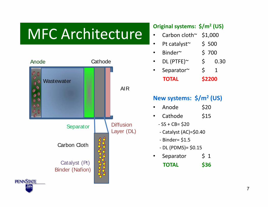
MFC Architecture Estimates for MFCs bull 100 euro m2 or $130m2
Estimates for MECs bull 100 euro m2 or $130m2
6
MFC Architecture
Anode Cathode
Wastewater AIR
Diffusion Separator Layer (DL)
Carbon Cloth
Catalyst (Pt) Binder (Nafion)
Original systems $m2 (US) bull Carbon cloth~ $1000
bull Pt catalyst~ $ 500
bull Binder~ $ 700
bull DL (PTFE)~ $ 030
bull Separator~ $ 1
TOTAL $2200
New systems $m2 (US) bull Anode $20
bull Cathode $15 ‐ SS + CB= $20
‐ Catalyst (AC)=$040
‐ Binder= $15
‐ DL (PDMS)= $015
bull Separator $ 1
TOTAL $36
7
8
MFC Materials Anode Graphite brush electrode bull Graphite fibers commercially
available (used in tennis rackets airplanesetc)
bull Easy to manufacture
bull Fiber diameter‐ 6‐10 μm a good match to bacteria (~1 μm)
bull High surface area per volume‐Up to 15000 m2m3
Logan et al (2007) Environ Sci Technol 8
Voltage Production Results Brushes still work better than flat mesh
B= Brush anode M= Mesh (flat) anode
Hays and Logan (2011) J Power Sources 9
Multi‐electrode MFCs
3 brushes (R3) 5 brushes (R5) 8 brushes (R8) 3500 m2m3 2800 m2m3 2900 m2m3
Electrode area (25 cm diameter brushchamber width = 40 m2m3
Lanas amp Logan (2013) J Power Sources 10
Cathode Activated Carbon Catalysts Carbon cloth with Pt
VITO cathode (no Pt)
Activated carbon cathode works almost as well as Pt catalyst
0
500
1000
1500 P
ower
Den
sity
(mW
m2 )
VITO cathode- with Pt
VITO cathode (no Pt)
0 2 4 6 8 10 Current Density (Am2)
11Zhang Cheng Van Bogaert Pant amp Logan (2009) Electrochem Commun
0
200
400
600
800
1000
1200
1400
1600
Max
imum
Pow
er D
ensi
ty (m
Wm
2 )
0
200
400
600
800
1000
1200
1400
1600
Pow
er D
ensi
ty (m
Wm
2 )
Activated Carbon Cathodes‐ (Manufactured by VITO)
0
200
400
600
800
1000
1200
1400
1600 Po
wer
Den
sity
(mW
m2 )
AC AC-Fe AC-Heat AC-CB Pt
B - 16 months A - 1 month
0 2 4 6 8 10 0 2 4 6 8 10 Current Density (Am2) Current Density (Am2)
0 5 10 15 20 Time (months)
0
200
400
600
800
1000
1200
1400
1600
0 2 4 6 8 10
Pow
er D
ensi
ty (m
Wm
2 )
Current Density (Am2)
DC - 17 months-HCl DI Water rinse HCl
Performance over 16 months
Original powernearly restoredusing acid (HCl)wash
Zhang Pant Zhang Liu Logan (2014) Chem Electro Chem 12
13
New Binder for Activated Carbon PVDF bull Using a PVDF binder is simple and effective
ndash 1‐ apply to SS mesh 2‐ phase inversion in water ndash Make at room temperature
ndash Amenable to continuous rolling process ndash No separate gas diffusion layer (GDL) needed
ndash Cost $15 mndash2 ($12 mndash2 for SS mesh $3 mndash2 for catalyst and binder)
Yang He Zhang Hickner Logan (2014) ESampT Letters
PVDF Binder Power the same as PTFE
bull Water pressure up applied to carbon clothPt to 12 m (vs 02 m for PTFE)
Yang He Zhang Hickner Logan (2014) ESampT Letters
Acetate amp PBS buffer
New-rev
Domestic Wastewater
14
MFCs and MECs for Wastewater Treatment
hellipand why MxCs alone cannot accomplish wastewater treatment
Low sCOD limits current generation
900
0
1
2
3
4
0 10 20 30 40 50 60 C
urre
nt D
ensi
ty (A
m2 )
Ac High 100 Ω Current
Ac High 100 Ω COD
D
ACETATE Current very stable then it suddenly decreases
800
700
CO
D (m
gL)
600
500
400
300
COD removal constant (first-order kinetics) 100
200 sCOD ~ 180 mgL
0
Time (h)2 500
450WW 100 Ω Current WW 100 Ω sCOD WW 100 Ω tCOD
WW
0 5 10 15 20 25 30
In both cases COD continues to be removed so treatment continues without electricity generation but ww cannot be discharged due to high COD
16
12
400
Cur
rent
Den
sity
(Am
2 )
CO
D (m
gL)350
300 250
tCOD ~ 150 mgL
sCOD ~ 100 mgL
08 200 150
04 100 50
0 0
Time (h)
Zhang He Ren Evans Logan (2015) Biores Technol 16
1
Current density vs soluble COD (sCOD) Current rapidly drops off at ~100 mgL sCOD
4
Ac Low 1000 Ω
Ac High 1000 Ω
WW 1000 Ω Cur
rent
Den
sity
(Am
2 )
1000 Ω
0 200 400 600 800 1000
Ac Low 100 Ω
Ac High 100 Ω
WW 100 Ω
WW-R 100 Ω
100 Ω
0 200 400 600 800 1000
Cur
rent
Den
sity
(Am
2 ) 08
06
04
02
0
3
2
1
0
COD (mgL) COD (mgL)
In both cases current rapidly decreases when sCOD is still high (~100 mgL)
17Zhang He Ren Evans Logan (2015) Biores Technol
How much COD removal can we get from domestic WW ~80‐90 but final COD is too high
Hays and Logan (2011) J Power Sources
‐Why isnrsquot more COD removed ‐What is ldquofaterdquo of COD
bull Influent
COD = 400 mgL or BOD5 = 200 mgL
bull Effluent BOD5 35‐40 mgL (like a Trickling Filter)
Removal gt80
18
MFC Performance using Domestic Wastewater
Wastewater and Design Considerations
bull Acetate + Phosphate buffer ne SyntheƟc wastewater ndash Acetate concentrations are usually too high to represent WW
ndash PBS used is artificially conductive7‐20 mScm (vs 1 mScm for WW)
bull Domestic wastewater ndash COD of ~300‐500 mgL (50 BOD5) ndash Composition is variable So lots of oxygen contamination of the
anode over time can have anode limitations on performance
bull Reactor design ndash Canrsquot have too narrow space between electrodes (it will clog) ndash Must take into account volume demands of air cathodes
bull Final effluent quality ndash If domestic ww used + need to discharge = Need AFMBR
ndash If industrial may only need to get to level suitable for discharge to sewers (no secondary process needed in this case)
MFC Architecture
Logan amp Elimelech (2012) Nature 21
22
Overall goal compact reactor design
Assume One anode-cathode module is 1 m2 projected area (height x width) and 10 cm thick
Result 10 modules = 10 m2
10 cm
10 cm
10 cm
10 cm
Design Limited by cathode area so in this example we achieve 10 m2m3
10 cm 100 cm
Logan (2012) Chem Sus Chem 22
MFC + AFMBR (Anaerobic Fluidized Bed Membrane Bioreactor)
Ren Ahn amp Logan (2014) Environ Sci Technol 23
Generation I MFC configuration
bull SEA Separator electrode assembly ndash Trimmed graphite fiber brush one side flat ndash Separator between brush anode and
cathode placed together
bull SPA Spaced electrode assembly ndash Brush placed distant from cathode so it
canrsquot touch it
bull Two reactors used in series ndash 2 times 4 h HRT = 8 h HRT
bull Total of 4 MFCs (2 SEA 2 SPA)
Ren Ahn amp Logan (2014) Environ Sci Technol 24
AFMBR Construction bull Idea of AFMBR first published by
Chae et al (ESampT) Used as a second stage to granular fluidized bed anerobic digester
bull AFMBR consists of a reactor body + ultrafiltration membrane + granular activated carbon (GAC)
bull GAC fluidized by recirculation
bull In tests here used with a hydraulic retention time of 1 hour
Ren Ahn amp Logan (2014) Environ Sci Technol 25
Experimental Setup MFC+AFMBR
Reactor HRTs MFC=4 h (each) AFMBR=1 h ldquoFrdquo= Granular activated carbon (GAC) fluidized used for
biofilm support and membrane cleaning (scour) ldquoMBRrdquo PVDF hollow fiber membranes MFC types SEA (separator) SPA (spaced no separator)
26Ren Ahn amp Logan (2014) Environ Sci Technol
Comparison of performance of SEA and SPA MFCs over time
bull Initially similar performance
bull After 5 months SEAgtgt SPA
bull Separator needed for long term performance
01
02
03
Pow
er (m
W)
SPA-U SEA-U SPA-D SEA-D
a
01
02
03
Pow
er (m
W)
NEW
05 1 15 2 Current (mA) U= Upflow (1st MFC in series)
0404
0 0
b After 5 months
0 05 1 15 2 Current (mA)
D=downflow (2nd MFC in series)
Ren Ahn amp Logan (2014) Environ Sci Technol 27
Effluent reduced to 16 mgL tCOD 250
bull Two trains of MFC (HRT = 4 h) to AFMBR (HRT = 1 h)
bull Membrane flux 16 Lm2h
bull 50 days performance
bull Energy balanced
(MFC produced = AFMBR used)
Con
cent
ratio
n (m
gL)
200
150
100
50
0 tCOD sCOD TSS
MFCs FMBR Effluent
491
503
510 434
359 486
925
862
996
bull Effluent COD = 16 mgL bull Effluent TSS lt1 mgL
WW in FMBR Permeate Ren Ahn amp Logan (2014) Environ Sci Technol 28
Key to AFMBR success Little fouling bull First 10 days initial rapid
increase in transmembrane 01 pressure (TMP)
bull Days 10‐50 only slight increase 008
in TMP
bull Flux of 16 LMH much greater than that in previous studies with anaerobic fluidized bed
TMP
(bar
)
006
004
002
0 10 20 30 40 50
reactors (AFBRs) ndash AFMBR 6‐7 LMH at start 0 ndash 4‐11 LMH at start
Time (d)
Ren Ahn amp Logan (2014) Environ Sci Technol 29
30
Conclusions
bull Microbial Fuel Cell Technologies‐‐MxCs Can they scale
Yes
30
MET Companies bull Emefcy (Israel) wwwemefcycom bull Cambrian Innovations (Boston MA) httpcambrianinnovationcom
bull ArbSource (with Arizona State University) wwwarbsourceus bull Waste2Watergy (with Oregon State University)
advantageoregonstateeduclientswaste2watergy
bull Living Power (with Harvard University) bull Quantum Intelligence (San Jose CA) bull Electroarchae wwwelectroarchaecom
bull MicroOrganic (New York) httpmicrorganictechcomtechnology bull
Thanks to students and researchers in the MxC team at Penn State
Current research sponsors SERDPDOD (2012-2015) Air ProductsDOE (2012-2014) GCEPStanford (2012-2015) NRELDOE (2012-2014)
International Collaborations

MFCs
Anode
Fuel (wastes)
Oxidation products
(CO2)
Bacteria that make electrical current
Electrical power generation in a Microbial Fuel Cell (MFC) using exoelectrogenic microorganisms
load e - e - Cathode
Oxidant (O2)
Reduced oxidant (H2O)
Liu e t al (2004) Environ Sci Technol
H+
2
3
Scaling up MFCs amp MECs MFCs= fuel cells make electricity MECs= electrolysis cells make H2
3
4
MEC Reactor that has 24 modules with a total of 144 electrode pairs (1000 L)
Cusick et al (2011) Appl Microbiol Biotechnol 4
5
Individual module performance of the MEC treating Wastewater
Predicted 380 mAmodule (total of 92 A)
500
Mod
ular
Cur
rent
(mA)
400
300
200
100
0 1 3 5 7 9 11 13 15 17 19 21 23
Module Number
H2 initially produced but it all was converted to CH4
Elec Energy input= 6 Wm3
Energy Out = 99 Wm3
16times more energy recovered than electrical energy put into the process
Cusick et al (2011) Appl Microbiol Biotechnol 5
MFC Architecture Estimates for MFCs bull 100 euro m2 or $130m2
Estimates for MECs bull 100 euro m2 or $130m2
6
MFC Architecture
Anode Cathode
Wastewater AIR
Diffusion Separator Layer (DL)
Carbon Cloth
Catalyst (Pt) Binder (Nafion)
Original systems $m2 (US) bull Carbon cloth~ $1000
bull Pt catalyst~ $ 500
bull Binder~ $ 700
bull DL (PTFE)~ $ 030
bull Separator~ $ 1
TOTAL $2200
New systems $m2 (US) bull Anode $20
bull Cathode $15 ‐ SS + CB= $20
‐ Catalyst (AC)=$040
‐ Binder= $15
‐ DL (PDMS)= $015
bull Separator $ 1
TOTAL $36
7
8
MFC Materials Anode Graphite brush electrode bull Graphite fibers commercially
available (used in tennis rackets airplanesetc)
bull Easy to manufacture
bull Fiber diameter‐ 6‐10 μm a good match to bacteria (~1 μm)
bull High surface area per volume‐Up to 15000 m2m3
Logan et al (2007) Environ Sci Technol 8
Voltage Production Results Brushes still work better than flat mesh
B= Brush anode M= Mesh (flat) anode
Hays and Logan (2011) J Power Sources 9
Multi‐electrode MFCs
3 brushes (R3) 5 brushes (R5) 8 brushes (R8) 3500 m2m3 2800 m2m3 2900 m2m3
Electrode area (25 cm diameter brushchamber width = 40 m2m3
Lanas amp Logan (2013) J Power Sources 10
Cathode Activated Carbon Catalysts Carbon cloth with Pt
VITO cathode (no Pt)
Activated carbon cathode works almost as well as Pt catalyst
0
500
1000
1500 P
ower
Den
sity
(mW
m2 )
VITO cathode- with Pt
VITO cathode (no Pt)
0 2 4 6 8 10 Current Density (Am2)
11Zhang Cheng Van Bogaert Pant amp Logan (2009) Electrochem Commun
0
200
400
600
800
1000
1200
1400
1600
Max
imum
Pow
er D
ensi
ty (m
Wm
2 )
0
200
400
600
800
1000
1200
1400
1600
Pow
er D
ensi
ty (m
Wm
2 )
Activated Carbon Cathodes‐ (Manufactured by VITO)
0
200
400
600
800
1000
1200
1400
1600 Po
wer
Den
sity
(mW
m2 )
AC AC-Fe AC-Heat AC-CB Pt
B - 16 months A - 1 month
0 2 4 6 8 10 0 2 4 6 8 10 Current Density (Am2) Current Density (Am2)
0 5 10 15 20 Time (months)
0
200
400
600
800
1000
1200
1400
1600
0 2 4 6 8 10
Pow
er D
ensi
ty (m
Wm
2 )
Current Density (Am2)
DC - 17 months-HCl DI Water rinse HCl
Performance over 16 months
Original powernearly restoredusing acid (HCl)wash
Zhang Pant Zhang Liu Logan (2014) Chem Electro Chem 12
13
New Binder for Activated Carbon PVDF bull Using a PVDF binder is simple and effective
ndash 1‐ apply to SS mesh 2‐ phase inversion in water ndash Make at room temperature
ndash Amenable to continuous rolling process ndash No separate gas diffusion layer (GDL) needed
ndash Cost $15 mndash2 ($12 mndash2 for SS mesh $3 mndash2 for catalyst and binder)
Yang He Zhang Hickner Logan (2014) ESampT Letters
PVDF Binder Power the same as PTFE
bull Water pressure up applied to carbon clothPt to 12 m (vs 02 m for PTFE)
Yang He Zhang Hickner Logan (2014) ESampT Letters
Acetate amp PBS buffer
New-rev
Domestic Wastewater
14
MFCs and MECs for Wastewater Treatment
hellipand why MxCs alone cannot accomplish wastewater treatment
Low sCOD limits current generation
900
0
1
2
3
4
0 10 20 30 40 50 60 C
urre
nt D
ensi
ty (A
m2 )
Ac High 100 Ω Current
Ac High 100 Ω COD
D
ACETATE Current very stable then it suddenly decreases
800
700
CO
D (m
gL)
600
500
400
300
COD removal constant (first-order kinetics) 100
200 sCOD ~ 180 mgL
0
Time (h)2 500
450WW 100 Ω Current WW 100 Ω sCOD WW 100 Ω tCOD
WW
0 5 10 15 20 25 30
In both cases COD continues to be removed so treatment continues without electricity generation but ww cannot be discharged due to high COD
16
12
400
Cur
rent
Den
sity
(Am
2 )
CO
D (m
gL)350
300 250
tCOD ~ 150 mgL
sCOD ~ 100 mgL
08 200 150
04 100 50
0 0
Time (h)
Zhang He Ren Evans Logan (2015) Biores Technol 16
1
Current density vs soluble COD (sCOD) Current rapidly drops off at ~100 mgL sCOD
4
Ac Low 1000 Ω
Ac High 1000 Ω
WW 1000 Ω Cur
rent
Den
sity
(Am
2 )
1000 Ω
0 200 400 600 800 1000
Ac Low 100 Ω
Ac High 100 Ω
WW 100 Ω
WW-R 100 Ω
100 Ω
0 200 400 600 800 1000
Cur
rent
Den
sity
(Am
2 ) 08
06
04
02
0
3
2
1
0
COD (mgL) COD (mgL)
In both cases current rapidly decreases when sCOD is still high (~100 mgL)
17Zhang He Ren Evans Logan (2015) Biores Technol
How much COD removal can we get from domestic WW ~80‐90 but final COD is too high
Hays and Logan (2011) J Power Sources
‐Why isnrsquot more COD removed ‐What is ldquofaterdquo of COD
bull Influent
COD = 400 mgL or BOD5 = 200 mgL
bull Effluent BOD5 35‐40 mgL (like a Trickling Filter)
Removal gt80
18
MFC Performance using Domestic Wastewater
Wastewater and Design Considerations
bull Acetate + Phosphate buffer ne SyntheƟc wastewater ndash Acetate concentrations are usually too high to represent WW
ndash PBS used is artificially conductive7‐20 mScm (vs 1 mScm for WW)
bull Domestic wastewater ndash COD of ~300‐500 mgL (50 BOD5) ndash Composition is variable So lots of oxygen contamination of the
anode over time can have anode limitations on performance
bull Reactor design ndash Canrsquot have too narrow space between electrodes (it will clog) ndash Must take into account volume demands of air cathodes
bull Final effluent quality ndash If domestic ww used + need to discharge = Need AFMBR
ndash If industrial may only need to get to level suitable for discharge to sewers (no secondary process needed in this case)
MFC Architecture
Logan amp Elimelech (2012) Nature 21
22
Overall goal compact reactor design
Assume One anode-cathode module is 1 m2 projected area (height x width) and 10 cm thick
Result 10 modules = 10 m2
10 cm
10 cm
10 cm
10 cm
Design Limited by cathode area so in this example we achieve 10 m2m3
10 cm 100 cm
Logan (2012) Chem Sus Chem 22
MFC + AFMBR (Anaerobic Fluidized Bed Membrane Bioreactor)
Ren Ahn amp Logan (2014) Environ Sci Technol 23
Generation I MFC configuration
bull SEA Separator electrode assembly ndash Trimmed graphite fiber brush one side flat ndash Separator between brush anode and
cathode placed together
bull SPA Spaced electrode assembly ndash Brush placed distant from cathode so it
canrsquot touch it
bull Two reactors used in series ndash 2 times 4 h HRT = 8 h HRT
bull Total of 4 MFCs (2 SEA 2 SPA)
Ren Ahn amp Logan (2014) Environ Sci Technol 24
AFMBR Construction bull Idea of AFMBR first published by
Chae et al (ESampT) Used as a second stage to granular fluidized bed anerobic digester
bull AFMBR consists of a reactor body + ultrafiltration membrane + granular activated carbon (GAC)
bull GAC fluidized by recirculation
bull In tests here used with a hydraulic retention time of 1 hour
Ren Ahn amp Logan (2014) Environ Sci Technol 25
Experimental Setup MFC+AFMBR
Reactor HRTs MFC=4 h (each) AFMBR=1 h ldquoFrdquo= Granular activated carbon (GAC) fluidized used for
biofilm support and membrane cleaning (scour) ldquoMBRrdquo PVDF hollow fiber membranes MFC types SEA (separator) SPA (spaced no separator)
26Ren Ahn amp Logan (2014) Environ Sci Technol
Comparison of performance of SEA and SPA MFCs over time
bull Initially similar performance
bull After 5 months SEAgtgt SPA
bull Separator needed for long term performance
01
02
03
Pow
er (m
W)
SPA-U SEA-U SPA-D SEA-D
a
01
02
03
Pow
er (m
W)
NEW
05 1 15 2 Current (mA) U= Upflow (1st MFC in series)
0404
0 0
b After 5 months
0 05 1 15 2 Current (mA)
D=downflow (2nd MFC in series)
Ren Ahn amp Logan (2014) Environ Sci Technol 27
Effluent reduced to 16 mgL tCOD 250
bull Two trains of MFC (HRT = 4 h) to AFMBR (HRT = 1 h)
bull Membrane flux 16 Lm2h
bull 50 days performance
bull Energy balanced
(MFC produced = AFMBR used)
Con
cent
ratio
n (m
gL)
200
150
100
50
0 tCOD sCOD TSS
MFCs FMBR Effluent
491
503
510 434
359 486
925
862
996
bull Effluent COD = 16 mgL bull Effluent TSS lt1 mgL
WW in FMBR Permeate Ren Ahn amp Logan (2014) Environ Sci Technol 28
Key to AFMBR success Little fouling bull First 10 days initial rapid
increase in transmembrane 01 pressure (TMP)
bull Days 10‐50 only slight increase 008
in TMP
bull Flux of 16 LMH much greater than that in previous studies with anaerobic fluidized bed
TMP
(bar
)
006
004
002
0 10 20 30 40 50
reactors (AFBRs) ndash AFMBR 6‐7 LMH at start 0 ndash 4‐11 LMH at start
Time (d)
Ren Ahn amp Logan (2014) Environ Sci Technol 29
30
Conclusions
bull Microbial Fuel Cell Technologies‐‐MxCs Can they scale
Yes
30
MET Companies bull Emefcy (Israel) wwwemefcycom bull Cambrian Innovations (Boston MA) httpcambrianinnovationcom
bull ArbSource (with Arizona State University) wwwarbsourceus bull Waste2Watergy (with Oregon State University)
advantageoregonstateeduclientswaste2watergy
bull Living Power (with Harvard University) bull Quantum Intelligence (San Jose CA) bull Electroarchae wwwelectroarchaecom
bull MicroOrganic (New York) httpmicrorganictechcomtechnology bull
Thanks to students and researchers in the MxC team at Penn State
Current research sponsors SERDPDOD (2012-2015) Air ProductsDOE (2012-2014) GCEPStanford (2012-2015) NRELDOE (2012-2014)
International Collaborations

3
Scaling up MFCs amp MECs MFCs= fuel cells make electricity MECs= electrolysis cells make H2
3
4
MEC Reactor that has 24 modules with a total of 144 electrode pairs (1000 L)
Cusick et al (2011) Appl Microbiol Biotechnol 4
5
Individual module performance of the MEC treating Wastewater
Predicted 380 mAmodule (total of 92 A)
500
Mod
ular
Cur
rent
(mA)
400
300
200
100
0 1 3 5 7 9 11 13 15 17 19 21 23
Module Number
H2 initially produced but it all was converted to CH4
Elec Energy input= 6 Wm3
Energy Out = 99 Wm3
16times more energy recovered than electrical energy put into the process
Cusick et al (2011) Appl Microbiol Biotechnol 5
MFC Architecture Estimates for MFCs bull 100 euro m2 or $130m2
Estimates for MECs bull 100 euro m2 or $130m2
6
MFC Architecture
Anode Cathode
Wastewater AIR
Diffusion Separator Layer (DL)
Carbon Cloth
Catalyst (Pt) Binder (Nafion)
Original systems $m2 (US) bull Carbon cloth~ $1000
bull Pt catalyst~ $ 500
bull Binder~ $ 700
bull DL (PTFE)~ $ 030
bull Separator~ $ 1
TOTAL $2200
New systems $m2 (US) bull Anode $20
bull Cathode $15 ‐ SS + CB= $20
‐ Catalyst (AC)=$040
‐ Binder= $15
‐ DL (PDMS)= $015
bull Separator $ 1
TOTAL $36
7
8
MFC Materials Anode Graphite brush electrode bull Graphite fibers commercially
available (used in tennis rackets airplanesetc)
bull Easy to manufacture
bull Fiber diameter‐ 6‐10 μm a good match to bacteria (~1 μm)
bull High surface area per volume‐Up to 15000 m2m3
Logan et al (2007) Environ Sci Technol 8
Voltage Production Results Brushes still work better than flat mesh
B= Brush anode M= Mesh (flat) anode
Hays and Logan (2011) J Power Sources 9
Multi‐electrode MFCs
3 brushes (R3) 5 brushes (R5) 8 brushes (R8) 3500 m2m3 2800 m2m3 2900 m2m3
Electrode area (25 cm diameter brushchamber width = 40 m2m3
Lanas amp Logan (2013) J Power Sources 10
Cathode Activated Carbon Catalysts Carbon cloth with Pt
VITO cathode (no Pt)
Activated carbon cathode works almost as well as Pt catalyst
0
500
1000
1500 P
ower
Den
sity
(mW
m2 )
VITO cathode- with Pt
VITO cathode (no Pt)
0 2 4 6 8 10 Current Density (Am2)
11Zhang Cheng Van Bogaert Pant amp Logan (2009) Electrochem Commun
0
200
400
600
800
1000
1200
1400
1600
Max
imum
Pow
er D
ensi
ty (m
Wm
2 )
0
200
400
600
800
1000
1200
1400
1600
Pow
er D
ensi
ty (m
Wm
2 )
Activated Carbon Cathodes‐ (Manufactured by VITO)
0
200
400
600
800
1000
1200
1400
1600 Po
wer
Den
sity
(mW
m2 )
AC AC-Fe AC-Heat AC-CB Pt
B - 16 months A - 1 month
0 2 4 6 8 10 0 2 4 6 8 10 Current Density (Am2) Current Density (Am2)
0 5 10 15 20 Time (months)
0
200
400
600
800
1000
1200
1400
1600
0 2 4 6 8 10
Pow
er D
ensi
ty (m
Wm
2 )
Current Density (Am2)
DC - 17 months-HCl DI Water rinse HCl
Performance over 16 months
Original powernearly restoredusing acid (HCl)wash
Zhang Pant Zhang Liu Logan (2014) Chem Electro Chem 12
13
New Binder for Activated Carbon PVDF bull Using a PVDF binder is simple and effective
ndash 1‐ apply to SS mesh 2‐ phase inversion in water ndash Make at room temperature
ndash Amenable to continuous rolling process ndash No separate gas diffusion layer (GDL) needed
ndash Cost $15 mndash2 ($12 mndash2 for SS mesh $3 mndash2 for catalyst and binder)
Yang He Zhang Hickner Logan (2014) ESampT Letters
PVDF Binder Power the same as PTFE
bull Water pressure up applied to carbon clothPt to 12 m (vs 02 m for PTFE)
Yang He Zhang Hickner Logan (2014) ESampT Letters
Acetate amp PBS buffer
New-rev
Domestic Wastewater
14
MFCs and MECs for Wastewater Treatment
hellipand why MxCs alone cannot accomplish wastewater treatment
Low sCOD limits current generation
900
0
1
2
3
4
0 10 20 30 40 50 60 C
urre
nt D
ensi
ty (A
m2 )
Ac High 100 Ω Current
Ac High 100 Ω COD
D
ACETATE Current very stable then it suddenly decreases
800
700
CO
D (m
gL)
600
500
400
300
COD removal constant (first-order kinetics) 100
200 sCOD ~ 180 mgL
0
Time (h)2 500
450WW 100 Ω Current WW 100 Ω sCOD WW 100 Ω tCOD
WW
0 5 10 15 20 25 30
In both cases COD continues to be removed so treatment continues without electricity generation but ww cannot be discharged due to high COD
16
12
400
Cur
rent
Den
sity
(Am
2 )
CO
D (m
gL)350
300 250
tCOD ~ 150 mgL
sCOD ~ 100 mgL
08 200 150
04 100 50
0 0
Time (h)
Zhang He Ren Evans Logan (2015) Biores Technol 16
1
Current density vs soluble COD (sCOD) Current rapidly drops off at ~100 mgL sCOD
4
Ac Low 1000 Ω
Ac High 1000 Ω
WW 1000 Ω Cur
rent
Den
sity
(Am
2 )
1000 Ω
0 200 400 600 800 1000
Ac Low 100 Ω
Ac High 100 Ω
WW 100 Ω
WW-R 100 Ω
100 Ω
0 200 400 600 800 1000
Cur
rent
Den
sity
(Am
2 ) 08
06
04
02
0
3
2
1
0
COD (mgL) COD (mgL)
In both cases current rapidly decreases when sCOD is still high (~100 mgL)
17Zhang He Ren Evans Logan (2015) Biores Technol
How much COD removal can we get from domestic WW ~80‐90 but final COD is too high
Hays and Logan (2011) J Power Sources
‐Why isnrsquot more COD removed ‐What is ldquofaterdquo of COD
bull Influent
COD = 400 mgL or BOD5 = 200 mgL
bull Effluent BOD5 35‐40 mgL (like a Trickling Filter)
Removal gt80
18
MFC Performance using Domestic Wastewater
Wastewater and Design Considerations
bull Acetate + Phosphate buffer ne SyntheƟc wastewater ndash Acetate concentrations are usually too high to represent WW
ndash PBS used is artificially conductive7‐20 mScm (vs 1 mScm for WW)
bull Domestic wastewater ndash COD of ~300‐500 mgL (50 BOD5) ndash Composition is variable So lots of oxygen contamination of the
anode over time can have anode limitations on performance
bull Reactor design ndash Canrsquot have too narrow space between electrodes (it will clog) ndash Must take into account volume demands of air cathodes
bull Final effluent quality ndash If domestic ww used + need to discharge = Need AFMBR
ndash If industrial may only need to get to level suitable for discharge to sewers (no secondary process needed in this case)
MFC Architecture
Logan amp Elimelech (2012) Nature 21
22
Overall goal compact reactor design
Assume One anode-cathode module is 1 m2 projected area (height x width) and 10 cm thick
Result 10 modules = 10 m2
10 cm
10 cm
10 cm
10 cm
Design Limited by cathode area so in this example we achieve 10 m2m3
10 cm 100 cm
Logan (2012) Chem Sus Chem 22
MFC + AFMBR (Anaerobic Fluidized Bed Membrane Bioreactor)
Ren Ahn amp Logan (2014) Environ Sci Technol 23
Generation I MFC configuration
bull SEA Separator electrode assembly ndash Trimmed graphite fiber brush one side flat ndash Separator between brush anode and
cathode placed together
bull SPA Spaced electrode assembly ndash Brush placed distant from cathode so it
canrsquot touch it
bull Two reactors used in series ndash 2 times 4 h HRT = 8 h HRT
bull Total of 4 MFCs (2 SEA 2 SPA)
Ren Ahn amp Logan (2014) Environ Sci Technol 24
AFMBR Construction bull Idea of AFMBR first published by
Chae et al (ESampT) Used as a second stage to granular fluidized bed anerobic digester
bull AFMBR consists of a reactor body + ultrafiltration membrane + granular activated carbon (GAC)
bull GAC fluidized by recirculation
bull In tests here used with a hydraulic retention time of 1 hour
Ren Ahn amp Logan (2014) Environ Sci Technol 25
Experimental Setup MFC+AFMBR
Reactor HRTs MFC=4 h (each) AFMBR=1 h ldquoFrdquo= Granular activated carbon (GAC) fluidized used for
biofilm support and membrane cleaning (scour) ldquoMBRrdquo PVDF hollow fiber membranes MFC types SEA (separator) SPA (spaced no separator)
26Ren Ahn amp Logan (2014) Environ Sci Technol
Comparison of performance of SEA and SPA MFCs over time
bull Initially similar performance
bull After 5 months SEAgtgt SPA
bull Separator needed for long term performance
01
02
03
Pow
er (m
W)
SPA-U SEA-U SPA-D SEA-D
a
01
02
03
Pow
er (m
W)
NEW
05 1 15 2 Current (mA) U= Upflow (1st MFC in series)
0404
0 0
b After 5 months
0 05 1 15 2 Current (mA)
D=downflow (2nd MFC in series)
Ren Ahn amp Logan (2014) Environ Sci Technol 27
Effluent reduced to 16 mgL tCOD 250
bull Two trains of MFC (HRT = 4 h) to AFMBR (HRT = 1 h)
bull Membrane flux 16 Lm2h
bull 50 days performance
bull Energy balanced
(MFC produced = AFMBR used)
Con
cent
ratio
n (m
gL)
200
150
100
50
0 tCOD sCOD TSS
MFCs FMBR Effluent
491
503
510 434
359 486
925
862
996
bull Effluent COD = 16 mgL bull Effluent TSS lt1 mgL
WW in FMBR Permeate Ren Ahn amp Logan (2014) Environ Sci Technol 28
Key to AFMBR success Little fouling bull First 10 days initial rapid
increase in transmembrane 01 pressure (TMP)
bull Days 10‐50 only slight increase 008
in TMP
bull Flux of 16 LMH much greater than that in previous studies with anaerobic fluidized bed
TMP
(bar
)
006
004
002
0 10 20 30 40 50
reactors (AFBRs) ndash AFMBR 6‐7 LMH at start 0 ndash 4‐11 LMH at start
Time (d)
Ren Ahn amp Logan (2014) Environ Sci Technol 29
30
Conclusions
bull Microbial Fuel Cell Technologies‐‐MxCs Can they scale
Yes
30
MET Companies bull Emefcy (Israel) wwwemefcycom bull Cambrian Innovations (Boston MA) httpcambrianinnovationcom
bull ArbSource (with Arizona State University) wwwarbsourceus bull Waste2Watergy (with Oregon State University)
advantageoregonstateeduclientswaste2watergy
bull Living Power (with Harvard University) bull Quantum Intelligence (San Jose CA) bull Electroarchae wwwelectroarchaecom
bull MicroOrganic (New York) httpmicrorganictechcomtechnology bull
Thanks to students and researchers in the MxC team at Penn State
Current research sponsors SERDPDOD (2012-2015) Air ProductsDOE (2012-2014) GCEPStanford (2012-2015) NRELDOE (2012-2014)
International Collaborations

4
MEC Reactor that has 24 modules with a total of 144 electrode pairs (1000 L)
Cusick et al (2011) Appl Microbiol Biotechnol 4
5
Individual module performance of the MEC treating Wastewater
Predicted 380 mAmodule (total of 92 A)
500
Mod
ular
Cur
rent
(mA)
400
300
200
100
0 1 3 5 7 9 11 13 15 17 19 21 23
Module Number
H2 initially produced but it all was converted to CH4
Elec Energy input= 6 Wm3
Energy Out = 99 Wm3
16times more energy recovered than electrical energy put into the process
Cusick et al (2011) Appl Microbiol Biotechnol 5
MFC Architecture Estimates for MFCs bull 100 euro m2 or $130m2
Estimates for MECs bull 100 euro m2 or $130m2
6
MFC Architecture
Anode Cathode
Wastewater AIR
Diffusion Separator Layer (DL)
Carbon Cloth
Catalyst (Pt) Binder (Nafion)
Original systems $m2 (US) bull Carbon cloth~ $1000
bull Pt catalyst~ $ 500
bull Binder~ $ 700
bull DL (PTFE)~ $ 030
bull Separator~ $ 1
TOTAL $2200
New systems $m2 (US) bull Anode $20
bull Cathode $15 ‐ SS + CB= $20
‐ Catalyst (AC)=$040
‐ Binder= $15
‐ DL (PDMS)= $015
bull Separator $ 1
TOTAL $36
7
8
MFC Materials Anode Graphite brush electrode bull Graphite fibers commercially
available (used in tennis rackets airplanesetc)
bull Easy to manufacture
bull Fiber diameter‐ 6‐10 μm a good match to bacteria (~1 μm)
bull High surface area per volume‐Up to 15000 m2m3
Logan et al (2007) Environ Sci Technol 8
Voltage Production Results Brushes still work better than flat mesh
B= Brush anode M= Mesh (flat) anode
Hays and Logan (2011) J Power Sources 9
Multi‐electrode MFCs
3 brushes (R3) 5 brushes (R5) 8 brushes (R8) 3500 m2m3 2800 m2m3 2900 m2m3
Electrode area (25 cm diameter brushchamber width = 40 m2m3
Lanas amp Logan (2013) J Power Sources 10
Cathode Activated Carbon Catalysts Carbon cloth with Pt
VITO cathode (no Pt)
Activated carbon cathode works almost as well as Pt catalyst
0
500
1000
1500 P
ower
Den
sity
(mW
m2 )
VITO cathode- with Pt
VITO cathode (no Pt)
0 2 4 6 8 10 Current Density (Am2)
11Zhang Cheng Van Bogaert Pant amp Logan (2009) Electrochem Commun
0
200
400
600
800
1000
1200
1400
1600
Max
imum
Pow
er D
ensi
ty (m
Wm
2 )
0
200
400
600
800
1000
1200
1400
1600
Pow
er D
ensi
ty (m
Wm
2 )
Activated Carbon Cathodes‐ (Manufactured by VITO)
0
200
400
600
800
1000
1200
1400
1600 Po
wer
Den
sity
(mW
m2 )
AC AC-Fe AC-Heat AC-CB Pt
B - 16 months A - 1 month
0 2 4 6 8 10 0 2 4 6 8 10 Current Density (Am2) Current Density (Am2)
0 5 10 15 20 Time (months)
0
200
400
600
800
1000
1200
1400
1600
0 2 4 6 8 10
Pow
er D
ensi
ty (m
Wm
2 )
Current Density (Am2)
DC - 17 months-HCl DI Water rinse HCl
Performance over 16 months
Original powernearly restoredusing acid (HCl)wash
Zhang Pant Zhang Liu Logan (2014) Chem Electro Chem 12
13
New Binder for Activated Carbon PVDF bull Using a PVDF binder is simple and effective
ndash 1‐ apply to SS mesh 2‐ phase inversion in water ndash Make at room temperature
ndash Amenable to continuous rolling process ndash No separate gas diffusion layer (GDL) needed
ndash Cost $15 mndash2 ($12 mndash2 for SS mesh $3 mndash2 for catalyst and binder)
Yang He Zhang Hickner Logan (2014) ESampT Letters
PVDF Binder Power the same as PTFE
bull Water pressure up applied to carbon clothPt to 12 m (vs 02 m for PTFE)
Yang He Zhang Hickner Logan (2014) ESampT Letters
Acetate amp PBS buffer
New-rev
Domestic Wastewater
14
MFCs and MECs for Wastewater Treatment
hellipand why MxCs alone cannot accomplish wastewater treatment
Low sCOD limits current generation
900
0
1
2
3
4
0 10 20 30 40 50 60 C
urre
nt D
ensi
ty (A
m2 )
Ac High 100 Ω Current
Ac High 100 Ω COD
D
ACETATE Current very stable then it suddenly decreases
800
700
CO
D (m
gL)
600
500
400
300
COD removal constant (first-order kinetics) 100
200 sCOD ~ 180 mgL
0
Time (h)2 500
450WW 100 Ω Current WW 100 Ω sCOD WW 100 Ω tCOD
WW
0 5 10 15 20 25 30
In both cases COD continues to be removed so treatment continues without electricity generation but ww cannot be discharged due to high COD
16
12
400
Cur
rent
Den
sity
(Am
2 )
CO
D (m
gL)350
300 250
tCOD ~ 150 mgL
sCOD ~ 100 mgL
08 200 150
04 100 50
0 0
Time (h)
Zhang He Ren Evans Logan (2015) Biores Technol 16
1
Current density vs soluble COD (sCOD) Current rapidly drops off at ~100 mgL sCOD
4
Ac Low 1000 Ω
Ac High 1000 Ω
WW 1000 Ω Cur
rent
Den
sity
(Am
2 )
1000 Ω
0 200 400 600 800 1000
Ac Low 100 Ω
Ac High 100 Ω
WW 100 Ω
WW-R 100 Ω
100 Ω
0 200 400 600 800 1000
Cur
rent
Den
sity
(Am
2 ) 08
06
04
02
0
3
2
1
0
COD (mgL) COD (mgL)
In both cases current rapidly decreases when sCOD is still high (~100 mgL)
17Zhang He Ren Evans Logan (2015) Biores Technol
How much COD removal can we get from domestic WW ~80‐90 but final COD is too high
Hays and Logan (2011) J Power Sources
‐Why isnrsquot more COD removed ‐What is ldquofaterdquo of COD
bull Influent
COD = 400 mgL or BOD5 = 200 mgL
bull Effluent BOD5 35‐40 mgL (like a Trickling Filter)
Removal gt80
18
MFC Performance using Domestic Wastewater
Wastewater and Design Considerations
bull Acetate + Phosphate buffer ne SyntheƟc wastewater ndash Acetate concentrations are usually too high to represent WW
ndash PBS used is artificially conductive7‐20 mScm (vs 1 mScm for WW)
bull Domestic wastewater ndash COD of ~300‐500 mgL (50 BOD5) ndash Composition is variable So lots of oxygen contamination of the
anode over time can have anode limitations on performance
bull Reactor design ndash Canrsquot have too narrow space between electrodes (it will clog) ndash Must take into account volume demands of air cathodes
bull Final effluent quality ndash If domestic ww used + need to discharge = Need AFMBR
ndash If industrial may only need to get to level suitable for discharge to sewers (no secondary process needed in this case)
MFC Architecture
Logan amp Elimelech (2012) Nature 21
22
Overall goal compact reactor design
Assume One anode-cathode module is 1 m2 projected area (height x width) and 10 cm thick
Result 10 modules = 10 m2
10 cm
10 cm
10 cm
10 cm
Design Limited by cathode area so in this example we achieve 10 m2m3
10 cm 100 cm
Logan (2012) Chem Sus Chem 22
MFC + AFMBR (Anaerobic Fluidized Bed Membrane Bioreactor)
Ren Ahn amp Logan (2014) Environ Sci Technol 23
Generation I MFC configuration
bull SEA Separator electrode assembly ndash Trimmed graphite fiber brush one side flat ndash Separator between brush anode and
cathode placed together
bull SPA Spaced electrode assembly ndash Brush placed distant from cathode so it
canrsquot touch it
bull Two reactors used in series ndash 2 times 4 h HRT = 8 h HRT
bull Total of 4 MFCs (2 SEA 2 SPA)
Ren Ahn amp Logan (2014) Environ Sci Technol 24
AFMBR Construction bull Idea of AFMBR first published by
Chae et al (ESampT) Used as a second stage to granular fluidized bed anerobic digester
bull AFMBR consists of a reactor body + ultrafiltration membrane + granular activated carbon (GAC)
bull GAC fluidized by recirculation
bull In tests here used with a hydraulic retention time of 1 hour
Ren Ahn amp Logan (2014) Environ Sci Technol 25
Experimental Setup MFC+AFMBR
Reactor HRTs MFC=4 h (each) AFMBR=1 h ldquoFrdquo= Granular activated carbon (GAC) fluidized used for
biofilm support and membrane cleaning (scour) ldquoMBRrdquo PVDF hollow fiber membranes MFC types SEA (separator) SPA (spaced no separator)
26Ren Ahn amp Logan (2014) Environ Sci Technol
Comparison of performance of SEA and SPA MFCs over time
bull Initially similar performance
bull After 5 months SEAgtgt SPA
bull Separator needed for long term performance
01
02
03
Pow
er (m
W)
SPA-U SEA-U SPA-D SEA-D
a
01
02
03
Pow
er (m
W)
NEW
05 1 15 2 Current (mA) U= Upflow (1st MFC in series)
0404
0 0
b After 5 months
0 05 1 15 2 Current (mA)
D=downflow (2nd MFC in series)
Ren Ahn amp Logan (2014) Environ Sci Technol 27
Effluent reduced to 16 mgL tCOD 250
bull Two trains of MFC (HRT = 4 h) to AFMBR (HRT = 1 h)
bull Membrane flux 16 Lm2h
bull 50 days performance
bull Energy balanced
(MFC produced = AFMBR used)
Con
cent
ratio
n (m
gL)
200
150
100
50
0 tCOD sCOD TSS
MFCs FMBR Effluent
491
503
510 434
359 486
925
862
996
bull Effluent COD = 16 mgL bull Effluent TSS lt1 mgL
WW in FMBR Permeate Ren Ahn amp Logan (2014) Environ Sci Technol 28
Key to AFMBR success Little fouling bull First 10 days initial rapid
increase in transmembrane 01 pressure (TMP)
bull Days 10‐50 only slight increase 008
in TMP
bull Flux of 16 LMH much greater than that in previous studies with anaerobic fluidized bed
TMP
(bar
)
006
004
002
0 10 20 30 40 50
reactors (AFBRs) ndash AFMBR 6‐7 LMH at start 0 ndash 4‐11 LMH at start
Time (d)
Ren Ahn amp Logan (2014) Environ Sci Technol 29
30
Conclusions
bull Microbial Fuel Cell Technologies‐‐MxCs Can they scale
Yes
30
MET Companies bull Emefcy (Israel) wwwemefcycom bull Cambrian Innovations (Boston MA) httpcambrianinnovationcom
bull ArbSource (with Arizona State University) wwwarbsourceus bull Waste2Watergy (with Oregon State University)
advantageoregonstateeduclientswaste2watergy
bull Living Power (with Harvard University) bull Quantum Intelligence (San Jose CA) bull Electroarchae wwwelectroarchaecom
bull MicroOrganic (New York) httpmicrorganictechcomtechnology bull
Thanks to students and researchers in the MxC team at Penn State
Current research sponsors SERDPDOD (2012-2015) Air ProductsDOE (2012-2014) GCEPStanford (2012-2015) NRELDOE (2012-2014)
International Collaborations
MFC Architecture
Anode Cathode
Wastewater AIR
Diffusion Separator Layer (DL)
Carbon Cloth
Catalyst (Pt) Binder (Nafion)
Original systems $m2 (US) bull Carbon cloth~ $1000
bull Pt catalyst~ $ 500
bull Binder~ $ 700
bull DL (PTFE)~ $ 030
bull Separator~ $ 1
TOTAL $2200
New systems $m2 (US) bull Anode $20
bull Cathode $15 ‐ SS + CB= $20
‐ Catalyst (AC)=$040
‐ Binder= $15
‐ DL (PDMS)= $015
bull Separator $ 1
TOTAL $36
7
8
MFC Materials Anode Graphite brush electrode bull Graphite fibers commercially
available (used in tennis rackets airplanesetc)
bull Easy to manufacture
bull Fiber diameter‐ 6‐10 μm a good match to bacteria (~1 μm)
bull High surface area per volume‐Up to 15000 m2m3
Logan et al (2007) Environ Sci Technol 8
Voltage Production Results Brushes still work better than flat mesh
B= Brush anode M= Mesh (flat) anode
Hays and Logan (2011) J Power Sources 9
Multi‐electrode MFCs
3 brushes (R3) 5 brushes (R5) 8 brushes (R8) 3500 m2m3 2800 m2m3 2900 m2m3
Electrode area (25 cm diameter brushchamber width = 40 m2m3
Lanas amp Logan (2013) J Power Sources 10
Cathode Activated Carbon Catalysts Carbon cloth with Pt
VITO cathode (no Pt)
Activated carbon cathode works almost as well as Pt catalyst
0
500
1000
1500 P
ower
Den
sity
(mW
m2 )
VITO cathode- with Pt
VITO cathode (no Pt)
0 2 4 6 8 10 Current Density (Am2)
11Zhang Cheng Van Bogaert Pant amp Logan (2009) Electrochem Commun
0
200
400
600
800
1000
1200
1400
1600
Max
imum
Pow
er D
ensi
ty (m
Wm
2 )
0
200
400
600
800
1000
1200
1400
1600
Pow
er D
ensi
ty (m
Wm
2 )
Activated Carbon Cathodes‐ (Manufactured by VITO)
0
200
400
600
800
1000
1200
1400
1600 Po
wer
Den
sity
(mW
m2 )
AC AC-Fe AC-Heat AC-CB Pt
B - 16 months A - 1 month
0 2 4 6 8 10 0 2 4 6 8 10 Current Density (Am2) Current Density (Am2)
0 5 10 15 20 Time (months)
0
200
400
600
800
1000
1200
1400
1600
0 2 4 6 8 10
Pow
er D
ensi
ty (m
Wm
2 )
Current Density (Am2)
DC - 17 months-HCl DI Water rinse HCl
Performance over 16 months
Original powernearly restoredusing acid (HCl)wash
Zhang Pant Zhang Liu Logan (2014) Chem Electro Chem 12
13
New Binder for Activated Carbon PVDF bull Using a PVDF binder is simple and effective
ndash 1‐ apply to SS mesh 2‐ phase inversion in water ndash Make at room temperature
ndash Amenable to continuous rolling process ndash No separate gas diffusion layer (GDL) needed
ndash Cost $15 mndash2 ($12 mndash2 for SS mesh $3 mndash2 for catalyst and binder)
Yang He Zhang Hickner Logan (2014) ESampT Letters
PVDF Binder Power the same as PTFE
bull Water pressure up applied to carbon clothPt to 12 m (vs 02 m for PTFE)
Yang He Zhang Hickner Logan (2014) ESampT Letters
Acetate amp PBS buffer
New-rev
Domestic Wastewater
14
MFCs and MECs for Wastewater Treatment
hellipand why MxCs alone cannot accomplish wastewater treatment
Low sCOD limits current generation
900
0
1
2
3
4
0 10 20 30 40 50 60 C
urre
nt D
ensi
ty (A
m2 )
Ac High 100 Ω Current
Ac High 100 Ω COD
D
ACETATE Current very stable then it suddenly decreases
800
700
CO
D (m
gL)
600
500
400
300
COD removal constant (first-order kinetics) 100
200 sCOD ~ 180 mgL
0
Time (h)2 500
450WW 100 Ω Current WW 100 Ω sCOD WW 100 Ω tCOD
WW
0 5 10 15 20 25 30
In both cases COD continues to be removed so treatment continues without electricity generation but ww cannot be discharged due to high COD
16
12
400
Cur
rent
Den
sity
(Am
2 )
CO
D (m
gL)350
300 250
tCOD ~ 150 mgL
sCOD ~ 100 mgL
08 200 150
04 100 50
0 0
Time (h)
Zhang He Ren Evans Logan (2015) Biores Technol 16
1
Current density vs soluble COD (sCOD) Current rapidly drops off at ~100 mgL sCOD
4
Ac Low 1000 Ω
Ac High 1000 Ω
WW 1000 Ω Cur
rent
Den
sity
(Am
2 )
1000 Ω
0 200 400 600 800 1000
Ac Low 100 Ω
Ac High 100 Ω
WW 100 Ω
WW-R 100 Ω
100 Ω
0 200 400 600 800 1000
Cur
rent
Den
sity
(Am
2 ) 08
06
04
02
0
3
2
1
0
COD (mgL) COD (mgL)
In both cases current rapidly decreases when sCOD is still high (~100 mgL)
17Zhang He Ren Evans Logan (2015) Biores Technol
How much COD removal can we get from domestic WW ~80‐90 but final COD is too high
Hays and Logan (2011) J Power Sources
‐Why isnrsquot more COD removed ‐What is ldquofaterdquo of COD
bull Influent
COD = 400 mgL or BOD5 = 200 mgL
bull Effluent BOD5 35‐40 mgL (like a Trickling Filter)
Removal gt80
18
MFC Performance using Domestic Wastewater
Wastewater and Design Considerations
bull Acetate + Phosphate buffer ne SyntheƟc wastewater ndash Acetate concentrations are usually too high to represent WW
ndash PBS used is artificially conductive7‐20 mScm (vs 1 mScm for WW)
bull Domestic wastewater ndash COD of ~300‐500 mgL (50 BOD5) ndash Composition is variable So lots of oxygen contamination of the
anode over time can have anode limitations on performance
bull Reactor design ndash Canrsquot have too narrow space between electrodes (it will clog) ndash Must take into account volume demands of air cathodes
bull Final effluent quality ndash If domestic ww used + need to discharge = Need AFMBR
ndash If industrial may only need to get to level suitable for discharge to sewers (no secondary process needed in this case)
MFC Architecture
Logan amp Elimelech (2012) Nature 21
22
Overall goal compact reactor design
Assume One anode-cathode module is 1 m2 projected area (height x width) and 10 cm thick
Result 10 modules = 10 m2
10 cm
10 cm
10 cm
10 cm
Design Limited by cathode area so in this example we achieve 10 m2m3
10 cm 100 cm
Logan (2012) Chem Sus Chem 22
MFC + AFMBR (Anaerobic Fluidized Bed Membrane Bioreactor)
Ren Ahn amp Logan (2014) Environ Sci Technol 23
Generation I MFC configuration
bull SEA Separator electrode assembly ndash Trimmed graphite fiber brush one side flat ndash Separator between brush anode and
cathode placed together
bull SPA Spaced electrode assembly ndash Brush placed distant from cathode so it
canrsquot touch it
bull Two reactors used in series ndash 2 times 4 h HRT = 8 h HRT
bull Total of 4 MFCs (2 SEA 2 SPA)
Ren Ahn amp Logan (2014) Environ Sci Technol 24
AFMBR Construction bull Idea of AFMBR first published by
Chae et al (ESampT) Used as a second stage to granular fluidized bed anerobic digester
bull AFMBR consists of a reactor body + ultrafiltration membrane + granular activated carbon (GAC)
bull GAC fluidized by recirculation
bull In tests here used with a hydraulic retention time of 1 hour
Ren Ahn amp Logan (2014) Environ Sci Technol 25
Experimental Setup MFC+AFMBR
Reactor HRTs MFC=4 h (each) AFMBR=1 h ldquoFrdquo= Granular activated carbon (GAC) fluidized used for
biofilm support and membrane cleaning (scour) ldquoMBRrdquo PVDF hollow fiber membranes MFC types SEA (separator) SPA (spaced no separator)
26Ren Ahn amp Logan (2014) Environ Sci Technol
Comparison of performance of SEA and SPA MFCs over time
bull Initially similar performance
bull After 5 months SEAgtgt SPA
bull Separator needed for long term performance
01
02
03
Pow
er (m
W)
SPA-U SEA-U SPA-D SEA-D
a
01
02
03
Pow
er (m
W)
NEW
05 1 15 2 Current (mA) U= Upflow (1st MFC in series)
0404
0 0
b After 5 months
0 05 1 15 2 Current (mA)
D=downflow (2nd MFC in series)
Ren Ahn amp Logan (2014) Environ Sci Technol 27
Effluent reduced to 16 mgL tCOD 250
bull Two trains of MFC (HRT = 4 h) to AFMBR (HRT = 1 h)
bull Membrane flux 16 Lm2h
bull 50 days performance
bull Energy balanced
(MFC produced = AFMBR used)
Con
cent
ratio
n (m
gL)
200
150
100
50
0 tCOD sCOD TSS
MFCs FMBR Effluent
491
503
510 434
359 486
925
862
996
bull Effluent COD = 16 mgL bull Effluent TSS lt1 mgL
WW in FMBR Permeate Ren Ahn amp Logan (2014) Environ Sci Technol 28
Key to AFMBR success Little fouling bull First 10 days initial rapid
increase in transmembrane 01 pressure (TMP)
bull Days 10‐50 only slight increase 008
in TMP
bull Flux of 16 LMH much greater than that in previous studies with anaerobic fluidized bed
TMP
(bar
)
006
004
002
0 10 20 30 40 50
reactors (AFBRs) ndash AFMBR 6‐7 LMH at start 0 ndash 4‐11 LMH at start
Time (d)
Ren Ahn amp Logan (2014) Environ Sci Technol 29
30
Conclusions
bull Microbial Fuel Cell Technologies‐‐MxCs Can they scale
Yes
30
MET Companies bull Emefcy (Israel) wwwemefcycom bull Cambrian Innovations (Boston MA) httpcambrianinnovationcom
bull ArbSource (with Arizona State University) wwwarbsourceus bull Waste2Watergy (with Oregon State University)
advantageoregonstateeduclientswaste2watergy
bull Living Power (with Harvard University) bull Quantum Intelligence (San Jose CA) bull Electroarchae wwwelectroarchaecom
bull MicroOrganic (New York) httpmicrorganictechcomtechnology bull
Thanks to students and researchers in the MxC team at Penn State
Current research sponsors SERDPDOD (2012-2015) Air ProductsDOE (2012-2014) GCEPStanford (2012-2015) NRELDOE (2012-2014)
International Collaborations
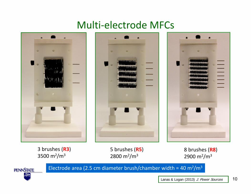

0
200
400
600
800
1000
1200
1400
1600
Max
imum
Pow
er D
ensi
ty (m
Wm
2 )
0
200
400
600
800
1000
1200
1400
1600
Pow
er D
ensi
ty (m
Wm
2 )
Activated Carbon Cathodes‐ (Manufactured by VITO)
0
200
400
600
800
1000
1200
1400
1600 Po
wer
Den
sity
(mW
m2 )
AC AC-Fe AC-Heat AC-CB Pt
B - 16 months A - 1 month
0 2 4 6 8 10 0 2 4 6 8 10 Current Density (Am2) Current Density (Am2)
0 5 10 15 20 Time (months)
0
200
400
600
800
1000
1200
1400
1600
0 2 4 6 8 10
Pow
er D
ensi
ty (m
Wm
2 )
Current Density (Am2)
DC - 17 months-HCl DI Water rinse HCl
Performance over 16 months
Original powernearly restoredusing acid (HCl)wash
Zhang Pant Zhang Liu Logan (2014) Chem Electro Chem 12
13
New Binder for Activated Carbon PVDF bull Using a PVDF binder is simple and effective
ndash 1‐ apply to SS mesh 2‐ phase inversion in water ndash Make at room temperature
ndash Amenable to continuous rolling process ndash No separate gas diffusion layer (GDL) needed
ndash Cost $15 mndash2 ($12 mndash2 for SS mesh $3 mndash2 for catalyst and binder)
Yang He Zhang Hickner Logan (2014) ESampT Letters
PVDF Binder Power the same as PTFE
bull Water pressure up applied to carbon clothPt to 12 m (vs 02 m for PTFE)
Yang He Zhang Hickner Logan (2014) ESampT Letters
Acetate amp PBS buffer
New-rev
Domestic Wastewater
14
MFCs and MECs for Wastewater Treatment
hellipand why MxCs alone cannot accomplish wastewater treatment
Low sCOD limits current generation
900
0
1
2
3
4
0 10 20 30 40 50 60 C
urre
nt D
ensi
ty (A
m2 )
Ac High 100 Ω Current
Ac High 100 Ω COD
D
ACETATE Current very stable then it suddenly decreases
800
700
CO
D (m
gL)
600
500
400
300
COD removal constant (first-order kinetics) 100
200 sCOD ~ 180 mgL
0
Time (h)2 500
450WW 100 Ω Current WW 100 Ω sCOD WW 100 Ω tCOD
WW
0 5 10 15 20 25 30
In both cases COD continues to be removed so treatment continues without electricity generation but ww cannot be discharged due to high COD
16
12
400
Cur
rent
Den
sity
(Am
2 )
CO
D (m
gL)350
300 250
tCOD ~ 150 mgL
sCOD ~ 100 mgL
08 200 150
04 100 50
0 0
Time (h)
Zhang He Ren Evans Logan (2015) Biores Technol 16
1
Current density vs soluble COD (sCOD) Current rapidly drops off at ~100 mgL sCOD
4
Ac Low 1000 Ω
Ac High 1000 Ω
WW 1000 Ω Cur
rent
Den
sity
(Am
2 )
1000 Ω
0 200 400 600 800 1000
Ac Low 100 Ω
Ac High 100 Ω
WW 100 Ω
WW-R 100 Ω
100 Ω
0 200 400 600 800 1000
Cur
rent
Den
sity
(Am
2 ) 08
06
04
02
0
3
2
1
0
COD (mgL) COD (mgL)
In both cases current rapidly decreases when sCOD is still high (~100 mgL)
17Zhang He Ren Evans Logan (2015) Biores Technol
How much COD removal can we get from domestic WW ~80‐90 but final COD is too high
Hays and Logan (2011) J Power Sources
‐Why isnrsquot more COD removed ‐What is ldquofaterdquo of COD
bull Influent
COD = 400 mgL or BOD5 = 200 mgL
bull Effluent BOD5 35‐40 mgL (like a Trickling Filter)
Removal gt80
18
MFC Performance using Domestic Wastewater
Wastewater and Design Considerations
bull Acetate + Phosphate buffer ne SyntheƟc wastewater ndash Acetate concentrations are usually too high to represent WW
ndash PBS used is artificially conductive7‐20 mScm (vs 1 mScm for WW)
bull Domestic wastewater ndash COD of ~300‐500 mgL (50 BOD5) ndash Composition is variable So lots of oxygen contamination of the
anode over time can have anode limitations on performance
bull Reactor design ndash Canrsquot have too narrow space between electrodes (it will clog) ndash Must take into account volume demands of air cathodes
bull Final effluent quality ndash If domestic ww used + need to discharge = Need AFMBR
ndash If industrial may only need to get to level suitable for discharge to sewers (no secondary process needed in this case)
MFC Architecture
Logan amp Elimelech (2012) Nature 21
22
Overall goal compact reactor design
Assume One anode-cathode module is 1 m2 projected area (height x width) and 10 cm thick
Result 10 modules = 10 m2
10 cm
10 cm
10 cm
10 cm
Design Limited by cathode area so in this example we achieve 10 m2m3
10 cm 100 cm
Logan (2012) Chem Sus Chem 22
MFC + AFMBR (Anaerobic Fluidized Bed Membrane Bioreactor)
Ren Ahn amp Logan (2014) Environ Sci Technol 23
Generation I MFC configuration
bull SEA Separator electrode assembly ndash Trimmed graphite fiber brush one side flat ndash Separator between brush anode and
cathode placed together
bull SPA Spaced electrode assembly ndash Brush placed distant from cathode so it
canrsquot touch it
bull Two reactors used in series ndash 2 times 4 h HRT = 8 h HRT
bull Total of 4 MFCs (2 SEA 2 SPA)
Ren Ahn amp Logan (2014) Environ Sci Technol 24
AFMBR Construction bull Idea of AFMBR first published by
Chae et al (ESampT) Used as a second stage to granular fluidized bed anerobic digester
bull AFMBR consists of a reactor body + ultrafiltration membrane + granular activated carbon (GAC)
bull GAC fluidized by recirculation
bull In tests here used with a hydraulic retention time of 1 hour
Ren Ahn amp Logan (2014) Environ Sci Technol 25
Experimental Setup MFC+AFMBR
Reactor HRTs MFC=4 h (each) AFMBR=1 h ldquoFrdquo= Granular activated carbon (GAC) fluidized used for
biofilm support and membrane cleaning (scour) ldquoMBRrdquo PVDF hollow fiber membranes MFC types SEA (separator) SPA (spaced no separator)
26Ren Ahn amp Logan (2014) Environ Sci Technol
Comparison of performance of SEA and SPA MFCs over time
bull Initially similar performance
bull After 5 months SEAgtgt SPA
bull Separator needed for long term performance
01
02
03
Pow
er (m
W)
SPA-U SEA-U SPA-D SEA-D
a
01
02
03
Pow
er (m
W)
NEW
05 1 15 2 Current (mA) U= Upflow (1st MFC in series)
0404
0 0
b After 5 months
0 05 1 15 2 Current (mA)
D=downflow (2nd MFC in series)
Ren Ahn amp Logan (2014) Environ Sci Technol 27
Effluent reduced to 16 mgL tCOD 250
bull Two trains of MFC (HRT = 4 h) to AFMBR (HRT = 1 h)
bull Membrane flux 16 Lm2h
bull 50 days performance
bull Energy balanced
(MFC produced = AFMBR used)
Con
cent
ratio
n (m
gL)
200
150
100
50
0 tCOD sCOD TSS
MFCs FMBR Effluent
491
503
510 434
359 486
925
862
996
bull Effluent COD = 16 mgL bull Effluent TSS lt1 mgL
WW in FMBR Permeate Ren Ahn amp Logan (2014) Environ Sci Technol 28
Key to AFMBR success Little fouling bull First 10 days initial rapid
increase in transmembrane 01 pressure (TMP)
bull Days 10‐50 only slight increase 008
in TMP
bull Flux of 16 LMH much greater than that in previous studies with anaerobic fluidized bed
TMP
(bar
)
006
004
002
0 10 20 30 40 50
reactors (AFBRs) ndash AFMBR 6‐7 LMH at start 0 ndash 4‐11 LMH at start
Time (d)
Ren Ahn amp Logan (2014) Environ Sci Technol 29
30
Conclusions
bull Microbial Fuel Cell Technologies‐‐MxCs Can they scale
Yes
30
MET Companies bull Emefcy (Israel) wwwemefcycom bull Cambrian Innovations (Boston MA) httpcambrianinnovationcom
bull ArbSource (with Arizona State University) wwwarbsourceus bull Waste2Watergy (with Oregon State University)
advantageoregonstateeduclientswaste2watergy
bull Living Power (with Harvard University) bull Quantum Intelligence (San Jose CA) bull Electroarchae wwwelectroarchaecom
bull MicroOrganic (New York) httpmicrorganictechcomtechnology bull
Thanks to students and researchers in the MxC team at Penn State
Current research sponsors SERDPDOD (2012-2015) Air ProductsDOE (2012-2014) GCEPStanford (2012-2015) NRELDOE (2012-2014)
International Collaborations
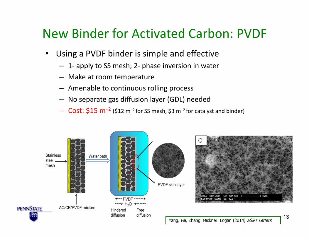
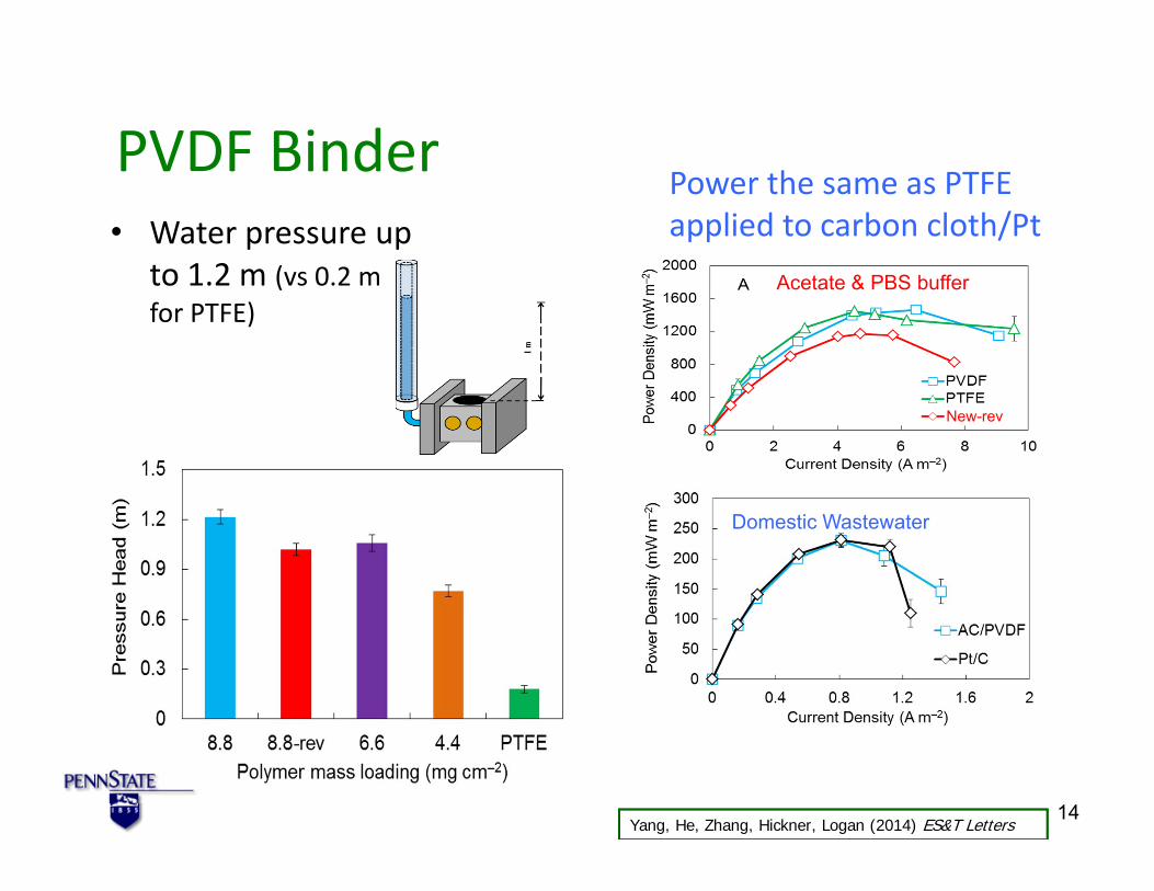

1
Current density vs soluble COD (sCOD) Current rapidly drops off at ~100 mgL sCOD
4
Ac Low 1000 Ω
Ac High 1000 Ω
WW 1000 Ω Cur
rent
Den
sity
(Am
2 )
1000 Ω
0 200 400 600 800 1000
Ac Low 100 Ω
Ac High 100 Ω
WW 100 Ω
WW-R 100 Ω
100 Ω
0 200 400 600 800 1000
Cur
rent
Den
sity
(Am
2 ) 08
06
04
02
0
3
2
1
0
COD (mgL) COD (mgL)
In both cases current rapidly decreases when sCOD is still high (~100 mgL)
17Zhang He Ren Evans Logan (2015) Biores Technol
How much COD removal can we get from domestic WW ~80‐90 but final COD is too high
Hays and Logan (2011) J Power Sources
‐Why isnrsquot more COD removed ‐What is ldquofaterdquo of COD
bull Influent
COD = 400 mgL or BOD5 = 200 mgL
bull Effluent BOD5 35‐40 mgL (like a Trickling Filter)
Removal gt80
18
MFC Performance using Domestic Wastewater
Wastewater and Design Considerations
bull Acetate + Phosphate buffer ne SyntheƟc wastewater ndash Acetate concentrations are usually too high to represent WW
ndash PBS used is artificially conductive7‐20 mScm (vs 1 mScm for WW)
bull Domestic wastewater ndash COD of ~300‐500 mgL (50 BOD5) ndash Composition is variable So lots of oxygen contamination of the
anode over time can have anode limitations on performance
bull Reactor design ndash Canrsquot have too narrow space between electrodes (it will clog) ndash Must take into account volume demands of air cathodes
bull Final effluent quality ndash If domestic ww used + need to discharge = Need AFMBR
ndash If industrial may only need to get to level suitable for discharge to sewers (no secondary process needed in this case)
MFC Architecture
Logan amp Elimelech (2012) Nature 21
22
Overall goal compact reactor design
Assume One anode-cathode module is 1 m2 projected area (height x width) and 10 cm thick
Result 10 modules = 10 m2
10 cm
10 cm
10 cm
10 cm
Design Limited by cathode area so in this example we achieve 10 m2m3
10 cm 100 cm
Logan (2012) Chem Sus Chem 22
MFC + AFMBR (Anaerobic Fluidized Bed Membrane Bioreactor)
Ren Ahn amp Logan (2014) Environ Sci Technol 23
Generation I MFC configuration
bull SEA Separator electrode assembly ndash Trimmed graphite fiber brush one side flat ndash Separator between brush anode and
cathode placed together
bull SPA Spaced electrode assembly ndash Brush placed distant from cathode so it
canrsquot touch it
bull Two reactors used in series ndash 2 times 4 h HRT = 8 h HRT
bull Total of 4 MFCs (2 SEA 2 SPA)
Ren Ahn amp Logan (2014) Environ Sci Technol 24
AFMBR Construction bull Idea of AFMBR first published by
Chae et al (ESampT) Used as a second stage to granular fluidized bed anerobic digester
bull AFMBR consists of a reactor body + ultrafiltration membrane + granular activated carbon (GAC)
bull GAC fluidized by recirculation
bull In tests here used with a hydraulic retention time of 1 hour
Ren Ahn amp Logan (2014) Environ Sci Technol 25
Experimental Setup MFC+AFMBR
Reactor HRTs MFC=4 h (each) AFMBR=1 h ldquoFrdquo= Granular activated carbon (GAC) fluidized used for
biofilm support and membrane cleaning (scour) ldquoMBRrdquo PVDF hollow fiber membranes MFC types SEA (separator) SPA (spaced no separator)
26Ren Ahn amp Logan (2014) Environ Sci Technol
Comparison of performance of SEA and SPA MFCs over time
bull Initially similar performance
bull After 5 months SEAgtgt SPA
bull Separator needed for long term performance
01
02
03
Pow
er (m
W)
SPA-U SEA-U SPA-D SEA-D
a
01
02
03
Pow
er (m
W)
NEW
05 1 15 2 Current (mA) U= Upflow (1st MFC in series)
0404
0 0
b After 5 months
0 05 1 15 2 Current (mA)
D=downflow (2nd MFC in series)
Ren Ahn amp Logan (2014) Environ Sci Technol 27
Effluent reduced to 16 mgL tCOD 250
bull Two trains of MFC (HRT = 4 h) to AFMBR (HRT = 1 h)
bull Membrane flux 16 Lm2h
bull 50 days performance
bull Energy balanced
(MFC produced = AFMBR used)
Con
cent
ratio
n (m
gL)
200
150
100
50
0 tCOD sCOD TSS
MFCs FMBR Effluent
491
503
510 434
359 486
925
862
996
bull Effluent COD = 16 mgL bull Effluent TSS lt1 mgL
WW in FMBR Permeate Ren Ahn amp Logan (2014) Environ Sci Technol 28
Key to AFMBR success Little fouling bull First 10 days initial rapid
increase in transmembrane 01 pressure (TMP)
bull Days 10‐50 only slight increase 008
in TMP
bull Flux of 16 LMH much greater than that in previous studies with anaerobic fluidized bed
TMP
(bar
)
006
004
002
0 10 20 30 40 50
reactors (AFBRs) ndash AFMBR 6‐7 LMH at start 0 ndash 4‐11 LMH at start
Time (d)
Ren Ahn amp Logan (2014) Environ Sci Technol 29
30
Conclusions
bull Microbial Fuel Cell Technologies‐‐MxCs Can they scale
Yes
30
MET Companies bull Emefcy (Israel) wwwemefcycom bull Cambrian Innovations (Boston MA) httpcambrianinnovationcom
bull ArbSource (with Arizona State University) wwwarbsourceus bull Waste2Watergy (with Oregon State University)
advantageoregonstateeduclientswaste2watergy
bull Living Power (with Harvard University) bull Quantum Intelligence (San Jose CA) bull Electroarchae wwwelectroarchaecom
bull MicroOrganic (New York) httpmicrorganictechcomtechnology bull
Thanks to students and researchers in the MxC team at Penn State
Current research sponsors SERDPDOD (2012-2015) Air ProductsDOE (2012-2014) GCEPStanford (2012-2015) NRELDOE (2012-2014)
International Collaborations
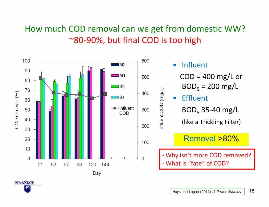
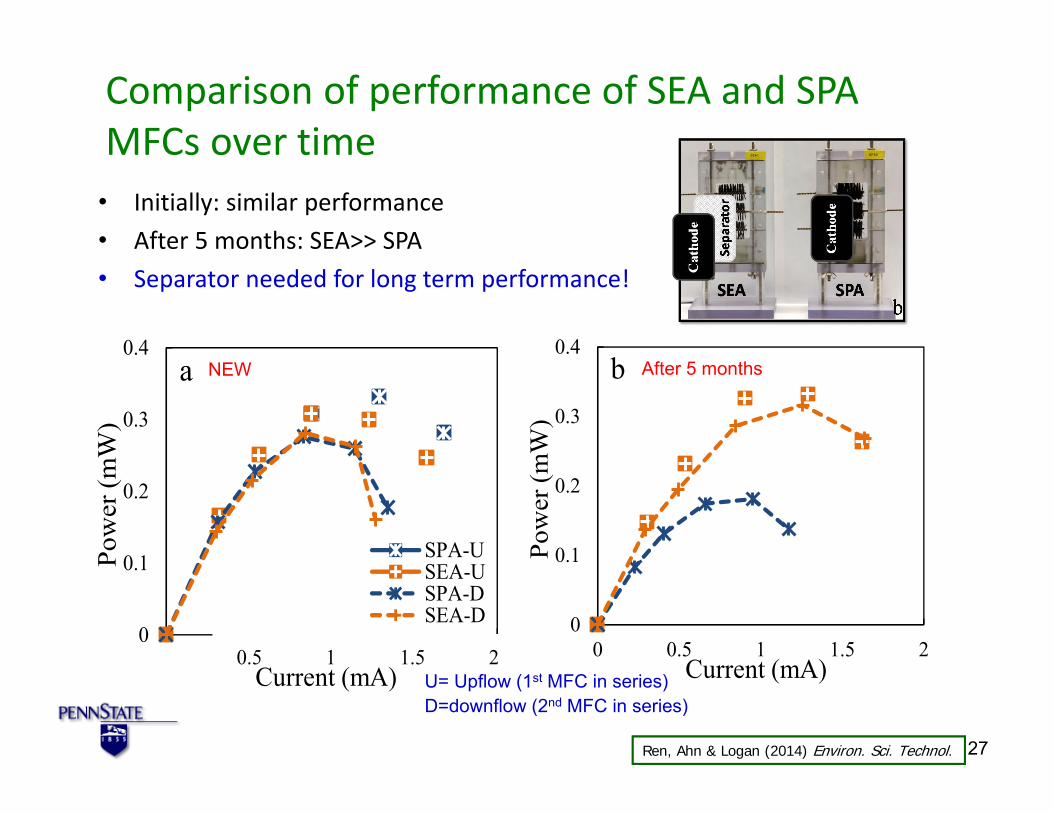

30
Conclusions
bull Microbial Fuel Cell Technologies‐‐MxCs Can they scale
Yes
30
MET Companies bull Emefcy (Israel) wwwemefcycom bull Cambrian Innovations (Boston MA) httpcambrianinnovationcom
bull ArbSource (with Arizona State University) wwwarbsourceus bull Waste2Watergy (with Oregon State University)
advantageoregonstateeduclientswaste2watergy
bull Living Power (with Harvard University) bull Quantum Intelligence (San Jose CA) bull Electroarchae wwwelectroarchaecom
bull MicroOrganic (New York) httpmicrorganictechcomtechnology bull
Thanks to students and researchers in the MxC team at Penn State
Current research sponsors SERDPDOD (2012-2015) Air ProductsDOE (2012-2014) GCEPStanford (2012-2015) NRELDOE (2012-2014)
International Collaborations
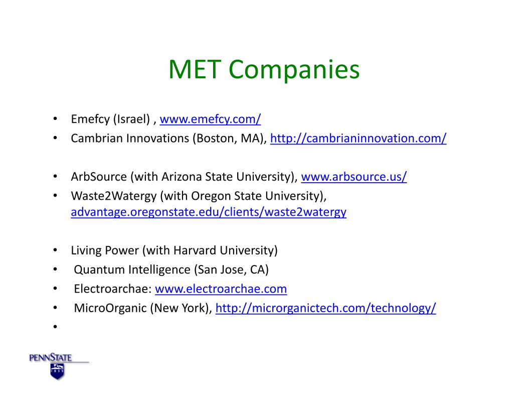
Thanks to students and researchers in the MxC team at Penn State
Current research sponsors SERDPDOD (2012-2015) Air ProductsDOE (2012-2014) GCEPStanford (2012-2015) NRELDOE (2012-2014)
International Collaborations

International Collaborations
Related Documents


