Install Guide Micro800 ™ 4 Ch Universal Thermistor Input Module (Catalog Number 2080sc-NTC) Table of Contents For More Information ................................................................................. 1 Environment and Enclosure ...................................................................... 2 Prevent Electrostatic Discharge ................................................................ 3 Parts List ................................................................................................... 4 Insert Module into Controller ..................................................................... 5 Wire the Module ........................................................................................ 6 Configuration Tags .................................................................................... 7 Configuring the Module ............................................................................. 9 Data Format ............................................................................................ 10 Adding the NTC to CCW ......................................................................... 13 Controller.Micro830.Micro830.Main ................................................. 20 Electrical Specifications .......................................................................... 22 Environmental Specifications .................................................................. 24 Hazardous Location Considerations ....................................................... 27 Environnements dangereux .................................................................... 28 For More Information PLC sample projects and documentation are available on our website at http://www.spectrumcontrols.com

Welcome message from author
This document is posted to help you gain knowledge. Please leave a comment to let me know what you think about it! Share it to your friends and learn new things together.
Transcript
Install Guide
Micro800™ 4 Ch Universal Thermistor Input Module (Catalog Number 2080sc-NTC)
Table of Contents For More Information ................................................................................. 1
Environment and Enclosure ...................................................................... 2
Prevent Electrostatic Discharge ................................................................ 3
Parts List ................................................................................................... 4
Insert Module into Controller ..................................................................... 5
Wire the Module ........................................................................................ 6
Configuration Tags .................................................................................... 7
Configuring the Module ............................................................................. 9
Data Format ............................................................................................ 10
Adding the NTC to CCW ......................................................................... 13
Controller.Micro830.Micro830.Main ................................................. 20
Electrical Specifications .......................................................................... 22
Environmental Specifications .................................................................. 24
Hazardous Location Considerations ....................................................... 27
Environnements dangereux .................................................................... 28
For More Information PLC sample projects and documentation are available on our website at
http://www.spectrumcontrols.com
Micro800™ 4 Ch Universal Thermistor Input Module 2
Publication 0100198-02 Rev. A
Environment and Enclosure
ATTENTION
This equipment is intended for use in a Pollution Degree 2 industrial environment, in overvoltage Category II applications (as defined in IEC publication 60664-1), at altitudes up to 2000 meters (6562 feet) without derating.
This equipment is considered Group 1, Class A industrial equipment according to IEC/CISPR Publication 11. Without appropriate precautions, there may be potential difficulties ensuring electromagnetic compatibility in other environments due to conducted as well as radiated disturbance.
This equipment is supplied as open-type equipment. It must be mounted within an enclosure that is suitably designed for those specific environmental conditions that will be present and appropriately designed to prevent personal injury resulting from accessibility to live parts. The enclosure must have suitable flame-retardant properties to prevent or minimize the spread of flame, complying with a flame spread rating of 5 VA, V2, V1, V0 (or equivalent) if non-metallic. The interior of the enclosure must be accessible only by the use of a tool. Subsequent sections of this publication may contain additional information regarding specific enclosure type ratings that are required to comply with certain product safety certifications.
In addition to this publication, see:
Industrial Automation Wiring and Grounding Guidelines, Allen-Bradley publication 1770-4.1, for additional installation requirements.
NEMA Standards publication 250 and IEC publication 60529, as applicable, for explanations of the degrees of protection provided by different types of enclosure.
Micro800™ 4 Ch Universal Thermistor Input Module 3
Publication 0100198-02 Rev. A
Prevent Electrostatic Discharge
WARNING
Electrostatic discharge can damage integrated circuits or semiconductors if you touch bus connector pins. Follow these guidelines when you handle the module:
Touch a grounded object to discharge static potential.
Wear an approved wrist-strap grounding device.
Do not touch connectors or pins on component boards.
Do not touch circuit components inside the module.
If available, use a static-safe work station.
When not in use, keep the module in its static-shield box.
WARNING
To comply with the CE Low Voltage Directive (LVD), all connected I/O must be powered from a source compliant with the following: Safety Extra Low Voltage (SELV) or Protected Extra Low Voltage (PELV).
Micro800™ 4 Ch Universal Thermistor Input Module 4
Publication 0100198-02 Rev. A
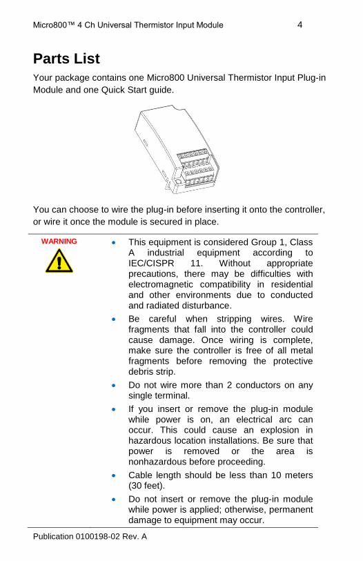
Parts List
Your package contains one Micro800 Universal Thermistor Input Plug-in
Module and one Quick Start guide.
You can choose to wire the plug-in before inserting it onto the controller,
or wire it once the module is secured in place.
WARNING
This equipment is considered Group 1, Class A industrial equipment according to IEC/CISPR 11. Without appropriate precautions, there may be difficulties with electromagnetic compatibility in residential and other environments due to conducted and radiated disturbance.
Be careful when stripping wires. Wire fragments that fall into the controller could cause damage. Once wiring is complete, make sure the controller is free of all metal fragments before removing the protective debris strip.
Do not wire more than 2 conductors on any single terminal.
If you insert or remove the plug-in module while power is on, an electrical arc can occur. This could cause an explosion in hazardous location installations. Be sure that power is removed or the area is nonhazardous before proceeding.
Cable length should be less than 10 meters (30 feet).
Do not insert or remove the plug-in module while power is applied; otherwise, permanent damage to equipment may occur.
Micro800™ 4 Ch Universal Thermistor Input Module 5
Publication 0100198-02 Rev. A
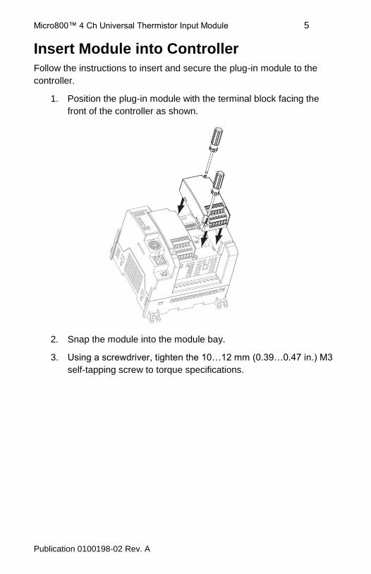
Insert Module into Controller
Follow the instructions to insert and secure the plug-in module to the
controller.
1. Position the plug-in module with the terminal block facing the
front of the controller as shown.
2. Snap the module into the module bay.
3. Using a screwdriver, tighten the 10…12 mm (0.39…0.47 in.) M3
self-tapping screw to torque specifications.
Micro800™ 4 Ch Universal Thermistor Input Module 6
Publication 0100198-02 Rev. A
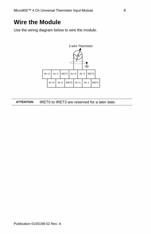
IN +2 IN -2 IRET2 IN +3 IN -3 IRET3
IN +0 IN -0 IRET0 IN +1 IN -1 IRET1
2-wire Thermistor
Wire the Module
Use the wiring diagram below to wire the module.
ATTENTION IRET0 to IRET3 are reserved for a later date.
Micro800™ 4 Ch Universal Thermistor Input Module 7
Publication 0100198-02 Rev. A
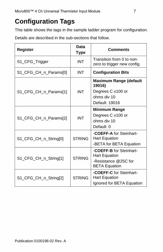
Configuration Tags
This table shows the tags in the sample ladder program for configuration.
Details are described in the sub-sections that follow.
Register Data
Type Comments
S1_CFG_Trigger INT Transition from 0 to non-zero to trigger new config.
S1_CFG_CH_n_Params[0] INT Configuration Bits
S1_CFG_CH_n_Params[1] INT
Maximum Range (default 19016)
Degrees C x100 or
ohms div 10
Default: 19016
S1_CFG_CH_n_Params[2] INT
Minimum Range
Degrees C x100 or
ohms div 10
Default: 0
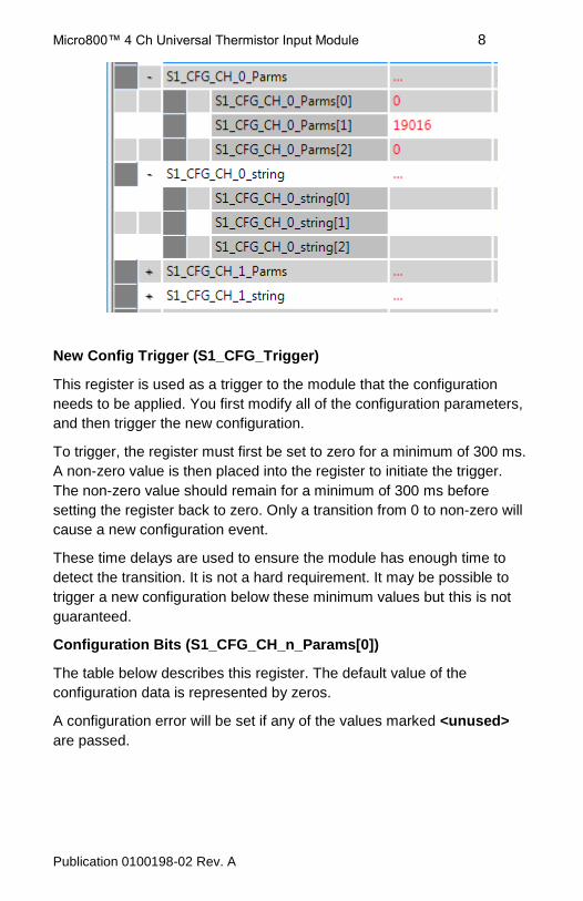
S1_CFG_CH_n_String[0] STRING
-COEFF-A for Steinhart-Hart Equation
-BETA for BETA Equation
S1_CFG_CH_n_String[1] STRING
-COEFF-B for Steinhart-Hart Equation
-Resistance @25C for BETA Equation
S1_CFG_CH_n_String[2] STRING
-COEFF-C for Steinhart-Hart Equation
Ignored for BETA Equation
Micro800™ 4 Ch Universal Thermistor Input Module 8
Publication 0100198-02 Rev. A
New Config Trigger (S1_CFG_Trigger)
This register is used as a trigger to the module that the configuration
needs to be applied. You first modify all of the configuration parameters,
and then trigger the new configuration.
To trigger, the register must first be set to zero for a minimum of 300 ms.
A non-zero value is then placed into the register to initiate the trigger.
The non-zero value should remain for a minimum of 300 ms before
setting the register back to zero. Only a transition from 0 to non-zero will
cause a new configuration event.
These time delays are used to ensure the module has enough time to
detect the transition. It is not a hard requirement. It may be possible to
trigger a new configuration below these minimum values but this is not
guaranteed.
Configuration Bits (S1_CFG_CH_n_Params[0])
The table below describes this register. The default value of the
configuration data is represented by zeros.
A configuration error will be set if any of the values marked <unused>
are passed.
Micro800™ 4 Ch Universal Thermistor Input Module 9
Publication 0100198-02 Rev. A
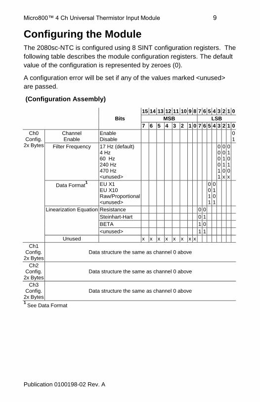
Configuring the Module
The 2080sc-NTC is configured using 8 SINT configuration registers. The
following table describes the module configuration registers. The default
value of the configuration is represented by zeroes (0).
A configuration error will be set if any of the values marked <unused>
are passed.
(Configuration Assembly)
Bits
15 14 13 12 11 10 9 8 7 6 5 4 3 2 1 0
MSB LSB
7 6 5 4 3 2 1 0 7 6 5 4 3 2 1 0
Ch0 Config.
2x Bytes
Channel Enable
Enable Disable
0 1
Filter Frequency 17 Hz (default) 4 Hz 60 Hz 240 Hz 470 Hz <unused>
0 0 0 0 1 1
0 0 1 1 0 x
0 1 0 1 0 x
Data Format1 EU X1
EU X10 Raw/Proportional <unused>
0 0 1 1
0 1 0 1
Linearization Equation Resistance 0 0
Steinhart-Hart
0 1
BETA 1 0
<unused> 1 1
Unused x x x x x x x x
Ch1 Config.
2x Bytes Data structure the same as channel 0 above
Ch2 Config.
2x Bytes Data structure the same as channel 0 above
Ch3 Config.
2x Bytes Data structure the same as channel 0 above
1 See Data Format
Micro800™ 4 Ch Universal Thermistor Input Module 10
Publication 0100198-02 Rev. A
Data Format EU x1
This displays the measured readings in their natural integer form. Due to
the measurement range and 16-bit data size, the highest resolution that
can be displayed for resistance is 10 ohms. Temperatures will have two
decimal places of resolution.
For resistance, it will be in the range from 0 to 32767 which represents
resistance in ohms divided by ten (0 to 327.67 k ohms).
For temperature, it will display in the range from +32767 to -32768
(+327.67 degrees C to -327.68 degrees C). The displayed values are
clipped at the user-defined Maximum and Minimum parameters (defined
below).
EU x10
This display format is the same as EU x1 but divided by 10.
Raw Proportional
The Raw Proportional Data Format uses the Maximum and Minimum
user-defined values as its end points and scale relative to them. The
Maximum Range is represented by +32767 while the Minimum Range is
-32768 to give a full 16-bit span.
The output shall be scaled relative to those two user-defined values.
When Equation is set to Resistance, you enter appropriate resistance
values for the Maximum and Minimum parameters. For the other
Equation settings, you enter appropriate temperature values for the
Maximum and Minimum parameters.
Equation
BETA
If the Equation is set to BETA, the COEFF-A/BETA string contains the
BETA parameter. The COEFF-B/R@25C string contains the resistance
at 25˚ C.
COEFF-C string will be ignored.
Micro800™ 4 Ch Universal Thermistor Input Module 11
Publication 0100198-02 Rev. A
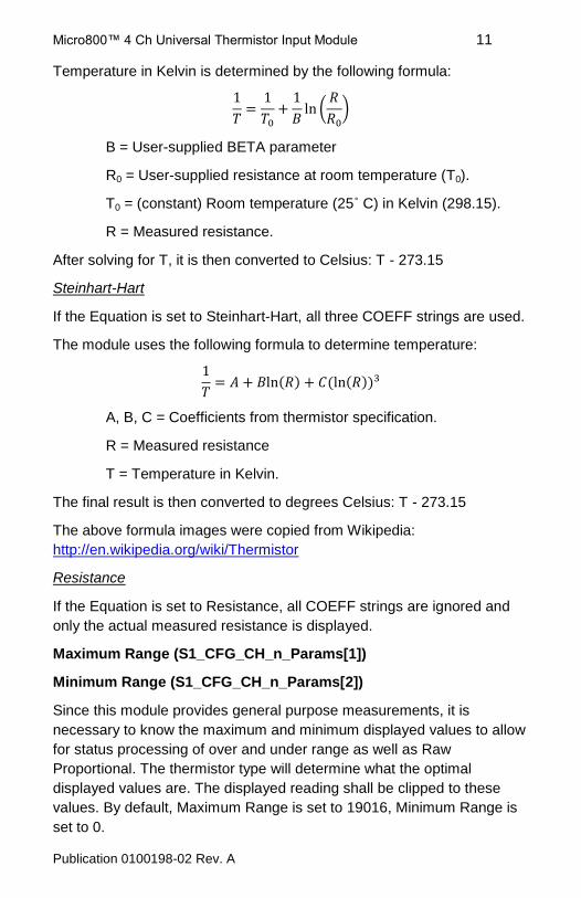
Temperature in Kelvin is determined by the following formula:
(
)
B = User-supplied BETA parameter
R0 = User-supplied resistance at room temperature (T0).
T0 = (constant) Room temperature (25˚ C) in Kelvin (298.15).
R = Measured resistance.
After solving for T, it is then converted to Celsius: T - 273.15
Steinhart-Hart
If the Equation is set to Steinhart-Hart, all three COEFF strings are used.
The module uses the following formula to determine temperature:
( ) ( ( ))
A, B, C = Coefficients from thermistor specification.
R = Measured resistance
T = Temperature in Kelvin.
The final result is then converted to degrees Celsius: T - 273.15
The above formula images were copied from Wikipedia:
http://en.wikipedia.org/wiki/Thermistor
Resistance
If the Equation is set to Resistance, all COEFF strings are ignored and
only the actual measured resistance is displayed.
Maximum Range (S1_CFG_CH_n_Params[1])
Minimum Range (S1_CFG_CH_n_Params[2])
Since this module provides general purpose measurements, it is
necessary to know the maximum and minimum displayed values to allow
for status processing of over and under range as well as Raw
Proportional. The thermistor type will determine what the optimal
displayed values are. The displayed reading shall be clipped to these
values. By default, Maximum Range is set to 19016, Minimum Range is
set to 0.
Micro800™ 4 Ch Universal Thermistor Input Module 12
Publication 0100198-02 Rev. A
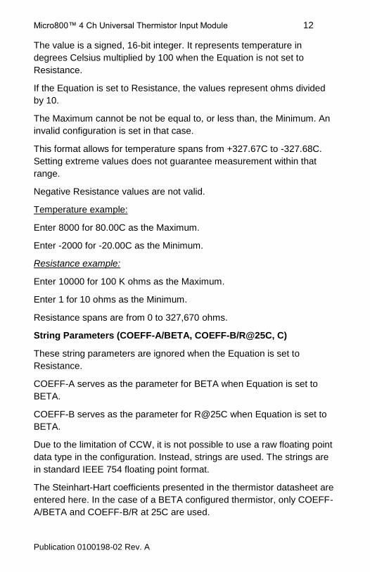
The value is a signed, 16-bit integer. It represents temperature in
degrees Celsius multiplied by 100 when the Equation is not set to
Resistance.
If the Equation is set to Resistance, the values represent ohms divided
by 10.
The Maximum cannot be not be equal to, or less than, the Minimum. An
invalid configuration is set in that case.
This format allows for temperature spans from +327.67C to -327.68C.
Setting extreme values does not guarantee measurement within that
range.
Negative Resistance values are not valid.
Temperature example:
Enter 8000 for 80.00C as the Maximum.
Enter -2000 for -20.00C as the Minimum.
Resistance example:
Enter 10000 for 100 K ohms as the Maximum.
Enter 1 for 10 ohms as the Minimum.
Resistance spans are from 0 to 327,670 ohms.
String Parameters (COEFF-A/BETA, COEFF-B/R@25C, C)
These string parameters are ignored when the Equation is set to
Resistance.
COEFF-A serves as the parameter for BETA when Equation is set to
BETA.
COEFF-B serves as the parameter for R@25C when Equation is set to
BETA.
Due to the limitation of CCW, it is not possible to use a raw floating point
data type in the configuration. Instead, strings are used. The strings are
in standard IEEE 754 floating point format.
The Steinhart-Hart coefficients presented in the thermistor datasheet are
entered here. In the case of a BETA configured thermistor, only COEFF-
A/BETA and COEFF-B/R at 25C are used.
Micro800™ 4 Ch Universal Thermistor Input Module 13
Publication 0100198-02 Rev. A
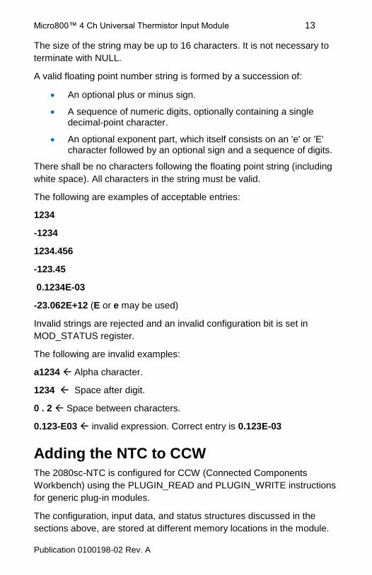
The size of the string may be up to 16 characters. It is not necessary to
terminate with NULL.
A valid floating point number string is formed by a succession of:
An optional plus or minus sign.
A sequence of numeric digits, optionally containing a single decimal-point character.
An optional exponent part, which itself consists on an 'e' or 'E' character followed by an optional sign and a sequence of digits.
There shall be no characters following the floating point string (including
white space). All characters in the string must be valid.
The following are examples of acceptable entries:
1234
-1234
1234.456
-123.45
0.1234E-03
-23.062E+12 (E or e may be used)
Invalid strings are rejected and an invalid configuration bit is set in
MOD_STATUS register.
The following are invalid examples:
a1234 Alpha character.
1234 Space after digit.
0 . 2 Space between characters.
0.123-E03 invalid expression. Correct entry is 0.123E-03
Adding the NTC to CCW
The 2080sc-NTC is configured for CCW (Connected Components
Workbench) using the PLUGIN_READ and PLUGIN_WRITE instructions
for generic plug-in modules.
The configuration, input data, and status structures discussed in the
sections above, are stored at different memory locations in the module.
Micro800™ 4 Ch Universal Thermistor Input Module 14
Publication 0100198-02 Rev. A
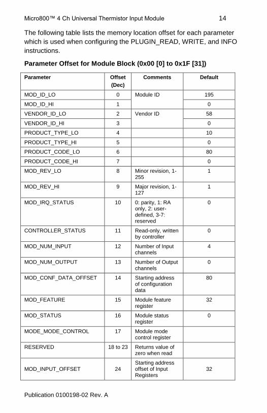
The following table lists the memory location offset for each parameter
which is used when configuring the PLUGIN_READ, WRITE, and INFO
instructions.
Parameter Offset for Module Block (0x00 [0] to 0x1F [31])
Parameter Offset
(Dec)
Comments Default
MOD_ID_LO 0 Module ID 195
MOD_ID_HI 1 0
VENDOR_ID_LO 2 Vendor ID 58
VENDOR_ID_HI 3 0
PRODUCT_TYPE_LO 4 10
PRODUCT_TYPE_HI 5 0
PRODUCT_CODE_LO 6 80
PRODUCT_CODE_HI 7 0
MOD_REV_LO 8 Minor revision, 1-255
1
MOD_REV_HI 9 Major revision, 1-127
1
MOD_IRQ_STATUS 10 0: parity, 1: RA only, 2: user-defined, 3-7: reserved
0
CONTROLLER_STATUS 11 Read-only, written by controller
0
MOD_NUM_INPUT 12 Number of Input channels
4
MOD_NUM_OUTPUT 13 Number of Output channels
0
MOD_CONF_DATA_OFFSET 14 Starting address of configuration data
80
MOD_FEATURE 15 Module feature register
32
MOD_STATUS 16 Module status register
0
MODE_MODE_CONTROL 17 Module mode control register
RESERVED 18 to 23 Returns value of zero when read
MOD_INPUT_OFFSET 24 Starting address offset of Input Registers
32
Micro800™ 4 Ch Universal Thermistor Input Module 15
Publication 0100198-02 Rev. A
Parameter Offset
(Dec)
Comments Default
MOD_OUTPUT_OFFSET 25 Starting address offset of Output Registers
48
MOD_INPUT_LATCH 26 Writing with 0xA5 to this register will trigger input latch
MOD_OUTPUT_APPLY 27
Writing with 0xA5 to this register will trigger output latch
0
MOD_INTERRUPT_CONF 28
Writing to this register will enable/disable module interrupt to controller
0
MOD_GC_DATA_LENGTH_LB 29
Low byte of the generic configuration data length
218
MOD_GC_DATA_LENGTH_HB 30
High byte of the generic configuration data length
0
RESERVED 31 Reserved
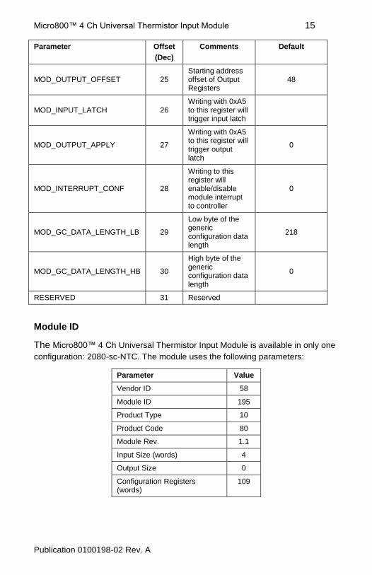
Module ID
The Micro800™ 4 Ch Universal Thermistor Input Module is available in only one
configuration: 2080-sc-NTC. The module uses the following parameters:
Parameter Value
Vendor ID 58
Module ID 195
Product Type 10
Product Code 80
Module Rev. 1.1
Input Size (words) 4
Output Size 0
Configuration Registers (words)
109
Micro800™ 4 Ch Universal Thermistor Input Module 16
Publication 0100198-02 Rev. A
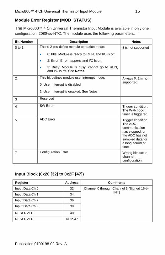
Module Error Register (MOD_STATUS)
The Micro800™ 4 Ch Universal Thermistor Input Module is available in only one
configuration: 2080-sc-NTC. The module uses the following parameters:
Bit Number Description Notes
0 to 1 These 2 bits define module operation mode:
0: Idle: Module is ready to RUN, and I/O is off.
2: Error: Error happens and I/O is off.
3: Busy: Module is busy, cannot go to RUN, and I/O is off. See Notes.
3 is not supported
2 This bit defines module user interrupt mode:
0: User Interrupt is disabled.
1: User Interrupt is enabled. See Notes.
Always 0. 1 is not supported.
3 Reserved
4 SW Error Trigger condition. The Watchdog timer is triggered.
5 ADC Error Trigger condition. The ADC communication has stopped, or the ADC has not sampled data for a long period of time.
7 Configuration Error Wrong bits set in channel configuration.
Input Block (0x20 [32] to 0x2F [47])
Register Address Comments
Input Data Ch 0 32 Channel 0 through Channel 3 (Signed 16-bit INT)
Input Data Ch 1 34
Input Data Ch 2 36
Input Data Ch 3 38
RESERVED 40
RESERVED 41 to 47
Micro800™ 4 Ch Universal Thermistor Input Module 17
Publication 0100198-02 Rev. A
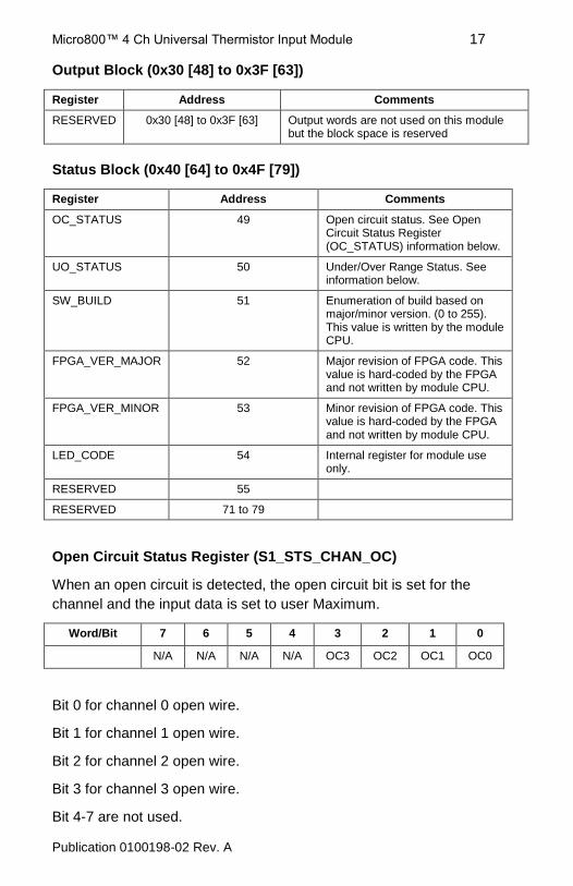
Output Block (0x30 [48] to 0x3F [63])
Register Address Comments
RESERVED 0x30 [48] to 0x3F [63] Output words are not used on this module but the block space is reserved
Status Block (0x40 [64] to 0x4F [79])
Register Address Comments
OC_STATUS 49 Open circuit status. See Open Circuit Status Register (OC_STATUS) information below.
UO_STATUS 50 Under/Over Range Status. See information below.
SW_BUILD 51 Enumeration of build based on major/minor version. (0 to 255). This value is written by the module CPU.
FPGA_VER_MAJOR 52 Major revision of FPGA code. This value is hard-coded by the FPGA and not written by module CPU.
FPGA_VER_MINOR 53 Minor revision of FPGA code. This value is hard-coded by the FPGA and not written by module CPU.
LED_CODE 54 Internal register for module use only.
RESERVED 55
RESERVED 71 to 79
Open Circuit Status Register (S1_STS_CHAN_OC)
When an open circuit is detected, the open circuit bit is set for the
channel and the input data is set to user Maximum.
Word/Bit 7 6 5 4 3 2 1 0
N/A N/A N/A N/A OC3 OC2 OC1 OC0
Bit 0 for channel 0 open wire.
Bit 1 for channel 1 open wire.
Bit 2 for channel 2 open wire.
Bit 3 for channel 3 open wire.
Bit 4-7 are not used.
Micro800™ 4 Ch Universal Thermistor Input Module 18
Publication 0100198-02 Rev. A
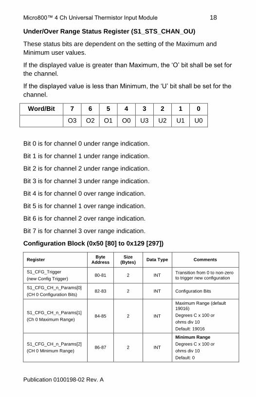
Under/Over Range Status Register (S1_STS_CHAN_OU)
These status bits are dependent on the setting of the Maximum and
Minimum user values.
If the displayed value is greater than Maximum, the ‘O’ bit shall be set for
the channel.
If the displayed value is less than Minimum, the ‘U’ bit shall be set for the
channel.
Word/Bit 7 6 5 4 3 2 1 0
O3 O2 O1 O0 U3 U2 U1 U0
Bit 0 is for channel 0 under range indication.
Bit 1 is for channel 1 under range indication.
Bit 2 is for channel 2 under range indication.
Bit 3 is for channel 3 under range indication.
Bit 4 is for channel 0 over range indication.
Bit 5 is for channel 1 over range indication.
Bit 6 is for channel 2 over range indication.
Bit 7 is for channel 3 over range indication.
Configuration Block (0x50 [80] to 0x129 [297])
Register Byte
Address Size
(Bytes) Data Type Comments
S1_CFG_Trigger
(new Config Trigger) 80-81 2 INT
Transition from 0 to non-zero to trigger new configuration
S1_CFG_CH_n_Params[0]
(CH 0 Configuration Bits) 82-83 2 INT Configuration Bits
S1_CFG_CH_n_Params[1]
(Ch 0 Maximum Range) 84-85 2 INT
Maximum Range (default 19016)
Degrees C x 100 or
ohms div 10
Default: 19016
S1_CFG_CH_n_Params[2]
(CH 0 Minimum Range) 86-87 2 INT
Minimum Range
Degrees C x 100 or
ohms div 10
Default: 0
Micro800™ 4 Ch Universal Thermistor Input Module 19
Publication 0100198-02 Rev. A
Register Byte
Address Size
(Bytes) Data Type Comments
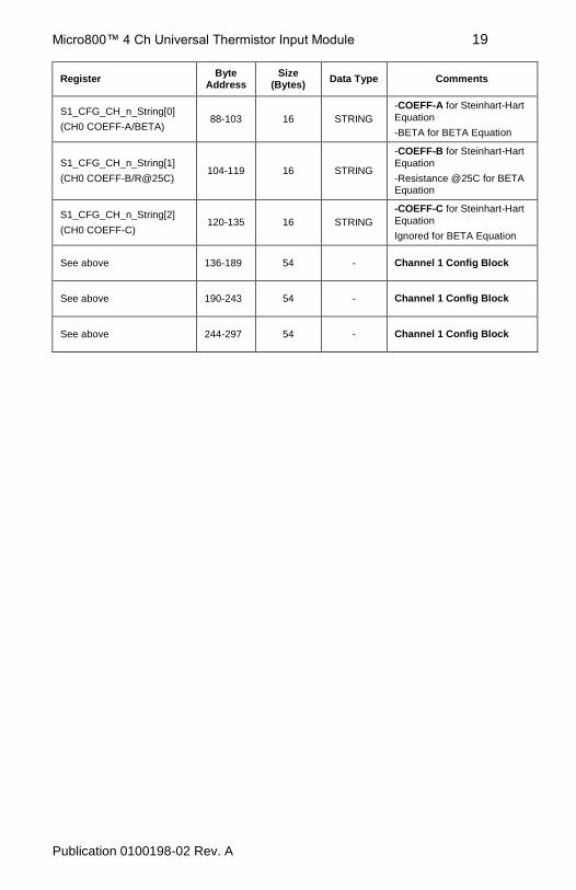
S1_CFG_CH_n_String[0]
(CH0 COEFF-A/BETA) 88-103 16 STRING
-COEFF-A for Steinhart-Hart
Equation
-BETA for BETA Equation
S1_CFG_CH_n_String[1]
(CH0 COEFF-B/R@25C) 104-119 16 STRING
-COEFF-B for Steinhart-Hart
Equation
-Resistance @25C for BETA Equation
S1_CFG_CH_n_String[2]
(CH0 COEFF-C) 120-135 16 STRING
-COEFF-C for Steinhart-Hart
Equation
Ignored for BETA Equation
See above 136-189 54 - Channel 1 Config Block
See above 190-243 54 - Channel 1 Config Block
See above 244-297 54 - Channel 1 Config Block
Micro800™ 4 Ch Universal Thermistor Input Module 20
Publication 0100198-02 Rev. A
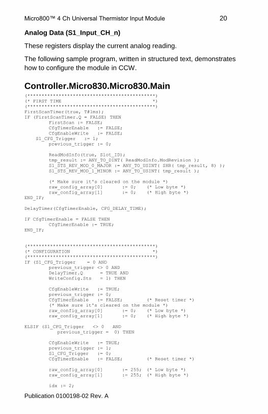
Analog Data (S1_Input_CH_n)
These registers display the current analog reading.
The following sample program, written in structured text, demonstrates
how to configure the module in CCW.
Controller.Micro830.Micro830.Main (*********************************************)
(* FIRST TIME *)
(*********************************************)
FirstScanTimer(true, T#1ms);
IF (FirstScanTimer.Q = FALSE) THEN
FirstScan := FALSE;
CfgTimerEnable := FALSE;
CfgEnableWrite := FALSE;
S1_CFG_Trigger := 1;
previous_trigger := 0;
ReadModInfo(true, Slot_ID);
tmp_result := ANY_TO_DINT( ReadModInfo.ModRevision );
S1_STS_REV_MOD_0_MAJOR := ANY_TO_USINT( SHR( tmp_result, 8) );
S1_STS_REV_MOD_1_MINOR := ANY_TO_USINT( tmp_result );
(* Make sure it's cleared on the module *)
raw_config_array[0] := 0; (* Low byte *)
raw_config_array[1] := 0; (* High byte *)
END_IF;
DelayTimer(CfgTimerEnable, CFG_DELAY_TIME);
IF CfgTimerEnable = FALSE THEN
CfgTimerEnable := TRUE;
END_IF;
(*********************************************)
(* CONFIGURATION *)
(*********************************************)
IF (S1_CFG_Trigger = 0 AND
previous_trigger <> 0 AND
DelayTimer.Q = TRUE AND
WriteConfig.Sts = 1) THEN
CfgEnableWrite := TRUE;
previous_trigger := 0;
CfgTimerEnable := FALSE; (* Reset timer *)
(* Make sure it's cleared on the module *)
raw_config_array[0] := 0; (* Low byte *)
raw_config_array[1] := 0; (* High byte *)
ELSIF (S1_CFG_Trigger <> 0 AND
previous_trigger = 0) THEN
CfgEnableWrite := TRUE;
previous_trigger := 1;
S1_CFG_Trigger := 0;
CfgTimerEnable := FALSE; (* Reset timer *)
raw_config_array[0] := 255; (* Low byte *)
raw_config_array[1] := 255; (* High byte *)
idx := 2;
Micro800™ 4 Ch Universal Thermistor Input Module 21
Publication 0100198-02 Rev. A
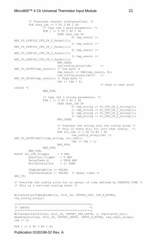
(* Translate channel configurations. *)
FOR chan_idx := 0 TO 3 BY 1 DO
(* Copy the 3 word parameters. *)
FOR i := 0 TO 2 BY 1 DO
CASE chan_idx OF
0: tmp_result :=
ANY_TO_DINT(S1_CFG_CH_0_Parms[i]);
1: tmp_result :=
ANY_TO_DINT(S1_CFG_CH_1_Parms[i]);
2: tmp_result :=
ANY_TO_DINT(S1_CFG_CH_2_Parms[i]);
3: tmp_result :=
ANY_TO_DINT(S1_CFG_CH_3_Parms[i]);
END_CASE;
raw_config_array[idx] :=
ANY_TO_USINT(tmp_result); (* Low byte *)
tmp_result := SHR(tmp_result, 8);
raw_config_array[idx+1] :=
ANY_TO_USINT(tmp_result); (* High byte *)
idx := idx + 2;
(* Skip to next word
offset *)
END_FOR;
(* Copy the 3 string parameters. *)
FOR i := 0 TO 2 BY 1 DO
CASE chan_idx OF
0: tmp_string := S1_CFG_CH_0_string[i];
1: tmp_string := S1_CFG_CH_1_string[i];
2: tmp_string := S1_CFG_CH_2_string[i];
3: tmp_string := S1_CFG_CH_3_string[i];
END_CASE;
(* Transfer the string into the config array *)
(* Only 16 chars will fit into chan config. *)
FOR str_idx := 1 TO 16 BY 1 DO
raw_config_array[idx] :=
ANY_TO_USINT(ASCII(tmp_string, str_idx));
idx := idx + 1;
END_FOR;
END_FOR;
END_FOR;
ELSIF (S1_CFG_Trigger = 0 AND
previous_trigger = 0 AND
DelayTimer.Q = TRUE AND
WriteConfig.Sts = 1) THEN
CfgEnableWrite := FALSE;
CfgTimerEnable := FALSE; (* Reset timer *)
END_IF;
(* Override the config write for an amount of time defined by STARTUP_TIME *)
(* This is a one-time startup event *)
WriteConfig(CfgEnableWrite, Slot_ID, OFFSET_CFG, CFG_N_BYTES,
raw_config_array);
(*********************************************)
(* INPUTS *)
(*********************************************)
WriteInputLatch(true, Slot_ID, OFFSET_INP_LATCH, 1, InputLatch_val);
ReadInputs(true, Slot_ID, OFFSET_INPUT, INPUT_N_BYTES, raw_input_array);
idx := 0;
FOR i := 0 TO 3 BY 1 DO
Micro800™ 4 Ch Universal Thermistor Input Module 22
Publication 0100198-02 Rev. A
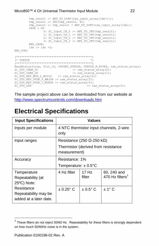
tmp_result := ANY_TO_DINT(raw_input_array[idx+1]);
tmp_result := SHL(tmp_result, 8);
tmp_result := tmp_result + ANY_TO_DINT(raw_input_array[idx]);
CASE i OF
0: S1_Input_CH_0 := ANY_TO_INT(tmp_result);
1: S1_Input_CH_1 := ANY_TO_INT(tmp_result);
2: S1_Input_CH_2 := ANY_TO_INT(tmp_result);
3: S1_Input_CH_3 := ANY_TO_INT(tmp_result);
END_CASE;
idx := idx +2;
END_FOR;
(*********************************************)
(* STATUS *)
(*********************************************)
ReadStatus(true, Slot_ID, OFFSET_STATUS, STATUS_N_BYTES, raw_status_array);
S1_STS_CHAN_OC := raw_status_array[0];
S1_STS_CHAN_OU := raw_status_array[1];
S1_STS_REV_MOD_2_BUILD := raw_status_array[2];
S1_STS_REV_FPGA_0_MAJOR := raw_status_array[3];
S1_STS_REV_FPGA_1_MINOR := raw_status_array[4];
S1_STS_LED := raw_status_array[5];
The sample project above can be downloaded from our website at
http://www.spectrumcontrols.com/downloads.htm
Electrical Specifications
Input Specifications Values
Inputs per module 4 NTC thermistor input channels, 2-wire
only
Input ranges Resistance (250 Ω-250 kΩ)
Thermistor (derived from resistance
measurement)
Accuracy Resistance: 1%
Temperature: ± 0.5°C
Temperature
Repeatability (at
25ºC) Note:
Resistance
Repeatability may be
added at a later date.
4 Hz filter 17 Hz filter
60, 240 and 470 Hz filters
1
± 0.25° C ± 0.5° C ± 1° C
1 These filters do not reject 50/60 Hz. Repeatability for these filters is strongly dependent
on how much 50/60Hz noise is in the system.
Micro800™ 4 Ch Universal Thermistor Input Module 23
Publication 0100198-02 Rev. A
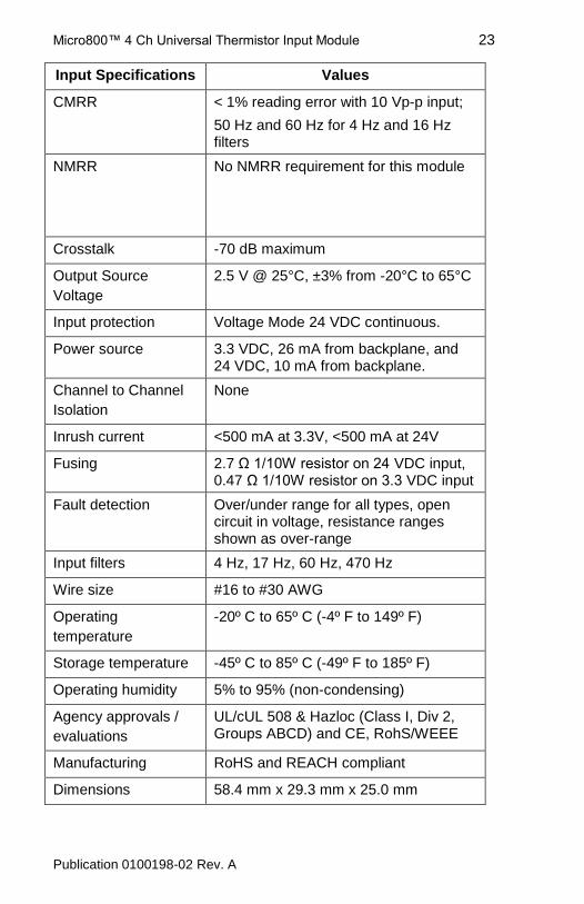
Input Specifications Values
CMRR < 1% reading error with 10 Vp-p input;
50 Hz and 60 Hz for 4 Hz and 16 Hz filters
NMRR No NMRR requirement for this module
Crosstalk -70 dB maximum
Output Source
Voltage
2.5 V @ 25°C, ±3% from -20°C to 65°C
Input protection Voltage Mode 24 VDC continuous.
Power source 3.3 VDC, 26 mA from backplane, and 24 VDC, 10 mA from backplane.
Channel to Channel
Isolation
None
Inrush current <500 mA at 3.3V, <500 mA at 24V
Fusing 2.7 Ω 1/10W resistor on 24 VDC input, 0.47 Ω 1/10W resistor on 3.3 VDC input
Fault detection Over/under range for all types, open circuit in voltage, resistance ranges shown as over-range
Input filters 4 Hz, 17 Hz, 60 Hz, 470 Hz
Wire size #16 to #30 AWG
Operating
temperature
-20º C to 65º C (-4º F to 149º F)
Storage temperature -45º C to 85º C (-49º F to 185º F)
Operating humidity 5% to 95% (non-condensing)
Agency approvals /
evaluations
UL/cUL 508 & Hazloc (Class I, Div 2, Groups ABCD) and CE, RohS/WEEE
Manufacturing RoHS and REACH compliant
Dimensions 58.4 mm x 29.3 mm x 25.0 mm
Micro800™ 4 Ch Universal Thermistor Input Module 24
Publication 0100198-02 Rev. A
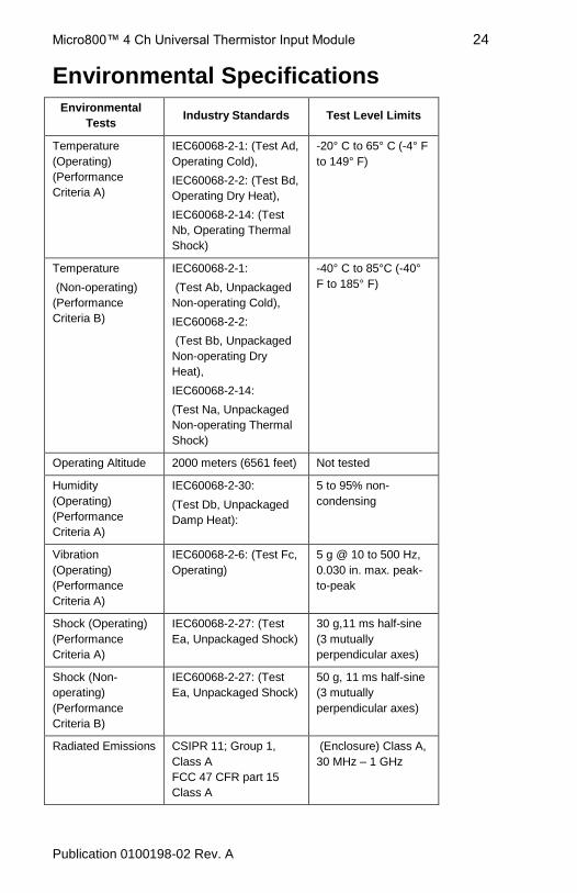
Environmental Specifications
Environmental
Tests Industry Standards Test Level Limits
Temperature
(Operating)
(Performance
Criteria A)
IEC60068-2-1: (Test Ad,
Operating Cold),
IEC60068-2-2: (Test Bd,
Operating Dry Heat),
IEC60068-2-14: (Test
Nb, Operating Thermal
Shock)
-20° C to 65° C (-4° F
to 149° F)
Temperature
(Non-operating)
(Performance
Criteria B)
IEC60068-2-1:
(Test Ab, Unpackaged
Non-operating Cold),
IEC60068-2-2:
(Test Bb, Unpackaged
Non-operating Dry
Heat),
IEC60068-2-14:
(Test Na, Unpackaged
Non-operating Thermal
Shock)
-40° C to 85°C (-40°
F to 185° F)
Operating Altitude 2000 meters (6561 feet) Not tested
Humidity
(Operating)
(Performance
Criteria A)
IEC60068-2-30:
(Test Db, Unpackaged
Damp Heat):
5 to 95% non-
condensing
Vibration
(Operating)
(Performance
Criteria A)
IEC60068-2-6: (Test Fc,
Operating)
5 g @ 10 to 500 Hz,
0.030 in. max. peak-
to-peak
Shock (Operating)
(Performance
Criteria A)
IEC60068-2-27: (Test
Ea, Unpackaged Shock)
30 g,11 ms half-sine
(3 mutually
perpendicular axes)
Shock (Non-
operating)
(Performance
Criteria B)
IEC60068-2-27: (Test
Ea, Unpackaged Shock)
50 g, 11 ms half-sine
(3 mutually
perpendicular axes)
Radiated Emissions CSIPR 11; Group 1,
Class A
FCC 47 CFR part 15
Class A
(Enclosure) Class A,
30 MHz – 1 GHz
Micro800™ 4 Ch Universal Thermistor Input Module 25
Publication 0100198-02 Rev. A
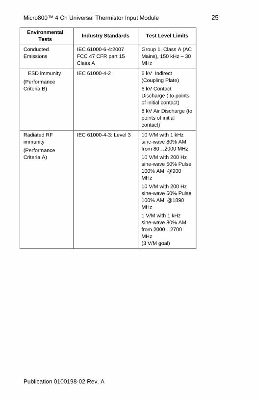
Environmental
Tests Industry Standards Test Level Limits
Conducted
Emissions
IEC 61000-6-4:2007
FCC 47 CFR part 15
Class A
Group 1, Class A (AC
Mains), 150 kHz – 30
MHz
ESD immunity
(Performance
Criteria B)
IEC 61000-4-2 6 kV Indirect
(Coupling Plate)
6 kV Contact
Discharge ( to points
of initial contact)
8 kV Air Discharge (to
points of initial
contact)
Radiated RF
immunity
(Performance
Criteria A)
IEC 61000-4-3: Level 3 10 V/M with 1 kHz
sine-wave 80% AM
from 80…2000 MHz
10 V/M with 200 Hz
sine-wave 50% Pulse
100% AM @900
MHz
10 V/M with 200 Hz
sine-wave 50% Pulse
100% AM @1890
MHz
1 V/M with 1 kHz
sine-wave 80% AM
from 2000…2700
MHz
(3 V/M goal)
Micro800™ 4 Ch Universal Thermistor Input Module 26
Publication 0100198-02 Rev. A
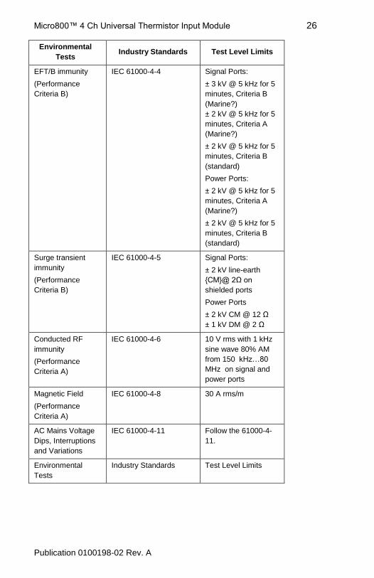
Environmental
Tests Industry Standards Test Level Limits
EFT/B immunity
(Performance
Criteria B)
IEC 61000-4-4 Signal Ports:
± 3 kV @ 5 kHz for 5
minutes, Criteria B
(Marine?)
± 2 kV @ 5 kHz for 5
minutes, Criteria A
(Marine?)
± 2 kV @ 5 kHz for 5
minutes, Criteria B
(standard)
Power Ports:
± 2 kV @ 5 kHz for 5
minutes, Criteria A
(Marine?)
± 2 kV @ 5 kHz for 5
minutes, Criteria B
(standard)
Surge transient
immunity
(Performance
Criteria B)
IEC 61000-4-5
Signal Ports:
± 2 kV line-earth
CM@ 2Ω on
shielded ports
Power Ports
± 2 kV CM @ 12 Ω
± 1 kV DM @ 2 Ω
Conducted RF
immunity
(Performance
Criteria A)
IEC 61000-4-6
10 V rms with 1 kHz
sine wave 80% AM
from 150 kHz…80
MHz on signal and
power ports
Magnetic Field
(Performance
Criteria A)
IEC 61000-4-8
30 A rms/m
AC Mains Voltage
Dips, Interruptions
and Variations
IEC 61000-4-11 Follow the 61000-4-
11.
Environmental
Tests
Industry Standards Test Level Limits
Micro800™ 4 Ch Universal Thermistor Input Module 27
Publication 0100198-02 Rev. A
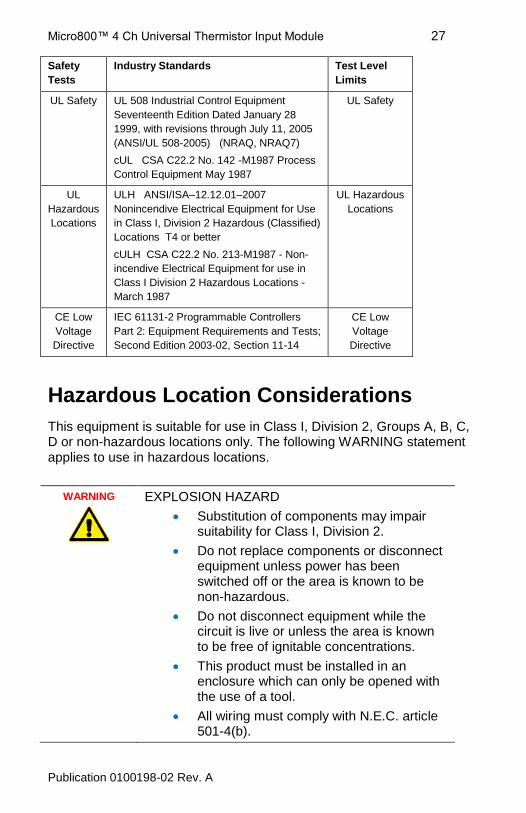
Safety
Tests
Industry Standards Test Level
Limits
UL Safety UL 508 Industrial Control Equipment
Seventeenth Edition Dated January 28
1999, with revisions through July 11, 2005
(ANSI/UL 508-2005) (NRAQ, NRAQ7)
cUL CSA C22.2 No. 142 -M1987 Process
Control Equipment May 1987
UL Safety
UL
Hazardous
Locations
ULH ANSI/ISA–12.12.01–2007
Nonincendive Electrical Equipment for Use
in Class I, Division 2 Hazardous (Classified)
Locations T4 or better
cULH CSA C22.2 No. 213-M1987 - Non-
incendive Electrical Equipment for use in
Class I Division 2 Hazardous Locations -
March 1987
UL Hazardous
Locations
CE Low
Voltage
Directive
IEC 61131-2 Programmable Controllers
Part 2: Equipment Requirements and Tests;
Second Edition 2003-02, Section 11-14
CE Low
Voltage
Directive
Hazardous Location Considerations
This equipment is suitable for use in Class I, Division 2, Groups A, B, C, D or non-hazardous locations only. The following WARNING statement applies to use in hazardous locations.
WARNING
EXPLOSION HAZARD
Substitution of components may impair suitability for Class I, Division 2.
Do not replace components or disconnect equipment unless power has been switched off or the area is known to be non-hazardous.
Do not disconnect equipment while the circuit is live or unless the area is known to be free of ignitable concentrations.
This product must be installed in an enclosure which can only be opened with the use of a tool.
All wiring must comply with N.E.C. article 501-4(b).
Micro800™ 4 Ch Universal Thermistor Input Module 28
Publication 0100198-02 Rev. A
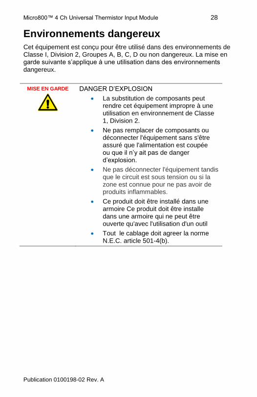
Environnements dangereux Cet équipement est conçu pour être utilisé dans des environnements de Classe I, Division 2, Groupes A, B, C, D ou non dangereux. La mise en garde suivante s’applique à une utilisation dans des environnements dangereux.
MISE EN GARDE
DANGER D’EXPLOSION
La substitution de composants peut rendre cet équipement impropre à une utilisation en environnement de Classe 1, Division 2.
Ne pas remplacer de composants ou déconnecter l'équipement sans s'être assuré que l'alimentation est coupée ou que il n’y ait pas de danger d’explosion.
Ne pas déconnecter l'équipement tandis que le circuit est sous tension ou si la zone est connue pour ne pas avoir de produits inflammables.
Ce produit doit être installé dans une armoire Ce produit doit être installe dans une armoire qui ne peut être ouverte qu'avec l'utilisation d'un outil
Tout le cablage doit agreer la norme N.E.C. article 501-4(b).
Micro800™ 4 Ch Universal Thermistor Input Module 29
Publication 0100198-02 Rev. A
Micro800™ 4 Ch Universal Thermistor Input Module 30
Publication 0100198-02 Rev. A
For Technical Support USA 440-646-6900 United Kingdom 01908 635230 Australia 1800-809-929 Mexico 001-888-365-8677 Brazil (55) 11 3618 8800 Europe (49) 2104 960 630
1705 132nd Ave NE Bellevue, WA 98005 USA Tel: 425-746-9481 Fax: 425-641-9473 Email: [email protected] Web: www.spectrumcontrols.com
Micro800 is a trademark of Rockwell Automation. Publication 2080sc-NTC Install Guide – June 2014 © 2013 Spectrum Controls, Inc. Printed in the USA.
Related Documents