Edith Cowan University Edith Cowan University Research Online Research Online Research outputs 2014 to 2021 11-1-2021 Micro-proppant placement in hydraulic and natural fracture Micro-proppant placement in hydraulic and natural fracture stimulation in unconventional reservoirs: A review stimulation in unconventional reservoirs: A review Masoud Aslannezhad Azim Kalantariasl Zhenjiang You Edith Cowan University Stefan Iglauer Edith Cowan University Alireza Keshavarz Edith Cowan University Follow this and additional works at: https://ro.ecu.edu.au/ecuworkspost2013 Part of the Engineering Commons 10.1016/j.egyr.2021.11.220 Aslannezhad, M., Kalantariasl, A., You, Z., Iglauer, S., & Keshavarz, A. (2021). Micro-proppant placement in hydraulic and natural fracture stimulation in unconventional reservoirs: A review. Energy Reports, 7, 8997-9022. https://doi.org/10.1016/j.egyr.2021.11.220 This Journal Article is posted at Research Online. https://ro.ecu.edu.au/ecuworkspost2013/11744

Welcome message from author
This document is posted to help you gain knowledge. Please leave a comment to let me know what you think about it! Share it to your friends and learn new things together.
Transcript

Edith Cowan University Edith Cowan University
Research Online Research Online
Research outputs 2014 to 2021
11-1-2021
Micro-proppant placement in hydraulic and natural fracture Micro-proppant placement in hydraulic and natural fracture
stimulation in unconventional reservoirs: A review stimulation in unconventional reservoirs: A review
Masoud Aslannezhad
Azim Kalantariasl
Zhenjiang You Edith Cowan University
Stefan Iglauer Edith Cowan University
Alireza Keshavarz Edith Cowan University
Follow this and additional works at: https://ro.ecu.edu.au/ecuworkspost2013
Part of the Engineering Commons
10.1016/j.egyr.2021.11.220 Aslannezhad, M., Kalantariasl, A., You, Z., Iglauer, S., & Keshavarz, A. (2021). Micro-proppant placement in hydraulic and natural fracture stimulation in unconventional reservoirs: A review. Energy Reports, 7, 8997-9022. https://doi.org/10.1016/j.egyr.2021.11.220 This Journal Article is posted at Research Online. https://ro.ecu.edu.au/ecuworkspost2013/11744
Energy Reports 7 (2021) 8997–9022
Contents lists available at ScienceDirect
Energy Reports
journal homepage: www.elsevier.com/locate/egyr
Micro-proppant placement in hydraulic and natural fracturestimulation in unconventional reservoirs: A reviewMasoud Aslannezhad a, Azim Kalantariasl a, Zhenjiang You b,c, Stefan Iglauer b,c,Alireza Keshavarz b,c,∗
a Department of Petroleum Engineering, School of Chemical and Petroleum Engineering, Shiraz University, Iranb School of Engineering, Edith Cowan University, 6027 Joondalup, WA, Australiac Center for Sustainable Energy and Resources, Edith Cowan University, 6027 Joondalup, WA, Australia
a r t i c l e i n f o
Article history:Received 4 August 2021Received in revised form 15 October 2021Accepted 11 November 2021Available online 4 December 2021
Keywords:Micro-proppants placementHydraulic fracturingNatural fracture stimulationUnconventional reservoirs
a b s t r a c t
Tight hydrocarbon reservoirs require stimulation to improve the recovery of oil and gas resources.Hydraulic fracturing is a technique extensively employed in the oil and gas industry to generatefractures including primary and secondary fractures. To keep these fractures open, proppants are used.However, some of these ractures are very narrow for conventional proppants to penetrate and prop,hence smaller proppants called micro-proppants are required. These micro-proppants can improvethe hydraulic conductivity of both, the primary fractures and the untouched microfractures, leadingto enhanced oil and gas recovery.
This paper presents a critical review on the progress of current micro-proppants models, technolo-gies and field applications (sub 100mesh proppants) with a particular attention to micro-proppantsplacement in hydraulic and natural fractures. The impact of various factors on micro-proppantplacement in the fractures is analyzed. These factors include proppant concentration (i.e., volumefraction of solid proppant), proppant size, fracturing fluid chemistry, and confining stress (causingproppant deformation and proppant embedment into the rock). This review concludes that usingmicro-proppants can improve the efficiency of the hydraulic fracturing treatment, leading to enhancedoil and gas production.
© 2021 The Authors. Published by Elsevier Ltd. This is an open access article under the CC BY-NC-NDlicense (http://creativecommons.org/licenses/by-nc-nd/4.0/).
1. Introduction
As conventional reservoirs are being depleted, unconventionalreservoirs are considered as a valuable source to meet globalenergy demands, especially following their commercial develop-ment using the advanced hydraulic fracturing technology (Awanet al., 2020a). Hydraulic fracturing treatment with proppants isan important technology used in the petroleum industry, mainlyfor treating naturally fractured reservoirs and improving recoveryfrom oil and gas reservoirs. Hydraulic fracturing generates high-conductivity pathways from the low permeable formations to theboreholes by pumping large quantities of fracturing fluids mixedwith sufficient proppant volume (Asadi et al., 2020; Dejam et al.,2018; Wei et al., 2019). Proppants are solid particles keepingthe hydraulic and induced fractures open after pumping fluidhas stopped. One of the biggest concerns with fracturing fluids(e.g., slickwater) is its weak ability to suspend and/or trans-port conventional proppants (e.g., sand) deep into the fracture
∗ Corresponding author at: School of Engineering, Edith Cowan University,6027 Joondalup, WA, Australia.
E-mail address: [email protected] (A. Keshavarz).
network. This is due to high density of conventional proppantsyielding rapid proppant settlement, although the proppant trans-port depends on many other factors, e.g. injection rate, proppantconcentration, size and density, type of proppant, fluid rheol-ogy, fracture width and roughness (Chun et al., 2020; Blytonet al., 2015; Huang et al., 2018a). Several studies have dealt withfracture surface roughness through numerical simulations andanalytical solutions (Drazer and Koplik, 2002; Kim and Inoue,2003; Schwarz and Enzmann, 2013), experimental studies (Leeet al., 2003; Konzuk and Kueper, 2004; Zimmerman et al., 2004;Watanabe et al., 2005; Jiang et al., 2004), both experimental andnumerical modeling (Schmittbuhl et al., 2008). Another impor-tant parameter that significantly affects the settling velocity ofthe proppant is surface area to weight ratio (Ford et al., 1994).High settling velocity causes the propped fractures to be muchshorter and narrower compared to the initially induced fractures(Kincaid et al., 2013; Sharma and Gadde, 2005; Palisch et al.,2010).
Natural fractures and induced microfractures within the com-plex network demonstrate a variety of lengths and widths. Thesefractures can propagate about 40 m (Jeffrey and Boucher, 2004)or even more than 100 m (Chambers and Meise, 2005) depending
https://doi.org/10.1016/j.egyr.2021.11.2202352-4847/© 2021 The Authors. Published by Elsevier Ltd. This is an open access article under the CC BY-NC-ND license (http://creativecommons.org/licenses/by-nc-nd/4.0/).

M. Aslannezhad, A. Kalantariasl, Z. You et al. Energy Reports 7 (2021) 8997–9022
on the injection pressure and fluid/rock properties. In addition,these fractures may have lengths of millimeters or less (e.g., from10 to 250 µm) and widths of less than 0.1 mm (e.g., from 1to 10 µm) (Anders et al., 2014; Wu et al., 2015; Zhou et al.,2016; Nagel and Sanchez-Nagel, 2015). From a geologic stand-point, the term microfracture refers to a fracture up to a fewtens of microns wide and up to a few millimeters in length thatis visible only under magnification (Anders et al., 2014; Galeet al., 2014). Thus, tight reservoirs with ultra-low permeabilitymay be economically feasible if the proppants reach these mi-crofractures and prevent them from closing, thereby enhancingthe production rate (Apaydin et al., 2012; Cipolla et al., 2009).In 2010, King (2010) suggested that more improvements wererequired for proppant particularly applied to propping inducedand natural microfractures. Comprehensive reviews on proppanttechnologies have been reported in previous studies (Liang et al.,2016; Pangilinan et al., 2016; Zoveidavianpoor and Gharibi, 2015).Danso et al. (2021) presented an extensive review of variousapplicable proppant technologies and challenges.
The proppant selection depends on the mechanical proper-ties of the formation rock and of the proppant itself (Awanet al., 2020b). The 100-mesh proppants currently in use may betoo large to reach the microfractures induced during hydraulicfracturing operation. Thus, to reach the natural and induced mi-crofractures, micro-proppants (i.e., fine proppants with diametersof 150 µm (100-mesh) or less) having high mobility are required.Several studies have successfully applied micro-sized proppantparticles in the field (Calvin et al., 2017a; Nguyen et al., 2013;Dahl et al., 2015a,b; Bose et al., 2015a). Blyton et al. (2015)and Zhang et al. (2017) simulated the transport and settlementof proppants in a fracture system using a coupled computa-tional fluid dynamics and discrete element method (CFD–DEM)approach. Sharma and Manchanda (2015) have suggested thatthe unpropped induced fractures may have a surface area of atleast one order of magnitude larger than the surface area of mainpropped fracture. This means if we can somehow keep fracturesopen, it would be possible to enhance the well productivitysignificantly.
Apart from the size, the best propping agent should havelow density and high resistance against crushing and corrosion.In addition, it should not be too expensive. Ceramic proppants,resin-coated sand (RCS) and silica sand are the best choices in thisregard (Lake, 2006). Placing proppants with enough concentrationand proper type is necessary so that the hydrocarbon can flowtowards the wellbore more efficiently. Proppant size, strength,material and grain size distribution are among the most impor-tant factors to consider when selecting proppant and designingthe fluid formulation as well. This choice is significantly affectedby fracture geometry, formation properties and selection of frac-turing fluid (Shah et al., 2017). Therefore, a good understandingof proppant transport and placement is necessary for designingpumping schedule and fluid formulation. For micro-proppants,the gravitational force is negligible compared to drag and elec-trostatic forces exerting on particles (You et al., 2015, 2019a). Inthis case, the actual density does not affect the proppant behavior.
The objective of this paper is to review conceptual (Sections 2–4), mathematical (Section 5), numerical (Section 6), experimental(Section 7) and field studies (Sections 8–9) of micro-proppants,and address how they may benefit the oil and gas productionenhancement.
2. Proppant placement and embedment
Various authors have studied the proppant placement andembedment under severe conditions in stress-sensitive reser-voirs (Lacy et al., 1998; Duenckel et al., 2011; Alramahi and Sund-berg, 2012; Ghosh et al., 2014; Li et al., 2015; Tang et al., 2018;
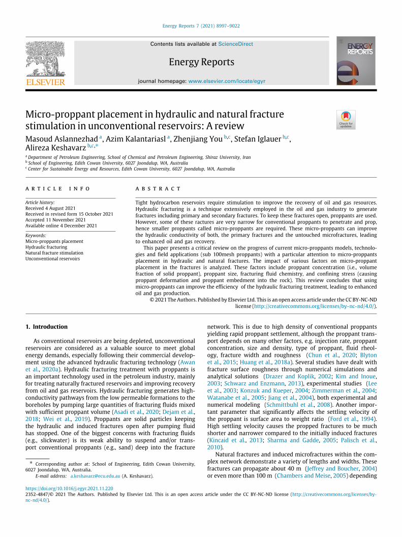
Huang et al., 2019; Fan and Chen, 2020; Di Vaira et al., 2020; Ke-shavarz et al., 2018). Although injection of proppant considerablyimproves fracture conductivity, proppant embedment may havenegative impact on well productivity. Fig. 1 illustrates proppantembedment, in which high compressive stress causes proppantsto insert into the formation rock. Proppant embedment occurswhen the formation rock is considerably softer than the proppant.Under high compressive stress, the proppant penetrates into thefracture faces during the pressure depletion resulting in a de-crease in fracture width. Consequently, high conductivity loss isinduced in relatively soft formations (Zhang and Hou, 2016).
Alramahi and Sundberg (2012) examined the proppant em-bedment in shale reservoirs and its impact on the conductivityof hydraulic fracture. Using laboratory data of proppant em-bedment, they derived an analytical approach to anticipate thestress-dependent conductivity of hydraulic fractures. They alsoinvestigated the relationships between fluid composition, rockmechanical properties, mineralogy, and proppant embedment.They found that there is a close relation between the amountof proppant embedment and the given rock stiffness and stresswhich, in turn, is influenced by the mineral content, chiefly thetype and quantity of clay minerals within the rock mass. Forstrong shale specimens, shallower proppant embedment was ob-served; however deeper proppant embedment was achieved forshales with the elastic modulus less than 6.89 GPa. Moreover, inrocks with higher clay content, greater value of embedment depthis expected. They also expressed that the proppant embedmentchiefly happened in the plastic deformation stage of the fracturesurfaces, which cannot be analyzed by any of the early proposedapproaches. Their analytical model can be used to anticipate theamount of conductivity loss because of proppant embedmentin various unconventional reservoirs. However, the impact oftemperature, creep, and fines migration are not considered in theanalytical model. Clays can also be sensitive to various carrierfluids, causing more complication. Li et al. (2015) established amathematical model to obtain proppant embedment based oncontact theory. According to their semi-analytical model, im-portant parameters including the rock deformation, proppantembedment depth and the resultant fracture conductivity couldbe estimated for both monolayer and multilayer embedmentpatterns. They found that the proppant embedment depth de-creases with the elastic modulus of coal, while increases with theelastic modulus of proppant, proppant size and confining stress.Moreover, the fracture conductivity decreases with the confiningstress, while increases with the proppant size, fracture width, andelastic modulus of both the rock and proppant. Tang et al. (2018)carried out experiments and numerical simulation to investigatethe effects of fracturing fluids and proppant concentration onproppant embedment. They concluded that the proppant embed-ment decreases with increasing the proppant concentration, sothat 150% proppant coverage is the optimum proppant concen-tration to reach the minimum proppant embedment. Moreover,the effect of fracturing fluid on proppant embedment is greaterwhen compared to high proppant concentrations such that theembedment under oil-saturated conditions is less than that un-der water-saturated conditions. Huang et al. (2019) proposedan analytical model to examine dynamic fracture closure con-sidering proppant embedment and proppant pack deformation.Wang et al. (2021) applied a predictive model involving finiteelement method (FEM), lattice Boltzmann method (LBM) andradial Darcy flow analytical solution to predict the proppantembedment and elastoplastic deformation of the coal (You et al.,2019b,c). They demonstrated that the elastoplastic deformationled to smaller permeability enhancement and less productionimprovement than the traditional linear elastic models. Ding et al.(2020) performed a time-lapse acoustic monitoring of proppant
8998
M. Aslannezhad, A. Kalantariasl, Z. You et al. Energy Reports 7 (2021) 8997–9022
Fig. 1. A cross-sectional view of fracture aperture (a) before embedment, and (b) after embedment.
emplacement and fracture acidizing on clay-abundant Marcel-lus shales. They investigated the effects of both fracture prop-ping and acidizing on microstructure and fracture permeabilityof the shale. The results of the experiment showed that geo-chemical alteration in fracture acidizing generates an alteredzone that decreases fracture stiffness and permeability. This in-dicates that coupling of fracture acidizing and propping couldcause proppant embedment issues in the shale due to reactionwith acids. Ahamed et al. (2019) performed a comprehensivereview on mechanisms of micro-proppant damage in coal seamreservoirs.
3. Graded proppant injection
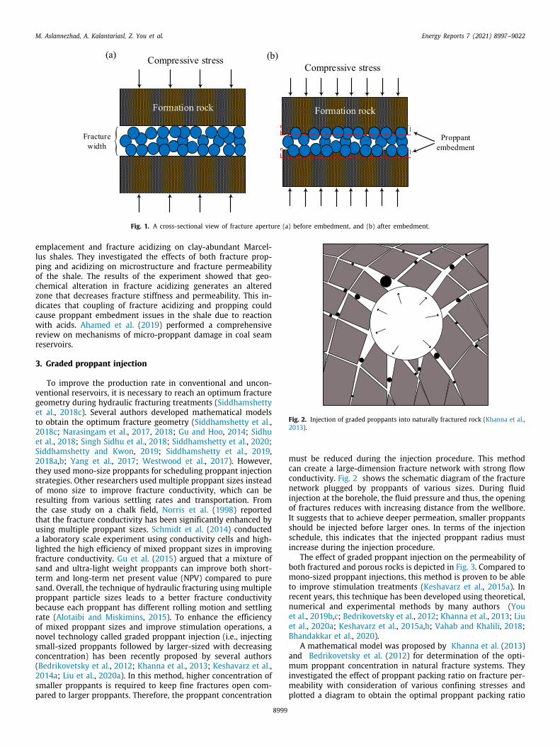
To improve the production rate in conventional and uncon-ventional reservoirs, it is necessary to reach an optimum fracturegeometry during hydraulic fracturing treatments (Siddhamshettyet al., 2018c). Several authors developed mathematical modelsto obtain the optimum fracture geometry (Siddhamshetty et al.,2018c; Narasingam et al., 2017, 2018; Gu and Hoo, 2014; Sidhuet al., 2018; Singh Sidhu et al., 2018; Siddhamshetty et al., 2020;Siddhamshetty and Kwon, 2019; Siddhamshetty et al., 2019,2018a,b; Yang et al., 2017; Westwood et al., 2017). However,they used mono-size proppants for scheduling proppant injectionstrategies. Other researchers used multiple proppant sizes insteadof mono size to improve fracture conductivity, which can beresulting from various settling rates and transportation. Fromthe case study on a chalk field, Norris et al. (1998) reportedthat the fracture conductivity has been significantly enhanced byusing multiple proppant sizes. Schmidt et al. (2014) conducteda laboratory scale experiment using conductivity cells and high-lighted the high efficiency of mixed proppant sizes in improvingfracture conductivity. Gu et al. (2015) argued that a mixture ofsand and ultra-light weight proppants can improve both short-term and long-term net present value (NPV) compared to puresand. Overall, the technique of hydraulic fracturing using multipleproppant particle sizes leads to a better fracture conductivitybecause each proppant has different rolling motion and settlingrate (Alotaibi and Miskimins, 2015). To enhance the efficiencyof mixed proppant sizes and improve stimulation operations, anovel technology called graded proppant injection (i.e., injectingsmall-sized proppants followed by larger-sized with decreasingconcentration) has been recently proposed by several authors(Bedrikovetsky et al., 2012; Khanna et al., 2013; Keshavarz et al.,2014a; Liu et al., 2020a). In this method, higher concentration ofsmaller proppants is required to keep fine fractures open com-pared to larger proppants. Therefore, the proppant concentration
Fig. 2. Injection of graded proppants into naturally fractured rock (Khanna et al.,2013).
must be reduced during the injection procedure. This methodcan create a large-dimension fracture network with strong flowconductivity. Fig. 2 shows the schematic diagram of the fracturenetwork plugged by proppants of various sizes. During fluidinjection at the borehole, the fluid pressure and thus, the openingof fractures reduces with increasing distance from the wellbore.It suggests that to achieve deeper permeation, smaller proppantsshould be injected before larger ones. In terms of the injectionschedule, this indicates that the injected proppant radius mustincrease during the injection procedure.
The effect of graded proppant injection on the permeability ofboth fractured and porous rocks is depicted in Fig. 3. Compared tomono-sized proppant injections, this method is proven to be ableto improve stimulation treatments (Keshavarz et al., 2015a). Inrecent years, this technique has been developed using theoretical,numerical and experimental methods by many authors (Youet al., 2019b,c; Bedrikovetsky et al., 2012; Khanna et al., 2013; Liuet al., 2020a; Keshavarz et al., 2015a,b; Vahab and Khalili, 2018;Bhandakkar et al., 2020).
A mathematical model was proposed by Khanna et al. (2013)and Bedrikovetsky et al. (2012) for determination of the opti-mum proppant concentration in natural fracture systems. Theyinvestigated the effect of proppant packing ratio on fracture per-meability with consideration of various confining stresses andplotted a diagram to obtain the optimal proppant packing ratio
8999

M. Aslannezhad, A. Kalantariasl, Z. You et al. Energy Reports 7 (2021) 8997–9022
Fig. 3. The effect of graded proppant injection on the permeability of both fractured and porous rocks. The black curve represents increase of pressure during theinjection of proppant-free water, and the green curve shows the decrease of permeability during proppant injection. Using this method in porous media where therock conductivity is provided by pores results in permeability impairment (blue curve). Whereas, the proppant injection into fractured rocks increases permeabilityduring the post-fracturing period (red curve) (Keshavarz et al., 2014a). (For interpretation of the references to color in this figure legend, the reader is referred tothe web version of this article.)
(OPPR). A packing ratio equal to unity represents a full monolayerof proppants in the fracture system and a packing ratio equalto zero represents that there is no proppant in the fracturesystem. The laboratory coreflood experiments were conducted byKeshavarz et al. (2014b,c) and Keshavarz et al. (2016a) to vali-date and correct Khanna’s diagram. Moreover, Liu et al. (2020a)further improved this diagram by considering three additionalimportant parameters including proppant deformation, proppantembedment into fracture wall, and fracture conductivity in orderto determine the OPPR.
Ribeiro et al. (2020) used numerical models to evaluate theperformance of graded proppant injection stimulation in coalseam gas reservoirs. The injection of small-sized proppants fol-lowed by larger ones would cause deeper permeation and opti-mal placement of proppants in the fracture system. The methodcan lead to development of the treated area and enhanced wellproductivity index. In addition, Hu et al. (2018) have done alaboratory scale experiment to design a pumping schedule formulti-size proppants in a pre-existing straight fracture. However,they have not considered average propped surface area (PSA)and average fracture conductivity (FC) to quantify the produc-tion rate. Bhandakkar et al. (2020) have proposed to improvegas production from unconventional reservoirs by proposing amulti-size proppant pumping schedule in which both PSA and FCparameters have been considered for simultaneously propagatingmultiple fractures. Mollanouri Shamsi et al. (2015) and Shamsiet al. (2017) evaluated the fracture conductivity under differentconfining stress using three various proppant size distributionssuch as well-graded, uniformly-graded and poorly-graded prop-pants. They applied a coupled Discrete Element Method (DEM)and Lattice Boltzmann Model (LBM) approach for optimizationof proppant size distributions for the maximum conductivityat a given stress state. They concluded that uniformly-gradedproppants result in higher conductivity compared to poorly andwell-graded proppant packs. Ramandi et al. (2021) carried out
graded proppant injection into naturally fractured coal at differ-ent pore pressures and measured the permeability of coal samplebefore and after the injection using X-ray micro computed tomog-raphy (micro-CT) scanner. They reported that graded proppantinjection causes a significant increase in the sample permeability.Bandara et al. (2020a,b) claimed that graded proppant injectionis an appropriate choice for fractures with greater roughness co-efficients. They showed that the injection of graded proppants isbeneficial for keeping high fracture apertures and creating lowerfracture tortuosity. Thus, it yields higher fracture conductivity andthereby increasing oil and gas recovery.
Apart from the proppant size, it is also important to considerthe difference between proppant density and fluid density ingraded proppant injection method, which results in a downwardmotion. Under practical conditions, the proppant size and densityonly have moderate impact on the proppant settling while thefluid viscosity has the highest impact (Roostaei et al., 2018). Luet al. (2020) conducted CFD–DEM simulation and reported thatlow-density proppant and high-viscosity fracturing fluid shouldbe pumped first to improve the distance of proppant placementand increase the effective fracture stimulation area. To study theeffects of the proppant density and size, fluid viscosity, and in-jection rate of the fluid on the proppant transport and placement,the reader is referred to the works in Han et al. (2016), Bahri andMiskimins (2021), Wang et al. (2019) and Barboza et al. (2021).
4. Micro-proppants
In recent years, micro-proppants have been investigated andapplied in the field by several authors (Dahl et al., 2015a,b; Jiet al., 2016; Madasu and Nguyen, 2017; Kim et al., 2018; Liet al., 2018; Cheung et al., 2018; Cortez-Montalvo et al., 2018; Lauet al., 2019; Kumar et al., 2019) and their importance in the un-conventional reservoir stimulation has been acknowledged. Dahlet al. (2015a,b) conducted a field pilot test to study the ef-fect of micro-proppants on production improvement of eleven
9000
M. Aslannezhad, A. Kalantariasl, Z. You et al. Energy Reports 7 (2021) 8997–9022
condensate-rich gas wells in Barnett shale. The results indicatedthat inclusion of micro-proppants in the pad stages before mainhydraulic fracture operation caused considerable improvementin well productivity over 395 days. The use of micro-proppantsincreased the gas production by 36%–55% and also increased thecondensate production by 23%–47% compared to the wells inwhich micro-proppants has not been pumped during pad stages.Ji et al. (2016) reported that applying 149 µm-sized proppantfor the hydraulic fracturing of the shale formation in Sichuan,China gave promising results. Recent field trials by Calvin et al.(2017a) showed that the use of micro-proppants in the pad fluidresults in considerable production uplifts compared to the offsetwells. They reported that for Woodford shale, an uplift of 25%in condensate production and 10% in gas production has beenachieved. A new simulation model was built by Madasu andNguyen (2017) to demonstrate the interaction between micro-proppants and microfractures and then the results were vali-dated by the laboratory experimental results. They concluded thatusing micro-proppants could significantly increase the effectivepermeability of microfractures. Kim et al. (2018) conducted aseries of experiments with various split shale core plugs extractedfrom Barnett, Bakken, and Eagle Ford formations to determinetheir stress-dependent permeability in the presence of micro-proppants placement among microcracks. Then, they derived ananalytical model to describe the interaction between the mono-layer micro-proppants and fracture walls under stress. The resultsshowed the great importance of utilizing micro-proppants to im-prove the microcracks permeability. Li et al. (2018) used field datafrom several major unconventional plays in the United States,Haynesville, Wolfcamp, and Eagle Ford to evaluate the effects ofsmall sized proppants on the post-fracturing production perfor-mance of stimulated wells. The results suggested that the wellsstimulated by small sized proppants have better gas productionrates for both short-term and long-term compared to those stim-ulated by larger size conventional proppants. Cheung et al. (2018)argued that using 297 µm/105 µm (50/140-mesh) proppantscreate higher fracture conductivity compared to 425 µm/212 µm(40/70-mesh) proppants in both Fox Creek and Wolfcamp forma-tions, which are respectively located in Appalachia and PermianBasin. Kumar et al. (2019) used a 3D simulator called ‘‘GeoFrac-3D’’ to study the transport and placement of micro-proppantsin the natural and hydraulic fracture networks. They consideredthe pressure dependent leak-off for the carrier fluid flowing intothe natural fracture/rock matrix system. The Eulerian–Eulerianapproach in which both fracturing fluid and the proppants areconsidered as slurry (i.e., a mixture of the proppants and fluid)was used to model the transport and placement of proppantswithin the fractures. The results of simulation revealed that thereare two contributing factors including proppant transport intomicrofractures and slow settling rate that make micro-proppantsusage highly effective. The settling rates of micro-proppants andthus their distribution and placement are affected by many fac-tors such as fluid rheology and velocity, near wellbore tortuosity,fracture aperture, micro-proppants size, and the interaction ofnatural and hydraulic fractures. In their study, the aperture sizeof the secondary/tight natural fractures lies within the ranges of0.26–1.98 mm. They also concluded that micro-proppants havehigh capability to uniformly distribute inside the naturally frac-tured unconventional reservoirs. This leads to higher fractureconductivity and thus increased oil and gas production. Moreover,the capability of the micro-proppants to readily invade secondaryor tight natural fractures will decrease pressure dependent leak-off distribution in the formation, causing reduction in the treatingpressure (Kumar et al., 2019).
It would be challenging to estimate the microfracture con-ductivity and effective permeability of unconventional reservoirs;
Table 1The mesh sizes of proppants Liang et al. (2016), Rassenfoss (2017).Mesh size Micron (µm) Millimeter (mm) Inch (in)
8 2380 2.38 0.09416 1190 1.19 0.04720 841 0.841 0.03330 595 0.595 0.02340 425 0.425 0.016750 297 0.297 0.01260 250 0.25 0.009870 212 0.212 0.0083100 149 0.149 0.0059140 105 0.105 0.0041150 100 0.1 0.0039200 75 0.075 0.0029270 53 0.053 0.0021300 50 0.05 0.0019325 44 0.044 0.0017400 37 0.037 0.0015530 25 0.025 0.0009635 20 0.02 0.0008
meanwhile, a new approach was considered by Inyang et al.(2019) using a stochastic method. The new approach gives anapproximation of matrix permeability and the conductivities ofpropped and unpropped microfracture when testing in laboratorywhere micro-proppants prop the microfractures. The presenceof the micro-proppants increases the effective conductivity ofmicrofractures by two orders of magnitude. Lau et al. (2019)outlined the importance of using micro-sized proppant in max-imizing the stimulated reservoir area and hence improving theproductivity of Barnett shale in Wise County, Texas. They pro-posed different materials for micro-proppants, of which hollowglass microsphere is more beneficial and practical because of itslow density and its most common usage in the oilfield as anadditive to drilling mud, cement and workover fluid.
Using production data of five different unconventional forma-tions including Marcellus, Permian Basin, Utica, Woodford andBarnett shale, Montgomery et al. (2020) demonstrated the ben-efits of micro-proppants application. They also discussed sev-eral operational benefits and important considerations for micro-proppants, reduced pumping pressures and using liquid slurry.The greater numbers of unpropped microfractures created in aformation are closed as soon as the hydraulic pressure is liftedor when the drawdown is applied by well production. If an agentcan prop the fractures properly, they will stay open and increasethe fluid flow, thereby more stimulated reservoir volume (SRV)can be achieved. Micro-proppants made of quartz grains are wellknown as broadsided particles with mean diameter 300 mesh (or50 µm). The way to measure the grain size is through countingthe number of holes per linear inch in a sieve mesh so thatthe particles can be sorted by their largest size (Liang et al.,2016). Table 1 lists the mesh sizes of proppants representing thelargest-size particles within a sand grade.
Micro-proppants, despite their small size, have a relativelygood conductivity in comparison with the flow capacity of un-propped secondary fractures, especially if they tend to be closed(Rassenfoss, 2017). Therefore, more understanding about themicro-proppants is highly demanded. The following sections willcover all the necessary information about micro-proppants aswell as the relevant numerical, experimental and field-scale stud-ies.
4.1. Properties of micro-proppants
The type of sand usually used in the pad fluid is of smallermesh followed by proppants with larger size near the borehole.Using this method, the finer proppants can keep microfractures
9001

M. Aslannezhad, A. Kalantariasl, Z. You et al. Energy Reports 7 (2021) 8997–9022
Table 2The settling velocity of different proppants Montgomery et al. (2020).Proppant type Settling velocity (ft/s) Viscosity (cps) = 1
Micro-proppants 0.029 Specific gravity of fluid = 180/140 0.22 Specific gravity of Proppant = 2.640/70 Sand 1.0720/40 Sand 4.28
open and reach farther points in the main fracture. Besides, largerfractures will be kept open by larger sized proppants (Thomp-son, 1977). The general belief is that first pumping of largerproppants can decrease or impede the contributions from mi-crofractures through size exclusion and bridging, even causingscreen-outs. An interesting point is that further smaller proppants(i.e., micro-proppants) has been applied to keep these cleatsand microfractures open. The properties of micro-proppants arediscussed in the following sections.
4.1.1. Extremely small size and low settling velocityFor taking the best advantage of fracture complexity, under-
standing the features of natural fractures, microfractures, beddingplanes, faults and their influence on effective permeability ofthe reservoir would be of utmost significance. Previous studiesshowed that these natural fractures and induced microfracturescan have widths as small as 1 to 10 µm and lengths as small as 10to 250 microns (Wu et al., 2015; Zhou et al., 2016; Apaydin et al.,2012). Because of their dimensions, plenty of natural fracturesand microfractures will not be propped. This reduces the wellproductivity. However, a lot of ultra-low permeability reservoirscan be made economic by keeping microfractures open in thereservoir (Cortez-Montalvo et al., 2018). The development ofmicro-proppants has solved the problems and can access mi-crofractures without bridging and settling out. Furthermore, theyhave enough strength to resist the high-closure stress. This hasbeen demonstrated successfully by Calvin et al. (2017a,b,c) andNguyen et al. (2013) through field applications.
The settling velocity of micro-proppants is low and affectedby four parameters including the proppant specific gravity, theproppant size, the fluid viscosity, and the fluid specific gravity.Stokes (1851) reported an analytical solution on particle settlingvelocity. Through the Stokes’ law, it is possible to determine theimpact of gravity on the proppant settling. Stokes’ law is writtenas below.
νt =gd2p
(ρp − ρf
)18µ
(1)
where vt is particle settling velocity (m/s), g is acceleration dueto gravity (m/s2), d is particle diameter (m), µ is Newtonian fluidviscosity (Pa s), and ρp and ρf are the density of the particle andcarrier fluid (kg/m3), respectively.
The settling velocity of different proppant sizes determined byStoke’s Law can be seen in Table 2. The settling velocity of micro-proppants, because of their size, would be much lower than thatof 100-mesh particles. This will aid transport of micro-proppantsdeep into the fractures (Montgomery et al., 2020).
It is recommended to add micro-proppants in pad fluid be-cause of two main reasons. First, the micro-proppants can propnarrow fractures, particularly induced microfractures or cleats,much easier than conventional proppants. Second, the settlingvelocity can be decreased in order for the proppant to be able toreach deep into the microfractures (Tanguay and Smith, 2018).
The experimental results pertinent to the settling velocity areas follows: the settling velocity of 200 mesh quartz sand equals1/10 of that of 20/40 mesh quartz sand and 1/5 of that of 40/70mesh quartz sand, meanwhile the settling velocity of 325 mesh
Table 3Price of various kinds of proppants O’Driscoll (2013).Proppant type Price per pound ($/lb)
Ceramics 0.27 to 0.90RCS 0.195 to 0.245Sand 0.019 to 0.058
quartz sand equals 1/44 of that of 20/40 mesh quartz sand and1/22 of that of 40/70 mesh quartz sand (Tanguay and Smith,2018).
Based on Eq. (1), with the increase in diameter and densityof proppant as well as the decrease in density and viscosity ofthe fracturing fluid, the settling velocity will increase. There-fore, using more viscous fluid alongside proppants with smallerdiameter and density will result in minimal proppant settling.However, further modifications to Stokes’ law are necessary toallow the use of non-Newtonian fluids. Also, other particles insuspension should be considered when designing the pumpingschedule. Daneshy and Crichlow (1980) has thoroughly discussedthe factors affecting Stokes’ law and proppant transport.
4.1.2. Strong stress resistance and thermal stabilityThe technology of micro-proppants which is based on ceramic
has greater capability of resisting higher confining stress andmore thermal stability in comparison with proppants made ofsilica sand (where silica begins to plastically above 200 oF),causing greater durability and conductivity. These special micro-proppants have a mean size of 325 mesh; however, the micro-proppants can vary in size ranging from 150 to less than 635mesh. This causes proppants to keep a wide range of microfrac-tures open (Patrascu et al., 2020). The ceramic proppants aremore erosive compared to the other kinds of micro-proppants(such as amorphous silica, silica sand and spherical ceramicgrains). This is why they can resolve fracture entry restrictionsat perforations and regions closer to the wellbore and decreasetotal friction pressure. This has been an objective for this specialuse. According to Health, Safety and Environment (HSE), it is saferfor operator when there is no silicosis concern about ceramicvs. silica-based products. Ultimately, since the ceramic proppantflows freely in dry form, it should be used like a regular proppant,with no need to be provided in slurry form as most micro-proppants. These are the features that can be helpful in termsof cost and operational efficiency (Patrascu et al., 2020).
Silica sand can be achieved through sand mining where severalof these sources can be found in the USA and a few others outsidethe USA. To make sure the sand has enough compressive strengthfor use in certain application, it needs to be tested. It is morecommon for sand to be used for propping fractures in shallowformations (Lake, 2006). As shown in Table 3, relative to resincoated sand (RCS) and ceramic proppants, sand is cheaper perpound.
Because RCS has higher strength, it is utilized when greatercompressive strength is needed to prevent proppant from crush-ing. Certain types of resins are applicable for making a consoli-dated pack in the fracture by which no more proppant flow backto the wellbore. Sand is cheaper than RCS but the effective densityof RCS is less than sand.
The materials that make up ceramic proppants are lightweightproppant (LWP), sintered bauxite and intermediate-strength prop-pant (ISP). Proppants with a higher strength such as sinteredbauxite are more expensive than LWP and ISP. Besides, thestrength of a ceramic proppant depends on its density. Theapplication of ceramic proppants is for stimulating deep wells(more than 8000 ft) where a greater in-situ stresses impose highforces on the proppants (Lake, 2006).
9002
M. Aslannezhad, A. Kalantariasl, Z. You et al. Energy Reports 7 (2021) 8997–9022
4.2. Advantages and disadvantages of micro-proppants
In unconventional oil and gas resources with extremely lowpermeability, these fine-mesh sized particles can be more fre-quently applied as proppant to improve the conductivity of thefracture networks. Some of the major advantages of micro-proppants include (Dahl et al., 2015b; Paryani et al., 2017; Elyet al., 2014; Nejad et al., 2015; Al-Tailji et al., 2016; Mittal et al.,2017):
1. Minimizing production loss and helping to increase welllife and long-term productivity through propping the sec-ondary and micro-sized fractures where 100 mesh prop-pants cannot.
2. Reducing treating pressures, thereby pressure dependentleak-off rates and screen-out occurrences can be mini-mized.
3. Traveling further into a larger number of natural fracturesas well as complex fracture networks and keeping themopen for the long term, resulting in enhanced ultimaterecovery.
4. Having excellent capability to be transported in slickwaterfluids.
5. Improving production contribution of treated area throughexpanding the stimulated reservoir volume (SRV).
6. Can be added during pad stage with no need to modify theestablished routines.
In spite of the broad application of micro-proppants and theiraforementioned advantages in terms of providing long-term hy-drocarbon production, it has some limitations. One of the mainshortcomings of ultra-light weight and micro-sized proppants istheir high treatment cost (Gu et al., 2015; Bulova et al., 2006).The methodology for estimation of fracturing treatment cost canbe found in O’Driscoll (2013) and Brannon and Starks (2009,2008a). The other major limitation is the handling. Because oftheir small size and the weather conditions such as wind thatmakes it difficult to keep the proppants confined within thefeeding hopper, micro-proppants are often mixed in a slurry formto improve the delivery efficiency, although they can also be keptin big bags (Patrascu et al., 2020; Al-Tailji et al., 2016; Mittal et al.,2017).
4.3. The environmental side effects of micro-proppant placement inthe fractures
One of the main challenges of using micro-proppants in thehydraulic fracturing of the unconventional reservoirs is the po-tential health and environmental risks, and the probable highcost associated with micro-proppants. Currently, there are veryfew models and experimental studies addressing the economicbenefits of this method over the conventional approaches (V.et al., 2021), as well as providing a cost-effective approach forhydraulic fracturing, with no environmental and safety concernsassociated with the field applications (Yekeen et al., 2019).
Zhang et al. (2021) evaluated the feasibility and the potentialadvantages of the combination of micro-proppants and super-critical carbon dioxide (SC-CO2) as non-aqueous fracturing flu-ids over traditional water-based fracturing (WBF) to overcomeenvironmental, economic and efficiency obstacles to unconven-tional gas extraction. The usage of WBF causes some environmen-tal issues (e.g., huge water consumption, water contamination)(Kondash et al., 2018) and permeability impairment (e.g., waterblockage effect, rock softening, clay swelling) (Bostrom et al.,2014) in shale gas production. Particularly in clay-rich shale gasreservoirs, clay swelling caused by water-based fracturing fluid
can close the pore channels and created fractures (Makhanovet al., 2014).
Compared to water-based fluids, gas fracturing may avoidformation problems such as clay swelling and prevent waterblocking (Song et al., 2018). SC-CO2 fracturing (SCF) has showngreat potential to improve the efficiency of shale gas recoveryin water-sensitive shale gas reservoirs, although it may havemany problems including safety issues, high friction, high costand pipe erosion (He et al., 2014; Siwei et al., 2019). In termsof environmental issues, the combination of micro-proppants andSC-CO2 fracturing has several advantages over WBF, such as nonewater consumption, little water contamination and greenhousestorage (Zhang et al., 2021).
The industry, scientific community and environmental regu-latory agencies need to be assured that using micro-proppantswill be free from environmental and health hazards. Improvingthe rheological properties of fracturing fluid at low cost, withno formation and environmental issues will motivate the large-scale application of micro-proppants (Yekeen et al., 2019). To thebest of our knowledge, limited experimental and simulation stud-ies are available that address the economic benefits, health andenvironmental impacts of micro-proppants applications in un-conventional reservoirs, and more investigation should be carriedout.
4.4. Effects of different parameters on micro-proppant placement
Several factors can influence the performance of proppantinjection treatment. Inappropriate selection of the concentrationsand sizes of proppants may lead to the blockage of conductivefractures without being able to travel further into secondaryfractures (Bedrikovetsky, 2008, 2013). The ionic strength and pHof the carrier fluid are two other important parameters affectingproppant–rock attraction or repulsion that may lead to exter-nal cakes formed near the fracture inlets (Bedrikovetsky, 2013;Da Silva et al., 2004; De Paiva et al., 2006; Kalantariasl et al.,2013, 2014a,b, 2015). To the best of our knowledge, to fullyoptimize proppant placement, it is essential to investigate theimpacts of the proppant concentration and size, the fracturingfluid chemistry (e.g., salinity, pH), and confining stress on the finalconductivity of the stimulated natural fracture networks.
4.4.1. Micro-proppants concentrationOne of the important factors that should be considered in
designing fracturing treatment is a balance between the quantityof micro-proppants and carrier fluid in which the concentrationshould not exceed a certain limit. This effectively provides andmaintains high conductivity conduits between boreholes and lowpermeable reservoirs. A high micro-proppant concentration re-sults in proppant trapping at the inlet of the narrow fractureand high resistance to the flow, thereby the fracture conductivityis reduced. Moreover, if the fractures are wide and admissive,the micro-proppants with high concentration may fill all thechannels and void spaces, forming a solid pack of micro-sizedproppants. In contrast, a low micro-proppants concentration maynot create enough proppant pillars to keep the fracture networksopen, hence decreases fracture conductivity (Madasu and Nguyen,2017). Therefore, an optimum proppant concentration should bedetermined to maximize the fracture conductivity during pro-duction. Ely et al. (2014) presented the improvement of initialproduction rate and the maintenance of well production pro-vided by a partial monolayer of micro-size proppants, comparedto high concentrations of proppant. A field case study showedthat it is possible to achieve partial monolayer proppant place-ment by using low viscosity fracturing fluids and a minimalamount of micro-proppants (Chambers and Meise, 2005). Khanna
9003

M. Aslannezhad, A. Kalantariasl, Z. You et al. Energy Reports 7 (2021) 8997–9022
Fig. 4. Illustration of (a) full monolayer and (b) partial monolayer within a fracture. The scale bar in the images of (a) and (b) is both 300 µm.
et al. (2012a) suggested an optimal proppant concentration ina fracture filled by a monolayer of proppants in which sev-eral parameters such as the proppant strength, reservoir stress,and rock material properties, fracture deformation, and prop-pant concentration had significant effect on fracture conductivity.Fig. 4 illustrates two state of proppant concentration within afracture. The optimal proppant concentration can provide highfracture conductivity by placing a partial monolayer of proppants.When proppants are packed closely, a full monolayer is formed.Compared to full monolayer, fractures with partial monolayerof proppants have the same geometry, but the vacant voidsamong the proppants lead to improve the conductivity of proppedfractures. A full monolayer, by definition, is formed when thewidth of propped fracture equals a proppant diameter with-out any remaining spaces into which more proppants can beplaced (Brannon et al., 2004).
4.4.2. Micro-proppant sizeIncreasing sizes of the proppants can achieve higher fracture
conductivity at low closure stresses. As a result of larger poresizes among the grains, larger flow capacity will be possible.However, with the increase of the closure stress, larger proppantsizes will be of less benefit. The reduction of fracture permeabilityalways happens faster with larger proppant sizes because as theyget larger, their resistance to high stress decreases. This leadsto less sphericity and more fines generation (Huang et al., 2017,2018b, 2021a,b). Accordingly, larger proppants result in less frac-ture permeability when the stress level exceeds a certain amount,compared to a similar proppant with smaller size (Economides,1992). For instance, the effects of particle size on stress–straincurves for spherical alumina particles are depicted in Fig. 5. Itis observed that the Young’s modulus decreases slightly withincrease of particle size for both nano-scale and micron-scaleparticles allowing for more plastic deformation and cracking dueto stress (Cho et al., 2006).
If proppant diameter is greater than aperture, bridging occursand the proppant is unable to flow through a fracture. In general,bridging happens when w/d (aperture divided by proppant di-ameter) falls below a critical bridging factor. However, there isdisagreement about the value of the factor.
Montgomery et al. (2020) proposed the bridging factor of 3to indicate that the fracture apertures must be at least threetimes the mean proppant size so that the proppants can enterthe apertures. The size of fracture widths needed to be proppedby different proppant sizes are listed in Table 4. When 100-meshproppant, for instance, is utilized to prop a fracture, the inducedfracture aperture should be equal to or wider than 0.909 mm toadmit the proppant.
Fig. 5. Effect of particle size on stress–strain curves for alumina particles ofdifferent size (Cho et al., 2006).
Table 4The bridging size of different proppants Montgomery et al. (2020).Proppant size D90 (µm*) Bridging factor Fracture aperture (mm)
Micro-proppants 70 3 0.210100 Mesh 303 3 0.90940/70 502 3 1.50620/40 825 3 2.475
However, recent studies have shown that the bridging factorof 3 to estimate the micro-proppant size may be not availablefor several phenomena. There are various factors resulting inbridging. The first is the ratio of fracture width to proppantdiameter (w/d) in which falling the ratio below a certain factorcan hinder shear flow of proppants. Chuprakov et al. (2021)evaluated the minimum ratio to be 2.5. The second factor is theroughness of fracture walls in which nonflatness of aperture wallsmakes proppants adjacent to walls immovable. The third factoris the softness of fracture walls, which facilitates embedmentof proppants into the fracture walls, and reduces proppant packwidth. Moreover, the bridging factor increases with the increaseof confining stress σn (Chuprakov et al., 2021). Several studieshave reported particular investigations on proppant bridging thatare based on lab experiments, (Barree and Conway, 2001; Rayet al., 2017; Van der Vlis et al., 1975). Van der Vlis et al. (1975)
9004
M. Aslannezhad, A. Kalantariasl, Z. You et al. Energy Reports 7 (2021) 8997–9022
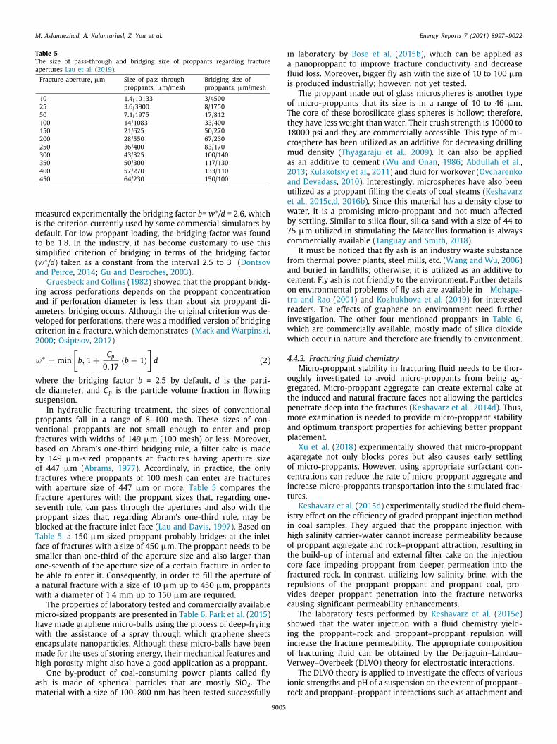
Table 5The size of pass-through and bridging size of proppants regarding fractureapertures Lau et al. (2019).Fracture aperture, µm Size of pass-through Bridging size of
proppants, µm/mesh proppants, µm/mesh
10 1.4/10133 3/450025 3.6/3900 8/175050 7.1/1975 17/812100 14/1083 33/400150 21/625 50/270200 28/550 67/230250 36/400 83/170300 43/325 100/140350 50/300 117/130400 57/270 133/110450 64/230 150/100
measured experimentally the bridging factor b= w∗/d = 2.6, whichis the criterion currently used by some commercial simulators bydefault. For low proppant loading, the bridging factor was foundto be 1.8. In the industry, it has become customary to use thissimplified criterion of bridging in terms of the bridging factor(w∗/d) taken as a constant from the interval 2.5 to 3 (Dontsovand Peirce, 2014; Gu and Desroches, 2003).
Gruesbeck and Collins (1982) showed that the proppant bridg-ing across perforations depends on the proppant concentrationand if perforation diameter is less than about six proppant di-ameters, bridging occurs. Although the original criterion was de-veloped for perforations, there was a modified version of bridgingcriterion in a fracture, which demonstrates (Mack and Warpinski,2000; Osiptsov, 2017)
w∗= min
[b, 1 +
Cp
0.17(b − 1)
]d (2)
where the bridging factor b = 2.5 by default, d is the parti-cle diameter, and Cp is the particle volume fraction in flowingsuspension.
In hydraulic fracturing treatment, the sizes of conventionalproppants fall in a range of 8–100 mesh. These sizes of con-ventional proppants are not small enough to enter and propfractures with widths of 149 µm (100 mesh) or less. Moreover,based on Abram’s one-third bridging rule, a filter cake is madeby 149 µm-sized proppants at fractures having aperture sizeof 447 µm (Abrams, 1977). Accordingly, in practice, the onlyfractures where proppants of 100 mesh can enter are fractureswith aperture size of 447 µm or more. Table 5 compares thefracture apertures with the proppant sizes that, regarding one-seventh rule, can pass through the apertures and also with theproppant sizes that, regarding Abram’s one-third rule, may beblocked at the fracture inlet face (Lau and Davis, 1997). Based onTable 5, a 150 µm-sized proppant probably bridges at the inletface of fractures with a size of 450 µm. The proppant needs to besmaller than one-third of the aperture size and also larger thanone-seventh of the aperture size of a certain fracture in order tobe able to enter it. Consequently, in order to fill the aperture ofa natural fracture with a size of 10 µm up to 450 µm, proppantswith a diameter of 1.4 mm up to 150 µm are required.
The properties of laboratory tested and commercially availablemicro-sized proppants are presented in Table 6. Park et al. (2015)have made graphene micro-balls using the process of deep-fryingwith the assistance of a spray through which graphene sheetsencapsulate nanoparticles. Although these micro-balls have beenmade for the uses of storing energy, their mechanical features andhigh porosity might also have a good application as a proppant.
One by-product of coal-consuming power plants called flyash is made of spherical particles that are mostly SiO2. Thematerial with a size of 100–800 nm has been tested successfully
in laboratory by Bose et al. (2015b), which can be applied asa nanoproppant to improve fracture conductivity and decreasefluid loss. Moreover, bigger fly ash with the size of 10 to 100 µmis produced industrially; however, not yet tested.
The proppant made out of glass microspheres is another typeof micro-proppants that its size is in a range of 10 to 46 µm.The core of these borosilicate glass spheres is hollow; therefore,they have less weight than water. Their crush strength is 10000 to18000 psi and they are commercially accessible. This type of mi-crosphere has been utilized as an additive for decreasing drillingmud density (Thyagaraju et al., 2009). It can also be appliedas an additive to cement (Wu and Onan, 1986; Abdullah et al.,2013; Kulakofsky et al., 2011) and fluid for workover (Ovcharenkoand Devadass, 2010). Interestingly, microspheres have also beenutilized as a proppant filling the cleats of coal steams (Keshavarzet al., 2015c,d, 2016b). Since this material has a density close towater, it is a promising micro-proppant and not much affectedby settling. Similar to silica flour, silica sand with a size of 44 to75 µm utilized in stimulating the Marcellus formation is alwayscommercially available (Tanguay and Smith, 2018).
It must be noticed that fly ash is an industry waste substancefrom thermal power plants, steel mills, etc. (Wang and Wu, 2006)and buried in landfills; otherwise, it is utilized as an additive tocement. Fly ash is not friendly to the environment. Further detailson environmental problems of fly ash are available in Mohapa-tra and Rao (2001) and Kozhukhova et al. (2019) for interestedreaders. The effects of graphene on environment need furtherinvestigation. The other four mentioned proppants in Table 6,which are commercially available, mostly made of silica dioxidewhich occur in nature and therefore are friendly to environment.
4.4.3. Fracturing fluid chemistryMicro-proppant stability in fracturing fluid needs to be thor-
oughly investigated to avoid micro-proppants from being ag-gregated. Micro-proppant aggregate can create external cake atthe induced and natural fracture faces not allowing the particlespenetrate deep into the fractures (Keshavarz et al., 2014d). Thus,more examination is needed to provide micro-proppant stabilityand optimum transport properties for achieving better proppantplacement.
Xu et al. (2018) experimentally showed that micro-proppantaggregate not only blocks pores but also causes early settlingof micro-proppants. However, using appropriate surfactant con-centrations can reduce the rate of micro-proppant aggregate andincrease micro-proppants transportation into the simulated frac-tures.
Keshavarz et al. (2015d) experimentally studied the fluid chem-istry effect on the efficiency of graded proppant injection methodin coal samples. They argued that the proppant injection withhigh salinity carrier-water cannot increase permeability becauseof proppant aggregate and rock–proppant attraction, resulting inthe build-up of internal and external filter cake on the injectioncore face impeding proppant from deeper permeation into thefractured rock. In contrast, utilizing low salinity brine, with therepulsions of the proppant–proppant and proppant–coal, pro-vides deeper proppant penetration into the fracture networkscausing significant permeability enhancements.
The laboratory tests performed by Keshavarz et al. (2015e)showed that the water injection with a fluid chemistry yield-ing the proppant–rock and proppant–proppant repulsion willincrease the fracture permeability. The appropriate compositionof fracturing fluid can be obtained by the Derjaguin–Landau–Verwey–Overbeek (DLVO) theory for electrostatic interactions.
The DLVO theory is applied to investigate the effects of variousionic strengths and pH of a suspension on the extent of proppant–rock and proppant–proppant interactions such as attachment and
9005

M. Aslannezhad, A. Kalantariasl, Z. You et al. Energy Reports 7 (2021) 8997–9022
Table 6The properties of micro-proppants Lau et al. (2019).
Proppant type Compositions 100–1000 (nm) 1–100 (µm) Density (g/cc) Strength Reference
Laboratory tested Graphememicro balls
Nanoparticles;graphene sheets
N/A 5 µm N/R TS = 130 GPa,E = 1 TPa,H = 2.5∼3 Mohs
Park et al. Parket al. (2015)
Fly ash 40%–60% SiO2;Inorganic arsenic;balance of Al2O3 ,Fe2O3 , CaO,MgO, TiO2
100–800 nm 10–100 µ m 1.1–1.5 H = 2.5 Mohs Bose et al. Boseet al. (2015b)
Commercially available
Hollowmicrospheres
Fused borosilicateglass
N/A D50 = 10, 19,21, 38, 46 µm
0.14–0.49 H = 6 Mohs,CS = 10000 psi
Keshavarz et al.Keshavarz et al.(2016a)
Hollow glassmicrospheres
∼70%–80% SiO2;balance of CaO;Na2O and B2O3
N/A D50 = 20, 26,30, 40 µm
0.28–0.60 CS = 18000 psi Thyagarajuet al.Thyagarajuet al. (2009)
Silica flour SiO2 N/A 75 & 44µm 2.65 H = 7 Mohs Dahl et al. Dahlet al. (2015a,b)
Silica sand SiO2 N/A 75 & 44 µm 2.65 CS = 5000 psi Tanguay andSmith Tanguayand Smith(2018)
N/A: Not available; N/R: Not reported; CS: Crush strength; E: Young’s modulus; H: Hardness; TS: Tensile strength.
Fig. 6. The total DLVO energy potential versus separation distance for proppant–proppant system: (a) rs = 5 µm and (b) rs = 9.5 µm (Keshavarz et al., 2015e).
repulsion (Keshavarz et al., 2014d; Landau et al., 1980). The totalDLVO energy potential, Vtot, between the rock matrix and in-jected proppants is the sum of the London–van der Waals forces,VLW, the electrical double layer, VEDL, and Born’s repulsion forcesVB (Gregory, 1981, 1975; Elimelech et al., 2013; Ruckensteinand Prieve, 1976; Israelachvili, 2011; Verwey, 1947; Awan et al.,2021).
The total energy potentials (Vtot ) obtained for various proppantsizes (rs) and different brine ionic strengths (I) are depicted inFigs. 6 and 7. In both proppant–proppant and proppant–coal sys-tems, the reduction in ionic strength causes the reduction of pri-mary and secondary minimal depth in Vtot-curves for both prop-pant sizes. This indicates that lower ionic strength of the injectedbrine causes proppant–proppant and proppant–coal repulsion. Inaddition, for all studied ionic strengths, increasing the proppantradius from 5 to 9.5 µm will increase the depth of primary mini-mum for proppant–proppant and proppant–coal systems (Figs. 6and 7). Hence, at constant ionic strength of carrier solution, thepossibility of proppant aggregate and proppant attachment tocoal surface is greater for the bigger proppants (Keshavarz et al.,2015e; Keshavarz, 2015).
The characteristic thickness of the electric double layer de-pends on temperature, solution ionic strength, and relative per-mittivity of the electrolyte solution. These features of the forma-tion water may differ significantly from those of the fracturingfluid, and when the injected solution interacts with the briny
formation water, the electric double layer of injected proppant-bearing solution is changed. Therefore, the interaction betweenthe fracturing fluid and the salty formation water may lead torapid aggregation and blockage at the interface between the twosolutions (Binazadeh et al., 2016; Sheng, 2014). Understandingthe interaction between injected solution and formation water isimportant and needs to be further investigated as it controls theaggregation of proppant particles.
4.4.4. Confining stressThe other major parameter that has significant effect on the
conductivity of fractures is confining stress. Some laboratory ex-periments have been conducted, utilizing various proppant types,to examine the impact of confining stress on the flow capacityof the fractures (Brannon and Starks, 2008b; Fredd et al., 2000;Gaurav et al., 2012; Kassis and Sondergeld, 2010; Parker et al.,2005; Johnson et al., 2020). When a borehole wall is hydraulicallyfractured, the permeability of unpropped fractures created in theformation will increase because of the roughness and asperitieson the rock surface. However, this natural permeability will bereduced and finally lost as the rock is exposed to a continuedincrease in effective stress, resulting from pressure drop in thereservoir. In addition, when the rock is exposed to stress, the rockcreeping would occur with time reducing the fracture conductiv-ity (Sone and Zoback, 2013). Therefore, the loss in the fractureconductivity occurs because of two main reasons. Firstly, the
9006

M. Aslannezhad, A. Kalantariasl, Z. You et al. Energy Reports 7 (2021) 8997–9022
Fig. 7. The total DLVO energy potential versus separation distance for proppant–coal system: (a) rs = 5 µm and (b) rs = 9.5 µm (Keshavarz et al., 2015e).
increase in effective stresses on rocks results from the pressuredrop in the reservoir; and secondly, the rock creeping with time.To counteract the possible consequences of these effects on thenatural permeability loss, proppants are introduced into the in-jection fluid to support and maintain the fracture conductivity. Incase of less proppant concentration, there will be larger distancebetween particles leading to rock deformation between parti-cles. This will reduce the permeability of the fracture. Thus, thebest concentration of proppant particles should be determinedwhere the highest permeability for the fracture system can beobtained (Khanna et al., 2013).
5. Evaluation of micro-proppant efficiency
5.1. Mathematical models for micro-proppants
The graded proppant injection model suggested by Bedrikovet-sky et al. (2012) and Khanna et al. (2013) shows the best possibleoutcome to increasing fracture permeability. In this model, first,the injection of small proppants and then bigger ones is carriedout and this leads to the percolation of smaller particles tothe deep reservoir whereas the bigger particles get trapped inthe zone close to the borehole. Consequently, a larger area ofreservoir is stimulated.
It was demonstrated by Khanna et al. (2013, 2012a) thathydraulic resistance created in the treated natural fractures is aconsequence of (1) the greater tortuosity caused by the presenceof particles; and (2) deformation of propped fracture aperturesthat is a result of rock stresses at the time of production. Accord-ingly, fracture deformation and proppant concentration are thetwo factors that have considerable effects on the conductivity ofthe fracture system. In case of higher concentration, there will bemore resistance against the flow leading to lower permeability.However, in case of lower concentration, there will be a higherdistance between proppants and therefore, there will be morerock deformation between proppants. The impact of this defor-mation is a reduction in fracture openings. Therefore, to achievethe highest conductivity, an optimum proppant concentrationmust be determined (Fig. 8).
Khanna et al. (2013, 2012a) have applied methods of com-putational fluid dynamic (CFD) to investigate the influence thatplacing proppant into the cleats may have on the permeability. Adimensionless parameter called proppant packing aspect ratio (β)was used in these models. This is a ratio of the proppant diameterand the distance between two adjacent proppants’ centers (l).Next, a hydraulic resistance correction factor (Eq. (2)) which is afunction of β has been introduced. Multiplying the hydraulic re-sistance correction factor by permeability will reveal the decreasein cleat permeability that is caused by proppant placement.
f (β, 0) =0.3197β2
− 0.7181β + 0.4057β2 − 0.4789β + 0.4048
(3)
The impact of rock deformation on permeability has also beeninvestigated by Hertz theory and finite element analysis. Fig. 9depicts the overall impact of cleat deformation and proppantplacement. It can be seen that the hydraulic resistance correctionfactor acts as a function of dimensionless stress and the proppantaspect ratio. The normal stress to the cleat divided by the coalmodulus of elasticity (E) is called dimensionless stress (εσ ).
According to Fig. 9, since the OPPR depends on the reser-voir stress, this parameter must be calculated for each stress.Afterward, the correction factor value can be determined byputting the aspect ratio in Fig. 9. Bedrikovetsky et al. (2012)and Khanna et al. (2013, 2012a) have reported the calculationprocedures of the optimum proppant concentration accordingto the computational fluid dynamics methods and hertz contacttheory.
Keshavarz et al. (2015a, 2016a, 2015c,e) has developed thismethod as an efficient technology using both mathematical mod-els and experimental studies. They suggested an injection planthat works according to a pre-specified size of stimulation regionand the assumption that natural fractures have even distributionaround the borehole, defined by Eqs. (3) and (4) (Keshavarz et al.,2015e)
tin (rDs) =8h0r2eqL
∫ α
rD(rDs)ϕ
(1 + εq ln
1ϕ
)1/4
dϕ (4)
rDs =D1
2h0=
12
(1 − εq ln rD
)(5)
where tin(rDs) is the injection time at which a proppant with sizeof rDs should be injected; h0 is the initial aperture of the fracture; Lis the spacing between the cleats; q is the constant injection rate;εq is dimensionless injection rate; rDs is the dimensionless particlesize; D1 is the particle diameter; re is the borehole drainageradius; rD is the dimensionless radial coordinate and rD= r/re(ris radial coordinate), α = rst/re (rst is stimulation radius); α
is the scaled radius of the stimulation zone and ϕ is a dummyintegration variable.
The following equation is used to determine the number of theproppants with diameter D1 (Keshavarz et al., 2015e)
Np (rDs) = 8β∗HL
rD1
(6)
where H is the reservoir thickness, and β∗ is the optimal packingratio.
Furthermore, they used a coupled geomechanical and fluidflow model to derive a stress-based analytical model describingrock deformation and fluid flow for graded proppant injection.This way, it would be possible to determine the optimum stimu-lation radius through which the highest level of productivity canbe obtained using the technology of injecting graded proppants.
9007

M. Aslannezhad, A. Kalantariasl, Z. You et al. Energy Reports 7 (2021) 8997–9022
Fig. 8. The flow tortuosity and cleat deformation arisen from the presence of proppants and rock stresses (a) two dimensional view (Khanna et al., 2013); (b) threedimensional view (Keshavarz et al., 2014d).
Fig. 9. Resistance correction factor for various dimensionless stresses (ϵσ =
σn/E) and packing aspect ratios (β = 2rs/l) (Khanna et al., 2012b).
The pressure distribution during injection (Pinj) and production(Ppr ) (before stimulation) can be calculated by Eqs. (6) and (7),respectively, as a function of radius (Keshavarz et al., 2013)
Pinj (r) = Pres +1 − ν
(1 + ν) Cfln
[1 −
qµCf (1 + ν)
2πk0 (1 − ν)ln
rre
](7)
Ppr (r) = Pres +1 − ν
(1 + ν) Cfln
[1 +
qproµCf (1 + ν)
2πk0 (1 − ν)ln
rre
](8)
where Pres is reservoir pressure, ν is Poisson’s ratio, µ fluid isviscosity, k0 is initial reservoir permeability, and Cf is the fracturecompressibility.
The permeability distribution during injection (kinj) and pro-duction (kpr ) (before stimulation) are defined by Eqs. (8) and(9) (Keshavarz et al., 2013)
kinj (r) = k0
[1 −
qinjµCf (1 + ν)
2πk0 (1 − ν)ln
rre
](9)
kpr (r) = k0
[1 +
qproµCf (1 + ν)
2πk0 (1 − ν)ln
rre
](10)
In the region that is stimulated by proppants (i.e., r≤rst ),there is less fracture permeability relative to the permeabilityof region without proppants (i.e., r≥r st ). Therefore, a correctionfactor (f ) is used so that the permeability of fracture system
inside the stimulated region would equal f×k(r). This factorwould be a function of two dimensionless parameters, namely thedimensionless stress (σn/E) and the aspect ratio (β).
Therefore, adding proppants to the fracturing fluid wouldchange the injectivity/productivity indexes. The reservoir per-meability during the proppant injection is determined by Eq.(10) where r st is the proppant stimulation radius. The hydraulicpressure will maintain the fractures open as injection is beingcarried out; thus, plugging of the cleats will be the only causeof permeability reduction. In Eq. (10), the decline of permeabil-ity due to the plugging of proppant in the cleat network willbe represented by the dimensionless factor f (β ,0), and for theproduction case, an analogous factor of f (β , σ /E) would be used(Eq. (11)). This factor shows the impact of proppant pluggingon the cleat and also describes the deformation and closure ofthe cleats around the proppant during production. In the areasbeyond the regions stimulated by proppants, Eq. (9) is used todetermine the reservoir permeability during production. UsingEqs. (10) and (11), the permeability in different reservoir radiican be determined during injection and production operations(Keshavarz et al., 2013).
kinj (r) =
{f (β, 0) .kinj (r) r ≤ rst
kinj (r) r > rst(11)
kpr (r) =
{f(β,
σ
E
).kinj (r) r ≤ rst
kpr (r) r > rst(12)
The derivation of these equations can be seen in the litera-ture (Keshavarz et al., 2013).
As aforementioned, Keshavarz et al. (2014b,c, 2016a, 2015c)have developed mathematical models trying to find the OPPR andthen, they have carried out experiments in order to confirm theveracity of their models. An improved model of graded proppantinjection has been proposed by Liu et al. (2020a,b,c) in whichthe Proppant Embedment and Proppant Deformation (PEPD) havebeen considered. In this model, an analytical calculation for PEPDhas been used and coupled with the model of graded proppantplacement (GPP). The diagram of Khanna’s OPPR is drawn againconsidering the effects of PEPD. The permeability correction fac-tor (PCF) has been analytically derived and written as Eq. (12):
⎧⎪⎪⎪⎪⎨⎪⎪⎪⎪⎩f =
(1 −
2αD1
)2⎡⎣ β
1 + β +15(D1−2α)2(1−φ2)
D12φ3
+ 1 − β
⎤⎦φ =
D1 − 2α −π6 (D1 − 2ζ ) +
2π3
( 32D1 − h
) h2
D21
D1 − 2α
(13)
9008
M. Aslannezhad, A. Kalantariasl, Z. You et al. Energy Reports 7 (2021) 8997–9022
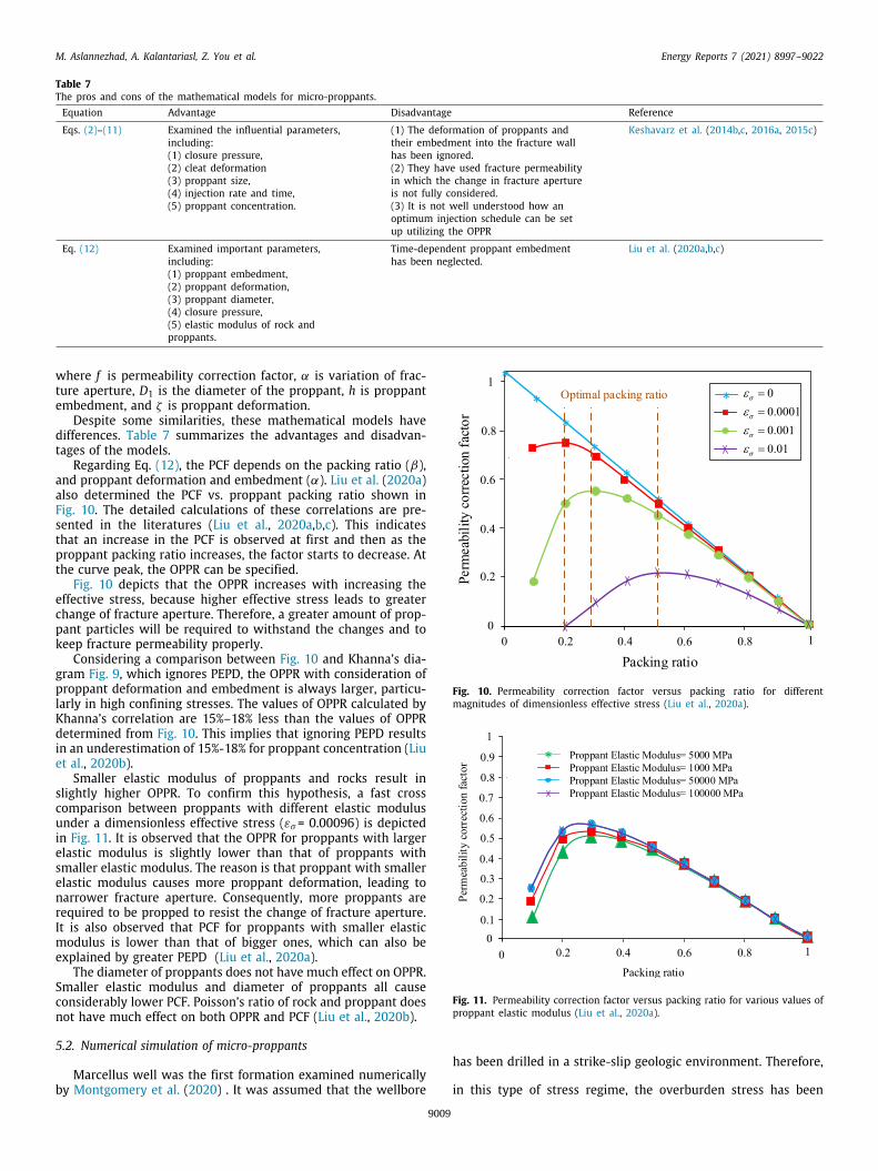
Table 7The pros and cons of the mathematical models for micro-proppants.Equation Advantage Disadvantage Reference
Eqs. (2)–(11) Examined the influential parameters,including:(1) closure pressure,(2) cleat deformation(3) proppant size,(4) injection rate and time,(5) proppant concentration.
(1) The deformation of proppants andtheir embedment into the fracture wallhas been ignored.(2) They have used fracture permeabilityin which the change in fracture apertureis not fully considered.(3) It is not well understood how anoptimum injection schedule can be setup utilizing the OPPR
Keshavarz et al. (2014b,c, 2016a, 2015c)
Eq. (12) Examined important parameters,including:(1) proppant embedment,(2) proppant deformation,(3) proppant diameter,(4) closure pressure,(5) elastic modulus of rock andproppants.
Time-dependent proppant embedmenthas been neglected.
Liu et al. (2020a,b,c)
where f is permeability correction factor, α is variation of frac-ture aperture, D1 is the diameter of the proppant, h is proppantembedment, and ζ is proppant deformation.
Despite some similarities, these mathematical models havedifferences. Table 7 summarizes the advantages and disadvan-tages of the models.
Regarding Eq. (12), the PCF depends on the packing ratio (β),and proppant deformation and embedment (α). Liu et al. (2020a)also determined the PCF vs. proppant packing ratio shown inFig. 10. The detailed calculations of these correlations are pre-sented in the literatures (Liu et al., 2020a,b,c). This indicatesthat an increase in the PCF is observed at first and then as theproppant packing ratio increases, the factor starts to decrease. Atthe curve peak, the OPPR can be specified.
Fig. 10 depicts that the OPPR increases with increasing theeffective stress, because higher effective stress leads to greaterchange of fracture aperture. Therefore, a greater amount of prop-pant particles will be required to withstand the changes and tokeep fracture permeability properly.
Considering a comparison between Fig. 10 and Khanna’s dia-gram Fig. 9, which ignores PEPD, the OPPR with consideration ofproppant deformation and embedment is always larger, particu-larly in high confining stresses. The values of OPPR calculated byKhanna’s correlation are 15%–18% less than the values of OPPRdetermined from Fig. 10. This implies that ignoring PEPD resultsin an underestimation of 15%-18% for proppant concentration (Liuet al., 2020b).
Smaller elastic modulus of proppants and rocks result inslightly higher OPPR. To confirm this hypothesis, a fast crosscomparison between proppants with different elastic modulusunder a dimensionless effective stress (εσ= 0.00096) is depictedin Fig. 11. It is observed that the OPPR for proppants with largerelastic modulus is slightly lower than that of proppants withsmaller elastic modulus. The reason is that proppant with smallerelastic modulus causes more proppant deformation, leading tonarrower fracture aperture. Consequently, more proppants arerequired to be propped to resist the change of fracture aperture.It is also observed that PCF for proppants with smaller elasticmodulus is lower than that of bigger ones, which can also beexplained by greater PEPD (Liu et al., 2020a).
The diameter of proppants does not have much effect on OPPR.Smaller elastic modulus and diameter of proppants all causeconsiderably lower PCF. Poisson’s ratio of rock and proppant doesnot have much effect on both OPPR and PCF (Liu et al., 2020b).
5.2. Numerical simulation of micro-proppants
Marcellus well was the first formation examined numericallyby Montgomery et al. (2020) . It was assumed that the wellbore
Fig. 10. Permeability correction factor versus packing ratio for differentmagnitudes of dimensionless effective stress (Liu et al., 2020a).
Fig. 11. Permeability correction factor versus packing ratio for various values ofproppant elastic modulus (Liu et al., 2020a).
has been drilled in a strike-slip geologic environment. Therefore,
in this type of stress regime, the overburden stress has been
9009

M. Aslannezhad, A. Kalantariasl, Z. You et al. Energy Reports 7 (2021) 8997–9022
Fig. 12. Cumulative oil production (COP) versus time. (a) Comparison between base case and the other two cases with different fracture spacing, and (b) effects offractures number on well productivity (Dahl et al., 2015a).
considered a slightly lower than the maximum horizontal stress.They argued that using micro-proppants in this type of well hasno effect because the pressure in the main hydraulic fracturingis not enough to generate dilated natural fractures. Dahl et al.(2015a) performed a reservoir simulation to show the effectsof micro-proppants on improving the conductivity of primaryand secondary micro-sized fractures created in tight formations,thereby enhancing well productivity. The numerical modelingwas conducted on a retrograde condensate reservoir with andwithout consideration of natural fractures.
The simulation results showed that increasing of both thenumber of hydraulic fractures and fractures spacing, indicatingfracture complexity, result in more cumulative oil production.Fig. 12a reveals that the presence of natural fractures improvescondensate recovery nearly twice compared to the base case(without fractures). Fig. 12b also depicts that the highest cumu-lative oil production belongs to a reservoir having the greatestnumber of fractures. Based on the obtained results, effectivestimulation and propping of primary and secondary fractures canincrease well productivity in complex reservoirs. Using micro-proppants is regarded as an opportunity to further enhance theconductivity of fractures achieved, even in leakoff-induced mi-crofractures. Therefore, transferring micro-proppants in placeswhere fracturing fluid travels inside the complex fractures is oneof the biggest concerns.
Inyang et al. (2019) conducted Kinetic Monte Carlo (KMC)simulations to examine the effects of using micro-proppants withdifferent concentrations on the effective permeability of the frac-tures. They concluded that the fracture conductivity is improvedas a function of micro-proppants concentration. The high concen-tration of micro-proppants can prop the secondary microfracturesand keep them open under high stress and during flow testing.
Kumar and Ghassemi (2019) conducted numerical simulationsto examine the potential benefits of using micro-proppants ina fracture system by comparing the results with those of con-ventional proppants. They used finite element method to modelthe transport and placement of proppants in horizontal wellswith multiple hydraulic fracture propagations. The fluid slurryused in the model consists of 400 mesh micro-proppants withthe density of 2.65 g/cm 3. Fig. 13 shows the position of differ-ent fractures considered in the model. The results revealed thatthe hydraulic fracture (HF) has greater openings in comparisonwith the primary and secondary natural fractures; thereby higherproppant distribution is expected in the HF part of the system.Furthermore, the openings of inner primary natural fracture (P-NF) are less than the outer ones because of stress shadowing
effect, thus the larger size conventional proppants cannot enterinto the natural fractures. Stress shadowing is a phenomenon inwhich the fractures in the subsurface are inclined to propagateaway from the direction of already fractured rock because ofchanges in stress regime (Germanovich et al., 1997; Fisher et al.,2004; Meyer and Bazan, 2011; Nagel et al., 2013).
Fig. 13 shows that the distribution of proppants in P-NFs ismuch lower than that of HF. On the other hand, the outer P-NFreceives more proppants than the inner P-NF which is attributedto their normal openings. Moreover, the inclination of the P-NFs with the HF axis causes proppants to distribute asymmetri-cally in the wings of the P-NFs and the proppant concentrationdistribution decreases in the P-NFs wings farther from the HFaxis. Therefore, the micro-proppants have potential to effectivelyprop primary and secondary fractures in which larger size con-ventional proppants cannot be placed (Kumar and Ghassemi,2019).
Montgomery et al. (2020) also numerically evaluated the po-tential benefits of micro-proppants in production improvementin Wolfcamp, Utica, Woodford SCOOP, and Barnett Shale forma-tions. They developed a new discrete fracture network modeldescribing the dynamic transportation of proppants. The micro-proppants used in the stimulation were very strong ceramicmicro-proppants with a high crush resistance of 60000 psi. Theresults showed the positive effects of micro-proppants applica-tion on the post-frac production and on the reservoir drainage inshale reservoirs. They reported that using micro-proppants causesconsiderable production uplifts and flattened trend of produc-tion decline curve. Moreover, because of micro-proppants capa-bility to enter farthest microfractures in the formation, higherproduction from fractures can be achieved, resulting in largerreservoir drainage. The results represent the priority of usingmicro-proppants over the conventional proppants in these shaleformations.
5.3. Laboratory studies on micro-proppants
Micro-proppants have attracted the attention of researcherssince the time they were initially studied in laboratory in 2013(Nguyen et al., 2013). Nguyen et al. (2013) have proposed stim-ulation techniques by using ultra-fine particles in tight reser-voirs. These attempts brought positive outcomes in the labo-ratory and showed that using micro-proppants would enhancefractures conductivity considerably. Furthermore, these ultra-fineproppants can be readily suspended in the carrier fluid and de-livered to the created microfractures and keep them open, af-ter pumping is ceased and the fractures tend to be closed and
9010
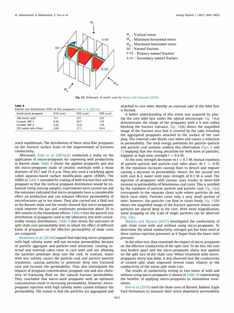
M. Aslannezhad, A. Kalantariasl, Z. You et al. Energy Reports 7 (2021) 8997–9022
Fig. 13. Schematic of model used by Kumar and Ghassemi (2019).
Table 8Particle size distribution (PSD) of fine proppants Dahl et al. (2015a).Small-sized proppant D10 (µm) D50 (µm) D90 (µm)
100-mesh sand 111 177 263Ceramic MP-1 9.43 29.7 110Ceramic MP-2 2.02 15.4 119325-mesh silica flour 2.64 17.1 43.4
reach equilibrium. The distribution of these ultra-fine proppantson the fracture surface leads to the improvement of fracturesconductivity.
Afterward, Dahl et al. (2015a,b) conducted a study on theapplication of micro-proppants for improving well productivityin Barrett shale. Table 8 shows the applied proppants and alsothe micro-proppants made of ceramic materials with a meandiameter of 29.7 and 15.4 µm. They also used a tackifying agentcalled aqueous-based surface modification agent (ASMA). TheASMA in Table 9 intended for coating of both fracture face and theproppant so that the vertical proppant distribution would be en-hanced. Using outcrop samples, experiments were carried out andthe outcomes indicated that micro-proppants have a considerableeffect on production and can enhance effective permeability ofmicrofractures up to ten times. They also carried out a field testin the Barnett shale and the results showed that micro-proppantscould improve the gas and condensate production about 20 to40% relative to the immediate offsets. Table 8 lists the particle sizedistribution of proppants used in the laboratory test with consid-erably various distributions. Table 9 also shows the outcomes ofsplit shale core permeability tests in which the effect of differentkinds of proppants on the effective permeability of shale coresare compared.
Keshavarz et al. (2014d) argued that injecting micro-proppantswith high salinity water will not increase permeability becauseof particle aggregate and particle–rock attraction, creating in-ternal and external cakes close to core inlet and not allowingthe particles penetrate deep into the rock. In contrast, waterwith less salinity causes the particle–coal and particle–particlerepulsions, causing particles to penetrate deep into fracturedrock and increase the permeability. They also investigated theimpacts of proppant concentration, proppant size and also chem-istry of fracturing fluid on the natural fracture permeability.They concluded that micro-sized proppants with an optimumconcentration result in increasing permeability. However, micro-proppant injection with high salinity water cannot enhance thepermeability. The reason is that the particles are aggregated and
attached to core inlet, thereby an external cake at the inlet faceis formed.
A better understanding of this event was acquired by plac-ing the core inlet face under the optical microscope. Fig. 14(a)demonstrates the image of the proppants with a 5 mm radiusblocking the fracture entrance. Fig. 14(b) shows the magnifiedimage of the fracture area that is covered by the cake revealingthe aggregated proppants attached to the surface of the coreplug. This external cake blocks core inlets and causes a reductionin permeability. The total energy potentials for particle–particleand particle–coal systems confirm this observation (Figs. 6 and7) implying that the strong attraction for both sizes of particles,happens at high ionic strength I = 0.6 M.
As the ionic strength decreases to I = 0.1 M, mutual repulsionof particle–particle and particle–coal takes place. At I = 0.05M, the repulsion increases causing fines to detach and migratecausing a decrease in permeability. Hence, for the second testwith core B-2, water with ionic strength of 0.1 M is used. Theinjection of proppants with various sizes results in three-foldincrease in permeability of bituminous coal cores. This is justifiedby the repulsion of particle–particle and particle–coal. Fig. 15(a)corresponds to the separate cleats scale where particles do notblock cleat inlets. Particles cover only a very small portion ofinlet; however, the particles can flow in cleats freely. Fig. 15(b)shows the magnified image of the fracture aperture where someparticles are placed deep in the core. With more magnification,some propping on the scale of single particles can be observed(Fig. 15c).
Madasu and Nguyen (2017) investigated the conductivity ofsplit shale cores with and without using micro-proppants. Todetermine the initial conductivity, nitrogen gas has been used atthree various injection pressures as it began from the lower inletpressure.
In the other test, they examined the impact of micro-proppantson the effective conductivity of the split core. To do this, the corewas broken apart and the micro-proppants slurry was appliedon the split face of the shale core. When treatment with micro-proppants slurry was done, it was observed that the conductivityof treated split shale improved several times relative to theconductivity of the initial split shale core.
The results of conductivity testing in two states of with andwithout using micro-proppants is shown in Table 10 representingthe benefits of applying micro-proppants in stimulation treat-ments.
Kim et al. (2018) used the shale cores of Barnett, Bakken, EagleFord formations to measure their stress dependent permeability
9011

M. Aslannezhad, A. Kalantariasl, Z. You et al. Energy Reports 7 (2021) 8997–9022
Table 9The effect of small-sized proppants and ASMA on the effective permeability of shale cores Dahl et al. (2015a).Proppants With proppants only With both proppants and ASMA
Ki (md) Kf(md) Type of treatment Ki (md) Kf (md)
100-mesh Sand NT NT 2-stage 14 1708100-mesh Sand 5 25 2-stage 12 304100-mesh Sand 2 17 1-stage 8.9 1832Ceramic MP-1 NT NT 1-stage 3.2 31.3Ceramic MP-2 NT NT 1-stage 0.43 1.97Ceramic MP-2 NT NT 2-stage 0.77 5.58325-mesh silica flour NT NT 1-stage 7.9 18.1
NT = not tested; Kf = Permeability of shale core with proppant; Ki= Permeability of shale core without proppant.
Fig. 14. Image of core B-1 inlet face after injecting proppant and plugging the rock: (a) core inlet face and (b) zoom (Keshavarz et al., 2015e).
Fig. 15. Image of core B-2 inlet face after injecting low ionic strength solution: (a) on the scale of fractured rock; (b) zoom on the scale of a single fracture; and (c)proppants placed within the fracture on the scale of a fracture aperture (Keshavarz et al., 2015e).
Table 10The impact of ultra-fine proppant and on effective conductivity of shale core Madasu and Nguyen (2017).Type of proppant Type of treatment Initial conductivity without
micro-proppants (md-ft)Conductivity withmicro-proppants (md-ft)
Ceramic micro-proppants Micro-proppants slurry 0.18 3.69
while using micro-proppants in microfractures. The laboratoryresults indicate that even a monolayer of micro-proppants cansignificantly enhance the permeability of microfractures.
To evaluate the impact of micro-proppants on the perme-ability of shale cores, both their initial permeability and theirpermeability after the stimulation should be known. Before split-ting the core plug, the permeability values of the Bakken shalecore have been measured under different pressure loads. Thecore permeability varies between 10–60 µD. The tested shalecore of Bakken is rich in fissures and microfractures; thereby ithas a highly stress-dependent permeability. With the increase
in differential pressure, the fractures start to close and thus,considerable reduction of permeability occurs. The permeabilityof the sample was reduced by a factor of 6 while increasing thepressure differential from 500 to 3600 psi (Kim et al., 2018).
The trend of permeability reduction of Barnett shale core be-fore splitting is the same; however, the permeability magnitudesof the intact core are much lower, varying from 100 nD to 1 µD.At high pressure differentials, the Bakken split core permeabilityenhanced by a factor of 8 and at low pressure differential, the per-meability improved by a factor of 15. The permeability enhancedwhen the core was divided; however, its permeability is very
9012

M. Aslannezhad, A. Kalantariasl, Z. You et al. Energy Reports 7 (2021) 8997–9022
sensitive to stress. The permeability improvement of Barnett coreplug was more significant than that of Bakken core plug becausethe initial permeability of Barnett was much lower than Bakkencore permeability.
Furthermore, treating split core plugs by liquid CO2 can im-prove its permeability. Besides, treating split core plugs by liquidCO2 plus micro-proppants slurry results in more improvementother than the improvement obtained from mere using of CO2.To convert gaseous CO2 into liquid phase, an accumulator wasdesigned with a moving piston adjusting its pressure and tem-perature. CO2 liquefaction happens when the pressure achievesabout 1,500 psig in the accumulator. Then, the liquid CO2 inthe accumulator will apply hydrostatic pressure to the split corepart. Using CO2, as a treating agent, shows great effectivenesssince it leads to an increase of 40–50% in split core permeability.Based on the experimental results, micro-proppants can improvethe permeability of split core plug significantly. Despite the factthat the uniform placement of micro-proppants in fractures isdifficult, it is definitely advantageous to use micro-proppants inthe stimulation treatments. In the presence of micro-proppants,the permeability of cores treated with CO2 had an increase of 15–30%. The same patterns have been seen for the split core plugof Barnett shale confirming the previously discussed findings.Micro-proppants could increase the permeability of Barnett coreplug by 60–80% (Kim et al., 2018). Microscale effects of CO2,which may change the microstructure of the rock and dissolvesome soluble organic matters, were not part of their analysis andrequire a detailed investigation. During CO2 injection, the mineraldissolution and precipitation may change formation porosity andpermeability, and alter fluid flow patterns. For more details aboutthe side effects of CO2 injection on formation damage, refer to theworks in Yuan and Wood (2018), Izgec et al. (2005), Steel et al.(2018), Jin et al. (2016) and Mohamed and Nasr-El-Din (2012).
Cortez-Montalvo et al. (2018) and Inyang et al. (2019) con-ducted an experimental study to examine the effects of micro-proppants on the microfractures conductivity of Eagle Ford, Mar-cellus,Delaware Wolfcamp and Barnett cores obtained from outcrops.They compared Eagle Ford cores treated by 0.001 lbm/ft 2 ultra-fine particles (UFPs) to the unstimulated core plugs. Marcellusand Delaware Wolfcamp micro-proppants treated cores achievedtwo orders of magnitude greater conductivity in comparison withuntreated core plugs. Interestingly, unlike the unstimulated cores,Barnett UFP-treated cores could sustain their conductivity underclosure stresses exceeding 4000 psi.
Liang et al. (2019) performed experiments and showed thatin stimulating tight carbonate reservoirs, using a mixture ofmicro-proppants and the delayed acid generating materials in thepad/pre-pad fluids can significantly enhance the permeability ofboth natural or induced microfractures.
According to the obtained results from the laboratory studies,it was believed that additional field case studies were requiredto completely understand how micro-proppants work in variousrock types and in a wide range of reservoir conditions.
6. Instruction on micro-proppants in the field operations
The micron-sized particulates are transported to the well siteas a concentrated slurry and then used in the first pad stages ofstimulation operations (Calvin et al., 2017b). Micro-proppants asslurry have been delivered to many wells in the United States.Because of small sizes of micro-proppants, there was a generalconcern of product loss and dusting. The composition of the slurrydiffers based on toll blender; but in general, it is an aqueoussolution made from micro-proppants and a viscosifying agent.The micro-proppant concentration target is about 65% of solution
weight. This can be approximated as 8.2 lb micro-proppants ineach gallon of slurry (Montgomery et al., 2020).
Micro-proppant slurry is viscous and creates static gel strength.Through a 3-inch valve, this can flow very easily out of an Inter-national Organization for Standardization (ISO) tank as it is riggedup to centrifugal pump. This micro-proppant slurry is usuallytransported to the location of the well with totes and ISO tankers.If the slurry is mixed with the exact specifications, it can beeasily pumped by using centrifugal pump. The operator insulatesthe ISO tank containers and based on the field experience, inshort run; it is possible to pump micro-proppants slurry even ininclement weather of winter operations as it is combined with aforced air heater (Montgomery et al., 2020). Most of the fracturingfluids used in the Woodford Shale, Barnett Shale, Utica Shale,Marcellus Shale and the Fayetteville Shale typically contain water,surfactants, friction reducer, scale inhibitors, assorted biocides,etc. Moreover, the fracturing fluids used in the Bakken Shale,Bossier Shale, Haynesville Shale and some areas of the Eagle FordShale usually contain assorted chemicals, gel or crosslinked gel.For deeper reservoirs, more viscous fluids might be demanded inthe near borehole region because of tortuosity problems near theboreholes (Montgomery, 2013; Harris and Heath, 1996; Kogsbøllet al., 1993; Stegent et al., 2010; van Ketterij and de Pater, 1999;Stadulis, 1995).
7. Field case studies of micro-proppants
The first field application of micro-proppants in the Barnettshale was reported by Dahl et al. (2015a). They described the per-meability improvement of microfractures using micro-proppantsover the first 210 days of production in eleven Barnett Shalewells. Calvin et al. (2017a) extended this work and describedthe effects of micro-proppants on well production in the liquids-rich South-Central Oklahoma Oil Province (SCOOP) Woodford.Rassenfoss (2017) reported the potential benefits of using micro-proppants to improve well production regarding the researchoutcomes of Calvin et al. (2017b). He argued that one of the manybenefits of micro-proppants is providing fairly good conductivityin comparison with the flow capacity of the secondary unproppedfractures, specifically if they tend to be closed. These articles haveattracted the attention of both practitioners in the oil and gasindustry and researchers (Kim et al., 2018; Kumar et al., 2019) andShrivastava and Sharma (2018) developing a series of laboratoryexperiments and placement models of micro-proppants.
The aforementioned papers clearly present the advantages ofutilizing micro-proppants to extend the propped area of naturaland induced fracture networks. Kumar et al. (2019) investigatedthe effect of micro-proppants on fracture conductivity and indi-cated that the smaller size proppants can be transported deeperinto the fractures causing more effective propped area. Fig. 16, forinstance, illustrate an additional 1486.5 m2 and 825 m2 fracturearea in the Eagle Ford and Utica formations, respectively, whenpropped with micro-proppants in comparison with 100-meshsand (Kumar et al., 2019; Montgomery et al., 2020).
7.1. Barnett Shale
The presence of well-developed natural fractures in the Bar-nett shale causes this unconventional reservoir to be drainedeffectively and economically, although most of these natural frac-tures are sealed except for the largest ones (Gale et al., 2007).A field pilot was conducted by Devon Energy Corporation oneleven horizontal wet gas wells within the Grassland area lo-cated in northeastern Wise County, Texas. This was the firstset of wells documented in the literature and was completelydescribed by Dahl et al. (2015a,b). During the field trials, they
9013
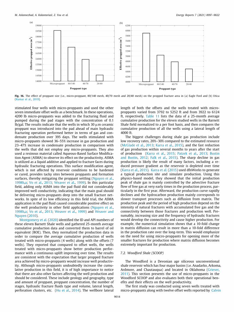
M. Aslannezhad, A. Kalantariasl, Z. You et al. Energy Reports 7 (2021) 8997–9022
Fig. 16. The effect of proppant size (i.e., micro-proppant, 80/140 mesh, 40/70 mesh and 20/40 mesh) on the propped fracture area in (a) Eagle Ford and (b) Utica(Kumar et al., 2019).
stimulated four wells with micro-proppants and used the otherseven immediate offset wells as a benchmark. In these operations,4200 lb micro-proppants was added to the fracturing fluid andpumped during the pad stages with the concentration of 0.1lb/gal. The results indicate that the wells in which 30 µm ceramicproppant was introduced into the pad ahead of main hydraulicfracturing operation performed better in terms of gas and con-densate production over 395 days. The wells stimulated withmicro-proppants showed 36–55% increase in gas production and23–47% increase in condensate production in comparison withthe wells that did not employ any micro-proppants. They alsoused a resinous material called Aqueous-Based Surface Modifica-tion Agent (ASMA) to observe its effect on the productivity. ASMAis utilized as a liquid additive and applied to fracture faces duringhydraulic fracturing operations. This surface modification agent,which is not affected by reservoir conditions to be hardenedor cured, provides tacky sites between proppants and formationsurfaces, thereby mitigating the proppant settling (Nguyen et al.,1998b,a; Vo et al., 2013; Weaver et al., 1999). In this particularfield, adding only ASMA into the pad fluid did not considerablyimproved well conductivity, indicating that the main goal shouldbe delivering micro-proppants deep into the small fracture net-works. In spite of its low efficiency in this field trial, the ASMAapplication in the pad fluid caused considerable positive effect onthe well productivity in other field applications (Nguyen et al.,1998b,a; Vo et al., 2013; Weaver et al., 1999) and Weaver andNguyen (2010).
Montgomery et al. (2020) identified the ID and API numbers ofthese eleven Barnett Shale wells and gathered 25-month averagecumulative production data and converted them to barrel of oilequivalent (BOE). Then, they normalized the production data inorder to compare the average cumulative production of wellstreated with micro-proppants (4 wells) along with the offsets (7wells). They reported that compared to offset wells, the wellstreated with micro-proppants show better production perfor-mance with a continuous uplift improving over time. The resultsare consistent with the expectation that larger propped fracturearea achieved by micro-proppants would increase well productiv-ity. Although micro-proppants undoubtedly increase the cumu-lative production in this field, it is of high importance to noticethat there are also other factors affecting the well production andshould be considered. These include geology and geography, typeand amount of proppant, proppant concentration, the number ofstages, hydraulic fracture fluids type and volume, lateral length,perforation clusters, etc. (Hu et al., 2014). The wellbore lateral
length of both the offsets and the wells treated with micro-proppants varied from 3792 to 5252 ft and from 3922 to 6124ft, respectively. Table 11 lists the data of a 25-month averagecumulative production for the eleven studied wells in the BarnettShale field normalized to a per foot basis, and then compares thecumulative production of all the wells using a lateral length of4000 ft.
The biggest challenges during shale gas production includelow recovery rates, 20%–30% compared to the estimated resource(McGlade et al., 2013; Karra et al., 2015), and the fast reductionof gas production within several months to years after the startof production (Karra et al., 2015; Patzek et al., 2013; Bustinand Bustin, 2012; Falk et al., 2015). The sharp decline in gasproduction is likely the result of many factors, including a re-duced pressure gradient as the reservoir is depleted over time(Karra et al., 2015). Karra et al. (2015) used dfnWorks to generatea typical production site and simulate production. Using thisphysics-based model, they showed that the initial productionpeak of shale gas is mainly controlled by the advective fractureflow of free gas at very early times in the production process, par-ticularly in the first year. Afterward, the production curve rapidlydeclines and the hydrocarbon production mainly corresponds toslower transport processes such as diffusion from matrix. Theproduction peak and the period of high production depend on theintensity of natural fractures with accumulated free gas and theconnectivity between those fractures and production well. Pre-sumably, increasing size and the frequency of hydraulic fractureswould develop the connectivity and cause higher production. Forexample, the numerical simulation shows that a 10-fold changein matrix diffusion can result in more than a 10-fold differencein the production rate over the long-term. This would emphasizeon the need for using micro-proppants for opening more of thesmaller fractures for production where matrix diffusion becomesextremely important for production.
7.2. Woodford Shale (SCOOP)
The Woodford is a Devonian age siliceous unconventionalshale reservoir which has four major basins (i.e. Anadarko, Arkoma,Ardmore, and Chautauqua) and located in Oklahoma (Grieser,2011). This section presents the use of micro-proppants in theWoodford SCOOP and also evaluates both their operational ben-efits and their effects on the well productivity.
The first study was conducted using seven wells treated withmicro-proppants along with twelve offset wells reported by Calvin
9014
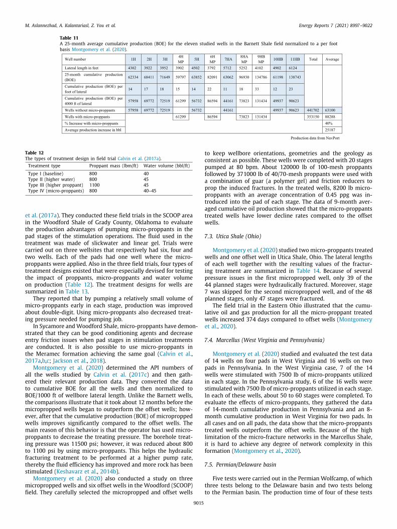
M. Aslannezhad, A. Kalantariasl, Z. You et al. Energy Reports 7 (2021) 8997–9022
Table 11A 25-month average cumulative production (BOE) for the eleven studied wells in the Barnett Shale field normalized to a per footbasis Montgomery et al. (2020).
Table 12The types of treatment design in field trial Calvin et al. (2017a).Treatment type Proppant mass (lbm/ft) Water volume (bbl/ft)
Type I (baseline) 800 40Type II (higher water) 800 45Type III (higher proppant) 1100 45Type IV (micro-proppants) 800 40–45
et al. (2017a). They conducted these field trials in the SCOOP areain the Woodford Shale of Grady County, Oklahoma to evaluatethe production advantages of pumping micro-proppants in thepad stages of the stimulation operations. The fluid used in thetreatment was made of slickwater and linear gel. Trials werecarried out on three wellsites that respectively had six, four andtwo wells. Each of the pads had one well where the micro-proppants were applied. Also in the three field trials, four types oftreatment designs existed that were especially devised for testingthe impact of proppants, micro-proppants and water volumeon production (Table 12). The treatment designs for wells aresummarized in Table 13.
They reported that by pumping a relatively small volume ofmicro-proppants early in each stage, production was improvedabout double-digit. Using micro-proppants also decreased treat-ing pressure needed for pumping job.
In Sycamore andWoodford Shale, micro-proppants have demon-strated that they can be good conditioning agents and decreaseentry friction issues when pad stages in stimulation treatmentsare conducted. It is also possible to use micro-proppants inthe Meramec formation achieving the same goal (Calvin et al.,2017a,b,c; Jackson et al., 2018).
Montgomery et al. (2020) determined the API numbers ofall the wells studied by Calvin et al. (2017c) and then gath-ered their relevant production data. They converted the datato cumulative BOE for all the wells and then normalized toBOE/1000 ft of wellbore lateral length. Unlike the Barnett wells,the comparisons illustrate that it took about 12 months before themicropropped wells began to outperform the offset wells; how-ever, after that the cumulative production (BOE) of microproppedwells improves significantly compared to the offset wells. Themain reason of this behavior is that the operator has used micro-proppants to decrease the treating pressure. The borehole treat-ing pressure was 11500 psi; however, it was reduced about 800to 1100 psi by using micro-proppants. This helps the hydraulicfracturing treatment to be performed at a higher pump rate,thereby the fluid efficiency has improved and more rock has beenstimulated (Keshavarz et al., 2014b).
Montgomery et al. (2020) also conducted a study on threemicropropped wells and six offset wells in the Woodford (SCOOP)field. They carefully selected the micropropped and offset wells
to keep wellbore orientations, geometries and the geology asconsistent as possible. These wells were completed with 20 stagespumped at 80 bpm. About 120000 lb of 100-mesh proppantsfollowed by 371000 lb of 40/70-mesh proppants were used witha combination of guar (a polymer gel) and friction reducers toprop the induced fractures. In the treated wells, 8200 lb micro-proppants with an average concentration of 0.45 ppg was in-troduced into the pad of each stage. The data of 9-month aver-aged cumulative oil production showed that the micro-proppantstreated wells have lower decline rates compared to the offsetwells.
7.3. Utica Shale (Ohio)
Montgomery et al. (2020) studied two micro-proppants treatedwells and one offset well in Utica Shale, Ohio. The lateral lengthsof each well together with the resulting values of the fractur-ing treatment are summarized in Table 14. Because of severalpressure issues in the first micropropped well, only 39 of the44 planned stages were hydraulically fractured. Moreover, stage7 was skipped for the second micropropped well, and of the 48planned stages, only 47 stages were fractured.
The field trial in the Eastern Ohio illustrated that the cumu-lative oil and gas production for all the micro-proppant treatedwells increased 374 days compared to offset wells (Montgomeryet al., 2020).
7.4. Marcellus (West Virginia and Pennsylvania)
Montgomery et al. (2020) studied and evaluated the test dataof 14 wells on four pads in West Virginia and 16 wells on twopads in Pennsylvania. In the West Virginia case, 7 of the 14wells were stimulated with 7500 lb of micro-proppants utilizedin each stage. In the Pennsylvania study, 6 of the 16 wells werestimulated with 7500 lb of micro-proppants utilized in each stage.In each of these wells, about 50 to 60 stages were completed. Toevaluate the effects of micro-proppants, they gathered the dataof 14-month cumulative production in Pennsylvania and an 8-month cumulative production in West Virginia for two pads. Inall cases and on all pads, the data show that the micro-proppantstreated wells outperform the offset wells. Because of the highlimitation of the micro-fracture networks in the Marcellus Shale,it is hard to achieve any degree of network complexity in thisformation (Montgomery et al., 2020).
7.5. Permian/Delaware basin
Five tests were carried out in the Permian Wolfcamp, of whichthree tests belong to the Delaware basin and two tests belongto the Permian basin. The production time of four of these tests
9015
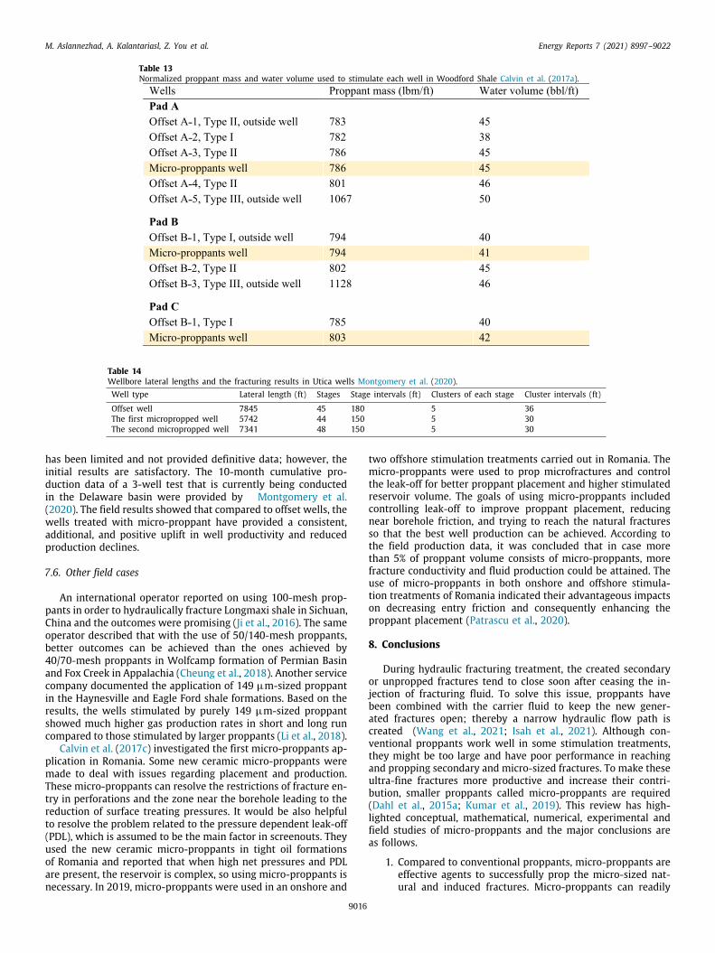
M. Aslannezhad, A. Kalantariasl, Z. You et al. Energy Reports 7 (2021) 8997–9022
Table 13Normalized proppant mass and water volume used to stimulate each well in Woodford Shale Calvin et al. (2017a).
Table 14Wellbore lateral lengths and the fracturing results in Utica wells Montgomery et al. (2020).Well type Lateral length (ft) Stages Stage intervals (ft) Clusters of each stage Cluster intervals (ft)
Offset well 7845 45 180 5 36The first micropropped well 5742 44 150 5 30The second micropropped well 7341 48 150 5 30
has been limited and not provided definitive data; however, theinitial results are satisfactory. The 10-month cumulative pro-duction data of a 3-well test that is currently being conductedin the Delaware basin were provided by Montgomery et al.(2020). The field results showed that compared to offset wells, thewells treated with micro-proppant have provided a consistent,additional, and positive uplift in well productivity and reducedproduction declines.
7.6. Other field cases
An international operator reported on using 100-mesh prop-pants in order to hydraulically fracture Longmaxi shale in Sichuan,China and the outcomes were promising (Ji et al., 2016). The sameoperator described that with the use of 50/140-mesh proppants,better outcomes can be achieved than the ones achieved by40/70-mesh proppants in Wolfcamp formation of Permian Basinand Fox Creek in Appalachia (Cheung et al., 2018). Another servicecompany documented the application of 149 µm-sized proppantin the Haynesville and Eagle Ford shale formations. Based on theresults, the wells stimulated by purely 149 µm-sized proppantshowed much higher gas production rates in short and long runcompared to those stimulated by larger proppants (Li et al., 2018).
Calvin et al. (2017c) investigated the first micro-proppants ap-plication in Romania. Some new ceramic micro-proppants weremade to deal with issues regarding placement and production.These micro-proppants can resolve the restrictions of fracture en-try in perforations and the zone near the borehole leading to thereduction of surface treating pressures. It would be also helpfulto resolve the problem related to the pressure dependent leak-off(PDL), which is assumed to be the main factor in screenouts. Theyused the new ceramic micro-proppants in tight oil formationsof Romania and reported that when high net pressures and PDLare present, the reservoir is complex, so using micro-proppants isnecessary. In 2019, micro-proppants were used in an onshore and
two offshore stimulation treatments carried out in Romania. Themicro-proppants were used to prop microfractures and controlthe leak-off for better proppant placement and higher stimulatedreservoir volume. The goals of using micro-proppants includedcontrolling leak-off to improve proppant placement, reducingnear borehole friction, and trying to reach the natural fracturesso that the best well production can be achieved. According tothe field production data, it was concluded that in case morethan 5% of proppant volume consists of micro-proppants, morefracture conductivity and fluid production could be attained. Theuse of micro-proppants in both onshore and offshore stimula-tion treatments of Romania indicated their advantageous impactson decreasing entry friction and consequently enhancing theproppant placement (Patrascu et al., 2020).
8. Conclusions
During hydraulic fracturing treatment, the created secondaryor unpropped fractures tend to close soon after ceasing the in-jection of fracturing fluid. To solve this issue, proppants havebeen combined with the carrier fluid to keep the new gener-ated fractures open; thereby a narrow hydraulic flow path iscreated (Wang et al., 2021; Isah et al., 2021). Although con-ventional proppants work well in some stimulation treatments,they might be too large and have poor performance in reachingand propping secondary and micro-sized fractures. To make theseultra-fine fractures more productive and increase their contri-bution, smaller proppants called micro-proppants are required(Dahl et al., 2015a; Kumar et al., 2019). This review has high-lighted conceptual, mathematical, numerical, experimental andfield studies of micro-proppants and the major conclusions areas follows.
1. Compared to conventional proppants, micro-proppants areeffective agents to successfully prop the micro-sized nat-ural and induced fractures. Micro-proppants can readily
9016
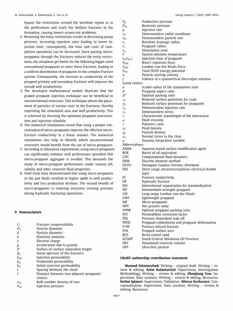
M. Aslannezhad, A. Kalantariasl, Z. You et al. Energy Reports 7 (2021) 8997–9022
bypass the restrictions around the borehole region or inthe perforations and reach the farthest fractures in theformation, causing lowers screen-out problems.
2. Removing the entry restrictions results in decreasing pumppressure, increasing injection rates leading to lower in-jection time; consequently, the time and costs of com-pletion operations can be decreased. Since passing micro-proppants through the fractures reduces the entry restric-tions, the situations get better for the following bigger sizedconventional proppants to enter these fractures, leading toa uniform distribution of proppants in the complex fracturesystem. Consequently, the increase in conductivity of thepropped primary and secondary fractures will improve theoverall well productivity.
3. The developed mathematical models illustrate that thegraded proppant injection technique can be beneficial inunconventional reservoirs. This technique allows the place-ment of particles of various sizes in the fractures, therebyimproving the stimulated area and well productivity. Thisis achieved by choosing the optimum proppant concentra-tion and injection schedule.
4. The numerical simulations reveal that using a proper con-centration of micro-proppants improve the effective micro-fracture conductivity in a linear manner. The numericalsimulations also help to identify which unconventionalreservoirs would benefit from the use of micro-proppants.
5. According to laboratory experiments, using micro-proppantscan significantly enhance well performance provided thatmicro-proppant aggregate is avoided. This demands thestudy of micro-proppant performance under various pH,salinity and other reservoir fluid properties.
6. Field trials have demonstrated that using micro-proppantsin the pad fluids resulted in higher uplift in well produc-tivity and less production declines. The second benefit ofmicro-proppants is reducing excessive treating pressureduring hydraulic fracturing operations.
9. Nomenclature
Cf Fracture compressibilityD1 Particle diameterd Particle diameterE Elasticity moduluse Electron chargeg Acceleration due to gravityh* Surface-to-surface separation lengthh0 Initial aperture of the fractureskinj Injection permeabilitykpr Production permeabilityk0 Initial reservoir permeabilityL Spacing between the cleatsl Distance between two adjacent proppants’
centersn∞ Bulk number density of ionsPinj Injection pressure
Ppr Production pressurePres Reservoir pressureq Injection raterD Dimensionless radial coordinaterDs Dimensionless particle sizere Borehole drainage radiusrs Proppant radiusrst Stimulation zoneT System absolute temperaturetin(rDs) Injection time of proppantVEDL Born’s repulsion forceVLW London–van der Waals forceVtot Total DLVO energy potentialvt Particle settling velocityz Valence of a symmetrical electrolyte solutionGreek Lettersα Scaled radius of the stimulation zoneβ Proppant aspect ratioβ∗ Optimal packing ratioγ1 Reduced surface potentials for coalsγ2 Reduced surface potentials for proppantsεq Dimensionless injection rateεσ Dimensionless stressλ Characteristic wavelength of the interactionµ Fluid viscosityν Poisson’s ratioρf Fluid densityρp Particle densityσn Normal stress to the cleatϕ Dummy integration variableAbbreviationsASMA Aqueous-based surface modification agentBOE Barrel of oil equivalentCFD Computational fluid dynamicsDEM Discrete element methodDLVO Derjaguin–Landau–Verwey–OverbeekEDL Short-range attractive/repulsive electrical double
layerFC Fracture conductivityHF Hydraulic fractureISO International organization for standardizationISP Intermediate-strength proppantLW Long-range London–van der WaalsLWP lightweight proppantMP Micro-proppantsNPV Net present valueOPPR Optimal proppant packing ratioPCF Permeability correction factorPDL Pressure dependent leak-offPEPD Proppant embedment and proppant deformationP-NF Primary natural fracturePSA Propped surface areaRCS Resin coated sandSCOOP South-Central Oklahoma Oil ProvinceSRV Stimulated reservoir volumeUFP Ultra-fine particle
CRediT authorship contribution statement
Masoud Aslannezhad: Writing - original draft, Writing – re-view & editing. Azim Kalantariasl: Supervision, Investigation,Methodology, Writing – review & editing. Zhenjiang You: Su-pervision, Data curation, Writing – review & editing, Resources.Stefan Iglauer: Supervision, Validation. Alireza Keshavarz: Con-ceptualization, Supervision, Data curation, Writing – review &editing, Resources.
9017
M. Aslannezhad, A. Kalantariasl, Z. You et al. Energy Reports 7 (2021) 8997–9022
Declaration of competing interest
The authors declare that they have no known competing finan-cial interests or personal relationships that could have appearedto influence the work reported in this paper.
References
Abdullah, M.N., et al., 2013. Prehydrating high-strength microspheres inlightweight cement slurry creates value for offshore Malaysian operator. In:SPE Asia Pacific Oil and Gas Conference and Exhibition. Society of PetroleumEngineers, Jakarta, Indonesia, p. 9.
Abrams, A., 1977. Mud design to minimize rock impairment due to particleinvasion. J. Pet. Technol. 29 (05), 586–592.
Ahamed, M., et al., 2019. Proppant damage mechanisms in coal seam reservoirsduring the hydraulic fracturing process: a review. Fuel 253, 615–629.
Al-Tailji, W., Shah, K., Davidson, B., 2016. The application and misapplicationof 100-mesh sand in multi-fractured horizontal wells in low-permeabilityreservoirs. In: SPE Hydraulic Fracturing Technology Conference. Society ofPetroleum Engineers.
Alotaibi, M.A., Miskimins, J.L., 2015. Slickwater proppant transport in complexfractures: new experimental findings & scalable correlation. In: SPE AnnualTechnical Conference and Exhibition. Society of Petroleum Engineers.
Alramahi, B., Sundberg, M., 2012. Proppant embedment and conductivity ofhydraulic fractures in shales. In: 46th US Rock Mechanics/GeomechanicsSymposium. American Rock Mechanics Association.
Anders, M.H., Laubach, S.E., Scholz, C.H., 2014. Microfractures: A review. J. Struct.Geol. 69, 377–394.
Apaydin, O.G., Ozkan, E., Raghavan, R., 2012. Effect of discontinuous microfrac-tures on ultratight matrix permeability of a dual-porosity medium. SPEReservoir Eval. Eng. 15 (04), 473–485.
Asadi, M.B., Dejam, M., Zendehboudi, S., 2020. Semi-analytical solution forproductivity evaluation of a multi-fractured horizontal well in a boundeddual-porosity reservoir. J. Hydrol. 581, 124288.
Awan, F.U.R., et al., 2020a. Stable dispersion of coal fines during hydraulicfracturing flowback in coal seam gas reservoirs—An experimental study.Energy Fuels 34 (5), 5566–5577.
Awan, F.U.R., et al., 2020b. A novel approach for using silica nanoparticles in aproppant pack to fixate coal fines. APPEA J. 60 (1), 88–96.
Awan, F.U.R., et al., 2021. Adsorption of nanoparticles on glass bead surfacefor enhancing proppant performance: A systematic experimental study. J.Molecular Liquids 328, 115398.
Bahri, A., Miskimins, J., 2021. The effects of fluid viscosity and density onproppant transport in complex slot systems. In: SPE Hydraulic FracturingTechnology Conference and Exhibition. OnePetro.
Bandara, K., Ranjith, P., Rathnaweera, T., 2020a. Laboratory-scale study onproppant behaviour in unconventional oil and gas reservoir formations. J.Natural Gas Sci. Eng. 78, 103329.
Bandara, K., et al., 2020b. Crushing and embedment of proppant packs undercyclic loading: An insight to enhanced unconventional oil/gas recovery.Geoscience Frontiers.
Barboza, B.R., Chen, B., Li, C., 2021. A review on proppant transport modelling.J. Pet. Sci. Eng. 108753.
Barree, R., Conway, M., 2001. Proppant holdup, bridging, and screenout be-havior in naturally fractured reservoirs. In: SPE Production and OperationsSymposium. OnePetro.
Bedrikovetsky, P., 2008. Upscaling of stochastic micro model for suspensiontransport in porous media. Transp. Porous Media 75 (3), 335–369.
Bedrikovetsky, P., 2013. Mathematical Theory of Oil and Gas Recovery: WithApplications to Ex-USSR Oil and Gas Fields. vol. 4, Springer Science &Business Media.
Bedrikovetsky, P.G., et al., 2012. Stimulation of natural cleats for gas productionfrom coal beds by graded proppant injection. In: SPE Asia Pacific Oil andGas Conference and Exhibition. Society of Petroleum Engineers.
Bhandakkar, P., Siddhamshetty, P., Kwon, J.S.-I., 2020. Numerical study of theeffect of propped surface area and fracture conductivity on shale gasproduction: Application for multi-size proppant pumping schedule design.J. Natural Gas Sci. Eng. 103349.
Binazadeh, M., et al., 2016. Effect of electrostatic interactions on water uptake ofgas shales: the interplay of solution ionic strength and electrostatic doublelayer. Energy Fuels 30 (2), 992–1001.
Blyton, C.A., Gala, D.P., Sharma, M.M., 2015. A comprehensive study of proppanttransport in a hydraulic fracture. In: SPE Annual Technical Conference andExhibition. Society of Petroleum Engineers.
Bose, C.C., et al., 2015a. Application of nanoproppants for fracture conductivityimprovement by reducing fluid loss and packing of micro-fractures. J. NaturalGas Sci. Eng. 27, 424–431.
Bose, C.C., et al., 2015b. Nano-proppants for fracture conductivity improvementand fluid loss reduction. In: SPE Western Regional Meeting. Society ofPetroleum Engineers.
Bostrom, N., et al., 2014. The time-dependent permeability damage caused byfracture fluid. In: SPE International Symposium and Exhibition on FormationDamage Control. OnePetro.
Brannon, H.D., Starks, T., 2008a. The Impact of Effective Fracture Area andConductivity on Fracture Deliverability and Stimulation Value. Paper. 116057.
Brannon, H.D., Starks, T.R., 2008b. The effects of Effective Fracture Area andconductivity on fracture deliverability and stimulation value. In: SPE AnnualTechnical Conference and Exhibition. Society of Petroleum Engineers.
Brannon, H.D., Starks, T.R., 2009. Maximizing return-on-fracturing-investment byusing ultra-lightweight proppants to optimize Effective Fracture Area: Canless be more? In: SPE Hydraulic Fracturing Technology Conference. Societyof Petroleum Engineers, The Woodlands, Texas, p. 13.
Brannon, H.D., et al., 2004. Maximizing fracture conductivity with proppantpartial monolayers: theoretical curiosity or highly productive reality? In: SPEAnnual Technical Conference and Exhibition. Society of Petroleum Engineers.
Bulova, M.N., et al., 2006. Benefits of the novel fiber-laden low-viscosity fluidsystem in fracturing low-permeability tight gas formations. In: SPE AnnualTechnical Conference and Exhibition. Society of Petroleum Engineers.
Bustin, A.M.M., Bustin, R.M., 2012. Importance of rock properties on theproducibility of gas shales. Int. J. Coal Geol. 103, 132–147.
Calvin, J., Grieser, B., Bachman, T., 2017a. Enhancement of well production inthe SCOOP woodford shale through the application of microproppant. In:SPE Hydraulic Fracturing Technology Conference and Exhibition. Society ofPetroleum Engineers.
Calvin, J., Grieser, B., Bachman, T., 2017b. Application of microproppant in theSCOOP woodford to improve well production. In: SPE Oklahoma City Oil andGas Symposium. Society of Petroleum Engineers.
Calvin, J., Grieser, B., Bachman, T., 2017c. Impact of microproppant on productionin the SCOOP Woodford Shale: A case history. In: SPE UnconventionalResources Conference. Society of Petroleum Engineers.
Chambers, R.W., Meise, K.D., 2005. Comparison of fracture geometries utilizingultralightweight proppants provide evidence that partial monolayers can becreated: a case history. In: SPE Annual Technical Conference and Exhibition.Society of Petroleum Engineers.
Cheung, B., Hilling, S., Brierley, S.P., 2018. Impact of low cost proppant andfluid systems in hydraulic fracturing of unconventional wells. In: AbuDhabi International Petroleum Exhibition & Conference. Society of PetroleumEngineers.
Cho, J., Joshi, M., Sun, C., 2006. Effect of inclusion size on mechanical proper-ties of polymeric composites with micro and nano particles. Compos. Sci.Technol. 66 (13), 1941–1952.
Chun, T., Li, Y., Wu, K., 2020. Comprehensive experimental study of proppanttransport in an inclined fracture. J. Pet. Sci. Eng. 184, 106523.
Chuprakov, D., Iuldasheva, A., Alekseev, A., 2021. Criterion of proppant packmobilization by filtrating fluids: Theory and experiments. J. Pet. Sci. Eng.196, 107792.
Cipolla, C., Lolon, E., Mayerhofer, M., 2009. The effect of proppant distri-bution and un-propped fracture con-ductivity on well performance inunconventional gas reservoirs. Spe 119368.
Cortez-Montalvo, J., et al., 2018. Laboratory evaluation of apparent conductivityof ultra-fine particulates. In: Unconventional Resources Technology Con-ference, Houston, Texas, 23-25 2018. Society of Exploration Geophysicists,American Association of Petroleum . . . .
Da Silva, M., et al., 2004. A new method for injectivity impairment character-ization from well and coreflood data. In: SPE Annual Technical Conferenceand Exhibition. Society of Petroleum Engineers.
Dahl, J., et al., 2015a. Application of micro-proppant to enhance well productionin unconventional reservoirs: Laboratory and field results. In: SPE WesternRegional Meeting. Society of Petroleum Engineers.
Dahl, J., et al., 2015b. Application of micro-proppant in liquids-rich, unconven-tional reservoirs to improve well production: Laboratory results, field results,and numerical simulations. In: Abu Dhabi International Petroleum Exhibitionand Conference. Society of Petroleum Engineers.
Daneshy, A., Crichlow, H., 1980. Numerical Solution of Sand Transport inHydraulic Fracturing. Halliburton Services, Duncan, OK.
Danso, D.K., et al., 2021. Recent advances in multifunctional proppant technologyand increased well output with micro and nano proppants. J. Pet. Sci. Eng.196, 108026.
De Paiva, R.O., et al., 2006. A comprehensive model for injectivity declineprediction during PWRI. In: SPE Europec/EAGE Annual Conference andExhibition. Society of Petroleum Engineers.
Dejam, M., Hassanzadeh, H., Chen, Z., 2018. Semi-analytical solution for pressuretransient analysis of a hydraulically fractured vertical well in a boundeddual-porosity reservoir. J. Hydrol. 565, 289–301.
Di Vaira, N., Leonardi, C., Johnson Jr., R., 2020. Modelling Micro-ProppantTransport in Stress-Sensitive Naturally-Fractured Reservoirs. In: SPE Europec.
9018

M. Aslannezhad, A. Kalantariasl, Z. You et al. Energy Reports 7 (2021) 8997–9022
Ding, J., et al., 2020. Time-lapse acoustic monitoring of fracture alteration inmarcellus shale. In: SPE/AAPG/SEG Unconventional Resources TechnologyConference. OnePetro.
Dontsov, E., Peirce, A., 2014. A new technique for proppant schedule design.Hydraul. Fract. J. 1 (3).
Drazer, G., Koplik, J., 2002. Transport in rough self-affine fractures. Phys. Rev. E66 (2), 026303.
Duenckel, R.J., et al., 2011. Proppant diagenesis-integrated analyses provide newinsights into origin, occurrence, and implications for proppant performance.In: SPE Hydraulic Fracturing Technology Conference. Society of PetroleumEngineers.
Economides, M.J., 1992. A Practical Companion to Reserv. Stimul.. Elsevier.Elimelech, M., Gregory, J., Jia, X., 2013. Particle Deposition and Aggregation:
Measurement, Modelling and Simulation. Butterworth-Heinemann.Ely, J.W., et al., 2014. Slick water fracturing and small proppant the future of
stimulation or a slippery slope? In: SPE Annual Technical Conference andExhibition. Society of Petroleum Engineers.
Falk, K., et al., 2015. Subcontinuum mass transport of condensed hydrocarbonsin nanoporous media. Nature Commun. 6 (1), 1–7.
Fan, M., Chen, C., 2020. Numerical simulation of the migration and deposition offine particles in a proppant-supported fracture. J. Pet. Sci. Eng. 194, 107484.
Fisher, M.K., et al., 2004. Optimizing horizontal completion techniques in thebarnett shale using microseismic fracture mapping. In: SPE Annual TechnicalConference and Exhibition. Society of Petroleum Engineers, Houston, Texas,p. 11.
Ford, J., et al., 1994. The formulation of milling fluids for efficient holecleaning: An experimental investigation. In: European Petroleum Conference.OnePetro.
Fredd, C., et al., 2000. Experimental study of hydraulic fracture conductivitydemonstrates the benefits of using proppants. In: SPE Rocky MountainRegional/Low-Permeability Reservoirs Symposium and Exhibition. Society ofPetroleum Engineers.
Gale, J.F., Reed, R.M., Holder, J., 2007. Natural fractures in the Barnett Shaleand their importance for hydraulic fracture treatments. AAPG Bull. 91 (4),603–622.
Gale, J.F.W., et al., 2014. Natural fractures in shale: A review and newobservations. AAPG Bull. 98 (11), 2165–2216.
Gaurav, A., Dao, E., Mohanty, K., 2012. Evaluation of ultra-light-weight proppantsfor shale fracturing. J. Pet. Sci. Eng. 92, 82–88.
Germanovich, L.N., et al., 1997. Hydraulic fracture with multiple segments I.Observations and model formulation. Int. J. Rock Mech. Mining Sci. 34 (3),97.e1–97.e19.
Ghosh, S., et al., 2014. Experimental investigation of proppant diagenesis.In: SPE/CSUR Unconventional Resources Conference–Canada. Society ofPetroleum Engineers.
Gregory, J., 1975. Interaction of unequal double layers at constant charge. J.Colloid Interface Sci. 51 (1), 44–51.
Gregory, J., 1981. Approximate expressions for retarded van der waalsinteraction. J. Colloid Interface Sci. 83 (1), 138–145.
Grieser, W.V., 2011. Oklahoma Woodford Shale: completion trends and pro-duction outcomes from three basins. In: SPE Production and OperationsSymposium. Society of Petroleum Engineers.
Gruesbeck, C., Collins, R., 1982. Particle transport through perforations. Soc.Petrol. Eng. J. 22 (06), 857–865.
Gu, M., Dao, E., Mohanty, K., 2015. Investigation of ultra-light weight proppantapplication in shale fracturing. Fuel 150, 191–201.
Gu, H., Desroches, J., 2003. New pump schedule generator for hydraulic frac-turing treatment design. In: SPE Latin American and Caribbean PetroleumEngineering Conference. OnePetro.
Gu, Q., Hoo, K.A., 2014. Evaluating the performance of a fracturing treatmentdesign. Ind. Eng. Chem. Res. 53 (25), 10491–10503.
Han, J., et al., 2016. Numerical study of proppant transport in complex fracturegeometry. In: SPE Low Perm Symposium. OnePetro.
Harris, P.C., Heath, S.J., 1996. High-quality foam fracturing fluids. In: SPE GasTechnology Symposium. Society of Petroleum Engineers, Calgary, Alberta,Canada, p. 9.
He, L., et al., 2014. Fracturing with carbon dioxide: Application status anddevelopment trend. Petrol. Explor. Dev. 41 (4), 513–519.
Hu, K., et al., 2014. Proppants selection based on field case studies of wellproduction performance in the Bakken shale play. In: SPE Western NorthAmerican and Rocky Mountain Joint Meeting. OnePetro.
Hu, X., et al., 2018. Effect of proppant addition schedule on the proppantdistribution in a straight fracture for slickwater treatment. J. Pet. Sci. Eng.167, 110–119.
Huang, F., et al., 2017. Critical conditions for massive fines detachment in-duced by single-phase flow in coalbed methane reservoirs: Modeling andexperiments. Energy Fuels 31 (7), 6782–6793.
Huang, H., et al., 2018a. Experimental study on the effect of injection parameterson proppant transport in rough vertical hydraulic fractures. In: SPE WesternRegional Meeting. OnePetro.
Huang, F., et al., 2018b. Massive fines detachment induced by moving gas-waterinterfaces during early stage two-phase flow in coalbed methane reservoirs.Fuel 222, 193–206.
Huang, J., et al., 2019. Reservoir depletion-induced proppant embedment anddynamic fracture closure. In: SPE Middle East Oil and Gas Show andConference. Society of Petroleum Engineers.
Huang, F., et al., 2021a. Detachment of coal fines deposited in proppant packsinduced by single-phase water flow: Theoretical and experimental analyses.Int. J. Coal Geol. 239, 103728.
Huang, F., et al., 2021b. Effects of proppant wettability and size on transportand retention of coal fines in saturated proppant packs: Experimental andtheoretical studies. Energy Fuels 35 (15), 11976–11991.
Inyang, U., et al., 2019. A kinetic Monte Carlo study to investigate the effec-tive permeability and conductivity of microfractures within unconventionalreservoirs. In: SPE Oklahoma City Oil and Gas Symposium. Society ofPetroleum Engineers.
Isah, A., et al., 2021. A comprehensive review of proppant transport in fracturedreservoirs: Experimental, numerical, and field aspects. J. Natural Gas Sci. Eng.103832.
Israelachvili, J.N., 2011. Intermolecular and Surface Forces. Academic Press.Izgec, O., et al., 2005. CO2 injection in carbonates. In: SPE Western Regional
Meeting. OnePetro.Jackson, J., Calvin, J., Drake, B., 2018. Stimulation design and treatment in the
sycamore formation of the South Central Oklahoma Oil Province Area of theAnadarko Basin. In: SPE Hydraulic Fracturing Technology Conference andExhibition. Society of Petroleum Engineers.
Jeffrey, R., Boucher, C., 2004. Sand Propped Hydraulic Fracture Stimulation ofHorizontal in-Seam Gas Drainage Holes at Dartbrook Coal Mine.
Ji, P., et al., 2016. Improving propped SRV in the long Ma Xi Shale: Newconcept trials and its performance. In: SPE Asia Pacific Hydraulic FracturingConference. Society of Petroleum Engineers.
Jiang, Y., Tanabashi, Y., Xiao, J., 2004. An improved shear-flow test apparatus andits application to deep underground construction. Int. J. Rock Mech. Min. Sci.41, 170–175.
Jin, M., et al., 2016. Geochemical modelling of formation damage risk during CO2injection in saline aquifers. J. Natural Gas Sci. Eng. 35, 703–719.
Johnson, R.L., et al., 2020. Integrating reservoir characterisation, diagnosticfracture injection testing, hydraulic fracturing and post-frac well productiondata to define pressure dependent permeability behavior in coal. In: SPE AsiaPacific Oil & Gas Conference and Exhibition.
Kalantariasl, A., Duhan, S., Bedrikovetsky, P., 2013. Type curves for injectivitydecline. In: SPE European Formation Damage Conference & Exhibition.Society of Petroleum Engineers.
Kalantariasl, A., Zeinijahromi, A., Bedrikovetsky, P., 2014a. External filter cakebuildup in dynamic filtration: mechanisms and key factors. In: SPE Interna-tional Symposium and Exhibition on Formation Damage Control. Society ofPetroleum Engineers.
Kalantariasl, A., Zeinijahromi, A., Bedrikovetsky, P., 2014b. Axi-symmetric two-phase suspension-colloidal flow in porous media during water injection. Ind.Eng. Chem. Res. 53 (40), 15763–15775.
Kalantariasl, A., et al., 2015. Nonuniform external filter cake in long injectionwells. Ind. Eng. Chem. Res. 54 (11), 3051–3061.
Karra, S., et al., 2015. Effect of advective flow in fractures and matrix diffusionon natural gas production. Water Resour. Res. 51 (10), 8646–8657.
Kassis, S., Sondergeld, C., 2010. Gas shale permeability: Effects of roughness,proppant, fracture offset, and confining pressure. In: International Oil andGas Conference and Exhibition in China.
Keshavarz, A., 2015. A Novel Technology for Enhanced Coal Seam Gas Recoveryby Graded Proppant Injection.
Keshavarz, A., et al., 2013. Stress-based mathematical model for graded proppantinjection in coal bed methane reservoirs. APPEA J. 53 (1), 337–346.
Keshavarz, A., et al., 2014a. Laboratory-based mathematical modelling of gradedproppant injection in CBM reservoirs. Int. J. Coal Geol. 136, 1–16.
Keshavarz, A., et al., 2014b. Stimulation of unconventional naturally fracturedreservoirs by graded proppant injection: experimental study and mathemati-cal model. In: SPE/EAGE European Unconventional Resources Conference andExhibition. European Association of Geoscientists & Engineers.
Keshavarz, A., et al., 2014c. Mathematical model for stimulation of CBMreservoirs during graded proppant injection. In: SPE/EAGE European Un-conventional Resources Conference and Exhibition. European Association ofGeoscientists & Engineers.
Keshavarz, A., et al., 2014d. Enhancement of CBM well fracturing throughstimulation of cleat permeability by ultra-fine particle injection. APPEA J.54 (1), 155–166.
Keshavarz, A., et al., 2015a. Graded proppant injection into coal seam gasand shale gas reservoirs for well stimulation. In: SPE European FormationDamage Conference and Exhibition. Society of Petroleum Engineers.
Keshavarz, A., et al., 2015b. A new technique for enhancing hydraulic fractur-ing treatment in unconventional reservoirs. In: EUROPEC 2015. Society ofPetroleum Engineers.
9019

M. Aslannezhad, A. Kalantariasl, Z. You et al. Energy Reports 7 (2021) 8997–9022
Keshavarz, A., et al., 2015c. Stimulation of unconventional reservoirs usinggraded proppant injection. In: SPE Russian Petroleum Technology Conference.Society of Petroleum Engineers.
Keshavarz, A., et al., 2015d. Effect of suspension fluid chemistry on fracturesystem stimulation using micro-sized proppant placement. In: SPE AsiaPacific Unconventional Resources Conference and Exhibition. Society ofPetroleum Engineers.
Keshavarz, A., et al., 2015e. Stimulation of coal seam permeability by micro-sized graded proppant placement using selective fluid properties. Fuel 144,228–236.
Keshavarz, A., et al., 2016a. Productivity enhancement by stimulation of naturalfractures around a hydraulic fracture using micro-sized proppant placement.J. Natural Gas Sci. Eng. 33, 1010–1024.
Keshavarz, A., et al., 2016b. Improving the conductivity of natural fracture sys-tems in conjunction with hydraulic fracturing in stress sensitive reservoirs.In: SPE Asia Pacific Oil & Gas Conference and Exhibition. Society of PetroleumEngineers, Perth, Australia, p. 11.
Keshavarz, A., et al., 2018. Enhanced gas recovery techniques from coalbedmethane reservoirs. In: Bahadori (Ed.), Fundamentals of Enhanced Oil andGas Recovery from Conventional and Unconventional Reservoirs. Elsevier,http://dx.doi.org/10.1016/B978-0-12-813027-8.00008-4.
Khanna, A., et al., 2012a. Optimal placement of proppant in narrow fracturechannels. J. Petrol. Sci. Eng. submitted on.
Khanna, A., et al., 2012b. Conductivity of narrow fractures filled with a proppantmonolayer. J. Pet. Sci. Eng. 100, 9–13.
Khanna, A., et al., 2013. Stimulation of the natural fracture system by gradedproppant injection. J. Pet. Sci. Eng. 111, 71–77.
Kim, H., Inoue, J., 2003. Analytical approach for anisotropic permeability througha single rough rock joint under shear deformation. J. Geophys. Res. 108 (B8).
Kim, B.Y., et al., 2018. Laboratory measurement of microproppant placementquality using split core plug permeability under stress. In: SPE HydraulicFracturing Technology Conference and Exhibition. Society of PetroleumEngineers.
Kincaid, K.P., et al., 2013. Self-suspending proppant. In: SPE Hydraulic FracturingTechnology Conference. Society of Petroleum Engineers.
King, G.E., 2010. Thirty years of gas shale fracturing: What have we learned? In:SPE Annual Technical Conference and Exhibition. Society of PetroleumEngineers.
Kogsbøll, H.H., Pitts, M.J., Owens, K.A., 1993. Effects of tortuosity in fracturestimulation of horizontal wells - A case study of the dan field. In: OffshoreEurope. Society of Petroleum Engineers, Aberdeen, United Kingdom, p. 19.
Kondash, A.J., Lauer, N.E., Vengosh, A., 2018. The intensification of the waterfootprint of hydraulic fracturing. Sci. Adv. 4 (8), eaar5982.
Konzuk, J.S., Kueper, B.H., 2004. Evaluation of cubic law based models describingsingle-phase flow through a rough-walled fracture. Water Resour. Res. 40 (2).
Kozhukhova, N., et al., 2019. Toxic effect of fly ash on biological environment.In: IOP Conference Series: Earth and Environmental Science. IOP Publishing.
Kulakofsky, D., et al., 2011. New class of microsphere improves economics andallows circulation where previous designs suffered losses: A case history. In:Offshore Mediterranean Conference and Exhibition. Offshore MediterraneanConference, Ravenna, Italy, p. 7.
Kumar, D., Ghassemi, A., 2019. A Fully Coupled 3D Simulation of HydraulicFracture Networks Propagation from the Horizontal Wells. Rock Mechanicsfor Natural Resources and Infrastructure Development.
Kumar, D., Gonzalez, R.A., Ghassemi, A., 2019. The role of micro-proppantsin conductive fracture network development. In: SPE Hydraulic FracturingTechnology Conference and Exhibition. Society of Petroleum Engineers.
Lacy, L., Rickards, A., Bilden, D., 1998. Fracture width and embedment testing insoft reservoir sandstone. SPE Drill. Complet. 13 (01), 25–29.
Lake, L.W., 2006. Petroleum Engineering Handbook. Soxciety of PetroleumEnginners.
Landau, L.D., Lifshi⁀ts, E.M., Pitaevskii, L.P., 1980. Course of Theoretical Physics:Statistical Physics. Elsevier Butterworth Heinemann.
Lau, H.C., Davis, C.L., 1997. Laboratory studies of plugging and clean-up of pro-duction screens in horizontal wellbores. In: SPE Annual Technical Conferenceand Exhibition. Society of Petroleum Engineers, San Antonio, Texas, p. 15.
Lau, H.C., Radhamani, A.V., Ramakrishna, S., 2019. Maximizing production fromshale reservoir by using micro-sized proppants. In: International PetroleumTechnology Conference. International Petroleum Technology Conference.
Lee, J., Kang, J.M., Choe, J., 2003. Experimental analysis on the effects of variableapertures on tracer transport. Water Resour. Res. 39 (1).
Li, C., Spurr, N., Royce, T., 2018. Post-fracturing production performance ofsmall sized proppant in major unconventional formations. In: SPE Interna-tional Hydraulic Fracturing Technology Conference and Exhibition. Society ofPetroleum Engineers.
Li, K., et al., 2015. New mathematical models for calculating proppantembedment and fracture conductivity. SPE J. 20 (03), 496–507.
Liang, F., et al., 2016. A comprehensive review on proppant technologies.Petroleum 2 (1), 26–39.
Liang, Feng, et al., 2019. Experimental and simulation approaches on evaluatingan improved hydraulic fracturing treatment for stimulating tight carbonatereservoirs. Aramco J. Technol. 12–24.
Liu, H., et al., 2020a. An optimized model of calculating optimal packing ratiofor graded proppant placement with consideration of proppant embedmentand deformation. J. Pet. Sci. Eng. 107703.
Liu, H., et al., 2020b. Influences of proppant embedment and deformation onmicro-sized graded proppant injection scheme. In: SPE Asia Pacific Oil &Gas Conference and Exhibition. Society of Petroleum Engineers, Virtual, p.14.
Liu, H., et al., 2020c. Modelling of micro-sized graded proppant injection in thenatural fractures around a hydraulic fracture with consideration of prop-pant embedment and deformation. In: Abu Dhabi International PetroleumExhibition & Conference. Society of Petroleum Engineers, Abu Dhabi, UAE, p.14.
Lu, C., et al., 2020. A novel hydraulic fracturing method based on the coupledcfd-dem numerical simulation study. Appl. Sci. 10 (9), 3027.
Mack, M.G., Warpinski, N.R., 2000. Mechanics of hydraulic fracturing. Reserv.Stimul. 6-1.
Madasu, S., Nguyen, P.D., 2017. Computational and experimental study ofmicrofracture conductivity in the eagle ford shale using microproppantpillars. In: SPE Reservoir Characterisation and Simulation Conference andExhibition. Society of Petroleum Engineers.
Makhanov, K., et al., 2014. Liquid uptake of gas shales: A workflow to es-timate water loss during shut-in periods after fracturing operations. J.Unconventional Oil Gas Resour. 7, 22–32.
McGlade, C., Speirs, J., Sorrell, S., 2013. Methods of estimating shale gas resources– Comparison, evaluation and implications. Energy 59, 116–125.
Meyer, B.R., Bazan, L.W., 2011. A discrete fracture network model for hy-draulically induced fractures — theory, parametric and case studies. In: SPEHydraulic Fracturing Technology Conference. Society of Petroleum Engineers,The Woodlands, Texas, USA, p. 36.
Mittal, A., Rai, C.S., Sondergeld, C.H., 2017. A study of propped-fracture con-ductivity: Impairment mechanisms under laboratory conditions. In: SPWLA58th Annual Logging Symposium. Society of Petrophysicists and Well-LogAnalysts.
Mohamed, I.M., Nasr-El-Din, H.A., 2012. Formation damage due to CO2 seques-tration in deep saline carbonate aquifers. In: SPE International Symposiumand Exhibition on Formation Damage Control. OnePetro.
Mohapatra, R., Rao, J.R., 2001. Some aspects of characterisation, utilisation andenvironmental effects of fly ash. J. Chem. Technol. Biotechnol. 76 (1), 9–26.
Mollanouri Shamsi, M., Nia, F., Jessen, K., 2015. Conductivity of proppant-packs under variable stress conditions: an integrated 3D discrete elementand lattice boltzman method approach. In: SPE Western Regional Meeting.OnePetro.
Montgomery, C., 2013. Fracturing fluids. In: ISRM International Conference forEffective and Sustainable Hydraulic Fracturing. International Society for RockMechanics and Rock Engineering, Brisbane, Australia, p. 23.
Montgomery, C.T., et al., 2020. Utilizing discrete fracture modeling and micro-proppant to predict and sustain production improvements in nano Darcyrock. In: SPE Hydraulic Fracturing Technology Conference and Exhibition.Society of Petroleum Engineers.
Nagel, N., Sanchez-Nagel, M., 2015. On the importance and impact of keygeomechanical parameters in unconventional play developments. In: 49thUS Rock Mechanics/Geomechanics Symposium. American Rock MechanicsAssociation.
Nagel, N., et al., 2013. Stress shadow evaluations for completion design inunconventional plays. In: SPE Unconventional Resources Conference Canada.Society of Petroleum Engineers, Calgary, Alberta, Canada, p. 14.
Narasingam, A., Siddhamshetty, P., Kwon, J.S.-I., 2018. Handling spatial het-erogeneity in reservoir parameters using proper orthogonal decompositionbased ensemble Kalman filter for model-based feedback control of hydraulicfracturing. Ind. Eng. Chem. Res. 57 (11), 3977–3989.
Narasingam, A., Siddhamshetty, P., Sang-Il Kwon, J., 2017. Temporal clusteringfor order reduction of nonlinear parabolic PDE systems with time-dependentspatial domains: Application to a hydraulic fracturing process. AIChE J. 63(9), 3818–3831.
Nejad, A.M., et al., 2015. A case history: evaluating well completions in eagle fordshale using a data-driven approach. In: SPE Hydraulic Fracturing TechnologyConference. Society of Petroleum Engineers.
Nguyen, P., Dewprashad, B., Weaver, J., 1998a. A new approach for enhancingfracture conductivity. In: SPE Asia Pacific Oil and Gas Conference andExhibition. Society of Petroleum Engineers.
Nguyen, P.D., et al., 1998b. Enhancing fracture conductivity through surfacemodification of proppant. In: SPE Formation Damage Control Conference.Society of Petroleum Engineers.
Nguyen, P.D., et al., 2013. Evaluating treatment methods for enhancingmicrofracture conductivity in tight formations. In: SPE UnconventionalResources Conference and Exhibition-Asia Pacific. Society of PetroleumEngineers.
9020

M. Aslannezhad, A. Kalantariasl, Z. You et al. Energy Reports 7 (2021) 8997–9022
Norris, M., et al., 1998. Multiple proppant fracturing of horizontal wellbores ina chalk formation: evolving the process in the Valhall Field. In: EuropeanPetroleum Conference. Society of Petroleum Engineers.
O’Driscoll, M., 2013. Proppant prospects for bauxite. In: 19th Bauxite & AluminaConference, 13e15 March, Miami, Florida, USA.
Osiptsov, A.A., 2017. Fluid mechanics of hydraulic fracturing: a review. J. Pet.Sci. Eng. 156, 513–535.
Ovcharenko, A., Devadass, M., 2010. Assessment on the performance of hollowglass microspheres in low density fluids for workover programs in fracturedbasement reservoir at the white tiger oil fields, Cuu Long Basin, Vietnam.In: SPE/IADC Managed Pressure Drilling and Underbalanced OperationsConference and Exhibition. Society of Petroleum Engineers, Kuala Lumpur,Malaysia, p. 15.
Palisch, T.T., Vincent, M., Handren, P.J., 2010. Slickwater fracturing: food forthought. SPE Product. Oper. 25 (03), 327–344.
Pangilinan, K.D., de Leon, A.C.C., Advincula, R.C., 2016. Polymers for proppantsused in hydraulic fracturing. J. Pet. Sci. Eng. 145, 154–160.
Park, S.-H., et al., 2015. Spray-assisted deep-frying process for the in situspherical assembly of graphene for energy-storage devices. Chem. Mater. 27(2), 457–465.
Parker, M.A., et al., 2005. High-porosity fractures yield high conductivity. In: SPEAnnual Technical Conference and Exhibition. Society of Petroleum Engineers,Dallas, Texas, p. 10.
Paryani, M., et al., 2017. Adaptive fracturing to avoid Frac hits and interference:A Wolfcamp Shale case study. In: SPE Unconventional Resources Conference.Society of Petroleum Engineers.
Patrascu, R., et al., 2020. First applications of novel microproppant to achieve op-timal production and enhance hydraulic fracture treatment placement-A Ro-manian case history. In: Unconventional Resources Technology Conference,URTEC.
Patzek, T.W., Male, F., Marder, M., 2013. Gas production in the Barnett Shaleobeys a simple scaling theory. Proc. Natl. Acad. Sci. 110 (49), 19731–19736.
Ramandi, H.L., et al., 2021. Digital and experimental rock analysis of proppantinjection into naturally fractured coal. Fuel 286, 119368.
Rassenfoss, S., 2017. Testing tiny grains seeking more output. J. Pet. Technol. 69(03), 28–34.
Ray, B., et al., 2017. An investigation into proppant dynamics in hydraulic frac-turing. In: SPE Hydraulic Fracturing Technology Conference and Exhibition.OnePetro.
Ribeiro, A., et al., 2020. Evaluating performance of graded proppant injectioninto CSG reservoir: A reservoir simulation study. In: Asia Pacific Uncon-ventional Resources Technology Conference, Brisbane, Australia, 18-19 2019.Unconventional Resources Technology Conference.
Roostaei, M., et al., 2018. Numerical simulation of proppant transport inhydraulic fractures. J. Pet. Sci. Eng. 163, 119–138.
Ruckenstein, E., Prieve, D.C., 1976. Adsorption and desorption of particles andtheir chromatographic separation. AIChE J. 22 (2), 276–283.
Schmidt, D., et al., 2014. Performance of mixed proppant sizes. In: SPE HydraulicFracturing Technology Conference. Society of Petroleum Engineers.
Schmittbuhl, J., et al., 2008. Fracture morphology and viscous transport. Int. J.Rock Mech. Min. Sci. 45 (3), 422–430.
Schwarz, J.-O., Enzmann, F., 2013. Simulation of fluid flow on fractures andimplications for reactive transport simulations. Transp. Porous Media 96 (3),501–525.
Shah, M., Shah, S., Sircar, A., 2017. A comprehensive overview on recentdevelopments in refracturing technique for shale gas reservoirs. J. NaturalGas Sci. Eng. 46, 350–364.
Shamsi, M.M.M., Nia, S.F., Jessen, K., 2017. Dynamic conductivity ofproppant-filled fractures. J. Pet. Sci. Eng. 151, 183–193.
Sharma, M.M., Gadde, P.B., 2005. The impact of proppant retardation on proppedfracture lengths. In: SPE Annual Technical Conference and Exhibition. Societyof Petroleum Engineers.
Sharma, M.M., Manchanda, R., 2015. The role of induced un-propped (IU)fractures in unconventional oil and gas wells. In: SPE Annual TechnicalConference and Exhibition. Society of Petroleum Engineers, Houston, Texas,USA, p. 14.
Sheng, J.J., 2014. Critical review of low-salinity waterflooding. J. Pet. Sci. Eng.120, 216–224.
Shrivastava, K., Sharma, M.M., 2018. Proppant transport in complex fracture net-works. In: SPE Hydraulic Fracturing Technology Conference and Exhibition.Society of Petroleum Engineers.
Siddhamshetty, P., Bhandakkar, P., Kwon, J.S.-I., 2020. Enhancing total fracturesurface area in naturally fractured unconventional reservoirs via modelpredictive control. J. Pet. Sci. Eng. 184, 106525.
Siddhamshetty, P., Kwon, J.S.-I., 2019. Simultaneous measurement uncertaintyreduction and proppant bank height control of hydraulic fracturing. Comput.Chem. Eng. 127, 272–281.
Siddhamshetty, P., Wu, K., Kwon, J.S.-I., 2018a. Optimization of simultaneouslypropagating multiple fractures in hydraulic fracturing to achieve uniformgrowth using data-based model reduction. Chem. Eng. Res. Des. 136,675–686.
Siddhamshetty, P., Wu, K., Kwon, J.S.-I., 2019. Modeling and control of proppantdistribution of multistage hydraulic fracturing in horizontal shale wells. Ind.Eng. Chem. Res. 58 (8), 3159–3169.
Siddhamshetty, P., Yang, S., Kwon, J.S.-I., 2018b. Modeling of hydraulic fracturingand designing of online pumping schedules to achieve uniform proppantconcentration in conventional oil reservoirs. Comput. Chem. Eng. 114,306–317.
Siddhamshetty, P., et al., 2018c. Feedback control of proppant bank heightsduring hydraulic fracturing for enhanced productivity in shale formations.AIChE J. 64 (5), 1638–1650.
Sidhu, H.S., et al., 2018. Model order reduction of nonlinear parabolic PDEsystems with moving boundaries using sparse proper orthogonal decom-position: Application to hydraulic fracturing. Comput. Chem. Eng. 112,92–100.
Singh Sidhu, H., Siddhamshetty, P., Kwon, J.S., 2018. Approximate dynamic pro-gramming based control of proppant concentration in hydraulic fracturing.Mathematics 6 (8), 132.
Siwei, M., He, L., Qinghai, Y., 2019. Exploration and practice of carbon se-questration realized by CO2 waterless fracturing. Energy Procedia 158,4586–4591.
Sone, H., Zoback, M.D., 2013. Mechanical properties of shale-gas reservoir rocks—Part 2: Ductile creep, brittle strength, and their relation to the elasticmodulusmechanical properties of gas shale—Part 2. Geophysics 78 (5),D393–D402.
Song, X.-z., et al., 2018. Transport feasibility of proppant by supercritical carbondioxide fracturing in reservoir fractures. J. Hydrodyn. 30 (3), 507–513.
Stadulis, J.M., 1995. Development of a completion design to control screenoutscaused by multiple near-wellbore fractures. In: Low Permeability ReservoirsSymposium. Society of Petroleum Engineers, Denver, Colorado, p. 16.
Steel, L., Mackay, E., Maroto-Valer, M.M., 2018. Experimental investigationof CO2-brine-calcite interactions under reservoir conditions. Fuel Process.Technol. 169, 122–131.
Stegent, N.A., et al., 2010. Cement technology improves fracture initiationand leads to successful treatments in the eagle ford shale. In: Tight GasCompletions Conference. Society of Petroleum Engineers, San Antonio, Texas,USA, p. 17.
Stokes, G.G., 1851. On the Effect of the Internal Friction of Fluids on the Motionof Pendulums.
Tang, Y., et al., 2018. Influences of proppant concentration and fracturing fluidson proppant-embedment behavior for inhomogeneous rock medium: anexperimental and numerical study. SPE Product. Oper. 33 (04), 666–678.
Tanguay, C., Smith, M., 2018. Microproppants Unlock Potential of SecondaryFractures.
Thompson, J.C., 1977. The theory, methods of application and results of the useof 100 mesh sand in stimulating permian basin formations. In: SPE PermianBasin Oil and Gas Recovery Conference. Society of Petroleum Engineers.
Thyagaraju, B., et al., 2009. Case study using hollow glass microspheres to reducethe density of drilling fluids in the Mumbai High Basin, India and subsequentfield trial at GTI Catoosa test facility, Tulsa, OK. In: SPE/IADC Middle EastDrilling Technology Conference & Exhibition.
V., Santiago, et al., 2021. Modelling and economic analyses of graded particleinjections in conjunction with hydraulically fracturing of coal seam gasreservoirs. In: Asia Pacific Unconventional Resources Technology Conference2021.
Vahab, M., Khalili, N., 2018. An X-FEM formulation for the optimized gradedproppant injection into hydro-fractures within saturated porous media.Transp. Porous Media 121 (2), 289–314.
van Ketterij, R.B., de Pater, C.J., 1999. Impact of perforations on hydraulic fracturetortuosity. SPE Product. Facilities 14 (02), 117–130.
Verwey, E.J.W., 1947. Theory of the stability of lyophobic colloids. J. Phys. Chem.51 (3), 631–636.
Van der Vlis, A., et al., 1975. Criteria for proppant placement and fractureconductivity. In: Fall Meeting of the Society of Petroleum Engineers of AIME.Society of Petroleum Engineers.
Vo, L.K., Nguyen, P.D., Weaver, J.D., 2013. Development and applications ofan aqueous-based surface modification agent. In: SPE European FormationDamage Conference & Exhibition. Society of Petroleum Engineers, Noordwijk,The Netherlands, p. 10.
Wang, J., Elsworth, D., Denison, M., 2019. Proppant transport in a propagatinghydraulic fracture and the evolution of transport properties. In: 53rd US RockMechanics/Geomechanics Symposium. OnePetro.
Wang, S., Wu, H., 2006. Environmental-benign utilisation of fly ash as low-costadsorbents. J. Hard Mater. 136 (3), 482–501.
Wang, D., et al., 2021. Numerical investigation of the effects of proppantembedment on fracture permeability and well production in queensland coalseam gas reservoirs. Int. J. Coal Geol. 103689.
Watanabe, N., et al., 2005. Numerical estimation of aperture structure and flowwetted field in rock fracture. Trans. Geotherm. Resour. Council 29, 431–436.
Weaver, J.D., Nguyen, P.D., 2010. Hydrophobic filming reduces frac gel andmineral scale damage. In: SPE Eastern Regional Meeting. Society of PetroleumEngineers.
9021

M. Aslannezhad, A. Kalantariasl, Z. You et al. Energy Reports 7 (2021) 8997–9022
Weaver, J.D., et al., 1999. Application of surface modification agent in wells withhigh flow rates. In: SPE Western Regional Meeting. Society of PetroleumEngineers.
Wei, M., et al., 2019. Transient production decline behavior analysis for amulti-fractured horizontal well with discrete fracture networks in shale gasreservoirs. J. Porous Media 22 (3).
Westwood, R.F., Toon, S.M., Cassidy, N.J., 2017. A sensitivity analysis of the effectof pumping parameters on hydraulic fracture networks and local stressesduring shale gas operations. Fuel 203, 843–852.
Wu, C., Onan, D.D., 1986. High-strength microsphere additive improves cementperformance in gulf of bohai. In: International Meeting on PetroleumEngineering. Society of Petroleum Engineers, Beijing, China, p. 5.
Wu, K., et al., 2015. A model for gas transport in microfractures of shale andtight gas reservoirs. AIChE J. 61 (6), 2079–2088.
Xu, L., et al., 2018. Enhancing placement of microsized proppant in microfrac-tures for increasing stimulated reservoir volume in shale reservoirs. In:SPE/AAPG/SEG Unconventional Resources Technology Conference.
Yang, S., Siddhamshetty, P., Kwon, J.S.-I., 2017. Optimal pumping schedule designto achieve a uniform proppant concentration level in hydraulic fracturing.Comput. Chem. Eng. 101, 138–147.
Yekeen, N., et al., 2019. Nanoparticles applications for hydraulic fracturing ofunconventional reservoirs: A comprehensive review of recent advances andprospects. J. Pet. Sci. Eng. 178, 41–73.
You, Z., et al., 2015. Particle mobilization in porous media: temperature effectson competing electrostatic and drag forces. Geophys. Res. Lett. 42 (8),2852–2860.
You, Z., et al., 2019a. Fines migration in geothermal reservoirs: Laboratory andmathematical modelling. Geothermics 77, 344–367.
You, Z., et al., 2019b. Influence of elastoplastic embedment on CSG productionenhancement using graded particle injection. APPEA J. 59 (1), 310–318.
You, Z., et al., 2019c. Development of predictive models in support of micro-particle injection in naturally fractured reservoirs. In: SPE/AAPG/SEG AsiaPacific Unconventional Resources Technology Conference.
Yuan, B., Wood, D.A., 2018. A comprehensive review of formation damage duringenhanced oil recovery. J. Pet. Sci. Eng. 167, 287–299.
Zhang, J., Hou, J., 2016. Theoretical conductivity analysis of surface modifica-tion agent treated proppant II – Channel fracturing application. Fuel 16528–32.
Zhang, G., Li, M., Gutierrez, M., 2017. Simulation of the transport and placementof multi-sized proppant in hydraulic fractures using a coupled CFD-DEMapproach. Adv. Powder Technol. 28 (7), 1704–1718.
Zhang, C., et al., 2021. Combined micro-proppant and supercritical carbondioxide (SC-CO2) fracturing in shale gas reservoirs: A review. Fuel 305,121431.
Zhou, Z., et al., 2016. Experimental investigation of the effect of imbibition onshale permeability during hydraulic fracturing. J. Natural Gas Sci. Eng. 29,413–430.
Zimmerman, R.W., et al., 2004. Non-linear regimes of fluid flow in rock fractures.Int. J. Rock Mech. Min. Sci. 41, 163–169.
Zoveidavianpoor, M., Gharibi, A., 2015. Application of polymers for coat-ing of proppant in hydraulic fracturing of subterraneous formations: Acomprehensive review. J. Natural Gas Sci. Eng. 24, 197–209.
9022
Related Documents


