Configuration and Use Manual 20000327, Rev FC July 2016 Micro Motion ® Model 2700 Transmitters with PROFIBUS-PA

Welcome message from author
This document is posted to help you gain knowledge. Please leave a comment to let me know what you think about it! Share it to your friends and learn new things together.
Transcript

Configuration and Use Manual20000327, Rev FC
July 2016
Micro Motion® Model 2700 Transmitters with PROFIBUS-PA

Safety and approval information
This Micro Motion product complies with all applicable European directives when properly installed in accordance with the instructions in this manual. Refer to the EC declaration of conformity for directives that apply to this product. The EC declaration of conformity, with all applicable European directives, and the complete ATEX Installation Drawings and Instructions are available on the internet at www.micromotion.com or through your local Micro Motion support center.
Information affixed to equipment that complies with the Pressure Equipment Directive can be found on the internet at www.micromotion.com/documentation.
For hazardous installations in Europe, refer to standard EN 60079-14 if national standards do not apply.
Other information
Full product specifications can be found in the product data sheet. Troubleshooting information can be found in the transmitter configuration manual. Product data sheets and manuals are available from the Micro Motion web site at www.micromotion.com/documentation.
Return policy
Micro Motion procedures must be followed when returning equipment. These procedures ensure legal compliance with government transportation agencies and help provide a safe working environment for Micro Motion employees. Failure to follow Micro Motion procedures will result in your equipment being refused delivery.
Information on return procedures and forms is available on our web support system at www.micromotion.com, or by phoning the Micro Motion Customer Service department.
Micro Motion customer service
Email:• Worldwide: [email protected]• Asia-Pacific: [email protected]
Telephone:
North and South America Europe and Middle East Asia Pacific
United States 800-522-6277 U.K. 0870 240 1978 Australia 800 158 727
Canada +1 303-527-5200 The Netherlands +31 (0) 704 136 666 New Zealand 099 128 804
Mexico +41 (0) 41 7686 111 France 0800917901 India 800 440 1468
Argentina +54 11 4837 7000 Germany 0800 182 5347 Pakistan 888 550 2682
Brazil +55 15 3413 8000 Italy 8008 77334 China +86 21 2892 9000
Venezuela +58 26 1731 3446 Central & Eastern +41 (0) 41 7686 111 Japan +81 3 5769 6803
Russia/CIS +7 495 981 9811 South Korea +82 2 3438 4600
Egypt 0800 000 0015 Singapore +65 6 777 8211
Oman 800 70101 Thailand 001 800 441 6426
Qatar 431 0044 Malaysia 800 814 008
Kuwait 663 299 01
South Africa 800 991 390
Saudia Arabia 800 844 9564
UAE 800 0444 0684

Contents
Chapter 1 Before You Begin ......................................................................................................... 71.1 Overview................................................................................................................................ 71.2 Safety..................................................................................................................................... 71.3 Determining transmitter information..................................................................................... 71.4 PROFIBUS-PA functionality ..................................................................................................... 81.5 Determining version information ........................................................................................... 81.6 Communication tools............................................................................................................. 91.7 Planning the configuration ..................................................................................................... 101.8 Pre-configuration worksheet.................................................................................................. 121.9 Flowmeter documentation..................................................................................................... 12
Chapter 2 Startup........................................................................................................................ 132.1 Overview................................................................................................................................ 132.2 Applying power ...................................................................................................................... 132.3 Setting the node address........................................................................................................ 142.4 Configuring the analog input function block channels............................................................ 142.5 Setting the I/O mode.............................................................................................................. 162.6 Configuring the totalizer block mode ..................................................................................... 182.7 Configuring pressure compensation....................................................................................... 202.8 Configuring temperature compensation ................................................................................ 23
Chapter 3 Calibration .................................................................................................................. 273.1 Overview................................................................................................................................ 273.2 Characterization, Smart Meter Verification, meter validation, and calibration ........................ 273.3 Performing a characterization ................................................................................................ 303.4 Performing Smart Meter Verification...................................................................................... 343.5 Performing meter validation .................................................................................................. 433.6 Performing zero calibration .................................................................................................... 453.7 Performing density calibration ............................................................................................... 48
Chapter 4 Configuration.............................................................................................................. 574.1 Overview................................................................................................................................ 574.2 Default target mode............................................................................................................... 574.3 Configuration map ................................................................................................................. 574.4 Configuring standard volume flow measurement for gas ....................................................... 584.5 Changing the measurement units .......................................................................................... 614.6 Configuring the petroleum measurement application............................................................ 644.7 Configuring the concentration measurement application ...................................................... 684.8 Changing the output scale ..................................................................................................... 704.9 Changing process alarms........................................................................................................ 714.10 Configuring status alarm severity ........................................................................................... 754.11 Changing the damping values ................................................................................................ 774.12 Changing slug flow limits and duration................................................................................... 794.13 Configuring cutoffs ................................................................................................................ 804.14 Changing the measurement mode parameter ....................................................................... 824.15 Configuring sensor parameters .............................................................................................. 834.16 Configuring the display .......................................................................................................... 844.17 Enabling LD Optimization....................................................................................................... 90

4 Model 2400S Transmitters
Chapter 5 Operation .................................................................................................................... 935.1 Overview................................................................................................................................ 935.2 Using the I&M functions ......................................................................................................... 935.3 Recording process variables ................................................................................................... 945.4 Viewing process variables ...................................................................................................... 945.5 Using sensor simulation mode ............................................................................................... 965.6 Accessing diagnostic information with a PROFIBUS host ........................................................ 965.7 Viewing transmitter status and alarms ................................................................................... 975.8 Using the totalizers and inventories ....................................................................................... 98
Chapter 6 Troubleshooting .......................................................................................................... 1036.1 Overview................................................................................................................................ 1036.2 Guide to troubleshooting topics ............................................................................................ 1036.3 Transmitter does not operate ................................................................................................ 1036.4 Transmitter does not communicate....................................................................................... 1046.5 Function blocks in Out-of-Service mode................................................................................. 1046.6 Zero or calibration failure ....................................................................................................... 1046.7 Output problems ................................................................................................................... 1056.8 Status alarms ......................................................................................................................... 1086.9 Diagnosing wiring problems .................................................................................................. 1116.10 Checking slug flow ................................................................................................................. 1136.11 Restoring a working configuration ......................................................................................... 1136.12 Checking the test points ........................................................................................................ 1136.13 Checking the core processor .................................................................................................. 1166.14 Checking sensor coils and RTD ............................................................................................... 120
Flowmeter Installation Types and Components 127A.1 Overview................................................................................................................................ 127A.2 Installation diagrams.............................................................................................................. 127A.3 Component diagrams ............................................................................................................ 127A.4 Wiring and terminal diagrams................................................................................................ 127
Using the Display 133B.1 Overview................................................................................................................................ 133B.2 Components .......................................................................................................................... 133B.3 Using the optical switches...................................................................................................... 133B.4 Using the display.................................................................................................................... 134B.5 Abbreviations......................................................................................................................... 138B.6 Display menus ....................................................................................................................... 140
Connecting with ProLink III 149C.1 Overview................................................................................................................................ 149C.2 Connecting to a personal computer ....................................................................................... 149
PROFIBUS-PA Status Byte 151D.1 Overview................................................................................................................................ 151D.2 Classic-mode status byte format............................................................................................ 151D.3 Condensed-mode status byte format..................................................................................... 152
Slave Diagnostic Response Bytes 155E.1 Overview................................................................................................................................ 155E.2 PROFIBUS specification diagnostic bytes................................................................................ 155

Configuration and Use Manual 5
Model 2700 PROFIBUS Block Parameters 163F.1 Overview................................................................................................................................ 163F.2 Slot identification ................................................................................................................... 163F.3 Physical block......................................................................................................................... 164F.4 Transducer block 1 (measurement, calibration, and diagnosis) .............................................. 168
NE53 History 207G.1 Overview................................................................................................................................ 207G.2 Software change history......................................................................................................... 207

6 Model 2400S Transmitters

Configuration and Use Manual 7
1 Before You Begin
1.1 OverviewThis chapter provides an orientation to the use of this manual, and includes a configuration overview flowchart and a pre-configuration worksheet. This manual describes the procedures required to start, configure, use, maintain, and troubleshoot Micro Motion® Model 2700 transmitters with PROFIBUS-PA.
1.2 SafetySafety messages are provided throughout this manual to protect personnel and equipment. Read each safety message carefully before proceeding to the next step.
1.3 Determining transmitter informationTransmitter options are indicated by the model number located on the transmitter tag. The model number is a string of the following form:
2700 * 1 * G * * * * * *
Mounting code:R = 4-wire remote mountI = Integral mountB = 4-wire remote mount to 9-wire remote core processorC = 9-wire remote mount
Display code1 = Display with glass lens2 = Backlit display with glass lens3 = No display5 = Backlit display with IIC approval, glass lens7 = Backlit display with non-glass lens
Output option codeG = PROFIBUS-PA
Software code 1:G = Concentration measurement applicationA = Petroleum measurement (API) application
Software code 2:C = Smart Meter Verification

8 Model 2700 Transmitters with PROFIBUS-PA
1.4 PROFIBUS-PA functionalityThe transmitter supports the following methods of configuration and operation:
• Configuration methods:
- Device description (EDD) for use with a PROFIBUS configuration tool such as Siemens® Simatic® Process Device Manager (PDM). In this manual, the term “EDD” is used to refer to this type of configuration.
- Direct read and write of PROFIBUS-PA bus parameters.
• Operation methods:
- GSD file with a PROFIBUS host. The transmitter supports two GSD options—Profile-specific, which is created by PNO, and Manufacturer-specific, which is created by by Micro Motion in order to implement a larger set of function blocks. See Section 2.5 for more information about the two GSD options.
In this manual, the term “host” or “PROFIBUS host” is used to refer to this type of operation.
- Device description (EDD) with PROFIBUS configuration tool (e.g., Simatic PDM). The EDD provides a superset of the operational functionality of the GSD, plus configuration capability.
• Identification and maintenance (I&M) functions:
- I&M 0
- I&M 1
- I&M 2
- PA I&M 0
The transmitter supports both classic and condensed status byte formats.
• Classic mode conforms to the PROFIBUS-PA Profile v3.01, Section 3.7.3.6.
• Condensed mode conforms to the PROFIBUS-PA Specification June 2005 Amendment 2 to the PROFIBUS Profile v3.01, Condensed Status and Diagnostic Messages v1.0.
1.5 Determining version informationTable 1-1 lists the version information you may need to know and describes how to obtain the information. Make sure you have the latest versions of the transmitter and ProLink III.
Note:The hardware for transmitters with v2.0 and lower firmware is incompatible with the hardware needed to support v3.0 and later firmware. To upgrade from an earlier firmware version to v3.0 or higher firmware requires hardware replacement.

Configuration and Use Manual 9
1.6 Communication toolsMost of the procedures described in this manual require the use of a communication tool. Table 1-2 lists the communication tools that can be used, with their functionality and requirements.
The PDM and GSD files can be downloaded from the following address:
http://www.emersonprocess.com/micromotion/softwaredownloads
Also available at this address is a document titled Commissioning MVD Profibus PA Documentation Supplement. This supplement will assist you with connecting to the transmitter with Siemens® Simatic® Process Device Manager (PDM). If you are using Simatic PDM, download the PDM file set and follow the EDD instructions in this manual.
Basic information on using the display is provided in Appendix B.
Table 1-1 Obtaining version information
Component Tool Method
Transmitter software With ProLink III View > Installed Options > Software Revision
With EDD MMI Coriolis Flow > Transducer Block > Device Information > Software Rev
With display OFF-LINE MAINT > VER
Core processor software With ProLink III Not available
With EDD Not available
With display OFF-LINE MAINT > VER
ProLink III With ProLink III Help > About ProLink III
GSD version(1)
(1) There are two GSD options available: Manufacturer-specific and Profile-specific. See Section 2.5 for more information.
Text editor Open file V4x_057A.gsd or PA139742.GSD and check parameter GSD_Revision
EDD version Text editor Open file MMIcorflow.DDL and check parameter DD_REVISION
Note:You can use ProLink III, the EDD, or PROFIBUS bus parameters for transmitter setup and maintenance. It is not necessary to have more than one of these methods available.
Table 1-2 Communication tools for Model 2700 transmitter with PROFIBUS-PA
Tool
Functionality
RequirementsView/operation Setup/maintenance
Transmitter display Partial Partial Transmitter with display
ProLink III Full Full ProLink III v3.2 or later
Host(1)
(1) There are two GSD options available: Manufacturer-specific and Profile-specific. See Section 2.5 for more information.
Partial None GSD file V4x_057A.gsd or PA139742.GSD
EDD Full Full PDM file set
Bus parameters Full Full None

10 Model 2700 Transmitters with PROFIBUS-PA
Basic information on ProLink III is provided in Appendix C. For more information, refer to the ProLink III manual, which is available on the Micro Motion web site (www.micromotion.com). For full configuration, maintenance, and operation of the Model 2700 transmitter with PROFIBUS-PA, use the latest version of ProLink III.
1.7 Planning the configurationRefer to the configuration overview flowchart in Figure 1-1 to plan transmitter configuration. In general, perform configuration steps in the order shown here.
Note:Depending on your installation and application, some configuration tasks may be optional.This manual provides information on topics that are not included in the configuration overview flowchart, e.g., using the transmitter, troubleshooting, and calibration procedures. Be sure to review these topics as required.

Configuration and Use Manual 11
Figure 1-1 Configuration overview
Chapter 2Flowmeter Startup
Chapter 1Before You Begin
Fill out pre-configuration worksheet
Apply power
Set node address
Chapter 3CalibrationOPTIONAL
Characterize the flowmeter
Zero the flowmeter
Verify meter performance
Validate against a standard
Calibrate for density
Calibrate for temperature
Chapter 4Configuration
Configure AI function block channels
Set I/O mode
Measurement units
Output scale
Process alarms
Damping
Slug flow
Alarm severity
Gas standard volume
Petroleum measurement
Concentration measurement
Cutoffs
Measurement mode
Device settings
Sensor parameters
Display functionality
Optional:Configure pressure
compensation
Optional:Configure temperature
compensation

12 Model 2700 Transmitters with PROFIBUS-PA
1.8 Pre-configuration worksheetThe pre-configuration worksheet provides a place to record information about your flowmeter and your application. This information will affect your configuration options as you work through this manual. You may need to consult with transmitter installation or application process personnel to obtain the required information.
If you are configuring multiple transmitters, make copies of this worksheet and fill one out for each individual transmitter.
1.9 Flowmeter documentationTable 1-4 lists documentation sources for additional information.
Table 1-3 Pre-configuration worksheet for transmitter
Transmitter Sensor
Model number Model number
Serial number Serial number
Software version
Node address
Measurement units
Mass flow Volume flow
Density Pressure
Temperature
Installed applications
Meter verification software
Petroleum measurement application
CONCENTRATION MEASUREMENT application
Table 1-4 Flowmeter documentation resources
Topic Document
Sensor installation Sensor documentation
Transmitter installation Micro Motion® Model 1700 and Model 2700 Transmitters: Installation Manual
Connecting the transmitter to Simatic PDM Commissioning MVD Profibus PA Documentation Supplement
Hazardous area installation See the approval documentation shipped with the transmitter, or download the appropriate documentation from the Micro Motion web site (www.micromotion.com)

Configuration and Use Manual 13
2 Startup
2.1 OverviewThis chapter describes the procedures you should perform the first time you start the flowmeter. You do not need to use these procedures every time you cycle power to the flowmeter.
The procedures in this section will enable you to:
• Apply power to the flowmeter (Section2.2)
• Set the node address (Section2.3)
• Configure the AI block channels (Section2.4)
• Set the I/O mode of the transmitter (Section2.5)
• Configure the totalizer block mode (Section2.6)
• Optional: Configure pressure compensation (Section2.7)
• Optional: Configure temperature compensation (Section2.8)
2.2 Applying powerBefore you apply power to the flowmeter, close and tighten all housing covers.
Turn on the electrical power at the power supply. The flowmeter will automatically perform diagnostic routines. If the transmitter has a display, the status LED will turn green and begin to flash when the transmitter has finished its startup diagnostics.
Note:All procedures provided in this chapter assume that you have established communication with the transmitter and that you are complying with all applicable safety requirements. See Appendix C or the documentation for your PROFIBUS host or configuration tool.
WARNING!Operating the flowmeter without covers in place creates electrical hazards that can cause death, injury, or property damage. Make sure all covers are in place before applying power to the transmitter.
Note:If this is the initial startup, or if power has been off long enough to allow components to reach ambient temperature, the flowmeter is ready to receive process fluid approximately one minute after power-up. However, it may take up to ten minutes for the electronics in the flowmeter to reach thermal equilibrium. During this warm-up period, you may observe minor measurement instability or inaccuracy.
14 Model 2700 Transmitters with PROFIBUS-PA
2.3 Setting the node addressThe factory default setting for the node address is 126. To set the node address:
• With the display, choose OFF-LINE MAINT > CONFG > ADDRESS PBUS.
• With ProLink III, choose ProLink > Configuration > Device (Profibus) > Profibus Address.
• With a PROFIBUS host, use the change address function of the host.
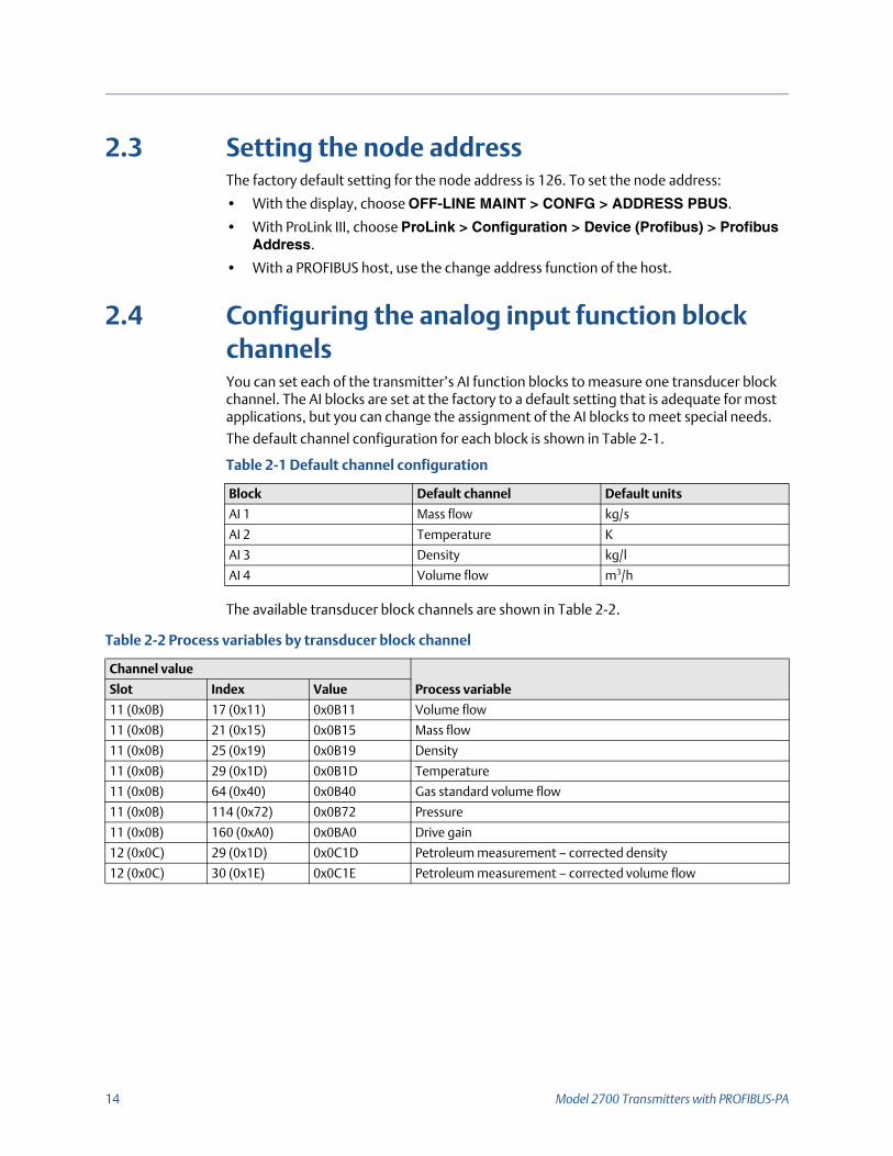
2.4 Configuring the analog input function block channelsYou can set each of the transmitter’s AI function blocks to measure one transducer block channel. The AI blocks are set at the factory to a default setting that is adequate for most applications, but you can change the assignment of the AI blocks to meet special needs.
The default channel configuration for each block is shown in Table 2-1.
The available transducer block channels are shown in Table 2-2.
Table 2-1 Default channel configuration
Block Default channel Default units
AI 1 Mass flow kg/s
AI 2 Temperature K
AI 3 Density kg/l
AI 4 Volume flow m3/h
Table 2-2 Process variables by transducer block channel
Channel value
Process variableSlot Index Value
11 (0x0B) 17 (0x11) 0x0B11 Volume flow
11 (0x0B) 21 (0x15) 0x0B15 Mass flow
11 (0x0B) 25 (0x19) 0x0B19 Density
11 (0x0B) 29 (0x1D) 0x0B1D Temperature
11 (0x0B) 64 (0x40) 0x0B40 Gas standard volume flow
11 (0x0B) 114 (0x72) 0x0B72 Pressure
11 (0x0B) 160 (0xA0) 0x0BA0 Drive gain
12 (0x0C) 29 (0x1D) 0x0C1D Petroleum measurement – corrected density
12 (0x0C) 30 (0x1E) 0x0C1E Petroleum measurement – corrected volume flow

Configuration and Use Manual 15
To configure the AI function block channels:
• With the EDD, bus parameters, or ProLink III, see the menu flowcharts in Figure 2-1
• With the display, see the menu flowchart in Appendix 2-14
12 (0x0C) 31 (0x1F) 0x0C1F Petroleum measurement – average corrected density
12 (0x0C) 32 (0x20) 0x0C20 Petroleum measurement – average corrected temp
12 (0x0C) 33 (0x21) 0x0C21 Petroleum measurement – CTL
12 (0x0C) 47 (0x2F) 0x0C2F Concentration measurement – reference density
12 (0x0C) 48 (0x30) 0x0C30 Concentration measurement – specific gravity
12 (0x0C) 49 (0x31) 0x0C31 Concentration measurement – standard volume flow
12 (0x0C) 50 (0x32) 0x0C32 Concentration measurement – net mass flow
12 (0x0C) 51 (0x33) 0x0C33 Concentration measurement – net volume flow
12 (0x0C) 52 (0x34) 0x0C34 Concentration measurement – concentration
12 (0x0C) 53 (0x35) 0x0C35 Concentration measurement – Baume
Table 2-2 Process variables by transducer block channel

16 Model 2700 Transmitters with PROFIBUS-PA
Figure 2-1 Configuring channels and units – EDD, bus parameters, and ProLink III
2.5 Setting the I/O modeThe transmitter can function in two different I/O modes: Profile-specific and Manufacturer-specific. The factory default is Manufacturer-specific. The two modes control which function blocks are available for use, and whether the format of the status byte is “classic” or “condensed.” (See Appendix D for more information on the format of
ProLink III
Function blocks tab
Apply
ProLink > Configuration
Select a channel for each AI function block
Select units for each AI and AO function block
EDD
Bus parameters
Block: Analog Input Block (Slots 1, 2, 3, and 5)Index: 30 (transducer block channel)Channel
Block: Analog Input Block (Slots 1, 2, 3, and 5)Index 28, Parameter 3 (units index)AI Block units
Block: Analog Output Block (Slots 9 and 10)Index 27, Parameter 3 (units index)
AO Block units
Block: Analog Input Block (Slots 1, 2, 3, and 5)Index: 30 (transducer block channel)Channel
Block: Analog Input Block (Slots 1, 2, 3, and 5)Index 28, Parameter 3 (units index)AI Block units
Block: Analog Output Block (Slots 9 and 10)Index 27, Parameter 3 (units index)
AO Block units

Configuration and Use Manual 17
the status byte.)
• In Profile-specific mode, the transmitter has the use of three AI blocks and one totalizer block. The status byte output format defaults to classic mode.
• In Manufacturer-specific mode, the transmitter has the use of four AI blocks, four totalizer blocks, and two AO blocks. The status byte output format defaults to condensed mode.
Refer to Table 2-3 for the slot identifications and blocks permitted by each mode. You must select modules exactly as described in Table 2-3, or select an empty module for slots that you do not intend to use. If any modules are left unconfigured, the transmitter will not send data.
To set the I/O mode of the transmitter:
• With the EDD or bus parameters, see the menu flowcharts in Figure 2-2.
• With the display, choose OFFLINE_MAINT > CONFG > IDENT SEL.
Figure 2-2 Setting the I/O mode
There are two GSD files that correspond to the two I/O modes. If you are using a PROFIBUS host with GSD files to operate the transmitter, you must use the GSD that corresponds to the I/O mode you have chosen. Table 2-4 lists the GSD file names. Load the correct GSD file into your PROFIBUS host or configuration tool.
Table 2-3 I/O mode slot configuration
Slot Profile-specific mode Manufacturer-specific mode
1 AI 1 AI 1
2 AI 2 AI 2
3 AI 3 AI 3
4 Totalizer 1 Totalizer 1
5 AI 4
6 Totalizer 2
7 Totalizer 3
8 Totalizer 4
9 AO 1
10 AO 2
Note:Set the I/O mode in the Physical Block before loading the GSD file.
EDD Bus parameters

18 Model 2700 Transmitters with PROFIBUS-PA
2.5.1 Overriding the status byte formatEach I/O mode has a default status byte format – classic or condensed. To override this default:
• With the GSD, set the Condensed Status parameterization bit to either 1 (for condensed status) or 0 (for classic status).
• With the EDD or bus parameters, use the menu flowcharts in Figure 2-3.
Figure 2-3 Status byte format
2.6 Configuring the totalizer block modeThe behavior of the four totalizer function blocks can be configured in two ways:
•Standard, which provides standard PROFIBUS totalizer function block behavior.
In this mode, the totalizer block will integrate whatever data it receives. The Out value of a totalizer in this mode has no relationship to the totalizer data reported by the transducer block, ProLink III, or the display.
• Any of the values in Table 2-5, which cause the totalizer function block to pass through the specified totalizer value from the transducer block.
Micro Motion recommends using one of these modes, because the totalizer block output will be more accurate and will match readings taken with ProLink III and the display.
To configure the totalizer block mode:
• With the EDD or bus parameters, refer to the menu flowcharts in Figure 2-4
• With the display, refer to the menu flowcharts inAppendix 2-16
Table 2-4 PROFIBUS GSD filenames
Identification number GSD file name
Profile specific PA139742.GSD
Manufacturer specific V4x_057A.gsd
Block: Physical Block 1 (Slot 0)Index 43 (Condensed status diagnostics)Status byte format
EDD Bus parameters

Configuration and Use Manual 19
Figure 2-4 Configuring totalizer function block mode
Table 2-5 Process variables by transducer block channel
Channel value
Process variableSlot Index Value
11(0x0B) 17(0x11) 0x0B11 Volume flow
11(0x0B) 21(0x15) 0x0B15 Mass flow
11(0x0B) 64(0x40) 0x0B40 Gas standard volume flow
12(0x0C) 30(0x1E) 0x0C1E Petroleum measurement – corrected volume flow
12(0x0C) 49(0x31) 0x0C31 Concentration measurement – standard volume flow
12(0x0C) 50(0x32) 0x0C32 Concentration measurement – net mass flow
12(0x0C) 51(0x33) 0x0C33 Concentration measurement – net volume flow
EDD
Block: Totalizer 1 (Slot 4)Index 52 (set to Mode value from table)
Mode
Block: Totalizer 1 (Slot 4)Index 52 (set to Mode value from table)
Block: Totalizer 1 (Slot 4)Index 52 (set to Mode value from table)
Block: Totalizer 1 (Slot 4)Index 52 (set to Mode value from table)
Bus parameters
MMI Coriolis Flow > Function Block
Totalizer 1 > Parameter
Integrator Function Block
Totalizer 2 > Parameter
Totalizer 3 > Parameter
Totalizer 4 > Parameter
Selection

20 Model 2700 Transmitters with PROFIBUS-PA
2.7 Configuring pressure compensation Due to process pressure change away from calibration pressure, there can be a change in sensor flow and density sensitivity. This change is called pressure effect. Pressure compensation corrects for these changes.
Not all sensors and applications require pressure compensation. Contact Micro Motion Customer Service before you configure pressure compensation.
Configuring pressure compensation requires three steps:
1. Determining pressure compensation values (Section2.7.1)
2. Enabling pressure compensation (Section2.7.2)
3. Selecting a pressure source (Section2.7.3)
2.7.1 Pressure compensation valuesThere are three values involved in pressure compensation:
• Flow factor – The flow factor is the percent change in flow rate per psi. Consult the product data sheet for your sensor for this value. You will need to reverse the sign of the flow factor. For example, if the flow factor in the product data sheet is –0.001% per psi, the pressure compensation flow factor would be +0.001% per psi.
• Density factor – The density factor is the change in fluid density, in g/cm3 per psi. Consult the product data sheet for your sensor for this value. You will need to reverse the sign of the density factor. For example, if the density factor in the product data sheet is –0.00004 g/cm3 per psi, the pressure compensation flow factor would be +0.00004 g/cm3 per psi.
• Flow calibration pressure – The pressure at which the flowmeter was calibrated. Refer to the calibration document shipped with your sensor. If the data is unavailable, use 20 psi (1,4 bar).
2.7.2 Enabling pressure compensationTo enable pressure compensation, see the menu flowcharts in Figure 2-5. You will need the three pressure compensation values from Section2.7.1.

Configuration and Use Manual 21
Figure 2-5 Enabling pressure compensation
Block: Transducer Block 1 (Slot 11)Index 112 (enable pressure compensation)
Enable pressure comp.
Block: Transducer Block 1 (Slot 11)Index 116 (flow factor)Index 117 (density factor)Index 118 (flow calibration pressure)
Pressure correction values
Block: Transducer Block 1 (Slot 11)Index 115 (pressure units)Pressure units
Block: Transducer Block 1 (Slot 11)Index 113 (pressure value)
Optional: Fixed pressure value
View > Preferences
Select Enable External Pressure Compensation
Apply
ProLink > Configuration
Enter values:Flow factor in Flow factorboxDensity factor in Densfactor boxFlow calibration pressure in Cal pressure box
Apply
Pressure tab
Set pressure units to match source
Optional: Enter a fixed pressure value in the External Pressure box
EDD Bus parameters
ProLink III
22 Model 2700 Transmitters with PROFIBUS-PA
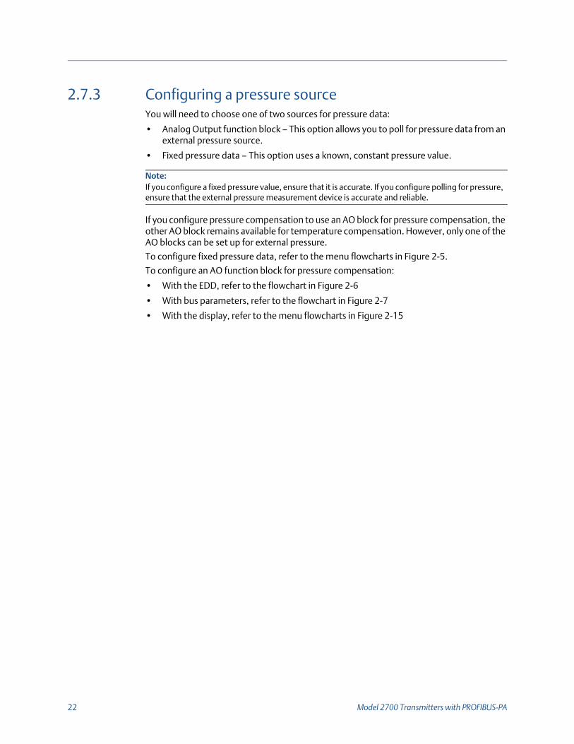
2.7.3 Configuring a pressure sourceYou will need to choose one of two sources for pressure data:
• Analog Output function block – This option allows you to poll for pressure data from an external pressure source.
• Fixed pressure data – This option uses a known, constant pressure value.
If you configure pressure compensation to use an AO block for pressure compensation, the other AO block remains available for temperature compensation. However, only one of the AO blocks can be set up for external pressure.
To configure fixed pressure data, refer to the menu flowcharts in Figure 2-5.
To configure an AO function block for pressure compensation:
• With the EDD, refer to the flowchart in Figure 2-6
• With bus parameters, refer to the flowchart in Figure 2-7
• With the display, refer to the menu flowcharts in Figure 2-15
Note:If you configure a fixed pressure value, ensure that it is accurate. If you configure polling for pressure, ensure that the external pressure measurement device is accurate and reliable.

Configuration and Use Manual 23
Figure 2-6 Configuring an AO function block for pressure compensation – EDD
Figure 2-7 Configuring an AO function block for pressure compensation – Bus parameters
2.8 Configuring temperature compensationExternal temperature compensation can be used with the petroleum measurement application or the enhanced density application:
•If external temperature compensation is enabled, an external temperature value (or a fixed temperature value), rather than the temperature value from the Coriolis sensor,
Function Block
Analog Output 1
Set IN Channel to Pressure
Parameters > General
Analog Output 2
MMI Coriolis Flow
Transducer Block
Compensation
AO Compensation
Note:When setting the IN channel to Pressure via the EDD, the OUT channel will be automatically set to Pressure as well. Setting the IN channel via bus parameters does not automatically change the OUT channel. You must manually set the OUT channel to Pressure or the block will go into Out of Service mode.
Block: Analog Output Block (Slots 9 and 10)Index 37 (IN channel), value = 0x0b72Index 38 (OUT channel), value = 0x0b72
Configure channel
Block: Transducer Block 1 (Slots 11)Index 121 (AO Compensation), value = 1Configure channel

24 Model 2700 Transmitter with PROFIBUS-PA
is used in petroleum measurement or enhanced density calculations only. The temperature value from the Coriolis sensor is used for all other calculations.
•If external temperature compensation is disabled, the temperature value from the Coriolis sensor is used in all calculations.
Configuring temperature compensation requires two steps:
1. Enabling external temperature compensation (Section2.8.1)
2. Configuring a temperature source (Section2.8.2)
2.8.1 Enabling external temperature compensationTo enable temperature compensation, refer to the flowcharts in Figure 2-8.
Figure 2-8 Enabling external temperature compensation
2.8.2 Configuring a temperature sourceExternal temperature data is reported through an analog output (AO) function block. The transmitter has two AO blocks, each of which can be assigned to a compensation variable channel.
To configure an AO function block for temperature compensation:
• With the EDD, refer to the flowchart in Figure 2-9
• With bus parameters, refer to the flowchart in Figure 2-10
• With the display, refer to the flowcharts in Figure 2-15
MMI Coriolis Flow > Transducer Block > Compensation > Temperature
Enable Disable Ext Temp
EDD
Block: Transducer Block 1 (Slot 11)Index 110 (enable temperature compensation)
Enable temperature comp.
Bus parameters
View > Preferences
Select Use External Temperature
Apply
ProLink III
Configuration and Use Manual 25
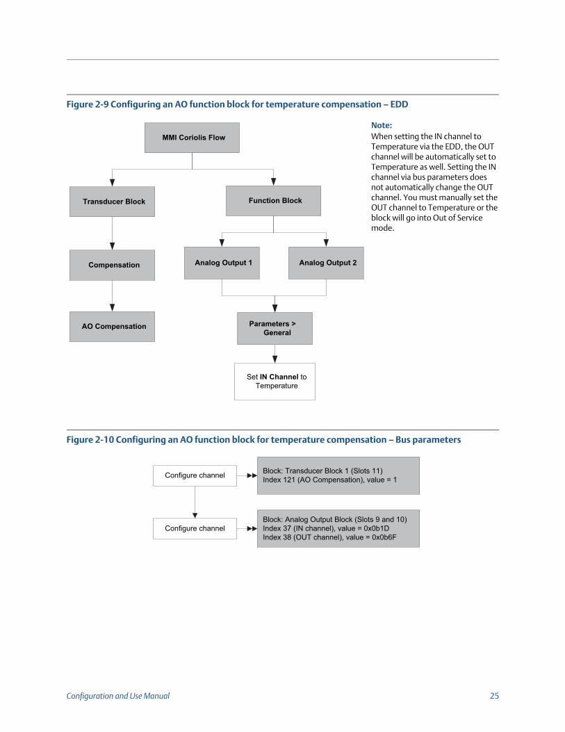
Figure 2-9 Configuring an AO function block for temperature compensation – EDD
Figure 2-10 Configuring an AO function block for temperature compensation – Bus parameters
Function Block
Analog Output 1
Set IN Channel to Temperature
Parameters > General
Analog Output 2
MMI Coriolis Flow
Transducer Block
Compensation
AO Compensation
Note:When setting the IN channel to Temperature via the EDD, the OUT channel will be automatically set to Temperature as well. Setting the IN channel via bus parameters does not automatically change the OUT channel. You must manually set the OUT channel to Temperature or the block will go into Out of Service mode.
Block: Analog Output Block (Slots 9 and 10)Index 37 (IN channel), value = 0x0b1DIndex 38 (OUT channel), value = 0x0b6F
Configure channel
Block: Transducer Block 1 (Slots 11)Index 121 (AO Compensation), value = 1Configure channel

26 Model 2700 Transmitters with PROFIBUS-PA
Configuration and Use Manual 27
3 Calibration
3.1 OverviewThis chapter describes the following procedures:
• Characterization (Section 3.3)
• Smart Meter Verification (Section 3.4)
• Meter validation and adjusting meter factors (Section 3.5)
• Zero calibration (Section 3.6)
• Density calibration (Section 3.7)
• Temperature calibration (Section 3.8)
3.2 Characterization, Smart Meter Verification, meter validation, and calibrationThere are four procedures:
• Characterization – adjusts the transmitter to compensate for the unique traits of the sensor with which it is paired
• Smart Meter Verification – establishing confidence in the sensor’s performance by analyzing secondary variables that are highly correlated with flow and density calibration factors
• Meter validation – confirming performance by comparing the sensor’s measurements to a primary standard
• Calibration – establishing the relationship between a process variable (flow, density, or temperature) and the signal produced by the sensor, or establishing the transmitter’s response to a zero-flow condition.
Meter validation, characterization, and calibration are available on all Model 2700 transmitters. Smart Meter Verification is available only if the Smart Meter Verification option was ordered with the transmitter.
These four procedures are discussed and compared in Sections 3.2.1 through 3.2.4. Before performing any of these procedures, review these sections to ensure that you will be performing the appropriate procedure for your purposes.
3.2.1 CharacterizationCharacterizing the flowmeter adjusts the transmitter to compensate for the unique traits of the sensor it is paired with. Characterization parameters (sometimes called “calibration factors”) describe the sensor’s sensitivity to flow, density, and temperature.
Note:All procedures provided in this chapter assume that you have established communication with the transmitter and that you are complying with all applicable safety requirements. See Appendix C or the documentation for your PROFIBUS host or configuration tool.

28 Model 2700 Transmitters with PROFIBUS-PA
If the transmitter and the sensor were ordered together as a Coriolis flowmeter, then the flowmeter has already been characterized. Under some circumstances (typically when pairing a sensor and transmitter together for the first time), you may need to re-enter characterization data. If you are unsure about whether you should characterize your flowmeter, contact Micro Motion Customer Service.
3.2.2 Smart Meter VerificationSmart Meter Verification evaluates the structural integrity of the sensor tubes by comparing current tube stiffness to the stiffness measured at the factory. Stiffness is defined as the load per unit deflection, or force divided by displacement. Because a change in structural integrity changes the sensor’s response to mass and density, this value can be used as an indicator of measurement performance. Changes in tube stiffness are typically caused by erosion, corrosion, or tube damage.
Smart Meter Verification does not affect measurement in any way. Micro Motion recommends performing Smart Meter Verification at regular intervals.
3.2.3 Meter validation and meter factorsMeter validation compares a measurement value reported by the transmitter with an external measurement standard. Meter validation requires one data point.
If the transmitter’s mass flow, volume flow, or density measurement is significantly different from the external measurement standard, you may want to adjust the corresponding meter factor. A meter factor is the value by which the transmitter multiplies the process variable value. The default meter factors are 1.0, resulting in no difference between the data retrieved from the sensor and the data reported externally.
Meter factors are typically used for proving the flowmeter against a Weights & Measures standard. You may need to calculate and adjust meter factors periodically to comply with regulations.
3.2.4 CalibrationThe flowmeter measures process variables based on fixed points of reference. Calibration adjusts those points of reference. Three types of calibration can be performed:
• Zero
• Density calibration
• Temperature calibration
Density and temperature calibration require two data points (low and high) and an external measurement for each. The density and temperature calibration procedure changes the offset and/or the slope of the line that represents the relationship between process density and the reported density value, or the relationship between process temperature and the reported temperature value.
Note:For meter validation to be useful, the external measurement standard must be more accurate than the sensor. See the sensor’s product data sheet for its accuracy specification
Note:For density or temperature calibration to be useful, the external measurements must be accurate.

Configuration and Use Manual 29
Zero calibration requires only that flow through the sensor is stopped.
Flowmeters are calibrated at the factory, and normally do not need to be calibrated in the field. Calibrate the flowmeter only if you must do so to meet regulatory requirements. Contact Micro Motion before calibrating your flowmeter.
3.2.5 Comparison and recommendationsWhen choosing among Smart Meter Verification, meter validation, and calibration, consider the following factors:
•Process and measurement interruption
- Smart Meter Verification provides an option that allows process measurement to continue during the test.
- Meter validation for density does not interrupt the process. However, meter validation for mass flow or volume flow requires process down-time for the length of the test.
- Calibration requires process down-time. In addition, density and temperature calibration require replacing the process fluid with low-density and high density fluids, or low-temperature and high-temperature fluids. Zero calibration requires stopping flow through the sensor.
•External measurement requirements
- Smart Meter Verification does not require external measurements.
- Zero calibration does not require external measurements.
- Density calibration, temperature calibration, and meter validation require external measurements. For good results, the external measurement must be highly accurate.
•Measurement adjustment
- Smart Meter Verification is an indicator of sensor condition, but does not change flowmeter internal measurement in any way.
- Meter validation does not change flowmeter internal measurement in any way. If you decide to adjust a meter factor as a result of a meter validation procedure, only the reported measurement is changed—the base measurement is not changed. You can always reverse the change by returning the meter factor to its previous value.
- Calibration changes the transmitter’s interpretation of process data, and accordingly changes the base measurement. If you perform a zero calibration, you can return to the factory zero (or, if using ProLink III, the previous zero). However, if you perform a density calibration or a temperature calibration, you cannot return to the previous calibration factors unless you have manually recorded them.
Micro Motion recommends obtaining the Smart Meter Verification transmitter option and performing Smart Meter Verification on a regular basis.
Note:Micro Motion recommends using meter validation and meter factors, rather than calibration, to prove the meter against a regulatory standard or to correct measurement error.

30 Model 2700 Transmitters with PROFIBUS-PA
3.3 Performing a characterizationCharacterizing a flowmeter involves entering parameters that are printed on the sensor tag.
3.3.1 Characterization parametersThe characterization parameters that must be entered depend on the sensor type: “T-Series” or “Other,” as listed in Table 3-1. The “Other” category includes all Micro Motion sensors except T-Series.
The characterization parameters are provided on the sensor tag. The format of the sensor tag varies depending on your sensor’s date of purchase. See Figures 3-1 and 3-2 for illustrations of newer and older sensor tags.
Table 3-1 Sensor characterization parameters
Characterization data EDD label Bus parameter index
Sensor type
T-Series Other
K1(1)
(1) See the section entitled “Density calibration factors.”
K1 92 3 3
K2(1) K2 93 3 3
FD(1) FD 94 3 3
D1(1) D1 97 3 3
D2(1) D2 98 3 3
DT or TC(1) Density Temp Coeff (DT) 102 3 3
Flow cal(2)
(2) See the section entitled “Flow calibration values.”
FD Value 99 3
FCF(2) FD Value 99 3
FT(2) FD Value 99 3
FTG FTG 103 3
FFQ FFQ 104 3
DTG DTG 105 3
DFQ1 DFQ1 106 3
DFQ2 DFQ2 107 3

Configuration and Use Manual 31
Figure 3-1 Sample calibration tags – All sensors except T-Series
Figure 3-2 Sample calibration tags – T-Series sensors
Density calibration factorsIf your sensor tag does not show a D1 or D2 value:
• For D1, enter the Dens A or D1 value from the calibration certificate. This value is the line-condition density of the low-density calibration fluid. Micro Motion uses air.
• For D2, enter the Dens B or D2 value from the calibration certificate. This value is the line-condition density of the high-density calibration fluid. Micro Motion uses water.
If your sensor tag does not show a K1 or K2 value:
• For K1, enter the first 5 digits of the density calibration factor. In the sample tag in Figure 3-1, this value is shown as 12500.
• For K2, enter the second 5 digits of the density calibration factor. In the sample tag in Figure 3-1, this value is shown as 14286.
If your sensor does not show an FD value, contact Micro Motion customer service. If your sensor tag does not show a DT or TC value, enter the last 3 digits of the density calibration factor. In the sample tag in Figure 3-1, this value is shown as 4.44.
Newer tag Older tag
19.0005.13
19.0005.130.00100.9980
12502.00014282.000
4.44000 310
12502142824.44
12500142864.44
Newer tag Older tag

32 Model 2700 Transmitters with PROFIBUS-PA
Flow calibration valuesTwo separate values are used to describe flow calibration: a 6-character FCF value (including one decimal point) and a 4-character FT value (including one decimal point). During characterization, these are entered as a single 10-character string that includes two decimal points. In ProLink III, this value is called the Flowcal parameter.
To obtain the required value:
• For older T-Series sensors, concatenate the FCF value and the FT value from the sensor tag, as shown below.
• For newer T-Series sensors, the 10-character string is represented on the sensor tag as the FCF value. The value should be entered exactly as shown, including the decimal points. No concatenation is required.
• For all other sensors, the 10-character string is represented on the sensor tag as the Flow Cal value. The value should be entered exactly as shown, including the decimal points. No concatenation is required.
Flow FCF X.XXXX FT X.XX

Configuration and Use Manual 33
3.3.2 How to characterizeTo characterize the flowmeter, refer to Table 3-1 and the menu flowcharts in Figure 3-3.
Figure 3-3 Characterizing the flowmeter
EDD
Bus parameters
ProLink III
Calibration > Density
Enter values from sensor tag
MMI Coriolis Flow > Transducer Block
Sensor Type Code• Curved Tube• Straight Tube
Device Information
ProLink > Configuration
Device tab
Sensor Type
Flow tab
Enter values from sensor tag
Density tab
Enter values from sensor tag
(1)Refer to Table 3-1 for bus parameter indices.
Block: Transducer Block 2 (Slot 12)Index 12 (sensor type code)Sensor type
Block: Transducer Block 1 (Slot 11)See note (1)Flow values
Block: Transducer Block 1 (Slot 11)See note (1)Density values

34 Model 2700 Transmitters with PROFIBUS-PA
3.4 Performing Smart Meter Verification
3.4.1 Preparing for the Smart Meter Verification testThe Smart Meter Verification procedure can be performed on any process fluid. It is not necessary to match factory conditions.
During the test, process conditions must be stable. To maximize stability:
•Maintain a constant temperature and pressure.
•Avoid changes to fluid composition (e.g., two-phase flow, settling, etc.).
•Maintain a constant flow. For higher test certainty, stop flow.
If stability varies outside test limits, the Smart Meter Verification procedure will be aborted. Verify the stability of the process and retry the test.
Transmitter configurationSmart Meter Verification is not affected by any parameters configured for flow, density, or temperature. It is not necessary to change the transmitter configuration.
Control loops and process measurementIf the transmitter outputs will be set to Last Measured Value or Fault during the test, the outputs will be fixed for two minutes. Disable all control loops for the duration of the test, and ensure that any data reported during this period is handled appropriately.
3.4.2 Running the Smart Meter Verification testTo run a Smart Meter Verification test:
• With the EDD, refer to Figure 3-4
• With bus parameters, refer to Figure 3-5 and to Table 3-2
• With ProLink III, refer to Figure 3-6
• With the display, refer to Figure 2-6
Note:To use Smart Meter Verification, the transmitter must be paired with an enhanced core processor, and the Smart Meter Verification option must be purchased for the transmitter.

Configuration and Use Manual 35
Figure 3-4 Smart Meter Verification – EDD
Device > Meter Verification
Start/Abort Meter Verification
Start Meter VerificationEnable MV
Select AlarmLast ValueFault ModeContinuemeasurement
Meter Verification in Progress
Meter verification PASSED
Meter verification FAILED
Abort Meter Verification
Manual Abort by End User
Meter verification error
Start Meter Verification

36 Model 2700 Transmitters with PROFIBUS-PA
Figure 3-5 Smart Meter Verification – bus parameters
Step 2Start/abort procedure
Step 1Set output state (optional)
Able to complete?
Step 8Check abort code
Yes (>0)
Step 3Check current algorithm state
Running? Step 4Read percent complete
Yes (=16) Step 6Check inlet stiffness
Within limits?No (>0)
Yes (=0)
Step 7Check outlet stiffness
Within limits?No (>0)
Yes (=0)
CAUTION PASS
No (<16)
No (=0)
Manual abort (optional)
Step 5Check algorithm abort state

Configuration and Use Manual 37
Table 3-2 PROFIBUS parameters for Smart Meter Verification
Step number Step description Parameters
1 Set output state Block: Transducer block 1
Index: 182
Value:
0: Last measured value (default)
1: Fault
2 Start/abort procedure Block: Transducer block 1
Index: 72 (Start/Stop Meter Verification)
0x00: No effect
0x01: Start On-Line Meter Verification
3 Check current algorithm state Block: Transducer block 1
Index: 75
Value:
Bits 4–6: State
4 Read percent complete Block: Transducer block 1
Index: 189 (Progress)
5 Check algorithm abort state Block: Transducer block 1
Index: 75
Value:
Bits 0–3: Abort code
6 Check inlet stiffness Block: Transducer block 1
Index: 77
0: Within uncertainty limit
1: Outside uncertainty limit
7 Check outlet stiffness Block: Transducer block 1
Index: 78
0: Within uncertainty limit
1: Outside uncertainty limit
8 Read abort code Block: Transducer block 1
Index: 185
Codes: See Table 3-3

38 Model 2700 Transmitters with PROFIBUS-PA
Figure 3-6 Smart Meter Verification – ProLink III
Verify configuration parameters
Tools > Meter Verification > Run Meter Verification
Enter descriptive data(optional)
Select output behavior
Reruntest?
Test result chart
Configuration Changedor Zero Changed?
View details (optional)
Yes
Next
View Previous Results
Next
Report
Test resultFail Pass
Yes NoBackNext
Next
Finish
Start Meter Verification
---------------------
No
Abort

Configuration and Use Manual 39
3.4.3 Reading and interpreting Smart Meter Verification test resultsPass/Fail/AbortWhen the Smart Meter Verification test is completed, the result will be reported as Pass, Fail/Caution (depending on the tool you are using), or Abort:
•Pass – The test result is within the specification uncertainty limit. In other words, the stiffness of the left and right pickoffs match the factory values plus or minus the specification uncertainty limit. If transmitter zero and configuration match factory values, the sensor will meet factory specifications for flow and density measurement. It is expected that meters will pass Smart Meter Verification every time the test is run.
•Fail/Caution – The test result is not within the specification uncertainty limit. Micro Motion recommends that you immediately repeat the Smart Meter Verification test. If you previously set outputs to Continue Measurement, change the setting to Last Measured Value or Fault.
- If the meter passes the second test, the first Fail/Caution result can be ignored.
- If the meter fails the second test, the flow tubes may be damaged. Use your process knowledge to determine the possibilities for damage and the appropriate actions for each. These actions might include removing the meter from service and physically inspecting the tubes. At minimum, you should perform a flow validation and a density calibration.
•Abort – A problem occurred with the Smart Meter Verification test (e.g., process instability). Abort codes are listed in Table 3-3, and suggested actions are provided for each code.
Table 3-3 Smart Meter Verification abort codes
Abort code Description Suggested action
1 User-initiated abort None required. Wait for 15 seconds before starting another test.
3 Frequency drift Ensure that temperature, flow, and density are stable, and rerun the test.
5 High drive gain Ensure that flow is stable, minimize entrained gas, and rerun the test.
8 Unstable flow Review the suggestions for stable flow in Section 3.4.1 and rerun the test.
13 No factory reference data for Smart Meter Verification test performed on air
Contact Micro Motion customer service and provide the abort code.
14 No factory reference data for Smart Meter Verification test performed on water
Contact Micro Motion customer service and provide the abort code.
15 No configuration data for Smart Meter Verification
Contact Micro Motion customer service and provide the abort code.
Other General abort Repeat the test. If the test aborts again, contact Micro Motion customer service and provide the abort code.

40 Model 2700 Transmitters with PROFIBUS-PA
Detailed test data with ProLink IIIFor each test, the following data is stored on the transmitter:
• Powered-on seconds at the time of the test
• Test result
• Stiffness of the left and right pickoffs, shown as percentage variation from the factory value. If the test aborted, 0 is stored for these values.
• Abort code, if applicable
ProLink III stores additional descriptive information for each test in a database on the local PC, including:
• Timestamp from the PC clock
• Current flowmeter identification data
• Current flow and density configuration parameters
• Current zero values
• Current process values for mass flow rate, volume flow rate, density, temperature, and external pressure
• (Optional) User-entered customer and test descriptions
If you run a Smart Meter Verification test from ProLink III, ProLink III first checks for new test results on the transmitter and synchronizes the local database if required. During this step, ProLink III displays the following message:
Synchronizing x out of yPlease wait
Test results are available at the end of each test, in the following forms:
A test result chart (see Figure 3-7).
A test report that includes the descriptive information for the current test, the test result chart, and background information about Smart Meter Verification. You can export this report to an HTML file or print it to the default printer.
Note:If you request an action while synchronization is in process, ProLink III displays a message asking whether or not you want to complete synchronization. If you choose No, the ProLink III database may not include the latest test results from the transmitter.
Note:To view the chart and the report for previous tests without running a test, click View Previous Test Results and Print Report from the first Smart Meter Verification panel. See Figure 3-7. Test reports are available only for tests initiated from ProLink III.

Configuration and Use Manual 41
Figure 3-7 Test result chart
The test result chart shows the results for all tests in the ProLink III database, plotted against the specification uncertainty limit. The inlet stiffness and the outlet stiffness are plotted separately. This helps to distinguish between local and uniform changes to the sensor tubes.
This chart supports trend analysis, which can be helpful in detecting meter problems before they become severe.
Note the following:
• The test result chart may not show all test results, and test counters may not be continuous. ProLink III stores information about all tests initiated from ProLink III and all tests available on the transmitter when the test database is synchronized. However, the transmitter stores only the twenty most recent test results. To
Initiated from ProLink IIIInitiated from the display or other tool

42 Model 2700 Transmitters with PROFIBUS-PA
ensure a complete result set, always use ProLink III to initiate the tests, or synchronize the ProLink III database before overwriting occurs.
• The chart uses different symbols to differentiate between tests initiated from ProLink III and tests initiated using a different tool. A test report is available only for tests that were initiated from ProLink III.
• You can double-click the chart to manipulate the presentation in a variety of ways (change titles, change fonts, colors, borders and gridlines, etc.), and to export the data to additional formats (including “to printer”).
• You can export this chart to a CSV file for use in external applications.
Detailed test data with the displayFor each Smart Meter Verification test, the following data is stored on the transmitter:
• Powered-on seconds at the time of the test
• Test result
• Stiffness of the left and right pickoffs, shown as percentage variation from the factory value. If the test aborted, 0 is stored for these values.
• Abort code, if applicable
To view this data, refer to the menu flowchart in Figure 2-7.
3.4.4 Setting up automatic or remote execution of the Smart Meter Verification testThere are two ways to execute a Smart Meter Verification test automatically:
• Set up a one-time automatic execution
• Set up a recurring execution
To set up a one-time automatic execution, set up a recurring execution, view the number of hours until the next scheduled test, or delete a schedule:
• With ProLink III, choose Tools > Meter Verification > Schedule Meter Verification.
• With the EDD, choose Device > Meter Verification.
• With the display, see Figure 2-8.
Note the following:
• If you are setting up a one-time automatic execution, specify the start time as a number of hours from the present time. For example, if the present time is 2:00 and you specify 3.5 hours, the test will be initiated at 5:30.
• If you are setting up a recurring execution, specify the number of hours to elapse between executions. The first test will be initiated when the specified number of hours has elapsed, and testing will be repeated at the same interval until the schedule is deleted. For example, if the present time is 2:00 and you specify 2 hours, the first test will be initiated at 4:00, the next at 6:00, and so on.
• If you delete the schedule, both the one-time execution and the recurring execution settings are deleted.

Configuration and Use Manual 43
3.5 Performing meter validationTo perform meter validation:
1. Determine the meter factor(s) to use. You may set any combination of the mass flow, volume flow, and density meter factors.Note that all three meter factors are independent:
• The mass flow meter factor affects only the value reported for mass flow.
• The density meter factor affects only the value reported for density.
• The volume flow meter factor affects only the value reported for volume flow.
Therefore, to adjust volume flow, you must set the meter factor for volume flow. Setting a meter factor for mass flow and a meter factor for density will not produce the desired result. The volume flow calculations are based on original mass flow and density values, before the corresponding meter factors have been applied.
2. Calculate the meter factor as follows:
a. Sample the process fluid and record the process variable value reported by the flowmeter.
b. Measure the sample using an external standard.
c. Calculate the new meter factor using the following formula:
If you are calculating the volume flow meter factor, note that proving volume in the field may be expensive, and the procedure may be hazardous for some process fluids. Therefore, because volume is inversely proportional to density, an alternative to direct sampling and measurement is to calculate the volume flow meter factor from the density meter factor. This method provides partial correction by adjusting for any portion of the total offset that is caused by density measurement offset. Use this method only when a volume flow reference is not available, but a density reference is available. To use this method:
d. Calculate the meter factor for density, using the preceding formula.
e. Calculate the volume flow meter factor from the density meter factor, as shown below:
3. Ensure that the meter factor is between 0.8 and 1.2, inclusive. If the calculated meter factor is outside these limits, contact Micro Motion customer service.
Note:This equation is mathematically equivalent to the equation shown below. You may use whichever equation you prefer
NewMeterFactor ConfiguredMeterFactor ExternalStandardActualFlowmeterMeasurement---------------------------------------------------------------------------------=
MeterFactorVolume1
MeterFactorDensity-----------------------------------------------=
MeterFactorVolume ConfiguredMeterFactorDensity
DensityFlowmeter
DensityExternalStandard-------------------------------------------------------=

44 Model 2700 Transmitters with PROFIBUS-PA
To adjust meter factors:
• With the EDD, bus parameters, or ProLink III, refer to the menu flowcharts in Figure 3-8.
• With the display, refer to the menu flowchart in Figure 2-12.
Example The flowmeter is installed and proved for the first time. The flowmeter mass measurement is 250.27 lb; the reference device measurement is 250 lb. A mass flow meter factor is determined as follows:
The first mass flow meter factor is 0.9989.
One year later, the flowmeter is proved again. The flowmeter mass measurement is 250.07 lb; the reference device measurement is 250.25 lb. A new mass flow meter factor is determined as follows:
The new mass flow meter factor is 0.9996.
MeterFactorMassFlow 1 250250.27------------------ 0.9989= =
MeterFactorMassFlow 0.9989 250.25250.07------------------ 0.9996= =

Configuration and Use Manual 45
Figure 3-8 Adjusting meter factors
3.6 Performing zero calibrationZeroing the flowmeter establishes the flowmeter’s point of reference when there is no flow. The meter was zeroed at the factory, and should not require a field zero. However, you may wish to perform a field zero to meet local requirements or to confirm the factory zero.
When you zero the flowmeter, you may need to adjust the zero time parameter. Zero time is the length of time the transmitter takes to determine its zero-flow reference point. The default zero time is 20 seconds.
• A long zero time may produce a more accurate zero reference but is more likely to result in zero failure. This is due to the increased possibility of noisy flow, which causes incorrect calibration.
• A short zero time is less likely to result in a zero failure but may produce a less accurate zero reference.
For most applications, the default zero time is appropriate.
EDD
Block: Transducer Block 1 (Slot 11)Index 36 (Mass factor)Index 37 (Density factor)Index 38 (Volume factor)
Meter Factors
Bus parameters
ProLink III
MMI Coriolis Flow > Transducer Block
Mass Factor
Measurement > Process Variable
Mass Flow
Density Factor
Density
Volume Factor
Volume Flow

46 Model 2700 Transmitters with PROFIBUS-PA
If the transmitter is connected to an enhanced core processor, there are two recovery functions that may be used if the zero procedure fails:
• Restore prior zero – Available only from ProLink III and only during the current zero procedure. Once you have closed the Calibration dialog box or disconnected from the transmitter, you can no longer restore the prior zero.
• Restore factory zero – Always available via all configuration tools.
3.6.1 Preparing for the zeroing procedureTo prepare for the zeroing procedure:
1. Apply power to the flowmeter. Allow the flowmeter to warm up for approximately 20 minutes.
2. Run the process fluid through the sensor until the sensor temperature reaches the normal process operating temperature.
3. Close the shutoff valve downstream from the sensor.
4. Ensure that the sensor is completely filled with fluid and the flow through the sensor has completely stopped.
3.6.2 Zeroing procedureTo zero the flowmeter:
• With the EDD, refer to the menu flowchart in Figure 3-9
• With bus parameters, refer to the menu flowchart in Figure 3-10
• With ProLink III, refer to the menu flowchart in Figure 3-11
• With the display, refer to the menu flowchart in Figure 2-17
Note:Do not zero the flowmeter if a high severity alarm is active. Correct the problem, then zero the flowmeter. You may zero the flowmeter if a low severity alarm is active.
Note:If the flowmeter fails the zeroing procedure twice, refer to Section 6.6.
CAUTION!If fluid is flowing through the sensor, the sensor zero calibration may be inaccurate, resulting in inaccurate process measurement. To improve the sensor zero calibration and measurement accuracy, ensure that process flow through the sensor has completely stopped.

Configuration and Use Manual 47
Figure 3-9 Zeroing procedure – EDD
Figure 3-10 Zeroing procedure – Bus parameters
Calibration > Zero Cal
Modify zero time if desired
Start Zero Cal
Stop flow through sensor
Execute
Zero in progress
OK
Zeroing success Troubleshoot
Block: Transducer Block 1 (Slot 11)Index 13 (zero calibration)Initiate zero
Block: Transducer Block 1 (Slot 11)Index 83 (zero time)
Modify zero time (if desired)
Block: Transducer Block 1 (Slot 11)Index 12 (zero point)Check zero value
Block: Transducer Block 1 (Slot 11)Index 143, Bit 0x8000Check status
Block: Transducer Block 1 (Slot 11)Index 141, Bits 0x0100, 0x0200, 0x0400, and 0x0800
Check for failure alarms

48 Model 2700 Transmitters with PROFIBUS-PA
Figure 3-11 Zeroing procedure – ProLink III
3.7 Performing density calibrationDensity calibration includes the following calibration points:
• All sensors:
- D1 calibration (low-density)
- D2 calibration (high-density)
• T-Series sensors only:
- D3 calibration (optional)
- D4 calibration (optional)
Modify zero timeif required
CalibrationFailure LED
Calibration in Progress LED turns red
Green
Troubleshoot
Red
Perform Auto Zero
Done
ProLink > Calibration > Zero Calibration
Wait until Calibration in Progress LED turns green

Configuration and Use Manual 49
For T-Series sensors, the optional D3 and D4 calibrations could improve the accuracy of the density measurement. If you choose to perform the D3 and D4 calibrations:
• Do not perform the D1 or D2 calibrations.
• Perform the D3 calibration if you have one calibrated fluid.
• Perform both the D3 and D4 calibrations if you have two calibrated fluids (other than air and water).
The calibrations that you choose must be performed without interruption, in the order listed here.
3.7.1 Preparing for density calibrationBefore beginning density calibration, review the requirements in this section.
Sensor requirementsDuring density calibration, the sensor must be completely filled with the calibration fluid, and flow through the sensor must be at the lowest rate allowed by your application. This is usually accomplished by closing the shutoff valve downstream from the sensor, then filling the sensor with the appropriate fluid.
Density calibration fluidsD1 and D2 density calibration require a D1 (low density) fluid and a D2 (high density) fluid. You may use air and water. If you are calibrating a T-Series sensor, the D1 fluid must be air and the D2 fluid must be water.
For D3 density calibration, the D3 fluid must meet the following requirements:
• Minimum density of 0.6 g/cm3
• Minimum difference of 0.1 g/cm3 between the density of the D3 fluid and the density of water. The density of the D3 fluid may be either greater or less than the density of water.
For D4 density calibration, the D4 fluid must meet the following requirements:
• Minimum density of 0.6 g/cm3
• Minimum difference of 0.1 g/cm3 between the density of the D4 fluid and the density of the D3 fluid. The density of the D4 fluid must be greater than the density of the D3 fluid.
• Minimum difference of 0.1 g/cm3 between the density of the D4 fluid and the density of water. The density of the D4 fluid may be either greater or less than the density of water
Note:Before performing the calibration, record your current calibration parameters. If you are using ProLink III, you can do this by saving the current configuration to a file on the PC. If the calibration fails, restore the known values.
Important:For T-Series sensors, the D1 calibration must be performed on air and the D2 calibration must be performed on water.

50 Model 2700 Transmitters with PROFIBUS-PA
3.7.2 Density calibration procedureTo perform a D1 and D2 density calibration, refer to the menu flowcharts Figures 3-12, 3-13, and 3-14.
To perform a D3 or a D3-and-D4 density calibration, refer to the menu flowcharts in Figures 3-15, 3-16, and 3-17.
Figure 3-12 D1 and D2 density calibration – EDD
D2 calibrationD1 calibration
Calibration > Density Cal
Fill sensor with D1 fluid
Start Lo Density Cal
Low Density Cal in progress
Execute
Fill sensor with D2 fluid
Start Hi Density Cal
High Density Cal in progress
Execute
Done
D1 = density of D1 fluid
D2 = density of D2 fluid

Configuration and Use Manual 51
Figure 3-13 D1 and D2 density calibration – Bus parameters
D2 CalibrationD1 Calibration
Block: Transducer Block 1 (Slot 11)Index 87 (low density cal)Initiate D1 calibration
Fill sensor with D1 fluid
Block: Transducer Block 1 (Slot 11)Index 92 (K1)Check K1 value
Block: Transducer Block 1 (Slot 11)Index 143, Bit 0x4000Check status
Block: Transducer Block 1 (Slot 11)Index 141, Bits 0x0100, 0x0200, and 0x0400
Check for failure alarms
Block: Transducer Block 1 (Slot 11)Index 97 (D1)
Enter density of D1 fluid
Block: Transducer Block 1 (Slot 11)Index 88 (high density cal)Initiate D2 calibration
Fill sensor with D2 fluid
Block: Transducer Block 1 (Slot 11)Index 93 (K2)Check K2 value
Block: Transducer Block 1 (Slot 11)Index 143, Bit 0x2000Check status
Block: Transducer Block 1 (Slot 11)Index 141, Bits 0x0100, 0x0200, and 0x0400
Check for failure alarms
Block: Transducer Block 1 (Slot 11)Index 98 (D2)
Enter density of D2 fluid
Done

52 Model 2700 Transmitters with PROFIBUS-PA
Figure 3-14 D1 and D2 density calibration – ProLink III
D2 CalibrationD1 Calibration
Enter density of D1 fluid
Calibration in Progress light turns green
Calibration in Progress light turns red
Close shutoff valve downstream from sensor Fill sensor with D1 fluid Fill sensor with D2 fluid
Close
Enter density of D2 fluid
Calibration in Progress light turns green
Calibration in Progress light turns red
Close
Done
Do Cal Do Cal
ProLink Menu > Calibration > Density cal – Point 1
ProLink Menu > Calibration > Density cal – Point 2

Configuration and Use Manual 53
Figure 3-15 D3 or D3-and-D4 density calibration – EDD
D4 calibrationD3 calibration
Calibration > T-Series Density Cal
Fill sensor with D3 fluid
Start D3 Density Cal
D3 Cal in progress
Execute
Fill sensor with D4 fluid
Start D4 Density Cal
D4 Cal in progress
Execute
Done
Done
D3 = density of D3 fluid
D4 = density of D4 fluid

54 Model 2700 Transmitters with PROFIBUS-PA
Figure 3-16 D3 or D3-and-D4 density calibration – Bus parameters
D4 CalibrationD3 Calibration
Block: Transducer Block 1 (Slot 11)Index 90 (D3 cal)Initiate D3 calibration
Fill sensor with D3 fluid
Block: Transducer Block 1 (Slot 11)Index 95 (K3)Check K3 value
Block: Transducer Block 1 (Slot 11)Index 143, Bit 0x0040Check status
Block: Transducer Block 1 (Slot 11)Index 141, Bits 0x0100, 0x0200, and 0x0400
Check for failure alarms
Block: Transducer Block 1 (Slot 11)Index 100 (D3)
Enter density of D3 fluid
Block: Transducer Block 1 (Slot 11)Index 91 (D4 cal)Initiate D4 calibration
Fill sensor with D4 fluid
Block: Transducer Block 1 (Slot 11)Index 96 (K4)Check K4 value
Block: Transducer Block 1 (Slot 11)Index 143, Bit 0x0080Check status
Block: Transducer Block 1 (Slot 11)Index 141, Bits 0x0100, 0x0200, and 0x0400
Check for failure alarms
Block: Transducer Block 1 (Slot 11)Index 101 (D4)
Enter density of D4 fluid
Done
Done

Configuration and Use Manual 55
Figure 3-17 D3 or D3-and-D4 density calibration – ProLink III
D4 CalibrationD3 Calibration
Enter density of D3 fluid
Calibration in Progress light turns green
Calibration in Progress light turns red
Close shutoff valve downstream from sensor Fill sensor with D3 fluid Fill sensor with D4 fluid
Close
Enter density of D4 fluid
Calibration in Progress light turns green
Calibration in Progress light turns red
Close
Done
Do Cal Do Cal
ProLink Menu > Calibration > Density cal – Point 3
ProLink Menu > Calibration > Density cal – Point 4
Done

56 Model 2700 Transmitters with PROFIBUS-PA

Configuration and Use Manual 57
4 Configuration
4.1 OverviewThis section describes how to change the operating settings of the transmitter.
4.2 Default target modeThe default target mode for all blocks is Auto. It is not necessary to set blocks to OOS mode before changing the parameters described in this chapter.
4.3 Configuration mapUse the map in Table 4-1 to guide you through a complete or partial configuration of the transmitter.
Note:All procedures provided in this chapter assume that you have established communication with the transmitter and that you are complying with all applicable safety requirements. See Appendix C or the documentation for your PROFIBUS host or configuration tool.
Table 4-1 Configuration map
Topic
Method
SectionEDD ProLink III Display
Gas standard volume 3 3 4.4
Measurement units 3 3 3 4.5
Petroleum measurement application 3 3 4.6
Concentration measurement application 3 3 4.7
Output scale 3 4.8
Process alarms 3 4.9
Alarm severity 3 3 4.10
Damping 3 3 4.11
Slug flow 3 3 4.12
Cutoffs 3 3 4.13
Measurement mode 3 3 4.14
Sensor parameters 3 3 4.15
Display functionality 3 3 3 4.16

58 Model 2700 Transmitters with PROFIBUS-PA
4.4 Configuring standard volume flow measurement for gasTwo types of volume flow measurement are available:
• Liquid volume (the default)
• Gas standard volume
Only one type of volume flow measurement can be performed at a time (i.e., if liquid volume flow measurement is enabled, gas standard volume flow measurement is disabled, and vice versa). Different sets of volume flow measurement units are available, depending on which type of volume flow measurement is enabled. If you want to use a gas volume flow unit, additional configuration is required.
To configure gas standard volume flow you must:
• Enable gas standard volume flow
• Specify the standard density (density at reference conditions) of your gas
• Select the measurement unit to use
• Set the low flow cutoff value
Note:If you will use the petroleum measurement application or the concentration measurement application, liquid volume flow measurement is required.
Note:The display will allow you to select a volume measurement unit from the set available for the configured volume flow type, but it will not allow you to configure gas standard volume flow.

Configuration and Use Manual 59
Figure 4-1 Enabling and configuring gas standard volume – EDD
Figure 4-2 Enabling and configuring gas standard volume – Bus parameters
Configuring GSVEnabling GSV
MMI Coriolis Flow > Transducer Block > Measurement > Process Variable > Volume Flow Type
Set Volume Flow Type to STD Gas Volume
MMI Coriolis Flow > Transducer Block > Measurement > Process Variable > Volume Flow
Gas Std Density
Gas Std Vol Flow Units
Gas Std Vol Flow Cutoff
Block: Transducer Block 1 (Slot 11)Index 62 (Enable GSV)Enabling GSV
Block: Transducer Block 1 (Slot 11)Index 63 (Gas density)Index 67 (GSV flow units)Index 69 (GSV flow cutoff)
Configuring GSV

60 Model 2700 Transmitters with PROFIBUS-PA
Figure 4-3 Enabling and configuring gas standard volume – ProLink III
Flow tab
Set Vol Flow Type to Std Gas Volume
Apply
ProLink > Configuration
Select units from the Std Gas Vol Flow
Units list
Configure Std Gas Vol Flow Cutoff
Known gas density?
Yes
Enter density in Std Gas Density box
No
Gas in Choose Gas
list?
Select gas from Choose Gas list
Yes
Change Reference Conditions
Enter Other Gas Property
Select method:Molecular WeightSpecific Gravity Compared to AirDensity(1)
Provide required information
No
Verify reference temperature and
pressure
Correct?
Enter new reference information
Gas Wizard
No
Next
Next
Finish
Yes
Notes:(1) If you select Density, you must enter the value
in the configured density units and you must provide the temperature and pressure at which the density value was determined.

Configuration and Use Manual 61
4.5 Changing the measurement unitsThe transmitter is able to store measurement units in two different places: in the transducer block and in the AI blocks. These two units locations are independent and can be set to different values. This affects configuration in the following ways:
• If you are using a PROFIBUS configuration tool or the display, units will be set to match in both the relevant AI block and the transducer block.
• If you are using ProLink III, use the Function Block tab to configure units. Although units can be configured on some of the other tabs, doing so may produce unintended results.
To configure measurement units, refer to Tables 4-2 through 4-7 and the flowcharts in Figures 2-1 and 2-3.
Note:Changing the measurement units for a process variable automatically changes the associated totalizer units as well. For example, setting the mass flow units to g/s will automatically set the mass totalizer unit to grams.
Note:Configure the AI block channel before configuring the AI block units. The AI blocks will produce an error if the measurement units are set to a value that is impossible for the configured channel.
Table 4-2 Mass flow measurement units
Mass flow unit
Unit descriptionEDD ProLink III Display
g/s g/s G/S Grams per second
g/min g/min G/MIN Grams per minute
g/h g/hr G/H Grams per hour
kg/s kg/s KG/S Kilograms per second
kg/min kg/min KG/MIN Kilograms per minute
kg/h kg/hr KG/H Kilograms per hour
kg/d kg/day KG/D Kilograms per day
t/min mTon/min T/MIN Metric tons per minute
t/h mTon/hr T/H Metric tons per hour
t/d mTon/day T/D Metric tons per day
lb/s lbs/s LB/S Pounds per second
lb/min lbs/min LB/MIN Pounds per minute
lb/h lbs/hr LB/H Pounds per hour
lb/d lbs/day LB/D Pounds per day
STon/min sTon/min ST/MIN Short tons (2000 pounds) per minute
STon/h sTon/hr ST/H Short tons (2000 pounds) per hour
STon/d sTon/day ST/D Short tons (2000 pounds) per day
LTon/h lTon/hr LT/H Long tons (2240 pounds) per hour
LTon/d lTon/day LT/D Long tons (2240 pounds) per day

62 Model 2700 Transmitters with PROFIBUS-PA
Table 4-3 Volume flow measurement units – Liquid
Volume flow unit
EDD ProLink III Display Unit description
CFS ft3/sec CUFT/S Cubic feet per second
CFM ft3/min CUF/MN Cubic feet per minute
CFH ft3/hr CUFT/H Cubic feet per hour
ft3/d ft3/day CUFT/D Cubic feet per day
m3/s m3/sec M3/S Cubic meters per second
m3/min m3/min M3/MIN Cubic meters per minute
m3/h m3/hr M3/H Cubic meters per hour
m3/d m3/day M3/D Cubic meters per day
gal/s US gal/sec USGPS U.S. gallons per second
GPM US gal/min USGPM U.S. gallons per minute
gal/h US gal/hr USGPH U.S. gallons per hour
gal/d US gal/d USGPD U.S. gallons per day
Mgal/d mil US gal/day MILG/D Million U.S. gallons per day
L/s l/sec L/S Liters per second
L/min l/min L/MIN Liters per minute
L/h l/hr L/H Liters per hour
ML/d mil l/day MILL/D Million liters per day
ImpGal/s Imp gal/sec UKGPS Imperial gallons per second
ImpGal/min Imp gal/min UKGPM Imperial gallons per minute
ImpGal/h Imp gal/hr UKGPH Imperial gallons per hour
ImpGal/d Imp gal/day UKGPD Imperial gallons per day
bbl/s barrels/sec BBL/S Barrels per second(1)
(1) Unit based on oil barrels (42 U.S. gallons).
bbl/min barrels/min BBL/MN Barrels per minute(1)
bbl/h barrels/hr BBL/H Barrels per hour(1)
bbl/d barrels/day BBL/D Barrels per day(1)
— Beer barrels/sec BBBL/S Beer barrels per second(2)
(2) Unit based on U.S. beer barrels (31 U.S. gallons).
— Beer barrels/min BBBL/MN Beer barrels per minute(2)
— Beer barrels/hr BBBL/H Beer barrels per hour(2)
— Beer barrels/day BBBL/D Beer barrels per day(2)
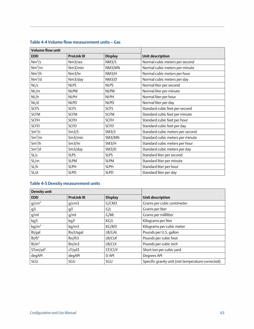
Configuration and Use Manual 63
Table 4-4 Volume flow measurement units – Gas
Volume flow unit
EDD ProLink III Display Unit description
Nm3/s Nm3/sec NM3/S Normal cubic meters per second
Nm3/m Nm3/min NM3/MN Normal cubic meters per minute
Nm3/h Nm3/hr NM3/H Normal cubic meters per hour
Nm3/d Nm3/day NM3/D Normal cubic meters per day
NL/s NLPS NLPS Normal liter per second
NL/m NLPM NLPM Normal liter per minute
NL/h NLPH NLPH Normal liter per hour
NL/d NLPD NLPD Normal liter per day
SCFS SCFS SCFS Standard cubic feet per second
SCFM SCFM SCFM Standard cubic feet per minute
SCFH SCFH SCFH Standard cubic feet per hour
SCFD SCFD SCFD Standard cubic feet per day
Sm3/s Sm3/S SM3/S Standard cubic meters per second
Sm3/m Sm3/min SM3/MN Standard cubic meters per minute
Sm3/h Sm3/hr SM3/H Standard cubic meters per hour
Sm3/d Sm3/day SM3/D Standard cubic meters per day
SL/s SLPS SLPS Standard liter per second
SL/m SLPM SLPM Standard liter per minute
SL/h SLPH SLPH Standard liter per hour
SL/d SLPD SLPD Standard liter per day
Table 4-5 Density measurement units
Density unit
Unit descriptionEDD ProLink III Display
g/cm3 g/cm3 G/CM3 Grams per cubic centimeter
g/L g/l G/L Grams per liter
g/ml g/ml G/ML Grams per milliliter
kg/L kg/l KG/L Kilograms per liter
kg/m3 kg/m3 KG/M3 Kilograms per cubic meter
lb/gal lbs/Usgal LB/GAL Pounds per U.S. gallon
lb/ft3 lbs/ft3 LB/CUF Pounds per cubic foot
lb/in3 lbs/in3 LB/CUI Pounds per cubic inch
STon/yd3 sT/yd3 ST/CUY Short ton per cubic yard
degAPI degAPI D API Degrees API
SGU SGU SGU Specific gravity unit (not temperature corrected)

64 Model 2700 Transmitters with PROFIBUS-PA
Although pressure units are listed in Table 4-7, the transmitter does not measure pressure. These units are for configuring external pressure compensation. Refer to Section 2.7.
4.6 Configuring the petroleum measurement applicationThe petroleum measurement parameters determine the values that will be used in petroleum measurement-related calculations. The petroleum measurement parameters are available only if the petroleum measurement application is enabled on your transmitter.
Table 4-6 Temperature measurement units
Temperature unit
Unit descriptionPROFIBUS-PA ProLink III Display
°C °C °C Degrees Celsius
°F °F °F Degrees Fahrenheit
°R °R °R Degrees Rankine
°K °K °K Kelvin
Table 4-7 Pressure measurement units
Pressure unit
Unit descriptionEDD ProLink III Display
ft H20 @68 DegF Ft Water @ 68°F FTH2O Feet water @ 68 °F
inch H2O @4 DegC In Water @ 4°C INW4C Inches water @ 4 °C
inch H20 @68 DegF In Water @ 68°F INH2O Inches water @ 68 °F
mm H2O @4 DegC mm Water @ 4°C mmW4C Millimeters water @ 4 °C
mm H20 @68 DegF mm Water @ 68°F mmH2O Millimeters water @ 68 °F
inch Hg @0 DegC In Mercury @ 0°C INHG Inches mercury @ 0 °C
mm Hg @0 DegC mm Mercury @ 0°C mmHG Millimeters mercury @ 0 °C
psi PSI PSI Pounds per square inch
bar bar BAR Bar
millibar millibar mBAR Millibar
g_per_cm2 g/cm2 G/SCM Grams per square centimeter
kg_per_cm2 kg/cm2 KG/SCM Kilograms per square centimeter
Pa pascals PA Pascals
MegaPa megapascals MPA Megapascals
KiloPa Kilopascals KPA Kilopascals
torr @0 DegC Torr @ 0C TORR Torr @ 0 °C
atm atms ATM Atmospheres
Note:The petroleum measurement application requires liquid volume measurement units. If you plan to use petroleum measurement process variables, ensure that liquid volume flow measurement is specified. See Section 4.4.

Configuration and Use Manual 65
4.6.1 About the petroleum measurement applicationSome applications that measure liquid volume flow or liquid density are particularly sensitive to temperature factors, and must comply with American Petroleum Institute (API) standards for measurement. The petroleum measurement application enables Correction of Temperature on volume of Liquids, or CTL.
Terms and definitionsThe following terms and definitions are relevant to the petroleum measurement application:
• API – American Petroleum Institute
• CTL – Correction of Temperature on volume of Liquids. The CTL value is used to calculate the VCF value
• TEC – Thermal Expansion Coefficient
• VCF – Volume Correction Factor. The correction factor to be applied to volume process variables. VCF can be calculated after CTL is derived
CTL derivation methodsThere are two derivation methods for CTL:
• Method 1 is based on observed density and observed temperature.
• Method 2 is based on a user-supplied reference density (or thermal expansion coefficient, in some cases) and observed temperature.
Petroleum measurement reference tablesReference tables are organized by reference temperature, CTL derivation method, liquid type, and density unit. The table selected here controls all the remaining options.
• Reference temperature:
- If you specify a 5x, 6x, 23x, or 24x table, the default reference temperature is 60 °F, and cannot be changed.
- If you specify a 53x or 54x table, the default reference temperature is 15 °C. However, you can change the reference temperature, as recommended in some locations (for example, to 14.0 or 14.5 °C).
• CTL derivation method:
- If you specify an odd-numbered table (5, 23, or 53), CTL will be derived using method 1 described above.
- If you specify an even-numbered table (6, 24, or 54), CTL will be derived using method 2 described above.
• The letters A, B, C, or D that are used to terminate table names define the type of liquid that the table is designed for:
- A tables are used with generalized crude and JP4 applications.
- B tables are used with generalized products.
- C tables are used with liquids with a constant base density or known thermal expansion coefficient.
- D tables are used with lubricating oils.

66 Model 2700 Transmitters with PROFIBUS-PA
• Different tables use different density units:
- Degrees API
- Relative density (SG)
- Base density (kg/m3)
Table 4-8 summarizes these options.
4.6.2 Configuration procedureThe petroleum measurement configuration parameters are listed and defined in Table 4-9.
Table 4-8 Petroleum measurement reference temperature tables
Table
CTL derivation method Base temperature
Density unit and range
Degrees API Base density Relative density
5A Method 1 60 °F, non-configurable 0 to +100
5B Method 1 60 °F, non-configurable 0 to +85
5D Method 1 60 °F, non-configurable –10 to +40
23A Method 1 60 °F, non-configurable 0.6110 to 1.0760
23B Method 1 60 °F, non-configurable 0.6535 to 1.0760
23D Method 1 60 °F, non-configurable 0.8520 to 1.1640
53A Method 1 15 °C, configurable 610 to 1075 kg/m3
53B Method 1 15 °C, configurable 653 to 1075 kg/m3
53D Method 1 15 °C, configurable 825 to 1164 kg/m3
Reference temperature Supports
6C Method 2 60 °F, non-configurable 60 °F Degrees API
24C Method 2 60 °F, non-configurable 60 °F Relative density
54C Method 2 15 °C, configurable 15 °C Base density in kg/m3
Table 4-9 Petroleum measurement parameters
Variable Description
Table type Specifies the table that will be used for reference temperature and reference density unit. Select the table that matches your requirements. See Petroleum measurement reference tables.
User defined TEC(1)
(1) Configurable if Table Type is set to 6C, 24C, or 54C.
Thermal expansion coefficient. Enter the value to be used in CTL calculation.
Temperature units(2)
(2) In most cases, the temperature unit used by the petroleum measurement reference table should also be the temperature unit configured for the transmitter to use in general processing. To configure the temperature unit, see Section 4.5.
Read-only. Displays the unit used for reference temperature in the reference table.
Density units Read-only. Displays the unit used for reference density in the reference table.
Reference temperature Read-only unless Table Type is set to 53x or 54x. If configurable:
Specify the reference temperature to be used in CTL calculation.
Enter reference temperature in °C.

Configuration and Use Manual 67
Setting the table typeTo set the petroleum measurement table type, refer to the flowcharts in Figure 4-4.
Figure 4-4 Setting the petroleum measurement table type
Setting the reference temperatureFor the temperature value to be used in CTL calculation, you can use the temperature data from the sensor, or you can configure external temperature compensation to use temperature data from an external temperature device.
•To use temperature data from the sensor, no action is required.
•To configure external temperature compensation, see Section 2.8.
MMI Coriolis Flow > Transducer Block > API
API2540 CTL Table Type
Block: Transducer Block 2 (Slot 12)Index 40 (API2540 CTL table type)Table type
API Setup tab
Apply
ProLink > Configuration
Select table type from the API Table Type
list
EDD Bus parameters
ProLink III

68 Model 2700 Transmitters with PROFIBUS-PA
Setting the thermal expansion coefficientIf the CTL derivation method for the petroleum measurement table type is method 2, you need to set the thermal expansion coefficient (TEC). To set a user-defined TEC, refer to the flowcharts in Figure 4-5.
Figure 4-5 Setting a user-defined TEC
4.7 Configuring the concentration measurement application Micro Motion sensors provide direct measurements of density, but not of concentration. The concentration measurement application calculates process variables such as concentration or density at reference temperature, using density process data appropriately corrected for temperature.
4.7.1 About the concentration measurement applicationThe concentration measurement calculation requires a concentration measurement curve, which specifies the relationship between temperature, concentration, and density for the process fluid being measured. Micro Motion supplies a set of six standard concentration measurement curves (see Table 4-10). If none of these curves is appropriate for your process fluid, you can configure a custom curve or purchase a custom curve from Micro Motion.
Note:For a detailed description of the concentration measurement application, see the manual entitled Micro Motion Enhanced Density Application: Theory, Configuration, and Use.The concentration measurement application requires liquid volume measurement units. If you plan to use concentration measurement process variables, ensure that liquid volume flow measurement is specified. See Section 4.4.
EDD Bus parameters
ProLink III
MMI Coriolis Flow > Transducer Block > API
API Thermal Expansion Coeff
Block: Transducer Block 2 (Slot 12)Index 39 (API thermal expansion coeff.)TEC
API Setup tab
Apply
ProLink > Configuration
Enter a coefficient in the User defined TEC box

Configuration and Use Manual 69
The derived variable, specified during configuration, controls the type of concentration measurement that will be produced. Each derived variable allows the calculation of a subset of concentration measurement process variables (see Table 4-11). The available concentration measurement process variables can be used in process control, just as mass flow rate, volume flow rate, and other process variables are used. For example, an event can be defined on a concentration measurement process variable.
• For all standard curves, the derived variable is Mass Conc (Dens).
• For custom curves, the derived variable may be any of the variables listed in Table 4-11.
The transmitter can hold up to six curves at any given time, but only one curve can be active (used for measurement) at a time. All curves that are in transmitter memory must use the same derived variable.
4.7.2 Configuration procedureComplete configuration instructions for the concentration measurement application are provided in the manual entitled Micro Motion Enhanced Density Application: Theory, Configuration, and Use.
Table 4-10 Standard curves and associated measurement units
Name Description Density unitTemperature unit
Deg Balling Curve represents percent extract, by mass, in solution, based on °Balling. For example, if a wort is 10 °Balling and the extract in solution is 100% sucrose, the extract is 10% of the total mass.
g/cm3 °F
Deg Brix Curve represents a hydrometer scale for sucrose solutions that indicates the percent by mass of sucrose in solution at a given temperature. For example, 40 kg of sucrose mixed with 60 kg of water results in a 40 °Brix solution.
g/cm3 °C
Deg Plato Curve represents percent extract, by mass, in solution, based on °Plato. For example, if a wort is 10 °Plato and the extract in solution is 100% sucrose, the extract is 10% of the total mass.
g/cm3 °F
HFCS 42 Curve represents a hydrometer scale for HFCS 42 (high fructose corn syrup) solutions that indicates the percent by mass of HFCS in solution.
g/cm3 °C
HFCS 55 Curve represents a hydrometer scale for HFCS 55 (high fructose corn syrup) solutions that indicates the percent by mass of HFCS in solution.
g/cm3 °C
HFCS 90 Curve represents a hydrometer scale for HFCS 90 (high fructose corn syrup) solutions that indicates the percent by mass of HFCS in solution.
g/cm3 °C
Note:The concentration measurement manual uses ProLink III as the standard configuration tool for the concentration measurement application. Because the PROFIBUS parameters are very similar to the ProLink III labels, you can follow the instructions for ProLink III and adapt them to your host. All of the parameters related to the concentration measurement application can be found in Transducer Block 2 (Slot 12).

70 Model 2700 Transmitters with PROFIBUS-PA
The typical configuration procedure simply sets up the concentration measurement application to use a standard curve. The following steps are required:
1. Set the transmitter’s density measurement unit to match the unit used by the curve (as listed in Table 4-10).
2. Set the transmitter’s temperature measurement unit to match the unit used by the curve (as listed in Table 4-10).
3. Set the derived variable to Mass Conc (Dens).
4. Specify the active curve.
4.8 Changing the output scaleThe AI function blocks can be configured to scale their output. The output scale is established by defining a process variable value at 0% of scale and at 100% of scale. The output of the AI block will be translated to a value between these two limits.
If you choose to use output scaling, note that it has no effect on the process values found in the transducer block. This results in the following behaviors:
• ProLink III and the display use the process values in the transducer block. Therefore, the output of a scaled AI block may differ from the value reported by other communication tools.
• Slug flow and flow cutoffs are configured in the transducer block. Therefore, output scaling has no effect on the behavior of the transmitter with regard to slug flow or flow cutoffs.
To change the output scale, refer to the flowcharts in Figure 4-6.

Configuration and Use Manual 71
Figure 4-6 Changing the output scale
4.9 Changing process alarmsThe transmitter uses process alarms to indicate that a process value has exceeded its user-defined limits. The transmitter maintains four alarm values for each process variable. In addition, the transmitter has an alarm hysteresis function to prevent erratic alarm reports.
4.9.1 Alarm valuesThe process alarm values are the limits for process variables. Whenever a process variable exceeds a process alarm value, the alarm will be reflected in the “Alarm Summary” parameters in each block.
Each AI function block and totalizer block has four process alarm limits: high alarm, high-high alarm, low alarm, and low-low alarm. See Figure 4-7. The high and low process alarm values represent normal process limits. The high-high and low-low process alarm values are used for more complex alarm signals (e.g., to indicate a more severe problem than a regular process alarm indicates).
Note:Process alarms are only posted through the AI function blocks and totalizer blocks and are not shown on the display or in ProLink III.
EDD
Block: Analog Input Block (Slots 1, 2, 3, and 5)Index 28, Parameter1 (EU100)Index 28, Parameter 2 (EU0)
Output Scale
Bus parameters

72 Model 2700 Transmitters with PROFIBUS-PA
Figure 4-7 Alarm values
To change the alarm values, refer to the flowcharts in Figure 4-8.
Proc
ess
varia
ble High alarm
High-high alarm
Low alarm
Low-low alarm
Normal process range

Configuration and Use Manual 73
Figure 4-8 Changing alarm values
EDD
Bus parameters

74 Model 2700 Transmitters with PROFIBUS-PA
4.9.2 Alarm hysteresisThe alarm hysteresis value is a percentage of the output scale. After a process alarm is created, the transmitter will not create new alarms unless the process first returns to a value within the range of the alarm hysteresis percentage. Figure 4-9 shows the transmitter’s alarm behavior with an alarm hysteresis value of 50%.
Note the following about hysteresis:
• A low hysteresis value allows the transmitter to broadcast a new alarm every time or nearly every time the process variable crosses over the alarm limit.
• A high hysteresis value prevents the transmitter from broadcasting new alarms unless the process variable first returns to a value sufficiently below the high alarm limit or above the low alarm limit.
Figure 4-9 High versus low alarm hysteresis values
To change the alarm hysteresis value, refer to the flowcharts in Figure 4-10.
Proc
ess
varia
ble
Alarm created
Hysteresis value
New alarms notcreated
LOW ALARM
HIGH ALARM
New alarmcreated here

Configuration and Use Manual 75
Figure 4-10 Changing the alarm hysteresis
4.10 Configuring status alarm severityThe severity level of some status alarms can be reclassified. For example:
• The default severity level for Alarm A020 (calibration factors unentered) is Fault, but you can reconfigure it to either Informational or Ignore.
• The default severity level for Alarm A102 (drive over-range) is Informational, but you can reconfigure it to either Ignore or Fault.
A list of all status alarms and default severity levels is shown in Table 4-11. (For more information on status alarms, including possible causes and troubleshooting suggestions, see Chapter 8.)
Table 4-11 Status alarms and severity levels
Alarm code Index Description Default severity Configurable
A001 1 EEPROM checksum Fault No
A002 2 RAM error Fault No
A003 3 Sensor failure Fault Yes
A004 4 Temperature sensor failure Fault No
A005 5 Input overrange Fault Yes
A006 6 Transmitter not configured Fault Yes
A008 8 Density overrange Fault Yes
A009 9 Transmitter initializing/warming up Ignore Yes
A010 10 Calibration failure Fault No
A011 11 Calibration too low Fault Yes
A012 12 Calibration too high Fault Yes
A013 13 Zero too noisy Fault Yes
A014 14 Transmitter failed Fault No
A016 16 Line temperature out-of-range Fault Yes
EDD Bus parameters

76 Model 2700 Transmitters with PROFIBUS-PA
To configure status alarm severity, refer to the flowcharts in Figure 4-11. Some configurable alarms can be set to either Informational or Ignore, but not to Fault.
A017 17 Meter RTD temperature out-of-range Fault Yes
A020 20 Calibration factors unentered Fault Yes
A021 21 Incorrect sensor type Fault No
A022 22 Configuration corrupt Fault Yes
A023 23 Totals corrupt Fault Yes
A024 24 CP program corrupt Fault Yes
A025 25 Boot sector fault Fault Yes
A026 26 Sensor/transmitter communication failure Fault No
A028 28 Sensor/transmitter write failure Fault No
A029 29 Internal communication failure Fault Yes
A030 30 Hardware/software incompatible Fault Yes
A031 31 Low power Fault No
A032 32 Smart Meter Verification in progress and outputs fixed
Informational Yes
A033 33 Tube Not Full Fault Yes
A034 34 Smart Meter Verification failed Informational Yes
A035 35 Smart Meter Verification aborted Informational Yes
A102 42 Drive overrange Informational Yes
A103 43 Data loss possible Informational Yes
A104 44 Calibration in progress Informational(1) Yes
A105 45 Slug flow Informational Yes
A106 46 Function block simulate Informational Yes
A107 47 Power reset occurred Informational Yes
A116 56 API temperature outside standard range Informational Yes
A117 57 API density out of limits Informational Yes
A120 60 Concentration measurement: unable to fit curve data
Informational No
A121 61 Concentration measurement: extrapolation alarm Informational Yes
A131 71 Smart Meter Verification in progress Informational Yes
A132 72 Simulation mode active Informational(1) Yes
(1) Can be set to either Informational or Ignore, but cannot be set to Fault.
Table 4-11 Status alarms and severity levels (continued)
Alarm code Index Description Default severity Configurable

Configuration and Use Manual 77
Figure 4-11 Configuring status alarm severity
4.11 Changing the damping valuesA damping value is a period of time, in seconds, over which the process variable value will change to reflect 63% of the change in the actual process. Damping helps the transmitter smooth out small, rapid measurement fluctuations.
• A high damping value makes the output appear to be smoother because the output must change slowly.
• A low damping value makes the output appear to be more erratic because the output changes more quickly.
To configure damping, refer to the flowcharts in Figure 4-12.
Note:There is also a “damping” parameter in each AI block called AI PV Filter Time (index 32). In order to avoid having two (potentially conflicting) damping values, you should set damping values only in the transducer block. The AI PV Filter Time parameter for each AI block should be set to 0
Block: Transducer Block 1 (Slot 11)Index 149 (Alarm index)Select alarm
Block: Transducer Block 1 (Slot 11)Index 150 (Alarm severity)Set severity
EDD Bus parameters
ProLink III
Alarm tab
Select an alarm from the Alarm list
Apply
ProLink > Configuration
Select a severity from the Severity list

78 Model 2700 Transmitters with PROFIBUS-PA
Figure 4-12 Changing the damping values
Flow tab
Enter a damping value in the Flow Damp box
Apply
ProLink > Configuration
Density tab
Enter a damping value in the Dens Damping box
Apply
Temperature tab
Enter a damping value in the Temp Damping box
Apply
Block: Transducer Block 1 (Slot 11)Index 33 (flow damping)Index 34 (temperature damping)Index 35 (density damping)
Damping
EDD
ProLink III
Bus parameters

Configuration and Use Manual 79
When you specify a new damping value, it is automatically rounded down to the nearest valid damping value. Valid damping values are listed in Table 4-12.
4.11.1 Damping and volume measurementWhen configuring damping values, note the following:
• Liquid volume flow is derived from mass and density measurements. Therefore, any damping applied to mass flow and density will affect liquid volume measurement.
• Gas standard volume flow is derived from mass flow measurement, but not from density measurement. Therefore, only damping applied to mass flow will affect gas standard volume measurement.
Be sure to set damping values accordingly.
4.12 Changing slug flow limits and durationSlugs—gas in a liquid process or liquid in a gas process—occasionally appear in some applications. The presence of slugs can significantly affect the process density reading. The slug flow parameters can help the transmitter suppress extreme changes in process variables, and can also be used to identify process conditions that require correction.
Slug flow parameters are as follows:
• Low slug flow limit — the point below which a condition of slug flow will exist. Typically, this is the lowest density you expect to observe for your process. The default value is 0.0 g/cm3. The valid range is 0.0–10.0 g/cm3.
• High slug flow limit — the point above which a condition of slug flow will exist. Typically, this is the highest density you expect to observe for your process. The default value is 5.0 g/cm3. The valid range is 0.0–10.0 g/cm3.
• Slug flow duration — the number of seconds the transmitter waits for a slug flow condition to clear. If the transmitter detects slug flow, it will post a slug flow alarm and hold its last “pre-slug” flow rate until the end of the slug flow duration and the measurement quality will be marked “uncertain.” If slugs are still present after the slug flow duration has expired, the transmitter will report a flow rate of zero (the measurement quality will remain at “uncertain”). The default value for slug flow duration is 0.0 seconds. The valid range is 0.0–60.0 seconds.
•
To configure slug flow limits and duration, refer to the flowcharts in Figure 4-13.
Table 4-12 Valid damping values
Process variable Valid damping values
Flow (mass and volume) 0, 0.04, 0.08, 0.16, ... 40.96
Density 0, 0.04, 0.08, 0.16, ... 40.96
Temperature 0, 0.6, 1.2, 2.4, 4.8, ... 76.8
Note:The slug flow limits must be entered in g/cm3, even if another unit has been configured for density. Slug flow duration is entered in seconds. Raising the low slug flow limit or lowering the high slug flow limit will increase the possibility of slug flow conditions. Conversely, lowering the low slug flow limit or raising the high slug flow limit will decrease the possibility of slug flow conditions. If slug flow duration is set to 0, the mass flow rate will be forced to 0 as soon as slug flow is detected.

80 Model 2700 Transmitters with PROFIBUS-PA
Figure 4-13 Configuring slug flow limits and duration
4.13 Configuring cutoffs Cutoffs are user-defined values below which the transmitter reports a value of zero for the specified process variable. Cutoffs can be configured for either mass flow, volume flow, or density.
Table 4-13 lists the default values and relevant comments for each cutoff. Note that the mass flow cutoff is not applied to the volume flow calculation. Even if the mass flow drops below the cutoff, and therefore the mass flow indicators go to zero, the volume flow rate will be calculated from the actual mass flow process variable.
To configure cutoffs, refer to the flowcharts in Figure 4-14.
Table 4-13 Cutoff default values and comments
Cutoff Default value Comments
Mass 0.0 g/s Micro Motion recommends a mass flow cutoff value of 0.2% of the sensor’s maximum flow rate for standard operation, and 2.5% of the sensor’s maximum flow rate for empty-full-empty batching.
Liquid volume 0.0 L/s The lower limit for volume flow cutoff is 0. The upper limit for volume flow cutoff is the sensor’s flow calibration factor, in L/s, multiplied by 0.2.
Density 0.2 g/cm3 The range for density cutoff is 0.0–0.5 g/cm3
Block: Transducer Block 1 (Slot 11)Index 130 (duration)Index 131 (low limit)Index 132 (high limit)
Slug flow
Density tab
Set the density limits:• Slug Low Limit• Slug High Limit
Apply
ProLink > Configuration
Set the slug flow duration in the Slug Duration box
Bus parameters
EDD ProLink III
MMI Coriolis Flow > Transducer Block Calibration
Slug Limit
Slug Duration Slug Low Limit Slug High Limit

Configuration and Use Manual 81
Figure 4-14 Configuring cutoffs
MMI Coriolis Flow > Transducer Block > Measurement > Process Variable
Mass Flow
Mass Flow Low Cutoff
Volume Flow
Volume Flow Low Cutoff(1)
Density
Density Cutoff
Flow tab
Enter values in the Mass Flow Cutoff or Volume Flow Cutoff(2)
boxes
Apply
ProLink > Configuration
Density tab
Enter a value in the Density Cutoff box
Apply
EDD
ProLink III
Bus parameters
Block: Transducer Block 1 (Slot 11)Index 9 (Mass flow cutoff)Index 39 (Liquid volume flow cutoff)Index 40 (Density cutoff)Index 69 (Gas standard volume flow cutoff)
Cutoffs
Notes:(1) When Gas Standard Volume is
configured, this option will be displayed as Gas Std Vol Flow Cutoff.
(2) When Gas Standard Volume is configured, this box will be labeled Std gas vol flow cutoff.

82 Model 2700 Transmitters with PROFIBUS-PA
4.14 Changing the measurement mode parameterThe measurement mode parameter defines how the flow is added to or subtracted from the totalizers.
• Forward flow moves in the direction of the arrow on the sensor.
• Reverse flow moves in the direction opposite from the arrow on the sensor.
Table 4-14 shows the possible values for the measurement mode parameter and the transmitter’s behavior when the flow is positive or negative. Only the unidirectional and bidirectional values are recognized by the PROFIBUS specification, so other values will be unrecognized by a PROFIBUS host or configuration tool. However, the transmitter will operate correctly in any of the modes listed in Table 4-14.
To change the measurement mode parameter, refer to the flowcharts in Figure 4-15.
Table 4-14 Totalizer behavior for each measurement mode value
Measurement mode value Bus index Forward flow Reverse flow
Unidirectional (forward only) 0 Increase No change
Reverse only 1 No change Increase
Bidirectional 2 Increase Decrease
Absolute value 3 Increase Increase
Negate/forward only 4 No change Increase
Negate/bidirectional 5 Decrease Increase

Configuration and Use Manual 83
Figure 4-15 Changing the measurement mode parameter
4.15 Configuring sensor parametersThe sensor parameters are used to describe the sensor component of your flowmeter. These sensor parameters are not used in transmitter processing, and are not required:
• Serial number
• Sensor material
• Liner material
• Flange
To configure the sensor parameters, refer to the flowcharts in Figure 4-16.
MMI Coriolis Flow > Transducer Block > Measurement > Process Variable > Mass Flow
Measurement Mode
Block: Transducer Block 1 (Slot 11)Index 10 (measurement mode)Measurement Mode
EDD Bus parameters
Flow tab
Select a value from the Flow Direction
list
Apply
ProLink > Configuration
ProLink III

84 Model 2700 Transmitters with PROFIBUS-PA
Figure 4-16 Configuring sensor parameters
4.16 Configuring the display You can restrict the display functionality or change the variables that are shown on the display.
4.16.1 Enabling and disabling display functionsEach display function and its associated parameter are listed in Table 4-15.
MMI Coriolis Flow > Transducer Block > Device Information
Sensor Serial Number
Sensor Material
Liner Material
Flange Type
Block: Transducer Block 2 (Slot 12)Index 10 (sensor serial number)Index 13 (sensor material)Index 14 (liner material)Index 15 (flange type)
Sensor parameters
Sensor tab
Enter the sensor serial number in the Sensor s/n
box
Apply
ProLink > Configuration
Select the sensor serial material from the Sensor
Matl list
Select the liner material from the Liner Matl list
Select the flange from the Flange list
EDD Bus parameters
ProLink III

Configuration and Use Manual 85
Note the following:
• If you use the display to disable access to the off-line menu, the off-line menu will disappear as soon as you exit the menu system. If you want to re-enable access, you must use a different method (e.g., ProLink III).
• If you are using the display to configure the display:
- You must enable Auto Scroll before you can configure Scroll Rate.
- You must enable the off-line password before you can configure the password.
To enable or disable display functions:
• With the EDD, refer to Figure 4-17
• With bus parameters, refer to Figure 4-18
• With ProLink III, refer to Figure 4-19
• With the display, refer to Figure 2-13
Table 4-15 Display functions and parameters
Display function EDD name Display code Enabled Disabled
Totalizer reset Totalizer Reset TOTALS RESET
Resetting mass and volume totalizers is permitted.
Resetting mass and volume totalizers is not possible.
Start/stop totalizers Start/Stop Totalizer TOTALS STOP Operator can start and stop totalizers from the display.
Operator cannot start or stop totalizers from the display.
Auto scroll(1)
(1) If enabled, you may want to configure Scroll Rate. See Section 4.16.2.
Auto Scroll AUTO SCRLL The display automatically scrolls through each process variable.
Operators must Scroll to view process variables.
Off-line menu Offline Menu DISPLAY OFFLN
Operators have access to the off-line menu.
No access to the offline menu.
Off-line password(2)
(2) If enabled, the display offline password must also be configured. See Section 4.16.4.
Offline Password OFFLINE PASSW
Password required for offline menu. See Section 4.16.4.
Offline menu accessible without a password.
Alarm menu Alarm Menu DISPLAY ALARM
Operator has access to alarm menu.
No access to the alarm menu.
Acknowledge all alarms
ACK All Alarms DISPLAY ACK Operator can acknowledge all current alarms at once.
Alarms must be acknowledged individually.
Display backlight Backlight DISPLAY BKLT Display backlight is ON. Display backlight is OFF.
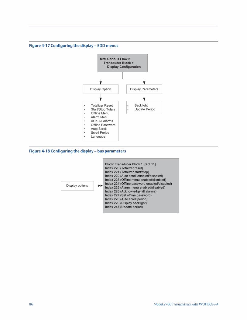
86 Model 2700 Transmitters with PROFIBUS-PA
Figure 4-17 Configuring the display – EDD menus
Figure 4-18 Configuring the display – bus parameters
Block: Transducer Block 1 (Slot 11)Index 220 (Totalizer reset)Index 221 (Totalizer start/stop)Index 222 (Auto scroll enabled/disabled)Index 223 (Offline menu enabled/disabled)Index 224 (Offline password enabled/disabled)Index 225 (Alarm menu enabled/disabled)Index 226 (Acknowledge all alarms)Index 227 (Set offline password)Index 228 (Auto scroll period)Index 229 (Display backlight)Index 247 (Update period)
Display options
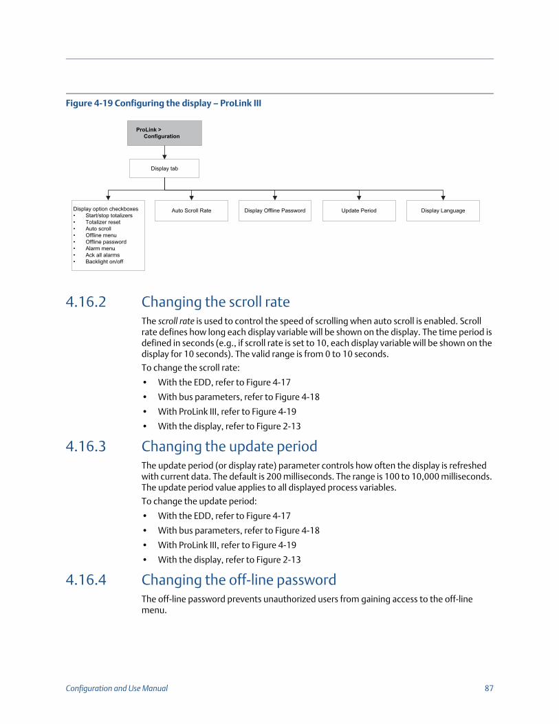
Configuration and Use Manual 87
Figure 4-19 Configuring the display – ProLink III
4.16.2 Changing the scroll rateThe scroll rate is used to control the speed of scrolling when auto scroll is enabled. Scroll rate defines how long each display variable will be shown on the display. The time period is defined in seconds (e.g., if scroll rate is set to 10, each display variable will be shown on the display for 10 seconds). The valid range is from 0 to 10 seconds.
To change the scroll rate:
• With the EDD, refer to Figure 4-17
• With bus parameters, refer to Figure 4-18
• With ProLink III, refer to Figure 4-19
• With the display, refer to Figure 2-13
4.16.3 Changing the update periodThe update period (or display rate) parameter controls how often the display is refreshed with current data. The default is 200 milliseconds. The range is 100 to 10,000 milliseconds. The update period value applies to all displayed process variables.
To change the update period:
• With the EDD, refer to Figure 4-17
• With bus parameters, refer to Figure 4-18
• With ProLink III, refer to Figure 4-19
• With the display, refer to Figure 2-13
4.16.4 Changing the off-line password The off-line password prevents unauthorized users from gaining access to the off-line menu.
Display tab
ProLink > Configuration
Display option checkboxes• Start/stop totalizers• Totalizer reset• Auto scroll• Offline menu• Offline password• Alarm menu• Ack all alarms• Backlight on/off
Auto Scroll Rate Display Offline Password Update Period Display Language

88 Model 2700 Transmitters with PROFIBUS-PA
To change the off-line password:
• With the EDD, refer to Figure 4-17
• With bus parameters, refer to Figure 4-18
• With ProLink III, refer to Figure 4-19
• With the display, refer to Figure 2-13
4.16.5 Changing the display languageThe display can be configured to use any of the following languages for data and menus:
• English
• French
• German
• Spanish
To change the display language:
• With the EDD, refer to Figure 4-17
• With bus parameters, refer to Figure 4-18
• With ProLink III, refer to Figure 4-19
• With the display, refer to Figure 2-13
4.16.6 Changing the display variables and precisionThe display can scroll through up to 15 process variables in any order. You can select the process variables you wish to see and the order in which they should appear.
Additionally, you can configure display precision for each display variable. Display precision controls the number of digits to the right of the decimal place. The range of the display precision is 0 to 5.
Table 4-16 shows an example of a display variable configuration. Notice that you can repeat variables and you can choose a value of “None.” The actual appearance of each process variable on the display is described in Appendix B.
Table 4-16 Example of a display variable configuration
Display variable Process variable
Display variable 1 Mass flow
Display variable 2 Volume flow
Display variable 3 Density
Display variable 4 Mass flow
Display variable 5 Volume flow

Configuration and Use Manual 89
Display variable 6 Mass totalizer
Display variable 7 Mass flow
Display variable 8 Temperature
Display variable 9 Volume flow
Display variable 10 Volume totalizer
Display variable 11 Density
Display variable 12 Temperature
Display variable 13 None
Display variable 14 None
Display variable 15 None
Table 4-16 Example of a display variable configuration (continued)
Display variable Process variable

90 Model 2700 Transmitters with PROFIBUS-PA
To change the display variables, refer to the flowcharts in Figure 4-20.
Figure 4-20 Changing the display variables and precision
4.17 Enabling LD OptimizationLD Optimization is a special compensation is that is specifically for hydrocarbon liquids. LD Optimization should not be used with any other process fluids. LD Optimization is available only with certain large sensor sizes. If your sensor can benefit from LD Optimization, the enable/disable option will appear in ProLink III or on the display.
ImportantIf you send the transmitter to a calibration facility to perform a water calibration, either during startup or any time thereafter, LD Optimization must be disabled. When you have completed the calibration, re-enable LD Optimization.
EDD
Block: Transducer Block 1 (Slot 11)Indices 232 through 246Display variables
Block: Transducer Block 1 (Slot 11)Index 231 (Number of decimals)Display precision
Bus parameters
Display tab
Apply
ProLink > Configuration
For each display variable, select a process variable
from the list
Enter a precision in the Number of Decimals box
ProLink III

Configuration and Use Manual 91
To enable LD Optimization, see Figures 4-21 and 4-22.
Figure 4-21 LD Optimization – ProLink III
Figure 4-22 LD Optimization – Display
OFF-LINE MAINT
Scroll and Select simultaneouslyfor 4 seconds
Scroll
Select
Select
Scroll
CONFG
Select
Scroll
MTR F
FACTOR LD
Scroll
LD OPT
Select

92 Model 2700 Transmitters with PROFIBUS-PA

Configuration and Use Manual 93
5 Operation
5.1 OverviewThis chapter describes how to use the transmitter in everyday operation. The following topics and procedures are discussed:
• Using the I&M functions (Section 5.2)
• Recording process variables (Section 5.3)
• Viewing process variables (Section 5.4)
• Using sensor simulation mode (Section 5.5)
• Accessing diagnostic information with a PROFIBUS host (Section 5.6)
• Viewing transmitter status and alarms (Section 5.7)
• Viewing and using the totalizers and inventories (Section 5.8)
5.2 Using the I&M functionsThe transmitter implements the following PROFIBUS identification and maintenance (I&M) functions:
• I&M 0
• I&M 1
• I & M 2
• PA I & M 0
Refer to Amendment 3 to the PROFIBUS Profile for Process Control Devices V 3.01: Identification and Maintenance Functions Version 1.0, December 2004 Order No. 3.042.
The I&M functions contain a variety of device and manufacturer information, all of which is hard-coded (read only). The I&M functions are not accessible via ProLink III or the display. If you are using Siemens Simatic PDM, v6.0 SP2 or higher is required. Earlier versions do not support I&M functions.
Refer to Appendix F for the bus parameters associated with the I&M functions.
Note:All procedures provided in this chapter assume that you have established communication with the transmitter and that you are complying with all applicable safety requirements. See Appendix C or the documentation for your PROFIBUS host or configuration tool.

94 Model 2700 Transmitters with PROFIBUS-PA
5.3 Recording process variablesMicro Motion suggests that you make a record of the process variables listed below, under normal operating conditions. This will help you recognize when the process variables are unusually high or low, and may help in fine-tuning transmitter configuration.
Record the following process variables:
• Flow rate
• Density
• Temperature
• Tube frequency
• Pickoff voltage
• Drive gain
To view these values, refer to Section 5.4.
5.4 Viewing process variablesProcess variables include measurements such as mass flow rate, volume flow rate, temperature, and density. You can view process variables with the display (if your transmitter has a display), ProLink III, a PROFIBUS configuration tool (e.g., Simatic PDM) using the EDD, or from a Class 2 PROFIBUS host using bus parameters.
5.4.1 With the displayBy default, the display shows the mass flow rate, mass total, volume flow rate, volume total, temperature, density, and drive gain. If desired, you can configure the display to show other process variables. See Section 4.16.5.
The LCD panel reports the abbreviated name of the process variable (e.g., DENS for density), the current value of that process variable, and the associated unit of measure (e.g., G/CM3). See Appendix B for information on the codes and abbreviations used for display variables.
To view a process variable with the display:
• If Auto Scroll is enabled, wait until the desired process variable appears on the LCD panel.
• If Auto Scroll is not enabled, Scroll until the name of the desired process variable either:
- Appears on the process variable line, or
- Begins to alternate with the units of measure
The precision of variables shown on the display is configurable. See Section 4.16.5. The display precision affects only the value shown on the display, and does not affect the actual process value stored in the transmitter.

Configuration and Use Manual 95
Process variable values are displayed using either standard decimal notation or exponential notation:
• Values < 100,000,000 are displayed in decimal notation (e.g., 1234567.8).
• Values 100,000,000 are displayed using exponential notation (e.g., 1.000E08).
- If the value is less than the precision configured for that process variable, the value is displayed as 0 (i.e., there is no exponential notation for fractional numbers).
- If the value is too large to be displayed with the configured precision, the displayed precision is reduced (i.e., the decimal point is shifted to the right) as required so that the value can be displayed.
5.4.2 With ProLink IIIThe Process Variables window opens automatically when you first connect to the transmitter. This window displays current values for the standard process variables (mass, volume, density, temperature, external pressure, and external temperature). If you have closed the Process Variables window, select ProLink > Process Variables.
To view petroleum measurement process variables (if the petroleum measurement application is enabled), select ProLink > API Process Variables.
To view concentration measurement process variables (if the concentration measurement application is enabled), select ProLink > CM Process Variables. The concentration measurement process variables that are displayed depend on the configuration of the concentration measurement application.
5.4.3 With PROFIBUS EDDSelect View > Process Variables to view standard process variables. petroleum measurement and concentration measurement variables are not displayed on this screen.
Select Device > API to view petroleum measurement variables. Select Device > CM Process Variables to view concentration measurement variables.
5.4.4 With bus parametersTo view standard process variables, examine index 26 (AI Out) of the appropriate AI function block. Refer to Section 2.5 for information about how slots correspond to AI function blocks.

96 Model 2700 Transmitters with PROFIBUS-PA
5.5 Using sensor simulation modeSensor simulation mode causes simulated values to be substituted for actual process data from the sensor. Sensor simulation mode can be enabled only with ProLink III (Figure 5-1).
Figure 5-1 Sensor simulation mode – ProLink III
5.6 Accessing diagnostic information with a PROFIBUS hostThe transmitter sends diagnostic information to a PROFIBUS host in the form of slave diagnostic response bytes. The number of bytes sent depends on whether the transmitter is configured for Manufacturer-specific or Profile-specific mode. See Section 2.5 for information about the mode, and Appendix E for information on interpreting the diagnostic bytes.
Sensor Simulation tab
Select Enable Simulation Mode
Apply
ProLink > Configuration Select a wave form
for mass flow, density, and
temperature from the Wave Form lists
Fixed wave Triangular or sine wave
Enter a value in the Fixed Value box
Enter period in the Period box
Enter minimum and maximum amplitude in the Minimum and
Maximum boxes

Configuration and Use Manual 97
5.7 Viewing transmitter status and alarmsYou can view transmitter status using the display, ProLink III, EDD, or bus parameters. Depending on the method chosen, different information is displayed.
5.7.1 With the displayThe display reports alarms in two ways:
• With a status LED, which reports only that one or more alarms has occurred
• Through the alarm queue, which reports each specific alarm
The status LED is located at the top of the display (Figure 5-2). The status LED can be in one of six possible states, as listed in Table 5-1. The procedure for responding to alarms is shown in Figure B-5.
Figure 5-2 Status LED
Note:If access to the alarm menu from the display has been disabled (see Section 4.16), then the display will not list alarm codes in an alarm queue and the status LED will not flash. The status LED will indicate status using solid green, yellow, or red.
Table 5-1 Status LED states
Status LED state Alarm priority
Green No alarm—normal operating mode
Flashing green(1)
(1) If the display alarm menu has been disabled, alarms cannot be acknowledged. In this case, the status LED will never flash to indicate an unacknowledged alarm.
Unacknowledged corrected condition
Yellow Acknowledged low severity alarm
Flashing yellow(1) Unacknowledged low severity alarm
Red Acknowledged high severity alarm
Flashing red(1) Unacknowledged high severity alarm
Status LED

98 Model 2700 Transmitters with PROFIBUS-PA
5.7.2 With ProLink IIIProLink III provides two ways to view alarm information:
• Choose ProLink > Status. This window shows the current status of all possible alarms, independent of configured alarm severity. The alarms are divided into three categories: Critical, Informational, and Operational. To view the indicators in a category, click on the associated tab. A tab is red if one or more status indicators in that category is active. On each tab, currently active alarms are shown by red indicators.
• Choose ProLink > Alarm Log. This window lists all active alarms, and all inactive but unacknowledged Fault and Informational alarms. (The transmitter automatically filters out Ignore alarms.) A green indicator means “inactive but unacknowledged” and a red indicator means “active.” Alarms are organized into two categories: High Priority and Low Priority.
5.7.3 With EDDThe transmitter sets its PROFIBUS output status to bad or uncertain whenever an alarm condition occurs. You can view the current alarms by selecting View > Device Status and then selecting Critical, Informational, or Operational. All possible alarms are shown, independent of configured alarm severity. Currently active alarms are shown by a check mark.
5.7.4 With bus parametersThe transmitter sets its PROFIBUS output status to bad or uncertain whenever an alarm condition occurs. You can view alarms by reading the status words of the block where the alarm originated. The status words are one or more parameters whose bits indicate alarm conditions:
• Index 23 (Alarm summary) of each AI function block (Slot 1, 2, 3, and 5).
• Indices 139–146 of transducer block 1 (Slot 11).
You must view all of the status words to get a comprehensive list of current alarms.
5.8 Using the totalizers and inventoriesThe totalizers keep track of the total amount of mass or volume measured by the transmitter over a period of time. The totalizers can be started and stopped, and the totals can be viewed and reset.
The inventories track the same values as the totalizers. Whenever totalizers are started or stopped, all inventories (including the petroleum measurement volume inventory and concentration measurement inventories) are started or stopped automatically. However, when totalizers are reset, inventories are not reset automatically—you must reset inventories separately. This allows you to use the inventories to keep running totals across multiple totalizer resets.
Note:The location of alarms in the Status and Alarm Log windows is not affected by the configured alarm severity (see Section 4.10). Alarms in the Status window are predefined as Critical, Informational, or Operational. Alarms in the Alarm Log window are predefined as High Priority or Low Priority.

Configuration and Use Manual 99
You can view all totalizer and inventory values using any of the communication tools: the display, ProLink III, the EDD, or bus parameters. Specific starting, stopping, and resetting functionality depends on the tool you are using.

100 Model 2700 Transmitters with PROFIBUS-PA
5.8.1 Viewing current values for totalizers and inventoriesYou can view current totals for the totalizers and inventories with the display (if your transmitter has a display), ProLink III, PROFIBUS EDD, or PROFIBUS bus parameters.
With the displayYou cannot view current totals with the display unless the display has been configured to show them. See Section 4.16.1.
To view a totalizer or inventory value, Scroll until the LCD panel shows the word TOTAL in the lower left and the desired units in the lower right. Refer to Table 5-2 and Figure 5-3.
Table 5-2 Totalizer and inventory display unit names
Totalizer/inventory Unit name on display
Mass total Mass unit
Mass inventory Mass unit alternating with MASSI
Volume total (liquid) Volume unit
Volume inventory (liquid) Volume unit alternating with LVOLI
Gas standard volume total Volume unit
Gas standard volume inventory Volume unit alternating with GSV I
Petroleum measurement corrected volume total
Volume unit alternating with TCORR
Petroleum measurement corrected volume inventory
Volume unit alternating with TCORI
ED net mass total Mass unit alternating with NET M
ED net volume total Mass unit alternating with NETMI
ED net volume inventory Mass unit alternating with NET V
ED standard volume total Mass unit alternating with STD V
ED standard volume inventory Mass unit alternating with STDVI

Configuration and Use Manual 101
Figure 5-3 Totalizer and inventory values on display
With ProLink IIITo view the current value of the totalizers and inventories with ProLink III, select ProLink > Totalizer or ProLink > API Totalizer, or ProLink > CM Totalizer.
With EDDTo view the current value of the totalizers and inventories:
• For standard mass, liquid standard volume, and gas standard volume, select View > Process Variables > Totalizer and then select Mass or Volume. (If the transmitter is configured to use gas standard volume, then Volume will be replaced by Gas Standard Volume.) Totals and inventories are displayed together.
• For petroleum measurement, select Device > Device > API Totalizer.
• For concentration measurement, select Device > Device > CM Totalizer.
With bus parametersTo view the current value of the totalizers and inventories, examine index 26 (TOT Total) of each totalizer function block (Slots 4, 6, 7, and 8).
5.8.2 Controlling the totalizers and inventoriesSpecific starting, stopping, and resetting functionality depends on the tool you are using.
With the displayIf the required value is shown on the display, you can use the display to start and stop all totalizers and inventories simultaneously, or to reset individual totalizers. See the flowchart in Figure 5-4. You cannot reset any inventories with the display.
Current value
Units of measure
TOTAL
Scroll opticalswitch

102 Model 2700 Transmitters with PROFIBUS-PA
Figure 5-4 Controlling totalizers and inventories with the display
With Prolink IIITo control concentration measurement totalizers and inventories, choose ProLink > CM Totalizer Control. To control all other totalizer and inventory functions, choose ProLink > Totalizer Control.
To reset inventories using ProLink III, you must first enable this capability. To enable inventory reset using ProLink III:
1. Choose View > Preferences.
2. Select the Enable Inventory Totals Reset checkbox.
3. Click Apply.
With PROFIBUS EDDTo start and stop totals and inventories, to reset all totals and inventories simultaneously, or to reset individual mass or volume totals and inventories, select Device > Device > Totalizer.
To reset petroleum measurement totals and inventories alone, select Device > Device > API Totalizer.
To reset concentration measurement totals and inventories alone, select Device > Device > CM Totalizer.
RESET(3)
Select
Scroll STOP/START(4)
RESET YES?
Process variable display
STOP/START YES?
Scroll
Mass total display(1) Volume total display(1)Scroll
Yes No
Select Scroll
EXIT
Select
Yes No
Select Scroll
Scroll
API total(1)(2)
ED total(1)(2)
Select
(1) Displayed only if configured as a display variable (see Section 4.16.6).(2) The petroleum measurement application or concentration measurement application must be enabled.(3) The display must be configured to allow totalizer resetting (see Section 4.16).(4) The display must be configured to allow stopping and starting (see Section 4.16).

Configuration and Use Manual 103
With PROFIBUS bus parametersIf the totalizer blocks are configured to report the status of one of the internal totalizers (i.e., not Standard mode) (see Section 2.6), you can reset that total or inventory by setting index 29 of the appropriate totalizer function block to 1.
You can also control the internal totalizers directly with the transducer block parameters shown in Table 5-3. Except where specified, enabling each function means setting its value to 0x0001.
Table 5-3 Stopping, starting, and resetting totalizers and inventories
To accomplish this:
Use this transducer block parameter:
Slot Index
Reset mass inventory 11 60
Reset liquid volume inventory 11 61
Reset gas standard volume total 11 70
Reset gas standard volume inventory 11 71
Reset petroleum measurement volume totalizer 12 36
Reset petroleum measurement volume inventory 12 37
Reset ED standard volume total 12 60
Reset ED standard volume inventory 12 63
Reset ED net mass total 12 61
Reset ED net mass inventory 12 64
Reset ED net volume total 12 62
Reset ED net volume inventory 12 65
Stop all totalizers and inventories 12 103
Start all totalizers and inventories 12 103
Reset all totals 12 104
Reset all inventories 12 105
Reset mass total 12 106
Reset liquid volume total 12 107

Configuration and Use Manual 103
6 Troubleshooting
6.1 OverviewThis section describes guidelines and procedures for troubleshooting the flowmeter. The information in this section will enable you to:
• Categorize the problem
• Determine whether you are able to correct the problem
• Take corrective measures (if possible)
6.2 Guide to troubleshooting topicsRefer to Table 6-1 for a list of troubleshooting topics discussed in this chapter.
6.3 Transmitter does not operateIf the transmitter is not receiving power and cannot communicate over the network or display, then perform all of the procedures under Section 6.9.
If the wiring checks do not indicate a problem with electrical connections, contact the Micro Motion Customer Service Department.
Note:All procedures provided in this chapter assume that you have established communication with the transmitter and that you are complying with all applicable safety requirements. See Appendix B or the documentation for your PROFIBUS host or configuration tool.
Table 6-1 Troubleshooting topics
Topic Section
Transmitter does not operate Section 6.3
Transmitter does not communicate Section 6.4
Function blocks stuck in OOS mode Section 6.5
Zero or calibration failure Section 6.6
Output problems Section 6.7
Status alarms Section 6.8
Diagnosing wiring problems Section 6.9
Checking slug flow Section 6.10
Restoring a working configuration Section 6.11
Checking the test points Section 6.12
Checking the core processor Section 6.13
Checking sensor coils and RTD Section 6.14

104 Model 2700 Transmitters with PROFIBUS-PA
6.4 Transmitter does not communicateIf the transmitter does not appear to be communicating on the network, then:
• Make sure the PROFIBUS network has proper termination.
• Check the PROFIBUS wiring between the transmitter and the DP/PA coupler, and between the DP/PA coupler and the host system.
• Perform the procedures under Section 6.9.4.
• Make sure the node address is set correctly. The node address is set to a default value of 126 at the factory. See Section 2.3.
• If using a configuration tool such as Simatic PDM, check whether the transmitter shows up in the live devices list.
• Make sure the I/O configuration is set up properly. See Section 2.5.
6.5 Function blocks in Out-of-Service modeIf all of the transmitter function blocks (AI, AO, and totalizer) are stuck in Out-of-Service mode, there may be a fault alarm active. The status alarms that will trigger OOS mode are shown in Table 6-2. Refer to Section 6.8 for a full description of status alarms and possible remedies.
6.6 Zero or calibration failureIf a zero or calibration procedure fails, the transmitter will send one or more status alarms indicating the cause of failure. Refer to Table 6-4 for descriptions of status alarms and possible remedies.
Table 6-2 OOS-mode alarms
Alarm Description
A001 EPROM checksum error
A002 RAM test error (core processor)
A003 Sensor failure (no tube interrupt)
A004 Temperature sensor out-of-range
A005 Input over-range
A008 Density over-range
A016 Line RTD temperature out-of-range
A017 Meter RTD temperature out-of-range
A022 (E)EPROM configuration DB interrupt (core processor)
A023 (E)EPROM totals corrupt (core processor)
A024 (E)EPROM program corrupt (core processor)
A025 Protected boot sector fault

Configuration and Use Manual 105
6.7 Output problemsMicro Motion suggests that you make a record of the process variables listed below, under normal operating conditions. This will help you recognize when the process variables are unusually high or low.
• Flow rate
• Density
• Temperature
• Tube frequency
• Pickoff voltage
• Drive gain
For troubleshooting, check the process variables under both normal flow and tubes-full no-flow conditions. Except for flow rate, you should see little or no change between flow and no-flow conditions. If you see a significant difference, record the values and contact the Micro Motion Customer Service Department for assistance.
Unusual values for process variables may indicate a variety of different problems. Table 6-3 lists several possible problems and remedies.
Table 6-3 Output problems and possible remedies
Symptom Cause Possible remedies
No output or incorrect process variable
CHANNEL parameter set incorrectly
Verify the CHANNEL parameter in the AI block matches the correct transducer block measurement channels.
Steady non-zero flow rate under no-flow conditions
Misaligned piping (especially in new installations)
Correct the piping.
Open or leaking valve Check or correct the valve mechanism.
Bad sensor zero Rezero the flowmeter. See Section 3.6.
Bad flow cal factor Verify characterization. See Section 6.7.4.
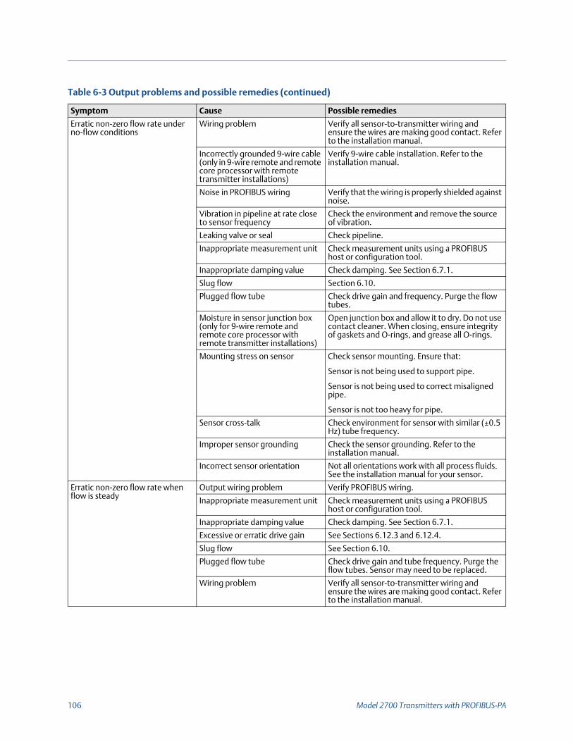
106 Model 2700 Transmitters with PROFIBUS-PA
Erratic non-zero flow rate under no-flow conditions
Wiring problem Verify all sensor-to-transmitter wiring and ensure the wires are making good contact. Refer to the installation manual.
Incorrectly grounded 9-wire cable (only in 9-wire remote and remote core processor with remote transmitter installations)
Verify 9-wire cable installation. Refer to the installation manual.
Noise in PROFIBUS wiring Verify that the wiring is properly shielded against noise.
Vibration in pipeline at rate close to sensor frequency
Check the environment and remove the source of vibration.
Leaking valve or seal Check pipeline.
Inappropriate measurement unit Check measurement units using a PROFIBUS host or configuration tool.
Inappropriate damping value Check damping. See Section 6.7.1.
Slug flow Section 6.10.
Plugged flow tube Check drive gain and frequency. Purge the flow tubes.
Moisture in sensor junction box (only for 9-wire remote and remote core processor with remote transmitter installations)
Open junction box and allow it to dry. Do not use contact cleaner. When closing, ensure integrity of gaskets and O-rings, and grease all O-rings.
Mounting stress on sensor Check sensor mounting. Ensure that:
Sensor is not being used to support pipe.
Sensor is not being used to correct misaligned pipe.
Sensor is not too heavy for pipe.
Sensor cross-talk Check environment for sensor with similar (±0.5 Hz) tube frequency.
Improper sensor grounding Check the sensor grounding. Refer to the installation manual.
Incorrect sensor orientation Not all orientations work with all process fluids. See the installation manual for your sensor.
Erratic non-zero flow rate when flow is steady
Output wiring problem Verify PROFIBUS wiring.
Inappropriate measurement unit Check measurement units using a PROFIBUS host or configuration tool.
Inappropriate damping value Check damping. See Section 6.7.1.
Excessive or erratic drive gain See Sections 6.12.3 and 6.12.4.
Slug flow See Section 6.10.
Plugged flow tube Check drive gain and tube frequency. Purge the flow tubes. Sensor may need to be replaced.
Wiring problem Verify all sensor-to-transmitter wiring and ensure the wires are making good contact. Refer to the installation manual.
Table 6-3 Output problems and possible remedies (continued)
Symptom Cause Possible remedies

Configuration and Use Manual 107
Inaccurate flow rate Bad flow cal factor Verify characterization. See Section 6.7.4.
Inappropriate measurement unit Check measurement units using a PROFIBUS host or configuration tool.
Bad sensor zero Rezero the flowmeter. See Section 3.6.
Bad density calibration factors Verify characterization. See Section 6.7.4.
Bad flowmeter grounding See Section 6.9.3.
Slug flow See Section 6.10.
Wiring problem Verify all sensor-to-transmitter wiring and ensure the wires are making good contact. Refer to the installation manual.
Inaccurate density reading Problem with process fluid Use standard procedures to check quality of process fluid.
Bad density calibration factors Verify characterization. See Section 6.7.4.
Wiring problem Verify all sensor-to-transmitter wiring and ensure the wires are making good contact. Refer to the installation manual.
Bad flowmeter grounding See Section 6.9.3.
Slug flow See Section 6.10.
Sensor cross-talk Check environment for sensor with similar (±0.5 Hz) tube frequency.
Plugged flow tube Check drive gain and tube frequency. Purge the flow tubes. Sensor may need to be replaced.
Temperature reading significantly different from process temperature
RTD failure Check for alarm conditions and follow troubleshooting procedure for indicated alarm.
Incorrect calibration factors Perform temperature calibration. See Section 3.8.
Verify characterization. See Section 3.3.
Temperature reading slightly different from process temperature
Incorrect calibration factors Perform temperature calibration. See Section 3.8.
Verify characterization. See Section 3.3.
Unusually high density reading Plugged flow tube Check drive gain and tube frequency. Purge the flow tubes.
Incorrect K2 value Verify characterization. See Section 6.7.4.
Unusually low density reading Slug flow See Section 6.10.
Incorrect K2 value Verify characterization. See Section 6.7.4.
Unusually high tube frequency Sensor erosion Contact Micro Motion Customer Service.
Unusually low tube frequency Plugged flow tube Check drive gain and tube frequency. Purge the flow tubes. Sensor may need to be replaced.
Unusually low pickoff voltages Several possible causes See Section 6.12.5.
Unusually high drive gain Several possible causes See Section 6.12.3.
Table 6-3 Output problems and possible remedies (continued)
Symptom Cause Possible remedies

108 Model 2700 Transmitters with PROFIBUS-PA
6.7.1 DampingAn incorrectly set damping value may make the transmitter’s output appear too sluggish or too jumpy. Adjust the damping parameters in the transducer block to achieve the damping effect you want. See Section 4.11.
Other damping problemsIf the transmitter appears to be applying damping values incorrectly or the damping effects do not appear to be changed by adjustments to the damping parameters, then the AI PV Filter Time parameter in an AI function block may be improperly set. Inspect each AI function block, and ensure that AI PV Filter Time is set to zero.
6.7.2 Low-flow cutoffIf the transmitter is sending an output of zero unexpectedly, then one of the low-flow cutoff parameters may be set incorrectly. Verify that the cutoff parameters in the transducer block are set to appropriate levels. See Section 4.13.
6.7.3 Output scale An incorrectly configured output scale can cause the transmitter to report unexpected output levels. Verify that the AI Out Scale values are set up correctly for each AI block. See Section 4.8.
6.7.4 CharacterizationIncorrect characterization parameters can cause the transmitter to send unexpected output values. However, you should suspect an incorrect characterization only if the transmitter and sensor have recently been paired together for the first time. Refer to Section 3.3 for more information about characterization.
6.7.5 CalibrationImproper calibration may cause the transmitter to send unexpected output values. However, you should suspect an improper calibration only if the transmitter has been field-calibrated recently. Refer to Sections 3.7 and 3.8 for more information about calibration.
6.8 Status alarmsStatus alarms are reported by a PROFIBUS host, the display, and ProLink III software. Remedies for the alarm states appear in Table 6-4.
Note:Micro Motion recommends using meter factors, rather than calibration, to prove the meter against a regulatory standard or to correct measurement error. Contact Micro Motion before calibrating your flowmeter. Refer to Section 3.5 for information about meter factors.
Note:Some status alarms will cause all of the function blocks (AI, AO, and totalizer) to change to Out of Service mode.

Configuration and Use Manual 109
Table 6-4 Status alarms and remedies
Display code Description Possible remedies
A001 EEPROM checksum Cycle power to the transmitter.
The flowmeter might need service. Contact Micro Motion Customer Service.
A002 RAM error Cycle power to the transmitter.
The flowmeter might need service. Contact Micro Motion Customer Service.
A003 Sensor failure Check the test points. See Section 6.12.
Check the sensor coils. See Section 6.14.
Check wiring to sensor. See Section 6.9.2.
Check for slug flow. See Section 6.10.
Check sensor tubes.
A004 Temperature overrange Check the test points. See Section 6.12.
Check the sensor coils. See Section 6.14.
Check wiring to sensor. See Section 6.9.2.
Verify process temperature range is within limits for sensor and transmitter.
Verify flowmeter characterization. See Section 6.7.4.
Contact Micro Motion Customer Service.
A005 Input overrange Check the test points. See Section 6.12.
Check the sensor coils. See Section 6.14.
Verify process conditions.
Verify that transmitter is configured to use appropriate measurement units. See Section 4.5.
Verify flowmeter characterization. See Section 6.7.4.
Re-zero the flowmeter. See Section 3.6.
A006 Transmitter not configured Check the characterization. Specifically, verify the FCF and K1 values. See Section 3.3.
Contact Micro Motion Customer Service.
A008 Density overrange Check the test points. See Section 6.12.
Check the sensor coils. See Section 6.14.
Check for air in flow tubes, tubes not filled, foreign material in tubes, coating in tubes.
Verify characterization. See Section 6.7.4.
A009 Transmitter initializing/warming up Allow the transmitter to warm up. The error should disappear from the status words once the transmitter is ready for normal operation. If alarm does not clear, make sure sensor is completely full or completely empty. Verify sensor configuration and transmitter wiring to sensor (refer to installation manual).
A010 Calibration failure If alarm appears during zero, ensure there is no flow through the sensor, then retry.
Cycle power to the flowmeter, then retry.
A011 Calibration too low Ensure there is no flow through sensor, then retry.
Cycle power to the flowmeter, then retry.
A012 Calibration too high Ensure there is no flow through sensor, then retry.
Cycle power to the flowmeter, then retry.

110 Model 2700 Transmitters with PROFIBUS-PA
A013 Zero too noisy Remove or reduce sources of electromechanical noise, then attempt the calibration or zero procedure again.
Possible sources of noise include:
Mechanical pumps
Electrical interference
Vibration effects from nearby machinery
Cycle power to the flowmeter, then retry.
A014 Transmitter failed Cycle power to the transmitter.
The transmitter might need service. Contact Micro Motion Customer Service.
A016 Line temp out-of-range Check the test points. See Section 6.12.
Check the sensor coils. See Section 6.14.
Check wiring to sensor. See Section 6.9.2.
Verify characterization. Section 6.7.4.
Contact Micro Motion Customer Service.
A017 Meter RTD temperature out-of-range
Check the test points. See Section 6.12.
Check the sensor coils. See Section 6.14.
Contact Micro Motion Customer Service.
A020 Calibration factors unentered Check the characterization. Specifically, verify the FCF value. See Section 3.3.
A021 Incorrect sensor type Check the characterization. Specifically, verify the K1 value. See Section 3.3.
A022 Configuration corrupt The flowmeter needs service. Contact Micro Motion Customer Service.
A023 Totals corrupt The flowmeter needs service. Contact Micro Motion Customer Service.
A024 CP program corrupt The flowmeter needs service. Contact Micro Motion Customer Service.
A025 Boot sector fault Cycle power to the meter.
The flowmeter might need service. Contact Micro Motion Customer Service.
A026 Sensor/transmitter communication failure
Check wiring between transmitter and core processor (see Section 6.9.2). The wires may be swapped. After swapping wires, cycle power to the flowmeter.
Check for noise in wiring or transmitter environment.
Check core processor LED. See Section 6.13.2.
Perform the core processor resistance test. See Section 6.13.3.
A028 Sensor/transmitter write failure Cycle power to the meter.
The flowmeter might need service. Contact Micro Motion Customer Service.
A030 Hardware/software incompatible The loaded software is not compatible with the programmed board type. Contact Micro Motion.
A031 Low Power The core processor is not receiving enough power. Check the power supply to the transmitter, and check power wiring between the transmitter and the core processor (4-wire remote installations only).
Table 6-4 Status alarms and remedies (continued)
Display code Description Possible remedies

Configuration and Use Manual 111
6.9 Diagnosing wiring problemsUse the procedures in this section to check the transmitter installation for wiring problems. Installation procedures are provided in the manual entitled Model 1700 and Model 2700 Transmitters: Installation Manual.
A032 Smart Meter Verification in progress and outputs fixed
Allow the procedure to complete.
If desired, abort the procedure and restart with outputs set to Continue Measurement.
A033 Sensor OK / Tubes Stopped by Process
No signal from LPO or RPO, suggesting that sensor tubes are not vibrating. Verify process. Check for air in the flow tubes, tubes not filled, foreign material in tubes, or coating in tubes.
A034 Smart Meter Verification failed Rerun the test. If the test fails again, see Section 3.4.3.
A035 Smart Meter Verification aborted If desired, read the abort code. See Section 3.4.3, and perform the appropriate action.
A102 Drive overrange Excessive or erratic drive gain. See Section 6.12.3.
Check the sensor coils. See Section 6.14.
A103 Data loss possible Cycle power to the transmitter.
The transmitter might need service. Contact Micro Motion Customer Service.
A104 Calibration in progress Allow the flowmeter to complete calibration.
A105 Slug flow Allow slug flow to clear from the process.
See Section 6.10.
A106 Function block is in simulation mode Disable function block simulation.
A107 Power reset occurred No action is necessary.
A116 API temperature outside standard range
Verify process.
Verify API reference table and temperature
configuration. See Section 4.6.
A117 API density out of limits Verify process.
Verify API reference table and temperature
configuration. See Section 4.6.
A120 Concentration measurement: unable to fit curve data
Verify enhanced density configuration.
A121 Concentration measurement: extrapolation alarm
Verify process temperature.
Verify process density.
Verify enhanced density configuration.
A131 Smart Meter Verification in progress Allow the procedure to complete.
If desired, abort the procedure and restart with outputs set to Fault.
A132 Simulation mode active Disable sensor simulation mode. See Section 5.5.
WARNING!Removing the wiring compartment covers in explosive atmospheres while the power is on can cause an explosion. Before removing the field wiring compartment cover in explosive atmospheres, shut off the power and wait five minutes.
Table 6-4 Status alarms and remedies (continued)
Display code Description Possible remedies

112 Model 2700 Transmitters with PROFIBUS-PA
6.9.1 Checking the power-supply wiringTo check the power-supply wiring:
1. Verify that the correct external fuse is used. An incorrect fuse can limit current to the transmitter and keep it from initializing.
2. Power down the transmitter.
3. If the transmitter is in a hazardous area, wait five minutes.
4. Ensure that the power supply wires are connected to the correct terminals. Refer to the installation manual.
5. Verify that the power-supply wires are making good contact and are not clamped to the wire insulation.
6. Inspect the voltage label on the inside of the field-wiring compartment. Verify that the voltage supplied to the transmitter matches the voltage specified on the label.
7. Use a voltmeter to test the voltage at the transmitter’s power supply terminals. Verify that it is within specified limits. For DC power, you may need to size the cable. Refer to the installation manual for information about the transmitter power supply.
6.9.2 Checking the sensor-to-transmitter wiring
To check the sensor-to-transmitter wiring, verify that:
• The transmitter is connected to the sensor according to the wiring information provided in the installation manual.
• The wires are making good contact with the terminals.
• For 4-wire connections, the mating connector between the core processor and the transmitter is securely plugged into its socket.
If the wires are incorrectly connected:
1. Power down the transmitter.
2. Wait five minutes before opening the transmitter compartment if the transmitter is in a hazardous area.
3. Correct the wiring.
4. Restore power to the transmitter.
6.9.3 Checking the groundingThe sensor and the transmitter must be grounded. If the core processor is installed as part of the transmitter or the sensor, it is grounded automatically. If the core processor is installed separately, it must be grounded separately. Refer to the installation manual.
6.9.4 Checking the communication wiringTo check the communication wiring, verify that:
• Communication wires and connections meet PROFIBUS wiring standards.
• Wires are connected according to instructions provided in the installation manual.
• Wires are making good contact with the terminals.
Note:This does not apply to flowmeters with an integrally-mounted transmitter.

Configuration and Use Manual 113
6.10 Checking slug flowThe dynamics of slug flow are described in Section 4.12. If the transmitter is reporting a slug flow alarm, first check the process and possible mechanical causes for the alarm:
• Actual changes in process density
• Cavitation or flashing
• Leaks
• Sensor orientation — sensor tubes should normally be down when measuring liquids, and up when measuring gases. Refer to the sensor documentation for more information about orientation.
If there are no mechanical causes for the slug flow alarm, the slow flow limits and duration may be set too high or too low. The high limit is set by default to 5.0 g/cm3, and the low limit is set by default to 0.0 g/cm3. Lowering the high limit or raising the low limit will cause the transmitter to be more sensitive to changes in density. If you expect occasional slug flow in your process, you may need to increase the slug flow duration. A longer slug flow duration will make the transmitter more tolerant of slug flow.
6.11 Restoring a working configurationAt times it may be easier to start from a known working configuration than to troubleshoot the existing configuration. To do this, you can:
• Restore a configuration file saved via ProLink III, if one is available. In ProLink III, selectFile > Send to Xmtr from File.
• Restore the factory configuration (ProLink III v2.6 or later required; transmitter must be connected to an enhanced core processor). In ProLink III, select ProLink > Configuration, click the Device tab, and click Restore Factory Configuration.
Neither of these methods will restore all of the transmitter’s configuration. For example, neither method will restore the configuration of the AI, AO, and totalizer function blocks. Using the restore factory configuration option will also not restore such things as the configuration of the display.
6.12 Checking the test pointsYou can diagnose sensor failure or overrange status alarms by checking the flowmeter test points. The test points include left and right pickoff voltages, drive gain, and tube frequency.
6.12.1 Obtaining the test pointsYou can obtain the test points with the PROFIBUS EDD, PROFIBUS bus parameters, or ProLink III.
With PROFIBUS EDDTo obtain the test points, select View > Diagnostics > Meter Diagnostics. Record the LPO Amplitude, RPO Amplitude, Drive Gain, and Tube Frequency values.
With PROFIBUS bus parametersTo obtain the test points, examine the indices listed in Table 6-5.

114 Model 2700 Transmitters with PROFIBUS-PA
With ProLink IIITo obtain the test points, select ProLink > Diagnostic Information. Record the Left Pickoff, Right Pickoff, Drive Gain, and Tube Frequency values.
6.12.2 Evaluating the test pointsUse the following guidelines to evaluate the test points:
• If the drive gain is at 100%, refer to Section 6.12.3.
• If the drive gain is unstable, refer to Section 6.12.4.
• If the value for the left or right pickoff does not equal the appropriate value from Table 6-6, based on the sensor flow tube frequency, refer to Section 6.12.5.
• If the values for the left and right pickoffs equal the appropriate values from Table 6-6, based on the sensor flow tube frequency, contact the Micro Motion Customer Service Department for assistance.
Table 6-5 Bus parameter test points
Slot Index Description
11 160 Drive gain
11 161 Tube frequency
11 163 LPO amplitude
11 164 RPO amplitude
Table 6-6 Sensor pickoff values
Sensor model(1)
(1) If your sensor model is not listed, contact Micro Motion Customer Support.
Pickoff value
ELITE Model CMF sensors 3.4 mV peak to peak per Hz based on flow tube frequency
Model CMF400 I.S. 2.7 mV peak to peak per Hz based on flow tube frequency
Model CMF400 with booster amplifier 3.4 mV peak to peak per Hz based on flow tube frequency
Model D, DL, and DT sensors 3.4 mV peak to peak per Hz based on flow tube frequency
Model F025, F050, and F100 sensors 3.4 mV peak to peak per Hz based on flow tube frequency
Model F200 sensors 2.0 mV peak to peak per Hz based on flow tube frequency
Model H025, H050, and H100 sensors 3.4 mV peak to peak per Hz based on flow tube frequency
Model H200 sensors 2.0 mV peak to peak per Hz based on flow tube frequency
Model R025, R050, or R100 sensor 3.4 mV peak to peak per Hz based on flow tube frequency
Model R200 sensor 2.0 mV peak to peak per Hz based on flow tube frequency
Micro Motion T-Series sensors 0.5 mV peak to peak per Hz based on flow tube frequency

Configuration and Use Manual 115
6.12.3 Excessive drive gainThe causes and possible solutions of excessive drive gain are listed in Table 6-7.
6.12.4 Erratic drive gainThe causes and possible solutions of erratic drive gain are listed in Table 6-8.
Table 6-7 Excessive drive gain causes and solutions
Cause Solution
Excessive slug flow Eliminate slugs.
Change the sensor orientation.
Plugged flow tube Purge the flow tubes. Sensor may need to be replaced.
Cavitation or flashing Increase inlet or back pressure at the sensor.
If a pump is located upstream from the sensor, increase the distance between the pump and sensor.
Drive board or module failure, cracked flow tube, or sensor imbalance
Contact Micro Motion Customer Service.
Mechanical binding at sensor Ensure sensor is free to vibrate.
Open drive or left pickoff sensor coil Contact Micro Motion Customer Service.
Flow rate out of range Ensure flow rate is within sensor limits.
Incorrect sensor characterization Verify characterization. See Section 3.3.
Table 6-8 Erratic drive gain causes and solutions
Cause Solution
Wrong K1 characterization constant for sensor Re-enter the K1 characterization constant. See Section 3.3.
Polarity of pick-off reversed or polarity of drive reversed
Contact Micro Motion Customer Service.
Slug flow Verify flow tubes are completely filled with process fluid, and that slug flow limits and duration are properly configured. See Section 4.12.
Foreign material caught in flow tubes Purge flow tubes. Sensor may need to be replaced.

116 Model 2700 Transmitters with PROFIBUS-PA
6.12.5 Low pickoff voltageThe causes and possible solutions of low pickoff voltage are listed in Table 6-9.
6.13 Checking the core processorTwo core processor procedures are available:
•You can check the core processor LED. The core processor has an LED that indicates different flowmeter conditions.
•You can perform the core processor resistance test to check for a damaged core processor.
For both tests you will need to expose the core processor.
Table 6-9 Low pickoff voltage causes and solutions
Cause Solution
Faulty wiring runs between the sensor and core processor
Refer to the sensor manual and transmitter installation manual.
Process flow rate beyond the limits of the sensor Verify that the process flow rate is not out of range of the sensor
Slug flow Verify the flow tubes are completely filled with process fluid, and that slug flow limits and duration are properly configured. See Section 4.12.
No tube vibration in sensor Check for plugging.
Ensure sensor is free to vibrate (no mechanical binding).
Verify wiring.
Test coils at sensor. See Section 6.14.
Process beyond the limits of the sensor Verify that the process flow rate is not out of range of the sensor.
Moisture in the sensor electronics Eliminate the moisture in the sensor electronics.
The sensor is damaged Contact Micro Motion Customer Service.

Configuration and Use Manual 117
6.13.1 Exposing the core processor Follow these procedures to expose the core processor.
1. Determine your installation type. See Appendix A.
2. If you have a 4-wire remote installation or a remote core processor with remote transmitter installation, simply remove the core processor lid. The core processor is intrinsically safe and can be opened in all environments.
3. If you have an integral installation:
a. Loosen the four cap screws that fasten the transmitter to the base (Figure 6-1).
b. Rotate the transmitter counter-clockwise so that the cap screws are in the unlocked position.
c. Gently lift the transmitter straight up, disengaging it from the cap screws. Do not disconnect or damage the wires that connect the transmitter to the core processor.
4. If you have a 9-wire remote installation:
a. Remove the end-cap.
b. Inside the core processor housing, loosen the three screws that hold the core processor mounting plate in place. Do not remove the screws. Rotate the mounting plate so that the screws are in the unlocked position.
c. Holding the tab on the mounting plate, slowly lower the mounting plate so that the top of the core processor is visible. Do not disconnect or damage the wires that connect the core processor to the transmitter.
Figure 6-1 Integral installation components
When reassembling components, take care not to pinch or stress the wires. Grease all O-rings.
4 × cap screws
Core processor
Transmitter

118 Model 2700 Transmitters with PROFIBUS-PA
6.13.2 Checking the core processor LEDDo not shut off power to the transmitter when checking the core processor LED. To check the core processor LED:
1. Expose the core processor according to the instructions in Section 6.13.1.
2. Check the core processor LED against the conditions listed in Table 6-10 (standard core processor) or Table 6-11 (enhanced core processor).
Table 6-10 Standard core processor LED behavior, flowmeter conditions, and remedies
LED behavior Condition Possible remedy
1 flash per second(75% off, 25% on)
Normal operation No action required
1 flash per second(25% off, 75% on)
Slug flow See Section 6.10.
Solid on Zero or calibration in progress
If zero or calibration procedure is in progress, no action is required. If these procedures are not in progress, contact Micro Motion Customer Service.
Core processor receiving between 11.5 and 5 volts
Check power supply to transmitter. See Section 6.9.1.
3 rapid flashes followed by a pause
Sensor not recognized Check wiring between transmitter and sensor (9-wire remote installation or remote core processor with remote transmitter installation). Refer to the installation manual.
Improper configuration
Verify characterization. See Section 3.3.
Broken pin between sensor and core processor
Contact Micro Motion Customer Service.
4 flashes per second Fault condition Check alarm status.
OFF Core processor receiving less than 5 volts
Verify power supply wiring to core processor. Refer to the installation manual.
If status LED is lit, transmitter is receiving power. Check voltage across terminals 1 (VDC+) and 2 (VDC–) in core processor. Normal reading is approximately 14 VDC. If reading is normal, internal core processor failure is possible — contact Micro Motion Customer Service. If reading is 0, internal transmitter failure is possible — contact Micro Motion Customer Service. If reading is less than 1 VDC, verify power supply wiring to core processor. Wires may be switched. Refer to the installation manual.
If status LED is not lit, transmitter is not receiving power. Check power supply. If power supply is operational, internal transmitter, display, or LED failure is possible. Contact Micro Motion Customer Service.
Core processor internal failure
Contact Micro Motion Customer Service.

Configuration and Use Manual 119
6.13.3 Core processor resistance testTo perform the core processor resistance test:
1. Disconnect power to the transmitter and core processor.
2. Expose the core processor according to the instructions in Section 6.13.1.
3. Measure the resistance across the following terminal pairs:
• The resistance across terminals 3 and 4 (RS-485A and RS-485B) should be 40–50 kilo-ohms.
• The resistance across terminals 2 and 3 (VDC– and RS-485A) should be 20–25 kilo-ohms.
• The resistance across terminals 2 and 4 (VDC– and RS-485B) should be 20–25 kilo-ohms.
If any of the resistance measurements are lower than specified, the core processor may not be able to communicate with a transmitter or remote host. Contact Micro Motion Customer Service.
Table 6-11 Enhanced core processor LED behavior, meter conditions, and remedies
LED behavior Condition Possible remedy
Solid green Normal operation No action required.
Flashing yellow Zero in progress If calibration is in progress, no action required. If no calibration is in progress, contact Micro Motion.
Solid yellow Low severity alarm Check alarm status.
Solid red High severity alarm Check alarm status.
Flashing red (80% on, 20% off)
Tubes not full If alarm A105 (slug flow) is active, see Section 6.10.
If alarm A033 (tubes not full) is active, verify process. Check for air in the flow tubes, tubes not filled, foreign material in tubes, or coating in tubes.
Flashing red (50% on, 50% off)
Electronics failed Contact Micro Motion Customer Service.
Flashing red (50% on, 50% off, skips every 4th)
Sensor failed Contact Micro Motion Customer Service.
OFF Core processor receiving less than 5 volts
Verify power supply wiring to core processor. Refer to Appendix A for diagrams.
If transmitter status LED is lit, transmitter is receiving power. Check voltage across terminals 1 (VDC+) and 2 (VDC–) in core processor. If reading is less than 1 VDC, verify power supply wiring to core processor. Wires may be switched. See Section 6.9.1. Otherwise, contact Micro Motion Customer Service.
If transmitter status LED is not lit, transmitter is not receiving power. Check power supply. See Section 6.9.1. If power supply is operational, internal transmitter, display, or LED failure is possible. Contact Micro Motion Customer Service.
Core processor internal failure
Contact Micro Motion Customer Service.

120 Model 2700 Transmitters with PROFIBUS-PA
6.14 Checking sensor coils and RTDProblems with sensor coils can cause several alarms, including sensor failure and a variety of out-of-range conditions. Checking the sensor coils involves testing the terminal pairs and testing for shorts to the case.
6.14.1 9-wire remote or remote core processor with remote transmitter installationIf you have a 9-wire remote or a remote core processor with remote transmitter installation:
1. Power down the transmitter.
2. If the transmitter is in a hazardous area, wait five minutes.
3. Remove the end-cap from the core processor housing.
4. Unplug the terminal blocks from the terminal board.
5. Using a digital multimeter (DMM), check the circuits listed in Table 6-12 by placing the DMM leads on the unplugged terminal blocks for each terminal pair.
6. There should be no open circuits (i.e., no infinite resistance readings). The LPO and RPO readings should be the same or very close (±5 ohms). If there are any unusual readings, repeat the coil measurement tests at the sensor junction box to eliminate the possibility of faulty cable. The readings for each coil pair should match at both ends.
7. If the cable is faulty, replace the cable.
8. Leave the core processor terminal blocks disconnected. At the sensor, remove the lid of the junction box and test each sensor terminal for a short to case by placing one DMM lead on the terminal and the other lead on the sensor case. With the DMM set to
Table 6-12 Circuit terminal pairs
Circuit Test terminal pair
Drive coil Brown to red
Left pickoff coil (LPO) Green to white
Right pickoff coil (RPO) Blue to gray
Resistance temperature detector (RTD) Yellow to violet
Lead length compensator (LLC) (All sensors except CMF400 IS and T-Series)
Composite RTD (T-Series only)
Fixed resistor (CMF400 IS only)
Yellow to orange

Configuration and Use Manual 121
its highest range, there should be infinite resistance on each lead. If there is any resistance at all, there is a short to the case.
9. Test the terminal pairs as follows:
• Brown against all other terminals except Red
• Red against all other terminals except Brown
• Green against all other terminals except White
• White against all other terminals except Green
• Blue against all other terminals except Gray
• Gray against all other terminals except Blue
• Orange against all other terminals except Yellow and Violet
• Yellow against all other terminals except Orange and Violet
• Violet against all other terminals except Yellow and Orange
There should be infinite resistance for each pair. If there is any resistance at all, there is a short between terminals.
10. See Table 6-13 for possible causes and solutions.
11. If the problem is not resolved, contact Micro Motion Customer Service.
Note:D600 sensors and CMF400 sensors with booster amplifiers have different terminal pairs. Contact Micro Motion Customer Service for assistance.
Note:When reassembling the meter components, be sure to grease all O-rings.
Table 6-13 Sensor and cable short to case possible causes and remedies
Possible cause Solution
Moisture inside the sensor junction box Make sure that the junction box is dry and no corrosion is present.
Liquid or moisture inside the sensor case Contact Micro Motion Customer Service.
Internally shorted feedthrough (sealed passage forwiring from sensor to sensor junction box)
Contact Micro Motion Customer Service.
Faulty cable Replace cable.
Improper wire termination Verify wire terminations inside sensor junction box. See the Micro Motion 9-Wire Flowmeter Cable Preparation and Installation Guide or the sensor documentation.

122 Model 2700 Transmitters with PROFIBUS-PA
6.14.2 4-wire remote or integral installationIf you have a 4-wire remote installation or an integral installation:
1. Power down the transmitter.
2. If the transmitter is in a hazardous environment, wait five minutes.
3. If you have a 4-wire remote installation, remove the core processor lid.
4. If you have an integral installation:
a. Loosen the four cap screws that fasten the transmitter to the base (Figure 6-1).
b. Rotate the transmitter counter-clockwise so that the cap screws are in the unlocked position.
c. Gently lift the transmitter straight up, disengaging it from the base.
5. If you have a standard core processor, loosen the captive screw (2,5 mm) at the center of the core processor. Carefully remove the core processor from the sensor by grasping it and lifting it straight up. Do not twist or rotate the core processor.
6. If you have an enhanced core processor, loosen the two captive screws (2,5 mm) that hold the core processor in the housing. Gently lift the core processor out of the housing, then disconnect the sensor cable from the feedthrough pins. Do not damage the feedthrough pins.
7. Use a digital multimeter (DMM) to check the resistance across the right and left pickoff coils. See Figure 6-2. Neither pair should be an open circuit (i.e., infinite resistance). The resistance values should be the same or very close (±5 ohms).
8. Use the DMM to check the resistance across the RTD and LLC (lead length compensation) circuits. See Figure 6-2. Neither pair should be an open circuit (i.e., infinite resistance).
9. Test for a ground to case by checking the resistance between each pin and the sensor case. With the DMM set to its highest range, there should be infinite resistance on each lead. If there is any resistance at all, there is a short to case.
Note:You have the option of disconnecting the 4-wire cable or leaving it connected.
CAUTION!If the core processor (feedthrough) pins are bent, broken, or damaged in any way, the core processor will not operate. Do not twist or rotate the core processor when lifting it. When replacing the core processor (or sensor cable) on the pins, be sure to align the guide pins and mount the core processor (or sensor cable) carefully.

Configuration and Use Manual 123
If a short to case is indicated, check for moisture or corrosion. If you are unable to determine the source of the problem, contact Micro Motion Customer Service.
10. Test for shorts across terminals by testing resistance across the following terminal pairs (see Figures 6-2 and 6-3). There should be infinite resistance in each case. If there is any resistance at all, there is a short between the terminals.
• Brown against all other terminals except Red
• Red against all other terminals except Brown
• Green against all other terminals except White
• White against all other terminals except Green
• Blue against all other terminals except Gray
• Gray against all other terminals except Blue
• Orange against all other terminals except Yellow and Violet
• Yellow against all other terminals except Orange and Violet
• Violet against all other terminals except Yellow and Orange
If a short between terminals is indicated, contact Micro Motion Customer Service.
Note:D600 sensors and CMF400 sensors with booster amplifiers have different terminal pairs. Contact Micro Motion Customer Service for assistance.

124 Model 2700 Transmitters with PROFIBUS-PA
Figure 6-2 Sensor pins – Standard core processor
Figure 6-3 Sensor pins – Enhanced core processor
Note:The pins are shown as they appear while looking at the feedthrough on the sensor.
Left pickoff( + )
Right pickoff( + )
Drive( + )
Drive( – )
Right pickoff( – )
Left pickoff( – )
Lead length compensator(1)
( + )
Resistance temperature detector return /Lead length compensator
(common)
Resistance temperature detector ( + )
(1) LLC for all sensors except T-Series and CMF400 I.S. For T-Series sensors, functions as composite RTD. For CMF400 I.S. sensors, functions as fixed resistor.
Left pickoff –
Right pickoff –
Drive – Drive +
Right pickoff +
Left pickoff +
Return for RTD, LLC,composite RTD, or fixed
resistor
RTD +
LLC / Composite RTD / Fixed resistor(1)
(1) Lead length compensator (LLC) for all sensors except T-Series, CMF400 I.S., and F300. For T-Series sensors, functions as composite RTD. CMF400 I.S. and F300 sensors, functions as fixed resistor.

Configuration and Use Manual 125
Reinstalling the core processorIf you removed the core processor, replace the core processor according to the instructions below.
1. If you have a standard core processor:
a. Align the three guide pins on the bottom of the core processor with the corresponding holes in the base of the core processor housing.
b. Carefully mount the core processor on the pins, taking care not to bend any pins.
2. If you have an enhanced core processor:
a. Plug the sensor cable onto the feedthrough pins, being careful not to bend or damage any pins.
b. Replace the core processor in the housing.
3. Tighten the captive screw(s) to 6 to 8 in-lbs (0,7 to 0,9 N-m) of torque.
4. If you have a 4-wire remote installation, replace the core processor lid.
5. If you have an integral installation:
a. Gently lower the transmitter onto the base, inserting the cap screws into the slots. Do not pinch or stress the wires.
b. Rotate the transmitter clockwise so that the cap screws are in the locked position.
c. Tighten the cap screws, torquing to 20 to 30 in-lbs (2,3 to 3,4 N-m).
Note:When reassembling the flowmeter components, grease all O-rings.

126 Model 2700 Transmitters with PROFIBUS-PA

Configuration and Use Manual 127
Appendix AFlowmeter Installation Types and Components
A.1 OverviewThis appendix provides illustrations of different flowmeter installations and components for the Model 2700 transmitter.
A.2 Installation diagramsModel 2700 transmitters can be installed in four different ways (see Figure A-1):
• Integral
• 4-wire remote
• 9-wire remote
• Remote core processor with remote transmitter
A.3 Component diagramsFigure A-2 shows the transmitter and core processor components in integral installations.
Figure A-3 shows the transmitter components in 4-wire remote installations and remote core processor with remote transmitter installations.
Figure A-4 shows the transmitter/core processor assembly in 9-wire remote installations.
In remote core processor with remote transmitter installations, the core processor is installed stand-alone. See Figure A-5.
A.4 Wiring and terminal diagramsIn 4-wire remote and remote core processor with remote transmitter installations, a 4-wire cable is used to connect the core processor to the transmitter’s mating connector. See Figure A-6.
In 9-wire remote installations, a 9-wire cable is used to connect the junction box on the sensor to the terminals on the transmitter/core processor assembly. See Figure A-8.
Figure A-9 shows the transmitter’s power supply terminals.
Figure A-9 shows the output terminals for the Model 2700 transmitter.

128 Model 2700 Transmitters with PROFIBUS-PA
Figure A-1 Installation types
Transmitter
Sensor
Junction box 9-wire cable
9-wire remote
Core processor (standard only)
4-wire remote TransmitterSensor
Core processor(standard or enhanced)
4-wire cable
Sensor
Core processor(standard only)
Integral
Remote core processor with remote transmitter
4-wire cable
9-wire cable
Sensor
Junction box
Transmitter
Core processor(standard only)

Configuration and Use Manual 129
Figure A-2 Transmitter and core processor components — Integral installations
Figure A-3 Transmitter components, junction end-cap removed — 4-wire remote and remote core processor with remote transmitter installations –
Base
Core processor
Transmitter
Sensor
Transition ring
4 X Cap screws (4 mm)
Ground lug
Mounting bracket
Main enclosure
Junction housing
Mating connector socket
Mating connector
Junction end-cap
4 X Cap screws(4 mm)
Conduit opening for 4-wire cable
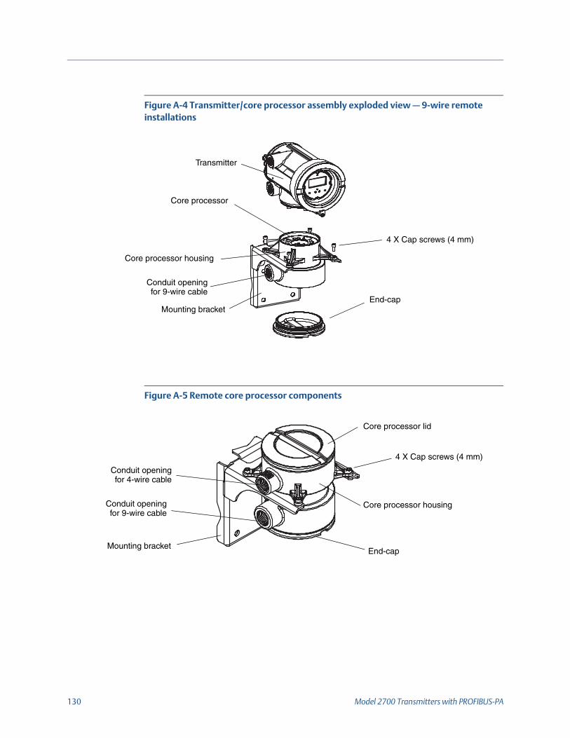
130 Model 2700 Transmitters with PROFIBUS-PA
Figure A-4 Transmitter/core processor assembly exploded view — 9-wire remote installations
Figure A-5 Remote core processor components
End-capMounting bracket
Core processor housing
Transmitter
Core processor
4 X Cap screws (4 mm)
Conduit openingfor 9-wire cable
End-capMounting bracket
Core processor lid
Core processor housing
Conduit openingfor 4-wire cable
Conduit openingfor 9-wire cable
4 X Cap screws (4 mm)
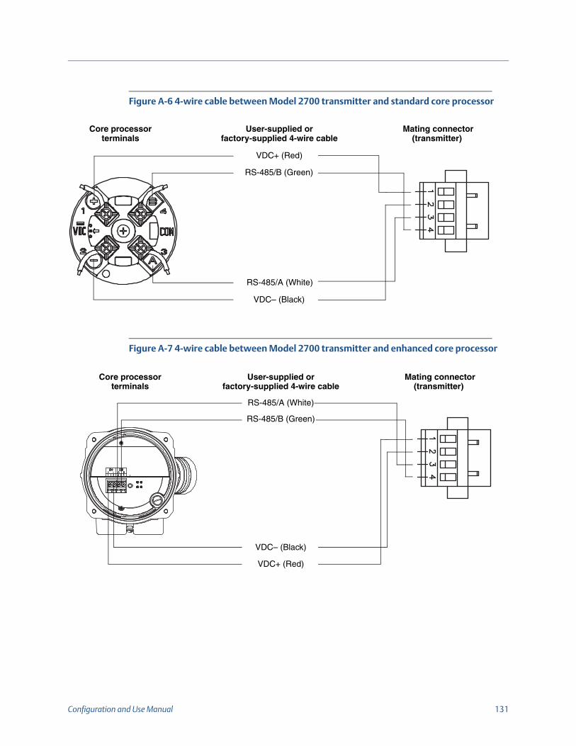
Configuration and Use Manual 131
Figure A-6 4-wire cable between Model 2700 transmitter and standard core processor
Figure A-7 4-wire cable between Model 2700 transmitter and enhanced core processor
Mating connector (transmitter)
Core processor terminals
VDC+ (Red)
VDC– (Black)
RS-485/B (Green)
RS-485/A (White)
User-supplied or factory-supplied 4-wire cable
Mating connector (transmitter)
Core processor terminals
VDC+ (Red)
VDC– (Black)
RS-485/B (Green)
RS-485/A (White)
User-supplied or factory-supplied 4-wire cable

132 Model 2700 Transmitters with PROFIBUS-PA
Figure A-8 9-wire cable between sensor junction box and core processor
Figure A-9 Output and power supply terminals
9-wire cable 9-wire terminal connections(core processor)
BrownRed
GreenWhite
BlueGray
Black(Drains from all wire sets)
BrownViolet
Yellow
BlueGrayOrange
RedGreenWhite
Mounting screw
Ground screwBlack
Plug andsocket
OrangeVioletYellow
to sensor junction box
Equipment ground
9 (–, N)
10 (+, L)
1
2
PROFIBUS terminals
Service port8
7

Configuration and Use Manual 133
Appendix B Using the Display
B.1 OverviewThis appendix describes the basic use of the display and provides a menu tree for the display. You can use the menu tree to locate and perform display commands quickly.
Note that Model 2700 transmitters can be ordered with or without displays. Not all configuration and use functions are available through the display. If you need the added functionality, or if your transmitter does not have a display, you must use either a PROFIBUS configuration tool or ProLink III.
B.2 ComponentsFigure B-1 illustrates the display components.
Figure B-1 Display components
B.3 Using the optical switchesThe Scroll and Select optical switches are used to navigate the display menus. To activate an optical switch, touch the lens in front of the optical switch or move your finger over the optical switch close to the lens. There is an optical switch indicator between the optical switches. When an optical switch is activated, the optical switch indicator is a solid red.
CAUTION!Do not insert an object into the openings as this can damage the equipment. Use your fingers to activate the optical switches.
Current value
Units of measure
Process variable line
Scroll optical switchSelect optical switch
Indicator light

134 Model 2700 Transmitters with PROFIBUS-PA
B.4 Using the displayThe display can be used to view process variable data or to access the transmitter menus for configuration or maintenance.
B.4.1 Display languageThe display can be configured for the following languages:
•English
•French
•Spanish
•German
Due to software and hardware restrictions, some English words and terms may appear in the non-English display menus. For a list of the codes and abbreviations used on the display, see Table 2-1.
For information on configuring the display language, see Section 4.16.5.
In this manual, English is used as the display language.
B.4.2 Viewing process variablesIn ordinary use, the Process variable line on the LCD panel shows the configured display variables, and the Units of measure line shows the measurement unit for that process variable.
• See Section 4.16.5 for information on configuring the display variables.
• See Table 2-1 for information on the codes and abbreviations used for display variables.
If more than one line is required to describe the display variable, the Units of measure line alternates between the measurement unit and the additional description. For example, if the LCD panel is displaying a mass inventory value, the Units of measure line alternates between the measurement unit (for example, G) and the name of the inventory (for example, MASSI).
Auto Scroll may or may not be enabled:
• If Auto Scroll is enabled, each configured display variable will be shown for the number of seconds specified for Scroll Rate.
• Whether Auto Scroll is enabled or not, the operator can manually scroll through the configured display variables by activating Scroll.
For more information on using the display to manage totalizers and inventories, see Section 5.8.
B.4.3 Using display menus
Note:The display menu system provides access to basic transmitter functions and data. It does not provide access to all functions and data. To access all functions and data, use a PROFIBUS host, PROFIBUS configuration tool, or ProLink III.

Configuration and Use Manual 135
To enter the display menu system:
1. Activate Scroll and Select simultaneously.
2. Hold Scroll and Select until the words SEE ALARM or OFF-LINE MAINT appear.
If no optical switch activity occurs for two minutes, the transmitter will exit the off-line menu system and return to the process variable display.
3. To move through a list of options, activate Scroll.
4. To select from a list or to enter a lower-level menu, scroll to the desired option, then activate Select. If a confirmation screen is displayed:
5. To confirm the change, activate Select.
6. To cancel the change, activate Scroll.
7. To exit a menu without making any changes:
• Use the EXIT option if available.
• Otherwise, activate Scroll at the confirmation screen.
B.4.4 Display passwordA password can be used to control access to either the off-line maintenance menu, the alarm menu, or both. The same code is used for both:
• If both passwords are enabled, the user must enter the password to access the top-level off-line menu. The user can then access either the alarm menu or the off-line maintenance menu without re-entering the password.
• If only one password is enabled, the user can access the top-level off-line menu, but will be prompted for the password when he or she attempts to access the alarm menu or the off-line maintenance menu (depending on which password is enabled). The user can access the other menu without a password.
• If neither password is enabled, the user can access all parts of the off-line menu without a password.
For information about enabling and setting the display password, refer to Section 4.16.4.
If a password is required, the word CODE? appears at the top of the password screen. Enter the digits of the password one at a time by using Scroll to choose a number and Select to move to the next digit.
If you encounter the display password screen but do not know the password, wait 30 seconds without activating any of the display optical switches. The password screen will timeout automatically and you will be returned to the previous screen.
Note:Access to the display menu system may be enabled or disabled. If disabled, the OFF-LINE MAINT option does not appear. For more information, see Section 4.16.1.
Note:If the petroleum measurement application is installed on your transmitter, the display password is always required to start, stop, or reset a totalizer, even if neither password is enabled. If the petroleum measurement application is not installed, the display password is never required for these functions, even if one of the passwords is enabled.

136 Model 2700 Transmitters with PROFIBUS-PA
B.4.5 Entering floating-point values with the displayCertain configuration values, such as meter factors or output ranges, are entered as floating-point values. When you first enter the configuration screen, the value is displayed in decimal notation (as shown in Figure B-2) and the active digit is flashing.
Figure B-2 Numeric values in decimal notation
To change the value:
1. Select to move one digit to the left. From the leftmost digit, a space is provided for a sign. The sign space wraps back to the rightmost digit.
2. Scroll to change the value of the active digit: 1 becomes 2, 2 becomes 3, ..., 9 becomes 0, 0 becomes 1. For the rightmost digit, an E option is included to switch to exponential notation.
3. To change the sign of a value:
a. Select to move to the space that is immediately left of the leftmost digit.
b. Use Scroll to specify – (for a negative value) or [blank] (for a positive value).
4. In decimal notation, you can change the position of the decimal point up to a maximum precision of four (four digits to the right of the decimal point). To do this:
a. Select until the decimal point is flashing.
b. Scroll. This removes the decimal point and moves the cursor one digit to the left.
c. Select to move one digit to the left. As you move from one digit to the next, a decimal point will flash between each digit pair.
d. When the decimal point is in the desired position, Scroll. This inserts the decimal point and moves the cursor one digit to the left.
5. To change from decimal to exponential notation (see Figure B-3):
a. Select until the rightmost digit is flashing.
b. Scroll to E, then Select. The display changes to provide two spaces for entering the exponent.
6. To enter the exponent:
a. Select until the desired digit is flashing.
b. Scroll to the desired value. You can enter a minus sign (first position only), values between 0 and 3 (for the first position in the exponent), or values between 0 and 9 (for the second position in the exponent).
c. Select.
SX.XXXXSignFor positive numbers, leave this space blank. For negative numbers, enter a minus sign (–).
DigitsEnter a number (maximum length: eight digits, or seven digits and a minus sign). Maximum precision is four.

Configuration and Use Manual 137
Figure B-3 Numeric values in exponential notation
To change from exponential to decimal notation:
1. Select until the E is flashing.
2. Scroll to d.
3. Select. The display changes to remove the exponent.To exit the menu:
• If the value has been changed, Select and Scroll simultaneously until the confirmation screen is displayed.
- Select to apply the change and exit.
- Scroll to exit without applying the change.
•If the value has not been changed, Select and Scroll simultaneously until the previous screen is displayed.
Note:When switching between decimal and exponential notation, any unsaved edits are lost. The system reverts to the previously saved value.
While in exponential notation, the positions of the decimal point and exponent are fixed.
SX.XXXEYY
Sign
DigitsEnter a four-digit number; three digits must fall to the right of the decimal point.
EExponent indicator
Sign or Digit (0–3)
Digit (0–9)

138 Model 2700 Transmitters with PROFIBUS-PA
B.5 AbbreviationsThe display uses a number of abbreviations. Table 2-1 lists the abbreviations used by the display.
Table 2-1 Display codes and abbreviations
Abbreviation Definition Abbreviation Definition
ACK ALARM Acknowledge alarm LPO_A Left pickoff amplitude
ACK ALL Acknowledge all alarms LVOLI Volume inventory
ADDR Address LZERO Live zero flow
AUTO SCRLL Auto scroll MAINT Maintenance
AVE_D Average density MASS Mass flow
AVE_T Average temperature MASSI Mass inventory
BRD_T Board temperature MFLOW Mass flow
BKLT Backlight MSMT Measurement
CAL Calibrate MTR F Meter factor
CHANGE CODE Change display password MTR_T Case temperature (T-Series only)
CODE Display password NET M CM net mass flow rate
CONC Concentration NET V CM net volume flow rate
CONFG Configure (or configuration) NETMI CM net mass inventory
CORE Core processor NETVI CM net volume inventory
CUR Z Current zero OFFLN Offline
DENS Density PASSW Password
DGAIN Drive gain PRESS Pressure
DISBL Disable PWRIN Input voltage
DRIVE% Drive gain r. Revision
DSPLY Display RDENS Density at reference temperature
ENABL Enable RPO_A Right pickoff amplitude
ENABLE ACK Enable the ACK ALL function SGU Specific gravity units
ENABLE ALARM Enable the alarm menu SIM Simulated
ENABLE AUTO Enable auto scroll SPECL Special
ENABLE OFFLN Enable the offline menu STD M Standard mass flow rate
ENABLE PASSW Enable the display password STD V Standard volume flow rate
ENABLE RESET Enable resetting of totals STDVI Standard volume inventory
ENABLE START Enable stopping/starting of totals TCDENS Temperature-corrected density
EXT_P External pressure TCORI Temperature-corrected inventory
EXT_T External temperature TCORR Temperature-corrected total
EXTRN External TCVOL Temperature-corrected volume

Configuration and Use Manual 139
FAC Z Factory zero TEMPR Temperature
FCF Flow calibration factor TUBEF Raw tube frequency
FLDIR Flow direction VER Version
GSV Gas standard volume VERFY Verify
GSV F Gas standard volume flow VFLOW Volume flow
GSV I Gas standard volume inventory VOL Volume flow
GSV T Gas standard volume total WRPRO Write protect
INTERN Internal WTAVE Weighted average
LANG Language XMTR Transmitter
LOCK Write protect
Table 2-1 Display codes and abbreviations (continued)
Abbreviation Definition Abbreviation Definition

140 Model 2700 Transmitters with PROFIBUS-PA
B.6 Display menusFigures 2-4 through 2-16 show the commands accessible through the display.
Figure 2-4 Display menu – Main
Figure B-5 Display menu – Alarms
SEE ALARM
Scroll and Select simultaneously for 4 seconds
OFF-LINE MAINTScrollENTERMETER/VERFYScroll
SEE ALARM
ACK ALL(1)
Yes
EXIT
Select
No
Alarm code
Scroll
ACK
Yes
Select
No
Active/unacknowledged
alarms?
NoYes
Select
NO ALARM
EXIT
Scroll
Scroll
Select
Scroll
ScrollSelect
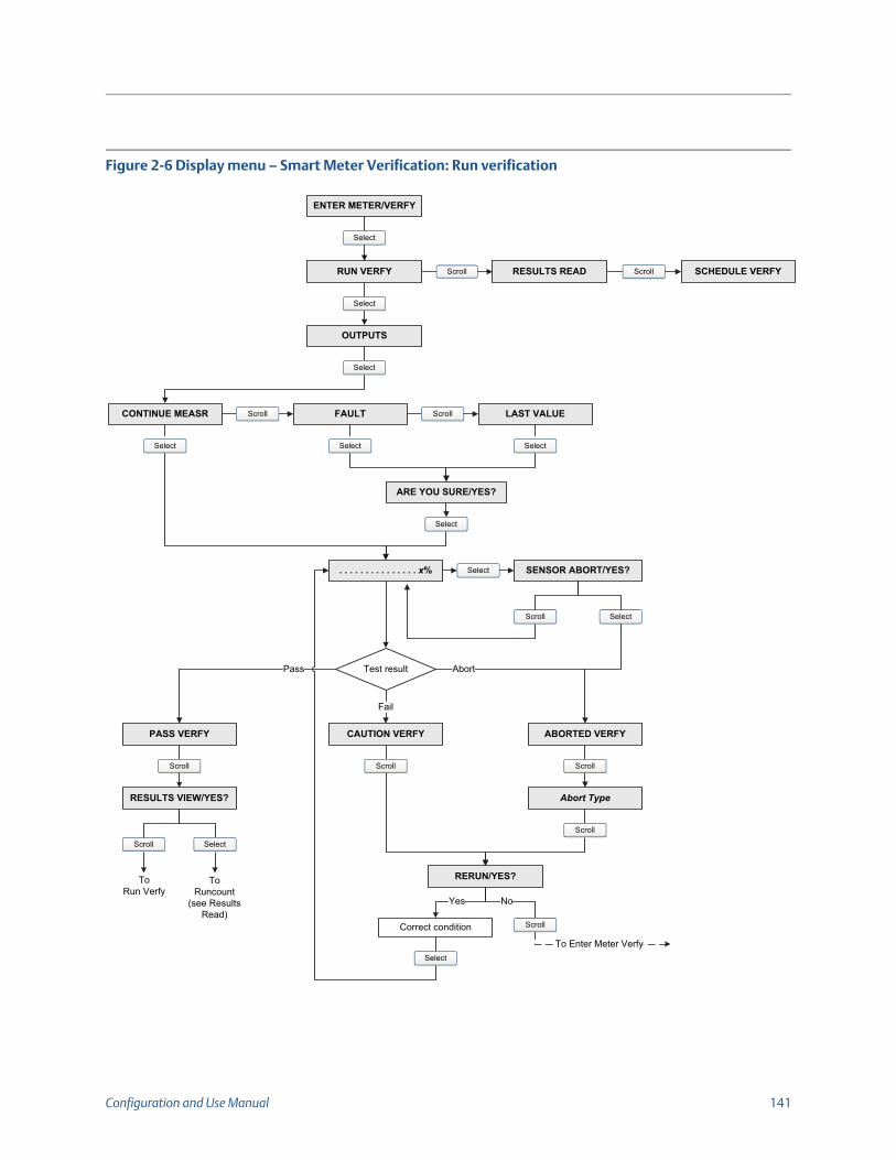
Configuration and Use Manual 141
Figure 2-6 Display menu – Smart Meter Verification: Run verification
OUTPUTS
ARE YOU SURE/YES?
. . . . . . . . . . . . . . . x%
PASS VERFY ABORTED VERFYCAUTION VERFY
Fail
Abort
RERUN/YES?
Yes No
Correct condition
CONTINUE MEASR FAULT LAST VALUE
Select
Scroll Scroll
Scroll
Select
Scroll
RESULTS VIEW/YES?
Select
Scroll Scroll
Select SelectSelect
Select SENSOR ABORT/YES?
SelectScroll
Abort Type
Scroll
Scroll Select
Test resultPass
To Enter Meter Verfy
ToRuncount
(see Results Read)
ToRun Verfy
RUN VERFY RESULTS READ SCHEDULE VERFY
ENTER METER/VERFY
Scroll Scroll
Select
Select

142 Model 2700 Transmitters with PROFIBUS-PA
Figure 2-7 Display menu – Smart Meter Verification: Read results
RUN VERFY RESULTS READ SCHEDULE VERFY
ENTER METER/VERFY
Scroll Scroll
Select
Select
xx L STF%
RUNCOUNT x
Select
xx HOURS
Select
PASS
Select
xx R STF%
Select
RESULTS MORE?
Select
Scroll
To Run Verfy
Pass
Select Scroll
Result type
Fail
Abort
xx HOURS
Select
CAUTION
xx L STF%
xx R STF%
Select
Select
xx HOURS
Abort Type
To Runcount x-1
Select
SelectSelect

Configuration and Use Manual 143
Figure 2-8 Display menu – Smart Meter Verification: Scheduling
Figure 2-9 Display menu – Off-line Maintenance
RUN VERFY RESULTS READ SCHEDULE VERFY
ENTER METER/VERFY
Scroll Scroll
Select
Select
SAVE/YES?
TURN OFF SCHED/YES?
SET NEXT
Select
Select
Schedule set? Yes
Schedule deleted
Scroll
HOURS LEFT
SelectScroll
xx HOURS
SET RECUR
No
SCHED IS OFF
xx HOURS
Select
Scroll
No Yes
Select
xx HOURS
Select
SAVE/YES?
Scroll
No Yes
Scroll
Select
Scroll
OFF-LINE MAINT
SWREV CONFG ZERO SENSOR VERFYScroll Scroll Scroll
Select

144 Model 2700 Transmitters with PROFIBUS-PA
Figure 2-10 Display menu – Off-line Maintenance: Configuration
Figure 2-11 Display menu – Off-line Maintenance: Configuration: Units
Figure 2-12 Display menu – Off-line Maintenance: Configuration: Meter factors
OFF-LINE MAINT
SWREV CONFG ZERO SENSOR VERFYScroll Scroll Scroll
Select
Select
UNITS MTR F DISPLAYScroll Scroll
ADDRESS PBUS IDENT SEL CONFIG AIScroll Scroll
CONFIG AO CONFIG TOTScroll
Scroll
Scroll
UNITS
Select
MASS VOL GSVScroll Scroll
DENS TEMP PRESSScroll ScrollScroll
MTR F
Select
MASS VOL DENSScroll Scroll

Configuration and Use Manual 145
Figure 2-13 Display menu – Off-line Maintenance: Configuration: Display
Figure 2-14 Display menu – Off-line Maintenance: Configuration: AI blocks
TOTALS RESET
DISPLAY
TOTALS STOP DISPLAY OFFLN
Select
Scroll Scroll
Scroll DISPLAY ALARM DISPLAY ACK AUTO SCRLL
CODE OFFLN
DISPLAY BKLT
SCROLL RATE CODE ALARM
DISPLAY LANG
CHANGE CODE DISPLAY RATE
Scroll Scroll
ScrollScrollScroll
Scroll ScrollScroll
Scroll
CONFG AI
Select
AI1 CHAN Scroll AI1 UNITS
AI4 CHAN Scroll AI4 UNITS
AI3 CHAN Scroll AI3 UNITS
AI2 CHAN Scroll AI2 UNITSScroll
Scroll
Scroll

146 Model 2700 Transmitters with PROFIBUS-PA
Figure 2-15 Display menu – Off-line Maintenance: Configuration: AO blocks
Figure 2-16 Display menu – Off-line Maintenance: Configuration: Totalizers
CONFG AO
Select
AO1 INCH Scroll AO1 PV UNITS
AO2 OUTCH Scroll AO2 OUT UNITS
AO2 INCH Scroll AO2 PV UNITS
AO1 OUTCH Scroll AO1 OUT UNITSScroll
Scroll
Scroll
CONFG TOT
Select
TOT1 MODE Scroll TOT1 CHAN
TOT3 MODE Scroll TOT3 CHAN
TOT2 CHAN Scroll TOT2 UNITS
TOT1 UNITS
Scroll TOT2 MODE
Scroll
Scroll
Scroll
TOT3 UNITS
Scroll TOT4 MODE TOT3 CHAN Scroll TOT4 UNITS
Scroll
Scroll

Configuration and Use Manual 147
Figure 2-17 Display menu – Off-line Maintenance: Zeroing
OFF-LINE MAINT
SWREV CONFG ZERO SENSOR VERFYScroll Scroll Scroll
Select
Select
………………….
ZERO/YES?CAL PASSCAL FAIL
CAL ZERO
Select
Select

148 Model 2700 Transmitters with PROFIBUS-PA

Configuration and Use Manual 149
Appendix C Connecting with ProLink III
C.1 OverviewThe instructions in this manual assume that users are already familiar with ProLink III software and can perform the following tasks:
• Start and navigate in ProLink III software
• Establish communication between ProLink III software and compatible devices
• Transmit and receive configuration information between ProLink III software andcompatible devices
If you are unable to perform the tasks listed above, consult the ProLink III software manual before attempting to use the software to configure a transmitter.
C.2 Connecting to a personal computerYou can temporarily connect a personal computer (PC) to the transmitter’s service port. The service port is located within the transmitter wiring compartment, beneath the intrinsic safety cover. See Figure C-1.
Figure C-1 Service port
Service port (7,8)
Power-supplycompartment door

150 Model 2700 Transmitters with PROFIBUS-PA
C.2.1 Connecting to the service portTo temporarily connect to the service port, which is located in the non-intrinsically safe power-supply compartment:
1. Open the cover to the intrinsically safe wiring compartment.
2. Open the transmitter’s power-supply compartment door.
3. Connect one end of the signal converter leads to the RS-485 terminals on the signal converter.
4. Connect the other end of the signal converter leads to the service-port terminals. See Figure C-2.
Figure C-2 Connecting to the service port
WARNING!Opening the wiring compartment in a hazardous area can cause an explosion. The service port should only be used for temporary connections. When the transmitter is in an explosive atmosphere, do not use the service port to connect to the transmitter.
WARNING!Opening the power supply compartment can expose the operator to electric shock. To avoid the risk of electric shock, do not touch the power supply wires or terminals while using the service port.
Service portRS-485 to RS-232 signal converter
25 to 9 pin serial port adapter (if necessary)
RS-485B
RS-485A

Configuration and Use Manual 151
Appendix D PROFIBUS-PA Status Byte
D.1 OverviewThis appendix describes the status byte reported by the transmitter to a PROFIBUS host. The output of each AI, AO, and totalizer function block is a 5-byte package: four bytes of process information and one byte indicating measurement quality, also called the status byte. The format of the status byte depends on whether the transmitter is configured for classic mode or condensed mode.
D.2 Classic-mode status byte formatTables 4-1 through D-6 describes the format of the status byte when the transmitter is configured for classic mode. Refer to Section 3.7.3.6 of the PROFIBUS-PA Profile for Process Control Devices v3.01 for more information.
Table 4-1 Classic-mode status byte format
Status bits Meaning Comment
00 Bad The measurement is not useful.
01 Uncertain The quality of the measurement is below normal, but may still be useful.
10 Good – Non-cascade
The quality of the measurement is good, but alarms may be indicated by the sub-status.
11 Good – Cascade The measurement is good.
Table 4-2 Sub-status format – Bad status
Bits Meaning Comment
0011 Device failure TRUE if the following alarm codes are active:A001, A002, A014, A029, or A030.
0100 Sensor failure TRUE if the following alarm codes are active:A003, A004, A005, A016, or A017.
0111 Out of service See the profile specification for details.
Table D-3 Sub-status format – Uncertain status
Bits Meaning Comment
0000 Non-specific TRUE if the following alarm codes are active:A005, A008, A010, A011, A012, A013, A021, A033, or A102.
0011 Initial value TRUE if the following alarm codes are active:A006 or A120.
1000 Simulated value TRUE if the following alarm codes are active:A132.
1001 Sensor calibration TRUE if the following alarm codes are active:A104.

152 Model 2700 Transmitters with PROFIBUS-PA
D.3 Condensed-mode status byte formatTable 4-7 describes the format of the status byte when the transmitter is configured for condensed mode. Refer to the PROFIBUS Specification Profile for Process Control Devices Version v3.01 December 2004 and the PROFIBUS Specification June 2005 Amendment 2 to the PROFIBUS Profile for Process Control Devices v3.01, Condensed Status and Diagnostic Messages v1.0 for additional information.
Table D-4 Sub-status format – Good status (non-cascade)
Bits Meaning Comment
0001 Update event
0010 Active advisory alarm
0011 Active critical alarm
Table D-5 Sub-status format – Good status (cascade)
Bits Meaning Comment
0000 OK This bit is set if no alarms are active.
Table D-6 Limit bits
Bits Meaning Comment
00 OK
01 Low limited
10 High limited
11 Constant
Table 4-7 Condensed-mode status byte format
Expanded status Condensed status Alarms
BAD_DEVICE_FAIL (0x0C) C_BAD_MAINTENANCE_ALARM (0x24…..0x27)(1)(2) A001, A002, A014, A029, A030
BAD_SENSOR_FAIL (0x10) C_BAD_PROCESS_RELATED (0x2B)(2) A003, A004, A016, A017
BAD_CFG_ERROR (0x04) C_BAD_FUNCTION_CHECK (0x3C ……0x3F)(1)(2) A006, A020, A021
BAD_NON_SPECIFIC (0x00) BAD_NON_SPECIFIC (0x00) All remaining fault alarms under this category.
UC_SIMULATED_VALUE (0x60) C_UNCERTAIN_SIMULATED_VALUE_START (0x73) A132
UC_SENSOR_CAL (0x64) C_BAD_FUNCTION_CHECK (0x3C ……0x3F)(1)(2) A104
UC_CFG_ERROR (0x5C) C_BAD_FUNCTION_CHECK (0x3C……0x3F)(1)(2) A006, A020, A021

Configuration and Use Manual 153
UC_NON_SPECIFIC (0x40) C_UNCERTAIN_PROCESS_RELATED (0x78.. …0x7B)(1) A005, A008, A010, A011, A012, A013, A033, A102
GOOD_NC_ADV_ALARM (0x88) C_GOOD_ACTIVE_ADVISORY_ALARM (0x88…..0x91)(1) All informational alarms.
GOOD_NC_UPDATE_EVT (0x84) C_GOOD_UPDATE_EVENT (0x84) ST revision update for transducer blocks.
GOOD_CAS_OK (0xC0) C_GOOD_CAS_OK (0xC0) None of the alarms stated above are active.
BAD_OUT_OF_SERVICE | LIMIT_CONSTANT (0x1C)
C_BAD_PASSIVATED (0x23) Actual mode of AI, AO, or totalizer blocks is Out of Service.
Totalizer Fail Safe: UC_NON_SPECIFIC (0x40)
C_UNCERTAINC_SUBSTITUTE_SET (0x4B) Failsafe – RUN mode
Totalizer Fail Safe: UC_LUV (0x44)
C_UNCERTAINC_PROCESS_RELATED (0x78….0x7B)(1) Failsafe – HOLD_LUV mode
Totalizer Fail Safe: UC_NON_SPECIFIC (0x40)
C_UNCERTAINC_SUBSTITUTE_SET (0x4B) Failsafe – MEMORY mode
UC_INITIAL_VAL (0x4C) C_UNCERTAIN_INITIAL_VALUE (0x4F) When reset or preset totals.
UC_SUBSTITUTE_VAL (0x48) C_UNCERTAIN_SUBSTITUTE_SET (0x4B) AO failsafe active.
(1) Limits status as applicable.(2) AI function block FB behaves like FSAFE_TYPE = 1 as per Section 3.3.1 (Table 19) of the PROFIBUS Specification June 2005, Order no. 3.042,
Amendment 2 to the PROFIBUS Profile for Process Control Devices v3.01, Condensed Status and Diagnostic Messages v1.0.
Table 4-7 Condensed-mode status byte format (continued)
Expanded status Condensed status Alarms

154 Model 2700 Transmitters with PROFIBUS-PA

Configuration and Use Manual 155
Appendix E Slave Diagnostic Response Bytes
E.1 OverviewThis appendix describes the diagnostic bytes reported by the transmitter to a PROFIBUS host. There are two sets of diagnostic bytes sent:
• Bytes 1–6 conform to the standard PROFIBUS specification.
• Byte 7 is the extended diagnostic header byte.
• Bytes 8–15 are extended diagnostic bytes that conform to the Profile 3.01 specification and the Diagnosis, Alarms, and Timestamping Profile Guidelines.
• The final 10 bytes are extended diagnostic bytes that correspond to alarms in the transmitter. Alarm codes referenced in these bytes are the codes shown on the transmitter display. Refer to Section 6.8 for more information about alarm codes.
E.2 PROFIBUS specification diagnostic bytesTables E-1 through E-6 describe the PROFIBUS diagnostic response bytes.
Note:AI, AO, and totalizer function blocks will go into Out of Service mode when any of the following diagnostics bits are set: 24 (hardware failure), 28 (memory error), or 29 (measurement failure).There can be as many as 62 device-related diagnostic bytes.
Table E-1 Byte 1
Bit Indication
0 Station not existent (this is set by the master if the slave does not respond)
1 Station not ready for data exchange
2 Configuration fault: slave did not accept last configuration data
3 Slave has extended diagnostic data to report
4 Slave does not support requested parameter function
5 Invalid slave response (this is set by the master)
6 Parameter fault: slave did not accept last parameterization data
7 Slaved is locked or controlled by another master (this is set by the master)
Table E-2 Byte 2
Bit Indication
0 Slave must be parameterized
1 Static diagnostic: master requesting diagnostics until bit is reset
2 This bit is always set to 1
3 Response monitoring/watchdog (1 = ON; 0 = OFF)
4 Slave is in freeze mode (1 = ON; 0 = OFF)
5 Slave is in sync mode (1 = ON; 0 = OFF)
6 Reserved
7 Slave is deactivated in master parameter set (this is set by the master)

156 Model 2700 Transmitters with PROFIBUS-PA
Table E-3 Byte 3
Bit Indication
0 Reserved (this is always set to 0)
1 Reserved (this is always set to 0)
2 Reserved (this is always set to 0)
3 Reserved (this is always set to 0)
4 Reserved (this is always set to 0)
5 Reserved (this is always set to 0)
6 Reserved (this is always set to 0)
7 Diagnostic overflow—transmitter has more diagnostic data than it can report
Table E-4 Byte 4
Bit Indication
0 Master station address
An address in the range of 0–125 decimal (0x0–0x7D hex) is the address of the controlling master.
An address of 255 decimal (0xFF hex) means the slave is not controlled or parameterized by a master.
1
2
3
4
5
6
7
Table E-5 Byte 5
Bit Indication
0 Ident number (MSB)(1)
(1) The identification number will be 0x9742 when in profile-specific I/O mode and 0x057A when in manufacturing-specific I/O mode. Refer to Section 2.5 for information about I/O modes.
1
2
3
4
5
6
7

Configuration and Use Manual 157
Table E-6 Byte 6
Bit Indication
0 Ident number (LSB)
1
2
3
4
5
6
7
Table E-7 Byte 7 – Extended diagnostic header byte
Bit Indication
0 Number of extended diagnostic bytes (including this header byte)
1
2
3
4
5
6 Identifier for device-related diagnostics status model (0x00)
7
Table E-8 Byte 8
Bit Indication
8 Status type = manufacturer-specific (32 decimal, 0x20 hex)
9
10
11
12
13
14
15 Identifier for status—always set to 1
Table E-9 Byte 9
Bit Indication
8 Slot number of physical block (per Profile 3.01 this is 0)
9
10
11
12
13
14
15

158 Model 2700 Transmitters with PROFIBUS-PA
Table E-10 Byte 10
Bit Indication
16 Error appears (when any new alarm is activated)
17 Error disappears (when an alarm is deactivated)
18 Reserved
19 Reserved
20 Reserved
21 Reserved
22 Reserved
23 Reserved
Table E-11 Byte 11
Bit Indication
24 Reserved (always set to 0)
25 Reserved (always set to 0)
26 Reserved (always set to 0)—Not used
27 Reserved (always set to 0)
28 Reserved (always set to 0)
29 Reserved (always set to 0)
30 Reserved (always set to 0)
31 Reserved (always set to 0)
Table E-12 Byte 12
Bit Indication
32 Reserved
33 Reserved
34 Reserved
35 Restart (A107)
36 Cold start (A107)
37 Maintenance required—Not used
38 Reserved
39 Ident_Number violation
Table E-13 Byte 13
Bit Indication
40 Maintenance alarm (A014, A001, A002, A003, A022, A023, A024, A026)
41 Maintenance demanded (A103)
42 Function check (A106 if any function block is in simulation mode)
43 PRO_COND (not used)
44 Reserved (always set to 0)
45 Reserved (always set to 0)
46 Reserved (always set to 0)
47 Reserved (always set to 0)

Configuration and Use Manual 159
Table E-14 Byte 14
Bit Indication
48 Reserved (always set to 0)
49 Reserved (always set to 0)
50 Reserved (always set to 0)
51 Reserved (always set to 0)
52 Reserved (always set to 0)
53 Reserved (always set to 0)
54 Reserved (always set to 0)
55 Extension available
Table E-15 Byte 15
Bit Indication
56 Undefined (A000)
57 EEPROM checksum error (A001)
58 RAM test error (A002)
59 Sensor not responding (no tube interrupt) (A003)
60 Temperature sensor out-of-range (A004)
61 Input over-range (A005)
62 Transmitter not characterized (A006)
63 Reserved
Table E-16 Byte 16
Bit Indication
64 Density outside limits (A008)
65 Transmitter initializing/warming up (A009)
66 Calibration failure (A010)
67 Excess calibration correction, zero too low (A011)
68 Excess calibration correction, zero too high (A012)
69 Process too noisy to perform auto zero (A013)
70 Transmitter failed (A014)
71 Reserved
Table E-17 Byte 17
Bit Indication
72 Line RTD temperature out-of-range (A016)
73 Meter RTD temperature out-of-range (A017)
74 Reserved
75 Reserved
76 Calibration factors unentered (A020)
77 Unrecognized/unentered sensor type (A021)
78 Reserved
79 Reserved

160 Model 2700 Transmitters with PROFIBUS-PA
Table E-18 Byte 18
Bit Indication
80 Reserved
81 Reserved
82 Sensor/xmtr communication failure (A026)
83 Reserved
84 Sensor/xmtr write failure (A028)
85 Internal communication failure (A029)
86 Hardware/software incompatible (A030)
87 Low power (A031)
Table E-19 Byte 19
Bit Indication
88 Meter verification fault alarm (A032)
89 Sensor OK/tubes stopped by process (A033)
90 Reserved
91 Reserved
92 Reserved
93 Reserved
94 Reserved
95 Reserved
Table E-20 Byte 20
Bit Indication
96 Reserved
97 Reserved
98 Drive overrange/partially full tube (A102)
99 Data loss possible (A103)
100 Calibration in progress (A104)
101 Slug flow (A105)
102 Reserved
103 Power reset occurred (A107)
Table E-21 Byte 21
Bit Indication
104 Reserved
105 Reserved
106 Reserved
107 Reserved
108 Reserved
109 Reserved
110 Reserved
111 Reserved

Configuration and Use Manual 161
Table E-22 Byte 22
Bit Indication
112 Petroleum measurement: temperature out-of-limits (A116)
113 Petroleum measurement: density out-of-limits (A117)
114 Reserved
115 Reserved
116 Concentration measurement: Unable to fit curve data (A120)
117 Concentration measurement: Extrapolation alarm (A121)
118 Reserved
119 Reserved

162 Model 2700 Transmitters with PROFIBUS-PA

Configuration and Use Manual 163
Appendix F Model 2700 PROFIBUS Block Parameters
F.1 OverviewThis appendix describes the block parameters of the Model 2700 transmitter with PROFIBUS-PA.
F.2 Slot identificationTable F-1 shows the slot assignment for blocks.
Table F-1 Block slot assignment
Slot Assigned block
0 Physical block
1 Analog input block 1
2 Analog input block 2
3 Analog input block 3
4 Totalizer block 1
5 Analog input block 4
6 Totalizer block 2
7 Totalizer block 3
8 Totalizer block 4
9 Analog output block 1
10 Analog output block 2
11 Transducer block 1
12 Transducer block 2

164 Model 2700 Transmitters with PROFIBUS-PA
F.3 Physical blockTable 6-2 shows the parameters for the physical block.
Table 6-2 Physical block parameters
Index Parameter Mnemonic Definition Message Type
Data Type/Structure
Size Store/Rate (HZ)
DefaultValue
Access Enumerated List of Values / Range
Modbus Register / Coil
Standard Parameters
16 BLOCK_OBJECT This object contains the characteristics of the block
RECORD DS-32 20 Cst ---- R NA NA
17 ST_REV A block has static block parameters that are not changed by the process. Values are assigned to this parameter during the configuration of optimization. The value of ST_REV increases by 1 after every change of a static block parameter.
SIMPLE Unsigned16 2 N 0 R NA NA
18 TAG_DESC Every block can be assigned a textual TAG description. The TAG_DESC must be unambiguous and unique in the field bus system.
SIMPLE Visible STRING
32 S ‘ ’ R/W NA NA
19 STRATEGY Grouping of function block. The STRATEGY field can be used to group blocks.
SIMPLE Unsigned16 2 S 0 R/W NA NA
20 ALERT_KEY This parameter contains the identification number of the plant unit.
SIMPLE Unsigned8 1 S 0 R/W NA NA
21 TARGET_MODE This parameter contains desired mode normally set by a control application of an operator. The modes are valid alternatively only, i.e. only one mode can be set at one time. A write access to this parameter with more than one mode is out of the range of the parameter and has to be rejected.
SIMPLE Unsigned8 1 S AUTO (0x08)
R/W AUTO ( 0x08) NA
22 MODE_BLK This parameter contains the current mode and the permitted and normal mode of the block.
RECORD DS-37 3 D --- R NA NA
23 ALARM_SUM This parameter contains the current states of the block alarms.
RECORD DS-42 8 D 0,0,0,0 R NA NA
Physical block parameters
24 SOFTWARE_REVISION(DD Name: Software Revision)
Revision-number of the software of the field device.
Simple Visible String 16 Cst --- R NA R-1200
25 HARDWARE_REVISION (DD Name: Hardware Revision)
Revision-number of the hardware of the field device.
Simple VisibleString
16 Cst 1.0 R NA Hard Coded
26 DEVICE_MAN_ID(DD Name: Manufacturing ID)
Identification code of the manufacturer of the field device.
Simple Unsigned16 2 Cst ---- R NA R-121
27 DEVICE_ID (DD Name: Device ID)
Manufacturer specific identification of the device.
Simple Visible String 16 Cst ---- R NA 2545-2554
28 DEVICE_SER_NUM(DD Name: PB Serial Number)
Serial number of the field device. Simple Visible String 16 Cst ---- R NA R122-123
29 DIAGNOSIS(DD Name: Physical Block Diagnosis)
Detailed information of the device, bitwise coded. More than one messagepossible at once. If MSB of byte 4 is set to 1 than more diagnose information isavailable in the DIAGNOSIS_EXTENSION parameter.
Simple Octet Stringbyte4,MSB=1more diagavailable
4 D ---- R Refer byte 11 to 14 of Extended Diagnostics bytes in Appendix A
NA
30 EMPTY
31 DIAGNOSIS_MASK(DD Name: Diagnosis Mask)
Definition of supported DIAGNOSIS information-bits.
Simple Octet string 4 Cst ---- R Out of Mandatory Alarms out of 4 Octets only Ident No. violation Alarm is supported.And Extension Available Alarm is supported0: not supported1: supported
Hard Coded0x00 0x800x00 0x80
32 EMPTY

Configuration and Use Manual 165
33 EMPTY
34 EMPTY
35 EMPTY
36 Reserved
37 Reserved
38 DEVICE_INSTALL_DATE Device Installation Date Simple Octect String 16 S Blank R/W 2278-2285
40 IDENT_NUMBER_SELECTOR(DD Name: Ident Number)
Each PROFIBUS-DP /IEC 61158/ device shall have an Ident_Number provided bythe PNO. There are profile specific Ident_Numbers. A device may have profilespecific and manufacturer specific ones. The user is able to choose one of theseusing this parameters.
Simple Unsigned8 1 S ---- R/W 0: profile specific Ident_Number V3.01 (mandatory)1: manufacturer specific Ident_Number V3.01
NA
42 FEATURE(DD Name: phys Feature)
Indicates optional features implemented in the device and the status of theseFeatures which indicates if the feature is supported or not supported.
Record DS-68 8 N 0x03, 0x00, 0x00, 0x00, 0x02, 0x00, 0x00, 0x00
R PROFIBUSSpecificationJune 2005Order No: 3.042Amendment 2tothe Profibus Profile for ProcessControl Devices V 3.01Condensed Status and DiagnosticMessagesV 1.0
NA
43 COND_STATUS_DIAG Condensed Status Diagnostics Simple Unsigned-8 1 S 0 R/W 0: Status and Diagnosis is provided as defined in -PROFIBUS Profile: “PROFIBUS-PA Profile for Process Control Devices” V3.01,December 2004. PNO-Order-No. 3.042.1: Condensed Status and Diagnosis information is provided. NA
NA
44 Reserved
45 Reserved
46 Reserved
47 Reserved
48 Reserved
49 Physical Block Views
Table 6-2 Physical block parameters (continued)
Index Parameter Mnemonic Definition Message Type
Data Type/Structure
Size Store/Rate (HZ)
DefaultValue
Access Enumerated List of Values / Range
Modbus Register / Coil

166 Model 2700 Transmitters with PROFIBUS-PA
F.3.1 Physical block objectTable 6-3 shows the physical block object.
Table 6-3 Physical block object
Slot/Index Element name Data type Size in bytes Value
Slot 0/Index 16
Reserved Unsigned 8 1 250 (default)
Block_Object Unsigned 8 1 01
Parent_Class Unsigned 8 1 01
Class Unsigned 8 1 250 (default)
DD_Refrence Unsigned 32 4 00 ,00, 00, 00 (Reserved)
DD_Revision Unsigned 16 2 00 ,00 (reserved)
Profile Octet String 2 64 02 (compact class B)
Profile_Revision Unsigned 16 2 03 01 (3.01)
Execution_Time Unsigned 8 1 00 (for future use)
Number_Of_Parameters Unsigned 16 2 00 26 ( Max no of Physical Block Parameters)
Address_of_View_1 Unsigned 16 2 00 49 (slot, index)
Number_of_Views Unsigned 8 1 01 (1 view)

Configuration and Use Manual 167
F.3.2 Physical block viewsTable 6-4 shows the physical block views.
Table 6-4 Physical block views
ODIndex
Parameter Mnemonic View 1
View 2
View 3
View 4
Standard Parameters
16 BLOCK_OBJECT
17 ST_REV 2
18 TAG_DESC
19 STRATEGY
20 ALERT_KEY
21 TARGET_MODE
22 MODE_BLK 3
23 ALARM_SUM 8
Overall sum of bytes in View Object 13
ODIndex
Parameter Mnemonic View 1
View 2
View 3
View 4
Standard Parameters
29 DIAGNOSIS 4
Overall sum of bytes in View Object(+ 13 Standard parameters bytes)
4+13

168 Model 2700 Transmitters with PROFIBUS-PA
F.4 Transducer block 1 (measurement, calibration, and diagnosis)Table 6-5 shows the parameters for transducer block 1.
Table 6-5 Transducer block 1 parameters
Index Parameter Mnemonic Definition Message Type
Data Type/Structure
Size Store/Rate (HZ)
DefaultValue
Access
Enumerated List of Values / Range
Modbus Register / Coil
Standard PA parameters
0 BLOCK_OBJECT This object contains the characteristics of the block
RECORD DS-32 20 CSt ---- R NA NA
1 ST_REV A block has static block parameters, that are not changed by the process. Values are assigned to this parameter during the configuration of optimization. The value of ST_REV increases by 1 after every change of a static block parameter.
SIMPLE Unsigned16
2 N 0 R NA NA
2 TAG_DESC Every block can be assigned a textual TAG description. The TAG_DESC must be unambiguous and unique in the field bus system.
SIMPLE OCTET STRING
32 S ‘ ’ R/W NA NA
3 STRATEGY Grouping of function block. The STRATEGY field can be used to group blocks.
SIMPLE Unsigned16
2 S 0 R/W NA NA
4 ALERT_KEY This parameter contains the identification number of the plant unit.
SIMPLE Unsigned8 1 S 0 R/W NA NA
5 TARGET_MODE This parameter contains desired mode normally set by a control application of an operator. The modes are valid alternatively only, i.e. only one mode can be set at one time. A write access to this parameter with more than one mode is out of the range of the parameter and has to be rejected.
SIMPLE Unsigned8 1 S AUTO (0x08)
R/W AUTO (0x08) NA
6 MODE_BLK This parameter contains the current mode and the permitted and normal mode of the block.
RECORD DS-37 3 D --- R NA NA
7 ALARM_SUM This parameter contains the current states of the block alarms.
RECORD DS-42 8 D 0,0,0,0
R NA NA
Standard Flow Transducer block Parameters
8 CALIBR_FACTOR(DD Name :Flow Cal Factor)
Gain compensation value for the flow sensor, so that flow indication is accurate as specified by the manufacturer.
SIMPLE Float 4 S --- R/W R-0407
9 LOW_FLOW_CUTOFF(DD Name : Mass Flow Cutoff)
Mass Flow can have an hysteresis. If the value has a hysteresis, this parameter defines the lower switching point. The unit of this value is the mass flow units
SIMPLE Float 4 S 0 R/W
R-0195
10 MEASUREMENT_MODE(DD Name: Measurement Mode)
Mode of flow measurement SIMPLE Unsigned8 1 S 0 R/W
0 = Forward Only1 = Reverse Only2 = Bi-Directional3 = Absolute Value4 = Negate/Forward Only 5 = Negate/Bi-Directional
R-0017
11 FLOW_DIRECTION(DD Name :Flow Direction)
Assigns an arbitrary positive or negative sign to the mass flow value
SIMPLE Unsigned8 1 S 0 R/W
0 = positive1 = negative
NA
12 ZERO_POINT(DD Name: Zero Point)
Offset compensation value for the flow sensor, so that true zero flow value can be indicated during no flow condition
SIMPLE Float 4 S ---- R/W
R-0233
13 ZERO_POINT_ADJUST(DD Name: Zero Calibration)
Initiates a device specific adjustment cycle that determines the true ZERO_POINT value during no flow process conditions. The result is shown in ZERO_POINT
SIMPLE Unsigned8 1 N 0 R/W
0 = cancel1 = execute
NA
14 ZERO_POINT_UNIT(DD Name: Zero Point Unit)
Selected unit code for ZERO_POINT parameter
SIMPLE Unsigned16
2 S 1057 R/W 1057 = microseconds
NA

Configuration and Use Manual 169
15 NOMINAL_SIZE(DD Name: Nominal Size)
Ideal size of the measuring pipe or process pipe size for insertion type flow transmitter
SIMPLE Float 4 S --- R/W NA
16 NOMINAL_SIZE_UNITS(DD Name: Nominal Size Units)
Selects the units for NOMINAL_SIZE parameter
SIMPLE Unsigned16
2 S 1019 R/W 1019 = inch NA
17 VOLUME_FLOW(DD Name : Volume Flow Rate)
Measure volume flow. This is an optional parameter for this device
RECORD 101 5 D --- R/W NA
18 VOLUME _FLOW_UNITS(DD Name :Volume Flow Units)
Selected unit code for VOLUME_FLOW, VOLUME_FLOW_LO_LIMIT and VOLUME_FLOW_HI_LIMIT
SIMPLE Unsigned16
2 S 1349 R/W
0000 = None1347 = m3/s1348 = m 3/min1349 = m3/hr1350 = m3/day1351 = L/s1352 = L/min1353 = L/hr1355 = Ml/day1356 = CFS1357 = CFM1358 = CFH1359 = ft3/day1362 = gal/s1363 = GPM1364 = gal/hour1365 = gal/day1366 = Mgal/day1367 = ImpGal/s1368 = ImpGal/min1369 = ImpGal/hr1370 = Impgal/day1371 = bbl/s1372 = bbl/min1373 = bbl/hr1374 = bbl/day1642 = beer bbl/s1643 = beer bbl/min1644 = beer bbl/hr1645 = beer bbl/day1999 = special
R-0042
21 MASS_FLOW(DD Name : Mass Flow Rate)
Measure mass flow. This is the Primary Variable (PV ) for this device
RECORD 101 5 D ---- R R-0247
22 MASS_FLOW_UNITS(DD Name : Mass Flow Units)
Selected unit code for MASS_FLOW, MASS _FLOW_LO_LIMIT and MASS _FLOW_HI_LIMIT
SIMPLE Unsigned16
2 S 1322 R/W
1318 = g/s1319 = g/min1320 = g/hr1322 = kg/s1323 = kg/min1324 = kg/hr1325 = kg/day1327 = t/min1328 = t/h1329 = t/d1330 = lb/s1331 = lb/min1332 = lb/hr 1333 = lb/day1335 = Ston/min1336 = Ston/hr1337 = Ston/day1340 = Lton/hr 1341 = Lton/day1999 = special
R-0039
25 DENSITY(DD Name : Density)
Measure density. This is the Secondary Variable (SV ) for this device
RECORD 101 5 D --- R R-0003
26 DENSITY_UNITS(DD Name : Density Units)
Selected unit code for DENSITY, DENSITY _LO_LIMIT and DENSITY _HI_LIMIT
SIMPLE Unsigned16
2 S 1103 R/W
0000 = None1097 = kg/m31100 = g/cm31103 = kg/L1104 = g/ml1105 = g/L1106 = lb/in31107 = lb/ft31108 = lb/gal1109 = Ston/yd31113 = DegAPI1114 = SGU
R-0040
29 TEMPERATURE(DD Name : Temperature)
Measure temperature. This is the Tertiary Variable (TV ) for this device
RECORD 101 5 D ---- R R-251
30 TEMPERATURE_UNITS(DD Name : Temperature Units)
Selected unit code for TEMPERATURE, TEMPERATURE _LO_LIMIT and TEMPERATURE _HI_LIMIT
SIMPLE Unsigned16
2 S 1000 R/W
0000 = None1000 = K1001 = Deg C1002 = Deg F 1003 = Deg R
R-0041
Manufacturer Specific Parameters
33 SNS_DampingFlowRate(DD Name : Flow Damping)
Flow rate (Mass and Volume) internal damping (seconds)
VARIABLE FLOAT 4 S 0.8 R/W 0.0 to 60.0 sec R-189 – 190
Table 6-5 Transducer block 1 parameters (continued)
Index Parameter Mnemonic Definition Message Type
Data Type/Structure
Size Store/Rate (HZ)
DefaultValue
Access
Enumerated List of Values / Range
Modbus Register / Coil

170 Model 2700 Transmitters with PROFIBUS-PA
34 SNS_DampingTemp(DD Name : Temperature Damping)
Temperature internal damping (seconds)
VARIABLE FLOAT 4 S 4.8 R/W 0.0 to 80.0 sec R-191 – 192
35 SNS_DampingDensity(DD Name : Density Damping)
Density internal damping (seconds)
VARIABLE FLOAT 4 S 1.6 R/W N/A0.0 to 60.0 sec R 193 – 194
36 SNS_MassMeterFactor(DD Name :Mass Factor)
Mass Rate Factor VARIABLE FLOAT 4 S 1.0 R/W 0.8 to 1.2 R- 279-0280
37 SNS_DensMeterFactor(DD Name :Density Factor)
Density Factor VARIABLE FLOAT 4 S 1.0 R/W 0.8 to 1.2 R-283 – 284
38 SNS_VolMeterFactor(DD Name : Volume Factor)
Volume Rate Factor VARIABLE FLOAT 4 S 1.0 R/W 0.8 to 1.2 R-281-282
39 SNS_VolumeFlowCutoff(DD Name : Volume Cutoff)
Volume flow cutoff for internal totalizers
VARIABLE FLOAT 4 S 0.0 R/W 0 to sensor limit R-197-198
40 SNS_LowDensityCutoff(DD Name : Density Cutoff)
Density cutoff for internal totalizers
VARIABLE FLOAT 4 S 0.0 R/W 0.0 to 0.5 R-149-150
41 EMPTY
42 EMPTY
43 EMPTY
44 EMPTY
45 EMPTY
46 EMPTY
47 EMPTY
48 EMPTY
Totalizers
49 Reserved
50 Reserved
51 Reserved
52 Reserved
53 EMPTY
54 SNS_MassTotal(DD Name :Mass Total)
Mass Total VARIABLE 101 5 D/20 0 R N/A R-0259-0260
55 SNS_VolTotal(DD Name : Volume Total)
Volume Total VARIABLE 101 5 D/20 0 R N/A R-0261-0262
56 SNS_MassInventory(DD Name : Mass Inventory)
Mass Inventory VARIABLE 101 5 D/20 0 R N/A R-0263-0264
57 SNS_VolInventory(DD Name : Volume Inventory)
Volume Inventory VARIABLE 101 5 D/20 0 R N/A R-0265-0266
58 SNS_MassTotalUnits(DD Name: Mass Total/Inv Units)
Standard or special mass total and mass inventory unit
ENUM Unsigned16
2 S g/s R 0000 = None1088 = Kg1089 = g 1092 = metric tons1094 = lbs1095 = short tons1096 = long tons1999 = special
R-0045
59 SNS_VolTotalUnits(DD Name: Volume Total/Inv Units)
Standard or special volume total or mass inventory unit
ENUM Unsigned16
2 S l/s R 0000 = None1034 = m31036 = cm31038 = l1043 = ft31048 = gal1049 = ImpGal1051 = bbl1641 = Beer bbl1999 = special
R-0046
60 SNS_ResetMassInv(DD Name: Reset Mass Inventory)
Reset Mass Inventory (“On” = Reset, “Off” = N/A)
METHOD Unsigned8 1 D - R/W 0X00 = None0X01 = Reset
Coil – 0192
61 SNS_ResetVolInv(DD Name: Reset Volume Inventory)
Reset Volume Inventory (“On” = Reset, “Off” = N/A)
METHOD Unsigned8 1 D - R/W 0x00 = None0X01 = Reset
Coil – 0193
Gas Process Variables
62 SNS_EnableGSV(DD Name: Enable Gas Std Volume Flow And Total)
Enable/Disable Gas Standard Volume Flow and Totals
ENUM Unsigned8 1 S 0x00 R/W 0x00 = disabled0x01 = enabled
Coil-0078
Table 6-5 Transducer block 1 parameters (continued)
Index Parameter Mnemonic Definition Message Type
Data Type/Structure
Size Store/Rate (HZ)
DefaultValue
Access
Enumerated List of Values / Range
Modbus Register / Coil

Configuration and Use Manual 171
63 SNS_GSV_GasDens(DD Name: Gas Std Density)
Gas Density used to calculate Reference Volume Gas Flow and Totals
VARIABLE FLOAT 4 S 0.0752 lb/ft3
R/W Density Sensor limits
R-0453-0454
64 SNS_GSV_VolFlow(DD Name: Gas Std Volume Flow Rate)
Reference Volume Gas Flow Rate (not valid when API or ED is enabled)
VARIABLE 101 5 D/20 0 R N/A R-0455-0456
65 SNS_GSV_VolTot(DD Name: GSV Total)
Reference Volume Gas Total (not valid when API or ED is enabled)
VARIABLE 101 5 D/20 0 R N/A R-0457-0458
66 SNS_GSV_VolInv(DD Name: GSV Inventory)
Reference Volume Gas Invnetory (not valid when API or ED is enabled)
VARIABLE 101 5 D/20 0 R N/A R-0459-0460
67 SNS_GSV_FlowUnits(DD Name : GSV Flow Units)
Gas Standard Volume Flow Engineering Units
ENUM Unsigned16
2 S SCFM
R/W 1360 = SCFM1361 = SCFH1605 = SCFD1522 = Nm3/s1523 = Nm3/m1524 = Nm3/h1525 = Nm3/d1527 = Sm3/s1528 = Sm3/m1529 = Sm3/h1530 = Sm3/d1532 = NL/s1533 = NL/m1534 = NL/h1535 = NL/d1537 = SL/s1538 = SL/m1539 = SL/h1540 = SL/d1604 = SCFS1999 = Special
R-2601
68 SNS_GSV_TotalUnits(DD Name: GSV Total/Inv Units)
Gas Standard Volume Total and Inventory Engineering Units
ENUM Unsigned16
2 S SCF R 0000 = None1053 = SCF1521 = Nm31526 = Sm31531 = NL1536 = SL1999 = Special
R-2602
69 SNS_GSV_FlowCutoff(DD Name: Gas Std Vol Flow Cutoff)
Gas Standard Volume Low Flow Cutoff
VARIABLE FLOAT 4 S --- R/W Must be >=0.0 R-461-462
70 SNS_ResetGSVolTotal(DD Name: Reset Gas Std Volume Total)
Reset Gas Standard Volume Total (“On” = Reset, “Off” = N/A)
Method Unsigned8 1 S -- R/W 0x00 = No effect0x01 = Reset
Coil-0063
71 SNS_ResetAPIGSVInv(DD Name: Reset Gas Std Volume Inventory)
Reset API/GSV Inventory (“On” = Reset, “Off” = N/A)
Method Unsigned8 1 S 0x00 R/W 0x00 = No Effect0x01 = Reset
Coil-0194
72 FRF_StartMeterVerDD Name: Start On-Line Meter Verification)
Start On-Line Meter Verification VARIABLE Unsigned8 1 D 0x00 R/W 0x00 = No Effect0x01 = Start On-Line Meter Verification
Coil-0190
73 FRF_MV_Index FCF Datalog Index VARIABLE Unsigned16
2 D 0x00 R/W (0-19, 0 = most recent run)
R-2984
74 FRF_MV_Counter FCF Datalog Item 1: Run Number
VARIABLE Unsigned16
2 N-CP
0x00 R R-2985
75 FRF_MV_Status FCF Datalog Item 5: Status Abort States are compressed to fit in 3 bits
VARIABLE Unsigned16
2 N-CP
0x00 R Bit7 = FCF pass/fail,
Bits6-4 = state, Bits3-0 = Abort code
R-2986
76 FRF_MV_Time FCF Datalog Item 2: Time Initiated (in running seconds)
VARIABLE Unsigned32
4 N-CP
0x00 R N/A R-2987–2988
77 FRF_MV_LPO_Norm FCF Datalog Item 3: LPO Normalized Data
VARIABLE FLOAT 4 N-CP
0x00 R N/A R-2989–2990
78 FRF_MV_RPO_Norm FCF Datalog Item 4: RPO Normalized Data
VARIABLE FLOAT 4 N-CP
0x00 R N/A R-2991–2992
79 FRF_MV_FirstRun_Time MV Timers: Time Until First Run in Hours
VARIABLE FLOAT 4 N-CP
0x00 R/W N/A R-2993–2994
80 FRF_MV_Elapse_Time MV Timers: Time between each run after the first run initiated in hours
VARIABLE FLOAT 4 N-CP
0x00 R/W N/A R-2995–2996
81 FRF_MV_Time_Left MV Timers: Time left until next run in hours
VARIABLE FLOAT 4 D 0x00 R N/A R-2997–2998
CALIBRATION BLOCK
82 SNS_FlowCalTempCoeff(DD Name: Flow Temp Coeff (FT))
Temperature coefficient for flow VARIABLE FLOAT 4 S 5.13 R/W >=0.0 R-409-410
83 SNS_MaxZeroingTime(DD Name: Zero Time)
Maximum zeroing time VARIABLE Unsigned16
2 S 20 R/W 5 to 300 R-0136
Table 6-5 Transducer block 1 parameters (continued)
Index Parameter Mnemonic Definition Message Type
Data Type/Structure
Size Store/Rate (HZ)
DefaultValue
Access
Enumerated List of Values / Range
Modbus Register / Coil

172 Model 2700 Transmitters with PROFIBUS-PA
84 SNS_AutoZeroStdDev(DD Name: Zero Std Dev)
Standard deviation of auto zero VARIABLE FLOAT 4 S - R N/A R-0231-232
85 SNS_AutoZeroValue(DD Name: Zero Offset)
Present flow signal offset at zero flow in sec
VARIABLE FLOAT 4 S - R/W -5.0 to 5.0 R-233-234
86 SNS_FailedCal(DD Name: Zero Failed Value)
Value of the zero if the zero cal failed
VARIABLE FLOAT 4 S - R N/A R-0235-0236
87 SNS_K1Cal(DD Name: Low Density Cal)
Perform low-density calibration METHOD Unsigned8 1 D - R/W 0x00= None0x01 = Start Cal
Coil-0013
88 SNS_K2Cal(DD Name: High Density Cal)
Perform high-density calibration METHOD Unsigned8 1 D - R/W 0x00 = None0x01 = Start Cal
Coil-0014
89 SNS_FdCal(DD Name: Flowing Density Cal)
Perform flowing-density calibration
METHOD Unsigned8 1 D - R/W 0x00 = None0x01 = Start Cal
Coil-0018
90 SNS_TseriesD3Cal(DD Name: D3 Density Cal)
Perform third point calibration METHOD Unsigned8 1 D - R/W 0x00 = None0x01 = Start Cal
Coil-0044
91 SNS_TseriesD4Cal(DD Name: D4 Density Cal)
Perform fourth point calibration METHOD Unsigned8 1 D - R/W 0x00 = None0x01 = Start Cal
Coil-0045
92 SNS_K1(DD Name: K1)
Density calibration constant 1 (sec)
VARIABLE FLOAT 4 S 1000.0
R/W 1000 to 50000 R-159-160
93 SNS_K2(DD Name: K2)
Density calibration constant 2 (sec)
VARIABLE FLOAT 4 S 50000.0
R/W 1000 to 50000 R-161-162
94 SNS_FD(DD Name: FD)
Flowing Density calibration constant
VARIABLE FLOAT 4 S - R/W >= 0.0 R303-304
95 SNS_TseriesK3(DD Name: K3
Density calibration constant 3 (sec)
VARIABLE FLOAT 4 S - R/W 0, or 1000 to 50000 R-0503
96 SNS_TseriesK4(DD Name: K4
Density calibration constant 4 (sec)
VARIABLE FLOAT 4 S - R/W 0, or 1000 to 50000 R-0519
97 SNS_D1(DD Name: D1)
Density 1 (g/cc) VARIABLE FLOAT 4 S - R/W Density Limits (and <0.05 if T-series)
R-0155-0156
98 SNS_D2(DD Name: D2)
Density 2 (g/cc) VARIABLE FLOAT 4 S 1.0 R/W Density Limits, and must be 1.0+/-0.1 for T-series
R-0157-0158
99 SNS_CalValForFD(DD Name: FD Value)
Flowing Density (g/cc) VARIABLE FLOAT 4 S - R/W >=0 R277-278
100 SNS_TseriesD3(DD Name: D3)
Density 3 (g/cc) VARIABLE FLOAT 4 S - R/W Density Limits, and must be at least +/-0.1 away from D2 and d3 > 0.6 g/cc
R-509
101 SNS_TseriesD4(DD Name: D4)
Density 4 (g/cc) VARIABLE FLOAT 4 S - R/W Density Limits, and must be at least +/-0.1 away from D2 and D3 And d3 <> 0 and d4 > 0.6 g/cc
R-511
102 SNS_DensityTempCoeff(DD Name: Density Temp Coeff (DT))
Density temperature coefficient VARIABLE FLOAT 4 S 4.44 R/W -20.0 to 20.0 R-0163-164
103 SNS_TSeriesFlowTGCO(DD Name: FTG)
T-Series: Flow TG Coefficient (FTG)
VARIABLE FLOAT 4 S 0.0 R/W N/A R-505
104 SNS_TSeriesFlowFQCO(DD Name: FFQ)
T-Ser es : Flow FQ Coefficient (FFQ)
VARIABLE FLOAT 4 S 0.0 R/W N/A R-507
105 SNS_TSeriesDensTGCO(DD Name: DTG)
T-Series: Density TG Coefficient (DTG)
VARIABLE FLOAT 4 S 0.0 R/W N/A R-513
106 SNS_TSeriesDensFQCO1(DD Name: DFQ1)
T-Series: Density FQ Coefficient #1 (DFQ1)
VARIABLE FLOAT 4 S 0.0 R/W N/A R-515
107 SNS_TSeriesDensFQCO2(DD Name: DFQ2)
T-Series: Density FQ Coefficient #2 (DFQ2)
VARIABLE FLOAT 4 S 0.0 R/W N/A R-517
108 SNS_TempCalOffset(DD Name: Temperature Offset)
Temperature calibration offset VARIABLE FLOAT 4 S 0.0 R/W N/A R-0413-414
109 SNS_TempCalSlope(DD Name: Temperature Slope)
Temperature calibration slope VARIABLE FLOAT 4 S 1.0 R/W N/A R-0411-0412
Temperature Compensation
110 SNS_EnableExtTemp(DD Name: Enable Disable Ext Temp)
Enable/Disable External Temp for API/ED (See 449/450)
Method Unsigned8 1 S 0x00 R/W 0x00 = Disable0x01 = Enable
Coil-0086
111 SNS_ExternalTempInput(The data base item is same as TEMPERATURE – index 29parameter)(DD Name: External Temp calibration input)
External temperature calibration input
RECORD 101 5 D --- R/W Temp. Sensor Limits R-0449-0450
Pressure Compensation
Table 6-5 Transducer block 1 parameters (continued)
Index Parameter Mnemonic Definition Message Type
Data Type/Structure
Size Store/Rate (HZ)
DefaultValue
Access
Enumerated List of Values / Range
Modbus Register / Coil

Configuration and Use Manual 173
112 SNS_EnablePresComp(DD Name: Pressure Compensation Enable /Disable)
Enable/Disable Pressure Compensation
ENUM Unsigned 8 1 S 0 R/W 0x00 = disabled0x01 = enabled
Coil-0082
113 SNS_ExternalPresInput (DD Name : External Pressure calibration input)
Pressure RECORD 101 5 D --- R/W 0 to 10,000 bar R-0451-452
114 SNS_Pressure(The data base item is same as SNS_ExternalPresInputparameter)(DD Name : External Read Pressure)
Pressure RECORD 1015
D ---- R R-0451-452
115 SNS_PressureUnits(DD Name : Pressure Units)
Pressure Unit ENUM Unsigned16
2 S g/cm3 R/W 0000 = None1148 = inch water @ 68F1146 = inch water @ 60F1156 = inch HG @ 0C1154 = ft water @ 68F1151 = mm water @ 68F1158 = mm HG @ 0C1141 = psi1137 = bar1138 = millibar1144 = g/cm21145 = kg/cm21130 = pascals1133 = kilopascals1139 = torr @ 0C1140 = atmospheres1147 = InH2O(4C)1150 = mmH2O(4C)
1132 = MPA
R-0044
116 SNS_FlowPresComp(DD Name: Flow Factor)
Pressure correction factor for flow
VARIABLE FLOAT 4 S 0.0 R/W -0.1 to 0.1 R-267-268
117 SNS_DensPresComp(DD Name: Density factor
Pressure correction factor for density
VARIABLE FLOAT 4 S 0.0 R/W -0.1 to 0.1 R-269-270
118 SNS_FlowCalPres(DD Name: Cal Pressure)
Flow calibration pressure VARIABLE FLOAT 4 S 0.0 R/W >=0.0 R-271-272
119 SNS_FlowZeroRestore(DD Name: Restore Factory Zero)
Restore Factory Zero METHOD Unsigned8 1 S R/W 0x00=None0x01 = Restore
Coil-0243
120 DB_SNS_AutoZeroFactory Factory flow signal offset at zero flow (units of uSec)
VARIABLE FLOAT 4 S --- R N/A R-2673
121 AO_BLK_COMP The Pressure / Temp. compensation selector parameter that decides the Temp. / Pressure compensation to be done using AO block or using Modbus or Transducer Block
VARIABLE U8 1 S 0 R/W 0 – Temp / Pressure Compensation through Modbus / Transducer Block1 – Temp / Pressure through AO Block
R-2276
122 SNS_MflowBaseUnit Base mass unit for special mass unit
ENUM Unsigned8 1 N Unit_gm = 60
R/W UNIT_gm = 60UNIT_kg = 61UNIT_MetTon = 62UNIT_lb = 63UNIT_ShTon = 64UNIT_LTon = 65
R-132
123 SNS_MflowBaseTime Base time unit for special mass unit
ENUM Unsigned8 1 N Unit_sec = 51
R/W UNIT_min = 50UNIT_sec = 51UNIT_hr = 52UNIT_day = 53
R-133
124 SNS_VflowBaseUnit Base volume unit for special volume unit
ENUM Unsigned8 1 N UNIT_liter = 41
R/W UNIT_gal = 40UNIT_liter = 41UNIT_ImpGal = 42UNIT_CuMtr = 43UNIT_bbl = 46UNIT_CuFt = 112 UNIT_beer_bbl = 170
R-134
125 SNS_VflowBaseTime Base time unit for special volume unit
ENUM Unsigned8 1 N Unit_sec = 51
R/W UNIT_min = 50UNIT_sec = 51UNIT_hr = 52UNIT_day = 53
R-135
Table 6-5 Transducer block 1 parameters (continued)
Index Parameter Mnemonic Definition Message Type
Data Type/Structure
Size Store/Rate (HZ)
DefaultValue
Access
Enumerated List of Values / Range
Modbus Register / Coil

174 Model 2700 Transmitters with PROFIBUS-PA
126 SNS_GSVflowBaseUnit Base gas standard volume unit ENUM Unsigned8 1 N UNIT_StdCuFt = 168
R/W UNIT_StdLiter = 171UNIT_NormLiter = 167 UNIT_StdCuMtr = 172 UNIT_NormCuMtr = 166 UNIT_StdCuFt = 168
R2603
127 SNS_GSVflowBaseTime Base time unit for special gas standard volume unit
ENUM Unsigned8 1 N Unit_sec = 51
R/W UNIT_min = 50UNIT_sec = 51UNIT_hr = 52UNIT_day = 53
R-2604
128 SYS_MasterReset Master reset ENUM Unsigned8 1 D false R/W 0x00=None0x01 = Master reset
Coil- 42
129 EMPTY
DIAGNOSTIC BLOCK
Slug Flow Setup
130 SNS_SlugDuration(DD Name: Slug Duration)
Slug duration (seconds) VARIABLE FLOAT 4 S 1.0 R/W 0 to 60 R-0141-142
131 SNS_SlugLo(DD Name :Slug Low Limit)
Low Density limit (g/cc) VARIABLE FLOAT 4 S 0.0 R/W Density Limits R-201-202
132 SNS_SlugHi(DD Name :Slug High Limit)
High Density limit (g/cc) VARIABLE FLOAT 4 S 5.0 R/W Density Limits R-199-200
Discrete Events
133 EMPTY
134 EMPTY
135 EMPTY
136 EMPTY
137 EMPTY
138 EMPTY
Alarm Status
139 PA_StatusWords1(DD Name: Alarm One Status)
Status Word 1 ENUM BIT_ENUMERATED
2 D/20 - R 0x0001 = Core EEPROM Checksum Error 0x0002 = Core RAM Test Error 0x0004 = Not Used0x0008 = Sensor Failure0x0010 = Temp OOR0x0020 = Cal Failed0x0040 = Other Failure0x0080 = Xmitter Init0x0100 = Not Used0x0200 = Not Used0x0400 = Simulation
Mode Active
(A132) 0x0800 = Not Used0x1000 = Watchdog Error0x2000 = Not Used0x4000 = Not Used0x8000 = Fault
R-419
Table 6-5 Transducer block 1 parameters (continued)
Index Parameter Mnemonic Definition Message Type
Data Type/Structure
Size Store/Rate (HZ)
DefaultValue
Access
Enumerated List of Values / Range
Modbus Register / Coil

Configuration and Use Manual 175
140 PA_StatusWords2(DD Name: Alarm Two Status)
Status Word 2 ENUM BIT_ENUMERATED
2 D/20 - R 0x0001 = Not Used0x0002 = Not Used0x0004 = Not Used0x0008 = Not Used0x0010 = Density OOR0x0020 = Drive OOR0x0040 = Not used0x0080 = Not Used0x0100 = NV err (CP)0x0200 = RAM err (CP) 0x0400 = Sensor Failure0x0800 = Temp OOR0x1000 = Input OOR0x2000 = Not Used0x4000 = Xmitter not Char0x8000 = Not Used
R-420
141 PA_StatusWords3(DD Name: Alarm Three Status)
Status Word 3 ENUM BIT_ENUMERATED
2 D/20 - R 0x0001 = Not Used0x0002 = Power Reset0x0004 = Xmitter Init0x0008 = Not Used0x0010 = Not Used0x0020 = Not Used0x0040 = Not Used0x0080 = Not Used0x0100 = Cal Failed0x0200 = Cal Fail: Low0x0400 = Cal Fail: High0x0800 = Cal Fail: Noisy0x1000 = Xmtr Failed0x2000 = Data Loss0x4000 = Cal in Progress0x8000 = Slug Flow
R-421
142 PA_StatusWords4(DD Name: Alarm Four Status)
Status Word 4 ENUM BIT_ENUMERATED
2 D/20 - R 0x0001 = API: Temp OOR0x0002 = API: Dens OOR0x0004 = Line RTD OOR0x0008 = Meter RTD OOR0x0010= Reverse Flow0x0020 = Factory Config. Data Invalid0x0040 = ED: bad curve0x0080 = LMV Override Active0x0100 = ED: Extrap error0x0200 = Need cal factor0x0400 = Not Used0x0800 = Not Used0x1000= Xmitter not Char0x2000 = NV err (CP)0x4000 = NV err (CP)0x8000 = NV err (CP)
R-422
Table 6-5 Transducer block 1 parameters (continued)
Index Parameter Mnemonic Definition Message Type
Data Type/Structure
Size Store/Rate (HZ)
DefaultValue
Access
Enumerated List of Values / Range
Modbus Register / Coil

176 Model 2700 Transmitters with PROFIBUS-PA
143 PA_StatusWords5(DD Name: Alarm Five Status)
Status Word 5 ENUM BIT_ENUMERATED
2 D/20 - R 0x0001 = Boot sector (CP)0x0002 = Not Used0x0004 = Not Used0x0008 = Not Used0x0010 = Not Used0x0020 = Not Used0x0040 = D3 in progress0x0080 = D4 in progress0x0100 = Not Used0x0200 = Not Used0x0400 = Temp slope in progress0x0800 = Temp offset in progress0x1000 = FD in progress 0x2000 = D2 in progress0x4000 = D1 in progress0x8000 = Zero in progress
R-423
144 PA_StatusWords6(DD Name: Alarm Six Status)
Status Word 6 ENUM BIT_ENUMERATED
2 D/20 - R 0x0001 = Not Used0x0002 = Not Used0x0004 = Not Used0x0008 = Not Used0x0010 = Not Used0x0020 = Not Used0x0040 = Not Used0x0080 = Not Used0x0100 = DE0 active0x0200 = DE1 active0x0400 = DE2 active0x0800 = DE3 active0x1000 = DE4 active0x2000 = Not Used0x4000 = Not Used0x8000 = Incorrect Board Type
(A30)
R-424
145 PA_StatusWords7(DD Name: Alarm Seven Status)
Status Word 7 ENUM BIT_ENUMERATED
2 D/20 --- R 0x0001 = K1/FCF combination Unrecognized.0x0002 = Warming Up0x0004 = Low Power (A31)0x0008 = Tube Not Full (A33)0x0010 = Meter Verification / Outputs in fault (A32) 0x0020 = Meter Verification / Outputs at last value (A131)0x0040 = PIC UI EEPROM Error 0x0080 = Not Used0x0100 = Not Used0x0200 = Not Used0x0400 = Not Used0x0800 = Not Used0x1000 = Not Used0x2000 = Not Used0x4000 = Not Used0x8000 = Not Used
R-433
146 PA_StatusWords8(DD Name: Alarm Eight Status)
Status Word 8 ENUM BIT_ENUMERATED
2 D/20 --- R 0x0001 = Not used0x0002 = Not Used0x0004 = Not Used0x0008 = Not Used0x0010 = Not Used0x0020 = Not Used0x0040 = Not Used0x0080 = Not Used0x0100 = Not Used0x0200 = Not Used0x0400 = Not Used0x0800 = Not Used0x1000 = Not Used0x2000 = Not Used0x4000 = Not Used0x8000 = Not Used
R-434
147 SYS_DigCommFaultActionCode(DD Name Digital Comm Fault Action)
Fault Limit Code ENUM Unsigned16
2 S 0 R/W 0 = Upscale1 = Downscale2 = Zero3 = NAN4 = Flow goes to zero5 = None
R-124
Table 6-5 Transducer block 1 parameters (continued)
Index Parameter Mnemonic Definition Message Type
Data Type/Structure
Size Store/Rate (HZ)
DefaultValue
Access
Enumerated List of Values / Range
Modbus Register / Coil

Configuration and Use Manual 177
148 DB_SYS_TimeoutValueLMV(DD Name : Last Measured Value Timeout)
Last Measure Value Fault Timeout
VARIABLE Unsigned16
2 S 0 R/W 0 to 60 R-314
149 UNI_Alarm_Index(DD Name: Alarm N Index)
Alarm Index ENUM Unsigned8 1 S 0 R/W 0 = Reserved1 = NVM Failure2 = RAM error /ROM error 3 = Sensor Fail4 = Temp. Overrange5 = Input Overrange6 = Transmitter not charactized7 = Reserved8 = Dens. Overrange9 = Xmitter Init10= Cal Failed11= Cal Fail: Low12= Cal Fail: High13= Cal Fail: Noisy14= Transmitter Fail15= Reserved16= Line RTD Over Range17= Meter RTD Over Range 18= Reserved19= Reserved20= Uncofig – K121 = Unrecognized / Unentered sensor type22 = NV Err (CP)23= NV Err (CP)24= NV Err (CP)25= Boot Fail (CP)26= Reserved27= Security Breach28= Reserved29= Internal Communication Failure30= Hardware / Software Incompatible31 = Low power32 = Meter Verification Fault Alarm33 = Tube not full34-41 = Undefined 42= Drive Overrange43 = Data Loss Possible 44= Cal in Progress45= Slug Flow46= Undefined47= Power Reset48-55= Reserved 56= API: Temp OOL57= API:Density OOL58-59= Reserved60= CM: Unable to fit curve data61= CM: Extrapolation alarm62-70= Reserved71 = Meter Verification Info Alarm72 = Simulation Mode.73- 139 = Undefined
R-1237
150 SYS_AlarmSeverity(DD Name :Alarm Severity)
Alarm Severity ENUM Unsigned8 1 S 0 R/W 0 = Ignore1 = Info2 = Fault
R-1238
151 SYS_AlarmStatus(DD Name :Alarm Status)
Alarmn Status (write 0 to acknowledge alarm)bit #0 = active (0=no, 1=yes)bit #1 = unacknowledged (0=no, 1=yes)
Unsigned8 BIT_ENUMERATED
1 D/20 -- R/W Between 0 to 3 R-1239
152 SYS_AlarmCount(DD Name : Alarm N Count)
Alarm n count(inactive to active transition)
VARIABLE Unsigned16
2 S --- R N/A R-1240
153 SYS_AlarmPosted(DD Name : Alarm N Last Posted)
Alarmn Last Posted (seconds since January 1, 1996)
VARIABLE Unsigned32
4 S --- R N/A R1241-1242
154 SYS_AlarmCleared(DD Name : Alarm N Last Cleared)
Alarmn Last clearded (seconds since January 1, 1996)
VARIABLE Unsigned32
4 S ---- R N/A R1243-1244
Table 6-5 Transducer block 1 parameters (continued)
Index Parameter Mnemonic Definition Message Type
Data Type/Structure
Size Store/Rate (HZ)
DefaultValue
Access
Enumerated List of Values / Range
Modbus Register / Coil

178 Model 2700 Transmitters with PROFIBUS-PA
155 SYS_AckAlarm(DD Name : Acknowledge)
Acknowledge alarm (write alarm index to acknowledge the alarm)1=A1,…, 39=A39, 40=A100, …, 70=A130)
VARIABLE Unsigned16
2 S ---- R/W Enum list is same as Alarm Index – R1237
R-2623
156 SYS_AckAllAlarms(DD Name : Acknowlege All)
Acknowledge All Alarms Method Unsigned8 1 S ----- R/W 0x00 = Not used0x01 = Acknowledge
Coil-0241
157 SYS_ClearAlarmHistory(DD Name: Reset Alarm History)
Reset Alarm History (“On” = reset, “Off” = N/A)
Method Unsigned8 1 S ---- R/W 0x00 = Not used0x01 = Reset
Coil-0053
158 EMPTY
159 EMPTY
Diagnostics
160 SNS_DriveGain(DD Name :Drive Gain)
Drive Gain RECORD 101 5 D ---- R R-291-292
161 SNS_RawTubeFreq(DD Name: Tube Frequency)
Raw Tube Period VARIABLE FLOAT 4 D/20 0 R N/A R-285-286
162 SNS_LiveZeroFlow(DD Name : Live Zero Flow)
Live Zero (MassFlow) VARIABLE FLOAT 4 D/20 0 R N/A R-293-294
163 SNS_LPOamplitude(DD Name : LPO Amplitude)
Left Pickoff Voltage VARIABLE FLOAT 4 D/20 0 R N/A R-287-288
164 SNS_RPOamplitude(DD Name : RPO Amplitude)
Right Pickoff Voltage VARIABLE FLOAT 4 D/20 0 R N/A R-289-290
165 SNS_BoardTemp(DD Name : Board Temperature)
Board Temperature (degC) VARIABLE FLOAT 4 D/20 0 R N/A R-383-384
166 SNS_MaxBoardTemp(DD Name: Maximum electronic temperature)
Maximum electronics temperature
VARIABLE FLOAT 4 D/20 0 R N/A R-463
167 SNS_MinBoardTemp(DD Name: Minimum electronic temperature)
Minimum electronics temperature
VARIABLE FLOAT 4 D/20 0 R N/A R-465
168 SNS_AveBoardTemp(DD Name: Average board temperature)
Average electronics temperature
VARIABLE FLOAT 4 D/20 0 R N/A R-467
169 SNS_MaxSensorTemp(DD Name: Maximum Sensor temperature)
Maximum sensor temperature VARIABLE FLOAT 4 D/20 0 R N/A R-435-436
170 SNS_MinSensorTemp(DD Name: Minimum Sensor temperature)
Minimum sensor temperature VARIABLE FLOAT 4 D/20 0 R N/A R-437-438
171 SNS_AveSensorTemp(DD Name: Average Sensor temperature)
Average sensor temperature VARIABLE FLOAT 4 D/20 0 R N/A R-439-440
172 SNS_WireRTDRes(DD Name: 9 wire cable RTD)
9-wire cable RTD Resistance (ohms)
VARIABLE FLOAT 4 D/20 0 R N/A R-469
173 SNS_LineRTDRes(DD Name: Meter RTD Resistance)
Meter RTD Resistance (ohms) VARIABLE FLOAT 4 D/20 0 R N/A R-475
174 SYS_PowerCycleCount(DD Name: Power Cycle Count)
Number of core processor power cycles
VARIABLE Unsigned16
2 D 0 R N/A R-497
175 SYS_PowerOnTimeSec(DD Name: Power On Time)
Power on time(Seconds since last reset)
VARIABLE Unsigned32
4 S --- R N/A R-2625-2626
176 SNS_InputVoltage(DD Name: Input_Voltage)
Input Voltage(Volts) VARIABLE FLOAT 4 S --- R N/A R0385-0386
177 SNS_TargetAmplitude(DD Name: Target Amplitude)
Actual Target Amplitude (mV/Hz) (Pre 700 2.1, Actual & Override)
VARIABLE FLOAT 4 S --- R N/A R-395-396
178 SNS_CaseRTDRes(DD Name: Case RTD Resistance)
Case RTD Resistance (ohms) VARIABLE FLOAT 4 S --- R N/A R-473-474
179 SYS_RestoreFactoryConfig(DD Name: Restore Factory Configuration)
Restore Factory Configuration (“On”=restore, “Off”=N/A)
Method Unsigned8 1 S ---- R/W 0x00 = no action0x01 = Restore
Coil-0247
180 SYS_ResetPowerOnTime(DD Name: Reset Power On Time)
Reset power-on time Method Unsigned8 1 S ---- R/W 0x00 = no action0x01 = Reset
Coil-242
Table 6-5 Transducer block 1 parameters (continued)
Index Parameter Mnemonic Definition Message Type
Data Type/Structure
Size Store/Rate (HZ)
DefaultValue
Access
Enumerated List of Values / Range
Modbus Register / Coil

Configuration and Use Manual 179
181 FRF_EnableFCFValidation(DD Name: FCF Varification)
Enable FCF Verification (0=disable, 1=normal enable, 2=Factory Verification of Air, 3=Factory Verification of Water, 4=debug)
ENUM Unsigned16
2 S ---- R/W 0x0000 = Disable0x0001 = Normal Enable0x0002 = Factory Verification of Air0x0003 = Factory Verification of Water0x0004 = Debug
R-3000
182 FRF_FaultAlarm(DD Name: FCF Varification Alarm)
Output state during FCF Verification (0=Last Value, 1=Fault)
VARIABLE Unsigned8 ( Bool)
1 D -- R/W N/A R-3093
183 DB_FRF_StiffnessLimit(DD Name: Stifness limit Set point)
Stiffness Limit Set point VARIABLE FLOAT 4 S 0.04 R/W 0< Stiffness limit <=1
R-3147
184 FRF_AlgoState(DD Name: Algorithm State)
Algorithm State (1 through 18)
VARIABLE Unsigned16
2 S ---- R N/A R-3001
185 FRF_AbortCode(DD Name: Abort Code)
Abort Code ENUM Uns igned16
2 S --- R 0=No error1=Manual Abort2=Watchdog Timeout3=Frequency Drift4=High Peak Drive Voltage5=High Drive Current Standard Deviation6=High Drive Current Mean Value7=Drive loop reported error8=High Delta T Standard Deviation9=High Delta T Value10=State Running
R-3002
186 FRF_StateAtAbort(DD Name: StateAt Abort)
State at Abort VARIABLE Unsigned16
2 S --- R N/A R-3003
187 DB_FRF_StiffOutLimLpo(DD Name: LPO Stiffness out of limit)
Stiffness out of limits LPO(0=No, 1=Yes)
VARIABLE Unsigned16
2 D --- R N/A R-3004
188 DB_FRF_StiffOutLimRpo(DD Name: RPO Stiffness out of limit)
Stiffness out of limits RPO(0=No, 1=Yes)
VARIABLE Unsigned16
2 D --- R N/A R-3005
189 FRF_Progress(DD Name: Progress)
Progress (% Complete) VARIABLE Unsigned16
2 S -- R N/A R-3020
190 DB_FRF_StiffnessLpo _Mean(DD Name: Stiffness LPO)
Stiffness LPO – current data means
VARIABLE FLOAT 4 S --- R N/A R-3101,R-3100
191 DB_FRF_StiffnessRpo_Mean(DD Name: Stiffness RPO)
Stiffness RPO – current data means
VARIABLE FLOAT 4 S --- R N/A R-3103,R-3100
192 DB_FRF_Damping_Mean(DD Name: Mean Damping)
Damping – current data means VARIABLE FLOAT 4 S --- R N/A R-3105,R-3100
193 DB_FRF_MassLpo_Mean(DD Name: Mean Mass LPO)
Mass LPO – current data means VARIABLE FLOAT 4 S --- R N/A R-3107,R-3100
194 DB_FRF_MassRpo_Mean(DD Name: Mean Mass RPO)
Mass RPO – current data means
VARIABLE FLOAT 4 S --- R N/A R-3109,R-3100
195 DB_FRF_StiffnessLpo_StdDev(DD Name: Stiffness LPO)
Stiffness LPO – current data std dev
VARIABLE FLOAT 4 S --- R N/A R-3101,R-3100
196 DB_FRF_StiffnessRpo_StdDev(DD Name: Stiffness RPO)
Stiffness RPO – current data std dev
VARIABLE FLOAT 4 S --- R N/A R-3103,R-3100
197 DB_FRF_Damping_StdDev(DD Name: Std Deviation Damping)
Damping – current data std dev VARIABLE FLOAT 4 S --- R N/A R-3105,R-3100
198 DB_FRF_MassLpo_StdDev(DD Name: Std Deviation Mass LPO)
Mass LPO – current data std dev
VARIABLE FLOAT 4 S --- R N/A R-3107,R-3100
199 DB_FRF_MassRpo_StdDev(DD Name: Std Deviation Mass RPO)
Mass RPO – current data std dev
VARIABLE FLOAT 4 S --- R N/A R-3109,R-3100
200 DB_FRF_StiffnessLpo_AirCal(DD Name: Factory Cal Stiffness LPO)
Stiffness LPO – factory cal air means
VARIABLE FLOAT 4 S --- R N/A R-3101,R-3100
201 DB_FRF_StiffnessRpo_AirCal(DD Name: Factory Cal Stiffness RPO)
Stiffness RPO – factory cal air means
VARIABLE FLOAT 4 S --- R N/A R-3103,R-3100
202 DB_FRF_Damping_AirCal(DD Name: Damping Factory Cal Air)
Damping – factory cal air means VARIABLE FLOAT 4 S --- R N/A R-3105,R-3100
203 DB_FRF_MassLpo_AirCal(DD Name: Mass LPO Air Cal)
Mass LPO – factory cal air means
VARIABLE FLOAT 4 S --- R N/A R-3107,R-3100
Table 6-5 Transducer block 1 parameters (continued)
Index Parameter Mnemonic Definition Message Type
Data Type/Structure
Size Store/Rate (HZ)
DefaultValue
Access
Enumerated List of Values / Range
Modbus Register / Coil

180 Model 2700 Transmitters with PROFIBUS-PA
204 DB_FRF_MassRpo_AirCal(DD Name: Mass RPO Air Cal)
Mass RPO – factory cal air means
VARIABLE FLOAT 4 S --- R N/A R-3109,R-3100
205 DB_FRF_StiffnessLpo_WaterCal(DD Name: Stiffness LPO Water Cal)
Stiffness LPO – cal water means
VARIABLE FLOAT 4 S --- R N/A R-3101,R-3100
206 DB_FRF_StiffnessRpo_WaterCal(DD Name: Stiffness RPO Water Cal)
Stiffness RPO – cal water means
VARIABLE FLOAT 4 S --- R N/A R-3103,R-3100
207 DB_FRF_Damping_WaterCal(DD Name: Damping Water Cal)
Damping – factory cal water means
VARIABLE FLOAT 4 S --- R N/A R-3105,R-3100
208 DB_FRF_MassLpo_WaterCal(DD Name: Mass LPO Water Cal)
Mass LPO – factory cal water means
VARIABLE FLOAT 4 S --- R N/A R-3107,R-3100
209 DB_FRF_MassRpo_WaterCal(DD Name: Mass RPO Water Cal)
Mass RPO – factory cal air means
VARIABLE FLOAT 4 S --- R N/A R-3109,R-3100
210 SNS_DriveCurrent(DD Name: Drive Current)
Drive Current (mA) VARIABLE FLOAT 4 D/20 ---- R N/A R-0401
211 SNS_SensorFailureTimeoutTime(DD Name: Sensor Failure Time Out)
Sensor Failure Time out(1/16sec units)
VARIABLE Unsigned16
2 S --- R/W NA R-0399
212 SNS_MassFlowHiLim Absolute value of the upper range mass flow of the sensor
SIMPLE FLOAT 4 N-CP
--- R NA R-0165
213 SNS_TempFlowHiLim Absolute value of the upper range temperature of the sensor
SIMPLE FLOAT 4 N-CP
--- R NA R-0167
214 SNS_DensityHiLim Absolute value of the upper range density of the sensor
SIMPLE FLOAT 4 N-CP
--- R NA R-0169
215 SNS_VolumeFlowHiLim Absolute value of the upper range volume flow of the sensor
SIMPLE FLOAT 4 N-CP
--- R NA R-0171
216 SNS_MassFlowLoLim Absolute value of the lower range mass flow of the sensor
SIMPLE FLOAT 4 N-CP
--- R NA R-0173
217 SNS_TempFlowLoLim Absolute value of the lower range temperature of the sensor
SIMPLE FLOAT 4 N-CP
--- R NA R-0175
218 SNS_DensityLoLim Absolute value of the lower range density of the sensor
SIMPLE FLOAT 4 N-CP
--- R NA R-0177
219 SNS_VolumeFlowLoLim Absolute value of the lower range volume flow of the sensor
SIMPLE FLOAT 4 N-CP
--- R NA R-0179
LDO
220 UI_EnableLdoTotalizerReset(DD Name: Totalizer Reset)
Enable/Disable LDO Totalizer Reset
ENUM Unsigned8 1 S 0x01 R/W 0x00 = disabled0x01 = enabled
Coil-0094
221 UI_EnableLdoTotalizerStartStop(DD Name: Start/ Stop Totals)
Enable/Disable LDO Totalizer Start/Stop option
ENUM Unsigned8 1 S 0x01 R/W 0x00 = disabled0x01 = enabled
Coil-0091
222 UI_EnableLdoAutoScrol(DD Name: Auto Scroll)
Enable/Disable LDO Auto Scroll Feature
ENUM Unsigned8 1 S 0x00 R/W 0x00 = disabled0x01 = enabled
Coil-0095
223 UI_EnableLdoOfflineMenu(DD Name: Offline Menu)
Enable/Disable LDO Offline Menu Feature
ENUM Unsigned8 1 S 0x01 R/W 0x00 = disabled0x01 = enabled
C-0096
224 UI_EnableSecurity(DD Name: Offline Password)
Enable/Disable LDO Offline Password
ENUM Unsigned8 1 S 0x00 R/W 0x00 = disabled0x01 = enabled
C-0097
225 UI_EnableLdoAlarmMenu(DD Name: Alarm Menu)
Enable/Disable LDO Alarm Menu
ENUM Unsigned8 1 S 0x01 R/W 0x00= disabled0x01 = enabled
C-0098
226 UI_EnableLdoAckAllAlarms(DD Name: ACK All Alarms)
Enable/Disable LDO Acknowledge All #larms Feautre
ENUM Unsigned8 1 S 0x01 R/W 0x00 = disabled0x01 = enabled
C-0099
227 UI_OfflinePassword(DD Name: Enter Offline Password)
LDO offline password VARIABLE Unsigned16
2 S 1234 R/W 0 – 9999 R-1115
228 UI_AutoScrollRate(DD Name: ScrollPeriod)
LDO Scroll rate VARIABLE Unsigned16
2 S 10 R/W Between 1 to 30 R-1116
229 UI_BacklightOn LDO Backlight Control ENUM Unsigned8 1 S 0x01 R/W 0x00 = off0x01 = on
Coil-0050
Table 6-5 Transducer block 1 parameters (continued)
Index Parameter Mnemonic Definition Message Type
Data Type/Structure
Size Store/Rate (HZ)
DefaultValue
Access
Enumerated List of Values / Range
Modbus Register / Coil

Configuration and Use Manual 181
230 UNI_UI_ProcVarIndex Process Variable Code (n = 0…94)
ENUM Unsigned8 1 S --- R/W 0 = Mass Flow Rate1 = Temperature2 = Mass Total3= Density4= Mass Inventory5= Line (Gross) Volume Flow Rate6= Line (Gross) Volume Total7= Line (Gross) Volume Invento8 = Not used9= Not used10= Not used11= Not used12= Not used13= Not used14= Not used15= API: Temp Corrected Density16= API: Temp Corrected (Standard) Volume Flow17= API: Temp Corrected (Standard) Volume Total18= API: Temp Corrected ( (Standard) Volume Inventory19= API: Batch Weighted Average Density20= API: Batch Weighted Average Temperature21= CM: Density At Reference
R-1367
Table 6-5 Transducer block 1 parameters (continued)
Index Parameter Mnemonic Definition Message Type
Data Type/Structure
Size Store/Rate (HZ)
DefaultValue
Access
Enumerated List of Values / Range
Modbus Register / Coil

182 Model 2700 Transmitters with PROFIBUS-PA
22= CM: Density (Fixed SG Units)23= CM: Standard Volume Flow Rate24= CM: Standard Volume Total25= CM: Standard Volume Inventory26= CM: Net Mass Flow Rate27= CM: Net Mass Total28= CM: Net Mass Inventory29= CM: Net Volume Flow Rate30= CM: Net Volume Total31= CM: Net Volume Inventory32= CM: Concentration33= API: CTL34= Not used35= Not used36= Not used37= Not used38= Not used39= Not used40= Not used41= Not used42= Not used43= Not used44= Not used45= Not used46=Raw Tube Frequency47= Drive Gain48= Case Temperature (T-Series)49= LPO Amplitude50= RPO Amplitude51= Board Temperature52= Input Voltage53= Externally read Pressure54= Not used55= Externally read Temperature56= CM: Density (Fixed Baume Units)/ Enhanced 57= Not used58= Not used59= Not used60= Not used61= Not used62= Gas Standard Volume Flow Rate63= Gas Standard Volume Total64= Gas Standard Volume Inventory65= Not used66= Not used67= Not used68= Not used69= Live Zero70= Not used71= Not used72= Not used73= Not used74= Not used75= Not used76= Not used77= Not used
Table 6-5 Transducer block 1 parameters (continued)
Index Parameter Mnemonic Definition Message Type
Data Type/Structure
Size Store/Rate (HZ)
DefaultValue
Access
Enumerated List of Values / Range
Modbus Register / Coil

Configuration and Use Manual 183
78= Not used79= Not used80= Not used81= Not used82= Not used83= Not used84= Not used85= Not used86= Not used87= Not used88= Not used89= Not used90= Not used91= Not used92= Not used93= Not used94= Not used95= Not used96= Not used97= Not used98= Not used99= Not used100= Not used101= Not used102= Not used 103= Not used104= Not used105-252 = Not used253= Not used254= Not used255= Not used
231 UI_NumDecimals For Totals, the number of digits to the right of the decimal point to display on LDO
VARIABLE Unsigned8 1 S - R/W 0 to 5 R-1368
232 UI_ProcessVariables (LDO_VAR_1_CODE)(DD Name: Display Variable 1)
Display the Variable #1associated with the code on the LDO
ENUM Unsigned16
2 S 0 R/W 0 = Mass Flow Rate1 = Temperature2 = Mass Total3 = Density4 = Mass Inventory5 = Volume Flow Rate6 = Volume Total7 = Volume Inventory8 – 11 = Not used12= Not used 13= Not used14= Not used15 = API: Corr Density16 = API: Corr Vol Flow17 = API: Corr Vol Total18 = API: Corr Vol Inv19 = API: Avg Density20 = API: Avg Temp21 = CM: Density At Ref22 = CM: Density ( SGU)23 = CM: Std Vol Flow Rate 24 = CM: Std Vol Total25 = CM: Std Vol Inventory26 = CM: Net Mass Flow27 = CM: Net Mass Total28 = CM: Net Mass Inv29 = CM: Net Vol Flow Rate30 = CM: Net Vol Total31 = CM: Net Vol Inventory32 = CM: Concentration33 = API: CTL34-45 = Not used46 = Raw Tube Frequency47 = Drive Gain48 = Case Temperature49 = LPO Amplitude50 = RPO Amplitude
R-1117
Table 6-5 Transducer block 1 parameters (continued)
Index Parameter Mnemonic Definition Message Type
Data Type/Structure
Size Store/Rate (HZ)
DefaultValue
Access
Enumerated List of Values / Range
Modbus Register / Coil

184 Model 2700 Transmitters with PROFIBUS-PA
51 = Board Temperature52 = Input Voltage53 = Ext. Input Pressure54 = Not used55 = Ext. Input Temp56 = CM: Density (Baume)57 = Not used58 = Not used59 = Not used60 = Not used61 = Not used62 = Gas Std Vol Flow63 = Gas Std Vol Total 64 = Gat Std Vol Inventory65 = Not used66 = Not used67 = Not used68 = Not used69 = Live Zero70 – 101 = Not used102 = Not used103 = Not used104 = Not used105 – 250 = Not used 251 – 255 = Not used
Table 6-5 Transducer block 1 parameters (continued)
Index Parameter Mnemonic Definition Message Type
Data Type/Structure
Size Store/Rate (HZ)
DefaultValue
Access
Enumerated List of Values / Range
Modbus Register / Coil

Configuration and Use Manual 185
233 UI_ProcessVariables (LDO_VAR_2_CODE) (DD Name: Display Variable 2)
Display the Variable#2 associated with the code on the LDO
ENUM Unsigned16
2 S 2 R/W 0 = Mass Flow Rate1 = Temperature2 = Mass Total3 = Density4 = Mass Inventory5 = Volume Flow Rate6 = Volume Total7 = Volume Inventory8 – 11 = Not used12= Not used 13= Not used14= Not used15 = API: Corr Density16 = API: Corr Vol Flow17 = API: Corr Vol Total18 = API: Corr Vol Inv19 = API: Avg Density20 = API: Avg Temp21 = ED: Density At Ref22 = ED: Density ( SGU)23 = ED: Std Vol Flow Rate 24 = ED: Std Vol Total25 = ED: Std Vol Inventory26 = ED: Net Mass Flow27 = ED: Net Mass Total28 = ED: Net Mass Inv29 = ED: Net Vol Flow Rate30 = ED: Net Vol Total31 = ED: Net Vol Inventory32 = ED: Concentration33 = API: CTL34-45 = Not used46 = Raw Tube Frequency47 = Drive Gain48 = Case Temperature49 = LPO Amplitude50 = RPO Amplitude51 = Board Temperature52 = Input Voltage53 = Ext. Input Pressure54 = Not used55 = Ext. Input Temp56 = ED: Density (Baume)57 = Not used58 = Not used59 = Not used60 = Not used61 = Not used62 = Gas Std Vol Flow63 = Gas Std Vol Total 64 = Gat Std Vol Inventory65 = Not used66 = Not used67 = Not used68 = Not used69 = Live Zero70 – 101 = Not used102 = Not used103 = Not used104 = Not used105 – 250 = Not used251 = None252 – 255 = Not used
R-1118
234 UI_ProcessVariables (LDO_VAR_3_CODE)(DD Name: Display Variable 3)
Display the Variable #3 associated with the code on the LDO
ENUM Unsigned16
2 S 5 R/W Same as LDO_VAR_2_CODE
R-1119
Table 6-5 Transducer block 1 parameters (continued)
Index Parameter Mnemonic Definition Message Type
Data Type/Structure
Size Store/Rate (HZ)
DefaultValue
Access
Enumerated List of Values / Range
Modbus Register / Coil
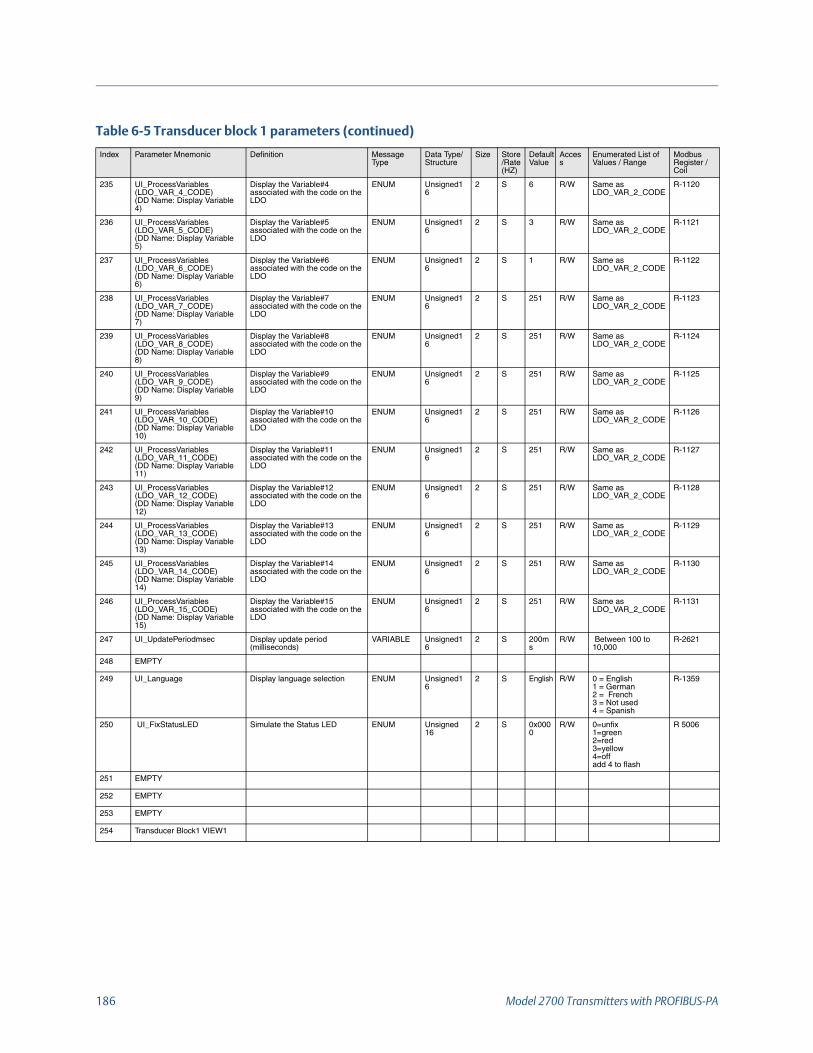
186 Model 2700 Transmitters with PROFIBUS-PA
235 UI_ProcessVariables (LDO_VAR_4_CODE)(DD Name: Display Variable 4)
Display the Variable#4 associated with the code on the LDO
ENUM Unsigned16
2 S 6 R/W Same as LDO_VAR_2_CODE
R-1120
236 UI_ProcessVariables (LDO_VAR_5_CODE)(DD Name: Display Variable 5)
Display the Variable#5 associated with the code on the LDO
ENUM Unsigned16
2 S 3 R/W Same as LDO_VAR_2_CODE
R-1121
237 UI_ProcessVariables (LDO_VAR_6_CODE)(DD Name: Display Variable 6)
Display the Variable#6 associated with the code on the LDO
ENUM Unsigned16
2 S 1 R/W Same as LDO_VAR_2_CODE
R-1122
238 UI_ProcessVariables (LDO_VAR_7_CODE)(DD Name: Display Variable 7)
Display the Variable#7 associated with the code on the LDO
ENUM Unsigned16
2 S 251 R/W Same as LDO_VAR_2_CODE
R-1123
239 UI_ProcessVariables (LDO_VAR_8_CODE)(DD Name: Display Variable 8)
Display the Variable#8 associated with the code on the LDO
ENUM Unsigned16
2 S 251 R/W Same as LDO_VAR_2_CODE
R-1124
240 UI_ProcessVariables (LDO_VAR_9_CODE)(DD Name: Display Variable 9)
Display the Variable#9 associated with the code on the LDO
ENUM Unsigned16
2 S 251 R/W Same as LDO_VAR_2_CODE
R-1125
241 UI_ProcessVariables (LDO_VAR_10_CODE)(DD Name: Display Variable 10)
Display the Variable#10 associated with the code on the LDO
ENUM Unsigned16
2 S 251 R/W Same as LDO_VAR_2_CODE
R-1126
242 UI_ProcessVariables (LDO_VAR_11_CODE)(DD Name: Display Variable 11)
Display the Variable#11 associated with the code on the LDO
ENUM Unsigned16
2 S 251 R/W Same as LDO_VAR_2_CODE
R-1127
243 UI_ProcessVariables (LDO_VAR_12_CODE)(DD Name: Display Variable 12)
Display the Variable#12 associated with the code on the LDO
ENUM Unsigned16
2 S 251 R/W Same as LDO_VAR_2_CODE
R-1128
244 UI_ProcessVariables (LDO_VAR_13_CODE)(DD Name: Display Variable 13)
Display the Variable#13 associated with the code on the LDO
ENUM Unsigned16
2 S 251 R/W Same as LDO_VAR_2_CODE
R-1129
245 UI_ProcessVariables (LDO_VAR_14_CODE)(DD Name: Display Variable 14)
Display the Variable#14 associated with the code on the LDO
ENUM Unsigned16
2 S 251 R/W Same as LDO_VAR_2_CODE
R-1130
246 UI_ProcessVariables (LDO_VAR_15_CODE)(DD Name: Display Variable 15)
Display the Variable#15 associated with the code on the LDO
ENUM Unsigned16
2 S 251 R/W Same as LDO_VAR_2_CODE
R-1131
247 UI_UpdatePeriodmsec Display update period (milliseconds)
VARIABLE Unsigned16
2 S 200ms
R/W Between 100 to 10,000
R-2621
248 EMPTY
249 UI_Language Display language selection ENUM Unsigned16
2 S English R/W 0 = English1 = German2 = French3 = Not used4 = Spanish
R-1359
250 UI_FixStatusLED Simulate the Status LED ENUM Unsigned 16
2 S 0x0000
R/W 0=unfix1=green2=red3=yellow4=offadd 4 to flash
R 5006
251 EMPTY
252 EMPTY
253 EMPTY
254 Transducer Block1 VIEW1
Table 6-5 Transducer block 1 parameters (continued)
Index Parameter Mnemonic Definition Message Type
Data Type/Structure
Size Store/Rate (HZ)
DefaultValue
Access
Enumerated List of Values / Range
Modbus Register / Coil

Configuration and Use Manual 187
F.4.1 Transducer block 1 objectTable F-6 shows the transducer block 1 object.
F.4.2 Transducer block 1 (measurement, calibration, and diagnosis) viewsTable F-7 shows the views for transducer block 1.
Table F-6 Transducer block 1 object
Slot/Index Element name Data type Size in bytes Value
Slot 11/Index 0
Reserved Unsigned 8 1 250 (default)
Block_Object Unsigned 8 1 03
Parent_Class Unsigned 8 1 03
Class Unsigned 8 1 03
DD_Refrence Unsigned 32 4 00 ,00, 00, 00 (reserved)
DD_Revision Unsigned 16 2 00 ,00 (reserved)
Profile Octet String 2 64 02 (compact class B)
Profile_Revision Unsigned 16 2 03 01 (3.01)
Execution_Time Unsigned 8 1 00 (for future use)
Number_Of_Parameters Unsigned 16 2 00 254(max number of TB1 parameters)
Address_of_View_1 Unsigned 16 2 11 254 (slot, index)
Number_of_Views Unsigned 8 1 01 (1 view)
Table F-7 Transducer block 1 views
ODIndex
Parameter Mnemonic View 1
View 2
View 3
View 4
Standard PA Parameters
0 BLOCK_OBJECT
1 ST_REV 2
2 TAG_DESC
3 STRATEGY
4 ALERT_KEY
5 TARGET_MODE
6 MODE_BLK 3
7 ALARM_SUM 8
Overall sum of bytes in View Object 13
ODIndex
Standard Flow Transducer block ParametersParameter Mnemonic
View 1
View 2
View 3
View 4
Standard Parameters
21 MASS_FLOW 5
25 DENSITY 5
29 TEMPERATURE 5
254 Overall sum of bytes in View Object(+ 13 Standard parameters bytes)
15+13

188 Model 2700 Transmitters with PROFIBUS-PA
F.4.3 Transducer block 2 (device information, API, CM) parametersTable F-8 shows the parameters for transducer block 2.
Table F-8 Transducer block 2 parameters
Index Parameter Mnemonic Definition Message Type
Data Type/Structure
Size Store/Rate (HZ)
DefaultValue
Access
Enumerated List of Values / Range
Modbus Register / Coil
Standard PA parameters
0 BLOCK_OBJECT This object contains the characteristics of the block
RECORD DS-32 20 S ---- R NA NA
1 ST_REV A block has static block parameters, that are not changed by the process. Values are assigned to this parameter during the configuration of optimization. The value of ST_REV increases by 1 after every change of a static block parameter.
SIMPLE Unsigned16 2 N 0 R NA NA
2 TAG_DESC Every block can be assigned a textual TAG description. The TAG_DESC must be unambiguous and unique in the field bus system.
SIMPLE OCTET STRING
32 S ‘ ’ R/W NA NA
3 STRATEGY Grouping of function block. The STRATEGY field can be used to group blocks.
SIMPLE Unsigned16 2 S 0 R/W NA NA
4 ALERT_KEY This parameter contains the identification number of the plant unit.
SIMPLE Unsigned8 1 S 0 R/W NA NA
5 TARGET_MODE This parameter contains desired mode normally set by a control application of an operator. The modes are valid alternatively only, i.e. only one mode can be set at one time. A write access to this parameter with more than one mode is out of the range of the parameter and has to be rejected.
SIMPLE Unsigned8 1 S AUTO (0x08)
R/W AUTO (0x08) NA
6 MODE_BLK This parameter contains the current mode and the permitted and normal mode of the block.
RECORD DS-37 3 D --- R NA NA
7 ALARM_SUM This parameter contains the current states of the block alarms.
RECORD DS-42 8 D 0,0,0,0
R NA NA
DEVICE INFORMATION BLOCK
Transmitter Data
8 SYS_FeatureKey(DD Name: Enabled Features)
Enabled Features STRING BIT_ENUMERATED
2 S - R 0x0000 = standard0x0800 = Meter Verification 0x0008 = Enh. Density0x0010 = API
R-5000
9 SYS_CEQ_Number(DD Name: CP ETO)
Model 2700 Transmitter CEQ Number
VARIABLE Unsigned16 2 S S/W Rev
R/W N/A R-5005
Sensor Data
10 SNS_SensorSerialNum(DD Name : Sensor Serial Number)
Sensor serial number VARIABLE Unsigned32 4 S 0 R/W >=0 and <=16777215.0f
R-0127-128
11 SNS_SensorType(DD Name: Sensor Model Number)
Sensor type (i.e. F200, CMF025)
STRING OCTET STRING
16 S “” R/W N/A R-0425
12 SNS_SensorTypeCode(DD Name: Sensor Type Code)
Sensor type code ENUM Unsigned16 2 S 0 R/W 0 = Curve Tube1 = Straight Tube
R-1139
13 SNS_SensorMaterial(DD Name : Sensor Material)
Sensor Material ENUM Unsigned16 2 S 0 R/W 0 = None3 = Hastelloy C-224 = Monel5 = Tantalum6 = Titanium 19 = 316L stainless steel23 = Inconel252 = Unknown253 = Special
R-0130

Configuration and Use Manual 189
14 SNS_LinerMaterial(DD Name : Sensor Liner)
Liner Material ENUM Unsigned16 2 S 0 R/W 0 = None 10 = PTFE (2larms) 11 = Halar 16 = Tefzel251 = None252 = Unknown253 = Special
R-0131
15 SNS_FlangeType(DD Name : Sensor Flange)
Flange Type ENUM Unsigned16 2 S 0 R/W 0 = ANSI 150 1 = ANSI 300 2 = ANSI 600 5 = PN 40 7 = JIS 10K 8 = JIS 20K 9 = ANSI 90010 = Sanitary Clamp Fitting11 = Union12 = PN 100 252 = Unknown253 = Special
R-0129
16 SNS_MassFlowLoSpan(DD Name: Mass Minimum Span)
Mass flow minimum range VARIABLE FLOAT 4 S Calc R N/A R-181-182
17 SNS_TempFlowLoSpan(DD Name: Temp Minimum Span)
Temperature minimum range
VARIABLE FLOAT 4 S Calc R N/A R-183-184
18 SNS_DensityLoSpan(DD Name: Density Minimum Span)
Density minimum range (g/cc)
VARIABLE FLOAT 4 S Calc R N/A R-185-186
19 SNS_VolumeFlowLoSpan(DD Name: Volume Minimum Span)
Volume flow minimum range VARIABLE FLOAT 4 S Calc R N/A R-187-188
20 SYS_BoardRevision Board Revision VARIABLE Unsigned8 1 S R N/A R-1163
21 SNS_HartDeviceID(0)(DD Name: Hart Device ID - 0)
Hart device ID. Mapped with R122 of core
VARIABLE Unsigned32 4 D R N/A R-1187
22 SNS_HartDeviceID(1)(DD Name: Hart Device ID - 1)
Hart device ID. Mapped with R122 of core
VARIABLE Unsigned32 4 D R N/A R-1188
23 PA_Preamble_Length Configures the device preamble number
Simple Unsigned-8 1 N EIGHT_BYTE = 3
R/W ONE_BYTE = 0, TWO_BYTE = 1FOUR_BYTE = 2EIGHT_BYTE = 3
R-7136
24 EMPTY
25 EMPTY
26 EMPTY
27 EMPTY
28 EMPTY
Petroleum Measurement
API Process Variables
29 SNS_API_CorrDensity(DD Name : PMI TC Density)
Temp Corrected Density RECORD 101 5 D ---- R R-0325-326
30 SNS_API_CorrVolFlow(DD Name : PMI TC Volume Flow)
Temp Corrected (Standard) Volume Flow
RECORD 101 5 D ---- R R-0331-332
31 SNS_API_AveCorrDensity(DD Name : PM Batch Weighted Average Density)
Batch Weighted Average Density
RECORD 101 5 D ---- R R-0337-338
32 SNS_API_AveCorrTemp(DD Name : PM Batch Weighted Average Temperature)
Batch Weighted Average Temperature
RECORD 101 5 D ---- R R-339-340
33 SNS_API_CTL(DD Name :PM CTL)
CTL RECORD 101 5 D ---- R R-0329-330
34 SNS_API_CorrVolTotal(DD Name : PM TC Volume Total)
Temp Corrected (Standard) Volume Total
VARIABLE 101 5 D/20 0 R N/A R-0333-0334
35 SNS_API_CorrVolInv(DD Name : PM TC Volume Inventory)
Temp Corrected (Standard) Volume Inventory
VARIABLE 101 5 D/20 0 R N/A R-0335-336
36 SNS_ResetApiRefVolTotal(DD Name : Reset PM TC Volume Total)
Reset API Reference Volume Total
METHOD Unsigned8 1 S - R/W 0x00 = None0x01 = Reset
Coil-0058
37 SNS_ResetAPIGSVInv(DD Name: Rest PM Volume Inventory)
Reset API/GSV Inventory (“On” = Reset, “Off” = N/A)
Method Unsigned8 1 S 0x00 R/W 0x00 = No Effect0x01 = Reset
Coil-0194
Table F-8 Transducer block 2 parameters (continued)
Index Parameter Mnemonic Definition Message Type
Data Type/Structure
Size Store/Rate (HZ)
DefaultValue
Access
Enumerated List of Values / Range
Modbus Register / Coil

190 Model 2700 Transmitters with PROFIBUS-PA
API Setup Data
38 SNS_APIRefTemp(DD Name:PM Reference Temp)
API Reference Temp VARIABLE FLOAT 4 S 15 R/W 0 to 100 R-0319-0320
39 SNS_APITEC(DD Name: PM Thermal Expansion Coeff)
API Thermal Expansion Coeff
VARIABLE FLOAT 4 S 0 R/W >= 0.000485 R-0323-0324
40 SNS_API2540TableType(DD Name: PM2540 CTL Table Type)
API 2540 CTLTable Type ENUM Unsigned16 2 S API_ TABLE_53A
R/W 19= Table 5D36= Table 6C49= Table 23A50= Table 23B51= Table 23D68= Table 24C81 = Table 53A82 = Table 53B83 = Table 53D100 = Table 54C
R-0351
41 EMPTY
42 EMPTY
43 EMPTY
44 EMPTY
45 EMPTY
46 EMPTY
Concentration Measurement
CM Process Variables
47 SNS_ED_RefDens(DD Name : CM Density at Reference)
Density At Reference RECORD 101 5 D ---- R RECORD R-0963
48 SNS_ED_SpecGrav(DD Name : CM Specific Gravity)
Density (Fixed SG Units) RECORD 101 5 D ---- R RECORD R-0965
49 SNS_ED_StdVolFlow(DD Name : CM TC Volume Flow)
Standard Volume Flow Rate RECORD 101 5 D ---- R RECORD R-0967
50 SNS_ED_NetMassFlow(DD Name : CM Net Mass Flow)
Net Mass Flow Rate RECORD 101 5 D ---- R RECORD R-0973
51 SNS_ED_NetVolFlow(DD Name : CM Net Volume Flow)
Net Volume Flow Rate RECORD 101 5 D ---- R RECORD R-0979
52 SNS_ED_Conc(DD Name : Concentration)
Concentration RECORD 101 5 D ---- R RECORD R-0985
53 SNS_ED_SpecDens(DD Name : CM Density (Baume))
Density (Fixed Baume Units)
RECORD 101 5 D ---- R RECORD R-0987
CM Totals
54 SNS_ED_StdVolTotal(DD Name : CM TC Volume Total)
Standard Volume Total VARIABLE FLOAT 4 D/20 0 R N/A R-0969
55 SNS_ED_StdVolInv(DD Name : CM TC Volume Inventory)
Standard Volume Inventory VARIABLE FLOAT 4 D/20 0 R N/A R-0971
56 SNS_ED_NetMassTotal(DD Name : CM Net Mass Total)
Net Mass Total VARIABLE FLOAT 4 D/20 0 R N/A R-0975
57 SNS_ED_NetMassInv(DD Name : CM Net Mass Inventory)
Net Mass Inventory VARIABLE FLOAT 4 D/20 0 R N/A R-0977
58 SNS_ED_NetVolTotal(DD Name : CM Net Volume Total)
Net Volume Total VARIABLE FLOAT 4 D/20 0 R N/A R-0981
59 SNS_ED_NetVolInv(DD Name : CM Net Volume Inventory)
Net Volume Inventory VARIABLE FLOAT 4 D/20 0 R N/A R-0983
60 SNS_ResetEDRefVolTotal(DD Name : Reset CM TC Volume Total)
Reset ED Standard Volume Total
METHOD Unsigned8 1 S - R/W 0x00 = None0x01 = Reset
Coil-0059
61 SNS_ResetEDNetMassTotal(DD Name : Reset CM Net Mass Total)
Reset ED Net Mass Total METHOD Unsigned8 1 S - R/W 0x00 = None0x01 = Reset
Coil-0060
Table F-8 Transducer block 2 parameters (continued)
Index Parameter Mnemonic Definition Message Type
Data Type/Structure
Size Store/Rate (HZ)
DefaultValue
Access
Enumerated List of Values / Range
Modbus Register / Coil

Configuration and Use Manual 191
62 SNS_ResetEDNetVolTotal(DD Name : Reset CM Net Volume Total)
Reset ED Net Volume Total METHOD Unsigned8 1 S - R/W 0x00 = None0x01 = Reset
Coil-0061
63 SNS_ResetEDVolInv(DD Name: Reset Volume Inventory At Reference Temp)
Reset ED Volume Inventory (“On” = Reset, “Off” = N/A)
Method Unsigned8 1 S R/W 0x00 = No Effect0x01 = Reset
Coil-0195
64 SNS_ResetEDNetMassInv(DD Name: Reset Net Mass Inventory)
Reset ED Net Mass Inventory (“On” = Reset, “Off” = N/A)
Method Unsigned8 1 S R/W 0x00 = No Effect0x01 = Reset
Coil-0196
65 SNS_ResetEDNetVolInv(DD Name: Reset Net Volume Inventory)
Reset ED Net Volume Inventory (“On” = Reset, “Off” = N/A)
Method Unsigned8 1 S R/W 0x00 = No Effect0x01 = Reset
Coil-0197
CM Setup Data
66 SNS_ED_CurveLock(DD Name: Lock/Unlock ED Curves)
Lock Enhanced Density Tables
ENUM Unsigned8 1 S 1 R/W 0x00 = not locked0x01 = locked
Coil-0085
67 SNS_ED_Mode(DD Name: Derived Variable)
Enhanced Density Mode ENUM Unsigned16 2 S Mass Conc. (Dens)
R/W 0 = None1= Dens @ Ref Temp2= Specific Gravity3= Mass Conc (Dens)4=Mass Conc (SG)5= Volume Conc (Dens)6= Volume Conc (SG)7= Concentration (Dens)8 = Concentration (SG)
R-0524
68 SNS_ED_ActiveCurve(DD Name: Active Calculation Curve)
Active Calculation Curve VARIABLE Unsigned16 2 S 0 R/W 0 through 5 R-0523
69 UNI_ED_CurveIndex(DD Name: Curve Configured)
Curve Configuration Index (n)
VARIABLE Unsigned8 1 S --- R/W 0 through 5 R-0527
70 UNI_ED_TempIndex(DD Name: Curve Temperature Isotherm Index (X-Axis))
Curven Temperature Isotherm Index (x-axis)
VARIABLE Unsigned8 1 S --- R/W 0 through 5 R-0528
71 UNI_ED_ConcIndex(DD Name: Curve Concentration Index (Y-Axis))
Curven Concentration Index (y-axis)
VARIABLE Unsigned8 1 S --- R/W 0 through 5 R-0529
72 SNS_ED_TempISO(DD Name: Curve N (6*5) Temp Isotherm X Value (X-Axis))
Curven (6x5) Temperature Isothermx Value (x-axis)
VARIABLE FLOAT 4 S --- R/W N/A R-0531
73 SNS_ED_DensAtTempISO(DD Name: Curve N (6*5) Density @ Temp Isotherm X, Concentration Y)
Curven (6x5) Density @ Temperature IsothermX, ConcentrationY
VARIABLE FLOAT 4 S ---- R/W N/A R-0533
74 SNS_ED_DensAtTempCoeff(DD Name: Curve N (6*5) Coeff @ Temp Isotherm X, Concentration Y)
Curven (6x5) Coeff @ Temperature IsothermX, ConcentrationY
VARIABLE FLOAT 4 S ----- R N/A R-0535
75 SNS_ED_ConcLabel55(DD Name: Curve N (6*5) Concentration Y Value (Label For Y-Axis))
Curven (6x5) ConcentrationY Value (Label for y-axis)
VARIABLE FLOAT 4 S ---- R/W N/A R-0537
76 SNS_ED_DensAtConc(DD Name: Curve N (5*1) Density @ Concentration Y (At Ref Temp))
Curven (5x1) Density at ConcentrationY (at Ref Temp)
VARIABLE FLOAT 4 S ----- R/W N/A R-0539
77 SNS_ED_DensAtConcCoeff(DD Name: Curve N (5*1) Coeff @ Concentration Y (At Ref Temp))
Curven (5x1) Coeff at ConcentrationY (at Ref Temp)
VARIABLE FLOAT 4 S ----- R N/A R-0541
78 SNS_ED_ConcLabel51(DD Name: Curve N (5*1) Concentration Y Value (Y-Axis))
Curven (5x1) ConcentrationY Value (y-axis)
VARIABLE FLOAT 4 S ---- R/W N/A R-0543
79 SNS_ED_RefTemp(DD Name: Curve N Reference Temperature)
Curven Reference Temperature
VARIABLE FLOAT 4 S ---- R/W Temp. sensor Limits R-0545
80 SNS_ED_SGWaterRefTemp(DD Name: Curve N Water Reference Temperature)
Curven SG Water Reference Temperature
VARIABLE FLOAT 4 S ---- R/W Temp. sensor limits R-0547
81 SNS_ED_SGWaterRefDens(DD Name: Curve N Water Reference Density)
Curven SG Water Reference Density
VARIABLE FLOAT 4 S ----- R/W Density Limits R-0549
Table F-8 Transducer block 2 parameters (continued)
Index Parameter Mnemonic Definition Message Type
Data Type/Structure
Size Store/Rate (HZ)
DefaultValue
Access
Enumerated List of Values / Range
Modbus Register / Coil

192 Model 2700 Transmitters with PROFIBUS-PA
82 SNS_ED_SlopeTrim(DD Name: Curve N Trim Slope)
Curven Slope Trim VARIABLE FLOAT 4 S ---- R/W 0.8 to 1.2 R-0551
83 SNS_ED_OffsetTrim(DD Name: Curve N Trim Offset)
Curven Offset Trim VARIABLE FLOAT 4 S ---- R/W None R-0553
84 SNS_ED_ExtrapAlarmLimit(DD Name: Curve N Alarm Limit (%))
Curven Extrapolation Alarm Limit: %
VARIABLE FLOAT 4 S ---- R/W 0 to 270 R-0555
85 SNS_ED_CurveName(DD Name: Curve N Curve Name)
Curven ASCII String – Name of Curve – 12 chars supported
VARIABLE OCTET STRING
12 S ---- R/W N/A R-2771- 2776
86 SNS_ED_MaxFitOrder(DD Name: Curve Fit Max Order)
Maximum Fit Order for 5x5 curve
VARIABLE Unsigned16 2 S ---- R/W 2, 3, 4, 5 R-0564
87 SNS_ED_FitResults(DD Name: Curve N Fit Results)
Curven Curve Fit Results ENUM Unsigned16 2 S ---- R 0 = Good1 = Poor2 = Failed3 = Empty
R-0569
88 SNS_ED_ConcUnitCode(DD Name: Curve N Concentration Units)
Curven Concentration Units Code
ENUM Unsigned16 2 S ---- R/W 1110 = Degrees Twaddell1426= Degrees Brix1111= Deg Baume (heavy)1112= Deg Baume (light)1343=% sol/wt1344=% sol/vol1427= Degrees Balling1428= Proof Per Volume1429 = Proof Per mass1346 = Percent Plato
R-0570
89 SNS_ED_ExpectedAcc(DD Name: Curve N Curve Fit Expected Accuracy)
Curven Curve Fit Expected Accuracy
VARIABLE FLOAT 4 S ------ R R-0571
90 SNS_ED_ResetFlag(DD Name: Reset All Curve Information)
Reset All Enhanced Density Curve Information
Method Unsigned8 1 S 1 W 0x00 = Not used 0x01 = Reset
Coil-249
91 SNS_ED_EnableDensLowExtrap(DD Name: Enable Density Low)
Enable Dens Low Extrap (Enhanced Denisty Extrap Alarm)
Method Unsigned8 1 S 1 R/W 0x00 = Disable0x01 = Enable
Coil-250
92 SNS_ED_EnableDensHighExtrap(DD Name: Enable Density High)
Enable Dens High Extrap (Enhanced Denisty Extrap Alarm)
Method Unsigned8 1 S 1 R/W 0x00 = Disable0x01 = Enable
Coil-251
93 SNS_ED_EnableTempLowExtrap(DD Name: Enable Temperature Low)
Enable Temp Low Extrap (Enhanced Denisty Extrap Alarm)
Method Unsigned8 1 S 1 R/W 0x00 = Disable0x01 = Enable
Coil-252
94 SNS_ED_EnableTempHighExtrap(DD Name: Enable Temperature High)
Enable Temp High Extrap (Enhanced Denisty Extrap Alarm)
Method Unsigned8 1 S 1 R/W 0x00 = Disable0x01 = Enable
Coil-253
95 DB_SNS_PuckDeviceTypeCode
Device Type Code forattached Core
Variable Unsigned16 2 D/20 R 40 = 700 CP50 = 80 CP
R-1162
96 SNS_ED_ConcUnits Curven Concentration Units Variable String 8 N-CP {‘N’,’O’,’N’,’E’,’ ‘,’ ‘,’ ‘,’ ‘}
R/W N/A R- 573-576
97 SNS_MflowText Special unit massflow text String OCTET STRING
8 N {‘N’,’O’,’N’,’E’,’ ‘,’ ‘,’ ‘,’ ‘}
R/W N/A R-52-55
98 SNS_MtotText Special unit massTotal text String OCTET STRING
8 N {‘N’,’O’,’N’,’E’,’ ‘,’ ‘,’ ‘,’ ‘}
R/W N/A R-56-59
99 SNS_VflowText Special unit Volume Flow text
String OCTET STRING
8 N {‘N’,’O’,’N’,’E’,’ ‘,’ ‘,’ ‘,’ ‘}
R/W N/A R- 60-63
Table F-8 Transducer block 2 parameters (continued)
Index Parameter Mnemonic Definition Message Type
Data Type/Structure
Size Store/Rate (HZ)
DefaultValue
Access
Enumerated List of Values / Range
Modbus Register / Coil

Configuration and Use Manual 193
F.4.4 Transducer block 2 objectTable F-9 shows the transducer block 2 object.
100 SNS_VtotText Special unit Volume text String OCTET STRING
8 N {‘N’,’O’,’N’,’E’,’ ‘,’ ‘,’ ‘,’ ‘}
R/W N/A R-64-67
101 SNS_GSVflowText Special unit GSV Volume Flow text
String OCTET STRING
8 N {‘N’,’O’,’N’,’E’,’ ‘,’ ‘,’ ‘,’ ‘}
R/W N/A R2607-2610
102 SNS_GSVtotText Special unit Volume Total text
String OCTET STRING
8 N {‘N’,’O’,’N’,’E’,’ ‘,’ ‘,’ ‘,’ ‘}
R/W N/A R2611-2614
Table F-9 Transducer block 2 object
Slot/Index Element name Data type Size in bytes Value
Slot 11/Index 0
Reserved Unsigned 8 1 250 (default)
Block_Object Unsigned 8 1 03
Parent_Class Unsigned 8 1 03
Class Unsigned 8 1 128 (manufacturer-specific class)
DD_Refrence Unsigned 32 4 00 ,00, 00, 00 (reserved)
DD_Revision Unsigned 16 2 00 ,00 (reserved)
Profile Octet String 2 64 02 (compact class B)
Profile_Revision Unsigned 16 2 03 01 (3.01)
Execution_Time Unsigned 8 1 00 (for future use)
Number_Of_Parameters Unsigned 16 2 00 98 (max number of TB2 parameters)
Address_of_View_1 Unsigned 16 2 12 98 (slot, index)
Number_of_Views Unsigned 8 1 01 (1 view)
Table F-8 Transducer block 2 parameters (continued)
Index Parameter Mnemonic Definition Message Type
Data Type/Structure
Size Store/Rate (HZ)
DefaultValue
Access
Enumerated List of Values / Range
Modbus Register / Coil

194 Model 2700 Transmitters with PROFIBUS-PA
F.4.5 Transducer block 2 (device information, API, CM) viewsTable F-10 shows the views for transducer block 2.
F.4.6 I & M functionsTable F-11 shows the parameters for I & M functions.
Table F-10 Transducer block 2 views
ODIndex
Parameter Mnemonic View 1
View 2
View 3
View 4
Standard Parameters
0 BLOCK_OBJECT
1 ST_REV 2
2 TAG_DESC
3 STRATEGY
4 ALERT_KEY
5 TARGET_MODE
6 MODE_BLK 3
7 ALARM_SUM 8
Overall sum of bytes in View Object 13
ODIndex
Parameter Mnemonic View 1
View 2
View 3
View 4
Standard Parameters
98 Overall sum of bytes in View Object(+ 13 Standard parameters bytes)
13
Table F-11 I & M parameters
Index Sub-Index
Parameter Mnemonic Definition Message Type Data Type/Structure
Size Store/Rate (HZ)
DefaultValue
Access Enumerated List of Values
Modbus Register / Coil
255 65000 IM_DEFAULT I&M0(Mandatory) VARIABLE Octet String 64 S --- R -- --
HEADER –Reserved STRING Octet String 10 S 0x00 R --- Hard coded
MANUFACTURER_ID – Identification code of the Manufacturer of the PA Device
VARIABLE Unsigned16 2 S 0x00
R --- Physical BlockIndex 26
DEVICE_MAN_ID
ORDER_ID –Order No. of the Device
STRING Visible String 20 S 2700S Profibus PA
R --- R 2545 – 2554
SERIAL_NO –Production Serial No. of the device
STRING Visible String 16 S ---- R --- Physical Block
Index 28 –
DEVICE_SER_NUM
HARDWARE_REVISION –Revision No. of the Hardware
VARIABLE Unsigned 16 2 S 0xFFFF R --- 0xFFFF
SOFTWARE_REVISION –Software or Firmware revision of the device or module
VARIABLE 1Char 3 Unsigned8
4 S --- R -- V 0xFF 0xFF 0xFF

Configuration and Use Manual 195
REV_COUNTER – According to /I&M/. The REV_COUNTER isincremented if a parameter content withstatic attribute in the according slot hasChanged.Slot 0 carries a REV_COUNTER thatcounts all changes of static parameters ofThe whole device.
VARIABLE Unsigned16 2 S 0 R --- Sum of ST_REV of all Blocks i.e. TB1 + TB2+AI1+AI2+AI3+AI4+TOT1+TOT2+TOT3+TOT4 + AO1+AO2
PROFILE_ID –Profile type of supporting Profile
VARIABLE Unsigned16 2 S 0x9700 R -- Hard Coded
PROFILE_SPECIFIC_TYPE –Specific Profile Type
VARIABLE Octet String 2 S 0x010x01
R -- Byte 0:BLOCK_OBJECT.BlockObjectByte 1:BLOCK_OBJECT.ParentClass
IM_VERSION –Implemented version of I & M function
VARIABLE 2 – Unsigned8 2 S 0x01,0x01
R -- Hard Coded
IM_SUPPORTED –Indicated Availability of I & M Records
VARIABLE Octet String 2 S 0x000x07
R -- Hard Coded
65001 IM_1 I&M1(Mandatory)
HEADER –Manufacturer Specific
STRING Octet String 10 S 0x00 R --- Hard Coded
TAG_FUNCTION –Device Identification Tag
STRING Visible String 32 S Blank0x20
R -- Physical block
Index 18TAG_DESC
TAG_LOCATION –Device Location Identification Tag
STRING Visible String 22 S Blank0x20
R -- Hard Coded
65002 IM_2 I&M2(Mandatory)
Header – Manufacture Specific
STRING Octet String 10 S0x00 R
--- Hard Coded
Date – Date of installation of PA Device
STRING Visible String 16 S Blank0x20
R --- Physical Block
Index – 38DEVICE_INSTALL_DATE
Reserved STRING Octect String 38 S 0x00 R ---- ---
65016 PA_IM_0 Header – Reserved STRING Octet String 10 S 0x00 R -- Hard Coded
PA_IM_VERSION – Version of the process device profilespecific extensions of I&MOctet 1 (MSB) = major version number,e.g. 1 of version 1.0Octet 2 (LSB) = minor version number, e.g.0 of version 1.0
VARIABLE Unsigned 8 2 S 0x01 0x00
R -- Hard Coded
HARDWARE_REVISION – Hardware Revision according to Physical Component
STRING Visible String 16 S Blank R --- Physical Block – Index25
SOFTWARE_REVISON – Firmware Revision of the according Physical component
STRING Visible String 16 S Blank R S Physical Block – Index-24
Reserved 18
PA_IM_SUPPORTED STRING Octet String 2 S0x000x00
R S Hard Coded
Table F-11 I & M parameters (continued)
Index Sub-Index
Parameter Mnemonic Definition Message Type Data Type/Structure
Size Store/Rate (HZ)
DefaultValue
Access Enumerated List of Values
Modbus Register / Coil

196 Model 2700 Transmitters with PROFIBUS-PA
F.4.7 AI function block parametersTable F-12 shows the parameters for the AI function blocks.
Table F-12 AI function block parameters
Index
Parameter Mnemonic Definition Message Type
Data Type/Structure
Size Store/Rate (HZ)
DefaultValue
Access Enumerated List of Values / Range
Modbus Register / Coil
Standard PA parameters
16 BLOCK_OBJECT This object contains the characteristics of the block
RECORD DS-32 20 S ---- R NA NA
17 ST_REV A block has static block parameters that are not changed by the process. Values are assigned to this parameter during the configuration of optimization. The value of ST_REV increases by 1 after every change of a static block parameter.
SIMPLE Unsigned16 2 N 0 R NA NA
18 TAG_DESC Every block can be assigned a textual TAG description. The TAG_DESC must be unambiguous and unique in the field bus system.
SIMPLE OCTET STRING
32 S ‘ ’ R/W NA NA
19 STRATEGY Grouping of function block. The STRATEGY field can be used to group blocks.
SIMPLE Unsigned16 2 S 0 R/W NA NA
20 ALERT_KEY This parameter contains the identification number of the plant unit.
SIMPLE Unsigned8 1 S 0 R/W NA NA
21 TARGET_MODE This parameter contains desired mode normally set by a control application of an operator. The modes are valid alternatively only, i.e. only one mode can be set at one time. A write access to this parameter with more than one mode is out of the range of the parameter and has to be rejected.
SIMPLE Unsigned8 1 S Auto (0x08)
R/W 0x08 – Auto0x10 – Manual0x80 – Out of Service
R-1506
22 MODE_BLK This parameter contains the current mode and the permitted and normal mode of the block.
RECORD DS-37 3 D ---- R NA R-1507
23 ALARM_SUM This parameter contains the current states of the block alarms.
RECORD DS-42 8 D 0,0,0,0
R NA NA
24 BATCH This parameter is intended to be used in Batch applications in line with IEC 61512Part1. Only Function Blocks carry this parameter. There is no algorithm necessaryWithin a Function Block.
RECORD DS-67 10 S 0,0,0,0
RW NA NA
25 RESERVED
AI Function Block Standard Parameters
26 OUT(DD Name: AI Out)
The Function Block parameter OUT contains the current measurement value in avendor specific or configuration adjusted engineering unit and the belonging statein AUTO MODE. The Function Block parameter OUT contains the value and statusset by an operator in MAN MODE.
RECORD 101 5 D ---- R/W ( Can be written only in Manual Mode)
NA NA
27 PV_SCALE(DD Name: AI PV Scale)
Conversion of the Process Variable into percent using the high and low scalevalues.
ARRAY FLOAT 8 S 100.00
R/W NA NA
28 OUT_SCALE(DD Name: AI Out Scale)
Scale of the Process Variable. RECORD DS-36 11 S 100.00
R/W NA R-1509 (Only units)
29 LIN_TYPE(DD Name: AI Linearization Type)
Type linearizationion. SIMPLE Unsigned8 1 S 1 R/W NA R-1510
30 CHANNEL(DD Name: AI Channel)
Reference to the active Transducer Block which provides the measurement valueto the Function Block.
SIMPLE Unsigned16 2 S --- R/W NA R-1508
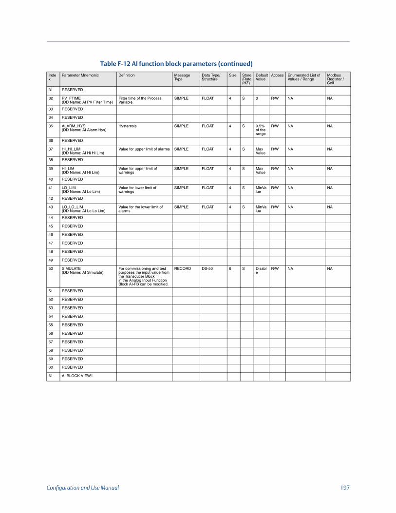
Configuration and Use Manual 197
31 RESERVED
32 PV_FTIME(DD Name: AI PV Filter Time)
Filter time of the Process Variable.
SIMPLE FLOAT 4 S 0 R/W NA NA
33 RESERVED
34 RESERVED
35 ALARM_HYS(DD Name: AI Alarm Hys)
Hysteresis SIMPLE FLOAT 4 S 0.5% of the range
R/W NA NA
36 RESERVED
37 HI_HI_LIM(DD Name: AI Hi Hi Lim)
Value for upper limit of alarms SIMPLE FLOAT 4 S Max Value
R/W NA NA
38 RESERVED
39 HI_LIM(DD Name: AI Hi Lim)
Value for upper limit of warnings
SIMPLE FLOAT 4 S Max Value
R/W NA NA
40 RESERVED
41 LO_LIM(DD Name: AI Lo Lim)
Value for lower limit of warnings
SIMPLE FLOAT 4 S MinValue
R/W NA NA
42 RESERVED
43 LO_LO_LIM(DD Name: AI Lo Lo Lim)
Value for the lower limit of alarms
SIMPLE FLOAT 4 S MinValue
R/W NA NA
44 RESERVED
45 RESERVED
46 RESERVED
47 RESERVED
48 RESERVED
49 RESERVED
50 SIMULATE(DD Name: AI Simulate)
For commissioning and test purposes the input value from the Transducer Blockin the Analog Input Function Block AI-FB can be modified.
RECORD DS-50 6 S Disable
R/W NA NA
51 RESERVED
52 RESERVED
53 RESERVED
54 RESERVED
55 RESERVED
56 RESERVED
57 RESERVED
58 RESERVED
59 RESERVED
60 RESERVED
61 AI BLOCK VIEW1
Table F-12 AI function block parameters (continued)
Index
Parameter Mnemonic Definition Message Type
Data Type/Structure
Size Store/Rate (HZ)
DefaultValue
Access Enumerated List of Values / Range
Modbus Register / Coil

198 Model 2700 Transmitters with PROFIBUS-PA
F.4.8 Analog input block objectsTable F-13 shows the analog input block objects.
F.4.9 AI function block viewsTable F-14 shows the views for the AI function blocks.
Table F-13 Analog input block objects
Slot/Index Element name Data type Size in bytes
Value
Slot 11/Index 0
Reserved Unsigned 8 1 250 (default)
Block_Object Unsigned 8 1 02 (function block)
Parent_Class Unsigned 8 1 01 (input)
Class Unsigned 8 1 01 (AI)
DD_Refrence Unsigned 32 4 00 ,00, 00, 00 (reserved)
DD_Revision Unsigned 16 2 00 ,00 (reserved)
Profile Octet String 2 64 02 (compact class B)
Profile_Revision Unsigned 16 2 03 01 (3.01)
Execution_Time Unsigned 8 1 00 (for future use)
Number_Of_Parameters Unsigned 16 2 00 45 (max number of AI block parameters)
Address_of_View_1 Unsigned 16 2 AI1 01 61 (slot, index)
AI2 02 61 (slot, index)
AI3 03 61 (slot, index)
AI4 05 61 (slot, index)
Number_of_Views Unsigned 8 1 01 (1 view)
Table F-14 AI function block views
ODIndex
Parameter Mnemonic View 1
View 2
View 3
View 4
Standard Parameters
16 BLOCK_OBJECT
17 ST_REV 2
18 TAG_DESC
19 STRATEGY
20 ALERT_KEY
21 TARGET_MODE
22 MODE_BLK 3
23 ALARM_SUM 8
Overall sum of bytes in View Object 13
ODIndex
Parameter Mnemonic View 1
View 2
View 3
View 4
Standard Parameters
26 Out 5
61 Overall sum of bytes in View Object(+ 13 Standard parameters bytes)
5+13

Configuration and Use Manual 199
F.4.10 AO function block parametersTable F-15 lists the parameters for the AO function blocks.
Table F-15 AO function block parameters
Index
Parameter Mnemonic Definition Message Type
Data Type/Structure
Size Store/Rate (HZ)
DefaultValue
Access Enumerated List of Values / Range
Modbus Register / Coil
Standard PA parameters
16 BLOCK_OBJECT This object contains the characteristics of the block
RECORD DS-32 20 S ---- R NA NA
17 ST_REV A block has static block parameters that are not changed by the process. Values are assigned to this parameter during the configuration of optimization. The value of ST_REV increases by 1 after every change of a static block parameter.
SIMPLE Unsigned16 2 N 0 R NA NA
18 TAG_DESC Every block can be assigned a textual TAG description. The TAG_DESC must be unambiguous and unique in the field bus system.
SIMPLE OCTET STRING
32 S ‘ ’ R/W NA NA
19 STRATEGY Grouping of function block. The STRATEGY field can be used to group blocks.
SIMPLE Unsigned16 2 S 0 R/W NA NA
20 ALERT_KEY This parameter contains the identification number of the plant unit.
SIMPLE Unsigned8 1 S 0 R/W NA NA
21 TARGET_MODE This parameter contains desired mode normally set by a control application of an operator. The modes are valid alternatively only, i.e. only one mode can be set at one time. A write access to this parameter with more than one mode is out of the range of the parameter and has to be rejected.
SIMPLE Unsigned8 1 S Auto (0x08)
R/W 0x08 – Auto0x10 – Manual0x80 – OOS
R-2295
22 MODE_BLK This parameter contains the current mode and the permitted and normal mode of the block.
RECORD DS-37 3 D --- R NA R-2296
23 ALARM_SUM This parameter contains the current states of the block alarms.
RECORD DS-42 8 D 0,0,0,0
R NA NA
24 BATCH This parameter is intended to be used in Batch applications in line with IEC 61512Part1. Only Function Blocks carry this parameter. There is no algorithm necessarywithin a Function Block.
RECORD DS-67 10 S 0,0,0,0
RW NA NA
AO Function Block Standard Parameters
25 SP(DD Name: AO Set Point)
Set point. RECORD 101 5 D ---- R/W NA NA
26 RESERVED
27 PV_SCALE(DD Name: AO PV Scale)
Conversion of the PV in engineering units to PV in percent as the input value of theFunction Block.
RECORD DS-36 11 S 100,0%
R/W NA R-2298 (only units)
28 READBACK(DD Name: AO ReadBack Value)
The actual position of the final control element within the travel span (betweenOPEN and CLOSE position) in units of PV_SCALE.
RECORD 101 5 D ---- R NA NA
29 RESERVED
30 RESERVED
31 RESERVED
32 RESERVED
33 RESERVED
34 RESERVED
35 RESERVED

200 Model 2700 Transmitters with PROFIBUS-PA
36 RESERVED
37 IN_CHANNEL(DD Name: AO IN Channel)
Reference to the active Transducer Block and its parameter that provides theactual position of the final control element.
SIMPLE Unsigned16 2 S --- R/W NA R-2297
38 OUT_CHANNEL(DD Name: AO OUT Channel)
Reference to the active Transducer Block and its parameter that provides theposition value for the final control element.
SIMPLE Unsigned16 2 S ---- R/W NA R-2299 (only units)
39 FSAFE_TIME(DD Name: AO Fail Safe Time)
Time in seconds from detection of failure of the actual used set point (SP = BAD orRCAS_IN <> GOOD) to the action of the block if the condition still exists.
SIMPLE Float 4 S 0 R/W NA NA
40 FSAFE_TYPE(DD Name: AO Fail Safe Type)
Defines reaction of the device, if a failure of the actual used set point is stilldetected after FSAFE_TIME or if the status of actual used set point is Initiate FailSafe.
SIMPLE Unsigned8 1 S 2 R/W 0: value FSAFE_VALUE is used as set pointstatus of OUT = UNCERTA–N – Substitute Value1: use last valid set pointstatus of OUT = UNCERTA–N – Last usable Valueor B–D – No communication, no LUV2: actuator goes to fail-safe position defined by ACTUATOR_ACTION (onlyuseful for actuators with spring return)status of OUT = B–D – non specific
NA
41 FSAFE_VALUE(DD Name: AO Fail Safe Value)
Set point used if FSAFE_TYPE = 1 and FSAFE is activated.
SIMPLE Float 4 S 0 R/W NA NA
42 RESERVED
43 RESERVED
44 RESERVED
45 RESERVED
46 RESERVED
47 POS_D(DD Name: AO POS_D)
The current position of the valve
RECORD 102 2 D --- R 0: not initialized1: closed2: opened3: intermediate
NA
48 RESERVED
49 CHECK_BACK(DD Name: AO Check Back)
Detailed information of the device, bitwise coded. More than one messagepossible at once.
SIMPLE Octet String 3 D ----- R NA NA
50 CHECK_BACK_MASK(DD Name: AO Check Back Mask)
Definition of supported CHECK_BACK information bits.
SIMPLE OctetString 3 Cst --- R 0: not supported1: supported
NA
51 SIMULATE(DD Name: AO Simulate)
For commissioning and maintenance reasons, it is possible to simulate theREADBACK by defining the value and the status.
RECORD DS-50 6 S Disabled
R/W NA NA
52 INCREASE_CLOSE(DD Name: AO Increase Close)
Direction of positioner in mode Rcas and Auto
SIMPLE Unsigned8 1 S 0 R/W 0: rising (increasing of set point input results in OPENING of the valve)1: falling (increasing of set point input results in CLOSING of the valve)
NA
53 OUT(DD Name: AO Out)
This parameter is the process variable of the AO Block in engineering units in AUTO mode and is the value specified by the operator in Manual mode.
RECORD 101 5 D ---- R/W (Can be written only in Manual Mode)
NA NA
54 OUT_SCALE(DD Name: AO Out Scale)
Scale of the Process Variable.
RECORD DS-36 11 S --- R/W NA NA
Table F-15 AO function block parameters (continued)
Index
Parameter Mnemonic Definition Message Type
Data Type/Structure
Size Store/Rate (HZ)
DefaultValue
Access Enumerated List of Values / Range
Modbus Register / Coil

Configuration and Use Manual 201
F.4.11 Analog output block objectsTable F-16 shows the analog output block objects.
55 RESERVED
56 RESERVED
57 RESERVED
58 RESERVED
59 RESERVED
60 RESERVED
61 RESERVED
62 RESERVED
63 RESERVED
64 RESERVED
65 AO BLOCK VIEW 1
Table F-16 Analog output block objects
Slot/Index Element name Data type Size in bytes
Value
Slot 11/Index 0
Reserved Unsigned 8 1 250 (default)
Block_Object Unsigned 8 1 02 (function block)
Parent_Class Unsigned 8 1 02 (output)
Class Unsigned 8 1 01 (A0)
DD_Refrence Unsigned 32 4 00 ,00, 00, 00 (reserved)
DD_Revision Unsigned 16 2 00 ,00 (reserved)
Profile Octet String 2 64 02 (compact class B)
Profile_Revision Unsigned 16 2 03 01 (3.01)
Execution_Time Unsigned 8 1 00 (for future use)
Number_Of_Parameters Unsigned 16 2 00 49 (max number of AO block parameters)
Address_of_View_1 Unsigned 16 2 AO1 09 65 (slot, index)
AO2 10 65 (slot, index)
Number_of_Views Unsigned 8 1 01 (1 view)
Table F-15 AO function block parameters (continued)
Index
Parameter Mnemonic Definition Message Type
Data Type/Structure
Size Store/Rate (HZ)
DefaultValue
Access Enumerated List of Values / Range
Modbus Register / Coil
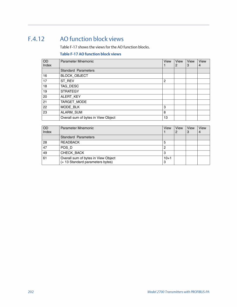
202 Model 2700 Transmitters with PROFIBUS-PA
F.4.12 AO function block viewsTable F-17 shows the views for the AO function blocks.
Table F-17 AO function block views
ODIndex
Parameter Mnemonic View 1
View 2
View 3
View 4
Standard Parameters
16 BLOCK_OBJECT
17 ST_REV 2
18 TAG_DESC
19 STRATEGY
20 ALERT_KEY
21 TARGET_MODE
22 MODE_BLK 3
23 ALARM_SUM 8
Overall sum of bytes in View Object 13
ODIndex
Parameter Mnemonic View 1
View 2
View 3
View 4
Standard Parameters
28 READBACK 5
47 POS_D 2
49 CHECK_BACK 3
61 Overall sum of bytes in View Object(+ 13 Standard parameters bytes)
10+13

Configuration and Use Manual 203
F.4.13 Totalizer block parametersTable F-18 lists the parameters for the totalizer blocks.
Table F-18 Totalizer block parameters
Index
Parameter Mnemonic Definition Message Type
Data Type/Structure
Size Store/Rate (HZ)
DefaultValue
Access Enumerated List of Values / Range
Modbus Register / Coil
Standard PA parameters
16 BLOCK_OBJECT This object contains the characteristics of the block
RECORD DS-32 20 S ---- R NA NA
17 ST_REV A block has static block parameters that are not changed by the process. Values are assigned to this parameter during the configuration of optimization. The value of ST_REV increases by 1 after every change of a static block parameter.
SIMPLE Unsigned16 2 N 0 R NA NA
18 TAG_DESC Every block can be assigned a textual TAG description. The TAG_DESC must be unambiguous and unique in the field bus system.
SIMPLE OCTET STRING
32 S ‘ ’ R/W NA NA
19 STRATEGY Grouping of function block. The STRATEGY field can be used to group blocks.
SIMPLE Unsigned16 2 S 0 R/W NA NA
20 ALERT_KEY This parameter contains the identification number of the plant unit.
SIMPLE Unsigned8 1 S 0 R/W NA NA
21 TARGET_MODE This parameter contains desired mode normally set by a control application of an operator. The modes are valid alternatively only, i.e. only one mode can be set at one time. A write access to this parameter with more than one mode is out of the range of the parameter and has to be rejected.
SIMPLE Unsigned8 1 S Auto (0x08)
R/W 0x08 – Auto0x10 – Manual0x80 – OOS
R-2287
22 MODE_BLK This parameter contains the current mode and the permitted and normal mode of the block.
RECORD DS-37 3 D --- R NA R-2288
23 ALARM_SUM This parameter contains the current states of the block alarms.
RECORD DS-42 8 D 0,0,0,0
R NA NA
24 BATCH This parameter is intended to be used in Batch applications in line with IEC 61512 Part 1. Only Function Blocks carry this parameter. There is no algorithm necessary within a Function Block.
RECORD DS-67 10 S 0,0,0,0
RW NA NA
25 RESERVED
Totalizer Function Block Standard Parameters
26 TOTAL(DD Name: TOT Total)
The Function Block parameter TOTAL contains the integrated quantity of the rate parameter provided by CHANNEL and the associated status.
RECORD 101 5 N 0 R/W ( Can be written only in Manual mode)
NA NA
27 UNIT_TOT(DD Name: TOT Total Units)
Unit of the totalized quantity. SIMPLE Unsigned16 2 S directintegral ofthechannelvalueunit
R/W NA R-2290
28 CHANNEL(DD Name: TOT Channel)
Reference to the active Transducer Block, which provides the measurement value to the Function Block.
SIMPLE Unsigned16 2 S --- R/W NA R-2289
29 SET_TOT(DD Name: TOT Set Total)
Reset of the internal value of the FB algorithm to 0 or set this value to PRESET_TOT.
SIMPLE Unsigned8 1 N 0 – Totalize
R/W 0: TOTALIZE1: RESET2: PRESET
R-2292
30 MODE_TOT(DD Name: TOT Mode Total)
This Function Block parameter governs the behavior of the totalization.
SIMPLE Unsigned8 1 N 0:BAL ANCE D
R/W 0: BALANCED1: POS_ONLY2: NEG_ONLY3: HOLD
R-2293

204 Model 2700 Transmitters with PROFIBUS-PA
31 FAIL_TOT(DD Name: TOT Fail Total)
Fail-safe mode of the Totalizer Function Block. This parameter governs thebehavior of the Function Block during the occurrence of input values with BAD status.
SIMPLE Unsigned8 1 S 0 – Run
R/W 0: RUN1: HOLD2: MEMORY
NA
32 PRESET_TOT(DD Name: TOT Preset Total)
This value is used as a preset for the internal value of the FB algorithm. The valueget effective if using the SET_TOT function.
SIMPLE Float 4 S 0 R/W NA NA
33 ALARM_HYS(DD Name: TOT Alarm Hys)
Hysteresis SIMPLE Float 4 S 0 R/W NA NA
34 HI_HI_LIM(DD Name: TOT Hi Hi Lim)
Value for upper limit of alarms
SIMPLE Float 4 S Max Value
R/W NA NA
35 HI_LIM(DD Name: TOT Hi Lim)
Value for upper limit of warnings
SIMPLE Float 4 S Max Value
R/W NA NA
36 LO_LIM(DD Name: TOT Lo Lim)
Value for lower limit of warnings
SIMPLE Float 4 S Min Value
R/W NA NA
37 LO_LO_LIM(DD Name: TOT Lo Lo Lim)
Value for the lower limit of alarms
SIMPLE Float 4 S Min Value
R/W NA NA
38 RESERVED
39 RESERVED
40 RESERVED
41 RESERVED
42 RESERVED
43 RESERVED
44 RESERVED
45 RESERVED
46 RESERVED
47 RESERVED
48 RESERVED
49 RESERVED
50 RESERVED
51 RESERVED
52 Totalizer Selection(DD Name: TOT Selection)
Selection of Totalizer operation mode
SIMPLE Unsigned8 1 S 0 RW 0 – Standard (Profile Specific)1 – Internal Mass Total2 – Internal Volume Total3 – Internal Mass Inventory4 – Internal volume Inventory5 – Internal GSV Total6 – Internal GSV Inventory7 – Internal API CorrVol Total8 – Internal API CorrVol Inventory9 – Internal ED_StdVolTotal10 – Internal ED_StdVolInv11 – Internal ED_NetMassTotal12 – Internal ED_NetMassInv13 – Internal ED_NetVolTotal14 – Internal ED_NetVolInv
R-2291
53 TOTALIZER BLOCK VIEW1
Table F-18 Totalizer block parameters (continued)
Index
Parameter Mnemonic Definition Message Type
Data Type/Structure
Size Store/Rate (HZ)
DefaultValue
Access Enumerated List of Values / Range
Modbus Register / Coil

Configuration and Use Manual 205
F.4.14 Totalizer block objectsTable F-19 shows the totalizer block objects.
F.4.15 Totalizer function block viewsTable F-20 shows the views for the totalizer function blocks.
Table F-19 Totalizer block objects
Slot/Index Element name Data type Size in bytes
Value
Slot 11/Index 0
Reserved Unsigned 8 1 250 (default)
Block_Object Unsigned 8 1 02 (function block)
Parent_Class Unsigned 8 1 05 (calculation class)
Class Unsigned 8 1 08 (TOT)
DD_Refrence Unsigned 32 4 00 ,00, 00, 00 (reserved)
DD_Revision Unsigned 16 2 00 ,00 (reserved)
Profile Octet String 2 64 02 (compact class B)
Profile_Revision Unsigned 16 2 03 01 (3.01)
Execution_Time Unsigned 8 1 00 (for future use)
Number_Of_Parameters Unsigned 16 2 00 37 (max number of totalizer block parameters)
Address_of_View_1 Unsigned 16 2 TOT1 04 53 (slot, index)
TOT2 06 53 (slot, index)
TOT3 07 53 (slot, index)
TOT4 08 53 (slot, index)
Number_of_Views Unsigned 8 1 01 (1 view)
Table F-20 Totalizer function block views
ODIndex
Parameter Mnemonic View 1
View 2
View 3
View 4
Standard Parameters
16 BLOCK_OBJECT
17 ST_REV 2
18 TAG_DESC
19 STRATEGY
20 ALERT_KEY
21 TARGET_MODE
22 MODE_BLK 3
23 ALARM_SUM 8
Overall sum of bytes in View Object 13
ODIndex
Parameter Mnemonic View 1
View 2
View 3
View 4
Standard Parameters
26 TOTAL 5
53 Overall sum of bytes in View Object(+ 13 Standard parameters bytes)
5+13

206 Model 2700 Transmitters with PROFIBUS-PA

Configuration and Use Manual 207
Appendix G NE53 History
G.1 OverviewThis appendix documents the change history of the Model 2700 transmitter with PROFIBUS-PA software.
G.2 Software change historyTable 7-1 describes the change history of the transmitter software. Operating instructions are English versions. Instructions in other languages have different part numbers but matching revision letters.
Table 7-1 Transmitter software change history
DateSoftware version Changes to software
Document revision
09/2000 1.0 Initial release 20000327 Rev. A
20000327 Rev. B08/2001 1.1 Software improvements
Expanded the ability to control totalizers through multiple communication protocols.
02/2002 2.0 Software improvements 20000327 Rev. C
20000327 Rev. D
20000327 Rev. E
Improved the handling of RS-485 communication via the service port.
Improved the user experience with the display.
Expanded the ability to control totalizers through multiple communication protocols.
Tightened data synchronization when accessing data via different communication tools.
Enhanced volume flow functionality.
Feature additions
Added protections against low-power conditions.
08/2008 2.2 Software improvements 20000327 Rev. F
Improved the user experience with the display.
Increased immunity to line noise.
Feature additions
Added drive gain as an Analog Input channel.
Added the ability to configure blocks without putting them in Out of Service mode.
Added improved diagnostic reporting.
Added density cutoffs.

208 Model 2700 Transmitters with PROFIBUS-PA
10/2009 3.0 Software improvements 20000327 Rev. FA
Improved EDD more closely matches ProLink III.
Added petroleum measurement application.
Added enhanced density application.
Improved consistency with other Micro Motion 2700 transmitters.
Feature additions
Added compatibility with enhanced core processor.
Added gas standard volume measurement.
Added configurable alarm severity.
Added meter verification.
Expanded LDO capability.
10/2010 3.1 Feature additions 20000327 Rev. FB
Added support for Smart Meter Verification.
Expanded LDO capability.
04/2011 3.2 Software improvements 20000327 Rev. FB
Maintenance release
07/2016 4.0 Software improvements 20000327 Rev. FC
Added support to configurable preambles
Added alarm A106
Moved some parameters from Transducer Block 1 to Transducer Block 2 per the PROFIBUS specification since they were mapped to reserved indexes.
Feature additions
Added special unit support
Table 7-1 Transmitter software change history (continued)
DateSoftware version Changes to software
Document revision

*20000327*20000327
Rev. FC2016
Micro Motion Inc. USAWorldwide Headquarters7070 Winchester CircleBoulder, Colorado 80301T +1 303-527-5200T +1 800-522-6277F +1 303-530-8459www.micromotion.com
Micro Motion EuropeEmerson Process ManagementNeonstraat 16718 WX EdeThe NetherlandsT +31 (0) 704136666F +31 (0) 318 495 556www.micromotion.nl
Micro Motion JapanEmerson Process Management1-2-5, Higashi ShinagawaShinagawa-kuTokyo 140-0002 JapanT +81 3 5769-6803F +81 3 5769-6844
Micro Motion AsiaEmerson Process Management1 Pandan CrescentSingapore 128461Republic of SingaporeT +65 6777-8211F +65 6770-8003
Micro Motion United KingdomEmerson Process Management LimitedHorsfield WayBredbury Industrial EstateStockport SK6 2SU U.K.T +44 0870 240 1978F +44 0800 966 181
©2016 Micro Motion, Inc. All rights reserved.
The Emerson logo is a trademark and service mark of Emerson Electric Co. Micro Motion, ELITE, ProLink, MVD and MVD Direct Connect marks are marks of one of the Emerson Process Management family of companies. All other marks are property of their respective owners.
Related Documents