This content has been downloaded from IOPscience. Please scroll down to see the full text. Download details: IP Address: 202.112.113.7 This content was downloaded on 14/10/2013 at 08:21 Please note that terms and conditions apply. Micro-fabricated membrane gas valves with a non-stiction coating deposited by C 4 F 8 /Ar plasma View the table of contents for this issue, or go to the journal homepage for more 2008 J. Micromech. Microeng. 18 095015 (http://iopscience.iop.org/0960-1317/18/9/095015) Home Search Collections Journals About Contact us My IOPscience

Welcome message from author
This document is posted to help you gain knowledge. Please leave a comment to let me know what you think about it! Share it to your friends and learn new things together.
Transcript
This content has been downloaded from IOPscience. Please scroll down to see the full text.
Download details:
IP Address: 202.112.113.7
This content was downloaded on 14/10/2013 at 08:21
Please note that terms and conditions apply.
Micro-fabricated membrane gas valves with a non-stiction coating deposited by C4F8/Ar
plasma
View the table of contents for this issue, or go to the journal homepage for more
2008 J. Micromech. Microeng. 18 095015
(http://iopscience.iop.org/0960-1317/18/9/095015)
Home Search Collections Journals About Contact us My IOPscience
IOP PUBLISHING JOURNAL OF MICROMECHANICS AND MICROENGINEERING
J. Micromech. Microeng. 18 (2008) 095015 (9pp) doi:10.1088/0960-1317/18/9/095015
Micro-fabricated membrane gas valveswith a non-stiction coating deposited byC4F8/Ar plasma
Jeahyeong Han1, Bruce Flachsbart1, Rich I Masel2 and Mark A Shannon1
1 Department of Mechanical Science and Engineering, University of Illinois at Urbana Champaign,1206 West Green Street, Urbana, IL 61801, USA2 Department of Chemical and Biomolecular Engineering, University of Illinois at Urbana Champaign,1206 West Green Street, Urbana, IL 61801, USA
E-mail: [email protected]
Received 2 April 2008, in final form 1 July 2008Published 1 August 2008Online at stacks.iop.org/JMM/18/095015
AbstractMicro-fabricated gas valves with C4F8/Ar treatment at the sealing interface are designed,fabricated and characterized to passively control gases in a micro gas analysis system. Thecheck valves form a seal between a polished Si/SiO2 substrate and a smooth polyimide (PI)membrane. The smooth PI membrane touches the SiO2 surface, giving rise to relatively strongvan der Waals adhesion, and under humid conditions hydrogen-bonded stiction can occur atthe interface between PI and SiO2. To prevent stiction from dominating adhesion, thevalve-seat surface was treated with a hydrophobic CFn thin film, which was formed byexposing the surface to C4F8/Ar inductively coupled plasma (ICP) at low power. The valveswithout a non-stiction coating did not open with inlet pressures up to 210 kPa. With anon-stiction coating, the valves showed an average initial opening pressure of 59.25 kPa. Inorder to further reduce the opening pressure, 40% of the valve-seat area is reduced. Aftermodification, the average opening pressure is reduced to 32.5 kPa. After the initial opening,the average in-use opening pressure was 16.9 kPa before area modification, and 13.1 kPa afterthe modification. The valve has been tested up to 10 000 open/close cycles under dry N2 gasflow, and an additional 3000 open/close cycles under humid N2 gas flow. The average forwardflow conductance of the valves before modification was 1.1 sccm kPa−1, and the conductanceafter modification was 1.41 sccm kPa−1. The measured leakage is between 0.0003 and0.004 sccm up to 35 kPa reverse pressure.
(Some figures in this article are in colour only in the electronic version)
1. Introduction
Microvalves have many advantages including control of smallsample volumes (<1 µl), short response times (<1 ms), lowpower consumption (i.e. potentially on the order of milliwattsfor electrostatic actuation) [1] and on-chip integration[1–7]. Microvalves are used for liquid or gas control in awide range of applications [1–3, 6, 7, 9–12]. The membranegas valve described here is being developed for integrationinto a micro-gas chromatograph (µ-GC) for the detection oflow concentrations (<ppb) of analyte in air [6–8]. The passivemicro check valve and an electrostatic micropump are used to
control gas flow into a preconcentrator, and the eluted sampleis to be subsequently injected into the separation column andtransported to the detectors. In this system, these microvalvesneed a low valve-opening pressure, good forward flow withrelatively low flow resistance and zero flow or no-leakagewhen closed [12]. However, many gas microvalves that canpassively maintain infinite reverse flow resistance can alsosuffer from stiction due to smooth surfaces in close hardcontact.
Many passive check valves consist of a cantilever ormembrane on a valve-seat surface [1, 2, 9, 10, 12–14], andtight sealing between the two surfaces induces bonding forces.
0960-1317/08/095015+09$30.00 1 © 2008 IOP Publishing Ltd Printed in the UK
J. Micromech. Microeng. 18 (2008) 095015 J Han et al
There are efforts to reduce the valve stiction problems byvarious surface treatments [6, 9, 13, 14]. The surface-treatedvalves with a Cr/Au coating and O2 plasma showed an openingpressure of 20–40 kPa [9]. A parylene check valve showeda reduced opening pressure from 139.5 to 13.95 kPa with theSAM-coated gold valve-seat surface [14]. A Teflon-coatedpolyimide (PI) membrane is used to reduce stiction [6], andgas phase BrF3 silicon etching is used to roughen the valve-seatsurface and to prevent stiction [13].
When a solid surface is in contact with another surface, thepossible adhesion mechanisms include van der Waals forces,hydrogen bonds, covalent bonds, electrostatic forces, metallicbonding and meniscus forces [15]. The dominant mechanismsare van der Waals, meniscus force and hydrogen bonds[15–18, 20]. Assuming a complete contact between two solidsurfaces, the pull-off force and surface energy relationshipobtained in [16] is
Fpull−off = A0
√2�γE
Lz
, (1)
where A0 is the normal touching area, E is the elastic modulusof the surface material, Lz is the thickness of the surface and�γ is the work of adhesion of the two surfaces. Therefore, thepull-off force (or stiction) is proportional to
√�γ . If lower
surface energy materials are used, lower adhesion is expected.Water condensation can occur in a small gap even in a
low-humidity environment [15], and this condensation leadsto in-use stiction problems. In this case, the source of thecollapse is capillary pressure (meniscus force). If a watermolecule of surface tension, γl , condensates on the undercutof a microstructure of gap, h, the liquid may tend to spreadon the surface resulting in a pressure, Pc, and the resultingmeniscus force, FL, will be [16]
FL = AmPc ≈ 2Amγl cos θc
h, (2)
where Am is the contact surface area and θc is the contactangle. Depending on the contact angle, the capillary forcecan act negatively or positively on stiction. If θc > π/2(hydrophobic), then the meniscus force is repulsive. If θc <
π/2 (hydrophilic), then the meniscus force is attractive. Inaddition to the capillary force, hydrogen bonding is anotherstrong bond. For example, the PI surface and silicon surfaceare both hydrated, and hydrogen bonding is possible whenthese two surfaces come into contact. Therefore, hydrophobicsurfaces are preferable to reduce adhesion during the dryingprocess and under a humid environment.
The adhesion force is also proportional to the contact area,which is shown by AFM force measurements with differentsizes of tip radius [15]. Surface roughness and materialcompliance can also affect the adhesion force [16].
Our membrane gas valves utilize a PI (HD Microsystems,PI-5878G) film to induce large deflection. PI has largeelongation limits (>100%), and chemical inertness, whichcan be bonded onto a silicon or silicon dioxide surface usingepoxy adhesive [19]. However, PI absorbs moisture up to3.4% wt of its volume, and the SiO2 surface also has affinity towater. Stiction can occur at the PI/SiO2 interface under humidconditions. There have been several techniques to prevent
stiction problems in MEMS structures, such as supercriticalcarbon dioxide drying [20], Teflon-like film coatings[21, 22] and self-assembled monolayer (SAM) coating [23].The properties of Teflon-like films have been investigated suchas contact angle, electrical breakdown strength and thermalstability [21, 22]. A SAM was used to coat a gold cantileverand bridges to prevent stiction from a substrate for an RFMEMS application [23].
In our device, the coating deposited by a C4F8/Arplasma is used as a non-stiction film, and this devicecharacterization is presented in this paper. This coatingrenders a valve-seat hydrophobic. An advantage of theC4F8/Ar plasma film over other coatings is the ease ofdeposition on a surface in an inductively coupled plasmadeep reactive ion etching (ICP/DRIE) system (SLR 770,Plasma-Therm) without special processing. To characterizethe valve performance, several tests are done including valveopening pressure measurement, forward and reverse flowcharacteristics and open/close cycling testing using dry N2
and humidified N2 gas flows.
2. Experiments
2.1. Membrane gas-valve schematic
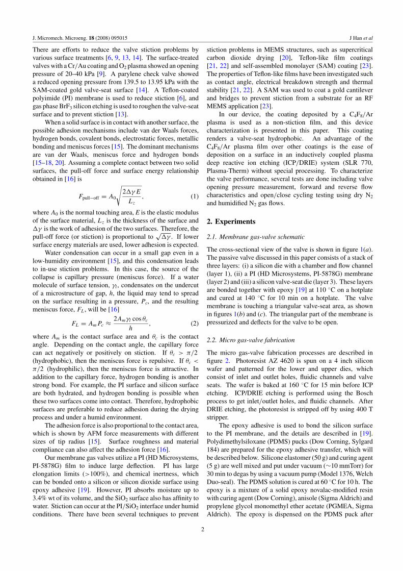
The cross-sectional view of the valve is shown in figure 1(a).The passive valve discussed in this paper consists of a stack ofthree layers: (i) a silicon die with a chamber and flow channel(layer 1), (ii) a PI (HD Microsystems, PI-5878G) membrane(layer 2) and (iii) a silicon valve-seat die (layer 3). These layersare bonded together with epoxy [19] at 110 ◦C on a hotplateand cured at 140 ◦C for 10 min on a hotplate. The valvemembrane is touching a triangular valve-seat area, as shownin figures 1(b) and (c). The triangular part of the membrane ispressurized and deflects for the valve to be open.
2.2. Micro gas-valve fabrication
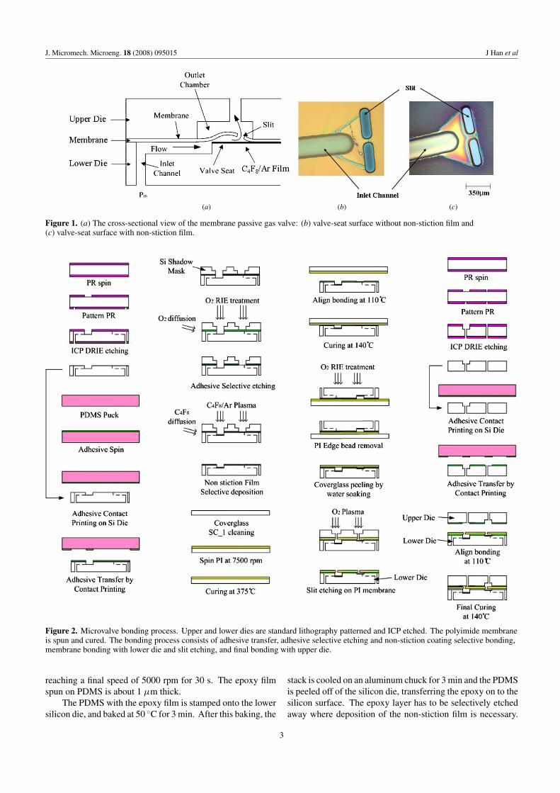
The micro gas-valve fabrication processes are described infigure 2. Photoresist AZ 4620 is spun on a 4 inch siliconwafer and patterned for the lower and upper dies, whichconsist of inlet and outlet holes, fluidic channels and valveseats. The wafer is baked at 160 ◦C for 15 min before ICPetching. ICP/DRIE etching is performed using the Boschprocess to get inlet/outlet holes, and fluidic channels. AfterDRIE etching, the photoresist is stripped off by using 400 Tstripper.
The epoxy adhesive is used to bond the silicon surfaceto the PI membrane, and the details are described in [19].Polydimethylsiloxane (PDMS) pucks (Dow Corning, Sylgard184) are prepared for the epoxy adhesive transfer, which willbe described below. Silicone elastomer (50 g) and curing agent(5 g) are well mixed and put under vacuum (∼10 mmTorr) for30 min to degas by using a vacuum pump (Model 1376, WelchDuo-seal). The PDMS solution is cured at 60 ◦C for 10 h. Theepoxy is a mixture of a solid epoxy novalac-modified resinwith curing agent (Dow Corning), anisole (Sigma Aldrich) andpropylene glycol monomethyl ether acetate (PGMEA, SigmaAldrich). The epoxy is dispensed on the PDMS puck after
2
J. Micromech. Microeng. 18 (2008) 095015 J Han et al
(a) (b) (c)
Figure 1. (a) The cross-sectional view of the membrane passive gas valve: (b) valve-seat surface without non-stiction film and(c) valve-seat surface with non-stiction film.
Figure 2. Microvalve bonding process. Upper and lower dies are standard lithography patterned and ICP etched. The polyimide membraneis spun and cured. The bonding process consists of adhesive transfer, adhesive selective etching and non-stiction coating selective bonding,membrane bonding with lower die and slit etching, and final bonding with upper die.
reaching a final speed of 5000 rpm for 30 s. The epoxy filmspun on PDMS is about 1 µm thick.
The PDMS with the epoxy film is stamped onto the lowersilicon die, and baked at 50 ◦C for 3 min. After this baking, the
stack is cooled on an aluminum chuck for 3 min and the PDMSis peeled off of the silicon die, transferring the epoxy on to thesilicon surface. The epoxy layer has to be selectively etchedaway where deposition of the non-stiction film is necessary.
3
J. Micromech. Microeng. 18 (2008) 095015 J Han et al
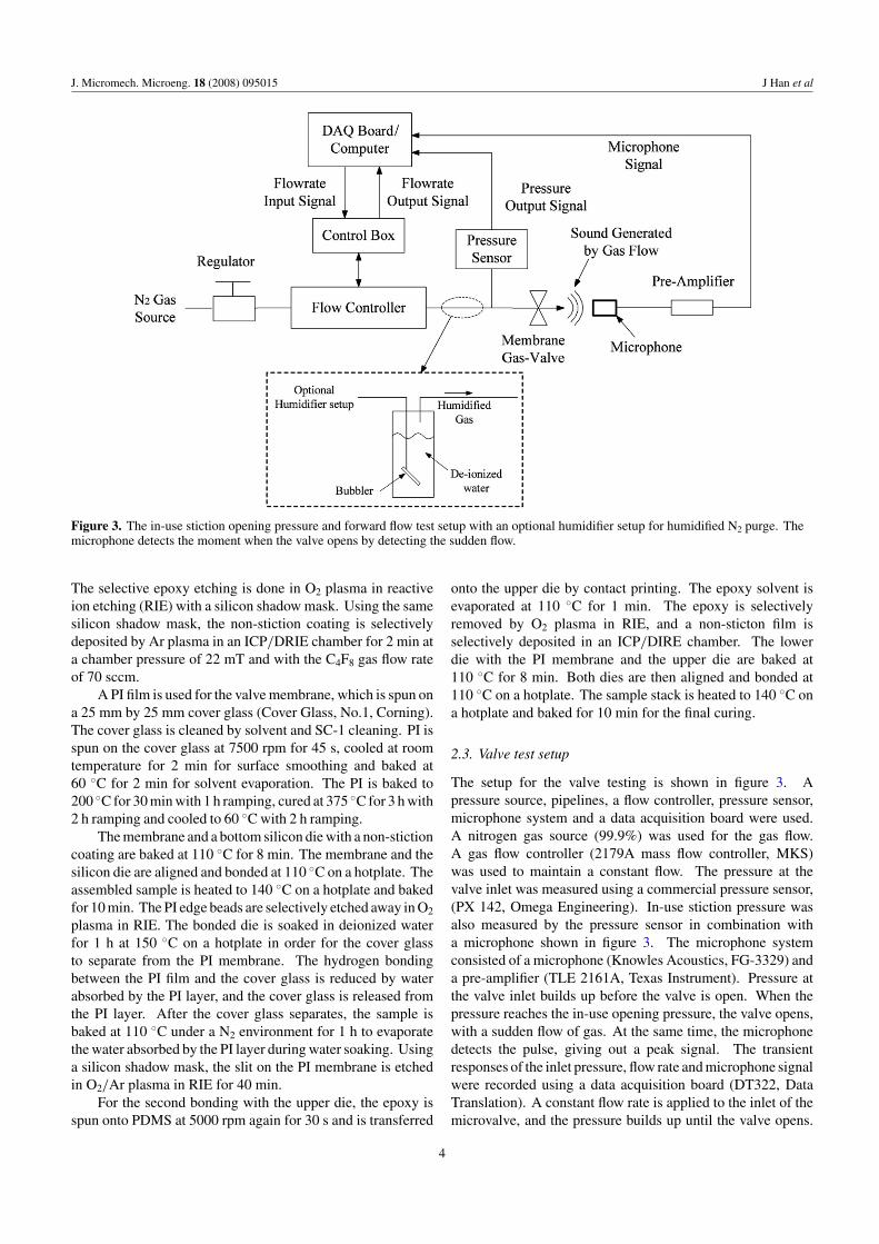
Figure 3. The in-use stiction opening pressure and forward flow test setup with an optional humidifier setup for humidified N2 purge. Themicrophone detects the moment when the valve opens by detecting the sudden flow.
The selective epoxy etching is done in O2 plasma in reactiveion etching (RIE) with a silicon shadow mask. Using the samesilicon shadow mask, the non-stiction coating is selectivelydeposited by Ar plasma in an ICP/DRIE chamber for 2 min ata chamber pressure of 22 mT and with the C4F8 gas flow rateof 70 sccm.
A PI film is used for the valve membrane, which is spun ona 25 mm by 25 mm cover glass (Cover Glass, No.1, Corning).The cover glass is cleaned by solvent and SC-1 cleaning. PI isspun on the cover glass at 7500 rpm for 45 s, cooled at roomtemperature for 2 min for surface smoothing and baked at60 ◦C for 2 min for solvent evaporation. The PI is baked to200 ◦C for 30 min with 1 h ramping, cured at 375 ◦C for 3 h with2 h ramping and cooled to 60 ◦C with 2 h ramping.
The membrane and a bottom silicon die with a non-stictioncoating are baked at 110 ◦C for 8 min. The membrane and thesilicon die are aligned and bonded at 110 ◦C on a hotplate. Theassembled sample is heated to 140 ◦C on a hotplate and bakedfor 10 min. The PI edge beads are selectively etched away in O2
plasma in RIE. The bonded die is soaked in deionized waterfor 1 h at 150 ◦C on a hotplate in order for the cover glassto separate from the PI membrane. The hydrogen bondingbetween the PI film and the cover glass is reduced by waterabsorbed by the PI layer, and the cover glass is released fromthe PI layer. After the cover glass separates, the sample isbaked at 110 ◦C under a N2 environment for 1 h to evaporatethe water absorbed by the PI layer during water soaking. Usinga silicon shadow mask, the slit on the PI membrane is etchedin O2/Ar plasma in RIE for 40 min.
For the second bonding with the upper die, the epoxy isspun onto PDMS at 5000 rpm again for 30 s and is transferred
onto the upper die by contact printing. The epoxy solvent isevaporated at 110 ◦C for 1 min. The epoxy is selectivelyremoved by O2 plasma in RIE, and a non-sticton film isselectively deposited in an ICP/DIRE chamber. The lowerdie with the PI membrane and the upper die are baked at110 ◦C for 8 min. Both dies are then aligned and bonded at110 ◦C on a hotplate. The sample stack is heated to 140 ◦C ona hotplate and baked for 10 min for the final curing.
2.3. Valve test setup
The setup for the valve testing is shown in figure 3. Apressure source, pipelines, a flow controller, pressure sensor,microphone system and a data acquisition board were used.A nitrogen gas source (99.9%) was used for the gas flow.A gas flow controller (2179A mass flow controller, MKS)was used to maintain a constant flow. The pressure at thevalve inlet was measured using a commercial pressure sensor,(PX 142, Omega Engineering). In-use stiction pressure wasalso measured by the pressure sensor in combination witha microphone shown in figure 3. The microphone systemconsisted of a microphone (Knowles Acoustics, FG-3329) anda pre-amplifier (TLE 2161A, Texas Instrument). Pressure atthe valve inlet builds up before the valve is open. When thepressure reaches the in-use opening pressure, the valve opens,with a sudden flow of gas. At the same time, the microphonedetects the pulse, giving out a peak signal. The transientresponses of the inlet pressure, flow rate and microphone signalwere recorded using a data acquisition board (DT322, DataTranslation). A constant flow rate is applied to the inlet of themicrovalve, and the pressure builds up until the valve opens.
4
J. Micromech. Microeng. 18 (2008) 095015 J Han et al
0
10
20
30
40
50
60
0 5 10 15 20 25Time [s]
Pres
sure
[K
Pa]
20 sccm Initial
20 sccm
10 sccm
5 sccm
4 sccm
3 sccm
Initial Opening Pressure Peak
In-use Opening Pressure Peaks
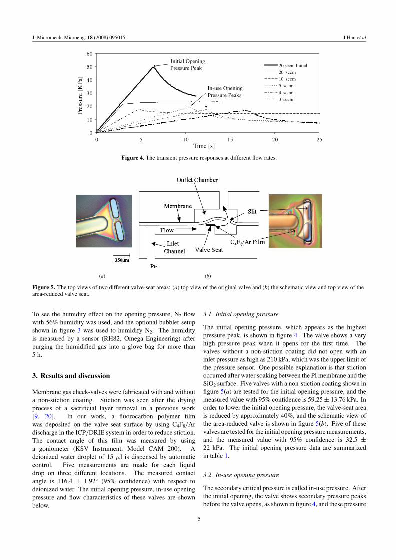
Figure 4. The transient pressure responses at different flow rates.
(a) (b)
Figure 5. The top views of two different valve-seat areas: (a) top view of the original valve and (b) the schematic view and top view of thearea-reduced valve seat.
To see the humidity effect on the opening pressure, N2 flowwith 56% humidity was used, and the optional bubbler setupshown in figure 3 was used to humidify N2. The humidityis measured by a sensor (RH82, Omega Engineering) afterpurging the humidified gas into a glove bag for more than5 h.
3. Results and discussion
Membrane gas check-valves were fabricated with and withouta non-stiction coating. Stiction was seen after the dryingprocess of a sacrificial layer removal in a previous work[9, 20]. In our work, a fluorocarbon polymer filmwas deposited on the valve-seat surface by using C4F8/Ardischarge in the ICP/DRIE system in order to reduce stiction.The contact angle of this film was measured by usinga goniometer (KSV Instrument, Model CAM 200). Adeionized water droplet of 15 µl is dispensed by automaticcontrol. Five measurements are made for each liquiddrop on three different locations. The measured contactangle is 116.4 ± 1.92◦ (95% confidence) with respect todeionized water. The initial opening pressure, in-use openingpressure and flow characteristics of these valves are shownbelow.
3.1. Initial opening pressure
The initial opening pressure, which appears as the highestpressure peak, is shown in figure 4. The valve shows a veryhigh pressure peak when it opens for the first time. Thevalves without a non-stiction coating did not open with aninlet pressure as high as 210 kPa, which was the upper limit ofthe pressure sensor. One possible explanation is that stictionoccurred after water soaking between the PI membrane and theSiO2 surface. Five valves with a non-stiction coating shown infigure 5(a) are tested for the initial opening pressure, and themeasured value with 95% confidence is 59.25 ± 13.76 kPa. Inorder to lower the initial opening pressure, the valve-seat areais reduced by approximately 40%, and the schematic view ofthe area-reduced valve is shown in figure 5(b). Five of thesevalves are tested for the initial opening pressure measurements,and the measured value with 95% confidence is 32.5 ±22 kPa. The initial opening pressure data are summarizedin table 1.
3.2. In-use opening pressure
The secondary critical pressure is called in-use pressure. Afterthe initial opening, the valve shows secondary pressure peaksbefore the valve opens, as shown in figure 4, and these pressure
5
J. Micromech. Microeng. 18 (2008) 095015 J Han et al
-6
-4
-2
0
2
4
6
8
10
12
4.71 4.714 4.718 4.722 4.726 4.73 4.734
Time [s]
Mic
roph
one
sign
al [
V]
(c)
(a)
(b)
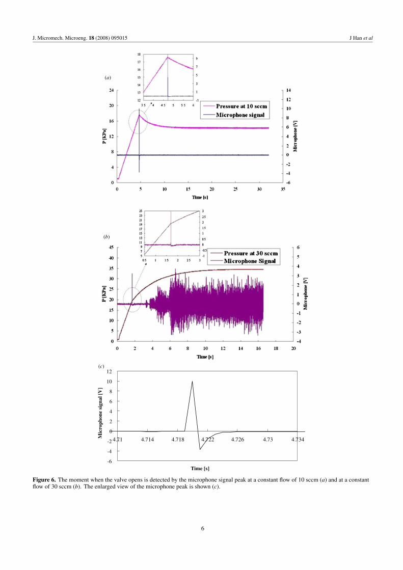
Figure 6. The moment when the valve opens is detected by the microphone signal peak at a constant flow of 10 sccm (a) and at a constantflow of 30 sccm (b). The enlarged view of the microphone peak is shown (c).
6

J. Micromech. Microeng. 18 (2008) 095015 J Han et al
0
5
10
15
20
25
30
35
40
45
1 10 100 1000 10000
# of Cycles
Ope
ning
Pre
ssur
e[K
Pa]
Figure 7. The valve open/close cycles have been tested under dry nitrogen, and the corresponding opening pressure data.
Table 1. Initial opening pressures with 95% confidence.
Initial openingValve type pressure (kPa)
Valve without a non-stiction coating Did not open up to 210 kPaValve with a non-stiction coating 59.25 ± 13.76Valve with a non-stiction coating 32.5 ± 22.0with a reduced area
peaks are used as a measure of in-use opening pressure. Fiveindividual valves of each design are used to measure thein-use opening pressure, and the average values are 16.9 kPafrom the original valves and 13.1 kPa from the area reducedvalves, showing a reduction in the average in-use openingpressure.
When the in-use opening pressure was lower than thesteady state pressure drop at a given flow rate, the pressurepeak was observed. These peaks are shown for flow ratesless than 10 sccm in figure 4. However, the pressure datafor the flow rate higher than 10 sccm did not show thepressure drop. In this case, the steady state pressure ishigher than the in-use opening pressure, and the pressurekeeps increasing after the valve opens. However, there existsa discontinuity in the pressure gradient with respect to timebefore and after the valve opens. Before the valve opens, thepressure rise linearly increases at the constant flow rate fromthe flow controller. After the valve opens, the pressure gradientmonotonically converges to a steady state value. As the flowrate is higher, this discontinuity becomes indistinguishable,and it becomes hard to detect the moment when the valveopens.
Another method to measure the moment when the valveopens is to use a microphone at the outlet. When the valveis open, a sudden flow occurs, and the pressure gradient isdetected by the microphone shown in figure 3. The case for thesteady state pressure less than the opening pressure is shownin figure 6(a), and the case for the steady state pressure higherthan the opening pressure is shown in figure 6(b). The in-useopening pressure is not only measured by the pressure sensoroutput but also assisted by the microphone output signals. Asshown in figure 6(c), the recorded microphone peak rise andfall time is less than 5 ms. The microphone signal is fast
Table 2. In-use opening pressures with 95% confidence.
In-use openingValve type pressure (kPa)
Valve with a non-stiction coating 16.9 ± 16.8Valve with a non-stiction coating 13.1 ± 6.0with a reduced area
enough to detect the moment when the valve opens. The in-use opening pressures are measured, and the average valueswith 95% confidence are summarized in table 2.
3.3. Changes in the in-use opening pressure over time
One of the valves was tested up to 10 000 open/close cyclesunder dry N2 gas flow, and additional 3000 open/close cyclesunder humidified N2 gas flow for the durability test. The in-useopening pressures under dry N2 gas flow are shown in figure 7.After 10 000 cycles, the passive valve operated successfullywithout stiction failure under dry N2 gas. The opening pressuregradually reduced over the cycles.
After 10 000 cycles under dry N2 gas, N2 gas with ahumidity of 56% was used for an additional 3000 cycles. Forthis testing, the test setup was modified as shown in figure 3.The bubbler setup was added before the microvalve. Deionizedwater is used to humidify the N2 gas flow. The in-use openingpressure is shown in figure 8 and is not greatly affected by the56% humidity gas flow. The valve membrane of the devicewas ruptured after 3000 open/close additional testing, andthe cycle test had to stop, as shown in figure 8. The overallopening pressure over 10 000 cycles under N2 gas was 13.86 ±4.22 kPa, and the overall opening pressure over 3000 cyclesunder humid gas was 12.76 ± 2.24 kPa. The opening pressurereduction could be due to a number of reasons, includingthe viscoelastic property of the PI membrane and fatigue, notmainly by the humidity effect.
3.4. Flow characteristics
A constant flow rate versus the steady state pressure dropwas measured for both original valves and reduced areavalves. While the flow controller sent out a constant flow, the
7
J. Micromech. Microeng. 18 (2008) 095015 J Han et al
0
5
10
15
20
25
30
35
40
45
1 10 100 1000 10000
# of Cycles
Ope
ning
Pre
ssur
e [K
Pa]
Cycle test stop
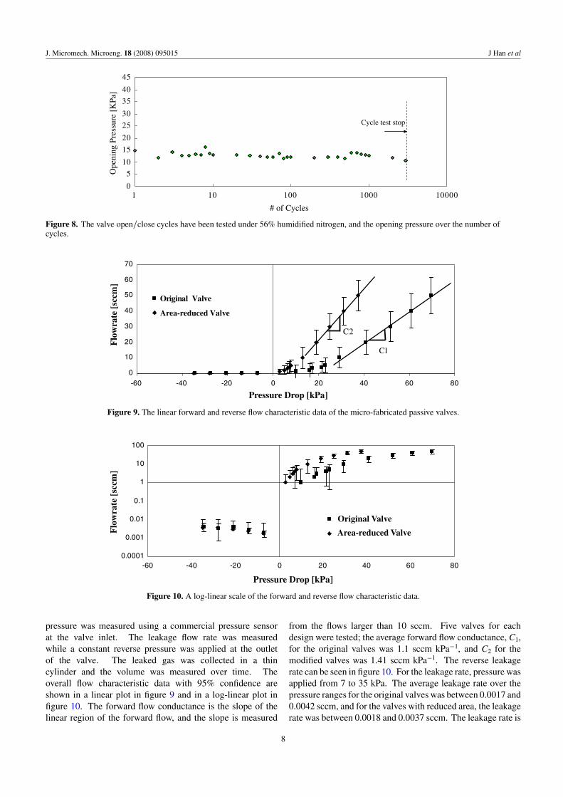
Figure 8. The valve open/close cycles have been tested under 56% humidified nitrogen, and the opening pressure over the number ofcycles.
0
10
20
30
40
50
60
70
-60 -40 -20 0 20 40 60 80
Pressure Drop [kPa]
Flo
wra
te [
sccm
]
Original Valve
Area-reduced Valve
C2
C1
Figure 9. The linear forward and reverse flow characteristic data of the micro-fabricated passive valves.
0.0001
0.001
0.01
0.1
1
10
100
-60 -40 -20 0 20 40 60 80
Pressure Drop [kPa]
Flo
wra
te [
sccm
]
Original Valve
Area-reduced Valve
Figure 10. A log-linear scale of the forward and reverse flow characteristic data.
pressure was measured using a commercial pressure sensorat the valve inlet. The leakage flow rate was measuredwhile a constant reverse pressure was applied at the outletof the valve. The leaked gas was collected in a thincylinder and the volume was measured over time. Theoverall flow characteristic data with 95% confidence areshown in a linear plot in figure 9 and in a log-linear plot infigure 10. The forward flow conductance is the slope of thelinear region of the forward flow, and the slope is measured
from the flows larger than 10 sccm. Five valves for eachdesign were tested; the average forward flow conductance, C1,for the original valves was 1.1 sccm kPa−1, and C2 for themodified valves was 1.41 sccm kPa−1. The reverse leakagerate can be seen in figure 10. For the leakage rate, pressure wasapplied from 7 to 35 kPa. The average leakage rate over thepressure ranges for the original valves was between 0.0017 and0.0042 sccm, and for the valves with reduced area, the leakagerate was between 0.0018 and 0.0037 sccm. The leakage rate is
8
J. Micromech. Microeng. 18 (2008) 095015 J Han et al
not only dominated by the valve-seat design, but can also beaffected by the slit size and location from the valve seat. Thesedeviations possibly came from the shadow mask alignment forthe membrane slit etching, and the slit size may vary due tothe variation of the PI membrane thickness at a given etchingtime.
4. Summary and conclusion
A micro gas valve utilizing a PI membrane was fabricatedwith an integrated non-stiction coating. In order to increaseforward flow, a flexible material, polyimide (E ∼ 2.3 GPa),is used as a membrane to have a large deflection at a givenpressure. To achieve a low leakage rate, a passive valve needstight sealing between the membrane and the valve seat. Thetight sealing design may induce stiction during fabrication.The affinity of PI to moisture induces stiction when PI touchesthe valve-seat surface. The film deposited by C4F8/Ar plasmain ICP/DRIE is integrated into the valve-seat surface duringfabrication, and the valve stiction is reduced. Initial openingpressures and in-use opening pressure are measured for twodifferent valve-seat designs. From the open/close cycle testsunder dry and 56% humid N2 gas flows, the average valuesof in-use opening pressures of the two different gas flows didnot vary significantly. The average forward flow conductancemeasured was 1.1 sccm kPa−1 and 1.41 sccm kPa−1 before andafter the valve-seat area reduction, respectively. The measuredleakage was approximately 0.004 sccm at the reverse pressureof 35 kPa.
Acknowledgments
We gratefully acknowledge financial support from the DefenseAdvanced Research Projects Agency (DARPA) under US AirForce grant FA8650-04-1-7121. Any opinions, findings andconclusions or recommendations expressed in this manuscriptare those of the authors and do not necessarily reflect the viewsof the Defense Advanced Projects Research Agency, or the USAir Force.
References
[1] Nquyen N, Huang X and Chuan T K 2002MEMS-micropumps: a review Trans. ASME, J. Fluid Eng.124 384–92
[2] Oh K W and Ahn C H 2006 A review of microvalvesJ. Micromech. Microeng. 16 R13–39
[3] Bien D C S, Mitchell S J N and Gamble H S 2003 Fabricationand characterization of a micromachined passive valveJ. Micromech. Microeng. 13 557–62
[4] Fazal I, Louwerse M C, Jansen H V and Elwenspoek M C2006 Design, fabrication, and characterization of a novelgas microvalve using micro- and fine-machiningJ. Micromech. Microeng. 16 1207–14
[5] Feng G H and Kim E S 2004 Micropump based on PZTunimorph and one-way parylene valves J. Micromech.Microeng. 14 429–35
[6] Lu C J et al 2005 First-generation hybrid MEMS gaschromatograph Lab Chip 5 1123–31
[7] Dziuban J A et al 2004 Portable gas chromatograph withintegrated components Sensors Actuators A115 318–30
[8] Tang D, Yeom J, Han J, Bae B, Masel R I and Shannon M A2005 A micro-post preconcentrator for a microscale gaschromatography system Micro Total Analysis Systems Conf.(Boston, 9–13 Oct) pp 660–2
[9] Wang X Q and Tai Y C 2000 A normally closed in-channelmicro check valve 13th IEEE Int. Conf. MEMS (Miyazaki,Japan, 23–27 Jan.) pp 68–73
[10] Chen P J, Rodger D C, Meng E M, Humayun M S and Tai Y C2007 Surface-micromachined parylene dual valves foron-chip unpowered microflow regulationJ. Microelectromech. Syst. 16 223
[11] Nam-Trung N, Thai-Quang T, Kok-Keong W, Soon-Seng Hand Cassandra L L 2004 Micro check valves for integrationinto polymeric microfluidic devices J. Micromech.Microeng. 14 69–75
[12] Meng E, Wang X Q, Mak H and Tai Y C 2000 A check-valvedsilicone diaphragm pump 13th IEEE Int. Conf. MEMS(Miyazaki, Japan, 23–27 Jan.) pp 62–67
[13] Wang X Q, Lin Q and Tai Y C 1999 A parylene micro checkvalve 12th IEEE Int. Conf. MEMS (Orlando, 17–21 Jan.)pp 177–82
[14] Xie J, Yang X Y, Wang X Q and Tai Y C 2001 Surfacemicromachined leakage proof parylene check valve 14thIEEE Int. Conf. MEMS (Interlaken, Switzerland, 21–25Jan.) pp 539–42
[15] Bhushan B 2003 Adhesion and stiction: mechanism,measurement techniques, and methods for reductionJ. Vac. Sci. Technol. 21 2262–96
[16] Persson B N J and Tosatti E 2001 The effect of surfaceroughness on the adhesion of elastic solids J. Chem. Phys.115 5597–610
[17] Bhushan B and Dandavate C 2000 Thin film friction andadhesion studies using atomic force microscopy J. Appl.Phys. 87 1201–10
[18] Eastman T and Zhu D M 1996 Adhesion forces betweensurface-modified AFM tips and a mica surface Langmuir12 2859–62
[19] Flacksbart B R, Qong K, Lannacone J M, Abante E N,Vlach R L, Rauchfuss P A, Bohn P W, Sweedler J V andShannon M A 2006 Design and fabrication of a multilayeredpolymer microfluidic chip with nanofluidic interconnectsvia adhesive contact printing Lab Chip 6 667–4
[20] Dyck C W, Smith J H, Miller S L, Russick E M andAdkins C L J 1996 Supercritical carbon dioxide solventextraction from surface-micromachined micromechanicalstructures Proc. SPIE 2879 225–35
[21] Matsumoto Y and Ishida M 2000 The property of plasmapolymerized fluorocarbon film in relation to CH4/C4F8
ratio and substrate temperature Sensors Actuators83 179–85
[22] Man P F, Gogoi B P and Mastrangelo C H 1996 Elimination ofpost-release adhesion in microstructures using thinconformal fluorocarbon films 9th IEEE Int. Conf. MEMS(San Diego, 11–15 Feb.) pp 55–60
[23] Kim J M, Baek C W, Park J H, Shin D S, Lee Y S andKim Y K 2002 Continuous anti-stiction coatings usingself-assembled monolayers for gold microstructuresJ. Micromech. Microeng. 12 688–95
[24] Derjaguin B V, Muller V M and Toporov Y P 1975 Effect ofcontact deformations on the adhesion of particles J. ColloidInterface Sci. 53 314–26
9
Related Documents