MiCOM P54x Series цифровые дифференциальные токовые реле
Jan 05, 2016
MiCOM P54x Series цифровые дифференциальные токовые реле. РЗА. Июль 2006. MiCOM P54x Series. Продольная дифференциальная токовая защита. MiCOM Protection. P940 Frequency Protection Relays. P840 Autoreclose Relays. P740 Busbar Protection Relays. P630 Transformer Protection Relays. - PowerPoint PPT Presentation
Welcome message from author
This document is posted to help you gain knowledge. Please leave a comment to let me know what you think about it! Share it to your friends and learn new things together.
Transcript


MiCOM P54x Series цифровые дифференциальные токовые реле
Июль 2006
РЗА

> Title of presentation - Date - References3 3
MiCOM P54x Series
Продольная дифференциальная токовая защита
> Title of presentation - Date - References4 4
MiCOM Protection
P340 Generator Protection RelaysP340 Generator Protection Relays
P430/P440 Distance Protection RelaysP430/P440 Distance Protection Relays
P540 Line Differential and Unit ProtectionP540 Line Differential and Unit Protection
P940 Frequency Protection RelaysP940 Frequency Protection Relays
P240 Universal Motor Protection RelayP240 Universal Motor Protection Relay
P840 Autoreclose RelaysP840 Autoreclose Relays
P740 Busbar Protection RelaysP740 Busbar Protection Relays
P630 Transformer Protection RelaysP630 Transformer Protection Relays
P140 Feeder Management RelaysP140 Feeder Management Relays

> Title of presentation - Date - References5 5
P540 защитные функции
УРОВ
Телеоткл. и команды
пользователя
Тепловая модель
1/3 ф АПВ
Опр. обрыва провода
Защита участка
ошиновки
ДЗЛ
МТЗТЗНП
ДЗ
Защита трансформатора

> Title of presentation - Date - References6 6
P541 для линейных или трансформаторных фидеров 40TE / 8”
P542 для линейных или трансформаторных фидеров с ТАПВ, (60TE / 12”)
P543 для линий с дистанционной защитой ОАПВ и ТАПВ, (60TE / 12”)
P544 для линий, подключенных через 2 выключателя с дистанционной защитой, (60TE /12”)
P540 Current Differential Relays-доступные модели (non GPS-synch.)

> Title of presentation - Date - References7 7
P540 Current Differential Relays -для классического применения и применения в
синхронизированных цифровых сетях
P545 для линий с дистанционной защитой ОАПВ и ТАПВ, , (80TE / 19”)
P546 для линий, подключенных через 2 выключателя с дистанционной защитой, (80TE /19”)
# GPS synchronisedmode described later

> Title of presentation - Date - References8 8
Дифферециальный принцип
End A
Линия связи
End B
Relay AAI BI
FI
IA + IB = 0 Healthy
IA + IB 0 (= IF) Fault
Relay B

> Title of presentation - Date - References9 9
Трехконцевая линия
CIAI BIFI
IA + IB + IC = 0 Healthy
IA + IB + IC 0 (= IF faulty)
Relay B
End C
End A

> Title of presentation - Date - References10 10
Current Differential - особенности
Не нужен вход напряжения
Подходит для 3-х концевых линий
Определяет повреждение через переходное сопротивление
Не реагирует на качания
Одно и то же время срабатывания
Проста в установке
> Title of presentation - Date - References11 11
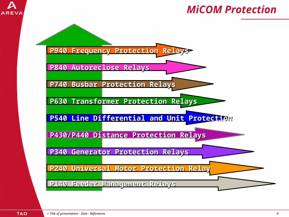
Полностью цифровое устройство
Пакеты данных0 I I I I I I 0 I 0 . . . . . 0 I 0 I I I I I I 0
A/D P
Цифровой интерфейс
End A End B

> Title of presentation - Date - References12 12
Main Features of P540 Relayдифференциальный элемент
Использование стандартного коммуникационного канала 56 or 64 kbits/s
Также работает по выделенной оптоволоконной паре
Пофазное исполнение
Компенсация емкостного тока
2 и 3 концевые линии
Измерение и компенсация времени задержки сигнала в канале
проверка достоверности данных в канале
Передача команд прямого и разрешающего телеотключения
8 пользовательских команд для свободного использования
> Title of presentation - Date - References13 13
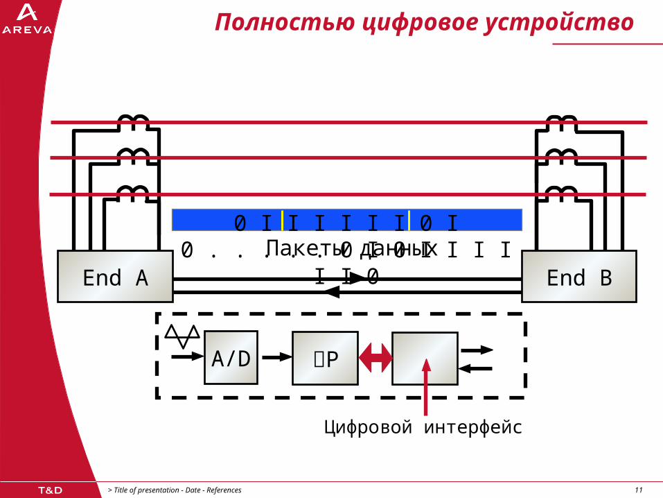
Прямое соединение
OPGW

> Title of presentation - Date - References14 14
Подключение через мультиплексор
850nm оптосоединител
ьP593
interfaceunit
ISDNX.21
electrical
MultiplexerG.703
or V.35 electrical
P591/2interface
unit

> Title of presentation - Date - References15 15
Multiplexed Optical Link
34 Mbit/s
Multiplexer Multiplexer
64kbits/s
Earth wire optical fibre
Telephone
Telecontrol
Teleprotection
End A End B

> Title of presentation - Date - References16 16
Multiplexed Microwave Link
64kbits/s
PCMMultiplexer
PCMMultiplexer
Telephone
Telecontrol
Teleprotection
End A End B

> Title of presentation - Date - References17 17
Прямое подключение к мультиплексору
850nm оптосоединитель
Multiplexer
Прямое безинтерфейсное соединение
IEEE C37.94

> Title of presentation - Date - References18 18
IEEE C37.94 –формат сообщения
Channel Data (192 bits)
D4
p q rp q
D3D1 D2 D2 D3D1
01010101 . . .sr s
1
1001 1
y11 1
0
0 11110011 00
sync1 1111000011
Header (16 bits)
Overhead (48 bits)
250µs125µs 375µs
256 bit frame
. . .D4 D6D5 D5 D6 D7 D7 D8 D8 D9 D9
1 0
D96D96
500µsTime

> Title of presentation - Date - References19 19
При выборе IEEE C37.94 в J релеуставка актуальна для основного и
резервного каналов

> Title of presentation - Date - References20 20
Оптический бюджет для прямого соединения
850nm Multi 1300nm Multi 1300nm Multi 1550nm Single
Mode Mode Mode Mode
мощность -19.8dBm -13dBm -13dBm -13dBmпередатчика
чувствительность -25.4dBm -40dBm -40dBm-40dBm
приемника
Optical Budget 5.6dB 27.0dB 27.0dB 27.0dB
Миним. 2.6dB 24.0dB 24.0dB 24.0dB запас (3db)*
удельное 2.6dB/km 0.8dB/km 0.4dB/km 0.3dB/kmзатухание
Maкс 1 km 30km 60km 80kmрасстояние
ближе дальше
Key: * 3dB –необходимый запас чувствительности в расчете на старение кабеля

> Title of presentation - Date - References21 21
Current Differential
16 bit АЦП
Асинхронные выборки по 8 точек на период
(12 samples/cycle in Disturbance Record)
Определение вектора тока после обсчета одного цикла по ряду Фурье
Proven best noise immunity in difficult applications adjacent to HVDC, switching noise, series compensation etc…
Коррекция вектора по времени

> Title of presentation - Date - References22 22
Измерение тока и фильтрация - 1
i(t)i2
i1
i3
i4
i5 i8
t
i6 i7
N= Номер выборки в цикле
I = 2N
N - 1
n = 1
i exp j n tn

> Title of presentation - Date - References23 23
Измерение тока и фильтрация - 2
I = 2sN
I = 2cN
I = I + I
N-1
n=1sin t.in
n
i i
2 2 o N + +
N-1
n=1 cos t.in n
s j c

> Title of presentation - Date - References24 24
Формат пакета данных
Startflag
Address DataFramecheck
Endflag
Statusand
commands
Currentvectors
Timingdata

> Title of presentation - Date - References25 25
Формат пакета данных
24 BytesTotal
Стартовый флаг (01111110) для синхронизации сообщения
Алрес реле
Метка времени для вычисления времени прохождения сигнала
Информация о статусе и передаваемых командах
3 фазных вектора тока
Дополнительное торможение (2 гармоника для P541/P542, рижим защиты участка ошиновки P544/P546)
CRC
Финишный флаг (01111110) для синхронизации сообщения

> Title of presentation - Date - References26 26
Конечное время прохождения сигнала
Ток на ПС В
Ток принятый от ПС А
задержка
Relay A Relay B

> Title of presentation - Date - References27 27
Компенсация времени прохождения сигнала
Синхронные выборки в обоих реле
Прямое сравнение выборок
Синхронизация между реле посредством GPS – что случится при отсутствии GPS?
Асинхронные выборки
Непрерывное измерение расхождения времени
Программная подгонка векторов
P545 and P546 only
Все модели, P541-P546

> Title of presentation - Date - References28 28
Время прохождения сигналаизмерения - 1
tA1
Пакет данных
Relay BRelay A
Current vectorstA1
tA2
tA3
tA4
tA5
tB1
tB2
tB3
tB4
tB5
tB *tp1

> Title of presentation - Date - References29 29
Время прохождения сигнала измерения - 2
Измеренное время выборкиtB3 = (tA - tp2)* *
Время задержкиtp1 = tp2 = 1/2 (tA - tA1) - td*
Пакет
данных
tB1tB2
tB3
tB4tB5
tB*
tA1
tA2
tA3
tA4
tp1
tA5
Current vectors
tA1
tB3*tA* Curren
t vector
stB3
tA1
td
tp2

> Title of presentation - Date - References30 30
Сравнение векторов тока
I (tA4)
I (tB3 )*
=t
t = (tA4 - tB3 )*
если I (tB3 ) = Is + j Ic
*= I cos + j I sinто I (tA4) = I (tB3 ) . (cos + j sin ) = I cos ( + ) + j I sin
(+)
*

> Title of presentation - Date - References31 31
Дифференциальная характеристика
IS1Угол наклона k1
I
клин
IC
IBIA
Угол наклона k2
S2
сраб
Торм ток
bias A B C
I = 1/2 ( I + I + I )
Диф ток
I =
I + I + Idiff
A B C

> Title of presentation - Date - References32 32
Мгновенные изменения времени передачи (1)
Неодинаковые времена приема/передачи приведут к неправильному сравнению векторов и неправильному вычислению диф. тока
Большинство цифровых каналов пропускают сигналы разных направлений по одному и тому же пути
Иногда кратковременно эти времена становятся разными
Могут привести к ложному срабатыванию

> Title of presentation - Date - References33 33
Мгновенные изменения времени передачи(2)
Реле непрерывно измеряет время прохождения
Любые изменения во времени передачи приводят к тому что реле поднимает уставку К1 до 200% для эффективного блокирования диф органа при токах до Is2
Изменения активны в течении установленного времени (мах 0,5 с) после которого уставка восстанавливается

> Title of presentation - Date - References34 34
Мгновенные изменения времени передачи(3)
Диф ток
I =
I + I + I
diff
A B C
Торм ток
bias A B C
I = 1/2 ( I + I + I )
IS1
Bias
k1 I
клин
Bias k
2
S2
сраб
Bias
20
0%

> Title of presentation - Date - References35 35
Компенсация емкостного тока
IchL IchR
IRIL
VL VR
ZL
В устройствах ДЗЛ необходимо устанавливать ток срабатывания выше тока заряда линииР543-546 вычитает емкостный ток из измеренного токаПольза: увеличение чувствительности при КЗ через переходное сопротивление

> Title of presentation - Date - References36 36
Типовые емкостные токи кабеля/ВЛ
Underground cables Overhead lines
Line Volts11kV 400kV
Line Volts132kV 400kV
30
1.2
A/km
1
0.3
A/km

> Title of presentation - Date - References37 37
P541/ P542 – защита трансформатора
Силовой трансформатор
P540Scheme
Virtual interposing CT
Vectorialcorrection
Ratiocorrection
Virtual interposing CT

> Title of presentation - Date - References38 38
Коррекция группы соединения
87
Yy0
0
Yd11
+30
Dy1 (-30 )
Yy0, Yd1, Yd5, Yy6, Yd7, Yd11, Ydy0 …… etc.0°, -30°, -150°, 180°, +150°, +30°, 0° …. etc.
87

> Title of presentation - Date - References39 39
Бросок тока-теория
m+
Постановка под напряжение
m-
m2
Рабочий режим
V
mI
V
mI

> Title of presentation - Date - References40 40
Example MV Application:Teed Feeder Protection
FI
Differential protection can be IDMT or DT delayed to discriminate with tapped feed protection: Fused spurs Tee-off transformer in-zone Ring main units (RMU)
End A End B

> Title of presentation - Date - References41 41
Example HV/EHV Application:Stub Bus Protection
P544 and P546 have two sets of differential CT inputs
When disconnector open, diff. protection is provided for the stub bus only
No current vectors transmitted to remote end
No diff. intertrip
Bus A
Bus B
Opendisconnector

> Title of presentation - Date - References42 42
Additional Communications ФУНКЦИИ канала
Все терминалы поддерживают двух- и трехрелейную схему
Возможность измерения тока на удаленном конце и фиксация его в осциллограмме
Статистика ошибок канала связи
Прямое телеотключение- может быть использовано для ускорения дистанционной защиты
Разрешающее телеускорение

> Title of presentation - Date - References43 43
Direct Intertrip
DTT=1
Data Message
Relay A Relay B
+- +-
TransformerProtection

> Title of presentation - Date - References44 44
Permissive Intertrip
BusbarRelay
F
+-
Example shows interlocked overcurrent protection Feeder fault seen within busbar zone Remote end trip after set delay for PIT & current > Is1
IB
Relay A Relay B
+-
PIT=1
Data Message

> Title of presentation - Date - References45 45
8 Programmable Intertrip/ControlCommands, End - End
8 Commands from PSL end A - PSL end BDistance and DEF aided channel schemesBreaker fail backtrip to upstream CBForce remote end A/R for successful local A/RSCADA for remote end substation
A B52 52
Single or dual fibre optic comms.
850nm1300nm1550nm
or MUX
8 + PIT
8 + PIT
&> 1 &
> 1
PSLPSL

> Title of presentation - Date - References46 46
Z3
Z3
Z1
Z1
Z2
Z2
Tx Rx
Tx Rx
Send Logic : Z1Trip Logic : Rx + Z2
Z3
Z2
Z1 1
T2
T3
TripT2
&
Z3
Z2
Z11
T2
T3
TripT2
&
100
0100
0
Best to Keep PSL Simple:схема работы ДЗ с разрешающим сигналом
(1)

> Title of presentation - Date - References47 47
Race between relay at D picking up and signal send from relay at C resetting, following opening of breaker at C
If signal send from C resets before relay D operates then aided tripping will not occur
To prevent this a 100ms delay on drop off of the signal send is used in the PSL
A
21
C
B
D
A
C
B
D
Send
Fault
Fault
21
21 21
Rx + Z2
Rx + Z2
PSL Implications:Permissive Underreach Scheme (2)

> Title of presentation - Date - References48 48
PSL Implications:P540 Distance Schemes
Better security is offered by a distance scheme if permissive signals are routed separately from the current differential
ie. - 87L channel failure for one line should not jeopardise the backup 21 scheme
При наличии параллельных линий рекомендуется для разрешающих сигналов использовать канал соседней линии
A
C
B
D
21 21
8787

> Title of presentation - Date - References49 49
Назначение уникальных адресов реле
Для предотвращения неправильного роутинга сигналов мультиплексором
Range of addresses for 2 terminal applications
1A, 1B; 2A, 2B; _ _ _ _ _ 20A, 20B
Range of addresses for 3 terminal applications
1A, 1B, 1C; 2A, 2B, 2C; _ _ _ _ _20A, 20B, 20C

> Title of presentation - Date - References50 50
Communications Path forTwo Ended Application
Tx
Rx
End A
Rx
Tx
End B
CH1

> Title of presentation - Date - References51 51
Communications Path forThree Ended Application
P540
CH1 CH2 TxRx
Rx Tx
RxTx
Rx Tx
Tx Rx
End B
End C
End A
P540
CH1
CH2
P540
CH2
CH1
Tx Rx
Note: Full line protection is provided even should one communications path fail
E.g. For A-B channel fail, C still offers line protection and will intertrip to A and B in the event of a fault

> Title of presentation - Date - References52 52
CH1
CH2
Both channels are active - relays automatically select the correct message should one channel fail
“Hot Standby”
Dual Redundant CommunicationChannels Option

> Title of presentation - Date - References53 53
Dual Redundant Communications
Relay A Relay B
Multiplexer

> Title of presentation - Date - References54 54
Use of Mixed Comms. Options in Suffix J
CH1 and CH2 can now be selected to operate with different optical drivers, one 850nm, plus a direct fibre connection:
CORTEC codes H to R:

> Title of presentation - Date - References55 55
Дублированное соединение
Relay A Relay B
мультиплексор
Direct Fibre
MUX
Используются оба канала CH1 and CH2...

> Title of presentation - Date - References56 56
Be Careful in Triangulated Schemeswith Mixed Comms Channels...
P540
CH1 CH2 TxRx
Rx Tx
RxTx
Rx Tx
Tx Rx
End B
End C
End A
P540
CH1
CH2
P540
CH2
CH1
Tx Rx End C has 850nm
CH1, and 1300nm CH2
End A has 850nm CH2, and 1300nm CH1
CH1 and CH2 can not be inverted by settings
RELAY A AND RELAY C WILL NOT BE THE SAME CORTEC
850nm
1300nm1300nm

> Title of presentation - Date - References57 57
87L Current Differential
Zone 1 / 2 Distance Zone 3Distance *
Zone 3Distance *
Directional / Non-Directional Overcurrent and Earth Fault
(* Zone 3 can be set forwarddirectional if required)
Dual Main Protection - 87L Differential, 21 Distance, Plus Backup

> Title of presentation - Date - References58 58
Использование дистанционного элемента
Возможна работа параллельно с ДЗЛ как вторая защита
Использование как резервной в случае потери канала
Для цели дальнего резервирования
Для смешанных линий запрещать АПВ в случае обнаружения повреждения на кабельном участке трассы

> Title of presentation - Date - References59 59
P543/P544: Distance ProtectionThree Quadrilateral Zones
R
X
Z2
Z1
Z3 Directional Line
Power swingblocking band
(Zone 3 can be set forwarddirectional if required)

> Title of presentation - Date - References60 60
Quadrilateral Characteristic
For load avoidance, and better ground fault resistive coverage on short lines
jX
Z
ZR
RR
LoadL
1F
Ph/G

> Title of presentation - Date - References61 61
Generating a Quadrilateral Zone 1 Impedance Characteristic via Four Phase Comparators
IZ
A1 = V - IZ
B1 = INR
A3 = -IZ
B3 = V + IR A2 = V -
IRB2 = -IZ
IR-IR
A4 = -IZ
B4 = VPOL
Trip criterion :- 180° < A - B
< 0°

> Title of presentation - Date - References62 62
Phase Comparator Principle
A B B A
B Lags A
Restrain condition
B Leads A
Operate condition
A A
BB

> Title of presentation - Date - References63 63
Fault incidence
CVT errorFaulted phase voltage
16% Synchronous polarising
Polarising voltage
(Before squaring and90 phase shift)
16% Cross Polarising Level Deals with CVT Transients and Close-up Faults

> Title of presentation - Date - References64 64
Preventing Zone - 1 OverreachQuadrilateral Characteristic
REA
IA
A B
RF EB
Prefault power flowIB
IF
jX
BRF
RA
X
Tilt Down

> Title of presentation - Date - References65 65
Preventing UnderreachQuadrilateral Characteristic
REA
IA
A B
EB
Prefault power flow
IB
jX
B
RF
RA
X
RF
Tilt Up

> Title of presentation - Date - References66 66
Neutral Current Polarisation of Quadrilateral Reach-Line
EA ZSA ZLA ZLB ZSB EBIA
IR
RF
PH E faultR
Prefault load flow

> Title of presentation - Date - References67 67
Sequence Diagram for Resistive Ground Fault
EA
EB
ZS1A ZL1A ZL1B ZS1B
I1A I1B
I2A I2B
I0A I0B
ZS2A ZL2A ZL2B ZS2B
ZS0A ZL0A ZL0B ZS0B
Z 0A Z 0B
Z0A Z0B I0A I0B= = IF in which case INA
= IF
IF
3
3RF

> Title of presentation - Date - References68 68
Negating Under/Overreach Effects of Infeed
During a single phase to ground fault the Neutral current is approximately in phase with the fault arc current
The reactance line of the Earth Quad Elements is polarised from Neutral Current
Under and overreach effects are minimised dynamically

> Title of presentation - Date - References69 69
Backup Overcurrent Protection51P/51N/67
Four stages of directional/non-directional phase overcurrent protection
I>1 and I>2 IDMT or definite time
I>3 and I>4 definite time (t=0, instantaneous)
Four stages of directional/non-directional earthfault protection
IN>1 and IN>2 IDMT or definite time
IN>3 and IN>4 definite time (t=0, instantaneous)
Directional decision polarised from VN or V , allowing use of open delta VTs
I> and IN> elements can be enabled permanently, or on channel failure
Useful for enabling as Switch on to Fault protection

> Title of presentation - Date - References70 70
Backup Overcurrent Protection51P/51N/67 IDMT Curves
IEC Curves
Current (Multiples of Is)
0.1
1
10
100
1000
1 10010
Operating Time (s)
IEEE Curves
0.1
1
10
100
1 10 100Current (Multiples of Is)
Operating Time (s)IEC SIIEC VIIEC EIIEC LTS
US MIUS VIUS EIUS IUS SI

> Title of presentation - Date - References71 71
УРОВ
2 уставки по
времени
Быстрый возврат
(15ms)
Запуск извне
Backtrip
Retrip
Trip
From other device
BFINIT

> Title of presentation - Date - References72 72
Возврат УРОВ

> Title of presentation - Date - References73 73
Overload Protection (1)
Overcurrent protection designed for fault conditions
Thermal replica provides better protection for overload
Current based
Flexible characteristics
Single or dual time constant
Reset facility
Non-volatile
Current
Time

> Title of presentation - Date - References74 74
Overload Protection (2):Dual Characteristic for Transformers
10000
1000
100
10
1 2 3 4 5 6
Trip time (s)
Current (multiple of thermal setting)
Single characteristic: = 120 mins
Dual characteristic
Single characteristic: = 5 mins

> Title of presentation - Date - References75 75
Broken Conductor Protection (1)
Majority of system faults are a result of short circuits
Easily detectable
Possibility of open circuit faults exist
Difficult to detect with conventional protection

> Title of presentation - Date - References76 76
Broken Conductor Detection (2)
Existing detection methods;
Combination of under/overcurrent logic
Negative phase sequence overcurrent
Consider suitability for all load conditions
P54* uses a ratio technique:
I2 / I1 is high for open circuit fault condition
Benefit: Load conditions have minimal effect

> Title of presentation - Date - References77 77
VT Supervision (1)
Alarms
Event record
Blocking
Adaptive
setting
I and 2 logic
3 on load logic
on energisation
logic
MCB digital input
A
B
C
VTS
Alarms
Event record
Blocking
Adaptive setting

> Title of presentation - Date - References80 80
Alternative Setting Groups:Use for Switched / Alternate Feeding
Settingselectioninputs
SCADAor PLC
2 31 4
Four groups available

> Title of presentation - Date - References81 81
Up to four reclose shots:
First high speed shot can be single pole
Three delayed AR shots
Selection of elements to initiate or block AR
Check synchronism function allows:
Live line/live bus in synchronism AR
Live line/dead bus AR
Dead line/live bus AR
Safety checking prior to manual CB close authorisation
Integrated Autorecloser with Check Synchronism (Example: P543)
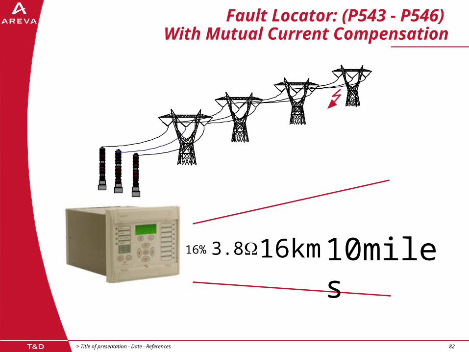
> Title of presentation - Date - References82 82
16% 3.8 16km10miles
Fault Locator: (P543 - P546) With Mutual Current Compensation

> Title of presentation - Date - References83 83
Bay Monitoring
CB state/discrepancy monitoring
CB condition monitoring:
Number of Trip operations
Sum of broken current; Ix (1.0 <= x <= 2.0)
CB operating time
CB operations during period
Condition based maintenance
> Title of presentation - Date - References84 84
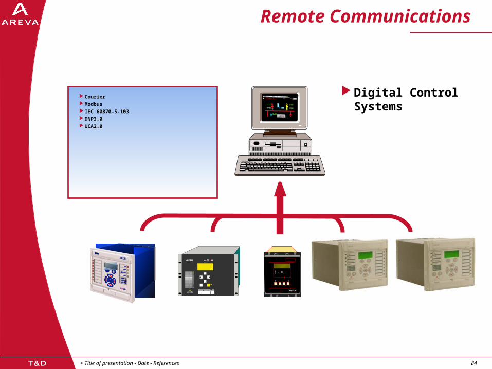
Remote Communications
Digital Control Systems
Courier Modbus IEC 60870-5-103 DNP3.0 UCA2.0

> Title of presentation - Date - References85 85
MiCOM P540 SeriesSummary
Per phase basis comparison
Differential gives high sensitivity and phase selectivity
More integration, less panel space, less interwiring, lower installation cost
Comprehensive backup protection, AR etc …
No need for panel mounted instruments
NO and NC contacts along with graphical PSL allow interlocking schemes etc to be configured
Self monitoring removes the need for extensive periodic injection testing
Condition monitoring of CB bay aids maintenance scheduling

> Title of presentation - Date - References86 86
P540 Main ProtectionUnit Protection Relays
Models P543-P546 cover both single and three pole tripping
applications P541, P542 and P547 cover three pole trip applications only P545 and P546 may also be used in conventional non-SDH
applications to boost digital I/O offered, needing no GPS P543 to P546 extra I/O supports 16 timers in PSL
Main Protection 21/21G 67/67N 50/51(N) A/R 1.5 CB I/O
P541 Current Differential 8/7
P542 Current Differential 16/14
P543 Current Differential 16/14
P544 Current Differential 16/14
P545 Current Differential 24/32
P546 Current Differential 24/32
P547 Phase Comparison 10/10

Related Documents