Comprehensive Protection Comprehensive generator protection including generator/transformer differential protection 100% stator ground fault protection via a 3rd harmonic measurement or low frequency injection techniques (depending on model) 3 phase tripping with faulted phase indication Advanced Communications Industry standard communication protocols including: IEC 61850, DNP 3.0, IEC 60870-5-103, Modbus, and Courier/K-Bus Modulated or demodulated IRIG-B or SNTP protocol for time synchronization Provides high-end cyber security aligned to industry standards and services (NERC® CIP, AAA, RADIUS, RBAC, Syslog (P345) Readily interfaces with multiple automation protocols, including IEC 61850 (Ed 1 and Ed 2) with optional redundancy including IEC 62439 PRP, HSR and RSTP - with HSR support up to 50 nodes in a ring Ease-of-Use Programmable scheme logic via powerful S1 Agile configuration for simplified setup Advanced monitoring features including circuit breaker state and condition monitoring Through fault monitoring, reducing costs associated with unplanned maintenance GE Grid Solutions MiCOM Agile P342/3/5/6 Generator Protection Relays Flexible and Reliable Integration of Protection, Control, Monitoring and Measurement Functions Extensive functionality is available to provide complete protection and control, with four models for a wide range of applications, covering most installations from small generators up to sophisticated systems including generator-transformer applications. The variable number of opto inputs and output contacts available allow complex protection schemes to be created using the relay's powerful but easy to use "Programmable Scheme Logic" (PSL). A choice of industry standard protocols are available on the relay, facilitating an easier integration into both new and existing network control systems. The optional redundant Ethernet board reduces the cost of ownership since the relay is natively embedded with the switch board. This reduces the amount of standalone switches needed, reducing the wiring, power supply and maintenance costs. Furthermore, increasing the availability rate decreases the risk of electrical outages. Continuous Improvement Grid Solutions’ philosophy is one of continuous improvement in our products and solutions. Our emphasis on communication in MiCOM has become a focus which secures leadership in the digital substation. To mark this phase of evolution, the brand “P40 Agile” is applied to the range. P40 Agile is a mark of performance and quality, proudly available from Grid Solutions, and only from Grid Solutions. Imagination at work

Welcome message from author
This document is posted to help you gain knowledge. Please leave a comment to let me know what you think about it! Share it to your friends and learn new things together.
Transcript

ComprehensiveProtection� Comprehensive generator protection
including generator/transformer differential protection
� 100% stator ground fault protection via a 3rd harmonic measurement or low frequency injection techniques (depending on model)
� 3 phase tripping with faulted phase indication
Advanced Communications� Industry standard communication
protocols including: IEC 61850, DNP 3.0, IEC 60870-5-103, Modbus, and Courier/K-Bus
� Modulated or demodulated IRIG-B or SNTP protocol for time synchronization
� Provides high-end cyber security aligned to industry standards and services (NERC® CIP, AAA, RADIUS, RBAC, Syslog (P345)
� Readily interfaces with multiple automation protocols, including IEC 61850 (Ed 1 and Ed 2) with optional redundancy including IEC 62439 PRP, HSR and RSTP - with HSR support up to 50 nodes in a ring
Ease-of-Use� Programmable scheme logic via powerful
S1 Agile configuration for simplified setup
� Advanced monitoring features including circuit breaker state and condition monitoring
� Through fault monitoring, reducing costs associated with unplanned maintenance
GEGrid Solutions
MiCOM Agile P342/3/5/6 Generator Protection Relays
Flexible and Reliable Integration of Protection, Control, Monitoringand Measurement FunctionsExtensive functionality is available to provide complete protection and control, with four models for a wide range of applications, covering most installations from small generators up to sophisticated systems including generator-transformer applications.
The variable number of opto inputs and output contacts available allow complex protection schemes to be created using the relay's powerful but easy to use "Programmable Scheme Logic" (PSL).
A choice of industry standard protocols are available on the relay, facilitating an easier integration into both new and existing network control systems.
The optional redundant Ethernet board reduces the cost of ownership since the relay is natively embedded with the switch board. This reduces the amount of standalone switches needed, reducing the wiring, power supply and maintenance costs. Furthermore, increasing the availability rate decreases the risk of electrical outages.
Continuous ImprovementGrid Solutions’ philosophy is one of continuous improvement in our products and solutions. Our emphasis on communication in MiCOM has become a focus which secures leadership in the digital substation. To mark this phase of evolution, the brand “P40 Agile” is applied to the range. P40 Agile is a mark of performance and quality, proudly available from Grid Solutions, and only from Grid Solutions.
Imagination at work

ApplicationThe MiCOM Agile P342 is suitable for protection of generators which require cost effective high quality protection. Protection includes overcurrent, ground fault, neutral voltage displacement, sensitive or restricted ground fault, voltage dependent overcurrent or underimpedance, under and overvoltage, under and overfrequency, reverse/forward, under/over power/VAr, field failure, negative phase sequence thermal, negative phase sequence overcurrent and overvoltage, turbine abnormal frequency, generator thermal and overfluxing, rotor ground fault, rate of change of frequency, check synchronising, transformer thermal and loss of life as well as VT and CT supervision.
GEGridSolutions.com
P342/3/5/6 Generator Protection
2
.The P346 can be used if additional generator/ transformer differential protection is required. The P343 is suitable for protection of larger or more important generators, providing 100% stator ground fault via a 3rd harmonic measuring technique, pole slipping and unintentional energisation at standstill protection, in addition to the features of the P346. The 345 is similar to 343 but includes second neutral voltage input for ground fault/Interturn protection and also 100% stator ground fault protection via a low frequency injection technique.
MiCOM Agile P342/3/5/6:Comprehensive protection for all your generator protection requirements
P342/3/5/6 Generator Protection
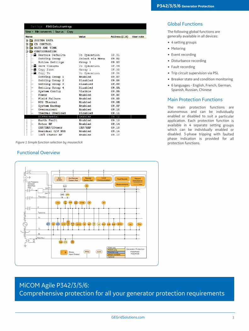
Figure 1 Simple function selection by mouseclick
GEGridSolutions.com 3
Functional Overview
Global FunctionsThe following global functions are generally available in all devices:
� 4 setting groups
� Metering
� Event recording
� Disturbance recording
� Fault recording
� Trip circuit supervision via PSL
� Breaker state and condition monitoring
� 6 languages - English, French, German, Spanish, Russian, Chinese
Main Protection FunctionsThe main protection functions are autonomous and can be individually enabled or disabled to suit a particular application. Each protection function is available in 4 separate setting groups which can be individually enabled or disabled. 3-phase tripping with faulted phase indication is provided for all protection functions.

100% Stator Ground Fault 3rd Harmonic Method (P343/5 Only)Third harmonic neutral undervoltage protection covers the final 15% of the stator winding and, in conjunction with the other ground fault elements, provides 100% ground fault protection for the stator. This is supervised by a 3-phase undervoltage element. Additional supervision using 3-phase active, reactive and apparent power can be enabled if required. A third harmonic neutral overvoltage protection is also provided for applications where the measurement is available at the terminal end of the generator. The blocking features of the undervoltage element are not required for this application.
100% Stator Ground Fault Low Frequency injection Method(P345 Only)Injecting a 20 Hz voltage to detect ground faults at the neutral point or terminals of generators is a reliable method for detecting ground faults in the entire generator and all electrically connected equipment. It has an advantage over the third harmonic method in that it is independent of the generator's characteristics and the mode of operation. Also, protection is possible at generator standstill. The protection relay measures the injected 20 Hz voltage and the flowing 20 Hz current. When the generator is operating normally, only a small amount of 20 Hz current will flow as a result of the stator capacitance to ground. When a ground fault occurs on the generator stator windings the 20 Hz current will increase. Two underresistance and one overcurrent stage of definite time protection are available. The measurement circuit is also monitored with a 20 Hz undervoltage and undercurrent element which can be used to block the protection.
The GPM-S-G 20 Hz generator and GPM-S-B bandpass filter modules can be used for the 20 Hz injection.
GEGridSolutions.com
P342/3/5/6 Generator Protection
Phase OvercurrentFour independent overcurrent stages are available. Each stage may be selected as non-directional or directional (forward/reverse). All stages have definite time (DT) delayed characteristics, two of the stages may also be independently set to one of nine inverse definite minimum time (IDMT) curves (IEC and IEEE) or to one of 4 user programmable curves.
The IDMT stages have a programmable reset timer for grading with electromechanical relays and to reduce clearance times where intermittent faults occur. The phase fault directional elements are internally polarised by quadrature phase-phase voltages, and will make a correct directional decision down to 0.5 V (Vn = 110/120 V) or 2.0 V (Vn = 380/440 V). A synchronous polarising signal is maintained for 3.2 s after voltage collapse to ensure that the instantaneous and time delayed overcurrent elements operate correctly for close-up 3-phase faults.
Standard Ground FaultThe standard ground fault element operates from a ground fault input connection to measure the fault current in the ground path of the generator. Two independent stages are available. Both stages have definite time (DT) delayed characteristics, the first stage may also be independently set to one of ten inverse definite minimum time (IDMT) curves (IEC and IEEE) or to one of 4 user programmable curves.
Sensitive Ground FaultA core balance CT should be used to drive the sensitive ground fault function. The directionality is provided by the residual voltage.
4
MiCOM Agile P343/5:100% stator ground fault and pole slipping protection for large machines
Generator/Transformer Differential (P343/5/6 only)3-phase generator differential protection is provided to detect stator phase faults. This can be set as either a percentage bias scheme with a dual slope characteristic or as a high impedance scheme. When high impedance is used, additional stabilising resistance and a metrosil will be required. 3-phase biased generator-transformer differential protection is provided to detect phase faults. This includes ratio and vector compensation as well as 2nd and 5thharmonic restraint for transformer inrush currents and overfluxing. Two high set differential elements are provided to ensure rapid clearance of high fault currents.
Interturn (Split Phase) Differential (P343/5/6 Only)On generators with multi-turn coils and two or more windings per phase, such as hydrogenerators, interturn (split phase) differential may be used to detect turn to turn faults. The element operates as a definite time overcurrent function with independant current setting per phase. It should be noted that when using this function the generator differential protection is not available.
Interturn (Residual Overvoltage)On generators with multi-turn or single turn coils interturn protection can be provided by measuring the residual voltage across the 3-phase windings.
To prevent operation for external faults, a negative phase sequence apparent power and a directional negative phase sequence overcurrent element can be used to interlock the residual overvoltage element in PSL.

Power/Var ProtectionFour definite time stages of power/VAr protection are provided and each stage can be independently configured to operate as under/over and forward/reverse. The power protection can be used to provide simple back-up overload protection (Overpower), protection against motoring (Reverse Power), CB interlocking to prevent overspeeding during machine shutdown (Low Forward Power) and motor loss of load protection (Low Reverse Power). The reverse VAr protection can be used to provide simple under excitation protection.
The P342-6 relays provide a standard 3- phase power/VAr protection element and also a single phase sensitive power/VAr protection element. The P345 sensitive power protection can be a single or wattmetric power/VAr element. The sensitive power/VAr protection can be used with dedicated metering class CTs using the sensitive current inputs (1 for single phase or 2 for wattmetric).
Loss Of FieldTo detect failure of the machine excitation, a two stage offset Mho impedance element is provided. This allows a small instantaneous characteristic to be used to provide fast tripping for loss of excitation at high power outputs, where system stability could be affected. The second stage can be set with a larger time delayed characteristic to provide stable, secure tripping under low power conditions. A directional line can be used to supervise the Mho characteristics. Integrating timers are provided to enable the impedance characteristic to provide time delayed pole slipping protection. A power factor alarm element is also available to offer more sensitive protection for unusual operating conditions, for example a lightly loaded unit operating as an induction generator.
P342/3/5/6 Generator Protection
WattmetricThe sensitive ground fault protection is also suitable for Petersen Coil grounded systems by enabling a wattmetric element. This form of protection uses the sensitive ground fault protection directional characteristic, but with a directional residual power threshold providing an additional constraint on operation.
Restricted Ground FaultThe restricted ground fault protection may be configured either as a high impedance or low impedance biased differential. When high impedance is used, additional stabilising resistance and a metrosil will be required.
Voltage Dependent Overcurrent/UnderimpedanceIn order to provide backup protection for phase faults, voltage dependant overcurrent and underimpedance protection are provided. The voltage dependant overcurrent element can be selected as voltage controlled or voltage restrained overcurrent, the timing characteristic can be set as either definite time or IDMT or to a user programmable curve. The under-impedance element is a 2-stage, 3-phase non-directional under-impedance element with a definite time delay.
Neutral Displacement/Residual OvervoltageResidual overvoltage protection is available for detecting ground faults where there is an isolated or high impedance ground. The residual voltage can be measured from a broken delta VT, from the secondary winding of a distribution transformer ground at the generator neutral, or can be calculated from the 3-phase to neutral voltage measurements. Each stage can be set with a definite time delay, an inverse time delay or a user programmable curve characteristic. The P342-6 have 2 measured and 2 calculated stages of residual overvoltage protection. The P345 have an additional neutral voltage input and thus have an additional 2 stages of measured residual overvoltage protection.
GEGridSolutions.com
Under/OvervoltageUnder/overvoltage protection may be configured to operate from either phase-phase or phase-neutral voltage elements. Three independent undervoltage stages and two overvoltage stages with definite time elements are available for under and overvoltage protection. The first stage can also be configured to an inverse time or a user programmable curve characteristic.
Under/OverfrequencyTwo independent stages of overfrequency and four of underfrequency are provided. Each stage functions as a definite time element.
Turbine Abnormal `QuencyTurbine abnormal frequency protection is included to protect the turbine blade from potential damage due to prolonged under/ over-frequency operation of generators. Up to six frequency bands can be programmed, each having an integrating timer to record the time spent within the band. The time in each band is stored in non volatile memory so that loss of auxiliary supply to the relay does not lead to a loss of the recorded time. When the time within a band has reached the user set limit, an alarm can be raised to initiate investigation and maintenance.
Rate Of Change OfFrequencyFour definite time delayed stages of df/dt protection are included which can be used for loss of grid or load shedding applications. The number of frequency averaging cycles, number of protection iterations, operating mode - fixed or rolling window - and direction of operation can be set to suit the application.
5

Pole Slipping (P343/5 only)The pole slipping protection uses the variation in "apparent" impedance as seen at the generator's terminals to detect pole slipping. If the measured impedance crosses the two halves of the lens characteristic and spends longer than a specified time in each half, a pole slip is counted. Two zones are created by a reactance line which is used to distinguish whether the impedance centre of the pole slip is located in the power system or in the generator. Separate counters are used to count pole slips in the 2 zones. A setting is also provided to determine whether the protection operates in a generating mode, motoring mode or both.
Resistance Temperature Detectors (RTDs)In order to monitor temperatures accurately, an option allowing measurement of temperatures using up to 10 platinum RTDs is available. This provides an instantaneous alarm and time delayed trip output for each RTD.
Generator Thermal OverloadTo monitor the thermal state of a generator, a thermal replica protection is provided. The thermal element has a trip and an alarm stage. Positive and negative sequence currents are taken into account so that any unbalance condition can be detected and any abnormal heating of the rotor can be avoided. There are separate time constants for heating and cooling and in the event of a loss of auxiliary supply the thermal state is stored in non-volatile memory.
GEGridSolutions.com
P342/3/5/6 Generator Protection
6
Transformer Thermal Overload, Loss of Life (LOL)The transformer thermal overload and LoL functions are based on the IEEE Standard C57.91-1995. Two three-stage definite time-delayed trip elements based on hot spot and top oil temperature are available for transformer overload protection. A pre-trip alarm is also provided. Frequent excesses of transformer rated current or operation at elevated temperatures will shorten the life expectancy of the transformer. The relay provides a transformer LoL calculation, using a thermal model that estimates the hot spot temperature.
Blocked Overcurrent LogicEach stage of overcurrent and ground fault protection can be blocked by an optically isolated input. This enables the overcurrent and ground fault protection to be integrated into a blocked overcurrent busbar protection scheme.
Analogue (Current Loop) Inputs And Outputs (CLIO)Four analogue (or current loop) inputs are provided for transducers with ranges of 0-1 mA, 0-10 mA, 0-20 mA or 4-20 mA. The analogue inputs can be used for various transducers such as vibration monitors, tachometers and pressure transducers. Associated with each input there are two time delayed protection stages, one for alarm and one for trip. Each stage can be set for 'over' or 'under' operation. Four analogue (or current loop) outputs are provided with ranges of 0-1 mA, 0-10 mA, 0-20 mA or 4- 20 mA, which can alleviate the need for separate transducers. These may be used to feed standard moving coil ammeters for analogue indication of certain measured quantities or into a SCADA using an existing analogue RTU.
Negative Phase Sequence ThermalTo protect against unbalanced stator currents caused by external faults or unbalanced loading, two stages of negative sequence protection are provided. These comprise a definite time alarm stage and a trip stage that operates with a thermal characteristic.
Negative Phase SequenceOvercurrentFour definite time negative phase sequence overcurrent stages are included. Each stage may be selected as non-directional or directional (forward/reverse) and can operate for remote phase-phase and phase-ground faults even with delta-star transformers present.
Negative Phase Sequence OvervoltageOne definite time stage of negative phase sequence overvoltage protection is provided. Negative phase sequence overvoltage protection can be used for the detection of voltage unbalance which can quickly lead to overheating and damage of generators.
OverfluxingTo protect the generator or connected transformer against overexcitation a five stage V/Hz element is provided. The first stage is a definite time alarm, the second stage can be used to provide an inverse/definite time or user programmable curve time trip characteristic and stages 3/5 are definite time.
Unintentional Energisation at Standstill (P343/5 only)If the machine circuit breaker is closed accidentally, when the machine is not running, very high current will result. A voltage supervised overcurrent scheme is available to protect against this condition. When the machine voltage is low, that is, the machine is not running, an instantaneous overcurrent element is enabled. Timers ensure that the element will be stable for normal voltage dips that could occur for system faults or machine reconnection.

P342/3/5/6 Generator Protection
Rotor Ground FaultRotor ground fault protection is used to detect ground faults in the excitation circuit of synchronous machines. The rotor ground resistance is measured using an external low frequency square wave injection, coupling and measurement unit and a P391 connected to the rotor circuit. The measurement of the rotor resistance is passed to the P34x via a current loop output (0-20mA) on the P391 connected to one of the four current loop inputs on the P34x. The rotor ground fault protection is only available if the relay includes the CLIO hardware option. Two underresistance stages of definite time protection are available for alarm and trip. The injection frequency is selectable at 0.25/0.5/1 Hz via a jumper link in the P391.
Phase RotationA facility is provided to maintain correct operation of all the protection functions even when the generator is running in a reverse phase sequence. This is achieved through user configurable settings available in four setting groups. The phase rotation for all 3-phase currents and voltages can be reversed. Also, for pump storage applications where 2 phases are swapped for pumping operation, the swapping of the phases can be emulated in the relay via settings for the 3-phase currents and voltages.
Supervisory FunctionsCircuit Breaker Failure ProtectionTwo stage circuit breaker failure protection may be used for tripping upstream circuit breakers and/or the local secondary trip coil. The circuit breaker failure logic may also be initiated externally from other protection devices if required. The P343/5/6 CB fail logic can be set to use current measurement from any of the 2 sets of 3-phase current inputs. Typically CB fail protection uses the CTs on the busbar side of the generator.
Voltage Transformer SupervisionVoltage transformer supervision (VTS) is provided to detect loss of one, two or three VT signals, providing indication and inhibition of voltage dependent protection elements. An optically isolated input may also be configured to initiate the voltage transformer supervision alarm and blocking when used with miniature circuit breakers (MCBs) or other external forms of voltage transformer supervision.
Current Transformer SupervisionCurrent transformer supervision (CTS) is provided to detect loss of phase CT signals and inhibit the operation of current dependent protection elements. CTS is provided for both sets of 3-phase CTs in the P343/5/6 relays. A patented differential CTS is also provided to detect loss of phase CT inputs. Operation of the differential protection can be blocked during a CT failure, or alternatively temporarily desensitised to avoid an unwanted trip.
Through Fault MonitoringThrough faults are a major cause of transformer damage and failure, stressing the insulation and mechanical integrity. An I²t calculation based on the recorded duration and maximum current is stored for each phase. Cumulative stored calculations for each phase are monitored so that the user may schedule the transformer maintenance or identify a need for system reinforcement to reduce the fault level based on this data.
Plant SupervisionTrip Circuit MonitoringMonitoring of the trip circuit in both breaker open and closed states can be realised using the programmable scheme logic. Circuit Breaker State MonitoringAn alarm will be generated if there is a discrepancy between the open and closed contacts of the circuit breaker.
GEGridSolutions.com
Comprehensive post-fault analysis and communication options
Circuit Breaker Condition MonitoringThe circuit breaker condition monitoringfeatures include:
� Monitoring the number of breaker trip operations
� Recording the sum of the broken current quantity Ix, 1.0 x 2.0
� Monitoring the breaker operating time
� Monitoring the fault frequency counter
Circuit Breaker Control and Check SynchronisingCircuit breaker control is available from the front panel user interface, optically isolated inputs and remotely via the substation communications. Check synchronising is included to verify that the generator frequency, voltage magnitude and phase angle match the system's before allowing the generator breaker to be closed. Transformer vector compensation is also included.
Event Records Time-tagged event records are stored. An optional modulated or demodulated IRIG-B port is available for accurate time synchronization. SNTP and IEEE1588 time synchronisation is also supported in Ethernet models
Fault Records � Indication of the faulted phase
� Protection operation
� Active setting group
� Relay and CB operating time
� Pre-fault and fault currents
� Bias and differential currents
Disturbance Records High performance waveform records contain all current transformer and voltage transformer input channels, plus up to 32 digital states, extracted in COMTRADE format.
7

IEC 61850 or DNP 3.0 is available when the optional Ethernet or redundant Ethernet port is ordered. IEC 61850 offers high-speed data exchange, peer-to-peer communication, reporting, disturbance record extraction and time synchronisation.
An optional fibre-optic interface is available for any of the above serial protocols. An optional 2nd rear communications port with the Courier protocol is available. This port is intended for central settings or remote access with S1 Agile. Clock synchronisation can be achieved using one of the protocols or using the IRIG-B input or using an opto input.
Redundant Ethernet Ports (IEC 61850/DNP 3.0)Px4x devices can be enhanced with an optional redundant Ethernet board.
The redundancy is managed by the market's fastest recovery time protocols: IEC 62439-3 PRP and HSR allowing bumpless redundancy and RSTP (Rapid Spanning Tree) protocol, offering multi-vendor interoperability. The redundant Ethernet board also has a watchdog relay contact and an SNMP interface to alarm in case of a failure.
Programmable Scheme LogicProgrammable scheme logic allows the user to customise the protection and control functions. It is also used to program the functionality of the optically isolated inputs, relay outputs and LED indications. The programmable scheme logic may be configured using the graphical S1 Agile PC based support software.
Independent Protection Settings GroupsThe settings are divided into two categories: protection settings and control and support settings. Four setting groups are provided for the protection settings to allow for different operating conditions and adaptive relaying.
Control InputsThe ON/OFF status of 32 control inputs can be changed manually or remotely via the communications to provide user defined control functions.
Function Keys(P343/5/6 only)Ten function keys are available for implementing scheme control functionality. The function keys operate in two modes, normal and toggled, and activate associated signals in PSL that can easily be used to customise the application. Each function key has an associated tri-color LED (red, green, yellow) allowing for clear indication of the associated function's state.
Certification IndicationEighteen tri-colour LEDs (P343/5/6) or 8 red LEDs (P342) are available for user programming. The P343/5/6 LED colours (red, green or yellow) are driven via digital databus signals in PSL and can be programmed to indicate up to four conditions/states for example.� ��Off - Not in service � Red - CB closed � Green - CB open � Yellow - CB not healthy
Information InterfacesInformation exchange is done via the local control panel, the front PC interface, the main rear communications interface (COMM1/RP1) or an optional second rear interface (COMM2/RP2).
Local CommunicationThe front USB communications port has been designed for use with the S1 Agile software and is primarily for configuring the relay settings and programmable scheme logic. It is also used to locally extract event, fault and disturbance record information and can be used as a commissioning tool by viewing all relay measurements simultaneously.
Rear CommunicationThe main rear communications interface supports the five protocols listed below (selected at time of order) and is intended for integration with substation control systems
� Courier/K-Bus
� Modbus
� IEC 60870-5-103
� DNP 3.0
� IEC 61850
For more information please contact GEGrid Solutions
Worldwide Contact CenterWeb: www.GEGridSolutions.com/contactPhone: +44 (0) 1785 250 070
GEGridSolutions.comIEC is a registered trademark of Commission Electrotechnique Internationale. IEEE is a registered trademark of the Institute of Electrical Electronics Engineers, Inc.
GE and the GE monogram are trademarks of General Electric Company.
GE reserves the right to make changes to specifications of products described at any time without notice and without obligation to notify any person of such changes.
P34x-Brochure-EN-2022-01-Grid-GA-0648. © Copyright 2022, General Electric Company. All rights reserved.
Imagination at work
Related Documents