MICE Collaboration Meeting March 29 - April 1, 2004 -- CERN MICE Integration Edgar Black/IITMarch17-1-007 Room

MICE Collaboration Meeting March 29 - April 1, 2004 -- CERN MICE Integration Edgar Black/IIT March17-1-007 Room.
Dec 21, 2015
Welcome message from author
This document is posted to help you gain knowledge. Please leave a comment to let me know what you think about it! Share it to your friends and learn new things together.
Transcript

MICE Collaboration MeetingMarch 29 - April 1, 2004 -- CERN
MICE Integration Edgar Black/IITMarch17-1-007
Room

Alignment considerations for integration• What are we aligning
• A thought on alignment reference
• Considerations for tolerances
• Features of integration, design requirements
• Support structures & transport concepts
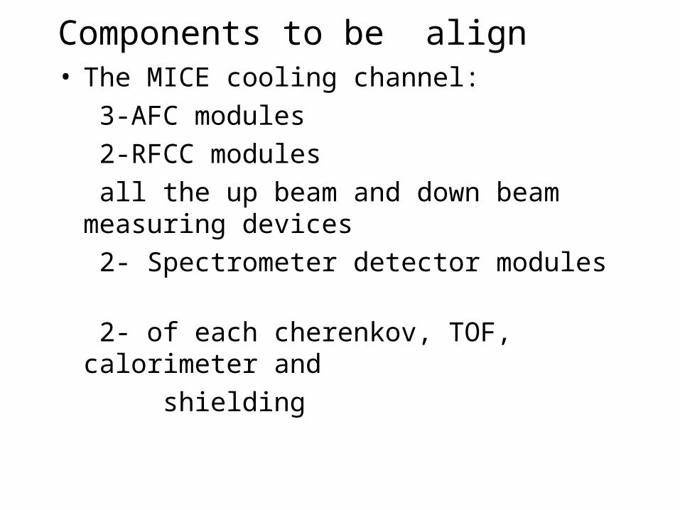
Components to be align• The MICE cooling channel:
3-AFC modules
2-RFCC modules
all the up beam and down beam measuring devices
2- Spectrometer detector modules
2- of each cherenkov, TOF, calorimeter and
shielding

Magnets lattice with shrinking estimated values (black color numbers are the initial dimensions for alignment at room temperature) additional alignments are preformed after shrinkage.

Assembled MICE experiment lattice

Reference for the alignment
• The beam to be processed is the reference to which the lattice shall be aligned to
• In principle, a line representing the center of the beam is the main reference for alignment
• Targets on the outside of the modules vacuum vessels are calibrated to the main reference line for alignment
• Surveyors fixed bench marks in the RAL facility are referenced to the vacuum vessel targets.

Considerations for tolerances• The modules vacuum vessels are the structural
supports for the magnets; therefore they are the fulcrum for the alignment of the components within the modules
• The connecting elements between modules, flanges and fastening devises, provide the means for the modules integration and alignment, this connections shall comply to the following requirements:– Interchangeability of modules at their stages of assembly– Structural longitudinal support against magnetic forces
in conjunction with the modules vertical support and anchoring
– Hermetic capacity to retain the vacuum within the modules

Integration of modules requirements• Primarily maintain the required separation to
permit the extraction or removal of the AFC modules
• Rigidly lock the vessels against internal and external forces in all directions including support to the floor
• Maintain the vacuum inside the vessels and • Provide a quick mean for the assemble and
disassemble of the module for removal from the lattice

MICE Sequence of integration

Support structures & transport considerations
• The performance of this operation requires a careful controlled guided movement so not to tilt or twist the module within the narrow < 2cm gaps at each side of the module
• The center of gravity of each module shall be carefully evaluated for the location and design of their support
• Several concepts are to be evaluated against the following requirements:
1. The modules support structures shall have provisions to allow anchoring at the in and out of the lattice positions
2. Shall provide means for the alignment of the module within a given value TBD
Related Documents