MIAH, INC SEABED TRENCHING OVERVIEW P.O. Box 3685 ∗ Salem, OR 97302 ∗ (503)-581-1988 ∗ FAX# (503) 581-3441 WWW.MIAHTRENCHERS.COM 1

Welcome message from author
This document is posted to help you gain knowledge. Please leave a comment to let me know what you think about it! Share it to your friends and learn new things together.
Transcript
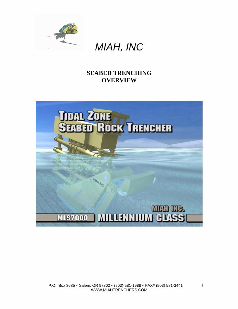
MIAH, INC
SEABED TRENCHING OVERVIEW
P.O. Box 3685 ∗ Salem, OR 97302 ∗ (503)-581-1988 ∗ FAX# (503) 581-3441 WWW.MIAHTRENCHERS.COM
1
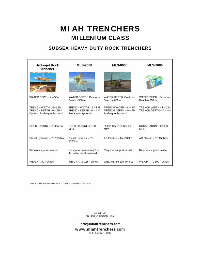
MIAH TRENCHERS MILLENIUM CLASS
SUBSEA HEAVY DUTY ROCK TRENCHERS
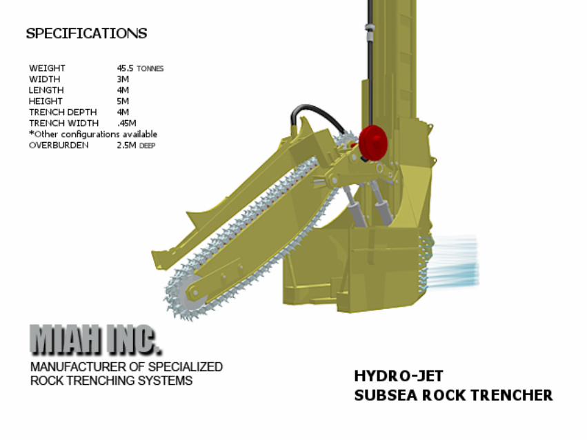
Hydro-jet Rock Trencher
MLS-7000 MLS-8000 MLS-9000
WATER DEPTH: 4 – 50m
WATER DEPTH: Onshore- Beach - 500 m
WATER DEPTH: Onshore- Beach – 600 m
WATER DEPTH: Onshore-Beach – 600 m
TRENCH WIDTH-.35–1.5M TRENCH DEPTH - 0 – 5M / Optional Prefatigue System©
TRENCH WIDTH - .5 - 3 M TRENCH DEPTH - 0 – 4 M Prefatigue System©
TRENCH WIDTH - .6 – 3M TRENCH DEPTH – 0 – 4M Prefatigue System©
TRENCH WIDTH - 1 – 2 M TRENCH DEPTH – 0 – 4M
ROCK HARDNESS: 90 MPa
ROCK HARDNESS: 90 MPa
ROCK HARDNESS: 90 MPa
ROCK HARDNESS: 350 MPa
Diesel Hydraulic – To 1500kw
Diesel Hydraulic – To 1500kw
AC Electric – To 1500kw
AC Electric – To 1500Kw
Requires support vessel
No support vessel req’d to 4m water depth-manned
Requires support vessel
Requires support vessel
WEIGHT: 80 Tonnes
WEIGHT: To 125 Tonnes
WEIGHT: To 100 Tonnes
WEIGHT: To 100 Tonnes
SPECIFICATIONS ARE SUBJECT TO CHAINGE WITHOUT NOTICE
MIAH INC SALEM, OREGON USA
www.miahtrenchers.com TEL. 503-581-1988
MIAH, INC
P.O. Box 3685 ∗ Salem, OR 97302 ∗ (503)-581-1988 ∗ FAX# (503) 581-3441 WWW.MIAHTRENCHERS.COM
2
Sub-Sea Hydro-Jet Rock Trenching System
The Miah Sub-Sea Hydrojet Rock Trenching System, is a high production trenching system and a dramatic
improvement of present conventional methods of excavating rock in the ocean floor for purposes of burying
pipelines, submarine electrical cables, fiber optic cables, etc. Present subsurface excavation methods in
solid rock include dredging, ripping and blasting, which in many cases extensively disturb the biological
environment in which they are utilized.
One major objective in developing The Miah Underwater Trenching System included reducing
environmental damage while subsurface work is being accomplished and to be able to restore the ocean
floor as closely as possible to its natural state. To accomplish this, highly sophisticated telemetry
equipment is utilized to insure and verify restorations of the ocean floor.
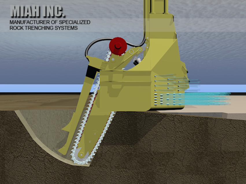
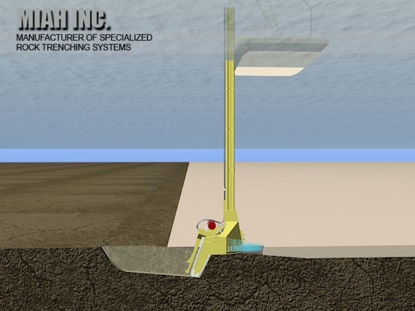
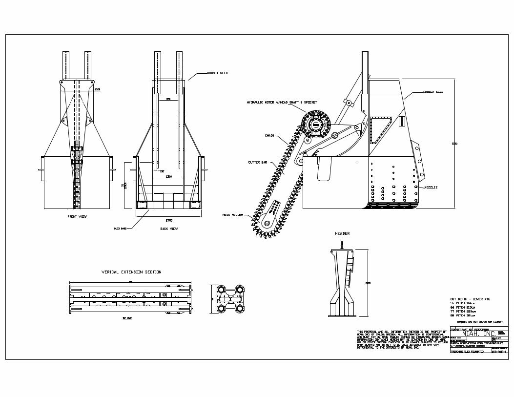
The rock-trenching sled is comprised of a hydraulically driven cutter assembly mounted on a sturdy steel
structured sled which is pulled along the ocean floor during operation by a barge on the surface. Power is
supplied by a power unit mounted on the vessel through an umbilical supported by a sturdy steel extension
structures to the trencher sled. The sled is equipped with an injector system that removes the overburden on
top of the solid rock strata enabling the sled to sit on the rock surface. The rock trencher trenches down
into the rock from the rock surface. The Miah rock trencher is utilized in conjunction with a more
conventional water injector unit that will clean the ditch prior to laying the pipe in a separate operation.
Water currents will carry sediments into the trench to cover the pipe and keep it in place. The well-defined
ditch configuration produced by the trencher will perfectly confine the pipe protecting it from drift, iceberg
scouring, dragging anchors and fishing gear. The actual trenching activity will take place within the
housing of the sled, which will confine the sediments keeping the surrounding environment from
being disturbed.

MIAH, INC
MLS7000 ROCK DREDGER/TRENCHER
SEABED TRENCHING OVERVIEW
P.O. Box 3685 ∗ Salem, OR 97302 ∗ (503)-581-1988 ∗ FAX# (503) 581-3441 WWW.MIAHTRENCHERS.COM
1
MIAH, INC
P.O. Box 3685 ∗ Salem, OR 97302 ∗ (503)-581-1988 ∗ FAX# (503) 581-3441 WWW.MIAHTRENCHERS.COM
2
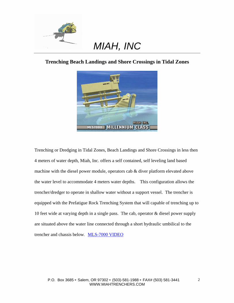
Trenching Beach Landings and Shore Crossings in Tidal Zones
Trenching or Dredging in Tidal Zones, Beach Landings and Shore Crossings in less then
4 meters of water depth, Miah, Inc. offers a self contained, self leveling land based
machine with the diesel power module, operators cab & diver platform elevated above
the water level to accommodate 4 meters water depths. This configuration allows the
trencher/dredger to operate in shallow water without a support vessel. The trencher is
equipped with the Prefatigue Rock Trenching System that will capable of trenching up to
10 feet wide at varying depth in a single pass. The cab, operator & diesel power supply
are situated above the water line connected through a short hydraulic umbilical to the
trencher and chassis below. MLS-7000 VIDEO
MIAH, INC
P.O. Box 3685 ∗ Salem, OR 97302 ∗ (503)-581-1988 ∗ FAX# (503) 581-3441 WWW.MIAHTRENCHERS.COM
4
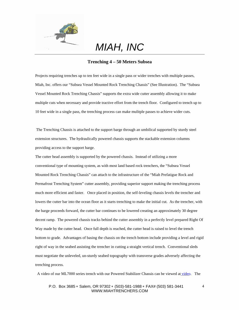
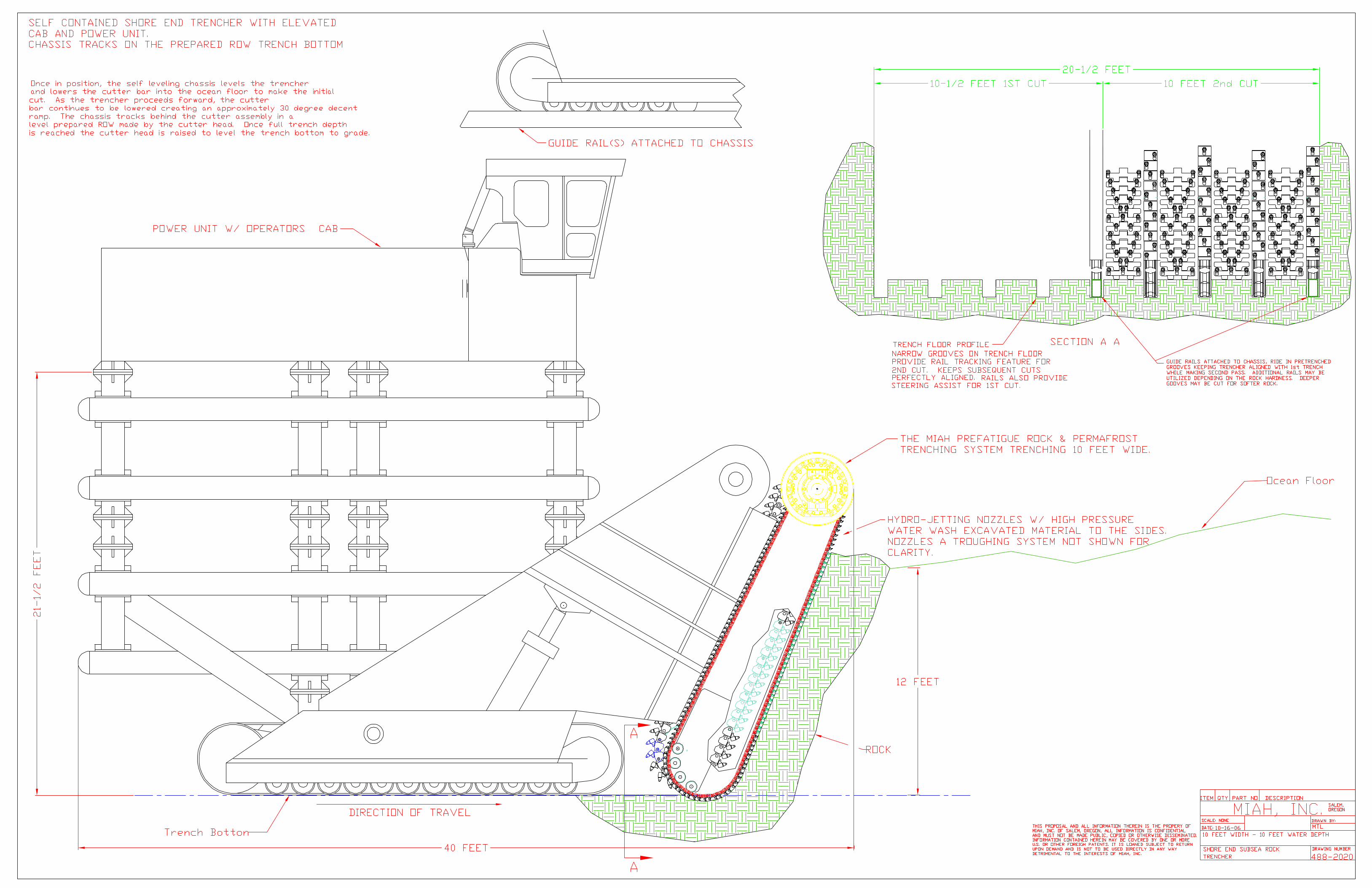
Trenching 4 – 50 Meters Subsea
Projects requiring trenches up to ten feet wide in a single pass or wider trenches with multiple passes,
Miah, Inc. offers our “Subsea Vessel Mounted Rock Trenching Chassis” (See Illustration). The “Subsea
Vessel Mounted Rock Trenching Chassis” supports the extra wide cutter assembly allowing it to make
multiple cuts when necessary and provide tractive effort from the trench floor. Configured to trench up to
10 feet wide in a single pass, the trenching process can make mulitple passes to achieve wider cuts.
The Trenching Chassis is attached to the support barge through an umbilical supported by sturdy steel
extension structures. The hydraulically powered chassis supports the stackable extension columns
providing access to the support barge.
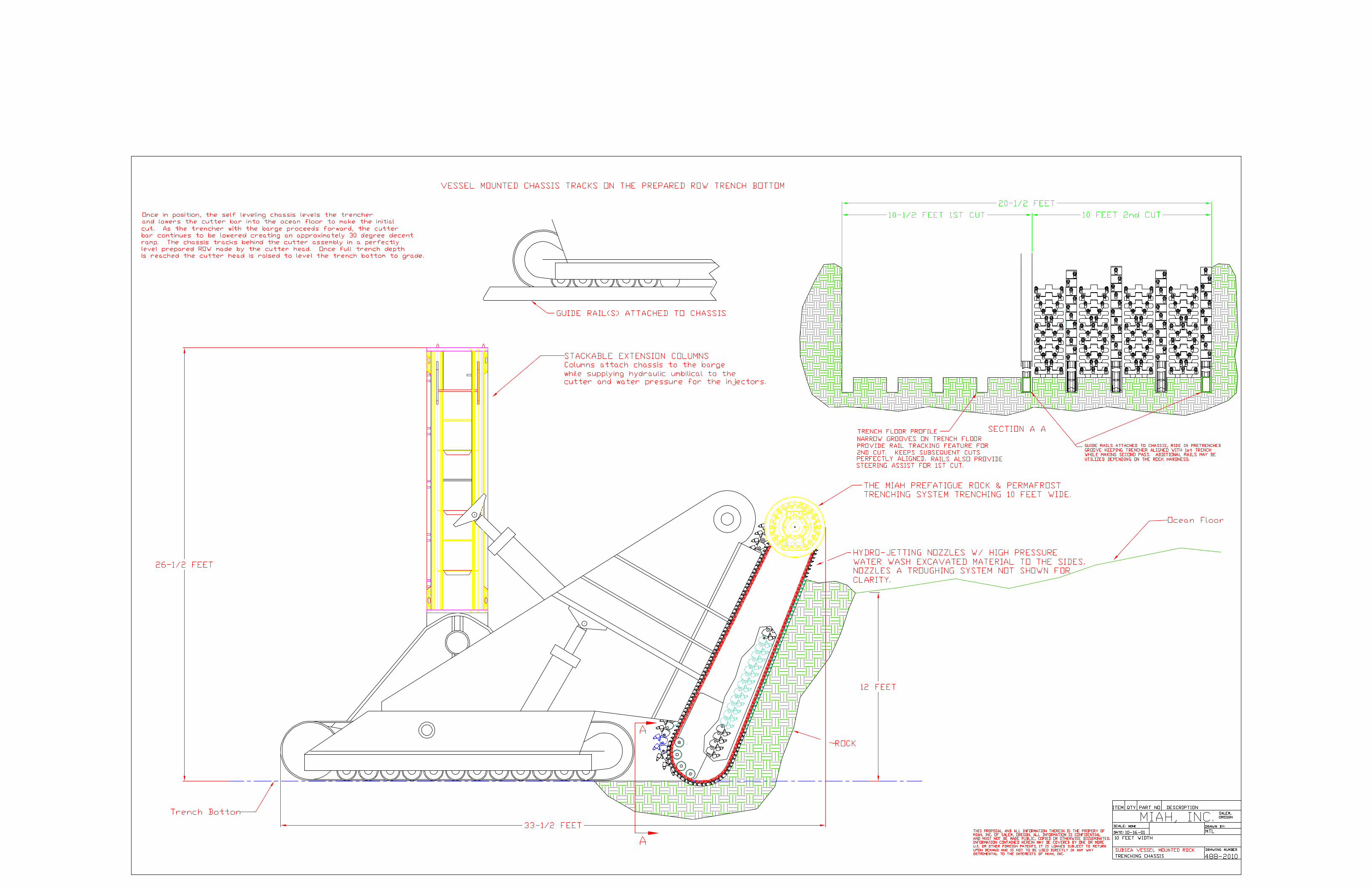
The cutter head assembly is supported by the powered chassis. Instead of utilizing a more
conventional type of mounting system, as with most land based rock trenchers, the “Subsea Vessel
Mounted Rock Trenching Chassis” can attach to the infrastructure of the “Miah Prefatigue Rock and
Permafrost Trenching System” cutter assembly, providing superior support making the trenching process
much more efficient and faster. Once placed in position, the self-leveling chassis levels the trencher and
lowers the cutter bar into the ocean floor as it starts trenching to make the initial cut. As the trencher, with
the barge proceeds forward, the cutter bar continues to be lowered creating an approximately 30 degree
decent ramp. The powered chassis tracks behind the cutter assembly in a perfectly level prepared Right Of
Way made by the cutter head. Once full depth is reached, the cutter head is raised to level the trench
bottom to grade. Advantages of basing the chassis on the trench bottom include providing a level and rigid
right of way in the seabed assisting the trencher in cutting a straight vertical trench. Conventional sleds
must negotiate the unleveled, un-sturdy seabed topography with transverse grades adversely affecting the
trenching process.
A video of our ML7000 series trench with our Powered Stabilizer Chassis can be viewed at video. The
MIAH, INC
P.O. Box 3685 ∗ Salem, OR 97302 ∗ (503)-581-1988 ∗ FAX# (503) 581-3441 WWW.MIAHTRENCHERS.COM
5
video depicts a similar concept however situated on a land-based machine with the stabilizer chassis only
assisting the main trencher by providing additional support.
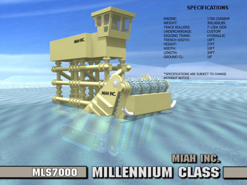
ENGINE: 1700-2500BHPWEIGHT: 300,000LBSTRACK ROLLERS: 7-12EA SIDEUNDERCARRIAGE: CUSTOMDIGGING TRANS: HYDRAULICTRENCH WIDTH: 10FTHEIGHT: 27FTWIDTH: 10FTLENGTH: 34FTGROUND CL: 18"
*SPECIFICATIONS ARE SUBJECT TO CHANGE WITHOUT NOTICE
MIAH, INC
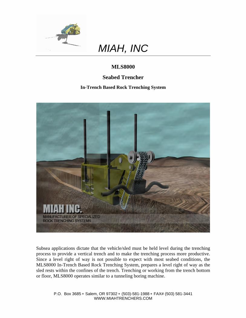
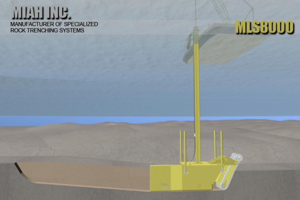
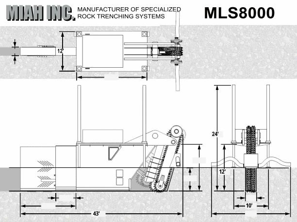
MLS8000
Seabed Trencher
In-Trench Based Rock Trenching System
Subsea applications dictate that the vehicle/sled must be held level during the trenching process to provide a vertical trench and to make the trenching process more productive. Since a level right of way is not possible to expect with most seabed conditions, the MLS8000 In-Trench Based Rock Trenching System, prepares a level right of way as the sled rests within the confines of the trench. Trenching or working from the trench bottom or floor, MLS8000 operates similar to a tunneling boring machine.
P.O. Box 3685 ∗ Salem, OR 97302 ∗ (503)-581-1988 ∗ FAX# (503) 581-3441 WWW.MIAHTRENCHERS.COM
MIAH, INC
P.O. Box 3685 ∗ Salem, OR 97302 ∗ (503)-581-1988 ∗ FAX# (503) 581-3441 WWW.MIAHTRENCHERS.COM
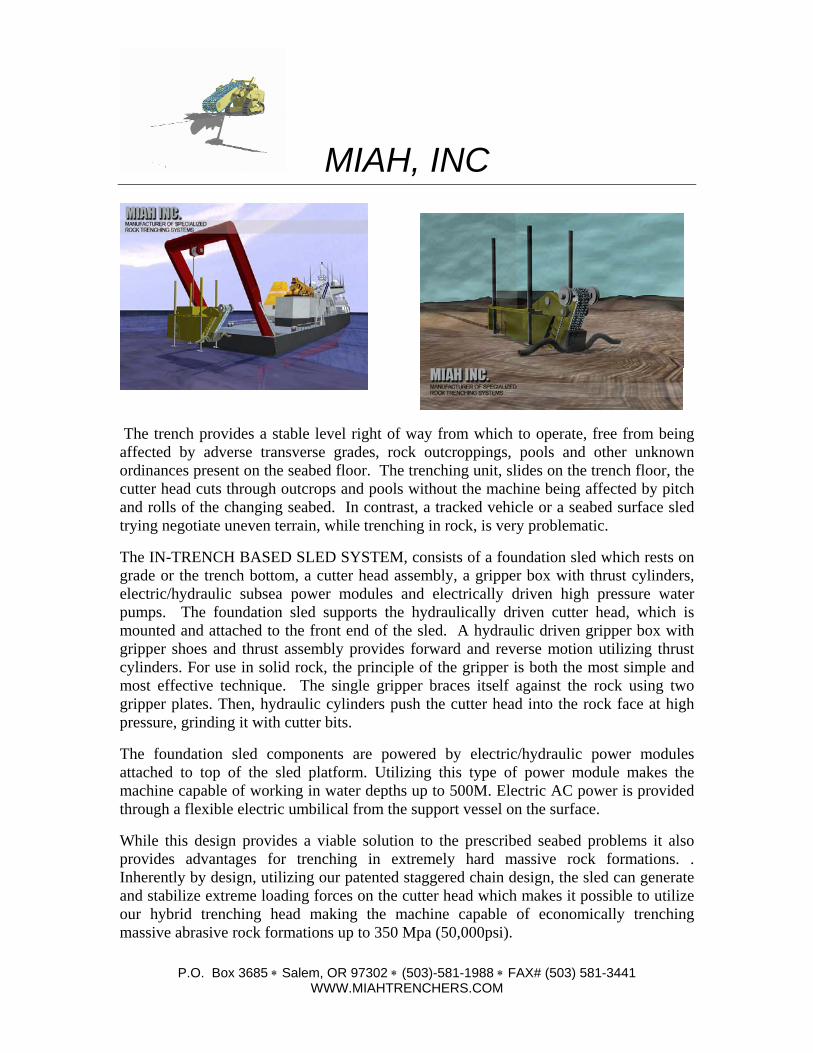
The trench provides a stable level right of way from which to operate, free from being affected by adverse transverse grades, rock outcroppings, pools and other unknown ordinances present on the seabed floor. The trenching unit, slides on the trench floor, the cutter head cuts through outcrops and pools without the machine being affected by pitch and rolls of the changing seabed. In contrast, a tracked vehicle or a seabed surface sled trying negotiate uneven terrain, while trenching in rock, is very problematic.
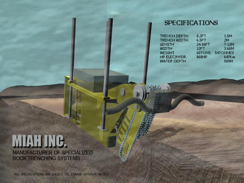
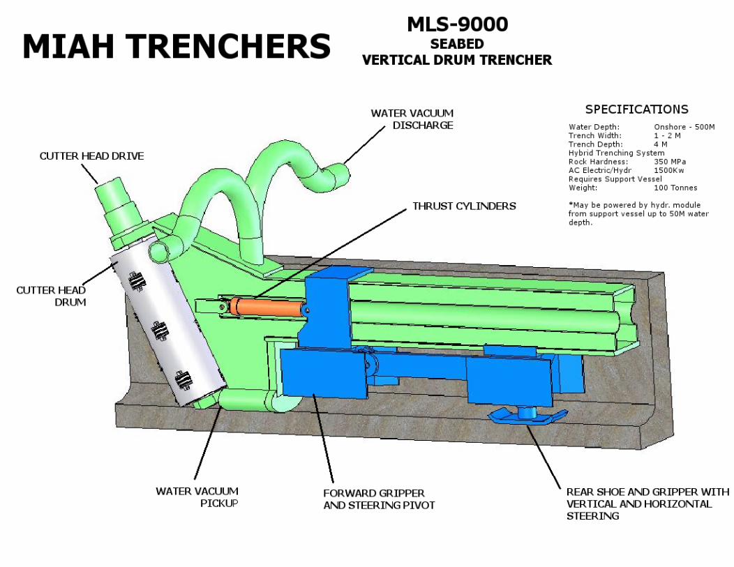
The IN-TRENCH BASED SLED SYSTEM, consists of a foundation sled which rests on grade or the trench bottom, a cutter head assembly, a gripper box with thrust cylinders, electric/hydraulic subsea power modules and electrically driven high pressure water pumps. The foundation sled supports the hydraulically driven cutter head, which is mounted and attached to the front end of the sled. A hydraulic driven gripper box with gripper shoes and thrust assembly provides forward and reverse motion utilizing thrust cylinders. For use in solid rock, the principle of the gripper is both the most simple and most effective technique. The single gripper braces itself against the rock using two gripper plates. Then, hydraulic cylinders push the cutter head into the rock face at high pressure, grinding it with cutter bits.
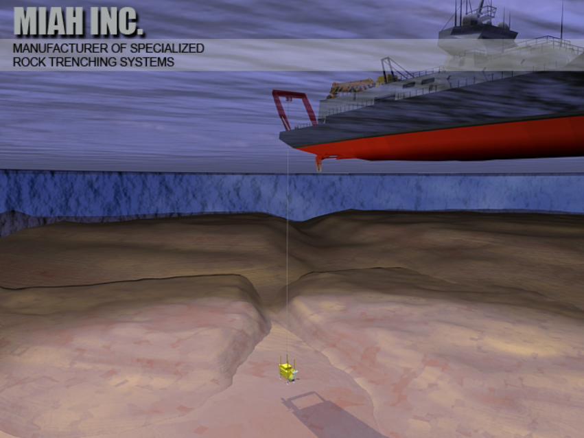
The foundation sled components are powered by electric/hydraulic power modules attached to top of the sled platform. Utilizing this type of power module makes the machine capable of working in water depths up to 500M. Electric AC power is provided through a flexible electric umbilical from the support vessel on the surface.
While this design provides a viable solution to the prescribed seabed problems it also provides advantages for trenching in extremely hard massive rock formations. . Inherently by design, utilizing our patented staggered chain design, the sled can generate and stabilize extreme loading forces on the cutter head which makes it possible to utilize our hybrid trenching head making the machine capable of economically trenching massive abrasive rock formations up to 350 Mpa (50,000psi).
MIAH INC.MIAH INC. MANUFACTURER OF SPECIALIZEDROCK TRENCHING SYSTEMS MLS8000
12'
24'
10'43'
12'
MIAH, INC
P.O. Box 3685 ∗ Salem, OR 97302 ∗ (503)-581-1988 ∗ FAX# (503) 581-3441 WWW.MIAHTRENCHERS.COM
4
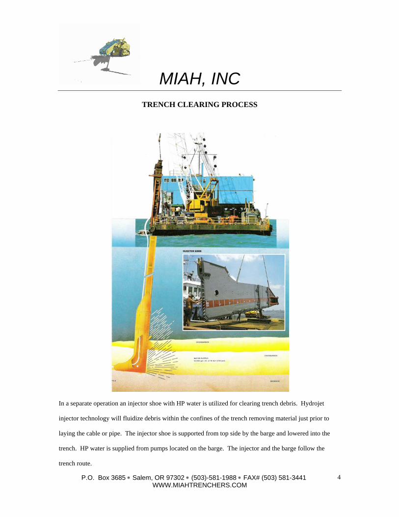
TRENCH CLEARING PROCESS
In a separate operation an injector shoe with HP water is utilized for clearing trench debris. Hydrojet
injector technology will fluidize debris within the confines of the trench removing material just prior to
laying the cable or pipe. The injector shoe is supported from top side by the barge and lowered into the
trench. HP water is supplied from pumps located on the barge. The injector and the barge follow the
trench route.
MIAH, INC
P.O. Box 3685 ∗ Salem, OR 97302 ∗ (503)-581-1988 ∗ FAX# (503) 581-3441 WWW.MIAHTRENCHERS.COM
MIAH, INC.
161 HIGH ST. SE P.O. BOX 3685
SALEM, OREGON 97302 USA
Tele 503-581-1988 Fax 503-581-3441
Email: [email protected] www.miahtrenchers.com
Related Documents