www.montanarigiulio.com O 18 190 100 200 REV:3_03_2020 MANUALS MGV25 RANGE INSTALLATION, USE AND MAINTENANCE GEARLESS

Welcome message from author
This document is posted to help you gain knowledge. Please leave a comment to let me know what you think about it! Share it to your friends and learn new things together.
Transcript
www.montanarigiulio.com
O18
190
100
200
REV:
3_03
_202
0MANUALS
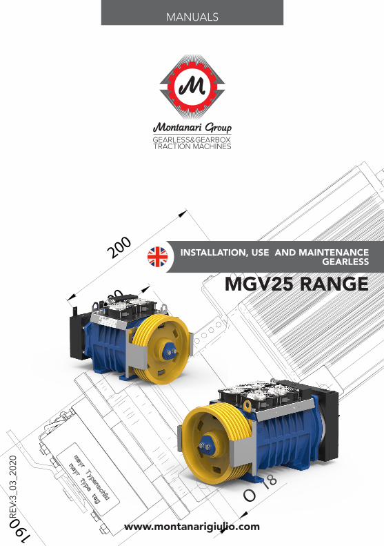
MGV25 RANGE
INSTALLATION, USE AND MAINTENANCEGEARLESS

2
DOWNLOAD OUR APP!
A unique container of all documentation available for gearboxes, gearless, speed governors and safety gears.
You may check your supply, configure the inverter, download manuals, tech reports, certificates and much more. Search for Montanari Giulio App, available on Google Play and App store.
SCAN THE QR TO DOWNLOADANDROID APP
SCAN THE QR TO DOWNLOADiOS APP
3www.montanarigiulio.com
MGV25 S-M-ML-L ENGLISH
Thank you for choosing a Montanari product.
Since 1970, Montanari Group has been focused on providing its customers with the best traction machines and components for lifts and escalators.We are proud to have you as a customer and user of the Montanari traction machines, and we are confident that we can work together for a long time.Thanks again for your choice.
Massimo MontanariCEO of Montanari Group
4
REV. DATE DESCRIPTION EDITED BY VERIFIED BY APPROVED BY
3 25/03/2020 First Redaction Marketing Dept Technical DeptAlberto Mantovani
STEFANO BERTONI (DTE)
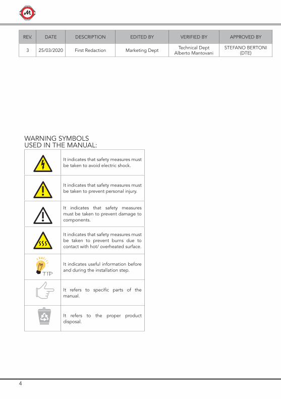
WARNING SYMBOLSUSED IN THE MANUAL:
TIP
!
!
It indicates that safety measures must be taken to avoid electric shock.
It indicates that safety measures must be taken to prevent personal injury.
It indicates that safety measures must be taken to prevent damage to components.
It indicates that safety measures must be taken to prevent burns due to contact with hot/ overheated surface.
It indicates useful information before and during the installation step.
It refers to specific parts of the manual.
It refers to the proper product disposal.
5www.montanarigiulio.com
MGV25 S-M-ML-L ENGLISH
CONTENTS
1. GENERAL INFORMATION .....................................................................71.1 Introduction ............................................................................................71.2 Copyright ...............................................................................................7
2. SAFETY ...................................................................................................82.1 Intended use ..........................................................................................82.2 User’s obligations ...................................................................................82.3 Correct disposal ...................................................................................92.4 Specific hazards ......................................................................................92.5 Legal References ....................................................................................9
3. IDENTIFICATION AND DATA ................................................................93.1 Identification plate .................................................................................93.2 Dimensions ...........................................................................................13
4. TRANSPORT AND STORAGE ..............................................................164.1 Handling ...............................................................................................164.2 Storage .................................................................................................17
5. DESCRIPTION ......................................................................................185.1 General description ..............................................................................185.2 Main components ...............................................................................185.3 Brake ....................................................................................................19
6. INSTALLATION .....................................................................................196.1 General installation information ...........................................................196.2 Installation surface ................................................................................206.3 Installation procedure...........................................................................206.4 Electrical installation - Connections .....................................................22
7. CONNECTION OF THE BRAKE FOR RESCUE SYSTEM ......................247.1 Connection of the cable to the brake levers ........................................247.2 Connection of the cable to the hand release lever ..............................267.3 Rescue System .....................................................................................26
6
8. OPERATION .........................................................................................278.1 Connections .........................................................................................278.2 Additional components ........................................................................278.3 General operation information .............................................................27
9. TROUBLESHOOTING, MAINTENANCE AND REPAIR ........................279.1 General information .............................................................................279.2 Traction/return sheave ..........................................................................289.3 Replacement of components ...............................................................289.4 Problems, causes and solutions .........................................................289.5 Maintenance and repair .......................................................................299.5.1 General indications ...........................................................................299.5.2 Description of maintenance activities................................................29
10. SPARE PARTS .......................................................................................3010.1 General information ...........................................................................3010.2 How to order spare parts ...................................................................30
11. BRAKE CERTIFICATE ...........................................................................3011.1 Exam certificate EU-BD 845 MGV25S-M ...........................................3111.2 Exam certificate EU-BD 1014 MGV25ML-L .......................................32
12. COMPLIANCE DECLARATION ............................................................33
7www.montanarigiulio.com
MGV25 S-M-ML-L ENGLISH
1. GENERAL INFORMATION1.1 IntroductionThese operating instructions must always be available for consultation. No liability is accepted for any malfunction due to installation not conforming to specifications, except in cases approved by Montanari Giulio & C.
All persons involved in the installation, operation, maintenance and repair of the unit must have read and understood the instructions.No liability is accepted for damage, breakage or accident caused by failure to follow the instructions.
To make technical improvements, Montanari reserves the right, if deemed necessary, to modify the units and accessories, preserving their essential cha-racteristics and improving efficiency and safety, without notice.
1.2 CopyrightAll rights to these operating instructions belong to Montanari Giulio & C. S.r.l. The information in this manual may not be reproduced or used in an unauthori-zed manner or made available to third parties without prior approval.
If you have any questions, please contact:
MONTANARI GROUPHEADQUARTER - MONTANARI GIULIO & C. SrlVia Bulgaria 39 - 41122 - Modena - ItaliaTel: +39 059 453611 - Fax: +39 059 [email protected]
8
2. SAFETY2.1 Intended useThe MGV25 gearless machine range is supplied ready for safe and reliable use. Any modification by the user that may affect safety or reliability is prohibited; it is also prohibited to tamper with devices or functions designed to prevent accidental contact.
The Montanari MGV25 gearless machine range must be used and operated in strict compliance with the conditions set out in the supply contract.
!Technical specifications considered: speed, cab capacity, cab weight, presence or absence of compensation, roping at the time of order.
No liability is accepted for any malfunction due to installation not conforming to specifications, except in cases approved by Montanari Giulio & C.
2.2 User’s obligationsThe operator must ensure that all persons involved in installation, operation, maintenance and repair have read and understood the supplied operating instructions and have adapted to them in order to:
• Avoid damage to property or persons.• Ensure safe and reliable operation of the unit.• Avoid breakage and environmental damage due to misuse.
In particular:• Always observe the relevant environmental and safety regulations when
transporting, assembling, installing, operating, maintaining and dismantling the unit.
• The unit must only be used, maintained and repaired by authorized, pro-perly trained and qualified personnel.
• The gearless must not be cleaned using high-pressure cleaning equipment. • All work must be carried out with care and with due attention to safety.• Any work on the unit should only be carried out when it is not in operation. • A warning must be placed on the main switch to clearly indicate that work
is in progress on the unit.• No welding must be carried out on the unit.• Do not use the unit as a grounding point for welding operations. • If any changes are detected (e.g. overheating or unusual noise) during
operation, switch off immediately.• Rotating components must be equipped with appropriate guards to pre-
vent contact.• If the unit is intended for installation in plant or machinery, the manufacturer
of such plant or machinery must ensure that the standards, indications and descriptions contained in these operating instructions are incorporated into its own instructions.
9www.montanarigiulio.com
MGV25 S-M-ML-L ENGLISH
N Norm Description1 UNI 10147 Maintenance: Terminology.
2 EN 81-20Safety rules for the construction and installation of lifts - Lifts for the transport of persons and goods.
3 EN 81 -50 Safety rules for the construction and installation of lifts - Examinations and tests.
4 EN 81 - 21Safety rules for the construction and installation of lifts - Lifts for the transport of persons and goods - Part 21: New passenger and goods passenger lifts in existing building.
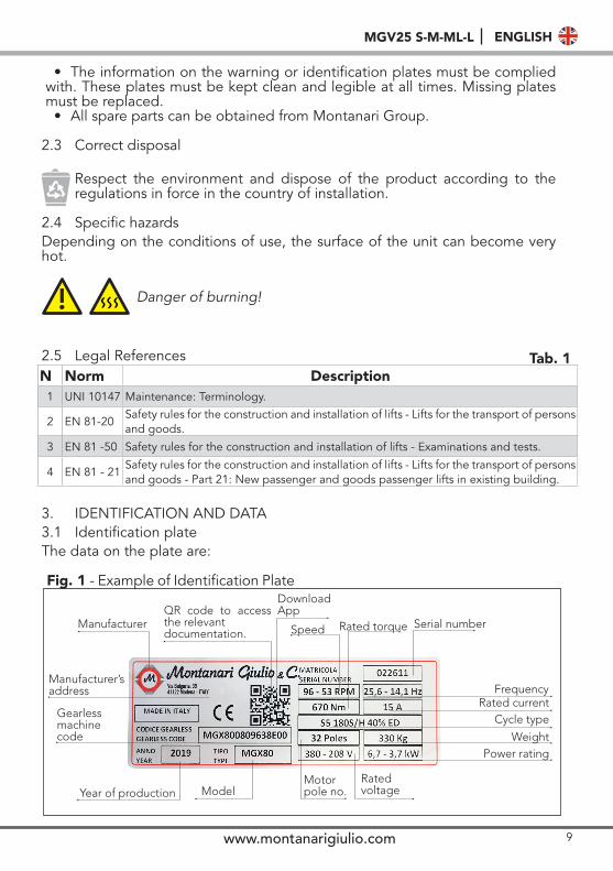
3. IDENTIFICATION AND DATA3.1 Identification plateThe data on the plate are:
• The information on the warning or identification plates must be complied with. These plates must be kept clean and legible at all times. Missing plates must be replaced.
• All spare parts can be obtained from Montanari Group.
2.3 Correct disposal
Respect the environment and dispose of the product according to the regulations in force in the country of installation.
2.4 Specific hazardsDepending on the conditions of use, the surface of the unit can become very hot.
Fig. 1
Danger of burning!!
Manufacturer
Manufacturer’s address
Year of production
Serial number
Gearless machine code
Model
Speed
Rated voltage
Frequency
Power rating
Cycle type
Rated torque
Motor pole no.
Rated current
Weight
QR code to access the relevant documentation.
2.5 Legal References Tab. 1
- Example of Identification PlateDownload App
10
Tab
. 2
Tab
. 3
MG
V25
STy
pe
PnSp
eed
VnC
nIn
Cm
axIm
axEM
FPo
les
FRs
LsSt
atic
Lo
adI
Dut
y C
ycle
Wei
ght
Co
de
mac
hine
kW[R
PM]
[V]
[Nm
][A
][N
m]
[A]
[V∙s
/ra
d]
[N°]
[Hz]
[Ω]
[mH
][K
g]
[kg
∙m2]
[Kg
]
MG
V25
1004
52B
500
MGV25
S1,
1545
210
250
1138
017
1416
63,
533
1800
0,2
180S
/H 4
0%12
0
MG
V25
1011
52B
500
MGV25
S2,
811
521
023
513
,532
019
1016
15,3
218
1800
0,2
180S
/H 4
0%12
0
MG
V25
1006
03B
500
MGV25
S1,
560
360
250
8,1
460
1520
168
6,8
6418
000,
218
0S/H
40%
120
MG
V25
1012
03B
500
MGV25
S3,
112
036
025
011
460
2114
1616
3,5
3318
000,
218
0S/H
40%
120
MG
V25
1019
23B
500
MGV25
S5
192
360
250
14,5
460
2811
1625
,61,
8518
1800
0,2
180S
/H 4
0%12
0
MG
V25
1028
03B
500
MGV25
S7,
629
236
025
019
460
368
1637
,31,
211
1800
0,2
180S
/H 4
0%12
0
MG
V25
1036
03B
500
MGV25
S8,
336
036
022
019
,546
043
716
480,
78 8
1800
0,2
180S
/H 4
0%12
0
MG
V25
1051
03B
500
MGV25
S11
,751
036
022
026
460
563
1668
0,46
418
000,
218
0S/H
40%
120
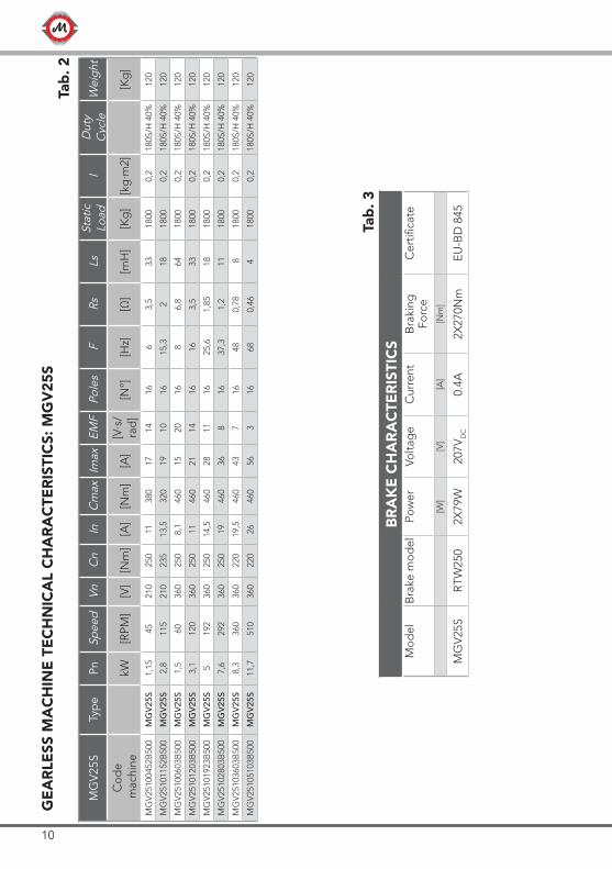
BR
AK
E C
HA
RA
CTE
RIS
TIC
SM
od
elB
rake
mo
del
Pow
erVo
ltag
eC
urre
ntB
raki
ng
Forc
eC
ertifi
cate
[W]
[V]
[A]
[Nm
]
MG
V25
SR
TW25
02X
79W
207V
DC
0.4A
2X27
0Nm
EU
-BD
845
GE
AR
LESS
MA
CH
INE
TE
CH
NIC
AL
CH
AR
AC
TER
ISTI
CS:
MG
V25
S
11www.montanarigiulio.com
MGV25 S-M-ML-L ENGLISH
MG
V25
MTy
pe
PnSp
eed
VnC
nIn
Cm
axIm
axEM
FPo
les
FRs
LsSt
atic
Lo
adI
Dut
y C
ycle
Wei
ght
Co
de
mac
hine
kW[R
PM]
[V]
[Nm
][A
][N
m]
[A]
[V∙s
/ra
d]
[N°]
[Hz]
[Ω]
[mH
][K
g]
[kg
∙m2]
[Kg
]
MG
V25
1508
03B
700
MGV25
M3,
280
360
385
1266
521
2016
10,7
3,8
4034
000,
218
0S/H
40%
180
MG
V25
1512
03B
700
MGV25
M4,
812
036
038
515
665
2715
1616
2,25
2534
000,
218
0S/H
40%
180
MG
V25
1519
23B
700
MGV25
M7,
719
236
038
520
665
3612
1625
,61,
415
3400
0,2
180S
/H 4
0%18
0
MG
V25
1528
03B
700
MGV25
M11
,328
036
038
527
665
509
1637
,30,
758
3400
0,2
180S
/H 4
0%18
0
MG
V25
1538
03B
700
MGV25
M15
,338
036
038
535
665
627
1650
,70,
475
3400
0,2
180S
/H 4
0%18
0
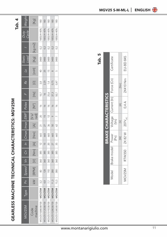
GE
AR
LESS
MA
CH
INE
TE
CH
NIC
AL
CH
AR
AC
TER
ISTI
CS:
MG
V25
M
BR
AK
E C
HA
RA
CTE
RIS
TIC
SM
od
elB
rake
mo
del
Pow
er
(Pn)
Volta
ge
(Vn)
Cur
rent
(In)
Forc
e (C
n)C
ertifi
cate
[W]
[V]
[A]
[Nm
]
MG
V25
MR
TW35
02X
82
W20
7VD
C0,
4 A
2X41
0 N
mE
U-B
D 8
45
Tab
. 4
Tab
. 5
12
MG
V25
ML
Typ
e Pn
Spee
dVn
Cn
InC
max
Imax
EMF
Pole
sF
RsLs
Stat
ic
Load
ID
uty
Cyc
leW
eigh
t
Co
de
mac
hine
kW[R
PM]
[V]
[Nm
][A
][N
m]
[A]
[V∙s
/ra
d]
[N°]
[Hz]
[Ω]
[mH
][K
g]
[kg
∙m2]
[Kg
]
MG
V25
2008
03B
C00
MGV25
ML
4,4
8036
053
015
915
2720
1610
,72,
832
3400
0,28
180S
/H 4
0%22
0
MG
V25
2012
03B
C00
MGV25
ML
6,7
120
360
530
1991
535
1616
161,
820
3400
0,28
180S
/H 4
0%22
0
MG
V25
2019
23B
C00
MGV25
ML
10,7
192
360
530
2591
547
1216
25,6
0,96
1134
000,
2818
0S/H
40%
220
MG
V25
2025
53B
C00
MGV25
ML
14,2
255
360
530
3491
562
916
340,
627
3400
0,28
180S
/H 4
0%22
0
MG
V25
2030
03B
C00
MGV25
ML
16,6
300
360
530
3791
568
816
400,
475
3400
0,28
180S
/H 4
0%22
0
MG
V25
LTy
pe
PnSp
eed
VnC
nIn
Cm
axIm
axEM
FPo
les
FRs
LsSt
atic
Lo
adI
Dut
y C
ycle
Wei
ght
Co
de
mac
hine
kW[R
PM]
[V]
[Nm
][A
][N
m]
[A]
[V∙s
/ra
d]
[N°]
[Hz]
[Ω]
[mH
][K
g]
[kg
∙m2]
[Kg
]
MG
V25
2606
03B
C00
MGV25
L4
6036
063
015
1100
2724
168
3,2
3734
000,
3118
0S/H
40%
240
MG
V25
2612
03B
C00
MGV25
L7,
912
036
063
022
1100
4018
1616
1,5
1834
000,
3118
0S/H
40%
240
MG
V25
2616
03B
C00
MGV25
L10
,616
036
063
028
1100
4914
1621
,30,
9511
3400
0,31
180S
/H 4
0%24
0
MG
V25
2621
03B
C00
MGV25
L13
,921
036
063
032
1100
5911
1628
0,65
834
000,
3118
0S/H
40%
240
MG
V25
2625
53B
C00
MGV25
L16
,825
536
063
040
1100
7110
1634
0,47
534
000,
3118
0S/H
40%
240
MG
V25
2636
03B
C00
MG
V25
L23
,736
036
063
052
1100
917
1648
0,28
334
000,
3118
0S/H
40%
240
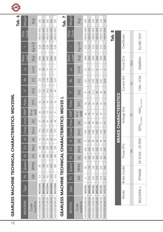
GE
AR
LESS
MA
CH
INE
TE
CH
NIC
AL
CH
AR
AC
TER
ISTI
CS:
MG
V25
ML
BR
AK
E C
HA
RA
CTE
RIS
TIC
SM
od
elB
rake
mo
del
Pow
er (P
n)Vo
ltag
e (V
n)C
urre
nt (I
n)Fo
rce
(Cn)
Cer
tifica
te
[W]
[V]
[A]
[Nm
]
MG
V25
ML-
LR
TW60
02X
372
W –
2X
92W
207V
DC
-PE
AK -
104
VD
C-H
OLD
1.8A
– 0
.9A
2X60
0Nm
EU
-BD
101
4
Tab
. 6
Tab
. 7
Tab
. 8
GE
AR
LESS
MA
CH
INE
TE
CH
NIC
AL
CH
AR
AC
TER
ISTI
CS:
MG
V25
L
13www.montanarigiulio.com
MGV25 S-M-ML-L ENGLISH
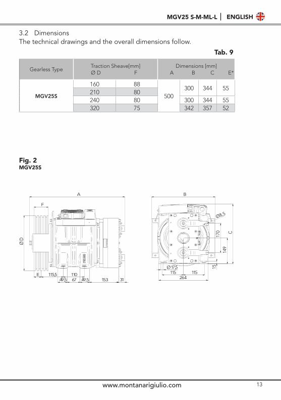
3.2 DimensionsThe technical drawings and the overall dimensions follow.
Fig. 2MGV25S
Gearless TypeTraction Sheave[mm]
Ø D FDimensions [mm]
A B C E*
MGV25S
160 88
500300 344 55
210 80240 80 300 344 55320 75 342 357 52
Tab. 9
ØD
F
A
E 115,5 11049,5 67 49,5 153 31
17,5Ø115 115
264
B
15
149
C
170
Ø8,5
14
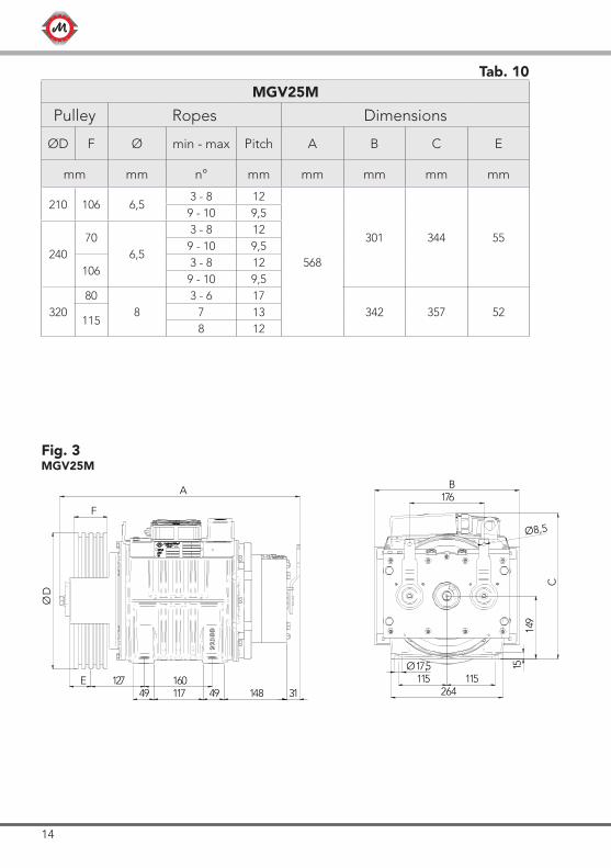
Fig. 3MGV25M
Tab. 10MGV25M
Pulley Ropes Dimensions
ØD F Ø min - max Pitch A B C E
mm mm n° mm mm mm mm mm
210 106 6,53 - 8 12
568
301 344 55
9 - 10 9,5
24070
6,5
3 - 8 129 - 10 9,5
1063 - 8 12
9 - 10 9,5
32080
83 - 6 17
342 357 52115
7 138 12
F
A
ØD
E 127 16049 117 49 148 31
176B
Ø8,514
9
C
1517,5Ø115 115
264
15www.montanarigiulio.com
MGV25 S-M-ML-L ENGLISH
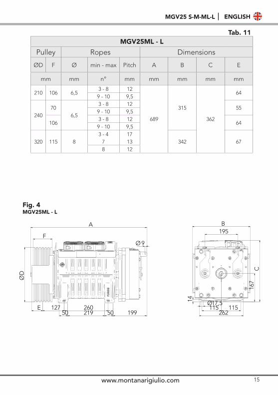
Tab. 11MGV25ML - L
Pulley Ropes Dimensions
ØD F Ø min - max Pitch A B C E
mm mm n° mm mm mm mm mm
210 106 6,53 - 8 12
689
315
362
649 - 10 9,5
24070
6,5
3 - 8 1255
9 - 10 9,5
1063 - 8 12
649 - 10 9,5
320 115 83 - 4 17
342 677 138 12
ØD
E 127 26050 219 50 199
Ø 9F
A195B
167
C
14
115 115262
17,5Ø
Fig. 4MGV25ML - L
16
Only use lifting systems and equipment with adequate lifting capacity for handling. The entire packaging is designed to allow movement with for lift and for lift truck.
!
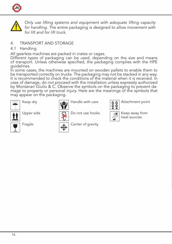
4. TRANSPORT AND STORAGE4.1 HandlingAll gearless machines are packed in crates or cages. Different types of packaging can be used, depending on the size and means of transport. Unless otherwise specified, the packaging complies with the HPE guidelines.In some cases, the machines are mounted on wooden pallets to enable them to be transported correctly on trucks. The packaging may not be stacked in any way. It is recommended to check the conditions of the material when it is received. In case of damage, do not proceed with the installation unless expressly authorized by Montanari Giulio & C. Observe the symbols on the packaging to prevent da-mage to property or personal injury. Here are the meanings of the symbols that may appear on the packaging.
Keep dry Handle with care
Upper side Do not use hooks
Fragile Center of gravity
Keep away from heat sources
Attachment point
17www.montanarigiulio.com
MGV25 S-M-ML-L ENGLISH
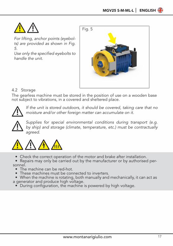
For lifting, anchor points (eyebol-ts) are provided as shown in Fig. 5. Use only the specified eyebolts to handle the unit.
Fig. 5! !
4.2 StorageThe gearless machine must be stored in the position of use on a wooden base not subject to vibrations, in a covered and sheltered place.
If the unit is stored outdoors, it should be covered, taking care that no moisture and/or other foreign matter can accumulate on it.!Supplies for special environmental conditions during transport (e.g. by ship) and storage (climate, temperature, etc.) must be contractually agreed.
!
• Check the correct operation of the motor and brake after installation. • Repairs may only be carried out by the manufacturer or by authorised per-
sonnel. • The machine can be red-hot. • These machines must be connected to inverters. • When the machine is rotating, both manually and mechanically, it can act as
a generator and produce high voltage.• During configuration, the machine is powered by high voltage.
! !
18
5. DESCRIPTION5.1 General descriptionThe MGV25 series gearless machines are permanent magnet motors with dou-ble brake system.
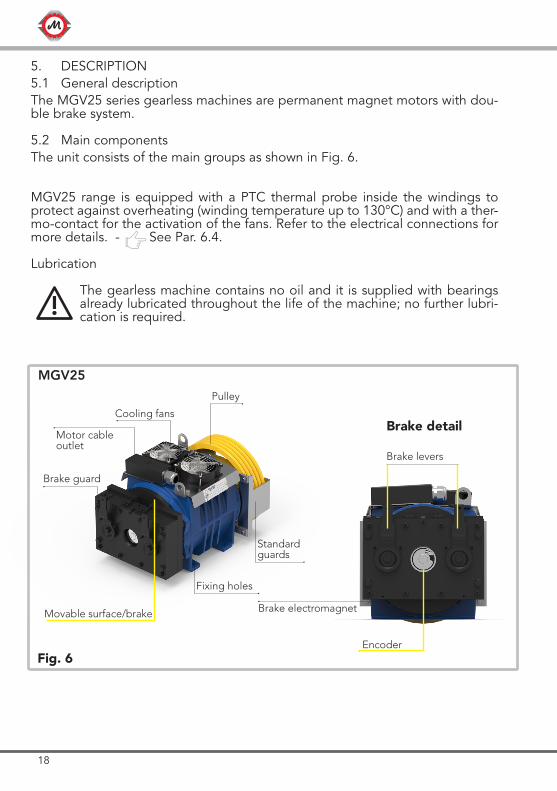
5.2 Main components The unit consists of the main groups as shown in Fig. 6.
MGV25 range is equipped with a PTC thermal probe inside the windings to protect against overheating (winding temperature up to 130°C) and with a ther-mo-contact for the activation of the fans. Refer to the electrical connections for more details. - See Par. 6.4. Lubrication
The gearless machine contains no oil and it is supplied with bearings already lubricated throughout the life of the machine; no further lubri-cation is required. !
Standard guards
Fig. 6
Cooling fans
Pulley
Fixing holes
Motor cable outlet
Brake levers
MGV25
Brake guard
Brake detail
Movable surface/brake
Encoder
Brake electromagnet
19www.montanarigiulio.com
MGV25 S-M-ML-L ENGLISH
5.3 BrakeThe gearless machine is supplied with a brake that conforms to the standards indicated in paragraph 2.5.The brake system is pre-calibrated by the manufacturer and no further adjustment is required.
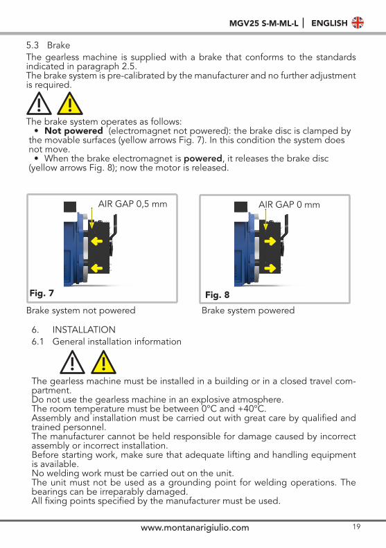
The brake system operates as follows:• Not powered (electromagnet not powered): the brake disc is clamped by
the movable surfaces (yellow arrows Fig. 7). In this condition the system does not move.
• When the brake electromagnet is powered, it releases the brake disc (yellow arrows Fig. 8); now the motor is released.
! !
AIR GAP 0,5 mm AIR GAP 0 mm
Brake system not powered Brake system powered
Fig. 7 Fig. 8
6. INSTALLATION6.1 General installation information
The gearless machine must be installed in a building or in a closed travel com-partment. Do not use the gearless machine in an explosive atmosphere. The room temperature must be between 0°C and +40°C.Assembly and installation must be carried out with great care by qualified and trained personnel.The manufacturer cannot be held responsible for damage caused by incorrect assembly or incorrect installation.Before starting work, make sure that adequate lifting and handling equipment is available.No welding work must be carried out on the unit.The unit must not be used as a grounding point for welding operations. The bearings can be irreparably damaged.All fixing points specified by the manufacturer must be used.
! !
20
Fig. 9
The air supply for cooling must not be prevented.
6.2 Installation surfaceThe installation surface must be uniform and level. The levelling tolerance is 0.1 mm.The installation surface must be rigid and robust enough to withstand the forces involved.
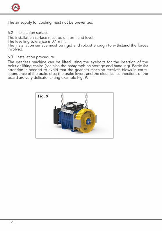
6.3 Installation procedureThe gearless machine can be lifted using the eyebolts for the insertion of the belts or lifting chains (see also the paragraph on storage and handling). Particular attention is needed to avoid that the gearless machine receives blows in corre-spondence of the brake disc; the brake levers and the electrical connections of the board are very delicate. Lifting example Fig. 9.
21www.montanarigiulio.com
MGV25 S-M-ML-L ENGLISH
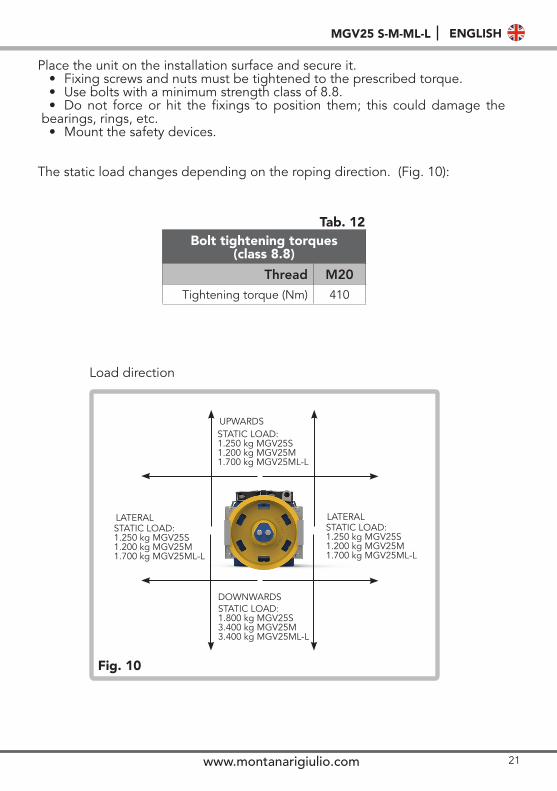
Place the unit on the installation surface and secure it.• Fixing screws and nuts must be tightened to the prescribed torque.• Use bolts with a minimum strength class of 8.8.• Do not force or hit the fixings to position them; this could damage the
bearings, rings, etc. • Mount the safety devices.
The static load changes depending on the roping direction. (Fig. 10):
Fig. 10
LATERAL
DOWNWARDSSTATIC LOAD:1.800 kg MGV25S3.400 kg MGV25M3.400 kg MGV25ML-L
STATIC LOAD:1.250 kg MGV25S1.200 kg MGV25M1.700 kg MGV25ML-L
STATIC LOAD:1.250 kg MGV25S1.200 kg MGV25M1.700 kg MGV25ML-L
UPWARDS
Bolt tightening torques (class 8.8)
Thread M20Tightening torque (Nm) 410
Load direction
Tab. 12
LATERALSTATIC LOAD:1.250 kg MGV25S1.200 kg MGV25M1.700 kg MGV25ML-L
22
! !
Brake disc closed Condition contact Brake disc free Condition
contact
Disconnected Connected
Connected Disconnected
BLACK
COM.
BLUE
N.O.
BLACK
COM.
GREY
N.C. COM. N.C.
BLACK
COM.
BLUE
N.O.
• The power cable must be routed separately from the other cables. • The motor power cable is shielded and the shield must be grounded. • The encoder cable must be routed away from the motor power cable to avoid
electrical interference.• The brake system has a power cable and another cable for the microswitch
contacts. (Figure no. 12). All electrical data are listed on the label of the brake system. The microswitch has two contacts: one open and one closed. (Fig. 12).
• These contacts indicate the brake condition (tab. 13).
Tab. 13
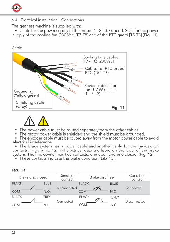
6.4 Electrical installation - ConnectionsThe gearless machine is supplied with:
• Cable for the power supply of the motor [1 - 2 - 3, Ground, SC] , for the power supply of the cooling fan (230 Vac) [F7-F8] and of the PTC guard [T5-T6] (Fig. 11).
BLACK GREY
Fig. 11
Cables for PTC probe PTC (T5 - T6)
Cooling fans cables (F7 - F8) [230Vac]
Cable
Shielding cable (Grey)
Grounding (Yellow green)
Power cables for the U-V-W phases(1 - 2 - 3)
23www.montanarigiulio.com
MGV25 S-M-ML-L ENGLISH
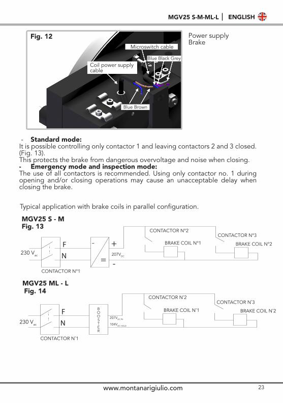
- Standard mode: It is possible controlling only contactor 1 and leaving contactors 2 and 3 closed. (Fig. 13). This protects the brake from dangerous overvoltage and noise when closing.- Emergency mode and inspection mode:The use of all contactors is recommended. Using only contactor no. 1 during opening and/or closing operations may cause an unacceptable delay when closing the brake.
Typical application with brake coils in parallel configuration.
Power supply Brake
Microswitch cable
Coil power supply cable
Blue Black Grey
Blue Brown
Fig. 12
Fig. 13
Fig. 14
MGV25 S - M
MGV25 ML - L
CONTACTOR N°1
BRAKE COIL N°1 BRAKE COIL N°2
CONTACTOR N°3
230 Vac
˜
CONTACTOR N°2
207VDC
CONTACTOR N˚1
BRAKE COIL N˚1 BRAKE COIL N˚2
CONTACTOR N˚3
230 Vac
CONTACTOR N˚2
BOOSTER
207VDC PK
104VDC HOLD
24
Fig. 16
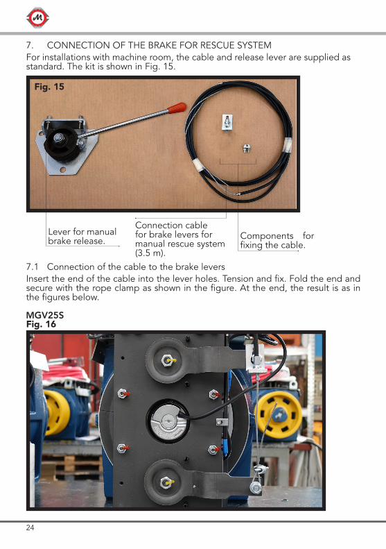
7. CONNECTION OF THE BRAKE FOR RESCUE SYSTEMFor installations with machine room, the cable and release lever are supplied as standard. The kit is shown in Fig. 15.
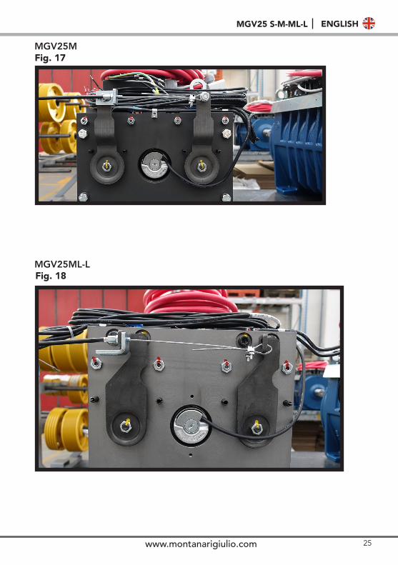
7.1 Connection of the cable to the brake leversInsert the end of the cable into the lever holes. Tension and fix. Fold the end and secure with the rope clamp as shown in the figure. At the end, the result is as in the figures below.
Components for fixing the cable.
Connection cable for brake levers for manual rescue system (3.5 m).
Lever for manual brake release.
Fig. 15
MGV25S
25www.montanarigiulio.com
MGV25 S-M-ML-L ENGLISH
Fig. 17
Fig. 18
MGV25M
MGV25ML-L
26
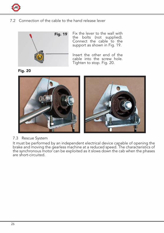
Insert the other end of the cable into the screw hole. Tighten to stop. Fig. 20.
Fix the lever to the wall with the bolts (not supplied). Connect the cable to the support as shown in Fig. 19.
Fig. 19
Fig. 20
7.3 Rescue SystemIt must be performed by an independent electrical device capable of opening the brake and moving the gearless machine at a reduced speed. The characteristics of the synchronous motor can be exploited as it slows down the cab when the phases are short-circuited.
7.2 Connection of the cable to the hand release lever
27www.montanarigiulio.com
MGV25 S-M-ML-L ENGLISH
8. OPERATION8.1 ConnectionsConnect the motor, brake, and monitoring devices.The connection must be made by qualified personnel in accordance with the applicable safety regulations. Installation and operation requirements and cur-rent national and international standards must be met.
8.2 Additional componentsIf third party additional components or options are installed, please refer to the information in the respective separate documentation provided.
8.3 General operation informationWhen operating the MGV25 unit, be sure to check that the following situations do not occur:
• Excessive operating temperature.• Excessive and unusual noise.
If any irregularity occurs during operation, turn off the power immediately. Iden-tify the cause of the malfunction by using the table in Chap. 9, containing a list of possible problems, causes and suggested remedies.
9. TROUBLESHOOTING, MAINTENANCE AND REPAIR9.1 General information
Observe all safety rules.Do not disassemble the motor on site. The bearings are protected and do not require any additional lubrication under standard conditions of use. Do not use high-pressure cleaners on the motor.
Montanari cannot guarantee or be held responsible for unauthorized operations on the unit, improper use, modifications made without its consent or the use of non-genuine spare parts.
If the cause of the malfunction cannot be identified, or if the unit has been repaired using the means available, you should contact one of our service centres for a specialised service.
!
Problems and malfunctions occurring during the warranty period, which are not precisely identified or which require work on the unit, must be referred to the manufacturer’s Customer Service department.
!
When repairing problems or malfunctions, the unit must be put out of service in order to prevent unintentional start-up. Place a warning sign on the starting switch.
!
28
9.2 Traction/return sheavePeriodically, at least once a year, check the wear of the grooves in the traction sheave. In case of slipping ropes or excessive wear, contact Montanari Giulio & C. for replacement instructions, always indicating the serial number.
9.3 Replacement of componentsInstructions for the replacement of any component must be requested each time from the technical department specifying the serial number.
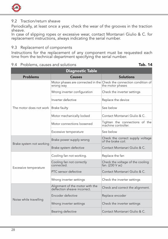
9.4 Problems, causes and solutions
Diagnostic TableProblems Causes Solutions
The motor does not work
Motor phases are connected in the wrong way
Check the connection condition of the motor phases
Wrong inverter configuration Check the inverter settings
Inverter defective Replace the device
Brake faulty See below
Motor mechanically locked Contact Montanari Giulio & C.
Motor connections loosened Tighten the connections of the machine controller.
Excessive temperature See below
Brake system not workingBrake power supply wrong Check the correct supply voltage
of the brake coil.
Brake system defective Contact Montanari Giulio & C.
Excessive temperature
Cooling fan not working. Replace the fan
Cooling fan not correctly connected.
Check the voltage of the cooling fan. (230 V ac)
PTC sensor defective Contact Montanari Giulio & C.
Wrong inverter settings Check the inverter settings
Noise while travelling
Alignment of the motor with the deflection sheave incorrect. Check and correct the alignment.
Encoder defective Replace encoder
Wrong inverter settings Check the inverter settings
Bearing defective Contact Montanari Giulio & C.
Tab. 14
29www.montanarigiulio.com
MGV25 S-M-ML-L ENGLISH
9.5 Maintenance and repair9.5.1 General indications
The unit must only be used, maintained and repaired by authorized, properly trained and qualified personnel.!
Compliance with the inspection and maintenance intervals is part of the condi-tions for the validity of the warranty.
9.5.2 Description of maintenance activities
Stop the unit and put it out of service. Place a warning sign on the start switch to prevent unintentional start.
Cleaning the unit.Remove dirt on the unit with a hard brush.Remove corrosion signs.The unit must not be cleaned with high pressure washing equipment.
30
10. SPARE PARTS10.1 General information
TIP
By keeping the main spare parts and wear parts in stock, the unit can always be used.
10.2 How to order spare partsThe manufacturer guarantees only genuine spare parts and accessories sup-plied by him.Other parts not supplied by the manufacturer have not been tested or appro-ved. The use of these parts can therefore compromise certain characteristics of the gearless machine and expose it to active and passive safety risks.
The manufacturer will not assume any responsibility and will not recog-nize warranty for damage caused by spare parts and accessories not supplied by the manufacturer himself.
!
When ordering spare parts, always specify:• Order no. of the machine to which they must be applied;• Description;• Quantity.
To order spare parts, write to [email protected].
11. BRAKE CERTIFICATEThe brake has been designed in accordance with the norm: EN 81 - 20:2014, EN 81-50:2015, EN81-1:1998+A3:2009(D).
This device can be used as a brake to slow down the cab in combination with a speed governor if the cab speed upwards is excessive. The exam certificate is EU-BD 845 + EU-BD 1014.
31www.montanarigiulio.com
MGV25 S-M-ML-L ENGLISH
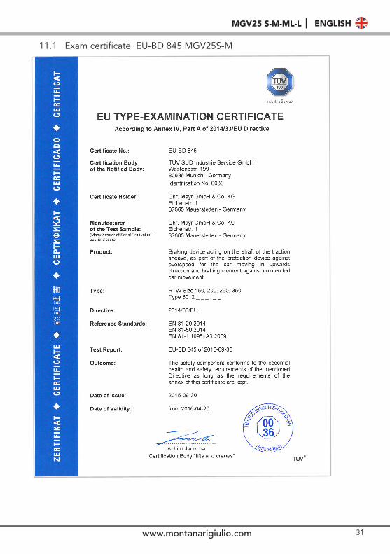
11.1 Exam certificate EU-BD 845 MGV25S-M
32
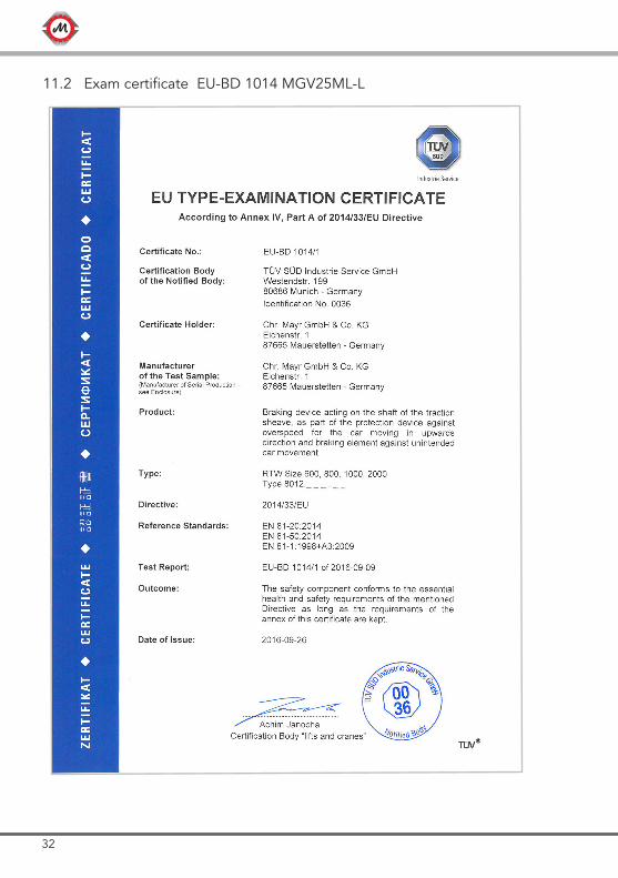
11.2 Exam certificate EU-BD 1014 MGV25ML-L
33www.montanarigiulio.com
MGV25 S-M-ML-L ENGLISH
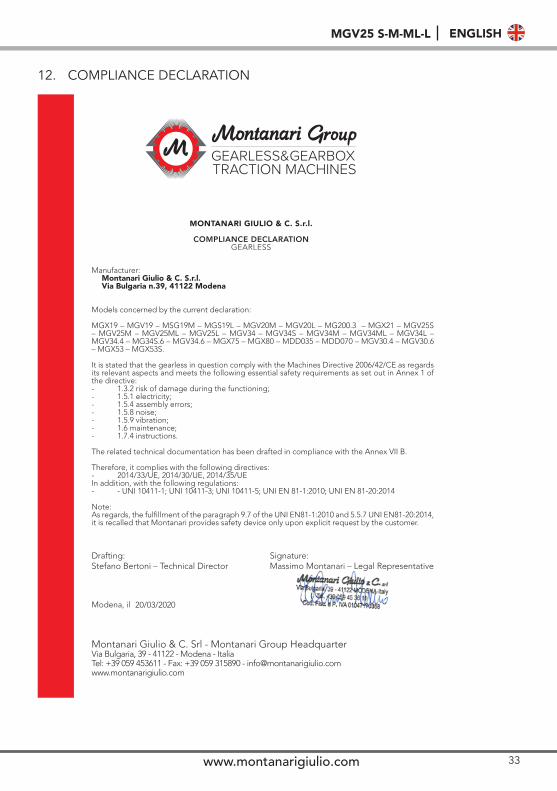
12. COMPLIANCE DECLARATION
Manufacturer:Montanari Giulio & C. S.r.l.Via Bulgaria n.39, 41122 Modena
Models concerned by the current declaration:
MGX19 – MGV19 – MSG19M – MGS19L – MGV20M – MGV20L – MG200.3 – MGX21 – MGV25S – MGV25M – MGV25ML – MGV25L – MGV34 – MGV34S – MGV34M – MGV34ML – MGV34L – MGV34.4 – MG34S.6 – MGV34.6 – MGX75 – MGX80 – MDD035 – MDD070 – MGV30.4 – MGV30.6 – MGX53 – MGX53S.
It is stated that the gearless in question comply with the Machines Directive 2006/42/CE as regards its relevant aspects and meets the following essential safety requirements as set out in Annex 1 of the directive:- 1.3.2 risk of damage during the functioning;- 1.5.1 electricity;- 1.5.4 assembly errors;- 1.5.8 noise;- 1.5.9 vibration;- 1.6 maintenance;- 1.7.4 instructions.
The related technical documentation has been drafted in compliance with the Annex VII B.
Therefore, it complies with the following directives:- 2014/33/UE, 2014/30/UE, 2014/35/UEIn addition, with the following regulations:- - UNI 10411-1; UNI 10411-3; UNI 10411-5; UNI EN 81-1:2010; UNI EN 81-20:2014
Note:As regards, the fulfillment of the paragraph 9.7 of the UNI EN81-1:2010 and 5.5.7 UNI EN81-20:2014, it is recalled that Montanari provides safety device only upon explicit request by the customer.
MONTANARI GIULIO & C. S.r.l.
COMPLIANCE DECLARATIONGEARLESS
Drafting:Stefano Bertoni – Technical Director
Signature:Massimo Montanari – Legal Representative
Modena, il 20/03/2020
Montanari Giulio & C. Srl - Montanari Group HeadquarterVia Bulgaria, 39 - 41122 - Modena - ItaliaTel: +39 059 453611 - Fax: +39 059 315890 - [email protected]

MONTANARI GROUP HEADQUARTERMontanari Giulio & C. Srl
Via Bulgaria 39 - 41122 - Modena - ItaliaTel: +39 059 453611 - Fax: +39 059 315890 - [email protected]
www.montanarigiulio.com
Related Documents