The data should be read in conjunction with the Magnetron Preamble. ABRIDGED DATA Fixed frequency pulse magnetron. Operating frequency . . . . . . 9170 + 30 MHz Minimum peak output power . . . . . . 25 kW Magnet . . . . . . . . . . . . . . . integral Output . . . . . . . . . . . . no. 16 waveguide (22.86 x 10.16 mm internal) Coupler . . . . . . . . . . . . . . UG-40B/U (NATO S.N. 5985-99-083-0051) Cooling . . . . . . . . . . . natural or forced-air GENERAL Electrical Cathode . . . . . . . . . . . . indirectly heated Heater voltage (see note 1) . . . . . . . 6.3 V Heater current at 6.3 V . . . . . . . . 0.55 A Heater starting current, peak value, not to be exceeded . . . . . . . . . 3.0 A max Cathode pre-heating time (minimum) (see note 2) . . . . . . . . . . . 60 s Mechanical Overall dimensions . . . . . . . . . . . see outline Net weight . . . . . . . . . . . . 1.5 kg approx Mounting position . . . . . . . . . . . . . any A minimum clearance of 50 mm must be maintained between the magnet and any magnetic materials. Cooling . . . . . . . . . . . natural or forced-air MAXIMUM AND MINIMUM RATINGS (Absolute values) These ratings cannot necessarily be used simultaneously, and no individual rating should be exceeded. Min Max Heater voltage (see note 1) . . . . . 5.7 6.9 V Heater starting current (peak) . . . . – 3.0 A Anode voltage (peak) . . . . . . . 7.5 8.2 kV Anode current (peak) . . . . . . . 6.0 10 A Input power (peak) . . . . . . . . – 75 kW Input power (mean) (see note 3) . . . – 85 W Duty cycle . . . . . . . . . . – 0.0015 Pulse duration . . . . . . . . . – 2.0 ms Rate of rise of voltage pulse (see notes 4 and 5) . . . . . . . – 200 kV/ms Anode temperature (see note 6) . . . – 120 8C VSWR at the output coupler . . . . – 1.5:1 TYPICAL OPERATION Operating Conditions Oscillation 1 2 Heater voltage . . . . . . . . . 6.3 6.3 V Anode current (peak) . . . . . . . 8.0 8.0 A Pulse duration . . . . . . . . . 1.0 0.1 ms Pulse repetition rate . . . . . . 500 1000 pps Rate of rise of voltage pulse . . . . 120 120 kV/ms Typical Performance Anode voltage (peak) . . . . . . . 8.0 8.0 kV Output power (peak) . . . . . . 27 27 kW Output power (mean) . . . . . . 13.5 2.7 W MG5230T X-Band Magnetron # e2v technologies (uk) limited 2016 A1A-MG5230T Issue 5, June 2016 100282 e2v technologies (uk) limited, Waterhouse Lane, Chelmsford, Essex CM1 2QU, UK Telephone: +44 (0)1245 493493 Facsimile: +44 (0)1245 492492 e-mail: [email protected] Internet: www.e2v.com Holding Company: e2v technologies plc

Welcome message from author
This document is posted to help you gain knowledge. Please leave a comment to let me know what you think about it! Share it to your friends and learn new things together.
Transcript

The data should be read in conjunction with the MagnetronPreamble.
ABRIDGED DATAFixed frequency pulse magnetron.
Operating frequency . . . . . . 9170 + 30 MHzMinimum peak output power . . . . . . 25 kWMagnet . . . . . . . . . . . . . . . integralOutput . . . . . . . . . . . . no. 16 waveguide
(22.86 x 10.16 mm internal)Coupler . . . . . . . . . . . . . . UG-40B/U
(NATO S.N. 5985-99-083-0051)Cooling . . . . . . . . . . . natural or forced-air
GENERALElectricalCathode . . . . . . . . . . . . indirectly heatedHeater voltage (see note 1) . . . . . . . 6.3 VHeater current at 6.3 V . . . . . . . . 0.55 AHeater starting current, peak value,not to be exceeded . . . . . . . . . 3.0 A max
Cathode pre-heating time (minimum)(see note 2) . . . . . . . . . . . 60 s
MechanicalOverall dimensions . . . . . . . . . . . see outlineNet weight . . . . . . . . . . . . 1.5 kg approxMounting position . . . . . . . . . . . . . any
A minimum clearance of 50 mm must be maintained betweenthe magnet and any magnetic materials.
Cooling . . . . . . . . . . . natural or forced-air
MAXIMUM AND MINIMUM RATINGS(Absolute values)These ratings cannot necessarily be used simultaneously, andno individual rating should be exceeded.
Min Max
Heater voltage (see note 1) . . . . . 5.7 6.9 VHeater starting current (peak) . . . . – 3.0 AAnode voltage (peak) . . . . . . . 7.5 8.2 kVAnode current (peak) . . . . . . . 6.0 10 AInput power (peak) . . . . . . . . – 75 kWInput power (mean) (see note 3) . . . – 85 WDuty cycle . . . . . . . . . . – 0.0015Pulse duration . . . . . . . . . – 2.0 msRate of rise of voltage pulse(see notes 4 and 5) . . . . . . . – 200 kV/ms
Anode temperature (see note 6) . . . – 120 8CVSWR at the output coupler . . . . – 1.5:1
TYPICAL OPERATIONOperating Conditions
Oscillation1 2
Heater voltage . . . . . . . . . 6.3 6.3 VAnode current (peak) . . . . . . . 8.0 8.0 APulse duration . . . . . . . . . 1.0 0.1 msPulse repetition rate . . . . . . 500 1000 ppsRate of rise of voltage pulse . . . . 120 120 kV/ms
Typical PerformanceAnode voltage (peak) . . . . . . . 8.0 8.0 kVOutput power (peak) . . . . . . 27 27 kWOutput power (mean) . . . . . . 13.5 2.7 W
MG5230TX-Band Magnetron
# e2v technologies (uk) limited 2016 A1A-MG5230T Issue 5, June 2016100282
e2v technologies (uk) limited, Waterhouse Lane, Chelmsford, Essex CM1 2QU, UK Telephone: +44 (0)1245 493493 Facsimile: +44 (0)1245 492492e-mail: [email protected] Internet: www.e2v.com Holding Company: e2v technologies plc
ewh
Text Box
ewh
Typewritten Text
123197
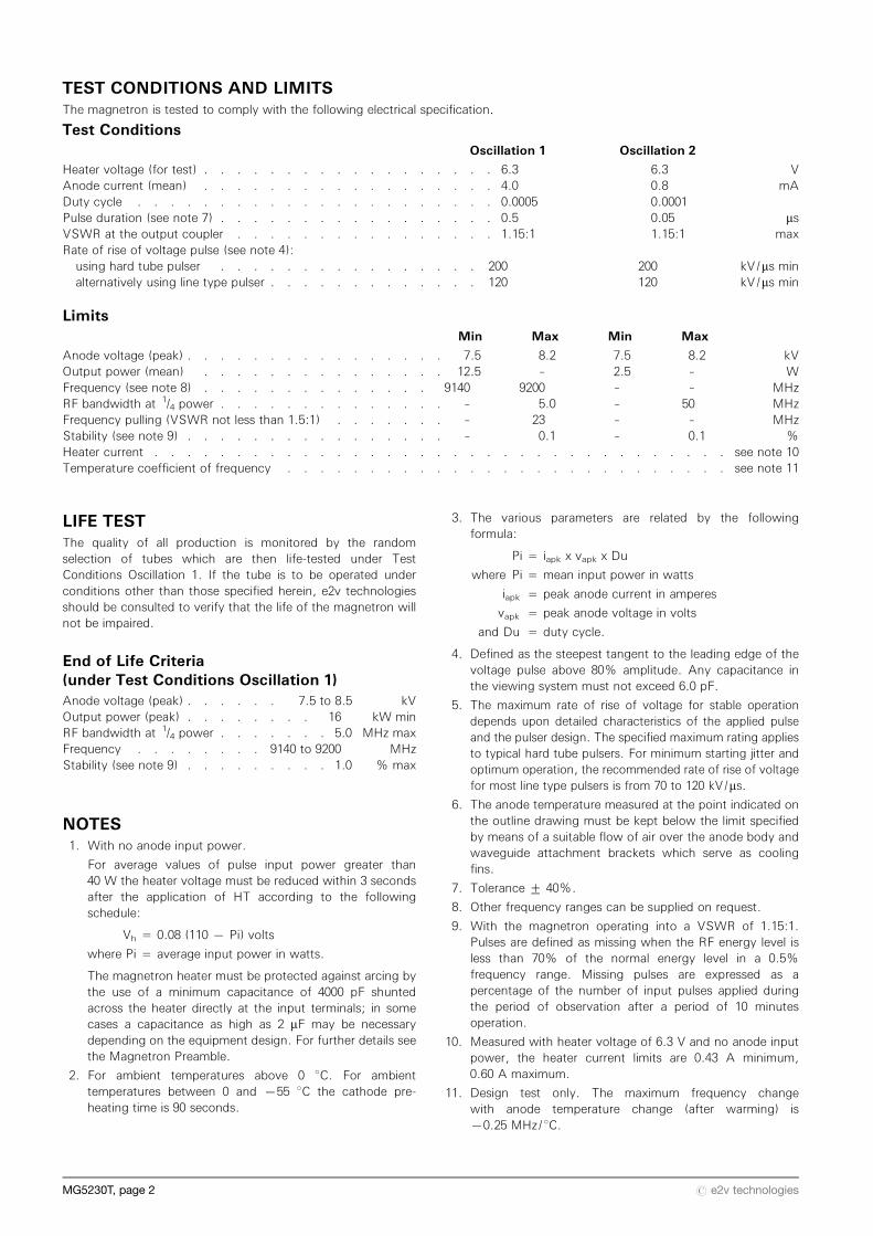
TEST CONDITIONS AND LIMITSThe magnetron is tested to comply with the following electrical specification.
Test ConditionsOscillation 1 Oscillation 2
Heater voltage (for test) . . . . . . . . . . . . . . . . . . 6.3 6.3 VAnode current (mean) . . . . . . . . . . . . . . . . . . 4.0 0.8 mADuty cycle . . . . . . . . . . . . . . . . . . . . . . 0.0005 0.0001Pulse duration (see note 7) . . . . . . . . . . . . . . . . . 0.5 0.05 msVSWR at the output coupler . . . . . . . . . . . . . . . . 1.15:1 1.15:1 maxRate of rise of voltage pulse (see note 4):using hard tube pulser . . . . . . . . . . . . . . . . 200 200 kV/ms minalternatively using line type pulser . . . . . . . . . . . . . 120 120 kV/ms min
LimitsMin Max Min Max
Anode voltage (peak) . . . . . . . . . . . . . . . . 7.5 8.2 7.5 8.2 kVOutput power (mean) . . . . . . . . . . . . . . . 12.5 – 2.5 – WFrequency (see note 8) . . . . . . . . . . . . . . 9140 9200 – – MHzRF bandwidth at 1/4 power . . . . . . . . . . . . . . – 5.0 – 50 MHzFrequency pulling (VSWR not less than 1.5:1) . . . . . . . – 23 – – MHzStability (see note 9) . . . . . . . . . . . . . . . . – 0.1 – 0.1 %Heater current . . . . . . . . . . . . . . . . . . . . . . . . . . . . . . . . . . . see note 10Temperature coefficient of frequency . . . . . . . . . . . . . . . . . . . . . . . . . . . see note 11
LIFE TESTThe quality of all production is monitored by the randomselection of tubes which are then life-tested under TestConditions Oscillation 1. If the tube is to be operated underconditions other than those specified herein, e2v technologiesshould be consulted to verify that the life of the magnetron willnot be impaired.
End of Life Criteria(under Test Conditions Oscillation 1)Anode voltage (peak) . . . . . . 7.5 to 8.5 kVOutput power (peak) . . . . . . . . 16 kW minRF bandwidth at 1/4 power . . . . . . . 5.0 MHz maxFrequency . . . . . . . . 9140 to 9200 MHzStability (see note 9) . . . . . . . . . 1.0 % max
NOTES1. With no anode input power.
For average values of pulse input power greater than40 W the heater voltage must be reduced within 3 secondsafter the application of HT according to the followingschedule:
Vh = 0.08 (110 7 Pi) volts
where Pi = average input power in watts.
The magnetron heater must be protected against arcing bythe use of a minimum capacitance of 4000 pF shuntedacross the heater directly at the input terminals; in somecases a capacitance as high as 2 mF may be necessarydepending on the equipment design. For further details seethe Magnetron Preamble.
2. For ambient temperatures above 0 8C. For ambienttemperatures between 0 and 755 8C the cathode pre-heating time is 90 seconds.
3. The various parameters are related by the followingformula:
Pi = iapk x vapk x Du
where Pi = mean input power in watts
iapk = peak anode current in amperes
vapk = peak anode voltage in volts
and Du = duty cycle.
4. Defined as the steepest tangent to the leading edge of thevoltage pulse above 80% amplitude. Any capacitance inthe viewing system must not exceed 6.0 pF.
5. The maximum rate of rise of voltage for stable operationdepends upon detailed characteristics of the applied pulseand the pulser design. The specified maximum rating appliesto typical hard tube pulsers. For minimum starting jitter andoptimum operation, the recommended rate of rise of voltagefor most line type pulsers is from 70 to 120 kV/ms.
6. The anode temperature measured at the point indicated onthe outline drawing must be kept below the limit specifiedby means of a suitable flow of air over the anode body andwaveguide attachment brackets which serve as coolingfins.
7. Tolerance + 40%.
8. Other frequency ranges can be supplied on request.
9. With the magnetron operating into a VSWR of 1.15:1.Pulses are defined as missing when the RF energy level isless than 70% of the normal energy level in a 0.5%frequency range. Missing pulses are expressed as apercentage of the number of input pulses applied duringthe period of observation after a period of 10 minutesoperation.
10. Measured with heater voltage of 6.3 V and no anode inputpower, the heater current limits are 0.43 A minimum,0.60 A maximum.
11. Design test only. The maximum frequency changewith anode temperature change (after warming) is70.25 MHz/8C.
MG5230T, page 2 # e2v technologies
10
8
6
4
2
0
35
30
25
20
15
10
5
00 2 4 6 8 10 12
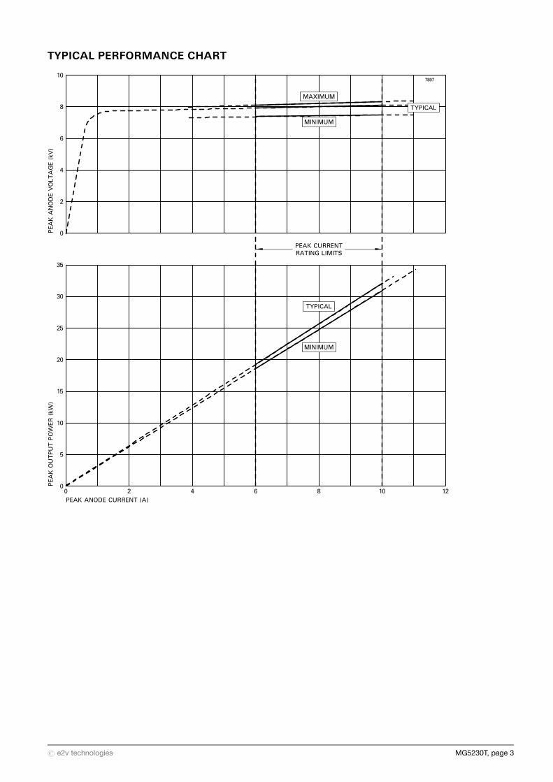
PEAKANODEVOLTAGE(kV)
PEAKOUTPUTPOWER(kW)
PEAK ANODE CURRENT (A)
PEAK CURRENTRATING LIMITS
MAXIMUM
TYPICAL
MINIMUM
TYPICAL
MINIMUM
7897
TYPICAL PERFORMANCE CHART
# e2v technologies MG5230T, page 3
W
AA
S
R
T
TO FIT 4BATERMINALS
LEADS Z LONGSEE NOTE 11
SEE NOTE 2
SEE NOTE 10
REFERENCEPLANE A
N
M L
K
Y
J
G E
F
Q
PB A
1H
REFERENCE PLANE CSEE NOTE 5 SURFACE A
SEE NOTES 2, 3 AND 4
2 HOLES 1DSEE NOTE 6
REFERENCE PLANE BSEE NOTE 9
4 HOLES 1C
SEE NOTE 8
SEE NOTE 7
SEE NOTE 1
7936
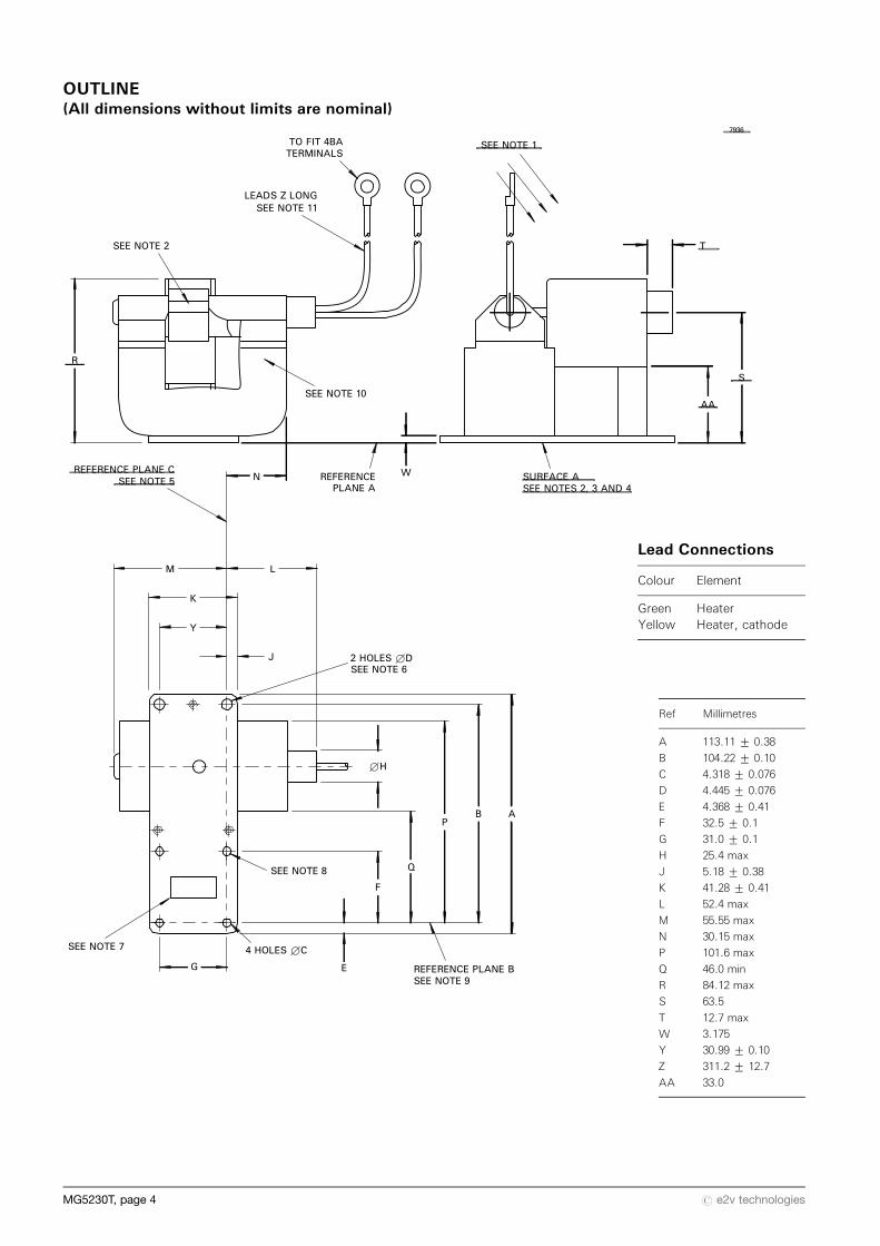
OUTLINE(All dimensions without limits are nominal)
Lead Connections
Colour Element
Green HeaterYellow Heater, cathode
Ref Millimetres
A 113.11 + 0.38
B 104.22 + 0.10
C 4.318 + 0.076
D 4.445 + 0.076
E 4.368 + 0.41
F 32.5 + 0.1
G 31.0 + 0.1
H 25.4 max
J 5.18 + 0.38
K 41.28 + 0.41
L 52.4 max
M 55.55 max
N 30.15 max
P 101.6 max
Q 46.0 min
R 84.12 max
S 63.5
T 12.7 max
W 3.175
Y 30.99 + 0.10
Z 311.2 + 12.7
AA 33.0
MG5230T, page 4 # e2v technologies
Outline Notes1. Recommended direction of air flow if required.
2. Anode temperature measured at this point.
3. With surface A resting on a flat surface plate, a feelergauge 0.51 mm thick and 3.18 mm wide will not enter morethan 3.18 mm at any point.
4. Surface A and interior surfaces of the waveguide will beplated with 1.55 mg/cm2 of gold or 4.65 mg/cm2 of silver,but will not be plated if the parts are made of monel orequivalent corrosion resistant materials. All other metalsurfaces will be painted with heat resistant paint orotherwise treated to prevent corrosion.
5. Reference plane C intersects plane B at the centre of themounting plate hole as shown and is mutually perpendi-cular to reference planes A and B.
6. These holes will lie within 0.127 mm of the indicatedcentres. A cylinder of 8.38 mm diameter and centred onthese holes will clear the side of the magnet.
7. The position of the waveguide hole is not specified on thisdrawing since tubes are tested and used with couplerUG-40B/U (NATO S.N. 5985-99-083-0051).
8. The centre of this hole will lie within 0.102 mm of referenceplane C.
9. Reference plane B passes through the centres of the twoholes of the mounting plate as shown and is perpendicularto reference plane A.
10. The north seeking pole of the magnet will be adjacent tothe cathode sidearm.
11. Length of flying leads measured from the centre line of theanode block.
HEALTH AND SAFETY HAZARDSe2v technologies magnetrons are safe to handle and operate,provided that the relevant precautions stated herein areobserved. e2v technologies does not accept responsibility fordamage or injury resulting from the use of electronic devices itproduces. Equipment manufacturers and users must ensure thatadequate precautions are taken. Appropriate warning labels andnotices must be provided on equipments incorporating e2vtechnologies devices and in operating manuals.
High VoltageEquipment must be designed so that personnel cannot comeinto contact with high voltage circuits. All high voltage circuitsand terminals must be enclosed and fail-safe interlock switchesmust be fitted to disconnect the primary power supply anddischarge all high voltage capacitors and other stored chargesbefore allowing access. Interlock switches must not bebypassed to allow operation with access doors open.
RF RadiationPersonnel must not be exposed to excessive RF radiation. AllRF connectors must be correctly fitted before operation so thatno leakage of RF energy can occur and the RF output must becoupled efficiently to the load. It is particularly dangerous tolook into open waveguide or coaxial feeders while the device isenergised. Screening of the cathode sidearm of high powermagnetrons may be necessary.
X-Ray RadiationHigh voltage magnetrons emit a significant intensity of X-raysnot only from the cathode sidearm but also from the outputwaveguide. These rays can constitute a health hazard unlessadequate shielding for X-ray radiation is provided. This is acharacteristic of all magnetrons and the X-rays emittedcorrespond to a voltage much higher than that of the anode.
Printed in England# e2v technologies MG5230T, page 5
Whilst e2v technologies has taken care to ensure the accuracy of the information contained herein it accepts no responsibility for the consequences of any usethereof and also reserves the right to change the specification of goods without notice. e2v technologies accepts no liability beyond that set out in its standardconditions of sale in respect of infringement of third party patents arising from the use of tubes or other devices in accordance with information contained herein.
Related Documents