Senior Design Project Proposal: Automated Cupcake-Making Machine MFET 480 --- Fall 2013 Erika Healy, Danielle Kunkel, David Long, Colin Tancredi, Zach Waechter, Dylan Wagner, Mike Wallyn, Chris White Submitted: Friday, December 13, 2013 1

Welcome message from author
This document is posted to help you gain knowledge. Please leave a comment to let me know what you think about it! Share it to your friends and learn new things together.
Transcript

Senior Design Project Proposal: Automated Cupcake-Making Machine
MFET 480 --- Fall 2013
Erika Healy, Danielle Kunkel, David Long, Colin Tancredi,
Zach Waechter, Dylan Wagner, Mike Wallyn, Chris White
!Submitted: Friday, December 13, 2013
!! 1

Letter of Transmittal
!December 13, 2013 !Senior MFET 480 Students Knoy Hall Room 258 !Dear Program Administrator: !!Enclosed is the Senior Design proposal for the 2013-2014 school year. This
report will detail all aspects of the project and include detailed listings of
parts needed and functionality, etc. This report will be complete with labeled
pictures and specified custom parts. We agree this project will be
completed by the specified date and fully functional for our project show
date.
!If there are any fully questions or concerns, please contact the Senior Design team in Knoy 258 or send an email to [email protected]. !Sincerely, !Erika Healy
Danielle Kunkel
David Long
Colin Tancredi
Zach Waechter
Dylan Wagner
Mike Wallyn
Chris White
!! 2

!Table of Contents
Executive summary...............................................................................................page 4
Statement of Problem...........................................................................................page 10
Proposed Solution................................................................................................page 12
Technical Descriptions
1. Robot Movements.....................................................................................page 14
2. End Of Arm Tooling...................................................................................page 16
3. Stabilizer Plate & Holder...........................................................................page 18
4. Tins & Liners.............................................................................................page 23
5. Batter Dispenser.......................................................................................page 25
6. Conveyor..................................................................................................page 27
7. Oven.........................................................................................................page 30
8. Sorting Flipper..........................................................................................page 31
9. Product Locator........................................................................................page 34
10.Icing Dispenser........................................................................................page 37
11.Sprinkle Dispenser...................................................................................page 42
12.Lids...........................................................................................................page 47
13.Final Drop Area........................................................................................page 49
14.Clean-Up Process…………………………………………………………….page 53
15.HMI Development....................................................................................page 56
16.Tracking...................................................................................................page 58
Conclusion..........................................................................................................page 59
!!
! 3

Executive Summary – Chris White
The Manufacturing Engineering Technology department of Purdue University has
requested that the students in its senior design course, MFET 480 and MFET 481,
complete a project that showcases the knowledge and skills gained in the MFET
curriculum. To accomplish this task, the students pooled different project ideas together
to determine which project best suits the skill sets of each student while also pushing
boundaries and possibly venturing into uncharted territory by including tasks that may
be unfamiliar to some. This course spans from August 19, 2013 to May 9, 2014 giving
us two semesters, or 32 weeks, to complete this project. Any proposed ideas that would
even be considered would have to adhere to this time frame. So, with all of this in mind,
it was decided that the project would be an automated cupcake line.
Why this project?
The class decided on the automated cupcake line not only because we felt that
this project fulfilled the requirements for the course but also because it sounded like fun;
we liked the idea of designing and manufacturing an assembly line that will produce
cupcakes to order. It is understood that delivering this project demands a lot of time and
effort. It will force each student to use their current skillset as well as develop new
abilities, all while working alongside others. Since we really liked the idea of a cupcake
assembly line, we will be more motivated to put in the necessary time to have an
impressive project. Whether or not we were successful in motivating ourselves to
complete this project in a timely fashion cannot be determined until the completion of
the project. We do, however, find this project very interesting, and think that it will really
“show off” the capabilities of the individuals in our MFET graduating class. ! 4

How will it work?
There is a lot that goes into this automated process as a whole; therefore, we
decided to break this process up into zones/stations. These stations consist of the
ordering station, batter station, baking, cooling/queuing station, icing station, sprinkles
station, lid station, and pick-up station. These stations all work in conjunction with each
other in order to complete the task of making cupcakes to order. Here is a brief
breakdown of each station and their individual processes.
Ordering Station
In order for the appropriate cupcake to be made, the customer will be presented
with order options. This will be accomplished using an HMI screen. The screen will
display all of the available cupcake variations that the customer can choose from. First,
it will ask “Vanilla or Chocolate Cake?” Then, “Vanilla or Chocolate Icing?” followed by a
prompt which asks “Which of the three sprinkle options would you like?” A “None” option
will also be included for the icing and sprinkles, but once the “No Icing” option is
selected, no sprinkles can be included. Once the order has been recorded, it is then
sent to a database that will store all orders. The order is then transferred to the PLC to
initiate the cupcake-making process. There will be several pre-made cupcakes in queue
so that when a cupcake is ordered, the cupcake that the customer will receive will
actually come from the cooling/queuing station. The cupcake that is being made will
actually be used to refill the void left in the queuing station by the cupcake that was just
ordered.
!! 5

Batter Station
When the process is initiated, the adept robot will use the vacuum gripper end of
arm tooling to pick up the stabilizer plate and place it on the conveyer that leads to the
oven. There will be a product stop there to keep the plate from entering the oven without
the cupcake being on it. Once the stabilizer plate is placed, a gantry will reach down into
the cupcake tin feeder and grab a tin. This tin is then grabbed by the clamp gripper of
the adept robot and transported to the gantry area where the cupcake tin liners will be
stationed. A liner will be picked up with the same type of gantry system that the cupcake
tins were picked up with, but this time the robot will position the cupcake tin directly
underneath the liner and the liner will be placed inside of the cupcake tin. Once the liner
is placed inside of the cupcake tin, the robot arm positions the cupcake tin underneath
the batter dispenser. There will be a photo eye sensor that will let the batter dispenser
know that there is an empty cupcake tin that needs to be filled. The batter then
dispenses a set amount of batter into the tin and then the tin is transported to the
stabilizer plate that is on the conveyer.
Baking Station
From the batter station, the uncooked cupcake is moved into the oven using the
conveyor. There will be a guard at the end of the conveyor leading into the oven that will
direct the cupcake to a certain spot in the oven. This will allow the cupcake to always
come out of the oven in the correct location so that cupcake handling from that point is
consistent. The oven will be heated to 325° F and the oven conveyor speed will be
adjusted to allow the cupcake to cook properly.
! 6

Cooling/Queuing Station
As the cupcakes leave the oven, the cupcake will be moved to its designated
cooling area. There will be two queuing lines, one for vanilla cupcakes and one for
chocolate cupcakes. The cupcake will be sorted and directed into the correct queuing
line. As mentioned in the ordering section, the cupcake that is being ordered is coming
from the queuing area, so when a cupcake leaves the queuing area, this cupcake will
replace it. This allows ample time for the cupcake to cool because there will be at least
4 or 5 cupcake ahead of it in the queuing line, therefore when the time comes for this
cupcake to be ordered, it will have had enough time to cool.
Icing Station
When a cupcake is released from the cooling/queuing station, it is directed to the
icing station. The cupcake is then stopped below the icing dispenser by a product
locater. This locater is used to position each cupcake in the same position below the
icing dispenser to allow for accurate dispensing. This locater is essentially a product
stop that only drops once the icing dispensing is complete. The icing will be dispensed
directly above the center of the top of the cupcake. The lift function of the lift and rotate
actuator will raise the cupcake until the nozzle of the dispenser is only a small distance
above the cupcake. This will allow the icing to only dispense in one location because
the pressure on the icing from the dispenser forces the icing to spread over the top of
the cupcake. The iced cupcake is then lowered back down to the line and the product
stop drops.
!! 7

Sprinkles Station
Once the cupcake leaves the icing station, the cupcake will enter the sprinkles
station. At the sprinkles station, there is another product locater used to position the
cupcake directly below the sprinkle dispenser funnel. The sprinkle machine will sense
with a photo eye when a cupcake is ready for sprinkles and the appropriate sprinkle
hopper will be initialized. The sprinkles will be dispensed and a hopper will catch them
and guide them to the top of the cupcake. The cupcake is then lowered back down to
the line and the product stop drops.
Lid Station
After the cupcake leaves the sprinkles station, it is then moved to the lid station.
There is yet another product locater at the lid station to position the cupcake directly
below the gantry that handles the lids. Once the cupcake arrives, the gantry grabs a lid
and positions it above the cupcake. Then the lid is placed on to the cupcake tin and
pressed onto the tin by the gantry. This will assure the lid is properly fixed to the
cupcake tin.
Pick-up Station
The final station of this cupcake-making process is the product pick-up station.
This station is where the finished cupcake is picked up by the customer and where the
stabilizer plates will be collected. There will be an extension added to the conveyer with
rollers on it to allow the cupcake to continue to roll into the pick-up area.
!! 8

!
! 9

!Statement of Problem – David Long
The MFET 480 Senior Project Class was task with developing a unique project.
This project needed to utilize the skills that we have obtained through the completion of
the MFET and MET required classes, internships, and extra-curricular projects. This
project had several decisions that needed to be decided.
The first decision of the project was to decide what product we are
manufacturing. Our team was tasked with finding a product that was commonly
acceptable. The product needed to be reasonable inexpensive.
The second decision was to determine if it was possible to create the
manufacturing process to create the product. Once the product is selected, our team
had to determine if there is a process that can be created to produce the product. This
is determine by what we can use from past projects and by what we needed to design.
The third decision is to determine how the flow of the product will take place.
Once the process of create the product is determine, the group needed to determine the
most efficient and effective flow of the product. The team needed to determine which
subassemblies connected to what other subassemblies.
The forth is to determine if all the subassemblies of the project can be assembled
and be effective. The team had to determine is any problems with connecting certain
subassemblies together. If there was any problems with any connections in the system,
then a solution need to be found.
! 10

The fifth requirement is to analyze and assess the time table of the project, to
ensure that the deadline is met. Our group had to determine all the steps needed to
complete the project in the time table, before the deadline. The team had to determine
the order and priority of each process.
The sixth is to analyze and assess the cost to and ensure that the needed
materials and products are order and received with enough time to implement in the
system. The team had to decide what products are needed to create each of the
subassemblies. The team then had to determine if the material is in stock or if the
material needed to be ordered.
These problems needed to be solved to be able to begin building the assembly
line.
!!
! 11

!Proposed Solution – Mike Wallyn
Our proposed solution is to create a fully-automated cupcake machine (shown in
Figure X). This machine will have a robot
area that has the tins and stabilizers
stacked up along with the batter
dispensers off to the side. Using the end
of arm tooling, the robot picks up a tin
and liner and places them on a stabilizer
plate. From there, the robot takes the
tin/plate and places it under the batter
dispensers, where the dispensers give out a measured amount of chosen batter. The
robot then takes the raw batter to the oven for cooking.
After cooking in the roller oven, the cupcake falls onto the line, where it is sorted
based on what type of batter it used; chocolate or vanilla. Here they will cool until a
person orders a cupcake. The drop line releases one cupcake of the correct variety to
be iced and sprinkled. Product locators at both dispensing stations ensure that the
cupcake tin and stabilizer are centered underneath the dispensers. As per customer ! 12
Figure X: Floor plan of the entire cupcake processing area.
specifications, the cupcake is iced with one of two different icing types and sprinkled
with one of three types of sprinkles.
The final step in the process is to put a lid on the cupcake. One final product stop
lines up the cupcake underneath a gantry that has a stack of lids in the center of the
drop line. The product stop drops and the completed cupcake rolls up to the final drop
area, where people can pick up their cupcake. Figure 6-1 depicts the floor plan of the
processing area.
! 13

!Robot Movements – Zach Waechter
To make a cupcake there first needs to be a tin and liner filled with batter. When
making cupcakes by hand this is done very easily and without much thought. To
automate this process a SCARA configuration robot (shown in Figure 1-1) will be
employed to simulate what will normally be done by hand. The robot will be the piece of
equipment that is in charge of placing the stabilizer plate, tin, and liner on the start of the
conveyor. The robot will also be what carries the tin to the batter dispenser in order to
get the tin filled with batter.
The first movement that the robot will
take is to pick up a stabilizer plate and
place it on the start of the conveyor. The
plate will be placed behind product stops to
ensure that it doesn’t move until the filled tin
is placed on it. The robot will use a
vacuum gripper to pick up the stabilizer plate. Once the stabilizer plate is placed on the
conveyor, the robot will switch to a different end of arm tooling. Instead of the vacuum
gripper, a clamp will be employed. It will fit around the tin to keep the tin from collapsing
in on itself. Once the end of arm tooling has been switched, the robot will move over to
where the tins are held. One of the tins should already be hanging from a vacuum.
Once the robot has closed around the tin, the vacuum will turn off. This will leave the tin
in the clamp on the end of the robot. The robot will then continue on to where the liners
are. A liner should be hanging on a vacuum, similar to how the tin was hanging. The ! 14
Figure 1-1: Epson SCARA configuration robot

robot will place the tin under the liner, and then the vacuum on the liner will be turned
off. This will result in a tin with liner being in the clamp. After the robot has the tin with
liner, it will move over and place them below the batter dispenser. Here the dispenser
will fill the tin with the desired flavor of batter. Once this has been done the tin will be
placed on the stabilizer plate that is waiting on the conveyor already. After everything
has been stationed on the conveyor, the product stop will lower allowing the cupcake to
make its way to the oven for baking.
!!!!!!!!!!!!!!
!!!
! 15

!!
End of Arm Tooling – David Long
The container needs to be assembled and transferred to a loading station then to
the first conveyor system. They system also needs to be notified if the containers are
nearly depleted. This process can be achieved by using two end of arm tooling for the
robot. The vacuum can be used to assemble the container, and the grip can be used to
move the container to the loading area and finally to the conveyor system. A sensor will
notify if the containers are getting low. The design would be similar to what is shown in
Figure 2-1.
Equipment Needed
- HAAS
- Electric Drill
Fabrication
Step 1- Cut 3 holes into 6” Bar
Step 2- Cut block into gripper design
Step 3- Connect bar to robot
Step 4- Connect vacuum to bar
Step 5- Connect rod to bar
Step 6- Connect pneumatic actuator to bar
Step 7- Connect gripper arms to pneumatic actuator
!!!
! 16
Figure 2-1

!!!
End Of Arm Tooling BOM
!
Name Description Quantit
y
Cost Supplier
Vacuum Gripper Vacuum Gripper 1 In Stock MFET Department
Proximity Switch Inductive Switch 1 In Stock MFET Department
Multipurpose 304
Stainless Steel Bar
1" x 4"x6” 1 68.91 McMaster Carr
Pneumatic Cylinder Pneumatic Cylinder 1 In Stock MFET Department
6”Bar of Stainless
Steel
6” Bar of Stainless
Steel
1 In Stock MFET Department
3/8X4 4” Bolt 1 7.54 McMaster Carr
3/8”-16 Nylon-Insert Hex
Locknuts
3 4.14 McMaster Carr
! 17
Stabilizer Plate & Holder – Chris White
Stabilizer Plate
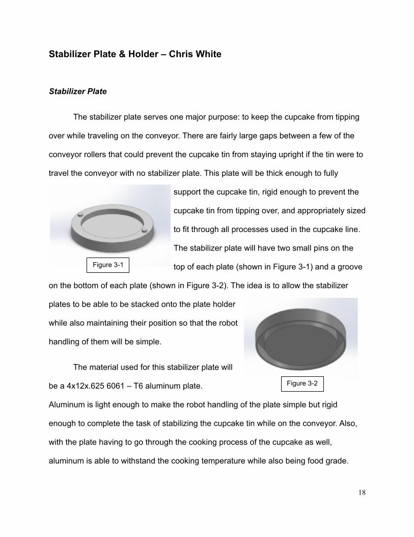
The stabilizer plate serves one major purpose: to keep the cupcake from tipping
over while traveling on the conveyor. There are fairly large gaps between a few of the
conveyor rollers that could prevent the cupcake tin from staying upright if the tin were to
travel the conveyor with no stabilizer plate. This plate will be thick enough to fully
support the cupcake tin, rigid enough to prevent the
cupcake tin from tipping over, and appropriately sized
to fit through all processes used in the cupcake line.
The stabilizer plate will have two small pins on the
top of each plate (shown in Figure 3-1) and a groove
on the bottom of each plate (shown in Figure 3-2). The idea is to allow the stabilizer
plates to be able to be stacked onto the plate holder
while also maintaining their position so that the robot
handling of them will be simple.
The material used for this stabilizer plate will
be a 4x12x.625 6061 – T6 aluminum plate.
Aluminum is light enough to make the robot handling of the plate simple but rigid
enough to complete the task of stabilizing the cupcake tin while on the conveyor. Also,
with the plate having to go through the cooking process of the cupcake as well,
aluminum is able to withstand the cooking temperature while also being food grade.
! 18
Figure 3-1
Figure 3-2

A CNC Haas mill will be used to fabricate this plate. The milling tool will be a 1/8”
high speed steel end mill. 3D SolidWorks has CAD/CAM capabilities which can be used
to program the CNC Haas mill to machine this plate. This type of aluminum can be
easily machined because of its hard nature so machining it with the Haas mill should not
be a problem.
!Stabilizer Plate BOM
!
!!
Material Description Vender QTY PriceAluminum Bar 3.25x36 6061 Aluminum McMaster Carr 2 $304.98
! 19

Stabilizer Plate Holder
The stabilizer plate holder (shown in Figure 3-4) is a simple device used to stack
the stabilizer plates in a consistent location. Essentially, this stabilizer plate holder is
made up of one long pin, two short pins, and a plate at the bottom. The two short pins
are positioning pins used to fit in the groove
on the bottom of the stabilizer plate. The long
pin will be used in conjunction with the end of
arm tooling on the robot. This pin will act as a
way to communicate to the operator that
there are no more stabilizer plates on the
holder and that they need to be refilled.
How this stabilizer plate holder will work with the robot arm is that when the robot
goes down to grab the last stabilizer plate, the long pin will touch the proximity sensor
that is attached to the robot arm and a signal will be sent from the sensor to the PLC to
inform the operator that there are no more stabilizer plates on the holder. The steps
below explain how the stabilizer plates will stack onto the stabilizer plate holder.
!!!!
! 20
Figure 3-4
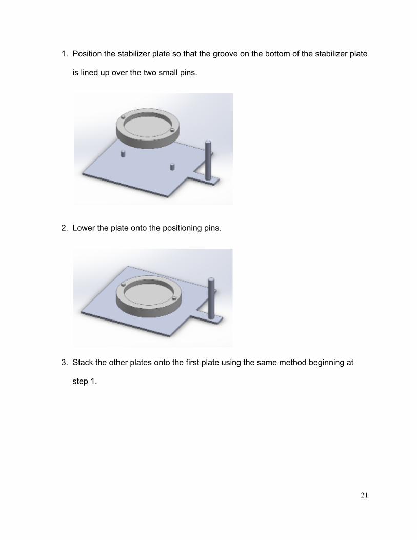
1. Position the stabilizer plate so that the groove on the bottom of the stabilizer plate
is lined up over the two small pins.
!
2. Lower the plate onto the positioning pins.
!
3. Stack the other plates onto the first plate using the same method beginning at
step 1.
! 21

!
As far as materials, this plate holder will be made using a 6x36x.125 6061 – T6
aluminum sheet and aluminum dowel pins. The aluminum sheet can have the corners
notched out and the pins can be welded to the plate or fastened. All of these materials
can be purchased online.
!Stabilizer Plate Holder BOM
!
!
Material Description Vender QTY PriceAluminum Plate 6x36x.125 6061 Aluminum McMaster Carr 1 $17.19Dowel Pins .25x1 Dowel Pins McMaster Carr 5 $9.11
! 22

Tins & Liners – Dylan Wagner
To dispense the tins we are going to use a simple
vacuum with linear actuation method. Instead of having the
vacuum mounted onto the linear action we will mount it to a
stationary plate and have the actuation move into it. This cuts
down on the amount of movement with air lines and cuts down
our chances on getting an airline pinched in the stroke.
It will work by first receiving a signal from the PLC that a
tin is needed. The vacuum will then turn on and the linear
actuator will begin to actuate. The PLC then will wait for a
signal back from a vacuum sensor located near the vacuum to
say it has latched onto a tin. The actuator will then turn off and
reverse direction so the tins will begin falling down, keeping the
latched tin on the vacuum suction device. Once a timer sets
true indicating all the tins have fallen
back down the PLC will tell the robot to
move and grab the tin. Once the
robot indicates to the PLC that it
has its grippers open and is in
position to receive the tin the vacuum of the dispenser will turn
off and the tin will fall into position on the robot end of arm
tooling. The robot PLC will then notify the robot that is has a
tin and it will begin to move to its next location.
! 23
Figure 4-1: This shows the linear actuator extending out for the tin
Figure 4-2: The upper part of the tin dispenser that contains that vacuum head for holding

The materials needed for this device are fairly short due to its non-complex
design. We will use a small aluminum plate with a 1” aluminum stock to make a simple
mount for the vacuum gripper. We will then need a clear tube of inner diameter 3-1/2”
to be able to house the tins for storage. Also needed is a linear actuator. More than
likely we will be able to use an actuator that we have already in the lab. This will make
for a quick build time and cut down on our overall time spent on this part.
! !!!!!!
! 24
Figure 4-3: The bottom part of the tin dispenser that contains the linear actuator and also the main hopper for
Figure 4-4: Shows the completed tin
dispenser assembly.

Batter Dispenser – Mike Wallyn ! The batter dispenser has a lot of limitations attached to it. It needs to be able to consistently dispense an exact amount of batter into a cupcake tin and do it with minimal mess. Also, it must be easily loadable and cleanable. And as with most every other component of our machine, the batter dispenser must be food safe.
While some ideas for a custom built batter vat were thrown around, a premade automatic pancake batter dispenser turned out to be the most effective solution to dispense batter, as shown in Figure 5-1. The dispenser works by adjusting the knob for the appropriate dispense amount, then pushing down on the piston to dispense the batter.
Two of these “cupcake” batter dispensers will be mounted in a simple metal cradle that will hold them in place in the robot area. Underneath each dispenser will be a photo eye that will be able to detect when the robot places a cupcake tin underneath one of the dispensers. The photo eye will trigger a linear actuator mounted to the dispenser that will dispense the batter into the tin, after which the robot will take the batter and tin to the oven for cooking. Figure 5-2 shows a rough model of the entire assembly.
!Batter Dispenser BOM
Material Description Vendor Quantity
Price
Pancake Batter Dispenser
WINCO 2 $73.75 ea.
Photoeye Rockwell Automation
2 $0
CQ2B 12-100DC Z Linear Actuator
SMC 2 TBD
! 25
Figure 5-1: The Pancake Batter Dispenser

!Potential Problems:
• Robot misses the photo eye
• Wrong dispenser dispenses
• Spillage
• Cupcake tin doesn’t trip the dispensers
!Solid Model:
12x108 T-304 Stainless Steel
McMaster-Carr 2 $165.48 ea.
! 26

!
!
! 27
Figure 5-2: Complete Batter Dispensing Assembly. Note that the drawing will be updated when exact
measurements are obtained.

!Conveyor – Danielle Kunkel
The conveyor is a critical component for transferring the uncooked cupcake,
which is on the stabilizer plate, to the oven. A mockup of the conveyor is shown in
Figure 6-1. The conveyor is motor driven. The stabilizer plate is put onto the conveyor.
The photo eye on the conveyor will sense that the stabilizer plate is there, telling the
product stop to push up. This allows for the filled cupcake tin to be put on the stabilizer
plate that is already on the conveyor. After the stabilizer plate and cupcake are all set,
the product stop can be released, allowing the arrangement to move forward along the
line. When the stabilizer plate and cupcake get to the end of the conveyor there is a
decline into the oven, which allows for a smooth transfer.
!Potential Problems:
• Conveyor doesn’t move
• Stabilizer plate and cupcake fall off of conveyor
• Product stop doesn’t stop cupcake or goes up too quickly
• Cupcake gets stuck on conveyor
• Cupcake doesn’t transfer to oven properly
!Required Equipment:
• Conveyor Rollers (we have old ones to refurbish)
• Motor
• Conveyor Belts
• Photo Eye
! 28

• Product Stop
• Misc. Hardware
!!
!
! 29
Figure 6-1

!!!
Conveyor BOM
!
Material Description Vender Qty Price
Photo eye Photo eye Rockwell
1 $0
Product Stop Refurbished ones Purdue 1 $0
Conveyor Rollers
Refurbished ones Purdue 1 $0
Conveyor Belts High-Performance Urethane Flat Belts, 3/4"
Width, 5/8" Min Pulley Diameter
McMaster Carr
2 $31.62
Motor DC Motor, Square Flange Face-Mount,
24VDC, 1/10 hp, 4200 rpm
McMaster Carr
1 $142.99
80/20 Barstock 80/20 Barstock 1.5” 80/20 inc
20ft $0
Aluminum Sheet Metal
Multipurpose 6061 Aluminum, Sheet, .125"
Thick, 36" x 36"
McMaster Carr
1 $164.34
! 30

!Oven – Dylan Wagner
The oven (shown in Figure 7-1) is the heart of this cupcake machine. That being
said, there needs to be extensive research done on what needs to be done with the
wiring and set up of the oven. According to the 2012-2013 senior design group, the only
thing that needs to be fixed is switching the
controls back to control voltage and not the
high voltage it’s at. We will need to look at the
wiring for the conveyor motor and see if we
can swap the leads to switch the direction of
the motor. If the leads cannot be swapped we
will need to physically turn the oven 180
degrees so that it is feeding into the cage
instead of the current set up (feeding out.)
As far as the temperature control is concerned, the oven was able to heat up
to over 400+ degrees last year so we should be able to find a happy medium and pair it
with a good conveyor speed to create a perfect cupcake.
!
! 31
Figure 7-1

!Sorting Flipper – Danielle Kunkel
The current design of our layout will allow for two different flavors of batter, vanilla
and chocolate. After the cupcake comes out of the oven it is essential that it is put in the
correct lane of the conveyor, this is possible by the flipper. For example, when the
vanilla cupcake comes out of the oven and onto the conveyor the flipper will turn a
certain amount of degrees to allow the cupcake to go into the correct line as shown in
Figure 8-1. If the next cupcake would happen to be a chocolate cupcake that comes out
of the oven and onto the conveyor, the flipper will turn a certain amount of degrees to
allow the cupcake to go into the correct line as shown in Figure 8-2. The flipper’s turning
is possible by a rotary actuator (see Figure 8-3).
!Potential Problems:
• Flipper turned the wrong way
• Flipper not turned enough
• Cupcake getting stuck on conveyor
!Required Equipment:
• SMC NC(D)RA1*50-100 rotary actuator
• Misc. mounting
• Airlines
• Flipper
• Aluminum Rod
! 32

!
! 33

!
!
!
!!!
! 34
Figure 8-1
Figure 8-2

!
!
!!
Sorting Flipper BOM
!!
Material Description Vender Qty Price
Rotary Actuator NC(D)RA1*50-100 rotary actuator
SMC 1 tbd
Aluminum Rod Multipurpose 6061 Aluminum Rod, 1"
Diameter, 3' Length
McMaster Carr
1 $35.17
Aluminum Plate Multipurpose 6061 Aluminum, 1 1/2" Thick,
12" x 12"
McMaster Carr
1 $114.58
! 35
Figure 8-3

!Product Locator – Zach Waechter
The main purpose of the product locator is to ensure
that the product (cupcake) comes to rest in a consistent
location every pass. Since the stabilizer plate is of a circular
construction, to locate it consistently two points of contact will
be used. The product stops will be built so that just two
points hit on the circle. This will make the product be self-
centering. This can be seen in Figure 9-1.
The construction of the product stop will start with a 3.5” wide adapter plate. The
adapter plate will be the physical piece that attaches to the actuator. To the adapter
plate, two smaller plates, the bolt holding plates, will be fastened to the ends. These
bolt holding plates will be 1” by 2.5”. These plates
will provide the length needed to raise the bolts
between the conveyor rollers. The bolts that actually
touch the stabilizer plate will be 3” long. They will be
adjustable by just varying the amount they are
screwed into the bolt holding plates. The bolts will
be 3/8” in diameter. The completed construction
can be seen in Figure 9-2.
The current construction of the product stops on the pizza line is of a very similar
construction. This means that only minor alterations will be needed. The only difference
between them and the ones we will need is length. The ones currently employed are 8”
! 36
Figure 9-1: Product locator mated with Stabilizer Plate
Figure 9-2: Completed product stop

long. This is far too wide and the stabilizer plate will slide right between them. SO by
shortening them to just 3.5” it will ensure that the stabilizer plate contacts the stops
instead of sliding between the bolts. The smaller size will also ensure that two of them
can be implemented side-by-side. This is an important feature as there will be a time
when there are going to be two lines of cupcakes running next to each other. Each line
will need its own product stop in order to keep the cupcakes organized.
There are several different issues that could possibly arise from this construction.
One being that the length of the bolts interferes with the running of the product stop. If
the bolts are too short they will fail to stop the product, and if they are too long then the
bolts will stop the product even when they are retracted. This can be overcome by
altering the length of the bolts if the problem does occur. Another problem may be that
if when the products are run side by side the actuators themselves are too wide to be
placed under the line. This can be overcome by staggering the product locators so that
there is extra room to place the actuators.
Product Locator BOM
Part Name Description Quantity Price
Actuator Lifting Mechanism 1 per product stop TBD
Adapter Plate Metal plate 3.5” x 1.2” x 0.5” 1 per product stop TBD
Bolt Holding Plate Metal Plate 1”x2.5”x0.2” 2 per product stop TBD
! 37

!Bolts ⅜” bolt 3” long 2 per product stop TBD
! 38

!Icing Dispenser – Colin Tancredi
Each customer will have the choice to add icing to their cupcake or not. Should
they not want icing, this step will be skipped altogether for that individual cupcake. But
for those who wish to have the cupcake iced, the following process will be followed:
In order to apply a desirable amount of icing onto each cupcake, the lift
mechanism of the lift-and-rotate actuator on the drop-line will be used. Above this
mechanism, we will fix a 6 inch stainless-steel cylindrical tube, closed on the bottom
(except for a small opening for the pastry bag nozzle to escape), with a circular
depressor on the top end to be attached to a linear actuator. As mentioned, attached to
the icing bag will be a star-shaped metal icing nozzle. The nozzle will be held in place in
the cylinder using a tapered rubber grommet around the opening in the bottom of the
cylinder. This ensures consistent location of the nozzle-end. There will be two identical
stations in series, one with vanilla, and the other with chocolate.
Possible Errors:
• Air pockets in icing bag
• Cupcake location inconsistencies
• Leaking icing bag/breaking bag
• Nozzle movement
• Cupcake falling off ‘Lift & Rotate’ platform
!!!
! 39

!How it works:
1. Cupcake and stabilizer plate will approach lift and rotate mechanism.
!
!2. Stops will locate cupcake to proper position; photo eye senses cupcake present,
lift initiates.
!
!! 40

!3. Linear actuator will press depressor plate against icing bag to squeeze icing out
nozzle.
!
!4. Just before the actuators motion is complete, the cupcake and plate will be
lowered back down to line, creating the desired effect.!
! !
! 41

5. Stops will drop and cupcake will move onto sprinkle station.!
!
!Icing Dispenser BOM
Part Name Quantity Price Vendor
6 inch diameter stainless-steel
tubing,
1 foot long
2 Total (1 per icing station)
$222.13 McMaster.com
Pastry bags 1 pack of 100 $6.99 Ebay.com
Pastry nozzle assortment
1 set of 24 pcs $9.99 Ebay.com
Thomson Electrak 1 Linear Actuator
2 $300-$400
(depending on model available)
Thomsonlinear.com
Aluminum bar stock Varies $200-$300 (in lab)
Vanilla Icing 1 Tub $59.95 Thebakerskitchen.net
! 42

!!
Chocolate Icing 1 Tub $59.95 Thebakerskitchen.net
ESTIMATED TOTAL: $1060.00
! 43

Sprinkle Dispenser – Erika Healy
The sprinkle dispensing station is designed to dispense sprinkles onto an iced
cupcake. Once the cupcake has been decorated with the appropriate icing, the
conveyor will move it to the sprinkle station. The cupcake will be stopped and located by
product stop pins. A photo eye sensor on the underside of the funnel will sense when a
cupcake is under it and the appropriate sprinkles corresponding to that order
(determined by tracking) will be dispensed. As shown in Figure 11-1 and Figure 11-2,
this machine was designed to funnel the three different sprinkle types to one centralized
location where the cupcake will stop every time it needs sprinkles. The logic behind this
design is to ease programming because the cupcake will always stop in one spot and
initialize tracking to fetch the appropriate sprinkles as oppose to using three sensors to
sense which sprinkles the cupcake needs. The outlet at the tip of the funnel is sized so
that the sprinkles will evenly distribute among the cupcake and not end up in one
concentrated area.
! 44Figure 11-1 Figure 11-2

The design of the individual sprinkle hopper consists of three tubes and a rotary
actuator. Figure 11-3 shows a solid model and Figure 11-4 shows hidden lines. The
middle of the three tubes rotates while the top and bottom remain stationary. The
hopper will be filled with sprinkles from the top and the top tube will act as the holder.
Once the appropriate sprinkles are identified, the rotary actuator will rotate the middle
tube of the corresponding hopper 180 degrees which will align the hole in the hopper
with the hole in the middle tube and allow sprinkles to fall and fill the hollow tube of the
middle tube. The rotary actuator will then rotate back to its original position, allowing the
sprinkles to fall out and down the slide that lets out directly over the cupcake.
!!!!!!!!!!!
! 45Figure 11-3 Figure 11-4

!Figure 11-5, Figure 11-6, Figure 11-7 (shown below) show the entire sprinkle
dispenser from different angles. Each hopper will be held in the fixture with set screws
screwed through the sides of the fixture to hold the hoppers centered in place.
! 46
Figure 11-5: full front view of the sprinkle machine
Figure 11-6: angled front view Figure 11-7: angled back view

There will be three options for sprinkles: chocolate sprinkles, rainbow sprinkles, and pink sprinkles. The sprinkles will be purchased in a 3-pack bundle from CK Products Jimmies for $34.09 for three 16-ounce bags (see Figure 11-8). Based on the assumption that a total of 1,000 cupcakes will be baked and each cupcake will need 0.2 ounces of sprinkles, roughly 3 bundles will be purchased for a total of 3 pounds of each option of sprinkles.!
!!!!
!!
Sprinkle Dispenser BOM
!
Potential Problems:
- Jamming/Clogging
- Sprinkles landing around instead of on the cupcake
- Sprinkles only fall on a small concentrated area of the cupcake
!! 47
Figure 11-8

Lids – Zach Waechter
The problem addressed by this section
is how to put the lids on the finished cupcake.
In order to attach the lids to the finished
product, a gantry robot (shown in Figure 12-1)
will be implemented. The robot will have a
stack of lids on one side of the conveyor belt.
It will go over to the stack of lids, and using
suction, will pick up one of the lids. If static
affects the number of lids that the robot picks up, then a brush will be attached to the
top of the lid holder in order to keep from picking up more than one lid at a time. The
robot will then take the lid over to where the finished product is waiting behind a product
stop. The robot will know that the product is waiting for the lid to be attached by a photo
eye. The photo eye will be just before the product stop. The cupcake will cover the
photo eye telling the gantry robot to lower a lid. It will seal the lid by pressing it down.
The end of arm tooling used by the gantry will be a
hollowed out cylinder as can be seen in Fig 12-2. It will
seal the lid by pressing on just the edges. As the robot
presses on the lid, the vacuum gripper will slide back inside
the end of arm tooling and then release the lid. The
finished product will then carry on and the gantry robot will
pick up another lid and wait for the next finished product.
! 48
Figure 12-2: Underside of end of arm tooling.
Figure 12-1: Picture of complete gantry robot

The majority of the materials needed to build this robot will be from PHD. The
horizontal slide will have 1000mm of travel, and the vertical travel will be 300mm. There
will also be 20” tall supports. The entire list of parts are as follows: horizontal gantry
axis 1000mm travel, vertical gantry axis 300mm travel, SFM to SK adapter kit, 20” tall
double stanchion mounting base, a baseplate, and a few switches. The other materials
needed are a 2” tall piece of pipe with a 2” diameter. A piece of pipe .5” in diameter to
be fastened to the top of that and a 1” adapter plate 1/8” thick to be fastened on the end
of the smaller pipe. The adapter plate will be what actually screws to the gantry
assembly.
The problems that may arise during the construction and running of the gantry
robot have a lot to do with clearance issues. If the height of the legs that hold up the
gantry are not the right length, the lid may either not reach the cupcake tin or may crash
into the side of the cupcake. Also the gantry must be wide enough to span across the
conveyor belt. If not adjustments will have to be made. Another possible error that
could arise is if the supply of lids runs out. The end of arm tooling will know it has a lid
by a vacuum sensor. If there are no lids available the bottom of the end of arm tooling
will hit before that vacuum sensor and let the operator know that the lids need to be
refilled.
!
! 49

!Final Staging Area – David Long
The problem is to create
a mechanism that can transport
the product off the conveyor
system and allow for retrieval of
the product by the consumer.
The solution to this problem is to
create a ramp with rollers to slide the cupcake off of the conveyor. The cupcake then
reaches an open ended holder; this will allow the consumer to retrieve the cupcake that
the individual ordered. The design in figure 13-1 demonstrates how this ramp may look
like. Final Staging Area BOM
!
!
Name Description QTY COST SUPPLIER
Multipurpose
304 Stainless
Steel SHEET
.120" Thick, 12"
x 24"
1 $54.92 McMaster Carr
Conveyor
Rollers
Conveyor
Rollers
2 In Stock MFET Department
! 50
Figure 13-1
Figure 13-1

Equipment Needed
• HAAS
• Electric Drill
• Band Saw
• Arc Welder
Fabrication
!Step 1- Cut the four 3” strips of sheet
metal
Step 2- Cut hole in specified strips for
rollers per figure 13-2
Step 3- Take off back plastic wall
Step 4- Take off back brace
Step 5- Cut the back black to even out
the top
Step 6- Cut the 5 holes in back brace
per figure 13-3
Step 7- Cut 12X6 Hole in plastic wall
Step 8- Cut 3 holes into the bottom plate
per figure 13-4
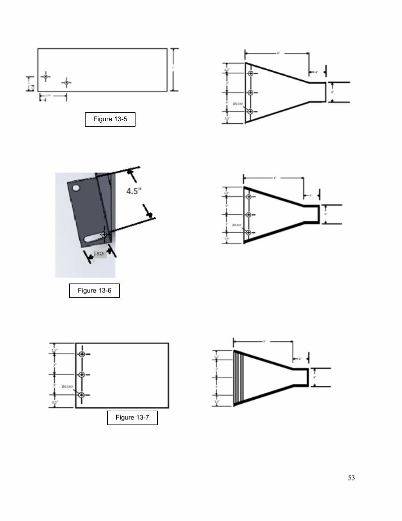
Step 9- Cut bottom to the specified
shape per figure 13-5
Step10- Weld the four 3” strip in
specified areas to form a Y shape per
figure 13-6
Step 11- Clean up the ramp and take off
edges
Step 12- Install rollers into sloped ramp
per figure 13-7
Step 13 – Reinstall Back brace in new
down slope position
Step 14- Reinstall back plastic wall
! 51

Step 15- Use three brackets to connect
back brace to sloped ramp
Step 16- Modify if necessary
!
! 52
! 53
Figure 13-5
Figure 13-6
Figure 13-7

!Clean-Up Process – Chris White
Because there are so many components on this cupcake line, the cleaning of
each station is essential. Each station that incorporates food products needs the most
attention as we need to keep this line in accordance with FDA regulations. Any time the
cupcake line is used, cleaning needs to take place immediately after use in order to
make cleaning easier and to allow for a quick start-up the next time the line is used.
Each station of this line has its own cleanup procedure and will be explained below.
Batter Station
This station has the potential to be the messiest station of the whole line;
therefore, the cleaning of this station is essential. The batter will be dispensed from bad
inside of the dispenser, so when the cupcake line is not running the bags should be
removed to check for possible batter residue inside of the dispenser. The dispenser can
be wiped down with a cloth and water and should be done immediately following the
use of the line to prevent batter build up. The dispenser nozzle should be wiped off
inside and out because the batter dispenses through the nozzle so there could be caked
up batter that needs to be removed. Also, the area directly beneath the dispenser
nozzle should be wiped down in instances where batter may have continued to
dispensed or dripped extra batter.
Icing Station
The icing station should be cleaned in a similar fashion as the batter station. The
icing is dispensed from a bag inside of the dispenser, so in order to clean the inside of ! 54

the dispenser, the bag must first be removed. The inside of the dispenser is to be wiped
down, with a cloth and water, to get rid of possible icing residue that may have been left
behind by the icing bag. Also the dispenser nozzle should be wiped do to prevent icing
build up inside of the nozzle. Directly below the nozzle is also a problem area that
should be cleaned because dispenser could dispense extra icing or even possibly drip
icing onto the lift and rotate platform.
Sprinkles Station
The sprinkles station also has the potential to be a very messy station because
depending on how well the sprinkles are dispensed, sprinkles could go everywhere.
There will be a tray underneath the conveyer positioned beneath the sprinkles
dispenser. This tray will attempt to catch any sprinkles that miss the cupcake. The tray
should be emptied and wiped down after each use of the cupcake line or if it is full to
prevent overfilling.
Pick-up Station
The pick-up station doesn’t really run the risk of having different food items
dispense there but there will be several stabilizer plates that will gather in this area.
These plates can simply be gathered and removed from this area during and after the
use of this cupcake line. These plates can then be set to the side until they need to be
placed on the stabilizer plate holder.
!!
! 55

!Overall Cleaning
Because this cupcake line needs to be food grade, everything has to be wiped
down to prevent dust or food build-up. Any moving piece of equipment needs to be
properly lubricated as need.
!
! 56

HMI Development – Dylan Wagner
The HMI’s will play a huge role in our process. The PanelView Plus 1000 (shown
in Figure 15-1) will be used solely for the purpose of ordering and system control. The
Versa View CE 1500H will be used for the purpose of tracking and being able to watch
where a customer’s cupcake is located
within the system.
The PanelView Plus 1000 will be
mounted inside a control box with other
various push buttons and safety
overrides. Here we will be able to control
all our systems needs and we will be able
to put the system into auto or manual,
and also control our maintenance
activities. The maintenance activities we
will be able to control include manual
reloading of all our hoppers and feeders,
clearing jams, possible over temperature
overrides, whole system manual/auto.
This panelviews features will be locked
so that only authorized members will be allowed to change settings within the system.
Also within the PanelView 1000 we will be able to control the ordering system. Here is
where we can change any tracking information that might not have been put in by the
user correctly.
! 57
Figure 15-1: PanelView Plus 1000 located in control box. It is used to control the system and input orders.

The VersaView CE 1500H (shown in Figure 15-2) will be used primarily as a
tracking screen. This will notify users when there cupcake is done and will show them
where the cupcake they selected is currently in the system. Depending on how much
time we have extra this
could also be used in the
ordering process. That way
the back area wouldn’t be a
cluttered and it would allow
us to easily be able to
process 2 orders at a time.
Being that these two
panelviews are already
wired into the system we will
not have to spend much time in the actual hardware of the system. We will be able to
jump into the software and start programming these right away.
!
! 58
Figure 15-2: VersaView CE 1500H

!Tracking – Dylan Wagner
The tracking idea that we are going to implement is one that is used in many car
plants throughout the country. It uses a method of synchronous copy statements
activated by a sensor indicating the palate made it to the next station. The data will be
stored in user defined data types and the information held will included; Name of
customer, type of cupcake (Choc or Vanilla), type of icing, and finally selection of
sprinkles. Also we will include an option for “To Go.” If this option is chosen the user’s
cupcake will receive a lid for easy on the go transportation. The tracking system will be
completely run from the processor but will be displayed thru the HMI. Any changes to
the data must be made by an authorized user. This style of tracking will assume a clean
transfer of data from the previous station. We believe this method will assure us the
easiest tracking method with the equipment provided.
!!
! 59

Conclusion – Mike Wallyn
While our senior design project’s main focus is to build a machine that brings
together what we have learned about manufacturing automation, our final design for the
automated cupcake machine includes a great deal of consideration towards cost, while
maintaining simplicity wherever we can. For example, rather than have a complex,
home built batter dispensing system, we opted instead for purchasing a pancake batter
dispenser. This tool is relatively inexpensive and solves multiple problems that arose
while designing a custom built batter dispenser, namely repeatability of dispensing and
the correct amount of batter to dispense with minimal mess. In other cases, we went
with designs that have been tested and proven on other projects like senior design
projects or old Automation Fair machines, such as incorporating the jelly bean
dispensing process into our plan for how we dispense the sprinkles onto the cupcake.
Nevertheless, we are still attempting to push the envelope by having an online ordering
system where people can remotely order up their cupcakes.
One of our biggest concerns for this project was making sure that anything that
needed to be fabricated, wired, programmed, etc. was done by us. We've learned a
great deal in the courses leading up to our project and we wanted to take advantage of
that knowledge as much as possible. Having someone else do the wiring or fabricating
for us is a complete waste when most of us already have that know-how.
All told, our primary goal of bringing our acquired knowledge together to produce
a manufacturing assembly line will be a huge success. We’ve managed to incorporate
PLCs, Robots, HMIs, and internet connectivity into our machine. Not only that, we’ve
managed to keep costs down as much as possible while still creating an effective ! 60

machine. We feel that we have effectively met every requirement put forth for this
project and met it satisfactorily.
If you have any questions, comments, or concerns, feel free to contact any one of us:
Erika Healy......................................................................................emhealy@purdue.edu
Danielle Kunkel................................................................................dkunkel@purdue.edu
David Long........................................................................................long15@purdue.edu
Colin Tancredi................................................................................ctancred@purdue.edu
Zachary Waechter........................................................................zwaechte@purdue.edu
Dylan Wagner.................................................................................wagnerdpu@live.com
Michael Wallyn...............................................................................mwallyn@purdue.edu
Chris White....................................................................................white113@purdue.edu
! 61