or Ur a l I Enquiry WM tell yeNo Oirif / BHARAT HEAVY ELECTRICALS LIMITED UAW/ &KR WI& / Transmission Business Group 1 , 1717t 111(11R / Materials Management Project PGCIL 765 KV SOLAPUR Commercial Technical Signing Enquiry No Enquiry Date Rev No Rev Date PI No Enquiry Type Inspection by Due Dt Comments Comments Authority 7002000483 11-Feb-20 0 7012000551 Package 25-Feb-20 RAJEEV KUMAR ROY 14 SUPPLY- VISUAL MONITORING SYSTEM/CCTV FLEXIBLE 25MM GI CONDUIT FOR CAT 6 CABLE AND POWER CABLE FOR ALL CAMERAS. Esuilamentattoil SN Equipment 1 SUPPLY- VISUAL MONITORING SYSTEM/CCTV FIBER DUPLEX PATCH CORD, 2 METER 2 SUPPLY- VISUAL MONITORING SYSTEM/CCTV LIU (12 PORT) 3 SUPPLY- VISUAL MONITORING SYSTEM/CCTV LIU ( 06 PORTS) 4 SUPPLY- VISUAL MONITORING SYSTEM/CCTV : JUNCTION BOX 5 SUPPLY- VISUAL MONITORING SYSTEM/CCTV : PTZ CAMERA-OUTDOOR 6 SUPPLY- VISUAL MONITORING SYSTEM/CCTV : CAMERA HOUSING 7 SUPPLY- VISUAL MONITORING SYSTEM/CCTV : VIDEO MONITORING SOFTWARE 8 SUPPLY- VISUAL MONITORING SYSTEM/CCTV : 600VA UPS 9 SUPPLY- VISUAL MONITORING SYSTEM/CCTV : MOUNTING HARDWARE FOR VMS CAMERA ON EXISTING STRUCTUE 10 SERVICES- VISUAL MONITORING SYSTEM/CCTV : DESIGN OF VISUAL MONITORING SYSTEM INCLUDING VMS LAYOUT, DETAILED CABLE SCHEDULE & DETAILED BILL OF QTY. 11 SERVICES- VISUAL MONITORING SYSTEM/CCTV : TESTING, COMMISSIONING AND SUPERVISION OF ERECTION OF VMS SYSTEM AT SITE 12 SUPPLY- VISUAL MONITORING SYSTEM/CCTV : FIBER OPTIC CABLE (6 CORE) ARMORED, SINGLE MODE 13 SUPPLY- VISUAL MONITORING SYSTEM/CCTV : CAT 6 CABLE (SHIELDED TWISTED PAIR - STP) BETWEEN CAMERA AND MEDIA CONVERTOR 15 SUPPLY- VISUAL MONITORING SYSTEM/CCTV : POWER CABLE (3CX2.5 SQ.MM) UNARMORED WITH TERMINAL CONNECTORS AND NECESSARY MOUNTING HARDWARE ON WALL / CEILING 16 SUPPLY- VISUAL MONITORING SYSTEM/CCTV : 25 MM DIA. HDPE PIPES FOR LAYING OF FIBER OPTIC CABLE 17 SUPPLY- VISUAL MONITORING SYSTEM/CCTV : MEDIA CONVERTOR- INDUSTRIAL GR HSN Code Phy Unit Plan Qty Dt Comments 0 NO 3.0000 0 NO 1.0000 0 NO 1.0000 0 NO 1.0000 0 NO 1.0000 0 NO 1.0000 0 NO 1.0000 0 NO 1.0000 0 NO 1.0000 0 LOT 1.0000 0 LOT 1.0000 0 MTR 1150.0000 0 MTR 20.0000 0 MTR 20.0000 0 MTR 20.0000 0 MTR 1133.0000 0 PAIR 1.0000 Instructions to Bidders You are requested to submit your most competitive offer so as to reach us positively by the tender opening date & time. THE TENDERS NOT RECEIVED WITHIN SCHEDULED DATE AND TIME ARE LIKELY TO BE IGNORED. BHEL shall not be responsible for any postal delay. In your own Interest, you are advised to carefully read "the Instructions to bidders". Incomplete bids and/or bids not complying with tender conditions shall be treated as non- responsive and are likely to be ignored. In case Tender Documents are not received within 7 days of this E-mail message, Intimate BHEL accordingly. If no intimation is received, it will be considered that you have received tender enquiry and delay in submission offer due to late receipt of tender documents will not be entertained. You are requested to submit your most competitive offer as stated In Terms & conditions. BHEL reserves the right to opt for reverse auction for obtaining beat prices. Offers Through E-MAIL / FAX I E-Procurement Portal:WHOSOEVER DESIRES TO SEND OFFERS ON THEIR OWN RISK (COMPLETE IN ALL RESPECTS) VIA E-MAIL or FAX HAVE TO SEND THE OFFERS TO THE COMMON E-MAIL ADDRESS tenderbox@hketh or 0120.6748581 FAX or bhel.abc.procure.com as instructed.THE RECEIVED EMAIL OFFERS WILL BE PRINTED BY PURCHASE COORDINATOR AND PUT THEM INTO COVERS AS PER CONVENTIONAL METHOD FOR TENDER OPENING I.E., TECHNO COMMERCIAL & PRICE OFFER SHALL BE PUT INTO TWO SEPARATE COVERS AND BOTH THE COVERS ARE KEPT IN THIRD COVER DULY SUPER SCRIBING ENQY. NO. AND DUE DATE. OFFERS SENT TO ANY OTHER E-MAIL ID or FAX NO AND INCOMPLETE OFFERS SHALL NOT BE CONSIDERED FOR EVALUATION PURPOSE.ThekirOhders who has sent offers with password,the passwords are to be forwarded to email id:tenderbox@bhelln it(.°'CO C 1.1)) 1 , P. c , It is suggested that the bidders are advised to send the files with 'password protection'. 1 ( 2 .g'' .,2A9 e. pis: ' eel t 0 (--,,"‘ . ...tku )1 „Po „ , o n c,; te"1 "- : 1 7 °140 ' ..4.... !cCio —(064- --. Z' - we' - - 4 1;6 : t cr4 , ‘ ) 1 ,` '''''°--■ -, -' r ' ,. ( e‘.-- - 4 . 1/4- , -, p-, , - Nco'' g - - 4 e r f.r. , il e *. s . :„. .. :, ,,,,,, --..t-s‘ e ,,.A 6 ,.,,,„„ 0.„,x ,,-„„mf ,..., for BHARAT HEAVY ELECTRICALS LTD f elk .A . , A,N , l '' v-e epo -coss- Ata 0°0 1, se ,00 50 0.1 , ook-

Welcome message from author
This document is posted to help you gain knowledge. Please leave a comment to let me know what you think about it! Share it to your friends and learn new things together.
Transcript
or
Ural I Enquiry WM tell yeNo Oirif / BHARAT HEAVY ELECTRICALS LIMITED UAW/ &KR WI& / Transmission Business Group 1,1717t 111(11R / Materials Management
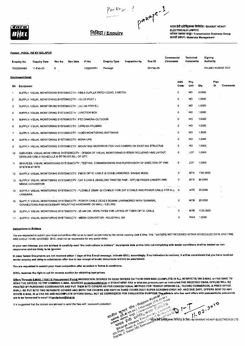
Project PGCIL 765 KV SOLAPUR
Commercial Technical Signing
Enquiry No Enquiry Date Rev No Rev Date PI No Enquiry Type Inspection by Due Dt Comments Comments Authority
7002000483 11-Feb-20 0
7012000551 Package
25-Feb-20 RAJEEV KUMAR ROY
14 SUPPLY- VISUAL MONITORING SYSTEM/CCTV FLEXIBLE 25MM GI CONDUIT FOR CAT 6 CABLE AND POWER CABLE FOR ALL
CAMERAS.
Esuilamentattoil
SN Equipment
1 SUPPLY- VISUAL MONITORING SYSTEM/CCTV FIBER DUPLEX PATCH CORD, 2 METER
2 SUPPLY- VISUAL MONITORING SYSTEM/CCTV LIU (12 PORT)
3 SUPPLY- VISUAL MONITORING SYSTEM/CCTV LIU ( 06 PORTS)
4 SUPPLY- VISUAL MONITORING SYSTEM/CCTV : JUNCTION BOX
5 SUPPLY- VISUAL MONITORING SYSTEM/CCTV : PTZ CAMERA-OUTDOOR
6 SUPPLY- VISUAL MONITORING SYSTEM/CCTV : CAMERA HOUSING
7 SUPPLY- VISUAL MONITORING SYSTEM/CCTV : VIDEO MONITORING SOFTWARE
8 SUPPLY- VISUAL MONITORING SYSTEM/CCTV : 600VA UPS
9 SUPPLY- VISUAL MONITORING SYSTEM/CCTV : MOUNTING HARDWARE FOR VMS CAMERA ON EXISTING STRUCTUE
10 SERVICES- VISUAL MONITORING SYSTEM/CCTV : DESIGN OF VISUAL MONITORING SYSTEM INCLUDING VMS LAYOUT, DETAILED CABLE SCHEDULE & DETAILED BILL OF QTY.
11 SERVICES- VISUAL MONITORING SYSTEM/CCTV : TESTING, COMMISSIONING AND SUPERVISION OF ERECTION OF VMS
SYSTEM AT SITE
12 SUPPLY- VISUAL MONITORING SYSTEM/CCTV : FIBER OPTIC CABLE (6 CORE) ARMORED, SINGLE MODE
13 SUPPLY- VISUAL MONITORING SYSTEM/CCTV : CAT 6 CABLE (SHIELDED TWISTED PAIR - STP) BETWEEN CAMERA AND
MEDIA CONVERTOR
15 SUPPLY- VISUAL MONITORING SYSTEM/CCTV : POWER CABLE (3CX2.5 SQ.MM) UNARMORED WITH TERMINAL CONNECTORS AND NECESSARY MOUNTING HARDWARE ON WALL / CEILING
16 SUPPLY- VISUAL MONITORING SYSTEM/CCTV : 25 MM DIA. HDPE PIPES FOR LAYING OF FIBER OPTIC CABLE
17 SUPPLY- VISUAL MONITORING SYSTEM/CCTV : MEDIA CONVERTOR- INDUSTRIAL GR
HSN Code
Phy Unit
Plan Qty Dt Comments
0 NO 3.0000
0 NO 1.0000
0 NO 1.0000
0 NO 1.0000
0 NO 1.0000
0 NO 1.0000
0 NO 1.0000
0 NO 1.0000
0 NO 1.0000
0 LOT 1.0000
0 LOT 1.0000
0 MTR 1150.0000
0 MTR 20.0000
0 MTR 20.0000
0 MTR 20.0000
0 MTR 1133.0000
0 PAIR 1.0000
Instructions to Bidders
You are requested to submit your most competitive offer so as to reach us positively by the tender opening date & time. THE TENDERS NOT RECEIVED WITHIN SCHEDULED DATE AND TIME
ARE LIKELY TO BE IGNORED. BHEL shall not be responsible for any postal delay.
In your own Interest, you are advised to carefully read "the Instructions to bidders". Incomplete bids and/or bids not complying with tender conditions shall be treated as non-
responsive and are likely to be ignored.
In case Tender Documents are not received within 7 days of this E-mail message, Intimate BHEL accordingly. If no intimation is received, it will be considered that you have received tender enquiry and delay in submission offer due to late receipt of tender documents will not be entertained.
You are requested to submit your most competitive offer as stated In Terms & conditions.
BHEL reserves the right to opt for reverse auction for obtaining beat prices.
Offers Through E-MAIL / FAX I E-Procurement Portal:WHOSOEVER DESIRES TO SEND OFFERS ON THEIR OWN RISK (COMPLETE IN ALL RESPECTS) VIA E-MAIL or FAX HAVE TO SEND THE OFFERS TO THE COMMON E-MAIL ADDRESS tenderbox@hketh or 0120.6748581 FAX or bhel.abc.procure.com as instructed.THE RECEIVED EMAIL OFFERS WILL BE PRINTED BY PURCHASE COORDINATOR AND PUT THEM INTO COVERS AS PER CONVENTIONAL METHOD FOR TENDER OPENING I.E., TECHNO COMMERCIAL & PRICE OFFER SHALL BE PUT INTO TWO SEPARATE COVERS AND BOTH THE COVERS ARE KEPT IN THIRD COVER DULY SUPER SCRIBING ENQY. NO. AND DUE DATE. OFFERS SENT TO ANY OTHER E-MAIL ID or FAX NO AND INCOMPLETE OFFERS SHALL NOT BE CONSIDERED FOR EVALUATION PURPOSE.ThekirOhders who has sent offers with password,the passwords
are to be forwarded to email id:tenderbox@bhelln it(.°'CO
C 1.1)) 1,P. c,
It is suggested that the bidders are advised to send the files with 'password protection'. 1 (2.g'' .,2A9e. pis: '
eel t 0 (--,,"‘
....tku )1„Po „ ,on c,; te"1"- :1 7°140
'..4....!cCio —(064- --.Z' - we' - -41;6:tcr4,‘ )1 ,` '''''°--■-,-' r' ,. (e‘.-- - 4.1/4- , -,p-,,- Nco'' g - - 4
e rf.r. , il e *. s.:„...:,,,,,,,--..t-s‘e,,.A6,.,,,„„ 0.„,x,,-„„mf ,..., for BHARAT HEAVY ELECTRICALS LTD
f elk .A.,A,N, l'' v-e epo -coss- Ata 0°01, se,00 50 0.1, ook-
1/4'
.1)1
Please acknowledge the receipt of tender enquiry and e-mail/fax back this letter by ticking_thrusemprIate item below
We acknowledge the receipt of tender.
(a) The offer against subject enquiry shall be submitted by the scheduled date and time.
(b) We regret to quote. The item in reference is out of our manufacturing range.
(c) We regret because of our prior commitments.
(d) Any other reason.
To RAJEEV KUMAR ROY Bharat Heavy Electricals Limited Transmission Business Group Tower-A,5th Floor, Advent Nevis IT Business Park, Plot No-7,Sector-142,Expressway Noida Noida-201305 Distt. Gautam BudhNagar,U.P Ph: 0120-6748137
TRTr4R aft ler till I Signature and Seal of Tenderer
Enquiry No : 70Q2000483 Enquiry Date: 11-Feb-20
0,1
IN' 6 4.\ '
•<e.(6 ,‹C4' ck
tale eJ
f • Vir
*41 MeV I BHARAT HEAVY ELECTRICALS LIMBED
ff7FITTITIff I Transmission Business Group 2ff7741.12-41F / Materials Management
41/ Enquiry.
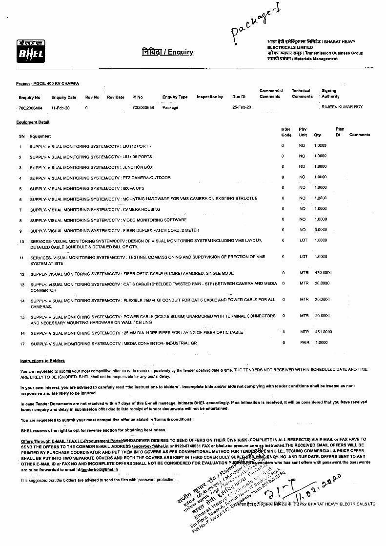
Proittot - PGCIL 400 KV CHAMPP
Commercial Technical Signing
Enquiry No Enquiry Date Rev No Rev Date PI No Enquiry Type Inspection by Due Dt Comments Comments Authority
7002000484 11-Feb-20 0 7012000556 Package 25-Feb-20 RAJEEV KUMAR ROY
HSN Phy Plan Code Unit Qty Dt Comments
0 NO 1.0000
0 NO 1.0000
0 NO 1.0000
0 NO 1.0000
0 NO 1.0000
0 NO 1.0000
0 NO 1.0000
0 NO 1.0000
0 NO 3.0000
0 LOT 1.0000
0 LOT 1.0000
0 MTR 470.0000
0 MTR 20.0000
0 MTR 20.0000
0 MTR 20.0000
0 MTR 451.0000
0 PAIR 1.0000
SN Equipment
1 SUPPLY- VISUAL MONITORING SYSTEM/CCTV : LIU (12 PORT)
2 SUPPLY- VISUAL MONITORING SYSTEM/CCTV : LIU ( 06 PORTS)
3 SUPPLY- VISUAL MONITORING SYSTEM/CCTV : JUNCTION BOX
4 SUPPLY- VISUAL MONITORING SYSTEM/CCTV : PTZ CAMERA-OUTDOOR
5 SUPPLY- VISUAL MONITORING SYSTEM/CCTV : 600VA UPS
6 SUPPLY- VISUAL MONITORING SYSTEM/CCTV : MOUNTING HARDWARE FOR VMS CAMERA ON EXISTING STRUCTUE
7 SUPPLY- VISUAL MONITORING SYSTEM/CCTV : CAMERA HOUSING
8 SUPPLY- VISUAL MONITORING SYSTEM/CCTV : VIDEO MONITORING SOFTWARE
9 SUPPLY- VISUAL MONITORING SYSTEM/CCTV : FIBER DUPLEX PATCH CORD, 2 METER
10 SERVICES- VISUAL MONITORING SYSTEM/CCTV : DESIGN OF VISUAL MONITORING SYSTEM INCLUDING VMS LAYOUT, DETAILED CABLE SCHEDULE & DETAILED BILL OF QTY.
11 SERVICES- VISUAL MONITORING SYSTEM/CCTV : TESTING, COMMISSIONING AND SUPERVISION OF ERECTION OF VMS
SYSTEM AT SITE
12 SUPPLY- VISUAL MONITORING SYSTEM/CCTV FIBER OPTIC CABLE (6 CORE) ARMORED, SINGLE MODE
13 SUPPLY- VISUAL MONITORING SYSTEM/CCTV CAT 6 CABLE (SHIELDED TWISTED PAIR - STP) BETWEEN CAMERA AND MEDIA
CONVERTOR
14 SUPPLY- VISUAL MONITORING SYSTEM/CCTV FLEXIBLE 25MM GI CONDUIT FOR CAT 6 CABLE AND POWER CABLE FOR ALL
CAMERAS.
15 SUPPLY- VISUAL MONITORING SYSTEM/CCTV : POWER CABLE (3CX2.5 SQ.MM) UNARMORED WITH TERMINAL CONNECTORS AND NECESSARY MOUNTING HARDWARE ON WALL / CEILING
16 SUPPLY- VISUAL MONITORING SYSTEM/CCTV : 25 MM DIA. HDPE PIPES FOR LAYING OF FIBER OPTIC CABLE
17 SUPPLY- VISUAL MONITORING SYSTEM/CCTV : MEDIA CONVERTOR- INDUSTRIAL GR
instructions to Bidders
You are requested to submit your most competitive offer so as to reach us positively by the tender opening date & time. THE TENDERS NOT RECEIVED WITHIN SCHEDULED DATE AND TIME ARE LIKELY TO BE IGNORED. BHEL shall not be responsible for any postal delay.
In your own Interest, you are advised to carefully read "the instructions to bidders". Incomplete bids andlor bids not complying with tender conditions shall be treated as non-
responsive and are likely to be Ignored.
In case Tender Documents are not received within 7 days of this E-mail message, Intimate BHEL accordingly. If no Intimation is received, It will be considered that you have received tender enquiry and delay in submission offer due to late receipt of tender documents will not be entertained.
You are requested to submit your most competitive offer as stated In Terms & conditions.
BHEL reserves the right to opt for reverse auction for obtaining best prices.
Offers Through E-MAIL I FAX) E-Procurement Portal-WHOSOEVER DESIRES TO SEND OFFERS ON THEIR OWN RISK (COMPLETE IN ALL RESPECTS) VIA E-MAIL or FAX HAVE TO SEND THE OFFERS TO THE COMMON E-MAIL ADDRESS tenderbo4@bhelin or 0120-6748581 FAX or bhelabc.procure.com instructed.THE RECEIVED EMAIL OFFERS WILL BE
PRINTED BY PURCHASE COORDINATOR AND PUT THEM INTO COVERS AS PER CONVENTIONAL METHOD FOR TEND ENING I.E., TECHNO COMMERCIAL 8 PRICE OFFER
SHALL BE PUT INTO TWO SEPARATE COVERS AND BOTH THE COVERS ARE KEPT IN THIRD COVER DULY SUPE ANCIY. NO. AND DUE DATE. OFFERS SENT TO ANY
OTHER E-MAIL ID or FAX NO AND INCOMPLETE OFFERS SHALL NOT BE CONSIDERED FOR EVALUATION PQM 'riders who has sent offers with password,the passwords
are to be forwarded to email id:tenderboX@bhelin .-Vae'cifiC ..LV-ii iii-i-12' ..J .cs1-
It is suggested that the bidders are advised to send the files with 'password protection'.
Icl-iv" 0 ' c,.-ii,ii '
't(6. \ °q,c' ,A \ '‘‘:‘C''''.'Cl° 40-
et, A'
\ •,. r1,0\
I 041-" • .4 ,,-, ,s, se
,d,0 „,,,,,„,a,s- .,.0',,\ " Q- le-
,,,,e',...-f.VITri-o NI 4 a*octf RIB' FA for BHARAT HEAVY ELECTRICALS LTD
iti* i3C-r li
e Z
s-(0 ,,e
\c31q
cP,ao. QUO
Please acknowledge the receipt of tender enquiry and e-maiVfax back this letter by ticking the appropriate item below
We acknowledge the receipt of tender.
(a) The offer against subject enquiry shall be submitted by the scheduled date and time.
(b) We regret to quote. The item in reference is out of our manufacturing range.
(c) We regret because of our prior commitments.
(d) Any other reason.
To RAJEEV KUMAR ROY Bharat Heavy Electricals Limited Transmission Business Group Tower-A,5th Floor, Advent Nevis IT Business Park, Plot No-7,Sector-142,Expressway Noida Noida-201305 Distt. Gautam BudhNagar,U.P Ph: 0120-6748137
vitt wr ailTrAfacimir 7$1.#111 / Signature and Seal of Tenderer
Enquiry No : 7002000484 Enquiry Date: 11-Feb-20
HOEL f*a4i / Enquiry
'WM te tlf mftffefl26 I BHARAT HEAVY ELECTRICALS LIMITED RAW 841,17 Witt I Transmission Business Group iif7fif)3111R / Materials Management
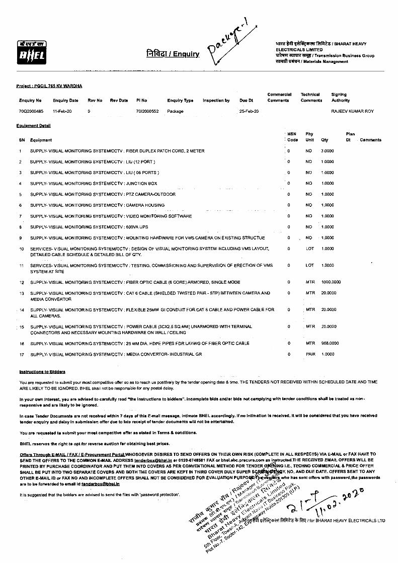
Projgct : PGCIL 765 KV WARDI1A
Commercial Technical Signing Enquiry No Enquiry Date Rev No Rev Date PI No Enquiry Type Inspection by Due Dt Comments Comments Authority
7002000485 11-Feb-20 0 7012000552 Package 25-Feb-20 RAJEEV KUMAR ROY
EqUIPMent Detail
SN Equipment HSN Code
Phy Unit
Plan Qty Dt Comments
1 SUPPLY- VISUAL MONITORING SYSTEM/CCTV : FIBER DUPLEX PATCH CORD, 2 METER 0 NO 3.0000
2 SUPPLY- VISUAL MONITORING SYSTEM/CCTV : LIU (12 PORT) 0 NO 1.0000
3 SUPPLY- VISUAL MONITORING SYSTEM/CCTV : LIU ( 06 PORTS) 0 NO 1.0000
4 SUPPLY- VISUAL MONITORING SYSTEM/CCTV : JUNCTION BOX 0 NO 1.0000
5 SUPPLY- VISUAL MONITORING SYSTEM/CCTV : PTZ CAMERA-OUTDOOR 0 NO 1.0000
8 SUPPLY- VISUAL MONITORING SYSTEM/CCTV : CAMERA HOUSING 0 NO 1.0000
7 SUPPLY- VISUAL MONITORING SYSTEM/CCTV : VIDEO MONITORING SOFTWARE 0 NO 1.0000
8 SUPPLY- VISUAL MONITORING SYSTEM/CCTV : 600VA UPS 0 NO 1.0000
9 SUPPLY- VISUAL MONITORING SYSTEM/CCTV : MOUNTING HARDWARE FOR VMS CAMERA ON EXISTING STRUCTUE 0 . NO 1.0000
10 SERVICES- VISUAL MONITORING SYSTEM/CCTV : DESIGN OF VISUAL MONITORING SYSTEM INCLUDING VMS LAYOUT, DETAILED CABLE SCHEDULE & DETAILED BILL OF QTY.
0 LOT 1.0000
11 SERVICES- VISUAL MONITORING SYSTEM/CCTV : TESTING, COMMISSIONING AND SUPERVISION OF ERECTION OF VMS 0 LOT 1.0000 SYSTEM AT SITE
12 SUPPLY- VISUAL MONITORING SYSTEM/CCTV : FIBER OPTIC CABLE (6 CORE) ARMORED, SINGLE MODE 0 MTR 1000.0000
13 SUPPLY- VISUAL MONITORING SYSTEM/CCTV : CAT 6 CABLE (SHIELDED TWISTED PAIR - STP) BETWEEN CAMERA AND 0 MTR 20.0000
MEDIA CONVERTOR
14 SUPPLY- VISUAL MONITORING SYSTEM/CCTV : FLEXIBLE 25MM GI CONDUIT FOR CAT 6 CABLE AND POWER CABLE FOR 0 MTR 20.0000
ALL CAMERAS.
15 SUPPLY- VISUAL MONITORING SYSTEM/CCTV : POWER CABLE (3CX2.5 SQ.MM) UNARMORED WITH TERMINAL 0 MTR 20.0000 CONNECTORS AND NECESSARY MOUNTING HARDWARE ON WALL / CEILING
16 SUPPLY- VISUAL MONITORING SYSTEM/CCTV : 25 MM DIA. HDPE PIPES FOR LAYING OF FIBER OPTIC CABLE 0 MTR 968.0000
17 SUPPLY- VISUAL MONITORING SYSTEM/CCTV : MEDIA CONVERTOR- INDUSTRIAL GR 0 PAIR 1.0000
instructions to Bidders
You are requested to submit your most competitive offer so as to reach us positively by the tender opening date & time. THE TENDERS NOT RECEIVED WITHIN SCHEDULED DATE AND TIME ARE LIKELY TO BE IGNORED. BHEL shall not be responsible for any postal delay.
In your own Interest, you are advised to carefully read "the Instructions to bidders". Incomplete bids and/or bids not complying with tender conditions shall be treated as non-responsive and are likely to be ignored.
In case Tender Documents are not received within 7 days of this E-mail message, Intimate BHEL accordingly. If no Intimation is received, it will be considered that you have received tender enquiry and delay in submission offer due to late receipt of tender documents will not be entertained.
You are requested to submit your most competitive offer as stated in Terms & conditions.
BHEL reserves the right to opt for reverse auction for obtaining best prices.
Offers Through E-MAIL I FAX / E-Procurement Portal•WHOSOEVER DESIRES TO SEND OFFERS ON THEIR OWN RISK (COMPLETE IN ALL RESPECTS) VIA E-MAIL or FAX HAVE TO SEND THE OFFERS TO THE COMMON E-MAIL ADDRESS tenderbo4Ig4hetin or 0120.6748581 FAX or bhel.abc.procure.com astructed.THE RECEIVED EMAIL OFFERS WILL BE PRINTED BY PURCHASE COORDINATOR AND PUT THEM INTO COVERS AS PER CONVENTIONAL METHOD FOR TENDER ING I.E., TECHNO COMMERCIAL & PRICE OFFER SHALL BE PUT INTO TWO SEPARATE COVERS AND BOTH THE COVERS ARE KEPT IN THIRD COVER DULY SUPER S Ott Y. NO. AND DUE DATE. OFFERS SENT TO ANY OTHER E-MAIL ID or FAX NO AND INCOMPLETE OFFERS SHALL NOT BE CONSIDERED FOR EVALUATION PURPO
(,‘lo haerl who has sent offers with password,the passwords
, are to be forwarded to email Id:I eAteAtox@IthgUn .e`' ea
2' .c.Cs It is suggested that the bidders are advised to send the files with 'password protection'. • cs' cfa
• cP,"c: \ 0\ c*s
A -.24:k*e)ctlf*42F01Z /for 40.
O- liAtiVk a BHARAT HEAVY ELECTRICALS LTD
00
fd° \.‘4°.
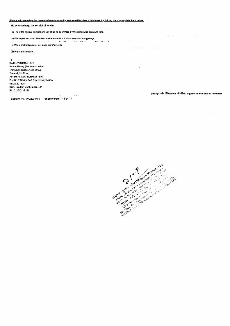
please acknowledge the receipt of tender enquiry and e-mail/fax back this letter by tickingrimumpropriate item below
We acknowledge the receipt of tender.
(a) The offer against subject enquiry shall be submitted by the scheduled date and time.
(b) We regret to quote. The item in reference is out of our manufacturing range.
(c) We regret because of our prior commitments.
(d) Any other reason.
To
RAJEEV KUMAR ROY
Bharat Heavy Electricals Limited
Transmission Business Group
Tower-A.5th Floor,
Advent Nevis IT Business Park,
Plot No-7,Sector-142,Expressway Noida
Noida-201305
Distt. Gautam BudhNagar,U.P
Ph: 0120-6748137 paw- alkfafag um et ft I Signature and Seal of Tenderer
Enquiry No : 7002000485 Enquiry Date: 11-Feb-20
01-"t' 141iff te Fectf I BHARAT HEAVY ELECTRICALS LIMITED tle111101111117 / Transmission Business Group I:m.413*m Materials Management
HOEL gird I Enquiry.
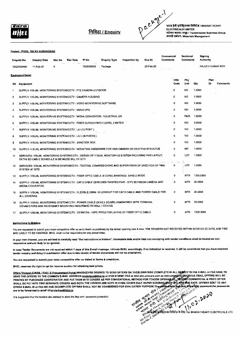
Prgject : PGCIL 765 KV AURANGBAD
Commercial Technical Signing
Enquiry No Enquiry Date Rev No Rev Date PI No Enquiry Type Inspection by Due Dt Comments Comments Authority
70Q2000486 11-Feb-20 0
7012000553 Package
25-Feb-20 RAJEEV KUMAR ROY
Egoloroent Detail
SN Equipment HSN Code
Phy Unit
Plan Qty Dt Comments
1 SUPPLY- VISUAL MONITORING SYSTEM/CCTV : PTZ CAMERA-OUTDOOR 0 NO 1.0000
2 SUPPLY- VISUAL MONITORING SYSTEM/CCTV : CAMERA HOUSING 0 NO 1.0000
3 SUPPLY- VISUAL MONITORING SYSTEM/CCTV : VIDEO MONITORING SOFTWARE 0 NO 1.0000
4 SUPPLY- VISUAL MONITORING SYSTEM/CCTV : 600VA UPS 0 NO 1.0000
5 SUPPLY- VISUAL MONITORING SYSTEM/CCTV : MEDIA CONVERTOR- INDUSTRIAL GR 0 PAIR 1.0000
6 SUPPLY- VISUAL MONITORING SYSTEM/CCTV : FIBER DUPLEX PATCH CORD, 2 METER 0 NO 3.0000
7 SUPPLY- VISUAL MONITORING SYSTEM/CCTV : LIU (12 PORT) 0 NO 1.0000
8 SUPPLY- VISUAL MONITORING SYSTEM/CCTV : LIU ( 06 PORTS) 0 NO 1.0000
9 SUPPLY- VISUAL MONITORING SYSTEM/CCTV : JUNCTION BOX 0 NO 1.0000
10 SUPPLY- VISUAL MONITORING SYSTEM/CCTV : MOUNTING HARDWARE FOR VMS CAMERA ON EXISTING STRUCTUE 0 NO 1.0000
11 SERVICES- VISUAL MONITORING SYSTEM/CCTV : DESIGN OF VISUAL MONITORING SYSTEM INCLUDING VMS LAYOUT, DETAILED CABLE SCHEDULE 8 DETAILED BILL OF QTY
0 LOT 1.0000
12 SERVICES- VISUAL MONITORING SYSTEM/CCTV : TESTING, COMMISSIONING AND SUPERVISION OF ERECTION OF VMS 0 LOT 1.0000
SYSTEM AT SITE
13 SUPPLY- VISUAL MONITORING SYSTEM/CCTV FIBER OPTIC CABLE (6 CORE) ARMORED, SINGLE MODE 0 MTR 1350.0000
14 SUPPLY- VISUAL MONITORING SYSTEM/CCTV CAT 6 CABLE (SHIELDED TWISTED PAIR - STP) BETWEEN CAMERA AND 0 MTR 20.0000
MEDIA CONVERTOR
15 SUPPLY- VISUAL MONITORING SYSTEM/CCTV FLEXIBLE 25MM GI CONDUIT FOR CAT 6 CABLE AND POWER CABLE FOR 0 MTR 20.0000
ALL CAMERAS.
16 SUPPLY- VISUAL MONITORING SYSTEM/CCTV : POWER CABLE (3CX2.5 SQ.MM) UNARMORED WITH TERMINAL 0 MTR 20.0000
CONNECTORS AND NECESSARY MOUNTING HARDWARE ON WALL / CEILING
17 SUPPLY- VISUAL MONITORING SYSTEM/CCTV : 25MM DIA. HDPE PIPES FOR LAYING OF FIBER OPTIC CABLE 0 MTR 1320.0000
Instructions to Bidders
You are requested to submit your most competitive offer so as to reach us positively by the tender opening date 8 time. THE TENDERS NOT RECEIVED WITHIN SCHEDULED DATE AND TIME ARE LIKELY TO BE IGNORED. BHEL shall not be responsible for any postal delay.
In your own interest, you are advised to carefully read "the instructions to bidders". Incomplete bids and/or bids not complying with tender conditions shall be treated as non- responsive and are likely to be ignored.
In case Tender Documents are not received within 7 days of this E-mail message, intimate BHEL accordingly. If no Intimation Is received, It will be considered that you have received tender enquiry and delay in submission offer due to late receipt of tender documents will not be entertained.
You are requested to submit your most competitive offer as stated In Terms 8 conditions.
BHEL reserves the right to opt for reverse auction for obtaining best prices.
Offers Through E-MAIL / FAX/ E-Procurement Portal•WHOSOEVER DESIRES TO SEND OFFERS ON THEIR OWN RISK (COMPLETE IN ALL I3ECTS) VIA E-MAIL or FAX HAVE TO SEND THE OFFERS TO THE COMMON E-MAIL ADDRESS tenderbos@ffhelin or 0120-8748581 FAX or bhel.abc.procure.com as instructed# cfIVED EMAIL OFFERS WILL BE
PRINTED BY PURCHASE COORDINATOR AND PUT THEM INTO COVERS AS PER CONVENTIONAL METHOD FOR TENDER OPENIW-• t„,,, , COMMERCIAL 8 PRICE OFFER
SHALL BE PUT INTO TWO SEPARATE COVERS AND BOTH THE COVERS ARE KEPT IN THIRD COVER DULY SUPER SCRIBIPV10111414f,A Istl DATE. OFFERS SENT TO ANY
OTHER E-MAIL ID or FAX NO AND INCOMPLETE OFFERS SHALL NOT BE CONSIDERED FOR EVALUATION PURPOSE.ThiffideAtte 1,\RPIT:„Vr1400 password,the passwords
f? \ 1P . :-..,,: <,. are to be forwarded to email Id:tenderbOX@bhelin .e. _ \ ‘5,6,
.A.O. (Z z4,_ scf,>\ , \ 0 a, It is suggested that the bidders are advised to send the files with 'password protection'. 41,
ea 1,d(c.. .cs {x
C .)-‘11')'1D <:\ fic(1
41440 9' Fa lift / for BHARAT HEAVY ELECTRICALS LTD os • Sao c, •S
cPs's-VD

Please acknowlegglibelegkiaLollestierAnguiry and e-mail/fax back this letter by ticking the aooroodate item below
We acknowledge the receipt of tender.
(a) The offer against subject enquiry shall be submitted by the scheduled date and time.
(b) We regret to quote. The item in reference is out of our manufacturing range.
(c) We regret because of our prior commitments.
(d) Any other reason.
To RAJEEV KUMAR ROY Bharat Heavy Electricals Limited Transmission Business Group Tower-A.5th Floor, Advent Nevis IT Business Park, Plot No-7,Sector-142,Expressway Noida Noida-201305 Distt. Gautam BudhNagar,U.P Ph: 0120-6748137
TMTM' q zdtt/ftff / Signature and Seal of renderer
Enquiry No : 7002000486 Enquiry Date: 11-Feb-20
o 'AO
e ■-1̀71,P <Cs c,19
2, 0 1 A '4!) \
6
<, ,c,<• <<"
to. No, ors 'k • cP
4..a S1 /4. 4442% ;A‘49
,)- \ • o_ 0
14778' r41 6 fatef / BHARAT HEAVY ELECTRICALS LIMITED 1111811:569PITT ITU / Transmission Business Group TrriTt uttrq I Materials Management
A qi / Enquiry.
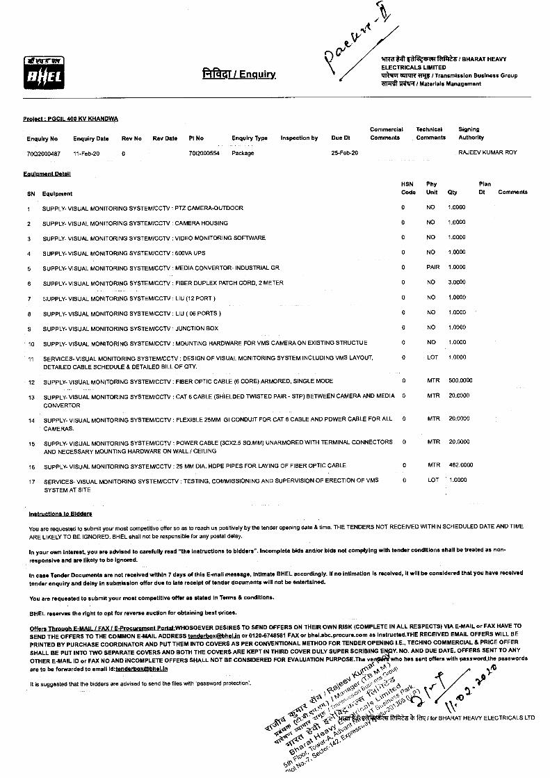
Ergject PGCIL 400 KV KHANDWA
Commercial
Technical Signing
Enquiry No Enquiry Date Rev No Rev Date
PI No Enquiry Type Inspection by
Due Dt Comments
Comments Authority
7002000487 11-Feb-20 0
7012000554 Package
25-Feb-20
RAJEEV KUMAR ROY
PTZ CAMERA-OUTDOOR
CAMERA HOUSING
VIDEO MONITORING SOFTWARE
600VA UPS
MEDIA CONVERTOR- INDUSTRIAL GR
FIBER DUPLEX PATCH CORD, 2 METER
LIU (12 PORT )
LIU ( 06 PORTS )
JUNCTION BOX
SUPPLY- VISUAL MONITORING SYSTEM/CCTV : MOUNTING HARDWARE FOR VMS CAMERA ON EXISTING STRUCTUE
SERVICES- VISUAL MONITORING SYSTEM/CCTV : DESIGN OF VISUAL MONITORING SYSTEM INCLUDING VMS LAYOUT, DETAILED CABLE SCHEDULE & DETAILED BILL OF QTY.
12 SUPPLY- VISUAL MONITORING SYSTEM/CCTV : FIBER OPTIC CABLE (6 CORE) ARMORED, SINGLE MODE
13 SUPPLY- VISUAL MONITORING SYSTEM/CCTV : CAT 6 CABLE (SHIELDED TWISTED PAIR - STP) BETWEEN CAMERA AND MEDIA
CONVERTOR
14 SUPPLY- VISUAL MONITORING SYSTEM/CCTV FLEXIBLE 25MM GI CONDUIT FOR CAT 6 CABLE AND POWER CABLE FOR ALL
CAMERAS.
Emil; rupgatattgi
SN Equipment
1
SUPPLY- VISUAL MONITORING SYSTEM/CCTV
2 SUPPLY- VISUAL MONITORING SYSTEM/CCTV
3 SUPPLY- VISUAL MONITORING SYSTEM/CCTV
4 SUPPLY- VISUAL MONITORING SYSTEM/CCTV
5 SUPPLY- VISUAL MONITORING SYSTEM/CCTV
6
SUPPLY- VISUAL MONITORING SYSTEM/CCTV
7 SUPPLY- VISUAL MONITORING SYSTEM/CCTV
8 SUPPLY- VISUAL MONITORING SYSTEM/CCTV
9 SUPPLY- VISUAL MONITORING SYSTEM/CCTV
10
11
HSN Code
Phy Unit
Plan Qty Dt Comments
0 NO 1.0000
0 NO 1.0000
0 NO 1.0000
0 NO 1.0000
0 PAIR 1.0000
0 NO 3.0000
0 NO 1.0000
0 NO 1.0000
0 NO 1.0000
0 NO 1.0000
0 LOT 1.0000
0 MTR 500.0000
0 MTR 20.0000
0 MTR 20.0000
0 MTR 20.0000
0 MTR 462.0000
0 LOT 1.0000
15 SUPPLY- VISUAL MONITORING SYSTEM/CCTV : POWER CABLE (3CX2.5 SQ.MM) UNARMORED WITH TERMINAL CONNECTORS AND NECESSARY MOUNTING HARDWARE ON WALL / CEILING
16 SUPPLY- VISUAL MONITORING SYSTEM/CCTV : 25 MM DIA. HOPE PIPES FOR LAYING OF FIBER OPTIC CABLE
17 SERVICES- VISUAL MONITORING SYSTEM/CCTV : TESTING, COMMISSIONING AND SUPERVISION OF ERECTION OF VMS
SYSTEM AT SITE
instructions to Bidders
You are requested to submit your most competitive offer so as to reach us positively by the tender opening date & time. THE TENDERS NOT RECEIVED WITHIN SCHEDULED DATE AND TIME ARE LIKELY TO BE IGNORED. BHEL shall not be responsible for any postal delay.
In your own Interest, you are advised to carefully read "the instructions to bidders". Incomplete bids and/or bids not complying with tender conditions shall be treated as non-
responsive and are likely to be Ignored.
In case Tender Documents are not received within 7 days of this E.mall message, Intimate BHEL accordingly. If no Intimation Is received, It will be considered that you have received tender enquiry and delay in submission offer due to late receipt of tender documents will not be entertained.
You are requested to submit your moat competitive offer as stated In Terms & conditions.
BHEL reserves the right to opt for reverse auction for obtaining best prices.
Offers Through E-MAIL / FAX / E-Procurement Portal:WHOSOEVER DESIRES TO SEND OFFERS ON THEIR OWN RISK (COMPLETE IN ALL RESPECTS) VIA E-MAIL or FAX HAVE TO SEND THE OFFERS TO THE COMMON E-MAIL ADDRESS tenderbox Wieldii or 0120-6748581 FAX or bhel.abc.procure.com as Instructed.THE RECEIVED EMAIL OFFERS WILL BE
PRINTED BY PURCHASE COORDINATOR AND PUT THEM INTO COVERS AS PER CONVENTIONAL METHOD FOR TENDER OPENING I.E., TECHNO COMMERCIAL & PRICE OFFER SHALL BE PUT INTO TWO SEPARATE COVERS AND BOTH THE COVERS ARE KEPT IN THIRD COVER DULY SUPER SCRIBING E Y. NO. AND DUE DATE. OFFERS SENT TO ANY OTHER E-MAIL ID or FAX NO AND INCOMPLETE OFFERS SHALL NOT BE CONSIDERED FOR EVALUATION PURPOSE.The ve who has sent offers with password,the passwords
are to be forwarded to email id:tenderbox@kbiEn '2■ 0-) AcC-) 0 ,,C' ./13
4.--- se, (--,`° 6 V yr
,OS0f--c0C‘- kePczS\ '} ..v l a N'
.". <':'' '''' 'Z k ' ' C 0.‘' 0 "S'S \ - ;s ? \\'` itftftt- tiz 1 for BHARAT HEAVY ELECTRICALS LTD
It is suggested that the bidders are advised to send the files with 'password protection'.
Please the receipt of tender and e-mail/fax back this letter by_tighigg_thsappygpriate item below
We acknowledge the receipt of tender.
(a) The offer against subject enquiry shall be submitted by the scheduled date and time.
(b) We regret to quote. The item in reference is out of our manufacturing range.
(c) We regret because of our prior commitments.
(d) Any other reason.
To RAJEEV KUMAR ROY Bharat Heavy Electricals Limited Transmission Business Group Tower-A,5th Floor. Advent Nevis IT Business Park, Plot No-7,Sector-142,Expressway Noida Noida-201305 Distt. Gautam BudhNagar,U.P Ph: 0120-6748137
amp arri zet *FT / Signature and Seal of Tenderer
Enquiry No : 70Q2000487 Enquiry Date: 11-Feb-20
UNE tit (r) I BHARAT HEAVY ELECTRICALS LIMITED 14111:115 =GRIPE! / Transmission Business Group 117111l) MAR I Materials Management
rmirnmi
NOEL fa @4I / Enquiry.
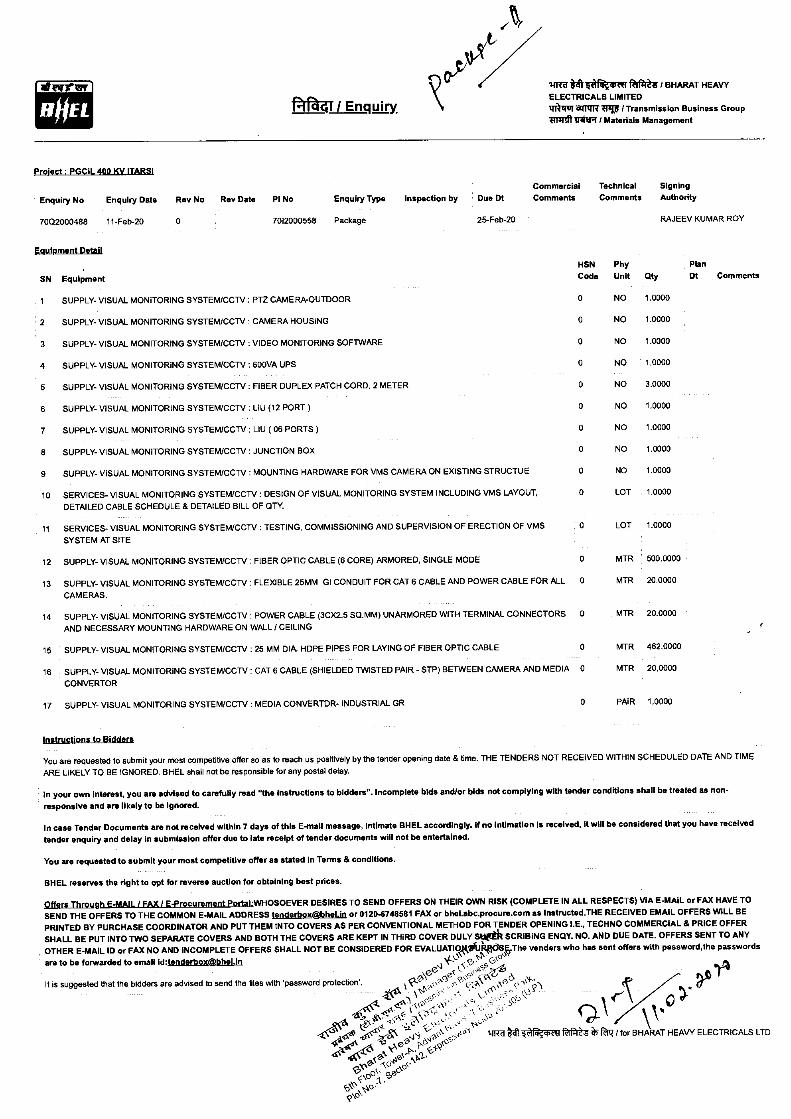
Project PGCIL 400 KV !TARSI
Commercial Technical Signing
Enquiry No Enquiry Date Rev No Rev Date PI No Enquiry Type Inspection by Due Dt Comments Comments Authority
7002000488 11-Feb-20 0 7012000558 Package 25-Feb-20 RAJEEV KUMAR ROY
Equipment Detail
2 SUPPLY- VISUAL MONITORING SYSTEM/CCTV CAMERA HOUSING
3 SUPPLY- VISUAL MONITORING SYSTEM/CCTV VIDEO MONITORING SOFTWARE
4 SUPPLY- VISUAL MONITORING SYSTEM/CCTV 600VA UPS
5 SUPPLY- VISUAL MONITORING SYSTEM/CCTV : FIBER DUPLEX PATCH CORD. 2 METER
6 SUPPLY- VISUAL MONITORING SYSTEM/CCTV : LIU (12 PORT)
7 SUPPLY- VISUAL MONITORING SYSTEM/CCTV : LIU ( 06 PORTS)
8 SUPPLY- VISUAL MONITORING SYSTEM/CCTV : JUNCTION BOX
9 SUPPLY- VISUAL MONITORING SYSTEM/CCTV : MOUNTING HARDWARE FOR VMS CAMERA ON EXISTING STRUCTUE
10 SERVICES- VISUAL MONITORING SYSTEM/CCTV : DESIGN OF VISUAL MONITORING SYSTEM INCLUDING VMS LAYOUT, DETAILED CABLE SCHEDULE & DETAILED BILL OF QTY.
11 SERVICES- VISUAL MONITORING SYSTEM/CCTV : TESTING, COMMISSIONING AND SUPERVISION OF ERECTION OF VMS
SYSTEM AT SITE
12 SUPPLY- VISUAL MONITORING SYSTEM/CCTV : FIBER OPTIC CABLE (6 CORE) ARMORED, SINGLE MODE
13 SUPPLY- VISUAL MONITORING SYSTEM/CCTV : FLEXIBLE 25MM GI CONDUIT FOR CAT 6 CABLE AND POWER CABLE FOR ALL
CAMERAS.
14 SUPPLY- VISUAL MONITORING SYSTEM/CCTV : POWER CABLE (3CX2.5 SQ.MM) UNARMORED WITH TERMINAL CONNECTORS AND NECESSARY MOUNTING HARDWARE ON WALL / CEILING
15 SUPPLY- VISUAL MONITORING SYSTEM/CCTV : 25 MM DIA. HDPE PIPES FOR LAYING OF FIBER OPTIC CABLE
16 SUPPLY- VISUAL MONITORING SYSTEM/CCTV : CAT 6 CABLE (SHIELDED TWISTED PAIR - STP) BETWEEN CAMERA AND MEDIA
CONVERTOR
17 SUPPLY- VISUAL MONITORING SYSTEM/CCTV : MEDIA CONVERTOR- INDUSTRIAL GR
HSN Code
Phy Unit
Plan Qty Dt Comments
0 NO 1.0000
0 NO 1.0000
0 NO 1.0000
0 NO 1.0000
0 NO 3.0000
0 NO 1.0000
0 NO 1.0000
0 NO 1.0000
0 NO 1.0000
0 LOT 1.0000
0 LOT 1.0000
0 MTR 500.0000
0 MTR 20.0000
0 MTR 20.0000
0 MTR 462.0000
0 MTR 20.0000
0 PAIR 1.0000
SN Equipment
1 SUPPLY- VISUAL MONITORING SYSTEM/CCTV PTZ CAMERA-OUTDOOR
Instructions to Bidders
You are requested to submit your most competitive offer so as to reach us positively by the tender opening date & time. THE TENDERS NOT RECEIVED WITHIN SCHEDULED DATE AND TIME ARE LIKELY TO BE IGNORED. BHEL shall not be responsible for any postal delay.
In your own Interest, you are advised to carefully read "the instructions to bidders". Incomplete bids and/or bids not complying with tender conditions shall be treated as non-
responsive and are likely to be Ignored.
In case Tender Documents are not received within 7 days of this E-mail message, Intimate BHEL accordingly. If no intimation Is received, It will be considered that you have received tender enquiry and delay in submission offer due to late receipt of tender documents will not be entertained.
You are requested to submit your most competitive offer as stated In Terms & conditions.
BHEL reserves the right to opt for reverse auction for obtaining best prices.
Offers Through E-MAIL / FAX I E-Procurement Portal:WHOSOEVER DESIRES TO SEND OFFERS ON THEIR OWN RISK (COMPLETE IN ALL RESPECTS) VIA E-MAIL or FAX HAVE TO SEND THE OFFERS TO THE COMMON E-MAIL ADDRESS tenderbokEkbheliq or 0120-6748581 FAX or bhel.abc.procure.com as instructed.THE RECEIVED EMAIL OFFERS WILL BE
PRINTED BY PURCHASE COORDINATOR AND PUT THEM INTO COVERS AS PER CONVENTIONAL METHOD FOR TENDER OPENING LE., TECHNO COMMERCIAL & PRICE OFFER SHALL BE PUT INTO TWO SEPARATE COVERS AND BOTH THE COVERS ARE KEPT IN THIRD COVER DULY Stletil SCRIBING ENQY. NO. AND DUE DATE. OFFERS SENT TO ANY OTHER E-MAIL ID or FAX NO AND INCOMPLETE OFFERS SHALL NOT BE CONSIDERED FOR EVALUATIQ81,9*(11:1SF,.The venders who has sent offers with password,the passwords
are to be forwarded to email id:tenderboxfthel.in J`'' 0 )̀v
It is suggested that the bidders are advised to send the files with 'password protection'.
esi c2,0 <2,q , e, ao4
Please acknowledge the receipt of tender enquiry and e-mail/fax back this letter by ticking_thempygpriate item below
We acknowledge the receipt of tender.
(a) The offer against subject enquiry shall be submitted by the scheduled date and time.
(b) We regret to quote. The item in reference is out of our manufacturing range.
(c) We regret because of our prior commitments.
(d) Any other reason.
To RAJEEV KUMAR ROY Bharat Heavy Electricals Limited Transmission Business Group Tower-ASth Floor, Advant Nevis IT Business Park, Plot No-7,Sector-142,Expressway Noida Noida-201305 Distt. Gautam BudhNagar,U.P Ph: 0120-6748137
WRIT ahi tF eimii 1111 iftff Signature and Seal of Tenderer
Enquiry No : 70Q2000488 Enquiry Date: 11-Feb-20
ifrruttft 4 cr nillttZd t BHARAT HEAVY ELECTRICALS LIMITED Tir O Mx/RI:iv/ Transmission Business Group iffRallfttIR / Materials Management
HOU 41 I Enquiry
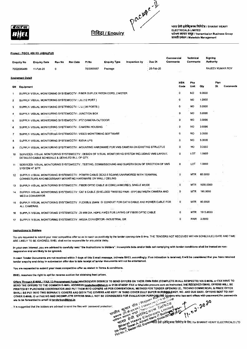
Eroject : PGCIL 400 KV JABALPUR
Commercial Technical Signing
Enquiry No Enquiry Date Rev No Rev Date PI No Enquiry Type Inspection by Due Dt Comments Comments Authority
7002000489 11-Feb-20 0
7012000557 Package
25-Feb-20 RAJEEV KUMAR ROY
HSN Phy Plan Code Unit Qty Dt Comments
NO 9.0000
NO 1.0000
NO 3.0000
NO 3.0000
NO 3.0000
NO 3.0000
NO 3.0000
NO 3.0000
NO 3.0000
0 LOT 1.0000
0 LOT 1.0000
0 MTR 60.0000
0 MTR 1550.0000
0 MTR 190.0000
0 MTR 60.0000
0 MTR 1513.0000
0 PAIR 3.0000
Instructions to Bidders
You are requested to submit your most competitive offer so as to reach us positively by the tender opening date 8 time. THE TENDERS NOT RECEIVED WITHIN SCHEDULED DATE AND TIME ARE LIKELY TO BE IGNORED. BHEL shall not be responsible for any postal delay.
In your own Interest, you are advised to carefully read "the instructions to bidders". Incomplete bids andlor bids not complying with tender conditions shall be treated as non-
responsive and are likely to be ignored.
In case Tender Documents are not received within 7 days of this E-mail message, intimate BHEL accordingly. If no Intimation Is received, It will be considered that you have received tender enquiry and delay in submission offer due to late receipt of tender documents will not be entertained.
You are requested to submit your most competitive offer as stated In Terms & conditions.
BHEL reserves the right to opt for reverse auction for obtaining best prices.
Offers Through E-MAIL! FAX I E-Procurement Portal:WHOSOEVER DESIRES TO SEND OFFERS ON THEIR OWN RISK (COMPLETE IN ALL RESPECTS) VIA E-MAIL or FAX HAVE TO SEND THE OFFERS TO THE COMMON E-MAIL ADDRESS )[email protected] or 0120-6748581 FAX or bhel.abc.procure.com as instructed.THE RECEIVED EMAIL OFFERS WILL BE PRINTED BY PURCHASE COORDINATOR AND PUT THEM INTO COVERS AS PER CONVENTIONAL METHOD FOR TENDER OPENING I.E., TECHNO COMMERCIAL & PRICE OFFER SHALL BE PUT INTO TWO SEPARATE COVERS AND BOTH THE COVERS ARE KEPT IN THIRD COVER DULY SUPER SCRIBINQY. NO. AND DUE DATE. OFFERS SENT TO ANY OTHER E-MAIL ID or FAX NO AND INCOMPLETE OFFERS SHALL NOT BE CONSIDERED FOR EVALUATION PURPSIFTnit Tilers who has sent offers with password,the passwords
are to be forwarded to email id:SenderboXfthelin P 1-- p, ON OP • ee t _ uo -......1-8 I _ .0, :1-A Ain r
'90 as
It is suggested that the bidders are advised to send the files with 'password protection'. .'" I l''' .L (A"Qrj crvt o,,, , _ ,,ok ■ . „,jt.
AN:e. l' '5 "el/V'' \5 \-T' kal ir, d: • e` il .t
8E1L,ifnw ISCOLTt ' es adt(1' Vc ?'‘59_10"k ' \ V ''
C‘--4 -e,-"ketasi 1-904° v166e
clat N. Ni41.0e NI 0%cocti faii12,1t ftk i for BHARAT HEAVY ELECTRICALS LTD
e:0,,10414.,0,..,42.- 5t7,1,56—
Equipment Detail
0
0
0
0
0
0
0
0
SN Equipment
1 SUPPLY- VISUAL MONITORING SYSTEM/CCTV FIBER DUPLEX PATCH CORD, 2 METER
2 SUPPLY- VISUAL MONITORING SYSTEM/CCTV LIU (12 PORT)
3 SUPPLY- VISUAL MONITORING SYSTEM/CCTV LIU ( 06 PORTS)
4 SUPPLY- VISUAL MONITORING SYSTEM/CCTV JUNCTION BOX
5 SUPPLY- VISUAL MONITORING SYSTEM/CCTV: PTZ CAMERA-OUTDOOR
6 SUPPLY- VISUAL MONITORING SYSTEM/CCTV CAMERA HOUSING 0
7 SUPPLY- VISUAL MONITORING SYSTEM/CCTV VIDEO MONITORING SOFTWARE
8 SUPPLY- VISUAL MONITORING SYSTEM/CCTV 600VA UPS
9 r,UPPLY- VISUAL MONITORING SYSTEM/CCTV : MOUNTING HARDWARE FOR VMS CAMERA ON EXISTING STRUCTUE
10 SERVICES- VISUAL MONITORING SYSTEM/CCTV : DESIGN OF VISUAL MONITORING SYSTEM INCLUDING VMS LAYOUT, DETAILED CABLE SCHEDULE 8 DETAILED BILL OF QTY.
11 SERVICES- VISUAL MONITORING SYSTEM/CCTV : TESTING, COMMISSIONING AND SUPERVISION OF ERECTION OF VMS
SYSTEM AT SITE
12 SUPPLY- VISUAL MONITORING SYSTEM/CCTV : POWER CABLE (3CX2.5 SQ.MM) UNARMORED WITH TERMINAL CONNECTORS AND NECESSARY MOUNTING HARDWARE ON WALL / CEILING
13 SUPPLY- VISUAL MONITORING SYSTEM/CCTV : FIBER OPTIC CABLE (6 CORE) ARMORED, SINGLE MODE
14 SUPPLY- VISUAL MONITORING SYSTEM/CCTV : CAT 6 CABLE (SHIELDED TWISTED PAIR - STP) BETWEEN CAMERA AND
MEDIA CONVERTOR
15 SUPPLY- VISUAL MONITORING SYSTEM/CCTV : FLEXIBLE 25MM GI CONDUIT FOR CAT 6 CABLE AND POWER CABLE FOR
ALL CAMERAS.
16 SUPPLY- VISUAL MONITORING SYSTEM/CCTV : 25 MM DIA. HDPE PIPES FOR LAYING OF FIBER OPTIC CABLE
17 SUPPLY- VISUAL MONITORING SYSTEM/CCTV : MEDIA CONVERTOR- INDUSTRIAL GR
Please acknowledge the receipt of tender enquiry and e-mailffax back this letter by ticking_theimproriate item below
We acknowledge the receipt of tender.
(a) The offer against subject enquiry shall be submitted by the scheduled date and time.
(b) We regret to quote. The item in reference is out of our manufacturing range.
(c) We regret because of our prior commitments.
(d) Any other reason.
To RAJEEV KUMAR ROY Bharat Heavy Electricals Limited Transmission Business Group Tower-A,5th Floor, Advent Nevis IT Business Park, Plot No-7,Sector-142,Expressway Noida Noida-201305 Distt. Gautam BudhNagar,U.P Ph: 0120-6748137
IRRITep Ieiri4iq,ir litt*ff Signature and Seal of Tenderer
Enquiry No : 70Q2000489 Enquiry Date: 11-Feb-20
It is suggested that the bidders are advised to send the files with 'password protection'.
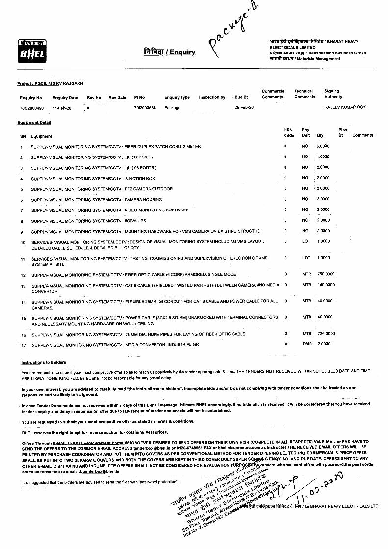
41 / Enquiry
striff it 6 mlef 1:81ftft / BHARAT HEAVY ELECTRICALS LIMITED 11131114 Whig lPJ I Transmission Business Group 81fff11tIn1Iff / Materials Management
ErsticaLersdissusvRugeffit Commercial Technical Signing
Enquiry No Enquiry Date Rev No Rev Date PI No
Enquiry Type Inspection by Due Dt Comments Comments Authority
7002000490 11-Feb-20 0
EqWpment Detail
HSN
SN Equipment
Code
1 SUPPLY- VISUAL MONITORING SYSTEM/CCTV : FIBER DUPLEX PATCH CORD, 2 METER 0
2 SUPPLY- VISUAL MONITORING SYSTEM/CCTV : LIU (12 PORT) 0
3 SUPPLY- VISUAL MONITORING SYSTEM/CCTV : LIU ( 06 PORTS) 0
4 SUPPLY- VISUAL MONITORING SYSTEM/CCTV : JUNCTION BOX 0
5 SUPPLY- VISUAL MONITORING SYSTEM/CCTV : PTZ CAMERA-OUTDOOR 0
6 SUPPLY- VISUAL MONITORING SYSTEM/CCTV : CAMERA HOUSING 0
7 SUPPLY- VISUAL MONITORING SYSTEM/CCTV : VIDEO MONITORING SOFTWARE 0
8 SUPPLY- VISUAL MONITORING SYSTEM/CCTV : 600VA UPS 0
9 SUPPLY- VISUAL MONITORING SYSTEM/CCTV : MOUNTING HARDWARE FOR VMS CAMERA ON EXISTING STRUCTUE 0
10 SERVICES- VISUAL MONITORING SYSTEM/CCTV : DESIGN OF VISUAL MONITORING SYSTEM INCLUDING VMS LAYOUT, 0
DETAILED CABLE SCHEDULE 8 DETAILED BILL OF QTY.
11 SERVICES- VISUAL MONITORING SYSTEM/CCTV : TESTING, COMMISSIONING AND SUPERVISION OF ERECTION OF VMS 0
SYSTEM AT SITE
12 SUPPLY- VISUAL MONITORING SYSTEM/CCTV : FIBER OPTIC CABLE (6 CORE) ARMORED, SINGLE MODE 0
13 SUPPLY- VISUAL MONITORING SYSTEM/CCTV CAT 6 CABLE (SHIELDED TWISTED PAIR - STP) BETWEEN CAMERA AND MEDIA 0
CONVERTOR
14 SUPPLY- VISUAL MONITORING SYSTEM/CCTV FLEXIBLE 25MM GI CONDUIT FOR CAT 6 CABLE AND POWER CABLE FOR ALL 0
CAMERAS.
15 SUPPLY- VISUAL MONITORING SYSTEM/CCTV : POWER CABLE (3CX2.5 SQ.MM) UNARMORED WITH TERMINAL CONNECTORS 0 AND NECESSARY MOUNTING HARDWARE ON WALL / CEILING
16 SUPPLY- VISUAL MONITORING SYSTEM/CCTV : 25 MM DIA. HDPE PIPES FOR LAYING OF FIBER OPTIC CABLE 0
17 SUPPLY- VISUAL MONITORING SYSTEM/CCTV : MEDIA CONVERTOR- INDUSTRIAL GR 0
7012000555 Package
25-Feb-20 RAJEEV KUMAR ROY
Phy Unit
Plan Oty Dt Comments
NO 6.0000
NO 1.0000
NO 2.0000
NO 2.0000
NO 2.0000
NO 2.0000
NO 2.0000
NO 2.0000
NO 2.0000
LOT 1.0000
LOT 1.0000
MTR 750.0000
MTR 140.0000
MTR 40.0000
MTR 40.0000
MTR 726.0000
PAIR 2.0000
instructions to Bidders
You are requested to submit your most competitive offer so as to reach us positively by the tender opening date 8 time. THE TENDERS NOT RECEIVED WITHIN SCHEDULED DATE AND TIME ARE LIKELY TO BE IGNORED. BHEL shall not be responsible for any postal delay.
In your own interest, you are advised to carefully read "the instructions to bidders". Incomplete bids andlor bids not complying with tender conditions shall be treated as non-
responsive and are likely to be ignored.
In case Tender Documents are not received within 7 days of this E-mail message, intimate BHEL accordingly. If no intimation is received, it will be considered that you have received tender enquiry and delay in submission offer due to late receipt of tender documents will not be entertained.
You are requested to submit your most competitive offer as stated in Terms 8 conditions.
BHEL reserves the right to opt for reverse auction for obtaining best prices.
Offers Through E-MAIL I FAX / E-Procurement Portal DESIRES TO SEND OFFERS ON THEIR OWN RISK (COMPLETE IN ALL RESPECTS) VIA E-MAIL or FAX HAVE TO
SEND THE OFFERS TO THE COMMON E-MAIL ADDRESS tenderboxehhelin or 0120-6748581 FAX or bhel.abc.procure.com as Instructed.THE RECEIVED EMAIL OFFERS WILL BE
PRINTED BY PURCHASE COORDINATOR AND PUT THEM INTO COVERS AS PER CONVENTIONAL METHOD FOR TENDER OPENING I.E., TECHNO COMMERCIAL 8 PRICE OFFER SHALL BE PUT INTO TWO SEPARATE COVERS AND BOTH THE COVERS ARE KEPT IN THIRD COVER DULY SUPER SCJI$1G ENCIY. NO. AND DUE DATE. OFFERS SENT TO ANY OTHER E-MAIL ID or FAX NO AND INCOMPLETE OFFERS SHALL NOT BE CONSIDERED FOR EVALUATION PURIVIOTIttonders who has sent offers with password,the passwords
are to be forwarded to email id:tenderbox@bhelin `t0• 10'9 J -(S• G •ee L ,c0ez,-6
cA
-- A6.
t ' ‘
r
e- Pksg o.
s
-1
\ 5 S
/A
` ‘
se
AN<; 4"S4
o o*q0fP
N
Nif-7T
,
‘
*
0.44
O 2s‘* aRone4 forr
0
BH
ARA T
cr
H EAV ELECTRICALS LTD pie°
Aoc-% Ivo,. se.- '■-c` 14o' 06"
Please acknowledge the receipt of tender enquiry and e-maiUfax back this letter by tickingthsimprupriate Item below
We acknowledge the receipt of tender.
(a) The offer against subject enquiry shall be submitted by the scheduled date and time.
(b) We regret to quote. The item in reference is out of our manufacturing range.
(c) We regret because of our prior commitments.
(d) Any other reason.
To RAJEEV KUMAR ROY Bharat Heavy Electricals Limited Transmission Business Group Tower-A,5th Floor, Advent Nevis IT Business Park, Plot No-7,Sector-142,Expressway Noida Noida-201305 Distt. Gautam BudhNagar,U.P Ph: 0120-6748137
WWITqff 3it *I iftti / Signature and Seal of Tenderer
Enquiry No : 7002000490 Enquiry Date: 11-Feb-20
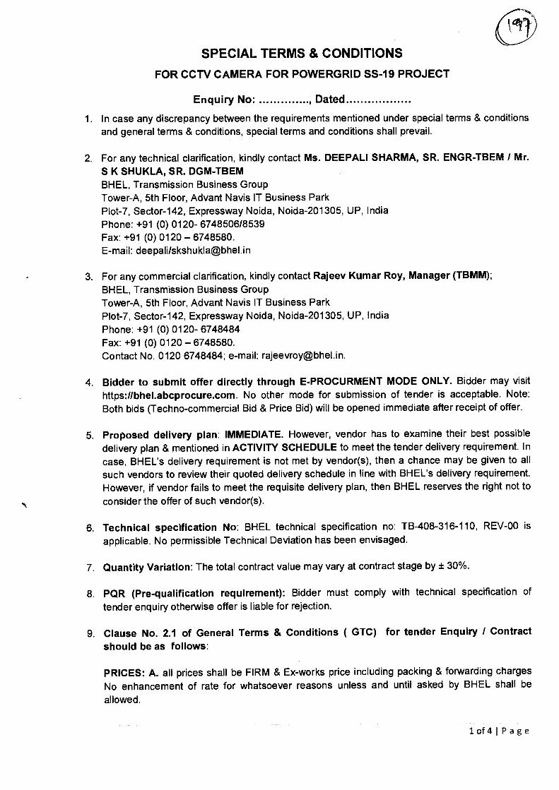
SPECIAL TERMS & CONDITIONS
FOR CCTV CAMERA FOR POWERGRID SS-19 PROJECT
Enquiry No: , Dated
1. In case any discrepancy between the requirements mentioned under special terms & conditions and general terms & conditions, special terms and conditions shall prevail.
2. For any technical clarification, kindly contact Ms. DEEPALI SHARMA, SR. ENGR-TBEM / Mr. S K SHUKLA, SR. DGM-TBEM BHEL, Transmission Business Group Tower-A, 5th Floor, Advant Navis IT Business Park Plot-7, Sector-142, Expressway Noida, Noida-201305, UP, India Phone: +91 (0) 0120- 6748506/8539 Fax: +91 (0) 0120 — 6748580. E-mail: deepali/skshukla©bhel.in
3. For any commercial clarification, kindly contact Rajeev Kumar Roy, Manager (TBMM); BHEL, Transmission Business Group Tower-A, 5th Floor, Advant Navis IT Business Park Plot-7, Sector-142, Expressway Noida, Noida-201305, UP, India Phone: +91 (0) 0120- 6748484 Fax: +91 (0) 0120 — 6748580. Contact No. 0120 6748484; e-mail: [email protected].
4. Bidder to submit offer directly through E-PROCURMENT MODE ONLY. Bidder may visit
https://bhel.abcprocure.com. No other mode for submission of tender is acceptable. Note: Both bids (Techno-commercial Bid & Price Bid) will be opened immediate after receipt of offer.
5. Proposed delivery plan: IMMEDIATE. However, vendor has to examine their best possible delivery plan & mentioned in ACTIVITY SCHEDULE to meet the tender delivery requirement. In case, BHEL's delivery requirement is not met by vendor(s), then a chance may be given to all such vendors to review their quoted delivery schedule in line with BHEL's delivery requirement. However, if vendor fails to meet the requisite delivery plan, then BHEL reserves the right not to consider the offer of such vendor(s).
6. Technical specification No: BHEL technical specification no: TB-408-316-110, REV-00 is applicable. No permissible Technical Deviation has been envisaged.
7. Quantity Variation: The total contract value may vary at contract stage by ± 30%.
8. PQR (Pre-qualification requirement): Bidder must comply with technical specification of tender enquiry otherwise offer is liable for rejection.
9. Clause No. 2.1 of General Terms & Conditions ( GTC) for tender Enquiry / Contract should be as follows:
PRICES: A. all prices shall be FIRM & Ex-works price including packing & forwarding charges No enhancement of rate for whatsoever reasons unless and until asked by BHEL shall be allowed.
lof4IPage
SPECIAL TERMS & CONDITIONS
FOR CCTV CAMERA FOR POWERGRID SS-19 PROJECT
Enquiry No: , Dated
PROJECT STATUS: Domestic in nature. GST is applicable as per currant prevailing rates.
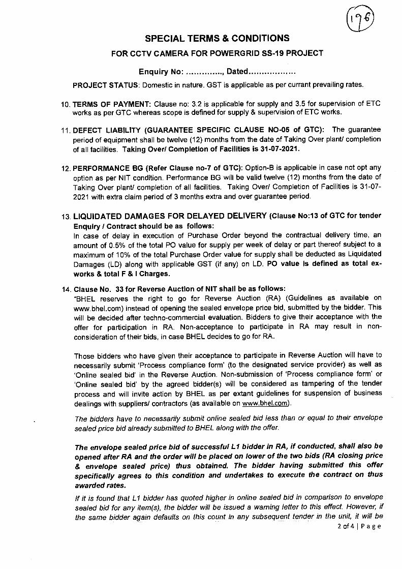
10. TERMS OF PAYMENT: Clause no: 3.2 is applicable for supply and 3.5 for supervision of ETC works as per GTC whereas scope is defined for supply & supervision of ETC works.
11. DEFECT LIABILITY (GUARANTEE SPECIFIC CLAUSE NO-05 of GTC): The guarantee period of equipment shall be twelve (12) months from the date of Taking Over plant/ completion of all facilities. Taking Over/ Completion of Facilities is 31-07-2021.
12. PERFORMANCE BG (Refer Clause no-7 of GTC): Option-B is applicable in case not opt any option as per NIT condition. Performance BG will be valid twelve (12) months from the date of Taking Over plant/ completion of all facilities. Taking Over/ Completion of Facilities is 31-07-2021 with extra claim period of 3 months extra and over guarantee period.
13. LIQUIDATED DAMAGES FOR DELAYED DELIVERY (Clause No:13 of GTC for tender Enquiry / Contract should be as follows: In case of delay in execution of Purchase Order beyond the contractual delivery time, an amount of 0.5% of the total PO value for supply per week of delay or part thereof subject to a maximum of 10% of the total Purchase Order value for supply shall be deducted as Liquidated Damages (LD) along with applicable GST (if any) on LD. PO value is defined as total ex-works & total F & I Charges.
14. Clause No. 33 for Reverse Auction of NIT shall be as follows: "BHEL reserves the right to go for Reverse Auction (RA) (Guidelines as available on
www.bhel.com) instead of opening the sealed envelope price bid, submitted by the bidder. This will be decided after techno-commercial evaluation. Bidders to give their acceptance with the offer for participation in RA. Non-acceptance to participate in RA may result in non-consideration of their bids, in case BHEL decides to go for RA.
Those bidders who have given their acceptance to participate in Reverse Auction will have to necessarily submit 'Process compliance form' (to the designated service provider) as well as 'Online sealed bid' in the Reverse Auction. Non-submission of 'Process compliance form' or 'Online sealed bid' by the agreed bidder(s) will be considered as tampering of the tender process and will invite action by BHEL as per extant guidelines for suspension of business dealings with suppliers/ contractors (as available on www.bhel.com).
The bidders have to necessarily submit online sealed bid less than or equal to their envelope sealed price bid already submitted to BHEL along with the offer.
The envelope sealed price bid of successful Ll bidder in RA, if conducted, shall also be opened after RA and the order will be placed on lower of the two bids (RA closing price & envelope sealed price) thus obtained. The bidder having submitted this offer specifically agrees to this condition and undertakes to execute the contract on thus awarded rates.
If it is found that Ll bidder has quoted higher in online sealed bid in comparison to envelope sealed bid for any item(s), the bidder will be issued a warning letter to this effect. However, if the same bidder again defaults on this count in any subsequent tender in the unit, it will be
2 of Wage
CI
SPECIAL TERMS & CONDITIONS
FOR CCTV CAMERA FOR POWERGRID SS-19 PROJECT
Enquiry No: , Dated
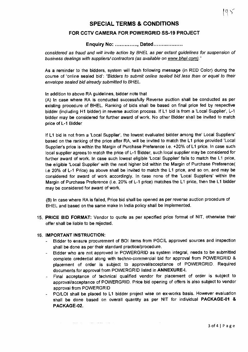
considered as fraud and will invite action by BHEL as per extant guidelines for suspension of business dealings with suppliers/ contractors (as available on www.bhel.com)."
As a reminder to the bidders, system will flash following message (in RED Color) during the course of 'online sealed bid': "Bidders to submit online sealed bid less than or equal to their envelope sealed bid already submitted to BHEL.
In addition to above RA guidelines, bidder note that (A) In case where RA is conducted successfully Reverse auction shall be conducted as per existing procedure of BHEL. Ranking of bids shall be based on final price fed by respective bidder (including H1 bidder) in reverse auction process. If L1 bid is from a 'Local Supplier', L-1 bidder may be considered for further award of work. No other Bidder shall be invited to match price of L-1 Bidder
If L1 bid is not from a 'Local Supplier', the lowest evaluated bidder among the' Local Suppliers' based on the ranking of the price after RA, will be invited to match the L1 price provided 'Local Supplier's price is within the Margin of Purchase Preference i.e. +20% of L1 price. In case such local supplier agrees to match the price of L-1 Bidder, such local supplier may be considered for further award of work. In case such lowest eligible 'Local Supplier' fails to match the L1 price, the eligible 'Local Supplier' with the next higher bid within the Margin of Purchase Preference( i.e 20% of L-1 Price) as above shall be invited to match the L1 price, and so on, and may be considered for award of work accordingly. In case none of the 'Local Suppliers' within the Margin of Purchase Preference (i.e. 20% of L-1 price) matches the L1 price, then the L1 bidder may be considered for award of work.
(B) In case where RA is failed, Price bid shall be opened as per reverse auction procedure of BHEL and based on the same make in India policy shall be implemented.
15. PRICE BID FORMAT: Vendor to quote as per specified price format of NIT, otherwise their offer shall be liable to be rejected.
16. IMPORTANT INSTRUCTION: Bidder to ensure procurement of BOI items from PGCIL approved sources and inspection shall be done as per their standard practice/procedure. Bidder who are not approved in POWERGRID as system integral, needs to be submitted complete credential along with techno-commercial bid for approval from POWERGRID & placement of order is subject to approval/acceptance of POWERGRID. Required documents for approval from POWERGRID listed in ANNEXURE-I. Final acceptance of technical qualified vendor for placement of order is subject to approval/acceptance of POWERGRID. Price bid opening of offers is also subject to vendor approval from POWERGRID PO/L01 shall be placed to L1 bidder project wise on ex-works basis. However evaluation shall be done based on overall quantity as per NIT for individual PACKAGE-01 & PACKAGE-02.
3of4IPage
ig4
SPECIAL TERMS & CONDITIONS
FOR CCTV CAMERA FOR POWERGRID SS-19 PROJECT
Enquiry No: , Dated
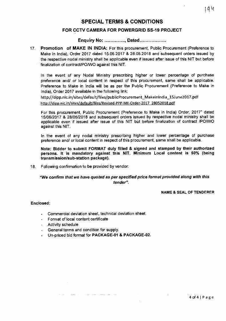
17. Promotion of MAKE IN INDIA: For this procurement, Public Procurement (Preference to Make in India), Order 2017 dated 15.06.2017 & 28.05.2018 and subsequent orders issued by the respective nodal ministry shall be applicable even if issued after issue of this NIT but before finalization of contract/PO/WO against this NIT.
In the event of any Nodal Ministry prescribing higher or lower percentage of purchase preference and/ or local content in respect of this procurement, same shall be applicable. Preference to Make in India will be as per the Public Procurement (Preference to Make in India), Order 2017 available in the following link: http://dipp.nic.inisites/clefault/files/publicProcurement_MakeinIndia_15June2017.pdf
http://dippmic.in/sitesidefault/files/Revised-PPP-M11-Order-2017 28052018.pdf
For this procurement, Public Procurement (Preference to Make in India) Order, 2017" dated 15/06/2017 & 28/05/2018 and subsequent orders issued by respective nodal ministry shall be applicable even if issued after issue of this NIT but before finalization of contract /PO/WO against this NIT.
In the event of any nodal ministry prescribing higher and lower percentage of purchase preference and/ or local content in respect of this procurement, same shall be applicable.
Note: Bidder to submit FORMAT duly filled & signed and stamped by their authorized persons. It is mandatory against this NIT. Minimum Local content is 50% (being transmission/sub-station package).
18. Following confirmation to be provided by vendor:
"We confirm that we have quoted as per specified price format provided along with this tender".
NAME & SEAL OF TENDERER
Enclosed:
- Commercial deviation sheet, technical deviation sheet. - Format of local content certificate - Activity schedule - General terms and condition for supply.
Un-priced bid format for PACKAGE-01 & PACKAGE-02.
4 of4IPage
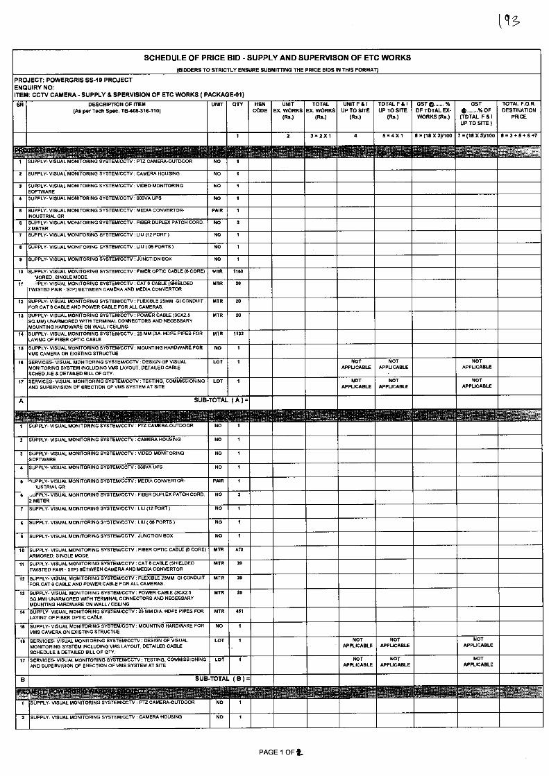
UNIT EX. WORKS
(Rs.)
TOTAL EX. WORKS
(Rs.)
SUPPLY- VISUAL MONITORING SYSTEWCCTV : PTZ CAMERA-OUTDOOR
SUPPLY. VISUAL MONITORING SYSTEWCCTV : CAMERA HOUSING
SUPPLY- VISUAL MONITORING SYSTEM/CCTV : VIDEO MONITORING SOFTWARE SUPPLY- VISUAL MONITORING SYSTEWCCTV : 800VA UPS
SUPPLY- VISUAL MONITORING SYSTEM/CCTV: MEDIA CONVERTOR. INDUSTRIAL GR SUPPLY- VISUAL MONITORING SYSTEM/CCTV: FIBER DUPLEX PATCH CORD, 2 METER SUPPLY- VISUAL MONITORING SYSTEWCCTV : LIU (12 PORT )
SUPPLY- VISUAL MONITORING SYSTEM/CCTV : LIU ( 08 PORTS )
SUPPLY- VISUAL MONITORING SYSTEM/CCTV: JUNCTION BOX
10 SUPPLY- VISUAL MONITORING SYSTEM/CCTV: FIBER OPTIC CABLE (8 CORE) •AORED, SINGLE MODE
11 ,,PLY. VISUAL MONITORING SYSTEM/CCTV: CAT 6 CABLE (SHIELDED TWISTED PAIR - STP) BETWEEN CAMERA AND MEDIA CONVERTOR
SUPPLY- VISUAL MONITORING SYSTEM/CCTV : FLEXIBLE 25MM GI CONDUIT .
FOR CAT 6 CABLE AND POWER CABLE FOR ALL CAMERAS.
O O O O O O O
SUPPLY- VISUAL MONITORING SYSTEM/CCTV : POWER CABLE (3CX2.5 SO.MM) UNARMORED WITH TERMINAL CONNECTORS AND NECESSARY MOUNTING HARDWARE ON WALL / CEILING
SUPPLY- VISUAL MONITORING SYSTEM/CCTV: 25MM DIA. HOPE PIPES FOR LAYING OF FIBER OPTIC CABLE
NOT APPUCABLE
NOT APPUCABLE
SUPPLY- VISUAL MONITORING SYSTEM/CCTV : LIU (12 PORT )
SUPPLY- VISUAL MONITORING SYSTEM/CCTV: LIU ( 08 PORTS )
SUPPLY. VISUAL MONITORING SYSTEWCCTV : JUNCTION BOX
SUPPLY- VISUAL MONITORING SYSTEM/CCTV : FIBER OPTIC CABLE (8 CORE) ARMORED, SINGLE MODE
SUPPLY- VISUAL MONITORING SYSTEM/CCTV : CAT 6 CABLE (SHIELDED TWISTED PAIR - STP) BETWEEN CAMERA AND MEDIA CONVERTOR
SUPPLY- VISUAL MONITORING SYSTEM/CCTV: FLEXIBLE 25MM GI CONDUIT FOR CAT 6 CABLE AND POWER CABLE FOR ALL CAMERAS.
SUPPLY- VISUAL MONITORING SYSTEM/CCTV : POWER CABLE (3CX2.5 SQ.MM) UNARMORED WITH TERMINAL CONNECTORS AND NECESSARY MOUNTING HARDWARE ON WALL / CEILING
NOT APPLICABLE
NOT APPLICABLE
SCHEDULE OF PRICE BID - SUPPLY AND SUPERVISON OF ETC WORKS (BIDDERS TO STRICTLY ENSURE SUBMITTING THE PRICE BIDS IN THIS FORMAT)
PROJECT: POWERGRIS SS-19 PROJECT ENQUIRY NO: ITEM: CCTV CAMERA - SUPPLY & SPERVISION OF ETC WORKS ( PACKAGE-01)
HSN CODE
DESCRIPTION OF ITEM (As per Tech Spec. TB-408-316-110) IIIN
UNIT F & I UP TO SITE
(Rs.)
TOTAL F & I UP TO SITE
(Rs.)
GST 42 X OF TOTAL EX-WORKS (Rs.)
GST % OF
(TOTAL F & I UP TO SITE )
TOTAL F.O.R. DESTINATION
PRICE
2 3=2X1
4 5 ■ 4 X 1 6 ■ (18 X 3)/100 7 = (18 X 5)/100 8 = 3 + 5 + 6 +7
■ U ■ N O
O O U
SUPPLY- VISUAL MONITORING SYSTEM/CCTV: MOUNTING HARDWARE FOR VMS CAMERA ON EXISTING STRUCTUE
SERVICES- VISUAL MONITORING SYSTEM/CCTV : DESIGN OF VISUAL MONITORING SYSTEM INCLUDING VMS LAYOUT. DETAILED CABLE SCHED JLE 8 DETAILED BILL OF QTY.
SERVICES- VISUAL MONITORING SYSTEWCCTV : TESTING, COMMISSIONING AND SUPERVISION OF ERECTION OF VMS SYSTEM AT SITE
SUB TOTAL ( A ) =
SUPPLY- VISUAL MONITORING SYSTEM/CCTV : PTZ CAMERA-OUTDOOR
SUPPLY- VISUAL MONITORING SYSTEM/CCTV: CAMERA HOUSING
SUPPLY- VISUAL MONITORING SYSTEM/CCTV: VIDEO MONITORING SOFTWARE
SUPPLY- VISUAL MONITORING SYSTEM/CCTV: 800VA UPS
5 SUPPLY- VISUAL MONITORING SYSTEM/CCTV: MEDIA CONVERTOR-1USTRIAL GR
JLIPPLY- VISUAL MONITORING SYSTEWCCTV : FIBER DUPLEX PATCH CORD, 2 METER
NOT APPLICABLE
NOT APPLICABLE
NOT APPLICABLE
NOT APPLICABLE
U N U U ■
U U ■ ■
SUPPLY- VISUAL MONITORING SYSTEM/CCTV: MOUNTING HARDWARE FOR VMS CAMERA ON EXISTING STRUCTUE
SERVICES- VISUAL MONITORING SYSTEWCCTV : DESIGN OF VISUAL MONITORING SYSTEM INCLUDING VMS LAYOUT, DETAILED CABLE SCHEDULE 8 DETAILED BILL OF QTY.
SERVICES. VISUAL MONITORING SYSTEWCCTV : TESTING. COMMISSIONING AND SUPERVISION OF ERECTION OF VMS SYSTEM AT SITE
SUB TOTAL ( B ) =
NOT APPUCABLE
NOT APPLICABLE
SUPPLY- VISUAL MONITORING SYSTEM/CCTV : 25 LAYING OF FIBER OPTIC CABLE
M DIA. HOPE PIPES FOR
NOT APPLICABLE
NOT APPLICABLE
SUPPLY- VISUAL MONITORING SYSTEM/CCTV: PTZ CAMERA-OUTDOOR
SUPPLY- VISUAL MONITORING SYSTEM/CCTV: CAMERA HOUSING
PAGE 1 OF t_
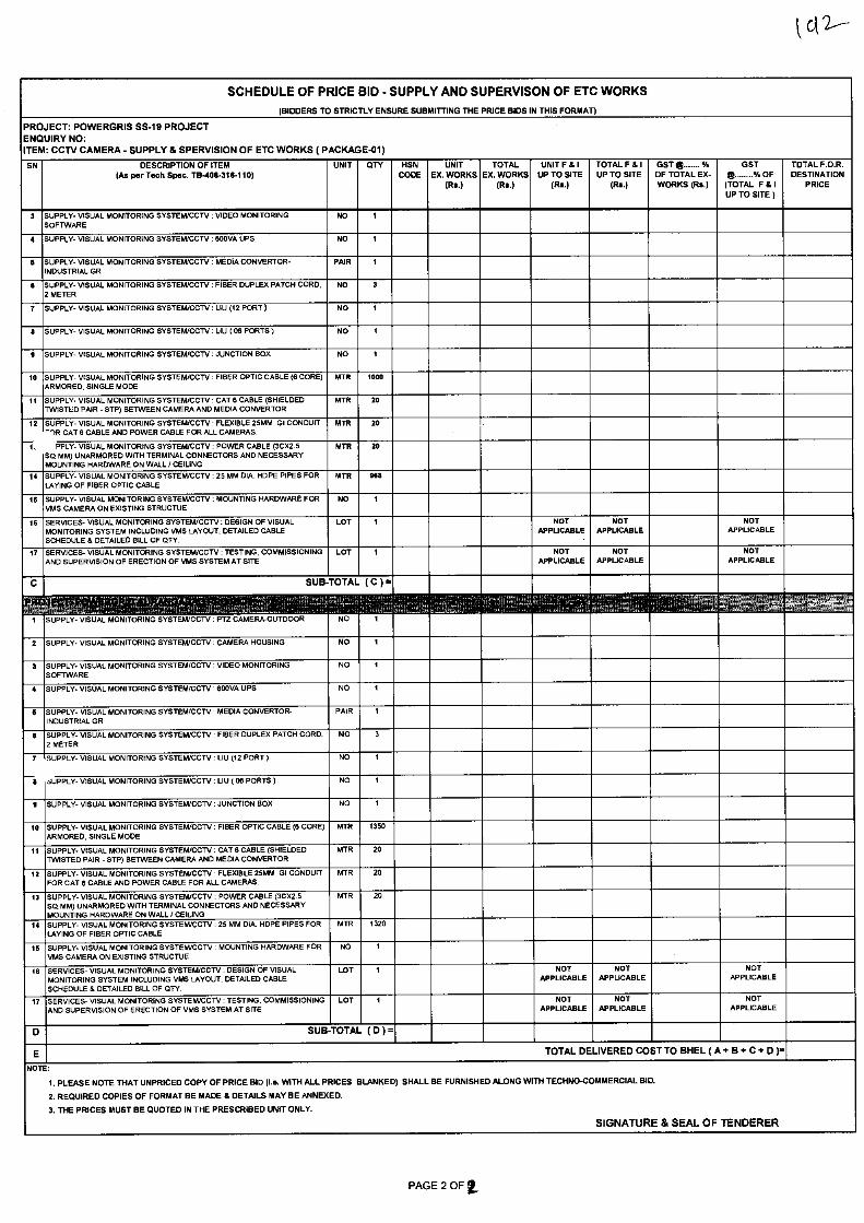
SCHEDULE OF PRICE BID - SUPPLY AND SUPERVISON OF ETC WORKS
(BIDDERS TO STRICTLY ENSURE SUBMITTING THE PRICE BIDS IN THIS FORMAT)
PROJECT: POWERGRIS SS-19 PROJECT ENQUIRY NO: ITEM: CCTV CAMERA - SUPPLY S SPERVISION OF ETC WORKS ( PACKAGE-01)
SN DESCRIPTION OF ITEM (As per Tech Spec. TB-408-315-110)
UNIT QTY HSN CODE
UNIT EX. WORKS
(Rs.)
TOTAL EX. WORKS
(Rs.)
UNIT F & I UP TO SITE
(Rs.)
TOTAL F & I UP TO SITE
(Rs.)
GST (5 % OF TOTAL EX- WORKS (Rs.)
GST e % OF (TOTAL F 8I UP TO SITE )
TOTAL F.O.R. DESTINATION
PRICE
3 SUPPLY- VISUAL MONITORING SYSTEM/CCTV: VIDEO MONITORING SOFTWARE
NO I
4 SUPPLY- VISUAL MONITORING SYSTEM/CCTV :1300VA UPS NO 1
5 SUPPLY- VISUAL MONITORING SYSTEM/CCTV: MEDIA CONVERTOR- INDUSTRIAL GR
PAIR 1
8 SUPPLY- VISUAL MONITORING SYSTEM/CCTV: FIBER DUPLEX PATCH CORD, 2 METER
NO 3
7 SUPPLY- VISUAL MONITORING SYSTEM/CCTV : LIU (12 PORT) NO 1
s SUPPLY- VISUAL MONITORING SYSTEM/CCTV : LIU ( 013 PORTS) NO 1
s SUPPLY- VISUAL MONITORING SYSTEWCCTV : JUNCTION BOX NO 1
10 SUPPLY- VISUAL MONITORING SYSTEWCCTV : FIBER OPTIC CABLE (8 CORE) ARMORED, SINGLE MODE
MTR 1000
11 SUPPLY- VISUAL MONITORING SYSTEM/CCTV: CAT 8 CABLE (SHIELDED TWISTLD PAIR - STP) BETWEEN CAMERA AND MEDIA CONVERTOR
MTR 20
12
1,
SUPPLY- VISUAL MONITORING SYSTEM/CCTV : FLEXIBLE 25MM GI CONDUIT -IR CAT 8 CABLE AND POWER CABLE FOR ALL CAMERAS.
MTR 20
PPLY- VISUAL MONITORING SYSTEM/CCTV : POWER CABLE (3CX2.5 SO.MM) UNARMORED WITH TERMINAL CONNECTORS AND NECESSARY
MTR 20
MOUNTING HARDWARE ON WALL / CEILING
14 SUPPLY- VISUAL MONITORING SYSTEM/CCTV: 25 MM DIA. HOPE PIPES FOR LAYING OF FIBER OPTIC CABLE
MTR 983
16 SUPPLY- VISUAL MONITORING SYSTEWCCTV : MOUNTING HARDWARE FOR VMS CAMERA ON EXISTING STRUCTUE
NO 1
16 SERVICES- VISUAL MONITORING SYSTEM/CCTV : DESIGN OF VISUAL MONITORING SYSTEM INCLUDING VMS LAYOUT, DETAILED CABLE SCHEDULE 8 DETAILED BILL OF QTY.
LOT 1 NOT APPLICABLE
NOT APPUCABLE
NOT APPLICABLE
17 SERVICES- VISUAL MONITORING SYSTEM/CCTV: TESTING, COMMISSIONING AND SUPERVISION OF ERECTION OF VMS SYSTEM AT SITE
LOT 1 NOT APPLICABLE
NOT APPUCABLE
NOT APPLICABLE
C SUB TOTAL ( C ) =
A. NO 1 1 SUPPLY- VISUAL MONITORING SYSTEM/CCTV: PTZ CAMERA-OUTDOOR
2 SUPPLY- VISUAL MONITORING SYSTEM/CCTV : CAMERA HOUSING NO 1
3 SUPPLY- VISUAL MONITORING SYSTEM/CCTV: VIDEO MONITORING SOFTWARE
NO 1
4 SUPPLY- VISUAL MONITORING SYSTEM/CCTV : 800VA UPS NO
5 SUPPLY- VISUAL MONITORING SYSTEWCCTV : MEDIA CONVERTOR- INDUSTRIAL GR
PAIR 1
6 SUPPLY- VISUAL MONITORING SYSTEM/CCN : FIBER DUPLEX PATCH CORD, 2 METER
NO
7
5
SUPPLY- VISUAL MONITORING SYSTEM/CCTV: LIU (12 PORT) NO 1
SUPPLY- VISUAL MONITORING SYSTEWCCTV : LIU ( 08 PORTS) NO
9 SUPPLY- VISUAL MONITORING SYSTEM/CCTV: JUNCTION BOX NO 1
10 SUPPLY- VISUAL MONITORING SYSTEM/CCTV: FIBER OPTIC CABLE (8 CORE) ARMORED, SINGLE MODE
MTR 1350
11 SUPPLY- VISUAL MONITORING SYSTEWCCTV : CAT 13 CABLE (SHIELDED TWISTED PAIR - STP) BETWEEN CAMERA AND MEDIA CONVERTOR
MTR 20
12 SUPPLY- VISUAL MONITORING SYSTEWCCTV : FLEXIBLE 25MM GI CONDUIT FOR CAT 8 CABLE AND POWER CABLE FOR ALL CAMERAS.
MTR 20
13 SUPPLY- VISUAL MONITORING SYSTEM/CCTV : POWER CABLE (3CX2.5 SO. MM) UNARMORED WITH TERMINAL CONNECTORS AND NECESSARY MOUNTING HARDWARE ON WALL / CEILING
MTR 20
14 SUPPLY- VISUAL MONITORING SYSTEWCCTV : 25 MM DIA. HDPE PIPES FOR LAYING OF FIBER OPTIC CABLE
MTR 1320
15 SUPPLY- VISUAL MONITORING SYSTEWCCTV : MOUNTING HARDWARE FOR VMS CAMERA ON EXISTING STRUCTUE
NO 1
16 SERVICES- VISUAL MONITORING SYSTEM/CCTV : DESIGN OF VISUAL MONITORING SYSTEM INCLUDING VMS LAYOUT, DETAILED CABLE SCHEDULE 8 DETAILED BILL OF QTY.
LOT 1 NOT APPLICABLE
NOT APPLICABLE
NOT APPLICABLE
17 SERVICES- VISUAL MONITORING SYSTEM/CCTV: TESTING, COMMISSIONING AND SUPERVISION OF ERECTION OF VMS SYSTEM AT SITE
LOT I NOT APPLICABLE
NOT APPLICABLE
NOT APPLICABLE
D SUB TOTAL ( D ) =
E TOTAL DELIVERED COST TO BHEL ( A 4. 13 4- C -1- D ).
NOTE:
1. PLEASE NOTE THAT UNPRICED COPY OF PRICE BID (I.e. WITH ALL PRICES BLANKED) SHALL BE FURNISHED ALONG WITH TECHNO-COMMERCIAL BID.
2. REQUIRED COPIES OF FORMAT BE MADE & DETAILS MAY BE ANNEXED.
3. THE PRICES MUST BE QUOTED IN THE PRESCRIBED UNIT ONLY.
SIGNATURE & SEAL OF TENDERER
PAGE 2 OF E
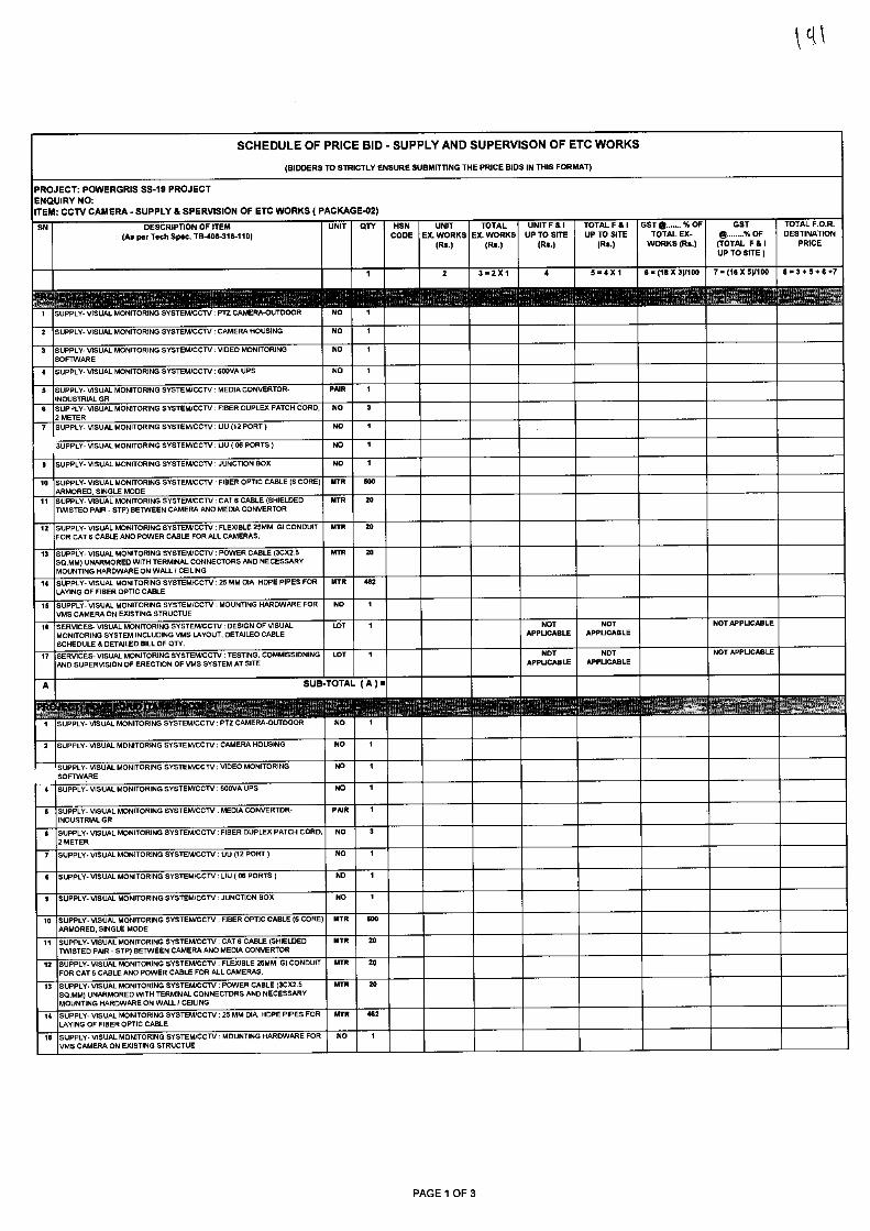
SCHEDULE OF PRICE BID - SUPPLY AND SUPERVISON OF ETC WORKS
(BIDDERS TO STRICTLY ENSURE SUBMITTING THE PRICE BIDS IN THIS FORMAT)
PROJECT: POWERGRIS SS-19 PROJECT ENQUIRY NO: ITEM: CCTV CAMERA - SUPPLY & SPERVISION OF ETC WORKS ( PACKAGE-02)
SN DESCRIPTION OF ITEM UNIT OTT HSN UNIT TOTAL UNIT F & I TOTAL F 8 I GST e % OF GST TOTAL F.O.R.
(As per Tech Spec. TB-4013-316-110) CODE EX. WORKS EX. WORKS UP TO SITE UP TO SITE TOTAL EX- 41(1 % OF DESTINATION
(Rs.) (Rs.) (Rs.) (Rs.) WORKS (Rs.) (TOTAL F 8I PRICE UP TO SITE )
3• 2 X 1 8 5=4X1 6.013%3000 7•(15X5)1100 5.3.5.-6.7
1 SUPPLY- VISUAL MONITORING SYSTEM/CCTV : PT2 CAMERA-OUTDOOR NO 1
2 SUPPLY-VISUAL MONITORING SYSTEM/CCTV : CAMERA HOUSING NO
3 SUPPLY- VISUAL MONITORING SYSTEM/CCTV : VIDEO MONITORING NO 1 SOFTWARE
SUPPLY- VISUAL MONITORING SYSTEM/CCTV :1300VA UPS NO 1
6 SUPPLY- VISUAL MONITORING SYSTEWCCTV : MEDIA CONVERTOR- PAIR 1
INDUSTRIAL GR
6 SUP 4LY- VISUAL MONITORING SYSTEM/CCTV : FIBER DUPLEX PATCH CORD. NO 3 2 METER
7 SUPPLY- VISUAL MONITORING SYSTEM/CCTV : LIU (12 PORT) NO 1
'SUPPLY- VISUAL MONITORING SYSTEM/CCTV LIU ( 06 PORTS )
9 SUPPLY- VISUAL MONITORING SYSTEM/CCTV : JUNCTION BOX
10 SUPPLY- VISUAL MONITORING SYSTEM/CCTV : FIBER OPTIC CABLE (6 CORE) BITS 000 ARMORED. SINGLE MODE
11 SUPPLY- VISUAL MONITORING SYSTEM/CCTV: CAT 6 CABLE (SHIELDED MTR 20 TWISTED PAIR - STP) BETWEEN CAMERA AND MEDIA CONVERTOR
12 SUPPLY- VISUAL MONITORING SYSTEM/CCTV : FLEXIBLE 25MM GI CONDUIT MTR 20 FOR CAT 6 CABLE AND POWER CABLE FOR ALL CAMERAS.
13 SUPPLY- VISUAL MONITORING SYSTEM/CCTV : POWER CABLE (30X2.5 MTR 20 SOMM) UNARMORED WITH TERMINAL CONNECTORS AND NECESSARY MOUNTING HARDWARE ON WALL I CEILING
14 SUPPLY- VISUAL MONITORING SYSTEM/CCTV : 25 MM DIA. HDPE PIPES FOR MTR 443 LAYING OF FIBER OPTIC CABLE
16 SUPPLY- VISUAL MONITORING SYSTEM/CCTV MOUNTING HARDWARE FOR NO 1 VMS CAMERA ON EXISTING STRUCTUE
16 SERVICES- VISUAL MONITORING SYSTEM/CCTV: DESIGN OF VISUAL MONITORING SYSTEM INCLUDING VMS LAYOUT, DETAILED CABLE SCHEDULE 6 DETAILED BILL OF CITY.
17 SERVICES- VISUAL MONITORING SYSTEM/CCTV TESTING, COMMISSIONING LOT AND SUPERVISION OF ERECTION OF VMS SYSTEM AT SITE
NOT
NOT APPUCABLE APPUCABLE
NOT
NOT APPUCABLE APPUCABLE
NOT APPUCABLE
NOT APPUCABLE
A SUB TOTAL ( A ) =
1 SUPPLY- VISUAL MONITORING SYSTEM/CCTV: PT2 CAMERA-OUTDOOR NO
2 SUPPLY- VISUAL MONITORING SYSTEM/CCTV CAMERA HOUSING NO
SUPPLY- VISUAL MONITORING SYSTEM/CCTV : VIDEO MONITORING SOFTWARE
4 SUPPLY- VISUAL MONITORING SYSTEM/CCTV : 600VA UPS
NO 1
NO 1
5 SUPPLY- VISUAL MONITORING SYSTEM/CCTV: MEDIA CONVERTOR- PAIR 1 INDUSTRIAL GR
6 SUPPLY- VISUAL MONITORING SYSTEM/CCTV: FIBER DUPLEX PATCH CORD, NO 3 2 METER
7 SUPPLY- VISUAL MONITORING SYSTEM/CCTV: UU (12 PORT )
5 SUPPLY- VISUAL MONITORING SYSTEM/CCTV LIU ( 06 PORTS )
SUPPLY- VISUAL MONITORING SYSTEM/CCTV : JUNCTION BOX
NO 1
NO
NO 1
10 SUPPLY- VISUAL MONITORING SYSTEM/CCTV FIBER OPTIC CABLE (6 CORE) MTR 500
ARMORED, SINGLE MODE
SUPPLY- VISUAL MONITORING SYSTESVCCIV : CATS CABLE (SHIELDED MTR 20 TWISTED PAIR - STP) BETWEEN CAMERA AND MEDIA CONVERTOR
12 SUPPLY- VISUAL MONITORING SYSTEM/CCTV: FLEXIBLE 25MM GI CONDUIT MTR 20 FOR CAT 6 CABLE AND POWER CABLE FOR ALL CAMERAS.
SUPPLY- VISUAL MONITORING SYSTEM/CCTV POWER CABLE (30%2.5 MTR 20 SOMM) UNARMORED WITH TERMINAL CONNECTORS AND NECESSARY MOUNTING HARDWARE ON WALL I CEILING
14 SUPPLY- VISUAL MONITORING SYSTEM/CCTV : 25MM DIA. HDPE PIPES FOR MTR 462
LAYING OF FIBER OPTIC CABLE
16 SUPPLY- VISUAL MONITORING SYSTEM/CCTV : MOUNTING HARDWARE FOR NO
VMS CAMERA ON EXISTING STRUCTUE
13
PAGE 1 OF 3
NOT APPLICABLE NOT NOT APPUCABLE APPUCABLE
NOT NOT APPLICABLE APPLICABLE
NOT APPLICABLE
NOT APPUCABLE NOT APPUCABLE
NOT APPUCABLE
NOT APPUCABLE
y yo
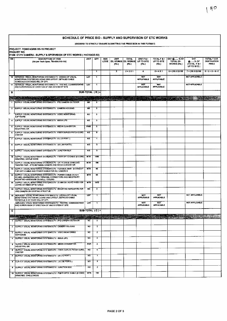
SCHEDULE OF PRICE BID - SUPPLY AND SUPERVISON OF ETC WORKS
(BIDDERS TO STRICTLY ENSURE SUBMITTING THE PRICE BIDS IN THIS FORMAT)
PROJECT: POWERGRIS SS-19 PROJECT ENQUIRY NO: ITEM: CCTV CAMERA - SUPPLY & SPERVISION OF ETC WORKS ( PACKAGE-02)
SN DESCRIPTION OF ITEM (As per Tech Spec. TB408-316-110)
UNIT QTY HSN UNIT TOTAL UNIT F & I TOTAL F & I GST fra X OF GST TOTAL F.O.R. CODE EX. WORKS EX. WORKS UP TO SITE UP TO SITE TOTAL EX- 92 /Y. OF DESTINATION
(Rs.) (Rs.) (Rs.) (R6.) WORKS (Rs.) (TOTAL F & I PRICE UP TO SITE )
16 SERVICES- VISUAL MONITORING SYSTEINCCTV : DESIGN OF VISUAL
LOT MONITORING SYSTEM INCLUDING VMS LAYOUT, DETAILED CABLE SCHEDULE 6 DETAILED BILL OF QTY.
17 SERVICES- VISUAL MONITORING SYSTEM/CCTV : TESTING, COMMISSIONING LOT AND SUPERVISION OF ERECTION OF VMS SYSTEM AT SITE
3.221 4 5.4X 1 6=(18X3)1100 7=o8 x syloo Be 3 +6.7
SUB TOTAL ( B ) =
2 SUPPLY- VISUAL MONITORING SYSTEM/CCN: CAMERA HOUSING
SUPPLY VISUAL MONITORING SYSTEM/CCTV -OPTZ CAMERAUTDOOR
SUPPLY- VISUAL MONITORING SYSTEM/CCTV VIDEO MONITORING SOFTWARE
SUPPLY- VISUAL MONITORING SYSTEM/CCTV 600VA UPS
SUPPLY- VISUAL MONITORING SYSTEM/CCTV : MEDIA CONVERTOR- PAIR 3 INDUSTRIAL GR
SUPPLY- VISUAL MONITORING SYSTEM/CCTV : FIBER DUPLEX PATCH CORD. NO 9 2 METER
SUPPLY- VISUAL MONITORING SYSTEM/CCTV : LIU (12 PORT) NO
SUPPLY- VISUAL MONITORING SYSTEM/CCTV LIU ( 06 PORTS )
SUPPLY- VISUAL MONITORING SYSTEM/CCTV : JUNCTION BOX
SUPPLY- VISUAL MONITORING SYSTEM/CCTV : FIBER OPTIC CABLE (6 CORE) MTR 1560 ARMORED, SINGLE MODE
SUPPLY- VISUAL MONITORING SYSTEM/CCTV : CATS CABLE (SHIELDED MTR 190 TWISTED PAIR - STP) BETWEEN CAMERA AND MEDIA CONVERTOR
SUPPLY- VISUAL MONITORING SYSTEM/CCTV : FLEXIBLE 25MM GI CONDUIT MTR 60 FOR CAT 6 CABLE AND POWER CABLE FOR ALL CAMERAS.
SUPPLY- VISUAL MONITORING SYSTEM/CCTV : POWER CABLE (3CX2.5 SQ.MM) UNARMORED WITH TERMINAL CONNECTORS AND NECESSARY MOUNTING HARDWARE ON WALL / CEIUNG
SUPPLY- VISUAL MONITORING SYSTEM/CCTV : 25 MM DIA. HOPE PIPES FOR LAYING OF FIBER OPTIC CABLE
SUPPLY- VISUAL MONITORING SYSTEM/CCTV MOUNTING HARDWARE FOR NO 3 VMS CAMERA ON EXISTING STRUCTUE
SERVICES- VISUAL MONITORING SYSTEM/CCTV : DESIGN OF VISUAL MONITORING SYSTEM INCLUDING VMS LAYOUT, DETAILED CABLE SCHEDULE & DETAILED BILL OF QTY.
SERVICES- VISUAL MONITORING SYSTEM/CCTV TESTING, COMMISSIONING LOT AND SUPERVISION OF ERECTION OF VMS SYSTEM AT SITE
4
6
7
a
9
10
11
12
13
14
16
16
MTR 60
MTR
1613
LOT
NO 3
NO 3
NO 3
NOT APPLICABLE
NOT APPLICABLE
B
C SUB TOTAL ( C ) =
SUPPLY- VISUAL MONITORING SYSTEWCCTV : UU (12 PORT )
SUPPLY- VISUAL MONITORING SYSTEWCCTV LIU ( 06 PORTS) ©-
SUPPLY- VISUAL MONITORING SYSTEM/CCTV PTZ CAMERA-OUTDOOR
SUPPLY- VISUAL MONITORING SYSTEM/CCTV : CAMERA HOUSING
SUPPLY- VISUAL MONITORING SYSTEM/CCTV : VIDEO MONITORING SOFTWARE
SUPPLY- VISUAL MONITORING SYSTEWCCTV : 600VA UPS
SUPPLY- VISUAL MONITORING SYSTEM/CC7V MEDIA CONVERTOR- INDUSTRIAL GR
SUPPLY- VISUAL MONITORING SYSTEM/CCTV : FIBER DUPLEX PATCH CORD, 2 METER
9 SUPPLY- VISUAL MONITORING SYSTEM/CCTV : JUNCTION BOX NO 2
10 SUPPLY- VISUAL MONITORING SYSTEM/CCTV : FIBER OPTIC CABLE (6 CORE) MTR 750 ARMORED, SINGLE MODE
PAGE 2 OF 3
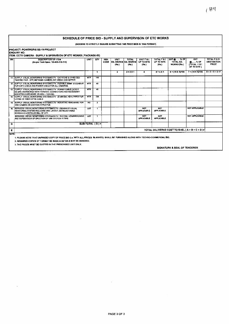
SCHEDULE OF PRICE BID - SUPPLY AND SUPERVISON OF ETC WORKS
(BIDDERS TO STRICTLY ENSURE SUBMITTING THE PRICE BIDS IN THIS FORMAT)
PROJECT: POWERGRIS SS-19 PROJECT ENQUIRY NO: ITEM: CCTV CAMERA - SUPPLY & SPERVISION OF ETC WORKS ( PACKAGE-02)
SN DESCRIPTION OF ITEM (As per Tech Spec. TB-408-316-110)
UNIT QTY HSN CODE
UNIT EX. WORKS
(Rs.)
TOTAL EX. WORKS
(Rs.)
UNIT F & I UP TO SITE
(Rs.)
TOTAL F & I UP TO SITE
(Rs.)
GST a % OF TOTAL EX-
WORKS (Rs.)
GST a % OF
(TOTAL F & I UP TO SITE )
TOTAL F.O.R. DESTINATION
PRICE
1 2 3e2X1 4 5e4X1 6e(18)(3)/100 7.08x5y100 8.3+5+447
11 SUPPLY- VISUAL MONITORING SYSTEWCCTV : CAT 6 CABLE (SHIELDED TWISTED PAIR - STP) BETWEEN CAMERA AND MEDIA CONVERTOR
MTR 140
12 SUP=LY- VISUAL MONITORING SYSTEM/CCTV: FLEXIBLE 25MM GI CONDUIT FOR CAT 6 CABLE AND POWER CABLE FOR ALL CAMERAS.
MTR 40
13 SUPPLY- VISUAL MONITORING SYSTEM/CCTV: POWER CABLE (30X2.5 SO.MM) UNARMORED WITH TERMINAL CONNECTORS AND NECESSARY MOUNTING HARDWARE ON WALL I CEILING
MTR 40
14 SUPPLY-VISUAL MONITORING SYSTEM/CCTV :25 MM DIA. HDPE PIPES FOR LAYING OF FIBER OPTIC CABLE
MTR 726
16 SUPPLY- VISUAL MONITORING SYSTEM/CCTV : MOUNTING HARDWARE FOR VMS CAMERA ON EXISTING STRUCTUE
NO 2
14 SERVICES- VISUAL MONITORING SYSTEM/CCTV : DESIGN OF VISUAL MONITORING SYSTEM INCLUDING VMS LAYOUT, DETAILED CABLE SCHEDULE IS DETAILED BILL OF QTY.
LOT 1 NOT APPUCABLE
NOT APPUCABLE
NOT APPUCABLE
SERVICES- VISUAL MONITORING SYSTEM/CCTV : TESTING, COMMISSIONING AND SUPERVISION OF ERECTION OF VMS SYSTEM AT SITE
LOT 1 NOT APPUCABLE
NOT APPUCABLE
NOT APPUCABLE
D SUB TOTAL ( D )
E TOTAL DELIVERED COST TO BHEL ( A + B .1. C + D )=
NOTE:
1. PLEASE NOTE THAT UNPRICED COPY OF PRICE BID (I.e. WITH ALL PRICES BLANKED) SHALL BE FURNISHED ALONG WITH TECHNO-COMMERCIAL BID.
2. REQUIRED COPIES OF FORMAT BE MADE & DETAILS MAY BE ANNEXED.
3. THE PRICES MUST BE QUOTED IN THE PRESCRIBED UNIT ONLY.
SIGNATURE 8 SEAL OF TENDERER
PAGE 3 OF 3
(Sg
sura tt oelf4schc1 CAP s (RM. tiq::1)1, 0141)
Bharat Heavy Electricals Limited (A Govt. of India Undertaking)
riTtolui psi, 3.A. / TBG, Noida, U.P.
*WC WitTRI Material Management
.fiqvgVn-i
HOT
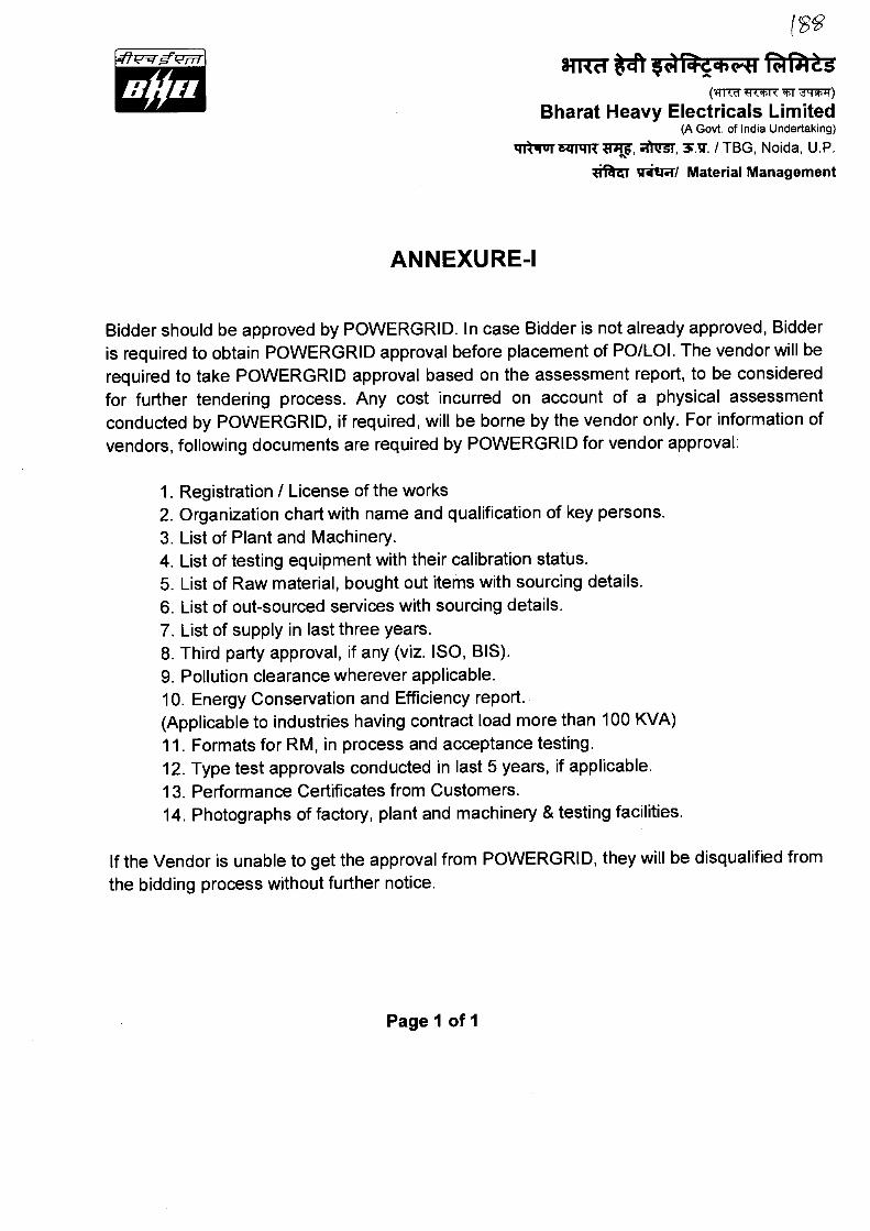
ANNEXURE-I
Bidder should be approved by POWERGRID. In case Bidder is not already approved, Bidder is required to obtain POWERGRID approval before placement of PO/LOI. The vendor will be required to take POWERGRID approval based on the assessment report, to be considered for further tendering process. Any cost incurred on account of a physical assessment conducted by POWERGRID, if required, will be borne by the vendor only. For information of vendors, following documents are required by POWERGRID for vendor approval:
1. Registration / License of the works 2. Organization chart with name and qualification of key persons. 3. List of Plant and Machinery. 4. List of testing equipment with their calibration status. 5. List of Raw material, bought out items with sourcing details. 6. List of out-sourced services with sourcing details. 7. List of supply in last three years. 8. Third party approval, if any (viz. ISO, BIS). 9. Pollution clearance wherever applicable. 10. Energy Conservation and Efficiency report. (Applicable to industries having contract load more than 100 KVA) 11. Formats for RM, in process and acceptance testing. 12. Type test approvals conducted in last 5 years, if applicable.
13. Performance Certificates from Customers. 14. Photographs of factory, plant and machinery & testing facilities.
If the Vendor is unable to get the approval from POWERGRID, they will be disqualified from the bidding process without further notice.
Page 1 of 1
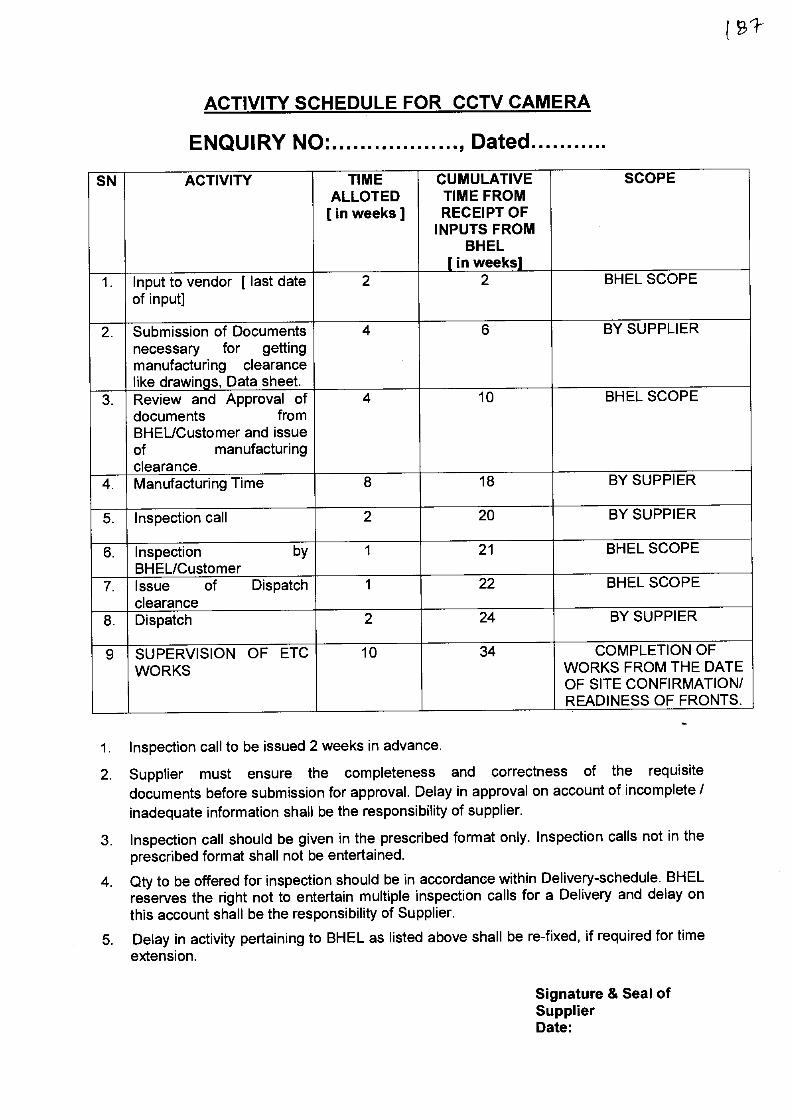
ACTIVITY SCHEDULE FOR CCTV CAMERA
ENQUIRY NO• , Dated
SN ACTIVITY TIME ALLOTED
[ in weeks ]
CUMULATIVE TIME FROM RECEIPT OF
INPUTS FROM BHEL
[ in weeks]
SCOPE
1. Input to vendor [ last date of input]
2 2 BHEL SCOPE
2. Submission of Documents necessary for getting manufacturing clearance like drawings, Data sheet.
4 6 BY SUPPLIER
3. Review and Approval of documents from BHEL/Customer and issue of manufacturing clearance.
4 10 BHEL SCOPE
4. Manufacturing Time 8 18 BY SUPPIER
5. Inspection call 2 20 BY SUPPIER
6. Inspection by BHEL/Customer
1 21 BHEL SCOPE
7. Issue of Dispatch clearance
1 22 BHEL SCOPE
8. Dispatch 2 24 BY SUPPIER
9 SUPERVISION OF ETC WORKS
10 34 COMPLETION OF WORKS FROM THE DATE OF SITE CONFIRMATION/ READINESS OF FRONTS.
1. Inspection call to be issued 2 weeks in advance.
2. Supplier must ensure the completeness and correctness of the requisite documents before submission for approval. Delay in approval on account of incomplete / inadequate information shall be the responsibility of supplier.
3. Inspection call should be given in the prescribed format only. Inspection calls not in the prescribed format shall not be entertained.
4. Qty to be offered for inspection should be in accordance within Delivery-schedule. BHEL reserves the right not to entertain multiple inspection calls for a Delivery and delay on this account shall be the responsibility of Supplier.
5. Delay in activity pertaining to BHEL as listed above shall be re-fixed, if required for time extension.
Signature & Seal of Supplier Date:

Page 1 of 2
Item Name : CCTV CAMERA Enquiry No. : Project : PGCIL SS-19 PROJECT
Type of project Transmission - : • : ... • • : Applicable percentage of Local Content
50 % ( Minimum)
Format for Affidavit of Self certification regarding Minimum Local Content in line with PPP-MH order, 2017 if applicable, to be provided on 'la non-judicia1 stamp paper of Rs. 100/-.
Date: / /2019
I S/ o, D/o, W/o, Resident of hereby solemnly affirm and declare as under:
That I will agree to abide by the terms and conditions of the Public Procurement (Preference to Make in India) Order, 2017 (hereinafter PPP-MII order) of Government of India issued vide Notification No:P-45021/2/2017 -BE-II dated 15/06/2017, its revision dated 28/05/2018 and any subsequent modifications/Amendments, if any and
That the information furnished hereinafter is correct to the best of my knowledge and belief and I undertake to produce relevant records before the procuring entity/BHEL or any other Government authority for the purpose of assessing the local content of goods/services/works supplied by me for (Enter the name of the Equipment/Item for Project).
That the local content for all inputs which constitute the said goods/services/works has been verified by me and I am responsible for the correctness of the claims made therein.
That the goods/services/works supplied by me for (Enter the name of the EquipmenKtem for Project) meets the 'Minimum Local Content 'as defined in the PPP-MII order.
That the value addition for the purpose of meeting the 'Minimum Local Content 'has been made by me at (Enter the details of the location(s) at which value addition is made).
That in the event of the local content of the goods/services/works mentioned herein is found to be incorrect and not meeting the prescribed Minimum Local Content criteria, based on the assessment of procuring agency (ies)/BHEL/Government Authorities for the purpose of assessing the local content, action shall be taken against me in line with the PPP-MII order and provisions of the Integrity pact/ Bidding Documents.
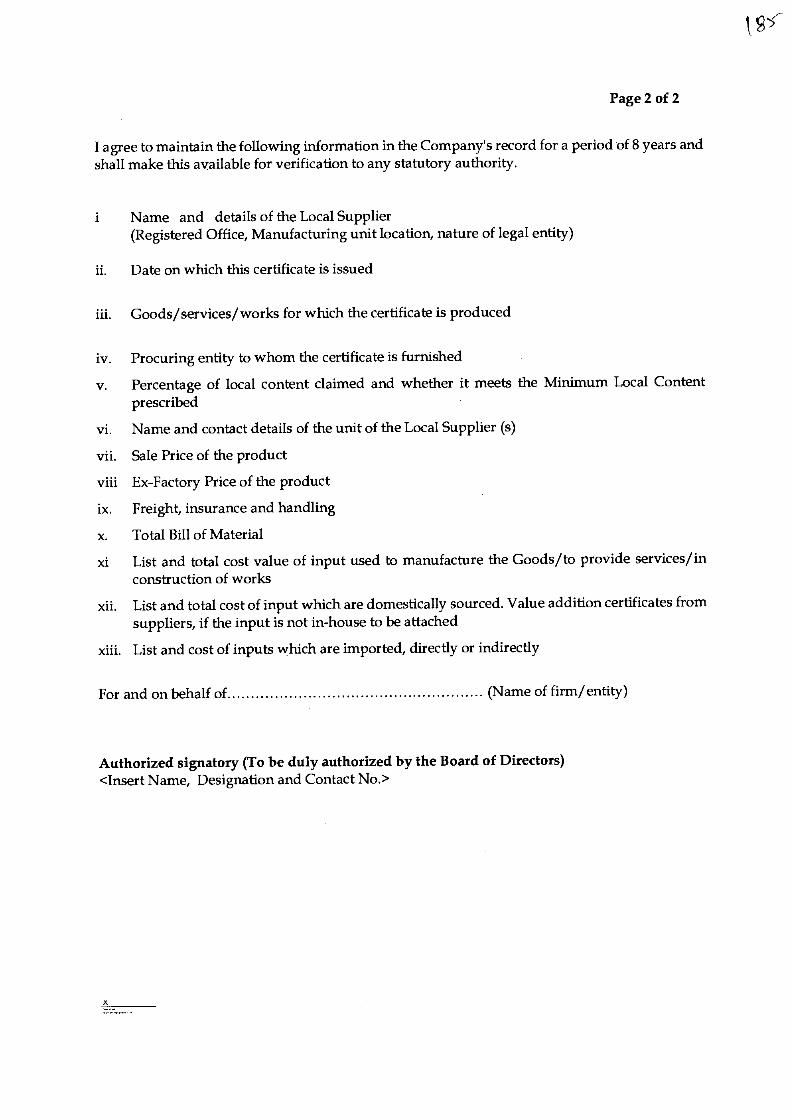
Page 2 of 2
I agree to maintain the following information in the Company's record for a period of 8 years and shall make this available for verification to any statutory authority.
i Name and details of the Local Supplier (Registered Office, Manufacturing unit location, nature of legal entity)
ii. Date on which this certificate is issued
iii. Goods/services/works for which the certificate is produced
iv. Procuring entity to whom the certificate is furnished
v. Percentage of local content claimed and whether it meets the Minimum Local Content prescribed
vi. Name and contact details of the unit of the Local Supplier (s)
vii. Sale Price of the product
viii Ex-Factory Price of the product
ix. Freight, insurance and handling
x. Total Bill of Material
xi List and total cost value of input used to manufacture the Goods/to provide services/in construction of works
xii. List and total cost of input which are domestically sourced. Value addition certificates from suppliers, if the input is not in-house to be attached
xiii. List and cost of inputs which are imported, directly or indirectly
For and on behalf of (Name of firm/entity)
Authorized signatory (To be duly authorized by the Board of Directors) <Insert Name, Designation and Contact No.>

SCHEDULE OF TECHNICAL DEVIATION
This Format is to be submitted In original duly signed by bidder. The following are the devitions/varlations/exceptions from the Terms and Conditions :-
S N CLAUSE NO. OF TERMS AND CONDITIONS
STATEMENT OF DEVIATION
In case, this schedule is not submitted, it will be presumed that the equipment /material to be supplied under this contract is deemed to be in compliance with the Terms and Conditions.
If there is NIL deviation,even then the format to be filled as NIL DEVIATION.
Note : Continuation Sheets of like size and format may be used as per the Bidders Requirement and shall be annexed to this schedule.
Signature of the authorised representative of
Place : Date : Bidders name
Designation. Company Seal.
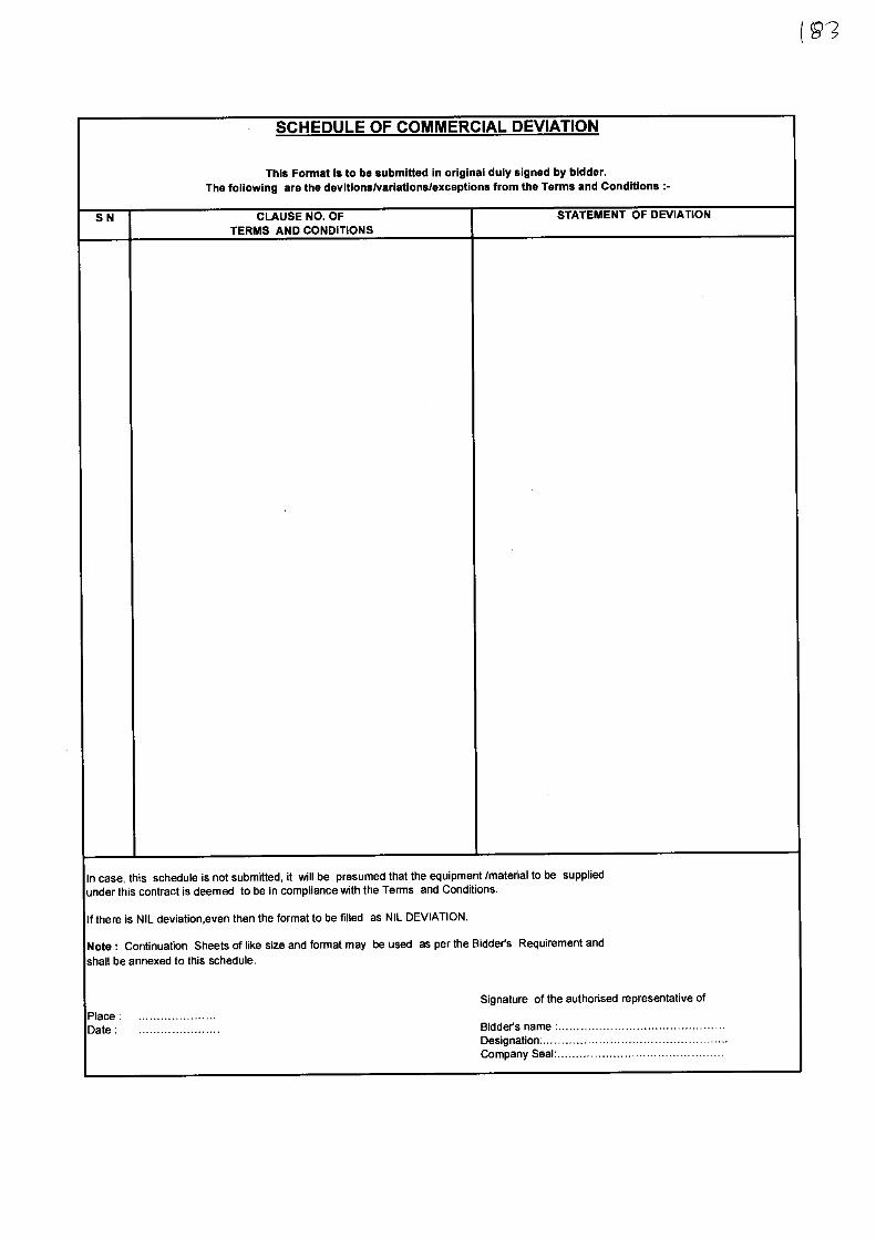
SCHEDULE OF COMMERCIAL DEVIATION
This Format is to be submitted in original duly signed by bidder. The following are the devitionsivariations/exceptions from the Terms and Conditions :-
S N CLAUSE NO. OF TERMS AND CONDITIONS
STATEMENT OF DEVIATION
In case, this schedule is not submitted, it will be presumed that the equipment /material to be supplied under this contract is deemed to be in compliance with the Terms and Conditions.
If there is NIL deviation,even then the format to be filled as NIL DEVIATION.
Note : Continuation Sheets of like size and format may be used as per the Bidders Requirement and
shall be annexed to this schedule.
Signature of the authorised representative of
Place : Date : Bidders name :
Designation- . Company Seal
g2
ti BHEUTBG/GTC/2016 REV 01k
BHARAT HEAVY ELECTRICALS LTD. (TRANSMISSION BUSINESS GROUP)
GENERAL TERMS AND CONDITIONS FOR TENDER ENQUIRY / CONTRACT
This is to be submitted duly signed by bidder in original. Clause-wise deviations and / or additional conditions / clarifications, if any, are to be brought out clearly in "Schedule of Commercial Deviation". Deviations and / or additional conditions / clarifications, if any, mentioned elsewhere in the bid / offer, shall not be considered.
Sr. No. 1. INSTRUCTION TO BIDDERS :
1.1 Sealed bids are invited for the items mentioned in the tender enquiry conforming to the NIT including Technical Specifications. Bids should be typed and free from overwriting and erasures. Corrections or additions / deletions, if any, must be clearly written and attested, otherwise offer may be rejected.
1.2 Bidder must ensure that their bid is submitted / dropped in the tender box on or before 14-00 Hrs. 1ST on the due date of opening, unless otherwise specified in the NIT, at the address as follows :-
Tender Box, Materials Management, Transmission Business Group, Bharat Heavy Electricals Limited, 5th Floor, Tower-A, Advant Navis IT Business Park, Plot-7, Sector-142, Noida Expressway, Noida, Dist. G. B. Nagar, U. P. — 201305
1.3 In case tender enquiry is floated though the e-procurement system, offer / bid has to be submitted through the e-procurement system ONLY as per instructions given in the e-procurement portal (https://bhel.abcprocure.com).
1.4 The bids shall be opened at 14-30 Hrs. 1ST on the due date of opening, in the presence of participating bidders who may like to be present, unless otherwise specified in the NIT. Bids received late are liable for rejection. Bidders sending bids by courier or post will have to ensure that it is timely delivered at the above address.
1.5 Bids are to be submitted duly signed with seal in two parts :-
a) Techno-commercial Bid (Part-I) — To be submitted in 2 sets (original + copy). A copy of Price Bid (Part-II) clearly mentioning all the necessary information as per format without prices "Un-Priced Bid" is also to be enclosed in Part-I Bid.
b) Price Bid (Part-II) — To be submitted only in one set in a separate sealed envelope. This should not contain any Technical and / or Commercial Terms and Conditions. The rates should be quoted both in figures and words.
1.6 The Part-I and Part-II Bids are to be sealed in separate envelopes and
Page 1 of 18
Sr. No.
marked as "Techno-commercial Bid (Part-I)" and "Price Bid (Part-11)" respectively. Both the envelopes are to be kept in another common envelope and marked as "BID". Each envelope should be sealed and superscribed with tender enquiry no., item / package name, project name and due date of opening. Bidder's name and address shall also be mentioned on each envelope.
1.7 For any technical clarification, please contact official mentioned in the tender enquiry / NIT.
1.8 For any commercial clarification please contact official issuing tender enquiry / NIT.
1.9 Price bid (Part-II) should not contain any additional information / description other than given in "Un-Priced Bid" submitted with "Techno-commercial Bid (Part-I)" except prices, otherwise bid is liable for rejection.
1.10 Price Bid submitted along with the bid shall remain valid up to validity of offer. Any discount / revised offer submitted by the bidder on its own shall be accepted provided it is received before the due date and time of offer submission (i.e. Part-I Bid). The discount shall be applied on pro-rata basis to all items including optional items, if any, unless specified otherwise by the bidder. Discount offered shall be valid for full duration of validity of the offer including extension of validity, if any. Unsolicited Supplementary / Revised Price Bid submitted after the due date and time of offer submission (i.e. Part-I Bid), during validity period of offer, unless asked by BHEL, shall not be considered. Withdrawal of quotation by the bidder, at any stage after its opening, may entail suitable action against such bidder by BHEL.
1.11 The consultants / firm (and any of its affiliates) shall not be eligible to participate against tender enquiry for the related goods or works or services for the same project, if they were engaged by BHEL-TBG for the consultancy services.
1.12 In case any Foreign OEM / Foreign Principal insists on engaging the services of an agent, such agent shall not be allowed to represent more than one manufacturer / supplier in the same tender. Moreover, either the agent could bid on behalf of the manufacturer / supplier or the manufacturer / supplier could bid directly but not both. In case bids are received from the manufacturer / supplier and the agent, bid received from the agent shall be ignored.
1.13 Non-conformities / errors / discrepancies in quoted prices in price bids shall be dealt as follows :-
a) If, in the price structure quoted for the required goods / services / works, there is discrepancy between the unit price and the total price (which is obtained by multiplying the unit price by the quantity), the unit price shall prevail and the total price corrected accordingly, unless in the opinion of BHEL there is an obvious misplacement of the decimal point in the unit price, in which case the total price as quoted shall govern and the unit price corrected accordingly.
b) If there is an error in a total corresponding to the addition or subtraction of subtotals, the subtotals shall prevail and the total shall be corrected.
BHEL/TBG/GTC/2016 REV 01
Page 2 of 18
BHEL/TBG/GTC/2016 REV 01 SC'
Sr. No.
c) If there is a discrepancy between words and figures, the amount in words shall prevail, unless the amount expressed in words is related to an arithmetic error, in which case the amount in figures shall prevail subject to (a) and (b) above.
d) If there is such discrepancy in an offer as mentioned in (a), (b) & (c) above, the same shall be conveyed to the bidder with target date upto which the bidder has to send his acceptance on the above lines and if the bidder does not agree to the decision of the BHEL, the bid is liable to be ignored.
1.14 In case the scope of the successful bidder / supplier against this tender enquiry includes Erection, Testing and Commissioning (ETC) of the equipment / material at site in addition to Supply, Purchase Order shall be placed for Supply Portion and Contract shall be separately awarded for ETC at Site Portion. General Terms and Conditions for Tender Enquiry / Contract mentioned herein shall be applicable for both Supply & ETC at Site. Additional Terms and Conditions for Tender Enquiry / Contract for Erection, Testing and Commissioning at Site "BHEUTBG/GTC-ETC/2016 REV01" shall be applicable for ETC at Site only which is to be read in conjunction with General Terms and Conditions for Tender Enquiry / Contract mentioned herein. However, any breach of either the Purchase Order or the Contract shall be deemed to be breach of the other.
1.15 Taxes and Duties payable extra as per Clause No. 2.3 in NIT, if not specified/quoted clearly as extra shall be considered as included in Ex-works Price and therefore shall not be reimbursed. Taxes and duties not payable extra as per NIT shall be deemed to be included in Ex-works Price.
1.16 If the rates for taxes and duties in respect of the quoted materials and / or services assumed by the Supplier are less than the tariff prevailing at the time of tendering, Supplier will be responsible for such under quotations. However if the rates assumed are higher than the correct rates prevailing at the time tendering, the difference will be to the credit of BHEL.
Note : Representative / official deputed by the bidder to witness tender opening must produce authorization letter for the same.
2. PRICES :
2.1 Unless specifically indicated in the NIT, all prices shall be FIRM. No enhancement of rate for whatsoever reasons unless and until asked by BHEL shall be allowed.
2.2 Unless specifically indicated in the NIT, the prices shall be on INR basis.
2.3 Unless specifically indicated in the NIT, the prices are to be quoted on FOR (Site / Destination) basis excluding GST. The break-up of prices shall be as under :-
a) Ex-works Price: Ex-works price including packing & forwarding charges.
Page 3 of 18
BHEL/TBG/GTC/2016 REV 01
Sr. No.
b) Freight: Freight for door delivery up to destination / site / store are to be quoted separately.
c) Insurance: Insurance for door delivery up to destination / site / store are to be quoted separately.
d) Type Test Charges: If asked in the technical specification, it is to be quoted separately for each test.
e) Charges for Supervision of Erection, Testing & Commissioning (ETC) at Site: To be quoted separately if specified in NIT/Price Schedule.
f) Charges for Testing & Commissioning at Site: To be quoted separately if specified in NIT/Price Schedule.
g) Charges for Erection, Testing & Commissioning at Site: To be quoted separately if specified in NIT/Price Schedule.
h) Training Charges: To be quoted separately if specified in NIT/Price Schedule.
2.4 GST rates along with HSN/SAC code as applicable on Sr No (a) to (h) above is to be mentioned separately in percentage in both un-priced bid and price bid.
Note : i) Unless otherwise specified in the NIT, the purchase order shall be placed on Ex-
works basis for Indian bidders. ii) Prices quoted by Indian bidders shall be in Indian Rupees only.
iii) In case Supervision of Erection, Testing & Commissioning (ETC) at Site or Testing & Commissioning at Site or Erection, Testing & Commissioning at Site is also in scope of the bidder along with supply, bidder has to ensure that prices quoted for such services also are in line with special terms & conditions of the NIT, if any.
iv) Unless otherwise specified in the NIT, Unloading at Site / Destination shall not be in the scope of the supplier.
v) Prices in respect of Sr No (a) to Sr No (h) of Clause 2.3 above are to be quoted inclusive of all taxes & Duties, charges. Levies , royalty etc if any, excluding GST.
3. TERMS OF PAYMENT :
3.1 For Supply only in scope of the supplier
100% of payment within 60 days from the date of receipt of complete invoice along with documents in 3 sets (original + 2 copies) as follows :
LR / GR duly endorsed by BHEL Site Official. Material Receipt Certificate issued by BHEL Site Official.
. GST Compliant Tax Invoice • Packing List (Case-wise)
Copy of Transit Insurance Certificate from underwriters. • Material Inspection Clearance Certificate (MICC) issued by BHEL Quality
Management
• Guarantee Certificate • Copy of Performance Bank Guarantee (PBG) • Certificate of acceptance of Type Test Reports issued by BHEL Engineering
Management wherever specifically mentioned in the Purchase Order.
Page 4 of 18
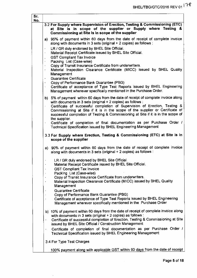
Sr. No.
3.2 For Supply where Supervision of Erection, Testing & Commissioning (ETC) at Site is in scope of the supplier or Supply where Testing & Commissioning at Site is in scope of the supplier
a) 95% of payment within 60 days from the date of receipt of complete invoice along with documents in 3 sets (original + 2 copies) as follows :
LR / GR duly endorsed by BHEL Site Official. Material Receipt Certificate issued by BHEL Site Official. GST Compliant Tax Invoice
• Packing List (Case-wise) • Copy of Transit Insurance Certificate from underwriters. • Material Inspection Clearance Certificate (MICC) issued by BHEL Quality
Management • Guarantee Certificate • Copy of Performance Bank Guarantee (PBG) • Certificate of acceptance of Type Test Reports issued by BHEL Engineering
Management wherever specifically mentioned in the Purchase Order.
b) 5% of payment within 60 days from the date of receipt of complete invoice along with documents in 3 sets (original + 2 copies) as follows : Certificate of successful completion of Supervision of Erection, Testing & Commissioning at Site if it is in the scope of the supplier or Certificate of successful completion of Testing & Commissioning at Site if it is in the scope of the supplier. Certificate of completion of final documentation as per Purchase Order / Technical Specification issued by BHEL Engineering Management
3.3 For Supply where Erection, Testing & Commissioning (ETC) at Site is in scope of the supplier
a) 90% of payment within 60 days from the date of receipt of complete invoice along with documents in 3 sets (original + 2 copies) as follows :
LR / GR duly endorsed by BHEL Site Official. Material Receipt Certificate issued by BHEL Site Official. GST Compliant Tax Invoice Packing List (Case-wise) Copy of Transit Insurance Certificate from underwriters. Material Inspection Clearance Certificate (MICC) issued by BHEL Quality Management Guarantee Certificate Copy of Performance Bank Guarantee (PBG) Certificate of acceptance of Type Test Reports issued by BHEL Engineering Management wherever specifically mentioned in the Purchase Order
b) 10% of payment within 60 days from the date of receipt of complete invoice along with documents in 3 sets (original + 2 copies) as follows :
• Certificate of successful completion of Erection, Testing & Commissioning at Site issued by BHEL Site Official / Construction Management
• Certificate of completion of final documentation as per Purchase Order / Technical Specification issued by BHEL Engineering Management
3.4 For Type Test Charges
100% payment along with applicable GST within 60 days from the date of receipt
BHEL/TBG/GTC/2016 REV 01 11Ag
Page 5 of 18
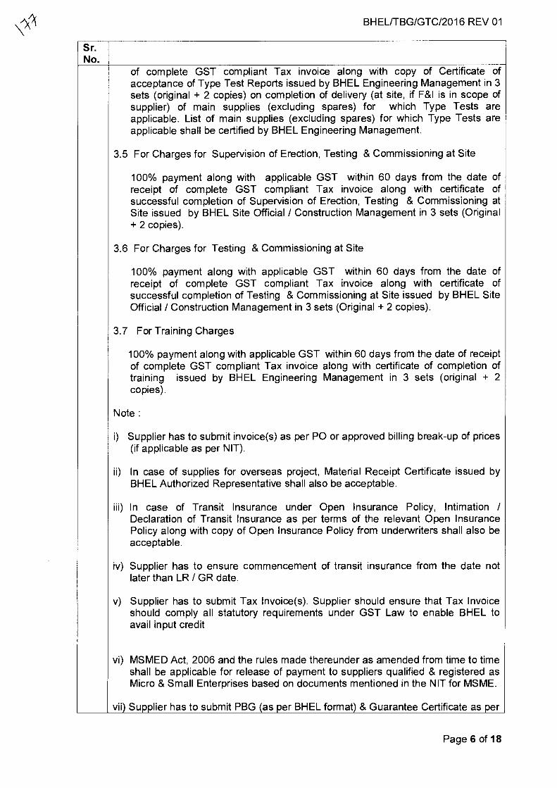
Sr. No.
of complete GST compliant Tax invoice along with copy of Certificate of acceptance of Type Test Reports issued by BHEL Engineering Management in 3 sets (original + 2 copies) on completion of delivery (at site, if F&I is in scope of supplier) of main supplies (excluding spares) for which Type Tests are applicable. List of main supplies (excluding spares) for which Type Tests are applicable shall be certified by BHEL Engineering Management.
3.5 For Charges for Supervision of Erection, Testing & Commissioning at Site
100% payment along with applicable GST within 60 days from the date of receipt of complete GST compliant Tax invoice along with certificate of successful completion of Supervision of Erection, Testing & Commissioning at Site issued by BHEL Site Official / Construction Management in 3 sets (Original + 2 copies).
3.6 For Charges for Testing & Commissioning at Site
100% payment along with applicable GST within 60 days from the date of receipt of complete GST compliant Tax invoice along with certificate of successful completion of Testing & Commissioning at Site issued by BHEL Site Official / Construction Management in 3 sets (Original + 2 copies).
3.7 For Training Charges
100% payment along with applicable GST within 60 days from the date of receipt of complete GST compliant Tax invoice along with certificate of completion of training issued by BHEL Engineering Management in 3 sets (original + 2 copies).
Note :
i) Supplier has to submit invoice(s) as per PO or approved billing break-up of prices (if applicable as per NIT).
ii) In case of supplies for overseas project, Material Receipt Certificate issued by BHEL Authorized Representative shall also be acceptable.
iii) In case of Transit Insurance under Open Insurance Policy, Intimation / Declaration of Transit Insurance as per terms of the relevant Open Insurance Policy along with copy of Open Insurance Policy from underwriters shall also be acceptable.
iv) Supplier has to ensure commencement of transit insurance from the date not later than LR / GR date.
v) Supplier has to submit Tax Invoice(s). Supplier should ensure that Tax Invoice should comply all statutory requirements under GST Law to enable BHEL to avail input credit
vi) MSMED Act, 2006 and the rules made thereunder as amended from time to time shall be applicable for release of payment to suppliers qualified & registered as Micro & Small Enterprises based on documents mentioned in the NIT for MSME.
vii) Supplier has to submit PBG (as per BHEL format) & Guarantee Certificate as per
BHEL/TBG/GTC/2016 REV 01
Page 6 of 18
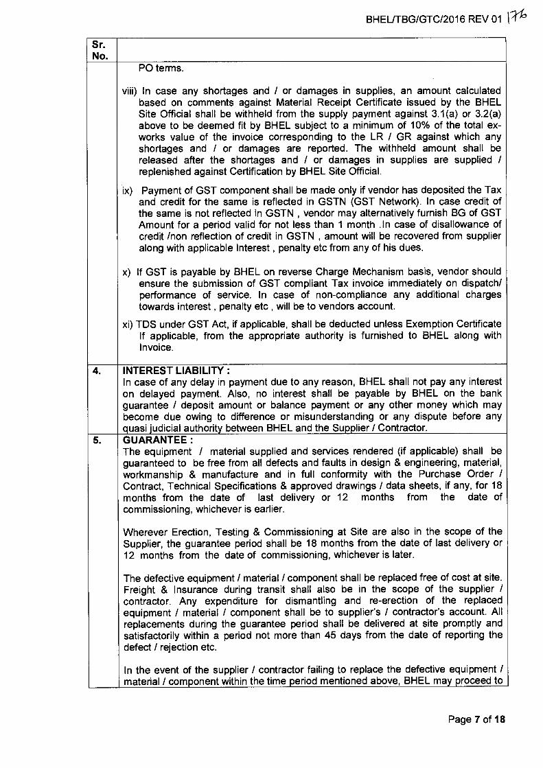
BHEUTBG/GTC/2016 REV 01 1;4'
Sr. No.
PO terms.
viii) In case any shortages and / or damages in supplies, an amount calculated based on comments against Material Receipt Certificate issued by the BHEL Site Official shall be withheld from the supply payment against 3.1(a) or 3.2(a) above to be deemed fit by BHEL subject to a minimum of 10% of the total ex-works value of the invoice corresponding to the LR / GR against which any shortages and / or damages are reported. The withheld amount shall be released after the shortages and / or damages in supplies are supplied / replenished against Certification by BHEL Site Official.
ix) Payment of GST component shall be made only if vendor has deposited the Tax and credit for the same is reflected in GSTN (GST Network). In case credit of the same is not reflected in GSTN , vendor may alternatively furnish BG of GST Amount for a period valid for not less than 1 month in case of disallowance of credit /non reflection of credit in GSTN , amount will be recovered from supplier along with applicable Interest , penalty etc from any of his dues.
x) If GST is payable by BHEL on reverse Charge Mechanism basis, vendor should ensure the submission of GST compliant Tax invoice immediately on dispatch/ performance of service. In case of non-compliance any additional charges towards interest , penalty etc , will be to vendors account.
xi) TDS under GST Act, if applicable, shall be deducted unless Exemption Certificate If applicable, from the appropriate authority is furnished to BHEL along with Invoice.
4. INTEREST LIABILITY : In case of any delay in payment due to any reason, BHEL shall not pay any interest on delayed payment. Also, no interest shall be payable by BHEL on the bank guarantee / deposit amount or balance payment or any other money which may become due owing to difference or misunderstanding or any dispute before any quasi judicial authority between BHEL and the Supplier / Contractor.
5. GUARANTEE: The equipment / material supplied and services rendered (if applicable) shall be guaranteed to be free from all defects and faults in design & engineering, material, workmanship & manufacture and in full conformity with the Purchase Order / Contract, Technical Specifications & approved drawings / data sheets, if any, for 18 months from the date of last delivery or 12 months from the date of commissioning, whichever is earlier.
Wherever Erection, Testing & Commissioning at Site are also in the scope of the Supplier, the guarantee period shall be 18 months from the date of last delivery or 12 months from the date of commissioning, whichever is later.
The defective equipment / material / component shall be replaced free of cost at site. Freight & Insurance during transit shall also be in the scope of the supplier / contractor. Any expenditure for dismantling and re-erection of the replaced equipment / material / component shall be to supplier's / contractor's account. All replacements during the guarantee period shall be delivered at site promptly and satisfactorily within a period not more than 45 days from the date of reporting the defect / rejection etc.
In the event of the supplier / contractor failing to replace the defective equipment / material / component within the time period mentioned above, BHEL may proceed to
Page 7 of 18
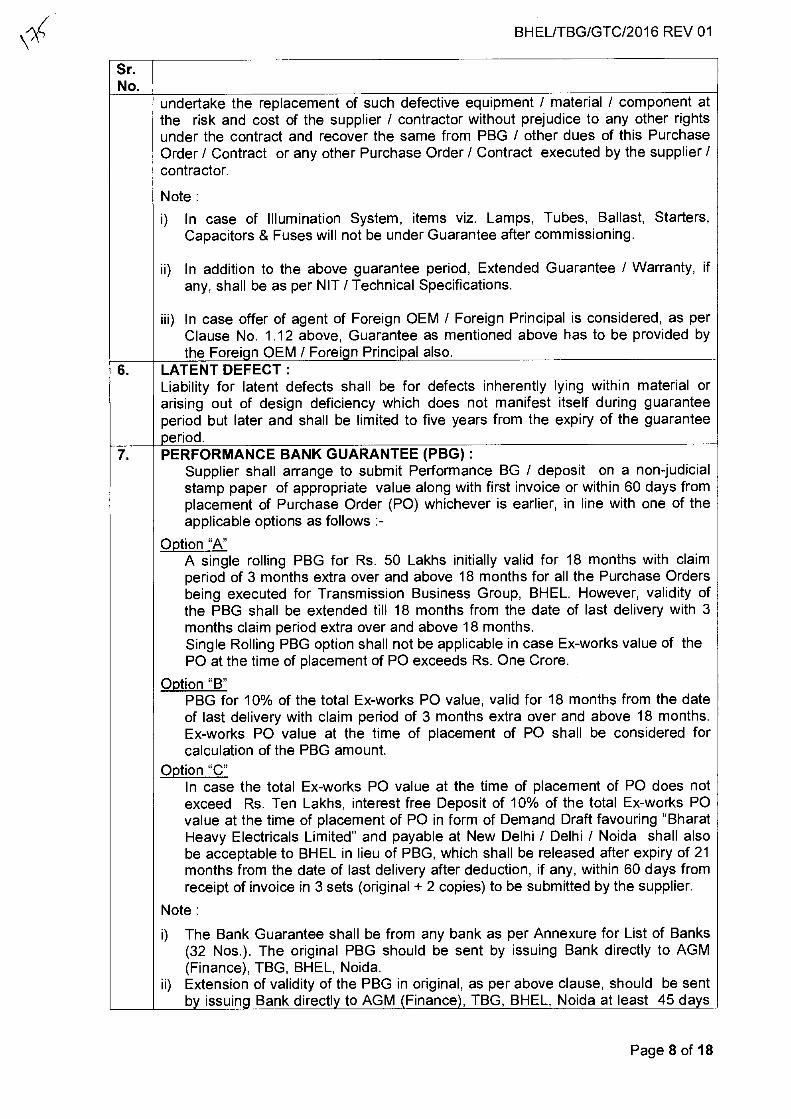
BHEL/TBG/GTC/2016 REV 01
Sr. No.
undertake the replacement of such defective equipment / material / component at the risk and cost of the supplier / contractor without prejudice to any other rights under the contract and recover the same from PBG / other dues of this Purchase Order / Contract or any other Purchase Order / Contract executed by the supplier / contractor.
Note :
i) In case of Illumination System, items viz. Lamps, Tubes, Ballast, Starters, Capacitors & Fuses will not be under Guarantee after commissioning.
ii) In addition to the above guarantee period, Extended Guarantee / Warranty, if any, shall be as per NIT / Technical Specifications.
iii) In case offer of agent of Foreign OEM / Foreign Principal is considered, as per Clause No. 1.12 above, Guarantee as mentioned above has to be provided by the Foreign OEM / Foreign Principal also.
6. LATENT DEFECT : Liability for latent defects shall be for defects inherently lying within material or arising out of design deficiency which does not manifest itself during guarantee period but later and shall be limited to five years from the expiry of the guarantee period.
7. PERFORMANCE BANK GUARANTEE (PBG) : Supplier shall arrange to submit Performance BG / deposit on a non-judicial stamp paper of appropriate value along with first invoice or within 60 days from placement of Purchase Order (PO) whichever is earlier, in line with one of the applicable options as follows :-
Option "A" A single rolling PBG for Rs. 50 Lakhs initially valid for 18 months with claim period of 3 months extra over and above 18 months for all the Purchase Orders being executed for Transmission Business Group, BHEL. However, validity of the PBG shall be extended till 18 months from the date of last delivery with 3 months claim period extra over and above 18 months. Single Rolling PBG option shall not be applicable in case Ex-works value of the PO at the time of placement of PO exceeds Rs. One Crore.
Option "B" PBG for 10% of the total Ex-works PO value, valid for 18 months from the date of last delivery with claim period of 3 months extra over and above 18 months. Ex-works PO value at the time of placement of PO shall be considered for calculation of the PBG amount.
Option "C" In case the total Ex-works PO value at the time of placement of PO does not exceed Rs. Ten Lakhs, interest free Deposit of 10% of the total Ex-works PO value at the time of placement of PO in form of Demand Draft favouring "Bharat Heavy Electricals Limited" and payable at New Delhi / Delhi / Noida shall also be acceptable to BHEL in lieu of PBG, which shall be released after expiry of 21 months from the date of last delivery after deduction, if any, within 60 days from receipt of invoice in 3 sets (original + 2 copies) to be submitted by the supplier.
Note :
i) The Bank Guarantee shall be from any bank as per Annexure for List of Banks (32 Nos.). The original PBG should be sent by issuing Bank directly to AGM (Finance), TBG, BHEL, Noida.
ii) Extension of validity of the PBG in original, as per above clause, should be sent by issuing Bank directly to AGM (Finance), TBG, BHEL, Noida at least 45 days
Page 8 of 18
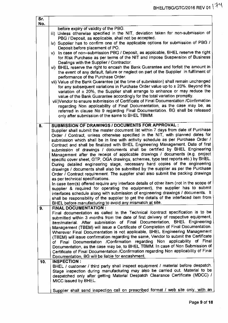
BHEL/TBG/GTC/2016 REV 01 \
Sr. No.
before expiry of validity of the PBG. iii) Unless otherwise specified in the NIT, deviation taken for non-submission of
PBG / Deposit, as applicable, shall not be accepted. iv) Supplier has to confirm one of the applicable options for submission of PBG /
Deposit before placement of PO. v) In case of non—submission PBG / Deposit, as applicable, BHEL reserve the right
for Risk Purchase as per terms of the NIT and impose Suspension of Business Dealings with the Supplier / Contractor.
vi) BHEL reserve the right to encash the Bank Guarantee and forfeit the amount in the event of any default, failure or neglect on part of the Supplier in fulfilment of performance of the Purchase Order.
vii) Value of the Bank Guarantee (at the time of submission) shall remain unchanged for any subsequent variations in Purchase Order value up to ± 20%. Beyond this variation of ± 20%, the Supplier shall arrange to enhance or may reduce the value of the Bank Guarantee accordingly for the total variation promptly.
viii)Vendor to ensure submission of Certificate of Final Documentation /Confirmation regarding Non applicability of Final Documentation, as the case may be, as referred in clause No 9 regarding Final Documentation. BG shall be released only after submission of the same to BHEL TBMM.
8. SUBMISSION OF DRAWINGS / DOCUMENTS FOR APPROVAL : Supplier shall submit the master document list within 7 days from date of Purchase Order / Contract, unless otherwise specified in the NIT, with planned dates for submission which shall be in line with activity schedule as per Purchase Order / Contract and shall be finalized with BHEL Engineering Management. Date of first submission of drawings / documents shall be certified by BHEL Engineering Management after the receipt of applicable drawings / documents (e.g. project specific cover sheet, GTP, OGA drawings, schemes, type test reports etc.) by BHEL. During detailed engineering stage, necessary hard copies of the engineering drawings / documents shall also be submitted by the supplier as per the Purchase Order / Contract requirement. The supplier shall also submit the packing drawings as per technical specifications. In case item(s) offered require any interface details of other item (not in the scope of supplier & required for operating the equipment), the supplier has to submit interfaces schedule along with submission of engineering drawings / documents. It shall be responsibility of the supplier to get the details of the interfaced item from BHEL before manufacturing to avoid any mismatch at site.
9. FINAL DOCUMENTATION : Final documentation as called in the Technical /contract specification is to be submitted within 3 months from the date of first delivery of respective equipment, item/material. After submission of Final Documentation, BHEL Engineering Management (TBEM) will issue a Certificate of Completion of Final Documentation. Wherever Final Documentation is not applicable, BHEL Engineering Management (TBEM) will issue confirmation regarding the same, Vendor to submit the Certificate of Final Documentation /Confirmation regarding Non applicability of Final Documentation, as the case may be, to BHEL TBMM. In case of Non Submission of Certificate of Final Documentation /Confirmation regarding Non applicability of Final Documentation, BG will be liable for encashment.
10. INSPECTION : BHEL / customer / third party shall inspect equipment / material before despatch. Stage inspection during manufacturing may also be carried out. Material to be despatched only after getting Material Despatch Clearance Certificate (MDCC) / MICC issued by BHEL.
Supplier shall send inspection call on prescribed format / web site only, with an
Page 9 of 18
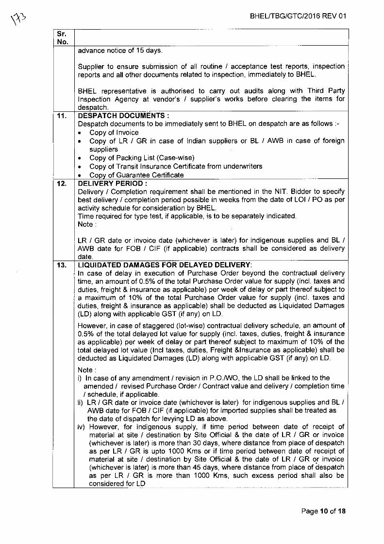
BHEL/TBG/GTC/2016 REV 01
Sr. No.
advance notice of 15 days.
Supplier to ensure submission of all routine / acceptance test reports, inspection reports and all other documents related to inspection, immediately to BHEL.
BHEL representative is authorised to carry out audits along with Third Party Inspection Agency at vendor's / supplier's works before clearing the items for despatch.
11. DESPATCH DOCUMENTS : Despatch documents to be immediately sent to BHEL on despatch are as follows :- • Copy of Invoice • Copy of LR / GR in case of Indian suppliers or BL / AWB in case of foreign
suppliers • Copy of Packing List (Case-wise) • Copy of Transit Insurance Certificate from underwriters • Copy of Guarantee Certificate
12. DELIVERY PERIOD : Delivery / Completion requirement shall be mentioned in the NIT. Bidder to specify best delivery / completion period possible in weeks from the date of LOI / PO as per activity schedule for consideration by BHEL. Time required for type test, if applicable, is to be separately indicated. Note :
LR / GR date or invoice date (whichever is later) for indigenous supplies and BL / AWB date for FOB / CIF (if applicable) contracts shall be considered as delivery date.
13. LIQUIDATED DAMAGES FOR DELAYED DELIVERY: In case of delay in execution of Purchase Order beyond the contractual delivery time, an amount of 0.5% of the total Purchase Order value for supply (incl. taxes and duties, freight & insurance as applicable) per week of delay or part thereof subject to a maximum of 10% of the total Purchase Order value for supply (incl. taxes and duties, freight & insurance as applicable) shall be deducted as Liquidated Damages (LD) along with applicable GST (if any) on LD.
However, in case of staggered (lot-wise) contractual delivery schedule, an amount of 0.5% of the total delayed lot value for supply (incl. taxes, duties, freight & insurance as applicable) per week of delay or part thereof subject to maximum of 10% of the total delayed lot value (Inc! taxes, duties, Freight &Insurance as applicable) shall be deducted as Liquidated Damages (LD) along with applicable GST (if any) on LD.
Note : i) In case of any amendment / revision in P.O./WO, the LD shall be linked to the
amended / revised Purchase Order / Contract value and delivery / completion time / schedule, if applicable.
ii) LR / GR date or invoice date (whichever is later) for indigenous supplies and BL / AWB date for FOB / CIF (if applicable) for imported supplies shall be treated as the date of dispatch for levying LD as above.
iv) However, for indigenous supply, if time period between date of receipt of material at site / destination by Site Official & the date of LR / GR or invoice (whichever is later) is more than 30 days, where distance from place of despatch as per LR / GR is upto 1000 Kms or if time period between date of receipt of material at site / destination by Site Official & the date of LR / GR or invoice (whichever is later) is more than 45 days, where distance from place of despatch as per LR / GR is more than 1000 Kms, such excess period shall also be considered for LD
Page 10 of 18
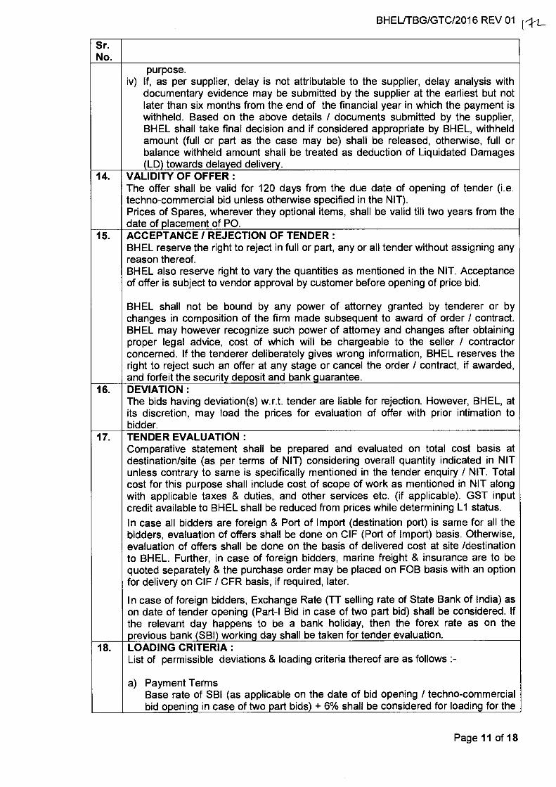
BHEL/TBG/GTC/2016 REV 01 rkt_
Sr. No.
purpose. iv) If, as per supplier, delay is not attributable to the supplier, delay analysis with
documentary evidence may be submitted by the supplier at the earliest but not later than six months from the end of the financial year in which the payment is withheld. Based on the above details / documents submitted by the supplier, BHEL shall take final decision and if considered appropriate by BHEL, withheld amount (full or part as the case may be) shall be released, otherwise, full or balance withheld amount shall be treated as deduction of Liquidated Damages (LD) towards delayed delivery.
14. VALIDITY OF OFFER : The offer shall be valid for 120 days from the due date of opening of tender (i.e. techno-commercial bid unless otherwise specified in the NIT). Prices of Spares, wherever they optional items, shall be valid till two years from the date of placement of PO.
15. ACCEPTANCE / REJECTION OF TENDER : BHEL reserve the right to reject in full or part, any or all tender without assigning any reason thereof. BHEL also reserve right to vary the quantities as mentioned in the NIT. Acceptance of offer is subject to vendor approval by customer before opening of price bid.
BHEL shall not be bound by any power of attorney granted by tenderer or by changes in composition of the firm made subsequent to award of order / contract. BHEL may however recognize such power of attorney and changes after obtaining proper legal advice, cost of which will be chargeable to the seller / contractor concerned. If the tenderer deliberately gives wrong information, BHEL reserves the right to reject such an offer at any stage or cancel the order / contract, if awarded, and forfeit the security deposit and bank guarantee.
16. DEVIATION : The bids having deviation(s) w.r.t. tender are liable for rejection. However, BHEL, at its discretion, may load the prices for evaluation of offer with prior intimation to bidder.
17. TENDER EVALUATION : Comparative statement shall be prepared and evaluated on total cost basis at destination/site (as per terms of NIT) considering overall quantity indicated in NIT unless contrary to same is specifically mentioned in the tender enquiry / NIT. Total cost for this purpose shall include cost of scope of work as mentioned in NIT along with applicable taxes & duties, and other services etc. (if applicable). GST input credit available to BHEL shall be reduced from prices while determining L1 status.
In case all bidders are foreign & Port of Import (destination port) is same for all the bidders, evaluation of offers shall be done on CIF (Port of Import) basis. Otherwise, evaluation of offers shall be done on the basis of delivered cost at site /destination to BHEL. Further, in case of foreign bidders, marine freight & insurance are to be quoted separately & the purchase order may be placed on FOB basis with an option for delivery on CIF / CFR basis, if required, later.
In case of foreign bidders, Exchange Rate (TT selling rate of State Bank of India) as on date of tender opening (Part-I Bid in case of two part bid) shall be considered. If the relevant day happens to be a bank holiday, then the forex rate as on the previous bank (SBI) working day shall be taken for tender evaluation.
18. LOADING CRITERIA : List of permissible deviations & loading criteria thereof are as follows :-
a) Payment Terms Base rate of SBI (as applicable on the date of bid opening / techno-commercial bid opening in case of two part bids) + 6% shall be considered for loading for the
Page 11 of 18
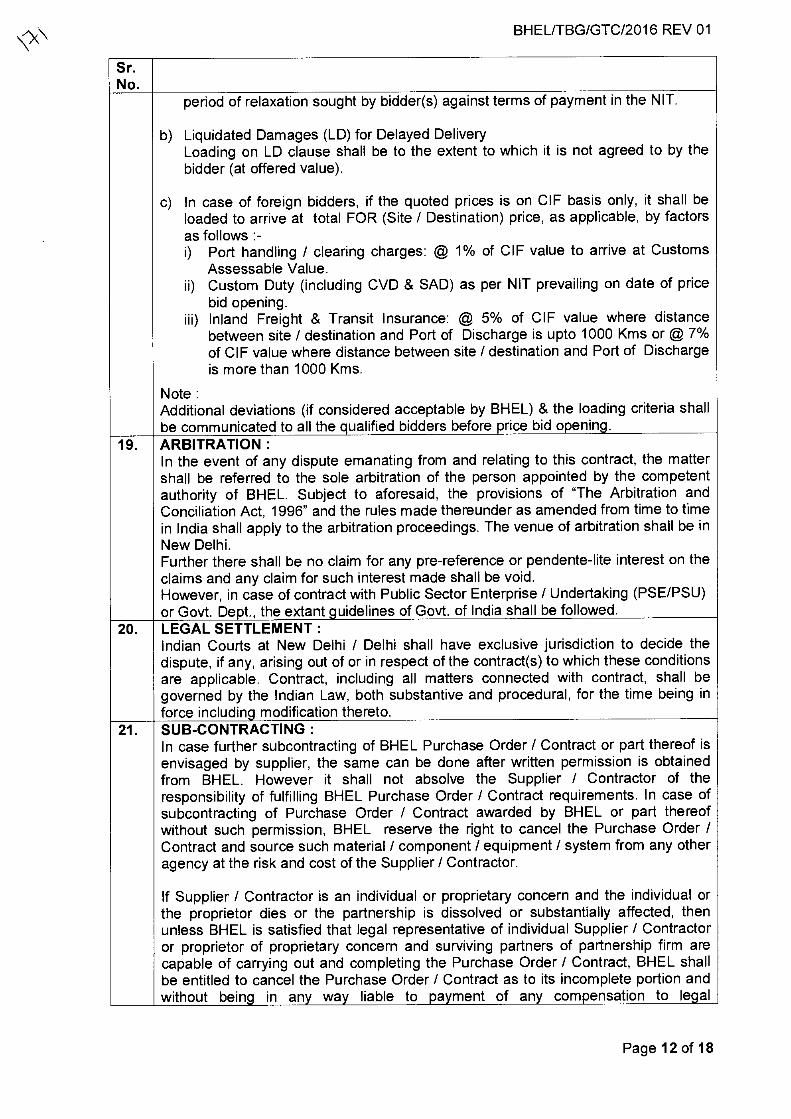
BHEL/TBG/GTC/2016 REV 01
Sr. No.
period of relaxation sought by bidder(s) against terms of payment in the NIT.
b) Liquidated Damages (LD) for Delayed Delivery Loading on LD clause shall be to the extent to which it is not agreed to by the bidder (at offered value).
c) In case of foreign bidders, if the quoted prices is on CIF basis only, it shall be loaded to arrive at total FOR (Site / Destination) price, as applicable, by factors as follows :- i) Port handling / clearing charges: @ 1% of CIF value to arrive at Customs
Assessable Value. ii) Custom Duty (including CVD & SAD) as per NIT prevailing on date of price
bid opening. iii) Inland Freight & Transit Insurance: @ 5% of CIF value where distance
between site / destination and Port of Discharge is upto 1000 Kms or @ 7% of CIF value where distance between site / destination and Port of Discharge is more than 1000 Kms.
Note : Additional deviations (if considered acceptable by BHEL) & the loading criteria shall be communicated to all the qualified bidders before price bid opening.
19. ARBITRATION : In the event of any dispute emanating from and relating to this contract, the matter shall be referred to the sole arbitration of the person appointed by the competent authority of BHEL. Subject to aforesaid, the provisions of "The Arbitration and Conciliation Act, 1996" and the rules made thereunder as amended from time to time in India shall apply to the arbitration proceedings. The venue of arbitration shall be in New Delhi. Further there shall be no claim for any pre-reference or pendente-lite interest on the claims and any claim for such interest made shall be void. However, in case of contract with Public Sector Enterprise / Undertaking (PSE/PSU) or Govt. Dept., the extant guidelines of Govt. of India shall be followed.
20. LEGAL SETTLEMENT : Indian Courts at New Delhi / Delhi shall have exclusive jurisdiction to decide the dispute, if any, arising out of or in respect of the contract(s) to which these conditions are applicable. Contract, including all matters connected with contract, shall be governed by the Indian Law, both substantive and procedural, for the time being in force including modification thereto.
21. SUB-CONTRACTING : In case further subcontracting of BHEL Purchase Order / Contract or part thereof is envisaged by supplier, the same can be done after written permission is obtained from BHEL. However it shall not absolve the Supplier / Contractor of the responsibility of fulfilling BHEL Purchase Order / Contract requirements. In case of subcontracting of Purchase Order / Contract awarded by BHEL or part thereof without such permission, BHEL reserve the right to cancel the Purchase Order / Contract and source such material / component / equipment / system from any other agency at the risk and cost of the Supplier / Contractor.
If Supplier / Contractor is an individual or proprietary concern and the individual or the proprietor dies or the partnership is dissolved or substantially affected, then unless BHEL is satisfied that legal representative of individual Supplier / Contractor or proprietor of proprietary concern and surviving partners of partnership firm are capable of carrying out and completing the Purchase Order / Contract, BHEL shall be entitled to cancel the Purchase Order / Contract as to its incomplete portion and without being in any way liable to payment of any compensation to legal
Page 12 of 18
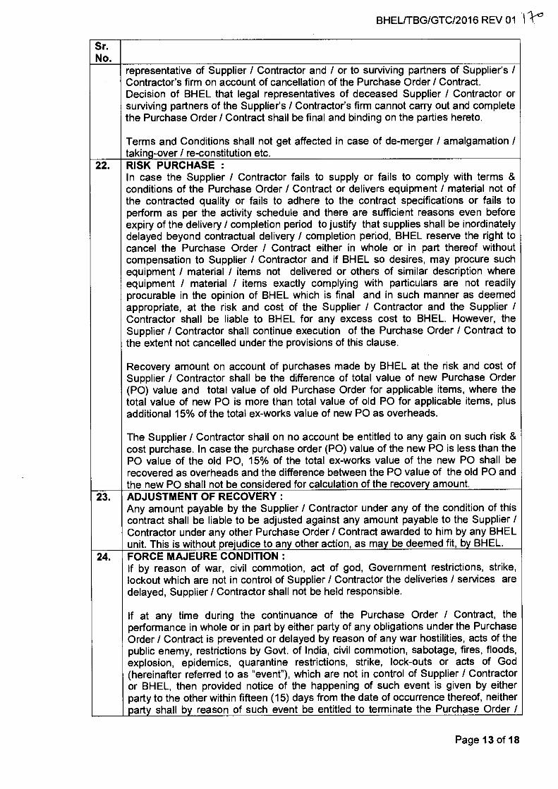
BHEL/TBG/GTC/2016 REV 01 11-4°
Sr. No.
representative of Supplier / Contractor and / or to surviving partners of Supplier's / Contractor's firm on account of cancellation of the Purchase Order / Contract. Decision of BHEL that legal representatives of deceased Supplier / Contractor or surviving partners of the Supplier's / Contractor's firm cannot carry out and complete the Purchase Order / Contract shall be final and binding on the parties hereto.
Terms and Conditions shall not get affected in case of de-merger / amalgamation / taking-over / re-constitution etc.
22. RISK PURCHASE : In case the Supplier / Contractor fails to supply or fails to comply with terms & conditions of the Purchase Order / Contract or delivers equipment / material not of the contracted quality or fails to adhere to the contract specifications or fails to perform as per the activity schedule and there are sufficient reasons even before expiry of the delivery / completion period to justify that supplies shall be inordinately delayed beyond contractual delivery / completion period, BHEL reserve the right to cancel the Purchase Order / Contract either in whole or in part thereof without compensation to Supplier / Contractor and if BHEL so desires, may procure such equipment / material / items not delivered or others of similar description where equipment / material / items exactly complying with particulars are not readily procurable in the opinion of BHEL which is final and in such manner as deemed appropriate, at the risk and cost of the Supplier / Contractor and the Supplier / Contractor shall be liable to BHEL for any excess cost to BHEL. However, the Supplier / Contractor shall continue execution of the Purchase Order / Contract to the extent not cancelled under the provisions of this clause.
Recovery amount on account of purchases made by BHEL at the risk and cost of Supplier / Contractor shall be the difference of total value of new Purchase Order (PO) value and total value of old Purchase Order for applicable items, where the total value of new PO is more than total value of old PO for applicable items, plus additional 15% of the total ex-works value of new PO as overheads.
The Supplier / Contractor shall on no account be entitled to any gain on such risk & cost purchase. In case the purchase order (PO) value of the new PO is less than the PO value of the old PO, 15% of the total ex-works value of the new PO shall be recovered as overheads and the difference between the PO value of the old PO and the new PO shall not be considered for calculation of the recovery amount.
23. ADJUSTMENT OF RECOVERY : Any amount payable by the Supplier / Contractor under any of the condition of this contract shall be liable to be adjusted against any amount payable to the Supplier / Contractor under any other Purchase Order / Contract awarded to him by any BHEL unit. This is without prejudice to any other action, as may be deemed fit, by BHEL.
24. FORCE MAJEURE CONDITION : If by reason of war, civil commotion, act of god, Government restrictions, strike, lockout which are not in control of Supplier / Contractor the deliveries / services are delayed, Supplier / Contractor shall not be held responsible.
If at any time during the continuance of the Purchase Order / Contract, the performance in whole or in part by either party of any obligations under the Purchase Order / Contract is prevented or delayed by reason of any war hostilities, acts of the public enemy, restrictions by Govt. of India, civil commotion, sabotage, fires, floods, explosion, epidemics, quarantine restrictions, strike, lock-outs or acts of God (hereinafter referred to as "event"), which are not in control of Supplier / Contractor or BHEL, then provided notice of the happening of such event is given by either party to the other within fifteen (15) days from the date of occurrence thereof, neither party shall by reason of such event be entitled to terminate the Purchase Order /
Page 13 of 18
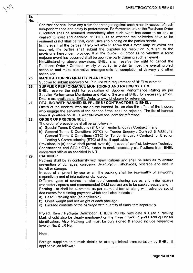
BHEL/TBG/GTC/2016 REV 01
Sr. No.
Contract nor shall have any claim for damages against each other in respect of such non-performance and delay in performance. Performance under the Purchase Order / Contract shall be resumed immediately after such event has come to an end or ceased to exist and decision of BHEL as to whether the deliveries have to be resumed or not shall be final, conclusive and binding on the parties hereto. In the event of the parties hereto not able to agree that a force majeure event has occurred, the parties shall submit the disputes for resolution pursuant to the provisions hereunder, provided that the burden of proof as to whether a force majeure event has occurred shall be upon the party claiming such an event. Notwithstanding above provisions, BHEL shall reserve the right to cancel the Purchase Order / Contract, wholly or partly, in order to meet the overall project schedule and make alternative arrangements for completion of delivery and other schedules.
25. MANUFACTURING QUALITY PLAN (MQP) : Supplier to submit approved MQP in line with requirement of BHEL/customer.
26. SUPPLIER PERFORMANCE MONITORING AND RATING SYSTEM : BHEL reserve the right for evaluation of Supplier Performance Rating as per Supplier Performance Monitoring and Rating System of BHEL for necessary action. Details are available at BHEL Website www.bhel.com for reference.
27. DEALING WITH BANNED SUPPLIERS / CONTRACTORS IN BHEL : Offers of the bidders, who are on the banned list, as also the offers of the bidders who engage the services of the banned firms, shall be rejected. The list of banned firms is available on BHEL website www.bhel.com for reference.
28. ORDER OF PRECEDENCE : The order of precedence shall be as follows :- a) Special Terms & Conditions (STC) for Tender Enquiry / Contract, if any b) General Terms & Conditions (GTC) for Tender Enquiry / Contract & Additional
General Terms & Conditions (GTC) for Tender Enquiry / Contract for Erection Testing & Commissioning (ETC) at Site, if applicable
Provisions in (a) above shall prevail over (b). In case of conflict, between Technical Specifications and STC / GTC, bidder to seek necessary clarifications from BHEL concerned official as specified in NIT.
29. PACKING : Packing shall be in conformity with specifications and shall be such as to ensure prevention of damages, corrosion, deterioration, shortages, pilferage and loss in transit or storage. In case of shipment by sea or air, the packing shall be sea-worthy or air-worthy respectively and of international standards. Different types of spares i.e. start-up / commissioning spares and initial spares (mandatory spares and recommended O&M spares) are to be packed separately. Packing List shall be submitted as per standard format along with advance set of documents for claiming payment which shall also indicate :- a) Case / Packing size (as applicable). b) Gross weight and net weight of each package. c) Detailed contents of the package with quantity of each item separately.
Project, Item / Package Description, BHEL's PO No. with date & Case / Packing Mark should also be clearly mentioned on the Case / Packing and Packing List for identification. Also, Packing List must be duly signed & should include respective Invoice No. & LR No.
Note :
Foreign suppliers to furnish details to arrange inland transportation by BHEL, if applicable, as follows :-
Page 14 of 18
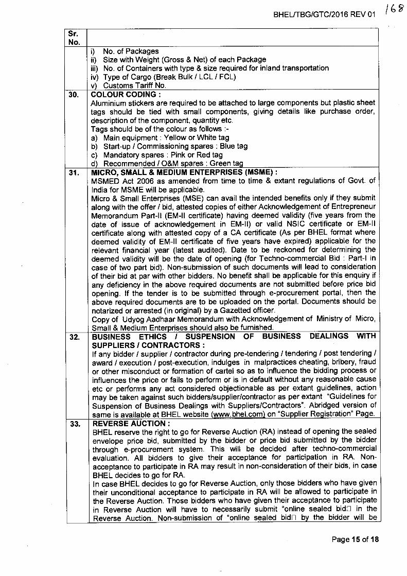
BHEL/TBG/GTC/2016 REV 01 / 6
Sr. No.
i) No. of Packages ii) Size with Weight (Gross & Net) of each Package iii) No. of Containers with type & size required for inland transportation iv) Type of Cargo (Break Bulk / LCL / FCL) v) Customs Tariff No.
30. COLOUR CODING : Aluminium stickers are required to be attached to large components but plastic sheet tags should be tied with small components, giving details like purchase order, description of the component, quantity etc. Tags should be of the colour as follows :- a) Main equipment : Yellow or White tag b) Start-up / Commissioning spares : Blue tag c) Mandatory spares : Pink or Red tag d) Recommended / O&M spares : Green tag
31. MICRO, SMALL & MEDIUM ENTERPRISES (MSME) : MSMED Act 2006 as amended from time to time & extant regulations of Govt. of India for MSME will be applicable. Micro & Small Enterprises (MSE) can avail the intended benefits only if they submit along with the offer / bid, attested copies of either Acknowledgement of Entrepreneur Memorandum Part-II (EM-II certificate) having deemed validity (five years from the date of issue of acknowledgement in EM-II) or valid NSIC certificate or EM-II certificate along with attested copy of a CA certificate (As per BHEL format where deemed validity of EM-II certificate of five years have expired) applicable for the relevant financial year (latest audited). Date to be reckoned for determining the deemed validity will be the date of opening (for Techno-commercial Bid : Part-1 in case of two part bid). Non-submission of such documents will lead to consideration of their bid at par with other bidders. No benefit shall be applicable for this enquiry if any deficiency in the above required documents are not submitted before price bid opening. If the tender is to be submitted through e-procurement portal, then the above required documents are to be uploaded on the portal. Documents should be notarized or arrested (in original) by a Gazetted officer. Copy of Udyog Aadhaar Memorandum with Acknowledgement of Ministry of Micro, Small & Medium Enterprises should also be furnished.
32. BUSINESS ETHICS / SUSPENSION OF BUSINESS DEALINGS WITH SUPPLIERS / CONTRACTORS : If any bidder / supplier / contractor during pre-tendering / tendering / post tendering / award / execution / post-execution, indulges in malpractices cheating, bribery, fraud or other misconduct or formation of cartel so as to influence the bidding process or influences the price or fails to perform or is in default without any reasonable cause etc or performs any act considered objectionable as per extant guidelines, action may be taken against such bidders/supplier/contractor as per extant "Guidelines for Suspension of Business Dealings with Suppliers/Contractors". Abridged version of same is available at BHEL website (www.bhel.com) on "Supplier Registration" Page.
33. REVERSE AUCTION : BHEL reserve the right to go for Reverse Auction (RA) instead of opening the sealed envelope price bid, submitted by the bidder or price bid submitted by the bidder through e-procurement system. This will be decided after techno-commercial evaluation. All bidders to give their acceptance for participation in RA. Non- acceptance to participate in RA may result in non-consideration of their bids, in case BHEL decides to go for RA. In case BHEL decides to go for Reverse Auction, only those bidders who have given their unconditional acceptance to participate in RA will be allowed to participate in the Reverse Auction. Those bidders who have given their acceptance to participate in Reverse Auction will have to necessarily submit "online sealed bidE in the Reverse Auction. Non-submission of "online sealed bid0 by the bidder will be
Page 15 of 18
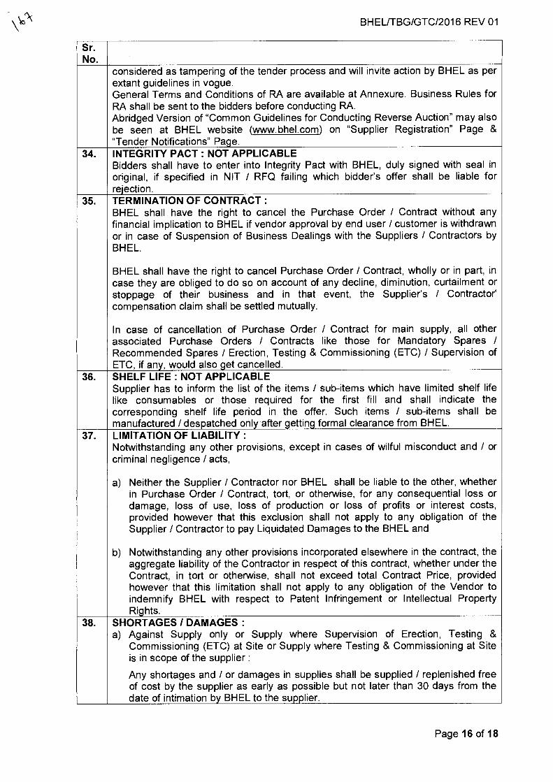
BHEL/TBG/GTC/2016 REV 01
Sr. No.
considered as tampering of the tender process and will invite action by BHEL as per extant guidelines in vogue. General Terms and Conditions of RA are available at Annexure. Business Rules for RA shall be sent to the bidders before conducting RA. Abridged Version of "Common Guidelines for Conducting Reverse Auction" may also be seen at BHEL website (www.bhel.com) on "Supplier Registration" Page & "Tender Notifications" Page.
34. INTEGRITY PACT : NOT APPLICABLE Bidders shall have to enter into Integrity Pact with BHEL, duly signed with seal in original, if specified in NIT / RFQ failing which bidder's offer shall be liable for rejection.
35. TERMINATION OF CONTRACT : BHEL shall have the right to cancel the Purchase Order / Contract without any financial implication to BHEL if vendor approval by end user / customer is withdrawn or in case of Suspension of Business Dealings with the Suppliers / Contractors by BHEL.
BHEL shall have the right to cancel Purchase Order / Contract, wholly or in part, in case they are obliged to do so on account of any decline, diminution, curtailment or stoppage of their business and in that event, the Supplier's / Contractor' compensation claim shall be settled mutually.
In case of cancellation of Purchase Order / Contract for main supply, all other associated Purchase Orders / Contracts like those for Mandatory Spares / Recommended Spares / Erection, Testing & Commissioning (ETC) / Supervision of ETC, if any, would also get cancelled.
36. SHELF LIFE : NOT APPLICABLE Supplier has to inform the list of the items / sub-items which have limited shelf life like consumables or those required for the first fill and shall indicate the corresponding shelf life period in the offer. Such items / sub-items shall be manufactured / despatched only after getting formal clearance from BHEL.
37. LIMITATION OF LIABILITY : Notwithstanding any other provisions, except in cases of wilful misconduct and / or criminal negligence / acts,
a) Neither the Supplier / Contractor nor BHEL shall be liable to the other, whether in Purchase Order / Contract, tort, or otherwise, for any consequential loss or damage, loss of use, loss of production or loss of profits or interest costs, provided however that this exclusion shall not apply to any obligation of the Supplier / Contractor to pay Liquidated Damages to the BHEL and
b) Notwithstanding any other provisions incorporated elsewhere in the contract, the aggregate liability of the Contractor in respect of this contract, whether under the Contract, in tort or otherwise, shall not exceed total Contract Price, provided however that this limitation shall not apply to any obligation of the Vendor to indemnify BHEL with respect to Patent Infringement or Intellectual Property Rights.
38. SHORTAGES / DAMAGES : a) Against Supply only or Supply where Supervision of Erection, Testing &
Commissioning (ETC) at Site or Supply where Testing & Commissioning at Site is in scope of the supplier :
Any shortages and / or damages in supplies shall be supplied / replenished free of cost by the supplier as early as possible but not later than 30 days from the date of intimation by BHEL to the supplier.
Page 16 of 18
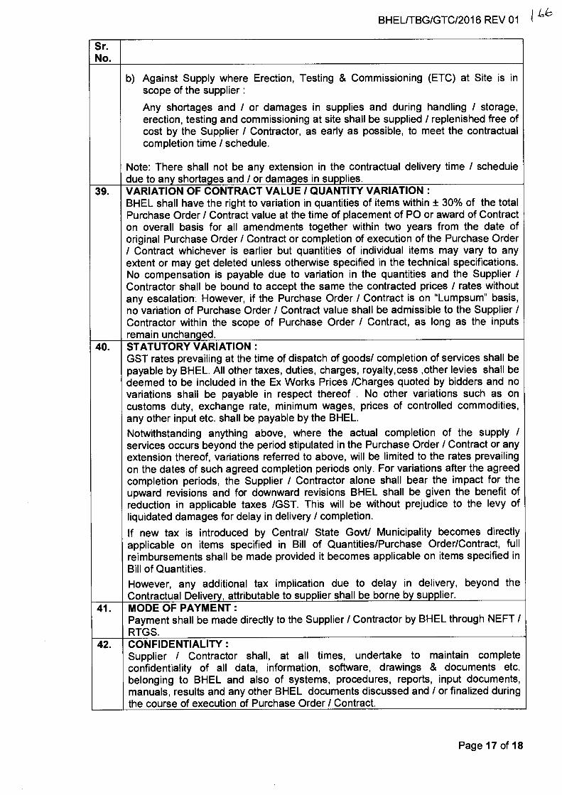
BHEUTBG/GTC/2016 REV 01
Sr. No.
b) Against Supply where Erection, Testing & Commissioning (ETC) at Site is in scope of the supplier :
Any shortages and / or damages in supplies and during handling / storage, erection, testing and commissioning at site shall be supplied / replenished free of cost by the Supplier / Contractor, as early as possible, to meet the contractual completion time / schedule.
Note: There shall not be any extension in the contractual delivery time / schedule due to any shortages and / or damages in supplies.
39. VARIATION OF CONTRACT VALUE / QUANTITY VARIATION : BHEL shall have the right to variation in quantities of items within ± 30% of the total Purchase Order / Contract value at the time of placement of PO or award of Contract on overall basis for all amendments together within two years from the date of original Purchase Order / Contract or completion of execution of the Purchase Order / Contract whichever is earlier but quantities of individual items may vary to any extent or may get deleted unless otherwise specified in the technical specifications. No compensation is payable due to variation in the quantities and the Supplier / Contractor shall be bound to accept the same the contracted prices / rates without any escalation. However, if the Purchase Order / Contract is on "Lumpsum" basis, no variation of Purchase Order / Contract value shall be admissible to the Supplier / Contractor within the scope of Purchase Order / Contract, as long as the inputs remain unchanged.
40. STATUTORY VARIATION : GST rates prevailing at the time of dispatch of goods/ completion of services shall be payable by BHEL. All other taxes, duties, charges, royalty,cess ,other levies shall be deemed to be included in the Ex Works Prices /Charges quoted by bidders and no variations shall be payable in respect thereof . No other variations such as on customs duty, exchange rate, minimum wages, prices of controlled commodities, any other input etc. shall be payable by the BHEL.
Notwithstanding anything above, where the actual completion of the supply / services occurs beyond the period stipulated in the Purchase Order / Contract or any extension thereof, variations referred to above, will be limited to the rates prevailing on the dates of such agreed completion periods only. For variations after the agreed completion periods, the Supplier / Contractor alone shall bear the impact for the upward revisions and for downward revisions BHEL shall be given the benefit of reduction in applicable taxes /GST. This will be without prejudice to the levy of liquidated damages for delay in delivery / completion.
If new tax is introduced by Central/ State Govt/ Municipality becomes directly applicable on items specified in Bill of Quantities/Purchase Order/Contract, full reimbursements shall be made provided it becomes applicable on items specified in Bill of Quantities.
However, any additional tax implication due to delay in delivery, beyond the Contractual Delivery, attributable to supplier shall be borne by supplier.
41. MODE OF PAYMENT : Payment shall be made directly to the Supplier / Contractor by BHEL through NEFT / RTGS.
42. CONFIDENTIALITY : Supplier / Contractor shall, at all times, undertake to maintain complete confidentiality of all data, information, software, drawings & documents etc. belonging to BHEL and also of systems, procedures, reports, input documents, manuals, results and any other BHEL documents discussed and / or finalized during the course of execution of Purchase Order / Contract.
Page 17 of 18
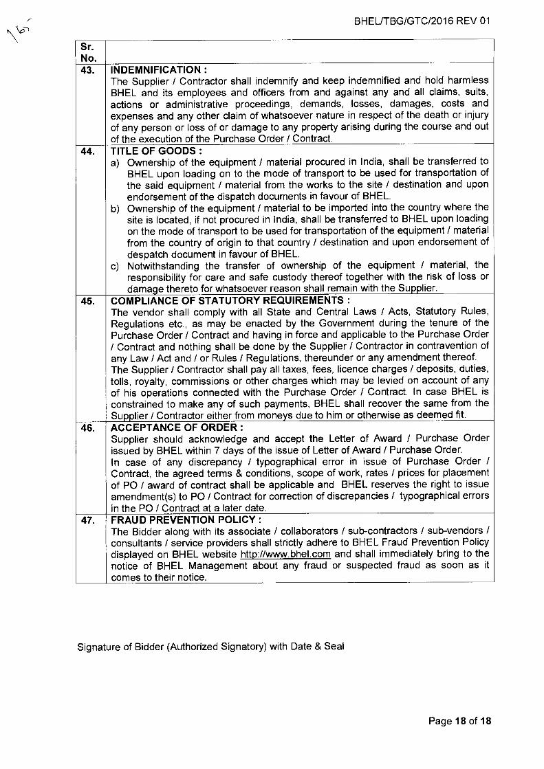
BHEL/TBG/GTC/2016 REV 01
Sr. No. 43. INDEMNIFICATION :
The Supplier / Contractor shall indemnify and keep indemnified and hold harmless BHEL and its employees and officers from and against any and all claims, suits, actions or administrative proceedings, demands, losses, damages, costs and expenses and any other claim of whatsoever nature in respect of the death or injury of any person or loss of or damage to any property arising during the course and out of the execution of the Purchase Order / Contract.
44. TITLE OF GOODS : a) Ownership of the equipment / material procured in India, shall be transferred to
BHEL upon loading on to the mode of transport to be used for transportation of the said equipment / material from the works to the site / destination and upon endorsement of the dispatch documents in favour of BHEL.
b) Ownership of the equipment / material to be imported into the country where the site is located, if not procured in India, shall be transferred to BHEL upon loading on the mode of transport to be used for transportation of the equipment / material from the country of origin to that country / destination and upon endorsement of despatch document in favour of BHEL.
c) Notwithstanding the transfer of ownership of the equipment / material, the responsibility for care and safe custody thereof together with the risk of loss or damage thereto for whatsoever reason shall remain with the Supplier.
45. COMPLIANCE OF STATUTORY REQUIREMENTS : The vendor shall comply with all State and Central Laws / Acts, Statutory Rules, Regulations etc., as may be enacted by the Government during the tenure of the Purchase Order / Contract and having in force and applicable to the Purchase Order / Contract and nothing shall be done by the Supplier / Contractor in contravention of any Law / Act and / or Rules / Regulations, thereunder or any amendment thereof. The Supplier / Contractor shall pay all taxes, fees, licence charges / deposits, duties, tolls, royalty, commissions or other charges which may be levied on account of any of his operations connected with the Purchase Order / Contract. In case BHEL is constrained to make any of such payments, BHEL shall recover the same from the Supplier / Contractor either from moneys due to him or otherwise as deemed fit.
46. ACCEPTANCE OF ORDER : Supplier should acknowledge and accept the Letter of Award / Purchase Order issued by BHEL within 7 days of the issue of Letter of Award / Purchase Order. In case of any discrepancy / typographical error in issue of Purchase Order / Contract, the agreed terms & conditions, scope of work, rates / prices for placement of PO / award of contract shall be applicable and BHEL reserves the right to issue amendment(s) to PO / Contract for correction of discrepancies / typographical errors in the PO / Contract at a later date.
47. FRAUD PREVENTION POLICY : The Bidder along with its associate / collaborators / sub-contractors / sub-vendors / consultants / service providers shall strictly adhere to BHEL Fraud Prevention Policy displayed on BHEL website http://www.bhel.com and shall immediately bring to the notice of BHEL Management about any fraud or suspected fraud as soon as it comes to their notice.
Signature of Bidder (Authorized Signatory) with Date & Seal
Page 18 of 18
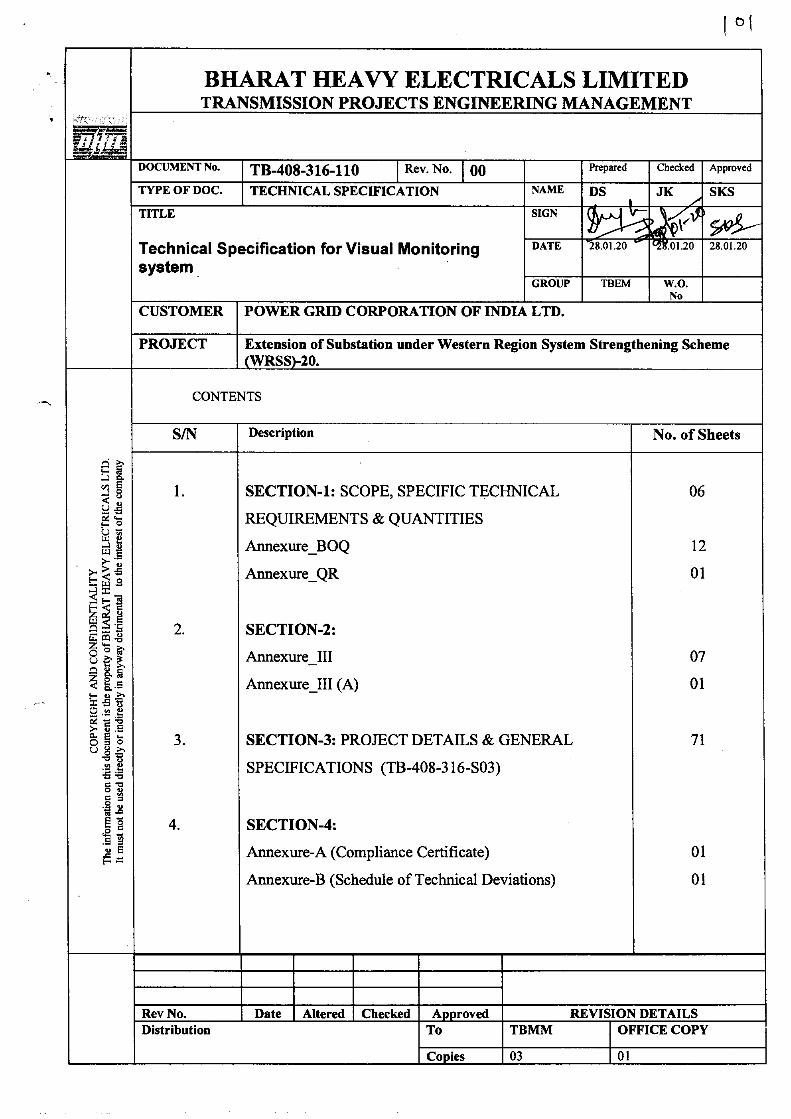
BHARAT HEAVY ELECTRICALS LIMITED TRANSMISSION PROJECTS ENGINEERING MANAGEMENT
DOCUMENT No. TB-408-316-110 Rev. No. 00 Prepared Checked Approved
TYPE OF DOC. TECHNICAL SPECIFICATION NAME DS JK SKS
TITLE SIGN 4i r- \ XP se6u. — Technical Specification for Visual Monitoring system .
DATE 28.01.20 • :.01.20 28 01 20
GROUP TBEM W.O. No
CUSTOMER POWER GRID CORPORATION OF INDIA LTD.
PROJECT Extension of Substation under Western Region System Strengthening Scheme (WRSS)-20.
CO
PY
RIG
HT
AN
D C
ON
FID
EN
TIA
LIT
Y
The
inf
orm
atio
n on
thi
s do
cum
ent
is th
e pr
oper
ty o
f B
HA
RAT
HE
AV
Y E
LE
CT
RIC
AL
S L
TD
. It
mus
t not
be
used
dire
ctly
or
indi
rect
ly i
n an
yway
det
rim
enta
l to
the
inte
rest
of
the
com
pany
CONTENTS
S/N Description No. of Sheets
1.
2.
3.
4.
SECTION-1: SCOPE, SPECIFIC TECHNICAL
REQUIREMENTS & QUANTITIES
Annexure_BOQ
Annexure_QR
SECTION-2:
Annexure_III
Armexure_III (A)
SECTION-3: PROJECT DETAILS & GENERAL
SPECIFICATIONS (TB-408-316-S03)
SECTION-4:
Annexure-A (Compliance Certificate)
Annexure-B (Schedule of Technical Deviations)
06
12
01
07
01
71
01
01
Rev No. Date Altered Checked Approved REVISION DETAILS Distribution To TBMM OFFICE COPY
Copies 03 01
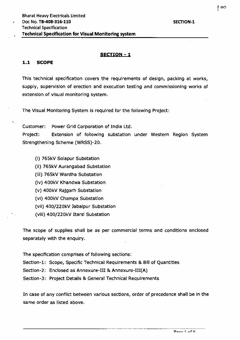
Bharat Heavy Electricals Limited Doc No. TB-408-316-110
SECTION-1
Technical Specification Technical Specification for Visual Monitoring system
SECTION - 1
1.1 SCOPE
This technical specification covers the requirements of design, packing at works,
supply, supervision of erection and execution testing and commissioning works of
extension of visual monitoring system.
The Visual Monitoring System is required for the following Project:
Customer: Power Grid Corporation of India Ltd.
Project: Extension of following substation under Western Region System
Strengthening Scheme (WRSS)-20.
(i) 765kV Solapur Substation
(ii) 765kV Aurangabad Substation
(iii) 765kV Wardha Substation
(iv) 400kV Khandwa Substation
(v) 400kV Rajgarh Substation
(vi) 400kV Champa Substation
(vii) 400/220kV Jabalpur Substation
(viii) 400/220kV Itarsi Substation
The scope of supplies shall be as per commercial terms and conditions enclosed
separately with the enquiry.
The specification comprises of following sections:
Section-1: Scope, Specific Technical Requirements & Bill of Quantities
Section-2: Enclosed as Annexure-III & Annexure-III(A)
Section-3: Project Details & General Technical Requirements
In case of any conflict between various sections, order of precedence shall be in the
same order as listed above.
Par,r. 1 rvF
q Bharat Heavy Electricals Limited Doc No. TB-408-316-110 Technical Specification
Technical Specification for Visual Monitoring system
SECTION-1
1.2 SPECIFIC TECHNICAL REQUIREMENT
Augmentation of Visual Monitoring system for Switchyard bays are in present
scope of supply & services. The provided system has to be integrated with existing
system. The bidder shall provide Color IP camera with PAN, Tilt & Zoom facility
suitably located in switchyard for monitoring of Switchyard bay & equipment. The
scope of bidder shall include providing all Items, Accessories, Line Interface units,
Fiber patch cords, Power supply units, Junction Boxes, Power Cables, Fiber Optic
Cables, Hardware and Software, etc. as are applicable to the product design, to meet
functional requirements. Compatibility enhancement of exiting VMS system, as
needed, shall be done to integrate visual monitoring for Switchyard bays under
present scope with existing Visual monitoring system of the station.
A copy of specification for Visual Monitoring system is enclosed at Annexure-III, which
shall be read only for the Augmentation scope of existing VMS system.
Junction Box - Shall be made of stainless steel of at least 1.5 mm thick or aluminum
enclosure of at least 1.6 mm thick and shall be dust, water and vermin proof.
Stainless steel used shall be of grade SS304. Suitable for Outdoor, weatherproof
application, IP 66 and above. Suitable size to mount all the accessories required for 1
camera such as UPS, media converter, LIU, Power switch etc to complete. Power
switch circuit is included in the scope.
Bidder to review the BOQ and consider any other item required for successful
completion of works. The same shall be under scope of bidder's supply.
1.3 OTHER TECHNICAL REQUIREMENT
1. The scope of the bidder shall include providing all items, accessories, line
interface units, Junction Boxes, Cables, Fiber Optic Cables, Pipe conduit,
Page 2 of 6
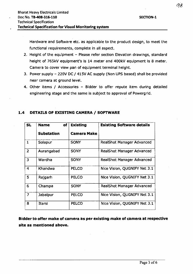
Bharat Heavy Electricals Limited Doc No. TB-408-316-110 Technical Specification Technical Specification for Visual Monitoring system
SECTION-1
q8
Hardware and Software etc. as applicable to the product design, to meet the
functional requirements, complete in all aspect.
2. Height of the equipment - Please refer section Elevation drawings, standard
height of 765kV equipment's is 14 meter and 400kV equipment is 8 meter.
Camera to cover view pan of equipment terminal height.
3. Power supply - 220V DC / 415V AC supply (Non UPS based) shall be provided
near camera at ground level.
4. Other items / Accessories - Bidder to offer repute item during detailed
engineering stage and the same is subject to approval of Powergrid.
1.4 DETAILS OF EXISTING CAMERA / SOFTWARE
SL Name of
Substation
Existing
Camera Make
Esisting Software details
1 Solapur SONY RealShot Manager Advanced
2 Aurangabad SONY RealShot Manager Advanced
3 Wardha SONY RealShot Manager Advanced
4 Khandwa PELCO Nice Vision, QUGNIFY Net 3.1
5 Rajgarh PELCO Nice Vision, QUGNIFY Net 3.1
6 Champa SONY RealShot Manager Advanced
7 Jabalpur PELCO Nice Vision, QUGNIFY Net 3.1
8 Itarsi PELCO Nice Vision, QUGNIFY Net 3.1
Bidder to offer make of camera as per existing make of camera at respective
site as mentioned above.
Page 3 of 6
Bharat Heavy Electricals Limited Doc No. TB-408-316-110
SECTION-1 Technical Specification
Technical Specification for Visual Monitoring system
1.5 BILL OF QUANTITY:
1. Please refer Annexure_BOQ
2. Total contract value may vary up to ±30% at contract stage.
3. Tentative quantities are mentioned in Annexure_BOQ. The above quantities
(BOQ) are as per preliminary design only. The detail design will be submitted
by vendor and subject to approval by the Customer. The BOQ quantities, which
are finalized after approval has to be supplied.
4. The Contract shall be on Bill of Quantity basis for the package. In case of
change in scope after award of the contract, the additions/ deletions to the
scope shall be as per the breakup unit rates for all the equipment and services
furnished by the bidder in his offer.
1.6 SCOPE:
Following work are not in the scope of contractor
1. Receipt of material, Storage at site.
2. Installation of HDPE Pipe, Power Cable & FO cable
3. Installation of Junction Box & Camera
4. Junction Box earthing
Following are scope of services at site
1. Supervision of erection of VMS system supplied by bidder.
2. Installation of accessories, Line Interface units, Fiber patch cords, Power supply
units, Hardware, JB & Camera accessories etc.
3. Termination of Cables, FO Cables, Patch cords etc complete.
4. Remaining activities for successful commissioning of VMS augmentation works.
1.7 TEST REQUIREMENT
The vendor shall submit a FAT (factory acceptance test) & SAT (site acceptance test)
plan complying the specification for POWERGRID / BHEL approval that will be used
during inspection at works & and site respectively.
i) Complete operating and maintenance manuals and training of O&M personnel.
Page 4 of 6
Bharat Heavy Electricals Limited • Doc No. TB-408-316-110
Technical Specification Technical Specification for Visual Monitoring system
SECTION-1
qg
ii) System commissioning and acceptance tests as specified in site acceptance test
(SAT) plan.
1.8 DOCUMENTS TO BE PROVIDED BY BIDDER
• Detailed BOQ to meet the requirement of specification with make, model &
quantity of each item
• Technical datasheet/Catalogues/brochures of the item
• Test certificates as per relevant standards
• Reference list of the Projects where similar equipment for similar application is
being used for at least 2 years.
1.9 TECHNICAL QUALIFYING REQUIREMENT
Please refer Annexure_QR
1.10 Techno commercial evaluation shall be done separately for 02 lots as
follows:
1. LOT-1 :
(i) 765kV Solapur Substation
(ii) 765kV Aurangabad Substation
(iii) 765kV Wardha Substation
(iv) 400kV Champa Substation
2. LOT-2:
(i) 400kV Khandwa Substation
(ii) 400kV Rajgarh Substation
(iii) 400/220kV Jabalpur Substation
(iv) 400/220kV Itarsi Substation
Page 5 of 6
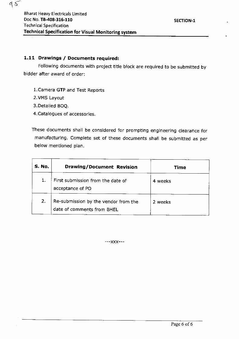
Bharat Heavy Electricals Limited Doc No. TB-408-316-110
SECTION-1 Technical Specification
Technical Specification for Visual Monitoring system
1.11 Drawings / Documents required:
Following documents with project title block are required to be submitted by
bidder after award of order:
1.Camera GTP and Test Reports
2.VMS Layout
3.Detailed BOQ.
4.Catalogues of accessories.
These documents shall be considered for prompting engineering clearance for
manufacturing. Complete set of these documents shall be submitted as per
below mentioned plan.
S. No. Drawing/Document Revision Time
1. First submission from the date of
acceptance of PO
4 weeks
2. Re-submission by the vendor from the
date of comments from BHEL
2 weeks
---XXX---
Page 6 of 6
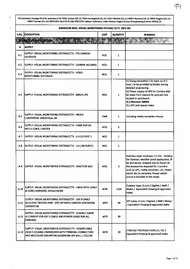
AIS Substation Package-5519 for extension of (I) 765kV Solapur S/S; (ii) 765kV Aurangabad S/S; (iii) 765kV Wardha S/S; (iv) 400kV Khandwa 5/5; (v) 400kV Rajgarh 5/5; (vi)
400kV Champa S//S; (vii) 400/220kV Itarsi SA & (viii) 400/220kV Jabalpur Substation under Western Region System Strengthening Scheme (WRSS)-20.
ANNEXURE-BOQ- VISUAL MONITORING SYSTEM/ CCTV (REV 00)
S.No. DESCRIPTION UNIT QUANTITY REMARKS
A SUPPLY
k1 SUPPLY- VISUAL MONITORING SYSTEM/CCTV : PT2 CAMERA-
OUTDOOR NOS. 1
A.2 SUPPLY- VISUAL MONITORING SYSTEM/CCTV : CAMERA HOUSING NOS. 1
A.3 SUPPLY- VISUAL MONITORING SYSTEM/CCTV : VIDEO
MONITORING SOFTWARE NM. 1
A.4 SUPPLY- VISUAL MONITORING SYSTEM/CCTV : 600VA UPS NOS. 1
(1) Sizing calculation ( for back up of 2
hour) to be provided by bidder during
detailed engineering .
(2) Power supply of UPS for Camera shall
be taken from nearest AC junction box
located in switchyard.
(3.) Minimum 600VA (4.) APC and repute make
A.5 SUPPLY- VISUAL MONITORING SYSTEM/CCTV : MEDIA
CONVERTOR- INDUSTRIAL GR PAIR 1 Including media converter chassis
A.6 SUPPLY- VISUAL MONITORING SYSTEM/CCTV : FIBER DUPLEX
PATCH CORD, 2 METER NOS. 3
A.7 SUPPLY- VISUAL MONITORING SYSTEM/CCTV : LIU (12 PORT) NOS. 1
A.8 SUPPLY- VISUAL MONITORING SYSTEM/CCTV : LIU ( 06 PORTS) NOS. 1
A.9 SUPPLY- VISUAL MONITORING SYSTEM/CCTV : JUNCTION BOX NOS. 1
Stainless steel, thickness 1.5 mm. Suitable
for Outdoor, weather proof application, IP
66 and above. Suitable size to mount all
the accessories required for 1 camera
such as UPS, media converter, LIU, Power
switch etc to complete. Power switch
circuit is included in the scope.
A.10 SUPPLY- VISUAL MONITORING SYSTEM/CCTV : FIBER OPTIC CABLE
(6 CORE) ARMORED, SINGLE MODE MTR 1150
Outdoor type, D-Link / Digilink / AMP /
Molex / Equivalent Powergrid approved
make.
A.11
SUPPLY- VISUAL MONITORING SYSTEM/CCTV : CAT 6 CABLE
(SHIELDED TWISTED PAIR - STP) BETWEEN CAMERA AND MEDIA
CONVERTOR
MTR 20 STP cable, D-Link / Digilink / AMP / Molex
/ Equivalent Powergrid approved make.
A.12
SUPPLY- VISUAL MONITORING SYSTEM/CCTV : FLEXIBLE 25MM
GI CONDUIT FOR CAT 6 CABLE AND POWER CABLE FOR ALL
CAMERAS.
MTR 20
A.13
SUPPLY- VISUAL MONITORING SYSTEM/CCTV : POWER CABLE
(30(2.5 SQ.MM) UNARMORED WITH TERMINAL CONNECTORS
AND NECESSARY MOUNTING HARDWARE ON WALL/ CEILING
MTR 20 FINOLEX/ POLYCAB/ HAVELLS / KEI /
Equivalent Powergrid approved make.
Page 1 of 12
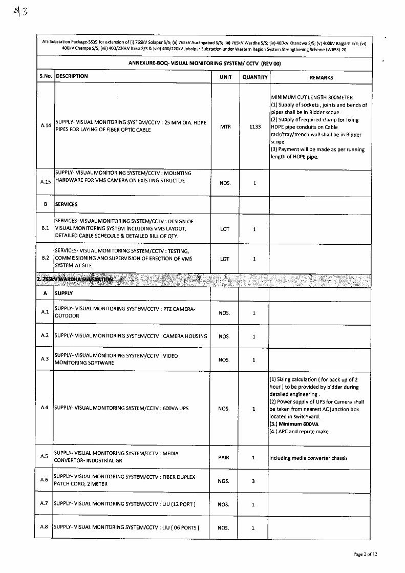
AIS Substation Package-SS19 for extension of (i) 765kV Solapur 5/5; (ii) 765kV Aurangabad 5/5; (iii) 765kV Wardha S/5; (iv) 400kV Khandwa S/S; (v) 400kV Rajgarh 5/5; (vi)
400kV Champa 5/S; (vii) 400/220kV 'tarsi S/S & (viii) 400/220kV Jabalpur Substation under Western Region System Strengthening Scheme (WRSS)-20.
ANNEXURE-BOQ- VISUAL MONITORING SYSTEM/ CCTV (REV 00)
S.No. DESCRIPTION UNIT QUANTITY REMARKS
A.14 SUPPLY- VISUAL MONITORING SYSTEM/CCTV : 25 MM DIA. HDPE
PIPES FOR LAYING OF FIBER OPTIC CABLE MTR 1133
MINIMUM CUT LENGTH 300METER
(1) Supply of sockets , joints and bends of
pipes shall be in Bidder scope.
(2) Supply of required clamp for fixing
HDPE pipe conduits on Cable
rack/tray/trench wall shall be in Bidder
scope.
(3) Payment will be made as per running
length of HDPE pipe.
A.15
SUPPLY- VISUAL MONITORING SYSTEM/CCTV : MOUNTING
HARDWARE FOR VMS CAMERA ON EXISTING STRUCTUE NOS. 1
B SERVICES
B.1
SERVICES- VISUAL MONITORING SYSTEM/CCTV : DESIGN OF
VISUAL MONITORING SYSTEM INCLUDING VMS LAYOUT,
DETAILED CABLE SCHEDULE & DETAILED BILL OF QTY.
LOT 1
B.2
SERVICES- VISUAL MONITORING SYSTEM/CCTV : TESTING,
COMMISSIONING AND SUPERVISION OF ERECTION OF VMS
SYSTEM AT SITE LOT 1
A SUPPLY
A.1 SUPPLY- VISUAL MONITORING SYSTEM/CCTV : PTZ CAMERA-
OUTDOOR NOS. 1
A.2 SUPPLY- VISUAL MONITORING SYSTEM/CCTV : CAMERA HOUSING NOS. 1
A.3 SUPPLY- VISUAL MONITORING SYSTEM/CCTV : VIDEO
MONITORING SOFTWARE NOS. 1
A.4 SUPPLY- VISUAL MONITORING SYSTEM/CCTV : 600VA UPS NOS. 1
(1) Sizing calculation ( for back up of 2
hour) to be provided by bidder during
detailed engineering .
(2) Power supply of UPS for Camera shall
be taken from nearest AC junction box
located in switchyard.
(3.) Minimum 600VA
(4.) APC and repute make
A.5 SUPPLY- VISUAL MONITORING SYSTEM/CCTV : MEDIA
CONVERTOR- INDUSTRIAL GR PAIR 1 Including media converter chassis
A 6 SUPPLY- VISUAL MONITORING SYSTEM/CCTV : FIBER DUPLEX
PATCH CORD, 2 METER 3 NOS.
A.7 SUPPLY- VISUAL MONITORING SYSTEM/CCTV : LIU (12 PORT) NOS. 1
A.8 SUPPLY- VISUAL MONITORING SYSTEM/CCTV : LIU ( 06 PORTS) NOS. 1
Page 2 of 12
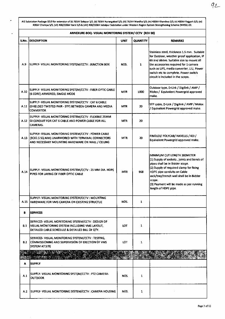
AIS Substation Package-SS19 for extension of (i) 765kV Solapur SA; (ii) 765kV Aurangabad WS; (iii) 765kV Wardha 5/5; (iv) 400kV Khandwa WS; (v) 400kV Rajgarh 5/5; (vi) 400kV Champa 5/S; (vii) 400/220kV itarsi & (viii) 400/220kV Jabalpur Substation under Western Region System Strengthening Scheme (WRSS)-20.
ANNEXURE-BOQ- VISUAL MONITORING SYSTEM/ CCTV (REV 00)
S.No. DESCRIPTION UNIT QUANTITY REMARKS
Stainless steel, thickness 1.5 mm. Suitable
for Outdoor, weather proof application, IP
66 and above. Suitable size to mount all
A.9 SUPPLY- VISUAL MONITORING SYSTEM/CCTV : JUNCTION BOX NOS. 1 the accessories required for 1 camera
such as UPS, media converter, LIU, Power
switch etc to complete. Power switch
circuit is included in the scope.
A.10 SUPPLY- VISUAL MONITORING SYSTEM/CCTV : FIBER OPTIC CABLE
(6 CORE) ARMORED, SINGLE MODE
Outdoor type, D-Link / Digilink / AMP /
MTR 1000 Molex / Equivalent Powergrid approved
make.
SUPPLY- VISUAL MONITORING SYSTEM/CCTV : CAT 6 CABLE
All (SHIELDED TWISTED PAIR - STP) BETWEEN CAMERA AND MEDIA MTR 20
CONVERTOR
SUPPLY- VISUAL MONITORING SYSTEM/CCTV : FLEXIBLE 25MM
A.12 GI CONDUIT FOR CAT 6 CABLE AND POWER CABLE FOR ALL MTR 20
CAMERAS.
SUPPLY- VISUAL MONITORING SYSTEM/CCTV : POWER CABLE
A.13 (3CX2.5 SQ.MM) UNARMORED WITH TERMINAL CONNECTORS MTR 20
AND NECESSARY MOUNTING HARDWARE ON WALL / CEILING
STP cable, D-Unk / Digilink / AMP / Molex
/ Equivalent Powergrid approved make.
FINOLEX/ POLYCAB/ HAVELLS / KEI /
Equivalent Powergrid approved make.
A.14 SUPPLY- VISUAL MONITORING SYSTEM/CCTV : 25 MM DIA. HDPE
PIPES FOR LAYING OF FIBER OPTIC CABLE
MINIMUM CUT LENGTH 300METER
(1) Supply of sockets , joints and bends of
pipes shall be in Bidder scope.
(2) Supply of required clamp for fixing
MTR 968 HDPE pipe conduits on Cable
rack/tray/trench wall shall be in Bidder
scope.
(3) Payment will be made as per running
length of HDPE pipe.
SUPPLY- VISUAL MONITORING SYSTEM/CCTV : MOUNTING
A.15 HARDWARE FOR VMS CAMERA ON EXISTING STRUCTUE NOS. 1
B SERVICES
SERVICES- VISUAL MONITORING SYSTEM/CCTV : DESIGN OF
B.1 VISUAL MONITORING SYSTEM INCLUDING VMS LAYOUT, LOT 1
DETAILED CABLE SCHEDULE & DETAILED BILL OF QTY.
SERVICES- VISUAL MONITORING SYSTEM/CCTV : TESTING,
B.2 COMMISSIONING AND SUPERVISION OF ERECTION OF VMS LOT 1
SYSTEM AT SITE
A SUPPLY
A.1 SUPPLY- VISUAL MONITORING SYSTEM/CCTV : PTZ CAMERA-
OUTDOOR NOS. 1
A.2 SUPPLY- VISUAL MONITORING SYSTEM/CCTV : CAMERA HOUSING NOS. 1
Page 3 of 12
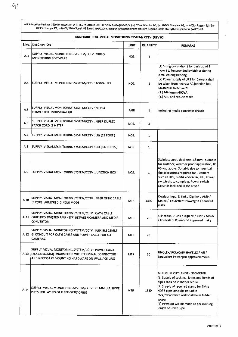
NS Substation Package-SS19 for extension of (i) 765kV Solapur S/S; (ii) 765kV Aurangabad S/S; (iii) 765kV Wardha VS; (iv) 400kV Khandwa 5/5; (v) 400kV Rajgarh 5/5; (vi)
400kV Champa S/5; (vii) 400/220kV (tarsi S/S & (viii) 400/220kV Jabalpur Substation under Western Region System Strengthening Scheme (WRSS)-20.
ANNEXURE-BOQ- VISUAL MONITORING SYSTEM/ CCTV (REV 00)
S.No. DESCRIPTION UNIT QUANTITY REMARKS
A.3 SUPPLY- VISUAL MONITORING SYSTEM/CCTV : VIDEO
MONITORING SOFTWARE NOS. 1
A.4 SUPPLY- VISUAL MONITORING SYSTEM/CCTV : 600VA UPS NOS. 1
(1) Sizing calculation ( for back up of 2
hour) to be provided by bidder during
detailed engineering .
(2) Power supply of UPS for Camera shall
be taken from nearest AC junction box
located in switchyard.
(3.) Minimum 600VA
(4.) APC and repute make
A.5 SUPPLY- VISUAL MONITORING SYSTEM/CCTV : MEDIA
CONVERTOR- INDUSTRIAL GR PAIR 1 Including media converter chassis
A.6 SUPPLY- VISUAL MONITORING SYSTEM/CCTV : FIBER DUPLEX
PATCH CORD, 2 METER NOS. 3
A.7 SUPPLY- VISUAL MONITORING SYSTEM/CCTV : LIU (12 PORT) NOS. 1
A.8 SUPPLY- VISUAL MONITORING SYSTEM/CCTV : LIU ( 06 PORTS) NOS. 1
A.9 SUPPLY- VISUAL MONITORING SYSTEM/CCTV : JUNCTION BOX NOS. 1
Stainless steel, thickness 1.5 mm. Suitable
for Outdoor, weather proof application, IP
66 and above. Suitable size to mount all
the accessories required for 1 camera
such as UPS, media converter, LIU, Power
switch etc to complete. Power switch
circuit is included in the scope.
A.10 SUPPLY- VISUAL MONITORING SYSTEM/CCTV : FIBER OPTIC CABLE
(6 CORE) ARMORED, SINGLE MODE MTR 1350
Outdoor type, D-Link / Digilink / AMP /
Molex / Equivalent Powergrid approved
make.
A.11
SUPPLY- VISUAL MONITORING SYSTEM/CCTV : CAT 6 CABLE
(SHIELDED TWISTED PAIR - STP) BETWEEN CAMERA AND MEDIA
CONVERTOR MTR 20
STP cable, D-Link / Digilink / AMP / Molex
/Equ iva lenowert Pgrid approved make.
A.12
SUPPLY- VISUAL MONITORING SYSTEM/CCTV : FLEXIBLE 25MM
GI CONDUIT FOR CAT 6 CABLE AND POWER CABLE FOR ALL
CAMERAS. MTR 20
A.13
SUPPLY- VISUAL MONITORING SYSTEM/CCTV : POWER CABLE
(3CX2.5 SQ.MM) UNARMORED WITH TERMINAL CONNECTORS
AND NECESSARY MOUNTING HARDWARE ON WALL/ CEILING
MTR 20 FINOLEX/ POLYCAB/ HAVELLS / KEI /
Equivalent Powergrid approved make.
A.14 SUPPLY- VISUAL MONITORING SYSTEM/CCTV : 25MM DIA. HDPE
PIPES FOR LAYING OF FIBER OPTIC CABLE MTR 1320
MINIMUM CUT LENGTH 300METER
(1) Supply of sockets , joints and bends of
pipes shall be in Bidder scope.
(2) Supply of required clamp for fixing
HDPE pipe conduits on Cable
rack/tray/trench wall shall be in Bidder
scope.
(3) Payment will be made as per running
length of HDPE pipe.
Page 4 of 12
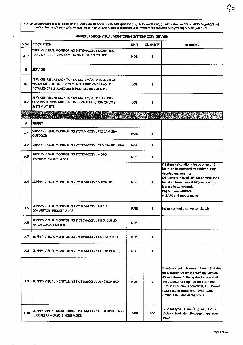
AIS Substation Package-SS19 for extension of (i) 765kV Solapur S/S; (ii) 765kV Aurangabad S/S; (iii) 765kV Wardha S/S; (Iv) 400kV Khandwa S/S; (v) 400kV Rajgarh S/S; (vi)
400kV Champa S/S; (vii) 400/220kV !tarsi S/S & (viii) 400/220kV Jabalpur Substation under Western Region System Strengthening Scheme (WRSS)-20.
ANNEXURE-BOQ- VISUAL MONITORING SYSTEM/ CCTV (REV 00)
S.No. DESCRIPTION UNIT QUANTITY REMARKS
A.15
SUPPLY- VISUAL MONITORING SYSTEM/CCTV : MOUNTING
HARDWARE FOR VMS CAMERA ON EXISTING STRUCTUE NOS. 1
B SERVICES
B.1 SERVICES- VISUAL MONITORING SYSTEM/CCTV : DESIGN OF
VISUAL MONITORING SYSTEM INCLUDING VMS LAYOUT,
DETAILED CABLE SCHEDULE & DETAILED BILL OF QTY.
LOT 1
B.2
SERVICES- VISUAL MONITORING SYSTEM/CCTV : TESTING,
COMMISSIONING AND SUPERVISION OF ERECTION OF VMS
SYSTEM AT SITE LOT 1
A
at
SUPPLY
k1 SUPPLY- VISUAL MONITORING SYSTEM/CCTV : PTZ CAMERA-
OUTDOOR NOS. 1
A.2 SUPPLY- VISUAL MONITORING SYSTEM/CCTV : CAMERA HOUSING NOS. 1
A.3 SUPPLY- VISUAL MONITORING SYSTEM/CCTV : VIDEO
MONITORING SOFTWARE NOS. 1
A.4 SUPPLY- VISUAL MONITORING SYSTEM/CCTV : 600VA UPS NOS. 1
(1) Sizing calculation ( for back up of 2
hour) to be provided by bidder during
detailed engineering .
(2) Power supply of UPS for Camera shall
be taken from nearest AC junction box
located in switchyard.
(3.) Minimum 600VA (4.) APC and repute make
A.5 SUPPLY- VISUAL MONITORING SYSTEM/CCTV : MEDIA
CONVERTOR- INDUSTRIAL GR PAIR 1 Including media converter chassis
A.6 SUPPLY- VISUAL MONITORING SYSTEM/CCTV : FIBER DUPLEX
PATCH CORD, 2 METER NOS. 3
A.7 SUPPLY- VISUAL MONITORING SYSTEM/CCTV : LIU (12 PORT) NOS. 1
A.8 SUPPLY- VISUAL MONITORING SYSTEM/CCTV : LIU ( 06 PORTS) NOS. 1
A.9 SUPPLY- VISUAL MONITORING SYSTEM/CCTV : JUNCTION BOX NOS. 1
Stainless steel, thickness 1.5 mm. Suitable
for Outdoor, weather proof application, IP
66 and above. Suitable size to mount all
the accessories required for 1 camera
such as UPS, media converter, LIU, Power
switch etc to complete. Power switch
circuit is included in the scope.
A.10 SUPPLY- VISUAL MONITORING SYSTEM/CCTV : FIBER OPTIC CABLE
(6 CORE) ARMORED, SINGLE MODE MTR 500
Outdoor type, D-Unk / Digilink /AMP /
Molex / Equivalent Powergrid approved
make.
q6
Page 5 of 12
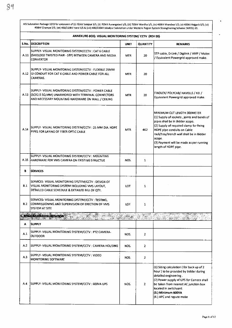
AIS Substation Package-5519 for extension of (i) 765kV Solapur S/S; (ii) 765kV Aurangabad 5/S; (iii) 765kV Wardha S/5; (iv) 400kV Khandwa S/S; (v) 400kV Rajgarh 5/5; (vi)
400kV Champa S/S; (vii) 400/220kV !tarsi S/S & (viii) 400/220kV Jabalpur Substation under Western Region System Strengthening Scheme (WRSS)-20.
ANNEXURE-BOQ- VISUAL MONITORING SYSTEM/ CCTV (REV 00)
S.No. DESCRIPTION UNIT QUANTITY REMARKS
A.11
SUPPLY- VISUAL MONITORING SYSTEM/CCTV : CAT 6 CABLE
(SHIELDED TWISTED PAIR - STP) BETWEEN CAMERA AND MEDIA
CONVERTOR
MTR 20 STP cable, D-Link / Digilink /AMP / Molex
/ Equivalent Powergrid approved make.
A.12
SUPPLY- VISUAL MONITORING SYSTEM/CCTV : FLEXIBLE 25MM
GI CONDUIT FOR CAT 6 CABLE AND POWER CABLE FOR ALL
CAMERAS.
MTR 20
A.13
SUPPLY- VISUAL MONITORING SYSTEM/CCTV : POWER CABLE
(3CX2.5 SQ.MM) UNARMORED WITH TERMINAL CONNECTORS
AND NECESSARY MOUNTING HARDWARE ON WALL/CEILING
MTR 20 FINOLEX/ POLYCAB/ HAVELLS / KEI /
Equivalent Powergrid approved make.
A.14 SUPPLY- VISUAL MONITORING SYSTEM/CCTV : 25 MM DIA. HDPE
PIPES FOR LAYING OF FIBER OPTIC CABLE MTR 462
MINIMUM CUT LENGTH 300METER
(1) Supply of sockets , joints and bends of
pipes shall be in Bidder scope.
(2) Supply of required clamp for fixing
HDPE pipe conduits on Cable
rack/tray/trench wall shall be in Bidder
scope.
(3) Payment will be made as per running
length of HDPE pipe.
A.15
SUPPLY- VISUAL MONITORING SYSTEM/CCTV : MOUNTING
HARDWARE FOR VMS CAMERA ON EXISTING STRUCTUE NOS. 1
B SERVICES
B.1
SERVICES- VISUAL MONITORING SYSTEM/CCTV : DESIGN OF
VISUAL MONITORING SYSTEM INCLUDING VMS LAYOUT,
DETAILED CABLE SCHEDULE & DETAILED BILL OF QTY.
LOT 1
B.2
SERVICES- VISUAL MONITORING SYSTEM/CCTV : TESTING,
COMMISSIONING AND SUPERVISION OF ERECTION OF VMS
SYSTEM AT SITE
LOT 1
.
:.,
A SUPPLY
A.1 SUPPLY- VISUAL MONITORING SYSTEM/CCTV : PTZ CAMERA-
OUTDOOR NO 2
A.2 SUPPLY- VISUAL MONITORING SYSTEM/CCTV : CAMERA HOUSING NOS. 2
A.3 SUPPLY- VISUAL MONITORING SYSTEM/CCTV : VIDEO
MONITORING SOFTWARE NOS. 2
A.4 SUPPLY- VISUAL MONITORING SYSTEM/CCTV : 600VA UPS NOS. 2
(1) Sizing calculation ( for back up of 2
hour) to be provided by bidder during
detailed engineering .
(2) Power supply of UPS for Camera shall
be taken from nearest AC junction box
located in switchyard.
(3.) Minimum 600VA
(4.) APC and repute make
Page 6 of 12
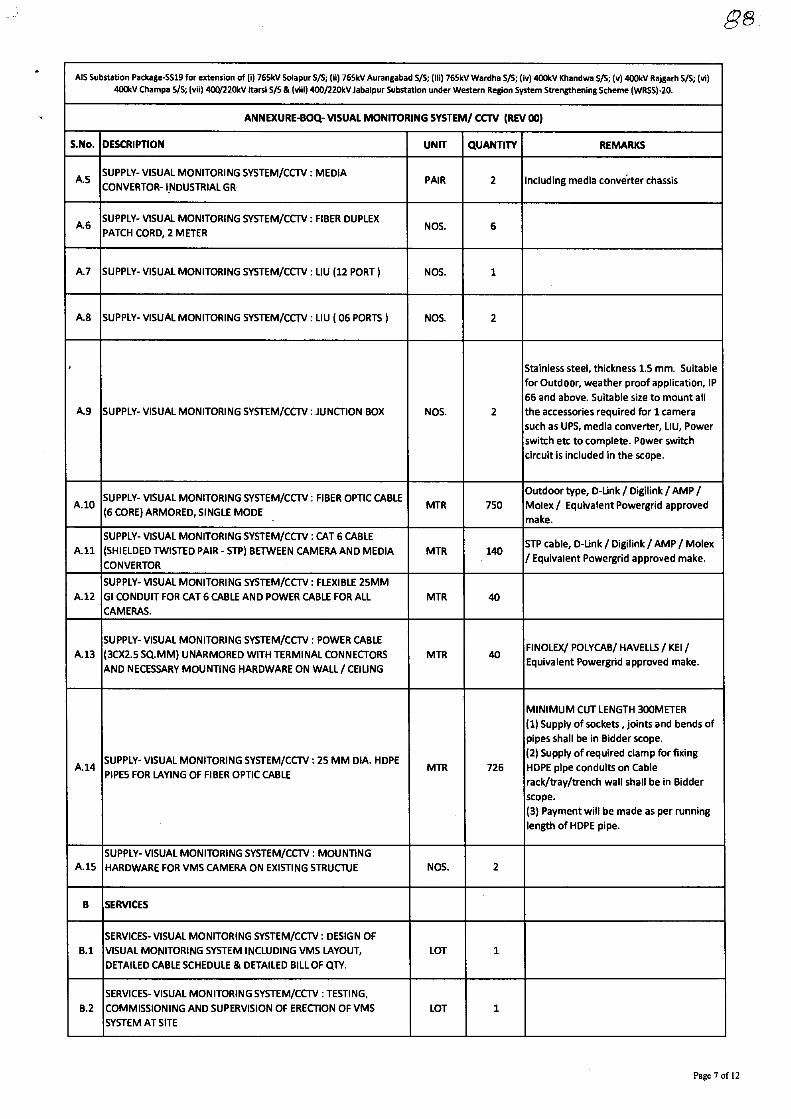
AIS Substation Package-SS19 for extension of (i) 765kV Solapur S/S; (ii) 765kV Aurangabad S/S; (iii) 765kV Wardha S/S; (iv) 400kV Khandwa 5/5; (v) 400kV Rajgarh S/S; (A) 400&V Champs VS; (vii) 400/220kV Itarsi S/S & (viii) 400/220kV Jabalpur Substation under Western Region System Strengthening Scheme (WRSS)-20.
ANNEXURE-BOQ- VISUAL MONITORING SYSTEM/ CCTV (REV 00)
S.No. DESCRIPTION UNIT QUANTITY REMARKS
A.5 SUPPLY- VISUAL MONITORING SYSTEM/CCTV: MEDIA
CONVERTOR- INDUSTRIAL GR PAIR 2 Including media converter chassis
A.6 SUPPLY- VISUAL MONITORING SYSTEM/CCTV : FIBER DUPLEX
PATCH CORD, 2 METER NOS. 6
A.7 SUPPLY- VISUAL MONITORING SYSTEM/CCTV : LIU (12 PORT) NOS. 1
A.8 SUPPLY- VISUAL MONITORING SYSTEM/CCTV : LIU ( 06 PORTS) NOS. 2
A.9 SUPPLY- VISUAL MONITORING SYSTEM/CCTV : JUNCTION BOX NOS. 2
Stainless steel, thickness 1.5 mm. Suitable
for Outdoor, weather proof application, IP
66 and above. Suitable size to mount all
the accessories required for 1 camera
such as UPS, media converter, LIU, Power
switch etc to complete. Power switch
circuit is included in the scope.
A.10 SUPPLY- VISUAL MONITORING SYSTEM/CCTV : FIBER OPTIC CABLE
(6 CORE) ARMORED, SINGLE MODE • MTR 750
Outdoor type, D-Link / Digilink / AMP /
Molex / Equivalent Powergrid approved
make.
A.11
SUPPLY- VISUAL MONITORING SYSTEM/CCTV : CAT 6 CABLE
(SHIELDED TWISTED PAIR - STP) BETWEEN CAMERA AND MEDIA
CONVERTOR
MTR 140 STP cable, D-Link / Digilink / AMP / Molex
/ Equivalent Powergrid approved make.
A.12
SUPPLY- VISUAL MONITORING SYSTEM/CCTV : FLEXIBLE 25MM
GI CONDUIT FOR CAT 6 CABLE AND POWER CABLE FOR ALL
CAMERAS.
MTR 40
A.13
SUPPLY- VISUAL MONITORING SYSTEM/CCTV : POWER CABLE
(3CX2.5 SQ.MM) UNARMORED WITH TERMINAL CONNECTORS
AND NECESSARY MOUNTING HARDWARE ON WALL / CEILING
MTR 40 FINOLEX/ POLYCAB/ HAVELLS / KEI /
Equivalent Powergrid approved make.
A.14 SUPPLY- VISUAL MONITORING SYSTEM/CCTV : 25 MM DIA. HDPE
PIPES FOR LAYING OF FIBER OPTIC CABLE MTR 726
MINIMUM CUT LENGTH 300METER
(1) Supply of sockets, joints and bends of
pipes shall be in Bidder scope.
(2) Supply of required clamp for fixing
HDPE pipe conduits on Cable
rack/tray/trench wall shall be in Bidder
scope.
(3) Payment will be made as per running
length of HDPE pipe.
A.15 SUPPLY- VISUAL MONITORING SYSTEM/CCTV : MOUNTING
HARDWARE FOR VMS CAMERA ON EXISTING STRUCTUE NOS. 2
B SERVICES
B.1
SERVICES- VISUAL MONITORING SYSTEM/CCTV : DESIGN OF
VISUAL MONITORING SYSTEM INCLUDING VMS LAYOUT,
DETAILED CABLE SCHEDULE & DETAILED BILL OF QTY.
LOT 1
B.2
SERVICES- VISUAL MONITORING SYSTEM/CCW : TESTING,
COMMISSIONING AND SUPERVISION OF ERECTION OF VMS
SYSTEM AT SITE
LOT 1
Page 7 of 12
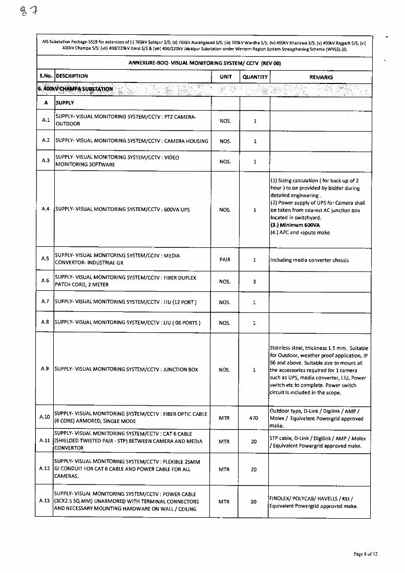
AIS Substation Package-5519 for extension of (i) 765kV Solapur S/S; (ii) 765kV Aurangabad S/S; (iii) 765kV Wardha 5/5; (iv) 400kV Khandwa 5/5; (v) 400kV Rajgarh 5/5; (vi)
400kV Champa S/S; (vii) 400/220kV !tarsi S/S & (viii) 400/220kV Jabalpur Substation under Western Region System Strengthening Scheme (WRS5)-20.
ANNEXURE-BOQ- VISUAL MONITORING SYSTEM/ CCTV (REV 00)
S.No. DESCRIPTION UNIT QUANTITY REMARKS
6; P BST 0.'
A SUPPLY
A.1 SUPPLY- VISUAL MONITORING SYSTEM/CCTV : PTZ CAMERA-
OUTDOOR NOS. 1
A.2 SUPPLY- VISUAL MONITORING SYSTEM/CCTV : CAMERA HOUSING NOS. 1
A.3 SUPPLY- VISUAL MONITORING SYSTEM/CCTV : VIDEO
MONITORING SOFTWARE NOS. 1
A.4 SUPPLY- VISUAL MONITORING SYSTEM/CCTV : 600VA UPS NOS. 1
(1) Sizing calculation ( for back up of 2
hour) to be provided by bidder during
detailed engineering .
(2) Power supply of UPS for Camera shall
be taken from nearest AC junction box
located in switchyard.
(3.) Minimum 600VA
(4.) APC and repute make
A.5 SUPPLY- VISUAL MONITORING SYSTEM/CCTV : MEDIA
CONVERTOR- INDUSTRIAL GR PAIR 1 Including media converter chassis
A.6 SUPPLY- VISUAL MONITORING SYSTEM/CCTV : FIBER DUPLEX
PATCH CORD, 2 METER NOS. 3
A.7 SUPPLY- VISUAL MONITORING SYSTEM/CCTV : LIU (12 PORT) NOS. 1
A.8 SUPPLY- VISUAL MONITORING SYSTEM/CCTV : LIU ( 06 PORTS) NOS. 1
A.9 SUPPLY- VISUAL MONITORING SYSTEM/CCTV : JUNCTION BOX NOS. 1
Stainless steel, thickness 1.5 mm. Suitable
for Outdoor, weather proof application, IP
66 and above. Suitable size to mount all
the accessories required for 1 camera
such as UPS, media converter, LIU, Power
switch etc to complete. Power switch
circuit is included in the scope.
A.10 SUPPLY- VISUAL MONITORING SYSTEM/CCTV : FIBER OPTIC CABLE
(6 CORE) ARMORED, SINGLE MODE MTR 470
Outdoor type, D-Link / Digilink / AMP /
Molex / Equivalent Powergrid approved
make.
All
SUPPLY- VISUAL MONITORING SYSTEM/CCTV : CAT 6 CABLE
(SHIELDED TWISTED PAIR - STP) BETWEEN CAMERA AND MEDIA
CONVERTOR MTR 20
STP cable, D-Link / Digilink / AMP / Molex
/ Equivalent Powergrid approved make.
A.12
SUPPLY- VISUAL MONITORING SYSTEM/CCTV : FLEXIBLE 25MM
GI CONDUIT FOR CAT 6 CABLE AND POWER CABLE FOR ALL
CAMERAS. MTR 20
A.13
SUPPLY- VISUAL MONITORING SYSTEM/CCTV : POWER CABLE
(3CX2.5 SQ.MM) UNARMORED WITH TERMINAL CONNECTORS
AND NECESSARY MOUNTING HARDWARE ON WALL / CEILING
MTR 20 FINOLEX/ POLYCAB/ HAVELLS / KEI /
Equivalent Powergrid approved make.
Page 8 of 12
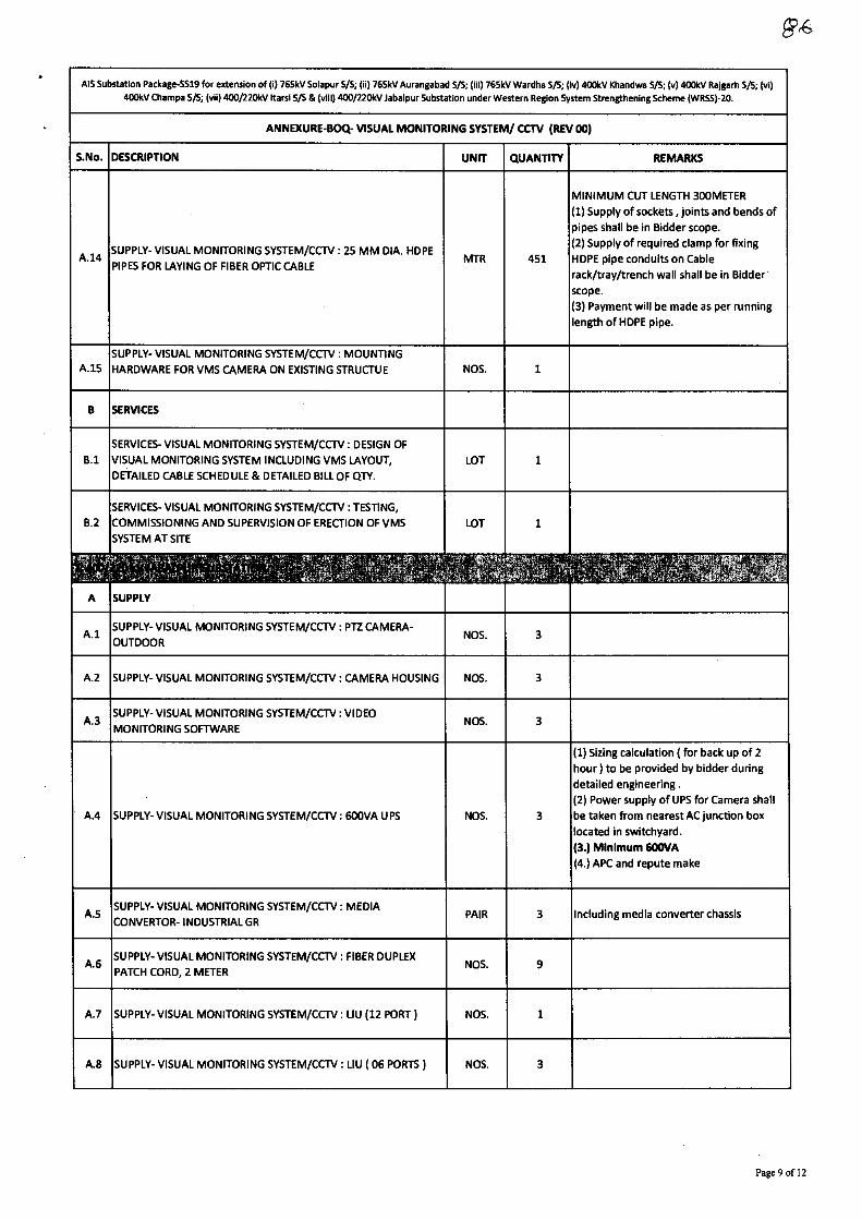
AIS Substation Package-5519 for extension of (i) 765kV Solapur 5/5; (ii) 765kV Aurangabad S/S; (iii) 765kV Wardha 5/5; (iv) 400kV Khandwa 5/5; (v) 400kV Rajgarh 5/5; (vi) 400kV Champa 5/5; (vii) 400/220kV 'tarsi 5/S & (viii) 400/220kV Jabalpur Substation under Western Region System Strengthening Scheme (WRSS)-20.
ANNEXURE-BOQ- VISUAL MONITORING SYSTEM/ CCTV (REV 00)
S.No. DESCRIPTION UNIT QUANTITY REMARKS
A.14 SUPPLY- VISUAL MONITORING SYSTEM/CCTV : 25 MM DIA. HDPE
PIPES FOR LAYING OF FIBER OPTIC CABLE
SUPPLY- VISUAL MONITORING SYSTEM/CCTV : MOUNTING
A.15 HARDWARE FOR VMS CAMERA ON EXISTING STRUCTUE
MINIMUM CUT LENGTH 300METER
(1) Supply of sockets , joints and bends of
pipes shall be in Bidder scope.
(2) Supply of required clamp for fixing
MTR 451 HDPE pipe conduits on Cable
rack/tray/trench wall shall be in Bidder
scope.
(3) Payment will be made as per running
length of HDPE pipe.
NOS. 1
B SERVICES
SERVICES- VISUAL MONITORING SYSTEM/CCTV : DESIGN OF
B.1 VISUAL MONITORING SYSTEM INCLUDING VMS LAYOUT, LOT 1
DETAILED CABLE SCHEDULE & DETAILED BILL OF QTY.
SERVICES- VISUAL MONITORING SYSTEM/CCTV : TESTING,
B.2 COMMISSIONING AND SUPERVISION OF ERECTION OF VMS LOT 1
SYSTEM AT SITE
A SUPPLY
SUPPLY- VISUAL MONITORING SYSTEM/CCTV : PTZ CAMERA-
A.1 OUTDOOR NOS. 3
A.2 SUPPLY- VISUAL MONITORING SYSTEM/CCTV : CAMERA HOUSING NOS. 3
A.3 SUPPLY- VISUAL MONITORING SYSTEM/CCTV : VIDEO
MONITORING SOFTWARE NOS. 3
A.4 SUPPLY- VISUAL MONITORING SYSTEM/CCTV : 600VA UPS
SUPPLY- VISUAL MONITORING SYSTEM/CCTV : MEDIA
A.5 CONVERTOR- INDUSTRIAL GR
(1) Sizing calculation ( for back up of 2
hour) to be provided by bidder during
detailed engineering .
(2) Power supply of UPS for Camera shall
NOS. 3 be taken from nearest AC junction box
located in switchyard.
(3.) Minimum 600VA
(4.) APC and repute make
PAIR 3 Including media converter chassis
.6 SUPPLY- VISUAL MONITORING SYSTEM/CCTV : FIBER DUPLEX
PATCH CORD, 2 METER NOS. 9
A.7 SUPPLY- VISUAL MONITORING SYSTEM/CCTV : LIU (12 PORT) NOS. 1
A.8 SUPPLY- VISUAL MONITORING SYSTEM/CCTV : LIU ( 06 PORTS) NOS. 3
Page 9 of 12
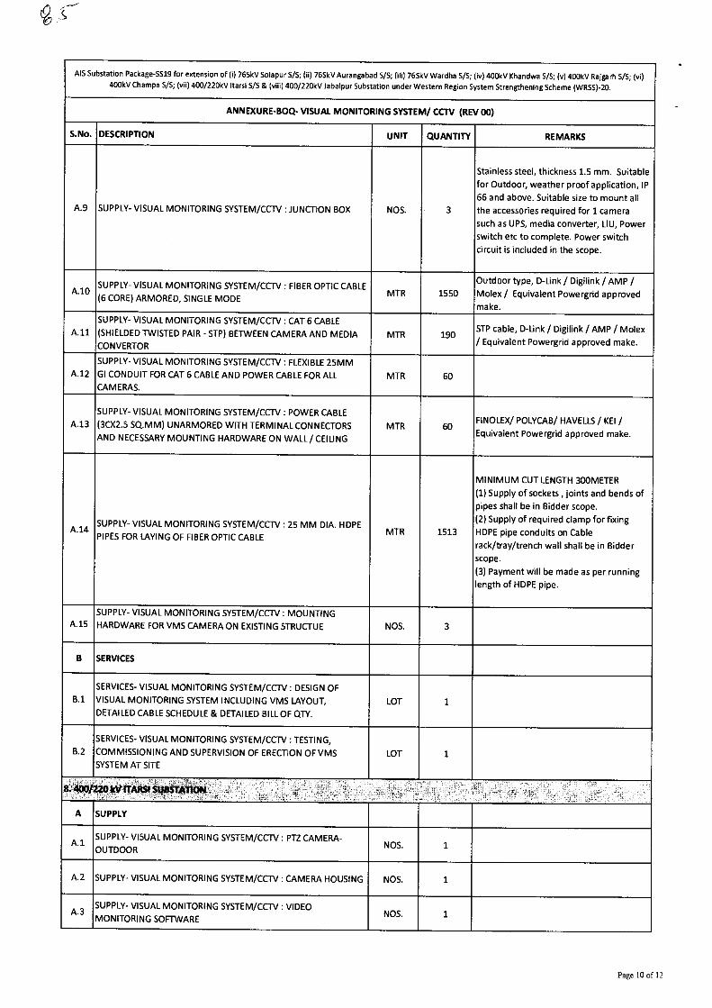
AIS Substation Package-5519 for extension of (i) 765kV Solapur S/S; (ii) 765kV Aurangabad S/S; (iii) 765kV Wardha 5/5; (iv) 400kV Khandwa 5/5; (v) 400kV Rajgarh 5/5; (vi)
400kV Champa S/S; (vii) 400/220kV !tarsi S/S & (viii) 400/220kV Jabalpur Substation under Western Region System Strengthening Scheme (WRSS)-20.
ANNEXURE-BOQ- VISUAL MONITORING SYSTEM/ CCTV (REV 00)
S.No. DESCRIPTION UNIT QUANTITY REMARKS
A.9 SUPPLY- VISUAL MONITORING SYSTEM/CCTV : JUNCTION BOX NOS. 3
Stainless steel, thickness 1.5 mm. Suitable
for Outdoor, weather proof application, IP
66 and above. Suitable size to mount all
the accessories required for 1 camera
such as UPS, media converter, LIU, Power
switch etc to complete. Power switch
circuit is included in the scope.
A.10 SUPPLY- VISUAL MONITORING SYSTEM/CCTV : FIBER OPTIC CABLE
(6 CORE) ARMORED, SINGLE MODE MTR 1550
Outdoor type, D-Link / Digilink / AMP /
Molex/ Equivalent Powergrid approved
make.
A.11
SUPPLY- VISUAL MONITORING SYSTEM/CCTV : CAT 6 CABLE
(SHIELDED TWISTED PAIR - STP) BETWEEN CAMERA AND MEDIA
CONVERTOR MTR 190
STP cable, D-Link / Digilink / AMP / Molex
/ Equivalent Powergrid approved make.
A.12
SUPPLY- VISUAL MONITORING SYSTEM/CCTV : FLEXIBLE 25MM
GI CONDUIT FOR CAT 6 CABLE AND POWER CABLE FOR ALL
CAMERAS. MTR 60
A.13
SUPPLY- VISUAL MONITORING SYSTEM/CCTV : POWER CABLE
(3CX2.5 SQ.MM) UNARMORED WITH TERMINAL CONNECTORS
AND NECESSARY MOUNTING HARDWARE ON WALL/ CEILING
MTR 60 FINOLEX/ POLYCAB/ HAVELLS / KEI /
Equivalent Powergrid approved make.
A.14 SUPPLY- VISUAL MONITORING SYSTEM/CCTV : 25MM DIA. HDPE
PIPES FOR LAYING OF FIBER OPTIC CABLE MTR 1513
MINIMUM CUT LENGTH 300METER
(1) Supply of sockets , joints and bends of
pipes shall be in Bidder scope.
(2) Supply of required clamp for fixing
HDPE pipe conduits on Cable
rack/tray/trench wall shall be in Bidder
scope.
(3) Payment will be made as per running
length of HDPE pipe.
A.15
SUPPLY- VISUAL MONITORING SYSTEM/CCTV : MOUNTING
HARDWARE FOR VMS CAMERA ON EXISTING STRUCTUE NOS. 3
B SERVICES
B.1
SERVICES- VISUAL MONITORING SYSTEM/CCTV : DESIGN OF
VISUAL MONITORING SYSTEM INCLUDING VMS LAYOUT,
DETAILED CABLE SCHEDULE & DETAILED BILL OF QTY.
LOT 1
B.2
SERVICES- VISUAL MONITORING SYSTEM/CCTV : TESTING,
COMMISSIONING AND SUPERVISION OF ERECTION OF VMS
SYSTEM AT SITE LOT 1
ry
A SUPPLY
A 1 SUPPLY- VISUAL MONITORING SYSTEM/CCTV : PTZ CAMERA-
OUTDOOR NOS. 1
A.2 SUPPLY- VISUAL MONITORING SYSTEM/CCTV : CAMERA HOUSING NOS. 1
A.3 SUPPLY- VISUAL MONITORING SYSTEM/CCTV : VIDEO
MONITORING SOFTWARE NOS. 1
Page 10 of 12
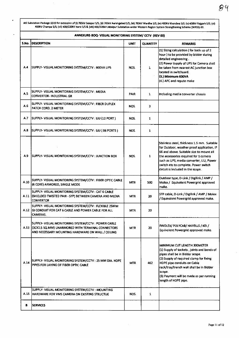
P t(
AIS Substation Package-5519 for extension of (i) 765kV Solapur S/S; (ii) 765kV Aurangabad S/S; (iii) 765kV Wardha 5/5; (iv) 400kV Khandwa S/S; (v) 400kV Rajgarh S/S; (vi)
400kV Champa 5/5; (vii) 400/220kV !tarsi S/S & (viii) 400/220kV Jabalpur Substation under Western Region System Strengthening Scheme (WRSS)-20.
ANNEXURE-BOQ- VISUAL MONITORING SYSTEM/ CCTV (REV 00)
S.No. DESCRIPTION UNIT QUANTITY REMARKS
A.4 SUPPLY- VISUAL MONITORING SYSTEM/CCTV : 600VA UPS NOS. 1
(1) Sizing calculation ( for back up of 2
hour ) to be provided by bidder during
detailed engineering .
(2) Power supply of UPS for Camera shall
be taken from nearest AC junction box
located in switchyard.
(3.) Minimum 600VA (4.) APC and repute make
A.5 SUPPLY- VISUAL MONITORING SYSTEM/CCTV : MEDIA
CONVERTOR- INDUSTRIAL GR PAIR 1 Including media converter chassis
A.6 SUPPLY- VISUAL MONITORING SYSTEM/CCTV : FIBER DUPLEX
PATCH CORD, 2 METER NOS. 3
A.7 SUPPLY- VISUAL MONITORING SYSTEM/CCTV : LIU (12 PORT) NOS. 1
A.8 SUPPLY- VISUAL MONITORING SYSTEM/CCTV : LIU ( 06 PORTS) NOS. 1
A.9 SUPPLY- VISUAL MONITORING SYSTEM/CCTV : JUNCTION BOX NOS. 1
Stainless steel, thickness 1.5 mm. Suitable
for Outdoor, weather proof application, IP
66 and above. Suitable size to mount all
the accessories required for 1 camera
such as UPS, media converter, LIU, Power
switch etc to complete. Power switch
circuit is included in the scope.
A.10 SUPPLY- VISUAL MONITORING SYSTEM/CCTV : FIBER OPTIC CABLE
(6 CORE) ARMORED, SINGLE MODE MTR 500
Outdoor type, D-Unk / Digilink / AMP /
Molex / Equivalent Powergrid approved
make.
A.11.
SUPPLY- VISUAL MONITORING SYSTEM/CCTV : CAT 6 CABLE
(SHIELDED TWISTED PAIR - STP) BETWEEN CAMERA AND MEDIA
CONVERTOR MTR 20
STP cable, D-Link / Digilink / AMP / Molex
/ Equivalent Powergrid approved make.
A.12
SUPPLY- VISUAL MONITORING SYSTEM/CCTV : FLEXIBLE 25MM
GI CONDUIT FOR CAT 6 CABLE AND POWER CABLE FOR ALL
CAMERAS.
MTR 20
A.13
SUPPLY- VISUAL MONITORING SYSTEM/CCTV : POWER CABLE
(30(2.5 SQ.MM) UNARMORED WITH TERMINAL CONNECTORS
AND NECESSARY MOUNTING HARDWARE ON WALL / CEILING
MTR 20 FINOLEX/ POLYCAB/ HAVELLS / KEI /
Equivalent Powergrid approved make.
A.14 SUPPLY- VISUAL MONITORING SYSTEM/CCTV : 25 MM DIA. HDPE
PIPES FOR LAYING OF FIBER OPTIC CABLE MTR 462
MINIMUM CUT LENGTH 300METER
(1) Supply of sockets, joints and bends of
pipes shall be in Bidder scope.
(2) Supply of required clamp for fixing
HDPE pipe conduits on Cable
rack/tray/trench wall shall be in Bidder
scope.
(3) Payment will be made as per running
length of HOPE pipe.
A.15
SUPPLY- VISUAL MONITORING SYSTEM/CCTV : MOUNTING
HARDWARE FOR VMS CAMERA ON EXISTING STRUCTUE NOS. 1
B SERVICES
Page 11 of 12
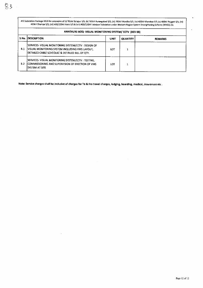
AIS Substation Package-5519 for extension of (i) 765kV Solapur 5/5; (ii) 765kV Aurangabad WS; (iii) 765kV Wardha VS; (iv) 400kV Khandwa VS; (v) 400kV Rajgarh 5/5; (vi)
400kV Champa 5/5; (vii) 400/220kV 'tarsi S/S & (viii) 400/220kV Jabalpur Substation under Western Region System Strengthening Scheme (WRSS)-20.
ANNEXURE-BOQ- VISUAL MONITORING SYSTEM/ CCTV (REV 00)
S.No. DESCRIPTION UNIT QUANTITY REMARKS
B.1
SERVICES- VISUAL MONITORING SYSTEM/CCTV : DESIGN OF
VISUAL MONITORING SYSTEM INCLUDING VMS LAYOUT,
DETAILED CABLE SCHEDULE & DETAILED BILL OF QTY.
LOT 1
8.2
SERVICES- VISUAL MONITORING SYSTEM/CCTV : TESTING,
COMMISSIONING AND SUPERVISION OF ERECTION OF VMS
SYSTEM AT SITE
LOT 1
Note: Service charges shall be inclusive of charges for To & Fro travel charges, lodging, boarding, medical, insurances etc .
Page 12 of 12

p2,
Bharat Heavy Electricals Limited
Doc No. TB-408-316-110
Technical Specification
Technical Specification for Visual Monitoring system
ANNEXURE-QR
TECHNICAL QUALIFYING REQUIREMENT
(1.) The Bidder should have experience of design, supply and installation of Visual Monitoring System / CCTV system in Switchyard / Power Plants/ Industrial/ Commercial Installations.
AND
(2.) The Bidder should have successfully executed similar job (as defined in point 1) having order value not less than Rs 10 lacs (excluding taxes, duties, F&I) as single order or not less than Rs. 6 lacs (excluding taxes, duties, F&I) each as two orders, during last five years as on the date of NOA..#
Documents to be submitted for Technical Requirements:
A. Bidder has to submit the Purchase Order / Work order copy defining the scope & value (as per point 1 & 2)
B. Bidder has to submit the certificate/end user certificate for completion of works / commissioning to meet the requirement as mentioned in 1 & 2 above.
# NOA: Date of NOA (Notification of Award) for reference project is 29.07.2019
\ \ 21)
PREPA ED BY
v
IEWED BY
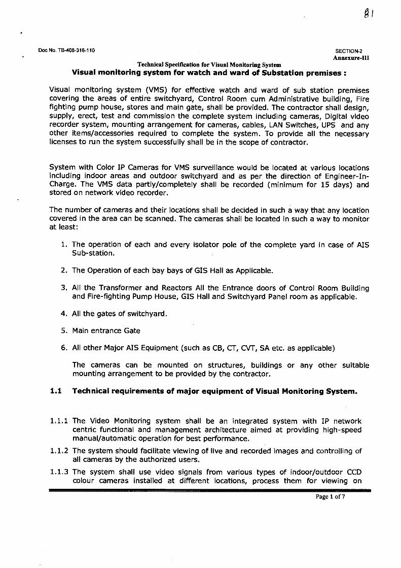
Doc No. TB-408-316-110
SECTION-2 Annexure-III
Technical Specification for Visual Monitoring System Visual monitoring system for watch and ward of Substation premises :
Visual monitoring system (VMS) for effective yvatch and ward of sub station premises covering the areas of entire switchyard, Control Room cum Administrative building, Fire fighting pump house, stores and main gate, shall be provided. The contractor shall design, supply, erect, test and commission the complete system including cameras, Digital video recorder system, mounting arrangement for cameras, cables, LAN Switches, UPS and any other items/accessories required to complete the system. To provide all the necessary licenses to run the system successfully shall be in the scope of contractor.
System with Color IP Cameras for VMS surveillance would be located at various locations including indoor areas and outdoor switchyard and as per the direction of Engineer-In-Charge. The VMS data partly/completely shall be recorded (minimum for 15 days) and stored on network video recorder.
The number of cameras and their locations shall be decided in such a way that any location covered in the area can be scanned. The cameras shall be located in such a way to monitor at least:
1. The operation of each and every isolator pole of the complete yard in case of AIS Sub-station.
2. The Operation of each bay bays of GIS Hall as Applicable.
3. All the Transformer and Reactors All the Entrance doors of Control Room Building and Fire-fighting Pump House, GIS Hall and Switchyard Panel room as applicable.
4. All the gates of switchyard.
5. Main entrance Gate
6. All other Major AIS Equipment (such as CB, CT, CVT, SA etc. as applicable)
The cameras can be mounted on structures, buildings or any other suitable mounting arrangement to be provided by the contractor.
1.1 Technical requirements of major equipment of Visual Monitoring System.
1.1.1 The Video Monitoring system shall be an integrated system with IP network centric functional and management architecture aimed at providing high-speed manual/automatic operation for best performance.
1.1.2 The system should facilitate viewing of live and recorded images and controlling of all cameras by the authorized users.
1.1.3 The system shall use video signals from various types of indoor/outdoor CCD colour cameras installed at different locations, process them for viewing on
Page 1 of 7
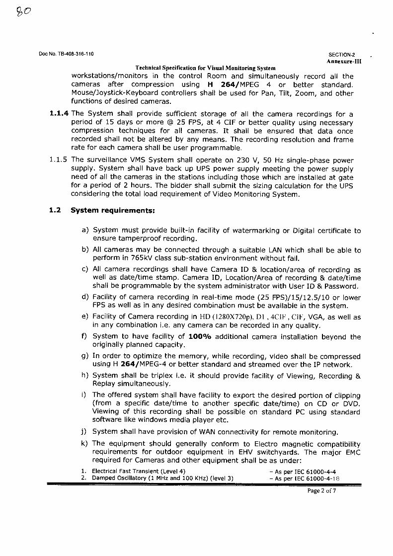
Doc No. TB-408-316-110 SECTION-2
Annexure-III Technical Specification for Visual Monitoring System
workstations/monitors in the control Room and simultaneously record all the cameras after compression using H 264/MPEG 4 or better standard. Mouse/Joystick-Keyboard controllers shall be used for Pan, Tilt, Zoom, and other functions of desired cameras.
1.1.4 The System shall provide sufficient storage of all the camera recordings for a period of 15 days or more @ 25 FPS, at 4 CIF or better quality using necessary compression techniques for all cameras. It shall be ensured that data once recorded shall not be altered by any means. The recording resolution and frame rate for each camera shall be user programmable.
1.1.5 The surveillance VMS System shall operate on 230 V, 50 Hz single-phase power supply. System shall have back up UPS power supply meeting the power supply need of all the cameras in the stations including those which are installed at gate for a period of 2 hours. The bidder shall submit the sizing calculation for the UPS considering the total load requirement of Video Monitoring System.
1.2 System requirements:
a) System must provide built-in facility of watermarking or Digital certificate to ensure tamperproof recording.
b) All cameras may be connected through a suitable LAN which shall be able to perform in 765kV class sub-station environment without fail.
c) All camera recordings shall have Camera ID & location/area of recording as well as date/time stamp. Camera ID, Location/Area of recording & date/time shall be programmable by the system administrator with User ID & Password.
d) Facility of camera recording in real-time mode (25 FPS)/15/12.5/10 or lower FPS as well as in any desired combination must be available in the system.
e) Facility of Camera recording in HD (I280X720p), DI , 4CIF , CIF, VGA, as well as in any combination i.e. any camera can be recorded in any quality.
f) System to have facility of 100% additional camera installation beyond the originally planned capacity.
g) In order to optimize the memory, while recording, video shall be compressed using H 264/MPEG-4 or better standard and streamed over the IP network.
h) System shall be triplex i.e. it should provide facility of Viewing, Recording & Replay simultaneously.
i) The offered system shall have facility to export the desired portion of clipping (from a specific date/time to another specific date/time) on CD or DVD. Viewing of this recording shall be possible on standard PC using standard software like windows media player etc.
j) System shall have provision of WAN connectivity for remote monitoring.
k) The equipment should generally conform to Electro magnetic compatibility requirements for outdoor equipment in EHV switchyards. The major EMC required for Cameras and other equipment shall be as under:
1. Electrical Fast Transient (Level 4) — As per IEC 61000-4-4 2. Damped Oscillatory (1 MHz and 100 KHz) (level 3) — As per IEC 61000-4-18
Page 2 of 7
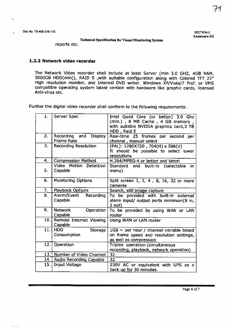
Doc No. TB-408-316-110
SECTION-2 Annexure-HI
Technical Specification for Visual Monitoring System reports etc.
1.2.2 Network video recorder
The Network Video recorder shall include at least Server (min 3.0 GHZ, 4GB RAM, 3000GB HDD(min)), RAID 5 ,with suitable configuration along with Colored TFT 22" High resolution monitor, and Internal DVD writer. Windows XP/Vista/7 Prof. or VMS compatible operating system latest version with hardware like graphic cards, licensed Anti-virus etc.
Further the digital video recorder shall conform to the following requirements:
1. Server Spec Intel Quad Core (or better) 3.0 Ghz (min.) , 8 MB Cache , 4 GB memory , with suitable NVIDIA graphics card,3 TB HDD , Raid 5
2. Recording and Display Frame Rate
Real-time 25 frames per second per channel , manual select
3. Recording Resolution (PAL): 1280X720 , 704(H) x 586(V) It should be possible to select lower resolutions
4. Compression Method H.264/MPEG-4 or better and latest
5. Video Motion Detection Capable
Standard and built-in (selectable in menu)
6. Monitoring Options Split screen 1, 2, 4 , 8, 16, 32 or more cameras
7. Playback Options Search, still image capture 8. Alarm/Event Recording
Capable To be provided with built-in external alarm input/ output ports minimum(8 in, 2 out)
9. Network Operation Capable
To be provided by using WAN or LAN router
10. Remote Internet Viewing Capable
Using WAN or LAN router
11. HDD Storage Consumption
1GB — per hour / channel variable based on frame speed and resolution settings, as well as compression
12. Operation Triplex operation (simultaneous recording, playback, network operation)
13. Number of Video Channel 32 14. Audio Recording Capable 32 15. Input Voltage 230V AC or equivalent with UPS as a
back up for 30 minutes.
Page 4 of 7
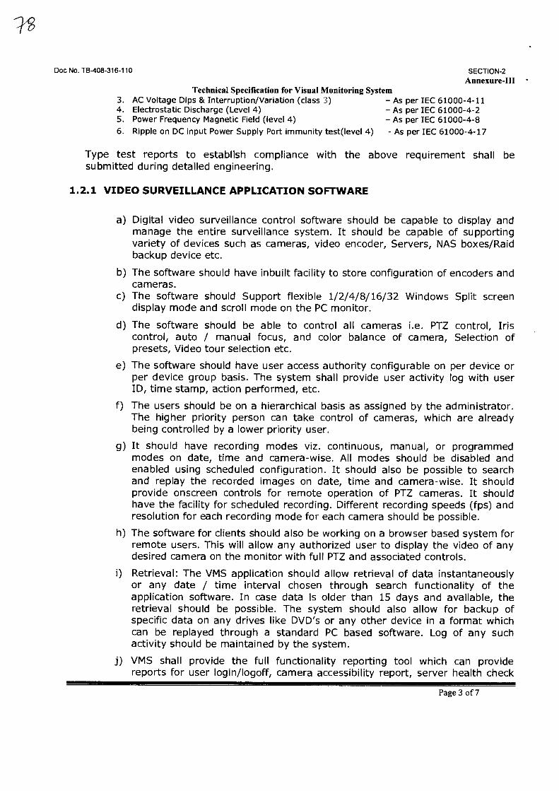
Doc No. TB-408-316-110 SECTION-2
Annexure-III • Technical Specification for Visual Monitoring System
3. AC Voltage Dips & Interruption/Variation (class 3) - As per IEC 61000-4-11 4. Electrostatic Discharge (Level 4) - As per IEC 61000-4-2 5. Power Frequency Magnetic Field (level 4) - As per IEC 61000-4-8 6. Ripple on DC input Power Supply Port immunity test(level 4) - As per IEC 61000-4-17
Type test reports to establish compliance with the above requirement shall be submitted during detailed engineering.
1.2.1 VIDEO SURVEILLANCE APPLICATION SOFTWARE
a) Digital video surveillance control software should be capable to display and manage the entire surveillance system. It should be capable of supporting variety of devices such as cameras, video encoder, Servers, NAS boxes/Raid backup device etc.
b) The software should have inbuilt facility to store configuration of encoders and cameras.
c) The software should Support flexible 1/2/4/8/16/32 Windows Split screen display mode and scroll mode on the PC monitor.
d) The software should be able to control all cameras i.e. PTZ control, Iris control, auto / manual focus, and color balance of camera, Selection of presets, Video tour selection etc.
e) The software should have user access authority configurable on per device or per device group basis. The system shall provide user activity log with user ID, time stamp, action performed, etc.
f) The users should be on a hierarchical basis as assigned by the administrator. The higher priority person can take control of cameras, which are already being controlled by a lower priority user.
g) It should have recording modes viz. continuous, manual, or programmed modes on date, time and camera-wise. All modes should be disabled and enabled using scheduled configuration. It should also be possible to search and replay the recorded images on date, time and camera-wise. It should provide onscreen controls for remote operation of PTZ cameras. It should have the facility for scheduled recording. Different recording speeds (fps) and resolution for each recording mode for each camera should be possible.
h) The software for clients should also be working on a browser based system for remote users. This will allow any authorized user to display the video of any desired camera on the monitor with full PTZ and associated controls.
i) Retrieval: The VMS application should allow retrieval of data instantaneously or any date / time interval chosen through search functionality of the application software. In case data is older than 15 days and available, the retrieval should be possible. The system should also allow for backup of specific data on any drives like DVD's or any other device in a format which can be replayed through a standard PC based software. Log of any such activity should be maintained by the system.
i) VMS shall provide the full functionality reporting tool which can provide reports for user login/logoff, camera accessibility report, server health check
Page 3 of 7
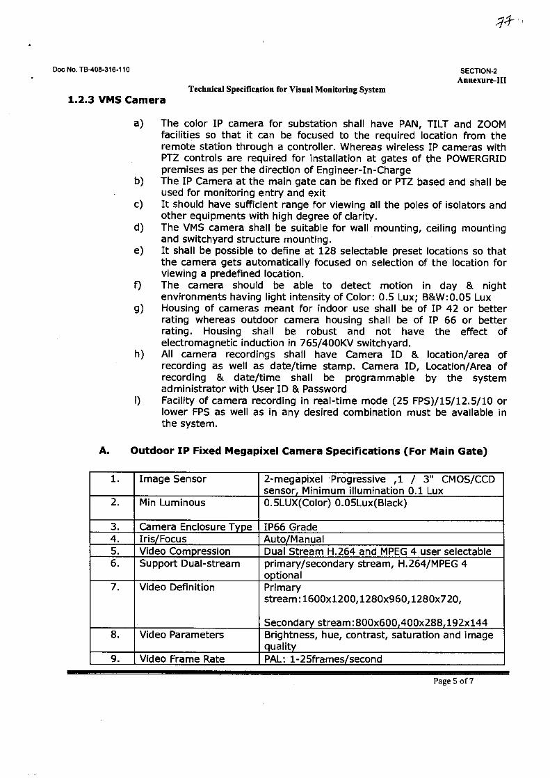
Doc No. TB-408-318-110
SECTION-2 Annexure-III
Technical Specification for Visual Monitoring System 1.2.3 VMS Camera
a) The color IP camera for substation shall have PAN, TILT and ZOOM facilities so that it can be focused to the required location from the remote station through a controller. Whereas wireless IP cameras with PTZ controls are required for installation at gates of the POWERGRID premises as per the direction of Engineer-In-Charge
b) The IP Camera at the main gate can be fixed or PTZ based and shall be used for monitoring entry and exit
c) It should have sufficient range for viewing all the poles of isolators and other equipments with high degree of clarity.
d) The VMS camera shall be suitable for wall mounting, ceiling mounting and switchyard structure mounting.
e) It shall be possible to define at 128 selectable preset locations so that the camera gets automatically focused on selection of the location for viewing a predefined location.
f) The camera should be able to detect motion in day & night environments having light intensity of Color: 0.5 Lux; B&W:0.05 Lux
g) Housing of cameras meant for indoor use shall be of IP 42 or better rating whereas outdoor camera housing shall be of IP 66 or better rating. Housing shall be robust and not have the effect of electromagnetic induction in 765/400KV switchyard.
h) All camera recordings shall have Camera ID & location/area of recording as well as date/time stamp. Camera ID, Location/Area of recording & date/time shall be programmable by the system administrator with User ID & Password
i) Facility of camera recording in real-time mode (25 FPS)/15/12.5/10 or lower FPS as well as in any desired combination must be available in the system.
A. Outdoor IP Fixed Megapixel Camera Specifications (For Main Gate)
1. Image Sensor 2-megapixel Progressive ,1 / 3" CMOS/CCD sensor, Minimum illumination 0.1 Lux
2. Min Luminous 0.5LUX(Color) 0.05Lux(Black)
3. Camera Enclosure Type IP66 Grade 4. Iris/Focus Auto/Manual 5. Video Compression Dual Stream H.264 and MPEG 4 user selectable 6. Support Dual-stream primary/secondary stream, H.264/MPEG 4
optional 7. Video Definition Primary
stream:1600x1200,1280x960,1280x720,
Secondary stream:800x600,400x288,192x144 Brightness, hue, contrast, saturation and image quality
8. Video Parameters
9. Video Frame Rate PAL: 1-25frames/second
Page 5 of 7
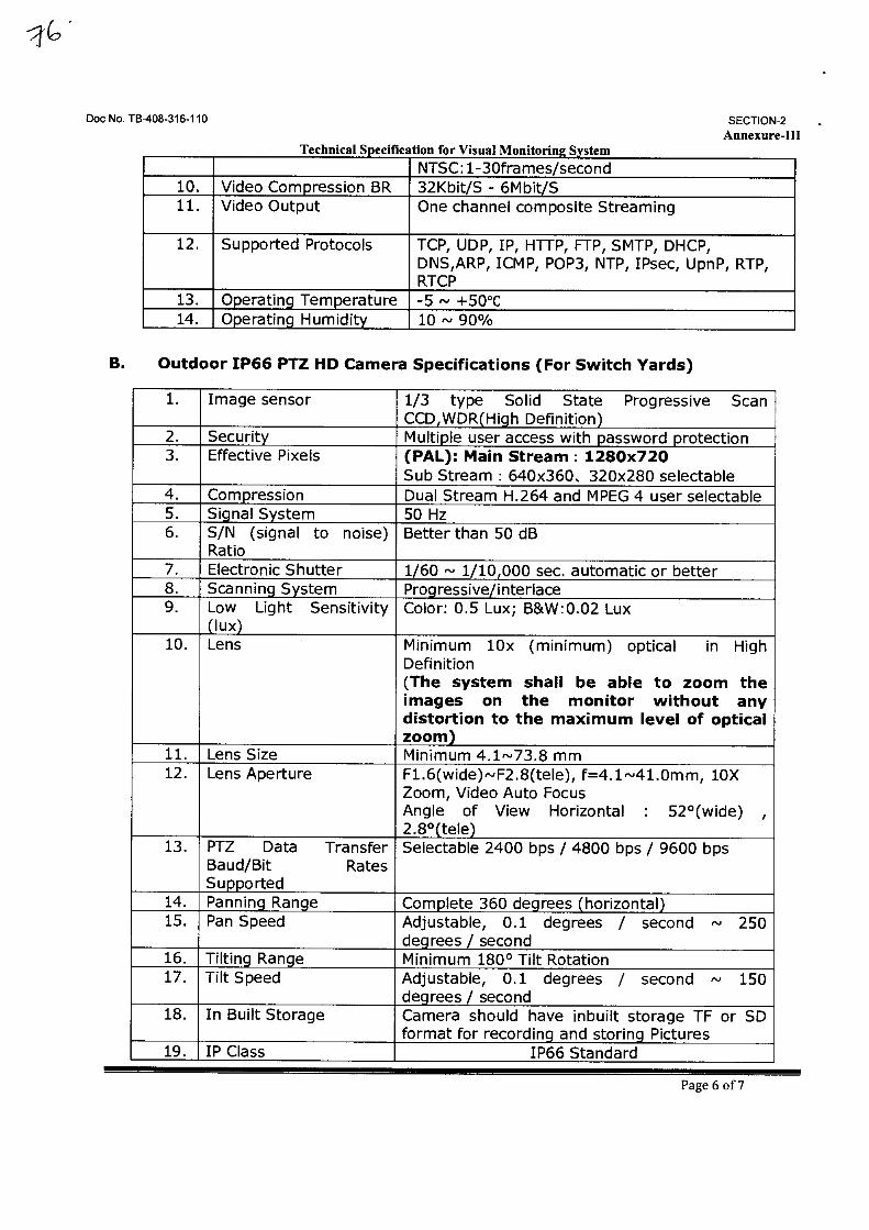
Doc No. TB-408-316-110
SECTION-2
Annexure-III Technical Specification for Visual Monitoring System
NTSC:1-30frames/second 32Kbit/S - 6Mbit/S 10. Video Compression BR
11. Video Output One channel composite Streaming
12. Supported Protocols TCP, UDP, IP, HTTP, FTP, SMTP, DHCP, DNS,ARP, ICMP, POP3, NTP, IPsec, UpnP, RTP, RTCP
13. Operating Temperature -5 ,,, +50°C 14. Operating Humidity 10 — 90%
B. Outdoor 1P66 PTZ HD Camera Specifications (For Switch Yards)
1. Image sensor 1/3 type Solid State Progressive Scan CCD,WDR(High Definition)
2. Security Multiple user access with password protection 3. Effective Pixels (PAL): Main Stream : 1280x720
Sub Stream : 640x360, 320x280 selectable 4. Compression Dual Stream H.264 and MPEG 4 user selectable 5. Signal System 50 Hz 6. S/N (signal to noise)
Ratio Better than 50 dB
7. Electronic Shutter 1/60 " 1/10,000 sec. automatic or better 8. Scanning System Progressive/interlace 9. Low Light Sensitivity
(lux) Color: 0.5 Lux; B&W:0.02 Lux
10. Lens Minimum 10x (minimum) optical in High Definition (The system shall be able to zoom the images on the monitor without any distortion to the maximum level of optical zoom)
11. Lens Size Minimum 4.173.8 mm 12. Lens Aperture F1.6(wide)—F2.8(tele), f=4.1-41.0mm, 10X
Zoom, Video Auto Focus Angle of View Horizontal : 52°(wide) , 2.8°(tele)
13. PTZ Data Transfer Baud/Bit Rates Supported
Selectable 2400 bps / 4800 bps / 9600 bps
14. Panning Range Complete 360 degrees (horizontal) 15. Pan Speed Adjustable, 0.1 degrees / second " 250
degrees / second 16. Tilting Range Minimum 180° Tilt Rotation 17. Tilt Speed Adjustable, 0.1 degrees / second — 150
degrees / second 18. In Built Storage Camera should have inbuilt storage TF or SD
format for recording and storing Pictures 19. IP Class IP66 Standard
Page 6 of 7
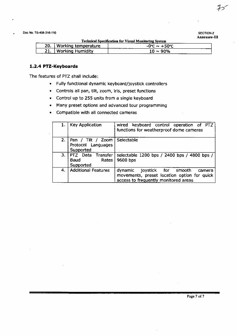
Doc No. TB-408-316-110
SECTION-2 Annexure-III
Technical Specification for Visual Monitoring System 20. Working temperature -0°C — +50°C 21. Working Humidity 10 — 90%
1.2.4 PTZ-Keyboards
The features of PTZ shall include:
• Fully functional dynamic keyboard/joystick controllers
• Controls all pan, tilt, zoom, iris, preset functions
• Control up to 255 units from a single keyboard
• Many preset options and advanced tour programming
• Compatible with all connected cameras
1. Key Application wired keyboard control operation of PTZ functions for weatherproof dome cameras
2. Pan / Tilt / Zoom Protocol Languages Supported
Selectable
3. PTZ Data Transfer Baud Rates Supported
selectable 1200 bps / 2400 bps / 4800 bps / 9600 bps
4. Additional Features dynamic joystick for smooth camera movements, preset location option for quick access to frequently monitored areas
Page 7 of 7
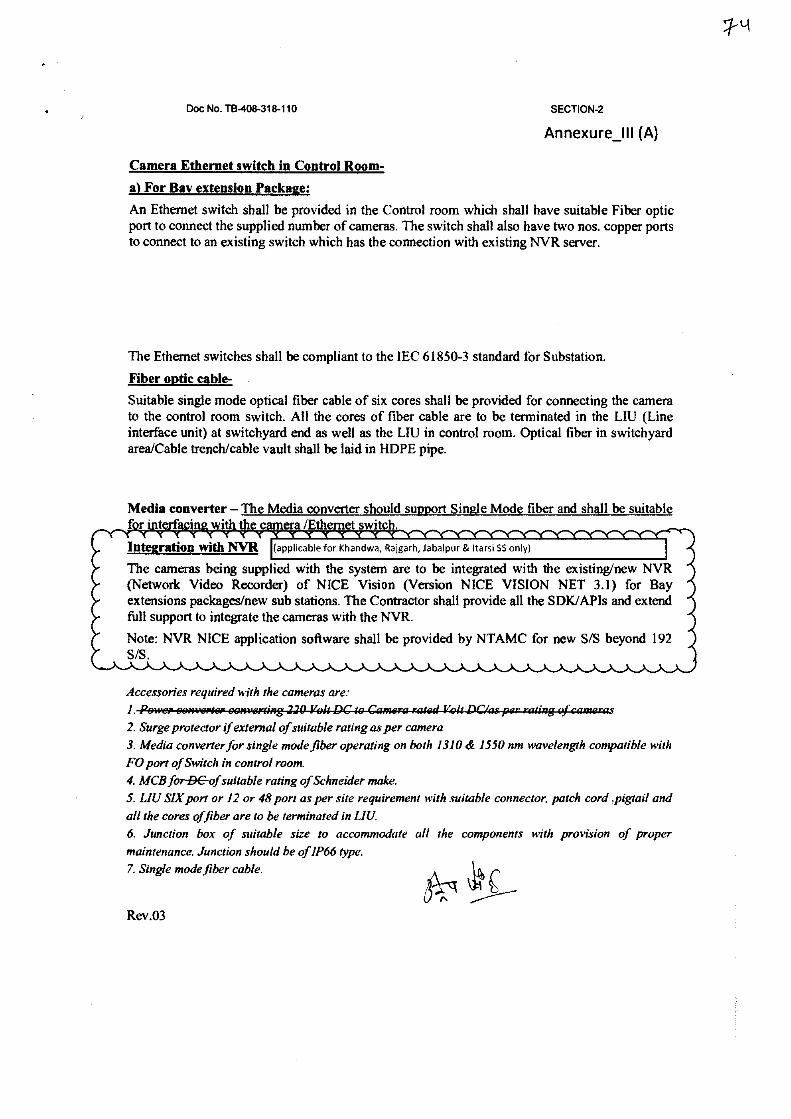
Doc No. TB-408-316-110 SECTION-2
Annexure_111 (A)
Camera Ethernet switch in Control Room-
a) For Bay extension Package:
An Ethernet switch shall be provided in the Control room which shall have suitable Fiber optic port to connect the supplied number of cameras. The switch shall also have two nos. copper ports to connect to an existing switch which has the connection with existing NVR server.
The Ethernet switches shall be compliant to the IEC 61850-3 standard for Substation.
Fiber optic cable-
Suitable single mode optical fiber cable of six cores shall be provided for connecting the camera to the control room switch. All the cores of fiber cable are to be terminated in the LIU (Line interface unit) at switchyard end as well as the LIU in control room. Optical fiber in switchyard area/Cable trench/cable vault shall be laid in HDPE pipe.
Media converter — The Media converter should support Single Mode fiber and shall be suitable f t- i• i - - • /E e • t s it h.
444444444444444444444444444444444444444444444444444444 Integration with NVR (applicable for Khandwa, Rajgarh, Jabalpur & [tarsi SS only)
The cameras being supplied with the system are to be integrated with the existing/new NVR (Network Video Recorder) of NICE Vision (Version NICE VISION NET 3.1) for Bay extensions packages/new sub stations. The Contractor shall provide all the SDK/APIs and extend full support to integrate the cameras with the NVR.
Note: NVR NICE application software shall be provided by NTAMC for new S/S beyond 192 S/S.
Accessories required with the cameras area I 2. Surge protector if external of suitable rating as per camera 3. Media converter for single mode fiber operating on both 1310 & 1550 nm wavelength compatible with FO port of Switch in control room. 4. MCB forD&of suitable rating of Schneider make. 5. LIU SIX port or 12 or 48 port as per site requirement with suitable connector, patch cord ,pigtail and all the cores of fiber are to be terminated in LIU. 6. Junction box of suitable size to accommodate all the components with provision of proper maintenance. Junction should be of IP66 type.
As-g47. Single mode fiber cable.
C Rev.03
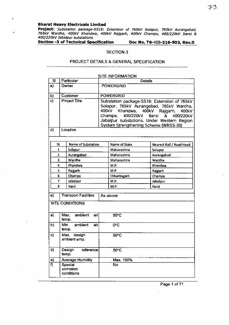
Bharat Heavy Electricals Limited Project: Substation package-SS19: Extension of 765kV Solapur, 765kV Aurangabad, 765kV Wardha, 400kV Khandwa, 400kV Rajgarh, 400kV Champa, 400/220kV Itarsi & 400/220kV Jabalpur substations Section -3 of Technical Specification Doc No. TB-408-316-S03, Rev.O
SECTION-3
PROJECT DETAILS & GENERAL SPECIFICATION
SITE INFORMATION SI Particular Details
a) Owner POWERGRID
b) Customer POWERGRID c) Project Title Substation package-SS19: Extension of 765kV
Solapur, 765kV Aurangabad, 765kV Wardha, 400kV Khandwa, 400kV Rajgarh, 400kV Champa, 400/220kV (tarsi & 400/220kV Jabalpur substations. Under Western Region System Strengthening Scheme (WRSS-20)
d) Location
SL Name of Substation Name of State Nearest Rail / Road Head
1 Solapur Maharashtra Solapur
2 Aurangabad Maharashtra Aurangabad
3 Wardha Maharashtra Wardha
4 Khandwa M.P. Khandwa
5 Rajgarh M.P Rajgarh
6 Champa Chhattisgarh Champa
7 Jabalpur M.P. Jabalpur
8 (tarsi M.P. (tarsi
e) Transport Facilities As above
SITE CONDITIONS
a) Max. ambient air temp.
50°C
b) Min. ambient air temp.
0°C
c) Max. design ambient emp.
50°C
d) Design reference temp.
50°C
e) Average Humidity Max. 100% f) Special
corrosion conditions
No
Page 1 of 71
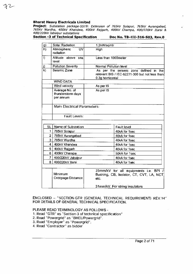
Bharat Heavy Electricals Limited Project: Substation package-SS19: Extension of 765kV Solapur, 765kV Aurangabad, 765kV Wardha, 400kV Khandwa, 400kV Rajgarh, 400kV Champa, 400/220kV Itarsi & 400/220kV Jabalpur substations Section -3 of Technical Specification Doc No. TB-408-316-S03, Rev.O
g) Solar Radiation 1.2kW/sqmtr h) Atmospheric UV
radiation High
i) Altitude above sea level
Less than 1000meter
j) Pollution Severity Normal Pollution level k) Seismic Zone As per the seismic zone defined in the
relevant BIS / IEC-62271-300 but not less than 0.3g horrizontal
WIND DATA Wind velocity As per IS Average No. of thunderstorm days per annum
As per IS
Main Electrical Parameters:
Fault Levels:
SL Name of Substation Fault level 1 765kV Solapur 40kA for 1sec 2 765kV Aurangabad 40kA for 1sec 3 765kV Wardha 40kA for 1sec 4 400kV Khandwa 40kA for lsec 5 400kV Ralgarh 40kA for 1 sec 6 400kV Champa 50kA for 1 sec 7 400/220kV Jabalpur 40kA for 1 sec 8 400/220kV !tarsi 40kA for 1sec
Minimum Creepage Distance
25mm/kV for all equipments i.e. BPI / Bushing, CB, Isolator, CT, CVT, LA, NCT etc.
31mm/kV. For string insulators
ENCLOSED — "SECTION-GTR (GENERAL TECHNICAL REQUIREMENT) REV.14" FOR DETAILS OF GENERAL TECHNICAL SPECIFICATION.
PLEASE READ TERMINOLOGY AS FOLLOWS 1. Read "GTR" as "Section-3 of technical specification" 2. Read "Powergrid" as "BHEL/Powergrid". 3. Read "Employer" as "Powergrid". 4. Read "Contractor" as bidder
Page 2 of 71
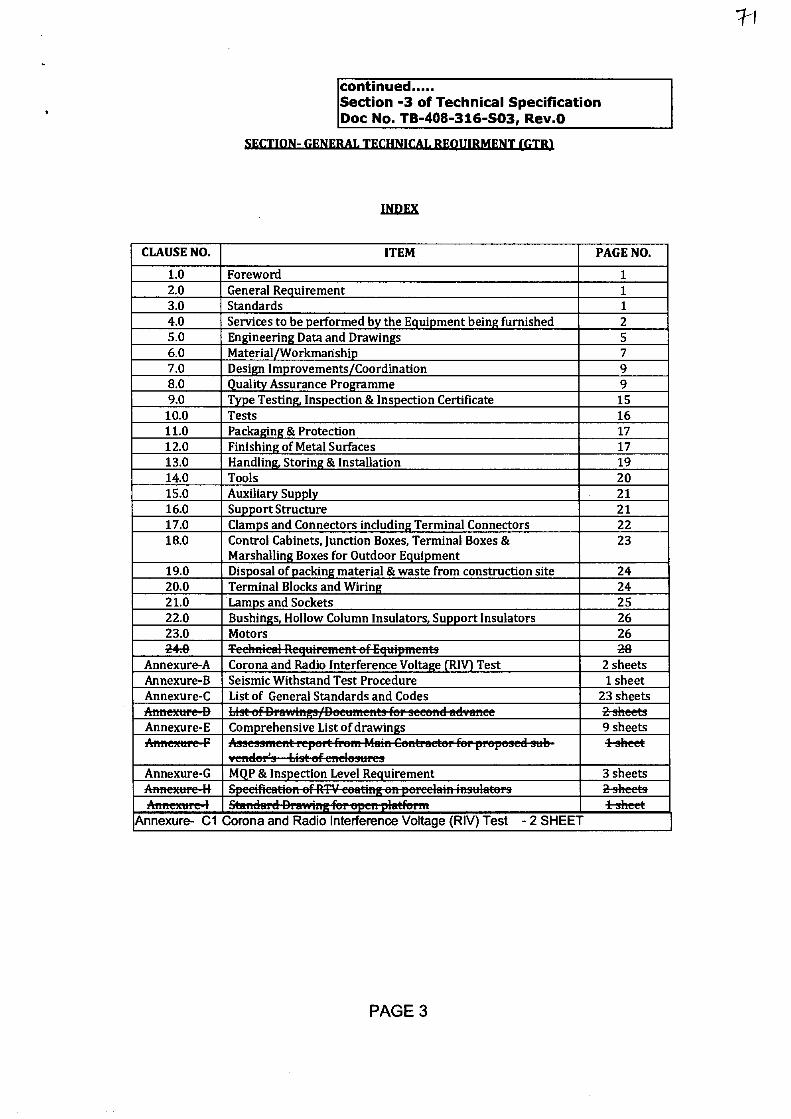
continued Section -3 of Technical Specification Doc No. TB-408-316-S03, Rev.O
SECTION- GENERAL TECHNICAL REQUIRMENT (GTR1
INDEX
CLAUSE NO. ITEM PAGE NO.
1.0 Foreword 1 2.0 General Requirement 1 3.0 Standards 1 4.0 Services to be performed by the Equipment being furnished 2 5.0 Engineering Data and Drawings 5 6.0 Material/Workmanship 7 7.0 Design Improvements/Coordination 9 8.0 Quality Assurance Programme 9 9.0 Type Testing, Inspection & Inspection Certificate 15
10.0 Tests 16 11.0 Packaging & Protection 17 12.0 Finishing of Metal Surfaces 17 13.0 Handling, Storing & Installation 19 14.0 Tools 20 15.0 Auxiliary Supply 21 16.0 Support Structure 21 17.0 Clamps and Connectors including Terminal Connectors 22 18.0 Control Cabinets, Junction Boxes, Terminal Boxes &
Marshalling Boxes for Outdoor Equipment 23
19.0 Disposal of packing material & waste from construction site 24 20.0 Terminal Blocks and Wiring 24 21.0 Lamps and Sockets 25 22.0 Bushings, Hollow Column Insulators, Support Insulators 26 23.0 Motors 26 24:0 Teehnieel-Requirentent-ef-Equipinents 26
Annexure-A Corona and Radio Interference Voltage (RIV) Test 2 sheets Annexure-B Seismic Withstand Test Procedure 1 sheet Annexure-C List of General Standards and Codes 23 sheets Annexere4) 2-sheets . Annexure-E Comprehensive List of drawings 9 sheets Artnexere-F .1-sheet ..
ventietz9_449tefertetestire2
Annexure-G MQP & Inspection Level Requirement 3 sheets Anftexttrc-H — , . ' ' 2-sheets Arutexere-I Standerd-Drawingfer-epettplefferet 1-sheet
Annexure- Cl Corona and Radio Interference Voltage (RIV) Test - 2 SHEET
1-)
PAGE 3
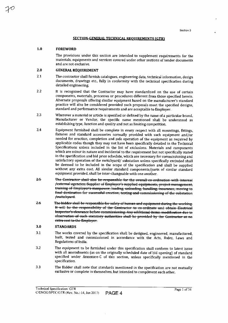
Section-3
1.0 FOREWORD
The provisions under this section are intended to supplement requirements for the materials, equipments and services covered under other sections of tender documents and are not exclusive.
2.0 GENERAL REQUIREMENT
2.1 The contractor shall furnish catalogues, engineering data, technical information, design documents, drawings etc., fully in conformity with the technical specification during detailed engineering.
2.2 It is recognised that the Contractor may have standardised on the use of certain components, materials, processes or procedures different from those specified herein. Alternate proposals offering similar equipment based on the manufacturer's standard practice will also be considered provided such proposals meet the specified designs, standard and performance requirements and are acceptable to Employer.
2.3 Wherever a material or article is specified or defined by the name of a particular brand, Manufacturer or Vendor, the specific name mentioned shall be understood as establishing type, function and quality and not as limiting competition.
2.4 Equipment furnished shall be complete in every respect with all mountings, fittings, fixtures and standard accessories normally provided with such equipment and/or needed for erection, completion and safe operation of the equipment as required by applicable codes though they may not have been specifically detailed in the Technical Specifications unless included in the list of exclusions. Materials and components which are minor in nature and incidental to the requirement but not specifically stated in the specification and bid price schedule, which are necessary for commissioning and satisfactory operation of the switchyard/ substation unless specifically excluded shall be deemed to be included in the scope of the specification and shall be supplied without any extra cost. All similar standard components/parts of similar standard equipment provided, shall be inter-changeable with one another.
275
26
ext-ra-east-te-tk-e-Etitc4eyer:
3.0 STANDARDS
3.1 The works covered by the specification shall be designed, engineered, manufactured, built, tested and commissioned in accordance with the Acts, Rules, Laws and Regulations of India.
3.2 The equipment to be furnished under this specification shall conform to latest issue with all amendments (as on the originally scheduled date of bid opening) of standard specified under Annexure-C of this section, unless specifically mentioned in the specification.
3.3 The Bidder shall note that standards mentioned in the specification are not mutually exclusive or complete in themselves, but intended to compliment each other.
Technical Specification: GTR C/ENGG/SPEC/GTR (Rev. No.:-14, Jan 2017) PAGE 4
Page 1 of 34
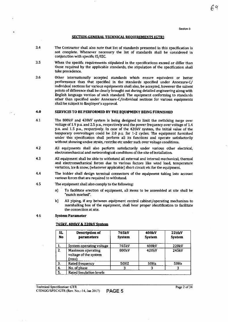
Section-3
SECTION-GENERAL TECHNICAL REQUIREMENTS (GTR1
3.4 The Contractor shall also note that list of standards presented in this specification is not complete. Whenever necessary the list of standards shall be considered in conjunction with specific IS/IEC.
3.5 When the specific requirements stipulated in the specifications exceed or differ than those required by the applicable standards, the stipulation of the specification shall take precedence.
3.6 Other internationally accepted standards which ensure equivalent or better performance than that specified in the standards specified under Annexure-C/ individual sections for various equipments shall also, be accepted, however the salient points of difference shall be clearly brought out during detailed engineering along with English language version of such standard. The equipment conforming to standards other than specified under Annexure-C/individual sections for various equipments shall be subject to Employer's approval.
4.0 SERVICES TO BE PERFORMED BY THE EQUIPMENT BEING FURNISHED
4.1 The 800kV and 420kV system is being designed to limit the switching surge over voltage of 1.9 p.u. and 2.5 p.u., respectively and the power frequency over voltage of 1.4 p.u. and 1.5 p.u., respectively. In case of the 420kV system, the initial value of the temporary overvoltages could be 2.0 p.u. for 1-2 cycles. The equipment furnished under this specification shall perform all its functions and operate satisfactorily without showing undue strain, restrike etc under such over voltage conditions.
4.2 All equipments shall also perform satisfactorily under various other electrical, electromechanical and meteorological conditions of the site of installation.
4.3 All equipment shall be able to withstand all external and internal mechanical, thermal and electromechanical forces due to various factors like wind load, temperature variation, ice & snow, (wherever applicable) short circuit etc for the equipment.
4.4 The bidder shall design terminal connectors of the equipment taking into account various forces that are required to withstand.
4.5 The equipment shall also comply to the following:
a) To facilitate erection of equipment, all items to be assembled at site shall be "match marked".
b) All piping, if any between equipment control cabinet/operating mechanism to marshalling box of the equipment, shall bear proper identification to facilitate the connection at site.
4.6 System Parameter
765kV. 400kV & 220kV System
SL No
Description of parameters
765kV System
400kV System
220kV System
1. System operating voltage 765kV 400kV 220kV 2. Maximum operating
voltage of the system (rms)
800kV 420kV 245kV
3. Rated frequency 50HZ 50Hz 50Hz 4. No. of phase 3 3 3 5. Rated Insulation levels
Technical Specification: GTR
Page 2 of 34 C/ENGG/SPEC/GTR (Rev. No.:-14, Jan 2017) PAGE 5
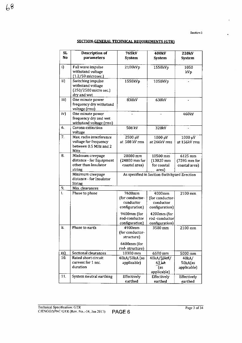
Section-3
SECTION-GENERAL TECHNICAL REQUIREMENTS (GTR).
SL No
Description of parameters
765kV System
400kV System
220kV System
i) Full wave impulse withstand voltage (1.2/50 microsec.)
2100kVp 1550kVp 1050 kVp
ii) Switching impulse withstand voltage (250/2500 micro sec.) dry and wet
1550kVp 1050kVp -
iii) One minute power frequency dry withstand voltage (rms)
830kV 630kV -
iv) One minute powerfrequency dry and wet withstand voltage (rms)
- - 460kV
6. Corona extinction voltage
508 kV 320kV -
7. Max. radio interference voltage for frequency between 0.5 MHz and 2 MHz
2500 µV at 508 kV rms
1000 tV at 266kV rms
1000 IN at 156kV rms
8. Minimum creepage distance - for Equipment other than Insulator string
20000 mm (24800 mm for
coastal area)
10500 mm (13020 mm for coastal
area)
6125 mm (7595 mm for coastal area)
Minimum creepage distance - for Insulator String
As specified in Section-Switchyard Erection
9. Min. clearances i. Phase to phase 7600mm
(for conductor- conductor
configuration)
9400mm (for rod-conductor configuration)
4000mm (for conductor-
conductor configuration)
4200mm (for rod -conductor configuration)
2100 mm
ii. Phase to earth 4900mm (for conductor-
structure)
6400mm (for rod- structure)
3500 mm 2100 mm
iii) Sectional clearances 10300 mm 6500 mm 5000 mm 10. Rated short circuit
current for 1 sec. duration
40kA/50kA (as applicable)
40kA/5.01ak/ 9...kk
(as applicable)
40kA/ 50kA(as
applicable)
11. System neutral earthing Effectively earthed
Effectively earthed
Effectively earthed
Technical Specification: GTR
Page 3 of 34 (1/ENGGISPEC/GTR (Rev. No.:-14, Jan 2017) PAGE 6
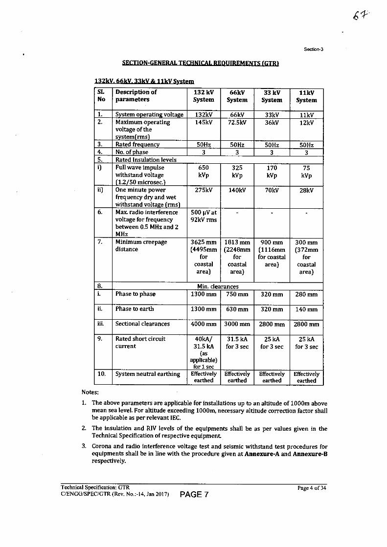
Section-3
SECTION-GENERAL TECHNICAL REQUIREMENTS (GTR1
132kV. 66kV. 33kV & 11kV System
SL No
Description of parameters
132 kV System
66kV System
33 kV System
11kV System
1. System operating voltage 132kV 66kV 33kV 11kV 2. Maximum operating
voltage of the system(rms)
145kV 72.5kV 36kV 12kV
3. Rated frequency 50Hz 50Hz 50Hz 50Hz 4. No. of phase 3 3 3 3 5. Rated Insulation levels i) Full wave impulse
withstand voltage (1.2/50 microsec.)
650 kVp
325 kVp
170 kVp
75 kVp
ii) One minute power frequency dry and wet withstand voltage (rms)
275kV 140kV 70kV 28kV
6. Max. radio interference voltage for frequency between 0.5 MHz and 2 MHz
500 [11, at 92kV rms
- - -
7. Minimum creepage distance
3625 mm (4495mm
for coastal area)
1813 mm (2248mm
for coastal area)
900 mm (1116mm for coastal
area)
300 mm (372mm
for coastal area)
8. Min. clearances i. Phase to phase 1300 mm 750 mm 320 mm 280 mm
ii. Phase to earth 1300 mm 630 mm 320 mm 140 mm
iii. Sectional clearances 4000 mm 3000 mm 2800 mm 2800 mm
9. Rated short circuit current
40kA/ 31.5 kA
(as applicable)
for 1 sec
31.5 kA for 3 sec
25 kA for 3 sec
25 kA for 3 sec
10. System neutral earthing Effectively earthed
Effectively earthed
Effectively earthed
Effectively earthed
Notes:
1. The above parameters are applicable for installations up to an altitude of 1000m above mean sea level. For altitude exceeding 1000m, necessary altitude correction factor shall be applicable as per relevant IEC.
2. The insulation and RIV levels of the equipments shall be as per values given in the Technical Specification of respective equipment.
3. Corona and radio interference voltage test and seismic withstand test procedures for equipments shall be in line with the procedure given at Annexure-A and Annexure-B respectively.
Technical Specification: GTR
Page 4 of 34 C/ENGG/SPEC/GTR (Rev. No.:-I4, Jan 2017) PAGE 7
Section-3
SECTION-GENERAL TECHNICAL REQUIREMENTS (GTR).
5.0 ENGINEERING DATA AND DRAWINGS
5.1 The list of drawings/documents which are to be submitted to the Employer is enclosed in Annexure-E. In case any additional drawings/documents are required, the same shall also be submitted during execution of the contract
5.2 The Contractor shall submit 4 (four) sets of drawings/ design documents /data / detailed bill of quantity and 1 (one) set of test reports for the approval of the Employer. The contractor shall also submit the softcopy of the above documents in addition to hardcopy.
5.3 Drawings
5.3.1 All drawings submitted by the Contractor shall be in sufficient detail to indicate the type, size, arrangement, material description, Bill of Materials, weight of each component, break-up for packing and shipment, dimensions, internal & the external connections, fixing arrangement required and any other information specifically requested in the specifications.
5.3.2 Drawings submitted by the Contractor shall be clearly marked with the name of the Employer, the unit designation, the specifications title, the specification number and the name of the Project. POWERGRID has standardized a large number of drawings/documents of various make including type test reports which can be used for all projects having similar requirements and in such cases no project specific approval (except for list of applicable drawings alongwith type test reports) is required. However, distribution copies of standard drawings/documents shall be submitted as per provision of the contract. All titles, noting, markings and writings on the drawing shall be in English. All the dimensions should be in SI units.
5.3.3 The review of these data by the Employer will cover only general conformance of the data to the specifications and documents, interfaces with the equipment provided under the specifications, external connections and of the dimensions which might affect substation layout This review by the Employer may not indicate a thorough review of all dimensions, quantities and details of the equipment, materials, any devices or items indicated or the accuracy of the information submitted. This review and/or approval by the Employer shall not be considered by the Contractor, as limiting any of his responsibilities and liabilities for mistakes and deviations from the requirements, specified under these specifications and documents.
5.5 All manufacturing and fabrication work in connection with the equipment prior to the approval of the drawings shall be at the Contractor's risk. The Contractor may make any changes in the design which are necessary to make the equipment conform to the provisions and intent of the Contract and such changes will again be subject to approval by the Employer. Approval of Contractor's drawing or work by the Employer shall not relieve the contractor of any of his responsibilities and liabilities under the Contract
5.6 All engineering data submitted by the Contractor after final process including review and approval by the Employer shall form part of the Contract Document and the entire works performed under these specifications shall be performed in strict conformity, unless otherwise expressly requested by the Employer in Writing.
5.7 Approval Procedure
The following schedule shall be followed generally for approval and for providing final documentation.
i) Approval/comments/ As per L2 schedule by Employer on initial submission
Technical Specification: GTR
Page 5 of 34 C/ENGG/SPEC/GTR (Rev. No.:-I4, Jan 2017) PAGE 8
Section-3
6
ii) Resubmission (whenever required)
iii) Approval or comments
iv) Furnishing of distribution copies (2 hard copies to each substation and one scanned copy (pdf format)
v) Furnishing of distribution copies of test reports
(a) Type test reports (one scanned softcopy in pdf format to each substation plus one for corporate centre & one hardcopy per substation)
(b) Routine Test Reports (one copy for each substation)
vi) Furnishing of instruction/ operation manuals (2 copies per substation and one softcopy (pdf format) for corporate centre & per substation)
(vii) As built drawings (two sets of hardcopy per substation & one softcopy (pdf format) for corporate centre & per substation)
NOTE:
Within 3 (three) weeks from date of comments
Within 3 (three) weeks of receipt of resubmission.
2 weeks from the date of approval
2 weeks from the date of final approval
-do-
On completion of Engineering
On completion of entire works
(1) The contractor may please note that all resubmissions must incorporate all comments given in the earlier submission by the Employer or adequate justification for not incorporating the same must be submitted failing which the submission of documents is likely to be returned.
(2) All drawings should be submitted in softcopy form, however substation design drawings like SLD, GA, all layouts etc. shall also be submitted in AutoCAD Version. SLD, GA & layout drawings shall be submitted for the entire substation in case of substation extension also.
(3) The instruction Manuals shall contain full details of drawings of all equipment being supplied under this contract, their exploded diagrams with complete instructions for storage, handling, erection, commissioning, testing, operation, trouble shooting, servicing and overhauling procedures.
(4) If after the commissioning and initial operation of the substation, the instruction manuals require any modifications/additions/changes, the same shall be incorporated and the updated final instruction manuals shall be submitted by the Contractor to the Employer.
(5) The Contractor shall furnish to the Employer catalogues of spare parts.
(6) All As-built drawings/documents shall be certified by site indicating the changes before final submission.
Technical Specification: GTR
Page 6 of 34 C/ENGG/SPEC/GTR (Rev. No.:-14, Jan 2017) PAGE 9
Section-3
SECTION-GENERAL TECHNICAL REQUIREMENTS LGTR)
5.8 The list of major drawings/documents to be approved to qualify for second advance as per Section SCC, shall be as per Annexure-D.
6.0 MATERIAL/ WORKMANSHIP
6.1 General Requirement
6.1.1 Where the specification does not contain references to workmanship, equipment, materials and components of the covered equipment, it is essential that the same must be new, of highest grade of the best quality of their kind, conforming to best engineering practice and suitable for the purpose for which they are intended.
6.1.2 In case where the equipment, materials or components are indicated in the specification as "similar" to any special standard, the Employer shall decide upon the question of similarity. When required by the specification or when required by the Employer the Contractor shall submit, for approval, all the information concerning the materials or components to be used in manufacture. Machinery, equipment, materials and components supplied, installed or used without such approval shall run the risk of subsequent rejection, it is to be understood that the cost as well as the time delay associated with the rejection shall be borne by the Contractor.
6.1.3 The design of the Works shall be such that installation, future expansions, replacements and general maintenance may be undertaken with a minimum of time and expenses. Each component shall be designed to be consistent with its duty and suitable factors of safety, subject to mutual agreements. All joints and fastenings shall be devised, constructed and documented so that the component parts shall be accurately positioned and restrained to fulfill their required function. In general, screw threads shall be standard metric threads. The use of other thread forms will only be permitted when prior approval has been obtained from the Employer.
6.1.4 Whenever possible, all similar part of the Works shall be made to gauge and shall also be made interchangeable with similar parts. All spare parts shall also be interchangeable and shall be made of the same materials and workmanship as the corresponding parts of the Equipment supplied under the Specification. Where feasible, common component units shall be employed in different pieces of equipment in order to minimize spare parts stocking requirements. All equipment of the same type and rating shall be physically and electrically interchangeable.
6.1.5 All materials and equipment shall be installed in strict accordance with the manufacturer's recommendation(s). Only first-class work in accordance with the best modern practices will be accepted. Installation shall be considered as being the erection of equipment at its permanent location. This, unless otherwise specified, shall include unpacking, cleaning and lifting into position, grouting, levelling, aligning, coupling of or bolting down to previously installed equipment bases/foundations, performing the alignment check and final adjustment prior to initial operation, testing and commissioning in accordance with the manufacturer's tolerances, instructions and the Specification. All factory assembled rotating machinery shall be checked for alignment and adjustments made as necessary to re-establish the manufacturer's limits suitable guards shall be provided for the protection of personnel on all exposed rotating and / or moving machine parts and shall be designed for easy installation and removal for maintenance purposes. The spare equipment(s) shall be installed at designated locations and tested for healthiness.
6.1.6 The Contractor shall apply oil and grease of the proper specification to suit the machinery, as is necessary for the installation of the equipment. Lubricants used for installation purposes shall be drained out and the system flushed through where necessary for applying the lubricant required for operation. The Contractor shall apply all operational lubricants to the equipment installed by him.
Technical Specification: GTR
Page 7 of 34 C/ENGG/SPEC/GTR (Rev. No.:-14, Jan 2017) PAGE 10
Section-3
SECTI9NGF.NERAL TECHNICAL REQUIREMENTS (GTR1
6.1.7 All oil, grease and other consumables used in the Works/Equipment shall be purchased in India unless the Contractor has any special requirement for the specific application of a type of oil or grease not available in India. If such is the case, he shall declare in the proposal, where such oil or grease is available. He shall help Employer in establishing equivalent Indian make and Indian Contractor. The same shall be applicable to other consumables too.
6.2 Provisions For Exposure to Hot and Humid climate
Outdoor equipment supplied under the specification shall be suitable for service and storage under tropical conditions of high temperature, high humidity, heavy rainfall and environment favourable to the growth of fungi and mildew. The indoor equipments located in non-air conditioned areas shall also be of same type.
6.2.1 Space Heaters
6.2.1.1 The heaters shall be suitable for continuous operation at 240V as supply voltage. On- off switch and fuse shall be provided.
6.2.1.2 One or more adequately rated thermostatically connected heaters shall be supplied to prevent condensation in any compartment The heaters shall be installed in the compartment and electrical connections shall be made sufficiently away from below the heaters to minimize deterioration of supply wire insulation. The heaters shall be suitable to maintain the compartment temperature to prevent condensation.
6.2.2 FUNGI STATIC VARNISH
Besides the space heaters, special moisture and fungus resistant varnish shall be applied on parts which may be subjected or predisposed to the formation of fungi due to the presence or deposit of nutrient substances. The varnish shall not be applied to any surface of part where the treatment will interfere with the operation or performance of the equipment Such surfaces or parts shall be protected against the application of the varnish.
6.2.3 Ventilation opening
Wherever ventilation is provided, the compartments shall have ventilation openings with fine wire mesh of brass to prevent the entry of insects and to reduce to a minimum the entry of dirt and dust
6.2.4 Degree of Protection
The enclosures of the Control Cabinets, Junction boxes and Marshalling Boxes, panels etc. to be installed shall comply with following degree of protection as detailed here under:
a) Installed out door: IP- 55 b) Installed indoor in air conditioned area: IP-31 c) Installed in covered area: IP-52 d) Installed indoor in non-air conditioned area where possibility of entry of water is
limited: IP-41. e) For LT Switchgear (AC & DC distribution Boards): IP-52
The degree of protection shall be in accordance with IS:13947 (Part-I)/IEC-60947 (Part-I)/IS 12063/IEC-60529. Type test report for IP-55 or higher degree of protection test, shall be submitted for approval.
6.3 RATING PLATES, NAME PLATES AND LABELS
6.3.1 Each main and auxiliary item of substation is to have permanently attached to it in a conspicuous position a rating plate of non-corrosive material upon which is to be engraved manufacturer's name, year of manufacture, equipment name, type or serial
Technical Specification: GTR
Page 8 of 34 C/ENGG/SPEC/GTR (Rev. No.:-14, Jan 2017) PAGE 11
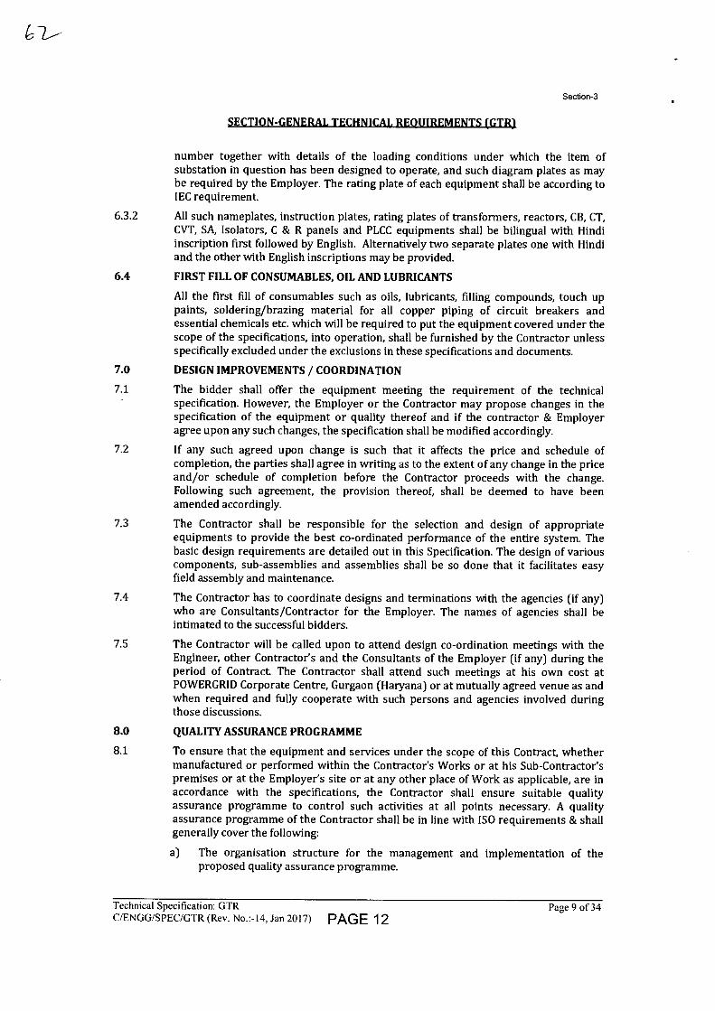
Section-3
SECTION-GENERAL TECHNICAL REQUIREMENTS (GTR1
number together with details of the loading conditions under which the item of substation in question has been designed to operate, and such diagram plates as may be required by the Employer. The rating plate of each equipment shall be according to IEC requirement.
6.3.2 All such nameplates, instruction plates, rating plates of transformers, reactors, CB, CT, CVT, SA, Isolators, C & R panels and PLCC equipments shall be bilingual with Hindi inscription first followed by English. Alternatively two separate plates one with Hindi and the other with English inscriptions may be provided.
6.4 FIRST FILL OF CONSUMABLES, OIL AND LUBRICANTS
All the first fill of consumables such as oils, lubricants, filling compounds, touch up paints, soldering/brazing material for all copper piping of circuit breakers and essential chemicals etc. which will be required to put the equipment covered under the scope of the specifications, into operation, shall be furnished by the Contractor unless specifically excluded under the exclusions in these specifications and documents.
7.0 DESIGN IMPROVEMENTS / COORDINATION
7.1 The bidder shall offer the equipment meeting the requirement of the technical specification. However, the Employer or the Contractor may propose changes in the specification of the equipment or quality thereof and if the contractor & Employer agree upon any such changes, the specification shall be modified accordingly.
7.2 If any such agreed upon change is such that it affects the price and schedule of completion, the parties shall agree in writing as to the extent of any change in the price and/or schedule of completion before the Contractor proceeds with the change. Following such agreement, the provision thereof, shall be deemed to have been amended accordingly.
7.3 The Contractor shall be responsible for the selection and design of appropriate equipments to provide the best co-ordinated performance of the entire system. The basic design requirements are detailed out in this Specification. The design of various components, sub-assemblies and assemblies shall be so done that it facilitates easy field assembly and maintenance.
7.4 The Contractor has to coordinate designs and terminations with the agencies (if any) who are Consultants/Contractor for the Employer. The names of agencies shall be intimated to the successful bidders.
7.5 The Contractor will be called upon to attend design co-ordination meetings with the Engineer, other Contractor's and the Consultants of the Employer (if any) during the period of Contract The Contractor shall attend such meetings at his own cost at POWERGRID Corporate Centre, Gurgaon (Haryana) or at mutually agreed venue as and when required and fully cooperate with such persons and agencies involved during those discussions.
8.0 QUALITY ASSURANCE PROGRAMME
8.1 To ensure that the equipment and services under the scope of this Contract, whether manufactured or performed within the Contractor's Works or at his Sub-Contractor's premises or at the Employer's site or at any other place of Work as applicable, are in accordance with the specifications, the Contractor shall ensure suitable quality assurance programme to control such activities at all points necessary. A quality assurance programme of the Contractor shall be in line with ISO requirements & shall generally cover the following:
a) The organisation structure for the management and implementation of the proposed quality assurance programme.
Technical Specification: GTR
Page 9 of 34 C/ENGG/SPEC/GTR (Rev. No.:-14, Jan 2017) PAGE 12
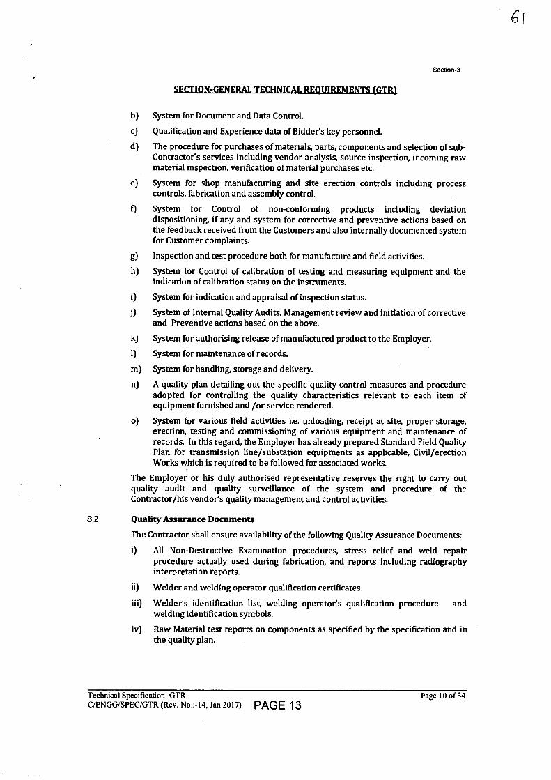
Section-3
SECTION-GENERAL TECHNICAL REQUIREMENTS (GTR1
b) System for Document and Data Control.
c) Qualification and Experience data of Bidder's key personnel.
d) The procedure for purchases of materials, parts, components and selection of sub-Contractor's services including vendor analysis, source inspection, incoming raw material inspection, verification of material purchases etc.
e) System for shop manufacturing and site erection controls including process controls, fabrication and assembly control.
f) System for Control of non-conforming products including deviation dispositioning, if any and system for corrective and preventive actions based on the feedback received from the Customers and also internally documented system for Customer complaints.
g) Inspection and test procedure both for manufacture and field activities.
h) System for Control of calibration of testing and measuring equipment and the indication of calibration status on the instruments.
i) System for indication and appraisal of inspection status.
j) System of Internal Quality Audits, Management review and initiation of corrective and Preventive actions based on the above.
k) System for authorising release of manufactured product to the Employer.
I) System for maintenance of records.
m) System for handling, storage and delivery.
n) A quality plan detailing out the specific quality control measures and procedure adopted for controlling the quality characteristics relevant to each item of equipment furnished and /or service rendered.
o) System for various field activities i.e. unloading, receipt at site, proper storage, erection, testing and commissioning of various equipment and maintenance of records. In this regard, the Employer has already prepared Standard Field Quality Plan for transmission line/substation equipments as applicable, Civil/erection Works which is required to be followed for associated works.
The Employer or his duly authorised representative reserves the right to carry out quality audit and quality surveillance of the system and procedure of the Contractor/his vendor's quality management and control activities.
8.2 Quality Assurance Documents
The Contractor shall ensure availability of the following Quality Assurance Documents:
i) All Non-Destructive Examination procedures, stress relief and weld repair procedure actually used during fabrication, and reports including radiography interpretation reports.
ii) Welder and welding operator qualification certificates.
iii) Welder's identification list, welding operator's qualification procedure and welding identification symbols.
iv) Raw Material test reports on components as specified by the specification and in the quality plan.
Technical Specification: GTR
Page 10 of 34 C/ENGG/SPEC/GTR (Rev. No.:-14, Jan 2017) PAGE 13
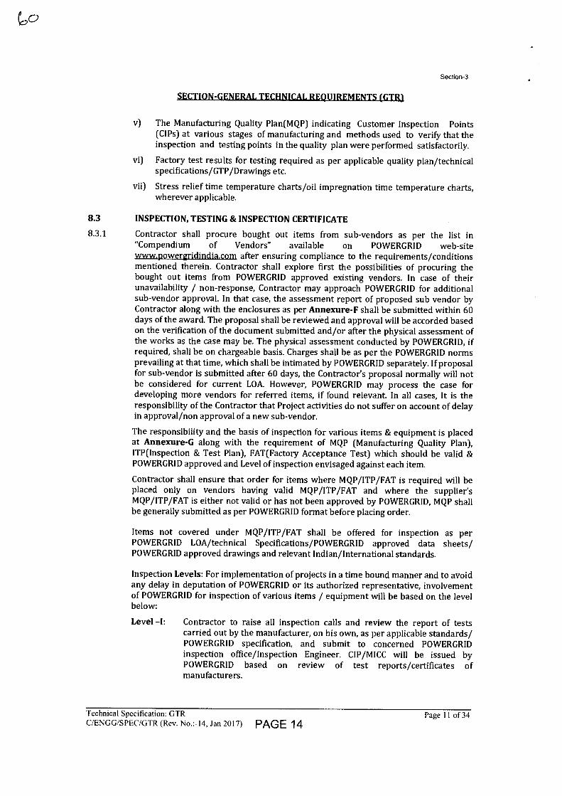
Section-3
SECTION-GENERAL TECHNICAL REQUIREMENTS (GTR1
v) The Manufacturing Quality Plan(MQP) indicating Customer Inspection Points (CIPs) at various stages of manufacturing and methods used to verify that the inspection and testing points in the quality plan were performed satisfactorily.
vi) Factory test results for testing required as per applicable quality plan/technical specifications/GTP/Drawings etc.
vii) Stress relief time temperature charts/oil impregnation time temperature charts, wherever applicable.
8.3 INSPECTION, TESTING & INSPECTION CERTIFICATE
8.3.1 Contractor shall procure bought out items from sub-vendors as per the list in "Compendium of Vendors" available on POWERGRID web-site www.powergridindia.com after ensuring compliance to the requirements/conditions mentioned therein. Contractor shall explore first the possibilities of procuring the bought out items from POWERGRID approved existing vendors. In case of their unavailability / non-response, Contractor may approach POWERGRID for additional sub-vendor approval. In that case, the assessment report of proposed sub vendor by Contractor along with the enclosures as per Annexure-F shall be submitted within 60 days of the award. The proposal shall be reviewed and approval will be accorded based on the verification of the document submitted and/or after the physical assessment of the works as the case may be. The physical assessment conducted by POWERGRID, if required, shall be on chargeable basis. Charges shall be as per the POWERGRID norms prevailing at that time, which shall be intimated by POWERGRID separately. If proposal for sub-vendor is submitted after 60 days, the Contractor's proposal normally will not be considered for current LOA. However, POWERGRID may process the case for developing more vendors for referred items, if found relevant. In all cases, It is the responsibility of the Contractor that Project activities do not suffer on account of delay in approval/non approval of a new sub-vendor.
The responsibility and the basis of inspection for various items & equipment is placed at Annexure-G along with the requirement of MQP (Manufacturing Quality Plan), ITP(Inspection & Test Plan), FAT(Factory Acceptance Test) which should be valid & POWERGRID approved and Level of inspection envisaged against each item.
Contractor shall ensure that order for items where MQP/ITP/FAT is required will be placed only on vendors having valid MQP/ITP/FAT and where the supplier's MQP/ITP/FAT is either not valid or has not been approved by POWERGRID, MQP shall be generally submitted as per POWERGRID format before placing order.
Items not covered under MQP/ITP/FAT shall be offered for inspection as per POWERGRID LOA/technical Specifications/POWERGRID approved data sheets/ POWERGRID approved drawings and relevant Indian/International standards.
Inspection Levels: For implementation of projects in a time bound manner and to avoid any delay in deputation of POWERGRID or its authorized representative, involvement of POWERGRID for inspection of various items / equipment will be based on the level below:
Level -I: Contractor to raise all inspection calls and review the report of tests carried out by the manufacturer, on his own, as per applicable standards/ POWERGRID specification, and submit to concerned POWERGRID inspection office/Inspection Engineer. C1P/MICC will be issued by POWERGRID based on review of test reports/certificates of manufacturers.
coo
Technical Specification: GTR
Page 11 of 34 C/ENGG/SPEC/GTR (Rev. No • 14, Jan 2017) PAGE 14
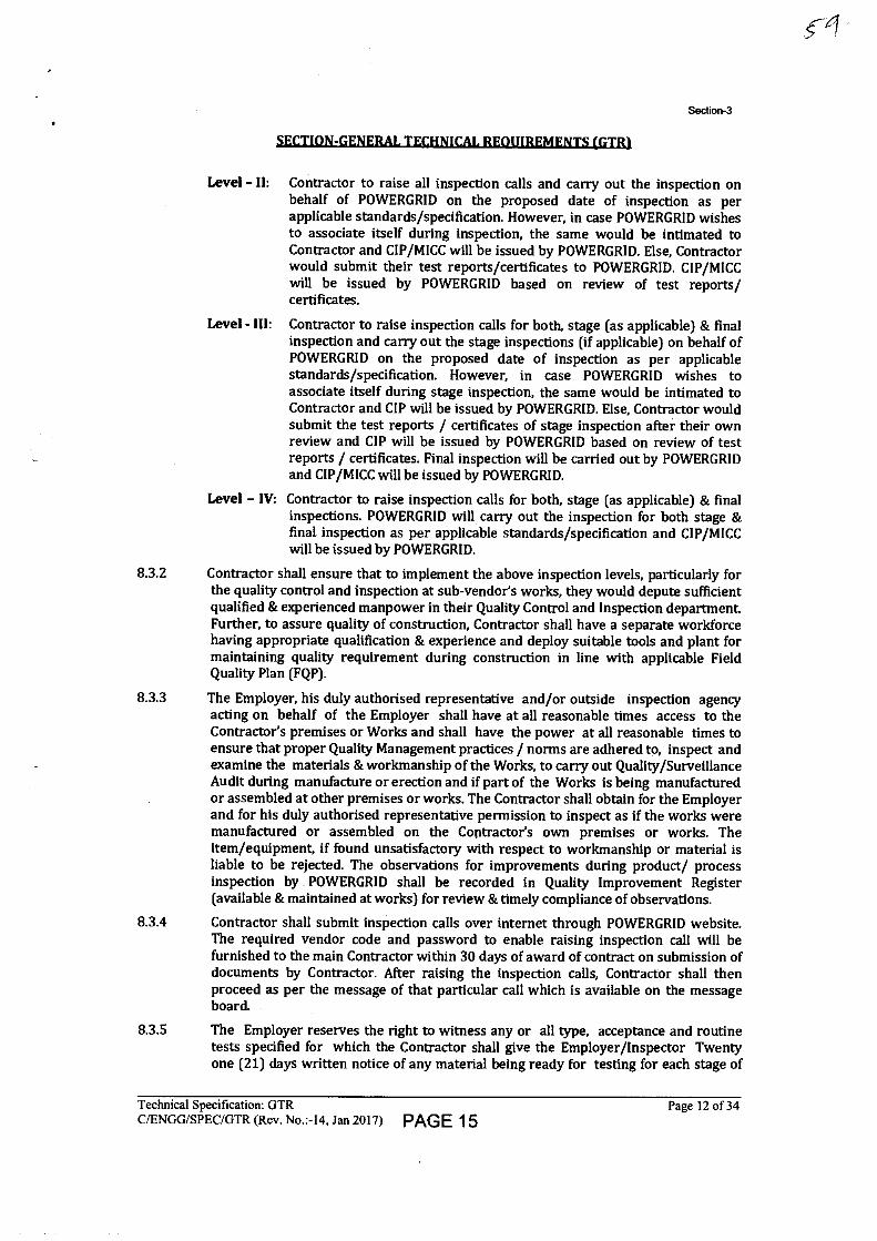
Section-3
Level - II: Contractor to raise all inspection calls and carry out the inspection on behalf of POWERGRID on the proposed date of inspection as per applicable standards/specification. However, in case POWERGRID wishes to associate itself during inspection, the same would be intimated to Contractor and CIP/MICC will be issued by POWERGRID. Else, Contractor would submit their test reports/certificates to POWERGRID. CIP/MICC will be issued by POWERGRID based on review of test reports/ certificates.
Level - Ill: Contractor to raise inspection calls for both, stage (as applicable) & final inspection and carry out the stage inspections (if applicable) on behalf of POWERGRID on the proposed date of inspection as per applicable standards/specification. However, in case POWERGRID wishes to associate itself during stage inspection, the same would be intimated to Contractor and CIP will be issued by POWERGRID. Else, Contractor would submit the test reports / certificates of stage inspection after their own review and CIP will be issued by POWERGRID based on review of test reports / certificates. Final inspection will be carried out by POWERGRID and CIP/MICC will be issued by POWERGRID.
Level - IV: Contractor to raise inspection calls for both, stage (as applicable) & final inspections. POWERGRID will carry out the inspection for both stage & final inspection as per applicable standards/specification and CIP/MICC will be issued by POWERGRID.
8.3.2 Contractor shall ensure that to implement the above inspection levels, particularly for the quality control and inspection at sub-vendor's works, they would depute sufficient qualified & experienced manpower in their Quality Control and Inspection department Further, to assure quality of construction, Contractor shall have a separate workforce having appropriate qualification & experience and deploy suitable tools and plant for maintaining quality requirement during construction in line with applicable Field Quality Plan (FQP).
8.3.3 The Employer, his duly authorised representative and/or outside inspection agency acting on behalf of the Employer shall have at all reasonable times access to the Contractor's premises or Works and shall have the power at all reasonable times to ensure that proper Quality Management practices / norms are adhered to, inspect and examine the materials & workmanship of the Works, to carry out Quality/Surveillance Audit during manufacture or erection and if part of the Works is being manufactured or assembled at other premises or works. The Contractor shall obtain for the Employer and for his duly authorised representative permission to inspect as if the works were manufactured or assembled on the Contractor's own premises or works. The item/equipment, if found unsatisfactory with respect to workmanship or material is liable to be rejected. The observations for improvements during product/ process inspection by POWERGRID shall be recorded in Quality Improvement Register (available & maintained at works) for review & timely compliance of observations.
8.3.4 Contractor shall submit inspection calls over internet through POWERGRID website. The required vendor code and password to enable raising inspection call will be furnished to the main Contractor within 30 days of award of contract on submission of documents by Contractor. After raising the inspection calls, Contractor shall then proceed as per the message of that particular call which is available on the message board.
8.3.5 The Employer reserves the right to witness any or all type, acceptance and routine tests specified for which the Contractor shall give the Employer/Inspector Twenty one (21) days written notice of any material being ready for testing for each stage of
Technical Specification: GTR
Page 12 of 34 C/ENGG/SPEC/GTR (Rev. No.:-14, Jan 2017) PAGE 15
Section-3
SECTION-GENERAL TECHNICAL REOUHIEMENTS (GTR)
testing as identified in the approved quality plan as customer inspection point(CIP) for indigenous inspections. All inspection calls for overseas material shall be given at least forty five (45) days in advance. Such tests shall be to the Contractor's account except for the expenses of the Inspection Engineer. The Employer/inspector, unless witnessing of the tests is waived by Employer, will attend such tests within Twenty one (21) days of the date of which the equipment is notified as being ready for test/inspection, failing which the Contractor may proceed with the test which shall be deemed to have been made in the Inspector's presence and he shall forthwith forward to the Inspector three copies of tests, duly certified. Contractor shall ensure, before giving notice for type test, that all drawings and quality plans have been got approved. The equipment shall be dispatched to site only after approval of Routine and Acceptance test results and Issuance of Dispatch Clearance in writing by the Employer. CIP/Material Inspection clearance certificate (MICC) shall be issued by the Employer after inspection of the equipment or review of test reports as applicable. Employer may waive off the presence of Employer's inspecting engineer. In that case test will be carried out as per approved QP and test certificate will be furnished by the supplier for approval. CIP/MICC will be issued only after review and approval of the test reports.
8.3.6 Contractor shall generally offer material for inspection as per supply bar chart approved by POWERGRID and not before 30 days from schedule indicated in the bar chart. In case Contractor offers material(s) for inspection prior to 30 days from the scheduled date with necessary approval of POWERGRID, POWERGRID shall inspect the material and issue CIP only. However, in such an exceptional case, MICC shall be issued only as per provision of original / revised approved supply schedule.
8.3.7 Contractor shall minimize the number of inspection calls by offering optimum quantities in each inspection call at the respective manufacturer's works.
8.3.8 Contractor shall inspect the material themselves and only after they are fully convinced about the Quality, they shall offer the material for POWERGRID inspection and shall also ensure that relevant portion of LOA/NOA, approved drawing and data sheets along with applicable Quality Plans are available at the works of Contractor or their Sub-vendor before the material is offered for inspection.
8.3.9 Contractor shall ensure that material which has been cleared for dispatch after inspection will be dispatched within 30 days in case of domestic supplies and within 60 days in case of Off-shore supplies from the date of issuance of CIP. Material which is not dispatched within stipulated time as above will be reoffered for POWERGRID inspection or specific approval of POWERGRID QA&I shall be obtained for delayed dispatch.
8.3.10 The Employer or IE shall give notice in writing to the Contractor, of any objection either to conformance to any drawings or to any equipment and workmanship which in his opinion is not in accordance with the Contract. The Contractor shall give due consideration to such objections and shall either make the modifications that may be necessary to meet the said objections or shall confirm in writing to the Employer/Inspection Engineer giving reasons therein, that no modifications are necessary to comply with the Contract.
8.3.11 All Test Reports and documents to be submitted in English during final inspection of equipment by POWERGRID or as and when required for submission.
8.3.12 When the factory tests have been completed at the Contractor's or Sub-Contractor's works, the Employer/Inspection Engineer(lE) shall issue a certificate to this effect within fifteen (15) days after completion of tests & submission of documents by Contractor/manufacturer but if the tests are not witnessed by the Employer/IE, the certificate shall be issued within fifteen (15) days of receipt of the Contractor's Test certificate by the Employer/IE. Contractor shall, on completion of all tests, submit test
Technical Specification: GTR
Page 13 of 34 C/ENGG/SPEC/GTR (Rev. No.:-I4, Jan 2017) PAGE 16
Section-3
SECTION-GENERAL TECHNICAL REQUIREMENTS (GTRI
reports within Ten (10) days to POWERGRID IE. Failure of the Employer/IE to issue such a certificate shall not prevent the Contractor from proceeding with the Works. The completion of these tests or the issue of the certificate shall not bind the Employer to accept the equipment should, it, on further tests after erection, be found not to comply with the Contract
8.3.13 In all cases, where the Contract provides for tests whether at the premises or works of the Contractor or of any Sub- Contractor, the Contractor, except where otherwise specified, shall provide free of charge such items as labour, materials, electricity, fuel, water, stores, apparatus and instruments as may be reasonably demanded by the Employer/Inspector or his authorised representative to carry out effectively such tests of the equipment in accordance with the Contract and shall give facilities to the Employer/Inspection Engineer or to his authorised representative to accomplish testing.
8.3.14 The inspection and acceptance by Employer and issue of Inspection Certificate thereon shall in no way limit the liabilities and responsibilities of the Contractor in respect of the agreed quality assurance programme forming a part of the Contract, or if such equipment is found to be defective at a later stage.
8.3.15 The Employer will have the right of having at his own expenses any other test(s) of reasonable nature carried out at Contractor's premises or at site or in any other place in addition of aforesaid type and routine tests, to satisfy that the material comply with the specification.
8.3.16 The Employer reserves the right for getting any additional field tests conducted on the completely assembled equipment at site to satisfy that material complies with specifications.
8.3.17 Rework/ Re-engineering, if any, on any item/equipment shall be carried out only after mutual discussions and in accordance with mutually agreed procedure. Contractor shall submit Joint Inspection Report of equipments under Re-Work/Re-Engineering alongwith procedure for the same to POWERGRID for approval, before taking up the Re-Work/Re-Engineering, failing which POWERGRID reserves the right to reject the equipment
8.3.18 Contractor may establish a field test Laboratory to execute Civil Construction testing requirements at site with the condition that all testing equipment shall be calibrated from POWERGRID approved accredited Testing laboratories, with calibration certificates kept available at site and all testing personnel employed in the Field Testing Laboratories to be qualified and experienced Engineers or testing to be carried out at POWERGRID approved Third Party Laboratories.
8.3.19 Contractor shall ensure that all possible steps are taken to avoid damages to the equipment during transport, storage and erection.
8.3.20 Contractor shall implement additional stringent quality checks and preparation during installation of GIS at site (if applicable) as per POWERGRID approved guidelines/Technical specifications.
8.3.21 Contractor shall ensure commissioning of all CSDs along with Circuit Breakers wherever applicable.
8.3.22 For EHV transformers/reactors:
Insulation oil shall be as per POWERGRID Technical specifications and same grade shall be used for impregnation of the active part & testing at the works of Transformer/Reactor Manufacturer and as well as for filling the Transformer/Reactors at site. Contractor to ensure that windings for Transformer/Reactors are made in air-conditioned environment Core-coil assembly shall be performed in positive
Technical Specification: GTR
Page 14 of 34 C/ENGG/SPEC/GTR (Rev. No.:-14, Jan 2017) PAGE 17
Section-3
SECTION-GENERAL TECHNICAL REQUIREMENTS (GTR1
pressurized dust controlled environment. Dust measurements shall be monitored regularly at Transformer / Reactor Manufacturer works. Contractor shall ensure that respective civil foundations & Fire walls for Transformer/Reactors units to be commissioned, shall be made ready at concerned sites before receipt of Transformer/Reactors units. All the requisite material for Neutral & Delta Bus formation required for charging of complete bank of 765KV class 1-ph Transformer/Reactor units shall be made available at the concerned sites before receipt of the Transformer/Reactor units at site.
8.3.23 The Employer reserves the right to increase or decrease their involvement in inspections at Contractor's Works or at his Sub-Contractor's premises or at the Employer's site or at any other place of Work based on performance of Contractor/sub-Contractor.
9.0 TYPE TESTING & CLEARANCE CERTIFICATE
9.1 All equipment being supplied shall conform to type tests as per technical specification and shall be subject to routine tests in accordance with requirements stipulated under respective sections.
9.2 The reports for all type tests as per technical specification shall be furnished by the Contractor alongwith equipment / material drawings. However, type test reports of similar equipments/ material already accepted in POWERGRID shall be applicable for all projects with similar requirement. The type tests conducted earlier should have either been conducted in accredited laboratory (accredited based on ISO / IEC Guide 25 / 17025 or EN 45001 by the national accreditation body of the country where laboratory is located) or witnessed by POWERGRID or representative authorized by POWERGRID or Utility or representative of accredited test lab.
Unless otherwise specified elsewhere, the type test reports submitted shall be of the tests conducted within last 10 (ten) years from the date of NOA. In case the test reports are of the test conducted earlier than 10 (ten) years from the date of NOA, the contractor shall repeat these test(s) at no extra cost to the Employer.
Further, in the event of any discrepancy in the test reports i.e. any test report not acceptable due to any design/manufacturing changes or due to non-compliance with the requirement stipulated in the Technical Specification or any/all type tests not carried out, same shall be carried out without any additional cost implication to the Employer.
The Contractor shall intimate the Employer the detailed program about the type tests atleast two (2) weeks in advance in case of domestic supplies & six (6) weeks in advance in case of foreign supplies.
9.3 The Employer intends to repeat those type tests which are indicated in the price schedule and the same shall be payable as per provision of contract The price of conducting type tests shall be included in Bid price and break up of these shall be given in the relevant schedule of Bid Proposal Sheets. These Type test charges would be considered in bid evaluation. In case Bidder does not indicate charges for any of the type tests or does not mention the name of any test in the price schedules, it will be presumed that the particular test has been offered free of charge. Further, in case any Bidder indicates that he shall not carry out a particular test, his offer shall be considered incomplete and shall be liable to be rejected. The Employer reserves the right to waive the repeating of type tests partly or fully and in case of waival, test charges for the same shall not be payable.
Technical Specification: GTR
Page 15 of 34 C/ENGG/SPEC/GTR (Rev. No.:-14, Jan 2017) PAGE 18
Section-3
9.4 The Employer reserves the right to witness any or all the type tests. The Employer shall bear all expenses for deputation of Employer's representative(s) for witnessing the type tests.
9.5 The list of makes of various items, for which Type test reports are not required to be submitted are specified in Compendium of Vendors (COV).
10.0 TESTS
10.1 Pre-commissioning Tests
On completion of erection of the equipment and before charging, each item of the equipment shall be thoroughly cleaned and then inspected jointly by the Employer and the Contractor for correctness and completeness of installation and acceptability for charging, leading to initial pre-commissioning tests at Site. The list of pre-commissioning tests to be performed are given in respective chapters and shall be included in the Contractor's quality assurance programme.
10.2 Commissioning Tests
10.2.1 The available instrumentation and control equipment will to be used during such tests and the Employer will calibrate, all such measuring equipment and devices as far as practicable.
10.2.2 Any special equipment, tools and tackles required for the successful completion of the Commissioning Tests shall be arranged by the Contractor at his own cost.
10.2.3 The specific tests requirement on equipment have been brought out in the respective chapters of the technical specification.
10.3.4 PRECOMMISSIONING, COMMISSIONING, TRIAL-RUN & COMPLETION
As soon as the Facilities covered by these specifications are physically completed in all respects, the Pre commissioning, Commissioning, Trial-run and Completion of the Facilities, as mentioned below, shall be attained in accordance with the procedure given in the Conditions of Contract, Vol.-I of the Bidding Documents.
(i) Pre commissioning : As per relevant Sections (ii) Commissioning : Charging of the Facilities at rated voltage.
Further, wherever appearing in these specifications, the words-'commissioning checks', 'installation checks', 'site tests', 'performance guarantee tests for fire protection system', are to be considered as 'pre commissioning checks'.
(iii) Trial-run : Operation of the Facilities or any part thereof by the Contractor immediately after the Commissioning for a continuous period of 72 (Seventy two) hours continuously. In case of interruption due to problem/ failure in the respective equipment, the contractor shall rectify the problem and after rectification, continuous 72 (Seventy two) hours period start after such rectification.
(iv) Completion : Upon successful completion of Trial-run.
'Guarantee Test(s)' and/or 'Functional Guarantees' are applicable only for Substation Automation System as specified in Section-'Substation Automation System.'
10.3. The Contractor shall be responsible for obtaining statutory clearances from the concerned authorities for commissioning the equipment and the switchyard. However necessary fee shall be reimbursed by POWERGRID on production of requisite documents.
Technical Specification: GTR
Page 16 of 34 C/ENGG/SPEC/GTR (Rev. No.:-14, Jan 2017) PAGE 19
Section-3
SECTION-GENERAL TECHNICAL REQUIREMENTS (GTR1
11.0 PACKAGING & PROTECTION
11.1 All the equipments shall be suitably protected, coated, covered or boxed and crated to prevent damage or deterioration during transit, handling and storage at Site till the time of erection. On request of the Employer, the Contractor shall also submit packing details/associated drawing for any equipment/material under his scope of supply, to facilitate the Employer to repack any equipment/material at a later date, in case the need arises. While packing all the materials, the limitation from the point of view of availability of Railway wagon sizes in India should be taken into account. The Contractor shall be responsible for any loss or damage during transportation, handling and storage due to improper packing. Any demurrage, wharfage and other such charges claimed by the transporters, railways etc. shall be to the account of the Contractor. Employer takes no responsibility of the availability of the wagons.
11.2 All coated surfaces shall be protected against abrasion, impact, discolouration and any other damages. All exposed threaded portions shall be suitably protected with either a metallic or a non-metallic protecting device. All ends of all valves and pipings and conduit equipment connections shall be properly sealed with suitable devices to protect them from damage.
12.0 FINISHING OF METAL SURFACES
12.1 All metal surfaces shall be subjected to treatment for anti-corrosion protection. All ferrous surfaces for external use unless otherwise stated elsewhere in the specification or specifically agreed, shall be hot-dip galvanized after fabrication. All steel conductors including those used for earthing/grounding (above ground level) shall also be galvanized according to IS: 2629.
12.2 HOT DIP GALVANISING
12.2.1 The minimum weight of the zinc coating shall be 610 gm/sq.m and minimum average thickness of coating shall be 86 microns for all items having thickness 6mm and above and 900 gm/sq.m for coastal area (30Iun from sea shore approximately) or as specified in Section-Project. For items lower than 6mm thickness requirement of coating thickness shall be as per relevant ASTM. For surface which shall be embedded in concrete, the zinc coating shall be 610 gm/sq.m minimum and 900 gm/sq.m for coastal area as specified in Section-Project.
12.2.2 The galvanized surfaces shall consist of a continuous and uniform thick coating of zinc, firmly adhering to the surface of steel. The finished surface shall be clean and smooth and shall be free from defects like discoloured patches, bare spots, unevenness of coating, spelter which is loosely attached to the steel globules, spiky deposits, blistered surface, flaking or peeling off, etc. The presence of any of these defects noticed on visual or microscopic inspection shall render the material liable to rejection.
12.2.3 After galvanizing, no drilling or welding shall be performed on the galvanized parts of the equipment excepting that nuts may be threaded after galvanizing. Sodium dichromate or alternate approved treatment shall be provided to avoid formation of white rust after hot dip galvanization.
12.2.4 The galvanized steel shall be subjected to four numbers of one minute dips in copper sulphate solution as per IS-2633.
12.2.5 Sharp edges with radii less than 2.5 mm shall be able to withstand four immersions of the Standard Preece test All other coatings shall withstand six immersions. The following galvanizing tests should essentially be performed as per relevant Indian Standards.
Coating thickness
Uniformity of zinc
Technical Specification: GTR
Page 17 of 34 C/ENGG/SPEC/GTR (Rev. No.:-14, Jan 2017) PAGE 20
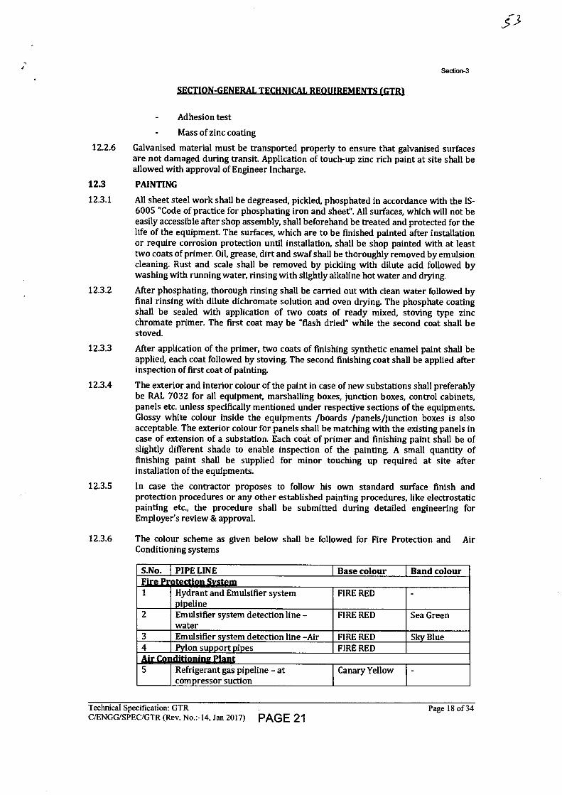
Section-3
tUL
Adhesion test
Mass of zinc coating
12.2.6 Galvanised material must be transported properly to ensure that galvanised surfaces are not damaged during transit. Application of touch-up zinc rich paint at site shall be allowed with approval of Engineer Incharge.
12.3 PAINTING
12.3.1 All sheet steel work shall be degreased, pickled, phosphated in accordance with the IS- 6005 "Code of practice for phosphating iron and sheet". All surfaces, which will not be easily accessible after shop assembly, shall beforehand be treated and protected for the life of the equipment. The surfaces, which are to be finished painted after installation or require corrosion protection until installation, shall be shop painted with at least two coats of primer. Oil, grease, dirt and swaf shall be thoroughly removed by emulsion cleaning. Rust and scale shall be removed by pickling with dilute acid followed by washing with running water, rinsing with slightly alkaline hot water and drying.
12.3.2 After phosphating, thorough rinsing shall be carried out with clean water followed by final rinsing with dilute dichromate solution and oven drying. The phosphate coating shall be sealed with application of two coats of ready mixed, stoving type zinc chromate primer. The first coat may be "flash dried" while the second coat shall be stoved.
12.3.3 After application of the primer, two coats of finishing synthetic enamel paint shall be applied, each coat followed by stoving. The second finishing coat shall be applied after inspection of first coat of painting.
12.3.4 The exterior and interior colour of the paint in case of new substations shall preferably be RAL 7032 for all equipment, marshalling boxes, junction boxes, control cabinets, panels etc. unless specifically mentioned under respective sections of the equipments. Glossy white colour inside the equipments /boards /panels/junction boxes is also acceptable. The exterior colour for panels shall be matching with the existing panels in case of extension of a substation. Each coat of primer and finishing paint shall be of slightly different shade to enable inspection of the painting. A small quantity of finishing paint shall be supplied for minor touching up required at site after installation of the equipments.
12.3.5 In case the contractor proposes to follow his own standard surface finish and protection procedures or any other established painting procedures, like electrostatic painting etc., the procedure shall be submitted during detailed engineering for Employer's review & approval.
12.3.6 The colour scheme as given below shall be followed for Fire Protection and Air Conditioning systems
S.No. PIPE LINE Base colour Band colour Fire Protection System 1 Hydrant and Emulsifier system
pipeline FIRE RED -
2 Emulsifier system detection line - water
FIRE RED Sea Green
3 Emulsifier system detection line -Air FIRE RED Sky Blue 4 Pylon support pipes FIRE RED Airlanditiuninalans 5 Refrigerant gas pipeline - at
compressor suction Canary Yellow -
Technical Specification: GTR
Page 18 of 34 C/ENGG/SPEC/GTR (Rev. No.:-14, Jan 2017) PAGE 21
Section-3
SECTION-GENERAL TECHNICAL REQUIREMENTS (GTRI
S.No. PIPE LINE Base colour Band colour 6 Refrigerant gas pipeline - at
compressor discharge Canary Yellow Red
7 Refrigerant liquid pipeline Dark Admiralty Green
-
8 Chilled water pipeline Sea Green - 9 Condenser water pipeline Sea Green Dark Blue
The direction of flow shall be marked by -4 (arrow) in black colour.
S I %Z./Z./Jr/Z.0 1111 rA 0 %WA 0 SO
Base Colour Direction of flow Band Colour
12.3.7 For aluminium casted surfaces, the surface shall be with smooth finish. Further, in case of aluminium enclosures, the surface shall be coated with powder (coating thickness of 60 microns) after surface preparation for painting. For stainless steel surfaces, no painting is envisaged.
13.0 HANDLING, STORING AND INSTALLATION
13.1 In accordance with the specific installation instructions as shown on manufacturer's drawings or as directed by the Employer or his representative, the Contractor shall unload, store, erect, install, wire, test and place into commercial use all the equipment included in the contract. Equipment shall be installed in a neat, workmanlike manner so that it is level, plumb, square and properly aligned and oriented. Commercial use of switchyard equipment means completion of all site tests specified and energisation at rated voltage.
13.2 Contractor may engage manufacturer's Engineers to supervise the unloading, transportation to site, storing, testing and commissioning of the various equipment being procured by them separately. Contractor shall unload, transport, store, erect, test and commission the equipment as per instructions of the manufacturer's supervisory Engineer(s) and shall extend full cooperation to them.
13.3 The contractor must ensure that the open storage platform (as per Drawing No. C- ENGG-CVL-STD-PLATFORM-01, Rev.0) is constructed for storage of outdoor type equipment/material prior to commencement of delivery at site. Outdoor equipment shall be stored on open storage platform, properly covered with waterproof and dustproof covers to protect them from water seepage and moisture ingress.
However, all indoor equipments including control & protection panels, Communication equipments and operating mechanism boxes etc. of outdoor equipments shall be stored indoors.
Storage of equipment on top of another one is not permitted if the wooden packing is used and there is possibility of equipment/packing damage. Material opened for joint inspection shall be repacked properly as per manufacturer's recommendations.
During storage of material regular periodic monitoring of important parameters like oil level / leakage, SF6 / Nitrogen pressure etc. shall be ensured by the contractor.
13.4 In case of any doubt/misunderstanding as to the correct interpretation of manufacturer's drawings or instructions, necessary clarifications shall be obtained from the Employer. Contractor shall be held responsible for any damage to the equipment consequent to not following manufacturer's drawings/instructions correctly.
13.5 Where assemblies are supplied in more than one section, Contractor shall make all necessary mechanical and electrical connections between sections including the connection between buses. Contractor shall also do necessary adjustments/alignments
Technical Specification: GTR
Page 19 of 34 C/ENGG/SPEC/GTR (Rev. No.:-14, Jan 2017) PAGE 22
Section-3
SECTION-GENERAL TECHNICAL REQUIREMENTS (GTR1
for proper operation of circuit breakers, isolators and their operating mechanisms. All components shall be protected against damage during unloading, transportation, storage, installation, testing and commissioning. Any equipment damaged due to negligence or carelessness or otherwise shall be replaced by the Contractor at his own expense.
13.6 Contractor shall be responsible for examining all the shipment and notify the Employer immediately of any damage, shortage, discrepancy etc. for the purpose of Employer's information only. The Contractor shall submit to the Employer every week a report detailing all the receipts during the weeks. However, the Contractor shall be solely responsible for any shortages or damages in transit, handling and/or in storage and erection of the equipment at Site. Any demurrage, wharfage and other such charges claimed by the transporters, railways etc. shall be to the account of the Contractor.
13.7 The Contractor shall be fully responsible for the equipment/material until the same is handed over to the Employer in an operating condition after commissioning. Contractor shall be responsible for the maintenance of the equipment/material while in storage as well as after erection until taken over by Employer, as well as protection of the same against theft, element of nature, corrosion, damages etc.
13.8 Where material / equipment is unloaded by Employer before the Contractor arrives at site or even when he is at site, Employer by right can hand over the same to Contractor and there upon it will be the responsibility of Contractor to store the material in an orderly and proper manner.
13.9 The Contractor shall be responsible for making suitable indoor storage facilities, to store all equipment which requires indoor storage.
13.10 The words 'erection' and 'installation' used in the specification are synonymous.
13.11 Exposed live parts shall be placed high enough above ground to meet the requirements of electrical and other statutory safety codes.
13.12 The design and workmanship shall be in accordance with the best engineering practices to ensure satisfactory performance throughout the service life. If at any stage during the execution of the Contract, it is observed that the erected equipment(s) do not meet the above minimum clearances the Contractor shall immediately proceed to correct the discrepancy at his risks and cost
13.13 Equipment Bases
A cast iron or welded steel base plate shall be provided for all rotating equipment which is to be installed on a concrete base unless otherwise agreed to by the Employer. Each base plate shall support the unit and its drive assembly, shall be of a neat design with pads for anchoring the units, shall have a raised lip all around, and shall have threaded drain connections.
14.0 TOOLS
14.1 TOOLS & PLANTS (T&P)
The Contractor shall arrange all T&P (such as necessary supports, cranes, ladders, platforms etc.) for erection, testing & commissioning of the system at his own cost. Further, all consumables, wastage and damages shall be to the account of contractor.
All such T&P shall be taken back by the contractor after commissioning of the system.
14.2 SPECIAL TOOLS AND TACKLES
The contractor shall supply all special tools and tackles required for Operation and maintenance of equipment. The special tools and tackles shall only cover items which
Technical Specification: GTR
Page 20 of 34 C/ENGG/SPEC/GTR (Rev. No.:-14, Jan 2017) PAGE 23
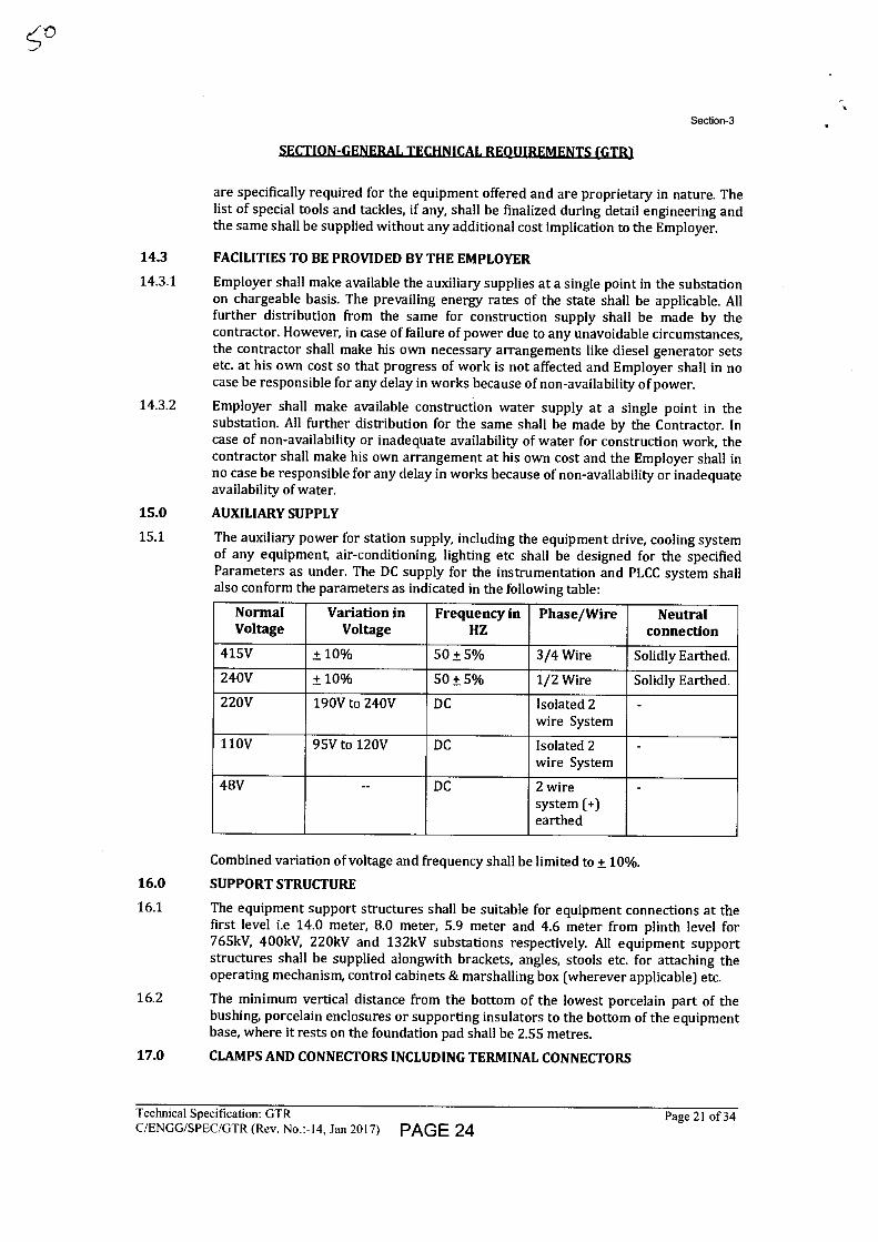
Section-3
11/4 t: 111/4 :1 1u1/4
are specifically required for the equipment offered and are proprietary in nature. The list of special tools and tackles, if any, shall be finalized during detail engineering and the same shall be supplied without any additional cost implication to the Employer.
14.3 FACILITIES TO BE PROVIDED BY THE EMPLOYER
14.3.1 Employer shall make available the auxiliary supplies at a single point in the substation on chargeable basis. The prevailing energy rates of the state shall be applicable. All further distribution from the same for construction supply shall be made by the contractor. However, in case of failure of power due to any unavoidable circumstances, the contractor shall make his own necessary arrangements like diesel generator sets etc. at his own cost so that progress of work is not affected and Employer shall in no case be responsible for any delay in works because of non-availability of power.
14.3.2 Employer shall make available construction water supply at a single point in the substation. All further distribution for the same shall be made by the Contractor. In case of non-availability or inadequate availability of water for construction work, the contractor shall make his own arrangement at his own cost and the Employer shall in no case be responsible for any delay in works because of non-availability or inadequate availability of water.
15.0 AUXILIARY SUPPLY
15.1 The auxiliary power for station supply, including the equipment drive, cooling system of any equipment, air-conditioning, lighting etc shall be designed for the specified Parameters as under. The DC supply for the instrumentation and PLCC system shall also conform the parameters as indicated in the following table:
Normal Voltage
Variation in Voltage
Frequency in HZ
Phase/Wire Neutral connection
415V ± 10% 50 ± 5% 3/4 Wire Solidly Earthed.
240V ± 10% 50 ± 5% 1/2 Wire Solidly Earthed.
220V 190V to 240V DC Isolated 2 wire System
-
110V 95V to 120V DC Isolated 2 wire System
48V -- DC 2 wire system (+) earthed
-
Combined variation of voltage and frequency shall be limited to ± 10%.
16.0 SUPPORT STRUCTURE
16.1 The equipment support structures shall be suitable for equipment connections at the first level i.e 14.0 meter, 8.0 meter, 5.9 meter and 4.6 meter from plinth level for 765kV, 400kV, 220kV and 132kV substations respectively. All equipment support structures shall be supplied alongwith brackets, angles, stools etc. for attaching the operating mechanism, control cabinets & marshalling box (wherever applicable) etc.
16.2 The minimum vertical distance from the bottom of the lowest porcelain part of the bushing, porcelain enclosures or supporting insulators to the bottom of the equipment base, where it rests on the foundation pad shall be 2.55 metres.
17M CLAMPS AND CONNECTORS INCLUDING TERMINAL CONNECTORS
Technical Specification: GTR C/ENGG/SPEC/GTR (Rev. No.:-I4, Jan 2017) PAGE 24
Page 21 of 34
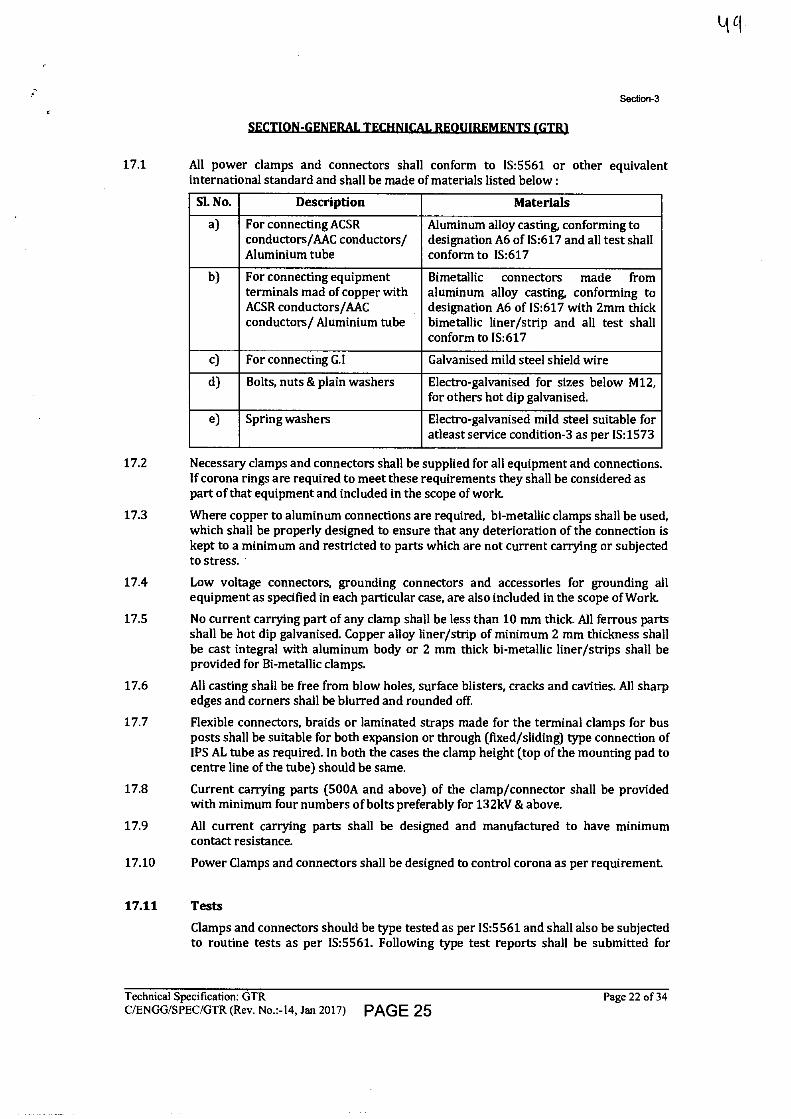
Section-3
SECTION-GENERAL TECHNICAL REQUIREMENTS (GTR1
17.1 All power clamps and connectors shall conform to 1S:5561 or other equivalent international standard and shall be made of materials listed below :
SI. No. Description Materials
a) For connecting ACSR conductors/AAC conductors/ Aluminium tube
Aluminum alloy casting, conforming to designation A6 of IS:617 and all test shall conform to IS:617
b) For connecting equipment terminals mad of copper with ACSR conductors/AAC conductors/ Aluminium tube
Bimetallic connectors made from aluminum alloy casting, conforming to designation A6 of IS:617 with 2mm thick bimetallic liner/strip and all test shall conform to IS:617
c) For connecting G.I Galvanised mild steel shield wire
d) Bolts, nuts & plain washers Electro-galvanised for sizes below M12, for others hot dip galvanised.
e) Spring washers Electro-galvanised mild steel suitable for atleast service condition-3 as per IS:1573
17.2 Necessary clamps and connectors shall be supplied for all equipment and connections. If corona rings are required to meet these requirements they shall be considered as part of that equipment and included in the scope of work.
17.3 Where copper to aluminum connections are required, bi-metallic clamps shall be used, which shall be properly designed to ensure that any deterioration of the connection is kept to a minimum and restricted to parts which are not current carrying or subjected to stress.
17.4 Low voltage connectors, grounding connectors and accessories for grounding all equipment as specified in each particular case, are also included in the scope of Work.
17.5 No current carrying part of any clamp shall be less than 10 mm thick All ferrous parts shall be hot dip galvanised. Copper alloy liner/strip of minimum 2 mm thickness shall be cast integral with aluminum body or 2 mm thick bi-metallic liner/strips shall be provided for Bi-metallic clamps.
17.6 All casting shall be free from blow holes, surface blisters, cracks and cavities. All sharp edges and corners shall be blurred and rounded off.
17.7 Flexible connectors, braids or laminated straps made for the terminal clamps for bus posts shall be suitable for both expansion or through (fixed/sliding) type connection of IPS AL tube as required. In both the cases the clamp height (top of the mounting pad to centre line of the tube) should be same.
17.8 Current carrying parts (500A and above) of the clamp/connector shall be provided with minimum four numbers of bolts preferably for 132kV & above.
17.9 All current carrying parts shall be designed and manufactured to have minimum contact resistance.
17.10 Power Clamps and connectors shall be designed to control corona as per requirement.
17.11 Tests
Clamps and connectors should be type tested as per IS:5561 and shall also be subjected to routine tests as per IS:5561. Following type test reports shall be submitted for
Technical Specification: GTR
Page 22 of 34 C/ENGG/SPEC/GTR (Rev. No.:-14, Jan 2017) PAGE 25
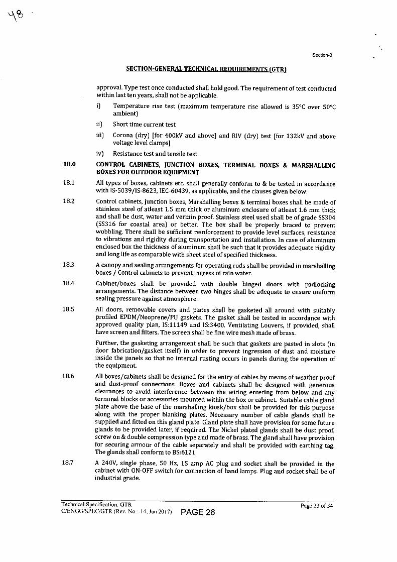
Section-3
SECTION-GENERAL TECHNICAkREOUIREMENTS (GTR1
approval. Type test once conducted shall hold good. The requirement of test conducted within last ten years, shall not be applicable.
i) Temperature rise test (maximum temperature rise allowed is 35°C over 50°C ambient)
ii) Short time current test
iii) Corona (dry) [for 400kV and above] and RIV (dry) test [for 132kV and above voltage level clamps]
iv) Resistance test and tensile test
18.0 CONTROL CABINETS, JUNCTION BOXES, TERMINAL BOXES & MARSHALLING BOXES FOR OUTDOOR EQUIPMENT
18.1 All types of boxes, cabinets etc. shall generally conform to & be tested in accordance with IS-5039/IS-8623, IEC-60439, as applicable, and the clauses given below:
18.2 Control cabinets, junction boxes, Marshalling boxes & terminal boxes shall be made of stainless steel of atleast 1.5 mm thick or aluminum enclosure of atleast 1.6 mm thick and shall be dust, water and vermin proof. Stainless steel used shall be of grade SS304 (SS316 for coastal area) or better. The box shall be properly braced to prevent wobbling. There shall be sufficient reinforcement to provide level surfaces, resistance to vibrations and rigidity during transportation and installation. In case of aluminum enclosed box the thickness of aluminum shall be such that it provides adequate rigidity and long life as comparable with sheet steel of specified thickness.
18.3 A canopy and sealing arrangements for operating rods shall be provided in marshalling boxes / Control cabinets to prevent ingress of rain water.
18.4 Cabinet/boxes shall be provided with double hinged doors with padlocking arrangements. The distance between two hinges shall be adequate to ensure uniform sealing pressure against atmosphere.
18.5 All doors, removable covers and plates shall be gasketed all around with suitably profiled EPDM/Neoprene/PU gaskets. The gasket shall be tested in accordance with approved quality plan, 1S:11149 and IS:3400. Ventilating Louvers, if provided, shall have screen and filters. The screen shall be fine wire mesh made of brass.
Further, the gasketing arrangement shall be such that gaskets are pasted in slots (in door fabrication/gasket itself) in order to prevent ingression of dust and moisture inside the panels so that no internal rusting occurs in panels during the operation of the equipment.
18.6 All boxes/cabinets shall be designed for the entry of cables by means of weather proof and dust-proof connections. Boxes and cabinets shall be designed with generous clearances to avoid interference between the wiring entering from below and any terminal blocks or accessories mounted within the box or cabinet. Suitable cable gland plate above the base of the marshalling kiosk/box shall be provided for this purpose along with the proper blanking plates. Necessary number of cable glands shall be supplied and fitted on this gland plate. Gland plate shall have provision for some future glands to be provided later, if required. The Nickel plated glands shall be dust proof, screw on & double compression type and made of brass. The gland shall have provision for securing armour of the cable separately and shall be provided with earthing tag. The glands shall conform to BS:6121.
18.7 A 240V, single phase, 50 Hz, 15 amp AC plug and socket shall be provided in the cabinet with ON-OFF switch for connection of hand lamps. Plug and socket shall be of industrial grade.
Technical Specification: GTR C/ENGG/SPEC/GTR (Rev. No.:-14, Jan 2017) PAGE 26
Page 23 of 34
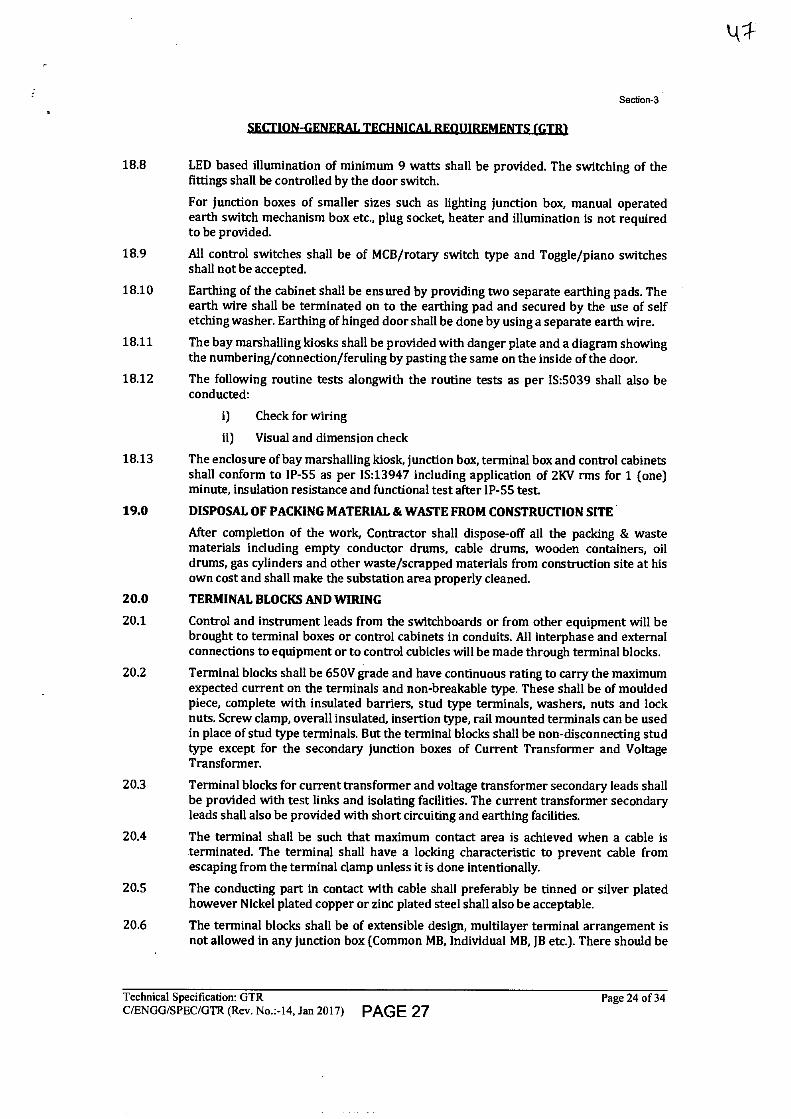
Section-3
SECTION-GENERAL TECHNICAL REOUIREMENTS (GTRI
18.8 LED based illumination of minimum 9 watts shall be provided. The switching of the fittings shall be controlled by the door switch.
For junction boxes of smaller sizes such as lighting junction box, manual operated earth switch mechanism box etc., plug socket, heater and illumination is not required to be provided.
18.9 All control switches shall be of MCB/rotary switch type and Toggle/piano switches shall not be accepted.
18.10 Earthing of the cabinet shall be ensured by providing two separate earthing pads. The earth wire shall be terminated on to the earthing pad and secured by the use of self etching washer. Earthing of hinged door shall be done by using a separate earth wire.
18.11 The bay marshalling kiosks shall be provided with danger plate and a diagram showing the numbering/connection/feruling by pasting the same on the inside of the door.
18.12 The following routine tests alongwith the routine tests as per IS:5039 shall also be conducted:
i) Check for wiring
ii) Visual and dimension check
18.13 The enclosure of bay marshalling kiosk, junction box, terminal box and control cabinets shall conform to IP-55 as per IS:13947 including application of 2KV rms for 1 (one) minute, insulation resistance and functional test after IP-55 test.
19.0 DISPOSAL OF PACKING MATERIAL & WASTE FROM CONSTRUCTION SITE
After completion of the work, Contractor shall dispose-off all the packing & waste materials including empty conductor drums, cable drums, wooden containers, oil drums, gas cylinders and other waste/scrapped materials from construction site at his own cost and shall make the substation area properly cleaned.
20.0 TERMINAL BLOCKS AND WIRING
20.1 Control and instrument leads from the switchboards or from other equipment will be brought to terminal boxes or control cabinets in conduits. All interphase and external connections to equipment or to control cubicles will be made through terminal blocks.
20.2 Terminal blocks shall be 650V grade and have continuous rating to carry the maximum expected current on the terminals and non-breakable type. These shall be of moulded piece, complete with insulated barriers, stud type terminals, washers, nuts and lock nuts. Screw clamp, overall insulated, insertion type, rail mounted terminals can be used in place of stud type terminals. But the terminal blocks shall be non-disconnecting stud type except for the secondary junction boxes of Current Transformer and Voltage Transformer.
20.3 Terminal blocks for current transformer and voltage transformer secondary leads shall be provided with test links and isolating facilities. The current transformer secondary leads shall also be provided with short circuiting and earthing facilities.
20.4 The terminal shall be such that maximum contact area is achieved when a cable is terminated. The terminal shall have a locking characteristic to prevent cable from escaping from the terminal clamp unless it is done intentionally.
20.5 The conducting part in contact with cable shall preferably be tinned or silver plated however Nickel plated copper or zinc plated steel shall also be acceptable.
20.6 The terminal blocks shall be of extensible design, multilayer terminal arrangement is not allowed in any junction box (Common MB, Individual MB, JB etc.). There should be
Technical Specification: GTR
Page 24 of 34 C/ENGG/SPEC/GTR (Rev. No.:-14, Jan 2017) PAGE 27
Section-3
SECTION-GENERAL TECHNICAL REQUIREMENTS (GTRI
sufficient space at both sides of terminals so that ferrule number of wires / TB numbers are clearly visible during wire removal or insertion.
20.7 The terminal blocks shall have locking arrangement to prevent its escape from the mounting rails.
20.8 The terminal blocks shall be fully enclosed with removable covers of transparent, non- deteriorating type plastic material. Insulating barriers shall be provided between the terminal blocks. These barriers shall not hinder the operator from carrying out the wiring without removing the barriers.
20.9 Unless otherwise specified terminal blocks shall be suitable for connecting the following conductors on each side.
a) All circuits except
Minimum of two of 2.5 sq mm CT/PT circuits copper flexible.
b) All CT/PT circuits Minimum of 4 nos. of 2.5 sq mm copper flexible.
20.10 The arrangements shall be in such a manner so that it is possible to safely connect or disconnect terminals on live circuits and replace fuse links when the cabinet is live.
20.11 Atleast 20 % spare terminals shall be provided on each panel/cubicle/box and these spare terminals shall be uniformly distributed on all terminals rows.
20.12 There shall be a minimum clearance of 250 mm between the First/bottom row of terminal block and the associated cable gland plate for outdoor ground mounted marshalling box and the clearance between two rows of terminal blocks shall be a minimum of 150 mm.
20.13 The Contractor shall furnish all wire, conduits and terminals for the necessary interphase electrical connections (where applicable) as well as between phases and common terminal boxes or control cabinets. For equipments rated for 400 kV and above the wiring required in these items shall be run in metallic ducts or shielded cables in order to avoid surge overvoltages either transferred through the equipment or due to transients induced from the EHV circuits.
20.14 All input and output terminals of each control cubicle shall be tested for surge withstand capability in accordance with the relevant IEC Publications, in both longitudinal and transverse modes. The Contractor shall also provide all necessary filtering, surge protection, interface relays and any other measures necessary to achieve an impulse withstand level at the cable interfaces of the equipment.
21.0 LAMPS & SOCKETS
21.1 Lamps & Sockets
All lamps shall use a socket base as per IS-1258, except in the case of signal lamps.
All sockets (convenience outlets) shall be suitable to accept both 5 Amp & 15 Amp pin round Standard Indian plugs. They shall be switched sockets with shutters.
21.2 Hand Lamp:
A 240 Volts, single Phase, 50 Hz AC plug point shall be provided in the interior of each cubicle with ON-OFF Switch for connection of hand lamps.
21.3 Switches and Fuses:
21.3.1 Each panel shall be provided with necessary arrangements for receiving, distributing, isolating and fusing of DC and AC supplies for various control, signaling, lighting and space heater circuits. The incoming and sub-circuits shall be separately provided with miniature circuit breaker / switch fuse units. Selection of the main and Sub-circuit fuse
Technical Specification: GTR
Page 25 of 34 C/ENGG/SPEC/GTR (Rev. No.:-I4, Jan 2017) PAGE 28
Section-3
SECTION-GENERAL TECHNICAL REQUIREMENTS (GTR).
ratings shall be such as to ensure selective clearance of sub-circuit faults. Potential circuits for relaying and metering shall be protected by HRC fuses.
21.3.2 All fuses shall be of HRC cartridge type conforming to IS:9228 mounted on plug-in type fuse bases. Miniature circuit breakers with thermal protection and alarm contacts will also be accepted. All accessible live connection to fuse bases shall be adequately shrouded. Fuses shall have operation indicators for indicating blown fuse condition. Fuse carrier base shall have imprints of the fuse rating and voltage.
22.0 Bushings, Hollow Column Insulators, Support Insulators:
22.1 Bushings shall be manufactured and tested in accordance with IS:2099 & IEC-60137 while hollow column insulators shall be manufactured and tested in accordance with IEC-62155/IS:5621.The support insulators shall be manufactured and tested as per IS:2544/IEC-60168 and IEC-60273. The insulators shall also conform to IEC-60815 as applicable.
The bidder may also offer composite hollow insulators, conforming to IEC-61462.
22.2 Support insulators, bushings and hollow column insulators shall be manufactured from high quality porcelain. Porcelain used shall be homogeneous, free from laminations, cavities and other flaws or imperfections that might affect the mechanical or dielectric quality and shall be thoroughly vitrified tough and impervious to moisture.
22.3 Glazing of the porcelain shall be uniform brown in colour, free from blisters, burrs and similar other defects.
22.4 Support insulators/bushings/hollow column insulators shall be designed to, have ample insulation, mechanical strength and rigidity for the conditions under which they will be used.
22.5 When operating at normal rated voltage there shall be no electric discharge between the conductors and bushing which would cause corrosion or injury to conductors, insulators or supports by the formation of substances produced by chemical action. No radio interference shall be caused by the insulators/bushings when operating at the normal rated voltage.
22.6 Bushing porcelain shall be robust and capable of withstanding the internal pressures likely to occur in service. The design and location of clamps and the shape and the strength of the porcelain flange securing the bushing to the tank shall be such that there is no risk of fracture. All portions of the assembled porcelain enclosures and supports other than gaskets, which may in any way be exposed to the atmosphere shall be composed of completely non hygroscopic material such as metal or glazed porcelain.
22.7 All iron parts shall be hot dip galvanised and all joints shall be air tight. Surface of joints shall be trued up porcelain parts by grinding and metal parts by machining. Insulator/bushing design shall be such as to ensure a uniform compressive pressure on the joints.
22.8 Tests
In bushing, hollow column insulators and support insulators shall conform to type tests and shall be subjected to routine tests in accordance with IS:2099 & IS:2544 & IS:5621.
4279
Technical Specification: GTR
Page 26 of 34 C/ENGG/SPEC/GTR (Rev. No.:-14, Jan 2017) PAGE 29
Section-3
Aimexure-147
23.0 MOTORS
Motors shall be "Squirrel Cage" three phase induction motors of sufficient size capable of satisfactory operation for the application and duty as required for the driven equipment and shall be subjected to routine tests as per applicable standards. The motors shall be of approved make.
23.1 Enclosures
a) Motors to be installed outdoor without enclosure shall have hose proof enclosure equivalent to IP-55 as per IS: 4691. For motors to be installed indoor i.e. inside a box, the motor enclosure, shall be dust proof equivalent to IP-44 as per IS: 4691.
b) Two independent earthing points shall be provided on opposite sides of the motor for bolted connection of earthing conductor.
c) Motors shall have drain plugs so located that they will drain water resulting from condensation or other causes from all pockets in the motor casing.
d) Motors weighing more than 25 Kg. shall be provided with eyebolts, lugs or other means to facilitate lifting.
23.2 Operational Features
a) Continuous motor rating (name plate rating) shall be at least ten (10) percent above the maximum load demand of the driven equipment at design duty point and the motor shall not be over loaded at any operating point of driven equipment that will rise in service.
b) Motor shall be capable at giving rated output without reduction in the expected life span when operated continuously in the system having the particulars as given in Clause 15.0 of this Section.
23.3 Starting Requirements:
a) All induction motors shall be suitable for full voltage direct-on-line starting. These shall be capable of starting and accelerating to the rated speed alongwith the driven equipment without exceeding the acceptable winding temperature even when the supply voltage drops down to 80% of the rated voltage.
b) Motors shall be capable of withstanding the electrodynamic stresses and heating imposed if it is started at a voltage of 110% of the rated value.
c) The locked rotor current shall not exceed six (6) times the rated full load current for all motors, subject to tolerance as given in IS:325.
d) Motors when started with the driven equipment imposing full starting torque under the supply voltage conditions specified under Clause 15.0 shall be capable of withstanding atleast two successive starts from cold condition at room temperature and one start from hot condition without injurious heating of winding. The motors shall also be suitable for three equally spread starts per hour under the above referred supply condition.
e) The locked rotor withstand time under hot condition at 110% of rated voltage shall be more than starting time with the driven equipment of minimum permissible voltage by at least two seconds or 15% of the accelerating time whichever is greater. In case it is not possible to meet the above requirement, the Bidder shall offer centrifugal type speed switch mounted on the motor shaft which shall remain closed for speed lower than 20% and open for speeds above
Technical Specification: GTR
Page 27 of 34 C/ENGG/SPEC/GTR (Rev. No.:-14, Jan 2017) PAGE 30
24.
24.1
Section-3
SECTION-GENERAL TECHNICAL REQUIREMENTS [GTR1
20% of the rated speed. The speed switch shall be capable of withstanding 120% of the rated speed in either direction of rotation.
23.4 Running Requirements:
a) The maximum permissible temperature rise over the ambient temperature of 50 degree C shall be within the limits specified in IS:325 (for 3-phase induction motors) after adjustment due to increased ambient temperature specified.
b) The double amplitude of motor vibration shall be within the limits specified in IS: 4729. Vibration shall also be within the limits specified by the relevant standard for the driven equipment when measured at the motor bearings.
c) All the induction motors shall be capable of running at 80% of rated voltage for a period of 5 minutes with rated load commencing from hot condition.
23.5 TESTING AND COMMISSIONING
An indicative list of tests is given below. Contractor shall perform any additional test based on specialities of the items as per the field Q.P./Instructions of the equipment Contractor or Employer without any extra cost to the Employer. The Contractor shall arrange all instruments required for conducting these tests alongwith calibration certificates and shall furnish the list of instruments to the Employer for approval.
(a) Insulation resistance.
(b) Phase sequence and proper direction of rotation.
(c) Any motor operating incorrectly shall be checked to determine the cause and the conditions corrected.
Technical Specification: GTR
Page 28 of 34 C/ENGG/SPEC/GTR (Rev. No.:-14, Jan 2017) PAGE 31
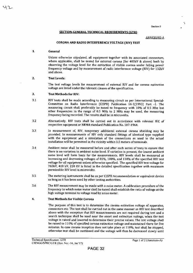
Section-3
SECTION-GENERAL TECHNICAL REOUIREMENTS {GTR)
ANNEXURE-A
CORONA AND RADIO INTERFERENCE VOLTAGE (RIV) TEST
1. General
Unless otherwise stipulated, all equipment together with its associated connectors, where applicable, shall be tested for external corona (for 400kV & above) both by observing the voltage level for the extinction of visible corona under falling power frequency voltage and by measurement of radio interference voltage (RIV) for 132kV and above.
2. Test Levels:
The test voltage levels for measurement of external RIV and for corona extinction voltage are listed under the relevant clauses of the specification.
3. Test Methods for RIV:
3.1 RIV tests shall be made according to measuring circuit as per International Special- Committee on Radio Interference (CISPR) Publication 16-1(1993) Part -1. The measuring circuit shall preferably be tuned to frequency with 10% of 0.5 Mhz but other frequencies in the range of 0.5 MHz to 2 MHz may be used, the measuring frequency being recorded. The results shall be in microvolts.
3.2 Alternatively, RIV tests shall be carried out in accordance with relevant IEC of respective equipment or NEMA standard Publication No. 107-1964.
3.3 In measurement of, RIV, temporary additional external corona shielding may be provided. In measurements of RIV only standard fittings of identical type supplied with the equipment and a simulation of the connections as used in the actual installation will be permitted in the vicinity within 3.5 meters of terminals.
3.4 Ambient noise shall be measured before and after each series of tests to ensure that there is no variation in ambient noise level. If variation is present, the lowest ambient noise level will form basis for the measurements. RIV levels shall be measured at increasing and decreasing voltages of 85%, 100%, and 110% of the specified RIV test voltage for all equipment unless otherwise specified. The specified RIV test voltage for 765kV, 400 kV, 220 KV is listed in the detailed specification together with maximum permissible RIV level in microvolts.
3.5 The metering instruments shall be as per CISPR recommendation or equivalent device so long as it has been used by other testing authorities.
3.6 The RIV measurement may be made with a noise meter. A calibration procedure of the frequency to which noise meter shall be tuned shall establish the ratio of voltage at the high voltage terminal to voltage read by noise meter.
4. Test Methods for Visible Corona
The purpose of this test is to determine the corona extinction voltage of apparatus, connectors etc. The test shall be carried out in the same manner as RIV test described above with the exception that RIV measurements are not required during test and a search technique shall be used near the onset and extinction voltage, when the test voltage is raised and lowered to determine their precise values. The test voltage shall be raised to 110% of specified corona extinction voltage and maintained there for five minutes. In case corona inception does not take place at 110%, test shall be stopped, otherwise test shall be continued and the voltage will then be decreased slowly until
Technical Specification: GTR Page 1 of 2 (Annexure-A) C/ENGG/SPEC/GTR (Rev. No.:-14, Jan'17)
PAGE 32
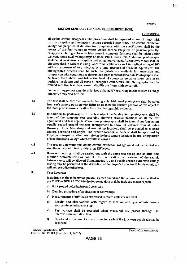
Section-3
SECTION-GENERAL TECHNICAL REOUIREMENTS (GTRJ
ANNEX]IRE-A
all visible corona disappears. The procedure shall be repeated at least 4 times with corona inception and extinction voltage recorded each time. The corona extinction voltage for purposes of determining compliance with the specification shall be the lowest of the four values at which visible corona (negative or positive polarity) disappears. Photographs with laboratory in complete darkness shall be taken under test conditions, at all voltage steps i.e. 85%, 100%, and 110%. Additional photographs shall be taken at corona inception and extinction voltages. At least two views shall be photographed in each case using Panchromatic film with an ASA daylight rating of 400 with an exposure of two minutes at a lens aperture of f/5.6 or equivalent. The photographic process shall be such that prints are available for inspection and comparison with conditions as determined from direct observation. Photographs shall be taken from above and below the level of connector so as to show corona on bushing, insulators and all parts of energised connectors. The photographs shall be framed such that test object essentially, fills the frame with no cut-off.
For recording purpose, modern devices utilizing UV recording methods such as image intensifier may also be used.
4.1 The test shall be recorded on each photograph. Additional photograph shall be taken from each camera position with lights on to show the relative position of test object to facilitate precise corona location from the photographic evidence.
4.2 In addition to photographs of the test object preferably four photographs shall be taken of the complete test assembly showing relative positions of all the test equipment and test objects. These four photographs shall be taken from four points equally spaced around the test arrangement to show its features from all sides. Drawings of the laboratory and test set up locations shall be provided to indicate camera positions and angles. The precise location of camera shall be approved by Employer's inspector, after determining the best camera locations by trial energisation of test object at a voltage which results in corona.
4.3 The test to determine the visible corona extinction voltage need not be carried out simultaneously with test to determine RIV levels.
4.4 However, both test shall be carried out with the same test set up and as little time duration between tests as possible. No modification on treatment of the sample between tests will be allowed. Simultaneous RIV and visible corona extinction voltage testing may be permitted at the discretion of Employer's inspector if, in his opinion, it will not prejudice other test.
S. Test Records:
In addition to the information previously mentioned and the requirements specified as per CISPR or NEMA 107-1964 the following data shall be included in test report:
a) Background noise before and after test.
b) Detailed procedure of application of test voltage.
c) Measurements of RIV levels expressed in micro volts at each level.
d) Results and observations with regard to location and type of interference sources detected at each step.
e) Test voltage shall be recorded when measured RIV passes through 100 microvolts in each direction.
f) Onset and extinction of visual corona for each of the four tests required shall be recorded.
Technical Specification: GTR Page 2 of 2 (Annexure-A) C/ENGG/SPEC/GTR (Rev. No.:-14, Jan'17)
PAGE 33
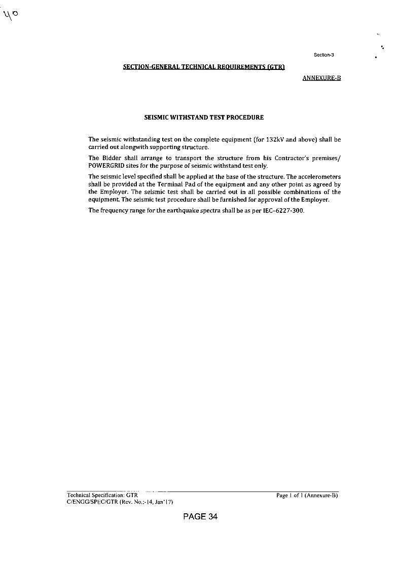
Section-3
SECTION-GENERAL TECHNICAL REQUIREMENTS (GTR1
ANNEXURE-B
SEISMIC WITHSTAND TEST PROCEDURE
The seismic withstanding test on the complete equipment (for 132kV and above) shall be carried out alongwith supporting structure.
The Bidder shall arrange to transport the structure from his Contractor's premises/ POWERGRID sites for the purpose of seismic withstand test only.
The seismic level specified shall be applied at the base of the structure. The accelerometers shall be provided at the Terminal Pad of the equipment and any other point as agreed by the Employer. The seismic test shall be carried out in all possible combinations of the equipment. The seismic test procedure shall be furnished for approval of the Employer.
The frequency range for the earthquake spectra shall be as per IEC-6227-300.
\,\ 0
Technical Specification: GTR Page 1 of 1 (Annexure-B) C/ENGG/SPEC/GTR (Rev. No.:-14, Jan'17)
PAGE 34
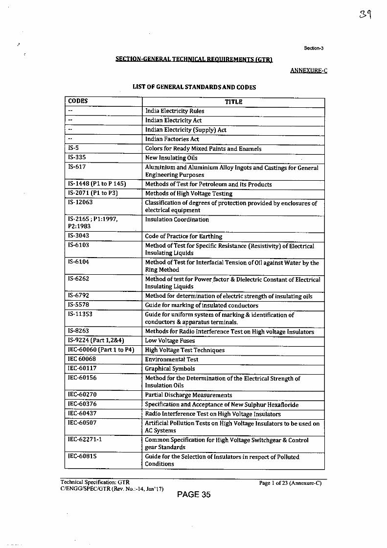
Section-3
I k 4 01 4 :I ZUL
ANNEXIJRE-C
LIST OF GENERAL STANDARDS AND CODES
CODES TITLE -- India Electricity Rules -- Indian Electricity Act -- Indian Electricity (Supply) Act -- Indian Factories Act IS-5 Colors for Ready Mixed Paints and Enamels IS-335 New Insulating Oils IS-617 Aluminium and Aluminium Alloy Ingots and Castings for General
Engineering Purposes IS-1448 (P1 to P 145) Methods of Test for Petroleum and its Products IS-2071 (P1 to P3) Methods of High Voltage Testing IS-12063 Classification of degrees of protection provided by enclosures of
electrical equipment IS-2165 ; P1:1997, P2:1983
Insulation Coordination
IS-3043 Code of Practice for Earthing IS-6103 Method of Test for Specific Resistance (Resistivity) of Electrical
Insulating Liquids IS-6104 Method of Test for Interfacial Tension of Oil against Water by the
Ring Method IS-6262 Method of test for Power factor & Dielectric Constant of Electrical
Insulating Liquids IS-6792 Method for determination of electric strength of insulating oils IS-5578 Guide for marking of insulated conductors IS-11353 Guide for uniform system of marking & identification of
conductors & apparatus terminals. IS-8263 Methods for Radio Interference Test on High voltage Insulators IS-9224 (Part 1,2&4) Low Voltage Fuses IEC-60060 (Part 1 to P4) High Voltage Test Techniques IEC 60068 Environmental Test IEC-60117 Graphical Symbols
IEC-60156 Method for the Determination of the Electrical Strength of Insulation Oils
IEC-60270 Partial Discharge Measurements IEC-60376 Specification and Acceptance of New Sulphur Hexafloride IEC-60437 Radio Interference Test on High Voltage Insulators IEC-60507 Artificial Pollution Tests on High Voltage Insulators to be used on
AC Systems IEC-62271-1 Common Specification for High Voltage Switchgear & Control
gear Standards
IEC-60815 Guide for the Selection of Insulators in respect of Polluted Conditions
Technical Specification: GTR C/ENGG/SPEC/GTR (Rev. No.:-14, Jan'17)
Page 1 of 23 (Annexure-C)
PAGE 35
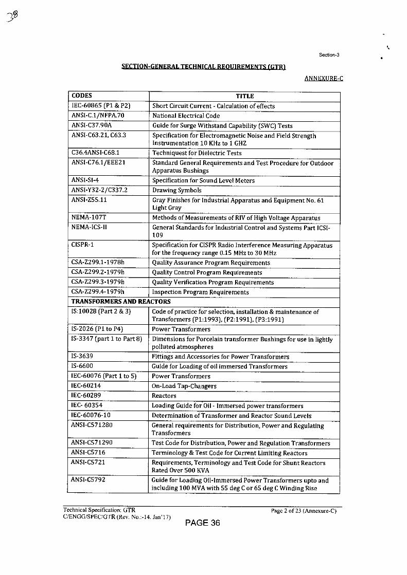
Section-3
SECTION-GENERAL TECHNICAL REQUIREMENTS (GTR)
ANNEXURE-C
CODES TITLE IEC-60865 (P1 & P2) Short Circuit Current - Calculation of effects
ANSI-C.1/NFPA.70 National Electrical Code
ANSI-C37.90A Guide for Surge Withstand Capability (SWC) Tests
ANSI-C63.21, C63.3 Specification for Electromagnetic Noise and Field Strength Instrumentation 10 KHz to 1 GHZ
C36.4ANSI-C68.1 Techniquest for Dielectric Tests
ANSI-C76.1/EEE21 Standard General Requirements and Test Procedure for Outdoor Apparatus Bushings
ANSI-SI-4 Specification for Sound Level Meters
ANSI-Y32-2/C337.2 Drawing Symbols
ANSI-Z55.11 Gray Finishes for Industrial Apparatus and Equipment No. 61 Light Gray
NEMA-107T Methods of Measurements of RIV of High Voltage Apparatus
NEMA-ICS-II General Standards for Industrial Control and Systems Part ICSI-109
CISPR-1 Specification for CISPR Radio Interference Measuring Apparatus for the frequency range 0.15 MHz to 30 MHz
CSA-Z299.1-1978h Quality Assurance Program Requirements
CSA-Z299.2-1979h Quality Control Program Requirements
CSA-Z299.3-1979h Quality Verification Program Requirements
CSA-Z299.4-1979h Inspection Program Requirements
TRANSFORMERS AND REACTORS
IS:10028 (Part 2 & 3) Code of practice for selection, installation & maintenance of Transformers (P1:1993), (P2:1991), (P3:1991)
IS-2026 (P1 to P4) Power Transformers
IS-3347 (part 1 to Part 8) Dimensions for Porcelain transformer Bushings for use in lightly polluted atmospheres
IS-3639 Fittings and Accessories for Power Transformers
IS-6600 Guide for Loading of oil immersed Transformers
IEC-60076 (Part 1 to 5) Power Transformers
IEC-60214 On-Load Tap-Changers
IEC-60289 Reactors
IEC- 60354 Loading Guide for.Oil - Immersed power transformers
IEC-60076-10 Determination of Transformer and Reactor Sound Levels
ANSI-0571280 General requirements for Distribution, Power and Regulating Transformers
ANSI-0571290 Test Code for Distribution, Power and Regulation Transformers
ANSI-05716 Terminology & Test Code for Current Limiting Reactors
ANSI-05721 Requirements, Terminology and Test Code for Shunt Reactors Rated Over 500 KVA
ANSI-05792 Guide for Loading Oil-Immersed Power Transformers upto and including 100 MVA with 55 deg C or 65 deg C Winding Rise
Technical Specification: GTR
Page 2 of 23 (Annexure-C) C/ENGG/SPEC/GTR (Rev. No.:-14, Jan'17)
PAGE 36
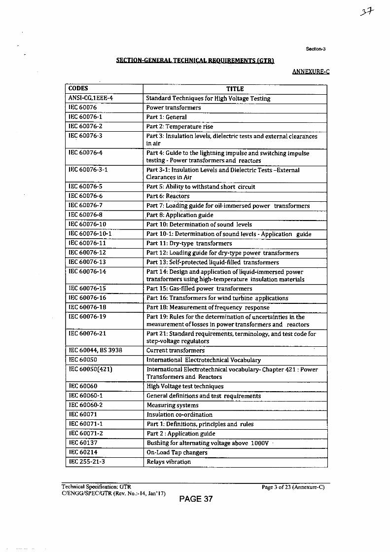
Section-3
SECTION-GENERAL TECHNICAL REQUIREMENTS (GTRI
ANNEXURE-C
CODES TITLE
ANSI-CG,HEE-4 Standard Techniques for High Voltage Testing IEC 60076 Power transformers IEC 60076-1 Part 1: General IEC 60076-2 Part 2: Temperature rise IEC 60076-3 Part 3: Insulation levels, dielectric tests and external clearances
in air
IEC 60076-4 Part 4: Guide to the lightning impulse and switching impulse testing - Power transformers and reactors
IEC 60076-3-1 Part 3-1: Insulation Levels and Dielectric Tests -External Clearances in Air
IEC 60076-5 Part 5: Ability to withstand short circuit IEC 60076-6 Part 6: Reactors
IEC 60076-7 Part 7: Loading guide for oil-immersed power transformers IEC 60076-8 Part 8: Application guide IEC 60076-10 Part 10: Determination of sound levels IEC 60076-10-1 Part 10-1: Determination of sound levels - Application guide IEC 60076-11 Part 11: Dry-type transformers IEC 60076-12 Part 12: Loading guide for dry-type power transformers IEC 60076-13 Part 13: Self-protected liquid-filled transformers
IEC 60076-14 Part 14: Design and application of liquid-immersed power transformers using high-temperature insulation materials
IEC 60076-15 Part 15: Gas-filled power transformers
IEC 60076-16 Part 16: Transformers for wind turbine applications
IEC 60076-18 Part 18: Measurement of frequency response
IEC 60076-19 Part 19: Rules for the determination of uncertainties in the measurement of losses in power transformers and reactors
IEC 60076-21 Part 21: Standard requirements, terminology, and test code for step-voltage regulators
IEC 60044, BS 3938 Current transformers
IEC 60050 International Electrotechnical Vocabulary IEC 60050(421) International Electrotechnical vocabulary- Chapter 421 : Power
Transformers and Reactors
IEC 60060 High Voltage test techniques
IEC 60060-1 General definitions and test requirements IEC 60060-2 Measuring systems
IEC 60071 Insulation co-ordination
IEC 60071-1 Part 1: Definitions, principles and rules
IEC 60071-2 Part 2 : Application guide IEC 60137 Bushing for alternating voltage above 1000V IEC 60214 On-Load Tap changers IEC 255-21-3 Relays vibration
Technical Specification: GTR
Page 3 of 23 (Annexure-C) C/ENGG/SPEC/GTR (Rev. No.:-14, Jan'17)
PAGE 37
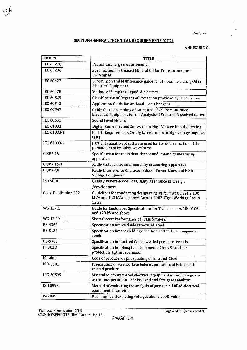
Section-3
SECTION-GENERAL TECHNICAL REQUIREMENTS (GTR)
ANNEXURE-C
CODES TITLE
IEC 60270 Partial discharge measurements
IEC 60296 Specification for Unused Mineral Oil for Transformers and Switchgear
IEC 60422 Supervision and Maintenance guide for Mineral Insulating Oil in Electrical Equipment
IEC 60475 Method of Sampling Liquid dielectrics
IEC 60529 Classification of Degrees of Protection provided by Enclosures
IEC 60542 Application Guide for On-Load Tap-Changers
IEC 60567 Guide for the Sampling of Gases and of Oil from Oil-filled Electrical Equipment for the Analysis of Free and Dissolved Gases
IEC 60651 Sound Level Meters
IEC 61083 Digital Recorders and Software for High Voltage Impulse testing
IEC 61083-1 Part 1: Requirements for digital recorders in high voltage impulse tests
IEC 61083-2 Part 2: Evaluation of software used for the determination of the parameters of impulse waveforms
CISPR 16 Specification for radio disturbance and immunity measuring apparatus
CISPR 16-1 Radio disturbance and immunity measuring apparatus
CISPR-18 Radio Interference Characteristics of Power Lines and High Voltage Equipment
ISO 9001 Quality system-Model for Quality Assurance in Design
/development
Cigre Publication 202 Guidelines for conducting design reviews for transformers 100 MVA and 123 kV and above. August 2002-Cigre Working Group 12.22
WG 12-15 Guide for Customers Specifications for Transformers 100 MVA and 123 kV and above
WG 12 19 Short Circuit Performance of Transformers.
BS-4360 Specification for weldable structural steel
BS-5135 Specification for arc welding of carbon and carbon manganese steels
BS-5500 Specification for unfired fusion welded pressure vessels
IS-3618 Specification for phosphate treatment of iron & steel for protection against corrosion
IS-6005 Code of practice for phosphating of Iron and Steel
ISO-8501 Preparation of steel surface before application of Paints and related product
IEC-60599 Mineral oil impregnated electrical equipment in service - guide to the interpretation of dissolved and free gases analysis
IS-10593 Method of evaluating the analysis of gases in oil filled electrical equipment in service
IS-2099 Bushings for alternating voltages above 1000 volts
Technical Specification: GTR
Page 4 of 23 (Annexure-C) C/ENGG/SPEC/GTR (Rev. No.:-14, Jan' 17)
PAGE 38
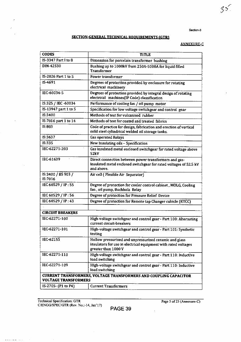
Section-3
ANNEXURFI
CODES TITLE
IS-3347 Part I to 8 Dimension for porcelain transformer bushing DIN-42530 Bushing up to 1000kV from 250A-5000A for liquid filled
Transformer IS-2026 Part 1 to 5 Power transformer IS-4691 Degrees of protection provided by enclosure for rotating
electrical machinery IEC-60034-5 Degrees of protection provided by integral design of rotating
electrical machines(IP Code) classification IS:325 / IEC -60034 Performance of cooling fan / oil pump motor IS-13947 part 1 to 5 Specification for low voltage switchgear and control gear IS:3400 Methods of test for vulcanised rubber IS:7016 part 1 to 14 Methods of test for coated and treated fabrics IS:803 Code of practice for design, fabrication and erection of vertical
mild steel cylindrical welded oil storage tanks. IS:3637 Gas operated Relays IS:335 New Insulating oils - Specification IEC-62271-203 Gas insulated metal enclosed switchgear for rated voltage above
52kV IEC-61639 Direct connection between power transformers and gas-
insulated metal enclosed switchgear for rated voltages of 52.5 kV and above.
IS:3400 / BS 903 / IS:7016
Air cell ( Flexible Air Separator)
IEC 60529 / IP : 55 Degree of protection for cooler control cabinet, MOLG, Cooling fan , oil pump, Buchholz Relay
IEC 60529 / IP : 56 Degree of protection for Pressure Relief Device IEC 60529 / IP : 43 Degree of protection for Remote tap Changer cubicle (RTCC)
CIRCUIT BREAKERS
IEC-62271-100 High-voltage switchgear and control gear - Part 100: Alternating current circuit-breakers
IEC-62271-101 High-voltage switchgear and control gear - Part 101: Synthetic testing
IEC-62155 Hollow pressurized and unpressurized ceramic and glass insulators for use in electrical equipment with rated voltages greater than 1000 V
IEC-62271-110 High-voltage switchgear and control gear - Part 110: Inductive load switching
IEC-62271-109 High-voltage switchgear and control gear - Part 110: Inductive load switching
CURRENT TRANSFORMERS, VOLTAGE TRANSFORMERS AND COUPLING CAPACITOR VOLTAGE TRANSFORMERS
IS-2705- (P1 to P4) Current Transformers
Technical Specification: GTR
Page 5 of 23 (Annexure-C) C/ENGG/SPEC/GTR (Rev. No.:-14, )an'17)
PAGE 39
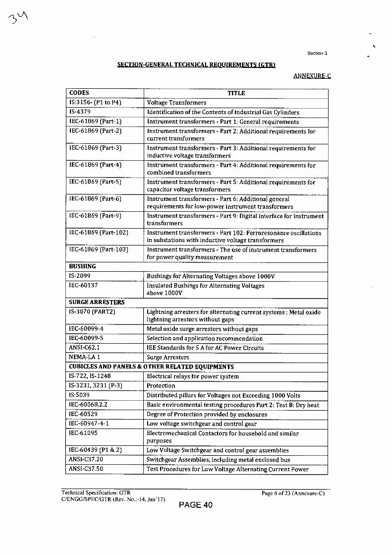
Section-3
SECTION-GENERAL TECHNICAL REQUIREMENTS (GTR)
ANNEXURE-C
CODES TITLE
IS:3156- (P1 to P4) Voltage Transformers
IS-4379 Identification of the Contents of Industrial Gas Cylinders
IEC-61869 (Part-1) Instrument transformers - Part 1: General requirements
IEC-61869 (Part-2) Instrument transformers - Part 2: Additional requirements for current transformers
IEC-61869 (Part-3) Instrument transformers - Part 3: Additional requirements for inductive voltage transformers
IEC-61869 (Part-4) Instrument transformers - Part 4: Additional requirements for combined transformers
IEC-61869 (Part-5) Instrument transformers - Part 5: Additional requirements for capacitor voltage transformers
IEC-61869 (Part-6) Instrument transformers - Part 6: Additional general requirements for low-power instrument transformers
IEC-61869 (Part-9) Instrument transformers - Part 9: Digital interface for instrument transformers
IEC-61869 (Part-102) Instrument transformers - Part 102: Ferroresonance oscillations in substations with inductive voltage transformers
IEC-61869 (Part-103) Instrument transformers - The use of instrument transformers for power quality measurement
BUSHING
IS-2099 Bushings for Alternating Voltages above 1000V
IEC-60137 Insulated Bushings for Alternating Voltages above 1000V
SURGE ARRESTERS
IS-3070 (PART2) Lightning arresters for alternating current systems : Metal oxide lightning arrestors without gaps
IEC-60099-4 Metal oxide surge arrestors without gaps
IEC-60099-5 Selection and application recommendation
ANSI-C62.1 IEE Standards for S A for AC Power Circuits
NEMA-LA 1 Surge Arresters
CUBICLES AND PANELS & OTHER RELATED EQUIPMENTS
IS-722, IS-1248 Electrical relays for power system
IS-3231, 3231 (P-3) Protection
IS:5039 Distributed pillars for Voltages not Exceeding 1000 Volts
IEC-60068.2.2 Basic environmental testing procedures Part 2: Test B: Dry heat
IEC-60529 Degree of Protection provided by enclosures
IEC-60947-4-1 Low voltage switchgear and control gear
IEC-61095 Electromechanical Contactors for household and similar purposes
IEC-60439 (P1 & 2) Low Voltage Switchgear and control gear assemblies
ANSI-C37.20 Switchgear Assemblies, including metal enclosed bus
ANSI-C37.50 Test Procedures for Low Voltage Alternating Current Power
Technical Specification: GTR
Page 6 of 23 (Annexure-C) C/ENGG/SPEC/GTR (Rev. No.:-14, Jan'17)
PAGE 40
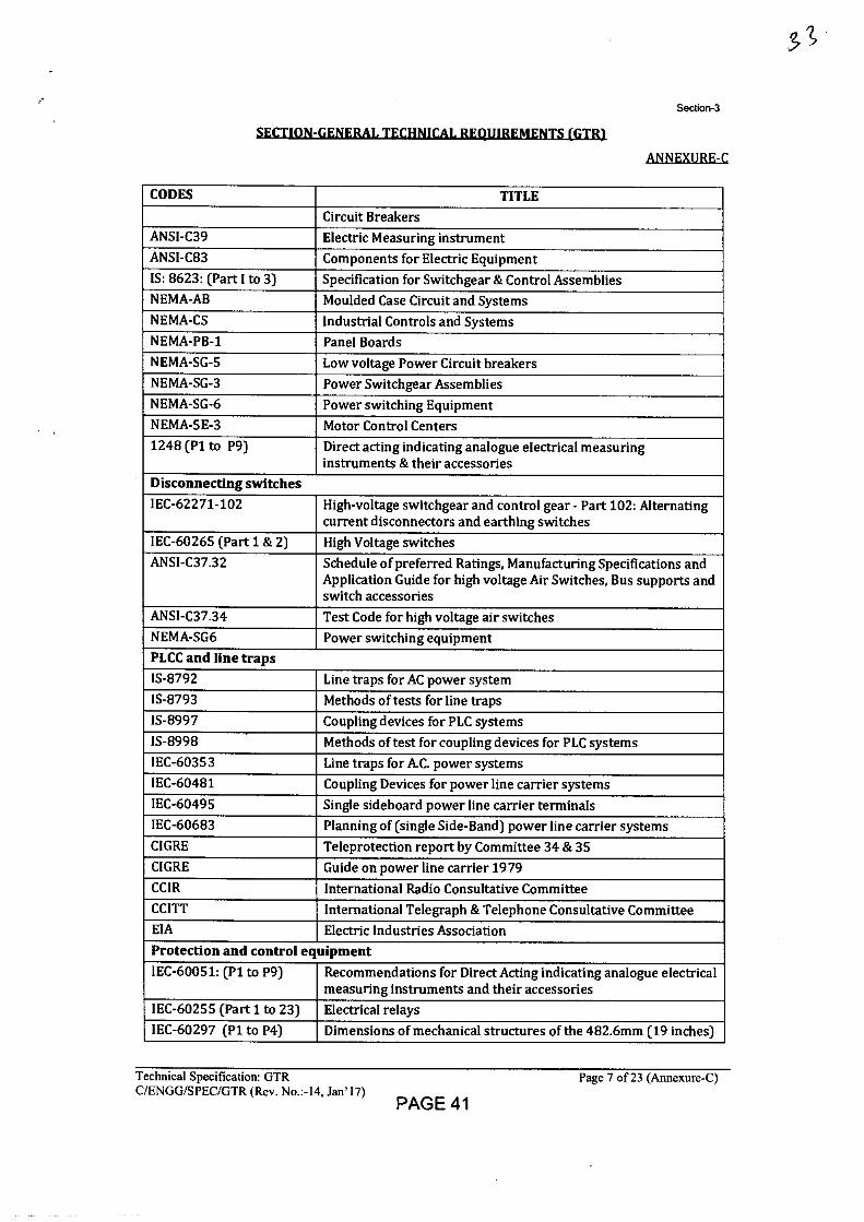
Section-3
SECTION-GENERAL TECHNICAL REQUIREMENTS (GTR)
ANNEXURE-C
CODES TITLE Circuit Breakers
ANSI-C39 Electric Measuring instrument ANSI-C83 Components for Electric Equipment IS: 8623: (Part I to 3) Specification for Switchgear & Control Assemblies NEMA-AB Moulded Case Circuit and Systems NEMA-CS Industrial Controls and Systems NEMA-PB-1 Panel Boards NEMA-SG-5 Low voltage Power Circuit breakers NEMA-SG-3 Power Switchgear Assemblies NEMA-SG-6 Power switching Equipment NEMA-5E-3 Motor Control Centers 1248 (P1 to P9) Direct acting indicating analogue electrical measuring
instruments & their accessories Disconnecting switches IEC-62271-102 High-voltage switchgear and control gear - Part 102: Alternating
current disconnectors and earthing switches IEC-60265 (Part 1 & 2) High Voltage switches ANSI-C37.32 Schedule of preferred Ratings, Manufacturing Specifications and
Application Guide for high voltage Air Switches, Bus supports and switch accessories
ANSI-C37.34 Test Code for high voltage air switches NEMA-SG6 Power switching equipment PLCC and line traps IS-8792 Line traps for AC power system IS-8793 Methods of tests for line traps IS-8997 Coupling devices for PLC systems IS-8998 Methods of test for coupling devices for PLC systems IEC-60353 Line traps for A.C. power systems IEC-60481 Coupling Devices for power line carrier systems IEC-60495 Single sideboard power line carrier terminals IEC-60683 Planning of (single Side-Band) power line carrier systems CIGRE Teleprotection report by Committee 34 & 35 CIGRE Guide on power line carrier 1979 CCIR International Radio Consultative Committee CCITT International Telegraph & Telephone Consultative Committee EIA Electric Industries Association Protection and control equipment IEC-60051: (P1 to P9) Recommendations for Direct Acting indicating analogue electrical
measuring instruments and their accessories IEC-60255 (Part 1 to 23) Electrical relays IEC-60297 (P1 to P4) Dimensions of mechanical structures of the 482.6mm (19 inches)
Technical Specification: GTR
Page 7 of 23 (Annexure-C) C/ENGG/SPEC/GTR (Rev. No.:-14, Jan'17)
PAGE 41
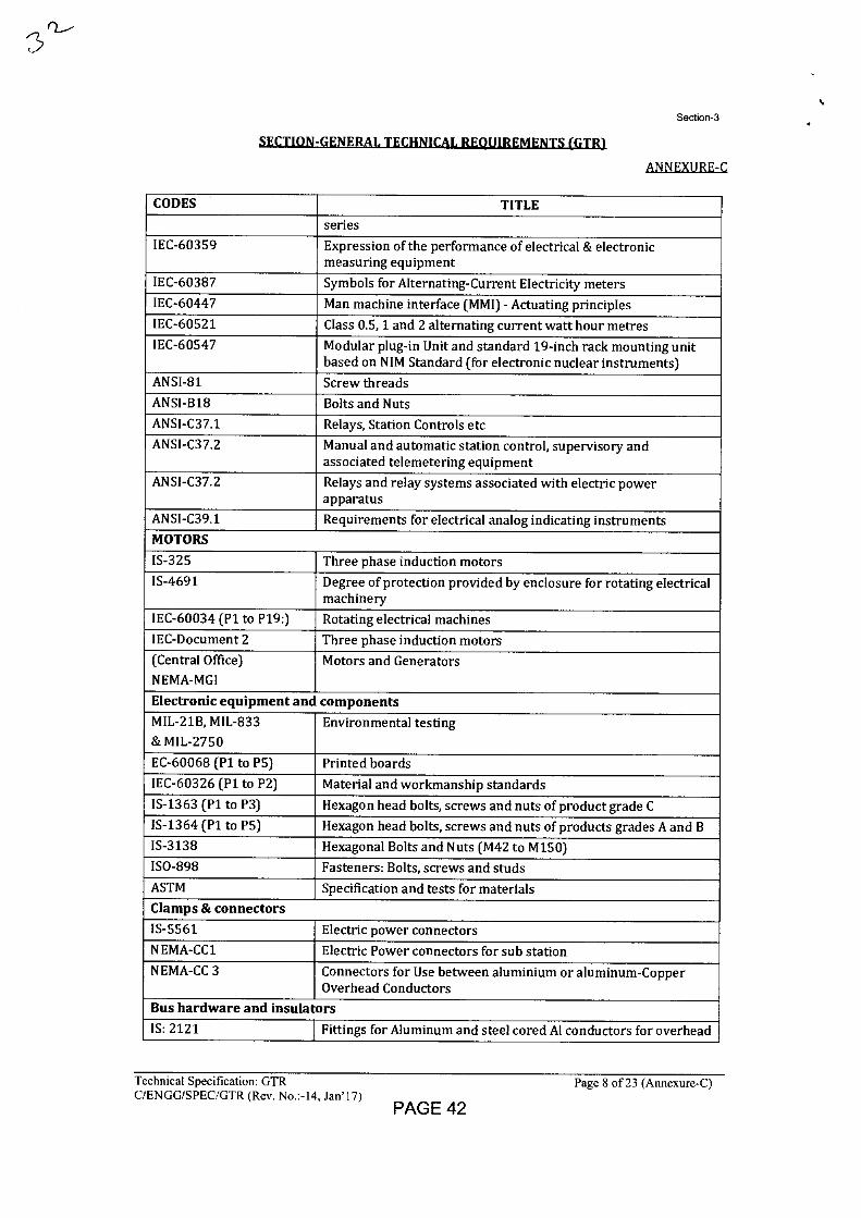
Section-3
SECTION-GENERAL TECHNICAL REQUIREMENTS (GTR)
ANEEXI/REC
CODES TITLE series
IEC-60359 Expression of the performance of electrical & electronic measuring equipment
IEC-60387 Symbols for Alternating-Current Electricity meters IEC-60447 Man machine interface (MMI) - Actuating principles IEC-60521 Class 0.5, 1 and 2 alternating current watt hour metres IEC-60547 Modular plug-in Unit and standard 19-inch rack mounting unit
based on NIM Standard (for electronic nuclear instruments) ANSI-81 Screw threads ANSI-B18 Bolts and Nuts ANSI-C37.1 Relays, Station Controls etc ANSI-C37.2 Manual and automatic station control, supervisory and
associated telemetering equipment ANSI-C37.2 Relays and relay systems associated with electric power
apparatus ANSI-C39.1 Requirements for electrical analog indicating instruments MOTORS IS-325 Three phase induction motors IS-4691 Degree of protection provided by enclosure for rotating electrical
machinery
IEC-60034 (P1 to P19:) Rotating electrical machines IEC-Document 2 Three phase induction motors (Central Office) NEMA-MGI
Motors and Generators
Electronic equipment and components MIL-21B, MIL-833 & MIL-2750
Environmental testing
EC-60068 (P1 to P5) Printed boards
IEC-60326 (P1 to P2) Material and workmanship standards IS-1363 (P1 to P3) Hexagon head bolts, screws and nuts of product grade C 1S-1364 (P1 to P5) Hexagon head bolts, screws and nuts of products grades A and B IS-3138 Hexagonal Bolts and Nuts (M42 to M150) ISO-898 Fasteners: Bolts, screws and studs ASTM Specification and tests for materials Clamps & connectors IS-5561 Electric power connectors NEMA-CC1 Electric Power connectors for sub station NEMA-CC 3 Connectors for Use between aluminium or aluminum-Copper
Overhead Conductors Bus hardware and insulators IS: 2121 Fittings for Aluminum and steel cored Al conductors for overhead
Technical Specification: GTR
Page 8 of 23 (Annexure-C) C/ENGG/SPEC/GTR (Rev. No.:-14, Jan'17)
PAGE 42
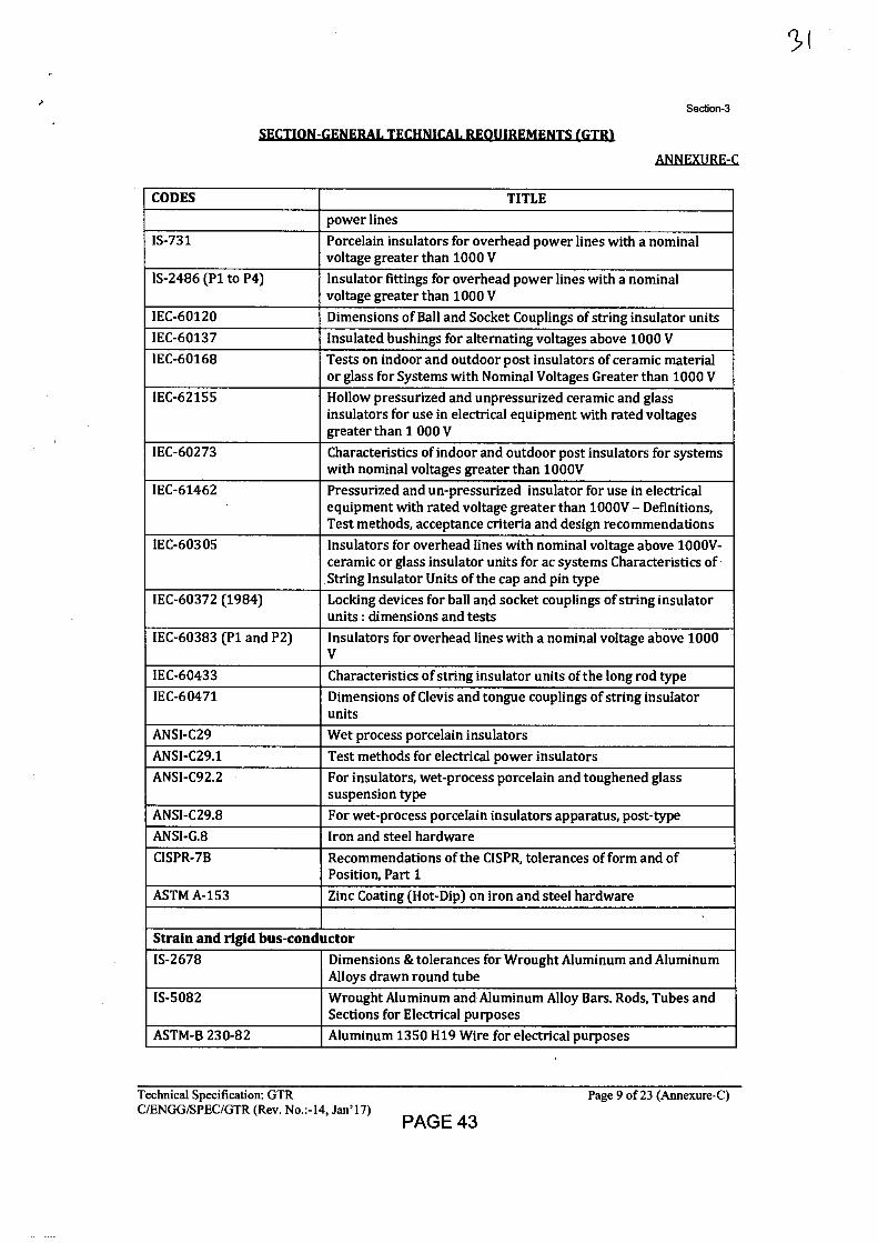
Section-3
SECTIDN-GFNERAL TECHNICAL REQUIREMENTS (GTR)
ANNEXURE-C
CODES TITLE power lines
1S-731 Porcelain insulators for overhead power lines with a nominal voltage greater than 1000 V
1S-2486 (P1 to P4) Insulator fittings for overhead power lines with a nominal voltage greater than 1000 V
IEC-60120 Dimensions of Ball and Socket Couplings of string insulator units
IEC-60137 Insulated bushings for alternating voltages above 1000 V IEC-60168 Tests on indoor and outdoor post insulators of ceramic material
or glass for Systems with Nominal Voltages Greater than 1000 V IEC-62155 Hollow pressurized and unpressurized ceramic and glass
insulators for use in electrical equipment with rated voltages greater than 1 000 V
IEC-60273 Characteristics of indoor and outdoor post insulators for systems with nominal voltages greater than 1000V
IEC-61462 Pressurized and un-pressurized insulator for use in electrical equipment with rated voltage greater than 1000V - Definitions, Test methods, acceptance criteria and design recommendations
IEC-60305 Insulators for overhead lines with nominal voltage above 1000V-ceramic or glass insulator units for ac systems Characteristics of String Insulator Units of the cap and pin type
IEC-60372 (1984) Locking devices for ball and socket couplings of string insulator units : dimensions and tests
IEC-60383 (P1 and P2) Insulators for overhead lines with a nominal voltage above 1000 V
IEC-60433 Characteristics of string insulator units of the long rod type IEC-60471 Dimensions of Clevis and tongue couplings of string insulator
units
ANSI-C29 Wet process porcelain insulators
ANSI-C29.1 Test methods for electrical power insulators
ANSI-C92.2 For insulators, wet-process porcelain and toughened glass suspension type
ANSI-C29.8 For wet-process porcelain insulators apparatus, post-type ANSI-G.8 Iron and steel hardware
CISPR-7B Recommendations of the CISPR, tolerances of form and of Position, Part 1
ASTM A-153 Zinc Coating (Hot-Dip) on iron and steel hardware
Strain and rigid bus-conductor 1S-2678 Dimensions & tolerances for Wrought Aluminum and Aluminum
Alloys drawn round tube
IS-5082 Wrought Aluminum and Aluminum Alloy Bars. Rods, Tubes and Sections for Electrical purposes
ASTM-B 230-82 Aluminum 1350 H19 Wire for electrical purposes
Technical Specification: GTR
Page 9 of 23 (Annexure-C) C/ENGG/SPEC/GTR (Rev. No.:-14, Jan'17)
PAGE 43
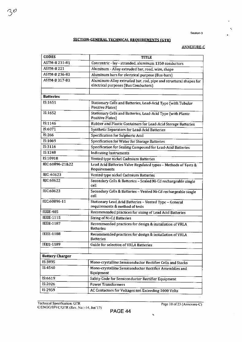
Section-3
■ t u
A'4NEXIIRF-r
CODES TITLE ASTM-B 231-81 Concentric - lay - stranded, aluminum 1350 conductors ASTM-B 221 Aluminum - Alloy extruded bar, road, wire, shape ASTM-B 236-83 Aluminum bars for electrical purpose (Bus-bars) ASTM-B 317-83 Aluminum-Alloy extruded bar, rod, pipe and structural shapes for
electrical purposes (Bus Conductors)
Batteries
IS:1651 Stationary Cells and Batteries, Lead-Acid Type (with Tubular Positive Plates)
IS:1652 Stationary Cells and Batteries, Lead-Acid Type (with Plante Positive Plates)
IS:1146 Rubber and Plastic Containers for Lead-Acid Storage Batteries IS:6071 Synthetic S4parators for Lead-Acid Batteries IS:266 Specification for Sulphuric Acid IS:1069 Specification for Water for Storage Batteries IS:3116 Specification for Sealing Compound for Lead-Acid Batteries IS:1248 Indicating Instruments
IS:10918 Vented type nickel Cadmium Batteries IEC:60896-21&22 Lead Acid Batteries Valve Regulated types - Methods of Tests &
Requirements
IEC: 60623 Vented type nickel Cadmium Batteries IEC:60622 Secondary Cells & Batteries - Sealed Ni-Cd rechargeable single
cell
IEC:60623 Secondary Cells & Batteries - Vented Ni-Cd rechargeable single cell
IEC:60896-11 Stationary Lead Acid Batteries - Vented Type - General requirements & method of tests
IEEE-485 Recommended practices for sizing of Lead Acid Batteries IEEE-1115 Sizing of Ni-Cd Batteries IEEE-1187 Recommended practices for design & installation of VRLA
Batteries IEEE-1188 Recommended practices for design & installation of VRLA
Batteries
IEEE-1189 Guide for selection of VRLA Batteries
Battery Charger
IS:3895 Mono-crystalline Semiconductor Rectifier Cells and Stacks IS:4540 Mono-crystalline Semiconductor Rectifier Assemblies and
Equipment IS:6619 Safety Code for Semiconductor Rectifier Equipment IS:2026 Power Transformers
IS:2959 AC Contactors for Voltages not Exceeding 1000 Volts
Technical Specification: GTR C/ENGG/SPEC/GTR (Rev. No.:-14, Jan'17)
Page 10 of 23 (Annexure-C)
PAGE 44
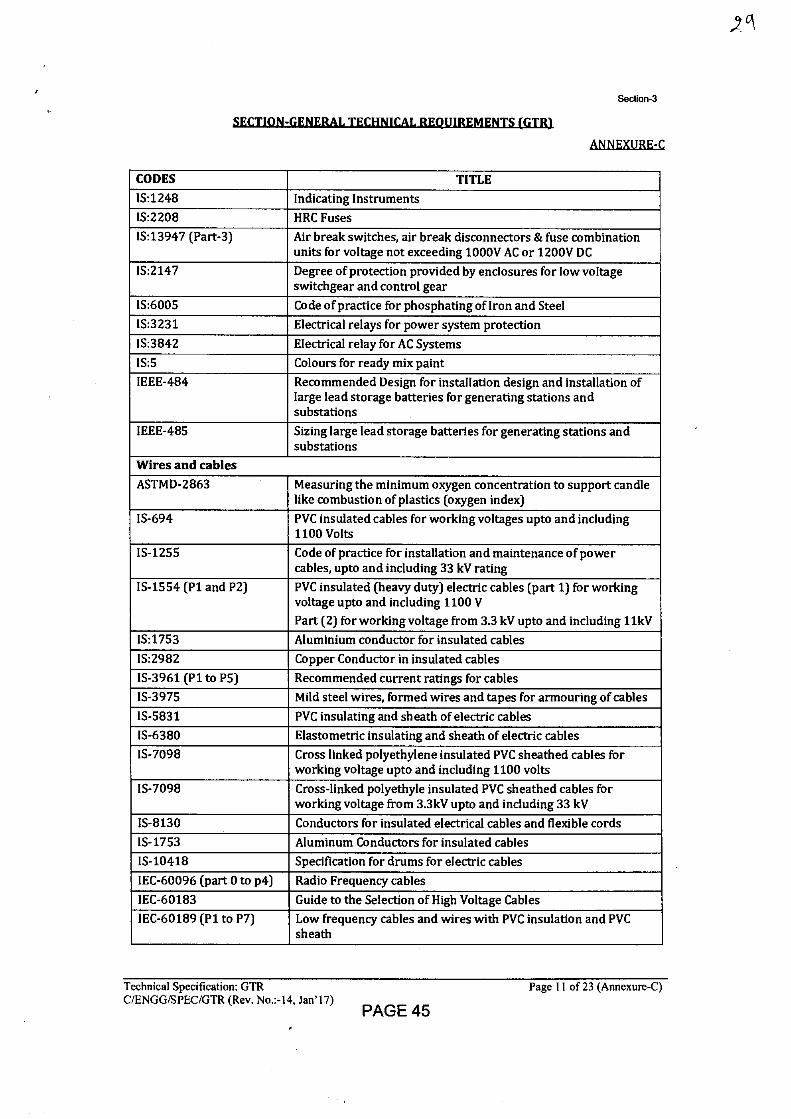
Section-3
SECTION-GENERAL TECHNICAL REQUIREMENTS (GTR1
AMEXURE-C
CODES TITLE
IS:1248 Indicating Instruments
IS:2208 HRC Fuses
IS:13947 (Part-3) Air break switches, air break disconnectors & fuse combination units for voltage not exceeding 1000V AC or 1200V DC
IS:2147 Degree of protection provided by enclosures for low voltage switchgear and control gear
IS:6005 Code of practice for phosphating of Iron and Steel
IS:3231 Electrical relays for power system protection
IS:3842 Electrical relay for AC Systems
IS:5 Colours for ready mix paint
IEEE-484 Recommended Design for installation design and installation of large lead storage batteries for generating stations and substations
IEEE-485 Sizing large lead storage batteries for generating stations and substations
Wires and cables ASTMD-2863 Measuring the minimum oxygen concentration to support candle
like combustion of plastics (oxygen index)
IS-694 PVC insulated cables for working voltages upto and including 1100 Volts
IS-1255 Code of practice for installation and maintenance of power cables, upto and including 33 kV rating
IS-1554 (P1 and P2) PVC insulated (heavy duty) electric cables (part 1) for working voltage upto and including 1100 V
Part (2) for working voltage from 3.3 kV upto and including 1 lkV
IS:1753 Aluminium conductor for insulated cables
IS:2982 Copper Conductor in insulated cables
IS-3961 (P1 to P5) Recommended current ratings for cables IS-3975 Mild steel wires, formed wires and tapes for armouring of cables
IS-5831 PVC insulating and sheath of electric cables
IS-6380 Elastometric insulating and sheath of electric cables IS-7098 Cross linked polyethylene insulated PVC sheathed cables for
working voltage upto and including 1100 volts
IS-7098 Cross-linked polyethyle insulated PVC sheathed cables for working voltage from 3.3kV upto and including 33 kV
IS-8130 Conductors for insulated electrical cables and flexible cords
IS-1753 Aluminum Conductors for insulated cables
IS-10418 Specification for drums for electric cables
IEC-60096 (part 0 to p4) Radio Frequency cables
IEC-60183 Guide to the Selection of High Voltage Cables IEC-60189 (P1 to P7) Low frequency cables and wires with PVC insulation and PVC
sheath
Technical Specification: GTR
Page 11 of 23 (Annexure-C) C/ENGG/SPEC/GTR (Rev. No.:-14, Jan'17)
PAGE 45
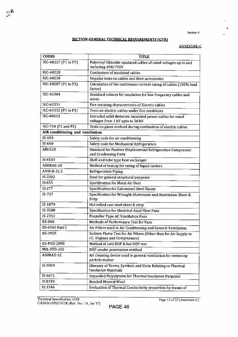
Section-3
SECTION-GENERAL TECHNICAL REQUIREMENTS (GTR1
ANNEXURE-C
CODES TITLE IEC-60227 (P1 to P7) Polyvinyl Chloride insulated cables of rated voltages up to and
including 450/750V
IEC-60228 Conductors of insulated cables
IEC-60230 Impulse tests on cables and their accessories
IEC-60287 (P1 to P3) Calculation of the continuous current rating of cables (100% load factor)
IEC-60304 Standard colours for insulation for low-frequency cables and wires
IEC-60331 Fire resisting characteristics of Electric cables
IEC-60332 (P1 to P3) Tests on electric cables under fire conditions
IEC-60502 Extruded solid dielectric insulated power cables for rated voltages from 1 kV upto to 30 kV
IEC-754 (P1 and P2) Tests on gases evolved during combustion of electric cables AIR conditioning and ventilation
IS-659 Safety code for air conditioning IS-660 Safety code for Mechanical Refrigeration
ARI:520 Standard for Positive Displacement Refrigeration Compressor and Condensing Units
IS:4503 Shell and tube type heat exchanger
ASHRAE-24 Method of testing for rating of liquid coolers
ANSI-B-31.5 Refrigeration Piping
IS:2062 Steel for general structural purposes IS:655 Specification for Metal Air Dust
IS:277 Specification for Galvanised Steel Sheets IS-737 Specification for Wrought Aluminium and Aluminium Sheet &
Strip
IS-1079 Hot rolled cast steel sheet & strip
IS-3588 Specification for Electrical Axial Flow Fans IS-2312 Propeller Type AC Ventilation Fans BS-848 Methods of Performance Test for Fans
BS-6540 Part-I Air Filters used in Air Conditioning and General Ventilation BS-3928 Sodium Flame Test for Air Filters (Other than for Air Supply to
I.C. Engines and Compressors)
US-PED-2098 Method of cold DOP & hot DOP test
MIL-STD-282 DOP smoke penetration method
ASHRAE-52 Air cleaning device used in general ventilation for removing particle matter
IS:3069 Glossary of Terms, Symbols and Units Relating to Thermal Insulation Materials
IS:4671 Expanded Polystyrene for Thermal Insulation Purposes IS:8183 Bonded Mineral Wool
IS:3346 Evaluation of Thermal Conductivity properties by means of
Technical Specification: GTR
Page 12 of 23 (Annexure-C) C/ENGG/SPEC/GTR (Rev. No.:-14, Jan'17)
PAGE 46
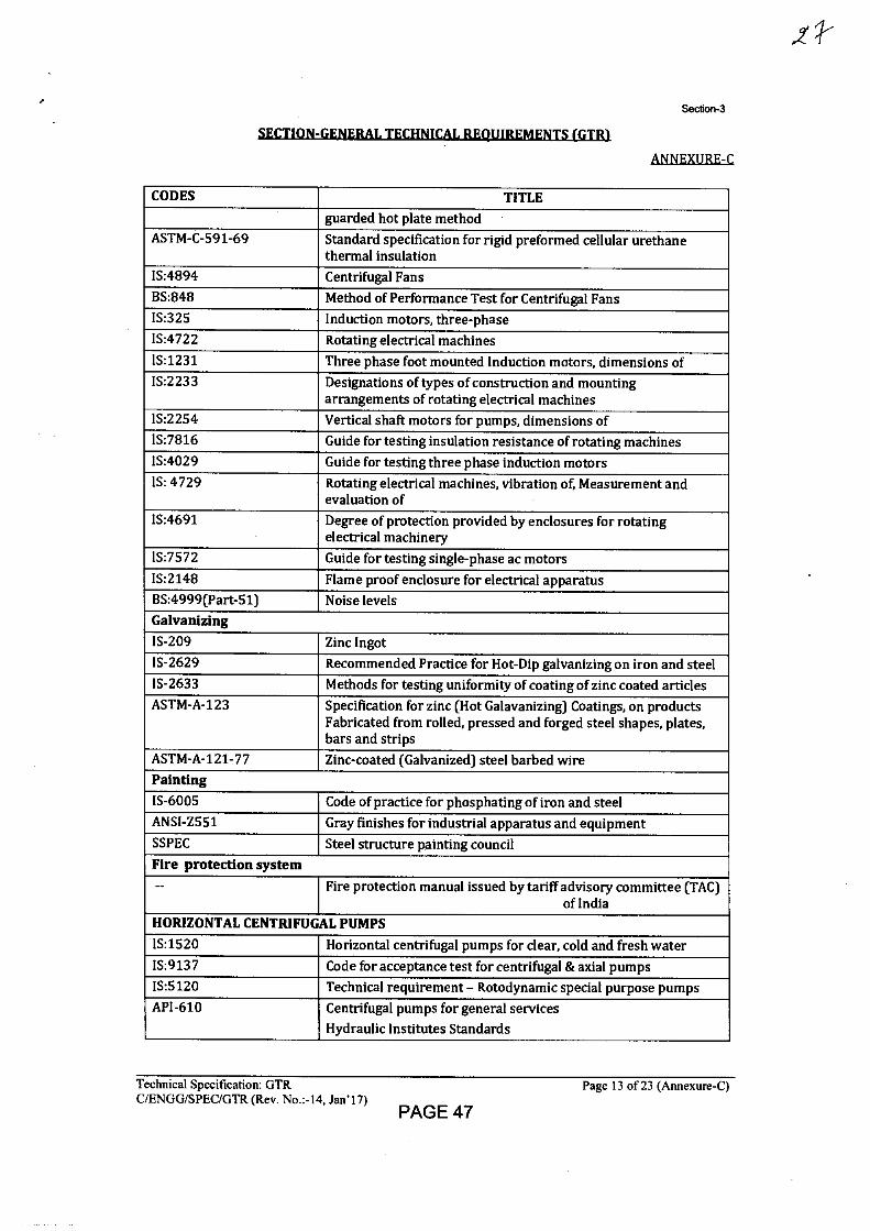
.z*
Section-3
SECTION-GENERAL TECHNICAL REQUIREMENTS (GTR)
ANNEXURE-C
CODES TITLE guarded hot plate method
ASTM-C-591-69 Standard specification for rigid preformed cellular urethane thermal insulation
IS:4894 Centrifugal Fans BS:848 Method of Performance Test for Centrifugal Fans IS:325 Induction motors, three-phase IS:4722 Rotating electrical machines IS:1231 Three phase foot mounted Induction motors, dimensions of IS:2233 Designations of types of construction and mounting
arrangements of rotating electrical machines IS:2254 Vertical shaft motors for pumps, dimensions of IS:7816 Guide for testing insulation resistance of rotating machines IS:4029 Guide for testing three phase induction motors IS: 4729 Rotating electrical machines, vibration of, Measurement and
evaluation of IS:4691 Degree of protection provided by enclosures for rotating
electrical machinery IS:7572 Guide for testing single-phase ac motors IS:2148 Flame proof enclosure for electrical apparatus BS:4999(Part-51) Noise levels Galvanizing IS-209 Zinc Ingot IS-2629 Recommended Practice for Hot-Dip galvanizing on iron and steel IS-2633 Methods for testing uniformity of coating of zinc coated articles ASTM-A-123 Specification for zinc (Hot Galavanizing) Coatings, on products
Fabricated from rolled, pressed and forged steel shapes, plates, bars and strips
ASTM-A-121-77 Zinc-coated (Galvanized) steel barbed wire Painting IS-6005 Code of practice for phosphating of iron and steel ANSI-Z551 Gray finishes for industrial apparatus and equipment SSPEC Steel structure painting council Fire protection system
-- Fire protection manual issued by tariff advisory committee (TAC) of India
HORIZONTAL CENTRIFUGAL PUMPS IS:1520 Horizontal centrifugal pumps for clear, cold and fresh water IS:9137 Code for acceptance test for centrifugal & axial pumps IS:5120 Technical requirement - Rotodynamic special purpose pumps API-610 Centrifugal pumps for general services
Hydraulic Institutes Standards
Technical Specification: GTR
Page 13 of 23 (Annexure-C) C/ENGG/SPEC/GTR (Rev. No.:-14, Jan'17)
PAGE 47
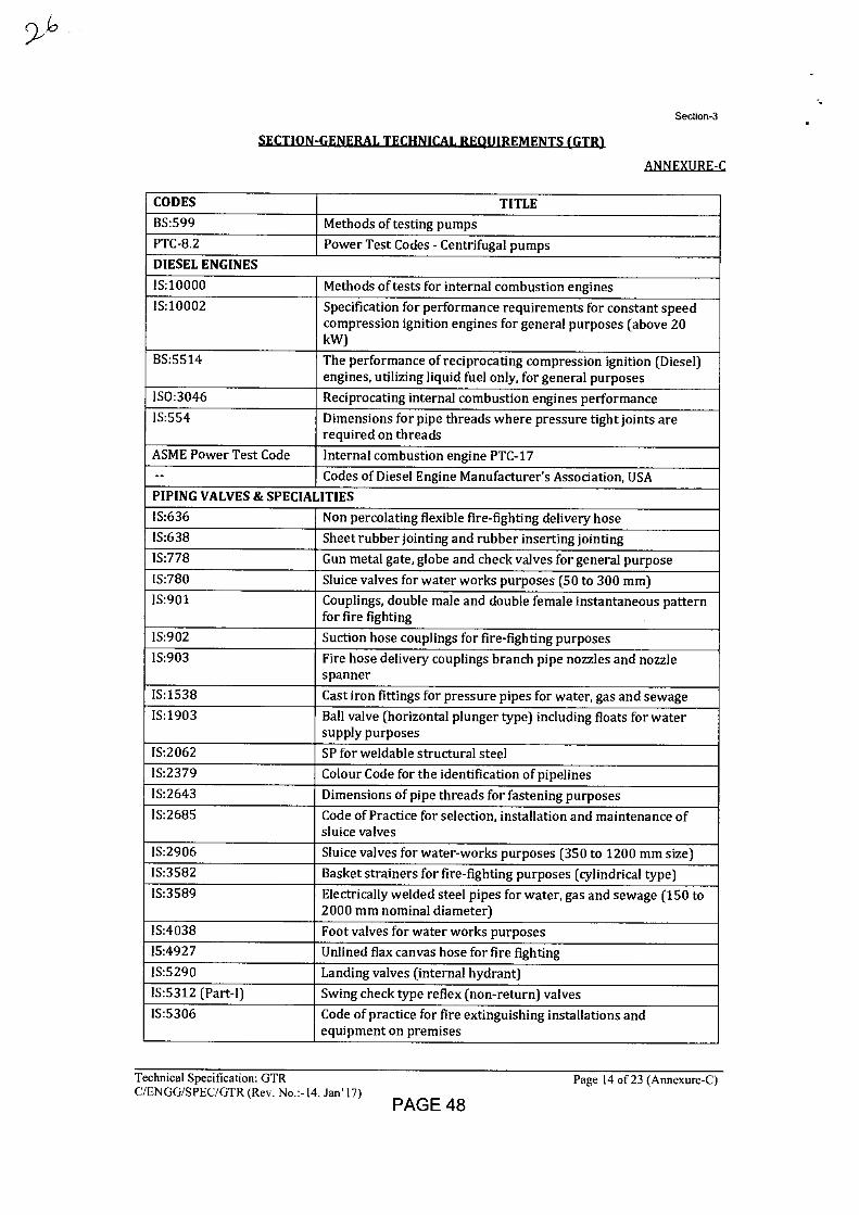
Section-3
SECTION-GENERAL TECHNICAL REQUIREMENTS (GTR)
ANNEXURE-C
CODES TITLE
BS:599 Methods of testing pumps
PTC-8.2 Power Test Codes - Centrifugal pumps
DIESEL ENGINES
IS:10000 Methods of tests for internal combustion engines
IS:10002 Specification for performance requirements for constant speed compression ignition engines for general purposes (above 20 kW)
BS:5514 The performance of reciprocating compression ignition (Diesel) engines, utilizing liquid fuel only, for general purposes
ISO:3046 Reciprocating internal combustion engines performance
IS:554 Dimensions for pipe threads where pressure tight joints are required on threads
ASME Power Test Code Internal combustion engine PTC-17
-- Codes of Diesel Engine Manufacturer's Association, USA
PIPING VALVES & SPECIALITIES
IS:636 Non percolating flexible fire-fighting delivery hose
IS:638 Sheet rubber jointing and rubber inserting jointing
IS:778 Gun metal gate, globe and check valves for general purpose
IS:780 Sluice valves for water works purposes (50 to 300 mm)
IS:901 Couplings, double male and double female instantaneous pattern for fire fighting
IS:902 Suction hose couplings for fire-fighting purposes
IS:903 Fire hose delivery couplings branch pipe nozzles and nozzle spanner
IS:1538 Cast iron fittings for pressure pipes for water, gas and sewage
IS:1903 Ball valve (horizontal plunger type) including floats for water supply purposes
IS:2062 SP for weldable structural steel
IS:2379 Colour Code for the identification of pipelines
IS:2643 Dimensions of pipe threads for fastening purposes
IS:2685 Code of Practice for selection, installation and maintenance of sluice valves
IS:2906 Sluice valves for water-works purposes (350 to 1200 mm size)
IS:3582 Basket strainers for fire-fighting purposes (cylindrical type)
IS:3589 Electrically welded steel pipes for water, gas and sewage (150 to 2000 mm nominal diameter)
IS:4038 Foot valves for water works purposes
IS:4927 Unlined flax canvas hose for fire fighting
IS:5290 Landing valves (internal hydrant)
IS:5312 (Part-I) Swing check type reflex (non-return) valves
IS:5306 Code of practice for fire extinguishing installations and equipment on premises
Technical Specification: GTR
Page 14 of 23 (Annexure-C) C/ENGG/SPEC/GTR (Rev. No.:-14, Jan'17)
PAGE 48
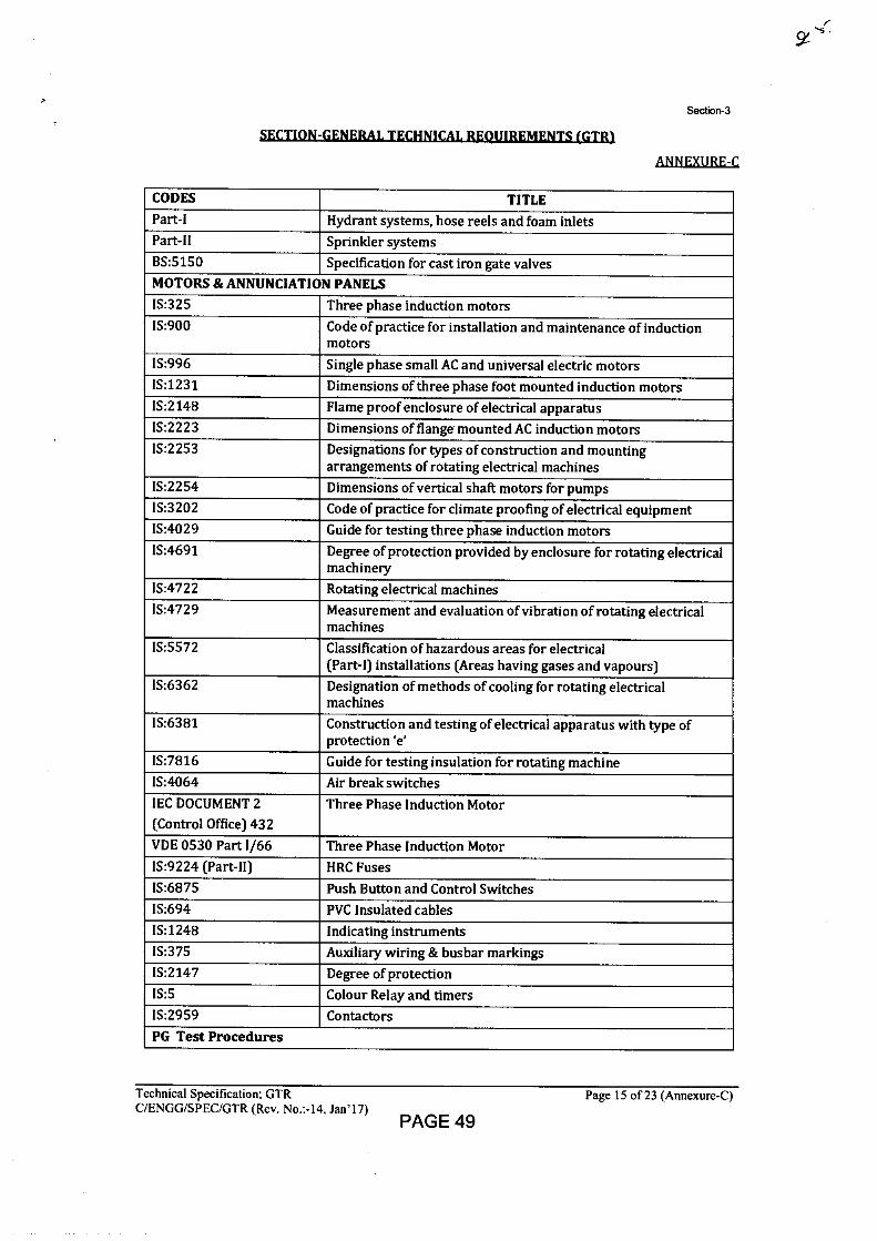
Section-3
SECTION-GENERAL TECHNICAL REQUIREMENTS (GTR)
ANNEXURE-C
CODES TITLE Part-I Hydrant systems, hose reels and foam inlets Part-II Sprinkler systems BS:5150 Specification for cast iron gate valves MOTORS & ANNUNCIATION PANELS IS:325 Three phase induction motors IS:900 Code of practice for installation and maintenance of induction
motors IS:996 Single phase small AC and universal electric motors 1S:1231 Dimensions of three phase foot mounted induction motors IS:2148 Flame proof enclosure of electrical apparatus IS:2223 Dimensions of flange mounted AC induction motors IS:2253 Designations for types of construction and mounting
arrangements of rotating electrical machines IS:2254 Dimensions of vertical shaft motors for pumps 1S:3202 Code of practice for climate proofing of electrical equipment IS:4029 Guide for testing three phase induction motors IS:4691 Degree of protection provided by enclosure for rotating electrical
machinery 1S:4722 Rotating electrical machines 1S:4729 Measurement and evaluation of vibration of rotating electrical
machines IS:5572 Classification of hazardous areas for electrical
(Part-I) installations (Areas having gases and vapours) IS:6362 Designation of methods of cooling for rotating electrical
machines 1S:6381 Construction and testing of electrical apparatus with type of
protection 'e' IS:7816 Guide for testing insulation for rotating machine IS:4064 Air break switches
IEC DOCUMENT 2 (Control Office) 432
Three Phase Induction Motor
VDE 0530 Part 1/66 Three Phase Induction Motor IS:9224 (Part-11) HRC Fuses IS:6875 Push Button and Control Switches IS:694 PVC Insulated cables IS:1248 Indicating instruments 1S:375 Auxiliary wiring & busbar markings IS:2147 Degree of protection 1S:5 Colour Relay and timers 1S:2959 Contactors PG Test Procedures
Technical Specification: GTR
Page 15 of 23 (Annexure-C) C/ENGG/SPEC/GTR (Rev. No.:-14, Jan'17)
PAGE 49
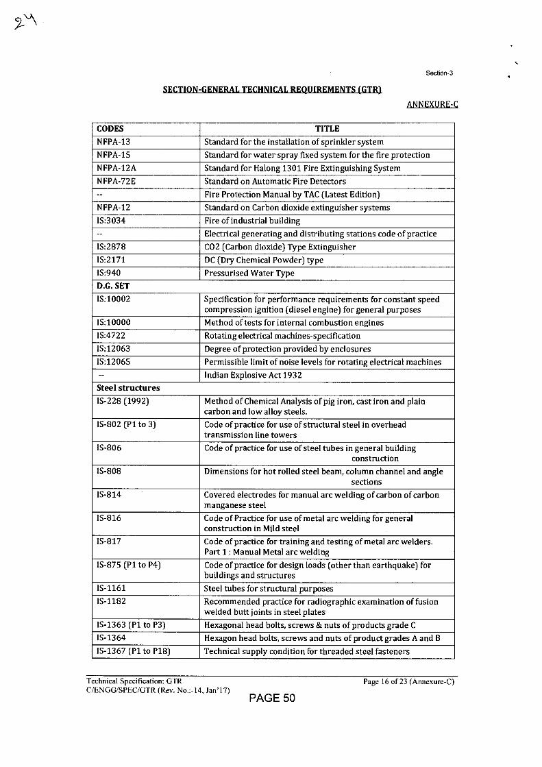
Section-3
SECTION-GENERAL TECHNICAL REQUIREMENTS (GTR)
ANNEXURE-C
CODES TITLE
NFPA-13 Standard for the installation of sprinkler system
NFPA-15 Standard for water spray fixed system for the fire protection
NFPA-12A Standard for Halong 1301 Fire Extinguishing System
NFPA-72E Standard on Automatic Fire Detectors
-- Fire Protection Manual by TAC (Latest Edition)
NFPA-12 Standard on Carbon dioxide extinguisher systems
IS:3034 Fire of industrial building
-- Electrical generating and distributing stations code of practice
IS:2878 CO2 (Carbon dioxide) Type Extinguisher
IS:2171 DC (Dry Chemical Powder) type
IS:940 Pressurised Water Type
D.G. SET
IS:10002 Specification for performance requirements for constant speed compression ignition (diesel engine) for general purposes
IS:10000 Method of tests for internal combustion engines
IS:4722 Rotating electrical machines-specification
IS:12063 Degree of protection provided by enclosures
IS:12065 Permissible limit of noise levels for rotating electrical machines
-- Indian Explosive Act 1932
Steel structures
IS-228 (1992) Method of Chemical Analysis of pig iron, cast iron and plain carbon and low alloy steels.
IS-802 (P1 to 3) Code of practice for use of structural steel in overhead transmission line towers
IS-806 Code of practice for use of steel tubes in general building construction
IS-808 Dimensions for hot rolled steel beam, column channel and angle sections
IS-814 Covered electrodes for manual arc welding of carbon of carbon manganese steel
IS-816 Code of Practice for use of metal arc welding for general construction in Mild steel
IS-817 Code of practice for training and testing of metal arc welders. Part 1 : Manual Metal arc welding
1S-875 (P1 to P4) Code of practice for design loads (other than earthquake) for buildings and structures
IS-1161 Steel tubes for structural purposes
IS-1182 Recommended practice for radiographic examination of fusion welded butt joints in steel plates
IS-1363 (P1 to P3) Hexagonal head bolts, screws & nuts of products grade C
IS-1364 Hexagon head bolts, screws and nuts of product grades A and B
IS-1367 (P1 to P18) Technical supply condition for threaded steel fasteners
Technical Specification: GTR
Page 16 of 23 (Annexure-C) C/ENGG/SPEC/GTR (Rev. No.:-I4, Jan'17)
PAGE 50
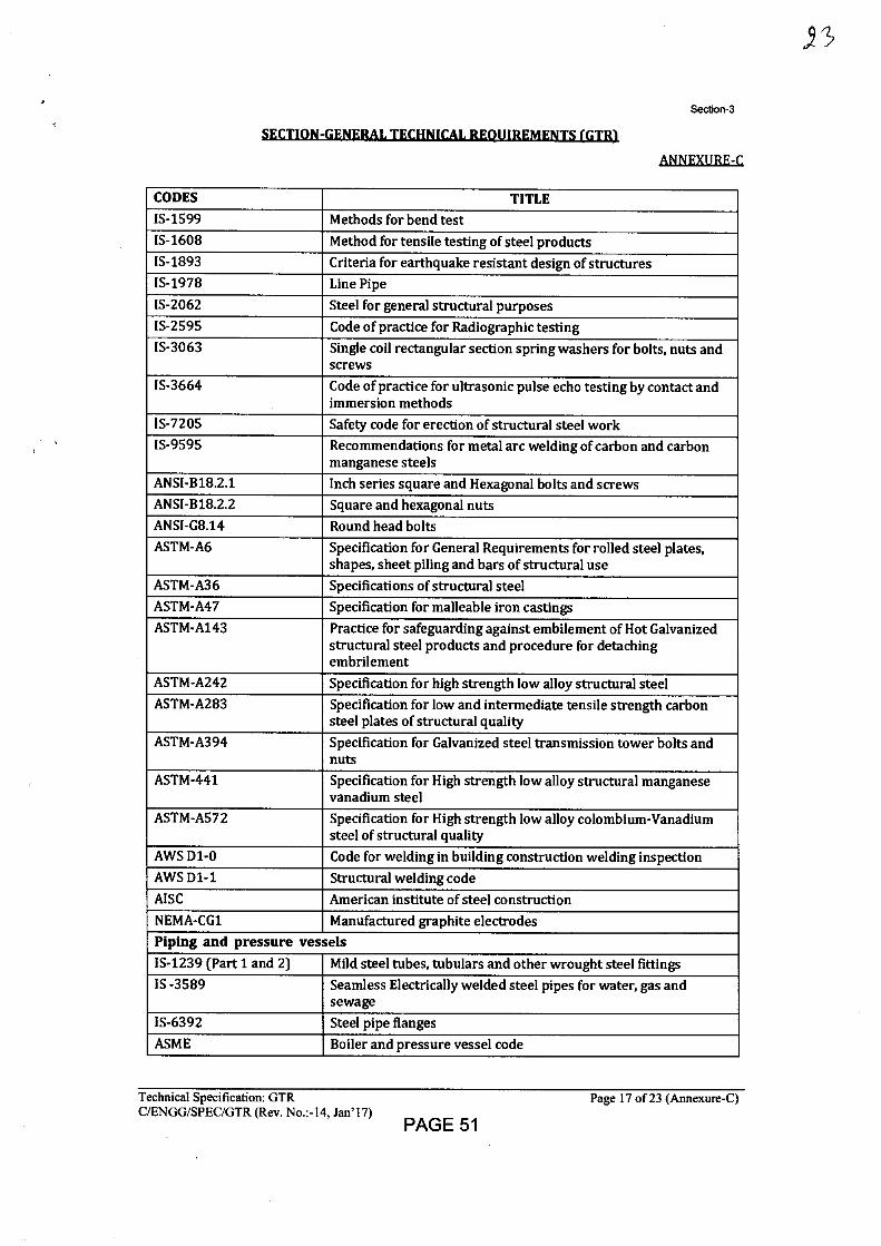
Section-3
SECTION-GENERAL TECHNICAL REOUIREMENTS (GTR)
AkINEXURE-C
CODES TITLE IS-1599 Methods for bend test IS-1608 Method for tensile testing of steel products IS-1893 Criteria for earthquake resistant design of structures IS-1978 Line Pipe
IS-2062 Steel for general structural purposes IS-2595 Code of practice for Radiographic testing IS-3063 Single coil rectangular section spring washers for bolts, nuts and
screws
IS-3664 Code of practice for ultrasonic pulse echo testing by contact and immersion methods
IS-7205 Safety code for erection of structural steel work IS-9595 Recommendations for metal arc welding of carbon and carbon
manganese steels ANSI-B18.2.1 Inch series square and Hexagonal bolts and screws ANSI-B18.2.2 Square and hexagonal nuts ANSI-G8.14 Round head bolts ASTM-A6 Specification for General Requirements for rolled steel plates,
shapes, sheet piling and bars of structural use
ASTM-A36 Specifications of structural steel ASTM-A47 Specification for malleable iron castings ASTM-A143 Practice for safeguarding against embilement of Hot Galvanized
structural steel products and procedure for detaching embrilement
ASTM-A242 Specification for high strength low alloy structural steel ASTM-A283 Specification for low and intermediate tensile strength carbon
steel plates of structural quality
ASTM-A394 Specification for Galvanized steel transmission tower bolts and nuts
ASTM-441 Specification for High strength low alloy structural manganese vanadium steel
ASTM-A572 Specification for High strength low alloy colombium-Vanadium steel of structural quality
AWS D1-0 Code for welding in building construction welding inspection
AWS D1-1 Structural welding code
AISC American institute of steel construction
NEMA-CG1 Manufactured graphite electrodes
Piping and pressure vessels IS-1239 (Part 1 and 2) Mild steel tubes, tubulars and other wrought steel fittings IS -3589 Seamless Electrically welded steel pipes for water, gas and
sewage
IS-6392 Steel pipe flanges
ASME Boiler and pressure vessel code
,93
Technical Specification: GTR
Page 17 of 23 (Annexure-C) C/ENGG/SPEC/GTR (Rev. No.:-14, lan'17)
PAGE 51
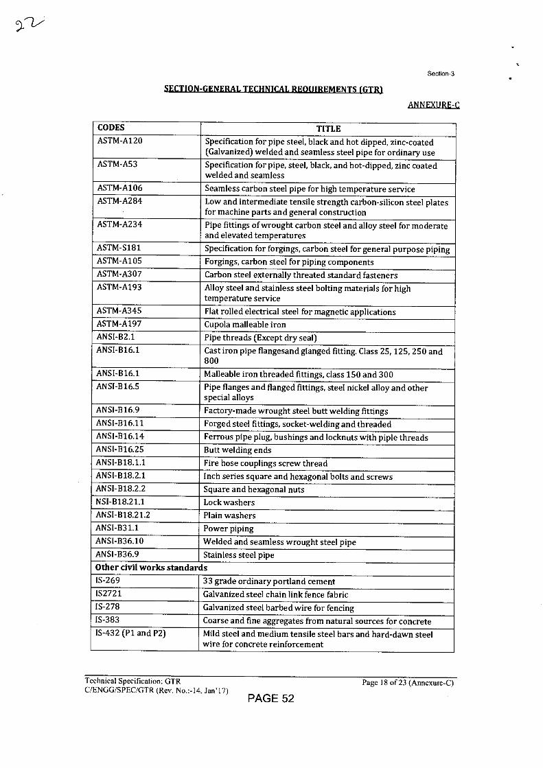
Section-3
IL u
ANNEXURE-C
CODES TITLE ASTM-A120 Specification for pipe steel, black and hot dipped, zinc-coated
(Galvanized) welded and seamless steel pipe for ordinary use ASTM-A53 Specification for pipe, steel, black, and hot-dipped, zinc coated
welded and seamless ASTM-A106 Seamless carbon steel pipe for high temperature service ASTM-A284 Low and intermediate tensile strength carbon-silicon steel plates
for machine parts and general construction ASTM-A234 Pipe fittings of wrought carbon steel and alloy steel for moderate
and elevated temperatures ASTM-S181 Specification for forgings, carbon steel for general purpose piping ASTM-A105 Forgings, carbon steel for piping components ASTM-A307 Carbon steel externally threated standard fasteners ASTM-A193 Alloy steel and stainless steel bolting materials for high
temperature service ASTM-A345 Flat rolled electrical steel for magnetic applications ASTM-A197 Cupola malleable iron ANSI-B2.1 Pipe threads (Except dry seal) ANSI-816.1 Cast iron pipe flangesand glanged fitting. Class 25, 125, 250 and
800 ANSI-B16.1 Malleable iron threaded fittings, class 150 and 300 ANSI-B16.5 Pipe flanges and flanged fittings, steel nickel alloy and other
special alloys ANSI-B16.9 Factory-made wrought steel butt welding fittings ANSI-B16.11 Forged steel fittings, socket-welding and threaded ANSI-B16.14 Ferrous pipe plug, bushings and locknuts with piple threads ANSI-B16.25 Butt welding ends ANSI-818.1.1 Fire hose couplings screw thread ANSI-B18.2.1 Inch series square and hexagonal bolts and screws ANSI-B18.2.2 Square and hexagonal nuts NSI-B18.21.1 Lock washers ANSI-B18.21.2 Plain washers ANSI-B31.1 Power piping ANSI-B36.10 Welded and seamless wrought steel pipe ANSI-B36.9 Stainless steel pipe Other civil works standards 1S-269 33 grade ordinary portland cement 1S2721 Galvanized steel chain link fence fabric 1S-278 Galvanized steel barbed wire for fencing IS-383 Coarse and fine aggregates from natural sources for concrete IS-432 (P1 and P2) Mild steel and medium tensile steel bars and hard-dawn steel
wire for concrete reinforcement
Technical Specification: GTR C/ENGG/SPEC/GTR (Rev. No.:-14, Jan'17)
Page 18 of 23 (Annexure-C)
PAGE 52
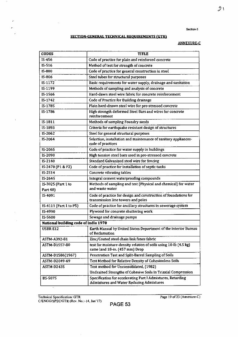
Section-3
SECTION-GENERAL TECHNICAL REQUIREMENTS (GTR).
ANNEXURE-C
CODES TITLE IS-456 Code of practice for plain and reinforced concrete
IS-516 Method of test for strength of concrete
IS-800 Code of practice for general construction in steel
IS-806 Steel tubes for structural purposes
IS-1172 Basic requirements for water supply, drainage and sanitation
IS-1199 Methods of sampling and analysis of concrete
IS-1566 Hard-dawn steel wire fabric for concrete reinforcement
IS-1742 Code of Practice for Building drainage
IS-1785 Plain hard-drawn steel wire for pre-stressed concrete
IS-1786 High strength deformed Steel Bars and wires for concrete reinforcement
IS-1811 Methods of sampling Foundry sands
IS-1893 Criteria for earthquake resistant design of structures
IS-2062 Steel for general structural purposes
IS-2064 Selection, installation and maintenance of sanitary appliances-code of practices
IS-2065 Code of practice for water supply in buildings
IS-2090 High tension steel bars used in pre-stressed concrete
IS-2140 Standard Galvanized steel wire for fencing
IS-2470 (P1 & P2) Code of practice for installation of septic tanks
IS-2514 Concrete vibrating tables
IS-2645 Integral cement waterproofing compounds
IS-3025 (Part 1 to Part 48)
Methods of sampling and test (Physical and chemical) for water and waste water
IS-4091 Code of practice for design and construction of foundations for transmission line towers and poles
IS-4111 (Part 1 to P5) Code of practice for ancillary structures in sewerage system
IS-4990 Plywood for concrete shuttering work
IS-5600 Sewage and drainage pumps
National building code of India 1970
USBR E12 Earth Manual by United States Department of the interior Bureau. of Reclamation
ASTM-A392-81 Zinc/Coated steel chain link fence fabric
ASTM-D1557-80 test for moisture-density relation of soils using 10-lb (4.5 kg) rame land 18-in. (457 mm) Drop
ASTM-D1586(1967) Penetration Test and Split-Barrel Sampling of Soils
ASTM-D2049-69 Test Method for Relative Density of Cohesionless Soils
ASTM-D2435 Test method for Unconsolidated, (1982) Undrained Strengths of Cohesive Soils in Triaxial Compression
BS-5075 Specification for accelerating Part I Admixtures, Retarding Admixtures and Water Reducing Admixtures
Technical Specification: GTR
Page 19 of 23 (Annexure-C) C/ENGG/SPEC/GTR (Rev. No.:-14, Jan'17)
PAGE 53
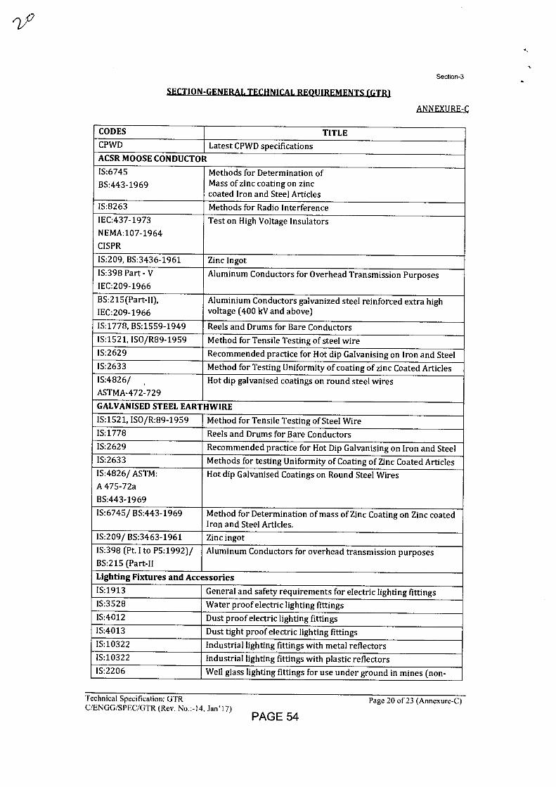
Section-3
SECTION-GENERAL TECHNICAL REQUIREMENTS (GTR)
AN NEXURE-I
CODES TITLE CPWD Latest CPWD specifications
ACSR MOOSE CONDUCTOR
IS:6745
BS:443-1969 Methods for Determination of Mass of zinc coating on zinc coated Iron and Steel Articles
IS:8263 Methods for Radio Interference IEC:437-1973
NEMA:107-1964
CISPR
Test on High Voltage Insulators
IS:209, BS:3436-1961 Zinc Ingot
IS:398 Part - V
IEC:209-1966 Aluminum Conductors for Overhead Transmission Purposes
BS:215(Part-II),
IEC:209-1966 Aluminium Conductors galvanized steel reinforced extra high voltage (400 kV and above)
IS:1778, BS:1559-1949 Reels and Drums for Bare Conductors IS:1521, ISO/R89-1959 Method for Tensile Testing of steel wire IS:2629 Recommended practice for Hot dip Galvanising on Iron and Steel IS:2633 Method for Testing Uniformity of coating of zinc Coated Articles IS:4826/
ASTMA-472-729 Hot dip galvanised coatings on round steel wires
GALVANISED STEEL EARTHWIRE
IS:1521, ISO/R:89-1959 Method for Tensile Testing of Steel Wire IS:1778 Reels and Drums for Bare Conductors IS:2629 Recommended practice for Hot Dip Galvanising on Iron and Steel IS:2633 Methods for testing Uniformity of Coating of Zinc Coated Articles IS:4826/ ASTM:
A 475-72a
BS:443-1969
Hot dip Galvanised Coatings on Round Steel Wires
IS:6745/ BS:443-1969 Method for Determination of mass of Zinc Coating on Zinc coated Iron and Steel Articles.
IS:209/ BS:3463-1961 Zinc ingot
IS:398 (Pt. Ito P5:1992)/
BS:215 (Part-II Aluminum Conductors for overhead transmission purposes
Lighting Fixtures and Accessories
IS:1913 General and safety requirements for electric lighting fittings IS:3528 Water proof electric lighting fittings IS:4012 Dust proof electric lighting fittings IS:4013 Dust tight proof electric lighting fittings IS:10322 Industrial lighting fittings with metal reflectors IS:10322 Industrial lighting fittings with plastic reflectors IS:2206 Well glass lighting fittings for use under ground in mines (non-
Technical Specification: GTR C/ENGG/SPEC/GTR (Rev. No 14, Jan' 17)
PAGE 54
Page 20 of 23 (Annexure-C)
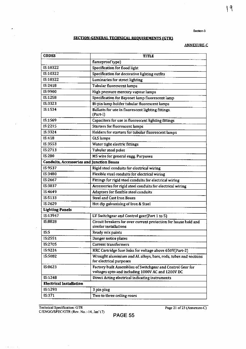
Section-3
SECTION-GENERAL TECHNICAL REQUIREMENTS (GTR1
ANEEXURLC
CODES TITLE flameproof type)
IS:10322 Specification for flood light IS:10322 Specification for decorative lighting outfits IS:10322 Luminaries for street lighting IS:2418 Tubular fluorescent lamps IS:9900 High pressure mercury vapour lamps IS:1258 Specification for Bayonet lamp fluorescent lamp IS:3323 Bi-pin lamp holder tubular fluorescent lamps IS:1534 Ballasts for use in fluorescent lighting fittings.
(Part-I) IS:1569 Capacitors for use in fluorescent lighting fittings IS:2215 Starters for fluorescent lamps IS:3324 Holders for starters for tubular fluorescent lamps IS:418 GLS lamps IS:3553 Water tight electric fittings IS:2713 Tubular steel poles IS:280 MS wire for general engg. Purposes Conduits, Accessories and Junction Boxes IS:9537 Rigid steel conduits for electrical wiring IS:3480 Flexible steel conduits for electrical wiring IS:2667 Fittings for rigid steel conduits for electrical wiring IS:3837 Accessories for rigid steel conduits for electrical wiring IS:4649 Adaptors for flexible steel conduits IS:5133 Steel and Cast Iron Boxes IS:2629 Hot dip galvanising of Iron & Steel Lighting Panels IS:13947 LV Switchgear and Control gear(Part 1 to 5) IS:8828 Circuit breakers for over current protection for house hold and
similar installations IS:5 Ready mix paints IS:2551 Danger notice plates IS:2705 Current transformers IS:9224 HRC Cartridge fuse links for voltage above 650V(Part-2) IS:5082 Wrought aluminium and Al. alloys, bars, rods, tubes and sections
for electrical purposes IS:8623 Factory built Assemblies of Switchgear and Control Gear for
voltages upto and including 1000V AC and 1200V DC IS:1248 Direct Acting electrical indicating instruments Electrical Installation IS:1293 3 pin plug IS:371 Two to three ceiling roses
I cl
Technical Specification: GTR
Page 21 of 23 (Annexure-C) C/ENGG/SPEC/GTR (Rev. No.:-14, Jan'17)
PAGE 55
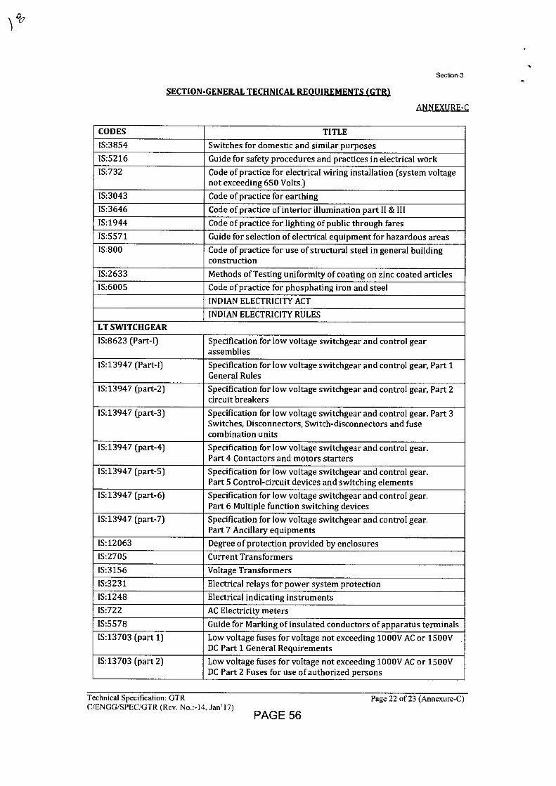
Section-3
SECTION-GENERAL TECHNICAL REQUIREMENTS (GTR)
ANNEXURE-C
CODES TITLE
IS:3854 Switches for domestic and similar purposes
IS:5216 Guide for safety procedures and practices in electrical work
IS:732 Code of practice for electrical wiring installation (system voltage not exceeding 650 Volts.)
IS:3043 Code of practice for earthing
IS:3646 Code of practice of interior illumination part II & III
1S:1944 Code of practice for lighting of public through fares
IS:5571 Guide for selection of electrical equipment for hazardous areas
IS:800 Code of practice for use of structural steel in general building construction
IS:2633 Methods of Testing uniformity of coating on zinc coated articles
IS:6005 Code of practice for phosphating iron and steel
INDIAN ELECTRICITY ACT
INDIAN ELECTRICITY RULES
LT SWITCHGEAR
IS:8623 (Part-I) Specification for low voltage switchgear and control gear assemblies
IS:13947 (Part-I) Specification for low voltage switchgear and control gear, Part 1 General Rules
IS:13947 (part-2) Specification for low voltage switchgear and control gear, Part 2 circuit breakers
IS:13947 (part-3) Specification for low voltage switchgear and control gear. Part 3 Switches, Disconnectors, Switch-disconnectors and fuse combination units
IS:13947 (part-4) Specification for low voltage switchgear and control gear. Part 4 Contactors and motors starters
IS:13947 (part-5) Specification for low voltage switchgear and control gear. Part 5 Control-circuit devices and switching elements
IS:13947 (part-6) Specification for low voltage switchgear and control gear. Part 6 Multiple function switching devices
IS:13947 (part-7) Specification for low voltage switchgear and control gear. Part 7 Ancillary equipments
IS:12063 Degree of protection provided by enclosures
IS:2705 Current Transformers
IS:3156 Voltage Transformers
IS:3231 Electrical relays for power system protection
IS:1248 Electrical indicating instruments
IS:722 AC Electricity meters
IS:5578 Guide for Marking of insulated conductors of apparatus terminals
IS:13703 (part 1) Low voltage fuses for voltage not exceeding 1000V AC or 1500V DC Part 1 General Requirements
IS:13703 (part 2) Low voltage fuses for voltage not exceeding 1000V AC or 1500V DC Part 2 Fuses for use of authorized persons
Technical Specification: GTR
Page 22 of 23 (Annexure-C) C/ENGG/SPEC/GTR (Rev. No.:-14, Jan'17)
PAGE 56
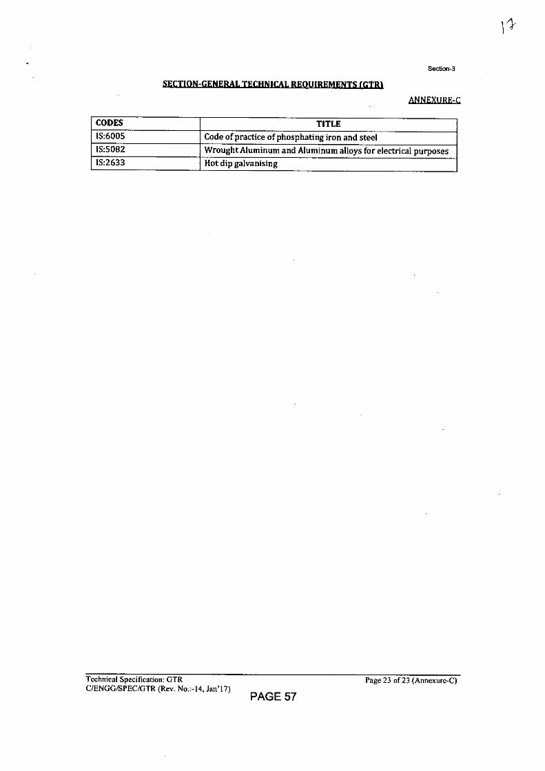
Section-3
ANNEXILIIE:L
CODES TITLE
IS:6005 Code of practice of phosphating iron and steel IS:5082 Wrought Aluminum and Aluminum alloys for electrical purposes IS:2633 Hot dip galvanising
11'
Technical Specification: GTR Page 23 of 23 (Annexure-C) C/ENGG/SPEC/GTR (Rev. No.:-14, Jan'17)
PAGE 57
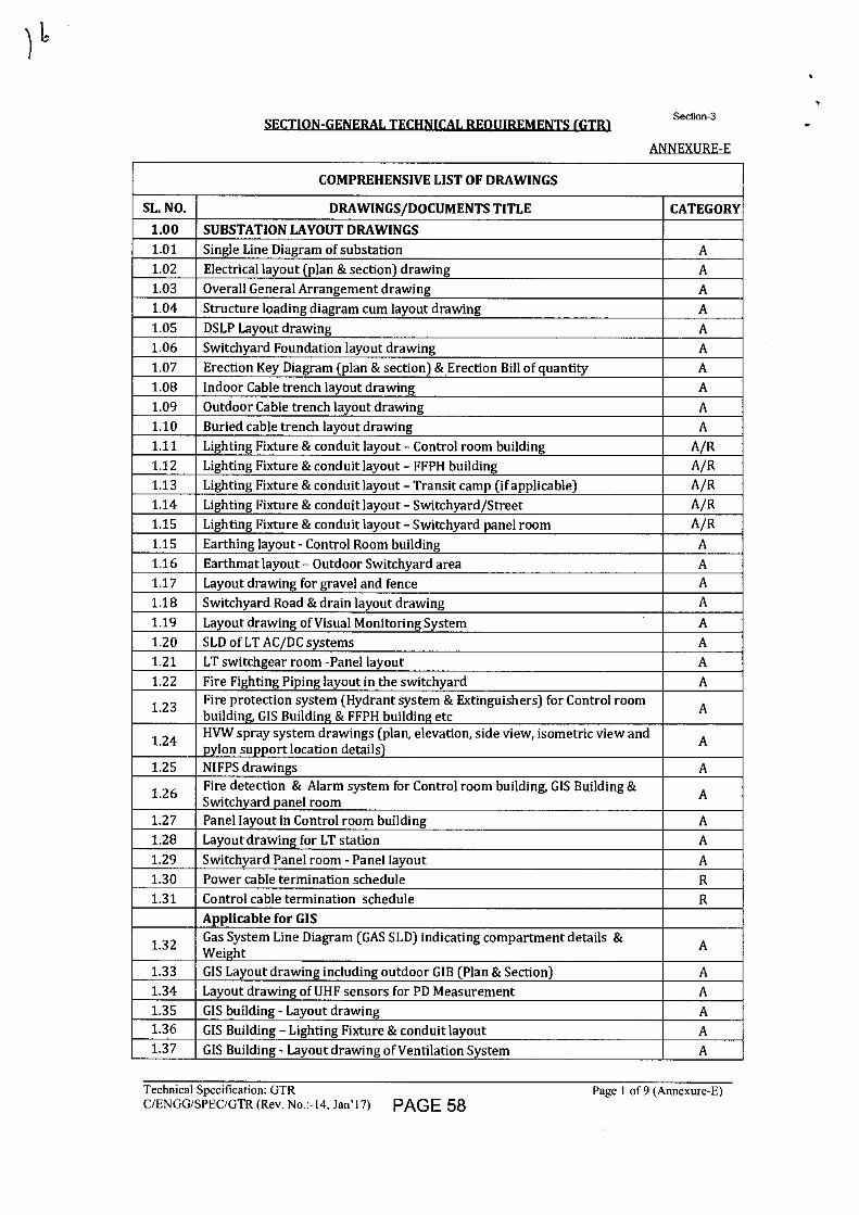
SECTION-GENERAL TECHNICAL REQUIREMENTS (GTR1 Section-3
ANNEXURE-E
COMPREHENSIVE LIST OF DRAWINGS
SL. NO. DRAWINGS/DOCUMENTS TITLE CATEGORY 1.00 SUBSTATION LAYOUT DRAWINGS 1.01 Single Line Diagram of substation A 1.02 Electrical layout (plan & section) drawing A 1.03 Overall General Arrangement drawing A 1.04 Structure loading diagram cum layout drawing A 1.05 DSLP Layout drawing A 1.06 Switchyard Foundation layout drawing A 1.07 Erection Key Diagram (plan & section) & Erection Bill of quantity A 1.08 Indoor Cable trench layout drawing A 1.09 Outdoor Cable trench layout drawing A 1.10 Buried cable trench layout drawing A 1.11 Lighting Fixture & conduit layout - Control room building A/R 1.12 Lighting Fixture & conduit layout - FFPH building A/R 1.13 Lighting Fixture & conduit layout - Transit camp (if applicable) A/R 1.14 Lighting Fixture & conduit layout - Switchyard/Street A/R 1.15 Lighting Fixture & conduit layout - Switchyard panel room A/R
1.15 Earthing layout - Control Room building A 1.16 Earthmat layout - Outdoor Switchyard area A 1.17 Layout drawing for gravel and fence A
1.18 Switchyard Road & drain layout drawing A
1.19 Layout drawing of Visual Monitoring System A 1.20 SLD of LT AC/DC systems A 1.21 LT switchgear room -Panel layout A 1.22 Fire Fighting Piping layout in the switchyard A
1.23 Fire protection system (Hydrant system & Extinguishers) for Control room building, GIS Building & FFPH building etc A
1.24 HVW spray system drawings (plan, elevation, side view, isometric view and pylon support location details) A
1.25 NIFPS drawings A
1.26 Fire detection & Alarm system for Control room building, GIS Building & Switchyard panel room A
1.27 Panel layout in Control room building A 1.28 Layout drawing for LT station A 1.29 Switchyard Panel room - Panel layout A 1.30 Power cable termination schedule R 1.31 Control cable termination schedule R
Applicable for GIS
1.32 Gas System Line Diagram (GAS SLD) indicating compartment details & Weight A
1.33 GIS Layout drawing including outdoor GIB (Plan & Section) A 1.34 Layout drawing of UHF sensors for PD Measurement A 1.35 GIS building - Layout drawing A 1.36 GIS Building - Lighting Fixture & conduit layout A 1.37 GIS Building - Layout drawing of Ventilation System A
Technical Specification: GTR
Page 1 of 9 (Annexure-E) C/ENGG/SPEC/GTR (Rev. No.:-14, Jan'17) PAGE 58
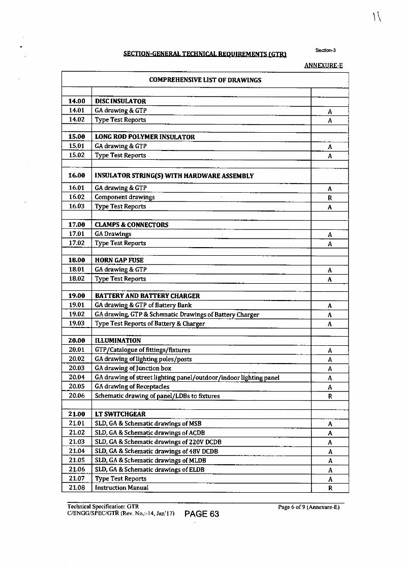
SECTION-GENERAL TECHNICAL REQUIREMENTS (GTRI Section-3
ANNEXURE-E
COMPREHENSIVE LIST OF DRAWINGS
14.00 DISC INSULATOR 14.01 GA drawing & GTP A 14.02 Type Test Reports A
15.00 LONG ROD POLYMER INSULATOR 15.01 GA drawing & GTP A 15.02 Type Test Reports A
16.00 INSULATOR STRING(S) WITH HARDWARE ASSEMBLY
16.01 GA drawing & GTP A 16.02 Component drawings R 16.03 Type Test Reports A
17.00 CLAMPS & CONNECTORS 17.01 GA Drawings A 17.02 Type Test Reports A
18.00 HORN GAP FUSE 18.01 GA drawing & GTP A 18.02 Type Test Reports A
19.00 BATTERY AND BATTERY CHARGER 19.01 GA drawing & GTP of Battery Bank A 19.02 GA drawing, GTP & Schematic Drawings of Battery Charger A 19.03 Type Test Reports of Battery & Charger A
20.00 ILLUMINATION 20.01 GTP/Catalogue of fittings/fixtures A 20.02 GA drawing of lighting poles/posts A 20.03 GA drawing of Junction box A 20.04 GA drawing of street lighting panel/outdoor/indoor lighting panel A 20.05 GA drawing of Receptacles A 20.06 Schematic drawing of panel/LDBs to fixtures R
21.00 LT SWITCHGEAR 21.01 SLD, GA & Schematic drawings of MSB A 21.02 SLD, GA & Schematic drawings of ACDB A 21.03 SLD, GA & Schematic drawings of 220V DCDB A 21.04 SLD, GA & Schematic drawings of 48V DCDB A 21.05 SLD, GA & Schematic drawings of MLDB A 21.06 SLD, GA & Schematic drawings of ELDB A 21.07 Type Test Reports A 21.08 Instruction Manual R
Technical Specification: GTR
Page 6 of 9 (Annexure-E) C/ENCrG/SPEC/GTR (Rev. No.:-14, Jan' 17) PAGE 63
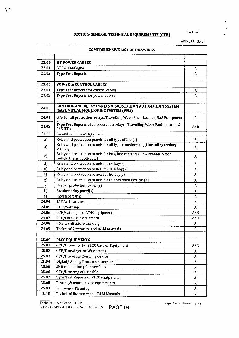
SECTION-GENERAL TECHNICAL REQUIREMENTS (GTR1 Section-3
ANNEXURE-E
COMPREHENSIVE LIST OF DRAWINGS
22.00 HT POWER CABLES 22.01 GTP & Catalogue A 22.02 Type Test Reports A
23.00 POWER & CONTROL CABLES 23.01 Type Test Reports for control cables A 23.02 Type Test Reports for power cables A
24.00 CONTROL AND RELAY PANELS & SUBSTATION AUTOMATION SYSTEM (SAS), VISUAL MONITORING SYSTEM (VMS)
24.01 GTP for all protection relays, Travelling Wave Fault Locator, SAS Equipment A
24.02 Type Test Reports of all protection relays , Travelling Wave Fault Locator & SAS IEDs A/R
24.03 GA and schematic drgs. for :- a) Relay and protection panels for all type of line(s) A
b) Relay and protection panels for all type transformer(s) including tertiary loading A
c) Relay and protection panels for bus/line reactor(s) (switchable & non-switchable as applicable) A
d) Relay and protection panels for tie bay(s) A e) Relay and protection panels for TBC bay(s) A f) Relay and protection panels for BC bay(s) A g) Relay and protection panels for Bus Sectionaliser bay(s) A h) Busbar protection panel (s) A i ) Breaker relay panel(s) A j) Interface panel A
24.04 SAS Architecture A 24.05 Relay Settings A 24.06 GTP/Catalogue of VMS equipment A/R 24.07 GTP/Catalogue of Camera A/R 24.08 VMS architecture drawing A 24.09 Technical Literature and O&M manuals R
25.00 PLCC EQUIPMENTS 25.01 GTP/Drawings for PLCC Carrier Equipment A/R 25.02 GTP/Drawings for Wave traps A 25.03 GTP/Drawings Coupling device A 25.04 Digital/ Analog Protection coupler A 25.05 SNR calculation (if applicable) R 25.06 GTP/Drawing of HE cable A 25.07 Type Test Reports of PLCC equipment A 25.08 Testing & maintenance equipments R 25.09 Frequency Planning A 25.10 Technical literature and O&M Manuals R
Technical Specification: GTR
Page 7 of 9 (Annexure-E) C/ENGG/SPEC/GTR (Rev. No.:-I4, Jan'17) PAGE 64
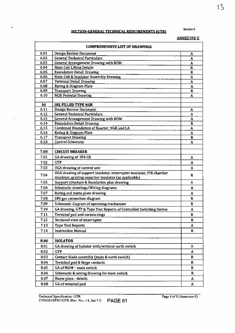
Section-3
ANNEXURE-E
COMPREHENSIVE LIST OF DRAWINGS
6.01 Design Review Document A 6.02 General Technical Particulars A 6.03 General Arrangement Drawing with BOM A 6.04 Main Coil Lifting Details R 6.05 Foundation Detail Drawing R 6.06 Main Coil & Insulator Assembly Drawing A 6.07 Terminal Detail Drawing A 6.08 Rating & Diagram Plate A 6.09 Transport Drawing R 6.10 NGR Pedestal Drawing A
b) OIL FILLED TYPE NGR 6.11 Design Review Document A 6.12 General Technical Particulars A 6.13 General Arrangement Drawing with BOM A 6.14 Foundation Detail Drawing R 6.15 Combined Foundation of Reactor, NGR and LA A 6.16 Rating & Diagram Plate A 6.17 Transport Drawing R 6.18 Control Schematic A
7.00 CIRCUIT BREAKER 7.01 GA drawing of SF6 CB A 7.02 GTP A 7.03 OGA drawing of control unit A
7.04 OGA drawing of support insulator, interrupter insulator, PIR chamber insulator, grading capacitor insulator (as applicable) R
7.05 Support structure & foundation plan drawing A 7.06 Schematic drawings/Wiring diagrams A 7.07 Rating and name plate drawing A 7.08 SF6 gas connection diagram R 7.09 Schematic diagram of operating mechanism R 7.10 GA drawing, GTP & Type Test Reports of Controlled Switching Device A 7.11 Terminal pad and corona rings R 7.12 Sectional view of interrupter R 7.13 Type Test Reports A 7.14 Instruction Manual R
8.00 ISOLATOR
8.01 GA drawing of Isolator with/without earth switch A 8.02 GTP A 8.03 Contact blade assembly (main & earth switch) R 8.04 Terminal pad & hinge contacts R 8.05 GA of MOM - main switch R 8.06 Schematic & wiring drawing for main switch R 8.07 Name plate - details A 8.08 GA of terminal pad A
Technical Specification: GTR
Page 4 of 9 (Annexure-E) C/ENGG/SPEC/GTR (Rev. No.:-14, Jan'17) PAGE 61
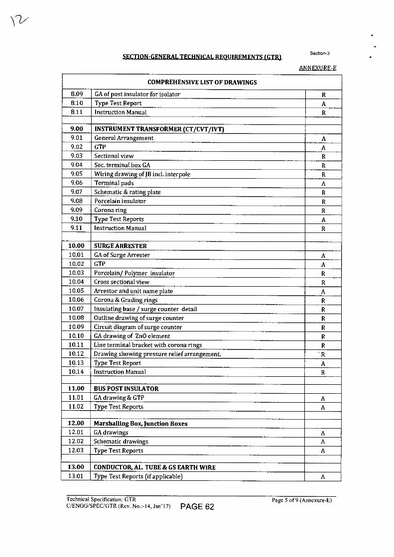
SECTION-GENERAL TECHNICAL_REQUIREMENTS (GTR1 Section-3
ANNEXURE-E
COMPREHENSIVE LIST OF DRAWINGS
8.09 GA of post insulator for isolator R 8.10 Type Test Report A 8.11 Instruction Manual R
9.00 INSTRUMENT TRANSFORMER (CT/CVT/IVT) 9.01 General Arrangement A 9.02 GTP A 9.03 Sectional view R 9.04 Sec. terminal box GA R 9.05 Wiring drawing of JB in interpole R 9.06 Terminal pads A 9.07 Schematic & rating plate R 9.08 Porcelain insulator R 9.09 Corona ring R 9.10 Type Test Reports A 9.11 Instruction Manual R
10.00 SURGE ARRESTER 10.01 GA of Surge Arrester A 10.02 GTP A 10.03 Porcelain/ Polymer insulator R 10.04 Cross sectional view R 10.05 Arrestor and unit name plate A 10.06 Corona & Grading rings R 10.07 Insulating base / surge counter detail R 10.08 Outline drawing of surge counter R 10.09 Circuit diagram of surge counter R 10.10 GA drawing of ZnO element R 10.11 Line terminal bracket with corona rings R 10.12 Drawing showing pressure relief arrangement. ' R 10.13 Type Test Report A 10.14 Instruction Manual R
11.00 BUS POST INSULATOR 11.01 GA drawing & GTP A 11.02 Type Test Reports A
12.00 Marshalling Box, Junction Boxes 12.01 GA drawings A 12.02 Schematic drawings A 12.03 Type Test Reports A
13.00 CONDUCTOR, AL. TUBE & GS EARTH WIRE 13.01 Type Test Reports (if applicable) A
Technical Specification: GTR
Page 5 of 9 (Annexure-E) C/ENGG/SPEC/GTR (Rev. No.:-14, Jan'17) PAGE 62
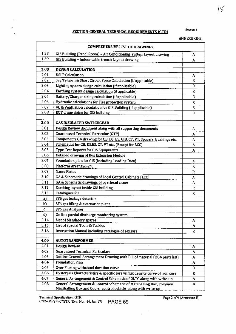
Section-3
ANNEXURE-E
COMPREHENSIVE LIST OF DRAWINGS
1.38 GIS Building (Panel Room) - Air Conditioning system layout drawing A 1.39 GIS Building - Indoor cable trench Layout drawing A
2.00 DESIGN CALCULATION 2.01 DSLP Calculation A 2.02 Sag Tension & Short Circuit Force Calculation (if applicable) R 2.03 Lighting system design calculation (if applicable) R 2.04 Earthing system design calculation (if applicable) R 2.05 Battery/Charger sizing calculation (if applicable) R 2.06 Hydraulic calculations for Fire protection system R 2.07 AC & Ventilation calculation for GIS Building (if applicable) R 2.08 EOT crane sizing for GIS building R
3.00 GAS INSULATED SWITCHGEAR 3.01 Design Review document along with all supporting documents A 3.02 Guaranteed Technical Particular (GTP) A 3.03 Components GA drawing for CB, DS, ES, GIB, CT, VT, Spacers, Bushings etc. A 3.04 Schematics for CB, DS,ES, CT, VT etc. (Except for LCC) A 3.05 Type Test Reports for GIS Equipments A 3.06 Detailed drawing of Bus Extension Module 3.07 Foundation plan for GIS (Including Loading Data) A 3.08 Platform Arrangement R 3.09 Name Plates R 3.10 GA & Schematic drawings of Local Control Cabinets (LCC) A 3.11 GA & Schematic drawings of overhead crane A 3.12 Earthing layout inside GIS building R 3.13 Catalogues for R a) SF6 gas leakage detector b) SF6 gas filling & evacuation plant c) SF6 gas Analyser d) On line partial discharge monitoring system
3.14 List of Mandatory spares A 3.15 List of Special Tools & Tackles A 3.16 Instruction Manual including catalogue of sensors R
4.00 AUTOTRANSFORMER 4.01 Design Review A 4.02 Guaranteed Technical Particulars A 4.03 Outline General Arrangement Drawing with Bill of material (OGA parts list) A 4.04 Foundation Plan A 4.05 Over Fluxing withstand duration curve R 4.06 Hysteresis Characteristics & specific loss vs flux density curve of iron core R 4.07 General Arrangement & Control Schematic of OLTC along with write-up A 4.08 General Arrangement & Control Schematic of Marshalling Box, Common
Marshalling Box and Cooler control cubicle along with write-up A
Technical Specification: GTR
Page 2 of 9 (Annexure-E) C/ENGG/SPEC/GTR (Rev. No.:-14, Jan'17) PAGE 59
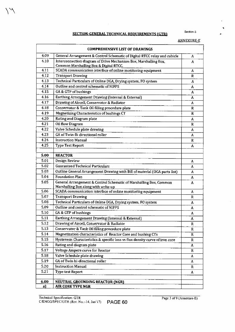
SECTION-GENERAL TECHNICAL REQUIREMENTS (GTR1 Section-3
ANNEXURE-E
COMPREHENSIVE LIST OF DRAWINGS
4.09 General Arrangement & Control Schematic of Digital RTCC relay and cubicle A 4.10 Interconnection diagram of Drive Mechanism Box, Marshalling Box,
Common Marshalling Box & Digital RTCC. A
4.11 SCADA communication interface of online monitoring equipment A 4.12 Transport Drawing R 4.13 Technical Particulars of Online DGA, Drying system, FO system A 4.14 Outline and control schematic of NIFPS A 4.15 GA & GTP of bushings A 4.16 Earthing Arrangement Drawing (Internal & External) A 4.17 Drawing of Aircell, Conservator & Radiator A 4.18 Conservator & Tank Oil filling procedure plate R 4.19 Magnetizing Characteristics of bushings CT R 4.20 Rating and Diagram plate A 4.21 Oil flow Diagram R 4.22 Valve Schedule plate drawing A 4.23 GA of Twin-Bi directional roller A 4.24 Instruction Manual R 4.25 Type Test Report A
5.00 REACTOR 5.01 Design Review A 5.02 Guaranteed Technical Particulars A 5.03 Outline General Arrangement Drawing with Bill of material (OGA parts list) A 5.04 Foundation Plan A 5.05 General Arrangement & Control Schematic of Marshalling Box, Common
Marshalling Box along with write-up A
5.06 SCADA communication interface of online monitoring equipment A 5.07 Transport Drawing R 5.08 Technical Particulars of Online DGA, Drying system, FO system A 5.09 Outline and control schematic of NIFPS A 5.10 GA & GTP of bushings A 5.11 Earthing Arrangement Drawing (Internal & External) A 5.12 Drawing of Aircell, Conservator & Radiator R 5.13 Conservator & Tank Oil filling procedure plate R 5.14 Magnetization characteristics of Reactor Core and bushing CTs R 5.15 Hysteresis Characteristics & specific loss vs flux density curve of iron core R 5.16 Rating and diagram plate A 5.17 Voltage Ampere curve for Reactor R 5.18 Valve Schedule plate drawing A 5.19 GA of Twin bi-directional roller A 5.20 Instruction Manual R 5.21 Type test Report A
6.00 NEUTRAL GROUNDING REACTOR (NGR) a) AIR CORE TYPE NGR
Technical Specification: GTR
Page 3 of 9 (Annexure-E) C/ENGG/SPEC/GTR (Rev. No.:-14, Jan' 17) PAGE 60
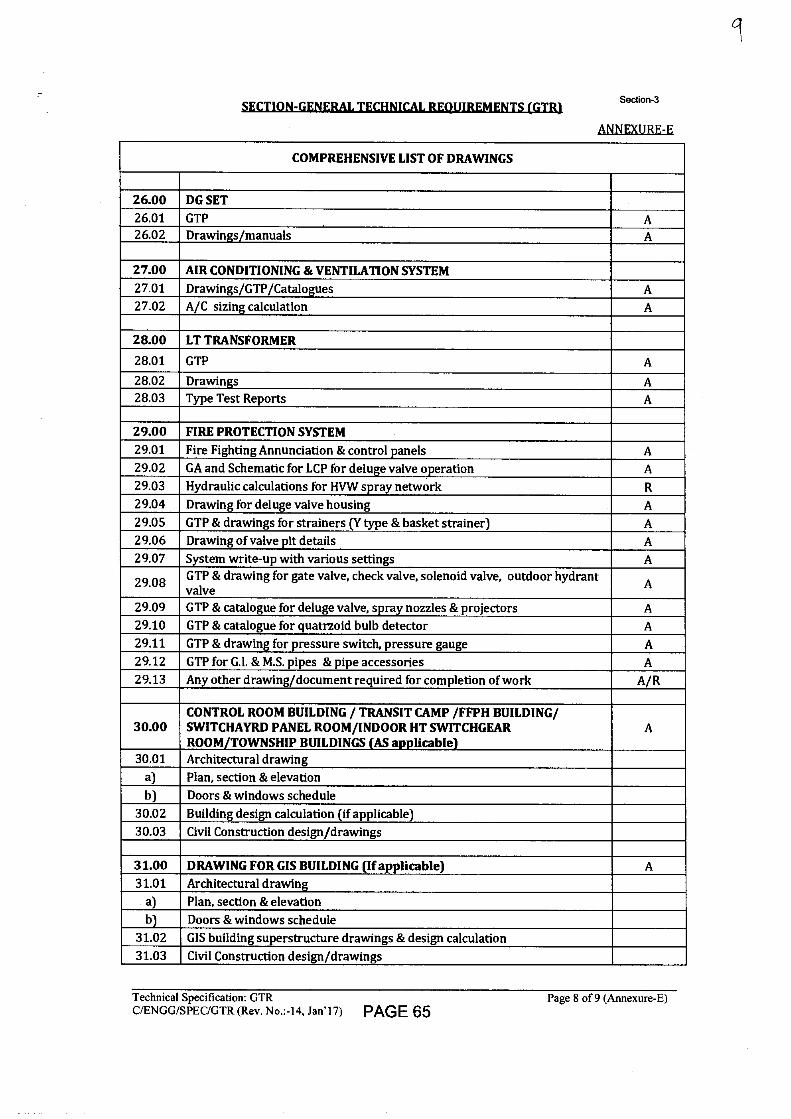
9
SECTION-GENERAL TECHNICAL REQUIREMENTS (GTR) Section-3
ANNEXURE-E
COMPREHENSIVE LIST OF DRAWINGS
26.00 DG SET 26.01 GTP A 26.02 Drawings/manuals A
27.00 AIR CONDITIONING & VENTILATION SYSTEM 27.01 Drawings/GTP/Catalogues A 27.02 A/C sizing calculation A
28.00 LT TRANSFORMER
28.01 GTP A 28.02 Drawings A 28.03 Type Test Reports A
29.00 FIRE PROTECTION SYSTEM 29.01 Fire Fighting Annunciation & control panels A 29.02 GA and Schematic for LCP for deluge valve operation A 29.03 Hydraulic calculations for HVW spray network R 29.04 Drawing for deluge valve housing A 29.05 GTP & drawings for strainers (Y type & basket strainer) A 29.06 Drawing of valve pit details A 29.07 System write-up with various settings A
29.08 GTP & drawing for gate valve, check valve, solenoid valve, outdoor hydrant valve A
29.09 GTP & catalogue for deluge valve, spray nozzles & projectors A 29.10 GTP & catalogue for quatrzoid bulb detector A 29.11 GTP & drawing for pressure switch, pressure gauge A 29.12 GTP for G.I. & M.S. pipes & pipe accessories A 29.13 Any other drawing/document required for completion of work A/R
30.00 CONTROL ROOM BUILDING / TRANSIT CAMP /FFPH BUILDING/ SWITCHAYRD PANEL ROOM/INDOOR HT SWITCHGEAR ROOM/TOWNSHIP BUILDINGS (AS applicable)
A
30.01 Architectural drawing a) Plan, section & elevation b) Doors & windows schedule
30.02 Building design calculation (if applicable) 30.03 Civil Construction design/drawings
31.00 DRAWING FOR GIS BUILDING (If applicable) A 31.01 Architectural drawing
a) Plan, section & elevation b) Doors & windows schedule
31.02 GIS building superstructure drawings & design calculation 31.03 Civil Construction design/drawings
Technical Specification: GTR
Page 8 of 9 (Annexure-E) C/ENGG/SPEC/GTR (Rev. No.:-14, Jan'17) PAGE 65
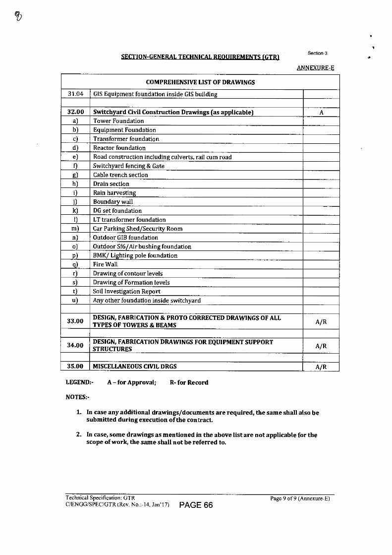
SECTION-GENERAL TECHNICAL REOUIREMENTS (GTR1 Section-3
ANNEXURE-E
COMPREHENSIVE LIST OF DRAWINGS
31.04 GIS Equipment foundation inside GIS building
32.00 Switchyard Civil Construction Drawings (as applicable) A a) Tower Foundation b) Equipment Foundation c) Transformer foundation d) Reactor foundation e) Road construction including culverts, rail cum road f) Switchyard fencing & Gate g) Cable trench section h) Drain section i) Rain harvesting j) Boundary wall k) DG set foundation 1) LT transformer foundation
m) Car Parking Shed/Security Room n) Outdoor GIB foundation o) Outdoor Sf6/Air bushing foundation p) BMK/ Lighting pole foundation q) Fire Wall r) Drawing of contour levels s) Drawing of Formation levels t) Soil Investigation Report u) Any other foundation inside switchyard
33.00 DESIGN, FABRICATION & PROTO CORRECTED DRAWINGS OF ALL TYPES OF TOWERS & BEAMS A/R
34.00 DESIGN, FABRICATION DRAWINGS FOR EQUIPMENT SUPPORT STRUCTURES A/R
35.00 MISCELLANEOUS CIVIL DRGS A/R
LEGEND:- A - for Approval; R- for Record
NOTES:-
1. In case any additional drawings/documents are required, the same shall also be submitted during execution of the contract.
2. In case, some drawings as mentioned in the above list are not applicable for the scope of work, the same shall not be referred to.
Technical Specification: GTR
Page 9 of 9 (Annexure-E) C/ENGG/SPEC/GTR (Rev. No.:-14, Jan'17) PAGE 66
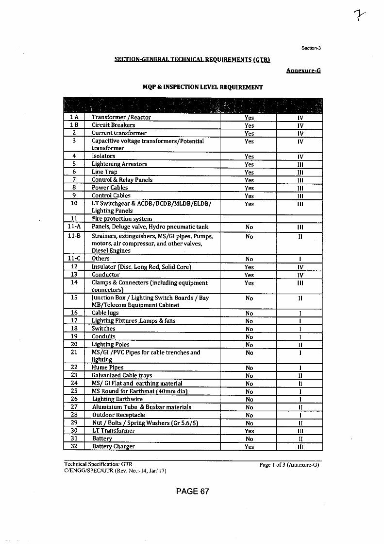
Section-3
SECTION-GENERA!. TECHNICAL REQUIREMENTS (GTR)
Annexure-G
MQP & INSPECTION LEVEL REQUIREMENT
1 A Transformer Reactor Yes IV 1 B Circuit Breakers Yes IV 2 Current transformer Yes IV 3 Capacitive voltage transformers/Potential
transformer Yes IV
4 Isolators Yes IV 5 Li : htenin: Arrestors Yes III 6 Line Tra • Yes Ill 7 Control & Rela Panels Yes III 8 Power Cables Yes III 9 Control Cables Yes III
10 LT Switchgear & ACDB/DCDB/MLDB/ELDB/ Li:htin: Panels
Yes Ill
11 Fire . rotection s stem 11-A Panels, Deluge valve, Hydro pneumatic tank. No III 11-B Strainers, extinguishers, MS/GI pipes, Pumps,
motors, air compressor, and other valves, Diesel En: 'nes
No II
11-C Others No I 12 Insulator Disc, Lon: Rod, Solid Core Yes IV 13 Conductor Yes IV 14 Clamps & Connecters (including equipment
connectors Yes III
15 Junction Box / Lighting Switch Boards / Bay MB Telecom E • ui • ment Cabinet
No II
16 Cable lu:s No I 17 Li: htin: Fixtures ,Lam • s & fans No I 18 Switches No I 19 Conduits No I 20 Li:htin: Poles No II 21 MS/GI /PVC Pipes for cable trenches and
li:htin• No I
22 Hume Pi • es No I 23 Galvanized Cable tra s No II 24 MS GI Flat and earthin: material No II 25 MS Round for Earthmat 40mm dia No I 26 Li:htin: Earthwire No I 27 Aluminium Tube & Busbar materials No II 28 Outdoor Rece •tacle No I 29 ' t o ts Arjanarna r .6j No Il 30 LT Transformer Yes III 31 Batte No II 32 Batte Char : er Yes III
Technical Specification: GTR
Page 1 of 3 (Annexure-G) C/ENGG/SPEC/GTR (Rev. No.:-I4, Jan'17)
PAGE 67
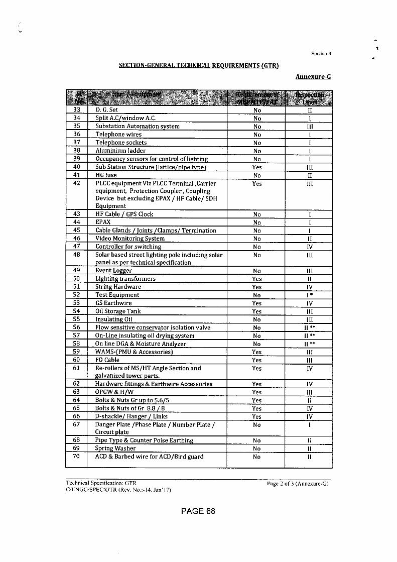
Section-3
Annexure-Q
SECTION-GENERAL TECHNICAL REQUIREMENTS (GT11).
33 D. G. Set No II 34 Split A.C/window A.C. No 1
35 Substation Automation system No III
Telephone wires 36 No 1 37 Telephone sockets No 1 38 Aluminium ladder No 1 39 Occupancy sensors for control of lighting No 1
Sub Station Structure (lattice/pipe type) 40 Yes 111 HG fuse 41 No II
42 PLCC equipment Viz PLCC Terminal ,Carrier equipment, Protection Coupler, Coupling Device but excluding EPAX / HF Cable/ SDH Equipment
Yes Ill
43 HF Cable GPS Clock No 44 EPAX No 45 Cable Glands / Joints /Clamps/ Termination No 1
Video Monitoring System 46 No II 47 Controller for switching No IV
48 Solar based street lighting pole including solar panel as per technical specification
No III
49 Event Logger No Ill
50 Lighting transformers Yes 11 51 String Hardware Yes IV 52 Test Equipment * No 1 53 GS Earthwire Yes IV 54 Oil Storage Tank Yes 55 Insulating Oil No 56 Flow sensitive conservator isolation valve No II ** 57 On-Line insulating oil drying system No II ** 58 On line DGA & Moisture Analyzer No II ** 59 WAMS-(PMU & Accessories) Yes 111 60 FO Cable Yes Ill 61 Re-rollers of MS/HT Angle Section and
galvanized tower parts. Yes IV
62 Hardware fittings & Earthwire Accessories Yes IV 63 OPGW & H/W Yes 111 64 Bolts & Nuts Gr up to 5.6/5 Yes 65 Bolts & Nuts of Gr 8.8 / 8 Yes IV
D-shackle/ Hanger / Links 66 Yes IV 67 Danger Plate /Phase Plate / Number Plate /
Circuit plate No 1
68 Pipe Type & Counter Poise Earthing No II
69 Spring Washer No 11 70 ACD & Barbed wire for ACD/Bird guard No II
Technical Specification: GTR Page 2 of 3 (Annexure-G) CiENGG/SPEC/CiTR (Rev. No • 14, Jan'17)
PAGE 68
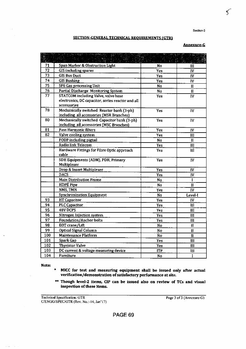
Section-3
SF.CTION-GENERAL TECHNICAL REQUIREMENTS (GTR)
Annexure-G
71 S . an Marker & Obstruction Li: ht No III 72 GIS includin: s • ares Yes IV 73 GIS Bus Duct Yes IV 74 GIS Bushin: Yes IV 75 SF6 Gas .rocessin: Unit No II 76 Partial Dischar:e Monitorin: S stem No II 77 STATCOM including Valve, valve base
electronics, DC capacitor, series reactor and all accessories
Yes IV
78 Mechanically switched Reactor bank (3-ph) includin: all accessories MSR Branches
Yes IV
80 Mechanically switched Capacitor bank (3-ph) includin: all accessories MSC Branches
Yes IV
81 Pass Harmonic filters Yes IV 82 Valve coolin: s stem Yes III
FODP includin: • i : . il No II Radio link Telecom Yes III Hardware Fittings for Fibre Optic approach cable
Yes III
SDH Equipments (ADM), PDH, Primary Multi . lexer
Yes IV
Dro • & Insert Multi . lexer Yes IV DACS Yes IV Main Distribution Frame No I HDPE Pi • e No II NMS, TMN Yes IV S nchronization E • ui . ment No Level-I
93 HT Ca p acitor Yes IV 94 PLC Ca. acitor Yes III 95 48V DCPS Yes III 96 Nitro:en In'ection s stem Yes III 97 Foundation Anchor bolts Yes III 98 EOT crane Lift No II 99 0 .tical Si:nal Column No II
100 Maintenance Platform No II 101 S•ark Ga. Yes HI 102 Th istor Valve Yes III 103 DC current & volta:e measurin: device ITP III 104 Furniture No I
Note: MICC for test and measuring equipment shall be issued only after actual verification/demonstration of satisfactory performance at site.
** Though level-2 items, CIP can be issued also on review of TCs and visual inspection of these items.
Technical Specification: GTR
Page 3 of 3 (Annexure-G) C!ENGG/SPEC/GTR (Rev. No.:-14, Jan'17)
PAGE 69
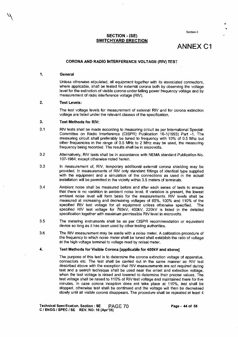
Section-3 SECTION - (SE)
SWITCHYARD ERECTION
ANNEX Cl
CORONA AND RADIO INTERFERENCE VOLTAGE (RIV) TEST
1. General
Unless otherwise stipulated, all equipment together with its associated connectors, where applicable, shall be tested for external corona both by observing the voltage level for the extinction of visible corona under falling power frequency voltage and by measurement of radio interference voltage (RIV).
2. Test Levels:
The test voltage levels for measurement of external RIV and for corona extinction voltage are listed under the relevant clauses of the specification.
3. Test Methods for RIV:
3.1 RIV tests shall be made according to measuring circuit as per International Special- Committee on Radio Interference (CISPR) Publication 16-1(1993) Part -1. The measuring circuit shall preferably be tuned to frequency with 10% of 0.5 Mhz but other frequencies in the range of 0.5 MHz to 2 MHz may be used, the measuring frequency being recorded. The results shall be in microvolts.
3.2 Alternatively, RIV tests shall be in accordance with NEMA standard Publication No. 107-1964, except otherwise noted herein.
3.3 In measurement of, RIV, temporary additional external corona shielding may be provided. In measurements of RIV only standard fittings of identical type supplied with the equipment and a simulation of the connections as used in the actual installation will be permitted in the vicinity within 3.5 meters of terminals.
3.4 Ambient noise shall be measured before and after each series of tests to ensure that there is no variation in ambient noise level. If variation is present, the lowest ambient noise level will form basis for the measurements. RIV levels shall be measured at increasing and decreasing voltages of 85%, 100% and 110% of the specified RIV test voltage for all equipment unless otherwise specified. The specified RIV test voltage for 765kV, 400kV, 220kV is listed in the detailed specification together with maximum permissible RIV level in microvolts.
3.5 The metering instruments shall be as per CISPR recommendation or equivalent device so long as it has been used by other testing authorities.
3.6 The RIV measurement may be made with a noise meter. A calibration procedure of the frequency to which noise meter shall be tuned shall establish the ratio of voltage at the high voltage terminal to voltage read by noise! meter.
4. Test Methods for Visible Corona [applicable for 400kV and above]
The purpose of this test is to determine the corona extinction voltage of apparatus, connectors etc. The test shall be carried out in the same manner as RIV test described above with the exception that RIV measurements are not required during test and a search technique shall be used near the onset and extinction voltage, when the test voltage is raised and lowered to determine their precise values. The test voltage shall be raised to 110% of RIV test voltage and maintained there for five minutes. In case corona inception does not take place at 110%, test shall be stopped, otherwise test shall be continued and the voltage will then be decreased slowly until all visible corona disappears. The procedure shall be repeated at least 4
Technical Specification, Section : SE PAGE 70
Page - 44 of 58 ClENGG / SPEC / SE REV. NO: 10 (Apr'16)
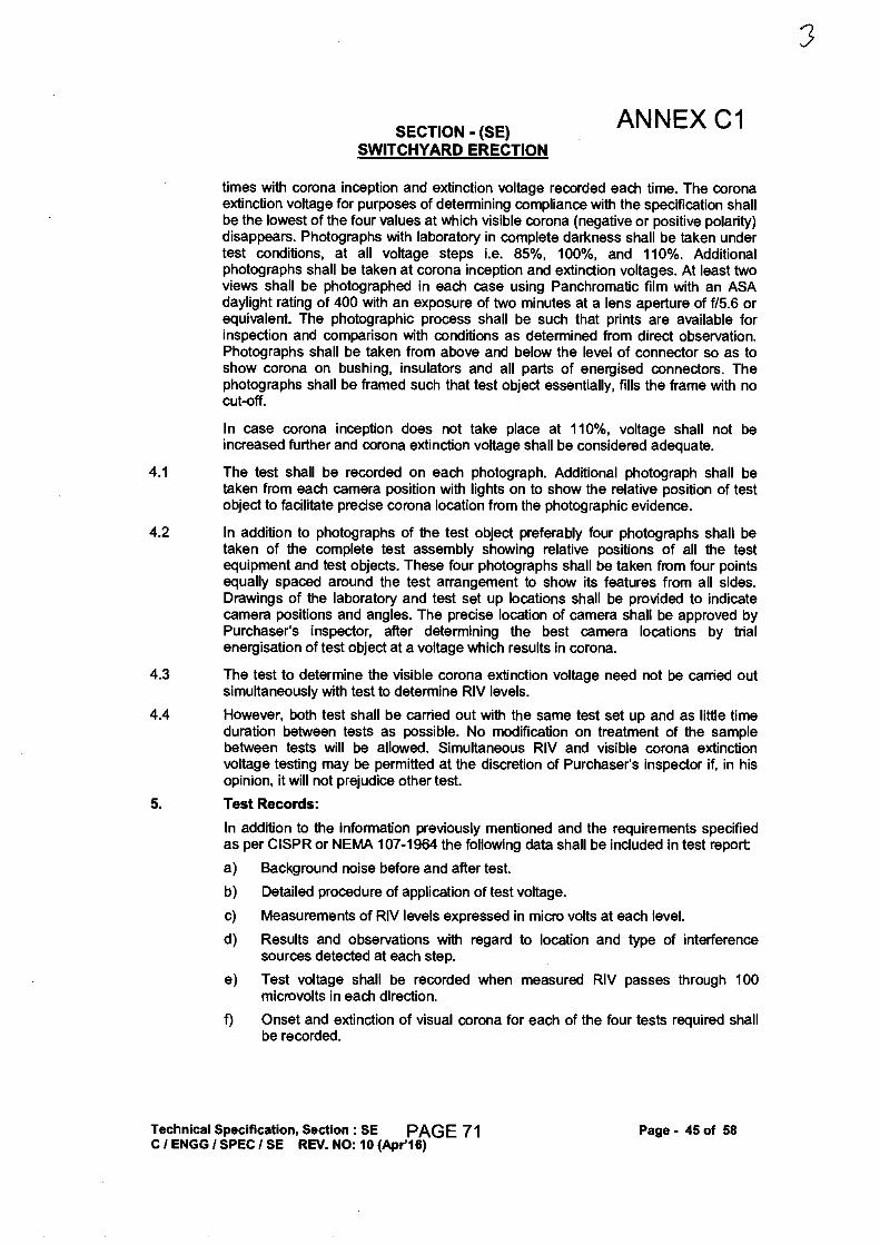
SECTION - (SE) ANNEX Cl
SWITCHYARD ERECTION
times with corona inception and extinction voltage recorded each time. The corona extinction voltage for purposes of determining compliance with the specification shall be the lowest of the four values at which visible corona (negative or positive polarity) disappears. Photographs with laboratory in complete darkness shall be taken under test conditions, at all voltage steps i.e. 85%, 100%, and 110%. Additional photographs shall be taken at corona inception and extinction voltages. At least two views shall be photographed in each case using Panchromatic film with an ASA daylight rating of 400 with an exposure of two minutes at a lens aperture of f/5.6 or equivalent. The photographic process shall be such that prints are available for inspection and comparison with conditions as determined from direct observation. Photographs shall be taken from above and below the level of connector so as to show corona on bushing, insulators and all parts of energised connectors. The photographs shall be framed such that test object essentially, fills the frame with no cut-off.
In case corona inception does not take place at 110%, voltage shall not be increased further and corona extinction voltage shall be considered adequate.
4.1 The test shall be recorded on each photograph. Additional photograph shall be taken from each camera position with lights on to show the relative position of test object to facilitate precise corona location from the photographic evidence.
4.2 In addition to photographs of the test object preferably four photographs shall be taken of the complete test assembly showing relative positions of all the test equipment and test objects. These four photographs shall be taken from four points equally spaced around the test arrangement to show its features from all sides. Drawings of the laboratory and test set up locations shall be provided to indicate camera positions and angles. The precise location of camera shall be approved by Purchaser's inspector, after determining the best camera locations by trial energisation of test object at a voltage which results in corona.
4.3 The test to determine the visible corona extinction voltage need not be carried out simultaneously with test to determine RIV levels.
4.4 However, both test shall be carried out with the same test set up and as little time duration between tests as possible. No modification on treatment of the sample between tests will be allowed. Simultaneous RIV and visible corona extinction voltage testing may be permitted at the discretion of Purchaser's inspector if, in his opinion, it will not prejudice other test.
5. Test Records:
In addition to the information previously mentioned and the requirements specified as per CISPR or NEMA 107-1964 the following data shall be included in test report:
a) Background noise before and after test.
b) Detailed procedure of application of test voltage.
c) Measurements of RIV levels expressed in micro volts at each level.
d) Results and observations with regard to location and type of interference sources detected at each step.
e) Test voltage shall be recorded when measured RIV passes through 100 microvolts in each direction.
f) Onset and extinction of visual corona for each of the four tests required shall be recorded.
Technical Specification, Section : SE PAGE 71
Page - 45 of 58 ClENGG / SPEC / SE REV. NO: 10 (Apr'16)
Bharat Heavy Electricals Limited Doc No. TB-408-316-110 Technical Specification
Technical Specification for Visual Monitoring system
Section-4/ Annexure - A
ANNEXURE-A
COMPLIANCE CERTIFICATE OF TECHNICAL SPECIFICATION
The bidder shall confirm compliance to the following by signing/ stamping this compliance certificate and furnishing same with the offer.
1. The scope of supply, technical details, construction features, design parameters etc. shall be as per technical specification & there are no exclusion/ deviation with regard to same.
2. There are no deviation(s) with respect to specification other than those furnished in the `schedule of technical deviations'.
3. Only those technical submittals which are specifically asked for in NIT to be submitted at tender stage shall be considered as part of offer. Any other submission, even if made, shall not be considered as part of offer.
4. Any comments/ clarifications on technical/ inspection requirements furnished as part of bidder's covering letter shall not be considered by BHEL, and bidder's offer shall be construed to be in conformance with the specification.
5. Any changes made by the bidder in the price schedule with respect to the description/ quantities from those given in 'BOO' of the specification shall not be considered (i.e., technical description & quantities as per the specification shall prevail).
Date: Bidder's Stamp & Signature
Section 4: Annexure Page 1 of 1

Bharat Heavy Electricals Limited
Doc No. TB-408-316-110 Technical Specification
Technical Specification for Visual Monitoring system
Section-4/ Annexure - B
ANNEXURE - B
SCHEDULE OF TECHNICAL DEVIATIONS
Bidder shall list below all technical deviation clause wise w.r.t. tender specifications:
S.No. Section/ Page No. Clause No. Deviation Reason / Justification
Any deviation not specifically brought out in this section shall not be admissible for any commercial implication at later stage. Except to the technical deviations listed in this schedule, bidder's offer shall be considered in full compliance to the tender specifications irrespective of any such deviation indicated / taken elsewhere in the submitted offer.
Date: Tenderer's Stamp & Signature
Section 4: Annexures Page 1 of 1
Related Documents