MF-7900DR-H24 INSTRUCTION MANUAL

Welcome message from author
This document is posted to help you gain knowledge. Please leave a comment to let me know what you think about it! Share it to your friends and learn new things together.
Transcript
MF-7900DR-H24INSTRUCTION MANUAL
i
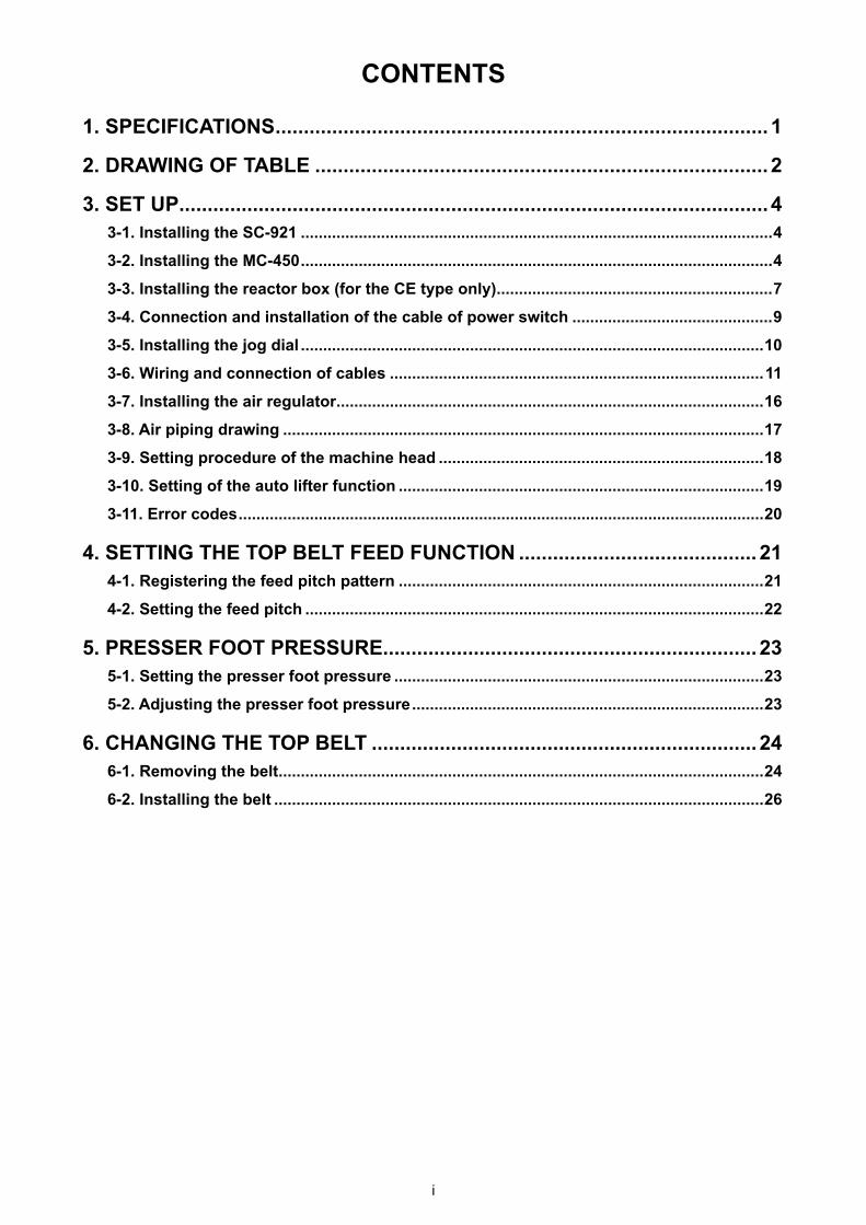
CONTENTS
1. SPECIFICATIONS ....................................................................................... 1
2. DRAWING OF TABLE ................................................................................ 2
3. SET UP ........................................................................................................ 43-1. Installing the SC-921 ..........................................................................................................4
3-2. Installing the MC-450 ..........................................................................................................4
3-3. Installing the reactor box (for the CE type only) ..............................................................7
3-4. Connection and installation of the cable of power switch .............................................9
3-5. Installing the jog dial ........................................................................................................10
3-6. Wiring and connection of cables ....................................................................................11
3-7. Installing the air regulator ................................................................................................16
3-8. Air piping drawing ............................................................................................................17
3-9. Setting procedure of the machine head .........................................................................18
3-10. Setting of the auto lifter function ..................................................................................19
3-11. Error codes ......................................................................................................................20
4. SETTING THE TOP BELT FEED FUNCTION .......................................... 214-1. Registering the feed pitch pattern ..................................................................................21
4-2. Setting the feed pitch .......................................................................................................22
5. PRESSER FOOT PRESSURE.................................................................. 235-1. Setting the presser foot pressure ...................................................................................23
5-2. Adjusting the presser foot pressure ...............................................................................23
6. CHANGING THE TOP BELT .................................................................... 246-1. Removing the belt .............................................................................................................24
6-2. Installing the belt ..............................................................................................................26
– 1 –
1. SPECIFICATIONS
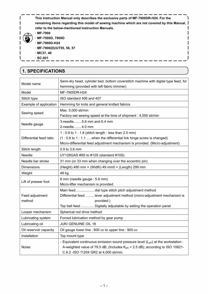
Model nameSemi-dry head, cylinder bed, bottom coverstitch machine with digital type feed, for hemming (provided with left fabric trimmer)
Model MF-7900DR-H24
Stitch type ISO standard 406 and 407
Example of application Hemming for knits and general knitted fabrics
Sewing speedMax. 5,000 sti/minFactory-set sewing speed at the time of shipment : 4,000 sti/min
Needle gauge3-needle........5.6 mm and 6.4 mm2-needle........4.0 mm
Differential feed ratio1 : 0.9 to 1 : 1.8 (stitch length : less than 2.5 mm)(1 : 0.6 to 1 : 1.1 .....when the differential link hinge screw is changed)Micro-differential feed adjustment mechanism is provided. (Micro-adjustment)
Stitch length 0.9 to 3.6 mm
Needle UY128GAS #9S to #12S (standard #10S)
Needle bar stroke 31 mm (or 33 mm when changing over the eccentric pin)
Dimensions (Height) 490 mm × (Width) 49 mm0 × (Length) 299 mm
Weight 48 kg
Lift of presser foot8 mm (needle gauge : 5.6 mm)Micro-lifter mechanism is provided.
Feed adjustment method
Main feed ................... dial type stitch pitch adjustment method Differential feed ......... lever adjustment method (micro-adjustment mechanism is
provided.)Top belt feed .............. Digitally adjustable by setting the operation panel
Looper mechanism Spherical rod drive method
Lubricating system Forced lubrication method by gear pump
Lubricating oil JUKI GENUINE OIL 18
Oil reservoir capacity Oil gauge lower line : 600 cc to upper line : 900 cc
Installation Top mount type
Noise- Equivalent continuous emission sound pressure level (LpA) at the workstation : A-weighted value of 79.5 dB; (Includes KpA = 2.5 dB); according to ISO 10821-
C.6.2 -ISO 11204 GR2 at 4,000 sti/min.
This Instruction Manual only describes the exclusive parts of MF-7900DR-H24. For the remaining items regarding this model of sewing machine which are not covered by this Manual, refer to the below-mentioned Instruction Manuals.· MF-7900· MF-7500D, 7900D· MF-7900D-H24· MF-7900(D)/UT55, 56, 57· MC37, 40· SC-921
– 2 –
5×20
4×8.5
60
745
(90)
Z
-Z
(7
ヶ所
)
ZZ
310
250
250
8560
±1
12568
158
325±2 20
248±
1
1200
7513
081
0±1
40
17
57
52
115±
1
360
192±1221
33.536
11.7
6896
158.5
Ø50
4×R10
R30R30 R30
40
40120
570
3
Ø50
310
278285
221
124
4927
2×R
R2
R30
Ø26 Ø8
.5
R2
A
B
C
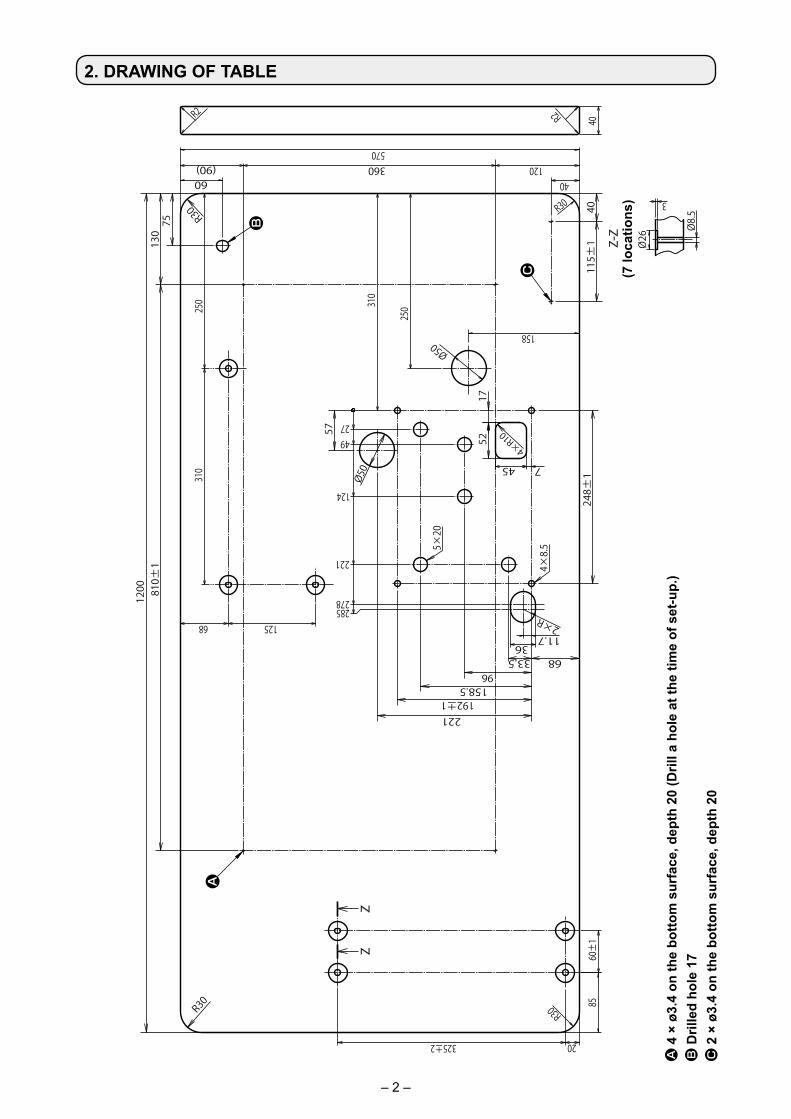
2. DRAWING OF TABLE
A 4
× ø
3.4
on th
e bo
ttom
sur
face
, dep
th 2
0 (D
rill a
hol
e at
the
time
of s
et-u
p.)
B D
rille
d ho
le 1
7C
2 ×
ø3.
4 on
the
botto
m s
urfa
ce, d
epth
20
(7 lo
catio
ns)
– 3 –
5×20
60
ZZ
ZZ
Z
ZZ
Z
96
532
158
125
11.7
250
310
221
158.5
1200
75
57
310
115±
1
810±
1
33.5
36
68
192±1
130
40
278285
221
124
4927
248±
1
Z
-Z
(7
ヶ所
)
3
Ø26 Ø8
.5
R30
R30
4×R10
(90)
R2R30
360570
R2
40
R30
40
120
2×R
Ø50 745
1752
4×8.
5
Ø50
165241
175
ZZ
ZZ
ZZ
146
A
B
C
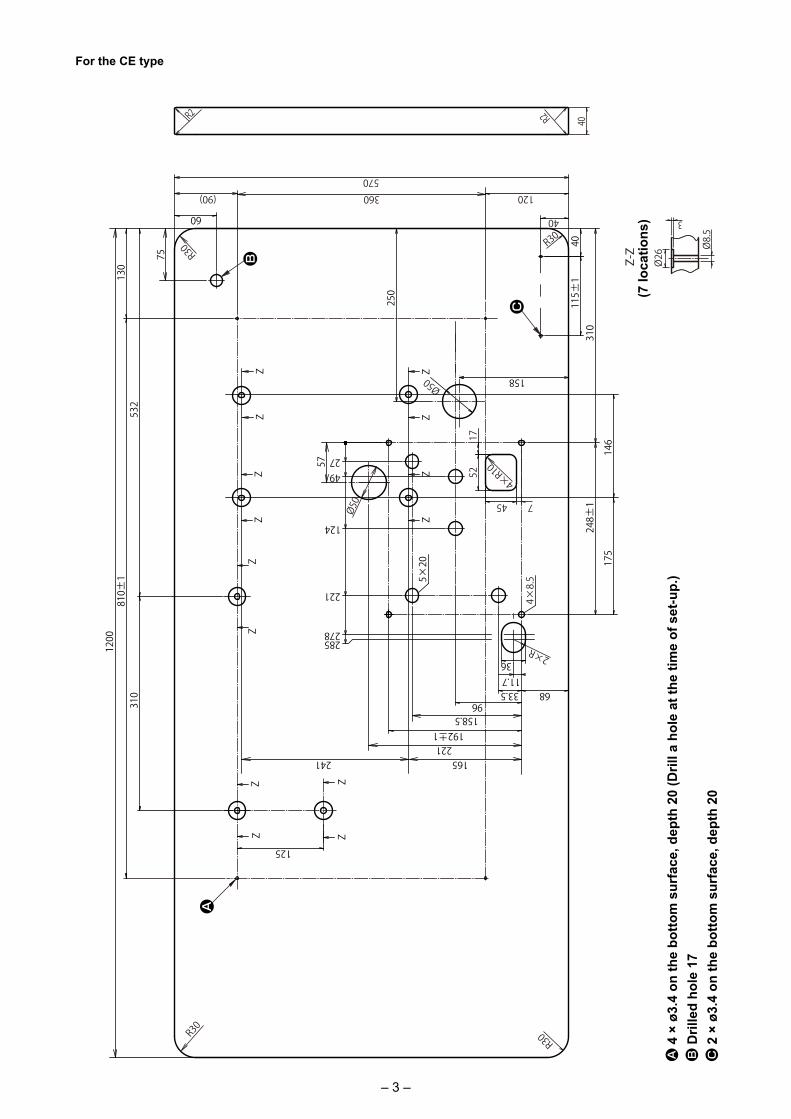
A 4
× ø
3.4
on th
e bo
ttom
sur
face
, dep
th 2
0 (D
rill a
hol
e at
the
time
of s
et-u
p.)
B D
rille
d ho
le 1
7C
2 ×
ø3.
4 on
the
botto
m s
urfa
ce, d
epth
20
For the CE type
(7 lo
catio
ns)
– 4 –
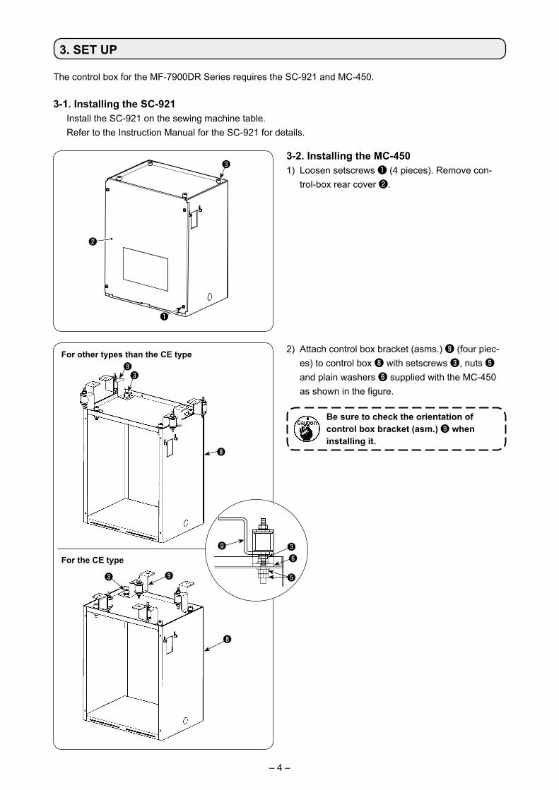
3. SET UP
3-2. Installing the MC-4501) Loosen setscrews ❶ (4 pieces). Remove con-
trol-box rear cover ❷.
3-1. Installing the SC-921 Install the SC-921 on the sewing machine table. Refer to the Instruction Manual for the SC-921 for details.
The control box for the MF-7900DR Series requires the SC-921 and MC-450.
❶
❷
❸
❾ ❸❻
❺
❽
❸❾
For the CE type
For other types than the CE type 2) Attach control box bracket (asms.) ❾ (four piec-es) to control box ❽ with setscrews ❸, nuts ❺ and plain washers ❻ supplied with the MC-450 as shown in the figure.
Be sure to check the orientation of control box bracket (asm.) ❾ when installing it.
❽
❾❸
– 5 –
���
�
❾
A
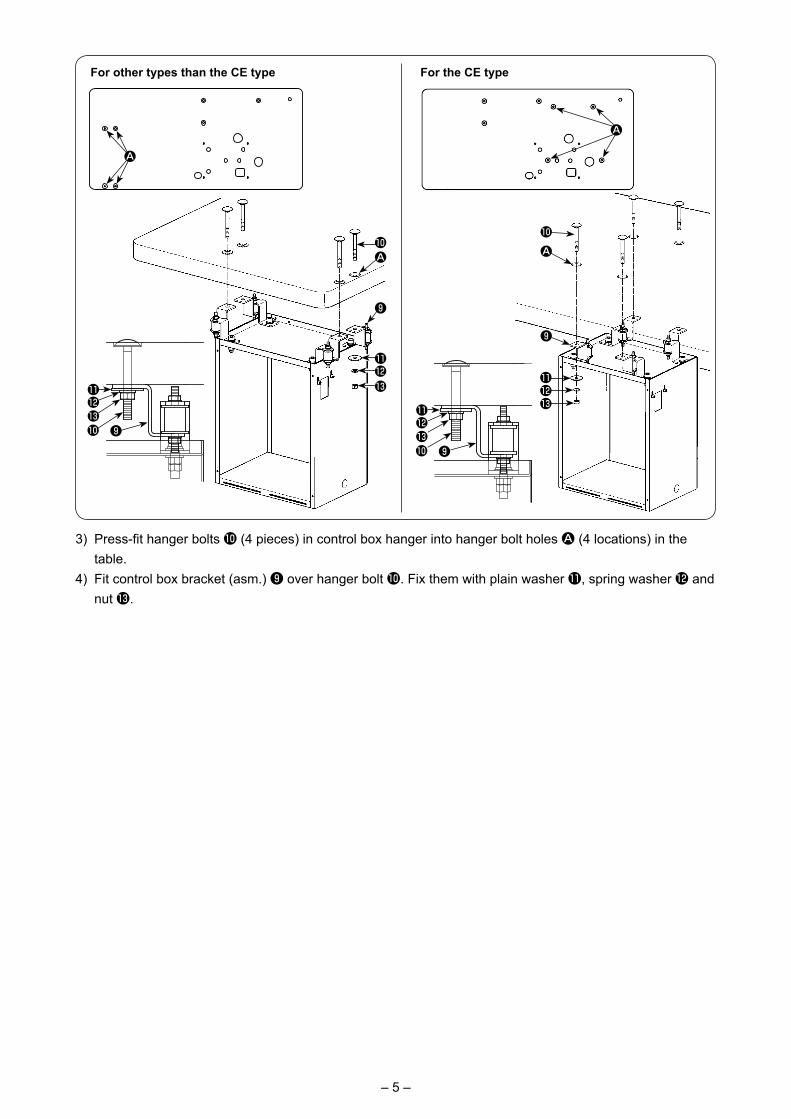
3) Press-fit hanger bolts � (4 pieces) in control box hanger into hanger bolt holes A (4 locations) in the table.
4) Fit control box bracket (asm.) ❾ over hanger bolt �. Fix them with plain washer �, spring washer � and nut �.
���� ❾
���
�
❾
A
���� ❾
A
For the CE typeFor other types than the CE type
A
– 6 –
❽
❶
❷
�
�
�
B
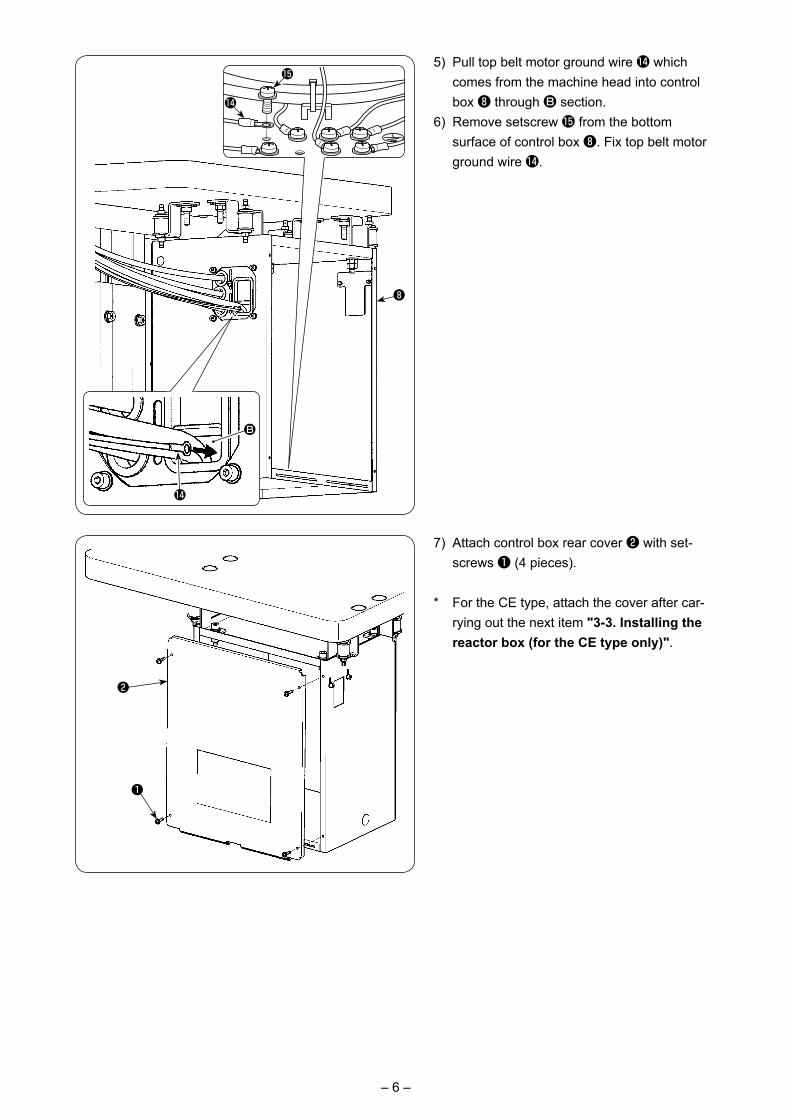
5) Pull top belt motor ground wire � which comes from the machine head into control box ❽ through B section.
6) Remove setscrew � from the bottom surface of control box ❽. Fix top belt motor ground wire �.
7) Attach control box rear cover ❷ with set-screws ❶ (4 pieces).
* For the CE type, attach the cover after car-rying out the next item "3-3. Installing the reactor box (for the CE type only)".
– 7 –
❸
C
❷
A
B
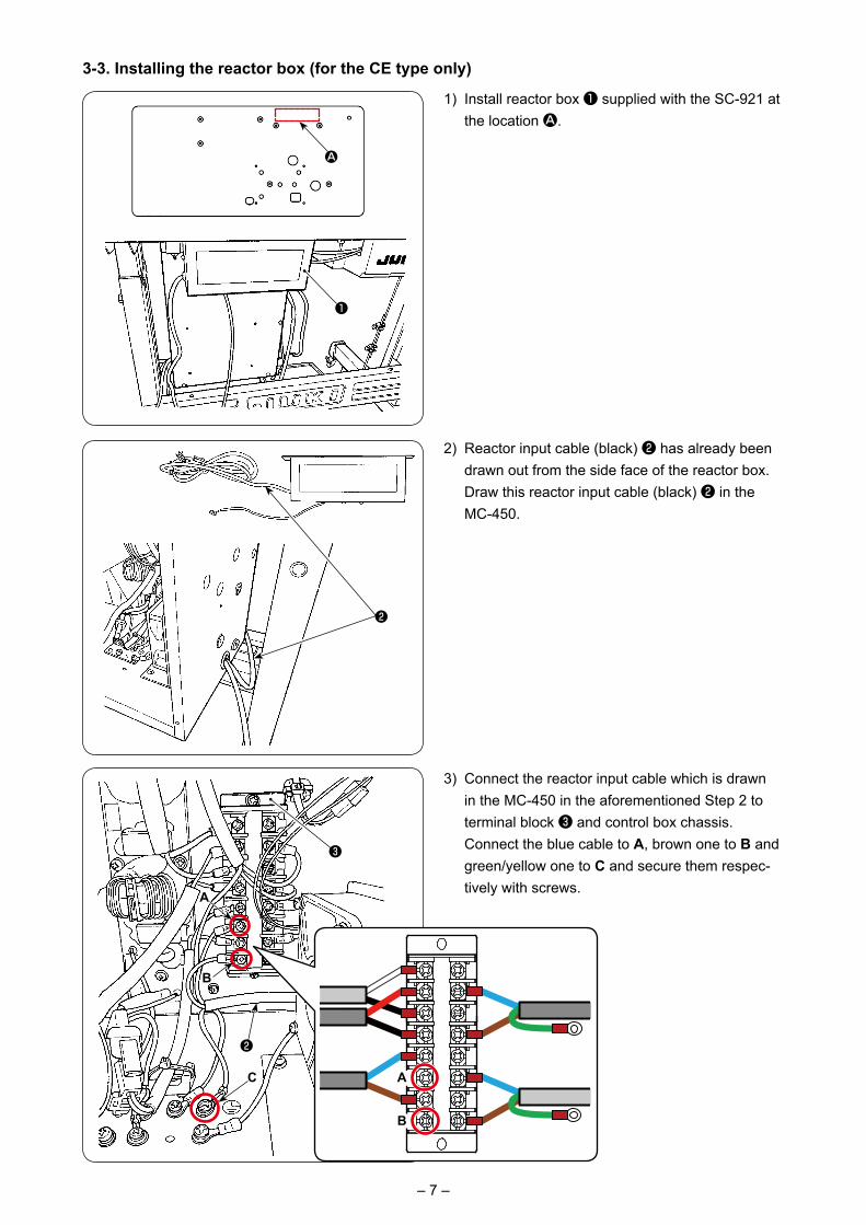
1) Install reactor box ❶ supplied with the SC-921 at the location A.
3-3. Installing the reactor box (for the CE type only)
2) Reactor input cable (black) ❷ has already been drawn out from the side face of the reactor box. Draw this reactor input cable (black) ❷ in the MC-450.
3) Connect the reactor input cable which is drawn in the MC-450 in the aforementioned Step 2 to terminal block ❸ and control box chassis.
Connect the blue cable to A, brown one to B and green/yellow one to C and secure them respec-tively with screws.
A
❶
❷
A
B
– 8 –
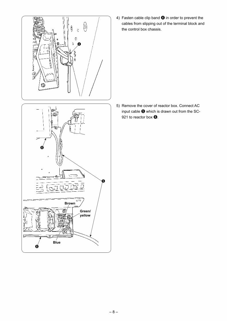
4) Fasten cable clip band ❹ in order to prevent the cables from slipping out of the terminal block and the control box chassis.
5) Remove the cover of reactor box. Connect AC input cable ❺ which is drawn out from the SC-921 to reactor box ❻.
❹
❺
❻Blue
Brown
Green/ yellow
❻
– 9 –
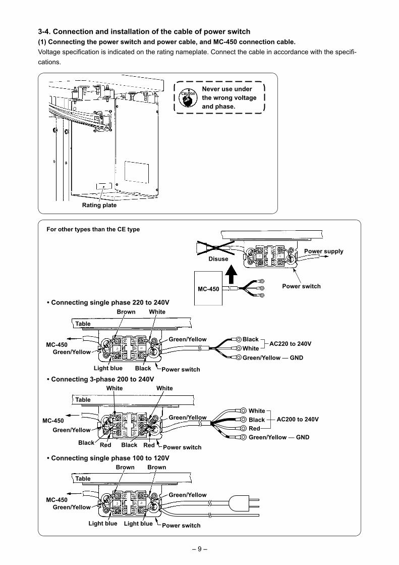
3-4. Connection and installation of the cable of power switch(1) Connecting the power switch and power cable, and MC-450 connection cable.Voltage specification is indicated on the rating nameplate. Connect the cable in accordance with the specifi-cations.
• Connecting 3-phase 200 to 240V
• Connecting single phase 220 to 240V
• Connecting single phase 100 to 120V
Never use under the wrong voltage and phase.
Power supply
MC-450
Disuse
Power switch
Light blue
Green/Yellow
Green/Yellow
Table
MC-450
Power switch
Brown Brown
Light blue
AC200 to 240V
White
Green/Yellow — GND
WhiteBlackRed
Black
Green/Yellow
Green/Yellow
Power switch
MC-450
Table
White
Black RedRed
Light blue
Green/Yellow
Green/Yellow
Table
MC-450
Power switch
Brown White
Black
Green/Yellow — GND
AC220 to 240VBlackWhite
Rating plate
For other types than the CE type
– 10 –
❶❷
❸
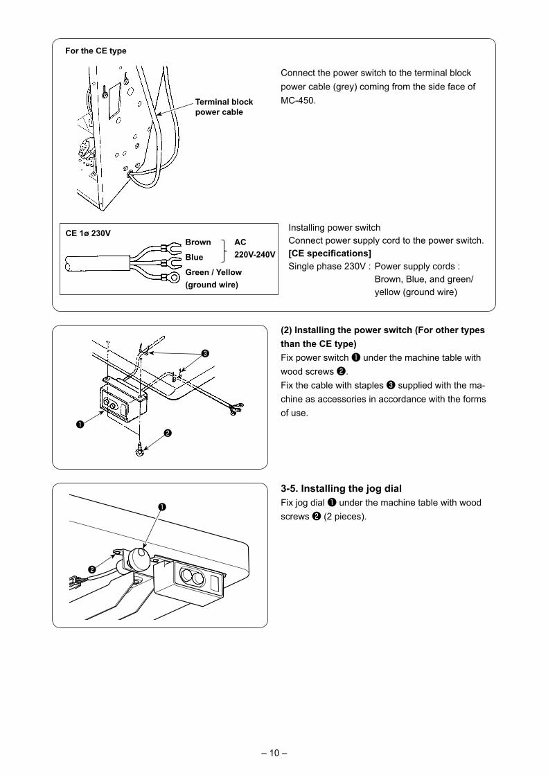
(2) Installing the power switch (For other types than the CE type)Fix power switch ❶ under the machine table with wood screws ❷.Fix the cable with staples ❸ supplied with the ma-chine as accessories in accordance with the forms of use.
3-5. Installing the jog dialFix jog dial ❶ under the machine table with wood screws ❷ (2 pieces).
❷
❶
For the CE type
Connect the power switch to the terminal block power cable (grey) coming from the side face of MC-450.Terminal block
power cable
CE 1ø 230VAC 220V-240V
Installing power switchConnect power supply cord to the power switch.[CE specifications] Single phase 230V : Power supply cords :
Brown, Blue, and green/yellow (ground wire)
Brown
Blue
Green / Yellow (ground wire)
– 11 –
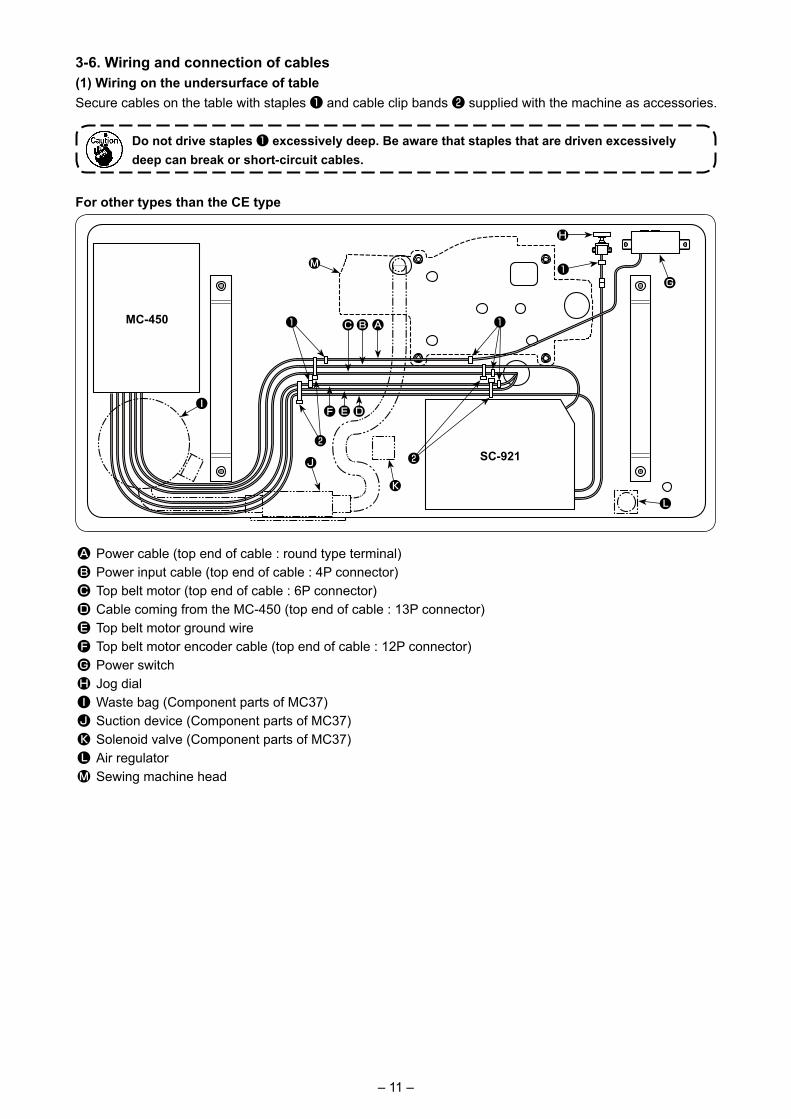
3-6. Wiring and connection of cables(1) Wiring on the undersurface of tableSecure cables on the table with staples ❶ and cable clip bands ❷ supplied with the machine as accessories.
A Power cable (top end of cable : round type terminal)B Power input cable (top end of cable : 4P connector)C Top belt motor (top end of cable : 6P connector)D Cable coming from the MC-450 (top end of cable : 13P connector)E Top belt motor ground wireF Top belt motor encoder cable (top end of cable : 12P connector)G Power switchH Jog dialI Waste bag (Component parts of MC37)J Suction device (Component parts of MC37)K Solenoid valve (Component parts of MC37)L Air regulatorM Sewing machine head
Do not drive staples ❶ excessively deep. Be aware that staples that are driven excessively deep can break or short-circuit cables.
MC-450
SC-921
❶ ❶A
DE
KL
F
J
I
M
BC
❶
❷❷
G
H
For other types than the CE type
– 12 –
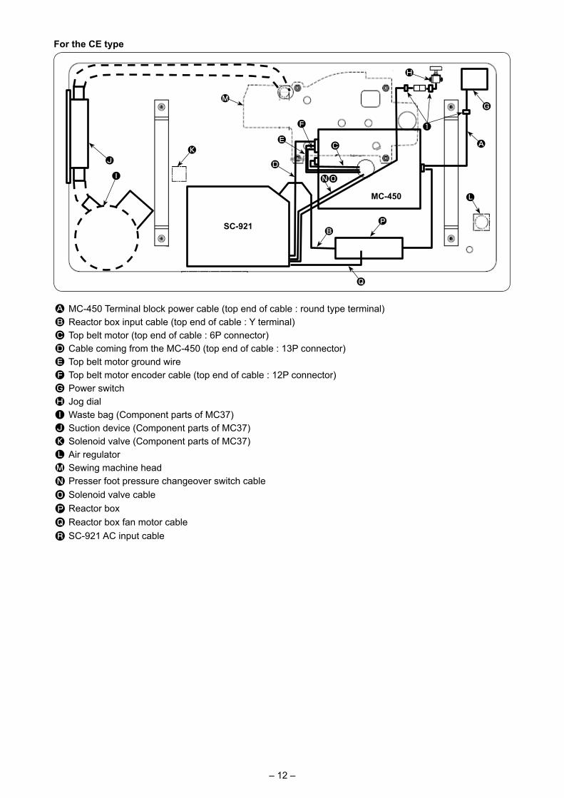
A MC-450 Terminal block power cable (top end of cable : round type terminal)B Reactor box input cable (top end of cable : Y terminal)C Top belt motor (top end of cable : 6P connector)D Cable coming from the MC-450 (top end of cable : 13P connector)E Top belt motor ground wireF Top belt motor encoder cable (top end of cable : 12P connector)G Power switchH Jog dialI Waste bag (Component parts of MC37)J Suction device (Component parts of MC37)K Solenoid valve (Component parts of MC37)L Air regulatorM Sewing machine headN Presser foot pressure changeover switch cableO Solenoid valve cableP Reactor boxQ Reactor box fan motor cableR SC-921 AC input cable
For the CE type
G
A
❶
H
I
JK
M
F
E
D
B
C
MC-450
SC-921
Q
NO
P
L
– 13 –
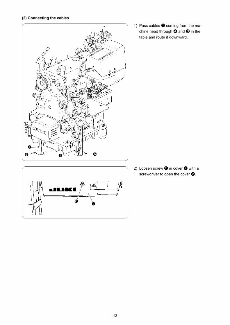
1) Pass cables ❶ coming from the ma-chine head through A and B in the table and route it downward.
(2) Connecting the cables
2) Loosen screw C in cover ❷ with a screwdriver to open the cover ❷.
C❷
❶
❶B A
– 14 –
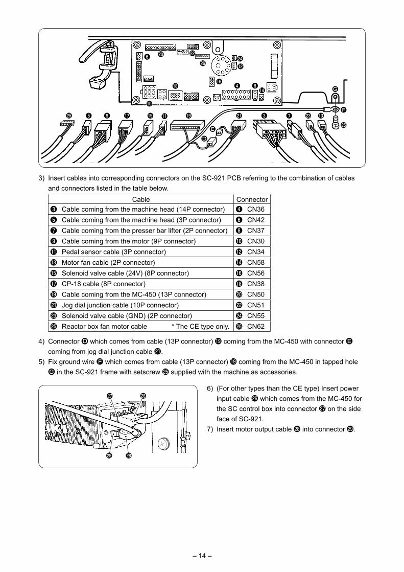
3) Insert cables into corresponding connectors on the SC-921 PCB referring to the combination of cables and connectors listed in the table below.
Cable Connector❸ Cable coming from the machine head (14P connector) ❹ CN36❺ Cable coming from the machine head (3P connector) ❻ CN42❼ Cable coming from the presser bar lifter (2P connector) ❽ CN37❾ Cable coming from the motor (9P connector) � CN30� Pedal sensor cable (3P connector) � CN34� Motor fan cable (2P connector) � CN58� Solenoid valve cable (24V) (8P connector) � CN56� CP-18 cable (8P connector) � CN38� Cable coming from the MC-450 (13P connector) � CN50� Jog dial junction cable (10P connector) � CN51� Solenoid valve cable (GND) (2P connector) � CN55� Reactor box fan motor cable * The CE type only. � CN62
4) Connector D which comes from cable (13P connector) � coming from the MC-450 with connector E coming from jog dial junction cable �.
5) Fix ground wire F which comes from cable (13P connector) � coming from the MC-450 in tapped hole G in the SC-921 frame with setscrew � supplied with the machine as accessories.
6) (For other types than the CE type) Insert power input cable � which comes from the MC-450 for the SC control box into connector � on the side face of SC-921.
7) Insert motor output cable � into connector �.
� �
��
❸ ❼ � �F
G
�❺ ❾ � � � � �
��❻
�
��
��
❹ ❽�
ED
�
�
– 15 –
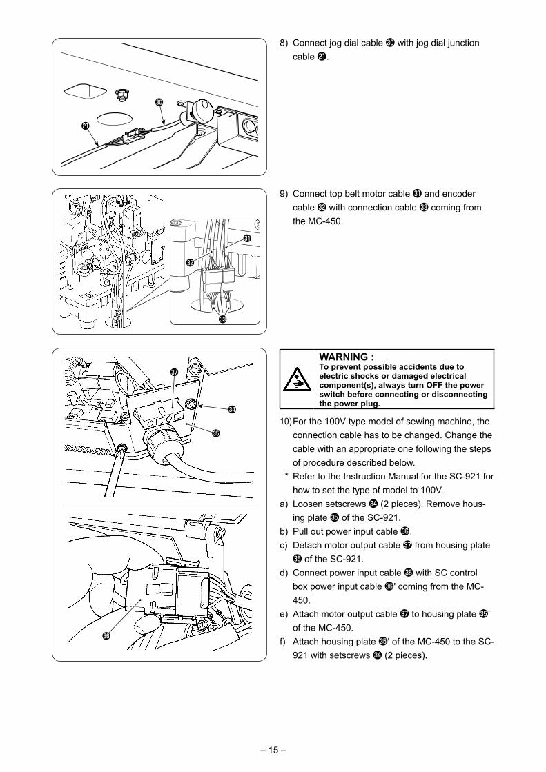
8) Connect jog dial cable � with jog dial junction cable �.
9) Connect top belt motor cable � and encoder cable � with connection cable � coming from the MC-450.
10) For the 100V type model of sewing machine, the connection cable has to be changed. Change the cable with an appropriate one following the steps of procedure described below.
* Refer to the Instruction Manual for the SC-921 for how to set the type of model to 100V.
a) Loosen setscrews � (2 pieces). Remove hous-ing plate � of the SC-921.
b) Pull out power input cable �. c) Detach motor output cable � from housing plate � of the SC-921.
d) Connect power input cable � with SC control box power input cable �' coming from the MC-450.
e) Attach motor output cable � to housing plate �' of the MC-450.
f) Attach housing plate �' of the MC-450 to the SC-921 with setscrews � (2 pieces).
�
�
�
�
�
�
�
�
�
WARNING :To prevent possible accidents due to electric shocks or damaged electrical component(s), always turn OFF the power switch before connecting or disconnecting the power plug.
– 16 –
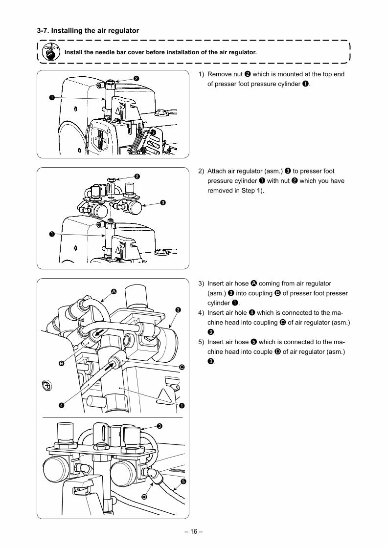
3-7. Installing the air regulator
Install the needle bar cover before installation of the air regulator.
1) Remove nut ❷ which is mounted at the top end of presser foot pressure cylinder ❶.
2) Attach air regulator (asm.) ❸ to presser foot pressure cylinder ❶ with nut ❷ which you have removed in Step 1).
3) Insert air hose A coming from air regulator (asm.) ❸ into coupling B of presser foot presser cylinder ❶.
4) Insert air hole ❹ which is connected to the ma-chine head into coupling C of air regulator (asm.) ❸.
5) Insert air hose ❺ which is connected to the ma-chine head into couple D of air regulator (asm.) ❸.
❶
❷
❶
❷
❸
A
B
❹
❸
❶
C
❺
❸
D
– 17 –
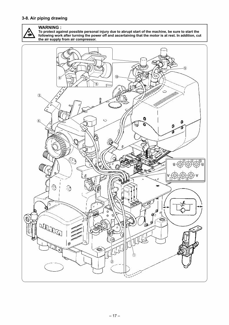
3-8. Air piping drawing
①
②
③
④
⑤
⑬
⑤
⑬
①
②
③
④
⑨
⑤
WARNING :To protect against possible personal injury due to abrupt start of the machine, be sure to start the following work after turning the power off and ascertaining that the motor is at rest. In addition, cut the air supply from air compressor.
– 18 –
❸ ❹ ❺ ❻
❸ ❹ ❺ ❻
❸ ❹ ❺ ❻
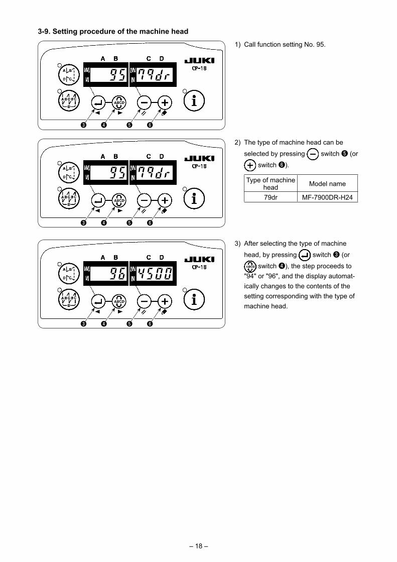
3-9. Setting procedure of the machine head
1) Call function setting No. 95.
2) The type of machine head can be
selected by pressing switch ❺ (or
switch ❻).
Type of machine head Model name
79dr MF-7900DR-H24
3) After selecting the type of machine
head, by pressing switch ❸ (or
switch ❹), the step proceeds to "94" or "96", and the display automat-ically changes to the contents of the setting corresponding with the type of machine head.
– 19 –
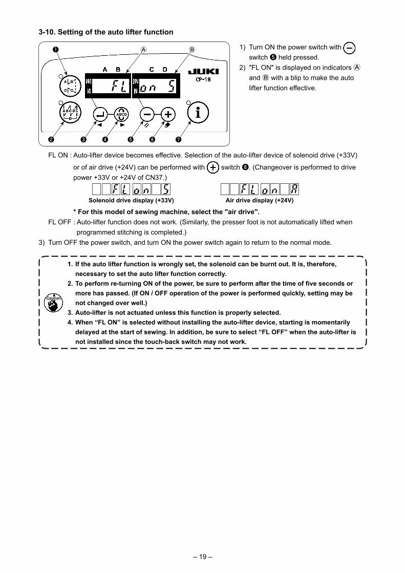
3-10. Setting of the auto lifter function
1) Turn ON the power switch with switch ❺ held pressed.
2) "FL ON" is displayed on indicators Ⓐ and Ⓑ with a blip to make the auto lifter function effective.
❻❺❹❸
❶ ⒷⒶ
❷ ❼
FL ON : Auto-lifter device becomes effective. Selection of the auto-lifter device of solenoid drive (+33V)
or of air drive (+24V) can be performed with switch ❻. (Changeover is performed to drive power +33V or +24V of CN37.)
Solenoid drive display (+33V) Air drive display (+24V)
* For this model of sewing machine, select the "air drive". FL OFF : Auto-lifter function does not work. (Similarly, the presser foot is not automatically lifted when
programmed stitching is completed.)3) Turn OFF the power switch, and turn ON the power switch again to return to the normal mode.
1. If the auto lifter function is wrongly set, the solenoid can be burnt out. It is, therefore, necessary to set the auto lifter function correctly.
2. To perform re-turning ON of the power, be sure to perform after the time of five seconds or more has passed. (If ON / OFF operation of the power is performed quickly, setting may be not changed over well.)
3. Auto-lifter is not actuated unless this function is properly selected.4. When “FL ON” is selected without installing the auto-lifter device, starting is momentarily
delayed at the start of sewing. In addition, be sure to select “FL OFF” when the auto-lifter is not installed since the touch-back switch may not work.
– 20 –
3-11. Error codesThe MF-7900DR has its specific errors as described below. For other errors, refer to the Instruction Manual for SC-921.
In case of the following, check again before you judge the case as trouble.
No.Description of error detected
Cause of occurrence expected
Items to be checked
E968 Motor driver error (inside of MC-450)
• Timing to re-turn the power ON is too early.
• Motor cable or encoder cable has slipped off or broken.
• Failure of the motor driver
• Wait for five more seconds and re-turn the pow-er ON.
• Check whether or not the following motor/en-coder cable connector has slipped off or wheth-er or not the cable has broken.
Motor cable connectors : MOT_3D (motor side) - MD_CN3 (MC-450 side)
Encoder cable connectors : MOT_2D (motor side) - MD_CN2 (MC-450 side)
No. Phenomenon Cause Corrective measure1 The top feed belt fails to
operate during sewing (in the case Error E968 has not occurred)
• Motor control cable connector CN50 (SC-921 side) or MD_CN1 (MC-450 side) has slipped off or is not securely connected.
• Check whether or not the connector has slipped off.
• Re-insert the slipped-off/loosened connector securely.
– 21 –
4. SETTING THE TOP BELT FEED FUNCTION
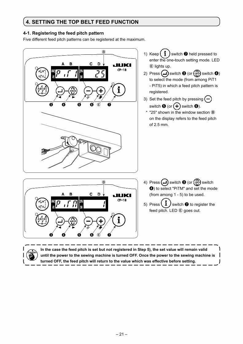
4-1. Registering the feed pitch patternFive different feed pitch patterns can be registered at the maximum.
In the case the feed pitch is set but not registered in Step 5), the set value will remain valid until the power to the sewing machine is turned OFF. Once the power to the sewing machine is turned OFF, the feed pitch will return to the value which was effective before setting.
❸ ❹ ❺
Ⓑ
❻ ❼Ⓔ
❸ ❹ ❺
Ⓑ
❻ ❼Ⓔ
1) Keep switch ❼ held pressed to enter the one-touch setting mode. LED Ⓔ lights up.
2) Press switch ❸ (or switch ❹) to select the mode (from among PiT1 - PiT5) in which a feed pitch pattern is registered.
3) Set the feed pitch by pressing
switch ❺ (or switch ❻). * "25" shown in the window section Ⓑ
on the display refers to the feed pitch of 2.5 mm.
4) Press switch ❸ (or switch ❹) to select "PiTM" and set the mode (from among 1 - 5) to be used.
5) Press switch ❼ to register the feed pitch. LED Ⓔ goes out.
– 22 –
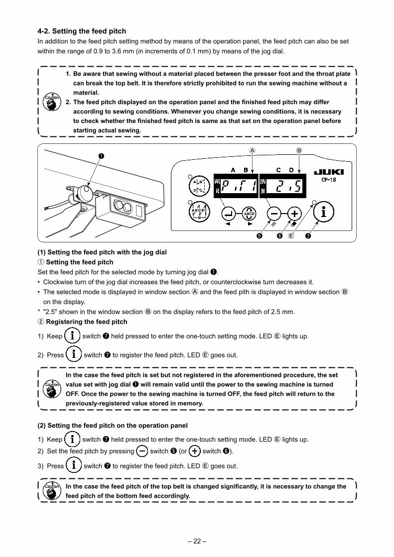
4-2. Setting the feed pitchIn addition to the feed pitch setting method by means of the operation panel, the feed pitch can also be set within the range of 0.9 to 3.6 mm (in increments of 0.1 mm) by means of the jog dial.
❺
ⒷⒶ
❻ ❼Ⓔ
(1) Setting the feed pitch with the jog dial① Setting the feed pitchSet the feed pitch for the selected mode by turning jog dial ❶. • Clockwise turn of the jog dial increases the feed pitch, or counterclockwise turn decreases it.• The selected mode is displayed in window section Ⓐ and the feed pith is displayed in window section Ⓑ
on the display. * "2.5" shown in the window section Ⓑ on the display refers to the feed pitch of 2.5 mm.② Registering the feed pitch
1) Keep switch ❼ held pressed to enter the one-touch setting mode. LED Ⓔ lights up.
2) Press switch ❼ to register the feed pitch. LED Ⓔ goes out.
(2) Setting the feed pitch on the operation panel
1) Keep switch ❼ held pressed to enter the one-touch setting mode. LED Ⓔ lights up.
2) Set the feed pitch by pressing switch ❺ (or switch ❻).
3) Press switch ❼ to register the feed pitch. LED Ⓔ goes out.
1. Be aware that sewing without a material placed between the presser foot and the throat plate can break the top belt. It is therefore strictly prohibited to run the sewing machine without a material.
2. The feed pitch displayed on the operation panel and the finished feed pitch may differ according to sewing conditions. Whenever you change sewing conditions, it is necessary to check whether the finished feed pitch is same as that set on the operation panel before starting actual sewing.
In the case the feed pitch is set but not registered in the aforementioned procedure, the set value set with jog dial ❶ will remain valid until the power to the sewing machine is turned OFF. Once the power to the sewing machine is turned OFF, the feed pitch will return to the previously-registered value stored in memory.
In the case the feed pitch of the top belt is changed significantly, it is necessary to change the feed pitch of the bottom feed accordingly.
❶
– 23 –
5. PRESSER FOOT PRESSURE
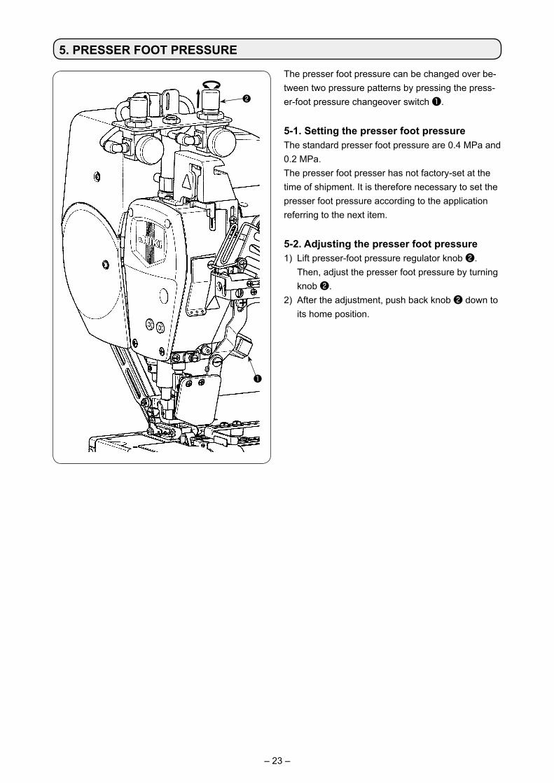
The presser foot pressure can be changed over be-tween two pressure patterns by pressing the press-er-foot pressure changeover switch ❶.
5-1. Setting the presser foot pressureThe standard presser foot pressure are 0.4 MPa and 0.2 MPa.The presser foot presser has not factory-set at the time of shipment. It is therefore necessary to set the presser foot pressure according to the application referring to the next item.
5-2. Adjusting the presser foot pressure1) Lift presser-foot pressure regulator knob ❷.
Then, adjust the presser foot pressure by turning knob ❷.
2) After the adjustment, push back knob ❷ down to its home position.
❶
❷
– 24 –
6. CHANGING THE TOP BELT
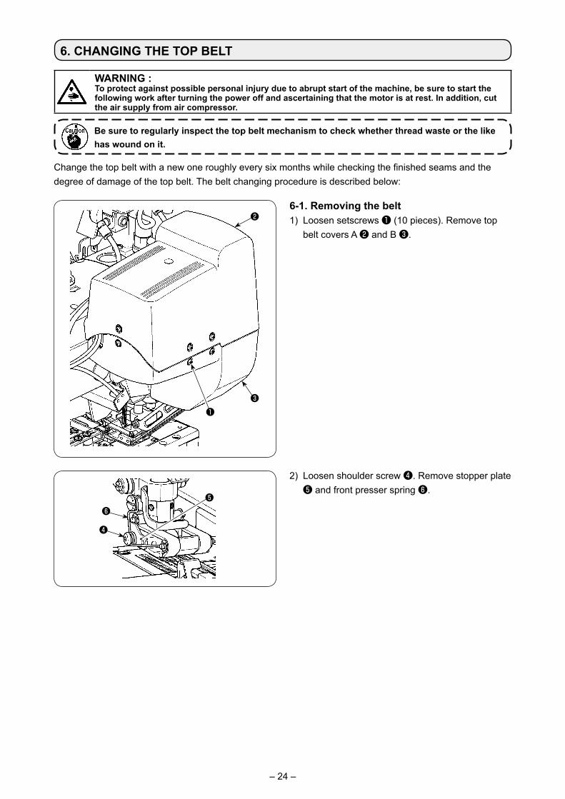
Change the top belt with a new one roughly every six months while checking the finished seams and the degree of damage of the top belt. The belt changing procedure is described below:
Be sure to regularly inspect the top belt mechanism to check whether thread waste or the like has wound on it.
6-1. Removing the belt1) Loosen setscrews ❶ (10 pieces). Remove top
belt covers A ❷ and B ❸.
❷
❸❶
❹
❻❺
2) Loosen shoulder screw ❹. Remove stopper plate ❺ and front presser spring ❻.
WARNING :To protect against possible personal injury due to abrupt start of the machine, be sure to start the following work after turning the power off and ascertaining that the motor is at rest. In addition, cut the air supply from air compressor.
– 25 –
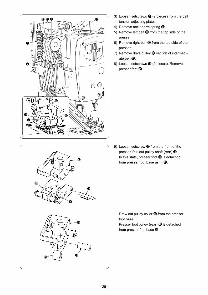
3) Loosen setscrews ❼ (2 pieces) from the belt tension adjusting plate.
4) Remove rocker arm spring ❽. 5) Remove left belt ❾ from the top side of the
presser.6) Remove right belt � from the top side of the
presser.7) Remove drive pulley � section of intermedi-
ate belt �.8) Loosen setscrews � (2 pieces). Remove
presser foot �.
9) Loosen setscrew � from the front of the presser. Pull out pulley shaft (rear) �.
In this state, presser foot � is detached from presser foot base asm. �.
❽
� � ❾ �
❼
�❾
�
�
Draw out pulley collar � from the presser foot base.
Presser foot pulley (rear) � is detached from presser foot base �.
�
�
�
�
�
�
�
– 26 –
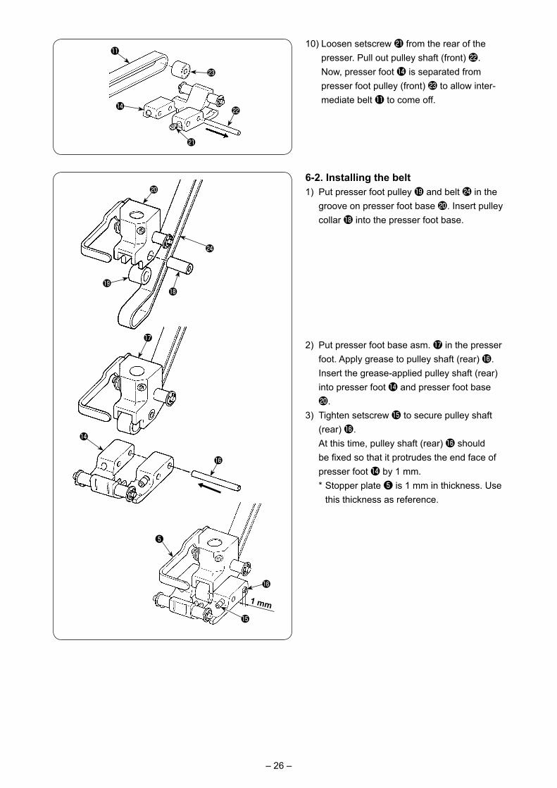
10) Loosen setscrew � from the rear of the presser. Pull out pulley shaft (front) �.
Now, presser foot � is separated from presser foot pulley (front) � to allow inter-mediate belt � to come off.
6-2. Installing the belt1) Put presser foot pulley � and belt � in the
groove on presser foot base �. Insert pulley collar � into the presser foot base.
2) Put presser foot base asm. � in the presser foot. Apply grease to pulley shaft (rear) �. Insert the grease-applied pulley shaft (rear) into presser foot � and presser foot base �.
3) Tighten setscrew � to secure pulley shaft (rear) �.
At this time, pulley shaft (rear) � should be fixed so that it protrudes the end face of presser foot � by 1 mm.
* Stopper plate ❺ is 1 mm in thickness. Use this thickness as reference.
�
��
�
�
�
�
�
�
��
�
�
�
1 mm
❺
– 27 –
❽
� � ❾ �
❼
�
� �
�Alignment
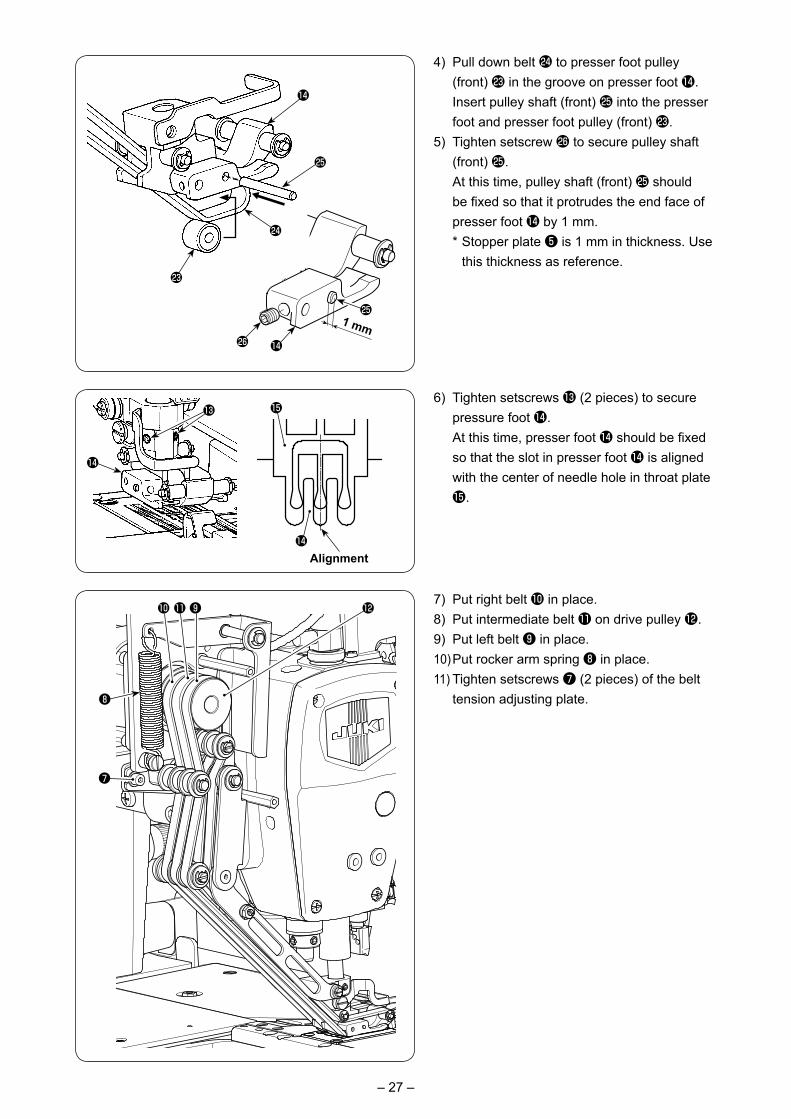
4) Pull down belt � to presser foot pulley (front) � in the groove on presser foot �.
Insert pulley shaft (front) � into the presser foot and presser foot pulley (front) �.
5) Tighten setscrew � to secure pulley shaft (front) �.
At this time, pulley shaft (front) � should be fixed so that it protrudes the end face of presser foot � by 1 mm.
* Stopper plate ❺ is 1 mm in thickness. Use this thickness as reference.
6) Tighten setscrews � (2 pieces) to secure pressure foot �.
At this time, presser foot � should be fixed so that the slot in presser foot � is aligned with the center of needle hole in throat plate �.
7) Put right belt � in place.8) Put intermediate belt � on drive pulley �.9) Put left belt ❾ in place.10) Put rocker arm spring ❽ in place.11) Tighten setscrews ❼ (2 pieces) of the belt
tension adjusting plate.
�
�1 mm
�
�
�
�
�
– 28 –
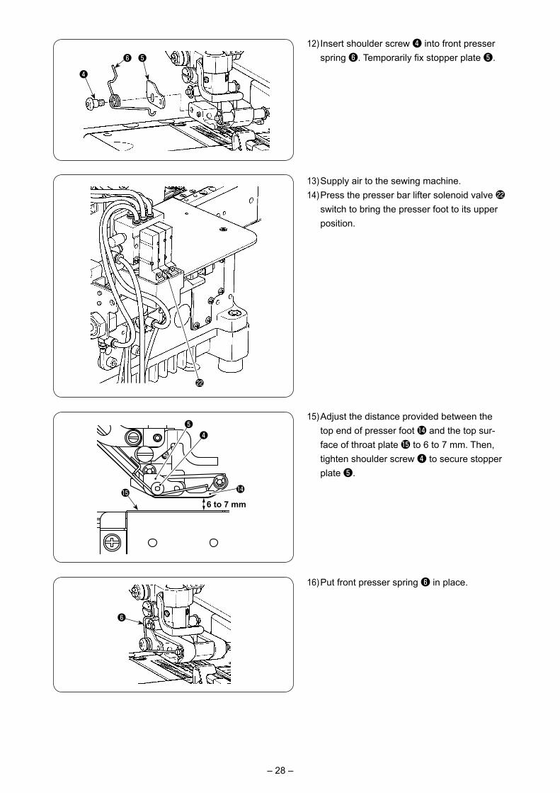
12) Insert shoulder screw ❹ into front presser spring ❻. Temporarily fix stopper plate ❺.
❹
❺❻
13) Supply air to the sewing machine.14) Press the presser bar lifter solenoid valve �
switch to bring the presser foot to its upper position.
�
15) Adjust the distance provided between the top end of presser foot � and the top sur-face of throat plate � to 6 to 7 mm. Then, tighten shoulder screw ❹ to secure stopper plate ❺.
6 to 7 mm
❺
�
❹
�
❻
16) Put front presser spring ❻ in place.
Related Documents