Sonicator ® 730 Maintenance Manual ® 1333 S. Claudina Street Anaheim, California 92805 U.S.A. Call toll free: (800)–854–9305 or call: (714)–533–2221 FAX: (714) 635–7539 March, 2003 IR7–39

Mettler Sonicare 730 Service Manual
Oct 22, 2014
Welcome message from author
This document is posted to help you gain knowledge. Please leave a comment to let me know what you think about it! Share it to your friends and learn new things together.
Transcript
Sonicator® 730
Maintenance Manual
®
1333 S. Claudina Street
Anaheim, California 92805 U.S.A. Call toll free: (800)–854–9305
or call: (714)–533–2221 FAX: (714) 635–7539
March, 2003 IR7–39
Mettler Electronics Corp.
2
FCC Frequency Interference Statement WARNING: This equipment generates and uses radio frequency energy and, if not installed and operated in strict accordance with the manufacturer’s instructions, may cause radio frequency interference.
NOTICE 1: This equipment has been verified to comply with the specifications in Part 18 of FCC Rules, which are designed to provide reasonable protection against radio frequency interference. However, there is no guarantee that interference will not occur in a particular installation.
NOTICE 2: If this equipment is found to be the source of radio frequency interference, which can be determined by turning the equipment off and on, the user should try to correct the interference by one or more of the following measures:
• Reorient the receiving antenna (as applicable).
• Relocate the Sonicator with respect to the receiver.
• Move the Sonicator away from the receiver.
• Plug the Sonicator into a different outlet than the receiver.
• If necessary, the user should consult with the dealer or manufacturer for additional suggestions. (The user may find FCC’s “Interference Handbook” helpful. It is available from the U.S. Government Printing Office, Washington, D.C. 20402, Stock No. 004–000–00450–7.)
NOTICE 3: The manufacturer is not responsible for any interference caused by unauthorized modification to this equipment.
Sonicator 730 Maintenance Manual
3
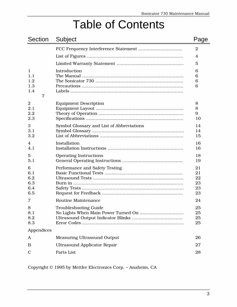
Table of Contents
Section Subject Page FCC Frequency Interference Statement ................................ 2
List of Figures ...................................................................... 4
Limited Warranty Statement ................................................. 5
1 Introduction 6 1.1 The Manual .......................................................................... 6 1.2 The Sonicator 730 ................................................................ 6 1.3 Precautions .......................................................................... 6 1.4 Labels .................................................................................. 7
2 Equipment Description 8 2.1 Equipment Layout ................................................................ 8 2.2 Theory of Operation .............................................................. 9 2.3 Specifications ....................................................................... 10
3 Symbol Glossary and List of Abbreviations 14 3.1 Symbol Glossary ................................................................... 14 3.2 List of Abbreviations ............................................................. 15
4 Installation 16 4.1 Installation Instructions ....................................................... 16
5 Operating Instructions 18 5.1 General Operating Instructions ............................................ 19
6 Performance and Safety Testing 21 6.1 Basic Functional Tests ......................................................... 21 6.2 Ultrasound Tests .................................................................. 22 6.3 Burn in ................................................................................ 23 6.4 Safety Tests .......................................................................... 23 6.5 Request for Feedback ........................................................... 23
7 Routine Maintenance 24
8 Troubleshooting Guide 25 8.1 No Lights When Main Power Turned On ................................ 25 8.2 Ultrasound Output Indicator Blinks ..................................... 25 8.3 Error Codes .......................................................................... 25
Appendices
A Measuring Ultrasound Output 26
B Ultrasound Applicator Repair 27
C Parts List 28 Copyright © 1995 by Mettler Electronics Corp. – Anaheim, CA
Mettler Electronics Corp.
4
List of Figures Number Title Page 2.1 Sonicator 730 Block Diagram 9
2.2 Sonicator 730 Old Block Diagram 9
2.3 Pulse Waveform 12
2.4 Continuous Wave Waveform 12
2.5 10 cm² / 1 MHz Applicator, Far Field Beam Scan 13
2.6 5 cm² / 1 MHz Applicator, Far Field Beam Scan 13
2.7 5 cm² / 3.3 MHz Applicator, Far Field Beam Scan 13
2.8 1 cm² / 3.3 MHz Applicator, Far Field Beam Scan 13
4.1 Sonicator 730, Bottom View— Main Power Switch and Line Cord, Applicator Cable and Combination Therapy Connections 16
4.2 Connecting the Applicator to the Universal Applicator Cable 17
5.1 Front membrane panel and LED indicators 18
B.1 Applicator Top Assembly 27
Sonicator 730 Maintenance Manual
5
Limited Warranty
The Sonicator 730 generating unit is warranted against defects in materials and workmanship for a period of two years from date of purchase. The Sonicator 730 applicators are warranted against defects in materials and workmanship for a period of one year from date of purchase. During the applicable warranty period Mettler Elec-tronics Corp. will, at its discretion, either repair or replace the Product without charge for these types of defects.
For service under this warranty, the Product must be returned by the buyer within the applicable warranty period to Mettler Electronics Corp. Shipping charges to Mettler Electronics Corp. under this warranty must be paid by the buyer. The buyer must also include a copy of the sales receipt or other proof of the date of purchase. If the Product is returned without proof of the date of purchase, it will be serviced as an out–of–warranty product at Mettler Electronics Corp.’s prevailing service rates.
Alteration, misuse, or neglect of the Product voids this warranty. Except as specifically set forth above, Mettler Electronics Corp. makes no warranties, express or implied, including without limitation any implied warranty of merchantability or fitness for a particular purpose, with respect to the Product. If any implied warranties apply as a matter of law, they are limited in duration to one year.
Mettler Electronics Corp. shall not be liable for any indirect, special, consequential or incidental damages resulting from any defect in or use of the Product.
Any legal action brought by the buyer relating to this warranty must be commenced within one year from the date any claim arises and must be brought only in the state or federal courts located in Orange County, California.
Some states do not allow limitations on how long an implied warranty lasts, or the exclusion or limitation of incidental or consequential damages, so the above limitations or exclusions may not apply to the buyer. This warranty gives the buyer specific legal rights, and the buyer may also have other rights which vary from state to state.
Mettler Electronics Corp.
6
Section 1—Introduction 1.1 The Manual This manual is intended to aid qualified biomedical engineers and technicians in testing, servicing, and repairing Sonicator 730’s. It contains an equipment description, operating procedures, theory of operation, test procedures, specifications, and troubleshooting tips.
This manual is current as of its publication. Mettler Electronics Corp. may, however, make improvements as required. To receive manual changes, send your name and address to:
Mettler Electronics Corp. Service Manual Changes 1333 S. Claudina Street
Anaheim, CA 92805.
1.2 The Sonicator 730 The Sonicator 730 is a microprocessor–controlled device providing continuous or pulsed ultrasound. It delivers 1 or 3 MHz ultrasound through four interchangeable applicators. They can be attached to the generator without recalibrating because the Sonicator 730 is self–tuning.
Two applicators are shipped with each generator. Applicators are sealed to facilitate underwater treatments, and are repaired by returning them to a Mettler Electronics Corp. authorized service facility.
The membrane control panel has clearly labeled key pads that produce audible feedback when activated. LED timer and output displays are large and bright.
Verify conformance to specifications at least yearly.
1.3 Precautions 1. The Sonicator 730 operates with high voltages. Servicing should be performed by
qualified ultrasound technicians or the unit should be returned to the factory for service.
2. The internal circuit boards are not designed to be serviced at the component level because of the extensive use of surface mount circuitry. Any attempt at replacing a surface mount component will result in damage to the board. Replace entire circuit board assemblies only!
3. For maximum safety, plug the Sonicator 730 into a grounded wall outlet of proper voltage only. Follow general safety practices for medical electronic equipment.
4. The Sonicator 730 requires 115 VAC [230 VAC in some models] (±10%), 50/60 Hz primary power. DISCONNECT THE LINE SUPPLY CORD PRIOR TO DISASSEMBLY OF THE UNIT. Line supply voltage is present on primary components exposed by removing the back cover.
5. Use calibrated test equipment in good working order.
6. USE OF CONTROLS OR ADJUSTMENTS, OR PERFORMANCE OF PROCEDURES OTHER THAN THOSE SPECIFIED IN THIS MANUAL AND IN THE Sonicator 730 INSTRUCTION MANUAL, MAY RESULT IN HAZARDOUS EXPOSURE TO ULTRASONIC ENERGY.
Sonicator 730 Maintenance Manual
7
7. Do not operate the Sonicator 730 in close proximity to operating shortwave or microwave diathermies.
8. Replace line fuses with specified type and rating only, to avoid risk of fire or other damage.
9. Do not operate the membrane control panel with pointed objects such as pencils, pens, or tools.
10. Make sure all connectors are tight with all pins making good contact when reassembling the unit after service.
11. As a prescription device, the Sonicator 730 may be sold only to, or on the order of, a physician, physical therapist, or other practitioner licensed by the state in which he/she practices.
1.4 Labels Each medical device must be uniquely identified for traceability and device history. This is accomplished with serial numbered labels unique to each device.
Product labels provide performance data, and must remain on the device at all times. Preserve label integrity during repair and servicing when actions such as removing access covers could cause label damage.
Please include model and serial numbers when requesting service assistance from the factory.

Mettler Electronics Corp.
8
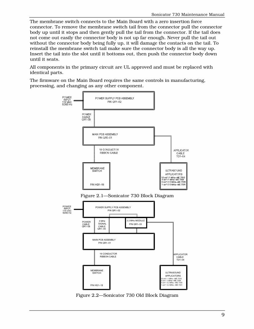
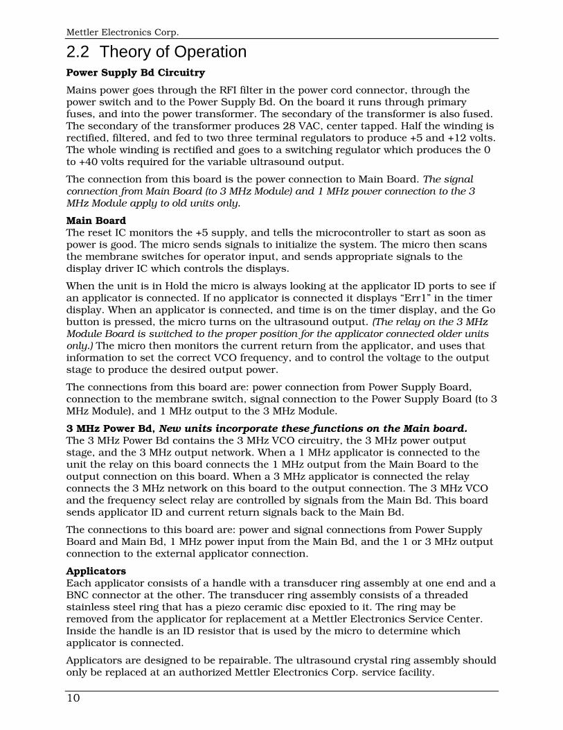
Section 2—Equipment Description 2.1 Equipment Layout The Sonicator 730 has two printed circuit boards (or three boards on units produced prior to January 7, 2003, S/N 122U6375 and earlier), up to four ultrasonic applicators (two standard), a membrane control panel, a main power switch, front and back housings, and interconnecting cables. A block diagram is shown in Fig. 2.1(or Fig. 2 Old Block Diagram).
Power Supply Board The Power Supply Board has a power transformer on it that mounts the board to the front housing with four screws. The input to the Power Supply Board is filtered mains power. The outputs are regulated +5, and +12 volts, and a 0 to 40 volt variable supply. The DC output voltages are available at a header at the bottom of the board assembly. The Power Supply Cable connects from here to the Main Board.
Main Board The Main Board contains the Microcontroller and the Eprom that holds the program. Also on the board is a display decoder, four 7-segment LED’s for treatment time indication, three 7-segment LED’s for output power indication, , and six individual (green) LED’s for control status information. The LED’s fit through holes in the front housing, and shine through the membrane switch. The Main Board also contains the 1 and 3 MHz VCO, the 1 and 3 MHz RF output stage, and the 1 and 3 MHz matching network. On older units, the main board had only 1 MHz functions and the ultrasound RF energy was coupled out through a BNC connector to a short cable that connects to the 3 MHz Module. The front panel membrane switch is connected to this board by means of a zero insertion force connector.
3 MHz Module, older units The 3 MHz Module is located on the back of the Power Supply Board. The module plugs into the Power Supply Board directly, and is held in place by two nuts. It contains the 3 MHz VCO, the 3 MHz RF output stage, and the 3 MHz matching network. It also contains a relay to switch the output between the 1 and 3 MHz outputs. The module is controlled by signals from the Main Bd. On newer units these functions have been incorporated into the main board.
Applicators Four applicators connect to the Sonicator 730. These include: one 10 cm² applicator at 1 MHz (7310); two 5 cm² applicators, one at 1 MHz (7305) and one at 3.3 MHz (7335); and one 1 cm² applicator at 3.3 MHz (7331). All Mettler Electronics Corp. ultrasound applicators are labeled for the model Sonicator with which they may be used. Other applicators from other Sonicator 730’s may be interchanged and will function properly because of the self tuning feature of the Sonicator 730 circuitry. Applicators connect to the Sonicator 730 with a universal applicator cable (ME7391) which has water resistant BNC connectors at each end.
Other Components The power input connector, main power rocker switch, and the applicator BNC connector are mounted to a bracket at the bottom end of the enclosure.
The Main Board is connected to the Power Supply Board with two flat cable assemblies. These are made with insulation displacement connectors. Care should be taken when removing them to pull on the connectors, not the flat cable.
The membrane switch is secured to the front housing with pressure sensitive adhesive. If the membrane switch is ever removed it must be replaced with a new one.
Sonicator 730 Maintenance Manual
9
The membrane switch connects to the Main Board with a zero insertion force connector. To remove the membrane switch tail from the connector pull the connector body up until it stops and then gently pull the tail from the connector. If the tail does not come out easily the connector body is not up far enough. Never pull the tail out without the connector body being fully up, it will damage the contacts on the tail. To reinstall the membrane switch tail make sure the connector body is all the way up. Insert the tail into the slot until it bottoms out, then push the connector body down until it seats.
All components in the primary circuit are UL approved and must be replaced with identical parts.
The firmware on the Main Board requires the same controls in manufacturing, processing, and changing as any other component.
Figure 2.1—Sonicator 730 Block Diagram
MEMBRANESWITCH
P/N HG1–18
19 CONDUCTORRIBBON CABLE
MAIN PCB ASSEMBLYP/N QR1–01
POWER SUPPLY PCB ASSEMBLYP/N QR1–02
ULTRASOUNDAPPLICATORS
5 cm² / 1 MHz—ME 73055 cm² / 3.3 MHz—ME 7335
10 cm² / 1 MHz—ME 7310
1 cm² / 3.3 MHz—ME 7331
POWERCABLEQR1–08
3 MHzSIGNALCABLE
QR1–45
APPLICATORCABLETD1–04
3.3 MHz MODULEP/N QR1–33
POWERINPUT
115 VAC50/60 Hz
Figure 2.2—Sonicator 730 Old Block Diagram
Mettler Electronics Corp.
10
2.2 Theory of Operation Power Supply Bd Circuitry
Mains power goes through the RFI filter in the power cord connector, through the power switch and to the Power Supply Bd. On the board it runs through primary fuses, and into the power transformer. The secondary of the transformer is also fused. The secondary of the transformer produces 28 VAC, center tapped. Half the winding is rectified, filtered, and fed to two three terminal regulators to produce +5 and +12 volts. The whole winding is rectified and goes to a switching regulator which produces the 0 to +40 volts required for the variable ultrasound output.
The connection from this board is the power connection to Main Board. The signal connection from Main Board (to 3 MHz Module) and 1 MHz power connection to the 3 MHz Module apply to old units only.
Main Board The reset IC monitors the +5 supply, and tells the microcontroller to start as soon as power is good. The micro sends signals to initialize the system. The micro then scans the membrane switches for operator input, and sends appropriate signals to the display driver IC which controls the displays.
When the unit is in Hold the micro is always looking at the applicator ID ports to see if an applicator is connected. If no applicator is connected it displays “Err1” in the timer display. When an applicator is connected, and time is on the timer display, and the Go button is pressed, the micro turns on the ultrasound output. (The relay on the 3 MHz Module Board is switched to the proper position for the applicator connected older units only.) The micro then monitors the current return from the applicator, and uses that information to set the correct VCO frequency, and to control the voltage to the output stage to produce the desired output power.
The connections from this board are: power connection from Power Supply Board, connection to the membrane switch, signal connection to the Power Supply Board (to 3 MHz Module), and 1 MHz output to the 3 MHz Module.
3 MHz Power Bd, New units incorporate these functions on the Main board. The 3 MHz Power Bd contains the 3 MHz VCO circuitry, the 3 MHz power output stage, and the 3 MHz output network. When a 1 MHz applicator is connected to the unit the relay on this board connects the 1 MHz output from the Main Board to the output connection on this board. When a 3 MHz applicator is connected the relay connects the 3 MHz network on this board to the output connection. The 3 MHz VCO and the frequency select relay are controlled by signals from the Main Bd. This board sends applicator ID and current return signals back to the Main Bd.
The connections to this board are: power and signal connections from Power Supply Board and Main Bd, 1 MHz power input from the Main Bd, and the 1 or 3 MHz output connection to the external applicator connection.
Applicators Each applicator consists of a handle with a transducer ring assembly at one end and a BNC connector at the other. The transducer ring assembly consists of a threaded stainless steel ring that has a piezo ceramic disc epoxied to it. The ring may be removed from the applicator for replacement at a Mettler Electronics Service Center. Inside the handle is an ID resistor that is used by the micro to determine which applicator is connected.
Applicators are designed to be repairable. The ultrasound crystal ring assembly should only be replaced at an authorized Mettler Electronics Corp. service facility.
Sonicator 730 Maintenance Manual
11
The universal applicator cable interconnects the applicator to the generator. It is detachable at both ends with BNC connectors. These connectors are specially designed to be water resistant. The type, length, and shielding of the cable are critical to the proper operation of the unit. Only applicator cables supplied by Mettler Electronics Corp. should be used.
2.3 Specifications General Specifications: Input: 115 VAC (±10%), 50/60 Hz, 0.6 amperes maximum
Certification: The Sonicator 730 complies with the ultrasound performance standards set forth in the Code of Federal Regulations, Title 21 (Food and Drugs), Part 1050.10
ETL and C-ETL Listed: Model ME 730 (9801427)
U.S. Patent Numbers: 4,966,131 and 5,095,890
Treatment Timer Indicator: The digital timer indicates time set in minutes and seconds prior to the start of treatment and treatment time remaining during treatment or when treatment is temporarily suspended.
Accuracy: ±0.5 minutes for times less than 5 minutes ±10% for times from 5 to 10 minutes ±1.0 minute for times greater that 10 minutes
Maximum treatment time: 29 minutes
Size: 4.3 in (H) x 6 in (D) x 13.4 in (L)
Weight: 5.1 pounds
Operating Temperature: +50°F to +131°F
Humidity: Operating, 30% to 75% Relative Humidity at 104°F Nonoperating, up to 90% Relative Humidity at 149°F
Storage Temperature: -40°F to 167°F
Ultrasonic Generator Specifications: Frequency: 1.0 MHz ±10% 3.3 MHz ±10%
Modes: Continuous Pulsed—20% Duty cycle
Pulse Repetition Rate: 100 Hz ±20%
Pulse Duration: 2 msec ±20%
Temporal Peak/ average intensity ratio: 5:1 ±20%
Maximum output power: 22 W with a 10 cm² applicator, (ME 7310) 11 W at with either 5 cm² applicator, (ME 7305 and ME 7335) 2.2 W with a 1 cm² applicator (ME 7331)
Maximum intensity: 2.2 W/cm² with all applicators
Indication accuracy: ±20% (for any level above 10% of maximum)
Mettler Electronics Corp.
12
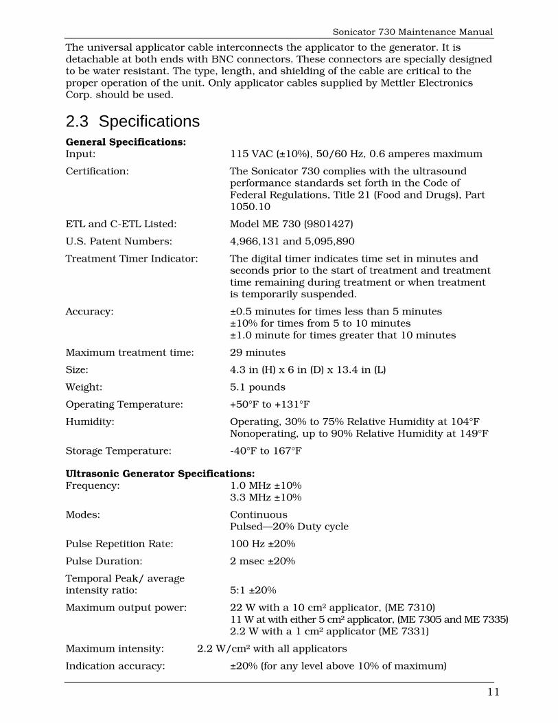
Output description: The output waveform is continuous or pulsed as programmed by the membrane panel control. In the pulse mode the 1 or 3.3 MHz square wave pulses are modulated. The power level is adjusted by varying the pulse amplitude. The pulse waveform is shown below:
2 ms 8 ms 2 msTime
Output1, 3.2 or 3.3 MHz
Pulse Space = 10 ms
Figure 2.3—Pulse Waveform
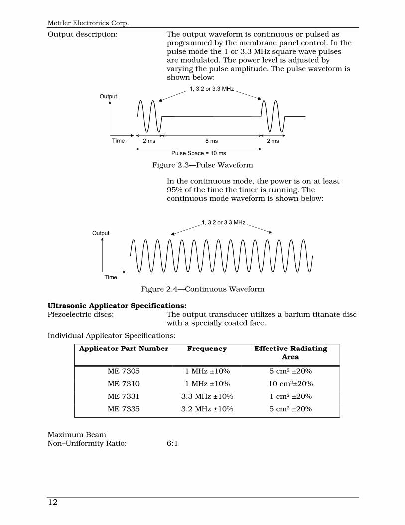
In the continuous mode, the power is on at least 95% of the time the timer is running. The continuous mode waveform is shown below:
Time
Output
1, 3.2 or 3.3 MHz
Figure 2.4—Continuous Waveform
Ultrasonic Applicator Specifications: Piezoelectric discs: The output transducer utilizes a barium titanate disc with a specially coated face.
Individual Applicator Specifications:
Applicator Part Number Frequency Effective Radiating Area
ME 7305 1 MHz ±10% 5 cm² ±20%
ME 7310 1 MHz ±10% 10 cm²±20%
ME 7331 3.3 MHz ±10% 1 cm² ±20%
ME 7335 3.2 MHz ±10% 5 cm² ±20%
Maximum Beam Non–Uniformity Ratio: 6:1
Sonicator 730 Maintenance Manual
13
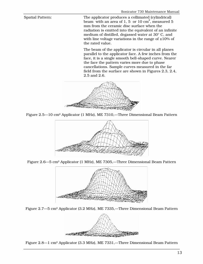
Spatial Pattern: The applicator produces a collimated (cylindrical) beam with an area of 1, 5 or 10 cm², measured 5 mm from the ceramic disc surface when the radiation is emitted into the equivalent of an infinite medium of distilled, degassed water at 30° C, and with line voltage variations in the range of ±10% of the rated value.
The beam of the applicator is circular in all planes parallel to the applicator face. A few inches from the face, it is a single smooth bell-shaped curve. Nearer the face the pattern varies more due to phase cancellations. Sample curves measured in the far field from the surface are shown in Figures 2.3, 2.4, 2.5 and 2.6.
Figure 2.5—10 cm² Applicator (1 MHz), ME 7310,—Three Dimensional Beam Pattern
Figure 2.6—5 cm² Applicator (1 MHz), ME 7305,—Three Dimensional Beam Pattern
Figure 2.7—5 cm² Applicator (3.2 MHz), ME 7335,—Three Dimensional Beam Pattern
Figure 2.8—1 cm² Applicator (3.3 MHz), ME 7331,—Three Dimensional Beam Pattern
Mettler Electronics Corp.
14
Section 3—Symbol Glossary and List of Abbreviations
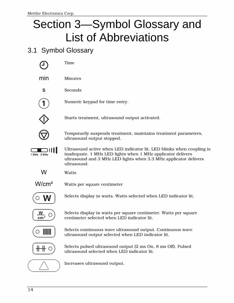
3.1 Symbol Glossary
Time
min Minutes
s Seconds
1 Numeric keypad for time entry.
Starts treatment, ultrasound output activated.
Temporarily suspends treatment, maintains treatment parameters, ultrasound output stopped.
Ultrasound active when LED indicator lit. LED blinks when coupling is inadequate. 1 MHz LED lights when 1 MHz applicator delivers ultrasound and 3 MHz LED lights when 3.3 MHz applicator delivers ultrasound.
W Watts
W/cm² Watts per square centimeter
W Selects display in watts. Watts selected when LED indicator lit.
Wcm2
Selects display in watts per square centimeter. Watts per square centimeter selected when LED indicator lit.
Selects continuous wave ultrasound output. Continuous wave ultrasound output selected when LED indicator lit.
Selects pulsed ultrasound output (2 ms On, 8 ms Off). Pulsed ultrasound selected when LED indicator lit.
Increases ultrasound output.
Sonicator 730 Maintenance Manual
15
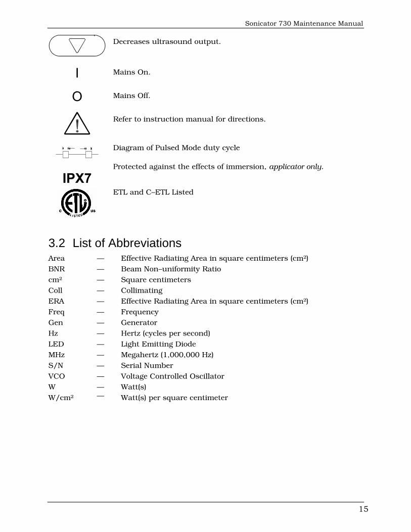
Decreases ultrasound output.
I Mains On.
O Mains Off.
Refer to instruction manual for directions.
Diagram of Pulsed Mode duty cycle
IPX7 Protected against the effects of immersion, applicator only.
ETL and C–ETL Listed
3.2 List of Abbreviations Area — Effective Radiating Area in square centimeters (cm²)
BNR — Beam Non–uniformity Ratio
cm² — Square centimeters
Coll — Collimating
ERA — Effective Radiating Area in square centimeters (cm²)
Freq — Frequency
Gen — Generator
Hz — Hertz (cycles per second)
LED — Light Emitting Diode
MHz — Megahertz (1,000,000 Hz)
S/N — Serial Number
VCO — Voltage Controlled Oscillator
W — Watt(s)
W/cm² — Watt(s) per square centimeter
Mettler Electronics Corp.
16
Section 4—Installation
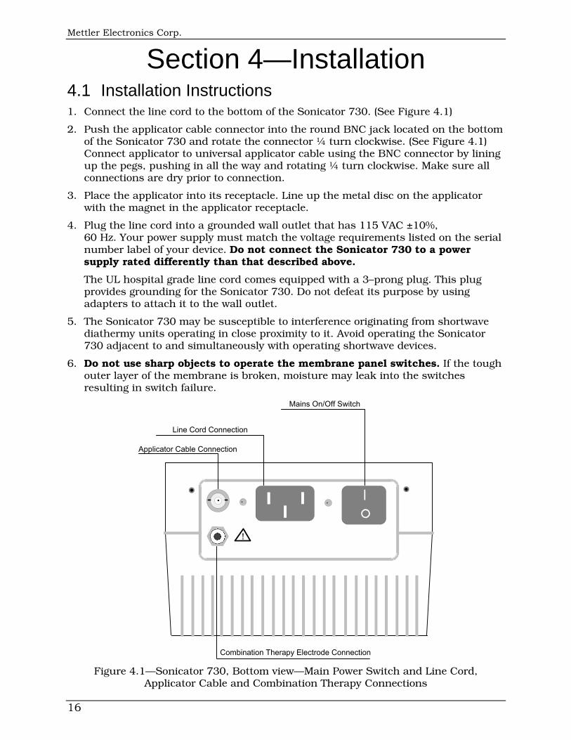
4.1 Installation Instructions 1. Connect the line cord to the bottom of the Sonicator 730. (See Figure 4.1)
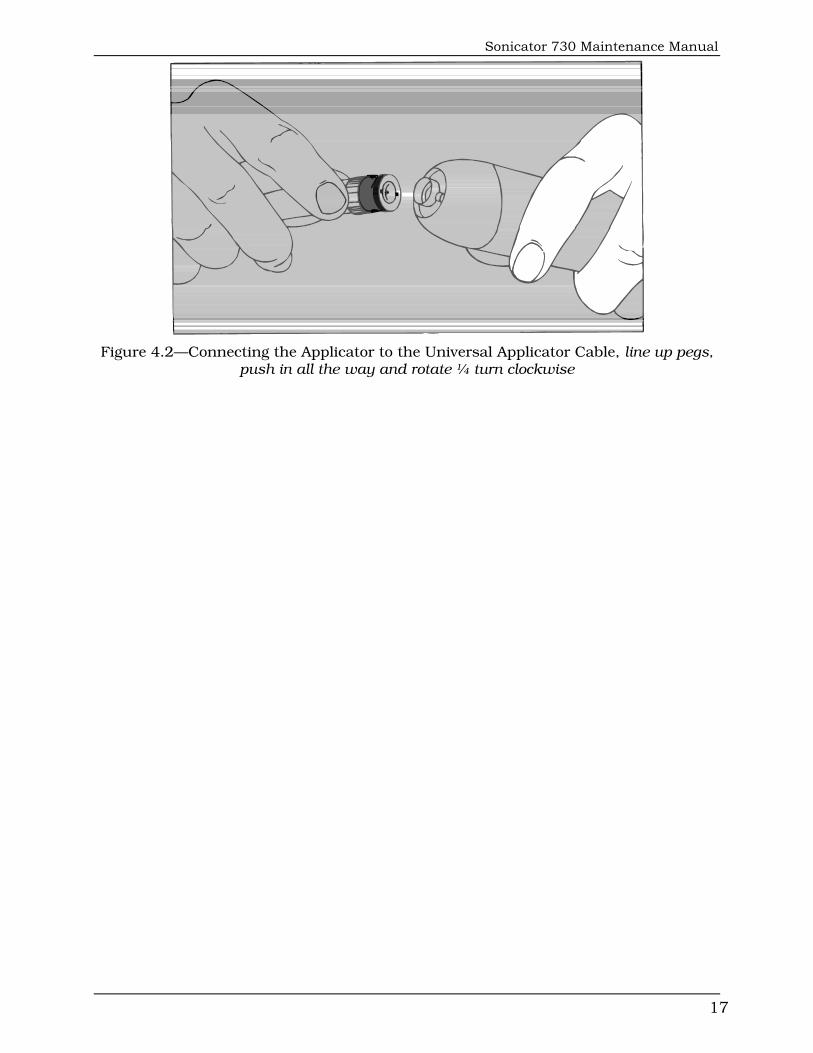
2. Push the applicator cable connector into the round BNC jack located on the bottom of the Sonicator 730 and rotate the connector ¼ turn clockwise. (See Figure 4.1) Connect applicator to universal applicator cable using the BNC connector by lining up the pegs, pushing in all the way and rotating ¼ turn clockwise. Make sure all connections are dry prior to connection.
3. Place the applicator into its receptacle. Line up the metal disc on the applicator with the magnet in the applicator receptacle.
4. Plug the line cord into a grounded wall outlet that has 115 VAC ±10%, 60 Hz. Your power supply must match the voltage requirements listed on the serial number label of your device. Do not connect the Sonicator 730 to a power supply rated differently than that described above.
The UL hospital grade line cord comes equipped with a 3–prong plug. This plug provides grounding for the Sonicator 730. Do not defeat its purpose by using adapters to attach it to the wall outlet.
5. The Sonicator 730 may be susceptible to interference originating from shortwave diathermy units operating in close proximity to it. Avoid operating the Sonicator 730 adjacent to and simultaneously with operating shortwave devices.
6. Do not use sharp objects to operate the membrane panel switches. If the tough outer layer of the membrane is broken, moisture may leak into the switches resulting in switch failure.
HH
Applicator Cable Connection
Line Cord Connection
Mains On/Off Switch
Combination Therapy Electrode Connection
!
Figure 4.1—Sonicator 730, Bottom view—Main Power Switch and Line Cord, Applicator Cable and Combination Therapy Connections
Sonicator 730 Maintenance Manual
17
Figure 4.2—Connecting the Applicator to the Universal Applicator Cable, line up pegs,
push in all the way and rotate ¼ turn clockwise

Mettler Electronics Corp.
18
Section 5—Operating Instructions
W Wcm2
R
R
0
8
5
2
9
6
3
4
1
7
TORSONICA
00.00 00.0
Figure 5.1—Front membrane panel and LED indicators
Sonicator 730 Maintenance Manual
19
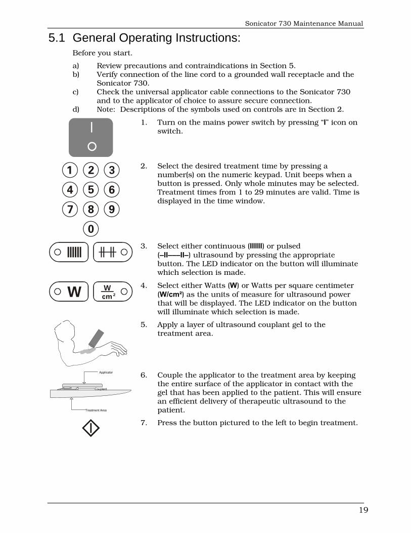
5.1 General Operating Instructions: Before you start.
a) Review precautions and contraindications in Section 5. b) Verify connection of the line cord to a grounded wall receptacle and the Sonicator 730. c) Check the universal applicator cable connections to the Sonicator 730 and to the applicator of choice to assure secure connection. d) Note: Descriptions of the symbols used on controls are in Section 2.
1. Turn on the mains power switch by pressing “I” icon on switch.
0
8
5
2
9
6
3
4
1
7
2. Select the desired treatment time by pressing a number(s) on the numeric keypad. Unit beeps when a button is pressed. Only whole minutes may be selected. Treatment times from 1 to 29 minutes are valid. Time is displayed in the time window.
3. Select either continuous (IIIIII) or pulsed (–II–––II–) ultrasound by pressing the appropriate button. The LED indicator on the button will illuminate which selection is made.
W Wcm2
4. Select either Watts (W) or Watts per square centimeter (W/cm²) as the units of measure for ultrasound power that will be displayed. The LED indicator on the button will illuminate which selection is made.
5. Apply a layer of ultrasound couplant gel to the treatment area.
Couplant
Applicator
Treatment Area
6. Couple the applicator to the treatment area by keeping the entire surface of the applicator in contact with the gel that has been applied to the patient. This will ensure an efficient delivery of therapeutic ultrasound to the patient.
7. Press the button pictured to the left to begin treatment.
Mettler Electronics Corp.
20
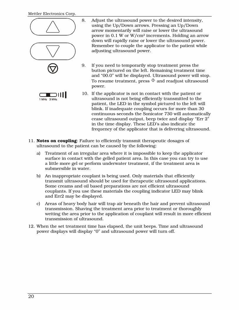
8. Adjust the ultrasound power to the desired intensity, using the Up/Down arrows. Pressing an Up/Down arrow momentarily will raise or lower the ultrasound power in 0.1 W or W/cm² increments. Holding an arrow down will rapidly raise or lower the ultrasound power. Remember to couple the applicator to the patient while adjusting ultrasound power.
9. If you need to temporarily stop treatment press the button pictured on the left. Remaining treatment time and “00.0” will be displayed. Ultrasound power will stop. To resume treatment, press and readjust ultrasound power.
10. If the applicator is not in contact with the patient or
ultrasound is not being efficiently transmitted to the patient, the LED in the symbol pictured to the left will blink. If inadequate coupling occurs for more than 30 continuous seconds the Sonicator 730 will automatically cease ultrasound output, beep twice and display “Err 2” in the time display. These LED’s also indicate the frequency of the applicator that is delivering ultrasound.
11. Notes on coupling: Failure to efficiently transmit therapeutic dosages of ultrasound to the patient can be caused by the following:
a) Treatment of an irregular area where it is impossible to keep the applicator surface in contact with the gelled patient area. In this case you can try to use a little more gel or perform underwater treatment, if the treatment area is submersible in water.
b) An inappropriate couplant is being used. Only materials that efficiently transmit ultrasound should be used for therapeutic ultrasound applications. Some creams and oil based preparations are not efficient ultrasound couplants. If you use these materials the coupling indicator LED may blink and Err2 may be displayed.
c) Areas of heavy body hair will trap air beneath the hair and prevent ultrasound transmission. Shaving the treatment area prior to treatment or thoroughly wetting the area prior to the application of couplant will result in more efficient transmission of ultrasound.
12. When the set treatment time has elapsed, the unit beeps. Time and ultrasound power displays will display “0” and ultrasound power will turn off.
Sonicator 730 Maintenance Manual
21
Section 6—Performance and Safety Testing
Equipment Required:
DVM, Dual Channel Scope, one 10x probe, Frequency Counter, Ohmic Power Meter, Ammeter, Leakage Current Tester, Hipot Tester, Variac, BNC “T” connector
Before Testing Units:
1. Review Safety Instructions in Section 1.
2. Review Operating Instructions in Section 5.
3. Review Keyboard Symbol Definitions in Section 3.
Procedure: 6.1 Basic Functional Tests:
6.1.1 Visual Check: Look at the case exterior for any obvious signs of mechanical damage or cracks in the housing. Inspect the power and applicator cables for any signs of fraying, failing insulation, or other mechanical damage. Inspect the applicator handle, the crystal face, and the ring assembly for any signs of mechanical damage. Open the case by removing the four screws in the case back panel. Inspect the inside for signs of any visible damage. Note that all the cables are attached at both ends.
Check primary wiring and fuses. Verify Fuses, 600 mA.
6.1.2 Power Supply Test: 6.1.2.1 Disconnect the Power Supply cable at J1 on the Main Bd and the
3 MHz signal cable at J4 on the main board, if applicable. Connect the unit to a Variac. Adjust Variac for 115 VAC out. Turn on power. Check for proper power supply voltages on the Power Supply Bd.
+40v PS Bd J1–2 to J1–5 (38 to 42)
+12v PS Bd J1–2 to J1–4 (11.7 to 12.3)
+5v PS Bd J1–2 to J1–3 (4.8 to 5.2)
6.1.2.2 Turn power off. Reconnect the Power Supply cable to J1 and the 3 MHz signal cable to J4, if applicable.
6.1.3 Main Bd: Power Up Check: 6.1.3.1 Turn power on. The time display should show “Err1”, and power
display should show “00.0”. The Watts and Continuous LED’s should be lit.
6.1.4 Key board Test: 6.1.4.1 To enter Diagnostic Mode press and release the “Hold” and
“Continuous” keys at the same time. When in Diagnostic Mode the displays will show all zeros and the six green LED’s will flash.
Mettler Electronics Corp.
22
6.1.4.2 Press “1” and then “Go”.
6.1.4.3 Press 0 – 9 and verify the numbers appear in the TIME LED’s.
6.1.4.4 Press “W”, “W/cm²”, Continuous & Pulse. Verify each LED lights as the switch is pressed.
6.1.4.5 Press the Up arrow and verify the Power LED’s increment.
6.1.4.6 Press the Down arrow and verify the Power LED’s decrement.
6.1.4.7 Press “Hold” to exit the Keyboard Diagnostic.
6.1.5 Display Test: 6.1.5.1 Press “2” and then “Go” to start the Display Diagnostic.
6.1.5.2 The right most LED will show the Diagnostic chosen, while all other LED’s will continually count from 0–9 then A–F.
6.1.5.3 Verify that the 7 segment LED’s are all of uniform brightness.
6.1.5.4 Press “Hold” to exit the Display Diagnostic.
6.2 Ultrasound Tests: 6.2.1 Output Waveform: Connect the applicator to the unit with a BNC “T” connector. Connect a 10x
scope probe to the BNC connector. Place the applicator in the watt meter. Zero the watt meter. Press Go. Set power to 5 Watts indicated on the unit. Verify that the output waveform is a smooth sine wave.
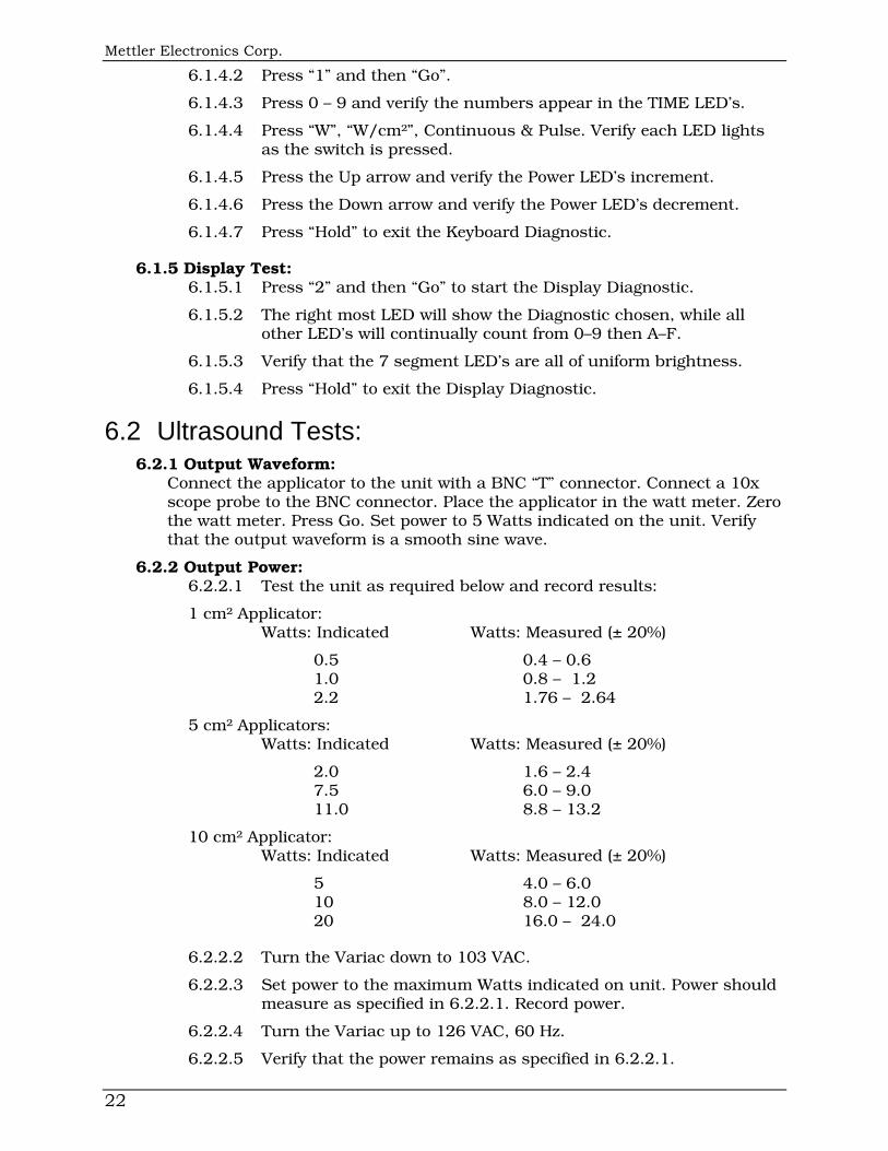
6.2.2 Output Power: 6.2.2.1 Test the unit as required below and record results:
1 cm² Applicator: Watts: Indicated Watts: Measured (± 20%)
0.5 0.4 – 0.6 1.0 0.8 – 1.2 2.2 1.76 – 2.64
5 cm² Applicators: Watts: Indicated Watts: Measured (± 20%)
2.0 1.6 – 2.4 7.5 6.0 – 9.0 11.0 8.8 – 13.2
10 cm² Applicator: Watts: Indicated Watts: Measured (± 20%)
5 4.0 – 6.0 10 8.0 – 12.0 20 16.0 – 24.0
6.2.2.2 Turn the Variac down to 103 VAC.
6.2.2.3 Set power to the maximum Watts indicated on unit. Power should measure as specified in 6.2.2.1. Record power.
6.2.2.4 Turn the Variac up to 126 VAC, 60 Hz.
6.2.2.5 Verify that the power remains as specified in 6.2.2.1.
Sonicator 730 Maintenance Manual
23
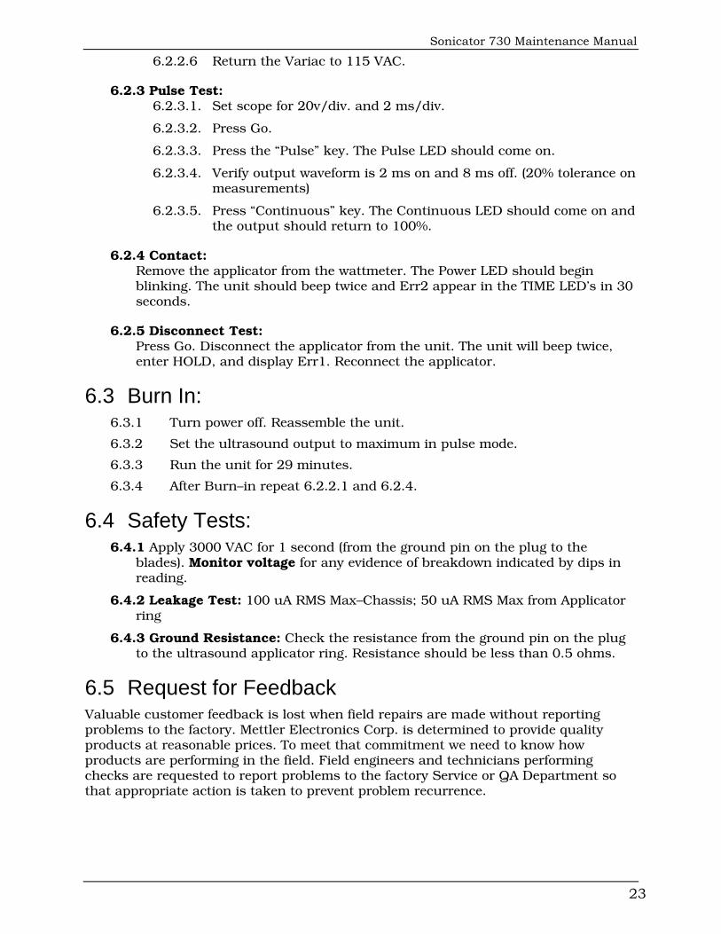
6.2.2.6 Return the Variac to 115 VAC.
6.2.3 Pulse Test: 6.2.3.1. Set scope for 20v/div. and 2 ms/div.
6.2.3.2. Press Go.
6.2.3.3. Press the “Pulse” key. The Pulse LED should come on.
6.2.3.4. Verify output waveform is 2 ms on and 8 ms off. (20% tolerance on measurements)
6.2.3.5. Press “Continuous” key. The Continuous LED should come on and the output should return to 100%.
6.2.4 Contact: Remove the applicator from the wattmeter. The Power LED should begin
blinking. The unit should beep twice and Err2 appear in the TIME LED’s in 30 seconds.
6.2.5 Disconnect Test: Press Go. Disconnect the applicator from the unit. The unit will beep twice,
enter HOLD, and display Err1. Reconnect the applicator.
6.3 Burn In: 6.3.1 Turn power off. Reassemble the unit.
6.3.2 Set the ultrasound output to maximum in pulse mode.
6.3.3 Run the unit for 29 minutes.
6.3.4 After Burn–in repeat 6.2.2.1 and 6.2.4.
6.4 Safety Tests: 6.4.1 Apply 3000 VAC for 1 second (from the ground pin on the plug to the
blades). Monitor voltage for any evidence of breakdown indicated by dips in reading.
6.4.2 Leakage Test: 100 uA RMS Max–Chassis; 50 uA RMS Max from Applicator ring
6.4.3 Ground Resistance: Check the resistance from the ground pin on the plug to the ultrasound applicator ring. Resistance should be less than 0.5 ohms.
6.5 Request for Feedback Valuable customer feedback is lost when field repairs are made without reporting problems to the factory. Mettler Electronics Corp. is determined to provide quality products at reasonable prices. To meet that commitment we need to know how products are performing in the field. Field engineers and technicians performing checks are requested to report problems to the factory Service or QA Department so that appropriate action is taken to prevent problem recurrence.
Mettler Electronics Corp.
24
Section 7—Routine Maintenance 7.1 Clean the Sonicator 730 with a damp cloth. Remove the line cord plug from the
wall before cleaning. Use a gentle household cleaner, sprayed on the cloth, for stubborn dirt. If this method is used, remove any cleaner residue with a clean damp cloth.
7.2 Disinfect applicators with an appropriate disinfectant. Rinse the applicator thoroughly after disinfection to remove any residue. Applicators and the universal applicator cable ARE NOT autoclavable. Thoroughly dry the BNC connectors before attempting to reconnect them.
Sonicator 730 Maintenance Manual
25
Section 8—Troubleshooting Guide 8.1 No Lights When Main Power Turned On
• Check line cord connected to line supply. • Check line cord securely connected to Sonicator 730. • Check line supply. • Check line fuses (F1 & F2) and secondary fuses (F3 & F4) on power supply
board.
8.2 Ultrasound Output Indicator Blinks • Try another applicator – if light comes on, original applicator may need
repair. • Use more ultrasound couplant gel and maintain constant applicator contact to
the treatment area to transmit ultrasound to the patient.
8.3 Error Codes The Sonicator 730 is equipped with internal diagnostics designed to facilitate operator troubleshooting. An error code (Err) is displayed in the TIMER DISPLAY if a problem is detected by the microprocessor. Error codes are:
Error code 1 (Err1): The Sonicator 730 is unable to detect the presence of an applicator. Check the universal applicator cable connections. The plugs should be pushed into the connectors and turned. If Err1 still is displayed in the timer window, install a different applicator and/or universal applicator cable. If the display returns to normal (no error code) the applicator may need repair or the universal applicator cable may need replacement.
Error code 2 (Err2): The applicator has been operating with an inadequate load for thirty consecutive seconds. The timer stops and output goes to zero.
Error code 3 (Err3): Indicates improper self–tuning. Install another applicator. If this resolves the error condition, the replaced applicator may need repair. If the error code is still present with the alternate applicator, return the Sonicator 730 and its applicator to the factory for repair.
Error code 4 (Err4) Usually indicates a shorted output stage. Power must be recycled to clear the display. Turn off main power and turn it back on. If condition persists, replace the Main Board.
Error code 5 (Err5) Indicates a voltage going to the output stage that is greater than requested. Problem can be with either the main board or the power supply board. Substitute boards to isolate the problem.
Mettler Electronics Corp.
26
Appendix A—Measuring Ultrasound Power Output
OHMIC Instruments ultrasound power meters, UPM–series, are traceable to National Institute of Science and Technology (NIST) standards. The UPM–DT–1 is recommended as first choice for measuring applicator output.
Whatever instrument is chosen to make these measurements, some basic principles apply to all. Degassed water must be the medium for ultrasound. Water used in ultrasound power meters must be degassed to less than 4 PPM (dissolved oxygen) for reliable results and adherence to FDA measurement requirements.
Mettler Electronics Corp. developed a good method for degassing water using a canning technique involving a pressure cooker and Mason jars. This is easier than boiling water for 30 minutes and transferring it to plastic bottles while still hot, then placing the bottles in a refrigerator. If interested in this method, send a request to the Mettler QA Department.
Also, when measuring ultrasound output, insure accurate placement of the applicator face over the center of the power meter target. If off center, the target will be moved around by ultrasound resulting in unstable readings.
Ultrasound output measurements should be taken in a stable environment, i.e., no air conditioning drafts across the power meter surface, and no vibrations shaking the power meter mechanism. These influences cause unstable readings and reduce reading repeatability.
Insure the power meter is zeroed between readings to verify a stable reference.
Finally, it is recommended that three sets of readings be taken and the average determined to obtain a more accurate representation of device performance. This helps minimize the effects of measurement variables.
Sonicator 730 Maintenance Manual
27
Appendix B—Ultrasound Applicator Repair
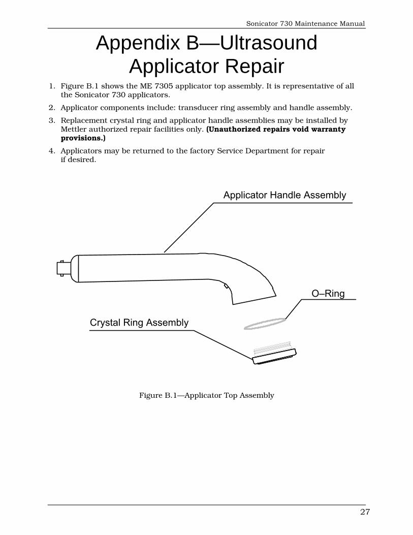
1. Figure B.1 shows the ME 7305 applicator top assembly. It is representative of all the Sonicator 730 applicators.
2. Applicator components include: transducer ring assembly and handle assembly.
3. Replacement crystal ring and applicator handle assemblies may be installed by Mettler authorized repair facilities only. (Unauthorized repairs void warranty provisions.)
4. Applicators may be returned to the factory Service Department for repair if desired.
Applicator Handle Assembly
Crystal Ring Assembly
O–Ring
Figure B.1—Applicator Top Assembly
Mettler Electronics Corp.
28
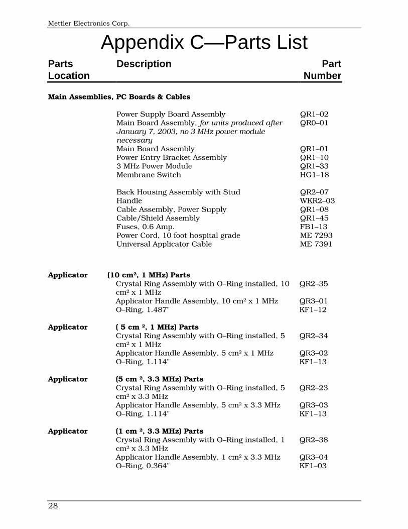
Appendix C—Parts List Parts Description Part Location Number
Main Assemblies, PC Boards & Cables
Power Supply Board Assembly QR1–02 Main Board Assembly, for units produced after January 7, 2003, no 3 MHz power module necessary
QR0–01
Main Board Assembly QR1–01 Power Entry Bracket Assembly QR1–10 3 MHz Power Module QR1–33 Membrane Switch HG1–18 Back Housing Assembly with Stud QR2–07 Handle WKR2–03 Cable Assembly, Power Supply QR1–08 Cable/Shield Assembly QR1–45 Fuses, 0.6 Amp. FB1–13 Power Cord, 10 foot hospital grade ME 7293 Universal Applicator Cable ME 7391
Applicator (10 cm², 1 MHz) Parts
Crystal Ring Assembly with O–Ring installed, 10 cm² x 1 MHz
QR2–35
Applicator Handle Assembly, 10 cm² x 1 MHz QR3–01 O–Ring, 1.487" KF1–12
Applicator
( 5 cm ², 1 MHz) Parts
Crystal Ring Assembly with O–Ring installed, 5 cm² x 1 MHz
QR2–34
Applicator Handle Assembly, 5 cm² x 1 MHz QR3–02 O–Ring, 1.114" KF1–13
Applicator
(5 cm ², 3.3 MHz) Parts
Crystal Ring Assembly with O–Ring installed, 5 cm² x 3.3 MHz
QR2–23
Applicator Handle Assembly, 5 cm² x 3.3 MHz QR3–03 O–Ring, 1.114" KF1–13
Applicator
(1 cm ², 3.3 MHz) Parts
Crystal Ring Assembly with O–Ring installed, 1 cm² x 3.3 MHz
QR2–38
Applicator Handle Assembly, 1 cm² x 3.3 MHz QR3–04 O–Ring, 0.364" KF1–03
Related Documents