Metropolis ® AMU Release 1.0 through 4.0 Applications and Planning Guide 365-312-847R4.0 CC109599779 Issue 4 November 2006 Lucent Technologies - Proprietary This document contains proprietary information of Lucent Technologies and is not to be disclosed or used except in accordance with applicable agreements. Copyright © 2006 Lucent Technologies Unpublished and Not for Publication All Rights Reserved See notice on first age

Welcome message from author
This document is posted to help you gain knowledge. Please leave a comment to let me know what you think about it! Share it to your friends and learn new things together.
Transcript
Metropolis ® AMURelease 1.0 through 4.0Applications and Planning Guide
365-312-847R4.0CC109599779
Issue 4November 2006
Lucent Technologies - ProprietaryThis document contains proprietary information of Lucent Technologies and
is not to be disclosed or used except in accordance with applicable agreements.
Copyright © 2006 Lucent TechnologiesUnpublished and Not for Publication
All Rights Reserved
See notice on first age

This material is protected by the copyright and trade secret laws of the United States and other countries. It may not be reproduced,distributed, or altered in any fashion by any entity (either internal or external to Lucent Technologies), except in accordance with applicableagreements, contracts or licensing, without the express written consent of Lucent Technologies and the business management owner of thematerial.
Trademarks
All trademarks and service marks specified herein are owned by their respective companies.
Notice
Every effort has been made to ensure that the information in this document was complete and accurate at the time of printing. However,information is subject to change.
Release notification
This document describes AMU release 4.0 and covers previous releases.
Compared to provided descriptions some of the legacy releases may vary due to the feature upgrades.
Declaration of Conformity
The Declaration of Conformity (DoC) for this product can be found in this document at“Conformity statements” (p. 5-5), or at:http://www.lucent.de/ecl.
WEEE directive
The Waste from Electrical and Electronic Equipment (WEEE) directivefor this product can be found in this document at“Eco-environmentalstatements” (p. 5-6).
Ordering information
The order number of this document is 365-312-847R4.0 (Issue 4).
Technical support
For information about Technical Support, please contact your Lucent Local/Regional Technical Support Service Representative or visithttp://www.lucent.com/support.
Information product support
To comment on this information product, go to the Online Comment Form (http://www.lucent-info.com/comments/enus/) or email yourcomments to the Comments Hotline ([email protected]).
See notice on first age
Lucent Technologies - ProprietarySee notice on first page

Contents
About this information product
Purpose............................................................................................................................................................................................ ixix
Reason for reissue....................................................................................................................................................................... ixix
Safety information................................................................................................................................................................... xiiixiii
Intended audience..................................................................................................................................................................... xiiixiii
How to use this information product............................................................................................................................... xiiixiii
Conventions used....................................................................................................................................................................... xvxv
Related documentation........................................................................................................................................................... xvixvi
Related training........................................................................................................................................................................ xviixvii
Software Release Description............................................................................................................................................ xviixvii
Intended use............................................................................................................................................................................... xviixvii
Optical safety........................................................................................................................................................................... xviiixviii
Technical Documentation...................................................................................................................................................... xxixxi
How to order .............................................................................................................................................................................. xxixxi
How to comment...................................................................................................................................................................... xxixxi
1 Introduction
Overview ...................................................................................................................................................................................... 1-11-1
Structure of hazard statements............................................................................................................................................ 1-21-2
System overview....................................................................................................................................................................... 1-41-4
2 Product description
Overview ...................................................................................................................................................................................... 2-12-1
...................................................................................................................................................................................................................................365-312-847R4.0Issue 4, November 2006
Lucent Technologies - ProprietarySee notice on first page
iii

Hardware overview of the Metropolis® AMU
Introduction ................................................................................................................................................................................. 2-22-2
System Architecture
Introduction .............................................................................................................................................................................. 2-112-11
Option cards
Introduction .............................................................................................................................................................................. 2-152-15
Technical specifications
Overview ................................................................................................................................................................................... 2-322-32
System specifications.......................................................................................................................................................... 2-332-33
Performance Monitoring..................................................................................................................................................... 2-512-51
Advanced TransLAN® Features...................................................................................................................................... 2-572-57
3 Features
Overview ...................................................................................................................................................................................... 3-13-1
New Features - Release 2.1
ITM-SC Management............................................................................................................................................................. 3-33-3
Performance Monitoring........................................................................................................................................................ 3-43-4
CWDM SFPs ............................................................................................................................................................................. 3-53-5
Bidirectional SFPs................................................................................................................................................................... 3-63-6
Fast Download Tool................................................................................................................................................................ 3-73-7
Physical interfaces
Overview ...................................................................................................................................................................................... 3-83-8
Transmission interfaces.......................................................................................................................................................... 3-93-9
Data interfaces........................................................................................................................................................................ 3-103-10
Timing interfaces.................................................................................................................................................................... 3-113-11
Orderwire interfaces............................................................................................................................................................. 3-123-12
Operations interfaces............................................................................................................................................................ 3-133-13
Power interfaces..................................................................................................................................................................... 3-143-14
Contents
...................................................................................................................................................................................................................................
iv Lucent Technologies - ProprietarySee notice on first page
365-312-847R4.0Issue 4, November 2006
Transmission features
Overview ................................................................................................................................................................................... 3-153-15
Cross-connection features................................................................................................................................................... 3-163-16
Transmission protection...................................................................................................................................................... 3-173-17
Equipment protection........................................................................................................................................................... 3-183-18
Ethernet features..................................................................................................................................................................... 3-193-19
Auto-negotiation..................................................................................................................................................................... 3-213-21
Link Capacity Adjustment Scheme (LCAS)............................................................................................................... 3-223-22
Link Pass Through (LPT).................................................................................................................................................. 3-233-23
Ethernet mapping schemes................................................................................................................................................ 3-243-24
Equipment features
Overview ................................................................................................................................................................................... 3-263-26
Equipment inventory and reports.................................................................................................................................... 3-273-27
Synchronization and timing
Overview ................................................................................................................................................................................... 3-283-28
Timing features....................................................................................................................................................................... 3-293-29
Timing interface features.................................................................................................................................................... 3-303-30
Operations, Administration, Maintenance, and Provisioning
Overview ................................................................................................................................................................................... 3-313-31
Remote maintenance, management, and control....................................................................................................... 3-323-32
4 Planning Network Applications
Overview ...................................................................................................................................................................................... 4-14-1
Planning network application options
Planning considerationsMetropolis® AMU .................................................................................................................. 4-24-2
Network topologies
Linear applications................................................................................................................................................................... 4-44-4
Folded ring application.......................................................................................................................................................... 4-64-6
Ring application........................................................................................................................................................................ 4-74-7
Contents
...................................................................................................................................................................................................................................365-312-847R4.0Issue 4, November 2006
Lucent Technologies - ProprietarySee notice on first page
v
Dual-homed ring application............................................................................................................................................... 4-84-8
Linear extension application................................................................................................................................................ 4-94-9
Dual ring closure................................................................................................................................................................... 4-104-10
Multiple ring application .................................................................................................................................................... 4-114-11
Hub application....................................................................................................................................................................... 4-124-12
Full capacity ring interconnection.................................................................................................................................. 4-134-13
Metropolis® AMU typical 1m/1o application............................................................................................................ 4-144-14
Grooming application........................................................................................................................................................... 4-154-15
IP Tunneling in the DCC channels application......................................................................................................... 4-164-16
GSM/UMTS application..................................................................................................................................................... 4-174-17
Multi-service application with theTransLAN® option board.............................................................................. 4-184-18
Point-to-point LAN connection........................................................................................................................................ 4-234-23
5 Quality and reliability
Overview ...................................................................................................................................................................................... 5-15-1
Quality
Overview ...................................................................................................................................................................................... 5-25-2
Lucent Technologies’ commitment to quality and reliability................................................................................ 5-35-3
Ensuring quality........................................................................................................................................................................ 5-45-4
Conformity statements........................................................................................................................................................... 5-55-5
Reliability specifications
Overview ...................................................................................................................................................................................... 5-95-9
General specifications.......................................................................................................................................................... 5-105-10
Reliability program .............................................................................................................................................................. 5-115-11
Reliability specifications ................................................................................................................................................... 5-125-12
6 Product support
Overview ...................................................................................................................................................................................... 6-16-1
Installation services................................................................................................................................................................. 6-26-2
Engineering services............................................................................................................................................................... 6-46-4
Contents
...................................................................................................................................................................................................................................
vi Lucent Technologies - ProprietarySee notice on first page
365-312-847R4.0Issue 4, November 2006
Maintenance services.............................................................................................................................................................. 6-66-6
Technical support..................................................................................................................................................................... 6-86-8
Documentation support........................................................................................................................................................ 6-106-10
Training support..................................................................................................................................................................... 6-116-11
Warranty .................................................................................................................................................................................... 6-126-12
Standard Repair...................................................................................................................................................................... 6-136-13
7 Ordering
Overview ...................................................................................................................................................................................... 7-17-1
Ordering information.............................................................................................................................................................. 7-27-2
A An SDH overview
Overview ..................................................................................................................................................................................... A-1A-1
SDH signal hierarchy............................................................................................................................................................ A-4A-4
SDH path and line sections................................................................................................................................................ A-6A-6
SDH frame structure.............................................................................................................................................................. A-9A-9
SDH digital multiplexing ................................................................................................................................................. A-11A-11
SDH interface......................................................................................................................................................................... A-13A-13
SDH multiplexing process................................................................................................................................................ A-14A-14
SDH demultiplexing process........................................................................................................................................... A-15A-15
SDH transport rates............................................................................................................................................................. A-16A-16
Glossary
Index
Contents
...................................................................................................................................................................................................................................365-312-847R4.0Issue 4, November 2006
Lucent Technologies - ProprietarySee notice on first page
vii

About this information productAbout this information product
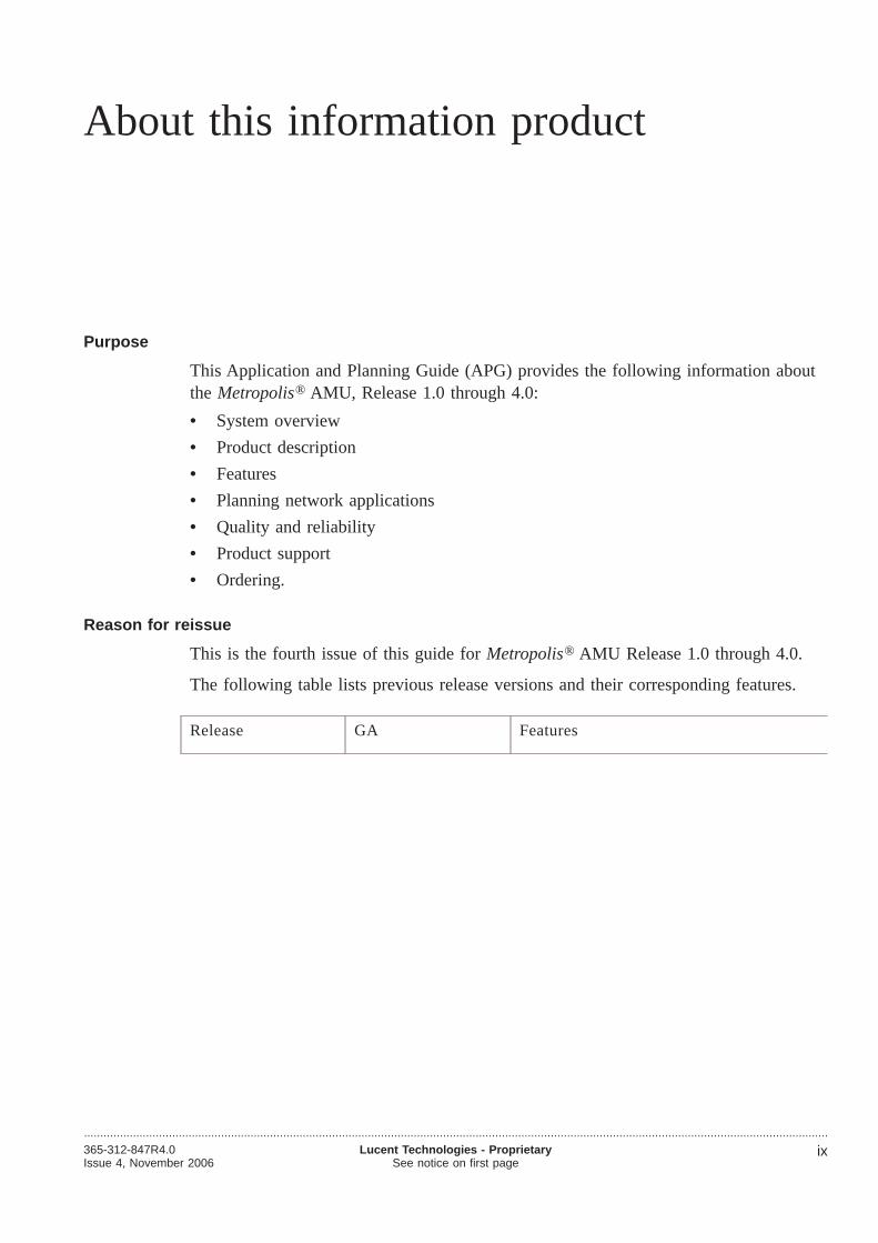
Purpose
This Application and Planning Guide (APG) provides the following information aboutthe Metropolis® AMU, Release 1.0 through 4.0:
• System overview
• Product description
• Features
• Planning network applications
• Quality and reliability
• Product support
• Ordering.
Reason for reissue
This is the fourth issue of this guide forMetropolis® AMU Release 1.0 through 4.0.
The following table lists previous release versions and their corresponding features.
Release GA Features
....................................................................................................................................................................................................................................365-312-847R4.0Issue 4, November 2006,
Lucent Technologies - ProprietarySee notice on first page
ix

1.0 August 2004 The following features have beenprovided in this release.
• One shelf variant with two main andfour option card slots and one shelfvariant with one main and one optioncard slot
• One main unit with pluggable lineinterfaces for two STM-1 or twoSTM-4; supports two extra STM-1interfaces
• Double width adapter card support forlegacy option cards; LAN boardoptimized for Ethernet Private Line(X8PL - Option card Ethernet PrivateLine 8 x E/FE interfaces) cards withLCAS
• 63 x E1 with RJ45 connectors (120Ω/75 Ω)
• 1 + 1 MSP protection on STM-1/4interfaces
• DCC for Network Elementmanagement
• Supports cross-connection betweentributary and aggregate interfaces;non-blocking LO connectivity
• MSP Performance Monitoring only
• Local and remote softwaredownloading
• Supports centralized alarmmanagement using Wavestar®ITM-CIT
• Supports remote alarm investigationthrough Miscellaneous Discrete Inputs(MDI) and Miscellaneous DiscreteOutputs (MDO)
• Cross-connect loopbacks for electricalinterfaces
• 2 Mbit/s external synchronizationclock
• Space efficient design for rackmounting
• Supported by the Wavestar®ITM-CIT - Release 13.02 andWavestar® ITM-SC Release 11.3
About this information product
...................................................................................................................................................................................................................................
x Lucent Technologies - ProprietarySee notice on first page
365-312-847R4.0Issue 4, November 2006
,
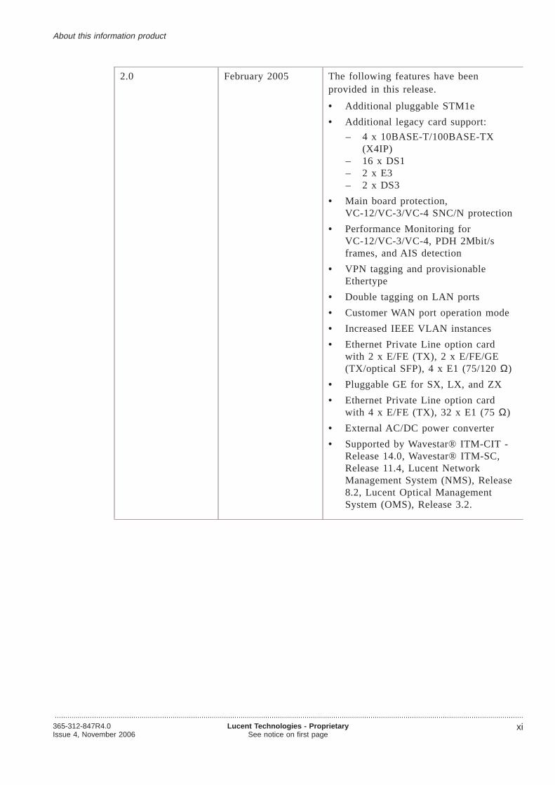
2.0 February 2005 The following features have beenprovided in this release.
• Additional pluggable STM1e
• Additional legacy card support:
– 4 x 10BASE-T/100BASE-TX(X4IP)
– 16 x DS1– 2 x E3– 2 x DS3
• Main board protection,VC-12/VC-3/VC-4 SNC/N protection
• Performance Monitoring forVC-12/VC-3/VC-4, PDH 2Mbit/sframes, and AIS detection
• VPN tagging and provisionableEthertype
• Double tagging on LAN ports
• Customer WAN port operation mode
• Increased IEEE VLAN instances
• Ethernet Private Line option cardwith 2 x E/FE (TX), 2 x E/FE/GE(TX/optical SFP), 4 x E1 (75/120Ω)
• Pluggable GE for SX, LX, and ZX
• Ethernet Private Line option cardwith 4 x E/FE (TX), 32 x E1 (75Ω)
• External AC/DC power converter
• Supported by Wavestar® ITM-CIT -Release 14.0, Wavestar® ITM-SC,Release 11.4, Lucent NetworkManagement System (NMS), Release8.2, Lucent Optical ManagementSystem (OMS), Release 3.2.
About this information product
...................................................................................................................................................................................................................................365-312-847R4.0Issue 4, November 2006,
Lucent Technologies - ProprietarySee notice on first page
xi
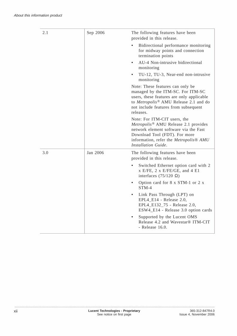
2.1 Sep 2006 The following features have beenprovided in this release.
• Bidirectional performance monitoringfor midway points and connectiontermination points
• AU-4 Non-intrusive bidirectionalmonitoring
• TU-12, TU-3, Near-end non-intrusivemonitoring
Note: These features can only bemanaged by the ITM-SC. For ITM-SCusers, these features are only applicableto Metropolis® AMU Release 2.1 and donot include features from subsequentreleases.
Note: For ITM-CIT users, theMetropolis® AMU Release 2.1 providesnetwork element software via the FastDownload Tool (FDT). For moreinformation, refer theMetropolis® AMUInstallation Guide.
3.0 Jan 2006 The following features have beenprovided in this release.
• Switched Ethernet option card with 2x E/FE, 2 x E/FE/GE, and 4 E1interfaces (75/120Ω)
• Option card for 8 x STM-1 or 2 xSTM-4
• Link Pass Through (LPT) onEPL4_E14 - Release 2.0,EPL4_E132_75 - Release 2.0,ESW4_E14 - Release 3.0 option cards
• Supported by the Lucent OMSRelease 4.2 and Wavestar® ITM-CIT- Release 16.0.
About this information product
...................................................................................................................................................................................................................................
xii Lucent Technologies - ProprietarySee notice on first page
365-312-847R4.0Issue 4, November 2006
,
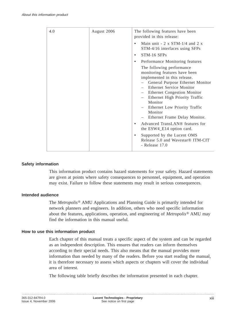
4.0 August 2006 The following features have beenprovided in this release:
• Main unit - 2 x STM-1/4 and 2 xSTM-4/16 interfaces using SFPs
• STM-16 SFPs
• Performance Monitoring features
The following performancemonitoring features have beenimplemented in this release.– General Purpose Ethernet Monitor– Ethernet Service Monitor– Ethernet Congestion Monitor– Ethernet High Priority Traffic
Monitor– Ethernet Low Priority Traffic
Monitor– Ethernet Frame Delay Monitor.
• Advanced TransLAN® features forthe ESW4_E14 option card.
• Supported by the Lucent OMSRelease 5.0 and Wavestar® ITM-CIT- Release 17.0
Safety information
This information product contains hazard statements for your safety. Hazard statementsare given at points where safety consequences to personnel, equipment, and operationmay exist. Failure to follow these statements may result in serious consequences.
Intended audience
The Metropolis® AMU Applications and Planning Guide is primarily intended fornetwork planners and engineers. In addition, others who need specific informationabout the features, applications, operation, and engineering ofMetropolis® AMU mayfind the information in this manual useful.
How to use this information product
Each chapter of this manual treats a specific aspect of the system and can be regardedas an independent description. This ensures that readers can inform themselvesaccording to their special needs. This also means that the manual provides moreinformation than needed by many of the readers. Before you start reading the manual,it is therefore necessary to assess which aspects or chapters will cover the individualarea of interest.
The following table briefly describes the information presented in each chapter.
About this information product
...................................................................................................................................................................................................................................365-312-847R4.0Issue 4, November 2006,
Lucent Technologies - ProprietarySee notice on first page
xiii
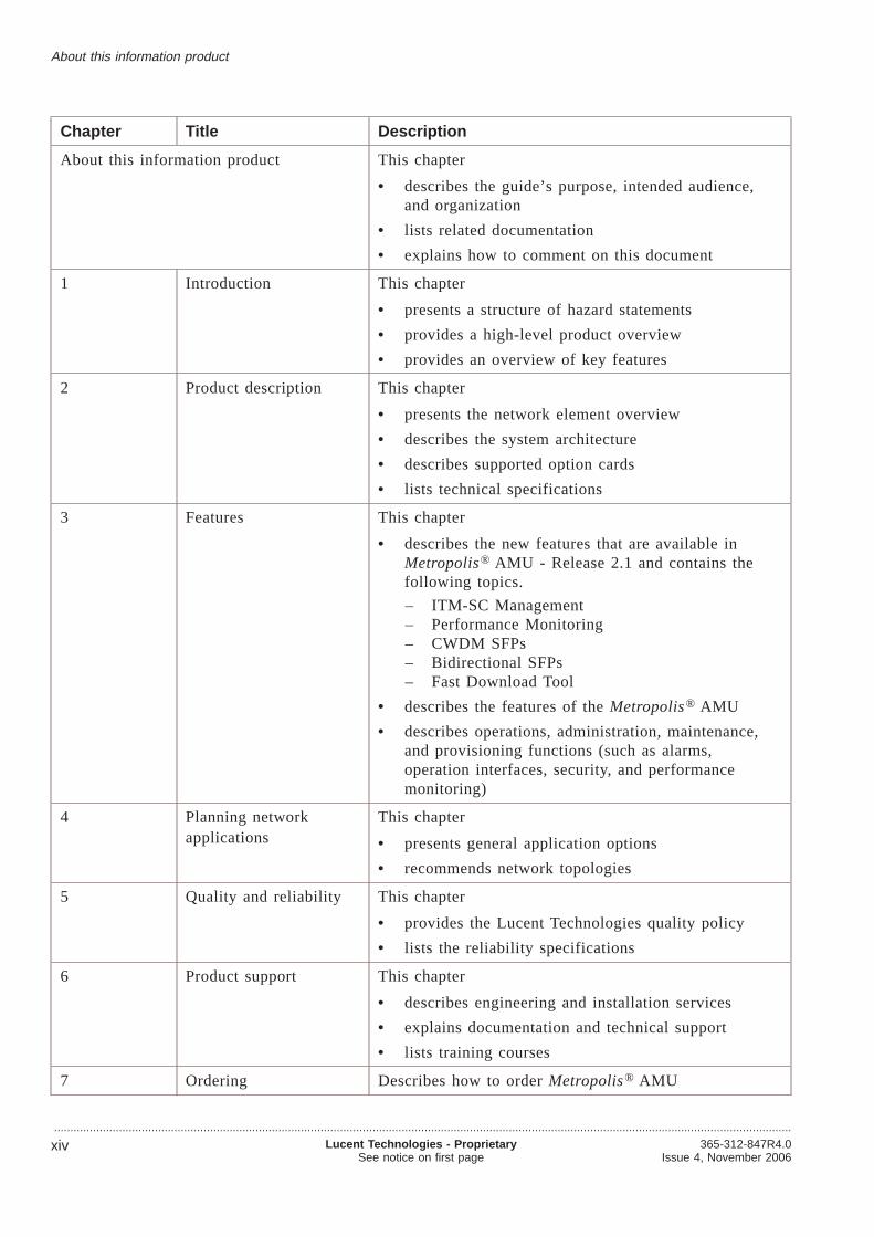
Chapter Title Description
About this information product This chapter
• describes the guide’s purpose, intended audience,and organization
• lists related documentation
• explains how to comment on this document
1 Introduction This chapter
• presents a structure of hazard statements
• provides a high-level product overview
• provides an overview of key features
2 Product description This chapter
• presents the network element overview
• describes the system architecture
• describes supported option cards
• lists technical specifications
3 Features This chapter
• describes the new features that are available inMetropolis® AMU - Release 2.1 and contains thefollowing topics.
– ITM-SC Management– Performance Monitoring– CWDM SFPs– Bidirectional SFPs– Fast Download Tool
• describes the features of theMetropolis® AMU
• describes operations, administration, maintenance,and provisioning functions (such as alarms,operation interfaces, security, and performancemonitoring)
4 Planning networkapplications
This chapter
• presents general application options
• recommends network topologies
5 Quality and reliability This chapter
• provides the Lucent Technologies quality policy
• lists the reliability specifications
6 Product support This chapter
• describes engineering and installation services
• explains documentation and technical support
• lists training courses
7 Ordering Describes how to orderMetropolis® AMU
About this information product
...................................................................................................................................................................................................................................
xiv Lucent Technologies - ProprietarySee notice on first page
365-312-847R4.0Issue 4, November 2006
,
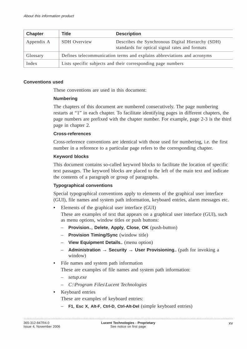
Chapter Title Description
Appendix A SDH Overview Describes the Synchronous Digital Hierarchy (SDH)standards for optical signal rates and formats
Glossary Defines telecommunication terms and explains abbreviations and acronyms
Index Lists specific subjects and their corresponding page numbers
Conventions used
These conventions are used in this document:
Numbering
The chapters of this document are numbered consecutively. The page numberingrestarts at “1” in each chapter. To facilitate identifying pages in different chapters, thepage numbers are prefixed with the chapter number. For example, page 2-3 is the thirdpage in chapter 2.
Cross-references
Cross-reference conventions are identical with those used for numbering, i.e. the firstnumber in a reference to a particular page refers to the corresponding chapter.
Keyword blocks
This document contains so-called keyword blocks to facilitate the location of specifictext passages. The keyword blocks are placed to the left of the main text and indicatethe contents of a paragraph or group of paragraphs.
Typographical conventions
Special typographical conventions apply to elements of the graphical user interface(GUI), file names and system path information, keyboard entries, alarm messages etc.
• Elements of the graphical user interface (GUI)These are examples of text that appears on a graphical user interface (GUI), suchas menu options, window titles or push buttons:
– Provision , Delete , Apply , Close , OK (push-button)
– Provision Timing/Sync (window title)
– View Equipment Details (menu option)
– Administration → Security → User Provisioning (path for invoking awindow)
• File names and system path informationThese are examples of file names and system path information:
– setup.exe
– C:\Program Files\Lucent Technologies
• Keyboard entriesThese are examples of keyboard entries:
– F1, Esc X , Alt-F , Ctrl-D , Ctrl-Alt-Del (simple keyboard entries)
About this information product
...................................................................................................................................................................................................................................365-312-847R4.0Issue 4, November 2006,
Lucent Technologies - ProprietarySee notice on first page
xv

A hyphen between two keys means that both keys have to be pressedsimultaneously. Otherwise, a single key has to be pressed, or several keys haveto be pressed in sequence.
– copy abc xyz (command)A complete command has to be entered.
• Alarms and error messagesThese are examples of alarms and error messages:
– Loss of Signal
– Circuit Pack Failure
– HP-UNEQ, MS-AIS, LOS, LOF
– Not enough disk space available
Abbreviations
Abbreviations used in this document can be found in the “Glossary” unless it can beassumed that the reader is familiar with the abbreviation.
Related documentation
This section briefly describes the documents that are included in theMetropolis® AMUdocumentation set.
• Installation GuideThe Metropolis® AMU Installation Guide (IG) provides step-by-step instructionsfor system installation and setup. It includes information needed for pre-installationsite planning and post-installation acceptance testing.
• Applications and Planning GuideThe Metropolis® AMU Applications and Planning Guide (APG) providesrecommendations for network planners, analysts, and managers. It is also used bythe Lucent Account Team. It presents a detailed overview of the system,recommends applications, provides planning requirements, engineering rules,ordering information, and technical specifications.
• User Operations GuideThe Metropolis® AMU User Operations Guide (UOG) provides step-by-stepinstructions to perform routine system operations such as system provisioning,operations, and administrative tasks using the ITM Craft Interface Terminal(ITM-CIT).
• Alarm Messages and Trouble Clearing GuideThe Metropolis® AMU Alarm Messages and Trouble Clearing Guide (AMTCG)provides a detailed description of alarm messages. It includes procedures forroutine maintenance, troubleshooting, diagnostics, and component replacement.
• The Lucent OMS Release 4.0 Provisioning Guide (ApplicationMetropolis® AMU)The Lucent OMS Provisioning Guide (ApplicationMetropolis® AMU) providesinstructions to perform system provisioning, operations, and administrative tasksusing the Lucent OMS.
About this information product
...................................................................................................................................................................................................................................
xvi Lucent Technologies - ProprietarySee notice on first page
365-312-847R4.0Issue 4, November 2006
,
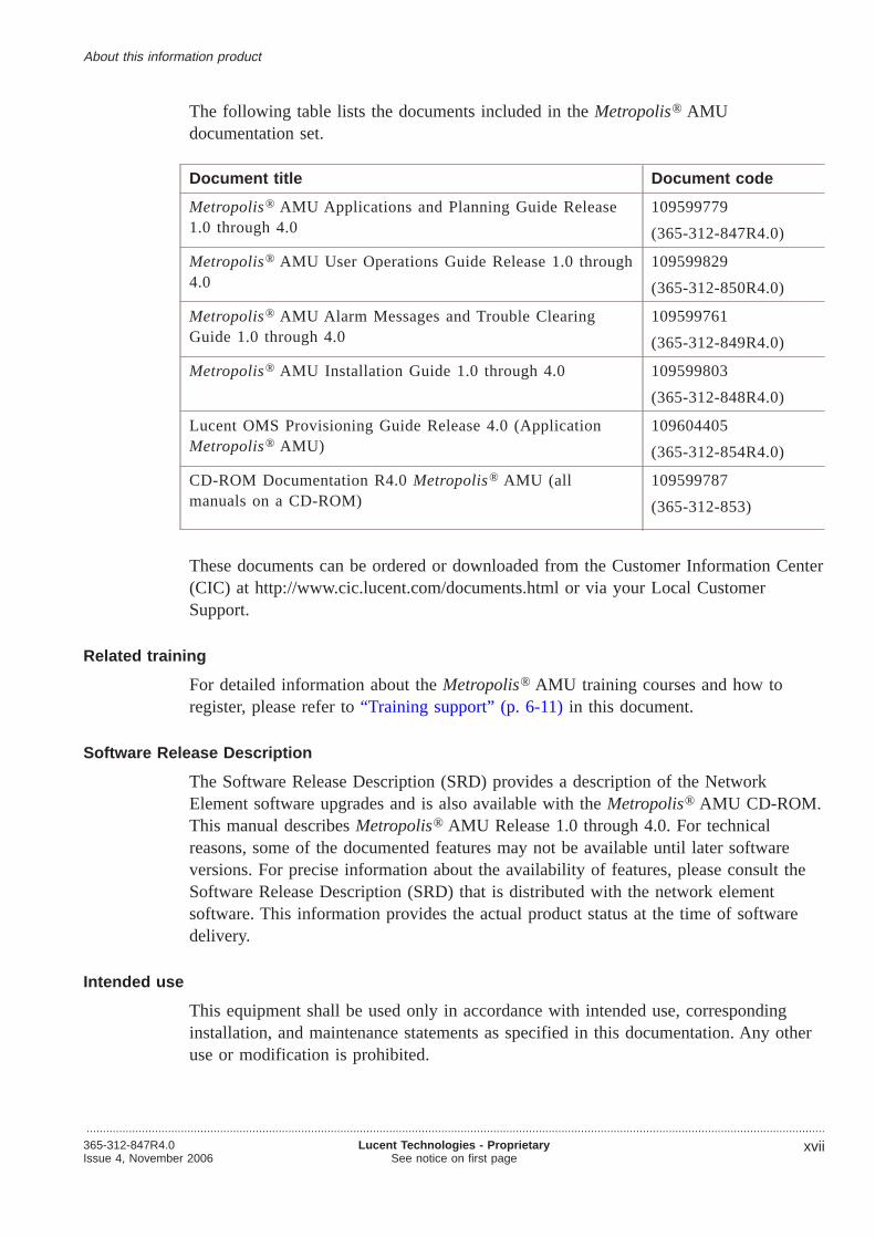
The following table lists the documents included in theMetropolis® AMUdocumentation set.
Document title Document code
Metropolis® AMU Applications and Planning Guide Release1.0 through 4.0
109599779
(365-312-847R4.0)
Metropolis® AMU User Operations Guide Release 1.0 through4.0
109599829
(365-312-850R4.0)
Metropolis® AMU Alarm Messages and Trouble ClearingGuide 1.0 through 4.0
109599761
(365-312-849R4.0)
Metropolis® AMU Installation Guide 1.0 through 4.0 109599803
(365-312-848R4.0)
Lucent OMS Provisioning Guide Release 4.0 (ApplicationMetropolis® AMU)
109604405
(365-312-854R4.0)
CD-ROM Documentation R4.0Metropolis® AMU (allmanuals on a CD-ROM)
109599787
(365-312-853)
These documents can be ordered or downloaded from the Customer Information Center(CIC) at http://www.cic.lucent.com/documents.html or via your Local CustomerSupport.
Related training
For detailed information about theMetropolis® AMU training courses and how toregister, please refer to“Training support” (p. 6-11)in this document.
Software Release Description
The Software Release Description (SRD) provides a description of the NetworkElement software upgrades and is also available with theMetropolis® AMU CD-ROM.This manual describesMetropolis® AMU Release 1.0 through 4.0. For technicalreasons, some of the documented features may not be available until later softwareversions. For precise information about the availability of features, please consult theSoftware Release Description (SRD) that is distributed with the network elementsoftware. This information provides the actual product status at the time of softwaredelivery.
Intended use
This equipment shall be used only in accordance with intended use, correspondinginstallation, and maintenance statements as specified in this documentation. Any otheruse or modification is prohibited.
About this information product
...................................................................................................................................................................................................................................365-312-847R4.0Issue 4, November 2006,
Lucent Technologies - ProprietarySee notice on first page
xvii
Optical safety
For a detailed description about Optical safety guidelines, refer theMetropolis® AMUSafety Guide.
IEC Customer Laser Safety Guidelines
Lucent Technologies declares that this product is compliant with all essential safetyrequirements as stated in IEC 60825-Part 1 and 2 “Safety of Laser Products” and“Safety of Optical Fibre Telecommunication Systems”. Futhermore, LucentTechnologies declares that the warning statements on equipment labels are inaccordance with the specified laser radiation class.
Optical Safety Declaration (if laser modules used)
Lucent Technologies declares that this product is compliant with all essential safetyrequirements as stated in IEC 60825-Part 1 and 2 “Safety of Laser Products” and“Safety of Optical Fiber Telecommunication Systems”. Furthermore, LucentTechnologies declares that the warning statements on equipment labels are inaccordance with the specified laser radiation class.
Optical Fiber Communications
This equipment contains an Optical Fiber Communications semiconductor laser/LEDtransmitter. The following Laser Safety Guidelines are provided for this product.
General Laser Information
Optical fiber telecommunication systems, their associated test sets, and similaroperating systems use semiconductor laser transmitters that emit infrared (IR) light atwavelengths between approximately 800 nanometers (nm) and 1600 nm. The emittedlight is above the red end of the visible spectrum, which is normally not visible to thehuman eye. Although the radiant end at near-IR wavelengths is officially designatedinvisible, some people can see the shorter wavelength energy even at power levels thatare several orders of magnitude below any levels that have been shown to cause injuryto the eye.
Conventional lasers can produce an intense beam of monochromatic light. The term“monochromaticity” means a single wavelength output of pure color that may bevisible or invisible to the eye. A conventional laser produces a small-size beam oflight, and because the beam size is small the power density (also called irradiance) isvery high. Consequently, lasers and laser products are subject to federal and applicablestate regulations, as well as international standards, for their safe operation.
A conventional laser beam expands very little over distance, or is said to be very wellcollimated. Thus, conventional laser irradiance remains relatively constant overdistance. However, lasers used in lightwave systems have a large beam divergence,typically 10 to 20 degrees. Here, irradiance obeys the inverse square law (doubling thedistance reduces the irradiance by a factor of 4) and rapidly decreases over distance.
Lasers and Eye Damage
The optical energy emitted by laser and high-radiance LEDs in the 400-1400 nm rangemay cause eye damage if absorbed by the retina. When a beam of light enters the eye,
About this information product
...................................................................................................................................................................................................................................
xviii Lucent Technologies - ProprietarySee notice on first page
365-312-847R4.0Issue 4, November 2006
,

the eye magnifies and focuses the energy on the retina magnifying the irradiance. Theirradiance of the energy that reaches the retina is approximately 105, or 100,000 timesmore than at the cornea and, if sufficiently intense, may cause a retinal burn.
The damage mechanism at the wavelengths used in an optical fiber telecommunicationsis thermal in origin, i.e., damage caused by heating. Therefore, a specific amount ofenergy is required for a definite time to heat an area of retinal tissue. Damage to theretina occurs only when one looks at the light long enough that the product of theretinal irradiance and the viewing time exceeds the damage threshold. Optical energiesabove 1400 nm cause corneal and skin burns, but do not affect the retina. Thethresholds for injury at wavelengths greater than 1400 nm are significantly higher thanfor wavelengths in the retinal hazard region.
Classification of Lasers
Manufacturers of lasers and laser products in the U.S. are regulated by the Food andDrug Administration’s Center for Devices and Radiological Health (FDA/CDRH) under21 CFR 1040. These regulations require manufacturers to certify each laser or laserproduct as belonging to one of four major Classes: I, II, lla, IlIa, lllb, or IV. TheInternational Electro-technical Commission is an international standards body thatwrites laser safety standards under IEC-60825. Classification schemes are similar withClasses divided into Classes 1, 1M, 2, 2M, 3R, 3B, and 4. Lasers are classifiedaccording to the accessible emission limits and their potential for causing injury.Optical fiber telecommunication systems are generally classified as Class I/1 because,under normal operating conditions, all energized laser transmitting circuit packs areterminated on optical fibers which enclose the laser energy with the fiber sheathforming a protective housing. Also, a protective housing/access panel is typicallyinstalled in front of the laser circuit pack shelves The circuit packs themselves,however, may be FDA/CDRH Class I, IIIb, or IV or IEC Class 1, 1M, 3R, 3B, or 4.
Laser Safety Precautions for Optical Fiber Telecommunication Systems
In its normal operating mode, an optical fiber telecommunication system is totallyenclosed and presents no risk of eye injury. It is a Class I/1 system under the FDA andIEC classifications.
The fiber optic cables that interconnect various components of an optical fibertelecommunication system can disconnect or break, and may expose people to laseremissions. Also, certain measures and maintenance procedures may expose thetechnician to emission from the semiconductor laser during installation and servicing.Unlike more familiar laser devices such as solid-state and gas lasers, the emissionpattern of a semiconductor laser results in a highly divergent beam. In a divergentbeam, the irradiance (power density) decreases rapidly with distance. The greater thedistance, the less energy will enter the eye, and the less potential risk for eye injury.Inadvertently viewing an un-terminated fiber or damaged fiber with the unaided eye atdistances greater than 5 to 6 inches normally will not cause eye injury, provided thepower in the fiber is less than a few milliwatts at the near IR wavelengths and a fewtens of milliwatts at the far IR wavelengths. However, damage may occur if an opticalinstrument such as a microscope, magnifying glass, or eye loupe is used to stare at theenergized fiber end.
About this information product
...................................................................................................................................................................................................................................365-312-847R4.0Issue 4, November 2006,
Lucent Technologies - ProprietarySee notice on first page
xix

CAUTION
Laser hazard
Use of controls, adjustments, and procedures other than those specified herein mayresult in hazardous laser radiation exposure.
Laser Safety Precautions for Enclosed Systems
Under normal operating conditions, optical fiber telecommunication systems arecompletely enclosed; nonetheless, the following precautions shall be observed:
1. Because of the potential for eye damage, technicians should not stare into opticalconnectors or broken fibers
2. Under no circumstance shall laser/fiber optic operations be performed by atechnician before satisfactorily completing an approved training course
3. Since viewing laser emissions directly in excess of Class I/1 limits with an opticalinstrument such as an eye loupe greatly increases the risk of eye damage,appropriate labels must appear in plain view, in close proximity to the optical porton the protective housing/access panel of the terminal equipment.
Laser Safety Precautions for Unenclosed Systems
During service, maintenance, or restoration, an optical fiber telecommunication systemis considered unenclosed. Under these conditions, follow these practices:
1. Only authorized, trained personnel shall be permitted to do service, maintenanceand restoration. Avoid exposing the eye to emissions from un-terminated, energizedoptical connectors at close distances. Laser modules associated with the opticalports of laser circuit packs are typically recessed, which limits the exposuredistance. Optical port shutters, Automatic Power Reduction (APR), andAutomatic Power Shut Down (APSD) are engineering controls that are also used tolimit emissions. However, technicians removing or replacing laser circuit packsshould not stare or look directly into the optical port with optical instruments ormagnifying lenses. (Normal eye wear or indirect viewing instruments such asFind-R-Scopes are not considered magnifying lenses or optical instruments.)
2. Only authorized, trained personnel shall use optical test equipment duringinstallation or servicing since this equipment contains semiconductor lasers (Someexamples of optical test equipment are Optical Time Domain Reflectometers(OTDR’s), Hand-Held Loss Test Sets.)
3. Under no circumstances shall any personnel scan a fiber with an optical test setwithout verifying that all laser sources on the fiber are turned off
4. All unauthorized personnel shall be excluded from the immediate area of theoptical fiber telecommunication systems during installation and service.
Consult ANSI Z136.2, American National Standard for Safe Use of Lasers in the U.S.;or, outside the U.S., IEC-60825, Part 2 for guidance on the safe use of optical fiberoptic communication in the workplace.
About this information product
...................................................................................................................................................................................................................................
xx Lucent Technologies - ProprietarySee notice on first page
365-312-847R4.0Issue 4, November 2006
,

Technical Documentation
The technical documentation as required by the Conformity Assessment procedure iskept at Lucent Technologies location which is responsible for this product. For moreinformation, please contact your local Lucent Technologies representative.
How to order
This information product can be ordered with the order number 365-312-847R4.0 atthe Customer Information Center (CIC), see http://www.cic.lucent.com/.
An overview of the ordering process and the latest software & licences information isprovided inChapter 7, “Ordering”of this manual.
How to comment
To comment on this information product, go to theOnline Comment Form(http://www.lucent-info.com/comments/enus/) or e-mail your comments to theComments Hotline ([email protected]).
About this information product
...................................................................................................................................................................................................................................365-312-847R4.0Issue 4, November 2006,
Lucent Technologies - ProprietarySee notice on first page
xxi

1 1Introduction
Overview...................................................................................................................................................................................................................................
Purpose
This chapter introduces theMetropolis® AMU.
Contents
Structure of hazard statements 1-2
System overview 1-4
...................................................................................................................................................................................................................................365-312-847R4.0Issue 4, November 2006
Lucent Technologies - ProprietarySee notice on first page
1-1
Structure of hazard statements...................................................................................................................................................................................................................................
Overview
Hazard statements describe the safety risks relevant while performing tasks on LucentTechnologies products during deployment and/or use. Failure to avoid the hazards mayhave serious consequences.
General structure
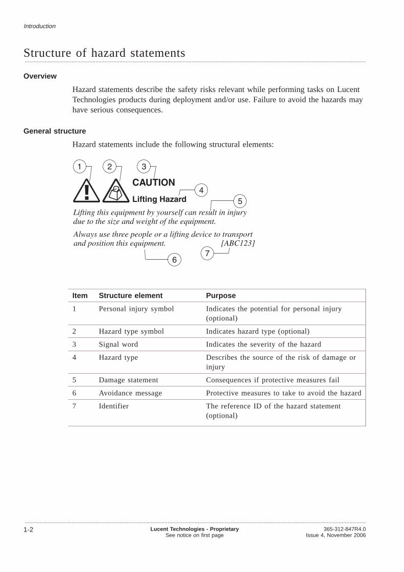
Hazard statements include the following structural elements:
Item Structure element Purpose
1 Personal injury symbol Indicates the potential for personal injury(optional)
2 Hazard type symbol Indicates hazard type (optional)
3 Signal word Indicates the severity of the hazard
4 Hazard type Describes the source of the risk of damage orinjury
5 Damage statement Consequences if protective measures fail
6 Avoidance message Protective measures to take to avoid the hazard
7 Identifier The reference ID of the hazard statement(optional)
Introduction
...................................................................................................................................................................................................................................
1-2 Lucent Technologies - ProprietarySee notice on first page
365-312-847R4.0Issue 4, November 2006
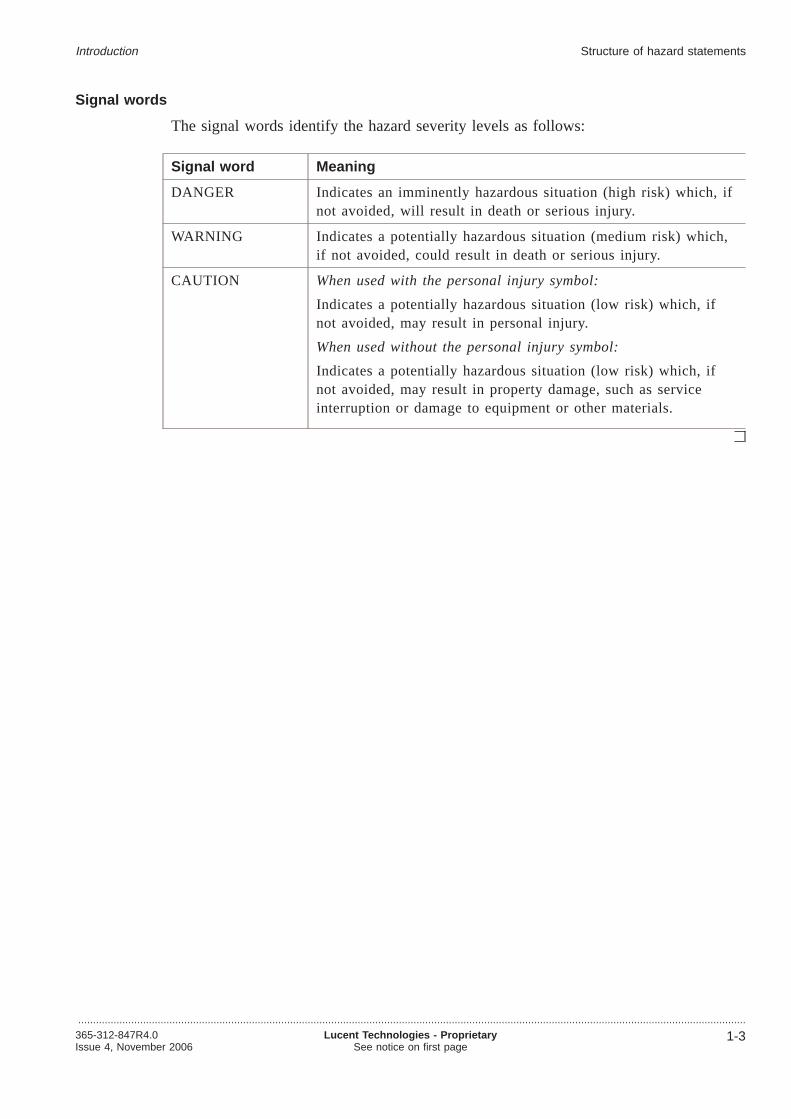
Signal words
The signal words identify the hazard severity levels as follows:
Signal word Meaning
DANGER Indicates an imminently hazardous situation (high risk) which, ifnot avoided, will result in death or serious injury.
WARNING Indicates a potentially hazardous situation (medium risk) which,if not avoided, could result in death or serious injury.
CAUTION When used with the personal injury symbol:
Indicates a potentially hazardous situation (low risk) which, ifnot avoided, may result in personal injury.
When used without the personal injury symbol:
Indicates a potentially hazardous situation (low risk) which, ifnot avoided, may result in property damage, such as serviceinterruption or damage to equipment or other materials.
Introduction Structure of hazard statements
...................................................................................................................................................................................................................................365-312-847R4.0Issue 4, November 2006
Lucent Technologies - ProprietarySee notice on first page
1-3
System overview...................................................................................................................................................................................................................................
The Metropolis® AMU is a high capacity, flexible and cost-effective widebandmultiplexer which can multiplex standard PDH and SDH bit rates as well as Ethernetsignals to line transport rates. In addition to a compact and flexible design, this systemis a useful element in building efficient and flexible networks due to its wide-rangingcapacity.
The 2m/4o version can be equipped with 2 main boards and upgraded with 4 optioncards as described inChapter 2, “Product description”and thus be adapted to specialnetwork requirements. The 1m/1o version can hold 1 main board and upgraded withone option board. The 2m/4o version holds two slots for main cards where operationwith either one or two main cards is possible. The second main card can be operatedas an additional tributary card or as main card equipment protection. The systemprovides the ability to add one option card.
In the access network, theMetropolis® AMU can be installed at the customer premisesfor fiber-to-the-business applications enabling a variety of configurations. Otherapplications include LAN-to-LAN traffic on campus networks or WANs.
The Metropolis® AMU MI-16/4 is an SDH STM-1/4 and STM-4/16 Terminal orAdd-Drop-Multiplexer optimized to provide various tributary services such asSTM-1/4, 1.5 Mbit/s, 2 Mbit/s, 34 Mbit/s, 45 Mbit/s, STM-1e, STM-4, 1000BASE-T/Xand 10/100BASE-T, to business and residential customers. The MI-14/4 main card isan SDH STM-1/4 and STM-1 Terminal or Add/Drop Multiplexer and provides varioustributary services such as STM-1, 1.5 Mbit/s, 2 Mbit/s, 34 Mbit/s, 45 Mbit/s, STM-1e,STM-4, 1000BASE-T/X and 10/100BASE-T.
The standardMetropolis® AMU MI-16/4 main card can be equipped with twomultirate STM-1/4 or STM-4/16 interfaces using SFPs. TheMetropolis® AMU MI-14/4main card can be equipped with two multirate STM-1/STM-4 and two STM-1interfaces. When required, the main card can be equipped with SFPs for STM-1 orSTM-4 single fiber working and STM-1e. The equipment is capable of 1+1 MSPprotection and SNC/N protection.
The space-efficient design ofMetropolis® AMU allows for wall or rack mounting. Formore information, please refer to theMetropolis® AMU Installation Guide.
Applications
The network applications can be found inChapter 4, “Planning Network Applications”.
Management
The Metropolis® AMU is managed by network management systems from LucentTechnologies. This includes the local craft terminal ITM-CIT which is available foron-site tasks, remote operations, and maintenance activities. Lucent’s NetworkManagement Systems or the Lucent NMS enable integrated management of an entiretransport network.
Introduction
...................................................................................................................................................................................................................................
1-4 Lucent Technologies - ProprietarySee notice on first page
365-312-847R4.0Issue 4, November 2006

Interworking
The Metropolis® AMU is a part of theMetropolis® AMU suite, which is amulti-service platform for next generation transmission products and have the prefix“Metropolis” in their names. The system can be deployed together with other products,for exampleMetropolis® AM / Metropolis® AMS. This makesMetropolis® AMU oneof the main building blocks for today’s and future networks.
Please check with Lucent Technologies for a complete list of products that are able tointerwork with Metropolis® AMU.
Introduction System overview
...................................................................................................................................................................................................................................365-312-847R4.0Issue 4, November 2006
Lucent Technologies - ProprietarySee notice on first page
1-5

2 2Product description
Overview...................................................................................................................................................................................................................................
Purpose
This chapter describes theMetropolis® AMU.
Chapter structure
After a description of the hardware design and system architecture, the option cards arepresented. It is then followed by the technical specifications of theMetropolis® AMU.
Contents
Hardware overview of the Metropolis® AMU 2-2
Introduction 2-2
System Architecture 2-11
Introduction 2-11
Option cards 2-15
Introduction 2-15
Technical specifications 2-32
System specifications 2-33
Performance Monitoring 2-51
Advanced TransLAN® Features 2-57
...................................................................................................................................................................................................................................365-312-847R4.0Issue 4, November 2006
Lucent Technologies - ProprietarySee notice on first page
2-1

Hardware overview of theMetropolis® AMU
Introduction...................................................................................................................................................................................................................................
The Metropolis® AMU is a high capacity, flexible and cost-effective widebandmultiplexer which can multiplex standard PDH and SDH bit rates as well as Ethernetsignals to line transport rates. TheMetropolis® AMU is a compact SDH Multiplexer,enabling cost-effective STM-1, STM-4, and STM-16 Add/Drop Multiplexer solutions.Several mechanical variants are defined to target specific applications. One set ofboards is used across the various mechanical configurations of theMetropolis® AMU.
Its space-efficient design allows for vertical (2m/4o and 1m/1o version) or horizontal(1m/1o version) installation within controlled environment locations (interior ETSI and19” racks). Note that the 2m/4o and 1m/1o versions and all the option cards used inthese versions support hot pluggable card insertion. The 2m/4o configuration allows theplacement of two systems side-by-side in a 19-inch or ETSI rack. The 1m/1oconfiguration allows the placement of up to 5 systems side-by-side. Please refer to theMetropolis® AMU Installation Guidefor details.
2m/4o version
The Metropolis® AMU 2m/4o version has 6 slots (2x main and 4x tributary) and isoptimized for high capacity and protected Central Office applications. The first andsecond main units can be plugged into the two main slots that are provided with a2m/4o configuration. Note that when a single main unit is used, it must be pluggedinto the Main-1 slot. In theMetropolis® AMU 2m/4o configuration, a second maincard can be fitted for high-availability configurations or to increase the capacity forSTM line interfaces. Most of the existingMetropolis® AMU option boards can befitted via an adapter card, which occupies two tributary slots.
Start-up configuration - 1m/1o version
The Metropolis® AMU 1m/1o version has 2 slots (1x main and 1x tributary) and istargeted for CPE and unprotected applications. The main unit can be plugged into themain slot of a 1m/1o configuration.
MA
IN-1
MA
IN-2
TR
IB-1
TR
IB-2
TR
IB-3
TR
IB-4
Product description
...................................................................................................................................................................................................................................
2-2 Lucent Technologies - ProprietarySee notice on first page
365-312-847R4.0Issue 4, November 2006

The Metropolis® AMU start-up configuration (1m/1o version) already supports 2 cagesfor hot-pluggable STM-1 or STM-4 interfaces and 2 cages for hot-pluggable STM-4 orSTM-16 interfaces. Note that the MI-16/4 provides two STM-1/4 interfaces and twoSTM-4/16 interfaces. The MI-14/4 provides two STM-1/4 interfaces and two interfacesfor STM-1, STM-1e or STM-1 single fiber working interfaces.
Note that the adapter card cannot be used in the 1m/1o shelf as it occupies two slots.
Subrack front view
The following figures display theMetropolis® AMU versions. Given below is theMI-16/4 - 2m/4o version.
MA
IN
TR
IB
Product description Introduction
....................................................................................................................................................................................................................................365-312-847R4.0Issue 4, November 2006
Lucent Technologies - ProprietarySee notice on first page
2-3

The following figure displays the MI-16/4 - 1m1/o version.
Product description Introduction
....................................................................................................................................................................................................................................
2-4 Lucent Technologies - ProprietarySee notice on first page
365-312-847R4.0Issue 4, November 2006
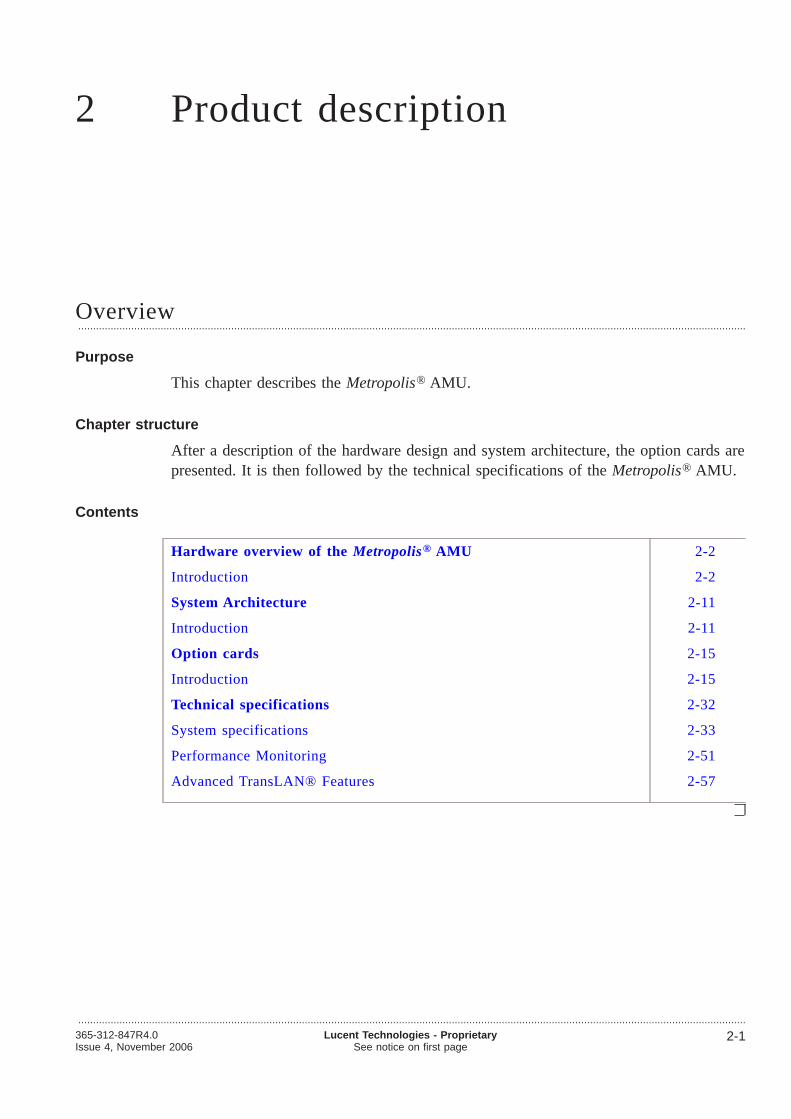
The following figure displays the MI-14/4 - 2m/4o version.
Product description Introduction
....................................................................................................................................................................................................................................365-312-847R4.0Issue 4, November 2006
Lucent Technologies - ProprietarySee notice on first page
2-5

The following figure displays the MI-14/4 - 1m/1o version.
Product description Introduction
....................................................................................................................................................................................................................................
2-6 Lucent Technologies - ProprietarySee notice on first page
365-312-847R4.0Issue 4, November 2006

Metropolis ® AMUAMU Main board - MI-16/4
The MI-16/4 main card provides the following functionality:
• 2 multirate STM-4/STM-16 interfaces using pluggable SFPs
• 2 multirate STM-1/STM-4 interfaces using pluggable SFPs
• Non-blocking 174 x 174 VC-4 cross-connect between both main cards and fourtributary cards (2m/4o unit). Supports VC-4 payloads.
• Non-blocking 48 x 48 VC-4 equivalents for VC-12/VC-3 cross-connections
• Timing functions with external synchronization input and output
• Power supply filter and dual power interfaces for power consumption by thecomplete shelf including the main unit
• System controller with external interfaces for Q-LAN, G-LAN, ITM-CIT,MDI/MDO, and 2 x USB ports for external devices
Product description Introduction
....................................................................................................................................................................................................................................365-312-847R4.0Issue 4, November 2006
Lucent Technologies - ProprietarySee notice on first page
2-7
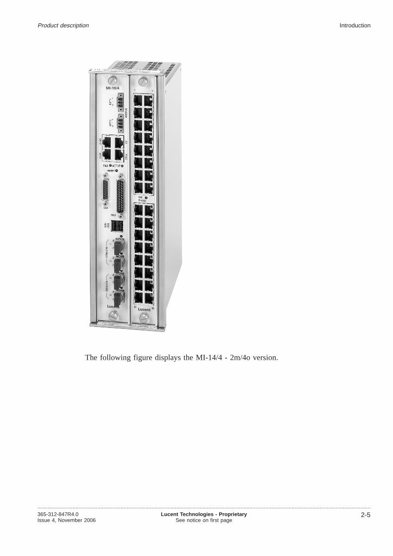
• Termination of DCC channels associated with STM-N interfaces - 40 DCC for theMultiplex section and 40 DCC for the Regenerator section.
• V.11 EOW interface
• Real time clock function.
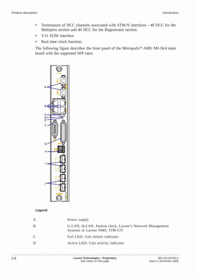
The following figure describes the front panel of theMetropolis® AMU MI-16/4 mainboard with the supported SFP rates.
Legend:
A Power supply
B G-LAN, Q-LAN, Station clock, Lucent’s Network ManagementSystems or Lucent NMS, ITM-CIT
C Fail LED: Unit failure indicator
D Active LED: Unit activity indicator
Product description Introduction
....................................................................................................................................................................................................................................
2-8 Lucent Technologies - ProprietarySee notice on first page
365-312-847R4.0Issue 4, November 2006
E Reset button
F EOW
G MDI/MDO
H USB
I Aggregate STM-4/STM-16 optical interfaces
J Aggregate STM-1/STM-4 optical interfaces
Metropolis ® AMU AMU Main board - MI-14/4
The MI-14/4 main card provides the following functionality:
• 2 multirate STM-1/STM-4 interfaces using pluggable SFPs
• 2 STM-1 interfaces using pluggable SFPs including STM-1e and STM-1 singlefiber working interfaces
• Non-blocking 76 x 76 VC-4 cross-connect between both main cards and fourtributary cards (2m/4o unit). Supports VC-4 payloads.
• Non-blocking 16 x 16 VC-4 equivalents for VC-12/VC-3 cross-connections
• Timing functions with external synchronization input and output
• Power supply filter and dual power interfaces for power consumption by thecomplete shelf including the main unit
• System controller with external interfaces for Q-LAN, G-LAN, ITM-CIT,MDI/MDO, and 2 x USB ports
• Termination of DCC channels associated with 32 STM-N interfaces - 16 DCC forthe Multiplex section and 16 DCC for the Regenerator section.
• V.11 EOW interface
• Real time clock function
The following figure describes the front panel of theMetropolis® AMU MI-14/4 maincard with the supported SFP rates.
Product description Introduction
....................................................................................................................................................................................................................................365-312-847R4.0Issue 4, November 2006
Lucent Technologies - ProprietarySee notice on first page
2-9
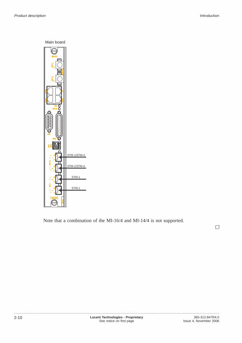
Note that a combination of the MI-16/4 and MI-14/4 is not supported.
Main board
STM-1/STM-4
STM-1/STM-4
STM-1
STM-1
Product description Introduction
....................................................................................................................................................................................................................................
2-10 Lucent Technologies - ProprietarySee notice on first page
365-312-847R4.0Issue 4, November 2006
System Architecture
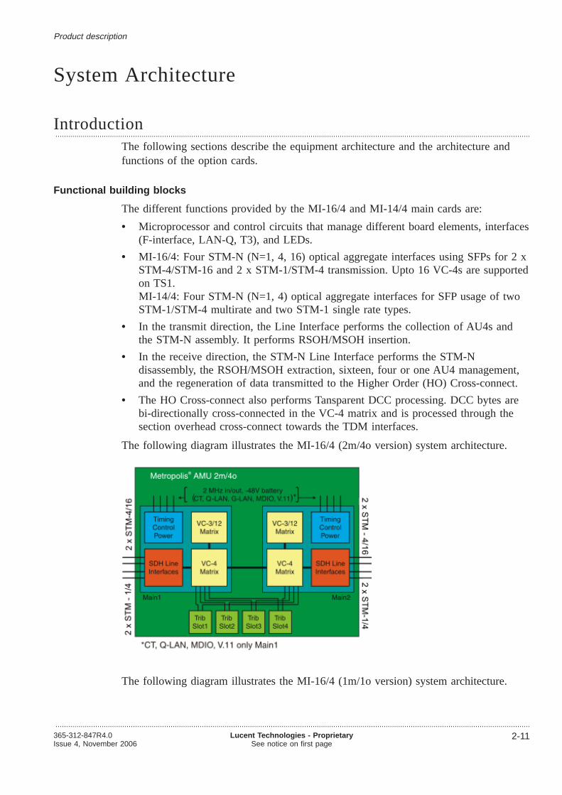
Introduction...................................................................................................................................................................................................................................
The following sections describe the equipment architecture and the architecture andfunctions of the option cards.
Functional building blocks
The different functions provided by the MI-16/4 and MI-14/4 main cards are:
• Microprocessor and control circuits that manage different board elements, interfaces(F-interface, LAN-Q, T3), and LEDs.
• MI-16/4: Four STM-N (N=1, 4, 16) optical aggregate interfaces using SFPs for 2 xSTM-4/STM-16 and 2 x STM-1/STM-4 transmission. Upto 16 VC-4s are supportedon TS1.MI-14/4: Four STM-N (N=1, 4) optical aggregate interfaces for SFP usage of twoSTM-1/STM-4 multirate and two STM-1 single rate types.
• In the transmit direction, the Line Interface performs the collection of AU4s andthe STM-N assembly. It performs RSOH/MSOH insertion.
• In the receive direction, the STM-N Line Interface performs the STM-Ndisassembly, the RSOH/MSOH extraction, sixteen, four or one AU4 management,and the regeneration of data transmitted to the Higher Order (HO) Cross-connect.
• The HO Cross-connect also performs Tansparent DCC processing. DCC bytes arebi-directionally cross-connected in the VC-4 matrix and is processed through thesection overhead cross-connect towards the TDM interfaces.
The following diagram illustrates the MI-16/4 (2m/4o version) system architecture.
The following diagram illustrates the MI-16/4 (1m/1o version) system architecture.
Product description
...................................................................................................................................................................................................................................365-312-847R4.0Issue 4, November 2006
Lucent Technologies - ProprietarySee notice on first page
2-11
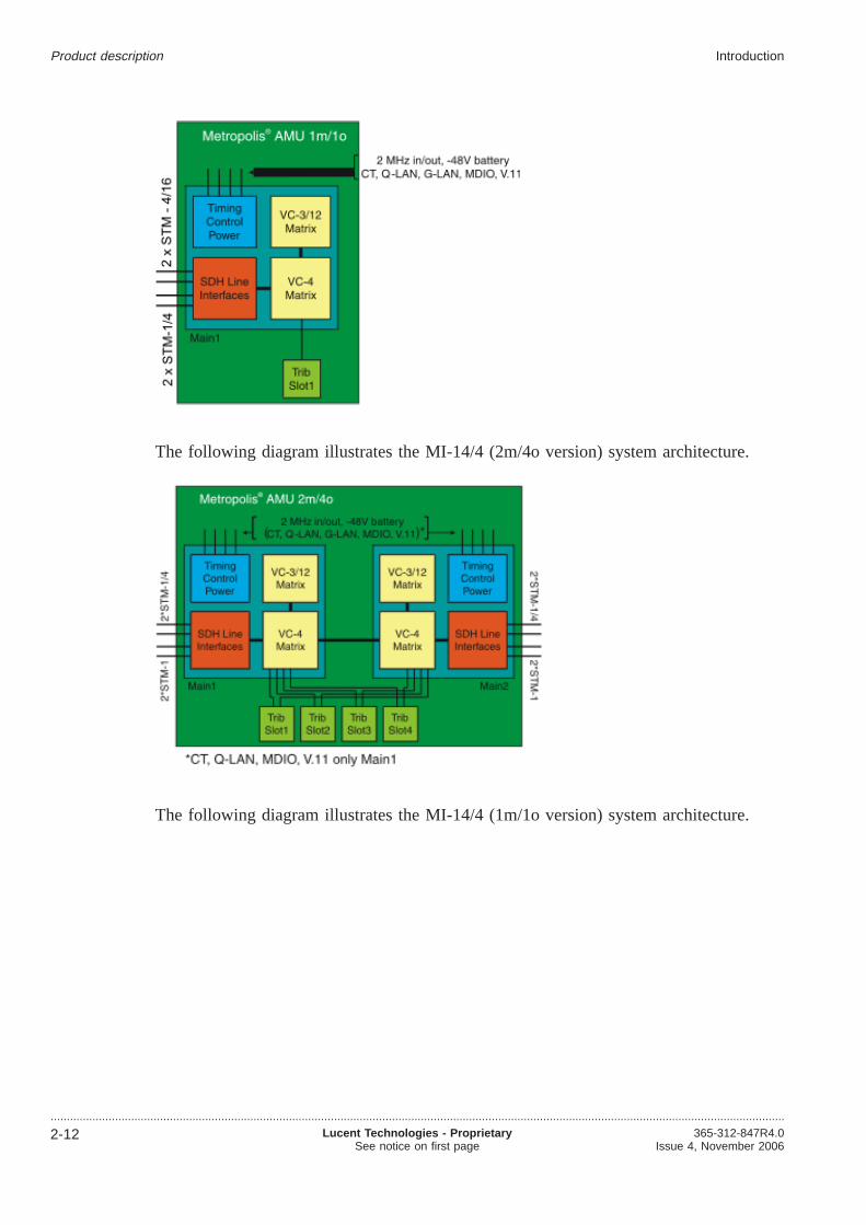
The following diagram illustrates the MI-14/4 (2m/4o version) system architecture.
The following diagram illustrates the MI-14/4 (1m/1o version) system architecture.
Product description Introduction
....................................................................................................................................................................................................................................
2-12 Lucent Technologies - ProprietarySee notice on first page
365-312-847R4.0Issue 4, November 2006

Cross-connect transmission flexibility
The following table provides a comparitive description of the MI-16/4 and MI-14/4cross-connect matrix.
MI-16/4 MI-14/4
HO cross-connect capabilities:
• 174 x 174 VC-4s
• includes 40 VC-4s on the line side, 40aggregate VC-4s, and 46 VC-4s to thetributary slots
HO cross-connect capabilities:
• 76 x 76 VC-4s are used for 4 x 10tributaries, 1 x 10 main, 2 x STM-4, 2x STM-1
LO cross-connect capabilities:
• Non-blocking 48 x 48 VC-4equivalents
or
• up to 192 x 192 VC-3sor
• up to 3024 x 3024 VC-12s
LO cross-connect capabilities:
• 16 x 16 VC-4 equivalentsor
• 48 x 48 VC-3sor
• 1008 x 1008 VC-12s
Loopbacks on incoming STM-N opticalsignals via the cross-connect matrix
Loopbacks on incoming STM-N opticalsignals via the cross-connect matrix
Up to 40 DCN channels Up to 16 DCN channels
4 STM-N line interfaces with RS and MSbytes processing; two multi-rate STM-4 orSTM-16 and two multi-rate STM-1 orSTM-4.
4 STM-N line interfaces with RS and MSbytes processing; two multi-rate STM-1 orSTM-4 and two STM-1 only.
Product description Introduction
....................................................................................................................................................................................................................................365-312-847R4.0Issue 4, November 2006
Lucent Technologies - ProprietarySee notice on first page
2-13
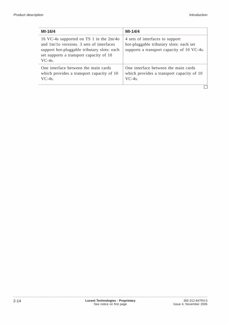
MI-16/4 MI-14/4
16 VC-4s supported on TS 1 in the 2m/4oand 1m/1o versions. 3 sets of interfacessupport hot-pluggable tributary slots: eachset supports a transport capacity of 10VC-4s.
4 sets of interfaces to supporthot-pluggable tributary slots: each setsupports a transport capacity of 10 VC-4s.
One interface between the main cardswhich provides a transport capacity of 10VC-4s.
One interface between the main cardswhich provides a transport capacity of 10VC-4s.
Product description Introduction
....................................................................................................................................................................................................................................
2-14 Lucent Technologies - ProprietarySee notice on first page
365-312-847R4.0Issue 4, November 2006

Option cards
Introduction...................................................................................................................................................................................................................................
This section describes the option cards which can be used together withMetropolis®
AMU in order to provide interfaces for various data rates or special applications.
PI-E1/63 and PI-E1/63_75 option cards
The PI-E1/63 and PI-E1/63_75 option cards provide 63 times 2 Mbit/s (E1) terminatedon 32 RJ-45 connectors for the use of twisted pair cables (120Ω version) and coaxialcable (75Ω version). It is available in 75Ω and 120Ω versions.
The following figure displays the front panel of the PI-E1/63 option card.
EPL4_E14 option card
Interfaces
On the faceplate the EPL4_E14 card provides:
• Two cages for Small Form-factor Pluggable (SFP) optical transceivers whichsupport 1000Base-X
• Two RJ45 connectors for triple rate Ethernet (10/100/1000Base-T)
Product description
...................................................................................................................................................................................................................................365-312-847R4.0Issue 4, November 2006
Lucent Technologies - ProprietarySee notice on first page
2-15

• Two RJ45 connectors for dual rate Ethernet (10/100Base-T)
• Two RJ45 connectors for four E1 interfaces with 75 / 120Ω (Selection can bemade on port level via the user interface; default is 120Ω.)
The EPL4_E14 unit provides 4 ethernet ports. Two of these (5 and 6) support 10/100Base-T line rates while the other two (pairs 7/8 and 9/10) are multirate ports capable of10/100/1000 Base-T/-X. For these ports, the selection between 1000 Base-T (electricalinterfaces 8 and 9) and 1000 Base-X (optical interfaces 7 and 10) has to be done viathe NMS. This selection can be done independently for each Port. When an opticalport is in use, the electrical counterpart is inactive and vice versa. Each connector andeach SFP has its own green LED (data link up: LED ON or down: LED OFF) andyellow LED (transmission: LED ON or no transmission: LED OFF).
The following figure shows the front panel of the EPL4_E14 option card.
The EPL_4_E14 option card is able to compensate a maximum delay difference of 128ms between the fastest and the slowest VC in receive direction.
Link Capacity Adjustment Scheme (LCAS)
The EPL4_E14 option card supports a flexible allocation of SDH bandwidth to LANports by making use of the Link Capacity Adjustment Scheme (LCAS, see“LCAS”(p. 3-22)). All LAN ports have the same capabilities. Each WAN port supportsVC-12-Xv (X = 1...63), VC-3-Xv (X = 1...9), VC-4-Xv (X=1..7).
GFP Encapsulation
GE
Rx
Rx
Tx
Tx
Lucent
8
FAIL
E1
14
EPL4_E14
E/F
E5
69
E/F
E/G
EG
E
107
Product description Introduction
....................................................................................................................................................................................................................................
2-16 Lucent Technologies - ProprietarySee notice on first page
365-312-847R4.0Issue 4, November 2006

GFP provides a generic mechanism to adapt traffic from higher-layer client signalsover a transport network. GFP encapsulation is implemented according toT1X1.5/2000-147.
The following GFP encapsulation are possible with EPL4_E14:
• Mapping of Ethernet MAC frames into Lower Order SDH VC12–Xv (X = 1...63)
• Mapping of Ethernet MAC frames into Lower Order SDH VC3–Xv (X = 1...9)
• Mapping of Ethernet MAC frames into Higher Order SDH VC4–Xv (X=1..7)
LAPS encapsulation is implemented according to ITU-T X.86.
Advanced rate control
The EPL4_E14 option card supports advanced rate control in the ingress and egressdirection which allows to set a strict traffic limit (PIR), in combination with a hold-offmechanism: Excess traffic is held off until the ingress or egress buffer overflows. Incase the ingress buffer fills above a certain threshold, pause messages are sent in thereverse direction to hold off further traffic. This behaviour improves the TCPthroughput. Note that Pause messages can be only sent when the Pause mode isenabled via the Lucent NMS.
Link Pass Through (LPT)
The EPL4_E14 option card supports the Link Pass Through (LPT) mode. Onpoint-to-point Ethernet Private Line connections, when GFP data encapsulation is usedthroughout the network, the system identifies defects from the network ingress port tothe network egress port. The GFP-CSF mechanism is used to notify the egress side thata loss of signal (synchronization) has occurred on the ingress port. Consequently, theegress side can either turn off the laser at the egress (in case of an optical level) orsubstitute an error pattern (for example, a /V/ ordered set for a 1000BASE-X). Inaddition, an alarm is raised at the egress side which indicates the ingress sidecondition. For more information about Link Pass Through, please refer to (LPT, see“LPT” (p. 3-23)). For additional information, please refer the TransLAN® EthernetSDH Transport Solution Applications and Planning Guide.
The EPL4_E14 option card supports Auto MDI/MDIX selection on all LAN ports.
Transmission rates
The following rates are supported with EPL4_E14:
• Mapping Ethernet packets into VC12-Xv (X = 1...63)
• Mapping Ethernet packets into VC3-Xv (X = 1...9)
• Mapping Ethernet packets into VC4-Xv (X=1..7)
Flexible bandwidth assignment
The transmission capacity of the EPL4_E14 option card towards the cross-connectmatrix is 8 x VC4s. These can be freely assigned to 4 VCGs. There is a fixed 1:1relationship from the 4 Ethernet ports to the 4 VCGs. For an illustrated description, see“EPL4_E14 option card” (p. 2-18).
Product description Introduction
....................................................................................................................................................................................................................................365-312-847R4.0Issue 4, November 2006
Lucent Technologies - ProprietarySee notice on first page
2-17

From the 8 VC-4s, two can be individually substructured to VC-12s to provide upto 2x 63 VC-12s. In this case, the first 4 VC-12s are reserved for the E1 ports. Note thatin case E1 interfaces are used, the first VC-4 needs to be substructured, otherwise, theyare not available. In addition, 3 VC-4s can be individually substructured to VC-3,thereby providing a total of 9 VC-3s.
The remaining 3 VC-4s cannot be substructured. For each of the 4 VCGs, a selectioncan be made between VC-12-Xv (X=1-63), VC-3-Xv (X=1-9), and VC-4-Xv (X=1-7),based on the total number of containers that are available for each type.
The following diagram illustrates the VC/VCG mapping for the EPL4_E14 option card.
Jumbo frame support
The EPL4_E14 option card supports overlength Ethernet frames (also known as Jumboframes) on LAN ports 7, 8, and 9, 10.
EPL4_E132_75 option card
Interfaces
On the faceplate the EPL4_E132_75 board provides:
• Four RJ45 connectors for dual rate Ethernet (10/100Base-T)
• Sixteen RJ45 connectors to cover 32 E1 interfaces with 75Ω only (2x E1 perRJ45)
All four Ethernet RJ45 connectors have their own green and yellow LED whichindicates a LAN connection and traffic flow respectively.
The following figure shows the front panel of the EPL4_E132_75 option card.
Product description Introduction
....................................................................................................................................................................................................................................
2-18 Lucent Technologies - ProprietarySee notice on first page
365-312-847R4.0Issue 4, November 2006
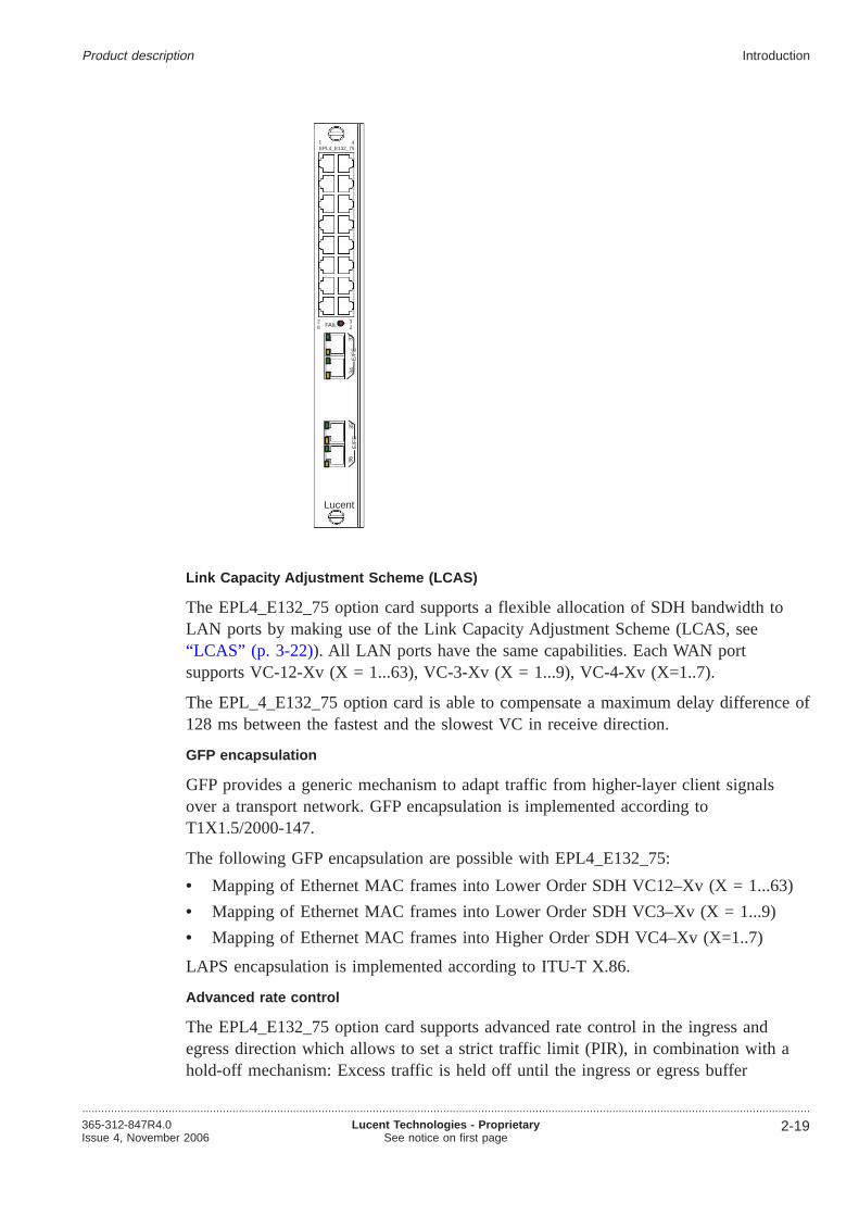
Link Capacity Adjustment Scheme (LCAS)
The EPL4_E132_75 option card supports a flexible allocation of SDH bandwidth toLAN ports by making use of the Link Capacity Adjustment Scheme (LCAS, see“LCAS” (p. 3-22)). All LAN ports have the same capabilities. Each WAN portsupports VC-12-Xv (X = 1...63), VC-3-Xv (X = 1...9), VC-4-Xv (X=1..7).
The EPL_4_E132_75 option card is able to compensate a maximum delay difference of128 ms between the fastest and the slowest VC in receive direction.
GFP encapsulation
GFP provides a generic mechanism to adapt traffic from higher-layer client signalsover a transport network. GFP encapsulation is implemented according toT1X1.5/2000-147.
The following GFP encapsulation are possible with EPL4_E132_75:
• Mapping of Ethernet MAC frames into Lower Order SDH VC12–Xv (X = 1...63)
• Mapping of Ethernet MAC frames into Lower Order SDH VC3–Xv (X = 1...9)
• Mapping of Ethernet MAC frames into Higher Order SDH VC4–Xv (X=1..7)
LAPS encapsulation is implemented according to ITU-T X.86.
Advanced rate control
The EPL4_E132_75 option card supports advanced rate control in the ingress andegress direction which allows to set a strict traffic limit (PIR), in combination with ahold-off mechanism: Excess traffic is held off until the ingress or egress buffer
FAIL
3334
Lucent
1 4EPL4_E132_75
28
32
3536
E/F
EE
/FE
Product description Introduction
....................................................................................................................................................................................................................................365-312-847R4.0Issue 4, November 2006
Lucent Technologies - ProprietarySee notice on first page
2-19
overflows. In case the ingress buffer fills above a certain threshold, pause messages aresent in the reverse direction to hold off further traffic. This behaviour improves theTCP throughput. Note that Pause messages are only sent when the Pause mode isenabled via the Lucent NMS.
Auto-negotiation
The EPL4_E132_75 option card supports Auto-negotiation. The Auto-negotiationfunction automatically configures the Ethernet interface parameters to establish anoptimal Ethernet link based on the capabilities of the near-end and far-end Ethernetinterfaces.
Auto-negotiation for twisted-pair systems, defined in Clause 28 of the Standard802.3-2002, has been extended to include all three speeds of Ethernet that aresupported over twisted-pair cable: 10Mbit/s 10Base-T, 100Mbit/s 100Base- TX, and1000 Mbit/s 1000Base-T. For more information about Auto-negotiation support, pleaserefer to the Metropolis® AMU User Operations Guide.
Link Pass Through (LPT)
The EPL4_E132_75 option card supports the Link Pass Through (LPT) mode. Onpoint-to-point Ethernet Private Line connections, when GFP data encapsulation is usedthroughout the network, the system identifies defects from the network ingress port tothe network egress port. The GFP-CSF mechanism is used to notify the egress side thata loss of signal (synchronization) has occurred on the ingress port. An alarm is raisedat the egress side which indicates the ingress side condition. For more information,please refer to (see LPT,“LPT” (p. 3-23)). For additional information, please also referto the TransLAN® Ethernet SDH Transport Solution Applications and Planning Guide.
The EPL4_E132_75 option card supports Auto MDI/MDIX selection on all LAN ports.
Transmission rates
The following rates are supported with EPL4_E132_75:
• Mapping Ethernet packets into VC12-Xv (X = 1...63)
• Mapping Ethernet packets into VC3-Xv (X = 1...9)
• Mapping Ethernet packets into VC4-Xv (X=1..7)
Flexible bandwidth assignment
The transmission capacity of the EPL4_E132_75 option card towards the cross-connectmatrix is 9 x VC-4s. One VC-4 is reserved for the 32 E1 ports and is not available forthe VCGs. The remaining 8 VC-4s can be freely assigned to 4 VCGs. There is a fixed1:1 relationship from the 4 Ethernet ports to the 4 VCGs. For an illustrated description,see (see fig. on page 2-17).
From the 8 VC-4s, two can be individually substructured to VC-12s, thereby providingupto 2 x 63 VC-12s. In this case, the first 4 VC-12s of the first VC-4 remain unused.
In addition, 3 VC-4s can be individually substructured to VC-3s, providing a total of 9VC-3s. The remaining 3 VC-4s cannot be substructured. For each of the 4 VCGs, a
Product description Introduction
....................................................................................................................................................................................................................................
2-20 Lucent Technologies - ProprietarySee notice on first page
365-312-847R4.0Issue 4, November 2006
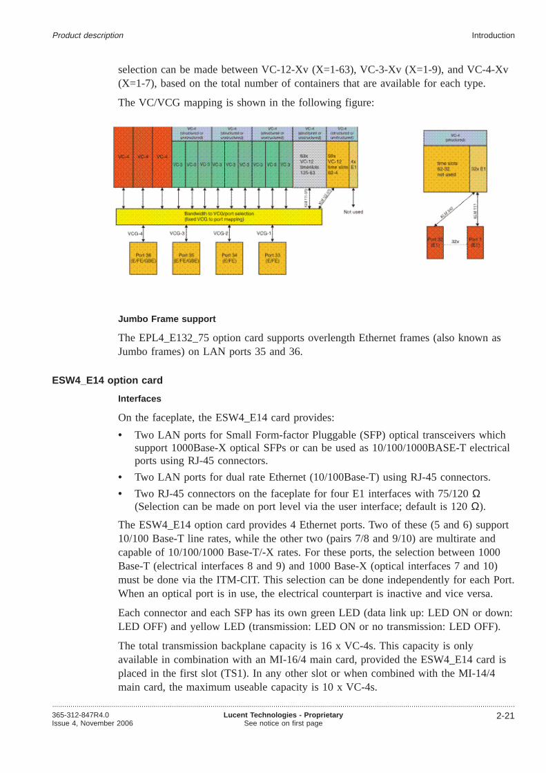
selection can be made between VC-12-Xv (X=1-63), VC-3-Xv (X=1-9), and VC-4-Xv(X=1-7), based on the total number of containers that are available for each type.
The VC/VCG mapping is shown in the following figure:
Jumbo Frame support
The EPL4_E132_75 option card supports overlength Ethernet frames (also known asJumbo frames) on LAN ports 35 and 36.
ESW4_E14 option card
Interfaces
On the faceplate, the ESW4_E14 card provides:
• Two LAN ports for Small Form-factor Pluggable (SFP) optical transceivers whichsupport 1000Base-X optical SFPs or can be used as 10/100/1000BASE-T electricalports using RJ-45 connectors.
• Two LAN ports for dual rate Ethernet (10/100Base-T) using RJ-45 connectors.
• Two RJ-45 connectors on the faceplate for four E1 interfaces with 75/120Ω(Selection can be made on port level via the user interface; default is 120Ω).
The ESW4_E14 option card provides 4 Ethernet ports. Two of these (5 and 6) support10/100 Base-T line rates, while the other two (pairs 7/8 and 9/10) are multirate andcapable of 10/100/1000 Base-T/-X rates. For these ports, the selection between 1000Base-T (electrical interfaces 8 and 9) and 1000 Base-X (optical interfaces 7 and 10)must be done via the ITM-CIT. This selection can be done independently for each Port.When an optical port is in use, the electrical counterpart is inactive and vice versa.
Each connector and each SFP has its own green LED (data link up: LED ON or down:LED OFF) and yellow LED (transmission: LED ON or no transmission: LED OFF).
The total transmission backplane capacity is 16 x VC-4s. This capacity is onlyavailable in combination with an MI-16/4 main card, provided the ESW4_E14 card isplaced in the first slot (TS1). In any other slot or when combined with the MI-14/4main card, the maximum useable capacity is 10 x VC-4s.
Product description Introduction
....................................................................................................................................................................................................................................365-312-847R4.0Issue 4, November 2006
Lucent Technologies - ProprietarySee notice on first page
2-21

The following figure shows the front panel of the ESW4_E14 option card.
Transmission rates
The following transmission rates are supported with ESW4_E14:
• Mapping Ethernet packets into VC12-Xv (X = 1...63)
• Mapping Ethernet packets into VC3-Xv (X = 1...21)
• Mapping Ethernet packets into VC4-Xv (X = 1...7)
Flexible bandwidth assignment
When the ESW4_E14 option card is inserted in tributary slot 1 of a 2m/4o or 1m/1oversion and the main unit is an M1-16/4, the total capacity of the unit is equivalent to16 VC4s (2.5 Gbit/s) with which up to eight VCGs can be created and each VCG canbe assigned to a WAN port. For WAN ports 1 though 4, a capacity of eight VC4s (1through 8) is available. By default, the 1st and 2nd VC4s are substructured in VC12s.Similarly, the 3rd, 4th, and 5th VC4s are substructured as VC3s. Optionally, the 1st to5th VC4s can be changed to unstructured VC4. The 6th, 7th, and 8th VC4s can onlybe used as VC4s. As a result, VC12-Xv (X=1..63), VC3-Xv (X=1..9) and/or VC4-Xv(X=1..7) groups can be created from at most 122 VC12s, 9 VC3s or 8 VC4s.
For WAN ports 5 through 8, a capacity of eight VC4s (9 though 16) is available. Ofthese 8 VC4s, the 9th and 10th VC-4 are substructured in VC12s and the 11th, 12th,and 13th VC4 are substructured in VC3s, by default. Optionally, the 9th to 13th VC4scan be changed to unstructured VC4. The VC4s 14 through 16 can only be used asVC4s. As a result, VC12-Xv (X=1..63), VC3-Xv (X=1..9) and/or VC4-Xv (X=1..7)groups can be created from at most 126 VC12s, 9 VC3s or 8 VC4s.
Product description Introduction
....................................................................................................................................................................................................................................
2-22 Lucent Technologies - ProprietarySee notice on first page
365-312-847R4.0Issue 4, November 2006

Note that if the E1 interfaces are used, four VC12s of the first VC4 must be reservedfor E1 transport. In this case, it is mandatory to substructure the first VC4 to carry 63VC12s.
The system automatically detects if the combination of slot number, main unit, andtributary unit allows 16 VC4 backplane capacity. No provisioning is required.
The following VC/VCG mapping diagram displays bandwidth selection options for theWAN ports 1, 2, 3, and 4.
The following VC/VCG mapping diagram displays the bandwidth selection options forthe WAN ports 5, 6, 7, and 8.
Jumbo frame support
Product description Introduction
....................................................................................................................................................................................................................................365-312-847R4.0Issue 4, November 2006
Lucent Technologies - ProprietarySee notice on first page
2-23

The ESW4_E14 option card supports overlength Ethernet frames (also known asJumbo frames) on all LAN ports and on WAN ports 3, 4, 7, and 8.
The ESW4_E14 option card can compensate a maximum delay difference of 64 msbetween the fastest and the slowest VC in receive direction.
Enhanced flow classification
The ESW4_E14 option card supports Enhanced Flow Classification - 802.1Q mode and802.1 ad mode. It supports the Flow Control and Pause Frames feature on LAN portsand provides Wire speed performance for forwarding, flooding, address look-up, andflow look-up requirements. The flow classifcation is based on port and priority, portand port, and port and VLAN-ID. The flow classification can be checked on a flexibleset of combinations such as IP_TOS, VLAN-ID, VLAN-UPT, and DA-MAC. The flowbucket can be set to handle 8k to 16k. However, an increased flow bucket size willdecrease performance. The ESW4_E14 option card is IEEE802.1Q/1ad compliant andsupports VLAN and/or ETHER_TYPE switching and adding or removing VLAN tags.
Auto-negotiation
The ESW4_E14 option card supports Auto-negotiation. The Auto-negotiation functionautomatically configures the Ethernet interface parameters to establish an optimalEthernet link based on the capabilities of the near-end and far-end Ethernet interfaces.
Auto-negotiation for twisted-pair systems, defined in Clause 28 of the Standard802.3-2002, has been extended to include all three speeds of Ethernet that aresupported over twisted-pair cable: 10Mbit/s 10Base-T, 100Mbit/s 100Base- TX, and1000 Mbit/s 1000Base-T. For more information about Auto-negotiation, please refer tothe Metropolis® AMU User Operations Guide.
Link Capacity Adjustment Scheme (LCAS)
The ESW4_E14 option card supports a flexible allocation of SDH bandwidth to LANports by making use of the Link Capacity Adjustment Scheme (LCAS, see“LCAS”(p. 3-22)). All LAN ports have the same capabilities. Each WAN port supportsVC-12-Xv (X = 1...63), VC-3-Xv (X = 1...9), VC-4-Xv (X = 1...7).
Repeater mode
For units containing Ethernet switches, it is possible to emulate the behaviour of aprivate line port by creating a two-port virtual switch, with one LAN and one WANport and provision it in Repeater Mode. This feature can be implemented in bothEthertype 8100 and Ethertype 9100 mode. In this mode, all traffic from the LAN orWAN side is transparently passed through, except the pause messages. The Pauseprotocol operates on the LAN interface and therefore, transmission without loss can beobtained if the peer node on the LAN link obeys the commands contained in pausemessages.
GFP encapsulation
GFP provides a generic mechanism to adapt traffic from higher-layer client signalsover a transport network. GFP encapsulation is implemented according toT1X1.5/2000-147.
Product description Introduction
....................................................................................................................................................................................................................................
2-24 Lucent Technologies - ProprietarySee notice on first page
365-312-847R4.0Issue 4, November 2006
The following GFP encapsulation are possible with ESW4_E14:
• Mapping Ethernet MAC frames into Lower Order SDH VC12-Xv (X = 1...63)
• Mapping Ethernet MAC frames into Lower Order SDH VC3-Xv (X = 1...21)
• Mapping Ethernet MAC frames into Higher Order SDH VC4-Xv (X = 1...7)
LAPS encapsulation is implemented according to ITU-T X.86.
Advanced rate control
The ESW4_E14 option card supports advanced rate control in the ingress and egressdirection which enables users to set a strict traffic limit (PIR), in combination with ahold-off mechanism: Excess traffic is held off until the ingress or egress bufferoverflows. In case the ingress buffer fills above a certain threshold, pause messages aresent in the reverse direction to hold off further traffic. This behaviour improves theTCP throughput.
Provisioning Committed Burst Size (CBS)
The Flow Profile containing the parameters that define the QoS regime and is appliedto a flow contains a user provisionable entry for the Committed Burst Size (CBS).
This entry describes the number of octets that may be″bursted″ before a frame is nolonger considered part of the″Committed Rate″. The CBS rate can be provisioned inkbytes between 1 and 25000 or as a time constant relative parameter to CIR: 10 or 110ms.
Provisioning Peak Burst Size (PBS)
The Flow Profile containing the parameters that define the QoS regime and is appliedto a flow contains a user provisionable entry for the Peak Burst Size (PBS).
This entry describes the number of octets that may be″bursted″ before a frame is nolonger considered part of the″Peak Rate″. The PBS rate can be provisioned in kbytesbetween 1 and 25000 or as a time constant relative parameter to CIR: 10 or 110 ms.
QoS features
The ESW4_E14 option card supports the following QOS features:
• Two rate three color marker (RFC 2697, RFC 2698, and MEF 10) per flow(switchable color aware/color unaware)Based on provisioned threshold rates (CIR and PIR):
– Red - The frame is dropped
– Yellow - The Dropping Precedence of the frame is set to high
– Green - The Dropping Precedence of the frame is set to low
• Over subscription (2 levels of Dropping Precedence) and strict policing modesBased on queue filling and the Dropping Precedence, frames can be dropped toavoid congestion
– A queue will allow fewer “yellow” frames than “green” frames
• 4 traffic classes, 4 egress queues per port
Product description Introduction
....................................................................................................................................................................................................................................365-312-847R4.0Issue 4, November 2006
Lucent Technologies - ProprietarySee notice on first page
2-25
Each QOS profile contains a Traffic Class (TC) entry.
– The traffic class determines the relative priority of a frame based on the trafficclass to queue assignment function and the scheulder settings
– The traffic class determines the outgoing p-bits for the egress direction
• Egress queue scheduling with strict Priority and/or Weighted Bandwidth options.
Sl-14/8 option card
Interfaces
On the faceplate, the Sl-14/8 card provides:
• Eight cages for Small Form-factor Pluggable (SFP) optical transceivers
• SFP-1 and SFP-5 support for STM-1 or STM-4 interfaces
• SFP-2 to SFP-4 and SFP-6 to SFP-8 support for STM-1 interfaces.
The board supports 1.2 Gigabit interfaces and provides a total transmission capacity ofeight VC-4s. This capacity is divided into two VC-4 groups namely, the SFP-1 toSFP-4 group and the SFP-5 to SFP-8 group. Each group provides a four VC-4transmission capacity. For example, if the SFP-1 is equipped with an STM-4 interface,the SFP-2 to SFP-4 have no more capacity and cannot be used. Similarly, if the SFP-5is equipped with an STM-4 interface, the SFP-6 to SFP-8 is being utilized andtherefore cannot be used for any additional capacity.
Each SFP transceiver has an LED which indicates three states. When the LED is on, itindicates hardware failures and confugration alarm. When the LED is blinking, itindicates transmission failure. When there are no failures, the LED is off. A fault onthe SFP is indicated by an LED on the SFP itself and not on the host unit’s LED.
The STM-1 and STM-4 in-loop and out-loop loopbacks are achieved by thecross-connect functionality.
The following figure shows the front panel of the Sl-14/8 option card.
Product description Introduction
....................................................................................................................................................................................................................................
2-26 Lucent Technologies - ProprietarySee notice on first page
365-312-847R4.0Issue 4, November 2006
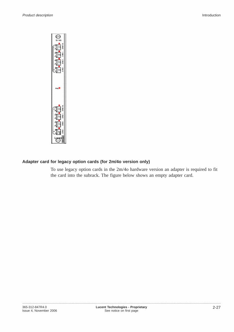
Adapter card for legacy option cards (for 2m/4o version only)
To use legacy option cards in the 2m/4o hardware version an adapter is required to fitthe card into the subrack. The figure below shows an empty adapter card.
Product description Introduction
....................................................................................................................................................................................................................................365-312-847R4.0Issue 4, November 2006
Lucent Technologies - ProprietarySee notice on first page
2-27

X2E3-V2 option card (legacy)
The X2E3-V2 option card provides two bidirectional 34 Mbit/s (E3) interfaces.
X2DS3-V2 option card (legacy)
The X2DS3-V2 option card provides two additional 45 Mbit/s (DS3) interfaces.
X16DS1 option card (legacy)
The X16DS1-V3 option card provides 16 additional 1.5 Mbit/s (DS1) interfaces.
X8PL option card (legacy)
The X8PL option card provides eight Ethernet interfaces in Private Line mode for theMetropolis® AMU. The Private Line mode enables traffic to be mapped from eachEthernet port one-to-one into an SDH container. Thus a private connection from anEthernet port through an SDH network to another Ethernet port at the remote end ofthe link is possible.
The X8PL option card supports a flexible allocation of SDH bandwidth to LAN portsby making use of the Link Capacity Adjustment Scheme (LCAS, see“LCAS” (p. 3-22)). All LAN ports have the same capabilities. Each WAN port supports VC-12-Xv (X =1...63) or VC-3-Xv (X = 1...3).
The VC-12s that form one VCG can be chosen from any TUG-3, in any timeslot order.However, it is recommended to select the VC-12s in sequential order, preferably in one
Product description Introduction
....................................................................................................................................................................................................................................
2-28 Lucent Technologies - ProprietarySee notice on first page
365-312-847R4.0Issue 4, November 2006
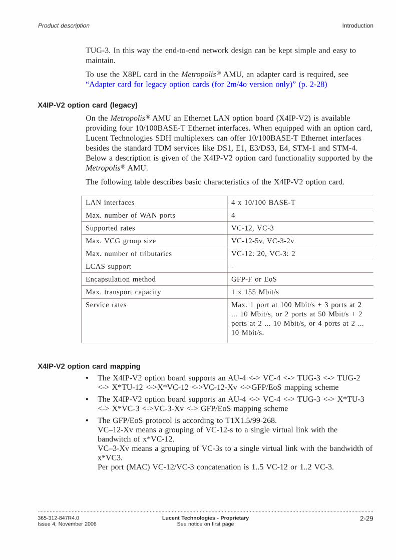
TUG-3. In this way the end-to-end network design can be kept simple and easy tomaintain.
To use the X8PL card in theMetropolis® AMU, an adapter card is required, see“Adapter card for legacy option cards (for 2m/4o version only)” (p. 2-28)
X4IP-V2 option card (legacy)
On theMetropolis® AMU an Ethernet LAN option board (X4IP-V2) is availableproviding four 10/100BASE-T Ethernet interfaces. When equipped with an option card,Lucent Technologies SDH multiplexers can offer 10/100BASE-T Ethernet interfacesbesides the standard TDM services like DS1, E1, E3/DS3, E4, STM-1 and STM-4.Below a description is given of the X4IP-V2 option card functionality supported by theMetropolis® AMU.
The following table describes basic characteristics of the X4IP-V2 option card.
LAN interfaces 4 x 10/100 BASE-T
Max. number of WAN ports 4
Supported rates VC-12, VC-3
Max. VCG group size VC-12-5v, VC-3-2v
Max. number of tributaries VC-12: 20, VC-3: 2
LCAS support -
Encapsulation method GFP-F or EoS
Max. transport capacity 1 x 155 Mbit/s
Service rates Max. 1 port at 100 Mbit/s + 3 ports at 2... 10 Mbit/s, or 2 ports at 50 Mbit/s + 2ports at 2 ... 10 Mbit/s, or 4 ports at 2 ...10 Mbit/s.
X4IP-V2 option card mapping
• The X4IP-V2 option board supports an AU-4 <-> VC-4 <-> TUG-3 <-> TUG-2<-> X*TU-12 <->X*VC-12 <->VC-12-Xv <->GFP/EoS mapping scheme
• The X4IP-V2 option board supports an AU-4 <-> VC-4 <-> TUG-3 <-> X*TU-3<-> X*VC-3 <->VC-3-Xv <-> GFP/EoS mapping scheme
• The GFP/EoS protocol is according to T1X1.5/99-268.VC–12-Xv means a grouping of VC-12-s to a single virtual link with thebandwitch of x*VC-12.VC–3-Xv means a grouping of VC-3s to a single virtual link with the bandwidth ofx*VC3.Per port (MAC) VC-12/VC-3 concatenation is 1..5 VC-12 or 1..2 VC-3.
Product description Introduction
....................................................................................................................................................................................................................................365-312-847R4.0Issue 4, November 2006
Lucent Technologies - ProprietarySee notice on first page
2-29
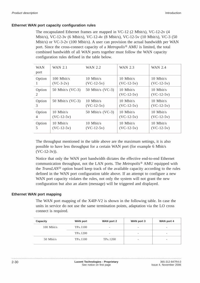
Ethernet WAN port capacity configuration rules
The encapsulated Ethernet frames are mapped in VC-12 (2 Mbit/s), VC-12-2v (4Mbit/s), VC-12-3v (6 Mbit/s), VC-12-4v (8 Mbit/s), VC-12-5v (10 Mbit/s), VC-3 (50Mbit/s) or VC-3-2v (100 Mbit/s). A user can provision the actual bandwidth per WANport. Since the cross-connect capacity of aMetropolis® AMU is limited, the totalcombined bandwidth of all WAN ports together must follow the WAN capacityconfiguration rules defined in the table below.
WANport
WAN 2.1 WAN 2.2 WAN 2.3 WAN 2.4
Option1
100 Mbit/s(VC-3-2v)
10 Mbit/s(VC-12-5v)
10 Mbit/s(VC-12-5v)
10 Mbit/s(VC-12-5v)
Option2
50 Mbit/s (VC-3) 50 Mbit/s (VC-3) 10 Mbit/s(VC-12-5v)
10 Mbit/s(VC-12-5v)
Option3
50 Mbit/s (VC-3) 10 Mbit/s(VC-12-5v)
10 Mbit/s(VC-12-5v)
10 Mbit/s(VC-12-5v)
Option4
10 Mbit/s(VC-12-5v)
50 Mbit/s (VC-3) 10 Mbit/s(VC-12-5v)
10 Mbit/s(VC-12-5v)
Option5
10 Mbit/s(VC-12-5v)
10 Mbit/s(VC-12-5v)
10 Mbit/s(VC-12-5v)
10 Mbit/s(VC-12-5v)
The throughput mentioned in the table above are the maximum settings, it is alsopossible to have less throughput for a certain WAN port (for example 6 Mbit/s(VC-12-3v)).
Notice that only the WAN port bandwidth dictates the effective end-to-end Ethernetcommunication throughput, not the LAN ports. TheMetropolis® AMU equipped withthe TransLAN® option board keep track of the available capacity according to the rulesdefined in the WAN port configuration table above. If an attempt to configure a newWAN port capacity violates the rules, not only the system will not grant the newconfiguration but also an alarm (message) will be triggered and displayed.
Ethernet WAN port mapping
The WAN port mapping of the X4IP-V2 is shown in the following table. In case theunits in service do not use the same termination points, adaptation via the LO crossconnect is required.
Capacity WAN port WAN port 2 WAN port 3 WAN port 4
100 Mbit/s TPx.1100 - - -
TPx.1200 - - -
50 Mbit/s TPx.1100 TPx.1200 - -
Product description Introduction
....................................................................................................................................................................................................................................
2-30 Lucent Technologies - ProprietarySee notice on first page
365-312-847R4.0Issue 4, November 2006
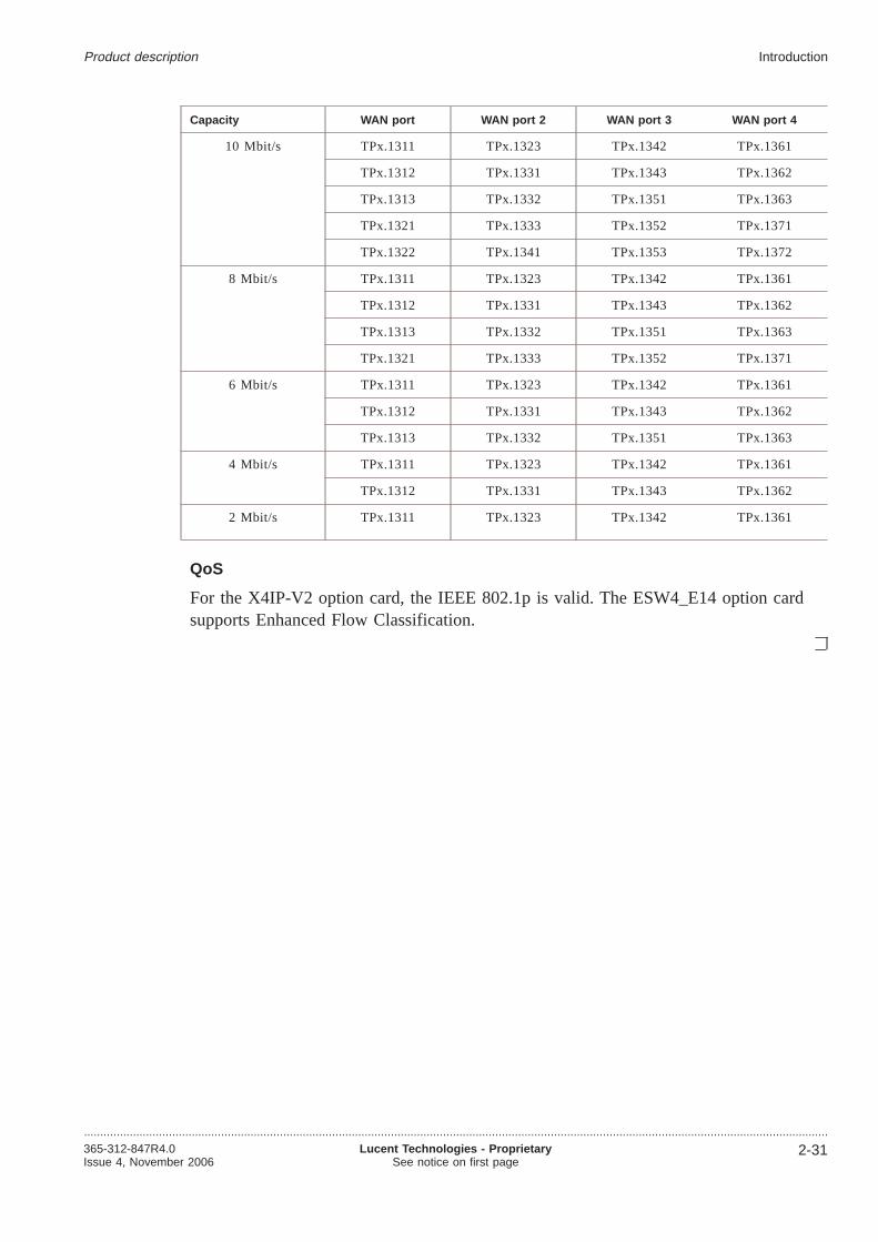
Capacity WAN port WAN port 2 WAN port 3 WAN port 4
10 Mbit/s TPx.1311 TPx.1323 TPx.1342 TPx.1361
TPx.1312 TPx.1331 TPx.1343 TPx.1362
TPx.1313 TPx.1332 TPx.1351 TPx.1363
TPx.1321 TPx.1333 TPx.1352 TPx.1371
TPx.1322 TPx.1341 TPx.1353 TPx.1372
8 Mbit/s TPx.1311 TPx.1323 TPx.1342 TPx.1361
TPx.1312 TPx.1331 TPx.1343 TPx.1362
TPx.1313 TPx.1332 TPx.1351 TPx.1363
TPx.1321 TPx.1333 TPx.1352 TPx.1371
6 Mbit/s TPx.1311 TPx.1323 TPx.1342 TPx.1361
TPx.1312 TPx.1331 TPx.1343 TPx.1362
TPx.1313 TPx.1332 TPx.1351 TPx.1363
4 Mbit/s TPx.1311 TPx.1323 TPx.1342 TPx.1361
TPx.1312 TPx.1331 TPx.1343 TPx.1362
2 Mbit/s TPx.1311 TPx.1323 TPx.1342 TPx.1361
QoS
For the X4IP-V2 option card, the IEEE 802.1p is valid. The ESW4_E14 option cardsupports Enhanced Flow Classification.
Product description Introduction
....................................................................................................................................................................................................................................365-312-847R4.0Issue 4, November 2006
Lucent Technologies - ProprietarySee notice on first page
2-31
Technical specifications
Overview...................................................................................................................................................................................................................................
Purpose
The following sections provide the technical specifications for theMetropolis® AMU.
Contents
System specifications 2-33
Performance Monitoring 2-51
Advanced TransLAN® Features 2-57
Product description
...................................................................................................................................................................................................................................
2-32 Lucent Technologies - ProprietarySee notice on first page
365-312-847R4.0Issue 4, November 2006
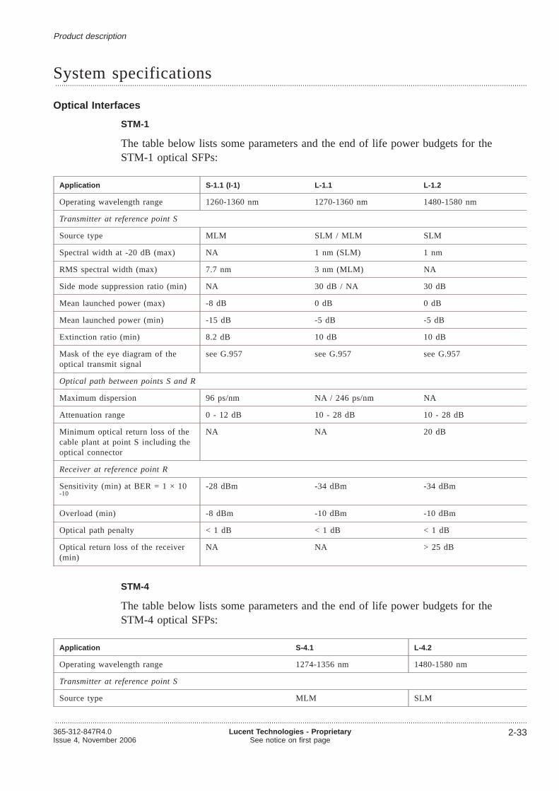
System specifications...................................................................................................................................................................................................................................
Optical Interfaces
STM-1
The table below lists some parameters and the end of life power budgets for theSTM-1 optical SFPs:
Application S-1.1 (I-1) L-1.1 L-1.2
Operating wavelength range 1260-1360 nm 1270-1360 nm 1480-1580 nm
Transmitter at reference point S
Source type MLM SLM / MLM SLM
Spectral width at -20 dB (max) NA 1 nm (SLM) 1 nm
RMS spectral width (max) 7.7 nm 3 nm (MLM) NA
Side mode suppression ratio (min) NA 30 dB / NA 30 dB
Mean launched power (max) -8 dB 0 dB 0 dB
Mean launched power (min) -15 dB -5 dB -5 dB
Extinction ratio (min) 8.2 dB 10 dB 10 dB
Mask of the eye diagram of theoptical transmit signal
see G.957 see G.957 see G.957
Optical path between points S and R
Maximum dispersion 96 ps/nm NA / 246 ps/nm NA
Attenuation range 0 - 12 dB 10 - 28 dB 10 - 28 dB
Minimum optical return loss of thecable plant at point S including theoptical connector
NA NA 20 dB
Receiver at reference point R
Sensitivity (min) at BER = 1 × 10⁻¹⁰
-28 dBm -34 dBm -34 dBm
Overload (min) -8 dBm -10 dBm -10 dBm
Optical path penalty < 1 dB < 1 dB < 1 dB
Optical return loss of the receiver(min)
NA NA > 25 dB
STM-4
The table below lists some parameters and the end of life power budgets for theSTM-4 optical SFPs:
Application S-4.1 L-4.2
Operating wavelength range 1274-1356 nm 1480-1580 nm
Transmitter at reference point S
Source type MLM SLM
Product description
...................................................................................................................................................................................................................................365-312-847R4.0Issue 4, November 2006
Lucent Technologies - ProprietarySee notice on first page
2-33

Application S-4.1 L-4.2
Spectral width at -20 dB (max) NA 1 nm
RMS spectral width (max) 2.5 nm NA
Side mode suppression ratio (min) NA 30 dB
Mean launched power (max) -8 dBm +2 dBm
Mean launched power (min) -15 dBm -3 dBm
Extinction ratio (min) 8.2 dB 10 dB
Mask of the eye diagram of the optical transmit signal see G.957 see G.957
Optical path between points S and R
Maximum dispersion 74 ps/nm NA
Optical attenuation range 0 - 12 dB 10 - 24 dB
Minimum optical return loss of the cable plant at point Sincluding the optical connector
NA 24 dB
Receiver at reference point R
Sensitivity (min) at BER = 1 × 10 -10 -28 dBm -28 dBm
Overload (min) -8 dBm -8 dBm
Optical path penalty < 1 dB < 1 dB
Optical return loss of the receiver (min) NA 27 dB
STM-16
The table below lists some parameters and the end of life power budgets for theSTM-16 SFPs:
Application I-16 S-16.1 L-16.1 L-16.2
Optical wavelength range 1266 - 1360 nm 1260-1360 nm 1280 - 1335 nm 1500 - 1580 nm
Transmission rate 2 488 320 kbit/s 2 488 320 kbit/s 2 488 320 kbit/s 2 488 320 kbit/s
Transmitter at reference point S
Source type MLM SLM SLM SLM
Max. spectral –20 dB width NA 1 nm 1 nm 1 nm
Max. spectral RMS width 4 nm NA NA NA
Min. side mode suppression NA 30 dB 30 dB 30 dB
Mean launched power (max) -3 dBm 0 dBm 3 dBm 3 dBm
Mean launched power (min) –10 dBm –5 dBm –2 dBm –2 dBm
Extinction ratio (min) 8.2 dB 8.2 dB 8.2 dB 8.2dB
Mask of the eye diagram ofthe optical transmit signal
see G.957 see G.957 see G.957 see G.957
Optical path between S and R
Max. chromatic dispersion 12 ps/nm NA NA 1600 ps/nm
Optical attenuation range 0 7 dB 0 12 dB 12 24 dB 12 24 dB
Product description System specifications
....................................................................................................................................................................................................................................
2-34 Lucent Technologies - ProprietarySee notice on first page
365-312-847R4.0Issue 4, November 2006
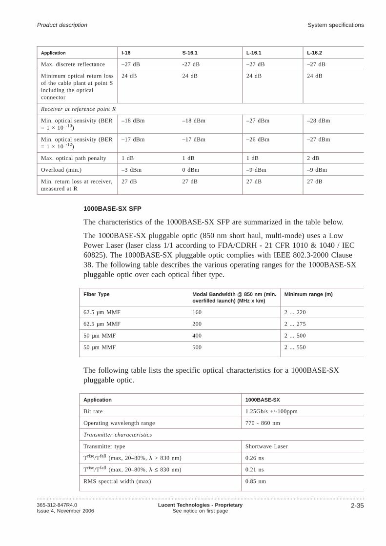
Application I-16 S-16.1 L-16.1 L-16.2
Max. discrete reflectance –27 dB -27 dB –27 dB –27 dB
Minimum optical return lossof the cable plant at point Sincluding the opticalconnector
24 dB 24 dB 24 dB 24 dB
Receiver at reference point R
Min. optical sensivity (BER= 1 × 10 -10)
–18 dBm –18 dBm –27 dBm –28 dBm
Min. optical sensivity (BER= 1 × 10 -12)
–17 dBm –17 dBm –26 dBm –27 dBm
Max. optical path penalty 1 dB 1 dB 1 dB 2 dB
Overload (min.) –3 dBm 0 dBm –9 dBm –9 dBm
Min. return loss at receiver,measured at R
27 dB 27 dB 27 dB 27 dB
1000BASE-SX SFP
The characteristics of the 1000BASE-SX SFP are summarized in the table below.
The 1000BASE-SX pluggable optic (850 nm short haul, multi-mode) uses a LowPower Laser (laser class 1/1 according to FDA/CDRH - 21 CFR 1010 & 1040 / IEC60825). The 1000BASE-SX pluggable optic complies with IEEE 802.3-2000 Clause38. The following table describes the various operating ranges for the 1000BASE-SXpluggable optic over each optical fiber type.
Fiber Type Modal Bandwidth @ 850 nm (min.overfilled launch) (MHz x km)
Minimum range (m)
62.5 µm MMF 160 2 ... 220
62.5 µm MMF 200 2 ... 275
50 µm MMF 400 2 ... 500
50 µm MMF 500 2 ... 550
The following table lists the specific optical characteristics for a 1000BASE-SXpluggable optic.
Application 1000BASE-SX
Bit rate 1.25Gb/s +/-100ppm
Operating wavelength range 770 - 860 nm
Transmitter characteristics
Transmitter type Shortwave Laser
Trise/Tfall (max, 20–80%,λ > 830 nm) 0.26 ns
Trise/Tfall (max, 20–80%,λ ≤ 830 nm) 0.21 ns
RMS spectral width (max) 0.85 nm
Product description System specifications
....................................................................................................................................................................................................................................365-312-847R4.0Issue 4, November 2006
Lucent Technologies - ProprietarySee notice on first page
2-35

Application 1000BASE-SX
Average launch power (max) -1.1 dBm (Class 1 safety limit as defined byIEEE 802.3–2000 Clause 38.7.2)
Average launch power (min) –9.5 dBm
Average launch power of OFF transmitter (max) –30 dBm
Extinction ratio (min) 9 dB
RIN (max) –117 dB/Hz
Mask of the eye diagram of the optical transmit signal see IEEE802.3
Receive Characteristics
Average receive power (max) 0 dBm
Receive sensitivity (min) at BER = 1 × 10 -12 –17 dBm
Return loss (min) 12 dB
Stressed receive sensitivity
(measured with conformance test signal at TP3 for BER =10–12 at the eye center)
–12.5 dBm (62.5 µm MMF)
–13.5 dBm (50 µm MMF)
The following table lists the worst-case power budget and link penalties for a1000BASE-SX pluggable optic. Link penalties are used for link budget calculations.
Description Unit 62.5 µmMMF
50 µm MMF
Modal bandwidth as measured at850 nm (minimum, overfilledlaunch)
MHz ×km
160 200 400 500
Link power budget dB 7.5 7.5 7.5 7.5
Operating distance m 220 275 500 550
Channel insertion loss (awavelength of 830 nm is used tocalculate the values)
dB 2.38 2.60 3.37 3.56
Link power penalties (awavelength of 830 nm is used tocalculate the values)
dB 4.27 4.29 4.07 3.57
Unallocated margin in link powerbudget (a wavelength of 830 nmis used to calculate the values)
dB 0.84 0.60 0.05 0.37
1000BASE-LX SFP
The following table lists the specific optical characteristics for a 1000BASE-LXpluggable optic.
The 1000BASE-LX pluggable optic uses a Low Power Laser (laser class 1/1 accordingto FDA/CDRH - 21 CFR 1010 & 1040 / IEC 60825). The 1000BASE-LX pluggable
Product description System specifications
....................................................................................................................................................................................................................................
2-36 Lucent Technologies - ProprietarySee notice on first page
365-312-847R4.0Issue 4, November 2006

optic complies with IEEE 802.3-2000 Clause 38. The table below describes the variousoperating ranges for the 1000BASE-LX pluggable optic over each optical fiber type.
Fiber Type Modal Bandwidth @ 1300 nm(min. overfilled launch)(MHz × km)
Minimum range(meters)
10 µm SSMF N/A 2 to 5000
The following table lists the specific optical characteristics for a 1000BASE-LXpluggable optic.
Application 1000BASE-LX
Bit rate 1.25Gb/s +/-100ppm
Operating wavelength range 1270 - 1355 nm
Transmitter Characteristics
Transmitter type Longwave Laser
Trise/Tfall (max, 20–80%) 0.26 ns
RMS spectral width (max) 4 nm
Average launch power (max) -3 dBm
Average launch power (min) -11 dBm
Average launch power of OFF transmitter (max) -30 dBm
Extinction ratio (min) 9 dB
Mask of the eye diagram of the optical transmit signal see IEEE802.3
RIN (max) -117 dB/Hz
Receive Characteristics
Average receive power (max) -3 dBm
Receive sensitivity (min) at BER = 1 × 10 -12 -19 dBm
Return loss (min) 12 dB
Stressed receive sensitivity
(measured with conformance test signal at TP3 for BER = 10–12at the eye center)
-14.4 dBm
The following table lists the worst-case power budget and link penalties for a1000BASE-LX pluggable optic. Link penalties are used for link budget calculations.
Description Unit 10 µm SMF
Link power budget dB 8
Operating distance m 5000
Channel insertion loss (a wavelength of 1270 nm is used tocalculate the values)
dB 4.57
Link power penalties (a wavelength of 1270 nm is used tocalculate the values)
dB 3.27
Product description System specifications
....................................................................................................................................................................................................................................365-312-847R4.0Issue 4, November 2006
Lucent Technologies - ProprietarySee notice on first page
2-37
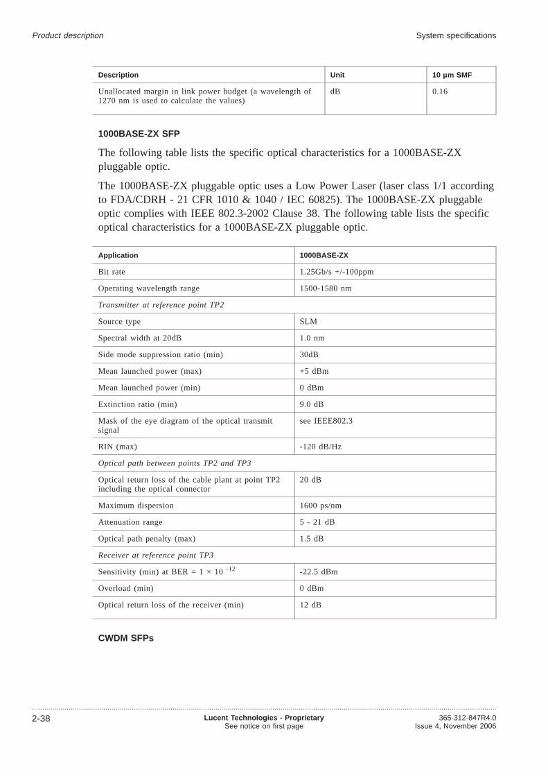
Description Unit 10 µm SMF
Unallocated margin in link power budget (a wavelength of1270 nm is used to calculate the values)
dB 0.16
1000BASE-ZX SFP
The following table lists the specific optical characteristics for a 1000BASE-ZXpluggable optic.
The 1000BASE-ZX pluggable optic uses a Low Power Laser (laser class 1/1 accordingto FDA/CDRH - 21 CFR 1010 & 1040 / IEC 60825). The 1000BASE-ZX pluggableoptic complies with IEEE 802.3-2002 Clause 38. The following table lists the specificoptical characteristics for a 1000BASE-ZX pluggable optic.
Application 1000BASE-ZX
Bit rate 1.25Gb/s +/-100ppm
Operating wavelength range 1500-1580 nm
Transmitter at reference point TP2
Source type SLM
Spectral width at 20dB 1.0 nm
Side mode suppression ratio (min) 30dB
Mean launched power (max) +5 dBm
Mean launched power (min) 0 dBm
Extinction ratio (min) 9.0 dB
Mask of the eye diagram of the optical transmitsignal
see IEEE802.3
RIN (max) -120 dB/Hz
Optical path between points TP2 and TP3
Optical return loss of the cable plant at point TP2including the optical connector
20 dB
Maximum dispersion 1600 ps/nm
Attenuation range 5 - 21 dB
Optical path penalty (max) 1.5 dB
Receiver at reference point TP3
Sensitivity (min) at BER = 1 × 10 -12 -22.5 dBm
Overload (min) 0 dBm
Optical return loss of the receiver (min) 12 dB
CWDM SFPs
Product description System specifications
....................................................................................................................................................................................................................................
2-38 Lucent Technologies - ProprietarySee notice on first page
365-312-847R4.0Issue 4, November 2006

The table below lists some parameters and the end of life power budgets for theCWDM STM-4/16 SFPs:
Application CWDM STM-4/16 40km CWDM STM-4/16 80km
Maximum channels 8 8
Interface at point SS
Maximum output power +5 dBm +5 dBm
Minimum output power 0 dBm 0 dBm
Operating wavelength 1471 nm +20m (m = 0 to 7) 1471 nm +20m (m = 0 to 7)
Maximum central wavelengthdeviation
+/- 6.5nm +/- 6.5nm
Minimum extinction ratio 8.2 dB 8.2 dB
Eye mask pattern see G.957 see G.957
Optical path between point SSand RS
Maximum channel insertion loss 17 dB 25.5 dB
Minimum channel insertion loss 5 dB 13 dB
Maximum dispersion 1000 ps/nm 1640 ps/nm
Minimum optical return loss atSS
24 dB 24 dB
Maximum discrete reflectancebetween SS and RS
27 dB 27 dB
Maximum differential groupdelay
120 ps 120 ps
Maximum optical cross talk 20 dB 20 dB
Interface at point RS
Maximum mean channel inputpower
0 dBm -8 dBm
Minimum sensitivity -18.5 dBm -28 dBm
Maximum optical path penalty 1.5 dB 2.5 dB
Maximum reflectance of receiver 27 dB 27 dB
Single-fiber Bidirectional SFPs
The table below lists some parameters and the end of life power budgets for theSTM-1, STM-4, 1 GbE Single-Fiber (Bidirectional) Short Haul optical modules (SFPs).
Product description System specifications
....................................................................................................................................................................................................................................365-312-847R4.0Issue 4, November 2006
Lucent Technologies - ProprietarySee notice on first page
2-39
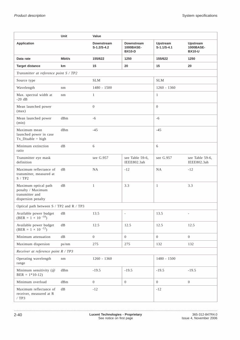
Unit Value
Application DownstreamS-1.2/S-4.2
Downstream1000BASE-BX10-D
UpstreamS-1.1/S-4.1
Upstream1000BASE-BX10-U
Data rate Mbit/s 155/622 1250 155/622 1250
Target distance km 15 20 15 20
Transmitter at reference point S / TP2
Source type SLM SLM
Wavelength nm 1480 - 1500 1260 - 1360
Max. spectral width at-20 dB
nm 1 1
Mean launched power(max)
0 0
Mean launched power(min)
dBm -6 -6
Maximum meanlaunched power in caseTx_Disable = high
dBm -45 -45
Minimum extinctionratio
dB 6 6
Transmitter eye maskdefinition
see G.957 see Table 59-6,IEEE802.3ah
see G.957 see Table 59-6,IEEE802.3ah
Maximum reflectance oftransmitter, measured atS / TP2
dB NA -12 NA -12
Maximum optical pathpenalty / Maximumtransmitter anddispersion penalty
dB 1 3.3 1 3.3
Optical path between S / TP2 and R / TP3
Available power budget(BER = 1 × 10⁻¹⁰)
dB 13.5 - 13.5 -
Available power budget(BER = 1 × 10-12)
dB 12.5 12.5 12.5 12.5
Minimum attenuation dB 0 0 0 0
Maximum dispersion ps/nm 275 275 132 132
Receiver at reference point R / TP3
Operating wavelengthrange
nm 1260 - 1360 1480 - 1500
Minimum sensitivity (@BER = 1*10-12)
dBm -19.5 -19.5 -19.5 -19.5
Minimum overload dBm 0 0 0 0
Maximum reflectance ofreceiver, measured at R/ TP3
dB -12 -12
Product description System specifications
....................................................................................................................................................................................................................................
2-40 Lucent Technologies - ProprietarySee notice on first page
365-312-847R4.0Issue 4, November 2006

Electrical STM-1 interface
The following table lists some parameters and the End of Life power budget of the155-Mbit/s electrical interface unit:
Unit Value
Application intra-office
SDH Level type STM-1
Transmission rate kbit/s 155,520 ± 20 ppm
Line coding type Coded Mark Inversion (CMI, G.703-12.1)
Impedance Ω 75
Return Loss
(8 ... 240 MHz.)
dB 15
Maximum cable attenuation (78 MHz) dB 12.7
Tributary interfaces
• STM-1 tributary interface at 155 Mbit/s according to G.957 via SFP. The 155Mbit/s optical access is done with a LC connector type.
• STM-1 tributary interface at 155 Mbit/s according to the ITU G703-15 via SFP.The STM-1e SFPs use the DIN 1.0/2.3 type connectors.
• STM-4 tributary interface at 622 Mbit/s according to G.957 via SFP. The 622Mbit/s optical access is realized with a LC connector type.
• Interface at 1.544 Mbit/s ± 130 ppm, AMI or B8ZS encoded (programmable ingroups of 8) and conforming to G.703-2 standard 1991, asynchronously mapped viaVC-11 to a TU-12. The 1.5 Mbit/s electrical (DS1) interface access is via a RJ45connector suitable for symmetrical twisted pair cables with an impedance of 100Ω.
• Interface at 2.048 Mbit/s ± 50 ppm, HDB3 coded and conforming to G.703standard 1991, asynchronously mapped via a VC-12 in TU-12. The 2 Mbit/selectrical (E1) interface access is via RJ45 connector suitable for symmetricaltwisted pair cables either with an impedance of 120Ω or coaxial cables with animpedance of 75Ω.Each 2 Mbit/s tributary interface (optional card) can be operated in ISDN PRI(Primary Rate Interface) or Leased-Line mode. It allows to transmit “30 B+D”according to G.962 and I.431. This feature requires the processing of the overheadcontained in timeslot 0 (TS0) of the 2 Mbit/s signal.
• Interface at 34.368 Mbit/s ± 20 ppm, HDB3 encoded and conforming to G.703-8October 1998, asynchronously mapped into LO-VC3. The 34 Mbit/ s electricalclear channel (E3) interface access is via a coaxial female DIN 1.6/5.6 typeconnector with an impedance of 75Ω.
• Interface at 44.736 Mbit/s ± 20 ppm, B3ZS encoded and conforming to G.703-6October 1998, directly mapped in a LO-VC3. The 45 Mbit/s electrical tributary(DS-3) interface access is via a coaxial female DIN 1.6/5.6 type connector with animpedance of 75Ω.
Product description System specifications
....................................................................................................................................................................................................................................365-312-847R4.0Issue 4, November 2006
Lucent Technologies - ProprietarySee notice on first page
2-41
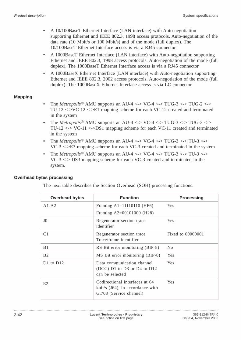
• A 10/100BaseT Ethernet Interface (LAN interface) with Auto-negotiationsupporting Ethernet and IEEE 802.3, 1998 access protocols. Auto-negotiation of thedata rate (10 Mbit/s or 100 Mbit/s) and of the mode (full duplex). The10/100BaseT Ethernet Interface access is via a RJ45 connector.
• A 1000BaseT Ethernet Interface (LAN interface) with Auto-negotiation supportingEthernet and IEEE 802.3, 1998 access protocols. Auto-negotiation of the mode (fullduplex). The 1000BaseT Ethernet Interface access is via a RJ45 connector.
• A 1000BaseX Ethernet Interface (LAN interface) with Auto-negotiation supportingEthernet and IEEE 802.3, 2002 access protocols. Auto-negotiation of the mode (fullduplex). The 1000BaseX Ethernet Interface access is via LC connector.
Mapping
• The Metropolis® AMU supports an AU-4 <-> VC-4 <-> TUG-3 <-> TUG-2 <->TU-12 <->VC-12 <->E1 mapping scheme for each VC-12 created and terminatedin the system
• The Metropolis® AMU supports an AU-4 <-> VC-4 <-> TUG-3 <-> TUG-2 <->TU-12 <-> VC-11 <->DS1 mapping scheme for each VC-11 created and terminatedin the system
• The Metropolis® AMU supports an AU-4 <-> VC-4 <-> TUG-3 <-> TU-3 <->VC-3 <->E3 mapping scheme for each VC-3 created and terminated in the system
• The Metropolis® AMU supports an AU-4 <-> VC-4 <-> TUG-3 <-> TU-3 <->VC-3 <-> DS3 mapping scheme for each VC-3 created and terminated in thesystem.
Overhead bytes processing
The next table describes the Section Overhead (SOH) processing functions.
Overhead bytes Function Processing
A1-A2 Framing A1=11110110 (HF6)
Framing A2=00101000 (H28)
Yes
J0 Regenerator section traceidentifier
Yes
C1 Regenerator section traceTrace/frame identifier
Fixed to 00000001
B1 RS Bit error monitoring (BIP-8) No
B2 MS Bit error monitoring (BIP-8) Yes
D1 to D12 Data communication channel(DCC) D1 to D3 or D4 to D12can be selected
Yes
E2 Codirectional interfaces at 64kbit/s (J64), in accordance withG.703 (Service channel)
Yes
Product description System specifications
....................................................................................................................................................................................................................................
2-42 Lucent Technologies - ProprietarySee notice on first page
365-312-847R4.0Issue 4, November 2006
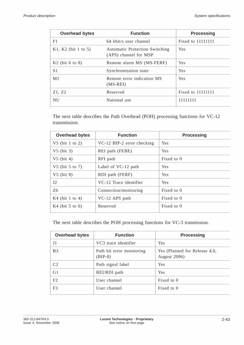
Overhead bytes Function Processing
F1 64 kbit/s user channel Fixed to11111111
K1, K2 (bit 1 to 5) Automatic Protection Switching(APS) channel for MSP
Yes
K2 (bit 6 to 8) Remote alarm MS (MS-FERF) Yes
S1 Synchronization state Yes
M1 Remote error indication MS(MS-REI)
Yes
Z1, Z2 Reserved Fixed to11111111
NU National use 11111111
The next table describes the Path Overhead (POH) processing functions for VC-12transmission.
Overhead bytes Function Processing
V5 (bit 1 to 2) VC-12 BIP-2 error checking Yes
V5 (bit 3) REI path (FEBE) Yes
V5 (bit 4) RFI path Fixed to 0
V5 (bit 5 to 7) Label of VC-12 path Yes
V5 (bit 8) RDI path (FERF) Yes
J2 VC-12 Trace identifier Yes
Z6 Connection/monitoring Fixed to 0
K4 (bit 1 to 4) VC-12 APS path Fixed to 0
K4 (bit 5 to 6) Reserved Fixed to 0
The next table describes the POH processing functions for VC-3 tranmission.
Overhead bytes Function Processing
J1 VC3 trace identifier Yes
B3 Path bit error monitoring(BIP-8)
Yes (Planned for Release 4.0,August 2006)
C2 Path signal label Yes
G1 REI/RDI path Yes
F2 User channel Fixed to 0
F3 User channel Fixed to 0
Product description System specifications
....................................................................................................................................................................................................................................365-312-847R4.0Issue 4, November 2006
Lucent Technologies - ProprietarySee notice on first page
2-43
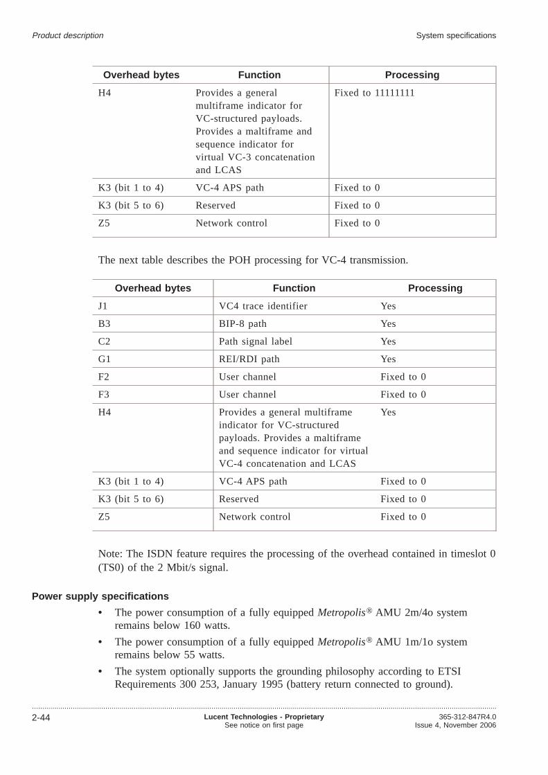
Overhead bytes Function Processing
H4 Provides a generalmultiframe indicator forVC-structured payloads.Provides a maltiframe andsequence indicator forvirtual VC-3 concatenationand LCAS
Fixed to 11111111
K3 (bit 1 to 4) VC-4 APS path Fixed to 0
K3 (bit 5 to 6) Reserved Fixed to 0
Z5 Network control Fixed to 0
The next table describes the POH processing for VC-4 transmission.
Overhead bytes Function Processing
J1 VC4 trace identifier Yes
B3 BIP-8 path Yes
C2 Path signal label Yes
G1 REI/RDI path Yes
F2 User channel Fixed to 0
F3 User channel Fixed to 0
H4 Provides a general multiframeindicator for VC-structuredpayloads. Provides a maltiframeand sequence indicator for virtualVC-4 concatenation and LCAS
Yes
K3 (bit 1 to 4) VC-4 APS path Fixed to 0
K3 (bit 5 to 6) Reserved Fixed to 0
Z5 Network control Fixed to 0
Note: The ISDN feature requires the processing of the overhead contained in timeslot 0(TS0) of the 2 Mbit/s signal.
Power supply specifications
• The power consumption of a fully equippedMetropolis® AMU 2m/4o systemremains below 160 watts.
• The power consumption of a fully equippedMetropolis® AMU 1m/1o systemremains below 55 watts.
• The system optionally supports the grounding philosophy according to ETSIRequirements 300 253, January 1995 (battery return connected to ground).
Product description System specifications
....................................................................................................................................................................................................................................
2-44 Lucent Technologies - ProprietarySee notice on first page
365-312-847R4.0Issue 4, November 2006
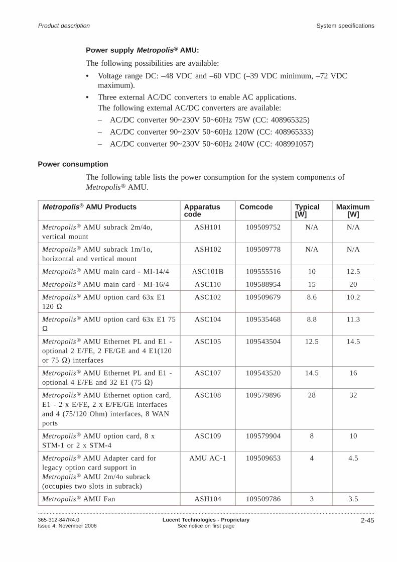
Power supply Metropolis ® AMU:
The following possibilities are available:
• Voltage range DC: –48 VDC and –60 VDC (–39 VDC minimum, –72 VDCmaximum).
• Three external AC/DC converters to enable AC applications.The following external AC/DC converters are available:
– AC/DC converter 90~230V 50~60Hz 75W (CC: 408965325)
– AC/DC converter 90~230V 50~60Hz 120W (CC: 408965333)
– AC/DC converter 90~230V 50~60Hz 240W (CC: 408991057)
Power consumption
The following table lists the power consumption for the system components ofMetropolis® AMU.
Metropolis ® AMU Products Apparatuscode
Comcode Typical[W]
Maximum[W]
Metropolis® AMU subrack 2m/4o,vertical mount
ASH101 109509752 N/A N/A
Metropolis® AMU subrack 1m/1o,horizontal and vertical mount
ASH102 109509778 N/A N/A
Metropolis® AMU main card - MI-14/4 ASC101B 109555516 10 12.5
Metropolis® AMU main card - MI-16/4 ASC110 109588954 15 20
Metropolis® AMU option card 63x E1120 Ω
ASC102 109509679 8.6 10.2
Metropolis® AMU option card 63x E1 75Ω
ASC104 109535468 8.8 11.3
Metropolis® AMU Ethernet PL and E1 -optional 2 E/FE, 2 FE/GE and 4 E1(120or 75 Ω) interfaces
ASC105 109543504 12.5 14.5
Metropolis® AMU Ethernet PL and E1 -optional 4 E/FE and 32 E1 (75Ω)
ASC107 109543520 14.5 16
Metropolis® AMU Ethernet option card,E1 - 2 x E/FE, 2 x E/FE/GE interfacesand 4 (75/120 Ohm) interfaces, 8 WANports
ASC108 109579896 28 32
Metropolis® AMU option card, 8 xSTM-1 or 2 x STM-4
ASC109 109579904 8 10
Metropolis® AMU Adapter card forlegacy option card support inMetropolis® AMU 2m/4o subrack(occupies two slots in subrack)
AMU AC-1 109509653 4 4.5
Metropolis® AMU Fan ASH104 109509786 3 3.5
Product description System specifications
....................................................................................................................................................................................................................................365-312-847R4.0Issue 4, November 2006
Lucent Technologies - ProprietarySee notice on first page
2-45
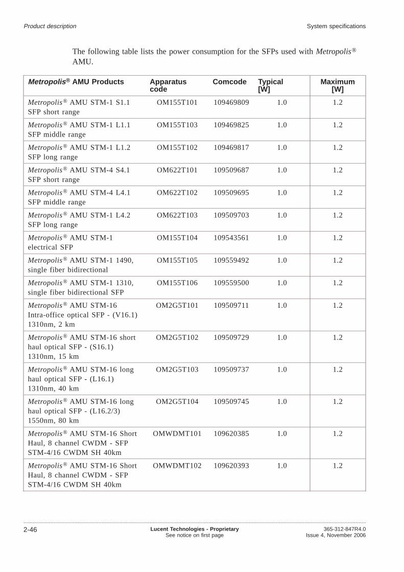
The following table lists the power consumption for the SFPs used withMetropolis®
AMU.
Metropolis ® AMU Products Apparatuscode
Comcode Typical[W]
Maximum[W]
Metropolis® AMU STM-1 S1.1SFP short range
OM155T101 109469809 1.0 1.2
Metropolis® AMU STM-1 L1.1SFP middle range
OM155T103 109469825 1.0 1.2
Metropolis® AMU STM-1 L1.2SFP long range
OM155T102 109469817 1.0 1.2
Metropolis® AMU STM-4 S4.1SFP short range
OM622T101 109509687 1.0 1.2
Metropolis® AMU STM-4 L4.1SFP middle range
OM622T102 109509695 1.0 1.2
Metropolis® AMU STM-1 L4.2SFP long range
OM622T103 109509703 1.0 1.2
Metropolis® AMU STM-1electrical SFP
OM155T104 109543561 1.0 1.2
Metropolis® AMU STM-1 1490,single fiber bidirectional
OM155T105 109559492 1.0 1.2
Metropolis® AMU STM-1 1310,single fiber bidirectional SFP
OM155T106 109559500 1.0 1.2
Metropolis® AMU STM-16Intra-office optical SFP - (V16.1)1310nm, 2 km
OM2G5T101 109509711 1.0 1.2
Metropolis® AMU STM-16 shorthaul optical SFP - (S16.1)1310nm, 15 km
OM2G5T102 109509729 1.0 1.2
Metropolis® AMU STM-16 longhaul optical SFP - (L16.1)1310nm, 40 km
OM2G5T103 109509737 1.0 1.2
Metropolis® AMU STM-16 longhaul optical SFP - (L16.2/3)1550nm, 80 km
OM2G5T104 109509745 1.0 1.2
Metropolis® AMU STM-16 ShortHaul, 8 channel CWDM - SFPSTM-4/16 CWDM SH 40km
OMWDMT101 109620385 1.0 1.2
Metropolis® AMU STM-16 ShortHaul, 8 channel CWDM - SFPSTM-4/16 CWDM SH 40km
OMWDMT102 109620393 1.0 1.2
Product description System specifications
....................................................................................................................................................................................................................................
2-46 Lucent Technologies - ProprietarySee notice on first page
365-312-847R4.0Issue 4, November 2006
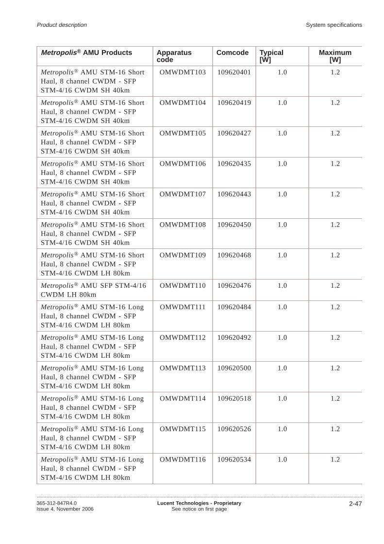
Metropolis ® AMU Products Apparatuscode
Comcode Typical[W]
Maximum[W]
Metropolis® AMU STM-16 ShortHaul, 8 channel CWDM - SFPSTM-4/16 CWDM SH 40km
OMWDMT103 109620401 1.0 1.2
Metropolis® AMU STM-16 ShortHaul, 8 channel CWDM - SFPSTM-4/16 CWDM SH 40km
OMWDMT104 109620419 1.0 1.2
Metropolis® AMU STM-16 ShortHaul, 8 channel CWDM - SFPSTM-4/16 CWDM SH 40km
OMWDMT105 109620427 1.0 1.2
Metropolis® AMU STM-16 ShortHaul, 8 channel CWDM - SFPSTM-4/16 CWDM SH 40km
OMWDMT106 109620435 1.0 1.2
Metropolis® AMU STM-16 ShortHaul, 8 channel CWDM - SFPSTM-4/16 CWDM SH 40km
OMWDMT107 109620443 1.0 1.2
Metropolis® AMU STM-16 ShortHaul, 8 channel CWDM - SFPSTM-4/16 CWDM SH 40km
OMWDMT108 109620450 1.0 1.2
Metropolis® AMU STM-16 ShortHaul, 8 channel CWDM - SFPSTM-4/16 CWDM LH 80km
OMWDMT109 109620468 1.0 1.2
Metropolis® AMU SFP STM-4/16CWDM LH 80km
OMWDMT110 109620476 1.0 1.2
Metropolis® AMU STM-16 LongHaul, 8 channel CWDM - SFPSTM-4/16 CWDM LH 80km
OMWDMT111 109620484 1.0 1.2
Metropolis® AMU STM-16 LongHaul, 8 channel CWDM - SFPSTM-4/16 CWDM LH 80km
OMWDMT112 109620492 1.0 1.2
Metropolis® AMU STM-16 LongHaul, 8 channel CWDM - SFPSTM-4/16 CWDM LH 80km
OMWDMT113 109620500 1.0 1.2
Metropolis® AMU STM-16 LongHaul, 8 channel CWDM - SFPSTM-4/16 CWDM LH 80km
OMWDMT114 109620518 1.0 1.2
Metropolis® AMU STM-16 LongHaul, 8 channel CWDM - SFPSTM-4/16 CWDM LH 80km
OMWDMT115 109620526 1.0 1.2
Metropolis® AMU STM-16 LongHaul, 8 channel CWDM - SFPSTM-4/16 CWDM LH 80km
OMWDMT116 109620534 1.0 1.2
Product description System specifications
....................................................................................................................................................................................................................................365-312-847R4.0Issue 4, November 2006
Lucent Technologies - ProprietarySee notice on first page
2-47
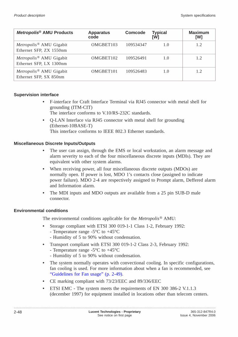
Metropolis ® AMU Products Apparatuscode
Comcode Typical[W]
Maximum[W]
Metropolis® AMU GigabitEthernet SFP, ZX 1550nm
OMGBET103 109534347 1.0 1.2
Metropolis® AMU GigabitEthernet SFP, LX 1300nm
OMGBET102 109526491 1.0 1.2
Metropolis® AMU GigabitEthernet SFP, SX 850nm
OMGBET101 109526483 1.0 1.2
Supervision interface
• F-interface for Craft Interface Terminal via RJ45 connector with metal shell forgrounding (ITM-CIT)The interface conforms to V.10/RS-232C standards.
• Q-LAN Interface via RJ45 connector with metal shell for grounding(Ethernet-10BASE-T)This interface conforms to IEEE 802.3 Ethernet standards.
Miscellaneous Discrete Inputs/Outputs
• The user can assign, through the EMS or local workstation, an alarm message andalarm severity to each of the four miscellaneous discrete inputs (MDIs). They areequivalent with other system alarms.
• When receiving power, all four miscellaneous discrete outputs (MDOs) arenormally open. If power is lost, MDO 1’s contacts close (assigned to indicatepower failure). MDO 2-4 are respectively assigned to Prompt alarm, Deffered alarmand Information alarm.
• The MDI inputs and MDO outputs are available from a 25 pin SUB-D maleconnector.
Environmental conditions
The environmental conditions applicable for theMetropolis® AMU:
• Storage compliant with ETSI 300 019-1-1 Class 1-2, February 1992:- Temperature range -5°C to +45°C- Humidity of 5 to 90% without condensation.
• Transport compliant with ETSI 300 019-1-2 Class 2-3, February 1992:- Temperature range -5°C to +45°C- Humidity of 5 to 90% without condensation.
• The system normally operates with convectional cooling. In specific configurations,fan cooling is used. For more information about when a fan is recommended, see“Guidelines for Fan usage” (p. 2-49).
• CE marking compliant with 73/23/EEC and 89/336/EEC
• ETSI EMC - The system meets the requirements of EN 300 386-2 V.1.1.3(december 1997) for equipment installed in locations other than telecom centers.
Product description System specifications
....................................................................................................................................................................................................................................
2-48 Lucent Technologies - ProprietarySee notice on first page
365-312-847R4.0Issue 4, November 2006
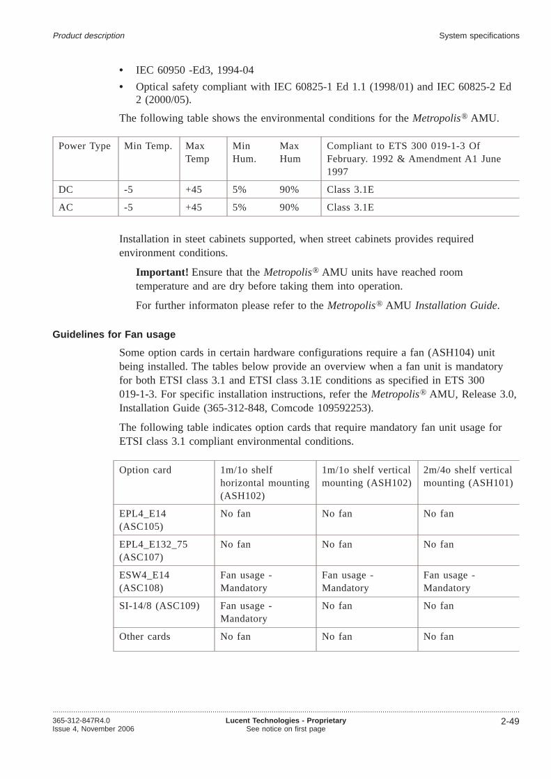
• IEC 60950 -Ed3, 1994-04
• Optical safety compliant with IEC 60825-1 Ed 1.1 (1998/01) and IEC 60825-2 Ed2 (2000/05).
The following table shows the environmental conditions for theMetropolis® AMU.
Power Type Min Temp. MaxTemp
MinHum.
MaxHum
Compliant to ETS 300 019-1-3 OfFebruary. 1992 & Amendment A1 June1997
DC -5 +45 5% 90% Class 3.1E
AC -5 +45 5% 90% Class 3.1E
Installation in steet cabinets supported, when street cabinets provides requiredenvironment conditions.
Important! Ensure that theMetropolis® AMU units have reached roomtemperature and are dry before taking them into operation.
For further informaton please refer to theMetropolis® AMU Installation Guide.
Guidelines for Fan usage
Some option cards in certain hardware configurations require a fan (ASH104) unitbeing installed. The tables below provide an overview when a fan unit is mandatoryfor both ETSI class 3.1 and ETSI class 3.1E conditions as specified in ETS 300019-1-3. For specific installation instructions, refer theMetropolis® AMU, Release 3.0,Installation Guide (365-312-848, Comcode 109592253).
The following table indicates option cards that require mandatory fan unit usage forETSI class 3.1 compliant environmental conditions.
Option card 1m/1o shelfhorizontal mounting(ASH102)
1m/1o shelf verticalmounting (ASH102)
2m/4o shelf verticalmounting (ASH101)
EPL4_E14(ASC105)
No fan No fan No fan
EPL4_E132_75(ASC107)
No fan No fan No fan
ESW4_E14(ASC108)
Fan usage -Mandatory
Fan usage -Mandatory
Fan usage -Mandatory
SI-14/8 (ASC109) Fan usage -Mandatory
No fan No fan
Other cards No fan No fan No fan
Product description System specifications
....................................................................................................................................................................................................................................365-312-847R4.0Issue 4, November 2006
Lucent Technologies - ProprietarySee notice on first page
2-49
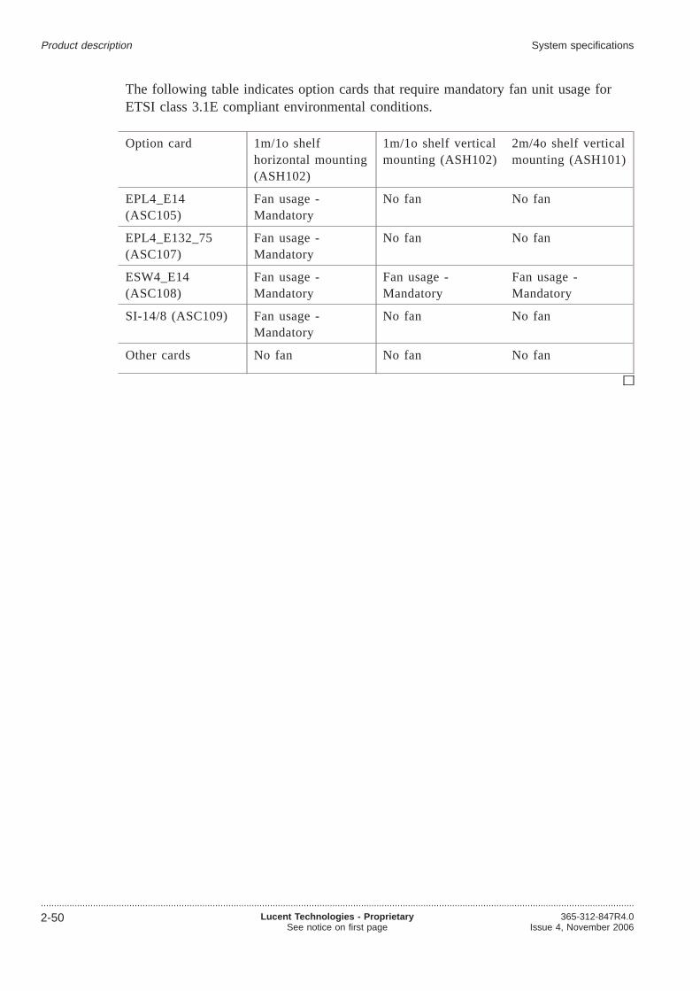
The following table indicates option cards that require mandatory fan unit usage forETSI class 3.1E compliant environmental conditions.
Option card 1m/1o shelfhorizontal mounting(ASH102)
1m/1o shelf verticalmounting (ASH102)
2m/4o shelf verticalmounting (ASH101)
EPL4_E14(ASC105)
Fan usage -Mandatory
No fan No fan
EPL4_E132_75(ASC107)
Fan usage -Mandatory
No fan No fan
ESW4_E14(ASC108)
Fan usage -Mandatory
Fan usage -Mandatory
Fan usage -Mandatory
SI-14/8 (ASC109) Fan usage -Mandatory
No fan No fan
Other cards No fan No fan No fan
Product description System specifications
....................................................................................................................................................................................................................................
2-50 Lucent Technologies - ProprietarySee notice on first page
365-312-847R4.0Issue 4, November 2006

Performance Monitoring...................................................................................................................................................................................................................................
Overview
• Performance monitoring is in accordance with ITU-T G.826 and G.784
• The following four parameters are available to estimate the error performance of apath:
– SES: number of Severely Errored Seconds in the received signal
– ES: number of Errored Seconds in the received signal
– BBE: number of Background Block Errors in the received signal
– UAS: number of UnAvailable Seconds in the received signal
• For termination points, Near-End Performance Monitoring can be done on theincoming MS16, MS4, MS1, VC-4, VC-3, and VC-12 signals. Non-intrusivemonitoring is only possible for AU-4 signals.
• Bi-directional and unidirectional performance monitoring
• Performance monitoring data is stored in one current and sixteen recent 15 minutesregisters, and one current and one recent 24 hours registers. Detailed informationabout Performance Monitoring are provided in the following sections.
• Threshold reports are generated when user-settable performance parameters areexceeded during 15 minutes and 24 hours periods
• Ethernet performance monitoring information can be derived from the GeneralPurpose Ethernet Port Monitor, Ethernet Service Monitor, Ethernet CongestionMonitor, Ethernet High Priority Traffic Monitor, Ethernet Low Priority TrafficMonitor, and Ethernet Frame Delay Monitor.. This information is available in 15minutes or 24 hours registers. For more information about Ethernet PerformanceMonitoring features, see“Advanced TransLAN® Features” (p. 2-57).
Capacity for 200 Monitoring Points per Tributary Slot
In addition to the capacity limit for the number of simultaneously active PM points atthe system level (600 in Release 4.0), there is a limit of 200 performance monitoringpoints for each slot in the system. For more information, refer the Metropolis® AMUUser Operations Guide.
Enhanced Ethernet Performance Monitoring
The ESW4_E14 option card provides enhanced Ethernet performance monitoringfunctions. Users can enable or disable the following Ethernet performance monitoringpoints.
• General Purpose Ethernet Port Monitor
• Ethernet Service Monitor
• Ethernet Congestion Monitor
• Ethernet High Priority Traffic Monitor
• Ethernet Low Priority Traffic Monitor
• Round Trip Delay Monitor.
Product description
...................................................................................................................................................................................................................................365-312-847R4.0Issue 4, November 2006
Lucent Technologies - ProprietarySee notice on first page
2-51
General Purpose Ethernet Monitor
The General Purpose Ethernet Monitor can be enabled or disabled on each LAN orWAN port. The following counters are available in this monitor:
• eINB: Number of octets in non-errored incoming frames
• eINF: Number of non-errored incoming frames
• eONB: Number of octets in outgoing frames
• eONF: Number of outgoing frames
• eINCP: Number of octets in non-errored incoming frames trapped to CPU
• eONCP: Number of octets in outgoing frames sourced by CPU
• eDFE: Number of incoming frames dropped due to frame format errors
• eCIF: Number of incoming frames dropped due to capacity limits in switch inputstage
• pUPR: Number of non-errored incoming unicast frames
• pMPR: Number of non-errored incoming multicast frames
• pBPR: Number of non-errored incoming broadcast frames
• pPPR: Number of non-errored incoming PAUSE frames
• pUPS: Number of outgoing unicast frames
• pMPS: Number of outgoing multicast frames
• pBPS: Number of outgoing broadcast frames
• pPPS: Number of outgoing PAUSE frames.
For more information, refer the Metropolis® AMU User Operations Guide.
Threshold Limit Notifications for General Purpose Ethernet Monitor
Users can enable or disable threshold limit notifications for each active GeneralPurpose Ethernet Port Monitor on each of the following eight parameters.
• eDFE - 15 minute bin
• eCIF - 15 minute bin
• eDFE - 24 hour bin
• eCIF - 24 hour bin.
Each General Purpose Ethernet Port Monitor has its own set of thresholds. In case oneof the thresholds is crossed while the threshold crossing is enabled, a correspondingalarm will be raised or cleared for the chosen General Purpose Ethernet Port Monitor.Users can provision “Set” or “Clear” thresholds for each of these counters. Note thatthis feature is only applicable in combination with the General Purpose EthernetMonitor features. For more information, refer the Metropolis® AMU User OperationsGuide.
Product description Performance Monitoring
....................................................................................................................................................................................................................................
2-52 Lucent Technologies - ProprietarySee notice on first page
365-312-847R4.0Issue 4, November 2006
Ethernet Service Monitor
The Ethernet service monitor can be enabled or disabled on each flow on a port onwhich Flow Classification is enabled. The following three counters are included in thismonitor:
• gQIB: Number of frames marked in “green” color (low dropping precedence)
• yQIB: Number of frames marked in “yellow” color (high dropping precedence)
• rQIB: Number of frames marked in “red” color (dropped immediately).
For more information, refer the Metropolis® AMU User Operations Guide.
Ethernet Congestion Monitor
The Ethernet Congestion Monitor can be enabled or disabled on each network roleegress port. The following counters are included in this monitor.
• g0EDBC: Number of octets in dropped green frames with traffic class 0
• y0EDBC: Number of octets in dropped yellow frames with traffic class 0
• g1EDBC: Number of octets in dropped green frames with traffic class 1
• y1EDBC: Number of octets in dropped yellow frames with traffic class 1
• g2EDBC: Number of octets in dropped green frames with traffic class 2
• g2EOCS: Number of seconds with at least one dropped green frame of traffic class2
• y2EDBC: Number of octets in dropped yellow frames with traffic class 2
• y2EOCS: Number of seconds with at least one dropped yellow frame of trafficclass 2
• g3EDBC: Number of octets in dropped green frames with traffic class 3
• g3EOCS: Number of seconds with at least one dropped green frame of traffic class3
• y3EDBC: Number of octets in dropped yellow frames with traffic class 3
• y3EOCS: Number of seconds with at least one dropped yellow frame of trafficclass 3.
For more information, refer the Metropolis® AMU User Operations Guide.
Threshold Limit Notifications for Ethernet Congestion Monitor
Users can individually enable or disable threshold limit notifications for each activeEthernet Congestion Monitor on the each of the following parameters.
• g2EOCS - 15 minute bin
• y2EOCS - 15 minute bin
• g3EOCS - 15 minute bin
• y3EOCS - 15 minute bin
• g2EOCS - 24 hour bin
• y2EOCS - 24 hour bin
• g3EOCS - 24 hour bin
• y3EOCS - 24 hour bin.
Product description Performance Monitoring
....................................................................................................................................................................................................................................365-312-847R4.0Issue 4, November 2006
Lucent Technologies - ProprietarySee notice on first page
2-53

Note that this feature is only applicable in combination with the Ethernet CongestionMonitor features.
For more information, refer the Metropolis® AMU User Operations Guide.
Ethernet High Priority Traffic Monitor
The Ethernet high priority traffic monitor can be enabled or disabled on each ingressnetwork role port. The following counters are included in this monitor.
• g3EINB: Number of octets in non-errored incoming green frames with traffic class3
• g3EINF: Number of non-errored incoming green frames with traffic class 3
• c3EIN: Number of octets in non-errored green frames with traffic class 3 andinternal protocol traffic, including encapsulation overhead (i.e. on the physicallayer)
• i3gEILS: Number of seconds marked″loaded″ in C3EIN count
• i3gEISLS: Number of seconds marked″severely loaded″ in C3EIN count
• y3EINB: Number of octets in non-errored incoming yellow frames with traffic class3
• y3EINF: Number of non-errored incoming yellow frames with traffic class 3
• g2EINB: Number of octets in non-errored incoming green frames with traffic class2
• g2EINF: Number of non-errored incoming green frames with traffic class 2
• c2EIN: Number of octets in non-errored green frames with traffic class 2, 3 andinternal protocol traffic, including encapsulation overhead (i.e. on the physicallayer)
• i32gEILS: Number of seconds marked″loaded″ in C2EIN count
• i32gEISLS: Number of seconds marked″severely loaded″ in C2EIN count
• y2EINB: Number of octets in non-errored incoming yellow frames with traffic class2
• y2EINF: Number of non-errored incoming yellow frames with traffic class 2.
Note that a one second interval performance counter is marked “Loaded” in case thecounter increments more than the provisioned Loaded Second (LS) threshold duringthis second. A one second interval on a performance counter is marked “SeverelyLoaded” in case the counter increments more than the provisioned Severely LoadedSecond (SLS) threshold during this second. For more information about LoadedSecond and Severely Loaded Second, refer the following sections.
For more information, refer the Metropolis® AMU User Operations Guide.
Ethernet Low Priority Traffic Monitor
The Ethernet Low Priority Traffic Monitor can be enabled or disabled on each ingressnetwork role port. The following counters are included in this monitor.
• g0EINB: Number of octets in non-errored incoming green frames with traffic class0
• g0EINF: Number of non-errored incoming green frames with traffic class 0
Product description Performance Monitoring
....................................................................................................................................................................................................................................
2-54 Lucent Technologies - ProprietarySee notice on first page
365-312-847R4.0Issue 4, November 2006
• y0EINB: Number of octets in non-errored incoming yellow frames with traffic class0
• y0EINF: Number of non-errored incoming yellow frames with traffic class 0
• g1EINB: Number of octets in non-errored incoming green frames with traffic class1
• g1EINF: Number of non-errored incoming green frames with traffic class 1
• y1EINB: Number of octets in non-errored incoming yellow frames with traffic class1
• y1EINF: Number of non-errored incoming yellow frames with traffic class 1.
For more information, refer theMetropolis® AMU User Operations Guide.
Threshold Limit Notifications for Ethernet High Priority Traffic Monitor
Users can individually enable or disable threshold crossing notifications for each activeEthernet High Priority Traffic Monitor on each of the following parameters.
• i3gEILS - 15 minute bin
• i3gEISLS - 15 minute bin
• i32gEILS - 15 minute bin
• i32gEISLS - 15 minute bin
• i3gEILS - 24 hour bin
• i3gEISLS - 24 hour bin
• i32gEILS - 24 hour bin
• i32gEISLS - 24 hour bin.
Each Ethernet High Priority Traffic Monitor has its own set of thresholds. In case oneof the thresholds is crossed while the threshold crossing is enabled, a correspondingalarm is raised or cleared for the Ethernet High Priority Traffic Monitor in question.Users can provision “Set” and “Clear” thresholds for each of these counters. Note thatthis feature is only applicable to the Ethernet High Priority Traffic Monitor feature.
For more information, refer the Metropolis® AMU User Operations Guide.
Provisionable LS/SLS Threshold
Users can provision thresholds (between 0%-100%) to define a Loaded Second (LS)and a Severely Loaded Second (SLS) for both C3EIN and C2EIN counters. One set ofprovisioned LS/SLS thresholds (four values) can be provisioned for each Ethernet HighPriority Traffic Monitor. Different thresholds can be set to 15 minute and 24 hourcounters. Note that this feature is only applicable to the Ethernet High Priority TrafficMonitor feature.
In combination with the LS and SLS provisioning in percentage, users can provisionthe bandwidth to which the percentages are applied (in kbit/s per port), whichrepresents the 100% traffic load, when no VCAT or LAG members have failed. Thesystem automatically scales back the thresholds in case VCAT or LAG bandwidth istemporarily lost. Note that this feature is only applicable to the Ethernet High PriorityTraffic Monitor feature.
Product description Performance Monitoring
....................................................................................................................................................................................................................................365-312-847R4.0Issue 4, November 2006
Lucent Technologies - ProprietarySee notice on first page
2-55

For more information, refer the Metropolis® AMU User Operations Guide.
Round Trip Delay Monitor
An Round Trip Delay Monitor can be enabled or disabled for a certain set of userspecified parameters which define an “Ethernet Service Route”. For each EthernetService Route, a frame delay monitor can be enabled. The following counters areincluded in this monitor.
• mRTD: Minimum round-trip delay recorded in the binning period (milliseconds)
• aRTD: Average round-trip delay over the binning period (milliseconds)
• xRTD: Maximum round-trip delay recorded in the binning period (milliseconds)
• p900RTD: Upper 90-percentile of round-trip delay over the binning period(milliseconds)
• p990RTD: Upper 99-percentile of round-trip delay over the binning period(milliseconds)
• p999RTD: Upper 99.9-percentile of round-trip delay over the binning period(milliseconds)
• sRTDM: Number of succesful RTD measurement frames transmitted
• uRTDM: Number of unsuccesful RTD measurement frames transmitted.
Note that an RTD measurement frame is considered successful if a valid responsecorresponding to the transmission frame was received from the targetted node.
Note that this feature is only applicable to the ESW4_E14 option card.
For more information, refer the Metropolis® AMU User Operations Guide.
Threshold Limit Notifications for Round Trip Delay Monitor
Users can individually enable or disable threshold limit notifications for each activeRound Trip Delay Monitor on any or each of the following parameters.
• aRTD - 15 minute bin
• xRTD - 15 minute bin
• uRTDM - 15 minute bin
• aRTD - 24 hour bin
• xRTD - 24 hour bin
• uRTDM - 24 hour bin.
Each Round Trip Delay Monitor has its own set of thresholds. In case one of thethresholds is crossed while the threshold limit is being enabled, a corresponding alarmis raised or cleared for the Round Trip Delay Monitor. Users can provision “Set” and“Clear” threshold limits for these counters. Note that this feature is only applicable tothe Round Trip Delay Monitor feature.
Product description Performance Monitoring
....................................................................................................................................................................................................................................
2-56 Lucent Technologies - ProprietarySee notice on first page
365-312-847R4.0Issue 4, November 2006
Advanced TransLAN® Features...................................................................................................................................................................................................................................
Ethernet Performance Monitoring (ESW4_E14)
Ethernet Performance Monitoring in SDH network elements is based on SDHperformance monitoring concepts. The following sections describe the advancedTransLAN® features that are implemented for Ethernet applications.
Round Trip Delay Measurement (RTD)
The following features enable Round Trip Delay measurement:
• One Shot Ethernet In-Service RTD Measurement - FROM Node
• Continuous Ethernet In-Service RTD Measurement - FROM Node
• RTD Measurement Accuracy
• Proprietary Ethernet In-Service RTD Measurement
One Shot Ethernet In-Service RTD Measurement - FROM Node
The virtual switches in the network element support proprietary in-service round tripdelay measurement by transmitting a special “ping” PDU from the local virtual switchthat is identified as the FROM Node to a remote switch that is identified as the TOnode. The TO node is identified by a MAC address. A ping frame with a definedlength can be sent with a certain VLAN, priority, and dropping precedence provisionedby the user. Based on the responses from the remote node, the round trip time iscalculated. The result is presented to the user as a delay in milliseconds or a time-out.
Continuous Ethernet In-Service RTD Measurement - FROM Node
Users can provision a continuously repeating round trip delay measurement with thefollowing parameters.
• FROM node virtual switch
• TO node MAC address
• Frame length
• V-LAN
• Traffic class
• Dropping precedence
The repitition rate is approximately 45 seconds. The results are presented in thePerformance Monitoring format. For more information, refer the Metropolis® AMUUser Operations Guide.
Proprietary Ethernet In-Service RTD Measurement - TO Node
Protocol data units (PDUs) that are transmitted by a remote Ethernet switch forin-service round trip measurement purposes (which are addressed to a local Ethernetswitch in the system) provide the appropriate response.
Product description
...................................................................................................................................................................................................................................365-312-847R4.0Issue 4, November 2006
Lucent Technologies - ProprietarySee notice on first page
2-57
Static MAC Address Table Configuration and Retrieval
The following features support static MAC address table configuration and retrieval.
• Manual unicast MAC address provisioning
• Manual multicast MAC address provisioning
• Delete/View dynamic entry from filtering database
• Port security by S-MAC address based access list
• Flushing the filtering database
• Limited automatic MAC address learning capacity per VLAN
• Provisionable MAC address ageing timer.
Manual Unicast MAC Address Provisioning
Users can view, create, and delete a unicast MAC address to and from the filteringdatabase of an Ethernet switch unit. A unicast MAC address entry in the filteringdatabase consists of a unicast MAC address, a V-LAN entry, and a destination port.Upon request, the user can view the entire list of provisioned static entries from thefiltering database of a switch unit. For more information, refer the Metropolis® AMUUser Operations Guide.
Manual Multicast MAC Address Provisioning
Users can view, create, and delete a multicast/broadcast MAC address to and from thefiltering database of an Ethernet switch unit. A multicast/broadcast MAC address entryin the filtering database consists of the multicast/broadcast MAC address, a V-LANentry, and a destination port list. Upon request, the user can view the entire list ofprovisioned static entries from the filtering database of a switch unit. This feature isonly applicable on the ESW4_E14 option card. For more information, refer theMetropolis® AMU User Operations Guide.
Delete/View Dynamic Entry from Filtering Database
Users can search for specific and dynamically learnt MAC addresses or V-LAN entriesin the filtering database of an Ethernet switch unit. If the specified entry is present, theassociated destination port is displayed. When required, such an entry can be deletedfrom the filtering database. This feature is only applicable to the ESW4_E14 optioncard. For more information, refer the Metropolis® AMU User Operations Guide.
Port Security by S-MAC Address based Access List
Users can lock or unlock an Ethernet switch port. On a locked port, the automaticaddress learning feature is disabled and all frames of the source MAC address that donot appear in the access list are dropped. An access list from the filtering database ofthe Ethernet switch is used. Before a frame is allowed to enter a locked port, thesource MAC address with the proper V-LAN number and port number must be presentin the filtering database.
Flushing the Filtering Database
When required, the user can delete all dynamically learnt addresses from the filteringdatabase of an Ethernet unit. For more information about this procedure, refer theMetropolis® AMU User Operations Guide. This feature is only applicable to the
Product description Advanced TransLAN® Features
....................................................................................................................................................................................................................................
2-58 Lucent Technologies - ProprietarySee notice on first page
365-312-847R4.0Issue 4, November 2006
ESW4_E14 option card. For more information, refer the Metropolis® AMU UserOperations Guide.
Limited Automatic MAC Address Learning Capacity per V-LAN
Users can limit the number of MAC addresses that can be automatically learnt fromany static V-LAN to a number below the maximum capacity of the Ethernet switch.Additionally, users can also retrieve a list of V-LANs with static registration on theEthernet unit with their respective limits.
Provisioning MAC Address Ageing Timer
Users can provision the ageing timer for automatically learnt MAC addresses between10 and 630 seconds (default 300 s) in 10 second steps. This timer value is common forall virtual switches that are instantiated on the same TransLAN® unit.
Product description Advanced TransLAN® Features
....................................................................................................................................................................................................................................365-312-847R4.0Issue 4, November 2006
Lucent Technologies - ProprietarySee notice on first page
2-59


3 3Features
Overview...................................................................................................................................................................................................................................
Purpose
This chapter briefly describes the features of theMetropolis® AMU.
For more information on the physical design features and the applicable standards,please refer toChapter 2, “Product description”.
Standards compliance
Lucent Technologies SDH products comply with the relevant SDH ETSI and ITU-Tstandards. Important functions defined in SDH standards such as the DataCommunication Channel (DCC), the associated 7-layer OSI protocol stack, the SDHmultiplexing structure and the Operations, Administration, Maintenance, andProvisioning (OAM&P) functions are implemented in Lucent Technologies productfamilies.
Lucent Technologies is heavily involved in various study groups with ITU-T, and ETSIcreating and maintaining the latest worldwide SDH standards.Metropolis® AMUcomply with all relevant and latest ETSI and ITU-T standards.
Contents
New Features - Release 2.1 3-3
ITM-SC Management 3-3
Performance Monitoring 3-4
CWDM SFPs 3-5
Bidirectional SFPs 3-6
Fast Download Tool 3-7
Physical interfaces 3-8
Transmission interfaces 3-9
Data interfaces 3-10
Timing interfaces 3-11
...................................................................................................................................................................................................................................365-312-847R4.0Issue 4, November 2006
Lucent Technologies - ProprietarySee notice on first page
3-1
Orderwire interfaces 3-12
Operations interfaces 3-13
Power interfaces 3-14
Transmission features 3-15
Cross-connection features 3-16
Transmission protection 3-17
Equipment protection 3-18
Ethernet features 3-19
Auto-negotiation 3-21
Link Capacity Adjustment Scheme (LCAS) 3-22
Link Pass Through (LPT) 3-23
Ethernet mapping schemes 3-24
Equipment features 3-26
Equipment inventory and reports 3-27
Synchronization and timing 3-28
Timing features 3-29
Timing interface features 3-30
Operations, Administration, Maintenance, and Provisioning 3-31
Remote maintenance, management, and control 3-32
Features Overview
....................................................................................................................................................................................................................................
3-2 Lucent Technologies - ProprietarySee notice on first page
365-312-847R4.0Issue 4, November 2006

New Features - Release 2.1
ITM-SC Management...................................................................................................................................................................................................................................
The Metropolis® AMU Release 2.1 supports performance monitoring features via theITM-SC Release 11.4.3. The following sections provide a detailed description of thesefeatures.
Note: For ITM-SC users, these features are only applicable toMetropolis® AMURelease 2.1 and do not include features from subsequent releases.
Features
...................................................................................................................................................................................................................................365-312-847R4.0Issue 4, November 2006
Lucent Technologies - ProprietarySee notice on first page
3-3
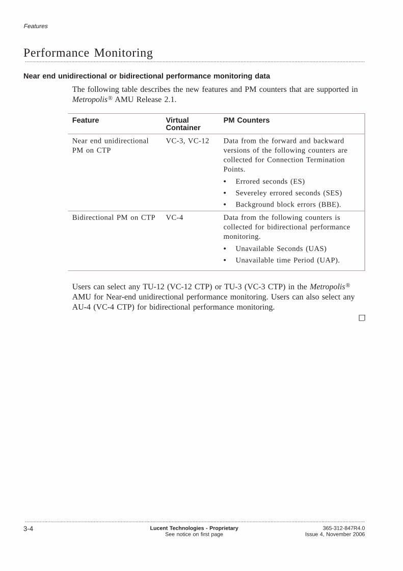
Performance Monitoring...................................................................................................................................................................................................................................
Near end unidirectional or bidirectional performance monitoring data
The following table describes the new features and PM counters that are supported inMetropolis® AMU Release 2.1.
Feature VirtualContainer
PM Counters
Near end unidirectionalPM on CTP
VC-3, VC-12 Data from the forward and backwardversions of the following counters arecollected for Connection TerminationPoints.
• Errored seconds (ES)
• Severeley errored seconds (SES)
• Background block errors (BBE).
Bidirectional PM on CTP VC-4 Data from the following counters iscollected for bidirectional performancemonitoring.
• Unavailable Seconds (UAS)
• Unavailable time Period (UAP).
Users can select any TU-12 (VC-12 CTP) or TU-3 (VC-3 CTP) in theMetropolis®
AMU for Near-end unidirectional performance monitoring. Users can also select anyAU-4 (VC-4 CTP) for bidirectional performance monitoring.
Features
...................................................................................................................................................................................................................................
3-4 Lucent Technologies - ProprietarySee notice on first page
365-312-847R4.0Issue 4, November 2006
CWDM SFPs...................................................................................................................................................................................................................................
The Metropolis® AMU Release 2.1 supports CWDM SFPs. Note that these SFPs canonly be operated for STM-4 transmission in the MI-14/4 main unit.
For ordering information about CWDM SFPs, refer“Metropolis® AMU SFPs” (p. 7-5).
For information about power consumption, refer“Power consumption” (p. 2-46).
Features
...................................................................................................................................................................................................................................365-312-847R4.0Issue 4, November 2006
Lucent Technologies - ProprietarySee notice on first page
3-5

Bidirectional SFPs...................................................................................................................................................................................................................................
The Metropolis® AMU Release 2.1 supports bidirectional SFPs. For orderinginformation about bidirectional SFPs, refer“Metropolis® AMU SFPs” (p. 7-5).
For information about power consumption, refer“Power consumption” (p. 2-46).
Features
...................................................................................................................................................................................................................................
3-6 Lucent Technologies - ProprietarySee notice on first page
365-312-847R4.0Issue 4, November 2006
Fast Download Tool...................................................................................................................................................................................................................................
The Fast Download Tool enables a quick installation of network element software tothe Metropolis® AMU. The latest version provides options to retain the MIB or deleteas necessary.
For more information about installing and downloading the Fast Download Tool on theMetropolis® AMU, refer the Metropolis® AMU Installation Guide.
Features
...................................................................................................................................................................................................................................365-312-847R4.0Issue 4, November 2006
Lucent Technologies - ProprietarySee notice on first page
3-7
Physical interfaces
Overview...................................................................................................................................................................................................................................
Purpose
This section provides information about all kinds of external physical interfaces of theMetropolis® AMU. For detailed technical data and optical parameters of the interfacesplease refer to“Technical specifications” (p. 2-32).
The Metropolis® AMU supports a variety of additional interfaces that are dependent onthe use of an option card. The choice of the option cards and data interfaces describedbelow provide outstanding transmission flexibility and integration capabilities.
Contents
Transmission interfaces 3-9
Data interfaces 3-10
Timing interfaces 3-11
Orderwire interfaces 3-12
Operations interfaces 3-13
Power interfaces 3-14
Features
...................................................................................................................................................................................................................................
3-8 Lucent Technologies - ProprietarySee notice on first page
365-312-847R4.0Issue 4, November 2006
Transmission interfaces...................................................................................................................................................................................................................................
SDH interface overview
Metropolis® AMU supports the synchronous transmission rates STM-1, STM-4, andSTM-16.
In the present release, STM-1, STM-4, and STM-16 optical as well as STM-1 electricalinterface types can be realized in a modular way by only changing the SFP. Four portson one main card are available to plug an SFP. However, only two of the four ports areavailable for STM-16 transmission.
PDH interface overview
Metropolis® AMU 2m/4o andMetropolis® AMU 1m/1o provide PDH interfaces via anoption card.
The following PDH interfaces can be configured via an option card:
• Sixteen 1.5 Mbit/s interfaces (only 2m/4o version with adapter card)
• Two 34 Mbit/s interfaces (only 2m/4o version with adapter card)
• Two 45 Mbit/s interfaces (only 2m/4o version with adapter card)
• Sixty-three times 2 Mbit/s (120Ω and 75Ω version available)
• Four times 2 Mbit/s (120Ω and 75Ω) at the EPL4_E14 option card
• Thirty-two times 2 Mbit/s (75Ω) at the EPL4_E132_75 option card
• Four times 2 Mbit/s at the ESW4_E14 option card. For the E1 interfaces, (120Ωand 75Ω) options available via the Lucent OMS.
Please note that legacy cards for 1.5 Mbit/s, 34 Mbit/s, and 45 Mbit/s require atwo-slot wide adapter card to fit in the shelf.
Features
...................................................................................................................................................................................................................................365-312-847R4.0Issue 4, November 2006
Lucent Technologies - ProprietarySee notice on first page
3-9

Data interfaces...................................................................................................................................................................................................................................
LAN interfaces
Metropolis® AMU supports a variety of Ethernet interfaces, depending on the optioncards in use.
• up to four 10/100BASE-T LAN interfaces, as part of theTransLAN® Ethernet SDHTransport Solution, at the X4IP-V2 option card (only 2m/4o version with adaptercard)
• up to eight Ethernet interfaces in Private Line mode at the X8PL option card (only2m/4o version with adapter card).
• up to two Ethernet/FastEthernet interfaces and twoEthernet/FastEthernet/GigabitEthernet interfaces with optional SFP usage forGigabitEthernet at the EPL4_E14 option card
• up to four Ethernet/FastEthernet interfaces at the EPL4_E132_75 option card
• 2 GE capable interfaces for either 10/100/1000 Base-T or 1000 Base-X and 2 E/FEinterfaces 10/100 Base-T transmission rate at the ESW4_E14 option card.
Please note that legacy cards like X8PL and X4IP require a two-slot wide adapter cardto fit in the shelf.
Features
...................................................................................................................................................................................................................................
3-10 Lucent Technologies - ProprietarySee notice on first page
365-312-847R4.0Issue 4, November 2006
Timing interfaces...................................................................................................................................................................................................................................
Metropolis® AMU provides one external timing input and output per main card forITU-T compliant 2MHz / 2Mb/s timing signals, see also“Timing interface features”(p. 3-30). The timing output is realized as RJ45 connector suitable for symmetricaltwisted pair cables with an impedance of 120Ω or coaxial cables with an impedanceof 75 Ω.
Real time information survival
The system contains a realtime clock cicuit which can survive a power outage of up to10 minutes. In case the power is restored within this time, the Fault Management(alarm event timestamping) and Performance Monitoring (binning, reporting, TCNs)functions will continue without requiring user intervention.
Synchronization and timing
• Synchronization can be derived from the incoming STM-1 or STM-4 or STM-16aggregate signals and STM-1 or STM-4 tributary signals.
• Synchronization can be derived from an incoming 2 Mbit/s (E1) data input.
• Re-synchronization of the 2 Mbit/s ports is supported.
• Support of SSM byte according to ETSI ETS 300 417-6.
• External synchronization input at 2.048 MHz and 2 Mbit/s (STCLK, one per maincard) is according to G.703-10 via RJ45 connector with an impedance of 120Ωsymmetrical or with an impedance of 75Ω.
• Internal Clock in accordance with ITU-T G.813 option 1.
Features
...................................................................................................................................................................................................................................365-312-847R4.0Issue 4, November 2006
Lucent Technologies - ProprietarySee notice on first page
3-11

Orderwire interfaces...................................................................................................................................................................................................................................
V.11 interfaces
The Metropolis® AMU supports one Engineering Order Wire (EOW) interface with a15 pin sub-D connector on the faceplate. Regardless of the configuration, the EOW issupported on Main-1 unit on line port 1 (LP1.1). The E2 channel is used to transfer theEOW data.
Features
...................................................................................................................................................................................................................................
3-12 Lucent Technologies - ProprietarySee notice on first page
365-312-847R4.0Issue 4, November 2006

Operations interfaces...................................................................................................................................................................................................................................
Operations interfaces
The Metropolis® AMU offers a wide range of operations interfaces to meet the needsof an evolving Operations System (OS) network. The operation interfaces include:
• Q-LAN interfaceThe Q interface enables network-oriented communication betweenMetropolis®
AMU systems and the element/network manager. This interface uses a Qx interfaceprotocol that is compliant with ITU-T recommendation G.773-CLNS1 to providethe capability for remote management via the Data Communication Channels(DCCs). The Q-LAN connector is either a 10 Mbit/s or 100 Mbit/s (10/100BASE-T) connector with automatic MDI/MDIX selection.
• F interface for a local PCOne RJ-45 F-interface is provided, at the main board of theMetropolis® AMUThis interface provides operation access for a locally installed PC, the CraftInterface Terminal (ITM-CIT)
• USB interfaceThe Metropolis® AMU provides two USB 1.1 interfaces labelled USB 1 and USB2. Each external USB interface provides upto 500mA at 5V to power externaldevices. An overcurrent circuit protects the power outputs in case of short circuits;the overcurrent condition can be read by the ITM-CIT. The USB controller alsosupports 4 internal USB 1.1 ports which are used as control and managementinterfaces via the backplane towards the tributary slots. The USB interface isrealized with a USB connector and is only used for internal system communication.
• G-LAN interfaceThe Metropolis® AMU provides a G LAN interface to connect to the Ethernet portof the PC (on which theFast Download Toolis installed) for quick softwaredownload. The G LAN interface supports the automatic MDI/MDIX function, sono crossover cable is needed.
• Miscellaneous Discrete InterfacesThe Metropolis® AMU provides 4 Miscellaneous Discrete Inputs (MDIs) and 4outputs (MDOs). The MDIs can be used to read the status of external alarm points,for example, power supply detectors, open door detectors or fire alarm detectors.The MDOs indicate the alarm status of the equipment and drive external signallingdevices. Labels can be associated to an MDI. An MDO can be coupled to an alarmevent.The Metropolis® AMU provides 4 Miscellaneous Discrete Inputs (MDIs) and 4outputs (MDOs). The MDIs can be used to read the status of external alarm points,for example, power supply detectors, open door detectors or fire alarm detectors.The MDOs indicate the alarm status of the equipment and drive external signallingdevices. Labels can be associated to an MDI. An MDO can be coupled to an alarmevent.
Features
...................................................................................................................................................................................................................................365-312-847R4.0Issue 4, November 2006
Lucent Technologies - ProprietarySee notice on first page
3-13

Power interfaces...................................................................................................................................................................................................................................
Optionally AC or DC powered
The Metropolis® AMU can optionally be AC powered or DC powered. However, therealization of the power supply is slightly different.The unit has two -48V power inputsand supports a full system load of 150W from a single 48V input. TheMetropolis®
AMU can only be AC powered by means of an external AC/DC converter.
DC power supply
The following table describes the DC Power supply specifications.
Metropolis ® AMU
Nominal voltage range –48 V DC to –60 V DC
Permissible voltage range –39 V DC to –72 V DC
Voltage range AC (optionalAC/DC converter needed)
88 132 VAC or 176 264 VAC
(selectable by switch)
Power inputs Two redundant power inputs that can protect each other.The system can operate completely normal on only one
power feeder.
Power connector 3-pin terminal block connector
Applicable standards ETS 300132-2
AC power supply
As an alternative to the DC power supply, an AC power supply can be facilitated viaan external AC/DC converter.
The following external AC/DC converters are available:
• AC/DC converter 90~230V 50~60Hz 75W (CC: 408965325)
• AC/DC converter 90~230V 50~60Hz 120W (CC: 408965333)
• AC/DC converter 90~230V 50~60Hz 240W (CC: 408991057)
Important! To operate theMetropolis® AMU AC powered, anexternal AC/DCconverteris required.
Related information
Please also refer to the Metropolis® AMU Installation Guide.
Features
...................................................................................................................................................................................................................................
3-14 Lucent Technologies - ProprietarySee notice on first page
365-312-847R4.0Issue 4, November 2006
Transmission features
Overview...................................................................................................................................................................................................................................
Purpose
This section presents an overview of the transmission related features of theMetropolis® AMU. For more detailed information on the implementation of the switchfunction in the NE please refer toChapter 2, “Product description”.
Contents
Cross-connection features 3-16
Transmission protection 3-17
Equipment protection 3-18
Ethernet features 3-19
Auto-negotiation 3-21
Link Capacity Adjustment Scheme (LCAS) 3-22
Link Pass Through (LPT) 3-23
Ethernet mapping schemes 3-24
Features
...................................................................................................................................................................................................................................365-312-847R4.0Issue 4, November 2006
Lucent Technologies - ProprietarySee notice on first page
3-15

Cross-connection features...................................................................................................................................................................................................................................
Cross-connection rates
Metropolis® AMU supports bidirectional cross-connections for VC-12, VC-3 and VC-4.The cross connect matrix is 100% flexible and non blocking.
The main unit supports loopbacks on incoming STM-N signals. Loopbackcross-connections are possible on VC-12 and VC-3 level as well as VC-4 level.
Transparent DCC cut-through
The MI-16/4 system supports up to 20 bi-directional connections for transparent DCCforwarding through the system from one STM-N port to another. Each bi-directionalconnection can support a transparent link for the DCC-RS or the DCC-MS or bothDCC channels associated with a single STM-N interface. However, note that only 20bi-directional connections can be supported with a combination of the MI-16/4 mainunit and the Sl-14/8 unit.
The MI-14/4 system supports up to eight bidirectional connections for transparent DCCforwarding through the system from STM-N port to another. Each connection cansupport transparent link for the DCC-RS or the DCC-MS or both DCC channelsassociated with a single STM-N interface.
The supported framing method is HDLC.
Please note that the same pool of connections that are available for Transparent DCCcut-through is also required for connecting the DCC of an STM-N port to the internalIS_IS router. This means a restriction on the number of available connections for DCCcut-through purposes.
Slaved switching for MSP is applicable to transparent DCC cut-through connections.
The Metropolis® AMU cross-connection function provides the following DCC features.
• Upto 40 MS-DCC and 40 RS-DCC terminations per system (4 from both mainunits, 8 from each tributary slot); via 2 TDM ports and a separate TDM port forin-band management channels. Users can access RS-DCC or MS-DCC or bothDCC channels of at most 16 different STM-N interfaces (including line andtributary).
• DCC support on STM-16 optical line interfaces via D1-3. The OSI layer 2 and 3functionality is supported via the RS-DCC channel of the STM-16 optical lineinterface. Each RS-DCC channel can be enabled or disabled individually.
• DCC support on STM-16 optical line interfaces via D4-12. The OSI lsyer 2 and 3functionality is supported via the MS-DCC channel of the STM-16 optical lineinterface. Each MS-DCC channel can be enabled or disabled individually.
Features
...................................................................................................................................................................................................................................
3-16 Lucent Technologies - ProprietarySee notice on first page
365-312-847R4.0Issue 4, November 2006
Transmission protection...................................................................................................................................................................................................................................
Supported protection mechanisms
To guarantee service availability, these transmission protection mechanisms aresupported by theMetropolis® AMU:
• Multiplex Section Protection (MSP) 1 + 1
– 1+1 MSP protection for optical and electrical STM-1 and opticalSTM-4/STM-16 interfaces.The protection switching can be configured revertive and non-revertive as wellas unidirectional and bidirectional (i.e. both directions of transmission are,respectively, switching separately or jointly). But the remote end of theMultiplex section must support the necessary features for this operation. AnySTM-N port combination with the same transmission rate can be used as acombination of line and tributary SDH ports.Forced, manual and lockout switch commands are supported. The MSPimplementation is compliant with the ITU-T Rec. G.841/Clause 7.1 and ETS300417-3-1 (i.e. the APS protocol is optimized for 1:N protection). ETSI failureof protocol applies. Under this protocol also an alarm-free interworking modewith SONET defined MSP is supported.The maximum switch completion time is 50 ms.
• Subnetwork Connection Protection (SNCP)
– VC-12 SNC/N protection (non-revertive)A non-intrusively monitored subnetwork connection protection (SNC/N) relationcan be set up between any arbitrary incoming TU-12 from any STM-N and anyother arbitrary incoming TU-12 from any STM-N interface (VC-12s aremapped into TU-12s).Only non-revertive operation is possible. Manual and forced switch commandsare supported. In the return channel the signal is simply bridged to bothoutputs.The maximum switch completion time is 50 ms.
– Lower order VC-3 SNC/N protection (non-revertive)A non-intrusively monitored subnetwork connection protection (SNC/N) relationcan be set up between any arbitrary incoming TU-3 from any STM-N interfaceand any other arbitrary incoming TU-3 from any STM-N interface.Only non-revertive operation is possible. Manual and forced switch commandsare supported. In the return channel, the signal is simply bridged to bothoutputs. note that hardware based SNCP switching for can be implemented forlower order VC-12 and VC-3s.The maximum switch completion time is 50 ms.
– Higher order VC-4 SNC/N protection (non-revertive)A non-intrusively monitored subnetwork connection protection (SNC/N) relationcan be set up between any arbitrary incoming TU-3 from any STM-N interfaceand any other arbitrary incoming TU-3 from any STM-N interface.Only non-revertive operation is possible. Manual and forced switch commandsare supported. In the return channel the signal is simply bridged to bothoutputs.The maximum switch completion time is 50 ms.
Features
...................................................................................................................................................................................................................................365-312-847R4.0Issue 4, November 2006
Lucent Technologies - ProprietarySee notice on first page
3-17

Equipment protection...................................................................................................................................................................................................................................
Supported protection mechanisms
Metropolis® AMU provides the following equipment protection mechanisms (mainboard based)
• 1+1 revertive equipment protection of the cross-connection function
• Equipment protection of the power supply filter function
• Equipment protection of the timing function
Equipment protection of cross-connection and timing function
If two units are present in the system an automatic protection switch relation can be setup by the user. The switching is revertive. This means that the service returns to theMain board 2 when both boards are working. Manual operation of the protection issupported and the unprotected operation is possible as well. The traffic interruptiontime is less than 50 ms with manual switch commands and less than 50 ms plus thedetection time for automatic protection switches triggered by a failure. The unit that isnot active can be pulled or replaced without causing bit errors in the traffic.
Important! Please note that the CIT, EOW, Q-LAN and MDI/MDO interfaces onthe Main board 2 are not operational.
Equipment protection of the power filter function
If two units are present in the system, both power filter parts are active.
Features
...................................................................................................................................................................................................................................
3-18 Lucent Technologies - ProprietarySee notice on first page
365-312-847R4.0Issue 4, November 2006
Ethernet features...................................................................................................................................................................................................................................
Switched Ethernet Applications
The TransLAN® ESW4_E14 option card can be used in any option card slot forEthernet, Fast Ethernet, and Gigabit Ethernet applications.
Please refer to“ESW4_E14 option card” (p. 2-21)for a detailed description of theESW4_E14 Ethernet option card.
The X4IP-V2 option card can be used for Ethernet and Fast Ethernet applications inMetropolis® AMU 2m/4o version (adapter card required).
Ethernet and Fast Ethernet applications
The X8PL option card can be used for Ethernet private line applications inMetropolis® AMU 2m/4o version (adapter card required).
Please refer to“X8PL option card (legacy)” (p. 2-28)for a more detailed description ofthe X8PL option card.
The EPL4_E14 and EPL4_E132_75 option cards can be used for Ethernet private lineapplications withMetropolis® AMU 2m/4o and 1m/1o version.
Please refer to“EPL4_E14 option card” (p. 2-15)and“EPL4_E132_75 option card”(p. 2-18)for a more detailed description of these option cards.
Main features of the legacy option cards X4IP-V2 and X8PL
The following table lists the main features and differences of the two option cardsX4IP-V2 and X8PL which can be used for Ethernet applications:
X4IP-V2 X8PL
4 ports 8 ports
provides a Layer 2 switch no switch
supports advanced networking applicationslike ring connections or point-to-multi-point connections
cost optimized option card forpoint-to-point applications
no LCAS (Link capacity adjustmentscheme) support
supports the LCAS (Link CapacityAdjustment Scheme) protocol (please referto “LCAS” (p. 3-22))
EoS (Ethernet over SDH) mapping or GFP(Generic Framing Procedure)
GFP or LAPS (Link Access ProcedureSDH) (please refer to“Ethernet mappingschemes” (p. 3-24))
Features
...................................................................................................................................................................................................................................365-312-847R4.0Issue 4, November 2006
Lucent Technologies - ProprietarySee notice on first page
3-19

Main Ethernet features of EPL4_E14 and EPL4_E132_75
The following table lists the main features and differences of the two option cardsEPL4_E14 and EPL4_E132_75 beside PDH which can be used for Ethernetapplications:
EPL4_E14 EPL4_E132_75
4 ports:
• two either optical (1000BASE-SXSFP) or electrical triple rate10/100/1000BASE-T
• two dual rate 10/100BaseT
(Only two Gigabit-interfaces can be usedat the same time, switching betweenmodes only available from the LucentNMS.)
4 ports:
• four dual rate 10/100BaseT
no switch no switch
point-to-point applications point-to-point applications
supports the LCAS protocol supports the LCAS protocol
GFP and LAPS mapping of Ethernetframes
GFP and LAPS mapping of Ethernetframes
Supports the Link Pass Through (LPT)mode
Supports the Link Pass Through (LPT)mode
Main Ethernet features of ESW4_E14 option card
The main features of the ESW4_E14 option card are listed below.
• 2 x GE capable interfaces for either 10/100/1000Base-T or 1000Base-X
• 2 x E/FE interfaces for 10/100Base-T
• 4 x E1 interfaces, 75/120Ω• Enhanced Flow Classification
• Upto 8 Virtual Concatenation Groups
• Low latency LCAS
• GFP + LAPS + PPP mapping of Ethernet frames
• Link Pass Through (LPT)
• Supports VLAN and/or ETHER_TYPE switching and adding/removing VLAN tags
Features Ethernet features
....................................................................................................................................................................................................................................
3-20 Lucent Technologies - ProprietarySee notice on first page
365-312-847R4.0Issue 4, November 2006

Auto-negotiation...................................................................................................................................................................................................................................
Auto-negotiation
The Auto-negotiation function automatically configures the Ethernet interfaceparameters to establish an optimal Ethernet link based on the capabilities of thenear-end and far-end Ethernet interfaces.
Auto-negotiation for twisted-pair systems, defined in Clause 28 of the Standard802.3-2002, has been extended to include all three speeds of Ethernet that aresupported over twisted-pair cable: 10Mbit/s 10Base-T, 100Mbit/s 100Base- TX, and1000 Mbit/s 1000Base-T.
The physical signaling portion of all three twisted-pair systems use the sameAuto-negotiation signaling standard. While Auto-negotiation can be disabled on10Base-T and 100Base-TX links, it is required on 1000- Base-T systems since GigabitEthernet systems use Auto-negotiation to establish the master-slave signal timingcontrol that is required to make the link operational. For more information about themaster-slave mode, please refer the Metropolis® AMU User Operations Guide.
To be able to override the Auto-negotiation function, it is possible to disableAuto-negotiation. This might be needed if Auto-negotiation cannot establish a link or ifa specific link speed / mode is required.
Features
...................................................................................................................................................................................................................................365-312-847R4.0Issue 4, November 2006
Lucent Technologies - ProprietarySee notice on first page
3-21

Link Capacity Adjustment Scheme (LCAS)...................................................................................................................................................................................................................................
LCAS
The X8PL, EPL4_E14, and EPL4_E132_75 option cards for Ethernet private lineapplications and the ESW4_E14 Ethernet option card support the Link CapacityAdjustment Scheme (LCAS).
LCAS defines a synchronization protocol between two termination points of a virtualconcatenated path that allows in-service dynamic sizing of the VCn-Xv bandwidth thatis available for Ethernet-over-SDH transmission. This bandwidth change can occureither in response to a failure condition on one member or a requirement for a changein bandwidth at an NE (provisioning action).
In case of failure, the bandwidth will be restored automatically after the failure clears.The size of the VCn-Xv is increased or decreased in steps of one VCn. Theprovisioning is performed by adding/removing paths to/from the Ethernet tributarycard.
The default LCAS hold-off timer is set to zero so that the LCAS mechanism will takeimmediate action. However, if the path over which the LCAS protocol is run isprotected by a transmission protection mechanism such as MSP or SNCP the LCAShold-off timer value should be raised (~100 ms) to allow the generally faster MSP orSNCP protection mechanisms to react before the LCAS undertakes any repair attempts.In this way less packets are lost.
Features
...................................................................................................................................................................................................................................
3-22 Lucent Technologies - ProprietarySee notice on first page
365-312-847R4.0Issue 4, November 2006
Link Pass Through (LPT)...................................................................................................................................................................................................................................
LPT
The Ethernet interface supports Link Pass Through mode. The Ethernet port transmitteris disabled in case of failures in the upstream network. For example, a remote Ethernetcable or optic fiber failure, an SDH/SONET network failure or any equipment failure.The downstream equipment, a LambdaRouter or an IP router, will observe the absenceof the Ethernet input signal and use it as a fast trigger to perform its native protectionscheme. The remote failures are transported in-band via the GFP-Client Signal Failmessage. The LPT is only supported on ports that operate in a one-to-one associationwith a WAN port. The option cards EPL4_E14, EPL4_E132_75, and ESW4_E14support the LPT mode.
Features
...................................................................................................................................................................................................................................365-312-847R4.0Issue 4, November 2006
Lucent Technologies - ProprietarySee notice on first page
3-23

Ethernet mapping schemes...................................................................................................................................................................................................................................
Introduction
Metropolis® AMU support the following schemes for the mapping of Ethernet packetsinto SDH frames:
• Link Access Procedure SDH (LAPS encapsulation)
• Generic Framing Procedure (GFP encapsulation)
• EoS (Ethernet over SDH) mapping
LAPS encapsulation
LAPS encapsulation is implemented according to ITU-T X.86. It is supported whenusing the EPL4_E14, EPL4_E132_75, and ESW4_E14 option cards.
The following rates are supported:
• Mapping Ethernet packets into Vc12-Xv
• Mapping Ethernet packets into Vc3-Xv
• Mapping Ethernet packets into Vc4-Xv
GFP encapsulation
GFP encapsulation is implemented according to T1X1.5/2000-147. It is supported whenusing the EPL4_E14, EPL4_E132_75, ESW4_E14, X8PL or X4IP-V2 option cards.
GFP provides a generic mechanism to adapt traffic from higher-layer client signalsover a transport network.
The following GFP encapsulation are possible:
• Mapping of Ethernet MAC frames into Lower Order SDH VC12–Xv
• Mapping of Ethernet MAC frames into Lower Order SDH VC3–Xv
• Mapping of Ethernet MAC frames into Higher Order SDH VC4–Xv
VC12–Xv GFP encapsulation
The Metropolis® AMU support virtual concatenation of Lower Order SDH VC-12 asinverse multiplexing technique to size the bandwidth of a single internal WAN port fortransport of encapsulated Ethernet and Fast Ethernet packets over the SDH/SONETnetwork. This is noted VC12-Xv, where X = 1...63 when using the X8PL and X =163 per port when using EPL4_E14, EPL4_E132_75, and ESW4_E14 option cards.Usage is in conformance with ITU-T G.707 Clause 11 (2000 Edition) and G.783Clause 12.5 (2000).
Additionally, the use of G.707 Extended Signal Label is supported using V5 (bits 5-7)field.
Features
...................................................................................................................................................................................................................................
3-24 Lucent Technologies - ProprietarySee notice on first page
365-312-847R4.0Issue 4, November 2006
VC3–Xv GFP encapsulation
The Metropolis® AMU support virtual concatenation of Lower Order SDH VC-3 asinverse multiplexing technique to size the bandwidth of a single internal WAN port fortransport of encapsulated Ethernet and Fast Ethernet packets over the SDH/SONETnetwork. This is noted VC3–Xv, where X = 1...3 for X8PL and X = 19 per port whenusing EPL4_E14, EPL4_E132_75, and ESW4_E14 option cards. Usage is inconformance with ITU-T G.707 Clause 11 (2000 Edition) and G.783 Clause 12.5(2000) and T1X1 T1.105 Clause 7.3.2 (2001 Edition).
VC4–Xv GFP encapsulation
The Metropolis® AMU supports virtual concatenation of Higher Order SDH VC-4 asinverse multiplexing technique to size the bandwidth of a single internal WAN port fortransport of encapsulated Gigabit Ethernet packets over the SDH network. This isnoted VC4-Xv, where X = 1...7 per port when using EPL4_E14, EPL4_E132_75, andESW4_E14 option cards. Usage is in conformance with ITU-T G.707 Clause 11 (2000Edition) and G.783 Clause 12.5 (2000) and T1X1 T1.105 Clause 7.3.2 (2001 Edition).
Features Ethernet mapping schemes
....................................................................................................................................................................................................................................365-312-847R4.0Issue 4, November 2006
Lucent Technologies - ProprietarySee notice on first page
3-25
Equipment features
Overview...................................................................................................................................................................................................................................
Purpose
This section provides information aboutMetropolis® AMU features concerningequipment inventory and failure reports.
Contents
Equipment inventory and reports 3-27
Features
...................................................................................................................................................................................................................................
3-26 Lucent Technologies - ProprietarySee notice on first page
365-312-847R4.0Issue 4, November 2006
Equipment inventory and reports...................................................................................................................................................................................................................................
Equipment inventory
For each installed circuit pack, theMetropolis® AMU automatically maintains aninventory of the following information:
• Serial number
• Functional name
• Item code
• Software release (of the NE)
• Comcode
• Interchangeability Marker
You can obtain this information by an inventory request command.
Metropolis® AMU additionally supports an inventory of used SFPs. Besides theadministrative state, the following information can be retrieved for the currently presentand last accepted SFP:
• Physical identifier
• Connector type
• Transceiver code
• Revision number
• Vendor serial number
• Comcode
• Compatibility byte
• Lucent unique number
• SFP vendor ID
• Module qualifier
• Module type
• CLEI code (if applicable)
• Apparatus code/Item code
• Interchangeability marker
Equipment failure reports
Failure reports are generated for equipment faults and can be forwarded via theITM-CIT or Lucent’s Network Management Systems or Lucent NMS interfaces.
Features
...................................................................................................................................................................................................................................365-312-847R4.0Issue 4, November 2006
Lucent Technologies - ProprietarySee notice on first page
3-27
Synchronization and timing
Overview...................................................................................................................................................................................................................................
Purpose
This section provides information about synchronization features, timing protection andtiming interfaces ofMetropolis® AMU.
Contents
Timing features 3-29
Timing interface features 3-30
Features
...................................................................................................................................................................................................................................
3-28 Lucent Technologies - ProprietarySee notice on first page
365-312-847R4.0Issue 4, November 2006

Timing features...................................................................................................................................................................................................................................
Synchronization modes
Several synchronization configurations can be used.Metropolis® AMU can beprovisioned for the following timing modes:
• free-running operation
• holdover mode
• locked mode
In locked mode, the internal SDH Equipment Clock (SEC) is locked to:
• one of the STM-N signals.
• one of the 2 Mbit/s tributary signals
• one of the external 2 MHz / 2 Mbit/s inputs (one per main board)
Features
...................................................................................................................................................................................................................................365-312-847R4.0Issue 4, November 2006
Lucent Technologies - ProprietarySee notice on first page
3-29

Timing interface features...................................................................................................................................................................................................................................
Synchronization Status Message (SSM) signal
A timing marker or synchronization status message signal can be used to transfer thesignal-quality level throughout a network. This will guarantee that all network elementsare always synchronized to the highest-quality clock that is available.
On Metropolis® AMU systems, the SSM algorithm or the timing marker is supportedaccording to ITU-T recommendation G.781 and ETSI recommendation ETS300-417-6-1. The SSM is supported on all STM-N interfaces.
External timing interfaces
Metropolis® AMU provides one external timing input and output per main card forITU-T compliant 2048 kHz / 2048 kbit/s timing signals. The timing output is realizedas RJ45 connector suitable for symmetrical twisted pair cables with an impedance of120 Ω or coaxial cables with an impedance of 75Ω.
2 Mbit/s tributary retiming
The user can choose whether individual 2 Mbit/s tributary outputs operate in“self-timed” or “re-synchronized” mode. In the (standard) self-timed mode, the phaseof the outgoing signal is a moving average of the phase of the 2 Mbit/s signal becausethe signal is embedded in the VC-12 that is disassembled. In the re-synchronized modethe 2 Mbit/s signal is timed by the SDH Equipment Clock (SEC) of the networkelement; frequency differences between the local clock and the 2 Mbit/s signalembedded in the VC-12 to be disassembled are accommodated by a slip buffer.
There is also the following option: whenever the traceability of the local clock dropsbelow a certain threshold, the re-timing 2 Mbit/s interfaces automatically switch toself-timing. When this fail condition disappears, these interfaces return to re-timing.These changes do not involve any hits in the traffic.
Important! Re-timing should only be applied when the network element whichperforms the re-timing and the network element which generated the 2 Mbit/ssignal have traced back their SECs to the same synchronization source. Otherwise acontinuous stream of 2 Mbit/s frame slips or skips will occur at the re-timing pointwhich is indicated by a FCS threshold crossing alarm.
The user has the option of operating individual 2 Mbit/s outputs in the“re-synchronized” mode. In this mode the 2 Mbit/s output signal is timed by thesystem clock of the network element.
Features
...................................................................................................................................................................................................................................
3-30 Lucent Technologies - ProprietarySee notice on first page
365-312-847R4.0Issue 4, November 2006

Operations, Administration, Maintenance, andProvisioning
Overview...................................................................................................................................................................................................................................
Purpose
The following section provides information about interfaces for Operations,Administration, Maintenance, and Provisioning (OAM&P) activities and the monitoringand diagnostics features ofMetropolis® AMU.
Contents
Remote maintenance, management, and control 3-32
Features
...................................................................................................................................................................................................................................365-312-847R4.0Issue 4, November 2006
Lucent Technologies - ProprietarySee notice on first page
3-31
Remote maintenance, management, and control...................................................................................................................................................................................................................................
First maintenance tier
The maintenance procedures of theMetropolis® AMU systems are built on two levelsof system information and control. The first maintenance tier consists of the LEDs onthe equipment. There are six LEDs on the front of the main board ofMetropolis®
AMU: Two are for unit level indications and four for failure indications related to eachindividual SFP. Additionally there are LEDs on option cards and near to the SFPs. TheLEDs indicate basic alarms or basic operation states.
Second maintenance tier
The second maintenance tier employs the Lucent Technologies network managementsystem. Detailed information and system control are obtained by using the ITM-CIT(Craft Interface Terminal), which supports provisioning, maintenance and configurationon a local basis. A similar facility (via a Q-LAN connection or via the DCC channels)is remotely available on the element manager or through Lucent’s NetworkManagement Systems or Lucent NMS, which provides a centralized maintenance viewand supports maintenance activities from a central location.
Lucent Network Management Systems
Lucent’s Network Management Systems or the Lucent NMS fully support themanagement ofMetropolis® AMU.
Fan Management
A fan is available for mounting below the 2m/4o version, below the vertically mounted1m/1o version (1 per shelf) or next to the horizontally mounted 1m/1o version (1 pershelf). The same fan can be used in all cases. The fan is in-service replaceable,provided that proper care is taken with the cabling. The fan is powered and managedvia the USB interface on the front of (one of the) Main Units. For more details, referthe Metropolis® AMU User Operations Guide.
Note: When two fans are placed under the 2m/4o version, 2 trib slots and 2 main slotsor 4 trib slots can be cooled effectively.
The presence of USB powered/controlled fans can be established on a remotemanagement system. Provisioning of fans is not necessary; they are auto-provisionedafter autonomous detection by the AMU hardware. Alarms will be raised if a fan failsor is removed.
Special Mounting Brackets
To use the horizontally positioned 1m/1o version in combination with a fan unit, itmust be mounted with a specific mounting bracket that allows sliding in and out of thefan unit.
Features
...................................................................................................................................................................................................................................
3-32 Lucent Technologies - ProprietarySee notice on first page
365-312-847R4.0Issue 4, November 2006
4 4Planning Network Applications
Overview...................................................................................................................................................................................................................................
Purpose
This chapter provides a high level overview of planning considerations andrecommends network topologies for theMetropolis® AMU Add-Drop-Multiplexer.
Contents
Planning network application options 4-2
Planning considerationsMetropolis® AMU 4-2
Network topologies 4-4
Linear applications 4-4
Folded ring application 4-6
Ring application 4-7
Dual-homed ring application 4-8
Linear extension application 4-9
Dual ring closure 4-10
Multiple ring application 4-11
Hub application 4-12
Full capacity ring interconnection 4-13
Metropolis® AMU typical 1m/1o application 4-14
Grooming application 4-15
IP Tunneling in the DCC channels application 4-16
GSM/UMTS application 4-17
Multi-service application with theTransLAN® option board 4-18
Point-to-point LAN connection 4-23
...................................................................................................................................................................................................................................365-312-847R4.0Issue 4, November 2006
Lucent Technologies - ProprietarySee notice on first page
4-1
Planning network application options
Planning considerationsMetropolis® AMU...................................................................................................................................................................................................................................
When planning your system with theMetropolis® AMU, the following items should beconsidered:
• Synchronous Capacity – one through four STM-N optical aggregate interface pairsthat can be equipped with five different STM-1 (S1.1; L1.1; L1.2; STM-1e; SH1310 and LH 1490 single fiber bidirectional), four different STM-4 (S4.1; L4.1;L4.2; SH 1310 and LH 1490 single fiber bidirectional) SFPs and single fiberworking SFPs, and four different STM-16 SFPs (l16, S16.1, L16.1, and L16.2) thatcan be used for short haul, long haul, and intra-office applications. The cWDMSFPs can be used for STM-4/STM-16 transmission over 40/80km, 8 wavelength(channel 11-18). For detailed technical data and optical parameters of the interfaces,please refer to“Technical specifications” (p. 2-32).Note that for single fiber bi-directional SFPs, a set or pair of SFPs with differentwavelengths such as 1310 and 1490 is required. For theMetropolis® AMU, use the1310nm (CC:109559500) and 1490nm (CC: 109559492) single fiber bi-directionalSFPs.
• Additional Capacity:
– Optional sixty-three additional 2 Mbit/s signals
– Optional two E/FE and two E/FE/GE [GE Base-T or Base-X (ZX, LX, SXthrough SFP)] and four E1 (provisionable 120Ω or 75 Ω)
– Optional four E/FE and thirty-two E1 (75Ω)
– Optional two E/FE, two E/FE/GE, and four E1 interfaces
– Switchable four STM-1, two STM-4, and eight STM-1 or only one STM-4
– Optional sixteen additional 1.5 Mbit/s signals (only in 2m/4o version withadapter card)
– Optional two 34 Mbit/s signals (only in 2m/4o version with adapter card)
– Optional two 45 Mbit/s signals (only in 2m/4o version with adapter card)
– Optional four 10/100BASE-Ts (only in 2m/4o version with adapter card)
– Optional eight E/FE interfaces in Private Line mode (only in 2m/4o versionwith adapter card)
– Additionally, four cages for two STM-1 and two STM-1/STM-1e or STM-4SFP plugin at the second main board
• Synchronization: STM-N aggregate line interface timing or via a 2 Mbit/s datainput or via the 2 MHz, 2 Mbit/s timing input
• Protection: VC-12/VC-3/VC-4 SNC/N
• 1+1 MSP protection for optical STM-1/STM-4/STM-16 and electrical STM-1interfaces.
Planning Network Applications
...................................................................................................................................................................................................................................
4-2 Lucent Technologies - ProprietarySee notice on first page
365-312-847R4.0Issue 4, November 2006
• Equipment protection: A system equipped with two main cards can either operate inequipment protection mode, or alternatively, the main card in slot MAIN2 operatesas a tributary card. The latter is easier to manage, but does not provide automaticswitch over in case of equipment failures in the transmission and timingfunctionality of the main cards.
• Operations Systems: Remote management with Lucent’s Network ManagementSystems or Lucent NMS and local management with Wavestar® ITM-CIT
• Two possibilities for Power supply :
– DC (unit contains DC connector)
– AC via an external AC/DC connector.
• The Metropolis® AMU provides four miscellaneous discrete inputs (MDIs) whichcan be used to read external devices assigned by the customer. Examples aremonitoring temperature, humidity, open doors, etc.The equipment provides four miscellaneous discrete outputs (MDOs) which can beused to drive external devices assigned by the customer. Examples are signalingdevices, temperature conditioning, etc.When not assigned by the customer, theMetropolis® AMU behave such thatMDO1 has been assigned to indicate power failure (this contact is normally closedwhen no power is present). MDO 2, MDO 3, MDO 4 are respectively assigned toPrompt, Deferred, Information alarms.
Planning Network Applications Planning considerations Metropolis® AMU
....................................................................................................................................................................................................................................365-312-847R4.0Issue 4, November 2006
Lucent Technologies - ProprietarySee notice on first page
4-3
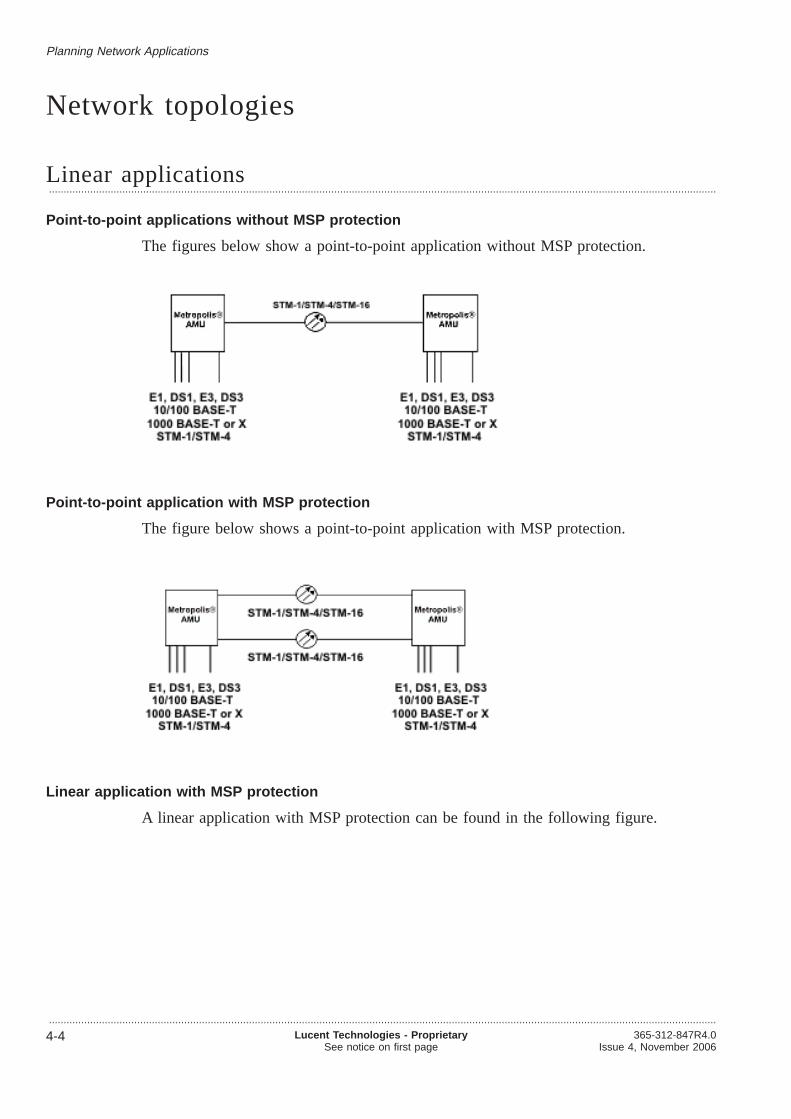
Network topologies
Linear applications...................................................................................................................................................................................................................................
Point-to-point applications without MSP protection
The figures below show a point-to-point application without MSP protection.
Point-to-point application with MSP protection
The figure below shows a point-to-point application with MSP protection.
Linear application with MSP protection
A linear application with MSP protection can be found in the following figure.
Planning Network Applications
...................................................................................................................................................................................................................................
4-4 Lucent Technologies - ProprietarySee notice on first page
365-312-847R4.0Issue 4, November 2006
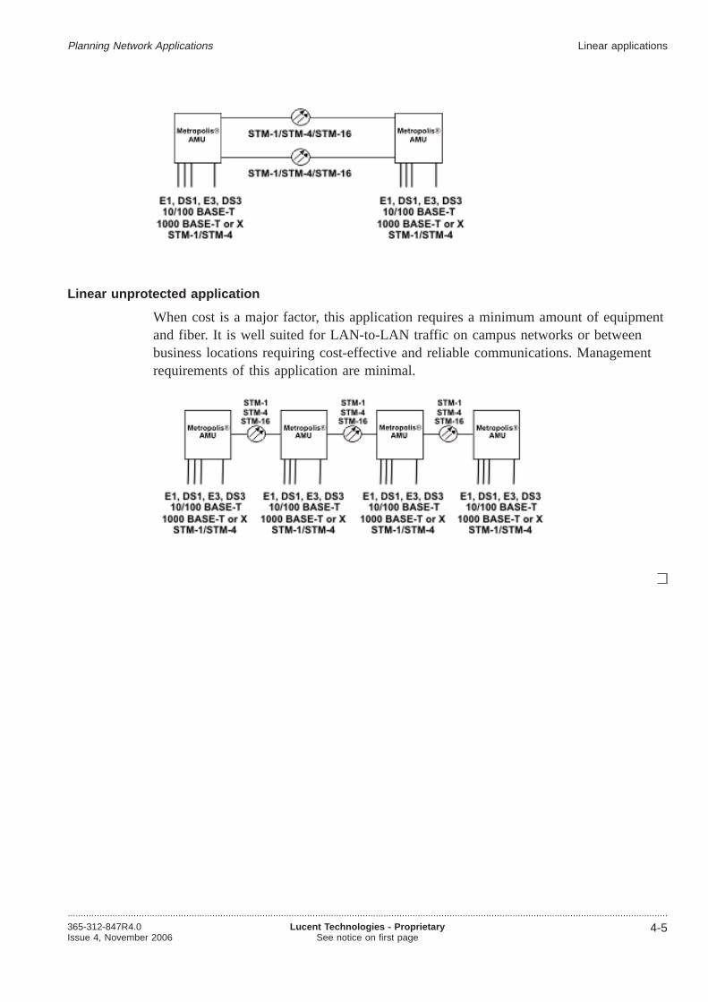
Linear unprotected application
When cost is a major factor, this application requires a minimum amount of equipmentand fiber. It is well suited for LAN-to-LAN traffic on campus networks or betweenbusiness locations requiring cost-effective and reliable communications. Managementrequirements of this application are minimal.
Planning Network Applications Linear applications
....................................................................................................................................................................................................................................365-312-847R4.0Issue 4, November 2006
Lucent Technologies - ProprietarySee notice on first page
4-5
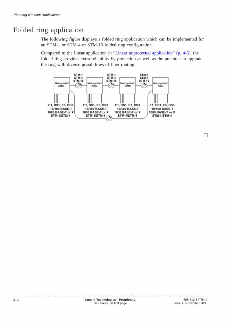
Folded ring application...................................................................................................................................................................................................................................
The following figure displays a folded ring application which can be implemented foran STM-1 or STM-4 or STM-16 folded ring configuration.
Compared to the linear application in“Linear unprotected application” (p. 4-5), thefolded-ring provides extra reliability by protection as well as the potential to upgradethe ring with diverse possibilities of fiber routing.
Planning Network Applications
...................................................................................................................................................................................................................................
4-6 Lucent Technologies - ProprietarySee notice on first page
365-312-847R4.0Issue 4, November 2006
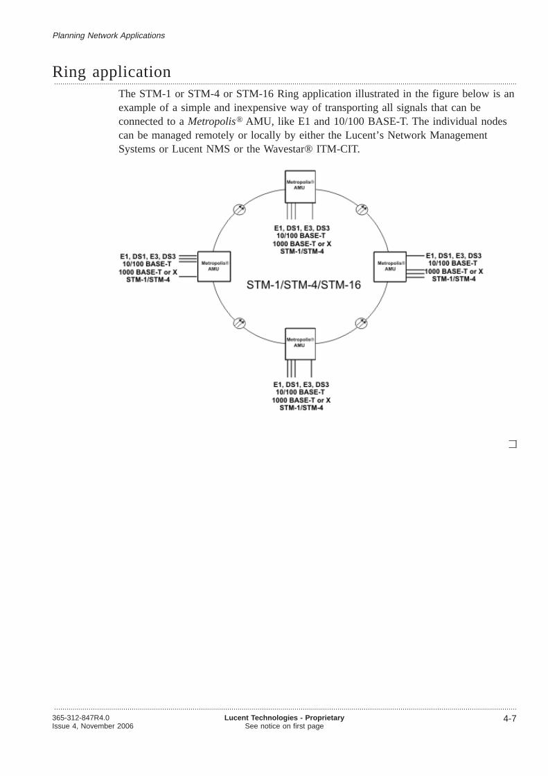
Ring application...................................................................................................................................................................................................................................
The STM-1 or STM-4 or STM-16 Ring application illustrated in the figure below is anexample of a simple and inexpensive way of transporting all signals that can beconnected to aMetropolis® AMU, like E1 and 10/100 BASE-T. The individual nodescan be managed remotely or locally by either the Lucent’s Network ManagementSystems or Lucent NMS or the Wavestar® ITM-CIT.
Planning Network Applications
...................................................................................................................................................................................................................................365-312-847R4.0Issue 4, November 2006
Lucent Technologies - ProprietarySee notice on first page
4-7
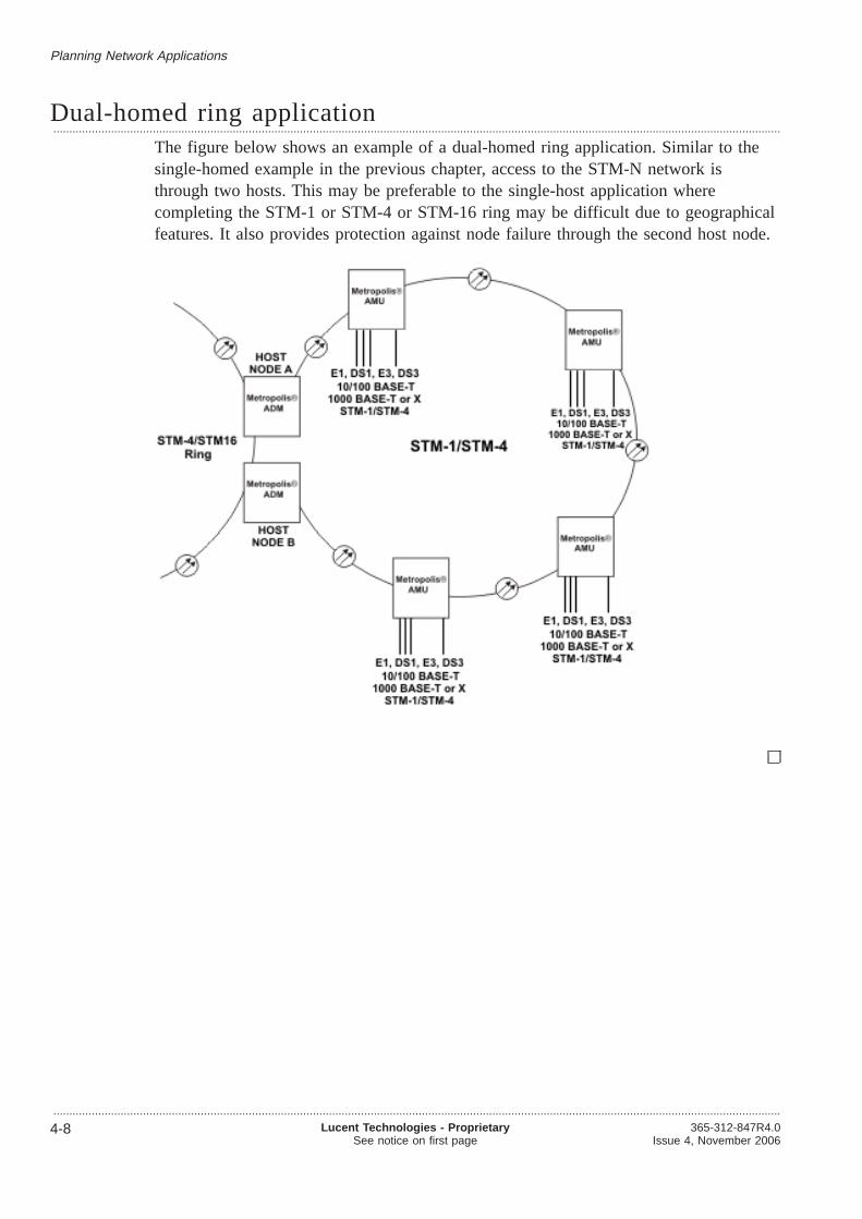
Dual-homed ring application...................................................................................................................................................................................................................................
The figure below shows an example of a dual-homed ring application. Similar to thesingle-homed example in the previous chapter, access to the STM-N network isthrough two hosts. This may be preferable to the single-host application wherecompleting the STM-1 or STM-4 or STM-16 ring may be difficult due to geographicalfeatures. It also provides protection against node failure through the second host node.
Planning Network Applications
...................................................................................................................................................................................................................................
4-8 Lucent Technologies - ProprietarySee notice on first page
365-312-847R4.0Issue 4, November 2006
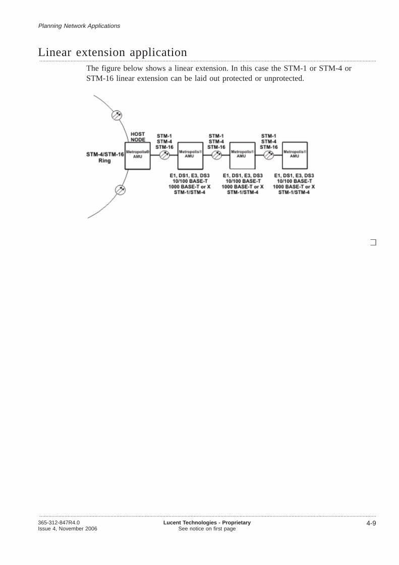
Linear extension application...................................................................................................................................................................................................................................
The figure below shows a linear extension. In this case the STM-1 or STM-4 orSTM-16 linear extension can be laid out protected or unprotected.
Planning Network Applications
...................................................................................................................................................................................................................................365-312-847R4.0Issue 4, November 2006
Lucent Technologies - ProprietarySee notice on first page
4-9
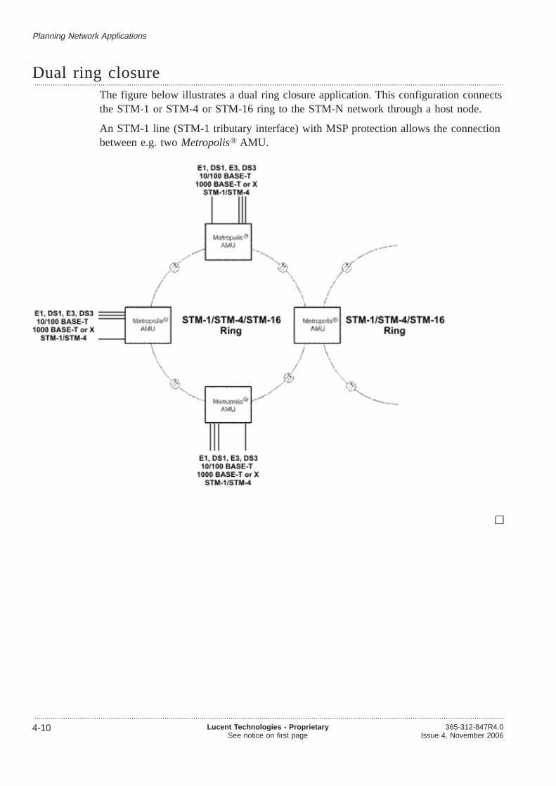
Dual ring closure...................................................................................................................................................................................................................................
The figure below illustrates a dual ring closure application. This configuration connectsthe STM-1 or STM-4 or STM-16 ring to the STM-N network through a host node.
An STM-1 line (STM-1 tributary interface) with MSP protection allows the connectionbetween e.g. twoMetropolis® AMU.
Planning Network Applications
...................................................................................................................................................................................................................................
4-10 Lucent Technologies - ProprietarySee notice on first page
365-312-847R4.0Issue 4, November 2006
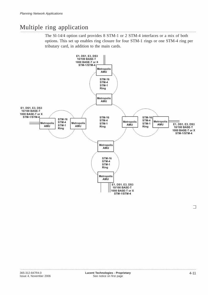
Multiple ring application...................................................................................................................................................................................................................................
The Sl-14/4 option card provides 8 STM-1 or 2 STM-4 interfaces or a mix of bothoptions. This set up enables ring closure for four STM-1 rings or one STM-4 ring pertributary card, in addition to the main cards.
Planning Network Applications
...................................................................................................................................................................................................................................365-312-847R4.0Issue 4, November 2006
Lucent Technologies - ProprietarySee notice on first page
4-11
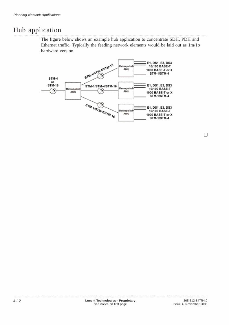
Hub application...................................................................................................................................................................................................................................
The figure below shows an example hub application to concentrate SDH, PDH andEthernet traffic. Typically the feeding network elements would be laid out as 1m/1ohardware version.
Planning Network Applications
...................................................................................................................................................................................................................................
4-12 Lucent Technologies - ProprietarySee notice on first page
365-312-847R4.0Issue 4, November 2006
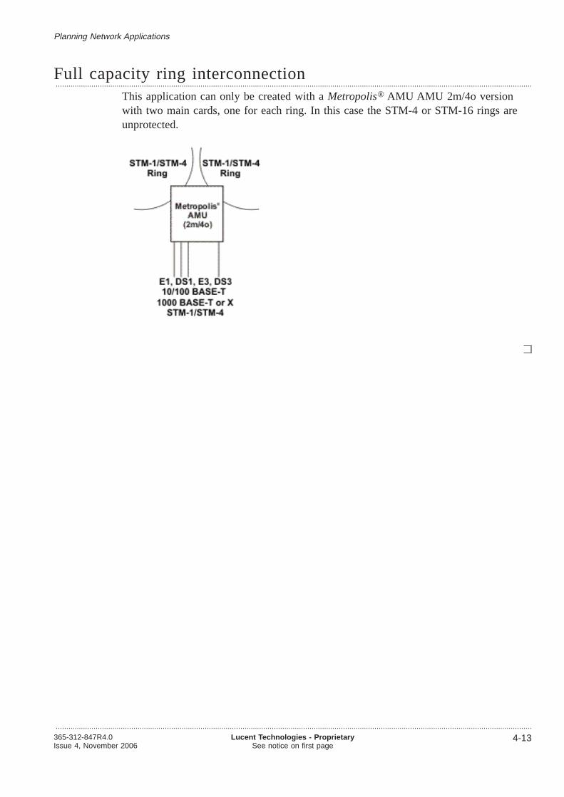
Full capacity ring interconnection...................................................................................................................................................................................................................................
This application can only be created with aMetropolis® AMU AMU 2m/4o versionwith two main cards, one for each ring. In this case the STM-4 or STM-16 rings areunprotected.
Planning Network Applications
...................................................................................................................................................................................................................................365-312-847R4.0Issue 4, November 2006
Lucent Technologies - ProprietarySee notice on first page
4-13

Metropolis® AMU typical 1m/1o application...................................................................................................................................................................................................................................
The figure below shows a typical example to interconnect SDH, PDH and Ethernettraffic in a ring with aMetropolis® AMU 1m/1o version.
Planning Network Applications
...................................................................................................................................................................................................................................
4-14 Lucent Technologies - ProprietarySee notice on first page
365-312-847R4.0Issue 4, November 2006

Grooming application...................................................................................................................................................................................................................................
The following figure depicts an example VC-12 grooming application.
Planning Network Applications
...................................................................................................................................................................................................................................365-312-847R4.0Issue 4, November 2006
Lucent Technologies - ProprietarySee notice on first page
4-15
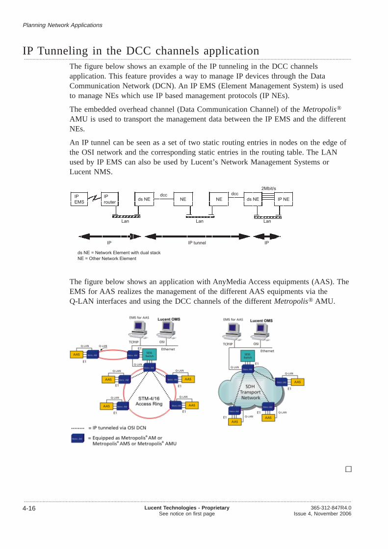
IP Tunneling in the DCC channels application...................................................................................................................................................................................................................................
The figure below shows an example of the IP tunneling in the DCC channelsapplication. This feature provides a way to manage IP devices through the DataCommunication Network (DCN). An IP EMS (Element Management System) is usedto manage NEs which use IP based management protocols (IP NEs).
The embedded overhead channel (Data Communication Channel) of theMetropolis®
AMU is used to transport the management data between the IP EMS and the differentNEs.
An IP tunnel can be seen as a set of two static routing entries in nodes on the edge ofthe OSI network and the corresponding static entries in the routing table. The LANused by IP EMS can also be used by Lucent’s Network Management Systems orLucent NMS.
The figure below shows an application with AnyMedia Access equipments (AAS). TheEMS for AAS realizes the management of the different AAS equipments via theQ-LAN interfaces and using the DCC channels of the differentMetropolis® AMU.
IP
EMSIP NE
IPds NE ds NENE NE
2Mbit/s
dcc dcc
IP IP tunnel IP
Lan
router
Lan Lan
ds NE = Network Element with dual stack
NE = Other Network Element
Planning Network Applications
...................................................................................................................................................................................................................................
4-16 Lucent Technologies - ProprietarySee notice on first page
365-312-847R4.0Issue 4, November 2006

GSM/UMTS application...................................................................................................................................................................................................................................
The Metropolis® AMU is an attractive offer in a ring topology for servingGSM/UMTS base stations.
The figure below illustrates an example ofMetropolis® AMU in a GSM/UMTSapplication.
Planning Network Applications
...................................................................................................................................................................................................................................365-312-847R4.0Issue 4, November 2006
Lucent Technologies - ProprietarySee notice on first page
4-17

Multi-service application with theTransLAN® option board...................................................................................................................................................................................................................................
The TransLAN® option board, enables the SDH network elements to provide Ethernetover SDH, and offers variable data applications on top of the traditional TDMapplications. This results in cost-effective, simple and reliable multi-service solutionsfor customers.TransLAN® can provide VLAN functions, and bandwidth can be sharedfor different customers.
Direct LAN-to-LAN interconnect (two LAN’s)
The most straightforward application of theTransLAN® option board is to interconnecttwo LAN segments that are at a distance that cannot be reached with a simple Ethernetrepeater, since that would violate the collision domain size rules. Both LAN’s do nothave to be of the same speed. It is possible to interconnect a 10BASE-T and a100BASE-T/X LAN this way. This application is shown in the figure below:
Direct LAN-to-LAN interconnect (Multiple LAN’s)
A next step in complexity is to interconnect multiple LAN’s, more than two, atdifferent locations. It is possible to associate a single LAN port with two or moreWAN ports. In this way, multiple sites can be interconnected, forming a fully Layer 2switched WAN Ethernet network. This application is shown in the figure below.
Planning Network Applications
...................................................................................................................................................................................................................................
4-18 Lucent Technologies - ProprietarySee notice on first page
365-312-847R4.0Issue 4, November 2006
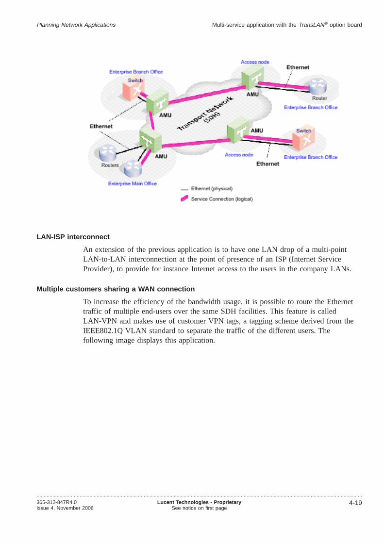
LAN-ISP interconnect
An extension of the previous application is to have one LAN drop of a multi-pointLAN-to-LAN interconnection at the point of presence of an ISP (Internet ServiceProvider), to provide for instance Internet access to the users in the company LANs.
Multiple customers sharing a WAN connection
To increase the efficiency of the bandwidth usage, it is possible to route the Ethernettraffic of multiple end-users over the same SDH facilities. This feature is calledLAN-VPN and makes use of customer VPN tags, a tagging scheme derived from theIEEE802.1Q VLAN standard to separate the traffic of the different users. Thefollowing image displays this application.
Planning Network Applications Multi-service application with the TransLAN® option board
....................................................................................................................................................................................................................................365-312-847R4.0Issue 4, November 2006
Lucent Technologies - ProprietarySee notice on first page
4-19
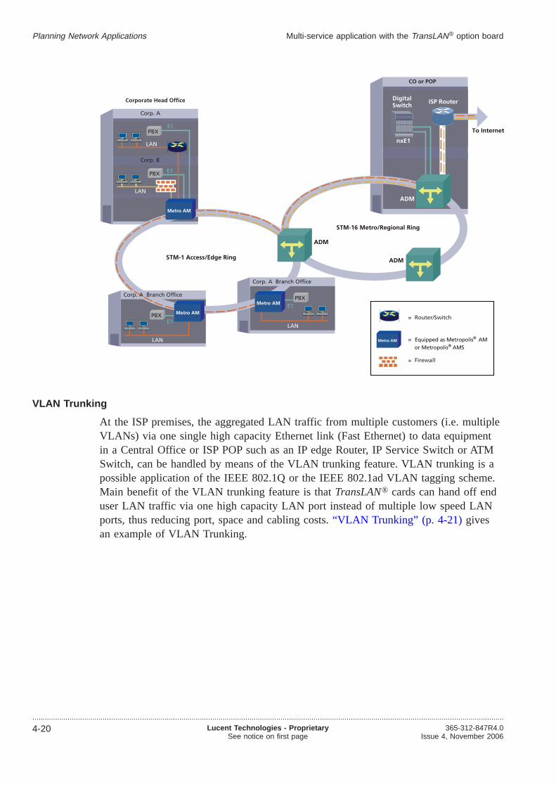
VLAN Trunking
At the ISP premises, the aggregated LAN traffic from multiple customers (i.e. multipleVLANs) via one single high capacity Ethernet link (Fast Ethernet) to data equipmentin a Central Office or ISP POP such as an IP edge Router, IP Service Switch or ATMSwitch, can be handled by means of the VLAN trunking feature. VLAN trunking is apossible application of the IEEE 802.1Q or the IEEE 802.1ad VLAN tagging scheme.Main benefit of the VLAN trunking feature is thatTransLAN® cards can hand off enduser LAN traffic via one high capacity LAN port instead of multiple low speed LANports, thus reducing port, space and cabling costs.“VLAN Trunking” (p. 4-21) givesan example of VLAN Trunking.
Corporate Head Office
Corp. A
Corp. B
PBX
PBX
LAN
LAN
CO or POP
LAN
Metro AM
Corp. A Branch Office
To Internet
PBXE1
E1PBX
LAN
LAN
Corp. A Branch Office
Metro AM
Metro AM
STM-16 Metro/Regional Ring
STM-1 Access/Edge Ring
ADM
ADM
ADM
Metro AM = Equipped as Metropolis® AM
= Firewall
= Router/Switch
E1
E1
nxE1
DigitalSwitch
ISP Router
or Metropolis® AMS
Planning Network Applications Multi-service application with the TransLAN® option board
....................................................................................................................................................................................................................................
4-20 Lucent Technologies - ProprietarySee notice on first page
365-312-847R4.0Issue 4, November 2006
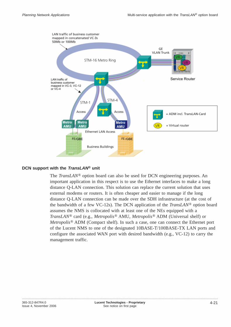
DCN support with the TransLAN ® unit
The TransLAN® option board can also be used for DCN engineering purposes. Animportant application in this respect is to use the Ethernet interfaces to make a longdistance Q-LAN connection. This solution can replace the current solution that usesexternal modems or routers. It is often cheaper and easier to manage if the longdistance Q-LAN connection can be made over the SDH infrastructure (at the cost ofthe bandwidth of a few VC-12s). The DCN application of theTransLAN® option boardassumes the NMS is collocated with at least one of the NEs equipped with aTransLAN® card (e.g.,Metropolis® AMU, Metropolis® ADM (Universal shelf) orMetropolis® ADM (Compact shelf). In such a case, one can connect the Ethernet portof the Lucent NMS to one of the designated 10BASE-T/100BASE-TX LAN ports andconfigure the associated WAN port with desired bandwidth (e.g., VC-12) to carry themanagement traffic.
Planning Network Applications Multi-service application with the TransLAN® option board
....................................................................................................................................................................................................................................365-312-847R4.0Issue 4, November 2006
Lucent Technologies - ProprietarySee notice on first page
4-21
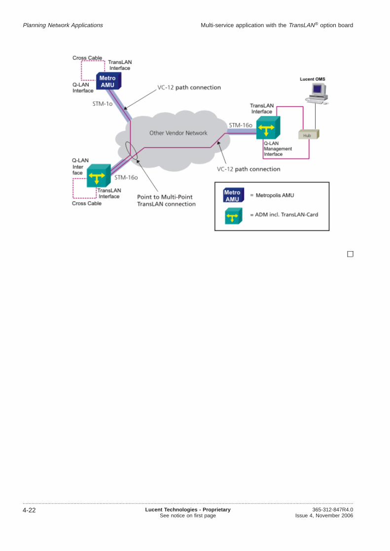
Planning Network Applications Multi-service application with the TransLAN® option board
....................................................................................................................................................................................................................................
4-22 Lucent Technologies - ProprietarySee notice on first page
365-312-847R4.0Issue 4, November 2006
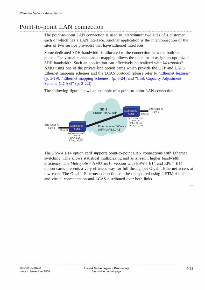
Point-to-point LAN connection...................................................................................................................................................................................................................................
The point-to-point LAN connection is used to interconnect two sites of a customereach of which has a LAN interface. Another application is the interconnection of thesites of two service providers that have Ethernet interfaces.
Some dedicated SDH bandwidth is allocated to the connection between both endpoints. The virtual concatenation mapping allows the operator to assign an optimizedSDH bandwidth. Such an application can effectively be realized withMetropolis®
AMU using one of the private line option cards which provide the GFP and LAPSEthernet mapping schemes and the LCAS protocol (please refer to“Ethernet features”(p. 3-19), “Ethernet mapping schemes” (p. 3-24)and“Link Capacity AdjustmentScheme (LCAS)” (p. 3-22)).
The following figure shows an example of a point-to-point LAN connection:
The ESW4_E14 option card supports point-to-point LAN connections with Ethernetswitching. This allows statistical multiplexing and as a result, higher bandwidthefficiency. TheMetropolis® AMU1m/1o version with ESW4_E14 and EPL4_E14option cards presents a very efficient way for full throughput Gigabit Ethernet access atlow costs. The Gigabit Ethernet connection can be transported using 2 STM-4 linksand virtual concatenation and LCAS distributed over both links.
SDHPublic Netw ork
Metropolis
MetropolisAMU
(with option card:X8PL or
)EPL4_E14 or
EPL4_132_75
Ethernet o ver VCn-Xv(GFP/LAPS/LCAS)
End-User ASite 1
End-User ASite 2
Ethernet
EthernetAMU
(with option card:X8PL or
)EPL4_E14 or
EPL4_132_75
Planning Network Applications
...................................................................................................................................................................................................................................365-312-847R4.0Issue 4, November 2006
Lucent Technologies - ProprietarySee notice on first page
4-23

5 5Quality and reliability
Overview...................................................................................................................................................................................................................................
Purpose
This chapter presents Lucent Technologies’ quality policy and describes the reliabilityof the Metropolis® AMU.
Contents
Quality 5-2
Lucent Technologies’ commitment to quality and reliability 5-3
Ensuring quality 5-4
Conformity statements 5-5
Reliability specifications 5-9
General specifications 5-10
Reliability program 5-11
Reliability specifications 5-12
...................................................................................................................................................................................................................................365-312-847R4.0Issue 4, November 2006
Lucent Technologies - ProprietarySee notice on first page
5-1

Quality
Overview...................................................................................................................................................................................................................................
Purpose
This section describes Lucent Technologies’ commitment to quality and reliability andhow quality is ensured.
Contents
Lucent Technologies’ commitment to quality and reliability 5-3
Ensuring quality 5-4
Conformity statements 5-5
Quality and reliability
...................................................................................................................................................................................................................................
5-2 Lucent Technologies - ProprietarySee notice on first page
365-312-847R4.0Issue 4, November 2006
Lucent Technologies’ commitment to quality and reliability...................................................................................................................................................................................................................................
Lucent Technologies is extremely committed to providing our customers with productsof the highest level of quality and reliability in the industry.Metropolis® AMU is aprime example of this commitment.
In line with this policy, all major transmission facilities in the USA, Europe and Chinaare ISO-9000 certified. In line with the above, Lucent Technologies’ policy statementin this respect is as follows.
Quality policy
Lucent Technologies is committed to achieving sustained business excellence byintegrating quality principles and methods into all we do at every level of our companyto
• anticipate and meet customer needs and exceed their expectations, every time
• relentlessly improve how we work – to deliver the world’s best and mostinnovative communications solutions – faster and more cost-effectively than ourcompetitors
Reliability in the product life-cycle
Each stage of the life cycle ofMetropolis® AMU relies on people and processes thatcontribute to the highest product quality and reliability possible. The reliability of aproduct begins at the earliest planning stage and continues into
• Product architecture
• Design and simulation
• Documentation
• Prototype testing during development
• Design change control
• Manufacturing and product testing (including 100% screening)
• Product quality assurance
• Product field performance
• Product field return management
The R&D community of Lucent Technologies is certified by ISO 9001.
Quality and reliability
...................................................................................................................................................................................................................................365-312-847R4.0Issue 4, November 2006
Lucent Technologies - ProprietarySee notice on first page
5-3

Ensuring quality...................................................................................................................................................................................................................................
This section describes the critical elements that ensure product quality and reliabilitywithin
• Product development
• Manufacturing
Critical elements of product development
The product development group’s strict adherence to the following critical elementsensures the product’s reliability
• Design standards
• Design and test practices
• Comprehensive qualification programs
• System-level reliability integration
• Reliability audits and predictions
• Development of quality assurance standards for manufactured products
Critical elements of manufacturing
Note: Independent Quality Representatives are also present at manufacturing locationsto ensure shipped product quality.
The manufacturing and field deployment groups’ strict adherence to the followingcritical elements ensures the product’s reliability
• Pre-manufacturing
• Qualification
• Accelerated product testing
• Product screening
• Production quality tracking
• Failure mode analysis
• Feedback and corrective actions
Quality and reliability
...................................................................................................................................................................................................................................
5-4 Lucent Technologies - ProprietarySee notice on first page
365-312-847R4.0Issue 4, November 2006
Conformity statements...................................................................................................................................................................................................................................
CE conformity
Hereby, Lucent Technologies declares that the Lucent Technologies product
Metropolis® AMU, Release 1.0 through 4.0
is in compliance with the essential requirements and other relevant provisions of thefollowing Directive:
IEC 60950-1 (ed. 1)
is tested and conforms with the essential requirements for protection of health and thesafety of the user and any other person and Electromagnetic Compatibility. Conformityis indicated by the CE mark affixed to the product. For more information regarding CEmarking and Declaration of Conformity (DoC), please contact your local LucentTechnologies Customer Service Organization.
This product is in conformity with Article 3, Paragraph 3 of the R&TTE Directive andinterworks in networks with other equipment connected to the opticaltelecommunication network.
Conformance with specifications of optical interfaces is granted as stated in the OfficialJournal of the European Union.
Compliance Statement in other European Languages
English
Hereby, Lucent Technologies, declares that thisMetropolis® AMU is in compliancewith the essential requirements and other relevant provisions of Directive IEC 60950-1(ed. 1).
Finnish
Lucent Technologies vakuuttaa täten ettäMetropolis® AMU tyyppinen laite ondirektiivin IEC 60950-1 (ed. 1) oleellisten vaatimusten ja sitä koskevien direktiivinmuiden ehtojen mukainen.
Dutch
Bij deze verklaart Lucent Technologies dat dezeMetropolis® AMU voldoet aan deessentiële eisen en aan de overige relevante bepalingen van Richtlijn IEC 60950-1 (ed.1).
French
Par la présente, Lucent Technologies déclare que ceMetropolis® AMU est conformeaux exigences essentielles et aux autres dispositions de la directive IEC 60950-1 (ed. 1)qui lui sont applicables.
Quality and reliability
...................................................................................................................................................................................................................................365-312-847R4.0Issue 4, November 2006
Lucent Technologies - ProprietarySee notice on first page
5-5

Swedish
Härmed intygar Lucent Technologies att dennaMetropolis® AMU står Iöverensstämmelse med de väsentliga egenskapskrav och övriga relevanta bestämmelsersom framgår av direktiv IEC 60950-1 (ed. 1).
Danish
Undertegnede Lucent Technologies erklærer herved, at følgende udstyrMetropolis®
AMU overholder de væsentlige krav og øvrige relevante krav i direktiv IEC 60950-1(ed. 1)
German
Hiermit erklärt Lucent Technologies die Übereinstimmung des GerätesMetropolis®
AMU mit den grundlegenden Anforderungen und den anderen relevanten Festlegungender Richtlinie IEC 60950-1 (ed. 1).
Greek
MΕ THN ΠAΡOYΣA Lucent Technologies∆ΗΛΩΝΕI OTI Metropolis® AMUΣYMMOΡΦΩΝΕTAI ΠΡOΣ TIΣ OYΣIΩ∆ΕIΣ AΠAITΗΣΕIΣ ΚAI TI Σ ΛOIΠΕΣΣΧΕTIΚΕΣ ∆IATA ΞΕIΣ TΗΣ O∆Η(IAΣ IEC 60950-1 (ed. 1)
Italian
Con la presente Lucent Technologies dichiara che questoMetropolis® AMU èconforme ai requisiti essenziali ed alle altre disposizioni pertinenti stabilite dalladirettiva IEC 60950-1 (ed. 1).
Spanish
Por medio de la presente Lucent Technologies declara que elMetropolis® AMUcumple con los requisitos esenciales y cualesquiera otras disposiciones aplicables oexigibles de la Directiva IEC 60950-1 (ed. 1)
Portuguese
Lucent Technologies declara que esteMetropolis® AMU está conforme com osrequisitos essenciais e outras provisões da Directiva IEC 60950-1 (ed. 1).
Eco-environmental statements
The statements that follow are the eco-environmental statements that apply to theWaste from Electrical and Electronic Equipment (WEEE) directive.
Packaging collection and recovery requirements
Countries, states, localities, or other jurisdictions may require that systems beestablished for the return and/or collection of packaging waste from the consumer, orother end user, or from the waste stream. Additionally, reuse, recovery, and/or recyclingtargets for the return and/or collection of the packaging waste may be established.
For more information regarding collection and recovery of packaging and packagingwaste within specific jurisdictions, please contact the Lucent Technologies FieldServices / Installation - Environmental Health and Safety organization.
Quality and reliability Conformity statements
....................................................................................................................................................................................................................................
5-6 Lucent Technologies - ProprietarySee notice on first page
365-312-847R4.0Issue 4, November 2006

For installations not performed by Lucent Technologies, please contact the LucentCustomer Support Center at:
Technical Support Services, Lucent Technologies.
Within the United States: 1 866 LUCENT8 (866 582 3688), prompt 1
From all other countries: +1 630 224 4672, prompt 2
Recycling / take-back / disposal of product
Electronic products bearing or referencing the symbol shown below when put on themarket within the European Union, shall be collected and treated at the end of theiruseful life, in compliance with applicable European Union and local legislation. Theyshall not be disposed of as part of unsorted municipal waste. Due to materials that maybe contained in the product, such as heavy metals or batteries, the environment andhuman health may be negatively impacted as a result of inappropriate disposal.
Note: In the European Union, a solid bar under the crossed-out wheeled bin indicatesthat the product was put on the market after 13 August 2005.
Moreover, in compliance with legal requirements and contractual agreements, whereapplicable, Lucent Technologies will offer to provide for the collection and treatmentof Lucent Technologies products at the end of their useful life, or products displacedby Lucent Technologies equipment offers.
For information regarding take-back of equipment by Lucent Technologies, or for moreinformation regarding the requirements for recycling/disposal of product, please contactyour Lucent Account Manager or Lucent Takeback Support at [email protected].
Material content compliance
European Union (EU) Directive 2002/95/EC, “Restriction of the use of certainHazardous Substances” (RoHS), restricts the use of lead, mercury, cadmium,hexavalent chromium, and certain flame retardants in electrical and electronicequipment. This Directive applies to electrical and electronic products placed on theEU market from 1 July 2006, with various exemptions, including an exemption forlead solder in network infrastructure equipment. Lucent products shipped to the EUfrom 1 July 2006 will comply with the RoHS Directive.
Quality and reliability Conformity statements
....................................................................................................................................................................................................................................365-312-847R4.0Issue 4, November 2006
Lucent Technologies - ProprietarySee notice on first page
5-7

Technical documentation
The technical documentation as required by the Conformity Assessment procedure iskept at Lucent Technologies location which is responsible for this product. For moreinformation please contact your local Lucent Technologies representative.
Quality and reliability Conformity statements
....................................................................................................................................................................................................................................
5-8 Lucent Technologies - ProprietarySee notice on first page
365-312-847R4.0Issue 4, November 2006
Reliability specifications
Overview...................................................................................................................................................................................................................................
Purpose
This section describes how reliability is specified.
Contents
General specifications 5-10
Reliability program 5-11
Reliability specifications 5-12
Quality and reliability
...................................................................................................................................................................................................................................365-312-847R4.0Issue 4, November 2006
Lucent Technologies - ProprietarySee notice on first page
5-9

General specifications...................................................................................................................................................................................................................................
This section provides general reliability specifications forMetropolis® AMU.
Mean time between failures
The mean time between failures (MTBF) for the wholeMetropolis® AMU aredescribed in“Metropolis® AMU circuit-pack fit rates and MTBF values” (p. 5-12).
Infant mortality factor
Note: The steady state failure rate is equal to the failure rate of the system.
The number of failures that a product experiences during the first year of service afterturn-up may be greater than the number of subsequent annual steady state failures. Thisis the early life or infant mortality period. The ratio of the first year failure rate to thesteady state failure rate is termed the infant mortality factor (IMF).
Quality and reliability
...................................................................................................................................................................................................................................
5-10 Lucent Technologies - ProprietarySee notice on first page
365-312-847R4.0Issue 4, November 2006
Reliability program...................................................................................................................................................................................................................................
Introduction
Reliability is a key ingredient of products life cycle from the earliest planning stage.Major occurrences at the start of the project involve modeling of system reliability.During the design and development stage, reliability predictions, qualification andselection of components, definition of quality assurance standards and prototyping ofcritical system areas ensured built-in reliability. Manufacturing and field deployment,techniques such as pre-manufacturing, qualification, tracking of production quality,burn-in tests, failure mode analysis and feedback and correction further enhance theongoing reliability of theMetropolis® AMU.
Quality and reliability
...................................................................................................................................................................................................................................365-312-847R4.0Issue 4, November 2006
Lucent Technologies - ProprietarySee notice on first page
5-11
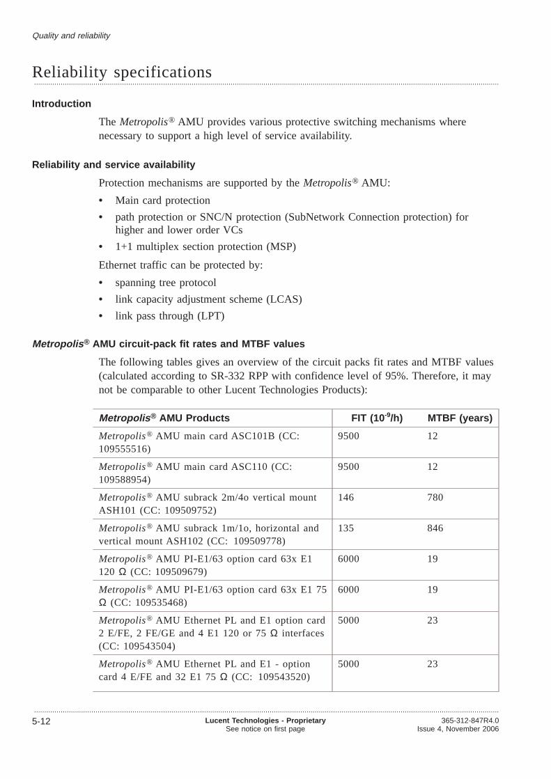
Reliability specifications...................................................................................................................................................................................................................................
Introduction
The Metropolis® AMU provides various protective switching mechanisms wherenecessary to support a high level of service availability.
Reliability and service availability
Protection mechanisms are supported by theMetropolis® AMU:
• Main card protection
• path protection or SNC/N protection (SubNetwork Connection protection) forhigher and lower order VCs
• 1+1 multiplex section protection (MSP)
Ethernet traffic can be protected by:
• spanning tree protocol
• link capacity adjustment scheme (LCAS)
• link pass through (LPT)
Metropolis ® AMU circuit-pack fit rates and MTBF values
The following tables gives an overview of the circuit packs fit rates and MTBF values(calculated according to SR-332 RPP with confidence level of 95%. Therefore, it maynot be comparable to other Lucent Technologies Products):
Metropolis ® AMU Products FIT (10 -9/h) MTBF (years)
Metropolis® AMU main card ASC101B (CC:109555516)
9500 12
Metropolis® AMU main card ASC110 (CC:109588954)
9500 12
Metropolis® AMU subrack 2m/4o vertical mountASH101 (CC: 109509752)
146 780
Metropolis® AMU subrack 1m/1o, horizontal andvertical mount ASH102 (CC: 109509778)
135 846
Metropolis® AMU PI-E1/63 option card 63x E1120 Ω (CC: 109509679)
6000 19
Metropolis® AMU PI-E1/63 option card 63x E1 75Ω (CC: 109535468)
6000 19
Metropolis® AMU Ethernet PL and E1 option card2 E/FE, 2 FE/GE and 4 E1 120 or 75Ω interfaces(CC: 109543504)
5000 23
Metropolis® AMU Ethernet PL and E1 - optioncard 4 E/FE and 32 E1 75Ω (CC: 109543520)
5000 23
Quality and reliability
...................................................................................................................................................................................................................................
5-12 Lucent Technologies - ProprietarySee notice on first page
365-312-847R4.0Issue 4, November 2006
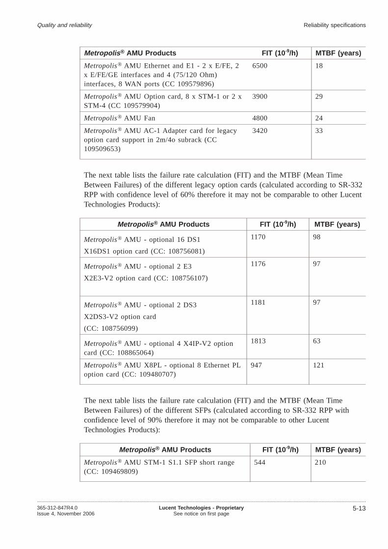
Metropolis ® AMU Products FIT (10 -9/h) MTBF (years)
Metropolis® AMU Ethernet and E1 - 2 x E/FE, 2x E/FE/GE interfaces and 4 (75/120 Ohm)interfaces, 8 WAN ports (CC 109579896)
6500 18
Metropolis® AMU Option card, 8 x STM-1 or 2 xSTM-4 (CC 109579904)
3900 29
Metropolis® AMU Fan 4800 24
Metropolis® AMU AC-1 Adapter card for legacyoption card support in 2m/4o subrack (CC109509653)
3420 33
The next table lists the failure rate calculation (FIT) and the MTBF (Mean TimeBetween Failures) of the different legacy option cards (calculated according to SR-332RPP with confidence level of 60% therefore it may not be comparable to other LucentTechnologies Products):
Metropolis ® AMU Products FIT (10 -9/h) MTBF (years)
Metropolis® AMU - optional 16 DS1
X16DS1 option card (CC: 108756081)
1170 98
Metropolis® AMU - optional 2 E3
X2E3-V2 option card (CC: 108756107)
1176 97
Metropolis® AMU - optional 2 DS3
X2DS3-V2 option card
(CC: 108756099)
1181 97
Metropolis® AMU - optional 4 X4IP-V2 optioncard (CC: 108865064)
1813 63
Metropolis® AMU X8PL - optional 8 Ethernet PLoption card (CC: 109480707)
947 121
The next table lists the failure rate calculation (FIT) and the MTBF (Mean TimeBetween Failures) of the different SFPs (calculated according to SR-332 RPP withconfidence level of 90% therefore it may not be comparable to other LucentTechnologies Products):
Metropolis ® AMU Products FIT (10 -9/h) MTBF (years)
Metropolis® AMU STM-1 S1.1 SFP short range(CC: 109469809)
544 210
Quality and reliability Reliability specifications
....................................................................................................................................................................................................................................365-312-847R4.0Issue 4, November 2006
Lucent Technologies - ProprietarySee notice on first page
5-13
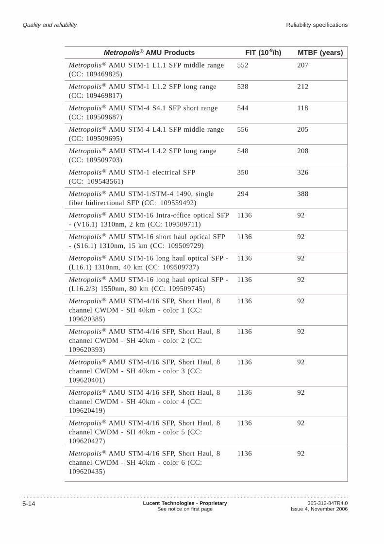
Metropolis ® AMU Products FIT (10 -9/h) MTBF (years)
Metropolis® AMU STM-1 L1.1 SFP middle range(CC: 109469825)
552 207
Metropolis® AMU STM-1 L1.2 SFP long range(CC: 109469817)
538 212
Metropolis® AMU STM-4 S4.1 SFP short range(CC: 109509687)
544 118
Metropolis® AMU STM-4 L4.1 SFP middle range(CC: 109509695)
556 205
Metropolis® AMU STM-4 L4.2 SFP long range(CC: 109509703)
548 208
Metropolis® AMU STM-1 electrical SFP(CC: 109543561)
350 326
Metropolis® AMU STM-1/STM-4 1490, singlefiber bidirectional SFP (CC: 109559492)
294 388
Metropolis® AMU STM-16 Intra-office optical SFP- (V16.1) 1310nm, 2 km (CC: 109509711)
1136 92
Metropolis® AMU STM-16 short haul optical SFP- (S16.1) 1310nm, 15 km (CC: 109509729)
1136 92
Metropolis® AMU STM-16 long haul optical SFP -(L16.1) 1310nm, 40 km (CC: 109509737)
1136 92
Metropolis® AMU STM-16 long haul optical SFP -(L16.2/3) 1550nm, 80 km (CC: 109509745)
1136 92
Metropolis® AMU STM-4/16 SFP, Short Haul, 8channel CWDM - SH 40km - color 1 (CC:109620385)
1136 92
Metropolis® AMU STM-4/16 SFP, Short Haul, 8channel CWDM - SH 40km - color 2 (CC:109620393)
1136 92
Metropolis® AMU STM-4/16 SFP, Short Haul, 8channel CWDM - SH 40km - color 3 (CC:109620401)
1136 92
Metropolis® AMU STM-4/16 SFP, Short Haul, 8channel CWDM - SH 40km - color 4 (CC:109620419)
1136 92
Metropolis® AMU STM-4/16 SFP, Short Haul, 8channel CWDM - SH 40km - color 5 (CC:109620427)
1136 92
Metropolis® AMU STM-4/16 SFP, Short Haul, 8channel CWDM - SH 40km - color 6 (CC:109620435)
1136 92
Quality and reliability Reliability specifications
....................................................................................................................................................................................................................................
5-14 Lucent Technologies - ProprietarySee notice on first page
365-312-847R4.0Issue 4, November 2006
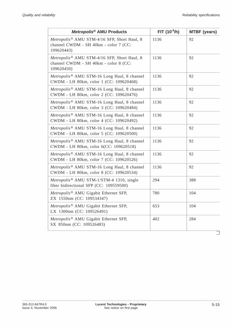
Metropolis ® AMU Products FIT (10 -9/h) MTBF (years)
Metropolis® AMU STM-4/16 SFP, Short Haul, 8channel CWDM - SH 40km - color 7 (CC:109620443)
1136 92
Metropolis® AMU STM-4/16 SFP, Short Haul, 8channel CWDM - SH 40km - color 8 (CC:109620450)
1136 92
Metropolis® AMU STM-16 Long Haul, 8 channelCWDM - LH 80km, color 1 (CC: 109620468)
1136 92
Metropolis® AMU STM-16 Long Haul, 8 channelCWDM - LH 80km, color 2 (CC: 109620476)
1136 92
Metropolis® AMU STM-16 Long Haul, 8 channelCWDM - LH 80km, color 3 (CC: 109620484)
1136 92
Metropolis® AMU STM-16 Long Haul, 8 channelCWDM - LH 80km, color 4 (CC: 109620492)
1136 92
Metropolis® AMU STM-16 Long Haul, 8 channelCWDM - LH 80km, color 5 (CC: 109620500)
1136 92
Metropolis® AMU STM-16 Long Haul, 8 channelCWDM - LH 80km, color 6(CC: 109620518)
1136 92
Metropolis® AMU STM-16 Long Haul, 8 channelCWDM - LH 80km, color 7 (CC: 109620526)
1136 92
Metropolis® AMU STM-16 Long Haul, 8 channelCWDM - LH 80km, color 8 (CC: 109620534)
1136 92
Metropolis® AMU STM-1/STM-4 1310, singlefiber bidirectional SFP (CC: 109559500)
294 388
Metropolis® AMU Gigabit Ethernet SFP,ZX 1550nm (CC: 109534347)
780 104
Metropolis® AMU Gigabit Ethernet SFP,LX 1300nm (CC: 109526491)
653 104
Metropolis® AMU Gigabit Ethernet SFP,SX 850nm (CC: 109526483)
402 284
Quality and reliability Reliability specifications
....................................................................................................................................................................................................................................365-312-847R4.0Issue 4, November 2006
Lucent Technologies - ProprietarySee notice on first page
5-15

6 6Product support
Overview...................................................................................................................................................................................................................................
Purpose
This chapter provides information about the support for theMetropolis® AMU.
Contents
Installation services 6-2
Engineering services 6-4
Maintenance services 6-6
Technical support 6-8
Documentation support 6-10
Training support 6-11
Warranty 6-12
Standard Repair 6-13
...................................................................................................................................................................................................................................365-312-847R4.0Issue 4, November 2006
Lucent Technologies - ProprietarySee notice on first page
6-1

Installation services...................................................................................................................................................................................................................................
This section describes the installation services available to supportMetropolis® AMU.
Lucent Technologies offers Installation Services focused on providing the technicalsupport and resources needed to efficiently and cost-effectively install your networkequipment. Lucent Technologies Installation Services provide unparalleled networkimplementation expertise to help install your wireline and wireless networks. We usestate-of-the-art tools and technology, and highly skilled technicians to install yourequipment and help to ensure the timely and complete implementation of your networksolution. By relying on our installation experts, we can rapidly build or expand yournetwork, help manage the complexity of implementing new technologies, reduceoperational costs, and help improve your competitive position by enabling your staff tofocus on the core aspects of your business rather than focusing on infrastructuredetails.
Description
Within Lucent Technologies’ overall Installation Services portfolio, Basic EquipmentInstallation and Site Supplemental Installation are the two services most closely linkedto the initial deployment of Lucent Technologies’ products into your network.
Basic Equipment Installation
Provides the resources, experience and tools necessary to install theMetropolis® AMUproduct into your network. We assemble, cable and wire, and test theMetropolis®
AMU, helping to ensure it is fully functioning as engineered and specified.
Site Supplemental Installation
Enhances the Basic Equipment Installation service by performing supplemental workthat is unique to your specific site location, configuration, or working requirements.Includes installation of material other than the main footprint product (such asearthquake bracing); provision of services unique to your site (such as, hauling andhoisting, multi-floor cabling, rental and local purchases) or as may be required by youroperations (such as, overtime to meet your compressed schedules, night work requestedby you, abnormal travel expenses, abnormal transportation or warehousing); and anyother additional effort or charges associated with your environment.
Benefits
When implementing our Installation Services, Lucent Technologies becomes a strategicpartner in helping you realize your long-term strategies and achieve your business andtechnological goals. We combine our state-of-the-art technical background, high-qualityprocesses, expertise in the latest technologies, knowledge of revolutionary equipmentbreakthroughs, and feature-rich project management tools to get your network up andrunning - quickly, efficiently, and reliably. With Lucent Technologies, you canconcentrate on your core business, while we apply our years of knowledge andexperience to installing your network.
Product support
...................................................................................................................................................................................................................................
6-2 Lucent Technologies - ProprietarySee notice on first page
365-312-847R4.0Issue 4, November 2006

Our Installation Services let you:
• Rapidly expand your network— by turning hardware into working systems, withthe capability to deploy multiple networks in parallel rollouts
• Reduce operational expense— of recruiting, training, and retaining skilledinstallation personnel
• Leverage Lucent Technologies’ resources and expertise— by utilizing our team ofknowledgeable and fully equipped experts that implement projects of any size,anywhere around the world
• Implement quality assurance— through our total quality management approach
• Reduce operational expenses— by avoiding the purchase of the necessarystate-of-the-art tools, test equipment, specialized test software, and spare parts thatLucent Technologies Installation Services utilize
• Ensure high-quality support— with Lucent Technologies’ extensive supportstructure, including proven methods and procedures, mechanized tools, professionaltraining, technical support, and access to Bell Labs.
Reference
For more information about specialized installation services and/or databasepreparation, please contact your local Account Executive.
Product support Installation services
...................................................................................................................................................................................................................................365-312-847R4.0Issue 4, November 2006
Lucent Technologies - ProprietarySee notice on first page
6-3
Engineering services...................................................................................................................................................................................................................................
This section describes the engineering services available to supportMetropolis® AMU.
Lucent Technologies Worldwide Services (LWS) offers Engineering Services focusedon providing the technical support and resources needed to efficiently andcost-effectively engineer your network equipment. We provide the best, mosteconomical equipment solution by ensuring your network equipment is configuredcorrectly, works as specified, and is ready for installation upon delivery. With ourproven, end-to-end solutions and experienced network engineering staff, LucentTechnologies Worldwide Services is the ideal partner to help service providers engineerand implement the technology that supports their business.
Description
Within Lucent Technologies’ overall Engineering Services portfolio, Site Survey, BasicEquipment Engineering, Site Engineering, and Site Records are the four services mostclosely linked to the initial deployment ofMetropolis® AMU into your network; eachis described below.
Site Survey
A Site Survey may be required to collect your site requirements needed for properequipment engineering. If adequate site requirements and records are not available upfront, a site survey would be performed to collect information required forconfiguration of the equipment and integration of the equipment into the site.
Basic Equipment Engineering
Ensures that the correct footprint hardware is ordered and that the ordered equipment isconfigured for optimal performance in the network for the customer. LucentTechnologies Engineering configures equipment requirements based on inputs from thecustomer order, completed questionnaires, and/or site survey data. The decisions as tospecific equipment needs are based on each component’s functionality and capacity,and the application of engineering rules associated with each component.
Site Engineering
Ensures that the correct site material is ordered and that the optimal equipment layoutfor the installation of the ordered equipment in the customer’s site is determined. SiteEngineering will be used in assisting the customer with determining the necessary siteconditions, layout and equipment required to properly install/integrate the footprinthardware components into a specific location.
Site Records
Site Records Service provides detailed record keeping which accurately documents thephysical placement and configuration of specified customer equipment. Depending onthe customer request, this can involve the initial creation of site records, updating ofexisting records, or ongoing maintenance of the customer’s records.
Product support
...................................................................................................................................................................................................................................
6-4 Lucent Technologies - ProprietarySee notice on first page
365-312-847R4.0Issue 4, November 2006

Benefits
When implementing our Engineering Services, Lucent Technologies becomes astrategic partner in helping you realize your long-term strategies and achieve yourbusiness and technological goals. Our Engineering Services portfolio delivers quick,responsive support, with state-of-the-art tools, top technicians and end-to-end servicesto help you engineer an optimal network solution. Whether you are looking tooutsource your total engineering effort or simply supplement basic coverage gaps, ourportfolio of services provides the flexible level of support you need. With LucentTechnologies, you can concentrate on your core business while we apply our years ofknowledge and experience in engineering your equipment solutions.
Our Engineering Services let you:
• Rapidly expand your network— by turning products into working systems, withthe capability to deploy multiple networks in parallel rollouts
• Reduce costs— by determining the most cost-effective network configuration andoptimal use of office space when planning and providing an equipment solution
• Reduce operational expense— of recruiting, training, and retaining skilledengineering personnel
• Leverage Lucent Technologies’ resources and expertise— by utilizing our team ofknowledgeable and fully equipped experts that can plan, design, and implementprojects of any size, anywhere around the world
• Implement quality assurance— through our total quality management approachand use of ISO-certified processes
• Provide one–stop shoppingwith a globally deployed engineering workforce, savingthe time, delays and coordination challenges of dealing with multiple equipmentvendors and service providers
• Keep pace with rapidly changing technology— by supporting the latesttechnologies and equipment breakthroughs, including Lucent Technologies’ andother vendor’s products
• Ensure high-quality support— with Lucent Technologies’ extensive supportstructure, including proven methods and procedures, mechanized tools, professionaltraining, technical support, and access to Bell Labs
• Maintain and track vital office records— keep track of equipment locations andconnections.
Reference
For more information about specialized engineering services, engineering consultations,and/or database preparation, please contact your local Account Executive.
Product support Engineering services
...................................................................................................................................................................................................................................365-312-847R4.0Issue 4, November 2006
Lucent Technologies - ProprietarySee notice on first page
6-5
Maintenance services...................................................................................................................................................................................................................................
This section describes the maintenance services available to supportMetropolis® AMU.
Description
Maintenance Services is composed of three primary services to support yourmaintenance needs. The services are
• Remote Technical Support Service (RTS)
• On-site Technical Support Service (OTS)
• Repair and Exchange Services (RES)
Remote Technical Support Service (RTS)
RTS provides remote technical support and Software Patches and Software Updates, asavailable, for deployed Lucent Technologies network elements to help cost-effectivelymaximize network availability and performance. With this service, system engineersdeliver remote support via phone or modem connection for rapid response, diagnosis,and resolution of system outages and issues.
Support from our expert remote system engineers will:
• enable trouble tracking, resolution, and restoration
• answer technical product-related questions and specific feature and functionquestions
• help identify and apply available Software Patches and Software Updates onCovered Products.
Single Point of Contact— access to Lucent Technologies engineers and information tohelp identify and resolve technical issues via phone or modem.
Lucent Technologies OnLine Customer Support—
• web-based tracking and management of Assistance Requests (AR)
• self-help services i.e., Knowledge Database, Documentation, E-mail.
Service Options—
• Premium RTS: 24 hours a day, 7 days a week (24 × 7)
• Standard RTS: 8 hours a day (8 am – 5 pm Client local time) 5 days per week (8× 5), Monday - Friday, excluding Lucent Technologies holidays.
Product support
...................................................................................................................................................................................................................................
6-6 Lucent Technologies - ProprietarySee notice on first page
365-312-847R4.0Issue 4, November 2006
On-site Technical Support (OTS)
OTS provides cost-effective support for Lucent Technologies products includingsystems that incorporate select third-party equipment.
• OTS Dispatched Technician — Lucent Technologies will dispatch a technician toyour location to provide on-site assistance. We offer multiple coverage options tomeet your needs from same-day dispatch, with 24 × 7 or 8 × 5 response, tonext-business-day dispatch, with 8 × 5 response.
• OTS Dedicated Technician — a Lucent Technologies technician works at yourlocation to perform daily maintenance tasks that keep your system running at peakperformance.
• OTS Dedicated Engineer — an expert Lucent Technologies engineer provides youwith customized on-site support and assistance in areas such as maintenance of newequipment, administration of software releases, and support with youradministrative processes.
Repair and Exchange Services (RES)
RES provides rapid replacement or repair of your defective hardware, eliminating theneed for you to purchase and maintain a costly spares inventory. These services candramatically reduce investment capital and recurring operating expenses while helpingto assure maximum network availability. RES offers
• Same Day Advanced Exchange — delivers a replacement part to Customerequipment site within four hours to enable rapid restoration of service to equipmentand the ability to return parts to Lucent Technologies later. We have established aninfrastructure of multi-point, overlapping-coverage field stocking locations andautomated electronic process controls that help us approach a 100% on-timedelivery track record.
• Next Day Advanced Exchange — delivers a replacement part on the very next day,7 days a week, including holidays. Consider what is at risk when you compare thisservice to a “business day” program.
• Return for Repair — is an economical solution, which allows the Customer toreturn your field-replaceable parts to Lucent Technologies for repair or replacement.Lucent Technologies returns them in a very timely manner and without unexpectedrepair fees.
Contact
For maintenance service contact information please refer to“Technical support”(p. 6-8).
Product support Maintenance services
...................................................................................................................................................................................................................................365-312-847R4.0Issue 4, November 2006
Lucent Technologies - ProprietarySee notice on first page
6-7
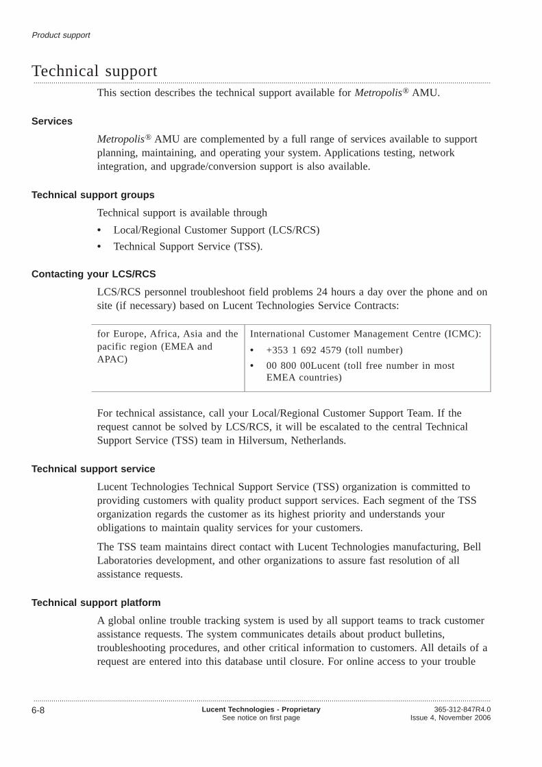
Technical support...................................................................................................................................................................................................................................
This section describes the technical support available forMetropolis® AMU.
Services
Metropolis® AMU are complemented by a full range of services available to supportplanning, maintaining, and operating your system. Applications testing, networkintegration, and upgrade/conversion support is also available.
Technical support groups
Technical support is available through
• Local/Regional Customer Support (LCS/RCS)
• Technical Support Service (TSS).
Contacting your LCS/RCS
LCS/RCS personnel troubleshoot field problems 24 hours a day over the phone and onsite (if necessary) based on Lucent Technologies Service Contracts:
for Europe, Africa, Asia and thepacific region (EMEA andAPAC)
International Customer Management Centre (ICMC):
• +353 1 692 4579 (toll number)
• 00 800 00Lucent (toll free number in mostEMEA countries)
For technical assistance, call your Local/Regional Customer Support Team. If therequest cannot be solved by LCS/RCS, it will be escalated to the central TechnicalSupport Service (TSS) team in Hilversum, Netherlands.
Technical support service
Lucent Technologies Technical Support Service (TSS) organization is committed toproviding customers with quality product support services. Each segment of the TSSorganization regards the customer as its highest priority and understands yourobligations to maintain quality services for your customers.
The TSS team maintains direct contact with Lucent Technologies manufacturing, BellLaboratories development, and other organizations to assure fast resolution of allassistance requests.
Technical support platform
A global online trouble tracking system is used by all support teams to track customerassistance requests. The system communicates details about product bulletins,troubleshooting procedures, and other critical information to customers. All details of arequest are entered into this database until closure. For online access to your trouble
Product support
...................................................................................................................................................................................................................................
6-8 Lucent Technologies - ProprietarySee notice on first page
365-312-847R4.0Issue 4, November 2006
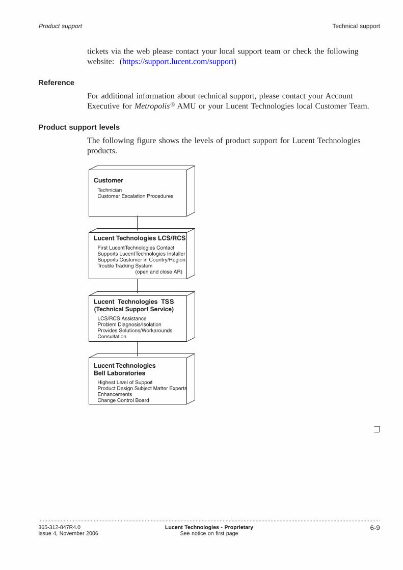
tickets via the web please contact your local support team or check the followingwebsite: (https://support.lucent.com/support)
Reference
For additional information about technical support, please contact your AccountExecutive forMetropolis® AMU or your Lucent Technologies local Customer Team.
Product support levels
The following figure shows the levels of product support for Lucent Technologiesproducts.
Product support Technical support
...................................................................................................................................................................................................................................365-312-847R4.0Issue 4, November 2006
Lucent Technologies - ProprietarySee notice on first page
6-9
Documentation support...................................................................................................................................................................................................................................
Lucent Technologies provides comprehensive product documentation tailored to theneeds of the different audiences. An overview of the documentation set can be found at“Related documentation” (p. xvi).
Customer comment
As customer satisfaction is extremely important to Lucent Technologies, every attemptis made to encourage feedback from customers about our information products. Thankyou for your feedback.
To comment on this information product online, go tohttp://www.lucent-info.com/comments.
Product support
...................................................................................................................................................................................................................................
6-10 Lucent Technologies - ProprietarySee notice on first page
365-312-847R4.0Issue 4, November 2006

Training support...................................................................................................................................................................................................................................
To complement your product needs, the Lucent Learning organization offers a formaltraining package, with the single training courses scheduled regularly at LucentTechnologies’ corporate training centers or to be arranged as on-site trainings at yourfacility.
Registering for a course or arranging an on-site training
To enroll in a training course at one of the Lucent Technologies corporate trainingcenters or to arrange an on-site training at your facility (suitcasing), please contact:
Asia, Pacific, andChina
Training Center Singapore, Singapore
voice: +65 6240 8394
fax: +65 6240 8017
Central America andLatin America
Training Center Mexico City, Mexico
voice: +52 55 527 87187
fax: +52 55 527 87185
Europe, Middle East,and Africa
Training Center Nuremberg, Germany
voice: +49 911 526 3831
fax: +49 911 526 6142
North American Region Training Center Altamonte Springs, USA
voice: +1-888-582-3688 - prompt 2
(+1-888-LUCENT8 - prompt 2).
To review the available courses or to enroll in a training course at one of LucentTechnologies’ corporate training centers you can also visit: https://training.lucent.com
Product support
...................................................................................................................................................................................................................................365-312-847R4.0Issue 4, November 2006
Lucent Technologies - ProprietarySee notice on first page
6-11
Warranty...................................................................................................................................................................................................................................
Introduction
Warranty, support, and trouble escalation procedures have been established on a percountry basis. Contact your Lucent Technologies account representative for details.
Discontinued Availability
Lucent Technologies reserves the right to notify the customer in advance of theintention to Discontinue the Availability (DA) of a product. Lucent Technologies alsoreserves the right to offer a Technical Support Contract (TSC) to make repair andtechnical support services available for an additional period of time after a product hasbeen discontinued. All TSC services will be at a specified price dependent on the termsand conditions of the contract.
The rights and obligations of Lucent Technologies and the customer shall neither beassigned nor delegated without prior written consent of the other party, except thatLucent Technologies may assign its obligations to any of its affiliates or non-LucentTechnologies contractors without further consent by the customer.
Product support
...................................................................................................................................................................................................................................
6-12 Lucent Technologies - ProprietarySee notice on first page
365-312-847R4.0Issue 4, November 2006
Standard Repair...................................................................................................................................................................................................................................
Introduction
If Lucent Technologies determines that a product is not defective or is in conformance,the customer shall pay Lucent Technologies the costs of handling, inspecting, testing,and transporting the product and, if applicable, travel and related expenses.
Repair interval
Lucent Technologies repair locations set their own standards for return intervals. Onaverage, the minimum time to return repairs to the customer is 14 days from thereceipt of the product by the repair location. The maximum time to return repairs tothe customer can range from 50 to 180 days.
Out-of-Warranty provisions
For any activity associated with repair or replacement of hardware and/or softwaresystems that is determined by Lucent Technologies to be out of warranty, materials andlabor will be billed at Lucent Technologies list price (time-and-materials plus additionalincurred expenses), or in accordance with a separate Technical Support Contract.
International repair and service
The customer or the customer’s in-country representative should send a description ofthe material to be returned for repair or service including the quantity, comcodes, andserial numbers (if available).
After the material has been shipped, the following information should be faxed to theService Center:
• Customer’s return address
• Customer contact name, telephone number, and fax number
• Value of material
• Identification of any hazardous equipment or material
• Shipping information including the date of shipment, air way bill, carrier name,flight number, number of cartons, and weight of material.
When the material arrives at the Service Center, it is entered into the Repair, Service,and Return database for tracking purposes.
The repair location will repair the material. If it is determined that an item is notrepairable and the item is under factory warranty, a replacement will be sent. If theitem is out of factory warranty, the customer will advise their Country DeskRepresentative if they would like to order a replacement.
The Service Center will prepare the paperwork for exporting the material, and ship thematerial to the customer. When available, the Service Center will fax the shippinginformation to the customer or the customer’s in-country representative.
Product support
...................................................................................................................................................................................................................................365-312-847R4.0Issue 4, November 2006
Lucent Technologies - ProprietarySee notice on first page
6-13

Upon receipt of the material, the customer or the customer’s in-country representativeshould send the Service Center the order numbers of the material received and the datethe material was received. The Service Center will then close the order on the Repair,Service, and Return database.
Important! Please note that Lucent Technologies warranty is contingent upon theuse of Lucent Technologies specified SFPs forMetropolis® AMU. Use of otherSFPs is not approved by Lucent Technologies and is fully at the customer’s ownrisk. Any warranty obligation of Lucent Technologies is extinguished whennon-Lucent specified SFPs are used.
Product support Standard Repair
...................................................................................................................................................................................................................................
6-14 Lucent Technologies - ProprietarySee notice on first page
365-312-847R4.0Issue 4, November 2006
7 7Ordering
Overview...................................................................................................................................................................................................................................
Purpose
This chapter provides an overview of the ordering process and the current orderinginformation forMetropolis® AMU.
The different comcodes listed hereafter can change. Contact your Lucent Technologiesrepresentative for updated information.
Contents
Ordering information 7-2
...................................................................................................................................................................................................................................365-312-847R4.0Issue 4, November 2006
Lucent Technologies - ProprietarySee notice on first page
7-1

Ordering information...................................................................................................................................................................................................................................
Metropolis® AMU has been carefully engineered and all equipment kitted to simplifythe ordering process. In this section the current ordering information are shown, asavailable on the issue date of this document.
Contact and further information
For all questions concerning ordering ofMetropolis® AMU, for any information aboutthe marketable items and their comcodes, and for ordering the equipment pleasecontact your Account Executive forMetropolis® AMU or your Lucent Technologieslocal customer team.
Orderable Metropolis ® AMU products
The tables below list the comcodes of theMetropolis® AMU Products. Software needsto be ordered together with the network element. To get the ordering information foravailable software versions please contact your local customer team.
The following table is intended to give an overview of the orderableMetropolis® AMUproducts. For installation guidelines, please refer theMetropolis® AMU InstallationGuide.
Metropolis ® AMU Products Apparatuscode
Comcode Comments
Metropolis® AMU main card ASC110 109588954Metropolis® AMU maincard with 2 x multirateSTM-1/4 and 2 x multirateSTM-4/16. DC powersupply, one powerconnector with each maincard (CC: 408887883) withstrain relief (CC:408887875) will bedelivered.
Metropolis® AMU main card ASC101B 109555516Metropolis® AMU maincard with 2 x multirateSTM-1/4 and 2 x STM-1.DC power supply, onepower connector with eachmain card (CC:408887883)with strain relief(CC:408887875) will bedelivered.
Metropolis® AMU subrack 2m/4o,vertical mount
ASH101 109509752Metropolis® AMU subrackwith 2 main and 4 optioncard slots for verticalmounting.
Ordering
...................................................................................................................................................................................................................................
7-2 Lucent Technologies - ProprietarySee notice on first page
365-312-847R4.0Issue 4, November 2006

Metropolis ® AMU Products Apparatuscode
Comcode Comments
Metropolis® AMU subrack 1m/1o,vertical mount
ASH102 109509760Metropolis® AMU subrackwith 1 main and 1 optioncard slot for verticalmounting only. No legacycard is supported. This rackis being replaced byCC109509778.
Metropolis® AMU subrack 1m/1o,vertical and horizontal mount
ASH102 109509778Metropolis® AMU subrack,1 main and 1 option cardslot, vertical and horizontalmounting. No legacy cardis supported. Note: Formounting, please follow themounting proceduresprovided in theMetropolis®
AMU Installation Guide.
Metropolis® AMU Adapter card forlegacy option card support inMetropolis® AMU 2m/4o subrack(occupies two slots in subrack)
ASC103 109509653 Adapter card forMetropolis® AMU 2m/4osubrack for usage of alegacy option board inMetropolis® AMU 2m/4osubracks (occupies twoslots in subrack)
Metropolis® AMU option card 63x E1120 Ω
ASC102 109509679Metropolis® AMU optioncard 63x 2 Mbit/s, 120Ω
Metropolis® AMU option card 63x E175 Ω
ASC104 109535468Metropolis® AMU optioncard 63x 2 Mbit/s, 75Ω
Metropolis® AMU Ethernet PL and E1- 2 E/FE, 2 FE/GE and 4 E1(120 or 75Ω) interfaces
ASC105 109543504Metropolis® AMU Ethernetprivate line card with 2xE/FE, 2x FE/GE + 4xE1(120 or 75Ω) interfaces
Metropolis® AMU Ethernet PL and E1- 4 E/FE and 32 E1 (75Ω)
ASC107 109543520Metropolis® AMU optioncard Ethernet private line +E1 4XE/FE, + 32X E1 (75Ω)
Metropolis® AMU option card -optional 2 x E/FE, 2 x E/FE/GEinterfaces and 4 E1 interfaces
ASC108 109579896 Metropolis® AMU - 2 xE/FE, 2 x E/FE/GEinterfaces and 4 (75/120Ω)interfaces, 8 WAN ports
Metropolis® AMU option card, 8 xSTM-1 or 2 x STM-4
ASC109 109579904 Metropolis® AMU optioncard, 8 x STM-1 or 2 xSTM-4
Ordering Ordering information
...................................................................................................................................................................................................................................365-312-847R4.0Issue 4, November 2006
Lucent Technologies - ProprietarySee notice on first page
7-3

Metropolis ® AMU Products Apparatuscode
Comcode Comments
Metropolis® AMU Basic verticalmounting kit - ETSI compliant
ASX001B 849029335 Metropolis® AMU 2m/4oand 1m/1o verticalmounting kit for ETSIracks
Metropolis® AMU Basic verticalmounting kit - 19” - ETSI compliant
ASX002B 849029343 Metropolis® AMU 2m/4oand 1m/1o verticalmounting kit for 19” racks
Metropolis® AMU 1m/1o horizontalmounting kit - ETSI compliant
ASX005B 849029350 Metropolis® AMU 1m/1ohorizontal mounting kit forETSI racks
Metropolis® AMU 1m/1o horizontalmounting kit - 19”
ASX006B 849029368 Metropolis® AMU 1m/1ohorizontal mounting kit for19” racks
Metropolis® AMU Basic mounting kit19” 40mm recessed
ASX007B 849029376 Metropolis® AMU 2m/4oand 1m/1o mounting kit for19” 40mm recessed racks
Metropolis® AMU Fan Kit ASX008 849029384 Metropolis® AMU Fan kitfor 2m/4o subrack, includes2 x AMU Fans
Metropolis® AMU 1m/1o subrackhorizontal mounting kit 19”
ASX009 849035456 Metropolis® AMU 1m/1ohorizontal mounting kit 19”- 40 mm offset
Metropolis® AMU Fans ASH104 109509786Metropolis® AMU Fan for1m/1o subrack and sparefor 2m/4o subrack
Metropolis® AMU blank face plate40mm
ASX004 109509802 To cover unused main slotpositions.
Metropolis® AMU blank face plate32mm
ASX003 109509794 To cover unused option slotpositions.
Metropolis ® AMU legacy option cards
The table below lists the comcodes of theMetropolis® AMU option cards.
Metropolis ® AMUProducts Apparatus code Comcodes
Metropolis® AMU - optional 8 Ethernet PLoption card (AMU AC-1 adapter card requiredto operate inMetropolis® AMU)
X8PL 109480707
Metropolis® AMU - optional 4 10/100BASE-TLAN interfaces option card (AMU AC-1 adaptercard required to operate inMetropolis® AMU)
X4IP-V2 108865064
Ordering Ordering information
...................................................................................................................................................................................................................................
7-4 Lucent Technologies - ProprietarySee notice on first page
365-312-847R4.0Issue 4, November 2006
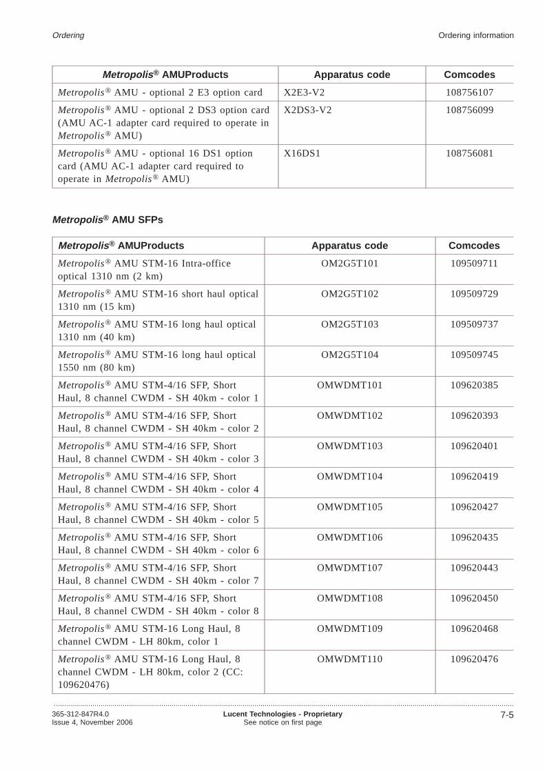
Metropolis ® AMUProducts Apparatus code Comcodes
Metropolis® AMU - optional 2 E3 option card X2E3-V2 108756107
Metropolis® AMU - optional 2 DS3 option card(AMU AC-1 adapter card required to operate inMetropolis® AMU)
X2DS3-V2 108756099
Metropolis® AMU - optional 16 DS1 optioncard (AMU AC-1 adapter card required tooperate inMetropolis® AMU)
X16DS1 108756081
Metropolis ® AMU SFPs
Metropolis ® AMUProducts Apparatus code Comcodes
Metropolis® AMU STM-16 Intra-officeoptical 1310 nm (2 km)
OM2G5T101 109509711
Metropolis® AMU STM-16 short haul optical1310 nm (15 km)
OM2G5T102 109509729
Metropolis® AMU STM-16 long haul optical1310 nm (40 km)
OM2G5T103 109509737
Metropolis® AMU STM-16 long haul optical1550 nm (80 km)
OM2G5T104 109509745
Metropolis® AMU STM-4/16 SFP, ShortHaul, 8 channel CWDM - SH 40km - color 1
OMWDMT101 109620385
Metropolis® AMU STM-4/16 SFP, ShortHaul, 8 channel CWDM - SH 40km - color 2
OMWDMT102 109620393
Metropolis® AMU STM-4/16 SFP, ShortHaul, 8 channel CWDM - SH 40km - color 3
OMWDMT103 109620401
Metropolis® AMU STM-4/16 SFP, ShortHaul, 8 channel CWDM - SH 40km - color 4
OMWDMT104 109620419
Metropolis® AMU STM-4/16 SFP, ShortHaul, 8 channel CWDM - SH 40km - color 5
OMWDMT105 109620427
Metropolis® AMU STM-4/16 SFP, ShortHaul, 8 channel CWDM - SH 40km - color 6
OMWDMT106 109620435
Metropolis® AMU STM-4/16 SFP, ShortHaul, 8 channel CWDM - SH 40km - color 7
OMWDMT107 109620443
Metropolis® AMU STM-4/16 SFP, ShortHaul, 8 channel CWDM - SH 40km - color 8
OMWDMT108 109620450
Metropolis® AMU STM-16 Long Haul, 8channel CWDM - LH 80km, color 1
OMWDMT109 109620468
Metropolis® AMU STM-16 Long Haul, 8channel CWDM - LH 80km, color 2 (CC:109620476)
OMWDMT110 109620476
Ordering Ordering information
...................................................................................................................................................................................................................................365-312-847R4.0Issue 4, November 2006
Lucent Technologies - ProprietarySee notice on first page
7-5
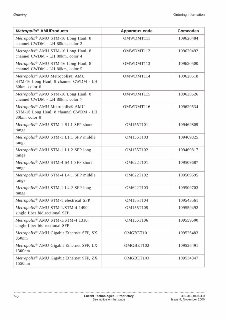
Metropolis ® AMUProducts Apparatus code Comcodes
Metropolis® AMU STM-16 Long Haul, 8channel CWDM - LH 80km, color 3
OMWDMT111 109620484
Metropolis® AMU STM-16 Long Haul, 8channel CWDM - LH 80km, color 4
OMWDMT112 109620492
Metropolis® AMU STM-16 Long Haul, 8channel CWDM - LH 80km, color 5
OMWDMT113 109620500
Metropolis® AMU Metropolis® AMUSTM-16 Long Haul, 8 channel CWDM - LH80km, color 6
OMWDMT114 109620518
Metropolis® AMU STM-16 Long Haul, 8channel CWDM - LH 80km, color 7
OMWDMT115 109620526
Metropolis® AMU Metropolis® AMUSTM-16 Long Haul, 8 channel CWDM - LH80km, color 8
OMWDMT116 109620534
Metropolis® AMU STM-1 S1.1 SFP shortrange
OM155T101 109469809
Metropolis® AMU STM-1 L1.1 SFP middlerange
OM155T103 109469825
Metropolis® AMU STM-1 L1.2 SFP longrange
OM155T102 109469817
Metropolis® AMU STM-4 S4.1 SFP shortrange
OM622T101 109509687
Metropolis® AMU STM-4 L4.1 SFP middlerange
OM622T102 109509695
Metropolis® AMU STM-1 L4.2 SFP longrange
OM622T103 109509703
Metropolis® AMU STM-1 electrical SFP OM155T104 109543561
Metropolis® AMU STM-1/STM-4 1490,single fiber bidirectional SFP
OM155T105 109559492
Metropolis® AMU STM-1/STM-4 1310,single fiber bidirectional SFP
OM155T106 109559500
Metropolis® AMU Gigabit Ethernet SFP, SX850nm
OMGBET101 109526483
Metropolis® AMU Gigabit Ethernet SFP, LX1300nm
OMGBET102 109526491
Metropolis® AMU Gigabit Ethernet SFP, ZX1550nm
OMGBET103 109534347
Ordering Ordering information
...................................................................................................................................................................................................................................
7-6 Lucent Technologies - ProprietarySee notice on first page
365-312-847R4.0Issue 4, November 2006

Recommended cables
Please refer to the Metropolis® AMU Installation Guide.
Ordering Ordering information
...................................................................................................................................................................................................................................365-312-847R4.0Issue 4, November 2006
Lucent Technologies - ProprietarySee notice on first page
7-7


Appendix A: An SDH overview
Overview...................................................................................................................................................................................................................................
Purpose
This chapter briefly describes the Synchronous Digital Hierarchy (SDH).
Synchronous Digital Hierarchy
In 1988, the ITU-T (formerly CCITT) came to an agreement on the SynchronousDigital Hierarchy (SDH). The corresponding ITU-T Recommendation G.707 forms thebasis of a global, uniform optical transmission network. SDH can operate withplesiochronous networks and therefore allows the continuous evolution of existingdigital transmission networks.
The major features and advantages of SDH are:
• Compatibility of transmission equipment and networks on a worldwide basis
• Uniform physical interfaces
• Easy cross connection of signals in the network nodes
• Possibility of transmitting PDH (Plesiochronous Digital Hierarchy) tributary signalsat bit rates commonly used at present
• Simple adding and dropping of individual channels without special multiplexers(add/drop facility)
• Easy transition to higher transmission rates
• Due to the standardization of the network element functions SDH supports asuperordinate network management and new monitoring functions and providestransport capacity and protocols (Telecommunication Management Network, TMN)for this purpose in the overheads of the multiplex signals.
• High flexibility and user-friendly monitoring possibilities, e.g. end-to-endmonitoring of the bit error ratio.
Purpose of SDH
The basic purpose of SDH is to provide a standard synchronous optical hierarchy withsufficient flexibility to accommodate digital signals that currently exist in today’snetwork, as well as those planned for the future.
....................................................................................................................................................................................................................................365-312-847R4.0Issue 4, November 2006
Lucent Technologies - ProprietarySee notice on first page
A-1
SDH currently defines standard rates and formats and optical interfaces. Today,mid-span meet is possible at the optical transmission level. These and other relatedissues continue to evolve through the ITU-T committees.
ITU-T addressed issues
The set of ITU-T Recommendations defines
• Optical parameters
• Multiplexing schemes to map existing digital signals (PDH) into SDH payloadsignals
• Overhead channels to support standard operation, administration, maintenance, andprovisioning (OAM&P) functions
• Criteria for optical line Automatic Protection Switch (APS)
References
For more detailed information on SDH, refer to
• ITU-T Recommendation G.703, “Physical/electrical characteristics of hierarchicaldigital interfaces”, October 1996
• ITU-T Recommendation G.707, “Network Node Interface For The SynchronousDigital Hierarchy (SDH)”, March 1996
• ITU-T Recommendation G.780, “Vocabulary of terms for synchronous digitalhierarchy (SDH) networks and equipment“ , November 1993
• ITU-T Recommendation G.783, “Characteristics of Synchronous Digital Hierarchy(SDH) Multiplexing Equipment Functional Blocks “, April 1997
• ITU-T Recommendation G.784, “Synchronous Digital Hierarchy (SDH)Management “, January 1994
• ITU-T Recommendation G.785, “Characteristics of a flexible multiplexer in asynchronous digital hierarchy environment “, November 1996
• ITU-T Recommendation G.813, “Timing characteristics of SDH equipment slaveclocks (SEC)“, August 1996
• ITU-T Recommendation G.823, “The control of jitter and wander within digitalnetworks which are based on the 2048-kbit/s hierarchy“, March 1993
• ITU-T Recommendation G.825, “The control of jitter and wander within digitalnetworks which are based on the synchronous digital hierarchy (SDH)“, March1993
• ITU-T Recommendation G.826, “ Error performance Parameters and Objectives forInternational, Constant Bit Rate Digital Paths at or Above the Primary Rate”,February 1999
• ITU-T Recommendation G.957, “Optical interfaces for equipments and systemsrelating to the synchronous digital hierarchy“, July 1995
An SDH overview Overview
...................................................................................................................................................................................................................................
A-2 Lucent Technologies - ProprietarySee notice on first page
365-312-847R4.0Issue 4, November 2006
Contents
SDH signal hierarchy A-4
SDH path and line sections A-6
SDH frame structure A-9
SDH digital multiplexing A-11
SDH interface A-13
SDH multiplexing process A-14
SDH demultiplexing process A-15
SDH transport rates A-16
An SDH overview Overview
...................................................................................................................................................................................................................................365-312-847R4.0Issue 4, November 2006
Lucent Technologies - ProprietarySee notice on first page
A-3

SDH signal hierarchy...................................................................................................................................................................................................................................
This section describes the basics of the SDH hierarchy.
STM-1 Frame
The SDH signal hierarchy is based on a basic “building block” frame called theSynchronous Transport Module 1 (STM-1), as shown in“SDH STM-1 frame” (p. A-5).
The STM-1 frame has a rate of 8000 frames per second and a duration of 125microseconds
The STM-1 frame consists of 270 columns and 9 rows.
Each cell in the matrix represents an 8-bit byte.
Transmitting Signals
The STM-1 frame (STM = Synchronous Transport Module) is transmitted seriallystarting from the left with row 1 column 1 through column 270, then row 2 column 1through 270, continuing on, row-by-row, until all 2430 bytes (9x270) of the STM-1frame have been transmitted. Because each STM-1 frame consists of 2430 bytes andeach byte has 8 bits, the frame contains 19440 bits a frame. There are 8000 STM-1frames a second, at the STM-1 signal rate of 155.520.000 (19440 x 8000) kbit/s.
Three higher bit rates are also defined:
• 622.080 Mbit/s (STM-4)
• 2488.320 Mbit/s (STM-16)
• 9953.280 Mbit/s (STM-64)
• 39813.120 Mbit/s (STM-256)
The bit rates of the higher order hierarchy levels are integer multiples of the STM-1transmission rate.
SDH STM-1 frame
The following figure illustrates the SDH STM-1 frame.
An SDH overview
...................................................................................................................................................................................................................................
A-4 Lucent Technologies - ProprietarySee notice on first page
365-312-847R4.0Issue 4, November 2006
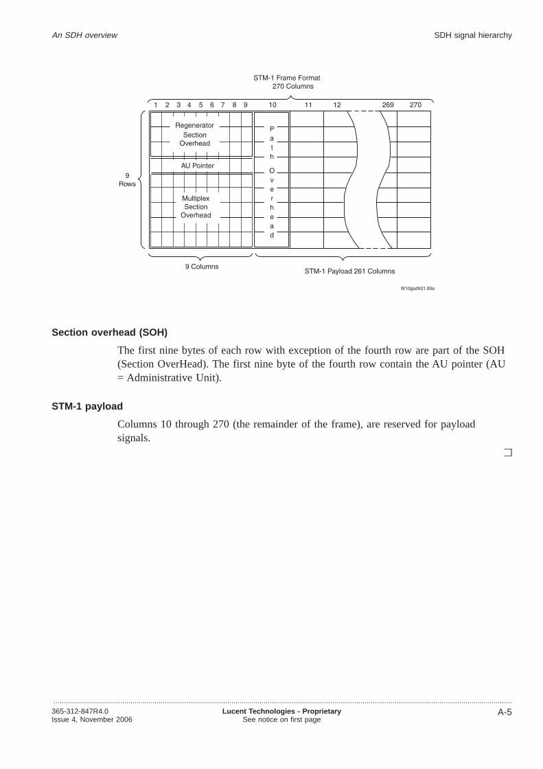
Section overhead (SOH)
The first nine bytes of each row with exception of the fourth row are part of the SOH(Section OverHead). The first nine byte of the fourth row contain the AU pointer (AU= Administrative Unit).
STM-1 payload
Columns 10 through 270 (the remainder of the frame), are reserved for payloadsignals.
An SDH overview SDH signal hierarchy
...................................................................................................................................................................................................................................365-312-847R4.0Issue 4, November 2006
Lucent Technologies - ProprietarySee notice on first page
A-5
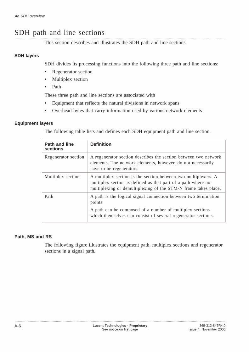
SDH path and line sections...................................................................................................................................................................................................................................
This section describes and illustrates the SDH path and line sections.
SDH layers
SDH divides its processing functions into the following three path and line sections:
• Regenerator section
• Multiplex section
• Path
These three path and line sections are associated with
• Equipment that reflects the natural divisions in network spans
• Overhead bytes that carry information used by various network elements
Equipment layers
The following table lists and defines each SDH equipment path and line section.
Path and linesections
Definition
Regenerator section A regenerator section describes the section between two networkelements. The network elements, however, do not necessarilyhave to be regenerators.
Multiplex section A multiplex section is the section between two multiplexers. Amultiplex section is defined as that part of a path where nomultiplexing or demultiplexing of the STM-N frame takes place.
Path A path is the logical signal connection between two terminationpoints.
A path can be composed of a number of multiplex sectionswhich themselves can consist of several regenerator sections.
Path, MS and RS
The following figure illustrates the equipment path, multiplex sections and regeneratorsections in a signal path.
An SDH overview
...................................................................................................................................................................................................................................
A-6 Lucent Technologies - ProprietarySee notice on first page
365-312-847R4.0Issue 4, November 2006
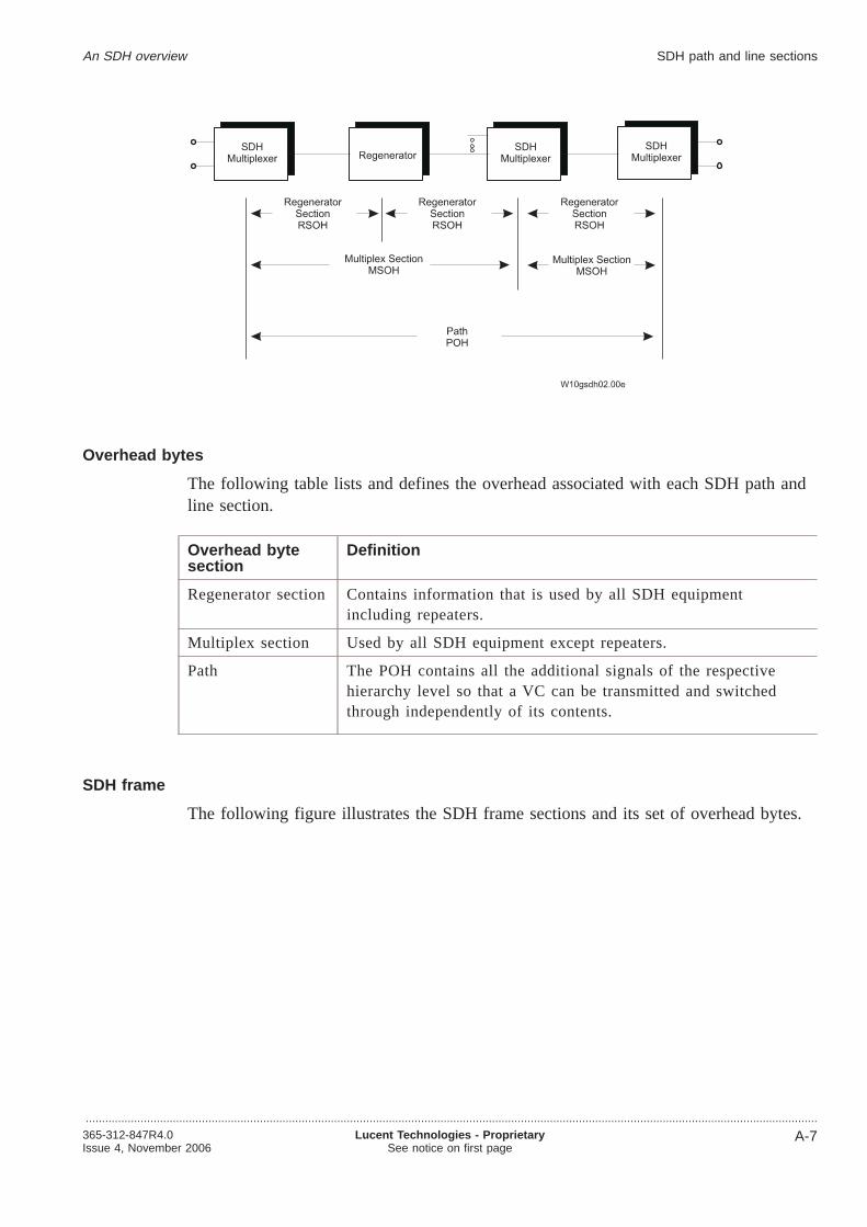
Overhead bytes
The following table lists and defines the overhead associated with each SDH path andline section.
Overhead bytesection
Definition
Regenerator section Contains information that is used by all SDH equipmentincluding repeaters.
Multiplex section Used by all SDH equipment except repeaters.
Path The POH contains all the additional signals of the respectivehierarchy level so that a VC can be transmitted and switchedthrough independently of its contents.
SDH frame
The following figure illustrates the SDH frame sections and its set of overhead bytes.
An SDH overview SDH path and line sections
...................................................................................................................................................................................................................................365-312-847R4.0Issue 4, November 2006
Lucent Technologies - ProprietarySee notice on first page
A-7
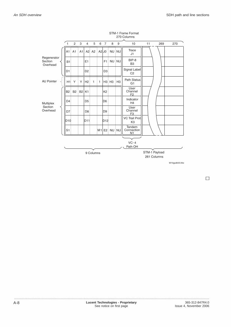
An SDH overview SDH path and line sections
...................................................................................................................................................................................................................................
A-8 Lucent Technologies - ProprietarySee notice on first page
365-312-847R4.0Issue 4, November 2006

SDH frame structure...................................................................................................................................................................................................................................
This section provides detailed information on the locations and functions of variousoverhead bytes for each of the following SDH path and line sections:
• Regenerator Section
• Multiplex Section
• Path
Section overhead
The following table identifies the location and function of each regenerator sectionoverhead byte.
Bytes Function
A1, A2 Frame alignment A1 =1111 0110 ; A2 =0010 1000 ; Thesefixed-value bytes are used for synchronization.
B1 BIP-8 parity test
Regenerator section error monitoring; BIP-8 :
Computed over all bits of the previous frame after scrambling; B1 isplaced into the SOH before scrambling;
BIP-X: (Bit Interleaved Parity X bits) Even parity, X-bit code;
first bit of code = even parity over first bit of all X-bit sequences;
B2 Multiplex section error monitoring; BIP-24 :
B2 is computed over all bits of the previous STM-1 frame except forrow 1 to 3 of the SOH (RSOH); B2 is computed after and placedbefore scrambling;
Z0 Spare bytes
D1 - D3 (=DCCR) D4 -D12 (= DCCM)
Data Communication Channel (network management informationexchange)
E1 Orderwire channel
E2 Orderwire channel
F1 User channel
K1, K2 Automatic protection switch
K2 MS-AIS/RDI indicator
S1 Synchronization Status Message
M1 REI (Remote Error Indication) byte
NU National Usage
An SDH overview
...................................................................................................................................................................................................................................365-312-847R4.0Issue 4, November 2006
Lucent Technologies - ProprietarySee notice on first page
A-9
Path overhead
The Path Overhead (POH) is generated for all plesiochronous tributary signals inaccordance with ITU-T Rec. G.709. The POH provides for integrity of communicationbetween the point of assembly of a Virtual Container VC and its point of disassembly.The following table shows the POH bytes and their functions.
Byte Location and Function
J1 Path Trace Identifier byte
B3 Path Bit Interleaved Parity (BIP-8)
Provides each path performance monitoring. This byte is calculatedover all bits of the previous payload before scrambling.
C2 Signal Label
All ″0″ means unequipped; other and″00000001″ means equipped
G1 Path Status
Conveys the STM-1 path terminating status, performance, and remotedefect indication (RDI) signal conditions back to an originating pathterminating equipment.
F2, F3 User Data Channel
Reserved for user communication.
H4 Multiframe Indicator
Provides a general multiframe indicator for VC-structured payloads.
K3 VC Trail protection.
N1 Tandem connection OH
AU pointer
The AU pointer together with the last 261 columns of the STM-1 frame forms an AUG(Administrative Unit Group). An AUG may contain one AU-4 or threebyte-multiplexed AU-3s (an AU-3 is exactly one third of the size of an AU-4). AU-3sare also compatible with the SONET standard (Synchronous Optical NETwork) whichis the predecessor of SDH (and still the prevailing technology within the USA). Threebyte-multiplexed STS frames (SONET frame), each containing one AU-3 can bemapped into one STM-1.
An SDH overview SDH frame structure
...................................................................................................................................................................................................................................
A-10 Lucent Technologies - ProprietarySee notice on first page
365-312-847R4.0Issue 4, November 2006

SDH digital multiplexing...................................................................................................................................................................................................................................
Digital multiplexing is SDH’s method of byte mapping tributary signals to a highersignal rate, which permits economical extraction of a single tributary signal without theneed to demultiplex the entire STM-1 payload. In addition, SDH provides overheadchannels for use by OAM&P groups.
SDH digital multiplexing
The following figure illustrates the SDH technique of mapping tributary signals intothe STM frames.
Transporting SDH payloads
Tributary signals are mapped into a digital signal called a virtual container (VC). TheVC is a structure designed for the transport and switching of STM payloads. There arevarious sizes of VCs: VC-11, VC-12, VC-2, VC-3, VC-4, VC-4-4C, VC-4-16C,VC-4-64C and VC-4-256C.
C-11
C-12
C-2
C-3STM-0
C-4
C-4-4C
C-4-16C
C-4-64C
C-4-256C
STM-1
STM-4
STM-16
STM-64
STM-256
VC-11
VC-12
VC-2
VC-3
VC-3
Pointer processing
Multiplexing
Aligning
Mapping
AU-3
…
VC-4
VC-4-4C
VC-4-16C
VC-4-64C
VC-4-256C
AU-4
AU-4-4C
AU-4-16C
AU-4-64C
AU-4-256C
TU-11
1
1
1
1
1
1
1
1
1
1
1
1
1
3
3
3
4
4
4
4
4
7
7
TU-12
TU-2
TU-3
TUG-2
TUG-3
AUG-1
AUG-4
AUG-16
AUG-64
AUG-256
An SDH overview
...................................................................................................................................................................................................................................365-312-847R4.0Issue 4, November 2006
Lucent Technologies - ProprietarySee notice on first page
A-11
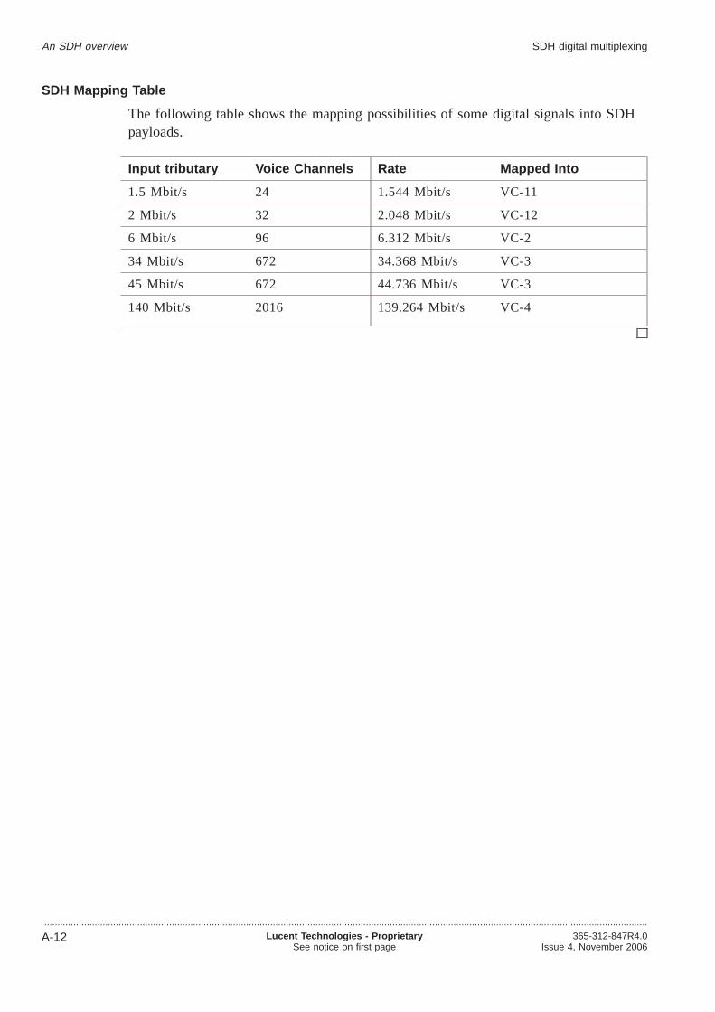
SDH Mapping Table
The following table shows the mapping possibilities of some digital signals into SDHpayloads.
Input tributary Voice Channels Rate Mapped Into
1.5 Mbit/s 24 1.544 Mbit/s VC-11
2 Mbit/s 32 2.048 Mbit/s VC-12
6 Mbit/s 96 6.312 Mbit/s VC-2
34 Mbit/s 672 34.368 Mbit/s VC-3
45 Mbit/s 672 44.736 Mbit/s VC-3
140 Mbit/s 2016 139.264 Mbit/s VC-4
An SDH overview SDH digital multiplexing
...................................................................................................................................................................................................................................
A-12 Lucent Technologies - ProprietarySee notice on first page
365-312-847R4.0Issue 4, November 2006
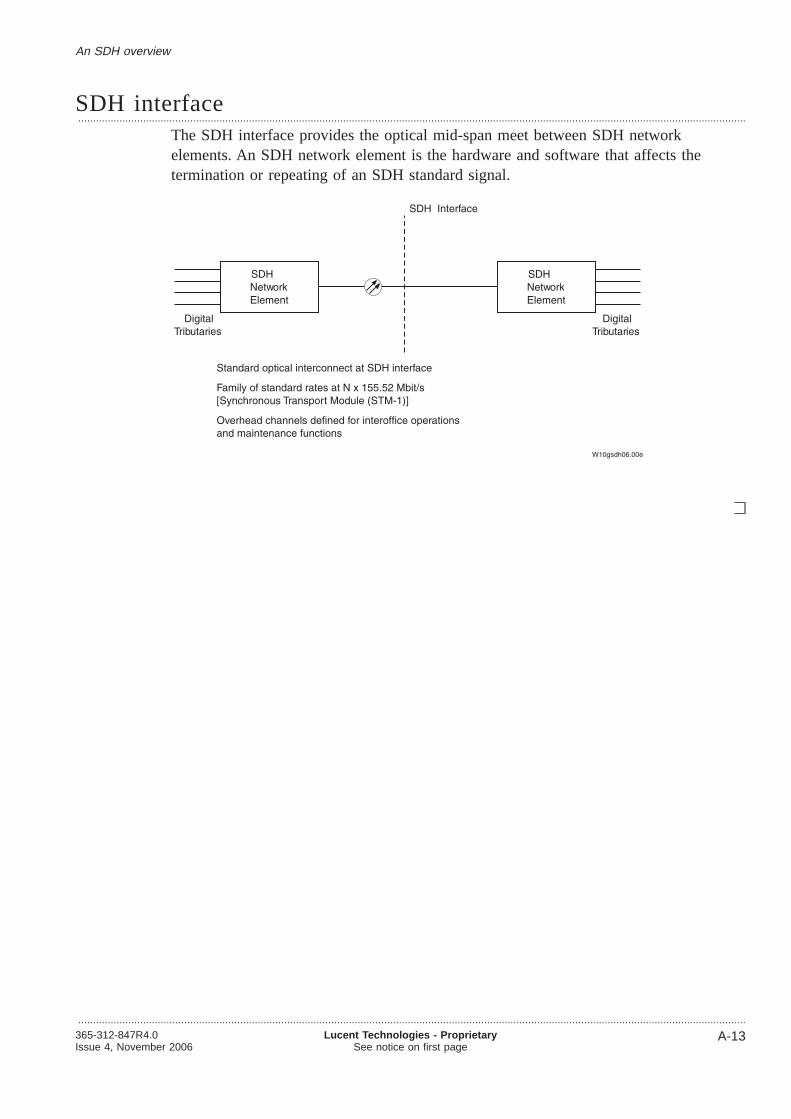
SDH interface...................................................................................................................................................................................................................................
The SDH interface provides the optical mid-span meet between SDH networkelements. An SDH network element is the hardware and software that affects thetermination or repeating of an SDH standard signal.
An SDH overview
...................................................................................................................................................................................................................................365-312-847R4.0Issue 4, November 2006
Lucent Technologies - ProprietarySee notice on first page
A-13

SDH multiplexing process...................................................................................................................................................................................................................................
SDH provides for multiplexing of 2-Mbit/s (C-12) and 34-Mbit/s (C-3) signals into anSTM-1 frame.
Furthermore, multiplexing paths also exist for the SONET specific 1.5-Mbit/s, 6-Mbit/sand 45-Mbit/s signals.
Process
The following describes the process for multiplexing a 2-Mbit/s signal. The“SDHdigital multiplexing” (p. A-11)illustrates the multiplexing process.
...................................................................................................................................................................................................
1 Input 2-Mbit/s tributary is mapped
• Each VC-12 carries a single 2-Mbit/s payload.
• The VC-12 is aligned into a Tributary Unit TU-2 using a TU pointer.
• Three TU-2 are then multiplexed into a Tributary Unit Group TUG-2.
• Seven TUG-2 are multiplexed into an TUG-3.
• Three TUG-3 are multiplexed into an VC-4.
• The VC-4 is aligned into an Administrative Unit AU-4 using a AU pointer.
• The AU-4 is mapped into an AUG which is then mapped into an STM-1 frame.
...................................................................................................................................................................................................
2 After VCs are multiplexed into the STM-1 payload, the section overhead is added.
...................................................................................................................................................................................................
3 Scrambled STM-1 signal is transported to the optical stage.
An SDH overview
...................................................................................................................................................................................................................................
A-14 Lucent Technologies - ProprietarySee notice on first page
365-312-847R4.0Issue 4, November 2006

SDH demultiplexing process...................................................................................................................................................................................................................................
Demultiplexing is the inverse of multiplexing. This topic describes how to demultiplexa signal.
Process
The following describes the process for demultiplexing an STM-1 signal to a 2 Mbit/ssignal. The“SDH digital multiplexing” (p. A-11)illustrates the demultiplexing process.
...................................................................................................................................................................................................
1 The unscrambled STM-1 signal from the optical conversion stages is processed toextract the path overhead and accurately locate the payload.
...................................................................................................................................................................................................
2 The STM-1 path overhead is processed to locate the VCs. The individual VCs are thenprocessed to extract VC overhead and, via the VC pointer, accurately locate the2-Mbit/s signal.
...................................................................................................................................................................................................
3 The 2-Mbit/s signal is desynchronized, providing a standard 2-Mbit/s signal to theasynchronous network.
Key points
SDH STM pointers are used to locate the payload relative to the transport overhead.
Remember the following key points about signal demultiplexing:
• The SDH frame is a fixed time (125 µs) and no bit-stuffing is used.
• The synchronous payload can float within the frame. This is to permitcompensation for small variations in frequency between the clocks of the twosystems that may occur if the systems are independently timed (plesiochronoustiming).
An SDH overview
...................................................................................................................................................................................................................................365-312-847R4.0Issue 4, November 2006
Lucent Technologies - ProprietarySee notice on first page
A-15
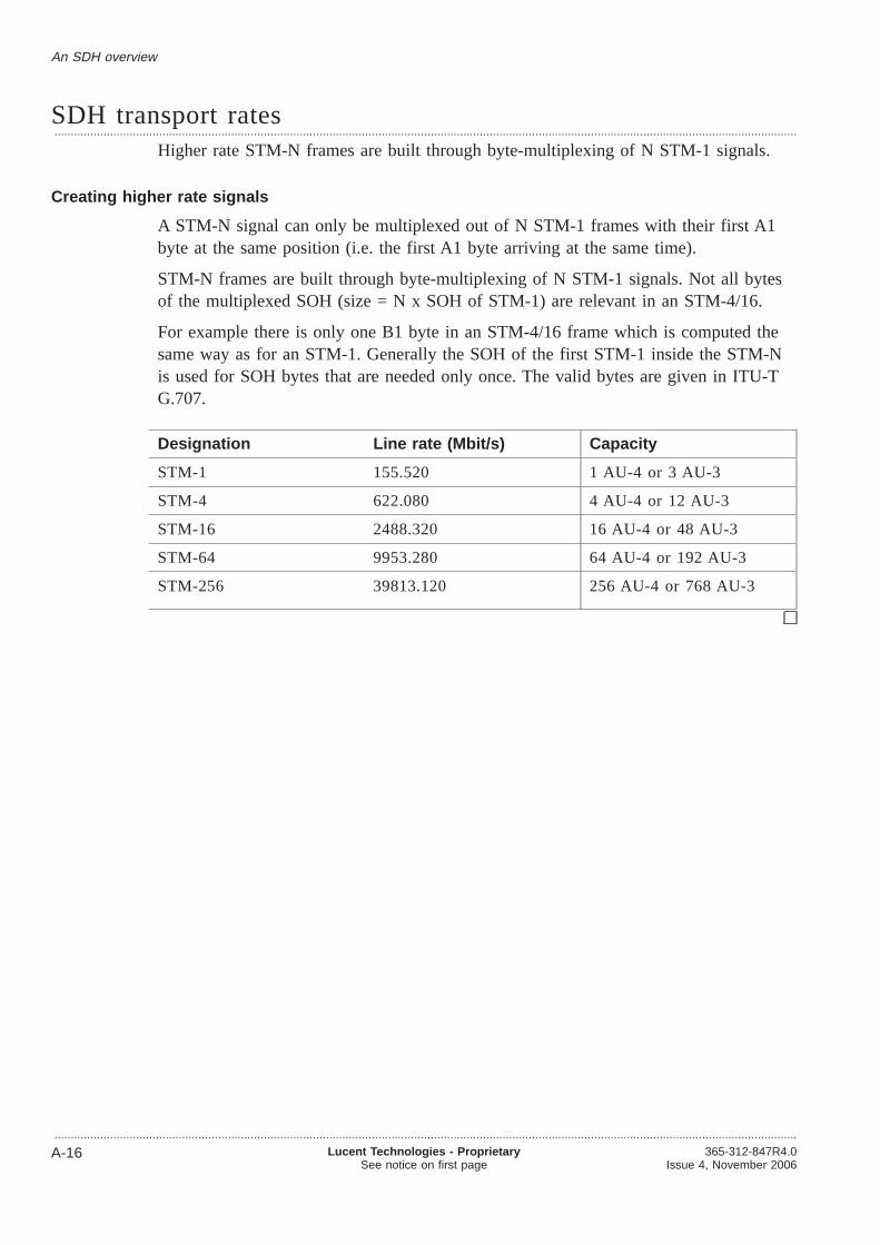
SDH transport rates...................................................................................................................................................................................................................................
Higher rate STM-N frames are built through byte-multiplexing of N STM-1 signals.
Creating higher rate signals
A STM-N signal can only be multiplexed out of N STM-1 frames with their first A1byte at the same position (i.e. the first A1 byte arriving at the same time).
STM-N frames are built through byte-multiplexing of N STM-1 signals. Not all bytesof the multiplexed SOH (size= N x SOH of STM-1) are relevant in an STM-4/16.
For example there is only one B1 byte in an STM-4/16 frame which is computed thesame way as for an STM-1. Generally the SOH of the first STM-1 inside the STM-Nis used for SOH bytes that are needed only once. The valid bytes are given in ITU-TG.707.
Designation Line rate (Mbit/s) Capacity
STM-1 155.520 1 AU-4 or 3 AU-3
STM-4 622.080 4 AU-4 or 12 AU-3
STM-16 2488.320 16 AU-4 or 48 AU-3
STM-64 9953.280 64 AU-4 or 192 AU-3
STM-256 39813.120 256 AU-4 or 768 AU-3
An SDH overview
...................................................................................................................................................................................................................................
A-16 Lucent Technologies - ProprietarySee notice on first page
365-312-847R4.0Issue 4, November 2006
Glossary
....................................................................................................................................................................................................................................
A ACAlternating Current
ACUAlarm Collection Unit. Radio Relay circuit pack that collects of equipment alarms,analogue measurements from internal monitoring points and calculation data.
ADMAdd-Drop Multiplexer
Administrative Unit (AU)Carrier for TUs
Administrative-Unit Pointer (AU PTR)Indicates the phase alignment of the VC-n with respect to the STM-N frame. The pointerposition is fixed with respect to the STM-N frame.
AdministratorLucent NMS Administrator.
AgentPerforms operations on managed objects and issues events on behalf of these managedobjects. All SDH managed objects will support at least one agent. Control of distantagents is possible via local “Managers”.
AlarmThe notification (audible or visual) of a significant event. See also Event.
Alarm Indication Signal (AIS)Code transmitted downstream in a digital Network that shows that an upstream failurehas been detected and also alarmed if the upstream alarm has not been suppressed. Alsocalled to as All OneS.
Alarm SeverityAn attribute that defines the priority of the alarm message. The way in which alarms areprocessed depends on the severity.
....................................................................................................................................................................................................................................365-312-847R4.0Issue 4, November 2006
Lucent Technologies - ProprietarySee notice on first page
GL-1

AligningUsing a pointer to indicate the head of a virtual container, e.g. to create anAdministrative Unit (AU) or a Tributary Unit (TU).
ALSAutomatic Laser Shutdown
Alternate Mark Inversion (AMI)A line code that employs a ternary signal to convert binary digits. In this line codesuccessive binary ones are represented by signal elements that are normally ofalternately positive and negative polarity but are equal in amplitude, binary zeros arerepresented by signal elements that have zero amplitude.
American Standard Code for Information Interchange (ASCII)A standard 8-bit code that is used to exchange information among data processingsystems and associated equipment.
AnomalyA difference between the actual and the desired operation of a function.
ANSIAmerican National Standards Institute
APSAutomatic Protection Switching
ASAlarm Suppression assembly
AssemblyGathering together of payload data with overhead and pointer information (an indicationof the direction of the signal).
AssociationA logical connection between manager and agent through which management informationcan be exchanged.
AsynchronousSee Non-synchronous.
ATCAuxiliary Transmission Channel
ATMAsynchronous Transfer Mode
AUAdministrative Unit
AU4ADAdministrative Unit 4 Assembler/Disassembler
Glossary
...................................................................................................................................................................................................................................
GL-2 Lucent Technologies - ProprietarySee notice on first page
365-312-847R4.0Issue 4, November 2006

AUGAdministrative Unit Group
Automatic Transmit Power Control (ATPC)Reduces the power output from the transmitter during normal propagation conditions andincreases the power output to maximum during fading periods to try to maintain thenominal level of receiver input.
Autonomous MessageA message transmitted from the controlled network element to the Lucent NMS that wasnot a response to a command that originated in the Lucent NMS.
....................................................................................................................................................................................................................................
B B3ZSBipolar 3-Zero Substitution
B8ZSBipolar 8-Zero Substitution
BBTRBackplane Bus Transceiver
BCBoard Controller
BCCBoard Controller Complex
BINBINary
BISDNBroadband Integrated Services Digital Network
Bit Error Ratio (BER)The ratio of bits received in error to bits sent.
Bit Interleaved Parity (BIP)A method of error monitoring that uses a specified number of bits (BIP-8)
BLD OUT LGBuild-Out Lightguide
Board Controller Local Area Network (BC-LAN)The internal local area network that provides communications between the LineController circuit pack and board controllers on the circuit packs that are associated witha high-speed line.
BranchingInterconnection of independent line systems.
Glossary
...................................................................................................................................................................................................................................365-312-847R4.0Issue 4, November 2006
Lucent Technologies - ProprietarySee notice on first page
GL-3
Broadband CommunicationVoice, data, and/or video communication at greater than 2 Mbit/s rates.
Broadband Service TransportSTM-1 concatenation transport over the SLM for ATM applications.
BUSTRBUS Transmitter and Receiver
....................................................................................................................................................................................................................................
C CASChannel Associated Signaling
CCCross-Connection, Cross-Connect
CCIRSee ITU-R.
CCITTSee ITU-T.
CCSCommon Channel Signaling
CEPTConférence Européenne des Administrations des Postes et des Télécommunications
ChannelA sub-unit of transmission capacity within a defined higher level of transmissioncapacity, e.g. a CEPT-4 (140 Mbit/s) within a 565 Mbit/s fiber system.
CIRCommitted Information Rate
CircuitA combination of two transmission channels that permits bidirectional transmission ofsignals between two points to support a single communication.
CITCraft Interface Terminal
Clear Channel (Cl. Ch.)A provisionable mode for the 34 and 140 Mbit/s tributary outputs that causes parityviolations not to be monitored or corrected before the 34 and 140 Mbit/s outputs areencoded.
ClientComputer in a computer network that generally offers a user interface to a server. Seealso Server.
Glossary
...................................................................................................................................................................................................................................
GL-4 Lucent Technologies - ProprietarySee notice on first page
365-312-847R4.0Issue 4, November 2006
CMICoded Mark Inversion
COCentral Office
Co-residentA hardware configuration where two Network Management Systems can beindependently active at the same time on the same hardware and software platformwithout interfering with each other’s functioning.
ConcatenationA procedure whereby a multiplicity of Virtual Containers are associated with each otherwith the result that their combined capacity can be used as a single container acrosswhich bit-sequence integrity is maintained.
Configuration Management (CM)Subsystem of the Lucent NMS that, among other things, configures the network andprocesses messages from the network.
CONN PCBConnector Printed Circuit Board
Container (C)Carries plesiochronous signal, the “payload”.
CPCircuit Pack
Craft Interface Terminal (CIT)Local manager for SDH network elements.
CRCCyclic Redundancy Check
Cross-Connect MapConnection map for an SDH network element; contains information about how signalsare connected between high speed time slots and low speed tributaries. See also SquelchMap.
CTPConnection Termination Point
....................................................................................................................................................................................................................................
D DACScan-TSee Integrated Transport Management Network Manager.
Data Communication Channel (DCC)The embedded overhead communication channel in the SDH line. The DCC is used forend-to-end communication and maintenance. It carries alarm, control, and statusinformation between network elements in an SDH network.
Glossary
...................................................................................................................................................................................................................................365-312-847R4.0Issue 4, November 2006
Lucent Technologies - ProprietarySee notice on first page
GL-5
Data Communication Equipment (DCE)Provides the signal conversion and coding between the data terminating equipment andthe line. The DCE may be separate equipment or a part of the data terminatingequipment.
Data Terminating Equipment (DTE)Originates data for transmission and accepts transmitted data.
Database AdministratorA user who administers the database of the Lucent NMS. See also User Privilege.
DCDirect Current
DCFData Communications Function
DCNData Communications Network
DCSDigital Cross-connect System
DDFDigital Distribution Frame
Dedicated Protection Ring (DP-Ring)A protection method used in some network elements.
Default Value ProvisioningThe original values are preprogrammed at the factory. These values can be overriddenusing local or remote provisioning.
DefectA limited interruption of the ability of an item to perform a required function. Thedefect may or may not lead to maintenance action this depends on the results ofadditional analysis.
DemultiplexingA process applied to a multiplexed signal to recover signals combined within it andrestore the distinct individual channels of these signals.
Digital LinkA transmission span such as a point-to-point 2 Mbit/s, 34 Mbit/s, 140 Mbit/s, VC12,VC3 or VC4 link between controlled network elements. The channels within a digitallink are insignificant.
Digital SectionA transmission span such as an STM-N or 565 Mbit/s signal. A digital section maycontain multiple digital channels.
Glossary
...................................................................................................................................................................................................................................
GL-6 Lucent Technologies - ProprietarySee notice on first page
365-312-847R4.0Issue 4, November 2006
Directory-Service Network Element (DSNE)A designated network element that is responsible for administering a database that mapsnetwork element names (node names) to addresses (node Id). There can be one DSNEper (sub)network.
DisassemblySplitting up of a signal into its constituents as payload data and overhead (an indicationof the direction of a signal).
DomainThe domain of a Lucent NMS is the set of all SDH network elements that are controlledby it.
DownstreamAt or towards the destination of the considered transmission stream, i.e. in the directionof transmission.
DPSData communication Packet Switch
DRIDual-Ring Interworking
DS-nDigital Signal, Level n
DSLDigital Subscriber Line
DTMFDual-Tone Multi-Frequency
Dual HomingAn STM-1/STM-4 ring with AM-1 Plus equipment can be dual homed on a ringconsisting ofMetropolis® AMU, Metropolis® ADM (Compact shelf) orWaveStar® ADM16/1. STM-16 rings can also be dual homed with theMetropolis® AMU.
Dual-Node InterworkingDual Node Interworking (DNI) is a configuration of two ring networks that share twocommon nodes. DNI allows a circuit with one termination in one ring and onetermination in another ring to survive a loss-of-signal failure of the shared node that iscurrently carrying service for the circuit.
DUSDo not Use for Synchronization
DWDMDense-Wavelength Division Multiplexing
Glossary
...................................................................................................................................................................................................................................365-312-847R4.0Issue 4, November 2006
Lucent Technologies - ProprietarySee notice on first page
GL-7

....................................................................................................................................................................................................................................
E EC-nElectrical Carrier, Level n
ECCEmbedded Control Channel
ECIEquipment Code Identifier
EDFEEthernet Dropped Frames Errors
EH&SEnvironmental Health and Safety
EINBEthernet Incoming Number of Mbytes
Element Management System (EMS)See Integrated Transport Management Subnetwork Controller.
EMCElectroMagnetic Compatibility
EMIElectroMagnetic Interference
EONBEthernet Outgoing Number of Mbytes
EOWEngineering Order Wire
Equivalent Bit Error Ratio (EBER)The calculated average bit error rate over a data stream.
Errored Second (ES)A performance monitoring parameter.
ESEnd System
ESDElectroStatic Discharge
ESPGElastic Store & Pointer Generator
ETSIEuropean Telecommunication Standardisation Institute
Glossary
...................................................................................................................................................................................................................................
GL-8 Lucent Technologies - ProprietarySee notice on first page
365-312-847R4.0Issue 4, November 2006

EventA significant change. Events in controlled network elements include signal failures,equipment failures, signals exceeding thresholds, and protection switch activity. When anevent occurs in a controlled network element, the controlled network element willgenerate an alarm or status message and send it to the Lucent NMS.
Event Management (EM)Subsystem of the Lucent NMS that processes and logs network event reports.
Externally TimedAn operating condition of a clock in which it is locked to an external reference and usestime constants that are altered to quickly bring the local oscillator’s frequency intoapproximate agreement with the synchronization reference frequency.
Extra TrafficUnprotected traffic that is carried over the protection channels when that capacity is notused for the protection of service traffic.
....................................................................................................................................................................................................................................
F Far End Block Error (FEBE)An indication returned to the transmitting node that an errored block has been detectedat the receiving node. A block is a specified grouping of bits.
Far End Receive Failure (FERF)An indication returned to a transmitting network element that the receiving networkelement has detected an incoming section failure.
FASFrame Alignment Signal
FAWFrame Alignment Word
FCFull contact Connector
FCCFederal Communications Commission
FDDIFiber Distributed Data Interface
FEPFront End Processor
Free RunningAn operating condition of a network element in which its local oscillator is not lockedto any synchronization reference and uses no storage techniques to sustain its accuracy.
Glossary
...................................................................................................................................................................................................................................365-312-847R4.0Issue 4, November 2006
Lucent Technologies - ProprietarySee notice on first page
GL-9

....................................................................................................................................................................................................................................
G GARPGeneric Attribute Registration Protocol
Gateway Network Element (GNE)Passes information between other network elements and management systems via a DataCommunications Network.
Gbit/sGigabits per second
Geographic LocationLocation of the Lucent NMS server. The geographic location is entered as part of theinstallation procedure of an NMS.
Geographic Redundancy (GR)Allows protection of management for a network element by assigning the networkelement to two OMSs. The first primary OMS usually manages the Network Elementand is now in the protected domain. If the primary OMS or the link between the networkelement and the primary OMS fails, the secondary OMS will automatically take overmanagement of the network element and is now in the protecting domain. The twoOMSs are connected by a peer to peer link, which they use to pass GeographicRedundancy management information to each other. This link must be established beforeany network element can be protected by Geographic Redundancy.
GFPGeneric Framing Procedure
Global Wait to Restore TimeThe time to wait before switching back to the timing reference occurs after a timing linkfailure has cleared. This time applies for all timing sources in a system hence the nameglobal. This can be between 0 and 60 minutes, in increments of one minute.
GNEGateway network element - A network element that passes information between othernetwork elements and operations systems via a data communications network.
GUIGraphical User Interface
GVRPGARP VLAN Registration Protocol (refer to“GARP” (p. GL-10))
....................................................................................................................................................................................................................................
H HEHost Exchange
High Density Bipolar 3 code (HDB3)Line code for e.g. 2 Mbit/s transmission systems.
Glossary
...................................................................................................................................................................................................................................
GL-10 Lucent Technologies - ProprietarySee notice on first page
365-312-847R4.0Issue 4, November 2006

High level Data Link Control (HDLC)Protocol in the data-link layer of the OSI reference model.
Higher order Path Adaptation (HPA)Function that adapts a lower order Virtual Container to a higher order Virtual Containerby processing the Tributary Unit pointer which indicates the phase of the lower orderVirtual Container Path Overhead relative to the higher order Virtual-Container PathOverhead, and assembling/disassembling the complete higher order Virtual Container.
Higher order Path Connection (HPC)Function that provides for flexible assignment of higher order Virtual Containers withinan STM-N signal.
Higher order Path Termination (HPT)Function that terminates a higher order path by generating and adding the appropriateVirtual-Container Path Overhead to the relevant container at the path source andremoving the Virtual-Container Path Overhead and reading it at the path sink.
HMIHuman Machine Interface
HOHigh Order
HoldoverAn operating condition of a clock in which its local oscillator is not locked to anexternal reference but uses storage techniques to maintain its accuracy with respect tothe last known frequency comparison with a synchronized reference.
Host NameName of the server on which the NMS is running.
HSHigh Speed
....................................................................................................................................................................................................................................
I I/OInput/Output
ICBInterconnection Box
ICPInterConnection Panel
IECInternational Electrotechnical Committee
IEEEInstitute of Electrical and Electronic Engineers
Glossary
...................................................................................................................................................................................................................................365-312-847R4.0Issue 4, November 2006
Lucent Technologies - ProprietarySee notice on first page
GL-11
IFIntermediate Frequency
IFTInterFace Terminal
Integrated Transport Management Craft Interface Terminal (ITM-CIT)Local manager for SDH network elements in a subnetwork. Also called the to as CraftInterface Terminal.
Intermediate System (IS)A system that routes/relays management information. An SDH network element may be acombined Intermediate and end system.
IPSInter Processor Status
ISIn-Service
IS-IS RoutingThe network elements in a management network, route packets (data) between each otherusing an IS-IS level protocol. The size of a network that is running IS-IS Level 1 islimited, and therefore certain mechanisms are employed to facilitate the management oflarger networks. For STATIC ROUTING, it is possible to disable the protocol over theLAN connections and thereby effectively cause the management network to bepartitioned into separate IS-IS Level 1 areas. In order for the NMS to communicate witha specific network element in one of these areas, the NMS must identify the Gatewaynetwork element through which this specific network element is connected to the LAN.All packets to this specific network element are routed directly to the Gateway networkelement by the NMS, before being re-routed (if necessary) within the Level 1 area. ForDYNAMIC ROUTING an IS-IS Level 2 routing protocol is used that allows a number ofLevel 1 areas to interwork. The network elements that connect an IS-IS area to anotherarea are set to run the IS-IS Level 2 protocol within the network element and on theconnection to other network elements. Packets can now be routed between IS-IS areasand the NMS does not have to identify the Gateway network elements.
ISDNIntegrated Services Digital Network
ISOInternational Standards Organisation
ITUInternational Telecommunications Union
ITU-RInternational Telecommunications Union - Radio standardization sector. Formerly knownas CCIR: Comité Consultatif International Radio; International Radio ConsultativeCommittee.
Glossary
...................................................................................................................................................................................................................................
GL-12 Lucent Technologies - ProprietarySee notice on first page
365-312-847R4.0Issue 4, November 2006
ITU-TInternational Telecommunications Union - Telecommunication standardization sector.Formerly known as CCITT: Comité Consultatif International Télégraphique &Téléphonique; International Telegraph and Telephone Consultative Committee.
....................................................................................................................................................................................................................................
J JitterShort term variations of amplitude and frequency components of a digital signal fromtheir ideal position in time.
....................................................................................................................................................................................................................................
L LANLocal Area Network
LBALightwave Booster Amplifier.
LBOLine Build Out - An optical attenuator that guarantees the proper signal level and shapeat the receiver input.
LCASLink Capacity Adjustment Scheme
LCNLocal Communications Network
LDILinear Drop/Insert (Add-Drop)
LEDLight Emitting Diode
LENLocal Exchange Node
LFLow Frequency
LHLong Haul
License keyAn encrypted code that is required to enable the use of specific modules in the NMS.Valid license keys can be obtained from your provider.
LineTransmission line; refers to a transmission medium, together with the associated highspeed equipment, that are required transport information between two consecutivenetwork elements, one of which originates the line signal and the other terminates theline signal.
Glossary
...................................................................................................................................................................................................................................365-312-847R4.0Issue 4, November 2006
Lucent Technologies - ProprietarySee notice on first page
GL-13
Line Build Out (LBO)An optical attenuator that guarantees the proper signal level and shape at the receiverinput.
Link Pass Through (LPT)The LPT mode is used to enable or improve network protection schemes on equipmentwhich is external to TransLAN® systems.
LNCLiNe Controller (SLM)
LOLow Order
LOFLoss Of Frame
LOMLoss Of Multiframe
Loop TimingA timing mode in which the terminal derives its transmit timing from the received linesignal.
LOPLoss Of Pointer
LOSLoss Of Signal
Lower order Path Adaptation (LPA)Function that adapts a PDH signal to a synchronous network by mapping the signal intoor de-mapping the signal out of a synchronous container.
Lower order Path Connection (LPC)Function that provides for flexible assignment of lower order VCs in a higher order VC.
Lower order Path Termination (LPT)Function that terminates a lower order path by generating and adding the appropriate VCPOH to the relevant container at the path source and removing the VC POH and readingit at the path sink.
LPULine Port Unit
LRXLine Receiver
LSLow Speed
Glossary
...................................................................................................................................................................................................................................
GL-14 Lucent Technologies - ProprietarySee notice on first page
365-312-847R4.0Issue 4, November 2006
LTALine Terminal Application
LTULine Termination Unit
LTXLine Transmitter
....................................................................................................................................................................................................................................
M MAFManagement Application Function
Management ConnectionIdentifies the type of routing used (STATIC or DYNAMIC). If STATIC is selected,Management Connection allows the gateway network element to be identified. See alsoIS-IS Routing.
Management Information Base (MIB)The Management Information Base is the database in the node. The MIB contains theconfiguration data of the node. A copy of each MIB is available in the EMS and iscalled the MIB image. Under normal circumstances, the MIB and MIB image of onenode are synchronized.
ManagerCapable of issuing network management operations and receiving events. The Managercommunicates with the Agent in the controlled network element.
Manufacturer Executable Code (MEC)Network element system software in binary format that is downloaded to one of thestores can be executed by the system controller of the network element.
MappingGathering together of payload data with overhead, i.e. packing the PDH signal into aVirtual Container.
MDIMiscellaneous Discrete Input
MDOMiscellaneous Discrete Output
Mediation Device (MD)Allows for exchange of management information between Operations System andnetwork elements.
MEFMaintenance Entity Function (in NE)
MEMSystem MEMory unit
Glossary
...................................................................................................................................................................................................................................365-312-847R4.0Issue 4, November 2006
Lucent Technologies - ProprietarySee notice on first page
GL-15
Message Communications Function (MCF)Function that provides facilities for the transport and routing of TelecommunicationsManagement Network messages to and from the Network Manager.
MFMediation Function
MFSMulti Frame Synchronization signal
MIB imageSee Management Information Base.
Midspan MeetThe capability to interface between two lightwave network elements of different vendors.This applies to high speed optical interfaces.
MLANMultiLAN
MMIMan-Machine Interface Also called Human Machine Interface (HMI)
MOManaged Object
MotifX-Windows System supplied by Open Software Foundation.
MSMultiplexer Section
MSOHMultiplex Section Overhead. Part of the SOH (Section Overhead). Is accessible only atline terminals and multiplexers.
MSPMultiplex Section Protection. Provides capability of switching a signal from a workingto a protection section.
MTBFMean Time Between Failures
MTBMAMean Time Between Maintenance Activities
MTIEMaximum Time Interval Error
MTPIMultiplexer Timing Physical Interface
Glossary
...................................................................................................................................................................................................................................
GL-16 Lucent Technologies - ProprietarySee notice on first page
365-312-847R4.0Issue 4, November 2006
MTTRMean Time To Repair
Multiplexer Section OverHead (MSOH)Part of the Section Overhead. Is accessible only at line terminals and multiplexers.
Multiplexer Section Protection (MSP)Provides capability of switching a signal from a working to a protection section.
Multiplexer Section Shared Protection Ring (MS-SPRING)A protection method used in multiplex line systems.
Multiplexer Section Termination (MST)Function that generates the Multiplexer Section Overhead in the transmit direction andterminates the Multiplexer Section Overhead in the receive direction.
Multiplexer Timing Source (MTS)Function that provides the timing reference to the relevant component parts of themultiplex equipment and represents the SDH network element clock.
MultiplexingA procedure by which multiple lower order path layer signals are adapted into a higherorder path, or by which the multiple higher order path layer signals are adapted into amultiplex section.
....................................................................................................................................................................................................................................
N NENetwork element. The NE is comprised of telecommunication equipment (or groups/partsof telecommunication equipment) and support equipment that performs network elementfunctions. A Network Element has one or more standard Q-type interfaces.
NEFNetwork element function
NEMNetwork element manager
Network Element (NE)A network element is comprised of telecommunication equipment (or groups/parts oftelecommunication equipment) and support equipment that performs network elementfunctions. A Network Element has one or more standard Q-type interfaces. A networkelement ican be directly managed by a management system. See also Node.
Network Element Equivalent (NEE)The functionality, database size and processing power that are required from the NMSare different for each type of network element that is supported. Therefore each typerepresents a certain amount of Network Element Equivalent.
Network Mediation Unit (NMU)Collects fault and alarm events from transmission equipment. The NMS can forwardalarms to the NMU. The NMU can forward alarms to an Operations System.
Glossary
...................................................................................................................................................................................................................................365-312-847R4.0Issue 4, November 2006
Lucent Technologies - ProprietarySee notice on first page
GL-17

Network Service Access Point (NSAP)An end system address of the System Controller according to ISO 8348 AD2. Theformat is ISO_DCC_LUCENT, which has the following structure:
NMCNetwork Maintenance Center
NMSNetwork Management System
NNENon-SDH network element
NNINetwork Node Interface
NodeA node or network element is defined as all equipment that is controlled by one systemcontroller.
NodeDefined as all equipment that is controlled by one system controller. A node can notalways be directly managed by a management system. See also network element.
NOMCNetwork Operation Maintenance Channel
Non-revertive switchingIn non-revertive switching, there is an active and standby high-speed line, circuit pack,etc. When a protection switch occurs, the standby line, circuit pack, etc., is selectedcausing the old standby line, circuit pack, etc., to be used for the new active line, circuitpack, etc. The original active line, circuit pack, etc., becomes the standby line, circuitpack, etc. This status remains in effect when the fault clears. Therefore, this protectionscheme is “non-revertive” in that there is no switch back to the original status in effectbefore the fault occurred.
Non-revertive switchingIn non-revertive switching there is an active and a standby high speed line, circuit pack,etc. When a protection switch occurs, the standby line, circuit pack, etc. is selectedwhich causes the old standby line, circuit pack, etc, to be used for the new active line,circuit pack, etc. The original active line, circuit pack, etc. becomes the standby line,circuit pack, etc. This status remains in effect when the faults clears. Therefore, thisprotection scheme is non-revertive in that there is no switch back to the original statusthat was in effect before the fault occurred.
Non-synchronousThe essential characteristic of timescales or signals such that their significant instants donot necessarily occur at the same average rate.
Glossary
...................................................................................................................................................................................................................................
GL-18 Lucent Technologies - ProprietarySee notice on first page
365-312-847R4.0Issue 4, November 2006
Not Protected DomainThe Not Protected Domain for the NMS contains all the network elements that aremanaged by that NMS and are not currently protected by another NMS. If the NMSfails, the network elements in this domain are not managed by any NMS. See alsoGeographic Redundancy.
NPINull Pointer Indication
NRZNon-Return to Zero
NSANon-Service Affecting
NTUNetwork Termination Unit
NUTNon pre-emptible Unprotected Traffic
NVMNon-Volatile Memory
....................................................................................................................................................................................................................................
O OAOptical Amplifier
OAM&POperations, Administration, Maintenance and Provisioning
OC-nOptical Carrier, Level n
ODFOptical Distribution Frame
ODUOptical Demultiplexer Unit
OFSOut of Frame Second
OIOptical Interface
OMUOptical Multiplexer Unit
OOFOut Of Frame
Glossary
...................................................................................................................................................................................................................................365-312-847R4.0Issue 4, November 2006
Lucent Technologies - ProprietarySee notice on first page
GL-19
OOSOut Of Service
Operations System (OS)The Operations System is the system that provides operations, administration andmaintenance functions.
OperatorA user of the NMS application with Operator privileges. See also User Privilege.
Optical Line System (OLS)A high-capacity lightwave system that is designed to multiplex eight optical signals withdifferent wavelengths into one combined signal through an optical fiber. There is adifference of 1.5 micrometer in wavelength between two multiplexed signals.
OSOperations System - A central computer-based system that is used to provide operations,administration and maintenance functions.
OSBOptical Splice Box
OSIOpen Systems Interconnection
OW(Engineering) Order Wire
....................................................................................................................................................................................................................................
P PABXPrivate Automatic Branch eXchange
Paddle Board - Peripheral Control and Timing link (PB-PCT)A small circuit board used in a 5ESS exchange for protection switching and optical toelectrical conversion of the PCT-link.
PathA logical connection between one termination point at which a standard format for asignal at the given rate is assembled and from which the signal is transmitted, andanother termination point at which the received standard frame format for the signal isdisassembled.
Path AISPath Alarm Indication Signal - A path-level code that is sent downstream in a digitalnetwork as an indication that an upstream failure has been detected and alarmed.
Path Overhead (POH)The Virtual-Container Path Overhead provides integrity of communication between thepoint of assembly of a Virtual Container and its point of disassembly.
Glossary
...................................................................................................................................................................................................................................
GL-20 Lucent Technologies - ProprietarySee notice on first page
365-312-847R4.0Issue 4, November 2006
Path Terminating EquipmentNetwork elements in which the path overhead is terminated.
PCPersonal Computer
PCBPrinted Circuit Board
PCMPulse Code Modulation
PCT-linkPeripheral Control and Timing-link
PDHPlesiochronous Digital Hierarchy
Peer NMSNMS at the other end of the peer-to-peer link.
Peer to Peer linkConnection between two NMSs with Geographic Redundancy. The link is used toco-ordinate the management of a network element. See also Geographic Redundancy.
Performance Monitoring (PM)Measures the quality of service and identifies degrading or marginally operating systems(before an alarm is generated).
PIPhysical Interface, Plesiochronous Interface
PIRPeak Information Rate
PJEPointer Justification Event
PlatformFamily of equipment and software configurations that are designed to support aparticular Application.
Plesiochronous NetworkA network that contains multiple subnetworks, each of which is internally synchronousand operates at the same nominal frequency, but the timing of any of the subnetworksmay be slightly different at any particular instant.
PLLPhase Lock Loop
Glossary
...................................................................................................................................................................................................................................365-312-847R4.0Issue 4, November 2006
Lucent Technologies - ProprietarySee notice on first page
GL-21
PMPerformance Monitoring - Measures the quality of service and identifies degrading ormarginally operating systems (before an alarm is generated).
PMAPerformance Monitoring Application
PointerAn indicator whose value defines the frame offset of a virtual container with respect tothe frame reference of the transport entity on which the Virtual Container is supported.
POTSPlain Old Telephone Service
PPPointer Processing
PPCPointer Processor and Cross-connect
Primary OMSNMS that is usually managing a network element. If the primary NMS fails,management of the network element is passed over to the secondary NMS. A networkelement should be provisioned normally on the primary NMS and then be configured foruse on the secondary NMS. See also Geographic Redundancy.
Primary Reference Clock (PRC)The main timing clock reference in SDH equipment.
Protected DomainThe protected domain for an NMS contains all the network elements for which thismanager is the primary NMS and which are protected by another secondary NMS. Seealso Geographic Redundancy.
Protecting DomainThe protecting domain for an NMS contains all the network elements for which thismanager is the secondary NMS. See also Geographic Redundancy.
ProtectionExtra capacity (channels, circuit packs) in transmission equipment that is not intended tobe used for service, but rather to serve as backup against equipment failures.
ProvisioningAssigning a value to a system parameter.
PSAPartially Service Affecting
PSDNPublic Switched Data Network
Glossary
...................................................................................................................................................................................................................................
GL-22 Lucent Technologies - ProprietarySee notice on first page
365-312-847R4.0Issue 4, November 2006

PSFPower Supply Filter
PSNPacket-Switched Network
PSTNPublic Switched Telephone Network
PTProtected Terminal Power-supply filter and Timing circuit pack
PVIDPort VLAN ID
....................................................................................................................................................................................................................................
Q Q-LANThin Ethernet LAN (10BaseT) that connects the manager to gateway network elementsso that management information can be exchanged between network elements andmanagement systems.
QAFQ-Adapter Function (in NE)
QOSQuality Of Service
Quality Level (QL)The quality of the timing signal(s) that are provided to clock a network element. Thelevel is provided by the Synchronization Status Marker which can accompany the timingsignal. If the System and Output Timing Quality Level mode is “Enabled”, and if thesignal selected for the Station-Clock Output has a quality level below the AcceptanceQuality Level, the network element “squelches” the Station-Clock Output Signal, whichmeans that no signal is forwarded at all. Possible levels are: - PRC (Primary ReferenceClock) - SSU_T (Synchronization Supply Unit - Transit) - SSU_L (SynchronizationSupply Unit - Local) - SEC (SDH Equipment Clock) - DUS (Do not Use forSynchronization).
....................................................................................................................................................................................................................................
R RARegenerator Application
Radio Protection Switching system (RPS)The main function of the RPS is to handle the automatic and manual switching from amain channel to a common protection channel in an N+1 system.
Radio Relay (RR)A point-to-point Digital Radio system to transport STM-1 signals via microwaves.
RCURigid Connect Unit
Glossary
...................................................................................................................................................................................................................................365-312-847R4.0Issue 4, November 2006
Lucent Technologies - ProprietarySee notice on first page
GL-23
RDDURCVR Data Distribution Unit
RDIRemote Defect Indicator. Previously known as Far End Receive Failure (FERF).
RDIRing Drop/Insert (Add-Drop)
RDSVRunning Digital Sum Violations
Receive-directionThe direction towards the cross-connect.
REGENRegenerator
Regenerator LoopLoop in a network element between the Station Clock Output(s) and one or both StationClock Inputs, which can be used to dejitterize the selected timing reference in networkapplications.
Regenerator Overhead Controller (ROC)SLM circuit pack that provides user access to the SDH overhead channels at repeatersites.
Regenerator Section Termination (RST)Function that generates the Regenerator Section Overhead (RSOH) in the transmitdirection and terminates the RSOH in the receive direction.
REIRemote Error Indication. Previously known as Far End Block Error (FEBE). The REIreflects the number of BIP-8 violations that were detected in the B3 of the incomingsignal on a per frame basis.
Relay Unit (RU)Radio Relay circuit pack whose main function is to perform protection switching whenthe Alignment Switch in the demodulator unit is unable to perform protection switching.
Restore TimerCounts down the time (in minutes) during which the switch waits to let the worker linerecover before switching back to it. This option can be set to prevent the protectionswitch continually switching if a line has a continual transient fault. This field is greyedout if the mode is non-revertive.
Revertive SwitchingIn revertive switching, there is a working and protection high speed line, circuit pack,etc. When a protection switch occurs, the protection line, circuit pack, etc. is selected.When the fault clears, service reverts back to the original working line.
Glossary
...................................................................................................................................................................................................................................
GL-24 Lucent Technologies - ProprietarySee notice on first page
365-312-847R4.0Issue 4, November 2006

RFRadio Frequency
RFIRemote-Failure Indicator
RGUReGenerator Unit
RouteA series of contiguous digital sections.
RPSRing Protection Switching
RSOHRegenerator-Section OverHead; part of the SOH.
RZReturn to Zero
....................................................................................................................................................................................................................................
S SAService Affecting Synchronous Adapter
SAIStation Alarm Interface
SCSquare coupled Connector
SDSignal Degrade
SDHSynchronous Digital Hierarchy. Definition of the degree of control of the various clocksin a digital network over other clocks.
SDH-TESDH - Terminal Equipment
SECSDH Equipment Clock
Secondary NMSBackup NMS for a network element should the primary NMS fail. A network elementshould be provisioned normally on the primary NMS and then be configured for use onthe secondary NMS. See also Geographic Redundancy.
SectionA transport entity in the transmission media layer that provides integrity of informationtransfer across a section layer network connection by means of a termination function at
Glossary
...................................................................................................................................................................................................................................365-312-847R4.0Issue 4, November 2006
Lucent Technologies - ProprietarySee notice on first page
GL-25

the section layer.
Section Adaptation (SA)Function that processes the AU-pointer to indicate the phase of the VC-3/4 POH relativeto the STM-N SOH and assembles/disassembles the complete STM-N frame.
Section Overhead (SOH)Capacity added to either an AU-4 or to an assembly of AU-3s to create an STM-1.Always contains STM-1 framing and can contain maintenance and operational functions.SOH can be subdivided into MSOH (multiplex section overhead) and RSOH (regeneratorsection overhead).
SEFSupport Entity Function (in NE)
Self-healingA network’s ability to automatically recover from the failure of one or more of itscomponents.
ServerComputer in a computer network that performs dedicated main tasks that requiregenerally sufficient performance. See also Client.
ServiceThe operational mode of a physical entity that indicates that the entity is providingservice. This designation will change with each switch action.
Severely Errored Frame Seconds (SEFS)A performance monitoring parameter.
Severely Errored Second (SES)A second that has a binary error ratio. SES is used as a performance monitoringparameter.
SeveritySee Alarm Severity
SFPSmall Form-Factor Pluggable Optics
SHShort Haul
SISynchronous Interface
SIBSubrack Interface Box
SLCSubscriber Loop Carrier
Glossary
...................................................................................................................................................................................................................................
GL-26 Lucent Technologies - ProprietarySee notice on first page
365-312-847R4.0Issue 4, November 2006
SLMSignal Label Mismatch
Smart Communication Channel (SCC)An HDLC messaging channel between the SDH-TE and the 5ESS host node. Similar tothe DCC messaging channels that are located in the STM-N section overhead.
SMLService Management Level
SMNSDH Management Network
SMSSDH Management Subnetwork
SNC/ISubNetwork Connection (protection) / Inherent monitoring
SNC/NISubNetwork Connection / Non Intrusive monitoring
SNRSignal to Noise Ratio
Soft WindowsPC emulator package for HP platforms.
SOHSection Overhead. Capacity added to either an AU-4 or to an assembly of AU-3s tocreate an STM-1. Always contains STM-1 framing and can contain maintenance andoperational functions. SOH can be subdivided in MSOH (Multiplex Section OverHead)and RSOH (Regenerator Section OverHead).
SONETSynchronous Optical Network
Space Diversity (SD)Reception of the Radio signal via mirror effects on Earth.
SPB2MSubrack Protection for 2 Mbit/s Board
Specification and Design Language (SDL)This is a standard formal language for specifying (essentially) finite state machines.
SPISDH Physical Interface Synchronous-Plesiochronous Interface
Squelch MapTraffic map for SLM Add-Drop Multiplexer network elements that contains informationfor each cross-connection in the ring and indicates the source and destination network
Glossary
...................................................................................................................................................................................................................................365-312-847R4.0Issue 4, November 2006
Lucent Technologies - ProprietarySee notice on first page
GL-27
elements for the low-speed circuit to which the cross-connection belongs. Thisinformation is used to prevent traffic misconnection in rings that have isolated networkelements or segments. See also Cross-Connect Map.
SSMSynchronization Status Marker
StandbyThe operational mode of a physical entity that indicates that the entity is not providingservice, but standby. This designation changes with each switch action.
StandbyThe operational mode of a physical entity that indicates that the entity is not providingservice but is on standby. This designation will change with each switch action.
Station Clock Input (SCI)An external clock may be connected to a Station Clock Input.
Station Clock Output (SCO)A clock signal that can be used for other systems.
STMSynchronous Transport Module Building block of SDH.
STMSynchronous Transport Module building block of SDH
STPSpanning Tree Protocol
Stretched Ring (STRING)An open ring in which each node is an Add-Drop Multiplexer. The end nodes operatewith one equipped high-speed line.
STSSynchronous Transport Signal; used in SONET.
STVRPSpanning Tree with VPN Registration Protocol
SubnetworkA group of interconnected/interrelated network elements. The most common connotationis an SDH network in which the network elements have Data Communications Channels(DCC) connectivity.
SupervisorA user of the OMS application with Supervisor privileges. See also User Privilege.
Supervisory Unit (SU)Radio Relay circuit pack that gives comprehensive supervision and control facilities tothe user by collecting information from the Alarm Collection Units and Alarm AdapterUnits.
Glossary
...................................................................................................................................................................................................................................
GL-28 Lucent Technologies - ProprietarySee notice on first page
365-312-847R4.0Issue 4, November 2006
SVCEService
Synchronization Supply Unit (SSU)A circuit pack that recovers and reshapes the clock signal in order to filter out jitter.Local (SSU_L) and Transit (SSU_T) types are available.
SynchronousThe essential characteristic of time-scales or signals such that their correspondingsignificant instants occur at precisely the same average rate.
Synchronous Digital Hierarchy (SDH)A hierarchical set of digital transport structures that is standardized for the transport ofsuitably adapted payloads over transmission networks.
Synchronous Equipment Management Function (SEMF)Function that converts performance data and implementation-specific hardware alarmsinto object-oriented messages for transmission over the DCC and/or the Q-interface. TheSEMF also converts object-oriented messages that are related to other managementfunctions so that they can pass across the S reference points.
Synchronous Line Multiplexer (SLM)A line multiplexer that is designed to multiplex VC-4 and STM-1 tributary port signalsinto STM-16 line port signals.
Synchronous NetworkThe synchronization of synchronous transmission systems with synchronous payloads toa master Network clock that can be traced to a single reference clock.
Synchronous Transport Module (STM)The information structure that is used to support (section layer) connections in SDH.
System AdministratorA user of the computer system on which the NMS application can be installed. See alsoUser Privilege.
System Controller (CTL)ISM circuit pack that controls the configuration of an Intelligent SynchronousMultiplexer system.
System Controller (SC)A circuit pack that controls and provisions all units. It also contains the datacommunication packet switch functionality that is necessary for routing of managementinformation between network elements and their management system.
System Controller (STC)SLM Add-Drop Multiplexer network element circuit pack that provides the highest levelof system control for the Synchronous Line Multiplexer system. The STC circuit packprovides overall administrative control of the system. The STC memory is provided bythe MEM circuit pack.
Glossary
...................................................................................................................................................................................................................................365-312-847R4.0Issue 4, November 2006
Lucent Technologies - ProprietarySee notice on first page
GL-29

System Controller (SYSCTL)OLS circuit pack that provides the highest level of system control for the Optical LineSystem. The SYSCTL circuit pack provides overall administrative control of the system.The SYSCTL memory is provided by the SYSMEM circuit pack.
System Memory Unit (MEM)SLM Add-Drop Multiplexer network element circuit pack that provides the highest levelof system control for the Synchronous Line Multiplexer system. The MEM circuit packprovides memory support for the System Controller (STC) circuit pack.
System Memory Unit (SYSMEM)OLS circuit pack that provides the highest level of system control for the Optical LineSystem. The SYSMEM circuit pack provides memory support for the SYSCTL circuitpack.
....................................................................................................................................................................................................................................
T TCAThreshold Crossing Alarm
TCP/IPTransmission Control Protocol/Internet Protocol
TDEVTiming DEViation
TDMTiming Division Multiplexing
TemplateA collection of parameters that define a specific network element configuration. Atemplate gives the user the opportunity to configure parameters in a network elementwith a single operation. The template is re-usable and allow the user to configure theparameters in many Network Elements in the same way. A set of default templates isprovided, and the user can create new templates and edit or delete user-created ones.Note that a template is always associated with one specific network element type andcan not be used for other network element types.
TERMTerminal Multiplexer
TGUTiming Generator Unit
TITiming Interface
TLMTeLeMetry Unit
TLPTerminal with Line Protection
Glossary
...................................................................................................................................................................................................................................
GL-30 Lucent Technologies - ProprietarySee notice on first page
365-312-847R4.0Issue 4, November 2006

TMNTelecommunications Management Network
TPU-PCTTributary Port Unit - Peripheral Control and Timing link
TPU155Tributary port Unit 155 Mbit/s
TPU2Tributary port Unit 2 Mbit/s
Transmit-directionThe direction outwards from the cross-connect.
Trellis Code ModulationA combined coding and modulation scheme for improving the reliability of a digitaltransmission system without increasing the transmitted power or the required bandwidth.
TRFTRansFer unit
TributaryA signal of a specific rate (2 Mbit/s, 34 Mbit/s, 140 Mbit/s, VC12, VC3, VC4, STM-1or STM-4) that may be added to or dropped from a line signal.
Tributary Overhead Controller (TOC)SLM circuit pack that allows access to the overhead bytes of the incoming tributarysignal.
Tributary Overhead Controller (TOHCTL)OLS circuit pack that allows access to the overhead bytes of the Supervisory channel.
Tributary Unit (TU)An information structure that provides adaptation between the lower order path layer andthe higher path layer. Consists of a VC-n plus a tributary unit pointer TU PTR.
Tributary Unit Pointer (TU PTR)Indicates the phase alignment of the VC with respect to the TU in which it resides. Thepointer position is fixed with respect to the TU frame.
TSATime Slot Assignment
TSITime Slot Interchange
TTPTrail Termination Point
TUGTributary Unit Group
Glossary
...................................................................................................................................................................................................................................365-312-847R4.0Issue 4, November 2006
Lucent Technologies - ProprietarySee notice on first page
GL-31

....................................................................................................................................................................................................................................
U UASUnAvailable Seconds
ULDTUltra Long Distance Transmission
Unavailable SecondsA performance monitoring parameter.
Uninterruptable Power Supply (UPS)Allows connected computer equipment to gracefully shutdown and therefore preventsdamage in the case of a power failure. Also absorbs dips in the power supply.
Universal Co-ordinated Time (UTC)An indication of the time of an event that is independent of the time-zone in which theevent occurred. The local time can be calculated from the Universal Co-ordinated Time.
UpgradeAn upgrade is the addition of new capabilities (feature). An upgrade requires newsoftware and may require new hardware.
UPLUser Panel
UpstreamAt or towards the source of the considered transmission stream, i.e. in the direction thatis opposite to the direction of transmission.
User PrivilegeA permission granted to a user to perform actions on the computer system on which theOMS application runs. User privileges are granted for the System Administrator,Supervisor or Operator.
....................................................................................................................................................................................................................................
V ValueA number, text string, or other menu selection that is associated with a parameter.
VCATVirtual Concatenation
VFVoice Frequency
Virtual Container (VC)Container with a path overhead.
VLANVirtual LAN
Glossary
...................................................................................................................................................................................................................................
GL-32 Lucent Technologies - ProprietarySee notice on first page
365-312-847R4.0Issue 4, November 2006

VPNVirtual Private Network
....................................................................................................................................................................................................................................
W Wait to Restore Time (WRT)The time to wait before switching back after a failure has cleared in a revertiveprotection scheme. This time can be between 0 and 15 minutes, in increments of oneminute.
WANWide Area Network
WanderLong term variations of amplitude frequency components (below 10 Hz) of a digitalsignal from their ideal position in time. Wander can result in buffer problems at areceiver.
WDMWavelength Division Multiplexing
What You See Is What You Get (WYSIWYG)Information as displayed on the screen will appear in the same way on printed output.
Wideband CommunicationsVoice, data, and/or video communication at digital rates from 64 kbit/s to 2 Mbit/s.
WindowsGraphical User Interface on PC systems.
WorkingLabel attached to a physical entity. Inthe case of revertive switching the working line orunit is the entity that carry service under normal operation. In the case of non-revertiveswitching this label has no particular meaning.
WSWorkStation
WSFWork Station Facility
....................................................................................................................................................................................................................................
X X-TerminalWorkstation that can support an X-Windows interface
XMTRTransmitter
XSUXMTR Switch Unit
Glossary
...................................................................................................................................................................................................................................365-312-847R4.0Issue 4, November 2006
Lucent Technologies - ProprietarySee notice on first page
GL-33


Index
A AC/DC converter,3-14, 3-14
Add/Drop, A-1
Application
Dual ring closure,4-10
Dual-Homed Ring,4-8
Folded Ring,4-6
GSM, 4-17
IP Tunneling,4-16
Linear, 4-4
Linear Extension,4-9, 4-9
Ring, 4-7
Applications,1-4
AU Pointer, A-10
Auto-negotiation,3-21, 3-21
.............................................................
C CIC
Customer InformationCenter,7-2
Circuit packs
fit rates, 5-12
Conventions,xv
course
registration,6-11
suitcase, arranging,6-11
suitcasing,6-11
cross-connections,3-16
.............................................................
D DCC channel,4-16
Digital Subscriber Line
DSL, 1-4, 3-10
Document conventions,xv
documentation
numbers,xvi
set; manuals,xvi
DS-3, 2-41
DS1, 2-41, 2-42, 4-2, 4-7, 5-13
DS3, 2-42, 4-2, 4-7, 5-13
.............................................................
E E1, 2-41, 2-42, 4-2, 4-9
E2, 2-42
E3, 2-41, 2-42, 4-2, 4-7, 5-13
ED
Engineering Drawing,7-2
Engineering orderwire
EOW, 3-12
engineering service,6-4
equipment,3-27
ESW4_E14
option cards,2-21
Ethernet interface,3-10
Ethernet over SDH
EoS, 3-19, 3-24
Ethernet performancemonitoring, 2-57
.............................................................
F Features and benefits,3-1
FIT, 5-13, 5-13, 5-13, 5-15
Front view, 2-3
.............................................................
G Generic framing procedure,3-24
Generic Framing Procedure
GFP, 3-19
Generic framing procedure
GFP, 3-24
GFP encapsulation
VC12–Xv, 3-24
VC3–Xv, 3-24
GFP/EoS,2-29, 2-29
.............................................................
I IMF
infant mortality factor,5-10
IMR
infant mortality rate,5-10
installation service,6-2
interface
Ethernet,3-10
Interface
F, 2-48
ISDN, 2-41
LAN, 2-42, 2-42, 2-42
Q-LAN, 2-48, 4-16
Supervision,2-48
....................................................................................................................................................................................................................................365-312-847R4.0Issue 4, November 2006
Lucent Technologies - ProprietarySee notice on first page
IN-1
interface
transmission,3-9
Interface
Tributary, 2-41
inventory, 3-27
ITM-CIT, 2-48, 4-3, 4-7
ITU-T, A-1
.............................................................
L LAPS encapsulation,3-24
LCAS, 3-22
Line Termination Unit
LTU, 1-4, 3-10
Link Access Procedure SDH
LAPS, 3-24
Link Access Procedure SDH(LAPS), 3-19
Link capacity adjustmentscheme
LCAS, 3-19
Link capacity adjustmentscheme (LCAS),3-22
Link pass through LPT,3-23
LPT, 3-23
Lucent Optical OMS,3-32
LWS
Lucent TechnologiesWorldwide Services,6-4
.............................................................
M MAC, 2-29
maintenance service,6-6
Maintenance tier
first, 3-32
second,3-32
Mapping, 2-29, 2-42
MDI, 2-48, 4-3
MDO, 2-48, 4-3, 4-3
Miscellaneous discrete input
MDI, 3-13
Miscellaneous discrete output
MDO, 3-13
MSP Protection,1-4, 1-4, 1-4,4-4
MTBF, 5-13, 5-13, 5-13, 5-15
Mean Time BetweenFailures,5-10
Multiplex Section Protection
MSP, 3-17
.............................................................
N Network Termination Unit
NTU, 1-4, 3-10
.............................................................
O OMS, 4-7, 4-16
Operations Interfaces
F interface,3-13
Q interfaces,3-13
User-settable miscellaneousdiscrete,3-13
option cards,2-15
.............................................................
P path overhead,A-9
Performance monitoring,2-51
Performance Monitoring,2-51
Ethernet,2-51
Plesiochronous DigitalHierarchy (PDH),A-1
POH, 2-43, 2-43, 2-44
Power supply,2-44, 2-45, 4-3
product
development,5-4
Product description,2-1
.............................................................
Q Quality and reliability,5-3
quality policy, 5-3
.............................................................
R re-timing
2 Mbit/s/1.5 Mbit/stributary, 3-30
Reliability, 5-11
and service availability,5-12
reliability
product,5-3
Reliability
specifications,5-12
RoHS Directive,5-7
.............................................................
S SDH, A-1
section overhead,A-9
Single-pair High-speed DSL
SHDSL, 3-10
Small Form Factor Pluggable
SFP,3-9
SNC/N Protection,1-4, 1-4, 1-4
Software Release Description,xvii
SOH, 2-42
SRD, xvii
Standards compliance,3-1
STM-1 frame,A-4
STM-1 tributary,4-7, 4-10
Subnetwork ConnectionProtection (SNCP),3-17
Synchronization,3-29, 4-2
configurations,3-29
status message support,3-30
Synchronous Digital Hierarchy(SDH), A-1
Synchronous Transport Module1 (STM-1), A-4
System overview,1-1
Index
...................................................................................................................................................................................................................................
IN-2 Lucent Technologies - ProprietarySee notice on first page
365-312-847R4.0Issue 4, November 2006
.............................................................
T T3, 2-11
technical specifications,2-32
Timing, 3-29
training, 6-11
TransLAN™, 5-13
transmission interface,3-9
Transmission protection,3-17
TSS
Technical Support Service,6-8
.............................................................
X X.21, 4-7
X4IP-V2, 2-29, 5-13
Index
...................................................................................................................................................................................................................................365-312-847R4.0Issue 4, November 2006
Lucent Technologies - ProprietarySee notice on first page
IN-3

Related Documents