Engineering Metrology Marcian Frank Antony T.O (CAD/CAM/Design)

Welcome message from author
This document is posted to help you gain knowledge. Please leave a comment to let me know what you think about it! Share it to your friends and learn new things together.
Transcript

Engineering Metrology
Marcian Frank Antony
T.O (CAD/CAM/Design)

Linear Measurement-Comparators
• Necessary measurement of the linear
measurement carried out by the Engineer
by comparing the size of the work piece or
other part with the known size of the end
Gauge.ie comparative measurement
Comparators
• Dimensional comparators are principal
instruments used in Linear Measurement
• Many principles have been used to obtain
suitable degrees of magnification of the
indicating devices relative to the change in
dimension being measured.

Types of Comparators
• Mechanical
• Mechanical-Optical
• Electrical.
• Fluid displacement.

Characteristics of Comparators• The instrument must be of robust design and
construction so as to withstand the effect of ordinary
usage without impairing its measuring accuracy.
• The indicating devices must be such that readings
are obtained in least possible time and for this,
magnification system used should be such that the
readings are dead beat. The system should be free
from backlash, and wear effects and the inertia,
should be minimum possible.
• Provision must be made for maximum compensation
for temperature effects.

Use of Comparators• In mass production, where components are to be
checked at a very fast rate.
• As laboratory standards from which working or
inspection, gauges are set and correlated.
• For inspecting newly purchased gauges.
• Attached with some machines, comparators can be
used as working gauges to prevent work spoilage
and to maintain required tolerances at all stages of
manufacturing.
• In selective assembly of parts, where parts are
graded in three groups depending upon their
tolerance.
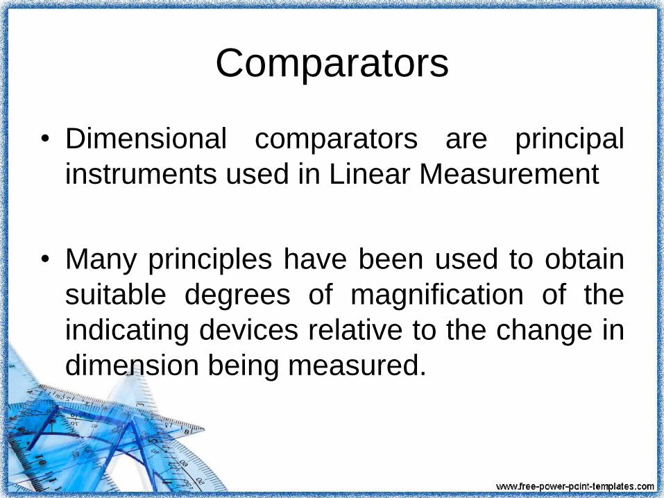
Mechanical ComparatorsSystems of Displacement
Amplification used in Mechanical
Comparators
1. Rack and Pinion. Measuring spindle
integral with a rack, engages a pinion
which amplifies the movement of
plunger through a gear train
2. Cam and gear train. In this case the
measuring spindle acts on a cam
which transmits the motion to the
amplifying gear train.

Mechanical Comparators• Lever with toothed sector.
lever with a toothed sector at its
end engages a pinion in the hub
of a crown gear sector which
further meshes with a final
pinion to produce indication
• Compound Levers. Here
levers forming a couple with
compound action are connected
through segments and pinion to
produce final pointer movement.
Mechanical Comparators
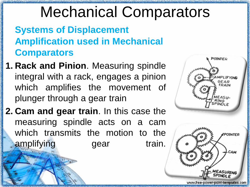
• Twisted Taut Strip. The
movement of measuring
spindle tilts the knee
causing straining which
further causes the twisted
taut band to rotate
proportionally. The motion
of strip is displayed by the
Attached pointer.

Dial Indicator
• The linear movement of the
spindle is magnified by means
of a gear and pinion train into
sizable rotation of the pointer
on the dial scale.
• The indicator is set to zero by
the use of slip gauges
representing the basic size of
the part. This is generally used
for inspection of small
precision-machined parts.
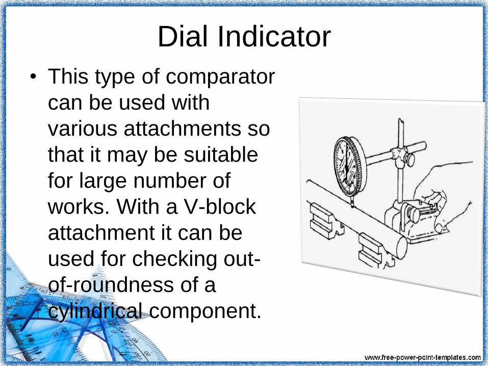
Dial Indicator
• This type of comparator
can be used with
various attachments so
that it may be suitable
for large number of
works. With a V-block
attachment it can be
used for checking out-
of-roundness of a
cylindrical component.
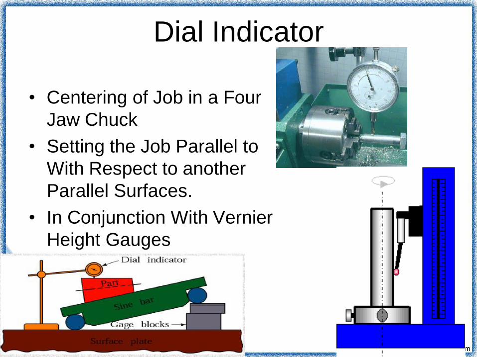
Dial Indicator
• Centering of Job in a Four
Jaw Chuck
• Setting the Job Parallel to
With Respect to another
Parallel Surfaces.
• In Conjunction With Vernier
Height Gauges

The Johansson ‘Mikrokator'
• Perhaps the simplest, yet most ingenious
movement used in this type of instrument
is one due to H.Abramson, a Swedish
Engineer, and which is made by C. E.
Johansson L td.
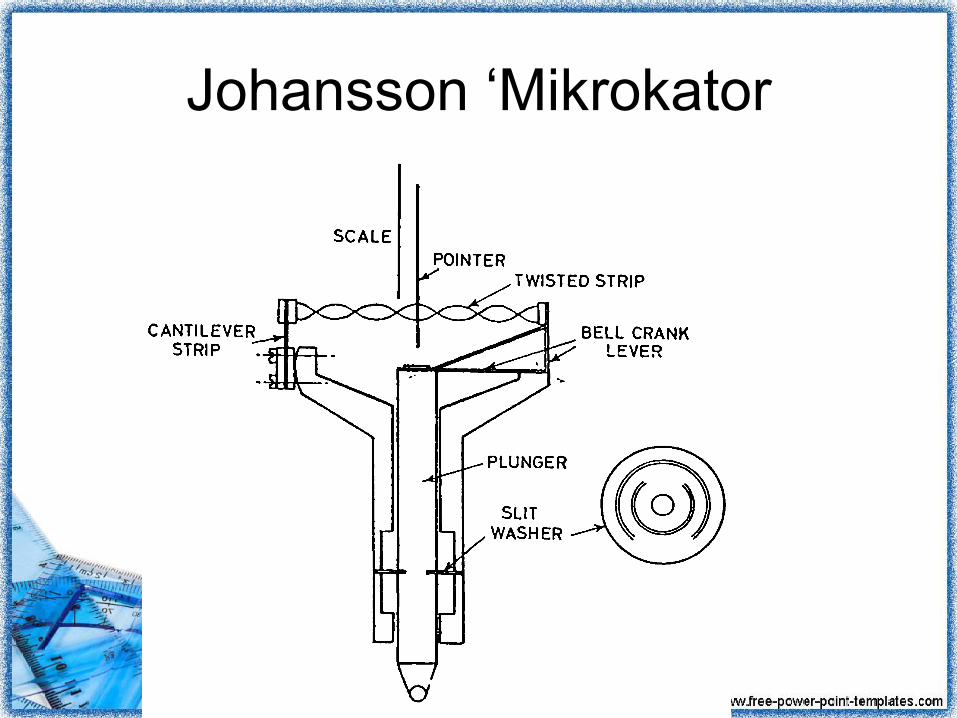
Johansson ‘Mikrokator
Construction
• A thin metal strip carries ,at the center of
its length a very high glass tube pointer.
• From the center the strip is permanently
twisted to form right and left hand helices.
• One end of the strip is fixed to the
adjustable cantilever strip the other being
anchored to the spring strip elbow, one
arm which carries the measuring Plunger.
Working
• As the plunger moves up and down the
elbow acts as bell crank lever and causes
the twisted strip to change its length and
thus further twist or untwist.
• Hence the pointer at the center of the
twisted strip rotates an amount
proportional to the change in length of the
strip.

Working
Mathematical Representation

Working
• The purpose of the cantilever strip other
than anchorage is used to is to allow an
adjustment to be made in amplification. Its
effective length may be varied
• The instrument is surprisingly robust and
is produced commercially in a range of
5000 X magnifications under controlled
laboratory conditions.

The sigma Comparator
• Another mechanical comparator of
ingenious, yet simple design is that
produced in a range of magnifications by
the Sigma Instrument Company.
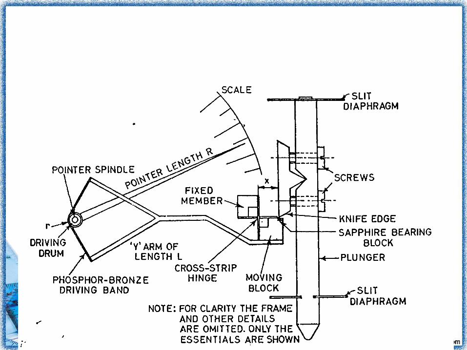

Construction
• The plunger, mounted on a pair of slit
diaphragms to give a frictionless linear
movement has mounted upon it a knife
edge which bears upon the face of the
moving member of a cross strip hinge.
• This consist of the moving component and
a fixed member connected by thin flexible
strips alternately at right angles at each
other.
Working
• If an external force applied to the to the
moving member it will pivot as would a
hinge about the line of intersection of the
strips.
• If the effective length of this arm is L and
the distance from the hinge pivot to the
knife edge is x then the first stage of the
magnification is L/x

Working
• To the extremities of the 'Y' arm is
attached a phosphor-bronze strip which is
passed around a drum of radius r attached
to the pointer spindle. If the pointer is of
length R then the second stage of the
magnification is R/r and the total
magnification is L/x × R/r
Working
• The magnification can be adjusted by
slackening one and tightening the other
screw, attaching the knife edge to the
plunger and thus adjusting distance x,
while a range of instruments of differing
magnifications can be produced by having
drums of different radii r and suitable
strips.

Reed Type Comparator
Reed Type Comparator
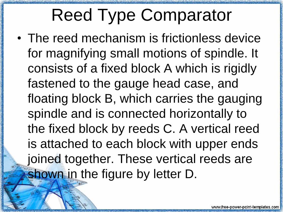
• The reed mechanism is frictionless device
for magnifying small motions of spindle. It
consists of a fixed block A which is rigidly
fastened to the gauge head case, and
floating block B, which carries the gauging
spindle and is connected horizontally to
the fixed block by reeds C. A vertical reed
is attached to each block with upper ends
joined together. These vertical reeds are
shown in the figure by letter D.

Reed Type Comparator
• Beyond this joint extends a pointer or
target. A linear motion of the spindle
moves the free block vertically causing the
vertical reed on the floating block to
slide past the vertical reed on the fixed
block.
Working• The vertical reeds are joined at the upper
end, instead of slipping, the movement causes both
reeds swing through an arc and as the target is
merely an extension of the vertical reeds, it swings
through a much wider arc.
• The amount of target swing is proportional to the
distance the floating
block has moved but of course very much magnified.
The scale may be calibrated by means of gauge block
(slip gauges) to indicate any deviation
from an initial setting.
Advantages• These are usually cheaper in comparison to other
devices of amplifying.
• These do not require any external supply such as
electricity or air and as such the variations in
outside supplies do not affect the accuracy.
• Usually the mechanical comparators have linear scale
which is easily understood.
• These are usually robust and compact and easy to
handle.
• For ordinary workshop conditions, these are suitable
and being portable can be issued from a store.

Disadvantages
• The mechanical comparators have got more moving parts
than other types. Due to more moving parts, the friction is
more and ultimately the accuracy is less.
• Any slackness in moving parts reduces the accuracy
considerably.
• The mechanism has more inertia and this may cause the
instruments to be sensitive to vibration.
• The range of the instrument is limited as the pointer
moves over a fixed scale.
• Error due to parallax is possible as the moving pointer
moves over a fixed scale.

Limitations• Comparators using this type of linkage
have sensitivities of the order of 0.25
micron per scale division.
• The mechanical amplification is usually
less than 100, but it is multiplied by the
optical lens system. It is available in
amplifications ranging from x 500 to x
1000.
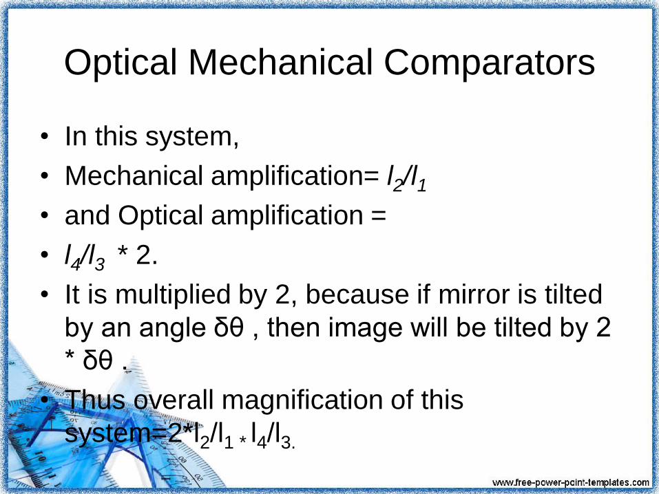
Optical Mechanical Comparators
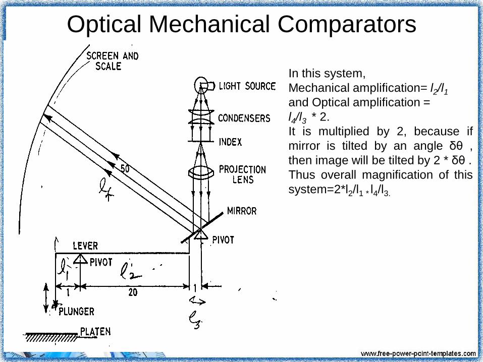
In this system,
Mechanical amplification= l2/l1and Optical amplification =
l4/l3 * 2.
It is multiplied by 2, because if
mirror is tilted by an angle δθ ,
then image will be tilted by 2 * δθ .
Thus overall magnification of this
system=2*l2/l1 * l4/l3.
Optical Mechanical Comparators
• In this system,
• Mechanical amplification= l2/l1
• and Optical amplification =
• l4/l3 * 2.
• It is multiplied by 2, because if mirror is tilted
by an angle δθ , then image will be tilted by 2
* δθ .
• Thus overall magnification of this
system=2*l2/l1 * l4/l3.

working
• In these instruments small displacements
of the measuring plunger are amplified by
initially a mechanical system consisting
usually pivoted levers followed by further
amplification by a simple optical system
involving the projection of a image.
• The mechanical system causes a plane
reflector to tilt about an axis. The image of
an index is then projected
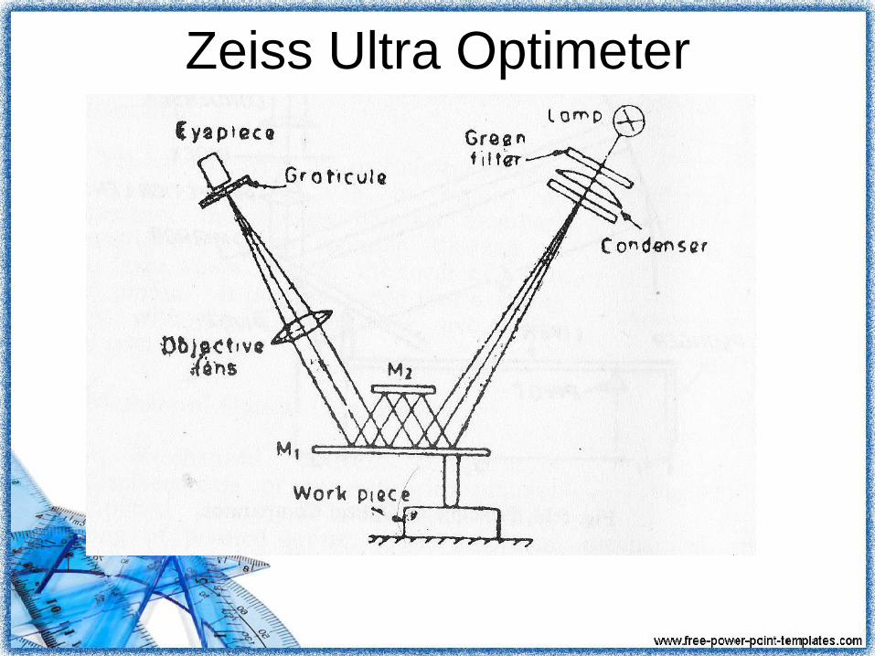
Zeiss Ultra Optimeter
Advantages• It has small number of moving parts and
hence a higher accuracy.
• In the optical comparators, the scale can
be made to move past a datum line and
thus have high range and no parallax
errors.
• It has very high magnification.
• Optical lever is weightless.
/
Disadvantages
• As the instrument has high magnification,
heat from the lamp, transformer etc. may
cause the setting to drift.
• An electrical supply is necessary.
• The apparatus is usually large and
expensive.
Disadvantages
• When the scale is projected on a screen,
then it is essential to use the instrument in
a dark room in order to take the readings
easily.
• The instruments in which the scale is
viewed through the eyepiece of a
microscope are not convenient for
continuous use.

Pneumatic Comparators
• Industrially, pneumatic comparators, in
which small variations are made in the
dimension being measured with respect to
a reference dimension which are shown by
variation in either
(a)Air Pressure
(b)The Velocity of air flow

Advantages of pneumatic Comparator
over Mechanical Comparator• High amplifications are possible
• No physical contact accuracy is high
• Internal dimensions are readily measured
• Measurement in tolerance and geometry
• Less operation and inspection time or less
cycle time.
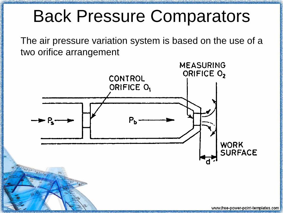
Back Pressure Comparators
The air pressure variation system is based on the use of a
two orifice arrangement
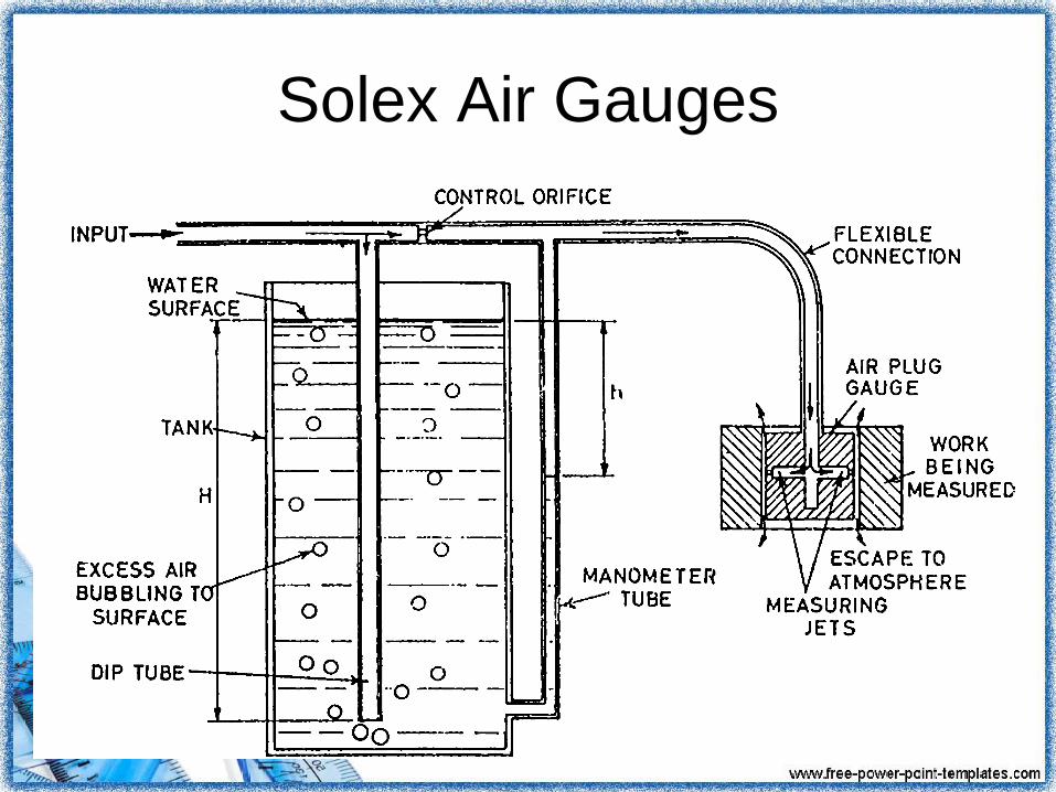
Solex Air Gauges
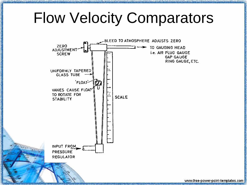
Flow Velocity Comparators

Electrical Comparators

Fluid Displacement Comparators

Slip Gauges
• A gauge block (also known as a gage
block, Johansson gauge, slip gauge, or
Jo block) is a precision ground and
lapped length measuring standard.
Invented in 1896 by Swedish machinist
Carl Edvard Johansson.
• Gauge blocks are the main means of
length standardization used by industry.

Slip Gauges
• Each gauge block consists of a block of
metal or ceramic with two opposing faces
ground precisely flat and parallel, a
precise distance apart.
• Standard grade blocks are made of a
hardened steel alloy, while calibration
grade blocks are often made of tungsten
carbide or chromium carbide because it is
harder and wears less

Wringing
• Wringing is the process of sliding two blocks
together so that their faces lightly bond.

The process of wringing
involves four steps• Wiping a clean gauge block across an oiled pad
• Wiping any extra oil off the gauge block using a
dry pad
• The block is then slid perpendicularly across the
other block while applying moderate pressure
until they form a cruciform.
• Finally, the block is rotated until it is inline with
the other block.

Slip Gauges
Slip Gauges
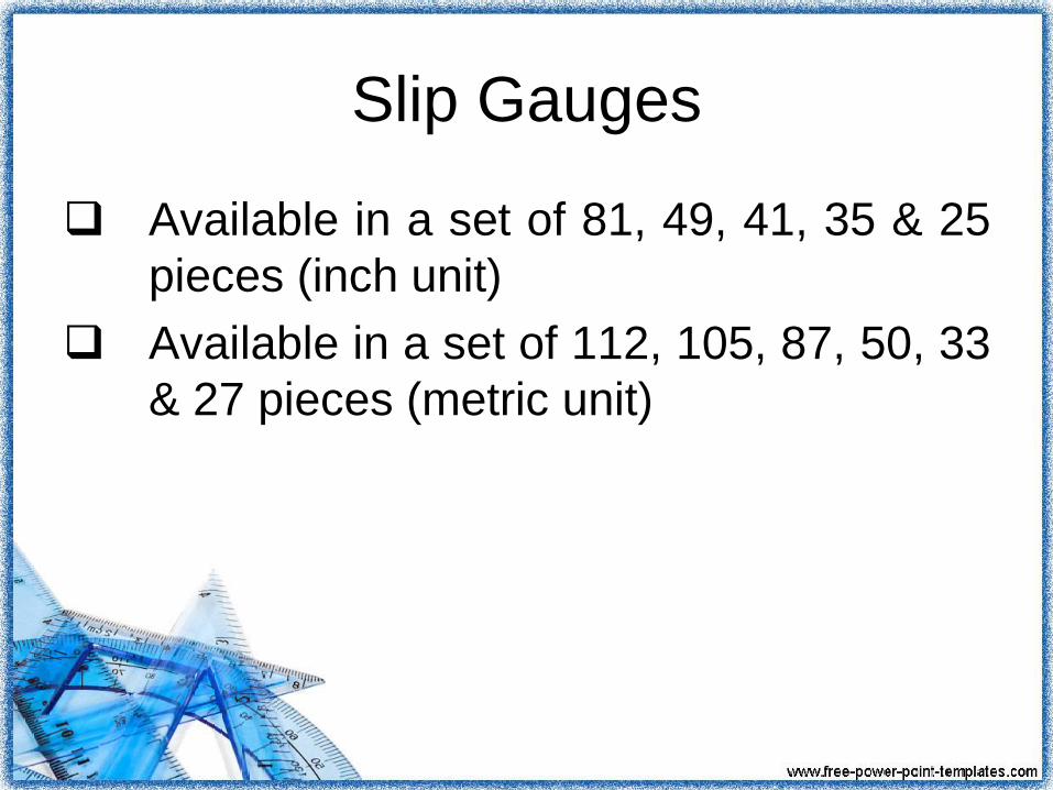
Available in a set of 81, 49, 41, 35 & 25
pieces (inch unit)
Available in a set of 112, 105, 87, 50, 33
& 27 pieces (metric unit)

Range (mm) Steps (mm) No. of Pieces
1.001 – 1.009 0.001 09
1.010 – 1.490 0.010 49
0.50 – 24.50 0.050 49
25, 50, 75, 100
25 04
1.0005 --- 01
TOTAL 112
Typical Gage Block Set

Grades of Slip gauges• Reference (AAA):
Small tolerance(±0.05 μm or ±0.000002 in) used to
establish standards
• Calibration (AA):
(Tolerance +0.10 μm to −0.05 μm) used to calibrate
inspection blocks and very high precision gauging
• Inspection (A):
(Tolerance +0.15 μm to −0.05 μm) used as toolroom
standards for setting other gauging tools
• Workshop (B):
large tolerance (tolerance +0.25 μm to −0.15 μm) used
as shop standards for precision measurement

Handling of Slip Gauges
• In use, the blocks are removed from the
set, cleaned of their protective coating
(petroleum jelly or oil) and wrung together
to form a stack of the required dimension,
with the minimum number of blocks.
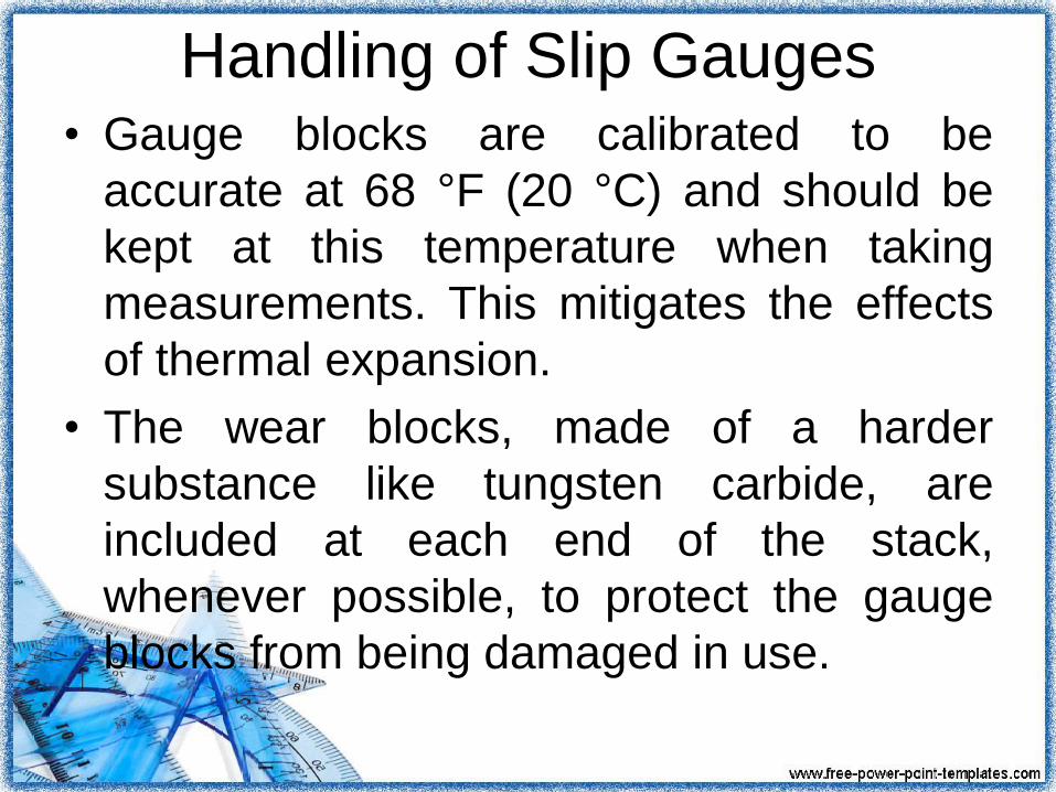
Handling of Slip Gauges• Gauge blocks are calibrated to be
accurate at 68 °F (20 °C) and should be
kept at this temperature when taking
measurements. This mitigates the effects
of thermal expansion.
• The wear blocks, made of a harder
substance like tungsten carbide, are
included at each end of the stack,
whenever possible, to protect the gauge
blocks from being damaged in use.

Sine Bar
• Used when accuracy of angle must be
checked to less than 5 minutes
• Consists of steel bar with two cylinders of
equal diameter fastened near ends
– Centers of cylinders exactly 90º to edge
– Distance between centers usually 5 or 10
inches and 100 or 200 millimeters.
• Made of stabilized tool hardened steel

Characteristics Permissible
Tolerance• Flatness of upper and lower surfaces
0.001 mm
• Parallelism of upper and lower surfaces
w.r.t. datum surface when resting on it
0.001 mm
• Flatness of side faces 0.005 mm
• Squareness of side faces to upper surface
0.003/25 mm
Parallelism of side faces to the axes of
rollers 0.01/25 mm
Flatness of end faces 0.003 mm
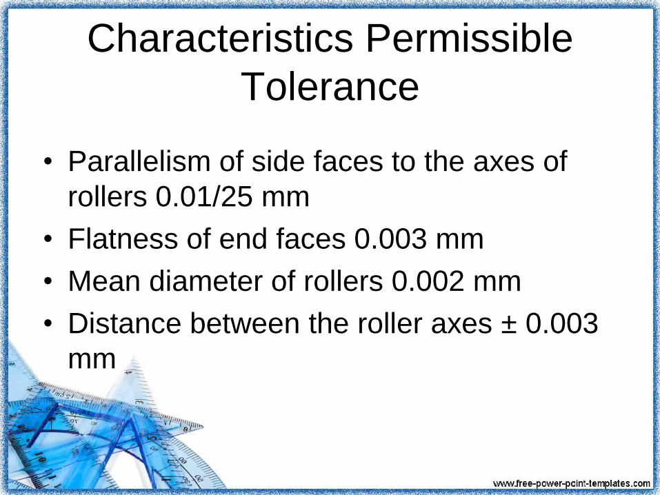
Characteristics Permissible
Tolerance
• Parallelism of side faces to the axes of
rollers 0.01/25 mm
• Flatness of end faces 0.003 mm
• Mean diameter of rollers 0.002 mm
• Distance between the roller axes ± 0.003
mm

Sine Bar

Features of Sine Bar
• The two rollers must have equal diameter
and be true cylinders.
• The rollers must be set parallel to each
other and to the upper face.
• The precise centre distance between the
rollers must be known.
• The upper face must have a high degree
of flatness.

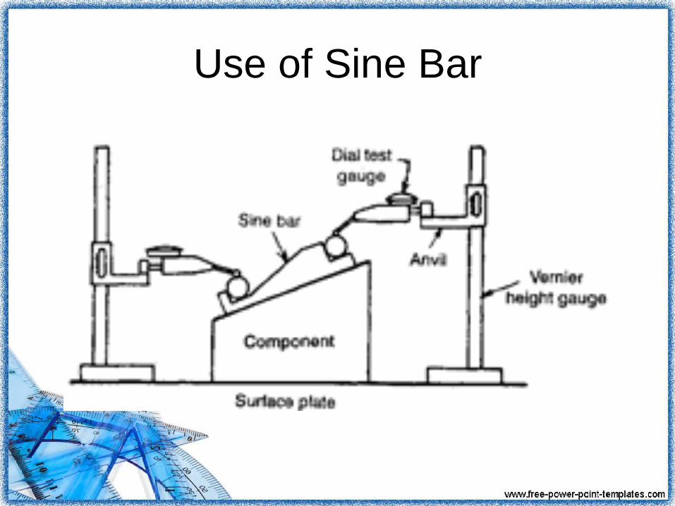
Use of Sine Bar
• Measuring known angles or locating any
work to a given angle.

Use of Sine Bar
• Checking of unknown angles
Use of Sine Bar
Assingment
• Limitations
• Precautions in use of Sine Bar
• Sine Table
• Sine Center

Auto collimator
Principle
1.The distance between the reflector and the lens has no effect on
the Separation distance between source and image.
2. For high sensitivity, i.e. a large value of x for it small angular
deviation,δ,a long focal length is required.

Auto collimator

Limit Gauges
Gage is a device / equipment used for
investigating the dimensional fitness of a part
for a specified function
Gaging is defined as a process of measuring
manufactured materials to assure the
specified uniformity of size and contour
required by the industries
Gaging accomplishes two functions: Controls the dimensions of a product within the prescribed
limitations
Segregates or rejects products that are outside these
limitations

System of Limits and Fits
Why Limits Required?
• It is impossible to make a part to a
specified definite size except by remote
chance.
• If by chance a part is made exactly to the
size required, it is impossible to measure it
accurately enough to prove it.
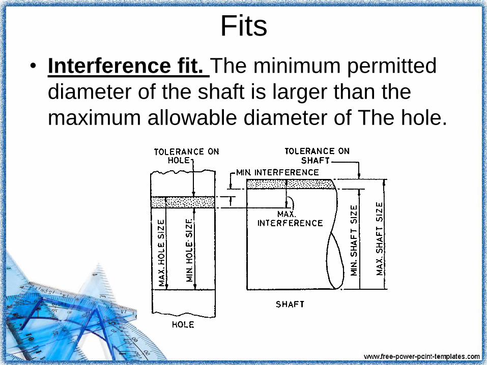
Fits
• Interference fit. The minimum permitted
diameter of the shaft is larger than the
maximum allowable diameter of The hole.

Fit
• Transition fit. diameter of the largest
allowable hole is greater than that of the
smallest shaft, but the smallest hole is
smaller than the largest shaft.
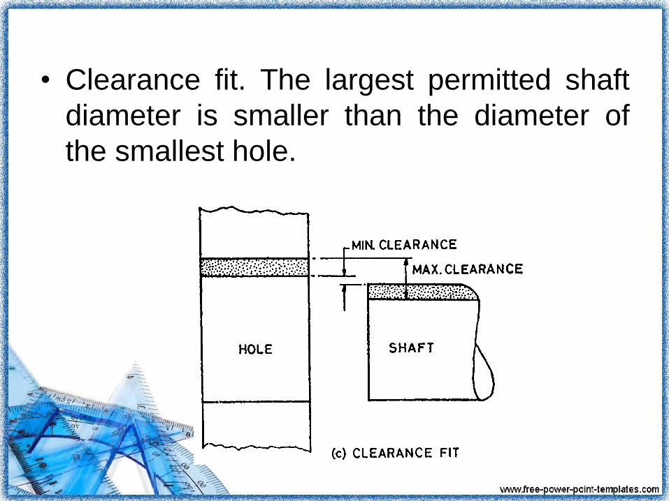
• Clearance fit. The largest permitted shaft
diameter is smaller than the diameter of
the smallest hole.

Definitions
• Limits of size. These are the maximum
and minimum sizes allowed in a given
component.
• Tolerance is the maximum size variation
which will be tolerated on a given
component.
• Allowance is the size difference between
the limiting conditions of, size on the two
components.
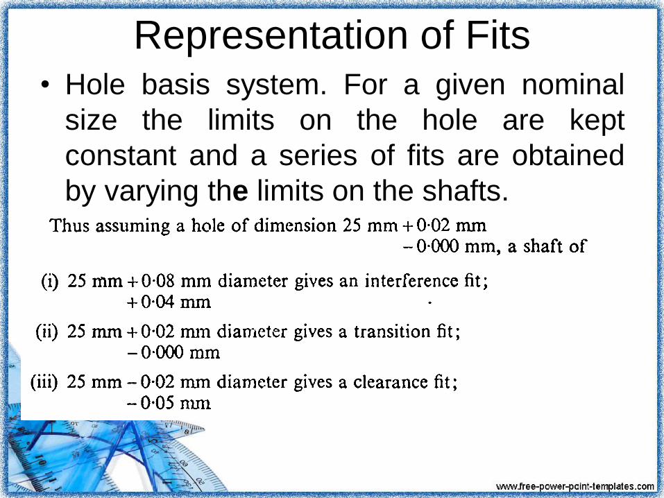
Representation of Fits• Hole basis system. For a given nominal
size the limits on the hole are kept
constant and a series of fits are obtained
by varying the limits on the shafts.

• Shaft basis system. A series of fits can
be arranged for a given nominal size using
a standard shaft and varying the limits on
the hoIe.

Queries - Discussion

Related Documents