1 METRO TUNNEL SEISMIC RESPONSE BY A HYBRID FDM-BEM George MANOLIS 1 ABSTRACT , Konstantia MAKRA 2 , Sonia PARVANOVA 3 and Petia DINEVA 4 A 2D elastodynamic model for the seismic response of Metro tunnels embedded in a laterally inhomogeneous, multilayered geological region overlying a rock stratum is developed herein. We employ a hybrid, finite difference-boundary element method (FDM-BEM), with the latter method embedded in the former so as to capture the near-site field details. More specifically, the FDM is used for simulating in-plane elastic wave propagation from the lower soil-rock interface into the overlying soil deposits. A BEM 'box' area containing the Metro tunnels and with the free surface of the geological deposit forming its upper boundary is then embedded within the FDM mesh. This way, wave motion from the FDM is filtered into the 'BEM box', and the BEM is subsequently used to model the near-site layers with the tunnels. Verification studies are then conducted for upward moving Gabor pulses, using the FDM alone, the present hybrid FDM-BEM and a hybrid FDM-finite element method (FEM) formulation. Finally, the methodology is applied to a N-S geological cross-section running through the center of Thessaloniki, Greece and containing two Metro tunnels excavated directly below an important Roman-era monument known as the Arch of Galerius that is part of the Rotunda complex. INTRODUCTION Scattering, diffraction and dynamic stress concentration phenomena around buried structures is one of the basic research topics in earthquake engineering, as it is relevant to infrastructure projects in seismically-prone regions (Howard 1983). More specifically, the seismic response of buried tunnels and their interaction with the surrounding geological continuum spurred the development of high- performance numerical methods for elastic wave propagation through complex media. Essentially, three main lines of approaches to this problem are distinguished, namely analytical or semi-analytical (Baron and Matthews 1961; Datta 1978; Liu et al. 1982; Lee and Cao 1989; Cao and Lee 1990; Liang and Liu 2009), numerical (Sanchez-Sesma and Campillo 1993; Luco and De Barros 1994; Alvarez- Rubio et al. 2004; Yu and Dravinski 2009; Dravinski and Yu 2013) and hybrid (Moczo et al. 1997; Gatmiri et al. 2008, 2009; Panza et al. 2009; Wuttke et al. 2011; Manolis et al. 2013). Generally speaking, there are two categories of numerical models that can handle the aforementioned three-component problem, see Johnson (1981): (a) all-in-one, source–path-site unified computational approach, demanding large computational resources, especially when the source– receiver distances are measured in the tens of km; (b) hybrid approaches based on a two-step procedure that combines source and path effects computed by one method, with the local site effects evaluated by another method. Thus, the elastic wave field computed by the former method is used as 1 Professor, Aristotle University, Thessaloniki, Greece, [email protected] 2 Researcher, Institute of Seismology and Earthquake Engineering, Thessaloniki, Greece, [email protected] 3 Assoc. Professor, University of Architecture, Civil Engineering & Geodesy, Sofia, Bulgaria, [email protected] 4 Professor, Bulgarian Academy of Sciences, Sofia, Bulgaria, [email protected]

Welcome message from author
This document is posted to help you gain knowledge. Please leave a comment to let me know what you think about it! Share it to your friends and learn new things together.
Transcript

1
METRO TUNNEL SEISMIC RESPONSE BY A HYBRID FDM-BEM
George MANOLIS1
ABSTRACT
, Konstantia MAKRA2, Sonia PARVANOVA3 and Petia DINEVA4
A 2D elastodynamic model for the seismic response of Metro tunnels embedded in a laterally inhomogeneous, multilayered geological region overlying a rock stratum is developed herein. We employ a hybrid, finite difference-boundary element method (FDM-BEM), with the latter method embedded in the former so as to capture the near-site field details. More specifically, the FDM is used for simulating in-plane elastic wave propagation from the lower soil-rock interface into the overlying soil deposits. A BEM 'box' area containing the Metro tunnels and with the free surface of the geological deposit forming its upper boundary is then embedded within the FDM mesh. This way, wave motion from the FDM is filtered into the 'BEM box', and the BEM is subsequently used to model the near-site layers with the tunnels. Verification studies are then conducted for upward moving Gabor pulses, using the FDM alone, the present hybrid FDM-BEM and a hybrid FDM-finite element method (FEM) formulation. Finally, the methodology is applied to a N-S geological cross-section running through the center of Thessaloniki, Greece and containing two Metro tunnels excavated directly below an important Roman-era monument known as the Arch of Galerius that is part of the Rotunda complex.
INTRODUCTION
Scattering, diffraction and dynamic stress concentration phenomena around buried structures is one of the basic research topics in earthquake engineering, as it is relevant to infrastructure projects in seismically-prone regions (Howard 1983). More specifically, the seismic response of buried tunnels and their interaction with the surrounding geological continuum spurred the development of high-performance numerical methods for elastic wave propagation through complex media. Essentially, three main lines of approaches to this problem are distinguished, namely analytical or semi-analytical (Baron and Matthews 1961; Datta 1978; Liu et al. 1982; Lee and Cao 1989; Cao and Lee 1990; Liang and Liu 2009), numerical (Sanchez-Sesma and Campillo 1993; Luco and De Barros 1994; Alvarez-Rubio et al. 2004; Yu and Dravinski 2009; Dravinski and Yu 2013) and hybrid (Moczo et al. 1997; Gatmiri et al. 2008, 2009; Panza et al. 2009; Wuttke et al. 2011; Manolis et al. 2013).
Generally speaking, there are two categories of numerical models that can handle the aforementioned three-component problem, see Johnson (1981): (a) all-in-one, source–path-site unified computational approach, demanding large computational resources, especially when the source–receiver distances are measured in the tens of km; (b) hybrid approaches based on a two-step procedure that combines source and path effects computed by one method, with the local site effects evaluated by another method. Thus, the elastic wave field computed by the former method is used as
1 Professor, Aristotle University, Thessaloniki, Greece, [email protected] 2 Researcher, Institute of Seismology and Earthquake Engineering, Thessaloniki, Greece, [email protected] 3Assoc. Professor, University of Architecture, Civil Engineering & Geodesy, Sofia, Bulgaria, [email protected] 4 Professor, Bulgarian Academy of Sciences, Sofia, Bulgaria, [email protected]

2
input to the latter one, making sure at the same time that the two methods are seamlessly linked so as to keep the common interface boundary perfectly permeable to waves moving outward form the core region and into the surrounding half-space. The present work can be viewed as effort in the latter direction, whereby a 'domain' type method (FDM) is linked with a 'boundary' method in an effort to exploit the best features of both (Manolis et al., 2013; 2014) in solving the problem whose general outline is shown in Fig.1 .
(a)
(b) (c)
Figure 1: (a) The Thessaloniki, Greece, Metro line running east to west (9 km under construction); (b) reconstruction of the Roman-era Rotunda monument complex in what is now the 'Syntrivani' Metro station
area and (c) the Arch of Galerius as it appears today.
MATHEMATICAL STATEMENT OF THE PROBLEM
The governing equation of motion in the continuum (the BEM 'box') is
0, =− ijij uρσ in 'BEM box ' x (0, )BQ T= (1)

G.D.Manolis, K. Makra, A. Parvanova and P. Dineva 3
The dependent variables of the problem are the displacement vector ( ) 2,1,, =itui x and the traction vector ( ) 2,1,, == intt jiji σx , where ( ) , 1,2in i =x is the outward pointing normal vector at field point
( )1 2,x x=x and ( ) 2,1,,, =jitij xσ is the stress tensor. The above equation is numerical solved by the BEM, taking into account the surface topography, the soil layering and the presence (or absence) of both unlined and lined cavities representing the Metro tunnel construction.
In essence, our boundary value problem (BVP) is the finite-sized region with the tunnels (the 'BEM box') receiving input from the larger geological cross-section of Fig. 2. Thus, the dynamic loads that develop along the lateral boundaries and base of the 'BEM box' result from a complex wave train emanating from bedrock and propagating upwards through the geological strata. To this end, the FDM (Moczo et al., 2007) is first employed to model the seismic source signal, the inhomogeneous geological deposits and the finite-sized region. Once the seismic motion at the perimeter of the finite-sized region has been determined, the BEM is used to model wave motion inside this region which now contains the buried tunnels (Manolis et al., 2013). It should be noted that the FDM computes time-dependent displacements, which have to be Fourier-transformed into the frequency domain to serve as input to the finite-sized region. The choice of the size of the 'BEM box' is crucial to the accuracy of the hybrid method, and the criterion used is that any wave backscattering into the surrounding geological strata must be negligible. The final step is to recover displacements, velocities and accelerations at receiver points along the free surface of the finite-sized region and to compute the dynamic stress concentration factor (SCF) that develops in either the tunnel liners or at the surface of the cavities. Although the Metro tunnels are lined, we also consider the case of cavities, which correspond to the early excavation stage.
HYBRID FDM-BEM TECHNIQUE
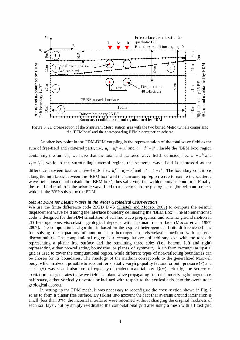
FDM-BEM Coupling: As the first step in the present hybrid technique, the FDM is applied to seismic wave propagation phenomena in the geological region of Fig. 2, but in the absence of tunnels. The time-dependent FDM solution for the seismic wave-field along the interface boundary delineating the ‘BEM Box’ is transformed to the frequency domain and stored for use as a boundary condition in the realization of the second step. This second step involves the BEM modeling of wave motion inside the ‘BEM box’, now containing the two embedded tunnels, see Fig. 3. The size of the 'BEM box' is the key parameter here and is estimated separately, using as criterion the damping out of backscattering effects emanating from the 'BEM box' to the surrounding medium.
0 100 200 300 400 500 600 700 800 900 1000 1100 1200 1300 1400
DISTANCE (M)
-200
-150
-100
-50
0
50
Altit
ude
(m)
White TowerLEP
Rotunda ComplexROT
OBS
C: 200/25 B1: 350/20
B2: 280/20
E1: 350/8
E3: 500/15
E4: 600/30
E5: 700/30
F1: 750/60
F2: 800/60
F3: 850/60
G: 2500/200
G: 2500/200
Boundary Element Box
Figure 2. The Thessaloniki, Greece Metro line: N-S cross-section through the 'Syntrivani' station area from the hills (OBS) through the Rotunda monument complex (ROT) to the White Tower monument (LEP) by the sea
4
Figure 3. 2D cross-section of the Syntrivani Metro station area with the two buried Metro tunnels comprising
the ‘BEM box’ and the corresponding BEM discretization scheme
Another key point in the FDM-BEM coupling is the representation of the total wave field as the sum of free-field and scattered parts, i.e., f
iscii uuu += and f
iscii ttt += . Inside the ‘BEM box’ region
containing the tunnels, we have that the total and scattered wave fields coincide, i.e., scii uu = and
scii tt = , while in the surrounding external region, the scattered wave field is expressed as the
difference between total and free-fields, i.e., fii
sci uuu −= and f
iisci ttt −= . The boundary conditions
along the interfaces between the ‘BEM box’ and the surrounding region serve to couple the scattered wave fields inside and outside the ‘BEM box’, thus satisfying the 'welded contact' condition. Finally, the free field motion is the seismic wave field that develops in the geological region without tunnels, which is the BVP solved by the FDM.
Step A: FDM for Elastic Waves in the Wider Geological Cross-section We use the finite difference code 2DFD_DVS (Kristek and Moczo, 2003) to compute the seismic displacement wave field along the interface boundary delineating the ‘BEM Box’. The aforementioned code is designed for the FDM simulation of seismic wave propagation and seismic ground motion in 2D heterogeneous viscoelastic geological deposits with a planar free surface (Moczo et al. 1997; 2007). The computational algorithm is based on the explicit heterogeneous finite-difference scheme for solving the equations of motion in a heterogeneous viscoelastic medium with material discontinuities. The computational region is a rectangular area of arbitrary size with the top side representing a planar free surface and the remaining three sides (i.e., bottom, left and right) representing either non-reflecting boundaries or planes of symmetry. A uniform rectangular spatial grid is used to cover the computational region, while different types of non-reflecting boundaries can be chosen for its boundaries. The rheology of the medium corresponds to the generalized Maxwell body, which makes it possible to account for spatially varying quality factors for both pressure (P) and shear (S) waves and also for a frequency-dependent material law ( )Q ω . Finally, the source of excitation that generates the wave field is a plane wave propagating from the underlying homogeneous half-space, either vertically upwards or inclined with respect to the vertical axis, into the overburden geological deposit.
In setting up the FDM mesh, it was necessary to reconfigure the cross-section shown in Fig. 2 so as to form a planar free surface. By taking into account the fact that average ground inclination is small (less than 3%), the material interfaces were reformed without changing the original thickness of each soil layer, but by simply re-adjusted the computational grid area using a mesh with a fixed grid
Deep tunnels - 48 BE/circle
Bottom boundary 25 BE Boundary conditions: u1 and u2 obtained by FDM
Rig
ht b
ound
ary
15 B
E B
C: u
1 an
d u
2 ob
tain
ed b
y F
DM
Free surface discretization 25 quadratic BE Boundary conditions: t1= t2=0
BC
: u1
and
u2
obta
ined
by
FD
M
Left
boun
dary
14
BE
25 BE at each interface
24m
10.5
13m
M L R
Shallow tunnels - 48 BE/circle
x1
x2
50m
x3
100m
1
2
4
5
3
10m
21
m
11m
6m
2m
10m
21
m
11m
8m

G.D.Manolis, K. Makra, A. Parvanova and P. Dineva 5
step of 2.0m in both horizontal and vertical directions. For a minimum S wave velocity of 200m/sec, this implies that the maximum frequency for which the results remain numerical stable is well over 15 Hz, using six grid spacings per minimum wavelength. To avoid undesirable artificial reflections, we used Higdon non-reflective boundaries for the lateral and bottom sides of the mesh. As an extra precaution, both sides (and especially the open side of the cross-section at the left end) were extended by several tens of meters. Next, wave attenuation is taken into account by introducing three relaxation mechanisms at three fixed frequency values of 0.1,1,10 Hz to insure a nearly constant
( ) 100Q ω = value in the frequency spectrum of interest, which is 0.05 15.0 Hz− . Finally, the seismic excitation at bedrock that gives rise to an in-plane, vertically propagating shear (SV) wave is a Gabor pulse of unit displacement amplitude and all results are plotted for a frequency spectrum reaching 10 Hz . Step B: BEM for Elastic Waves in the Near Site Sub-region As previously mentioned, the BEM is used for solution of the BVP comprising Eq. (1) plus the boundary conditions outlined above for the 'BEM box' sub-region. Note that the free-field motion ( )f
if
i tu , input coming from the surrounding geological region is applied along the left, right and bottom interface boundaries. This input is computed by the FDM (as the first step) in the absence of tunnels in the 'BEM box'. Next, the displacement-based BEM formulation with sub-structuring capabilities is used for modeling this layered finite region, first in the absence of cavities (as a verification check), and then in the presence of both cavities and lined tunnels with either deep or shallow burial.
More specifically, we use the fundamental solution of Eq. (1) in conjunction with the dynamic equivalent to Betti’s reciprocity theorem to recover the conventional displacement boundary integral equation formulation for 2D problems as
( ) ( ) ( ) ( ) ( )* *, , , , , , ,ij j ij j ij jS S
c u U t dS T u dSω ω ω ω ω= −∫ ∫x x y y x y y (2)
In the above, ( )ijc x is the jump term depending on the local geometry at the receiver (or collocation) point 1 2( , )x xx , 1 2( , )y yy is the source point, ( )ju x and ( )jt x respectively are displacements and
tractions along the boundary (i.e., the field variables), and finally * ( , )ijU x y and * *
,( , ) ( , ) ( )ij ijql qk l kT C U n=x y x y x are the displacement fundamental solution and the corresponding
traction solution, the latter derived from the former by use of the constitutive law ijqlC and the outward pointing unit normal vector at the receiver point ( )kn x . Surface S comprises external boundaries of the box, plus all interfaces between any two consecutive layers. Using standard procedure by which all surfaces are discretized using three-node, quadratic boundary elements (BE), and followed by imposition of a nodal collocation scheme on Eq. (2), we recover the following matrix equation system: [ ]{ } [ ]{ } { }− =G t H u 0 (3)
System matrices G and H result from the numerical integration using Gaussian quadrature of surface integrals containing the products of fundamental solutions times interpolation functions used for representing the field variables. They are fully populated matrices of size 2 2N N× , where N is the total number of nodes, while vectors u and t now contain the boundary displacements and tractions. In here, we implemented a BEM sub-structuring technique, whereby each single soil layer, starting from the bottom of the 'BEM box' upwards, is modeled as a single domain. Imposition of the boundary conditions in the form of displacement continuity and traction equilibrium across common interfaces and boundaries yields the necessary conditions for the assembly of the complete system matrices G and H from those of the individual layers. When the uppermost soil layer is finally reached, it is solved as a single domain. Thus, sub-structuring allows for the sequential solution of several smaller systems of linear algebraic equations instead of a large single one, but contains the entirety of all nodal points of the 'BEM box'.

6
NUMERICAL RESULTS
At first, a series of verification studies were conducted (see Manolis et al., 2013; 2014) in order to calibrate the proposed hybrid FDM-BEM technique. More specifically, when a boundary element (BE) mesh is used for the discretization of surfaces and interfaces, the relative size of these elements may result in mismatches that cause spurious wave reflections. In general, wave reflections are less pronounced for higher order BE, and for this reason we use quadratic BE here. The accuracy criterion states that / 10SV BElλ > , where BEl is the length of the BE and SVλ is the S-wave length. Comparisons done with the results of Luco and Barros (1994) for the kinematic and stress fields around cylindrical cavities embedded in the half-space and with those of Sanchez-Sesma and Campillo (1993) for surface topography all showed that meshes such as the one shown in Fig. 3 yield very accurate results.
Next, we commence a parametric study regarding the presence of tunnels in the near-site region of the Thessaloniki Metro construction, as depicted in the N-S geological cut of Fig. 2. The FDM component of the hybrid method is first used to compute the input to the 'BEM box' bottom and lateral interfaces for a transient signal placed at the base of the geological deposit. Then, the BEM component is used as the second step in recovering the kinematic field that develops at the free surface and the stress field in the tunnel interfaces of the near site. The mechanical properties of the near site are summarized in Table 1, see Raptakis et al. (2004).
Table 1. Mechanical Properties of Soil Layers in the Near-site
Layer Νο.
Density ρ (kg/m3)
VS (m/s)
VP (m/s)
Damping (%)
Modulus of elasticity E (MPa)
Poisson's ratio ν
1 1850 250 1500 2.5 344 0.486 2 1950 330 1850 2.5 630 0.484 3 1950 400 2000 6.25 923 0.479 4 2050 500 2000 3.33 1500 0.467 5 2100 600 2000 1.67 2190 0.451
For a unit displacement amplitude Gabor pulse of 1.0 sec duration and emanating from bedrock,
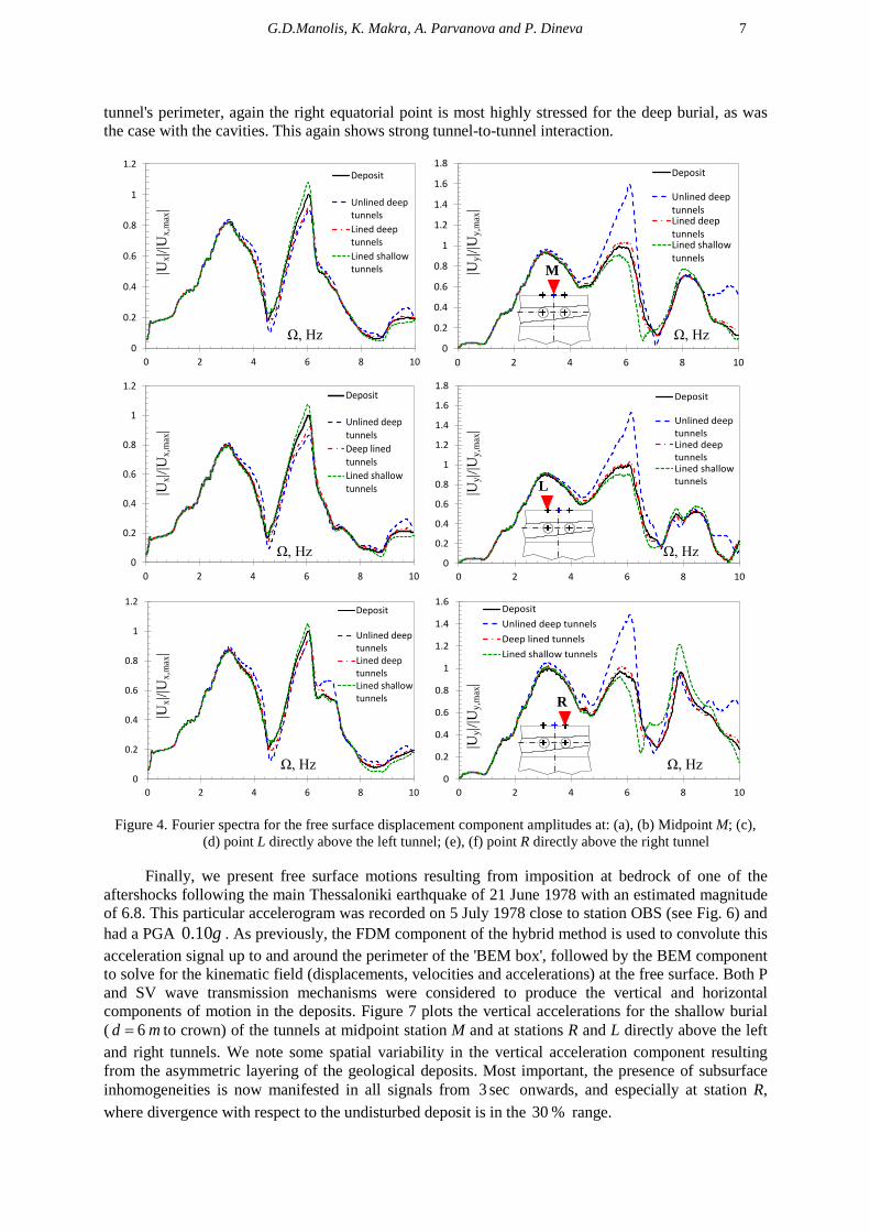
we examine both horizontal and vertical, free surface displacement amplitudes for the following cases of the near-site region: (i) absence of cavities, (ii) two deeply buried cavities, (iii) two deeply buried lined tunnels and (iv) two lined tunnels with shallow burial. Figure 4 plots all this information for the same three surface observation points above the tunnels, also used in the verification studies (i.e., M, R, L). These displacement components are given in the frequency domain and are further normalized with respect to the maximum displacement amplitude value observed for just the soil deposit in the 0 10 Hz− frequency range, so as to illustrate amplification and de-amplification effects. We note that the Gabor pulse is essentially a 'white noise' input, so all results here can be interpreted as spectra. At first, we observe little amplification in the horizontal displacement spectra, and in fact the presence of tunnels is barely detectable. The situation however is different for the vertical displacement spectra, where at about 6 Hz the presence of the deeply buried cavities is clearly detectable and leads to amplification values in the 40 60 %− range. Given the asymmetry in the underlying soil layers, the spectra are also asymmetric for points R and L, with the former one showing a second amplification peak at around 8 Hz .
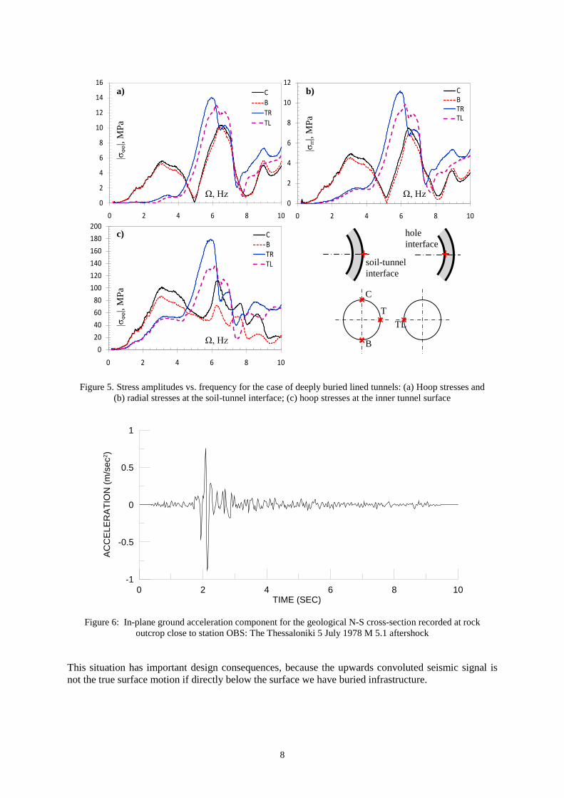
Next, Fig. 5 plots stress amplitudes versus frequency at four select locations along the perimeter of the cavities and the lined tunnels with deep burial. Starting with the two cavities, we observe that a hoop stress maximum of 60 MPa is recorded at the right equatorial point and for a frequency of 6 Hz . It is around this frequency value that the maxima for the remaining three locations are recorded, with the left equatorial point registering 40 MPa , while even smaller values are observed for the crown and bottom. This is a manifestation of strong interaction effects. A similar state of affairs is observed for the lined tunnels, the difference being that we have both inner and outer liner surfaces to contend with. Stress values for hoop and radial stresses are low for the outer liner surface, with maximum values in the range of 10 14 MPa− . As expected, large hoop stresses are observed at the inner liner surface, with maximum values registering around 180 MPa . In terms of location around the
G.D.Manolis, K. Makra, A. Parvanova and P. Dineva 7
tunnel's perimeter, again the right equatorial point is most highly stressed for the deep burial, as was the case with the cavities. This again shows strong tunnel-to-tunnel interaction.
Figure 4. Fourier spectra for the free surface displacement component amplitudes at: (a), (b) Midpoint M; (c), (d) point L directly above the left tunnel; (e), (f) point R directly above the right tunnel
Finally, we present free surface motions resulting from imposition at bedrock of one of the
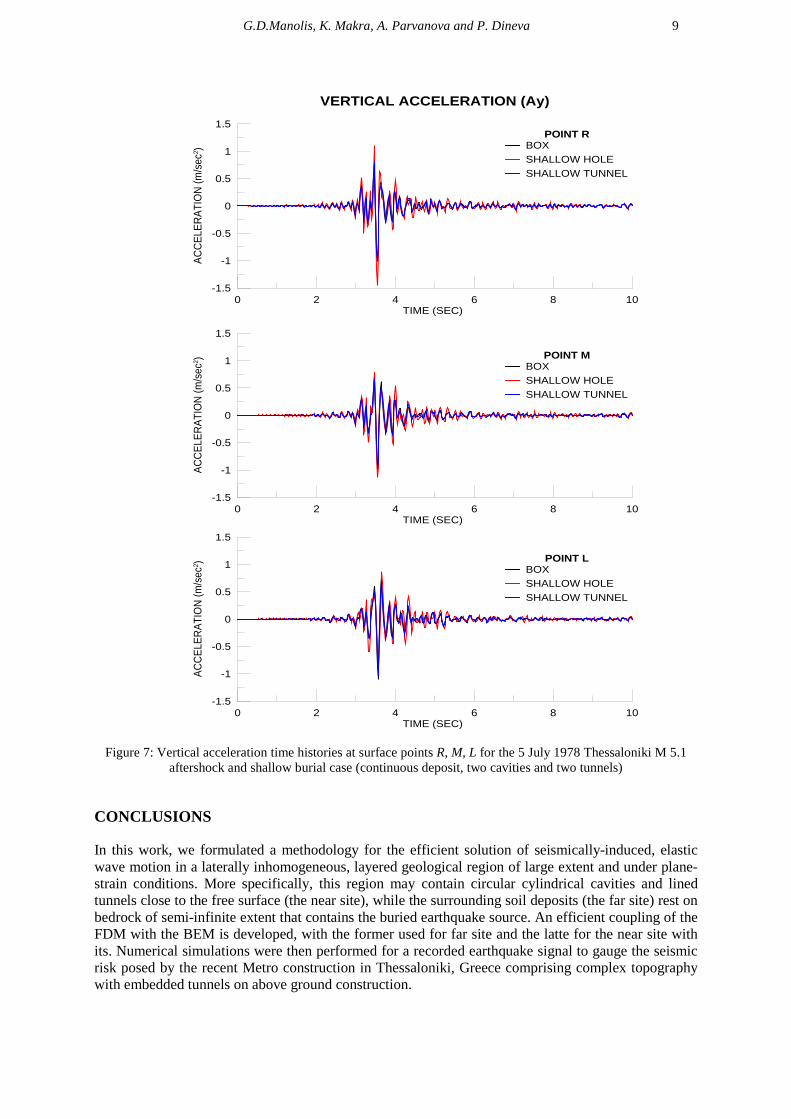
aftershocks following the main Thessaloniki earthquake of 21 June 1978 with an estimated magnitude of 6.8. This particular accelerogram was recorded on 5 July 1978 close to station OBS (see Fig. 6) and had a PGA 0.10g . As previously, the FDM component of the hybrid method is used to convolute this acceleration signal up to and around the perimeter of the 'BEM box', followed by the BEM component to solve for the kinematic field (displacements, velocities and accelerations) at the free surface. Both P and SV wave transmission mechanisms were considered to produce the vertical and horizontal components of motion in the deposits. Figure 7 plots the vertical accelerations for the shallow burial ( 6d m= to crown) of the tunnels at midpoint station M and at stations R and L directly above the left and right tunnels. We note some spatial variability in the vertical acceleration component resulting from the asymmetric layering of the geological deposits. Most important, the presence of subsurface inhomogeneities is now manifested in all signals from 3 sec onwards, and especially at station R, where divergence with respect to the undisturbed deposit is in the 30 % range.
0
0.2
0.4
0.6
0.8
1
1.2
0 2 4 6 8 10
Deposit
Unlined deeptunnelsDeep linedtunnelsLined shallowtunnels
0
0.2
0.4
0.6
0.8
1
1.2
0 2 4 6 8 10
Deposit
Unlined deeptunnelsLined deeptunnelsLined shallowtunnels
0
0.2
0.4
0.6
0.8
1
1.2
1.4
1.6
1.8
0 2 4 6 8 10
Deposit
Unlined deeptunnelsLined deeptunnelsLined shallowtunnels
0
0.2
0.4
0.6
0.8
1
1.2
1.4
1.6
1.8
0 2 4 6 8 10
Deposit
Unlined deeptunnelsLined deeptunnelsLined shallowtunnels
0
0.2
0.4
0.6
0.8
1
1.2
0 2 4 6 8 10
Deposit
Unlined deeptunnelsLined deeptunnelsLined shallowtunnels
0
0.2
0.4
0.6
0.8
1
1.2
1.4
1.6
0 2 4 6 8 10
DepositUnlined deep tunnelsDeep lined tunnelsLined shallow tunnels
Ω, Hz Ω, Hz
Ω, Hz Ω, Hz
Ω, Hz Ω, Hz
|Ux|/
|Ux,
max
|
|Uy|/
|Uy,
max
|
|Ux|/
|Ux,
max
|
|Uy|/
|Uy,
max
|
|Ux|/
|Ux,
max
|
|Uy|/
|Uy,
max
|
M
L
R
8
Figure 5. Stress amplitudes vs. frequency for the case of deeply buried lined tunnels: (a) Hoop stresses and (b) radial stresses at the soil-tunnel interface; (c) hoop stresses at the inner tunnel surface
0 2 4 6 8 10TIME (SEC)
-1
-0.5
0
0.5
1
AC
CE
LER
ATI
ON
(m/s
ec2 )
Figure 6: In-plane ground acceleration component for the geological N-S cross-section recorded at rock outcrop close to station OBS: The Thessaloniki 5 July 1978 M 5.1 aftershock
This situation has important design consequences, because the upwards convoluted seismic signal is not the true surface motion if directly below the surface we have buried infrastructure.
0
2
4
6
8
10
12
14
16
0 2 4 6 8 10
CBTRTL
0
2
4
6
8
10
12
0 2 4 6 8 10
CBTRTL
020406080
100120140160180200
0 2 4 6 8 10
CBTRTL
Ω, Hz
|σφφ
|, M
Pa
Ω, Hz Ω, Hz
|σrr|,
MPa
|σφφ
|, M
Pa
a) b)
c)
soil-tunnel interface
hole interface
C
B
T TL
G.D.Manolis, K. Makra, A. Parvanova and P. Dineva 9
0 2 4 6 8 10TIME (SEC)
-1.5
-1
-0.5
0
0.5
1
1.5
ACCE
LERA
TIO
N (m
/sec
2 ) POINT LBOXSHALLOW HOLESHALLOW TUNNEL
0 2 4 6 8 10TIME (SEC)
-1.5
-1
-0.5
0
0.5
1
1.5
ACCE
LERA
TIO
N (m
/sec
2 ) POINT MBOXSHALLOW HOLESHALLOW TUNNEL
0 2 4 6 8 10TIME (SEC)
-1.5
-1
-0.5
0
0.5
1
1.5
ACCE
LERA
TIO
N (m
/sec
2 )
POINT RBOXSHALLOW HOLESHALLOW TUNNEL
VERTICAL ACCELERATION (Ay)
Figure 7: Vertical acceleration time histories at surface points R, M, L for the 5 July 1978 Thessaloniki M 5.1 aftershock and shallow burial case (continuous deposit, two cavities and two tunnels)
CONCLUSIONS
In this work, we formulated a methodology for the efficient solution of seismically-induced, elastic wave motion in a laterally inhomogeneous, layered geological region of large extent and under plane-strain conditions. More specifically, this region may contain circular cylindrical cavities and lined tunnels close to the free surface (the near site), while the surrounding soil deposits (the far site) rest on bedrock of semi-infinite extent that contains the buried earthquake source. An efficient coupling of the FDM with the BEM is developed, with the former used for far site and the latte for the near site with its. Numerical simulations were then performed for a recorded earthquake signal to gauge the seismic risk posed by the recent Metro construction in Thessaloniki, Greece comprising complex topography with embedded tunnels on above ground construction.
10
Acknowledgement: Author PSD acknowledges support provided by DFG Grant No. WU 496/5-1.
REFERENCES
Alvarez-Rubio, S, Sanchez-Sesma, FJ, Benito, JJ and Alarcon, E (2004) "The direct boundary element method: 2D site effects assessment on laterally varying layered media (methodology)," Soil Dynamics and Earthquake Engineering 24, 167-180.
Baron, ML and Matthews, AT (1961) “Diffraction of pressure waves by a cylindrical cavity in an elastic medium,” Journal of Applied Mechanics 28(3), 347-354.
Cao, H and Lee, VW (1990) "Scattering and diffraction of plane P-waves by circular-cylindrical canyons with variable depth-to width ratio," Soil Dynamics and Earthquake Engineering 9(3), 141-150.
Datta, SK (1978) “Scattering of elastic waves,” In: Mechanics Today, Vol.4, Edited by S. Nemat Nasser, Pergamon Press, New York.
Dravinski, M and Yu, MC (2013) "The effect of impedance contrast upon surface motion due to scattering of plane harmonic P, SV, and Rayleigh waves by a randomly corrugated elastic inclusion", Journal of Seismology 17, 281–295
Gatmiri B, Arson C and Nguyen KV (2008) "Seismic site effects by an optimized 2D BE/FE method I. Theory, numerical optimization and application to topographical irregularities", Soil Dynamics and Earthquake Engineering 28: 632-645.
Gatmiri B, Maghoul P and Arson C (2009), "Site-specific spectral response of seismic movement due to geometrical and geotechnical characteristics of sites," Soil Dynamics and Earthquake Engineering 29: 51-70.
Howard, T, editor (1983) Seismic Design of Embankments and Caverns, Proceedings ASCE Geotechnical Division Symposium, May 16-20, 1983, Philadelphia, Pennsylvania, ASCE Publication, New York.
Johnson JJ editor (1981) Soil-Structure-Interaction: The Status of Current Analysis Methods and Research, Research Report NUREG CR-1780, Nuclear Regulatory Commission, Washington, DC.
Kristek, J and Moczo, P (2003) "Seismic wave propagation in viscoelastic media with material discontinuities: A 3D 4th-order staggered-grid finite-difference modeling". Bulletin of the Seismological Society of America 93, 2273-2280.
Lee, VW and Cao, H (1989) "Diffraction of SV wave by circular canyons of various depth", Journal of Engineering Mechanics ASCE 115(9), 2035-2056.
Liang, J and Liu, Z (2009) “Diffraction of plane SV waves by a cavity in poroelastic half-space", Earthquake Engineering and Engineering Vibration 8, 29-46.
Liu, D, Gai, B and Tao, G (1982) “Applications of the method of complex functions to dynamic stress concentrations", Wave Motion 4, 293-304.
Luco JE and Barros CP (1994) "Dynamic Displacements and Stresses in the Vicinity of a Cylindrical Cavity Embedded in a Half-Space", Earthquake Engineering and Structural Dynamics 23: 321-340.
Manolis GD, Makra K, Dineva PS and Rangelov TV (2013) "Seismic wave field evaluation in a complex urban geological region with tunnels," Earthquakes and Structures, 5(2): 161-205
Manolis GD, Parvanova SL, Makra K and Dineva PS (2014) "Seismic response of buried metro tunnels by a hybrid FDM-BEM approach", Bulletin of Earthquake Engineering, under review
Moczo, P, Bystricky, E, Kristek, J, Carcione, JM and Bouchon, M (1997) "Hybrid modeling of P-SV seismic motion at inhomogeneous viscoelastic topographic structures", Bulletin of the Seismological Society of America 87(5), 1305-1323.
Moczo P, Kristek J, Galis M., Pazak P, Balazovjech M (2007) “The finite-difference and finite-element modeling of seismic wave propagation and earthquake motion”, Acta Physica Slovaca, 51(2): 177-406
Panza, G, Paskaleva, I, Dineva, PS and La Mura, C (2009) "Earthquake site effects modelling by hybrid MS-BIEM: The case study of Sofia, Bulgaria", Rendiconti di Scienze Fisiche by the Accademia dei Lincei 20, 91-116.
Raptakis D, Makra K., Anastasiadis A, Pitilakis K (2004) “Complex site effects in Thessaloniki Greece: I. Soil structure and confirmation of observations with 1D analysis”, Bulletin of Earthquake Engineering, 2(3): 271-300.
Sanchez-Sesma FJ and Campillo M (1993) "Topographic effects for incident P, SV and Rayleigh waves", Tectonophysics 218: 113-125.
Yu, MC and Dravinski, M (2009) "Scattering of plane harmonic P, SV or Rayleigh waves by a completely embedded corrugated cavity", Geophysical Journal International 178, 479–487.
Wuttke F, Dineva PS and Schanz T (2011) "Seismic wave propagation in laterally inhomogeneous geological region via a new hybrid approach", Journal of Sound and Vibration 330, 664–684.
Related Documents