METRO Burnett Transit Center Escalator Design ARCHITECTURALLY EXPOSED STRUCTURAL STEEL FRAMING 05 12 13-1 Section 05 12 13 ARCHITECTURALLY EXPOSED STRUCTURAL STEEL FRAMING PART 1 - G E N E R A L 1.01 SUMMARY A. Section includes architecturally exposed structural-steel (AESS). 1. Requirements in Division 05 “Structural Steel Framing” also apply to AESS. B. Related Sections include: 1. Division 05 “Structural Steel Framing” for additional requirements applicable to AESS. 2. Division 05 “Metal Fabrications” for miscellaneous steel fabrications and other metal items not defined as structural steel. 3. Division 09 “High-Performance Coatings” for surface preparation and priming requirements. 1.02 MEASUREMENT AND PAYMENT A. No separate payment will be made for 05 12 13 ARCHITECTURALLY EXPOSED STRUCTURAL STEEL FRAMING. Include price for all ARCHITECTURALLY EXPOSED STRUCTURAL STEEL FRAMING in Bid Form line item 05 12 00 STRUCTURAL STEEL FRAMING. The price shall include all work and material required for ARCHITECTURALLY EXPOSED STRUCTURAL STEEL FRAMING as described in the plans and specifications. 1.03 DEFINITIONS A. AESS: Structural steel designated as “architecturally exposed structural steel” or “AESS” in the Contract Documents. B. Category 2 AESS: AESS that is within 20 feet vertically and horizontally of a walking surface and that is visible to a person standing on that walking surface or is designated as “Category 2 architecturally exposed structural steel” or “AESS-2” in the Contract Documents.

Welcome message from author
This document is posted to help you gain knowledge. Please leave a comment to let me know what you think about it! Share it to your friends and learn new things together.
Transcript
METRO Burnett Transit Center Escalator Design
ARCHITECTURALLY EXPOSED STRUCTURAL STEEL FRAMING
05 12 13-1
Section 05 12 13
ARCHITECTURALLY EXPOSED STRUCTURAL STEEL FRAMING
PART 1 - G E N E R A L
1.01 SUMMARY
A. Section includes architecturally exposed structural-steel (AESS).
1. Requirements in Division 05 “Structural Steel Framing” also apply to AESS.
B. Related Sections include:
1. Division 05 “Structural Steel Framing” for additional requirements applicable to AESS.
2. Division 05 “Metal Fabrications” for miscellaneous steel fabrications and other metal items not defined as structural steel.
3. Division 09 “High-Performance Coatings” for surface preparation and priming requirements.
1.02 MEASUREMENT AND PAYMENT
A. No separate payment will be made for 05 12 13 ARCHITECTURALLY EXPOSED STRUCTURAL STEEL FRAMING. Include price for all ARCHITECTURALLY EXPOSED STRUCTURAL STEEL FRAMING in Bid Form line item 05 12 00 STRUCTURAL STEEL FRAMING. The price shall include all work and material required for ARCHITECTURALLY EXPOSED STRUCTURAL STEEL FRAMING as described in the plans and specifications.
1.03 DEFINITIONS
A. AESS: Structural steel designated as “architecturally exposed structural steel” or “AESS” in the Contract Documents.
B. Category 2 AESS: AESS that is within 20 feet vertically and horizontally of a walking surface and that is visible to a person standing on that walking surface or is designated as “Category 2 architecturally exposed structural steel” or “AESS-2” in the Contract Documents.
METRO Burnett Transit Center Escalator Design
ARCHITECTURALLY EXPOSED STRUCTURAL STEEL FRAMING
05 12 13-2
1.04 COORDINATION
A. Coordinate selection of shop primers with topcoats to be applied over them. Comply with paint and coating manufacturers' written recommendations to ensure that shop primers and topcoats are compatible with one another.
1.05 PREINSTALLATION MEETINGS
A. Preinstallation Conference: Conduct conference at Project site.
1.06 ACTION SUBMITTALS
A. Shop Drawings: Show fabrication of AESS components. Shop Drawings for structural steel may be used for AESS provided items of AESS are specifically identified and requirements below are met for AESS.
1. Include details of cuts, connections, splices, camber, holes, and other pertinent data.
2. Include embedment Drawings.
3. Indicate welds by standard AWS symbols, distinguishing between shop and field welds, and show size, length, and type of each weld. Show backing bars that are to be removed and supplemental fillet welds where backing bars are to remain. Indicate grinding, finish, and profile of welds.
4. Indicate type, size, and length of bolts, distinguishing between shop and field bolts. Identify pretensioned and slip-critical, high-strength bolted connections. Indicate orientation of bolt heads.
5. Indicate exposed surfaces and edges and surface preparation being used.
6. Indicate special tolerances and erection requirements.
B. Samples: Submit Samples of AESS to set quality standards for exposed welds.
1. Two steel plates, 3/8 by 8 by 4 inches, with long edges joined by a groove weld and with weld ground smooth.
2. Square steel tube, minimum 8 inches in diameter, with end of another round steel tube or pipe, approximately 4 inches in diameter, welded to its side at a 45-degree angle with a continuous fillet weld and with weld ground smooth and blended.
METRO Burnett Transit Center Escalator Design
ARCHITECTURALLY EXPOSED STRUCTURAL STEEL FRAMING
05 12 13-3
1.07 INFORMATIONAL SUBMITTALS
A. Paint Compatibility Certificates: From manufacturers of topcoats applied over shop primers, certifying that shop primers are compatible with topcoats.
1.08 QUALITY ASSURANCE
A. Fabricator Qualifications: A qualified fabricator that participates in the AISC Quality Certification Program and is designated an AISC-Certified Plant, Category STD, or is accredited by the IAS Fabricator Inspection Program for Structural Steel (AC 172).
B. Installer Qualifications: A qualified installer who participates in the AISC Quality Certification Program and is designated an AISC-Certified Erector, Category CSE.
C. Mockups: Build mockups of AESS to set quality standards for fabrication and installation.
1. Build mockup of typical portion of AESS as shown on Drawings or if not indicated as directed by Architect.
2. Coordinate high-performance coatings requirements with Division 09 “High-Performance Coatings.”
3. Approved mockups may become part of the completed Work if undisturbed at time of Substantial Completion.
1.09 DELIVERY, STORAGE, AND HANDLING
A. Use special care in handling to prevent twisting, warping, nicking, and other damage. Store materials to permit easy access for inspection and identification. Keep steel members off ground and spaced by using pallets, dunnage, or other supports and spacers. Protect steel members and packaged materials from corrosion and deterioration.
1. Do not store materials on structure in a manner that might cause distortion, damage, or overload to members or supporting structures. Repair or replace damaged materials or structures as directed.
1.10 FIELD CONDITIONS
A. Field Measurements: Where AESS is indicated to fit against other construction, verify actual dimensions by field measurements before fabrication.
METRO Burnett Transit Center Escalator Design
ARCHITECTURALLY EXPOSED STRUCTURAL STEEL FRAMING
05 12 13-4
PART 2 - P R O D U C T S
2.01 BOLTS, CONNECTORS, AND ANCHORS
A. Refer to Division 05 Section “Structural Steel Framing” for requirements.
2.02 FILLER
A. Filler: Polyester filler intended for use in repairing dents in automobile bodies.
2.03 PRIMER
A. Primer: Comply with Division 09 Section “High-Performance Coatings.”
2.04 FABRICATION
A. Shop fabricate and assemble AESS to the maximum extent possible. Locate field joints at concealed locations if possible. Detail assemblies to minimize handling and to expedite erection.
B. In addition to special care used to handle and fabricate AESS, comply with the following:
1. Fabricate with exposed surfaces smooth, square, and free of surface blemishes including pitting, rust, scale, and roughness.
2. Fabricate Category 2 AESS with exposed surfaces free of seams to maximum extent possible.
3. Remove blemishes by filling or grinding or by welding and grinding, before cleaning, treating, and shop priming.
4. Fabricate with piece marks fully hidden in the completed structure or made with media that permits full removal after erection.
5. Fabricate Category 2 AESS to the tolerances specified in AISC 303 for steel that is not designated AESS.
6. Seal-weld open ends of hollow structural sections with 3/8-inch closure plates for AESS.
C. Coping, Blocking, and Joint Gaps: Maintain uniform gaps of 1/8 inch with a tolerance of 1/32 inch for AESS.
D. Bolt Holes: Cut, drill,or punch standard bolt holes perpendicular to metal surfaces.
METRO Burnett Transit Center Escalator Design
ARCHITECTURALLY EXPOSED STRUCTURAL STEEL FRAMING
05 12 13-5
E. Holes: Provide holes required for securing other work to structural steel and for other work to pass through steel members.
1. Cut, drill, or punch holes perpendicular to steel surfaces. Do not thermally cut bolt holes or enlarge holes by burning.
2. Baseplate Holes: Cut, drill, mechanically thermal cut, or punch holes perpendicular to steel surfaces.
3. Weld threaded nuts to framing and other specialty items indicated to receive other work.
2.05 SHOP CONNECTIONS
A. High-Strength Bolts: Shop install high-strength bolts according to RCSC's “Specification for Structural Joints Using ASTM A 325 or A 490 Bolts” for type of bolt and type of joint specified.
1. Joint Type: Snug tightened.
B. Weld Connections: Comply with AWS D1.1/D1.1M for tolerances, appearances, welding procedure specifications, weld quality, and methods used in correcting welding work, and comply with the following:
1. Assemble and weld built-up sections by methods that will maintain true alignment of axes without exceeding specified tolerances.
2. Use weld sizes, fabrication sequence, and equipment for AESS that limit distortions to allowable tolerances.
3. Provide continuous welds of uniform size and profile where AESS is welded.
4. Grind butt and groove welds flush to adjacent surfaces within tolerance of plus 1/16 inch, minus zero inch for Category 2 AESS.
5. Make butt and groove welds flush to adjacent surfaces within tolerance of plus 1/16 inch, minus zero inch for Category 2 AESS. Do not grind unless required for clearances or for fitting other components, or unless directed to correct unacceptable work.
6. Remove backing bars or runoff tabs; back-gouge and grind steel smooth for Category 2 AESS.
7. At locations where welding on the far side of an exposed connection of Category 2 AESS occurs, grind distortions and marking of the steel to a smooth profile aligned with adjacent material.
METRO Burnett Transit Center Escalator Design
ARCHITECTURALLY EXPOSED STRUCTURAL STEEL FRAMING
05 12 13-6
8. Make fillet welds for Category 2 AESS oversize and grind to uniform profile with smooth face and transition.
9. Make fillet welds for Category 2 AESS of uniform size and profile with exposed face smooth and slightly concave. Do not grind unless directed to correct unacceptable work.
2.06 SHOP PRIMING
A. Shop prime steel surfaces except the following:
1. Surfaces embedded in concrete or mortar. Extend priming of partially embedded members to a depth of 2 inches.
2. Surfaces to be field welded.
3. Surfaces to be high-strength bolted with slip-critical connections.
4. Surfaces to receive sprayed fire-resistive materials.
B. Surface Preparation: Clean surfaces to be painted. Remove loose rust and mill scale and spatter, slag, or flux deposits. Prepare surfaces according to the following specifications and standards:
1. SSPC-SP 6/NACE No. 3, “Commercial Blast Cleaning.”
C. Priming: Immediately after surface preparation, apply primer according to manufacturer's written instructions and at rate recommended by SSPC to provide a minimum dry film thickness of 1.5 mils. Use priming methods that result in full coverage of joints, corners, edges, and exposed surfaces.
1. Stripe paint corners, crevices, bolts, welds, and sharp edges.
2. Apply two coats of shop paint to surfaces that are inaccessible after assembly or erection. Change color of second coat to distinguish it from first.
PART 3 - E X E C U T I O N
3.01 EXAMINATION
A. Verify, with steel erector present, elevations of concrete- and masonry-bearing surfaces and locations of anchor rods, bearing plates, and other embedments for compliance with requirements.
METRO Burnett Transit Center Escalator Design
ARCHITECTURALLY EXPOSED STRUCTURAL STEEL FRAMING
05 12 13-7
1. Prepare a certified survey of bearing surfaces, anchor rods, bearing plates, and other embedments showing dimensions, locations, angles, and elevations.
B. Examine AESS for twists, kinks, warping, gouges, and other imperfections before erecting.
C. Proceed with installation only after unsatisfactory conditions have been corrected.
3.02 PREPARATION
A. Provide temporary shores, guys, braces, and other supports during erection to keep AESS secure, plumb, and in alignment against temporary construction loads and loads equal in intensity to design loads. Remove temporary supports when permanent structural steel, connections, and bracing are in place unless otherwise indicated.
1. If possible, locate welded tabs for attaching temporary bracing and safety cabling where they will be concealed from view in the completed Work.
2. Do not remove temporary shoring supporting composite deck construction until cast-in-place concrete has attained its design compressive strength.
3.03 ERECTION
A. Set AESS accurately in locations and to elevations indicated and according to AISC 303 and AISC 360.
1. Erect Category 2 AESS to the tolerances specified in AISC 303 for steel that is designated AESS.
B. Do not use thermal cutting during erection unless approved by Architect. Finish thermally cut sections within smoothness limits in AWS D1.1/D1.1M.
3.04 FIELD CONNECTIONS
A. High-Strength Bolts: Install high-strength bolts according to RCSC's “Specification for Structural Joints Using ASTM A 325 or A 490 Bolts” for type of bolt and type of joint specified.
1. Joint Type: Snug tightened.
2. Orient bolt heads in same direction for each connection and to maximum extent possible in same direction for similar connections.
METRO Burnett Transit Center Escalator Design
ARCHITECTURALLY EXPOSED STRUCTURAL STEEL FRAMING
05 12 13-8
B. Weld Connections: Comply with requirements in “Weld Connections” Paragraph in “Shop Connections” Article.
1. Remove backing bars or runoff tabs; back-gouge and grind steel smooth for Category 2 AESS.
2. Remove erection bolts in Category 2 AESS, fill holes, and grind smooth.
3. Fill weld access holes in Category 2 AESS and grind smooth.
3.05 FIELD QUALITY CONTROL
A. Testing Agency: Owner will engage a qualified independent testing and inspecting agency to inspect AESS as specified in Division 05 “Structural Steel Framing.” The testing agency is not responsible for enforcing requirements relating to aesthetic effect.
B. Architect will observe AESS in place to determine acceptability relating to aesthetic effect.
3.06 REPAIRS AND PROTECTION
A. Remove welded tabs that were used for attaching temporary bracing and safety cabling and that are exposed to view in the completed Work. Grind steel smooth.
B. Touchup Painting: Immediately after erection, clean field welds, bolted connections, and abraded areas of shop paint, and paint exposed areas with the same material as used for shop painting to comply with SSPC-PA 1 for touching up shop-painted surfaces.
1. Clean and prepare surfaces by SSPC-SP 2 hand-tool cleaning or SSPC-SP 3 power-tool cleaning.
END OF SECTION
METRO Burnett Transit Center Escalator Design METAL FABRICATIONS
05 50 00-1
SECTION 05 50 00
METAL FABRICATIONS
PART 1 - G E N E R A L
1.01 SUMMARY
A. Section includes:
1. Steel framing and supports for applications where framing and supports are not specified in other Sections.
2. Steel posts supports for Exterior Grilles and Screens.
3. Modifications to existing guardrail post base plates.
4. Sump pit covers.
1.02 MEASUREMENT AND PAYMENT
A. No separate payment will be made for 05 50 00 METAL FABRICATIONS. Include price for all METAL FABRICATIONS in Bid Form line item 10 82 13 EXTERIOR GRILLES AND SCREENS. The price shall include all work and material required for METAL FABRICATIONS as described in the plans and specifications.
1.03 COORDINATION
A. Coordinate selection of shop primers with topcoats to be applied over them. Comply with paint and coating manufacturers' written recommendations to ensure that shop primers and topcoats are compatible with one another.
B. Coordinate installation of metal fabrications that are anchored to or that receive other work. Furnish setting drawings, templates, and directions for installing anchorages, including sleeves, concrete inserts, anchor bolts, and items with integral anchors, that are to be embedded in concrete or masonry. Deliver such items to Project site in time for installation.
1.04 ACTION SUBMITTALS
A. Product Data: For paint products.
METRO Burnett Transit Center Escalator Design METAL FABRICATIONS
05 50 00-2
B. Shop Drawings: Show fabrication and installation details. Include plans, elevations, sections, and details of metal fabrications and their connections. Show anchorage and accessory items.
1.05 INFORMATIONAL SUBMITTALS
A. Welding certificates.
1.06 QUALITY ASSURANCE
A. Welding Qualifications: Qualify procedures and personnel according to AWS D1.1/D1.1M, “Structural Welding Code - Steel.”
1.07 FIELD CONDITIONS
A. Field Measurements: Verify actual locations of walls and other construction contiguous with metal fabrications by field measurements before fabrication.
PART 2 - P R O D U C T S
2.01 PERFORMANCE REQUIREMENTS
A. Thermal Movements: Allow for thermal movements from ambient and surface temperature changes acting on exterior metal fabrications by preventing buckling, opening of joints, overstressing of components, failure of connections, and other detrimental effects.
1. Temperature Change: 120 deg F, ambient; 180 deg F, material surfaces.
2.02 METALS
A. Metal Surfaces, General: Provide materials with smooth, flat surfaces unless otherwise indicated. For metal fabrications exposed to view in the completed Work, provide materials without seam marks, roller marks, rolled trade names, or blemishes.
B. Steel Plates, Shapes, and Bars: ASTM A 36/A 36M.
C. Rolled-Steel Floor Plate: ASTM A 786/A 786M, rolled from plate complying with ASTM A 36/A 36M or ASTM A 283/A 283M, Grade C or D.
D. Steel Tubing: ASTM A 500/A 500M, cold-formed steel tubing.
E. Steel Pipe: ASTM A 53/A 53M, Standard Weight (Schedule 40) unless otherwise indicated.
METRO Burnett Transit Center Escalator Design METAL FABRICATIONS
05 50 00-3
F. Slotted Channel Framing: Cold-formed metal box channels (struts) complying with MFMA-4.
1. Size of Channels: 1-5/8 by 1-5/8 inches unless otherwise indicated.
2. Material: Galvanized steel, ASTM A 653/A 653M, structural steel, Grade 33, with G90 coating; not less than 0.079-inch nominal thickness.
2.03 FASTENERS
A. General: Unless otherwise indicated, provide Type 304 stainless-steel fasteners. Select fasteners for type, grade, and class required.
B. Steel Bolts and Nuts: Regular hexagon-head bolts, ASTM A 307, Grade A; with hex nuts, ASTM A 563; and, where indicated, flat washers.
C. Steel Bolts and Nuts: Regular hexagon-head bolts, ASTM A 325, Type 3; with hex nuts, ASTM A 563, Grade C3; and, where indicated, flat washers.
D. Stainless-Steel Bolts and Nuts: Regular hexagon-head annealed stainless-steel bolts, ASTM F 593; with hex nuts, ASTM F 594; and, where indicated, flat washers; Alloy Group 1.
E. Anchor Bolts: ASTM F 1554, Grade 36, of dimensions indicated; with nuts, ASTM A 563; and, where indicated, flat washers.
1. Hot-dip galvanize or provide mechanically deposited, zinc coating where item being fastened is indicated to be galvanized.
F. Anchors, General: Anchors capable of sustaining, without failure, a load equal to six times the load imposed when installed in unit masonry and four times the load imposed when installed in concrete, as determined by testing according to ASTM E 488/E 488M, conducted by a qualified independent testing agency.
G. Cast-in-Place Anchors in Concrete: Either threaded type or wedge type unless otherwise indicated; galvanized ferrous castings, either ASTM A 47/A 47M malleable iron or ASTM A 27/A 27M cast steel. Provide bolts, washers, and shims as needed, all hot-dip galvanized per ASTM F 2329.
H. Post-Installed Anchors: Torque-controlled expansion anchors or chemical anchors.
1. Material: Alloy Group 1 stainless-steel bolts, ASTM F 593, and nuts, ASTM F 594.
METRO Burnett Transit Center Escalator Design METAL FABRICATIONS
05 50 00-4
2.04 MISCELLANEOUS MATERIALS
A. Galvanizing Repair Paint: High-zinc-dust-content paint complying with SSPC-Paint 20 and compatible with paints specified to be used over it.
2.05 FABRICATION, GENERAL
A. Shop Assembly: Preassemble items in the shop to greatest extent possible. Disassemble units only as necessary for shipping and handling limitations. Use connections that maintain structural value of joined pieces. Clearly mark units for reassembly and coordinated installation.
B. Cut, drill, and punch metals cleanly and accurately. Remove burrs and ease edges to a radius of approximately 1/32 inch unless otherwise indicated. Remove sharp or rough areas on exposed surfaces.
C. Form bent-metal corners to smallest radius possible without causing grain separation or otherwise impairing work.
D. Form exposed work with accurate angles and surfaces and straight edges.
E. Weld corners and seams continuously to comply with the following:
1. Use materials and methods that minimize distortion and develop strength and corrosion resistance of base metals.
2. Obtain fusion without undercut or overlap.
3. Remove welding flux immediately.
4. At exposed connections, finish exposed welds and surfaces smooth and blended so no roughness shows after finishing.
F. Form exposed connections with hairline joints, flush and smooth, using concealed fasteners or welds where possible. Where exposed fasteners are required, use Phillips flat-head (countersunk) fasteners unless otherwise indicated. Locate joints where least conspicuous.
G. Fabricate seams and other connections that are exposed to weather in a manner to exclude water. Provide weep holes where water may accumulate.
H. Cut, reinforce, drill, and tap metal fabrications as indicated to receive finish hardware, screws, and similar items.
METRO Burnett Transit Center Escalator Design METAL FABRICATIONS
05 50 00-5
I. Provide for anchorage of type indicated; coordinate with supporting structure. Space anchoring devices to secure metal fabrications rigidly in place and to support indicated loads.
J. Where units are indicated to be cast into concrete or built into masonry, equip with integrally welded steel strap anchors, 1/8 by 1-1/2 inches, with a minimum 6-inch embedment and 2-inch hook, not less than 8 inches from ends and corners of units and 24 inches o.c., unless otherwise indicated.
2.06 MISCELLANEOUS FRAMING AND SUPPORTS
A. General: Provide steel framing and supports not specified in other Sections as needed to complete the Work.
B. Fabricate units from steel shapes, plates, and bars of welded construction unless otherwise indicated. Fabricate to sizes, shapes, and profiles indicated and as necessary to receive adjacent construction.
1. Fabricate units from slotted channel framing where indicated.
2. Furnish inserts for units installed after concrete is placed.
C. Galvanize miscellaneous framing and supports.
2.07 ELEVATOR PIT SUMP COVERS
A. Fabricate from 3/16-inch rolled-steel floor plate with four 1-inch- diameter holes for water drainage and for lifting.
B. Provide steel angle supports as indicated.
C. Galvanize elevator pit sump covers.
2.08 FINISHES, GENERAL
A. Finish metal fabrications after assembly.
B. Finish exposed surfaces to remove tool and die marks and stretch lines, and to blend into surrounding surface.
2.09 STEEL AND IRON FINISHES
A. Galvanizing: Hot-dip galvanize items as indicated to comply with ASTM A 153/A 153M for steel and iron hardware and with ASTM A 123/A 123M for other steel and iron products.
METRO Burnett Transit Center Escalator Design METAL FABRICATIONS
05 50 00-6
PART 3 - E X E C U T I O N
3.01 INSTALLATION, GENERAL
A. Cutting, Fitting, and Placement: Perform cutting, drilling, and fitting required for installing metal fabrications. Set metal fabrications accurately in location, alignment, and elevation; with edges and surfaces level, plumb, true, and free of rack; and measured from established lines and levels.
B. Fit exposed connections accurately together to form hairline joints. Weld connections that are not to be left as exposed joints but cannot be shop welded because of shipping size limitations. Do not weld, cut, or abrade surfaces of exterior units that have been hot-dip galvanized after fabrication and are for bolted or screwed field connections.
C. Field Welding: Comply with the following requirements:
1. Use materials and methods that minimize distortion and develop strength and corrosion resistance of base metals.
2. Obtain fusion without undercut or overlap.
3. Remove welding flux immediately.
4. At exposed connections, finish exposed welds and surfaces smooth and blended so no roughness shows after finishing and contour of welded surface matches that of adjacent surface.
D. Fastening to In-Place Construction: Provide anchorage devices and fasteners where metal fabrications are required to be fastened to in-place construction. Provide threaded fasteners for use with concrete and masonry inserts, toggle bolts, through bolts, lag screws, wood screws, and other connectors.
E. Provide temporary bracing or anchors in formwork for items that are to be built into concrete, masonry, or similar construction.
3.02 INSTALLING MISCELLANEOUS FRAMING AND SUPPORTS
A. General: Install framing and supports to comply with requirements of items being supported, including manufacturers' written instructions and requirements indicated on Shop Drawings.
3.03 ADJUSTING AND CLEANING
A. Galvanized Surfaces: Clean field welds, bolted connections, and abraded areas and repair galvanizing to comply with ASTM A 780/A 780M.
METRO Burnett Transit Center Escalator Design METAL FABRICATIONS
05 50 00-7
END OF SECTION

METRO Burnett Transit Center Escalator Design BENTONITE WATERPROOFING
07 17 00-1
Section 07 17 00
BENTONITE WATERPROOFING
PART 1 - G E N E R A L
1.01 SUMMARY
A. Section includes:
1. Bentonite waterproofing.
2. Molded-sheet drainage panels.
1.02 MEASUREMENT AND PAYMENT
A. No separate payment will be made for 07 17 00 BENTONITE WATERPROOFING. Include price for all BENTONITE WATERPROOFING in Bid Form line item 03 30 00 CAST-IN-PLACE CONCRETE. The price shall include all work and material required for BENTONITE WATERPROOFING as described in the plans and specifications.
1.03 PREINSTALLATION
A. Preinstallation Conference: Conduct conference at Project site.
1.04 ACTION SUBMITTALS
A. Product Data: For each type of product.
1. Include construction details, material descriptions, and installation instructions.
B. Shop Drawings: Include installation details for waterproofing, penetrations, and interface with other work.
C. Samples: For each of the following products, in sizes indicated:
1. Waterproofing: 6 inches square.
2. Molded-Sheet Drainage Panels: 6 inches square.
1.05 INFORMATIONAL SUBMITTALS
A. Sample Warranty: For manufacturer's special warranty.
METRO Burnett Transit Center Escalator Design BENTONITE WATERPROOFING
07 17 00-2
1.06 FIELD CONDITIONS
A. Weather Limitations: Proceed with installation only when existing and forecasted weather conditions permit bentonite waterproofing to be installed according to manufacturer's written instructions and warranty requirements.
1. Do not apply waterproofing materials to surfaces where ice or frost is visible. Do not apply bentonite waterproofing materials in areas with standing water.
2. Do not place bentonite clay products in panel or composite form on damp surfaces unless such practice is approved in writing by manufacturer.
1.07 WARRANTY
A. Special Warranty: Manufacturer and Installer agree to repair or replace components of bentonite waterproofing system that fail in materials or workmanship within specified warranty period.
1. Warranty Period: Five years from date of Substantial Completion.
PART 2 - P R O D U C T S
2.01 BENTONITE-FILLED PAPER PANELS
A. Bentonite Panels: 3/16-inch-thick, corrugated kraft-paper panels with a minimum of 1.0 lb/sq. ft. of bentonite confined in corrugations of boards.
1. Products: Subject to compliance with requirements, available products that may be incorporated into the Work include, but are not limited to, the following:
a. CETCO, a Minerals Technologies company; Volclay.
2.02 MOLDED-SHEET DRAINAGE PANELS
A. Nonwoven-Geotextile-Faced Molded-Sheet Drainage Panels: Composite subsurface drainage panel consisting of studded, nonbiodegradable, molded-plastic-sheet drainage core; with a nonwoven, needle-punched geotextile facing with an apparent opening size not exceeding No. 70 sieve laminated to one side of the core, with a polymeric film bonded to the other side; and with a vertical flow rate of 9 to 18 gpm per ft..
B. Molded-Sheet Collector-Panel System: Composite subsurface collector-panel system by same manufacturer as primary molded-sheet drainage panels; consisting of a high-profile, studded, nonbiodegradable, molded-plastic-sheet
METRO Burnett Transit Center Escalator Design BENTONITE WATERPROOFING
07 17 00-3
drainage core; with a woven-geotextile facing with an apparent opening size not exceeding No. 40 sieve laminated to one side of the core, without a polymeric film bonded to the other side; and with a vertical flow rate of 9 to 15 gpm per ft. Provide system with manufacturer's outlets, connectors, tapes, and other accessories to connect primary molded-sheet drainage panels with piped subdrainage system.
2.03 ACCESSORIES
A. Granular Bentonite: Sodium bentonite clay containing a minimum of 90 percent montmorillonite (hydrated aluminum silicate), with a minimum of 90 percent passing a No. 20 sieve.
B. Bentonite Mastic: Bentonite compound of trowelable consistency, specifically formulated for application at joints and penetrations.
C. Bentonite Tubes: Manufacturer's standard 2-inch-diameter, water-soluble tube containing approximately 1.5 lb/ft. of granular bentonite; hermetically sealed; designed specifically for placing on wall footings at line of joint with exterior base of wall.
D. Termination Bar: Extruded-aluminum or formed-stainless-steel bars with upper flange to receive sealant.
E. Sealants: As recommended in writing by waterproofing manufacturer. Comply with requirements specified in Division 07 “Joint Sealants.”
F. Tapes: Waterproofing manufacturer's recommended waterproof tape for joints between sheets, membranes, or panels.
G. Adhesive: Waterproofing manufacturer's water-based adhesive used to secure waterproofing to both vertical and horizontal surfaces.
PART 3 - E X E C U T I O N
3.01 EXAMINATION
A. Examine substrates, areas, and conditions, with Installer present, for compliance with requirements for substrate preparations and other conditions affecting performance of bentonite waterproofing.
B. Examine bentonite materials before installation. Reject materials that have been prematurely exposed to moisture.
METRO Burnett Transit Center Escalator Design BENTONITE WATERPROOFING
07 17 00-4
C. Verify that substrate is complete and that work that will penetrate waterproofing is complete and rigidly installed.
D. Proceed with installation only after unsatisfactory conditions have been corrected.
3.02 PREPARATION
A. Clean, prepare, and treat substrates according to manufacturer's written instructions.
B. Formed Concrete Surfaces: Remove fins and projections. Fill voids, rock pockets, form-tie holes, and other defects with bentonite mastic or cement grout patching material according to manufacturer's written instructions.
C. Excavation Support and Protection System: If water is seeping, use plastic protection sheets or other suitable means to prevent wetting the bentonite waterproofing. Fill minor gaps and spaces 1/8 inch wide or wider with wood, metal, concrete, or other appropriate filling material. Cover or fill large voids and crevices with cement mortar according to manufacturer's written instructions.
3.03 INSTALLATION, GENERAL
A. Prepare substrates, voids, cracks, and cavities; and install waterproofing and accessories according to manufacturer's written instructions.
1. Before installing, verify the correct side of waterproofing that shall face substrate surface.
2. Apply granular bentonite around penetrations in horizontal surfaces and changes in plane according to manufacturer's details in preparation for bentonite tubes and mastic.
3. Apply bentonite tubes, bentonite mastic, or both at changes of plane, construction joints in substrate, projections, and penetrations.
4. Prime concrete substrates. Primer may be omitted on concrete surfaces that comply with manufacturer's written requirements for dryness, surface texture, and freedom from imperfections.
B. Apply bentonite tubes continuously on footing against base of wall to be waterproofed.
C. Protect waterproofing from damage and wetting before and during subsequent construction operations. Repair punctures, tears, and cuts.
METRO Burnett Transit Center Escalator Design BENTONITE WATERPROOFING
07 17 00-5
D. Install protection course before backfilling or placing overburden when recommended in writing by waterproofing manufacturer.
3.04 BENTONITE-FILLED PAPER PANEL INSTALLATION
A. Install a continuous layer of bentonite panels, with ends and edges lapped a minimum of 1-1/2 inches unless otherwise indicated. Stagger joints in adjoining panel rows.
B. Concrete Walls: Starting at bottom of wall, apply bentonite panels with ends and edges lapped and with vertical joints staggered. Secure with fasteners or adhesive as recommended in writing by manufacturer. Extend to bottom of footing, grade beam, or wall.
1. Horizontal-to-Vertical Transitions: Install bentonite tubes immediately before backfilling and compact backfill over the joint.
2. Termination at Grade: Extend bentonite panels to within 2 inches of finish grade unless otherwise indicated. Secure top edge with termination bar. Apply sealant to top edge of termination bar.
3.05 MOLDED-SHEET DRAINAGE PANEL INSTALLATION
A. Place and secure molded-sheet drainage panels according to manufacturer's written instructions. Use adhesives or another method that does not penetrate waterproofing. Lap edges and ends of geotextile to maintain continuity. Protect installed molded-sheet drainage panels during subsequent construction.
B. Molded-Sheet Collector-Panel System: Install according to manufacturer's written instructions. Connect to piped subdrainage system.
3.06 FIELD QUALITY CONTROL
A. Manufacturer's Field Service: Engage a factory-authorized service representative to test and inspect completed waterproofing installation before covering with other construction, and provide written report stating that installation complies with manufacturer's written instructions.
1. Remove and replace applications of bentonite waterproofing where inspection indicates that it does not comply with specified requirements.
END OF SECTION

METRO Burnett Transit Center Escalator Design
SHEET METAL FLASHING AND TRIM
07 62 00-1
SECTION 07 62 00
SHEET METAL FLASHING AND TRIM
PART 1 - G E N E R A L
1.01 SUMMARY
A. Section includes:
1. Formed sheet metal fabrications.
2. Extruded aluminum leaders and downspouts for rain drainage.
B. Related Sections include Division 10 Section “Protective Covers” for gutters provided with protective covers.
1.02 MEASUREMENT AND PAYMENT
A. No separate payment will be made for 07 62 00 SHEET METAL FLASHING AND TRIM. Include price for all SHEET METAL FLASHING AND TRIM in Bid Form line item 10 73 00 CANOPY ROOF (PROTECTIVE COVERS). The price shall include all work and material required for SHEET METAL FLASHING AND TRIM as described in the plans and specifications.
1.03 COORDINATION
A. Coordinate sheet metal flashing and trim layout and seams with sizes and locations of penetrations to be flashed, and joints and seams in adjacent materials.
B. Coordinate sheet metal flashing and trim installation with adjoining roofing and wall materials, joints, and seams to provide leakproof, secure, and noncorrosive installation.
1.04 PREINSTALLATION MEETINGS
A. Preinstallation Conference: Conduct conference at Project site.
1. Review sheet metal flashing observation and repair procedures after flashing installation.
1.05 ACTION SUBMITTALS
A. Shop Drawings: For sheet metal flashing and trim.
METRO Burnett Transit Center Escalator Design
SHEET METAL FLASHING AND TRIM
07 62 00-2
1. Include plans, elevations, sections, and attachment details.
2. Detail fabrication and installation layouts, expansion-joint locations, and keyed details. Distinguish between shop- and field-assembled work.
3. Include identification of material, thickness, weight, and finish for each item and location in Project.
4. Include details for forming, including profiles, shapes, seams, and dimensions.
5. Include details for joining, supporting, and securing, including layout and spacing of fasteners, cleats, clips, and other attachments. Include pattern of seams.
6. Include details of termination points and assemblies.
7. Include details of special conditions.
8. Include details of connections to adjoining work.
B. Samples for Verification: For each type of exposed finish.
1. Sheet Metal Flashing: 12 inches long by actual width of unit, including finished seam and in required profile. Include fasteners, cleats, clips, closures, and other attachments.
2. Trim, Metal Closures, Expansion Joints, Joint Intersections, and Miscellaneous Fabrications: 12 inches long and in required profile. Include fasteners and other exposed accessories.
1.06 CLOSEOUT SUBMITTALS
A. Maintenance Data: For sheet metal flashing and trim, and its accessories, to include in maintenance manuals.
1.07 QUALITY ASSURANCE
A. Fabricator Qualifications: Employs skilled workers who custom fabricate sheet metal flashing and trim similar to that required for this Project and whose products have a record of successful in-service performance.
1.08 DELIVERY, STORAGE, AND HANDLING
A. Do not store sheet metal flashing and trim materials in contact with other materials that might cause staining, denting, or other surface damage. Store
METRO Burnett Transit Center Escalator Design
SHEET METAL FLASHING AND TRIM
07 62 00-3
sheet metal flashing and trim materials away from uncured concrete and masonry.
B. Protect strippable protective covering on sheet metal flashing and trim from exposure to sunlight and high humidity, except to extent necessary for period of sheet metal flashing and trim installation.
C. WARRANTY
1. Special Warranty on Finishes: Manufacturer agrees to repair finish or replace sheet metal flashing and trim that shows evidence of deterioration of factory-applied finishes within specified warranty period.
a. Exposed Panel Finish: Deterioration includes, but is not limited to, the following:
1) Color fading more than 5 Hunter units when tested according to ASTM D 2244.
2) Chalking in excess of a No. 8 rating when tested according to ASTM D 4214.
3) Cracking, checking, peeling, or failure of paint to adhere to bare metal.
b. Finish Warranty Period: 20 years from date of Substantial Completion.
PART 2 - P R O D U C T S
2.01 PERFORMANCE REQUIREMENTS
A. General: Sheet metal flashing and trim assemblies shall withstand wind loads, structural movement, thermally induced movement, and exposure to weather without failure due to defective manufacture, fabrication, installation, or other defects in construction. Completed sheet metal flashing and trim shall not rattle, leak, or loosen, and shall remain watertight.
B. Sheet Metal Standard for Flashing and Trim: Comply with SMACNA's “Architectural Sheet Metal Manual” requirements for dimensions and profiles shown unless more stringent requirements are indicated.
C. Thermal Movements: Allow for thermal movements from ambient and surface temperature changes to prevent buckling, opening of joints, overstressing of components, failure of joint sealants, failure of connections, and other
METRO Burnett Transit Center Escalator Design
SHEET METAL FLASHING AND TRIM
07 62 00-4
detrimental effects. Base calculations on surface temperatures of materials due to both solar heat gain and nighttime-sky heat loss.
1. Temperature Change: 120 deg F, ambient; 180 deg F, material surfaces.
2.02 SHEET METALS
A. General: Protect mechanical and other finishes on exposed surfaces from damage by applying strippable, temporary protective film before shipping.
A. Aluminum Sheet: ASTM B 209, alloy as standard with manufacturer for finish required, with temper as required to suit forming operations and performance required; with smooth, flat surface.
1. Exposed Coil-Coated Finish: Metallic fluoropolymer complying with AAMA 2605; a three-coat fluoropolymer finish with suspended metallic flakes containing not less than 70 percent PVDF resin by weight in both color coat and clear topcoat. Prepare, pretreat, and apply coating to exposed metal surfaces to comply with coating and resin manufacturers' written instructions.
2. Color: As selected by Architect from manufacturer's full range.
2.03 ALUMINUM TUBE
A. Aluminum, General: Provide alloy and temper recommended by aluminum producer and finisher for type of use and finish indicated, and with not less than the strength and durability properties of alloy and temper designated below for each aluminum form required.
B. Extruded Tubing: ASTM B 221, Alloy 6063-T5/T52.
C. High-Performance Organic Finish: Two-coat fluoropolymer finish complying with AAMA 2605 and containing not less than 70 percent PVDF resin by weight in color coat. Prepare, pretreat, and apply coating to exposed metal surfaces to comply with coating and resin manufacturers' written instructions.
1. Color and Gloss: As selected by Architect from manufacturer's full range.
2.04 UNDERLAYMENT MATERIALS
A. Self-Adhering, High-Temperature Sheet: Minimum 30 mils thick, consisting of a slip-resistant polyethylene- or polypropylene-film top surface laminated to a layer of butyl-modified adhesive, with release-paper backing; specifically designed to withstand high metal temperatures beneath metal roofing. Provide primer according to written recommendations of underlayment manufacturer.
METRO Burnett Transit Center Escalator Design
SHEET METAL FLASHING AND TRIM
07 62 00-5
1. Manufacturers: Subject to compliance with requirements, available manufacturers offering products that may be incorporated into the Work include, but are not limited to the following:
a. Carlisle Residential; a division of Carlisle Construction Materials.
b. Grace Construction Products; W.R. Grace & Co. -- Conn.
c. Protecto Wrap Company.
2. Thermal Stability: ASTM D 1970; stable after testing at 240 deg F or higher.
3. Low-Temperature Flexibility: ASTM D 1970; passes after testing at minus 20 deg F or lower.
2.05 MISCELLANEOUS MATERIALS
A. General: Provide materials and types of fasteners, solder, protective coatings, sealants, and other miscellaneous items as required for complete sheet metal flashing and trim installation and as recommended by manufacturer of primary sheet metal unless otherwise indicated.
B. Fasteners: Self-tapping screws, self-locking rivets and bolts, and other suitable fasteners designed to withstand design loads and recommended by manufacturer of primary sheet metal.
1. General: Blind fasteners or self-drilling screws, gasketed, with hex-washer head.
a. Exposed Fasteners: Heads matching color of sheet metal using plastic caps or factory-applied coating. Provide metal-backed EPDM or PVC sealing washers under heads of exposed fasteners bearing on weather side of metal.
b. Blind Fasteners: High-strength aluminum or stainless-steel rivets suitable for metal being fastened.
2. Fasteners for Aluminum Sheet: Aluminum or Series 300 stainless steel.
C. Sealant Tape: Pressure-sensitive, 100 percent solids, polyisobutylene compound sealant tape with release-paper backing. Provide permanently elastic, nonsag, nontoxic, nonstaining tape 1/2-inch wide and 1/8 inch thick.
D. Elastomeric Sealant: ASTM C 920, elastomeric silicone polymer sealant; of type, grade, class, and use classifications required to seal joints in sheet metal flashing and trim and remain watertight.
METRO Burnett Transit Center Escalator Design
SHEET METAL FLASHING AND TRIM
07 62 00-6
2.06 FABRICATION, GENERAL
A. General: Custom fabricate sheet metal flashing and trim and extruded aluminum leaders to comply with details shown and recommendations in cited sheet metal standard that apply to design, dimensions, geometry, metal thickness, and other characteristics of item required. Fabricate sheet metal flashing and trim in shop to greatest extent possible.
1. Fabricate sheet metal flashing and trim in thickness or weight needed to comply with performance requirements, but not less than that specified for each application and metal.
2. Fabricate sheet metal flashing and trim from stainless steel, 0.016 inch thick unless otherwise indicated.
3. Fabricate downspouts and leaders from aluminum tube in thickness indicated on Drawings.
4. Obtain field measurements for accurate fit before shop fabrication.
5. Form sheet metal flashing and trim to fit substrates without excessive oil canning, buckling, and tool marks; true to line, levels, and slopes; and with exposed edges folded back to form hems.
6. Conceal fasteners and expansion provisions where possible. Do not use exposed fasteners on faces exposed to view.
B. Fabrication Tolerances: Fabricate sheet metal flashing and trim that is capable of installation to a tolerance of 1/4 inch in 20 feet on slope and location lines indicated on Drawings and within 1/8-inch offset of adjoining faces and of alignment of matching profiles.
C. Expansion Provisions: Form metal for thermal expansion of exposed flashing and trim.
1. Form expansion joints in sheet metal of intermeshing hooked flanges, not less than 1-inch deep, filled with elastomeric sealant concealed within joints. Use lapped expansion joints only where indicated on Drawings.
D. Sealant Joints: Where movable, nonexpansion-type joints are required, form metal to provide for proper installation of elastomeric sealant according to cited sheet metal standard.
E. Fabricate cleats and attachment devices from same material as accessory being anchored or from compatible, noncorrosive metal.
METRO Burnett Transit Center Escalator Design
SHEET METAL FLASHING AND TRIM
07 62 00-7
F. Seams for Aluminum: Fabricate nonmoving seams with flat-lock seams. Form seams and seal with epoxy seam sealer. Rivet joints where necessary for strength.
2.07 ROOF-DRAINAGE SHEET METAL FABRICATIONS
A. Downspouts and Leaders: Fabricate rectangular downspouts and leaders to dimensions indicated, complete with mitered elbows. Furnish with metal hangers fabricated as indicated on Drawings. Shop fabricate elbows.
1. Fabricate from aluminum tubing of thickness indicated on Drawings.
PART 3 - E X E C U T I O N
3.01 EXAMINATION
A. Examine substrates, areas, and conditions, with Installer present, for compliance with requirements for installation tolerances, substrate, and other conditions affecting performance of the Work.
1. Verify compliance with requirements for installation tolerances of substrates.
2. Verify that substrate is sound, dry, smooth, clean, sloped for drainage, and securely anchored.
B. Proceed with installation only after unsatisfactory conditions have been corrected.
3.02 UNDERLAYMENT INSTALLATION
A. Self-Adhering Sheet Underlayment: Install self-adhering sheet underlayment, wrinkle free. Prime substrate if recommended by underlayment manufacturer. Comply with temperature restrictions of underlayment manufacturer for installation; use primer for installing underlayment at low temperatures. Apply in shingle fashion to shed water, with end laps of not less than 6 inches staggered 24 inches between courses. Overlap side edges not less than 3-1/2 inches. Roll laps and edges with roller. Cover underlayment within 14 days.
3.03 INSTALLATION, GENERAL
A. General: Anchor sheet metal flashing and trim and other components of the Work securely in place, with provisions for thermal and structural movement. Use fasteners[, solder], protective coatings, separators, sealants, and other
METRO Burnett Transit Center Escalator Design
SHEET METAL FLASHING AND TRIM
07 62 00-8
miscellaneous items as required to complete sheet metal flashing and trim system.
1. Install sheet metal flashing and trim true to line, levels, and slopes. Provide uniform, neat seams with minimum exposure of solder, welds, and sealant.
2. Install sheet metal flashing and trim to fit substrates and to result in watertight performance. Verify shapes and dimensions of surfaces to be covered before fabricating sheet metal.
3. Space cleats not more than 12 inches apart. Attach each cleat with at least two fasteners. Bend tabs over fasteners.
4. Install exposed sheet metal flashing and trim with limited oil canning, and free of buckling and tool marks.
5. Torch cutting of sheet metal flashing and trim is not permitted.
B. Metal Protection: Where dissimilar metals contact each other, or where metal contacts pressure-treated wood or other corrosive substrates, protect against galvanic action or corrosion by painting contact surfaces with bituminous coating or by other permanent separation as recommended by sheet metal manufacturer or cited sheet metal standard.
C. Expansion Provisions: Provide for thermal expansion of exposed downspouts and leaders. Space movement joints at maximum of 10 feet with no joints within 24 inches of corner or intersection.
1. Expansion Joints in Sheet Metal:
a. Form expansion joints of intermeshing hooked flanges, not less than 1 inch deep, filled with sealant concealed within joints.
b. Use lapped expansion joints only where indicated on Drawings.
2. Expansion Joints in Aluminum Tube: Install expansion joints at locations indicated but not farther apart than required to accommodate thermal movement. Provide slip-joint internal sleeve extending 2 inches beyond joint on either side, fasten internal sleeve securely to one side, and locate joint within 6 inches of bracket.
D. Fasteners: Use fastener sizes that penetrate metal framing and decking not less than recommended by fastener manufacturer to achieve maximum pull-out resistance.
METRO Burnett Transit Center Escalator Design
SHEET METAL FLASHING AND TRIM
07 62 00-9
E. Conceal fasteners and expansion provisions where possible in exposed work and locate to minimize possibility of leakage. Cover and seal fasteners and anchors as required for a tight installation.
F. Seal joints as required for watertight construction.
1. Use sealant-filled joints unless otherwise indicated. Embed hooked flanges of joint members not less than 1 inch into sealant. Form joints to completely conceal sealant. When ambient temperature at time of installation is between 40 and 70 deg F, set joint members for 50 percent movement each way. Adjust setting proportionately for installation at higher ambient temperatures. Do not install sealant-type joints at temperatures below 40 deg F.
2. Prepare joints and apply sealants to comply with requirements in Division 07 “Joint Sealants.”
G. Soldered Joints: Clean surfaces to be soldered, removing oils and foreign matter. Pre-tin edges of sheets with solder to width of 1-1/2 inches; however, reduce pre-tinning where pre-tinned surface would show in completed Work.
1. Do not use torches for soldering.
2. Heat surfaces to receive solder, and flow solder into joint. Fill joint completely. Completely remove flux and spatter from exposed surfaces.
3.04 ERECTION TOLERANCES
A. Installation Tolerances: Shim and align sheet metal flashing and trim within installed tolerance of 1/4 inch in 20 feet on slope and location lines indicated on Drawings and within 1/8-inch offset of adjoining faces and of alignment of matching profiles.
3.05 CLEANING AND PROTECTION
A. Clean exposed metal surfaces of substances that interfere with uniform oxidation and weathering.
B. Clean and neutralize flux materials. Clean off excess solder.
C. Clean off excess sealants.
D. Remove temporary protective coverings and strippable films as sheet metal flashing and trim are installed unless otherwise indicated in manufacturer's written installation instructions. On completion of sheet metal flashing and trim installation, remove unused materials and clean finished surfaces as
METRO Burnett Transit Center Escalator Design
SHEET METAL FLASHING AND TRIM
07 62 00-10
recommended by sheet metal flashing and trim manufacturer. Maintain sheet metal flashing and trim in clean condition during construction.
E. Replace sheet metal flashing and trim that have been damaged or that have deteriorated beyond successful repair by finish touchup or similar minor repair procedures.
END OF SECTION
METRO Burnett Transit Center Escalator Design JOINT SEALANTS
07 92 00-1
Section 07 92 00
JOINT SEALANTS
PART 1 - G E N E R A L
1.01 SUMMARY
A. Section includes silicone joint sealants.
1.02 MEASUREMENT AND PAYMENT
A. No separate payment will be made for 07 92 00 JOINT SEALANTS. Include price for all JOINT SEALANTS in Bid Form line item 08 44 26.16 POLYCARBONATE CURTAIN WALL SYSTEM. The price shall include all work and material required for JOINT SEALANTS as described in the plans and specifications.
1.03 PREINSTALLATION MEETINGS
A. Preinstallation Conference: Conduct conference at Project site.
1.04 ACTION SUBMITTALS
A. Product Data: For each joint-sealant product.
B. Samples for Initial Selection: Manufacturer's color charts consisting of strips of cured sealants showing the full range of colors available for each product exposed to view.
C. Samples for Verification: For each kind and color of joint sealant required, provide Samples with joint sealants in 1/2-inch-wide joints formed between two 6-inch-long strips of material matching the appearance of exposed surfaces adjacent to joint sealants.
D. Joint-Sealant Schedule: Include the following information:
1. Joint-sealant application, joint location, and designation.
2. Joint-sealant manufacturer and product name.
3. Joint-sealant formulation.
4. Joint-sealant color.
METRO Burnett Transit Center Escalator Design JOINT SEALANTS
07 92 00-2
1.05 INFORMATIONAL SUBMITTALS
A. Field-Adhesion-Test Reports: For each sealant application tested.
B. Sample Warranties: For special warranties.
1.06 QUALITY ASSURANCE
A. Installer Qualifications: An authorized representative who is trained and approved by manufacturer.
1.07 FIELD CONDITIONS
A. Do not proceed with installation of joint sealants under the following conditions:
1. When ambient and substrate temperature conditions are outside limits
permitted by joint-sealant manufacturer or are below 40 deg F.
2. When joint substrates are wet.
3. Where joint widths are less than those allowed by joint-sealant manufacturer
for applications indicated.
4. Where contaminants capable of interfering with adhesion have not yet been
removed from joint substrates.
1.08 WARRANTY
A. Special Installer's Warranty: Installer agrees to repair or replace joint sealants that do not comply with performance and other requirements specified in this Section within specified warranty period.
1. Warranty Period: Two years from date of Substantial Completion.
B. Special Manufacturer's Warranty: Manufacturer agrees to furnish joint sealants to repair or replace those joint sealants that do not comply with performance and other requirements specified in this Section within specified warranty period.
1. Warranty Period: Ten years from date of Substantial Completion.
C. Special warranties specified in this article exclude deterioration or failure of joint sealants from the following:
METRO Burnett Transit Center Escalator Design JOINT SEALANTS
07 92 00-3
1. Movement of the structure caused by stresses on the sealant exceeding
sealant manufacturer's written specifications for sealant elongation and
compression.
2. Disintegration of joint substrates from causes exceeding design
specifications.
3. Mechanical damage caused by individuals, tools, or other outside agents.
4. Changes in sealant appearance caused by accumulation of dirt or other
atmospheric contaminants.
PART 2 - P R O D U C T S
2.01 JOINT SEALANTS, GENERAL
A. Compatibility: Provide joint sealants, backings, and other related materials that are compatible with one another and with joint substrates under conditions of service and application, as demonstrated by joint-sealant manufacturer, based on testing and field experience.
B. Colors of Exposed Joint Sealants: As selected by Architect from manufacturer's full range.
2.02 SILICONE JOINT SEALANTS
A. Silicone, S, NS, 50, NT: Single-component, nonsag, plus 50 percent and minus 50 percent movement capability, nontraffic-use, neutral-curing silicone joint sealant; ASTM C 920, Type S, Grade NS, Class 50, Use NT.
1. Products: Subject to compliance with requirements, provide one of the
following:
a. Dow Corning Corporation; Dow Corning® 791 Silicone Weatherproofing
Sealant.
b. GE Construction Sealants; Momentive Performance Materials Inc.;
SCS2000 SilPruf.
c. Pecora Corporation; PCS.
d. Sika Corporation; Joint Sealants; Sikasil WS-295.
METRO Burnett Transit Center Escalator Design JOINT SEALANTS
07 92 00-4
2.03 JOINT-SEALANT BACKING
A. Sealant Backing Material, General: Nonstaining; compatible with joint substrates, sealants, primers, and other joint fillers; and approved for applications indicated by sealant manufacturer based on field experience and laboratory testing.
B. Cylindrical Sealant Backings: ASTM C 1330, of size and density to control sealant depth and otherwise contribute to producing optimum sealant performance.
1. Provide any of the following types, as approved in writing by joint-sealant
manufacturer for joint application indicated:
a. Type C (closed-cell material with a surface skin).
b. Type O (open-cell material).
c. Type B (bicellular material with a surface skin).
C. Bond-Breaker Tape: Polyethylene tape or other plastic tape recommended by sealant manufacturer for preventing sealant from adhering to rigid, inflexible joint-filler materials or joint surfaces at back of joint. Provide self-adhesive tape where applicable.
2.04 MISCELLANEOUS MATERIALS
A. Primer: Material recommended by joint-sealant manufacturer where required for adhesion of sealant to joint substrates indicated, as determined from preconstruction joint-sealant-substrate tests and field tests.
B. Cleaners for Nonporous Surfaces: Chemical cleaners acceptable to manufacturers of sealants and sealant backing materials, free of oily residues or other substances capable of staining or harming joint substrates and adjacent nonporous surfaces in any way, and formulated to promote optimum adhesion of sealants to joint substrates.
C. Masking Tape: Nonstaining, nonabsorbent material compatible with joint sealants and surfaces adjacent to joints.
METRO Burnett Transit Center Escalator Design JOINT SEALANTS
07 92 00-5
PART 3 - E X E C U T I O N
3.01 EXAMINATION
A. Examine joints indicated to receive joint sealants, with Installer present, for compliance with requirements for joint configuration, installation tolerances, and other conditions affecting performance of the Work.
B. Proceed with installation only after unsatisfactory conditions have been corrected.
3.02 PREPARATION
A. Surface Cleaning of Joints: Clean out joints immediately before installing joint sealants to comply with joint-sealant manufacturer's written instructions and the following requirements:
1. Remove all foreign material from joint substrates that could interfere with
adhesion of joint sealant, including dust, paints (except for permanent,
protective coatings tested and approved for sealant adhesion and
compatibility by sealant manufacturer), old joint sealants, oil, grease,
waterproofing, water repellents, water, surface dirt, and frost.
2. Clean porous joint substrate surfaces by brushing, grinding, mechanical
abrading, or a combination of these methods to produce a clean, sound
substrate capable of developing optimum bond with joint sealants. Remove
loose particles remaining after cleaning operations above by vacuuming or
blowing out joints with oil-free compressed air. Porous joint substrates
include the following:
a. Concrete.
3. Remove laitance and form-release agents from concrete.
4. Clean nonporous joint substrate surfaces with chemical cleaners or other
means that do not stain, harm substrates, or leave residues capable of
interfering with adhesion of joint sealants. Nonporous joint substrates
include the following:
a. Metal.
b. Glazing
METRO Burnett Transit Center Escalator Design JOINT SEALANTS
07 92 00-6
B. Joint Priming: Prime joint substrates where recommended by joint-sealant manufacturer or as indicated by preconstruction joint-sealant-substrate tests or prior experience. Apply primer to comply with joint-sealant manufacturer's written instructions. Confine primers to areas of joint-sealant bond; do not allow spillage or migration onto adjoining surfaces.
C. Masking Tape: Use masking tape where required to prevent contact of sealant or primer with adjoining surfaces that otherwise would be permanently stained or damaged by such contact or by cleaning methods required to remove sealant smears. Remove tape immediately after tooling without disturbing joint seal.
3.03 INSTALLATION OF JOINT SEALANTS
A. General: Comply with joint-sealant manufacturer's written installation instructions for products and applications indicated, unless more stringent requirements apply.
B. Sealant Installation Standard: Comply with recommendations in ASTM C 1193 for use of joint sealants as applicable to materials, applications, and conditions indicated.
C. Install sealant backings of kind indicated to support sealants during application and at position required to produce cross-sectional shapes and depths of installed sealants relative to joint widths that allow optimum sealant movement capability.
1. Do not leave gaps between ends of sealant backings.
2. Do not stretch, twist, puncture, or tear sealant backings.
3. Remove absorbent sealant backings that have become wet before sealant
application, and replace them with dry materials.
D. Install bond-breaker tape behind sealants where sealant backings are not used between sealants and backs of joints.
E. Install sealants using proven techniques that comply with the following and at the same time backings are installed:
1. Place sealants so they directly contact and fully wet joint substrates.
2. Completely fill recesses in each joint configuration.
METRO Burnett Transit Center Escalator Design JOINT SEALANTS
07 92 00-7
3. Produce uniform, cross-sectional shapes and depths relative to joint widths
that allow optimum sealant movement capability.
F. Tooling of Nonsag Sealants: Immediately after sealant application and before skinning or curing begins, tool sealants according to requirements specified in subparagraphs below to form smooth, uniform beads of configuration indicated; to eliminate air pockets; and to ensure contact and adhesion of sealant with sides of joint.
1. Remove excess sealant from surfaces adjacent to joints.
2. Use tooling agents that are approved in writing by sealant manufacturer and
that do not discolor sealants or adjacent surfaces.
3. Provide concave joint profile per Figure 8A in ASTM C 1193 unless
otherwise indicated.
4. Provide flush joint profile at locations indicated on Drawings according to
Figure 8B in ASTM C 1193.
5. Provide recessed joint configuration of recess depth and at locations
indicated on Drawings according to Figure 8C in ASTM C 1193.
a. Use masking tape to protect surfaces adjacent to recessed tooled joints.
3.04 FIELD QUALITY CONTROL
A. Field-Adhesion Testing: Field test joint-sealant adhesion to joint substrates as follows:
1. Extent of Testing: Test completed and cured sealant joints as follows:
a. Perform 10 Insert number tests for the first 1000 feet of joint length for
each kind of sealant and joint substrate.
b. Perform one test for each 1000 feet of joint length thereafter or one test
per each floor per elevation.
2. Test Method: Test joint sealants according to Method A, Field-Applied
Sealant Joint Hand Pull Tab, in Appendix X1 in ASTM C 1193 or Method A,
Tail Procedure, in ASTM C 1521.
METRO Burnett Transit Center Escalator Design JOINT SEALANTS
07 92 00-8
a. For joints with dissimilar substrates, verify adhesion to each substrate
separately; extend cut along one side, verifying adhesion to opposite
side. Repeat procedure for opposite side.
3. Inspect tested joints and report on the following:
a. Whether sealants filled joint cavities and are free of voids.
b. Whether sealant dimensions and configurations comply with specified
requirements.
c. Whether sealants in joints connected to pulled-out portion failed to
adhere to joint substrates or tore cohesively. Include data on pull
distance used to test each kind of product and joint substrate. Compare
these results to determine if adhesion complies with sealant
manufacturer's field-adhesion hand-pull test criteria.
4. Record test results in a field-adhesion-test log. Include dates when sealants
were installed, names of persons who installed sealants, test dates, test
locations, whether joints were primed, adhesion results and percent
elongations, sealant material, sealant configuration, and sealant
dimensions.
5. Repair sealants pulled from test area by applying new sealants following
same procedures used originally to seal joints. Ensure that original sealant
surfaces are clean and that new sealant contacts original sealant.
B. Evaluation of Field-Adhesion-Test Results: Sealants not evidencing adhesive failure from testing or noncompliance with other indicated requirements will be considered satisfactory. Remove sealants that fail to adhere to joint substrates during testing or to comply with other requirements. Retest failed applications until test results prove sealants comply with indicated requirements.
3.05 CLEANING
A. Clean off excess sealant or sealant smears adjacent to joints as the Work progresses by methods and with cleaning materials approved in writing by manufacturers of joint sealants and of products in which joints occur.
3.06 PROTECTION
A. Protect joint sealants during and after curing period from contact with contaminating substances and from damage resulting from construction
METRO Burnett Transit Center Escalator Design JOINT SEALANTS
07 92 00-9
operations or other causes so sealants are without deterioration or damage at time of Substantial Completion. If, despite such protection, damage or deterioration occurs, cut out, remove, and repair damaged or deteriorated joint sealants immediately so installations with repaired areas are indistinguishable from original work.
END OF SECTION

METRO Burnett Transit Center Escalator Design
POLYCARBONATE CURTAIN WALL SYSTEM
08 44 26.16-1
SECTION 08 44 26.16
POLYCARBONATE CURTAIN WALL SYSTEM
PART 1 - G E N E R A L
1.01 SUMMARY
A. Section includes steel framed, point-supported curtain wall assemblies with plastic glazing.
1.02 MEASUREMENT AND PAYMENT
A. Measurement and Payment shall be on a Lump Sum basis entered in the Bid Form in item 08 44 26.16 POLYCARBONATE CURTAIN WALL SYSTEM. The work shall include but not be limited to POLYCARBONATE CURTAIN WALL SYSTEM AND JOINT SEALANTS complete in place, as described in the plans and specifications.
1.03 PREINSTALLATION MEETINGS
A. Preinstallation Conference: Conduct conference at Project site.
1.04 ACTION SUBMITTALS
A. Product Data: For each type of product.
B. Shop Drawings: For steel framed, point-supported curtain wall assemblies. Include plans, elevations, sections, details, and attachments to other work.
1. Include details of provisions for assembly expansion and contraction.
2. Include full-size isometric details of each vertical-to-horizontal intersection of assembly, showing the following:
a. Joinery including concealed welds.
b. Anchorage.
c. Expansion provisions.
d. Glazing.
e. Flashing and drainage.
METRO Burnett Transit Center Escalator Design
POLYCARBONATE CURTAIN WALL SYSTEM
08 44 26.16-2
C. Samples: For each exposed finish required.
D. Fabrication Sample: Of each framing intersection of assemblies, made from 12-inch lengths of full-size components and showing details of the following:
1. Glazing support.
2. Glazing.
3. Sealants.
E. Delegated-Design Submittal: For steel framed, point-supported glazed curtain wall assemblies with point supported plastic glazing indicated to comply with performance requirements and design criteria, including analysis data signed and sealed by the qualified professional engineer responsible for their preparation.
1.05 INFORMATIONAL SUBMITTALS
A. Sample warranties.
1.06 CLOSEOUT SUBMITTALS
A. Maintenance data.
1.07 QUALITY ASSURANCE
A. Installer Qualifications: An entity approved by the steel framed, point-supported curtain wall manufacturer that employs installers and supervisors who are experienced in erecting the types of assemblies specified.
B. Mockups: Provide steel framed, point-supported curtain wall assemblies and accessories required to construct integrated exterior mockup specified in Division 01 Section “Mockups.”
C. Product Options: Information on Drawings and in Specifications establishes requirements for aesthetic effects and performance characteristics of steel framed, point-supported curtain wall assemblies. Aesthetic effects are indicated by dimensions, arrangements, alignment, and profiles of components and assemblies as they relate to sightlines, to one another, and to adjoining construction.
1. Do not change intended aesthetic effects, as judged solely by Architect, except with Architect's approval. If changes are proposed, submit comprehensive explanatory data to Architect for review.
METRO Burnett Transit Center Escalator Design
POLYCARBONATE CURTAIN WALL SYSTEM
08 44 26.16-3
1.08 WARRANTY
A. Special Warranty: Manufacturer agrees to repair or replace components of steel framed, point-supported curtain wall assemblies that do not comply with requirements or that fail in materials or workmanship within specified warranty period.
1. Failures include, but are not limited to, the following:
a. Structural failures including, but not limited to, excessive deflection.
b. Noise or vibration created by wind and thermal and structural movements.
c. Deterioration of metals, metal finishes, and other materials beyond normal weathering.
d. Water penetration through fixed glazing and framing areas.
2. Warranty Period: Five years from date of Substantial Completion.
PART 2 - P R O D U C T S
2.01 PERFORMANCE REQUIREMENTS
A. Delegated Design: Engage a qualified professional engineer, as defined in Division 01 Section “Quality Requirements,” to design steel framed, point-supported glazed curtain wall assemblies.
B. General Performance: Comply with performance requirements specified, as determined by testing of steel framed, point-supported glazed curtain wall assemblies representing those indicated for this Project without failure due to defective manufacture, fabrication, installation, or other defects in construction.
1. Steel framed, point-supported glazed curtain wall assemblies shall withstand movements of supporting structure including, but not limited to, story drift, twist, column shortening, long-term creep, and deflection from uniformly distributed and concentrated live loads.
2. Failure also includes the following:
a. Thermal stresses transferring to building structure.
b. Glazing breakage.
METRO Burnett Transit Center Escalator Design
POLYCARBONATE CURTAIN WALL SYSTEM
08 44 26.16-4
c. Noise or vibration created by wind and thermal and structural movements.
d. Loosening or weakening of fasteners, attachments, and other components.
C. Structural Loads:
1. Wind Loads: Determine positive and negative wind pressures according to ASCE/SEI 7 using wind speed criteria indicated on Structural Drawings but not less than 30 psf.
D. Deflection of Framing Members: At design wind pressure, as follows:
1. Deflection Normal to Wall Plane: Limited to edge of glazing in a direction perpendicular to glazing plane not exceeding 1/175 of the glazing edge length for each individual glazing lite or an amount that restricts edge deflection of individual glazing lites to 3/4 inch, whichever is less.
2. Deflection Parallel to Glazing Plane: Limited to amount not exceeding that which reduces glazing bite to less than 75 percent of design dimension and that which reduces edge clearance between framing members and glazing or other fixed components to less than 1/8 inch.
E. Structural: Test according to ASTM E 330 as follows:
1. When tested at positive and negative wind-load design pressures, assemblies do not evidence deflection exceeding specified limits.
2. When tested at 150 percent of positive and negative wind-load design pressures, assemblies, including anchorage, do not evidence material failures, structural distress, or permanent deformation of main framing members exceeding 0.2 percent of span.
3. Test Durations: As required by design wind velocity, but not less than 10 seconds.
F. Plastic glazing sheets and glazing materials shall withstand normal temperature changes, wind, and impact loads without failure, including loss or breakage of plastic sheets attributable to the following: deterioration of plastic sheet and glazing materials, or other defects in materials and installation.
G. Thermal Movements: Allow for thermal movements resulting from ambient and surface temperature changes:
1. Temperature Change: 120 deg F, ambient; 180 deg F, material surfaces.
METRO Burnett Transit Center Escalator Design
POLYCARBONATE CURTAIN WALL SYSTEM
08 44 26.16-5
2.02 MANUFACTURERS
A. Basis of Design: Design is based on steel framed, point-supported curtain wall assemblies designed and manufactured by Novum Structures, LLC. or Sentech Architectural Systems.
2.03 SYSTEM DESCRIPTION
A. Steel framed, point-supported curtain wall assemblies consists of plastic glazing units, supported by spider fittings (ball and joint rotules) with 10-degree rotation capacity to anchor perpendicular to the plane of the glazing mounted to steel framing with glazing units butt glazed with structural glazing sealant.
2.04 FRAMING
A. Point Supported Fittings: Fabricate spiders and rotules from stainless steel, Type 316, with machined finish.
B. Framing Members: Structural steel tube as specified in Division 05 Section “Architecturally Exposed Structural Steel Framing” in sizes required to support imposed loads.
2.05 GLAZING
A. Monolithic Polycarbonate Glazing: Polycarbonate sheet; ASTM C 1349, Appendix X1, Type I (standard, UV stabilized), with a polished finish.
1. Manufacturers: Subject to compliance with requirements, available manufacturers offering products that may be incorporated into the Work include, but are not limited to the following:
a. Altuglas International, Division of Arkema Inc.
b. Amerilux International, LLC.
c. Covestro LLC; Plastics (formerly Bayer MaterialScience).
d. SABIC Innovative Plastics IP BV.
2. Nominal Thickness: 0.50 inch.
3. Color: Transparent light gray tint.
4. Combustibility Class: CC1.
5. Flame-Spread Index: 200 or less.
METRO Burnett Transit Center Escalator Design
POLYCARBONATE CURTAIN WALL SYSTEM
08 44 26.16-6
2.06 ACCESSORIES
A. Fasteners and Accessories: Manufacturer's standard stainless steel fasteners and accessories compatible with adjacent materials.
1. Use self-locking devices where fasteners are subject to loosening or turning out from thermal and structural movements, wind loads, or vibration.
B. Concealed Flashing: Manufacturer's standard corrosion-resistant, nonstaining, nonbleeding flashing compatible with adjacent materials.
PART 3 - E X E C U T I O N
3.01 EXAMINATION
A. Examine areas, with Installer present, for compliance with requirements for installation tolerances and other conditions affecting performance of the Work.
B. Proceed with installation only after unsatisfactory conditions have been corrected.
3.02 PREPARATION
A. Prepare surfaces that are in contact with structural sealant according to sealant manufacturer's written instructions to ensure compatibility and adhesion. Preparation includes, but is not limited to, cleaning and priming surfaces.
3.03 INSTALLATION
A. Erect steel framing according to requirements of Division 05 Section “Architecturally Exposed Structural Steel Framing.”
B. Erect steel framed, point-supported curtain wall assemblies and accessory items according to manufacturer’s installation instructions and approved Shop Drawings.
1. Do not position glazing units by the use of force. Provide temporary bracing and support as required to ensure stability during installation process.
2. Bolt Head Orientation: Orient exposed bolt heads as indicated on the approved Shop Drawings.
3. Field Welding: If required at glazing arm supports, provide weld profile, quality and finish consistent with quality of shop welds. If not visible, then welds shall comply with visual appearance specified in AWS D1.1.
METRO Burnett Transit Center Escalator Design
POLYCARBONATE CURTAIN WALL SYSTEM
08 44 26.16-7
a. Weld Size: As indicated on approved Shop Drawings.
b. Protect glazing units from heat and splatter.
4. Bolts: Fully tighten according to methods indicated in approved Shop Drawings. Tighten specified pre-stressed bolts using the necessary tools and the torques checked. Reset calibrations often to ensure torque is accurate.
5. Clean glazing connectors receiving glazing materials of deleterious substances that might impair the work. Remove protective coatings that might fail in adhesion or interfere with bond of sealants. Comply with the manufacturer’s instructions for final wiping of surfaces immediately before the application of primer and glazing sealants. Wipe metal surfaces with an appropriate cleaning agent.
6. Ensure neoprene spacers separate the glazing from attachment plates.
7. Set the glazing in a manner that produces the greatest possible degree of uniformity in appearance. Face all glazing, which has a dissimilar face, with matching faces in the same direction. Carefully remove all stickers and clean affected area.
C. Install sealant according to Division 07 Section “Joint Sealants” and according to sealant manufacturer's written instructions, to produce weatherproof joints. Install joint filler behind sealant as recommended by sealant manufacturer.
3.04 ERECTION TOLERANCES
A. Erection Tolerances: Install steel framed, point-supported glazed curtain wall assemblies to comply with the following maximum tolerances:
1. Plumb: 1/8 inch in 10 feet; 1/4 inch in 20 feet.
2. Level: 1/8 inch in 20 feet; 1/4 inch in 20 feet.
3. Alignment:
a. Where surfaces abut in line or are separated by reveal or protruding element up to 1/2 inch wide, limit offset from true alignment to 1/16 inch.
b. Where surfaces are separated by reveal or protruding element from 1/2 to 1 inch wide, limit offset from true alignment to 1/8 inch.
c. Where surfaces are separated by reveal or protruding element of 1 inch wide or more, limit offset from true alignment to 1/4 inch.
METRO Burnett Transit Center Escalator Design
POLYCARBONATE CURTAIN WALL SYSTEM
08 44 26.16-8
4. Location: Limit variation from plane to 1/8 inch in 12 feet; 1/2 inch over total length.
3.05 CLEANING AND PROTECTION
A. Protect plastic glazing from contact with contaminating substances from construction operations. If, despite such protection, contaminating substances do come into contact with plastic glazing, remove immediately and wash plastic glazing according to plastic glazing manufacturer's written instructions.
B. Remove and replace plastic glazing that is broken, chipped, cracked, abraded, or damaged in other ways during construction period, including natural causes, accidents, and vandalism.
C. Wash plastic glazing on both faces before date scheduled for inspections intended to establish date of Substantial Completion in each area of Project. Wash plastic glazing according to plastic glazing manufacturer's written instructions.
END OF SECTION
METRO Burnett Transit Center Escalator Design EXTERIOR PAINTING
09 91 13-1
Section 09 91 13
EXTERIOR PAINTING
PART 1 - G E N E R A L
1.01 SUMMARY
A. Section includes surface preparation and the application of paint systems.
B. Related Section includes Division 09 “High-Performance Coatings” for AESS surfaces.
C. Related Section includes Section 10 82 13 “Exterior Grilles and Screens”, paragraph 2.05 Steel Finishes, Sub-paragraph A. Powder Coated Finish.
1.02 MEASUREMENT AND PAYMENT
A. No separate payment will be made for 09 91 13 EXTERIOR PAINTING. Include price for all EXTERIOR PAINTING in Bid Form line item 10 82 13 EXTERIOR GRILLES AND SCREENS. The price shall include all work and material required for EXTERIOR PAINTING as described in the plans and specifications.
1.03 DEFINITIONS
A. MPI Gloss Level 5: 35 to 70 units at 60 degrees, according to ASTM D 523.
1.04 ACTION SUBMITTALS
A. Product Data: For each type of product. Include preparation requirements and application instructions.
1. Include printout of current “MPI Approved Products List” for each product category specified, with the proposed product highlighted.
2. Indicate VOC content.
B. Samples for Initial Selection: For each type of topcoat product.
C. Samples for Verification: For each type of paint system and each color and gloss of topcoat.
1. Submit Samples on rigid backing, 8 inches square.
METRO Burnett Transit Center Escalator Design EXTERIOR PAINTING
09 91 13-2
2. Apply coats on Samples in steps to show each coat required for system.
3. Label each coat of each Sample.
4. Label each Sample for location and application area.
D. Product List: Cross-reference to paint system and locations of application areas. Use same designations indicated on Drawings and in schedules. Include color designations.
1.05 MAINTENANCE MATERIAL SUBMITTALS
A. Furnish extra materials that match products installed and that are packaged with protective covering for storage and identified with labels describing contents.
1. Paint: 5 percent, but not less than 1 gal. of each material and color applied.
1.06 QUALITY ASSURANCE
A. Mockups: Apply mockups of each paint system indicated and each color and finish selected to verify preliminary selections made under Sample submittals and to demonstrate aesthetic effects and set quality standards for materials and execution.
1. Architect will select one surface to represent surfaces and conditions for application of each paint system.
a. Vertical and Horizontal Surfaces: Provide samples of at least 100 sq. ft.
b. Other Items: Architect will designate items or areas required.
2. Final approval of color selections will be based on mockups.
a. If preliminary color selections are not approved, apply additional mockups of additional colors selected by Architect at no added cost to Owner.
3. Approval of mockups does not constitute approval of deviations from the Contract Documents contained in mockups unless Architect specifically approves such deviations in writing.
4. Subject to compliance with requirements, approved mockups may become part of the completed Work if undisturbed at time of Substantial Completion.
METRO Burnett Transit Center Escalator Design EXTERIOR PAINTING
09 91 13-3
1.07 DELIVERY, STORAGE, AND HANDLING
A. Store materials not in use in tightly covered containers in well-ventilated areas with ambient temperatures continuously maintained at not less than 45 deg F.
1. Maintain containers in clean condition, free of foreign materials and residue.
2. Remove rags and waste from storage areas daily.
1.08 FIELD CONDITIONS
A. Apply paints only when temperature of surfaces to be painted and ambient air temperatures are between 50 and 95 deg F.
B. Do not apply paints in snow, rain, fog, or mist; when relative humidity exceeds 85 percent; at temperatures less than 5 deg F above the dew point; or to damp or wet surfaces.
PART 2 - P R O D U C T S
2.01 MANUFACTURERS
A. Manufacturers: Subject to compliance with requirements, provide products by one of the following:
1. Benjamin Moore & Co.
2. PPG Architectural Finishes, Inc.
3. Sherwin-Williams Company (The).
2.02 PAINT, GENERAL
A. MPI Standards: Products shall comply with MPI standards indicated and shall be listed in its “MPI Approved Products Lists.”
B. Material Compatibility:
1. Materials for use within each paint system shall be compatible with one another and substrates indicated, under conditions of service and application as demonstrated by manufacturer, based on testing and field experience.
2. For each coat in a paint system, products shall be recommended in writing by topcoat manufacturers for use in paint system and on substrate indicated.
METRO Burnett Transit Center Escalator Design EXTERIOR PAINTING
09 91 13-4
PART 3 - E X E C U T I O N
3.01 EXAMINATION
A. Examine substrates and conditions, with Applicator present, for compliance with requirements for maximum moisture content and other conditions affecting performance of the Work.
B. Maximum Moisture Content of Substrates: When measured with an electronic moisture meter as follows:
1. Concrete (If applicable): 12 percent.
C. Verify suitability of substrates, including surface conditions and compatibility, with existing finishes and primers.
D. Proceed with coating application only after unsatisfactory conditions have been corrected.
1. Application of coating indicates acceptance of surfaces and conditions.
3.02 PREPARATION
A. Comply with manufacturer's written instructions and recommendations in “MPI Architectural Painting Specification Manual” and “MPI Maintenance Repainting Manual” applicable to substrates and paint systems indicated.
B. Remove hardware, covers, plates, and similar items already in place that are removable and are not to be painted. If removal is impractical or impossible because of size or weight of item, provide surface-applied protection before surface preparation and painting.
1. After completing painting operations, use workers skilled in the trades involved to reinstall items that were removed. Remove surface-applied protection.
C. Clean substrates of substances that could impair bond of paints, including dust, dirt, oil, grease, and incompatible paints and encapsulants.
1. Remove incompatible primers and reprime substrate with compatible primers or apply tie coat as required to produce paint systems indicated.
D. Concrete Substrates (If applicable): Remove release agents, curing compounds, efflorescence, and chalk. Do not paint surfaces if moisture content or alkalinity of surfaces to be painted exceeds that permitted in manufacturer's written instructions.
METRO Burnett Transit Center Escalator Design EXTERIOR PAINTING
09 91 13-5
3.03 APPLICATION
A. Apply paints according to manufacturer's written instructions and recommendations in “MPI Architectural Painting Specification Manual.”
1. Use applicators and techniques suited for paint and substrate indicated.
2. Paint surfaces behind movable items same as similar exposed surfaces. Before final installation, paint surfaces behind permanently fixed items with prime coat only.
3. Paint both sides and edges of exterior doors and entire exposed surface of exterior door frames.
B. If undercoats or other conditions show through topcoat, apply additional coats until cured film has a uniform paint finish, color, and appearance.
C. Apply paints to produce surface films without cloudiness, spotting, holidays, laps, brush marks, roller tracking, runs, sags, ropiness, or other surface imperfections. Cut in sharp lines and color breaks.
3.04 FIELD QUALITY CONTROL
A. Dry Film Thickness Testing: Owner may engage the services of a qualified testing and inspecting agency to inspect and test paint for dry film thickness.
1. Contractor shall touch up and restore painted surfaces damaged by testing.
2. If test results show that dry film thickness of applied paint does not comply with paint manufacturer's written recommendations, Contractor shall pay for testing and apply additional coats as needed to provide dry film thickness that complies with paint manufacturer's written recommendations.
3.05 CLEANING AND PROTECTION
A. At end of each workday, remove rubbish, empty cans, rags, and other discarded materials from Project site.
B. After completing paint application, clean spattered surfaces. Remove spattered paints by washing, scraping, or other methods. Do not scratch or damage adjacent finished surfaces.
C. Protect work of other trades against damage from paint application. Correct damage to work of other trades by cleaning, repairing, replacing, and refinishing, as approved by Architect, and leave in an undamaged condition.
METRO Burnett Transit Center Escalator Design EXTERIOR PAINTING
09 91 13-6
D. At completion of construction activities of other trades, touch up and restore damaged or defaced painted surfaces.
3.06 EXTERIOR PAINTING SCHEDULE
A. Steel and Iron Substrates: Apply to steel substrates that are not designated as AESS.
1. Water-Based Light Industrial Coating System MPI EXT 5.1B:
a. Prime Coat: Primer, zinc rich, inorganic, MPI #19.
b. Intermediate Coat: Light industrial coating, exterior, water based, matching topcoat.
c. Topcoat: Light industrial coating, exterior, water based, semi-gloss (MPI Gloss Level 5), MPI #163.
B. Galvanized-Metal Substrates:
1. Water-Based Light Industrial Coating System MPI EXT 5.3K:
a. Prime Coat: Primer, epoxy, anti-corrosive, MPI #101.
b. Intermediate Coat: Light industrial coating, exterior, water based, matching topcoat.
c. Topcoat: Light industrial coating, exterior, water based, semi-gloss (MPI Gloss Level 5), MPI #163.
END OF SECTION
METRO Burnett Transit Center Escalator Design HIGH-PERFORMANCE COATINGS
09 96 00-1
Section 09 96 00
HIGH-PERFORMANCE COATINGS
PART 1 - G E N E R A L
1.01 SUMMARY
A. Section includes surface preparation and the application of high-performance coating systems on the exterior steel substrates.
1. Division 05 “Architecturally Exposed Structural Steel Framing” for shop priming of structural steel with primers specified in this Section.
1.02 MEASUREMENT AND PAYMENT
A. No separate payment will be made for 09 96 00 HIGH-PERFORMANCE COATINGS. Include price for all HIGH-PERFORMANCE COATINGS in Bid Form line item 05 12 00 STRUCTURAL STEEL FRAMING. The price shall include all work and material required for HIGH-PERFORMANCE COATINGS as described in the plans and specifications.
1.03 DEFINITIONS
A. MPI Gloss Level 5: 35 to 70 units at 60 degrees, according to ASTM D 523.
B. MPI Gloss Level 6: 70 to 85 units at 60 degrees, according to ASTM D 523.
1.04 ACTION SUBMITTALS
A. Product Data: For each type of product. Include preparation requirements and application instructions.
1. Include printout of current “MPI Approved Products List” for each product category specified, with the proposed product highlighted.
2. Indicate VOC content.
B. Samples for Initial Selection: For each type of topcoat product indicated.
C. Samples for Verification: For each type of coating system and each color and gloss of topcoat indicated.
1. Submit Samples on rigid backing, 8 inches square.
METRO Burnett Transit Center Escalator Design HIGH-PERFORMANCE COATINGS
09 96 00-2
2. Apply coats on Samples in steps to show each coat required for system.
3. Label each coat of each Sample.
4. Label each Sample for location and application area.
D. Product List: Cross-reference to coating system and locations of application areas. Use same designations indicated on Drawings and in schedules. Include color designations.
1.05 QUALITY ASSURANCE
A. Mockups: Apply mockups of each coating system indicated to verify preliminary selections made under Sample submittals and to demonstrate aesthetic effects and set quality standards for materials and execution.
1. Architect will select one surface to represent surfaces and conditions for application of each coating system and will designate areas required.
2. Final approval of color selections will be based on mockups.
a. If preliminary color selections are not approved, apply additional mockups of additional colors selected by Architect at no added cost to Owner.
3. Approval of mockups does not constitute approval of deviations from the Contract Documents contained in mockups unless Architect specifically approves such deviations in writing.
4. Subject to compliance with requirements, approved mockups may become part of the completed Work if undisturbed at time of Substantial Completion.
1.06 DELIVERY, STORAGE, AND HANDLING
A. Store materials not in use in tightly covered containers in well-ventilated areas with ambient temperatures continuously maintained at not less than 45 deg F.
1. Maintain containers in clean condition, free of foreign materials and residue.
2. Remove rags and waste from storage areas daily.
1.07 FIELD CONDITIONS
A. Apply coatings only when temperature of surfaces to be coated and ambient air temperatures are between 50 and 95 deg F.
METRO Burnett Transit Center Escalator Design HIGH-PERFORMANCE COATINGS
09 96 00-3
B. Do not apply coatings when relative humidity exceeds 85 percent; at temperatures less than 5 deg F above the dew point; or to damp or wet surfaces.
C. Do not apply exterior coatings in snow, rain, fog, or mist.
PART 2 - P R O D U C T S
2.01 MANUFACTURERS
A. Basis of Design: Design is based on the Sherwin-Williams products scheduled in the Exterior High-Performance Coating Schedule at the end of Part 3. Subject to compliance with requirements, provide named product or comparable product approved by the Architect by one of the following:
1. Benjamin Moore & Co.
2. Akzo Nobel Devoe Coatings.
3. PPG Architectural Finishes, Inc.
4. Tnemec Inc.
2.02 HIGH-PERFORMANCE COATINGS, GENERAL
A. MPI Standards: Products shall comply with MPI standards indicated and shall be listed in its “MPI Approved Products Lists.”
B. Material Compatibility:
1. Materials for use within each paint system shall be compatible with one another and substrates indicated, under conditions of service and application as demonstrated by manufacturer, based on testing and field experience.
2. For each coat in a paint system, products shall be recommended in writing by topcoat manufacturers for use in paint system and on substrate indicated.
3. Products shall be of same manufacturer for each coat in a coating system.
C. Colors: As indicated in color schedule or if not indicated as selected by Architect from manufacturer's full range.
METRO Burnett Transit Center Escalator Design HIGH-PERFORMANCE COATINGS
09 96 00-4
PART 3 - E X E C U T I O N
3.01 EXAMINATION
A. Examine substrates and conditions, with Applicator present, for compliance with requirements for maximum moisture content and other conditions affecting performance of the Work.
B. Verify suitability of substrates, including surface conditions and compatibility, with existing finishes and primers.
C. Proceed with coating application only after unsatisfactory conditions have been corrected.
1. Application of coating indicates acceptance of surfaces and conditions.
3.02 PREPARATION
A. Comply with manufacturer's written instructions and recommendations in “MPI Architectural Painting Specification Manual” applicable to substrates and coating systems indicated.
B. Remove hardware, covers, plates, and similar items already in place that are removable and are not to be painted. If removal is impractical or impossible because of size or weight of item, provide surface-applied protection before surface preparation and painting.
1. After completing painting operations, use workers skilled in the trades involved to reinstall items that were removed. Remove surface-applied protection if any.
C. Clean substrates of substances that could impair bond of coatings, including dust, dirt, oil, grease, and incompatible paints and encapsulants.
1. Remove incompatible primers and reprime substrate with compatible primers or apply tie coat as required to produce coating systems indicated.
D. Shop-Primed Steel Substrates: Clean field welds, bolted connections, and areas where shop paint is abraded. Paint exposed areas with the same material as used for shop priming to comply with SSPC-PA 1 for touching up shop-primed surfaces.
METRO Burnett Transit Center Escalator Design HIGH-PERFORMANCE COATINGS
09 96 00-5
3.03 APPLICATION
A. Apply high-performance coatings according to manufacturer's written instructions and recommendations in “MPI Architectural Painting Specification Manual.”
1. Use applicators and techniques suited for coating and substrate indicated.
2. Coat surfaces behind movable equipment and furniture same as similar exposed surfaces. Before final installation, coat surfaces behind permanently fixed equipment or furniture with prime coat only.
3. Coat backsides of access panels, removable or hinged covers, and similar hinged items to match exposed surfaces.
4. Do not apply coatings over labels of independent testing agencies or equipment name, identification, performance rating, or nomenclature plates.
B. If undercoats or other conditions show through final coat, apply additional coats until cured film has a uniform coating finish, color, and appearance.
C. Apply coatings to produce surface films without cloudiness, spotting, holidays, laps, brush marks, runs, sags, ropiness, or other surface imperfections. Produce sharp glass lines and color breaks.
3.04 FIELD QUALITY CONTROL
A. Dry Film Thickness Testing: Owner may engage the services of a qualified testing and inspecting agency to inspect and test coatings for dry film thickness.
1. Contractor shall touch up and restore coated surfaces damaged by testing.
2. If test results show that dry film thickness of applied coating does not comply with coating manufacturer's written recommendations, Contractor shall pay for testing and apply additional coats as needed to provide dry film thickness that complies with coating manufacturer's written recommendations.
3.05 CLEANING AND PROTECTION
A. At end of each workday, remove rubbish, empty cans, rags, and other discarded materials from Project site.
METRO Burnett Transit Center Escalator Design HIGH-PERFORMANCE COATINGS
09 96 00-6
B. After completing coating application, clean spattered surfaces. Remove spattered coatings by washing, scraping, or other methods. Do not scratch or damage adjacent finished surfaces.
C. Protect work of other trades against damage from coating operation. Correct damage to work of other trades by cleaning, repairing, replacing, and recoating, as approved by Architect, and leave in an undamaged condition.
D. At completion of construction activities of other trades, touch up and restore damaged or defaced coated surfaces.
3.06 EXTERIOR HIGH-PERFORMANCE COATING SCHEDULE
A. Architecturally Exposed Steel Substrates:
1. Pigmented Polyurethane over Inorganic Zinc-Rich Primer and High-Build Epoxy System MPI EXT 5.1L:
a. Prime Coat: Primer, zinc rich, inorganic, MPI #19.
1) Basis of Design: Sherwin-Williams Protective & Marine Zinc Clad XI.
b. Intermediate Coat: Epoxy, high build, low gloss, MPI #108.
1) Basis of Design: Sherwin-Williams Protective & Marine Macropoxy 646 Fast Cure Epoxy.
c. Topcoat: Polyurethane, two component, pigmented, gloss (MPI Gloss Level 6), MPI #72.
1) Basis of Design: Sherwin-Williams Protective & Marine Acrolon 218 HS.
END OF SECTION
METRO Burnett Transit Center Escalator Design PROTECTIVE COVERS (CANOPY ROOF)
10 73 00-1
SECTION 10 73 00
PROTECTIVE COVERS (CANOPY ROOF)
PART 1 - G E N E R A L
1.01 Summary
A. Section includes extruded aluminum protective covers.
1.02 MEASUREMENT AND PAYMENT
A. Measurement and Payment shall be on a Lump Sum basis entered in the Bid Form in item 10 73 00 CANOPY ROOF. The work shall include but not be limited to 10 73 00 PROTECTIVE COVERS (CANOPY ROOF), 07 62 00 SHEET METAL FLASHING AND TRIM, and 10 81 13 BIRD CONTROL DEVICES complete in place, as described in the plans and specifications
1.03 PREINSTALLATION MEETINGS
A. Preinstallation Conference: Conduct conference at Project site.
1.04 Action SUBMITTALS
A. Product Data.
B. Shop Drawings: Plans and elevations for protective covers.
1. Include layout, sizes, thicknesses, and types of aluminum decking; fabrication; provisions for drainage, and fastening and anchorage details, including mechanical fasteners.
C. Samples: For each type of finish and color selections.
D. Delegated-Design Submittal: For protective covers indicated to comply with performance requirements and design criteria, including analysis data signed and sealed by the qualified professional engineer responsible for their preparation.
1.05 INFORMATIONAL SUBMITTALS
A. Warranties: Samples of special warranties.
METRO Burnett Transit Center Escalator Design PROTECTIVE COVERS (CANOPY ROOF)
10 73 00-2
1.06 CLOSEOUT SUBMITTALS
A. Maintenance Data: For protective covers to include in maintenance manuals.
1.07 QUALITY ASSURANCE
A. Manufacturer Qualifications: A manufacturer capable of fabricating extruded aluminum protective covers meet or exceed specified performance requirements.
B. Installer Qualifications: Manufacturer of protective covers.
C. Product Options: Information on Drawings and in Specifications establishes requirements for aesthetic effects and performance characteristics of protective cover assemblies. Aesthetic effects are indicated by dimensions, arrangements, alignment, and profiles of components and assemblies as they relate to sightlines, to one another, and to adjoining construction.
1. Do not revise intended aesthetic effects, as judged solely by Architect, except with Architect's approval. If revisions are proposed, submit comprehensive explanatory data to Architect for review.
D. Welding Qualifications: Qualify procedures and personnel according to AWS D1.2/D1.2M, “Structural Welding Code - Aluminum.”
1.08 PROJECT CONDITIONS
A. Field Measurements: Verify actual locations of structural supports for protective covers by field measurements before fabrication and indicate measurements on Shop Drawings.
1.09 WARRANTY
A. Special Assembly Warranty: Standard form in which manufacturer agrees to repair or replace components of extruded aluminum protective covers that do not comply with requirements or that fail in materials or workmanship within specified warranty period.
1. Failures include, but are not limited to, the following:
a. Structural failures including, but not limited to, excessive deflection.
b. Noise or vibration created by wind and thermal and structural movements.
c. Deterioration of metals and other materials beyond normal weathering.
METRO Burnett Transit Center Escalator Design PROTECTIVE COVERS (CANOPY ROOF)
10 73 00-3
d. Water penetration through decking areas or drainage components.
2. Warranty Period: Five years from date of Substantial Completion.
B. Special Finish Warranty: Standard form in which manufacturer agrees to repair finishes or replace aluminum that shows evidence of deterioration of factory-applied finishes within specified warranty period.
1. Deterioration includes, but is not limited to, the following:
a. Color fading more than 5 Hunter units when tested according to ASTM D 2244.
b. Chalking in excess of a No. 8 rating when tested according to ASTM D 4214.
c. Cracking, checking, peeling, or failure of paint to adhere to bare metal.
2. Warranty Period: 20 years from date of Substantial Completion.
PART 2 - M A T E R I A L S
2.01 PERFORMANCE REQUIREMENTS
A. General Performance: Extruded aluminum protective covers shall comply with performance requirements without failure due to defective manufacture, fabrication, installation, or other defects in construction.
B. Delegated Design: Design extruded aluminum protective covers, including comprehensive engineering analysis by a qualified professional engineer, using performance requirements and design criteria indicated.
C. Structural Performance: Extruded aluminum protective covers shall withstand the effects of gravity loads and the following loads and stresses within limits and under conditions indicated.
1. Dead and Live Loads: As required by local authorities having jurisdiction.
2. Wind Loads: Determine lateral loads and uplift loads according to ASCE/SEI 7 using wind speed criteria indicated on Structural Drawings.
2.02 MANUFACTURERS
A. Basis of Design: Design is based on products manufactured by AVAdek. Subject to compliance with requirements, provide products by named
METRO Burnett Transit Center Escalator Design PROTECTIVE COVERS (CANOPY ROOF)
10 73 00-4
manufacturer or comparable products approved by the Architect manufactured by one of the following:
1. Dittmer Architectural Aluminum.
2. East Texas Canopy, Inc.
3. Mapes Architectural Products
4. Mason Corporation
5. Superior Metal Products.
2.03 Materials
A. Aluminum: Alloy and temper recommended by manufacturer for type of use and finish indicated.
1. Extruded Bars, Rods, Profiles, and Tubes: ASTM B 221.
2. Extruded Structural Pipe and Tubes: ASTM B 429.
3. Welding Rods and Bare Electrodes: AWS A5.10/A5.10M.
2.04 COMPONENTS
A. Sizes indicated on Drawings for columns, beams, and deck are minimum. Use larger or heavier component sizes where required to meet performance requirements.
B. Decking: Manufacturer’s standard extruded decking with flush appearance when viewed from below in thickness as required for performance.
1. Basis of Design: AVADek Self-Mating Deck.
C. Fasteners and Accessories: Manufacturer's standard corrosion-resistant, nonstaining, nonbleeding fasteners and accessories compatible with adjacent materials.
1. Reinforce members as required to receive fastener threads.
2. Where exposed fasteners are required provide countersunk Phillips screw heads, finished to match framing system.
D. Concealed Flashing: Unless otherwise indicated, provide manufacturer's standard corrosion-resistant, nonstaining, nonbleeding flashing compatible with adjacent materials.
METRO Burnett Transit Center Escalator Design PROTECTIVE COVERS (CANOPY ROOF)
10 73 00-5
2.05 FABRICATION
A. Form or extruded aluminum shapes before finishing.
B. Weld in concealed locations to greatest extent possible to minimize distortion or discoloration of finish. Remove weld spatter and welding oxides from exposed surfaces by descaling or grinding.
C. Fabricate components that, when assembled, have the following characteristics:
1. Profiles that are sharp, straight, and free of defects or deformations.
2. Accurately fitted joints with ends coped or mitered.
3. Physical and thermal isolation of glazing from framing members.
4. Accommodations for thermal and mechanical movements of framing and decking.
5. Fasteners, anchors, and connection devices that are concealed from view to greatest extent possible.
6. Components curved to indicated radii.
7. Have an internal drainage system as indicated on Drawings.
8. Provide welded end closures at the deck terminations.
D. After fabrication, clearly mark components to identify their locations in Project according to Shop Drawings.
2.06 ALUMINUM FINISHES
A. High-Performance Organic Finish: Two-coat fluoropolymer finish complying with AAMA 2605 and containing not less than 70 percent PVDF resin by weight in color coat. Prepare, pretreat, and apply coating to exposed metal surfaces to comply with coating and resin manufacturers' written instructions.
1. Color and Gloss: As indicated by manufacturer's designations or if not indicated as selected by Architect from manufacturer's full range.
METRO Burnett Transit Center Escalator Design PROTECTIVE COVERS (CANOPY ROOF)
10 73 00-6
PART 3 - E X E C U T I O N
3.01 EXAMINATION
A. Examine areas, with Installer present, for compliance with requirements for installation tolerances and other conditions affecting performance of the Work.
B. Proceed with installation only after unsatisfactory conditions have been corrected.
3.02 PREPARATION
A. Erect protective covers after concrete and masonry work in vicinity is completed and cleaned.
3.03 INSTALLATION
A. General:
1. Comply with manufacturer's written instructions and approved Shop Drawings.
2. Do not install damaged components.
3. Fit joints to produce hairline joints free of burrs and distortion.
4. Rigidly secure nonmovement joints.
5. Install anchors with separators and isolators to prevent metal corrosion and electrolytic deterioration and to prevent impeding movement of moving joints.
6. Seal joints watertight unless otherwise indicated.
B. Install flashing as required.
C. Metal Protection:
1. Where aluminum will contact dissimilar metals, protect against galvanic action by painting contact surfaces with primer or by applying sealant or tape or installing nonconductive spacers as recommended by manufacturer for this purpose.
2. Where aluminum will contact concrete or masonry, protect against corrosion by painting contact surfaces with bituminous paint.
METRO Burnett Transit Center Escalator Design PROTECTIVE COVERS (CANOPY ROOF)
10 73 00-7
D. Install components to drain water passing joints, condensation occurring within framing members, and moisture migrating within glazed aluminum curtain wall to exterior.
1. Install raincaps over draining sections of the deck.
2. Connect drainage components to downspouts.
3.04 ERECTION TOLERANCES
A. Erection Tolerances: Install protective covers to comply with the following maximum tolerances:
1. Plumb: 1/8 inch in 10 feet; 1/4 inch over total height.
2. Level: 1/4 inch in 20 feet; 1/2 inch in 40 feet.
3. Alignment:
a. Where surfaces are separated by reveal or protruding element from 1/2 to 1 inch wide, limit offset from true alignment to 1/8 inch.
b. Where surfaces are separated by reveal or protruding element of 1 inch wide or more, limit offset from true alignment to 1/4 inch.
4. Location: Limit variation from plane to 1/2 inch in 12 feet; 1 inch over total length.
3.05 CLEANING AND PROTECTION
A. Remove temporary protective coverings and strippable films, if any, as framing and decking are installed, unless otherwise indicated in manufacturer's written installation instructions. On completion of installation, clean finished surfaces as recommended by manufacturer of components. Maintain in a clean condition during construction.
B. After installation, clear drainage channels of obstructions, dirt, and sealant.
C. Replace protective cover components that have been damaged or have deteriorated beyond successful repair by finish touchup or similar minor repair procedures.
END OF SECTION

METRO Burnett Transit Center Escalator Design BIRD CONTROL DEVICES
10 81 13-1
Section 10 81 13
BIRD CONTROL DEVICES
PART 1 - G E N E R A L
1.01 SUMMARY
A. Section includes stainless steel bird spikes to prevent birds from landing and roosting.
1.02 MEASUREMENT AND PAYMENT
A. No separate payment will be made for 10 81 13 BIRD CONTROL DEVICES. Include price for all BIRD CONTROL DEVICES in Bid Form line item 10 73 00 CANOPY ROOF. The price shall include all work and material required for BIRD CONTROL DEVICES as described in the plans and specifications.
1.03 ACTION SUBMITTALS
A. Product Data: For each type of product.
B. Samples: For each product specified, not less than 8 inches length.
1.04 MAINTENANCE MATERIAL SUBMITTALS
A. Furnish extra materials that match products installed and that are packaged with protective covering for storage and identified with labels describing contents.
1. Full-size units equal to 2 percent of quantity installed.
1.05 QUALITY ASSURANCE
A. Mockups: Build mockups to set quality standards for materials and execution.
1. Build mockup of typical installation as directed by Architect.
2. Approval of mockups does not constitute approval of deviations from the Contract Documents contained in mockups unless Architect specifically approves such deviations in writing.
3. Subject to compliance with requirements, approved mockups may become part of the completed Work if undisturbed at time of Substantial Completion.
METRO Burnett Transit Center Escalator Design BIRD CONTROL DEVICES
10 81 13-2
1.06 WARRANTY
A. Manufacturer's Warranty: Manufacturer agrees to repair or replace products that fail in materials or workmanship within specified warranty period.
1. Warranty Period: 10 years from date of Substantial Completion.
PART 2 - P R O D U C T S
2.01 MANUFACTURERS
A. Basis-of-Design: Design is based on Bird-B-Gone, Inc. Stainless Steel Bird Spikes. Subject to compliance with requirements, provide named product or comparable product approved by Architect.
2.02 DESCRIPTION
A. Provide products with minimum 40 spikes per foot in linear array with “no gap” center spike and non-staggered design.
B. Length: Two ft. sections
C. Width of Coverage: As required for condition indicated.
D. Height: 4-3/4 inches
E. Base Strip: Flexible with capability to base can bend up to 360 deg. With stainless steel spikes securely anchored into base.
F. Spike Thickness: 1.1 mm diameter.
G. Number of Rows: As determined by the manufacturer and based on project conditions.
H. Mounting System: Post installed anchors.
2.03 MATERIALS
A. Base: UV stabilized polycarbonate. Heat and weather resistant, (plus 310 deg F to minus 200 deg F).
METRO Burnett Transit Center Escalator Design BIRD CONTROL DEVICES
10 81 13-3
B. Stainless Steel Wire: ASTM A555, Type 316.
2.04 ACCESSORIES
A. Adhesives: Outdoor construction adhesive, is non-silicone based, and acceptable to the manufacturer.
B. Post-Installed Anchors: Fastener systems with an evaluation report acceptable to authorities having jurisdiction, based on ICC-ES AC193.
1. Material: Alloy Group 1 stainless-steel bolts, ASTM F 593, and nuts, ASTM F 594.
PART 3 - E X E C U T I O N
3.01 EXAMINATION
A. Examine substrates and conditions for compliance with requirements for installation tolerances and other conditions affecting performance of the Work.
B. Proceed with installation only after unsatisfactory conditions have been corrected.
3.02 Preparation
A. Clean surface to remove bird droppings, nesting materials, rust, peeling paint or other debris.
3.03 INSTALLATION
A. Install bird protection devices using stainless steel fasteners and adhesive installed continuously over the entire length.
1. Follow the contours and angles closely; cut or break away to fit properly.
2. Space materials in accordance with manufacturer’s recommendations.
3.04 PROTECTION
A. Remove and replace bird control devices that are damaged before Substantial Completion.
END OF SECTION

METRO Burnett Transit Center Escalator Design
EXTERIOR GRILLES AND SCREENS
10 82 13-1
SECTION 10 82 13
EXTERIOR GRILLES AND SCREENS
PART 1 - G E N E R A L
1.01 SUMMARY
A. Section includes metal framed woven wire screens.
1.02 MEASUREMENT AND PAYMENT
A. Measurement and Payment shall be on a Lump Sum basis entered in the Bid Form in item 10 82 13 EXTERIOR GRILLES AND SCREENS. The work shall include but not be limited to EXTERIOR GRILLES AND SCREENS, METAL FABRICATIONS, and EXTERIOR PAINTING complete in place, as described in the plans and specifications.
1.03 COORDINATION
A. Coordinate installation of anchorages for metal screens.
B. Schedule installation so wall attachments are made only to completed walls. Do not support railings temporarily by any means that do not satisfy structural performance requirements.
1.04 ACTION SUBMITTALS
A. Product Data: For the following:
1. Manufacturer's product lines of woven wire mesh.
B. Shop Drawings: Include plans, elevations, sections, details, and attachments to other work.
C. Samples: For each type of exposed woven wire mesh.
1. Assembled Sample of screen panel made from full-size components, including framing and infill. Sample need not be full height.
METRO Burnett Transit Center Escalator Design
EXTERIOR GRILLES AND SCREENS
10 82 13-2
1.05 DELIVERY, STORAGE, AND HANDLING
A. Protect mechanical finishes on exposed surfaces from damage by applying a strippable, temporary protective covering before shipping.
1.06 FIELD CONDITIONS
A. Field Measurements: Verify actual locations of walls and other construction contiguous with metal fabrications by field measurements before fabrication.
PART 2 - P R O D U C T S
2.01 METALS, GENERAL
A. Metal Surfaces, General: Provide materials with smooth surfaces, without seam marks, roller marks, rolled trade names, stains, discolorations, or blemishes.
B. Brackets, Flanges, and Anchors: Cast or formed metal of same type of material and finish as supported rails unless otherwise indicated.
2.02 STEEL
A. Steel Plates, Shapes, and Bars: ASTM A 36/A 36M.
B. Woven-Wire Mesh: Intermediate-crimp, square pattern, 1-inch woven-wire mesh, made from 0.12-inch-diameter galvanized steel wire complying with ASTM A 510.
1. Basis of Design: Design is based on McNichols Co. Square Intercrimp Weave. Subject to compliance with requirements, provide named product or comparable product approved by Architect.
2.03 FASTENERS
A. General: Provide Type 304 or Type 316 stainless-steel fasteners.
B. Fasteners for Anchoring screens to Other Construction: Select fasteners of type, grade, and class required to produce connections suitable for anchoring railings to other types of construction indicated.
METRO Burnett Transit Center Escalator Design
EXTERIOR GRILLES AND SCREENS
10 82 13-3
2.04 FABRICATION
A. General: Fabricate screens to comply with requirements indicated for design, dimensions, member sizes and spacing, details, finish, and anchorage.
B. Shop assemble screens to greatest extent possible to minimize field splicing and assembly. Disassemble units only as necessary for shipping and handling limitations. Clearly mark units for reassembly and coordinated installation. Use connections that maintain structural value of joined pieces.
C. Cut, drill, and punch metals cleanly and accurately. Remove burrs and ease edges to a radius of approximately 1/32 inch unless otherwise indicated. Remove sharp or rough areas on exposed surfaces.
D. Form work true to line and level with accurate angles and surfaces.
E. Fabricate connections that are exposed to weather in a manner that excludes water. Provide weep holes where water may accumulate.
F. Cut, reinforce, drill, and tap as indicated to receive finish hardware, screws, and similar items.
G. Brackets, Flanges, Fittings, and Anchors: Provide wall brackets, flanges, miscellaneous fittings, and anchors to anchor screens to other work as indicated.
2.05 FINISHES, GENERAL
A. Comply with NAAMM's “Metal Finishes Manual for Architectural and Metal Products” for recommendations for applying and designating finishes.
2.06 STEEL FINISHES
A. Powder-Coat Finish: Prepare, treat, and coat galvanized metal to comply with resin manufacturer's written instructions and as follows:
1. Prepare galvanized metal by thoroughly removing grease, dirt, oil, flux, and other foreign matter.
2. Treat prepared metal with zinc-phosphate pretreatment, rinse, and seal surfaces.
3. Apply thermosetting polyester or acrylic urethane powder coating with cured-film thickness not less than 1.5 mils.
METRO Burnett Transit Center Escalator Design
EXTERIOR GRILLES AND SCREENS
10 82 13-4
4. Color: As selected by Architect from manufacturer's full range.
PART 3 - E X E C U T I O N
3.01 INSTALLATION, GENERAL
A. Fit exposed connections together to form tight, hairline joints.
B. Perform cutting, drilling, and fitting required for installing screens. Set screens accurately in location, alignment, and elevation; measured from established lines and levels and free of rack.
1. Do not weld, cut, or abrade surfaces of railing components that are coated or finished after fabrication and that are intended for field connection by mechanical or other means without further cutting or fitting.
2. Set screens plumb within a tolerance of 1/16 inch in 3 feet.
C. Control of Corrosion: Prevent galvanic action and other forms of corrosion by insulating metals and other materials from direct contact with incompatible materials.
1. Coat, with a heavy coat of bituminous paint, concealed surfaces of aluminum that are in contact with grout, concrete, masonry, wood, or dissimilar metals.
D. Adjust screens before anchoring to ensure matching alignment at abutting joints.
E. Fastening to In-Place Construction: Use anchorage devices and fasteners where necessary for securing railings and for properly transferring loads to in-place construction.
3.02 ADJUSTING AND CLEANING
A. Clean aluminum and stainless steel by washing thoroughly with clean water and soap and rinsing with clean water.
B. Touchup Painting: Immediately after erection, clean field welds, bolted connections, and abraded areas of shop paint, and paint exposed areas with the same material as used for shop painting to comply with SSPC-PA 1 requirements for touching up shop-painted surfaces.
1. Apply by brush or spray to provide a minimum 2.0-mil dry film thickness.
METRO Burnett Transit Center Escalator Design
EXTERIOR GRILLES AND SCREENS
10 82 13-5
3.03 PROTECTION
A. Protect finishes of screens from damage during construction period with temporary protective coverings approved by screen manufacturer. Remove protective coverings at time of Substantial Completion.
B. Restore finishes damaged during installation and construction period so no evidence remains of correction work. Return items that cannot be refinished in the field to the shop; make required alterations and refinish entire unit, or provide new units.
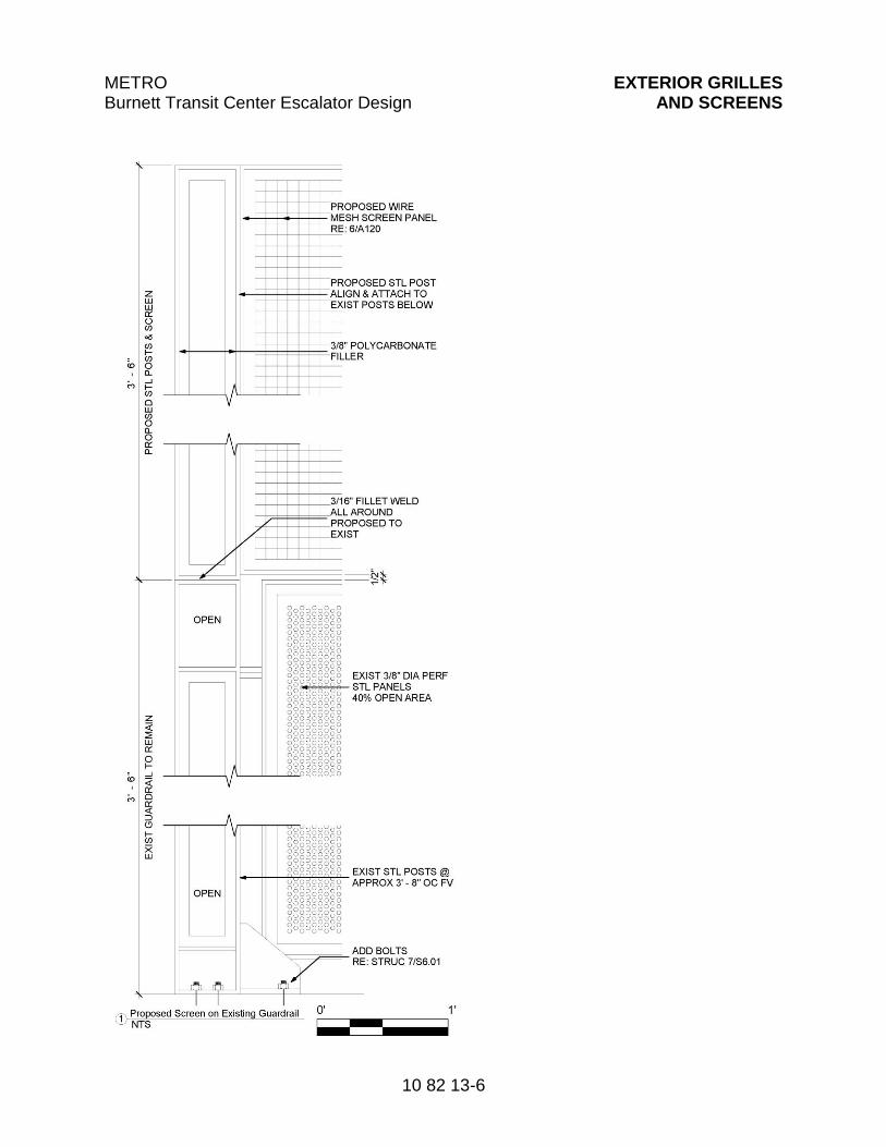
METRO Burnett Transit Center Escalator Design
EXTERIOR GRILLES AND SCREENS
10 82 13-6
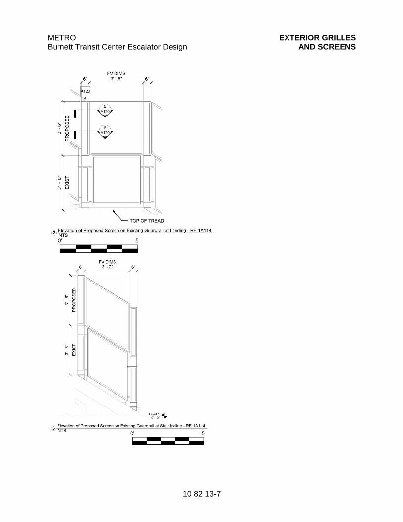
METRO Burnett Transit Center Escalator Design
EXTERIOR GRILLES AND SCREENS
10 82 13-7
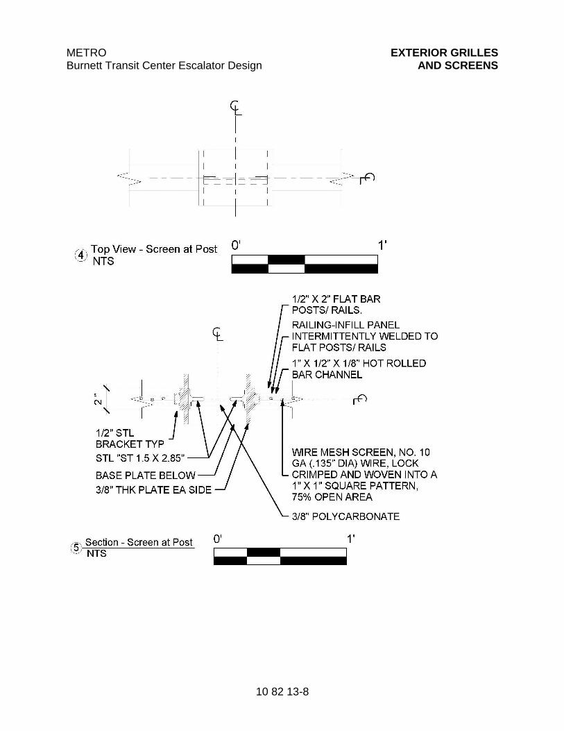
METRO Burnett Transit Center Escalator Design
EXTERIOR GRILLES AND SCREENS
10 82 13-8
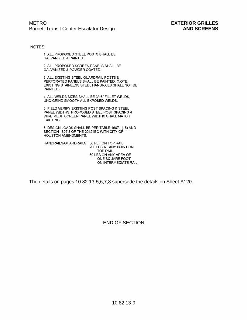
METRO Burnett Transit Center Escalator Design
EXTERIOR GRILLES AND SCREENS
10 82 13-9
The details on pages 10 82 13-5,6,7,8 supersede the details on Sheet A120.
END OF SECTION

METRO Burnett Transit Center Escalator Design ESCALATORS
14 31 00-1
Section 14 31 00
ESCALATORS
PART 1 - G E N E R A L
1.01 SUMMARY
A. Section includes heavy duty escalator system.
B. Related Sections include:
1. Division 03 “Cast-in-Place Concrete” for setting sleeves, inserts, and anchoring devices in concrete.
2. Division 05 “Structural Steel Framing” for attachment plates, angle brackets, and other preparation of structural steel to support escalator trusses.
1.02 MEASUREMENT AND PAYMENT
A. Measurement and Payment shall be on a Lump Sum basis entered in the Bid Form in item 14 31 00 PROVIDE AND INSTALL (TWO) COMPLETE 32” WIDE ESCALATORS. The work shall include but not be limited to 14 31 00 PROVIDE AND INSTALL (TWO) COMPLETE 32” WIDE ESCALATORS complete in place, as described in the plans and specifications
1.03 ACTION SUBMITTALS
A. Product Data: Include capacities, sizes, performances, safety features, finishes, and similar information.
B. Shop Drawings:
1. Include plans, elevations, sections, and details indicating coordination with building structure and relationships with other construction.
2. Include wiring diagrams detailing locations and wiring for power, signal and control systems.
3. Indicate maximum loads imposed on building structure at points of support, and power requirements.
4. Indicate access and ventilation for escalator machine space.
C. Samples for Initial Selection: For exposed materials involving color selection.
METRO Burnett Transit Center Escalator Design ESCALATORS
14 31 00-2
D. Samples for Verification: For exposed escalator finishes, 3-inch-square Samples of sheet materials, and 4-inch lengths of running trim members.
E. Delegated-Design Submittal: For escalators.
1.04 INFORMATIONAL SUBMITTALS
A. Qualification Data: For Installer and manufacturer.
B. Manufacturer Certificates: Signed by manufacturer certifying that escalator layout and dimensions, as shown on Drawings, and electrical service, as shown and specified, are adequate for escalator system being provided.
C. Field quality control reports.
D. Sample Warranty: For special warranty.
1.05 CLOSEOUT SUBMITTALS
A. Operation and Maintenance Data: For escalators to include in emergency, operation, and maintenance manuals.
1. Submit maintenance and repair manuals, hardbound and indexed, in a minimum of four volumes as follows;
a. Wiring Diagram Manual with page size of 11 inches by 17 inches.
b. Maintenance and Renewal Parts Catalog with page size of 8-1/2 inches by 11 inches.
c. Six sets of publications shall be supplied under this contract.
2. Manuals shall include the following data:
B. Manuals: Prior to installation, escalator contractor shall submit two (2) complete sets of Installation, Operation and Maintenance manuals in CD/electronic version only for approval. After customer approval and prior to the beginning of acceptance testing, four (4) copies of approved manuals shall be provided by the escalator contractor in CD/electronic version only. The manuals shall include the following:
1. Complete table of contents.
2. Complete instructions regarding operation and maintenance of equipment, including disassembly and assembly of drive system, handrail drive assembly, and track system. Included will be complete illustrated, exploded
METRO Burnett Transit Center Escalator Design ESCALATORS
14 31 00-3
views of various assemblies, and a complete, illustrated, exploded view for identifying various parts.
3. Complete nomenclature of replaceable parts, with part numbers.
4. Sample copies of proposed preventative maintenance methods.
5. Descriptions of safety devices.
6. Safety rules, description of common tests and procedures.
7. Procedures for adjusting brake, handrail tension, handrail chain drive tension, step chain tension, track system, and mechanical components, including pictorials.
8. Instructions for removing floor plate, replacing comb segments, and removing and installing steps, and interior panels.
9. Troubleshooting techniques.
10. Detailed lubrication and cleaning schedule indicating weekly, monthly, quarterly, semiannual, and annual lubrication; and a description of each lubrication point, lubrication type, and specification.
11. Control and schematic electrical wiring diagrams of controller, including wiring of safety devices to connections with remote indication and control panels for each escalator and group of escalators.
12. Electrical layout showing placement of lighting, light switches, receptacles, light fixtures, disconnect switches, and convenience outlets in machinery room, truss envelope, and pits.
13. Complete detailed drawings and wiring diagram of escalator fault finding device and connection to diagnostic display panel.
C. Inspection and Acceptance Certificates and Operating Permits: As required by authorities having jurisdiction for normal, unrestricted escalator use.
D. Continuing Maintenance Proposal: Submit a continuing maintenance proposal from Installer to Owner, in the form of a standard three-year maintenance agreement, starting on date initial maintenance service is concluded. State services, obligations, conditions, and terms for agreement period and for future renewal options.
METRO Burnett Transit Center Escalator Design ESCALATORS
14 31 00-4
1.06 QUALITY ASSURANCE
A. Manufacturer Qualifications: A company with a minimum of 10 years of documented successful experience manufacturing escalators of the type required.
B. Installer Qualifications: Escalator manufacturer or an authorized representative who is trained and approved by manufacturer.
1.07 DELIVERY, STORAGE, AND HANDLING
A. Deliver, store, and handle materials, components, and equipment in manufacturer's protective packaging. Store materials, components, and equipment off of ground, under cover, and in a dry location.
1.08 COORDINATION
A. Coordinate installation of sleeves, block outs, escalator equipment with integral anchors, and other items that are embedded in concrete or masonry for escalator equipment. Furnish templates, sleeves, escalator equipment with integral anchors, and installation instructions and deliver to Project site in time for installation.
B. Coordinate locations and dimensions of other work relating to escalators including sumps and floor drains in pits; electrical service; and electrical outlets, lights, and switches in pits.
1.09 WARRANTY
A. Manufacturer's Special Warranty: Manufacturer agrees to repair, restore, or replace escalator work that fails in materials or workmanship within specified warranty period.
1. Failures include, but are not limited to, operation or control system failure, including excessive malfunctions; performances below specified ratings; excessive wear; unusual deterioration or aging of materials or finishes; unsafe conditions; the need for excessive maintenance; abnormal noise or vibration; and similar unusual, unexpected, and unsatisfactory conditions.
2. Warranty Period: Three years from date of Substantial Completion.
1.10 MAINTENANCE TOOLS
A. Provide diagnostic tools, manuals, terminals and devices with total and complete written instructions and adjustment information for performing troubleshooting, system adjustments and special or emergency functions
METRO Burnett Transit Center Escalator Design ESCALATORS
14 31 00-5
required by Code. All service tools, terminals and devices shall become the property of the Owner and will be of the non-destructive type. Provide two (2) sets of tools.
PART 2 - P R O D U C T S
2.01 MANUFACTURERS
A. Basis of Design: Design is based on KONE E3X Transit Escalator. Subject to compliance with requirements, provide named product or comparable product approved by Architect.
B. Source Limitations: Obtain escalators from single manufacturer.
2.02 PERFORMANCE REQUIREMENTS
A. Regulatory Requirements: Comply with ASME A17.1/CSA B44.
B. Braking Performance: Provide brakes that stop escalator in up-running mode at a rate no greater than 3 ft./s2.
C. Escalator shall have the capability of operating at full load under normal modes of operation with mean time between operational (non-structural) failures (MTBF) of 3500 hours.
1. Operational failures excluding such items as vandalism, safety switches of building failures shall not result in structural failure of a step or any other component with any potential for bodily injury to the user.
D. Delegated Design: Engage a qualified professional engineer, licensed as a Professional Engineer to practice in the State of Texas to design escalators.
E. Structural and Mechanical Performance for High-Traffic Escalators: For the purposes of structural design, driving machine and power transmission calculations, and brake calculations, design high-traffic escalators for loads not less than two times the design loads required by ASME A17.1/CSA B44.
F. Structural Performance of Balustrades, Deck Barricades, and Handrails: Provide components and assemblies capable of withstanding the effects of loads indicated in ASCE/SEI 7 for handrail assemblies and guardrail systems.
2.03 ESCALATORS
A. Escalators, General: Manufacturer's standard heavy-duty escalators complying with requirements. Unless otherwise indicated, manufacturer's standard
METRO Burnett Transit Center Escalator Design ESCALATORS
14 31 00-6
components shall be used, as included in standard escalator systems and as required for complete system.
B. Escalators shall comply with the following requirements:
1. Vertical Rise: 35’ ft.; (field Verify before fabrication)
2. Inclination: 30 Degrees
3. Nominal Step Width: 800mm (32”)
4. Speed: Not to exceed 0.5m/s (100 fpm)
5. Flat Steps: Three (3)
6. Maintenance Speed: As specified
7. Upper track radius: 2.7
8. Lower track radius: 2.0
9. Static Brake Load: The minimum accumulation for the total number of exposed steps on the incline.
a. 800mm/32” Step: 245 kg/540 lbs. per step
10. Dynamic Brake Load: Minimum peak average load running in down direction on exposed steps on the incline:
a. 800mm/32” Step: 116 kg/256 lbs. per step
11. Motor Duty: Continuous operations with a minimum average peak step load as follows:
a. 800mm/32” Step: 116 kg/256 lbs. per step
12. Step Chain Loads: Based on the peak average step loads as follows:
a. 800mm/32” step: 116 kg/256 lbs. per step
C. Controls and safety devices
1. Operating controls:
a. Escalators shall have key operated switches, accessible at both upper and lower landings, located on the exterior deck above the newel base. Alternate locations may be used subject to approval by the Authority.
METRO Burnett Transit Center Escalator Design ESCALATORS
14 31 00-7
b. Each keyed switch shall be clearly and permanently labeled, including starting and direction selection.
c. Interlocks shall be provided to bring the escalator to a smooth stop, in either direction of travel, before a change of direction may be made.
2. Safety Devices:
a. Safety devices shall be included, but not limited to, that which is required by ASME A17.1.
b. A lockable stop switch or disconnect shall be provided in the lower and upper pits of escalators.
D. Balustrades, skirt panels, and decking
1. Balustrades and skirt panels:
a. Skirt Panels shall be a minimum 3mm (0.118”) thick and Inner Panels shall be a minimum 2mm 0(.079”) thick, type 316 stainless steel with no backing. Stiffeners, brackets, attachment angles and other concealed ferrous metal framework shall be galvanized or constructed of equivalent corrosion resistant materials.
b. Panels shall be constructed, when practical, in equal lengths for interchangeability.
c. Panels shall be attached to permit easy removal for inspection, lubrication, and adjustment of safety devices.
d. Panels shall be sized so that not more than two (2) persons shall be required to remove a panel, and without the aid of special handling equipment.
e. Exposed panel fastener requirements (where used): panels shall be fastened to their respective supports or mating portions with tamper-proof, flathead machine screws.
f. When framework to which panels are fastened is less than 0.25-inch thick, steel backup plates with a minimum 0.25-inch thickness shall be added which have tapped holes or clearance holes where necessary.
2. Decking shall be stainless steel, identical to balustrade, with minimum of 0.079-inch thickness.
METRO Burnett Transit Center Escalator Design ESCALATORS
14 31 00-8
3. Decking between escalators shall be designed to support a live load of 80 kg (175 lbs/sq. ft.) without permanent deformation.
4. Paneling, decking, and other enclosures shall be supported on steel framework.
E. Electrical Equipment
1. Motors: The driving motors shall be AC induction motors with starters. Voltage 460 V.A.C. nominal (standard), 3 phase, Frequency 60 Hertz.
a. The motors shall be totally enclosed with external cooling fins.
b. The motor protection class shall be equivalent to IP 55, insulation group F.
c. Driving motors and motor switchgear shall be designed in such a way so as to provide a smooth start.
d. The motor shall be designed for operation under the specified duty cycle and loads as follows:
1) 800mm/32” wide step: 116 kg/256 lbs. per step
2. Controller
a. The main controller shall use an Allen-Bradley Programmable Logic Controller (PLC) to control and monitor the status of the escalator. The escalator control equipment shall contain diagnostic capabilities as required for the ease of complete maintenance. The diagnostic system shall be an integral part of the controller and provide user-friendly interaction between the service person and the controls. All such systems shall be free from decaying circuits that must be periodically reprogrammed by the manufacturer.
b. Switch gear shall be mounted in NEMA 4X cabinets with strip heaters and labeled terminal strips.
c. The main control switchgear of an escalator shall contain at least the following devices:
1) Lockable main switch thermal and magnetic motor protection starter for up and down travel, hour counter, auxiliary contactors, phase failure device, phase sequence monitor, and ground fault monitor.
METRO Burnett Transit Center Escalator Design ESCALATORS
14 31 00-9
d. The controller cabinet shall furthermore contain a permanently mounted interactive human machine interface (HMI) device.
e. The indication shall be locked automatically. Manual reset type faults shall be acknowledged and reset individually. The emergency stop shall not be locked.
f. All terminals shall have identification markings and all cables shall be provided with cable markers.
g. The controller shall be provided with a means of starting motors smoothly and gradually, reducing inrush current and mechanical shock upon start up. Adjustable settings for accelerating time and starting torque shall be provided. The starter shall also contain auxiliary contacts and a thermal overload relay for motor protection. Two devices shall be provided to remove power from the driving machine motor. At least one device shall be an electromechanical contactor.
h. Maintenance Receptacles: Electric power receptacles shall be furnished and installed in the upper and lower pits. Each receptacle shall be of the GFCI duplex type, waterproof, grounded, and rated for one hundred twenty (120) volts at twenty (20) amperes. The receptacles in the pits shall be surface mounted on the walls.
2.04 MATERIALS
A. Stainless Steel
1. Shapes and bars: ASTM A276, type 304 or 316.
2. Plate, sheet, or strip.
a. Over 3mm/0.118”: ASTM A240, type 304 on ASTM A36 base.
b. Under 3mm/0.118”: ASTM A240, type 304.
B. Fasteners: Fasteners shall be of equal or greater corrosion resistance to metal being fastened. Fasteners shall be furnished with self locking nuts or retaining rings (spring washers, toothed disks). No aluminum fasteners are permitted.
2.05 FINISHES
A. Stainless Steel: No. 4 finish, ASTM A480.
B. Aluminum Castings and Extrusions: Commercial mill finish.
METRO Burnett Transit Center Escalator Design ESCALATORS
14 31 00-10
C. Galvanizing
1. Sheet Steel: ASTM A446, or A526m as applicable. Coating designation G185.
2. Other galvanizing: ASTM A123, ASTM A153, ASTM A385, or ASTM A386, as applicable.
D. Galvanizing Touch Up: Zinc dust coating, MIL-P-21035 or MIL-P-26915.
E. Paint and Corrosion Protection: Each escalator shall have the following minimum corrosion protection.
1. After welding, the truss shall be hot dipped galvanized with a coating in accordance with ASTM A90.
2. Cast metal parts such as gear housings, chain sprockets and return station half circles, shall be painted with a rust inhibitive primer coat after preparation by sandblasting.
3. Steel parts which are not specified to be galvanized shall be painted as follows:
a. First finish coat: two (2) mil (dry film thickness), minimum thickness.
b. Second finish coat: two (2) mil (dry film thickness), minimum thickness.
4. Bright or uncoated axles, shafts, etc. shall be protected by zinc chromate or chrome plating.
5. Screws, nuts, washers and lock washers shall be galvanized or zinc plated.
6. Oil collector chutes and collection trays shall be fabricated of galvanized steel.
2.06 MECHANICAL EQUIPMENT
A. Tracks
1. Design and fabrication of tracks shall retain steps and running gear safely under load requirements and at the highest design speeds specified.
2. Contractor shall assemble and secure sections. The system shall be adjustable, and welding of the tracks is not acceptable.
METRO Burnett Transit Center Escalator Design ESCALATORS
14 31 00-11
3. Design of the mechanical components shall provide for easy installation and removal without the dismantling of parts of the structure.
4. Tracks shall be properly supported on trusses to provide correct alignment and smooth transition to return stations. The rolling surface of the track shall be a minimum thickness of 3mm/.018”.
5. The guiding system for the step chains and step wheels shall be of zinc plated or galvanized steel profiles with smooth and even running surfaces, and with the joints cut diagonally to the running direction. The profiles shall not be welded together at the joints.
6. A second, continuous guiding profile shall be provided above the step chain rollers so that the step chains are positively guided in the area of the escalator open to passengers.
B. Steps
1. The step to skirt gap shall comply with the requirements of ASME A17.1 2010, regardless of any previous version of ASME A17.1 in effect.
2. The entire step assembly shall be unpainted natural aluminum finish or treated with not less than one (1) coat of zinc chromate primer and one (1) coat of powder coated enamel for corrosion resistance.
3. Steps and their various attachments shall permit removal of steps without disturbing balustrades.
4. The design shall permit the running of the drive with one in six steps installed for convenience in cleaning and inspection.
5. Step rollers shall have polyurethane tires on hubs, sealed roller bearings, and a diameter of no less than 100mm (4”). Step rollers shall not require any additional lubrication and must be rated for severe, heavy-duty service.
6. Steps shall be constructed so as to be driven by step linkages to step or step rollers.
7. Contractor shall provide washers and nuts as follows:
a. Tap bolts: Lock washers.
b. Through bolts: Lock nuts or Customer approved equal.
8. Rated Loads:
METRO Burnett Transit Center Escalator Design ESCALATORS
14 31 00-12
a. In addition to the minimum requirements given in the Codes, Contractor shall design the steps for a minimum breaking load of 116 kg/256 lbs. per 800mm/32” step with a safety factor of eight (8).
b. The steps shall carry the load under maximum concentric and eccentric loading conditions without distortion.
C. Step Chain
1. Chain shall be endless, roller type step chains; one (1) on each side of step.
2. Step chains shall be of heat treated steel construction, supported at intervals by linkage wheels.
3. A means to prevent steps from coming into physical contact with each other and to prevent chains from sagging or buckling shall be provided.
4. A means to maintain constant distance between step axles shall be provided.
5. An automatic tensioning device to maintain tension under load and to compensate for wear shall be provided. The device shall be located within the truss at the lower end.
6. A means for individual fine adjustment of tension for each side shall be provided.
7. Step chains shall be constructed to permit removal of segments as may be required for replacement purposes at a minimum of every six (6) axle sections. Each escalator shall have at least two one axle sections.
8. Support wheels spaced to distribute load and to guide linkage throughout run shall be provided. Rollers shall be constructed of polyurethane material, with diameter sufficient to provide reliability, maintainability, smoothness of motion, and to operate within noise level requirements specified. The chain rollers shall have polyurethane tires on metallic hubs, sealed bearings, a diameter of not less than 100mm (4”), must require no additional lubrication, and be mounted outside the chain link.
9. Wheels shall be affixed to permit rapid replacement.
10. Each pair of step chains shall be a matched set within manufacturing tolerances. Only precision, roller fishplate chains of high grade heat treated steel shall be used as step chains. The pins, axles, bushing, and rollers shall be hardened and ground.
METRO Burnett Transit Center Escalator Design ESCALATORS
14 31 00-13
11. Step chain and chain pins shall have a minimal diameter of at least 16mm (0.625”). In addition, the diameter will be of a size so that the surface pressure at engaging points will not exceed 30 N/sq. mm (3450 lbs/sq. inch). This is to be based on the peak average step loads as follows:
a. 800mm/32-inch step: 116 kg/256 lbs.
12. Safety Factor: 6.
13. A shielding device to protect chain, track guides, and rollers against water, dirt, and debris.
D. Combplate Assemblies
1. Combplate assemblies of wear resisting, non-corrosive metal material, with exposed anti slip surfaces shall be fabricated.
2. Combplate segments meeting the following requirements shall be provided.
a. Shall be removable to permit ease of replacement.
b. Shall be yellow in color for safety/demarcation.
c. Shall have not less than three (3), nor more than seven (7), combplate segments per combplate Assembly.
d. Provisions for lateral and vertical fine adjustments shall be provided so that cleats of step treads pass between combteeth with minimum clearances.
e. Combteeth meeting the following requirements shall be provided.
1) Teeth shall be designed so as to withstand a load of 114 kg/250 lbs. applied in an upward direction at the tip of any one (1) tooth.
E. Floor Plates
1. Shall have stainless steel frames at floor openings, designed to be supported on truss heads.
2. Shall be designed to cover entire area of upper and lower landings as indicated.
3. Shall be reinforced, as necessary, to be rigid and able to withstand a live load of 114 kg/250 lbs per sq. ft., with no permanent deformation.
METRO Burnett Transit Center Escalator Design ESCALATORS
14 31 00-14
4. Shall be extruded of die cast aluminum in a ribbed pattern transverse to the escalator axis. Ribs shall be designed to provide maximum traction, and will be finished in the same manner as the combplates.
5. Shall have exposed portions constructed of material and finish to harmonize with steps and combplates.
F. Drive Machinery
1. Motor and drive mechanism shall be mounted within the truss envelope and inside the step band at the upper end. The machine/drive shall be directly coupled to the escalator step band main shaft through gears (chain connections are not acceptable). Shafts shall be designed for ease of assembly or disassembly.
2. Carriage Requirements:
a. Carriages shall have a spring operated device provided to aid in tension and mechanical adjustment.
b. Carriages shall have a scale and pointer provided on accessible section of carriage frame to indicate movement and amount of adjustment available. Position scale and pointer to indicate zero (0) for initial position of carriage, prior to placing in service.
3. Gear Box Requirements:
a. Three (3) stage planetary gear type shall be provided.
b. Gear bearings shall be housed in an oil tight, dust proof case provided with a sight glass or dipstick method of determining oil level in the case. The case shall provide a convenient method for draining the oil.
c. Lubricant shall be synthetic, subject to Customer approval.
d. The assembly shall have no openings in order to minimize accumulation of dust and debris.
e. Rotating parts shall be provided with a means for lubrication and retention of lubricants.
f. Sealed bearings shall be used in those environmental conditions where entry of water or dust may adversely affect bearing performance.
g. Exposed, moving drive elements shall be protected by sealed metal housings, which shall provide continuous lubrication to components.
METRO Burnett Transit Center Escalator Design ESCALATORS
14 31 00-15
h. A low oil level sensor shall be provided to prohibit starting of the escalator during automatic operation with low oil in the gear case.
G. Drip Pans
1. Galvanized, welded to the truss, water tight drip pans for the entire length and width of trusses shall be provided. They shall also be sloped for proper drainage and collection of spent lubricants as well as any moisture or water which may enter the escalator.
2. Drip pans of sufficient size to collect and maintain, within truss areas, oil and grease drippings from step linkage and all forms of loose debris that may be deposited in drip pans from steps at turn around points at upper and lower portions of truss shall be provided. This system shall be separate from the water drain in order to prevent the discharge of spent lubricants into sewer system.
3. Access to drip pans at lower landings of escalators for the purpose of cleaning drain catch basins shall be provided.
H. Handrails
1. Handrails shall receive their motion from main escalator drive through direct gearing and drive shaft, or chain driven from the main shaft, so that handrail and steps operate at the same speed in each direction of travel.
2. A means to take up handrail slack using a tensioning device, where required, shall be located within escalators. In addition, an approved method of releasing the device for repair or removal of handrails shall be provided.
3. Newels meeting the following requirements shall be provided.
a. Newels shall be designed and constructed so that handrail shall return into newel end at a point inconspicuous and difficult for passengers to reach.
b. Newel sheaves shall be provided at upper and lower newels.
c. Handrails, handrail drive system, and guides shall be so designed and installed that handrail cannot be thrown off or disengaged while running. Special design attention shall be given to the area where handrails pass from drive system to guides.
METRO Burnett Transit Center Escalator Design ESCALATORS
14 31 00-16
d. Handrail rollers shall have sealed bearings that have provision for retention of lubricant to ensure satisfactory lubrication and operation. Additional lubrication shall not be required.
e. Friction drive sheaves and idlers shall be designed and positioned so that lubricant cannot reach surface of handrail.
f. Handrails shall be constructed of laminated, steel, wire mesh, or steel cable reinforced, flexible elastomer material vulcanized into an integral, seamless, smooth handrail resistant to environmental conditions. A “V” shaped underside design shall be used, providing a more positive drive.
g. Handrail color shall be black. Round white markers inlaid into the handrail material shall be provided.
h. Handrail guides shall be continuous on exposed portion of handrails and constructed of stainless steel.
I. Brakes
1. Motor Brake
a. Brake shall be capable of stopping and holding a descending escalator with a peak average load on the exposed steps in the incline area of:
1) 800mm/32” Wide Step: 116 kg/256 lbs. per step
b. The brake coil shall be insulated to class F. A monitor shall be provided, and if brake wear becomes insufficient for safe usage, restart of escalator shall be prevented.
2. Step Band Lock
a. Shall be manually applied and mechanically engaged to prevent movement of linkages, while escalator is disconnected from its power supply.
b. Electrical interlock shall be provided to prevent escalator drive motors from starting while step band lock is engaged.
J. Trusses
1. General
a. The truss shall be designed to support the dead weight of the escalator (full static load).
METRO Burnett Transit Center Escalator Design ESCALATORS
14 31 00-17
b. The additional deflection of the loaded truss with application of live load shall not exceed one-thousandth (1/1000) of the span.
c. The slip joint slide bearings shall be fabricated using glass filled TFE bearing surface or 316 stainless steel, one sliding on the other.
2. Field Splices, Connections, and Shims
a. Field splices shall be rigid, non-deforming, and maintain alignment.
b. Shims shall be galvanized steel with a maximum height of 51mm (2”).
K. Step Chain Tensioning Device
1. The step chain tensioning device shall be of a design that keeps the step chains at the correct tension.
2. A pointer and scale shall be provided to gauge step chain tensioning and wear.
3. Bearings, where used, shall be rated AFBMA L10, 200,000 hours.
4. The tensioning device shall consist of two (2) chain sprockets for step chain return, and shall be fitted on a common shaft by means of roller bearings.
5. The tensioning shaft shall be tensioned by compression springs at both sides.
L. Lubrication System Requirements
1. Step Chain
a. All parts, other than sealed items, requiring lubrication shall be designed for an automatic or remote lubricating system. The system shall operate only when the escalator is running. The rate of lubrication shall be adjustable via the controller HMI. A reservoir with a low oil level signal to the controller, and a minimum capacity of 9.5 liters/2.5 gallons shall be provided.
b. System shall be positive acting and located in the escalator pit.
c. Reservoir level indications shall be provided where lubricants are contained within housings, supply tanks and larger filler cups.
d. Electric heaters can be installed and connected to the panel to maintain lubricant viscosity.
METRO Burnett Transit Center Escalator Design ESCALATORS
14 31 00-18
2. Miscellaneous Lubrication
a. Bearings
1) Sealed bearings shall be used where possible.
2) Bearings requiring manual lubrication shall be furnished with fittings to accommodate the use of a pressure gun for lubrication.
3) Self lubricating bearings or material other than ball or roller type bearings may be used where practical.
3. Manual Lubrication: Location of manual lubrication points shall be easily accessible and available.
M. Indicators
1. Escalator users shall be informed by means of indicator lights identifying the pre-determined running direction of the escalator.
2. Two (2) circular cut outs, 70 mm/2.75” minimum diameter in upper and lower balustrade newel or inner deck, each containing an inset red and green light, shall be provided. The green light will be illuminated at the entrance for escalator running direction and the red light will be illuminated at the exiting end.
N. Maintenance Drive Unit
1. Reduced speed maintenance operation controlled by a manual handset shall be provided. When operated, the escalator shall run in the direction selected, at a speed of not more than 25 percent of rated speed. This speed shall be maintained when steps are removed for servicing. The running shall be continuous so long as an “up” or “down” button on the handset is being pressed. The handset shall have a 3 m/10-ft (minimum) retractile type cord with a plug connector. When plugged into a receptacle, there shall be no means of operating or running the escalator except by the service handset. Receptacles shall be located in both the upper and lower pits.
O. Room Storage Cabinet
1. A metal cabinet shall be provided of not less than 0.55 cubic meter/20 cubic feet in volume 1320mm high X 910mm wide X 460mm deep (52” X 36” X 18”) in a room assigned by the Customer.
METRO Burnett Transit Center Escalator Design ESCALATORS
14 31 00-19
2. Cabinet shall have lockable doors, mounted on legs or a pedestal, and be a minimum of 100mm/4” off the floor.
3. Cabinet shall be painted and marked for control purposes, as directed by the Customer, and escalator contractor shall store small parts, supplies, tools, and other materials within.
P. Demarcation Lights
1. Each unit shall have two (2) LED fixtures, green in color, and UL labeled “suitable for wet locations”.
PART 3 - E X E C U T I O N
3.01 EXAMINATION
A. Examine escalator areas, with Installer present, for compliance with requirements for installation tolerances and other conditions affecting performance of the Work.
B. Examine supporting structure, machine spaces, and pits; verify critical dimensions; and examine conditions under which escalators are to be installed.
C. Examine supply of electric feeder wires to the terminals of the control panel, including fused main line switch or circuit breaker.
D. Prepare written report, endorsed by Installer, listing conditions detrimental to performance of the Work.
E. Proceed with installation only after unsatisfactory conditions have been corrected.
3.02 INSTALLATION
A. Comply with manufacturer's written instructions.
B. Set escalators true to line and level, properly supported, and anchored to building structure. Use established benchmarks, lines, and levels to ensure dimensional coordination of the Work.
C. Adjust installed components for smooth, efficient operation, complying with required tolerances and free of hazardous conditions. Lubricate operating parts, including bearings, tracks, chains, guides, and hardware. Test operating devices, equipment, signals, controls, and safety devices. Install oil drip pans and verify that no oil drips outside of pans.
METRO Burnett Transit Center Escalator Design ESCALATORS
14 31 00-20
D. Repair damaged finishes so no evidence remains of correction work. Return items that cannot be refinished in the field to the shop, make required repairs and refinish entire unit, or provide new units as required.
3.03 TEMPORARY USE OF ESCALATORS
A. Do not use escalators for construction purposes or during the period prior to Substantial Completion, except with written authorization from Owner. If Owner authorizes temporary use of escalators, the following conditions shall apply:
1. Contractor shall provide a "temporary acceptance form" for Owner to sign.
2. Neither the new installation period nor the warrantee shall start without Owner's written approval.
3. Contractor shall provide all temporary protection of escalators installed.
4. Contractor shall return escalators in the condition which existed when Owner approved the “temporary use.”
3.04 FIELD QUALITY CONTROL
A. Acceptance Testing: On completion of escalator installation and before permitting escalator use, perform acceptance tests as required and recommended by ASME A17.1/CSA B44 and by authorities having jurisdiction.
1. For escalators specified to comply with requirements more stringent than those of ASME A17.1/CSA B44, perform tests for compliance with specified requirements. Test safety devices that are not required by ASME A17.1/CSA B44 as well as those that are.
B. Advise Owner, Architect, and authorities having jurisdiction in advance of dates and times that tests are to be performed.
3.05 DEMONSTRATION
A. Engage a factory-authorized service representative to train Owner's maintenance personnel to operate, adjust, and maintain escalators.
B. Check operation of escalators with Owner's personnel present before date of Substantial Completion and again not more than one month before end of warranty period. Determine that operation systems and devices are functioning properly.
METRO Burnett Transit Center Escalator Design ESCALATORS
14 31 00-21
3.06 MAINTENANCE
A. Initial Maintenance Service: Beginning at Substantial Completion, maintenance service shall include 36 months' full maintenance by skilled employees of escalator Installer. Include monthly preventive maintenance, repair or replacement of worn or defective components, lubrication, cleaning, and adjusting as required for proper escalator operation. Parts and supplies shall be manufacturer's authorized replacement parts and supplies.
1. Perform maintenance during normal working hours.
2. Include 24-hour-per-day, 7-day-per-week emergency callback service with response time of two hours or less.
END OF SECTION

Related Documents